COOLING TOWER CELLS - FIBERGLASS UNITS - INSTRUCTION MANUAL I.O.M. #054 6/99 • INSTALLATION • OPERATION • MAINTENANCE TEMPTEK, INC. 525 East Stop 18 Road Greenwood, IN 46142 phone: 317-887-6352 fax: 317-881-1277 web site: www.temptek.com e-mail: [email protected]

Welcome message from author
This document is posted to help you gain knowledge. Please leave a comment to let me know what you think about it! Share it to your friends and learn new things together.
Transcript
COOLING TOWERCELLS
- FIBERGLASS UNITS -
INSTRUCTIONMANUAL
I.O.M. #054 6/99
• INSTALLATION• OPERATION• MAINTENANCE
TEMPTEK, INC. 525 East Stop 18 Road Greenwood, IN 46142phone: 317-887-6352 fax: 317-881-1277web site: www.temptek.com e-mail: [email protected]

TEMPTEK, INC.525 East Stop 18 RoadGreenwood, IN 46142
317-887-6352 Fax: 317-881-1277
© 1999 TEMPTEK, INC.
INSTRUCTION MANUALFOR
FIBERGLASS TOWER CELLSCOVERING MODELS:
All ‘TP’ models
PRESENTING INSTRUCTIONS FOR
INSTALLATIONOPERATION
MAINTENANCE

Page: 4
Note: this page intentionally left blank

‘TP’ Fiberglass Tower Cells
Page: 5TEMPTEK, INC.525 East Stop 18 Road Greenwood, Indiana 46142
317-887-6352 Fax: 317-881-1277Service Department Fax: 317-885-8683
TABLE OF CONTENTS
1.0 TECHNICAL DATA 71.1 Single Cell Units 81.2 Expanded Cell Units 91.3 Cross Section 10
2.0 PHYSICAL DATA 112.1 T45P Physical 122.2 T85P Physical 132.3 T135P Physical 142.4 T170P Physical 152.5 T270P Physical 162.6 T405P Physical 172.7 T540P Physical 18
3.0 INSTALLATION 193.1 Assembly and Rigging Instructions 203.2 Typical Tower Cell Support Stand 213.3 Typical 1 Pump Tower System Configuration 223.4 Typical 2 Pump Tower System Configuration 243.5 Tower Stand Mounting Options 263.6 Typical Vacuum Breaker 273.7 Typical Press Drop 283.8 Expandable Tower Cell Installation 293.9 Operation & Maintenance Schedule 30
4.0 APPENDIX 314.1 Typical Hydraulic Heat Exchanger Cooling
by HP @ 10° ∅T 324.2 Tower Water Requirements vs Pipe Size
to Condenser Chillers 334.3 Wet Bulb Temperatures 34

Note: this page intentionally left blank

‘TP’ Fiberglass Tower Cells
Page: 7TEMPTEK, INC.525 East Stop 18 Road Greenwood, Indiana 46142
317-887-6352 Fax: 317-881-1277Service Department Fax: 317-885-8683
1.0 GENERAL1.1 SINGLE CELL UNITS1.2 EXPANDED CELL UNITS1.3 CROSS SECTION

‘TP’ Fiberglass Tower Cells
Page: 8TEMPTEK, INC.525 East Stop 18 Road Greenwood, Indiana 46142
317-887-6352 Fax: 317-881-1277Service Department Fax: 317-885-8683
1.1 SINGLE CELL UNITS
MODEL T45P T85P T135PCAPACITY IN TONS 45 85 135FLOW RATE (GPM) 135 255 405
FAN DATAQUANTITY 1 1 1RPM 1170 1170 870# OF BLADE/TOTAL DIAMETER (INCHES) 9/36 9/42 6/60CFM 12040 21700 30500
MOTOR DATAQUANTITY 1 1 1TOTAL NAMEPLATE HP 3 5 7.5AMPS @ 208/3/60 11.0 17.5 25.3AMPS @ 230/3/60 9.6 15.2 22.0AMPS @ 460/3/60 4.8 7.6 11.0AMPS @ 575/3/60 3.9 6.1 9.0
WATER DATAWATER MAKE-UP (GPM) 1.2 2.4 3.2WATER BLEED-OFF (GPM) 0.6 1.2 1.6PRESSURE LOSS IN HEADER (PSI) 4 4 4PIPE SIZE: TO/FROM (INCHES) 3/4 4/6 4/6
DIMENSIONS DATA (INCHES)HEIGHT 136 136 136WIDTH 60 84 96DEPTH 49 73 85
WEIGHT DATA (LBS)DRY 725 1290 1612WET 1470 3100 4200SHIPPING 1100 1580 1950
T135P shown
‘TP’ Fiberglass Tower Cells
Page: 9TEMPTEK, INC.525 East Stop 18 Road Greenwood, Indiana 46142
317-887-6352 Fax: 317-881-1277Service Department Fax: 317-885-8683
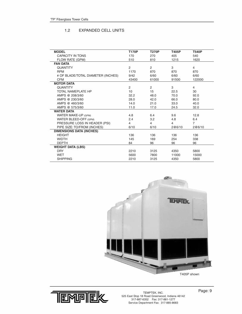
1.2 EXPANDED CELL UNITS
MODEL T170P T270P T405P T540PCAPACITY IN TONS 170 270 405 540FLOW RATE (GPM) 510 810 1215 1620
FAN DATAQUANTITY 2 2 3 4RPM 1170 870 870 870# OF BLADE/TOTAL DIAMETER (INCHES) 9/42 6/60 6/60 6/60CFM 43400 61000 91500 122000
MOTOR DATAQUANTITY 2 2 3 4TOTAL NAMEPLATE HP 10 15 22.5 30AMPS @ 208/3/60 32.2 48.0 70.0 92.0AMPS @ 230/3/60 28.0 42.0 66.0 80.0AMPS @ 460/3/60 14.0 21.0 33.0 40.0AMPS @ 575/3/60 11.0 17.0 24.5 32.0
WATER DATAWATER MAKE-UP (GPM) 4.8 6.4 9.6 12.8WATER BLEED-OFF (GPM) 2.4 3.2 4.8 6.4PRESSURE LOSS IN HEADER (PSI) 4 4 4 7PIPE SIZE: TO/FROM (INCHES) 6/10 6/10 2@6/10 2@6/10
DIMENSIONS DATA (INCHES)HEIGHT 136 136 136 136WIDTH 145 169 254 338DEPTH 84 96 96 96
WEIGHT DATA (LBS)DRY 2210 3125 4350 5800WET 5600 7800 11000 15000SHIPPING 2210 3125 4350 5800
T405P shown
‘TP’ Fiberglass Tower Cells
Page: 10TEMPTEK, INC.525 East Stop 18 Road Greenwood, Indiana 46142
317-887-6352 Fax: 317-881-1277Service Department Fax: 317-885-8683
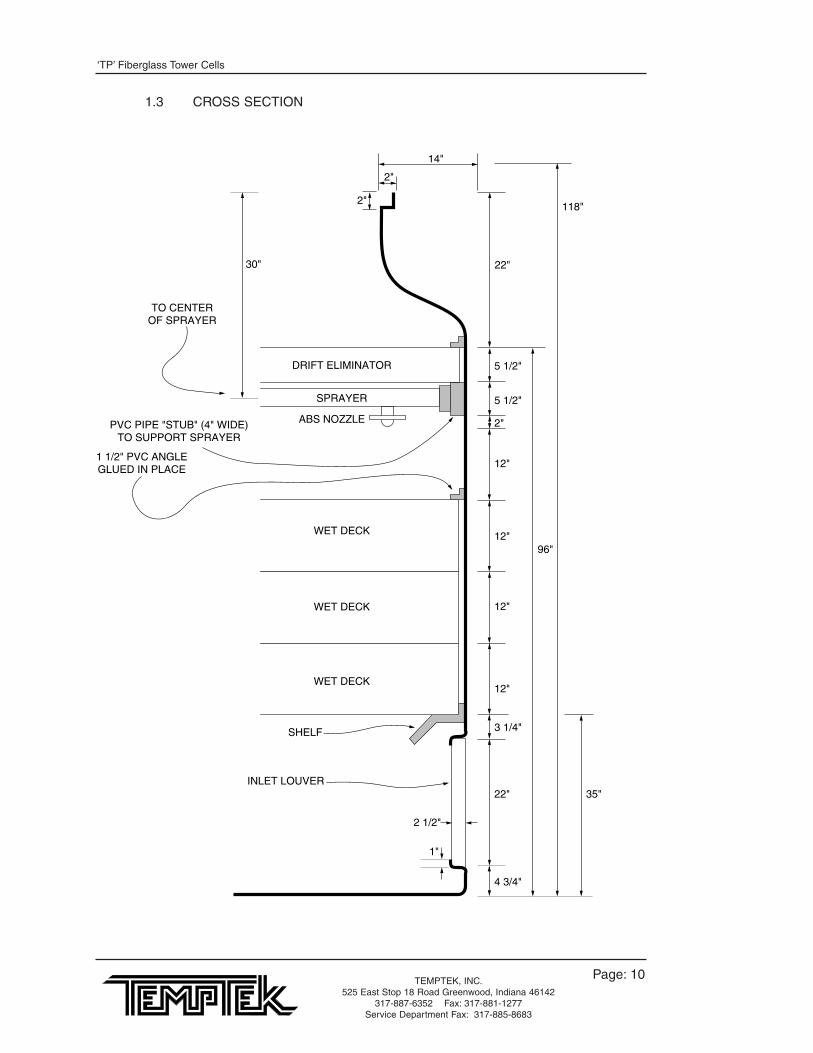
1.3 CROSS SECTION
22" 35"
118"
96"
3 1/4"
4 3/4"
14"
2"
2"
22"30"
TO CENTEROF SPRAYER
1 1/2" PVC ANGLEGLUED IN PLACE
SHELF
2 1/2"
1"
SPRAYER
DRIFT ELIMINATOR
ABS NOZZLE
WET DECK
WET DECK
WET DECK
INLET LOUVER
12"
12"
12"
12"
2"
5 1/2"
5 1/2"
PVC PIPE "STUB" (4" WIDE)TO SUPPORT SPRAYER

‘TP’ Fiberglass Tower Cells
Page: 11TEMPTEK, INC.525 East Stop 18 Road Greenwood, Indiana 46142
317-887-6352 Fax: 317-881-1277Service Department Fax: 317-885-8683
2.0 INSTALLATION2.1 T45P PHYSICAL2.2 T85P PHYSICAL2.3 T135P PHYSICAL2.4 T170P PHYSICAL2.5 T270P PHYSICAL2.6 T405P PHYSICAL2.7 T540P PHYSICAL

‘TP’ Fiberglass Tower Cells
Page: 12TEMPTEK, INC.525 East Stop 18 Road Greenwood, Indiana 46142
317-887-6352 Fax: 317-881-1277Service Department Fax: 317-885-8683
2.1 T45P PHYSICAL
3" SCHED 40PVC
WATER INLET
1140 RPM3 HP TEFC
4" PVC SLIP FLANGEWATER OUTLET
48 3/4"
59 1/2"
19 3/8"
13 3/4"
8 11
96"
126"
137 1/2"
1"9"
1"
9"
TYPICAL MTG. HOLE LAYOUTALL HOLES 5/8" DIA.
‘TP’ Fiberglass Tower Cells
Page: 13TEMPTEK, INC.525 East Stop 18 Road Greenwood, Indiana 46142
317-887-6352 Fax: 317-881-1277Service Department Fax: 317-885-8683
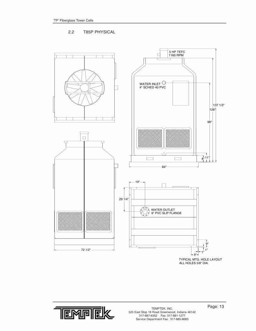
2.2 T85P PHYSICAL
WATER OUTLET6" PVC SLIP FLANGE
ALL HOLES 5/8" DIA.TYPICAL MTG. HOLE LAYOUT
9"
1"
9"1"
19"
29 1/4"
5 HP TEFC1160 RPM
WATER INLET4" SCHED 40 PVC
137 1/2"
126"
96"
11"8"
84"
72 1/2"
‘TP’ Fiberglass Tower Cells
Page: 14TEMPTEK, INC.525 East Stop 18 Road Greenwood, Indiana 46142
317-887-6352 Fax: 317-881-1277Service Department Fax: 317-885-8683
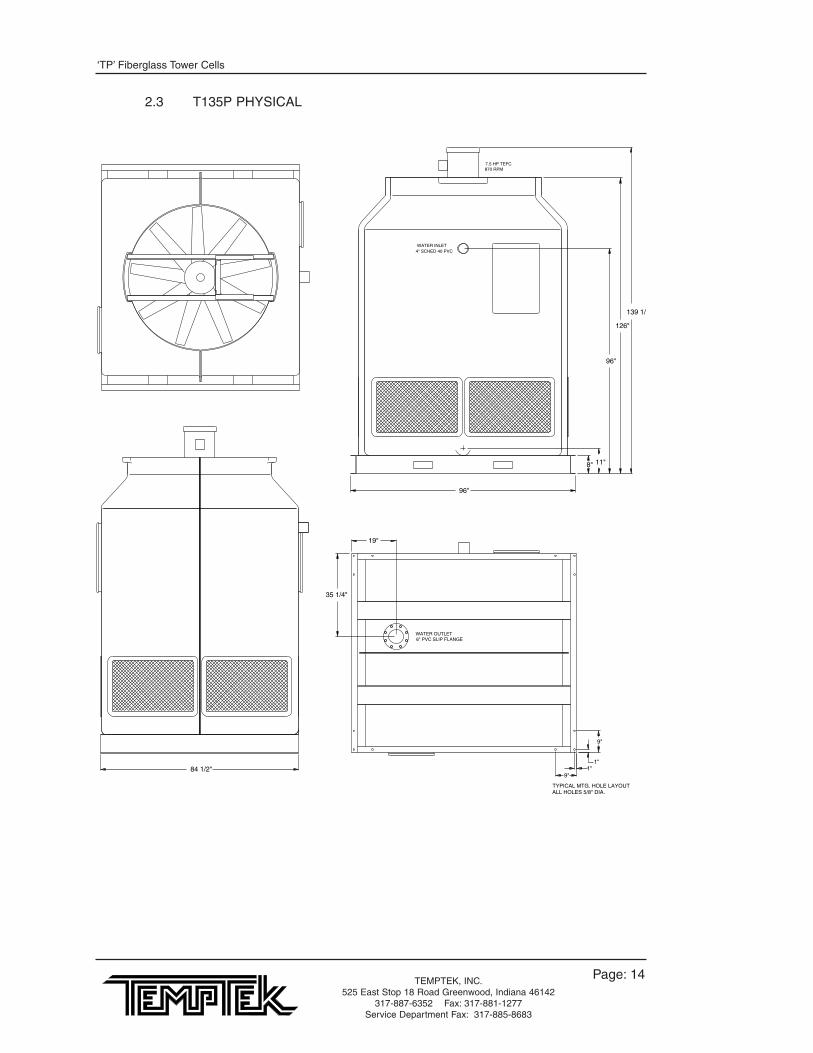
2.3 T135P PHYSICAL
WATER OUTLET6" PVC SLIP FLANGE
TYPICAL MTG. HOLE LAYOUTALL HOLES 5/8" DIA.
1"
9"
1"9"
19"
35 1/4"
7.5 HP TEFC870 RPM
WATER INLET4" SCHED 40 PVC
96"
8" 11"
96"
126"
139 1/2
84 1/2"
‘TP’ Fiberglass Tower Cells
Page: 15TEMPTEK, INC.525 East Stop 18 Road Greenwood, Indiana 46142
317-887-6352 Fax: 317-881-1277Service Department Fax: 317-885-8683
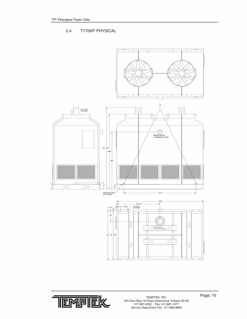
2.4 T170KP PHYSICAL
1160 RPM5 HP TEFC
121"
8 PLACES3/4" DIA.6" 12"
81 1/2"84"
19"
1 1/4"
11"
137 1/2"
126"
96"
8"
145"
72 1/2"
BOTH SIDESHOISTING TABS
6" SCHED 40 PVCWATER INLET
10" PVC SLIP FLANGEWATER OUTLET

‘TP’ Fiberglass Tower Cells
Page: 16TEMPTEK, INC.525 East Stop 18 Road Greenwood, Indiana 46142
317-887-6352 Fax: 317-881-1277Service Department Fax: 317-885-8683
2.5 T270P PHYSICAL
BOTH SIDESHOISTING TABS
10" PVC SLIP FLANGEWATER OUTLET
6" SCHED 40 PVCWATER INLET
870 RPM7.5 HP TEFC
8 PLACES3/4" DIA.
93 1/2"96"
19"
1 1/4"
139 1/2"
126"
87"
8"
169"
84 1/2"
6" 12"
145"
11"
‘TP’ Fiberglass Tower Cells
Page: 17TEMPTEK, INC.525 East Stop 18 Road Greenwood, Indiana 46142
317-887-6352 Fax: 317-881-1277Service Department Fax: 317-885-8683
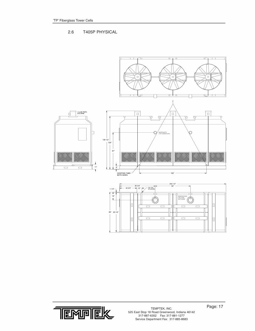
2.6 T405P PHYSICAL
BOTH SIDESHOISTING TABS
8 PLACES3/4" DIA.
SLIP FLANGE2 @ 10" PVCWATER OUTLETS
2 @ 6" SCHED 40 PVCWATER INLETS
870 RPM7.5 HP TEFC
93 1/2"96"
19"
1 1/4"
160"
139 1/2"
126"
87"
8"11"
40 3/4"84 3/4"
253 1/2"
12"84"

‘TP’ Fiberglass Tower Cells
Page: 18TEMPTEK, INC.525 East Stop 18 Road Greenwood, Indiana 46142
317-887-6352 Fax: 317-881-1277Service Department Fax: 317-885-8683
2.7 T540P PHYSICAL
7.5 HP TEFC870 RPM
WATER INLETS3 @ 6" SCHED 40 PVC
WATEROUTLETS
3 @ 10" PVCSLIP FLANGE
3/4" DIA.8 PLACES
HOISTING TABSBOTH SIDES
84"84"
12"
338"
85"
78 1/2"
11"8
87"
126"
139 1/2"
169"
1 1/4"
19"
96" 93 1/2"

‘TP’ Fiberglass Tower Cells
Page: 19TEMPTEK, INC.525 East Stop 18 Road Greenwood, Indiana 46142
317-887-6352 Fax: 317-881-1277Service Department Fax: 317-885-8683
3.0 INSTALLATION3.1 ASSEMBLY AND RIGGING INSTRUCTIONS3.2 TYPICAL TOWER CELL SUPPORT STAND3.3 TYPICAL 1-PUMP TOWER SYSTEM CONFIGURATION3.4 TYPICAL 2-PUMP TOWER SYSTEM CONFIGURATION3.5 TOWER STAND MOUNTING OPTIONS3.6 TYPICAL VACUUM BREAKER3.7 TYPICAL PRESS DROP3.8 EXPANDABLE TOWER CELL INSTALLATION3.9 RECOMMENDED OPERATION AND MAINTENANCE SCHEDULE
‘TP’ Fiberglass Tower Cells
Page: 20TEMPTEK, INC.525 East Stop 18 Road Greenwood, Indiana 46142
317-887-6352 Fax: 317-881-1277Service Department Fax: 317-885-8683
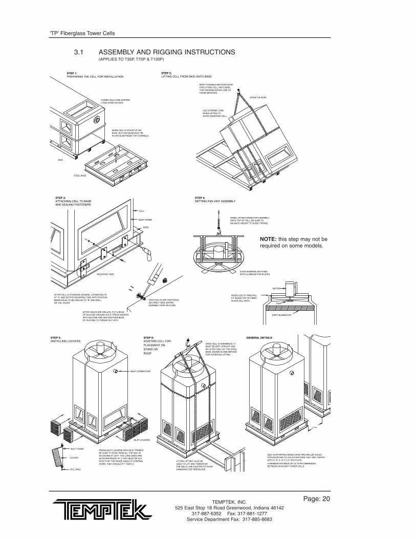
3.1 ASSEMBLY AND RIGGING INSTRUCTIONS(APPLIES TO T35P, T75P & T120P)
SELF-SUPPORTING BASES HAVE PRE-DRILLED HOLESFOR MOUNTING TO LEG EXTENTIONS THAT ARE TOPPEDWITH A 10" X 10" X 1/2" HRS PLATE.
A MINIMUM DISTANCE OF 24" IS RECOMMENDEDBETWEEN ADJACENT TOWER CELLS.
24 MIN.
GENERAL DETAILS
TOWER CELLS ARE SHIPPEDLYING DOWN ON SKID.
SKID
WHEN CELL IS STOOD UP ONBASE, BOTTOM SEAM MUST BEIN SPACE BETWEEN TOP CHANNELS.
STEEL BASE
STEP 1:PREPARING THE CELL FOR INSTALLATION
STRAP OR ROPE
USE EXTREME CAREWHEN LIFTING TOAVOID DAMAGING CELL.
MANY POSSIBLE METHODS EXISTFOR LIFTING CELL ONTO BASE.THIS DIAGRAM SHOWS ONE OFTHESE METHODS.
STEP 2:LIFTING CELL FROM SKID ONTO BASE
CELL
INLET FRAME
BASE
MOUNTING TABS
AFTER CELL IS STANDING ON BASE, LOOSEN BOLTSAT "A" AND ROTATE MOUNTING TABS INTO POSITION.MARK HOLES TO BE DRILLED AT "B" AND DRILL3/8" DIA. HOLES.
ONCE BOLTS ARE TIGHTENEDSECURELY SEAL ENTIREASSEMBLY WITH SILICONE.
AFTER HOLES ARE DRILLED, PUT A BEADOF SILICONE AROUND HOLE; PRESS WASHERINTO SILICONE AND ADD ANOTHER BEADOF SILICONE TO THREAD NUT INTO.
STEP 3:ATTACHING CELL TO BASEAND SEALING FASTENERS
PRESS INLET LOUVERS INTO INLET FRAMES.BE SURE TO PUSH THEM ALL THE WAY INAS SHOWN AT LEFT. THE LONG SIDES ARE AN INTERFRENCE FIT.) THEY MUST BE PUTIN SO THAT THE INSIDE ANGLE IS POINTINGDOWN. THEY SHOULD FIT TIGHTLY.
INLET LOUVERS
CELL WALL
INLET FRAME
LOUVER
INLET CONNECTION
STEP 5:INSTALLING LOUVERS
ONCE CELL IS ASSEMBLED, ITMUST BE KEPT UPRIGHT ANDBE LIFTED ONLY BY THE STEELBASE. SHOWN IS ONE METHODFOR OVERHEAD LIFTING.
A FORK LIFT MAY ALSO BEUSED TO LIFT AND TRANSPORTTHE CELLS. USE CAUTION TO AVOIDDAMAGING THE FIBERGLASS.
STEP 6:HOISTING CELL FOR
PLACEMENT ON
STAND OR
ROOF
WHEN LIFTING FAN/MOTOR ASSEMBLYONTO TOP OF CELL, BE SURE TO BALANCE WEIGHT TO AVOID TIPPING.
AVOID BUMPING ANYTHINGWITH ALUMINUM FAN BLADES.
MOTOR
FAN
DRIFT ELIMINATOR
INSIDE LEG OF RING WILLFIT INSIDE TOP OF FIBER-GLASS CELL BODY.
STEP 4:SETTING FAN UNIT ASSEMBLY
NOTE: this step may not berequired on some models.
‘TP’ Fiberglass Tower Cells
Page: 21TEMPTEK, INC.525 East Stop 18 Road Greenwood, Indiana 46142
317-887-6352 Fax: 317-881-1277Service Department Fax: 317-885-8683
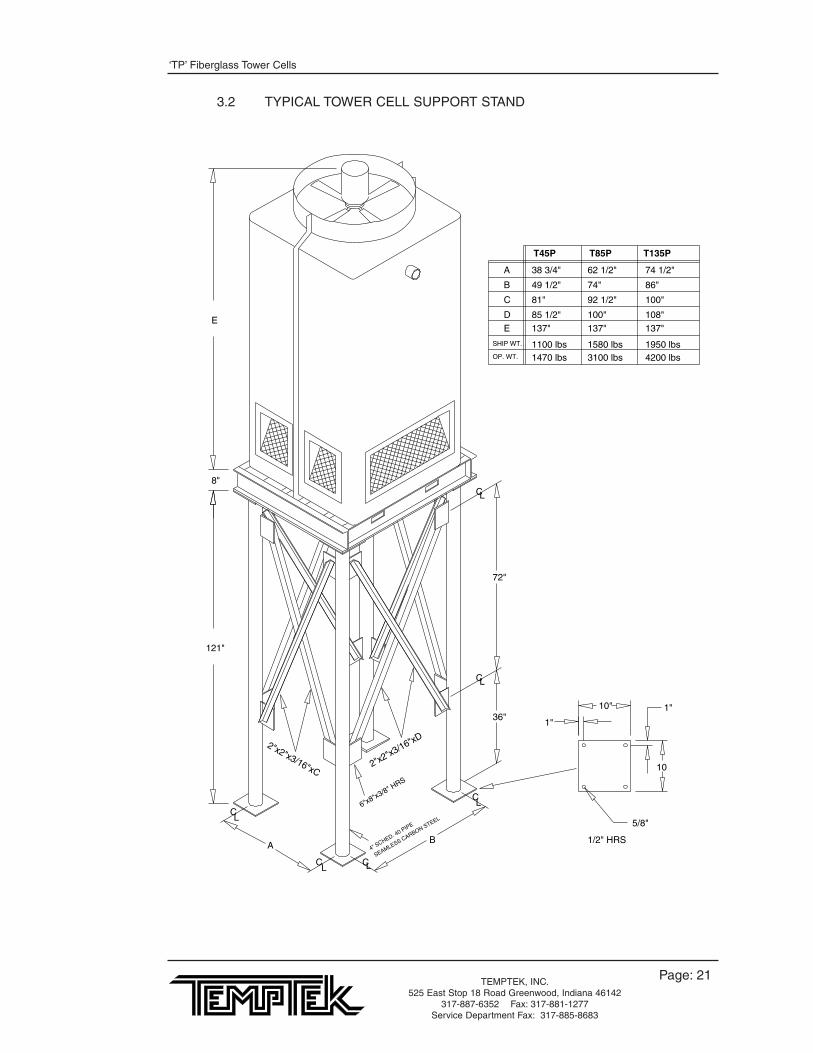
3.2 TYPICAL TOWER CELL SUPPORT STAND
137"137" 137"E
SEAMLESS CARBON STEEL
4" SCHED. 40 PIPE
LC
LC
LC LC
OP. WT.
SHIP WT.
4200 lbs1950 lbs
3100 lbs1580 lbs
1470 lbs1100 lbs
108"100"85 1/2"
100"92 1/2"81"
86"74"49 1/2"
74 1/2"62 1/2"38 3/4"
D
C
B
A
T85P T135P T45P
6"x8"x3/8" HRS
2"x2"x3/16"xC2"x2"x3/16"xD
LC
LC
1/2" HRS
5/8"
10"
1"
1"
10
E
8"
121"
AB
72"
36"
‘TP’ Fiberglass Tower Cells
Page: 22TEMPTEK, INC.525 East Stop 18 Road Greenwood, Indiana 46142
317-887-6352 Fax: 317-881-1277Service Department Fax: 317-885-8683
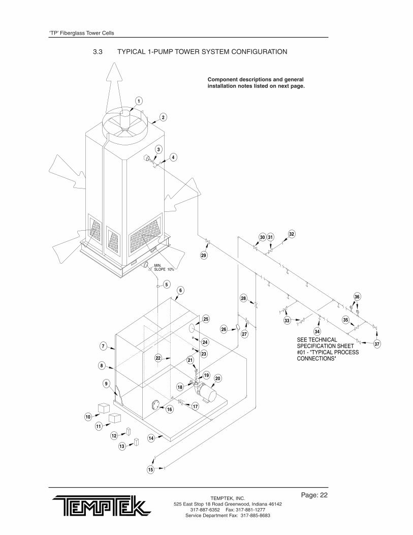
3.3 TYPICAL 1-PUMP TOWER SYSTEM CONFIGURATION
SEE TECHNICALSPECIFICATION SHEET#01 - "TYPICAL PROCESSCONNECTIONS"
SLOPE 10%MIN.
14
11
10
13
12
22
26
18
21
1920
23
24
27
28
30
29
65
7
8
9
17
15
25
3132
33
34
35
36
37
3
4
2
1
16
Component descriptions and generalinstallation notes listed on next page.

‘TP’ Fiberglass Tower Cells
Page: 23TEMPTEK, INC.525 East Stop 18 Road Greenwood, Indiana 46142
317-887-6352 Fax: 317-881-1277Service Department Fax: 317-885-8683
ONE PUMP TOWER SYSTEM* Items included in typical TTS^ Items supplied by owner1* tower fan motor2* tower cell3^ tower flow control valve4^ capped tees for future expansion5^ tower return line to tank: 8-10” from bottom of tank6* tank - process side7* pump tank assembly8* angle iron tank banding - increases slenderness ratio9* tank insulation - recommended for out-door applications in freeze areas10 tower pump starter11 tower fan starter12 tower fan thermostat13 tower pump thermostat14 pump deck - optional mounting platform15^ to plant open drain16^ capped pump port (future expansion)17^ tank drain18* tower pump suction valve19* tower pump discharge valve20* tower pump21^ tower pump discharge pressure gauge22* tank divider: baffle23* plugged port (use for water level switch)24* plugged port (use for water make-up supply)25* overflow port26^ check valve - required only if header system is run above tank level... to retain water in
piping during shut down27^ tower bleed valve - set @ 2 GPM per ton of tower28^ emergency operation drain valve29^ main header valve - from process30^ main header valve - to process31^ emergency operation water supply valve32^ from plant water service33^ valves at header branches to provide service flexibility and balance flow34^ tees at existing and future machine drops35^ system balance valve - sized per system capacity. Use CASH ACME K-20, K-5, or
equivalent36^ temperature and pressure gauges at header end to monitor performance37^ valve or cap header ends to allow for future expansion

‘TP’ Fiberglass Tower Cells
Page: 24TEMPTEK, INC.525 East Stop 18 Road Greenwood, Indiana 46142
317-887-6352 Fax: 317-881-1277Service Department Fax: 317-885-8683
SEE TECHNICALSPECIFICATION SHEET#01 - "TYPICAL PROCESSCONNECTIONS"
SLOPE 10%MIN.
TYPICAL VACUUM BREAKERSSEE TECHNICAL SPECIFICATIONS SHEET #10
16
1814
13
12
15
19 20
21
22
23
24
28
2726
29
30
32
33
35
34
7
5
6
8
9
10
11
25
17
31
3637
38
39
40
41
42
3
4
2
1
Component descriptions and generalinstallation notes listed on next page.
3.4 TYPICAL 2-PUMP TOWER SYSTEM CONFIGURATION

‘TP’ Fiberglass Tower Cells
Page: 25TEMPTEK, INC.525 East Stop 18 Road Greenwood, Indiana 46142
317-887-6352 Fax: 317-881-1277Service Department Fax: 317-885-8683
TWO PUMP TOWER SYSTEM* Items included in typical TTS^ Items supplied by owner1* tower fan motor2* tower cell3^ tower flow control valve4^ capped tees for future expansion5^ tower return line to tank: 8-10” from bottom of tank6^ from process line: 8-10” from bottom of tank7* tank - process side8* tank - tower side9* pump tank assembly10* angle iron banding - increases slenderness ratio11* tank insulation - recommended for out-door applications in freeze areas12^ process pump starter13^ tower fan starter14* tower pump starter15* tower pump thermostat16* tower fan thermostat17^ to plant open drain18 pump deck - optional mounting platform19* tower pump suction valve 20* tower pump21* tower pump discharge valve22^ tower pump discharge pressure gauge23* tank divider: baffle24* process pump suction valve25^ tank drain valve26* process pump27* process pump discharge valve28^ process pump discharge pressure gauge29* plugged port - use for water level switch30* plugged port - use for water make-up supply connection31* tank overflow port32^ tower bleed valve - set @ 2 GPM per ton of tower33^ emergency operation drain valve34^ main header valve - from process35^ main header valve - to process36^ emergency operation water supply valve37^ from plant water service38^ valves at header branches to provide service flexibility and balance flow39^ tees at existing and future machine drops40 system balance valve - sized per system capacity. Use CASH ACME K-20, K-5, or
equivalent41^ temperature and pressure gauges at header end to monitor performance42^ valved or capped header ends to allow for future expansion
‘TP’ Fiberglass Tower Cells
Page: 26TEMPTEK, INC.525 East Stop 18 Road Greenwood, Indiana 46142
317-887-6352 Fax: 317-881-1277Service Department Fax: 317-885-8683
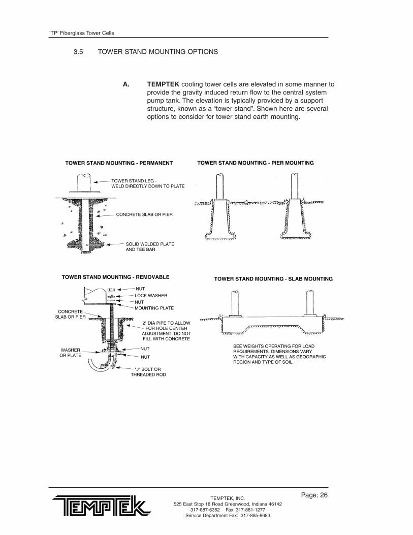
A. TEMPTEK cooling tower cells are elevated in some manner toprovide the gravity induced return flow to the central systempump tank. The elevation is typically provided by a supportstructure, known as a “tower stand”. Shown here are severaloptions to consider for tower stand earth mounting.
TOWER STAND MOUNTING - PERMANENT
SOLID WELDED PLATEAND TEE BAR
TOWER STAND LEG -WELD DIRECTLY DOWN TO PLATE
CONCRETE SLAB OR PIER
TOWER STAND MOUNTING - PIER MOUNTING
TOWER STAND MOUNTING - SLAB MOUNTING
SEE WEIGHTS OPERATING FOR LOADREQUIREMENTS. DIMENSIONS VARYWITH CAPACITY AS WELL AS GEOGRAPHICREGION AND TYPE OF SOIL.
TOWER STAND MOUNTING - REMOVABLE
NUT
NUT
NUT
LOCK WASHER
NUTMOUNTING PLATE
CONCRETESLAB OR PIER
2" DIA PIPE TO ALLOWFOR HOLE CENTER
ADJUSTMENT. DO NOTFILL WITH CONCRETE
WASHEROR PLATE
"J" BOLT OR THREADED ROD
3.5 TOWER STAND MOUNTING OPTIONS
‘TP’ Fiberglass Tower Cells
Page: 27TEMPTEK, INC.525 East Stop 18 Road Greenwood, Indiana 46142
317-887-6352 Fax: 317-881-1277Service Department Fax: 317-885-8683
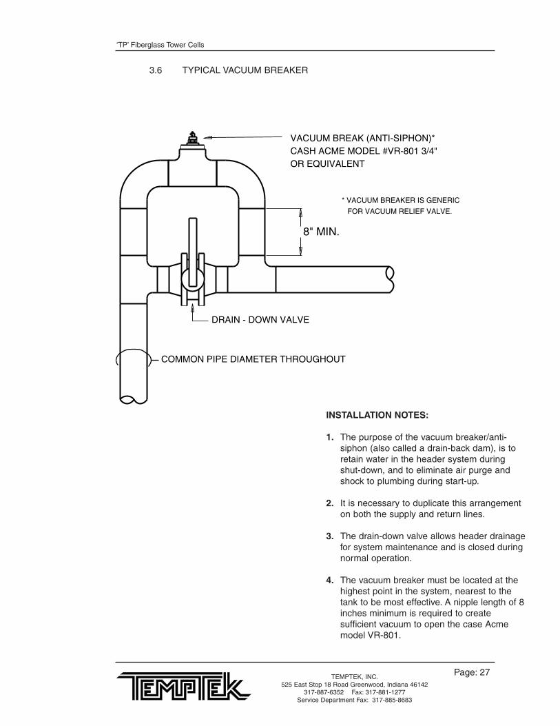
3.6 TYPICAL VACUUM BREAKER
* VACUUM BREAKER IS GENERIC
FOR VACUUM RELIEF VALVE.
DRAIN - DOWN VALVE
COMMON PIPE DIAMETER THROUGHOUT
8" MIN.
VACUUM BREAK (ANTI-SIPHON)*CASH ACME MODEL #VR-801 3/4"OR EQUIVALENT
INSTALLATION NOTES:
1. The purpose of the vacuum breaker/anti-siphon (also called a drain-back dam), is to retain water in the header system during shut-down, and to eliminate air purge and shock to plumbing during start-up.
2. It is necessary to duplicate this arrangement on both the supply and return lines.
3. The drain-down valve allows header drainage for system maintenance and is closed during normal operation.
4. The vacuum breaker must be located at the highest point in the system, nearest to the tank to be most effective. A nipple length of 8 inches minimum is required to create sufficient vacuum to open the case Acme model VR-801.

‘TP’ Fiberglass Tower Cells
Page: 28TEMPTEK, INC.525 East Stop 18 Road Greenwood, Indiana 46142
317-887-6352 Fax: 317-881-1277Service Department Fax: 317-885-8683
KEY
TWS - Tower Water SupplyTWR - Tower Water ReturnCWS - Chilled Water Supply*CWR - Chilled Water Return*
*INSULATE ALL CHILLEDWATER PIPING
The design of the unit-to-process hook up is key to optimizing the capability of the heating/cooling system.Selecting proper pipe ID’s, minimum run lengths, minimum elbows, tees, etc. are all important to creating a lowpressure drop... thus a high flow rate... installation.
This diagram schematically contains piping and valving details which may not be needed in all cases. However, formolding installations requiring maximum flexibility, a relatively minor increase in original piping costs can have greatefficiency paybacks in the future.
Select pipe sizes for 5-7 feet per second flow velocity and 5-10 psi pressure drop. Consult Temptek’s engineeringdepartment for assistance when needed.
TWS
TWR
CWSCWR
TWR CWR
TWS CWS
To/fromAuxiliary Unit
To/from Auxiliary Unit
To/fromAuxiliary Unit
Temperature and pressure gaugescheck system performance
Note: for many processes, watermanifolds are desirable at this location
Water Regulator Valve
HydraulicHeat Exchanger
Mold - Roll
or other process
To/fromAuxiliary Unit
TWS
TWR
CWSCWR
1 3
4
5 6 7 8
9
10
11
12
13 14
18 17 15 16
19 20
2
VALVE POSITION
Tower supply for auxiliary Open: 1 - 2Chilled water for auxiliary Open: 3 - 4Tower on mold Open: 5 - 6 - 9 - 10 - 11 - 12Chilled water on mold Open: 7 - 8 - 11 - 12Auxiliary on mold Open: 13 - 14Tower on heat exchanger Open: 5 - 6 - 17 - 18Chilled water on heat exchanger Open: 7 - 8 - 15 - 16Auxiliary on heat exchanger Open: 19 - 20
3.7 TYPICAL PRESS DROP

‘TP’ Fiberglass Tower Cells
Page: 29TEMPTEK, INC.525 East Stop 18 Road Greenwood, Indiana 46142
317-887-6352 Fax: 317-881-1277Service Department Fax: 317-885-8683
3.8 EXPANDABLE TOWER CELL INSTALLATION
FROM PROCESS
SIZE TOWER SUPPLY PIPING FOR TOTAL FUTURE CAPACITY.INSTALL PLUGGED TEES AND BALANCE VALVE ON
FIRST TOWER FOR FUTURE USE.
ADJUST VALVES TO PROPERLY DIVIDE RETURN WATER HEAT LOAD.
SUPPLY SEPARATE RETURNSTO TANK.
MINIMUM SLOPE 10%RETURN TO TANK
BALANCEVALVE
•
•
•
•
FUTURE TOWER CELLSFUTURE TOWER CELL
ORIGINAL TOWER CELL
REFER TO FYI# 6-G-6 "EXPANSION OF COOLING TOWERSYSTEMS" FOR ADDITIONAL INFORMATION.

‘TP’ Fiberglass Tower Cells
Page: 30TEMPTEK, INC.525 East Stop 18 Road Greenwood, Indiana 46142
317-887-6352 Fax: 317-881-1277Service Department Fax: 317-885-8683
RECOMMENDEDOPERATION AND MAINTENANCE SCHEDULEfor cooling tower cells
TYPE SERVICE
Inspect general condition of unit
Clean debris from unit
Clean and flush sump
*Check and adjust sump water level
Inspect heat transfer section (fill)
Inspect spray nozzles
Check and adjust bleed rate
*Check operation of make-up valve
Check unit for unusual noise or vibration
Check motor voltage and current
Lubricate fan motor bearings
Check fan for rotation without obstruction
Check fan and pump motor for proper rotation
Drain sump and piping
Inspect protective finsih
START-UP
X
X
X
X
X
X
X
X
X
X
X
X
X
MONTHLY
X
X
X
X
X
X
X
X
X
X
SIX MONTHS
X
SHUT DOWN
X
X
X
ANNUALLY
X*For unit without a remote sump
3.9 OPERATION AND MAINTENANCE SCHEDULE

‘TP’ Fiberglass Tower Cells
Page: 31TEMPTEK, INC.525 East Stop 18 Road Greenwood, Indiana 46142
317-887-6352 Fax: 317-881-1277Service Department Fax: 317-885-8683
4.0 APPENDIX4.1 TYPICAL HYDRAULIC HEAT EXCHANGER COOLING BY HP @ 10° ∅T4.2 TOWER WATER REQUIREMENTS VS PIPE SIZE TO CONDENSE
CHILLERS4.3 WET BULB
‘TP’ Fiberglass Tower Cells
Page: 32TEMPTEK, INC.525 East Stop 18 Road Greenwood, Indiana 46142
317-887-6352 Fax: 317-881-1277Service Department Fax: 317-885-8683
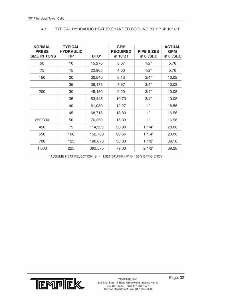
NORMAL TYPICAL GPM ACTUALPRESS HYDRAULIC REQUIRED PIPE SIZES GPM
SIZE IN TONS HP BTU* @ 10°ΔT @ 6”/SEC @ 6”/SEC
50 10 15,270 3.07 1/2” 5.76
75 15 22,905 4.60 1/2” 5.76
150 20 30,540 6.13 3/4” 10.08
25 38,175 7.67 3/4” 10.08
200 30 45,180 9.20 3/4” 10.08
35 53,445 10.73 3/4” 10.08
40 61,080 12.27 1” 16.56
45 68,715 13.80 1” 16.56
250/300 50 76,350 15.33 1” 16.56
450 75 114,525 23.00 1 1/4” 28.08
550 100 152,700 30.66 1 1.4” 28.08
700 125 190,876 38.33 1 1/2” 38.16
1,000 225 393,575 79.03 2 1/2” 89.28
*ASSUME HEAT REJECTION IS = 1,527 BTU/HR/HP @ 100% EFFICIENCY
4.1 TYPICAL HYDRAULIC HEAT EXCHANGER COOLING BY HP @ 10° ∅ T

‘TP’ Fiberglass Tower Cells
Page: 33TEMPTEK, INC.525 East Stop 18 Road Greenwood, Indiana 46142
317-887-6352 Fax: 317-881-1277Service Department Fax: 317-885-8683
4.2 TOWER WATER REQUIREMENT VS PIPE SIZE TO CONDENSE CHILLERS
CHILLER GPM REQUIREMENTS BTU REJECTION PIPETONS @ 6” PER SEC PER HOUR SIZE
2 6 26,000 1/2”
5 15 62,500 1”
7.5 22 93,750 1”
10 30 125,000 1 1/2”
15 45 187,000 1 1/2”
20 60 250,000 2”
30 90 375,000 2 1/2”
40 120 500,000 3”
60 180 750,000 4”
‘TP’ Fiberglass Tower Cells
Page: 34TEMPTEK, INC.525 East Stop 18 Road Greenwood, Indiana 46142
317-887-6352 Fax: 317-881-1277Service Department Fax: 317-885-8683
4.3 WET BULB
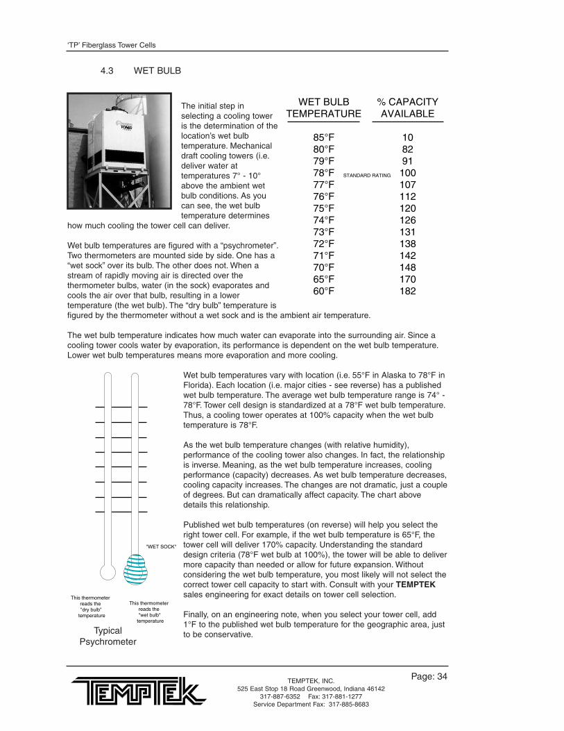
The initial step inselecting a cooling toweris the determination of thelocation’s wet bulbtemperature. Mechanicaldraft cooling towers (i.e.deliver water attemperatures 7° - 10°above the ambient wetbulb conditions. As youcan see, the wet bulbtemperature determines
how much cooling the tower cell can deliver.
Wet bulb temperatures are figured with a “psychrometer”.Two thermometers are mounted side by side. One has a“wet sock” over its bulb. The other does not. When astream of rapidly moving air is directed over thethermometer bulbs, water (in the sock) evaporates andcools the air over that bulb, resulting in a lowertemperature (the wet bulb). The “dry bulb” temperature isfigured by the thermometer without a wet sock and is the ambient air temperature.
The wet bulb temperature indicates how much water can evaporate into the surrounding air. Since acooling tower cools water by evaporation, its performance is dependent on the wet bulb temperature.Lower wet bulb temperatures means more evaporation and more cooling.
Wet bulb temperatures vary with location (i.e. 55°F in Alaska to 78°F inFlorida). Each location (i.e. major cities - see reverse) has a publishedwet bulb temperature. The average wet bulb temperature range is 74° -78°F. Tower cell design is standardized at a 78°F wet bulb temperature.Thus, a cooling tower operates at 100% capacity when the wet bulbtemperature is 78°F.
As the wet bulb temperature changes (with relative humidity),performance of the cooling tower also changes. In fact, the relationshipis inverse. Meaning, as the wet bulb temperature increases, coolingperformance (capacity) decreases. As wet bulb temperature decreases,cooling capacity increases. The changes are not dramatic, just a coupleof degrees. But can dramatically affect capacity. The chart abovedetails this relationship.
Published wet bulb temperatures (on reverse) will help you select theright tower cell. For example, if the wet bulb temperature is 65°F, thetower cell will deliver 170% capacity. Understanding the standarddesign criteria (78°F wet bulb at 100%), the tower will be able to delivermore capacity than needed or allow for future expansion. Withoutconsidering the wet bulb temperature, you most likely will not select thecorrect tower cell capacity to start with. Consult with your TEMPTEKsales engineering for exact details on tower cell selection.
Finally, on an engineering note, when you select your tower cell, add1°F to the published wet bulb temperature for the geographic area, justto be conservative.
WET BULBTEMPERATURE
85°F80°F79°F78°F77°F76°F75°F74°F73°F72°F71°F70°F65°F60°F
% CAPACITYAVAILABLE
108291
100107112120126131138142148170182
STANDARD RATING
������
"WET SOCK"
This thermometer reads the "wet bulb"
temperature
This thermometer reads the "dry bulb"
temperature
TypicalPsychrometer

‘TP’ Fiberglass Tower Cells
Page: 35TEMPTEK, INC.525 East Stop 18 Road Greenwood, Indiana 46142
317-887-6352 Fax: 317-881-1277Service Department Fax: 317-885-8683
State City °FAlabama
Birmingham 78Mobile 80Montgomery 78
ArizonaFlagstaff 65Phoenix 76Tucson 72Yuma 78
ArkansasLittle rock 78
CaliforniaBakersfield 70El Centro 78Fresno 72Long Beach 70Los Angles 70Needles 80Oakland 65Pasadena 70Sacramento 72San Bernardino 72San Diego 70San Francisco 65
ColoradoDenver 64
ConnecticutBridgeport 75Hartford 75New Haven 75
DelawareWilmington 78
D.C.Washington 78
FloridaJacksonville 78Miami 79Pensacola 78Tampa 78
GeorgiaAtlanta 76Augusta 76Brunswick 78Columbus 76Savannah 78
IdahoBoise 65
IllinoisChicago 75Peoria 76
IndianaEvansville 76Fort Wayne 75Indianapolis 76
IowaDes Moines 77Sioux City 77
KansasWichita 75
KentuckyLouisville 78
LouisianaNew Orleans 79Shreveport 78
MaineAugusta 73Bangor 73Portland 73
State City °FMaryland
Baltimore 78Cumberland 75
MassachusettsBoston 75Springfield 75Worcester 75
MichiganDetroit 75Flint 75Grand Rapids 75Saginaw 75
MinnesotaDuluth 73Minneapolis 75St. Paul 75
MississippiVicksburg 78
MissouriKansas city 75St. Louis 76
MontanaBillings 66Helena 65Missoula 66
NebraskaLincoln 77Omaha 77
NevadaReno 65
New HampshireConcord 73Manchester 75Portsmouth 73
New JerseyCamden 76Jersey City 75Newark 75Trenton 78
New MexicoAlbuquerque 68Santa Fe 65
New YorkAlbany 75Buffalo 75New York 75Rochester 75Syracuse 75
North CarolinaAsheville 75Charlotte 75Greensboro 75Raleigh 76Wilmington 78
North DakotaBismarck 73
OhioAkron 75Canton 75Cincinnati 78Cleveland 75Columbus 76Dayton 76Toledo 75Youngstown 75
OklahomaOklahoma City 77Tulsa 77
State City °FOregon
Baker 66Portland 68Roseburg 66
PennsylvaniaAltoona 75Erie 75Harrisburg 75Oil City 75Philadelphia 76Pittsburgh 75Scranton 75
Rhode IslandPawtucket 75Providence 75
South CarolinaCharleston 78Columbia 75Greenville 75
South DakotaSioux Falls 75
TennesseeChattanooga 76Knoxville 76Memphis 78Nashville 76
TexasAbilene 75Austin 78Corpus Christi 80Dallas 78El Paso 69Fort Worth 78Galveston 80Houston 78Lubbock 72San Antonio 78Port Arthur 80San Angelo 74Wichita Falls 76
UtahSalt Lake City 65
VermontBurlington 73Rutland 73
VirginiaNorfolk 78Richmond 78Roanoke 76
WashingtonSeattle 65Spokane 65Tacoma 64Walla Walla 65Wenatchee 65Yakima 65
West VirginiaBluefield 75Charleston 75Huntington 76Parkersburg 75Wheeling 75
WisconsinMadison 75Milwaukee 75
WyomingCheyenne 65
WET BULB VALUES FOR MAJOR GEOGRAPHIC AREAS

Page: 36
Note: this page intentionally left blank

END
© 1999 TEMPTEK, INC.
RE 1 6/99

Related Documents