Learn How to Optimize Heat Exchanger Designs using Aspen Shell & Tube Mechanical A self guided demo to get started with Aspen Shell & Tube Mechanical

Welcome message from author
This document is posted to help you gain knowledge. Please leave a comment to let me know what you think about it! Share it to your friends and learn new things together.
Transcript

Learn How to Optimize Heat Exchanger Designs using Aspen Shell & Tube Mechanical A self guided demo to get started with Aspen Shell & Tube Mechanical
© 2015 Aspen Technology, Inc. All rights reserved. 2
Why Use Aspen Shell & Tube Mechanical?
Aspen Shell & Tube Mechanical optimizes the design of all mechanical components, and
performs detailed code calculations, customized cost estimates, detailed drawing
packages, and a complete bill of materials.
When used with Aspen Shell & Tube Exchanger, Aspen Shell & Tube Mechanical
ensures consistency between thermal and mechanical designs. This enables engineers
to both optimize and efficiently validate the thermal and mechanical designs of shell and
tube heat exchangers.
When used as a standalone program in design mode, Aspen Shell & Tube Mechanical
can optimize the design of a full shell and tube exchanger with minimal input calculating
flanges, tube sheets, expansion joints, supports, shell, and nozzle reinforcement.
© 2015 Aspen Technology, Inc. All rights reserved. 3
Why Use Aspen Shell & Tube Mechanical?
Obtain a detailed mechanical design of Aspen Shell & Tube Exchanger and be able to:
– Perform detailed code calculations for all components
– Obtain detailed drawing packages
– Get a complete bill of materials
– Get customize cost estimates - material & labor
© 2015 Aspen Technology, Inc. All rights reserved. 4
Objective
This document serves as a simple “getting started” guide, showing you the most common
progression of how an equipment designer would use Aspen Shell & Tube Mechanical to
generate an optimal heat exchanger design.
This guide demonstrates how to:
• Specify input data
• Run the program
• View key results
• Transfer results to other formats
© 2015 Aspen Technology, Inc. All rights reserved. 5
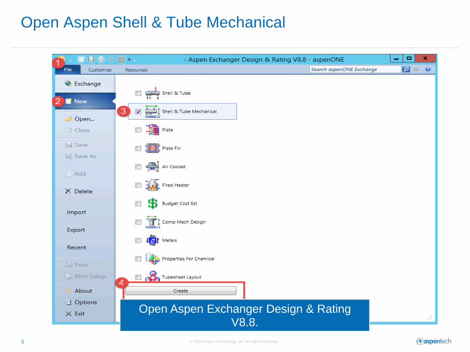
Open Aspen Shell & Tube Mechanical
Open Aspen Exchanger Design & Rating V8.8.
© 2015 Aspen Technology, Inc. All rights reserved. 6
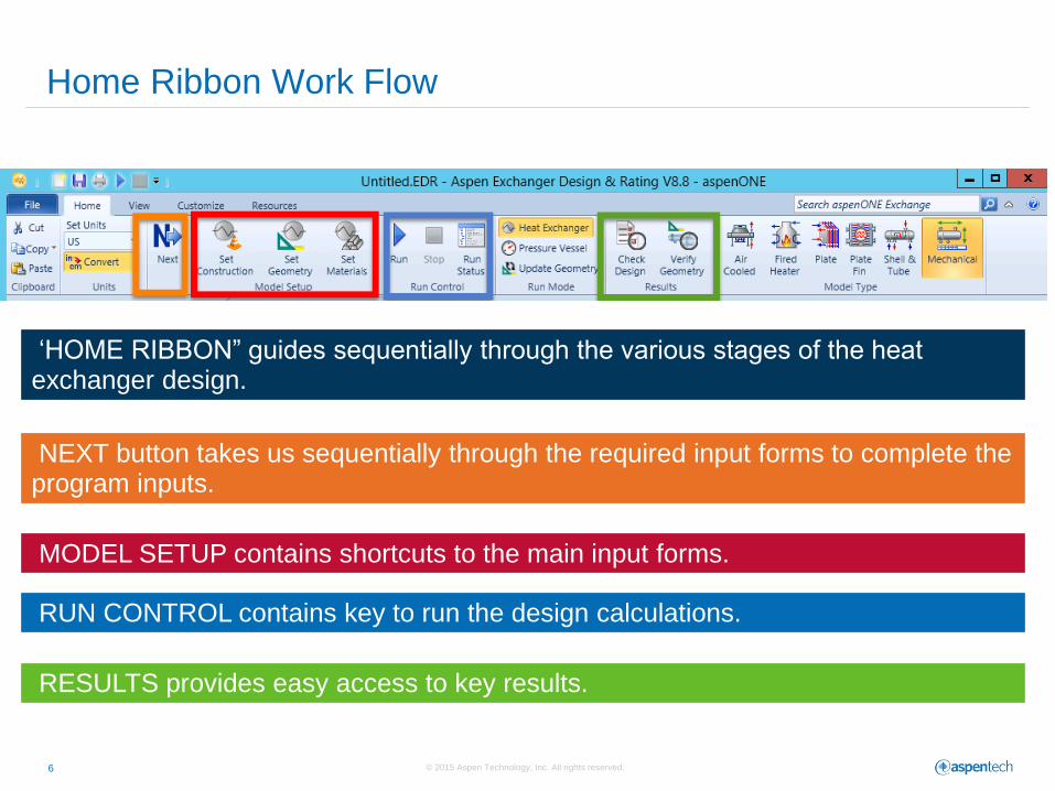
Home Ribbon Work Flow
‘HOME RIBBON” guides sequentially through the various stages of the heat exchanger design.
NEXT button takes us sequentially through the required input forms to complete the program inputs.
MODEL SETUP contains shortcuts to the main input forms.
RUN CONTROL contains key to run the design calculations.
RESULTS provides easy access to key results.
© 2015 Aspen Technology, Inc. All rights reserved. 7
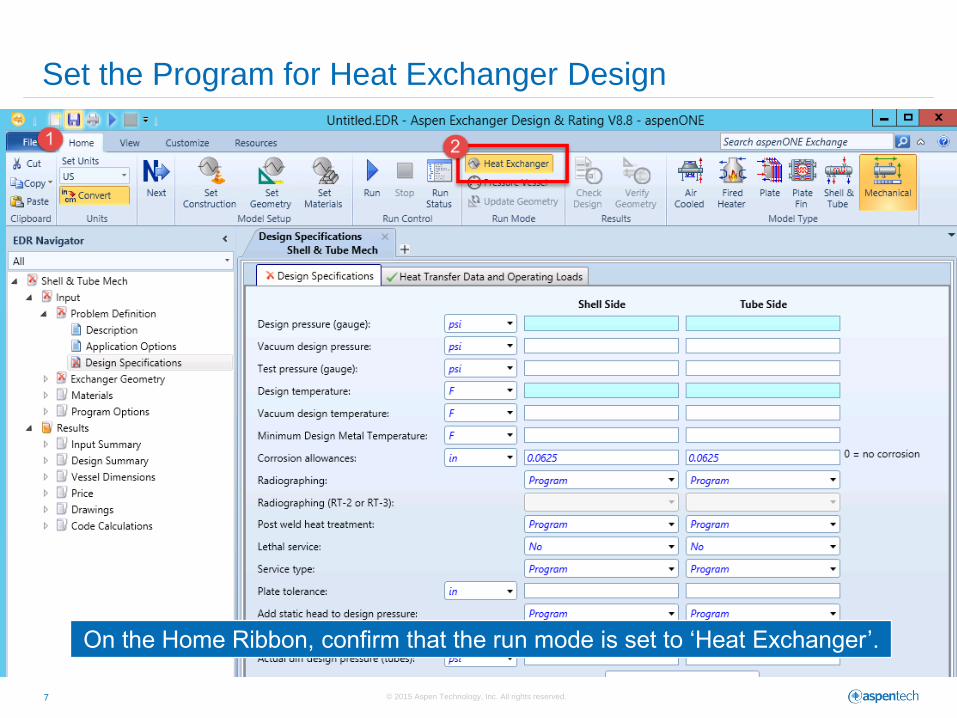
Set the Program for Heat Exchanger Design
On the Home Ribbon, confirm that the run mode is set to ‘Heat Exchanger’.
© 2015 Aspen Technology, Inc. All rights reserved. 8
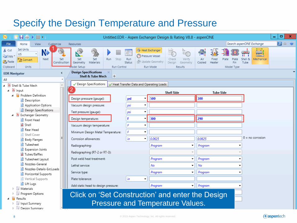
Specify the Design Temperature and Pressure
Click on ‘Set Construction’ and enter the Design Pressure and Temperature Values.
© 2015 Aspen Technology, Inc. All rights reserved. 9
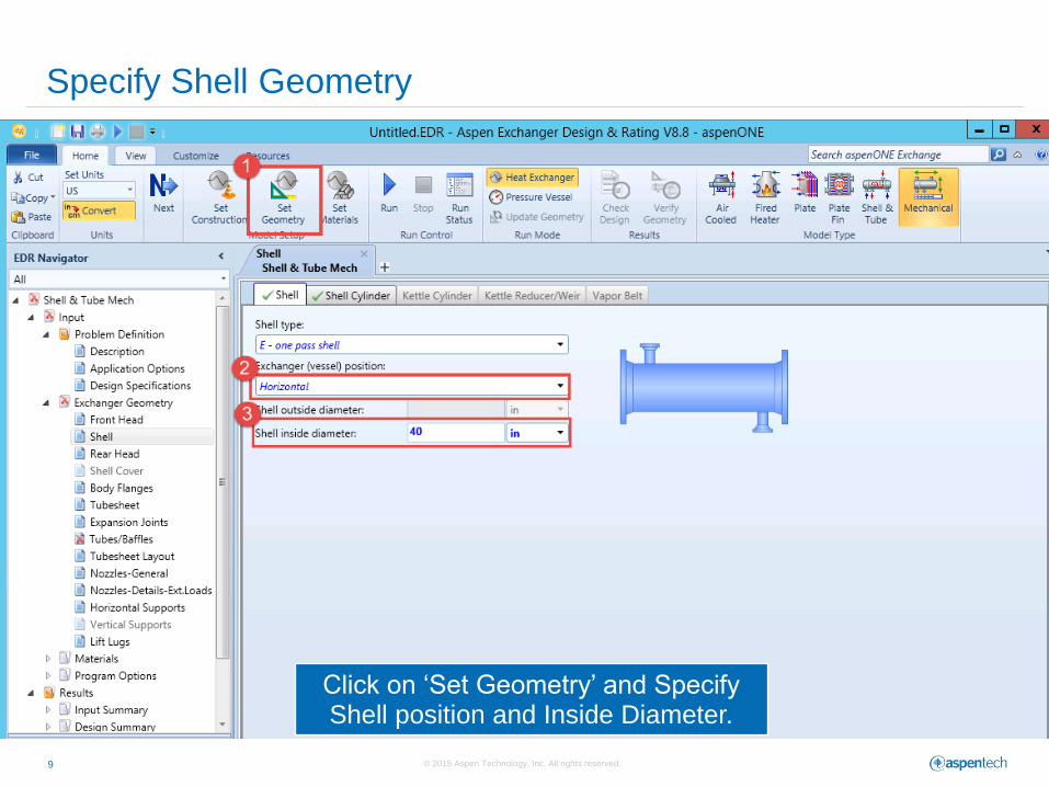
Specify Shell Geometry
Click on ‘Set Geometry’ and Specify Shell position and Inside Diameter.
© 2015 Aspen Technology, Inc. All rights reserved. 10
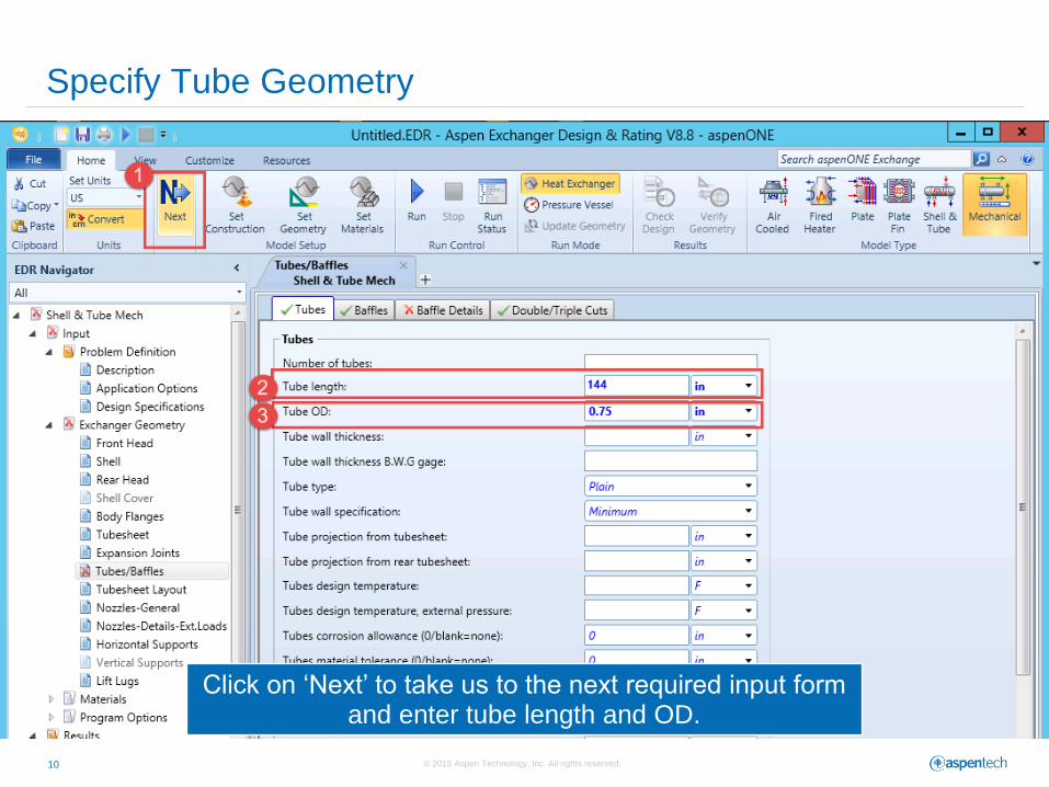
Specify Tube Geometry
Click on ‘Next’ to take us to the next required input form and enter tube length and OD.
© 2015 Aspen Technology, Inc. All rights reserved. 11
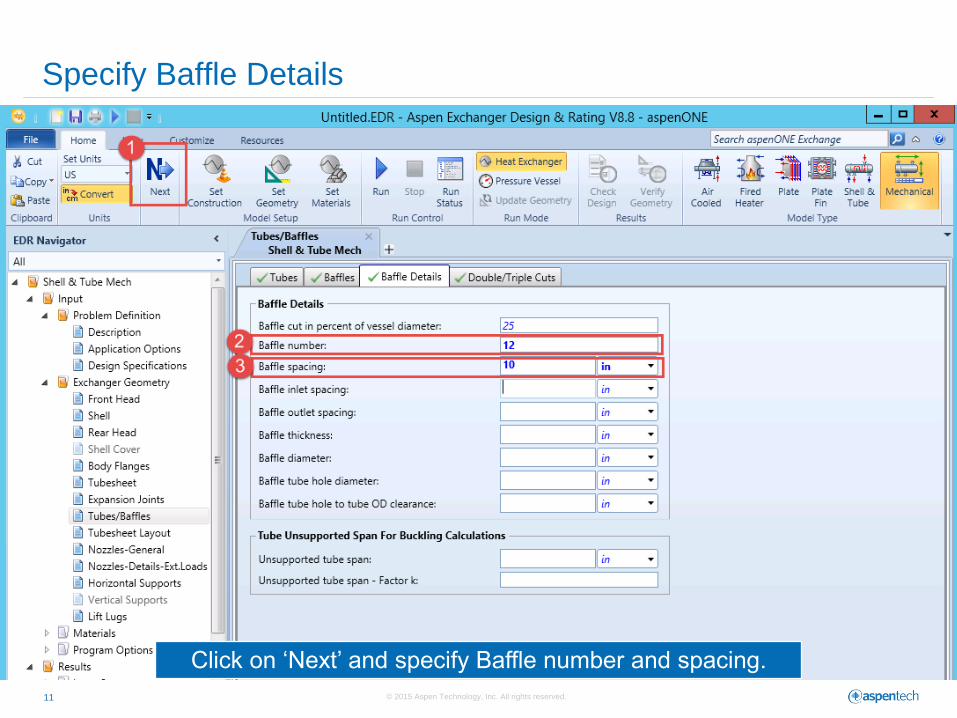
Specify Baffle Details
Click on ‘Next’ and specify Baffle number and spacing.
© 2015 Aspen Technology, Inc. All rights reserved. 12
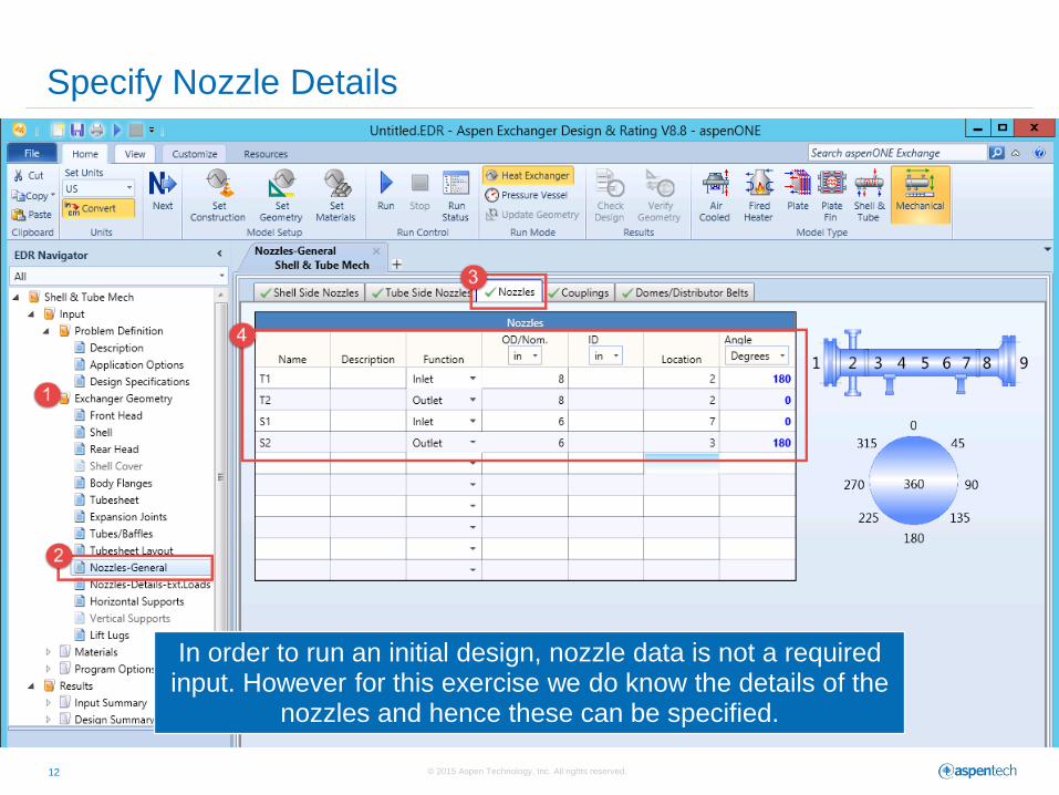
Specify Nozzle Details
In order to run an initial design, nozzle data is not a required input. However for this exercise we do know the details of the
nozzles and hence these can be specified.
© 2015 Aspen Technology, Inc. All rights reserved. 13
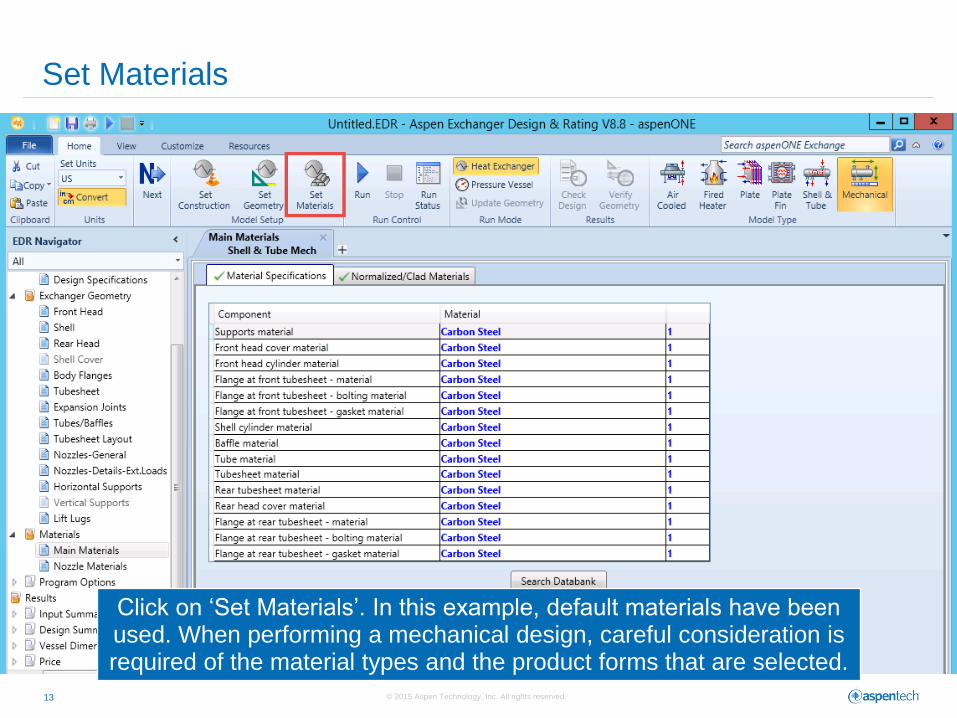
Set Materials
Click on ‘Set Materials’. In this example, default materials have been used. When performing a mechanical design, careful consideration is required of the material types and the product forms that are selected.
© 2015 Aspen Technology, Inc. All rights reserved. 14
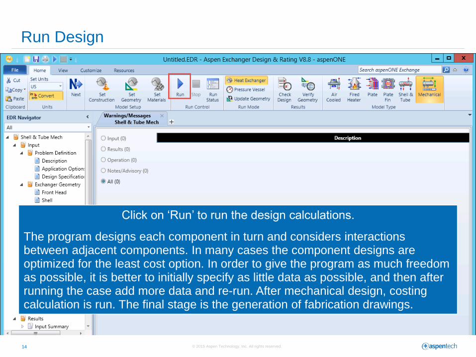
Run Design
Click on ‘Run’ to run the design calculations.
The program designs each component in turn and considers interactions between adjacent components. In many cases the component designs are optimized for the least cost option. In order to give the program as much freedom as possible, it is better to initially specify as little data as possible, and then after running the case add more data and re-run. After mechanical design, costing calculation is run. The final stage is the generation of fabrication drawings.
© 2015 Aspen Technology, Inc. All rights reserved. 15
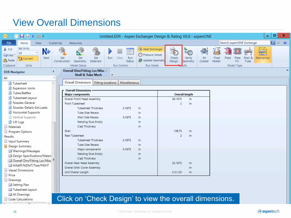
View Overall Dimensions
Click on ‘Check Design’ to view the overall dimensions.
© 2015 Aspen Technology, Inc. All rights reserved. 16
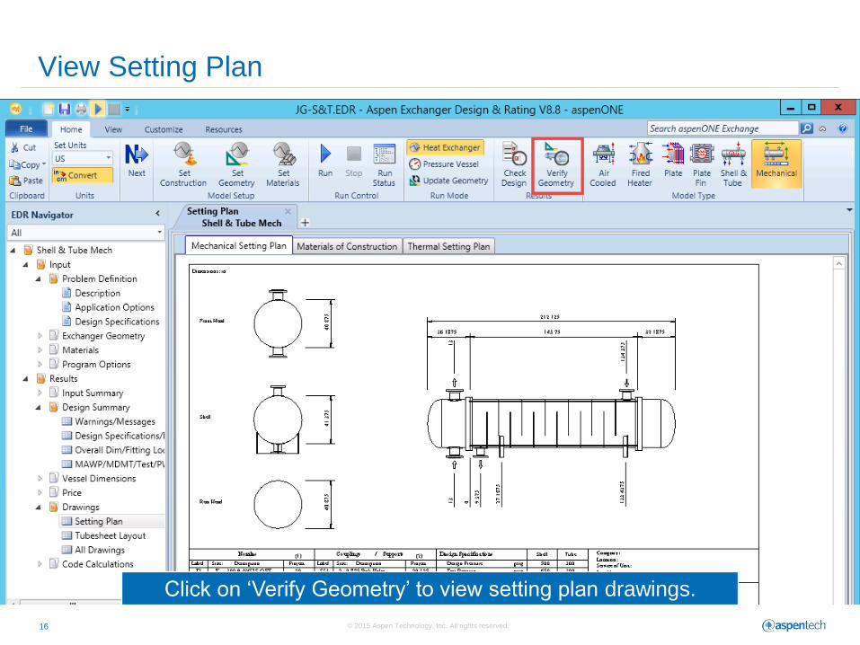
View Setting Plan
Click on ‘Verify Geometry’ to view setting plan drawings.
© 2015 Aspen Technology, Inc. All rights reserved. 17
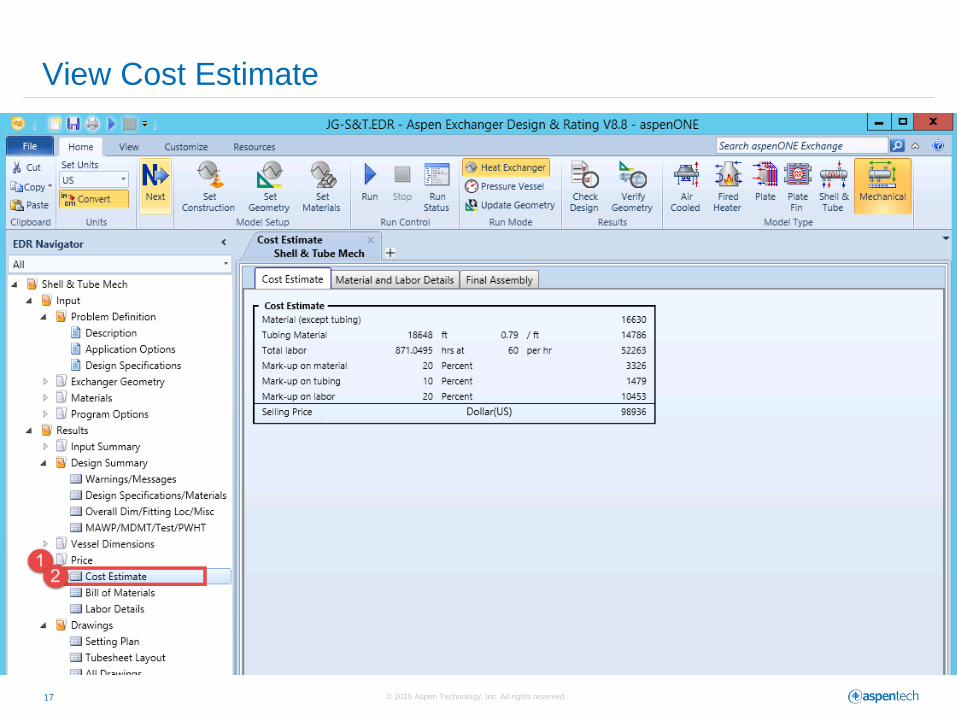
View Cost Estimate
© 2015 Aspen Technology, Inc. All rights reserved. 18
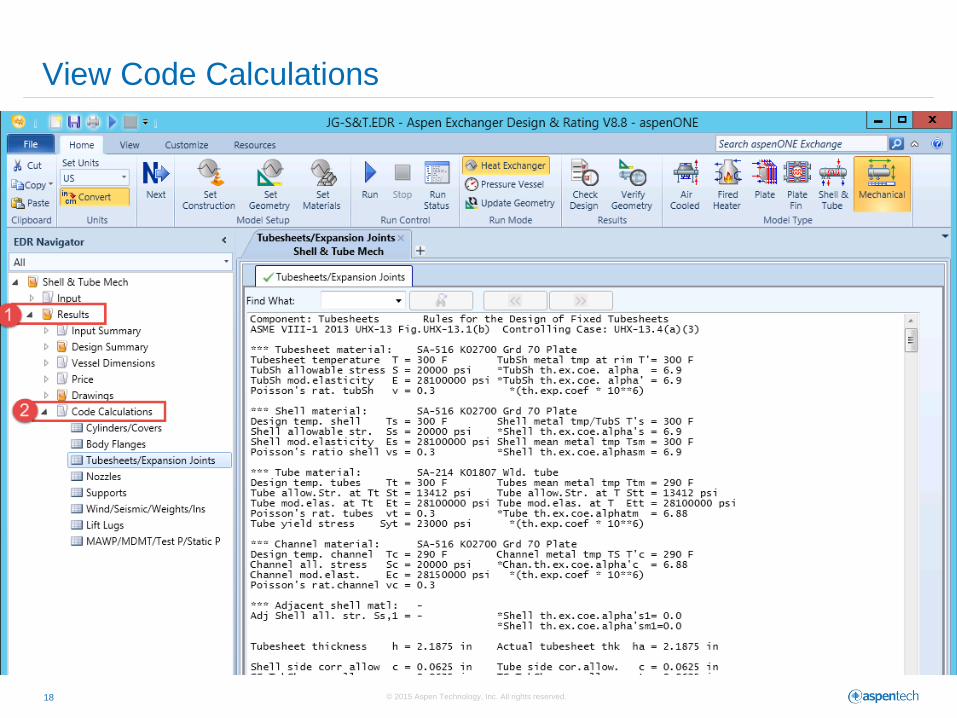
View Code Calculations
© 2015 Aspen Technology, Inc. All rights reserved. 19
Copy Results to Other Formats
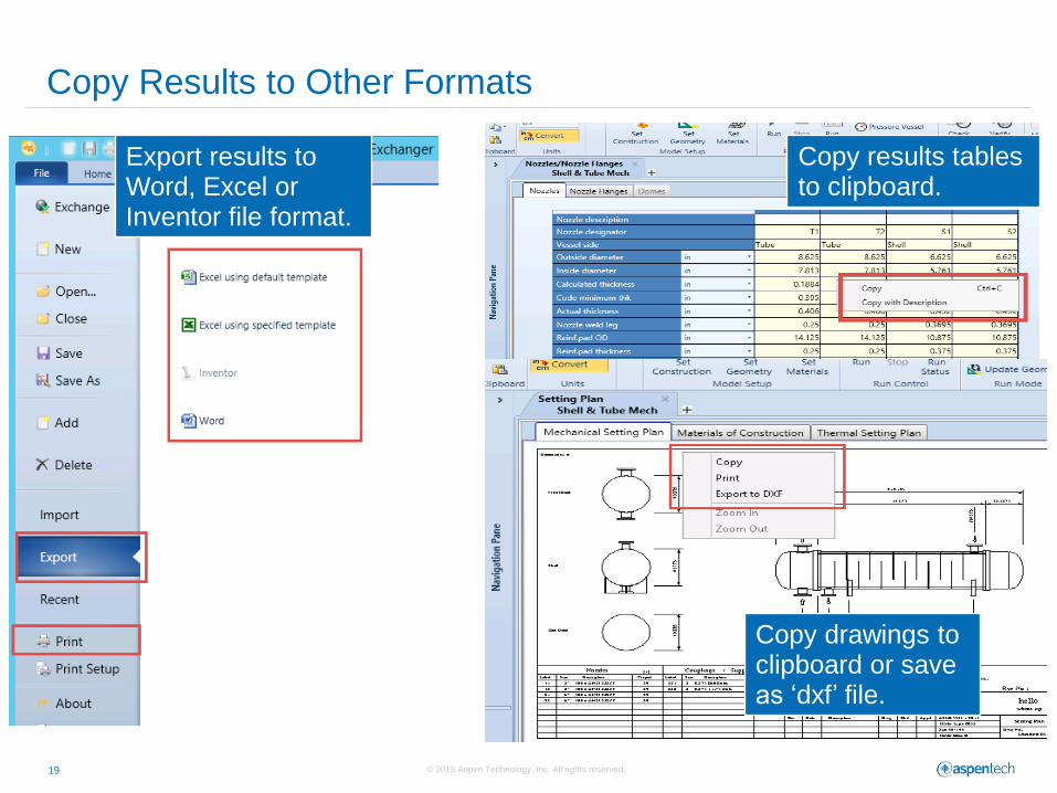
Export results to Word, Excel or Inventor file format.
Copy results tables to clipboard.
Copy drawings to clipboard or save as ‘dxf’ file.
© 2015 Aspen Technology, Inc. All rights reserved. 20
Additional Resources & Contacts
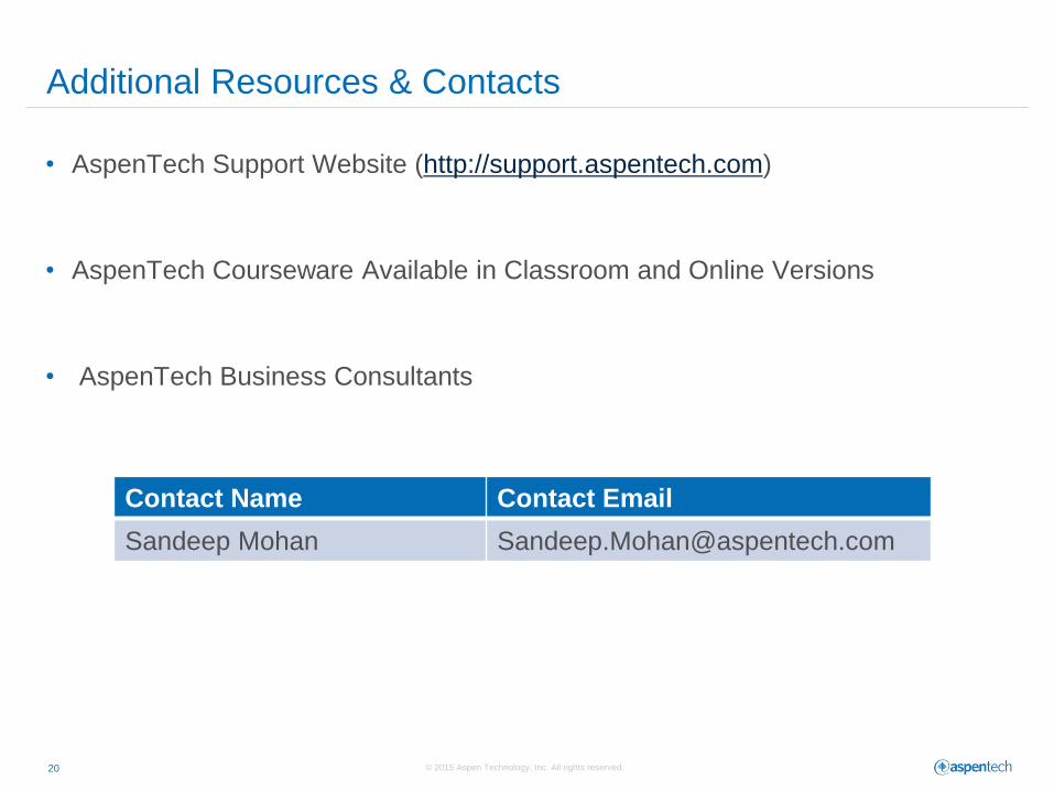
• AspenTech Support Website (http://support.aspentech.com)
• AspenTech Courseware Available in Classroom and Online Versions
• AspenTech Business Consultants
Contact Name Contact Email
Sandeep Mohan [email protected]
Related Documents