United States Contact Us; Live Chat Premier Login Shop Support Community Search Support Home Page My Account Feedback Back to Contents Page About Your System Dell™ PowerEdge™ T410 Systems Hardware Owner's Manual Accessing System Features During Startup Front-Panel Features and Indicators LCD Panel Features (Optional) Hard-Drive Status Indicators Back-Panel Features and Indicators Guidelines for Connecting External Devices NIC Indicator Codes Power Indicator Codes Diagnostic Lights (Optional) LCD Status Messages (Optional) System Messages Warning Messages Diagnostics Messages Alert Messages Other Information You May Need Accessing System Features During Startup The following keystrokes provide access to system features during startup. Front-Panel Features and Indicators Figure 1-1. Front Panel Features and Indicators Keystroke Description <F2> Enters the System Setup program. See Using the System Setup Program and UEFI Boot Manager. <F10> Enters System Services, which opens the Unified Server Configurator. The Unified Server Configurator allows you to access utilities such as embedded system diagnostics. For more information, see the Unified Server Configurator documentation. <F11> Enters the BIOS Boot Manager or the UEFI Boot Manager, depending on the system's boot configuration. See Using the System Setup Program and UEFI Boot Manager. <F12> Starts PXE boot. <Ctrl+E> Enters the Baseboard Management Controller (BMC) or iDRAC Configuration Utility, which allows access to the system event log (SEL) and configuration of remote access to the system. For more information, see the BMC or iDRAC user documentation. <Ctrl+C> Enters the SAS Configuration Utility. For more information, see the SAS adapter documentation. <Ctrl+R> Enters the PERC configuration utility. For more information, see the PERC card documentation. <Ctrl+S> Enters the utility to configure NIC settings for PXE boot. For more information, see the documentation for your integrated NIC. NOTE: Depending on the configuration, your system may have an LCD panel or LED diagnostic indicators. The illustration in this section shows a system with an LCD panel. Sign In Cart pagina 1 van 16 Documentation 3-7-2011 http://support.dell.com/support/edocs/systems/pet410/en/hom/html/about.htm

Welcome message from author
This document is posted to help you gain knowledge. Please leave a comment to let me know what you think about it! Share it to your friends and learn new things together.
Transcript
United States Contact Us; Live Chat Premier Login
Shop Support Community Search
Support Home Page
My Account Feedback
Back to Contents Page
About Your System
Dell™ PowerEdge™ T410 Systems Hardware Owner's Manual
Accessing System Features During Startup
Front-Panel Features and Indicators
LCD Panel Features (Optional)
Hard-Drive Status Indicators
Back-Panel Features and Indicators
Guidelines for Connecting External Devices
NIC Indicator Codes
Power Indicator Codes
Diagnostic Lights (Optional)
LCD Status Messages (Optional)
System Messages
Warning Messages
Diagnostics Messages
Alert Messages
Other Information You May Need
Accessing System Features During Startup
The following keystrokes provide access to system features during startup.
Front-Panel Features and Indicators
Figure 1-1. Front Panel Features and Indicators
Keystroke Description
<F2> Enters the System Setup program. See Using the System Setup Program and UEFI Boot Manager.
<F10> Enters System Services, which opens the Unified Server Configurator. The Unified Server Configurator allows you to access utilities such as embedded system diagnostics. For more information, see the Unified Server Configurator documentation.
<F11> Enters the BIOS Boot Manager or the UEFI Boot Manager, depending on the system's boot configuration. See Using the System Setup Program and UEFI Boot Manager.
<F12> Starts PXE boot.
<Ctrl+E> Enters the Baseboard Management Controller (BMC) or iDRAC Configuration Utility, which allows access to the system event log (SEL) and configuration of remote access to the system. For more information, see the BMC or iDRAC user documentation.
<Ctrl+C> Enters the SAS Configuration Utility. For more information, see the SAS adapter documentation.
<Ctrl+R> Enters the PERC configuration utility. For more information, see the PERC card documentation.
<Ctrl+S> Enters the utility to configure NIC settings for PXE boot. For more information, see the documentation for your integrated NIC.
NOTE: Depending on the configuration, your system may have an LCD panel or LED diagnostic indicators. The illustration in this section shows a system with an LCD panel.
Sign In Cart
pagina 1 van 16Documentation
3-7-2011http://support.dell.com/support/edocs/systems/pet410/en/hom/html/about.htm

LCD Panel Features (Optional)
The system's LCD panel provides system information and status and error messages to signify when the system is operating correctly or when the system needs attention. See LCD Status Messages (Optional) for information about
specific status codes.
The LCD backlight lights blue during normal operating conditions and lights amber to indicate an error condition. When the system is in standby mode, the LCD backlight is off and can be turned on by pressing the Select button on the LCD panel. The LCD backlight will remain off if LCD messaging is turned off through the BMC or iDRAC utility, the LCD panel, or other tools.
Item Indicator, Button, or Connector
Icon Description
1 Front bezel Covers the system's front-loading hard drives.
2 USB connectors (2) Connects USB devices to the system. The ports are USB 2.0-compliant.
3 NMI button Used to troubleshoot software and device driver errors when using certain operating systems. This button can be pressed using the end of a paper clip.
Use this button only if directed to do so by qualified support personnel or by the operating system's documentation.
4 Power-on indicator, power button
The power-on indicator lights when the system power is on.
The power button controls the DC power supply output to the system.
NOTE: When powering on the system, the video monitor can take up to 25seconds to display an image, depending on the amount of memory installed in the system.
NOTE: On ACPI-compliant operating systems, turning off the system using the power button causes the system to perform a graceful shutdown before power to the system is turned off.
NOTE: To force an ungraceful shutdown, press and hold the power button for five seconds.
5 System identification button
The identification button on the front panel can be used to locate a particular system. When the button is pushed, the LCD panel on the front flashes blue until the button is pushed again.
6 LCD menu buttons Allows you to navigate the control panel LCD menu.
7 LED or LCD panel NOTE: Depending on the configuration, your system may have either an LCDpanel or LED diagnostic indicators.
LED panel — The four diagnostic indicator lights display error codes during system startup. See Diagnostic Lights (Optional).
LCD panel — Provides system ID, status information, and system errormessages.
The LCD lights blue during normal system operation. The LCD lights amber when the system needs attention, and the LCD panel displays an error code followed by descriptive text.
NOTE: If the system is connected to AC power and an error has been detected, the LCD lights amber regardless of whether the system has been powered on.
8 Optical drive (optional)
One or two optional SATA DVD-ROM or DVD+RW drives.
NOTE: DVD devices are data only.
9 Tape drive(optional)
One optional half-height (using one drive bay) or full-height drive (using two drive bays).
10 Front bezel lock Secures the front bezel to the system.
pagina 2 van 16Documentation
3-7-2011http://support.dell.com/support/edocs/systems/pet410/en/hom/html/about.htm

Figure 1-2. LCD Panel Features
Home Screen
The Home screen displays user-configurable information about the system. This screen is displayed during normal
system operation when there are no status messages or errors present. When the system is in standby mode, the LCDbacklight will turn off after five minutes of inactivity if there are no error messages. Press one of the three navigation buttons (Select, Left, or Right) to view the Home screen.
To navigate to the Home screen from another menu, continue to select the up arrow until the Home icon is displayed, and then select the Home icon.
From the Home screen, press the Select button to enter the main menu. See the following tables for information on
the Setup and View submenus.
Setup Menu
View Menu
Item Buttons Description
1 Left Moves the cursor back in one-step increments.
2 Select Selects the menu item highlighted by the cursor.
3 Right Moves the cursor forward in one-step increments.
During message scrolling:
� Press once to increase scrolling speed.� Press again to stop.� Press again to return to default scrolling speed.� Press again to repeat the cycle.
4 System identification
Turns the system ID mode on (LCD panel flashes blue) and off.
Press quickly to toggle the system ID on and off. If the system hangs during POST, press and hold the system ID button for more than five seconds to enter BIOS Progress mode.
NOTE: When you select an option in the Setup menu, you must confirm the option before proceeding to the next action.
Option Description
BMC or DRAC
NOTE: If an iDRAC6 Express card is installed on the system, the BMC option is replaced by DRAC.
Select DHCP or Static IP to configure the network mode. If Static IP is selected, the available fields are IP, Subnet (Sub), and Gateway (Gtw). Select Setup DNS to enable DNS and to view domain addresses. Two separate DNS entries are available.
Set error Select SEL to display LCD error messages in a format that matches the IPMI description in the SEL. This can be useful when trying to match an LCD message with an SEL entry.
Select Simple to display LCD error messages in a simplified user-friendly description. See LCD Status Messages (Optional) for a list of messages in this
format.
Set home Select the default information to be displayed on the LCD Home screen. See View
Menu to see the options and option items that can be selected to display by
default on the Home screen.
Option Description
BMC IP or DRAC IP
NOTE: If an iDRAC6 Express card is installed on the system, the BMC IP option is replaced by DRAC IP.
Displays the IPv4 or IPv6 addresses for the iDRAC6. Addresses include DNS (Primary and Secondary), Gateway, IP, and Subnet(IPv6 does not have Subnet).
NOTE: BMC IP supports only IPv4 addresses.
MAC Displays the MAC addresses for DRAC, iSCSIn, or NETn.
NOTE: If the iDRAC Express card is not installed on the system, the MAC option displays the MAC addresses for BMC, iSCSIn or NETn.
Name Displays the name of the Host, Model, or User String for the
system.
pagina 3 van 16Documentation
3-7-2011http://support.dell.com/support/edocs/systems/pet410/en/hom/html/about.htm

Hard-Drive Status Indicators
Figure 1-3. Hard-Drive Indicators
Back-Panel Features and Indicators
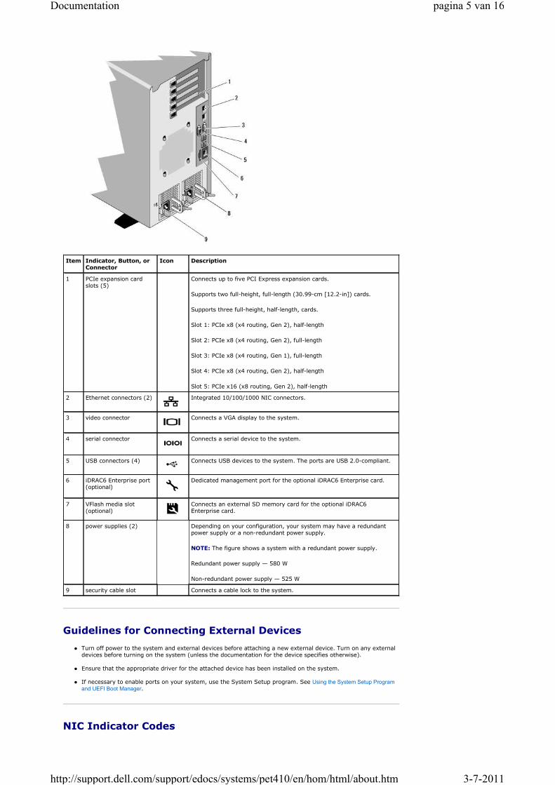
Figure 1-4. Back-Panel Features and Indicators
Number Displays the Asset tag or the Service tag for the system.
Power Displays the power output of the system in BTU/hr or Watts. The display format can be configured in the Set home submenu of the Setup menu. See Setup Menu.
Temperature Displays the temperature of the system in Celsius or Fahrenheit. The
display format can be configured in the Set home submenu of the Setup menu. See Setup Menu.
1 drive-activity indicator (green) 2 drive-status indicator (green and amber)
Drive-Status Indicator Pattern (RAID Only)
Condition
Blinks green two times per second Identify drive/preparing for removal
Off Drive ready for insertion or removal
NOTE: The drive status indicator remains off until all hard drives are initialized after system power is applied. Drives are not ready for insertion or removal during this time.
Blinks green, amber, and off Drive predicted failure
Blinks amber four times per second Drive failed
Blinks green slowly Drive rebuilding
Steady green Drive online
Blinks green three seconds, amber three seconds, and off six seconds.
Rebuild aborted
pagina 4 van 16Documentation
3-7-2011http://support.dell.com/support/edocs/systems/pet410/en/hom/html/about.htm
Guidelines for Connecting External Devices
� Turn off power to the system and external devices before attaching a new external device. Turn on any external devices before turning on the system (unless the documentation for the device specifies otherwise).
� Ensure that the appropriate driver for the attached device has been installed on the system.
� If necessary to enable ports on your system, use the System Setup program. See Using the System Setup Program
and UEFI Boot Manager.
NIC Indicator Codes
Item Indicator, Button, orConnector
Icon Description
1 PCIe expansion card slots (5)
Connects up to five PCI Express expansion cards.
Supports two full-height, full-length (30.99-cm [12.2-in]) cards.
Supports three full-height, half-length, cards.
Slot 1: PCIe x8 (x4 routing, Gen 2), half-length
Slot 2: PCIe x8 (x4 routing, Gen 2), full-length
Slot 3: PCIe x8 (x4 routing, Gen 1), full-length
Slot 4: PCIe x8 (x4 routing, Gen 2), half-length
Slot 5: PCIe x16 (x8 routing, Gen 2), half-length
2 Ethernet connectors (2) Integrated 10/100/1000 NIC connectors.
3 video connector Connects a VGA display to the system.
4 serial connector Connects a serial device to the system.
5 USB connectors (4) Connects USB devices to the system. The ports are USB 2.0-compliant.
6 iDRAC6 Enterprise port(optional)
Dedicated management port for the optional iDRAC6 Enterprise card.
7 VFlash media slot(optional)
Connects an external SD memory card for the optional iDRAC6 Enterprise card.
8 power supplies (2) Depending on your configuration, your system may have a redundant power supply or a non-redundant power supply.
NOTE: The figure shows a system with a redundant power supply.
Redundant power supply — 580 W
Non-redundant power supply — 525 W
9 security cable slot Connects a cable lock to the system.
pagina 5 van 16Documentation
3-7-2011http://support.dell.com/support/edocs/systems/pet410/en/hom/html/about.htm
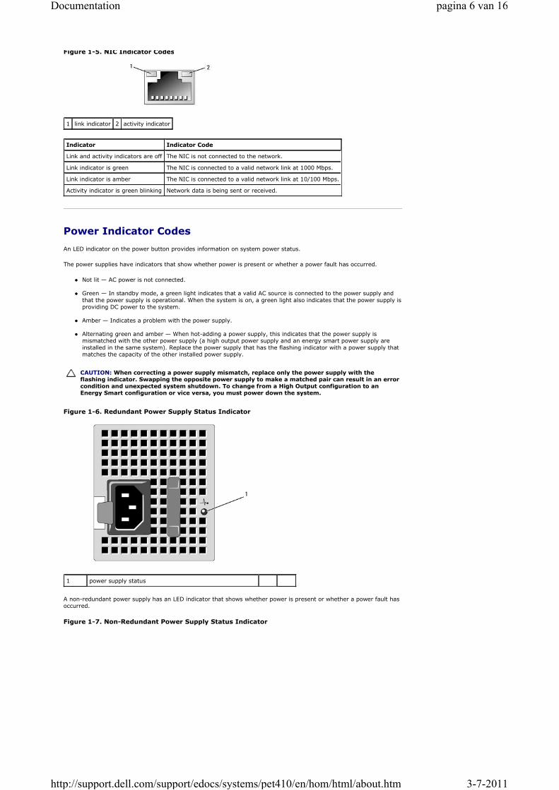
Figure 1-5. NIC Indicator Codes
Power Indicator Codes
An LED indicator on the power button provides information on system power status.
The power supplies have indicators that show whether power is present or whether a power fault has occurred.
� Not lit — AC power is not connected.
� Green — In standby mode, a green light indicates that a valid AC source is connected to the power supply and
that the power supply is operational. When the system is on, a green light also indicates that the power supply is providing DC power to the system.
� Amber — Indicates a problem with the power supply.
� Alternating green and amber — When hot-adding a power supply, this indicates that the power supply is mismatched with the other power supply (a high output power supply and an energy smart power supply are
installed in the same system). Replace the power supply that has the flashing indicator with a power supply that matches the capacity of the other installed power supply.
Figure 1-6. Redundant Power Supply Status Indicator
A non-redundant power supply has an LED indicator that shows whether power is present or whether a power fault has occurred.
Figure 1-7. Non-Redundant Power Supply Status Indicator
1 link indicator 2 activity indicator
Indicator Indicator Code
Link and activity indicators are off The NIC is not connected to the network.
Link indicator is green The NIC is connected to a valid network link at 1000 Mbps.
Link indicator is amber The NIC is connected to a valid network link at 10/100 Mbps.
Activity indicator is green blinking Network data is being sent or received.
CAUTION: When correcting a power supply mismatch, replace only the power supply with the flashing indicator. Swapping the opposite power supply to make a matched pair can result in an error condition and unexpected system shutdown. To change from a High Output configuration to an Energy Smart configuration or vice versa, you must power down the system.
1 power supply status
pagina 6 van 16Documentation
3-7-2011http://support.dell.com/support/edocs/systems/pet410/en/hom/html/about.htm

� Not lit — AC power is not connected.
� Green — In standby mode, a green light indicates that a valid AC source is connected to the power supply and that the power supply is operational. When the system is on, a green light also indicates that the power supply isproviding DC power to the system.
Diagnostic Lights (Optional)
The four diagnostic indicator lights on the system front panel display error codes during system startup. Table 1-5 lists the causes and possible corrective actions associated with these codes. A highlighted circle indicates the light is on; anon-highlighted circle indicates the light is off.
1 power supply test switch 2 power supply status
NOTE: The diagnostic LEDs are not present when the system is equipped with an LCD display.
Code Causes Corrective Action
The system is in a normal offcondition or a possible pre-BIOS failure has occurred.
The diagnostic lights are not litafter the system successfully
boots to the operating system.
Plug the system into a working electrical outlet and press the power button.
The system is in a normal operating condition after POST.
Information only.
BIOS checksum failure detected;
system is in recovery mode.
See Getting Help.
Possible processor failure. See Troubleshooting the Processors.
Memory failure. See Troubleshooting System Memory.
Possible expansion card failure. See Troubleshooting Expansion Cards.
Possible video failure. See Getting Help.
Hard drive failure. Ensure that the diskette drive and hard drive are properly connected. See Hard Drives for information on the drives installed in your system.
Possible USB failure. See Troubleshooting a USB Device.
No memory modules detected. See Troubleshooting System Memory.
System board failure. See Getting Help.
Memory configuration error. See Troubleshooting System Memory.
Possible system board resourceand/or system board hardware failure.
See Getting Help.
Possible system resource See Getting Help.
pagina 7 van 16Documentation
3-7-2011http://support.dell.com/support/edocs/systems/pet410/en/hom/html/about.htm

LCD Status Messages (Optional)
The LCD messages refer to events recorded in the System Event Log (SEL). For information on the SEL and configuring system management settings, see the systems management software documentation.
Table 1-2. LCD Status Messages
configuration error.
Other failure. Ensure that the diskette drive, optical drive, and hard drives are properly connected. See Troubleshooting Your System for the appropriate drive installed in your system. If the problem persists, see Getting Help.
NOTE: If your system fails to boot, press the System ID button for at least five seconds until an error code appears on the LCD. Record the code, then see Getting Help.
Code Text Causes Corrective Actions
N/A SYSTEM NAME A 62-character string that can be defined by the user in the System Setup program.
The SYSTEM NAME displays under the following conditions:
� The system is powered on.� The power is off and active errors are
displayed.
This message is for information only.
You can change the system ID and name in the System Setup program. See Entering the System Setup Program.
E1000 Failsafe voltage
error. Contact
support.
Check the system event log for critical failure events.
Remove AC power to the system for 10 seconds and restart the system.
If the problem persists, see Getting
Help.
E1114 Ambient Temp exceeds
allowed range.Ambient temperature has a reached a point outside of the allowed range.
See Troubleshooting System Cooling
Problems.
E1116 Memory disabled,
temp above range.
Power cycle AC.
Memory has exceeded allowable temperature and has been disabled to prevent damage to the components.
Remove AC power to the system for 10 seconds and restart the system.
See Troubleshooting System Cooling
Problems. If the problem persists, see Getting Help.
E1210 Motherboard battery
failure. Check
battery.
CMOS battery is missing or the voltage is outside of the allowable range.
See Troubleshooting the System Battery.
E1211 RAID Controller
battery failure.
Check battery.
RAID battery is either missing, bad, or unable to recharge due to thermal issues.
Reseat the RAID battery connector. See Installing a RAID Battery, and Troubleshooting System Cooling
Problems.
E1216 3.3V Regulator
failure. Reseat PCIe
cards.
3.3V voltage regulator has failed. Remove and reseat the PCIe expansion cards. If the problem persists, see Troubleshooting Expansion
Cards.
E1229 CPU # VCORE
Regulator failure.
Reseat CPU.
Specified processor VCORE voltage regulator has failed.
Reseat the processor(s). See Troubleshooting the Processors.
If the problem persists, see Getting
Help.
E122A CPU # VTT Regulator
failure. Reseat CPU.Specified processor VTT voltage regulator has failed.
Reseat the processor(s). See Troubleshooting the Processors.
If the problem persists, see Getting
Help.
E122C CPU Power Fault.
Power cycle AC.A power fault was detected when powering up the processor(s).
Remove AC power to the system for 10 seconds and restart the system.
If the problem persists, see Getting
Help.
E122D Memory Regulator #
Failed. Reseat
DIMMs.
One of the memory regulators has failed.. Reseat the memory modules. See Troubleshooting System Memory.
E122E On-board regulator
failed. Call
support.
One of the on-board voltage regulators
failed.
Remove AC power to the system for
10 seconds and restart the system.
If the problem persists, see Getting
Help.
E1310 Fan ## RPM exceeding
range. Check fan.RPM of the specified fan is outside of the
intended operating range.
See Troubleshooting System Cooling
Problems.
E1311 Fan module ## RPM
exceeding range.
Check fan.
RPM of the specified fan in a specified module is outside of intended operating range.
See Troubleshooting System Cooling
Problems.
E1313 Fan redundancy lost.
Check fans.The system is no longer fan redundant. Check LCD for additional scrolling
pagina 8 van 16Documentation
3-7-2011http://support.dell.com/support/edocs/systems/pet410/en/hom/html/about.htm
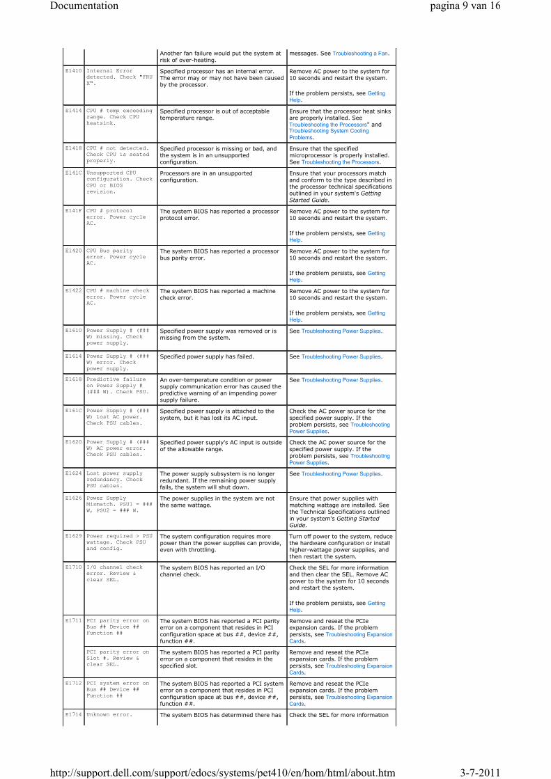
Another fan failure would put the system at
risk of over-heating.
messages. See Troubleshooting a Fan.
E1410 Internal Error
detected. Check "FRU
X".
Specified processor has an internal error. The error may or may not have been caused by the processor.
Remove AC power to the system for 10 seconds and restart the system.
If the problem persists, see Getting
Help.
E1414 CPU # temp exceeding
range. Check CPU
heatsink.
Specified processor is out of acceptable temperature range.
Ensure that the processor heat sinks are properly installed. See Troubleshooting the Processors" and Troubleshooting System Cooling
Problems.
E1418 CPU # not detected.
Check CPU is seated
properly.
Specified processor is missing or bad, and the system is in an unsupported configuration.
Ensure that the specifiedmicroprocessor is properly installed. See Troubleshooting the Processors.
E141C Unsupported CPU
configuration. Check
CPU or BIOS
revision.
Processors are in an unsupportedconfiguration.
Ensure that your processors matchand conform to the type described in the processor technical specifications outlined in your system's Getting
Started Guide.
E141F CPU # protocol
error. Power cycle
AC.
The system BIOS has reported a processor protocol error.
Remove AC power to the system for 10 seconds and restart the system.
If the problem persists, see Getting
Help.
E1420 CPU Bus parity
error. Power cycle
AC.
The system BIOS has reported a processor bus parity error.
Remove AC power to the system for 10 seconds and restart the system.
If the problem persists, see Getting
Help.
E1422 CPU # machine check
error. Power cycle
AC.
The system BIOS has reported a machine check error.
Remove AC power to the system for 10 seconds and restart the system.
If the problem persists, see Getting
Help.
E1610 Power Supply # (###
W) missing. Check
power supply.
Specified power supply was removed or is missing from the system.
See Troubleshooting Power Supplies.
E1614 Power Supply # (###
W) error. Check
power supply.
Specified power supply has failed. See Troubleshooting Power Supplies.
E1618 Predictive failure
on Power Supply #
(### W). Check PSU.
An over-temperature condition or power supply communication error has caused the predictive warning of an impending power supply failure.
See Troubleshooting Power Supplies.
E161C Power Supply # (###
W) lost AC power.
Check PSU cables.
Specified power supply is attached to the
system, but it has lost its AC input.
Check the AC power source for the
specified power supply. If the problem persists, see Troubleshooting
Power Supplies.
E1620 Power Supply # (###
W) AC power error.
Check PSU cables.
Specified power supply's AC input is outside
of the allowable range.
Check the AC power source for the
specified power supply. If the problem persists, see Troubleshooting
Power Supplies.
E1624 Lost power supply
redundancy. Check
PSU cables.
The power supply subsystem is no longer
redundant. If the remaining power supply fails, the system will shut down.
See Troubleshooting Power Supplies.
E1626 Power Supply
Mismatch. PSU1 = ###
W, PSU2 = ### W.
The power supplies in the system are not the same wattage.
Ensure that power supplies with matching wattage are installed. Seethe Technical Specifications outlined
in your system's Getting StartedGuide.
E1629 Power required > PSU
wattage. Check PSU
and config.
The system configuration requires more power than the power supplies can provide, even with throttling.
Turn off power to the system, reducethe hardware configuration or installhigher-wattage power supplies, and
then restart the system.
E1710 I/O channel check
error. Review &
clear SEL.
The system BIOS has reported an I/O channel check.
Check the SEL for more information and then clear the SEL. Remove ACpower to the system for 10 seconds and restart the system.
If the problem persists, see Getting
Help.
E1711 PCI parity error on
Bus ## Device ##
Function ##
The system BIOS has reported a PCI parity error on a component that resides in PCI
configuration space at bus ##, device ##, function ##.
Remove and reseat the PCIe expansion cards. If the problem
persists, see Troubleshooting Expansion
Cards.
PCI parity error on
Slot #. Review &
clear SEL.
The system BIOS has reported a PCI parity error on a component that resides in the
specified slot.
Remove and reseat the PCIe expansion cards. If the problem
persists, see Troubleshooting Expansion
Cards.
E1712 PCI system error on
Bus ## Device ##
Function ##
The system BIOS has reported a PCI system error on a component that resides in PCI
configuration space at bus ##, device ##, function ##.
Remove and reseat the PCIe expansion cards. If the problem
persists, see Troubleshooting Expansion
Cards.
E1714 Unknown error. The system BIOS has determined there has Check the SEL for more information
pagina 9 van 16Documentation
3-7-2011http://support.dell.com/support/edocs/systems/pet410/en/hom/html/about.htm

Review & clear SEL. been an error in the system, but is unable to
determine its origin.
and then clear the SEL. Remove AC
power to the system for 10 seconds and restart the system.
If the problem persists, see Getting
Help.
E171F PCIe fatal error on
Bus ## Device ##
Function ##
The system BIOS has reported a PCIe fatal error on a component that resides in PCI configuration space at bus ##, device ##, function ##.
Remove and reseat the PCIe expansion cards. If the problem persists, see Troubleshooting Expansion
Cards.
E1810 Hard drive ## fault.
Review & clear SEL.The specified hard drive has experienced a fault.
See Troubleshooting a Hard Drive.
E1812 Hard drive ##
removed. Check
drive.
The specified hard drive has been removed from the system.
Information only.
E1920 iDRAC6 Upgrade
FailedThe iDRAC6 Express card is not installed
properly or the card is bad.
Reseat the iDRAC6 Express Card.
See Installing an iDRAC6 Express Card.
If the problem persists, see Getting
Help.
E1A14 SAS cable A failure.
Check connection.SAS cable A is missing or bad. Reseat the cable. If the problem
persists, replace cable.
If the problem persists, see Getting
Help.
E1A15 SAS cable B failure.
Check connection.SAS cable B is missing or bad. Reseat the cable. If the problem
persists, replace cable.
If the problem persists, see Getting
Help.
E1A1D Control panel USB
cable not detected.
Check cable.
USB cable to the control panel is missing or bad.
Reseat the cable. If the problempersists, replace cable.
If the problem persists, see Getting
Help.
E2010 Memory not detected.
Inspect DIMMs.No memory was detected in the system. Install or reseat memory modules.
See Installing Memory Modules or Troubleshooting System Memory.
E2011 Memory configuration
failure. Check
DIMMs.
Memory detected, but is not configurable.
Error detected during memory configuration.
See Troubleshooting System Memory.
E2012 Memory configured
but unusable. Check
DIMMs.
Memory configured, but is unusable. See Troubleshooting System Memory.
E2013 BIOS unable to
shadow memory. Check
DIMMs.
The system BIOS failed to copy its flash image into memory.
See Troubleshooting System Memory.
E2014 CMOS RAM failure.
Power cycle AC.CMOS failure. CMOS RAM not functioning properly.
Remove AC power to the system for 10 seconds and restart the system.
If the problem persists, see Getting
Help.
E2015 DMA Controller
failure. Power cycle
AC.
DMA controller failure. Remove AC power to the system for 10 seconds and restart the system.
If the problem persists, see Getting
Help.
E2016 Interrupt Controller
failure. Power cycle
AC.
Interrupt controller failure. Remove AC power to the system for 10 seconds and restart the system.
If the problem persists, see Getting
Help.
E2017 Timer refresh
failure. Power cycle
AC.
Timer refresh failure. Remove AC power to the system for 10 seconds and restart the system.
If the problem persists, see Getting
Help.
E2018 Programmable Timer
error. Power cycle
AC.
Programmable interval timer error. Remove AC power to the system for 10 seconds and restart the system.
If the problem persists, see Getting
Help.
E2019 Parity error. Power
cycle AC.Parity error. Remove AC power to the system for
10 seconds and restart the system.
If the problem persists, see Getting
Help.
E201A SuperIO failure.
Power cycle AC.SIO failure. Remove AC power to the system for
10 seconds and restart the system.
If the problem persists, see Getting
Help.
E201B Keyboard Controller
error. Power cycle
AC.
Keyboard controller failure. Remove AC power to the system for 10 seconds and restart the system.
pagina 10 van 16Documentation
3-7-2011http://support.dell.com/support/edocs/systems/pet410/en/hom/html/about.htm

Solving Problems Described by LCD Status Messages
The code and text on the LCD can often specify a very precise fault condition that is easily corrected. For example, if the code E1418 CPU_1_Presence appears, you know that a microprocessor is not installed in socket 1.
In contrast, you might be able to determine the problem if multiple related errors occur. For example, if you receive a series of messages indicating multiple voltage faults, you might determine that the problem is a failing power supply.
Removing LCD Status Messages
If the problem persists, see Getting
Help.
E201C SMI initialization failure. Power cycle AC.
System management interrupt (SMI) initialization failure.
Remove AC power to the system for 10 seconds and restart the system.
If the problem persists, see Getting
Help.
E201D Shutdown test failure. Power cycle AC.
BIOS shutdown test failure. Remove AC power to the system for 10 seconds and restart the system.
If the problem persists, see Getting
Help.
E201E POST memory test failure. Check DIMMs.
BIOS POST memory test failure. See Troubleshooting System Memory.
If the problem persists, see Getting
Help.
E2020 CPU configuration failure. Check screen message.
Processor configuration failure. Check screen for specific error messages. See Troubleshooting the
Processors.
E2021 Incorrect memory configuration. Review User Guide.
Incorrect memory configuration. Check screen for specific errormessages. See Troubleshooting System
Memory.
E2022 General failure during POST. Check screen message.
General failure after video. Check screen for specific error messages.
E2023 BIOS Unable to mirror memory. Check DIMMs.
The system BIOS could not enable memory mirroring because of a faulty memory module or an invalid memory configuration.
See Troubleshooting System Memory.
E2110 Multibit Error on DIMM ##. Reseat DIMM.
The memory module in slot "##" has had a multi-bit error (MBE).
See Troubleshooting System Memory.
E2111 SBE log disabled on DIMM ##. Reseat DIMM.
The system BIOS has disabled memory single-bit error (SBE) logging and will not log anymore SBEs until the system is
rebooted. "##" represents the memory module implicated by the BIOS.
Remove AC power to the system for 10 seconds and restart the system.
If the problem persists, see
Troubleshooting System Memory.
E2112 Memory spared on DIMM ##. Power cycle AC.
The system BIOS has spared the memory because it has determined the memory had too many errors. "##" represents the
memory module implicated by the BIOS.
Remove AC power to the system for 10 seconds and restart the system.
If the problem persists, see
Troubleshooting System Memory.
E2113 Mem mirror OFF on DIMM ## & ##. Power cycle AC
The system BIOS has disabled memory mirroring because it has determined one half of the mirror has had too many errors. "## & ##" represents the memory-module
pair implicated by the BIOS.
Remove AC power to the system for 10 seconds and restart the system.
If the problem persists, see Troubleshooting System Memory.
I1910 Intrusion detected. Check chassis cover.
System cover has been removed. Information only.
I1911 LCD Log Full. Check SEL to review all Errors.
LCD overflow message. A maximum of ten error messages can display sequentially on
the LCD. The eleventh message instructs the user to check the SEL for details on the events.
Check the SEL for details on the events.
Remove AC power to the system for
10 seconds or clear the SEL.
I1912 SEL full. Review &clear log.
The SEL is full of events and is unable to log any more.
Check the SEL for details on theevents, then clear the SEL.
I1920 iDRAC6 UpgradeSuccessful
iDRAC6 Express card has been installed correctly
Information only
W1228 RAID Controller battery capacity < 24hr.
Warns predictively that the RAID battery has less than 24 hours of charge left.
Allow RAID battery to charge to greater than 24 hours of sustained charge.
If problem persists, replace RAID
battery. See "Installing a RAID Battery."
W1627 Power required > PSUwattage. Check PSU and config.
The system configuration requires more power than what the power supply canprovide.
Turn off power to the system, reduce the hardware configuration or install higher-wattage power supplies, and
then restart the system.
W1628 Performancedegraded. Check PSU and systemconfiguration.
The system configuration requires more power than what the power supply can provide, but it can boot if throttled.
Turn off power to the system, reducethe hardware configuration or installhigher-wattage power supplies, and then restart the system.
NOTE: For the full name of an abbreviation or acronym used in this table, see the Glossary.
pagina 11 van 16Documentation
3-7-2011http://support.dell.com/support/edocs/systems/pet410/en/hom/html/about.htm

For faults associated with sensors, such as temperature, voltage, fans, and so on, the LCD message is automatically removed when that sensor returns to a normal state. For example, if temperature for a component goes out of range, the LCD displays the fault; when the temperature returns to the acceptable range, the message is removed from the LCD. For other faults, you must take action to remove the message from the display:
� Clear the SEL — You can perform this task remotely, but you will lose the event history for the system.
� Power cycle — Turn off the system and disconnect it from the electrical outlet; wait approximately ten seconds, reconnect the power cable, and restart the system.
Any of these actions will remove fault messages, and return the status indicators and LCD colors to the normal state.Messages will reappear under the following conditions:
� The sensor returns to a normal state but fails again, resulting in a new SEL entry.
� The system is reset and new error events are detected.
� A failure is recorded from another source that maps to the same display entry.
System Messages
System messages appear on the screen to notify you of a possible problem with the system.
Table 1-3. System Messages
NOTE: If you receive a system message not listed in the table, check the documentation for the application that is running when the message appears or the operating system's documentation for an explanation of the message and recommended action.
Message Causes Corrective Actions
128-bit Advanced ECC mode
disabled. For 128-bit
Advanced ECC, DIMMs must be
installed in pairs. Pairs
must be matched in size and
geometry.
The Advanced ECC option enabled in BIOS is no longer valid due to an unsupported memory configuration, possibly a faulty or removed memory module. The Advanced ECC setting has been
disabled.
Check other messages for a faulty memory module. Reconfigure the memory modules for Advanced ECC mode. See System Memory.
Alert! Advanced ECC Memory
Mode disabled! Memory
configuration does not
support Advanced ECC Memory
Mode.
Advanced ECC Memory Mode was enabled in the system setup program, but the current configuration does not support
Advanced ECC Memory Mode. A memory module may be faulty.
Ensure that the memory modules areinstalled in a configuration that supportsAdvanced ECC Memory Mode. Check other system messages for additional information
for possible causes. For memory configuration information, see General Memory
Module Installation Guidelines. If the problem persists, see Troubleshooting System Memory."
Alert! iDRAC6 not
responding. Rebooting.The iDRAC6 is not responding to BIOS communication either because it is not functioningproperly or has not completed initialization. The system will reboot.
Wait for the system to reboot.
Alert! iDRAC6 not
responding. Power required
may exceed PSU wattage.
Alert! Continuing system
boot accepts the risk that
system may power down
without warning.
The iDRAC6 has hung.
The iDRAC6 was remotely reset while system was booting.
After AC recovery, the iDRAC6 takes longer than normal to boot.
Remove AC power to the system for 10seconds and restart the system.
Alert! Node Interleaving
disabled! Memory
configuration does not
support Node Interleaving.
The memory configuration does
not support node interleaving, or the configuration has changed (for example, a memory module has failed) so that node interleavingcannot be supported. The system continues to run, but without node
interleaving.
Ensure that the memory modules are
installed in a configuration that supports node interleaving. Check other systemmessages for additional information for possible causes. For memory configuration information, see General Memory Module
Installation Guidelines. If the problem persists, see Troubleshooting System Memory."
Alert! Power required
exceeds PSU wattage. Check
PSU and system
configuration.
Alert! Continuing system
boot accepts the risk that
system may power down
without warning.
The system configuration of processor(s), memory modules,
and expansion cards may not be supported by the power supplies.
If any system components were just upgraded, return the system to the previous
configuration. If the system boots without this warning, then the replaced component(s) are not supported with this power supply. If Energy Smart power supplies are installed, replace them with High Output powersupplies to use the components. See Power
Supplies.
Alert! Redundant memory
disabled! Memory
configuration does not
support redundant memory.
Memory Sparing or Memory Mirroring was enabled in the system setup program, but the
current configuration does not support redundant memory. A memory module may be faulty.
Check the memory modules for failure. See Troubleshooting System Memory. Reset the memory setting, if appropriate. See Using the
System Setup Program and UEFI Boot Manager.
Alert! System fatal error
during previous boot.An error caused the system toreboot.
Check other system messages for additional information for possible causes.
BIOS MANUFACTURING MODE
detected. MANUFACTURING MODE
will be cleared before the
next boot. System reboot
System is in manufacturing mode. Reboot to take the system out ofmanufacturing mode.
pagina 12 van 16Documentation
3-7-2011http://support.dell.com/support/edocs/systems/pet410/en/hom/html/about.htm
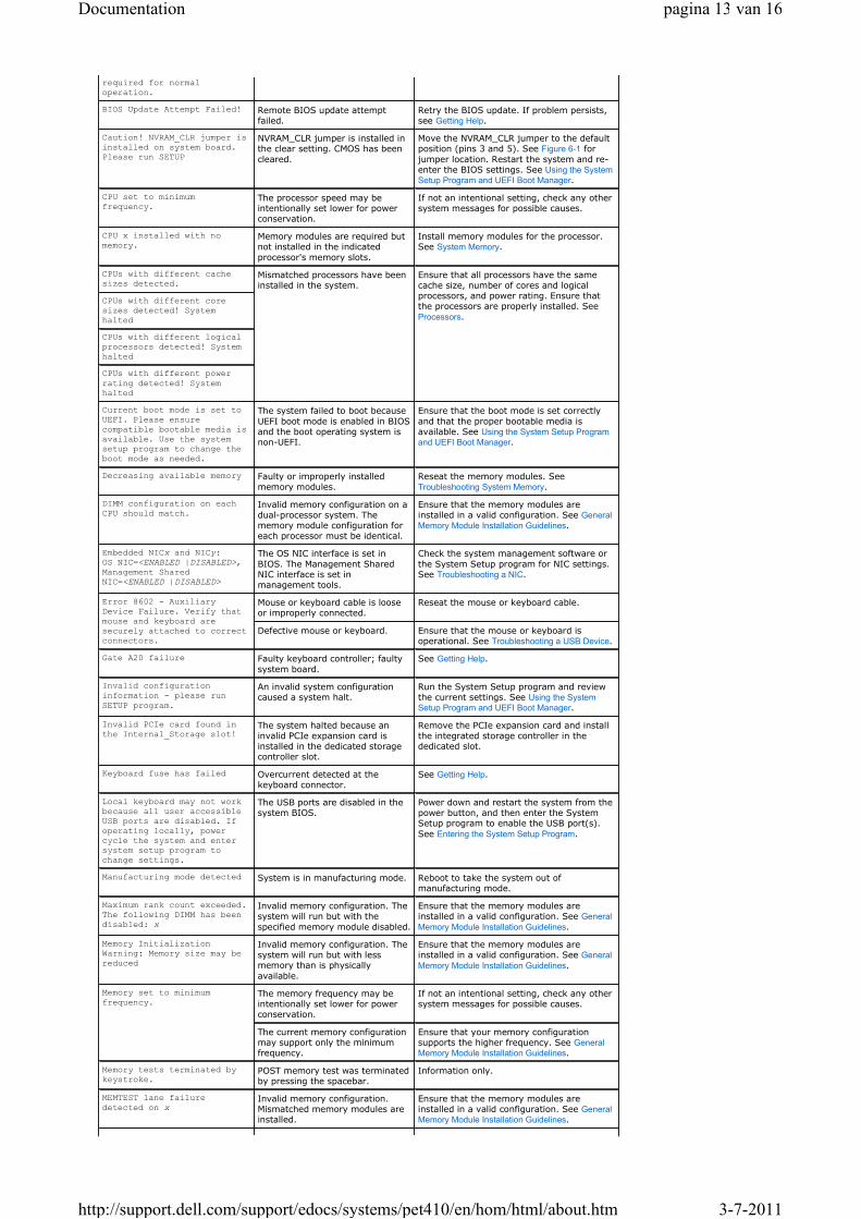
required for normal operation.
BIOS Update Attempt Failed! Remote BIOS update attemptfailed.
Retry the BIOS update. If problem persists, see Getting Help.
Caution! NVRAM_CLR jumper is installed on system board. Please run SETUP
NVRAM_CLR jumper is installed in the clear setting. CMOS has been
cleared.
Move the NVRAM_CLR jumper to the default position (pins 3 and 5). See Figure 6-1 for
jumper location. Restart the system and re-enter the BIOS settings. See Using the System
Setup Program and UEFI Boot Manager.
CPU set to minimumfrequency.
The processor speed may beintentionally set lower for powerconservation.
If not an intentional setting, check any other system messages for possible causes.
CPU x installed with nomemory.
Memory modules are required but not installed in the indicated
processor's memory slots.
Install memory modules for the processor. See System Memory.
CPUs with different cache sizes detected.
Mismatched processors have been installed in the system.
Ensure that all processors have the same cache size, number of cores and logicalprocessors, and power rating. Ensure that the processors are properly installed. See
Processors.
CPUs with different core sizes detected! Systemhalted
CPUs with different logical processors detected! Systemhalted
CPUs with different power
rating detected! Systemhalted
Current boot mode is set to UEFI. Please ensure compatible bootable media is available. Use the system setup program to change the boot mode as needed.
The system failed to boot because
UEFI boot mode is enabled in BIOS and the boot operating system is non-UEFI.
Ensure that the boot mode is set correctly
and that the proper bootable media is available. See Using the System Setup Program
and UEFI Boot Manager.
Decreasing available memory Faulty or improperly installed memory modules.
Reseat the memory modules. See Troubleshooting System Memory.
DIMM configuration on each CPU should match.
Invalid memory configuration on adual-processor system. The memory module configuration for each processor must be identical.
Ensure that the memory modules areinstalled in a valid configuration. See General
Memory Module Installation Guidelines.
Embedded NICx and NICy:OS NIC=<ENABLED |DISABLED>, Management Shared NIC=<ENABLED |DISABLED>
The OS NIC interface is set in
BIOS. The Management Shared NIC interface is set inmanagement tools.
Check the system management software or
the System Setup program for NIC settings. See Troubleshooting a NIC.
Error 8602 - AuxiliaryDevice Failure. Verify that mouse and keyboard aresecurely attached to correct connectors.
Mouse or keyboard cable is loose or improperly connected.
Reseat the mouse or keyboard cable.
Defective mouse or keyboard. Ensure that the mouse or keyboard isoperational. See Troubleshooting a USB Device.
Gate A20 failure Faulty keyboard controller; faulty
system board.
See Getting Help.
Invalid configuration information - please run
SETUP program.
An invalid system configuration caused a system halt.
Run the System Setup program and review the current settings. See Using the System
Setup Program and UEFI Boot Manager.
Invalid PCIe card found in the Internal_Storage slot!
The system halted because an invalid PCIe expansion card is installed in the dedicated storage controller slot.
Remove the PCIe expansion card and install the integrated storage controller in the dedicated slot.
Keyboard fuse has failed Overcurrent detected at the keyboard connector.
See Getting Help.
Local keyboard may not work because all user accessibleUSB ports are disabled. If operating locally, power cycle the system and enter system setup program to change settings.
The USB ports are disabled in thesystem BIOS.
Power down and restart the system from the power button, and then enter the SystemSetup program to enable the USB port(s).
See Entering the System Setup Program.
Manufacturing mode detected System is in manufacturing mode. Reboot to take the system out ofmanufacturing mode.
Maximum rank count exceeded. The following DIMM has been disabled: x
Invalid memory configuration. The system will run but with the
specified memory module disabled.
Ensure that the memory modules are installed in a valid configuration. See General
Memory Module Installation Guidelines.
Memory InitializationWarning: Memory size may be reduced
Invalid memory configuration. The system will run but with lessmemory than is physically
available.
Ensure that the memory modules are installed in a valid configuration. See General
Memory Module Installation Guidelines.
Memory set to minimum
frequency.The memory frequency may beintentionally set lower for powerconservation.
If not an intentional setting, check any other system messages for possible causes.
The current memory configuration may support only the minimum frequency.
Ensure that your memory configuration supports the higher frequency. See General
Memory Module Installation Guidelines.
Memory tests terminated by keystroke.
POST memory test was terminated by pressing the spacebar.
Information only.
MEMTEST lane failure
detected on xInvalid memory configuration. Mismatched memory modules areinstalled.
Ensure that the memory modules areinstalled in a valid configuration. See General
Memory Module Installation Guidelines.
pagina 13 van 16Documentation
3-7-2011http://support.dell.com/support/edocs/systems/pet410/en/hom/html/about.htm

Mirror mode disabled. For
mirror mode, DIMMs must be
installed in pairs. Pairs
must be matched in size and
geometry.
The memory configuration does
not match the setting in BIOS. The BIOS setting has been disabled.
Reconfigure the memory modules for
Memory Mirroring mode. See System Memory.
No boot device available Faulty or missing optical drivesubsystem, hard drive, or hard-drive subsystem, or no bootable USB key installed.
Use a bootable USB key, optical drive, or hard drive. If the problem persists, see Troubleshooting an Optical Drive, Troubleshooting
a USB Device, and Troubleshooting a Hard Drive.
See Using the System Setup Program and UEFI
Boot Manager for information on setting the order of boot devices.
No boot sector on hard drive Incorrect configuration settings inSystem Setup program, or no operating system on hard drive.
Check the hard-drive configuration settings in the System Setup program. See Using the
System Setup Program and UEFI Boot Manager. If necessary, install the operating system on your hard drive. See your operating system
documentation.
No timer tick interrupt Faulty system board. See Getting Help.
PCIe Training Error:
Expected Link Width is x,
Actual Link Width is y.
Faulty or improperly installed PCIe
card in the specified slot.
Reseat the PCIe card in the specified slot
number. See Troubleshooting Expansion Cards.If the problem persists, see Getting Help.
Plug & Play Configuration
ErrorError encountered in initializingPCIe device; faulty system board.
Install the NVRAM_CLR jumper in the clear position (pins 1 and 3) and reboot the
system. See Figure 6-1 for jumper location. If the problem persists, see Troubleshooting the
Processors.
Quad rank DIMM detected
after single rank or dual
rank DIMM in socket.
Invalid memory configuration. Ensure that the memory modules are
installed in a valid configuration. See General
Memory Module Installation Guidelines.
Read fault
Requested sector not found
The operating system cannot read
from the hard drive, optical drive, or USB device, the system could not find a particular sector on the disk, or the requested sector isdefective.
Replace the optical medium, USB medium, or
USB device. Ensure that the USB cables,SAS/SATA backplane cables, or optical drive cables are properly connected. See Troubleshooting a USB Device, Troubleshooting
an Optical Drive, or Troubleshooting a Hard Drive
for the appropriate drive(s) installed in your
system.
SATA Port x device not found There is no device connected to the specified SATA port.
Information only.
Sector not found
Seek error
Seek operation failed
Faulty hard drive, USB device, or USB medium.
Replace the USB medium or device. Ensure that the USB or SAS backplane cables areproperly connected. See Troubleshooting a USB
Device or Troubleshooting a Hard Drive for the appropriate drive(s) installed in your system.
Shutdown failure General system error. See Getting Help.
Sparing mode disabled. For
sparing mode, matched sets
of three must be populated
across slots.
The memory configuration does not match the setting in BIOS. The
BIOS setting has been disabled.
Reconfigure the memory modules forMemory Sparing mode. See System Memory.
The amount of system memory
has changedMemory has been added or removed or a memory module may be faulty.
If memory has been added or removed, this message is informative and can be ignored. If memory has not been added or removed,check the SEL to determine if single-bit ormulti-bit errors were detected and replace
the faulty memory module. See Troubleshooting System Memory.
The following DIMMs should
match in geometry: x,x,...Invalid memory configuration. The specified memory modules do not
match in size, number of ranks, or number of data lanes.
Ensure that the memory modules areinstalled in a valid configuration. See General
Memory Module Installation Guidelines.The following DIMMs should
match in rank count: x,x,...
The following DIMMs should
match in size: x,x,...
The following DIMMs should
match in size and geometry:
x,x,...
The following DIMMs should
match in size and rank
count: x,x,...
Thermal sensor not detected
on xA memory module without athermal sensor is installed in the specified memory slot.
Replace the memory module. See System
Memory.
Time-of-day clock stopped Faulty battery or faulty chip. See Troubleshooting the System Battery.
Time-of-day not set - please
run SETUP programIncorrect Time or Date settings;faulty system battery.
Check the Time and Date settings. See Using the System Setup Program and UEFI Boot
Manager. If the problem persists, replace the system battery. See System Battery.
Timer chip counter 2 failed Faulty system board. See Getting Help.
TPM configuration operation
honored. System will now
reset.
A TPM configuration command has been entered. The system will reboot and execute the command.
Information only.
TPM configuration operation
is pending. Press (I) to
Ignore OR (M) to Modify to
allow this change and reset
the system.
This message displays during
system restart after a TPM configuration command has beenentered. User interaction is required to proceed.
Enter I or M to proceed.
pagina 14 van 16Documentation
3-7-2011http://support.dell.com/support/edocs/systems/pet410/en/hom/html/about.htm

Warning Messages
A warning message alerts you to a possible problem and prompts you to respond before the system continues a task. For example, before you format a diskette, a message will warn you that you may lose all data on the diskette.
WARNING: Modifying could
prevent security.
TPM failure A Trusted Platform Module (TPM)function has failed.
See Getting Help.
Unable to launch System
Services image. System
halted!
System halted after F10 keystrokebecause System Services image is either corrupted in the system
firmware or has been lost due tosystem board replacement.
The iDRAC6 Enterprise card flash memory may be corrupted.
Restart the system and update the Unified Server Configurator repository to the latest software to restore full functionality. See the
Unified Server Configuration userdocumentation for more information.
Restore the flash memory using the latest version on support.dell.com. See the iDRAC6 user's guide for instructions on performing a field replacement of the flash memory.
Unexpected interrupt in
protected modeImproperly seated memory modules or faulty keyboard/mouse controller chip.
Reseat the memory modules. See Troubleshooting System Memory. If the problem persists, see Getting Help.
Unsupported CPU combination
Unsupported CPU stepping
detected
Processor(s) is not supported by
the system.
Install a supported processor or processor
combination. See Processors.
Unsupported DIMM detected.
The following DIMM has been
disabled: x
Invalid memory configuration. The system will run but with thespecified memory module disabled.
Ensure that the memory modules are installed in a valid configuration. See General
Memory Module Installation Guidelines.
Unsupported memory
configuration. DIMM mismatch
across slots detected:
x,x,...
Invalid memory configuration. Memory modules are mismatched in the specified slots.
Ensure that the memory modules areinstalled in a valid configuration. See General
Memory Module Installation Guidelines.
Unused memory detected.
DIMMs installed in the
following slot(s) are not
available when in Mirror
mode
The memory configuration is notoptimal for mirroring or Advanced
ECC Memory Mode. Modules in the specified slots are unused.
Reconfigure the memory for MemoryMirroring or Advanced ECC Memory Mode, or
change the memory mode to Optimized or Sparing in the BIOS setup screen. See System Memory.
Unused memory detected.
DIMMs installed in the
following slot(s) are not
available when in 128-Bit
Advanced ECC mode:
The memory configuration is not optimal for mirroring or Advanced
ECC Memory Mode. Modules in the specified slots are unused.
Reconfigure the memory for MemoryMirroring or Advanced ECC Memory Mode, or
change the memory mode to Optimized or Sparing in the BIOS setup screen. See System Memory.
Warning: A fatal error has
caused system reset! Please
check the system event log!
A fatal system error occurred and
caused the system to reboot.
Check the SEL for information that was
logged during the error. See the applicabletroubleshooting section in Troubleshooting Your
System for any faulty components specified in the SEL.
Warning: Control Panel is
not installed.The control panel is not installed or has a faulty cable connection.
Install the control panel, or check the cable connections between the display module, the control panel board, and the system board. See Control Panel Assembly (Service-Only
Procedure).
Warning! No micro code
update loaded for processor
n
Micro code update failed. Update the BIOS firmware. See Getting Help.
Warning! Power required
exceeds PSU wattage. Check
PSU and system
configuration.
Warning! Performance
degraded. CPU and memory set
to minimum frequencies to
meet PSU wattage. System
will reboot.
The system configuration ofprocessor(s), memory modules, and expansion cards may not be
supported by the power supplies.
If any system components were just upgraded, return the system to the previous configuration. If the system boots without
this warning, then the replaced component(s) are not supported with this power supply. If Energy Smart power supplies are installed, replace them with the High Output powersupplies to use the components. See Power
Supplies.
Warning! PSU mismatch. PSU
redundancy lost. Check PSU.A High Output power supply and an Energy Smart power supply areinstalled in the system at the sametime.
Install two High Output or two Energy Smart power supplies in the system.
You can also run the system on one power supply until you can obtain two power
supplies of the same type. See Troubleshooting Power Supplies.
Warning! Unsupported memory
configuration detected. The
memory configuration is not
optimal. The recommended
memory configuration is:
<message>
Invalid memory configuration. The system will run but with reduced
functionality.
Ensure that the memory modules areinstalled in a valid configuration. See General
Memory Module Installation Guidelines. If theproblem persists, see Troubleshooting System
Memory.
Write fault
Write fault on selected
drive
Faulty USB device, USB medium, optical drive assembly, hard drive, or hard-drive subsystem.
Replace the USB medium or device. Ensure that the USB, SAS backplane, or SATA cables are properly connected. See Troubleshooting a USB Device,
Troubleshooting an Optical Drive, and Troubleshooting a Hard Drive.
NOTE: For the full name of an abbreviation or acronym used in this table, see the Glossary.
pagina 15 van 16Documentation
3-7-2011http://support.dell.com/support/edocs/systems/pet410/en/hom/html/about.htm
snWEB4
Warning messages usually interrupt the task and require you to respond by typing y (yes) or n (no).
Diagnostics Messages
The system diagnostic utilities may issue messages if you run diagnostic tests on your system. See Running the System
Diagnostics for more information about system diagnostics.
Alert Messages
Systems management software generates alert messages for your system. Alert messages include information, status,warning, and failure messages for drive, temperature, fan, and power conditions. For more information, see thesystems management software documentation.
Other Information You May Need
� The Getting Started Guide provides an overview of system features, setting up your system, and technicalspecifications.
� Any media that ships with your system that provides documentation and tools for configuring and managingyour system, including those pertaining to the operating system, system management software, system updates, and system components that you purchased with your system.
� The Unified Server Configurator User's Guide provides information about setting up USC, configuring hardwareand firmware, and deploying the operating system.
Back to Contents Page
NOTE: Warning messages are generated by either the application or the operating system. For moreinformation, see the documentation that accompanied the operating system or application.
WARNING: See the safety and regulatory information that shipped with your system. Warranty information may be included within this document or as a separate document.
NOTE: Always check for updates on support.dell.com and read the updates first because they often supersede information in other documents.
Support Home Page
Shop
Solutions
Services
Systems
Software & Peripherals
Support
Home Users
Small Businesses
Enterprise IT
Community
Join the Discussion
Share Your Ideas
Read our Blog
Ratings & Reviews
Community Home
Company Information
About Dell
Corporate Responsibility
Careers
Investors
Newsroom
My Account
Sign-in / Register
Order Status
Laptops | Desktops | Business Laptops | Business Desktops | Workstations | Servers | Storage | Services | Monitors | Printers | LCD TVs | Electronics
© 2011 Dell | About Dell | Terms of Sale | Unresolved Issues | Privacy | About Our Ads and Emails | Dell Recycling | Contact | Site Map | FeedbackAT | AU | BE | BR | CA | CH | CL | CN | CO | DE | DK | ES | FR | HK | IE | IN | IT | JP | KR | ME | MX | MY |
NL | NO | PA | PR | RU | SE | SG | UK | VE | ALL
Large Text
pagina 16 van 16Documentation
3-7-2011http://support.dell.com/support/edocs/systems/pet410/en/hom/html/about.htm
Related Documents