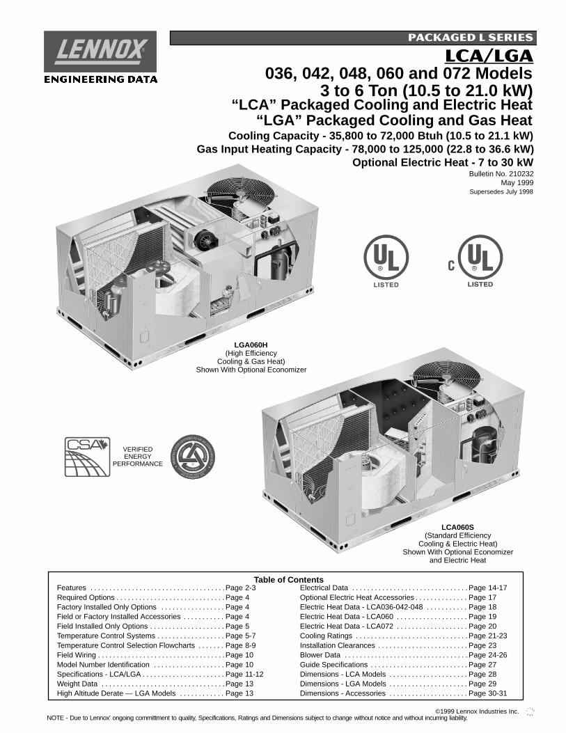
036, 042, 048, 060 and 072 Models 3 to 6 Ton (10.5 to 21.0 kW) LCA/LGA Bulletin No. 210232 May 1999 Supersedes July 1998 “LCA” Packaged Cooling and Electric Heat “LGA” Packaged Cooling and Gas Heat Cooling Capacity - 35,800 to 72,000 Btuh (10.5 to 21.1 kW) Gas Input Heating Capacity - 78,000 to 125,000 (22.8 to 36.6 kW) Optional Electric Heat - 7 to 30 kW PACKAGED L SERIES Table of Contents Features Page 2-3 .................................... Required Options Page 4 ............................. Factory Installed Only Options Page 4 ................. Field or Factory Installed Accessories Page 4 ........... Field Installed Only Options Page 5 .................... Temperature Control Systems Page 5-7 .................. Temperature Control Selection Flowcharts Page 8-9 ....... Field Wiring Page 10 .................................. Model Number Identification Page 10 ................... Specifications - LCA/LGA Page 11-12 ...................... Weight Data Page 13 ................................. High Altitude Derate — LGA Models Page 13 ............ Electrical Data Page 14-17 ............................... Optional Electric Heat Accessories Page 17 .............. Electric Heat Data - LCA036-042-048 Page 18 ........... Electric Heat Data - LCA060 Page 19 ................... Electric Heat Data - LCA072 Page 20 ................... Cooling Ratings Page 21-23 .............................. Installation Clearances Page 23 ........................ Blower Data Page 24-26 ................................. Guide Specifications Page 27 .......................... Dimensions - LCA Models Page 28 ..................... Dimensions - LGA Models Page 29 ..................... Dimensions - Accessories Page 30-31 ..................... LCA060S (Standard Efficiency Cooling & Electric Heat) Shown With Optional Economizer and Electric Heat VERIFIED ENERGY PERFORMANCE LGA060H (High Efficiency Cooling & Gas Heat) Shown With Optional Economizer NOTE - Due to Lennox’ ongoing committment to quality, Specifications, Ratings and Dimensions subject to change without notice and without incurringliability. ©1999 Lennox Industries Inc.

Welcome message from author
This document is posted to help you gain knowledge. Please leave a comment to let me know what you think about it! Share it to your friends and learn new things together.
Transcript
036, 042, 048, 060 and 072 Models3 to 6 Ton (10.5 to 21.0 kW)
LCA/LGA
Bulletin No. 210232May 1999
Supersedes July 1998
“LCA” Packaged Cooling and Electric Heat“LGA” Packaged Cooling and Gas Heat
Cooling Capacity - 35,800 to 72,000 Btuh (10.5 to 21.1 kW)Gas Input Heating Capacity - 78,000 to 125,000 (22.8 to 36.6 kW)
Optional Electric Heat - 7 to 30 kW
PACKAGED L SERIES
ENGINEERING DATA
Table of ContentsFeatures Page 2-3. . . . . . . . . . . . . . . . . . . . . . . . . . . . . . . . . . . .Required Options Page 4. . . . . . . . . . . . . . . . . . . . . . . . . . . . .Factory Installed Only Options Page 4. . . . . . . . . . . . . . . . .Field or Factory Installed Accessories Page 4. . . . . . . . . . .Field Installed Only Options Page 5. . . . . . . . . . . . . . . . . . . .Temperature Control Systems Page 5-7. . . . . . . . . . . . . . . . . .Temperature Control Selection Flowcharts Page 8-9. . . . . . .Field Wiring Page 10. . . . . . . . . . . . . . . . . . . . . . . . . . . . . . . . . .Model Number Identification Page 10. . . . . . . . . . . . . . . . . . .Specifications - LCA/LGA Page 11-12. . . . . . . . . . . . . . . . . . . . . .Weight Data Page 13. . . . . . . . . . . . . . . . . . . . . . . . . . . . . . . . .High Altitude Derate — LGA Models Page 13. . . . . . . . . . . .
Electrical Data Page 14-17. . . . . . . . . . . . . . . . . . . . . . . . . . . . . . .Optional Electric Heat Accessories Page 17. . . . . . . . . . . . . .Electric Heat Data - LCA036-042-048 Page 18. . . . . . . . . . .Electric Heat Data - LCA060 Page 19. . . . . . . . . . . . . . . . . . .Electric Heat Data - LCA072 Page 20. . . . . . . . . . . . . . . . . . .Cooling Ratings Page 21-23. . . . . . . . . . . . . . . . . . . . . . . . . . . . . .Installation Clearances Page 23. . . . . . . . . . . . . . . . . . . . . . . .Blower Data Page 24-26. . . . . . . . . . . . . . . . . . . . . . . . . . . . . . . . .Guide Specifications Page 27. . . . . . . . . . . . . . . . . . . . . . . . . .Dimensions - LCA Models Page 28. . . . . . . . . . . . . . . . . . . . .Dimensions - LGA Models Page 29. . . . . . . . . . . . . . . . . . . . .Dimensions - Accessories Page 30-31. . . . . . . . . . . . . . . . . . . . .
LCA060S(Standard Efficiency
Cooling & Electric Heat)Shown With Optional Economizer
and Electric Heat
VERIFIEDENERGY
PERFORMANCE
LGA060H(High Efficiency
Cooling & Gas Heat)Shown With Optional Economizer
NOTE - Due to Lennox’ ongoing committment to quality, Specifications, Ratings and Dimensions subject to change without notice and without incurring liability.©1999 Lennox Industries Inc.
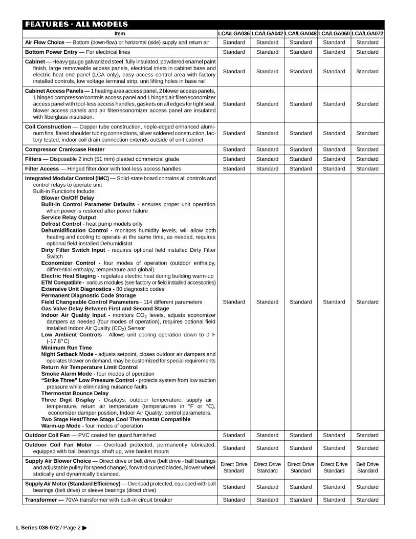
FEATURES - ALLModels
Item LCA/LGA036 LCA/LGA042 LCA/LGA048 LCA/LGA060 LCA/LGA072
Air Flow Choice — Bottom (down-flow) or horizontal (side) supply and return air Standard Standard Standard Standard Standard
Bottom Power Entry — For electrical lines Standard Standard Standard Standard Standard
Cabinet — Heavy gauge galvanized steel, fully insulated, powdered enamel paintfinish, large removeable access panels, electrical inlets in cabinet base andelectric heat end panel (LCA only), easy access control area with factoryinstalled controls, low voltage terminal strip, unit lifting holes in base rail
Standard Standard Standard Standard Standard
Cabinet Access Panels — 1 heating area access panel, 2 blower access panels,1 hinged compressor/controls access panel and 1 hinged air filter/economizeraccess panel with tool-less access handles, gaskets on all edges for tight seal,blower access panels and air filter/economizer access panel are insulatedwith fiberglass insulation.
Standard Standard Standard Standard Standard
Coil Construction — Copper tube construction, ripple-edged enhanced alumi-num fins, flared shoulder tubing connections, silver soldered construction, fac-tory tested, indoor coil drain connection extends outside of unit cabinet
Standard Standard Standard Standard Standard
Compressor Crankcase Heater Standard Standard Standard Standard Standard
Filters — Disposable 2 inch (51 mm) pleated commercial grade Standard Standard Standard Standard Standard
Filter Access — Hinged filter door with tool-less access handles Standard Standard Standard Standard Standard
Integrated Modular Control (IMC) — Solid-state board contains all controls andcontrol relays to operate unitBuilt-in Functions Include:
Blower On/Off DelayBuilt-in Control Parameter Defaults - ensures proper unit operation
when power is restored after power failureService Relay OutputDefrost Control - heat pump models onlyDehumidification Control - monitors humidity levels, will allow both
heating and cooling to operate at the same time, as needed, requiresoptional field installed Dehumidistat
Dirty Filter Switch Input - requires optional field installed Dirty FilterSwitch
Economizer Control - four modes of operation (outdoor enthalpy,differential enthalpy, temperature and global)
Electric Heat Staging - regulates electric heat during building warm-upETM Compatible - various modules (see factory or field installed accessories)Extensive Unit Diagnostics - 80 diagnostic codesPermanent Diagnostic Code StorageField Changeable Control Parameters - 114 different parametersGas Valve Delay Between First and Second StageIndoor Air Quality Input - monitors CO2 levels, adjusts economizer
dampers as needed (four modes of operation), requires optional fieldinstalled Indoor Air Quality (CO2) Sensor
Low Ambient Controls - Allows unit cooling operation down to 0EF(-17.8EC)
Minimum Run TimeNight Setback Mode - adjusts setpoint, closes outdoor air dampers and
operates blower on demand, may be customized for special requirementsReturn Air Temperature Limit ControlSmoke Alarm Mode - four modes of operation“Strike Three” Low Pressure Control - protects system from low suction
pressure while eliminating nuisance faultsThermostat Bounce DelayThree Digit Display - Displays: outdoor temperature, supply air
temperature, return air temperature (temperatures in °F or °C),economizer damper position, Indoor Air Quality, control parameters.
Two Stage Heat/Three Stage Cool Thermostat CompatibleWarm-up Mode - four modes of operation
Standard Standard Standard Standard Standard
Outdoor Coil Fan — PVC coated fan guard furnished Standard Standard Standard Standard Standard
Outdoor Coil Fan Motor — Overload protected, permanently lubricated,equipped with ball bearings, shaft up, wire basket mount
Standard Standard Standard Standard Standard
Supply Air Blower Choice — Direct drive or belt drive (belt drive - ball bearingsand adjustable pulley for speed change), forward curved blades, blower wheelstatically and dynamically balanced.
Direct DriveStandard
Direct DriveStandard
Direct DriveStandard
Direct DriveStandard
Belt DriveStandard
Supply Air Motor (Standard Efficiency) — Overload protected, equipped with ballbearings (belt drive) or sleeve bearings (direct drive)
Standard Standard Standard Standard Standard
Transformer — 70VA transformer with built-in circuit breaker Standard Standard Standard Standard Standard
L Series 036-072 / Page 2�
FEATURES - LCAModels
Item LCA/LGA036 LCA/LGA042 LCA/LGA048 LCA/LGA060 LCA/LGA072
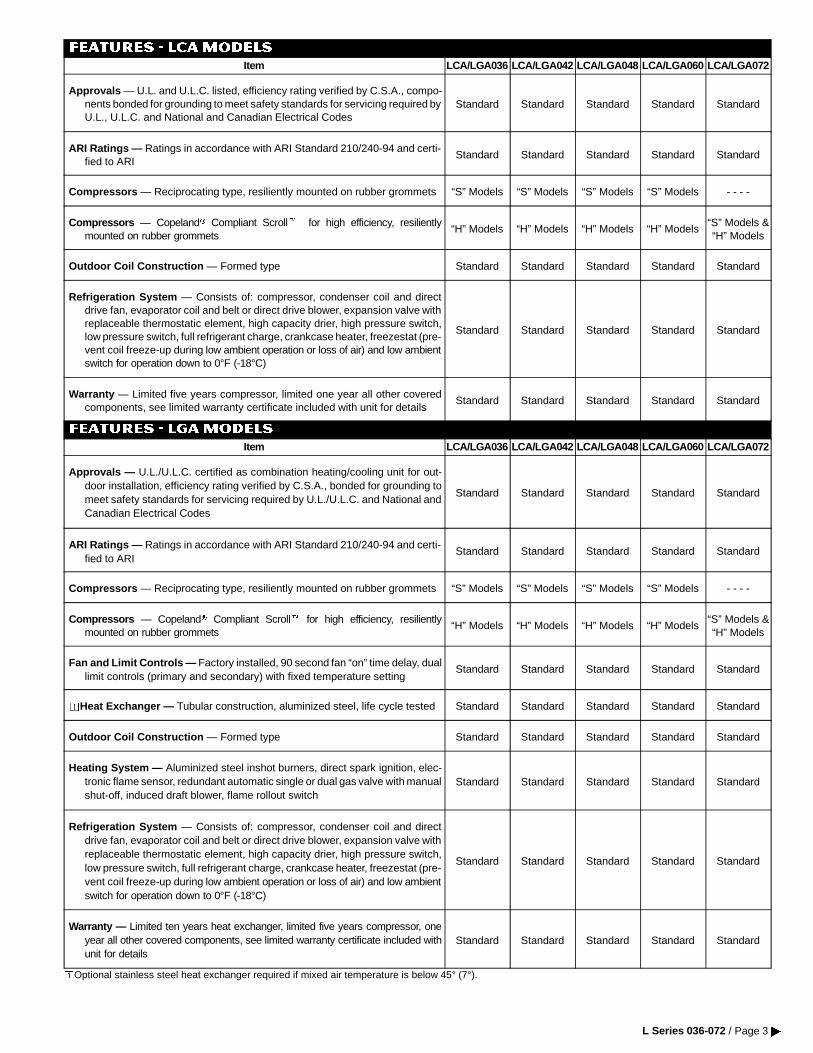
Approvals — U.L. and U.L.C. listed, efficiency rating verified by C.S.A., compo-nents bonded for grounding to meet safety standards for servicing required byU.L., U.L.C. and National and Canadian Electrical Codes
Standard Standard Standard Standard Standard
ARI Ratings — Ratings in accordance with ARI Standard 210/240-94 and certi-fied to ARI
Standard Standard Standard Standard Standard
Compressors — Reciprocating type, resiliently mounted on rubber grommets “S” Models “S” Models “S” Models “S” Models - - - -
Compressors — CopelandX Compliant ScrollZ for high efficiency, resilientlymounted on rubber grommets
“H” Models “H” Models “H” Models “H” Models“S” Models &“H” Models
Outdoor Coil Construction — Formed type Standard Standard Standard Standard Standard
Refrigeration System — Consists of: compressor, condenser coil and directdrive fan, evaporator coil and belt or direct drive blower, expansion valve withreplaceable thermostatic element, high capacity drier, high pressure switch,low pressure switch, full refrigerant charge, crankcase heater, freezestat (pre-vent coil freeze-up during low ambient operation or loss of air) and low ambientswitch for operation down to 0°F (-18°C)
Standard Standard Standard Standard Standard
Warranty — Limited five years compressor, limited one year all other coveredcomponents, see limited warranty certificate included with unit for details
Standard Standard Standard Standard Standard
FEATURES - LGAModels
Item LCA/LGA036 LCA/LGA042 LCA/LGA048 LCA/LGA060 LCA/LGA072
Approvals — U.L./U.L.C. certified as combination heating/cooling unit for out-door installation, efficiency rating verified by C.S.A., bonded for grounding tomeet safety standards for servicing required by U.L./U.L.C. and National andCanadian Electrical Codes
Standard Standard Standard Standard Standard
ARI Ratings — Ratings in accordance with ARI Standard 210/240-94 and certi-fied to ARI
Standard Standard Standard Standard Standard
Compressors — Reciprocating type, resiliently mounted on rubber grommets “S” Models “S” Models “S” Models “S” Models - - - -
Compressors — CopelandX Compliant ScrollZ for high efficiency, resilientlymounted on rubber grommets
“H” Models “H” Models “H” Models “H” Models“S” Models &“H” Models
Fan and Limit Controls — Factory installed, 90 second fan “on” time delay, duallimit controls (primary and secondary) with fixed temperature setting
Standard Standard Standard Standard Standard
ooHeat Exchanger — Tubular construction, aluminized steel, life cycle tested Standard Standard Standard Standard Standard
Outdoor Coil Construction — Formed type Standard Standard Standard Standard Standard
Heating System — Aluminized steel inshot burners, direct spark ignition, elec-tronic flame sensor, redundant automatic single or dual gas valve with manualshut-off, induced draft blower, flame rollout switch
Standard Standard Standard Standard Standard
Refrigeration System — Consists of: compressor, condenser coil and directdrive fan, evaporator coil and belt or direct drive blower, expansion valve withreplaceable thermostatic element, high capacity drier, high pressure switch,low pressure switch, full refrigerant charge, crankcase heater, freezestat (pre-vent coil freeze-up during low ambient operation or loss of air) and low ambientswitch for operation down to 0°F (-18°C)
Standard Standard Standard Standard Standard
Warranty — Limited ten years heat exchanger, limited five years compressor, oneyear all other covered components, see limited warranty certificate included withunit for details
Standard Standard Standard Standard Standard
oOptional stainless steel heat exchanger required if mixed air temperature is below 45° (7°).
L Series 036-072 / Page 3 �
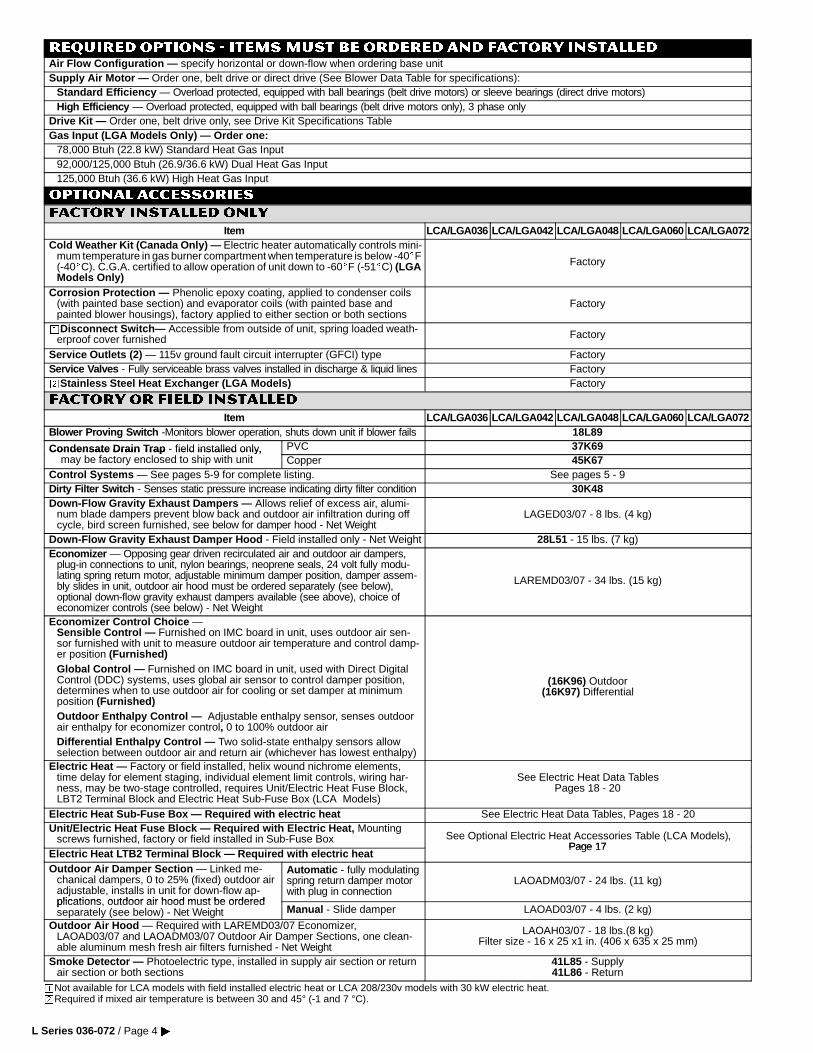
REQUIRED OPTIONS - ITEMSMUST BE ORDERED AND FACTORY INSTALLEDAir Flow Configuration — specify horizontal or down-flow when ordering base unitSupply Air Motor — Order one, belt drive or direct drive (See Blower Data Table for specifications):
Standard Efficiency — Overload protected, equipped with ball bearings (belt drive motors) or sleeve bearings (direct drive motors)High Efficiency — Overload protected, equipped with ball bearings (belt drive motors only), 3 phase only
Drive Kit — Order one, belt drive only, see Drive Kit Specifications TableGas Input (LGA Models Only) — Order one:
78,000 Btuh (22.8 kW) Standard Heat Gas Input92,000/125,000 Btuh (26.9/36.6 kW) Dual Heat Gas Input125,000 Btuh (36.6 kW) High Heat Gas Input
OPTIONAL ACCESSORIES
FACTORY INSTALLED ONLY
Item LCA/LGA036 LCA/LGA042 LCA/LGA048 LCA/LGA060 LCA/LGA072Cold Weather Kit (Canada Only) — Electric heater automatically controls mini-
mum temperature in gas burner compartment when temperature is below -40EF(-40EC). C.G.A. certified to allow operation of unit down to -60EF (-51EC) (LGAModels Only)
Factory
Corrosion Protection — Phenolic epoxy coating, applied to condenser coils(with painted base section) and evaporator coils (with painted base andpainted blower housings), factory applied to either section or both sections
Factory
ooDisconnect Switch— Accessible from outside of unit, spring loaded weath-erproof cover furnished Factory
Service Outlets (2) — 115v ground fault circuit interrupter (GFCI) type FactoryService Valves - Fully serviceable brass valves installed in discharge & liquid lines FactorywwStainless Steel Heat Exchanger (LGA Models) Factory
FACTORY or FIELD INSTALLED
Item LCA/LGA036 LCA/LGA042 LCA/LGA048 LCA/LGA060 LCA/LGA072Blower Proving Switch -Monitors blower operation, shuts down unit if blower fails 18L89
Condensate Drain Tra p - field installed only, PVC 37K69Condensate Drain Trap field installed only,may be factory enclosed to ship with unit Copper 45K67
Control Systems — See pages 5-9 for complete listing. See pages 5 - 9Dirty Filter Switch - Senses static pressure increase indicating dirty filter condition 30K48Down-Flow Gravity Exhaust Dampers — Allows relief of excess air, alumi-
num blade dampers prevent blow back and outdoor air infiltration during offcycle, bird screen furnished, see below for damper hood - Net Weight
LAGED03/07 - 8 lbs. (4 kg)
Down-Flow Gravity Exhaust Damper Hood - Field installed only - Net Weight 28L51 - 15 lbs. (7 kg)Economizer — Opposing gear driven recirculated air and outdoor air dampers,
plug-in connections to unit, nylon bearings, neoprene seals, 24 volt fully modu-lating spring return motor, adjustable minimum damper position, damper assem-bly slides in unit, outdoor air hood must be ordered separately (see below),optional down-flow gravity exhaust dampers available (see above), choice ofeconomizer controls (see below) - Net Weight
LAREMD03/07 - 34 lbs. (15 kg)
Economizer Control Choice —Sensible Control — Furnished on IMC board in unit, uses outdoor air sen-sor furnished with unit to measure outdoor air temperature and control damp-er position (Furnished)Global Control — Furnished on IMC board in unit, used with Direct DigitalControl (DDC) systems, uses global air sensor to control damper position,determines when to use outdoor air for cooling or set damper at minimumposition (Furnished)Outdoor Enthalpy Control — Adjustable enthalpy sensor, senses outdoorair enthalpy for economizer control, 0 to 100% outdoor airDifferential Enthalpy Control — Two solid-state enthalpy sensors allowselection between outdoor air and return air (whichever has lowest enthalpy)
(16K96) Outdoor(16K97) Differential
Electric Heat — Factory or field installed, helix wound nichrome elements,time delay for element staging, individual element limit controls, wiring har-ness, may be two-stage controlled, requires Unit/Electric Heat Fuse Block,LBT2 Terminal Block and Electric Heat Sub-Fuse Box (LCA Models)
See Electric Heat Data TablesPages 18 - 20
Electric Heat Sub-Fuse Box — Required with electric heat See Electric Heat Data Tables, Pages 18 - 20Unit/Electric Heat Fuse Block — Required with Electric Heat, Mounting
screws furnished, factory or field installed in Sub-Fuse Box See Optional Electric Heat Accessories Table (LCA Models),Page 17
Electric Heat LTB2 Terminal Block — Required with electric heatPage 17
Outdoor Air Damper Section — Linked me-chanical dampers, 0 to 25% (fixed) outdoor airadjustable, installs in unit for down-flow ap-plications outdoor air hood must be ordered
Automatic - fully modulatingspring return damper motorwith plug in connection
LAOADM03/07 - 24 lbs. (11 kg)
plications, outdoor air hood must be orderedseparately (see below) - Net Weight Manual - Slide damper LAOAD03/07 - 4 lbs. (2 kg)
Outdoor Air Hood — Required with LAREMD03/07 Economizer,LAOAD03/07 and LAOADM03/07 Outdoor Air Damper Sections, one clean-able aluminum mesh fresh air filters furnished - Net Weight
LAOAH03/07 - 18 lbs.(8 kg)Filter size - 16 x 25 x1 in. (406 x 635 x 25 mm)
Smoke Detector — Photoelectric type, installed in supply air section or returnair section or both sections
41L85 - Supply41L86 - Return
oNot available for LCA models with field installed electric heat or LCA 208/230v models with 30 kW electric heat.wRequired if mixed air temperature is between 30 and 45° (-1 and 7 °C).
L Series 036-072 / Page 4�
OPTIONAL ACCESSORIES - Continued
FIELD INSTALLEDONLY
Item LCA/LGA036
LCA/LGA042
LCA/LGA048
LCA/LGA060 LCA/LGA072
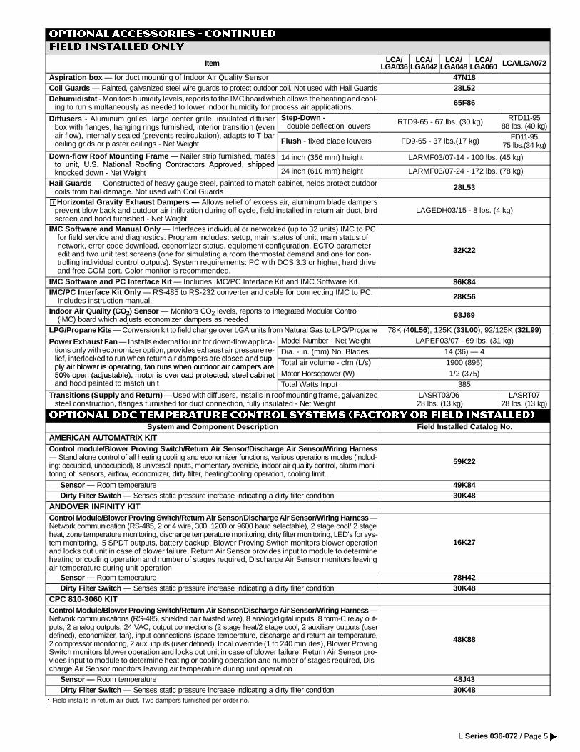
Aspiration box — for duct mounting of Indoor Air Quality Sensor 47N18Coil Guards — Painted, galvanized steel wire guards to protect outdoor coil. Not used with Hail Guards 28L52Dehumidistat - Monitors humidity levels, reports to the IMC board which allows the heating and cool-
ing to run simultaneously as needed to lower indoor humidity for process air applications. 65F86
Diffusers - Aluminum grilles, large center grille, insulated diffuserbox with flanges, hanging rings furnished, interior transition (even
Step-Down -double deflection louvers RTD9-65 - 67 lbs. (30 kg) RTD11-95
88 lbs. (40 kg)box with flanges, hanging rings furnished, interior transition (evenair flow), internally sealed (prevents recirculation), adapts to T-barceiling grids or plaster ceilings - Net Weight Flush - fixed blade louvers FD9-65 - 37 lbs.(17 kg) FD11-95
75 lbs.(34 kg)Down-flow Roof Mounting Frame — Nailer strip furnished, mates
to unit U S National Roofing Contractors Approved shipped14 inch (356 mm) height LARMF03/07-14 - 100 lbs. (45 kg)
to unit, U.S. National Roofing Contractors Approved, shippedknocked down - Net Weight 24 inch (610 mm) height LARMF03/07-24 - 172 lbs. (78 kg)
Hail Guards — Constructed of heavy gauge steel, painted to match cabinet, helps protect outdoorcoils from hail damage. Not used with Coil Guards 28L53
ooHorizontal Gravity Exhaust Dampers — Allows relief of excess air, aluminum blade dampersprevent blow back and outdoor air infiltration during off cycle, field installed in return air duct, birdscreen and hood furnished - Net Weight
LAGEDH03/15 - 8 lbs. (4 kg)
IMC Software and Manual Only — Interfaces individual or networked (up to 32 units) IMC to PCfor field service and diagnostics. Program includes: setup, main status of unit, main status ofnetwork, error code download, economizer status, equipment configuration, ECTO parameteredit and two unit test screens (one for simulating a room thermostat demand and one for con-trolling individual control outputs). System requirements: PC with DOS 3.3 or higher, hard driveand free COM port. Color monitor is recommended.
32K22
IMC Software and PC Interface Kit — Includes IMC/PC Interface Kit and IMC Software Kit. 86K84IMC/PC Interface Kit Only — RS-485 to RS-232 converter and cable for connecting IMC to PC.
Includes instruction manual. 28K56
Indoor Air Quality (CO 2) Sensor — Monitors CO2 levels, reports to Integrated Modular Control(IMC) board which adjusts economizer dampers as needed 93J69
LPG/Propane Kits — Conversion kit to field change over LGA units from Natural Gas to LPG/Propane 78K (40L56), 125K (33L00), 92/125K (32L99)
Power Exhaust Fan — Installs external to unit for down-flow applica- Model Number - Net Weight LAPEF03/07 - 69 lbs. (31 kg)Power Exhaust Fan Installs external to unit for down flow a lications only with economizer option, provides exhaust air pressure re-lief interlocked to run when return air dampers are closed and sup
Dia. - in. (mm) No. Blades 14 (36) — 4lief, interlocked to run when return air dampers are closed and sup-ply air blower is operating, fan runs when outdoor air dampers are Total air volume - cfm (L/s) 1900 (895)ply air blower is operating, fan runs when outdoor air dampers are50% open (adjustable), motor is overload protected, steel cabinet Motor Horsepower (W) 1/2 (375)50% o en (adjustable), motor is overload rotected, steel cabinetand hood painted to match unit Total Watts Input 385
Transitions (Supply and Return) — Used with diffusers, installs in roof mounting frame, galvanizedsteel construction, flanges furnished for duct connection, fully insulated - Net Weight
LASRT03/0628 lbs. (13 kg)
LASRT0728 lbs. (13 kg)
OPTIONAL DDC TEMPERATURE CONTROL SYSTEMS (Factory or Field Installed)System and Component Description Field Installed Catalog No.
AMERICAN AUTOMATRIX KITControl module/Blower Proving Switch/Return Air Sensor/Discharge Air Sensor/Wiring Harness— Stand alone control of all heating cooling and economizer functions, various operations modes (includ-ing: occupied, unoccupied), 8 universal inputs, momentary override, indoor air quality control, alarm moni-toring of: sensors, airflow, economizer, dirty filter, heating/cooling operation, cooling limit.
59K22
Sensor — Room temperature 49K84Dirty Filter Switch — Senses static pressure increase indicating a dirty filter condition 30K48
ANDOVER INFINITY KITControl Module/Blower Proving Switch/Return Air Sensor/Discharge Air Sensor/Wiring Harness —Network communication (RS-485, 2 or 4 wire, 300, 1200 or 9600 baud selectable), 2 stage cool/ 2 stageheat, zone temperature monitoring, discharge temperature monitoring, dirty filter monitoring, LED’s for sys-tem monitoring, 5 SPDT outputs, battery backup, Blower Proving Switch monitors blower operationand locks out unit in case of blower failure, Return Air Sensor provides input to module to determineheating or cooling operation and number of stages required, Discharge Air Sensor monitors leavingair temperature during unit operation
16K27
Sensor — Room temperature 78H42Dirty Filter Switch — Senses static pressure increase indicating a dirty filter condition 30K48
CPC 810-3060 KITControl Module/Blower Proving Switch/Return Air Sensor/Discharge Air Sensor/Wiring Harness —Network communications (RS-485, shielded pair twisted wire), 8 analog/digital inputs, 8 form-C relay out-puts, 2 analog outputs, 24 VAC, output connections (2 stage heat/2 stage cool, 2 auxiliary outputs (userdefined), economizer, fan), input connections (space temperature, discharge and return air temperature,2 compressor monitoring, 2 aux. inputs (user defined), local override (1 to 240 minutes), Blower ProvingSwitch monitors blower operation and locks out unit in case of blower failure, Return Air Sensor pro-vides input to module to determine heating or cooling operation and number of stages required, Dis-charge Air Sensor monitors leaving air temperature during unit operation
48K88
Sensor — Room temperature 48J43Dirty Filter Switch — Senses static pressure increase indicating a dirty filter condition 30K48
oField installs in return air duct. Two dampers furnished per order no.
L Series 036-072 / Page 5 �
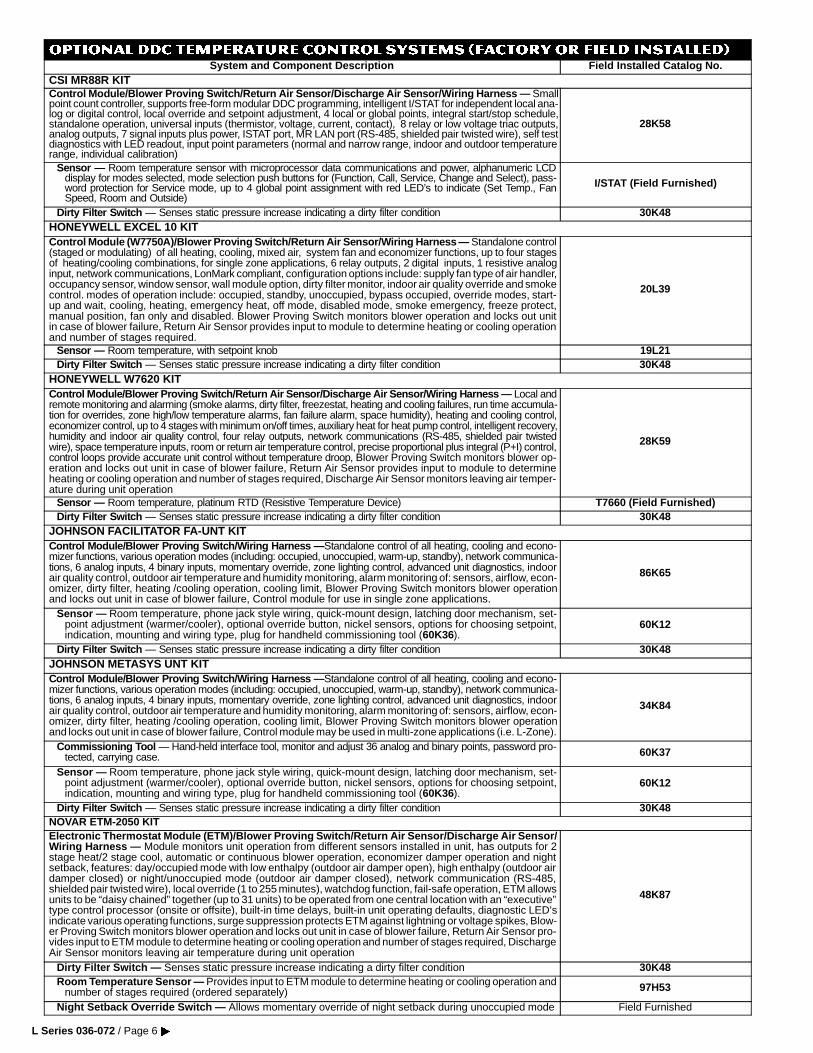
OPTIONAL DDC TEMPERATURE CONTROL SYSTEMS (Factory or Field Installed)System and Component Description Field Installed Catalog No.
CSI MR88R KITControl Module/Blower Proving Switch/Return Air Sensor/Discharge Air Sensor/Wiring Harness — Smallpoint count controller, supports free-form modular DDC programming, intelligent I/STAT for independent local ana-log or digital control, local override and setpoint adjustment, 4 local or global points, integral start/stop schedule,standalone operation, universal inputs (thermistor, voltage, current, contact), 8 relay or low voltage triac outputs,analog outputs, 7 signal inputs plus power, ISTAT port, MR LAN port (RS-485, shielded pair twisted wire), self testdiagnostics with LED readout, input point parameters (normal and narrow range, indoor and outdoor temperaturerange, individual calibration)
28K58
Sensor — Room temperature sensor with microprocessor data communications and power, alphanumeric LCDdisplay for modes selected, mode selection push buttons for (Function, Call, Service, Change and Select), pass-word protection for Service mode, up to 4 global point assignment with red LED’s to indicate (Set Temp., FanSpeed, Room and Outside)
I/STAT (Field Furnished)
Dirty Filter Switch — Senses static pressure increase indicating a dirty filter condition 30K48HONEYWELL EXCEL 10 KITControl Module (W7750A)/Blower Proving Switch/Return Air Sensor/Wiring Harness — Standalone control(staged or modulating) of all heating, cooling, mixed air, system fan and economizer functions, up to four stagesof heating/cooling combinations, for single zone applications, 6 relay outputs, 2 digital inputs, 1 resistive analoginput, network communications, LonMark compliant, configuration options include: supply fan type of air handler,occupancy sensor, window sensor, wall module option, dirty filter monitor, indoor air quality override and smokecontrol. modes of operation include: occupied, standby, unoccupied, bypass occupied, override modes, start-up and wait, cooling, heating, emergency heat, off mode, disabled mode, smoke emergency, freeze protect,manual position, fan only and disabled. Blower Proving Switch monitors blower operation and locks out unitin case of blower failure, Return Air Sensor provides input to module to determine heating or cooling operationand number of stages required.
20L39
Sensor — Room temperature, with setpoint knob 19L21Dirty Filter Switch — Senses static pressure increase indicating a dirty filter condition 30K48
HONEYWELL W7620 KITControl Module/Blower Proving Switch/Return Air Sensor/Discharge Air Sensor/Wiring Harness — Local andremote monitoring and alarming (smoke alarms, dirty filter, freezestat, heating and cooling failures, run time accumula-tion for overrides, zone high/low temperature alarms, fan failure alarm, space humidity), heating and cooling control,economizer control, up to 4 stages with minimum on/off times, auxiliary heat for heat pump control, intelligent recovery,humidity and indoor air quality control, four relay outputs, network communications (RS-485, shielded pair twistedwire), space temperature inputs, room or return air temperature control, precise proportional plus integral (P+I) control,control loops provide accurate unit control without temperature droop, Blower Proving Switch monitors blower op-eration and locks out unit in case of blower failure, Return Air Sensor provides input to module to determineheating or cooling operation and number of stages required, Discharge Air Sensor monitors leaving air temper-ature during unit operation
28K59
Sensor — Room temperature, platinum RTD (Resistive Temperature Device) T7660 (Field Furnished)Dirty Filter Switch — Senses static pressure increase indicating a dirty filter condition 30K48
JOHNSON FACILITATOR FA-UNT KITControl Module/Blower Proving Switch/Wiring Harness — Standalone control of all heating, cooling and econo-mizer functions, various operation modes (including: occupied, unoccupied, warm-up, standby), network communica-tions, 6 analog inputs, 4 binary inputs, momentary override, zone lighting control, advanced unit diagnostics, indoorair quality control, outdoor air temperature and humidity monitoring, alarm monitoring of: sensors, airflow, econ-omizer, dirty filter, heating /cooling operation, cooling limit, Blower Proving Switch monitors blower operationand locks out unit in case of blower failure, Control module for use in single zone applications.
86K65
Sensor — Room temperature, phone jack style wiring, quick-mount design, latching door mechanism, set-point adjustment (warmer/cooler), optional override button, nickel sensors, options for choosing setpoint,indication, mounting and wiring type, plug for handheld commissioning tool (60K36).
60K12
Dirty Filter Switch — Senses static pressure increase indicating a dirty filter condition 30K48JOHNSON METASYS UNT KITControl Module/Blower Proving Switch/Wiring Harness — Standalone control of all heating, cooling and econo-mizer functions, various operation modes (including: occupied, unoccupied, warm-up, standby), network communica-tions, 6 analog inputs, 4 binary inputs, momentary override, zone lighting control, advanced unit diagnostics, indoorair quality control, outdoor air temperature and humidity monitoring, alarm monitoring of: sensors, airflow, econ-omizer, dirty filter, heating /cooling operation, cooling limit, Blower Proving Switch monitors blower operationand locks out unit in case of blower failure, Control module may be used in multi-zone applications (i.e. L-Zone).
34K84
Commissioning Tool — Hand-held interface tool, monitor and adjust 36 analog and binary points, password pro-tected, carrying case. 60K37
Sensor — Room temperature, phone jack style wiring, quick-mount design, latching door mechanism, set-point adjustment (warmer/cooler), optional override button, nickel sensors, options for choosing setpoint,indication, mounting and wiring type, plug for handheld commissioning tool (60K36).
60K12
Dirty Filter Switch — Senses static pressure increase indicating a dirty filter condition 30K48NOVAR ETM-2050 KITElectronic Thermostat Module (ETM)/Blower Proving Switch/Return Air Sensor/Discharge Air Sensor/Wiring Harness — Module monitors unit operation from different sensors installed in unit, has outputs for 2stage heat/2 stage cool, automatic or continuous blower operation, economizer damper operation and nightsetback, features: day/occupied mode with low enthalpy (outdoor air damper open), high enthalpy (outdoor airdamper closed) or night/unoccupied mode (outdoor air damper closed), network communication (RS-485,shielded pair twisted wire), local override (1 to 255 minutes), watchdog function, fail-safe operation, ETM allowsunits to be “daisy chained” together (up to 31 units) to be operated from one central location with an “executive”type control processor (onsite or offsite), built-in time delays, built-in unit operating defaults, diagnostic LED’sindicate various operating functions, surge suppression protects ETM against lightning or voltage spikes, Blow-er Proving Switch monitors blower operation and locks out unit in case of blower failure, Return Air Sensor pro-vides input to ETM module to determine heating or cooling operation and number of stages required, DischargeAir Sensor monitors leaving air temperature during unit operation
48K87
Dirty Filter Switch — Senses static pressure increase indicating a dirty filter condition 30K48Room Temperature Sensor — Provides input to ETM module to determine heating or cooling operation and
number of stages required (ordered separately) 97H53
Night Setback Override Switch — Allows momentary override of night setback during unoccupied mode Field Furnished
L Series 036-072 / Page 6�
OPTIONAL DDC TEMPERATURE CONTROL SYSTEMS (Factory or Field Installed)
System and Component Description Field Installed Catalog No.
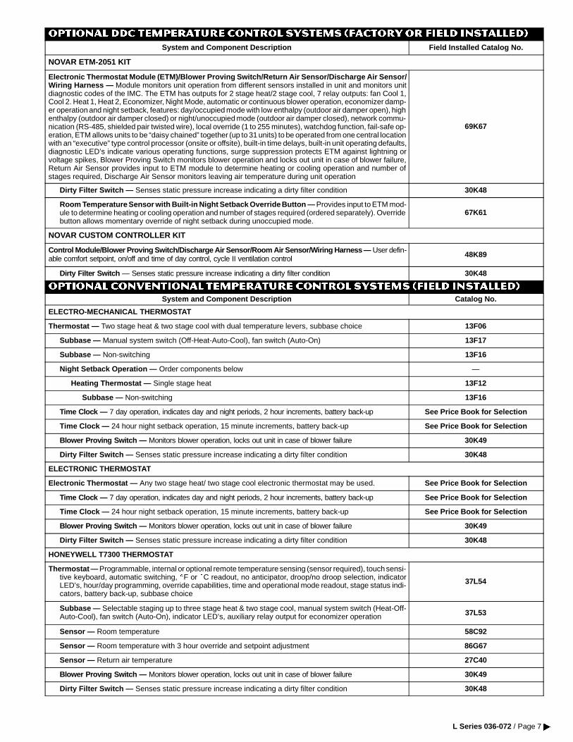
NOVAR ETM-2051 KIT
Electronic Thermostat Module (ETM)/Blower Proving Switch/Return Air Sensor/Discharge Air Sensor/Wiring Harness — Module monitors unit operation from different sensors installed in unit and monitors unitdiagnostic codes of the IMC. The ETM has outputs for 2 stage heat/2 stage cool, 7 relay outputs: fan Cool 1,Cool 2. Heat 1, Heat 2, Economizer, Night Mode, automatic or continuous blower operation, economizer damp-er operation and night setback, features: day/occupied mode with low enthalpy (outdoor air damper open), highenthalpy (outdoor air damper closed) or night/unoccupied mode (outdoor air damper closed), network commu-nication (RS-485, shielded pair twisted wire), local override (1 to 255 minutes), watchdog function, fail-safe op-eration, ETM allows units to be “daisy chained” together (up to 31 units) to be operated from one central locationwith an “executive” type control processor (onsite or offsite), built-in time delays, built-in unit operating defaults,diagnostic LED’s indicate various operating functions, surge suppression protects ETM against lightning orvoltage spikes, Blower Proving Switch monitors blower operation and locks out unit in case of blower failure,Return Air Sensor provides input to ETM module to determine heating or cooling operation and number ofstages required, Discharge Air Sensor monitors leaving air temperature during unit operation
69K67
Dirty Filter Switch — Senses static pressure increase indicating a dirty filter condition 30K48
Room Temperature Sensor with Built-in Night Setback Override Button — Provides input to ETM mod-ule to determine heating or cooling operation and number of stages required (ordered separately). Overridebutton allows momentary override of night setback during unoccupied mode.
67K61
NOVAR CUSTOM CONTROLLER KIT
Control Module/Blower Proving Switch/Discharge Air Sensor/Room Air Sensor/Wiring Harness — User defin-able comfort setpoint, on/off and time of day control, cycle II ventilation control 48K89
Dirty Filter Switch — Senses static pressure increase indicating a dirty filter condition 30K48
OPTIONAL CONVENTIONAL TEMPERATURE CONTROL SYSTEMS (Field Installed)
System and Component Description Catalog No.
ELECTRO-MECHANICAL THERMOSTAT
Thermostat — Two stage heat & two stage cool with dual temperature levers, subbase choice 13F06
Subbase — Manual system switch (Off-Heat-Auto-Cool), fan switch (Auto-On) 13F17
Subbase — Non-switching 13F16
Night Setback Operation — Order components below —
Heating Thermostat — Single stage heat 13F12
Subbase — Non-switching 13F16
Time Clock — 7 day operation, indicates day and night periods, 2 hour increments, battery back-up See Price Book for Selection
Time Clock — 24 hour night setback operation, 15 minute increments, battery back-up See Price Book for Selection
Blower Proving Switch — Monitors blower operation, locks out unit in case of blower failure 30K49
Dirty Filter Switch — Senses static pressure increase indicating a dirty filter condition 30K48
ELECTRONIC THERMOSTAT
Electronic Thermostat — Any two stage heat/ two stage cool electronic thermostat may be used. See Price Book for Selection
Time Clock — 7 day operation, indicates day and night periods, 2 hour increments, battery back-up See Price Book for Selection
Time Clock — 24 hour night setback operation, 15 minute increments, battery back-up See Price Book for Selection
Blower Proving Switch — Monitors blower operation, locks out unit in case of blower failure 30K49
Dirty Filter Switch — Senses static pressure increase indicating a dirty filter condition 30K48
HONEYWELL T7300 THERMOSTAT
Thermostat — Programmable, internal or optional remote temperature sensing (sensor required), touch sensi-tive keyboard, automatic switching, EF or EC readout, no anticipator, droop/no droop selection, indicatorLED’s, hour/day programming, override capabilities, time and operational mode readout, stage status indi-cators, battery back-up, subbase choice
37L54
Subbase — Selectable staging up to three stage heat & two stage cool, manual system switch (Heat-Off-Auto-Cool), fan switch (Auto-On), indicator LED’s, auxiliary relay output for economizer operation 37L53
Sensor — Room temperature 58C92
Sensor — Room temperature with 3 hour override and setpoint adjustment 86G67
Sensor — Return air temperature 27C40
Blower Proving Switch — Monitors blower operation, locks out unit in case of blower failure 30K49
Dirty Filter Switch — Senses static pressure increase indicating a dirty filter condition 30K48
L Series 036-072 / Page 7 �
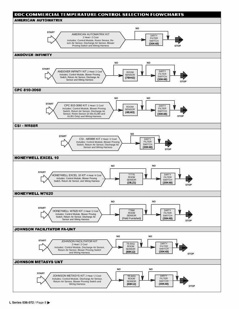
DDC COMMERCIAL TEMPERATURE CONTROL SELECTION FLOWCHARTS
$0(5,&$1 $8720$75,;
AMERICAN AUTOMATRIX KIT2 Heat / 2 Cool
Includes: Control Module, Room Sensor, Re-turn Air Sensor, Discharge Air Sensor, Blower
Proving Switch and Wiring Harness
START
STOP
DIRTYFILTER
SWITCH(30K48)
NO
$1'29(5 ,1),1,7<
STOP
ROOMSENSOR(78H42)
NO
DIRTYFILTER
SWITCH(30K48)
NO
ANDOVER INFINITY KIT 2 Heat / 2 CoolIncludes: Control Module, Blower ProvingSwitch, Return Air Sensor, Discharge Air
Sensor and Wiring Harness
START
&3& ��������
STOP
ROOMSENSOR(48J43)
NO
DIRTYFILTER
SWITCH(30K48)
NO
CPC 810-3060 KIT 2 Heat / 2 CoolIncludes: Control Module, Blower ProvingSwitch, Return Air Sensor, Discharge AirSensor, Room Sensor (in kits 61J80 and
61J81 Only) and Wiring Harness
START
&6, � 05��5
STOP
DIRTYFILTER
SWITCH(30K48)
NO
CSI - MR88R KIT 2 Heat / 2 CoolIncludes: Control Module, Blower ProvingSwitch, Return Air Sensor, Discharge Air
Sensor and Wiring Harness
START
+21(<:(// (;&(/ ��
HONEYWELL EXCEL 10 KIT 4 Heat / 4 CoolIncludes: Control Module, Blower Proving
Switch, Return Air Sensor, and Wiring Harness
STOP
T7770ROOM
SENSOR(19L21)
NO
DIRTYFILTER
SWITCH(30K48)
NO
START
+21(<:(// :����
STOP
T7660ROOM
SENSOR(Field Furnished)
NO
DIRTYFILTER
SWITCH(30K48)
NO
HONEYWELL W7620 KIT 2 Heat / 2 CoolIncludes: Control Module, Blower ProvingSwitch, Return Air Sensor, Discharge Air
Sensor and Wiring Harness
START
-2+1621 )$&,/,7$725 )$�817
NO
START
STOP
TE-6411ROOM
SENSOR(60K12)
DIRTYFILTER
SWITCH(30K48)
NO
JOHNSON FACILITATOR KIT2 Heat / 2 Cool
Includes: Control Module, Discharge Air Sensor,Return Air Sensor, Blower Proving Switch
and Wiring Harness
-2+1621 0(7$6<6 817
NO
JOHNSON METASYS KIT 2 Heat / 2 CoolIncludes: Control Module, Discharge Air Sensor,Return Air Sensor, Blower Proving Switch and
Wiring Harness
START
NO
STOP
TE-6411ROOM
SENSOR(60K12)
DIRTYFILTER
SWITCH(30K48)
L Series 036-072 / Page 8�
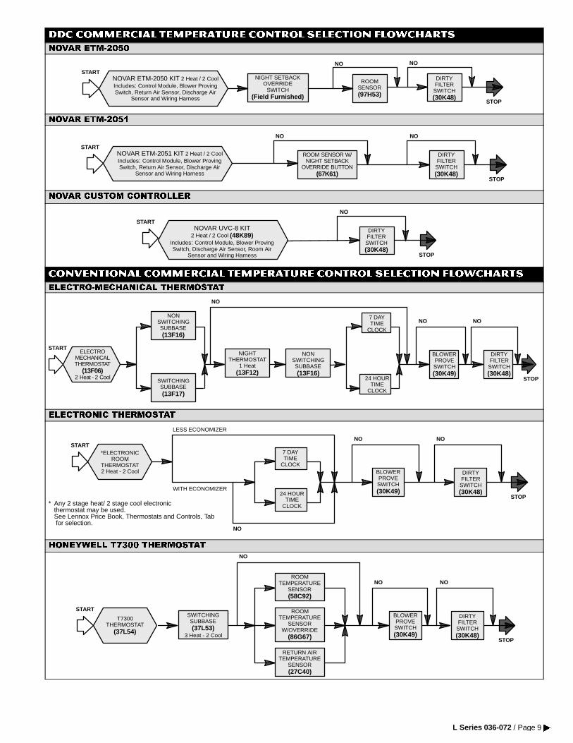
DDC COMMERCIAL TEMPERATURE CONTROL SELECTION FLOWCHARTS
129$5 (70�����
STOP
START
ROOMSENSOR(97H53)
NO
DIRTYFILTER
SWITCH(30K48)
NO
NIGHT SETBACKOVERRIDE
SWITCH(Field Furnished)
NOVAR ETM-2050 KIT 2 Heat / 2 CoolIncludes: Control Module, Blower ProvingSwitch, Return Air Sensor, Discharge Air
Sensor and Wiring Harness
129$5 (70�����
STARTNOVAR ETM-2051 KIT 2 Heat / 2 CoolIncludes: Control Module, Blower ProvingSwitch, Return Air Sensor, Discharge Air
Sensor and Wiring Harness
NO
STOP
ROOM SENSOR W/NIGHT SETBACK
OVERRIDE BUTTON(67K61)
DIRTYFILTER
SWITCH(30K48)
NO
129$5 &86720 &21752//(5
START
STOP
DIRTYFILTER
SWITCH(30K48)
NO
NOVAR UVC-8 KIT2 Heat / 2 Cool (48K89)
Includes: Control Module, Blower ProvingSwitch, Discharge Air Sensor, Room Air
Sensor and Wiring Harness
CONVENTIONAL COMMERCIAL TEMPERATURE CONTROL SELECTION FLOWCHARTS
(/(&752�0(&+$1,&$/ 7+(50267$7
24 HOURTIME
CLOCK
NO
STOP
ELECTROMECHANICALTHERMOSTAT
(13F06)2 Heat - 2 Cool
START
NONSWITCHINGSUBBASE(13F16)
SWITCHINGSUBBASE(13F17)
NIGHTTHERMOSTAT
1 Heat(13F12)
NONSWITCHINGSUBBASE(13F16)
7 DAYTIME
CLOCK
NO NO
BLOWERPROVESWITCH(30K49)
DIRTYFILTER
SWITCH(30K48)
(/(&7521,& 7+(50267$7
STOP
*ELECTRONICROOM
THERMOSTAT2 Heat - 2 Cool
START
24 HOURTIME
CLOCK
7 DAYTIME
CLOCK
NO NO
BLOWERPROVESWITCH(30K49)
DIRTYFILTER
SWITCH(30K48)
LESS ECONOMIZER
WITH ECONOMIZER
NO
* Any 2 stage heat/ 2 stage cool electronicthermostat may be used.See Lennox Price Book, Thermostats and Controls, Tabfor selection.
+21(<:(// 7���� 7+(50267$7
ROOMTEMPERATURE
SENSORW/OVERRIDE
(86G67)
NO
STOP
T7300THERMOSTAT
(37L54)
STARTSWITCHINGSUBBASE(37L53)
3 Heat - 2 Cool
NO NO
BLOWERPROVESWITCH(30K49)
DIRTYFILTER
SWITCH(30K48)
ROOMTEMPERATURE
SENSOR(58C92)
RETURN AIRTEMPERATURE
SENSOR(27C40)
L Series 036-072 / Page 9 �
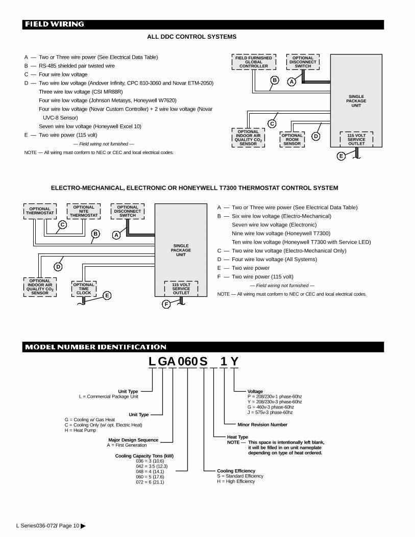
FIELDWIRING
ELECTRO-MECHANICAL, ELECTRONIC OR HONEYWELL T7300 THERMOSTAT CONTROL SYSTEM
OPTIONALTHERMOSTAT
OPTIONALNITE
THERMOSTAT
OPTIONALDISCONNECT
SWITCH
OPTIONALTIME
CLOCK
OPTIONALINDOOR AIR
QUALITY CO2SENSOR
115 VOLTSERVICEOUTLET
SINGLEPACKAGE
UNIT
A — Two or Three wire power (See Electrical Data Table)
B — Six wire low voltage (Electro-Mechanical)
Seven wire low voltage (Electronic)
Nine wire low voltage (Honeywell T7300)
Ten wire low voltage (Honeywell T7300 with Service LED)
C — Two wire low voltage (Electro-Mechanical Only)
D — Four wire low voltage (All Systems)
E — Two wire power
F — Two wire power (115 volt)
— Field wiring not furnished —
NOTE — All wiring must conform to NEC or CEC and local electrical codes.
AB
C
E
D
ALL DDC CONTROL SYSTEMS
FIELD FURNISHEDGLOBAL
CONTROLLER
OPTIONALDISCONNECT
SWITCH
OPTIONALROOM
SENSOR
115 VOLTSERVICEOUTLET
SINGLEPACKAGE
UNIT
AB
C
D
E
A — Two or Three wire power (See Electrical Data Table)
B — RS-485 shielded pair twisted wire
C — Four wire low voltage
D — Two wire low voltage (Andover Infinity, CPC 810-3060 and Novar ETM-2050)
Three wire low voltage (CSI MR88R)
Four wire low voltage (Johnson Metasys, Honeywell W7620)
Four wire low voltage (Novar Custom Controller) + 2 wire low voltage (Novar
UVC-8 Sensor)
Seven wire low voltage (Honeywell Excel 10)
E — Two wire power (115 volt)
— Field wiring not furnished —
NOTE — All wiring must conform to NEC or CEC and local electrical codes.
OPTIONALINDOOR AIR
QUALITY CO2SENSOR
F
MODEL NUMBER IDENTIFICATION
Minor Revision Number
L GA Y
Unit TypeL = Commercial Package Unit
Unit TypeG = Cooling w/ Gas HeatC = Cooling Only (w/ opt. Electric Heat)H = Heat Pump
Major Design SequenceA = First Generation
1060
Cooling Capacity Tons (kW)036 = 3 (10.6)042 = 3.5 (12.3)048 = 4 (14.1)060 = 5 (17.6)072 = 6 (21.1)
S
Cooling EfficiencyS = Standard EfficiencyH = High Efficiency
Heat TypeNOTE — This space is intentionally left blank,
it will be filled in on unit nameplatedepending on type of heat ordered.
VoltageP = 208/230v-1 phase-60hzY = 208/230v-3 phase-60hzG = 460v-3 phase-60hzJ = 575v-3 phase-60hz
L Series036-072/ Page 10�
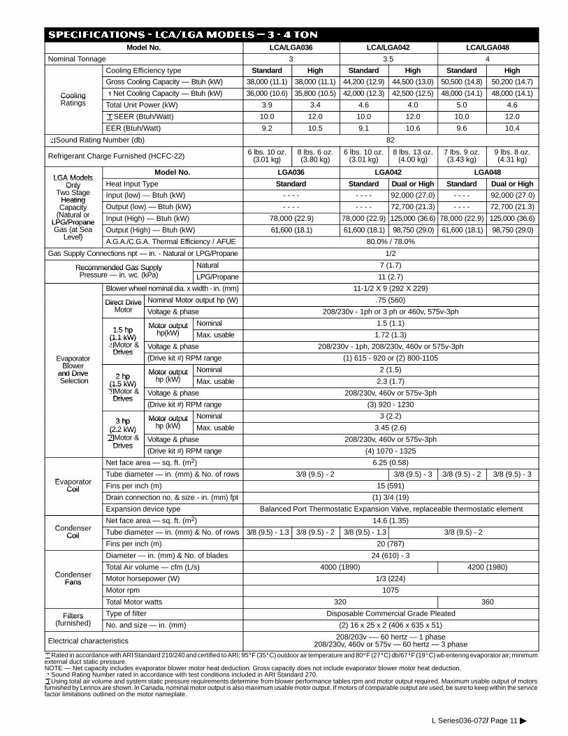
SPECIFICATIONS - LCA/LGAModels � 3 - 4 ton
Model No. LCA/LGA036 LCA/LGA042 LCA/LGA048
Nominal Tonnage 3 3.5 4
Cooling Efficiency type Standard High Standard High Standard High
Gross Cooling Capacity — Btuh (kW) 38,000 (11.1) 38,000 (11.1) 44,200 (12.9) 44,500 (13.0) 50,500 (14.8) 50,200 (14.7)
Cooling oNet Cooling Capacity — Btuh (kW) 36,000 (10.6) 35,800 (10.5) 42,000 (12.3) 42,500 (12.5) 48,000 (14.1) 48,000 (14.1)CoolingRatings Total Unit Power (kW) 3.9 3.4 4.6 4.0 5.0 4.6
oSEER (Btuh/Watt) 10.0 12.0 10.0 12.0 10.0 12.0
EER (Btuh/Watt) 9.2 10.5 9.1 10.6 9.6 10.4
wSound Rating Number (db) 82
Refrigerant Charge Furnished (HCFC-22) 6 lbs. 10 oz.(3.01 kg)
8 lbs. 6 oz.(3.80 kg)
6 lbs. 10 oz.(3.01 kg)
8 lbs. 13 oz.(4.00 kg)
7 lbs. 9 oz.(3.43 kg)
9 lbs. 8 oz.(4.31 kg)
LGA ModelsModel No. LGA036 LGA042 LGA048
LGA ModelsOnly
T SHeat Input Type Standard Standard Dual or High Standard Dual or HighOnly
Two StageHeating
Input (low) — Btuh (kW) - - - - - - - - 92,000 (27.0) - - - - 92,000 (27.0)HeatingCapacity
(N t lOutput (low) — Btuh (kW) - - - - - - - - 72,700 (21.3) - - - - 72,700 (21.3)Ca acity
(Natural orLPG/Propane Input (High) — Btuh (kW) 78,000 (22.9) 78,000 (22.9) 125,000 (36.6) 78,000 (22.9) 125,000 (36.6)LPG/Pro aneGas (at Sea
Level)Output (High) — Btuh (kW) 61,600 (18.1) 61,600 (18.1) 98,750 (29.0) 61,600 (18.1) 98,750 (29.0)(
Level)A.G.A./C.G.A. Thermal Efficiency / AFUE 80.0% / 78.0%
Gas Supply Connections npt — in. - Natural or LPG/Propane 1/2
Recommended Gas Supply Natural 7 (1.7)Recommended Gas Su lyPressure — in. wc. (kPa) LPG/Propane 11 (2.7)
Blower wheel nominal dia. x width - in. (mm) 11-1/2 X 9 (292 X 229)
Direct Drive Nominal Motor output hp (W) .75 (560)Direct DriveMotor Voltage & phase 208/230v - 1ph or 3 ph or 460v, 575v-3ph
1 5 hpMotor output Nominal 1.5 (1.1)
1.5 hp(1.1 kW)
Motor out uthp(kW) Max. usable 1.72 (1.3)(1.1 kW)
pMotor &Drives
Voltage & phase 208/230v - 1ph, 208/230v, 460v or 575v-3ph
EvaporatorBl
Drives(Drive kit #) RPM range (1) 615 - 920 or (2) 800-1105
Blowerand Drive 2 hp
Motor output Nominal 2 (1.5)and DriveSelection
2 hp(1.5 kW)
Motor out uthp (kW) Max. usable 2.3 (1.7)(1.5 kW)
pMotor &Drives
Voltage & phase 208/230v, 460v or 575v-3phDrives
(Drive kit #) RPM range (3) 920 - 1230
3 hp Motor output Nominal 3 (2.2)3 hp
(2.2 kW)
Motor out uthp (kW) Max. usable 3.45 (2.6)(2.2 kW)
pMotor &Drives
Voltage & phase 208/230v, 460v or 575v-3phDrives
(Drive kit #) RPM range (4) 1070 - 1325
Net face area — sq. ft. (m2) 6.25 (0.58)
EvaporatorTube diameter — in. (mm) & No. of rows 3/8 (9.5) - 2 3/8 (9.5) - 3 3/8 (9.5) - 2 3/8 (9.5) - 3
EvaporatorCoil Fins per inch (m) 15 (591)Coil
Drain connection no. & size - in. (mm) fpt (1) 3/4 (19)
Expansion device type Balanced Port Thermostatic Expansion Valve, replaceable thermostatic element
CondenserNet face area — sq. ft. (m2) 14.6 (1.35)
CondenserCoil Tube diameter — in. (mm) & No. of rows 3/8 (9.5) - 1.3 3/8 (9.5) - 2 3/8 (9.5) - 1.3 3/8 (9.5) - 2Coil
Fins per inch (m) 20 (787)
Diameter — in. (mm) & No. of blades 24 (610) - 3
CondenserTotal Air volume — cfm (L/s) 4000 (1890) 4200 (1980)
CondenserFans Motor horsepower (W) 1/3 (224)Fans
Motor rpm 1075
Total Motor watts 320 360
Filters Type of filter Disposable Commercial Grade PleatedFilters(furnished) No. and size — in. (mm) (2) 16 x 25 x 2 (406 x 635 x 51)
Electrical characteristics 208/203v -— 60 hertz — 1 phase208/230v, 460v or 575v — 60 hertz — 3 phase
oRated in accordance with ARI Standard 210/240 and certified to ARI; 95EF (35EC) outdoor air temperature and 80EF (27EC) db/67EF (19EC) wb entering evaporator air; minimumexternal duct static pressure.NOTE — Net capacity includes evaporator blower motor heat deduction. Gross capacity does not include evaporator blower motor heat deduction.wSound Rating Number rated in accordance with test conditions included in ARI Standard 270.pUsing total air volume and system static pressure requirements determine from blower performance tables rpm and motor output required. Maximum usable output of motorsfurnished by Lennox are shown. In Canada, nominal motor output is also maximum usable motor output. If motors of comparable output are used, be sure to keep within the servicefactor limitations outlined on the motor nameplate.
L Series036-072/ Page 11�
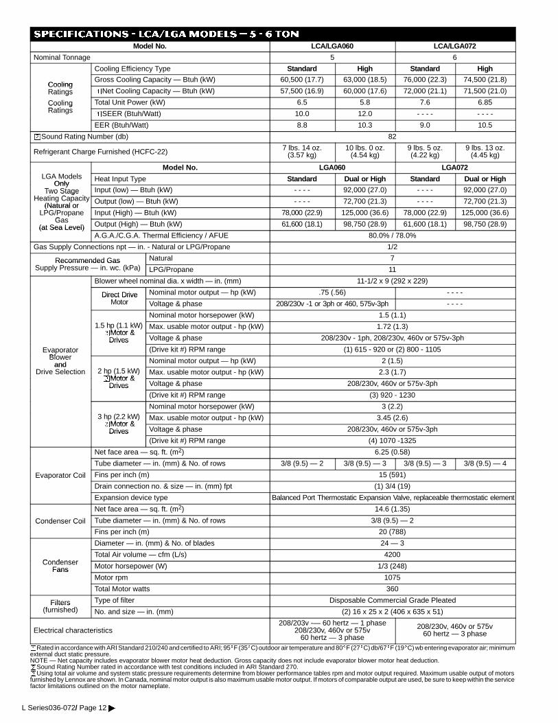
SPECIFICATIONS - LCA/LGAModels � 5 - 6 tonModel No. LCA/LGA060 LCA/LGA072
Nominal Tonnage 5 6
Cooling Efficiency Type Standard High Standard High
CoolingGross Cooling Capacity — Btuh (kW) 60,500 (17.7) 63,000 (18.5) 76,000 (22.3) 74,500 (21.8)
CoolingRatings oNet Cooling Capacity — Btuh (kW) 57,500 (16.9) 60,000 (17.6) 72,000 (21.1) 71,500 (21.0)Ratings
CoolingR ti
Total Unit Power (kW) 6.5 5.8 7.6 6.85Coo gRatings oSEER (Btuh/Watt) 10.0 12.0 - - - - - - - -
EER (Btuh/Watt) 8.8 10.3 9.0 10.5
wSound Rating Number (db) 82
Refrigerant Charge Furnished (HCFC-22) 7 lbs. 14 oz.(3.57 kg)
10 lbs. 0 oz.(4.54 kg)
9 lbs. 5 oz.(4.22 kg)
9 lbs. 13 oz.(4.45 kg)
Model No. LGA060 LGA072LGA Models
OnlyHeat Input Type Standard Dual or High Standard Dual or High
OnlyTwo Stage
H ti C itInput (low) — Btuh (kW) - - - - 92,000 (27.0) - - - - 92,000 (27.0)Two Stage
Heating Capacity(Natural or
Output (low) — Btuh (kW) - - - - 72,700 (21.3) - - - - 72,700 (21.3)(Natural or
LPG/PropaneGas
Input (High) — Btuh (kW) 78,000 (22.9) 125,000 (36.6) 78,000 (22.9) 125,000 (36.6)Gas
(at Sea Level) Output (High) — Btuh (kW) 61,600 (18.1) 98,750 (28.9) 61,600 (18.1) 98,750 (28.9)(at Sea Level)A.G.A./C.G.A. Thermal Efficiency / AFUE 80.0% / 78.0%
Gas Supply Connections npt — in. - Natural or LPG/Propane 1/2
Recommended Gas Natural 7Recommended GasSupply Pressure — in. wc. (kPa) LPG/Propane 11
Blower wheel nominal dia. x width — in. (mm) 11-1/2 x 9 (292 x 229)
Direct Drive Nominal motor output — hp (kW) .75 (.56) - - - -Direct DriveMotor Voltage & phase 208/230v -1 or 3ph or 460, 575v-3ph - - - -
Nominal motor horsepower (kW) 1.5 (1.1)1.5 hp (1.1 kW)pMotor &
Max. usable motor output - hp (kW) 1.72 (1.3)pMotor &
Drives Voltage & phase 208/230v - 1ph, 208/230v, 460v or 575v-3ph
EvaporatorBl
Drives(Drive kit #) RPM range (1) 615 - 920 or (2) 800 - 1105a o ato
Blowerand Nominal motor output — hp (kW) 2 (1.5)and
Drive Selection 2 hp (1.5 kW)pMotor &
Max. usable motor output - hp (kW) 2.3 (1.7)pMotor &
Drives Voltage & phase 208/230v, 460v or 575v-3phDrives(Drive kit #) RPM range (3) 920 - 1230
Nominal motor horsepower (kW) 3 (2.2)3 hp (2.2 kW)pMotor &
Max. usable motor output - hp (kW) 3.45 (2.6)pMotor &
Drives Voltage & phase 208/230v, 460v or 575v-3phDrives(Drive kit #) RPM range (4) 1070 -1325
Net face area — sq. ft. (m2) 6.25 (0.58)
Tube diameter — in. (mm) & No. of rows 3/8 (9.5) — 2 3/8 (9.5) — 3 3/8 (9.5) — 3 3/8 (9.5) — 4
Evaporator Coil Fins per inch (m) 15 (591)
Drain connection no. & size — in. (mm) fpt (1) 3/4 (19)
Expansion device type Balanced Port Thermostatic Expansion Valve, replaceable thermostatic element
Net face area — sq. ft. (m2) 14.6 (1.35)
Condenser Coil Tube diameter — in. (mm) & No. of rows 3/8 (9.5) — 2Co de se Co
Fins per inch (m) 20 (788)
Diameter — in. (mm) & No. of blades 24 — 3
CondenserTotal Air volume — cfm (L/s) 4200
CondenserFans Motor horsepower (W) 1/3 (248)Fans
Motor rpm 1075
Total Motor watts 360
Filters Type of filter Disposable Commercial Grade PleatedFilters(furnished) No. and size — in. (mm) (2) 16 x 25 x 2 (406 x 635 x 51)
Electrical characteristics208/203v -— 60 hertz — 1 phase
208/230v, 460v or 575v60 hertz — 3 phase
208/230v, 460v or 575v60 hertz — 3 phase
oRated in accordance with ARI Standard 210/240 and certified to ARI; 95EF (35EC) outdoor air temperature and 80EF (27EC)db/67EF (19EC) wb entering evaporator air; minimumexternal duct static pressure.NOTE — Net capacity includes evaporator blower motor heat deduction. Gross capacity does not include evaporator blower motor heat deduction.wSound Rating Number rated in accordance with test conditions included in ARI Standard 270.pUsing total air volume and system static pressure requirements determine from blower performance tables rpm and motor output required. Maximum usable output of motorsfurnished by Lennox are shown. In Canada, nominal motor output is also maximum usable motor output. If motors of comparable output are used, be sure to keep within the servicefactor limitations outlined on the motor nameplate.
L Series036-072/ Page 12�
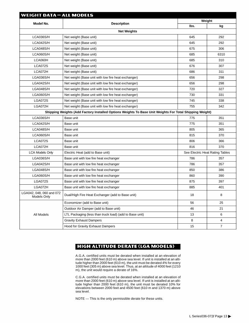
WEIGHT DATA � ALLMODELS
Model No DescriptionWeight
Model No. Descriptionlbs. kg
Net Weights
LCA036S/H Net weight (Base unit) 645 292
LCA042S/H Net weight (Base unit) 645 292
LCA048S/H Net weight (Base unit) 675 306
LCA060S/H Net weight (Base unit) 685 6310
LCA060H Net weight (Base unit) 685 310
LCA072S Net weight (Base unit) 676 307
LCA072H Net weight (Base unit) 686 311
LGA036S/H Net weight (Base unit with low fire heat exchanger) 656 298
LGA042S/H Net weight (Base unit with low fire heat exchanger) 656 298
LGA048S/H Net weight (Base unit with low fire heat exchanger) 720 327
LGA060S/H Net weight (Base unit with low fire heat exchanger) 730 331
LGA072S Net weight (Base unit with low fire heat exchanger) 745 338
LGA072H Net weight (Base unit with low fire heat exchanger) 755 342
Shipping Weights (Add Factory Installed Options Weights To Base Unit Weights For Total Shipping Weight)
LCA036S/H Base unit 775 351
LCA042S/H Base unit 775 351
LCA048S/H Base unit 805 365
LCA060S/H Base unit 815 370
LCA072S Base unit 806 366
LCA072H Base unit 816 370
LCA Models Only Electric Heat (add to Base unit) See Electric Heat Rating Tables
LGA036S/H Base unit with low fire heat exchanger 786 357
LGA042S/H Base unit with low fire heat exchanger 786 357
LGA048S/H Base unit with low fire heat exchanger 850 386
LGA060S/H Base unit with low fire heat exchanger 860 390
LGA072S Base unit with low fire heat exchanger 875 397
LGA072H Base unit with low fire heat exchanger 885 401
LGA042, 048, 060 and 072Models Only Dual/High Fire Heat Exchanger (add to Base unit) 18 8
Economizer (add to Base unit) 56 25
Outdoor Air Damper (add to Base unit) 46 21
All Models LTL Packaging (less than truck load) (add to Base unit) 13 6
Gravity Exhaust Dampers 8 4
Hood for Gravity Exhaust Dampers 15 7
HIGH ALTITUDE DERATE (LGAMODELS)
A.G.A. certified units must be derated when installed at an elevation ofmore than 2000 feet (610 m) above sea level. If unit is installed at an alti-tude higher than 2000 feet (610 m), the unit must be derated 4% for every1000 feet (305 m) above sea level. Thus, at an altitude of 4000 feet (1210m), the unit would require a derate of 16%.
C.G.A. certified units must be derated when installed at an elevation ofmore than 2000 feet (610 m) above sea level. If unit is installed at an alti-tude higher than 2000 feet (610 m), the unit must be derated 10% forelevations between 2000 feet and 4500 feet (610 m and 1370 m) abovesea level.
NOTE — This is the only permissible derate for these units.
L Series036-072/ Page 13�
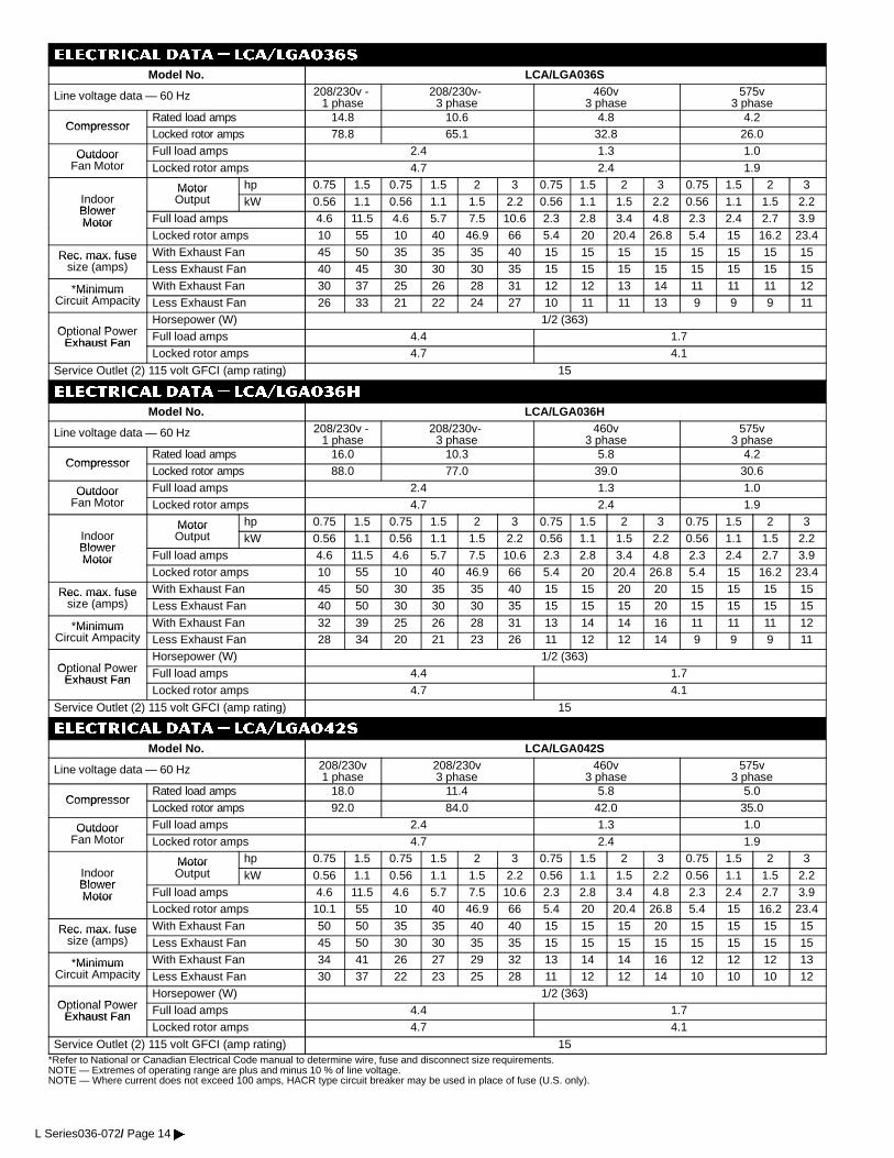
ELECTRICAL DATA � lca/lga036S
Model No. LCA/LGA036S
Line voltage data — 60 Hz 208/230v -1 phase
208/230v-3 phase
460v3 phase
575v3 phase
CompressorRated load amps 14.8 10.6 4.8 4.2
CompressorLocked rotor amps 78.8 65.1 32.8 26.0
Outdoor Full load amps 2.4 1.3 1.0OutdoorFan Motor Locked rotor amps 4.7 2.4 1.9
Motor hp 0.75 1.5 0.75 1.5 2 3 0.75 1.5 2 3 0.75 1.5 2 3IndoorBlower
MotorOutput kW 0.56 1.1 0.56 1.1 1.5 2.2 0.56 1.1 1.5 2.2 0.56 1.1 1.5 2.2
BlowerMotor Full load amps 4.6 11.5 4.6 5.7 7.5 10.6 2.3 2.8 3.4 4.8 2.3 2.4 2.7 3.9Motor
Locked rotor amps 10 55 10 40 46.9 66 5.4 20 20.4 26.8 5.4 15 16.2 23.4
Rec. max. fuse With Exhaust Fan 45 50 35 35 35 40 15 15 15 15 15 15 15 15Rec. max. fusesize (amps) Less Exhaust Fan 40 45 30 30 30 35 15 15 15 15 15 15 15 15
*Minimum With Exhaust Fan 30 37 25 26 28 31 12 12 13 14 11 11 11 12MinimumCircuit Ampacity Less Exhaust Fan 26 33 21 22 24 27 10 11 11 13 9 9 9 11
Optional PowerHorsepower (W) 1/2 (363)
Optional PowerExhaust Fan Full load amps 4.4 1.7Exhaust Fan
Locked rotor amps 4.7 4.1
Service Outlet (2) 115 volt GFCI (amp rating) 15
ELECTRICAL DATA � lca/lga036H
Model No. LCA/LGA036H
Line voltage data — 60 Hz 208/230v -1 phase
208/230v-3 phase
460v3 phase
575v3 phase
CompressorRated load amps 16.0 10.3 5.8 4.2
CompressorLocked rotor amps 88.0 77.0 39.0 30.6
Outdoor Full load amps 2.4 1.3 1.0OutdoorFan Motor Locked rotor amps 4.7 2.4 1.9
Motor hp 0.75 1.5 0.75 1.5 2 3 0.75 1.5 2 3 0.75 1.5 2 3IndoorBlower
MotorOutput kW 0.56 1.1 0.56 1.1 1.5 2.2 0.56 1.1 1.5 2.2 0.56 1.1 1.5 2.2
BlowerMotor Full load amps 4.6 11.5 4.6 5.7 7.5 10.6 2.3 2.8 3.4 4.8 2.3 2.4 2.7 3.9Motor
Locked rotor amps 10 55 10 40 46.9 66 5.4 20 20.4 26.8 5.4 15 16.2 23.4
Rec. max. fuse With Exhaust Fan 45 50 30 35 35 40 15 15 20 20 15 15 15 15Rec. max. fusesize (amps) Less Exhaust Fan 40 50 30 30 30 35 15 15 15 20 15 15 15 15
*Minimum With Exhaust Fan 32 39 25 26 28 31 13 14 14 16 11 11 11 12MinimumCircuit Ampacity Less Exhaust Fan 28 34 20 21 23 26 11 12 12 14 9 9 9 11
Optional PowerHorsepower (W) 1/2 (363)
Optional PowerExhaust Fan Full load amps 4.4 1.7Exhaust Fan
Locked rotor amps 4.7 4.1
Service Outlet (2) 115 volt GFCI (amp rating) 15
ELECTRICAL DATA � lca/lga042S
Model No. LCA/LGA042S
Line voltage data — 60 Hz 208/230v1 phase
208/230v3 phase
460v3 phase
575v3 phase
CompressorRated load amps 18.0 11.4 5.8 5.0
CompressorLocked rotor amps 92.0 84.0 42.0 35.0
Outdoor Full load amps 2.4 1.3 1.0OutdoorFan Motor Locked rotor amps 4.7 2.4 1.9
Motor hp 0.75 1.5 0.75 1.5 2 3 0.75 1.5 2 3 0.75 1.5 2 3IndoorBlower
MotorOutput kW 0.56 1.1 0.56 1.1 1.5 2.2 0.56 1.1 1.5 2.2 0.56 1.1 1.5 2.2
BlowerMotor Full load amps 4.6 11.5 4.6 5.7 7.5 10.6 2.3 2.8 3.4 4.8 2.3 2.4 2.7 3.9Motor
Locked rotor amps 10.1 55 10 40 46.9 66 5.4 20 20.4 26.8 5.4 15 16.2 23.4
Rec. max. fuse With Exhaust Fan 50 50 35 35 40 40 15 15 15 20 15 15 15 15Rec. max. fusesize (amps) Less Exhaust Fan 45 50 30 30 35 35 15 15 15 15 15 15 15 15
*Minimum With Exhaust Fan 34 41 26 27 29 32 13 14 14 16 12 12 12 13MinimumCircuit Ampacity Less Exhaust Fan 30 37 22 23 25 28 11 12 12 14 10 10 10 12
Optional PowerHorsepower (W) 1/2 (363)
Optional PowerExhaust Fan Full load amps 4.4 1.7Exhaust Fan
Locked rotor amps 4.7 4.1
Service Outlet (2) 115 volt GFCI (amp rating) 15*Refer to National or Canadian Electrical Code manual to determine wire, fuse and disconnect size requirements.NOTE — Extremes of operating range are plus and minus 10 % of line voltage.NOTE — Where current does not exceed 100 amps, HACR type circuit breaker may be used in place of fuse (U.S. only).
L Series036-072/ Page 14�
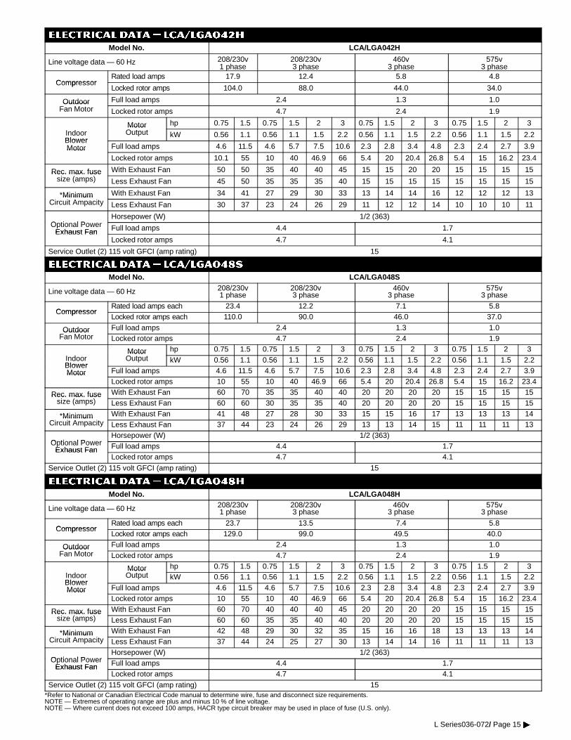
ELECTRICAL DATA � lca/lga042H
Model No. LCA/LGA042H
Line voltage data — 60 Hz 208/230v1 phase
208/230v3 phase
460v3 phase
575v3 phase
CompressorRated load amps 17.9 12.4 5.8 4.8
CompressorLocked rotor amps 104.0 88.0 44.0 34.0
Outdoor Full load amps 2.4 1.3 1.0OutdoorFan Motor Locked rotor amps 4.7 2.4 1.9
Motor hp 0.75 1.5 0.75 1.5 2 3 0.75 1.5 2 3 0.75 1.5 2 3IndoorBlower
MotorOutput kW 0.56 1.1 0.56 1.1 1.5 2.2 0.56 1.1 1.5 2.2 0.56 1.1 1.5 2.2
BlowerMotor Full load amps 4.6 11.5 4.6 5.7 7.5 10.6 2.3 2.8 3.4 4.8 2.3 2.4 2.7 3.9Motor
Locked rotor amps 10.1 55 10 40 46.9 66 5.4 20 20.4 26.8 5.4 15 16.2 23.4
Rec. max. fuse With Exhaust Fan 50 50 35 40 40 45 15 15 20 20 15 15 15 15Rec. max. fusesize (amps) Less Exhaust Fan 45 50 35 35 35 40 15 15 15 15 15 15 15 15
*Minimum With Exhaust Fan 34 41 27 29 30 33 13 14 14 16 12 12 12 13MinimumCircuit Ampacity Less Exhaust Fan 30 37 23 24 26 29 11 12 12 14 10 10 10 11
O ti l PHorsepower (W) 1/2 (363)
Optional PowerExhaust Fan Full load amps 4.4 1.7Exhaust Fan
Locked rotor amps 4.7 4.1
Service Outlet (2) 115 volt GFCI (amp rating) 15
ELECTRICAL DATA � lca/lga048SModel No. LCA/LGA048S
Line voltage data — 60 Hz 208/230v1 phase
208/230v3 phase
460v3 phase
575v3 phase
CompressorRated load amps each 23.4 12.2 7.1 5.8
CompressorLocked rotor amps each 110.0 90.0 46.0 37.0
Outdoor Full load amps 2.4 1.3 1.0OutdoorFan Motor Locked rotor amps 4.7 2.4 1.9
MotorO
hp 0.75 1.5 0.75 1.5 2 3 0.75 1.5 2 3 0.75 1.5 2 3IndoorBlower
MotorOutput kW 0.56 1.1 0.56 1.1 1.5 2.2 0.56 1.1 1.5 2.2 0.56 1.1 1.5 2.2
BlowerMotor Full load amps 4.6 11.5 4.6 5.7 7.5 10.6 2.3 2.8 3.4 4.8 2.3 2.4 2.7 3.9Motor
Locked rotor amps 10 55 10 40 46.9 66 5.4 20 20.4 26.8 5.4 15 16.2 23.4
Rec. max. fuse With Exhaust Fan 60 70 35 35 40 40 20 20 20 20 15 15 15 15Rec. max. fusesize (amps) Less Exhaust Fan 60 60 30 35 35 40 20 20 20 20 15 15 15 15
*Minimum With Exhaust Fan 41 48 27 28 30 33 15 15 16 17 13 13 13 14MinimumCircuit Ampacity Less Exhaust Fan 37 44 23 24 26 29 13 13 14 15 11 11 11 13
Optional PowerHorsepower (W) 1/2 (363)
Optional PowerExhaust Fan Full load amps 4.4 1.7Exhaust Fan
Locked rotor amps 4.7 4.1
Service Outlet (2) 115 volt GFCI (amp rating) 15
ELECTRICAL DATA � lca/lga048H
Model No. LCA/LGA048H
Line voltage data — 60 Hz 208/230v1 phase
208/230v3 phase
460v3 phase
575v3 phase
CompressorRated load amps each 23.7 13.5 7.4 5.8
CompressorLocked rotor amps each 129.0 99.0 49.5 40.0
Outdoor Full load amps 2.4 1.3 1.0OutdoorFan Motor Locked rotor amps 4.7 2.4 1.9
Motor hp 0.75 1.5 0.75 1.5 2 3 0.75 1.5 2 3 0.75 1.5 2 3IndoorBlower
MotorOutput kW 0.56 1.1 0.56 1.1 1.5 2.2 0.56 1.1 1.5 2.2 0.56 1.1 1.5 2.2
BlowerMotor Full load amps 4.6 11.5 4.6 5.7 7.5 10.6 2.3 2.8 3.4 4.8 2.3 2.4 2.7 3.9Motor
Locked rotor amps 10 55 10 40 46.9 66 5.4 20 20.4 26.8 5.4 15 16.2 23.4
Rec. max. fuse( )
With Exhaust Fan 60 70 40 40 40 45 20 20 20 20 15 15 15 15Rec. max. fusesize (amps) Less Exhaust Fan 60 60 35 35 40 40 20 20 20 20 15 15 15 15
*Minimum With Exhaust Fan 42 48 29 30 32 35 15 16 16 18 13 13 13 14MinimumCircuit Ampacity Less Exhaust Fan 37 44 24 25 27 30 13 14 14 16 11 11 11 13
Optional PowerHorsepower (W) 1/2 (363)
Optional PowerExhaust Fan Full load amps 4.4 1.7Exhaust Fan
Locked rotor amps 4.7 4.1
Service Outlet (2) 115 volt GFCI (amp rating) 15*Refer to National or Canadian Electrical Code manual to determine wire, fuse and disconnect size requirements.NOTE — Extremes of operating range are plus and minus 10 % of line voltage.NOTE — Where current does not exceed 100 amps, HACR type circuit breaker may be used in place of fuse (U.S. only).
L Series036-072/ Page 15�

ELECTRICAL DATA � lca/lga060S
Model No. LCA/LGA060S
Line voltage data — 60 Hz 208/230v -1 phase
208/230v3 phase
460v3 phase
575v3 phase
CompressorRated load amps each 26.9 16.7 8.6 6.0
CompressorLocked rotor amps each 141.0 110.0 55.0 44.0
Outdoor Full load amps 2.4 1.3 1.0OutdoorFan Motor Locked rotor amps 4.7 2.4 1.9
Motor hp 0.75 1.5 0.75 1.5 2 3 0.75 1.5 2 3 0.75 1.5 2 3IndoorBlower
MotorOutput kW 0.56 1.1 0.56 1.1 1.5 2.2 0.56 1.1 1.5 2.2 0.56 1.1 1.5 2.2
BlowerMotor Full load amps 4.6 11.5 4.6 5.7 7.5 10.6 2.3 2.8 3.4 4.8 2.3 2.4 2.7 3.9Motor
Locked rotor amps 10 55 10 40 46.9 66 5.4 20 20.4 26.8 5.4 15 16.2 23.4
Rec. max. fuse( )
With Exhaust Fan 70 70 45 50 50 50 20 25 25 25 15 15 15 20Rec. max. fusesize (amps) Less Exhaust Fan 60 70 40 45 45 50 20 20 20 25 15 15 15 15
*Minimum With Exhaust Fan 46 52 33 34 36 39 17 17 18 19 13 13 13 15MinimumCircuit Ampacity Less Exhaust Fan 41 48 28 29 31 34 15 15 16 17 11 11 12 13
Optional PowerHorsepower (W) 1/2 (363)
Optional PowerExhaust Fan Full load amps 4.4 1.7Exhaust Fan
Locked rotor amps 4.7 4.1
Service Outlet (2) 115 volt GFCI (amp rating) 15
ELECTRICAL DATA � lca/lga060H
Model No. LCA/LGA060H
Line voltage data — 60 Hz 208/230v -1 phase
208/230v3 phase
460v3 phase
575v3 phase
CompressorRated load amps each 28.8 17.3 9.0 7.1
CompressorLocked rotor amps each 169.0 123.0 62.0 50.0
Outdoor Full load amps 2.4 1.3 1.0OutdoorFan Motor Locked rotor amps 4.7 2.4 1.9
Motor hp 0.75 1.5 0.75 1.5 2 3 0.75 1.5 2 3 0.75 1.5 2 3IndoorBlower
MotorOutput kW 0.56 1.1 0.56 1.1 1.5 2.2 0.56 1.1 1.5 2.2 0.56 1.1 1.5 2.2
BlowerMotor Full load amps 4.6 11.5 4.6 5.7 7.5 10.6 2.3 2.8 3.4 4.8 2.3 2.4 2.7 3.9Motor
Locked rotor amps 10 55 10 40 46.9 66 5.4 20 20.4 26.8 5.4 15 16.2 23.4
Rec. max. fuse With Exhaust Fan 70 70 50 50 50 50 25 25 25 25 20 20 20 20Rec. max. fusesize (amps) Less Exhaust Fan 70 70 45 45 45 50 20 20 20 25 15 15 15 20
*Minimum With Exhaust Fan 48 55 34 35 36 40 17 18 18 20 14 14 15 16MinimumCircuit Ampacity Less Exhaust Fan 44 50 29 30 32 35 15 16 16 18 13 13 13 14
O ti l PHorsepower (W) 1/2 (363)
Optional PowerExhaust Fan Full load amps 4.4 1.7Exhaust Fan
Locked rotor amps 4.7 4.1
Service Outlet (2) 115 volt GFCI (amp rating) 15
ELECTRICAL DATA � lca/lga072S
Model No. LCA/LGA072SLine voltage data — 60 Hz 208/230v - 3 phase 460v - 3 phase 575v - 3 phase
CompressorRated load amps each 20.7 9.0 7.4
CompressorLocked rotor amps each 156.0 70.0 54.0
Outdoor Full load amps 2.4 1.3 1.0OutdoorFan Motor Locked rotor amps 4.7 2.4 1.9
Motor hp 1.5 2 3 1.5 2 3 1.5 2 3IndoorBlower
MotorOutput kW 1.1 1.5 2.2 1.1 1.5 2.2 1.1 1.5 2.2
BlowerMotor Full load amps 5.7 7.5 10.6 2.8 3.4 4.8 2.4 2.7 3.9Motor
Locked rotor amps 40 46.9 66 20 20.4 26.8 15 16.2 23.4
Rec. max. fuse With Exhaust Fan 50 60 60 25 25 25 20 20 20Rec. max. fusesize (amps) Less Exhaust Fan 50 50 50 20 20 25 20 20 20
*Minimum With Exhaust Fan 39 41 44 18 18 20 15 15 16MinimumCircuit Ampacity Less Exhaust Fan 34 36 39 16 16 18 13 13 15
Optional Po erHorsepower (W) 1/2 (363)
Optional PowerExhaust Fan Full load amps 4.4 1.7Exhaust Fan
Locked rotor amps 4.7 4.1
Service Outlet (2) 115 volt GFCI (amp rating) 15*Refer to National or Canadian Electrical Code manual to determine wire, fuse and disconnect size requirements.NOTE — Extremes of operating range are plus and minus 10 % of line voltage.NOTE — Where current does not exceed 100 amps, HACR type circuit breaker may be used in place of fuse (U.S. only).
L Series036-072/ Page 16�
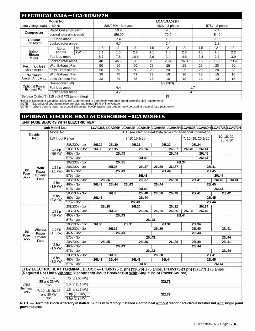
ELECTRICAL DATA � lca/lga072H
Model No. LCA/LGA072HLine voltage data — 60 Hz 208/230v - 3 phase 460v - 3 phase 575v - 3 phase
CompressorRated load amps each 19.9 9.0 7.4
CompressorLocked rotor amps each 156.00 70.0 54.0
Outdoor Full load amps 2.4 1.3 1.0OutdoorFan Motor Locked rotor amps 4.7 2.4 1.9
I dMotor hp 1.5 2 3 1.5 2 3 1.5 2 3
IndoorBlower
MotorOutput kW 1.1 1.5 2.2 1.1 1.5 2.2 1.1 1.5 2.2
BlowerMotor Full load amps 5.7 7.5 10.6 2.8 3.4 4.8 2.4 2.7 3.9Motor
Locked rotor amps 40 46.9 66 20 20.4 26.8 15 16.2 23.4
Rec. max. fuse With Exhaust Fan 50 50 60 25 25 25 20 20 20Rec. max. fusesize (amps) Less Exhaust Fan 50 50 50 20 20 25 20 20 20
*Minimum With Exhaust Fan 38 40 43 18 18 20 15 15 16MinimumCircuit Ampacity Less Exhaust Fan 33 35 38 16 16 18 13 13 15
Optional PowerHorsepower (W) 1/2 (363)
Optional PowerExhaust Fan
Full load amps 4.4 1.7Exhaust FanLocked rotor amps 4.7 4.1
Service Outlet (2) 115 volt GFCI (amp rating) 15*Refer to National or Canadian Electrical Code manual to determine wire, fuse and disconnect size requirements.NOTE — Extremes of operating range are plus and minus 10 % of line voltage.NOTE — Where current does not exceed 100 amps, HACR type circuit breaker may be used in place of fuse (U.S. only).
OPTIONAL ELECTRIC HEAT ACCESSORIES � LCAMODELS
UNIT FUSE BLOCKS WITH ELECTRIC HEATUnit Model No. LCA036S LCA036H LCA042S LCA042H LCA048S LCA048H LCA060S LCA060H LCA072S LCA072H
ElectricModel No. EHA (see Electric Heat Data tables for additional information)
ElectricHeat kW Input Range 7, 10 15 & 20 7, 10, 15, 20 & 25 10, 15, 20,
25, & 30208/230v - 1ph 26L29 26L30 26L31 26L32 26L34
.75 hp 208/230v - 3ph 26L36 26L35 26L36 26L37 26L40 26L41.75 h(.56 kW) 460v - 3ph 26L43 26L44 26L45 - - - -(.56 kW)
575v - 3ph 26L43 26L44208/230v - 1ph 26L31 26L34
UnitWith 1.5 hp 208/230v - 3ph 26L36 26L37 26L36 26L37 26L41
UnitFuse
WithPower
1.5 h(1.1 kW) 460v - 3ph 26L43 26L44 26L45
FuseBlock
PowerExhaust
F
(1.1 kW)575v - 3ph 26L43 26L44Block Fans
2 hp208/230v - 3ph 26L36 26L37 26L38 26L41 26L42 26L41
2 hp(1 5 kW)
460v - 3ph 26L43 26L44 26L43 26L44 26L45(1.5 kW)
575v - 3ph 26L43 26L44
3 hp208/230v - 3ph 26L38 26L40 26L38 26L40 26L41 26L42
3 hp(2 2 kW)
460v - 3ph 26L43 26L44 26L45(2.2 kW)
575v - 3ph 26L43 26L44208/230v - 1ph 26L28 26L30 26L32 26L34
.75 hp 208/230v - 3ph 26L35 26L36 26L35 26L36 26L38 26L40.75 h(.56 kW) 460v - 3ph 26L43 26L44 - - - -( 56 )
575v - 3ph 26L43208/230v - 1ph 26L30 26L31 26L32 26L34
UnitWithout 1.5 hp 208/230v - 3ph 26L35 26L36 26L40 26L41
UnitFuse
WithoutPower
1.5 h(1.1 kW) 460v - 3ph 26L43 26L44
FuseBlock
PowerExhaust
F
(1.1 kW)575v - 3ph 26L43 26L44Block Fans
2 hp208/230v - 3ph 26L35 26L36 26L38 26L40 26L41
2 hp(1 5 kW)
460v - 3ph 26L43 26L44(1.5 kW)
575v - 3ph 26L43 26L44
3 hp208/230v - 3ph 26L36 26L38 26L41
3 hp(2 2 kW)
460v - 3ph 26L43 26L44 26L43 26L44 26L45(2.2 kW)
575v - 3ph 26L43 26L44
LTB2 ELECTRIC HEAT TERMINAL BLOCK — LTB2-175 (1 ph) (32L76) 175 amps, LTB2-175-(3 ph) (32L77) 175 amps(Required For Units Without Disconnect/Circuit Breaker But With Single Point Power Source)
7, 10, 15,20 and 25 kW
.75 hp (.56 kW)32L76
LTB2Terminal
20 and 25 kW1ph 1.5 hp (1.1 kW)
32L76
TerminalBlock 7, 10, 15, 20, 25 1.5 hp (1.1 kW)Block 7, 10, 15, 20, 25
and 30 kW 2 hp (1.5 kW) 32L77and 30 kW3ph 3 hp (2.2 kW)
32L77
NOTE — Terminal Block is factory installed in units with factory installed electric heat without disconnect/circuit breaker but with single pointpower source.
L Series036-072/ Page 17�

OPTIONAL ELECTRIC HEAT DATA (REQUIRES UNIT FUSE BLOCK, TERMINAl BLOCK AND SUB-FUSE BOX)
LCA036(S)(H), LCA042(S)(H), LCA048(S)(H)
kW SizeElectric Heat
Model No Voltage*Heater Only
S b F se BoxNo.of Volts kW Btuh
aaTotal Unit (with Power Exhaust Fan) &Electric Heat Minimum Circuit AmpacitykW Size
Required Model No., Voltage& Net Weight
Sub-Fuse Box(Required) & Net Weight
oof
StepsVoltsInput
kWInput
BtuhOutput .75 hp
(.56 kW)1.5 hp
(1.1 kW)2 hp
(1.5 kW)3 hp
(2.2 kW)
1 PHASE
EHA060 7 EHAFB 71 208 5.3 18,100 42 51
7 kWEHA060-7
208/230v - 1 ph (23L62)EHAFB-7
208/230v - 1 ph (27L01)1 220 5.9 20,100
- - - - - - - -7 kW 208/230v - 1 ph (23L62)9 lbs. (4 kg)
208/230v - 1 ph (27L01)10 lbs. (5 kg) 1 230 6.4 21,900 47 56
- - - - - - - -9 lbs. (4 kg) 10 lbs. (5 kg)
1 240 7.0 23,90047 56
EHA060 10 EHAFB 10c2 208 7.5 25,600 56 64
10 kWEHA060-10
208/230v - 1 ph (23L63)EHAFB-10
208/230v - 1 ph (27L02)c2 220 8.4 28,700
- - - - - - - -10 kW 208/230v - 1 ph (23L63)9 lbs. (4 kg)
208/230v - 1 ph (27L02)10 lbs. (5 kg) c2 230 9.2 31,400 63 72
- - - - - - - -9 lbs. (4 kg) 10 lbs. (5 kg)
c2 240 10.0 34,20063 72
EHA060 15 EHAFB 15c2 208 11.3 38,600 78 87
15 kWEHA060-15
208/230v - 1 ph (23L64)EHAFB-15
208/230v - 1 ph (27L03)c2 220 12.6 43,000
- - - - - - - -15 kW 208/230v - 1 ph (23L64)9 lbs. (4 kg)
208/230v - 1 ph (27L03)10 lbs. (5 kg) c2 230 13.8 47,100 89 97
- - - - - - - -9 lbs. (4 kg) 10 lbs. (5 kg)
c2 240 15.0 51,20089 97
EHA060 20 EHAFB 20c2 208 15.0 51,200 101 110
20 kWEHA060-20
208/230v - 1 ph (23L65)EHAFB-20
208/230v - 1 ph (27L04)c2 220 16.8 57,400
- - - - - - - -20 kW 208/230v - 1 ph (23L65)12 lbs. (6 kg)
208/230v - 1 ph (27L04)10 lbs. (5 kg) c2 230 18.4 62,800 115 123
- - - - - - - -12 lbs. (6 kg) 10 lbs. (5 kg)
c2 240 20.0 68,300115 123
3 PHASE1 208 5.3 18,100 29 30 33 361 220 5.9 20,1001 230 6.4 21,900 32 33 35 39
EHA060-7208/230 3 ph (23L67)
EHAFB-7 1 240 7.0 23,90032 33 35 39
7 kW208/230v - 3 ph (23L67)
460v - 3 ph (23L73)
EHAFB-7208/230v - 3 ph (27L06) 1 440 5.9 20,100
7 kW 460v - 3 ph (23L73)575v - 3 ph (23L79)
208/230v 3 h (27L06)460/575v - 3 ph (27L12)
10 lb (5 k )1 460 6.4 21,900 16 16 17 19575v - 3 ph (23L79)
9 lbs. (4 kg)
( )10 lbs. (5 kg) 1 480 7.0 23,900
16 16 17 19
9 lbs. (4 kg)1 550 5.9 20,1001 575 6.4 21,900 13 14 14 151 600 7.0 23,900
13 14 14 15
1 208 7.5 25,600 37 38 40 441 220 8.4 28,7001 230 9.2 31,400 41 42 44 48
EHA072-10208/230 3 h (23L68)
EHAFB-10208/230 3 h (27L07)
1 240 10.0 34,20041 42 44 48
10 kW208/230v - 3 ph (23L68)
460v - 3 ph (23L74)208/230v - 3 ph (27L07)
460v - 3 ph (27L13)1 440 8.4 28,700
10 kW 460v - 3 ph (23L74)575v - 3 ph (23L80)
460v - 3 ph (27L13)575v - 3 ph (27L18) 1 460 9.2 31,400 20 21 21 23575v - 3 ph (23L80)
9 lbs. (4 kg)575v - 3 ph (27L18)
10 lbs. (5 kg) 1 480 10.0 34,20020 21 21 23
9 lbs. (4 kg) 10 lbs. (5 kg)1 550 8.4 28,7001 575 9.2 31,400 17 17 18 191 600 10.0 34,200
17 17 18 19
1 208 11.3 38,600 50 51 53 571 220 12.6 43,000
EHAFB-15 1 230 13.8 41,700 56 57 59 63EHA072-15
208/230 3 ph (23L69)
EHAFB 15208/230v - 3 ph (27L08)
EHAFB 15/201 240 15.0 51,200
56 57 59 63
15 kW208/230v - 3 ph (23L69)
460v - 3 ph (23L75)
( )EHAFB-15/20
460v 3 ph (27L14)1 440 12.6 43,000
15 kW 460v - 3 ph (23L75)575v - 3 ph (23L81)
460v - 3 ph (27L14)EHAFB-15 1 460 13.8 47,100 28 28 29 31575v - 3 ph (23L81)
9 lbs. (4 kg)EHAFB-15
575v - 3 ph (27L19) 1 480 15.0 51,20028 28 29 31
9 lbs. (4 kg) 575v - 3 h (27L19)10 lbs. (5 kg) 1 550 12.6 43,00010 lbs. (5 kg)
1 575 13.8 47,100 23 23 24 251 600 15.0 51,200
23 23 24 25
c2 208 15.0 51,200 63 64 66 70c2 220 16.8 57,400
EHAFB-20 c2 230 18.4 62,800 71 72 74 78EHA072-20
208/230 3 ph (23L70)
EHAFB 20208/230v - 3 ph (27L09)
EHAFB 20/25c2 240 20.0 68,300
71 72 74 78
20 kW208/230v - 3 ph (23L70)
460v - 3 ph (23L76)
( )EHAFB-20/25
460v - 3 ph (27L15)1 440 16.8 57,400
20 kW 460v - 3 ph (23L76)575v - 3 ph (23L82)
460v - 3 ph (27L15)EHAFB-15/20 1 460 18.4 62,800 35 36 37 38575v - 3 ph (23L82)
12 lbs. (6 kg)EHAFB-15/20
575v - 3 ph (27L14) 1 480 20.0 68,30035 36 37 38
12 lbs. (6 kg) 575v - 3 h (27L14)10 lbs. (5 kg) 1 550 16.8 57,40010 lbs. (5 kg)
1 575 18.4 62,800 29 29 30 311 600 20.0 68,300
29 29 30 31
aRefer to National or Canadian Electrical Code manual to determine wire, fuse and disconnect size requirements. Use wires suitable for at least 167qF (75qC).cMay be used with two stage control.*NOTE — Heater Sub-Fuse Box is required for fusing electric heat and must be ordered extra. Factory installed heaters will have fuse box installed. Also requires LTB2 Terminal Block.
L Series036-072/ Page 18�
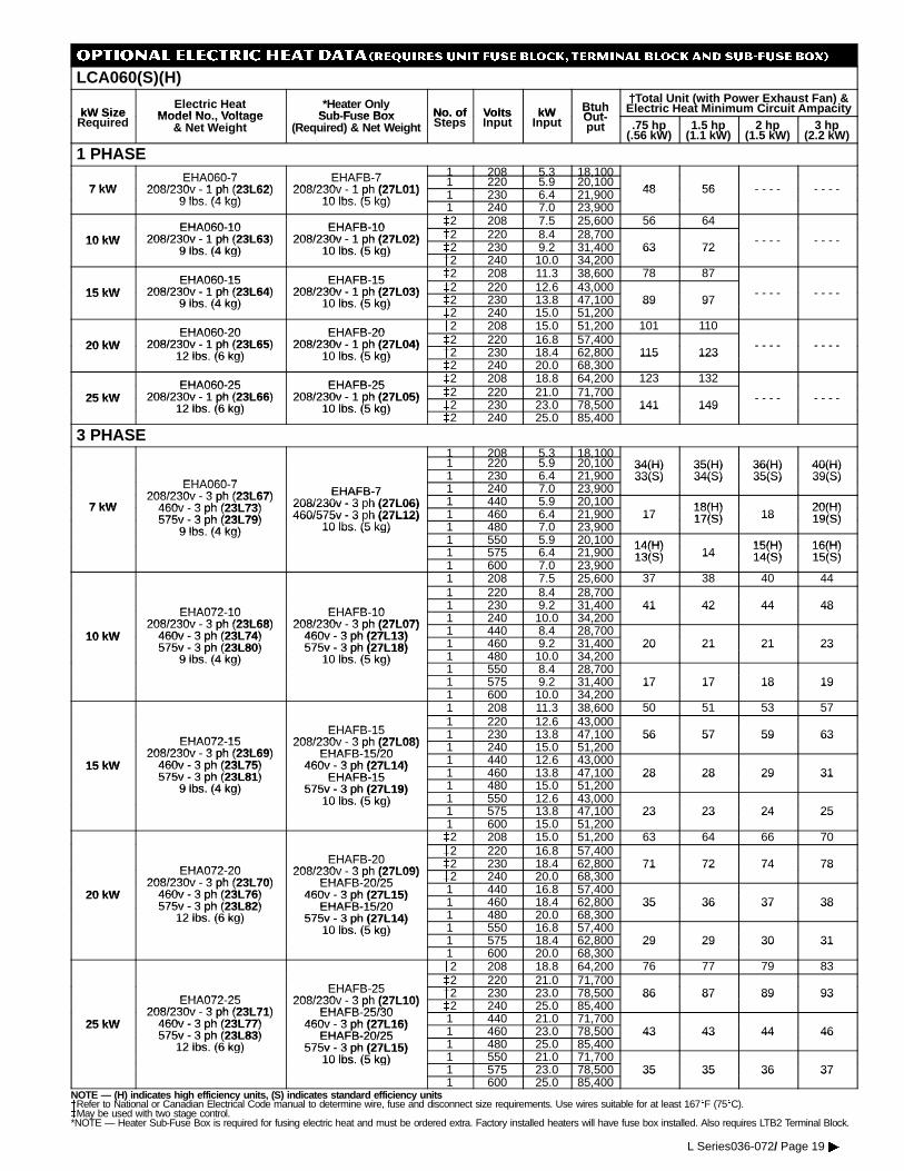
OPTIONAL ELECTRIC HEAT DATA (REQUIRES UNIT FUSE BLOCK, TERMINAl BLOCK AND SUB-FUSE BOX)
LCA060(S)(H)
kW SizeElectric Heat
Model No Voltage*Heater Only
S b-F se Box No. of Volts kW BtuhO t
aaTotal Unit (with Power Exhaust Fan) &Electric Heat Minimum Circuit AmpacitykW Size
Required Model No., Voltage& Net Weight
Sub-Fuse Box(Required) & Net Weight
No. ofSteps
VoltsInput
kWInput
BtuhOut-put .75 hp
(.56 kW)1.5 hp
(1.1 kW)2 hp
(1.5 kW)3 hp
(2.2 kW)
1 PHASEEHA060 7 EHAFB 7 1 208 5.3 18,100
7 kWEHA060-7
208/230v 1 ph (23L62)EHAFB-7
208/230v 1 ph (27L01)1 220 5.9 20,100
48 567 kW 208/230v - 1 ph (23L62)9 lbs (4 kg)
208/230v - 1 ph (27L01)10 lbs (5 kg) 1 230 6.4 21,900 48 56 - - - - - - - -
9 lbs. (4 kg)( )
10 lbs. (5 kg) 1 240 7.0 23,900
EHA060-10 EHAFB-10 c2 208 7.5 25,600 56 64
10 kWEHA060-10
208/230v - 1 ph (23L63)EHAFB-10
208/230v - 1 ph (27L02) c2 220 8.4 28,700 - - - - - - - -10 kW 208/230v - 1 ph (23L63)9 lbs (4 kg)
208/230v - 1 ph (27L02)10 lbs (5 kg) c2 230 9.2 31,400 63 72
- - - - - - - -9 lbs. (4 kg) 10 lbs. (5 kg)
c2 240 10.0 34,20063 72
EHA060-15 EHAFB-15 c2 208 11.3 38,600 78 87
15 kWEHA060-15
208/230v - 1 ph (23L64)EHAFB-15
208/230v - 1 ph (27L03) c2 220 12.6 43,000 - - - - - - - -15 kW 208/230v - 1 ph (23L64)9 lbs (4 kg)
208/230v - 1 ph (27L03)10 lbs (5 kg) c2 230 13.8 47,100 89 97
- - - - - - - -9 lbs. (4 kg) 10 lbs. (5 kg)
c2 240 15.0 51,20089 97
EHA060-20 EHAFB-20 c2 208 15.0 51,200 101 110
20 kWEHA060-20
208/230v - 1 ph (23L65)EHAFB-20
208/230v - 1 ph (27L04) c2 220 16.8 57,400 - - - - - - - -20 kW 208/230v - 1 ph (23L65)12 lbs (6 kg)
208/230v - 1 ph (27L04)10 lbs (5 kg) c2 230 18.4 62,800 115 123
- - - - - - - -12 lbs. (6 kg) 10 lbs. (5 kg)
c2 240 20.0 68,300115 123
EHA060-25 EHAFB-25 c2 208 18.8 64,200 123 132
25 kWEHA060-25
208/230v - 1 ph (23L66)EHAFB-25
208/230v - 1 ph (27L05) c2 220 21.0 71,700 - - - - - - - -25 kW 208/230v - 1 ph (23L66)12 lbs (6 kg)
208/230v - 1 ph (27L05)10 lbs (5 kg) c2 230 23.0 78,500 141 149
- - - - - - - -12 lbs. (6 kg) 10 lbs. (5 kg)
c2 240 25.0 85,400141 149
3 PHASE1 208 5.3 18,1001 220 5.9 20,100 34(H) 35(H) 36(H) 40(H)
EHA060 71 230 6.4 21,900
34(H)33(S)
35(H)34(S)
36(H)35(S)
40(H)39(S)
EHA060-7208/230v 3 ph (23L67) EHAFB-7 1 240 7.0 23,900
33(S) 34(S) 35(S) 39(S)
7 kW208/230v - 3 ph (23L67)
460v 3 ph (23L73)EHAFB-7
208/230v - 3 ph (27L06) 1 440 5.9 20,100 18(H) 20(H)7 kW 460v - 3 ph (23L73)575v - 3 ph (23L79)
208/230v - 3 h (27L06)460/575v - 3 ph (27L12) 1 460 6.4 21,900 17
18(H)17(S) 18
20(H)19(S)575v - 3 ph (23L79)
9 lbs (4 kg)460/575v - 3 h (27L12)
10 lbs. (5 kg) 1 480 7.0 23,90017 17(S) 18 19(S)
9 lbs. (4 kg) 10 lbs. (5 kg)1 550 5.9 20,100 14(H) 15(H) 16(H)1 575 6.4 21,900
14(H)13(S) 14
15(H)14(S)
16(H)15(S)
1 600 7.0 23,90013(S) 14 14(S) 15(S)
1 208 7.5 25,600 37 38 40 441 220 8.4 28,700
EHA072 10 EHAFB 101 230 9.2 31,400 41 42 44 48
EHA072-10208/230v - 3 ph (23L68)
EHAFB-10208/230v - 3 ph (27L07) 1 240 10.0 34,200
41 42 44 48
10 kW208/230v - 3 ph (23L68)
460v - 3 ph (23L74)208/230v - 3 ph (27L07)
460v - 3 ph (27L13) 1 440 8.4 28,70010 kW 460v - 3 ph (23L74)575v - 3 ph (23L80)
460v - 3 ph (27L13)575v - 3 ph (27L18) 1 460 9.2 31,400 20 21 21 23575v - 3 ph (23L80)
9 lbs. (4 kg)575v - 3 ph (27L18)
10 lbs. (5 kg) 1 480 10.0 34,20020 21 21 23
9 lbs. (4 kg) 10 lbs. (5 kg)1 550 8.4 28,7001 575 9.2 31,400 17 17 18 191 600 10.0 34,200
17 17 18 19
1 208 11.3 38,600 50 51 53 57
EHAFB 151 220 12.6 43,000
EHA072 15EHAFB-15
208/230v 3 ph (27L08)1 230 13.8 47,100 56 57 59 63
EHA072-15208/230v - 3 ph (23L69)
208/230v - 3 ph (27L08)EHAFB 15/20 1 240 15.0 51,200
56 57 59 63
15 kW208/230v - 3 ph (23L69)
460v - 3 ph (23L75)
( )EHAFB-15/20
460v - 3 ph (27L14) 1 440 12.6 43,00015 kW 460v - 3 ph (23L75)575v - 3 ph (23L81)
460v - 3 ph (27L14)EHAFB-15 1 460 13.8 47,100 28 28 29 31575v - 3 ph (23L81)
9 lbs. (4 kg)EHAFB-15
575v - 3 ph (27L19) 1 480 15.0 51,20028 28 29 31
9 lbs. (4 kg) 575v - 3 ph (27L19)10 lbs. (5 kg) 1 550 12.6 43,00010 lbs. (5 kg)
1 575 13.8 47,100 23 23 24 251 600 15.0 51,200
23 23 24 25
c2 208 15.0 51,200 63 64 66 70
EHAFB 20c2 220 16.8 57,400
EHA072 20EHAFB-20
208/230v 3 ph (27L09)c2 230 18.4 62,800 71 72 74 78
EHA072-20208/230v - 3 ph (23L70)
208/230v - 3 ph (27L09)EHAFB 20/25 c2 240 20.0 68,300
71 72 74 78
20 kW208/230v - 3 ph (23L70)
460v - 3 ph (23L76)
( )EHAFB-20/25
460v - 3 ph (27L15) 1 440 16.8 57,40020 kW 460v - 3 ph (23L76)575v - 3 ph (23L82)
460v - 3 ph (27L15)EHAFB-15/20 1 460 18.4 62,800 35 36 37 38575v - 3 ph (23L82)
12 lbs. (6 kg)EHAFB-15/20
575v - 3 ph (27L14) 1 480 20.0 68,30035 36 37 38
12 lbs. (6 kg) 575v - 3 ph (27L14)10 lbs. (5 kg) 1 550 16.8 57,40010 lbs. (5 kg)
1 575 18.4 62,800 29 29 30 311 600 20.0 68,300
29 29 30 31
c2 208 18.8 64,200 76 77 79 83
EHAFB 25c2 220 21.0 71,700
EHA072 25EHAFB-25
208/230v 3 ph (27L10)c2 230 23.0 78,500 86 87 89 93
EHA072-25208/230v - 3 ph (23L71)
208/230v - 3 ph (27L10)EHAFB 25/30 c2 240 25.0 85,400
86 87 89 93
25 kW208/230v - 3 ph (23L71)
460v - 3 ph (23L77)
( )EHAFB-25/30
460v - 3 ph (27L16) 1 440 21.0 71,70025 kW 460v - 3 ph (23L77)575v - 3 ph (23L83)
460v - 3 ph (27L16)EHAFB-20/25 1 460 23.0 78,500 43 43 44 46575v - 3 ph (23L83)
12 lbs. (6 kg)EHAFB-20/25
575v - 3 ph (27L15) 1 480 25.0 85,40043 43 44 46
12 lbs. (6 kg) 575v - 3 ph (27L15)10 lbs. (5 kg) 1 550 21.0 71,70010 lbs. (5 kg)
1 575 23.0 78,500 35 35 36 371 600 25.0 85,400
35 35 36 37
NOTE — (H) indicates high efficiency units, (S) indicates standard efficiency unitsaRefer to National or Canadian Electrical Code manual to determine wire, fuse and disconnect size requirements. Use wires suitable for at least 167qF (75qC).cMay be used with two stage control.*NOTE — Heater Sub-Fuse Box is required for fusing electric heat and must be ordered extra. Factory installed heaters will have fuse box installed. Also requires LTB2 Terminal Block.
L Series036-072/ Page 19�
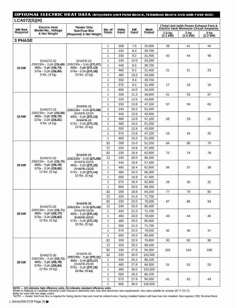
OPTIONAL ELECTRIC HEAT DATA (REQUIRES UNIT FUSE BLOCK, TERMINAl BLOCK AND SUB-FUSE BOX)
LCA072(S)(H)
kW SizeElectric Heat
Model No Voltage*Heater Only
S b F se Box No. of Volts kW BtuhaaTotal Unit (with Power Exhaust Fan) &Electric Heat Minimum Circuit AmpacitykW Size
Required Model No., Voltage& Net Weight
Sub-Fuse Box(Required) & Net Weight
No. ofSteps
VoltsInput
kWInput
BtuhOutput 1.5 hp
(1.1 kW)2 hp
(1.5 kW)3 hp
(2.2 kW)
3 PHASE1 208 7.5 25,600 39 41 44
1 220 8.4 28,700
1 230 9.2 31,400 42 44 48
EHA072-10 EHAFB-10 1 240 10.0 34,200
10 kW
EHA072 10208/230v - 3 ph (23L68)
460v - 3 ph (23L74)
EHAFB 10208/230v - 3 ph (27L07)
460v - 3 ph (27L13)1 440 8.4 28,700
10 kW 460v - 3 ph (23L74)575v - 3 ph (23L80)
460v - 3 ph (27L13)575v - 3 ph (27L18) 1 460 9.2 31,400 21 21 23575v - 3 h (23L80)
9 lbs. (4 kg)575v - 3 h (27L18)
10 lbs. (5 kg) 1 480 10.0 34,200( g) ( g)
1 550 8.4 28,700
1 575 9.2 31,400 17 18 19
1 600 10.0 34,200
8 9
1 208 11.3 38,600 51 53 57
1 220 12.6 43,000
EHAFB-151 230 13.8 47,100 57 59 63
EHA072-15EHAFB-15
208/230v - 3 ph (27L08) 1 240 15.0 51,200
5 59 63
15 kW
EHA072 15208/230v - 3 ph (23L69)
460v - 3 ph (23L75)
208/230v 3 h (27L08)EHAFB-15/20
460v 3 ph (27L14)1 440 12.6 43,000
15 kW 460v - 3 ph (23L75)575v - 3 ph (23L81)
460v - 3 ph (27L14)EHAFB-15 1 460 13.8 47,100 28 29 31575v - 3 h (23L81)
9 lbs. (4 kg)EHAFB-15
575v - 3 ph (27L19)10 lb (5 k )
1 480 15.0 51,200
8 9 3( g) ( )
10 lbs. (5 kg) 1 550 12.6 43,000
1 575 13.8 47,100 23 24 25
1 600 15.0 51,200
c2 208 15.0 51,200 64 66 70
c2 220 16.8 57,400
EHAFB-20c2 230 18.4 62,800 72 74 78
EHA072-20EHAFB-20
208/230v - 3 ph (27L09) c2 240 20.0 68,300
8
20 kW
EHA072 20208/230v - 3 ph (23L70)
460v - 3 ph (23L76)
208/230v - 3 h (27L09)EHAFB-20/25
460v 3 ph (27L15)1 440 16.8 57,400
20 kW 460v - 3 ph (23L76)575v - 3 ph (23L82)
460v - 3 ph (27L15)EHAFB-15/20 1 460 18.4 62,800 36 37 38575v - 3 h (23L82)
12 lbs. (6 kg)EHAFB-15/20
575v - 3 ph (27L14)10 lb (5 k )
1 480 20.0 68,300
36 3 38( g) ( )
10 lbs. (5 kg) 1 550 16.8 57,400
1 575 18.4 62,800 29 30 31
1 600 20.0 68,300
9 30 3
c2 208 18.8 64,200 77 79 83
c2 220 21.0 71,700
EHAFB-25c2 230 23.0 78,500 87 89 93
EHA072-25EHAFB-25
208/230v - 3 ph (27L10) c2 240 25.0 85,400
8 89 93
25 kW
EHA072 25208/230v - 3 ph (23L71)
460v - 3 ph (23L77)
208/230v 3 h (27L10)EHAFB-25/30
460v 3 ph (27L16)1 440 21.0 71,700
25 kW 460v - 3 ph (23L77)575v - 3 ph (23L83)
460v - 3 ph (27L16)EHAFB-20/25 1 460 23.0 78,500 43 44 46575v - 3 h (23L83)
12 lbs. (6 kg)EHAFB-20/25
575v - 3 ph (27L15)10 lb (5 k )
1 480 25.0 85,400( g) ( )10 lbs. (5 kg) 1 550 21.0 71,700
1 575 23.0 78,500 35 36 37
1 600 25.0 85,400
c2 208 22.5 76,800 90 92 96
c2 220 25.2 86,100
c2 230 27.6 94,300 102 104 108
EHA072-30 EHAFB-30208/230v - 3 ph (27L11)
c2 240 30.0 102,500
0 0 08
30 kW
EHA072 30208/230v - 3 ph (23L72)
460v - 3 ph (23L78)
208/230v - 3 ph (27L11)460v - 3 ph (27L17) 1 440 25.2 86,100
30 kW 460v - 3 ph (23L78)575v - 3 ph (23L84)
460v - 3 h (27L17)EHAFB-25/30
575v 3 ph (27L16)1 460 27.6 94,300 51 52 53575v - 3 h (23L84)
12 lbs. (6 kg) 575v - 3 ph (27L16)10 lbs. (5 kg) 1 480 30.0 102,500
5 5 53( g)
10 lbs. (5 kg)1 550 25.2 86,100
1 575 27.6 94,300 41 42 43
1 600 30.0 102,500NOTE — (H) indicates high efficiency units, (S) indicates standard efficiency unitsaRefer to National or Canadian Electrical Code manual to determine wire, fuse and disconnect size requirements. Use wires suitable for at least 167qF (75qC).cMay be used with two stage control.*NOTE — Heater Sub-Fuse Box is required for fusing electric heat and must be ordered extra. Factory installed heaters will have fuse box installed. Also requires LTB2 Terminal Block.
L Series036-072/ Page 20�
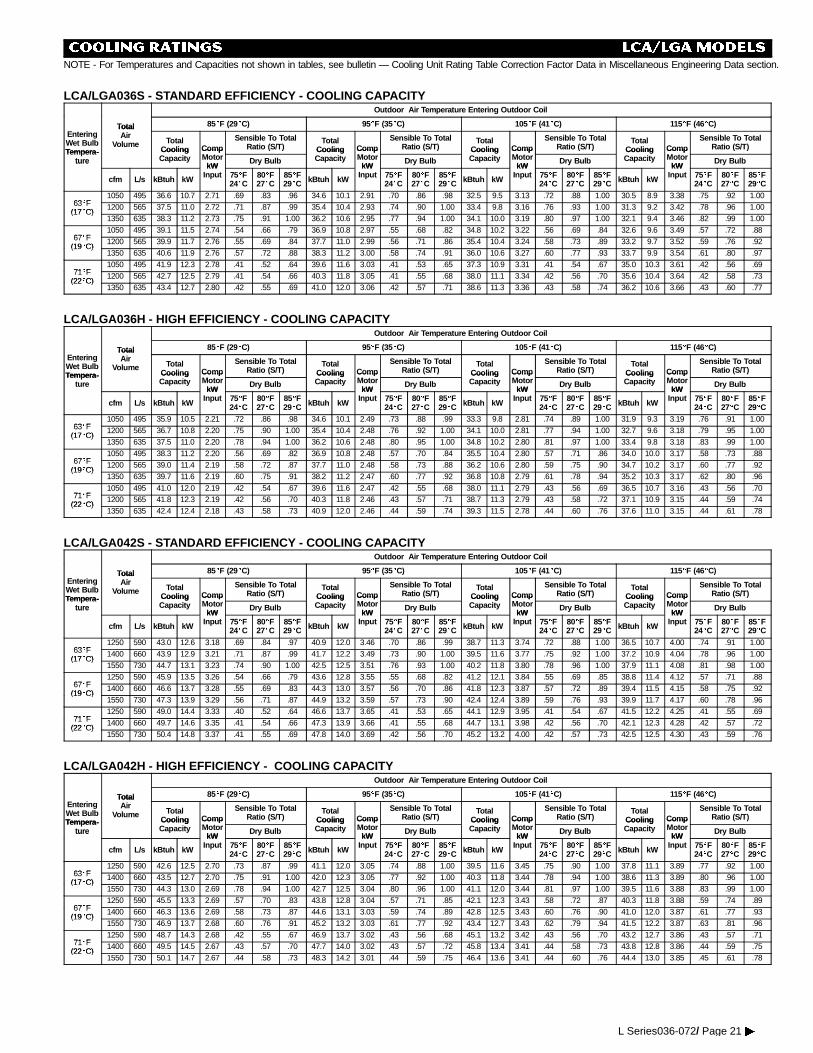
COOLING RATINGS LCA/LGAMODELSNOTE - For Temperatures and Capacities not shown in tables, see bulletin — Cooling Unit Rating Table Correction Factor Data in Miscellaneous Engineering Data section.
LCA/LGA036S - STANDARD EFFICIENCY - COOLING CAPACITYOutdoor Air Temperature Entering Outdoor Coil
Total 85EEF (29EEC) 95EEF (35EEC) 105EEF (41EEC) 115EEF (46EEC)EnteringWet BulbTempera-
TotalAir
Volume TotalCoolin g Comp
Sensible To TotalRatio (S/T)
TotalCoolin g Comp
Sensible To TotalRatio (S/T)
TotalCoolin g Comp
Sensible To TotalRatio (S/T)
TotalCoolin g Comp
Sensible To TotalRatio (S/T)
Tempera-ture
CoolingCapacity
CompMotor
kWDry Bulb
CoolingCapacity
CompMotor
kWDry Bulb
CoolingCapacity
CompMotor
kWDry Bulb
CoolingCapacity
CompMotor
kWDry Bulbture
cfm L/s kBtuh kW
kWInput 75EEF
24EEC80EEF27EEC
85EEF29EEC kBtuh kW
kWInput 75EEF
24EEC80EEF27EEC
85EEF29EEC kBtuh kW
kWInput 75EEF
24EEC80EEF27EEC
85EEF29EEC kBtuh kW
kWInput 75EEF
24EEC80EEF27EEC
85EEF29EEC
63EF1050 495 36.6 10.7 2.71 .69 .83 .96 34.6 10.1 2.91 .70 .86 .98 32.5 9.5 3.13 .72 .88 1.00 30.5 8.9 3.38 .75 .92 1.00
63EF(17EC)
1200 565 37.5 11.0 2.72 .71 .87 .99 35.4 10.4 2.93 .74 .90 1.00 33.4 9.8 3.16 .76 .93 1.00 31.3 9.2 3.42 .78 .96 1.00(17EC)
1350 635 38.3 11.2 2.73 .75 .91 1.00 36.2 10.6 2.95 .77 .94 1.00 34.1 10.0 3.19 .80 .97 1.00 32.1 9.4 3.46 .82 .99 1.00
67EF1050 495 39.1 11.5 2.74 .54 .66 .79 36.9 10.8 2.97 .55 .68 .82 34.8 10.2 3.22 .56 .69 .84 32.6 9.6 3.49 .57 .72 .88
67EF(19EC)
1200 565 39.9 11.7 2.76 .55 .69 .84 37.7 11.0 2.99 .56 .71 .86 35.4 10.4 3.24 .58 .73 .89 33.2 9.7 3.52 .59 .76 .92(19EC)
1350 635 40.6 11.9 2.76 .57 .72 .88 38.3 11.2 3.00 .58 .74 .91 36.0 10.6 3.27 .60 .77 .93 33.7 9.9 3.54 .61 .80 .97
71EF1050 495 41.9 12.3 2.78 .41 .52 .64 39.6 11.6 3.03 .41 .53 .65 37.3 10.9 3.31 .41 .54 .67 35.0 10.3 3.61 .42 .56 .69
71EF(22EC)
1200 565 42.7 12.5 2.79 .41 .54 .66 40.3 11.8 3.05 .41 .55 .68 38.0 11.1 3.34 .42 .56 .70 35.6 10.4 3.64 .42 .58 .73(22EC)
1350 635 43.4 12.7 2.80 .42 .55 .69 41.0 12.0 3.06 .42 .57 .71 38.6 11.3 3.36 .43 .58 .74 36.2 10.6 3.66 .43 .60 .77
LCA/LGA036H - HIGH EFFICIENCY - COOLING CAPACITYOutdoor Air Temperature Entering Outdoor Coil
Total 85EEF (29EEC) 95EEF (35EEC) 105EEF (41EEC) 115EEF (46EEC)EnteringWet BulbTempera-
TotalAir
Volume TotalCooling Comp
Sensible To TotalRatio (S/T)
TotalCooling Comp
Sensible To TotalRatio (S/T)
TotalCooling Comp
Sensible To TotalRatio (S/T)
TotalCooling Comp
Sensible To TotalRatio (S/T)
Tempera-ture
CoolingCapacity
CompMotor
kWDry Bulb
CoolingCapacity
CompMotor
kWDry Bulb
CoolingCapacity
CompMotor
kWDry Bulb
CoolingCapacity
CompMotor
kWDry Bulbture
cfm L/s kBtuh kW
kWInput 75EEF
24EEC80EEF27EEC
85EEF29EEC kBtuh kW
kWInput 75EEF
24EEC80EEF27EEC
85EEF29EEC kBtuh kW
kWInput 75EEF
24EEC80EEF27EEC
85EEF29EEC kBtuh kW
kWInput 75EEF
24EEC80EEF27EEC
85EEF29EEC
63EF1050 495 35.9 10.5 2.21 .72 .86 .98 34.6 10.1 2.49 .73 .88 .99 33.3 9.8 2.81 .74 .89 1.00 31.9 9.3 3.19 .76 .91 1.00
63EF(17EC)
1200 565 36.7 10.8 2.20 .75 .90 1.00 35.4 10.4 2.48 .76 .92 1.00 34.1 10.0 2.81 .77 .94 1.00 32.7 9.6 3.18 .79 .95 1.00(17EC)
1350 635 37.5 11.0 2.20 .78 .94 1.00 36.2 10.6 2.48 .80 .95 1.00 34.8 10.2 2.80 .81 .97 1.00 33.4 9.8 3.18 .83 .99 1.00
67EF1050 495 38.3 11.2 2.20 .56 .69 .82 36.9 10.8 2.48 .57 .70 .84 35.5 10.4 2.80 .57 .71 .86 34.0 10.0 3.17 .58 .73 .88
67EF(19EC)
1200 565 39.0 11.4 2.19 .58 .72 .87 37.7 11.0 2.48 .58 .73 .88 36.2 10.6 2.80 .59 .75 .90 34.7 10.2 3.17 .60 .77 .92(19EC)
1350 635 39.7 11.6 2.19 .60 .75 .91 38.2 11.2 2.47 .60 .77 .92 36.8 10.8 2.79 .61 .78 .94 35.2 10.3 3.17 .62 .80 .96
71EF1050 495 41.0 12.0 2.19 .42 .54 .67 39.6 11.6 2.47 .42 .55 .68 38.0 11.1 2.79 .43 .56 .69 36.5 10.7 3.16 .43 .56 .70
71EF(22EC)
1200 565 41.8 12.3 2.19 .42 .56 .70 40.3 11.8 2.46 .43 .57 .71 38.7 11.3 2.79 .43 .58 .72 37.1 10.9 3.15 .44 .59 .74(22EC)
1350 635 42.4 12.4 2.18 .43 .58 .73 40.9 12.0 2.46 .44 .59 .74 39.3 11.5 2.78 .44 .60 .76 37.6 11.0 3.15 .44 .61 .78
LCA/LGA042S - STANDARD EFFICIENCY - COOLING CAPACITYOutdoor Air Temperature Entering Outdoor Coil
Total 85EEF (29EEC) 95EEF (35EEC) 105EEF (41EEC) 115EEF (46EEC)EnteringWet BulbTempera-
TotalAir
Volume TotalCooling Comp
Sensible To TotalRatio (S/T)
TotalCooling Comp
Sensible To TotalRatio (S/T)
TotalCooling Comp
Sensible To TotalRatio (S/T)
TotalCooling Comp
Sensible To TotalRatio (S/T)
Tempera-ture
CoolingCapacity
CompMotor
kWDry Bulb
CoolingCapacity
CompMotor
kWDry Bulb
CoolingCapacity
CompMotor
kWDry Bulb
CoolingCapacity
CompMotor
kWDry Bulbture
cfm L/s kBtuh kW
kWInput 75EEF
24EEC80EEF27EEC
85EEF29EEC kBtuh kW
kWInput 75EEF
24EEC80EEF27EEC
85EEF29EEC kBtuh kW
kWInput 75EEF
24EEC80EEF27EEC
85EEF29EEC kBtuh kW
kWInput 75EEF
24EEC80EEF27EEC
85EEF29EEC
63EF1250 590 43.0 12.6 3.18 .69 .84 .97 40.9 12.0 3.46 .70 .86 .99 38.7 11.3 3.74 .72 .88 1.00 36.5 10.7 4.00 .74 .91 1.00
63EF(17EC)
1400 660 43.9 12.9 3.21 .71 .87 .99 41.7 12.2 3.49 .73 .90 1.00 39.5 11.6 3.77 .75 .92 1.00 37.2 10.9 4.04 .78 .96 1.00(17EC)
1550 730 44.7 13.1 3.23 .74 .90 1.00 42.5 12.5 3.51 .76 .93 1.00 40.2 11.8 3.80 .78 .96 1.00 37.9 11.1 4.08 .81 .98 1.00
67EF1250 590 45.9 13.5 3.26 .54 .66 .79 43.6 12.8 3.55 .55 .68 .82 41.2 12.1 3.84 .55 .69 .85 38.8 11.4 4.12 .57 .71 .88
67EF(19EC)
1400 660 46.6 13.7 3.28 .55 .69 .83 44.3 13.0 3.57 .56 .70 .86 41.8 12.3 3.87 .57 .72 .89 39.4 11.5 4.15 .58 .75 .92(19EC)
1550 730 47.3 13.9 3.29 .56 .71 .87 44.9 13.2 3.59 .57 .73 .90 42.4 12.4 3.89 .59 .76 .93 39.9 11.7 4.17 .60 .78 .96
71EF1250 590 49.0 14.4 3.33 .40 .52 .64 46.6 13.7 3.65 .41 .53 .65 44.1 12.9 3.95 .41 .54 .67 41.5 12.2 4.25 .41 .55 .69
71EF(22EC)
1400 660 49.7 14.6 3.35 .41 .54 .66 47.3 13.9 3.66 .41 .55 .68 44.7 13.1 3.98 .42 .56 .70 42.1 12.3 4.28 .42 .57 .72(22EC)
1550 730 50.4 14.8 3.37 .41 .55 .69 47.8 14.0 3.69 .42 .56 .70 45.2 13.2 4.00 .42 .57 .73 42.5 12.5 4.30 .43 .59 .76
LCA/LGA042H - HIGH EFFICIENCY - COOLING CAPACITYOutdoor Air Temperature Entering Outdoor Coil
Total 85EEF (29EEC) 95EEF (35EEC) 105EEF (41EEC) 115EEF (46EEC)EnteringWet BulbTempera-
TotalAir
Volume TotalCooling Comp
Sensible To TotalRatio (S/T)
TotalCooling Comp
Sensible To TotalRatio (S/T)
TotalCooling Comp
Sensible To TotalRatio (S/T)
TotalCooling Comp
Sensible To TotalRatio (S/T)
Tempera-ture
CoolingCapacity
CompMotor
kWDry Bulb
CoolingCapacity
CompMotor
kWDry Bulb
CoolingCapacity
CompMotor
kWDry Bulb
CoolingCapacity
CompMotor
kWDry Bulbture
cfm L/s kBtuh kW
kWInput 75EEF
24EEC80EEF27EEC
85EEF29EEC kBtuh kW
kWInput 75EEF
24EEC80EEF27EEC
85EEF29EEC kBtuh kW
kWInput 75EEF
24EEC80EEF27EEC
85EEF29EEC kBtuh kW
kWInput 75EEF
24EEC80EEF27EEC
85EEF29EEC
63EF1250 590 42.6 12.5 2.70 .73 .87 .99 41.1 12.0 3.05 .74 .88 1.00 39.5 11.6 3.45 .75 .90 1.00 37.8 11.1 3.89 .77 .92 1.00
63EF(17EC)
1400 660 43.5 12.7 2.70 .75 .91 1.00 42.0 12.3 3.05 .77 .92 1.00 40.3 11.8 3.44 .78 .94 1.00 38.6 11.3 3.89 .80 .96 1.00(17EC)
1550 730 44.3 13.0 2.69 .78 .94 1.00 42.7 12.5 3.04 .80 .96 1.00 41.1 12.0 3.44 .81 .97 1.00 39.5 11.6 3.88 .83 .99 1.00
67EF1250 590 45.5 13.3 2.69 .57 .70 .83 43.8 12.8 3.04 .57 .71 .85 42.1 12.3 3.43 .58 .72 .87 40.3 11.8 3.88 .59 .74 .89
67EF(19EC)
1400 660 46.3 13.6 2.69 .58 .73 .87 44.6 13.1 3.03 .59 .74 .89 42.8 12.5 3.43 .60 .76 .90 41.0 12.0 3.87 .61 .77 .93(19EC)
1550 730 46.9 13.7 2.68 .60 .76 .91 45.2 13.2 3.03 .61 .77 .92 43.4 12.7 3.43 .62 .79 .94 41.5 12.2 3.87 .63 .81 .96
71EF1250 590 48.7 14.3 2.68 .42 .55 .67 46.9 13.7 3.02 .43 .56 .68 45.1 13.2 3.42 .43 .56 .70 43.2 12.7 3.86 .43 .57 .71
71EF(22EC)
1400 660 49.5 14.5 2.67 .43 .57 .70 47.7 14.0 3.02 .43 .57 .72 45.8 13.4 3.41 .44 .58 .73 43.8 12.8 3.86 .44 .59 .75(22EC)
1550 730 50.1 14.7 2.67 .44 .58 .73 48.3 14.2 3.01 .44 .59 .75 46.4 13.6 3.41 .44 .60 .76 44.4 13.0 3.85 .45 .61 .78
L Series036-072/ Page 21�
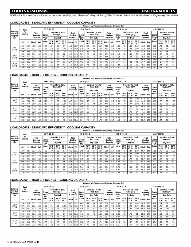
COOLING RATINGS LCA/LGAMODELSNOTE - For Temperatures and Capacities not shown in tables, see bulletin — Cooling Unit Rating Table Correction Factor Data in Miscellaneous Engineering Data section.
LCA/LGA048S - STANDARD EFFICIENCY - COOLING CAPACITYOutdoor Air Temperature Entering Outdoor Coil
Total 85EEF (29EEC) 95EEF (35EEC) 105EEF (41EEC) 115EEF (46EEC)EnteringWet BulbTempera-
TotalAir
Volume TotalCooling Comp
Sensible To TotalRatio (S/T)
TotalCooling Comp
Sensible To TotalRatio (S/T)
TotalCooling Comp
Sensible To TotalRatio (S/T)
TotalCooling Comp
Sensible To TotalRatio (S/T)
Tempera-ture
CoolingCapacity
CompMotor
kWDry Bulb
CoolingCapacity
CompMotor
kWDry Bulb
CoolingCapacity
CompMotor
kWDry Bulb
CoolingCapacity
CompMotor
kWDry Bulbture
cfm L/s kBtuh kW
kWInput 75EEF
24EEC80EEF27EEC
85EEF29EEC kBtuh kW
kWInput 75EEF
24EEC80EEF27EEC
85EEF29EEC kBtuh kW
kWInput 75EEF
24EEC80EEF27EEC
85EEF29EEC kBtuh kW
kWInput 75EEF
24EEC80EEF27EEC
85EEF29EEC
63EF1400 660 48.9 14.3 3.49 .69 .84 .97 46.6 13.7 3.72 .70 .86 .99 44.2 13.0 4.00 .72 .89 1.00 41.9 12.3 4.30 .74 .91 1.00
63EF(17EC)
1600 755 50.1 14.7 3.51 .72 .88 1.00 47.7 14.0 3.76 .74 .90 1.00 45.3 13.3 4.04 .76 .93 1.00 42.9 12.6 4.34 .78 .96 1.00(17EC)
1800 850 51.0 14.9 3.54 .75 .92 1.00 48.7 14.3 3.78 .77 .94 1.00 46.3 13.6 4.07 .79 .97 1.00 43.9 12.9 4.39 .82 .99 1.00
67EF1400 660 52.1 15.3 3.56 .54 .66 .80 49.6 14.5 3.81 .55 .68 .82 47.1 13.8 4.10 .55 .69 .85 44.5 13.0 4.42 .57 .71 .87
67EF(19EC)
1600 755 53.1 15.6 3.58 .55 .69 .84 50.6 14.8 3.83 .56 .71 .87 47.9 14.0 4.13 .57 .73 .89 45.3 13.3 4.46 .59 .75 .92(19EC)
1800 850 53.9 15.8 3.60 .57 .72 .88 51.3 15.0 3.86 .58 .74 .91 48.6 14.2 4.16 .59 .77 .94 46.0 13.5 4.49 .61 .79 .96
71EF1400 660 55.7 16.3 3.63 .40 .52 .64 53.0 15.5 3.90 .41 .53 .65 50.4 14.8 4.21 .41 .54 .67 47.7 14.0 4.57 .41 .55 .69
71EF(22EC)
1600 755 56.7 16.6 3.65 .41 .54 .67 54.0 15.8 3.93 .41 .55 .69 51.2 15.0 4.24 .42 .56 .70 48.5 14.2 4.60 .42 .57 .73(22EC)
1800 850 57.4 16.8 3.67 .42 .56 .70 54.7 16.0 3.94 .42 .57 .72 51.9 15.2 4.27 .42 .58 .74 49.1 14.4 4.63 .43 .60 .77
LCA/LGA048H - HIGH EFFICIENCY - COOLING CAPACITYOutdoor Air Temperature Entering Outdoor Coil
Total 85EEF (29EEC) 95EEF (35EEC) 105EEF (41EEC) 115EEF (46EEC)EnteringWet BulbTempera-
TotalAir
Volume TotalCooling Comp
Sensible To TotalRatio (S/T)
TotalCooling Comp
Sensible To TotalRatio (S/T)
TotalCooling Comp
Sensible To TotalRatio (S/T)
TotalCooling Comp
Sensible To TotalRatio (S/T)
Tempera-ture
CoolingCapacity
CompMotor
kWDry Bulb
CoolingCapacity
CompMotor
kWDry Bulb
CoolingCapacity
CompMotor
kWDry Bulb
CoolingCapacity
CompMotor
kWDry Bulbture
cfm L/s kBtuh kW
kWInput 75EEF
24EEC80EEF27EEC
85EEF29EEC kBtuh kW
kWInput 75EEF
24EEC80EEF27EEC
85EEF29EEC kBtuh kW
kWInput 75EEF
24EEC80EEF27EEC
85EEF29EEC kBtuh kW
kWInput 75EEF
24EEC80EEF27EEC
85EEF29EEC
63EF1400 660 48.9 14.3 3.12 .68 .84 .98 47.1 13.8 3.52 .69 .85 .99 45.2 13.2 3.97 .70 .88 1.00 43.3 12.7 4.49 .72 .90 1.00
63EF(17EC)
1600 755 50.1 14.7 3.13 .72 .89 1.00 48.2 14.1 3.53 .73 .91 1.00 46.3 13.6 3.99 .75 .93 1.00 44.3 13.0 4.50 .77 .95 1.00(17EC)
1800 850 51.0 14.9 3.15 .75 .93 1.00 49.2 14.4 3.55 .77 .95 1.00 47.3 13.9 4.00 .79 .97 1.00 45.4 13.3 4.52 .81 .99 1.00
67EF1400 660 51.9 15.2 3.16 .53 .66 .80 50.0 14.7 3.56 .54 .67 .82 48.0 14.1 4.01 .55 .68 .84 46.0 13.5 4.53 .55 .70 .86
67EF(19EC)
1600 755 53.0 15.5 3.17 .55 .69 .85 51.0 14.9 3.57 .56 .70 .87 48.9 14.3 4.03 .57 .72 .89 46.8 13.7 4.55 .58 .74 .92(19EC)
1800 850 53.8 15.8 3.18 .57 .72 .90 51.8 15.2 3.59 .58 .74 .92 49.6 14.5 4.04 .59 .76 .94 47.5 13.9 4.55 .60 .78 .97
71EF1400 660 55.4 16.2 3.20 .40 .52 .64 53.4 15.6 3.61 .40 .52 .65 51.2 15.0 4.06 .40 .53 .66 49.1 14.4 4.58 .41 .54 .67
71EF(22EC)
1600 755 56.4 16.5 3.22 .40 .54 .67 54.3 15.9 3.62 .41 .54 .68 52.1 15.3 4.08 .41 .55 .69 49.8 14.6 4.60 .42 .56 .71(22EC)
1800 850 57.2 16.8 3.23 .41 .56 .70 55.0 16.1 3.64 .42 .57 .72 52.7 15.4 4.10 .42 .58 .73 50.4 14.8 4.60 .42 .59 .76
LCA/LGA060S - STANDARD EFFICIENCY - COOLING CAPACITYOutdoor Air Temperature Entering Outdoor Coil
Total 85EEF (29EEC) 95EEF (35EEC) 105EEF (41EEC) 115EEF (46EEC)EnteringWet BulbTempera-
TotalAir
Volume TotalCooling Comp
Sensible To TotalRatio (S/T)
TotalCooling Comp
Sensible To TotalRatio (S/T)
TotalCooling Comp
Sensible To TotalRatio (S/T)
TotalCooling Comp
Sensible To TotalRatio (S/T)
Tempera-ture
CoolingCapacity
CompMotor
kWDry Bulb
CoolingCapacity
CompMotor
kWDry Bulb
CoolingCapacity
CompMotor
kWDry Bulb
CoolingCapacity
CompMotor
kWDry Bulbture
cfm L/s kBtuh kW
kWInput 75EEF
24EEC80EEF27EEC
85EEF29EEC kBtuh kW
kWInput 75EEF
24EEC80EEF27EEC
85EEF29EEC kBtuh kW
kWInput 75EEF
24EEC80EEF27EEC
85EEF29EEC kBtuh kW
kWInput 75EEF
24EEC80EEF27EEC
85EEF29EEC
63EF1750 825 58.7 17.2 4.69 .70 .85 .97 56.2 16.5 5.05 .71 .87 .99 53.5 15.7 5.43 .73 .89 1.00 50.7 14.9 5.81 .75 .92 1.00
63EF(17EC)
2000 945 59.9 17.6 4.73 .73 .89 1.00 57.4 16.8 5.10 .74 .91 1.00 54.7 16.0 5.48 .76 .93 1.00 51.9 15.2 5.87 .79 .96 1.00(17EC)
2250 1060 61.1 17.9 4.77 .76 .93 1.00 58.5 17.1 5.15 .78 .95 1.00 55.8 16.4 5.54 .80 .97 1.00 53.0 15.5 5.93 .83 .99 1.00
67EF1750 825 62.3 18.3 4.81 .54 .67 .81 59.6 17.5 5.19 .55 .68 .83 56.7 16.6 5.58 .56 .70 .85 53.7 15.7 5.96 .57 .72 .88
67EF(19EC)
2000 945 63.3 18.6 4.84 .56 .70 .86 60.6 17.8 5.23 .57 .72 .88 57.6 16.9 5.62 .58 .74 .90 54.5 16.0 6.02 .59 .76 .93(19EC)
2250 1060 64.2 18.8 4.87 .58 .73 .90 61.4 18.0 5.26 .59 .75 .92 58.5 17.1 5.66 .60 .77 .94 55.3 16.2 6.06 .61 .80 .97
71EF1750 825 66.3 19.4 4.93 .41 .53 .65 63.5 18.6 5.34 .41 .54 .66 60.4 17.7 5.75 .41 .55 .68 57.2 16.8 6.17 .42 .56 .70
71EF(22EC)
2000 945 67.4 19.8 4.97 .41 .55 .68 64.5 18.9 5.38 .42 .56 .70 61.3 18.0 5.80 .42 .57 .71 58.0 17.0 6.21 .43 .58 .74(22EC)
2250 1060 68.3 20.0 5.00 .42 .56 .71 65.3 19.1 5.41 .42 .58 .73 62.1 18.2 5.83 .43 .59 .75 58.7 17.2 6.25 .43 .60 .78
LCA/LGA060H - HIGH EFFICIENCY - COOLING CAPACITYOutdoor Air Temperature Entering Outdoor Coil
Total 85EEF (29EEC) 95EEF (35EEC) 105EEF (41EEC) 115EEF (46EEC)EnteringWet BulbTempera-
TotalAir
Volume TotalCooling Comp
Sensible To TotalRatio (S/T)
TotalCooling Comp
Sensible To TotalRatio (S/T)
TotalCooling Comp
Sensible To TotalRatio (S/T)
TotalCooling Comp
Sensible To TotalRatio (S/T)
Tempera-ture
CoolingCapacity
CompMotor
kWDry Bulb
CoolingCapacity
CompMotor
kWDry Bulb
CoolingCapacity
CompMotor
kWDry Bulb
CoolingCapacity
CompMotor
kWDry Bulbture
cfm L/s kBtuh kW
kWInput 75EEF
24EEC80EEF27EEC
85EEF29EEC kBtuh kW
kWInput 75EEF
24EEC80EEF27EEC
85EEF29EEC kBtuh kW
kWInput 75EEF
24EEC80EEF27EEC
85EEF29EEC kBtuh kW
kWInput 75EEF
24EEC80EEF27EEC
85EEF29EEC
63EF1750 825 60.7 17.8 3.93 .71 .86 .99 58.7 17.2 4.43 .72 .88 1.00 56.6 16.6 5.00 .73 .89 1.00 54.3 15.9 5.64 .74 .92 1.00
63EF(17EC)
2000 945 62.1 18.2 3.95 .74 .91 1.00 60.0 17.6 4.45 .75 .93 1.00 57.9 17.0 5.02 .77 .94 1.00 55.6 16.3 5.65 .79 .96 1.00(17EC)
2250 1060 63.3 18.6 3.96 .78 .95 1.00 61.2 17.9 4.46 .79 .97 1.00 59.1 17.3 5.03 .81 .98 1.00 56.8 16.6 5.66 .83 1.00 1.00
67EF1750 825 64.3 18.8 3.97 .55 .68 .83 62.1 18.2 4.47 .56 .69 .84 59.8 17.5 5.04 .56 .71 .86 57.4 16.8 5.68 .57 .72 .88
67EF(19EC)
2000 945 65.4 19.2 3.98 .57 .72 .87 63.2 18.5 4.49 .58 .73 .89 60.8 17.8 5.05 .58 .74 .91 58.3 17.1 5.70 .59 .76 .93(19EC)
2250 1060 66.4 19.5 3.99 .59 .75 .92 64.1 18.8 4.49 .60 .77 .94 61.7 18.1 5.07 .61 .78 .96 59.1 17.3 5.71 .62 .81 .98
71EF1750 825 68.4 20.0 4.01 .41 .53 .66 66.0 19.3 4.52 .41 .54 .67 63.6 18.6 5.09 .41 .55 .68 61.0 17.9 5.73 .42 .56 .70
71EF(22EC)
2000 945 69.5 20.4 4.03 .42 .56 .69 67.1 19.7 4.53 .42 .56 .71 64.6 18.9 5.10 .42 .57 .72 61.9 18.1 5.74 .43 .58 .74(22EC)
2250 1060 70.4 20.6 4.03 .42 .58 .73 67.9 19.9 4.54 .43 .59 .74 65.3 19.1 5.11 .43 .60 .76 62.6 18.3 5.75 .44 .61 .78
L Series036-072/ Page 22�
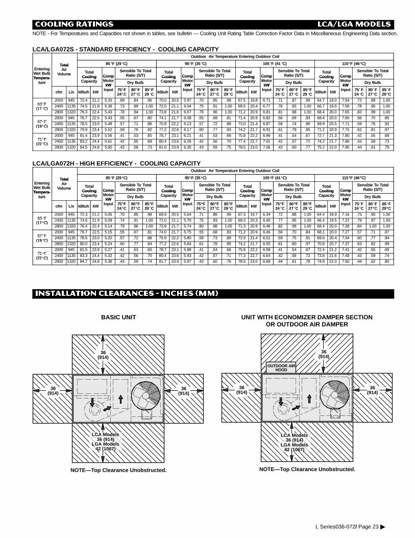
COOLING RATINGS LCA/LGAMODELSNOTE - For Temperatures and Capacities not shown in tables, see bulletin — Cooling Unit Rating Table Correction Factor Data in Miscellaneous Engineering Data section.
LCA/LGA072S - STANDARD EFFICIENCY - COOLING CAPACITYOutdoor Air Temperature Entering Outdoor Coil
Total 85EEF (29EEC) 95EEF (35EEC) 105EEF (41EEC) 115EEF (46EEC)EnteringWet BulbTempera-
TotalAir
Volume TotalCooling Comp
Sensible To TotalRatio (S/T)
TotalCooling Comp
Sensible To TotalRatio (S/T)
TotalCooling Comp
Sensible To TotalRatio (S/T)
TotalCooling Comp
Sensible To TotalRatio (S/T)
Tempera-ture
CoolingCapacity
CompMotor
kWDry Bulb
CoolingCapacity
CompMotor
kWDry Bulb
CoolingCapacity
CompMotor
kWDry Bulb
CoolingCapacity
CompMotor
kWDry Bulbture
cfm L/s kBtuh kW
kWInput 75EEF
24EEC80EEF27EEC
85EEF29EEC kBtuh kW
kWInput 75EEF
24EEC80EEF27EEC
85EEF29EEC kBtuh kW
kWInput 75EEF
24EEC80EEF27EEC
85EEF29EEC kBtuh kW
kWInput 75EEF
24EEC80EEF27EEC
85EEF29EEC
63EF2000 945 72.4 21.2 5.33 .69 .84 .96 70.0 20.5 5.97 .70 .85 .98 67.5 19.8 6.71 .71 .87 .99 64.7 19.0 7.54 .73 .89 1.00
63EF(17EC)
2400 1135 74.5 21.8 5.38 .73 .89 1.00 72.0 21.1 6.04 .75 .91 1.00 69.5 20.4 6.77 .76 .93 1.00 66.7 19.5 7.59 .78 .95 1.00(17EC)
2800 1320 76.3 22.4 5.43 .78 .94 1.00 73.8 21.6 6.07 .79 .96 1.00 71.2 20.9 6.81 .81 .98 1.00 68.4 20.0 7.65 .83 .99 1.00
67EF2000 945 76.7 22.5 5.43 .55 .67 .80 74.1 21.7 6.08 .55 .68 .81 71.4 20.9 6.82 .56 .69 .83 68.4 20.0 7.65 .56 .70 .85
67EF(19EC)
2400 1135 78.5 23.0 5.48 .57 .71 .86 75.8 22.2 6.13 .57 .72 .88 73.0 21.4 6.87 .58 .74 .90 69.9 20.5 7.71 .59 .76 .92(19EC)
2800 1320 79.9 23.4 5.52 .59 .76 .92 77.2 22.6 6.17 .60 .77 .93 74.2 21.7 6.91 .61 .79 .95 71.2 20.9 7.75 .62 .81 .97
71EF2000 945 81.4 23.9 5.56 .41 .53 .65 78.7 23.1 6.21 .41 .53 .66 75.8 22.2 6.96 .41 .54 .67 72.7 21.3 7.80 .42 .55 .68
71EF(22EC)
2400 1135 83.2 24.4 5.61 .42 .55 .69 80.4 23.6 6.26 .42 .56 .70 77.4 22.7 7.01 .42 .57 .72 74.2 21.7 7.86 .43 .58 .73(22EC)
2800 1320 84.5 24.8 5.65 .43 .58 .73 81.6 23.9 6.30 .43 .59 .75 78.5 23.0 7.06 .43 .60 .77 75.2 22.0 7.90 .44 .61 .79
LCA/LGA072H - HIGH EFFICIENCY - COOLING CAPACITYOutdoor Air Temperature Entering Outdoor Coil
Total 85EEF (29EEC) 95EEF (35EEC) 105EEF (41EEC) 115EEF (46EEC)EnteringWet BulbTempera-
TotalAir
Volume TotalCooling Comp
Sensible To TotalRatio (S/T)
TotalCooling Comp
Sensible To TotalRatio (S/T)
TotalCooling Comp
Sensible To TotalRatio (S/T)
TotalCooling Comp
Sensible To TotalRatio (S/T)
Tempera-ture
CoolingCapacity
CompMotor
kWDry Bulb
CoolingCapacity
CompMotor
kWDry Bulb
CoolingCapacity
CompMotor
kWDry Bulb
CoolingCapacity
CompMotor
kWDry Bulbture
cfm L/s kBtuh kW
kWInput 75EEF
24EEC80EEF27EEC
85EEF29EEC kBtuh kW
kWInput 75EEF
24EEC80EEF27EEC
85EEF29EEC kBtuh kW
kWInput 75EEF
24EEC80EEF27EEC
85EEF29EEC kBtuh kW
kWInput 75EEF
24EEC80EEF27EEC
85EEF29EEC
63EF2000 945 72.3 21.2 5.05 .70 .85 .98 69.9 20.5 5.64 .71 .86 .99 67.3 19.7 6.34 .72 .88 1.00 64.4 18.9 7.16 .73 .90 1.00
63EF(17EC)
2400 1135 74.6 21.9 5.09 .74 .91 1.00 72.0 21.1 5.70 .75 .93 1.00 69.3 20.3 6.40 .77 .95 1.00 66.4 19.5 7.22 .79 .97 1.00(17EC)
2800 1320 76.4 22.4 5.14 .79 .96 1.00 73.9 21.7 5.74 .80 .98 1.00 71.3 20.9 6.46 .82 .99 1.00 68.4 20.0 7.28 .84 1.00 1.00
67EF2000 945 76.7 22.5 5.15 .55 .67 .81 74.0 21.7 5.75 .55 .68 .83 71.2 20.9 6.46 .56 .70 .84 68.1 20.0 7.27 .57 .71 .87
67EF(19EC)
2400 1135 78.5 23.0 5.20 .57 .72 .88 75.9 22.2 5.80 .58 .73 .89 72.9 21.4 6.51 .59 .75 .91 69.6 20.4 7.34 .60 .77 .94(19EC)
2800 1320 80.0 23.4 5.24 .60 .77 .94 77.2 22.6 5.84 .61 .78 .95 74.2 21.7 6.55 .61 .80 .97 70.8 20.7 7.37 .63 .82 .99
71EF2000 945 81.5 23.9 5.27 .41 .53 .65 78.7 23.1 5.88 .41 .54 .66 75.8 22.2 6.58 .41 .54 .67 72.4 21.2 7.41 .42 .55 .69
71EF(22EC)
2400 1135 83.3 24.4 5.32 .42 .56 .70 80.4 23.6 5.93 .42 .57 .71 77.3 22.7 6.64 .42 .58 .72 73.8 21.6 7.48 .43 .59 .74(22EC)
2800 1320 84.7 24.8 5.36 .43 .59 .74 81.7 23.9 5.97 .43 .60 .76 78.5 23.0 6.68 .44 .61 .78 74.9 22.0 7.50 .44 .62 .80
INSTALLATION CLEARANCES - INCHES (MM)
BASIC UNIT
LCA Models36 (914)
LGA Models42 (1067)
36(914)
36(914)
36(914)
NOTE—Top Clearance Unobstructed.
UNIT WITH ECONOMIZER DAMPER SECTIONOR OUTDOOR AIR DAMPER
36(914)
36(914)
NOTE—Top Clearance Unobstructed.
36(914)
OUTDOOR AIRHOOD
LCA Models36 (914)
LGA Models42 (1067)
L Series036-072/ Page 23�
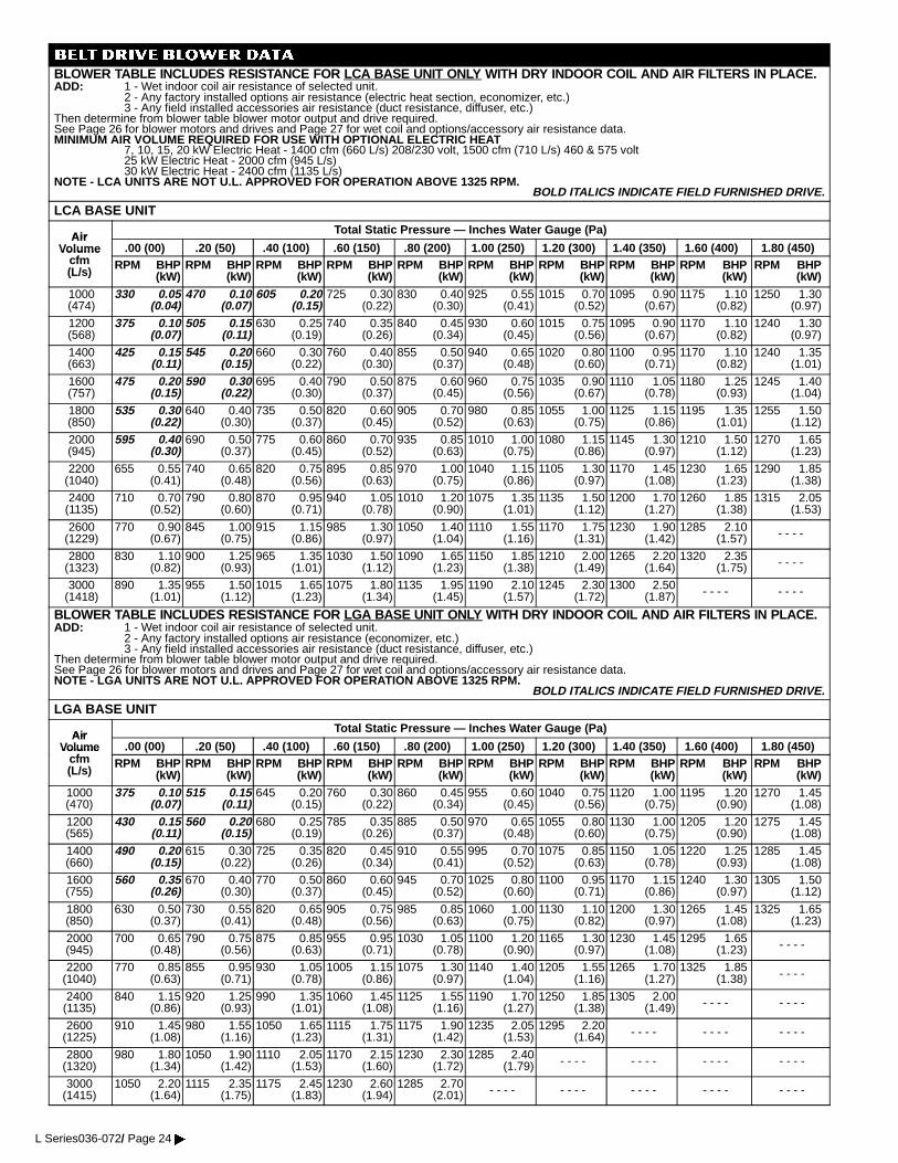
BELT DRIVE BLOWER DATABLOWER TABLE INCLUDES RESISTANCE FOR LCA BASE UNIT ONLY WITH DRY INDOOR COIL AND AIR FILTERS IN PLACE.ADD: 1 - Wet indoor coil air resistance of selected unit.
2 - Any factory installed options air resistance (electric heat section, economizer, etc.)3 - Any field installed accessories air resistance (duct resistance, diffuser, etc.)
Then determine from blower table blower motor output and drive required.See Page 26 for blower motors and drives and Page 27 for wet coil and options/accessory air resistance data.MINIMUM AIR VOLUME REQUIRED FOR USE WITH OPTIONAL ELECTRIC HEAT
7, 10, 15, 20 kW Electric Heat - 1400 cfm (660 L/s) 208/230 volt, 1500 cfm (710 L/s) 460 & 575 volt25 kW Electric Heat - 2000 cfm (945 L/s)30 kW Electric Heat - 2400 cfm (1135 L/s)
NOTE - LCA UNITS ARE NOT U.L. APPROVED FOR OPERATION ABOVE 1325 RPM.BOLD ITALICS INDICATE FIELD FURNISHED DRIVE.
LCA BASE UNIT
AirTotal Static Pressure — Inches Water Gauge (Pa)
AirVolume
f.00 (00) .20 (50) .40 (100) .60 (150) .80 (200) 1.00 (250) 1.20 (300) 1.40 (350) 1.60 (400) 1.80 (450)Volume
cfm(L/s)
RPM BHP(kW)
RPM BHP(kW)
RPM BHP(kW)
RPM BHP(kW)
RPM BHP(kW)
RPM BHP(kW)
RPM BHP(kW)
RPM BHP(kW)
RPM BHP(kW)
RPM BHP(kW)
1000(474)
330 0.05(0.04)
470 0.10(0.07)
605 0.20(0.15)
725 0.30(0.22)
830 0.40(0.30)
925 0.55(0.41)
1015 0.70(0.52)
1095 0.90(0.67)
1175 1.10(0.82)
1250 1.30(0.97)
1200(568)
375 0.10(0.07)
505 0.15(0.11)
630 0.25(0.19)
740 0.35(0.26)
840 0.45(0.34)
930 0.60(0.45)
1015 0.75(0.56)
1095 0.90(0.67)
1170 1.10(0.82)
1240 1.30(0.97)
1400(663)
425 0.15(0.11)
545 0.20(0.15)
660 0.30(0.22)
760 0.40(0.30)
855 0.50(0.37)
940 0.65(0.48)
1020 0.80(0.60)
1100 0.95(0.71)
1170 1.10(0.82)
1240 1.35(1.01)
1600(757)
475 0.20(0.15)
590 0.30(0.22)
695 0.40(0.30)
790 0.50(0.37)
875 0.60(0.45)
960 0.75(0.56)
1035 0.90(0.67)
1110 1.05(0.78)
1180 1.25(0.93)
1245 1.40(1.04)
1800(850)
535 0.30(0.22)
640 0.40(0.30)
735 0.50(0.37)
820 0.60(0.45)
905 0.70(0.52)
980 0.85(0.63)
1055 1.00(0.75)
1125 1.15(0.86)
1195 1.35(1.01)
1255 1.50(1.12)
2000(945)
595 0.40(0.30)
690 0.50(0.37)
775 0.60(0.45)
860 0.70(0.52)
935 0.85(0.63)
1010 1.00(0.75)
1080 1.15(0.86)
1145 1.30(0.97)
1210 1.50(1.12)
1270 1.65(1.23)
2200(1040)
655 0.55(0.41)
740 0.65(0.48)
820 0.75(0.56)
895 0.85(0.63)
970 1.00(0.75)
1040 1.15(0.86)
1105 1.30(0.97)
1170 1.45(1.08)
1230 1.65(1.23)
1290 1.85(1.38)
2400(1135)
710 0.70(0.52)
790 0.80(0.60)
870 0.95(0.71)
940 1.05(0.78)
1010 1.20(0.90)
1075 1.35(1.01)
1135 1.50(1.12)
1200 1.70(1.27)
1260 1.85(1.38)
1315 2.05(1.53)
2600(1229)
770 0.90(0.67)
845 1.00(0.75)
915 1.15(0.86)
985 1.30(0.97)
1050 1.40(1.04)
1110 1.55(1.16)
1170 1.75(1.31)
1230 1.90(1.42)
1285 2.10(1.57) - - - -
2800(1323)
830 1.10(0.82)
900 1.25(0.93)
965 1.35(1.01)
1030 1.50(1.12)
1090 1.65(1.23)
1150 1.85(1.38)
1210 2.00(1.49)
1265 2.20(1.64)
1320 2.35(1.75) - - - -
3000(1418)
890 1.35(1.01)
955 1.50(1.12)
1015 1.65(1.23)
1075 1.80(1.34)
1135 1.95(1.45)
1190 2.10(1.57)
1245 2.30(1.72)
1300 2.50(1.87) - - - - - - - -
BLOWER TABLE INCLUDES RESISTANCE FOR LGA BASE UNIT ONLY WITH DRY INDOOR COIL AND AIR FILTERS IN PLACE.ADD: 1 - Wet indoor coil air resistance of selected unit.
2 - Any factory installed options air resistance (economizer, etc.)3 - Any field installed accessories air resistance (duct resistance, diffuser, etc.)
Then determine from blower table blower motor output and drive required.See Page 26 for blower motors and drives and Page 27 for wet coil and options/accessory air resistance data.NOTE - LGA UNITS ARE NOT U.L. APPROVED FOR OPERATION ABOVE 1325 RPM.
BOLD ITALICS INDICATE FIELD FURNISHED DRIVE.
LGA BASE UNIT
AirTotal Static Pressure — Inches Water Gauge (Pa)
AirVolume
f.00 (00) .20 (50) .40 (100) .60 (150) .80 (200) 1.00 (250) 1.20 (300) 1.40 (350) 1.60 (400) 1.80 (450)Volume
cfm(L/s)
RPM BHP(kW)
RPM BHP(kW)
RPM BHP(kW)
RPM BHP(kW)
RPM BHP(kW)
RPM BHP(kW)
RPM BHP(kW)
RPM BHP(kW)
RPM BHP(kW)
RPM BHP(kW)
1000(470)
375 0.10(0.07)
515 0.15(0.11)
645 0.20(0.15)
760 0.30(0.22)
860 0.45(0.34)
955 0.60(0.45)
1040 0.75(0.56)
1120 1.00(0.75)
1195 1.20(0.90)
1270 1.45(1.08)
1200(565)
430 0.15(0.11)
560 0.20(0.15)
680 0.25(0.19)
785 0.35(0.26)
885 0.50(0.37)
970 0.65(0.48)
1055 0.80(0.60)
1130 1.00(0.75)
1205 1.20(0.90)
1275 1.45(1.08)
1400(660)
490 0.20(0.15)
615 0.30(0.22)
725 0.35(0.26)
820 0.45(0.34)
910 0.55(0.41)
995 0.70(0.52)
1075 0.85(0.63)
1150 1.05(0.78)
1220 1.25(0.93)
1285 1.45(1.08)
1600(755)
560 0.35(0.26)
670 0.40(0.30)
770 0.50(0.37)
860 0.60(0.45)
945 0.70(0.52)
1025 0.80(0.60)
1100 0.95(0.71)
1170 1.15(0.86)
1240 1.30(0.97)
1305 1.50(1.12)
1800(850)
630 0.50(0.37)
730 0.55(0.41)
820 0.65(0.48)
905 0.75(0.56)
985 0.85(0.63)
1060 1.00(0.75)
1130 1.10(0.82)
1200 1.30(0.97)
1265 1.45(1.08)
1325 1.65(1.23)
2000(945)
700 0.65(0.48)
790 0.75(0.56)
875 0.85(0.63)
955 0.95(0.71)
1030 1.05(0.78)
1100 1.20(0.90)
1165 1.30(0.97)
1230 1.45(1.08)
1295 1.65(1.23) - - - -
2200(1040)
770 0.85(0.63)
855 0.95(0.71)
930 1.05(0.78)
1005 1.15(0.86)
1075 1.30(0.97)
1140 1.40(1.04)
1205 1.55(1.16)
1265 1.70(1.27)
1325 1.85(1.38) - - - -
2400(1135)
840 1.15(0.86)
920 1.25(0.93)
990 1.35(1.01)
1060 1.45(1.08)
1125 1.55(1.16)
1190 1.70(1.27)
1250 1.85(1.38)
1305 2.00(1.49) - - - - - - - -
2600(1225)
910 1.45(1.08)
980 1.55(1.16)
1050 1.65(1.23)
1115 1.75(1.31)
1175 1.90(1.42)
1235 2.05(1.53)
1295 2.20(1.64) - - - - - - - - - - - -
2800(1320)
980 1.80(1.34)
1050 1.90(1.42)
1110 2.05(1.53)
1170 2.15(1.60)
1230 2.30(1.72)
1285 2.40(1.79) - - - - - - - - - - - - - - - -
3000(1415)
1050 2.20(1.64)
1115 2.35(1.75)
1175 2.45(1.83)
1230 2.60(1.94)
1285 2.70(2.01) - - - - - - - - - - - - - - - - - - - -
L Series036-072/ Page 24�
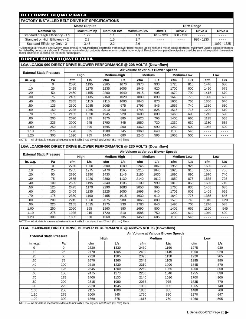
BELT DRIVE BLOWERDATA
FACTORY INSTALLED BELT DRIVE KIT SPECIFICATIONSMotor Outputs RPM Range
Nominal hp Maximum hp Nominal kW Maximum kW Drive 1 Drive 2 Drive 3 Drive 4Standard or High Efficiency - 1.5 1.72 1.1 1.3 615 - 920 800 - 1105 - - - - - - - -Standard or High Efficiency - 2 2.3 1.5 1.7 - - - - - - - - 920 - 1230 - - - -
Standard Efficiency Only - 3 3.45 2.2 2.6 - - - - - - - - - - - - 1070 - 1325*Using total air volume and system static pressure requirements determine from blower performance tables rpm and motor output required. Maximum usable output of motorsfurnished by Lennox are shown. In Canada, nominal motor output is also maximum usable motor output. If motors of comparable output are used, be sure to keep within the servicefactor limitations outlined on the motor nameplate.
DIRECT DRIVE BLOWER DATA
LGA/LCA036-060 DIRECT DRIVE BLOWER PERFORMANCE @ 208 VOLTS (Downflow)
External Static Press reAir Volume at Various Blower Speeds
External Static PressureHigh Medium-High Medium Medium-Low Low
in. w.g. Pa cfm L/s cfm L/s cfm L/s cfm L/s cfm L/s0 0 2530 1195 2265 1070 1970 930 1720 810 1440 680
.10 25 2495 1175 2235 1055 1945 920 1700 800 1430 675
.20 50 2450 1155 2200 1040 1915 905 1670 790 1415 670
.30 75 2405 1135 2160 1020 1880 890 1640 775 1390 655
.40 100 2355 1110 2115 1000 1840 870 1605 755 1360 640
.50 125 2300 1085 2065 975 1795 845 1565 740 1330 630
.60 150 2235 1055 2010 950 1745 825 1515 715 1290 610
.70 175 2165 1020 1945 920 1690 800 1460 690 1245 590
.80 200 2090 985 1875 885 1620 765 1400 660 1195 565
.90 225 2000 945 1790 845 1550 730 1330 630 1130 5351.00 250 1895 895 1695 800 1460 690 1250 590 1055 5001.10 275 1770 835 1580 745 1360 640 1160 545 - - - - - - - -1.20 300 1620 765 1440 680 1240 585 1055 500 - - - - - - - -
NOTE — All air data is measured external to unit with 2 row dry coil and 2 inch (51 mm) filters.
LGA/LCA036-060 DIRECT DRIVE BLOWER PERFORMANCE @ 230 VOLTS (Downflow)
External Static Press reAir Volume at Various Blower Speeds
External Static PressureHigh Medium-High Medium Medium-Low Low
in. w.g. Pa cfm L/s cfm L/s cfm L/s cfm L/s cfm L/s0 0 2750 1300 2500 1180 2245 1060 1955 925 1630 770
.10 25 2705 1275 2470 1165 2215 1045 1925 910 1600 755
.20 50 2650 1250 2430 1145 2180 1030 1890 890 1570 740
.30 75 2585 1220 2390 1130 2140 1010 1850 875 1535 725
.40 100 2535 1195 2340 1105 2100 990 1810 855 1500 710
.50 125 2475 1170 2290 1080 2050 965 1760 830 1455 685
.60 150 2405 1135 2225 1050 1995 940 1705 805 1405 665
.70 175 2330 1100 2155 1015 1930 910 1640 775 1365 645
.80 200 2245 1060 2075 980 1865 880 1575 745 1310 620
.90 225 2155 1015 1975 930 1780 840 1495 705 1240 5851.00 250 2050 965 1860 880 1690 800 1405 665 1150 5451.10 275 1935 915 1720 810 1585 750 1290 610 1040 4901.20 300 1805 850 1560 735 1450 685 1160 545 - - - - - - - -
NOTE — All air data is measured external to unit with 2 row dry coil and 2 inch (51 mm) filters.
LGA/LCA036-060 DIRECT DRIVE BLOWER PERFORMANCE @ 460/575 VOLTS (Downflow)
External Static Press reAir Volume at Various Blower Speeds
External Static PressureHigh Medium Low
in. w.g. Pa cfm L/s cfm L/s cfm L/s0 0 2820 1330 2460 1160 1975 930
.10 25 2770 1305 2430 1145 1950 920
.20 50 2720 1285 2395 1130 1920 905
.30 75 2670 1260 2345 1105 1885 890
.40 100 2610 1230 2310 1090 1845 870
.50 125 2545 1200 2260 1065 1800 850
.60 150 2475 1170 2200 1040 1755 830
.70 175 2400 1130 2140 1010 1700 800
.80 200 2315 1090 2065 975 1635 770
.90 225 2220 1045 1980 935 1565 7401.00 250 2115 1000 1880 885 1480 7001.10 275 2000 945 1760 830 1370 6471.20 300 1860 875 1615 760 1260 595
NOTE — All air data is measured external to unit with 2 row dry coil and 2 inch (51 mm) filters.
L Series036-072/ Page 25�
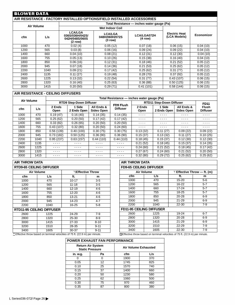
BLOWERDATA
AIR RESISTANCE - FACTORY INSTALLED OPTIONS/FIELD INSTALLED ACCESSORIES
Air Vol meTotal Resistance — inches water gauge (Pa)
Air VolumeWet Indoor Coil
cfm L/sLCA/LGA
036S/036H/042S/042H/048S/060S
(2 row)
LCA/LGA048H/060H/072S
(3 row)
LCA/LGA072H(4 row)
Electric Heat(LCA Models) Economizer
1000 470 0.02 (4) 0.05 (12) 0.07 (18) 0.06 (15) 0.04 (10)1200 565 0.03 (8) 0.06 (16) 0.09 (24) 0.09 (22) 0.04 (10)1400 660 0.04 (10) 0.08 (21) 0.12 (31) 0.12 (30) 0.04 (10)1600 755 0.05 (13) 0.10 (26) 0.15 (38) 0.16 (40) 0.04 (10)1800 850 0.06 (16) 0.12 (31) 0.18 (46) 0.21 (52) 0.05 (12)2000 945 0.07 (18) 0.14 (36) 0.21 (53) 0.25 (62) 0.05 (12)2200 1040 0.09 (21) 0.17 (42) 0.25 (62) 0.31 (77) 0.05 (12)2400 1135 0.11 (27) 0.19 (48) 0.28 (70) 0.37 (92) 0.05 (12)2600 1225 0.13 (32) 0.22 (54) 0.31 (77) 0.43 (107) 0.06 (15)2800 1320 0.16 (40) 0.25 (63) 0.36 (88) 0.50 (125) 0.06 (15)3000 1415 0.20 (50) 0.29 (71) 0.41 (101) 0.58 (144) 0.06 (15)
AIR RESISTANCE - CEILING DIFFUSERS
Air Vol meTotal Resistance — inches water gauge (Pa)
Air VolumeRTD9 Step-Down Diffuser
FD9 Fl shRTD11 Step-Down Diffuser FD11
cfm L/s2 EndsOpen
1 Side2 Ends Open
All Ends &Sides Open
FD9 FlushDiffuser 2 Ends
Open1 Side
2 Ends OpenAll Ends &Sides Open
FD11Flush
Diffuser1000 470 0.19 (47) 0.16 (40) 0.14 (35) 0.14 (35) - - - - - - - - - - - - - - - -1200 565 0.25 (62) 0.20 (50) 0.17 (42) 0.17 (42) - - - - - - - - - - - - - - - -1400 660 0.33 (82) 0.26 (65) 0.20 (50) 0.20 (50) - - - - - - - - - - - - - - - -1600 755 0.43 (107) 0.32 (80) 0.20 (50) 0.24 (60) - - - - - - - - - - - - - - - -1800 850 0.56 (139) 0.40 (100) 0.30 (75) 0.30 (75) 0.13 (32) 0.11 (27) 0.09 (22) 0.09 (22)2000 945 0.73 (182) 0.50 (125) 0.36 (90) 0.36 (90) 0.15 (37) 0.13 (32) 0.11 (27) 0.10 (25)2200 1040 0.95 (237) 0.63 (157) 0.44 (110) 0.44 (110) 0.18 (45) 0.15 (37) 0.12 (30) 0.12 (30)2400 1135 - - - - - - - - - - - - - - - - 0.21 (52) 0.18 (45) 0.15 (37) 0.14 (35)2600 1225 - - - - - - - - - - - - - - - - 0.24 (60) 0.21 (52) 0.18 (45) 0.17 (42)2800 1320 - - - - - - - - - - - - - - - - 0.27 (67) 0.24 (60) 0.21 (52) 0.20 (50)3000 1415 - - - - - - - - - - - - - - - - 0.32 (80) 0.29 (72) 0.25 (62) 0.25 (62)
AIR THROW DATARTD9-65 CEILING DIFFUSER
Air Volume oEffective Throwcfm L/s ft. m1000 470 10-17 3-51200 565 11-18 3-51400 660 12-19 4-61600 755 12-20 4-61800 850 13-21 4-62000 945 14-23 4-72200 1040 16-25 5-8
RTD11-95 CEILING DIFFUSER2600 1225 24-29 7-92800 1320 25-30 8-93000 1415 27-33 8-103200 1510 28-35 9-113400 1605 30-37 9-11
oEffective throw based on terminal velocities of 75 ft. (22.9 m) per minute.
AIR THROW DATAFD9-65 CEILING DIFFUSER
Air Volume oEffective Throw — ft. (m)cfm L/s ft. m1000 470 15-20 5-61200 565 16-22 5-71400 660 17-24 5-71600 755 18-25 5-71800 850 20-28 6-92000 945 21-29 6-92200 1040 22-30 7-9
FD11-95 CEILING DIFFUSER2600 1225 19-24 6-72800 1320 20-28 6-93000 1415 21-29 6-93200 1510 22-29 7-93400 1605 22-30 7-9
oEffective throw based on terminal velocities of 75 ft. (22.9 m) per minute.
POWER EXHAUST FAN PERFORMANCEReturn Air System
Static PressureAir Volume Exhausted
in. w.g. Pa cfm L/s0 0 1900 370
0.05 12 1745 8250.10 25 1570 7400.15 37 1400 6600.20 50 1230 5800.25 62 1060 5000.30 75 970 4600.35 87 800 380
L Series036-072/ Page 26�
GUIDE SPECIFICATIONSPrepared for the guidance of architects, consulting engineers andmechanical contractors.General — Furnish and install a single package air to air DX mechanicalcooling system or cooling and gas fired heating system, complete with au-tomatic controls. The single package unit shall be a standard product ofa firm regularly engaged in the manufacture of heating-cooling equipment.The manufacturer shall have parts and service available throughout theU.S. and Canada.The installed weight shall not be more than lbs. (kg). Entire unitshall have a width of not more than inches (mm), a depth of notmore than inches (mm) and an overall height of not more than
inches (mm). The equipment shall be shipped completely factoryassembled, precharged, piped and wired internally ready for field connec-tions. In addition, manufacturer shall test operate system at the factory be-fore shipment.Air Distribution — Equipment shall be capable of bottom (down-flow) orside (horizontal) handling of conditioned air. All air distribution ducts shall befiberglass or ga. galvanized steel insulated with inch(mm) thick lb./ft.3 (kg/m3) density fiberglass or equivalent.Approvals — All electrical components shall have U.L. and U.L.C. Listing.All wiring shall be in compliance with NEC and CEC.Equipment Warranty — Aluminized Steel Heat Exchangers shall have alimited warranty for a full ten years. Optional Stainless Steel Heat Ex-changers shall have a limited warranty for a full fifteen years (LGA Mod-els). Compressors have a limited warranty for a full five years. IntegratedModular Control shall have a limited warranty for a full 3 years. All othercomponents have a limited warranty for one year. Refer to the LennoxEquipment Limited Warranty certificate included with the unit for details.Cooling System — The total certified cooling capacity shall not be lessthan Btuh (kW) with an indoor coil air volume of cfm (L/s),an entering wet bulb air temperature of °F (°C), an entering drybulb air temperature of °F (°C) and an outdoor coil entering tempera-ture of °F (°C). The compressor power input shall not exceed
kW at these conditions.The coils shall be non-ferrous construction with aluminum fins mechani-cally bonded to durable copper tubes. Coils shall be pressure leak tested.Coil face area shall be not less than sq. ft. (m2) (indoor coil) and
sq. ft. (m2) (outdoor coil). Outdoor coils shall be formed coilconstruction.Compressor shall be resiliently mounted, have overload protection andcrankcase heater. The refrigeration system shall have discharge suctionand liquid line gauge ports, thermostatic expansion valve, high pressureswitch, low pressure switch, drier, freezestat and full refrigerant charge.Optional service valves shall be available. All models shall have low ambi-ent operation down to 0°F (-17.7°C). All models shall be rated in accor-dance with ARI Standard 210/240-94.Heating System (LGA Models) — The heating capacity output shall be
Btuh (kW) with a gas input of Btuh (kW).Tubular heat exchanger and inshot type gas burners shall be constructedof aluminized steel. Controls shall consist of direct spark ignition, electron-ic flame sensor controls, flame rollout switch, limit controls and automaticredundant dual gas valve with staging control and combustion air provingswitch on induced draft blower. Unit shall be available for use with LPG/propane as an option. Heat exchanger shall be removable for servicing.Complete service access shall be provided for controls and wiring. Shallbe U.L./U.L.C. design certified for outdoor installation. Optional stainlesssteel heat exchanger shall be available for applications where mixed airtemperature is between 30 and 45° F (-1 and 7°C).Cabinet — Shall be galvanized steel with a powdered enamel paint finishelectrostatically bonded to the metal. Cabinet panels where conditioned airis handled shall be fully insulated to prevent sweating and minimize sound.Openings shall be provided for bottom or side power connection entry. In-door coil condensate drain extended outside cabinet shall be provided. Lift-ing holes shall be provided for rigging.Service Access — Cabinet panels shall be hinged with tool-less access forcompressor/heating/controls, blower and air filter/economizer compartments.Supply Air Blower — Centrifugal supply air blower shall be driven by amulti-speed direct drive motor or belt drive motor with ball bearings and ad-justable drive. Blower assembly shall be accessible for servicing. Beltdrive motor mount base shall permit ease of motor changeover and belttension adjustment. Blower wheel shall be statically and dynamically bal-anced. Blower shall be capable of delivering cfm (L/s) at an externalstatic pressure of inches water gauge (Pa) requiring not morethan bhp (W) and rpm.Integrated Modular Control (IMC) — Solid state control board shall beprovided to operate unit. Built-in functions shall include: blower on/offdelay, built-in control parameter defaults, service relay output, dirty filterswitch input, dehumidistat input, economizer control, electric heat staging,ETM compatible, unit diagnosis, diagnostics code storage, gas valvedelay between stages, indoor air quality input, low ambient controls, mini-mum run time, night setback mode, smoke alarm mode, low pressure con-trol, thermostat bounce delay, three digit display, °F or °C display, 2 stageheat/3 stage cool thermostat compatible and warm up mode.Outdoor Coil Fan — Direct drive propeller type outdoor coil fan shall dis-charge vertically and be direct driven by a hp (W) motor. Fan motorshall have ball bearings and be permanently lubricated and inherently pro-tected. Fan shall have a safety guard.
Air Filters — Disposable 2 inch (51 mm) thick pleated filters furnishedshall have not less than sq. ft. (m2) of free area.OPTIONAL ACCESSORIESAdditive Electric Heaters (LCA Models) — The certified total heating ca-pacity output shall be Btuh with kW input at
volts power supply.Electric heaters shall be available for factory or field installation. Heatingelements shall be nichrome bare wire exposed directly to the air stream.Time delays shall bring the elements on and off in sequence with a timedelay between each element. Limit controls shall provide overload andshort circuit protection.Blower Proving Switch — Furnish and factory install air pressure switchto monitor blower operation.Ceiling Diffusers — Furnish and install a (flush or stepdown) optionalcombination ceiling supply and return air diffuser. It shall be capable of notless than ft. (m) radius of effective throw. Supply and return transi-tions shall be available, for field installation in the roof mounting frame, toprovide duct connection to the diffuser.Coil Guards — Furnish and install painted, galvanized steel coil guards.Control Systems — Shall provide a selection of control systems to auto-matically operate the mechanical equipment through the heating or cool-ing and ventilating cycles as required.Corrosion Protection — Furnish and factory apply phenolic epoxy coat-ing to either or both of the following:Outdoor coils with painted outdoor base section. Indoor coil with paintedindoor base section and painted blower housings.Dirty Filter Switch — Furnish and install pressure switch that indicatesdirty filter, relays information to Integrated Modular Control.Dehumidistat — Furnish and install dehumidistat, relays information toIntegrated Modular Control.Disconnect — Furnish and factory install unit disconnect switch.Economizer Section — Furnish and install economizer complete with recir-culated air dampers, outside air dampers and controls. Low leakage dampersshall ride in nylon bearings. The economizer section shall provide for theintroduction of outdoor air for minimum ventilation and free cooling. Integratedeconomizer control shall allow compressors to cycle for additional cooling, asneeded. Damper actuator shall be opposing gear driven, 24 volt, fully modu-lating design. Plug-in control board (on unit IMC board) shall consist of adjust-able minimum positioner, enthalpy setpoint and DIP switches for setting typeof control logic used. Economizer control options shall consist of sensibletemperature, global, outdoor enthalpy and differential enthalpy (outdoor andreturn air). Optional outdoor air hood (required) with filters shall be galvanizedsteel with a powdered enamel paint finish electrostatically bonded to the met-al. Economizer shall be available for factory or field installation.Gravity Exhaust Dampers — Pressure operated dampers shall be avail-able for factory or field installation. Extruded aluminum dampers shall pre-vent blow-back and outdoor air infiltration during off cycle.Hail Guards — Furnish and install heavy gauge, painted steel hail guards.High Efficiency Blower Motor — Furnish and factory install high efficiency beltdrive blower motor. Not available in 1.5 hp (1.1 kW) (1ph) or 3 hp (2.2 kW) size.Horizontal Gravity Exhaust Dampers — Pressure operated dampers shallbe available for field installation in the return air duct. Extruded aluminumdampers shall prevent blow-back and outdoor air infiltration during off cycle.Indoor Air Quality Sensor — Furnish and field install sensor to monitorCO2 levels, relays information to Integrated Module Control which adjustseconomizer dampers proportionately to the pollutant level.Outdoor Air Damper Section — Optional outdoor dampers shall be avail-able to provide outdoor air requirements of up to 25%. Models shall beavailable for manual or automatic operation. Motorized dampers shall beopposing gear driven design. Motorized damper section shall install inter-nal to the unit. Optional outdoor air hood (required) with filters shall be gal-vanized steel with a powdered enamel paint finish electrostatically bondedto the metal. Dampers shall be available for factory or field installation.Power Exhaust Fan — Shall be available for all models with economizer(down-flow applications only). Direct drive propeller type fan shall exhaustair through gravity exhaust damper. Motor shall be overload protected.Fan shall be field installed between economizer and gravity exhaustdampers.Roof Mounting Frame — Furnish and install a steel roof mounting framefor bottom discharge and return air duct connection. It shall mate to the bot-tom perimeter of the equipment. When flashed into the roof it shall makea unit mounting curb and provide weatherproof duct connection and entryinto the conditioned area. Height of frame shall be inches (mm).Flashing shall be the responsibility of the roofing contractor. Frame shallbe approved by U.S. National Roofing Contractors Association.Service Outlets — Furnish and factory install dual 115 volt, 15 amp GFCItype service outlets. Wiring shall be field provided.Service Valves (LCA/LGA) — Furnish and factory install fully serviceablebrass service valves in discharge and liquid lines. Shall allow refrigerantpump down to high side of system for servicing of low side.Smoke Detectors — Furnish and factory install photoelectric type smokedetector in either or both return air section and supply air section.Terminal Block (LCA Models) — Shall be required for units without dis-connect switch but with single point power supply and electric heat.Unit Fuse Block (LCA Models) — Shall be required for units with singlepoint power supply and electric heat.
L Series036-072/ Page 27�
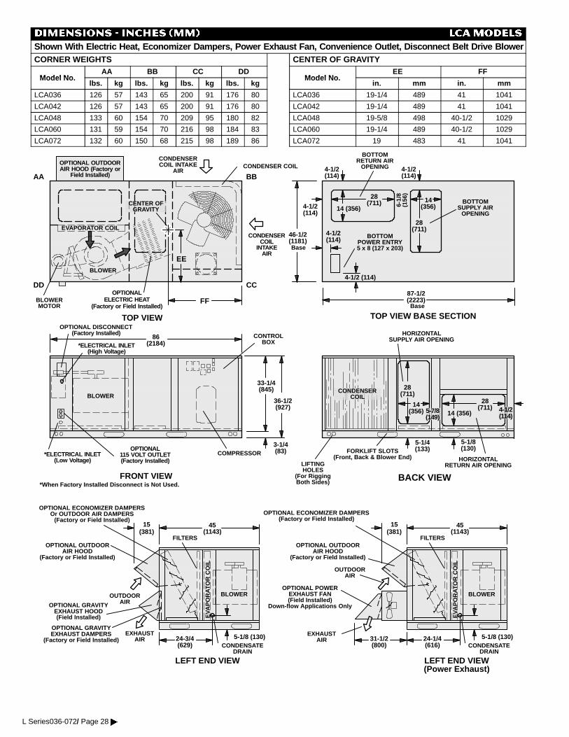
DIMENSIONS - INCHES (MM) LCAMODELS
Shown With Electric Heat, Economizer Dampers, Power Exhaust Fan, Convenience Outlet, Disconnect Belt Drive BlowerCORNER WEIGHTS
Model NoAA BB CC DD
Model No.lbs. kg lbs. kg lbs. kg lbs. kg
LCA036 126 57 143 65 200 91 176 80
LCA042 126 57 143 65 200 91 176 80
LCA048 133 60 154 70 209 95 180 82
LCA060 131 59 154 70 216 98 184 83
LCA072 132 60 150 68 215 98 189 86
CENTER OF GRAVITY
Model NoEE FF
Model No.in. mm in. mm
LCA036 19-1/4 489 41 1041
LCA042 19-1/4 489 41 1041
LCA048 19-5/8 498 40-1/2 1029
LCA060 19-1/4 489 40-1/2 1029
LCA072 19 483 41 1041
TOP VIEW
FRONT VIEW
TOP VIEW BASE SECTION
BACK VIEW
BOTTOMPOWER ENTRY5 x 8 (127 x 203)
BLOWER
EVAPORATOR COIL
CONDENSER COIL
36-1/2(927)
BLOWERMOTOR
CONTROLBOX
HORIZONTALRETURN AIR OPENING
BOTTOMRETURN AIR
OPENING
3-1/4(83)
33-1/4(845) CONDENSER
COIL
CONDENSERCOIL
INTAKEAIR
CONDENSERCOIL INTAKE
AIR
*ELECTRICAL INLET(Low Voltage)
BOTTOMSUPPLY AIR
OPENING
COMPRESSOR
LIFTINGHOLES
(For RiggingBoth Sides)
FORKLIFT SLOTS(Front, Back & Blower End)
Base
HORIZONTALSUPPLY AIR OPENING
87-1/2(2223)
4-1/2(114)
4-1/2(114)
4-1/2(114)
4-1/2(114)
28(711)
28(711)
14 (356)14
(356)
86(2184)
6-1/
8(1
56)
OPTIONALELECTRIC HEAT
(Factory or Field Installed)
4-1/2 (114)
OPTIONAL DISCONNECT(Factory Installed)
*When Factory Installed Disconnect is Not Used.
28(711)
28(711)
14 (356)14
(356)
AA BB
CCDD
EE
FF
OPTIONAL OUTDOORAIR HOOD (Factory or
Field Installed)
Base
46-1/2(1181)
EXHAUSTAIR
OUTDOORAIR
15(381)
LEFT END VIEW
CONDENSATEDRAIN
EVA
PO
RAT
OR
CO
IL
BLOWER
45(1143)
5-1/8 (130)24-3/4(629)
FILTERSOPTIONAL OUTDOOR
AIR HOOD(Factory or Field Installed)
OPTIONAL GRAVITYEXHAUST HOOD(Field Installed)
OPTIONAL ECONOMIZER DAMPERSOr OUTDOOR AIR DAMPERS
(Factory or Field Installed)
OPTIONAL GRAVITYEXHAUST DAMPERS
(Factory or Field Installed)EXHAUST
AIR
OUTDOORAIR
15(381)
LEFT END VIEW(Power Exhaust)
CONDENSATEDRAIN
EVA
PO
RAT
OR
CO
IL
BLOWER
45(1143)
5-1/8 (130)24-1/4(616)
FILTERSOPTIONAL OUTDOOR
AIR HOOD(Factory or Field Installed)
OPTIONAL ECONOMIZER DAMPERS(Factory or Field Installed)
OPTIONAL POWEREXHAUST FAN(Field Installed)
Down-flow Applications Only
31-1/2(800)
BLOWER
CENTER OFGRAVITY
OPTIONAL115 VOLT OUTLET(Factory Installed)
*ELECTRICAL INLET(High Voltage)
4-1/2(114)
5-7/8(149)
5-1/4(133)
5-1/8(130)
L Series036-072/ Page 28�
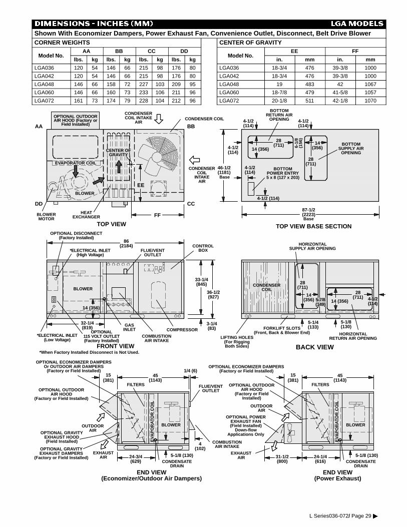
DIMENSIONS - INCHES (MM) LGAMODELS
Shown With Economizer Dampers, Power Exhaust Fan, Convenience Outlet, Disconnect, Belt Drive BlowerCORNER WEIGHTS
Model NoAA BB CC DD
Model No.lbs. kg lbs. kg lbs. kg lbs. kg
LGA036 120 54 146 66 215 98 176 80
LGA042 120 54 146 66 215 98 176 80
LGA048 146 66 158 72 227 103 209 95
LGA060 146 66 160 73 233 106 211 96
LGA072 161 73 174 79 228 104 212 96
CENTER OF GRAVITY
Model NoEE FF
Model No.in. mm in. mm
LGA036 18-3/4 476 39-3/8 1000
LGA042 18-3/4 476 39-3/8 1000
LGA048 19 483 42 1067
LGA060 18-7/8 479 41-5/8 1057
LGA072 20-1/8 511 42-1/8 1070
OPTIONAL POWEREXHAUST FAN(Field Installed)
Down-flowApplications Only
TOP VIEW
FRONT VIEW
TOP VIEW BASE SECTION
BACK VIEW
BOTTOMPOWER ENTRY5 x 8 (127 x 203)
BLOWER
EVAPORATOR COIL
CONDENSER COIL
36-1/2(927)
BLOWERMOTOR
CONTROLBOX
HORIZONTALRETURN AIR OPENING
BOTTOMRETURN AIR
OPENING
3-1/4(83)
33-1/4(845) CONDENSER
COIL
CONDENSERCOIL
INTAKEAIR
CONDENSERCOIL INTAKE
AIR
BOTTOMSUPPLY AIR
OPENING
COMPRESSOR
LIFTING HOLES(For RiggingBoth Sides)
FORKLIFT SLOTS(Front, Back & Blower End)
Base
HORIZONTALSUPPLY AIR OPENING
87-1/2(2223)
4-1/2(114)
4-1/2(114)
4-1/2(114)
4-1/2(114)
28(711)
28(711)
14 (356)14
(356)
86(2184)
6-1/
8(1
56)
4-1/2 (114)
*When Factory Installed Disconnect is Not Used.
28(711)
28(711)
14 (356)14
(356)
AA BB
CCDD
EE
FF
OPTIONAL OUTDOORAIR HOOD (Factory or
Field Installed)
Base
46-1/2(1181)
EXHAUSTAIR
OUTDOORAIR
15(381)
END VIEW(Economizer/Outdoor Air Dampers)
CONDENSATEDRAIN
EVA
PO
RAT
OR
CO
IL
BLOWER
45(1143)
5-1/8 (130)24-3/4(629)
FILTERSOPTIONAL OUTDOOR
AIR HOOD(Factory or Field Installed)
OPTIONAL GRAVITYEXHAUST HOOD(Field Installed)
OPTIONAL ECONOMIZER DAMPERSOr OUTDOOR AIR DAMPERS
(Factory or Field Installed)
OPTIONAL GRAVITYEXHAUST DAMPERS
(Factory or Field Installed)EXHAUST
AIR
OUTDOORAIR
15(381)
END VIEW(Power Exhaust)
CONDENSATEDRAIN
EVA
PO
RAT
OR
CO
IL
BLOWER
45(1143)
5-1/8 (130)24-1/4(616)
FILTERSOPTIONAL OUTDOORAIR HOOD
(Factory or FieldInstalled)
OPTIONAL ECONOMIZER DAMPERS(Factory or Field Installed)
31-1/2(800)
BLOWER
HEATEXCHANGER
CENTER OFGRAVITY
GASINLET
FLUE/VENTOUTLET
COMBUSTIONAIR INTAKE
14 (356)
OPTIONAL DISCONNECT(Factory Installed)
*ELECTRICAL INLET(Low Voltage)
FLUE/VENTOUTLET
COMBUSTIONAIR INTAKE4
(102)
*ELECTRICAL INLET(High Voltage)
32-1/4(819)
1/4 (6)
OPTIONAL115 VOLT OUTLET(Factory Installed)
4-1/2(114)
5-7/8(149)
5-1/4(133)
5-1/8(130)
L Series036-072/ Page 29�
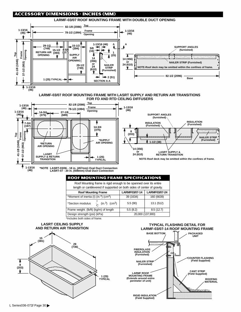
ACCESSORY DIMENSIONS - INCHES (MM)
LARMF-03/07 ROOF MOUNTING FRAME WITH DOUBLE DUCT OPENING
NAILER STRIP (Furnished)
NOTE-Roof deck may be omitted within the confines of frame.
SUPPORT ANGLES(furnished)
RETURN AIROPENING SUPPLY
AIROPENING
AA
NAILERSTRIP
(Furnished)
1-13/16 (46)
2 (51)SECTION A-A
5/8(16) 1
(25)
Fra
me
Ope
ning
FrameOpening
1-13/16(46)
1-13/16(46)
1-13/16(46)
78-1/2 (1994)
37-1
/2(9
53)
41-1
/8(1
045)
29-1/2(749)
15-1/2(394)
29-1/2(749)
15-1/2(394)4-5/8
(117)
1 (25) TYPICAL
14(356)
or24
(610)
14 (356)or
24 (610)
82-1/8 (2086) Top
82-1/2 (2096)Base
Top
LARMF-03/07 ROOF MOUNTING FRAME WITH LASRT SUPPLY AND RETURN AIR TRANSITIONSFOR FD AND RTD CEILING DIFFUSERS
NAILER STRIP(Furnished)
NOTE-Roof deck may be omitted within the confines of frame.
SUPPORT ANGLES(furnished)
Fra
me
Ope
ning
FrameOpening1-13/16
(46)
1-13/16(46)
1-13/16(46)
82-1/8 (2086)
78-1/2 (1994)
37-1
/2(9
53)
41-1
/8(1
045)
1 (25)TYPICAL
LASRTSUPPLY & RETURN
TRANSITION
8(203)
1-1/2 (38)
INSULATION(Furnished)
INSULATION(Furnished)
1-13/16(46)
*SUPPLYAIR OPENING
LASRT SUPPLY &RETURN TRANSITION
*RETURNAIR OPENING
7-3/4(197) 14-3/4
(375)
27-1/8(689)
14-3/4(375)
14 (356)or
24 (610)
*NOTE LASRT-03/06 - 18 in. (457mm) Oval Duct ConnectionLASRT-07 - 20 in. (508mm) Oval Duct Connection
Top
Top
ROOFMOUNTING FRAME SPECIFICATIONS
Roof Mounting frame is rigid enough to be spanned over its entirelength or cantilevered if supported on both sides of center of gravity.
Roof Mounting Frame LARMF03/07-14 LARMF03/07-24*Moment of inertia (I) (in.4) (cm4) 39 (1634) 160 (6639)
*Section modulusI-C
(in.3) (cm3) 5.5 (90) 13.1 (512)
Frame weight. (lb/ft) (kg/m) of length 5.5 (8.2) 8.5 (12.7)
Design strength (psi) (kPa) 20,000 (137,900)*Includes both sides of frame.
29(736)
15(381)
8(203)
1 (25)TYPICAL
LASRT CEILING SUPPLYAND RETURN AIR TRANSITION
LARMF ROOFMOUNTING FRAME
(Extends around entireperimeter of unit)
FIBERGLASSINSULATION(Furnished)
COUNTER FLASHING(Field Supplied)
BASE BOTTOM
RIGID INSULATION(Field Supplied)
ROOFINGMATERIAL
CANT STRIP(Field Supplied)
TYPICAL FLASHING DETAIL FORLARMF-03/07-14 ROOF MOUNTING FRAME
PACKAGEDUNIT
NAILER STRIP(Furnished)
L Series036-072/ Page 30�
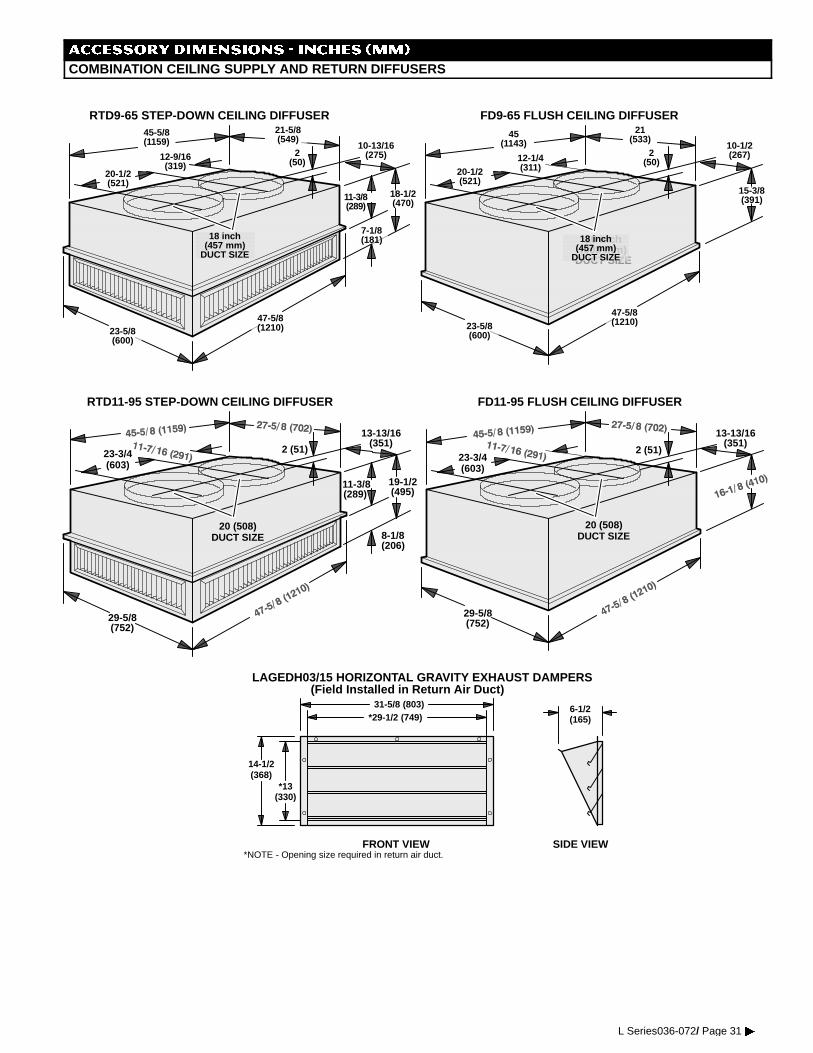
ACCESSORY DIMENSIONS - INCHES (MM)
COMBINATION CEILING SUPPLY AND RETURN DIFFUSERS
20 inch(508 mm)
DUCT SIZE
20-1/2(521)
18 inch(457 mm)
DUCT SIZE
47-5/8(1210)23-5/8
(600)
7-1/8(181)
18-1/2(470)
11-3/8(289)
10-13/16(275)2
(50)
21-5/8(549)
45-5/8(1159)
12-9/16(319)
45(1143)
21(533)
47-5/8(1210)23-5/8
(600)
20-1/2(521)
12-1/4(311)
2(50)
10-1/2(267)
RTD9-65 STEP-DOWN CEILING DIFFUSER FD9-65 FLUSH CEILING DIFFUSER
15-3/8(391)
18 inch(457 mm)
DUCT SIZE
20 (508)DUCT SIZE
20 (508)DUCT SIZE
29-5/8(752)
8-1/8(206)
19-1/2(495)
13-13/16(351)
2 (51)23-3/4(603)
RTD11-95 STEP-DOWN CEILING DIFFUSER FD11-95 FLUSH CEILING DIFFUSER
29-5/8(752)
2 (51)23-3/4(603)
13-13/16(351)
11-3/8(289)
FRONT VIEW SIDE VIEW
31-5/8 (803)
14-1/2(368)
*13(330)
6-1/2(165)*29-1/2 (749)
*NOTE - Opening size required in return air duct.
LAGEDH03/15 HORIZONTAL GRAVITY EXHAUST DAMPERS(Field Installed in Return Air Duct)
L Series036-072/ Page 31�
Related Documents