International Symposium on Energy Conversion Fundamentals 21-25 June 2004, Gumussuyu, Istanbul, Turkey Comparison of Turbulence Models for an Internal Flow with Side Wall Mass Injection B. A. Sen, U. G. Yuksel and K. Kirkkopru Faculty of Mechanical Engineering, Istanbul Technical University, Gumussuyu, Istanbul, Turkey Introduction Solid propellant rocket boosters (SPRB) are used extensively in aerospace activities when a strong thrust is needed as in the case of lifting off the satellites for space activities [1]. Flow structures occurring within the SPRB’s have drawn the attention of the researchers either experimentally [2,3], or as it happens increasingly today, computationally [4,5]. The flow field inside the combustion chamber experiences different processes since the characteristic velocity throughout the chamber is on the order of Ma = O(10 -2 ) [6], whereas the exit velocity is supersonic. Time dependent behavior of various processes, turbulence, combustion, as well as with the compressibility effects add intricacy into the simulation processes. Today, major study field for the SPRBs is the flow stability problem inside the combustion chamber [6], and its interaction with combustion [7] and turbulence [8]. This study is the first part of an ongoing research held in the Faculty of Mechanical Engineering at Istanbul Technical University (ITU), to simulate the interaction of the turbulence, combustion and the acoustic field inside SPRBs. In this preliminary work, a computational study has been performed to identify the effect of various turbulence models on the calculations of cold flow field inside a model SPRB combustion chamber. A commercial flow solver, Fluent 6.1.22, has been employed for the computations. The flow configuration chosen is an idealization of that found in a solid rocket motor, and was selected in accordance with the VECLA facility of ONERA that is an experimental set up for investigating the characteristics of injection driven flows [4,8,9]. Schematic of the facility is given in Figure 1, where the length of the channel is = L 0.581 m and its height is = h 0.0103 m. The channel is bounded at 0 by a permeable wall allowing the mass injection and at = h y / = h y / 1 by an impermeable wall. The upstream at = L x / 0, head-end, is closed and the downstream, at = L x / 1, exit section, is open to the atmosphere. Sidewall mass injection is used to mimic the normal velocity of gaseous products generated by combustion of gasified propellant. For this particular work, based on the Reynolds averaged Navier Stokes equations, computations have been performed by modeling the turbulence with one equation model (Spallart Allmaras), two equation models (Standard k-ε, RNG k-ε, Realizable k-ε, SST k-ω) and the Reynolds Stress model. Set of governing equations has been solved by employing the Finite Volume technique [10]. Boundary conditions were specified as, air injection mass flux, 2.619 kg/m = m & 2 s, and the appropriate turbulence quantities, = k ~ 0.0001 m 2 /s 2 , = ε ~ 0.001 m 2 /s 3 , = ω ~ 0.4 1/s, at the permeable wall; pressure outlet, 137400 Pa, in the exit section and no slip condition for the impermeable wall at 1 and the solid wall in the head-end, at = h y / = h y / 0. Reynolds number based on the injection velocity and the channel height, , is approximately 8000. Density was calculated by the ideal gas law, and hence air injection temperature, 300 K, was specified. Normalized longitudinal velocity and the turbulent intensity profiles calculated with various turbulence closure models are compared with those from the experiment reported in [9] at several cross sections. i Re 1

Welcome message from author
This document is posted to help you gain knowledge. Please leave a comment to let me know what you think about it! Share it to your friends and learn new things together.
Transcript
International Symposium on Energy Conversion Fundamentals 21-25 June 2004, Gumussuyu, Istanbul, Turkey
Comparison of Turbulence Models for an Internal Flow with Side Wall Mass Injection B. A. Sen, U. G. Yuksel and K. Kirkkopru Faculty of Mechanical Engineering, Istanbul Technical University, Gumussuyu, Istanbul, Turkey
Introduction
Solid propellant rocket boosters (SPRB) are used extensively in aerospace activities when a strong thrust is needed as in the case of lifting off the satellites for space activities [1]. Flow structures occurring within the SPRB’s have drawn the attention of the researchers either experimentally [2,3], or as it happens increasingly today, computationally [4,5]. The flow field inside the combustion chamber experiences different processes since the characteristic velocity throughout the chamber is on the order of Ma = O(10-2) [6], whereas the exit velocity is supersonic. Time dependent behavior of various processes, turbulence, combustion, as well as with the compressibility effects add intricacy into the simulation processes. Today, major study field for the SPRBs is the flow stability problem inside the combustion chamber [6], and its interaction with combustion [7] and turbulence [8].
This study is the first part of an ongoing research held in the Faculty of Mechanical Engineering at Istanbul Technical University (ITU), to simulate the interaction of the turbulence, combustion and the acoustic field inside SPRBs. In this preliminary work, a computational study has been performed to identify the effect of various turbulence models on the calculations of cold flow field inside a model SPRB combustion chamber. A commercial flow solver, Fluent 6.1.22, has been employed for the computations.
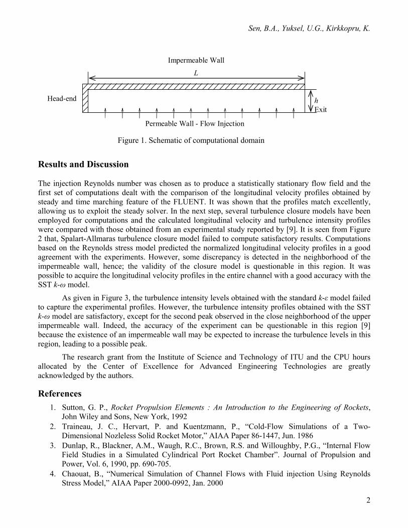
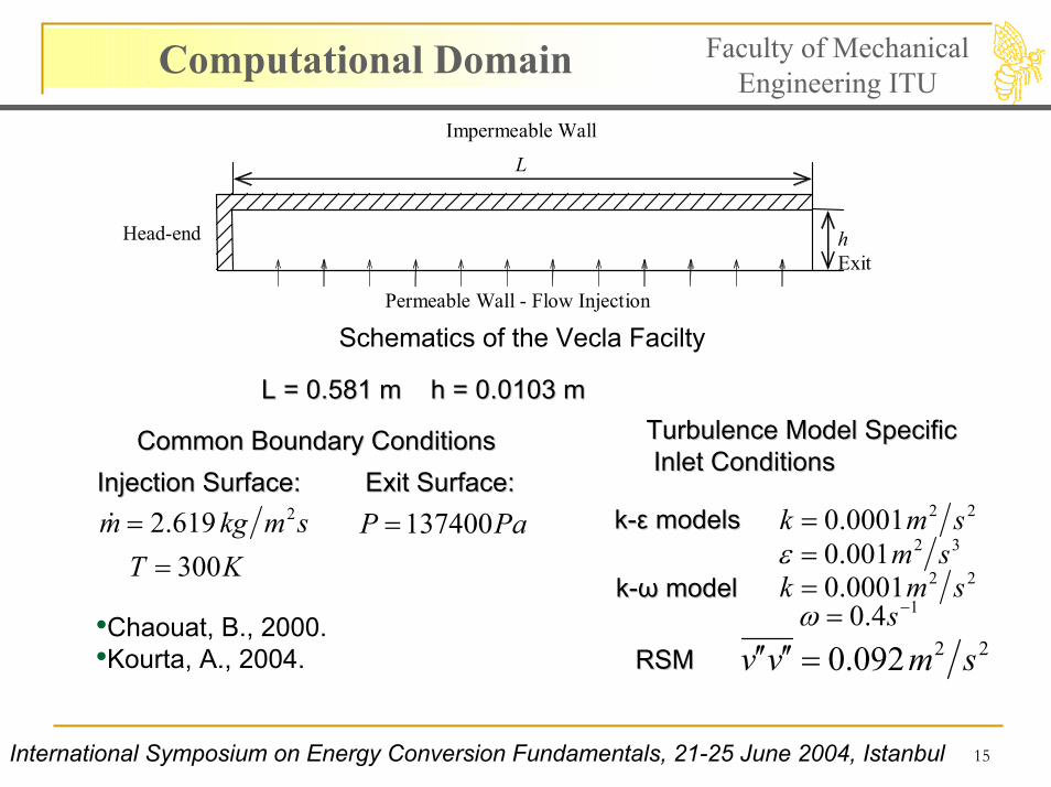
The flow configuration chosen is an idealization of that found in a solid rocket motor, and was selected in accordance with the VECLA facility of ONERA that is an experimental set up for investigating the characteristics of injection driven flows [4,8,9]. Schematic of the facility is given in Figure 1, where the length of the channel is =L 0.581 m and its height is =h 0.0103 m. The channel is bounded at 0 by a permeable wall allowing the mass injection and at =hy / =hy / 1 by an impermeable wall. The upstream at =Lx / 0, head-end, is closed and the downstream, at =Lx / 1, exit section, is open to the atmosphere. Sidewall mass injection is used to mimic the normal velocity of gaseous products generated by combustion of gasified propellant.
For this particular work, based on the Reynolds averaged Navier Stokes equations, computations have been performed by modeling the turbulence with one equation model (Spallart Allmaras), two equation models (Standard k-ε, RNG k-ε, Realizable k-ε, SST k-ω) and the Reynolds Stress model. Set of governing equations has been solved by employing the Finite Volume technique [10]. Boundary conditions were specified as, air injection mass flux, 2.619 kg/m=m& 2s, and the appropriate turbulence quantities, =k~ 0.0001 m2/s2, =ε~ 0.001 m2/s3, =ω~ 0.4 1/s, at the permeable wall; pressure outlet, 137400 Pa, in the exit section and no slip condition for the impermeable wall at
1 and the solid wall in the head-end, at =hy / =hy / 0. Reynolds number based on the injection velocity and the channel height, , is approximately 8000. Density was calculated by the ideal gas law, and hence air injection temperature, 300 K, was specified. Normalized longitudinal velocity and the turbulent intensity profiles calculated with various turbulence closure models are compared with those from the experiment reported in [9] at several cross sections.
iRe
1
Report Documentation Page Form ApprovedOMB No. 0704-0188
Public reporting burden for the collection of information is estimated to average 1 hour per response, including the time for reviewing instructions, searching existing data sources, gathering andmaintaining the data needed, and completing and reviewing the collection of information. Send comments regarding this burden estimate or any other aspect of this collection of information,including suggestions for reducing this burden, to Washington Headquarters Services, Directorate for Information Operations and Reports, 1215 Jefferson Davis Highway, Suite 1204, ArlingtonVA 22202-4302. Respondents should be aware that notwithstanding any other provision of law, no person shall be subject to a penalty for failing to comply with a collection of information if itdoes not display a currently valid OMB control number.
1. REPORT DATE 22 JUN 2004
2. REPORT TYPE N/A
3. DATES COVERED -
4. TITLE AND SUBTITLE Comparison of Turbulence Models for an Internal Flow with Side WallMass Injection
5a. CONTRACT NUMBER
5b. GRANT NUMBER
5c. PROGRAM ELEMENT NUMBER
6. AUTHOR(S) 5d. PROJECT NUMBER
5e. TASK NUMBER
5f. WORK UNIT NUMBER
7. PERFORMING ORGANIZATION NAME(S) AND ADDRESS(ES) Istanbul Technical University, Gumussuyu, Istanbul, Turkey
8. PERFORMING ORGANIZATIONREPORT NUMBER
9. SPONSORING/MONITORING AGENCY NAME(S) AND ADDRESS(ES) 10. SPONSOR/MONITOR’S ACRONYM(S)
11. SPONSOR/MONITOR’S REPORT NUMBER(S)
12. DISTRIBUTION/AVAILABILITY STATEMENT Approved for public release, distribution unlimited
13. SUPPLEMENTARY NOTES See also ADM001793, International Symposium on Energy Conversion Fundamentals Held in Istanbul,Turkey on 21-25 June 2005., The original document contains color images.
14. ABSTRACT
15. SUBJECT TERMS
16. SECURITY CLASSIFICATION OF: 17. LIMITATION OF ABSTRACT
UU
18. NUMBEROF PAGES
30
19a. NAME OFRESPONSIBLE PERSON
a. REPORT unclassified
b. ABSTRACT unclassified
c. THIS PAGE unclassified
Standard Form 298 (Rev. 8-98) Prescribed by ANSI Std Z39-18
Sen, B.A., Yuksel, U.G., Kirkkopru, K.
Impermeable Wall
L
h Exit
Permeable Wall - Flow Injection
Head-end
Figure 1. Schematic of computational domain
Results and Discussion
The injection Reynolds number was chosen as to produce a statistically stationary flow field and the first set of computations dealt with the comparison of the longitudinal velocity profiles obtained by steady and time marching feature of the FLUENT. It was shown that the profiles match excellently, allowing us to exploit the steady solver. In the next step, several turbulence closure models have been employed for computations and the calculated longitudinal velocity and turbulence intensity profiles were compared with those obtained from an experimental study reported by [9]. It is seen from Figure 2 that, Spalart-Allmaras turbulence closure model failed to compute satisfactory results. Computations based on the Reynolds stress model predicted the normalized longitudinal velocity profiles in a good agreement with the experiments. However, some discrepancy is detected in the neighborhood of the impermeable wall, hence; the validity of the closure model is questionable in this region. It was possible to acquire the longitudinal velocity profiles in the entire channel with a good accuracy with the SST k-ω model.
As given in Figure 3, the turbulence intensity levels obtained with the standard k-ε model failed to capture the experimental profiles. However, the turbulence intensity profiles obtained with the SST k-ω model are satisfactory, except for the second peak observed in the close neighborhood of the upper impermeable wall. Indeed, the accuracy of the experiment can be questionable in this region [9] because the existence of an impermeable wall may be expected to increase the turbulence levels in this region, leading to a possible peak.
The research grant from the Institute of Science and Technology of ITU and the CPU hours allocated by the Center of Excellence for Advanced Engineering Technologies are greatly acknowledged by the authors.
References 1. Sutton, G. P., Rocket Propulsion Elements : An Introduction to the Engineering of Rockets,
John Wiley and Sons, New York, 1992 2. Traineau, J. C., Hervart, P. and Kuentzmann, P., “Cold-Flow Simulations of a Two-
Dimensional Nozleless Solid Rocket Motor,” AIAA Paper 86-1447, Jun. 1986 3. Dunlap, R., Blackner, A.M., Waugh, R.C., Brown, R.S. and Willoughby, P.G., “Internal Flow
Field Studies in a Simulated Cylindrical Port Rocket Chamber”. Journal of Propulsion and Power, Vol. 6, 1990, pp. 690-705.
4. Chaouat, B., “Numerical Simulation of Channel Flows with Fluid injection Using Reynolds Stress Model,” AIAA Paper 2000-0992, Jan. 2000
2

International Symposium on Energy Conversion Fundamentals 21-25 June 2004, Gumussuyu, Istanbul, Turkey
3
Normalized Longitudinal Velocity
Cha
nnel
Hei
ght[
m]
0 0.3 0.6 0.9 1.2 1.5 1.80.0000
0.0025
0.0050
0.0075
0.0100
ExperimentalLaminarSpalart Allmaras
Normalized Longitudinal Velocity
Cha
nnel
Hei
ght[
m]
0 0.3 0.6 0.9 1.2 1.5 1.80.0000
0.0025
0.0050
0.0075
0.0100
Experimentalk-eps. Standardk-eps. Realizablek-eps. RNG
Normalized Longitudial Velocity
Cha
nnel
Hei
ght[
m]
0 0.3 0.6 0.9 1.2 1.5 1.80.0000
0.0025
0.0050
0.0075
0.0100
Experimentalk-wRSM
Figure 2. Normalized longitudinal velocity profiles, at =x 0.500 m, obtained with a) Laminar and Spalart-Allmaras, b) Standard k- ε, RNG k- ε and Realizable k- ε, c) Reynolds stress and SST k-ω
closure models and from the experiment [9].
Turbulence Intensity
Cha
nnel
Hei
ght[
m]
0 10 20 30 40 500.0000
0.0025
0.0050
0.0075
0.0100
x=0.031 mx=0.120 mx=0.220 mx=0.350 mx=0.400 mx=0.450 mx=0.500 mx=0.570 m
Turbulence Intensity
Cha
nnel
Hei
ght[
m]
0 5 10 15 200.0000
0.0025
0.0050
0.0075
0.0100
x=0.031 mx=0.120 mx=0.220 mx=0.350 mx=0.400 mx=0.450 mx=0.500 mx=0.570 m
Turbulence Intensity
Cha
nnel
Hei
ght[
m]
0 5 10 15 200.0000
0.0025
0.0050
0.0075
0.0100
Figure 3. Turbulence intensity profiles obtained with a) Standard k- ε, b) SST k-ω and from c) Experiment [9].
5. Apte, S. and Yang, V., “Unsteady Flow Evolution and Combustion Dynamics of Homogeneous
Solid Propellant in a Rocket Motor,” Combustion and Flame, Vol. 131, 2002, pp. 110-131. 6. Kirkkopru, K., Kassoy, D.R., Zhao, Q. and Staab, P.L., “Acoustically Generated Unsteady
Vorticity Field in a Long Narrow Cylinder with Sidewall Injection,” Journal of Engineering Mathematics, Vol. 42, 2002, pp. 65-90.
7. Chu, W.-W., Yang, V. and Majdalani, J., “Premixed Flame Response to Acoustic Waves in a Porous-Walled Chamber with Surface Mass Injection,” Combustion and Flame, Vol. 133, 2003, pp. 359-370.
8. Chaouat, B. and Schiestel, R., “Reynolds Stress Transport Modelling for Steady and Unsteady Channel Flows with Wall Injection,” Journal of Turbulence, Vol. 3, 2002
9. Kourta, A., “Instability of Channel Flow with Surface Mass Injection and Paretial Vortex Shedding,” Computers & Fluids, Vol. 33, 2004, pp. 155-178.
10. FLUENT 6.1 User’s Guide, February 2003.
International Symposium on Energy Conversion Fundamentals 21-25 June 2004, Gumussuyu, Istanbul,TURKEY
Comparison of Turbulence Models for an Internal Flow
with Side Wall Mass Injection
B. A. Sen U. G. Yuksel and K. Kirkkopru
Faculty of Mechanical Engineering,Istanbul Technical University, Gumussuyu, Istanbul, Turkey

2
Overview of the Presentation Faculty of Mechanical Engineering ITU
• Introduction• Governing Equations• Numerical Models and Boundary Conditions• Computational Results• Conclusion
International Symposium on Energy Conversion Fundamentals, 21-25 June 2004, Istanbul
3
Introduction Faculty of Mechanical Engineering ITU
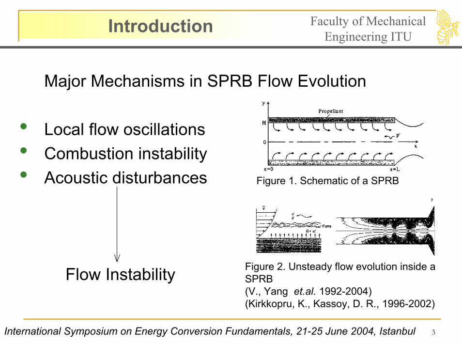
Major Mechanisms in SPRB Flow Evolution
• Local flow oscillations• Combustion instability• Acoustic disturbances
Flow Instability
Figure 1. Schematic of a SPRB
Figure 2. Unsteady flow evolution inside a SPRB(V., Yang et.al. 1992-2004)(Kirkkopru, K., Kassoy, D. R., 1996-2002)
International Symposium on Energy Conversion Fundamentals, 21-25 June 2004, Istanbul
4
Introduction Faculty of Mechanical Engineering ITU
International Symposium on Energy Conversion Fundamentals, 21-25 June 2004, Istanbul
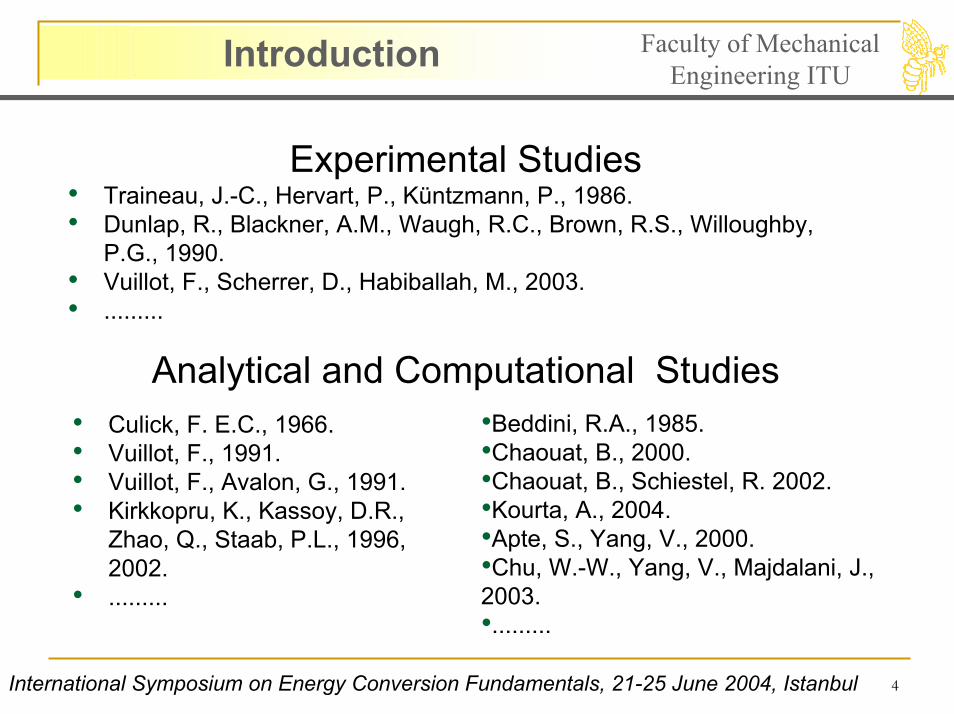
• Culick, F. E.C., 1966. • Vuillot, F., 1991.• Vuillot, F., Avalon, G., 1991.• Kirkkopru, K., Kassoy, D.R.,
Zhao, Q., Staab, P.L., 1996, 2002.
• .........
•Beddini, R.A., 1985.•Chaouat, B., 2000. •Chaouat, B., Schiestel, R. 2002. •Kourta, A., 2004.•Apte, S., Yang, V., 2000. •Chu, W.-W., Yang, V., Majdalani, J., 2003.•.........
Experimental Studies• Traineau, J.-C., Hervart, P., Küntzmann, P., 1986. • Dunlap, R., Blackner, A.M., Waugh, R.C., Brown, R.S., Willoughby,
P.G., 1990. • Vuillot, F., Scherrer, D., Habiballah, M., 2003.• .........
Analytical and Computational Studies
5
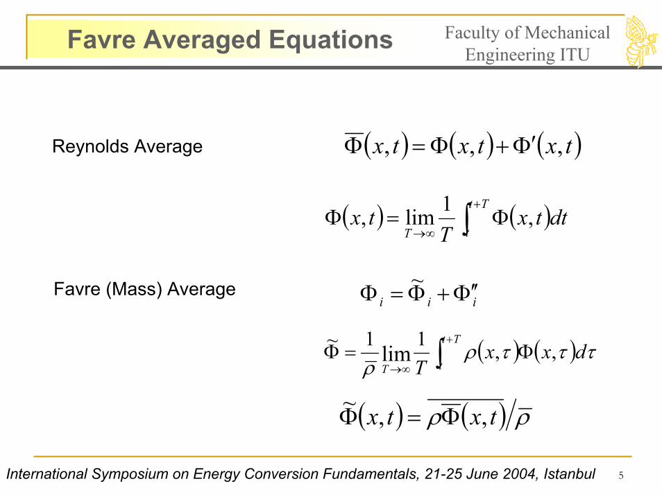
Favre Averaged Equations Faculty of Mechanical Engineering ITU
( ) ( ) ( )txtxtx ,,, Φ′+Φ=ΦReynolds Average
( ) ( )∫+
∞→Φ=Φ
Tt
tTdttx
Ttx ,1lim,
iii Φ′′+Φ=Φ ~Favre (Mass) Average
( ) ( )∫+
∞→Φ=Φ
Tt
tTdxx
Tτττρ
ρ,,11~
lim
( ) ( ) ρρ txtx ,,~ Φ=Φ
International Symposium on Energy Conversion Fundamentals, 21-25 June 2004, Istanbul
6
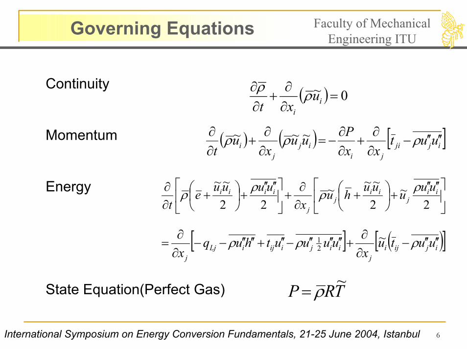
Governing Equations Faculty of Mechanical Engineering ITU
Continuity
Momentum
Energy
State Equation(Perfect Gas)
( ) ( ) [ ]ijjiji
ijj
i uutxx
Puux
ut
′′′′−∂∂
+∂∂
−=∂∂
+∂∂ ρρρ ~~~
′′′′+
+
∂∂
+
′′′′+
+
∂∂
2~
2
~~~22
~~ii
jii
jj
iiii uuuuuhux
uuuuet
ρρρρ
[ ] ( )[ ]ijijij
iijiijiLjj
uutux
uuuuthuqx
′′′′−∂∂
+′′′′′′−′′+′′′′−−∂∂
= ρρρ ~21
TRP ~ρ=
( ) 0~ =∂∂
+∂∂
ii
uxt
ρρ
International Symposium on Energy Conversion Fundamentals, 21-25 June 2004, Istanbul

7
Turbulence Models Faculty of Mechanical Engineering ITU
First Order Models
•Spalart Allmaras Model•Standard k-ε model•RNG k-ε model•Realizable k-ε model•SST k-omega model
Boussinesq approximation
jijik
kTjiTij k
xuSuu δρδµµρ ~
32~
32~2 −
∂∂
−=′′′′−
Second Order Model
•Reynolds Stress Model ijuu ′′′′
International Symposium on Energy Conversion Fundamentals 21-25 June 2004, Istanbul
8
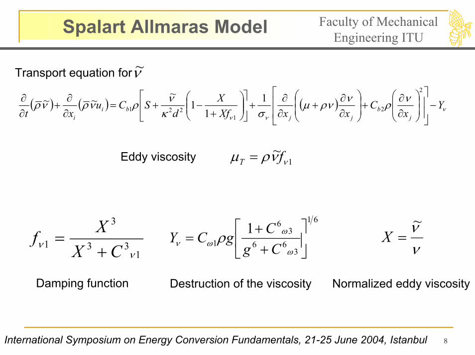
Spalart Allmaras Model Faculty of Mechanical Engineering ITU
Transport equation for ν~
( ) ( ) ( ) ννν
νρνρνµσκ
νρνρνρ Yx
CxxXf
Xd
SCuxt j
bjj
bii
−
∂∂
+
∂∂
+∂∂
+
+
−+=∂∂
+∂∂
2
21
2211
11
~~~
1~
ννρµ fT =Eddy viscosity
νν~
=X61
366
36
11
++
=ω
ωων ρ
CgCgCY
133
3
1ν
ν CXXf+
=
Damping function Destruction of the viscosity Normalized eddy viscosity
International Symposium on Energy Conversion Fundamentals, 21-25 June 2004, Istanbul
9
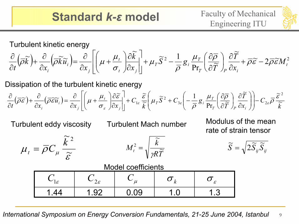
Standard k-ε model Faculty of Mechanical Engineering ITU
( ) ( ) 22 ~2~~
~Pr1~~
~~~t
iPT
TiT
jt
t
ji
i
MxT
TgS
xk
xuk
xk
tερερρµ
ρµ
σµµρρ −+
∂∂
∂∂
−+
∂∂
+
∂∂
=∂∂
+∂∂Turbulent kinetic energy
( ) ( )k
CTT
gCSk
CuiPT
TiT
j
t
ji
i~
~~~
1~~~~~~~
2
232
1ερρµ
µεεµµερερ εεε
ε
−
∂
∂∂
−++
∂
+
∂=
∂+
∂
Dissipation of the turbulent kinetic energy
xxxxt Prρσ ∂∂∂∂∂
ερµ µ ~
~ 2kCt = TRkM t ~~
2
γ= ijij SSS ~~2~
=
Model coefficients
1.31.00.091.921.44εσε1C kσµCε2C
Modulus of the mean rate of strain tensor
Turbulent eddy viscosity Turbulent Mach number
International Symposium on Energy Conversion Fundamentals, 21-25 June 2004, Istanbul
10
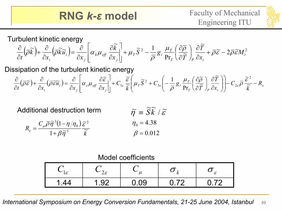
RNG k-ε model Faculty of Mechanical Engineering ITU
( ) ( ) 22 ~2~~
~Pr1~~
~~~t
iPT
TiT
jeffk
ji
i
MxT
TgS
xk
xuk
xk
tερερρµ
ρµµαρρ −+
∂∂
∂∂
−+
∂∂
∂∂
=∂∂
+∂∂
( ) ( ) εεεεεερρµ
ρµεεµαερερ R
kC
xT
TgCS
kC
xxu
xt iPT
TiT
jeff
ji
i
−−
∂∂
∂∂
−++
∂∂
∂∂
=∂∂
+∂∂
~~~
~~
Pr1~
~~~~~~
2
232
1
Turbulent kinetic energy
Dissipation of the turbulent kinetic energy
εη ~/~~~ kS≡38.40 =η
Additional destruction term
( )k
CR ~
~~1
1~ 2
30
3 εηβ
ηηηρµε +
−=
012.0=β
0.720.720.091.921.44εσε1C kσµCε2C
Model coefficients
International Symposium on Energy Conversion Fundamentals, 21-25 June 2004, Istanbul

11
Realizable k-ε model Faculty of Mechanical Engineering ITU
( ) ( ) 22 ~2~~
~Pr1~~
~~~t
iPT
TiT
jk
t
jj
i
MxT
TgS
xk
xuk
xk
tερερρµ
ρµ
σµ
µρρ −−∂∂
∂∂
−+
∂∂
+
∂∂
=∂∂
+∂∂
( ) ( )
∂∂
∂∂
−++
−+
∂∂
+
∂∂
=∂∂
+∂∂
iPT
Ti
j
t
jj
i xT
TgC
kC
kCSC
xxu
xt
~~Pr
1~~
~~~~~~~~~
31
2
21ρµ
ρε
ευερερε
σµ
µερερ εεε
Dissipation of the turbulent kinetic energy
Turbulent kinetic energy
εη ~
~~~ kS=
+
=5~
~,43.0max1 ηηC
ε
µ
~
~~1
0kuAA
C
S
∗
+=
Model coefficients
1.21.01.91.44ε1C 2C kσ εσ
International Symposium on Energy Conversion Fundamentals, 21-25 June 2004, Istanbul
12
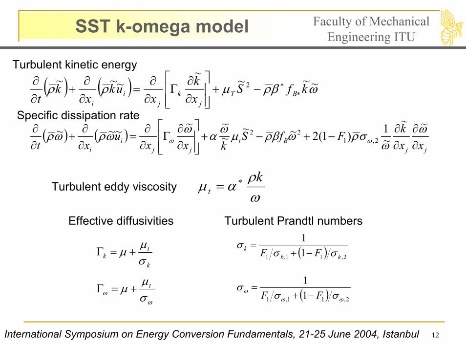
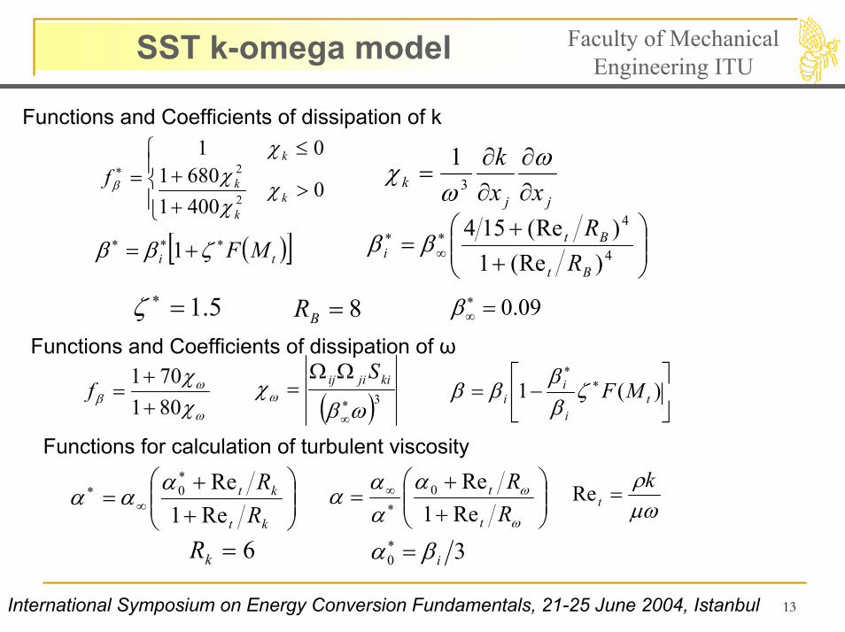
SST k-omega model Faculty of Mechanical Engineering ITU
( ) ( ) ωβρµρρ ~~~~~~~ 2 kfS
xk
xuk
xk
t BTj
kj
ii
∗∗−+
∂∂
Γ∂∂
=∂∂
+∂∂
( ) ( )jj
Btjj
ii xx
kFfSkxx
uxt ∂
∂∂∂
−+−+
∂∂
Γ∂∂
=∂∂
+∂∂ ω
ωσρωβρµωαωωρωρ ωω
~~~1)1(2~~
~~~~~~
2,122
Turbulent kinetic energy
Specific dissipation rate
ωραµ k
t∗=Turbulent eddy viscosity
Effective diffusivities Turbulent Prandtl numbers
( ) 2,11,1 11
kkk FF σσ
σ−+
=
k
tk σ
µµ +=Γ
ωω σ
µµ t+=Γ ( ) 2,11,1 11
ωωω σσ
σFF −+
=
International Symposium on Energy Conversion Fundamentals, 21-25 June 2004, Istanbul
13
SST k-omega model Faculty of Mechanical Engineering ITU
Functions and Coefficients of dissipation of k
>++
≤=∗
040016801
01
2
2
kk
k
k
f χχχ
χ
βjj
k xxk∂∂
∂∂
=ω
ωχ 3
1
++
= ∗∞
∗4
4
)Re(1)Re(154
Bt
Bti R
Rββ( )[ ]ti MF∗∗∗ += ζββ 1
5.1 ==ζ =β∗ 8BR 09.0∗∞
Functions and Coefficients of dissipation of ω
ω
ωβ χ
χ801701
++
=f ( )3ωβχω ∗
∞
ΩΩ= kijiij S
−= 1iββ
∗∗
)( ti
i MFζββ
Functions for calculation of turbulent viscosity
++
=∗
∞∗
kt
kt
RR
Re1Re0α
αα
6=kRµωρk
t =Re
++
= ∗∞
ω
ωααα
αRR
t
t
Re1Re0
30 iβα =∗
International Symposium on Energy Conversion Fundamentals, 21-25 June 2004, Istanbul
14
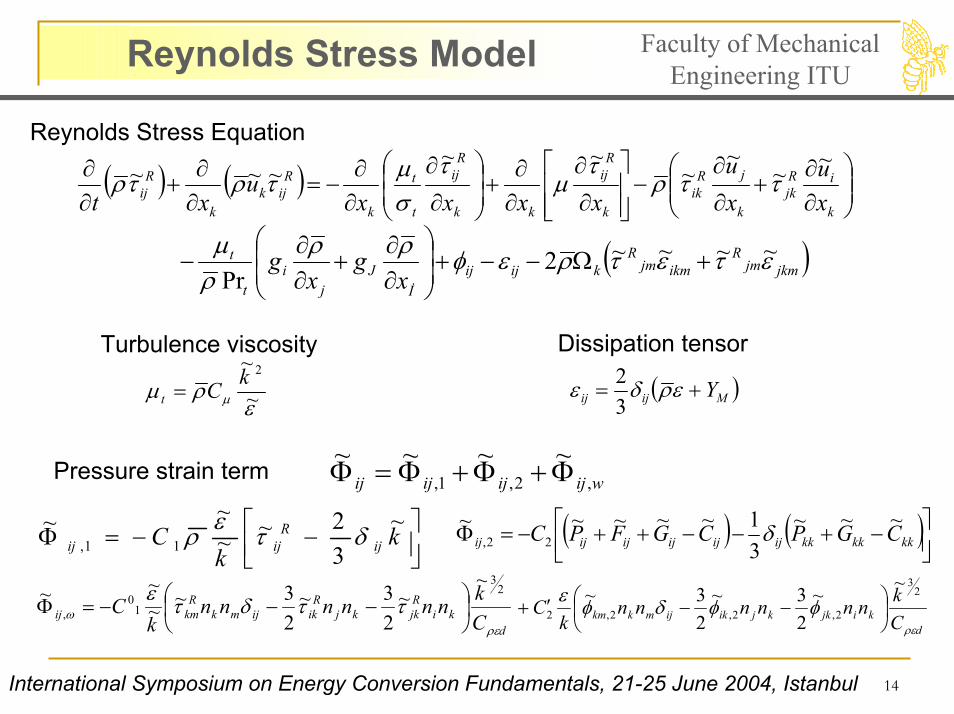
Reynolds Stress Model Faculty of Mechanical Engineering ITU
Reynolds Stress Equation
( ) ( )
∂∂
+∂
∂−
∂
∂
∂∂
+
∂
∂
∂∂
−=∂∂
+∂∂
k
iRjk
k
jRik
k
Rij
kk
Rij
t
t
k
Rijk
k
Rij x
uxu
xxxxu
xt
~~~
~~~
~~~ ττρτ
µτ
σµτρτρ
( )jkmjmR
ikmjmR
kijijİ
Jj
it
t
xg
xg ετετρεφρρ
ρµ ~~~~2Pr
+Ω−−+
∂∂
+∂∂
−
ερµ µ ~
~ 2kCt =
Turbulence viscosity
( )Mijij Y+= ερδε32
Dissipation tensor
wijijijij ,2,1,~~~~ Φ+Φ+Φ=ΦPressure strain term
−−=Φ k
kC ij
Rijij
~32~~
~~11, δτερ ( ) ( )
−+−−++−=Φ kkkkkkijijijijijij CGPCGFPC ~~~
31~~~~~
22, δ
dki
Rjkkj
Rikijmk
Rkmij C
knnnnnnk
Cρε
ω ττδτε 23
10
,
~~
23~
23~~
~~
−−−=Φ
dkijkkjikijmkkm C
knnnnnnk
Cρε
φφδφε 23
2,2,2,2
~~23~
23~
−−′+
International Symposium on Energy Conversion Fundamentals, 21-25 June 2004, Istanbul
15
Computational Domain Faculty of Mechanical Engineering ITU
Impermeable Wall
L
h Exit
Permeable Wall - Flow Injection
Head-end
Schematics of the Vecla Facilty
Injection SurfaceInjection Surface::
L = 0.581 m h = 0.0103 mL = 0.581 m h = 0.0103 m
Common Boundary ConditionsCommon Boundary ConditionsExit SurfaceExit Surface::
smkgm 2619.2=& 220001.0 smk =32001.0 sm=εKT 300=
PaP 137400=
TurbulenceTurbulence Model Model SpecificSpecificInlet ConditionsInlet Conditions
kk--εε modelsmodels
kk--ωω modelmodel 220001.0 smk =14.0 −= sω
RSMRSM 22092.0 smvv =′′′′•Chaouat, B., 2000. •Kourta, A., 2004.
International Symposium on Energy Conversion Fundamentals, 21-25 June 2004, Istanbul
16
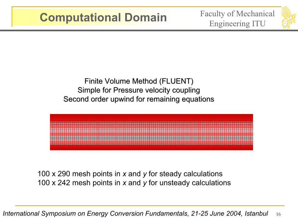
Computational Domain Faculty of Mechanical Engineering ITU
Finite Volume MethodFinite Volume Method (FLUENT)(FLUENT)Simple for Pressure velocity couplingSimple for Pressure velocity coupling
Second order upwind for remaining equationsSecond order upwind for remaining equations
100 x 290 mesh points in x and y for steady calculations100 x 242 mesh points in x and y for unsteady calculations
International Symposium on Energy Conversion Fundamentals, 21-25 June 2004, Istanbul
17
Time Marching Approach Faculty of Mechanical Engineering ITU
Flow Time [sec]
Long
itudi
nalV
eloc
ity[m
/s]a
tx=0
.15
m
0.00 0.03 0.06 0.09 0.12 0.15 0.18 0.2123.0
24.0
25.0
26.0
Flow Time [sec]
Long
itudi
nalV
eloc
ity[m
/s]a
tx=0
.55
m
0.00 0.03 0.06 0.09 0.12 0.15 0.18 0.2193.0
93.5
94.0
94.5
95.0
95.5
96.0
Time [sec]
Mas
sOut
let/I
nlet
0.030 0.060 0.090 0.120 0.150 0.180 0.2100.9700
0.9800
0.9900
1.0000
1.0100
1.0200
1.0300
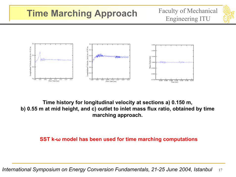
Time history for longitudinal velocity at sections a) 0.150 m, b) 0.55 m at mid height, and c) outlet to inlet mass flux ratio, obtained by time
marching approach.
SST k-ω model has been used for time marching computations
International Symposium on Energy Conversion Fundamentals, 21-25 June 2004, Istanbul
18
Time Marching–Steady Approaches Faculty of Mechanical Engineering ITU
Normalized Longitudinal Velocity
Cha
nnel
Hei
ght[
m]
0 0.3 0.6 0.9 1.2 1.5 1.80.0000
0.0025
0.0050
0.0075
0.0100
ExperimentalSteady ApproachTime Marching Approach
Normalized Longitudinal Velocity
Cha
nnel
Hei
ght[
m]
0 0.3 0.6 0.9 1.2 1.5 1.80.0000
0.0025
0.0050
0.0075
0.0100
ExperimentalSteady ApproachTime Marching Approach
Normalized Longitudinal Velocity
Cha
nnel
Hei
ght[
m]
0 0.3 0.6 0.9 1.2 1.5 1.80.0000
0.0025
0.0050
0.0075
0.0100
ExperimentalSteady ApproachTime Marching Approach
Normalized Longitudinal Velocity
Cha
nnel
Hei
ght[
m]
0 0.3 0.6 0.9 1.2 1.5 1.80.0000
0.0025
0.0050
0.0075
0.0100
ExperimentalSteady ApproachTime Marching Approach
Normalized Longitudinal Velocity
Cha
nnel
Hei
ght[
m]
0 0.3 0.6 0.9 1.2 1.5 1.80.0000
0.0025
0.0050
0.0075
0.0100
ExperimentalSteady ApproachTime Marching Approach
Normalized Longitudinal VelocityC
hann
elH
eigh
t[m
]0 0.3 0.6 0.9 1.2 1.5 1.8
0.0000
0.0025
0.0050
0.0075
0.0100
ExperimentalSteady ApproachTime Marching Approach
Normalized Longitudinal Velocity
Cha
nnel
Hei
ght[
m]
0 0.3 0.6 0.9 1.2 1.5 1.80.0000
0.0025
0.0050
0.0075
0.0100
ExperimentalSteady ApproachTime Marching Approach
a) b) c) d)
e) f) g) h)
Normalized Longitudinal Velocity
Cha
nnel
Hei
ght[
m]
0 0.3 0.6 0.9 1.2 1.5 1.80.0000
0.0025
0.0050
0.0075
0.0100 ExperimentalSteady ApproachTime Marching Approach
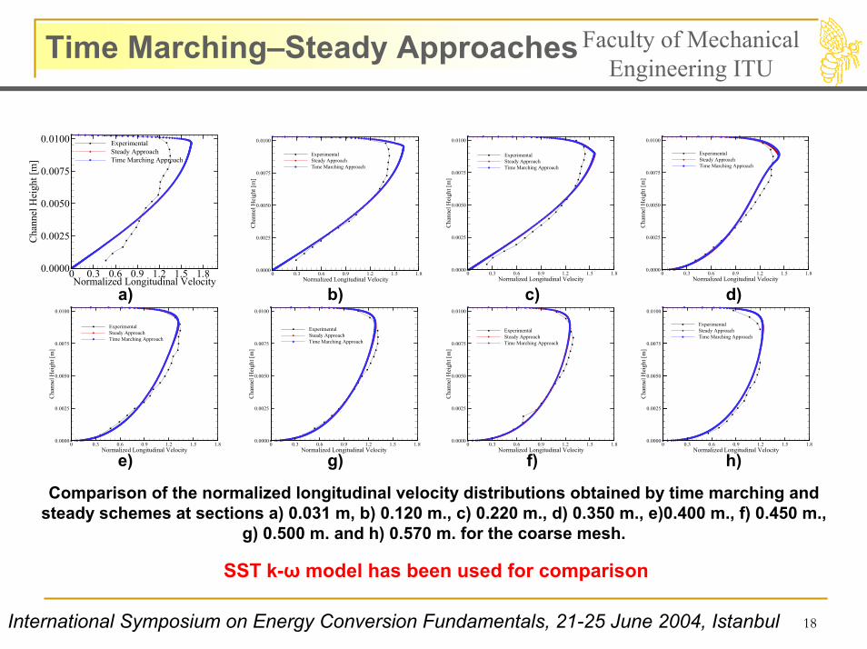
Comparison of the normalized longitudinal velocity distributions obtained by time marching and steady schemes at sections a) 0.031 m, b) 0.120 m., c) 0.220 m., d) 0.350 m., e)0.400 m., f) 0.450 m.,
g) 0.500 m. and h) 0.570 m. for the coarse mesh.
SST k-ω model has been used for comparison
International Symposium on Energy Conversion Fundamentals, 21-25 June 2004, Istanbul
19
Laminar and Spalart Allmaras Faculty of Mechanical Engineering ITU
Normalized Longitudinal Velocity
Cha
nnel
Hei
ght[
m]
0 0.3 0.6 0.9 1.2 1.5 1.80.0000
0.0025
0.0050
0.0075
0.0100
LaminarExperimentalSpalart Allmaras
Normalized Streamwise Velocity
Cha
nnel
Hei
ght[
m]
0 0.3 0.6 0.9 1.2 1.5 1.80.0000
0.0025
0.0050
0.0075
0.0100
ExperimentalLaminarSpalart Allmaras
Normalized Longitudinal Velocity
Cha
nnel
Hei
ght[
m]
0 0.3 0.6 0.9 1.2 1.5 1.80.0000
0.0025
0.0050
0.0075
0.0100
LaminarExperimentalSpalart Allmaras
Normalized Longitudinal Velocity
Cha
nnel
Hei
ght[
m]
0 0.3 0.6 0.9 1.2 1.5 1.80.0000
0.0025
0.0050
0.0075
0.0100
ExperimentalLaminarSpalart Allmaras
Normalized Longitudinal Velocity
Cha
nnel
Hei
ght[
m]
0 0.3 0.6 0.9 1.2 1.5 1.80.0000
0.0025
0.0050
0.0075
0.0100
ExperimentalLaminarSpalart Allmaras
Normalized Longitudinal VelocityC
hann
elH
eigh
t[m
]0 0.3 0.6 0.9 1.2 1.5 1.8
0.0000
0.0025
0.0050
0.0075
0.0100
ExperimentalLaminarSpalart Allmaras
Normalized Longitudinal Velocity
Cha
nnel
Hei
ght[
m]
0 0.3 0.6 0.9 1.2 1.5 1.80.0000
0.0025
0.0050
0.0075
0.0100
ExperimentalLaminarSpalart Allmaras
Normalized Longitudinal Velocity
Cha
nnel
Hei
ght[
m]
0 0.3 0.6 0.9 1.2 1.5 1.80.0000
0.0025
0.0050
0.0075
0.0100
LaminarExperimentalSpalart Allmaras
a) b) c) d)
e) f) g) h)
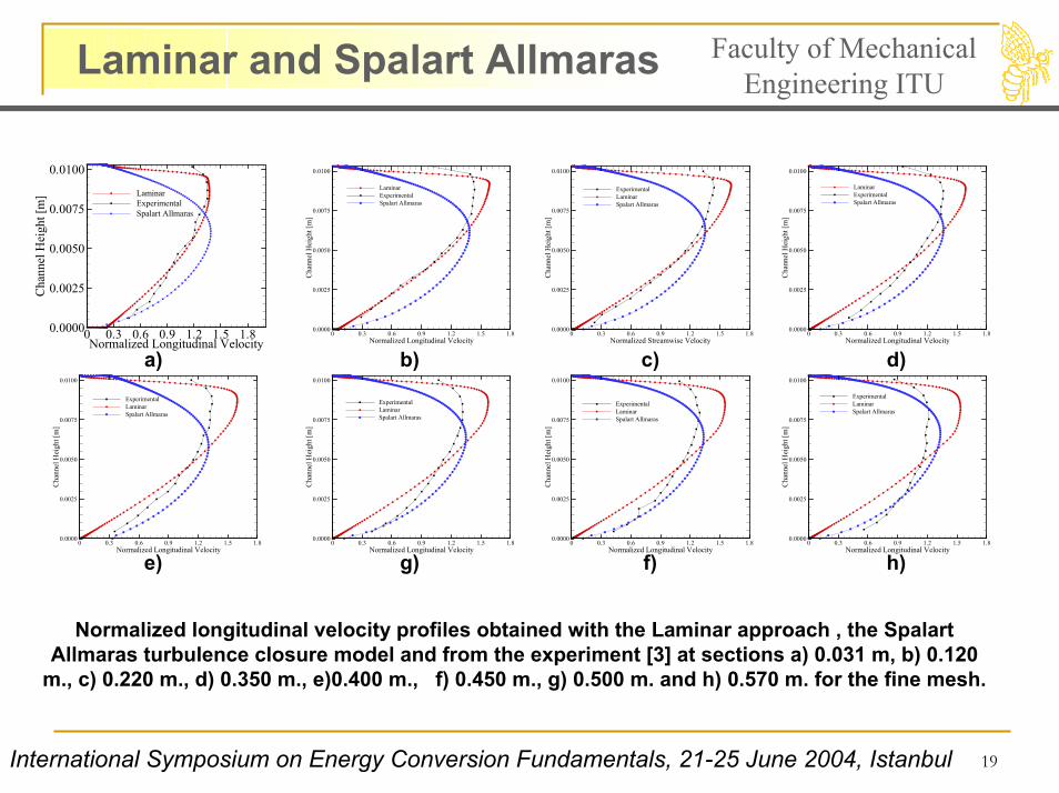
Normalized longitudinal velocity profiles obtained with the Laminar approach , the Spalart Allmaras turbulence closure model and from the experiment [3] at sections a) 0.031 m, b) 0.120
m., c) 0.220 m., d) 0.350 m., e)0.400 m., f) 0.450 m., g) 0.500 m. and h) 0.570 m. for the fine mesh.
International Symposium on Energy Conversion Fundamentals, 21-25 June 2004, Istanbul
20
Computations with k-ε based Faculty of Mechanical Engineering ITU
Normalized Longitudinal Velocity
Cha
nnel
Hei
ght[
m]
0 0.3 0.6 0.9 1.2 1.5 1.80.0000
0.0025
0.0050
0.0075
0.0100
k-eps. Standardk-eps. Realizablek-eps. RNGExperimental
Normalized Longitudinal Velocity
Cha
nnel
Hei
ght[
m]
0 0.3 0.6 0.9 1.2 1.5 1.80.0000
0.0025
0.0050
0.0075
0.0100
Experimentalk-eps. Standardk-eps. Realizablek-eps. RNG
Normalized Longitudinal Velocity
Cha
nnel
Hei
ght[
m]
0 0.3 0.6 0.9 1.2 1.5 1.80.0000
0.0025
0.0050
0.0075
0.0100
Experimentalk-eps. Standardk-eps. Realizablek-eps. RNG
Normalized Longitudinal VelocityC
hann
elH
eigh
t[m
]0 0.3 0.6 0.9 1.2 1.5 1.8
0.0000
0.0025
0.0050
0.0075
0.0100
Experimentalk-eps. Standardk-eps. Realizablek-eps. RNG
Normalized Longitudinal Velocity
Cha
nnel
Hei
ght[
m]
0 0.3 0.6 0.9 1.2 1.5 1.80.0000
0.0025
0.0050
0.0075
0.0100
Experimentalk-eps. Standardk-eps. Realizablek-eps. RNG
Normalized Longitudinal Velocity
Cha
nnel
Hei
ght[
m]
0 0.3 0.6 0.9 1.2 1.5 1.80.0000
0.0025
0.0050
0.0075
0.0100k-e Standardk-e Realizablek-e RNGExperimental
a) b) c) d)
e) f) g) h)
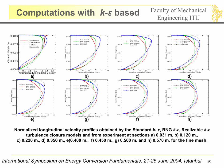
Normalized longitudinal velocity profiles obtained by the Standard k- ε, RNG k-ε, Realizable k-εturbulence closure models and from experiment at sections a) 0.031 m, b) 0.120 m.,
c) 0.220 m., d) 0.350 m., e)0.400 m., f) 0.450 m., g) 0.500 m. and h) 0.570 m. for the fine mesh.
International Symposium on Energy Conversion Fundamentals, 21-25 June 2004, Istanbul
21
Reynolds Stress Model Faculty of Mechanical Engineering ITU
Normalized Longitudinal Velocity
Cha
nnel
Hei
ght[
m]
0 0.3 0.6 0.9 1.2 1.5 1.80.0000
0.0025
0.0050
0.0075
0.0100
ExperimentalRSM
Normalized Longitudinal Velocity
Cha
nnel
Hei
ght[
m]
0 0.3 0.6 0.9 1.2 1.5 1.80.0000
0.0025
0.0050
0.0075
0.0100
ExperimentalRSM
Normalized Longitudinal Velocity
Cha
nnel
Hei
ght[
m]
0 0.3 0.6 0.9 1.2 1.5 1.80.0000
0.0025
0.0050
0.0075
0.0100
ExperimentalRSM
Normalized Longitudial Velocity
Cha
nnel
Hei
ght[
m]
0 0.3 0.6 0.9 1.2 1.5 1.80.0000
0.0025
0.0050
0.0075
0.0100
ExperimentalRSM
Normalized Longitudial Velocity
Cha
nnel
Hei
ght[
m]
0 0.3 0.6 0.9 1.2 1.5 1.80.0000
0.0025
0.0050
0.0075
0.0100
ExperimentalRSM
Normalized Longitudial Velocity
Cha
nnel
Hei
ght[
m]
0 0.3 0.6 0.9 1.2 1.5 1.80.0000
0.0025
0.0050
0.0075
0.0100
ExperimentalRSM
Normalized Longitudinal Velocity
Cha
nnel
Hei
ght[
m]
0 0.3 0.6 0.9 1.2 1.5 1.80.0000
0.0025
0.0050
0.0075
0.0100
ExperimentalRSM
Normalized Longitudinal Velocity
Cha
nnel
Hei
ght[
m]
0 0.3 0.6 0.9 1.2 1.5 1.80.0000
0.0025
0.0050
0.0075
0.0100ExperimentalRSM
a) b) c) d)
e) f) g) h)
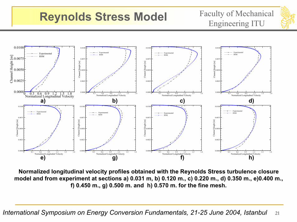
Normalized longitudinal velocity profiles obtained with the Reynolds Stress turbulence closuremodel and from experiment at sections a) 0.031 m, b) 0.120 m., c) 0.220 m., d) 0.350 m., e)0.400 m.,
f) 0.450 m., g) 0.500 m. and h) 0.570 m. for the fine mesh.
International Symposium on Energy Conversion Fundamentals, 21-25 June 2004, Istanbul
22
SST k-omega Faculty of Mechanical Engineering ITU
Normalized Longitudinal Velocity
Cha
nnel
Hei
ght[
m]
0 0.3 0.6 0.9 1.2 1.5 1.80.0000
0.0025
0.0050
0.0075
0.0100
Experimentalk-w
Normalized Streamwise Velocity
Cha
nnel
Hei
ght[
m]
0 0.3 0.6 0.9 1.2 1.5 1.80.0000
0.0025
0.0050
0.0075
0.0100
Experimentalk-w
Normalized Longitudinal Velocity
Cha
nnel
Hei
ght[
m]
0 0.3 0.6 0.9 1.2 1.5 1.80.0000
0.0025
0.0050
0.0075
0.0100
Experimentalk-w
Normalized Longitudinal Velocity
Cha
nnel
Hei
ght[
m]
0 0.3 0.6 0.9 1.2 1.5 1.80.0000
0.0025
0.0050
0.0075
0.0100
Experimentalk-w
Normalized Longitudinal Velocity
Cha
nnel
Hei
ght[
m]
0 0.3 0.6 0.9 1.2 1.5 1.80.0000
0.0025
0.0050
0.0075
0.0100
Experimentalk-w
Normalized Longitudinal VelocityC
hann
elH
eigh
t[m
]0 0.3 0.6 0.9 1.2 1.5 1.8
0.0000
0.0025
0.0050
0.0075
0.0100
Experimentalk-w
Normalized Longitudinal Velocity
Cha
nnel
Hei
ght[
m]
0 0.3 0.6 0.9 1.2 1.5 1.80.0000
0.0025
0.0050
0.0075
0.0100
Experimentalk-w
Normalized Longitudinal Velocity
Cha
nnel
Hei
ght[
m]
0 0.3 0.6 0.9 1.2 1.5 1.80.0000
0.0025
0.0050
0.0075
0.0100
Experimentalk-w
a) b) c) d)
e) f) g) h)
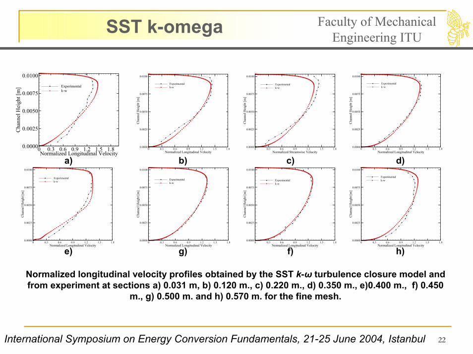
Normalized longitudinal velocity profiles obtained by the SST k-ω turbulence closure model and from experiment at sections a) 0.031 m, b) 0.120 m., c) 0.220 m., d) 0.350 m., e)0.400 m., f) 0.450
m., g) 0.500 m. and h) 0.570 m. for the fine mesh.
International Symposium on Energy Conversion Fundamentals, 21-25 June 2004, Istanbul
23
Turbulence Intensity Faculty of Mechanical Engineering ITU
Turbulence Intensity
Cha
nnel
Hei
ght[
m]
0 10 20 30 40 500.0000
0.0025
0.0050
0.0075
0.0100
x=0.031 mx=0.120 mx=0.220 mx=0.350 mx=0.400 mx=0.450 mx=0.500 mx=0.570 m
Turbulence Intensity
Cha
nnel
Hei
ght[
m]
0 10 20 30 40 500.0000
0.0025
0.0050
0.0075
0.0100
x=0.031 mx=0.120 mx=0.220 mx=0.350 mx=0.400 mx=0.450 mx=0.500 mx=0.570 m
Turbulence Intensity
Cha
nnel
Hei
ght[
m]
0 5 10 15 200.0000
0.0025
0.0050
0.0075
0.0100
x=0.031 mx=0.120 mx=0.220 mx=0.350 mx=0.400 mx=0.450 mx=0.500 mx=0.570 m
Turbulence Intensity
Cha
nnel
Hei
ght[
m]
0 5 10 15 200
0.0025
0.005
0.0075
0.01
Turbulence Intensity
Cha
nnel
Hei
ght[
m]
0 5 10 15 200.0000
0.0025
0.0050
0.0075
0.0100
x=0.031 mx=0.120 mx=0.220 mx=0.350 mx=0.400 mx=0.450 mx=0.500 mx=0.570 m
Turbulence Intensity
Cha
nnel
Hei
ght[
m]
0 5 10 15 200.0000
0.0025
0.0050
0.0075
0.0100
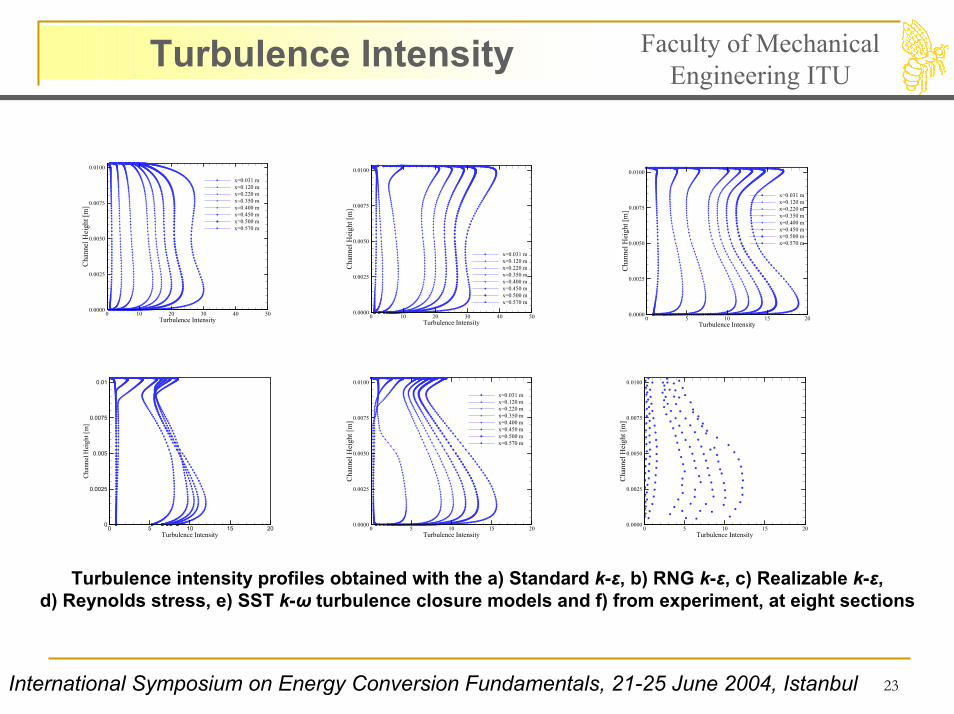
Turbulence intensity profiles obtained with the a) Standard k-ε, b) RNG k-ε, c) Realizable k-ε, d) Reynolds stress, e) SST k-ω turbulence closure models and f) from experiment, at eight sections
International Symposium on Energy Conversion Fundamentals, 21-25 June 2004, Istanbul
24
Results Faculty of MechanicalEngineering ITU
• k-ε based computations have not produced velocity and turbulence intensity profiles compatible with the experimental profiles, neither in the pre (laminar) nor post-transition (turbulent) sections.
• Computations based on the Reynolds Stress Model have predictedthe normalized longitudinal velocity profiles well except for thelaminar region, and turbulence intensity profiles are similarqualitatively as those from the experiments.
• SST k-ω turbulence closure model has yielded the longitudinalvelocity profiles in a good agreement with the experiment [3]. Furthermore, accuracy of the turbulence intensity profiles was satisfactory compared with the results from the rest of the closure models.
International Symposium on Energy Conversion Fundamentals, 21-25 June 2004, Istanbul
25
Faculty of Mechanical Engineering ITU
The research grant from the Institute of Science and Technology of ITU and the CPU hours allocated by the Center of Excellence for Advanced Engineering Technologies at ITU are greatly acknowledged by the authors.
International Symposium on Energy Conversion Fundamentals, 21-25 June 2004, Istanbul
26
References Faculty of Mechanical Engineering ITU
1. Sutton, G. P., Rocket Propulsion Elements : An Introduction to the Engineering of Rockets, John Wiley and Sons, New York, 1992
2. Traineau, J. C., Hervart, P. and Kuentzmann, P., “Cold-Flow Simulations of a Two-Dimensional Nozeless Solid Rocket Motor,” AIAA Paper 86-1447. 1986.
3. Dunlap, R., Blackner, A.M., Waugh, R.C., Brown, R.S. and Willoughby, P.G., “Internal Flow Field Studies in a Simulated Cylindrical Port Rocket Chamber,” Journal of Propulsion and Power, Vol. 6, 1990, pp. 690-705.
4. Vuillot, F., Scherrer, D. and Habiballah, M., “CFD Code Validation for Space Propulsion Applications,” 5th International Symposium on Liquid Space Propulsion-Longlife Combusition Devices Technology, Chattanooga, USA 27-30 October 2003.
5. Kourta, A., “Instability of Channel Flow with Surface Mass Injection and Parietal Vortex Shedding,”Computers & Fluids, Vol. 33, 2004, pp. 155-178.
6. Chaouat, B. and Schiestel, R. “Reynolds Stress Transport Modeling for Steady and Unsteady Channel Flows with Wall Injection,” Journal of Turbulence, Vol3, 2002
7. Sabnis, J.S., Madabhushi, R.K., Gibeling, H.J. and MacDonald, H., “On the Use of k- ε Turbulence model for Computation of Solid Rocket Internal Flows, AIAA Paper 89-2558, 1989.
8. Beddini, R.A., “Injection Induced Flows in Porous-Walled Ducts. AIAA Journal, Vol. 24, 1985, pp. 1766-1773.
International Symposium on Energy Conversion Fundamentals 21-25 June 2004, Istanbul
27
References Faculty of Mechanical Engineering ITU
9. Culick, F. E.C., “Rotational Axisymmetric Mean Flow and Damping of Acoustic Waves in Solid Propellant Rocket Motors,” AIAA Journal, Vol. 4, 1966, pp. 1462-1464.
10. Chaouat, B., “Numerical Simulation of Channel Flows with Fluid injection Using Reynolds Stress Model,” AIAA Paper 2000-0992, 2000.
11. Vuillot, F.,” Numerical Computation of Acoustic Boundary Layers in Large Solid Propellant Space Boosters,” AIAA Paper 91-0206, 1991
12. Vuillot, F., Avalon, G., “Acoustic Boundary Layers in Solid Propellant Rocket Motors Using Navier-Stokes Equations,” Journal of Propulsion and Power, Vol. 7, 1991, pp. 231-239.
13. Kirkkopru, K., Kassoy, D.R., Zhao, Q. and Staab, P.L., “Acoustically Generated Unsteady Vorticity Field in a Long Narrow Cylinder with Sidewall Injection,” Journal of Engineering Mathematics, Vol. 42, 2002, pp. 65-90.
14. Apte, S. and Yang, V., “Unsteady Flow Evolution and Combustion Dynamics of Homogeneous Solid Propellant in a Rocket Motor,” Combustion and Flame, Vol. 131, 2002, pp. 110-131.
15. Chu, W.-W., Yang, V., Majdalani, J., “Premixed Flame Response to Acoustic Waves in a Porous-Walled Chamber with Surface Mass Injection,” Combustion and Flame, Vol. 133, 2003, pp. 359-370.
16. FLUENT 6.1 User’s Guide, February 2003
International Symposium on Energy Conversion Fundamentals, 21-25 June 2004, Istanbul
Related Documents