Laser welding of aluminium alloys 5083 and 6082 under conduction regime J.M. Sa ´ nchez-Amaya *, T. Delgado, L. Gonza ´ lez-Rovira, F.J. Botana Departamento de Ciencia de Materiales e Ingenierı´a Metalu ´rgica y Quı´mica Inorga ´nica, Grupo de Ensayos, Corrosio ´n y Proteccio ´n, Universidad de Ca ´diz, Lab. 712, CASEM, Avda. Repu ´blica Saharaui s/n, 11510 Puerto Real, Ca ´diz, Spain 1. Introduction The laser welding is a promising technology to a lot of industrial sectors because of the possibility of joining and repairing different materials. Laser welding technology have some disadvantages in comparison with other conventional joining technologies, as the high costs of equipment, strict requirements concerning the laser beam adjustment and the samples alignment. However, laser welding show important advantages compared with other techniques, as the low heat input, the high localisation ability, the high welding speed, the high flexibility, the high weld quality and the high production rate [1–5]. It is reported elsewhere [1,2,6] that laser welding can be carried out by means of two different regimes: keyhole and conduction. Keyhole regime involves the employment of higher density power and usually leads to narrower welding beads than the conduction regime [4,5,7,8]. The former mechanism often generates welding beads with high porosity due to gas entrapment occurring during the solidification of the weld pool. In contrast, conduction welding is a more stable process because the metal evaporation takes place at a lower level than at keyhole mode [1,2]. In fact, it has been recently reported that aluminium alloy 5083 has magnesium lost of about 1–4% when welded under conduction mode [1], while 13– 22% under keyhole regime [9]. The laser welding is generally more difficult to apply to aluminium alloys [10,11] than to steel alloys, due to its higher reflectivity, higher thermal conductivity and lower viscosity [5,12]. Thus, the thermal conductivity of aluminium alloys (143 W m 1 K 1 ) is about one order of magnitude higher than that of steels (14 W m 1 K 1 ) [1,13]. Additionally, aluminium alloys have high reflectivity (sometimes higher than 80%), being more reflective as the aluminium alloy is purer. The high reflectivity makes the aluminium alloys absorb low fraction of the incident radiation; the high thermal conductivity provokes a rapid heat transfer, avoiding the concentration of energy in the weld pool; and finally, the lower viscosity of the welding pool limits the expansion of the pool before the solidification [1]. Little research has been reported on welding aluminium alloys of the series 5000 (Al-Mg) and 6000 (Al-Mg-Si) under conduction regime with diode laser [1,14]. Among them, in [14] a high power diode laser has been successfully employed to weld 5022 and 6016 aluminium alloys. In this paper, samples of 1 mm thickness were successfully welded, being analysed the influence of the processing rate on the depths and widths of the welds obtained. It was observed that at 4 kW, full penetration bead-on-plate and butt welding was achieved up to a welding speed of 12 m/min for 5022 and 6 m/min for 6016 [14]. The maximum welding speed to get full penetration varies in these alloys due to their different heat conductivity. In [1], bead-on-plate welds of 5083 samples free of defects were obtained at 1.5 m/min or 3 m/min and 1.5 kW, analysing the influence of the superficial treatment and the processing rate on the welds properties. The penetration under these conditions ranged between Applied Surface Science 255 (2009) 9512–9521 ARTICLE INFO Article history: Received 28 May 2009 Received in revised form 14 July 2009 Accepted 22 July 2009 Available online 30 July 2009 Keywords: Laser welding Aluminium alloys Conduction regime Depth estimation Corrosion resistance ABSTRACT In this work, samples of aluminium alloys 5083-T0 and 6082-T6 have been welded under conduction regime, using a high power diode laser. The influence of experimental variables, as the laser power and the linear welding rate, on the sizes and properties of the butt weld beads has been studied. In addition to measure the depths and widths of the weld beads, their microstructure, microhardness profile and corrosion resistance have been analysed. The results obtained allow one to define the experimental conditions leading to good quality butt welds with higher penetration than those published in the recent literature under conduction regime. Maximum penetration values of 3 and 2.3 mm were obtained for 5083 and 6082, respectively. Additionally, a simple mathematical expression relating the weld depth (d) with the laser power (P) and the processing rate (v) has been proposed: d ¼ðP bb 0 Þ=ðavÞðba 0 Þ=a, being a, a 0 , b and b 0 constant values for each alloy and under the employed experimental conditions. The values of these coefficients have been estimated from the fitting to the experimental depth values of 5083 and 6082 butt welds generated under conduction regime. ß 2009 Elsevier B.V. All rights reserved. * Corresponding author. Tel.: +34 956 016762; fax: +34 956 016164. E-mail address: [email protected] (J.M. Sa ´ nchez-Amaya). Contents lists available at ScienceDirect Applied Surface Science journal homepage: www.elsevier.com/locate/apsusc 0169-4332/$ – see front matter ß 2009 Elsevier B.V. All rights reserved. doi:10.1016/j.apsusc.2009.07.081

Welcome message from author
This document is posted to help you gain knowledge. Please leave a comment to let me know what you think about it! Share it to your friends and learn new things together.
Transcript
Applied Surface Science 255 (2009) 9512–9521
Laser welding of aluminium alloys 5083 and 6082 under conduction regime
J.M. Sanchez-Amaya *, T. Delgado, L. Gonzalez-Rovira, F.J. Botana
Departamento de Ciencia de Materiales e Ingenierıa Metalurgica y Quımica Inorganica, Grupo de Ensayos, Corrosion y Proteccion, Universidad de Cadiz,
Lab. 712, CASEM, Avda. Republica Saharaui s/n, 11510 Puerto Real, Cadiz, Spain
A R T I C L E I N F O
Article history:
Received 28 May 2009
Received in revised form 14 July 2009
Accepted 22 July 2009
Available online 30 July 2009
Keywords:
Laser welding
Aluminium alloys
Conduction regime
Depth estimation
Corrosion resistance
A B S T R A C T
In this work, samples of aluminium alloys 5083-T0 and 6082-T6 have been welded under conduction
regime, using a high power diode laser. The influence of experimental variables, as the laser power and
the linear welding rate, on the sizes and properties of the butt weld beads has been studied. In addition to
measure the depths and widths of the weld beads, their microstructure, microhardness profile and
corrosion resistance have been analysed. The results obtained allow one to define the experimental
conditions leading to good quality butt welds with higher penetration than those published in the recent
literature under conduction regime. Maximum penetration values of 3 and 2.3 mm were obtained for
5083 and 6082, respectively. Additionally, a simple mathematical expression relating the weld depth (d)
with the laser power (P) and the processing rate (v) has been proposed: d ¼ ðP � bb0Þ=ðavÞ � ðba0Þ=a, being
a, a0 , b and b0 constant values for each alloy and under the employed experimental conditions. The values
of these coefficients have been estimated from the fitting to the experimental depth values of 5083 and
6082 butt welds generated under conduction regime.
� 2009 Elsevier B.V. All rights reserved.
Contents lists available at ScienceDirect
Applied Surface Science
journal homepage: www.e lsev ier .com/ locate /apsusc
1. Introduction
The laser welding is a promising technology to a lot of industrialsectors because of the possibility of joining and repairing differentmaterials. Laser welding technology have some disadvantages incomparison with other conventional joining technologies, as thehigh costs of equipment, strict requirements concerning the laserbeam adjustment and the samples alignment. However, laserwelding show important advantages compared with othertechniques, as the low heat input, the high localisation ability,the high welding speed, the high flexibility, the high weld qualityand the high production rate [1–5].
It is reported elsewhere [1,2,6] that laser welding can be carriedout by means of two different regimes: keyhole and conduction.Keyhole regime involves the employment of higher density powerand usually leads to narrower welding beads than the conductionregime [4,5,7,8]. The former mechanism often generates weldingbeads with high porosity due to gas entrapment occurring duringthe solidification of the weld pool. In contrast, conduction weldingis a more stable process because the metal evaporation takes placeat a lower level than at keyhole mode [1,2]. In fact, it has beenrecently reported that aluminium alloy 5083 has magnesium lostof about 1–4% when welded under conduction mode [1], while 13–22% under keyhole regime [9].
* Corresponding author. Tel.: +34 956 016762; fax: +34 956 016164.
E-mail address: [email protected] (J.M. Sanchez-Amaya).
0169-4332/$ – see front matter � 2009 Elsevier B.V. All rights reserved.
doi:10.1016/j.apsusc.2009.07.081
The laser welding is generally more difficult to apply toaluminium alloys [10,11] than to steel alloys, due to its higherreflectivity, higher thermal conductivity and lower viscosity [5,12].Thus, the thermal conductivity of aluminium alloys(143 W m�1 K�1) is about one order of magnitude higher thanthat of steels (14 W m�1 K�1) [1,13]. Additionally, aluminiumalloys have high reflectivity (sometimes higher than 80%), beingmore reflective as the aluminium alloy is purer. The highreflectivity makes the aluminium alloys absorb low fraction ofthe incident radiation; the high thermal conductivity provokes arapid heat transfer, avoiding the concentration of energy in theweld pool; and finally, the lower viscosity of the welding poollimits the expansion of the pool before the solidification [1].
Little research has been reported on welding aluminium alloys ofthe series 5000 (Al-Mg) and 6000 (Al-Mg-Si) under conductionregime with diode laser [1,14]. Among them, in [14] a high powerdiode laser has been successfully employed to weld 5022 and 6016aluminium alloys. In this paper, samples of 1 mm thickness weresuccessfully welded, being analysed the influence of the processingrate on the depths and widths of the welds obtained. It was observedthat at 4 kW, full penetration bead-on-plate and butt welding wasachieved up to a welding speed of 12 m/min for 5022 and 6 m/minfor 6016 [14]. The maximum welding speed to get full penetrationvaries in these alloys due to their different heat conductivity. In [1],bead-on-plate welds of 5083 samples free of defects were obtainedat 1.5 m/min or 3 m/min and 1.5 kW, analysing the influence ofthe superficial treatment and the processing rate on the weldsproperties. The penetration under these conditions ranged between
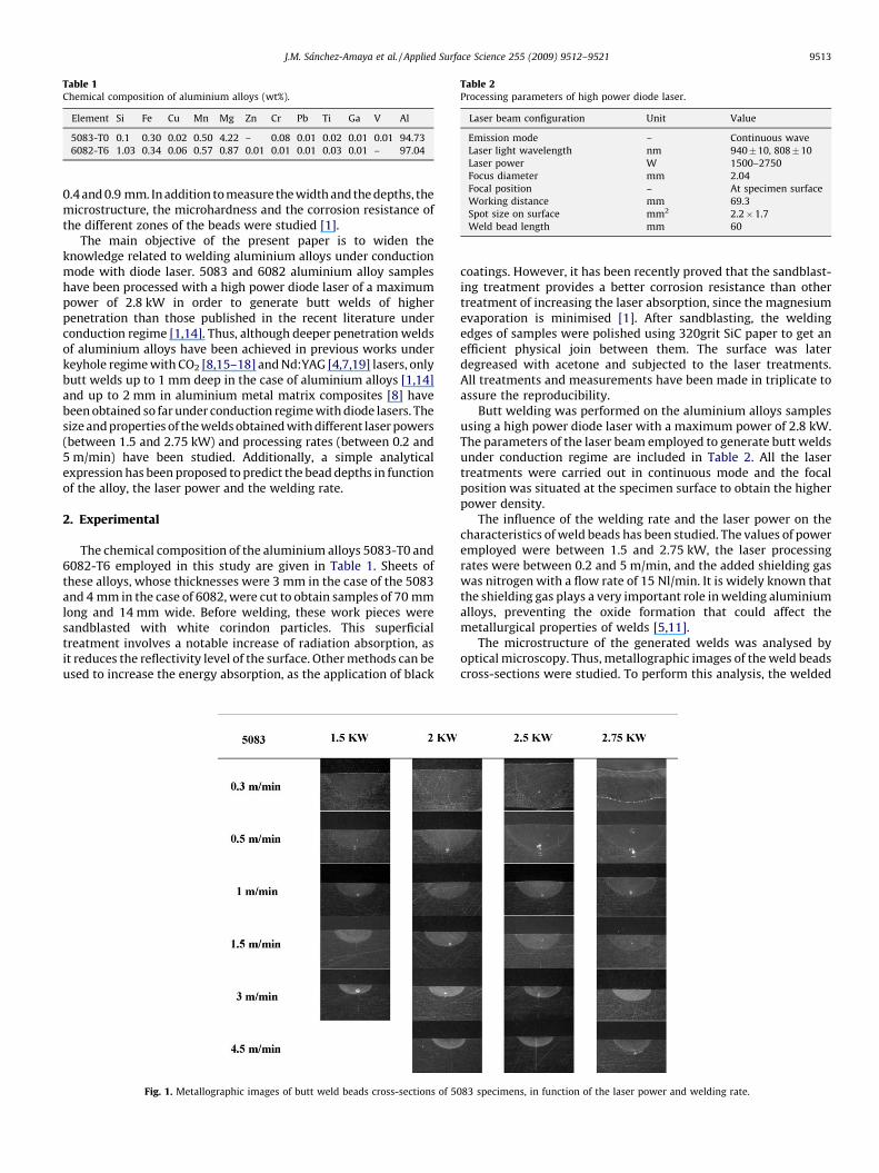
Table 1Chemical composition of aluminium alloys (wt%).
Element Si Fe Cu Mn Mg Zn Cr Pb Ti Ga V Al
5083-T0 0.1 0.30 0.02 0.50 4.22 – 0.08 0.01 0.02 0.01 0.01 94.73
6082-T6 1.03 0.34 0.06 0.57 0.87 0.01 0.01 0.01 0.03 0.01 – 97.04
Table 2Processing parameters of high power diode laser.
Laser beam configuration Unit Value
Emission mode – Continuous wave
Laser light wavelength nm 940�10, 808�10
Laser power W 1500–2750
Focus diameter mm 2.04
Focal position – At specimen surface
Working distance mm 69.3
Spot size on surface mm2 2.2�1.7
Weld bead length mm 60
J.M. Sanchez-Amaya et al. / Applied Surface Science 255 (2009) 9512–9521 9513
0.4 and 0.9 mm. In addition to measure the width and the depths, themicrostructure, the microhardness and the corrosion resistance ofthe different zones of the beads were studied [1].
The main objective of the present paper is to widen theknowledge related to welding aluminium alloys under conductionmode with diode laser. 5083 and 6082 aluminium alloy sampleshave been processed with a high power diode laser of a maximumpower of 2.8 kW in order to generate butt welds of higherpenetration than those published in the recent literature underconduction regime [1,14]. Thus, although deeper penetration weldsof aluminium alloys have been achieved in previous works underkeyhole regime with CO2 [8,15–18] and Nd:YAG [4,7,19] lasers, onlybutt welds up to 1 mm deep in the case of aluminium alloys [1,14]and up to 2 mm in aluminium metal matrix composites [8] havebeen obtained so far under conduction regime with diode lasers. Thesize and properties of the welds obtained with different laser powers(between 1.5 and 2.75 kW) and processing rates (between 0.2 and5 m/min) have been studied. Additionally, a simple analyticalexpression has been proposed to predict the bead depths in functionof the alloy, the laser power and the welding rate.
2. Experimental
The chemical composition of the aluminium alloys 5083-T0 and6082-T6 employed in this study are given in Table 1. Sheets ofthese alloys, whose thicknesses were 3 mm in the case of the 5083and 4 mm in the case of 6082, were cut to obtain samples of 70 mmlong and 14 mm wide. Before welding, these work pieces weresandblasted with white corindon particles. This superficialtreatment involves a notable increase of radiation absorption, asit reduces the reflectivity level of the surface. Other methods can beused to increase the energy absorption, as the application of black
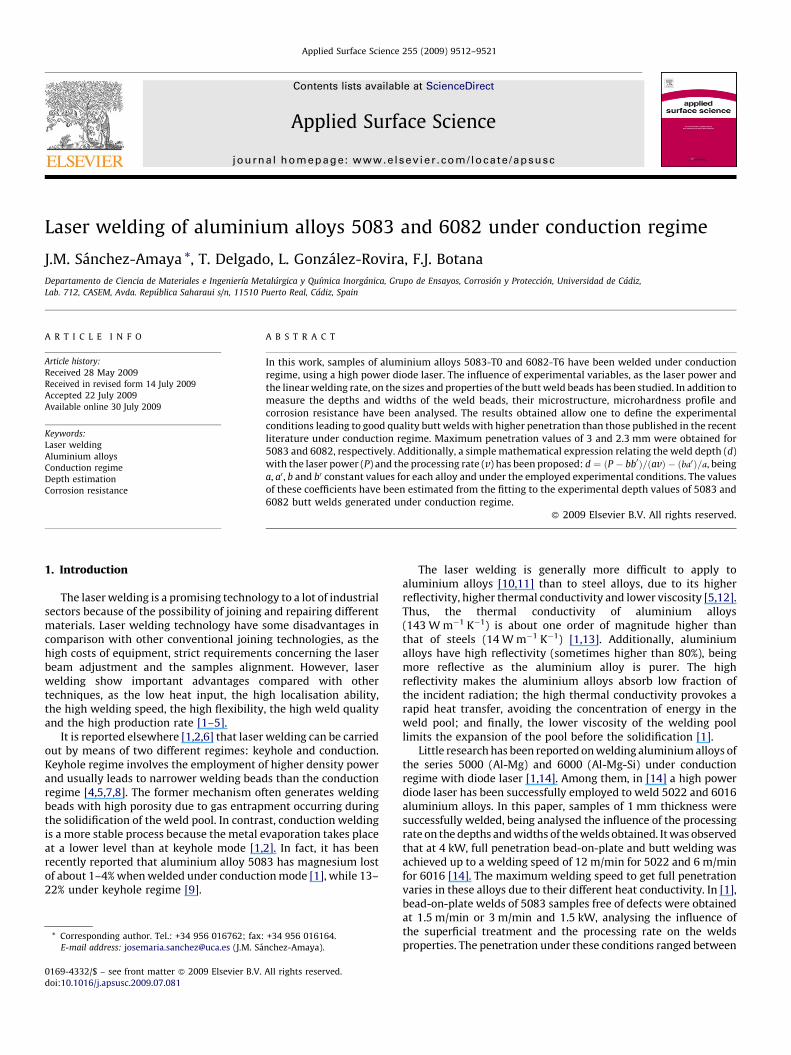
Fig. 1. Metallographic images of butt weld beads cross-sections of 50
coatings. However, it has been recently proved that the sandblast-ing treatment provides a better corrosion resistance than othertreatment of increasing the laser absorption, since the magnesiumevaporation is minimised [1]. After sandblasting, the weldingedges of samples were polished using 320grit SiC paper to get anefficient physical join between them. The surface was laterdegreased with acetone and subjected to the laser treatments.All treatments and measurements have been made in triplicate toassure the reproducibility.
Butt welding was performed on the aluminium alloys samplesusing a high power diode laser with a maximum power of 2.8 kW.The parameters of the laser beam employed to generate butt weldsunder conduction regime are included in Table 2. All the lasertreatments were carried out in continuous mode and the focalposition was situated at the specimen surface to obtain the higherpower density.
The influence of the welding rate and the laser power on thecharacteristics of weld beads has been studied. The values of poweremployed were between 1.5 and 2.75 kW, the laser processingrates were between 0.2 and 5 m/min, and the added shielding gaswas nitrogen with a flow rate of 15 Nl/min. It is widely known thatthe shielding gas plays a very important role in welding aluminiumalloys, preventing the oxide formation that could affect themetallurgical properties of welds [5,11].
The microstructure of the generated welds was analysed byoptical microscopy. Thus, metallographic images of the weld beadscross-sections were studied. To perform this analysis, the welded
83 specimens, in function of the laser power and welding rate.
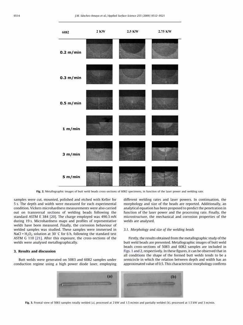
Fig. 2. Metallographic images of butt weld beads cross-sections of 6082 specimens, in function of the laser power and welding rate.
J.M. Sanchez-Amaya et al. / Applied Surface Science 255 (2009) 9512–95219514
samples were cut, mounted, polished and etched with Keller for5 s. The depth and width were measured for each experimentalcondition. Vickers microhardness measurements were also carriedout on transversal sections of welding beads following thestandard ASTM E 384 [20]. The charge employed was 490.3 mNduring 19 s. Microhardness maps and profiles of representativewelds have been measured. Finally, the corrosion behaviour ofwelded samples was studied. These samples were immersed inNaCl + H2O2 solution at 30 8C for 6 h, following the standard testASTM G 110 [21]. After this exposure, the cross-sections of thewelds were analysed metallographically.
3. Results and discussion
Butt welds were generated on 5083 and 6082 samples underconduction regime using a high power diode laser, employing
Fig. 3. Frontal view of 5083 samples totally welded (a), processed at 2 kW an
different welding rates and laser powers. In continuation, themorphology and size of the beads are reported. Additionally, ananalytical equation has been proposed to predict the penetration infunction of the laser power and the processing rate. Finally, themicrostructure, the mechanical and corrosion properties of thewelds are analysed.
3.1. Morphology and size of the welding beads
Firstly, the results obtained from the metallographic study of thebutt weld beads are presented. Metallographic images of butt weldbeads cross-sections of 5083 and 6082 samples are included inFigs. 1 and 2, respectively. In these figures, it can be observed that inall conditions the shape of the formed butt welds tends to be asemicircle in which the relation between depth and width has anapproximated value of 0.5. This characteristic morphology confirms
d 1.5 m/min and partially welded (b), processed at 1.5 kW and 3 m/min.
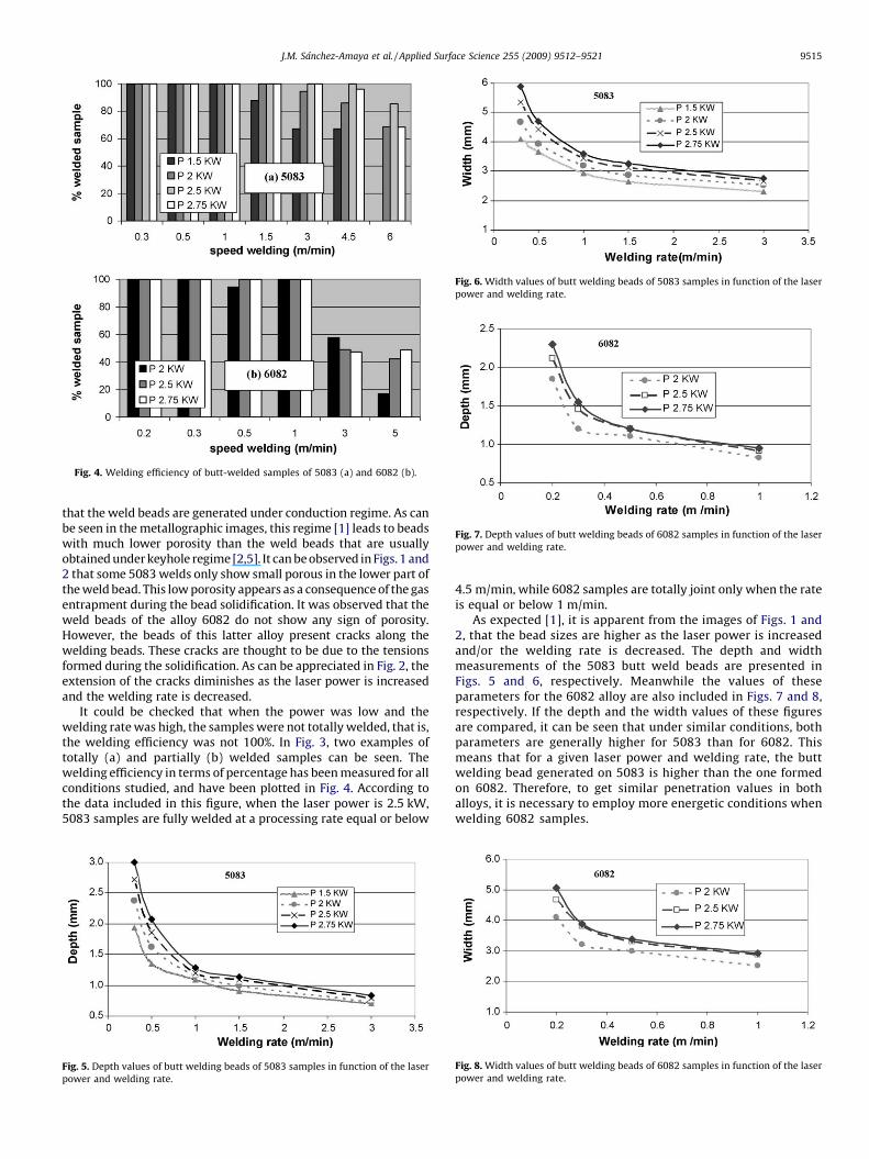
Fig. 4. Welding efficiency of butt-welded samples of 5083 (a) and 6082 (b).
Fig. 6. Width values of butt welding beads of 5083 samples in function of the laser
power and welding rate.
Fig. 7. Depth values of butt welding beads of 6082 samples in function of the laser
power and welding rate.
J.M. Sanchez-Amaya et al. / Applied Surface Science 255 (2009) 9512–9521 9515
that the weld beads are generated under conduction regime. As canbe seen in the metallographic images, this regime [1] leads to beadswith much lower porosity than the weld beads that are usuallyobtained under keyhole regime [2,5]. It can be observed in Figs. 1 and2 that some 5083 welds only show small porous in the lower part ofthe weld bead. This low porosity appears as a consequence of the gasentrapment during the bead solidification. It was observed that theweld beads of the alloy 6082 do not show any sign of porosity.However, the beads of this latter alloy present cracks along thewelding beads. These cracks are thought to be due to the tensionsformed during the solidification. As can be appreciated in Fig. 2, theextension of the cracks diminishes as the laser power is increasedand the welding rate is decreased.
It could be checked that when the power was low and thewelding rate was high, the samples were not totally welded, that is,the welding efficiency was not 100%. In Fig. 3, two examples oftotally (a) and partially (b) welded samples can be seen. Thewelding efficiency in terms of percentage has been measured for allconditions studied, and have been plotted in Fig. 4. According tothe data included in this figure, when the laser power is 2.5 kW,5083 samples are fully welded at a processing rate equal or below
Fig. 5. Depth values of butt welding beads of 5083 samples in function of the laser
power and welding rate.
4.5 m/min, while 6082 samples are totally joint only when the rateis equal or below 1 m/min.
As expected [1], it is apparent from the images of Figs. 1 and2, that the bead sizes are higher as the laser power is increasedand/or the welding rate is decreased. The depth and widthmeasurements of the 5083 butt weld beads are presented inFigs. 5 and 6, respectively. Meanwhile the values of theseparameters for the 6082 alloy are also included in Figs. 7 and 8,respectively. If the depth and the width values of these figuresare compared, it can be seen that under similar conditions, bothparameters are generally higher for 5083 than for 6082. Thismeans that for a given laser power and welding rate, the buttwelding bead generated on 5083 is higher than the one formedon 6082. Therefore, to get similar penetration values in bothalloys, it is necessary to employ more energetic conditions whenwelding 6082 samples.
Fig. 8. Width values of butt welding beads of 6082 samples in function of the laser
power and welding rate.
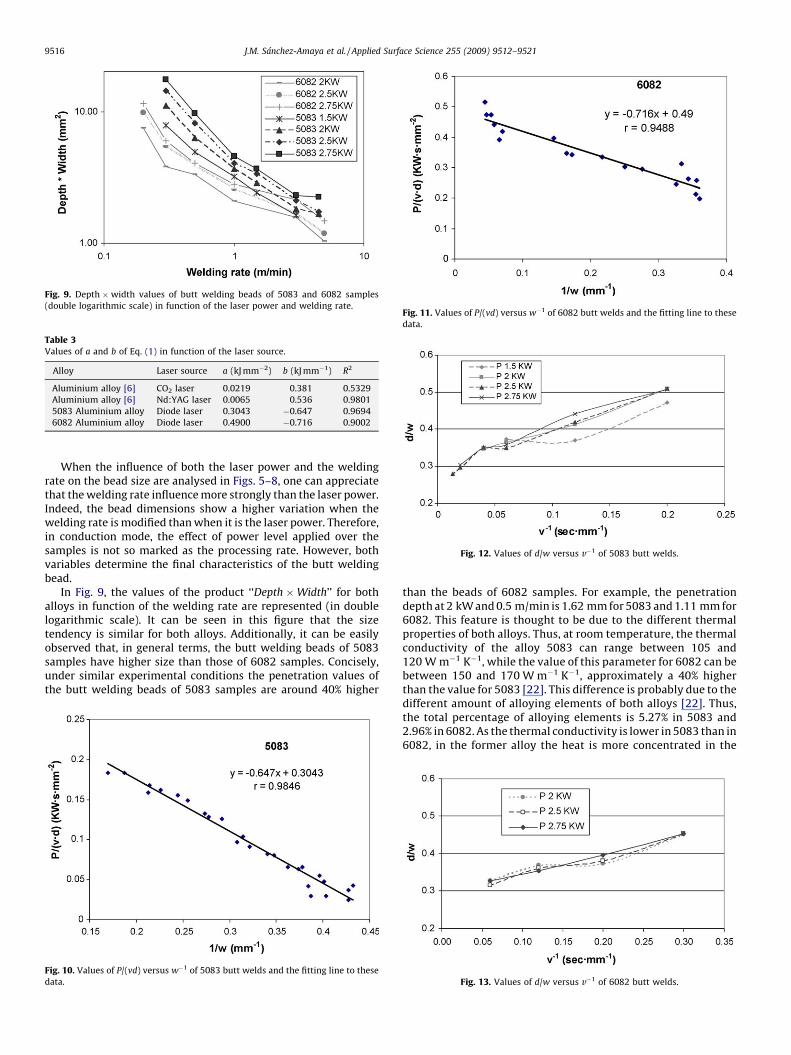
Fig. 9. Depth �width values of butt welding beads of 5083 and 6082 samples
(double logarithmic scale) in function of the laser power and welding rate.
Fig. 12. Values of d/w versus v�1 of 5083 butt welds.
Table 3Values of a and b of Eq. (1) in function of the laser source.
Alloy Laser source a (kJ mm�2) b (kJ mm�1) R2
Aluminium alloy [6] CO2 laser 0.0219 0.381 0.5329
Aluminium alloy [6] Nd:YAG laser 0.0065 0.536 0.9801
5083 Aluminium alloy Diode laser 0.3043 �0.647 0.9694
6082 Aluminium alloy Diode laser 0.4900 �0.716 0.9002
Fig. 11. Values of P/(vd) versus w�1 of 6082 butt welds and the fitting line to these
data.
J.M. Sanchez-Amaya et al. / Applied Surface Science 255 (2009) 9512–95219516
When the influence of both the laser power and the weldingrate on the bead size are analysed in Figs. 5–8, one can appreciatethat the welding rate influence more strongly than the laser power.Indeed, the bead dimensions show a higher variation when thewelding rate is modified than when it is the laser power. Therefore,in conduction mode, the effect of power level applied over thesamples is not so marked as the processing rate. However, bothvariables determine the final characteristics of the butt weldingbead.
In Fig. 9, the values of the product ‘‘Depth �Width’’ for bothalloys in function of the welding rate are represented (in doublelogarithmic scale). It can be seen in this figure that the sizetendency is similar for both alloys. Additionally, it can be easilyobserved that, in general terms, the butt welding beads of 5083samples have higher size than those of 6082 samples. Concisely,under similar experimental conditions the penetration values ofthe butt welding beads of 5083 samples are around 40% higher
Fig. 10. Values of P/(vd) versus w�1 of 5083 butt welds and the fitting line to these
data.
than the beads of 6082 samples. For example, the penetrationdepth at 2 kW and 0.5 m/min is 1.62 mm for 5083 and 1.11 mm for6082. This feature is thought to be due to the different thermalproperties of both alloys. Thus, at room temperature, the thermalconductivity of the alloy 5083 can range between 105 and120 W m�1 K�1, while the value of this parameter for 6082 can bebetween 150 and 170 W m�1 K�1, approximately a 40% higherthan the value for 5083 [22]. This difference is probably due to thedifferent amount of alloying elements of both alloys [22]. Thus,the total percentage of alloying elements is 5.27% in 5083 and2.96% in 6082. As the thermal conductivity is lower in 5083 than in6082, in the former alloy the heat is more concentrated in the
Fig. 13. Values of d/w versus v�1 of 6082 butt welds.
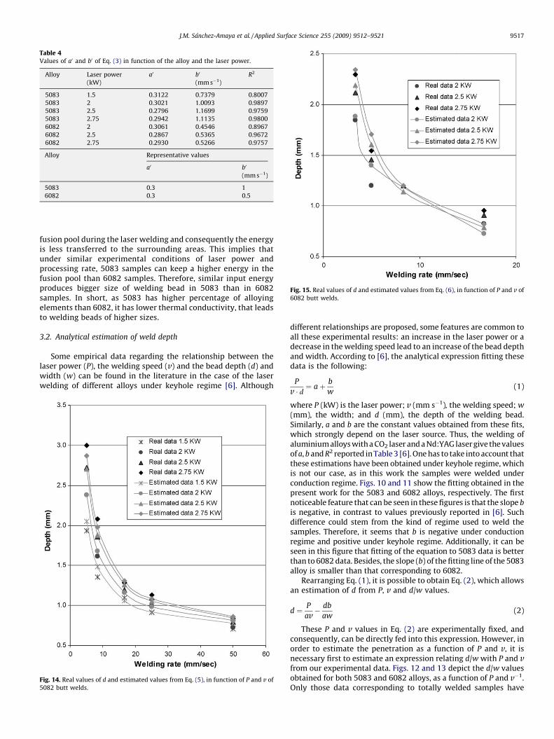
Fig. 15. Real values of d and estimated values from Eq. (6), in function of P and v of
6082 butt welds.
Table 4Values of a0 and b0 of Eq. (3) in function of the alloy and the laser power.
Alloy Laser power
(kW)
a0 b0
(mm s�1)
R2
5083 1.5 0.3122 0.7379 0.8007
5083 2 0.3021 1.0093 0.9897
5083 2.5 0.2796 1.1699 0.9759
5083 2.75 0.2942 1.1135 0.9800
6082 2 0.3061 0.4546 0.8967
6082 2.5 0.2867 0.5365 0.9672
6082 2.75 0.2930 0.5266 0.9757
Alloy Representative values
a0 b0
(mm s�1)
5083 0.3 1
6082 0.3 0.5
J.M. Sanchez-Amaya et al. / Applied Surface Science 255 (2009) 9512–9521 9517
fusion pool during the laser welding and consequently the energyis less transferred to the surrounding areas. This implies thatunder similar experimental conditions of laser power andprocessing rate, 5083 samples can keep a higher energy in thefusion pool than 6082 samples. Therefore, similar input energyproduces bigger size of welding bead in 5083 than in 6082samples. In short, as 5083 has higher percentage of alloyingelements than 6082, it has lower thermal conductivity, that leadsto welding beads of higher sizes.
3.2. Analytical estimation of weld depth
Some empirical data regarding the relationship between thelaser power (P), the welding speed (v) and the bead depth (d) andwidth (w) can be found in the literature in the case of the laserwelding of different alloys under keyhole regime [6]. Although
Fig. 14. Real values of d and estimated values from Eq. (5), in function of P and v of
5082 butt welds.
different relationships are proposed, some features are common toall these experimental results: an increase in the laser power or adecrease in the welding speed lead to an increase of the bead depthand width. According to [6], the analytical expression fitting thesedata is the following:
P
v � d ¼ aþ b
w(1)
where P (kW) is the laser power; v (mm s�1), the welding speed; w
(mm), the width; and d (mm), the depth of the welding bead.Similarly, a and b are the constant values obtained from these fits,which strongly depend on the laser source. Thus, the welding ofaluminium alloys with a CO2 laser and a Nd:YAG laser give the valuesof a, b and R2 reported in Table 3 [6]. One has to take into account thatthese estimations have been obtained under keyhole regime, whichis not our case, as in this work the samples were welded underconduction regime. Figs. 10 and 11 show the fitting obtained in thepresent work for the 5083 and 6082 alloys, respectively. The firstnoticeable feature that can be seen in these figures is that the slope b
is negative, in contrast to values previously reported in [6]. Suchdifference could stem from the kind of regime used to weld thesamples. Therefore, it seems that b is negative under conductionregime and positive under keyhole regime. Additionally, it can beseen in this figure that fitting of the equation to 5083 data is betterthan to 6082 data. Besides, the slope (b) of the fitting line of the 5083alloy is smaller than that corresponding to 6082.
Rearranging Eq. (1), it is possible to obtain Eq. (2), which allowsan estimation of d from P, v and d/w values.
d ¼ P
av� db
aw(2)
These P and v values in Eq. (2) are experimentally fixed, andconsequently, can be directly fed into this expression. However, inorder to estimate the penetration as a function of P and v, it isnecessary first to estimate an expression relating d/w with P and vfrom our experimental data. Figs. 12 and 13 depict the d/w valuesobtained for both 5083 and 6082 alloys, as a function of P and v�1.Only those data corresponding to totally welded samples have
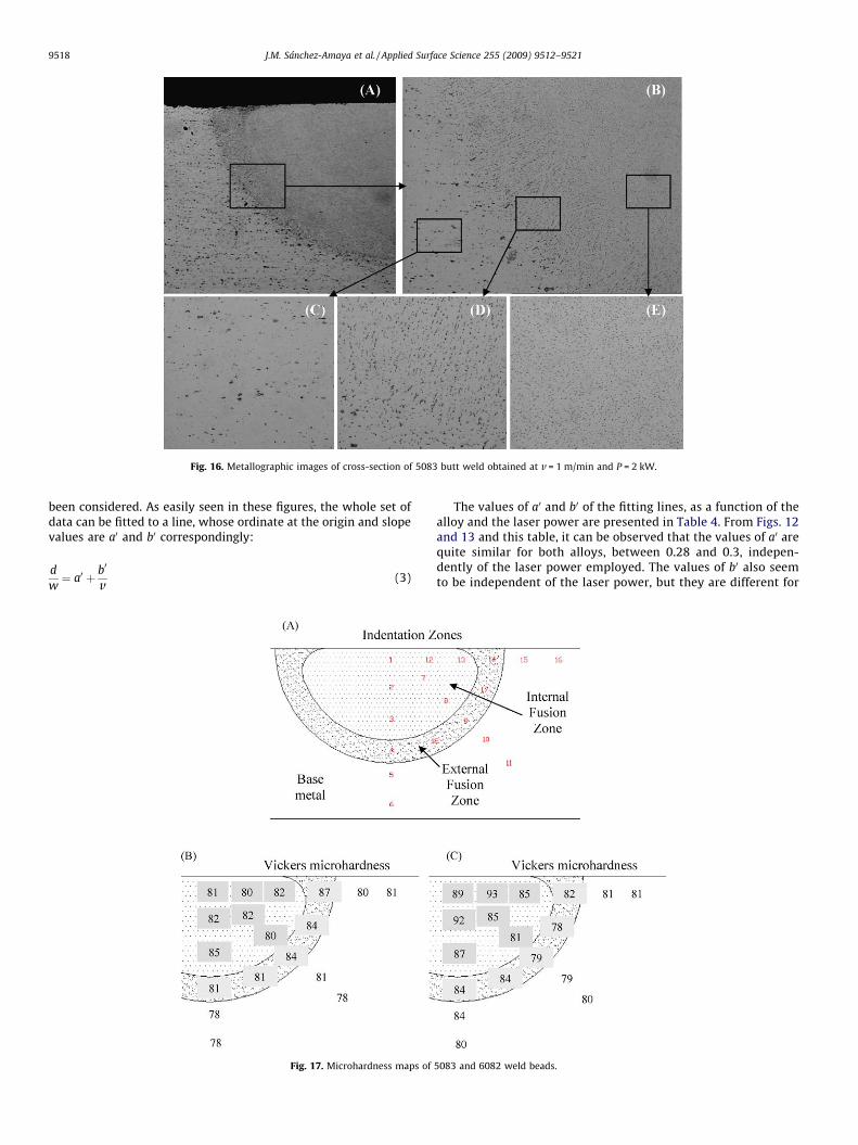
Fig. 16. Metallographic images of cross-section of 5083 butt weld obtained at v = 1 m/min and P = 2 kW.
J.M. Sanchez-Amaya et al. / Applied Surface Science 255 (2009) 9512–95219518
been considered. As easily seen in these figures, the whole set ofdata can be fitted to a line, whose ordinate at the origin and slopevalues are a0 and b0 correspondingly:
d
w¼ a0 þ b0
v(3)
Fig. 17. Microhardness maps of
The values of a0 and b0 of the fitting lines, as a function of thealloy and the laser power are presented in Table 4. From Figs. 12and 13 and this table, it can be observed that the values of a0 arequite similar for both alloys, between 0.28 and 0.3, indepen-dently of the laser power employed. The values of b0 also seemto be independent of the laser power, but they are different for
5083 and 6082 weld beads.
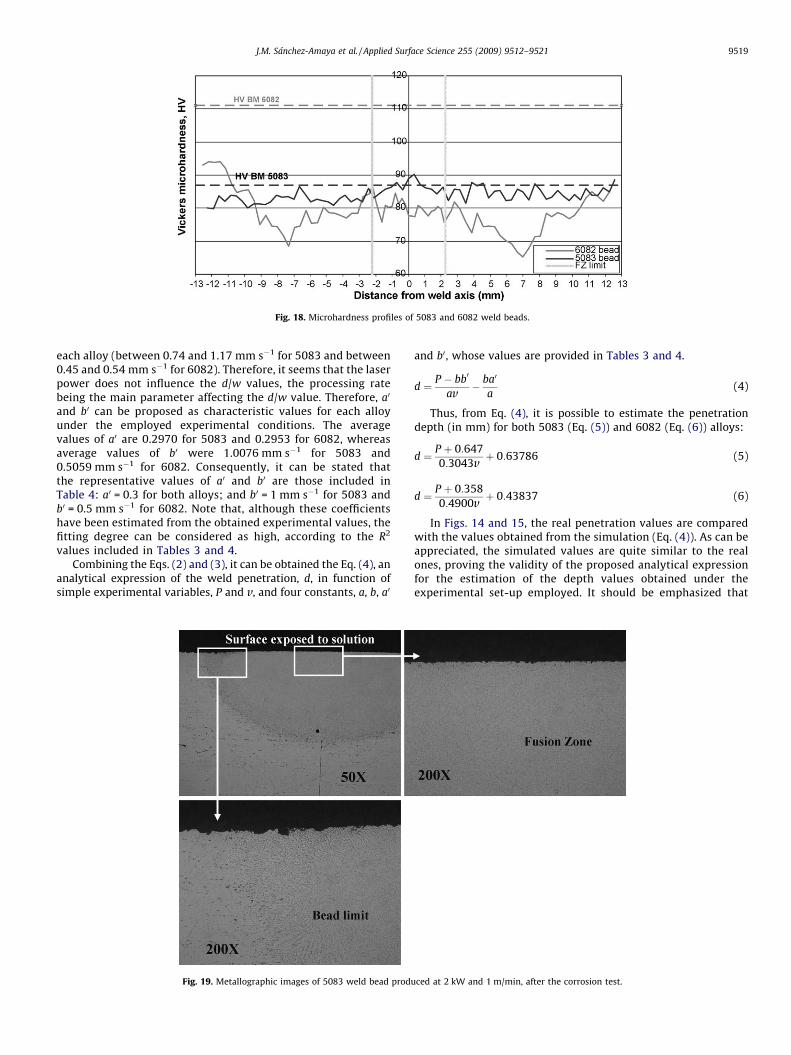
Fig. 18. Microhardness profiles of 5083 and 6082 weld beads.
J.M. Sanchez-Amaya et al. / Applied Surface Science 255 (2009) 9512–9521 9519
each alloy (between 0.74 and 1.17 mm s�1 for 5083 and between0.45 and 0.54 mm s�1 for 6082). Therefore, it seems that the laserpower does not influence the d/w values, the processing ratebeing the main parameter affecting the d/w value. Therefore, a0
and b0 can be proposed as characteristic values for each alloyunder the employed experimental conditions. The averagevalues of a0 are 0.2970 for 5083 and 0.2953 for 6082, whereasaverage values of b0 were 1.0076 mm s�1 for 5083 and0.5059 mm s�1 for 6082. Consequently, it can be stated thatthe representative values of a0 and b0 are those included inTable 4: a0 = 0.3 for both alloys; and b0 = 1 mm s�1 for 5083 andb0 = 0.5 mm s�1 for 6082. Note that, although these coefficientshave been estimated from the obtained experimental values, thefitting degree can be considered as high, according to the R2
values included in Tables 3 and 4.Combining the Eqs. (2) and (3), it can be obtained the Eq. (4), an
analytical expression of the weld penetration, d, in function ofsimple experimental variables, P and v, and four constants, a, b, a0
Fig. 19. Metallographic images of 5083 weld bead produ
and b0, whose values are provided in Tables 3 and 4.
d ¼ P � bb0
av� ba0
a(4)
Thus, from Eq. (4), it is possible to estimate the penetrationdepth (in mm) for both 5083 (Eq. (5)) and 6082 (Eq. (6)) alloys:
d ¼ P þ 0:647
0:3043vþ 0:63786 (5)
d ¼ P þ 0:358
0:4900vþ 0:43837 (6)
In Figs. 14 and 15, the real penetration values are comparedwith the values obtained from the simulation (Eq. (4)). As can beappreciated, the simulated values are quite similar to the realones, proving the validity of the proposed analytical expressionfor the estimation of the depth values obtained under theexperimental set-up employed. It should be emphasized that
ced at 2 kW and 1 m/min, after the corrosion test.
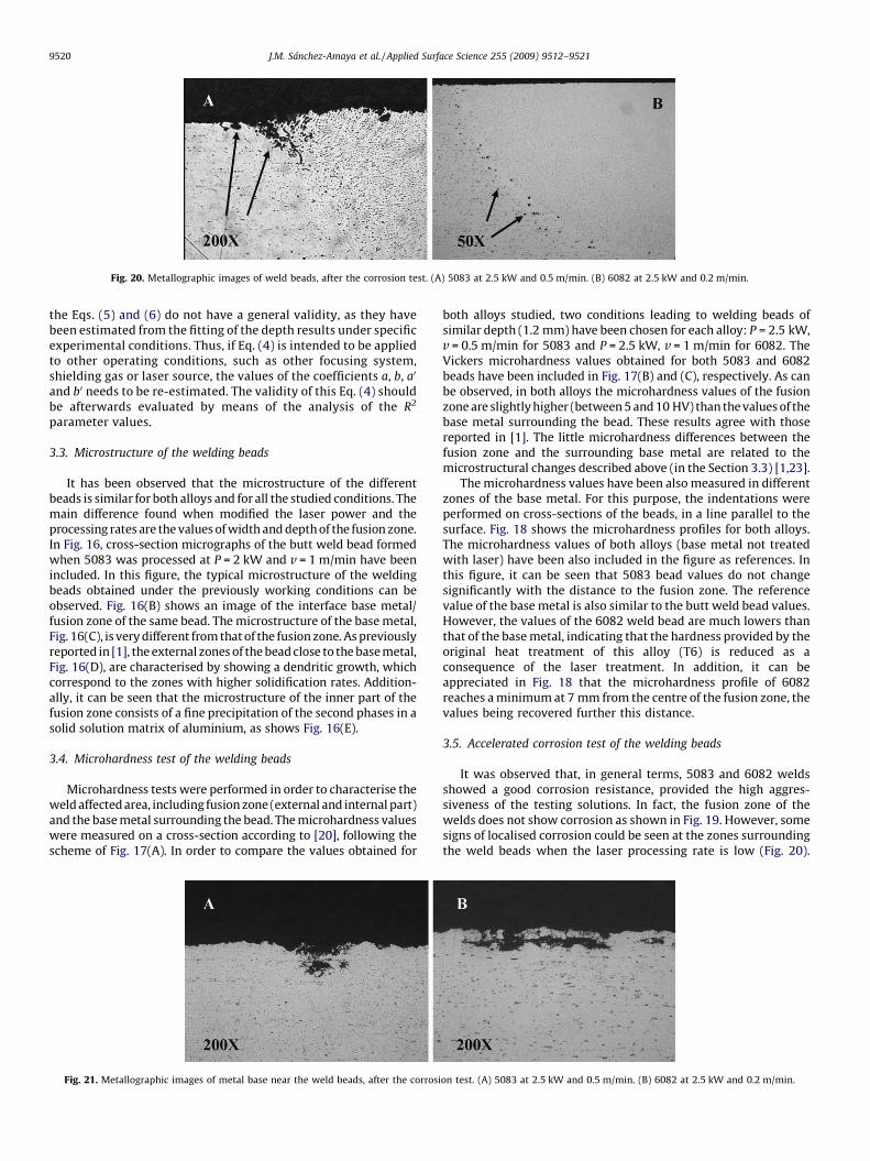
Fig. 20. Metallographic images of weld beads, after the corrosion test. (A) 5083 at 2.5 kW and 0.5 m/min. (B) 6082 at 2.5 kW and 0.2 m/min.
J.M. Sanchez-Amaya et al. / Applied Surface Science 255 (2009) 9512–95219520
the Eqs. (5) and (6) do not have a general validity, as they havebeen estimated from the fitting of the depth results under specificexperimental conditions. Thus, if Eq. (4) is intended to be appliedto other operating conditions, such as other focusing system,shielding gas or laser source, the values of the coefficients a, b, a0
and b0 needs to be re-estimated. The validity of this Eq. (4) shouldbe afterwards evaluated by means of the analysis of the R2
parameter values.
3.3. Microstructure of the welding beads
It has been observed that the microstructure of the differentbeads is similar for both alloys and for all the studied conditions. Themain difference found when modified the laser power and theprocessing rates are the values of width and depth of the fusion zone.In Fig. 16, cross-section micrographs of the butt weld bead formedwhen 5083 was processed at P = 2 kW and v = 1 m/min have beenincluded. In this figure, the typical microstructure of the weldingbeads obtained under the previously working conditions can beobserved. Fig. 16(B) shows an image of the interface base metal/fusion zone of the same bead. The microstructure of the base metal,Fig. 16(C), is very different from that of the fusion zone. As previouslyreported in [1], the external zones of the bead close to the base metal,Fig. 16(D), are characterised by showing a dendritic growth, whichcorrespond to the zones with higher solidification rates. Addition-ally, it can be seen that the microstructure of the inner part of thefusion zone consists of a fine precipitation of the second phases in asolid solution matrix of aluminium, as shows Fig. 16(E).
3.4. Microhardness test of the welding beads
Microhardness tests were performed in order to characterise theweld affected area, including fusion zone (external and internal part)and the base metal surrounding the bead. The microhardness valueswere measured on a cross-section according to [20], following thescheme of Fig. 17(A). In order to compare the values obtained for
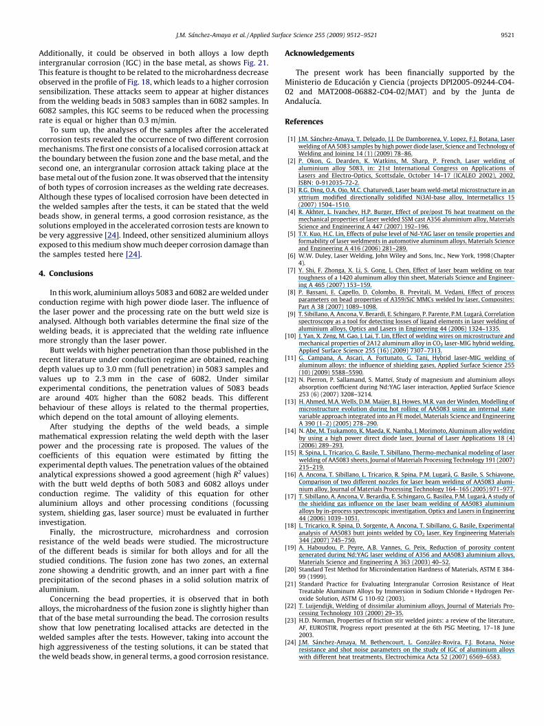
Fig. 21. Metallographic images of metal base near the weld beads, after the corrosi
both alloys studied, two conditions leading to welding beads ofsimilar depth (1.2 mm) have been chosen for each alloy: P = 2.5 kW,v = 0.5 m/min for 5083 and P = 2.5 kW, v = 1 m/min for 6082. TheVickers microhardness values obtained for both 5083 and 6082beads have been included in Fig. 17(B) and (C), respectively. As canbe observed, in both alloys the microhardness values of the fusionzone are slightly higher (between 5 and 10 HV) than the values of thebase metal surrounding the bead. These results agree with thosereported in [1]. The little microhardness differences between thefusion zone and the surrounding base metal are related to themicrostructural changes described above (in the Section 3.3) [1,23].
The microhardness values have been also measured in differentzones of the base metal. For this purpose, the indentations wereperformed on cross-sections of the beads, in a line parallel to thesurface. Fig. 18 shows the microhardness profiles for both alloys.The microhardness values of both alloys (base metal not treatedwith laser) have been also included in the figure as references. Inthis figure, it can be seen that 5083 bead values do not changesignificantly with the distance to the fusion zone. The referencevalue of the base metal is also similar to the butt weld bead values.However, the values of the 6082 weld bead are much lowers thanthat of the base metal, indicating that the hardness provided by theoriginal heat treatment of this alloy (T6) is reduced as aconsequence of the laser treatment. In addition, it can beappreciated in Fig. 18 that the microhardness profile of 6082reaches a minimum at 7 mm from the centre of the fusion zone, thevalues being recovered further this distance.
3.5. Accelerated corrosion test of the welding beads
It was observed that, in general terms, 5083 and 6082 weldsshowed a good corrosion resistance, provided the high aggres-siveness of the testing solutions. In fact, the fusion zone of thewelds does not show corrosion as shown in Fig. 19. However, somesigns of localised corrosion could be seen at the zones surroundingthe weld beads when the laser processing rate is low (Fig. 20).
on test. (A) 5083 at 2.5 kW and 0.5 m/min. (B) 6082 at 2.5 kW and 0.2 m/min.
J.M. Sanchez-Amaya et al. / Applied Surface Science 255 (2009) 9512–9521 9521
Additionally, it could be observed in both alloys a low depthintergranular corrosion (IGC) in the base metal, as shows Fig. 21.This feature is thought to be related to the microhardness decreaseobserved in the profile of Fig. 18, which leads to a higher corrosionsensibilization. These attacks seem to appear at higher distancesfrom the welding beads in 5083 samples than in 6082 samples. In6082 samples, this IGC seems to be reduced when the processingrate is equal or higher than 0.3 m/min.
To sum up, the analyses of the samples after the acceleratedcorrosion tests revealed the occurrence of two different corrosionmechanisms. The first one consists of a localised corrosion attack atthe boundary between the fusion zone and the base metal, and thesecond one, an intergranular corrosion attack taking place at thebase metal out of the fusion zone. It was observed that the intensityof both types of corrosion increases as the welding rate decreases.Although these types of localised corrosion have been detected inthe welded samples after the tests, it can be stated that the weldbeads show, in general terms, a good corrosion resistance, as thesolutions employed in the accelerated corrosion tests are known tobe very aggressive [24]. Indeed, other sensitized aluminium alloysexposed to this medium show much deeper corrosion damage thanthe samples tested here [24].
4. Conclusions
In this work, aluminium alloys 5083 and 6082 are welded underconduction regime with high power diode laser. The influence ofthe laser power and the processing rate on the butt weld size isanalysed. Although both variables determine the final size of thewelding beads, it is appreciated that the welding rate influencemore strongly than the laser power.
Butt welds with higher penetration than those published in therecent literature under conduction regime are obtained, reachingdepth values up to 3.0 mm (full penetration) in 5083 samples andvalues up to 2.3 mm in the case of 6082. Under similarexperimental conditions, the penetration values of 5083 beadsare around 40% higher than the 6082 beads. This differentbehaviour of these alloys is related to the thermal properties,which depend on the total amount of alloying elements.
After studying the depths of the weld beads, a simplemathematical expression relating the weld depth with the laserpower and the processing rate is proposed. The values of thecoefficients of this equation were estimated by fitting theexperimental depth values. The penetration values of the obtainedanalytical expressions showed a good agreement (high R2 values)with the butt weld depths of both 5083 and 6082 alloys underconduction regime. The validity of this equation for otheraluminium alloys and other processing conditions (focussingsystem, shielding gas, laser source) must be evaluated in furtherinvestigation.
Finally, the microstructure, microhardness and corrosionresistance of the weld beads were studied. The microstructureof the different beads is similar for both alloys and for all thestudied conditions. The fusion zone has two zones, an externalzone showing a dendritic growth, and an inner part with a fineprecipitation of the second phases in a solid solution matrix ofaluminium.
Concerning the bead properties, it is observed that in bothalloys, the microhardness of the fusion zone is slightly higher thanthat of the base metal surrounding the bead. The corrosion resultsshow that low penetrating localised attacks are detected in thewelded samples after the tests. However, taking into account thehigh aggressiveness of the testing solutions, it can be stated thatthe weld beads show, in general terms, a good corrosion resistance.
Acknowledgements
The present work has been financially supported by theMinisterio de Educacion y Ciencia (projects DPI2005-09244-C04-02 and MAT2008-06882-C04-02/MAT) and by the Junta deAndalucıa.
References
[1] J.M. Sanchez-Amaya, T. Delgado, J.J. De Damborenea, V. Lopez, F.J. Botana, Laserwelding of AA 5083 samples by high power diode laser, Science and Technology ofWelding and Joining 14 (1) (2009) 78–86.
[2] P. Okon, G. Dearden, K. Watkins, M. Sharp, P. French, Laser welding ofaluminium alloy 5083, in: 21st International Congress on Applications ofLasers and Electro-Optics, Scottsdale, October 14–17 (ICALEO 2002), 2002,ISBN: 0-912035-72-2.
[3] R.G. Ding, O.A. Ojo, M.C. Chaturvedi, Laser beam weld-metal microstructure in anyttrium modified directionally solidified Ni3Al-base alloy, Intermetallics 15(2007) 1504–1510.
[4] R. Akhter, L. Ivanchev, H.P. Burger, Effect of pre/post T6 heat treatment on themechanical properties of laser welded SSM cast A356 aluminium alloy, MaterialsScience and Engineering A 447 (2007) 192–196.
[5] T.Y. Kuo, H.C. Lin, Effects of pulse level of Nd-YAG laser on tensile properties andformability of laser weldments in automotive aluminum alloys, Materials Scienceand Engineering A 416 (2006) 281–289.
[6] W.W. Duley, Laser Welding, John Wiley and Sons, Inc., New York, 1998 (Chapter4).
[7] Y. Shi, F. Zhonga, X. Li, S. Gong, L. Chen, Effect of laser beam welding on teartoughness of a 1420 aluminum alloy thin sheet, Materials Science and Engineer-ing A 465 (2007) 153–159.
[8] P. Bassani, E. Capello, D. Colombo, B. Previtali, M. Vedani, Effect of processparameters on bead properties of A359/SiC MMCs welded by laser, Composites:Part A 38 (2007) 1089–1098.
[9] T. Sibillano, A. Ancona, V. Berardi, E. Schingaro, P. Parente, P.M. Lugara, Correlationspectroscopy as a tool for detecting losses of ligand elements in laser welding ofaluminium alloys, Optics and Lasers in Engineering 44 (2006) 1324–1335.
[10] J. Yan, X. Zeng, M. Gao, J. Lai, T. Lin, Effect of welding wires on microstructure andmechanical properties of 2A12 aluminum alloy in CO2 laser-MIG hybrid welding,Applied Surface Science 255 (16) (2009) 7307–7313.
[11] G. Campana, A. Ascari, A. Fortunato, G. Tani, Hybrid laser-MIG welding ofaluminum alloys: the influence of shielding gases, Applied Surface Science 255(10) (2009) 5588–5590.
[12] N. Pierron, P. Sallamand, S. Matteı, Study of magnesium and aluminium alloysabsorption coefficient during Nd:YAG laser interaction, Applied Surface Science253 (6) (2007) 3208–3214.
[13] H. Ahmed, M.A. Wells, D.M. Maijer, B.J. Howes, M.R. van der Winden, Modelling ofmicrostructure evolution during hot rolling of AA5083 using an internal statevariable approach integrated into an FE model, Materials Science and EngineeringA 390 (1–2) (2005) 278–290.
[14] N. Abe, M. Tsukamoto, K. Maeda, K. Namba, J. Morimoto, Aluminum alloy weldingby using a high power direct diode laser, Journal of Laser Applications 18 (4)(2006) 289–293.
[15] R. Spina, L. Tricarico, G. Basile, T. Sibillano, Thermo-mechanical modeling of laserwelding of AA5083 sheets, Journal of Materials Processing Technology 191 (2007)215–219.
[16] A. Ancona, T. Sibillano, L. Tricarico, R. Spina, P.M. Lugara, G. Basile, S. Schiavone,Comparison of two different nozzles for laser beam welding of AA5083 alumi-nium alloy, Journal of Materials Processing Technology 164–165 (2005) 971–977.
[17] T. Sibillano, A. Ancona, V. Berardia, E. Schingaro, G. Basilea, P.M. Lugara, A study ofthe shielding gas influence on the laser beam welding of AA5083 aluminiumalloys by in-process spectroscopic investigation, Optics and Lasers in Engineering44 (2006) 1039–1051.
[18] L. Tricarico, R. Spina, D. Sorgente, A. Ancona, T. Sibillano, G. Basile, Experimentalanalysis of AA5083 butt joints welded by CO2 laser, Key Engineering Materials344 (2007) 745–750.
[19] A. Haboudou, P. Peyre, A.B. Vannes, G. Peix, Reduction of porosity contentgenerated during Nd:YAG laser welding of A356 and AA5083 aluminium alloys,Materials Science and Engineering A 363 (2003) 40–52.
[20] Standard Test Method for Microindentation Hardness of Materials, ASTM E 384-99 (1999).
[21] Standard Practice for Evaluating Intergranular Corrosion Resistance of HeatTreatable Aluminum Alloys by Immersion in Sodium Chloride + Hydrogen Per-oxide Solution, ASTM G 110-92 (2003).
[22] T. Luijendijk, Welding of dissimilar aluminium alloys, Journal of Materials Pro-cessing Technology 103 (2000) 29–35.
[23] H.D. Norman, Properties of friction stir welded joints: a review of the literature,AF, EUROSTIR, Progress report presented at the 6th PSG Meeting, 17–18 June2003.
[24] J.M. Sanchez-Amaya, M. Bethencourt, L. Gonzalez-Rovira, F.J. Botana, Noiseresistance and shot noise parameters on the study of IGC of aluminium alloyswith different heat treatments, Electrochimica Acta 52 (2007) 6569–6583.
Related Documents