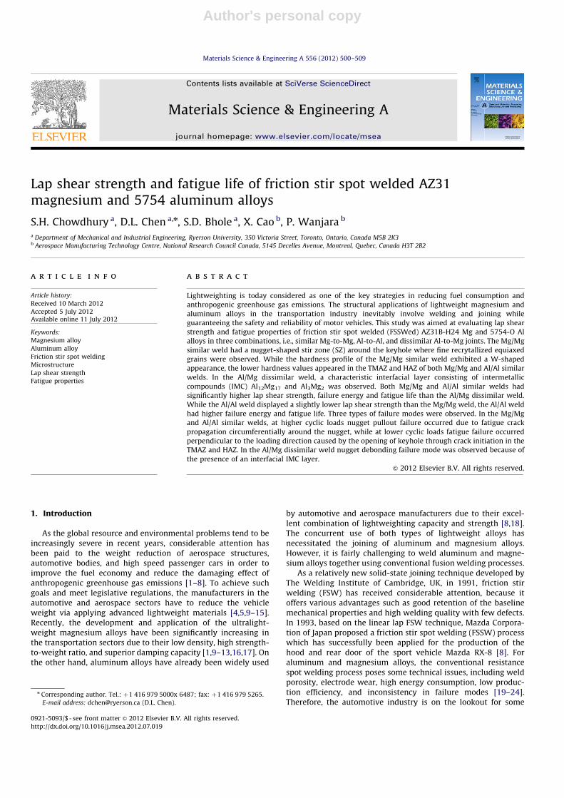
Author's personal copy Lap shear strength and fatigue life of friction stir spot welded AZ31 magnesium and 5754 aluminum alloys S.H. Chowdhury a , D.L. Chen a,n , S.D. Bhole a , X. Cao b , P. Wanjara b a Department of Mechanical and Industrial Engineering, Ryerson University, 350 Victoria Street, Toronto, Ontario, Canada M5B 2K3 b Aerospace Manufacturing Technology Centre, National Research Council Canada, 5145 Decelles Avenue, Montreal, Quebec, Canada H3T 2B2 article info Article history: Received 10 March 2012 Accepted 5 July 2012 Available online 11 July 2012 Keywords: Magnesium alloy Aluminum alloy Friction stir spot welding Microstructure Lap shear strength Fatigue properties abstract Lightweighting is today considered as one of the key strategies in reducing fuel consumption and anthropogenic greenhouse gas emissions. The structural applications of lightweight magnesium and aluminum alloys in the transportation industry inevitably involve welding and joining while guaranteeing the safety and reliability of motor vehicles. This study was aimed at evaluating lap shear strength and fatigue properties of friction stir spot welded (FSSWed) AZ31B-H24 Mg and 5754-O Al alloys in three combinations, i.e., similar Mg-to-Mg, Al-to-Al, and dissimilar Al-to-Mg joints. The Mg/Mg similar weld had a nugget-shaped stir zone (SZ) around the keyhole where fine recrytallized equiaxed grains were observed. While the hardness profile of the Mg/Mg similar weld exhibited a W-shaped appearance, the lower hardness values appeared in the TMAZ and HAZ of both Mg/Mg and Al/Al similar welds. In the Al/Mg dissimilar weld, a characteristic interfacial layer consisting of intermetallic compounds (IMC) Al 12 Mg 17 and Al 3 Mg 2 was observed. Both Mg/Mg and Al/Al similar welds had significantly higher lap shear strength, failure energy and fatigue life than the Al/Mg dissimilar weld. While the Al/Al weld displayed a slightly lower lap shear strength than the Mg/Mg weld, the Al/Al weld had higher failure energy and fatigue life. Three types of failure modes were observed. In the Mg/Mg and Al/Al similar welds, at higher cyclic loads nugget pullout failure occurred due to fatigue crack propagation circumferentially around the nugget, while at lower cyclic loads fatigue failure occurred perpendicular to the loading direction caused by the opening of keyhole through crack initiation in the TMAZ and HAZ. In the Al/Mg dissimilar weld nugget debonding failure mode was observed because of the presence of an interfacial IMC layer. & 2012 Elsevier B.V. All rights reserved. 1. Introduction As the global resource and environmental problems tend to be increasingly severe in recent years, considerable attention has been paid to the weight reduction of aerospace structures, automotive bodies, and high speed passenger cars in order to improve the fuel economy and reduce the damaging effect of anthropogenic greenhouse gas emissions [1–8]. To achieve such goals and meet legislative regulations, the manufacturers in the automotive and aerospace sectors have to reduce the vehicle weight via applying advanced lightweight materials [4,5,9–15]. Recently, the development and application of the ultralight- weight magnesium alloys have been significantly increasing in the transportation sectors due to their low density, high strength- to-weight ratio, and superior damping capacity [1,9–13,16,17]. On the other hand, aluminum alloys have already been widely used by automotive and aerospace manufacturers due to their excel- lent combination of lightweighting capacity and strength [8,18]. The concurrent use of both types of lightweight alloys has necessitated the joining of aluminum and magnesium alloys. However, it is fairly challenging to weld aluminum and magne- sium alloys together using conventional fusion welding processes. As a relatively new solid-state joining technique developed by The Welding Institute of Cambridge, UK, in 1991, friction stir welding (FSW) has received considerable attention, because it offers various advantages such as good retention of the baseline mechanical properties and high welding quality with few defects. In 1993, based on the linear lap FSW technique, Mazda Corpora- tion of Japan proposed a friction stir spot welding (FSSW) process which has successfully been applied for the production of the hood and rear door of the sport vehicle Mazda RX-8 [8]. For aluminum and magnesium alloys, the conventional resistance spot welding process poses some technical issues, including weld porosity, electrode wear, high energy consumption, low produc- tion efficiency, and inconsistency in failure modes [19–24]. Therefore, the automotive industry is on the lookout for some Contents lists available at SciVerse ScienceDirect journal homepage: www.elsevier.com/locate/msea Materials Science & Engineering A 0921-5093/$ - see front matter & 2012 Elsevier B.V. All rights reserved. http://dx.doi.org/10.1016/j.msea.2012.07.019 n Corresponding author. Tel.: þ1 416 979 5000x 6487; fax: þ1 416 979 5265. E-mail address: [email protected] (D.L. Chen). Materials Science & Engineering A 556 (2012) 500–509

Welcome message from author
This document is posted to help you gain knowledge. Please leave a comment to let me know what you think about it! Share it to your friends and learn new things together.
Transcript
Author's personal copy
Lap shear strength and fatigue life of friction stir spot welded AZ31magnesium and 5754 aluminum alloys
S.H. Chowdhury a, D.L. Chen a,n, S.D. Bhole a, X. Cao b, P. Wanjara b
a Department of Mechanical and Industrial Engineering, Ryerson University, 350 Victoria Street, Toronto, Ontario, Canada M5B 2K3b Aerospace Manufacturing Technology Centre, National Research Council Canada, 5145 Decelles Avenue, Montreal, Quebec, Canada H3T 2B2
a r t i c l e i n f o
Article history:
Received 10 March 2012
Accepted 5 July 2012Available online 11 July 2012
Keywords:
Magnesium alloy
Aluminum alloy
Friction stir spot welding
Microstructure
Lap shear strength
Fatigue properties
a b s t r a c t
Lightweighting is today considered as one of the key strategies in reducing fuel consumption and
anthropogenic greenhouse gas emissions. The structural applications of lightweight magnesium and
aluminum alloys in the transportation industry inevitably involve welding and joining while
guaranteeing the safety and reliability of motor vehicles. This study was aimed at evaluating lap shear
strength and fatigue properties of friction stir spot welded (FSSWed) AZ31B-H24 Mg and 5754-O Al
alloys in three combinations, i.e., similar Mg-to-Mg, Al-to-Al, and dissimilar Al-to-Mg joints. The Mg/Mg
similar weld had a nugget-shaped stir zone (SZ) around the keyhole where fine recrytallized equiaxed
grains were observed. While the hardness profile of the Mg/Mg similar weld exhibited a W-shaped
appearance, the lower hardness values appeared in the TMAZ and HAZ of both Mg/Mg and Al/Al similar
welds. In the Al/Mg dissimilar weld, a characteristic interfacial layer consisting of intermetallic
compounds (IMC) Al12Mg17 and Al3Mg2 was observed. Both Mg/Mg and Al/Al similar welds had
significantly higher lap shear strength, failure energy and fatigue life than the Al/Mg dissimilar weld.
While the Al/Al weld displayed a slightly lower lap shear strength than the Mg/Mg weld, the Al/Al weld
had higher failure energy and fatigue life. Three types of failure modes were observed. In the Mg/Mg
and Al/Al similar welds, at higher cyclic loads nugget pullout failure occurred due to fatigue crack
propagation circumferentially around the nugget, while at lower cyclic loads fatigue failure occurred
perpendicular to the loading direction caused by the opening of keyhole through crack initiation in the
TMAZ and HAZ. In the Al/Mg dissimilar weld nugget debonding failure mode was observed because of
the presence of an interfacial IMC layer.
& 2012 Elsevier B.V. All rights reserved.
1. Introduction
As the global resource and environmental problems tend to beincreasingly severe in recent years, considerable attention hasbeen paid to the weight reduction of aerospace structures,automotive bodies, and high speed passenger cars in order toimprove the fuel economy and reduce the damaging effect ofanthropogenic greenhouse gas emissions [1–8]. To achieve suchgoals and meet legislative regulations, the manufacturers in theautomotive and aerospace sectors have to reduce the vehicleweight via applying advanced lightweight materials [4,5,9–15].Recently, the development and application of the ultralight-weight magnesium alloys have been significantly increasing inthe transportation sectors due to their low density, high strength-to-weight ratio, and superior damping capacity [1,9–13,16,17]. Onthe other hand, aluminum alloys have already been widely used
by automotive and aerospace manufacturers due to their excel-lent combination of lightweighting capacity and strength [8,18].The concurrent use of both types of lightweight alloys hasnecessitated the joining of aluminum and magnesium alloys.However, it is fairly challenging to weld aluminum and magne-sium alloys together using conventional fusion welding processes.
As a relatively new solid-state joining technique developed byThe Welding Institute of Cambridge, UK, in 1991, friction stirwelding (FSW) has received considerable attention, because itoffers various advantages such as good retention of the baselinemechanical properties and high welding quality with few defects.In 1993, based on the linear lap FSW technique, Mazda Corpora-tion of Japan proposed a friction stir spot welding (FSSW) processwhich has successfully been applied for the production of thehood and rear door of the sport vehicle Mazda RX-8 [8]. Foraluminum and magnesium alloys, the conventional resistancespot welding process poses some technical issues, including weldporosity, electrode wear, high energy consumption, low produc-tion efficiency, and inconsistency in failure modes [19–24].Therefore, the automotive industry is on the lookout for some
Contents lists available at SciVerse ScienceDirect
journal homepage: www.elsevier.com/locate/msea
Materials Science & Engineering A
0921-5093/$ - see front matter & 2012 Elsevier B.V. All rights reserved.
http://dx.doi.org/10.1016/j.msea.2012.07.019
n Corresponding author. Tel.: þ1 416 979 5000x 6487; fax: þ1 416 979 5265.
E-mail address: [email protected] (D.L. Chen).
Materials Science & Engineering A 556 (2012) 500–509
Author's personal copy
alternative and relatively new methods, such as structural adhe-sives, rivets, and toggle-locks, to join aluminum and magnesiumsheets. The FSSW process provides a potential solution in terms ofjoint strength performance, weld quality, and operational costwithout adding extra weight [20]. Although a number of paperson the joining of Mg and Al alloys using FSSW have recently beenreported [8,18,25,26], only limited studies have been done on lapshear strength and especially fatigue resistance of the FSSWjoints, a topic of vital importance for guaranteeing the safe andreliable applications. With regards to FSS welds made of similar Alalloys, the failure modes at quasi-static and cyclic loads vary withloading type. Lin et al. [27] observed some differences in thefracture path between quasi-static loads and fatigue loads forAA6111-T4 alloy. Latabhai et al. [28] indicated that the shearstrength first increased and then decreased with increasing toolrotational rate for AA6061-T5 FSSW joints, while Tozaki et al. [29]reported that the tensile shear strength monotonically increasedwith increasing tool rotational rate. Mallick and Agarwal [30]evaluated the fatigue performance of FSS welds made of AM60and AA5754 alloys but the failure mechanisms were not studiedin detail. FSS welds of dissimilar Al and Mg alloys were observedto exhibit different failure modes compared with thosewith identical alloys for both top and bottom sheets [18,25,31].However, the integrity and durability issues of similar Mg and Alwelds and dissimilar Al-to-Mg welds especially under cyclicloading have not been systematically studied, and no fatiguebehavior for such FSS welds in relation to the change in the failuremode has been reported in the open literature. It is also unclearhow large the difference would be between the Mg/Mg similarwelds, Al/Al similar welds, and Al/Mg dissimilar welds. The mainobjective of the present study was, therefore, to identify thetensile shear strength and fatigue resistance of the FSSWedsimilar AZ31B-H24 and AA5754-O, and dissimilar AZ31-to-AA5754 alloy joints.
2. Experimental procedure
Commercial AZ31B-H24 Mg and AA5754-O Al alloy sheetswith a thickness of 2 mm were selected for FSSW. The nominalchemical compositions were Mg–3Al–1Zn–0.6Mn–0.005Ni–0.005Fe for AZ31B-H24 and Al–3.42Mg–0.23Sc–0.22Zr forAl5754-O. The Mg and Al alloy sheets were cut into small couponsof 35 mm�100 mm with the loading axis along the rollingdirection. Two coupons were overlaid over an area of35 mm�35 mm and FSSW was performed at the center of theoverlapped area. Three types of material combinations, i.e.,similar Mg-to-Mg and Al-to-Al, and dissimilar (top) Al-to-Mg(bottom) alloys were used. The FSSW tool made from H13 toolsteel had diameters of 13 mm for the scrolled shoulder and 5 mmfor the left-hand threaded pin. The welding process parameterswere: pin length of 2.8 mm, tool rotational rate of 2000 rpm, toolplunge rate of 3 mm/s, tool removal rate of 15 mm/s, shoulderplunge depth of 0.2 mm and dwell time of 2 s. The weldedsamples were carefully sectioned using a low speed diamondcutter to examine the cross-sectional microstructure and poten-tial defects. Then the specimens were cold mounted, ground,polished and etched with acetic picral (10 ml acetic acid (99%),4.2 g picric acid, 10 ml H2O, 70 ml ethanol (95%)) for the Mg alloyand Keller’s reagent (2.5 ml nitric acid, 1.5 ml hydrochloric acid,1 ml hydrofluoric acid and 100 ml distilled water) for the Al alloy.The microstructure was observed with an optical microscopeequipped with quantitative image analysis software. Vickersmicrohardness was measured with a computerized Buehlermicrohardness tester across the sectioned weld. A load of 100 gand dwell time of 15 s was applied during the microindentation
hardness testing. All the indentations were adequately spaced toavoid any potential effect of strain fields caused by adjacentindentations. To evaluate the mechanical strength of the welds,lap shear tensile tests of the welds were conducted using a fullycomputerized United tensile testing machine at a crosshead dis-placement speed of 10 mm/min in air at room temperature (RT).
Fatigue tests were performed using a fully computerizedInstron 8801 servo-hydraulic testing system under load control.A load ratio of R¼0.2, sinusoidal waveform, and a frequency of50 Hz were applied in all the tests. At least two samples weretested at each load level. The fracture surfaces of the FSSW jointsafter fatigue tests were examined using a JSM-6380LV scanningelectron microscope (SEM) equipped with Oxford energy disper-sive X-ray spectroscopy (EDS) system and three-dimensional (3D)fractographic analysis capacity. Additionally, a multi-functionalPANalytical X-ray diffractometer was used to identify the forma-tion of potential intermetallic compounds in the dissimilar Al-to-Mg welds from the fracture surface (both Mg side and Al side)after fatigue tests. X-ray diffraction (XRD) was performed usingCuKa radiation at 45 kV and 40 mA. The diffraction angle (2y) atwhich the X-rays hit the sample varied from 201 to 1101 with astep size of 0.051 and 3 s in each step.
3. Results and discussion
3.1. Microstructure
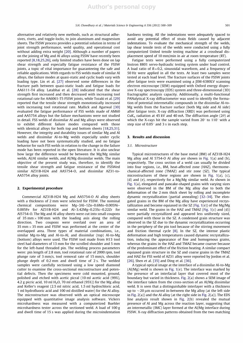
Typical microstructures of the base metal (BM) of AZ31B-H24Mg alloy and Al 5754-O Al alloy are shown in Fig. 1(a) and (b),respectively. The cross section of a weld can usually be dividedinto four regions, i.e., BM, heat-affected zone (HAZ), thermome-chanical-affected zone (TMAZ) and stir zone (SZ). The typicalmicrostructures of these regions are shown in Fig. 1(a), (c),(d) and (e), respectively for a Mg/Mg similar weld. As shown inFig. 1(a), elongated and pancake-shaped grains with varying sizeswere observed in the BM of the Mg alloy due to both thedeformation of the 2 mm thick sheet by rolling and incompletedynamic recrystallization (partial annealing) [32–34]. The elon-gated grains in the BM of the Mg alloy have experienced recrys-tallization and become equiaxed in the SZ (Fig. 1(e)) of the Mg/Mgsimilar weld. The grains in the HAZ and TMAZ (Fig. 1(c) and (d))were partially recrystallized and appeared less uniformly sized,compared with those in the SZ. A condensed grain structure wasobserved in the SZ due to the dynamic recrystallization occurringin the periphery of the pin tool because of the stirring movementand friction thermal cycle [8]. In the SZ, the intense plasticdeformation and high temperatures caused dynamic recrystalliza-tion, inducing the appearance of fine and homogenous grains,whereas the grains in the HAZ and TMAZ became coarser becauseof the predominant effect of the friction heating. A similar compactequiaxed grain structure in the SZ and coarse grains in the TMAZand HAZ for FSS weld of AZ31 alloy were reported by Jordon et al.[26], Shen et al. [35] and Ding et al. [36].
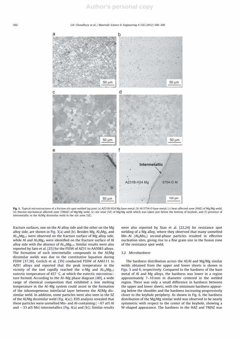
A typical optical image at the interface of a dissimilar Al-to-Mg(Al/Mg) weld is shown in Fig. 1(e). The interface was marked bythe presence of an interfacial layer that covered most of theboundary but varied in thickness. Fig. 2(a) shows a SEM image ofthe interface taken from the cross-section of an Al/Mg dissimilarweld. It is seen that a distinguishable interlayer with a thicknessup to �20 mm occurred in-between the Mg alloy (at the left sidein Fig. 2(a)) and the Al alloy (at the right side in Fig. 2(a)). The EDSline analysis result shown in Fig. 2(b) revealed the mutualpresence of Al and Mg across the reaction layer, suggesting thatan intermetallic (IMC) layer formed at the Al/Mg interface duringFSSW. X-ray diffraction patterns obtained from the two matching
S.H. Chowdhury et al. / Materials Science & Engineering A 556 (2012) 500–509 501
Author's personal copy
fracture surfaces, one on the Al alloy side and the other on the Mgalloy side, are shown in Fig. 3(a) and (b). Besides Mg, Al3Mg2 andAl12Mg17 were observed on the fracture surface of Mg alloy side,while Al and Al3Mg2 were identified on the fracture surface of Alalloy side with the absence of Al12Mg17. Similar results were alsoreported by Sato et al. [25] for the FSSW of AZ31 to AA5083 alloys.The formation of such intermetallic compounds in the Al/Mgdissimilar welds was due to the constitutive liquation duringFSSW [37,38]. Gerlich et al. [39] conducted FSSW of AA6111 toAZ91 alloys and reported that the peak temperature in thevicinity of the tool rapidly reached the a-Mg and Al12Mg17
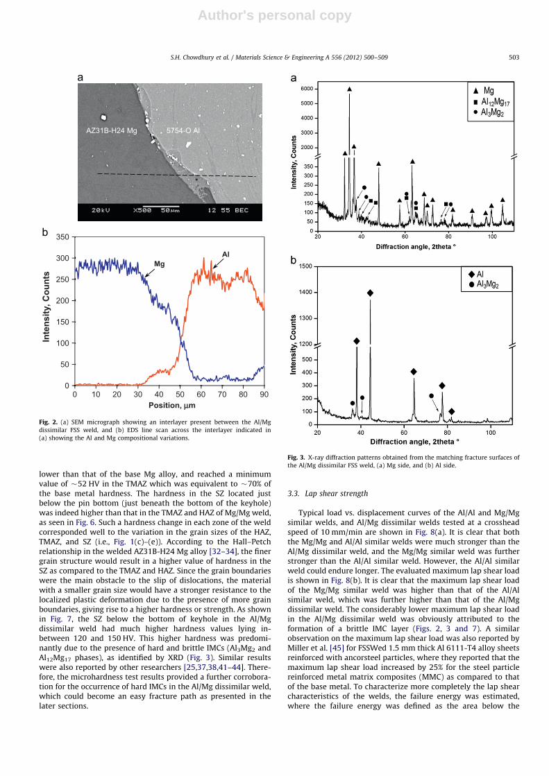
eutectic temperature of 437 1C, at which the eutectic microstruc-ture formed. According to the Al–Mg phase diagram [40], a widerange of chemical composition that exhibited a low meltingtemperature in the Al–Mg system could assist in the formationof the inhomogeneous interfacial layer between the Al/Mg dis-similar weld. In addition, some particles were also seen in the SZof the Al/Mg dissimilar weld (Fig. 4(a)). EDS analysis revealed thatthese particles were unmelted Mn- and Al-containing (�67 at% Aland �33 at% Mn) intermetallics (Fig. 4(a) and (b)). Similar results
were also reported by Xiao et al. [22,24] for resistance spotwelding of a Mg alloy, where they observed that many unmeltedMn–Al (Al8Mn5) second-phase particles resulted in effectivenucleation sites, giving rise to a fine grain size in the fusion zoneof the resistance spot weld.
3.2. Microhardness
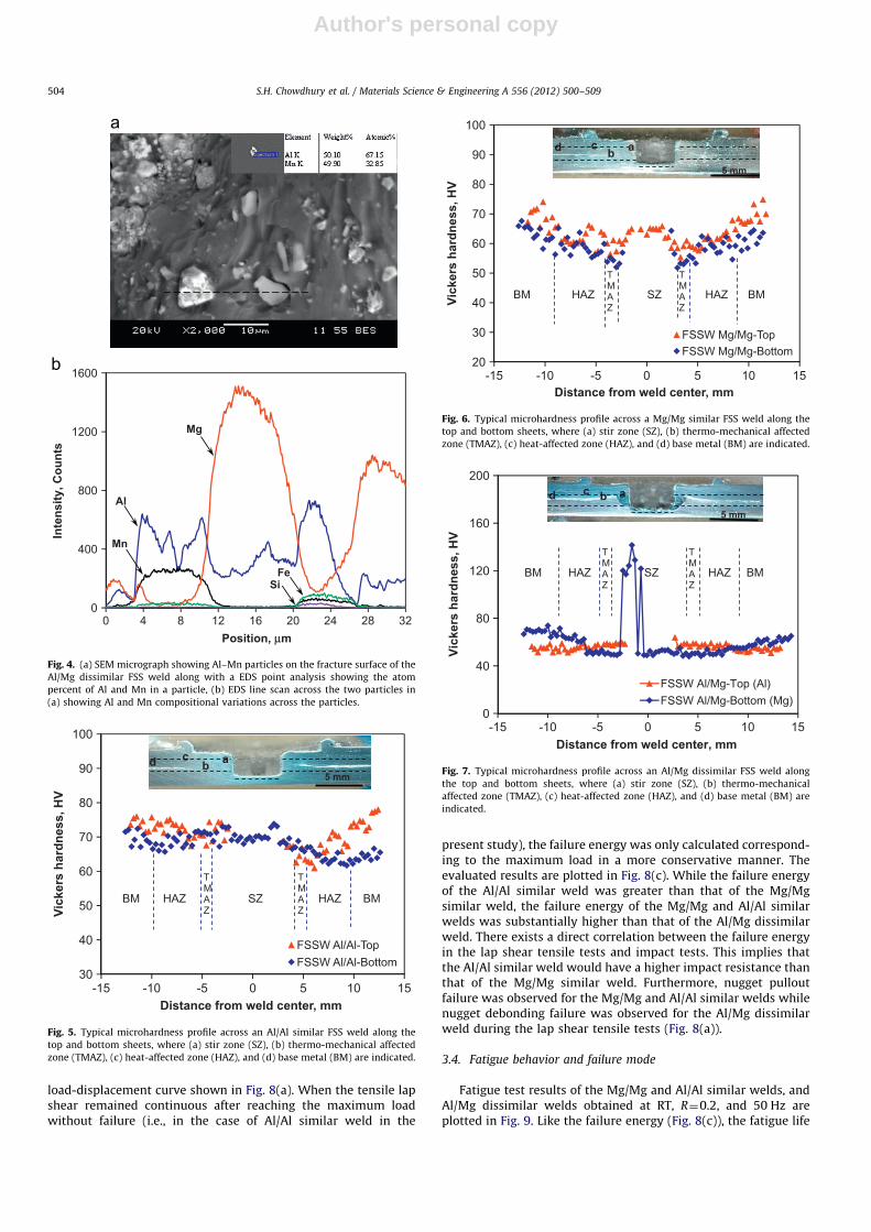
The hardness distribution across the Al/Al and Mg/Mg similarwelds obtained from the upper and lower sheets is shown inFigs. 5 and 6, respectively. Compared to the hardness of the basemetal of Al and Mg alloys, the hardness was lower in a regionapproximately 7–10 mm in diameter centered in the weldedregion. There was only a small difference in hardness betweenthe upper and lower sheets, with the minimum hardness appear-ing below the shoulder and the hardness increasing progressivelycloser to the keyhole periphery. As shown in Fig. 6, the hardnessdistribution of the Mg/Mg similar weld was observed to be nearlysymmetric with respect to the center of the keyhole, showing aW-shaped appearance. The hardness in the HAZ and TMAZ was
Fig. 1. Typical microstructures of a friction stir spot welded lap joint (a) AZ31B-H24 Mg base metal, (b) Al 5754-O base metal, (c) heat-affected zone (HAZ) of Mg/Mg weld,
(d) thermo-mechanical affected zone (TMAZ) of Mg/Mg weld, (e) stir zone (SZ) of Mg/Mg weld which was taken just below the bottom of keyhole, and (f) presence of
intermetallic in the Al/Mg dissimilar weld in the stir zone (SZ).
S.H. Chowdhury et al. / Materials Science & Engineering A 556 (2012) 500–509502
Author's personal copy
lower than that of the base Mg alloy, and reached a minimumvalue of �52 HV in the TMAZ which was equivalent to �70% ofthe base metal hardness. The hardness in the SZ located justbelow the pin bottom (just beneath the bottom of the keyhole)was indeed higher than that in the TMAZ and HAZ of Mg/Mg weld,as seen in Fig. 6. Such a hardness change in each zone of the weldcorresponded well to the variation in the grain sizes of the HAZ,TMAZ, and SZ (i.e., Fig. 1(c)–(e)). According to the Hall–Petchrelationship in the welded AZ31B-H24 Mg alloy [32–34], the finergrain structure would result in a higher value of hardness in theSZ as compared to the TMAZ and HAZ. Since the grain boundarieswere the main obstacle to the slip of dislocations, the materialwith a smaller grain size would have a stronger resistance to thelocalized plastic deformation due to the presence of more grainboundaries, giving rise to a higher hardness or strength. As shownin Fig. 7, the SZ below the bottom of keyhole in the Al/Mgdissimilar weld had much higher hardness values lying in-between 120 and 150 HV. This higher hardness was predomi-nantly due to the presence of hard and brittle IMCs (Al3Mg2 andAl12Mg17 phases), as identified by XRD (Fig. 3). Similar resultswere also reported by other researchers [25,37,38,41–44]. There-fore, the microhardness test results provided a further corrobora-tion for the occurrence of hard IMCs in the Al/Mg dissimilar weld,which could become an easy fracture path as presented in thelater sections.
3.3. Lap shear strength
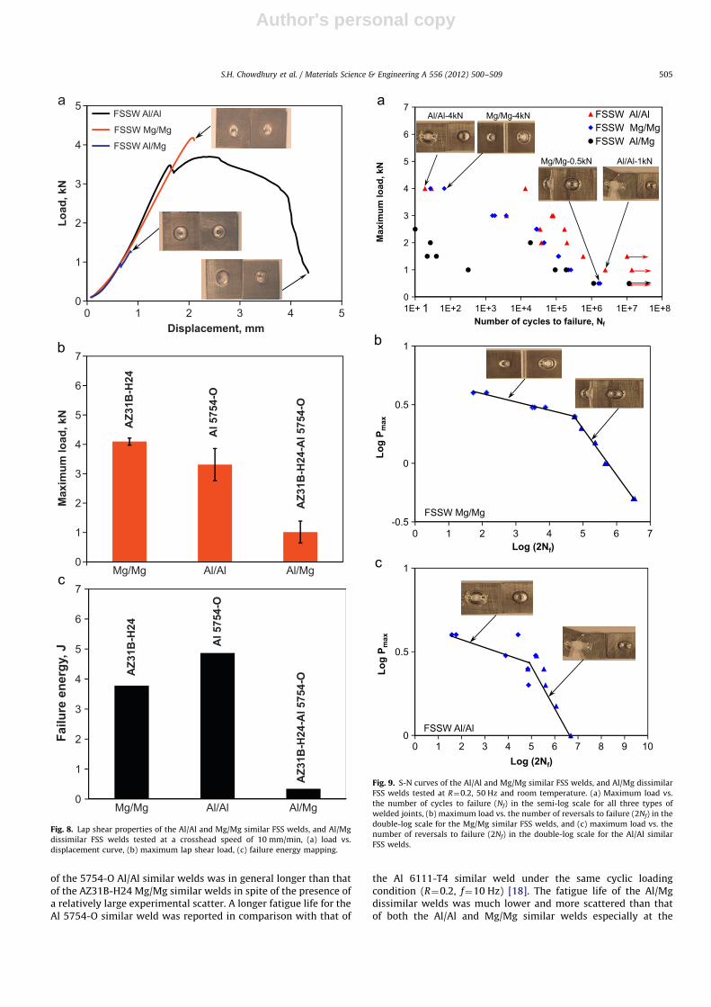
Typical load vs. displacement curves of the Al/Al and Mg/Mgsimilar welds, and Al/Mg dissimilar welds tested at a crossheadspeed of 10 mm/min are shown in Fig. 8(a). It is clear that boththe Mg/Mg and Al/Al similar welds were much stronger than theAl/Mg dissimilar weld, and the Mg/Mg similar weld was furtherstronger than the Al/Al similar weld. However, the Al/Al similarweld could endure longer. The evaluated maximum lap shear loadis shown in Fig. 8(b). It is clear that the maximum lap shear loadof the Mg/Mg similar weld was higher than that of the Al/Alsimilar weld, which was further higher than that of the Al/Mgdissimilar weld. The considerably lower maximum lap shear loadin the Al/Mg dissimilar weld was obviously attributed to theformation of a brittle IMC layer (Figs. 2, 3 and 7). A similarobservation on the maximum lap shear load was also reported byMiller et al. [45] for FSSWed 1.5 mm thick Al 6111-T4 alloy sheetsreinforced with ancorsteel particles, where they reported that themaximum lap shear load increased by 25% for the steel particlereinforced metal matrix composites (MMC) as compared to thatof the base metal. To characterize more completely the lap shearcharacteristics of the welds, the failure energy was estimated,where the failure energy was defined as the area below the
0
50
100
150
200
250
300
350
0 10 20 30 40 50 60 70 80 90
Inte
nsity
, Cou
nts
Position, µµm
AlMg
AZ31B-H24 Mg 5754-O Al
Fig. 2. (a) SEM micrograph showing an interlayer present between the Al/Mg
dissimilar FSS weld, and (b) EDS line scan across the interlayer indicated in
(a) showing the Al and Mg compositional variations.
Fig. 3. X-ray diffraction patterns obtained from the matching fracture surfaces of
the Al/Mg dissimilar FSS weld, (a) Mg side, and (b) Al side.
S.H. Chowdhury et al. / Materials Science & Engineering A 556 (2012) 500–509 503
Author's personal copy
load-displacement curve shown in Fig. 8(a). When the tensile lapshear remained continuous after reaching the maximum loadwithout failure (i.e., in the case of Al/Al similar weld in the
present study), the failure energy was only calculated correspond-ing to the maximum load in a more conservative manner. Theevaluated results are plotted in Fig. 8(c). While the failure energyof the Al/Al similar weld was greater than that of the Mg/Mgsimilar weld, the failure energy of the Mg/Mg and Al/Al similarwelds was substantially higher than that of the Al/Mg dissimilarweld. There exists a direct correlation between the failure energyin the lap shear tensile tests and impact tests. This implies thatthe Al/Al similar weld would have a higher impact resistance thanthat of the Mg/Mg similar weld. Furthermore, nugget pulloutfailure was observed for the Mg/Mg and Al/Al similar welds whilenugget debonding failure was observed for the Al/Mg dissimilarweld during the lap shear tensile tests (Fig. 8(a)).
3.4. Fatigue behavior and failure mode
Fatigue test results of the Mg/Mg and Al/Al similar welds, andAl/Mg dissimilar welds obtained at RT, R¼0.2, and 50 Hz areplotted in Fig. 9. Like the failure energy (Fig. 8(c)), the fatigue life
0
400
800
1200
1600
0 4 8 12 16 20 24 28 32
Inte
nsity
, Cou
nts
Position, µm
Al
Mn
Mg
FeSi
Fig. 4. (a) SEM micrograph showing Al–Mn particles on the fracture surface of the
Al/Mg dissimilar FSS weld along with a EDS point analysis showing the atom
percent of Al and Mn in a particle, (b) EDS line scan across the two particles in
(a) showing Al and Mn compositional variations across the particles.
30
40
50
60
70
80
90
100
-15 -10 -5 0 5 10 15
Vick
ers
hard
ness
, HV
Distance from weld center, mm
FSSW Al/Al-TopFSSW Al/Al-Bottom
MBMB ZAHZAH
TMAZ
TMAZ
SZ
d cb a
5 mm
Fig. 5. Typical microhardness profile across an Al/Al similar FSS weld along the
top and bottom sheets, where (a) stir zone (SZ), (b) thermo-mechanical affected
zone (TMAZ), (c) heat-affected zone (HAZ), and (d) base metal (BM) are indicated.
20
30
40
50
60
70
80
90
100
-15 -10 -5 0 5 15
Vick
ers
hard
ness
, HV
10Distance from weld center, mm
FSSW Mg/Mg-TopFSSW Mg/Mg-Bottom
MBMB HAZ HAZ
TMAZ
TMAZ
SZ
d cb a
5 mm
Fig. 6. Typical microhardness profile across a Mg/Mg similar FSS weld along the
top and bottom sheets, where (a) stir zone (SZ), (b) thermo-mechanical affected
zone (TMAZ), (c) heat-affected zone (HAZ), and (d) base metal (BM) are indicated.
0
40
80
120
160
200
-15 -10 -5 0 5 10 15
Vick
ers
hard
ness
, HV
Distance from weld center, mm
FSSW Al/Mg-Top (Al)FSSW Al/Mg-Bottom (Mg)
abc
MBMB ZAHZAH
TMAZ
TMAZ
WELDNUGGET
d c b a
SZ
5 mm
Fig. 7. Typical microhardness profile across an Al/Mg dissimilar FSS weld along
the top and bottom sheets, where (a) stir zone (SZ), (b) thermo-mechanical
affected zone (TMAZ), (c) heat-affected zone (HAZ), and (d) base metal (BM) are
indicated.
S.H. Chowdhury et al. / Materials Science & Engineering A 556 (2012) 500–509504
Author's personal copy
of the 5754-O Al/Al similar welds was in general longer than thatof the AZ31B-H24 Mg/Mg similar welds in spite of the presence ofa relatively large experimental scatter. A longer fatigue life for theAl 5754-O similar weld was reported in comparison with that of
the Al 6111-T4 similar weld under the same cyclic loadingcondition (R¼0.2, f¼10 Hz) [18]. The fatigue life of the Al/Mgdissimilar welds was much lower and more scattered than thatof both the Al/Al and Mg/Mg similar welds especially at the
0
1
2
3
4
5
Load
, kN
Displacement, mm
FSSW Al/Al
FSSW Mg/Mg
FSSW Al/Mg
0
1
2
3
4
5
6
7
Max
imum
load
, kN
AZ3
1B-H
24
Al5
754-
O
AZ3
1B-H
24-A
l 575
4-O
0
1
2
3
4
5
6
7
0 1 2 3 4 5
Mg/Mg Al/Al Al/Mg
Mg/Mg Al/Al Al/Mg
Failu
re e
nerg
y, J
AZ3
1B-H
24
Al5
754-
O
AZ3
1B-H
24-A
l 575
4-O
Fig. 8. Lap shear properties of the Al/Al and Mg/Mg similar FSS welds, and Al/Mg
dissimilar FSS welds tested at a crosshead speed of 10 mm/min, (a) load vs.
displacement curve, (b) maximum lap shear load, (c) failure energy mapping.
0
1
2
3
4
5
6
7
1E+ 1 1E+2 1E+3 1E+4 1E+5 1E+6 1E+7 1E+8
Max
imum
load
, kN
Number of cycles to failure, N
-0.5
0
0.5
1
Log
P max
Log (2N )
FSSW Mg/Mg
0
0.5
1
760 1 2 3 4 5
0 1 2 3 4 5 6 7 8 9 10
Log
P max
Log (2N )
FSSW Al/Al
Fig. 9. S-N curves of the Al/Al and Mg/Mg similar FSS welds, and Al/Mg dissimilar
FSS welds tested at R¼0.2, 50 Hz and room temperature. (a) Maximum load vs.
the number of cycles to failure (Nf) in the semi-log scale for all three types of
welded joints, (b) maximum load vs. the number of reversals to failure (2Nf) in the
double-log scale for the Mg/Mg similar FSS welds, and (c) maximum load vs. the
number of reversals to failure (2Nf) in the double-log scale for the Al/Al similar
FSS welds.
S.H. Chowdhury et al. / Materials Science & Engineering A 556 (2012) 500–509 505

Author's personal copy
maximum cyclic load higher than 1 kN. Again, this was due to theformation of IMCs at the interface between the Mg and Al alloysduring FSSW (Figs. 2, 3, and 7). The weld nugget was pulled out ofthe top sheet of the Mg/Mg and Al/Al similar welds at themaximum cyclic load of 4 kN, as shown by the inserted imagesin Fig. 9. The nugget pullout failure occurred as the crackpropagated circumferentially around the nugget. The shear stressin the remaining area of the nugget increased with each advance-ment of the crack front. After the crack had propagated aroundhalf of the nugget with a keyhole the shear stresses acting in thearea were such that the remaining cross section could not sustainthe shear overload, then the nugget pullout failure occurred. Incontrast, the failure of the Al/Al and Mg/Mg similar weldsoccurred nearly at a right angle to the loading direction at themaximum cyclic load below 1.5 kN (Fig. 9). This suggests that thefatigue failure was caused by the opening of the keyhole throughcrack initiation in the TMAZ and HAZ, due to the significantmicrostructural change or grain coarsening (Fig. 1(c) and (d)) andthe lower hardness (Figs. 5 and 6), and then propagated perpen-dicular to the loading direction that indeed resulted in normaltensile failure mode. Nugget debonding failure mode wasobserved in the Al/Mg dissimilar welds as a consequence of the
presence of an interfacial IMC layer in the Al/Mg dissimilar welds(Figs. 2, 3, and 7).
Fig. 9(b) and (c) could be used to characterize better thefatigue data and failure mode obtained in the present studywhere the maximum cyclic load vs. the number of reversals tofailure (2Nf) was plotted in a double-log scale for the Mg/Mg andAl/Al similar welds. It should be noted that the run-out data forwhich no failure occurred at or over 1�107 cycles were notincluded in the fitting. As shown in Fig. 9(b) and (c) for the Mg/Mg and Al/Al similar welds, a longer fatigue life was observed atthe lower maximum load, where the slope was steeper corre-sponding to the normal tensile failure mode, than that at thehigher maximum load where the slope was flatter in line with thefailure mode of nugget pullout.
3.5. Fractography
Figs. 10 and 11 show SEM images of the fatigue fracturesurfaces of the Mg/Mg and Al/Al similar welds and the loaddependence of failure mode. At a lower level of maximum cyclicloads, as shown in Figs. 10(a)–(c) and 11(a)–(c), fatigue crackingwas caused by the opening of the keyhole through the TMAZ and
Fig. 10. Typical SEM images of fatigue fracture surface of the Al/Al similar FSS weld, (a) normal tensile fracture surface at a lower Pmax¼1 kN, (b) crack propagation zone at
a lower Pmax¼1 kN, (c) fatigue striations in the crack propagation zone at a higher magnification, (d) overall view of shear fracture surface at a higher Pmax¼4 kN, and
(e) shear fracture of region B in (d) at a higher magnification.
S.H. Chowdhury et al. / Materials Science & Engineering A 556 (2012) 500–509506
Author's personal copy
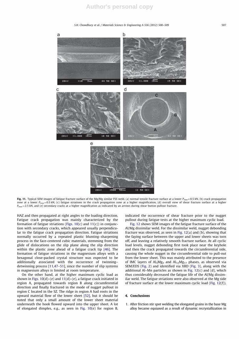
HAZ and then propagated at right angles to the loading direction.Fatigue crack propagation was mainly characterized by theformation of fatigue striations (Figs. 10(c) and 11(c)) in conjunc-tion with secondary cracks, which appeared usually perpendicu-lar to the fatigue crack propagation direction. Fatigue striationsnormally occurred by a repeated plastic blunting–sharpeningprocess in the face-centered cubic materials, stemming from theglide of dislocations on the slip plane along the slip directionwithin the plastic zone ahead of a fatigue crack tip [46]. Theformation of fatigue striations in the magnesium alloys with ahexagonal close-packed crystal structure was expected to beadditionally associated with the occurrence of twinning–detwinning process [11,47–51], since the number of slip systemsin magnesium alloys is limited at room temperature.
On the other hand, at the higher maximum cyclic load asshown in Figs. 10(d)–(e) and 11(d)–(e), a fatigue crack initiated inregion A, propagated towards region B along circumferentialdirection and finally fractured in the mode of nugget pullout inregion C located in the SZ. The ridge in region A had roots in theupward material flow of the lower sheet [52], but it should benoted that only a small amount of the lower sheet materialunderneath the hook flowed upward into the upper sheet. A lotof elongated dimples, e.g., as seen in Fig. 10(e) for region B,
indicated the occurrence of shear fracture prior to the nuggetpullout during fatigue tests at the higher maximum cyclic load.
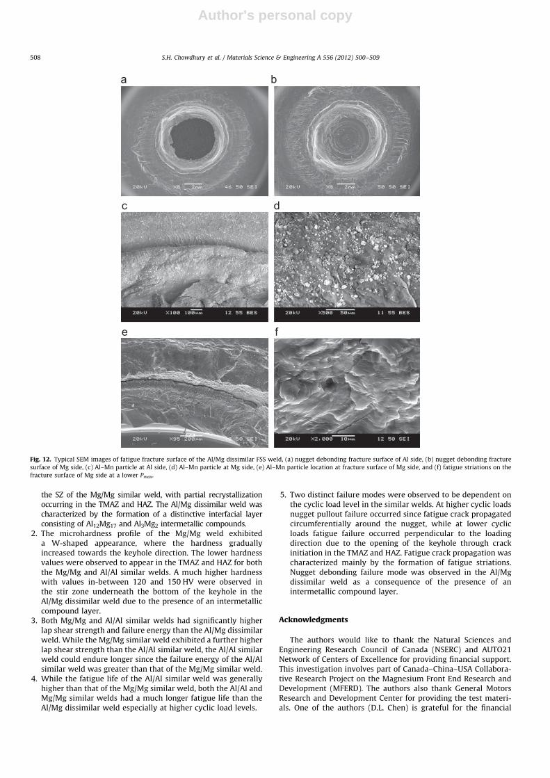
Fig. 12 shows SEM images of the fatigue fracture surface of theAl/Mg dissimilar weld. For the dissimilar weld, nugget debondingfracture was observed, as seen in Fig. 12(a) and (b), showing thatthe faying surface between the upper and lower sheets was tornoff, and leaving a relatively smooth fracture surface. At all cyclicload levels, nugget debonding first took place near the keyholeand then the crack propagated towards the circumferential side,causing the whole nugget in the circumferential side to pull-outfrom the lower sheet. This was mainly attributed to the presenceof IMC layers of Al3Mg2 and Al12Mg17 phases, as observed viaSEM/EDS (Fig. 2) and identified via XRD (Fig. 3), along with theadditional Al–Mn particles as shown in Fig. 12(c) and (d), whichthus considerably decreased the fatigue life of the Al/Mg dissim-ilar weld. The fatigue striations were also observed at the Mg sideof fracture surface at the lower maximum cyclic load (Fig. 12(f)).
4. Conclusions
1. After friction stir spot welding the elongated grains in the base Mgalloy became equiaxed as a result of dynamic recrystallization in
Fig. 11. Typical SEM images of fatigue fracture surface of the Mg/Mg similar FSS weld, (a) normal tensile fracture surface at a lower Pmax¼0.5 kN, (b) crack propagation
zone at a lower Pmax¼0.5 kN, (c) fatigue striations in the crack propagation zone at a higher magnification, (d) overall view of shear fracture surface at a higher
Pmax¼2.5 kN, and (e) secondary cracks at a higher magnification as indicated by an arrows during shear button pullout fracture.
S.H. Chowdhury et al. / Materials Science & Engineering A 556 (2012) 500–509 507
Author's personal copy
the SZ of the Mg/Mg similar weld, with partial recrystallizationoccurring in the TMAZ and HAZ. The Al/Mg dissimilar weld wascharacterized by the formation of a distinctive interfacial layerconsisting of Al12Mg17 and Al3Mg2 intermetallic compounds.
2. The microhardness profile of the Mg/Mg weld exhibiteda W-shaped appearance, where the hardness graduallyincreased towards the keyhole direction. The lower hardnessvalues were observed to appear in the TMAZ and HAZ for boththe Mg/Mg and Al/Al similar welds. A much higher hardnesswith values in-between 120 and 150 HV were observed inthe stir zone underneath the bottom of the keyhole in theAl/Mg dissimilar weld due to the presence of an intermetalliccompound layer.
3. Both Mg/Mg and Al/Al similar welds had significantly higherlap shear strength and failure energy than the Al/Mg dissimilarweld. While the Mg/Mg similar weld exhibited a further higherlap shear strength than the Al/Al similar weld, the Al/Al similarweld could endure longer since the failure energy of the Al/Alsimilar weld was greater than that of the Mg/Mg similar weld.
4. While the fatigue life of the Al/Al similar weld was generallyhigher than that of the Mg/Mg similar weld, both the Al/Al andMg/Mg similar welds had a much longer fatigue life than theAl/Mg dissimilar weld especially at higher cyclic load levels.
5. Two distinct failure modes were observed to be dependent onthe cyclic load level in the similar welds. At higher cyclic loadsnugget pullout failure occurred since fatigue crack propagatedcircumferentially around the nugget, while at lower cyclicloads fatigue failure occurred perpendicular to the loadingdirection due to the opening of the keyhole through crackinitiation in the TMAZ and HAZ. Fatigue crack propagation wascharacterized mainly by the formation of fatigue striations.Nugget debonding failure mode was observed in the Al/Mgdissimilar weld as a consequence of the presence of anintermetallic compound layer.
Acknowledgments
The authors would like to thank the Natural Sciences andEngineering Research Council of Canada (NSERC) and AUTO21Network of Centers of Excellence for providing financial support.This investigation involves part of Canada–China–USA Collabora-tive Research Project on the Magnesium Front End Research andDevelopment (MFERD). The authors also thank General MotorsResearch and Development Center for providing the test materi-als. One of the authors (D.L. Chen) is grateful for the financial
Fig. 12. Typical SEM images of fatigue fracture surface of the Al/Mg dissimilar FSS weld, (a) nugget debonding fracture surface of Al side, (b) nugget debonding fracture
surface of Mg side, (c) Al–Mn particle at Al side, (d) Al–Mn particle at Mg side, (e) Al–Mn particle location at fracture surface of Mg side, and (f) fatigue striations on the
fracture surface of Mg side at a lower Pmax.
S.H. Chowdhury et al. / Materials Science & Engineering A 556 (2012) 500–509508
Author's personal copy
support by the Premier’s Research Excellence Award (PREA), NSERC-Discovery Accelerator Supplement (DAS) Award, Canada Foundationfor Innovation (CFI), and Ryerson Research Chair (RRC) program. Theassistance of Q. Li, A. Machin, J. Amankrah, and R. Churaman inperforming the experiments is gratefully acknowledged. Theauthors also thank Dr. S. Xu, Dr. K. Sadayappan, Dr. M.S. Kozdras,Dr. J. Jackman, Professor N. Atalla, Professor N. Zhou, Professor D.Weckman, Professor S. Lambert, Professor H. Jahed, Professor Y.S.Yang, Professor M.F. Horstemeyer, Professor B. Jordon, Professor J.Allison, Dr. A.A. Luo, Mr. R. Osborne, Mr. J.F. Quinn, Dr. X.M. Su, andMr. L. Zhang for their helpful discussion.
References
[1] T.M. Pollock, Science 328 (2010) 986–987.[2] M. Wise, K. Calvin, A. Thomson, L. Clarke, B. Bond-Lamberty, R. Sands,
S.J. Smith, A. Janetos, J. Edmonds, Science 324 (2009) 1183–1186.[3] E. Alonso, T.M. Lee, C. Bjelkengren, R. Roth, R.E. Kirchain, Environ. Sci.
Technol. 46 (5) (2012) 2893–2901.[4] H.-J. Kim, G.A. Keoleian, S.J. Skerlos, J. Ind. Ecol. 15 (1) (2011) 64–80.[5] H.-J. Kim, C. McMillan, G.A. Keoleian, S.J. Skerlos, J. Ind. Ecol. 14 (6) (2010)
929–946.[6] D. Shindell, G. Faluvegi, M. Walsh, S.C. Anenberg, R.V. Dingenen, N.Z. Muller,
J. Austin, D. Koch, G. Milly, Nature Climate Change 1 (2011) 59–66.[7] D.A. Howey, Nature Climate Change 2 (2012) 28–29.[8] Z. Zhang, X. Yang, J. Zhang, G. Zhou, X. Xu, B. Zou, Mater. Des. 32 (2011)
4461–4470.[9] J.B. Jordon, J.B. Gibson, M.F. Horstemeyer, H.EI. Kadiri, J.C. Baird, A.A. Luo,
Mater. Sci. Eng. A 528 (22–23) (2011) 6860–6871.[10] Q. Yu, J.X. Zhang, Y.Y. Jiang, Q.Z. Li, Int. J. Fatigue 36 (2012) 47–58.[11] S. Begum, D.L. Chen, S. Xu, A.A. Luo, Mater. Sci. Eng. A A517 (1–2) (2009)
334–343.[12] C.L. Fan, D.L. Chen, A.A. Luo, Mater. Sci. Eng. A A519 (1–2) (2009) 38–45.[13] H.Y. Wu, J.C. Yang, J.H. Liao, F.J. Zhu, Mater. Sci. Eng. A 535 (2012) 68–75.[14] H. Kang, I. Accorsi, B. Patel, E. Pakalnins, Procedia Eng. 2 (2010) 129–138.[15] H.Y. Wang, L.M. Liu, Z.Y. Jia, J. Mater. Sci. 46 (2011) 5534–5540.[16] S.J. Liang, H.F. Sun, Z.Y. Liu, E. Wang, J. Alloys Compds. 472 (2009) 127–132.[17] J.B. Jiang, Z.D. Zhang, J. Alloys Compds. 466 (2008) 368–372.[18] V.X. Tran, J. Pan, T. Pan, Int. J. Fatigue 30 (2008) 2175–2190.[19] P. Thornton, A. Krause, R. Davies, Weld. J. (Miami, FL, US) 75 (1996) 101–108.[20] A. Gean, S.A. Westgate, J.C. Kucza, J.C. Ehrstorm, Weld. J. (Miami, FL, US) 78
(1999) 80–86.[21] L. Liu, L. Xiao, J.C. Feng, Y.H. Tian, S.Q. Zhou, Y. Zhou, Metall. Mater. Trans. A
41 (10) (2010) 2642–2650.[22] L. Xiao, L. Liu, Y. Zhou, S. Esmaeili, Metall. Mater. Trans. A 41A (2010)
1511–1522.
[23] D.Q. Sun, B. Lang, D.X. Sun, J.B. Li, Mater. Sci. Eng. A 460–461 (2007) 494–498.[24] L. Xiao, L. Liu, D.L. Chen, S. Esmaeili, Y. Zhou, Mater. Sci. Eng. A 529 (2011)
81–87.[25] Y.S. Sato, A. Shiota, H. Kokawa, K. Okamoto, Q. Yang, C. Kim, Sci. Technol.
Weld. Joining 15 (4) (2010) 310–324.[26] J.B. Jordon, M.F. Horstemeyer, S.R. Daniewicz, H. Badarinarayan, J. Grantham,
J. Eng. Mater. Technol. 132 (2010) 041008-1–041008-10.[27] P.C. Lin, J. Pan, T. Pan, Int. J. Fatigue 30 (1) (2008) 74–89.[28] S. Lathabai, M.J. Painter, G.M.D. Cantin, V.K. Tyagi, Scripta Mater. 55 (2006)
899–902.[29] Y. Tozaki, Y. Uematsu, K. Tokaji, Int. J. Mach. Tool. Manu. 47 (2007)
2230–2236.[30] P.K. Mallick, L. Agarwal, Society of Automotive Engineers, Warrendale, PA,
SAE Technical Paper no. 2009-01-0024, 2009.[31] Y.H. Yin, A. Ikuta, T.H. North, Mater. Des. 31 (2010) 4764–4776.[32] N. Afrin, D.L. Chen, X. Cao, M. Jahazi, Mater. Sci. Eng. A 172 (2008) 179–186.[33] N. Afrin, D.L. Chen, X. Cao, M. Jahazi, Scripta Mater. 57 (11) (2007)
1004–1007.[34] M. Fairman, N. Afrin, D.L. Chen, X.J. Cao, M. Jahazi, Can. Metall. Q 46 (4)
(2007) 425–432.[35] J. Shen, D. Min, D. Wang, Mater. Des 32 (2011) 5033–5037.[36] C. Ding, Y. Ni, C. Guo, G. Quan, J. Ge, Adv. Mater. Res. 314–316 (2011)
953–956.[37] Y.S. Sato, S.H.C. Park, M. Michiuchi, H. Kokawa, Scripta Mater. 50 (2004)
1233–1236.[38] Y.C. Chen, K. Nakata, Scripta Mater. 58 (2008) 433–436.[39] A. Gerlich, P. Su, T.H. North, Sci. Technol. Weld. Joining 10 (2005) 647–652.[40] J.L. Murray, Phase Diagrams of Binary Magnesium Alloys, ASM International,
Materials Park, OH, 1988,17.[41] D.H. Choi, B.W. Ahn, C.Y. Lee, Y.M. Yeon, K. Song, S.B. Jung, Intermetallics 19
(2011) 125–130.[42] D. Dietrich, D. Nickel, M. Krause, T. Lampke, M.P. Coleman, V. Randle, J. Mater.
Sci. 46 (2011) 357–364.[43] V.K. Patel, S.D. Bhole, D.L. Chen, Sci. Technol. Weld. Joining 10 (2011)
647–652.[44] V.K. Patel, S.D. Bhole, D.L. Chen, Scripta Mater. 65 (10) (2011) 911–914.[45] S.F. Miller, S.G. Arul, G.H. Kruger, T.Y. Pan, A.J. Shih, J. Eng. Mater. Technol. 133
(2011) 031009-1–031009-10.[46] C. Laird, ASTM STP 415 (1967) 131–168.[47] S. Begum, D.L. Chen, S. Xu, A.A. Luo, Int. J. Fatigue 31 (2009) 726–735.[48] S. Begum, D.L. Chen, S. Xu, A.A. Luo, Metall. Mater. Trans. A 39 (2008)
3014–3026.[49] X.Z. Lin, D.L. Chen, Mater. Sci. Eng. A 496 (1–2) (2008) 106–113.[50] H.A. Patel, D.L. Chen, S.D. Bhole, K. Sadayappan, Mater. Sci. Eng. A 528 (1)
(2010) 208–219.[51] H.A. Patel, N. Rashidi, D.L. Chen, S.D. Bhole, A.A. Luo, Mater. Sci. Eng. A 546
(2012) 72–81.[52] Y. Tozaki, Y. Uematsu, K. Tokaji, J. Mater. Process. Technol. 210 (2010)
844–851.
S.H. Chowdhury et al. / Materials Science & Engineering A 556 (2012) 500–509 509
Related Documents