Friction Stir Welded AZ31 Magnesium Alloy: Microstructure, Texture, and Tensile Properties S.H. CHOWDHURY, D.L. CHEN, S.D. BHOLE, X. CAO, and P. WANJARA This study was aimed at characterizing the microstructure, texture and tensile properties of a friction stir welded AZ31B-H24 Mg alloy with varying tool rotational rates and welding speeds. Friction stir welding (FSW) resulted in the presence of recrystallized grains and the relevant drop in hardness in the stir zone (SZ). The base alloy contained a strong crystallographic texture with basal planes (0002) largely parallel to the rolling sheet surface and h11 20i directions aligned in the rolling direction (RD). After FSW the basal planes in the SZ were slightly tilted toward the TD determined from the sheet normal direction (or top surface) and also slightly inclined toward the RD determined from the transverse direction (or cross section) due to the intense shear plastic flow near the pin surface. The prismatic planes ð10 10Þ and pyramidal planes ð10 11Þ formed fiber textures. After FSW both the strength and ductility of the AZ31B-H24 Mg alloy decreased with a joint efficiency in-between about 75 and 82 pct due to the changes in both grain structure and texture, which also weakened the strain rate dependence of tensile properties. The welding speed and rotational rate exhibited a stronger effect on the YS than the UTS. Despite the lower ductility, strain-hardening exponent and hardening capacity, a higher YS was obtained at a higher welding speed and lower rotational rate mainly due to the smaller recrystallized grains in the SZ arising from the lower heat input. DOI: 10.1007/s11661-012-1382-3 Ó The Minerals, Metals & Materials Society and ASM International 2012 I. INTRODUCTION DUE to significant environmental challenges and ever-increasing energy prices faced by the transportation industry, lightweighting of motor vehicles is being considered as a key strategy for improving the fuel economy and lowering anthropogenic environment- damaging emissions. [1–9] Of the prevalent materials for the next-generation transportation vehicles in the auto- motive and aerospace industries, magnesium alloys represent a lucrative option for the weight reduction owing to their low density, high strength-to-weight ratio, environmental friendliness, castability and recy- clability. [1,10–22] As the structural application of magne- sium alloys inevitably involves welding and joining in the manufacturing process, understanding the weldabil- ity of magnesium alloys plays an essential role in determining the viability of component lightweighting through replacement with magnesium alloys. As an enabling and green solid-state joining technol- ogy, friction stir welding (FSW) [21] has a high potential for the assembly of magnesium alloys because it can significantly mitigate the challenges normally associated with fusion welding processes, including susceptibility to hot cracking, compositional segregation of alloying elements and precipitation of divorced intermetallic particles. [18,22–29] As a thermomechanical process with optimal welding parameters, FSW has the advantage of refining the grain size in the weldment via severe plastic deformation and recrystallization, [30–37] which could contribute towards enhancing the formability and increasing the strength of the assembly. Naturally safety enhancement must be an integral part in any conceptual design, development, and deployment of lightweight, fuel-efficient and environmentally-sus- tainable next generation motor vehicles. In this regard, mechanical properties including strength, ductility and strain-hardening behavior of magnesium alloys used in the structural applications must be evaluated in relation to the microstructural changes to guarantee the integrity and reliability of the joint and assembly. While there are numerous investigations on the properties of magnesium alloys, only some limited studies on the properties of welded magnesium alloy joints are reported. Quan et al. [38] studied the effects of heat input on microstruc- ture and tensile properties of a laser welded AZ31 Mg alloy. Liu and Dong [39] reported the effect of microstruc- tural changes on the tensile properties of a non-autog- enous gas tungsten arc welded AZ31 magnesium alloy. Zhu et al. [40] presented the effect of welding parameters on the welding defects and microstructural evolution in CO 2 and diode laser welded AZ31 magnesium alloy. Tensile testing has also been conducted on friction stir welded (FSWed) AZ31, [18,22,41–44] FSWed wrought AZ61 [45] and a fine-grained laser welded Mg alloy. [46] Some earlier results on the microstructural changes and S.H. CHOWDHURY, Graduate Student, D.L. CHEN, Professor and Ryerson Research Chair, and S.D. BHOLE, Professor, are with the Department of Mechanical and Industrial Engineering, Ryerson University, 350 Victoria Street, Toronto, ON M5B 2K3 Canada. Contact e-mail: [email protected] X. CAO, Research Officer, and P. WANJARA, Group Leader, are with the Aerospace Manufacturing Technology Centre, National Research Council Canada, 5145 Decelles Avenue, Montreal, QC H3T 2B2, Canada. Manuscript submitted April 15, 2012. Article published online August 24, 2012 METALLURGICAL AND MATERIALS TRANSACTIONS A VOLUME 44A, JANUARY 2013—323

Welcome message from author
This document is posted to help you gain knowledge. Please leave a comment to let me know what you think about it! Share it to your friends and learn new things together.
Transcript
Friction Stir Welded AZ31 Magnesium Alloy: Microstructure,Texture, and Tensile Properties
S.H. CHOWDHURY, D.L. CHEN, S.D. BHOLE, X. CAO, and P. WANJARA
This study was aimed at characterizing the microstructure, texture and tensile properties of afriction stir welded AZ31B-H24 Mg alloy with varying tool rotational rates and welding speeds.Friction stir welding (FSW) resulted in the presence of recrystallized grains and the relevantdrop in hardness in the stir zone (SZ). The base alloy contained a strong crystallographic texturewith basal planes (0002) largely parallel to the rolling sheet surface and h11�20i directions alignedin the rolling direction (RD). After FSW the basal planes in the SZ were slightly tilted towardthe TD determined from the sheet normal direction (or top surface) and also slightly inclinedtoward the RD determined from the transverse direction (or cross section) due to the intenseshear plastic flow near the pin surface. The prismatic planes ð10�10Þ and pyramidal planes ð10�11Þformed fiber textures. After FSW both the strength and ductility of the AZ31B-H24 Mg alloydecreased with a joint efficiency in-between about 75 and 82 pct due to the changes in both grainstructure and texture, which also weakened the strain rate dependence of tensile properties. Thewelding speed and rotational rate exhibited a stronger effect on the YS than the UTS. Despitethe lower ductility, strain-hardening exponent and hardening capacity, a higher YS wasobtained at a higher welding speed and lower rotational rate mainly due to the smallerrecrystallized grains in the SZ arising from the lower heat input.
DOI: 10.1007/s11661-012-1382-3� The Minerals, Metals & Materials Society and ASM International 2012
I. INTRODUCTION
DUE to significant environmental challenges andever-increasing energy prices faced by the transportationindustry, lightweighting of motor vehicles is beingconsidered as a key strategy for improving the fueleconomy and lowering anthropogenic environment-damaging emissions.[1–9] Of the prevalent materials forthe next-generation transportation vehicles in the auto-motive and aerospace industries, magnesium alloysrepresent a lucrative option for the weight reductionowing to their low density, high strength-to-weightratio, environmental friendliness, castability and recy-clability.[1,10–22] As the structural application of magne-sium alloys inevitably involves welding and joining inthe manufacturing process, understanding the weldabil-ity of magnesium alloys plays an essential role indetermining the viability of component lightweightingthrough replacement with magnesium alloys.
As an enabling and green solid-state joining technol-ogy, friction stir welding (FSW)[21] has a high potentialfor the assembly of magnesium alloys because it cansignificantly mitigate the challenges normally associated
with fusion welding processes, including susceptibility tohot cracking, compositional segregation of alloyingelements and precipitation of divorced intermetallicparticles.[18,22–29] As a thermomechanical process withoptimal welding parameters, FSW has the advantage ofrefining the grain size in the weldment via severe plasticdeformation and recrystallization,[30–37] which couldcontribute towards enhancing the formability andincreasing the strength of the assembly.Naturally safety enhancement must be an integral part
in any conceptual design, development, and deploymentof lightweight, fuel-efficient and environmentally-sus-tainable next generation motor vehicles. In this regard,mechanical properties including strength, ductility andstrain-hardening behavior of magnesium alloys used inthe structural applications must be evaluated in relationto the microstructural changes to guarantee the integrityand reliability of the joint and assembly. While there arenumerous investigations on the properties of magnesiumalloys, only some limited studies on the properties ofwelded magnesium alloy joints are reported. Quanet al.[38] studied the effects of heat input on microstruc-ture and tensile properties of a laser welded AZ31 Mgalloy. Liu and Dong[39] reported the effect of microstruc-tural changes on the tensile properties of a non-autog-enous gas tungsten arc welded AZ31 magnesium alloy.Zhu et al.[40] presented the effect of welding parameterson the welding defects and microstructural evolution inCO2 and diode laser welded AZ31 magnesium alloy.Tensile testing has also been conducted on friction stirwelded (FSWed) AZ31,[18,22,41–44] FSWed wroughtAZ61[45] and a fine-grained laser welded Mg alloy.[46]
Some earlier results on the microstructural changes and
S.H. CHOWDHURY, Graduate Student, D.L. CHEN, Professorand Ryerson Research Chair, and S.D. BHOLE, Professor, are withthe Department of Mechanical and Industrial Engineering, RyersonUniversity, 350 Victoria Street, Toronto, ON M5B 2K3 Canada.Contact e-mail: [email protected] X. CAO, Research Officer, andP. WANJARA, Group Leader, are with the Aerospace ManufacturingTechnology Centre, National Research Council Canada, 5145 DecellesAvenue, Montreal, QC H3T 2B2, Canada.
Manuscript submitted April 15, 2012.Article published online August 24, 2012
METALLURGICAL AND MATERIALS TRANSACTIONS A VOLUME 44A, JANUARY 2013—323
strength of various FSWed magnesium alloys have beenwell documented in References 34, 47–49. Severalauthors have studied the strain hardening behavior ofmagnesium alloys with emphasis on the relationshipbetween the grain size strengthening and dislocationstrain hardening of the material.[19,44,50–52] However,relatively little attention has been paid as to how themechanical properties of the FSWed joints change withdifferent processing parameters.
In addition, severe plastic deformation in the materialoccurs at the elevated temperatures during the FSWprocess, and preferential orientation or texture evolu-tion is possible in the stir zone (SZ) and thermo-mechanically affected zones (TMAZ) of the weldedjoint. Since texture can strongly affect the mechanicalproperties of a material, the investigation of the crys-tallographic orientations arising from the FSW processis becoming an emerging research area of interest. Theprogressive developments in electron backscatter dif-fraction over the last decade or so have promotedresearch work on the microtexture of FSWed materi-als.[48,53,54] A common phenomenon in these studies isthe development of different micro-textures in variousregions of the weldment. By analyzing X-ray diffraction(XRD) patterns, Chang et al.[55] studied the grainorientation of FSWed AZ31 and found that the toolrotational rate played an important role in the orienta-tion of the basal plane (0002). Park et al.[48] reportedthat the development of the texture was due to the basalslip ð0002Þh11�20i, which was favored over prismatic orpyramidal slip at the room temperature, and the strainrates during plastic deformation. The large difference inthe critical resolved shear stress between the basal and
non-basal slip resulted in significant anisotropicmechanical properties of magnesium alloys, and hencethe textures that developed during FSW would have astrong influence on the mechanical properties. Althoughlimited work on the texture changes of FSWed Mgalloys has been reported,[41,48,55] no systematic studieson the macrotexture characteristics in relation to themechanical properties have been reported in the litera-ture. It is unknown how the basal plane, prismatic planeand pyramidal plane would be altered during FSW ofAZ31 Mg alloy. The aim of the present investigationwas, therefore, to evaluate the effect of welding param-eters on the microstructure, texture and mechanicalproperties of FSWed AZ31B-H24 Mg alloy sheets. Aspart of the microstructural analysis, the macrotexture ofthe FSWed AZ31B-H24 Mg alloy sheets was studied bypole figure measurements and the crystallographicorientations of the basal plane, prismatic plane, andpyramidal plane were discussed.
II. EXPERIMENTAL PROCEDURE
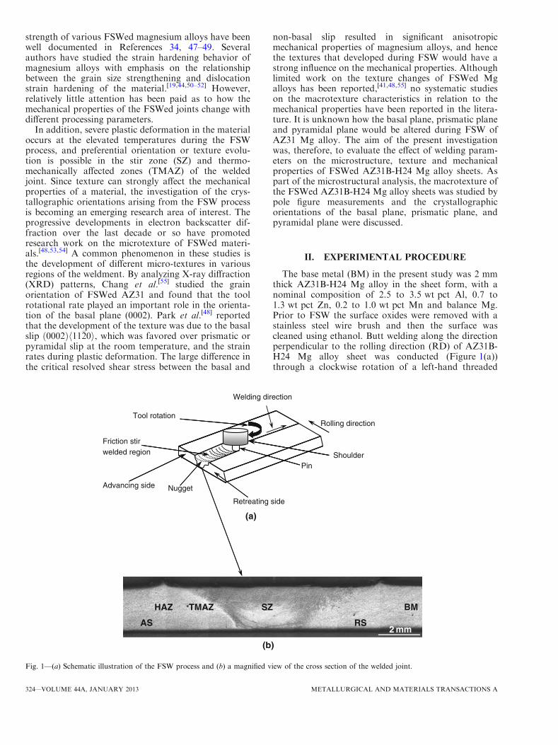
The base metal (BM) in the present study was 2 mmthick AZ31B-H24 Mg alloy in the sheet form, with anominal composition of 2.5 to 3.5 wt pct Al, 0.7 to1.3 wt pct Zn, 0.2 to 1.0 wt pct Mn and balance Mg.Prior to FSW the surface oxides were removed with astainless steel wire brush and then the surface wascleaned using ethanol. Butt welding along the directionperpendicular to the rolling direction (RD) of AZ31B-H24 Mg alloy sheet was conducted (Figure 1(a))through a clockwise rotation of a left-hand threaded
Advancing side
Friction stirwelded region
(a)
(b)
Tool rotation
AS
Nugget
HAZ TMAZ
Retreating side
Welding direction
SZ
Pin
Rolling direction
Shoulder
RS 2 mm
BM
Fig. 1—(a) Schematic illustration of the FSW process and (b) a magnified view of the cross section of the welded joint.
324—VOLUME 44A, JANUARY 2013 METALLURGICAL AND MATERIALS TRANSACTIONS A
pin (1.65 mm in length and 3.175 mm in diameter) atvarying welding speeds of 5 to 20 mm/s and toolrotational rates of 1000 to 2000 rpm. The weldedwork-pieces were sectioned perpendicular to the weldingdirection to extract specimens for microscopic examin-ations. Then the specimens were mounted in a cold-setting resin, ground using SiC papers, polished down toa 0.05 lm finish using Masterprep and etched withacetic picral (10 mL acetic acid (99 pct), 4.2 g picricacid, 10 mL H2O, 70 mL ethanol (95 pct)).[24–26] Themicrostructure was observed with a Nikon opticalmicroscope equipped with quantitative image analysissoftware as well as a JEOL JSM-6380 LV scanningelectron microscope equipped with an energy dispersiveX-ray spectroscopy (EDS) system and 3D fractographicanalysis capacity. The microhardness profile across theweldments was measured using an automated BuehlerVickers microhardness tester operated at a load of 100 gand dwell time of 15 seconds. The indention interval wasselected to be 0.3 mm to ensure at least three timesindentation diagonal length, so as to avoid any potentialeffect of strain fields caused by adjacent indentations.The crystallographic texture distribution of the FSWedspecimens was measured by a Panalytical X’Pert PROX-ray diffractometer (XRD) using Cu-Ka radiation(wavelength k = 0.15406 nm) at 45 kV and 40 mAwith a sample tilt angle ranging from 0 to 70 deg. Thespecimens for the pole figure measurements weremounted on the XRD sample stage in such an orienta-tion that the sheet RD was parallel to the X-axis of thesample stage, with the X-ray incident beam beingimpinged on either the top surface or cross section (inthe form of seven layers of ‘‘sandwich’’ sample stacked)of the FSWed specimens. The pole figures were mea-sured and analyzed by ‘X-pert texture’ software, wherethe results were represented as ð0002Þ; ð10�10Þ, andð10�11Þ color-scale intensity poles. Sub-sized tensilespecimens, in accordance with ASTM standard E8M-08, were machined along the rolling (or longitudinal)direction for both the BM and welded joints; the weldedregion was centered within the 25 mm gauge length.Tensile tests were conducted using a computerizedUnited tensile testing machine at room temperatureand at constant strain rates of 1 9 10�2, 1 9 10�3,1 9 10�4 and 1 9 10�5 s�1. At least two samples weretested at each strain rate. An extensometer with a gaugelength of 25 mm was used to measure the strain duringthe tensile tests.
III. RESULTS AND DISCUSSION
A. Microstructure
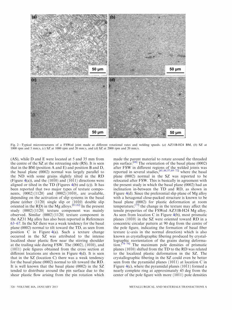
A schematic illustration of the FSW process is shownin Figure 1(a) and a typical macroscopic image of thewelded cross-section is shown in Figure 1(b). The SZ,TMAZ and heat-affected zone (HAZ) could be identifiedand the microstructural changes would be expected.The microstructure of the AZ31B-H24 BM, as shownin Figure 2(a), consisted of deformed/twinned and some-what elongated grains with varying sizes. The heterogeneity
in such a grain structure of the BM was due to bothheavy deformation by rolling to become a 2 mm thicksheet and incomplete dynamic recrystallization (partialannealing) in the H24 condition.[18,22,44,56] The averagegrain size of the BM was about 3.6 ± 2.2 lm.The effect of the welding speed and tool rotational
rate on the microstructure in the SZ is shown inFigures 2(b) through (d). It is seen that, in comparisonwith the BM microstructure (Figure 2(a)), considerablemicrostructural changes occurred after FSW, with theSZ consisting of an equiaxed grain structure withsmooth boundaries, irrespective of the welding speedand rotational rate (Figures 2(b) through (d)). This wasattributed to the occurrence of dynamic recrystallizationthat arose from a combination of frictional heating,intense plastic deformation, and viscous dissipation dueto the rotation of the welding tool during FSW. Similarresults have been reported in References 22, 44, 56, and57. The grain size was observed to decrease withincreasing welding speed (Figures 2(b) and (c)) butincreased with increasing rotational rate (Figures 2(c)and (d)). Such a microstructural evolution could berationalized on the basis of heat input during FSW.Since heat input decreased with increasing welding speedand decreasing rotational rate, a shorter time or lowerpeak temperature was available for grain growth at ahigher welding speed or at a lower tool rotation rate,which resulted in a smaller grain size. Similar resultshave been obtained for the thicker (5 mm in thickness)FSWed AZ31B-H24 Mg alloy[22,44,56] as well as FSWed6061 and 7075 Al alloys.[36,37,58]
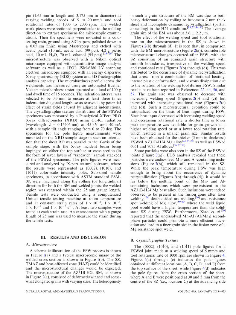
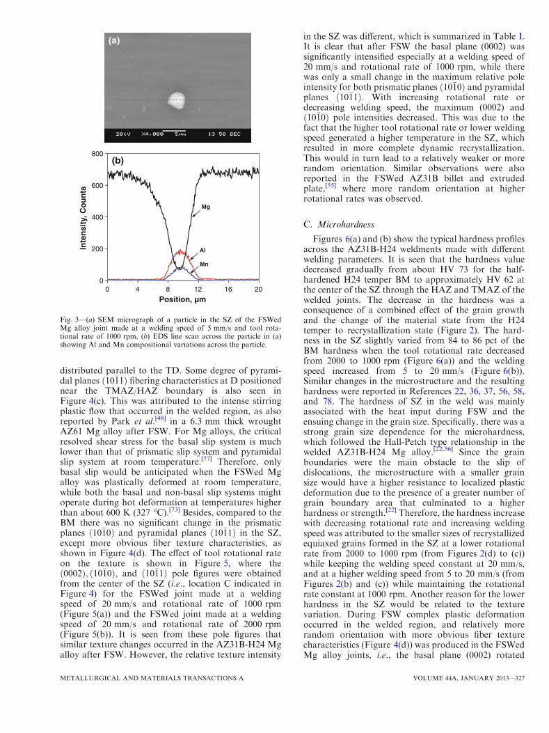
Some particles were also seen in the SZ of the FSWedjoints (Figure 3(a)). EDS analysis revealed that theseparticles were undissolved Mn- and Al-containing inclu-sions (Figure 3(b)), which still remained in the SZ.While the peak temperature during FSW was highenough to bring about the occurrence of dynamicrecrystallization (Figures 2(b) through (d)), it would befar below the melting point of the Mn- and Al-containing inclusions which were pre-existent in theAZ31B-H24 Mg base alloy. Such inclusions were indeedobserved to be present in the fusion zone after laserwelding,[24] double-sided arc welding,[26] and resistancespot welding of Mg alloy,[59,60] where the weld liquidpool would have a higher temperature than the solid-state SZ during FSW. Furthermore, Xiao et al.[59]
reported that the undissolved Mn-Al (Al8Mn5) second-phase particles could promote a more efficient nucle-ation and lead to a finer grain size in the fusion zone of aMg resistance spot weld.
B. Crystallographic Texture
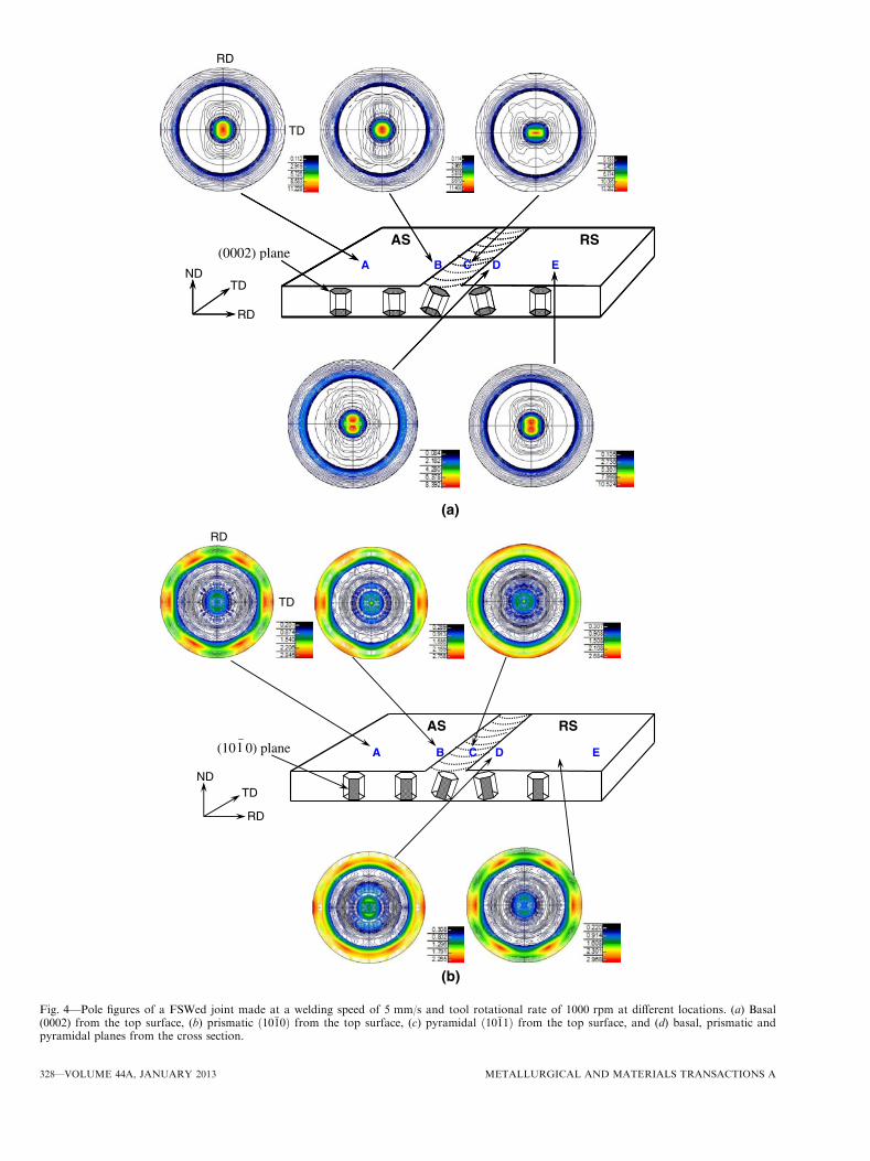
The ð0002Þ; ð10�10Þ; and ð10�11Þ pole figures for aFSWed joint made at a welding speed of 5 mm/s andtool rotational rate of 1000 rpm are shown in Figure 4.Figures 4(a) through (c) indicates the pole figuresobtained at different locations (A, B, C, D, and E) fromthe top surface of the sheet, while Figure 4(d) indicatesthe pole figures from the cross section of the sheet,where A and B were positioned at 30 and 5 mm from thecentre of the SZ (i.e., location C) at the advancing side
METALLURGICAL AND MATERIALS TRANSACTIONS A VOLUME 44A, JANUARY 2013—325
(AS), while D and E were located at 5 and 35 mm fromthe centre of the SZ at the retreating side (RS). It is seenthat in the BM (position A and E) and position B and D,the basal plane (0002) normal was largely parallel tothe ND with some grains slightly tilted in the RD(Figure 4(a)), and the ð10�10Þ and ð10�11Þ directions werealigned or tilted in the TD (Figures 4(b) and (c)). It hasbeen reported that two major types of texture compo-nents, ð0002Þh11�20i and ð0002Þh10�10i, are available,depending on the activation of slip systems in the basalplane (either h11�20i single slip or h10�10i double sliporiented in the RD) in the Mg alloys.[61,62] In the presentstudy ð0002Þh11�20i texture component was mainlyobserved. Similar ð0002Þh11�20i texture component inthe AZ31 Mg alloy has also been reported in References63–67. In the SZ there was a weak tendency for the basalplane (0002) normal to tilt toward the TD, as seen fromposition C in Figure 4(a). Such a texture changeoccurred in the SZ was attributed to the intenselocalized shear plastic flow near the stirring shoulderat the trailing side during FSW. The ð0002Þ; ð10�10Þ, andð10�11Þ pole figures obtained from the cross section atdifferent locations are shown in Figure 4(d). It is seenthat in the SZ (location C) there was a weak tendencyfor the basal plane (0002) normal to tilt toward the RD.It is well known that the basal plane (0002) in the SZtended to distribute around the pin surface due to theshear plastic flow arising from the pin rotation which
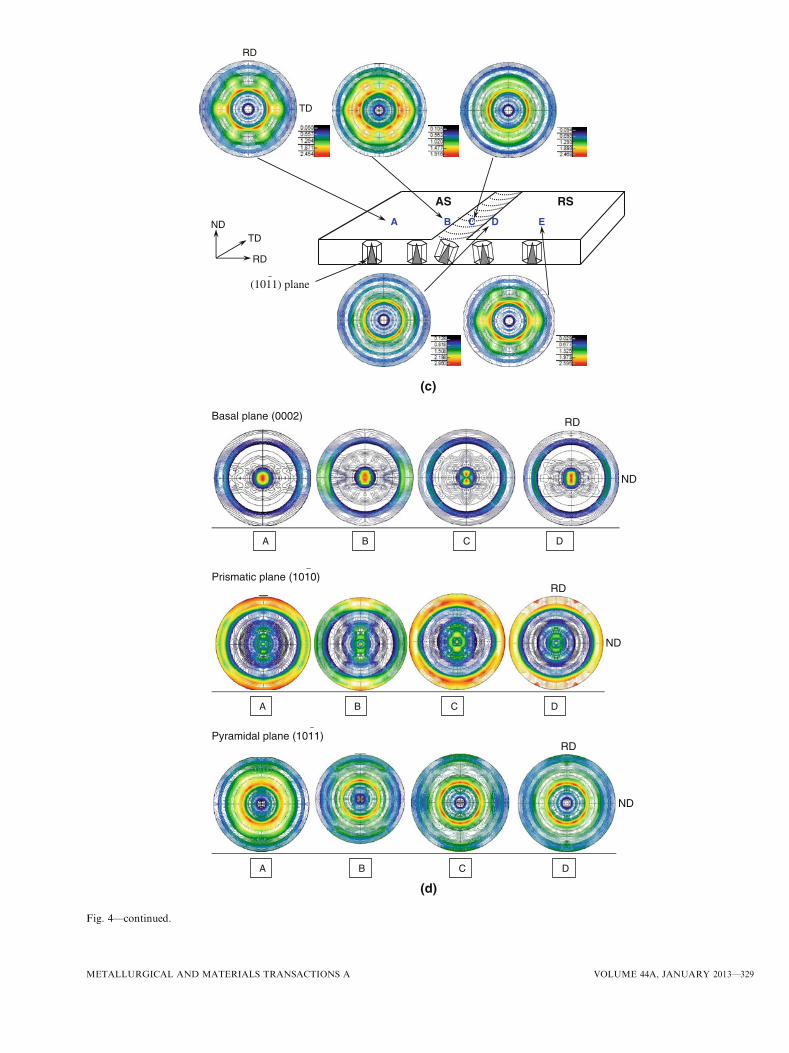
made the parent material to rotate around the threadedpin surface.[68] The orientation of the basal plane (0002)after FSW in different regions of the welded joints wasreported in several studies,[41,48,57,69–72] where the basalplane (0002) normal in the SZ was reported to berelocated after FSW. This is basically in agreement withthe present study in which the basal plane (0002) had aninclination in-between the TD and RD, as shown inFigure 4(d). Since the preferential slip plane of Mg alloywith a hexagonal close-packed structure is known to bebasal plane (0002) for plastic deformation at roomtemperature,[73] the change in the texture may affect thetensile properties of the FSWed AZ31B-H24 Mg alloy.As seen from location C in Figure 4(b), most prismaticplanes ð10�10Þ in the SZ were oriented toward RD in aconcentric circular pattern at 90 deg from the centre ofthe pole figure, indicating the formation of basal fibertexture (c-axis in the normal direction) which is alsoknown as crystallographic fibering produced by crystal-lographic reorientation of the grains during deforma-tion.[74–76] The maximum pole densities of prismaticplanes ð10�10Þ shifted from the TD to the RD was relatedto the localized plastic deformation in the SZ. Thecrystallographic fibering in the SZ could even be betterseen from the pyramidal planes ð10�11Þ at location C inFigure 4(c), where the pyramidal planes ð10�11Þ formed anearly complete ring at approximately 45 deg from thecenter of the pole figure with more ð10�11Þ pole densities
Fig. 2—Typical microstructures of a FSWed joint made at different rotational rates and welding speeds. (a) AZ31B-H24 BM, (b) SZ at1000 rpm and 5 mm/s, (c) SZ at 1000 rpm and 20 mm/s, and (d) SZ at 2000 rpm and 20 mm/s.
326—VOLUME 44A, JANUARY 2013 METALLURGICAL AND MATERIALS TRANSACTIONS A
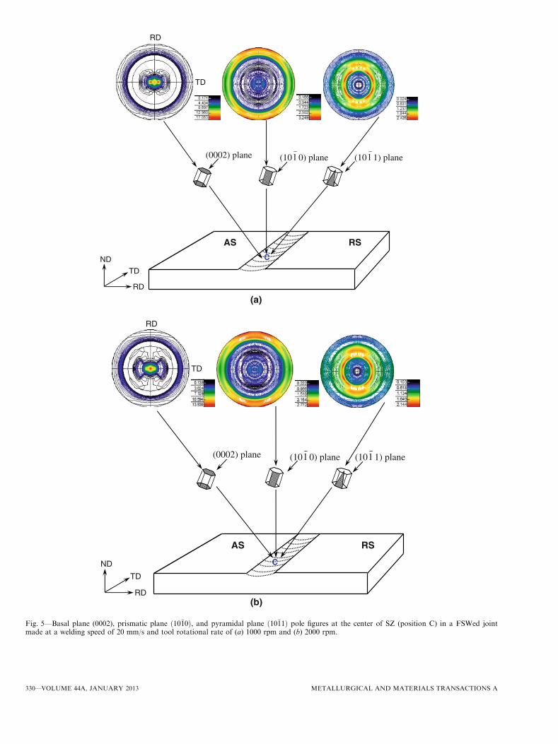
distributed parallel to the TD. Some degree of pyrami-dal planes ð10�11Þ fibering characteristics at D positionednear the TMAZ/HAZ boundary is also seen inFigure 4(c). This was attributed to the intense stirringplastic flow that occurred in the welded region, as alsoreported by Park et al.[48] in a 6.3 mm thick wroughtAZ61 Mg alloy after FSW. For Mg alloys, the criticalresolved shear stress for the basal slip system is muchlower than that of prismatic slip system and pyramidalslip system at room temperature.[77] Therefore, onlybasal slip would be anticipated when the FSWed Mgalloy was plastically deformed at room temperature,while both the basal and non-basal slip systems mightoperate during hot deformation at temperatures higherthan about 600 K (327 �C).[73] Besides, compared to theBM there was no significant change in the prismaticplanes ð10�10Þ and pyramidal planes ð10�11Þ in the SZ,except more obvious fiber texture characteristics, asshown in Figure 4(d). The effect of tool rotational rateon the texture is shown in Figure 5, where theð0002Þ; ð10�10Þ, and ð10�11Þ pole figures were obtainedfrom the center of the SZ (i.e., location C indicated inFigure 4) for the FSWed joint made at a weldingspeed of 20 mm/s and rotational rate of 1000 rpm(Figure 5(a)) and the FSWed joint made at a weldingspeed of 20 mm/s and rotational rate of 2000 rpm(Figure 5(b)). It is seen from these pole figures thatsimilar texture changes occurred in the AZ31B-H24 Mgalloy after FSW. However, the relative texture intensity
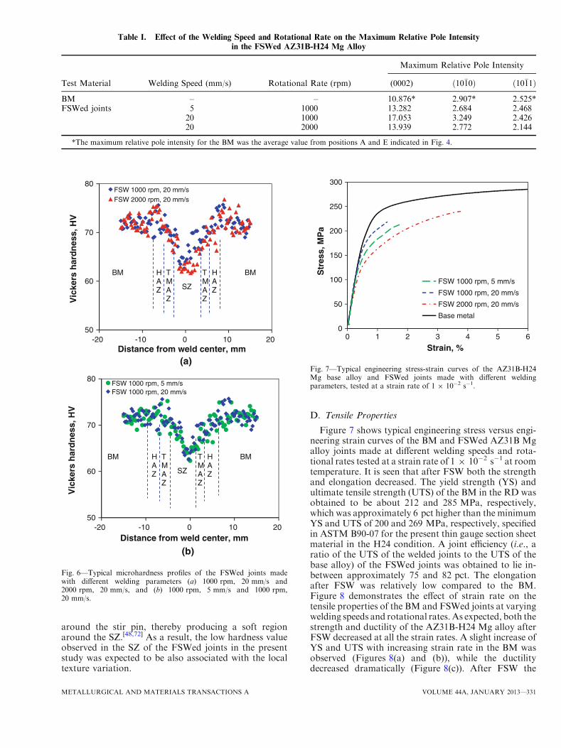
in the SZ was different, which is summarized in Table I.It is clear that after FSW the basal plane (0002) wassignificantly intensified especially at a welding speed of20 mm/s and rotational rate of 1000 rpm, while therewas only a small change in the maximum relative poleintensity for both prismatic planes ð10�10Þ and pyramidalplanes ð10�11Þ. With increasing rotational rate ordecreasing welding speed, the maximum (0002) andð10�10Þ pole intensities decreased. This was due to thefact that the higher tool rotational rate or lower weldingspeed generated a higher temperature in the SZ, whichresulted in more complete dynamic recrystallization.This would in turn lead to a relatively weaker or morerandom orientation. Similar observations were alsoreported in the FSWed AZ31B billet and extrudedplate,[55] where more random orientation at higherrotational rates was observed.
C. Microhardness
Figures 6(a) and (b) show the typical hardness profilesacross the AZ31B-H24 weldments made with differentwelding parameters. It is seen that the hardness valuedecreased gradually from about HV 73 for the half-hardened H24 temper BM to approximately HV 62 atthe center of the SZ through the HAZ and TMAZ of thewelded joints. The decrease in the hardness was aconsequence of a combined effect of the grain growthand the change of the material state from the H24temper to recrystallization state (Figure 2). The hard-ness in the SZ slightly varied from 84 to 86 pct of theBM hardness when the tool rotational rate decreasedfrom 2000 to 1000 rpm (Figure 6(a)) and the weldingspeed increased from 5 to 20 mm/s (Figure 6(b)).Similar changes in the microstructure and the resultinghardness were reported in References 22, 36, 37, 56, 58,and 78. The hardness of SZ in the weld was mainlyassociated with the heat input during FSW and theensuing change in the grain size. Specifically, there was astrong grain size dependence for the microhardness,which followed the Hall-Petch type relationship in thewelded AZ31B-H24 Mg alloy.[22,56] Since the grainboundaries were the main obstacle to the slip ofdislocations, the microstructure with a smaller grainsize would have a higher resistance to localized plasticdeformation due to the presence of a greater number ofgrain boundary area that culminated to a higherhardness or strength.[22] Therefore, the hardness increasewith decreasing rotational rate and increasing weldingspeed was attributed to the smaller sizes of recrystallizedequiaxed grains formed in the SZ at a lower rotationalrate from 2000 to 1000 rpm (from Figures 2(d) to (c))while keeping the welding speed constant at 20 mm/s,and at a higher welding speed from 5 to 20 mm/s (fromFigures 2(b) and (c)) while maintaining the rotationalrate constant at 1000 rpm. Another reason for the lowerhardness in the SZ would be related to the texturevariation. During FSW complex plastic deformationoccurred in the welded region, and relatively morerandom orientation with more obvious fiber texturecharacteristics (Figure 4(d)) was produced in the FSWedMg alloy joints, i.e., the basal plane (0002) rotated
0
200
400
600
800
0 4 8 12 16 20
Inte
nsi
ty, C
ou
nts
Position, µm
Al
Mn
Mg
(b)
(a)
Fig. 3—(a) SEM micrograph of a particle in the SZ of the FSWedMg alloy joint made at a welding speed of 5 mm/s and tool rota-tional rate of 1000 rpm, (b) EDS line scan across the particle in (a)showing Al and Mn compositional variations across the particle.
METALLURGICAL AND MATERIALS TRANSACTIONS A VOLUME 44A, JANUARY 2013—327
ND
(0002) p
RD
TDD
RD
plane
TD
AS RS
(101 0) plane
AS RS
RD
TDND
B C EDA
A B D EC
TD
RD
(a)
(b)
Fig. 4—Pole figures of a FSWed joint made at a welding speed of 5 mm/s and tool rotational rate of 1000 rpm at different locations. (a) Basal(0002) from the top surface, (b) prismatic ð10�10Þ from the top surface, (c) pyramidal ð10�11Þ from the top surface, and (d) basal, prismatic andpyramidal planes from the cross section.
328—VOLUME 44A, JANUARY 2013 METALLURGICAL AND MATERIALS TRANSACTIONS A
(1011) plane
AS RS
RD
TDND A B D EC
TD
RD
Basal plane (0002)
Prismatic plane (1010)
Pyramidal plane (1011)
A B C D
A B C D
A B C D
ND
RD
(c)
(d)
ND
RD
ND
RD
Fig. 4—continued.
METALLURGICAL AND MATERIALS TRANSACTIONS A VOLUME 44A, JANUARY 2013—329
RD
TD
ND
SRSA
(0002) plane (101 0) plane (101 1) plane
C
TD
RD
RD
TD
ND
A SRS
(0002) plane (101 0) plane (101 1) plane
C
TD
RD
(a)
(b)
Fig. 5—Basal plane (0002), prismatic plane ð10�10Þ, and pyramidal plane ð10�11Þ pole figures at the center of SZ (position C) in a FSWed jointmade at a welding speed of 20 mm/s and tool rotational rate of (a) 1000 rpm and (b) 2000 rpm.
330—VOLUME 44A, JANUARY 2013 METALLURGICAL AND MATERIALS TRANSACTIONS A
around the stir pin, thereby producing a soft regionaround the SZ.[48,72] As a result, the low hardness valueobserved in the SZ of the FSWed joints in the presentstudy was expected to be also associated with the localtexture variation.
D. Tensile Properties
Figure 7 shows typical engineering stress versus engi-neering strain curves of the BM and FSWed AZ31B Mgalloy joints made at different welding speeds and rota-tional rates tested at a strain rate of 1 9 10�2 s�1 at roomtemperature. It is seen that after FSW both the strengthand elongation decreased. The yield strength (YS) andultimate tensile strength (UTS) of the BM in the RD wasobtained to be about 212 and 285 MPa, respectively,which was approximately 6 pct higher than the minimumYS and UTS of 200 and 269 MPa, respectively, specifiedin ASTM B90-07 for the present thin gauge section sheetmaterial in the H24 condition. A joint efficiency (i.e., aratio of the UTS of the welded joints to the UTS of thebase alloy) of the FSWed joints was obtained to lie in-between approximately 75 and 82 pct. The elongationafter FSW was relatively low compared to the BM.Figure 8 demonstrates the effect of strain rate on thetensile properties of the BM and FSWed joints at varyingwelding speeds and rotational rates. As expected, both thestrength and ductility of the AZ31B-H24 Mg alloy afterFSW decreased at all the strain rates. A slight increase ofYS and UTS with increasing strain rate in the BM wasobserved (Figures 8(a) and (b)), while the ductilitydecreased dramatically (Figure 8(c)). After FSW the
Table I. Effect of the Welding Speed and Rotational Rate on the Maximum Relative Pole Intensity
in the FSWed AZ31B-H24 Mg Alloy
Test Material Welding Speed (mm/s) Rotational Rate (rpm)
Maximum Relative Pole Intensity
(0002) ð10�10Þ ð10�11Þ
BM – – 10.876* 2.907* 2.525*FSWed joints 5 1000 13.282 2.684 2.468
20 1000 17.053 3.249 2.42620 2000 13.939 2.772 2.144
*The maximum relative pole intensity for the BM was the average value from positions A and E indicated in Fig. 4.
50
60
70
80
-20 -10 0 10 20
Vic
kers
har
dn
ess,
HV
Distance from weld center, mm
FSW 1000 rpm, 20 mm/s
FSW 2000 rpm, 20 mm/s
MBMB HAZ
TMAZ
TMAZ
SZ
HAZ
(a)
50
60
70
80
-20 -10 0 10 20
Vic
kers
har
dn
ess,
HV
Distance from weld center, mm
FSW 1000 rpm, 5 mm/sFSW 1000 rpm, 20 mm/s
MBMB HAZ
TMAZ
TMAZ
SZ
HAZ
(b)
Fig. 6—Typical microhardness profiles of the FSWed joints madewith different welding parameters (a) 1000 rpm, 20 mm/s and2000 rpm, 20 mm/s, and (b) 1000 rpm, 5 mm/s and 1000 rpm,20 mm/s.
0
50
100
150
200
250
300
0 1 2 3 4 5 6
Str
ess,
MP
a
Strain, %
FSW 1000 rpm, 5 mm/s
FSW 1000 rpm, 20 mm/s
FSW 2000 rpm, 20 mm/s
Base metal
Fig. 7—Typical engineering stress-strain curves of the AZ31B-H24Mg base alloy and FSWed joints made with different weldingparameters, tested at a strain rate of 1 9 10�2 s�1.
METALLURGICAL AND MATERIALS TRANSACTIONS A VOLUME 44A, JANUARY 2013—331
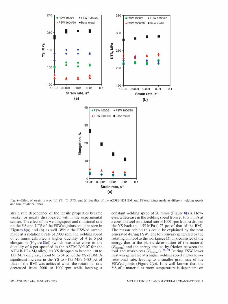
strain rate dependence of the tensile properties becameweaker or nearly disappeared within the experimentalscatter. The effect of the welding speed and rotational rateon the YS and UTS of the FSWed joints could be seen inFigures 8(a) and (b) as well. While the FSWed samplemade at a rotational rate of 2000 rpm and welding speedof 20 mm/s exhibited a higher ductility of 4 to 5 pctelongation (Figure 8(c)) (which was also close to theductility of 6 pct specified in the ASTM B90-07 for theAZ31B-H24 Mg alloy), its YS dropped to become 130 to135 MPa only, i.e., about 61 to 64 pct of the YS of BM.Asignificant increase in the YS to ~175 MPa (~83 pct ofthat of the BM) was achieved when the rotational ratedecreased from 2000 to 1000 rpm while keeping a
constant welding speed of 20 mm/s (Figure 8(a)). How-ever, a decrease in the welding speed from 20 to 5 mm/s ata constant tool rotational rate of 1000 rpm led to adrop inthe YS back to ~155 MPa (~73 pct of that of the BM).The reason behind this could be explained by the heatgenerated during FSW. The total energy generated by therotating pin tool to the workpiece (Etotal), consisted of theenergy due to the plastic deformation of the material(Eplastic) and the energy created by friction between thetool and workpieces (Efriction).
[56,79] During FSW lowerheatwas generated at a higherwelding speed and/or lowerrotational rate, leading to a smaller grain size of theFSWed joints (Figure 2(c)). It is well known that theYS of a material at room temperature is dependent on
120
150
180
210
240
YS
, MP
a
Strain rate, s-1
FSW 1000/5 FSW 1000/20
FSW 2000/20 Base metal
150
200
250
300
350
UT
S, M
Pa
Strain rate, s-1
FSW 1000/5 FSW 1000/20
FSW 2000/20 Base metal
0
10
20
30
40
1E-05 0.0001 0.001 0.01 0.1 1E-05 0.0001 0.001 0.01 0.1
1E-05 0.0001 0.001 0.01 0.1
Elo
ng
atio
n, %
Strain rate, s-1
FSW 1000/5 FSW 1000/20
FSW 2000/20 Base metal
(b)(a)
(c)
Fig. 8—Effect of strain rate on (a) YS, (b) UTS, and (c) ductility of the AZ31B-H24 BM and FSWed joints made at different welding speedsand tool rotational rates.
332—VOLUME 44A, JANUARY 2013 METALLURGICAL AND MATERIALS TRANSACTIONS A
the grain size according to the following Hall-Petchrelationship,
ry ¼ r0 þ kd�1=2; ½1�
where ry is the YS of the material, d is the grain size, r0
is the ‘‘friction stress’’ representing the overall resistanceof the crystal lattice to dislocation movement (or the YScorresponding to a material with infinitely large grainsize, which is similar to that of a single crystal), and k isa constant called ‘‘locking parameter’’ reflecting therelative hardening contribution of grain boundaries asobstacles to the slip of dislocations across the grainboundaries.[22,76,79] Grain boundaries were the majorobstacle to the slip of dislocations and the material witha smaller grain size would impose more restrictions tothe dislocation movement and have a higher resistanceto localized plastic deformation stemming from thepresence of a greater number of grain boundaries thatled to a higher YS. Since the grain size of the FSWedsamples at a welding speed of 20 mm/s and rotationalrate of 1000 rpm (Figure 2(c)) was smaller than that ofthe FSWed samples at a welding speed of 5 mm/s androtational rate of 1000 rpm (Figure 2(b)) and FSWedsamples at a welding speed of 20 mm/s and rotationalrate of 2000 rpm (Figure 2(d)), a higher value of YS inthe FSWed samples at a welding speed of 20 mm/s androtational rate of 1000 rpm would be expected. Asshown in Figure 8(b) the UTS increased with increasingwelding speed and rotational rate as well. However, theextent of its increase was not so significant in compar-ison with the change in the YS. Similar results wereobserved by several researchers.[18,22,80] Besides the effectof grain sizes or grain boundaries, crystallographicorientation/texture distribution also strongly influencedthe tensile strength since plastic deformation arose fromthe slip on the closed-packed basal planes with theminimum critical resolved shear stress as mentionedearlier. When the FSWed joints was deformed at roomtemperature along the RD (loading direction), the basalplanes would rotate to lie parallel to the rolling sheetsurface and the tensile axis. This might be a result ofbasal dislocation activity in favorably oriented grains.Similar correlation between the texture and tensilebehavior for FSWed of AZ31 alloy were reported byWoo et al.,[41,72] Yang et al.[69] and Yu et al.[71] Incomparison with other two welding conditions, thestronger intensity of basal planes (0002) present in thelow-hardness SZ at a welding speed of 20 mm/s androtational rate of 1000 rpm (Table I) implied that thebasal planes were more oriented parallel to the rollingsheet surface, i.e., the basal plane normal of more grainswas perpendicular to the sheet surface which resulted ina stronger pole intensity. As shown in Figures 7 and8(c), the percent elongation increased with increasingrotational rate, which was in good agreement with theresults reported in References 22, 44, and 81.
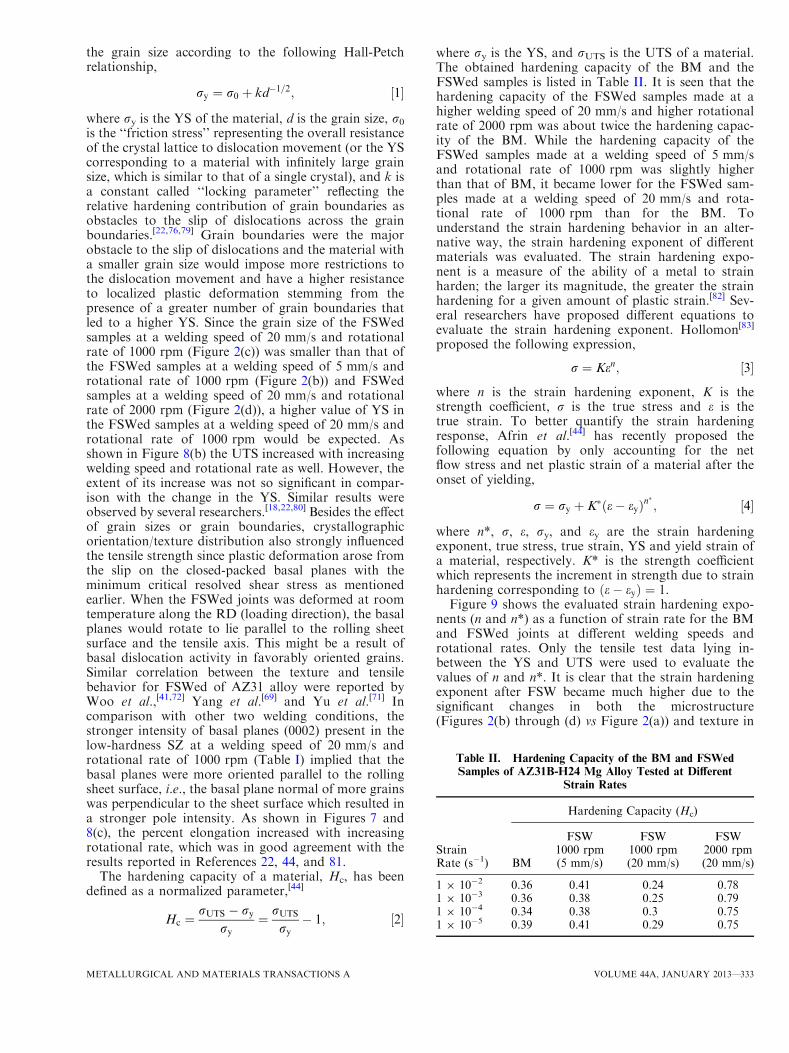
The hardening capacity of a material, Hc, has beendefined as a normalized parameter,[44]
Hc ¼rUTS � ry
ry¼ rUTS
ry� 1; ½2�
where ry is the YS, and rUTS is the UTS of a material.The obtained hardening capacity of the BM and theFSWed samples is listed in Table II. It is seen that thehardening capacity of the FSWed samples made at ahigher welding speed of 20 mm/s and higher rotationalrate of 2000 rpm was about twice the hardening capac-ity of the BM. While the hardening capacity of theFSWed samples made at a welding speed of 5 mm/sand rotational rate of 1000 rpm was slightly higherthan that of BM, it became lower for the FSWed sam-ples made at a welding speed of 20 mm/s and rota-tional rate of 1000 rpm than for the BM. Tounderstand the strain hardening behavior in an alter-native way, the strain hardening exponent of differentmaterials was evaluated. The strain hardening expo-nent is a measure of the ability of a metal to strainharden; the larger its magnitude, the greater the strainhardening for a given amount of plastic strain.[82] Sev-eral researchers have proposed different equations toevaluate the strain hardening exponent. Hollomon[83]
proposed the following expression,
r ¼ Ken; ½3�
where n is the strain hardening exponent, K is thestrength coefficient, r is the true stress and e is thetrue strain. To better quantify the strain hardeningresponse, Afrin et al.[44] has recently proposed thefollowing equation by only accounting for the netflow stress and net plastic strain of a material after theonset of yielding,
r ¼ ry þ K�ðe� eyÞn�; ½4�
where n*, r, e, ry, and ey are the strain hardeningexponent, true stress, true strain, YS and yield strain ofa material, respectively. K* is the strength coefficientwhich represents the increment in strength due to strainhardening corresponding to ðe� eyÞ ¼ 1.Figure 9 shows the evaluated strain hardening expo-
nents (n and n*) as a function of strain rate for the BMand FSWed joints at different welding speeds androtational rates. Only the tensile test data lying in-between the YS and UTS were used to evaluate thevalues of n and n*. It is clear that the strain hardeningexponent after FSW became much higher due to thesignificant changes in both the microstructure(Figures 2(b) through (d) vs Figure 2(a)) and texture in
Table II. Hardening Capacity of the BM and FSWedSamples of AZ31B-H24 Mg Alloy Tested at Different
Strain Rates
StrainRate (s�1)
Hardening Capacity (Hc)
BM
FSW1000 rpm(5 mm/s)
FSW1000 rpm(20 mm/s)
FSW2000 rpm(20 mm/s)
1 9 10�2 0.36 0.41 0.24 0.781 9 10�3 0.36 0.38 0.25 0.791 9 10�4 0.34 0.38 0.3 0.751 9 10�5 0.39 0.41 0.29 0.75
METALLURGICAL AND MATERIALS TRANSACTIONS A VOLUME 44A, JANUARY 2013—333
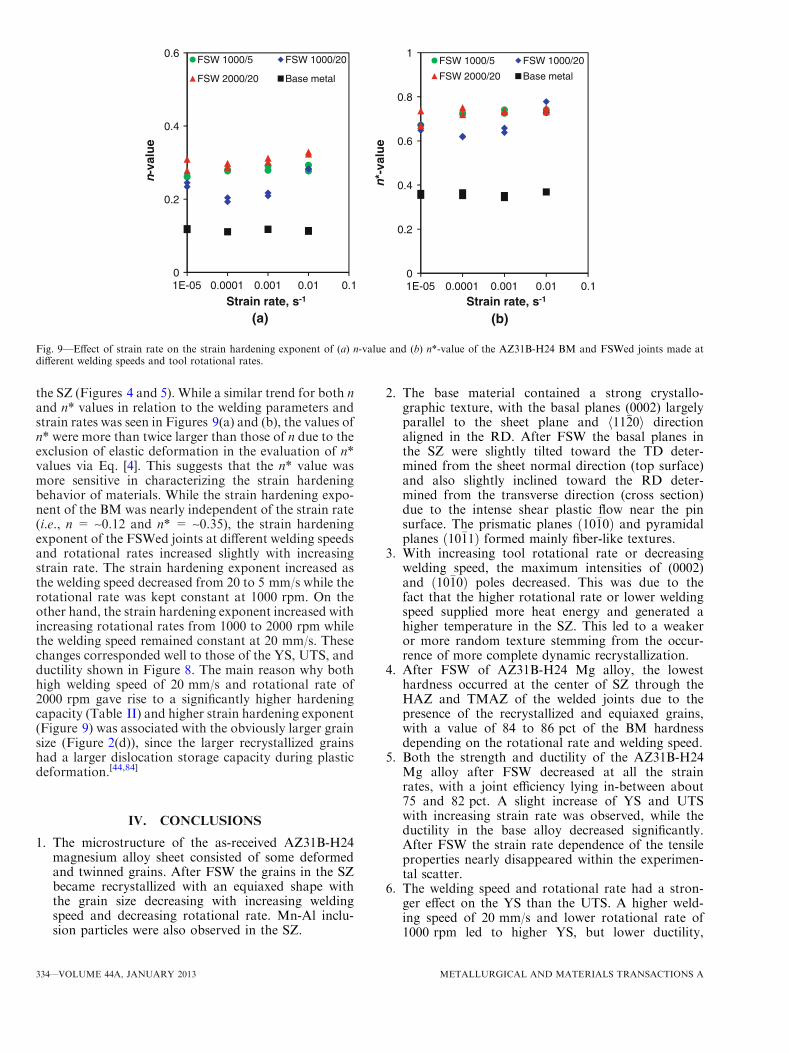
the SZ (Figures 4 and 5). While a similar trend for both nand n* values in relation to the welding parameters andstrain rates was seen in Figures 9(a) and (b), the values ofn* were more than twice larger than those of n due to theexclusion of elastic deformation in the evaluation of n*values via Eq. [4]. This suggests that the n* value wasmore sensitive in characterizing the strain hardeningbehavior of materials. While the strain hardening expo-nent of the BM was nearly independent of the strain rate(i.e., n = ~0.12 and n* = ~0.35), the strain hardeningexponent of the FSWed joints at different welding speedsand rotational rates increased slightly with increasingstrain rate. The strain hardening exponent increased asthe welding speed decreased from 20 to 5 mm/s while therotational rate was kept constant at 1000 rpm. On theother hand, the strain hardening exponent increased withincreasing rotational rates from 1000 to 2000 rpm whilethe welding speed remained constant at 20 mm/s. Thesechanges corresponded well to those of the YS, UTS, andductility shown in Figure 8. The main reason why bothhigh welding speed of 20 mm/s and rotational rate of2000 rpm gave rise to a significantly higher hardeningcapacity (Table II) and higher strain hardening exponent(Figure 9) was associated with the obviously larger grainsize (Figure 2(d)), since the larger recrystallized grainshad a larger dislocation storage capacity during plasticdeformation.[44,84]
IV. CONCLUSIONS
1. The microstructure of the as-received AZ31B-H24magnesium alloy sheet consisted of some deformedand twinned grains. After FSW the grains in the SZbecame recrystallized with an equiaxed shape withthe grain size decreasing with increasing weldingspeed and decreasing rotational rate. Mn-Al inclu-sion particles were also observed in the SZ.
2. The base material contained a strong crystallo-graphic texture, with the basal planes (0002) largelyparallel to the sheet plane and h11�20i directionaligned in the RD. After FSW the basal planes inthe SZ were slightly tilted toward the TD deter-mined from the sheet normal direction (top surface)and also slightly inclined toward the RD deter-mined from the transverse direction (cross section)due to the intense shear plastic flow near the pinsurface. The prismatic planes ð10�10Þ and pyramidalplanes ð10�11Þ formed mainly fiber-like textures.
3. With increasing tool rotational rate or decreasingwelding speed, the maximum intensities of (0002)and ð10�10Þ poles decreased. This was due to thefact that the higher rotational rate or lower weldingspeed supplied more heat energy and generated ahigher temperature in the SZ. This led to a weakeror more random texture stemming from the occur-rence of more complete dynamic recrystallization.
4. After FSW of AZ31B-H24 Mg alloy, the lowesthardness occurred at the center of SZ through theHAZ and TMAZ of the welded joints due to thepresence of the recrystallized and equiaxed grains,with a value of 84 to 86 pct of the BM hardnessdepending on the rotational rate and welding speed.
5. Both the strength and ductility of the AZ31B-H24Mg alloy after FSW decreased at all the strainrates, with a joint efficiency lying in-between about75 and 82 pct. A slight increase of YS and UTSwith increasing strain rate was observed, while theductility in the base alloy decreased significantly.After FSW the strain rate dependence of the tensileproperties nearly disappeared within the experimen-tal scatter.
6. The welding speed and rotational rate had a stron-ger effect on the YS than the UTS. A higher weld-ing speed of 20 mm/s and lower rotational rate of1000 rpm led to higher YS, but lower ductility,
0
0.2
0.4
0.6
n-v
alu
e
Strain rate, s-1
FSW 1000/5 FSW 1000/20
FSW 2000/20 Base metal
0
0.2
0.4
0.6
0.8
1
1E-05 0.0001 0.001 0.01 0.1 1E-05 0.0001 0.001 0.01 0.1
n*-
valu
e
Strain rate, s-1
FSW 1000/5 FSW 1000/20
FSW 2000/20 Base metal
(a) (b)
Fig. 9—Effect of strain rate on the strain hardening exponent of (a) n-value and (b) n*-value of the AZ31B-H24 BM and FSWed joints made atdifferent welding speeds and tool rotational rates.
334—VOLUME 44A, JANUARY 2013 METALLURGICAL AND MATERIALS TRANSACTIONS A
strain-hardening exponent and hardening capacity.This was due to the smaller recrystallized grains inthe low-hardness SZ arising from the lower heatinput.
ACKNOWLEDGMENTS
The authors would like to thank the Natural Sci-ences and Engineering Research Council of Canada(NSERC) and AUTO21 Network of Centers of Excel-lence for providing financial support. This investiga-tion involves part of Canada-China-USACollaborative Research Project on the MagnesiumFront End Research and Development (MFERD).The authors also thank General Motors Research andDevelopment Center for providing the test materials.One of the authors (D.L. Chen) is grateful for thefinancial support by the Premier’s Research ExcellenceAward (PREA), NSERC-Discovery Accelerator Sup-plement (DAS) Award, Canada Foundation for Inno-vation (CFI), and Ryerson Research Chair (RRC)program. The assistance of Q. Li, A. Machin,J. Amankrah, and R. Churaman in performing theexperiments is gratefully acknowledged. The authorsalso thank Dr. S. Xu, Dr. K. Sadayappan, Dr. M.S.Kozdras, Dr. J. Jackman, Professor N. Atalla, Profes-sor N. Zhou, Professor D. Weckman, ProfessorS. Lambert, Professor H. Jahed, Professor Y.S. Yang,Professor M.F. Horstemeyer, Professor B. Jordon,Professor J. Allison, Dr. A.A. Luo, Mr. R. Osborne,Mr. J.F. Quinn, Dr. X.M. Su, and Mr. L. Zhang fortheir helpful discussion.
REFERENCES1. T.M. Pollock: Science, 2010, vol. 328, pp. 986–87.2. S.J. Davis, K. Caldeira, and H.D. Matthews: Science, 2010,
vol. 329, pp. 1330–33.3. M. Wise, K. Calvin, A. Thomson, L. Clarke, B. Bond-Lamberty,
R. Sands, S.J. Smith, A. Janetos, and J. Edmonds: Science, 2009,vol. 324, pp. 1183–86.
4. W.G. Agnew: Science, 1974, vol. 183, pp. 254–56.5. L.R. Kump: Nature, 2002, vol. 419, pp. 188–90.6. D.A. Howey: Nat. Clim. Chang., 2012, vol. 2, pp. 28–29.7. D. Shindell, G. Faluvegi, M. Walsh, S.C. Anenberg, R.V.
Dingenen, N.Z. Muller, J. Austin, D. Koch, and G. Milly: Nat.Clim. Chang., 2011, vol. 1, pp. 59–66.
8. H.-J. Kim, G.A. Keoleian, and S.J. Skerlos: J. Ind. Ecol., 2011,vol. 15, pp. 64–80.
9. H.-J. Kim, C. McMillan, G.A. Keoleian, and S.J. Skerlos: J. Ind.Ecol., 2010, vol. 14, pp. 929–46.
10. E.A. Nyberg, A.A. Luo, K. Sadayappan, and W.F. Shi: Adv.Mater. Process., 2008, vol. 166, pp. 35–37.
11. S. Begum, D.L. Chen, S. Xu, and A.A. Luo: Metall. Mater. Trans.A, 2008, vol. 39A, pp. 3014–26.
12. S. Begum, D.L. Chen, S. Xu, and A.A. Luo: Int. J. Fatigue, 2009,vol. 31, pp. 726–35.
13. S. Begum, D.L. Chen, S. Xu, and A.A. Luo: Mater. Sci. Eng. A,2009, vol. A517, pp. 334–43.
14. Q. Yu, J. Zhang, Y. Jiang, and Q. Li: Int. J. Fatigue, 2011, vol. 33,pp. 437–47.
15. Q. Yu, J. Zhang, Y. Jiang, and Q. Li: Int. J. Fatigue, 2012, vol. 36,pp. 47–58.
16. J.B. Jordon, J.B. Gibson, M.F. Horstemeyer, H.E. Kadiri, J.C.Baird, and A.A. Luo:Mater. Sci. Eng. A, 2011, vol. 528, pp. 6860–71.
17. J.D. Bernard, J.B. Jordon, M.F. Horstemeyer, H.E. Kadiri, J.C.Baird, D. Lamb, and A.A. Luo: Scripta Mater., 2010, vol. 63,pp. 751–56.
18. X. Cao and M. Jahazi: Mater. Des., 2009, vol. 30, pp. 2033–42.19. X.Z. Lin and D.L. Chen: J. Mater. Eng. Perform., 2008, vol. 17,
pp. 894–901.20. A. Tharumarajah and P. Koltun: J. Clean. Prod., 2007, vol. 15,
pp. 1007–13.21. W.M. Thomas, E.D. Nicholas, J.C. Needham, M.G. Church,
P. Templesmith, and C.J. Dawes: GB Patent ApplicationNo. 9125978.9, 1991.
22. N. Afrin, D.L. Chen, X. Cao, and M. Jahazi: Mater. Sci. Eng. A,2008, vol. 472, pp. 179–86.
23. C. Liu, D.L. Chen, S. Bhole, X. Cao, and M. Jahazi: Mater.Charact., 2009, vol. 60, pp. 370–76.
24. S.M. Chowdhury, D.L. Chen, S.D. Bhole, X. Cao, E. Powidajko,D.C. Weckman, and Y. Zhou: Metall. Mater. Trans. A, 2011,vol. 42A, pp. 1974–89.
25. S.H. Chowdhury, D.L. Chen, S.D. Bhole, E. Powidajko, D.C.Weckman, and Y. Zhou: Metall. Mater. Trans. A, 2012, vol. 43A,pp. 2133–47.
26. S.M. Chowdhury, D.L. Chen, S.D. Bhole, X. Cao, E. Powidajko,D.C. Weckman, and Y. Zhou: Mater. Sci. Eng. A, 2010, vol. 527,pp. 2951–61.
27. S.F. Su, J.C. Huang, H.K. Lin, and N.J. Ho:Metall. Mater. Trans.A, 2002, vol. 33A, pp. 1461–73.
28. L.M. Liu, G. Song, and M.L. Zhu: Metall. Mater. Trans. A, 2008,vol. 39A, pp. 1702–11.
29. S.H. Wu, J.C. Huang, and Y.N. Wang: Metall. Mater. Trans. A,2004, vol. 35A, pp. 2455–69.
30. H.W. Lee, T.S. Lui, and L.H. Chen: J. Alloy. Compd., 2009,vol. 475, pp. 139–44.
31. H. Watanabe, H. Tsutsui, T. Mukai, K. Ishikawa, Y. Okanda, M.Kohzu, andK.Higashi:Mater. Trans.A, 2001, vol. 42, pp. 1200–05.
32. T. Mukai, M. Yamanoi, H. Watanabe, and H. Higashi: ScriptaMater., 2001, vol. 45, pp. 89–94.
33. A. Bussiba, A.B. Artzy, A. Shtechman, S. Ifergan, and M. Kupiec:Mater. Sci. Eng. A, 2001, vol. 302, pp. 56–62.
34. R.S. Mishra and Z.Y. Ma:Mater. Sci. Eng. R, 2005, vol. 50, pp. 1–78.
35. Z.Y. Ma: Metall. Mater. Trans. A, 2008, vol. 39A, pp. 642–58.36. A.H. Feng, D.L. Chen, and Z.Y. Ma: Metall. Mater. Trans. A,
2010, vol. 41A, pp. 957–71.37. A.H. Feng, D.L. Chen, and Z.Y. Ma: Metall. Mater. Trans. A,
2010, vol. 41A, pp. 2626–41.38. Y.J. Quan, Z.H. Chen, X.S. Gong, and Z.H. Yu: Mater. Charact.,
2008, vol. 59, pp. 1491–97.39. L.M. Liu and C. Dong: Mater. Lett., 2006, vol. 60, pp. 2194–97.40. J. Zhu, L. Li, and Z. Liu: Appl. Surf. Sci., 2005, vol. 247, pp. 300–
06.41. W. Woo, H. Choo, D.W. Brown, P.K. Liaw, Z. Feng, M.B. Prime,
and Z. Feng: Scripta Mater., 2006, vol. 54, pp. 1859–64.42. X.H. Wang and K.S. Wang: Mater. Sci. Eng. A, 2006, vol. 431,
pp. 114–17.43. L. Commin, M. Dumont, J.E. Masse, and L. Barrallier: Acta
Mater., 2009, vol. 57, pp. 326–34.44. N. Afrin, D.L. Chen, X. Cao, and M. Jahazi: Scripta Mater., 2007,
vol. 57, pp. 1004–07.45. P.B. Srinivasan, R. Zettler, C. Blawert, and W. Dietzel: Mater.
Charact., 2009, vol. 60, pp. 389–96.46. L. Yu, K. Nakata, N. Yamamoto, and J. Liao: Mater. Lett., 2009,
vol. 63, pp. 870–72.47. R. Nandan, T. DebRoy, and H.K.D.H. Bhadeshia: Prog. Mater
Sci., 2008, vol. 53, pp. 980–1023.48. S.H.C. Park, Y.S. Sato, and H. Kokawa: Metall. Mater. Trans. A,
2003, vol. 34A, pp. 987–94.49. J. Liao, N. Yamamoto, and K. Nakata: Metall. Mater. Trans. A,
2009, vol. 40A, pp. 2212–19.50. U.F. Kocks and H. Mecking: Prog. Mater Sci., 2003, vol. 48,
pp. 171–273.51. J.A. del Valle, F. Carreno, and O.A. Ruano: Acta Mater., 2006,
vol. 54, pp. 4247–59.
METALLURGICAL AND MATERIALS TRANSACTIONS A VOLUME 44A, JANUARY 2013—335
52. J.A. del Valle and O.A. Ruano: Scripta Mater., 2006, vol. 55,pp. 775–78.
53. M. Fujimoto, S. Koga, N. Abe, Y.S. Sato, and H. Kokawa: Sci.Technol. Weld. Join., 2008, vol. 13, pp. 663–70.
54. R.W. Fonda, J.F. Bingert, and K.J. Colligan: Scripta Mater.,2004, vol. 51, pp. 243–48.
55. C.I. Chang, C.J. Lee, and J.C. Huang: Scripta Mater., 2004,vol. 51, pp. 509–14.
56. M. Fairman, N. Afrin, D.L. Chen, X.J. Cao, and M. Jahazi: Can.Metall. Q., 2007, vol. 46, pp. 425–32.
57. S.H.C. Park, Y.S. Sato, and H. Kokawa: Scripta Mater., 2003,vol. 49, pp. 161–66.
58. A.H. Feng, D.L. Chen, and Z.Y. Ma: Mater. Sci. Forum, 2009,vols. 618–619, pp. 41–44.
59. L. Xiao, L. Liu, Y. Zhou, and S. Esmaeili: Metall. Mater. Trans.A, 2010, vol. 41A, pp. 1511–22.
60. L. Xiao, L. Liu, D.L. Chen, S. Esmaeili, and Y. Zhou: Mater. Sci.Eng. A, 2011, vol. 529, pp. 81–87.
61. G. Gottstein and T.A. Samman: Mater. Sci. Forum, 2005,vols. 495–497, pp. 623–32.
62. Y.N. Wang and J.C. Huang: Mater. Chem. Phys., 2003, vol. 81,pp. 11–26.
63. T.A. Samman and G. Gottstein: Mater. Sci. Eng. A, 2008,vol. 488, pp. 406–14.
64. I. Ulacia, S. Yi, M.T. Perez-Prado, N.V. Dudamell, F. Galvez, D.Letzig, and I. Hurtado: 4th International Conference on High Speedforming, Columbus, OH, March 9–10, 2010, pp. 189–97.
65. K.U. Kainer: Proceedings of the 7th International Conference onMagnesium Alloys and Their Application, Dresden, Germany,November 6–9, 2006, pp. 161–63.
66. X. Li, F. Jiao, T. Al-Samman, and S.G. Chowdhury: ScriptaMater., 2012, vol. 66, pp. 159–62.
67. X. Li, T. Al-Samman, S. Mu, and G. Gottstein: Mater. Sci. Eng.A, 2011, vol. 528, pp. 7915–25.
68. S.M. Chowdhury, D.L. Chen, S.D. Bhole, and X. Cao: MaterSci.Eng. A, 2010, vol. 527 (21–22), pp. 6064–75.
69. J. Yang, B.L. Xiao, D. Wang, and Z.Y. Ma: Mater. Sci. Eng. A,2010, vol. 527, pp. 708–14.
70. D.T. Zhang, M. Suzuki, and K. Maruyama: Acta Metall. Sin.(Engl. Lett.), 2006, vol. 19, pp. 335–40.
71. Z. Yu, H. Choo, Z. Feng, and S.C. Vogel: Scripta Mater., 2010,vol. 63, pp. 1112–15.
72. W. Woo and H. Choo: Sci. Technol. Weld. Join., 2011, vol. 16,pp. 267–72.
73. A. Couret and D. Caillard: Acta Metall., 1985, vol. 33, pp. 1447–54.
74. L. Helis, K. Okayasu, and H. Fukutomi: Mater. Sci. Eng. A, 2006,vol. 430, pp. 98–103.
75. H.T. Jeong and T.K. Ha: J. Mater. Process. Technol., 2007,vols. 187–188, pp. 559–61.
76. G.E. Dieter: Mechanical Metallurgy, 3rd ed., McGraw-Hill, Bos-ton, MA, 1986.
77. R.W. Fonda and K.E. Knipling: Sci. Technol. Weld. Join., 2011,vol. 16, pp. 288–94.
78. W.B. Lee, Y.M. Yeon, and S.B. Jung: Mater. Sci. Technol., 2003,vol. 19, pp. 785–90.
79. C. Hamilton, A. Sommers, and S. Dymek: Int. J. Mach. Tool.Manuf., 2009, vol. 49, pp. 230–38.
80. S. Lim, S. Kim, C.G. Lee, C.D. Yim, and S.J. Kim:Metall. Mater.Trans. A, 2005, vol. 36A, pp. 1609–12.
81. K. Elangovan and V. Balasubramanian: Mater. Sci. Eng. A, 2007,vol. 459, pp. 7–18.
82. W.D. Callister, Jr. and DC Rethwisch: Materials Science andEngineering—An Introduction, 8th ed., John Wiley & Sons, Inc.,New York, 2009.
83. J.H. Hollomon: Trans. AIME, 1945, vol. 162, pp. 268–89.84. X.H. Chen, F.S. Pan, J.J. Mao, J.F. Wang, D.F. Zhang, A.T.
Tang, and J. Peng: Mater. Des., 2011, vol. 32, pp. 1526–30.
336—VOLUME 44A, JANUARY 2013 METALLURGICAL AND MATERIALS TRANSACTIONS A
Related Documents