Landmines Detection and Assessment in Egypt: an Experimental Test Site Evaluation for GPR Approach Mohamed Metwaly ab , Abbas M. Abbas b , Gad El-Qady b , and Jun Matsushima a a The University of Tokyo, Graduate School of Engineering, Japan b National Research Institute of Astronomy and Geophysics, Cairo, Egypt Landmine detection requires adequate techniques to measure the minor contrast in the physical parameters and efficient algorithms for processing the data in a way makes the measured contrast in the property visible. However, recent landmines are completely or partially made of non-metallic components. Consequently, metal detector can not be sensitive tool for detecting such types. Application of GPR techniques in the field of landmines are improving drastically since it gives the high resolution required for addressing these targets even if they have not any metallic components. In this work, we are testing the applicability of GPR techniques to resolve the shape and depth of metallic and plastic landmine-like targets planted in a hot dry sand test site at the western desert of Egypt. The comparison between synthetic and field GPR response reveals the potential for fast diagnostic estimation of several landmines characteristics rather than detection only. 1. Introduction Landmines that are left behind some war ac- tions constitute one of the biggest obstacles to- wards the development and living in a normal way in many war zones. According to United Nations statistics, there are at present over 110 million land mines laid out in approximately 70 coun- tries. Landmines are deployed more rapidly than they are cleared, consequently the total amount of mines is increasing gradually. Most antiper- sonnel (AP) mines, especially the small ones, are placed close to the surface (not more than 30 cm). In the open desert areas, these mines can be dis- placed from their original position due to the ef- fect of weathering activities such as floods and sand moving. Moreover, recent mines are com- posed of plastic material or contain very small amounts of metal. The demand for better meth- ods both to discover and disarm mines is therefore established. Conventional metal detectors used in many contaminated areas can not differentiate between real mines, clutter, and sometimes the changes in surface conductivity [1]. The traditional con- firmation for such problem is to prod the soil at shallow angle from one side using a thin stick to characterize the type and probably the shape of the object [1]; however this is an essentially dan- gerous operation. Ground penetrating radar (GPR) became in the last decade one of the promising sensors for detection and discrimination of buried metallic and non-metallic mines [2]. The radar is able to detect various types of mines because of the dif- ferences in dielectric properties between the mine and the surrounding soil. This difference causes a reflection and diffraction of the radar waves at the mine surface and hereby gives information about the depth and consequently the actual po- sition [3]. 2. Data Acquisition In order to study the so called a radar finger- print for different mine-like objects, test site has been constructed in the hot dry sand of western Egyptian desert. The host rock which was com- posed of marly limestone has been replaced by friable sand for about one meter depth. A set of different metallic, plastic and partially metallic objects, like the real landmines, have been buried regularly along two profiles at various depths (12 to 40 cm). The entire site was covered with a flat 1

Welcome message from author
This document is posted to help you gain knowledge. Please leave a comment to let me know what you think about it! Share it to your friends and learn new things together.
Transcript
Landmines Detection and Assessment in Egypt: an Experimental TestSite Evaluation for GPR Approach
Mohamed Metwalyab, Abbas M. Abbasb, Gad El-Qadyb, and Jun Matsushimaa
aThe University of Tokyo, Graduate School of Engineering, Japan
bNational Research Institute of Astronomy and Geophysics, Cairo, Egypt
Landmine detection requires adequate techniques to measure the minor contrast in the physical parametersand efficient algorithms for processing the data in a way makes the measured contrast in the property visible.However, recent landmines are completely or partially made of non-metallic components. Consequently, metaldetector can not be sensitive tool for detecting such types. Application of GPR techniques in the field of landminesare improving drastically since it gives the high resolution required for addressing these targets even if they havenot any metallic components. In this work, we are testing the applicability of GPR techniques to resolve the shapeand depth of metallic and plastic landmine-like targets planted in a hot dry sand test site at the western desertof Egypt. The comparison between synthetic and field GPR response reveals the potential for fast diagnosticestimation of several landmines characteristics rather than detection only.
1. Introduction
Landmines that are left behind some war ac-tions constitute one of the biggest obstacles to-wards the development and living in a normal wayin many war zones. According to United Nationsstatistics, there are at present over 110 millionland mines laid out in approximately 70 coun-tries. Landmines are deployed more rapidly thanthey are cleared, consequently the total amountof mines is increasing gradually. Most antiper-sonnel (AP) mines, especially the small ones, areplaced close to the surface (not more than 30 cm).In the open desert areas, these mines can be dis-placed from their original position due to the ef-fect of weathering activities such as floods andsand moving. Moreover, recent mines are com-posed of plastic material or contain very smallamounts of metal. The demand for better meth-ods both to discover and disarm mines is thereforeestablished.
Conventional metal detectors used in manycontaminated areas can not differentiate betweenreal mines, clutter, and sometimes the changesin surface conductivity [1]. The traditional con-firmation for such problem is to prod the soil atshallow angle from one side using a thin stick to
characterize the type and probably the shape ofthe object [1]; however this is an essentially dan-gerous operation.
Ground penetrating radar (GPR) became inthe last decade one of the promising sensors fordetection and discrimination of buried metallicand non-metallic mines [2]. The radar is able todetect various types of mines because of the dif-ferences in dielectric properties between the mineand the surrounding soil. This difference causesa reflection and diffraction of the radar waves atthe mine surface and hereby gives informationabout the depth and consequently the actual po-sition [3].
2. Data Acquisition
In order to study the so called a radar finger-print for different mine-like objects, test site hasbeen constructed in the hot dry sand of westernEgyptian desert. The host rock which was com-posed of marly limestone has been replaced byfriable sand for about one meter depth. A set ofdifferent metallic, plastic and partially metallicobjects, like the real landmines, have been buriedregularly along two profiles at various depths (12to 40 cm). The entire site was covered with a flat
1
2 G. El-Qady
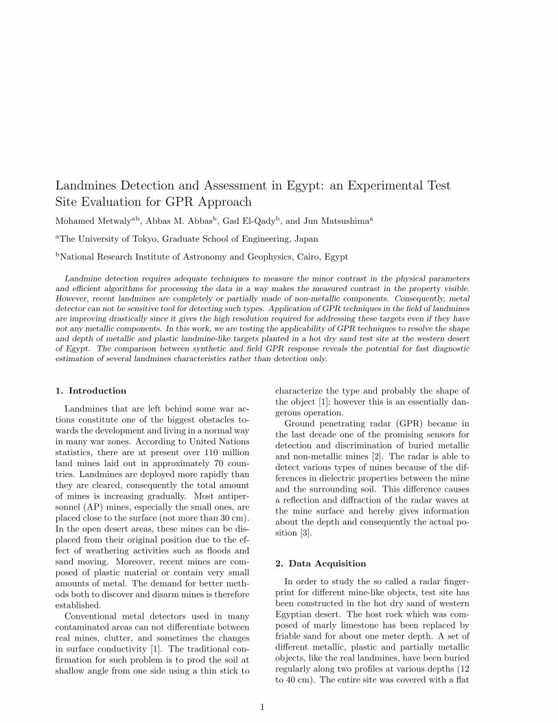
Figure 1: Typical radargram for different metallicbodies (#1–#5) after application of background re-moval.
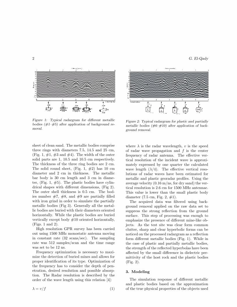
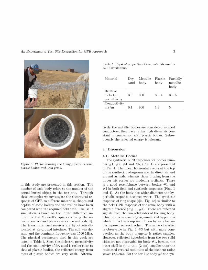
sheet of clean sand. The metallic bodies comprisethree rings with diameters 7.5, 14.5 and 25 cm,(Fig. 1, #1, #3 and #4). The width of the outersolid parts are 1, 10.5 and 10.5 cm respectively.The thickness of the three ring bodies are 2 cm.The solid round sheet, (Fig. 1, #2) has 10 cmdiameter and 2 cm in thickness. The metallicbar body is 30 cm length and 3 cm in diame-ter, (Fig. 1, #5). The plastic bodies have cylin-drical shapes with different dimensions, (Fig 2).The outer shell thickness is 0.5 cm. The bod-ies number #7, #8, and #9 are partially filledwith iron grind in order to simulate the partiallymetallic bodies (Fig 3). Generally all the metal-lic bodies are buried with their diameters orientedhorizontally. While the plastic bodies are buriedvertically except body #10 oriented horizontally,(Figs. 1 and 2).
High resolution GPR survey has been carriedout using 1500 MHz monostatic antenna movingin constant rate (32 scans/sec). The samplingrate was 512 samples/scan and the time rangewas set to be 12 ns.
Frequency optimization is necessary to maxi-mize the detection of buried mines and allows forproper identification of its type. Optimization ofthe frequency has to consider the depth of pen-etration, desired resolution and possible absorp-tion. The Radar resolution is described by theorder of the wave length using this relation [4]:
λ = v/f (1)
Figure 2: Typical radargram for plastic and partiallymetallic bodies (#6–#10) after application of back-ground removal.
where λ is the radar wavelength, v is the speedof radar wave propagation and f is the centerfrequency of radar antenna. The effective ver-tical resolution of the incident wave is approxi-mately expressed by one quarter the calculatedwave length (λ/4). The effective vertical reso-lutions of radar waves have been estimated formetallic and plastic georadar profiles. Using theaverage velocity (0.16 m/ns, for dry sand) the ver-tical resolution is 2.6 cm for 1500 MHz antennae.This value is lower than the small plastic bodydiameter (7.5 cm, Fig. 2, #1).
The acquired data was filtered using back-ground removal applied on the raw data set tosuppress the strong reflection from the groundsurface. This step of processing was enough toemphasize the presence of different mine-like ob-jects. As the test site was clear form commonclutter, sharp and clear hyperbolic forms can benoticed on the processed radargram as a reflectionform different metallic bodies (Fig. 1). While inthe case of plastic and partially metallic bodies,the strength of the reflected hyperbolas have beenaffected by the small difference in dielectric per-mittivity of the host rock and the plastic bodies(Fig. 2).
3. Modeling
The simulation response of different metallicand plastic bodies based on the approximationof the true physical properties of the objects used
An Experimental Test Site Evaluation for GPR Approach 3
Figure 3: Photos showing the filling process of someplastic bodies with iron grind.
in this study are presented in this section. Thenumber of each body refers to the number of theactual buried object in the test site. Throughthese examples we investigate the theoretical re-sponse of GPR to different materials, shapes anddepths of some bodies and the results have beencompared with the acquired field data. The GPRsimulation is based on the Finite Difference so-lution of the Maxwell’s equations using the re-flector surface and plan-wave source methods [5].The transmitter and receiver are hypotheticallylocated at air-ground interface. The soil was drysand and the dominant frequency was 1500 MHz.The physical parameters used in this work arelisted in Table 1. Since the dielectric permittivityand the conductivity of dry sand is rather close tothat of plastic bodies, the reflected energy frommost of plastic bodies are very weak. Alterna-
Table 1: Physical properties of the materials used inGPR simulations.
Material Dry Metallic Plastic Partiallysand body body metallic
bodyRelativedielectric 3.5 300 3− 4 3− 6permittivityConductivitymS/m 0.1 900 1.3 5
tively the metallic bodies are considered as goodconductors; they have rather high dielectric con-stant in comparison with plastic bodies. Subse-quently the reflected energy is relevant.
4. Discussion
4.1. Metallic BodiesThe synthetic GPR responses for bodies num-
ber #1, #2, #4 and #5, (Fig. 1) are presentedin Fig. 4. The linear horizontal events at the topof the synthetic radargrams are the direct air andground arrivals, whereas those dipping from theupper left corner are modeling artifacts. Thereis a good resemblance between bodies #1 and#2 in both field and synthetic responses (Figs. 1and 4). As the body has wider diameter the hy-perbolic response becomes wider. The syntheticresponse of ring shape (#4, Fig. 4c) is similar tothe field GPR response of the same body with aslight difference (Fig. 1, #4). There are reflectedsignals from the two solid sides of the ring body.This produces generally asymmetrical hyperbolawhich in fact is composed of two hyperbolae su-perimposed on each other. The same characteris observable in Fig. 1 #3 but with more com-paction as the body diameter is rather smaller.However, reflected hyperbolae from the two solidsides are not observable for body #1, because theouter shell is quite thin (2 cm), smaller than theestimated vertical resolution of the incident radarwaves (2.6 cm). For the bar-like body #5 the syn-
4 G. El-Qady
Figure 4: Synthetic 1500 MHz GPR responses for dif-ferent metallic bodies (#1–#4), numbers are referringto bodies in Fig. 1.
thetic and field GPR response has a slight differ-ence compared to that of the ring bodies. It hasa little elongated response with some diffractedsignals from the two ends (Fig. 4, d and Fig. 1,#5). The modeled body has been tilted by 10◦ tothe left side to produce the same field response.
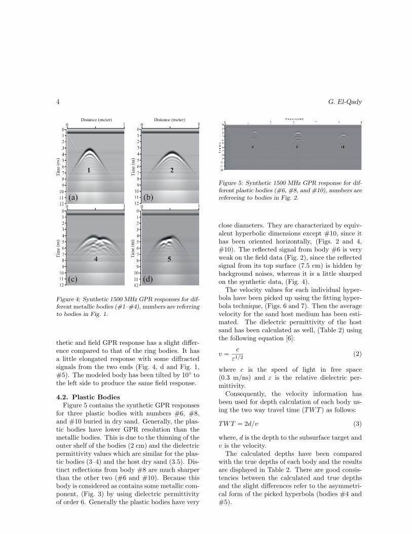
4.2. Plastic BodiesFigure 5 contains the synthetic GPR responses
for three plastic bodies with numbers #6, #8,and #10 buried in dry sand. Generally, the plas-tic bodies have lower GPR resolution than themetallic bodies. This is due to the thinning of theouter shelf of the bodies (2 cm) and the dielectricpermittivity values which are similar for the plas-tic bodies (3–4) and the host dry sand (3.5). Dis-tinct reflections from body #8 are much sharperthan the other two (#6 and #10). Because thisbody is considered as contains some metallic com-ponent, (Fig. 3) by using dielectric permittivityof order 6. Generally the plastic bodies have very
Figure 5: Synthetic 1500 MHz GPR response for dif-ferent plastic bodies (#6, #8, and #10), numbers arerefereeing to bodies in Fig. 2.
close diameters. They are characterized by equiv-alent hyperbolic dimensions except #10, since ithas been oriented horizontally, (Figs. 2 and 4,#10). The reflected signal from body #6 is veryweak on the field data (Fig. 2), since the reflectedsignal from its top surface (7.5 cm) is hidden bybackground noises, whereas it is a little sharpedon the synthetic data, (Fig. 4).
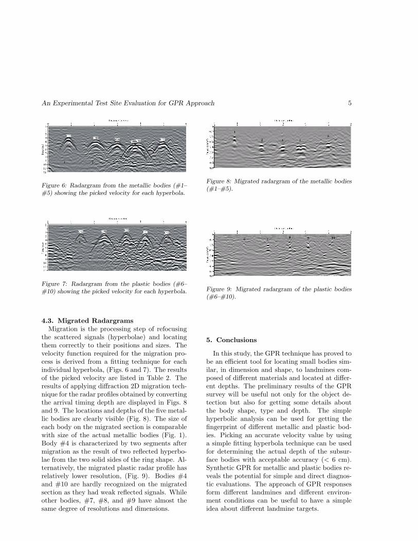
The velocity values for each individual hyper-bola have been picked up using the fitting hyper-bola technique, (Figs. 6 and 7). Then the averagevelocity for the sand host medium has been esti-mated. The dielectric permittivity of the hostsand has been calculated as well, (Table 2) usingthe following equation [6]:
v =c
ε1/2(2)
where c is the speed of light in free space(0.3 m/ns) and ε is the relative dielectric per-mittivity.
Consequently, the velocity information hasbeen used for depth calculation of each body us-ing the two way travel time (TWT ) as follows:
TWT = 2d/v (3)
where, d is the depth to the subsurface target andv is the velocity.
The calculated depths have been comparedwith the true depths of each body and the resultsare displayed in Table 2. There are good consis-tencies between the calculated and true depthsand the slight differences refer to the asymmetri-cal form of the picked hyperbola (bodies #4 and#5).
An Experimental Test Site Evaluation for GPR Approach 5
Figure 6: Radargram from the metallic bodies (#1–#5) showing the picked velocity for each hyperbola.
Figure 7: Radargram from the plastic bodies (#6–#10) showing the picked velocity for each hyperbola.
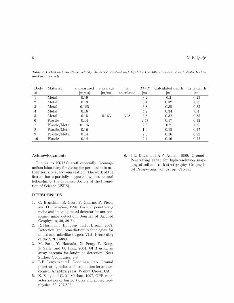
4.3. Migrated RadargramsMigration is the processing step of refocusing
the scattered signals (hyperbolae) and locatingthem correctly to their positions and sizes. Thevelocity function required for the migration pro-cess is derived from a fitting technique for eachindividual hyperbola, (Figs. 6 and 7). The resultsof the picked velocity are listed in Table 2. Theresults of applying diffraction 2D migration tech-nique for the radar profiles obtained by convertingthe arrival timing depth are displayed in Figs. 8and 9. The locations and depths of the five metal-lic bodies are clearly visible (Fig. 8). The size ofeach body on the migrated section is comparablewith size of the actual metallic bodies (Fig. 1).Body #4 is characterized by two segments aftermigration as the result of two reflected hyperbo-lae from the two solid sides of the ring shape. Al-ternatively, the migrated plastic radar profile hasrelatively lower resolution, (Fig. 9). Bodies #4and #10 are hardly recognized on the migratedsection as they had weak reflected signals. Whileother bodies, #7, #8, and #9 have almost thesame degree of resolutions and dimensions.
Figure 8: Migrated radargram of the metallic bodies(#1–#5).
Figure 9: Migrated radargram of the plastic bodies(#6–#10).
5. Conclusions
In this study, the GPR technique has proved tobe an efficient tool for locating small bodies sim-ilar, in dimension and shape, to landmines com-posed of different materials and located at differ-ent depths. The preliminary results of the GPRsurvey will be useful not only for the object de-tection but also for getting some details aboutthe body shape, type and depth. The simplehyperbolic analysis can be used for getting thefingerprint of different metallic and plastic bod-ies. Picking an accurate velocity value by usinga simple fitting hyperbola technique can be usedfor determining the actual depth of the subsur-face bodies with acceptable accuracy (< 6 cm).Synthetic GPR for metallic and plastic bodies re-veals the potential for simple and direct diagnos-tic evaluations. The approach of GPR responsesform different landmines and different environ-ment conditions can be useful to have a simpleidea about different landmine targets.
6 G. El-Qady
Table 2: Picked and calculated velocity, dielectric constant and depth for the different metallic and plastic bodiesused in this study.
Body Material v measured v average ε TWT Calculated depth True depth# [m/ns] [m/ns] calculated [ns] [m] [m]1 Metal 0.19 3.2 0.2 0.252 Metal 0.19 3.4 0.32 0.33 Metal 0.185 3.8 0.35 0.354 Metal 0.16 4.2 0.34 0.45 Metal 0.15 0.163 3.38 3.8 0.32 0.356 Plastic 0.14 2.47 0.17 0.127 Plastic/Metal 0.175 2.3 0.2 0.28 Plastic/Metal 0.16 1.9 0.15 0.179 Plastic/Metal 0.14 2.3 0.16 0.2210 Plastic 0.14 2.4 0.16 0.22
Acknowledgments
Thanks to NRIAG staff especially Geomag-netism laboratory for giving the permission to usetheir test site at Fayoum station. The work of thefirst author is partially supported by postdoctoralfellowship of the Japanese Society of the Promo-tion of Science (JSPS).
REFERENCES
1. C. Bruschini, B. Gros, F. Guerne, P. Piece,and O. Carmona, 1998, Ground penetratingradar and imaging metal detector for antiper-sonnel mine detection, Journal of AppliedGeophysics, 40, 59-71.
2. R. Harman, J. Holloway, and J. Broach, 2003,Detection and remediation technologies formines and minelike targets VIII, Proceedingof the SPIE 5089.
3. M. Sato, Y. Hamada, X. Feng, F. Kong,Z. Zeng, and G. Fang, 2004, GPR using anarray antenna for landmine detection, NearSurface Geophysics, 3-9.
4. L.B. Conyers and D. Goodman, 1997, Groundpenetrating radar; an introduction for archae-ologist, AltaMira press. Walnut Creek, CA.
5. X. Zeng and G. McMechan, 1997, GPR char-acterization of buried tanks and pipes, Geo-physics, 62, 797-806.
6. J.L. Davis and A.P. Annan, 1989: Ground-Penetrating radar for high-resolution map-ping of soil and rock stratigraphy, Geophysi-cal Prospecting, vol. 37, pp. 531-551.
Related Documents