1 / 44 LAN SPECIFICATION Reproduction prohibited without authorization of Wize Alliance LAN PROTOCOL SPECIFICATION V1.3 Version Modifications Date 1.0 Initial version 22/09/2017 1.1 Evolution of the Wize protocol specification to facilitate support for more countries and applications : - Frequency-band-agnostic main specification, Creation of a “Regional Parameters” document - Improved support for multiple application layers (L6App) - Improved support for roaming (L6NetwId) - Specifications for each application layer moved to separate documents - Minor clarifications and improvements Nota : Due to potential system impacts, alignment with EN13757-4:2018 version is deferred to Wize V2.0. Roaming support and Walk-by/Drive-by options will also be considered for V2.0 or later. 07/06/2019 1.2 Editorial (chapter numbers) Lvers changes v1.1 not used keep 001 for all versions v1.x of this specification 12/11/2020 1.3 Precisions related to passive roaming (no protocol changes) 08/07/2021 Summary

Welcome message from author
This document is posted to help you gain knowledge. Please leave a comment to let me know what you think about it! Share it to your friends and learn new things together.
Transcript

1 / 44
LAN SPECIFICATION
Reproduction prohibited without authorization of Wize Alliance
LAN PROTOCOL
SPECIFICATION
V1.3
Version Modifications Date
1.0 Initial version 22/09/2017
1.1
Evolution of the Wize protocol specification to facilitate support for more countries and applications :
- Frequency-band-agnostic main specification, Creation of a “Regional Parameters” document
- Improved support for multiple application layers (L6App) - Improved support for roaming (L6NetwId) - Specifications for each application layer moved to
separate documents - Minor clarifications and improvements
Nota : Due to potential system impacts, alignment with EN13757-4:2018 version is deferred to Wize V2.0. Roaming support and Walk-by/Drive-by options will also be considered for V2.0 or later.
07/06/2019
1.2 Editorial (chapter numbers) Lvers changes v1.1 not used keep 001 for all versions v1.x of this specification
12/11/2020
1.3 Precisions related to passive roaming (no protocol changes) 08/07/2021
Summary

2 / 44
LAN SPECIFICATION
Reproduction prohibited without authorization of Wize Alliance
This document outlines the Detailed Functional and Technical Specification of the Wize LAN protocol.
The LAN network designates the medium range radio network between the devices and the gateways.
3 / 44
LAN SPECIFICATION
Reproduction prohibited without authorization of Wize Alliance
Table of contents
Introduction .......................................................................................................... 7
Reference documents .......................................................................................... 8 Applicable standards ...................................................................................................................8 Annexed specifications ...............................................................................................................8
General principles ................................................................................................ 9
Outline of the LAN architecture and possible transfers ...............................................................9
Uplink broadcast ...................................................................................................................... 10
Downlink unicast ...................................................................................................................... 11
Downlink broadcast .................................................................................................................. 11 Types of message flows on the LAN interface ......................................................................... 12 Bidirectionality management principle ..................................................................................... 12 Exchange security management principle ............................................................................... 13
Overall Wize security concept .................................................................................................. 13
Authentication and encryption between Head-End system and devices ............................... 15
Authentication between gateway and device ........................................................................... 16 OSI model ................................................................................................................................ 16 Data link layers ......................................................................................................................... 17 Presentation layers .................................................................................................................. 17 Application layers ..................................................................................................................... 18
Common application layers ...................................................................................................... 18
Specific application layers ........................................................................................................ 18 Layer association block diagram .............................................................................................. 19
Detailed specification of the data link layer ..................................................... 20
Format of LLC-EXCHANGE frames (DATA, COMMAND, RESPONSE, INSTPING, INSTPONG flows) 20
Format of LLC-DOWNLOAD frames (DOWNLOAD flows) ...................................................... 22
Dynamic Exchanges specification ................................................................... 23
Selection of frequency channels and modulations .................................................................. 23 Specification for data upload sequencing (DATA flows) .......................................................... 23 Specification for command and response sequencing ............................................................ 24 Specification for connectivity test message sequencing ......................................................... 26 Specification for readjusting device central frequency ............................................................. 28 Specification for device transmission power management ..................................................... 28 Specification for the clock synchronisation mechanism ........................................................... 29
Clock synchronization initiated by Head-End system .............................................................. 29
Clock synchronization initiated by device (fine correction) ...................................................... 30
Clock synchronization management rules ............................................................................... 31 Specification for software download management .................................................................. 31
Detailed specification of the presentation layer .............................................. 34
PRES-EXCHANGE presentation layer .................................................................................... 34 PRES-DOWNLOAD presentation layer ................................................................................... 39
Appendix A : message encryption ................................................................... 42
Appendix B : message transmitter authentication footprints ........................ 43
Appendix C : RS(255,223) Encoding ................................................................ 44

4 / 44
LAN SPECIFICATION
Reproduction prohibited without authorization of Wize Alliance
5 / 44
LAN SPECIFICATION
Reproduction prohibited without authorization of Wize Alliance
Tables and figures
Figure 1: Overview of network architecture ................................................................................................9 Figure 2 : LAN modems and radio-electric coverage areas ..........................................................................9 Figure 3 : Uplink broadcast ........................................................................................................................ 10 Figure 4 : Downlink unicast ....................................................................................................................... 11 Figure 5 : Downlink broadcast ................................................................................................................... 11 Figure 6 : Types of flow .............................................................................................................................. 12 Figure 7 : Bidirectionality principle ............................................................................................................ 13 Figure 8 : end to end authentication and ciphering .................................................................................. 14 Figure 9 : OSI model layers used in Wize LAN protocol ............................................................................ 17 Figure 10 : Layer association ..................................................................................................................... 19 Figure 11 : C-Field bits ............................................................................................................................... 20 Figure 12 : Format of the L2 LLC-EXCHANGE frame .................................................................................. 21 Figure 13 : Format of the L2 LLC-DOWNLOAD frame ................................................................................ 22 Figure 14 : Sequencing of DATA message transmissions .......................................................................... 24 Figure 15 : Device reception window ........................................................................................................ 25 Figure 16 : Time sequencing of commands/responses ............................................................................. 25 Figure 17 : Sequencing of commands/responses ...................................................................................... 26 Figure 18: Installation mode sequencing .................................................................................................. 27 Figure 19: Installation message sequencing .............................................................................................. 27 Figure 20 : Frequency readjustment, example with a 7ppm threshold .................................................... 28 Figure 21 : Block reception sequencing ..................................................................................................... 32 Figure 22: Software download sequence .................................................................................................. 34 Figure 23 : Format of L6 PRES-EXCHANGE frames .................................................................................... 35 Figure 24:PRES-EXCHANGE – Generation of authentication and encryption fields ................................. 38 Figure 25 : Format of the INSTPONG frame .............................................................................................. 39 Figure 26:Format of the PRES-DOWNLOAD L6 frames ............................................................................. 40 Figure 27 : PRES-DOWNLOAD – Principle for generating securing fields .................................................. 41 Figure 28 : Extract from the reference document – The CTR mode ......................................................... 42 Figure 29 : Extract from the reference document – CMAC ....................................................................... 43
Table 1: Applicable standards ......................................................................................................................8 Table 2 : Annexed specifications ..................................................................................................................8 Table 3 : Types of flow ............................................................................................................................... 12 Table 4: Data Link Layer ............................................................................................................................. 17 Table 5:Presentation layers ....................................................................................................................... 17 Table 6: Common application layers ......................................................................................................... 18 Table 7:Specific application layers ............................................................................................................ 19 Table 8: C-Field symbolic codes ................................................................................................................ 20 Table 9: Fields of the L2 LLC-EXCHANGE frame ........................................................................................ 22 Table 10: Fields of the L2 LLC-DOWNLOAD frame .................................................................................... 23 Table 11:RF parameters ............................................................................................................................ 23 Table 12 : Fields of the PRES-EXCHANGE L6 frame ................................................................................... 38 Table 13 : Fields of the PRES-DOWNLOAD M6 frame ............................................................................... 40
6 / 44
LAN SPECIFICATION
Reproduction prohibited without authorization of Wize Alliance
Contributors
Accenture Cédric Hochar Alciom Yannick Avelino Robert Lacoste ATOS Worldgrid Emmanuel Besse Itron Eric Frotey GRDF Gilles Bizot Alain Désandré Tim Leloir Jérémy Leuzzi Sylvain Orthlieb Alexandre Vialle Suez Patrick Braut Eric Farnier Jean-René Herbron Samuel Loyson Thierry Maldonado Mickaël Mille Yann Moysan Radiocrafts Peder Martin Evjen Sagemcom Patrick Cazein Erwan Perico STMicroelectronics Daniel Derrien Zolertia/AllWize Marc Fabregas

7 / 44
LAN SPECIFICATION
Reproduction prohibited without authorization of Wize Alliance
Introduction
This document is the specification of the Wize LAN protocol. The LAN interface is the radio-frequency
interface that ensures communication between the devices and the gateways.
The Wize LAN protocol is largely based on standard EN 13757-4:2013, with the following basic
technological choices:
• Implementation of the N2 mode (two-way link VHF band)
• Format of “manufacturer specific” type application frames
• Integration of advanced security functions
This document thus adds to this standard, specifying implementation as well as any necessary specific
deviations and additions. These modifications concern the following points in particular:
• Generalisation of mode N frequency channel management
• Optimised management of transmission sequencing and bidirectionality
• Application layers providing extremely compact frame formats that maximises radio channel
capacity and device autonomy
• More reliable security management (data encryption, transmitter authentication, service denial
protection, etc.)
• Definition of a “broadcast” mode for updating device software
• Definition of a new “high speed” modulation in a 12.5 kHz channel
Nota : It should be highlighted that, due to joint work of the Wize Alliance members and CEN standard working groups, the majority of these deviations and additions are now indeed part of EN13757-4:2018 standard version. The next version of Wize Standard specification will be aligned with this new version after a detailed analysis of any compatibility risks. For consistency and system compatibility, this V1.1 version stays aligned with EN13757-4:2013 as was V1.0.

8 / 44
LAN SPECIFICATION
Reproduction prohibited without authorization of Wize Alliance
.
Reference documents Applicable standards
Reference Document Version
N[1]
EN 13757-4
Communication systems for meters and remote reading of meters
2013 version (CEN TC/294)
N[2]
EN 300220-1
Electromagnetic compatibility and Radio spectrum Matters (ERM); Short Range Devices (SRD); Radio equipment to be used in the 25 MHz to 1 000 MHz frequency range with power levels ranging up to 500 mW; Part 1: Technical characteristics and test methods
June 2017 (V3.1.1)
N[3]
REC/ERC/70-03
ERC RECOMMENDATION 70-03 (Tromsø 1997 and subsequent amendments) RELATING TO THE USE OF SHORT RANGE DEVICES (SRD); Recommendation adopted by the Frequency Management, Regulatory Affairs and Spectrum Engineering Working Groups
5/10/2018 version
N[4]
EN300220-4
Short Range Devices (SRD) operating in the frequency range 25 MHz to 1 000 MHz; Part 4: Harmonised Standard covering the essential requirements of article 3.2 of the Directive 2014/53/EU; Metering devices operating in designated band 169,400 MHz to 169,475 MHz
June 2017 (V1.1.1)
Table 1: Applicable standards
Annexed specifications
Reference Document Version
A[1]
Wize - 02 : Regional parameters
V1.1
A[2]
Wize - 03 : Common Application Layers
V1.3
A[3]
Wize - 05 Application Layer for Water Metering
V1.2
A[4]
Wize - 04 : Application Layer for Gas Metering
V1.2
Table 2 : Annexed specifications

9 / 44
LAN SPECIFICATION
Reproduction prohibited without authorization of Wize Alliance
General principles Note: The first part of this document presents the general principles of the LAN interface. The following
sections outline the specifications in detail.
Outline of the LAN architecture and possible transfers
The collection system consists of 3 types of systems interconnected by two network levels:
• The Head-End system (data collection) and the gateways are connected by the WAN network,
• The gateways and the devices are connected by the LAN network, outlined in this specification.
There are no intermediate relays between the gateways and the devices in this version of the LAN
specification. The architecture is thus as follows :
Figure 1: Overview of network architecture
Each gateway can be equipped with one or more LAN modems. Each modem defines a given radio-
electric coverage zone. A multi-modem gateway allows spatial diversity for better reception.
Figure 2 : LAN modems and radio-electric coverage areas
LANWANHead-end
DevicesGateways
WANHead-end
Devices
Gateways
LAN modems
RF coverage area
10 / 44
LAN SPECIFICATION
Reproduction prohibited without authorization of Wize Alliance
The architecture of the system and of the LAN network in particular was defined according to the following
guidelines:
• To give priority to the devices’ autonomy in terms of energy, as this point is fundamental in order
to comply with Wize overall goals;
• To ensure the greatest possible transparency of the gateway with respect to message content
(excluding functions relating to minimisation of traffic on the WAN and functions required for
network deployment phases);
• To guarantee a level of security that complies with the high-level security requirements of Wize
members, based on high standards of Telecom protocols (end-to-end encryption, integrity
guarantee)
• To be compatible with production of devices compatible with strict economic goals and supported
by at least two technological suppliers.
On this Head-End system, at addressing protocol level, only 3 types of transfer have been defined for the
LAN interface as defined below.
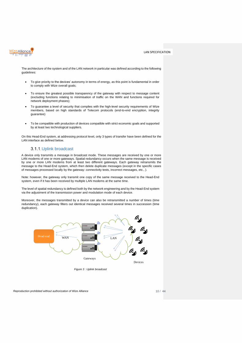
Uplink broadcast
A device only transmits a message in broadcast mode. These messages are received by one or more LAN modems of one or more gateways. Spatial redundancy occurs when the same message is received by one or more LAN modems from at least two different gateways. Each gateway retransmits the
message to the Head-End system, which then delete duplicate messages (except in the specific cases
of messages processed locally by the gateway: connectivity tests, incorrect messages, etc., ).
Note: however, the gateway only transmit one copy of the same message received to the Head-End
system, even if it has been received by multiple LAN modems at the same time.
The level of spatial redundancy is defined both by the network engineering and by the Head-End system
via the adjustment of the transmission power and modulation mode of each device.
Moreover, the messages transmitted by a device can also be retransmitted a number of times (time
redundancy), each gateway filters out identical messages received several times in succession (time
duplication).
Figure 3 : Uplink broadcast
LANWAN
Devices
Gateways
Head-end

11 / 44
LAN SPECIFICATION
Reproduction prohibited without authorization of Wize Alliance
Downlink unicast
Occasionally the Head-End system may send a message to a specific device. This transmission takes place via a specific gateway (through a specific LAN modem), selected by the Head-End system and designated as the referent gateway of the device. Gateways do not know the devices for which they are the referent and merely retransmit the message to the device after reception of a Head-End system command and when this is possible for them to do so (in a device reception window). Such messages are only sent to a specific device (unicast).
Figure 4 : Downlink unicast
Exceptionally (device connectivity test phase), the same downlink Unicast mechanism is used to send
messages to a device at the gateway’s initiative.
Downlink broadcast
A specific mode allows the broadcasting of messages via a gateway’s LAN modem to all the devices in
its radio-frequency coverage zone. This mode is only used for software download (cf. 5.8).
Figure 5 : Downlink broadcast
Note: the broadcasting gateway is not necessarily the referent gateway of all the devices receiving the
transmitted messages. This is because the same device is, generally speaking, in the radio-electric
coverage zone of a number of gateways. The Head-End system is responsible for scheduling and
selecting the broadcasting gateways and LAN modems.
LANWAN
Devices
Gateways
Head-end
LANLANWANWAN
Devices
Gateways
Head-end
12 / 44
LAN SPECIFICATION
Reproduction prohibited without authorization of Wize Alliance
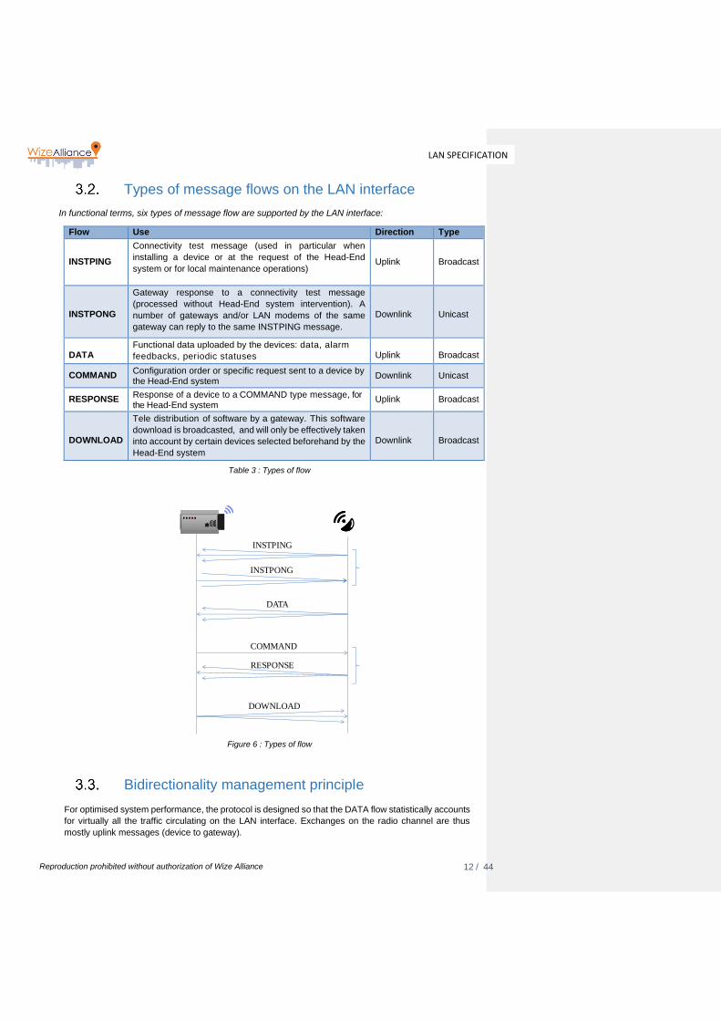
Types of message flows on the LAN interface
In functional terms, six types of message flow are supported by the LAN interface:
Flow Use Direction Type
INSTPING
Connectivity test message (used in particular when
installing a device or at the request of the Head-End
system or for local maintenance operations)
Uplink
Broadcast
INSTPONG
Gateway response to a connectivity test message
(processed without Head-End system intervention). A
number of gateways and/or LAN modems of the same
gateway can reply to the same INSTPING message.
Downlink
Unicast
DATA
Functional data uploaded by the devices: data, alarm
feedbacks, periodic statuses
Uplink
Broadcast
COMMAND Configuration order or specific request sent to a device by the Head-End system
Downlink
Unicast
RESPONSE Response of a device to a COMMAND type message, for the Head-End system
Uplink
Broadcast
DOWNLOAD
Tele distribution of software by a gateway. This software
download is broadcasted, and will only be effectively taken
into account by certain devices selected beforehand by the
Head-End system
Downlink
Broadcast
Table 3 : Types of flow
Figure 6 : Types of flow
Bidirectionality management principle
For optimised system performance, the protocol is designed so that the DATA flow statistically accounts
for virtually all the traffic circulating on the LAN interface. Exchanges on the radio channel are thus
mostly uplink messages (device to gateway).
DATA
COMMAND
RESPONSE
DOWNLOAD
INSTPING
INSTPONG
13 / 44
LAN SPECIFICATION
Reproduction prohibited without authorization of Wize Alliance
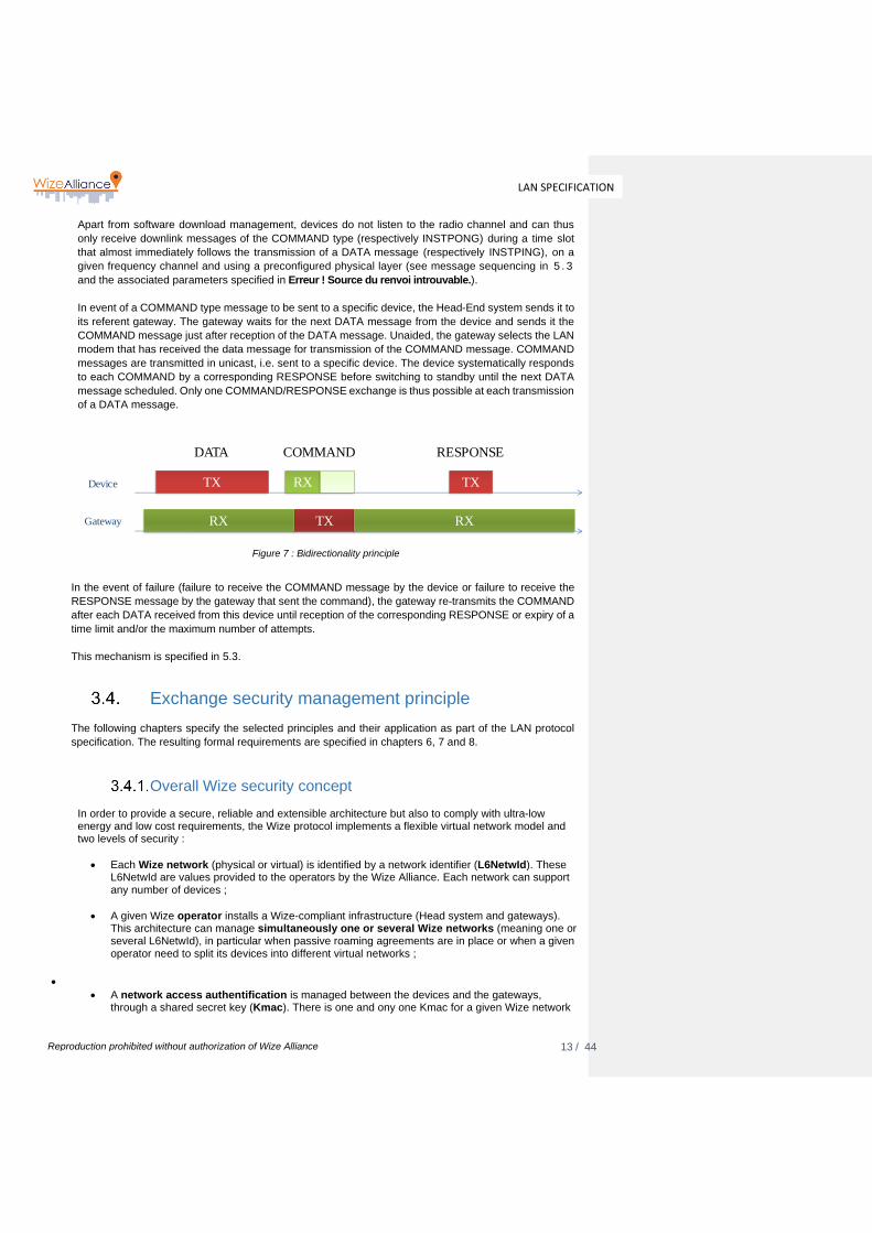
Apart from software download management, devices do not listen to the radio channel and can thus
only receive downlink messages of the COMMAND type (respectively INSTPONG) during a time slot
that almost immediately follows the transmission of a DATA message (respectively INSTPING), on a
given frequency channel and using a preconfigured physical layer (see message sequencing in 5 . 3
and the associated parameters specified in Erreur ! Source du renvoi introuvable.).
In event of a COMMAND type message to be sent to a specific device, the Head-End system sends it to
its referent gateway. The gateway waits for the next DATA message from the device and sends it the
COMMAND message just after reception of the DATA message. Unaided, the gateway selects the LAN
modem that has received the data message for transmission of the COMMAND message. COMMAND
messages are transmitted in unicast, i.e. sent to a specific device. The device systematically responds
to each COMMAND by a corresponding RESPONSE before switching to standby until the next DATA
message scheduled. Only one COMMAND/RESPONSE exchange is thus possible at each transmission
of a DATA message.
Figure 7 : Bidirectionality principle
In the event of failure (failure to receive the COMMAND message by the device or failure to receive the
RESPONSE message by the gateway that sent the command), the gateway re-transmits the COMMAND
after each DATA received from this device until reception of the corresponding RESPONSE or expiry of a
time limit and/or the maximum number of attempts.
This mechanism is specified in 5.3.
Exchange security management principle
The following chapters specify the selected principles and their application as part of the LAN protocol
specification. The resulting formal requirements are specified in chapters 6, 7 and 8.
Overall Wize security concept In order to provide a secure, reliable and extensible architecture but also to comply with ultra-low energy and low cost requirements, the Wize protocol implements a flexible virtual network model and two levels of security :
• Each Wize network (physical or virtual) is identified by a network identifier (L6NetwId). These L6NetwId are values provided to the operators by the Wize Alliance. Each network can support any number of devices ;
• A given Wize operator installs a Wize-compliant infrastructure (Head system and gateways). This architecture can manage simultaneously one or several Wize networks (meaning one or several L6NetwId), in particular when passive roaming agreements are in place or when a given operator need to split its devices into different virtual networks ;
•
• A network access authentification is managed between the devices and the gateways, through a shared secret key (Kmac). There is one and ony one Kmac for a given Wize network
Device TX RX
Gateway TXRX RX
TX
DATA COMMAND RESPONSE
14 / 44
LAN SPECIFICATION
Reproduction prohibited without authorization of Wize Alliance
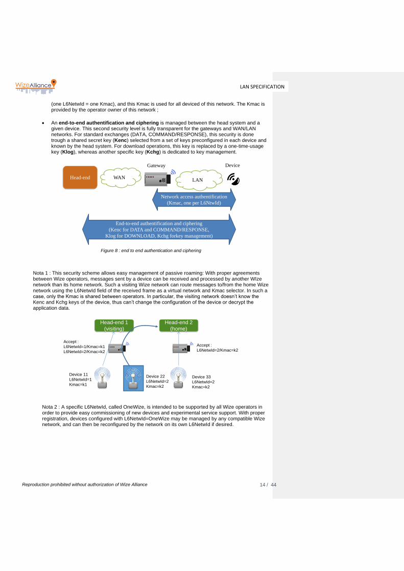
(one L6NetwId = one Kmac), and this Kmac is used for all deviced of this network. The Kmac is provided by the operator owner of this network ;
• An end-to-end authentification and ciphering is managed between the head system and a
given device. This second security level is fully transparent for the gateways and WAN/LAN networks. For standard exchanges (DATA, COMMAND/RESPONSE), this security is done trough a shared secret key (Kenc) selected from a set of keys preconfigured in each device and known by the head system. For download operations, this key is replaced by a one-time-usage key (Klog), whereas another specific key (Kchg) is dedicated to key management.
Figure 8 : end to end authentication and ciphering
Nota 1 : This security scheme allows easy management of passive roaming: With proper agreements between Wize operators, messages sent by a device can be received and processed by another WIze network than its home network. Such a visiting Wize network can route messages to/from the home Wize network using the L6NetwId field of the received frame as a virtual network and Kmac selector. In such a case, only the Kmac is shared between operators. In particular, the visiting network doesn’t know the Kenc and Kchg keys of the device, thus can’t change the configuration of the device or decrypt the application data.
Nota 2 : A specific L6NetwId, called OneWize, is intended to be supported by all Wize operators in order to provide easy commissioning of new devices and experimental service support. With proper registration, devices configured with L6NetwId=OneWize may be managed by any compatible Wize network, and can then be reconfigured by the network on its own L6NetwId if desired.
LANWAN
DeviceGateway
Head-end
End-to-end authentification and ciphering
(Kenc for DATA and COMMAND/RESPONSE,
Klog for DOWNLOAD, Kchg forkey management)
Network access authentification
(Kmac, one per L6NtwId)
Head-end 1
(visiting)
Head-end 2
(home)
Device 11
L6NetwId=1
Kmac=k1
Device 22
L6NetwId=2
Kmac=k2
Device 33
L6NetwId=2
Kmac=k2
Accept :
L6NetwId=2/Kmac=k2
Accept :
L6NetwId=1/Kmac=k1
L6NetwId=2/Kmac=k2

15 / 44
LAN SPECIFICATION
Reproduction prohibited without authorization of Wize Alliance
Authentication and encryption between Head-End system and devices
The security of exchanges between the Head-End system and the devices is mainly based on
implementation of authentication and message encryption, using only symmetric cryptography
techniques. The general principles used are outlined below:
• A set of Kenc keys are pre-programmed in the factory in each device’s memory together as well
as a Kchg key (used for key transfer), and recorded in the Head-End system. The number of
Kenc keys available in a device can be read via the CIPH_KEY_COUNT parameter
(recommended value is 14 in the current version of the specification);
• At any time, one and only one Kenc key is selected in the device, via the CIPH_CURRENT_KEY
parameter. The index of the current key can be changed by a command transmitted by the Head-End
system: any of the keys can be selected. The factory setting is always key 1 (parameter
CIPH_CURRENT_KEY = 1);
• The messages exchanged between the Head-End system and the device are encrypted via an
AES CTR algorithm using the current Kenc key and an initialisation vector made up of certain
fields that are transmitted without encryption in the message as per the specification below. The
index of the current key is also transmitted without encryption in the message to avoid
synchronization issues between the two subsystems when a key is changed (particularly for the
Head-End system);
• In the particular case of transmission of a key via the Head-End system (Klog in the case of a
software download notification or of a key management message), the current key is replaced by
a specific Kchg key for the command and the corresponding answer;
• The encryption can be disabled, but only via the secured local interface, by selecting the “zero”
key index. After being disabled, it can then be reenabled if necessary via the
CIPH_CURRENT_KEY parameter. Hence a device's message encryption can only be disabled if
the devices has a local interface.
• In addition to this end-to-end encryption, each message contains a secure signature of the
message calculated by the sender (Head system or device) using the Kenc key. The recipient
(device or Head-End system) ignores messages when the verification of this secure signature is
false. Moreover, the device ignores messages encrypted with a key number other than the current
key number.
In the specific case of software download, the Kenc key of a device cannot be used as the message is
sent to a number of devices at the same time. In this case, the Kenc key is replaced by a single-use Klog
key for encryption and authentication of software download messages transmitted by the Head-End
system via the gateway. This key is transmitted in a secure manner by the Head-End system prior to
each new software download to each device that is due to receive this software download. As stated
Head-end
Device 11
L6NetwId=1
Kmac=k1
Device 22
L6NetwId=One-Wize
Kmac=OneWize Kmac
Accept :
L6NetwId=1/Kmac=k1
L6NetwId=One-Wize/Kmac=OneWize Kmac
16 / 44
LAN SPECIFICATION
Reproduction prohibited without authorization of Wize Alliance
above, the latter uses the Kchg key for encryption and authentication purposes (see 5.8).
Note: the Head-End system is free to select the Klog keys for the various software download sequences
of one or more variants of a software, or, if necessary, a common key.
Authentication between gateway and device
Gateways are transparent with respect to the encrypted payload messages exchanged between the
Head-End system and the devices. Therefore they do not need to know the Kenc and Kchg keys of the
devices. However, mainly in order to reduce the incidence of denial of service attacks, a second level of
authentication has been implemented between the gateways and the devices (limitating the risk of WAN
and Head-End system saturation), through a network access authentification mecanism.
This network access authentication is managed between gateways and as follows:
• For each network or virtual network (identified by one L6NetwId), a specific Kmac key is pre-
programmed in the factory in each device and communicated by the Head system to each
gateway. This key is common for all devices within one network or virtual network.;
• Each message is authenticated by a secure signature of the message calculated using the Kmac
key and calculed by the sender. The recipient (gateway or device) ignores all messages for which the
signature is false, meaning if the secure signature doesn’t match with the signature calculated using the
Kmac associated with the L6NetwId of the message.
OSI model
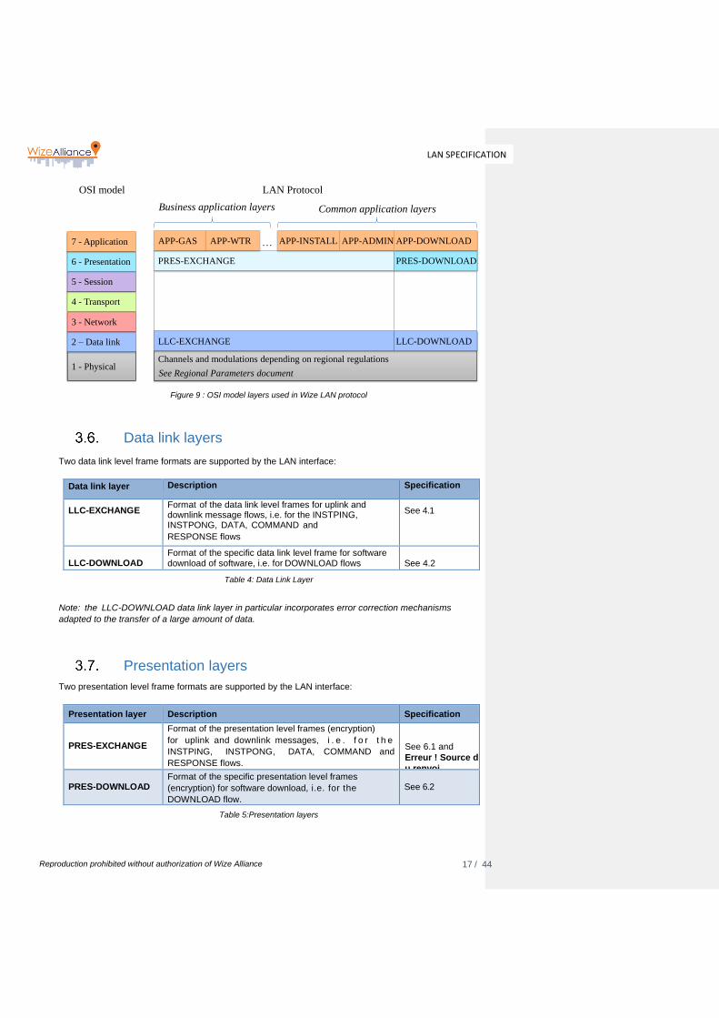
This LAN protocol specification is based on a simplified OSI layer model:
• Physical layer (Layer 1): specifies the radio-electric modulation used and the low level encoding of messages (preamble and synchronisation of frames, encoding of bits, etc.), based on the frequency channels of the band used (see Regional Parameters document [A1])
• Data link layer (Layer 2) (see 3.6): specifies the frames’ point-to-point exchange level format (addressing, error checking), as well as the dynamic management of exchange sequencing
• Presentation layer (Layer 6) (see 3.7): specifies the additional data sent by the LAN protocol (time stamp, etc.), as well as data encryption and authentication methods
• Application layer (Layer 7) (see 3.8): specifies the functional content of the messages transferred to the LAN interface (see documents [A2], [A3] and [A4]).
For each layer, a number of variants are possible and are described in the following chapters :
17 / 44
LAN SPECIFICATION
Reproduction prohibited without authorization of Wize Alliance
Figure 9 : OSI model layers used in Wize LAN protocol
Data link layers
Two data link level frame formats are supported by the LAN interface:
Data link layer Description Specification
LLC-EXCHANGE Format of the data link level frames for uplink and downlink message flows, i.e. for the INSTPING, INSTPONG, DATA, COMMAND and
RESPONSE flows
See 4.1
LLC-DOWNLOAD
Format of the specific data link level frame for software download of software, i.e. for DOWNLOAD flows
See 4.2
Table 4: Data Link Layer
Note: the LLC-DOWNLOAD data link layer in particular incorporates error correction mechanisms
adapted to the transfer of a large amount of data.
Presentation layers
Two presentation level frame formats are supported by the LAN interface:
Presentation layer Description Specification
PRES-EXCHANGE
Format of the presentation level frames (encryption)
for uplink and downlink messages, i . e . f o r t h e
INSTPING, INSTPONG, DATA, COMMAND and
RESPONSE flows.
See 6.1 and
Erreur ! Source d
u renvoi
introuvable. PRES-DOWNLOAD
Format of the specific presentation level frames
(encryption) for software download, i.e. for the
DOWNLOAD flow.
See 6.2
Table 5:Presentation layers
1 - Physical
2 – Data link
3 - Network
4 - Transport
5 - Session
6 - Presentation
7 - Application
OSI model LAN Protocol
Channels and modulations depending on regional regulations
LLC-EXCHANGE
PRES-EXCHANGE
See Regional Parameters document
APP-GAS APP-WTR
Common application layersBusiness application layers
APP-INSTALL APP-ADMIN…
PRES-DOWNLOAD
APP-DOWNLOAD
LLC-DOWNLOAD

18 / 44
LAN SPECIFICATION
Reproduction prohibited without authorization of Wize Alliance
Application layers
In addition to physical, data link and presentation layers, the Wize Protocol specifies several application layers to satisfy the requirements of all targeted end application, while using the same infrastructure and transport protocols. These application layers are part of the Wize Specification but specified in separate documents ([A2] to [A4] to date). The Wize application layers are split into two categories :
• Common application layers (mandatory for any Wize device), specified in [A2].
• Specific application layers (optional, specific to each target end application. A given Wize device can support one or several specific application layers, or even no specific application layer (test devices for example).
The selection of the application layer for a given message is done through the L6App field, transmitted as part of the L6 presentation layer header. The selection of the application layer is done through:
• Firstly C field value, refer to §4.1
• L6App field value when “Flow” is “Data” as per Table 8 in §4.1
Common application layers
The currently defined, and mandatory, common application layers are specified in the document [A2]
“Wize Protocol : Common application Layers”. These applications layers are the following :
Application layer Description Specification
APP-INSTALL Connectivity test messages format, i.e. for the INSTPING and INSTPONG flows
See Common Applicative Layers document section 4.3
APP-ADMIN
Device configuration and monitoring
messages format
See Common Applicative Layers document section 4.4
APP-DOWNLOAD Software download messages format,
i.e. for the DOWNLOAD flow
See Common Applicative Layers document section 4.5
Table 6: Common application layers
Specific application layers
The currently defined, and optional, specific application layers are listed on the Wize web site. Each
alliance member can propose new applications layers to the Alliance and will get a corresponding L6App
value to identify this application layer.
As examples, the documents [A3] and A[4] are the specifications of these two specific Wize applications
layers :
Application layer Description Specification
APP-METER-GAS Specific application layer for gaz smart meters
See [A4] Wize Protocol : Application Layer for Gas Metering
Commenté [FE1]: Coherence avec Wize -03 Common App Layer v 1.1 et suivante
19 / 44
LAN SPECIFICATION
Reproduction prohibited without authorization of Wize Alliance
APP-METER-WTR
Specific application layer for water
smart meters
See [A3] Wize Protocol : Application Layer for Water Metering
Table 7:Specific application layers
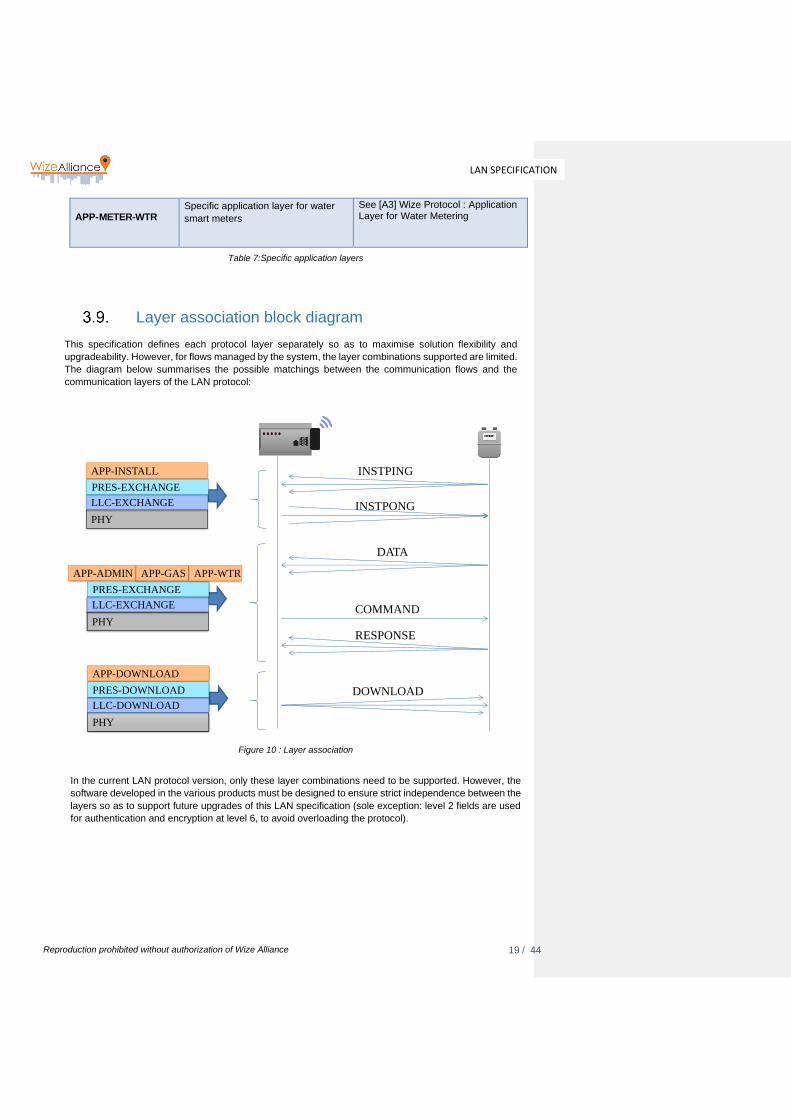
Layer association block diagram
This specification defines each protocol layer separately so as to maximise solution flexibility and
upgradeability. However, for flows managed by the system, the layer combinations supported are limited.
The diagram below summarises the possible matchings between the communication flows and the
communication layers of the LAN protocol:
Figure 10 : Layer association
In the current LAN protocol version, only these layer combinations need to be supported. However, the
software developed in the various products must be designed to ensure strict independence between the
layers so as to support future upgrades of this LAN specification (sole exception: level 2 fields are used
for authentication and encryption at level 6, to avoid overloading the protocol).
DATA
COMMAND
RESPONSE
DOWNLOAD
INSTPING
INSTPONG
PHY
LLC-EXCHANGE
APP-ADMIN
PHY
LLC-DOWNLOAD
APP-DOWNLOAD
PRES-EXCHANGE
PRES-DOWNLOAD
PHY
LLC-EXCHANGE
APP-INSTALL
PRES-EXCHANGE
APP-GAS APP-WTR
20 / 44
LAN SPECIFICATION
Reproduction prohibited without authorization of Wize Alliance
RES
PRM
0
PRI
Function code
Detailed specification of the data link layer
Format of LLC-EXCHANGE frames (DATA, COMMAND, RESPONSE, INSTPING, INSTPONG flows)
The format of the data link level frames of the LLC-EXCHANGE type (used for uplink and downlink
flows of the INSTPING, INSTPONG, DATA, COMMAND and RESPONSE type) conforms, as per
standard EN13757-4:
• to format B (only one CRC per frame),
• in the Slow response Delay mode (device response may be delayed),
• without Extended Link Layer (no additional L2 information in order to allievate the frames).
The device is the exchange initiator (as understood by the standard: the primary station) for the DATA
and INSTPING/INSTPONG flows.
The gateway is the exchange initiator (as understood by the standard: the primary station) for the
COMMAND/RESPONSE flows.
Note: only format B of standard EN13757-4 must be supported by the devices and the gateways (one
CRC per 115 byte block). Moreover, the frames are limited in this protocol to application messages of
at most 115 bytes (in reality longer messages need to be segmented to prevent pointless complexity
at device supply level) and thus only require one CRC per message.
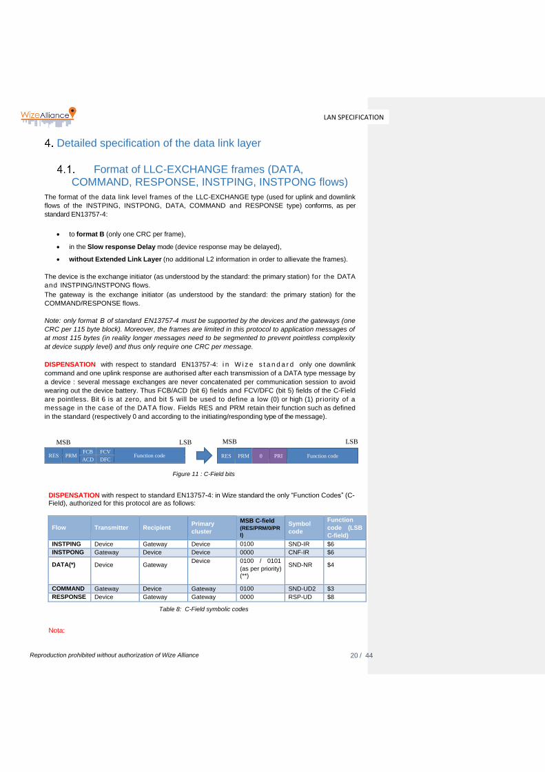
DISPENSATION with respect to standard EN13757-4: i n W i z e s t a n d a r d only one downlink
command and one uplink response are authorised after each transmission of a DATA type message by
a device : several message exchanges are never concatenated per communication session to avoid
wearing out the device battery. Thus FCB/ACD (bit 6) fields and FCV/DFC (bit 5) fields of the C-Field
are pointless. Bit 6 is at zero, and bit 5 will be used to define a low (0) or high (1) priority of a
message in the case of the DATA flow. Fields RES and PRM retain their function such as defined
in the standard (respectively 0 and according to the initiating/responding type of the message).
MSB LSB MSB LSB
Figure 11 : C-Field bits
DISPENSATION with respect to standard EN13757-4: in Wize standard the only “Function Codes” (C-Field), authorized for this protocol are as follows:
Flow
Transmitter
Recipient
Primary
cluster
MSB C-field (RES/PRM/0/PR
I)
Symbol
code
Function
code (LSB
C-field)
INSTPING Device Gateway Device 0100 SND-IR $6
INSTPONG Gateway Device Device 0000 CNF-IR $6
DATA(*)
Device
Gateway Device 0100 / 0101
(as per priority) (**)
SND-NR
$4
COMMAND Gateway Device Gateway 0100 SND-UD2 $3
RESPONSE Device Gateway Gateway 0000 RSP-UD $8
Table 8: C-Field symbolic codes
Nota:
RES
PRM FCB FCV
Function code ACD DFC
21 / 44
LAN SPECIFICATION
Reproduction prohibited without authorization of Wize Alliance
(*) The selection of the application layer is given by L6App field in case of DATA flow see 3.8
(**) Priority flag could be set freely by the application layer, but is ignored by the Wize infrastructure
and devices to date
DISPENSATION with respect to standard EN13757-4: fields M-Field and A-Field always relate to the
MANUFACTURER and to the individual number of the device, both for uplink and downlink messages.
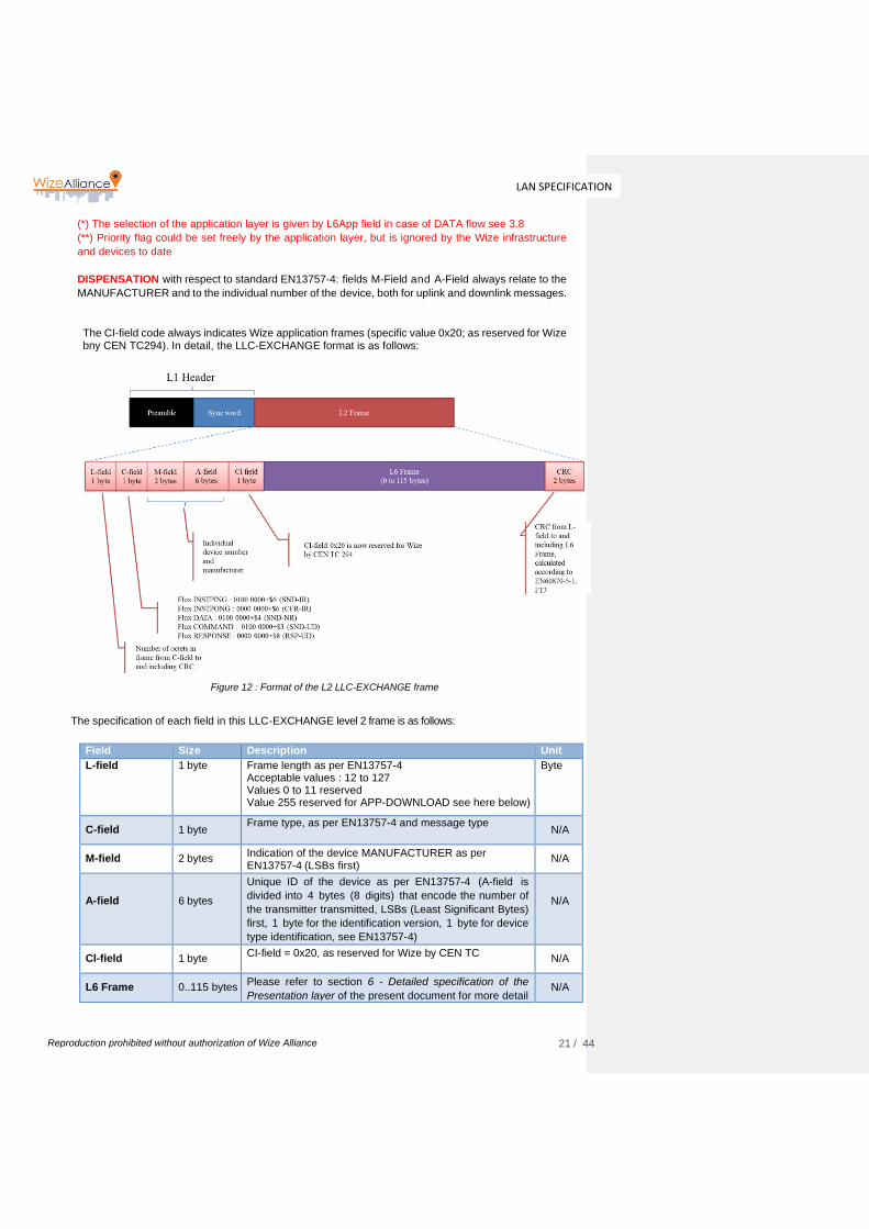
The CI-field code always indicates Wize application frames (specific value 0x20; as reserved for Wize bny CEN TC294). In detail, the LLC-EXCHANGE format is as follows:
Figure 12 : Format of the L2 LLC-EXCHANGE frame
The specification of each field in this LLC-EXCHANGE level 2 frame is as follows:
Field Size Description Unit
L-field 1 byte Frame length as per EN13757-4 Acceptable values : 12 to 127 Values 0 to 11 reserved Value 255 reserved for APP-DOWNLOAD see here below)
Byte
C-field
1 byte Frame type, as per EN13757-4 and message type
N/A
M-field
2 bytes Indication of the device MANUFACTURER as per EN13757-4 (LSBs first)
N/A
A-field
6 bytes
Unique ID of the device as per EN13757-4 (A-field is
divided into 4 bytes (8 digits) that encode the number of
the transmitter transmitted, LSBs (Least Significant Bytes)
first, 1 byte for the identification version, 1 byte for device
type identification, see EN13757-4)
N/A
Cl-field
1 byte CI-field = 0x20, as reserved for Wize by CEN TC
N/A
L6 Frame
0..115 bytes
Please refer to section 6 - Detailed specification of the
Presentation layer of the present document for more detail
N/A
22 / 44
LAN SPECIFICATION
Reproduction prohibited without authorization of Wize Alliance
CRC
2 bytes Checksum of the message as per EN13757-4. MSBs first
N/A
Table 9: Fields of the L2 LLC-EXCHANGE frame
Format of LLC-DOWNLOAD frames (DOWNLOAD flows)
The format of the data link level frames of the LLC-DOWNLOAD type (used for software download
DOWNLOAD type downlink flows) is specific as this format is intended for broadcasting long data
sequences requiring minimum frame corruption by binary transmission errors.
These frames, broadcast in a predefined time window outside standard exchange periods are identified
by a specific L-field value equal to $FF, i.e. 11111111 in binary (value never used for LLC-EXCHANGE
frames as the maximum length of these frames is 127 bytes). The resilience of the device receiver must
be increased by a tolerance to all L-field values of more than 127 (subject to an integrity check of the
code received by the application layer).
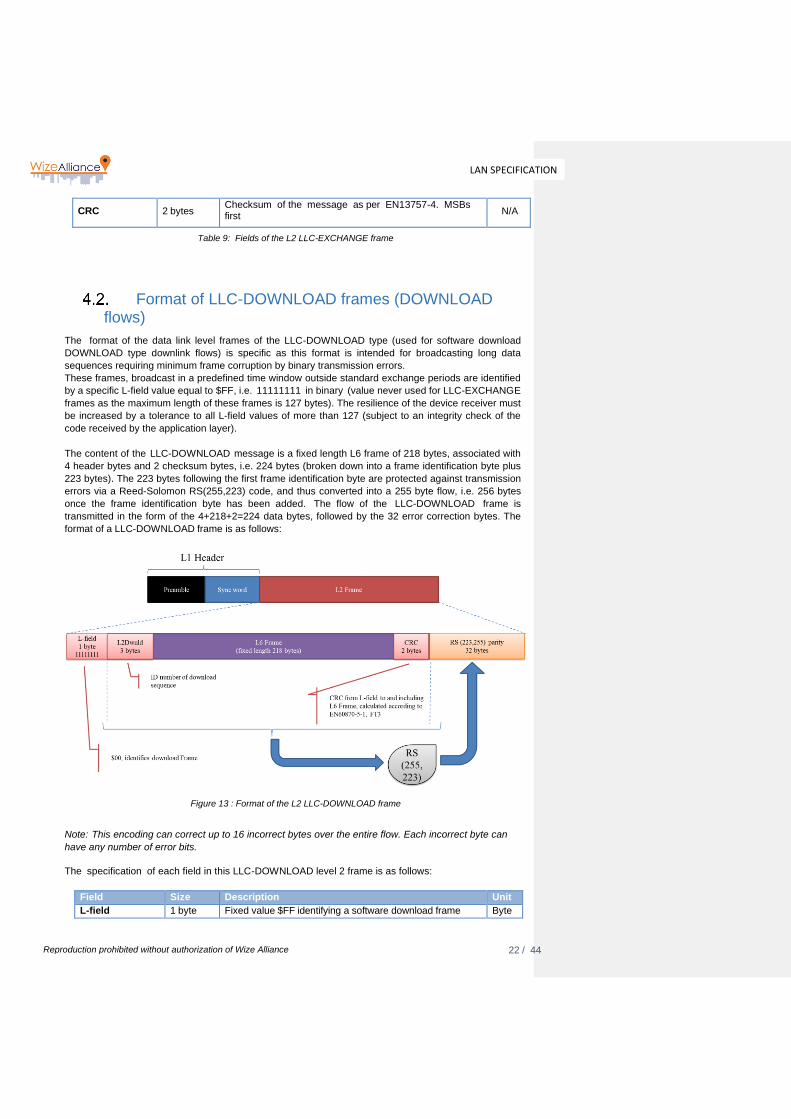
The content of the LLC-DOWNLOAD message is a fixed length L6 frame of 218 bytes, associated with
4 header bytes and 2 checksum bytes, i.e. 224 bytes (broken down into a frame identification byte plus
223 bytes). The 223 bytes following the first frame identification byte are protected against transmission
errors via a Reed-Solomon RS(255,223) code, and thus converted into a 255 byte flow, i.e. 256 bytes
once the frame identification byte has been added. The flow of the LLC-DOWNLOAD frame is
transmitted in the form of the 4+218+2=224 data bytes, followed by the 32 error correction bytes. The
format of a LLC-DOWNLOAD frame is as follows:
Figure 13 : Format of the L2 LLC-DOWNLOAD frame
Note: This encoding can correct up to 16 incorrect bytes over the entire flow. Each incorrect byte can
have any number of error bits.
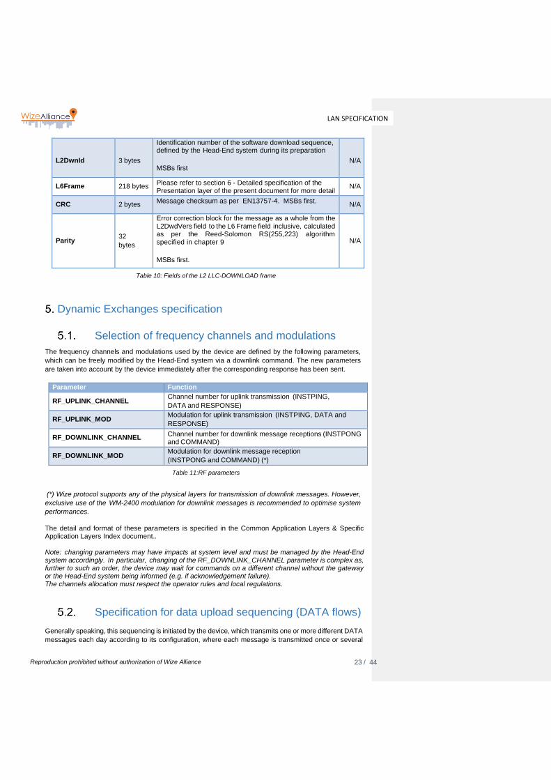
The specification of each field in this LLC-DOWNLOAD level 2 frame is as follows:
Field Size Description Unit
L-field 1 byte Fixed value $FF identifying a software download frame Byte
23 / 44
LAN SPECIFICATION
Reproduction prohibited without authorization of Wize Alliance
L2DwnId
3 bytes
Identification number of the software download sequence, defined by the Head-End system during its preparation
MSBs first
N/A
L6Frame
218 bytes Please refer to section 6 - Detailed specification of the Presentation layer of the present document for more detail
N/A
CRC
2 bytes Message checksum as per EN13757-4. MSBs first.
N/A
Parity
32
bytes
Error correction block for the message as a whole from the L2DwdVers field to the L6 Frame field inclusive, calculated as per the Reed-Solomon RS(255,223) algorithm specified in chapter 9
MSBs first.
N/A
Table 10: Fields of the L2 LLC-DOWNLOAD frame
Dynamic Exchanges specification
Selection of frequency channels and modulations
The frequency channels and modulations used by the device are defined by the following parameters,
which can be freely modified by the Head-End system via a downlink command. The new parameters
are taken into account by the device immediately after the corresponding response has been sent.
Parameter Function
RF_UPLINK_CHANNEL Channel number for uplink transmission (INSTPING,
DATA and RESPONSE)
RF_UPLINK_MOD Modulation for uplink transmission (INSTPING, DATA and
RESPONSE)
RF_DOWNLINK_CHANNEL Channel number for downlink message receptions (INSTPONG and COMMAND)
RF_DOWNLINK_MOD Modulation for downlink message reception
(INSTPONG and COMMAND) (*)
Table 11:RF parameters
(*) Wize protocol supports any of the physical layers for transmission of downlink messages. However,
exclusive use of the WM-2400 modulation for downlink messages is recommended to optimise system
performances.
The detail and format of these parameters is specified in the Common Application Layers & Specific Application Layers Index document.. Note: changing parameters may have impacts at system level and must be managed by the Head-End system accordingly. In particular, changing of the RF_DOWNLINK_CHANNEL parameter is complex as, further to such an order, the device may wait for commands on a different channel without the gateway or the Head-End system being informed (e.g. if acknowledgement failure). The channels allocation must respect the operator rules and local regulations.
Specification for data upload sequencing (DATA flows)
Generally speaking, this sequencing is initiated by the device, which transmits one or more different DATA
messages each day according to its configuration, where each message is transmitted once or several

24 / 44
LAN SPECIFICATION
Reproduction prohibited without authorization of Wize Alliance
times (time redundancy). Transmission times are randomly spread in order to minimise the risk of
repetitive message collisions.
Figure 14 : Sequencing of DATA message transmissions
To allow message exchanges of the COMMAND/RESPONSE type, a device must transmit DATA type
messages periodically, except in the case of the complete disabling of its radio-frequency link. This
transmission frequency can be freely defined by the device, although a minimum of one message per day
is recommended for the proper operation of LAN protocol exchanges.
Management of the LAN protocol requires, for this function as for other functions, a generator of random numbers in the equipment (devices and LAN modem). These random number generators must guarantee uniform statistical distribution and non-correlation between two items of equipment. They must thus allow for a reasonably intrinsically random factor (duration since commissioning, radio levels or similar) and not only an algorithmic calculation.
Specification for command and response sequencing
Devices can only receive COMMAND type messages after transmission of a DATA message (whatever is
the application layer, for example a APP-ADMIN COMMAND can be sent after receiving a APP-METER-
GAS DATA message).
Following each end of transmission of a DATA type message, the device waits for a fixed duration
EXCH_RX_DELAY (typically five seconds, at least 1s), and then must listen to the downlink radio
channel for a time EXCH_RX_LENGTH (typically twenty milliseconds), for reception of a possible
COMMAND message. These specifications indicate the effective reception window of the device. More
exactly, the device MANUFACTURER must guarantee that the device can receive a message:
• For which the first preamble bit is transmitted at the earliest EXCH_RX_DELAY after the end of
command transmission (last CRC bit)
• For which the last synchronisation word bit is transmitted at the latest
EXCH_RX_DELAY+EXCH_RX_LENGTH after the end of command transmission (last CRC bit)
device gateway
25 / 44
LAN SPECIFICATION
Reproduction prohibited without authorization of Wize Alliance
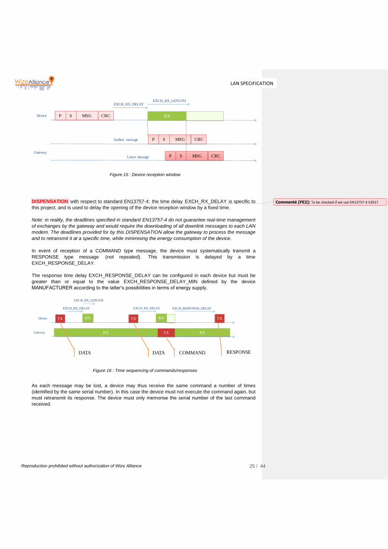
Figure 15 : Device reception window
DISPENSATION with respect to standard EN13757-4: the time delay EXCH_RX_DELAY is specific to
this project, and is used to delay the opening of the device reception window by a fixed time.
Note: in reality, the deadlines specified in standard EN13757-4 do not guarantee real-time management
of exchanges by the gateway and would require the downloading of all downlink messages to each LAN
modem. The deadlines provided for by this DISPENSATION allow the gateway to process the message
and to retransmit it at a specific time, while minimising the energy consumption of the device.
In event of reception of a COMMAND type message, the device must systematically transmit a
RESPONSE type message (not repeated). This transmission is delayed by a time
EXCH_RESPONSE_DELAY.
The response time delay EXCH_RESPONSE_DELAY can be configured in each device but must be
greater than or equal to the value EXCH_RESPONSE_DELAY_MIN defined by the device
MANUFACTURER according to the latter’s possibilities in terms of energy supply.
Figure 16 : Time sequencing of commands/responses
As each message may be lost, a device may thus receive the same command a number of times
(identified by the same serial number). In this case the device must not execute the command again, but
must retransmit its response. The device must only memorise the serial number of the last command
received.
Device
Gateway
RX
EXCH_RX_DELAYEXCH_RX_LENGTH
P MSGS CRC
P MSGS CRC
P MSGS CRC
Earliest message
Latest message
Device TX RX
EXCH_RX_DELAY
Gateway TXRX RX
TX RX
EXCH_RX_DELAY
EXCH_RX_LENGTH
TX
EXCH_RESPONSE_DELAY
DATA DATA COMMAND RESPONSE
Commenté [FE2]: To be checked if we use EN13757-4 V2017
26 / 44
LAN SPECIFICATION
Reproduction prohibited without authorization of Wize Alliance
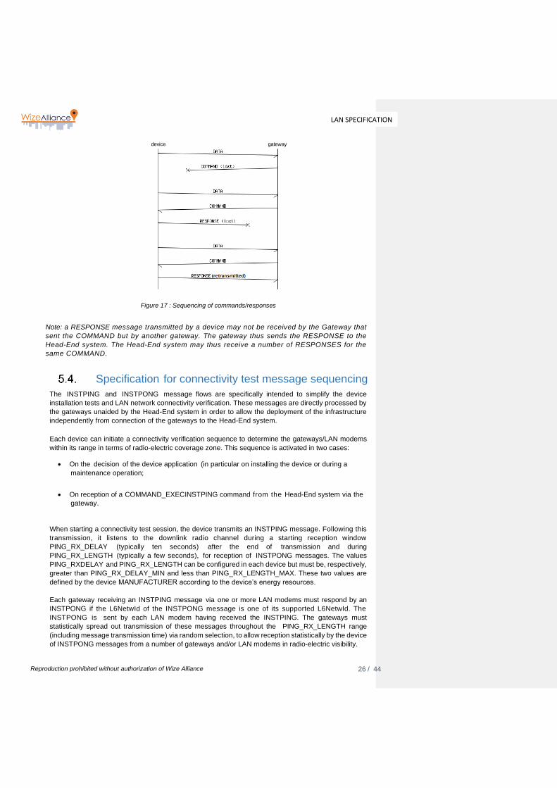
Figure 17 : Sequencing of commands/responses
Note: a RESPONSE message transmitted by a device may not be received by the Gateway that
sent the COMMAND but by another gateway. The gateway thus sends the RESPONSE to the
Head-End system. The Head-End system may thus receive a number of RESPONSES for the
same COMMAND.
Specification for connectivity test message sequencing
The INSTPING and INSTPONG message flows are specifically intended to simplify the device
installation tests and LAN network connectivity verification. These messages are directly processed by
the gateways unaided by the Head-End system in order to allow the deployment of the infrastructure
independently from connection of the gateways to the Head-End system.
Each device can initiate a connectivity verification sequence to determine the gateways/LAN modems
within its range in terms of radio-electric coverage zone. This sequence is activated in two cases:
• On the decision of the device application (in particular on installing the device or during a
maintenance operation;
• On reception of a COMMAND_EXECINSTPING command from the Head-End system via the
gateway.
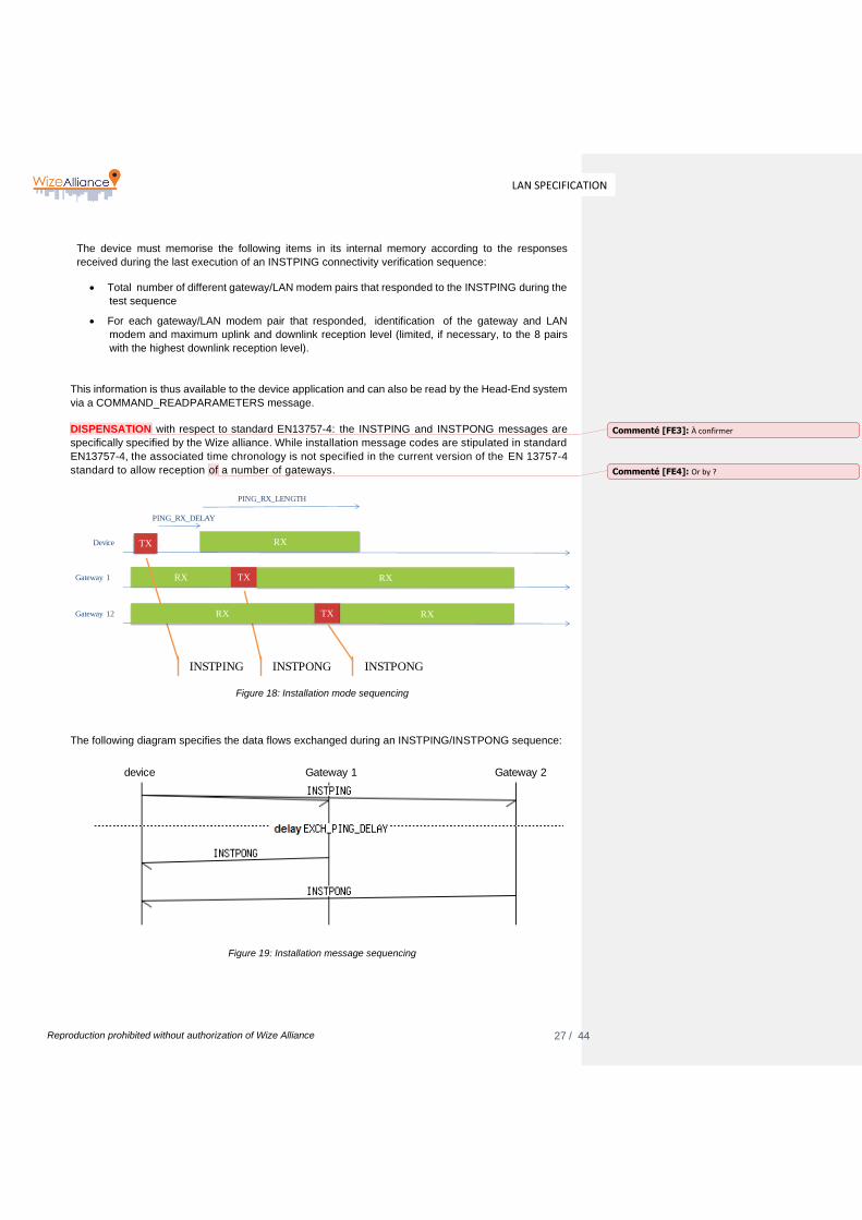
When starting a connectivity test session, the device transmits an INSTPING message. Following this
transmission, it listens to the downlink radio channel during a starting reception window
PING_RX_DELAY (typically ten seconds) after the end of transmission and during
PING_RX_LENGTH (typically a few seconds), for reception of INSTPONG messages. The values
PING_RXDELAY and PING_RX_LENGTH can be configured in each device but must be, respectively,
greater than PING_RX_DELAY_MIN and less than PING_RX_LENGTH_MAX. These two values are
defined by the device MANUFACTURER according to the device’s energy resources.
Each gateway receiving an INSTPING message via one or more LAN modems must respond by an
INSTPONG if the L6NetwId of the INSTPONG message is one of its supported L6NetwId. The
INSTPONG is sent by each LAN modem having received the INSTPING. The gateways must
statistically spread out transmission of these messages throughout the PING_RX_LENGTH range
(including message transmission time) via random selection, to allow reception statistically by the device
of INSTPONG messages from a number of gateways and/or LAN modems in radio-electric visibility.
device gateway
27 / 44
LAN SPECIFICATION
Reproduction prohibited without authorization of Wize Alliance
The device must memorise the following items in its internal memory according to the responses
received during the last execution of an INSTPING connectivity verification sequence:
• Total number of different gateway/LAN modem pairs that responded to the INSTPING during the
test sequence
• For each gateway/LAN modem pair that responded, identification of the gateway and LAN
modem and maximum uplink and downlink reception level (limited, if necessary, to the 8 pairs
with the highest downlink reception level).
This information is thus available to the device application and can also be read by the Head-End system
via a COMMAND_READPARAMETERS message.
DISPENSATION with respect to standard EN13757-4: the INSTPING and INSTPONG messages are
specifically specified by the Wize alliance. While installation message codes are stipulated in standard
EN13757-4, the associated time chronology is not specified in the current version of the EN 13757-4
standard to allow reception of a number of gateways.
Figure 18: Installation mode sequencing
The following diagram specifies the data flows exchanged during an INSTPING/INSTPONG sequence:
Figure 19: Installation message sequencing
Device TX RX
PING_RX_DELAY
Gateway 1 TXRX RX
PING_RX_LENGTH
INSTPING INSTPONG
Gateway 12 TXRX RX
INSTPONG
device Gateway 1 Gateway 2
Commenté [FE3]: À confirmer
Commenté [FE4]: Or by ?
28 / 44
LAN SPECIFICATION
Reproduction prohibited without authorization of Wize Alliance
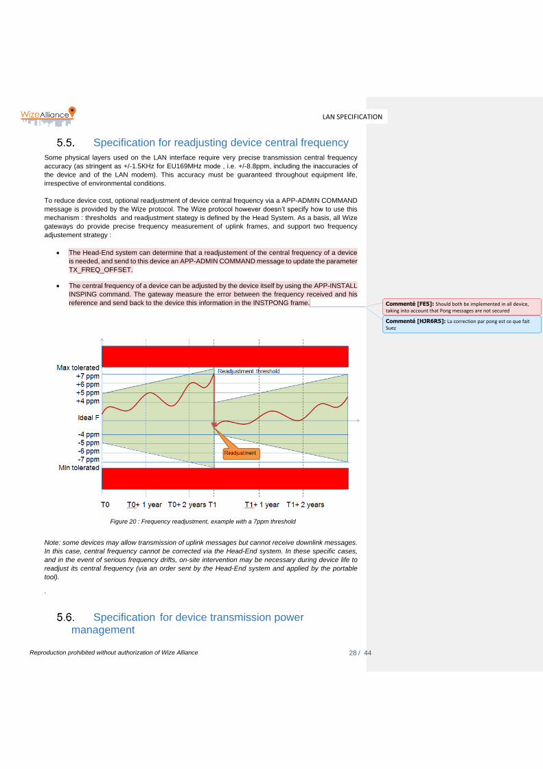
Specification for readjusting device central frequency
Some physical layers used on the LAN interface require very precise transmission central frequency
accuracy (as stringent as +/-1.5KHz for EU169MHz mode , i.e. +/-8.8ppm, including the inaccuracies of
the device and of the LAN modem). This accuracy must be guaranteed throughout equipment life,
irrespective of environmental conditions.
To reduce device cost, optional readjustment of device central frequency via a APP-ADMIN COMMAND
message is provided by the Wize protocol. The Wize protocol however doesn’t specify how to use this
mechanism : thresholds and readjustment stategy is defined by the Head System. As a basis, all Wize
gateways do provide precise frequency measurement of uplink frames, and support two frequency
adjustement strategy :
• The Head-End system can determine that a readjustement of the central frequency of a device
is needed, and send to this device an APP-ADMIN COMMAND message to update the parameter
TX_FREQ_OFFSET.
• The central frequency of a device can be adjusted by the device itself by using the APP-INSTALL
INSPING command. The gateway measure the error between the frequency received and his
reference and send back to the device this information in the INSTPONG frame.
Figure 20 : Frequency readjustment, example with a 7ppm threshold
Note: some devices may allow transmission of uplink messages but cannot receive downlink messages.
In this case, central frequency cannot be corrected via the Head-End system. In these specific cases,
and in the event of serious frequency drifts, on-site intervention may be necessary during device life to
readjust its central frequency (via an order sent by the Head-End system and applied by the portable
tool).
.
Specification for device transmission power management
Commenté [FE5]: Should both be implemented in all device, taking into account that Pong messages are not secured
Commenté [HJR6R5]: La correction par pong est ce que fait Suez
29 / 44
LAN SPECIFICATION
Reproduction prohibited without authorization of Wize Alliance
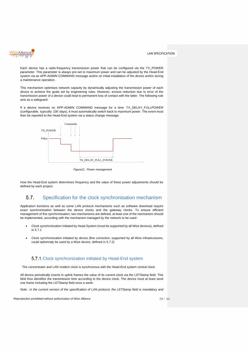
Each device has a radio-frequency transmission power that can be configured via the TX_POWER
parameter. This parameter is always pre-set to maximum power and can be adjusted by the Head-End
system via an APP-ADMIN COMMAND message and/or on initial installation of the device and/or during
a maintenance operation.
This mechanism optimises network capacity by dynamically adjusting the transmission power of each
device to achieve the goals set by engineering rules. However, excess reduction due to error of the
transmission power of a device could lead to permanent loss of contact with the latter. The following rule
acts as a safeguard:
If a device receives no APP-ADMIN COMMAND message for a time TX_DELAY_FULLPOWER
(configurable, typically 100 days), it must automatically switch back to maximum power. The event must
then be reported to the Head-End system via a status change message.
Figure21 : Power management
How the Head-End system determines frequency and the value of these power adjustments should be
defined by each project.
Specification for the clock synchronisation mechanism
Application functions as well as some LAN protocol mechanisms such as software download require
exact synchronisation between the device clocks and the gateway clocks. To ensure efficient
management of this synchronisation, two mechanisms are defined, at least one of the mechanism should
be implemented, according with the mechanism managed by the network to be used :
• Clock synchronization initiated by Head-System (must be supported by all Wize devices), defined
in 5.7.1
• Clock synchronization initiated by device (fine correction, supported by all Wize infrastructures,
could optionnaly be used by a Wize device, defined in 5.7.2)
Clock synchronization initiated by Head-End system
The concentrator and LAN modem clock is synchronous with the Head-End system central clock.
All device periodically inserts in uplink frames the value of its current clock via the L6TStamp field. This
field thus identifies the transmission time according to the device clock. The device must at least send
one frame including the L6TStamp field once a week.
Note : in the current version of the specification of LAN protocol, the L6TStamp field is mandatory and
PMax
Commands
TX_DELAY_FULL_POWER
TX_POWER

30 / 44
LAN SPECIFICATION
Reproduction prohibited without authorization of Wize Alliance
thus, the requirement to send at least one frame per week is fulfilled automatically.
Note: this L6TStamp field is in the level 6 header of the LAN protocol. It is thus not encrypted, which
allows the gateway to remove time duplicates of the messages as only this field is modified in the event
of transmission time redundancy. For example, this is possible by doing a bitwise comparison of the
encrypted fields.
On reception of a message, the LAN modem records the current value of its clock and sends the message
and time stamp to the gateway, and then to the Head-End system
The Head-End system can thus compare the frame transmission time, via the latter’s L6TStamp field,
and its reception time by the LAN modem. As these two times equal the radio-electric propagation times,
the Head-End system can thus determine and correct the clock error of the meter:
Two parameters are used to correct the meter clock via a COMMAND type message:
• The CLOCK_CURRENT_EPOCH parameter allows absolute redefinition of a device clock
• The CLOCK_OFFSET_CORRECTION parameter allows relative correction of meter time (+/- N
seconds)
• The CLOCK_DRIFT_CORRECTION parameter corrects meter clock frequency (+/-S seconds
every D days)
Figure22 : Clock correction
How the Head-End system determines the frequency and the value of these clock adjustments should be defined by each project.
Clock synchronization initiated by device (fine correction) A device can also do a fine time adjustment by synchronizing with the time from one or several gateways. Gateways’ clocks are considered as a reference to be used by the device to correct its time. The time data for this process is exchanged during the connectivity test using APP-INSTALL INSTPING messages sent to all visible gateways. All gateways receiving INSTPING will answer with an INSTPONG message, including a time stamp information from the gateway. INSTPING and INSTPONG messages are not ciphered, and are not sent to the Head-End system. These messages are exchanged at the initiative of a device, typically :
• After reception of a download announcement.
• If the device detects an important time error through application level informations.
• Regularly, each EXECPING_PERIODE in month + random value in days between 0 to 30, in order to smooth the radio channels usage.This feature can be deactivated by setting EXECPING_PERIODE to zero, the default value is 6 months.
LANWANHead-end
Device
Message + L6TStamp
Message + L6TStamp + Tstamp reception
Absolute and/or slope correctionAnalysis
Gateway

31 / 44
LAN SPECIFICATION
Reproduction prohibited without authorization of Wize Alliance
The time update is managed by the device, at INSTPONG reception, depending on the time error. More
exactly :
• The device compares the L6TStamp field of the downlink message with the value of the 2 least
significant bytes of its internal EPOCH as follows:
either
the gateway’s L6TStamp: KKKK (16 unsigned bits) in seconds
the device’s EPOCH: XXXXDDDD (32 unsigned bits) in seconds
It calculates:
DDDD - KKKK = N seconds separating the device from K by -32768 to +32767,
A fine correction of the device EPOCH is carried out only if -127 <= N <= +127
Clock synchronization management rules
Clock synchronization and adjustments are critical operations that need to be managed with precise rules. All WIze devices must follows the following principles :
• All clock synchronization corrections (command received from the Head-End system or device
initiated fine-correction) must not be immediately executed by the device but kept in memory and
executed at 00:00UTC.
• At that time, the device must check it any clock correction has to be done, and updates its clock
correction registers as required (CLOCK_CURRENT_EPOCH,
CLOCK_OFFSET_CORRECTION, CLOCK_DRIFT_CORRECTION). It then notifies the Head-
End system that it has carried out a correction by flagging the next non redundant data message.
• Clock synchronization initiated by device, if implemented by the device, must be managed by the
devices with a lower priority than clock synchronization initiated by the Head-End system. This
means that if a clock synchronization message was received from the Head-System before
00:00UTC, then no device-initiated fine adjustment must be taken into account for that day.
• If more than one clock synchronization command was received by a device from the Head-End
system on a given day, only the last command received must be executed.
Specification for software download management
Tele-distribution of device software is possible using the APP-DOWNLOAD application layer associated
with the LLC-DOWNLOAD and PRES-DOWNLOAD low-level layers. The rules for software downloads
are as follows:
Each software download sequence is identified by a L2DwnId sequence number allocated by the Head-
End system and concerns an homogeneous set of devices, i.e.:
• The same MANUFACTURER;
• The same type (as defined by the manufacturer rules, must match with same firmware version) ;
• In the radio-electric coverage zone of the same LAN modem of the same gateway (hereafter
referred to as the software download gateway).
A software download operation consists, at the LAN interface, of the reliable delivery of a set of N
data blocks of fixed size (210 bytes) to the devices concerned, where each block is identified by its
L6DwnBNum number. The internal structure of these data blocks and their use for the effective
updating of the device are the MANUFACTURER’s responsibility. The Head-End system is
responsible for their encryption, the calculation of the associated authentication footprints and their
32 / 44
LAN SPECIFICATION
Reproduction prohibited without authorization of Wize Alliance
distribution.
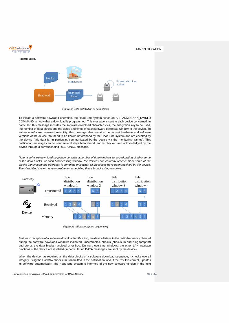
Figure23: Tele distribution of data blocks
To initiate a software download operation, the Head-End system sends an APP-ADMIN ANN_DWNLD
COMMAND to notify that a download is programmed. This message is sent to each device concerned. In
particular, this message includes the software download characteristics, the encryption key to be used,
the number of data blocks and the dates and times of each software download window to the device. To
enhance software download reliability, this message also contains the current hardware and software
versions of the device that need to be known beforehand by the Head-End system and are checked by
the device (this data is, in particular, communicated by the device via the monitoring frames). This
notification message can be sent several days beforehand, and is checked and acknowledged by the
device through a corresponding RESPONSE message.
Note: a software download sequence contains a number of time windows for broadcasting of all or some
of the data blocks. At each broadcasting window, the devices can correctly receive all or some of the
blocks transmitted: the operation is complete only when all the blocks have been received by the device.
The Head-End system is responsible for scheduling these broadcasting windows.
Figure 21 : Block reception sequencing
Further to reception of a software download notification, the device listens to the radio-frequency channel
during the software download windows indicated, unscrambles, checks (checksum and Klog footprint)
and stores the data blocks received error-free. During these time windows, the other LAN interface
functions of the device are disabled (in particular no DATA messages are sent by the device).
When the device has received all the data blocks of a software download sequence, it checks overall
integrity using the HashSw checksum transmitted in the notification and, if the result is correct, updates
its software automatically. The Head-End system is informed of the new software version in the next
Head-end
Manufacturer
blocks
Encrypted
blocks
Updated with blocs
received
Device
1 2 3 4 5 6 1 2 3 4 5 6
1 2 x 4 x 6 1 x 3 4 5 6
Transmitted
Received
Memory 1 2 x 4 x 6 1 2 3 4 5 6
Tele
distribution
window 1
Tele
distribution
window 2
Tele
distribution
window 3
Tele
distribution
window 4
Gateway

33 / 44
LAN SPECIFICATION
Reproduction prohibited without authorization of Wize Alliance
monitoring type application frame. In event of a start error on the new version, the device automatically
backtracks.
Note: With some Specific Application layers, the Head-End system can also be informed of the progress
of software download via status bits transmitted in daily DATA frames of the Specific Application Layer.
Cf documents [A3] and [A4]
A downloading sequence must be aborted by a device in the following cases:
• Failure of the integrity check of all data blocks using the HashSw checksum transmitted in the
notification;
• Reception of a new software download notification with an L2DwnId ID other than the ID of the
current sequence, prior to the finalisation of the current software download (*).
(*): However, the device must accept a new software download notification identified by the same L2DwnId as the current session. In particular, this allows the Head-End system to reschedule additional broadcast windows if all the blocks have not been received by enough devices. This can be detected by the Head-End system via the software version index uploaded by each device in the monitoring type application frames.

34 / 44
LAN SPECIFICATION
Reproduction prohibited without authorization of Wize Alliance
Figure 22: Software download sequence
Detailed specification of the presentation layer
PRES-EXCHANGE presentation layer
To meet clock synchronisation, exchange authentication and flow management needs, seven fields have
been included in the layer 2 frame structure, in addition to the L6 Frame to be transmitted :
• A L6Ctrl field specifying the LAN protocol version (L6Vers, see table 12) and the current Kenc
security key index (L6KeySel)
• A L6NetwID field, specifying the virtual network identifier that must transmit this frame (and corresponding to a given Kmac network access authentication key)
26
Device 1Gateway Device 2
35 / 44
LAN SPECIFICATION
Reproduction prohibited without authorization of Wize Alliance
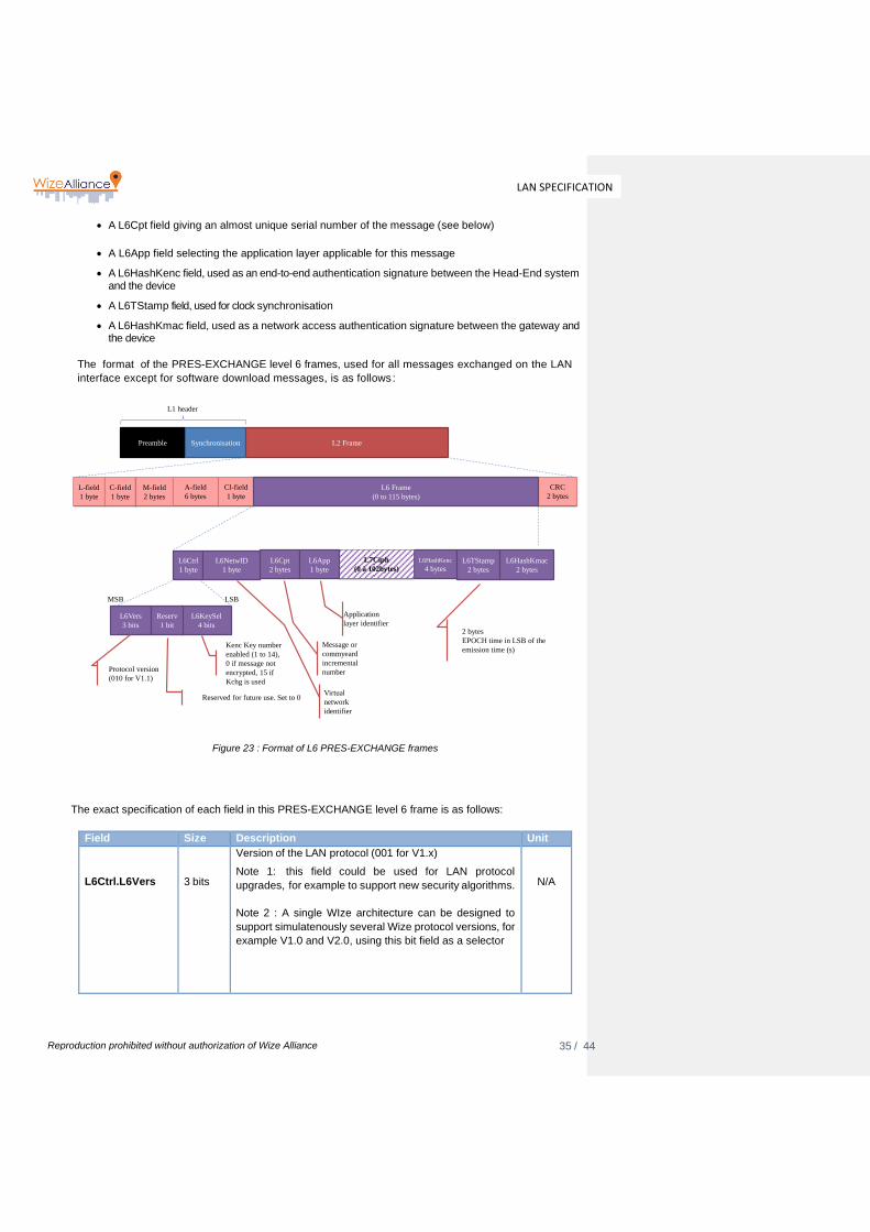
• A L6Cpt field giving an almost unique serial number of the message (see below)
• A L6App field selecting the application layer applicable for this message
• A L6HashKenc field, used as an end-to-end authentication signature between the Head-End system and the device
• A L6TStamp field, used for clock synchronisation
• A L6HashKmac field, used as a network access authentication signature between the gateway and the device
The format of the PRES-EXCHANGE level 6 frames, used for all messages exchanged on the LAN
interface except for software download messages, is as follows:
Figure 23 : Format of L6 PRES-EXCHANGE frames
The exact specification of each field in this PRES-EXCHANGE level 6 frame is as follows:
Field Size Description Unit
L6Ctrl.L6Vers
3 bits
Version of the LAN protocol (001 for V1.x)
Note 1: this field could be used for LAN protocol
upgrades, for example to support new security algorithms.
Note 2 : A single WIze architecture can be designed to
support simulatenously several Wize protocol versions, for
example V1.0 and V2.0, using this bit field as a selector
N/A
Preamble Synchronisation L2 Frame
L1 header
L-field
1 byte
C-field
1 byte
M-field
2 bytes
A-field
6 bytes
Cl-field
1 byte
CRC
2 bytes
L6 Frame
(0 to 115 bytes)
L6Vers
3 bits
L6KeySel
4 bits
Reserv
1 bit
MSB LSB
Protocol version
(010 for V1.1)
Kenc Key number
enabled (1 to 14),
0 if message not
encrypted, 15 if
Kchg is used
2 bytes
EPOCH time in LSB of the
emission time (s)
L6HashKenc
4 bytesL6TStamp
2 bytes
L6HashKmac
2 bytes
L6Cpt
2 bytes
L7Ciph
(0 à 102bytes)L6Ctrl
1 byte
L6NetwID
1 byte
L6App
1 byte
Application
layer identifier
Message or
commyeard
incremental
number
Reserved for future use. Set to 0Virtual
network
identifier

36 / 44
LAN SPECIFICATION
Reproduction prohibited without authorization of Wize Alliance
L6Ctrl.reserved
1 bit
Reserved value, set to 0.
N/A
L6Ctrl.L6KeySel
4 bits
Number of the current encryption and authentication key:
- 0 if encryption disabled
- 1 to 14 if one of the Kenc keys is used, corresponding to
the index of the Kenc key effectively enabled and used
- 15 if the Kchg key is used (specific case of ANN-
DOWNLOAD and COMMAND-WRITEKEY messages,
see WIZE – 03 Common Application Layers & Specific
Application Layers Index document)
Note 1: the device must ignore a frame received with a
key number other than that configured in the device,
except in two cases:
- In the specific case of INSTPING and INSTPONG
messages that are always transmitted non-
encrypted and where L6KeySel=0
- In the specific case of COMMAND application
messages of the ANN-DOWNLOAD or
COMMAND-WRITEKEY type that are always
transmitted encrypted by the Kchg key
(L6KeySel=15)
N/A
L6NetwId
1 byte
Frame field for the Network identifier, must be set by the
device with the same value than its parameter
L6NETWID (capital letters) for uplink messages; for
downlink it is checked by the device and the message
ignored when the field does not match
All of the L6NetwId codes are available from the Wize
alliance that manages their allocation (see Wize web site
or contact Wize Alliance at : [email protected]).
In particular, one L6NetwId code is reserved for OneWize
easy commissioning virtual network..
N/A

37 / 44
LAN SPECIFICATION
Reproduction prohibited without authorization of Wize Alliance
L6Cpt
2 bytes
Message incremental number:
- For DATA and INSTPING/INSTPONG messages:
incremented by the device for each new message
generated, as the device is managed separately for the
DATA and INSTPING/INSTPONG messages by the
device. (management of a separate device for DATA flow
and of a separate device for INSTPING/INSTPONG flows)
- For COMMAND/RESPONSE messages: serial order of
the command generated by the Head-End system. The
device must use the same serial number for the associated
response.
MSBs first
N/A
L6App
1 byte
This field contains the ID of the primary application layer. All of the L6App codes are available from the Wize alliance that manages their allocation (see Wize web site or contact Wize Alliance at : [email protected]).
N/A
L7 Ciph
0..102 bytes
Result of encryption of the application frame, calculated by
the algorithm specified in Appendix A.
N/A
Field Size Description Unit
L6HashKenc
4 bytes
Authentication signature of the transmitter of the message between the Head-End system and the device.
Calculated by the algorithm specified in chapter 6.1 on the
L7Ciph field.
The authentication key used is:
- the Kenc current key (identified by L6Ctrl.L6KeySel) if
L6Ctrl.L6KeySel is between 1 and 14
- the Kchg key if L6Ctrl.L6KeySel=15
- the Kmac key if the message is not encrypted
(L6Ctrl.L6KeySel=0)
MSBs first
N/A
L6TStamp
2 bytes
Time stamp of the transmission time of the message by the device or the gateway. This field is made up of the two LSB bytes of the current EPOCH
MSBs first
Sec

38 / 44
LAN SPECIFICATION
Reproduction prohibited without authorization of Wize Alliance
L6HashKmac
2 bytes
Authentication signature of the transmitter of the message between the gateway and the device.
Calculated by the algorithm specified in the appendix in
chapter 8 on the message from the L6Ctrl field to the
L6Tstamp field inclusive.
The authentication key used is the Kmac key
MSBs first
N/A
Table 12 : Fields of the PRES-EXCHANGE L6 frame
The following diagram specifies the method for generating authentication and encryption fields:
Figure 24:PRES-EXCHANGE – Generation of authentication and encryption fields
The details of the encryption algorithms are given in chapter 7.
Note: the authentication and encryption algorithms could be subject to future changes (longer keys, etc.).
With respect to the LAN protocol, this would be managed by a change in protocol version (L6Ctrl.L6Vers
field). Keys could either be based on a combination of existing keys or on new keys.
The Kenc and Kmac keys are programmed in the factory with a length of 256 bits. Only the first 128 bits
Preamble Synchronisation L2 Frame
L1 header
L-field
1 byte
C-field
1 byte
M-field
2 bytes
A-field
6 bytes
Cl-field
1 byte
CRC
2 bytes
L6 Frame
(0 to 115 bytes)
L6HashKenc
4 bytesL6TStamp
2 bytes
L6HashKmac
2 bytes
L6Cpt
2 bytes
L7Ciph
(0 à 102bytes)L6Ctrl
1 byte
LNetwId
1 byte
L6App
1 byte
AES
128
CTR
(Kenc)
Init. vector (16 bytes)
M-FIELD
(2 bytes)
A-FIELD
(6 bytes)
L6Cpt
(2-bytes)
C-FIELD
(1 byte)
0-Padding
(1 byte)
CiphSeq
(4 bytes)
Confidential data
| |
Additional block 0 (16 bytes)
M-FIELD
(2 bytes)
A-FIELD
(6 bytes)
L6Cpt
(2-bytes)
0-Padding
(6 bytes)
| |
Additional block 0 (16 bytes)
M-FIELD
(2 bytes)
A-FIELD
(6 bytes)
0-Padding
(8 bytes)
AES
CMAC
(Kenc)
AES
CMAC
(Kmac)

39 / 44
LAN SPECIFICATION
Reproduction prohibited without authorization of Wize Alliance
(MSB) are used in the PRES-EXCHANGE layer.
In the specific case of non-encrypted INSTPING and INSTPONG messages, exchanged without action
by the Head-End system, authentication is achieved using only the Kmac key as follows:
• For the INSTPING message :
o The L6HashKenc field is also calculated in the same way as for the general case,
but using the Kmac key in place of Kenc in the case of INSTPING message.
• For the INSTPONG message :
o The L6HashKenc field content is replaced by the gateway time (EPOCH, encoded
on 4 bytes).
o The L6TStamp field content is replaced by the frequency error measured by the
gateway (encoding and framing is same as Tx_FREQ_OFFSET parameter).
Figure 25 : Format of the INSTPONG frame
PRES-DOWNLOAD presentation layer
The format of the PRES-DOWNLOAD level 6 frames, used only for software download, is as follows:
Preamble Synchronisation L2 Frame
L1 header
L-field
1 byte
C-field
1 byte
M-field
2 bytes
A-field
6 bytes
Cl-field
1 byte
CRC
2 bytes
L6 Frame
(0 to 115 bytes)
L6Vers
3 bits
L6KeySel
4 bits
Reserv
1 bit
MSB LSB
= 0 4 bytes
EPOCH time in LSB of the
transmission time (s)
EPOCH
4 bytes
TX_FREQ
_OFFSET
2 bytes
L6HashKmac
2 bytes
L6Cpt
2 bytes
L7Ciph
(0 à 102bytes)L6Ctrl
1 byte
L6NetwId
1 byte
L6App
1 byte
Error measurement of
frequency on two signed
bytes.
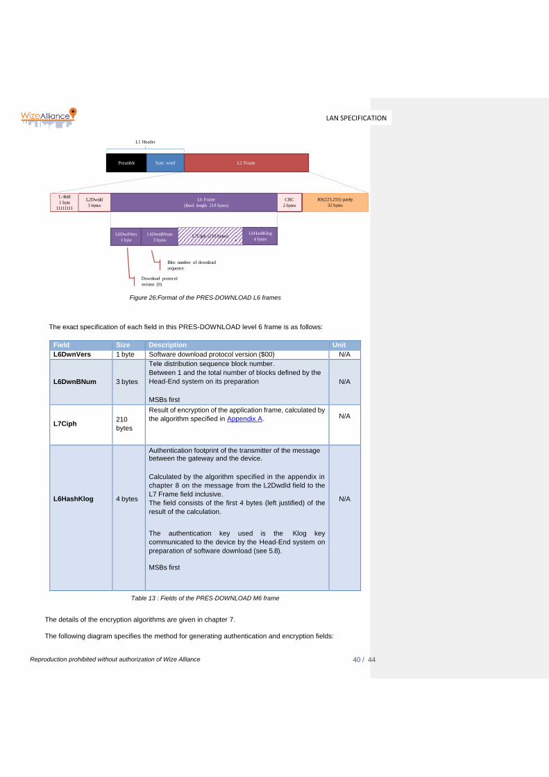
40 / 44
LAN SPECIFICATION
Reproduction prohibited without authorization of Wize Alliance
Figure 26:Format of the PRES-DOWNLOAD L6 frames
The exact specification of each field in this PRES-DOWNLOAD level 6 frame is as follows:
Field Size Description Unit
L6DwnVers 1 byte Software download protocol version ($00) N/A
L6DwnBNum
3 bytes
Tele distribution sequence block number.
Between 1 and the total number of blocks defined by the
Head-End system on its preparation
MSBs first
N/A
L7Ciph
210
bytes
Result of encryption of the application frame, calculated by
the algorithm specified in Appendix A.
N/A
L6HashKlog
4 bytes
Authentication footprint of the transmitter of the message between the gateway and the device.
Calculated by the algorithm specified in the appendix in
chapter 8 on the message from the L2DwdId field to the
L7 Frame field inclusive.
The field consists of the first 4 bytes (left justified) of the
result of the calculation.
The authentication key used is the Klog key
communicated to the device by the Head-End system on
preparation of software download (see 5.8).
MSBs first
N/A
Table 13 : Fields of the PRES-DOWNLOAD M6 frame
The details of the encryption algorithms are given in chapter 7.
The following diagram specifies the method for generating authentication and encryption fields:
Preamble Sync word L2 Frame
L1 Header
L-field
1 byte
11111111
RS(223,255) parity
32 bytes
L6DwdVers
1 byte
L6DwnBNum
3 bytes
L6HashKlog
4 bytesL7Ciph (210 bytes)
L6 Frame
(longueur fixe de 221 bytes)
Download protocol
version (0)
Bloc number of download
sequence
CRC
2 bytes
L6 Frame
(fixed length 218 bytes)
L2Dwnld
3 bytes
CRC
2 bytes

41 / 44
LAN SPECIFICATION
Reproduction prohibited without authorization of Wize Alliance
Figure 27 : PRES-DOWNLOAD – Principle for generating securing fields

42 / 44
LAN SPECIFICATION
Reproduction prohibited without authorization of Wize Alliance
Appendix A : message encryption
The algorithm used for message encryption and decryption is AES 128 in counter mode (CTR).
Figure 28 : Extract from the reference document – The CTR mode
The counter value is specified by the following requirements
The initial encryption counter (IV) is the concatenation of the following fields:
For PRES-EXCHANGE: the encryption counter consists of the M-Field, A-Field, L6Cpt, C-field, 1 stuffing
byte (equal to 0) and CiphSeq fields in that order, left justified (M- Field in MSB position, total length
always equal to 16 bytes);
2 bytes 6 bytes 2 bytes 1 byte 1 byte 4 bytes
M-FIELD A-FIELD L6Cpt C-FIELD 00 CiphSeq
For PRES-DOWNLOAD: the encryption counter consists of the L2DwnId, L6DwnBNum, then 6 bytes
equal to 0 and CiphSeq fields in that order, left justified (L2DwnId in MSB position, total length always
equal to 16 bytes).
The CiphSeq field, which is an integral part of the encryption counter, is a 32-bit counter not transmitted
in the frame. Its value is zero for the first message encryption block. It is incremented by one for each of
the following blocks.
3 bytes 3 bytes 6 bytes 4 bytes
L2DwnLd L6DwnBNum 000000000000 CiphSeq

43 / 44
LAN SPECIFICATION
Reproduction prohibited without authorization of Wize Alliance
Appendix B : message transmitter authentication footprints
The security principles are specified in NIST Special Publication – The CMAC mode for Authentification - 800-38B - 2005 Edition. Other reference document : NIST Special Publication – Recommendation for Block Cipher Modes of Operations - 800-38A - 2001 Edition In more detail:
The algorithm used for the message transmitter authentication footprints is AES 128 in CMAC
authentication mode.
Figure 29 : Extract from the reference document – CMAC

44 / 44
LAN SPECIFICATION
Reproduction prohibited without authorization of Wize Alliance
Appendix C : RS(255,223) Encoding
The LLC-DOWNLOAD level 2 layer, used for software download of software (see 4.2) uses an error
correction code to enhance the reliability of long frame transfers. This code is a Reed-Solomon code
with the following parameters:
• N=255;
• K=223;
• S=8.
This code thus processes a data block of 223 symbols (bytes in this case), each with 8 bits, generating
at the output 255 bytes including the 223 initial data bytes completed with 255-223=32 redundant bytes.
This code can correct up to 16 incorrect bytes in the entire 255 bytes transmitted.
The reference source code for this algorithm is:
http://www.eccpage.com/rs.c
END OF DOCUMENT
Related Documents