1 / 13 LAN SPECIFICATION Reproduction prohibited without authorization of Wize Alliance REGIONAL PARAMETERS V1.1 Version Modifications Date 1.0 Initial version (included in LAN Protocol Specification v1.0) 22/09/2017 1.1 Separate document for regional parameters 07/06/2019 Summary This document outlines the regional parameters of the physical layer of the Wize LAN protocol (i.e. those related to the frequency band). The LAN network designates the medium range radio network between the devices and the gateways.

Welcome message from author
This document is posted to help you gain knowledge. Please leave a comment to let me know what you think about it! Share it to your friends and learn new things together.
Transcript

1 / 13
LAN SPECIFICATION
Reproduction prohibited without authorization of Wize Alliance
REGIONAL PARAMETERS
V1.1
Version Modifications Date
1.0 Initial version (included in LAN Protocol Specification v1.0) 22/09/2017
1.1 Separate document for regional parameters 07/06/2019
Summary This document outlines the regional parameters of the physical layer of the Wize LAN protocol (i.e. those related to the frequency band). The LAN network designates the medium range radio network between the devices and the gateways.

2 / 13
LAN SPECIFICATION
Reproduction prohibited without authorization of Wize Alliance
Table of contents Summary .....................................................................................................................................................1 Table of contents .........................................................................................................................................2 Tables and figures .......................................................................................................................................3 Contributors.................................................................................................................................................4
1 Introduction .......................................................................................................... 4
2 Reference documents .......................................................................................... 4
2.1 Applicable standards ........................................................................................... 4
2.2 Main specifications .............................................................................................. 4
3 Wize regional parameters list .............................................................................. 5
4 EU169 regional parameters ................................................................................. 6 4.1 Physical layers .............................................................................................................................6 4.2 Frequency channels ....................................................................................................................6 4.3 Detailed specification of the physical layers ...............................................................................7 4.3.1 Specification of the frequency channels .....................................................................................7 4.3.2 PHY-WM2400 physical layer ......................................................................................................7 4.3.3 PHY-WM4800 physical layer ......................................................................................................8 4.3.4 PHY-HSPEED physical layer ......................................................................................................9 4.4 Physical link parameters .......................................................................................................... 10 4.5 Data encoding & preamble ...................................................................................................... 11 4.5.1 Encoding .................................................................................................................................. 11 4.5.2 Preamble and synchronization pattern .................................................................................... 12 4.6 DATA LAN parameter dictionary .............................................................................................. 12 4.6.1 LAN Parameters ....................................................................................................................... 12

3 / 13
LAN SPECIFICATION
Reproduction prohibited without authorization of Wize Alliance
Tables and figures
Figure 9 : Physical layer/channel allocations ................................................................................................6 Figure 11 : Format of PHY-WM2400 frames ................................................................................................8 Figure 12 : Format of the PHY-WM4800 frame ............................................................................................9 Figure 13: Format of PHY-HSPEED frames ................................................................................................. 10
Table 2 : Physical layers ................................................................................................................................6 Table 6 : Channel frequencies ......................................................................................................................7 Table 7 : Characteristics of the PHY-WM2400 layer.....................................................................................8 Table 8 : Characteristics of the PHY-WM4800 layer.....................................................................................9 Table 9 : Characteristics of the PHY-HSPEED layer .................................................................................... 10
4 / 13
LAN SPECIFICATION
Reproduction prohibited without authorization of Wize Alliance
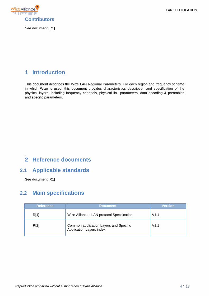
Contributors See document [R1]
1 Introduction This document describes the Wize LAN Regional Parameters. For each region and frequency scheme in which Wize is used, this document provides characteristics description and specification of the physical layers, including frequency channels, physical link parameters, data encoding & preambles and specific parameters. .
2 Reference documents
2.1 Applicable standards See document [R1]
2.2 Main specifications
Reference Document Version
R[1] Wize Alliance : LAN protocol Specification
V1.1
R[2]
Common application Layers and Specific Application Layers index
V1.1

5 / 13
LAN SPECIFICATION
Reproduction prohibited without authorization of Wize Alliance
3 Wize regional parameters list
The following regional parameters have been defined for use of Wize, provided with their common reference name:
Common reference
name
Region(s) of use Frequency bands and key characteristics
EU169
Europe
169MHz ISM band with modulations as defined by EN13757-4 mode N2
(others bands are under investigation and would be added on request, please contact the Wize alliance)

6 / 13
LAN SPECIFICATION
Reproduction prohibited without authorization of Wize Alliance
4 EU169 regional parameters
These regional parameters are used by Wize for the LAN interface in Europe is the 169 MHz band. It is a license-free ISM band at the European level, usable with duty cycles up to 10% for tracking and remote device reading applications as per recommendation REC/ERC/70-03 (annex 2)..
4.1 Physical layers
While using EU169 regional parameters, three different physical layers are supported on the LAN interface:
Physical layer Description Specification
PHY-WM2400 Physical layer using mode EN13757-4 N2a-f at 2400bps
see 4.3.2
PHY-WM4800 Physical layer using mode EN13757-4 N2a-f at 4800bps
see 4.3.3
PHY-HSPEED
High speed specific physical layer for very densely populated zones, using a 12.5KHz channel similar to modes EN13757-3 N2a-f
see 4.3.4
Table 1 : Physical layers
4.2 Frequency channels
As per standard EN13757-4 (mode N2), this frequency band is divided into 6 channels, each 12.5 KHz wide.
DISPENSATION with respect to standard EN13757-4: standard EN13757-4 stipulates the use of physical layer PHY-WM2400 on some of the six channels of the 169MHz band, and the use of the physical layer PHY-WM4800 on the rest. To optimise engineering and network capacity, the Wize LAN protocol allows the free use of one or more of the various physical layers in each frequency channel. (*)
DISPENSATION with respect to standard EN13757-4: for two-way exchanges (N2 mode, COMMAND/RESPONSE flows), the modulation used in the downlink direction by Wize protocol may be different from that used in the uplink direction (*)
(*) Nota : It should be highlighted that, due to joint work of the Wize Alliance members and CEN standard working groups, the majority of these deviations and additions are now indeed part of EN13757-4:2018 standard version. The next version (V2.0) of Wize Standard specification will be aligned with this new version after a detailed analysis of any compatibility risks. For consistency and system compatibility, this V1.1 version stay aligned with EN13757-4:2013 as was V1.0.
Mode Channel Central frequency
(MHz)
Channel spacing (KHz)
Flow (kbps) and modulation
Central frequency tolerance
Max Tx Power
Duty cycle
N1a,N2a N1b, N2b
1a 169.406250 WM-2400
1b 169.418750 Or N1c, N2c 2a 169.431250
12.5 WM-4800 1.5 500 mW 10% N1d, N2b 2b 169.443750
Or N1e, N2e 3a 169.456250 WM-HSPEED N1f, N2f 3b 169.468750
Figure 1 : Physical layer/channel allocations

7 / 13
LAN SPECIFICATION
Reproduction prohibited without authorization of Wize Alliance
The equipment hardware (device and LAN modem) must at least be compatible with the use of:
• the three physical modulations PHY_WM2400, PHY_WM4800 and PHY_HSPEED in the uplink direction;
• the two physical modulations PHY_WM2400 and PHY_WM4800 in the downlink direction
This applies to each of the 6 channels. Note: as per regulations, this frequency band must be used according to a cyclical transmission ratio of 10% (duty cycle): all equipment transmitting on this band can transmit at most 6 minutes every hour. In reality, this only affects the download of software by the gateways, as this limit must be taken into account by the Head-End system for scheduling purposes.
4.3 Detailed specification of the physical layers
4.3.1 Specification of the frequency channels
Communications via the LAN interface take place on six separate frequency channels. Each physical layer can use each of these channels for a specific communication.
The frequency band used is the harmonised band 169.4 MHz to 169.475 MHz. Each of the 6 Ni
channels (1 ≤ i ≤ 6) has a width of 12.5KHz and a central frequency equal to:
Fi = 169.39375 + i*0.0125 MHz Each of the six channels is identified by the following frequency channel number:
Frequency channel number Central frequency
100 169.406250 MHz 110 169.418750 MHz 120 169.431250 MHz 130 169.443750 MHz 140 169.456250 MHz 150 169.468750 MHz
Table 2 : Channel frequencies
Note: The other frequency channel number values are reserved for future extensions. Central frequency accuracy must be guaranteed by design for the gateway + device assembly according to the specified tolerance of +/-1.5KHz required for the WM-4800 mode, which is the most restrictive (see 4.2), i.e. +/-8.8ppm. To reduce the cost of the devices, the readjustment of the central frequency via a downlink command is possible in order to compensate oscillator long-term drifts (quartz ageing) and to allievate long-term stability requirements for central frequency.
4.3.2 PHY-WM2400 physical layer The PHY-WM2400 physical layer is strictly identical to the physical layer specified in standard EN13757-4 (EN13757-4) for modes N2c and N2d, with the two specific adaptations below:
• In mode PHY-WM2400, the frequency channel can be freely chosen, according to LAN layer configuration, out of all the available frequency channels (see 4.3.1), and is not limited to the two channels N2c and N2d (see 4.2)

8 / 13
LAN SPECIFICATION
Reproduction prohibited without authorization of Wize Alliance
• DISPENSATION with respect to standard EN13757-4: the frequency deviation tolerance is +/-0.2% (static) instead of the +/-10% specified in EN13757-4, and the GFSK modulation must be of the continuous phase type, so as to optimise the receiver’s achievable performances (modulation index exactly 2.0). (*)
(*) Nota : It should be highlighted that, due to joint work of the Wize Alliance members and CEN standard working groups, the majority of these deviations and additions are now indeed part of EN13757-4:2018 standard version. The next version (V2.0) of Wize Standard specification will be aligned with this new version after a detailed analysis of any compatibility risks. For consistency and system compatibility, this V1.1 version stay aligned with EN13757-4:2013 as was V1.0.
The main characteristics of this modulation are thus as follows:
Parameter Min Nominal Max Comments Channel width 12.5KHz Central frequency Cf. paragraph 4.1
Channels 100 to 150
Central freq tolerance -2KHz +2KHz Modulation GFSK Continuous phase Deviation -0.2% (*) +/-2.4KHz +0.2% (*) -2.4KHz=0, +2.4KHz=1 Modulation index 2.0 Filtering index 0.5BT Bit rate -100ppm 2400bps +100ppm Binary encoding NRZ MSBs first
Table 3 : Characteristics of the PHY-WM2400 layer
(* ) The tolerances indicated are tolerances on static deviations, i.e. for set binary levels, and thus do not affect hardware cost as all current integrated transceivers have numerical modulators. On transitions between two logical states, a difference of 10% maximum with the theoretical GFSK deviation is tolerated.
As per standard EN13757-4, the physical frame in mode PHY-WM2400 thus consists of a preamble of 16 bits and a synchronisation sequence of 16 bits, followed by an L2 level frame of variable length. The frame format chosen for the LAN protocol is the format B of standard EN13757-4 (only one CRC per frame). The frame header format is thus as follows:
Figure 2 : Format of PHY-WM2400 frames
4.3.3 PHY-WM4800 physical layer
The PHY-WM4800 physical layer is strictly identical to the physical layer specified in standard EN13757-4 for modes N2a, N2b, N2e and N2f, with the two specific adaptations below:
• The frequency channel can be freely chosen, according to LAN layer configuration, out of all the available frequency channels (see 4.3.1), and is not limited to the two channels N2c and N2d (see 4.2)
• DISPENSATION with respect to standard EN13757-4: the frequency deviation tolerance is
+/-0.2% (static) instead of the +/-10% as specified in EN13757-4, and the GFSK modulation must be of the continuous phase type, so as to optimise the receiver’s achievable
Preamble16 bits
0101010101010101
Sync word16 bits
11110110 01110010L2 Frame

9 / 13
LAN SPECIFICATION
Reproduction prohibited without authorization of Wize Alliance
performances (modulation index exactly 1.0). (*)
(*) Nota : It should be highlighted that, due to joint work of the Wize Alliance members and CEN standard working groups, the majority of these deviations and additions are now indeed part of EN13757-4:2018 standard version. The next version (V2.0) of Wize Standard specification will be aligned with this new version after a detailed analysis of any compatibility risks. For consistency and system compatibility, this V1.1 version stay aligned with EN13757-4:2013 as was V1.0.
The main characteristics of this modulation are thus as follows:
Parameter Min Nominal Max Comments Channel width 12.5KHz Central frequency Cf. paragraph 4.1
Channels 100 to 150
Central freq tolerance -1.5KHz +1.5KHz Modulation GFSK Continuous phase Deviation -0.2% (*) +/-2.4KHz +0.2% (*) -2.4KHz=0, +2.4KHz=1 Modulation index 1.0 Filtering index 0.5BT Bit rate -100ppm 4800bps +100ppm Binary encoding NRZ MSBs first
Table 4 : Characteristics of the PHY-WM4800 layer
(* ) The tolerances indicated are tolerances on static deviations, i.e. for set binary levels, and thus do not affect hardware cost as all current integrated transceivers have numerical modulators. On transitions between two logical states, a difference of 10% maximum with the theoretical GFSK deviation is tolerated. The format of the physical frame in PHY-WM4800 mode is strictly identical to that used for mode PHY_WM2400:
Figure 3 : Format of the PHY-WM4800 frame
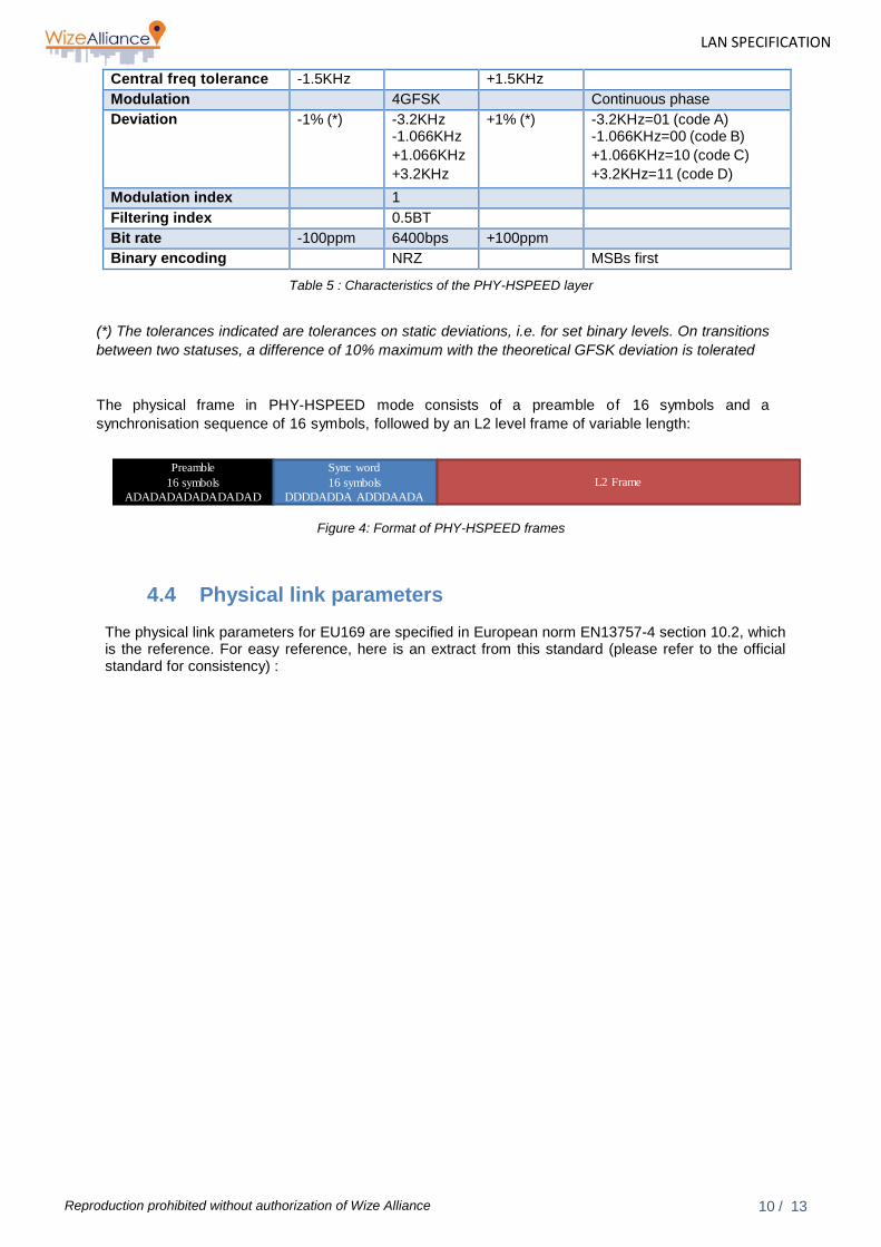
4.3.4 PHY-HSPEED physical layer The PHY-HSPEED physical layer is a variant used to increase channel capacity using a specific bitrate and a 4GFSK modulation specified in standard EN13757-4. (*)
(*) Nota : It should be highlighted that, due to joint work of the Wize Alliance members and CEN standard working groups, this addition is now indeed part of EN13757-4:2018 standard version. The next version (V2.0) of Wize Standard specification will be aligned with this new version after a detailed analysis of any compatibility risks. For consistency and system compatibility, this V1.1 version stay aligned with EN13757-4:2013 as was V1.0.
The main characteristics for this physical mode are as follows:
Parameter Min Nominal Max Comments Channel width 12.5KHz Central frequency Cf. paragraph 4.1
Channels 100 to 150
Preamble16 bits
0101010101010101
Sync word16 bits
11110110 01110010L2 Frame
10 / 13
LAN SPECIFICATION
Reproduction prohibited without authorization of Wize Alliance
Central freq tolerance -1.5KHz +1.5KHz Modulation 4GFSK Continuous phase Deviation -1% (*) -3.2KHz
-1.066KHz +1.066KHz +3.2KHz
+1% (*) -3.2KHz=01 (code A) -1.066KHz=00 (code B) +1.066KHz=10 (code C) +3.2KHz=11 (code D)
Modulation index 1 Filtering index 0.5BT Bit rate -100ppm 6400bps +100ppm Binary encoding NRZ MSBs first
Table 5 : Characteristics of the PHY-HSPEED layer
(*) The tolerances indicated are tolerances on static deviations, i.e. for set binary levels. On transitions between two statuses, a difference of 10% maximum with the theoretical GFSK deviation is tolerated
The physical frame in PHY-HSPEED mode consists of a preamble of 16 symbols and a synchronisation sequence of 16 symbols, followed by an L2 level frame of variable length:
Figure 4: Format of PHY-HSPEED frames
4.4 Physical link parameters
The physical link parameters for EU169 are specified in European norm EN13757-4 section 10.2, which is the reference. For easy reference, here is an extract from this standard (please refer to the official standard for consistency) :
Preamble16 symbols
ADADADADADADADAD
Sync word16 symbols
DDDDADDA ADDDAADAL2 Frame

11 / 13
LAN SPECIFICATION
Reproduction prohibited without authorization of Wize Alliance
Table 10 : EN13757 Mode N, Modulation and timing
4.5 Data encoding & preamble The data encoding and preamble specifications for EU169 are specified in European norm EN13757-4 section 10.2, which is the reference. For easy reference, here is an extract from this standard (please refer to the official standard for consistency) :
4.5.1 Encoding Data transmitted using GFSK modulation shall be NRZ encoded, with the low frequency corresponding to a binary “0”. Data transmitted using 4GFSK modulation shall be NRZ encoded, with the lowest frequency corresponding to binary “01” (symbol A), the second frequency corresponding to binary “00” (B), the third frequency corresponding to binary “10” (C) and the highest frequency corresponding to binary “11” (D).

12 / 13
LAN SPECIFICATION
Reproduction prohibited without authorization of Wize Alliance
Each data byte shall be transmitted with the most significant bit first.
4.5.2 Preamble and synchronization pattern All transmissions using GFSK shall, where n = 8, be preceded by either; - n × (01) 11110110 10001101 (frame format A) or, - n × (01) 11110110 01110010, (frame format B). All transmissions using 4GFSK shall, where n = 8, be preceded by either; - n × (AD) DDDDADDA DAAADDAD (frame format A) or, - n × (AD) DDDDADDA ADDDAADA (frame format B). NOTE: The first pattern is equivalent to, the bit pattern n × (0111) 1111111101111101 1101010111110111 and the second pattern is equivalent to the bit pattern n × (0111) 1111111101111101 0111111101011101. All chips of each frame, including pre- and postamble, shall form an uninterrupted sequence. The decoder may optionally detect that the receiver has captured another transmission, by detecting a new preamble and synchronization pattern in conjunction with an abrupt increase in the received signal strength. In that case, the receiver shall stop the analysis of the current frame and start detecting a new frame. This “capture detect” feature increases the communication capacity of the system in presence of many devices.
4.6 DATA LAN parameter dictionary
4.6.1 LAN Parameters
The parameters ID from $08 to $10 i n c l u d e d are reserved for PHY layer managements and are then dependant of the regional parameter set. For EU169 regional parameters, the respective coding of PHY layer parameters are the following :
Id Parameter name Description Size
(bytes) Mode L/R Coding Default value
Specified in Common Application Layers & Specific Application Layers index document ( [R2])
Specific to EU169 regional parameters
08 RF_UPLINK_CHANNEL
Frequency channel to be used for all uplink message transmissions 1 R/W L/R
100,110,120,130,140,150. other : reserved
Cf. WIZE Alliance for allocation (channel 120
preferred as the downlink channel
only)
09 RF_DOWNLINK_CHANNEL
Frequency channel to be used for all message receptions (except firmware download) 1 R/W L/R
100,110,120,130,140,150. Other : reserved 120
0A RF_UPLINK_MOD
Modulation to be used for all uplink message transmissions 1 R/W L/R
00 : WM-2400, 01 : WM-4800, 02 : WM-HSPEED, Other : reserved 0
0B RF_DOWNLINK_MOD
Modulation to be used for all message receptions (except 1 R/W L/R
00 : WM-2400, 01 : WM-4800, 02 : WM-HSPEED, Other : reserved 0

13 / 13
LAN SPECIFICATION
Reproduction prohibited without authorization of Wize Alliance
firmware download)
10 TX_POWER
Transceiver nominal transmission power 1 R/W L/R
00 : Pmax, 01 : PMax – 6dB, 02 : PMax-12dB, Other : reserved 0
Table 12 : PHY parameters dependant on the regional parameters set
END OF DOCUMENT
Related Documents