LabVIEW Multicore Real-Time Multi- LabVIEW Multicore Real-Time Multi- Input Muli-Output Discrete Input Muli-Output Discrete Multitone Transceiver Testbed Multitone Transceiver Testbed Yousof Mortazavi, Aditya Chopra, and Prof. Brian L. Evans Wireless Networking and Communications Group The University of Texas at Austin

LabVIEW Multicore Real-Time Multi-Input Muli -Output Discrete Multitone Transceiver Testbed
Dec 31, 2015
LabVIEW Multicore Real-Time Multi-Input Muli -Output Discrete Multitone Transceiver Testbed. Yousof Mortazavi , Aditya Chopra, and Prof. Brian L. Evans Wireless Networking and Communications Group The University of Texas at Austin. Introduction. Discrete Multitone Modulation. - PowerPoint PPT Presentation
Welcome message from author
This document is posted to help you gain knowledge. Please leave a comment to let me know what you think about it! Share it to your friends and learn new things together.
Transcript
LabVIEW Multicore Real-Time Multi-Input LabVIEW Multicore Real-Time Multi-Input Muli-Output Discrete Multitone Muli-Output Discrete Multitone Transceiver TestbedTransceiver Testbed
Yousof Mortazavi,Aditya Chopra, and Prof. Brian L. Evans
Wireless Networking and Communications GroupThe University of Texas at Austin
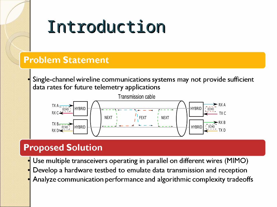
IntroductionIntroduction

Discrete Multitone Discrete Multitone ModulationModulation
DMT modulation is used in wireline communication systems (e.g. DSL)
Divide frequency selective channel into many narrowband subchannels
Transmit data over each frequency flat subchannel Modulate/demodulate multicarrier signal using Fast Fourier
Transform

MIMO DMT TestbedMIMO DMT TestbedDesign Goal: Create a 2x2 DMT hardware testbed
◦ Enable rapid prototyping/testing of new designs◦ Provide user with complete control over system
parameters◦ Connect to different cables◦ Visualize channel state and communication performance
Benefits of Hardware Testbed◦ Configure system parameters and signal processing
blocks◦ Evaluate communication performance vs.
computational complexity tradeoffs◦ Support many different cables
Design Challenges◦ Real-time constraints on transmitter and receiver
system◦ Analog front-ends for signal conditioning

Modem Implementation- Modem Implementation- HardwareHardware
TX0 TX1 RX0 RX1
EmbeddedPC
PXI-8106
PXI Backplane - PXI-1045
LPFLPF
HH
LPFLPF
HH
LPFLPF
HH
LPFLPF
HH
PXI-5421 A/D
PXI-5122 D/A
TCP Link
LPF : Low Pass FilterH: Hybrid

Modem Implementation- Modem Implementation- SoftwareSoftwareReal-Time Target
◦ LabVIEW Real-Time Vis Accesses hardware Calls DLL functions
◦ C++ Dynamic Link Library (DLL) Digital discrete-time baseband processing – Generates/processes samples sent/received
to/from hardware◦ Real-time operating system
Runs on target to guarantee real-time performance
Desktop PC◦ TCP/IP link to real-time target◦ Asynchronous visualization and control using
LabVIEW
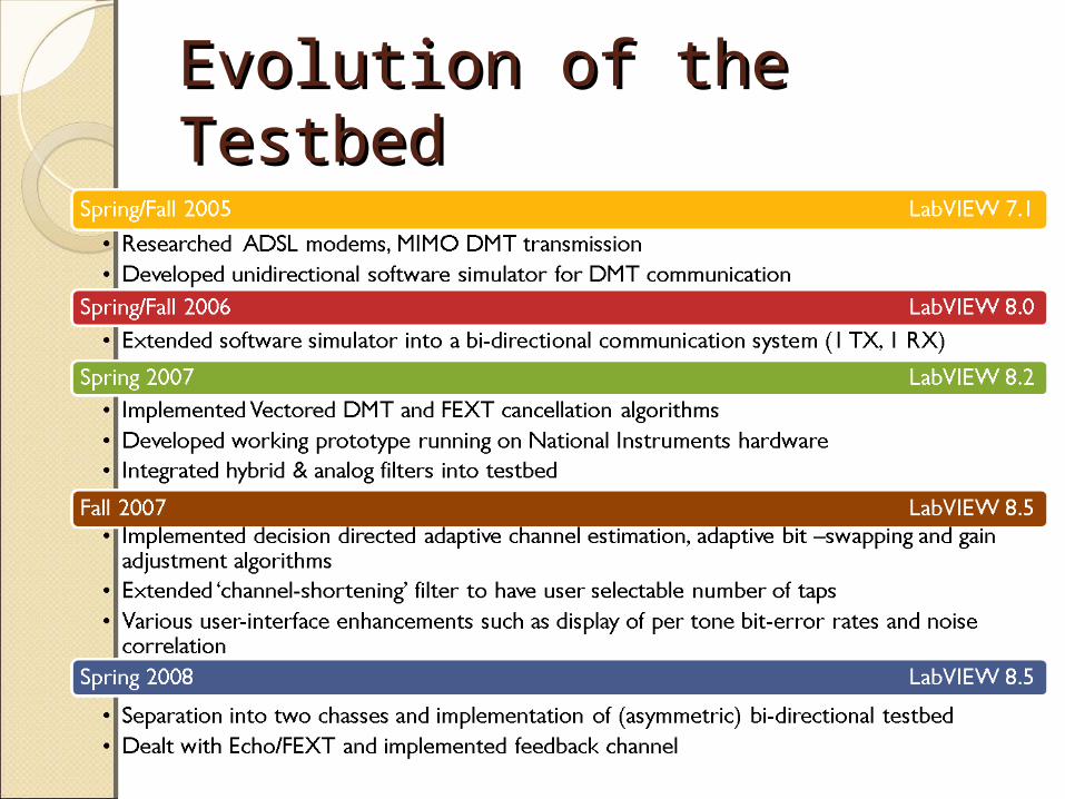
Evolution of the TestbedEvolution of the Testbed

Bit AllocationBit Allocation Fixed amount of energy available to transmit per
DMT symbol DMT allows different number of bits transmitted on
each tone Adapt bit allocation to maximize throughput or
SNR margin on each tone Hughes Hartog bit allocation algorithm [1987]
implemented
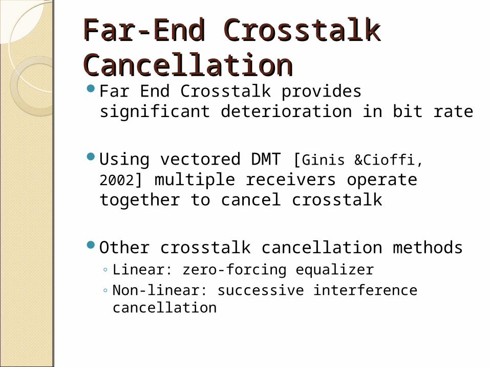
Far-End Crosstalk Far-End Crosstalk CancellationCancellationFar End Crosstalk provides significant
deterioration in bit rate
Using vectored DMT [Ginis &Cioffi, 2002] multiple receivers operate together to cancel crosstalk
Other crosstalk cancellation methods◦ Linear: zero-forcing equalizer◦ Non-linear: successive interference
cancellation

SlicerSlicer
Vectored DMTVectored DMT
QHYQHYSuccessiveInterferenceCancellation
SuccessiveInterferenceCancellation
Estimate channel
matrix H
H = Q R
Training (per-tone)Training (per-tone)
• Uses channel estimate and both received signals to effectively cancel crosstalk
y0
y1
For each tone, H, Q and R are 2x2 matrices
Q RSymbol decoding Symbol decoding
(per-tone)(per-tone)

Experimental ResultsExperimental Results• System Parameters
• 256 tones per DMT symbol• Maximum Transmitted Voltage 5.0V• Receiver noise floor ~ -60dB
• 1000ft CAT-5 cable
• Inter-twisted pairs for maximum far-end crosstalk
• Far-end crosstalk limits SNR to ~10dB

Experimental ResultsExperimental Results
SIC – Successive Interference Cancellation

Target CPU UtilizationTarget CPU Utilization


ReferencesReferencesD. Hughes-Hartog, ”Ensemble
modem structure for imperfect transmission media.” U.S. Patents Nos. 4,679,227 (July 1987), 4,731,816 (March 1988), and 4,833,706 (May 1989)
G. Ginis and J. Cioffi, “Vectored transmission for digital subscriber line systems,” IEEE J. Select. Areas Commun., vol. 20, no. 5, pp. 1085-1104, Jun. 2002
BackupBackup
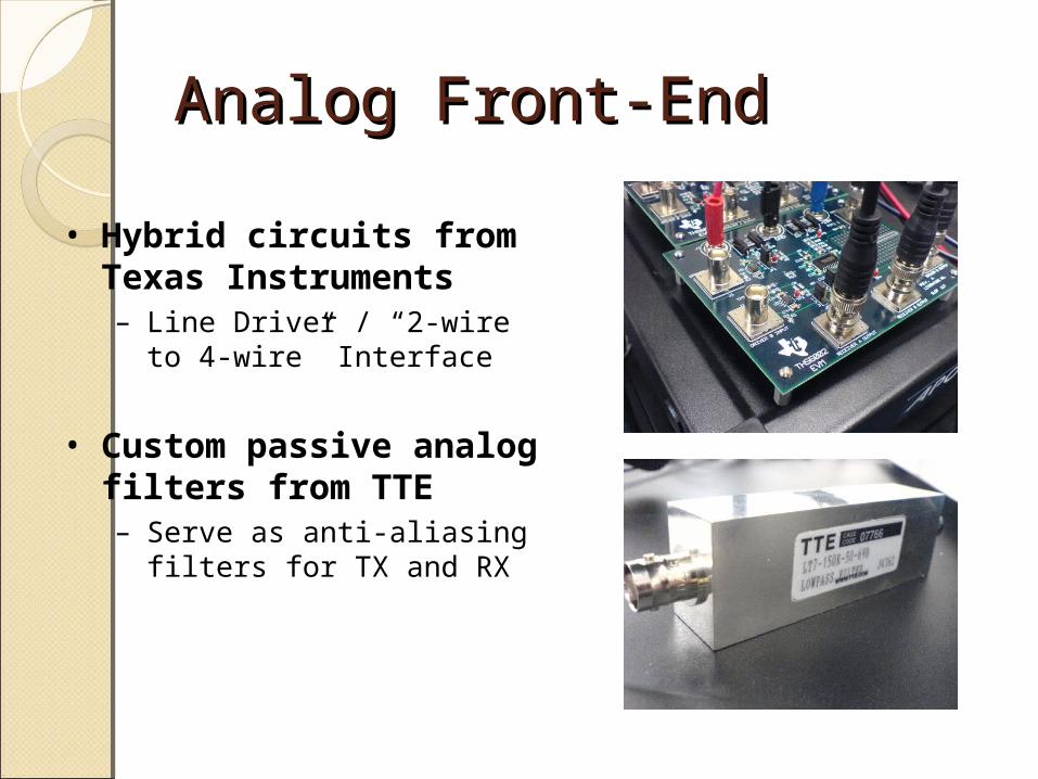
Analog Front-EndAnalog Front-End
• Hybrid circuits from Texas Instruments– Line Driver / “2-wire to 4-
wire” Interface
• Custom passive analog filters from TTE– Serve as anti-aliasing
filters for TX and RX
Related Documents

![[10] the Multitone Channel](https://static.cupdf.com/doc/110x72/577d1f8a1a28ab4e1e90cd58/10-the-multitone-channel.jpg)