Lab 3: Fading Lab Objectives This lab introduces for loops and while loops through control of LEDs, piezo buzzers, and DC motors. Students will observe the how the two loops work and how to perform the same actions with the two loops. Materials 1) Arduino Uno 2) MakeBlock Shield 3) 1 × LED 4) 1 × 220 Ω Resistor 5) 1 × DC motor 6) 1 × buzzer 7) Wires for Building Circuits 8) Wire Cutters 9) Wire Strippers Theory Figure 1: Me Base Shield The MakeBlock Me Base Shield, shown in Figure 1, is a device which stacks on top of the Arduino. This device provides simple phone cord connections (RJ25) between ports and various modules. Modules can include various MakeBlock sensors, motor drivers, and lights. Figure 2, shows the different ports on the shield. Page 1 of 6

Welcome message from author
This document is posted to help you gain knowledge. Please leave a comment to let me know what you think about it! Share it to your friends and learn new things together.
Transcript

Lab 3: Fading Lab
Objectives
This lab introduces for loops and while loops through control of LEDs, piezo buzzers, andDC motors. Students will observe the how the two loops work and how to perform the sameactions with the two loops.
Materials
1) Arduino Uno
2) MakeBlock Shield
3) 1 × LED
4) 1 × 220 Ω Resistor
5) 1 × DC motor
6) 1 × buzzer
7) Wires for Building Circuits
8) Wire Cutters
9) Wire Strippers
Theory
Figure 1: Me Base Shield
The MakeBlock Me Base Shield, shown in Figure 1, is a device which stacks on top ofthe Arduino. This device provides simple phone cord connections (RJ25) between ports andvarious modules. Modules can include various MakeBlock sensors, motor drivers, and lights.Figure 2, shows the different ports on the shield.
Page 1 of 6
4 September 2014 MENG 189L Fading Lab
DC MotorDrivers
Power Port
Power Switch
Module Ports
Figure 2: Shield Diagram
Figure 3: Module Color Code
Figure 4: Module Port Legend
Page 2 of 6
4 September 2014 MENG 189L Fading Lab
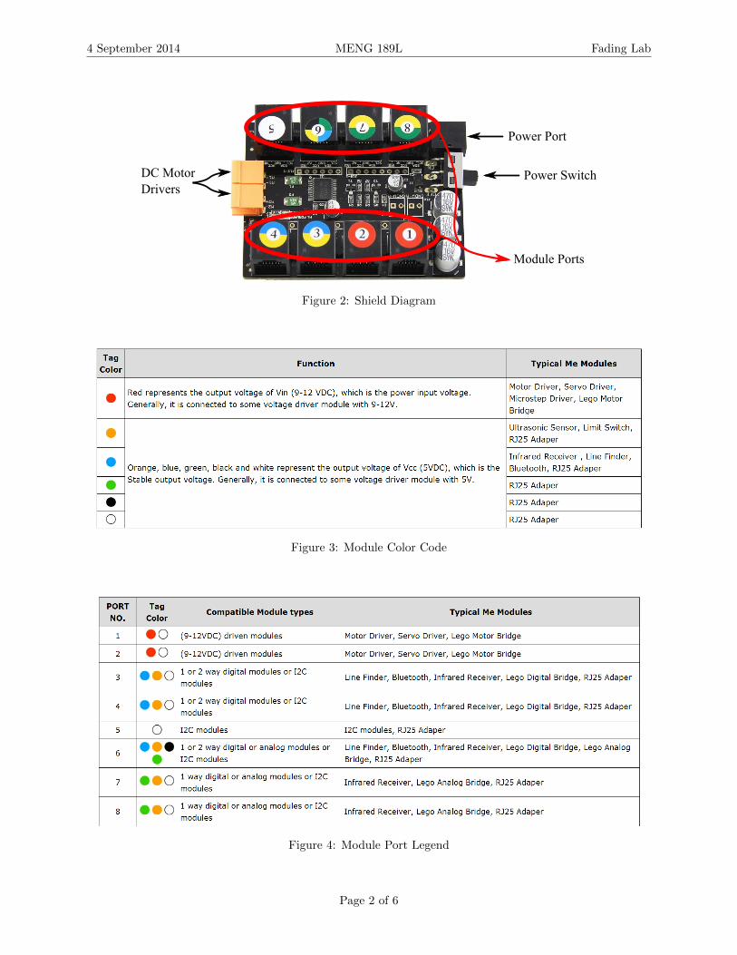
while Loops
A while loop repeats a set of code until a condition is true. Below are some examples thatchange the variable x from 0 to 100 in steps of one.
1 // Method 12 i n t x = 0 ;3 whi l e ( x < 100)4 5 x = x + 1 ;6 7 // Method 28 x = 0 ;9 whi l e ( x < 100)
10 11 x +=1;12 13 // Method 314 x = 0 ;15 whi le ( x < 100)16 17 x++;18
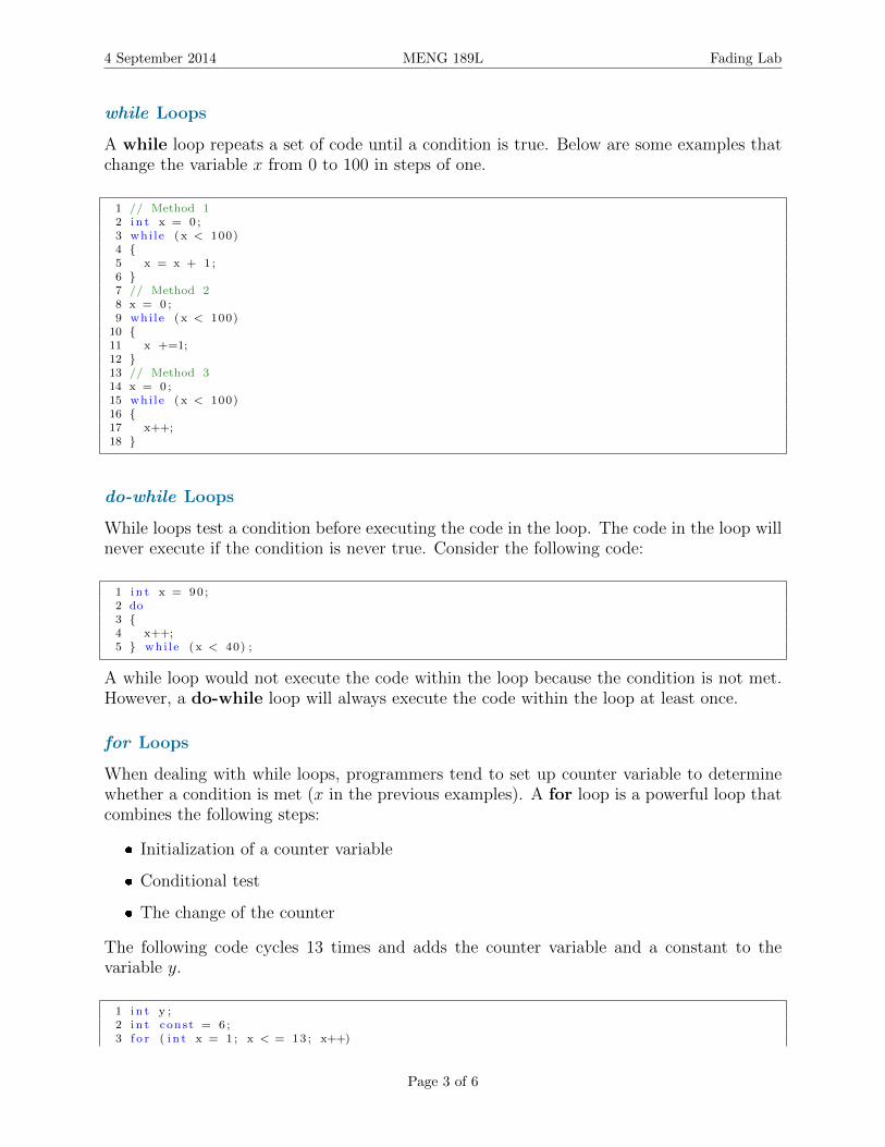
do-while Loops
While loops test a condition before executing the code in the loop. The code in the loop willnever execute if the condition is never true. Consider the following code:
1 i n t x = 90 ;2 do3 4 x++;5 whi le ( x < 40) ;
A while loop would not execute the code within the loop because the condition is not met.However, a do-while loop will always execute the code within the loop at least once.
for Loops
When dealing with while loops, programmers tend to set up counter variable to determinewhether a condition is met (x in the previous examples). A for loop is a powerful loop thatcombines the following steps:
Initialization of a counter variable
Conditional test
The change of the counter
The following code cycles 13 times and adds the counter variable and a constant to thevariable y.
1 i n t y ;2 i n t const = 6 ;3 f o r ( i n t x = 1 ; x < = 13 ; x++)
Page 3 of 6

4 September 2014 MENG 189L Fading Lab
4 5 y = x + const ;6
Laboratory Exercises
1. Check the resistor and be sure you picked the right one. Ask a TA if you have a problemfinding the value of the resistor.
2. Use the jumper wires and make the circuit in figure below. (DO NOT CONNECT ANYTHING TO THE USB PORT OR POWER SOURCE BEFORE CHECKING WITHTAs). Supplying too much power and wrong connections can damage the Arduino.
11
55
1010
1515
2020
2525
3030
A A
B B
C C
D D
E E
F F
G G
H H
I I
J J
13 12 11 10
9 8 7 6 5 4 3 2
L
5V A0
ANALOGWIN
AR
EF
1
GN
D
TX
RXR
ES
ET
3V3
A1
A2
A3
A4
A5
VIN
GN
D
GN
D
DIGITALWnPWM= o
ArduinoTM
IOR
EF
ICS
P
ICSP2
ON
POWER
01T
X0
RX
0RESET
Figure 5: Fade circuit
3. Now open the sketchpad and check the setting for port number and board type.
4. In sketchpad, try to make a new code for making a fading LED. You can use the codebelow. LED is the pin number and the brightness is a number from 0 to 255. For thispart, make a for loop to incrementally increase and decrease the brightness. Ask a TAif you have questions setting up a for loop.
1 analogWrite (LED, b r i gh tne s s ) ;
Page 4 of 6

4 September 2014 MENG 189L Fading Lab
5. Try to use the volt meter to see how the voltage changes with different brightness values.Put the positive probe on the output of port 11, and put the negative probe on ground.
6. Unassemble the circuit and put every thing back in the boxes.
Making a Buzzer
1. Use the jumper wires and make the circuit in figure below. (DO NOT CONNECT ANYTHING TO THE USB PORT OR POWER SOURCE BEFORE CHECKING WITHTAs). Supplying too much power and wrong connections can damage the Arduino.
11
55
1010
1515
2020
2525
3030
A A
B B
C C
D D
E E
F F
G G
H H
I I
J J
13 12 11 10
9 8 7 6 5 4 3 2
L
5V A0
ANALOGWIN
AR
EF
1
GN
D
TX
RX
RE
SE
T
3V3
A1
A2
A3
A4
A5
VIN
GN
D
GN
D
DIGITALWnPWM= o
ArduinoTM
IOR
EF
ICS
P
ICSP2
ON
POWER
01T
X0
RX
0RESET
Figure 6: Buzzer circuit
2. In sketchpad, try to make a new code for making a buzzer produce sound. You can usethe code below which Buzzer is the pin number and the buzzVal is a number from 0 to255. For this part, make a while loop to incrementally increase and decrease the tone.Ask a TA if you have questions setting up a while loop.
1 analogWrite ( Buzzer , buzzVal ) ;
3. Unassemble the circuit and put every thing back in the boxes.
Page 5 of 6

4 September 2014 MENG 189L Fading Lab
Move a DC motor
1. Wait for TAs to show you how to connect the MakeBlock shield to the Arduino. Connecta DC motor to the shield.
2. Use the jumper wires and make the circuit in figure below. (DO NOT CONNECT ANYTHING TO THE USB PORT OR POWER SOURCE BEFORE CHECKING WITHTAs). Supplying too much power and wrong connections can damage the Arduino.
1 2 3 4
8 7 6 5
A0 A1 A2 A3 A4 A5
RX0TX1K2~34~5~67GND 12 ~11 ~10 ~9 8AREF 13
GNDGND5V3.3VRESET VIN
OFF
ON
1348M1KFORWARD
M2KFORWARD
M1K-
M1K+
M2+
M2K-
47016VSYK
47016VSYK
47016VSYK
2225VSYK
2225VSYK
Figure 7: DC Motor circuit
3. In sketchpad, try to make a new code a which makes a DC motor move at differentspeeds. You can use the code below where speed is a number that ranges from -255 to255. For this part, make a do-while loop to incrementally increase and decrease thespeed. Ask a TA if you have questions setting up a do-while loop.
1 MeDCMotor motor (M1) ; // I n i t a l i z e s DC motor on port M12 motor . runSpeed ( speed ) ; // goes in the do−whi le loop
4. Unassemble the circuit and put every thing back in the boxes.
5. Do not leave the class until you understand every step that you did (you’ll need theseskills later on in the year).
Page 6 of 6
Related Documents