Wiring for Damper Actuators and Control Valves February 2010

Welcome message from author
This document is posted to help you gain knowledge. Please leave a comment to let me know what you think about it! Share it to your friends and learn new things together.
Transcript

Wiring forDamper Actuators and Control ValvesFebruary 2010
800-543-9038 USA 866-805-7089 CANADA 203-791-8396 LATIN AMERICA
2
L300
62 -
2/1
0 -
Subj
ect t
o ch
ange
. © B
elim
o Ai
rcon
trol
s (U
SA),
Inc.
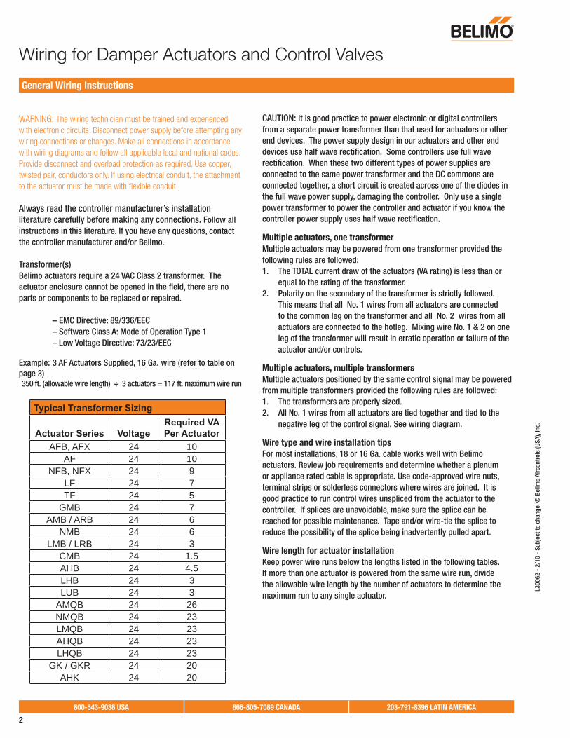
WARNING: The wiring technician must be trained and experienced with electronic circuits. Disconnect power supply before attempting any wiring connections or changes. Make all connections in accordance with wiring diagrams and follow all applicable local and national codes. Provide disconnect and overload protection as required. Use copper, twisted pair, conductors only. If using electrical conduit, the attachment to the actuator must be made with fl exible conduit.
Always read the controller manufacturer’s installation literature carefully before making any connections. Follow all instructions in this literature. If you have any questions, contact the controller manufacturer and/or Belimo.
Transformer(s)Belimo actuators require a 24 VAC Class 2 transformer. The actuator enclosure cannot be opened in the fi eld, there are no parts or components to be replaced or repaired.
– EMC Directive: 89/336/EEC – Software Class A: Mode of Operation Type 1 – Low Voltage Directive: 73/23/EEC
Example: 3 AF Actuators Supplied, 16 Ga. wire (refer to table on page 3)350 ft. (allowable wire length) ÷ 3 actuators = 117 ft. maximum wire run
CAUTION: It is good practice to power electronic or digital controllers from a separate power transformer than that used for actuators or other end devices. The power supply design in our actuators and other end devices use half wave rectifi cation. Some controllers use full wave rectifi cation. When these two different types of power supplies are connected to the same power transformer and the DC commons are connected together, a short circuit is created across one of the diodes in the full wave power supply, damaging the controller. Only use a single power transformer to power the controller and actuator if you know the controller power supply uses half wave rectifi cation.
Multiple actuators, one transformer Multiple actuators may be powered from one transformer provided the following rules are followed:1. The TOTAL current draw of the actuators (VA rating) is less than or
equal to the rating of the transformer.2. Polarity on the secondary of the transformer is strictly followed.
This means that all No. 1 wires from all actuators are connected to the common leg on the transformer and all No. 2 wires from all actuators are connected to the hotleg. Mixing wire No. 1 & 2 on one leg of the transformer will result in erratic operation or failure of the actuator and/or controls.
Multiple actuators, multiple transformersMultiple actuators positioned by the same control signal may be powered from multiple transformers provided the following rules are followed:1. The transformers are properly sized.2. All No. 1 wires from all actuators are tied together and tied to the
negative leg of the control signal. See wiring diagram.
Wire type and wire installation tipsFor most installations, 18 or 16 Ga. cable works well with Belimo actuators. Review job requirements and determine whether a plenum or appliance rated cable is appropriate. Use code-approved wire nuts, terminal strips or solderless connectors where wires are joined. It is good practice to run control wires unspliced from the actuator to the controller. If splices are unavoidable, make sure the splice can be reached for possible maintenance. Tape and/or wire-tie the splice to reduce the possibility of the splice being inadvertently pulled apart.
Wire length for actuator installationKeep power wire runs below the lengths listed in the following tables. If more than one actuator is powered from the same wire run, divide the allowable wire length by the number of actuators to determine the maximum run to any single actuator.
Typical Transformer Sizing
Actuator Series Voltage Required VA Per Actuator
AFB, AFX 24 10AF 24 10
NFB, NFX 24 9LF 24 7TF 24 5
GMB 24 7AMB / ARB 24 6
NMB 24 6LMB / LRB 24 3
CMB 24 1.5AHB 24 4.5LHB 24 3LUB 24 3
AMQB 24 26NMQB 24 23LMQB 24 23AHQB 24 23LHQB 24 23
GK / GKR 24 20AHK 24 20
General Wiring Instructions
Wiring for Damper Actuators and Control Valves

800-543-9038 USA 866-805-7089 CANADA 203-791-8396 LATIN AMERICA
3
L300
62 -
2/1
0 -
Sub
ject
to c
hang
e. ©
Bel
imo
Airc
ontr
ols
(USA
), In
c.Wire Size vs. Length of Run for Damper Actuators and Control Valves
*Bel
imo
act
uato
rs a
nd a
uxili
ary
swit
ches
are
des
igne
d a
s a
IEC
pro
tect
ion
clas
s II,
do
uble
insu
late
d, a
nd d
o n
ot
req
uire
an
ind
epen
den
t g
roun
d w
ire
to
eart
h, u
nles
s o
ther
wis
e in
dic
ated
in t
his
do
cum
ent
24 VACA
F…
US
NF
…U
SLF
…U
ST
F…
US
GM
/GR
…A
M/A
R…
NM
…LM
/LR
…C
M…
AH
…LH
…LU
…T
R…
AM
Q…
NM
Q…
LMQ
…A
HQ
…LH
Q…
108
75
76
66
1.5
4.5
33
118
1818
1818
MA
X D
ista
nce
bet
wee
n A
ctua
tor
and
Sup
ply
(fee
t)
2057
540
040
040
040
011
75
1822
027
532
545
032
557
537
510
7575
075
075
075
020
0012
012
012
012
012
0
1635
045
050
070
050
090
055
011
7511
2511
2511
2511
2520
020
020
020
020
0
1455
070
080
011
0080
011
3892
530
030
030
030
030
0
1290
010
5011
2511
7511
2512
5011
5047
547
547
547
547
5
110 VAC
AF
…U
SN
F…
US
LF…
US
TF
…U
SG
M…
AM
…N
M…
LM…
CM
…
119.
57.
56
77.
56.
54.
53.
5
MA
X D
ista
nce
bet
wee
n A
ctua
tor
and
Sup
ply
(fee
t)
2025
032
5
1821
522
027
537
532
532
532
550
060
0
1634
535
045
057
550
050
050
080
010
00
1454
555
070
090
080
080
080
012
5015
00
1289
590
010
5011
5011
2511
2511
25
220 VAC
AF
…U
SLF
…U
ST
F…
US
GM
…A
M…
NM
…LM
…C
M…
117
67.
57.
56.
54.
53.
5
MA
X D
ista
nce
bet
wee
n A
ctua
tor
and
Sup
ply
(fee
t)
2025
032
5
1821
532
537
532
532
532
550
060
0
1634
550
057
550
050
050
080
010
00
1454
580
090
080
080
080
012
5015
00
1289
511
2511
5011
2511
2511
25
wire
gau
ge
wire
gau
ge
wire
gau
ge
VA VA VA

800-543-9038 USA 866-805-7089 CANADA 203-791-8396 LATIN AMERICA
4
L300
62 -
2/1
0 -
Subj
ect t
o ch
ange
. © B
elim
o Ai
rcon
trol
s (U
SA),
Inc.
Wire Size vs. Length of Run for SY Series Actuators
The
NE
C m
and
ates
tha
t 24
VA
C o
ver
100
VA p
ow
er r
equi
res
CLA
SS
1 w
irin
g c
ond
uit.
Lo
cal c
od
es m
ay v
ary.
Do
NO
T m
ix C
LAS
S 1
& C
LAS
S 2
cir
cuit
s in
th
e sa
me
cond
uit.
Gen
eral
ly, 2
4 VA
C a
ctua
tors
ove
r 10
0 VA
sho
uld
be
chan
ged
to
120
VA
C m
od
els.
SY
1S
Y2
SY
3S
Y4
SY
5
Am
ps
Am
ps
Am
ps
Am
ps
Am
ps
wire
gau
ge
1.8
33
66.
5
MA
X D
ista
nce
bet
wee
n A
ctua
tor
and
Sup
ply
(fee
t)
1892
5555
1614
487
8743
40
1423
314
014
070
65
1235
721
421
410
799
1060
636
436
418
216
8
890
554
354
327
125
0
24 VAC
SY
1S
Y2
SY
3S
Y4
SY
5S
Y6
SY
7S
Y8
SY
9S
Y10
SY
11S
Y12
Am
ps
Am
ps
Am
ps
Am
ps
Am
ps
Am
ps
Am
ps
Am
ps
Am
ps
Am
ps
Am
ps
Am
ps
wire
gau
ge
0.5
11
1.3
1.5
1.8
3.2
43.
24
34
MA
X D
ista
nce
bet
wee
n A
ctua
tor
and
Sup
ply
(fee
t)
1815
1575
875
858
350
542
123
718
923
718
925
318
9
1623
8111
9011
9091
679
466
137
229
837
229
839
729
8
1438
4619
2319
2314
7912
8210
6860
148
160
148
164
148
1
1258
8229
4129
4122
6219
6116
3491
973
591
973
598
073
5
1010
000
5000
5000
3846
3333
2778
1563
1250
1563
1250
1667
1250
814
925
7463
7463
5741
4975
4146
2332
1866
2332
1866
2488
1866
110 VAC
SY
1S
Y2
SY
3S
Y4
SY
5S
Y6
SY
7S
Y8
SY
9S
Y10
SY
11S
Y12
Am
ps
Am
ps
Am
ps
Am
ps
Am
ps
Am
ps
Am
ps
Am
ps
Am
ps
Am
ps
Am
ps
Am
ps
wire
gau
ge
0.3
0.5
0.5
0.6
0.7
0.8
1.6
21.
62
1.6
2.2
MA
X D
ista
nce
bet
wee
n A
ctua
tor
and
Sup
ply
(fee
t)
1850
5130
3030
3025
2521
6518
9494
775
894
775
894
768
9
1679
3747
6247
6239
6834
0129
7614
8811
9014
8811
9014
8810
82
1412
821
7692
7692
6410
5495
4808
2404
1923
2404
1923
2404
1748
1219
608
1176
511
765
9804
8403
7353
3676
2941
3676
2941
3676
2674
1033
333
2000
020
000
1666
714
286
1250
062
5050
0062
5050
0062
5045
45
849
751
2985
129
851
2487
621
322
1865
793
2874
6393
2874
6393
2867
84
220 VAC

800-543-9038 USA 866-805-7089 CANADA 203-791-8396 LATIN AMERICA
5
L300
62 -
2/1
0 -
Sub
ject
to c
hang
e. ©
Bel
imo
Airc
ontr
ols
(USA
), In
c.Wiring for Damper Actuators and Control Valves
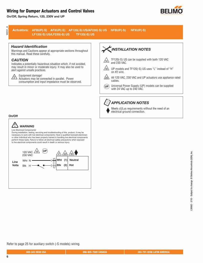
On/Off, Spring Return, 24V
Blk (1) Common
Red (2) + Hot
24 VAC Transformer
Line Volts
2 3 5
Actuators with plenum rated cable do not have numbers on wires; use color codes instead.
Actuators with appliance cables are numbered.
3 Actuators may also be powered by 24 VDC.
5
Meets cULus requirements without the need of anelectrical ground connection.
Actuators: AF24(-S) US NFB24(-S) NFX24(-S) LF24(-S) US TF24(-S) US
INSTALLATION NOTES
APPLICATION NOTES
Equipment damage!Actuators may be connected in parallel. Power consumption and input impedance must be observed.
2
CAUTIONIndicates a potentially hazardous situation which, if not avoided, may result in minor or moderate injury. It may also be used to alert against unsafe practices.
Warnings and Cautions appear at appropriate sections throughout this manual. Read these carefully.
Hazard Identification
WARNINGLive Electrical Components!During installation, testing, servicing and troubleshooting of this product, it may be necessary to work with live electrical components. Have a qualified licensed electrician or other individual who has been properly trained in handling live electrical components perform these tasks. Failure to follow all electrical safety precautions when exposed to live electrical components could result in death or serious injury.
On/Off
A
W23
6
Refer to page 25 for auxiliary switch (-S models) wiring.
800-543-9038 USA 866-805-7089 CANADA 203-791-8396 LATIN AMERICA
6
L300
62 -
2/1
0 -
Subj
ect t
o ch
ange
. © B
elim
o Ai
rcon
trol
s (U
SA),
Inc.
19
Wht (1) Neutral
Blk (2) Hot
Wht N
Blk HLine Volts
2120 VAC230 VAC
UP models and TF120(-S) US uses “L” instead of “H” on #2 wire.
All 120 VAC, 230 VAC and UP actuators use appliance ratedcables.
14
20
19
TF120(-S) US can be supplied with both 120 VAC and 230 VAC.
Meets cULus requirements without the need of anelectrical ground connection.
Actuators: AFBUP(-S) AFXUP(-S) AF120(-S) US/AF230(-S) US NFBUP(-S) NFXUP(-S) LF120(-S) US/LF230(-S) US TF120(-S) US
INSTALLATION NOTES
APPLICATION NOTES
Equipment damage!Actuators may be connected in parallel. Power consumption and input impedance must be observed.
2
CAUTIONIndicates a potentially hazardous situation which, if not avoided, may result in minor or moderate injury. It may also be used to alert against unsafe practices.
Warnings and Cautions appear at appropriate sections throughout this manual. Read these carefully.
Hazard Identification
WARNINGLive Electrical Components!During installation, testing, servicing and troubleshooting of this product, it may be necessary to work with live electrical components. Have a qualified licensed electrician or other individual who has been properly trained in handling live electrical components perform these tasks. Failure to follow all electrical safety precautions when exposed to live electrical components could result in death or serious injury.
On/Off
1420
W23
1_A
UP
UP Universal Power Supply (UP) models can be supplied with 24 VAC up to 240 VAC.
Wiring for Damper Actuators and Control Valves On/Off, Spring Return, 120, 230V and UP
Refer to page 25 for auxiliary switch (-S models) wiring.

800-543-9038 USA 866-805-7089 CANADA 203-791-8396 LATIN AMERICA
7
L300
62 -
2/1
0 -
Sub
ject
to c
hang
e. ©
Bel
imo
Airc
ontr
ols
(USA
), In
c. Blk (1) Common
Red (2) + Hot
Wht (3) +
† +
ComHot
Controller
LineVolts
CW CCW
LF24-3(-S) US
The indication of direction is valid for switch position CW.
2
24 VAC Transformer
5
Triac Source
Triac SinkTriac Sink with Separate Transformer
TF24-3(-S) US
Actuators with plenum rated cable do not have numbers onwires; use color codes instead. Actuators with appliance cables are numbered.
For triac sink the Common connection from the actuator must be connected to the Hot connection of the controller. The actuator must be connected to the control board common.
3 Actuators may also be powered by 24 VDC.
5
11
Meets cULus requirements without the need of anelectrical ground connection.
Actuators: LF24-3(-S) US TF24-3(-S) US LFC24-3...US
INSTALLATION NOTES
APPLICATION NOTES
Equipment damage!Actuators may be connected in parallel. Power consumption and input impedance must be observed.
2
CAUTIONIndicates a potentially hazardous situation which, if not avoided, may result in minor or moderate injury. It may also be used to alert against unsafe practices.
Warnings and Cautions appear at appropriate sections throughout this manual. Read these carefully.
Hazard Identification
LineVolts
The indication of direction is valid for switch position CW.
Blk (1) Common
Red (2) + Hot
Wht (3) +
† +
24 VAC Transformer
LF24-3(-S) USCW CCW
LFC24-3-R USLFC24-3-S USTF24-3(-S) US
a
b
3 5
Floating Point
WARNINGLive Electrical Components!During installation, testing, servicing and troubleshooting of this product, it may be necessary to work with live electrical components. Have a qualified licensed electrician or other individual who has been properly trained in handling live electrical components perform these tasks. Failure to follow all electrical safety precautions when exposed to live electrical components could result in death or serious injury.
TF24-3(-S) US
Blk (1) Common
Red (2) + Hot
Wht (3) +
† +
ComHot
Controller
LineVolts
CW CCWLF24-3(-S) US
The indication of direction is valid for switch position CW.
2
24 VAC Transformer
5 11
6
WARNINGLive Electrical Components!During installation, testing, servicing and troubleshooting of this product, it may be necessary to work with live electrical components. Have a qualified licensed electrician or other individual who has been properly trained in handling live electrical components perform these tasks. Failure to follow all electrical safety precautions when exposed to live electrical components could result in death or serious injury.
Blk (1) Common
Red (2) + Hot
Wht (3) +
† +
ComHot
Controller
LineVolts
CW CCW
LF24-3(-S) US
The indication of direction is valid for switch position CW.
2
24 VAC Transformer LineVolts
24 VAC Transformer
5
TF24-3(-S) US
6
WARNINGLive Electrical Components!During installation, testing, servicing and troubleshooting of this product, it may be necessary to work with live electrical components. Have a qualified licensed electrician or other individual who has been properly trained in handling live electrical components perform these tasks. Failure to follow all electrical safety precautions when exposed to live electrical components could result in death or serious injury.
WARNINGLive Electrical Components!During installation, testing, servicing and troubleshooting of this product, it may be necessary to work with live electrical components. Have a qualified licensed electrician or other individual who has been properly trained in handling live electrical components perform these tasks. Failure to follow all electrical safety precautions when exposed to live electrical components could result in death or serious injury.
Actuator Wire Number ColorTF24-3 US 4 OrgTF24-3-S US 5 OrgLF24-3 US 4 GrnLF24-3-S US 5 Wht
†
6Actuators Hot wire must be connected to the control board common.
W23
2
Wiring for Damper Actuators and Control Valves Floating Point, Spring Return, 24V
Refer to page 25 for auxiliary switch (-S models) wiring.

800-543-9038 USA 866-805-7089 CANADA 203-791-8396 LATIN AMERICA
8
L300
62 -
2/1
0 -
Subj
ect t
o ch
ange
. © B
elim
o Ai
rcon
trol
s (U
SA),
Inc.
Wiring for Damper Actuators and Control Valves On/Off and Floating Point, Non-Spring Return, Electronic Fail-Safe, 24V
Blk 1 Common
Red 2 +
Wht 3 +
Blk 1 Common
Red 2 +
Wht 3 +
Floating PointOn/Off
Floating PointOn/Off – SPDT Switch
2 3 524 VAC Transformer
a opena closed
Blk (1) Common
Red (2) +
Wht (3) +a
LineVolts
The indication of direction is valid for switch position 1.
LMB(X)24-3...
NMB(X)24-3...
AMB(X)24-3...
GMB(X)24-3...
CMB24-3...
LRB(X)24-3...
ARB(X)24-3...
1 0
24 VAC Transformer
Blk (1) Common
Red (2) +
Wht (3) +
LineVolts
The indication of direction is valid for switch position 1.
2 3 5
1 0
24 VAC Transformer
TR24-3 (-T) US
Line Volts
Note: TR24-3 (-T) US cannot be wired in parallel with any actuator.
5
TR24-3 (-T) US
24 VAC Transformer
Line Volts
Note: TR24-3 (-T) US cannot be wired in parallel with any actuator.
Actuators: LMB24-3(-S) (-T) AMB24-3(-S) LMX24-3(-T) AMX24-3(-T) LRB24-3(-S) ARX24-3 TR24-3(-T) US NMB24-3 GMB24-3… NMX24-3(-T) GMX24-3… ARB24-3(-S) LRX24-3 CMB24-3… ARB24-3-5 GRB24-3-5 GRB24-3-7 GMB24-3-X1 LRCB24-3(-S)
Actuators with plenum rated cable do not have numbers on wires; use color codes instead. Actuators with appliance cables are numbered.
The TR24-3-T US actuators are provided witha numbered screw terminal strip instead of cable.
TR24-3 US actuators cannot be wired in parallel.
3 Actuators may also be powered by 24 VDC.
5
16
17
Meets cULus requirements without the need of anelectrical ground connection.
Equipment damage!Actuators may be connected in parallel. Power consumption and input impedance must be observed.
2
CAUTIONIndicates a potentially hazardous situation which, if not avoided, may result in minor or moderate injury. It may also be used to alert against unsafe practices.
Warnings and Cautions appear at appropriate sections throughout this manual. Read these carefully.
Hazard IdentificationINSTALLATION NOTES
APPLICATION NOTES
Live Electrical Components!During installation, testing, servicing and troubleshooting of this product, it may be necessary to work with live electrical components. Have a qualified licensed electrician or other individual who has been properly trained in handling live electrical components perform these tasks. Failure to follow all electrical safety precautions when exposed to live electrical components could result in death or serious injury.
WARNINGLive Electrical Components!During installation, testing, servicing and troubleshooting of this product, it may be necessary to work with live electrical components. Have a qualified licensed electrician or other individual who has been properly trained in handling live electrical components perform these tasks. Failure to follow all electrical safety precautions when exposed to live electrical components could result in death or serious injury.
WARNING
LMB(X)24-3...
NMB(X)24-3...
AMB(X)24-3...
GMB(X)24-3...
CMB24-3...
LRB(X)24-3...
ARB(X)24-3...
16 17 5 16 17
W33
2
Blk 1 Common
Red 2 +
Wht 3 +
On/Off
On/Off – SPDT Switch
2 3 524 VAC Transformer
a opena closed
Blk (1) Common
Red (2) +
Wht (3) +a
LineVolts
The indication of direction is valid for switch position 1.
LMB(X)24-3...
NMB(X)24-3...
AMB(X)24-3...
GMB(X)24-3...
CMB24-3...
LRB(X)24-3...
ARB(X)24-3...
1 0
24 VAC Transformer
TR24-3 (-T) US
Line Volts
Note: TR24-3 (-T) US cannot be wired in parallel with any actuator.
Live Electrical Components!During installation, testing, servicing and troubleshooting of this product, it may be necessary to work with live electrical components. Have a qualified licensed electrician or other individual who has been properly trained in handling live electrical components perform these tasks. Failure to follow all electrical safety precautions when exposed to live electrical components could result in death or serious injury.
WARNING
16 17 5
Refer to page 25 for auxiliary switch (-S models) wiring.

800-543-9038 USA 866-805-7089 CANADA 203-791-8396 LATIN AMERICA
9
L300
62 -
2/1
0 -
Sub
ject
to c
hang
e. ©
Bel
imo
Airc
ontr
ols
(USA
), In
c.Wiring for Damper Actuators and Control Valves
Floating Point, Electronic Fail-Safe, 24V
Floating Point
Actuators: GKB24-3 NKQB24-3
Actuators may also be powered by 24 VDC.
1 Provide overload protection and disconnect as required.
3
5
8
Meets cULus requirements without the need of anelectrical ground connection.
Equipment damage!Actuators may be connected in parallel. Power consumption and input impedance must be observed.
2
CAUTIONIndicates a potentially hazardous situation which, if not avoided, may result in minor or moderate injury. It may also be used to alert against unsafe practices.
Warnings and Cautions appear at appropriate sections throughout this manual. Read these carefully.
Hazard IdentificationINSTALLATION NOTES
APPLICATION NOTESLive Electrical Components!During installation, testing, servicing and troubleshooting of this product, it may be necessary to work with live electrical components. Have a qualified licensed electrician or other individual who has been properly trained in handling live electrical components perform these tasks. Failure to follow all electrical safety precautions when exposed to live electrical components could result in death or serious injury.
WARNING
W61
2
9 For triac sink the common connection from the actuatormust be connected to the hot connection of the controller.
Control signal may be pulsed from either the Hot (source)or the Common (sink) 24 VAC line.
Contact closures A & B also can be triacs.A & B should both be closed for triac source and open fortriac sink.
GKB24-3NKQB24-3

800-543-9038 USA 866-805-7089 CANADA 203-791-8396 LATIN AMERICA
10
L300
62 -
2/1
0 -
Subj
ect t
o ch
ange
. © B
elim
o Ai
rcon
trol
s (U
SA),
Inc.
15152
100 to 240 VAC
a opena closed
The indication of direction is valid for switch position 1.
Blu (1) Common
Blk (2) +
Wht (3) +a
N L1
H L2
–
1 0
2100 to 240 VAC
The indication of direction is valid for switch position 1.
Blk (1) Common
Red (2) +
Wht (3) +
N L1
H L2
1 0
On/Off Floating Point
Actuators: LMX120-3 AMX120-3 LRX120-3 CMB120-3 NMX120-3 GMX120-3 ARX120-3
15
19
LMB(X), NMB(X), AMB(X), GMB(X), LRB(X), and ARB(X)can be supplied with either 120 VAC or 230 VAC.
All 120VAC and 230VAC actuators use appliance ratedcables.
Meets cULus requirements without the need of anelectrical ground connection.
INSTALLATION NOTES
APPLICATION NOTES
Equipment damage!Actuators may be connected in parallel. Power consumption and input impedance must be observed.
2
CAUTIONIndicates a potentially hazardous situation which, if not avoided, may result in minor or moderate injury. It may also be used to alert against unsafe practices.
Warnings and Cautions appear at appropriate sections throughout this manual. Read these carefully.
Hazard Identification
WARNINGLive Electrical Components!During installation, testing, servicing and troubleshooting of this product, it may be necessary to work with live electrical components. Have a qualified licensed electrician or other individual who has been properly trained in handling live electrical components perform these tasks. Failure to follow all electrical safety precautions when exposed to live electrical components could result in death or serious injury.
WARNINGLive Electrical Components!During installation, testing, servicing and troubleshooting of this product, it may be necessary to work with live electrical components. Have a qualified licensed electrician or other individual who has been properly trained in handling live electrical components perform these tasks. Failure to follow all electrical safety precautions when exposed to live electrical components could result in death or serious injury.
19 19
Actuators with appliance cables are numbered.A
W36
4
Wiring for Damper Actuators and Control Valves On/Off and Floating Point, Non-Spring Return, 100 to 240V
Refer to page 25 for auxiliary switch (-S models) wiring.

800-543-9038 USA 866-805-7089 CANADA 203-791-8396 LATIN AMERICA
11
L300
62 -
2/1
0 -
Sub
ject
to c
hang
e. ©
Bel
imo
Airc
ontr
ols
(USA
), In
c.
3 4
Blk (1) Common
Red (2) + Hot
Wht (3) Y Input, 2 to 10
24 VAC Transformer
6
Control Signal (+)VDC/mA
(–)
Feedback Signal (+)2 to 10 VDC (–)
Ω 500 Ω
Line
Volts
LF24-SR(-S) US
CW CCW
3 4
NFB24-SR(-S)AF24-SR US
Blk (1) Common
Red (2) + Hot
Wht (3) Y Input, 2 to 10V
24 VAC Transformer
8
Control Signal (+)VDC/mA
(–) Ω
500 Ω
Line
Volts
AFA24-SR USTF24-SR(-S) US
Actuators: AF24-SR US AFA24-SR US NFB24-SR(-S) NFX24-SR(-S) LF24-SR(-S) US TF24-SR(-S) US
Equipment damage!Up to four actuators may be connected in parallel if not mechanically linked. Power consumption and input impedance must be observed.
4
CAUTIONIndicates a potentially hazardous situation which, if not avoided, may result in minor or moderate injury. It may also be used to alert against unsafe practices.
Warnings and Cautions appear at appropriate sections throughout this manual. Read these carefully.
Hazard Identification
WARNINGLive Electrical Components!During installation, testing, servicing and troubleshooting of this product, it may be necessary to work with live electrical components. Have a qualified licensed electrician or other individual who has been properly trained in handling live electrical components perform these tasks. Failure to follow all electrical safety precautions when exposed to live electrical components could result in death or serious injury.
WARNINGLive Electrical Components!During installation, testing, servicing and troubleshooting of this product, it may be necessary to work with live electrical components. Have a qualified licensed electrician or other individual who has been properly trained in handling live electrical components perform these tasks. Failure to follow all electrical safety precautions when exposed to live electrical components could result in death or serious injury.
Meets cULus requirements without the need of anelectrical ground connection.
A 500 Ω resistor converts the 4 to 20 mA control signal to 2 to 10 VDC.
APPLICATION NOTES
Actuators with plenum rated cable do not have numbers on wires; use color codes instead. Actuators with appliance cables are numbered.
3 Actuators may also be powered by 24 VDC.
5
Only connect common to neg. (–) leg of control circuits. 6
INSTALLATION NOTES
8
7
The AFA24-SR US and TF24-SR(-S) US are supplied without position feedback.
7 7
5
(5) U Output, 2 to 10V
6
5
W23
3_A
NFX24-SR(-S)
Actuator ColorWire NumberAF24-SR US 5 WhtNFB24-SR(-S) 5 OrgNFX24-SR(-S) 5 OrgLF24-SR US 5 GrnLF24-SR-S US 5 Wht
†
†
Wiring for Damper Actuators and Control Valves Proportional, Spring Return, 24V
Refer to page 25 for auxiliary switch (-S models) wiring.

800-543-9038 USA 866-805-7089 CANADA 203-791-8396 LATIN AMERICA
12
L300
62 -
2/1
0 -
Subj
ect t
o ch
ange
. © B
elim
o Ai
rcon
trol
s (U
SA),
Inc.
TR24-SR (-T) US
7
7
24 VAC Transformer
Blk (1) Common
Red (2) + Hot
Wht (3) Y Input 2 to 10V
Line
Volts
VDC/mAControl Signal
(–)
(+)
Ω500 Ω
3
Actuators: LMB24-SR (-T) NMB24-SR LMX24-SR (-T) NMX24-SR (-T) LRB24-SR TR24-SR (-T) US AMB24-SR GMB24-SR AMX24-SR (-T) GMX24-SR ARB24-SR LRX24-SR ARX24-SR CMB24-SR-L CMB24-SR-R GKB24-SR GKX24-SR
Actuators with plenum rated cable do not have numbers on wires; use color codes instead. Actuators with appliance cables are numbered.
3 Actuators may also be powered by 24 VDC.
5
Only connect common to neg. (–) leg of control circuits. Terminal models (-T) have no-feedback.
6
INSTALLATION NOTES
Meets cULus requirements without the need of anelectrical ground connection.
A 500 Ω resistor converts the 4 to 20 mA control signal to 2 to 10 VDC.
APPLICATION NOTES
Equipment damage!Up to four actuators may be connected in parallel if not mechanically linked. Power consumption and input impedance must be observed.
4
CAUTIONIndicates a potentially hazardous situation which, if not avoided, may result in minor or moderate injury. It may also be used to alert against unsafe practices.
Warnings and Cautions appear at appropriate sections throughout this manual. Read these carefully.
Hazard Identification
LMB(X)24-SR...
NMB(X)24-SR...
AMB(X)24-SR...
GMB(X)24-SR...
LRB(X)24-SR...
ARB(X)24-SR...
LHB(X)24-SR...
AHB(X)24-SR...
LUB(X)24-SR
CMB24-SR...
1 0
Blk (1) Common
Red (2) + Hot
Wht (3) Y Input, 2 to 10V
Org (5) U Output, 2 to 10V
24 VAC Transformer
6
7
Control Signal (+)VDC/mA
(–)
Feedback Signal (+)2 to 10 VDC (–)
Ω 500 Ω
Line
Volts
3
WARNINGLive Electrical Components!During installation, testing, servicing and troubleshooting of this product, it may be necessary to work with live electrical components. Have a qualified licensed electrician or other individual who has been properly trained in handling live electrical components perform these tasks. Failure to follow all electrical safety precautions when exposed to live electrical components could result in death or serious injury.
WARNINGLive Electrical Components!During installation, testing, servicing and troubleshooting of this product, it may be necessary to work with live electrical components. Have a qualified licensed electrician or other individual who has been properly trained in handling live electrical components perform these tasks. Failure to follow all electrical safety precautions when exposed to live electrical components could result in death or serious injury.
4
4
55
6
W33
3
Wiring for Damper Actuators and Control Valves Proportional, Non-Spring Return, Electronic Fail-Safe, 24V

800-543-9038 USA 866-805-7089 CANADA 203-791-8396 LATIN AMERICA
13
L300
62 -
2/1
0 -
Sub
ject
to c
hang
e. ©
Bel
imo
Airc
ontr
ols
(USA
), In
c.Wiring for Damper Actuators and Control Valves
Proportional, Non-Spring Return, 100 to 240V
15
Actuators: LMX120-SR AMX120-SR ARX120-SR NMX120-SR LRX120-SR
7
15 LMB(X), NMB(X), AMB(X), GMB(X), LRB(X), and ARB(X) can be supplied with either 120 VAC or 230 VAC.
Only connect common to neg. (–) leg of control circuits. 6
INSTALLATION NOTES
Meets cULus requirements without the need of anelectrical ground connection. A 500 resistor converts the 4 to 20 mA controlsignal to 2 to 10 VDC.
APPLICATION NOTES
Equipment damage!Actuators may be connected in parallel. Power consumption and input impedance must be observed.
2
CAUTIONIndicates a potentially hazardous situation which, if not avoided, may result in minor or moderate injury. It may also be used to alert against unsafe practices.
Warnings and Cautions appear at appropriate sections throughout this manual. Read these carefully.
Hazard Identification
2
Wht (1) Neutral
Blk (2) Hot +
N L1
H L2
6 Blk (1) Common
Red (2) Hot +
Wht (3) Y Input, 2 to 10VControl Signal
2 to 10 VDCFeedback Signal
Org (5) U Output, 2 to 10V
(–)
(+)(–)(+)
1 0
100 to 240 VAC
Cabl
e 2
Cabl
e 1
5
WARNINGLive Electrical Components!During installation, testing, servicing and troubleshooting of this product, it may be necessary to work with live electrical components. Have a qualified licensed electrician or other individual who has been properly trained in handling live electrical components perform these tasks. Failure to follow all electrical safety precautions when exposed to live electrical components could result in death or serious injury.
19 All 120 VAC and 230 VAC actuators use appliance ratedcables.
19
7
VDC/mA
Actuators with appliance cables are numbered.A
W36
5
800-543-9038 USA 866-805-7089 CANADA 203-791-8396 LATIN AMERICA
14
L300
62 -
2/1
0 -
Subj
ect t
o ch
ange
. © B
elim
o Ai
rcon
trol
s (U
SA),
Inc.
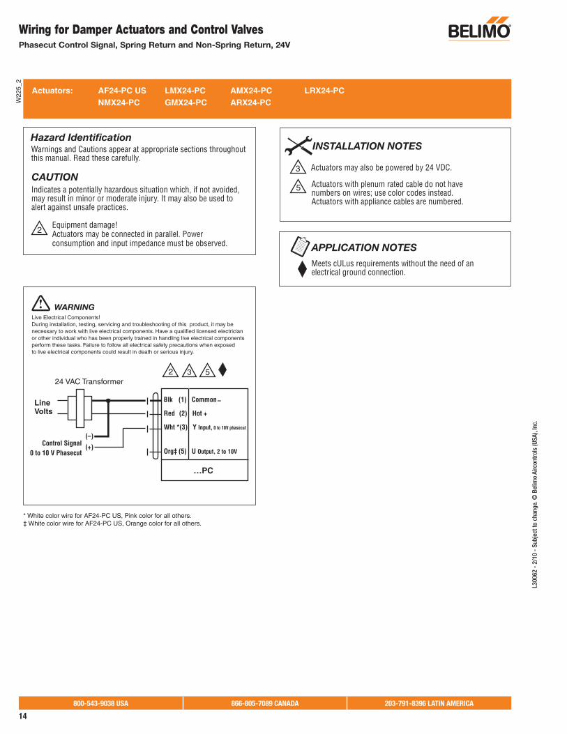
Actuators: AF24-PC US LMX24-PC AMX24-PC LRX24-PC NMX24-PC GMX24-PC ARX24-PC
Equipment damage!Actuators may be connected in parallel. Power consumption and input impedance must be observed.
2
CAUTIONIndicates a potentially hazardous situation which, if not avoided, may result in minor or moderate injury. It may also be used to alert against unsafe practices.
Warnings and Cautions appear at appropriate sections throughout this manual. Read these carefully.
Hazard Identification
Meets cULus requirements without the need of anelectrical ground connection.
APPLICATION NOTES
Actuators with plenum rated cable do not have numbers on wires; use color codes instead. Actuators with appliance cables are numbered.
3 Actuators may also be powered by 24 VDC.
5
INSTALLATION NOTES
WARNINGLive Electrical Components!During installation, testing, servicing and troubleshooting of this product, it may be necessary to work with live electrical components. Have a qualified licensed electrician or other individual who has been properly trained in handling live electrical components perform these tasks. Failure to follow all electrical safety precautions when exposed to live electrical components could result in death or serious injury.
24 VAC Transformer
Blk (1) Common
Red (2) Hot +
Wht *(3) Y Input, 0 to 10V phasecut
Org‡ (5) U Output, 2 to 10V
LineVolts
0 to 10 V PhasecutControl Signal
(–)
(+)
–
…PC
3 52
* White color wire for AF24-PC US, Pink color for all others.‡ White color wire for AF24-PC US, Orange color for all others.
W22
5_2
Wiring for Damper Actuators and Control Valves Phasecut Control Signal, Spring Return and Non-Spring Return, 24V

800-543-9038 USA 866-805-7089 CANADA 203-791-8396 LATIN AMERICA
15
L300
62 -
2/1
0 -
Sub
ject
to c
hang
e. ©
Bel
imo
Airc
ontr
ols
(USA
), In
c.
Actuators: LF24-ECON-R03 US LF24-ECON-R10 US AF24-ECON-R03 US
Actuators with plenum rated cable do not have numbers on wires; use color codes instead. Actuators with appliance cables are numbered.
5
Equipment damage!Actuators may be connected in parallel. Power consumption and input impedance must be observed.
2
CAUTIONIndicates a potentially hazardous situation which, if not avoided, may result in minor or moderate injury. It may also be used to alert against unsafe practices.
Warnings and Cautions appear at appropriate sections throughout this manual. Read these carefully.
Hazard Identification INSTALLATION NOTES
26Min-position is adjustable from 0 to 100% with apotentiometer on the actuator cover.
27A relay or switch can spring return the actuator when theRTU fan de-energizes, or if low ambient temperature is sensed.
28A standard relay can be used to close the sensor circuit toengage economizer mode, e.g. outside air changeover devicelike a dry bulb or enthalpy limit switch. Honeywell logic module W7459A and enthalpy sensor C7400 also provide terminals for this switching.
29A remote CO2 sensor or DDC controller can change thestandard relay opening or closing the sensor circuit. This device can be a relay or a dry bulb/enthalpy limit switch.
30
30
Override control for Y2 only accepts 0 to 10 VDCoverride control.
W20
2
W20
3
24 VAC Transformer
LineVolts
3 k NTC*MA thermistorsetpoint 55 F
Blk (1) Common
Red (2) + Hot
Wht (3) Y1 Org (4) Y2 Min-pos, 0 to 10 V
Grn (5) U Output, 2 to 10V
DefaultCW CCW
0
.2.4 .6
.8
1
MIN
LF24-ECON-R03 USLF24-ECON-R10 US
WARNINGLive Electrical Components!During installation, testing, servicing and troubleshooting of this product, it may be necessary to work with live electrical components. Have a qualified licensed electrician or other individual who has been properly trained in handling live electrical components perform these tasks. Failure to follow all electrical safety precautions when exposed to live electrical components could result in death or serious injury.
WARNINGLive Electrical Components!During installation, testing, servicing and troubleshooting of this product, it may be necessary to work with live electrical components. Have a qualified licensed electrician or other individual who has been properly trained in handling live electrical components perform these tasks. Failure to follow all electrical safety precautions when exposed to live electrical components could result in death or serious injury.
27
28
29
27
29
5
Standard Economizer Mode Wiring Override
Override Control
WireAF24-ECON
LF24-ECON… position ApplicationInput SignalY1 24 VAC Drive closed (0%) Morning warm-up cycle
Y1 Common Drive open (100%) Smoke Purge
Y1 Open wire Drive to min. position Mechanical cooling inuse, RTU thermostat
calls for heat.
Y2 0 VDC to 10 VDC Min. position of 0% to 100% Override potentiometervia a remote C02
sensor/controller orDDC controller.
24 VAC Transformer
LineVolts
Blk (1) Common
Red (2) + Hot
Wht (3) Y1 Org (4) Y2 Min-pos, 0 to 10V
Grn (5) U Output, 2 to 10V
DefaultCW CCW
0
.2.4 .6
.8
1
MINA
A
B
B
OverrideClosed (0%)
OverrideOpen (100%)
5
0 to 10 VDC
(–) (+)
Control Signal (–) (+)
Control Signal0 to 10 VDC
AF24-ECON-R03 USLF24-ECON-R03 USLF24-ECON-R10 US
AF24-ECON-R03 US
26 26
2
30
2
*10 k NTC thermistor for -R10 types.
®
W60
4
Wiring for Damper Actuators and Control ValvesProportional, Spring Return, 24V, 3 kΩ or 10 kΩ Control Input

800-543-9038 USA 866-805-7089 CANADA 203-791-8396 LATIN AMERICA
16
L300
62 -
2/1
0 -
Subj
ect t
o ch
ange
. © B
elim
o Ai
rcon
trol
s (U
SA),
Inc.
Wiring for Damper Actuators and Control Valves Proportional, Spring Return, 24V, 2 to 10 VDC (or 4 to 20 mA)
Control Signal or Three-Position On/Off Control
5
7
3
Equipment damage!Actuators may be connected in parallel. Power consumption and input impedance must be observed.
2
CAUTIONIndicates a potentially hazardous situation which, if not avoided, may result in minor or moderate injury. It may also be used to alert against unsafe practices.
Warnings and Cautions appear at appropriate sections throughout this manual. Read these carefully.
Hazard Identification INSTALLATION NOTES
26
26
31
31
32
32
W17
6
WARNINGLive Electrical Components!During installation, testing, servicing and troubleshooting of this product, it may be necessary to work with live electrical components. Have a qualified licensed electrician or other individual who has been properly trained in handling live electrical components perform these tasks. Failure to follow all electrical safety precautions when exposed to live electrical components could result in death or serious injury.
Three-Position Control with a SPDT Switch or Two Contact Closures (e.g. fan, cooling Y)
W17
6
WARNINGLive Electrical Components!During installation, testing, servicing andtroubleshooting of this product, it may be necessary to work with live electrical components. Have a qualified licensed electrician or other individual who has been properly trained in handling live electrical components perform these tasks. Failure to follow all electrical safety precautions when exposed to live electrical components could result in death or serious injury.
Min-Position with Full Open Override (with a singlecontact closure)
Actuators may also be powered by 24 VDC.
Actuators with plenum rated cable do not have numbers on wires; use color codes instead. Actuators with appliance cables are numbered.
A 500 resister converts the 4 to 20 mA control signal to 2 to 10 VDC.
Min-position is adjustable from 0 to 100% with apotentiometer on the actuator cover.
For three-position control set direction of rotation to CW (default).
Switch A, actuator spring returns when open (e.g., fan interlock).
5 3
5
W17
9
WARNINGLive Electrical Components!During installation, testing, servicing and troubleshooting of this product, it may be necessary to work with live electrical components. Have a qualified licensed electrician or other individual who has been properly trained in handling live electrical components perform these tasks. Failure to follow all electrical safety precautions when exposed to live electrical components could result in death or serious injury.
2 to 10 VDC Control of LF24-SR-E US
Three-Position Control SignalsSwitch A Wire 3-White (D) PositionWire 2-Red (x)
Open** Any Any Closed (via spring)
Closed 24 VAC Open Min-position*
Closed Open 24 VAC Full Open*
Closed
* Desired position achieved by driving actuator with motor.** An example would be to interlock the actuator power supply with the fan motor starter.
24 VAC 24 VAC Full Open*
24 VAC Transformer
Blk (1) Common
Red (2) + Hot
Wht (3) Y Input, 2 to 10V
Grn (5) U Output, 2 to 10V
Line
Volts
2 to 10 VDCControl Signal
(–)(+)
LF24-SR-E US
.8
.6
.4
.20
MIN
1DefaultCW CCW
3 2
7
21
21
26
31
32
5 321 24 VAC Transformer
Line
Volts24 VAC
Blk (1) Common
Red (2) x + Min-position
Wht (3) D Y Full Open
Grn (5) U Output, 2 to 10V
LF24-SR-E US
.8
.6
.4
.20
MIN
1DefaultCW CCW
24 VAC Transformer
Blk (1) Common
Red (2) x + Min-position
Wht (3) D Y Full Open
Grn (5) U Output, 2 to 10V
Line
Volts24 VAC
LF24-SR-E US
.8
.6
.4
.20
MIN
1DefaultCW CCW
Actuators: LF24-SR-E US
Meets cULus requirements without the need of anelectrical ground connection. Provide overload protection and disconnect as required.
APPLICATION NOTES
21
26
W60
5

800-543-9038 USA 866-805-7089 CANADA 203-791-8396 LATIN AMERICA
17
L300
62 -
2/1
0 -
Sub
ject
to c
hang
e. ©
Bel
imo
Airc
ontr
ols
(USA
), In
c.Wiring for Control Valves
On/Off and Floating Point, Spring and Non-Spring Return, 24V
Com
Blk (1) – Common
Wht (2) + extending
Wht (3) + retracting
Floating Point and On/Off Control (diagram shown with defaultposition of S1.2: Off)
Meets cULus requirements without the need of anelectrical ground connection.
Equipment damage!Actuators may be connected in parallel. Power consumption and input impedance must be observed.
2
2
2
2
2
CAUTIONIndicates a potentially hazardous situation which, if not avoided, may result in minor or moderate injury. It may also be used to alert against unsafe practices.
Warnings and Cautions appear at appropriate sections throughout this manual. Read these carefully.
Hazard Identification APPLICATION NOTES
Live Electrical Components!During installation, testing, servicing and troubleshooting of this product, it may be necessary to work with live electrical components. Have a qualified licensed electrician or other individual who has been properly trained in handling live electrical components perform these tasks. Failure to follow all electrical safety precautions when exposed to live electrical components could result in death or serious injury.
WARNING
24 VAC Transformer
= actuator plunger extending
= actuator plunger retracting
Blk (1) – Common
Wht (2) + extending
Wht (3) + retracting
Line
Volts
NV24-3 USNVD24-3 US
On/Off Control (diagram shown with default position of S1.2: Off)
24 VAC Transformer
Line
Volts
NV24-3 USNVD24-3 US
On/Off Control-using actuator to drive one direction and spring the opposite direction. NOTE: A bridge must be made inside the NVF between terminals 2 and 3 (diagram shown with default position of S3.2: 3-way Off, 2-way On)
24 VAC Transformer
Blk (1) – Common
Wht (2) + HotWht (3) Y1 Input
Line
Volts
NVFD24 USNVFD24-E US
On/Off Control-using actuator to drive open/close, spring uponpower loss. (diagram shown with default position of S3.2: 3-wayOff, 2-way On)
24 VAC Transformer
Blk (1) – Common
Red (2) + HotWht (3) Y1 Input
Line
Volts
NVFD24 USNVFD24-E US
SPRING RETURN ACTUATORS MODEL DESIGNATION
extending plunger (spring down)NVFD24-E USNVFD24-MFT-E USNVF24-MFT-E US
retracting plunger (spring up)NVFD24 USNVFD24-MFT USNVF24-MFT US
Actuators: NV24-3 US NVD24-3 US NVFD24 (-E) US
2
Triac Source Floating Point24 VAC Transformer (AC only)
Blk (1) – Common
Wht (2) + Hot
Wht (3) Y1 Input
Line
Volts
Hot
Controller
Com
NV24-3 USNVD24-3 US
Live Electrical Components!During installation, testing, servicing and troubleshooting of this product, it may be necessary to work with live electrical components. Have a qualified licensed electrician or other individual who has been properly trained in handling live electrical components perform these tasks. Failure to follow all electrical safety precautions when exposed to live electrical components could result in death or serious injury.
WARNING2
Triac Sink Floating Point24 VAC Transformer (AC only)
Blk (1) – Common
Wht (2) + Hot
Wht (3) Y1 Input
Line
Volts
Hot
Controller
NV24-3 USNVD24-3 US
W60
6

800-543-9038 USA 866-805-7089 CANADA 203-791-8396 LATIN AMERICA
18
L300
62 -
2/1
0 -
Subj
ect t
o ch
ange
. © B
elim
o Ai
rcon
trol
s (U
SA),
Inc.
NVF24-MFT USNVF24-MFT-E USNVFD24-MFT USNVFD24-MFT-E USNV24-MFT USNVD24-MFT US
Blk (1) Common
Red (2) + Hot
Wht (3) Y1 Input, 2 to 10V
Wht (5) U Output, 2 to 10V
24 VAC Transformer
Control Signal (+)VDC/mA
(–)
Feedback Signal (+)2 to 10 VDC(–)
500
Line
Volts
MFT Typical 2 to 10 VDC or 4 to 20 mA Wiring (diagram shown with default position of S3.2: 3-way Off, 2-way On)
NVF24-MFT USNVF24-MFT-E USNVFD24-MFT USNVFD24-MFT-E USNV24-MFT USNVD24-MFT US
Blk (1) – Common
Red (2) + Hot
Wht (3) Y1 Input
Wht (5) U Output, 2 to 10V
24 VAC Transformer
Requires diode
Feedback Signal2 to 10 VDC
Line
Volts
Floating Point Control. (diagram shown with default position of S3.2: 3-way Off, 2-way On.)
NVF24-MFT USNVF24-MFT-E USNVFD24-MFT USNVFD24-MFT-E USNV24-MFT USNVD24-MFT US
Blk (1) – Common
Red (2) + Hot
Wht (3) Y Input
Wht (5) U Output
24 VAC Transformer
Feedback Signal (+)2 to 10 VDC
(–)
Line
Volts
Pulse Width Modulation Control Wiring (diagram shown with defaultposition of S3.2: 3-way Off, 2-way On)
Triac Source Floating Point
12NVF24-MFT USNVF24-MFT-E USNVFD24-MFT USNVFD24-MFT-E USNV24-MFT USNVD24-MFT US
Blk (1) Common
Red (2) + Hot
Wht (3) Y1 Input, 2 to 10V
Wht (5) U Output, 2 to 10V
24 VAC Transformer (AC only)Line
Volts
CCW CW
Hot
Controller PositionFeedback
COM
A
B
CCW
CW
A B 1
CCW
CW
A B 1
Direction of rotation switch
SPRING RETURN ACTUATORS MODEL DESIGNATION
extending plunger (spring down)NVFD24-E USNVFD24-MFT-E USNVF24-MFT-E US
retracting plunger (spring up)NVFD24 USNVFD24-MFT USNVF24-MFT US
8
For triac sink the Common connection from the actuatormust be connected to the Hot connection of the controller. Position feedback cannot be used with a triac sink controller.The actuator internal common reference is not compatible.
10
12
12
12
12
Meets cULus requirements without the need of anelectrical ground connection.
Equipment damage!Actuators may be connected in parallel. Power consumption and input impedance must be observed.
2
8
2
CAUTIONIndicates a potentially hazardous situation which, if not avoided, may result in minor or moderate injury. It may also be used to alert against unsafe practices.
Warnings and Cautions appear at appropriate sections throughout this manual. Read these carefully.
Hazard Identification INSTALLATION NOTES
APPLICATION NOTES
Actuators: NVF24-MFT (-E) US NVFD24-MFT (-E) US NV24-MFT US NVD24-MFT US
2
2
2
IN4004 or IN4007 diode.(IN4007 supplied, Belimo part number 40155)
Control signal may be pulsed from either the Hot (Source)or Common (Sink) 24 VAC line.
Live Electrical Components!During installation, testing, servicing and troubleshooting of this product, it may be necessary to work with live electrical components. Have a qualified licensed electrician or other individual who has been properly trained in handling live electrical components perform these tasks. Failure to follow all electrical safety precautions when exposed to live electrical components could result in death or serious injury.
WARNING
Triac Sink Floating Point
12NVF24-MFT USNVF24-MFT-E USNVFD24-MFT USNVFD24-MFT-E USNV24-MFT USNVD24-MFT US
Blk (1) Common
Red (2) + Hot
Wht (3) Y1 Input, 2 to 10V
Wht (5) U Output, 2 to 10V
24 VAC Transformer (AC only)Line
Volts
Hot
Controller
COM
210Live Electrical Components!During installation, testing, servicing and troubleshooting of this product, it may be necessary to work with live electrical components. Have a qualified licensed electrician or other individual who has been properly trained in handling live electrical components perform these tasks. Failure to follow all electrical safety precautions when exposed to live electrical components could result in death or serious injury.
WARNING
W60
7
Wiring for Control Valves MFT, Spring and Non-Spring Return, 24V

800-543-9038 USA 866-805-7089 CANADA 203-791-8396 LATIN AMERICA
19
L300
62 -
2/1
0 -
Sub
ject
to c
hang
e. ©
Bel
imo
Airc
ontr
ols
(USA
), In
c.Wiring for Damper Actuators and Control Valves
MFT, Spring Return, 24V
PWM
Floating Point
Two Position
Override Control to min, mid, max, Positions
Functions
0%
50%
100%
Control mode acc. to Y
Min*
Mid*
Max*
Normal**
* Default selectable 0-100%. See Configuration Data Sheet.** Customizable. See Configuration Data Sheet.
A B C
500 Ω
Ω
Blk (1) Common
Red (2) + Hot
Wht (3) Y1 Input, 2 to 10V
(–) (+)
Line
Volts
24 VAC Transformer (AC only)
B
C
A
1/4 watt
Blk (1) Common
Red (2) Hot
Wht (3) Y Input
(5) U Output
Line
Volts
24 VAC/DC Transformer
a(–)
(+)
CCW CW
CCW CW
Line
Volts
(–) (+)
24 VAC Transformer
Blk (1) – Common
Red (2) + Hot
Wht (3) Y1 Input
(5) U Output 2 to 10V
CCW
CW
A B 5
CCW
CW
A B 5
Direction of rotation switch
A
B
Actuators: TF24-MFT US LF24-MFT(-S) US
Actuators with plenum rated cable do not have numbers on wires; use color codes instead. Actuators with appliance cables are numbered.
3 Actuators may also be powered by 24 VDC.
5
8Equipment damage!Actuators may be connected in parallel if not mechanically mounted to the same shaft. Power consumption and input impedance must be observed.
4
4
9
8
10
12
CAUTIONIndicates a potentially hazardous situation which, if not avoided, may result in minor or moderate injury. It may also be used to alert against unsafe practices.
Warnings and Cautions appear at appropriate sections throughout this manual. Read these carefully.
Hazard Identification INSTALLATION NOTES
Control signal may be pulsed from either the Hot (Source) or Common (Sink) 24 VAC line.
10For triac sink the Common connection from the actuator mustbe connected to the Hot connection of the controller. Positionfeedback cannot be used with a Triac sink controller. Theactuator internal common reference is not compatible.
IN4004 or IN4007 diode. (IN4007 supplied, Belimo part number 40155).
9 Contact closures A & B also can be triacs. A & B should both beclosed for triac source and open for triac sink.
12
Meets cULus requirements without the need of anelectrical ground connection.
Blk (1) Common
Red (2) + Hot
Wht (3) Y Input
(5) U Output
Line
Volts
24 VAC Transformer (AC only)
CCW CW
(–) (+)
8
4
4 3
7
APPLICATION NOTES
7 A 500 Ω resistor converts the 4 to 20 mA control signal to2 to 10 VDC.
Live Electrical Components!During installation, testing, servicing and troubleshooting of this product, it may be necessary to work with live electrical components. Have a qualified licensed electrician or other individual who has been properly trained in handling live electrical components perform these tasks. Failure to follow all electrical safety precautions when exposed to live electrical components could result in death or serious injury.
WARNING
Feedback Signal 2 to 10 VDC
PositionFeedback VDC
Control Signal2-10 VDC or 4 to 20 mA
PositionFeedback VDC
† Actuator Wire Number ColorTF24-MFT US 5 OrgLF24-MFT US 5 Grn
†
†
†
5
5
5
5
W22
8_A
Refer to page 25 for auxiliary switch (-S models) wiring.

800-543-9038 USA 866-805-7089 CANADA 203-791-8396 LATIN AMERICA
20
L300
62 -
2/1
0 -
Subj
ect t
o ch
ange
. © B
elim
o Ai
rcon
trol
s (U
SA),
Inc.
Blk (1) Common
Red (2) + Hot
Wht (3) Y Input
Org (5) U Output
Pnk (4) Y2 Input
Line
Volts
24 VAC Transformer (AC only)
(+)
(–)
4
PositionFeedback VDC
8
9Contact closures A & B also can be triacs. A & B should both be closed for triac source and open for triac sink.
7
Blk (1) Common
Red (2) + Hot
Pnk (4) Y2 Input
Wht (3) Y1 Input, 2 to 10V
Grn (5) U Output, 2 to 10V
(–)(+)
Line
Volts
24 VAC Transformer
VDC/4-20 mA
Ω 500 Ω1/4 watt
PWM
Triac Source and Sink Diagrams (See page 20)
Floating Point Two Position
Override Control to min, mid, max, Positions
Functions
0%
50%
100%
Control mode acc. to Y
Min*
Mid*
Max*
Normal**
* Default selectable 0-100%. See Configuration Data Sheet.** Customizable. See Configuration Data Sheet.
a b c
500 Ω
Ω
Blk (1) Common
Red (2) + Hot
Pnk (4) Y2 InputOrg (5)
Wht (3) Y1 Input, 2 to 10V
(–)(+)
Line
Volts
24 VAC Transformer (AC Only)
7
3
B
C
A
1/4 watt
3 54
CCW CW
Actuators: AFB24-MFT(-S) AFX24-MFT(-S) NFB24-MFT(-S) NFX24-MFT(-S) LMX LRX NMX AMX ARX GKX NKQ ARX24-MFT-5 ARB24-MFT-5 GRX24-MFT-5 GMX24-MFT-X1 GRB24-MFT-S GRB24-MFT-5 GRB24-MFT-7
Actuators with plenum rated cable do not have numbers on wires; use color codes instead. Actuators with appliance cables are numbered.
3 Actuators may also be powered by 24 VDC.
5
Meets cULus requirements without the need of an electrical ground connection.
8
Equipment damage!Actuators may be connected in parallel if not mechanically mounted to the same shaft. Power consumption and input impedance must be observed.
4
CAUTIONIndicates a potentially hazardous situation which, if not avoided, may result in minor or moderate injury. It may also be used to alert against unsafe practices.
Warnings and Cautions appear at appropriate sections throughout this manual. Read these carefully.
Hazard Identification INSTALLATION NOTES
APPLICATION NOTES
Live Electrical Components!During installation, testing, servicing and troubleshooting of this product, it may be necessary to work with live electrical components. Have a qualified licensed electrician or other individual who has been properly trained in handling live electrical components perform these tasks. Failure to follow all electrical safety precautions when exposed to live electrical components could result in death or serious injury.
WARNING
Live Electrical Components!During installation, testing, servicing and trouble shooting of this product, it may be necessary to work with live electrical components. Have a qualified licensed electrician or other individual who has been properly trained in handling live electrical components perform these tasks. Failure to follow all electrical safety precautions when exposed to live electrical components could result in death or serious injury.
WARNING
Control signal may be pulsed from either the Hot (Source) or Common (Sink) 24 VAC line.
10For triac sink the Common connection from the actuator must be connected to the Hot connection of the controller. Position feedback cannot be used with a triac sink controller. The actuator internal common reference is not compatible.
7A 500 Ω resistor converts the 4 to 20 mA control signalto 2 to 10 VDC.
CCW
CW
A B 5
CCW
CW
A B 5
Direction of rotation switch
Line
Volts
(–)(+)
24 VAC Transformer
Blk (1) Common –
Red (2) Hot +
Wht (3) Y1 Input
Org (5) U Output 2 to 10V
Pnk (4) Y2 Input
8
34
A
B
9
10
Blk (1) Common
Red (2) Hot
Pnk (4) Y2 Input Wht (3) Y Input
Org (5) U Output
Line
Volts
24 VAC/DC Transformer
a
PositionFeedback VDC
(+)
(–)
4 3
Control Signal4 to 20 mA or 2 to 10 VDC
2 to 10 VDCFeedback Signal
2-10 VDC or 4 to 20 mAControl Signal
5
5
5
5
W40
0_A
Wiring for Damper Actuators and Control Valves MFT, Spring Return, Non-Spring Return, Electronic Fail-Safe, 24V

800-543-9038 USA 866-805-7089 CANADA 203-791-8396 LATIN AMERICA
21
L300
62 -
2/1
0 -
Sub
ject
to c
hang
e. ©
Bel
imo
Airc
ontr
ols
(USA
), In
c.
Actuators: LMX LRX NMX AMX ARX ARX24-MFT-5 ARB24-MFT-5 GMX24-MFT GMX24-MFT-X1 GRX24-MFT-5 GRX24-MFT-7 GRB24-MFT-5 GRB24-MFT-7
Actuators with plenum rated cable do not have numbers on wires; use color codes instead. Actuators with appliance cables are numbered.
5
Meets cULus requirements without the need of anelectrical ground connection.
6
Equipment damage!Actuators may be connected in parallel if not mechanically mounted to the same shaft. Power consumption and input impedance must be observed.
4
CAUTIONIndicates a potentially hazardous situation which, if not avoided, may result in minor or moderate injury. It may also be used to alert against unsafe practices.
Warnings and Cautions appear at appropriate sections throughout this manual. Read these carefully.
Hazard Identification INSTALLATION NOTES
APPLICATION NOTES
Only connect common neg (-) leg of control circuits.
11For triac sink with common connection from the actuatormust be connected to the hot connection of the controller. The actuator must be connected to the control boardcommon.
Triac Sink
Blk (1) Common
Red (2) + HotWht (3) Y1 Input
Pnk (4) Y2 InputOrg (5) U Output 2 to 10 V
ComHot
Controller
Line
Volts
411
24 VAC Transformer
5 6
WARNINGLive Electrical Components!During installation, testing, servicing and troubleshooting of this product, it may be necessary to work with live electrical components. Have a qualified licensed electrician or other individual who has been properly trained in handling live electrical components perform these tasks. Failure to follow all electrical safety precautions when exposed to live electrical components could result in death or serious injury.
Triac Source
WARNINGLive Electrical Components!During installation, testing, servicing and troubleshooting of this product, it may be necessary to work with live electrical components. Have a qualified licensed electrician or other individual who has been properly trained in handling live electrical components perform these tasks. Failure to follow all electrical safety precautions when exposed to live electrical components could result in death or serious injury.
Blk (1) Common
Red (2) + HotWht (3) Y1 Input
Pnk (4) Y2 InputOrg (5) U Output 2 to 10 V
ComHot
Controller
Line
Volts
4
24 VAC Transformer
5
Triac Sink with Separate Transformer
Blk (1) Common
Red (2) + HotWht (3) Y1 Input
Pnk (4) Y2 InputOrg (5) U Output 2 to 10 V
ComHot
Controller
Line
Volts
24 VAC Transformer Line
Volts
24 VAC Transformer
WARNINGLive Electrical Components!During installation, testing, servicing and troubleshooting of this product, it may be necessary to work with live electrical components. Have a qualified licensed electrician or other individual who has been properly trained in handling live electrical components perform these tasks. Failure to follow all electrical safety precautions when exposed to live electrical components could result in death or serious injury.
4 5
W40
2
Wiring for Damper Actuators and Control Valves MFT, Non-Spring Return, 24V

800-543-9038 USA 866-805-7089 CANADA 203-791-8396 LATIN AMERICA
22
L300
62 -
2/1
0 -
Subj
ect t
o ch
ange
. © B
elim
o Ai
rcon
trol
s (U
SA),
Inc.
Wiring multiple...MFT actuators to single shaft and/or on valves. All MFT actuators are wired in master-slave configuration.
MFT actuator configurations should also co-ordinate with each other. Meaning the master input = controllers output. Master output = slave input. Slave output = controller input.
Controller Output
SlaveInput
SlaveFeedback
MasterFeedback
0.1 to 25.5 sec 2 to 10 VDC 2 to 10 VDC 0 to 5 VDC
Equipment damage!Actuators may be connected in parallel if not mechanically mounted to the same shaft. Power consumption and input impedance must be observed.
4
CAUTIONIndicates a potentially hazardous situation which, if not avoided, may result in minor or moderate injury. It may also be used to alert against unsafe practices.
Warnings and Cautions appear at appropriate sections throughout this manual. Read these carefully.
Hazard Identification
Actuators with plenum rated cable do not have numbers on wires; use color codes instead. Actuators with appliance cables are numbered.
3 Actuators may also be powered by 24 VDC.
5
8
INSTALLATION NOTES
Control signal may be pulsed from either the Hot or Common 24 VAC line.
Blk (1) Common
Red (2) + Hot
Wht (3) Y Input
Org (5) U Output
CCW CW
Master
CCW CW
Slave
24 VAC Transformer (AC Only)
Line Volts
Position Feedback VDC
0 to 5 VDC
(–)
(+)
8
3
5
4
5
.1 to 25.5 sec
2 to 10 VDC
Blk (1) Common
Red (2) + Hot
Wht (3) Y Input
Org (5) U Output
2 to 10 VDC
Pulse Width Modulation
WARNINGLive Electrical Components!During installation, testing, servicing and troubleshooting of this product, it may be necessary to work with live electrical components. Have a qualified licensed electrician or other individual who has been properly trained in handling live electrical components perform these tasks. Failure to follow all electrical safety precautions when exposed to live electrical components could result in death or serious injury.
Control Type: PWM
Example
W23
4_A
GMX(B)24-MFT 2 640 in-lb
Multiple Actuators Mounted to One Control ShaftModel Max. Qty Per Shaft Torque Generated
AFB24-MFT(-S)AFX24-MFT(-S) 3 432 in-lb
Wiring for Damper Actuators and Control Valves Wiring Multiple MFT Actuators

800-543-9038 USA 866-805-7089 CANADA 203-791-8396 LATIN AMERICA
23
L300
62 -
2/1
0 -
Sub
ject
to c
hang
e. ©
Bel
imo
Airc
ontr
ols
(USA
), In
c.Wiring for Damper Actuators and Control Valves
Spring Return and Non-Spring Return, 24V for use withHoneywell® Electronic Series 90, or a 0 to 135 Ω input
INSTALLATION NOTES
21
22
23
24
25
Actuators with plenum rated cable do not have numbers on wires; use color codes instead. Actuators with appliance cables are numbered.Provide overload protection and disconnect as required.Actuators and controller must have separate transformers.Consult controller instruction data for more detailed information.Resistor value depends on the type of controller and the number of actuators. No resistor is used for one actuator. Honeywell® resistor kits may also be used.To reverse control rotation, use the reversing switch.
Override
Switch A Switch B Damper Position
Damper Open
Damper Closed
The direction of rotation switch is set so that the fail safe position and the position of the damper is closed with no signal at wire R.
W01
5W
016
Low Limit Control
21
22
22
23
24
21
21
23
24
23
24
Blk (1) CommonRed (2) + Hot
Pnk (4) WWht (3) RGry (5) BOrg (6) ‘U5’ Output 2 to 10 VDC
A
B
A
B
Line
Volts
Line
Volts
Line
Volts
Line
Volts
24 VAC Transformer
24 VAC Transformer
24 VAC Transformer
135 Ω
Controller
-MFT95
-MFT95
W
R
B
Blk (1) CommonRed (2) + Hot
Pnk (4) WWht (3) RGry (5) BOrg (6) ‘U5’ Output 2 to 10 VDC
-MFT95
Blk (1) CommonRed (2) + Hot
Pnk (4) W
Wht (3) R
Gry (5) B
Org (6) ‘U5’ Output 2 to 10 VDCSeries 90 low limit control135 Ω for 0 to 50% control280 Ω for 0 to 100% control
Series 90Controller
W W
R
R
B
B
W01
7
High Limit Control
2222
22
21
23
24
23
25
23
25
23
25
23
25
23
25
23
25
24
24
Line
Volts
Line
Volts
Line
Volts
24 VAC Transformer
21
21
Line
Volts
Line
Volts
24 VAC Transformer
21
21
24 VAC Transformer
-MFT95
Blk (1) CommonRed (2) + Hot
Pnk (4) W
Wht (3) R
Gry (5) B
Org (6) ‘U5’ Output 2 to 10 VDC
-MFT95
Blk (1) CommonRed (2) + Hot
Pnk (4) W
Wht (3) R
Gry (5) B
Org (6) ‘U5’ Output 2 to 10 VDC
-MFT95
Blk (1) CommonRed (2) + Hot
Pnk (4) W
Wht (3) R
Gry (5) B
Org (6) ‘U5’ Output 2 to 10 VDC
-MFT95
Blk (1) CommonRed (2) + Hot
Pnk (4) W
Wht (3) R
Gry (5) B
Org (6) ‘U5’ Output 2 to 10 VDC
-MFT95
Blk (1) CommonRed (2) + Hot
Pnk (4) W
Wht (3) R
Gry (5) B
Org (6) ‘U5’ Output 2 to 10 VDC
-MFT95
Blk (1) CommonRed (2) + Hot
Pnk (4) WWht (3) RGry (5) BOrg (6) ‘U5’ Output 2 to 10 VDC
-MFT95
Blk (1) CommonRed (2) + Hot
Pnk (4) WWht (3) RGry (5) BOrg (6) ‘U5’ Output 2 to 10 VDC
Series 90 high limit control - 280 Ω
Series 90Controller
W
W
R
RB B
W01
8
Wiring Multiple Actuators to a Series 90 Controller
To otheractuatorsResistor Kit No. ZG-R03
Series 90Controller
ShuntingResistor
W
R
B
No. of actuators Resistance 2 140 Ω 3 71.5 Ω 4 47.5 Ω 5 37.5 Ω 6 28 Ω
Resistor Kit No. ZG-R06
No. of actuators Resistance 2 1300 Ω 3 910 Ω 4 768 Ω
Wiring Multiple Actuators to a Series 90 Controllerusing a Minimum Position Potentiometer
22
22
22
22
23
23
24
24Line
Volts
Line
Volts
21
21
24 VAC Transformer
25
23
25
-MFT95
Blk (1) CommonRed (2) + Hot
Pnk (4) WWht (3) RGry (5) BOrg (6) ‘U5’ Output 2 to 10 VDC
-MFT95
Blk (1) CommonRed (2) + Hot
Pnk (4) WWht (3) RGry (5) BOrg (6) ‘U5’ Output 2 to 10 VDC
W01
9
To otheractuators
Series 90Controller
S963AMinimum Position
Potentiometer
H205 Change-over Controller
OccupiedContact
ShuntingResistor
W
W
W
R
R
RB
B
B
Typical wiring diagrams for multiple actuatorsused with the W973, W7100 and T775 controllers
W02
0
To otheractuators
Q209AMinimum Position
Potentiometer
H205ChangeoverController
W973, W7100Controller
OccupiedContact
Honeywell T675AMorning Warmup
ShuntingResistor
To otheractuators
Honeywell Q209AMinimum Position
Potentiometer
ShuntingResistor
Used with the W973 and W7100 controllers
Honeywell T675A Morning
Warmup
W973, W7100 T775
W
W
W
R
R R
Y
B
B
W R B
21
21
Line
Volts
Line
Volts
24 VAC Transformer
W W
R
R
WR
B
B
Actuators: AFB24-MFT95 AFX24-MFT95 GMX24-MFT95 AMX24-MFT95 NMX24-MFT95 LMX24-MFT95
Wne
w60
408_
6
Wire Colors1 = Black2 = Red
3 = White4 = Pink
5 = Gray6 = Orange
5
5
5
5
5
55

800-543-9038 USA 866-805-7089 CANADA 203-791-8396 LATIN AMERICA
24
L300
62 -
2/1
0 -
Subj
ect t
o ch
ange
. © B
elim
o Ai
rcon
trol
s (U
SA),
Inc.
Equipment damage!Actuators may be connected in parallel. Power consumption and input impedance must be observed.
2
CAUTIONIndicates a potentially hazardous situation which, if not avoided, may result in minor or moderate injury. It may also be used to alert against unsafe practices.
Warnings and Cautions appear at appropriate sections throughout this manual. Read these carefully.
Hazard Identification
W21
5
W02
7
WARNINGLive Electrical Components!During installation, testing, servicing and troubleshooting of this product, it may be necessary to work with live electrical components. Have a qualified licensed electrician or other individual who has been properly trained in handling live electrical components perform these tasks. Failure to follow all electrical safety precautions when exposed to live electrical components could result in death or serious injury.
WARNINGLive Electrical Components!During installation, testing, servicing and troubleshooting of this product, it may be necessary to work with live electrical components. Have a qualified licensed electrician or other individual who has been properly trained in handling live electrical components perform these tasks. Failure to follow all electrical safety precautions when exposed to live electrical components could result in death or serious injury.
Typical Control Wiring for MP-52XX Series Actuators toControllers Requiring External 20 VDC Power Supply
6 to 9 VDC Control of LF24-MFT (-S) -20 US
Multiple LF24-MFT (-S) -20 US Actuators from One Controller
W02
9
3
INSTALLATION NOTES
21
Actuators may also be powered by 24 VDC
Provide overload protection and disconnect as required.
24 VAC Transformer
Blk (1) Common
Red (2) + Hot
Wht (3) Y Input, 6 to 9V
Wht (4) Output +20 VDC
Wht (5) U Output 2 to 10V
Wht (6) Common +20 VDC
6 to 9 VDCControl Signal
(+)
Power to Controller
Feedback 2-10 VDC
Controller Common (–)
LF24-MFT (-S) -20 US
CW CCW
Line
Volts
2
3
2
3
2
3
21
21
21
LF24-MFT (-S) -20 US
24 VAC Transformer
24 VAC Transformer
Blk (1) Common
Red (2) + Hot
Wht (3) Y Input, 6 to 9V
Wht (4) Output +20 VDC
Wht (5) U Output 2 to 10V
Wht (6) Common +20 VDC
6 to 9 VDCControl Signal
(+)
Power to Controller
Feedback 2-10 VDC
Controller Common (–)
LF24-MFT (-S) -20 US
CW CCW
Line
Volts
Blk (1) Common
Red (2) + Hot
Wht (3) Y Input, 6 to 9V
Wht (4) Output, +20 VDC
Wht (5) U Output 2 to 10V
Wht (6) Common +20 VDC
CW CCW
Line
Volts
To other actuators
CP-8102TP-810XTP-8121TP-8124TP-8232
TypicalController
MP-52XX
Black
RedYellow
Blue
+20 (Red)OP1 (Yellow)COM (Blue) COM
N.O.
N.C.
BrownOrange
Aux.Switch
VacPower
Green
BelimoMP-52XX (SR or MFT)Black/Blue, Power 2, HotBlack, Power 1, ComRed, +20 4, +20 VDCYellow, OP1 3, SignalBlue, COM 6, Com VDCBrown, N.O. S3, N.O. “-S” typeOrange, N.C. S2, N.C. “-S” typeGreen, Ground Not used
Wire cross reference
24 Vac: Black/Blue120 Vac: White240 Vac: White/Black
Belimo modulating actuatorsare 24 VAC/DC, if 120 or 240is available an external transformer is required.
Maximum of 2
MP-52XX-500 models includeinternal SPDT auxiliary switch.
1
1
2
3
2
3
Actuators: LF24-MFT-20 US LF24-MFT-S-20 US W60
9
Wiring for Damper Actuators and Control Valves Proportional, Spring Return, 24V, 6 to 9 VDCOutput Power Supply 20 VDC provides power to controllers
Refer to page 25 for auxiliary switch (-S models) wiring.

800-543-9038 USA 866-805-7089 CANADA 203-791-8396 LATIN AMERICA
25
L300
62 -
2/1
0 -
Sub
ject
to c
hang
e. ©
Bel
imo
Airc
ontr
ols
(USA
), In
c.
Wiring multiple...MFT actuators to single shaft and/or on valves. All MFT actuators are wired in master-slave configuration.
MFT actuator configurations should also co-ordinate with each other. Meaning the master input = controllers output. Master output = slave input. Slave output = controller input.
AFB24-MFT(-S)AFX24-MFT(-S)GMX(B)24-MFT 2
432 in-lb
640 in-lb
Controller Output
SlaveInput
SlaveFeedback
MasterFeedback
2 to 10 VDC2 to 10 VDC 2 to 10 VDC 0 to 5 VDC
Equipment damage!Actuators may be connected in parallel if not mechanically mounted to the same shaft. Power consumption and input impedance must be observed.
4
CAUTIONIndicates a potentially hazardous situation which, if not avoided, may result in minor or moderate injury. It may also be used to alert against unsafe practices.
Warnings and Cautions appear at appropriate sections throughout this manual. Read these carefully.
Hazard Identification
Actuators with plenum rated cable do not have numbers on wires; use color codes instead. Actuators with appliance cables are numbered.
3 Actuators may also be powered by 24 VDC.
5
21
INSTALLATION NOTES
Provide overload protection and disconnect as required.
23 Consult controller instruction data for more detailedinformation.
25 To reverse control rotation, use the reversing switch.
Blk (1) Common
Red (2) + Hot
Wht (3) Y Input, 2 to 10 V
Org (5) U Output 2 to 10 V
CCW CW
Master
CCW CW
Slave
24 VAC Transformer
Line Volts
Control Signal 2 to 10 VDC or4 to 20 mA
500 Ω 1/4 watt
(–)(+)
3
5
4
Maximum 4 actuators per shaft.
Blk (1) Common
Red (2) + Hot
Wht (3) Y Input, 2 to 10 V
Org (5) U
5
5
5
Multiple Actuators Mounted to One Control Shaft
VDC or 4-20mA
WARNINGLive Electrical Components!During installation, testing, servicing and troubleshooting of this product, it may be necessary to work with live electrical components. Have a qualified licensed electrician or other individual who has been properly trained in handling live electrical components perform these tasks. Failure to follow all electrical safety precautions when exposed to live electrical components could result in death or serious injury.
Blk (1) Common
Red (2) + Hot
Wht (3) WPnk (4) RGry (5) B
Org (6) U Output, 2 to 10 V
Master
CCW CW
Slave
-MFT95
-MFT
24 VAC Transformer
Line Volts
3
21
23
25
23
25
4
Blk (1) Common
Red (2) + Hot
Wht (3) Y1 Input
Pnk (4) Y2 Input
Org (6) U Output 2 to 10 V
W
R
B
WARNINGLive Electrical Components!During installation, testing, servicing and troubleshooting of this product, it may be necessary to work with live electrical components. Have a qualified licensed electrician or other individual who has been properly trained in handling live electrical components perform these tasks. Failure to follow all electrical safety precautions when exposed to live electrical components could result in death or serious injury.
Control Type: VDC or 4-20mA MFT95
Example
Multiple Actuators Mounted to One Control ShaftModel Max. Qty Per Shaft Torque Generated
W23
4_2_
B
3
Wiring for Damper Actuators and Control Valves Wiring Multiple MFT Actuators

800-543-9038 USA 866-805-7089 CANADA 203-791-8396 LATIN AMERICA
26
L300
62 -
2/1
0 -
Subj
ect t
o ch
ange
. © B
elim
o Ai
rcon
trol
s (U
SA),
Inc.
Product Voltage Resistive Inductive Load Load
AFB...-SAFX...-S
AF…-S US 250 7.0 A 2.5 ANFB...-SNFX…-S 250 3.0 A 0.5 A
LF…-S US 250 3.0 A 0.5 A
TF…-S US 250 3.0 A 0.5 A
AMB(X)…-S 250 3.0 A 0.5 A
LMB(X)…-S 250 3.0 A 0.5 A
ARB(X)…-S 250 3.0 A 0.5 A
LRB(X)…-S 250 3.0 A 0.5 A
S1A, S2A 250 3.0 A 0.5 A
One built-in auxiliary switch (1xSPDT), for end position indication, interlock control, fan startup, etc.
Two built-in auxiliary switches (2xSPDT), for end position indication, interlock control, fan startup, etc.
LF…-S USTF…-S USLMB(X)24-3-SAMB(X)24-3-SLRB(X)24-3-SARB(X)24-3-S
S1
S2
S3
NC
NO0° to 95°
Auxiliary Switch Wiring for LF…-S US, TF…-S, LMB(X)24-3-S, AMB(X)24-3-S, LRB(X)24-3-S, ARB(X)24-3-S
Auxiliary Switch Wiring for AFB...-S, AFX...-S, NFB...-S, NFX...-S
AFB…-SAFX…-SNFB…-SNFX…-S
S1
S2
S3
S4
S5
S6
NC
NO
NC
NO
10°
10° to 90°
Auxiliary Switch Ratings
Add on Auxiliary Switches S1A/S2A for GMB(X), AMB(X), NMB(X), LMB(X), GRB(X),ARB(X), NRB(X), LRB(X)
S1NC
NO
NC
NO
S2
S3
S4
S5
S6
S2A
S1
S1A
NC
NO
S2
S3
Actuators: AFB...-S AFX...-S AF...-S US NFB...-S NFX...-S LF...-S US TF...-S US AMB(X)...-S LMB(X)...-S ARB(X)...-S LRB(X)...-S S1A/S2A
1
13
INSTALLATION NOTES
Meets cULus requirements without the need of anelectrical ground connection.
APPLICATION NOTES
1
13
W22
4_A
Auxiliary Switch Wiring for AF… -S US
AF…-S US
S1
S2
S3
S4
S5
S6
NC
NO
NC
NO
5°
25° to 85°
13
250 3.0 A 0.5 A
†
Same voltage must be used for dual switch models. Either 24 VAC or line voltage, not both.†
Wiring for Damper Actuators and Control Valves Auxiliary Switch Wiring

800-543-9038 USA 866-805-7089 CANADA 203-791-8396 LATIN AMERICA
27
L300
62 -
2/1
0 -
Sub
ject
to c
hang
e. ©
Bel
imo
Airc
ontr
ols
(USA
), In
c.Interface Wiring Detail
SYx-MFT, 24V, 120/230V
INSTALLATION NOTES
CAUTION
Notes:1. Motor CAMS have been factory calibrated and should not be moved.2. An adaption must be performed if any limit switch is adjusted. This will
calibrate the beginning and end stopping points. Press the adaption button for 3 seconds and release.
Control Signal +
Control Signal -
FDBK +
Adaption
MFT Connection
24V
Control Signal +
Control Signal -
FDBK +
FDBK -
Adaption
Direction of Rotation
N
H
120/230V
Actuators: SYx-MFT
FDBK -

800-543-9038 USA 866-805-7089 CANADA 203-791-8396 LATIN AMERICA
28
L300
62 -
2/1
0 -
Subj
ect t
o ch
ange
. © B
elim
o Ai
rcon
trol
s (U
SA),
Inc.
SYx-P Interface Wiring Detail
Potentiometer(Factory Pre-set)
For 2-position actuators with 1k feedback optionPotentiometer points 1, 2, 3 are wired to terminal blocks 8, 9, 10.When a valve is closed: 8, 9 1k
9, 10 0kWhen a valve is opened: 8, 9 0k
9, 10 1k
For modulating actuators with 1k feedback option*Potentiometer points 1, 2, 3 are wired to terminal blocks 8, 9, 10.When a valve is closed: 8, 9 1k
9, 10 0kWhen a valve is opened: 8, 9 0k
9, 10 1k
INPUT = 2-10 VDC
INPUT = 4-20mA
INPUT = 1-5 VDC
OUTPUT = 2-10 VDC
OUTPUT = 4-20mA
LOSS OF SIGNAL = STOP
RESPONSE = REVERSE
RESPONSE = DIRECT
LOSS OF SIGNAL = CLOSED (Direct Acting)
LOSS OF SIGNAL = OPEN (Reverse Acting)
LOSS OF SIGNAL = OPEN (Direct Acting)
LOSS OF SIGNAL = CLOSED (Reverse Acting)
ON
ON
OFF
ON
OFF
OFF
OFF
OFF
ON
ON ON
ON
OFF
OFF
OFF
OFF
ON
ON
OFF
ON
12345678
678 235 4 1
8 7 6 245 3 1
8 7 6 245 3 1
8 7 6 245 3 1
678 235 4 1
8 7 6 245 3 1
78 56 4 23 1
8 7 6 245 3 1
8 7 6 245 3 1
Notes:1. Do not change sensitivity or dip switch settings with power applied!2. VR1 and VR2 are factory calibrated and should not be moved.3. Motor CAMS have been factory calibrated and should not be moved.
DipSwitchSettings
Sensitivity switch settingis position #3 for factorydefault. To widen dead-band, select a highernumber (up to 9).
NSupply
H- SIG+ IN
- FB+ OUT
Open LED
Closed LED
Sensitivity
VR2
VR1
Dip Switch
WARNING
*On modulatingactuators DO NOTmaster/slave usingoptional potentiometer.
INSTALLATION NOTES
CAUTION

800-543-9038 USA 866-805-7089 CANADA 203-791-8396 LATIN AMERICA
29
L300
62 -
2/1
0 -
Sub
ject
to c
hang
e. ©
Bel
imo
Airc
ontr
ols
(USA
), In
c.Wiring for Damper Actuators and Control Valves
On/Off, 24V, 120/230V
SY Actuator Wiring Diagram, SY1…5-24 – On/Off SY1…12-110 (220) On/Off
Observe class 1 and class 2 wiring restrictions.
Transformer sizing = SY actuator draw X 1.25 (safety margin)(Ex. SY2-24 requires 3.0A x 1.25 = 3.75A, 3.75A X 24 VAC = 90VA Transformer).
Indicates an action or condition that may cause irreversible damage to the actuator(s) or associated equipment.
Equipment damage!Power consumption and input impedance must be observed.
CAUTIONIndicates a potentially hazardous situation which, if not avoided, may result in minor or moderate injury. It may also be used to alert against unsafe practices.
Warnings and Cautions appear at appropriate sections throughout this manual. Read these carefully.
Hazard Identification INSTALLATION NOTES
NOTES SY1…5-24
Each actuator should be powered by a single, isolated control transformer.
using a common control signal input.
Required:
24 VAC Transformer
Line Volts
Open
Close
G Ground
1 Common
3 Open
4 Closed
5 Connect to #1 for fully open indication
6 Connect to #1 for fully
closed indication
7
G Ground
1 Common
3 Open
4 Closed
5 Connect to #1 for fully open indication
6 Connect to #1 for fully
closed indication
7 HTR
A
B
C
D
E
F
LS3
A-C (Open Indication)
LS4
D-F (Closed Indication)
Contact Rating: 5A 250 VAC Max.
SY2…5-24
120 and 230 VACG
Open
Close
G
N L1
H L2
HTR
A
B
C
D
E
F
LS3
A-C (Open Indication)
LS4
D-F (Closed Indication)
Contact Rating: 5A 250 VAC Max.
SY2…12-110 (220)
NOTES SY1…12-110 (220)
Caution: Power Supply Voltage
using a common control signal input.
Required:
SY1-24
A
B
C
E
F
Contact Rating: 5A 125 VAC Max. 3A 250 VAC Max.
A-B (Open Indication)
LS4
LS3
A-E (Closed Indication)
SY1-110 (220)
A
B
C
E
F
Contact Rating: 5A 125 VAC Max. 3A 250 VAC Max.
A-B (Open Indication)
LS4
LS3
A-E (Closed Indication)
SY1 Contact Arrangements
33
33
W54
6

800-543-9038 USA 866-805-7089 CANADA 203-791-8396 LATIN AMERICA
30
L300
62 -
2/1
0 -
Subj
ect t
o ch
ange
. © B
elim
o Ai
rcon
trol
s (U
SA),
Inc.
Wiring for Damper Actuators and Control Valves Proportional, 24V, 120/230V
Each actuator should be powered by a single, isolated control transformer.
"–" wiring to a common is prohibited. Terminals 4 and 6 need to be wired separately.
SY Actuator Wiring Diagram, SY1-24P and SY1-110P (220P)
Indicates an action or condition that may cause irreversible damage to the actuator(s) or associated equipment.
CAUTION
may result in minor or moderate injury. It may also be used to alert against unsafe practices.
this manual. Read these carefully.
Hazard Identification
33
33
INSTALLATION NOTES
Use of feedback is optional.
APPLICATION NOTES
36
34Ground shielded wire at control panel chassis. Tape back ground at actuator.
NOTES SY1…24P
24 VAC Transformer
Line Volts
G Ground
4 Power Supply Com
5 Power Supply Hot
6 Control Signal (-)
7 Control Signal (+)
8 Internal Use Only
9 Internal Use Only
10 Internal Use Only
11 Feedback (-)
12 Feedback (+)Feedback
Control signal
G
SY1-24P
A
B
C
E
F
LS4
LS3
G Ground
4 Power Supply Com
5 Power Supply Hot
6 Control Signal (-)
7 Control Signal (+)
8 Internal Use Only
9 Internal Use Only
10 Internal Use Only
11 Feedback (-)
12 Feedback (+)
120 and 230 VAC
N L1
H L2
SY1 -110P (220P)
A
B
C
E
F
LS4
LS3
NOTES SY1…110P (220P)
Caution: "–" wiring to a common is
prohibited. Terminals 4 and 6 need to be wired separately.
Control signal
Feedback
G
34
36
34
36
W54
7

800-543-9038 USA 866-805-7089 CANADA 203-791-8396 LATIN AMERICA
31
L300
62 -
2/1
0 -
Sub
ject
to c
hang
e. ©
Bel
imo
Airc
ontr
ols
(USA
), In
c.Wiring for Damper Actuators and Control Valves
Proportional, 24V, 120/230V
Each actuator should be powered by a single, isolated control transformer.
"–" wiring to a common is prohibited.
Actuator: SY2…5-24MFT SY2...12-120MFT SY2...12-230MFT
Indicates an action or condition that may cause irreversible damage to the actuator(s) or associated equipment.
CAUTIONIndicates a potentially hazardous situation which, if not avoided, may result in minor or moderate injury. It may also be used to alert against unsafe practices.
this manual. Read these carefully.
Hazard Identification
33
INSTALLATION NOTES
Use of feedback is optional.
APPLICATION NOTES
34
36
Ground shielded wire at control panel chassis. Tape back ground at actuator.
NOTES SY2...5-24MFT NOTES SY2...12-120MFT (230MFT)
Caution:
SY2...5-24MFT
SY2...12-120MFT(230MFT)
A
B
C
E
F
LS4
LS3
1
Y
U5
C1
2
C2
B
A
1
9
8
10
3
2
/-
~/+
Internal Use Only
Internal Use Only
Internal Use Only
Not Used -
Control Signal
Not Used -
Internal Use Only
Internal Use Only
Internal Use Only
Internal Use Only
Power Supply Com
Power Supply Hot 24VAC
Internal Use Only
Feedback
Control Signal (-)
Feedback Signal (+)
Feedback Signal (-)
33
Control Signal (+)
SYx-24MFT
Address
Adaption
PC ToolService Jack
G PE
Y1Y2
3436
Power Supply Com – 120v (N) / 230v (L1)
Power Supply Hot – 120v (H) / 230v (L2)
1
Y
U5
C1
2
C2
B
A
1
9
8
10
3
2
Internal Use Only
Internal Use Only
Internal Use Only
Not Used -
Control Signal
Not Used -
Internal Use Only
Internal Use Only
Internal Use Only
Internal Use Only
Internal Use Only
Feedback
Control Signal (-)
Feedback Signal (+)
Feedback Signal (-)
Control Signal (+)
SYx-230MFT
Address Adaption
PC ToolService Jack
SYx-120MFT
LN
G PE
Y1
Y2
3436
W54
7_2

800-543-9038 USA 866-805-7089 CANADA 203-791-8396 LATIN AMERICA
32
L300
62 -
2/1
0 -
Subj
ect t
o ch
ange
. © B
elim
o Ai
rcon
trol
s (U
SA),
Inc.
Wiring for Damper Actuators and Control ValvesOn/Off, 24V, 120/230V
SY Actuator Wiring Diagram, SY1…5-24 – Multiple Wiring SY1…12-110 (220) – Multiple Wiring
Observe class 1 and class 2 wiring restrictions.
Transformer sizing = SY actuator draw X 1.25 (safety margin)(Ex. SY2-24 requires 3.0A x 1.25 = 3.75A, 3.75A X 24 VAC = 90VA Transformer).
Indicates an action or condition that may cause irreversible damage to the actuator(s) or associated equipment.
Equipment damage!Power consumption and input impedance must be observed.
CAUTIONIndicates a potentially hazardous situation which, if not avoided, may result in minor or moderate injury. It may also be used to alert against unsafe practices.
Warnings and Cautions appear at appropriate sections throughout this manual. Read these carefully.
Hazard Identification INSTALLATION NOTES
24 VAC Transformer
Line Volts
G Ground
1 Common
3 Open
4 Closed 5 6
7 HTR
A
B
C
D
E
F
LS3
A-C (Open Indication)
LS4
D-F (Closed Indication)
Contact Rating: 5A 250 VAC Max.
SY2…5-24
G Ground
1 Common
3 Open
4 Closed
5
6
7 HTR
A
B
C
D
E
F
LS3
A-C (Open Indication)
LS4
D-F (Closed Indication)
Contact Rating: 5A 250 VAC Max.
SY2…5-24
K1Open
Close K1-B
K1-A
Actuator A
Actuator B G Ground
1 Common
3 Open
4 Closed
5 6 7 HTR
A
B
C
D
E
F
LS3
A-C (Open Indication)
LS4
D-F (Closed Indication)
Contact Rating: 5A 250 VAC Max.
G Ground
1 Common
3 Open
4 Closed
5
6
7 HTR
A
B
C
D
E
F
LS3
A-C (Open Indication)
LS4
D-F (Closed Indication)
Contact Rating: 5A 250 VAC Max.
SY2…12-110 (220)
SY2…12-110 (220)
Open
Close K1-B
K1-A
Actuator A
Actuator B120 and 230 VAC
N L1
H L2
NOTESCaution: Power Supply Voltage.
using a common control signal input.
Required:
SY1 -24
A
B
C
E
F
Contact Rating: 5A 125 VAC Max. 3A 250 VAC Max.
A-B (Open Indication)
LS4
LS3
A-E (Closed Indication)
SY1-110 (220)
A
B
C
E
F
Contact Rating: 5A 125 VAC Max. 3A 250 VAC Max.
A-B (Open Indication)
LS4
LS3
A-E (Closed Indication)
SY1 Contact Arrangements
G G
G
K1
G
W54
9

800-543-9038 USA 866-805-7089 CANADA 203-791-8396 LATIN AMERICA
33
L300
62 -
2/1
0 -
Sub
ject
to c
hang
e. ©
Bel
imo
Airc
ontr
ols
(USA
), In
c.
SY Actuator Wiring Diagram, SY1-24P – Multiple Wiring
Observe class 1 and class 2 wiring restrictions.
Transformer sizing = SY actuator draw X 1.25 (safety margin)(Ex. SY2-24 requires 3.0A x 1.25 = 3.75A, 3.75A X 24 VAC = 90VA Transformer).
Indicates an action or condition that may cause irreversible damage to the actuator(s) or associated equipment.
Equipment damage!Power consumption and input impedance must be observed.
CAUTIONIndicates a potentially hazardous situation which, if not avoided, may result in minor or moderate injury. It may also be used to alert against unsafe practices.
Warnings and Cautions appear at appropriate sections throughout this manual. Read these carefully.
Hazard Identification 33
33
INSTALLATION NOTES
24 VAC Transformer
Line Volts
G Ground
4 Power Supply Com
5 Power Supply Hot
6 Control Signal (-)
7 Control Signal (+)
8 Internal Use Only
9 Internal Use Only
10 Internal Use Only
11 Feedback (-)
12 Feedback (+)Feedback (B)
G Ground
4 Power Supply Com
5 Power Supply Hot
6 Control Signal (-)
7 Control Signal (+)
8 Internal Use Only
9 Internal Use Only
10 Internal Use Only
11 Feedback (-)
12 Feedback (+)
SY1 -24P
24 VAC Transformer
Line Volts
Feedback (A)Control Signal
Actuator B
Actuator A
Use of feedback is optional.
APPLICATION NOTES
Recommended twisted shielded pair for control wiring. Ground shielded wire at control panel chassis. Tape back ground at actuator.
SY1 -24P
A
B
C
E
F
Contact Rating: 5A 125 VAC Max. 3A 250 VAC Max.
A-B (Open Indication)
LS4
LS3
A-E (Closed Indication)
A
B
C
E
F
Contact Rating: 5A 125 VAC Max. 3A 250 VAC Max.
A-B (Open Indication)
LS4
LS3
A-E (Closed Indication)
NOTES SY1-24P Each actuator should be powered by a single, isolated control transformer.
SY1-24P notes: Power supply Com/Neutral and Control Signal "–" wiring to a common is prohibited. Terminals 4 and 6 need to be wired separately otherwise irreversible damage will occur.
power applied.
G
G
35
36
33
35
36
35
36
W55
0
Wiring for Control Valves Proportional, 24V

800-543-9038 USA 866-805-7089 CANADA 203-791-8396 LATIN AMERICA
34
L300
62 -
2/1
0 -
Subj
ect t
o ch
ange
. © B
elim
o Ai
rcon
trol
s (U
SA),
Inc.
Actuators: SY2...5-24MFT
Indicates an action or condition that may cause irreversible damage to the actuator(s) or associated equipment.
Equipment damage!Power consumption and input impedance must be observed.
CAUTIONIndicates a potentially hazardous situation which, if not avoided, may result in minor or moderate injury. It may also be used to alert against unsafe practices.
Warnings and Cautions appear at appropriate sections throughout this manual. Read these carefully.
Hazard Identification
A
B
C
D
E
F
LS3
A-C (Open Indication)
LS4
D-F (Closed Indication)
Contact Rating: 5A 250 VAC Max.
SY2…5-24MFT
Observe class 1 and class 2 wiring restrictions.
Transformer sizing = SY actuator draw X 1.25 (safety margin)(Ex. SY2-24 requires 3.0A x 1.25 = 3.75A, 3.75A X 24 VAC = 90VA Transformer).
INSTALLATION NOTES
Use of feedback is optional.
APPLICATION NOTES
Recommended twisted shielded pair for control wiring. Ground shielded wire at control panel chassis. Tape back ground at actuator.
NOTES SY2...5-24MFT Each actuator should be powered by a single, isolated control transformer.
┴1
Y
U5
C1
┴2
C2
B
A
1
9
8
10
3
2
┴/-
~/+
Internal Use Only
Internal Use Only
Internal Use Only
Not Used -
Not Used -
Internal Use Only
Internal Use Only
Internal Use Only
Internal Use Only
Power Supply Com
Power Supply Hot 24VAC
Internal Use Only
Feedback
Control Signal (-)
Feedback Signal (+)
Feedback Signal (-)
Control Signal (+)
SYx-24MFT
PC ToolService Jack
┴1
Y
U5
C1
┴2
C2
B
A
1
9
8
10
3
2
┴/-
~/+
Internal Use Only
Internal Use Only
Internal Use Only
Not Used -
Control Signal
Not Used -
Internal Use Only
Internal Use Only
Internal Use Only
Internal Use Only
Power Supply Com
Power Supply Hot 24VAC
Internal Use Only
Feedback
Control Signal (-)
Feedback Signal (+)
Feedback Signal (-)
Control Signal (+)
SYx-24MFT
PC ToolService Jack
G PE
G PE
Actuator B
Actuator A
Address
Adaption
Y1 Y2
Address
Adaption
Y1 Y2
33
35
36
33
35
36
33
3536
W55
0_2
Wiring for Control ValvesProportional, Multiple Wiring, 24V
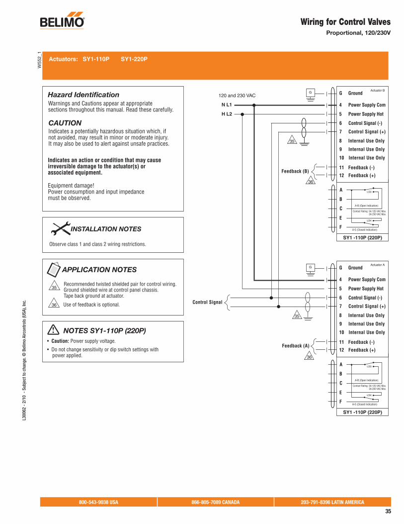
800-543-9038 USA 866-805-7089 CANADA 203-791-8396 LATIN AMERICA
35
L300
62 -
2/1
0 -
Sub
ject
to c
hang
e. ©
Bel
imo
Airc
ontr
ols
(USA
), In
c.
Indicates an action or condition that may cause irreversible damage to the actuator(s) or associated equipment.
Equipment damage!Power consumption and input impedance must be observed.
CAUTIONIndicates a potentially hazardous situation which, if not avoided, may result in minor or moderate injury. It may also be used to alert against unsafe practices.
Warnings and Cautions appear at appropriate sections throughout this manual. Read these carefully.
Hazard Identification G Ground
4 Power Supply Com
5 Power Supply Hot
6 Control Signal (-)
7 Control Signal (+)
8 Internal Use Only
9 Internal Use Only
10 Internal Use Only
11 Feedback (-)
12 Feedback (+)Feedback (B)
G Ground
4 Power Supply Com
5 Power Supply Hot
6 Control Signal (-)
7 Control Signal (+)
8 Internal Use Only
9 Internal Use Only
10 Internal Use Only
11 Feedback (-)
12 Feedback (+)Feedback (A)
Control Signal
Actuator B
Actuator A
120 and 230 VAC
N L1
H L2
SY1 -110P (220P)
A
B
C
E
F
Contact Rating: 5A 125 VAC Max. 3A 250 VAC Max.
A-B (Open Indication)
LS4
LS3
A-E (Closed Indication)
SY1 -110P (220P)
A
B
C
E
F
Contact Rating: 5A 125 VAC Max. 3A 250 VAC Max.
A-B (Open Indication)
LS4
LS3
A-E (Closed Indication)
Actuators: SY1-110P SY1-220P
NOTES SY1-110P (220P)Caution: Power supply voltage.
power applied.
Use of feedback is optional.
APPLICATION NOTES
Recommended twisted shielded pair for control wiring. Ground shielded wire at control panel chassis. Tape back ground at actuator.
Observe class 1 and class 2 wiring restrictions.
INSTALLATION NOTES
G
G
35
36
35
36
35
36
W55
2_1
Wiring for Control Valves Proportional, 120/230V

800-543-9038 USA 866-805-7089 CANADA 203-791-8396 LATIN AMERICA
36
L300
62 -
2/1
0 -
Subj
ect t
o ch
ange
. © B
elim
o Ai
rcon
trol
s (U
SA),
Inc.
Indicates an action or condition that may cause irreversible damage to the actuator(s) or associated equipment.
Equipment damage!Power consumption and input impedance must be observed.
CAUTIONIndicates a potentially hazardous situation which, if not avoided, may result in minor or moderate injury. It may also be used to alert against unsafe practices.
Warnings and Cautions appear at appropriate sections throughout this manual. Read these carefully.
Hazard Identification
A
B
C
D
E
F
LS3
A-C (Open Indication)
LS4
D-F (Closed Indication)
Contact Rating: 5A 250 VAC Max.
SY2...12-120MFT
SY2...12-230MFT
Actuators: SY2...12-120MFT SY2...12-230MFT
NOTES SY2...12-120MFT (230MFT)Caution: Power supply voltage.
Use of feedback is optional.
APPLICATION NOTES
Recommended twisted shielded pair for control wiring. Ground shielded wire at control panel chassis. Tape back ground at actuator.
Observe class 1 and class 2 wiring restrictions.
INSTALLATION NOTES
Power Supply Com – 120V (N) / 230V (L1)
Power Supply Hot – 120V (H) / 230V (L2)
1
Y
U5
C1
2
C2
B
A
1
9
8
10
3
2
Internal Use Only
Internal Use Only
Internal Use Only
Not Used -
Not Used -
Internal Use Only
Internal Use Only
Internal Use Only
Internal Use Only
Internal Use Only
Feedback
Control Signal (-)
Feedback Signal (+)
Feedback Signal (-)
Control Signal (+)
SYx-230MFT
Address Adaption
PC ToolService Jack
SYx-120MFT
LN
Power Supply Com – 120V (N) / 230V (L1)
Power Supply Hot – 120V (H) / 230V (L2)
1
Y
U5
C1
2
C2
B
A
1
9
8
10
3
2
Internal Use Only
Internal Use Only
Internal Use Only
Not Used -
Control Signal
Not Used -
Internal Use Only
Internal Use Only
Internal Use Only
Internal Use Only
Internal Use Only
Feedback
Control Signal (-)
Feedback Signal (+)
Feedback Signal (-)
Control Signal (+)
SYx-230MFT
Address Adaption
PC ToolService Jack
SYx-120MFT
LN
G PE
G PE
Actuator A
Actuator B
Y1
Y2
Y1
Y2
35
36
35
36
36
35
W55
2_2
Wiring for Control ValvesProportional, Multiple Wiring, 120/230V
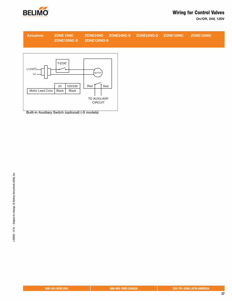
800-543-9038 USA 866-805-7089 CANADA 203-791-8396 LATIN AMERICA
37
L300
62 -
2/1
0 -
Sub
ject
to c
hang
e. ©
Bel
imo
Airc
ontr
ols
(USA
), In
c.
Actuators: ZONE 24NC ZONE24NO ZONE24NC-S ZONE24NO-S ZONE120NC ZONE120NO ZONE120NC-S ZONE120NO-S
TO AUXILIARYCIRCUIT
Red Red
MOTOR
T-STAT
L1(HOT)
L2
24 120/230
Motor Lead Color Black Black
Built-in Auxiliary Switch (optional) (-S models)
Wiring for Control Valves On/Off, 24V, 120V
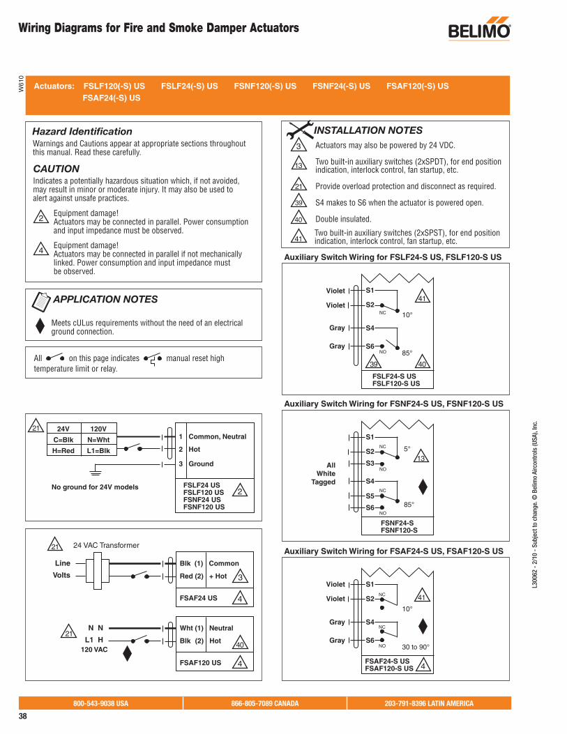
800-543-9038 USA 866-805-7089 CANADA 203-791-8396 LATIN AMERICA
38
L300
62 -
2/1
0 -
Subj
ect t
o ch
ange
. © B
elim
o Ai
rcon
trol
s (U
SA),
Inc.
Wiring Diagrams for Fire and Smoke Damper Actuators
All on this page indicates manual reset hightemperature limit or relay.
Actuators: FSLF120(-S) US FSLF24(-S) US FSNF120(-S) US FSNF24(-S) US FSAF120(-S) US FSAF24(-S) US
Equipment damage!Actuators may be connected in parallel. Power consumption and input impedance must be observed.
2
Equipment damage!Actuators may be connected in parallel if not mechanicallylinked. Power consumption and input impedance mustbe observed.
4
CAUTIONIndicates a potentially hazardous situation which, if not avoided, may result in minor or moderate injury. It may also be used to alert against unsafe practices.
Warnings and Cautions appear at appropriate sections throughout this manual. Read these carefully.
Hazard IdentificationActuators may also be powered by 24 VDC.
Two built-in auxiliary switches (2xSPDT), for end position indication, interlock control, fan startup, etc.
Provide overload protection and disconnect as required.
S4 makes to S6 when the actuator is powered open.
Double insulated.
3
21
39
40
INSTALLATION NOTES
Meets cULus requirements without the need of an electrical ground connection.
APPLICATION NOTES
Auxiliary Switch Wiring for FSNF24-S US, FSNF120-S US
FSNF24-SFSNF120-S
S1
S2
S3
S4
S5
S6
NC
NO
NC
NO
5°
85°
13
Auxiliary Switch Wiring for FSLF24-S US, FSLF120-S US
FSLF24-S USFSLF120-S US
S1
S2
S4
S6
NC
NO
10°
85°
41
4039
41
Auxiliary Switch Wiring for FSAF24-S US, FSAF120-S US
FSAF24-S USFSAF120-S US
S1
S2
S4
S6
Violet
Violet
Gray
Gray
Violet
AllWhite
Tagged
Violet
Gray
Gray
NC
NC
NO
10°
30 to 90°
4
2
21
FSLF24 USFSLF120 USFSNF24 USFSNF120 US
1 Common, Neutral
2 Hot
3 Ground
24V
C=Blk
H=Red
120V
N=Wht
L1=Blk
No ground for 24V models
40
4
3
21
21
Blk (1) Common
Red (2) + Hot
FSAF24 US
24 VAC Transformer
Line
Volts
4
Wht (1) Neutral
Blk (2) Hot
FSAF120 US
120 VAC
N N
L1 H
41
13
Two built-in auxiliary switches (2xSPST), for end position indication, interlock control, fan startup, etc.
W61
0

800-543-9038 USA 866-805-7089 CANADA 203-791-8396 LATIN AMERICA
39
L300
62 -
2/1
0 -
Sub
ject
to c
hang
e. ©
Bel
imo
Airc
ontr
ols
(USA
), In
c.
Auxiliary Switch Wiring for FSAF24-BAL-S US,FSAF24-SR-S US
Balancing Control Fire and Smoke
Proportional Control Fire and Smoke
Actuators: FSAF24-BAL (-S) US FSAF24-SR US
Equipment damage!Actuators may be connected in parallel if not mechanically mounted to the same shaft. Power consumption and input impedance must be observed.
2
CAUTIONIndicates a potentially hazardous situation which, if not avoided, may result in minor or moderate injury. It may also be used to alert against unsafe practices.
Warnings and Cautions appear at appropriate sections throughout this manual. Read these carefully.
Hazard Identification
Actuators may also be powered by 24 VDC.
Only connect common neg (-) leg of control circuits.
A 500 resister converts the 4 to 20 mA control signal to 2 to 10 VDC.
Two built-in auxiliary switches (2xSPDT), for end positionindication, interlock control, fan startup, etc.
Provide overload protection and disconnect as required.
Only connect Hot, Wire 2 to Wire 3 override controls.
Double Insulated
13
3
6
7
21
37
40
INSTALLATION NOTES
Meets cULus or UL requirements without the need of an electrical ground connection.
APPLICATION NOTES
FSAF24-BAL-S USFSAF24-SR-S US
S1
S2
S3
S4
S5
S6
NC
NO
NC
NO
10°
30° to 90°
40
13
FSAF24-SR US
Control Signal (+)2 to 10 VDC
(–)
Blk (1) Common
Red (2) + Hot
Wht (3) Y1 Input, 2 to 10V
Grn (5) U Output, 2 to 10V
Blk (1) Common
Red (2) + Hot
Wht (3) Y1 Input, 2 to 10V
Grn (5) U Output, 2 to 10V
24 VAC Transformer
Line
Volts
21
21
3
3
FSAF24-SR US
7
6
FSAF24-BAL
Blk (1) Common
Red (2) + Hot
(3) Override Open
24 VAC Transformer
OVERRIDE CONTROLSee technicaldocumentation fortypical methods.
Line
Volts
21
37
3
2
24 VAC Transformer
Control Signal (+)4 to 20 mA
(–)
Feedback Signal (+)2 to 10 VDC
(–)
500
Line
Volts
All on this page indicates manual reset hightemperature limit or relay.
W61
1
Wiring Diagrams for Fire and Smoke Damper Actuators

ACR Supply Company Inc.2719 Hillsborough RoadDurham, NC 27705Phone: 919-286-2228With branches in NC
Aireco Supply9120 Washington BoulevardSavage, MD 20763-0414Phone: 301-953-8800With branches in MD, VA
Amcon Controls, Inc.11906 Warfield StreetSan Antonio,TX 78216Phone: 210-349-6161Houston, TX branch 713-464-7002
Applied AutomationA Wilson Mohr Company3186 South Washington Street, #230Salt Lake City, UT 84115Phone: 801-486-6454
Boston Aircontrols, Inc.8 Blanchard RoadBurlington, MA 01803Phone: 781-272-5800
Charles D. Jones Co.445 Bryant Street, Unit #1Denver, CO 80204-4800Phone: 800-777-0910With branches in CO, MO, KS
Climatic Control Div/ICD5061 W. State StreetMilwaukee, WI 53208Phone: 800-242-1656With branches in WI
Cochrane Supply and Engineering, Inc.30303 Stephenson HighwayMadison Heights, MI 48071-1633Phone: 800-482-4894With branches in MI and Maumee, OH
Columbus Temperature Control1053 E. 5th AvenueColumbus, OH 43201Phone: 800-837-1837
Controlco5600 Imhoff Drive, Suite GConcord, CA 94520Phone: 925-602-7728With branches in CA, NV
Control Products9101 Jameel, Suite 130Houston, TX 77447Concord, CA 94520Phone: 713-690-6300
Edward C. Smyers & Co.223 Fort Pitt BoulevardPittsburgh, PA 15222-1505Phone: 412-471-3222
Engineered Control Systems4805 N.W. 79th AvenueSuite 11Miami, FL 33166Phone: 305-418-8901With branches in FL
G & O Thermal Supply5435 N. Northwest HighwayChicago, IL 60630Phone: 773-763-1300With branches in ILIndustrial Controls Distributors LLC1776 Bloomsbury AvenueWanamassa, NJ 07712Phone: 800-631-2112With branches inGA, KY, IN, MA, ME, NC, NY, OH, PA, TN
Interstate HVAC Controls30 Vineland StreetBrighton, MA 02135 Phone: 617-782-9000
Jackson Controls1708 E. 10th StreetIndianapolis, IN 46201Phone: 317-231-2200
M & M Controls9E West Aylesbury RoadTimonium, MD 21093Phone: 410-252-1221With a branch in Alexandria, VA
MICONTROLS, Inc.6516 5th Place SouthSeattle, WA 98124Phone: 800-877-8026With branches in WA, OR
Meier Supply123 Brown StreetJohnson City, NY 13790 Phone: 607-797-7700With branches in NY, PA
Minvalco, Inc.3340 Gorham AvenueMinneapolis, MN 55426-4267Phone: 952-920-0131With branches in MN
RSD/Refrigeration Supply Distribution 26021 Atlantic Ocean DriveLake Forest, CA 92630Phone: 949-380-7878With branches inCA, NV, OR, AK, AZ, ID, UT, WA, MT
Saint Louis Boiler Supply, Co. 617 Hanley Industrial CourtSt. Louis, MO 63144Phone: 314-962-9242
South Side Control Supply, Co. 488 N. Milwaukee AvenueChicago, IL 60610-3923Phone: 312-226-4900With branches in IL, IN
Stromquist and Company4620 Atlanta RoadSmyrna, GA 30080Phone: 404-794-3440With a branch in Orlando, FL
Temperature Control Systems10315 Brockwood RoadDallas, TX 75238Phone: 214-343-1444With branches in OK, TX
Tower Equipment Co., Inc.1320 West Broad StreetStratford, CT 06615Phone: 800-346-4647
Twinco Supply Corporation55 Craven StreetHuntington Station, NY 11746-2143Phone: 800-794-3188With branches in NY
Wilson-Mohr, Inc.12610 West Airport Blvd, Suite 100Sugarland, TX 77478Phone: 281-295-8850
Belimo Platinum DistributorsU
SA
CA
NA
DA For a complete list of distributors
in Canada, please visit our website: www.belimo.caor call toll free: 866-805-7089

BELIMO AmericasUSA Locations, 43 Old Ridgebury Road, Danbury, CT 06810Tel. 800-543-9038, Fax 800-228-8283, [email protected]
1049 Fortunado Loop, Sparks, NV 89436Tel. 800 987-9042, Fax 800-987-8875, [email protected]
Canada Locations, 14/16 – 5716 Coopers Avenue, Mississauga, Ontario L4Z 2E8Tel. 866-805-7089, Fax 905-712-3124, [email protected]
Latin America Customer Service, Tel. 203-791-8396, Fax 203-791-9139, [email protected]
Belimo worldwide: www.belimo.com
Related Documents