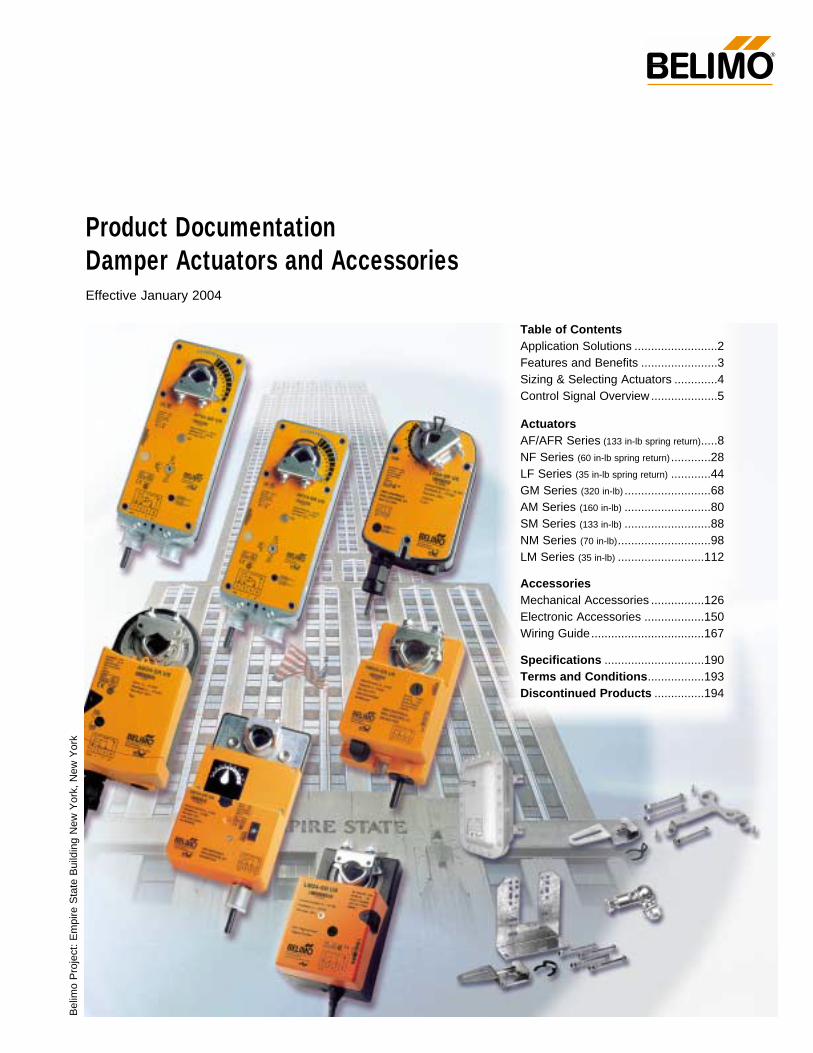
Product Documentation Damper Actuators and Accessories Effective January 2004 ® Belimo Project: Empire State Building New York, New York Table of Contents Application Solutions .........................2 Features and Benefits .......................3 Sizing & Selecting Actuators .............4 Control Signal Overview ....................5 Actuators AF/AFR Series (133 in-lb spring return).....8 NF Series (60 in-lb spring return) ............28 LF Series (35 in-lb spring return) ............44 GM Series (320 in-lb) ..........................68 AM Series (160 in-lb) ..........................80 SM Series (133 in-lb) ..........................88 NM Series (70 in-lb) ............................98 LM Series (35 in-lb) ..........................112 Accessories Mechanical Accessories ................126 Electronic Accessories ..................150 Wiring Guide ..................................167 Specifications ..............................190 Terms and Conditions.................193 Discontinued Products ...............194

Welcome message from author
This document is posted to help you gain knowledge. Please leave a comment to let me know what you think about it! Share it to your friends and learn new things together.
Transcript
Product DocumentationDamper Actuators and AccessoriesEffective January 2004
®
Bel
imo
Pro
ject
: E
mpi
re S
tate
Bui
ldin
g N
ew Y
ork,
New
Yor
k
Table of Contents Application Solutions .........................2Features and Benefits .......................3Sizing & Selecting Actuators .............4Control Signal Overview ....................5
ActuatorsAF/AFR Series (133 in-lb spring return).....8NF Series (60 in-lb spring return)............28LF Series (35 in-lb spring return) ............44GM Series (320 in-lb) ..........................68AM Series (160 in-lb) ..........................80SM Series (133 in-lb) ..........................88NM Series (70 in-lb)............................98LM Series (35 in-lb) ..........................112
AccessoriesMechanical Accessories ................126Electronic Accessories ..................150Wiring Guide..................................167
Specifications ..............................190Terms and Conditions.................193Discontinued Products ...............194

Application Solutions ®
K4-2 US Universal clampStandard for all AF, NF and AM series actuators Eases installation – Only two nuts to tighten
Increased flexibility – 1/2” to 1.05” capacityCentered on:1/2”, 3/4” and 1.05” shafts
Reduced cost - No need to purchase separate accessories
Retrofit applications
Replace virtually any Non-Direct coupled actuator with a high quality solution from Belimo.
Solve any application - Widest range of mounting brackets and accessories
Reduce installation cost – By resizing the damper you can select from 7 Belimo seriesof actuator types and torque ranges. 35 to 320 in-lb.
Retrofit of non-direct coupled actuators
Our 0 to 135 ohm input actuators are a cost effective replace-ment for applications where the existing actuators have failedand the controller is still in good working condition.
AF24-MFT95 US - Spring Return, 133 in-lb and
AM24-MFT 95 US - Non-spring return, 160 in-lb
We offer a complete line of mounting accessories for non-direct coupled applications (see pages 134-141)
ZG-108 – replaces Honeywell, Johnson and BarberColman non-direct coupled actuators. (see page 142)
New products
Need a retrofit solution for your existing Staefa Controls SmartII controls?Our retrofit solutions will accept the 0 to 20 V phasecut outputallowing for simple installation without replacing the controller.
AF24-PC US – Spring Return, 133 in-lb (see pages 18-19)
AM24-PC US – Non-spring return, 160 in-lb (see pages 86-87)
Remove for3/4” to 1.05”shafts
ZS-150WeatherShield
ZS-300 NEMA 4XHousing
ZS-260 ExplosionHousing
OTHER HOUSINGS
ZS-100 Weather Shield
ZS-260Explosion ProofHousing
ZG-110MountingBracket
ZG-DC1Damper Clip
ZG-100 UniversalMounting Bracket
ZG-108 UniversalMounting Bracket
KH8 UniversalCrankarm withKG8 Balljoint
ZG-102 Multiple ActuatorMounting Bracket
ZG-DC2Damper Clip
ZG-AF USCrankarmAdaptor Kit
KG-8 90° Ball Joint
KH-AFCrankarm
2
ZG-106/ZG-107Mounting Bracket
AF…NF…
ZG-106
ZG-107ZG-107 ZG-108
9080
7060
50
40
30
20
100
-5
0
R
9080
7060
50
40
30
20
100
-5
0
R
K4(-1) Clamp with ZDB Angle
of Rotation Limiter
IND-2 Position Indicator(optional)
AF…NF…
AF…NF…
AF…NF…
ZG-108
AF…NF…

3
F203
58 /
5 4
3 2
1 -0
1/04
-10M
-IG-S
ubje
ct to
cha
nge.
© B
elim
o Ai
rcon
trols
(USA
), In
c.
Why Choose Belimo?A CLOSER LOOK…
Cut labor costs with simple direct coupling.
True mechanical spring return – the most reliable failsafe.
Reverse mount for clockwise or counterclockwise fail-safe.
Check damper position easily with clear position indicator.
Overload-proof throughout rotation
Temporary restrictions in damper movement will not change actuator operation. Actuator returns to normal operation when restriction is removed.
Built-in or add on mechanical stops to adjust angle of rotation
By eliminating internal condensation Golden Point breather membraneoptimizes performance in harsh airstream environments. (AF series)
Built-in auxiliary switch is easy to use, offers feedback or signal for additional device. (-S models)
Manual override crank speeds installation(Not available with LF, NF and AFR… series)
Need to change control direction? Do it easily with a simple switch on actuator housing.
Microprocessor-controlled brushless DC motor increases actuator life span and reliability, provides constant running time. (modulating and (-SR) and floating point (-3) actuators)
Rugged housings withstand rough handling in the mechanical room.
3 ft. appliance cable and conduit connector eases installation.
Double insulated – no need for separate safety ground. A Belimoexclusive (on 120/230V models, and all models with built-in aux.switches).
Automatically compensates for damper seal wear, ensuring tight close-off.
Features and Benefits®
LF… SeriesThe “Installers choice” for:
Classroom Unit Ventilators Fan coil units Economizers Airhandlers and Rooftop units Control dampers
Our New LF24-SR-E USIs a 2-10VDC controlled actuator with a built-inMin position potentiometer specifically forEconomizer applications.
Retrofit and Non-Direct coupled linkage solutions
Belimo offers the widest range of mechanicalaccessories for the replacement of competitiveproducts as well as for the unique installation.
Give us a call with your application problem.
Brushless DC motor technology
The latest Belimo product with our Brushless DC motor technology is the 35 in-lb LM… series.
With the increase in product lifespan and qualitythe LM series creates a new level of expectation for actuators installed in VAV applications.
Only ONE moving part!
No brushes to wear out
Position feedback is generated by ASIC
Overload proof; reduces power consumption in end position
Running noise is reduced to absolute minimum
LM… Series actuators with Brushless motors
LM24-3 (-T) US, Floating point or tri-state control, 35 in-lb
LM24-SR-2.0 (-T) US, Proportional 2-10 VDC control, 35 in-lb
©
4
F203
58 /
5 4
3 2
1 -0
1/04
-10M
-IG-S
ubje
ct to
cha
nge.
© B
elim
o Ai
rcon
trols
(USA
), In
c.
®
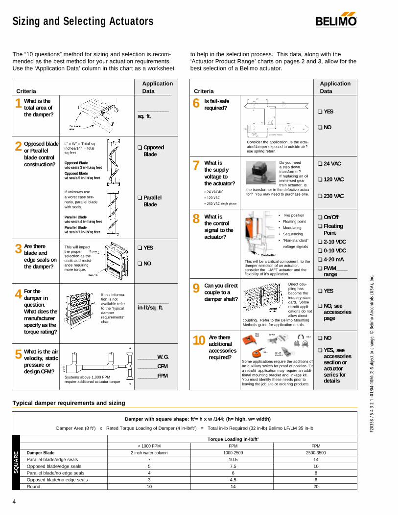
The “10 questions” method for sizing and selection is recom-mended as the best method for your actuation requirements.Use the ‘Application Data’ column in this chart as a worksheet
to help in the selection process. This data, along with the‘Actuator Product Range’ charts on pages 2 and 3, allow for thebest selection of a Belimo actuator.
Damper with square shape: ft2= h x w /144; (h= high, w= width)
Damper Area (8 ft2) x Rated Torque Loading of Damper (4 in-lb/ft2) = Total in-lb Required (32 in-lb) Belimo LF/LM 35 in-lb
Torque Loading in-lb/ft2
< 1000 FPM FPM FPM
Damper Blade 2 inch water column 1000-2500 2500-3500
Parallel blade/edge seals 7 10.5 14
Opposed blade/edge seals 5 7.5 10
Parallel blade/no edge seals 4 6 8
Opposed blade/no edge seals 3 4.5 6
Round 10 14 20
Sizing and Selecting Actuators
This will impact the proper selection as theseals add resist-ance requiringmore torque.
If this informa-tion is notavailable referto the “typicaldamperrequirements”chart.
Systems above 1,000 FPMrequire additional actuator torque
FAN
FAN
E
OAR
SA
A = MIXING PLENUM∆PT
∆PD
∆PD
∆PD
∆PT
∆PT
A
B
OA
Consider the application. Is the actu-ator/damper exposed to outside air?use spring return.
• Two position
• Floating point
• Modulating
• Sequencing
• “Non-standard”
voltage signals
This will be a critical component to thedamper selection of an actuator.consider the …MFT actuator and theflexibility of it’s application.
Controller
If unknown use a worst case sce-nario, parallel bladewith seals.
L” x W” = Total sqinches/144 = totalsq feet
Typical damper requirements and sizing
SQ
UA
RE
What is the total area of the damper?
Opposed bladeor Parallelblade controlconstruction?
Are thereblade andedge seals onthe damper?
For thedamper inquestion. What does themanufacturerspecify as thetorque rating?
What is the airvelocity, staticpressure ordesign CFM?
Is fail-saferequired?
What is the supplyvoltage to the actuator?• 24 VAC/DC
• 120 VAC
• 230 VAC single phase
What is the controlsignal to theactuator?
Can you directcouple to adamper shaft?
Are thereadditionalaccessoriesrequired?
___________sq. ft.
OpposedBlade
ParallelBlade
YES
NO
___________in-lb/sq. ft.
_______W.G.
_______CFM
_______FPM
YES
NO
24 VAC
120 VAC
230 VAC
On/Off
FloatingPoint
2-10 VDC
0-10 VDC
4-20 mA
PWM____range
YES
NO, seeaccessoriespage
NO
YES, seeaccessoriessection oractuator series fordetails
Opposed Blade w/o seals 3 in-lb/sq feet
Opposed Blade w/ seals 5 in-lb/sq feet
Parallel Blade w/o seals 4 in-lb/sq feet
Parallel Blade w/ seals 7 in-lb/sq feet
Do you need a step down transformer? If replacing an oilimmersed geartrain actuator. Is
the transformer in the defective actua-tor? You may need to purchase one.
Direct cou-pling hasbecome theindustry stan-dard. Someretrofit appli-cations do notallow direct
coupling. Refer to the Belimo MountingMethods guide for application details.
K4-2
KH-AFKH-AF-1
Some applications require the additions ofan auxiliary switch for proof of position. Ora retrofit application may require an addi-tional mounting bracket and linkage kit.You must identify these needs prior toleaving the job site or ordering products.
ApplicationCriteria Data
1
2
3
4
5
ApplicationCriteria Data
6
7
8
9
10SN1SN2
SA…
ZG-AM
F203
58 /
5 4
3 2
1 -0
1/04
-10M
-IG-S
ubje
ct to
cha
nge.
© B
elim
o Ai
rcon
trols
(USA
), In
c.
® Control Signal Overview
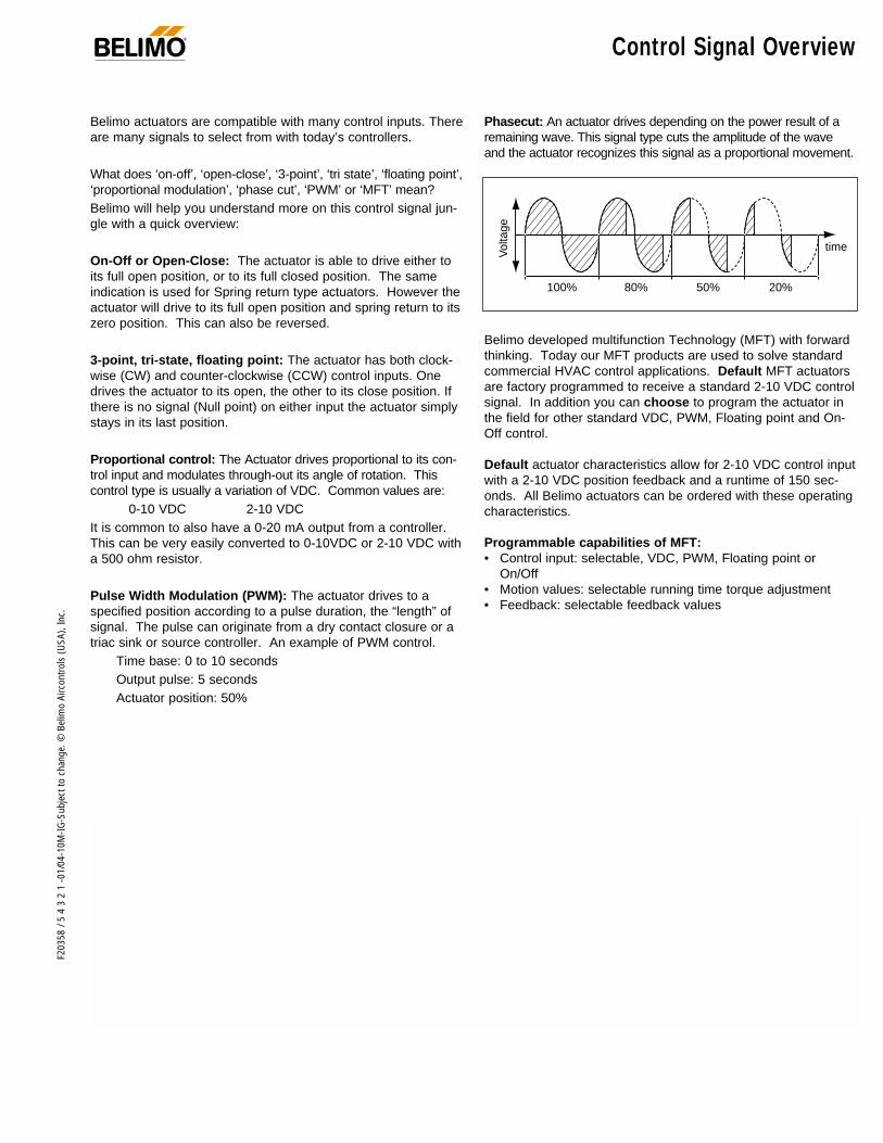
Belimo actuators are compatible with many control inputs. Thereare many signals to select from with today’s controllers.
What does ‘on-off’, ‘open-close’, ‘3-point’, ‘tri state’, ‘floating point’,‘proportional modulation’, ‘phase cut’, ‘PWM’ or ‘MFT’ mean?Belimo will help you understand more on this control signal jun-gle with a quick overview:
On-Off or Open-Close: The actuator is able to drive either toits full open position, or to its full closed position. The sameindication is used for Spring return type actuators. However theactuator will drive to its full open position and spring return to itszero position. This can also be reversed.
3-point, tri-state, floating point: The actuator has both clock-wise (CW) and counter-clockwise (CCW) control inputs. Onedrives the actuator to its open, the other to its close position. Ifthere is no signal (Null point) on either input the actuator simplystays in its last position.
Proportional control: The Actuator drives proportional to its con-trol input and modulates through-out its angle of rotation. Thiscontrol type is usually a variation of VDC. Common values are:
0-10 VDC 2-10 VDCIt is common to also have a 0-20 mA output from a controller.This can be very easily converted to 0-10VDC or 2-10 VDC witha 500 ohm resistor.
Pulse Width Modulation (PWM): The actuator drives to aspecified position according to a pulse duration, the “length” ofsignal. The pulse can originate from a dry contact closure or atriac sink or source controller. An example of PWM control.
Time base: 0 to 10 secondsOutput pulse: 5 secondsActuator position: 50%
Phasecut: An actuator drives depending on the power result of aremaining wave. This signal type cuts the amplitude of the waveand the actuator recognizes this signal as a proportional movement.
Belimo developed multifunction Technology (MFT) with forwardthinking. Today our MFT products are used to solve standardcommercial HVAC control applications. Default MFT actuatorsare factory programmed to receive a standard 2-10 VDC controlsignal. In addition you can choose to program the actuator inthe field for other standard VDC, PWM, Floating point and On-Off control.
Default actuator characteristics allow for 2-10 VDC control inputwith a 2-10 VDC position feedback and a runtime of 150 sec-onds. All Belimo actuators can be ordered with these operatingcharacteristics.
Programmable capabilities of MFT:• Control input: selectable, VDC, PWM, Floating point or
On/Off• Motion values: selectable running time torque adjustment• Feedback: selectable feedback values
100%
Vol
tage
80% 50% 20%
time

Airside Products 24 V
AC ±
20%
, VDC
+/-
15%
120
VAC
±10
%23
0 VA
C ±
10%
VA ra
ting
Wat
tage
runn
ing
(hol
ding
)
Mot
or D
rive
(Def
ault)
*(…
MFT
US
adju
stab
le 7
5 to
300
sec
.)
Sprin
g Re
turn
On/O
ffFl
oatin
g Po
int
2-10
VDC
(Def
ault)
4-20
mA*
(w/5
00Ω
resi
stor
)0
to 2
0 v.
pha
secu
t6-
9 VD
C, 2
0 VD
C ou
tput
vol
tage
Hone
ywel
l Ser
ies
90, 0
-135
ΩLO
NTAL
K
On/O
ff*Fl
oatin
g Po
int*
Star
t and
Spa
n ad
j., S
tart
0.5
to
30 V
DC. S
pan
2.5
to 3
2 VD
C*PW
M a
dj.,
0.0
2 to
50.
0 se
cond
s*2-
10 V
DC (D
efau
lt)
VDC
Varia
ble,
Sta
rt 0
to 8
,Sp
an 2
to 1
0 VD
C*
35 in
-lb [4
Nm
], Ap
prox
. 8sq
.ft.
60 in
-lb [7
Nm
], Ap
prox
. 15
sq. f
t.70
in-lb
[8Nm
], Ap
prox
. 18
sq. f
t.13
3 in
-lb [1
5 Nm
], Ap
prox
. 33
sq. f
t.16
0 in
-lb [1
8 Nm
], Ap
prox
. 40
sq. f
t.32
0 in
-lb [3
6Nm
], Ap
prox
. 80
sq. f
t.1
SPDT
, 6A
(1.5
A in
duct
ive)
@25
0 V1
SPDT
, 6A
(2.5
A in
duct
ive)
@24
V2
SPDT
, 7A
(2.5
A in
duct
ive)
@25
0VAd
d-on
See
Page
Num
ber
Power Power Running Control Control Input Position Torque AuxiliarySupply Consumption Time Input Multi-Function Feedback (based on 4 in-lb per sq.ft) Switches
LF24-SR US 5 2.5 (1) 150 <25♦ 44 $ 350.00LF24-SR-E US* 5 2.5 (1) 150 <25♦ 44 $ 380.00LF24-SR-S US 5 2.5 (1) 150 <25♦ 44 $ 400.00LF24-MFT US 5 2.5 (1) 150 <25♦ ‡ $ 400.00LF24-MFT-S US 5 2.5 (1) 150 <25♦ ‡ $ 450.00LF24-MFT-20 US 6 3.5 (1.5) 150 <25♦ ‡ $ 440.00LF24-MFT-S-20 US 6 3.5 (1.5) 150 <25♦ ‡ $ 490.00LF24-3 US 5 2.5 (1) 150 <25♦ 44 $ 310.00LF24-3-S US 5 2.5 (1) 150 <25♦ 44 $ 360.00LFC24-3-R US 5 2.5 (1) 90 <25♦ 44 $ 360.00LFC24-3-S US 5 2.5 (1) 90 <25♦ 44 $ 410.00NF24-SR US 6 3 (1) 150 <60 28 $ 370.00NF24-SR-S US 6 3 (1) 150 <60 28 $ 440.00NF24-MFT US 10 6 (1.8) 150 <60 ‡ $ 450.00NF24-MFT-S US 10 6 (1.8) 150 <60 ‡ $ 520.00AF24-MFT US 10 6 (1.8) 150 <20 ‡ $ 525.00AF24-MFT-S US 10 6 (1.8) 150 <20 ‡ $ 600.00AF24-MFT95 US 10 6 (2) 150 <20 ‡ $ 580.00AF24-SR US 10 6 (2) 150 <20 8 $ 475.00AFR24-SR US 10 6 (2) 150 <20 8 $ 450.00AFR24-3 US 10 6 (2) 150 <20 8 $ 430.00AFR24-3-S US 10 6 (2) 150 <20 8 $ 485.00AF24LON US 10 6 (2) 150 <20 ‡ $ 700.00AF24-PC US* 10 6 (2) 150 <20 8 $ 580.00LM24-3 US 3 2 95 112 $ 150.00LM24-3.1 US 3 2 95 112 $ 140.00LM24-3-T US 3 2 95 112 $ 130.00LM24-3-T.1 US 3 2 95 112 $ 116.00LM24-SR-2.0 US 4 2 95 112 $ 220.00LM24-SR-2.0.1 US 4 2 95 112 $ 210.00LM24-SR-T-2.0 US 4 2 95 112 $ 200.00LM24-SR-T-2.0.1 US 4 2 95 112 $ 190.00LMC24-SR US†(fast running) 4 2.5 25-35 112 $ 230.00
LM24-MFT US 4 2 150 ‡ $ 300.00LM24-MFT.1 US 4 2 150 ‡ $ 290.00NM24 US 3.5 2 75-150 98 $ 170.00NM24-SR US 3.5 1.3 150 98 $ 254.00NM24-MFT US 3.5 1.3 150 ‡ $ 330.00NM24-MFT.1 US 3.5 1.3 150 ‡ $ 320.00NMQ24-MFT US 12 9 (1.2) 5 ‡ $ 400.00AM24 US 4.5 2.5 110-150 80 $ 250.00AM24-SR US 5 2.5 150 80 $ 360.00AM24-MFT US 5 2.5 150 ‡ $ 400.00AM24LON US 5 2.5 150 ‡ $ 550.00AM24-PC US* 5 2.5 150 80 $ 485.00AM24-MFT95 US* 4.2 2 150 ‡ $ 485.00GM24 US 6 3 135 68 $ 350.00GM24-SR US 7 3 135 ♦♦ 68 $ 475.00GM24-MFT US 7 3 150 ‡ $ 540.00GM24LON US 7 3 150 ‡ $ 750.00* Variable † Torque 18 in-lb ♦ <60 sec. @ -22°F [-30°C] ♦♦ The GM24-SR US actuator torque will remain at 266 in-lb.* New products are in bold print ‡ All …MFT actuator details can be found in the Multi-Function documentation
NO
N-S
PR
ING
RE
TU
RN
SP
RIN
G R
ET
UR
N
List Price
Actuator Product RangeModulating actuator application chart
6
F203
58 /
5 4
3 2
1 -0
1/04
-10M
-IG-S
ubje
ct to
cha
nge.
© B
elim
o Ai
rcon
trols
(USA
), In
c.
®
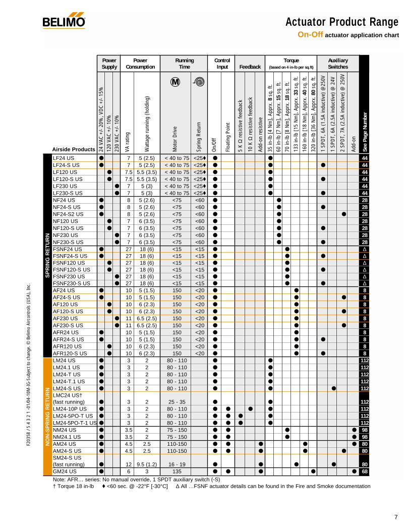
Actuator Product RangeOn-Off actuator application chart
7
F203
58 /
5 4
3 2
1 -0
1/04
-10M
-IG-S
ubje
ct to
cha
nge.
© B
elim
o Ai
rcon
trols
(USA
), In
c.
®
Airside Products 24 V
AC +
/- 20
%, V
DC +
/- 15
%12
0 VA
C +/
- 10%
230
VAC
+/- 1
0%
VA ra
ting
Wat
tage
runn
ing
(hol
ding
)
Mot
or D
rive
Sprin
g Re
turn
On/O
ff
Floa
ting
Poin
t
5 K
Ωre
sist
ive
feed
back
10 K
Ωre
sist
ive
feed
back
Add-
on re
sist
ive
35 in
-lb [4
Nm
], Ap
prx.
8sq
. ft.
60 in
-lb [7
Nm
], Ap
prx.
15
sq. f
t.
70 in
-lb [8
Nm
], Ap
prx.
18
sq. f
t.
133
in-lb
[15
Nm],
Appr
x. 3
3sq
. ft.
160
in-lb
[18
Nm],
Appr
x. 4
0sq
. ft.
320
in-lb
[36
Nm],
Appr
x. 8
0sq
. ft.
1 SP
DT, 6
A (1
.5A
indu
ctiv
e) @
250V
1 SP
DT, 6
A (2
.5A
indu
ctiv
e) @
24V
2 SP
DT, 7
A (2
.5A
indu
ctiv
e) @
250
V
Add-
on
See
Page
Num
ber
Power Power Running Control Torque AuxiliarySupply Consumption Time Input Feedback (based on 4 in-lb per sq.ft) Switches
LF24 US 7 5 (2.5) < 40 to 75 <25♦ 44 $ 250.00LF24-S US 7 5 (2.5) < 40 to 75 <25♦ 44 $ 300.00LF120 US 7.5 5.5 (3.5) < 40 to 75 <25♦ 44 $ 280.00LF120-S US 7.5 5.5 (3.5) < 40 to 75 <25♦ 44 $ 330.00LF230 US 7 5 (3) < 40 to 75 <25♦ 44 $ 310.00LF230-S US 7 5 (3) < 40 to 75 <25♦ 44 $ 360.00NF24 US 8 5 (2.6) <75 <60 28 $ 270.00NF24-S US 8 5 (2.6) <75 <60 28 $ 340.00NF24-S2 US 8 5 (2.6) <75 <60 28 $ 345.00NF120 US 7 6 (3.5) <75 <60 28 $ 310.00NF120-S US 7 6 (3.5) <75 <60 28 $ 380.00NF230 US 7 6 (3.5) <75 <60 28 $ 360.00NF230-S US 7 6 (3.5) <75 <60 28 $ 430.00FSNF24 US 27 18 (6) <15 <15 ∆ $ 350.00FSNF24-S US 27 18 (6) <15 <15 ∆ $ 420.00FSNF120 US 27 18 (6) <15 <15 ∆ $ 400.00FSNF120-S US 27 18 (6) <15 <15 ∆ $ 470.00FSNF230 US 27 18 (6) <15 <15 ∆ $ 412.00FSNF230-S US 27 18 (6) <15 <15 ∆ $ 482.00AF24 US 10 5 (1.5) 150 <20 8 $ 375.00AF24-S US 10 5 (1.5) 150 <20 8 $ 450.00AF120 US 10 6 (2.3) 150 <20 8 $ 425.00AF120-S US 10 6 (2.3) 150 <20 8 $ 500.00AF230 US 11 6.5 (2.5) 150 <20 8 $ 500.00AF230-S US 11 6.5 (2.5) 150 <20 8 $ 570.00AFR24 US 10 5 (1.5) 150 <20 8 $ 350.00AFR24-S US 10 5 (1.5) 150 <20 8 $ 425.00AFR120 US 10 6 (2.3) 150 <20 8 $ 400.00AFR120-S US 10 6 (2.3) 150 <20 8 $ 475.00LM24 US 3 2 80 - 110 112 $ 150.00LM24.1 US 3 2 80 - 110 112 $ 140.00LM24-T US 3 2 80 - 110 112 $ 114.00LM24-T.1 US 3 2 80 - 110 112 $ 100.00LM24-S US 3 2 80 - 110 112 $ 190.00LMC24 US†(fast running) 3 2 25 - 35 112 $ 160.00LM24-10P US 3 2 80 - 110 112 $ 200.00LM24-5PO-T US 3 2 80 - 110 112 $ 170.00LM24-5PO-T-1 US 3 2 80 - 110 112 $ 160.00NM24 US 3.5 2 75 - 150 98 $ 170.00NM24.1 US 3.5 2 75 - 150 98 $ 166.00AM24 US 4.5 2.5 110-150 80 $ 250.00AM24-S US 4.5 2.5 110-150 80 $ 320.00SM24-S US(fast running) 12 9.5 (1.2) 16 - 19 80 $ 320.00GM24 US 6 3 135 68 $ 350.00
Note: AFR… series: No manual override, 1 SPDT auxiliary switch (-S)† Torque 18 in-lb ♦ <60 sec. @ -22°F [-30°C] ∆ All …FSNF actuator details can be found in the Fire and Smoke documentation
NO
N-S
PR
ING
RE
TU
RN
SP
RIN
G R
ET
UR
N
List Price
8
F203
58 /
5 4
3 2
1 -0
1/04
-10M
-IG-S
ubje
ct to
cha
nge.
© B
elim
o Ai
rcon
trols
(USA
), In
c.
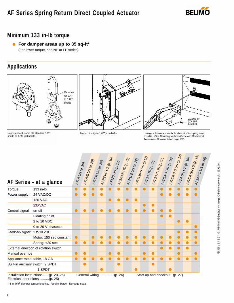
AF Series Spring Return Direct Coupled Actuator®
Applications
Minimum 133 in-lb torque For damper areas up to 35 sq-ft*
(For lower torque, see NF or LF series)
ZG106 or ZG 107bracket
Mount directly to 1.05” jackshafts.New standard clamp fits standard 1/2”shafts to 1.05” jackshafts.
Linkage solutions are available when direct coupling is notpossible. (See Mounting Methods Guide and MechanicalAccessories Documentation page 132)
Removefor 3/4” to 1.05”shafts
Torque: 133 in-lb
Power supply : 24 VAC/DC
120 VAC
230 VAC
Control signal: on-off
Floating point
2 to 10 VDC
0 to 20 V phasecut
Feedback signal: 2 to 10 VDC
Motor: 150 sec constant
Spring: <20 sec
External direction of rotation switch
Manual override
Appliance rated cable, 18 GA
Built-in auxiliary switch 2 SPDT
1 SPDT
Installation instructions ......(p. 20–26) General wiring ..............(p. 26) Start-up and checkout (p. 27)Electrical operations ..........(p. 25)* 4 in-lb/ft2 damper torque loading. Parallel blade. No edge seals.
AF Series – at a glance AF2
4 U
S (p
. 10)
AF2
4-S
US
(p. 1
0)A
FR24
US
(p. 1
0)A
FR24
-S U
S (p
. 10)
AF1
20 U
S (p
. 12)
AF1
20-S
US
(p. 1
2)A
FR12
0 U
S (p
. 12)
AFR
120-
S U
S (p
.12)
AF2
30 U
S (p
. 12)
AF2
30-S
US
(p. 1
2)A
FR24
-3 U
S (p
. 14)
AFR
24-3
-S U
S (p
. 14)
AF2
4-S
R U
S (p
. 16)
AFR
24-S
R U
S (p
. 16)
AF2
4-P
C U
S (p
. 18)

9
F203
58 /
5 4
3 2
1 -0
1/04
-10M
-IG-S
ubje
ct to
cha
nge.
© B
elim
o Ai
rcon
trols
(USA
), In
c.
AF
A CLOSER LOOK…
AF Series Spring Return Direct Coupled Actuator®
LISTED94D5TEMP. IND ®. EQUIP.
UL
Cut labor costs with simple direct coupling.
True mechanical spring return – the most reliable failsafe.
Reverse mount for clockwise or counterclockwise fail-safe.
Check damper position easily with clear position indicator.
Overload-proof throughout rotation
Temporary restrictions in damper movement will not changeactuator operation. Actuator returns to normal operation whenrestriction is removed. (modulating actuators)
Easy mechanical stop to adjust angle of rotation (add ZDB-AF2 accessory).
By eliminating internal condensation Golden Point breather membrane optimizes performance in harsh airstream environments.
Built-in auxiliary switch is easy to use, offers feedback or signal for additional device. (-S models)
Manual override crank speeds installation(Not available with AFR… series)
Need to change control direction? Do it easily with a simple switch. (modulating actuators)
Microprocessor-controlled brushless DC motor increases actu-ator life span and reliability, provides constant running time. (modulating actuators)
Rugged metal housing withstands rough handling in themechanical room.
3 ft. appliance cable and conduit connectoreases installation.
Double insulated – no need for separate safety ground. A Belimo exclusive. (-S,120V, 230V models)
Automatically compensates for damper seal wear, ensuring tightclose-off.
The Belimo Difference
Customer Commitment.Extensive product range. Competitive project pricing. Application assistance. Same-day shipments. Free technical support. Five year warranty.
Low Installation and Life-Cycle Cost.Easy installation. Accuracy and repeatability. Low power consumption. No maintenance.
Long Service Life.Components tested before assembly. Every product tested before shipment. 20+ years direct coupled actuator design.
©

F203
58 /
5 4
3 2
1 -0
1/04
-10M
-IG-S
ubje
ct to
cha
nge.
© B
elim
o Ai
rcon
trols
(USA
), In
c.
AF24 (-S) US, AFR24 (-S) US On-off, spring return safety, 24 V
®
Torque min. 133 in-lb, for control of air dampers
ApplicationFor on-off, fail-safe control of dampers in HVAC systems.Actuator sizing should be done in accordance with the dampermanufacturer’s specifications. Control is on-off from an auxil-iary contact, or a manual switch.
The actuator is mounted directly to a damper shaft up to 1.05”in diameter by means of its universal clamp. A crankarm andseveral mounting brackets are available for applications wherethe actuator cannot be direct coupled to the damper shaft.
OperationThe AF series actuators provide true spring return operation forreliable fail-safe application and positive close off on air tightdampers. The spring return system provides consistent torqueto the damper with, and without, power applied to the actuator.
The AF and AFR series provide 95° of rotation and are provid-ed with a graduated position indicator showing -5° to 90°.The AF has a unique manual positioning mechanism whichallows the setting of any damper position within its 95° of rota-tion. The AF and AFR series actuators are shipped in the zeroposition (5° from full fail-safe) to provide automatic compres-sion against damper gaskets for tight shut-off. When power isapplied to the AF series, the manual mechanism is released.When power is applied to the AFR series its “one time use”mechanism is released. The actuators will now try to closeagainst the -5° position during its normal control operations.The manual override can also be released physically by theuse of a crank supplied with the actuator (AF series).
The AF uses a brushless DC motor which is controlled by anApplication Specific Integrated Circuit (ASIC). The ASIC moni-tors and controls the actuator’s rotation and provides a digitalrotation sensing function to prevent damage to the actuator ina stall condition. The actuator may be stalled anywhere in itsnormal rotation without the need of mechanical end switches.
The AF24-S US version is provided with 2 built in auxiliaryswitches. These SPDT switches are provided for safety inter-facing or signaling, for example, for fan start-up. The switchingfunction at the fail-safe position is fixed at +5°, the other switchfunction is adjustable between +25° to +85°. The AFR… seriesactuators are provided with 1 SPDT switch, adjustablebetween 5° to 85°.
Dimensions (All numbers in brackets are metric.)
1.97"
3.15
" [8
0]
3.86
" [9
8]3.
10"
[78]
2.24
" [5
7]
[50]
1.93
"[4
9]
2.64"[67]
0.26" [6.5]5.85" [148.5]
10.59" [269]
0.35" [9]
0.39" [10]
0.65" [16.5]
0.19" [5]
K4-2 US (supplied)
1/2" Centered (Default)
3/4" Centered (Field Selectable)
1.05" Centered (Field Selectable)
K4-1 US (optional)
3/4" to 1.05" Adjustable
K4 US (optional)
3/8" to 3/4" Adjustable
LISTED94D5TEMP. IND ®. EQUIP.
UL
Technical Data AF24 (-S) US
Power supply 24 VAC ± 20% 50/60 Hz24 VDC ± 10%
Power consumption running: 5 Wholding: 1.5 W
Transformer sizing 10 VA (class 2 power source)
Electrical connection 3 ft, 18 GA appliance cable1/2” conduit connector
Electrical protection auxiliary switches are double insulated
Overload protection electronic throughout -5° to 90° rotation
Angle of rotation 95°, adjustable 30 to 90° w/ ZDB-AF2
Torque 133 in-lb [15 Nm] constant
Direction of rotation spring return can be selected byCW/CCW mounting
Position indication visual indicator, -5° to 90° (-5° isspring return position)
Manual override 3mm hex crank (shipped w/actuator)
Auxiliary switches 2 x SPDT 7A (2.5A) @ 250 VAC, UL listedone set at +5°, one adjustable 25° to 85°
Running time 150 sec. constant, independent ofload, spring return < 20 sec
Humidity 5 to 95% RH non-condensing
Ambient temperature -22°F to +122°F [-30°C to +50°C]
Storage temperature -40°F to +176°F [-40°C to +80°C]
Housing NEMA type 2 / IP54
Housing material zinc coated steel
Agency listings UL 873 listed, CSA C22.2 No. 24 certified
Noise level max. 45 dB (A)
Servicing maintenance free
Quality standard ISO 9001
Weight 6.0 lbs (2.7 kg.)
AFR24 (-S) US (same as above except)
Position indication -5° to 90° position indication
Manual override Not available
Auxiliary switches 1 x SPDT 7A (2.5A) @ 250 VAC, UL listedadjustable 5° to 85°
10
D00
1
©

11
F203
58 /
5 4
3 2
1 -0
1/04
-10M
-IG-S
ubje
ct to
cha
nge.
© B
elim
o Ai
rcon
trols
(USA
), In
c.
AF
AF24 (-S) US, AFR24 (-S) USOn-off, spring return safety, 24 V
®
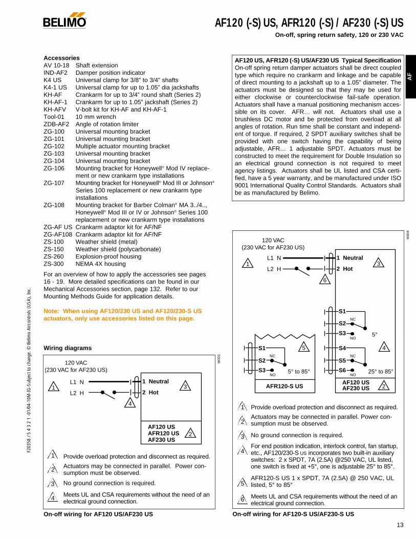
AccessoriesAV 10-18 Shaft extensionIND-AF2 Damper position indicatorK4 US Universal clamp for 3/8” to 3/4” shaftsK4-1 US Universal clamp for up to 1.05” dia jackshaftsK4-H Universal clamp for hexshafts 3/8” to 5/8”KH-AF Crankarm for up to 3/4” round shaft (Series 2)KH-AF-1 Crankarm for up to 1.05” jackshaft (Series 2)KH-AFV V-bolt kit for KH-AF and KH-AF-1Tool-01 10 mm wrenchZDB-AF2 Angle of rotation limiterZG-100 Universal mounting bracketZG-101 Universal mounting bracketZG-102 Multiple actuator mounting bracketZG-103 Universal mounting bracketZG-104 Universal mounting bracketZG-106 Mounting bracket for Honeywell® Mod IV
replacement or new crankarm type installationsZG-107 Mounting bracket for Honeywell® Mod III or Johnson®
Series 100 replacement or new crankarm typeinstallations
ZG-108 Mounting bracket for Barber Colman® MA 3../4..,Honeywell® Mod III or IV or Johnson® Series 100replacement or new crankarm type installations
ZG-AF US Crankarm adaptor kit for AF/NF ZG-AF108 Crankarm adaptor kit for AF/NF ZS-100 Weather shield (metal)ZS-150 Weather shield (polycarbonate)ZS-260 Explosion-proof housingZS-300 NEMA 4X housing
For an overview of how to apply the accessories see pages 16 - 19. More detailed specifications can be found in ourMechanical Accessories section, page 132. Refer to ourMounting Methods Guide for application details.
Note: When using AF24 US and AF24-S US actuators,only use accessories listed on this page.
Wiring diagrams
AF24 (-S) US, AFR24 (-S) US Typical SpecificationOn-off spring return damper actuators shall be direct coupledtype which require no crankarm and linkage and be capable ofdirect mounting to a jackshaft up to a 1.05” diameter. The actu-ators must be designed so that they may be used for eitherclockwise or counterclockwise fail-safe operation. Actuatorsshall have a manual positioning mechanism accessible on itscover. AFR… will not. Actuators shall use a brushless DCmotor and be protected from overload at all angles of rotation.Run time shall be constant and independent of torque. Ifrequired, 2 SPDT auxiliary switches shall be provided with oneswitch having the capability of being adjustable, AFR… 1adjustable SPDT. Actuators with switches must be constructedto meet the requirement for Double Insulation so an electricalground connection is not required to meet agency listings.Actuators shall be UL listed and CSA certified, have a 5 yearwarranty, and be manufactured under ISO 9001 InternationalQuality Control Standards. Actuators shall be as manufac-tured by Belimo.
2
3
1 Provide overload protection and disconnect as required.
Actuators may be connected in parallel. Power con-sumption must be observed.
Actuator may also be powered by 24 VDC.
2
3
1
4
5
6
Provide overload protection and disconnect as required.
Actuators may be connected in parallel. Power con-sumption must be observed.
Actuator may also be powered by 24 VDC.
For end position indication, interlock control, fan start-up, etc., AF24-S US incorporates two built-in auxiliaryswitches: 2 x SPDT, 7A (2.5A) @250 VAC, UL listed,one switch is fixed at +5°, one is adjustable 25° to85°.
AFR24-S US 1 x SPDT, 7A (2.5A) @ 250 VAC, ULlisted, 5° to 85°
Meets UL and CSA requirements without the need of anelectrical ground connection.
On-off wiring for AF24 US, AFR24 US On-off wiring for AF24-S US, AFR24-S US
1 Common
2 + Hot
1
2
24 VAC Transformer
AF24 US AFR24 US
Line Volts 3
1 Common
2 + Hot
1
2
24 VAC Transformer
AF24-S US
Line Volts 3
4
6
S1
S2
S3
S4
S5
S6
NC
NO
NC
NO
5°
25° to 85°
AFR24-S US
5S1
S2
S3
NC
NO5° to 85°
W00
1
W00
2

F203
58 /
5 4
3 2
1 -0
1/04
-10M
-IG-S
ubje
ct to
cha
nge.
© B
elim
o Ai
rcon
trols
(USA
), In
c.
Torque min. 133 in-lb, for control of air dampers
ApplicationFor on-off, fail-safe control of dampers in HVAC systems.Actuator sizing should be done in accordance with the dampermanufacturer’s specifications. Control is on-off from an auxil-iary contact, or a manual switch.
The actuator is mounted directly to a damper shaft up to 1.05”in diameter by means of its universal clamp. A crankarm andseveral mounting brackets are available for applications wherethe actuator cannot be direct coupled to the damper shaft.
OperationThe AF series actuators provide true spring return operation forreliable fail-safe application and positive close off on air tightdampers. The spring return system provides consistent torqueto the damper with, and without, power applied to the actuator.
The AF and AFR series provide 95° of rotation and are provid-ed with a graduated position indicator showing -5° to 90°. TheAF has a unique manual positioning mechanism which allowsthe setting of any damper position within its 95° of rotation.The AF and AFR series actuators are shipped in the zeroposition (5° from full fail-safe) to provide automatic compres-sion against damper gaskets for tight shut-off. When power isapplied to the AF series, the manual mechanism is released.When power is applied to the AFR series its “one time use”mechanism is released. The actuators will now try to closeagainst the -5° position during its normal control operations.The manual override can also be released physically by theuse of a crank supplied with the actuator (AF series).
The AF uses a brushless DC motor which is controlled by anApplication Specific Integrated Circuit (ASIC). The ASIC monitorsand controls the actuator’s rotation and provides a digital rotationsensing function to prevent damage to the actuator in a stall con-dition. The actuator may be stalled anywhere in its normal rota-tion without the need of mechanical end switches. The actuatorsare Double Insulated so a ground connection is not required.
The AF120/230-S US version is provided with 2 built-in auxil-iary switches. These SPDT switches are provided for safetyinterfacing or signaling, for example, for fan start-up. Theswitching function at the fail-safe position is fixed at +5°, theother switch function is adjustable between +25° to +85°. TheAFR… series actuators are provided with 1 SPDT switch,adjustable between 5° to 85°.
Dimensions (All numbers in brackets are metric.)
AF120 (-S) US, AFR120 (-S) US / AF230 (-S) US On-off, spring return safety, 120 or 230 VAC
1.97"
3.15
" [8
0]
3.86
" [9
8]3.
10"
[78]
2.24
" [5
7]
[50]
1.93
"[4
9]
2.64"[67]
0.26" [6.5]5.85" [148.5]
10.59" [269]
0.35" [9]
0.39" [10]
0.65" [16.5]
0.19" [5]
K4-2 US (supplied)
1/2" Centered (Default)
3/4" Centered (Field Selectable)
1.05" Centered (Field Selectable)
K4-1 US (optional)
3/4" to 1.05" Adjustable
K4 US (optional)
3/8" to 3/4" Adjustable
LISTED94D5TEMP. IND ®. EQUIP.
UL
®
Technical Data AF120 (-S) US AF230 (-S) USPower supply 120 VAC ± 10% 230 VAC ±14%
50/60 Hz 50/60 Hz
Power consumption running: 6 W 6.5 Wholding: 2.3 W 2.5 W
Transformer sizing 10 VA 11 VA
Electrical connection 3 ft, 18 GA appliance cable1/2” conduit connector
Electrical protection actuators are double insulated
Overload protection electronic throughout -5° to 90° rotation
Angle of rotation 95°, adjustable 30 to 90° w/ ZDB-AF2
Torque 133 in-lb [15 Nm] constant
Direction of rotation spring return can be selected byCW/CCW mounting
Position indication visual indicator, -5° to 90° (-5° isspring return position)
Manual override 3mm hex crank (shipped w/actuator)
Auxiliary switches 2 x SPDT 7A (2.5A) @ 250 VAC, UL listed
(AF120/230-S) one set at +5°, one adjustable 25° to 85°
Running time 150 sec. constant, independent ofload, spring return < 20 sec
Humidity 5 to 95% RH non-condensing
Ambient temperature -22°F to +122°F [-30°C to +50°C]
Storage temperature -40°F to +176°F [-40°C to +80°C]
Housing NEMA type 2 / IP54
Housing material zinc coated steel
Agency listings UL 873 listed, CSA C22.2 No. 24 certified
Noise level max. 45 dB (A)
Servicing maintenance free
Quality standard ISO 9001
Weight 6.9 lbs (3.1 kg.)
AFR120 US (same as above except)
Position indication -5° to 90° position indication
Manual override Not available, when powered theactuator will drive to -5° for damperpre-tensioning
AFR120-S US (same as above except)
Position indication -5° to 90° position indication
Manual override Not available, when powered theactuator will drive to -5° for damperpre-tensioning
Auxiliary switches 1 x SPDT 7A (2.5A) @ 250 VAC, UL listedadjustable 5° to 85°
12
D00
1
©
13
F203
58 /
5 4
3 2
1 -0
1/04
-10M
-IG-S
ubje
ct to
cha
nge.
© B
elim
o Ai
rcon
trols
(USA
), In
c.
AF
AF120 (-S) US, AFR120 (-S) / AF230 (-S) USOn-off, spring return safety, 120 or 230 VAC
AccessoriesAV 10-18 Shaft extensionIND-AF2 Damper position indicatorK4 US Universal clamp for 3/8” to 3/4” shaftsK4-1 US Universal clamp for up to 1.05” dia jackshaftsKH-AF Crankarm for up to 3/4” round shaft (Series 2)KH-AF-1 Crankarm for up to 1.05” jackshaft (Series 2)KH-AFV V-bolt kit for KH-AF and KH-AF-1Tool-01 10 mm wrenchZDB-AF2 Angle of rotation limiterZG-100 Universal mounting bracketZG-101 Universal mounting bracketZG-102 Multiple actuator mounting bracketZG-103 Universal mounting bracketZG-104 Universal mounting bracketZG-106 Mounting bracket for Honeywell® Mod IV replace-
ment or new crankarm type installationsZG-107 Mounting bracket for Honeywell® Mod III or Johnson®
Series 100 replacement or new crankarm typeinstallations
ZG-108 Mounting bracket for Barber Colman® MA 3../4..,Honeywell® Mod III or IV or Johnson® Series 100replacement or new crankarm type installations
ZG-AF US Crankarm adaptor kit for AF/NF ZG-AF108 Crankarm adaptor kit for AF/NF ZS-100 Weather shield (metal)ZS-150 Weather shield (polycarbonate)ZS-260 Explosion-proof housingZS-300 NEMA 4X housing
For an overview of how to apply the accessories see pages 16 - 19. More detailed specifications can be found in ourMechanical Accessories section, page 132. Refer to ourMounting Methods Guide for application details.
Note: When using AF120/230 US and AF120/230-S USactuators, only use accessories listed on this page.
AF120 US, AFR120 (-S) US/AF230 US Typical SpecificationOn-off spring return damper actuators shall be direct coupledtype which require no crankarm and linkage and be capableof direct mounting to a jackshaft up to a 1.05” diameter. Theactuators must be designed so that they may be used foreither clockwise or counterclockwise fail-safe operation.Actuators shall have a manual positioning mechanism acces-sible on its cover. AFR… will not. Actuators shall use abrushless DC motor and be protected from overload at allangles of rotation. Run time shall be constant and independ-ent of torque. If required, 2 SPDT auxiliary switches shall beprovided with one switch having the capability of beingadjustable, AFR… 1 adjustable SPDT. Actuators must beconstructed to meet the requirement for Double Insulation soan electrical ground connection is not required to meetagency listings. Actuators shall be UL listed and CSA certi-fied, have a 5 year warranty, and be manufactured under ISO9001 International Quality Control Standards. Actuators shallbe as manufactured by Belimo.
Wiring diagrams
2
1 Provide overload protection and disconnect as required.
Actuators may be connected in parallel. Power con-sumption must be observed.
No ground connection is required.
Meets UL and CSA requirements without the need of anelectrical ground connection.
2
3
1
3
Provide overload protection and disconnect as required.
Actuators may be connected in parallel. Power con-sumption must be observed.
No ground connection is required.
For end position indication, interlock control, fan startup,etc., AF120/230-S US incorporates two built-in auxiliaryswitches: 2 x SPDT, 7A (2.5A) @250 VAC, UL listed,one switch is fixed at +5°, one is adjustable 25° to 85°.
AFR120-S US 1 x SPDT, 7A (2.5A) @ 250 VAC, ULlisted, 5° to 85°
Meets UL and CSA requirements without the need of anelectrical ground connection.
®
4
4
5
6
On-off wiring for AF120 US/AF230 US On-off wiring for AF120-S US/AF230-S US
1 Neutral
2 Hot1
2
120 VAC (230 VAC for AF230 US)
AF120 US AFR120 US AF230 US
3
4
L1 N
L2 H
120 VAC (230 VAC for AF230 US)
1 Neutral
2 Hot1
2AF120 US AF230 US
3
4
6
S1
S2
S3
S4
S5
S6
NC
NO
NC
NO
5°
25° to 85°
AFR120-S US
5S1
S2
S3
NC
NO5° to 85°
L1 N
L2 H
W00
3
W00
4

F203
58 /
5 4
3 2
1 -0
1/04
-10M
-IG-S
ubje
ct to
cha
nge.
© B
elim
o Ai
rcon
trols
(USA
), In
c.
Torque min. 133 in-lb, for control of air dampers
ApplicationFor modulating or on-off control of dampers in HVAC systems.Actuator sizing should be done in accordance with the dampermanufacturer’s specifications.
The actuator is mounted directly to a damper shaft up to 1.05”in diameter by means of its universal clamp. A crankarm andseveral mounting brackets are available for applications wherethe actuator cannot be direct coupled to the damper shaft.
Control is floating point from a triac or relay, or on-off from anauxiliary contact from a fan motor contactor, controller, ormanual switch. The AFR24-3-S US is constructed to meetthe requirements for Double Insulated devices. These unitsdo not require a ground connection to meet electrical coderequirements.
OperationThe AFR series actuators provide true spring return operationfor reliable fail-safe application and positive close-off on airtight dampers. The spring return system provides consistenttorque to the damper with, and without, power applied to theactuator.
The AFR series provides 95° of rotation and is provided with agraduated position indicator showing -5° to 90°. The AFRseries actuators are shipped in the zero position (5° from fullfail-safe) to provide automatic compression against dampergaskets for tight shut-off. When power is applied to the AFRseries its “one time use” mechanism is released.
The AFR uses a brushless DC motor which is controlled by anApplication Specific Integrated Circuit (ASIC) and a micro-processor. The microprocessor provides the intelligence to theASIC to provide a constant rotation rate. The ASIC monitorsand controls the brushless DC motor’s rotation and provides adigital rotation sensing function to prevent damage to the actua-tor in a stall condition. The actuator may be stalled anywhere inits normal rotation without the need of mechanical end switches.
The AFR24-3-S version is provided with 1 built-in auxiliaryswitch. This SPDT switch is provided for safety interfacing orsignaling, for example, for fan start-up. The switching functionis adjustable between 5 to 85°.
The AF24-MFT (-S) US actuator with P-30… series configura-tions provides for floating point control, manual override andtwo auxiliary switches (-S). Please see the Multi-FunctionTechnology® documentation 2.5 for more details
Dimensions (All numbers in brackets are metric.)
AFR24-3 (-S) US On-off, spring return reversible, floating point, 24V
1.97"
3.15
" [8
0]
3.86
" [9
8]3.
10"
[78]
2.24
" [5
7]
[50]
1.93
"[4
9]
2.64"[67]
0.26" [6.5]5.85" [148.5]
10.59" [269]
0.35" [9]
0.39" [10]
0.65" [16.5]
0.19" [5]
K4-2 US (supplied)
1/2" Centered (Default)
3/4" Centered (Field Selectable)
1.05" Centered (Field Selectable)
K4-1 US (optional)
3/4" to 1.05" Adjustable
K4 US (optional)
3/8" to 3/4" Adjustable
LISTED94D5TEMP. IND ®. EQUIP.
UL
®
Technical Data AFR24-3 (-S) US
Power supply 24 VAC ± 20% 50/60 Hz24 VDC ± 10%
Power consumption running: 6 W ; holding: 2 W
Transformer sizing 10 VA (class 2 power source)
Electrical connection 3 ft, 18 GA appliance cable1/2” conduit connector
Electrical protection auxiliary switches are double insulated
Overload protection electronic throughout -5° to 90° rotation
Input impedance 1000 Ω (0.6w) control inputs
Angle of rotation 95°, adjustable 30 to 90° w/ ZDB-AF2
Torque 133 in-lb [15 Nm] constant
Direction of rotation spring: reversible with CW/CCW mounting
motor: reversible with built-in switch
Position indication visual indicator, -5° to 90°
Manual override Not available
Auxiliary switches 1 x SPDT 7A (2.5A) @ 250 VAC, UL listed(AF24-3-S) adjustable 5° to 85°
Running time 150 sec. constant, independent ofload, spring return < 20 sec
Humidity 5 to 95% RH non-condensing
Ambient temperature -22°F to +122°F [-30°C to +50°C]
Storage temperature -40°F to +176°F [-40°C to +80°C]
Housing NEMA type 2 /IP54
Housing material zinc coated metal
Agency listings UL 873 listed, CSA C22.2 No. 24 certified
Noise level max. 45 dB (A)
Servicing maintenance free
Quality standard ISO 9001
Weight 6.0 lbs (2.7 kg.)
14
D00
2
©

15
F203
58 /
5 4
3 2
1 -0
1/04
-10M
-IG-S
ubje
ct to
cha
nge.
© B
elim
o Ai
rcon
trols
(USA
), In
c.
AF
AFR24-3 (-S) US On-off, spring return reversible, floating point, 24V
AccessoriesAV 10-18 Shaft extensionIND-AF2 Damper position indicatorK4 US Universal clamp for 3/8” to 3/4” shaftsK4-1 US Universal clamp for up to 1.05” dia jackshaftsK4-H Universal clamp for hexshafts 3/8” to 5/8”KH-AF Crankarm for up to 3/4” round shaft (Series 2)KH-AF-1 Crankarm for up to 1.05” jackshaft (Series 2)KH-AFV V-bolt kit for KH-AF and KH-AF-1Tool-01 10 mm wrenchZDB-AF2 Angle of rotation limiterZG-100 Universal mounting bracketZG-101 Universal mounting bracketZG-102 Multiple actuator mounting bracketZG-103 Universal mounting bracketZG-104 Universal mounting bracketZG-106 Mounting bracket for Honeywell® Mod IV replace-
ment or new crankarm type installationsZG-107 Mounting bracket for Honeywell® Mod III or Johnson®
Series 100 replacement or new crankarm type installationsZG-108 Mounting bracket for Barber Colman® MA 3../4..,
Honeywell® Mod III or IV or Johnson® Series 100replacement or new crankarm type installations
ZG-AF US Crankarm adaptor kit for AF/NF ZG-AF108 Crankarm adaptor kit for AF/NF ZS-100 Weather shield (metal)ZS-150 Weather shield (polycarbonate)ZS-260 Explosion-proof housingZS-300 NEMA 4X housing
For an overview of how to apply the accessories see pages 16 - 19. More detailed specifications can be found in ourMechanical Accessories section, page 132. Refer to ourMounting Methods Guide for application details.
Note: When using AFR24-3 (-S) US actuators, only useaccessories listed on this page.
AFR24-3 US, AFR24-3-S US Typical SpecificationFloating point, on-off spring return damper actuators shall be direct coupled typewhich require no crankarm and linkage and be capable of direct mounting to a jack-shaft up to a 1.05” diameter. The actuators must be designed so that they may beused for either clockwise or counterclockwise fail-safe operation. Actuators shallhave an external direction of rotation switch to reverse control logic. Actuators shalluse a brushless DC motor and be protected from overload at all angles of rotation.Run time shall be constant and independent of torque. If required, 1 SPDT auxiliaryswitch shall be provided with having the capability of being adjustable, AFR…1adjustable SPDT. Actuators with auxiliary switches must be constructed to meet therequirements for Double Insulation so an electrical ground connection is not requiredto meet agency listings. Actuators shall be UL listed and CSA certified, have a 5year warranty, and be manufactured under ISO 9001 International Quality ControlStandards. Actuators shall be as manufactured by Belimo.
®
1 2324 VAC Transformer
a opena closed
The indication of direction is valid for switch position CW.
Blk (1) Common
Red (2) +
Wht (3) +
Wht (4) +
AFR24-3 (-S) USCCW CW
a
Line Volts
Line Volts
The indication of direction is valid for switch position CW.
Blk (1) Common
Red (2) +
Wht (3) +
Wht (4) +
24 VAC Transformer
AFR24-3 (-S) USCCW CW
CCWCW
stop
a(3)
b(4)
stop stop stop
Installation Side
Direction of Rotation Switch
xxxx
xxxx
xx
xx
xx
xx
xxx
xxxx
xxxx
xx
xx
xx
xx
xxx
CWCCWSwitch
Positions
CCWCW
Wiring Diagrams
On-Off control of AFR24-3 (-S) US
Triac sink
Auxiliary switches of AF24-3-S US
Blk (1) Common
Red (2) + Hot
Wht (3) +
Wht (4) +
ComHot
Controller
Line Volts
CCW CW
AFR24-3 (-S) US
The indication of direction is valid for switch position CW.
1
2
24 VAC Transformer
Blk (1) Common
Red (2) + Hot
Wht (3) +
Wht (4) +
ComHot
Controller
Line Volts
CCW CW
AFR24-3 (-S) US
The indication of direction is valid for switch position CW.
1
2
4
5
24 VAC Transformer
Triac sink with separate transformers
Blk (1) Common
Red (2) + Hot
Wht (3) +
Wht (4) +
ComHot
Controller
Line Volts
CCW CW
AFR24-3 (-S) US
The indication of direction is valid for switch position CW.
1
2
5
24 VAC Transformer Line Volts
1 24 VAC Transformer
7AFR24-3-S US
6S1
S2
S3
NC
NO5° to 85°
Floating point control of AFR24-3 (-S) US
2
3
4
5
6
7
1 Provide overload protection and disconnect as required.
Actuators may be connected in parallel. Power consumption must be observed.
May also be powered by 24 VDC.
The Common connection from the actuator must be connected to the Hot connectionof the controller.
The actuator Hot must be connected to the control board Common.
For end position indication, interlock control, fan startup, etc., AFR24-3-S US incor-porates one built-in auxiliary switch: 1 x SPDT, 7A (2.5A) @250 VAC, UL listed,adjustable 5° to 85°.
Meets UL & CSA requirements without the need of an electrical ground connection.
Notes:
Triac source
W00
5W
006
W00
7
W01
0W
009
W00
8

F203
58 /
5 4
3 2
1 -0
1/04
-10M
-IG-S
ubje
ct to
cha
nge.
© B
elim
o Ai
rcon
trols
(USA
), In
c.
Torque min. 133 in-lb, for control of air dampers
ApplicationFor proportional modulation of dampers in HVAC systems.Actuator sizing should be done in accordance with the dampermanufacturer’s specifications.
The actuator is mounted directly to a damper shaft up to 1.05”in diameter by means of its universal clamp. A crankarm andseveral mounting brackets are available for applications wherethe actuator cannot be direct coupled to the damper shaft.
The actuator operates in response to a 2 to 10 VDC, with theaddition of a 500Ω resistor, a 4 to 20 mA control input from anelectronic controller or positioner. A 2 to 10 VDC feedbacksignal is provided for position indication or master-slave appli-cations.
OperationThe AF series actuators provide true spring return operation forreliable fail-safe application and positive close-off on air tightdampers. The spring return system provides constant torque tothe damper with, and without, power applied to the actuator.
The AF series provides 95° of rotation and is provided with agraduated position indicator showing -5 to 90°. The AF has aunique manual positioning mechanism which allows the set-ting of any damper position within its 95° of rotation. Whenpower is applied to the AFR series its “one time use” mecha-nism is released. The actuator is shipped in the zero position(5° from full fail-safe) to provide automatic compressionagainst damper gaskets for tight shut-off. When power isapplied, the manual mechanism is released and the actuatordrives toward the full fail-safe position. The actuator willmemorize the angle where it stops rotating and use this pointfor its zero position for its normal control operations. Themanual override can also be released physically by the use ofa crank supplied with the actuator.
The AF uses a brushless DC motor which is controlled by anApplication Specific Integrated Circuit (ASIC) and a micro-processor. The microprocessor provides the intelligence to theASIC to provide a constant rotation rate and to know the actu-ator’s exact zero position. The ASIC monitors and controlsthe brushless DC motor’s rotation and provides a digital rota-tion sensing function to prevent damage to the actuator in astall condition. The actuator may be stalled anywhere in itsnormal rotation without the need of mechanical end switches.
Dimensions (All numbers in brackets are metric.)
1.97"
3.15
" [8
0]
3.86
" [9
8]3.
10"
[78]
2.24
" [5
7]
[50]
1.93
"[4
9]
2.64"[67]
0.26" [6.5]5.85" [148.5]
10.59" [269]
0.35" [9]
0.39" [10]
0.65" [16.5]
0.19" [5]
K4-2 US (supplied)
1/2" Centered (Default)
3/4" Centered (Field Selectable)
1.05" Centered (Field Selectable)
K4-1 US (optional)
3/4" to 1.05" Adjustable
K4 US (optional)
3/8" to 3/4" Adjustable
AF24-SR US, AFR24-SR US Proportional damper actuator, spring return safety, 24 V for 2 to 10 VDC and 4 to 20 mA control signal. Output signal of 2 to 10 VDC for position indication
Technical Data AF24-SR US
Power supply 24 VAC ± 20% 50/60 Hz24 VDC ± 10%
Power consumption running: 6 W ; holding: 2 W
Transformer sizing 10 VA (class 2 power source)
Electrical connection 3 ft, 18 GA appliance cable1/2” conduit connector
Overload protection electronic throughout 0 to 95° rotation
Operating range Y 2 to 10 VDC, 4 to 20 mA
Input impedance 100 kΩ (0.1 mA), 500ΩFeedback output U 2 to 10 VDC (max. 0.5 mA) for 95°
Angle of rotation mechanically limited to 95°
Torque 133 in-lb [15 Nm] constant
Direction of rotation spring return reversible with CW/CCW mounting. Control direction selected by switch: CW=CW with decrease in signalCCW=CCW with a decrease in signal
Position indication visual indicator, -5° to 90° (-5° is springreturn position)
Manual override 3mm hex crank (shipped w/actuator)
Running time 150 sec. constant, independent of load,spring return < 20 sec
Humidity 5 to 95% RH non-condensing
Ambient temperature -22°F to +122°F [-30°C to +50°C]
Storage temperature -40°F to +176°F [-40°C to +80°C]
Housing NEMA type 2 / IP54
Housing material zinc coated metal
Agency listings UL 873 listed, CSA C22.2 No. 24 certified
Noise level max. 45 dB (A)
Servicing maintenance free
Quality standard ISO 9001
Weight 6.0 lbs (2.7 kg.)
AFR24-SR US (same as above except)
Position indication -5° to 95°
Manual override Not available
LISTED94D5TEMP. IND ®. EQUIP.
UL
®
16
D00
1
©
17
F203
58 /
5 4
3 2
1 -0
1/04
-10M
-IG-S
ubje
ct to
cha
nge.
© B
elim
o Ai
rcon
trols
(USA
), In
c.
AF
AF24-SR US, AFR24-SR US Proportional damper actuator, spring return safety, 24 V for 2 to 10 VDC and
4 to 20 mA control signal. Output signal of 2 to 10 VDC for position indication
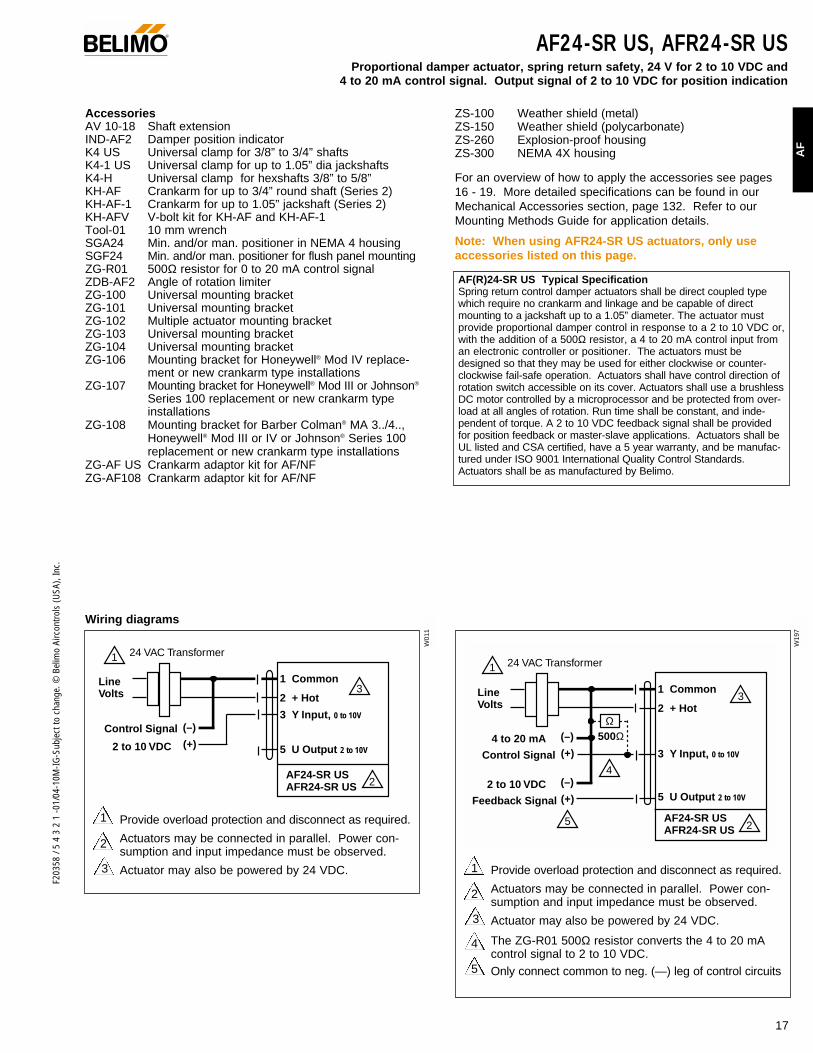
AccessoriesAV 10-18 Shaft extensionIND-AF2 Damper position indicatorK4 US Universal clamp for 3/8” to 3/4” shaftsK4-1 US Universal clamp for up to 1.05” dia jackshaftsK4-H Universal clamp for hexshafts 3/8” to 5/8”KH-AF Crankarm for up to 3/4” round shaft (Series 2)KH-AF-1 Crankarm for up to 1.05” jackshaft (Series 2)KH-AFV V-bolt kit for KH-AF and KH-AF-1Tool-01 10 mm wrenchSGA24 Min. and/or man. positioner in NEMA 4 housingSGF24 Min. and/or man. positioner for flush panel mountingZG-R01 500Ω resistor for 0 to 20 mA control signalZDB-AF2 Angle of rotation limiterZG-100 Universal mounting bracketZG-101 Universal mounting bracketZG-102 Multiple actuator mounting bracketZG-103 Universal mounting bracketZG-104 Universal mounting bracketZG-106 Mounting bracket for Honeywell® Mod IV replace-
ment or new crankarm type installationsZG-107 Mounting bracket for Honeywell® Mod III or Johnson®
Series 100 replacement or new crankarm type installations
ZG-108 Mounting bracket for Barber Colman® MA 3../4..,Honeywell® Mod III or IV or Johnson® Series 100replacement or new crankarm type installations
ZG-AF US Crankarm adaptor kit for AF/NF ZG-AF108 Crankarm adaptor kit for AF/NF
ZS-100 Weather shield (metal)ZS-150 Weather shield (polycarbonate)ZS-260 Explosion-proof housingZS-300 NEMA 4X housing
For an overview of how to apply the accessories see pages 16 - 19. More detailed specifications can be found in ourMechanical Accessories section, page 132. Refer to ourMounting Methods Guide for application details.
Note: When using AFR24-SR US actuators, only useaccessories listed on this page.
Wiring diagrams
2
1 Provide overload protection and disconnect as required.
Actuators may be connected in parallel. Power con-sumption and input impedance must be observed.
Actuator may also be powered by 24 VDC.3
2
1 Provide overload protection and disconnect as required.
Actuators may be connected in parallel. Power con-sumption and input impedance must be observed.
Actuator may also be powered by 24 VDC.
The ZG-R01 500Ω resistor converts the 4 to 20 mAcontrol signal to 2 to 10 VDC. Only connect common to neg. (—) leg of control circuits
4
5
3
®
AF(R)24-SR US Typical Specification Spring return control damper actuators shall be direct coupled typewhich require no crankarm and linkage and be capable of directmounting to a jackshaft up to a 1.05” diameter. The actuator mustprovide proportional damper control in response to a 2 to 10 VDC or,with the addition of a 500Ω resistor, a 4 to 20 mA control input froman electronic controller or positioner. The actuators must bedesigned so that they may be used for either clockwise or counter-clockwise fail-safe operation. Actuators shall have control direction ofrotation switch accessible on its cover. Actuators shall use a brushlessDC motor controlled by a microprocessor and be protected from over-load at all angles of rotation. Run time shall be constant, and inde-pendent of torque. A 2 to 10 VDC feedback signal shall be providedfor position feedback or master-slave applications. Actuators shall beUL listed and CSA certified, have a 5 year warranty, and be manufac-tured under ISO 9001 International Quality Control Standards.Actuators shall be as manufactured by Belimo.
Control Signal (+)2 to 10 VDC
(–)
1 Common
2 + Hot
3 Y Input, 0 to 10V
5 U Output 2 to 10V
1
2
3
24 VAC Transformer
AFR24-SR USAF24-SR US
Line Volts
W01
1
W19
7
1 Common
2 + Hot
3 Y Input, 0 to 10V
5 U Output 2 to 10V
1 24 VAC Transformer
5
3
2
4Control Signal (+)
4 to 20 mA (–)
Feedback Signal (+)2 to 10 VDC (–)
Ω500Ω
Line Volts
AFR24-SR USAF24-SR US

F203
58 /
5 4
3 2
1 -0
1/04
-10M
-IG-S
ubje
ct to
cha
nge.
© B
elim
o Ai
rcon
trols
(USA
), In
c.
Torque min. 133 in-lb, for control of air dampers
ApplicationFor proportional modulation of dampers in HVAC systems.Actuator sizing should be done in accordance with the dampermanufacturer’s specifications.
The actuator is mounted directly to a damper shaft up to 1.05”in diameter by means of its universal clamp. A crankarm andseveral mounting brackets are available for applications wherethe actuator cannot be direct coupled to the damper shaft.
The actuator operates in response to a 0-10 V phasecut con-trol input from an electronic controller or positioner. A 2 to 10VDC feedback signal is provided for position indication ormaster-slave applications.
OperationThe AF series actuators provide true spring return operation forreliable fail-safe application and positive close-off on air tightdampers. The spring return system provides constant torque tothe damper with, and without, power applied to the actuator.
The AF series provides 95° of rotation and is provided with agraduated position indicator showing -5 to 90°. The AF has aunique manual positioning mechanism which allows the set-ting of any damper position within its 95° of rotation. Whenpower is applied to the AFR series its “one time use” mecha-nism is released. The actuator is shipped in the zero position(5° from full fail-safe) to provide automatic compressionagainst damper gaskets for tight shut-off. When power isapplied, the manual mechanism is released and the actuatordrives toward the full fail-safe position. The actuator willmemorize the angle where it stops rotating and use this pointfor its zero position for its normal control operations. Themanual override can also be released physically by the use ofa crank supplied with the actuator.
The AF uses a brushless DC motor which is controlled by anApplication Specific Integrated Circuit (ASIC) and a micro-processor. The microprocessor provides the intelligence to theASIC to provide a constant rotation rate and to know the actu-ator’s exact zero position. The ASIC monitors and controlsthe brushless DC motor’s rotation and provides a digital rota-tion sensing function to prevent damage to the actuator in astall condition. The actuator may be stalled anywhere in itsnormal rotation without the need of mechanical end switches.
Dimensions (All numbers in brackets are metric.)
1.97"
3.15
" [8
0]
3.86
" [9
8]3.
10"
[78]
2.24
" [5
7]
[50]
1.93
"[4
9]
2.64"[67]
0.26" [6.5]5.85" [148.5]
10.59" [269]
0.35" [9]
0.39" [10]
0.65" [16.5]
0.19" [5]
K4-2 US (supplied)
1/2" Centered (Default)
3/4" Centered (Field Selectable)
1.05" Centered (Field Selectable)
K4-1 US (optional)
3/4" to 1.05" Adjustable
K4 US (optional)
3/8" to 3/4" Adjustable
AF24-PC US Proportional damper actuator, spring return safety, 24 V for 0 to 20 V phasecut control signal. Output signal of 2 to 10 VDC for position indication
Technical Data AF24-PC US
Power supply 24 VAC ± 20% 50/60 Hz24 VDC ± 10%
Power consumption running: 6 W ; holding: 2.5 W
Transformer sizing 10 VA (class 2 power source)
Electrical connection 3 ft, 18 GA appliance cable1/2” conduit connector
Overload protection electronic throughout 0 to 95° rotation
Operating range Y 0 to 10 V phasecut
Input impedance 8 kΩ (0.1 mA), 50mW
Feedback output U 2 to 10 VDC (max. 0.5 mA) for 95°
Angle of rotation mechanically limited to 95°
Torque 133 in-lb [15 Nm] constant
Direction of rotation spring return reversible with CW/CCW mounting. Control direction selected by switch: CW=CW with decrease in signalCCW=CCW with a decrease in signal
Position indication visual indicator, -5° to 90° (-5° is springreturn position)
Manual override 3mm hex crank (shipped w/actuator)
Running time 150 sec. constant, independent of load,spring return < 20 sec
Humidity 5 to 95% RH non-condensing
Ambient temperature -22°F to +122°F [-30°C to +50°C]
Storage temperature -40°F to +176°F [-40°C to +80°C]
Housing NEMA type 2 / IP54
Housing material zinc coated metal
Agency listings UL 873 listed, CSA C22.2 No. 24 certified
Noise level max. 45 dB (A)
Servicing maintenance free
Quality standard ISO 9001
Weight 6.0 lbs (2.7 kg.)
LISTED94D5TEMP. IND ®. EQUIP.
UL
®
D00
1
©
18

19
F203
58 /
5 4
3 2
1 -0
1/04
-10M
-IG-S
ubje
ct to
cha
nge.
© B
elim
o Ai
rcon
trols
(USA
), In
c.
AF
AF24-PC US Proportional damper actuator, spring return safety, 24 V for 0 to 20 V phasecut control signal.
Output signal of 2 to 10 VDC for position indication
AccessoriesAV 10-18 Shaft extensionIND-AF2 Damper position indicatorK4 US Universal clamp for 3/8” to 3/4” shaftsK4-1 US Universal clamp for up to 1.05” dia jackshaftsK4-H Universal clamp for hexshafts 3/8” to 5/8”KH-AF Crankarm for up to 3/4” round shaft (Series 2)KH-AF-1 Crankarm for up to 1.05” jackshaft (Series 2)KH-AFV V-bolt kit for KH-AF and KH-AF-1Tool-01 10 mm wrenchSGA24 Min. and/or man. positioner in NEMA 4 housingSGF24 Min. and/or man. positioner for flush panel mountingZG-R01 500Ω resistor for 0 to 20 mA control signalZDB-AF2 Angle of rotation limiterZG-100 Universal mounting bracketZG-101 Universal mounting bracketZG-102 Multiple actuator mounting bracketZG-103 Universal mounting bracketZG-104 Universal mounting bracketZG-106 Mounting bracket for Honeywell® Mod IV replace-
ment or new crankarm type installationsZG-107 Mounting bracket for Honeywell® Mod III or Johnson®
Series 100 replacement or new crankarm type installations
ZG-108 Mounting bracket for Barber Colman® MA 3../4..,Honeywell® Mod III or IV or Johnson® Series 100replacement or new crankarm type installations
ZG-AF US Crankarm adaptor kit for AF/NF ZG-AF108 Crankarm adaptor kit for AF/NF
ZS-100 Weather shield (metal)ZS-150 Weather shield (polycarbonate)ZS-260 Explosion-proof housingZS-300 NEMA 4X housing
For an overview of how to apply the accessories see pages 16 - 19. More detailed specifications can be found in ourMechanical Accessories section, page 132. Refer to ourMounting Methods Guide for application details.
Note: When using AFR24-SR US actuators, only useaccessories listed on this page.
Wiring diagrams
2
1 Provide overload protection and disconnect as required.
Actuators may be connected in parallel. Power con-sumption and input impedance must be observed.
Actuator may also be powered by 24 VDC.3
®
AF24-PC US Typical Specification Spring return control damper actuators shall be direct coupled typewhich require no crankarm and linkage and be capable of directmounting to a jackshaft up to a 1.05” diameter. The actuator mustprovide proportional damper control in response to a 0 to 20 Vphasecut control output from an electronic controller or positioner.The actuators must be designed so that they may be used for eitherclockwise or counterclockwise fail-safe operation. Actuators shallhave control direction of rotation switch accessible on its cover.Actuators shall use a brushless DC motor controlled by a micro-processor and be protected from overload at all angles of rotation.Run time shall be constant, and independent of torque. A 2 to 10VDC feedback signal shall be provided for position feedback ormaster-slave applications. Actuators shall be UL listed and CSAcertified, have a 5 year warranty, and be manufactured under ISO9001 International Quality Control Standards. Actuators shall be asmanufactured by Belimo.
Control Signal (+)2 to 20 VDC
(–)
1 Common
2 + Hot
3 Y Input, 0 to 20V Phasecut
5 U Output 2 to 10V
1
2
3
24 VAC Transformer
AF24-PC US
Line Volts
W18
4
0 to 20 V phasecut control of AF24-PC US
20
F203
58 /
5 4
3 2
1 -0
1/04
-10M
-IG-S
ubje
ct to
cha
nge.
© B
elim
o Ai
rcon
trols
(USA
), In
c.
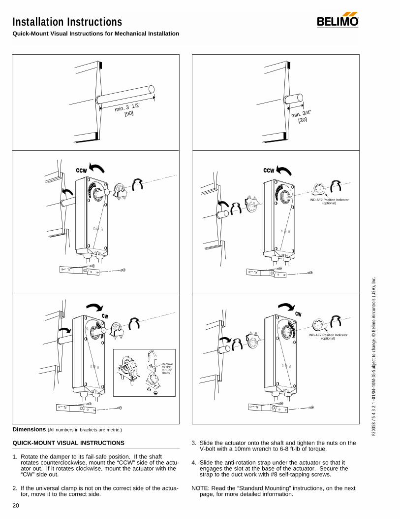
Installation InstructionsQuick-Mount Visual Instructions for Mechanical Installation
IND-AF2 Position Indicator(optional)
IND-AF2 Position Indicator(optional)
QUICK-MOUNT VISUAL INSTRUCTIONS
1. Rotate the damper to its fail-safe position. If the shaftrotates counterclockwise, mount the “CCW” side of the actu-ator out. If it rotates clockwise, mount the actuator with the“CW” side out.
2. If the universal clamp is not on the correct side of the actua-tor, move it to the correct side.
3. Slide the actuator onto the shaft and tighten the nuts on theV-bolt with a 10mm wrench to 6-8 ft-lb of torque.
4. Slide the anti-rotation strap under the actuator so that itengages the slot at the base of the actuator. Secure thestrap to the duct work with #8 self-tapping screws.
NOTE: Read the “Standard Mounting” instructions, on the nextpage, for more detailed information.
min. 3 1/2"
[90] min. 3/4"
[20]
®
Removefor 3/4” to 1.05”shafts
Dimensions (All numbers in brackets are metric.)

21
F203
58 /
5 4
3 2
1 -0
1/04
-10M
-IG-S
ubje
ct to
cha
nge.
© B
elim
o Ai
rcon
trols
(USA
), In
c.
AF
Installation InstructionsMechanical Installation
Standard Mounting
70
60
50
40
30
20
10
02
34 6 8 10
5 7 9
Dam
per A
rea
(sq.
ft.)
Torque Loading (in-lb/ sq. ft.)
Torque LoadingChart
Mechanical Operation
The actuator is mounted directly to a damper shaft up to 1.05” in diameter by means of its universal clamp. A crankarm and sever-al mounting brackets are available for applications where the actuator cannot be direct coupled to the damper shaft. The AF seriesactuators provide true spring return operation for reliable fail-safe application and positive close-off on air tight dampers. The springreturn system provides constant torque to the damper with, and without, power applied to the actuator. The AF…-S versions areprovided with 2 built-in auxiliary switches. These SPDT switches are provided for safety interfacing or signaling, for example, for fanstart-up. The switching function at the fail-safe position is fixed at +5°, the other switch function is adjustable between +25 to +85°.The AFR… series are provided with 1 x SPDT 7A (2.5A) @ 250 VAC, UL listed adjustable switch, 5° to 85°.
Automatic Airtight Dampers/Manual Override
The AF series provides 95° of rotation and is provided with a graduated position indicator showing -5 to 90°. The AF has a uniquemanual positioning mechanism which allows the setting of any damper position within its 95° of rotation. A pre-tensioned springautomatically tightens damper when power is applied to the actuator, compensating for damper seal deterioration. The actuator isshipped in the 0 position (5° from full fail-safe) to provide automatic compression against damper gaskets for tight shut-off. Whenpower is applied, the manual mechanism is released and the actuator drives toward the full fail-safe position. While the AFR…series actuators do not have a manual override they do provide the -5° pre-tensioning feature.
Note:The AF…series actuator is shipped with the manualoverride adjusted for a 0° position at the universal clamp (notat full fail-safe, -5° ). This allows for automatic compression ofdamper blade seals when the actuator is in use, providingtight shut-off. This assumes that the damper is to have tightshut-off at the fail-safe position. If tight close-off is desired atthe opposite direction from fail-safe, the manual overrideshould be released so the actuator can go to the full fail-safeposition. See the manual override instructions.
1. Manually move the damper to the fail-safe position (usuallyclosed). If the shaft rotated counterclockwise ( ), thisis a CCW installation. If the shaft rotated clockwise ( ),this is a CW installation. In a CCW installation, the actuatorside marked “CCW” faces out, while in a CW installation,the side marked “CW” faces out. All other steps are identi-cal.
2. The actuator is usually shipped with the universal clampmounted to the “CCW” side of the actuator. To test for
Determining Torque Loading and Actuator Sizing
Damper torque loadings, used in selecting the correct size actua-tor, should be provided by the damper manufacturer. If thisinformation is not available, the following general selectionguidelines can be used.
Damper Type Torque Loading
Opposed blade, without edge seals, 3 in-lb/sq. ft.for non-tight close-off applications
Parallel blade, without edge seals, 4 in-lb/sq. ft.for non-tight close-off applications
Opposed blade, with edge seals, 5 in-lb/sq. ft.for tight close-off applications
Parallel blade, with edge seals, 7 in-lb/sq. ft.for tight close-off applications
The above torque loadings will work for most applications under2 in. w.g. static pressure or 1000 FPM face velocity. For appli-cations between this criteria and 3 in. w.g. or 2500 FPM, thetorque loading should be increased by a multiplier of 1.5. If theapplication calls for higher criteria up to 4 in. w.g. or 3000 FPM,use a multiplier of 2.0.
General Information
Belimo actuators should be mounted indoors in a dry, relatively clean environment free from corrosive fumes. If the actuator is tobe mounted outdoors, a protective enclosure must be used to shield the actuator. For new construction work, order dampers with extended shafts. Instruct the installing contractor to allow space for mounting and serv-ice of the Belimo actuator on the shaft. The damper shaft must extend at least 3 1/2" from the duct. If the shaft extends less than 3 1/2"or if an obstruction blocks access, the shaft can be extended with the AV 10-18 shaft extension or the actuator may be mounted in itsshort shaft configuration.
®

22
F203
58 /
5 4
3 2
1 -0
1/04
-10M
-IG-S
ubje
ct to
cha
nge.
© B
elim
o Ai
rcon
trols
(USA
), In
c.
Installation InstructionsMechanical Installation
adequate shaft length, slide the actuator over the shaftwith the side marked “CCW” (or the “CW” side if this is theside with the clamp). If the shaft extends at least 1/8”through the clamp, mount the actuator as follows. If not,go to the Short Shaft Installation section.
Fig. A Universal Clamp and IND-AF2 Pointer (optional)positions indicating fail-safe and pre-load settings
3. If the clamp is not on the correct side as determined in step#1, re-mount the clamp as follows. If it is on the correctside, proceed to step #5. Look at the universal clamp. Ifyou are mounting the actuator with the “CCW” side out,position the clamp so that the pointer section of the tab ispointing to 0° (see Fig. C) and the spline pattern of theclamp mates with spline of the actuator. Slip the clampover the spline. (Use the same procedure if the “CW” side isout.) If your application requires a mechanical minimumposition, read the Rotation Limiting, Mechanical MinimumDamper Position section.
4. Lock the clamp to the actuator using the retaining clip. 5. Verify that the damper is still in its full fail-safe position.6. Slide the actuator over the shaft.7. Position the actuator in the desired location.8. Tighten the two nuts on the clamp using a 10mm wrench
or socket using 6-8 ft-lb of torque.9. Slip the stud of the anti rotation strap into the slot at the
base of the actuator. The stud should be positionedapproximately 1/16 of an inch from the closed end of theslot. Bend the strap as needed to reach the duct. Attachthe strap to the duct with #8 self tapping screws.
Short Shaft InstallationIf the shaft extends at least 3/4” from the duct, follow thesesteps:1. Determine the best orientation for the universal clamp on
the back of the actuator. The best location would be whereyou have the easiest access to the V bolt nuts on theclamp.
2. Engage the clamp to the actuator as close as possible tothe determined location.
3. Lock the clamp in place using the remaining retainer clip.4. Verify that the damper is still in its full fail-safe position.5. Slide the actuator over the shaft.6. Position the actuator in the desired location.7. Tighten the two nuts on the clamp using a 10mm wrench
or socket using 6-8 ft-lb of torque.8. Slip the stud of the anti-rotation strap into the slot at the
base of the actuator. The stud should be positionedapproximately 1/16 of an inch from the closed end of theslot. Bend the strap as needed to reach the duct. Attachthe strap to the duct with #8 self tapping screws.
9. If damper position indication is required, use the optionalIND-AF2 pointer. See Fig. A.
Jackshaft InstallationThe AF… series actuator is designed for use with jackshaftsup to 1.05” in diameter. In most applications, the AF actuatormay be mounted in the same manner as a standard dampershaft application. If more torque is required than one AF actu-ator can provide, a second AF actuator may be mounted tothe jackshaft using the ZG-102 multiple actuator mountingbracket. See wiring guide for wiring details.
Correct pointer mountingposition when actuator isat 5° preload.
4030
20
10
0-5
40
30
20
100
-5
Correct pointer mountingposition if actuator is atfull fail-safe.
40
30
20
100
-5
4030
20
10
0-5
Correct clamp mountingposition when actuator isshipped from factory(with 5° preload)
30
20
10
0-5
30
20
100
CW
Correct clamp mountingposition if actuator is atfull fail-safe.
30
20
10
0-5
30
20
100
-5
CCW
CWCCW
CWCCW
CWCCW
®
Mounting:If the actuators are mounted onthe opposed ends of the shaft,the actuator direction must beselected carefully. Usually, thedirection of rotation is reversed.
AF actuators which may beused on one shaft:
MaxQuantity
Model Per Shaft
AF24 (-S) USAFR24 (-S) USAF120 (-S) US 4AFR120 (-S) USAF230 (-S) US
AF24-SR US 4AFR24-SR US 4
AFR24-3 (-S) US 4

23
F203
58 /
5 4
3 2
1 -0
1/04
-10M
-IG-S
ubje
ct to
cha
nge.
© B
elim
o Ai
rcon
trols
(USA
), In
c.
AF
Installation InstructionsMechanical Installation
Multiple Actuator MountingIf more torque is required than one AF actuator can provide, asecond AF actuator may be mounted to the shaft using theZG-102 multiple mounting bracket. Notes:The manual positioning mechanism cannot be used in
multiple actuator applications.
Special Wiring and Additional Information: See wiring guide
Rotation LimitationThe angle of rotation limiter, ZDB-AF2, is used in conjunctionwith the tab on the universal clamp or IND-AF2 position indicatorwhich comes with the ZDB-AF2. In order to function properly,the clamp or indicator must be mounted correctly. See Fig. A.
The ZDB-AF2 may not work in certain mounting orientationsusing the ZG-106 or ZG-107 mounting brackets. It will not workwith the ZG-108 mounting bracket. Limiting the damper rotationmust be accomplished by adjusting the crankarm linkage.
The ZDB-AF2 may be used in 2 ways to control the rotationaloutput of the AF series actuator. One use is in the applicationwhere a damper has a designed rotation less than 90°. Anexample would be a 45° or 60° rotating damper. The otherapplication would be to set a minimum damper position whichcan be easily set or changed without having to remove theactuator from the damper.
Damper rotation limiting1. Determine the amount of damper rotation required.2. Locate the Angle of Rotation Limiter (ZDB-AF2) on the
actuator so that its edge lines up with the degree grad-uation on the actuator face which corresponds with therequired rotation. See Fig. C.
3. Find the appropriate cross-hair location through theslot of the limiter. This is the screw mounting location.
4. Pierce through the label material to allow easy fasten-ing of the retaining screw.
5. Position the limiter back to the desired position, mak-ing sure the locating “teeth” on the limiter are engagedinto the locating holes on the actuator.
6. Fasten the limiter to the actuator using the self tappingscrew provided.
7. Test the damper rotation either manually with the man-ual crank or apply power and if required, a control sig-nal. Re-adjust if necessary.
Mechanical minimum damper positionIn order to use this procedure, the actuator must be mount-ed for short shaft mounting. See pages 8 & 10.1. Position the damper to its minimum position by using
the manual crank or by providing the appropriate con-trol signal to the AF24… modulating type actuator.
2. Place the indicator on to the actuator spline in theapproximate position shown in Fig. D. Fasten it withthe retaining clip. Note that the mounting orientation isdifferent than the mounting used for Damper RotationLimiting.
3. Place the ZDB-AF2 rotation limiter on the actuator sothat it either makes contact with, or is as close as pos-sible to, the edge of the indicator. See Fig. E. Makesure that the locating teeth are engaged into the locat-ing holes on the actuator. If all of the mounting teethdo not align with the holes, the mounting location ofthe indicator to the spline may have to be moved. Thelimiter would then be remounted to get the best posi-tion match of both parts.
4. Find the cross-hair location through the slot of the lim-iter. This is the screw mounting location.
5. Pierce through the label material to allow easy fasten-ing of the retaining screw.
6. Fasten the limiter to the actuator using the self tappingscrew provided.
7. Test the damper operation either manually with themanual crank or apply power and if required, a controlsignal. Re-adjust if necessary.
®
20
3040
Screw secured atthese cross hairs
20
3040
Secure angle-of-rotation limiter
Screw
Philips screwdriver
20
3040
Angle of rotation is now set at 40°.
Fig. C ZDB-AF2 Securing the Angle of Rotation Limiter
9080
7060
50
40
30
20
100
-5
908070
6050
4030
20
10
0-5
CWCCW
9080
7060
50
40
30
20
100
-5
908070
6050
4030
20
10
0-5
908 90
CWCCW
Fig. D
Fig. E

24
F203
58 /
5 4
3 2
1 -0
1/04
-10M
-IG-S
ubje
ct to
cha
nge.
© B
elim
o Ai
rcon
trols
(USA
), In
c.
Installation Instructions ®
This method should not be used for outside air damper appli-cations. The damper will never go to the full close-off position.This may cause coils to freeze or other system problems. TheAF24-SR (-S) US wired to either the SGA24 or SGF24 can beused for minimum position setting and still provide full close-off.
Manual overrideThe AF series actuators can be manually positioned to easeinstallation or for emergency positioning.
1. The manual override will only work if no power is availableto the actuator.
2. Insert the manual crank (shipped with the actuator) intothe hexagon hole located on either side of the actuator. Anillustration, located on the label, shows the location.
3. Turn the crank in the direction shown on the label (clock-wise on the “CW” side, counterclockwise on the “CCW”side). It will take approximately 19 revolutions to rotatethe full 95° of rotation.
4. To lock the actuator in the required position, rotate thecrank quickly in the opposite direction, 1/2 of a revolution. The“lock closed” icon on the label shows the correct direction.
5. The manual override may be disengaged in 2 ways. - Rotate the crank about a 1/4 revolution in the same
direction as the initial winding. The “lock open” iconshows the correct direction.
- Apply power to wire 1 and 2. The actuator will automati-cally disengage the override function and will go to the“on” position in the case of the on-off versions. Or, in thecase of the proportional versions, go to the 0 signal posi-tion and then go to the position corresponding to thecontrol signal. The actuator will now work normally.
Testing the installation without power The actuator/damper installation may be tested without powerat the actuator. Refer to the manual positioning section of theinstructions. Move the damper to its full non-fail-safe positionusing the manual crank. Disengage the manual positionmechanism and have the damper go to full fail-safe position.Correct any mechanical problems and retest.
Auxiliary SwitchesThe AF series actuators may be ordered with 2 built-in SPDTauxiliary switches used for safety interfacing or signalling, forexample, for fan start-up. The switch position near the fail-safeposition is fixed at 5°. The other is adjustable between 25 and85° of rotation. The crank, supplied with the actuator, or a 3mm
allen wrench is used to adjust the switching position. AFR…series 1 x SPDT 7A (2.5A) @ 250 VAC, UL listed adjustable 5° to 85°
Switch Rating
Voltage Resistive Load Inductive Load
120 VAC 7A 5A
250 VAC 7A 2.5A
Two methods may be used to adjust the switching point of theadjustable switch.
Method 1 - See Fig. F1 The actuator must be in its fail-safe position.2. Insert the crank into the hexagon shaped hole located in
the center of the adjustable switch pointer.3. Rotate the crank until the switch pointer is at the desired
switch point in degrees as shown.
Method 2 - See Fig. G1. Position the damper to the point at which you want the
switch to activate. This may be done by using the manualoverride or by providing the appropriate proportional sig-nal to AF24… modulating type actuator. The position ofthe switch pointer is not important during this step.
2. Insert the crank into the hexagon shaped hole located inthe center of the adjustable switch pointer.
3. Rotate the switch pointer to just past the switch point indi-cating arrow as shown.
30 4050
607080
25…85°
Factory setting 85°
30 4050
607080
25…85°
Rotate withcrank handle
30 4050
607080
25…85°
60° set
Crank Handle
30 4050
607080
25…85°
Actuatorafter locking
30 4050
607080
25…85°
Switch operates
30 4050
607080
25…85°
Switch doesnot operate
Crank Handle
Fig. F
Fig. G
Winding the damper actuator
- insert crank handle- turn handle in direc-
tion of arrow
Locking the damper actuator
- rotate crank handle1/2 turn in the direc-tion shown by the“locked” icon.
Unlocking the damper actuator
(2 options)- rotate crank handle
1/4 turn in the directionshown by the“unlocked” icon.
- remote control by sup-plying power to theunit for > than 3 sec.
(Not provided with AFR…series)
Factory setting 85°Rotate withcrank handle 45° set
5…85°
10 2030
4050
607080
5…85°
10 2030
4050
607080
5…85°
10 2030
4050
607080
Crank Handle
Fig. D
AF…series
AFR…series

25
F203
58 /
5 4
3 2
1 -0
1/04
-10M
-IG-S
ubje
ct to
cha
nge.
© B
elim
o Ai
rcon
trols
(USA
), In
c.
AF
Installation InstructionsNon-direct mounting methods and electrical operation
®
General The AF series actuators utilize brushless DC motor technolo-gy. The AF uses this motor in conjunction with an ApplicationSpecific Integrated Circuit (ASIC). In the On-Off versions ofthe AF, the ASIC monitors and controls the actuator’s rotationand a digital rotation sensing function to prevent damage tothe actuator. The AF24… modulating type actuators incorpo-rate a built in microprocessor. The microprocessor providesthe intelligence to the ASIC to provide a constant rotation rateand knows the actuator’s exact zero position.
Brushless DC motor operation Belimo’s brushless DC motor spins by reversing the poles ofstationary electromagnets housed inside of a rotating perma-nent magnet. The electromagnetic poles are switched by aspecial ASIC circuit developed by Belimo. Unlike the conven-tional DC motor, there are no brushes to wear or commutatorsto foul.
Overload protection The AF series actuators are protected from overload at allangles of rotation. The ASIC circuit constantly monitors the
rotation of the DC motor inside the actuator and stops thepulses to the motor when it senses a stall condition. The DCmotor remains energized and produces full rated torque to theload. This helps ensure that dampers are fully closed and thatedge and blade seals are always properly compressed.
The AF… actuators are protected against overload by digitaltechnology located in the ASIC. The ASIC circuitry constantlymonitors the rotation of the brushless DC motor inside theactuator and stops the pulsing to the motor when it senses astall condition. The motor remains energized and producesfull rated torque during stall conditions.
Motor position detection Belimo brushless DC motors eliminate the need for poten-tiometers for positioning in modulating type actuators. Insidethe motor are three “Hall Effect” sensors. These sensorsdetect the spinning rotor and send pulses to the microproces-sor which counts the pulses and calculates the position towithin 1/3 of a revolution of the motor.
Electrical Operation
Crankarm for AF Series Actuators
KH-AF Non-direct mounting with ZG-108 mounting bracket
KH-AF crankarm including retaining ring. Caution: theretaining clip supplied with the clamp is not used to mount theKH-AF crankarm.
Multiple dampers direct coupled to one actuator with link-age to operate the other damper.
The KH-AF (-1) crankarm is used in non-direct coupledmounting applications. The KH-AF (-1) may also be used tosimultaneously direct couple to a damper shaft and provide anadditional crank arm connection to a second damper. TheKH-AFV V-bolt kit must be used for this non-direct application(see illustration below).
Two sizes are available:KH-AF For round shafts up to 3/4” or square shafts up to 5/8”KH-AF-1For jackshafts up to 1.05”
KH-AFV V-bolt kit for KH-AF(-1) crankarm
Note: KH-AF (-1) crankarms cannot be used on AF Series 1 actuators.
KH-AF (-1)crankarmwith KH-AFVV-bolt kit
KH-8crankarm

26
F203
58 /
5 4
3 2
1 -0
1/04
-10M
-IG-S
ubje
ct to
cha
nge.
© B
elim
o Ai
rcon
trols
(USA
), In
c.
Installation InstructionsGeneral Wiring
General Wiring Instructions
WARNING The wiring technician must be trained and experi-enced with electronic circuits. Disconnect power supplybefore attempting any wiring connections or changes. Makeall connections in accordance with wiring diagrams and followall applicable local and national codes. Provide disconnectand overload protection as required. Use copper, twisted pair,conductors only. If using electrical conduit, the attachment tothe actuator must be made with flexible conduit.
Always read the controller manufacturer's installation lit-erature carefully before making any connections. Followall instructions in this literature. If you have any questions,contact the controller manufacturer and/or Belimo.
Transformer(s)The AF24 . . actuators require a 24 VAC class 2 transformerand draws a maximum of 10 VA per actuator. The actuatorenclosure cannot be opened in the field, there are no parts orcomponents to be replaced or repaired.
– EMC directive: 89/336/EEC– Software class A: Mode of operation type 1– Low voltage directive: 73/23/EEC
CAUTION: It is good practice to power electronic or digitalcontrollers from a separate power transformer than that usedfor actuators or other end devices. The power supply designin our actuators and other end devices use half wave rectifica-tion. Some controllers use full wave rectification. When thesetwo different types of power supplies are connected to thesame power transformer and the DC commons are connectedtogether, a short circuit is created across one of the diodes inthe full wave power supply, damaging the controller. Only usea single power transformer to power the controller and actua-tor if you know the controller power supply uses half wave rec-tification.
Multiple actuators, one transformer Multiple actuators may be powered from one transformer provid-ed the following rules are followed:1. The TOTAL current draw of the actuators (VA rating) is
less than or equal to the rating of the transformer.2. Polarity on the secondary of the transformer is strictly fol-
lowed. This means that all No. 1 wires from all actuatorsare connected to the common leg on the transformer andall No. 2 wires from all actuators are connected to thehotleg. Mixing wire No. 1 & 2 on one leg of the trans-former will result in erratic operation or failure of the actua-tor and/or controls.
Multiple actuators, multiple transformersMultiple actuators positioned by the same control signal maybe powered from multiple transformers provided the followingrules are followed:1. The transformers are properly sized.2. All No. 1 wires from all actuators are tied together and tied
to the negative leg of the control signal. See wiring dia-gram.
Wire length for AF… actuatorsKeep power wire runs below the lengths listed in the Fig. H. Ifmore than one actuator is powered from the same wire run,divide the allowable wire length by the number of actuators todetermine the maximum run to any single actuator. Example: 3 actuators, 16 Ga wire
350 Ft ÷ 3 Actuators = 117 Ft. Maximum wire run
Maximum wire length:
Wire Size Max. Feet. Wire Size Max. Feet12 Ga 900 Ft. 18 Ga 225 Ft.14 Ga 550 Ft. 20 Ga 125 Ft. 16 Ga 350 Ft. 22 Ga 60 Ft.
Fig. H
Wire Type and Wire Installation TipsFor most installations, 18 or 16 Ga. cable works well with theAF24. . actuators. Use code-approved wire nuts, terminalstrips or solderless connectors where wires are joined. It isgood practice to run control wires unspliced from the actuatorto the controller. If splices are unavoidable, make sure thesplice can be reached for possible maintenance. Tape and/orwire-tie the splice to reduce the possibility of the splice beinginadvertently pulled apart.
The AF24… proportional actuators have a digital circuit that isdesigned to ignore most unwanted input signals (pickup). Insome situations the pickup may be severe enough to causeerratic running of the actuator. For example, a large inductiveload (high voltage AC wires, motors, etc.) running near thepower or control wiring may cause excessive pickup. Tosolve this problem, make one or more of the followingchanges:1. Run the wire in metallic conduit.2. Re-route the wiring away from the source of pickup.3. Use shielded wire (Belden 8760 or equal). Ground the
shield to an earth ground. Do not connect it to the actua-tor common.
Initialization of the AF24-SR US, AFR24-SR US When power is initially applied, the actuator will first releaseits preload position (This assumes a manual position has beenset, The AFR… is pre set from the factory). The actuator willthen rotate to the full fail-safe position. At this point the micro-processor recognizes that the actuator is at full fail-safe anduses this position as the base for all of its position calcula-tions. The microprocessor will retain the initialized zero duringshort power failures of up to 20 seconds. For power failuresgreater than 20 seconds, the actuator would naturally return toits full fail-safe position prior to the microprocessor losing itsmemory. The actuator will also re-initialize if the manual posi-tion mechanism is used.
®
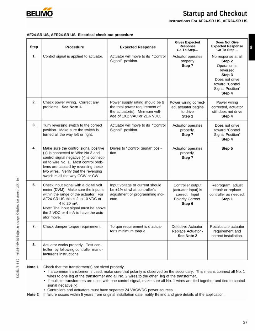
27
F203
58 /
5 4
3 2
1 -0
1/04
-10M
-IG-S
ubje
ct to
cha
nge.
© B
elim
o Ai
rcon
trols
(USA
), In
c.
AF
Startup and CheckoutInstructions For AF24-SR US, AFR24-SR US
®
Procedure
Control signal is applied to actuator.
Check power wiring. Correct anyproblems. See Note 1.
Turn reversing switch to the correctposition. Make sure the switch isturned all the way left or right.
Make sure the control signal positive(+) is connected to Wire No 3 andcontrol signal negative (-) is connect-ed to wire No. 1. Most control prob-lems are caused by reversing thesetwo wires. Verify that the reversingswitch is all the way CCW or CW.
Check input signal with a digital voltmeter (DVM). Make sure the input iswithin the range of the actuator. ForAF24-SR US this is 2 to 10 VDC or
4 to 20 mA.Note: The input signal must be abovethe 2 VDC or 4 mA to have the actu-ator move.
Check damper torque requirement.
Actuator works properly. Test con-troller by following controller manu-facturer's instructions.
Expected Response
Actuator will move to its “ControlSignal” position.
Power supply rating should be ≥the total power requirement ofthe actuator(s). Minimum volt-age of 19.2 VAC or 21.6 VDC.
Actuator will move to its “ControlSignal” position.
Drives to “Control Signal” posi-tion
Input voltage or current shouldbe ±1% of what controller'sadjustment or programming indi-cate.
Torque requirement is ≤ actua-tor’s minimum torque.
Gives ExpectedResponse
Go To Step…
Actuator operatesproperlyStep 7
Power wiring correct-ed, actuator begins
to driveStep 1
Actuator operatesproperly.Step 7
Actuator operatesproperly.Step 7
Controller output(actuator input) is
correct. InputPolarity Correct.
Step 6
Defective Actuator.Replace Actuator -
See Note 2
Does Not GiveExpected Response
Go To Step…
No response at allStep 2
Operation isreversedStep 3
Does not drivetoward "ControlSignal Position"
Step 4
Power wiringcorrected, actuatorstill does not drive
Step 4
Does not drivetoward “ControlSignal Position”
Step 4
Step 5
Reprogram, adjustrepair or replace
controller as needed.Step 1
Recalculate actuatorrequirement and
correct installation.
Step
1.
2.
3.
4.
5.
7.
8.
Note 1 Check that the transformer(s) are sized properly. • If a common transformer is used, make sure that polarity is observed on the secondary. This means connect all No. 1
wires to one leg of the transformer and all No. 2 wires to the other leg of the transformer. • If multiple transformers are used with one control signal, make sure all No. 1 wires are tied together and tied to control
signal negative (-).• Controllers and actuators must have separate 24 VAC/VDC power sources.
Note 2 If failure occurs within 5 years from original installation date, notify Belimo and give details of the application.
AF24-SR US, AFR24-SR US Electrical check-out procedure

28
F203
58 /
5 4
3 2
1 -0
1/04
-10M
-IG-S
ubje
ct to
cha
nge.
© B
elim
o Ai
rcon
trols
(USA
), In
c.
NF Series Spring Return Direct Coupled Actuator ®
Minimum 60 in-lb torque For damper areas up to 15 sq-ft*
Torque: 60 in-lb
Power supply : 24 VAC
120 VAC
230 VAC
Control signal: on-off
Control signal: proportional 2 to 10 VDC
Feedback signal: 2 to 10 VDC
Running time motor <75 sec
motor 150 sec constant
spring <60 sec
External direction of rotation switch
Appliance rated cable, 18 GA
Built-in auxiliary switch
Two built-in auxiliary switches
Installation instructions ......(p. 36–41) General wiring ..............(p. 41)Start-up and checkout ......(p. 42)
NF Series – at a glance
K4-1 USClamp
ZG106 or ZG 107bracket
* 4 in-lb/ft2 damper torque loading. Parallel blade. No edge seals.
Mount directly to 1.05” jackshafts withaccessory clamp.
Linkage is available when direct coupling isnot possible. (See Mounting Methods Guide5.1 and Mechanical Accessories Doc 4.2)
NF2
4 U
S (p
. 30)
NF2
4-S
US
(p. 3
0)
NF2
4-S
2 U
S (p
. 30)
NF1
20 U
S (p
. 32)
NF1
20-S
US
(p. 3
2)
NF2
30 U
S (p
. 32)
NF2
30-S
US
(p. 3
2)
NF2
4-S
R U
S (p
. 34)
NF2
4-S
R-S
US
(p. 3
4)
Applications

29
F203
58 /
5 4
3 2
1 -0
1/04
-10M
-IG-S
ubje
ct to
cha
nge.
© B
elim
o Ai
rcon
trols
(USA
), In
c.
NF
A CLOSER LOOK…
NF Series Spring Return Direct Coupled Actuator®
LISTED94D5TEMP. IND ®. EQUIP.
UL
Cut labor costs with simple direct coupling.
True mechanical spring return – the most reliable failsafe.
Mount for clockwise or counterclockwise fail-safe.
Check damper position easily with clear position indicator.
Don’t worry about actuator burn-out. Belimo is overload-proof throughout rotation
Easy mechanical stop to adjust angle of rotation. (add ZDB-AF2 accessory).
Need to change control direction? Do it easily with a simple switch. (NF24-SR US)
Golden Point breather membrane optimizes performance in harsh airstream environments.
Built-in auxiliary switch(s) is easy to use, offers feedback or signal for additional device. (NF24-S2 US has two switches,NF24-S US, NF120-S US, NF230-S US)
Microprocessor-controlled brushless DC motor increases actuator life span and reliability, provides constant running time. (NF24-SR US)
Rugged metal housing withstands rough handling in themechanical room.
3 ft. appliance rated cable and conduit connectoreases installation.
The Belimo Difference
Customer Commitment.Extensive product range. Competitive project pricing. Application assistance. Same-day shipments. Free technical support. Five year warranty.
Low Installation and Life-Cycle Cost.Easy installation. Accuracy and repeatability. Low power consumption. No maintenance.
Long Service Life.Components tested before assembly. Every product tested before shipment. 20+ years direct coupled actuator design.
©

F203
58 /
5 4
3 2
1 -0
1/04
-10M
-IG-S
ubje
ct to
cha
nge.
© B
elim
o Ai
rcon
trols
(USA
), In
c.
Torque min. 60 in-lb, for control of air dampers
ApplicationFor on-off, fail-safe control of dampers in HVAC systems.Actuator sizing should be done in accordance with the dampermanufacturer’s specifications. Control is on-off from an auxil-iary contact, or a manual switch.
The actuator is mounted directly to a damper shaft up to 1.05”in diameter by means of its universal clamp. A crank arm andseveral mounting brackets are available for applications wherethe actuator cannot be direct coupled to the damper shaft.
OperationThe NF series actuators provide true spring return operationfor reliable fail-safe application and positive close off on airtight dampers. The spring return system provides constanttorque to the damper with, and without, power applied to theactuator.The NF series provides 95° of rotation and is provided with agraduated position indicator showing 0° to 95°.The actuator may be stalled anywhere in its normal rotationwithout the need of mechanical end switches.
The NF24-S US version is provided with 1 built in auxiliaryswitch. This SPDT switch is provided for safety interfacing orsignaling, for example, for fan start-up. The switching functionis adjustable between 5° and 85°.
The NF24-S2 US version is provided with 2 built-in auxiliaryswitches. These SPDT switches are provided for safety inter-facing or signaling, for example, for fan start-up. The switchingfunction at the fail-safe position is fixed at +5°, the otherswitch function is adjustable between +25° to +85°.
NF24 (-S,-S2) US On-off, spring return safety, 24 V
®
Technical Data NF24 (-S) US
Power supply 24 VAC ± 20% 50/60 Hz24 VDC ± 10%
Power consumption running: 5 Wholding: 2.6 W
Transformer sizing 8 VA (class 2 power source)
Electrical connection 3 ft, 18 GA appliance cable1/2” conduit connector
Overload protection Electronic throughout 0 to 95° rotation
Electrical protection Auxiliary switches are double insulated
Angle of rotation 95°, adjustable 30 to 95° w/ accessories
Torque 60 in-lb [7 Nm] constant torque
Direction of rotation spring return can be selected byCW/CCW mounting
Position indication visual indicator, 0° to 95° (0° is springreturn position)
Auxiliary switches 1 x SPDT 7A (2.5A) @ 250 VAC, UL listedadjustable 5° to 85°
Running time motor: < 75 secspring: < 60 sec
Humidity 5 to 95% RH non-condensing
Ambient temperature -22°F to +122°F [-30°C to +50°C]
Storage temperature -40°F to +176°F [-40°C to +80°C]
Housing NEMA type 2 / IP54
Housing material zinc coated steel
Agency listings UL 873 listed, CSA C22.2 No.24 certified
Noise level max. 45 dB (A)
Servicing maintenance free
Quality standard ISO 9001
Weight 6.6 lbs (3.0 kg.)
Technical Data NF24 (-S2) US
Auxiliary switches 2 x SPDT 7A (2.5A) @ 250 VAC, UL listedone set at +5°, one adjustable 25° to 85°
(NF24-S)
(nominal)
1.97"
3.15
" [8
0]
3.86
" [9
8]3.
10"
[78]
2.24
" [5
7]
[50]
1.93
"[4
9]
2.64"[67]
0.26" [6.5]5.85" [148.5]
10.59" [269]
0.35" [9]
0.39" [10]
0.65" [16.5]
0.19" [5]
K4-2 US (supplied)
1/2" Centered (Default)
3/4" Centered (Field Selectable)
1.05" Centered (Field Selectable)
K4-1 US (optional)
3/4" to 1.05" Adjustable
K4 US (optional)
3/8" to 3/4" Adjustable
Dimensions (All ratings in brackets are metric.)
LISTED94D5TEMP. IND ®. EQUIP.
UL
D01
1
30

31
F203
58 /
5 4
3 2
1 -0
1/04
-10M
-IG-S
ubje
ct to
cha
nge.
© B
elim
o Ai
rcon
trols
(USA
), In
c.
NF
NF24 (-S,-S2) USOn-off, spring return safety, 24 V
®
AccessoriesAV 10-18 Shaft extensionIND-AF2 Damper position indicatorK4-1 US Universal clamp for up to 1.05” dia jackshaftsK4-H Universal clamp for hexshafts 3/8” to 5/8”KH-AF Crankarm for up to 3/4” round shaft KH-AF-1 Crankarm for up to 1.05” jackshaft KH-AFV V-bolt kit for KH-AF and KH-AF-1Tool-01 10 mm wrenchZDB-AF2 Angle of rotation limiterZG-100 Universal mounting bracketZG-101 Universal mounting bracketZG-102 Multiple actuator mounting bracketZG-103 Universal mounting bracketZG-104 Universal mounting bracketZG-106 Mounting bracket for Honeywell® Mod IV replace-
ment or new crankarm type installationsZG-107 Mounting bracket for Honeywell® Mod III or Johnson®
Series 100 replacement or new crankarm typeinstallations
ZG-108 Mounting bracket for Barber Colman® MA 3../4..,Honeywell® Mod III or IV or Johnson® Series 100replacement or new crankarm type installations
ZG-AF US Crankarm adaptor kit for AF/NF ZG-AF108 Crankarm adaptor kit for AF/NF ZS-100 Weather shield (metal)ZS-150 Weather shield (polycarbonate)ZS-260 Explosion-proof housingZS-300 NEMA 4X housing
Note: When using NF24 (-S, -S2) US actuators, only useaccessories listed on this page.
Wiring diagrams
NF24 US Typical SpecificationOn-off spring return damper actuators shall be direct coupledtype which require no crankarm and linkage and be capableof direct mounting to a jackshaft up to a 1.05” diameter. Theactuators must be designed so that they may be used foreither clockwise or counterclockwise fail-safe operation.Actuators shall be protected from overload at all angles ofrotation. If required, 1 or 2 SPDT auxiliary switch shall be pro-vided having the capability of being adjustable. Actuatorswith auxiliary switches must be constructed to meet therequirements for Double Insulation so an electrical ground isnot required to meet agency listings. Actuators shall be ULlisted and CSA certified, have a 5 year warranty, and be man-ufactured under ISO 9001 International Quality ControlStandards. Actuators shall be as manufactured by Belimo.
2
3
1 Provide overload protection and disconnect as required.
Actuators may be connected in parallel. Power con-sumption must be observed.
Actuator may also be powered by 24 VDC.
2
3
1
4
5
Provide overload protection and disconnect as required.
Actuators may be connected in parallel. Power con-sumption must be observed.
Actuator may also be powered by 24 VDC.
For end position indication, interlock control, fan start-up, etc., NF24-S US incorporates a built-in auxiliaryswitch: 1 x SPDT, 7A (2.5A) @250 VAC, UL listed,adjustable 5° to 85°. NF24-S2 US incorporates twobuilt-in auxiliary switches: 2 x SPDT, 7A (2.5A) @250VAC, UL listed, one switch is fixed at +5°, one isadjustable 25° to 85°.
Meets UL and CSA requirements without the need of anelectrical ground connection.
On-off wiring for NF24 US On-off wiring for NF24-S US
1 Common
2 + Hot
1
2
24 VAC Transformer
NF24 (-S,-S2) US
Line Volts 3
1 Common
2 + Hot
1
2
24 VAC Transformer
NF24-S US2NF24-S2 US
Line Volts 3
4
5
S1
S2
S3
NC
NO5° to 85°
4
S1
S2
S3
S4
S5
S6
NC
NO
NC
NO
5°
25° to 85°
W06
3
W06
4

F203
58 /
5 4
3 2
1 -0
1/04
-10M
-IG-S
ubje
ct to
cha
nge.
© B
elim
o Ai
rcon
trols
(USA
), In
c.
NF120 (-S) US / NF230 (-S) US On-off, spring return safety, 120 or 230 VAC
Torque min. 60 in-lb, for control of air dampers
ApplicationFor on-off, fail-safe control of dampers in HVAC systems.Actuator sizing should be done in accordance with the dampermanufacturer’s specifications. Control is on-off from an auxil-iary contact, or a manual switch.
The actuator is mounted directly to a damper shaft up to 1.05”in diameter by means of its universal clamp. A crank arm andseveral mounting brackets are available for applications wherethe actuator cannot be direct coupled to the damper shaft.
OperationThe NF series actuators provide true spring return operationfor reliable fail-safe application and positive close off on airtight dampers. The spring return system provides constanttorque to the damper with, and without, power applied to theactuator.The NF series provides 95° of rotation and is provided with agraduated position indicator showing 0° to 95°. The actuator may be stalled anywhere in its normal rotationwithout the need of mechanical end switches.
The NF120-S / NF230-S US versions are provided with 1built-in auxiliary switch. This SPDT switch is provided for safe-ty interfacing or signaling, for example, for fan start-up. Theswitching function is adjustable between 5° and 85°.
Technical Data NF120 (-S) US NF230 (-S) US
Power supply 120 VAC ± 10% 230 VAC ± 10%50/60 Hz 50/60 Hz
Power consumption running: 6 W 6 Wholding: 3.5 W 3.5W
Transformer sizing 7 VA 7 VA
Electrical connection 3 ft, 18 GA appliance cable1/2” conduit connector
Overload protection Electronic throughout 0 to 95° rotation
Electrical protection Auxiliary switches are double insulated
Angle of rotation 95°, adjustable 30 to 95° w/ accessories
Torque 60 in-lb [7 Nm] constant torque
Direction of rotation spring return can be selected byCW/CCW mounting
Position indication visual indicator, 0° to 95° (0° is springreturn position)
Auxiliary switches 1 x SPDT 7A (2.5A) @ 250 VAC, (-S models) UL listed, adjustable 5° to 85°
Running time motor: < 75 secspring: < 60 sec
Humidity 5 to 95% RH non-condensing
Ambient temperature -22°F to +122°F [-30°C to +50°C]
Storage temperature -40°F to +176°F [-40°C to +80°C]
Housing NEMA type 2 / IP54
Housing material zinc coated steel
Agency listings UL 873 listed, CSA C22.2 No.24 certified
Noise level max. 45 dB (A)
Servicing maintenance free
Quality standard ISO 9001
Weight 7.3 lbs (3.3 kg.)
LISTED94D5TEMP. IND ®. EQUIP.
UL
®
(nominal)
32
1.97"
3.15
" [8
0]
3.86
" [9
8]3.
10"
[78]
2.24
" [5
7]
[50]
1.93
"[4
9]
2.64"[67]
0.26" [6.5]5.85" [148.5]
10.59" [269]
0.35" [9]
0.39" [10]
0.65" [16.5]
0.19" [5]
K4-2 US (supplied)
1/2" Centered (Default)
3/4" Centered (Field Selectable)
1.05" Centered (Field Selectable)
K4-1 US (optional)
3/4" to 1.05" Adjustable
K4 US (optional)
3/8" to 3/4" Adjustable
Dimensions (All ratings in brackets are metric.)
D01
1

33
F203
58 /
5 4
3 2
1 -0
1/04
-10M
-IG-S
ubje
ct to
cha
nge.
© B
elim
o Ai
rcon
trols
(USA
), In
c.
NF
NF120 (-S) US / NF230 (-S) US On-off, spring return safety, 120 or 230 VAC
AccessoriesAV 10-18 Shaft extensionIND-AF2 Damper position indicatorK4-1 US Universal clamp for up to 1.05” dia jackshaftsK4-H Universal clamp for hexshafts 3/8” to 5/8”KH-AF Crankarm for up to 3/4” round shaft KH-AF-1 Crankarm for up to 1.05” jackshaft KH-AFV V-bolt kit for KH-AF and KH-AF-1Tool-01 10 mm wrenchZDB-AF2 Angle of rotation limiterZG-100 Universal mounting bracketZG-101 Universal mounting bracketZG-102 Multiple actuator mounting bracketZG-103 Universal mounting bracketZG-104 Universal mounting bracketZG-106 Mounting bracket for Honeywell® Mod IV replace-
ment or new crankarm type installationsZG-107 Mounting bracket for Honeywell® Mod III or Johnson®
Series 100 replacement or new crankarm typeinstallations
ZG-108 Mounting bracket for Barber Colman® MA 3../4..,Honeywell® Mod III or IV or Johnson® Series 100replacement or new crankarm type installations
ZG-AF US Crankarm adaptor kit for AF/NF ZG-AF108 Crankarm adaptor kit for AF/NF ZS-100 Weather shield (metal)ZS-150 Weather shield (polycarbonate)ZS-260 Explosion-proof housingZS-300 NEMA 4X housing
Note: When using NF120 US, NF120-S, NF230 US andNF230-S US actuators, only use accessories listed on thispage.
NF120 US / NF230 US Typical SpecificationOn-off spring return damper actuators shall be direct coupledtype which require no crankarm and linkage and be capableof direct mounting to a jackshaft up to a 1.05” diameter. Theactuators must be designed so that they may be used foreither clockwise or counterclockwise fail-safe operation.Actuators shall be protected from overload at all angles ofrotation. If required, 1 SPDT auxiliary switch shall be providedhaving the capability of being adjustable. Actuators with aux-iliary switches must be constructed to meet the requirementsfor Double Insulation so an electrical ground is not required tomeet agency listings. Actuators shall be UL listed and CSAcertified, have a 5 year warranty, and be manufactured underISO 9001 International Quality Control Standards. Actuatorsshall be as manufactured by Belimo.
Wiring diagrams
2
1 Provide overload protection and disconnect as required.
Actuators may be connected in parallel. Power con-sumption must be observed.
No ground connection is required.
2
3
1
3
Provide overload protection and disconnect as required.
Actuators may be connected in parallel. Power con-sumption must be observed.
No ground connection is required.
For end position indication, interlock control, fan start-up, etc., NF120-S US and NF230-S incorporate onebuilt-in auxiliary switch: 1 x SPDT, 7A (2.5A) @250VAC, UL listed, adjustable 5° to 85°.
Meets UL and CSA requirements without the need of anelectrical ground connection.
®
4
5
On-off wiring for NF120 US / NF230 US On-off wiring for NF120-S US / NF230-S US
1 Neutral
2 Hot
3 Ground
1
2
230 VAC 120 VAC
NF120 US NF230 US
Wht N
Blk H
1 Neutral
2 Hot
2
3
4
5
S1
S2
S3
NC
NO5° to 85°
NF120-S US NF230-S US
1
120 VAC
L1 N
L2 H
W06
6
W06
7

F203
58 /
5 4
3 2
1 -0
1/04
-10M
-IG-S
ubje
ct to
cha
nge.
© B
elim
o Ai
rcon
trols
(USA
), In
c.
NF24-SR (-S) US Proportional damper actuator, spring return safety, 24 V for 2 to 10 VDC, or 4 to 20 mA control signal.Output signal of 2 to 10 VDC for position indication
Torque min. 60 in-lb, for control of air dampers
ApplicationFor proportional modulation of dampers in HVAC systems.Actuator sizing should be done in accordance with the dampermanufacturer’s specifications.
The actuator is mounted directly to a damper shaft up to 1.05”in diameter by means of its universal clamp. A crank arm andseveral mounting brackets are available for applications wherethe actuator cannot be direct coupled to the damper shaft.
The actuator operates in response to a 2 to 10 VDC, or with theaddition of a 500Ω resistor, a 4 to 20 mA control input from anelectronic controller or positioner. A 2 to 10 VDC feedback signalis provided for position indication or master-slave applications.
OperationThe NF series actuators provide true spring return operation forreliable fail-safe application and positive close-off on air tightdampers. The spring return system provides constant torque tothe damper with, and without, power applied to the actuator.The NF series provides 95° of rotation and is provided with agraduated position indicator showing 0° to 95°.
The NF24-SR US uses a brushless DC motor which is con-trolled by an Application Specific Integrated Circuit (ASIC) anda microprocessor. The microprocessor provides the intelli-gence to the ASIC to provide a constant rotation rate and toknow the actuator’s exact fail-safe position. The ASIC moni-tors and controls the brushless DC motor’s rotation and pro-vides a digital rotation sensing function to prevent damage tothe actuator in a stall condition. The actuator may be stalledanywhere in its normal rotation without the need of mechani-cal end switches.
Technical Data NF24-SR US
Power supply 24 VAC ± 20% 50/60 Hz24 VDC ± 10%
Power consumption running: 3 Wholding: 1 W
Transformer sizing 6 VA (class 2 power source)
Electrical connection 3 ft, 18 GA appliance cable1/2” conduit connector
Overload protection Electronic throughout 0 to 95° rotation
Operating range Y 2 to 10 VDC, 4 to 20mA
Input impedance 100 kΩ (0.1 mA), 500ΩFeedback output U 2 to 10 VDC (max. 0.5 mA) for 95°
Angle of rotation 95°, adjustable 30° to 95° w/accessory
Torque 60 in-lb [7 Nm] constant torque
Direction of rotation spring return reversible with CW/CCW mounting. Control direction selected by switch: CW=CW with decrease in signalCCW=CCW with a decrease in signal
Position indication visual indicator, 0° to 95°(0° is spring return position)
Auxiliary switches 1 x SPDT 7A (2.5A) @ 250 VAC, UL listedadjustable 5° to 85°
Running time motor: 150 sec constant,independent of load
spring: < 60 sec
Humidity 5 to 95% RH non-condensing
Ambient temperature -22°F to +122°F [-30°C to +50°C]
Storage temperature -40°F to +176°F [-40°C to +80°C]
Housing NEMA type 2 / IP54
Housing material zinc coated metal
Agency listings UL 873 listed, CSA C22.2 No.24 certified
Noise level max. 45 dB (A)
Servicing maintenance free
Quality standard ISO 9001
Weight 6.0 lbs (2.7 kg.)
LISTED94D5TEMP. IND ®. EQUIP.
UL
®
(nominal)
(NF24-SR(-S)
1.97"
3.15
" [8
0]
3.86
" [9
8]3.
10"
[78]
2.24
" [5
7]
[50]
1.93
"[4
9]
2.64"[67]
0.26" [6.5]5.85" [148.5]
10.59" [269]
0.35" [9]
0.39" [10]
0.65" [16.5]
0.19" [5]
K4-2 US (supplied)
1/2" Centered (Default)
3/4" Centered (Field Selectable)
1.05" Centered (Field Selectable)
K4-1 US (optional)
3/4" to 1.05" Adjustable
K4 US (optional)
3/8" to 3/4" Adjustable
Dimensions (All ratings in brackets are metric.)
D01
1
34
©
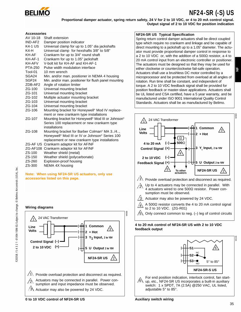
35
F203
58 /
5 4
3 2
1 -0
1/04
-10M
-IG-S
ubje
ct to
cha
nge.
© B
elim
o Ai
rcon
trols
(USA
), In
c.
NF
NF24-SR (-S) USProportional damper actuator, spring return safety, 24 V for 2 to 10 VDC, or 4 to 20 mA control signal.
Output signal of 2 to 10 VDC for position indication
AccessoriesAV 10-18 Shaft extensionIND-AF2 Damper position indicatorK4-1 US Universal clamp for up to 1.05” dia jackshaftsK4-H Universal clamp for hexshafts 3/8” to 5/8”KH-AF Crankarm for up to 3/4” round shaft KH-AF-1 Crankarm for up to 1.05” jackshaft KH-AFV V-bolt kit for KH-AF and KH-AF-1PTA-250 Pulse width modulation interfaceTool-01 10 mm wrenchSGA24 Min. and/or man. positioner in NEMA 4 housingSGF24 Min. and/or man. positioner for flush panel mountingZDB-AF2 Angle of rotation limiterZG-100 Universal mounting bracketZG-101 Universal mounting bracketZG-102 Multiple actuator mounting bracketZG-103 Universal mounting bracketZG-104 Universal mounting bracketZG-106 Mounting bracket for Honeywell® Mod IV replace-
ment or new crankarm type installationsZG-107 Mounting bracket for Honeywell® Mod III or Johnson®
Series 100 replacement or new crankarm type installations
ZG-108 Mounting bracket for Barber Colman® MA 3../4..,Honeywell® Mod III or IV or Johnson® Series 100replacement or new crankarm type installations
ZG-AF US Crankarm adaptor kit for AF/NF ZG-AF108 Crankarm adaptor kit for AF/NF ZS-100 Weather shield (metal)ZS-150 Weather shield (polycarbonate)ZS-260 Explosion-proof housingZS-300 NEMA 4X housing
Note: When using NF24-SR US actuators, only useaccessories listed on this page.
NF24-SR US Typical Specification Spring return control damper actuators shall be direct coupledtype which require no crankarm and linkage and be capable ofdirect mounting to a jackshaft up to a 1.05” diameter. The actu-ator must provide proportional damper control in response toa 2 to 10 VDC or, with the addition of a 500Ω resistor, a 4 to20 mA control input from an electronic controller or positioner.The actuators must be designed so that they may be used foreither clockwise or counterclockwise fail-safe operation.Actuators shall use a brushless DC motor controlled by amicroprocessor and be protected from overload at all angles ofrotation. Run time shall be constant, and independent oftorque. A 2 to 10 VDC feedback signal shall be provided forposition feedback or master-slave applications. Actuators shallbe UL listed and CSA certified, have a 5 year warranty, and bemanufactured under ISO 9001 International Quality ControlStandards. Actuators shall be as manufactured by Belimo.
Wiring diagrams
2
1 Provide overload protection and disconnect as required.
Actuators may be connected in parallel. Power con-sumption and input impedance must be observed.
Actuator may also be powered by 24 VDC.3
®
2
1 Provide overload protection and disconnect as required.
Up to 4 actuators may be connected in parallel. With4 actuators wired to one 500Ω resistor. Power con-sumption must be observed.
Actuator may also be powered by 24 VDC.
A 500Ω resistor converts the 4 to 20 mA control signalto 2 to 10 VDC. (ZG-R01) Only connect common to neg. (–) leg of control circuits
For end position indication, interlock control, fan start-up, etc., NF24-SR US incorporates a built-in auxiliaryswitch: 1 x SPDT, 7A (2.5A) @250 VAC, UL listed,adjustable 5° to 85°.
4
5
6
3
4 to 20 mA control of NF24-SR US with 2 to 10 VDCfeedback output
0 to 10 VDC control of NF24-SR US Auxiliary switch wiring
Control Signal (+)2 to 10 VDC
(–)
1 Common
2 + Hot
3 Y1 Input, 2 to 10V
5 U Output 2 to 10V
1
2
3
24 VAC Transformer
NF24-SR US
Line Volts
1 Common
2 + Hot
3 Y1 Input, 2 to 10V
5 U Output 2 to 10V
1 24 VAC Transformer
5
3
2
4
NF24-SR US
Control Signal (+)4 to 20 mA (–)
Feedback Signal (+)2 to 10 VDC (–)
Ω500Ω
Line Volts
To other actuators
NF24-SR-S US
6S1
S2
S3
NC
NO5° to 85°
W06
8
W14
6W
069
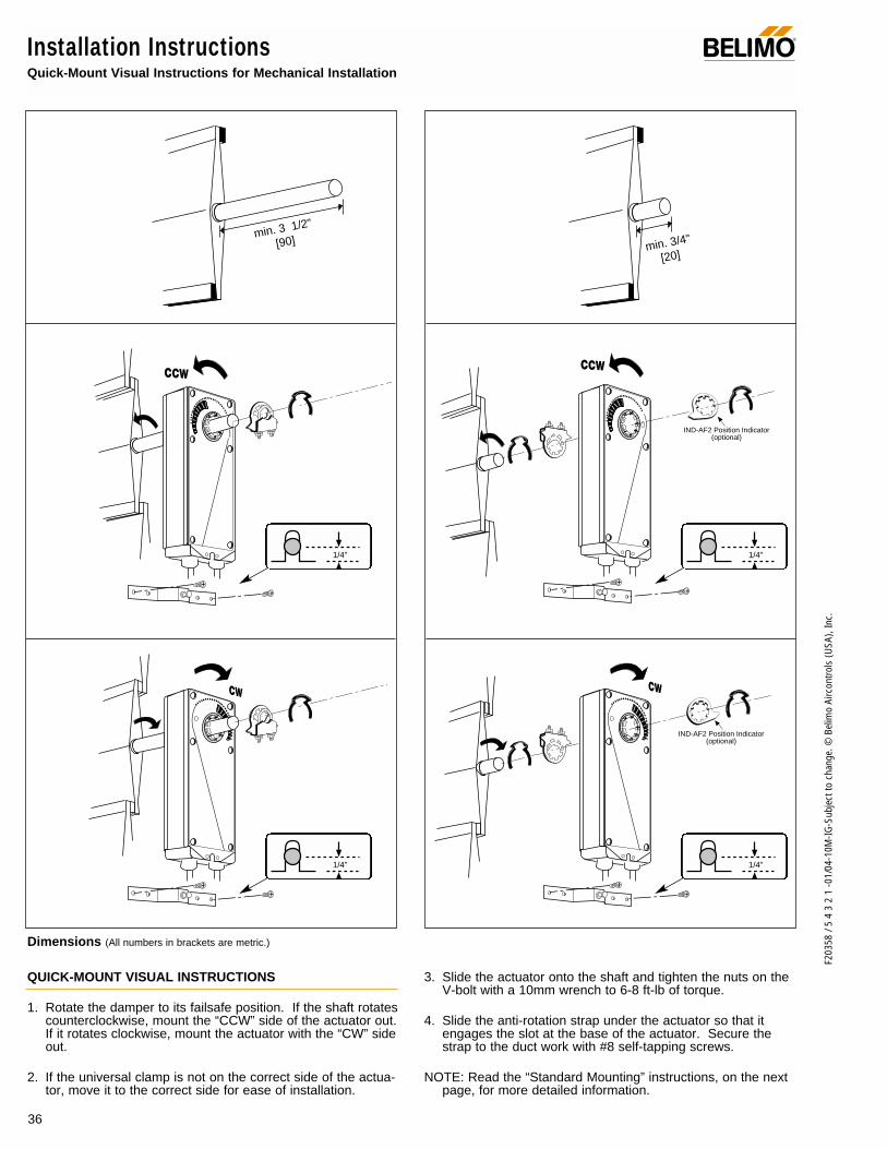
36
F203
58 /
5 4
3 2
1 -0
1/04
-10M
-IG-S
ubje
ct to
cha
nge.
© B
elim
o Ai
rcon
trols
(USA
), In
c.
Installation InstructionsQuick-Mount Visual Instructions for Mechanical Installation
®
IND-AF2 Position Indicator(optional)
IND-AF2 Position Indicator(optional)
QUICK-MOUNT VISUAL INSTRUCTIONS
1. Rotate the damper to its failsafe position. If the shaft rotatescounterclockwise, mount the “CCW” side of the actuator out.If it rotates clockwise, mount the actuator with the “CW” sideout.
2. If the universal clamp is not on the correct side of the actua-tor, move it to the correct side for ease of installation.
3. Slide the actuator onto the shaft and tighten the nuts on theV-bolt with a 10mm wrench to 6-8 ft-lb of torque.
4. Slide the anti-rotation strap under the actuator so that itengages the slot at the base of the actuator. Secure thestrap to the duct work with #8 self-tapping screws.
NOTE: Read the “Standard Mounting” instructions, on the nextpage, for more detailed information.
min. 3 1/2"
[90] min. 3/4"
[20]
1/4" 1/4"
1/4" 1/4"
Dimensions (All numbers in brackets are metric.)

37
F203
58 /
5 4
3 2
1 -0
1/04
-10M
-IG-S
ubje
ct to
cha
nge.
© B
elim
o Ai
rcon
trols
(USA
), In
c.
NF
Installation InstructionsMechanical Installation
Standard Mounting
30
25
20
15
10
5
02
34 6 8 10
5 7 9
Dam
per A
rea
(sq.
ft.)
Torque Loading (in-lb/ sq. ft.)
Torque LoadingChart
Mechanical Operation
The actuator is mounted directly to a damper shaft up to 1.05” in diameter by means of its universal clamp. A crank arm and sever-al mounting brackets are available for applications where the actuator cannot be direct coupled to the damper shaft.
The NF series actuators provide true spring return operation for reliable fail-safe application and positive close-off on air tightdampers. The spring return system provides consistent torque to the damper with, and without, power applied to the actuator.
The NF series provides 95° of rotation and is provided with a graduated position indicator showing 0° to 95°.
The NF…-S versions are provided with 1 built-in auxiliary switch. This SPDT switch is provided for safety interfacing or signaling,for example, for fan start-up. The switching function is adjustable between 5° and 85°. (NF24-S2, with 2 built-in switches, adjustablebetween +25° and +85°)
1. See Fig. B. Manually move the damper to the fail-safeposition (a) (usually closed). If the shaft rotated counter-clockwise ( ), this is a CCW installation. If the shaftrotated clockwise ( ), this is a CW installation. In aCCW installation, the actuator side marked “CCW” facesout, while in a CW installation, the side marked “CW”faces out. All other steps are identical.
2. The actuator is usually shipped with the universal clampmounted to the “CCW” side of the actuator. To test foradequate shaft length, slide the actuator over the shaftwith the side marked “CCW” (or the “CW” side if this is theside with the clamp). If the shaft extends at least 1/8”through the clamp, mount the actuator as follows. If not,go to the Short Shaft Installation section.
Determining Torque Loading and Actuator Sizing
Damper torque loadings, used in selecting the correct size actua-tor, should be provided by the damper manufacturer. If thisinformation is not available, the following general selectionguidelines can be used.
Damper Type Torque Loading
Opposed blade, without edge seals, 3 in-lb/sq. ft.for non-tight close-off applications
Parallel blade, without edge seals, 4 in-lb/sq. ft.for non-tight close-off applications
Opposed blade, with edge seals, 5 in-lb/sq. ft.for tight close-off applications
Parallel blade, with edge seals, 7 in-lb/sq. ft.for tight close-off applications
The above torque loadings will work for most applications under2 in. w.g. static pressure or 1000 FPM face velocity. For appli-cations between this criteria and 3 in. w.g. or 2500 FPM, thetorque loading should be increased by a multiplier of 1.5. If theapplication calls for higher criteria up to 4 in. w.g. or 3000 FPM,use a multiplier of 2.0.
General Information
Belimo actuators should be mounted indoors in a dry, relatively clean environment free from corrosive fumes. If the actuator is tobe mounted outdoors, a protective enclosure must be used to shield the actuator. For new construction work, order dampers with extended shafts. Instruct the installing contractor to allow space for mounting and serv-ice of the Belimo actuator on the shaft. The damper shaft must extend at least 3 1/2" from the duct. If the shaft extends less than 3 1/2"or if an obstruction blocks access, the shaft can be extended with the AV 10-18 shaft extension or the actuator may be mounted in itsshort shaft configuration.
®
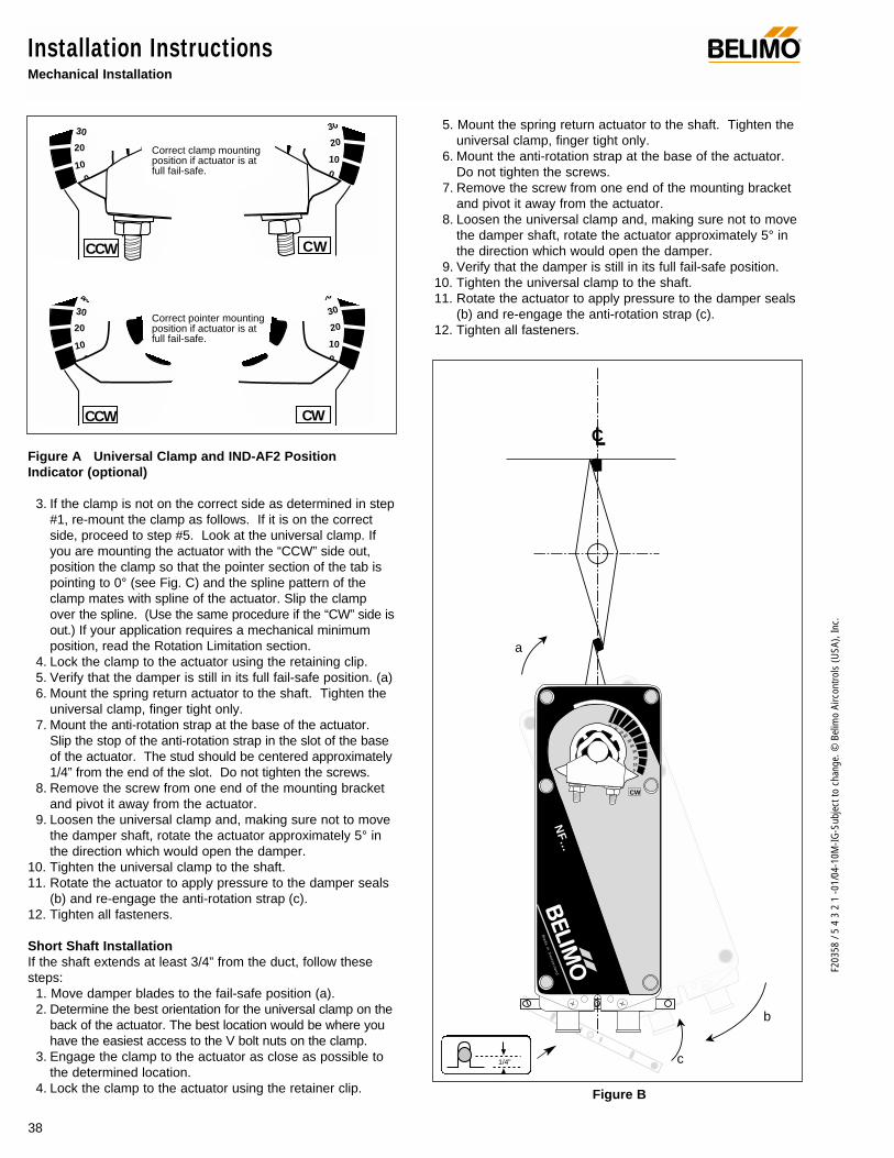
38
F203
58 /
5 4
3 2
1 -0
1/04
-10M
-IG-S
ubje
ct to
cha
nge.
© B
elim
o Ai
rcon
trols
(USA
), In
c.
Installation InstructionsMechanical Installation
Figure A Universal Clamp and IND-AF2 PositionIndicator (optional)
3. If the clamp is not on the correct side as determined in step#1, re-mount the clamp as follows. If it is on the correctside, proceed to step #5. Look at the universal clamp. Ifyou are mounting the actuator with the “CCW” side out,position the clamp so that the pointer section of the tab ispointing to 0° (see Fig. C) and the spline pattern of theclamp mates with spline of the actuator. Slip the clampover the spline. (Use the same procedure if the “CW” side isout.) If your application requires a mechanical minimumposition, read the Rotation Limitation section.
4. Lock the clamp to the actuator using the retaining clip. 5. Verify that the damper is still in its full fail-safe position. (a)6. Mount the spring return actuator to the shaft. Tighten the
universal clamp, finger tight only.7. Mount the anti-rotation strap at the base of the actuator.
Slip the stop of the anti-rotation strap in the slot of the baseof the actuator. The stud should be centered approximately1/4” from the end of the slot. Do not tighten the screws.
8. Remove the screw from one end of the mounting bracketand pivot it away from the actuator.
9. Loosen the universal clamp and, making sure not to movethe damper shaft, rotate the actuator approximately 5° inthe direction which would open the damper.
10. Tighten the universal clamp to the shaft.11. Rotate the actuator to apply pressure to the damper seals
(b) and re-engage the anti-rotation strap (c).12. Tighten all fasteners.
Short Shaft InstallationIf the shaft extends at least 3/4” from the duct, follow thesesteps:
1. Move damper blades to the fail-safe position (a).2. Determine the best orientation for the universal clamp on the
back of the actuator. The best location would be where youhave the easiest access to the V bolt nuts on the clamp.
3. Engage the clamp to the actuator as close as possible tothe determined location.
4. Lock the clamp to the actuator using the retainer clip.
5. Mount the spring return actuator to the shaft. Tighten theuniversal clamp, finger tight only.
6. Mount the anti-rotation strap at the base of the actuator.Do not tighten the screws.
7. Remove the screw from one end of the mounting bracketand pivot it away from the actuator.
8. Loosen the universal clamp and, making sure not to movethe damper shaft, rotate the actuator approximately 5° inthe direction which would open the damper.
9. Verify that the damper is still in its full fail-safe position.10. Tighten the universal clamp to the shaft.11. Rotate the actuator to apply pressure to the damper seals
(b) and re-engage the anti-rotation strap (c).12. Tighten all fasteners.
30
20
10
0
CCW
30
20
100
-5
Correct clamp mountingposition if actuator is atfull fail-safe.
4030
20
10
0-5
40
30
20
100
-5
Correct pointer mountingposition if actuator is atfull fail-safe.
CW
CCW CW
®
Figure B
R
5°
M
1 2 S1 S2
(COM) (+)
Made in Sw i t ze r l and
30 40 5060
70
80
25…85°
90 80 70 6050
40
30
20
10
0
-5
LC
Ma
de
in S
wi t z
er l a
nd
9080
7060
50
40
30
20
100
-5
b
c
a
CW
®
NF…
1/4"
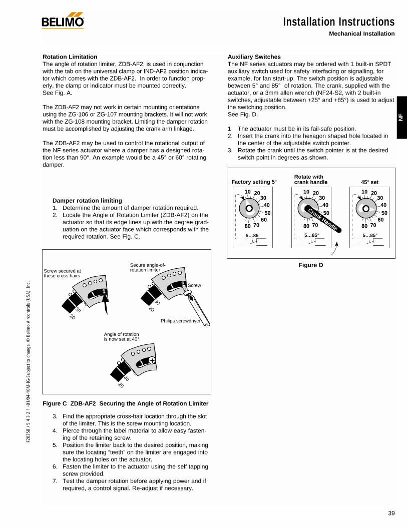
39
F203
58 /
5 4
3 2
1 -0
1/04
-10M
-IG-S
ubje
ct to
cha
nge.
© B
elim
o Ai
rcon
trols
(USA
), In
c.
NF
Installation InstructionsMechanical Installation
Rotation LimitationThe angle of rotation limiter, ZDB-AF2, is used in conjunctionwith the tab on the universal clamp or IND-AF2 position indica-tor which comes with the ZDB-AF2. In order to function prop-erly, the clamp or indicator must be mounted correctly. See Fig. A.
The ZDB-AF2 may not work in certain mounting orientationsusing the ZG-106 or ZG-107 mounting brackets. It will not workwith the ZG-108 mounting bracket. Limiting the damper rotationmust be accomplished by adjusting the crank arm linkage.
The ZDB-AF2 may be used to control the rotational output ofthe NF series actuator where a damper has a designed rota-tion less than 90°. An example would be a 45° or 60° rotatingdamper.
Damper rotation limiting1. Determine the amount of damper rotation required.2. Locate the Angle of Rotation Limiter (ZDB-AF2) on the
actuator so that its edge lines up with the degree grad-uation on the actuator face which corresponds with therequired rotation. See Fig. C.
3. Find the appropriate cross-hair location through the slotof the limiter. This is the screw mounting location.
4. Pierce through the label material to allow easy fasten-ing of the retaining screw.
5. Position the limiter back to the desired position, makingsure the locating “teeth” on the limiter are engaged intothe locating holes on the actuator.
6. Fasten the limiter to the actuator using the self tappingscrew provided.
7. Test the damper rotation before applying power and ifrequired, a control signal. Re-adjust if necessary.
Auxiliary SwitchesThe NF series actuators may be ordered with 1 built-in SPDTauxiliary switch used for safety interfacing or signalling, forexample, for fan start-up. The switch position is adjustablebetween 5° and 85° of rotation. The crank, supplied with theactuator, or a 3mm allen wrench (NF24-S2, with 2 built-inswitches, adjustable between +25° and +85°) is used to adjustthe switching position.See Fig. D.
1 The actuator must be in its fail-safe position.2. Insert the crank into the hexagon shaped hole located in
the center of the adjustable switch pointer.3. Rotate the crank until the switch pointer is at the desired
switch point in degrees as shown.
®
20
3040
Screw secured atthese cross hairs
20
3040
Secure angle-of-rotation limiter
Screw
Philips screwdriver
20
3040
Angle of rotation is now set at 40°.
Figure C ZDB-AF2 Securing the Angle of Rotation Limiter
Factory setting 5°Rotate withcrank handle 45° set
5…85°
10 2030
4050
607080
5…85°
10 2030
4050
607080
5…85°
10 2030
4050
607080
Crank Handle
Figure D

40
F203
58 /
5 4
3 2
1 -0
1/04
-10M
-IG-S
ubje
ct to
cha
nge.
© B
elim
o Ai
rcon
trols
(USA
), In
c.
Installation InstructionsNon-direct mounting methods and additional information
Initialization of the NF24-SR US When power is initially applied, the microprocessor recognizesthat the actuator is at full fail-safe and uses this position asthe base for all of its position calculations. The microprocessorwill retain the initialized zero during short power failures of upto 20 seconds. For power failures greater than 20 seconds theactuator would naturally return to it full fail-safe position priorto the microprocessor losing its memory. When power isapplied again, the actuator will re-initialize the zero position.The microprocessor will keep count of these short power fail-ures until 16 occur. At this point, the microprocessor will auto-matically drive the actuator to its zero position and re-initializeto correct for any possible error accumulation.
Motor position detectionBelimo brushless DC motors eliminate the need for potentiome-ters for positioning. Inside the motor are three “Hall Effect” sen-sors. These sensors detect the spinning rotor and send pulsesto the microprocessor which counts the pulses and calculatesthe position to within 1/3 of a revolution of the motor.
Overload protectionThe Belimo NF24-SR US actuator is protected from overloadat all angles of rotation. The on board microprocessor con-stantly monitors the rotation of the DC drive motor inside theactuator and stops the pulses to the motor when it senses astall condition. The DC motor remains energized and pro-duces full rated torque to the load. This helps ensure thatdampers are fully closed and that edge and blade seals arealways properly compressed.
Brushless DC motor operationBelimo's brushless DC motor spins by reversing the poles ofstationary electromagnets housed inside rotating permanentmagnets. The electromagnetic poles are switched by a micro-processor and a special ASIC (Application Specific IntegratedCircuit) developed by Belimo. Unlike the conventional DCmotor, there are no brushes to wear or commutators to foul.
Additional Operational Information for NF24-SR US Proportional Actuators
®
Crankarm
KH-AF Non-direct mounting with ZG-108 mounting bracket
KH-AF crankarm including retaining ring. Caution: theretaining clip supplied with the clamp is not used to mount theKH-AF crankarm.
Non-direct mounting using various accessories
The KH-AF (-1) crankarm is used in non-direct coupledmounting applications.
Two sizes are available:KH-AF For round shafts up to 3/4” or square shafts up to5/8”KH-AF-1For jackshafts up to 1.05”
ZG-AF USLinkageKitKH-AF
Crankarm
ZG-106 orZG-107
DC1 Damper Clip

41
F203
58 /
5 4
3 2
1 -0
1/04
-10M
-IG-S
ubje
ct to
cha
nge.
© B
elim
o Ai
rcon
trols
(USA
), In
c.
NF
WARNING The wiring technician must be trained and experi-enced with electronic circuits. Disconnect power supplybefore attempting any wiring connections or changes. Makeall connections in accordance with wiring diagrams and followall applicable local and national codes. Provide disconnectand overload protection as required. Use copper, twisted pair,conductors only. If using electrical conduit, the attachment tothe actuator must be made with flexible conduit.
Always read the controller manufacturer's installation lit-erature carefully before making any connections. Followall instructions in this literature. If you have any questions,contact the controller manufacturer and/or Belimo.
Transformer(s)The NF24 . . actuator requires a 24 VAC class 2 transformerand draws a maximum of 8 VA per actuator. The actuatorenclosure cannot be opened in the field, there are no parts orcomponents to be replaced or repaired.
– EMC directive: 89/336/EEC– Software class A: Mode of operation type 1– Low voltage directive: 73/23/EEC
CAUTION: It is good practice to power electronic or digitalcontrollers from a separate power transformer than that usedfor actuators or other end devices. The power supply designin our actuators and other end devices use half wave rectifica-tion. Some controllers use full wave rectification. When thesetwo different types of power supplies are connected to thesame power transformer and the DC commons are connectedtogether, a short circuit is created across one of the diodes inthe full wave power supply, damaging the controller. Only usea single power transformer to power the controller and actua-tor if you know the controller power supply uses half wave rec-tification.
Multiple actuators, one transformer Multiple actuators may be powered from one transformer pro-vided the following rules are followed:1. The TOTAL current draw of the actuators (VA rating) is
less than or equal to the rating of the transformer.2. Polarity on the secondary of the transformer is strictly fol-
lowed. This means that all No. 1 wires from all actuatorsare connected to the common leg on the transformer andall No 2 wires from all actuators are connected to the hot-leg. Mixing wire No. 1 & 2 on one leg of the transformerwill result in erratic operation or failure of the actuatorand/or controls.
Multiple actuators, multiple transformersMultiple actuators positioned by the same control signal maybe powered from multiple transformers provided the followingrules are followed:1. The transformers are properly sized.2. All No. 1 wires from all actuators are tied together and tied
to the negative leg of the control signal. See wiring dia-gram page 19.
Wire length for NF… actuatorsKeep power wire runs below the lengths listed in the table inFig. E. If more than one actuator is powered from the same
wire run, divide the allowable wire length by the number of actu-ators to determine the maximum run to any single actuator. Example for NF24-SR US:
3 actuators, 16 Ga wire 550 Ft ÷ 3 Actuators = 183 Ft. Maximum wire run
Maximum wire length:
Wire Size Max. Feet. Wire Size Max. Feet12 Ga 1100 Ft. 18 Ga 260 Ft.14 Ga 700 Ft. 20 Ga 140 Ft. 16 Ga 440 Ft. 22 Ga 75 Ft.
Figure E
Wire Type and Wire Installation TipsFor most installations, 18 or 16 Ga. cable works well with theNF24… actuators. Use code-approved wire nuts, terminalstrips or solderless connectors where wires are joined. It isgood practice to run control wires unspliced from the actuatorto the controller. If splices are unavoidable, make sure thesplice can be reached for possible maintenance. Tape and/orwire-tie the splice to reduce the possibility of the splice beinginadvertently pulled apart.
The NF24… proportional actuators have a digital circuit that isdesigned to ignore most unwanted input signals (pickup). Insome situations the pickup may be severe enough to causeerratic running of the actuator. For example, a large inductiveload (high voltage AC wires, motors, etc.) running near thepower or control wiring may cause excessive pickup. To solvethis problem, make one or more of the following changes:1. Run the wire in metallic conduit.2. Re-route the wiring away from the source of pickup.3. Use shielded wire (Belden 8760 or equal). Ground the
shield to an earth ground. Do not connect it to the actua-tor common.
Wire Size Max. Feet. Wire Size Max. Feet12 Ga 1500 Ft. 18 Ga 375 Ft.14 Ga 925 Ft. 20 Ga 200 Ft. 16 Ga 550 Ft. 22 Ga 100 Ft.
Wire Size Max. Feet. Wire Size Max. Feet12 Ga 1250 Ft. 18 Ga 320 Ft.14 Ga 800 Ft. 20 Ga 160 Ft. 16 Ga 500 Ft. 22 Ga 85 Ft.
Installation InstructionsGeneral Wiring
General Wiring Instructions
®
NF24 (-S) US
NF120 (-S) US / NF230 (-S) US
NF24-SR (-S) US
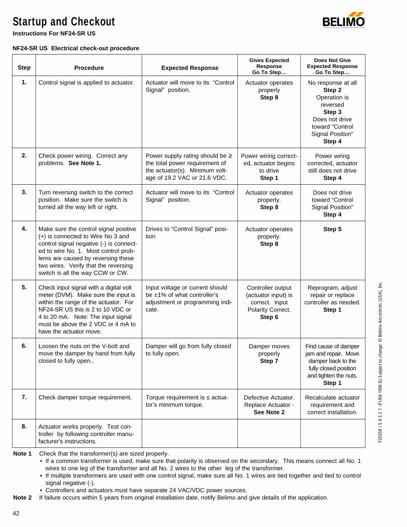
42
F203
58 /
5 4
3 2
1 -0
1/04
-10M
-IG-S
ubje
ct to
cha
nge.
© B
elim
o Ai
rcon
trols
(USA
), In
c.
Startup and CheckoutInstructions For NF24-SR US
Procedure
Control signal is applied to actuator.
Check power wiring. Correct anyproblems. See Note 1.
Turn reversing switch to the correctposition. Make sure the switch isturned all the way left or right.
Make sure the control signal positive(+) is connected to Wire No 3 andcontrol signal negative (-) is connect-ed to wire No. 1. Most control prob-lems are caused by reversing thesetwo wires. Verify that the reversingswitch is all the way CCW or CW.
Check input signal with a digital voltmeter (DVM). Make sure the input iswithin the range of the actuator. ForNF24-SR US this is 2 to 10 VDC or 4 to 20 mA. Note: The input signalmust be above the 2 VDC or 4 mA tohave the actuator move.
Loosen the nuts on the V-bolt andmove the damper by hand from fullyclosed to fully open..
Check damper torque requirement.
Actuator works properly. Test con-troller by following controller manu-facturer's instructions.
Expected Response
Actuator will move to its “ControlSignal” position.
Power supply rating should be ≥the total power requirement ofthe actuator(s). Minimum volt-age of 19.2 VAC or 21.6 VDC.
Actuator will move to its “ControlSignal” position.
Drives to “Control Signal” posi-tion
Input voltage or current shouldbe ±1% of what controller'sadjustment or programming indi-cate.
Damper will go from fully closedto fully open.
Torque requirement is ≤ actua-tor’s minimum torque.
Gives ExpectedResponse
Go To Step…
Actuator operatesproperlyStep 8
Power wiring correct-ed, actuator begins
to driveStep 1
Actuator operatesproperly.Step 8
Actuator operatesproperly.Step 8
Controller output(actuator input) is
correct. InputPolarity Correct.
Step 6
Damper moves properlyStep 7
Defective Actuator.Replace Actuator -
See Note 2
Does Not GiveExpected Response
Go To Step…
No response at allStep 2
Operation isreversedStep 3
Does not drivetoward "ControlSignal Position"
Step 4
Power wiringcorrected, actuatorstill does not drive
Step 4
Does not drivetoward “ControlSignal Position”
Step 4
Step 5
Reprogram, adjustrepair or replace
controller as needed.Step 1
Find cause of damperjam and repair. Movedamper back to thefully closed positionand tighten the nuts.
Step 1
Recalculate actuatorrequirement and
correct installation.
Step
1.
2.
3.
4.
5.
6.
7.
8.
Note 1 Check that the transformer(s) are sized properly. • If a common transformer is used, make sure that polarity is observed on the secondary. This means connect all No. 1
wires to one leg of the transformer and all No. 2 wires to the other leg of the transformer. • If multiple transformers are used with one control signal, make sure all No. 1 wires are tied together and tied to control
signal negative (-).• Controllers and actuators must have separate 24 VAC/VDC power sources.
Note 2 If failure occurs within 5 years from original installation date, notify Belimo and give details of the application.
NF24-SR US Electrical check-out procedure
®

43
F203
58 /
5 4
3 2
1 -0
1/04
-10M
-IG-S
ubje
ct to
cha
nge.
© B
elim
o Ai
rcon
trols
(USA
), In
c.
NF
Notes/Work Pad®
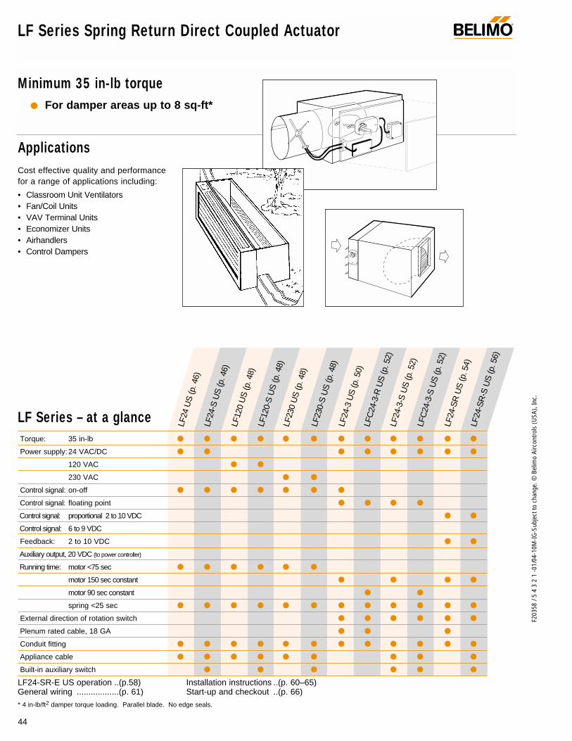
44
F203
58 /
5 4
3 2
1 -0
1/04
-10M
-IG-S
ubje
ct to
cha
nge.
© B
elim
o Ai
rcon
trols
(USA
), In
c.
LF Series Spring Return Direct Coupled Actuator®
Minimum 35 in-lb torque For damper areas up to 8 sq-ft*
LF Series – at a glance
* 4 in-lb/ft2 damper torque loading. Parallel blade. No edge seals.
Torque: 35 in-lb
Power supply: 24 VAC/DC
120 VAC
230 VAC
Control signal: on-off
Control signal: floating point
Control signal: proportional 2 to 10 VDC
Control signal: 6 to 9 VDC
Feedback: 2 to 10 VDC
Auxiliary output, 20 VDC (to power controller)
Running time: motor <75 sec
motor 150 sec constant
motor 90 sec constant
spring <25 sec
External direction of rotation switch
Plenum rated cable, 18 GA
Conduit fitting
Appliance cable
Built-in auxiliary switch
LF24-SR-E US operation ..(p.58) Installation instructions ..(p. 60–65)General wiring ..................(p. 61) Start-up and checkout ..(p. 66)
LF24
US
(p. 4
6)LF
24-S
US
(p. 4
6)LF
120
US
(p. 4
8)LF
120-
S U
S (p
. 48)
LF23
0 U
S (p
. 48)
LF23
0-S
US
(p. 4
8)LF
24-3
US
(p. 5
0)LF
C24
-3-R
US
(p. 5
2)
LFC
24-3
-S U
S (p
. 52)
LF24
-3-S
US
(p. 5
2)
LF24
-SR
US
(p. 5
4)LF
24-S
R-S
US
(p. 5
6)
ApplicationsCost effective quality and performance for a range of applications including:
• Classroom Unit Ventilators• Fan/Coil Units• VAV Terminal Units• Economizer Units• Airhandlers• Control Dampers
LF… actuator

45
F203
58 /
5 4
3 2
1 -0
1/04
-10M
-IG-S
ubje
ct to
cha
nge.
© B
elim
o Ai
rcon
trols
(USA
), In
c.
LF
LF Series Spring Return Direct Coupled Actuator®
LISTED94D5TEMP. IND ®. EQUIP.
UL
Cut labor costs with (10 min. installation) simple direct coupling.Actuator Centers on 1/2” shaft. (K6-1, 3/4” clamp optional)
True mechanical spring return – the most reliable failsafe.
Mount for clockwise or counterclockwise fail-safe.
Easy-to-adjust mechanical stop to limit damper rotation.
Check damper position easily with clear position indicator.
Don’t worry about actuator burn-out. Belimo is overload-proof throughout rotation
Need to change control direction? Do it easily with a simple switch. (modulating actuators)
Built-in auxiliary switch is easy to use, offers feedback or signal for additional device.
Microprocessor-controlled brushless DC motor increases actuator life span and reliability, provides constant running time. (modulating actuators)
Rugged metal housing withstands rough handling in themechanical room.
3 ft. cable and conduit connector eases installation.
A CLOSER LOOK…
The Belimo Difference
Customer Commitment.Extensive product range. Competitive project pricing. Application assistance. Same-day shipments. Free technical support. Five year warranty.
Low Installation and Life-Cycle Cost.Easy installation. Accuracy and repeatability. Low power consumption. No maintenance.
Long Service Life.Components tested before assembly. Every product tested before shipment. 20+ years direct coupled actuator design.
©

F203
58 /
5 4
3 2
1 -0
1/04
-10M
-IG-S
ubje
ct to
cha
nge.
© B
elim
o Ai
rcon
trols
(USA
), In
c.
LF24 (-S) US On-off, spring return safety, 24 V
®
Torque min. 35 in-lb, for control of air dampers
ApplicationFor on-off, fail-safe control of dampers in HVAC systems.Actuator sizing should be done in accordance with the dampermanufacturer’s specifications. Control is on-off from an auxil-iary contact, digital output, or a manual switch.
The actuator is mounted directly to a damper shaft from 3/8”up to 1/2” in diameter by means of its universal clamp, 1/2”shaft centered at delivery. For shafts up to 3/4” use K6-1accessory. A crank arm and several mounting brackets areavailable for applications where the actuator cannot be directcoupled to the damper shaft.
OperationThe LF series actuators provide true spring return operation forreliable fail-safe application and positive close off on air tightdampers. The spring return system provides consistent torqueto the damper with, and without, power applied to the actuator.The LF series provides 95° of rotation and is provided with agraduated position indicator showing 0° to 90°.The actuator may be stalled anywhere in its normal rotationwithout the need of mechanical end switches. Power con-sumption is reduced in holding mode.
The LF24-S US version is provided with 1 built in auxiliaryswitch. This SPDT switch is provided for safety interfacing orsignaling, for example, for fan start-up. The switching functionis adjustable between 0° and 95°. The auxiliary switch in theLF24-S is double insulated so an electrical ground connectionis not necessary.
Dimensions (All numbers in brackets are metric.)
0.39" [10]
7.67" [195]
3.66" [93]
1.93"[49]
6.10" [155]
3.15" [80]3.86"[98]
0.256" [6.5]0.98"[25]
4.92" [125]
0.79"[20]
0.5"[12.7]
0.71" [18]
0.74" [18.7]
2.24"[57]
3.23" [82]
0.25" [6.3]
Standard: 3/8" to 1/2"
3/8" to 7/16" Optional
1/2" to 3/4" w/K6-1 accessory
Technical Data LF24 (-S) US
Power supply 24 VAC ± 20% 50/60 Hz24 VDC ± 10%
Power consumption running: 5 Wholding: 2.5 W
Transformer sizing 7 VA (class 2 power source)
Electrical connection 3 ft, 18 GA appliance cable(LF24-S US has 2 cables)1/2” conduit connector
Overload protection electronic throughout 0 to 95° rotation
Angle of rotation max. 95°, adjust. with mechanical stop
Torque 35 in-lb [4 Nm]
Direction of rotation reversible with cw/ccw mounting
Position indication visual indicator, 0° to 90° (0° is springreturn position)
Auxiliary switch 1 x SPDT 6A (1.5) @ 250 VAC, UL listedadjustable 0° to 95° (double insulated)
Running time motor: < 40 to 75 secspring: < 25 sec @-4°F to +122°F [-20°C to +50°C]
< 60 sec @-22°F [-30°C]
Humidity 5 to 95% RH non-condensing
Ambient temperature -22°F to +122°F [-30°C to +50°C]
Storage temperature -40°F to +176°F [-40°C to +80°C]
Housing NEMA type 2 / IP54
Housing material zinc coated steel
Agency listings UL 873 listed, CSA C22.2 No.24 certified, CE
Noise level max: running < 50 db (A)spring return 62 dB (A)
Servicing maintenance free
Quality standard ISO 9001
Weight LF24 3.1 lbs (1.40 kg.)LF24-S 3.2 lbs (1.45 kg.)
LISTED94D5TEMP. IND ®. EQUIP.
UL
(LF24-S)
(nominal)
46
D01
0

47
F203
58 /
5 4
3 2
1 -0
1/04
-10M
-IG-S
ubje
ct to
cha
nge.
© B
elim
o Ai
rcon
trols
(USA
), In
c.
LF
LF24 (-S) USOn-off, spring return safety, 24 V
®
AccessoriesAV 10-18 Shaft extension (K6-1 is required)IND-LF Damper position indicatorK6-1 Universal clamp for up to 3/4” diameter shaftsKH-LF Crankarm for up to 1/2” round shaft Tool-01 10 mm wrenchZG-LF2 Crankarm adaptor kit for LF ZG-112 Mounting bracket for Honeywell Mod IV, M6415
type actuators, and new installationsZG-LF112 Crankarm adaptor kit for Honeywell Mod IV,
M6415 type actuators, and new installationsZS-100 Weather shield (metal)ZS-150 Weather shield (polycarbonate)ZS-260 Explosion-proof housing
Note: When using LF24 US and LF24-S US actuators,only use accessories listed on this page.
Wiring diagrams
LF24 (-S) US Typical SpecificationOn-off spring return damper actuators shall be direct coupledtype which require no crankarm and linkage and be capableof direct mounting to a shaft up to a 3/4” diameter and centera 1/2” shaft. The actuators must be designed so that they maybe used for either clockwise or counterclockwise fail-safeoperation. Actuators shall be protected from overload at allangles of rotation. If required, 1 SPDT auxiliary switch shall beprovided having the capability of being adjustable. Actuatorswith auxiliary switch must be constructed to meet the require-ments for Double Insulation so an electrical ground is notrequired to meet agency listings. Actuators shall be UL listedand CSA certified, have a 5 year warranty, and be manufac-tured under ISO 9001 International Quality Control Standards.Actuators shall be as manufactured by Belimo.
2
3
1 Provide overload protection and disconnect as required.
Actuators may be connected in parallel. Power con-sumption must be observed.
Actuator may also be powered by 24 VDC.
2
3
1
4
5
Provide overload protection and disconnect as required.
Actuators may be connected in parallel. Power con-sumption must be observed.
Actuator may also be powered by 24 VDC.
For end position indication, interlock control, fan start-up, etc., LF24-S US incorporates a built-in auxiliaryswitch: 1 x SPDT, 6A (1.5A) @250 VAC, UL listed,adjustable 0° to 95°.
Meets UL and CSA requirements without the need of anelectrical ground connection.
On-off wiring for LF24 US On-off wiring for LF24-S US
1 Common
2 + Hot
1
2
24 VAC Transformer
LF24 US
Line Volts 3
1 Common
2 + Hot
1
2
24 VAC Transformer
LF24-S US
Line Volts 3
4
5
S1
S2
S3
NC
NO0° to 95°W
047
W04
8

F203
58 /
5 4
3 2
1 -0
1/04
-10M
-IG-S
ubje
ct to
cha
nge.
© B
elim
o Ai
rcon
trols
(USA
), In
c.
Torque min. 35 in-lb, for control of air dampers
ApplicationFor on-off, fail-safe control of dampers in HVAC systems.Actuator sizing should be done in accordance with the dampermanufacturer’s specifications. Control is on-off from an auxil-iary contact, or a manual switch.
The actuator is mounted directly to a damper shaft from 3/8”up to 1/2” in diameter by means of its universal clamp, 1/2”shaft centered at delivery. For shafts up to 3/4” use K6-1accessory. A crank arm and several mounting brackets areavailable for applications where the actuator cannot be directcoupled to the damper shaft.
OperationThe LF series actuators provide true spring return operation forreliable fail-safe application and positive close off on air tightdampers. The spring return system provides consistent torqueto the damper with, and without, power applied to the actuator.The LF series provides 95° of rotation and is provided with agraduated position indicator showing 0° to 90°. The actuator may be stalled anywhere in its normal rotationwithout the need of mechanical end switches. Power con-sumption is reduced in holding mode. The actuator is doubleinsulated so an electrical ground connection is not necessary.
The LF120-S US and LF230-S US versions are provided with1 built-in auxiliary switch. This SPDT switch is provided forsafety interfacing or signaling, for example, for fan start-up.The switching function is adjustable between 0° and 95°.
Dimensions (All numbers in brackets are metric.)
LF120 (-S) US / LF230 (-S) USOn-off, spring return safety, 120/230 VAC
Technical Data LF120 (-S) US LF230 (-S) US
Power supply 120 VAC ± 10% 230 VAC ± 10%50/60 Hz 50/60 Hz
Power consumption running: 5.5 W 5 W holding: 3.5 W 3 W
Transformer sizing 7.5 VA 7 VA
Electrical connection 3 ft, 18 GA appliance cable (-S models have 2 cables)1/2” conduit connector
Overload protection electronic throughout 0 to 95° rotation
Electrical protection actuators are double insulated
Angle of rotation max 95°, adjust. with mechanical stop
Torque 35 in-lb [4 Nm] constant torque
Direction of rotation reversible with cw/ccw mounting
Position indication visual indicator, 0° to 90° (0° isspring return position)
Auxiliary switch 1 x SPDT 6A (1.5A) @ 250 VAC, UL listed(-S models) adjustable 0° to 95°
Electrical protection actuators are double insulated
Running time motor: < 40 to 75 secspring:< 25 sec @-4°F to +122°F [-20°C to +50°C]
< 60 sec @-22°F [-30°C]
Humidity 5 to 95% RH non-condensing
Ambient temperature -22°F to +122°F [-30°C to +50°C]
Storage temperature -40°F to +176°F [-40°C to +80°C]
Housing NEMA type 2 / IP54
Housing material zinc coated steel
Agency listings UL 873, CSA C22.2 No. 24 Certified,CE [LF230(-S) US]
Noise level max: running < 50 db (A)spring return 62 dB (A)
Servicing maintenance free
Quality standard ISO 9001
Weight LF120/230 3.4 lbs (1.54 kg.)LF120/230-S 3.5 lbs (1.60 kg.)
®
(nominal)
LISTED94D5TEMP. IND ®. EQUIP.
UL
48
0.39" [10]
7.67" [195]
3.66" [93]
1.93"[49]
6.10" [155]
3.15" [80]3.86"[98]
0.256" [6.5]0.98"[25]
4.92" [125]
0.79"[20]
0.5"[12.7]
0.71" [18]
0.74" [18.7]
2.24"[57]
3.23" [82]
0.25" [6.3]
Standard: 3/8" to 1/2"
3/8" to 7/16" Optional
1/2" to 3/4" w/K6-1 accessory
D01
0

49
F203
58 /
5 4
3 2
1 -0
1/04
-10M
-IG-S
ubje
ct to
cha
nge.
© B
elim
o Ai
rcon
trols
(USA
), In
c.
LF
LF120 (-S) US / LF230 (-S) US On-off, spring return safety, 120/230 VAC
AccessoriesAV 10-18 Shaft extension (K6-1 is required)IND-LF Damper position indicatorK6-1 Universal clamp for up to 3/4” diameter shaftsKH-LF Crankarm for up to 1/2” round shaft Tool-01 10 mm wrenchZG-LF2 Crankarm adaptor kit for LF ZG-112 Mounting bracket for Honeywell Mod IV, M6415
type actuators, and new installationsZG-LF112 Crankarm adaptor kit for Honeywell Mod IV,
M6415 type actuators, and new installations ZS-100 Weather shield (metal)ZS-150 Weather shield (polycarbonate)ZS-260 Explosion-proof housing
Note: When using LF120/230 US and LF120-S/230-S USactuators, only use accessories listed on this page.
LF120 (-S) US / LF230 (-S) US Typical SpecificationOn-off spring return damper actuators shall be direct coupledtype which require no crankarm and linkage and be capable ofdirect mounting to a shaft up to a 3/4” diameter and center a1/2” shaft. The actuators must be designed so that they maybe used for either clockwise or counterclockwise fail-safe oper-ation. Actuators shall be protected from overload at all anglesof rotation. If required, 1 SPDT auxiliary switch shall be pro-vided having the capability of being adjustable. Actuatorsmust be constructed to meet the requirements for DoubleInsulation so an electrical ground is not required to meetagency listings. Actuators shall be UL listed and CSA certified,have a 5 year warranty, and be manufactured under ISO 9001International Quality Control Standards. Actuators shall be asmanufactured by Belimo.
Wiring diagrams
2
1 Provide overload protection and disconnect as required.
Actuators may be connected in parallel. Power con-sumption must be observed.
No ground connection is required.
2
3
1
3
Provide overload protection and disconnect as required.
Actuators may be connected in parallel. Power con-sumption must be observed.
No ground connection is required.
For end position indication, interlock control, fan start-up, etc., LF120-S US and LF230-S US incorporateone built-in auxiliary switch: 1 x SPDT, 6A (1.5A)@250 VAC, UL listed, adjustable 0° to 95°.
Meets UL and CSA requirements without the need of anelectrical ground connection.
®
4
5
On-off wiring for LF120 US / LF230 US On-off wiring for LF120-S US / LF230-S US
1 Neutral
2 Hot1
2
120 VAC (230 VAC for LF230 US)
LF120 US LF230 US
3L1 N
L2 H
1 Neutral
2 Hot
2
3
4
5
5
S1
S2
S3
NC
NO0° to 95°
LF120-S US LF230-S US
1
120 VAC (230 VAC for LF230 US)
L1 N
L2 H
W04
9
W05
0

F203
58 /
5 4
3 2
1 -0
1/04
-10M
-IG-S
ubje
ct to
cha
nge.
© B
elim
o Ai
rcon
trols
(USA
), In
c.
LF24-3 (-S) US On-off, spring return safety, reversible, floating point, 24V
Torque min. 35 in-lb, for control of air dampers
ApplicationFor modulation or on-off control of dampers in HVAC systems.Actuator sizing should be done in accordance with the dampermanufacturer’s specifications.
The actuator is mounted directly to a damper shaft from 3/8”up to 1/2” in diameter by means of its universal clamp, 1/2”shaft centered at delivery. For shafts up to 3/4” use K6-1accessory. A crank arm and several mounting brackets areavailable for applications where the actuator cannot be directcoupled to the damper shaft.
Control is floating point from a triac or relay, or on-off from anauxiliary contact from a fan motor contactor, controller, ormanual switch.
OperationThe LF series actuators provide true spring return operation forreliable fail-safe application and positive close-off on air tightdampers. The spring return system provides consistent torqueto the damper with, and without, power applied to the actuator.
The LF series provides 95° of rotation and is provided with agraduated position indicator showing 0 to 90°.
The LF24-3 (-S) US uses a brushless DC motor which is con-trolled by an Application Specific Integrated Circuit (ASIC) and amicroprocessor. The microprocessor provides the intelligence tothe ASIC to provide a constant rotation rate. The ASIC monitorsand controls the brushless DC motor’s rotation and provides adigital rotation sensing function to prevent damage to the actua-tor in a stall condition. The actuator may be stalled anywhere inits normal rotation without the need of mechanical end switches.Power consumption is reduced in holding mode.
The LF24-3-S US version is provided with 1 built-in auxiliaryswitch. This SPDT switch is provided for safety interfacing orsignaling, for example, for fan start-up. The switching functionis adjustable between 0° and 95°. The auxiliary switch in theLF24-3-S US is double insulated so an electrical ground is notnecessary.
Dimensions (All numbers in brackets are metric.)
Technical Data LF24-3 (-S) US
Power supply 24 VAC ± 20% 50/60 Hz24 VDC ± 10%
Power consumption running: 2.5 W ; holding: 1 W
Transformer sizing 5 VA (class 2 power source)
Electrical connection LF24-3 US 3 ft, plenum rated cableLF24-3-S US 3 ft, 18 GA appliance
cables (2)1/2” conduit connector
Overload protection electronic throughout 0 to 95° rotation
Input impedance 1000 Ω (0.6w) control inputs
Angle of rotation max. 95°, adjust. with mechanical stop
Torque 35 in-lb [4 Nm]
Direction of rotation spring: reversible with cw/ccw mountingmotor: reversible with built-in switch
Position indication visual indicator, 0° to 90° (0° isspring return position)
Auxiliary switch 1 x SPDT 6A (1.5A) @ 250 VAC, UL listed(LF24-3-S US) adjustable 0° to 95° (double insulated)
Running time motor: 150 sec constant, independent of load
spring: < 25 sec @-4°F to +122°F [-20°C to +50°C]
< 60 sec @-22°F [-30°C]
Humidity 5 to 95% RH non-condensing
Ambient temperature -22°F to +122°F [-30°C to +50°C]
Storage temperature -40°F to +176°F [-40°C to +80°C]
Housing NEMA type 2 /IP54
Housing material zinc coated metal
Agency listings UL 873 listed; CSA C22.2 No. 24 certified, CE
Noise level max: running < 30 db (A)spring return 62 dB (A)
Servicing maintenance free
Quality standard ISO 9001
Weight LF24-3 3.1 lbs (1.40 kg.)LF24-3-S 3.6 lbs (1.45 kg.)
LISTED94D5TEMP. IND ®. EQUIP.
UL
®
50
0.39" [10]
7.67" [195]
3.66" [93]
1.93"[49]
6.10" [155]
3.15" [80]3.86"[98]
0.256" [6.5]0.98"[25]
4.92" [125]
0.79"[20]
0.5"[12.7]
0.71" [18]
0.74" [18.7]
2.24"[57]
3.23" [82]
0.25" [6.3]
Standard: 3/8" to 1/2"
3/8" to 7/16" Optional
1/2" to 3/4" w/K6-1 accessory
D01
0
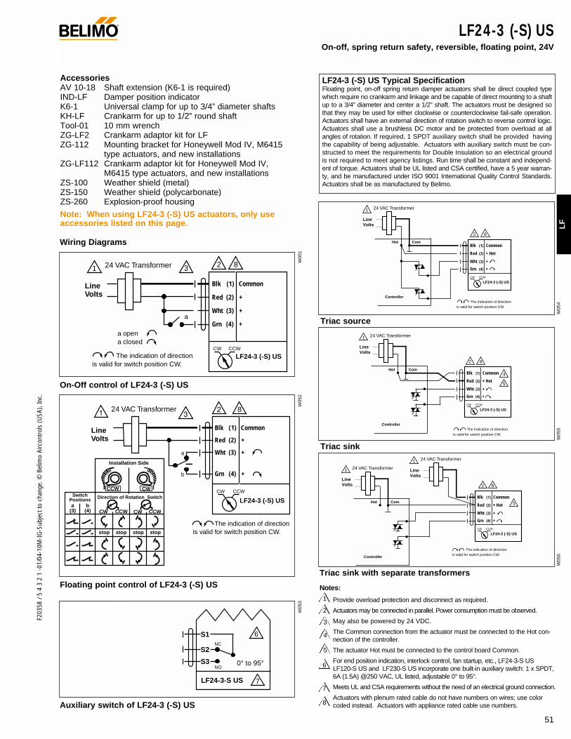
51
F203
58 /
5 4
3 2
1 -0
1/04
-10M
-IG-S
ubje
ct to
cha
nge.
© B
elim
o Ai
rcon
trols
(USA
), In
c.
LF
LF24-3 (-S) US On-off, spring return safety, reversible, floating point, 24V
AccessoriesAV 10-18 Shaft extension (K6-1 is required)IND-LF Damper position indicator K6-1 Universal clamp for up to 3/4” diameter shaftsKH-LF Crankarm for up to 1/2” round shaft Tool-01 10 mm wrenchZG-LF2 Crankarm adaptor kit for LF ZG-112 Mounting bracket for Honeywell Mod IV, M6415
type actuators, and new installationsZG-LF112 Crankarm adaptor kit for Honeywell Mod IV,
M6415 type actuators, and new installationsZS-100 Weather shield (metal)ZS-150 Weather shield (polycarbonate)ZS-260 Explosion-proof housing
Note: When using LF24-3 (-S) US actuators, only useaccessories listed on this page.
LF24-3 (-S) US Typical SpecificationFloating point, on-off spring return damper actuators shall be direct coupled typewhich require no crankarm and linkage and be capable of direct mounting to a shaftup to a 3/4” diameter and center a 1/2” shaft. The actuators must be designed sothat they may be used for either clockwise or counterclockwise fail-safe operation.Actuators shall have an external direction of rotation switch to reverse control logic.Actuators shall use a brushless DC motor and be protected from overload at allangles of rotation. If required, 1 SPDT auxiliary switch shall be provided havingthe capability of being adjustable. Actuators with auxiliary switch must be con-structed to meet the requirements for Double Insulation so an electrical groundis not required to meet agency listings. Run time shall be constant and independ-ent of torque. Actuators shall be UL listed and CSA certified, have a 5 year warran-ty, and be manufactured under ISO 9001 International Quality Control Standards.Actuators shall be as manufactured by Belimo.
®
1 2 8324 VAC Transformer
a opena closed
The indication of direction is valid for switch position CW.
Blk (1) Common
Red (2) +
Wht (3) +
Grn (4) +
LF24-3 (-S) USCW CCW
a
Line Volts
Line Volts
The indication of direction is valid for switch position CW.
Blk (1) Common
Red (2) +
Wht (3) +
Grn (4) +
24 VAC Transformer
LF24-3 (-S) USCW CCW
bCCWCW
stop
a(3) (4)
stop stop stop
Installation Side
Direction of Rotation Switch
xxxx
xxxx
xx
xx
xx
xx
xxx
xxxx
xxxx
xx
xx
xx
xx
xxx
CWCCWSwitch
Positions
CCWCW
a
b
8
Wiring Diagrams
On-Off control of LF24-3 (-S) US
Triac source
Triac sink
Floating point control of LF24-3 (-S) US
Auxiliary switch of LF24-3 (-S) US
Blk (1) Common
Red (2) + Hot
Wht (3) +
Grn (4) +
ComHot
Controller
Line Volts
CW CCW
LF24-3 (-S) US
The indication of direction is valid for switch position CW.
1
2
24 VAC Transformer
8
Blk (1) Common
Red (2) + Hot
Wht (3) +
Grn (4) +
ComHot
Controller
Line Volts
CW CCW
LF24-3 (-S) US
The indication of direction is valid for switch position CW.
1
2
4
5
24 VAC Transformer
8
Triac sink with separate transformers
Blk (1) Common
Red (2) + Hot
Wht (3) +
Grn (4) +
ComHot
Controller
Line Volts
CW CCW
LF24-3 (-S) US
The indication of direction is valid for switch position CW.
1
2
5
24 VAC Transformer Line Volts
1 24 VAC Transformer
8
7LF24-3-S US
6S1
S2
S3
NC
NO0° to 95°
2
3
4
5
1 Provide overload protection and disconnect as required.
Actuators may be connected in parallel. Power consumption must be observed.
May also be powered by 24 VDC.
The Common connection from the actuator must be connected to the Hot con-nection of the controller.
The actuator Hot must be connected to the control board Common.
For end position indication, interlock control, fan startup, etc., LF24-3-S US LF120-S US and LF230-S US incorporate one built-in auxiliary switch: 1 x SPDT,6A (1.5A) @250 VAC, UL listed, adjustable 0° to 95°.
Meets UL and CSA requirements without the need of an electrical ground connection.
Actuators with plenum rated cable do not have numbers on wires; use colorcoded instead. Actuators with appliance rated cable use numbers.
6
7
8
Notes:
W05
3W
052
W05
1
W05
4W
055
W05
6

F203
58 /
5 4
3 2
1 -0
1/04
-10M
-IG-S
ubje
ct to
cha
nge.
© B
elim
o Ai
rcon
trols
(USA
), In
c.
LFC24-3-R (-S) US On-off, spring return safety, reversible, floating point, 24V, Trane Voyager retrofit
Torque min. 35 in-lb, for control of air dampers
ApplicationFor modulation or on-off control of dampers in HVAC systems.Actuator sizing should be done in accordance with the dampermanufacturer’s specifications.
The actuator is mounted directly to a damper shaft from 3/8”up to 1/2” in diameter by means of its universal clamp, 1/2”shaft centered at delivery. For shafts up to 3/4” use K6-1accessory. The ZG-LFC114 universal mounting kit can beused with the LFC24-3-R US actuator for retrofit of the econo-mizer section of the Trane Voyager unit.
Control is floating point from a triac or relay, or on-off from anauxiliary contact from a fan motor contactor, controller, ormanual switch.
OperationThe LF series actuators provide true spring return operation forreliable fail-safe application and positive close-off on air tightdampers. The spring return system provides consistent torqueto the damper with, and without, power applied to the actuator.
The LF series provides 95° of rotation and is provided with agraduated position indicator showing 0 to 90°.
The LFC24-3-R (-S) US uses a brushless DC motor which iscontrolled by an Application Specific Integrated Circuit (ASIC) anda microprocessor. The microprocessor provides the intelligenceto the ASIC to provide a constant rotation rate. The ASIC moni-tors and controls the brushless DC motor’s rotation and providesa digital rotation sensing function to prevent damage to the actua-tor in a stall condition. The actuator may be stalled anywhere inits normal rotation without the need of mechanical end switches.Power consumption is reduced in holding mode.
The LFC24-3-S US version is provided with 1 built-in auxiliaryswitch. This SPDT switch is provided for safety interfacing orsignaling, for example, for fan start-up. The switching functionis adjustable between 0° and 95°. The auxiliary switch in theLFC24-3-S US is double insulated so an electrical ground isnot necessary.
Dimensions (All numbers in brackets are metric.)
Technical Data LFC24-3-R US
Power supply 24 VAC ± 20% 50/60 Hz24 VDC ± 10%
Power consumption running: 2.5 W ; holding: 1 W
Transformer sizing 5 VA (class 2 power source)
Electrical connection LFC24-3-R US 3 ft, plenum ratedcable 4 male spade connectors
Overload protection electronic throughout 0 to 95° rotation
Input impedance 1000 Ω (0.6w) control inputs
Angle of rotation max. 95°, adjust. with mechanical stop
Torque 35 in-lb [4 Nm]
Direction of rotation spring: reversible with cw/ccw mountingmotor: reversible with built-in switch
Position indication visual indicator, 0° to 90° (0° is springreturn position)
Running time motor: 90 sec constant, independent of load
spring: < 25 sec @-4°F to +122°F [-20°C to +50°C]
< 60 sec @-22°F [-30°C]
Humidity 5 to 95% RH non-condensing
Ambient temperature -22°F to +122°F [-30°C to +50°C]
Storage temperature -40°F to +176°F [-40°C to +80°C]
Housing NEMA type 2 /IP54
Housing material zinc coated metal
Agency listings UL 873 listed; CSA C22.2 No.24 certified, CE
Noise level max: running < 30 db (A)spring return 62 dB (A)
Servicing maintenance free
Quality standard ISO 9001
Weight LFC24-3-R US 3.1 lbs (1.40 kg.)
Technical Data LFC24-3-S US
Auxiliary switch 1 x SPDT 6A (1.5A) @ 250 VAC, UL listedadjustable 0° to 95° (double insulated)
Electrical Connection 3 ft, 18 GA appliance cables (2)1/2” conduit connector
Weight LFC24-3-S US 3.6 lbs (1.45 kg.)
LISTED94D5TEMP. IND ®. EQUIP.
UL
®
52
0.39" [10]
7.67" [195]
3.66" [93]
1.93"[49]
6.10" [155]
3.15" [80]3.86"[98]
0.256" [6.5]0.98"[25]
4.92" [125]
0.79"[20]
0.5"[12.7]
0.71" [18]
0.74" [18.7]
2.24"[57]
3.23" [82]
0.25" [6.3]
Standard: 3/8" to 1/2"
3/8" to 7/16" Optional
1/2" to 3/4" w/K6-1 accessory
D01
0
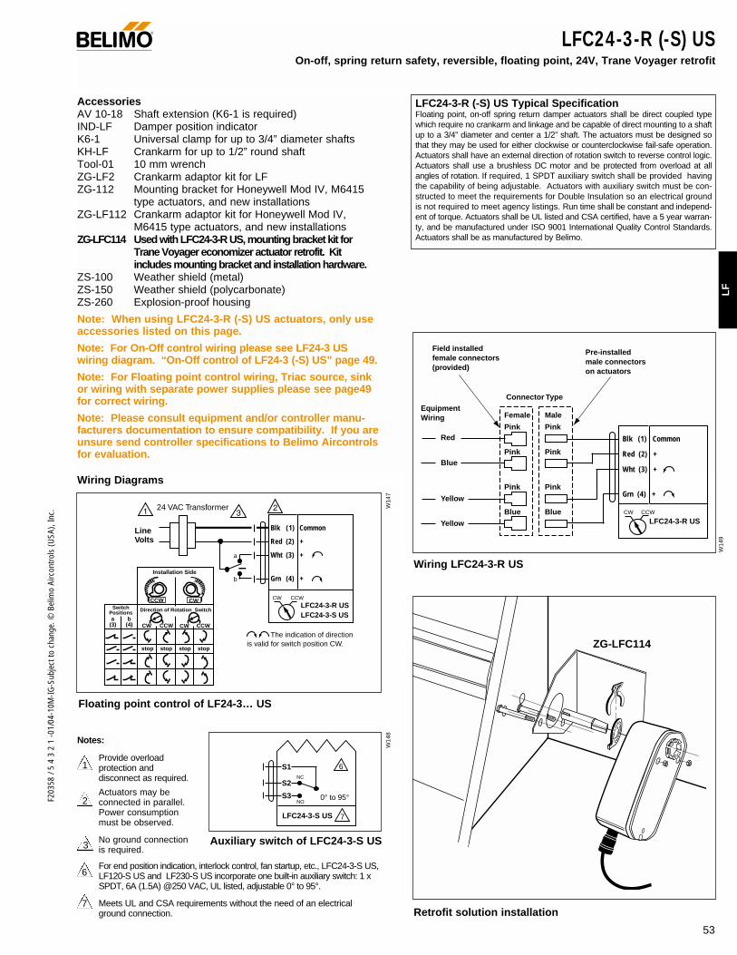
53
F203
58 /
5 4
3 2
1 -0
1/04
-10M
-IG-S
ubje
ct to
cha
nge.
© B
elim
o Ai
rcon
trols
(USA
), In
c.
LF
LFC24-3-R (-S) USOn-off, spring return safety, reversible, floating point, 24V, Trane Voyager retrofit
AccessoriesAV 10-18 Shaft extension (K6-1 is required)IND-LF Damper position indicator K6-1 Universal clamp for up to 3/4” diameter shaftsKH-LF Crankarm for up to 1/2” round shaft Tool-01 10 mm wrenchZG-LF2 Crankarm adaptor kit for LF ZG-112 Mounting bracket for Honeywell Mod IV, M6415
type actuators, and new installationsZG-LF112 Crankarm adaptor kit for Honeywell Mod IV,
M6415 type actuators, and new installationsZG-LFC114 Used with LFC24-3-R US, mounting bracket kit for
Trane Voyager economizer actuator retrofit. Kit includes mounting bracket and installation hardware.
ZS-100 Weather shield (metal)ZS-150 Weather shield (polycarbonate)ZS-260 Explosion-proof housing
Note: When using LFC24-3-R (-S) US actuators, only useaccessories listed on this page.
Note: For On-Off control wiring please see LF24-3 USwiring diagram. “On-Off control of LF24-3 (-S) US” page 49.
Note: For Floating point control wiring, Triac source, sinkor wiring with separate power supplies please see page49for correct wiring.
Note: Please consult equipment and/or controller manu-facturers documentation to ensure compatibility. If you areunsure send controller specifications to Belimo Aircontrolsfor evaluation.
LFC24-3-R (-S) US Typical SpecificationFloating point, on-off spring return damper actuators shall be direct coupled typewhich require no crankarm and linkage and be capable of direct mounting to a shaftup to a 3/4” diameter and center a 1/2” shaft. The actuators must be designed sothat they may be used for either clockwise or counterclockwise fail-safe operation.Actuators shall have an external direction of rotation switch to reverse control logic.Actuators shall use a brushless DC motor and be protected from overload at allangles of rotation. If required, 1 SPDT auxiliary switch shall be provided havingthe capability of being adjustable. Actuators with auxiliary switch must be con-structed to meet the requirements for Double Insulation so an electrical groundis not required to meet agency listings. Run time shall be constant and independ-ent of torque. Actuators shall be UL listed and CSA certified, have a 5 year warran-ty, and be manufactured under ISO 9001 International Quality Control Standards.Actuators shall be as manufactured by Belimo.
®
Line Volts
The indication of direction is valid for switch position CW.
Blk (1) Common
Red (2) +
Wht (3) +
Grn (4) +
24 VAC Transformer
LFC24-3-R USLFC24-3-S US
CW CCW
bCCWCW
stop
a(3) (4)
stop stop stop
Installation Side
Direction of Rotation Switch
xxxx
xxxx
xx
xx
xx
xx
xxx
xxxx
xxxx
xx
xx
xx
xx
xxx
CWCCWSwitch
Positions
CCWCW
a
b
Wiring Diagrams
Floating point control of LF24-3… US
Blk (1) Common
Red (2) +
Wht (3) +
Grn (4) +
LFC24-3-R USCW CCW
PinkRed
Blue
Yellow
Yellow
Pink
Female
Connector TypeEquipment Wiring
Field installed female connectors (provided)
Pre-installed male connectors on actuators
Male
Pink Pink
Pink Pink
Blue Blue
7LFC24-3-S US
6S1
S2
S3
NC
NO0° to 95°
Auxiliary switch of LFC24-3-S US
2
3
1Provide overload protection anddisconnect as required.
Actuators may be connected in parallel. Power consumption must be observed.
No ground connection is required.
For end position indication, interlock control, fan startup, etc., LFC24-3-S US,LF120-S US and LF230-S US incorporate one built-in auxiliary switch: 1 xSPDT, 6A (1.5A) @250 VAC, UL listed, adjustable 0° to 95°.
Meets UL and CSA requirements without the need of an electricalground connection.
6
7
Notes:
ZG-LFC114
Wiring LFC24-3-R US
Retrofit solution installation
W14
7W
148
W14
9

F203
58 /
5 4
3 2
1 -0
1/04
-10M
-IG-S
ubje
ct to
cha
nge.
© B
elim
o Ai
rcon
trols
(USA
), In
c.
Torque min. 35 in-lb, for control of air dampers
ApplicationFor proportional modulation of dampers in HVAC systems.Actuator sizing should be done in accordance with the dampermanufacturer’s specifications.
The actuator is mounted directly to a damper shaft from 3/8”up to 1/2” in diameter by means of its universal clamp, 1/2”shaft centered at delivery. For shafts up to 3/4” use K6-1accessory. A crank arm and several mounting brackets areavailable for applications where the actuator cannot be directcoupled to the damper shaft.
The actuator operates in response to a 2 to 10 VDC, or with theaddition of a 500Ω resistor, a 4 to 20 mA control input from anelectronic controller or positioner. A 2 to 10 VDC feedback signalis provided for position indication or master-slave applications.
OperationThe LF series actuators provide true spring return operation forreliable fail-safe application and positive close-off on air tightdampers. The spring return system provides consistent torqueto the damper with, and without, power applied to the actuator.The LF series provides 95° of rotation and is provided with agraduated position indicator showing 0 to 90°.
The LF24-SR (-S) US uses a brushless DC motor which iscontrolled by an Application Specific Integrated Circuit (ASIC)and a microprocessor. The microprocessor provides the intelli-gence to the ASIC to provide a constant rotation rate and toknow the actuator’s exact fail-safe position. The ASIC moni-tors and controls the brushless DC motor’s rotation and pro-vides a digital rotation sensing function to prevent damage tothe actuator in a stall condition. The actuator may be stalledanywhere in its normal rotation without the need of mechani-cal end switches. Power consumption is reduced in holdingmode.
The LF24-SR-S US version is provided with 1 built-in auxiliaryswitch. This SPDT switch is provided for safety interfacing orsignaling, for example, for fan start-up. The switching functionis adjustable between 0° and 95°. The auxiliary switch in theLF24-SR-S US is double insulated so an electrical ground innot necessary.
Dimensions (All numbers in brackets are metric.)
LF24-SR (-S) US Proportional damper actuator, spring return safety, 24 V for 2 to 10 VDC, or 4 to 20 mA control signal.Output signal of 2 to 10 VDC for position indication.
Technical Data LF24-SR (-S) US
Power supply 24 VAC ± 20% 50/60 Hz24 VDC ± 10%
Power consumption running: 2.5 W; holding: 1 W
Transformer sizing 5 VA (class 2 power source)
Electrical connection LF24-SR US 3 ft, plenum rated cableLF24-SR-SUS 3 ft, 18 GA appliance
cables (2)1/2” conduit connector
Overload protection electronic throughout 0 to 95° rotation
Operating range Y 2 to 10 VDC, 4 to 20mA
Input impedance 100 kΩ (0.1 mA), 500ΩFeedback output U 2 to 10 VDC (max. 0.7 mA) for 95°
Angle of rotation max. 95°, adjust. with mechanical stop
Torque 35 in-lb [4 Nm]
Direction of rotation spring return reversible with cw/ccwmounting control direction selected by switch:CW=CW with a decrease in signalCCW=CCW with a decrease in signal
Position indication visual indicator, 0° to 95°(0° is spring return position)
Auxiliary switch 1 x SPDT 6A (1.5A) @ 250 VAC, UL listed(LF24-SR-S US) adjustable 0° to 95° (double insulated)
Running time motor: 150 sec constant,independent of load
spring:< 25 sec @-4°F to +122°F [-20°C to +50°C]
< 60 sec @-22°F [-30°C]
Humidity 5 to 95% RH non-condensing
Ambient temperature -22°F to +122°F [-30°C to +50°C]
Storage temperature -40°F to +176°F [-40°C to +80°C]
Housing NEMA type 2 / IP54
Housing material zinc coated metal
Agency listings UL 873 listed; CSA C22.2 No. 24 certified, CE
Noise level max: running < 30 db (A)spring return 62 dB (A)
Servicing maintenance free
Quality standard ISO 9001
Weight LF24-SR 3.1 lbs (1.40 kg.)LF24-SR-S 3.2 lbs (1.45 kg.)
LISTED94D5TEMP. IND ®. EQUIP.
UL
®
(nominal)
0.39" [10]
7.67" [195]
3.66" [93]
1.93"[49]
6.10" [155]
3.15" [80]3.86"[98]
0.256" [6.5]0.98"[25]
4.92" [125]
0.79"[20]
0.5"[12.7]
0.71" [18]
0.74" [18.7]
2.24"[57]
3.23" [82]
0.25" [6.3]
Standard: 3/8" to 1/2"
3/8" to 7/16" Optional
1/2" to 3/4" w/K6-1 accessory
D01
0
54
©
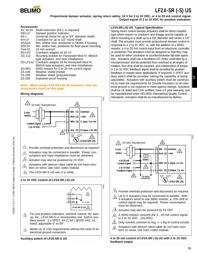
55
F203
58 /
5 4
3 2
1 -0
1/04
-10M
-IG-S
ubje
ct to
cha
nge.
© B
elim
o Ai
rcon
trols
(USA
), In
c.
LF
2 to 10 VDC control of LF24-SR (-S) US
LF24-SR (-S) USProportional damper actuator, spring return safety, 24 V for 2 to 10 VDC, or 4 to 20 mA control signal.
Output signal of 2 to 10 VDC for position indication.
AccessoriesAV 10-18 Shaft extension (K6-1 is required)IND-LF Damper position indicator K6-1 Universal clamp for up to 3/4” diameter shaftsKH-LF Crankarm for up to 1/2” round shaft SGA24 Min. and/or man. positioner in NEMA 4 housingSGF24 Min. and/or man. positioner for flush panel mountingTool-01 10 mm wrenchZG-LF2 Crankarm adaptor kit for LF ZG-112 Mounting bracket for Honeywell Mod IV, M6415
type actuators, and new installationsZG-LF112 Crankarm adaptor kit for Honeywell Mod IV,
M6415 type actuators, and new installationsZG-R01 500Ω resistor for 0 to 20 mA control signalZS-100 Weather shield (metal)ZS-150 Weather shield (polycarbonate)ZS-260 Explosion-proof housing
Note: When using LF24-SR (-S) US actuators, only useaccessories listed on this page.
LF24-SR (-S) US Typical Specification Spring return control damper actuators shall be direct coupledtype which require no crankarm and linkage and be capable ofdirect mounting to a shaft up to a 3/4” diameter and center a 1/2”shaft. The actuator must provide proportional damper control inresponse to a 2 to 10 VDC or, with the addition of a 500Ωresistor, a 4 to 20 mA control input from an electronic controlleror positioner.The actuators must be designed so that they maybe used for either clockwise or counterclockwise fail-safe opera-tion. Actuators shall use a brushless DC motor controlled by amicroprocessor and be protected from overload at all angles ofrotation. Run time shall be constant, and independent of torque.A 2 to 10 VDC feedback signal shall be provided for positionfeedback or master-slave applications. If required, 1 SPDT aux-iliary switch shall be provided having the capability of beingadjustable. Actuators with auxiliary switch must be construct-ed to meet the requirements for Double Insulation so an elec-trical ground is not required to meet agency listings. Actuatorsshall be UL listed and CSA certified, have a 5 year warranty, andbe manufactured under ISO 9001 International Quality ControlStandards. Actuators shall be as manufactured by Belimo.
Wiring diagrams
2
1
2
1
Provide overload protection and disconnect as required.
Actuators may be connected in parallel. Power con-sumption and input impedance must be observed.
Actuator may also be powered by 24 VDC.
Actuators with plenum rated cable do not have num-bers on wires; use color codes instead.
The LF24-SR-S US wire 5 is white.
3
4
®
2
1 Provide overload protection and disconnect as required.
Up to 4 actuators may be connected in parallel. With4 actuators wired to one 500Ω resistor, a +2% shift ofcontrol signal may be required. Power consumptionmust be observed.
Actuator may also be powered by 24 VDC.
A 500Ω resistor converts the 4…20 mA control signalto 2 to 10 VDC. (ZG-R01) Only connect common to neg. (—) leg of control circuits.
Actuators with plenum rated cable do not have num-bers on wires; use color codes instead.
4
5
6
3
4 to 20 mA control of LF24-SR (-S) US with 2 to 10 VDC feedback output
Auxiliary switch of LF24-SR-S US
For end position indication, interlock control, fan start-up, etc., LF24-SR-S US incorporates one built-in aux-iliary switch: 1 x SPDT, 6A (1.5A ) @250 VAC, ULlisted, adjustable 0° to 95°.
Meets UL & CSA requirements without the need of anelectrical ground connection.
5
1
1 4
5
2
3
24 VAC Transformer
Blk (1) Common
Red (2) + Hot
Wht (3) Y Input, 2 to 10V
Grn (5) U Output, 2 to 10V
LF24-SR US
Line Volts
2 to 10 VDCControl Signal (–)
(+)
CW CCW
2LF24-SR-S US
1S1
S2
S3
NC
NO0° to 95°
4
To other actuators
6
3
5
24 VAC Transformer
Blk (1) Common
Red (2) + Hot
Wht (3) Y Input, 2 to 10V
Grn (5) U Output, 2 to 10V
4 to 20 mAControl Signal
(–)(+)
2 to 10 VDCFeedback Signal
(–)(+)
Ω500Ω
2
LF24-SR US
CW CCW
1
Line Volts
1
W05
7W
058
W05
9

• Torque min. 35 in-lb, for control of air dampers• Built-in adjustable min-position for 3-position and
proportional control
ApplicationFor proportional control with minimum position setpoint, orthree position control of dampers in HVAC systems. Actuatorsizing should be done in accordance with the damper manu-facturer’s specifications.
The actuator is mounted directly to a damper shaft from 3/8”up to 1/2” in diameter by means of its universal clamp, 1/2”shaft centered at delivery. For shafts up to 3/4” use K6-1accessory. A crank arm and several mounting brackets areavailable for applications where the actuator cannot be directcoupled to the damper shaft.
The actuator operates in response to 24 VAC on wire 2 or 3,which allows the LF24-SR-E US to retrofit or replace Honeywell®
M8405A actuators.
OperationThe LF series actuators provide true spring return operation forreliable fail-safe application and positive close-off on air tightdampers. The spring return system provides constant torque tothe damper with, and without, power applied to the actuator.The LF series provides 95° of rotation and is provided with agraduated position indicator showing 0 to 90°.
The LF24-SR-E US uses a brushless DC motor which is con-trolled by an Application Specific Integrated Circuit (ASIC) anda microprocessor. The microprocessor provides the intelligenceto the ASIC to provide a constant rotation rate and to know theactuator’s exact position. The ASIC monitors and controls thebrushless DC motor’s rotation and provides a digital rotationsensing function to prevent damage to the actuator in a stall condition. The actuator may be stalled anywhere in itsnormal rotation without the need of mechanical end switches.Power consumption is reduced in holding mode.
See wiring diagrams for LF24-SR-E US for more details on 3-position control.
InstallationRefer to LF Section of the Standard Actuation and Accessories,2003 Product Documentation.
Honeywell®
is a trademark of Honeywell Inc.
Dimensions (All numbers in brackets are metric.)
LF24-SR-E US Proportional damper actuator, 24 V for 2 to 10 VDC (or 4 to 20 mA) control signal or 3-position on/off control, with minimum position potentiometer. Output signal of 2 to 10 VDC for position indication.
Technical Data LF24-SR-E US
Power supply 24 VAC ± 20% 50/60 Hz, 24 VDC ± 10%
Power consumption running: 2.5 W; holding: 1 W
Transformer sizing 5 VA (class 2 power source)
Electrical connection 3 ft, plenum rated cable1/2” conduit connector
Overload protection electronic throughout 0 to 95° rotation
Control signal Y 0 to 10 VDC, 0 to 20 mA, or 24 VACfor 3-position on/off control
Input impedance 100 kΩOperating range Y 2 to 10 VDC, 4 to 20mA between
0% and 100%
Feedback output U 2 to 10 VDC (max. 0.7 mA) for 95°
Angle of rotation max. 95°, adjust. with mechanical stop
Torque 35 in-lb [4 Nm]
Override function Minimum, Open, Closed via spring Min-position adjusts on actuator coverbetween 0 and 100% (scaled 0 to 1)
Direction of rotation Spring return direction is reversible withCW/CCW mounting.Motor direction selected by switch:CW (Default)=CW with a decreasing signal CCW=CCW with a decreasing signal.
Position indication visual indicator, 0° to 95° scaled as0 to 1 (0° is spring return position)
Running time motor: 150 sec constant,independent of load
spring: < 25 sec @-4°F to +122°F [-20°C to +50°C]
< 60 sec @-22°F [-30°C]
Humidity 5 to 95% RH non-condensing
Ambient temperature -22°F to +122°F [-30°C to +50°C]
Storage temperature -40°F to +176°F [-40°C to +80°C]
Housing NEMA type 2 / IP54
Housing material zinc coated metal
Agency listings UL 873 listed; CSA C22.2 No. 24 certified, CE
Noise level max: running < 30 db (A)spring return 62 dB (A)
Servicing maintenance free
Quality standard ISO 9001
Weight 3.2 lbs (1.45 kg.)
LISTED94D5TEMP. IND ®. EQUIP.
UL
®
0.39" [10]
7.67" [195]
3.66" [93]
1.93"[49]
6.10" [155]
3.15" [80]3.86"[98]
0.256" [6.5]0.98"[25]
4.92" [125]
0.79"[20]
0.5"[12.7]
0.71" [18]
0.74" [18.7]
2.24"[57]
3.23" [82]
0.25" [6.3]
Standard: 3/8" to 1/2"
3/8" to 7/16" Optional
1/2" to 3/4" w/K6-1 accessory
CCW
D05
9
56
F203
58 /
5 4
3 2
1 -0
1/04
-10M
-IG-S
ubje
ct to
cha
nge.
© B
elim
o Ai
rcon
trols
(USA
), In
c.
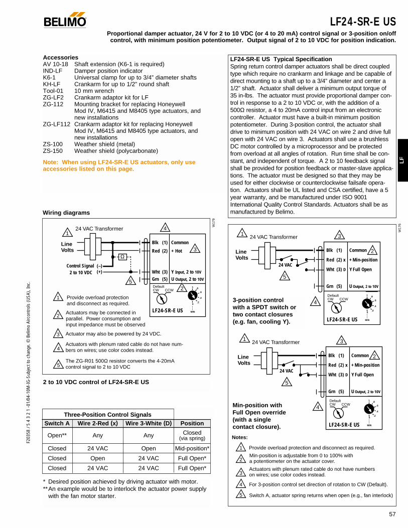
57
F203
58 /
5 4
3 2
1 -0
1/04
-10M
-IG-S
ubje
ct to
cha
nge.
© B
elim
o Ai
rcon
trols
(USA
), In
c.
LF
Three-Position Control SignalsSwitch A Wire 2-Red (x) Wire 3-White (D) Position
Open** Any Any Closed (via spring)
Closed 24 VAC Open Mid-position*
Closed Open 24 VAC Full Open*
Closed 24 VAC 24 VAC Full Open*
* Desired position achieved by driving actuator with motor. **An example would be to interlock the actuator power supply
with the fan motor starter.
® LF24-SR-E USProportional damper actuator, 24 V for 2 to 10 VDC (or 4 to 20 mA) control signal or 3-position on/off
control, with minimum position potentiometer. Output signal of 2 to 10 VDC for position indication.
AccessoriesAV 10-18 Shaft extension (K6-1 is required)IND-LF Damper position indicator K6-1 Universal clamp for up to 3/4” diameter shaftsKH-LF Crankarm for up to 1/2” round shaft Tool-01 10 mm wrenchZG-LF2 Crankarm adaptor kit for LF ZG-112 Mounting bracket for replacing Honeywell
Mod IV, M6415 and M8405 type actuators, and new installations
ZG-LF112 Crankarm adaptor kit for replacing Honeywell Mod IV, M6415 and M8405 type actuators, and new installations
ZS-100 Weather shield (metal)ZS-150 Weather shield (polycarbonate)
Note: When using LF24-SR-E US actuators, only use accessories listed on this page.
LF24-SR-E US Typical Specification Spring return control damper actuators shall be direct coupledtype which require no crankarm and linkage and be capable ofdirect mounting to a shaft up to a 3/4” diameter and center a1/2” shaft. Actuator shall deliver a minimum output torque of35 in-lbs. The actuator must provide proportional damper con-trol in response to a 2 to 10 VDC or, with the addition of a500Ω resistor, a 4 to 20mA control input from an electroniccontroller. Actuator must have a built-in minimum positionpotentiometer. During 3-position control, the actuator shalldrive to minimum position with 24 VAC on wire 2 and drive fullopen with 24 VAC on wire 3. Actuators shall use a brushlessDC motor controlled by a microprocessor and be protectedfrom overload at all angles of rotation. Run time shall be con-stant, and independent of torque. A 2 to 10 feedback signalshall be provided for position feedback or master-slave applica-tions. The actuator must be designed so that they may beused for either clockwise or counterclockwise failsafe opera-tion. Actuators shall be UL listed and CSA certified, have a 5year warranty, and be manufactured under ISO 9001International Quality Control Standards. Actuators shall be asmanufactured by Belimo.Wiring diagrams
1 3
4
5
2
24 VAC Transformer
Blk (1) Common
Red (2) x + Min-position
Wht (3) D Y Full Open
Grn (5) U Output, 2 to 10V
Line Volts
24 VAC
LF24-SR-E US
.8
.6
.4
.20
MIN
1Default CW CCW
4
1 324 VAC Transformer
Line Volts
24 VAC
5
2Blk (1) Common
Red (2) x + Min-position
Wht (3) D Y Full Open
Grn (5) U Output, 2 to 10V
LF24-SR-E US
.8
.6
.4
.20
MIN
1Default CW CCW
Notes:
1
2
Provide overload protection and disconnect as required.
Min-position is adjustable from 0 to 100% with a potentiometer on the actuator cover.
3Actuators with plenum rated cable do not have numbers on wires; use color codes instead.
4
5
For 3-position control set direction of rotation to CW (Default).
Switch A, actuator spring returns when open (e.g., fan interlock).
W17
9
W17
6
3-position control with a SPDT switch ortwo contact closures (e.g. fan, cooling Y).
Min-position with Full Open override (with a single contact closure).
14
5
52
3
24 VAC Transformer
Blk (1) Common
Red (2) + Hot
Wht (3) Y Input, 2 to 10V
Grn (5) U Output, 2 to 10V
Line Volts
1
2
Provide overload protection and disconnect as required.
Actuators may be connected in parallel. Power consumption and input impedance must be observed
3
4Actuators with plenum rated cable do not have num- bers on wires; use color codes instead.
The ZG-R01 500Ω resistor converts the 4-20mA control signal to 2 to 10 VDC
Actuator may also be powered by 24 VDC.
2 to 10 VDCControl Signal (–)
(+)
LF24-SR-E US
.8
.6
.4
.20
MIN
1Default CW CCW
Ω
2 to 10 VDC control of LF24-SR-E US
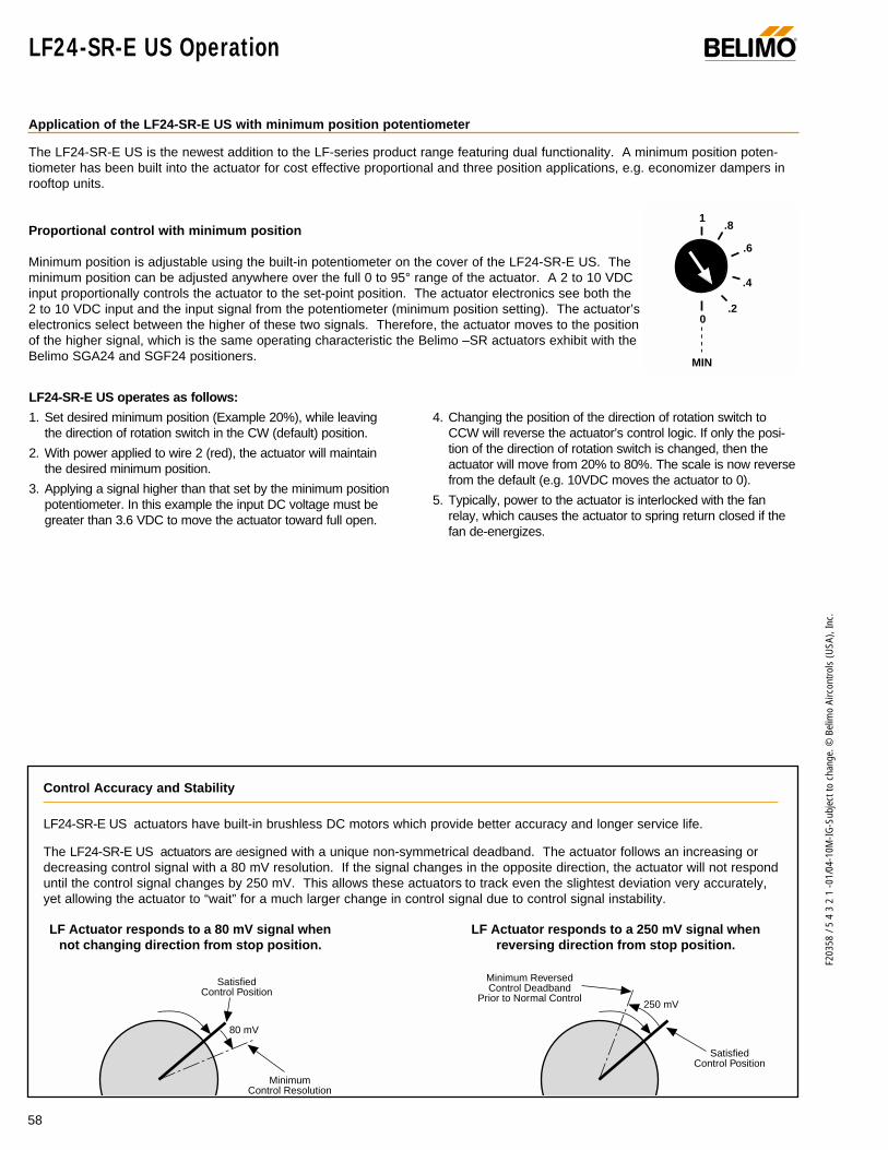
58
F203
58 /
5 4
3 2
1 -0
1/04
-10M
-IG-S
ubje
ct to
cha
nge.
© B
elim
o Ai
rcon
trols
(USA
), In
c.
SatisfiedControl Position
SatisfiedControl Position
MinimumControl Resolution
Minimum ReversedControl Deadband
Prior to Normal Control
80 mV
250 mV
LF Actuator responds to a 80 mV signal whennot changing direction from stop position.
LF Actuator responds to a 250 mV signal whenreversing direction from stop position.
®
LF24-SR-E US operates as follows:
1. Set desired minimum position (Example 20%), while leavingthe direction of rotation switch in the CW (default) position.
2. With power applied to wire 2 (red), the actuator will maintainthe desired minimum position.
3. Applying a signal higher than that set by the minimum positionpotentiometer. In this example the input DC voltage must begreater than 3.6 VDC to move the actuator toward full open.
4. Changing the position of the direction of rotation switch toCCW will reverse the actuator’s control logic. If only the posi-tion of the direction of rotation switch is changed, then theactuator will move from 20% to 80%. The scale is now reversefrom the default (e.g. 10VDC moves the actuator to 0).
5. Typically, power to the actuator is interlocked with the fanrelay, which causes the actuator to spring return closed if thefan de-energizes.
Application of the LF24-SR-E US with minimum position potentiometer
The LF24-SR-E US is the newest addition to the LF-series product range featuring dual functionality. A minimum position poten-tiometer has been built into the actuator for cost effective proportional and three position applications, e.g. economizer dampers inrooftop units.
Proportional control with minimum position
Minimum position is adjustable using the built-in potentiometer on the cover of the LF24-SR-E US. Theminimum position can be adjusted anywhere over the full 0 to 95° range of the actuator. A 2 to 10 VDCinput proportionally controls the actuator to the set-point position. The actuator electronics see both the2 to 10 VDC input and the input signal from the potentiometer (minimum position setting). The actuator’selectronics select between the higher of these two signals. Therefore, the actuator moves to the positionof the higher signal, which is the same operating characteristic the Belimo –SR actuators exhibit with theBelimo SGA24 and SGF24 positioners.
LF24-SR-E US Operation
LF24-SR-E US actuators have built-in brushless DC motors which provide better accuracy and longer service life.
The LF24-SR-E US actuators are designed with a unique non-symmetrical deadband. The actuator follows an increasing ordecreasing control signal with a 80 mV resolution. If the signal changes in the opposite direction, the actuator will not responduntil the control signal changes by 250 mV. This allows these actuators to track even the slightest deviation very accurately,yet allowing the actuator to “wait” for a much larger change in control signal due to control signal instability.
Control Accuracy and Stability
.8
.6
.4
.20
1
MIN

59
F203
58 /
5 4
3 2
1 -0
1/04
-10M
-IG-S
ubje
ct to
cha
nge.
© B
elim
o Ai
rcon
trols
(USA
), In
c.
LF
LF24-SR-E US Operation®
The LF24-SR-E US will:
• Direct couple to the damper shaft between 3/8” and 3/4”diameter for reduced installation cost.
• Spring return in either CW or CCW direction depending onmounting orientation of the actuator. This feature elimi-nates the need to select a specific model with correctspring return direction.
• Spring returns in <25 seconds @ -4° to +122°F.
• Increase minimum torque output to 35 in-lbs for 40% moretorque than other 3-position actuator solutions.
• Drive to the adjustable minimum position from either thefully Open or Closed position using its brushless DC motorfor improved reliability. Spring returns only during powerloss.
• Drive full stroke in 150 seconds.
• Output a 2 to 10 VDC signal for position feedback
• Control a damper proportionally between minimum positionand full open (2 to 10 VDC input) for additional applications.
• Have dual (3-position and proportional control) wiring dia-grams on actuator label for clear and easy wiring in thefield.
• Consumes only 2.5 W driving to setpoint and 1 W to holdposition, lower than actuators using AC motor technology.
Features of the Belimo Three-Position Solution
Three-Position control using the LF24-SR-E US
By applying the LF24-SR override functionality and the new mini-mum position potentiometer, it is possible to achieve simple three-position control with the LF24-SR-E US.
1. Set desired minimum position (Example 20%), while leaving thedirection of rotation switch in the CW (default) position. Thedirection of rotation switch does not need to be changed forthree-position control, because direction of rotation can bechanged by flipping the actuator.
2. With 24 VAC power applied across wire 1 (black) and 2 (red),the actuator will maintain minimum position.
3. Applying 24 VAC power across wire 1 (black) and 3 (white) overrides the minimum position and moves the actuator to Full Open.
4. With no power applied to actuator, it will spring return (fail-safe)closed.
5. Typically, power to the actuator is interlocked with the fanrelay, which causes the actuator to spring return closed if thefan de-energizes.
Replacing an M8405 actuator
The three-position control functionality of the LF24-SR-E USallows direct replacement of a Honeywell M8405A foot mount-ed economizer actuator.
MountingFor non-direct coupled applications use the ZG-LF112 HWaccessory kit, which includes the KH-LF crankarm and ZG112bracket and an accessory logic module mounting kit. The ZG-112 aligns the plane of the crankarm with that of theHoneywell M8405A. ZG-112 has at least two mounting holesthat match the M805A foot pattern. The logic module mount-ing kit allows for attachment to the end of the LF24-SR-E USactuator. It provides for installation flexibility to place the mod-ule where space is available.
WiringFor proper control logic wiring always refer to the controllermanufactures documentation. See the 2003 ProductDocumentation Standard Actuation and Accessories for properthree position wiring diagram Belimo wiring diagram, page 55.
ZG-LF112 Crankarm adaptor kit
– Bracket and crankarm for replace-ment of Honeywell M8405 actuators.
ZG-112
KH-LFcrankarm

60
F203
58 /
5 4
3 2
1 -0
1/04
-10M
-IG-S
ubje
ct to
cha
nge.
© B
elim
o Ai
rcon
trols
(USA
), In
c.
Preliminary steps1. Belimo actuators should be mounted indoors in dry, rela-
tively clean environment free from corrosive fumes. If theactuator is to be mounted outdoors, a protective enclosuremust be used to shield the actuator. (See BelimoMechanical Accessories Doc. 5.2)
2. For new construction work, order dampers with extendedshafts. Instruct the installing contractor to allow space formounting and service of the Belimo actuator on the shaft.
3. For standard mounting, the damper shaft must extend at least3 1/2" from the duct. If the shaft extends less than 3 1/2", theactuator may be mounted in itsshort shaft configuration. If anobstruction blocks access, theshaft can be extended with theAV 10-18 shaft extension. (K6-1 is required)
Installation InstructionsQuick-Mount Visual Instructions
min 3 1/2”[90]
min 3 1/2”[90]
min 3/4”[20]
IND-LF Position Indicator(optional)
min 3/4”[20]
IND-LF Position Indicator(optional)
1. Rotate the damper to its failsafe position. If the shaft rotatescounterclockwise, mount the “CCW” side of the actuator out. If itrotates clockwise, mount the actuator with the “CW” side out.
2. If the universal clamp is not on the correct side of the actua-tor, move it to the correct side.
3. Slide the actuator onto the shaft and tighten the nuts on theV-bolt with a 10mm wrench to 6-8 ft-lb of torque.
4. Slide the anti-rotation strap under the actuator so that itengages the slot at the base of the actuator. Secure thestrap to the duct work with #8 self-tapping screws.
NOTE: Read the “Standard Mounting” instructions, on page 17,for more detailed information.
min 3 1/2”[90]
min 3/4”[20]
®
StandardMounting
Short ShaftMounting
Dimensions (All numbers in brackets are metric.)

61
F203
58 /
5 4
3 2
1 -0
1/04
-10M
-IG-S
ubje
ct to
cha
nge.
© B
elim
o Ai
rcon
trols
(USA
), In
c.
LF
WARNING The wiring technician must be trained and experi-enced with electronic circuits. Disconnect power supplybefore attempting any wiring connections or changes. Makeall connections in accordance with wiring diagrams and followall applicable local and national codes. Provide disconnectand overload protection as required. Use copper, twisted pair,conductors only. If using electrical conduit, the attachment tothe actuator must be made with flexible conduit.
Always read the controller manufacturer's installation lit-erature carefully before making any connections. Followall instructions in this literature. If you have any questions,contact the controller manufacturer and/or Belimo.
Transformer(s)The LF24 . . actuator requires a 24 VAC class 2 transformerand draws a maximum of 7 VA per actuator. The actuatorenclosure cannot be opened in the field, there are no parts orcomponents to be replaced or repaired.
– EMC directive: 89/336/EEC– Software class A: Mode of operation type 1– Low voltage directive: 73/23/EEC
CAUTION: It is good practice to power electronic or digitalcontrollers from a separate power transformer than that usedfor actuators or other end devices. The power supply designin our actuators and other end devices use half wave rectifica-tion. Some controllers use full wave rectification. When thesetwo different types of power supplies are connected to thesame power transformer and the DC commons are connectedtogether, a short circuit is created across one of the diodes inthe full wave power supply, damaging the controller. Only usea single power transformer to power the controller and actua-tor if you know the controller power supply uses half wave rec-tification.
Multiple actuators, one transformer Multiple actuators may be powered from one transformer pro-vided the following rules are followed:1. The TOTAL current draw of the actuators (VA rating) is
less than or equal to the rating of the transformer.2. Polarity on the secondary of the transformer is strictly fol-
lowed. This means that all No. 1 wires from all actuatorsare connected to the common leg on the transformer andall No 2 wires from all actuators are connected to the hot-leg. Mixing wire No. 1 & 2 on one leg of the transformerwill result in erratic operation or failure of the actuatorand/or controls.
Multiple actuators, multiple transformersMultiple actuators positioned by the same control signal maybe powered from multiple transformers provided the followingrules are followed:1. The transformers are properly sized.2. All No. 1 wires from all actuators are tied together and tied
to the negative leg of the control signal. See wiring diagram.
Wire length for LF… actuatorsKeep power wire runs below the lengths listed in the table inFig. A. If more than one actuator is powered from the samewire run, divide the allowable wire length by the number of actu-ators to determine the maximum run to any single actuator. Example for LF24-SR US:
3 actuators, 16 Ga wire 550 Ft ÷ 3 Actuators = 183 Ft. Maximum wire run
Maximum wire length:
Wire Size Max. Feet. Wire Size Max. Feet12 Ga 1100 Ft. 18 Ga 260 Ft.14 Ga 700 Ft. 20 Ga 140 Ft. 16 Ga 440 Ft. 22 Ga 75 Ft.
Fig. A
Wire Type and Wire Installation TipsFor most installations, 18 or 16 Ga. cable works well with theLF24… actuators. Use code-approved wire nuts, terminalstrips or solderless connectors where wires are joined. It isgood practice to run control wires unspliced from the actuatorto the controller. If splices are unavoidable, make sure thesplice can be reached for possible maintenance. Tape and/orwire-tie the splice to reduce the possibility of the splice beinginadvertently pulled apart.
The LF24… proportional actuators have a digital circuit that isdesigned to ignore most unwanted input signals (pickup). Insome situations the pickup may be severe enough to causeerratic running of the actuator. For example, a large inductiveload (high voltage AC wires, motors, etc.) running near thepower or control wiring may cause excessive pickup. To solvethis problem, make one or more of the following changes:1. Run the wire in metallic conduit.2. Re-route the wiring away from the source of pickup.3. Use shielded wire (Belden 8760 or equal). Ground the
shield to an earth ground. Do not connect it to the actua-tor common.
Brushless DC motor operationBelimo's brushless DC motor spins by reversing the poles ofstationary electromagnets housed inside rotating permanentmagnets. The electromagnetic poles are switched by a micro-processor and a special ASIC (Application Specific IntegratedCircuit) developed by Belimo. Unlike the conventional DCmotor, there are no brushes to wear or commutators to foul.
Wire Size Max. Feet. Wire Size Max. Feet12 Ga 1500 Ft. 18 Ga 375 Ft.14 Ga 925 Ft. 20 Ga 200 Ft. 16 Ga 550 Ft. 22 Ga 100 Ft.
Installation InstructionsGeneral Wiring
®
LF24 (-S) US
LF120 (-S) US / LF230 (-S) US
LF24-SR (-S) US / LF24-3 (-S) US / LFC24-3-R (-S) US
Wire Size Max. Feet. Wire Size Max. Feet12 Ga 1250 Ft. 18 Ga 320 Ft.14 Ga 800 Ft. 20 Ga 160 Ft. 16 Ga 500 Ft. 22 Ga 85 Ft.
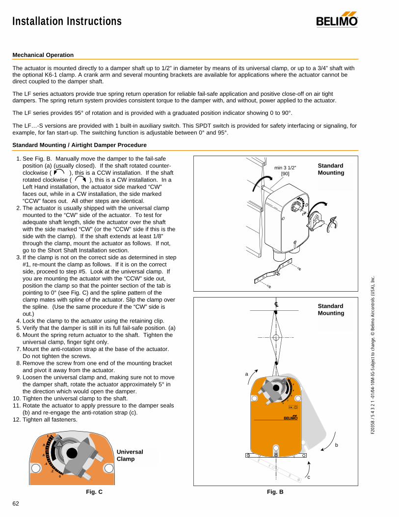
62
F203
58 /
5 4
3 2
1 -0
1/04
-10M
-IG-S
ubje
ct to
cha
nge.
© B
elim
o Ai
rcon
trols
(USA
), In
c.
1. See Fig. B. Manually move the damper to the fail-safeposition (a) (usually closed). If the shaft rotated counter-clockwise ( ), this is a CCW installation. If the shaftrotated clockwise ( ), this is a CW installation. In aLeft Hand installation, the actuator side marked “CW”faces out, while in a CW installation, the side marked“CCW” faces out. All other steps are identical.
2. The actuator is usually shipped with the universal clampmounted to the “CW” side of the actuator. To test foradequate shaft length, slide the actuator over the shaftwith the side marked “CW” (or the “CCW” side if this is theside with the clamp). If the shaft extends at least 1/8”through the clamp, mount the actuator as follows. If not,go to the Short Shaft Installation section.
3. If the clamp is not on the correct side as determined in step#1, re-mount the clamp as follows. If it is on the correctside, proceed to step #5. Look at the universal clamp. Ifyou are mounting the actuator with the “CCW” side out,position the clamp so that the pointer section of the tab ispointing to 0° (see Fig. C) and the spline pattern of theclamp mates with spline of the actuator. Slip the clamp overthe spline. (Use the same procedure if the “CW” side isout.)
4. Lock the clamp to the actuator using the retaining clip. 5. Verify that the damper is still in its full fail-safe position. (a)6. Mount the spring return actuator to the shaft. Tighten the
universal clamp, finger tight only.7. Mount the anti-rotation strap at the base of the actuator.
Do not tighten the screws.8. Remove the screw from one end of the mounting bracket
and pivot it away from the actuator.9. Loosen the universal clamp and, making sure not to move
the damper shaft, rotate the actuator approximately 5° inthe direction which would open the damper.
10. Tighten the universal clamp to the shaft.11. Rotate the actuator to apply pressure to the damper seals
(b) and re-engage the anti-rotation strap (c).12. Tighten all fasteners.
Installation Instructions ®
Standard Mounting / Airtight Damper Procedure
Mechanical Operation
The actuator is mounted directly to a damper shaft up to 1/2” in diameter by means of its universal clamp, or up to a 3/4” shaft withthe optional K6-1 clamp. A crank arm and several mounting brackets are available for applications where the actuator cannot bedirect coupled to the damper shaft.
The LF series actuators provide true spring return operation for reliable fail-safe application and positive close-off on air tightdampers. The spring return system provides consistent torque to the damper with, and without, power applied to the actuator.
The LF series provides 95° of rotation and is provided with a graduated position indicator showing 0 to 90°.
The LF…-S versions are provided with 1 built-in auxiliary switch. This SPDT switch is provided for safety interfacing or signaling, forexample, for fan start-up. The switching function is adjustable between 0° and 95°.
UniversalClamp
0
.2
.4
.6
.8
1
Fig. BFig. C
0124
56
789
LC
b
c
a
.2
.4
.6
.8
1
CW
0
®
StandardMounting
StandardMounting
min 3 1/2”[90]
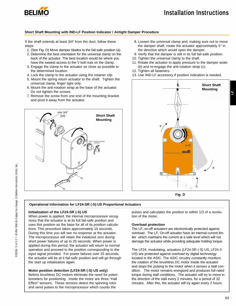
63
F203
58 /
5 4
3 2
1 -0
1/04
-10M
-IG-S
ubje
ct to
cha
nge.
© B
elim
o Ai
rcon
trols
(USA
), In
c.
LF
If the shaft extends at least 3/4” from the duct, follow thesesteps:
1. (See Fig. D) Move damper blades to the fail-safe position (a).2. Determine the best orientation for the universal clamp on the
back of the actuator. The best location would be where youhave the easiest access to the V bolt nuts on the clamp.
3. Engage the clamp to the actuator as close as possible tothe determined location.
4. Lock the clamp to the actuator using the retainer clip.5. Mount the spring return actuator to the shaft. Tighten the
universal clamp, finger tight only.6. Mount the anti-rotation strap at the base of the actuator.
Do not tighten the screws.7. Remove the screw from one end of the mounting bracket
and pivot it away from the actuator.
8. Loosen the universal clamp and, making sure not to movethe damper shaft, rotate the actuator approximately 5° inthe direction which would open the damper.
9. Verify that the damper is still in its full fail-safe position.10. Tighten the universal clamp to the shaft.11. Rotate the actuator to apply pressure to the damper seals
(b) and re-engage the anti-rotation strap (c).12. Tighten all fasteners.13. Use IND-LF accessory if position indication is needed.
Installation Instructions®
Short Shaft Mounting with IND-LF Position Indicator / Airtight Damper Procedure
Initialization of the LF24-SR (-S) US When power is applied, the internal microprocessor recog-nizes that the actuator is at its full fail-safe position anduses this position as the base for all of its position calcula-tions. This procedure takes approximately 15 seconds.During this time you will see no response at the actuator.The microprocessor will retain the initialized zero duringshort power failures of up to 25 seconds. When power isapplied during this period, the actuator will return to normaloperation and proceed to the position corresponding to theinput signal provided. For power failures over 25 seconds,the actuator will be at it fail-safe position and will go throughthe start up initialization again.
Motor position detection (LF24-SR (-S) US only)Belimo brushless DC motors eliminate the need for poten-tiometers for positioning. Inside the motor are three “HallEffect” sensors. These sensors detect the spinning rotorand send pulses to the microprocessor which counts the
pulses and calculates the position to within 1/3 of a revolu-tion of the motor.
Overload protectionThe LF, on-off actuators are electronically protected againstoverload. The LF, On-off actuator have an internal current lim-iter which maintains the current at a safe level which will notdamage the actuator while providing adequate holding torque.
The LF24, modulating, actuators (LF24-SR (-S) US, LF24-3US) are protected against overload by digital technologylocated in the ASIC. The ASIC circuitry constantly monitorsthe rotation of the brushless DC motor inside the actuatorand stops the pulsing to the motor when it senses a stall con-dition. The motor remains energized and produces full ratedtorque during stall conditions. The actuator will try to move inthe direction of the stall every 2 minutes, for a period of 32minutes. After this, the actuator will try again every 2 hours.
Operational Information for LF24-SR (-S) US Proportional Actuators
min 3/4”[20]
IND-LF Position Indicator(optional)
Fig. D
0124
56
789
LC
b
c
a
.2
.4
.6
.8
1
CW
0
®
Short ShaftMounting
Short ShaftMounting
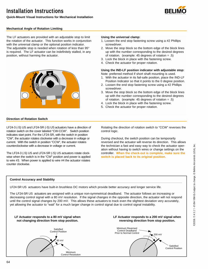
64
F203
58 /
5 4
3 2
1 -0
1/04
-10M
-IG-S
ubje
ct to
cha
nge.
© B
elim
o Ai
rcon
trols
(USA
), In
c.
The LF actuators are provided with an adjustable stop to limitthe rotation of the actuator. This function works in conjunctionwith the universal clamp or the optional position indicator.The adjustable stop is needed when rotation of less than 95°is required. The LF actuator can be indefinitely stalled, in anyposition, without harming the actuator.
Using the universal clamp:1. Loosen the end stop fastening screw using a #2 Phillips
screwdriver. 2. Move the stop block so the bottom edge of the block lines
up with the number corresponding to the desired degreesof rotation. (example: 45 degrees of rotation = .5)
3. Lock the block in place with the fastening screw.4. Check the actuator for proper rotation.
Using the IND-LF position indicator with adjustable stop:Note: preferred method if short shaft mounting is used.1. With the actuator in its fail-safe position, place the IND-LF
Position Indicator so that it points to the 0 degree position.2. Loosen the end stop fastening screw using a #2 Phillips
screwdriver.3. Move the stop block so the bottom edge of the block lines
up with the number corresponding to the desired degreesof rotation. (example: 45 degrees of rotation = .5)
4. Lock the block in place with the fastening screw.5. Check the actuator for proper rotation.
0
.2
.4
.6
.8
1
Mechanical Angle of Rotation Limiting
Installation InstructionsQuick-Mount Visual Instructions for Mechanical Installation
®
LF24-SR US actuators have built-in brushless DC motors which provide better accuracy and longer service life.
The LF24-SR US actuators are designed with a unique non-symmetrical deadband. The actuator follows an increasing ordecreasing control signal with a 80 mV resolution. If the signal changes in the opposite direction, the actuator will not responduntil the control signal changes by 200 mV. This allows these actuators to track even the slightest deviation very accurately,yet allowing the actuator to “wait” for a much larger change in control signal due to control signal instability.
Control Accuracy and Stability
SatisfiedControl Position
SatisfiedControl Position
MinimumControl Resolution
Minimum ReversedControl Deadband
Prior to Normal Control
80 mV
200 mV
LF Actuator responds to a 80 mV signal whennot changing direction from stop position.
LF Actuator responds to a 200 mV signal whenreversing direction from stop position.
LF24-3 (-S) US and LF24-SR (-S) US actuators have a direction ofrotation switch on the cover labeled “CW-CCW”. Switch positionindicates start point. For the LF24-SR, with the switch in position“CW”, the actuator rotates clockwise with a decrease in voltage orcurrent. With the switch in position “CCW”, the actuator rotatescounterclockwise with a decrease in voltage or current.
The LF24-3 (-S) US and LF24-SR (-S) US actuators rotate clock-wise when the switch is in the “CW” position and power is appliedto wire #3. When power is applied to wire #4 the actuator rotatescounter clockwise.
Rotating the direction of rotation switch to “CCW” reverses thecontrol logic.
During checkout, the switch position can be temporarilyreversed and the actuator will reverse its direction. This allowsthe technician a fast and easy way to check the actuator oper-ation without having to switch wires or change settings on thecontroller. When the check-out is complete, make sure theswitch is placed back to its original position.
Direction of Rotation Switch

65
F203
58 /
5 4
3 2
1 -0
1/04
-10M
-IG-S
ubje
ct to
cha
nge.
© B
elim
o Ai
rcon
trols
(USA
), In
c.
LF
Installation Instructions®
The …-S model actuators are equipped with an adjustableauxiliary switch used to indicate damper position or to inter-face additional controls or equipment. Switching positions canbe set over the full 0 to 95° rotation simply by setting a switchon the actuator.
1. Set desired switch position. (Example 60%)2. As the actuator rotates, the switch indicator moves from .6
(60%) toward 0 (0%). When the indicator passes 0 theswitch contact between S1 and S2 is broken and the con-tact between S1 and S3 is made.
Auxiliary Switches
.8
.6
.4
.20
1
S1S2
S3
S1S2
S3
Non-direct Mounting Methods
KH-LF crankarm including retaining ring.
KH-LFFor shafts up to 1/2”
ZG-112
(pushrod not supplied with kit)
KG6 ball joint anduniversal crankarm
(not included)
KG6 ball joint(not included)
KH-LFcrankarm
KH-LFcrankarm
ZG-LF2 Crankarm adaptor kit
ZG-LF112 Crankarm adaptor kit
Voltage Resistive load Inductive load
120 VAC 6 A 3 A250 VAC 6 A 1.5 A
Switch Rating

66
F203
58 /
5 4
3 2
1 -0
1/04
-10M
-IG-S
ubje
ct to
cha
nge.
© B
elim
o Ai
rcon
trols
(USA
), In
c.
®Startup and CheckoutInstructions For LF24-SR (-S) US
Procedure
Remove power to reset actuator.Re-apply power.Apply control signal to actuator.
Check power wiring. Correct anyproblems. See Note 1.
Turn reversing switch to the correctposition. Make sure the switch isturned all the way left or right.
Make sure the control signal positive(+) is connected to Wire No 3 andcontrol signal negative (-) is connect-ed to wire No. 1. Most control prob-lems are caused by reversing thesetwo wires. Verify that the reversingswitch is all the way CCW or CW.
Check input signal with a digital voltmeter (DVM). Make sure the input iswithin the range of the actuator. ForLF24-SR US this is 2 to 10 VDC or 4 to 20 mA. Note: The input signalmust be above the 2 VDC or 4 mA tohave the actuator move.
Loosen the nuts on the V-bolt andmove the damper by hand from fullyclosed to fully open.
Check damper torque requirement.
Actuator works properly. Test con-troller by following controller manu-facturer's instructions.
Expected Response
Actuator will move to its “ControlSignal” position.
Power supply rating should be ≥the total power requirement ofthe actuator(s). Minimum volt-age of 19.2 VAC or 21.6 VDC.
Actuator will move to its “ControlSignal” position.
Drives to “Control Signal” posi-tion
Input voltage or current should be±1% of what controller's adjust-ment or programming indicate.
Damper will go from fully closedto fully open.
Torque requirement is ≤ actua-tor’s minimum torque.
Gives ExpectedResponse
Go To Step…
Actuator operatesproperlyStep 8
Power wiring correct-ed, actuator begins
to driveStep 1
Actuator operatesproperly.Step 8
Actuator operatesproperly.Step 8
Controller output(actuator input) is
correct. InputPolarity Correct.
Step 6
Damper moves properlyStep 7
Defective Actuator.Replace Actuator -
See Note 2
Does Not GiveExpected Response
Go To Step…
No response at allStep 2
Operation isreversedStep 3
Does not drivetoward "ControlSignal Position"
Step 4
Power wiringcorrected, actuatorstill does not drive
Step 4
Does not drivetoward “ControlSignal Position”
Step 4
Step 5
Reprogram, adjustrepair or replace
controller as needed.Step 1
Find cause of damperjam and repair. Movedamper back to thefully closed positionand tighten the nuts.
Step 1
Recalculate actuatorrequirement and
correct installation.
Step
1.
2.
3.
4.
5.
6.
7.
8.
Note 1 Check that the transformer(s) are sized properly. • If a common transformer is used, make sure that polarity is observed on the secondary. This means connect all No. 1
wires to one leg of the transformer and all No. 2 wires to the other leg of the transformer. • If multiple transformers are used with one control signal, make sure all No. 1 wires are tied together and tied to control
signal negative (-).• Controllers and actuators must have separate 24 VAC/VDC power sources.
Note 2 If failure occurs within 5 years from original installation date, notify Belimo and give details of the application.
LF24-SR (-S) US Electrical check-out procedure

67
F203
58 /
5 4
3 2
1 -0
1/04
-10M
-IG-S
ubje
ct to
cha
nge.
© B
elim
o Ai
rcon
trols
(USA
), In
c.
LF
® Notes/Work Pad
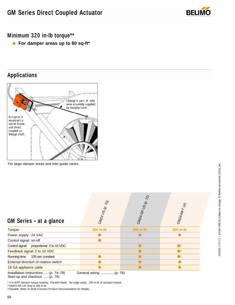
68
F203
58 /
5 4
3 2
1 -0
1/04
-10M
-IG-S
ubje
ct to
cha
nge.
© B
elim
o Ai
rcon
trols
(USA
), In
c.
Applications
Actuator ismounted tovortex frame.and directcoupled tolinkage shaft.
Linkage is part of inletvane assembly suppliedby manufacturer.
GM Series Direct Coupled Actuator ®
Minimum 320 in-lb torque** For damper areas up to 80 sq-ft*
Torque: 320 in-lb 266 in-lb 320 in-lb
Power supply : 24 VAC
Control signal: on-off
Control signal: proportional 2 to 10 VDC †
Feedback signal: 2 to 10 VDC †
Running time 135 sec constant †
External direction of rotation switch
18 GA appliance cable
Installation instructions ......(p. 74–78) General wiring ..............(p. 76)Start-up and checkout ......(p. 79)
GM Series – at a glance
* 4 in-lb/ft2 damper torque loading. Parallel blade. No edge seals. 320 in-lb of actuator torque.**GM24-SR US Only is 266 in-lb†Variable: Refer to Multi-Function Product Documentation for details.
For large damper areas and inlet guide vanes.
GM
24 U
S (p
. 70)
GM
24-S
R U
S (p
. 72)
GM
24-M
FT U
S

69
F203
58 /
5 4
3 2
1 -0
1/04
-10M
-IG-S
ubje
ct to
cha
nge.
© B
elim
o Ai
rcon
trols
(USA
), In
c.
GM
A CLOSER LOOK…
GM Series Direct Coupled Actuator®
LISTED94D5TEMP. IND ®. EQUIP.
UL
Cut labor costs with simple direct coupling– The Belimo Concept.
Check damper position easily with clear indicator.
Don’t worry about actuator burn-out. Belimo is overload-proof throughout rotation
Easy mechanical stop to adjust angle of rotation. (add ZDB-GM accessory).
Push-button manual override speeds installation.
Need to change control direction? Do it easily with a simple switch.
Microprocessor-controlled brushless DC motor increases actuator life span and reliability, provides constant running time.
Rugged NEMA 2 housing provides protection from splashing water.
3 ft. appliance cable and conduit connectoreases installation.
Microprocessor controlled.
The Belimo Difference
Customer Commitment.Extensive product range. Competitive project pricing. Application assistance. Same-day shipments. Free technical support. Five year warranty.
Low Installation and Life-Cycle Cost.Easy installation. Accuracy and repeatability. Low power consumption. No maintenance.
Long Service Life.Components tested before assembly. Every product tested before shipment. 20+ years direct coupled actuator design.
©
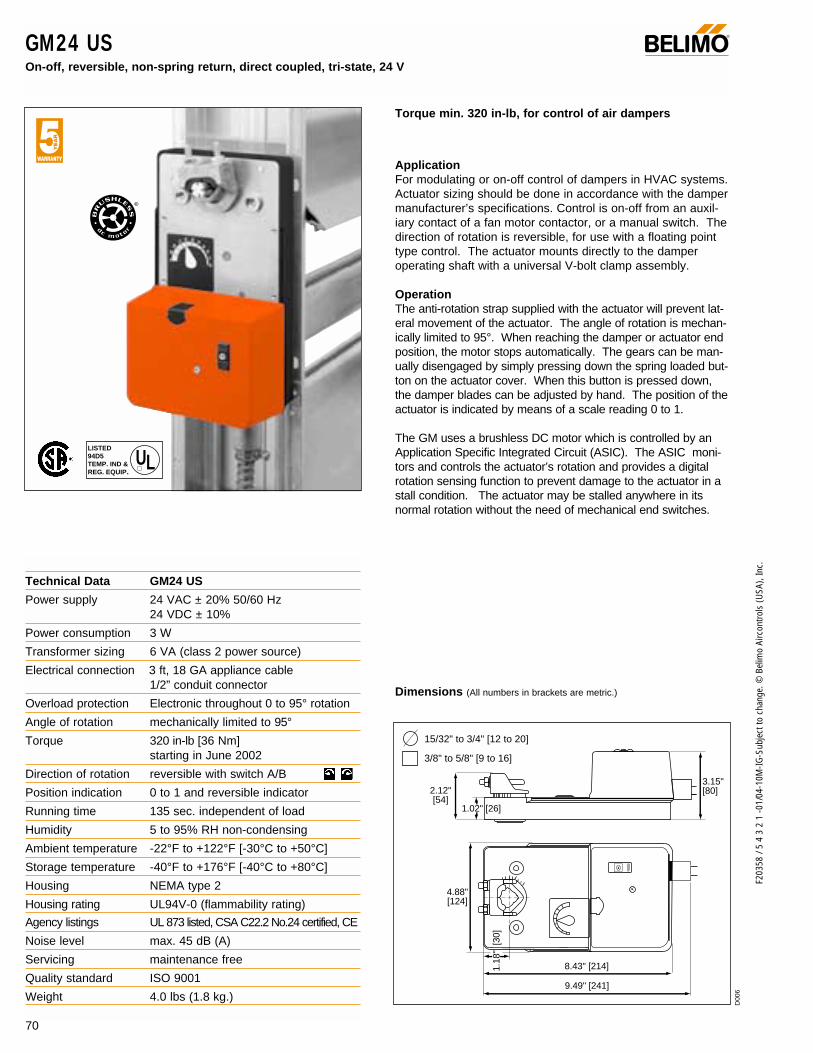
F203
58 /
5 4
3 2
1 -0
1/04
-10M
-IG-S
ubje
ct to
cha
nge.
© B
elim
o Ai
rcon
trols
(USA
), In
c.
GM24 US On-off, reversible, non-spring return, direct coupled, tri-state, 24 V
®
Torque min. 320 in-lb, for control of air dampers
ApplicationFor modulating or on-off control of dampers in HVAC systems.Actuator sizing should be done in accordance with the dampermanufacturer’s specifications. Control is on-off from an auxil-iary contact of a fan motor contactor, or a manual switch. Thedirection of rotation is reversible, for use with a floating pointtype control. The actuator mounts directly to the damperoperating shaft with a universal V-bolt clamp assembly.
OperationThe anti-rotation strap supplied with the actuator will prevent lat-eral movement of the actuator. The angle of rotation is mechan-ically limited to 95°. When reaching the damper or actuator endposition, the motor stops automatically. The gears can be man-ually disengaged by simply pressing down the spring loaded but-ton on the actuator cover. When this button is pressed down,the damper blades can be adjusted by hand. The position of theactuator is indicated by means of a scale reading 0 to 1.
The GM uses a brushless DC motor which is controlled by anApplication Specific Integrated Circuit (ASIC). The ASIC moni-tors and controls the actuator’s rotation and provides a digitalrotation sensing function to prevent damage to the actuator in astall condition. The actuator may be stalled anywhere in itsnormal rotation without the need of mechanical end switches.
Dimensions (All numbers in brackets are metric.)
2.12" [54]
1.02" [26]
3.15"[80]
4.88" [124]
1.18
" [3
0]
8.43" [214]
9.49" [241]
15/32" to 3/4" [12 to 20]
3/8" to 5/8" [9 to 16]
Technical Data GM24 US
Power supply 24 VAC ± 20% 50/60 Hz24 VDC ± 10%
Power consumption 3 W
Transformer sizing 6 VA (class 2 power source)
Electrical connection 3 ft, 18 GA appliance cable1/2” conduit connector
Overload protection Electronic throughout 0 to 95° rotation
Angle of rotation mechanically limited to 95°
Torque 320 in-lb [36 Nm]starting in June 2002
Direction of rotation reversible with switch A/B
Position indication 0 to 1 and reversible indicator
Running time 135 sec. independent of load
Humidity 5 to 95% RH non-condensing
Ambient temperature -22°F to +122°F [-30°C to +50°C]
Storage temperature -40°F to +176°F [-40°C to +80°C]
Housing NEMA type 2
Housing rating UL94V-0 (flammability rating)
Agency listings UL 873 listed, CSA C22.2 No.24 certified, CE
Noise level max. 45 dB (A)
Servicing maintenance free
Quality standard ISO 9001
Weight 4.0 lbs (1.8 kg.)
LISTED94D5TEMP. IND ®. EQUIP.
UL
70
D00
6
©

71
F203
58 /
5 4
3 2
1 -0
1/04
-10M
-IG-S
ubje
ct to
cha
nge.
© B
elim
o Ai
rcon
trols
(USA
), In
c.
GM
GM24 USOn-off, reversible, non-spring return, direct coupled, tri-state, 24 V
®
AccessoriesKH8 Universal crankarmKG10 Ball jointNSV24 Battery back-up moduleP… Feedback potentiometerSZS Mid-position switchS1,S2 Auxiliary switchTool-01 10mm wrenchZDB-GM Angle of rotation limiter (Series 2)ZG-H2 Actuator operator handleZG-GM2 Crankarm adaptor kitZG-100 Universal mounting bracketZG-101 Universal mounting bracketZG-102 Multiple actuator mounting bracketZG-103 Universal mounting bracketZG-104 Universal mounting bracketZS-100 Weather shield (metal)ZS-150 Weather shield (polycarbonate)ZS-260 Explosion-proof housingZS-300 NEMA 4X housing
NOTE: When using GM24 US actuators, use only theaccessories listed on this page.
Wiring diagrams
GM24 US - Typical Specification:Control damper actuators shall be electronic direct coupledtype which require no crankarm and linkage. Actuators shallbe UL listed and CSA certified, have a 2 year warranty, andbe manufactured under ISO 9001 International Quality ControlStandards. Actuators shall have reversing switch and manualoverride on the cover. Actuators shall use a brushless DCmotor and be protected from overload at all angles of rotation.Run time shall be constant and independent of torque.Actuators shall be as manufactured by Belimo.
On-Off control of GM24 US
1 Provide overload protection and disconnect asrequired.
Actuator may also be powered by 24 VDC.
Tri-State control of GM24 US
1 Provide overload protection and disconnect asrequired.
Actuator may also be powered by 24 VDC.2 2
1
2
24 VAC Transformer
a opena closed
The indication of direc- tion is valid for switch position A.
1 Common
2 +
3 +
A
BGM24 US
Line Volts
a
1
2
24 VAC Transformer
The indication of direc- tion is valid for switch position A.
1 Common
2 +
3 +
A
BGM24 US
Line Volts
W07
0
Multiple actuators mounted to shaft
Model Maximum quantity per shaft
GM24 US 2
GM24-SR US 2
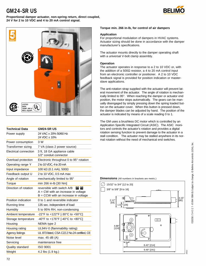
GM24-SR US Proportional damper actuator, non-spring return, direct coupled, 24 V for 2 to 10 VDC and 4 to 20 mA control signal.
F203
58 /
5 4
3 2
1 -0
1/04
-10M
-IG-S
ubje
ct to
cha
nge.
© B
elim
o Ai
rcon
trols
(USA
), In
c.
®
Torque min. 266 in-lb, for control of air dampers
ApplicationFor proportional modulation of dampers in HVAC systems.Actuator sizing should be done in accordance with the dampermanufacturer’s specifications.
The actuator mounts directly to the damper operating shaftwith a universal V-bolt clamp assembly.
OperationThe actuator operates in response to a 2 to 10 VDC or, withthe addition of a 500Ω resistor, a 4 to 20 mA control inputfrom an electronic controller or positioner. A 2 to 10 VDCfeedback signal is provided for position indication or master-slave applications.
The anti-rotation strap supplied with the actuator will prevent lat-eral movement of the actuator. The angle of rotation is mechan-ically limited to 95°. When reaching the damper or actuator endposition, the motor stops automatically. The gears can be man-ually disengaged by simply pressing down the spring loaded but-ton on the actuator cover. When this button is pressed down,the damper blades can be adjusted by hand. The position of theactuator is indicated by means of a scale reading 0 to 1.
The GM uses a brushless DC motor which is controlled by anApplication Specific Integrated Circuit (ASIC). The ASIC moni-tors and controls the actuator’s rotation and provides a digitalrotation sensing function to prevent damage to the actuator in astall condition. The actuator may be stalled anywhere in its nor-mal rotation without the need of mechanical end switches.
Dimensions (All numbers in brackets are metric.)
Technical Data GM24-SR US
Power supply 24 VAC ± 20% 50/60 Hz 24 VDC ± 10%
Power consumption 3 W
Transformer sizing 7 VA (class 2 power source)
Electrical connection 3 ft, 18 GA appliance cable1/2” conduit connector
Overload protection Electronic throughout 0 to 95° rotation
Operating range Y 2 to 10 VDC, 4 to 20 mA
Input impedance 100 kΩ (0.1 mA), 500ΩFeedback output U 2 to 10 VDC, 0.5 mA max
Angle of rotation mechanically limited to 95°
Torque min 266 in-lb [30 Nm]
Direction of rotation reversible with switch A/BA = CW with an increase in voltageB = CCW with an increase in voltage
Position indication 0 to 1 and reversible indicator
Running time 135 sec. independent of load
Humidity 5 to 95% RH, non-condensing
Ambient temperature -22°F to +122°F [-30°C to +50°C]
Storage temperature -40°F to +176°F [-40°C to +80°C]
Housing NEMA type 2
Housing rating UL94V-0 (flammability rating)
Agency listings UL 873 listed, CSA C22.2 No.24 certified, CE
Noise level max. 45 dB (A)
Servicing maintenance free
Quality standard ISO 9001
Weight 4.2 lbs (1.9 kg.)
LISTED94D5TEMP. IND ®. EQUIP.
UL
72
2.12" [54]
1.02" [26]
3.15"[80]
4.88" [124]
1.18
" [
30]
8.43" [214]
9.49" [241]
15/32" to 3/4" [12 to 20]
3/8" to 5/8" [9 to 16]D
012
©
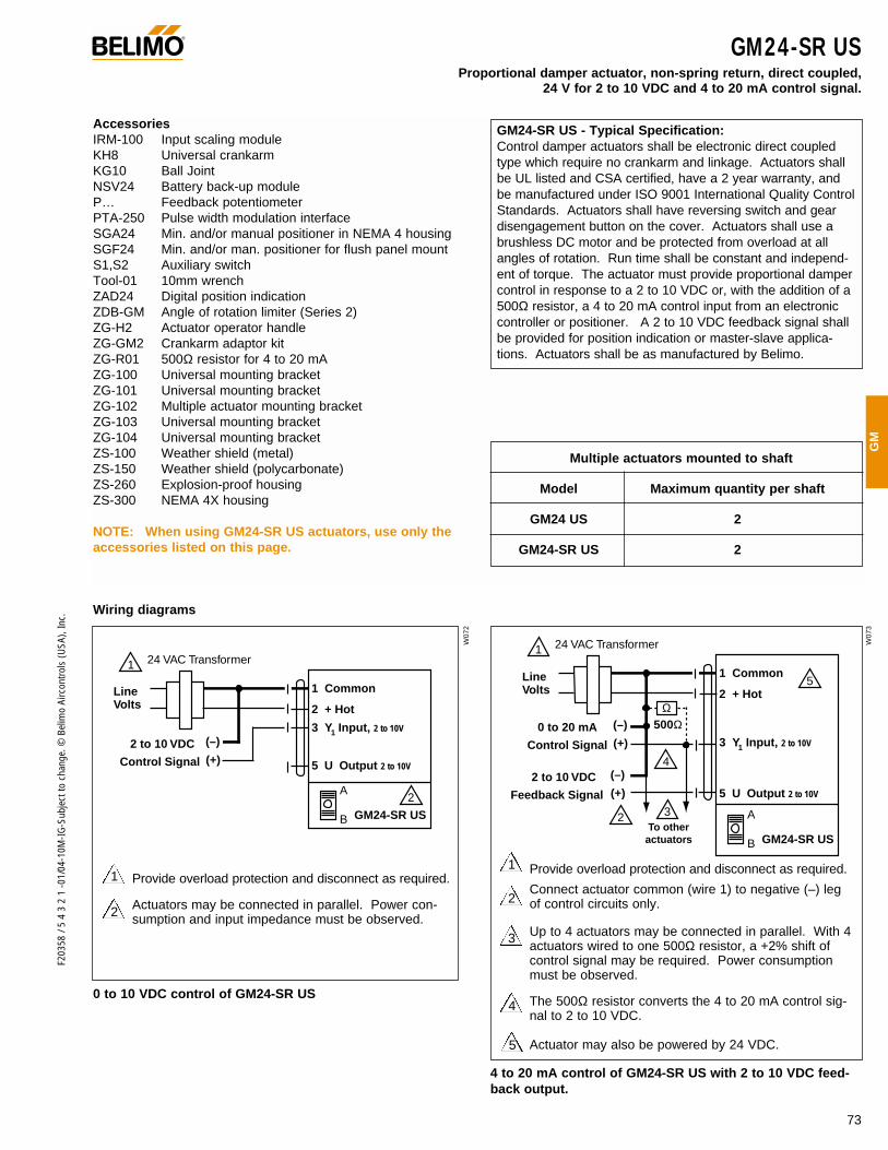
73
F203
58 /
5 4
3 2
1 -0
1/04
-10M
-IG-S
ubje
ct to
cha
nge.
© B
elim
o Ai
rcon
trols
(USA
), In
c.
GM
®
AccessoriesIRM-100 Input scaling moduleKH8 Universal crankarmKG10 Ball JointNSV24 Battery back-up moduleP… Feedback potentiometerPTA-250 Pulse width modulation interfaceSGA24 Min. and/or manual positioner in NEMA 4 housingSGF24 Min. and/or man. positioner for flush panel mountS1,S2 Auxiliary switchTool-01 10mm wrenchZAD24 Digital position indicationZDB-GM Angle of rotation limiter (Series 2)ZG-H2 Actuator operator handleZG-GM2 Crankarm adaptor kitZG-R01 500Ω resistor for 4 to 20 mAZG-100 Universal mounting bracketZG-101 Universal mounting bracketZG-102 Multiple actuator mounting bracketZG-103 Universal mounting bracketZG-104 Universal mounting bracketZS-100 Weather shield (metal)ZS-150 Weather shield (polycarbonate)ZS-260 Explosion-proof housingZS-300 NEMA 4X housing
NOTE: When using GM24-SR US actuators, use only theaccessories listed on this page.
Wiring diagrams
GM24-SR US - Typical Specification:Control damper actuators shall be electronic direct coupledtype which require no crankarm and linkage. Actuators shallbe UL listed and CSA certified, have a 2 year warranty, andbe manufactured under ISO 9001 International Quality ControlStandards. Actuators shall have reversing switch and geardisengagement button on the cover. Actuators shall use abrushless DC motor and be protected from overload at allangles of rotation. Run time shall be constant and independ-ent of torque. The actuator must provide proportional dampercontrol in response to a 2 to 10 VDC or, with the addition of a500Ω resistor, a 4 to 20 mA control input from an electroniccontroller or positioner. A 2 to 10 VDC feedback signal shallbe provided for position indication or master-slave applica-tions. Actuators shall be as manufactured by Belimo.
2
1 Provide overload protection and disconnect as required.
Actuators may be connected in parallel. Power con-sumption and input impedance must be observed.
4 to 20 mA control of GM24-SR US with 2 to 10 VDC feed-back output.
0 to 10 VDC control of GM24-SR US
2
1
3
Provide overload protection and disconnect as required.
Connect actuator common (wire 1) to negative (–) legof control circuits only.
Up to 4 actuators may be connected in parallel. With 4actuators wired to one 500Ω resistor, a +2% shift ofcontrol signal may be required. Power consumptionmust be observed.
The 500Ω resistor converts the 4 to 20 mA control sig-nal to 2 to 10 VDC.
Actuator may also be powered by 24 VDC.
4
5
GM24-SR USProportional damper actuator, non-spring return, direct coupled,
24 V for 2 to 10 VDC and 4 to 20 mA control signal.
Multiple actuators mounted to shaft
Model Maximum quantity per shaft
GM24 US 2
GM24-SR US 2
Control Signal (+)2 to 10 VDC (–)
1 Common
2 + Hot
3 Y Input, 2 to 10V
5 U Output 2 to 10V
1
2
24 VAC Transformer
A
B GM24-SR US
Line Volts
1
1 Common
2 + Hot
3 Y Input, 2 to 10V
5 U Output 2 to 10V
1 24 VAC Transformer
2
5
4
3 A
B GM24-SR US
Control Signal (+)0 to 20 mA (–)
Feedback Signal (+)2 to 10 VDC (–)
Ω500Ω
To other actuators
Line Volts
1
W07
2
W07
3

74
F203
58 /
5 4
3 2
1 -0
1/04
-10M
-IG-S
ubje
ct to
cha
nge.
© B
elim
o Ai
rcon
trols
(USA
), In
c.
Installation InstructionsQuick-Mount Visual Instructions for Mechanical Installation
®
10
5
0
10
5
0
min. 3/4"
[20 mm]
min. 2 1/2"
[63 mm]
Installation instruction for damper shafts with a minimumlength of 2 1/2 inch [63 mm] for GM series actuators
1. Move the damper to closed position.2. Position actuator onto damper shaft.3. Hand tighten nuts on V-clamp.4. If necessary, bend anti-rotation strap at both ends to fit
between damper frame.5. Fix anti-rotation strap to damper frame.6. Disengage gears with manual release button on casing.7. Turn motor clamp back to 5° before closed position and
allow gears to re-engage.8. Align the actuator at 90° to the damper shaft and verify
that the damper is still in the fully closed position.9. Tighten nuts on the V-clamp.
Installation instruction for damper shafts with a minimumlength of 3/4 inch [20 mm] or bridging of damper frame
1. Disengage gears with manual release button on casing(Manual operation).
2. Turn actuator clamp back to 5° before closed position andallow gears to re-engage.
3. Pull out universal clamp after removing retaining clip.4. Fix universal clamp onto damper shaft.5. Move damper into closed position.6. Position actuator onto universal clamp.7. Refit retaining clip.8 If necessary bend or cut anti-rotation strap on either side
to fit the damper frame.9. Slide the stud of the anti-rotation strap into slot on actua-
tor base and fix it with screws to damper frame.
Actuator is mounted to vortexframe. and direct coupled tolinkage shaft.
2nd actuator
Linkage is part ofinlet vane assemblysupplied by manu-facturer.
Installation instruction for mounting GM actuators oninlet guide vanes.
1. Rotate vortex jackshaft fully counterclockwise.2. Depress manual release button on actuator and rotate
universal clamp fully counterclockwise.3. Position the actuator on the jackshaft so that the actua-
tor is in a position to mount to the anti-rotation strap.4. Position and mount the anti-rotation strap to the vortex
frame so that the mounting stud is one-sixteenth inchfrom the bottom of the mounting slot of the actuator.
5. Verify that rotation of the actuator is correct for full oper-ation of the vortex blades. Adjust linkage if necessary.Fully tighten the V-bolt nuts.
6. If additional torque is required, add second actuator tothe other end of the shaft assembly.

75
F203
58 /
5 4
3 2
1 -0
1/04
-10M
-IG-S
ubje
ct to
cha
nge.
© B
elim
o Ai
rcon
trols
(USA
), In
c.
GM
Installation InstructionsMechanical Installation
1. Slip the actuator's universal clamp over the damper shaft.Make sure that the bottom of the actuator (metal side) istoward the duct and the controls on the cover are accessi-ble. Place the actuator in the desired mounting position.
2. Turn the damper shaft until the blades are fully closed.3. Hand tighten the two nuts on the GM24 . . universal clamp. 4. Slide the stud of the anti-rotation bracket into the slot in the
bottom of the actuator. Bend the strap as needed to sup-port the rear of the actuator.
5. Fasten the strap to the duct with two screws. We recom-mend No. 8 self tapping sheet metal screws.
6. Loosen the two nuts on the universal clamp. Disengage theactuator gear train by pressing the “manual override button”(half round black button). Keeping the gears disengaged,and the damper fully closed, rotate the clamp until it isabout 5° from the closed position.
7. Tighten the two nuts on the clamp with a 10 mm wrench(Belimo Tool-01). Use 9 to 11 ft-lb of torque.
The damper is now fully closed but the actuator is 5° from fullyclosed. This is called “pre-loading” the actuator. When theactuator is powered and sent to the closed position: it will putits full torque on the shaft compressing the edge and bladeseals. This ensures that the damper will meet its leakage rating.The actuator is electronically protected from overload and will not bedamaged.
Manual overrideThe Belimo GM24 . . actuators have a black, half round “manualoverride button” located on the top of the housing. Press this buttonand the gear train is disengaged so the damper shaft can be movedmanually. Release the button and the gear train is re-engaged.
Testing the installation without power1. Disengage the gear train with the manual override button
and move the shaft from closed to open to closed. Ensurethat there is no binding and that the damper goes fullyopen and closes with 5° of actuator stroke left.
2. Correct any problems and retest.
General Information
Standard Mounting
If more torque is required than one GM can provide, a second actuator may be installed on the same shaft. See page 78 for wiring details.
Multiple Actuator Mounting
Preliminary steps1. Belimo actuators should be mounted indoors in a dry, relatively clean environment free from corrosive fumes. If the actuator is
mounted outdoors, a protective enclosure must be used to shield the actuator. 2. For new construction work, order dampers with extended shafts. Instruct the installing contractor to allow space for mounting the
Belimo actuator on the shaft.
For replacement of existing gear train actuators, there are two options: A. From a performance standpoint, it is best to mount the actuator directly onto the damper shaft. B. If the damper shaft is not accessible, mount the GM24-. . actuator with a ZG-GM2 crankarm kit, and a mounting bracket
(ZG-100, ZG-101, ZG-103, ZG-104)
140
120
100
80
60
40
20
0
23
4 6 8 105 7 9
Dam
per
Are
a (s
q. f
t.)
Torque Loading (in-lb/ sq. ft.)
Torque LoadingChart
Determining Torque Loading and Actuator Sizing
Damper torque loadings, used in selecting the correct size actua-tor, should be provided by the damper manufacturer. If thisinformation is not available, the following general selectionguidelines can be used.
Damper Type Torque Loading
Opposed blade, without edge seals, 3 in-lb/sq. ft.for non-tight close-off applications
Parallel blade, without edge seals, 4 in-lb/sq. ft.for non-tight close-off applications
Opposed blade, with edge seals, 5 in-lb/sq. ft.for tight close-off applications
Parallel blade, with edge seals, 7 in-lb/sq. ft.for tight close-off applications
The above torque loadings will work for most applications under2 in. w.g. static pressure or 1000 FPM face velocity. For appli-cations between this criteria and 3 in. w.g. or 2500 FPM, thetorque loading should be increased by a multiplier of 1.5. If theapplication calls for higher criteria up to 4 in. w.g. or 3000 FPM,use a multiplier of 2.0.
®
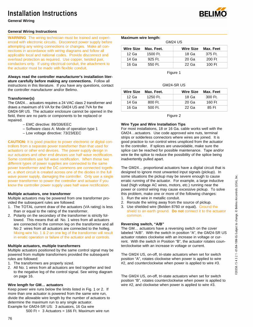
76
F203
58 /
5 4
3 2
1 -0
1/04
-10M
-IG-S
ubje
ct to
cha
nge.
© B
elim
o Ai
rcon
trols
(USA
), In
c.
Installation InstructionsGeneral Wiring
WARNING The wiring technician must be trained and experi-enced with electronic circuits. Disconnect power supply beforeattempting any wiring connections or changes. Make all con-nections in accordance with wiring diagrams and follow allapplicable local and national codes. Provide disconnect andoverload protection as required. Use copper, twisted pair,conductors only. If using electrical conduit, the attachment tothe actuator must be made with flexible conduit.
Always read the controller manufacturer's installation liter-ature carefully before making any connections. Follow allinstructions in this literature. If you have any questions, contactthe controller manufacturer and/or Belimo.
Transformer(s)The GM24… actuators requires a 24 VAC class 2 transformer anddraws a maximum of 6 VA for the GM24 US and 7VA for theGM24-SR US. The actuator enclosure cannot be opened in thefield, there are no parts or components to be replaced orrepaired.
– EMC directive: 89/336/EEC– Software class A: Mode of operation type 1– Low voltage directive: 73/23/EEC
CAUTION: It is good practice to power electronic or digital con-trollers from a separate power transformer than that used foractuators or other end devices. The power supply design inour actuators and other end devices use half wave rectification.Some controllers use full wave rectification. When these twodifferent types of power supplies are connected to the samepower transformer and the DC commons are connected togeth-er, a short circuit is created across one of the diodes in the fullwave power supply, damaging the controller. Only use a singlepower transformer to power the controller and actuator if youknow the controller power supply uses half wave rectification.
Multiple actuators, one transformer Multiple actuators may be powered from one transformer pro-vided the subsequent rules are followed:1. The TOTAL current draw of the actuators (VA rating) is less
than or equal to the rating of the transformer.2. Polarity on the secondary of the transformer is strictly fol-
lowed. This means that all No. 1 wires from all actuatorsare connected to the common leg on the transformer and allNo 2 wires from all actuators are connected to the hotleg.Mixing wire No. 1 & 2 on one leg of the transformer will resultin erratic operation or failure of the actuator and or controls.
Multiple actuators, multiple transformersMultiple actuators positioned by the same control signal may bepowered from multiple transformers provided the subsequentrules are followed:1. The transformers are properly sized.2. All No. 1 wires from all actuators are tied together and tied
to the negative leg of the control signal. See wiring diagramon page 16.
Wire length for GM… actuatorsKeep power wire runs below the limits listed in Fig. 1 or 2. Ifmore than one actuator is powered from the same wire run,divide the allowable wire length by the number of actuators todetermine the maximum run to any single actuator. Example for GM24-SR US: 3 actuators, 16 Ga wire
500 Ft ÷ 3 Actuators = 166 Ft. Maximum wire run
Maximum wire length:GM24 US
Wire Size Max. Feet. Wire Size Max. Feet12 Ga 1500 Ft. 18 Ga 375 Ft.14 Ga 925 Ft. 20 Ga 200 Ft16 Ga 550 Ft. 22 Ga 100 Ft
Figure 1
GM24-SR US
Wire Size Max. Feet. Wire Size Max. Feet12 Ga 1250 Ft. 18 Ga 300 Ft.14 Ga 800 Ft. 20 Ga 160 Ft16 Ga 500 Ft. 22 Ga 85 Ft
Figure 2
Wire Type and Wire Installation TipsFor most installations, 18 or 16 Ga. cable works well with theGM24…actuators. Use code approved wire nuts, terminalstrips or solderless connectors where wires are joined. It isgood practice to run control wires unspliced from the actuatorto the controller. If splices are unavoidable, make sure thesplice can be reached for possible maintenance. Tape and/orwire tie the splice to reduce the possibility of the splice beinginadvertently pulled apart.
The GM24… proportional actuators have a digital circuit that isdesigned to ignore most unwanted input signals (pickup). Insome situations the pickup may be severe enough to causeerratic running of the actuator. For example, a large inductiveload (high voltage AC wires, motors, etc.) running near thepower or control wiring may cause excessive pickup. To solvethis problem, make one or more of the following changes:1. Run the wire in metallic conduit.2. Reroute the wiring away from the source of pickup.3. Use shielded wire (Belden 8760 or equal). Ground the
shield to an earth ground. Do not connect it to the actuatorcommon.
Reversing switch, “A/B”The GM… actuators have a reversing switch on the coverlabeled “A/B”. With the switch in position “A”, the GM24-SR USactuator rotates clockwise with an increase in voltage or cur-rent. With the switch in Position “B”, the actuator rotates coun-terclockwise with an increase in voltage or current.
The GM24 US, on-off, tri-state actuators when set for switchposition “A”, rotates clockwise when power is applied to wire#2, and counterclockwise when power is applied to wire #3.
The GM24 US, on-off, tri-state actuators when set for switchposition “B”, rotates counterclockwise when power is applied towire #2, and clockwise when power is applied to wire #3.
General Wiring Instructions
®
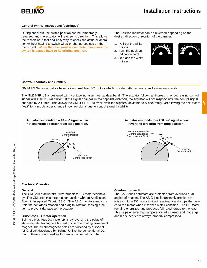
77
F203
58 /
5 4
3 2
1 -0
1/04
-10M
-IG-S
ubje
ct to
cha
nge.
© B
elim
o Ai
rcon
trols
(USA
), In
c.
GM
General Wiring Instructions (continued)
Installation Instructions®
General The GM Series actuators utilize brushless DC motor technolo-gy. The GM uses this motor in conjunction with an ApplicationSpecific Integrated Circuit (ASIC). The ASIC monitors and con-trols the actuator’s rotation and a digital rotation sensing func-tion to prevent damage to the actuator.
Brushless DC motor operation Belimo’s brushless DC motor spins by reversing the poles ofstationary electromagnets housed inside of a rotating permanentmagnet. The electromagnetic poles are switched by a specialASIC circuit developed by Belimo. Unlike the conventional DCmotor, there are no brushes to wear or commutators to foul.
Overload protection The GM Series actuators are protected from overload at allangles of rotation. The ASIC circuit constantly monitors therotation of the DC motor inside the actuator and stops the puls-es to the motor when it senses a stall condition. The DC motorremains energized and produces full rated torque to the load.This helps ensure that dampers are fully closed and that edgeand blade seals are always properly compressed.
During checkout, the switch position can be temporarilyreversed and the actuator will reverse its direction. This allowsthe technician a fast and easy way to check the actuator opera-tion without having to switch wires or change settings on thethermostat. When the check-out is complete, make sure theswitch is placed back to its original position.
The Position Indicator can be reversed depending on thedesired direction of rotation of the damper.
1. Pull out the whitepointer.
2. Turn the positionindication card.
3. Replace the whitepointer.
Electrical Operation
GM24 US Series actuators have built-in brushless DC motors which provide better accuracy and longer service life.
The GM24-SR US is designed with a unique non-symmetrical deadband. The actuator follows an increasing or decreasing controlsignal with a 40 mV resolution. If the signal changes in the opposite direction, the actuator will not respond until the control signalchanges by 200 mV. This allows the GM24-SR US to track even the slightest deviation very accurately, yet allowing the actuator to“wait” for a much larger change in control signal due to control signal instability.
Control Accuracy and Stability
0.1.2
.3.4 .5 .6 .7
.8.91 0
.1.2
.3.4.5.6.7
.8.91
Satisfied Control Position
Satisfied Control Position
Minimum Control Resolution
Minimum Reversed Control Deadband
Prior to Normal Control
40 mV
200 mV
Actuator responds to a 40 mV signal when not changing direction from stop position.
Actuator responds to a 200 mV signal when reversing direction from stop position.
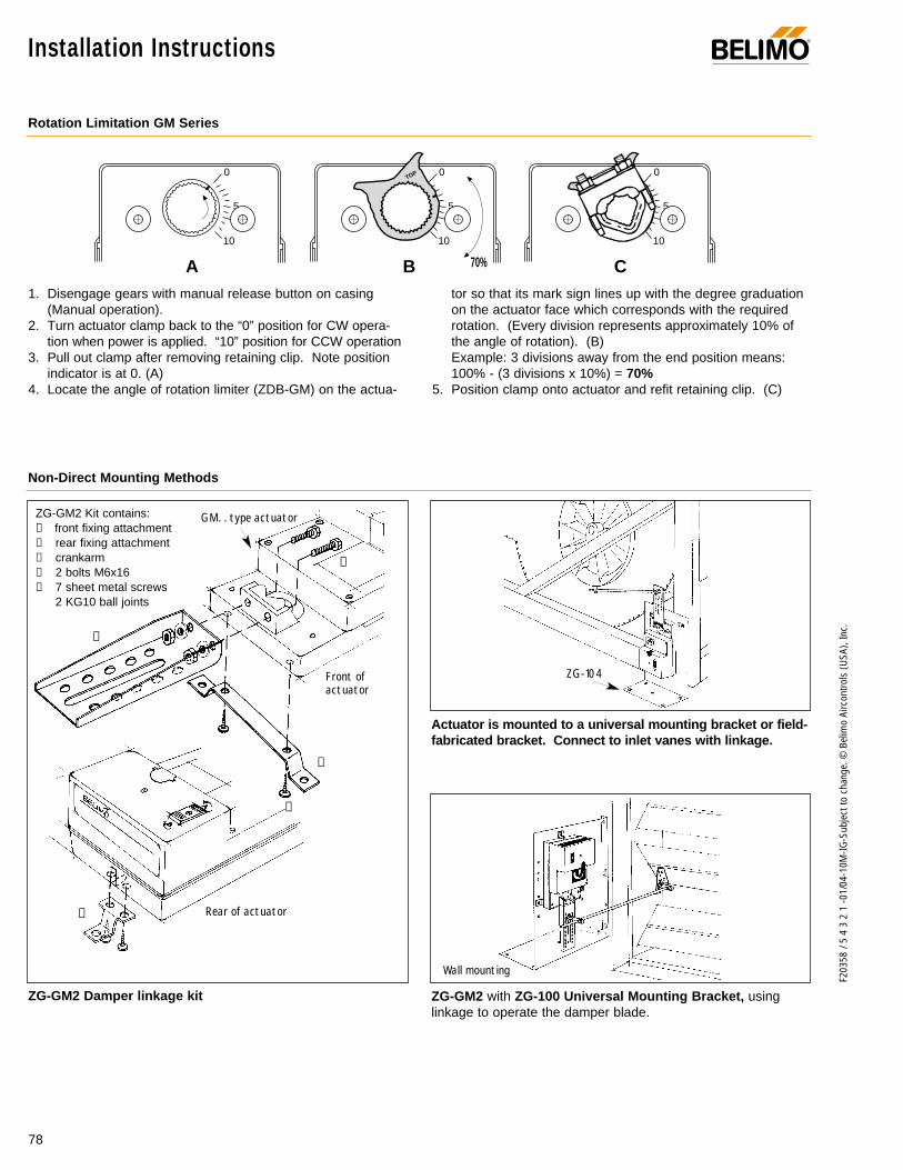
78
F203
58 /
5 4
3 2
1 -0
1/04
-10M
-IG-S
ubje
ct to
cha
nge.
© B
elim
o Ai
rcon
trols
(USA
), In
c.
0
5
10
0
5
10
0
5
10
TOPTOP
70%
Rotation Limitation GM Series
Non-Direct Mounting Methods
1. Disengage gears with manual release button on casing(Manual operation).
2. Turn actuator clamp back to the “0” position for CW opera-tion when power is applied. “10” position for CCW operation
3. Pull out clamp after removing retaining clip. Note positionindicator is at 0. (A)
4. Locate the angle of rotation limiter (ZDB-GM) on the actua-
tor so that its mark sign lines up with the degree graduationon the actuator face which corresponds with the requiredrotation. (Every division represents approximately 10% ofthe angle of rotation). (B)Example: 3 divisions away from the end position means:100% - (3 divisions x 10%) = 70%
5. Position clamp onto actuator and refit retaining clip. (C)
ZG-GM2 with ZG-100 Universal Mounting Bracket, usinglinkage to operate the damper blade.
Actuator is mounted to a universal mounting bracket or field-fabricated bracket. Connect to inlet vanes with linkage.
ZG-GM2 Damper linkage kit
GM. . type actuator
Front ofactuator
Rear of actuator
➀
➃
➃
➄
➁
➂
ZG-GM2 Kit contains:➀ front fixing attachment➁ rear fixing attachment➂ crankarm➃ 2 bolts M6x16➄ 7 sheet metal screws
2 KG10 ball joints
Wall mounting
ZG-104
A B C
Installation Instructions ®

79
F203
58 /
5 4
3 2
1 -0
1/04
-10M
-IG-S
ubje
ct to
cha
nge.
© B
elim
o Ai
rcon
trols
(USA
), In
c.
GM
Startup and CheckoutInstructions For GM24-SR US
Procedure
Control signal is applied to actuator.
Check power wiring. Correct anyproblems. See Note 1.
Turn reversing switch to the correctposition.
Make sure the control signal positive(+) is connected to Wire No 3 andcontrol signal negative (-) is connect-ed to wire No. 1. Most control prob-lems are caused by reversing thesetwo wires. Verify that the reversingswitch is all the way CCW or CW.
Check input signal with a digital voltmeter (DVM). Make sure the input iswithin the range of the actuator. ForGM24-SR US this is 0 to 10 VDC or0 to 20 mA. Note: The input signal must be abovethe 2 VDC or 4 mA to have the actu-ator move.
Use the manual override button tomove the damper by hand from fullyclosed to fully open.
Check damper torque requirement.
Actuator works properly. Test con-troller by following controller manu-facturer's instructions.
Expected Response
Actuator will move to its “ControlSignal” position.
Power supply rating should be ≥the total power requirement ofthe actuator(s). Minimum volt-age of 19.2 VAC or 21.6 VDC.
Actuator will move to its “ControlSignal” position.
Drives to “Control Signal” posi-tion
Input voltage or current shouldbe ±1% of what controller'sadjustment or programming indi-cate.
Damper will go from fully closedto fully open.
Torque requirement is ≤ actua-tor’s minimum torque.
Gives ExpectedResponse
Go To Step…
Actuator operatesproperlyStep 8
Power wiring correct-ed, actuator begins
to driveStep 1
Actuator operatesproperly.Step 8
Actuator operatesproperly.Step 8
Controller output(actuator input) is
correct. InputPolarity Correct.
Step 6
Damper moves properlyStep 7
Defective Actuator.Replace Actuator -
See Note 2
Does Not GiveExpected Response
Go To Step…
No response at allStep 2
Operation isreversedStep 3
Does not drivetoward "ControlSignal Position"
Step 4
Power wiringcorrected, actuatorstill does not drive
Step 4
Does not drivetoward “ControlSignal Position”
Step 4
Step 5
Reprogram, adjustrepair or replace
controller as needed.Step 1
Find cause ofdamper jam and
repair.Step 1
Recalculate actuatorrequirement and
correct installation.
Step
1.
2.
3.
4.
5.
6.
7.
8.
Note 1 Check that the transformer(s) are sized properly. • If a common transformer is used, make sure that polarity is observed on the secondary. This means connect all No. 1
wires to one leg of the transformer and all No. 2 wires to the other leg of the transformer. • If multiple transformers are used with one control signal, make sure all No. 1 wires are tied together and tied to control
signal negative (-).• Controllers and actuators must have separate 24 VAC/VDC power sources.
Note 2 If failure occurs within 5 years from original installation date, notify Belimo and give details of the application.
GM24-SR US Electrical check-out procedure
®

80
F203
58 /
5 4
3 2
1 -0
1/04
-10M
-IG-S
ubje
ct to
cha
nge.
© B
elim
o Ai
rcon
trols
(USA
), In
c.
AM Series Direct Coupled Actuator
Areas of Application
Versatile and Powerful Minimum 160 in-lb torque in a compact package.
For damper areas up to 40 sq-ft*.
®
3/4" minAV1
1
2
3
4
5
5
4
1
3
1
Kit specification2 ball joints KG8 (20204)Spacer (22127)Crank arm (22165)Front mountingbracket (22167)Rear mountingbracket (20346)
2 Screws M6 x 16 (43600)7 Self-tapping screws 4,2 x 13 (43990)
2
Direct Coupledup to 3/4” standard shaftsor Jackshafts to 1.05”(with K4-1 Clamp)
Mounting withlinkage (ZG-AMaccessory kit)
Short shaftmounting (withAV1 clamp)
Fits Jackshafts also.
Torque: 160 in-lb 133in-lb
Power supply: 24 VAC/DC
Control signal: on-off/floating On/Off
Control signal: proportional 2 to 10 VDC
Control signal: 0… 135Ω or Honeywell®
Electronic Series 900 to 20 V phasecut
Feedback: 2 to 10 VDC
Running time: 150 sec constant
Running time: 110 to 150 sec load dependent
Running time: 100 to 200 sec load dependent
Running time: 16 to 19 sec load dependent
External direction of rotation switch
Conduit fitting
Appliance cable
Built-in auxiliary switches
UL listed, CSA certified, CE
Auxiliary switches and feedback potentiometer ....................................(p.88- 90)Installation instructions ......(p. 91–95) General wiring ..............(p. 93) Start-up and checkout (p. 96)
* 4 in-lb/ft2 damper torque loading. Parallel blade. No edge seals.
AM
24 U
S (p
. 82)
AM
24-S
US
(p. 8
2)
AM
24-S
R U
S (p
. 84)
SM
24-S
US
(p. 8
8)
AM
24-P
C U
S (p
. 86)
AM Series – at a glance

81
F203
58 /
5 4
3 2
1 -0
1/04
-10M
-IG-S
ubje
ct to
cha
nge.
© B
elim
o Ai
rcon
trols
(USA
), In
c.
AM
AM Series Direct Coupled Actuator®
LISTED94D5TEMP. IND ®. EQUIP.
UL
20% more torque than SM.
Fits inside 4” damper frame.
Full stroke overload protection.
Electronic deadband for accuracy and stability (proportional models).
Easy direct coupled mounting, including jackshafts to 1.05”.
Check damper position with clear position indicator.
Set actuator to compensate for damper seal wear andcompression (proportional models).
Constant running time aids control loop tuning (proportional models).
Added flexibility with built-in mechanical stops.
Fully adjustable, built-in auxiliary switches (AM24-S US only).
Auxiliary switch add-on mounts on clamp,includes conduit fitting (SA1 US, SA2 US).
Push button manual override
Easily reverse control direction with switch on housing
3’ cable speeds installations
Micro processor controlled Brushless DC Motor
The Belimo Difference
Customer Commitment.Extensive product range. Competitive project pricing. Application assistance. Same-day shipments. Free technical support. Five year warranty.
Low Installation and Life-Cycle Cost.Easy installation. Accuracy and repeatability. Low power consumption. No maintenance.
Long Service Life.Components tested before assembly. Every product tested before shipment. 20+ years direct coupled actuator design.
A CLOSER LOOK…
©

82
F203
58 /
5 4
3 2
1 -0
1/04
-10M
-IG-S
ubje
ct to
cha
nge.
© B
elim
o Ai
rcon
trols
(USA
), In
c.
AM24 (-S) US On-off/ floating point control, non-spring return, direct coupled, 24 V
ApplicationFor on-off and floating point control of dampers in HVAC sys-tems. Actuator sizing should be done in accordance with thedamper manufacturer’s specifications.
The actuator is mounted directly to a damper shaft up to 3/4”in diameter by means of its universal clamp, or up to a 1.05”jackshaft with the optional K4-1 clamp. A crankarm and sever-al mounting brackets are available for applications where theactuator cannot be direct coupled to the damper shaft.
OperationThe actuator is not provided with and does not require anylimit switches, but is electronically protected against overload.The angle of rotation is mechanically limited to 95°. Whenreaching the damper or actuator end position, the actuatorautomatically stops. The gears can be manually disengagedwith a button on the actuator cover. The position of the actua-tor is indicated by a visual pointer. The anti-rotation strap sup-plied with the actuator will prevent lateral movement.
The AM24-S US version is provided with two built-in auxiliaryswitches. These SPDT switches are provided for safety inter-facing or signaling. The switching function is adjustablebetween 0 and 95°.
Torque min. 160 in-lb, for control of air dampers.
AM24 USAM24-S US
Technical Data AM24 US, AM24-S US
Power supply 24 VAC ± 20% 50/60 Hz 24 VDC ± 10%
Power consumption 2.5 W
Transformer sizing 4.5 VA (Class 2 power source)
Electrical connection 3 ft, 18 GA, appliance cable, 1/2” conduit connector
Overload protection electronic throughout 0 to 95° rotation
Angle of rotation 0-95° adjustable stops
Torque min 160 in-lb [18 Nm]
Direction of rotation reversible with switch “CCW-CW”
Position indication clip-on indicator
Running time 110 to 150 sec. for 0 to 160 in-lb
Manual override external push button
Humidity 5 to 95% RH, non-condensing
Ambient temperature -22°F to +122°F [-30°C to +50°C]
Storage temperature -40°F to +176°F [-40°C to +80°C]
Housing type NEMA 2 (IP54 with cable entry down)
Housing material rating UL94-5V (flammability rating)
Noise level less than 45 dB (A)
Servicing maintenance free
Agency listings UL 873 listed, CSA C22.2 No.24 certified, CE
Quality standard ISO 9001
Weight 2.8 lbs [1.3 kg]
AM24-S US
Auxiliary switches adj. 0° to 95°, 2 x SPDT 3A (0.5A) @24 VAC
8.75" [222]
7.5" [191]1.81" [46]
3.62"[92]
.90"[23]
3.0"[76]
1.77"[45]
K4-2 US (supplied)
1/2" Centered (Default)
3/4" Centered (Field Selectable)
1.05" Centered (Field Selectable)
K4-1 US (optional)
3/4" to 1.05" Adjustable
K4 US (optional)
3/8" to 3/4" Adjustable
Dimensions (All numbers in brackets are metric.)
LISTED94D5TEMP. IND ®. EQUIP.
UL
AM24 US
®
D01
3
©

83
F203
58 /
5 4
3 2
1 -0
1/04
-10M
-IG-S
ubje
ct to
cha
nge.
© B
elim
o Ai
rcon
trols
(USA
), In
c.
AM
12
424 VAC Transformer
The indication of direction is valid for switch position CW.
Blk (1) Common
Wht (2) +
Wht (3) +
AM24 (-S) USCCW CW
Line Volts
–
S1
S2
S3
S4
S5
S6
0° to 95°
0° to 95°
NO
NO
NC
NC
3
4
AM24 (-S) US
AM24 (-S) US On-off/ floating point control, non-spring return, direct coupled, 24 V
AM24 (-S) US - Typical Specification:Control damper actuators shall be electronic direct coupled typewhich require no crank arm and linkage and be capable of directmounting to a jackshaft up to a 1.05” diameter. Actuators shallbe UL and CSA listed, have a 5 year warranty, and be manu-factured under ISO 9001 International Quality ControlStandards. Actuators shall have reversing switch and manualoverride on the cover, and be protected from overload at allangles of rotation. If required, two adjustable SPDT auxiliaryswitches shall be provided (AM24-S US). Actuators shall be asmanufactured by Belimo.
Auxiliary switch wiring for AM24-S US
3
4
2
1 Provide overload protection and disconnect as required.
Actuators may also be powered by 24 VDC.
For end position indication, interlock control, fan startup,etc., AM24-S US incorporates two built-in auxiliary switch-es: 2 x SPDT, 3A (0.5A) @24 VAC, UL listed,adjustable between 0° and 95°.
Meets UL and CSA requirements without the need of an electrical ground connection.
Notes
Wiring diagrams
AccessoriesAV 1 Damper shaft extension for AM AV10-18 Universal shaft extensionK4 US On All Accessories lists in the bookK4-1 US Clamp for 3/4” to 1.05” jackshaftsK4-H Hex shaft clamp, for 3/8”-5/8” shaftsKH-AM CrankarmSA1 US, SA2 US Auxiliary switchesPA… US 140 Ω, 500 Ω, 1000 Ω, 2800 Ω feedback
potentiometers Tool-01 10 mm wrenchZG-AM Crank arm adaptor kitZG-100 Mounting bracket ZG-101 Mounting bracket ZG-103 Mounting bracket ZG-104 Mounting bracketZS-100 Weather shield (metal)ZS-150 Weather shield (polycarbonate)ZS-260 Explosion-proof housingZS-300 NEMA 4X housing
12
424 VAC Transformer
a opena closed
The indication of direction is valid for switch position CW.
Blk (1) Common
Wht (2) +
Wht (3) +
AM24 (-S) USCCW CW
a
Line Volts
–
On-off control
Floating point or on-off control
®
W07
4
W07
6
W07
5

84
F203
58 /
5 4
3 2
1 -0
1/04
-10M
-IG-S
ubje
ct to
cha
nge.
© B
elim
o Ai
rcon
trols
(USA
), In
c.
AM24-SR US Proportional damper actuator, non-spring return, direct coupled, 24 V, for 2 to 10 VDC and 4 to 20 mA control signal
ApplicationFor proportional modulation of dampers in HVAC systems.Actual actuator sizing should be done in accordance with thedamper manufacturer’s specifications.
The actuator is mounted directly to a damper shaft up to 3/4”in diameter by means of its universal clamp, or up to a 1.05”jackshaft with the optional K4-1 clamp. A crankarm and severalmounting brackets are available for applications where theactuator cannot be direct coupled to the damper shaft.
OperationThe actuator operates in response to a 2 to 10 VDC, or, with theaddition of a 500Ω resistor, a 4 to 20 mA control input from anelectronic controller or positioner. A 2 to 10 VDC feedback signalis provided for position indication or master-slave applications.
The actuator has a constant running time of 150 seconds. Afunctional test of the actuator-damper assembly may be doneby pressing in the manual override button, this will activate theactuators test mode and cycle the actuator fully closed andback to control point. The microprocessor will correct for com-pression of tight close-off gaskets with age, providing the actua-tor is not on its mechanical stops.
A 2 to 10 VDC feedback (U) is provided with full 8 volt outputrange proportional to the operational rotation of the damper. Adigital rotation sensing circuit protects the actuator in a stall any-where in its 95° operating range without the need of limit switches.Add on auxiliary switches are easily fastened directly onto theactuator body for signalling and switching functions.
8.75" [222]
7.5" [191]1.81" [46]
3.62"[92]
.90"[23]
3.0"[76]
1.77"[45]
K4-2 US (supplied)
1/2" Centered (Default)
3/4" Centered (Field Selectable)
1.05" Centered (Field Selectable)
K4-1 US (optional)
3/4" to 1.05" Adjustable
K4 US (optional)
3/8" to 3/4" Adjustable
Technical Data AM24-SR US
Power supply 24 VAC, ± 20%, 50/60 Hz 24 VDC, ±10%
Power consumption 2.5 W running, 1.2 W holding
Transformer sizing 5 VA (Class 2 power source)
Operating range Y 2 to 10 VDC, 4 to 20 mA
Input impedance 100kΩ (0.1 mA), 500Ω for 4 to 20mA
Feedback output 'U' 2 to 10 VDC, 0.5 mA max
Electrical connection 3 ft, 18 GA, appliance cable, 1/2” conduit connector
Overload protection electronic throughout 0 to 95° rotation
Torque min 160 in-lb (18 Nm)
Direction of rotation reversible with switch “CCW-CW”CW with a decrease in voltageCCW with a decrease in voltage
Position indication clip on indicator
Manual override external push button
Angle of rotation 0-95° adjustable stops
Running time 150 secs. constant, independent of load
Run time stability ± 5%
Humidity 5 to 95% RH, non-condensing
Operating temperature -22 to +122° F (-30 to +50° C)
Storage temperature -40 to +176° F (-40 to +80° C)
Housing NEMA 2 (IP54 with cable entry down)
Housing material UL 94-5V (flammability rating)
Noise level less than 45 dB (A)
Agency listings UL 873 listed, CSA C22.2 No.24 certified, CE
Quality standard ISO 9001
Servicing maintenance free
Weight 2.8 lbs. (1.3kg.)
Dimensions (All numbers in brackets are metric.)
Torque min. 160 in-lb, for control of air dampers.
LISTED94D5TEMP. IND ®. EQUIP.
UL
AM24-SR US
®
D00
7
©
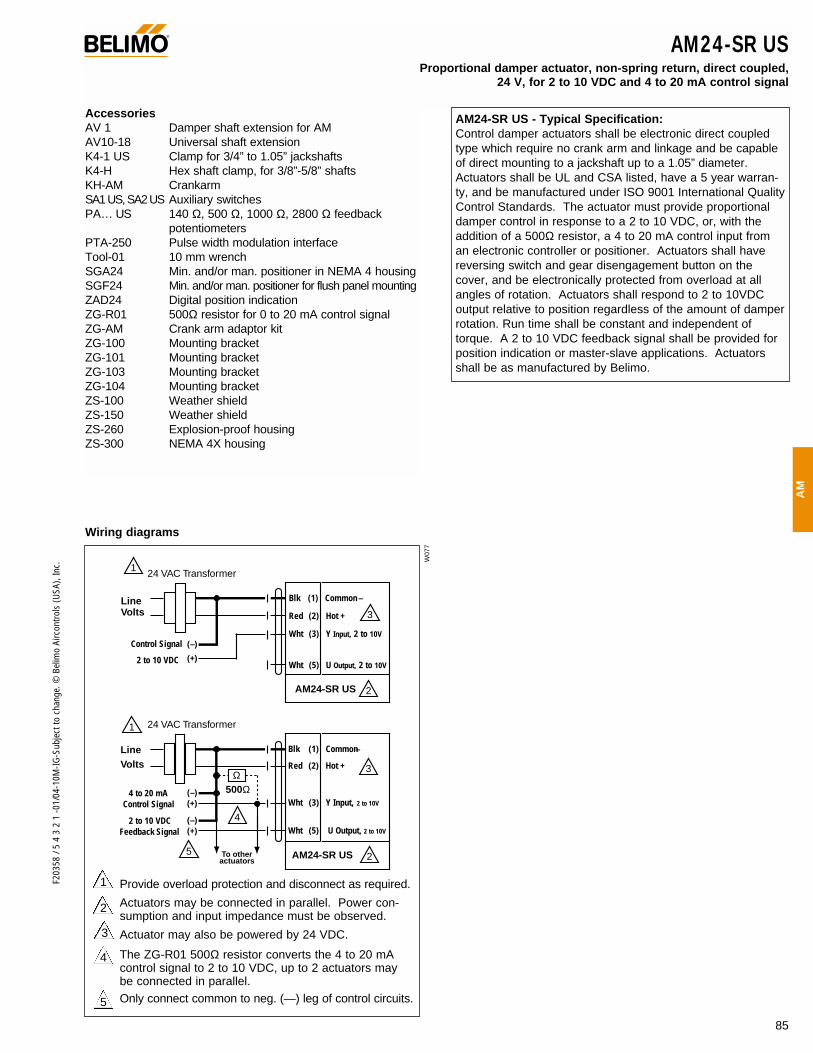
85
F203
58 /
5 4
3 2
1 -0
1/04
-10M
-IG-S
ubje
ct to
cha
nge.
© B
elim
o Ai
rcon
trols
(USA
), In
c.
AM
AM24-SR USProportional damper actuator, non-spring return, direct coupled,
24 V, for 2 to 10 VDC and 4 to 20 mA control signal
AM24-SR US - Typical Specification:Control damper actuators shall be electronic direct coupledtype which require no crank arm and linkage and be capableof direct mounting to a jackshaft up to a 1.05” diameter.Actuators shall be UL and CSA listed, have a 5 year warran-ty, and be manufactured under ISO 9001 International QualityControl Standards. The actuator must provide proportionaldamper control in response to a 2 to 10 VDC, or, with theaddition of a 500Ω resistor, a 4 to 20 mA control input froman electronic controller or positioner. Actuators shall havereversing switch and gear disengagement button on thecover, and be electronically protected from overload at allangles of rotation. Actuators shall respond to 2 to 10VDCoutput relative to position regardless of the amount of damperrotation. Run time shall be constant and independent oftorque. A 2 to 10 VDC feedback signal shall be provided forposition indication or master-slave applications. Actuatorsshall be as manufactured by Belimo.
Wiring diagrams
2
1 Provide overload protection and disconnect as required.
Actuators may be connected in parallel. Power con-sumption and input impedance must be observed.
Actuator may also be powered by 24 VDC.
The ZG-R01 500Ω resistor converts the 4 to 20 mAcontrol signal to 2 to 10 VDC, up to 2 actuators may be connected in parallel.Only connect common to neg. (—) leg of control circuits.
4
5
3
AccessoriesAV 1 Damper shaft extension for AM AV10-18 Universal shaft extensionK4-1 US Clamp for 3/4” to 1.05” jackshaftsK4-H Hex shaft clamp, for 3/8”-5/8” shaftsKH-AM CrankarmSA1 US, SA2 US Auxiliary switchesPA… US 140 Ω, 500 Ω, 1000 Ω, 2800 Ω feedback
potentiometers PTA-250 Pulse width modulation interfaceTool-01 10 mm wrenchSGA24 Min. and/or man. positioner in NEMA 4 housingSGF24 Min. and/or man. positioner for flush panel mountingZAD24 Digital position indicationZG-R01 500Ω resistor for 0 to 20 mA control signalZG-AM Crank arm adaptor kitZG-100 Mounting bracket ZG-101 Mounting bracket ZG-103 Mounting bracket ZG-104 Mounting bracketZS-100 Weather shieldZS-150 Weather shieldZS-260 Explosion-proof housingZS-300 NEMA 4X housing
®
1
2
3
24 VAC Transformer
Blk (1) Common
Red (2) Hot +
Wht (3) Y Input, 2 to 10V
Wht (5) U Output, 2 to 10V
AM24-SR US
Line Volts
2 to 10 VDC
Control Signal (–)
(+)
–
4
To other actuators
3
5
24 VAC Transformer
Blk (1) Common
Red (2) Hot +
Wht (3) Y Input, 2 to 10V
Wht (5) U Output, 2 to 10V
4 to 20 mAControl Signal
(–)(+)
2 to 10 VDCFeedback Signal
(–)(+)
Ω500Ω
2AM24-SR US
1
Line Volts
–
W07
7

AM24-PC US Proportional damper actuator, non-spring return, direct coupled, 24 V, for 0 to 20 V phasecut control signal
86
F203
58 /
5 4
3 2
1 -0
1/04
-10M
-IG-S
ubje
ct to
cha
nge.
© B
elim
o Ai
rcon
trols
(USA
), In
c.
ApplicationFor proportional modulation of dampers in HVAC systems.Actual actuator sizing should be done in accordance with thedamper manufacturer’s specifications.
The actuator is mounted directly to a damper shaft up to 3/4”in diameter by means of its universal clamp, or up to a 1.05”jackshaft with the optional K4-1 clamp. A crankarm and severalmounting brackets are available for applications where theactuator cannot be direct coupled to the damper shaft.
OperationThe actuator operates in response to 0 to 10 V phasecut controlinput from an electronic controller or positioner. A 2 to 10 VDCfeedback signal is provided for position indication or master-slaveapplications.
The actuator has a constant running time of 150 seconds. Afunctional test of the actuator-damper assembly may be doneby pressing in the manual override button, this will activate theactuators test mode and cycle the actuator fully closed andback to control point. The microprocessor will correct for com-pression of tight close-off gaskets with age, providing the actua-tor is not on its mechanical stops.
A 2 to 10 VDC feedback (U) is provided with full 8 volt outputrange proportional to the operational rotation of the damper. Adigital rotation sensing circuit protects the actuator in a stall any-where in its 95° operating range without the need of limit switches.Add on auxiliary switches are easily fastened directly onto theactuator body for signalling and switching functions.
8.75" [222]
7.5" [191]1.81" [46]
3.62"[92]
.90"[23]
3.0"[76]
1.77"[45]
K4-2 US (supplied)
1/2" Centered (Default)
3/4" Centered (Field Selectable)
1.05" Centered (Field Selectable)
K4-1 US (optional)
3/4" to 1.05" Adjustable
K4 US (optional)
3/8" to 3/4" Adjustable
Technical Data AM24-PC US
Power supply 24 VAC, ± 20%, 50/60 Hz 24 VDC, ±10%
Power consumption 2.5 W running, 1.2 W holding
Transformer sizing 5 VA (Class 2 power source)
Operating range Y 0 to 10 V, phasecut
Input impedance 8kΩ (50 mW)
Feedback output 'U' 2 to 10 VDC, 0.5 mA max
Electrical connection 3 ft, 18 GA, appliance cable, 1/2” conduit connector
Overload protection electronic throughout 0 to 95° rotation
Torque min 160 in-lb (18 Nm)
Direction of rotation reversible with switch “CCW-CW”CW with a decrease in voltageCCW with a decrease in voltage
Position indication clip on indicator
Manual override external push button
Angle of rotation 0-95° adjustable stops
Running time 150 secs. constant, independent of load
Run time stability ± 5%
Humidity 5 to 95% RH, non-condensing
Operating temperature -22 to +122° F (-30 to +50° C)
Storage temperature -40 to +176° F (-40 to +80° C)
Housing NEMA 2 (IP54 with cable entry down)
Housing material UL 94-5V (flammability rating)
Noise level less than 45 dB (A)
Agency listings UL 873 listed, CSA C22.2 No.24 certified, CE
Quality standard ISO 9001
Servicing maintenance free
Weight 2.8 lbs. (1.3kg.)
Dimensions (All numbers in brackets are metric.)
Torque min. 160 in-lb, for control of air dampers.
LISTED94D5TEMP. IND ®. EQUIP.
UL
AM24-PC US
D00
7
©
®
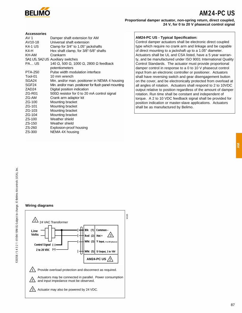
AM24-PC USProportional damper actuator, non-spring return, direct coupled,
24 V, for 0 to 20 V phasecut control signal
87
F203
58 /
5 4
3 2
1 -0
1/04
-10M
-IG-S
ubje
ct to
cha
nge.
© B
elim
o Ai
rcon
trols
(USA
), In
c.
AM
AM24-PC US - Typical Specification:Control damper actuators shall be electronic direct coupledtype which require no crank arm and linkage and be capableof direct mounting to a jackshaft up to a 1.05” diameter.Actuators shall be UL and CSA listed, have a 5 year warran-ty, and be manufactured under ISO 9001 International QualityControl Standards. The actuator must provide proportionaldamper control in response to a 0 to 10 V phasecut controlinput from an electronic controller or positioner. Actuatorsshall have reversing switch and gear disengagement buttonon the cover, and be electronically protected from overload atall angles of rotation. Actuators shall respond to 2 to 10VDCoutput relative to position regardless of the amount of damperrotation. Run time shall be constant and independent oftorque. A 2 to 10 VDC feedback signal shall be provided forposition indication or master-slave applications. Actuatorsshall be as manufactured by Belimo.
Wiring diagrams
AccessoriesAV 1 Damper shaft extension for AM AV10-18 Universal shaft extensionK4-1 US Clamp for 3/4” to 1.05” jackshaftsK4-H Hex shaft clamp, for 3/8”-5/8” shaftsKH-AM CrankarmSA1 US, SA2 US Auxiliary switchesPA… US 140 Ω, 500 Ω, 1000 Ω, 2800 Ω feedback
potentiometers PTA-250 Pulse width modulation interfaceTool-01 10 mm wrenchSGA24 Min. and/or man. positioner in NEMA 4 housingSGF24 Min. and/or man. positioner for flush panel mountingZAD24 Digital position indicationZG-R01 500Ω resistor for 0 to 20 mA control signalZG-AM Crank arm adaptor kitZG-100 Mounting bracket ZG-101 Mounting bracket ZG-103 Mounting bracket ZG-104 Mounting bracketZS-100 Weather shieldZS-150 Weather shieldZS-260 Explosion-proof housingZS-300 NEMA 4X housing
1
2
3
24 VAC Transformer
Blk (1) Common
Red (2) Hot +
Wht (3) Y Input, 0 to 20V phasecut
Wht (5) U Output, 2 to 10V
AM24-PC US
Line Volts
2 to 20 VDC
Control Signal (–)
(+)
–
W18
5
1
2
3
Provide overload protection and disconnect as required.
Actuators may be connected in parallel. Power consumption and input impedance must be observed.
Actuator may also be powered by 24 VDC.
®
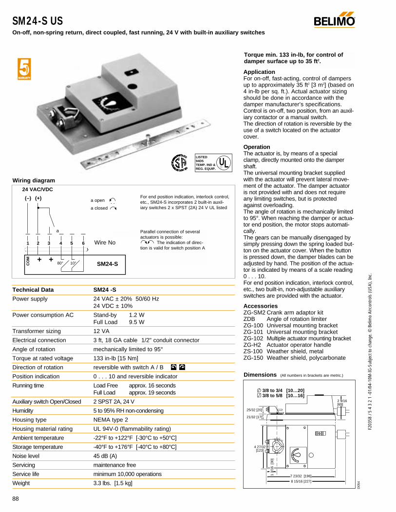
88
F203
58 /
5 4
3 2
1 -0
1/04
-10M
-IG-S
ubje
ct to
cha
nge.
© B
elim
o Ai
rcon
trols
(USA
), In
c.
SM24-S US On-off, non-spring return, direct coupled, fast running, 24 V with built-in auxiliary switches
®
Technical Data SM24 -S
Power supply 24 VAC ± 20% 50/60 Hz 24 VDC ± 10%
Power consumption AC Stand-by 1.2 W Full Load 9.5 W
Transformer sizing 12 VA
Electrical connection 3 ft, 18 GA cable 1/2" conduit connector
Angle of rotation mechanically limited to 95°
Torque at rated voltage 133 in-lb [15 Nm]
Direction of rotation reversible with switch A / B
Position indication 0 . . . 10 and reversible indicator
Running time Load Free approx. 16 secondsFull Load approx. 19 seconds
Auxiliary switch Open/Closed 2 SPST 2A, 24 V
Humidity 5 to 95% RH non-condensing
Housing type NEMA type 2
Housing material rating UL 94V-0 (flammability rating)
Ambient temperature -22°F to +122°F [-30°C to +50°C]
Storage temperature -40°F to +176°F [-40°C to +80°C]
Noise level 45 dB (A)
Servicing maintenance free
Service life minimum 10,000 operations
Weight 3.3 lbs. [1.5 kg]
Wiring diagram
+ +SM24-S
24 VAC/VDC
(–) (+)
1 2 3 4 5 6 Wire No
Parallel connection of severalactuators is possible:
The indication of direc-tion is valid for switch position A
For end position indication, interlock control,etc., SM24-S incorporates 2 built-in auxil-iary switches 2 x SPST (2A) 24 V UL listed
a open
a closed
a
CO
M
Dimensions (All numbers in brackets are metric.)
ApplicationFor on-off, fast-acting, control of dampersup to approximately 35 ft2 [3 m2] (based on4 in-lb per sq. ft.). Actual actuator sizingshould be done in accordance with thedamper manufacturer’s specifications.Control is on-off, two position, from an auxil-iary contactor or a manual switch.The direction of rotation is reversible by theuse of a switch located on the actuatorcover.
OperationThe actuator is, by means of a specialclamp, directly mounted onto the dampershaft.The universal mounting bracket suppliedwith the actuator will prevent lateral move-ment of the actuator. The damper actuatoris not provided with and does not requireany limiting switches, but is protectedagainst overloading.The angle of rotation is mechanically limitedto 95°. When reaching the damper or actua-tor end position, the motor stops automati-cally.The gears can be manually disengaged bysimply pressing down the spring loaded but-ton on the actuator cover. When the buttonis pressed down, the damper blades can beadjusted by hand. The position of the actua-tor is indicated by means of a scale reading0 . . . 10.For end position indication, interlock control,etc., two built-in, non-adjustable auxiliaryswitches are provided with the actuator.
AccessoriesZG-SM2 Crank arm adaptor kitZDB Angle of rotation limiterZG-100 Universal mounting bracketZG-101 Universal mounting bracketZG-102 Multiple actuator mounting bracketZG-H2 Actuator operator handleZS-100 Weather shield, metalZG-150 Weather shield, polycarbonate
Torque min. 133 in-lb, for control ofdamper surface up to 35 ft2.
80° 10°
LISTED94D5TEMP. IND ®. EQUIP.
UL
25/32 [20]
3/8 to 3/4 [10…20]3/8 to 5/8 [10…16]
21/32 [17]
2 9/16 [65]
4 27/32 [123]
1 3/
16 [
30]
7 23/32 [196]
8 15/16 [227]
D05
4

89
F203
58 /
5 4
3 2
1 -0
1/04
-10M
-IG-S
ubje
ct to
cha
nge.
© B
elim
o Ai
rcon
trols
(USA
), In
c.
AM
Mounting Instructions
1. Remove pointer assembly from the actuator. Press downthe manual override button and rotate the actuator fullycounter-clockwise.
2. Invert SA… US switch and turn the driver disk fully clock-wise as indicated.
3. Slide SA… US switch onto actuator and check for the cor-rect mating of the driver disk to the universal clamp. Securewith screw.
4. Adjust switch dials as necessary
5. Remount the white plastic pointer only onto SA… US switch.
Auxiliary Switches SA1 US, SA2 US For the direct coupled actuator AM2…
OperationThe SA1 US and SA2 US auxiliary switches are used to indi-cate when a desired position of a damper is reached or to inter-face additional controls for a specific control sequence. Theyare modular units that mount directly onto the AM type actua-tors and held in place with a prefitted screw. A driver disk isattached to the actuator clamp and offers direct transmission ofthe actuator position to the microswitch operating cams. Theswitching points can be set over the full scale of 0 to 1 simplyby adjusting the slotted discs.
®
Wiring Diagrams
SA2 US
S1
S2
S3
S4
S5
S6
SA1 US
NC
NO
S1
S2
S3
N.C.
N.O.
N.C.
N.O.
N.C.
N.O.
1
2 3 4 5
Voltage Resistive Inductive120 6.0 A 5.0 A250 6.0 A 2.5 A
Technical Data SA1 US SA2 US
No. of switches 1xSPDT 2xSPDT
Switching capacity 6 A (2.5A) 250 VAC
Switching point adjustable over full actuator rotation 0 to 1. Pre-setting with scale possible.
Electrical connection 3 ft, 18 GA appliance cable1/2” conduit connector
Humidity 5 to 95% RH non-condensing
Ambient temperature -22° F to +122° F [-30° C to +50° C]
Storage temperature -40° F to +176° F [-40° C to +80° C]
Housing type NEMA type 2
Housing material rating UL 94-5VA (flammability rating)
Agency listings UL 873 listed, CSA C22.2 No.24 certified, CE
Weight 8 oz [225 g] 9.3 oz [265 g]
Electrical protection auxiliary switches are double insulated

90
F203
58 /
5 4
3 2
1 -0
1/04
-10M
-IG-S
ubje
ct to
cha
nge.
© B
elim
o Ai
rcon
trols
(USA
), In
c.
Feedback Potentiometer PA…US For the direct coupled actuator AM2…
®
ApplicationThe PA… US feedback potentiometers are used with AM actu-ators to provide a resistive signal which varies with damperposition. The PA… US units are applied with commercial pro-portional temperature controllers to provide feedback of thedamper position, or with electric or electronic meters to pro-vide position indication. The signal can also be used as apositioner for parallel operation of multiple actuators.
OperationThe PA… US feedback potentiometer is mounted onto thedamper actuator. A driver disk is attached to the actuatorclamp and offers direct transmission of the actuator to thepotentiometer.
Mounting Instructions
1. Remove pointer assembly from the actuator. Press downthe manual override button and rotate the actuator fullycounter-clockwise.
2. Invert PA… US and turn the driver disk fully clockwise asindicated.
3. Slide PA… US onto actuator and check for the correct mat-ing of the driver disk to the universal clamp. Secure withscrew.
4. Remount the white plastic pointer only, from the pointerassembly, onto PA… US.Types
PA500 US Feedback potentiometer 500ΩPA1000 US Feedback potentiometer 1000ΩPA2800 US Feedback potentiometer 2800Ω
Technical Data PA… US
Resistance values as above
Output 1W
Tolerance ± 5%
Linearity ± 2%
Resolution min. 1%
Residual resistance max. 5% on both sides
Electrical connection 3 ft, 18 GA appliance cable1/2” conduit connector
Humidity 5 to 95% RH non-condensing
Ambient temperature -22°F to +122°F [-30°C to +50°C]
Storage temperature -40°F to +176°F [-40°C to +80°C]
Housing NEMA type 2
Housing rating UL94-5V (flammability rating)
Servicing maintenance free
Agency listings UL 873 listed, CSA C22.2 No.24 certified, CE
Quality standard ISO 9001
Weight 8.8 oz [250 g]
Electrical protection Class 2 circuits
P1
P2
P3
PA…
0
10
Wiring diagram
1 2
3 4

91
F203
58 /
5 4
3 2
1 -0
1/04
-10M
-IG-S
ubje
ct to
cha
nge.
© B
elim
o Ai
rcon
trols
(USA
), In
c.
AM
AM Series… Installation InstructionsQuick-Mount Visual Instructions
1. Turn damper blade to its fully closed position. With manualoverride button depressed, rotate actuator clamp to about1/16” - 1/8” between actuator stop and clamp, depending ondamper seal design. Slide actuator over shaft and finger-tighten nuts.
2. Using a screwdriver, Select clockwise or counterclockwise rota-tion. (Example shown is for clockwise closing damper). Slideanti-rotation bracket up under actuator engaging center cut-outon actuator back. Secure bracket with self-tapping screws.
3. Tighten the two nuts on the universal clamp with 10 mmwrench, 6-8 ft-lb torque. (On dampers with edge seals, actuatorwill compress damper blades when reaching end position forair-tight damper.)
4. Adjust end stops, if required.
1 2
3 4
min. 48
10...16
10...20
min. 1.88” [48]
3/8”…3/4”3/8”…5/8”
R
L
M
M
1/4"
9 Nm
➀
➁ ➂
1/16" - 1/8"
®
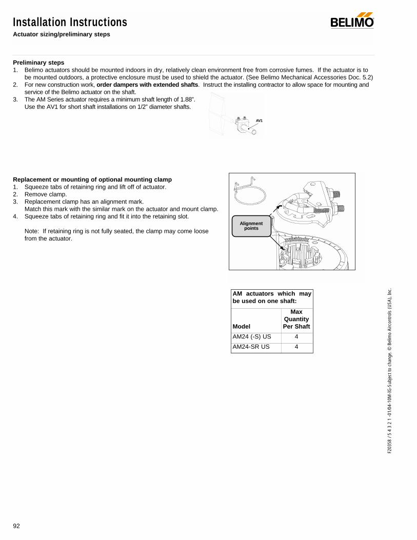
Installation InstructionsActuator sizing/preliminary steps
Preliminary steps1. Belimo actuators should be mounted indoors in dry, relatively clean environment free from corrosive fumes. If the actuator is to
be mounted outdoors, a protective enclosure must be used to shield the actuator. (See Belimo Mechanical Accessories Doc. 5.2)2. For new construction work, order dampers with extended shafts. Instruct the installing contractor to allow space for mounting and
service of the Belimo actuator on the shaft.3. The AM Series actuator requires a minimum shaft length of 1.88”.
Use the AV1 for short shaft installations on 1/2” diameter shafts.
Replacement or mounting of optional mounting clamp1. Squeeze tabs of retaining ring and lift off of actuator.2. Remove clamp.3. Replacement clamp has an alignment mark.
Match this mark with the similar mark on the actuator and mount clamp.4. Squeeze tabs of retaining ring and fit it into the retaining slot.
Note: If retaining ring is not fully seated, the clamp may come loosefrom the actuator.
Alignmentpoints
92
F203
58 /
5 4
3 2
1 -0
1/04
-10M
-IG-S
ubje
ct to
cha
nge.
© B
elim
o Ai
rcon
trols
(USA
), In
c.
®
AV1
AM actuators which maybe used on one shaft:
MaxQuantity
Model Per Shaft
AM24 (-S) US 4
AM24-SR US 4

93
F203
58 /
5 4
3 2
1 -0
1/04
-10M
-IG-S
ubje
ct to
cha
nge.
© B
elim
o Ai
rcon
trols
(USA
), In
c.
AM
Installation InstructionsGeneral Wiring
WARNING The wiring technician must be trained and experi-enced with electronic circuits. Disconnect power supply beforeattempting any wiring connections or changes. Make all con-nections in accordance with wiring diagrams and follow allapplicable local and national codes. Provide disconnect andoverload protection as required. Use copper, twisted pair,conductors only. If using electrical conduit, the attachment tothe actuator must be made with flexible conduit.
Always read the controller manufacturer's installation liter-ature carefully before making any connections. Follow allinstructions in this literature. If you have any questions, contactthe controller manufacturer and/or Belimo.
Transformer(s)The AM Series actuators require a 24 VAC class 2 transformerand draw a maximum of 5 VA. The actuator enclosure cannotbe opened in the field, there are no parts or components to bereplaced or repaired.
– EMC directive: 89/336/EEC– Software class A: Mode of operation type 1– Low voltage directive: 73/23/EEC
CAUTION: It is good practice to power electronic or digital con-trollers from a separate power transformer than that used foractuators or other end devices. The power supply design inour actuators and other end devices use half wave rectification.Some controllers use full wave rectification. When these twodifferent types of power supplies are connected to the samepower transformer and the DC commons are connected togeth-er, a short circuit is created across one of the diodes in the fullwave power supply, damaging the controller. Only use a singlepower transformer to power the controller and actuator if youknow the controller power supply uses half wave rectification.
Multiple actuators, one transformer Multiple actuators may be powered from one transformer pro-vided the following rules are followed:1. The TOTAL current draw of the actuators (VA rating) is less
than or equal to the rating of the transformer.2. Polarity on the secondary of the transformer is strictly fol-
lowed. This means that all No. 1 wires from all actuatorsare connected to the common leg on the transformer and allNo 2 wires from all actuators are connected to the hotleg.Mixing wire No. 1 & 2 on one leg of the transformer willresult in erratic operation or failure of the actuator and orcontrols.
Multiple actuators, multiple transformersMultiple actuators positioned by the same control signal may bepowered from multiple transformers provided the following rulesare followed:1. The transformers are properly sized.2. All No. 1 wires from all actuators are tied together and tied
to the negative leg of the control signal. See wiring diagram.
Wire length for AM Series actuatorsKeep power wire runs below the limits listed in the Fig. 1. Ifmore than one actuator is powered from the same wire run,divide the allowable wire length by the number of actuators todetermine the maximum run to any single actuator.
Maximum wire length:
Wire Size Max. Feet. Wire Size Max. Feet12 Ga 1800 Ft. 18 Ga 450 Ft.14 Ga 1100 Ft. 20 Ga 275 Ft16 Ga 700 Ft. 22 Ga 125 Ft
Fig. 1
Example for AM… US: 3 actuators, 18 Ga wire 450 Ft ÷ 3 Actuators = 150 Ft. Maximum wire run.
Wire Type and Wire Installation TipsFor most installations, 18 or 16 Ga. cable works well with theAM24 type actuators. Use code approved wire nuts, terminalstrips or solderless connectors where wires are joined. It isgood practice to run control wires unspliced from the actuatorto the controller. If splices are unavoidable, make sure thesplice can be reached for possible maintenance. Tape and/orwire tie the splice to reduce the possibility of the splice beinginadvertently pulled apart.
Overload protection All Belimo actuators are electronically protected against over-load. In the AM series an electronic circuit maintains the cur-rent at a level which will not damage the motor while providingadequate holding torque.
Operational Information for AM Series Proportional Actuators (AM24-SR US)
InitializationThe proportional models of the AM series (AM24-SR US,) must gothrough an initialization procedure to learn the zero signal position.When the power is first applied to the actuator, or the gear releasebutton is depressed, the actuator will move to its zero signal position.After the actuator learns this, it will drive to its control position.
Note: If power is lost to the actuator, and the actuator is moved byuse of its manual override, the actuator must be re-initialized whenpower is returned, by pushing the override button.
Motor position detection Belimo brushless DC motors eliminate the need for potentiome-ters for positioning. Inside the motor are three “Hall Effect”sensors. These sensors detect the spinning rotor and sendpulses to the microprocessor which counts the pulses and cal-culates the position to within 1/3 of a revolution of the motor.
®

94
F203
58 /
5 4
3 2
1 -0
1/04
-10M
-IG-S
ubje
ct to
cha
nge.
© B
elim
o Ai
rcon
trols
(USA
), In
c.
Adjust angle-of-rotationin steps of 2.5°
Direction of Rotation Switch
Manual Override
Installation InstructionsFeature operation
Mechanical Angle of Rotation Limiting
The adjustable stops are needed when there is no damper stopor if you want the damper to stop rotating before it reaches itsstops. The AM actuator can be indefinitely stalled in any posi-tion without harm. 1. Loosen the two end stops with a No. 2 Phillips head screwdriver
being careful not to unscrew the captive nut under the slot.2. Move the stops (in 2.5° steps) to the desired position and re-
tighten the screws.
AM actuators have a reversing switch on the cover labeled“CW-CCW”. Switch position indicates start point. For theAM24-SR US, with the switch in position “CW”, the actuatorrotates clockwise with an decrease in voltage or current. Withthe switch in position “CCW”, the actuator rotates counterclock-wise with an decrease in voltage or current.
The AM24 (-S) US rotates clockwise when the switch is in the “CW”position and power is applied to wire #2. When power is applied towire #3 the actuator rotates counter clockwise.Rotating the “CW/CCW” switch to “CCW” reverses the controllogic.
During checkout, the switch position can be temporarilyreversed and the actuator will reverse its direction. This allowsthe technician a fast and easy way to check the actuator opera-tion without having to switch wires or change settings on thethermostat. When the check-out is complete, make sure theswitch is placed back to its original position.
CW M
CCW M
CW M
CCW M
2 VDC 10 VDC10 VDC 2 VDC
A button on the actuator cover disengages the gear train so thedamper shaft can be moved manually. Release the button and thegear train is re-engaged.
Use the manual override to test the installation withoutpower. For tight shut-off the damper should close with 5°of actuator stroke left.
CW M
CCW M
Gear release button
AM Series proportional actuators have built-in brushless DC motors which provide better accuracy and longer service life.
The AM Series actuators are designed with a unique non-symmetrical deadband. The actuator follows an increasing ordecreasing control signal with a 80 mV resolution. If the signal changes in the opposite direction, the actuator will not responduntil the control signal changes by 200 mV. This allows these actuators to track even the slightest deviation very accurately,yet allowing the actuator to “wait” for a much larger change in control signal due to control signal instability.
Control Accuracy and Stability
SatisfiedControl Position
SatisfiedControl Position
MinimumControl Resolution
Minimum ReversedControl Deadband
Prior to Normal Control
80 mV
200 mV
AM Actuator responds to a 80 mV signal whennot changing direction from stop position.
AM Actuator responds to a 200 mV signalwhen reversing direction from stop position.
AM24-SR US, AM24-SRS US
®

95
F203
58 /
5 4
3 2
1 -0
1/04
-10M
-IG-S
ubje
ct to
cha
nge.
© B
elim
o Ai
rcon
trols
(USA
), In
c.
AM
Installation Instructions and AccessoriesFeature operation and additional accessories
AV1 Short shaft adaptor
Used on 3/8” to 3/4" diametershafts that are shorter than1.875" and mounting space isminimal.
AV 10-18 Shaft extension
For damper shafts 3/8 to 11/16 in[10 to 18] dia or 3/8 to 9/16 in [10to 14] square.
Mounting brackets
SA…US Auxiliary switches, PA…US Feedback potentiometers
SGA24/SGF24
Minimum and/or manual positioner(electronic), SGA24 is enclosed ina NEMA 4 housing. The SGF24 isfor flush panel mounting.
240
SGA24SGF24
1
2
3
4
5
5
4
1
3
1
Kit specification2 ball joints KG8 (20204)Spacer (22127)Crank arm (22165)Front mountingbracket (22167)Rear mountingbracket (20346)
2 Screws M6 x 16 (43600)7 Self-tapping screws 4,2 x 13 (43990)
2
3/4" minAV1
9.44”
ZG-100 Mounting bracket ZG-101 Mounting bracket ZG-103 Mounting bracket ZG-104 Mounting bracket
R
L
M
M
1
. 8
. 6. 4
. 2
0
0. 2
. 4
. 6
. 81
R
L
M
M
1
.8
.6.4
.2
0
0.2
.4
.6.81
R
L
M
M
R
L
M
M
Adjustable Auxiliary Switches
The AM24-S US actuator is equipped with two adjustable auxiliaryswitches used to indicate damper position or to interface additionalcontrols or equipment. Switching positions can be set over the fullscale of 0 to 95° simply by setting switch on the actuator cover.
Method A1. Push the manual override button and rotate the clamp to the
“0” position.2. Set the desired switch position: example: 20% of rotation is
“.2” on the setting scale.3. Check the switch operation. As the indicator passes the “0”
switch position, the contact between S1 and S2, or S4 andS5, is broken and the contact between S1 and S3, or S5and S6 is made.
Method B1. Use manual override to position universal clamp to desired
switch position.2. Turn switch pointer to “0”.
(switch function may also be monitored by a meter for precise setting)
0% 100%
20%
1
0.2
.4.6.8
S4
S6S5
S4
S6S5
1
0.2.4.6
.8
S1
S3S2
S1
S3S2
Voltage Resistive load Inductive load
24 VAC 3 A 0.5 A
Switch Rating
Clamp is in the “0” position
Accessories
®
ZG-AM - Crank arm adaptor kit
For use when the actuator cannot be mounted directly to the damper shaft.
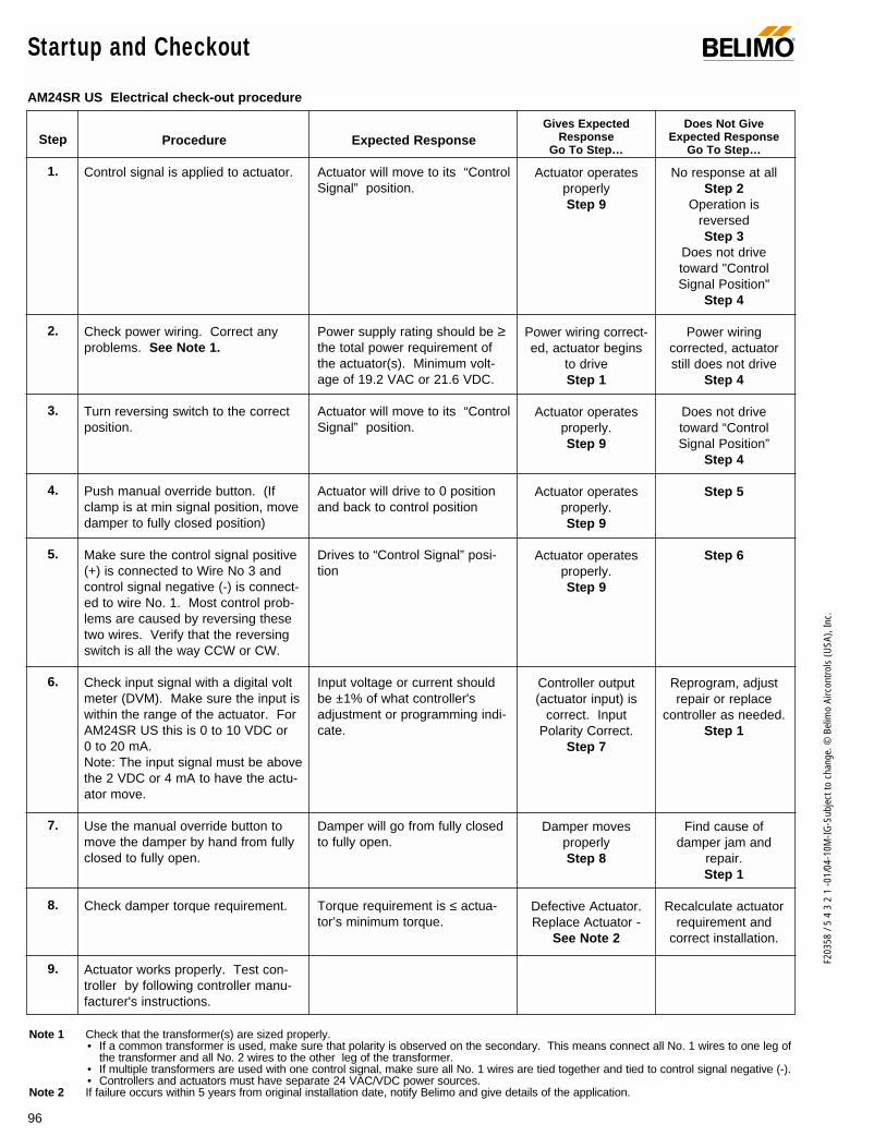
96
F203
58 /
5 4
3 2
1 -0
1/04
-10M
-IG-S
ubje
ct to
cha
nge.
© B
elim
o Ai
rcon
trols
(USA
), In
c.
Startup and Checkout ®
Procedure
Control signal is applied to actuator.
Check power wiring. Correct anyproblems. See Note 1.
Turn reversing switch to the correctposition.
Push manual override button. (Ifclamp is at min signal position, movedamper to fully closed position)
Make sure the control signal positive(+) is connected to Wire No 3 andcontrol signal negative (-) is connect-ed to wire No. 1. Most control prob-lems are caused by reversing thesetwo wires. Verify that the reversingswitch is all the way CCW or CW.
Check input signal with a digital voltmeter (DVM). Make sure the input iswithin the range of the actuator. ForAM24SR US this is 0 to 10 VDC or0 to 20 mA. Note: The input signal must be abovethe 2 VDC or 4 mA to have the actu-ator move.
Use the manual override button tomove the damper by hand from fullyclosed to fully open.
Check damper torque requirement.
Actuator works properly. Test con-troller by following controller manu-facturer's instructions.
Expected Response
Actuator will move to its “ControlSignal” position.
Power supply rating should be ≥the total power requirement ofthe actuator(s). Minimum volt-age of 19.2 VAC or 21.6 VDC.
Actuator will move to its “ControlSignal” position.
Actuator will drive to 0 positionand back to control position
Drives to “Control Signal” posi-tion
Input voltage or current shouldbe ±1% of what controller'sadjustment or programming indi-cate.
Damper will go from fully closedto fully open.
Torque requirement is ≤ actua-tor’s minimum torque.
Gives ExpectedResponse
Go To Step…
Actuator operatesproperlyStep 9
Power wiring correct-ed, actuator begins
to driveStep 1
Actuator operatesproperly.Step 9
Actuator operatesproperly.Step 9
Actuator operatesproperly.Step 9
Controller output(actuator input) is
correct. InputPolarity Correct.
Step 7
Damper moves properlyStep 8
Defective Actuator.Replace Actuator -
See Note 2
Does Not GiveExpected Response
Go To Step…
No response at allStep 2
Operation isreversedStep 3
Does not drivetoward "ControlSignal Position"
Step 4
Power wiringcorrected, actuatorstill does not drive
Step 4
Does not drivetoward “ControlSignal Position”
Step 4
Step 5
Step 6
Reprogram, adjustrepair or replace
controller as needed.Step 1
Find cause ofdamper jam and
repair.Step 1
Recalculate actuatorrequirement and
correct installation.
Step
1.
2.
3.
4.
5.
6.
7.
8.
9.
Note 1 Check that the transformer(s) are sized properly. • If a common transformer is used, make sure that polarity is observed on the secondary. This means connect all No. 1 wires to one leg of
the transformer and all No. 2 wires to the other leg of the transformer. • If multiple transformers are used with one control signal, make sure all No. 1 wires are tied together and tied to control signal negative (-).• Controllers and actuators must have separate 24 VAC/VDC power sources.
Note 2 If failure occurs within 5 years from original installation date, notify Belimo and give details of the application.
AM24SR US Electrical check-out procedure

97
F203
58 /
5 4
3 2
1 -0
1/04
-10M
-IG-S
ubje
ct to
cha
nge.
© B
elim
o Ai
rcon
trols
(USA
), In
c.
AM
® Notes/Work Pad

98
F203
58 /
5 4
3 2
1 -0
1/04
-10M
-IG-S
ubje
ct to
cha
nge.
© B
elim
o Ai
rcon
trols
(USA
), In
c.
NM Series – at a glance
NM Series Direct Coupled Actuator ®
Minimum 70 in-lb torque For damper areas up to 18 sq-ft*
Medium Volume Control Dampers.
Damper is mountedthrough a wall with controlshaft exposed, but spacetoo tight to direct couple. Actuator mounted on field-
fabricated plate to controla cone-type VAV damper
KH-8 Crankarm -final position must bevertical when damperis fully open.
Mount actuatorat a 45° angleto allow for full90° crankarmrotation.
ZG-NM3
ZG-NM3
ZG-105
NM24…
ZG-NM4
NM24…
NM24…
NM
24 U
S (p
. 100
)
NM
24-S
R U
S (p
. 102
)
Torque 70 in-lb
Power supply 24 VAC
Control signal on-off/floating point
Control signal modulating - 2 to 10 VDC
Control signal pulse width modulating
Control signal start/span adjustable
Running time 75 to 150 sec for 0 to 70 in-lb
Running time 150 sec independent of load.
External direction of rotation switch
Angle of rotation limiting (mechanical)
External manual override
Auxiliary switches ..............(p. 104) Installation instructions ..(p. 105–110)General wiring ..................(p. 107) Start-up and checkout ..(p. 111)
* 4 in-lb/ft2 damper torque loading. Parallel blade. No edge seals.
Application Methods

99
F203
58 /
5 4
3 2
1 -0
1/04
-10M
-IG-S
ubje
ct to
cha
nge.
© B
elim
o Ai
rcon
trols
(USA
), In
c.
NM
A CLOSER LOOK…
NM Series Direct Coupled Actuator®
LISTED94D5TEMP. IND ®. EQUIP.
UL
Cut labor costs with simple direct coupling.
Check damper position from a distance withclear position indicator.
Don’t worry about actuator burn-out. Belimo is overload-proof throughout rotation.
Enjoy added flexibility with easy mechanical stop to adjust angle of rotation.
Need to change control direction? Do it easily with a simple switch.
Simple manual override button helps you getup and running faster.
Auxiliary switch accessory (SN1,SN2) is easy to use, offers feedback or signal for additional device.
3 ft. plenum rated cable eases installationConduit connector provided: one less detailto worry about.
Microprocessor-controlled brushless DC motor increases actuator life span and reliability, provides constant running time independent of load. (Proportional actuators)
The Belimo Difference
Customer Commitment.Extensive product range. Competitive project pricing. Application assistance. Same-day shipments. Free technical support. Five year warranty.
Low Installation and Life-Cycle Cost.Easy installation. Accuracy and repeatability. Low power consumption. No maintenance.
Long Service Life.Components tested before assembly. Every product tested before shipment. 20+ years direct coupled actuator design.
©
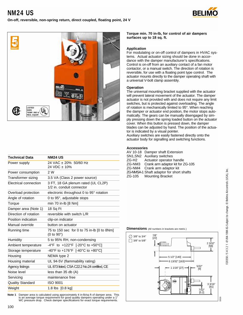
100
F203
58 /
5 4
3 2
1 -0
1/04
-10M
-IG-S
ubje
ct to
cha
nge.
© B
elim
o Ai
rcon
trols
(USA
), In
c.
NM24 USOn-off, reversible, non-spring return, direct coupled, floating point, 24 V
®
ApplicationFor modulating or on-off control of dampers in HVAC sys-tems. Actual actuator sizing should be done in accor-dance with the damper manufacturer’s specifications.Control is on-off from an auxiliary contact of a fan motorcontactor, or a manual switch. The direction of rotation isreversible, for use with a floating point type control. Theactuator mounts directly to the damper operating shaft witha universal V-bolt clamp assembly.
OperationThe universal mounting bracket supplied with the actuatorwill prevent lateral movement of the actuator. The damperactuator is not provided with and does not require any limitswitches, but is protected against overloading. The angleof rotation is mechanically limited to 95°. When reachingthe damper or actuator end position, the motor stops auto-matically. The gears can be manually disengaged by sim-ply pressing down the spring loaded button on the actuatorcover. When this button is pressed down, the damperblades can be adjusted by hand. The position of the actua-tor is indicated by a visual pointer. Auxiliary switches are easily fastened directly onto theactuator body for signalling and switching functions.
AccessoriesAV 10-18 Damper shaft ExtensionSN1,SN2 Auxiliary switchesZG-H2 Actuator operator handleZG-NM3 Crank arm adaptor kit for ZG-105ZG-NM4 Crank arm adaptor kitZG-NMSA-1 Shaft adaptor for short shaftsZG-105 Mounting Bracket
Technical Data NM24 US
Power supply 24 VAC ± 20% 50/60 Hz 24 VDC ± 10%
Power consumption 2 W
Transformer sizing 3.5 VA (Class 2 power source)
Electrical connection 3 FT, 18 GA plenum rated (UL CL2P) 1/2 in. conduit connector
Overload protection electronic throughout 0 to 95° rotation
Angle of rotation 0 to 95°, adjustable stops
Torque min 70 in-lb [8 Nm]
Damper area (Note 1) 18 Sq Ft
Direction of rotation reversible with switch L/R
Position indication clip-on indicator
Manual override button on actuator
Running time 75 to 150 sec for 0 to 75 in-lb [0 to 8Nm] (0 to 90°)
Humidity 5 to 95% RH, non-condensing
Ambient temperature -4°F to +122°F [-20°C to +50°C]
Storage temperature -40°F to +176°F [-40°C to +80°C]
Housing NEMA type 2
Housing material UL 94-5V (flammability rating)
Agency listings UL 873 listed, CSA C22.2 No.24 certified, CE
Noise level less than 35 db (A)
Servicing maintenance free
Quality Standard ISO 9001
Weight 1.8 lbs [0.8 kg]
Dimensions (All numbers in brackets are metric.)
Torque min. 70 in-lb, for control of air damperssurfaces up to 18 sq. ft.
LISTED94D5TEMP. IND ®. EQUIP.
UL
Note 1 Damper area is calculated using approximately 4 in-lb/sq ft of damper area. Thisis an average torque requirement for good quality dampers operating under a 1"WC pressure drop. Check damper specifications for exact torque requirements.
2 3/32"[58]
5/32"[9]
3 3/16"[81]
7/32"[5.2]
5 1/2" [140]
6 13/32'' [163]
1 1/16" [27]
7/8" [22]
3/8" to 3/4"
3/8" to 5/8"
D01
6

101
F203
58 /
5 4
3 2
1 -0
1/04
-10M
-IG-S
ubje
ct to
cha
nge.
© B
elim
o Ai
rcon
trols
(USA
), In
c.
NM
NM24 USOn-off, reversible, non-spring return, direct coupled, floating point, 24 V
®
Bulk packaging - NM24.1 US
The bulk packaging option for the NM… series has been discontinued as of October 2003
Part # 11333 (UOM:1)
T-Type bracketThese are included in the single-actuatorpackages.
L-Type bracket 21731
Part #: 12503-00001 (UOM:24)(includes 21731) shipped separately upon request.
NM24 US - Typical Specification:Control damper actuators shall be electronic direct coupledtype which require no crank arm and linkage. Actuators shallbe UL and CSA listed, have a 5 year warranty, and be man-ufactured under ISO 9001 International Quality ControlStandards. Actuators shall have reversing switch and manu-al override on the cover, and be protected from overload atall angles of rotation. Actuators shall be as manufactured byBelimo.
12324 VAC Transformer
a opena closed
The indication of direction is valid for switch position R.
Blk (1) Common
Red (2) +
Wht (3) +
NM24 US L R
a
Line Volts
–
24 VAC Transformer
The indication of direction is valid for switch position R.
Blk (1) Common
Red (2) +
Wht (3) +
NM24 USL R
Line Volts
21 3
Wiring Diagrams
On-Off control of NM24 US Tri-State control of NM24 US
2
3
1 Provide overload protection and disconnect as required.
Actuators are provided with color coded wires. Wirenumbers are provided for reference.
May also be powered by 24 VDC.
Notes:
W15
0
W12
0
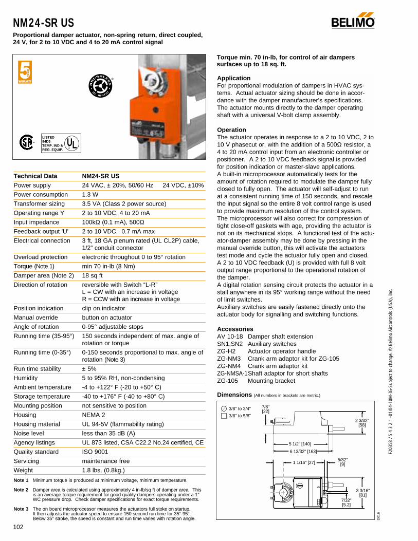
102
F203
58 /
5 4
3 2
1 -0
1/04
-10M
-IG-S
ubje
ct to
cha
nge.
© B
elim
o Ai
rcon
trols
(USA
), In
c.
NM24-SR USProportional damper actuator, non-spring return, direct coupled, 24 V, for 2 to 10 VDC and 4 to 20 mA control signal
®
ApplicationFor proportional modulation of dampers in HVAC sys-tems. Actual actuator sizing should be done in accor-dance with the damper manufacturer’s specifications.The actuator mounts directly to the damper operatingshaft with a universal V-bolt clamp assembly.
OperationThe actuator operates in response to a 2 to 10 VDC, 2 to10 V phasecut or, with the addition of a 500Ω resistor, a4 to 20 mA control input from an electronic controller orpositioner. A 2 to 10 VDC feedback signal is providedfor position indication or master-slave applications. A built-in microprocessor automatically tests for theamount of rotation required to modulate the damper fullyclosed to fully open. The actuator will self-adjust to runat a consistent running time of 150 seconds, and rescalethe input signal so the entire 8 volt control range is usedto provide maximum resolution of the control system.The microprocessor will also correct for compression oftight close-off gaskets with age, providing the actuator isnot on its mechanical stops. A functional test of the actu-ator-damper assembly may be done by pressing in themanual override button, this will activate the actuatorstest mode and cycle the actuator fully open and closed.A 2 to 10 VDC feedback (U) is provided with full 8 voltoutput range proportional to the operational rotation ofthe damper.A digital rotation sensing circuit protects the actuator in astall anywhere in its 95° working range without the needof limit switches.Auxiliary switches are easily fastened directly onto theactuator body for signalling and switching functions.
AccessoriesAV 10-18 Damper shaft extensionSN1,SN2 Auxiliary switchesZG-H2 Actuator operator handleZG-NM3 Crank arm adaptor kit for ZG-105ZG-NM4 Crank arm adaptor kitZG-NMSA-1Shaft adaptor for short shaftsZG-105 Mounting bracket
Technical Data NM24-SR US
Power supply 24 VAC, ± 20%, 50/60 Hz 24 VDC, ±10%
Power consumption 1.3 W
Transformer sizing 3.5 VA (Class 2 power source)
Operating range Y 2 to 10 VDC, 4 to 20 mA
Input impedance 100kΩ (0.1 mA), 500ΩFeedback output 'U' 2 to 10 VDC, 0.7 mA max
Electrical connection 3 ft, 18 GA plenum rated (UL CL2P) cable,1/2” conduit connector
Overload protection electronic throughout 0 to 95° rotation
Torque (Note 1) min 70 in-lb (8 Nm)
Damper area (Note 2) 18 sq ft
Direction of rotation reversible with Switch “L-R”L = CW with an increase in voltageR = CCW with an increase in voltage
Position indication clip on indicator
Manual override button on actuator
Angle of rotation 0-95° adjustable stops
Running time (35-95°) 150 seconds independent of max. angle ofrotation or torque
Running time (0-35°) 0-150 seconds proportional to max. angle ofrotation (Note 3)
Run time stability ± 5%
Humidity 5 to 95% RH, non-condensing
Ambient temperature -4 to +122° F (-20 to +50° C)
Storage temperature -40 to +176° F (-40 to +80° C)
Mounting position not sensitive to position
Housing NEMA 2
Housing material UL 94-5V (flammability rating)
Noise level less than 35 dB (A)
Agency listings UL 873 listed, CSA C22.2 No.24 certified, CE
Quality standard ISO 9001
Servicing maintenance free
Weight 1.8 lbs. (0.8kg.)
Note 1 Minimum torque is produced at minimum voltage, minimum temperature.
Note 2 Damper area is calculated using approximately 4 in-lb/sq ft of damper area. Thisis an average torque requirement for good quality dampers operating under a 1"WC pressure drop. Check damper specifications for exact torque requirements.
Note 3 The on board microprocessor measures the actuators full stoke on startup. It then adjusts the actuator speed to ensure 150 second run time for 35°-95°.Below 35° stroke, the speed is constant and run time varies with rotation angle.
Dimensions (All numbers in brackets are metric.)
Torque min. 70 in-lb, for control of air damperssurfaces up to 18 sq. ft.
LISTED94D5TEMP. IND ®. EQUIP.
UL
2 3/32"[58]
5/32"[9]
3 3/16"[81]
7/32"[5.2]
5 1/2" [140]
6 13/32'' [163]
1 1/16" [27]
7/8" [22]
3/8" to 3/4"
3/8" to 5/8"
D01
6
©
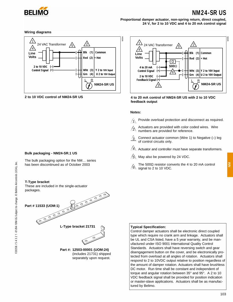
103
F203
58 /
5 4
3 2
1 -0
1/04
-10M
-IG-S
ubje
ct to
cha
nge.
© B
elim
o Ai
rcon
trols
(USA
), In
c.
NM
NM24-SR USProportional damper actuator, non-spring return, direct coupled,
24 V, for 2 to 10 VDC and 4 to 20 mA control signal
®
1
42524 VAC Transformer
Blk (1) Common
Red (2) + Hot
Wht (3) Y 2 to 10V Input
Grn (4) U 2 to 10V Output
NM24-SR USL R
Line Volts
2 to 10 VDCControl Signal
(–)(+)
1
4
25
3
6
24 VAC Transformer
Blk (1) Common
Red (2) + Hot
Wht (3) Y 2 to 10V Input Grn (4) U 2 to 10V Output
NM24-SR USL R
Line Volts
4 to 20 mAControl Signal
(–)(+)
2 to 10 VDCFeedback Signal
(–)(+)
Ω500Ω
Wiring diagrams
Typical Specification:Control damper actuators shall be electronic direct coupledtype which require no crank arm and linkage. Actuators shallbe UL and CSA listed, have a 5 year warranty, and be man-ufactured under ISO 9001 International Quality ControlStandards. Actuators shall have reversing switch and geardisengagement button on the cover, and be electronically pro-tected from overload at all angles of rotation. Actuators shallrespond to 2 to 10VDC output relative to position regardless ofthe amount of damper rotation. Actuators shall have brushlessDC motor. Run time shall be constant and independent oftorque and angular rotation between 35° and 95°. A 2 to 10VDC feedback signal shall be provided for position indicationor master-slave applications. Actuators shall be as manufac-tured by Belimo.
2 to 10 VDC control of NM24-SR US 4 to 20 mA control of NM24-SR US with 2 to 10 VDC feedback output
2
1
3
4
5
6
Provide overload protection and disconnect as required.
Actuators are provided with color coded wires. Wirenumbers are provided for reference.
Connect actuator common (Wire 1) to Negative (–) legof control circuits only.
Actuator and controller must have separate transformers.
May also be powered by 24 VDC.
The 500Ω resistor converts the 4 to 20 mA controlsignal to 2 to 10 VDC.
Bulk packaging - NM24-SR.1 US
The bulk packaging option for the NM… series has been discontinued as of October 2003
Part # 11533 (UOM:1)
Notes:
L-Type bracket 21731
W09
4
W09
5
Part #: 12503-00001 (UOM:24)(includes 21731) shipped separately upon request.
T-Type bracketThese are included in the single-actuatorpackages.
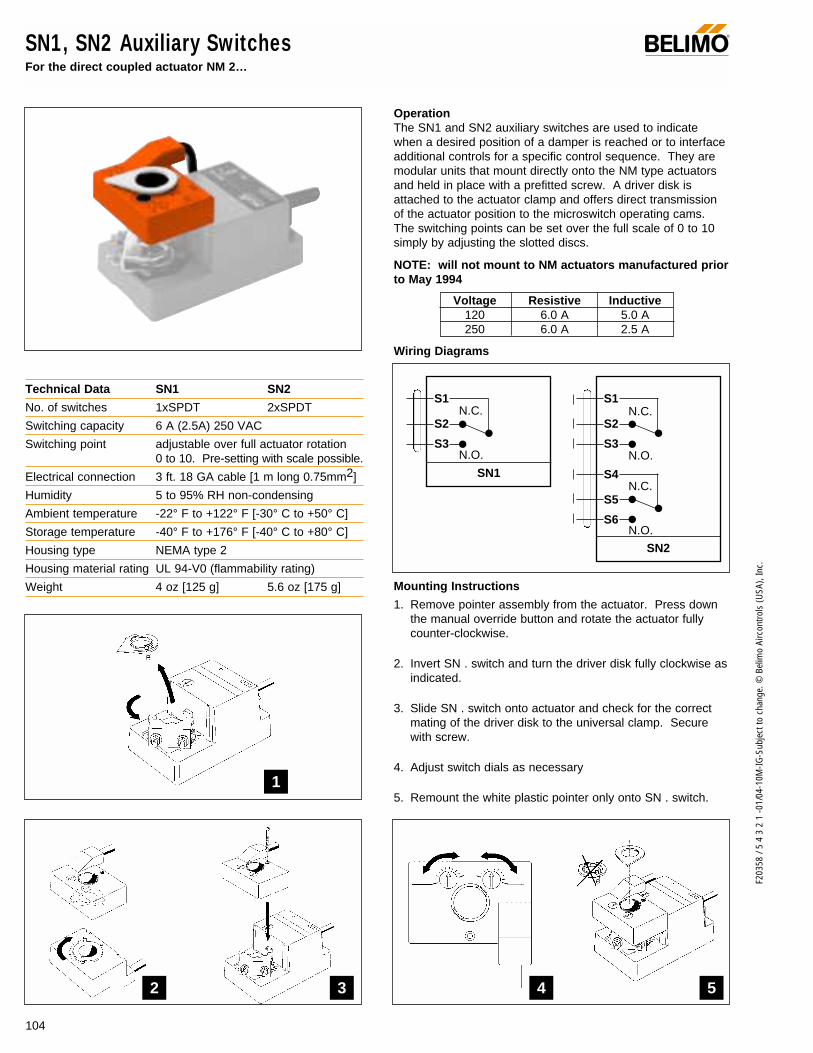
104
F203
58 /
5 4
3 2
1 -0
1/04
-10M
-IG-S
ubje
ct to
cha
nge.
© B
elim
o Ai
rcon
trols
(USA
), In
c.
Mounting Instructions
1. Remove pointer assembly from the actuator. Press downthe manual override button and rotate the actuator fullycounter-clockwise.
2. Invert SN . switch and turn the driver disk fully clockwise asindicated.
3. Slide SN . switch onto actuator and check for the correctmating of the driver disk to the universal clamp. Securewith screw.
4. Adjust switch dials as necessary
5. Remount the white plastic pointer only onto SN . switch.
SN1, SN2 Auxiliary SwitchesFor the direct coupled actuator NM 2…
OperationThe SN1 and SN2 auxiliary switches are used to indicatewhen a desired position of a damper is reached or to interfaceadditional controls for a specific control sequence. They aremodular units that mount directly onto the NM type actuatorsand held in place with a prefitted screw. A driver disk isattached to the actuator clamp and offers direct transmissionof the actuator position to the microswitch operating cams.The switching points can be set over the full scale of 0 to 10simply by adjusting the slotted discs.
NOTE: will not mount to NM actuators manufactured priorto May 1994
Technical Data SN1 SN2
No. of switches 1xSPDT 2xSPDT
Switching capacity 6 A (2.5A) 250 VAC
Switching point adjustable over full actuator rotation 0 to 10. Pre-setting with scale possible.
Electrical connection 3 ft. 18 GA cable [1 m long 0.75mm2]
Humidity 5 to 95% RH non-condensing
Ambient temperature -22° F to +122° F [-30° C to +50° C]
Storage temperature -40° F to +176° F [-40° C to +80° C]
Housing type NEMA type 2
Housing material rating UL 94-V0 (flammability rating)
Weight 4 oz [125 g] 5.6 oz [175 g]
®
Wiring Diagrams
SN2
S1
S2
S3
S4
S5
S6
SN1
NC
NO
S1
S2
S3
N.C.
N.O.
N.C.
N.O.
N.C.
N.O.
1
2 3 4 5
Voltage Resistive Inductive120 6.0 A 5.0 A250 6.0 A 2.5 A
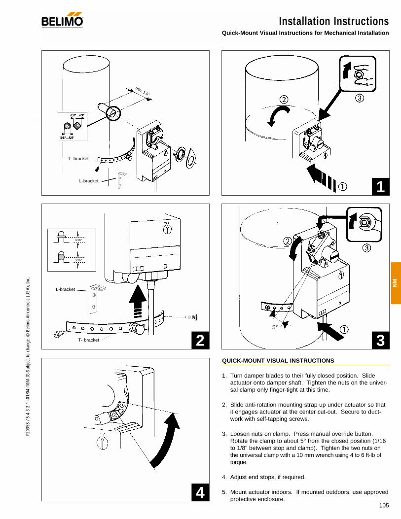
105
F203
58 /
5 4
3 2
1 -0
1/04
-10M
-IG-S
ubje
ct to
cha
nge.
© B
elim
o Ai
rcon
trols
(USA
), In
c.
NM
Installation InstructionsQuick-Mount Visual Instructions for Mechanical Installation
®
QUICK-MOUNT VISUAL INSTRUCTIONS
1. Turn damper blades to their fully closed position. Slideactuator onto damper shaft. Tighten the nuts on the univer-sal clamp only finger-tight at this time.
2. Slide anti-rotation mounting strap up under actuator so thatit engages actuator at the center cut-out. Secure to duct-work with self-tapping screws.
3. Loosen nuts on clamp. Press manual override button.Rotate the clamp to about 5° from the closed position (1/16to 1/8" between stop and clamp). Tighten the two nuts onthe universal clamp with a 10 mm wrench using 4 to 6 ft-lb oftorque.
4. Adjust end stops, if required.
5. Mount actuator indoors. If mounted outdoors, use approvedprotective enclosure.
1
2 3
4
T- bracket
L-bracket
T- bracket
L-bracket
5°
min. 1.5”
3/16"
3/16"

106
F203
58 /
5 4
3 2
1 -0
1/04
-10M
-IG-S
ubje
ct to
cha
nge.
© B
elim
o Ai
rcon
trols
(USA
), In
c.
Installation InstructionsMechanical Installation
®
1. Remove the plastic position indicator from the actuator. Slipthe actuator's universal clamp over the damper shaft. Makesure that the bottom of the actuator (metal side) is towardthe duct and the controls on the cover are accessible.Place the actuator in the desired mounting position.
2. Turn the damper shaft until the blades are fully closed.3. Hand tighten the two nuts on the NM24 . . universal clamp. 4. Slide the stud of the anti-rotation bracket into the slot in the
bottom of the actuator. Bend the strap as needed to sup-port the rear of the actuator.
5. Fasten the strap to the duct with two screws. We recom-mend No. 8 self tapping sheet metal screws.
6. Loosen the two nuts on the universal clamp. Disengage theactuator gear train by pressing the “manual override button”(half round black button near the cable entry). Keeping thegears disengaged, and the damper fully closed, rotate theclamp until it is about 5° from the closed position or approxi-mately 1/16 to 1/8 of an inch between the mechanical stopand the universal clamp.
7. Tighten the two nuts on the clamp with an 10 mm wrench(Belimo Tool-01). Use 4…6 ft-lb of torque.
The damper is now fully closed but the actuator is 5° from fullyclosed. This is called “pre-loading” the actuator. When theactuator is powered and sent to the closed position: it will put its
full torque on the shaft compressing the edge and blade seals.This ensures that the damper will meet its leakage rating. The actua-tor is electronically protected from overload and will not be damaged.
Adjustable stopsThe adjustable stops are needed when there is no damper stopor if you want the damper to halt rotating before it reaches itsstops. The NM24. . actuator can be indefinitely stalled in anyposition without harm. 1. Loosen the two end stops with a No. 2 Phillips head screwdriv-
er being careful not to unscrew the captive nut under the slot.2. Move the stops to the desired position and re-tighten the screws.
Manual overrideThe Belimo NM24. . actuators have a black, half round “manualoverride button” located next to the cable entry. Press this buttonand the gear train is disengaged so the damper shaft can be movedmanually. Release the button and the gear train is re-engaged.
Testing the installation without power1. Disengage the gear train with the manual override button
and move the shaft from closed to open to closed. Ensurethat there is no binding and that the damper goes fullyopen and closes with 5° of actuator stroke left.
2. Correct any problems and retest.
General Information
Standard Mounting
Preliminary steps1. Belimo actuators should be mounted indoors in a dry, relatively clean environment free from corrosive fumes. If the actuator is
to be mounted outdoors, a protective enclosure must be used to shield the actuator. 2. For new construction work, order dampers with extended shafts. Instruct the installing contractor to allow space for mounting and
service of the Belimo actuator on the shaft. The damper shaft must extend at least 2" from the duct. If the shaft extends less than 2"or if an obstruction blocks access, the shaft can be extended with the AV 10-18 shaft extension or the ZG NMSA-1 for applicationswith minimal mounting area.
For replacement of existing gear train actuators, there are two options: A. From a performance standpoint, it is best to mount the actuator on the damper shaft. B. If the damper shaft is not accessible, mount the NM24-. . actuator with a ZG-NM4 linkage kit, to convert to a crankarm style
application or the ZG-105 mounting bracket with the ZG-NM3.

107
F203
58 /
5 4
3 2
1 -0
1/04
-10M
-IG-S
ubje
ct to
cha
nge.
© B
elim
o Ai
rcon
trols
(USA
), In
c.
NM
Installation InstructionsGeneral Wiring
®
WARNING The wiring technician must be trained and experi-enced with electronic circuits. Disconnect power supply beforeattempting any wiring connections or changes. Make all con-nections in accordance with wiring diagrams and follow allapplicable local and national codes. Provide disconnect andoverload protection as required. Use copper, twisted pair,conductors only. If using electrical conduit, the attachmentmust be made with flexible conduit.
Always read the controller manufacturer's installation liter-ature carefully before making any connections. Follow allinstructions in this literature. If you have any questions, contactthe controller manufacturer and/or Belimo.
Transformer(s)The NM24 type actuator requires a 24 VAC class 2 transformerand draws a maximum of 3.5 VA per actuator. The actuatorenclosure cannot be opened in the field, there are no parts orcomponents to be replaced or repaired.
– EMC directive: 89/336/EEC– Software class A: Mode of operation type 1– Low voltage directive: 73/23/EEC
CAUTION: It is good practice to power electronic or digital con-trollers from a separate power transformer than that used foractuators or other end devices. The power supply design inour actuators and other end devices use half wave rectification.Some controllers use full wave rectification. When these twodifferent types of power supplies are connected to the samepower transformer and the DC commons are connected togeth-er, a short circuit is created across one of the diodes in the fullwave power supply, damaging the controller. Only use a singlepower transformer to power the controller and actuator if youknow the controller power supply uses half wave rectification.
Multiple actuators, one transformer Multiple actuators may be powered from one transformer pro-vided the following rules are followed:1. The TOTAL current draw of the actuators (VA rating) is less
than or equal to the rating of the transformer.2. Polarity on the secondary of the transformer is strictly fol-
lowed. This means that all No. 1 wires from all actuatorsare connected to the common leg on the transformer and allNo 2 wires from all actuators are connected to the hotleg.Mixing wire No. 1 & 2 on one leg of the transformer willresult in erratic operation or failure of the actuator and orcontrols.
Multiple actuators, multiple transformersMultiple actuators positioned by the same control signal may bepowered from multiple transformers provided the following rulesare followed:1. The transformers are properly sized.2. All No. 1 wires from all actuators are tied together and tied
to the negative leg of the control signal. See wiring diagram.
Wire length for NM type actuatorsKeep power wire runs below the limits listed in the Fig. 1. Ifmore than one actuator is powered from the same wire run,divide the allowable wire length by the number of actuators todetermine the maximum run to any single actuator. Example: 3 actuators, 16 Ga wire
1000 Ft ÷ 3 Actuators = 333 Ft. Maximum wire run.
Maximum wire length:
Wire Size Max. Feet. Wire Size Max. Feet12 Ga 2500 Ft. 18 Ga 600 Ft.14 Ga 1600 Ft. 20 Ga 350 Ft16 Ga 1000 Ft. 22 Ga 175 Ft
Fig. 1
Wire Type and Wire Installation TipsFor most installations, 18 or 16 Ga. cable works well with theNM24 type actuators. Use code approved wire nuts, terminalstrips or solderless connectors where wires are joined. It isgood practice to run control wires unspliced from the actuatorto the controller. If splices are unavoidable, make sure thesplice can be reached for possible maintenance. Tape and/orwire tie the splice to reduce the possibility of the splice beinginadvertently pulled apart.
The NM24. . proportional actuators have a digital circuit that isdesigned to ignore most unwanted input signals (pickup). Insome situations the pickup may be severe enough to causeerratic running of the actuator. For example, a large inductiveload (high voltage AC wires, motors, etc.) running near thepower or control wiring may cause excessive pickup. To solvethis problem, make one or more of the following changes:1. Run the wire in metallic conduit.2. Reroute the wiring away from the source of pickup.3. Use shielded wire (Belden 8760 or equal). Ground the
shield to an earth ground. Do not connect it to the actuatorcommon.
Reversing switch, “L-R”The NM24-/SR US actuators have a reversing switch on thecover labeled “L-R”. With the switch in position “L”, the actua-tor rotates clockwise with an increase in voltage or current.With the switch in Position “R”, the actuator rotates counter-clockwise with an increase in voltage or current.
The NM24 US, on-off, tri-state actuators when set for switchposition “R”, rotate clockwise when power is applied to wire #3,and counterclockwise when power is applied to wire #2.
During checkout, the switch position can be temporarilyreversed and the actuator will reverse its direction. This allowsthe technician a fast and easy way to check the actuator opera-tion without having to switch wires or change settings on thethermostat. When the check-out is complete, make sure theswitch is placed back to its original position.
General Wiring Instructions
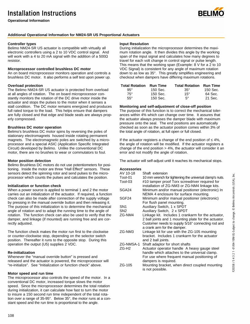
108
F203
58 /
5 4
3 2
1 -0
1/04
-10M
-IG-S
ubje
ct to
cha
nge.
© B
elim
o Ai
rcon
trols
(USA
), In
c.
Installation InstructionsOperational Information
®
Additional Operational Information for NM24-SR US Proportional Actuators
Controller types Belimo NM24-SR US actuator is compatible with virtually allelectronic controllers using a 2 to 10 VDC control signal. Andwill work with a 4 to 20 mA signal with the addition of a 500Ωresistor.
Microprocessor controlled brushless DC motorAn on board microprocessor monitors operation and controls abrushless DC motor. It also performs a self test upon power up.
Overload protectionThe Belimo NM24-SR US actuator is protected from overloadat all angles of rotation. The on board microprocessor con-stantly monitors the rotation of the DC drive motor inside theactuator and stops the pulses to the motor when it senses astall condition. The DC motor remains energized and producesfull rated torque to the load. This helps ensure that dampersare fully closed and that edge and blade seals are always prop-erly compressed.
Brushless DC motor operationBelimo's brushless DC motor spins by reversing the poles ofstationary electromagnets housed inside rotating permanentmagnets. The electromagnetic poles are switched by a micro-processor and a special ASIC (Application Specific IntegratedCircuit) developed by Belimo. Unlike the conventional DCmotor, there are no brushes to wear or commutators to foul.
Motor position detectionBelimo Brushless DC motors do not use potentiometers for posi-tioning. Inside the motor are three "Hall Effect" sensors. Thesesensors detect the spinning rotor and send pulses to the micro-processor which counts the pulses and calculates the position.
Initialization or function checkWhen a power source is applied to terminal 1 and 2 the motorcarries out an initialization of the actuator. If required, a functioncheck can also be made after connection of the supply voltageby pressing in the manual override button and then releasing it.The purpose of this initialization is to determine the mechanicalangle of rotation and to adapt the running time to the angle ofrotation. The function check can also be used to verify that thedamper, and linkage (if mounted) are running free and are cor-rectly adjusted.
The function check makes the motor run first to the clockwiseor counter-clockwise stop, depending on the selector switchposition. Thereafter it runs to the opposite stop. During thisoperation the output (U5) supplies 2 VDC.
Re-initializationWhenever the “manual override button” is pressed andreleased and the actuator is powered, the microprocessor will“re-initialize”. See “Initialization or function check” above.
Motor speed and run timeThe microprocessor also controls the speed of the motor. In aconventional DC motor, increased torque slows the motorspeed. Since the microprocessor determines the total rotationduring initialization, it can calculate how fast to turn the motorto insure a 150 second run time independent of the total rota-tion over a range of 35-95°. Below 35°, the motor runs at a con-stant speed and the run time is proportional to the angle.
Input ResolutionDuring initialization the microprocessor determines the maxi-mum rotation angle. It then divides this angle by the workingspan of the input signal and calculates how many degrees totravel for each volt change in control signal or pulse length.This means that the working span (Example: 8 V for a 2 to 10VDC Signal) is consistent for any angle of maximum rotationdown to as low as 35°. This greatly simplifies engineering andcheckout when dampers have differing maximum rotations.
Total Rotation Run Time Total Rotation Run Time95° 150 Sec. 35° 150 Sec.75° 150 Sec. 15° 64 Sec.55° 150 Sec. 5° 21 Sec.
Monitoring and self-adjustment of close-off positionThe purpose of this function is to correct the mechanical toler-ances within 4% which can change over time. It assures thatthe actuator always presses the damper blade with maximumpressure onto the seal. The end positions are automaticallychecked as soon as the actuator position comes within 3% ofthe total angle of rotation, at full open or full closed.
If the actuator registers a change of the end position of ≤ 4%,the angle of rotation will be modified. If the actuator registers achange of the end position > 4%, the actuator will consider it anerror and not modify the angle of rotation.
The actuator will self-adjust until it reaches its mechanical stops.
AccessoriesAV 10-18 Shaft extension Tool-01 10 mm wrench for tightening the universal clamp's nuts.Tool-03 #10 tamper proof Torx screwdriver required for
installation of ZG-NM3 or ZG-NM4 linkage kits.SGA24 Minimum and/or manual positioner (electronic) In
NEMA 4 enclosure for surface mounting.SGF24 Minimum and/or manual positioner (electronic)
For flush panel mounting.SN1 Auxiliary Switch, 1 x SPDTSN2 Auxiliary Switch, 2 x SPDTZG-NM4 Linkage kit. Includes 1 crankarm for the actuator,
2 ball joints and 1 mounting plate for the actuator.Customer needs to supply 5/16" connecting rod anda crank arm for the damper.
ZG-NM3 Linkage kit for use with the ZG-105 mountingbracket. Includes 1 crankarm for the actuatorand 2 ball joints.
ZG-NMSA-1 Shaft adaptor for short shaftsZG-H2 Actuator operator handle A heavy gauge steel
handle which attaches to the universal clamp.For use where frequent manual positioning ofdampers is required.
ZG-105 Mounting bracket, when direct coupled mountingis not possible.

109
F203
58 /
5 4
3 2
1 -0
1/04
-10M
-IG-S
ubje
ct to
cha
nge.
© B
elim
o Ai
rcon
trols
(USA
), In
c.
NM
AccessoriesAdditional accessories
®
ZG-H2 Actuator Operator Handle
Used when it is desirable to move or adjust damper by hand.Increases leverage and precision during set-up and testing.
ZG-NMSA-1 Shaft adaptor
Used on 1/2" diameter shafts that are shorter than 3/4" andmounting space is minimal.
AV 10-18 Shaft Extension
For damper shafts 3/8 to 11/16 in [10 to 18] dia or 3/8 to 9/16in [10 to 14] square.
ZG-NM3 - Crank arm adaptor kit
For use when the actuator cannot be mounted directly to thedamper shaft. Similar to ZG-NM4 (below) but without mountingplate. To be used with ZG-105 (right).
ZG-105 Mounting Bracket
ZG-NM4 - Crank arm adaptor kit
For use when the actuator cannot be mounted directly to thedamper shaft.
Mounting Instructions for ZG-NM4 Linkage Kit
1. Remove the four retaining screws ➀ in the base of theactuator.
Note: A # 10 tamper-proof Torx screwdriver is required.
2. Install the mounting plate ➁ to the base of the actuatorusing the four retaining screws from step #3.
3. Mount the actuator assembly in a convenient location bythe damper.
4. Insert the crankarm assembly ➂ into the universal clampand tighten in the desired position.
5. Adjust the crank arm linkage for proper damper operation
SGA24/SGF24
Minimum and/or manual positioner (electronic), SGA24 isenclosed in a NEMA 4 housing. The SGF24 is for flush panelmounting.
➀
➁
➂ (by others)
SGA24SGF24

110
F203
58 /
5 4
3 2
1 -0
1/04
-10M
-IG-S
ubje
ct to
cha
nge.
© B
elim
o Ai
rcon
trols
(USA
), In
c.
Non-Direct Mounting Methods®
Actuator mounted on a field-fabricated 16 ga. plate to con-trol a cone-type VAV damper
Universal mounting bracket or a field-fabricated 16 ga.angle iron or plate. Used when there is little clearancebetween the damper shaft and the wall.
Use this method when there is little clearance between thedamper shaft and the wall.
Damper is mounted through a wallwith control shaft exposed, butspace too tight to direct couple.
KH-8 Crankarm - finalposition must be verticalwhen damper is fullyopen.
Mount actuator ata 45° angle toallow for full 90°crankarm rotation.
ZG-NM3
ZG-NM3
ZG-105
NM24…
ZG-NM4
NM24…
NM24…

111
F203
58 /
5 4
3 2
1 -0
1/04
-10M
-IG-S
ubje
ct to
cha
nge.
© B
elim
o Ai
rcon
trols
(USA
), In
c.
NM
Startup and CheckoutInstructions For NM24-SR US
®
Procedure
Connect signal Input to wires 1 & 3.Connect signal output (if used) towires 1 & 4Connect 24 VAC/VDC power toWires 1 & 2
Check power wiring. Correct anyproblems. Note 1
Turn reversing switch to the correctposition. Make sure the switch isturned all the way left or right. Press“Override Button” all the way downand release
Make sure the control signal positive(+) is connected to Wire No 3 andcontrol signal negative (-) is connect-ed to wire No. 1. Most control prob-lems are caused by reversing thesetwo wires. Verify that the reversingswitch is all the way CCW or CW.
Disconnect signal input from WiresNo. 1 & 3
Check input signal with a digital voltmeter (DVM). Make sure the input iswithin the range of the actuator. ForNM24-SR this is 2 to 10 VDC or4 to 20 mA (with 500Ω resistor).
Disconnect power from Wire No. 2.Reconnect signal input to Wires No.1 & 3. Reconnect power to Wire No. 2
Actuator does not drive
Actuator works properly. Test con-troller by following controller manu-facturer's instructions.
Expected Response
Actuator drives to the “NoSignal” position (usually closed),then to the “Maximum Signal”position (usually open) then tothe “Control Signal” position.
Power supply rating should be ≥the total power requirement ofthe actuator(s). Minimum volt-age of 19.2 VAC or 21.6 VDC.
Actuator drives to the “NoSignal” position (usually closed),then to the “Maximum Signal”position (usually open) then tothe “Control Signal” position.
Drives to “Control Signal” posi-tion
Actuator drives to the “NoSignal” position
Input voltage or current shouldbe ±1% of what controller'sadjustment or programming indi-cate.
Actuator drives to the “NoSignal” position (usually closed),then to the “Maximum Signal”position (usually open) then tothe “Control Signal” position.
Defective actuator
Actuator RespondsGo To Step ...
Actuator operatesproperlyStep 9
Power wiring correct-ed, actuator begins
to driveStep 1
Actuator operatesproperlyStep 9
Actuator operatesproperlyStep 9
Step 6
Controller output(actuator input) is
correct. InputPolarity Correct.
Step 7
Actuator operatesproperlyStep 9
No ResponseGo To Step
No response at allStep 2
Operation isreversedStep 3
Does not drivetoward "ControlSignal Position"
Step 4
Power wiringcorrected, actuatorstill does not drive
Step 8
Does not drivetoward “ControlSignal Position”
Step 4
Step 5
Step 8
Reprogram, adjustrepair or replace
controller as needed.Step 7
Step 8
Replace actuator
Step
1.
2.
3.
4.
5.
6.
7.
8.
9.
Note 1 Check that the transformer(s) are sized properly. • If a common transformer is used, make sure that polarity is observed on the secondary. This means connect all No. 1
wires to one leg of the transformer and all No. 2 wires to the other leg of the transformer. • If multiple transformers are used with one control signal, make sure all No. 1 wires are tied together and tied to control
signal negative (-).• Controllers and actuators must have separate 24 VAC/VDC power sources.
NM24-SR US
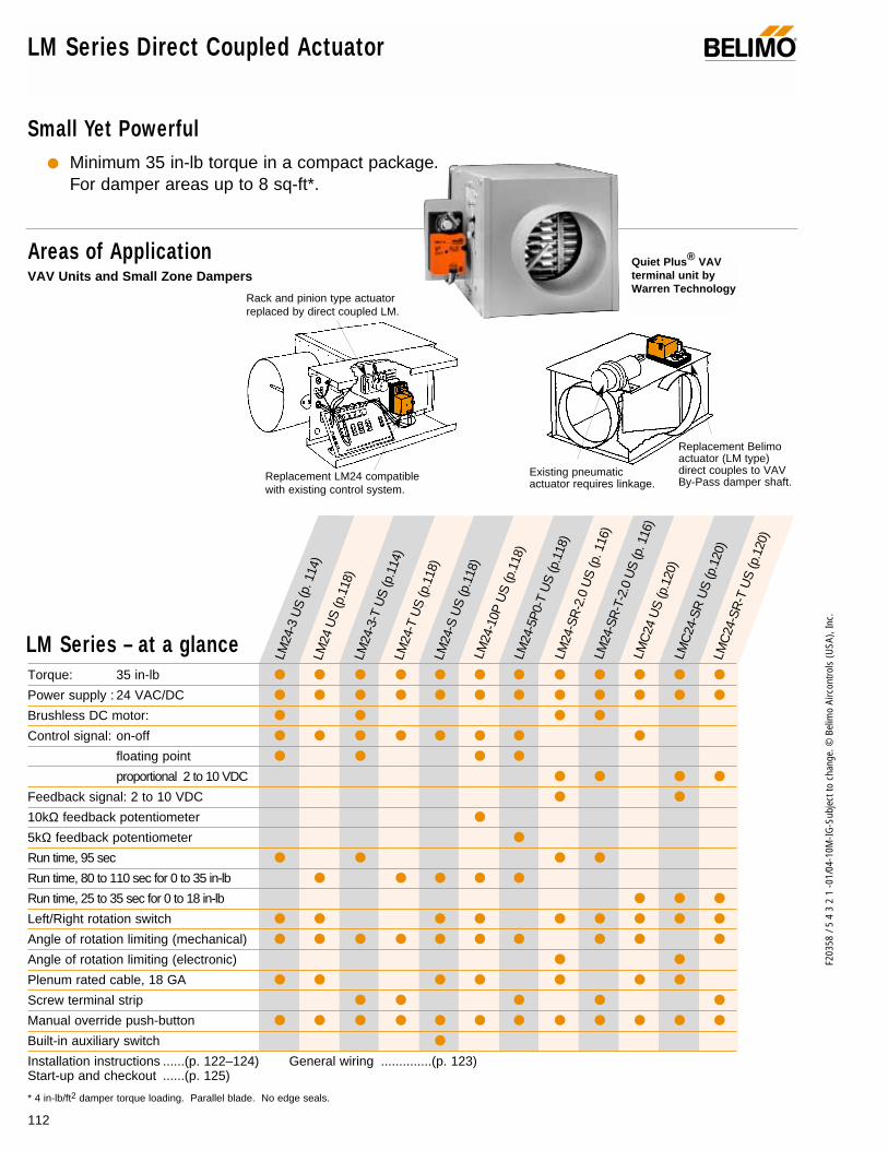
112
F203
58 /
5 4
3 2
1 -0
1/04
-10M
-IG-S
ubje
ct to
cha
nge.
© B
elim
o Ai
rcon
trols
(USA
), In
c.
LM Series Direct Coupled Actuator
Areas of Application
Small Yet Powerful Minimum 35 in-lb torque in a compact package.
For damper areas up to 8 sq-ft*.
®
Torque: 35 in-lb
Power supply : 24 VAC/DC
Brushless DC motor:
Control signal: on-off
floating point
proportional 2 to 10 VDC
Feedback signal: 2 to 10 VDC
10kΩ feedback potentiometer
5kΩ feedback potentiometer
Run time, 95 sec
Run time, 80 to 110 sec for 0 to 35 in-lb
Run time, 25 to 35 sec for 0 to 18 in-lb
Left/Right rotation switch
Angle of rotation limiting (mechanical)
Angle of rotation limiting (electronic)
Plenum rated cable, 18 GA
Screw terminal strip
Manual override push-button
Built-in auxiliary switch
Installation instructions ......(p. 122–124) General wiring ..............(p. 123)Start-up and checkout ......(p. 125)
* 4 in-lb/ft2 damper torque loading. Parallel blade. No edge seals.
LM Series – at a glance
LM24
-3 U
S (p
. 114
)
LM24
-3-T
US
(p.1
14)
LM24
-T U
S (p
.118
)LM
24-S
US
(p.1
18)
LM24
US
(p.1
18)
LM24
-10P
US
(p.1
18)
LM24
-5P
0-T
US
(p.1
18)
LM24
-SR
-2.0
US
(p. 1
16)
LM24
-SR
-T-2
.0 U
S (p
. 116
)LM
C24
US
(p.1
20)
LMC
24-S
R U
S (p
.120
)LM
C24
-SR
-T U
S (p
.120
)
Rack and pinion type actuatorreplaced by direct coupled LM.
Replacement LM24 compatible with existing control system.
Replacement Belimoactuator (LM type)direct couples to VAVBy-Pass damper shaft.
Existing pneumatic actuator requires linkage.
VAV Units and Small Zone DampersQuiet Plus® VAV terminal unit byWarren Technology

113
F203
58 /
5 4
3 2
1 -0
1/04
-10M
-IG-S
ubje
ct to
cha
nge.
© B
elim
o Ai
rcon
trols
(USA
), In
c.
LM
LISTED94D5TEMP. IND ®. EQUIP.
UL
Brushless DC Motor for added accuracy and controllability.
Cut labor costs with simple direct coupling.
Check damper position from a distance withclear position indication.
Don’t worry about actuator burn-out. Belimo is overload-proof throughout rotation.
Enjoy added flexibility with easy mechanical stops to adjust angle of rotation.(LM24-SR-2.0 US has electronic rotation limiting.)
Consistent running time independent of load.
Easily accessible manual override push-buttonhelps you pre-tension damper blades.
Need to change control direction? Do it easily with a simple switch.
3 ft. plenum rated cable eases installation(external terminal strip also available)
Bulk Packaging Offers BigValue for Large Jobs,Stocking Orders.
LM Series Direct Coupled Actuator®
The Belimo Difference
Customer Commitment.Extensive product range. Competitive project pricing. Application assistance. Same-day shipments. Free technical support. Five year warranty.
Low Installation and Life-Cycle Cost.Easy installation. Accuracy and repeatability. Low power consumption. No maintenance.
Long Service Life.Components tested before assembly. Every product tested before shipment. 20+ years direct coupled actuator design.
A CLOSER LOOK…
©

114
F203
58 /
5 4
3 2
1 -0
1/04
-10M
-IG-S
ubje
ct to
cha
nge.
© B
elim
o Ai
rcon
trols
(USA
), In
c.
ApplicationFor on-off and floating point control of dampers in HVAC sys-tems. Actuator sizing should be done in accordance with thedamper manufacturer’s specifications. The actuator mountsdirectly to the damper operating shaft with a universal V-boltclamp assembly.
OperationThe actuator is not provided with and does not require any limitswitches, but is electronically protected against overload. Theangle of rotation is mechanically limited to 95°. When reachingthe damper or actuator end position, the actuator automaticallystops. The gears can be manually disengaged with a button onthe actuator cover. The position of the actuator is indicated bya visual pointer. The anti-rotation strap supplied with the actua-tor will prevent lateral movement.
The LM24-3 US and LM24-3-T US actuators use a BrushlessDC motor, which is controlled by an Application SpecificIntegrated Circuit (ASIC). The ASIC monitors and controls theactuator’s rotation and provides a digital rotation sensing (DRS)function to prevent damage to the actuator in a stall condition.
Accessories11533 T-type anti-rotation bracket22065 L-type anti-rotation bracket (included)ZG-LMSA Shaft adaptor for short shaftsTool-02 8 mm wrench
LM24-3 (-T) US On-off/ floating point control, non-spring return, direct coupled, 24 V
Dimensions (All numbers in brackets are metric.)
Torque min. 35 in-lb, for control of damper surfaces up to 8 sq ft.
LM24-3 USLM24-3-T US
LM24-3 US LM24-3-T US
LISTED94D5TEMP. IND ®. EQUIP.
UL
®
Technical Data LM24… on-off/floating point
Power supply 24 VAC ± 20% 50/60 Hz 24 VDC ± 10%
Power consumption 2 W
Transformer sizing 3 VA (Class 2 power source)
Electrical connection 3 ft, 18 GA, UL CL2P plenum cable
Control On-off/Floating point
Overload protection Electronic throughout 0 to 95° rotation
Input impedance 3900ΩAngle of rotation max 95°, adjust. with mechanical stops
Torque min 35 in-lb [4 Nm], Independent of load
Direction of rotation reversible w/switch CW/CCW (not on “-T” models)
Position indication clip-on indicator (not on “-T” models)
Running time 95 seconds
Manual override external push button
Humidity 5 to 95% RH, non-condensing
Ambient temperature -22°F to +122°F [-30°C to +50°C]
Storage temperature -40°F to +176°F [-40°C to +80°C]
Housing type NEMA type 2 (-T models NEMA 1)
Housing material rating UL94-5V
Noise level less than 35 dB (A)
Servicing maintenance free
Agency listings UL873 listed, CSA 22.2 No. 24 certified, CE
Quality standard ISO 9001
Weight 1.2 lbs [0.55 kg]
LM24-3-T.1 US
Electrical connection Screw terminal (for 26 to 14 GA wire)
Housing NEMA type 1
Direction of rotation Reverse wires terminals 2 and 3
©
L R
20%
100
%
1
1
0
0
3.47" [88]
4.53" [115]
3.68" [93.5]0.85" [21.5]
1.28" [32.5]
2.56" [65]
2.32" [58.9]
1/4" to 5/8" [6 to 16]
1/4" to 7/16" [6 to 11]
D01
4
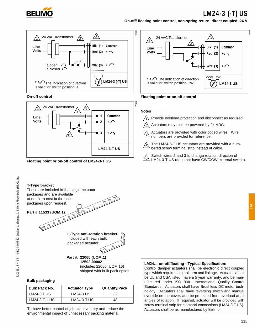
115
F203
58 /
5 4
3 2
1 -0
1/04
-10M
-IG-S
ubje
ct to
cha
nge.
© B
elim
o Ai
rcon
trols
(USA
), In
c.
LM
1 3224 VAC Transformer
a opena closed
The indication of direction is valid for switch position R.
Blk (1) Common
Red (2) +
Wht (3) +
LM24-3 (-T) US
L R
a
Line Volts
12
324 VAC Transformer
The indication of direction is valid for switch position CW.
Blk (1) Common
Red (2) +
Wht (3) +
LM24-3 US
CCW CW
Line Volts
LM24-3 (-T) USOn-off/ floating point control, non-spring return, direct coupled, 24 V
LM24… on-off/floating - Typical Specification:Control damper actuators shall be electronic direct coupledtype which require no crank arm and linkage. Actuators shallbe UL and CSA listed, have a 5 year warranty, and be man-ufactured under ISO 9001 International Quality ControlStandards. Actuators shall have Brushless DC motor tech-nology. Actuators shall have reversing switch and manualoverride on the cover, and be protected from overload at allangles of rotation. If required, actuator will be provided withscrew terminal strip for electrical connections (LM24-3-T US).Actuators shall be as manufactured by Belimo.
On-off control
Line Volts
1 Common
2 +
3 +
24 VAC Transformer
LM24-3-T US
6
512
Floating point or on-off control of LM24-3-T US
3
2
5
6
1 Provide overload protection and disconnect as required.
Actuators may also be powered by 24 VDC.
Actuators are provided with color coded wires. Wirenumbers are provided for reference.
The LM24-3-T US actuators are provided with a num-bered screw terminal strip instead of cable.
Switch wires 2 and 3 to change rotation direction ofLM24-3-T US (does not have CW/CCW external switch).
Floating point or on-off control
Bulk packaging
Bulk Pack No. Actuator Type Quantity/Pack
LM24-3.1 US LM24-3 US 32
LM24-3-T.1 US LM24-3-T US 48
®
Notes
T-Type bracketThese are included in the single-actuator packages and are available at no extra cost in the bulk packages upon request.
Part # 11533 (UOM:1)
L-Type anti-rotation bracket.Included with each bulk packaged actuator.
W08
0
W08
2
W08
1
To have better control of job site inventory and reduce theenvironmental impact of unnecessary packing material.
Part #: 22065 (UOM:1)12502-00002 (includes 22065: UOM:16) shipped with bulk pack option.

116
F203
58 /
5 4
3 2
1 -0
1/04
-10M
-IG-S
ubje
ct to
cha
nge.
© B
elim
o Ai
rcon
trols
(USA
), In
c.
LM24-SR (-T) -2.0 US Proportional control, non-spring return, direct coupled, 24 V, for 2 to 10 VDC and 4 to 20 mA control signal
ApplicationFor proportional modulation of dampers in HVAC systems.Actuator sizing should be done in accordance with the dampermanufacturer’s specifications. The actuator mounts directly tothe damper operating shaft with a universal V-bolt clampassembly. The actuator operates in response to a 2 to 10 VDCor, with the addition of a 500 Ω resistor, a 4 to 20 mA input sig-nal from an electronic controller or positioner. A 2 to 10 VDCfeedback signal is provided for position indication or masterslave applications. (Not available on “-T” versions)The LM24-SR-2.0 US provides an electronic angle of rotationadjustment to limit the actuators rotation 20% to 100% while stillusing the full input signal and feedback control range. (Notavailable on LM24-SR-T-2.0 US)
OperationThe anti-rotation strap supplied with the actuator will prevent lat-eral movement of the actuator. The damper actuator is not pro-vided with and does not require any limit switches, but is pro-tected electronically against overload. The angle of rotation ismechanically limited to 95°. When reaching the damper or actu-ator end position, the actuator automatically stops. The gearscan be manually disengaged by pressing a button on the actua-tor cover. The position of the actuator is indicated by a visualpointer. The LM24-SR-2.0 US and LM24-SR-T-2.0 US actuators use aBrushless DC motor, which is controlled by an Application SpecificIntegrated Circuit (ASIC). The ASIC monitors and controls theactuator’s rotation and provides a digital rotation sensing (DRS)function to prevent damage to the actuator in a stall condition.
Accessories11533 T-type anti-rotation bracket22065 L-type anti-rotation bracket (included)ZG-LMSA Shaft adaptor for short shaftsTool-02 8 mm wrenchZG-R01 500Ω resistor for 4 to 20 mA
Dimensions (All numbers in brackets are metric.)
Torque min. 35 in-lb, for control of damper surfaces up to 8 sq ft.
LM24-SR-2.0 USLM24-SR-T-2.0 US
®
LM24-SR-T-2.0 USLM24-SR-2.0 US
LISTED94D5TEMP. IND ®. EQUIP.
UL
©
Technical Data LM24-SR-2.0 US
Power supply 24 VAC ± 20% 50/60 Hz 24 VDC ± 10%
Power consumption 2 W
Transformer sizing 4 VA (Class 2 power source)
Electrical connection LM24-SR-2.0 US: 3 ft, 18 GA, ULCL2P plenum cable
Overload protection Electronic throughout 0 to 95° rotation
Operating range Y 2 to 10 VDC, 4 to 20 mA
Input impedance 100 kΩ (0.1 mA), 500ΩFeedback output ‘U’ 2 to 10 VDC (max. 0.7 mA )
(not available on LM24-SR-T-2.0 US
Angle of rotation max 95°, electronically adjustable 20 to 100% on LM24-SR-2.0 US
Torque min 35 in-lb, Independent of load
Direction of rotation reversible with switch CW/CCWCW = with an increase in voltageCCW = with an increase in voltage
Position indication clip-on indicator (not on “-T” models)
Running time 95 seconds
Manual override external push button
Humidity 5 to 95% RH, non-condensing
Ambient temperature -22°F to +122°F [-30°C to +50°C]
Storage temperature -40°F to +176°F [-40°C to +80°C]
Housing type NEMA type 2 (-T models Nema type1)
Housing material rating UL 94-5V
Noise level less than 35 dB (A)
Servicing maintenance free
Agency listings UL 873 listed, CSA 22..2 No. 24 certified, CE
Quality standard ISO 9001
Weight 1.2 lbs [0.55 kg]
LM24-SR-T-2.0.1 US
Electrical connection Screw terminals (for 26 to 14 GA wire)
Angle of rotation max 95°, adjust. with mechanical stops
Housing NEMA type 1
Feedback No feedback with the LM24-SR-T-2.0 US
L R
20%
100
%
1
1
0
0
3.47" [88]
4.53" [115]
3.68" [93.5]0.85" [21.5]
1.28" [32.5]
2.56" [65]
2.32" [58.9]
1/4" to 5/8" [6 to 16]
1/4" to 7/16" [6 to 11]
D01
4
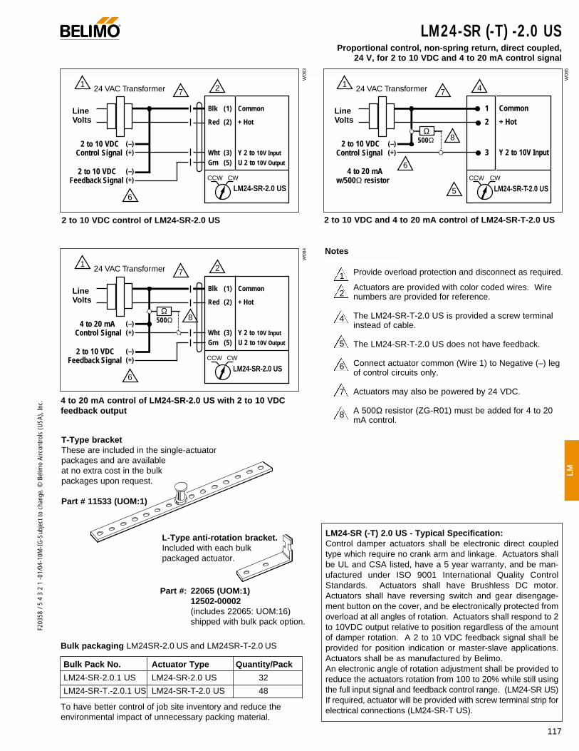
117
F203
58 /
5 4
3 2
1 -0
1/04
-10M
-IG-S
ubje
ct to
cha
nge.
© B
elim
o Ai
rcon
trols
(USA
), In
c.
LM
LM24-SR (-T) -2.0 US Proportional control, non-spring return, direct coupled,
24 V, for 2 to 10 VDC and 4 to 20 mA control signal
1 2724 VAC Transformer
Blk (1) Common
Red (2) + Hot
Wht (3) Y 2 to 10V Input
Grn (5) U 2 to 10V Output
LM24-SR-2.0 USCCW CW
Line Volts
2 to 10 VDCControl Signal
2 to 10 VDCFeedback Signal
(–)(+)
(–)(+)
6
1 2724 VAC Transformer
Blk (1) Common
Red (2) + Hot
Wht (3) Y 2 to 10V Input
Grn (5) U 2 to 10V Output
LM24-SR-2.0 USCCW CW
Line Volts
4 to 20 mAControl Signal
2 to 10 VDCFeedback Signal
(–)(+)
(–)(+)
6
8Ω
500Ω
2 to 10 VDC control of LM24-SR-2.0 US
4 to 20 mA control of LM24-SR-2.0 US with 2 to 10 VDC feedback output
2
4
5
6
7
8
1 Provide overload protection and disconnect as required.
Actuators are provided with color coded wires. Wirenumbers are provided for reference.
The LM24-SR-T-2.0 US is provided a screw terminalinstead of cable.
The LM24-SR-T-2.0 US does not have feedback.
Connect actuator common (Wire 1) to Negative (–) legof control circuits only.
Actuators may also be powered by 24 VDC.
A 500Ω resistor (ZG-R01) must be added for 4 to 20mA control.
1 4724 VAC Transformer
1 Common
2 + Hot
3 Y 2 to 10V Input
LM24-SR-T-2.0 USCCW CW
Line Volts
4 to 20 mA
Control Signal
w/500Ω resistor
(–)(+)
6
8Ω
500Ω2 to 10 VDC
5
2 to 10 VDC and 4 to 20 mA control of LM24-SR-T-2.0 US
®
Bulk packaging LM24SR-2.0 US and LM24SR-T-2.0 US
LM24-SR (-T) 2.0 US - Typical Specification:Control damper actuators shall be electronic direct coupledtype which require no crank arm and linkage. Actuators shallbe UL and CSA listed, have a 5 year warranty, and be man-ufactured under ISO 9001 International Quality ControlStandards. Actuators shall have Brushless DC motor.Actuators shall have reversing switch and gear disengage-ment button on the cover, and be electronically protected fromoverload at all angles of rotation. Actuators shall respond to 2to 10VDC output relative to position regardless of the amountof damper rotation. A 2 to 10 VDC feedback signal shall beprovided for position indication or master-slave applications.Actuators shall be as manufactured by Belimo.An electronic angle of rotation adjustment shall be provided toreduce the actuators rotation from 100 to 20% while still usingthe full input signal and feedback control range. (LM24-SR US)If required, actuator will be provided with screw terminal strip forelectrical connections (LM24-SR-T US).
Notes
Bulk Pack No. Actuator Type Quantity/Pack
LM24-SR-2.0.1 US LM24-SR-2.0 US 32
LM24-SR-T.-2.0.1 US LM24-SR-T-2.0 US 48
T-Type bracketThese are included in the single-actuator packages and are available at no extra cost in the bulk packages upon request.
Part # 11533 (UOM:1)
W08
3W
084
W08
5
To have better control of job site inventory and reduce theenvironmental impact of unnecessary packing material.
L-Type anti-rotation bracket.Included with each bulk packaged actuator.
Part #: 22065 (UOM:1)12502-00002 (includes 22065: UOM:16) shipped with bulk pack option.

118
F203
58 /
5 4
3 2
1 -0
1/04
-10M
-IG-S
ubje
ct to
cha
nge.
© B
elim
o Ai
rcon
trols
(USA
), In
c.
ApplicationFor on-off control of dampers in HVAC systems. Actuator siz-ing should be done in accordance with the damper manufac-turer’s specifications. The actuator mounts directly to thedamper operating shaft with a universal V-bolt clamp assem-bly.
OperationThe actuator is not provided with and does not require anylimit switches, but is electronically protected against overload.The angle of rotation is mechanically limited to 95°. Whenreaching the damper or actuator end position, the actuatorautomatically stops. The gears can be manually disengagedwith a button on the actuator cover. The position of the actua-tor is indicated by a visual pointer. The anti-rotation strap sup-plied with the actuator will prevent lateral movement.
AccessoriesLM-P T-type anti-rotation bracketZG-LMSA Shaft adaptor for short shaftsTool-02 8 mm wrench
LM24 (-T) US On-off control, non-spring return, direct coupled, 24 V
Torque min. 35 in-lb, for control of damper surfaces up to 8 sq ft.
LM24 USLM24-S USLM24-10P USLM24-5P0-T USLM24-T US
LM24-S US LM24-T US
LISTED94D5TEMP. IND ®. EQUIP.
UL
Technical Data LM24… on-off/floating point Power supply 24 VAC ± 20% 50/60 Hz 24 VDC ± 10%Power consumption 2 W Transformer sizing 3 VA (Class 2 power source) Electrical connection 3 ft, 18 GA, UL CL2P plenum cableControl On-offOverload protection Electronic throughout 0 to 95° rotationAngle of rotation max 95°, adjust. with mechanical stopsTorque min 35 in-lb [4 Nm]Direction of rotation reversible w/switch L/R (not on “-T” models)Position indication clip-on indicator (not on “-T” models)Running time 80 to 110 sec. for 0 to 35 in-lb Manual override external push button Humidity 5 to 95% RH, non-condensingAmbient temperature -22°F to +122°F [-30°C to +50°C]Storage temperature -40°F to +176°F [-40°C to +80°C]Housing type NEMA type 2 (-T models NEMA 1)Housing material rating UL94-5V Noise level less than 35 dB (A)Servicing maintenance freeAgency listings UL 873 listed, CSA C22.2 No.24 certified, CEQuality standard ISO 9001Weight 1.2 lbs [0.55 kg]LM24-S US Control On-offAuxiliary switch Adj. 0° to 95°, SPDT 6 A (2.5A) @ 24 VACLM24-10P US Control On-off/Floating pointFeedback 10 kΩ, 1W potentiometerLM24-5P0-T.1 US (bulk pack only)Control On-off/Floating pointFeedback 5 kΩ, 1W potentiometerHousing NEMA type 1Direction of rotation Reverse wires terminals 2 and 3LM24-T.1 US (bulk pack only)Control On-offElectrical connection Screw terminal (for 26 to 14 GA wire)Housing NEMA type 1Direction of rotation Reverse wires terminals 2 and 3
®
Dimensions (All numbers in brackets are metric.)
1
1
0
0
3.47" [88]
4.53" [115]
3.68" [93.5]0.85" [21.5]
1.28" [32.5]
2.56" [65]
2.32" [58.9]
1/4" to 5/8" [6 to 16]
1/4" to 7/16" [6 to 11]
D01
5
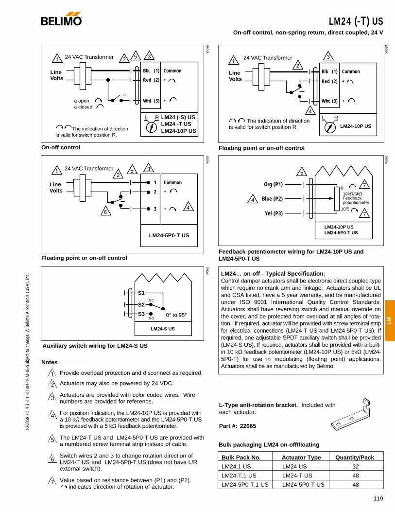
119
F203
58 /
5 4
3 2
1 -0
1/04
-10M
-IG-S
ubje
ct to
cha
nge.
© B
elim
o Ai
rcon
trols
(USA
), In
c.
LM
1 5 3224 VAC Transformer
a opena closed
The indication of direction is valid for switch position R.
Blk (1) Common
Red (2) +
Wht (3) +
LM24 -T USLM24 (-S) US
LM24-10P US
L R
a
Line Volts
12
3
4
24 VAC Transformer
The indication of direction is valid for switch position R.
Blk (1) Common
Red (2) +
Wht (3) +
LM24-10P US
L R
Line Volts
LM24-S US
S1
S2
S3
NC
NO0° to 95°
LM24 (-T) US On-off control, non-spring return, direct coupled, 24 V
LM24… on-off - Typical Specification:Control damper actuators shall be electronic direct coupled typewhich require no crank arm and linkage. Actuators shall be ULand CSA listed, have a 5 year warranty, and be man-ufacturedunder ISO 9001 International Quality Control Standards.Actuators shall have reversing switch and manual override onthe cover, and be protected from overload at all angles of rota-tion. If required, actuator will be provided with screw terminal stripfor electrical connections (LM24-T US and LM24-5P0-T US). Ifrequired, one adjustable SPDT auxiliary switch shall be provided(LM24-S US). If required, actuators shall be provided with a built-in 10 kΩ feedback potentiometer (LM24-10P US) or 5kΩ (LM24-5P0-T) for use in modulating (floating point) applications.Actuators shall be as manufactured by Belimo.
On-off control
Line Volts
1 Common
2 +
3 +
24 VAC Transformer
LM24-5P0-T US
64
512
3
LM24-10P US LM24-5P0-T US
0
10/5
10kΩ/5kΩ Feedback potentiometer
7
5
4
7
Org (P1)
Blue (P2)
Yel (P3)
Floating point or on-off control Feedback potentiometer wiring for LM24-10P US and LM24-5P0-T US
Auxiliary switch wiring for LM24-S US
3
2
4
5
6
7
1 Provide overload protection and disconnect as required.
Actuators may also be powered by 24 VDC.
Actuators are provided with color coded wires. Wirenumbers are provided for reference.
For position indication, the LM24-10P US is provided witha 10 kΩ feedback potentiometer and the LM24-5P0-T USis provided with a 5 kΩ feedback potentiometer.
The LM24-T US and LM24-5P0-T US are provided witha numbered screw terminal strip instead of cable.
Switch wires 2 and 3 to change rotation direction ofLM24-T US and LM24-5P0-T US (does not have L/Rexternal switch).
Value based on resistance between (P1) and (P2).indicates direction of rotation of actuator.
Floating point or on-off control
Bulk packaging LM24 on-off/floating
Bulk Pack No. Actuator Type Quantity/Pack
LM24.1 US LM24 US 32
LM24-T.1 US LM24-T US 48
LM24-5P0-T.1 US LM24-5P0-T US 48
L-Type anti-rotation bracket. Included with each actuator.
Part #: 22065
Notes
®
W08
6
W08
9
W08
7W
088
W09
0

120
F203
58 /
5 4
3 2
1 -0
1/04
-10M
-IG-S
ubje
ct to
cha
nge.
© B
elim
o Ai
rcon
trols
(USA
), In
c.
ApplicationFor on-off control of dampers in HVAC systems (LMC24 US).For proportional modulation of dampers in HVAC systems(LMC24-SR-T US). Actuator sizing should be done in accor-dance with the damper manufacturer’s specifications. The actuator mounts directly to the damper operating shaft with a universal V-bolt clamp assembly.
The LMC24-SR-T US actuator operates in response to a 2 to 10VDC or, with the addition of a 500 Ω resistor, a 4 to 20 mA inputsignal from an electronic controller or positioner. A 2 to 10 VDCfeedback signal is provided for position indication or masterslave applications. The LMC24-SR US provides an electronicangle of rotation adjustment (not available in the LMC24-SR-T US) tolimit the actuators rotation 20% to 100% while still using the fullinput signal and feedback control range.
OperationThe actuator is not provided with and does not require any limitswitches, but is electronically protected against overload. Theangle of rotation is mechanically limited to 95°. When reachingthe damper or actuator end position, the actuator automaticallystops. The gears can be manually disengaged with a button onthe actuator cover. The position of the actuator is indicated by avisual pointer. The anti-rotation strap supplied with the actuatorwill prevent lateral movement.
AccessoriesLM-P T-type anti-rotation bracketIRM-100 Input scaling module (For LMC24-SR-T US only)ZG-LMSA Shaft adaptor for short shaftsPTA-250 Pulse width modulating interface
(For LMC24-SR-T US only)SGA24 Min. and/or manual positioner in NEMA 4 housing
(For LMC24-SR-T US only)SGF24 Min. and/or manual positioner for flush panel mount
(For LMC24-SR-T US only)Tool-02 8 mm wrenchZAD24 Digital position indication (For LMC24-SR-T US only)ZG-R01 500Ω resistor for 4 to 20 mA
(For LMC24-SR-T US only)
LMC24 (-SR) (-T) USNon-spring return, direct coupled, 24 V, 25 to 35 sec. running time
Torque min. 18 in-lb, for control of damper surfaces up to 4.5 sq ft.
LMC24 US (on/off)LMC24-SR US (proportional)LMC24-SR-T US (proportional)
LMC24 US LMC24-SR US
LISTED94D5TEMP. IND ®. EQUIP.
UL
®
Technical Data LMC24 (-SR) US… Power supply 24 VAC ± 20% 50/60 Hz 24 VDC ± 10%
Power consumption LMC24 US 2.0 W LMC24-SR (-T) US 2.5 W
Transformer sizing LMC24 US 3 VA LMC24-SR (-T) US 4 VA
Electrical connection 3 ft, 18 GA, UL CL2P plenum cable
Control On-off (LMC24 US)
Overload protection Electronic throughout 0 to 95° rotation
Angle of rotation max 95°, adjust. with mechanical stops(LMC24 US), electronically adjustable 20 to 100% on LMC24-SR US only
Torque min 18 in-lb [2 Nm]
Operating range Y 2 to 10 VDC, 4 to 20 mA (LMC24-SR (-T) US)
Input impedance 100 kΩ (0.1 mA), 500Ω (LMC24-SR (-T) US)
Feedback output ‘U’ 2 to 10 VDC (max. 0.7 mA )(LMC24-SR-T US)
Direction of rotation reversible with switch “CCW-CW”LMC24-SR-T US:CW with a decrease in voltageCCW with a decrease in voltage
Position indication clip-on indicator
Running time 25 to 35 sec. for 0 to 18 in-lb
Manual override external push button
Humidity 5 to 95% RH, non-condensing
Ambient temperature -22°F to +122°F [-30°C to +50°C]
Storage temperature -40°F to +176°F [-40°C to +80°C]
Housing type NEMA type 2
Housing material rating UL94-5V
Noise level less than 35 dB (A)
Servicing maintenance free
Agency listings UL 873 listed, CSA C22.2 No.24 certified, CE
Quality standard ISO 9001
Weight 1.2 lbs [0.55 kg]
LMC24-SR-T US
Electrical connection Screw terminals (for 26 to 14 GA wire)
Angle of rotation max 95°, adjust. with mechanical stops
Housing NEMA type 1
Feedback No feedback with the LMC24-SR-T US
Note: Actuators do not have Brushless DC Motor
Dimensions (All numbers in brackets are metric.)
1
1
0
0
3.47" [88]
4.53" [115]
3.68" [93.5]0.85" [21.5]
1.28" [32.5]
2.56" [65]
2.32" [58.9]
1/4" to 5/8" [6 to 16]
1/4" to 7/16" [6 to 11]
D01
5
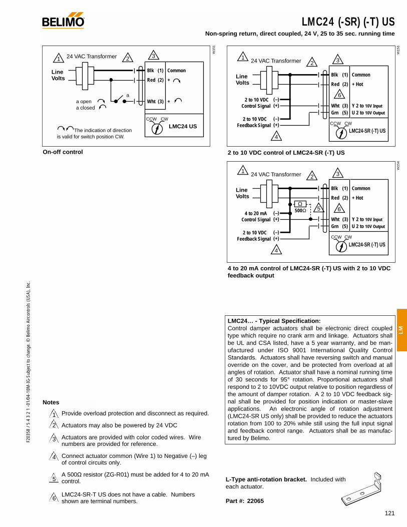
121
F203
58 /
5 4
3 2
1 -0
1/04
-10M
-IG-S
ubje
ct to
cha
nge.
© B
elim
o Ai
rcon
trols
(USA
), In
c.
LM
1 3224 VAC Transformer
a opena closed
The indication of direction is valid for switch position CW.
Blk (1) Common
Red (2) +
Wht (3) +
LMC24 USCCW CW
a
Line Volts
LMC24 (-SR) (-T) US Non-spring return, direct coupled, 24 V, 25 to 35 sec. running time
LMC24… - Typical Specification:Control damper actuators shall be electronic direct coupledtype which require no crank arm and linkage. Actuators shallbe UL and CSA listed, have a 5 year warranty, and be man-ufactured under ISO 9001 International Quality ControlStandards. Actuators shall have reversing switch and manualoverride on the cover, and be protected from overload at allangles of rotation. Actuator shall have a nominal running timeof 30 seconds for 95° rotation. Proportional actuators shallrespond to 2 to 10VDC output relative to position regardless ofthe amount of damper rotation. A 2 to 10 VDC feedback sig-nal shall be provided for position indication or master-slaveapplications. An electronic angle of rotation adjustment(LMC24-SR US only) shall be provided to reduce the actuatorsrotation from 100 to 20% while still using the full input signaland feedback control range. Actuators shall be as manufac-tured by Belimo.
On-off control
3
2
4
5
6
1 Provide overload protection and disconnect as required.
Actuators may also be powered by 24 VDC
Actuators are provided with color coded wires. Wirenumbers are provided for reference.
Connect actuator common (Wire 1) to Negative (–) legof control circuits only.
A 500Ω resistor (ZG-R01) must be added for 4 to 20 mAcontrol.
LMC24-SR-T US does not have a cable. Numbersshown are terminal numbers.
L-Type anti-rotation bracket. Included with each actuator.
Part #: 22065
®
Notes
1 3224 VAC Transformer
Blk (1) Common
Red (2) + Hot
Wht (3) Y 2 to 10V Input
Grn (5) U 2 to 10V Output
LMC24-SR (-T) USCCW CW
Line Volts
2 to 10 VDCControl Signal
2 to 10 VDCFeedback Signal
(–)(+)
(–)(+)
4
6
1 3224 VAC Transformer
Blk (1) Common
Red (2) + Hot
Wht (3) Y 2 to 10V Input
Grn (5) U 2 to 10V Output
LMC24-SR (-T) USCCW CW
Line Volts
4 to 20 mAControl Signal
2 to 10 VDCFeedback Signal
(–)(+)
(–)(+)
4
65Ω
500Ω
2 to 10 VDC control of LMC24-SR (-T) US
4 to 20 mA control of LMC24-SR (-T) US with 2 to 10 VDC feedback output
W15
1
W15
3W
154
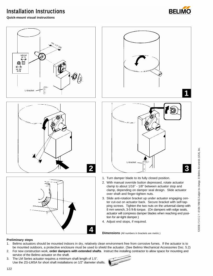
122
F203
58 /
5 4
3 2
1 -0
1/04
-10M
-IG-S
ubje
ct to
cha
nge.
© B
elim
o Ai
rcon
trols
(USA
), In
c.
Preliminary steps1. Belimo actuators should be mounted indoors in dry, relatively clean environment free from corrosive fumes. If the actuator is to
be mounted outdoors, a protective enclosure must be used to shield the actuator. (See Belimo Mechanical Accessories Doc. 5.2)2. For new construction work, order dampers with extended shafts. Instruct the installing contractor to allow space for mounting and
service of the Belimo actuator on the shaft.3. The LM Series actuator requires a minimum shaft length of 1.5”.
Use the ZG-LMSA for short shaft installations on 1/2” diameter shafts.
Installation InstructionsQuick-mount visual instructions
®
1. Turn damper blade to its fully closed position.2. With manual override button depressed, rotate actuator
clamp to about 1/16” - 1/8” between actuator stop andclamp, depending on damper seal design. Slide actuatorover shaft and finger-tighten nuts.
3. Slide anti-rotation bracket up under actuator engaging cen-ter cut-out on actuator back. Secure bracket with self-tap-ping screws. Tighten the two nuts on the universal clamp with8 mm wrench, 3-5 ft-lb torque. (On dampers with edge seals,actuator will compress damper blades when reaching end posi-tion for air-tight damper.)
4. Adjust end stops, if required.
1
2 3
4
L-bracket
L-bracket
min. 1.5” [38]
Dimensions (All numbers in brackets are metric.)

WARNING The wiring technician must be trained and experi-enced with electronic circuits. Disconnect power supply beforeattempting any wiring connections or changes. Make all con-nections in accordance with wiring diagrams and follow allapplicable local and national codes. Provide disconnect andoverload protection as required. Use copper, twisted pair,conductors only.
Always read the controller manufacturer's installation liter-ature carefully before making any connections. Follow allinstructions in this literature. If you have any questions, contactthe controller manufacturer and/or Belimo.
Transformer(s)The LM Series actuators require a 24 VAC class 2 transformerand draw a maximum of 4 VA. The actuator enclosure cannotbe opened in the field, there are no parts or components to bereplaced or repaired.
– EMC directive: 89/336/EEC– Software class A: Mode of operation type 1– Low voltage directive: 73/23/EEC
CAUTION: It is good practice to power electronic or digital con-trollers from a separate power transformer than that used foractuators or other end devices. The power supply design inour actuators and other end devices use half wave rectification.Some controllers use full wave rectification. When these twodifferent types of power supplies are connected to the samepower transformer and the DC commons are connected togeth-er, a short circuit is created across one of the diodes in the fullwave power supply, damaging the controller. Only use a singlepower transformer to power the controller and actuator if youknow the controller power supply uses half wave rectification.
Multiple actuators, one transformer Multiple actuators may be powered from one transformer pro-vided the following rules are followed:1. The TOTAL current draw of the actuators (VA rating) is less
than or equal to the rating of the transformer.2. Polarity on the secondary of the transformer is strictly fol-
lowed. This means that all No. 1 wires from all actuatorsare connected to the common leg on the transformer and allNo 2 wires from all actuators are connected to the hotleg.Mixing wire No. 1 & 2 on one leg of the transformer willresult in erratic operation or failure of the actuator and orcontrols.
Multiple actuators, multiple transformersMultiple actuators positioned by the same control signal may bepowered from multiple transformers provided the following rulesare followed:
1. The transformers are properly sized.2. All No. 1 wires from all actuators are tied together and tied
to the negative leg of the control signal. See wiring diagram.
Wire length for LM Series actuatorsKeep power wire runs below the limits listed in the Fig. 1. Ifmore than one actuator is powered from the same wire run,divide the allowable wire length by the number of actuators todetermine the maximum run to any single actuator.
Maximum wire length:
Wire Size Max. Feet. Wire Size Max. Feet16 Ga 1225 Ft. 20 Ga 400 Ft18 Ga 725 Ft. 22 Ga 200 Ft
Fig. 1
Example for LM… US: 3 actuators, 18 Ga wire 725 Ft ÷ 3 Actuators = 241.6 Ft. Maximum wire run.
Wire Type and Wire Installation TipsFor most installations, 18 or 16 Ga. cable works well with theLM24 type actuators. Use code approved wire nuts, terminalstrips or solderless connectors where wires are joined. It isgood practice to run control wires unspliced from the actuatorto the controller. If splices are unavoidable, make sure thesplice can be reached for possible maintenance. Tape and/orwire tie the splice to reduce the possibility of the splice beinginadvertently pulled apart.
LM Series Actuators with Terminal StripLM…-T actuators feature an external screw terminal strip onthe top of the actuator housing (instead of cable). Connectionsare numbered and a wiring schematic is shown next to the ter-minal strip. The terminals are designed for 26 to 14 GA wire.
Overload protection All Belimo actuators are electronically protected against over-load. In the LM series an electronic circuit maintains the cur-rent at a level which will not damage the motor while providingadequate holding torque.
Installation InstructionsGeneral Wiring
123
F203
58 /
5 4
3 2
1 -0
1/04
-10M
-IG-S
ubje
ct to
cha
nge.
© B
elim
o Ai
rcon
trols
(USA
), In
c.
LM
®
0 1
Manual Override
A button on the actuator cover disengages the gear train so thedamper shaft can be moved manually. Release the button and thegear train is re-engaged.
Use the manual override to test the installation withoutpower. For tight shut-off the damper should close with 5°of actuator stroke left.
0 1
Gear releasebutton

AF
124
F203
58 /
5 4
3 2
1 -0
1/04
-10M
-IG-S
ubje
ct to
cha
nge.
© B
elim
o Ai
rcon
trols
(USA
), In
c.
0 1
Adjust angle-of-rotation in steps of 2.5°
Installation InstructionsFeature Operation
Mechanical Angle of Rotation Limiting (LM Series, On-Off/Floating and LM24-SR-T-2.0 US)
The adjustable stops are needed when there is no damper stopor if you want the damper to halt rotating before it reaches itsstops. The LM actuator can be indefinitely stalled in any posi-tion without harm. 1. Loosen the two end stops with a No. 2 Phillips head screwdriv-
er being careful not to unscrew the captive nut under the slot.2. Move the stops (in 2.5° steps) to the desired position and re-
tighten the screws.
LM actuators have a reversing switch on the cover labeled “CW-CCW”. Switch position indicates start point. For the LM24-SR (-T)2.0 US, with the switch in position “CW”, the actuator rotates clock-wise with an increase in voltage or current. With the switch in posi-tion “CCW”, the actuator rotates counterclockwise with an increasein voltage or current.
The LM24-3-T US does not have a switch. They rotate clock-wise when power is applied to wire #3, and counterclockwisewhen power is applied to wire #2.
During checkout, the switch position can be temporarilyreversed and the actuator will reverse its direction. This allowsthe technician a fast and easy way to check the actuator opera-tion without having to switch wires or change settings on thethermostat. When the check-out is complete, make sure theswitch is placed back to its original position.
CW
CCW
0 1
CW
CCW
0 1
10 VDC2 VDC 2 VDC10 VDC
Direction of rotation switch. Position indicates start point.
Electronic Angle of Rotation Limiting (LM24-SR-2.0 US)
With the LM24-SR-2.0 US proportional actuator, you canadjust the angle of rotation (95°) anywhere between 20% and100% using an external adjustment. A potentiometer limitsrotation while allowing the full control input and feedback range(2 to 10 VDC), providing higher control resolution within the lim-ited angle of rotation.
CCW
0 1
CW
CW
CCW
2 VDC
10 VDC
45°/50% Limit
Feedback signal will alsobe adjusted 2 to 10 VDC
0 1
2 VDC
10 VDC
45°/50% Limit
0 1
20% 100%
100%20%
Limitation set at 50%Angle of rotation = 45°Control signal = 10 VDC
Direction of Rotation Switch (All LM except LM24-3-T US)
®
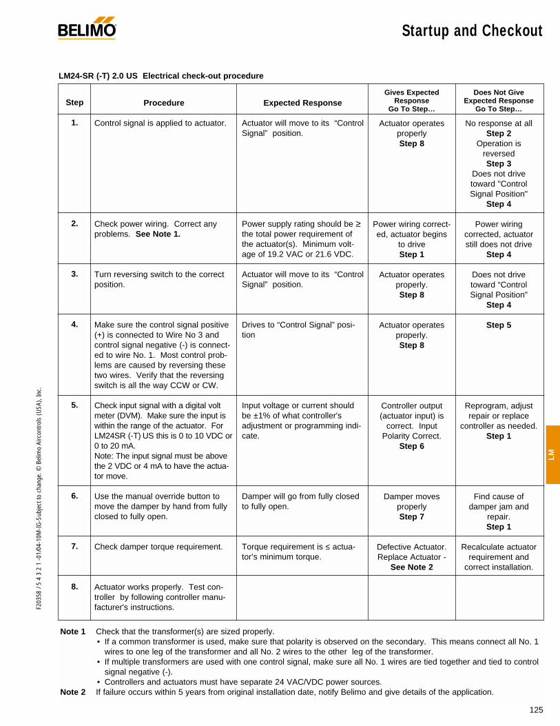
125
F203
58 /
5 4
3 2
1 -0
1/04
-10M
-IG-S
ubje
ct to
cha
nge.
© B
elim
o Ai
rcon
trols
(USA
), In
c.
LM
®
Procedure
Control signal is applied to actuator.
Check power wiring. Correct anyproblems. See Note 1.
Turn reversing switch to the correctposition.
Make sure the control signal positive(+) is connected to Wire No 3 andcontrol signal negative (-) is connect-ed to wire No. 1. Most control prob-lems are caused by reversing thesetwo wires. Verify that the reversingswitch is all the way CCW or CW.
Check input signal with a digital voltmeter (DVM). Make sure the input iswithin the range of the actuator. ForLM24SR (-T) US this is 0 to 10 VDC or0 to 20 mA. Note: The input signal must be abovethe 2 VDC or 4 mA to have the actua-tor move.
Use the manual override button tomove the damper by hand from fullyclosed to fully open.
Check damper torque requirement.
Actuator works properly. Test con-troller by following controller manu-facturer's instructions.
Expected Response
Actuator will move to its “ControlSignal” position.
Power supply rating should be ≥the total power requirement ofthe actuator(s). Minimum volt-age of 19.2 VAC or 21.6 VDC.
Actuator will move to its “ControlSignal” position.
Drives to “Control Signal” posi-tion
Input voltage or current shouldbe ±1% of what controller'sadjustment or programming indi-cate.
Damper will go from fully closedto fully open.
Torque requirement is ≤ actua-tor’s minimum torque.
Gives ExpectedResponse
Go To Step…
Actuator operatesproperlyStep 8
Power wiring correct-ed, actuator begins
to driveStep 1
Actuator operatesproperly.Step 8
Actuator operatesproperly.Step 8
Controller output(actuator input) is
correct. InputPolarity Correct.
Step 6
Damper moves properlyStep 7
Defective Actuator.Replace Actuator -
See Note 2
Does Not GiveExpected Response
Go To Step…
No response at allStep 2
Operation isreversedStep 3
Does not drivetoward "ControlSignal Position"
Step 4
Power wiringcorrected, actuatorstill does not drive
Step 4
Does not drivetoward “ControlSignal Position”
Step 4
Step 5
Reprogram, adjustrepair or replace
controller as needed.Step 1
Find cause ofdamper jam and
repair.Step 1
Recalculate actuatorrequirement and
correct installation.
Step
1.
2.
3.
4.
5.
6.
7.
8.
Note 1 Check that the transformer(s) are sized properly. • If a common transformer is used, make sure that polarity is observed on the secondary. This means connect all No. 1
wires to one leg of the transformer and all No. 2 wires to the other leg of the transformer. • If multiple transformers are used with one control signal, make sure all No. 1 wires are tied together and tied to control
signal negative (-).• Controllers and actuators must have separate 24 VAC/VDC power sources.
Note 2 If failure occurs within 5 years from original installation date, notify Belimo and give details of the application.
LM24-SR (-T) 2.0 US Electrical check-out procedure
Startup and Checkout
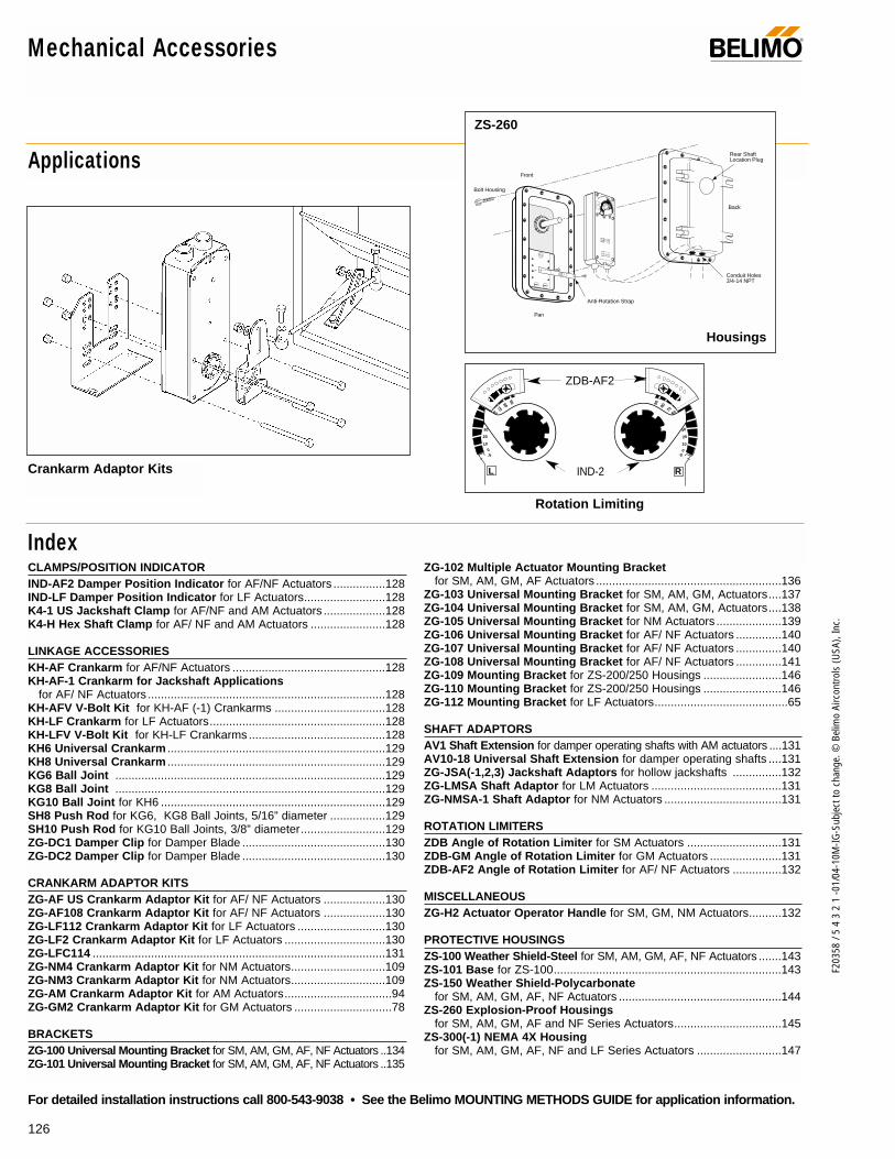
126
F203
58 /
5 4
3 2
1 -0
1/04
-10M
-IG-S
ubje
ct to
cha
nge.
© B
elim
o Ai
rcon
trols
(USA
), In
c.
For detailed installation instructions call 800-543-9038 • See the Belimo MOUNTING METHODS GUIDE for application information.
Mechanical Accessories ®
Applications
IndexCLAMPS/POSITION INDICATORIND-AF2 Damper Position Indicator for AF/NF Actuators ................128 IND-LF Damper Position Indicator for LF Actuators.........................128 K4-1 US Jackshaft Clamp for AF/NF and AM Actuators ...................128K4-H Hex Shaft Clamp for AF/ NF and AM Actuators .......................128
LINKAGE ACCESSORIESKH-AF Crankarm for AF/NF Actuators ...............................................128KH-AF-1 Crankarm for Jackshaft Applications
for AF/ NF Actuators .........................................................................128KH-AFV V-Bolt Kit for KH-AF (-1) Crankarms ..................................128 KH-LF Crankarm for LF Actuators......................................................128 KH-LFV V-Bolt Kit for KH-LF Crankarms ..........................................128 KH6 Universal Crankarm ...................................................................129KH8 Universal Crankarm ...................................................................129 KG6 Ball Joint ...................................................................................129 KG8 Ball Joint ...................................................................................129 KG10 Ball Joint for KH6 .....................................................................129 SH8 Push Rod for KG6, KG8 Ball Joints, 5/16” diameter .................129 SH10 Push Rod for KG10 Ball Joints, 3/8” diameter..........................129 ZG-DC1 Damper Clip for Damper Blade ............................................130 ZG-DC2 Damper Clip for Damper Blade ............................................130
CRANKARM ADAPTOR KITSZG-AF US Crankarm Adaptor Kit for AF/ NF Actuators ...................130 ZG-AF108 Crankarm Adaptor Kit for AF/ NF Actuators ...................130 ZG-LF112 Crankarm Adaptor Kit for LF Actuators ...........................130 ZG-LF2 Crankarm Adaptor Kit for LF Actuators ...............................130ZG-LFC114 ..........................................................................................131ZG-NM4 Crankarm Adaptor Kit for NM Actuators.............................109ZG-NM3 Crankarm Adaptor Kit for NM Actuators.............................109 ZG-AM Crankarm Adaptor Kit for AM Actuators.................................94 ZG-GM2 Crankarm Adaptor Kit for GM Actuators ..............................78
BRACKETSZG-100 Universal Mounting Bracket for SM, AM, GM, AF, NF Actuators ..134ZG-101 Universal Mounting Bracket for SM, AM, GM, AF, NF Actuators ..135
ZG-102 Multiple Actuator Mounting Bracketfor SM, AM, GM, AF Actuators .........................................................136
ZG-103 Universal Mounting Bracket for SM, AM, GM, Actuators....137 ZG-104 Universal Mounting Bracket for SM, AM, GM, Actuators....138 ZG-105 Universal Mounting Bracket for NM Actuators ....................139 ZG-106 Universal Mounting Bracket for AF/ NF Actuators ..............140 ZG-107 Universal Mounting Bracket for AF/ NF Actuators ..............140 ZG-108 Universal Mounting Bracket for AF/ NF Actuators ..............141 ZG-109 Mounting Bracket for ZS-200/250 Housings ........................146 ZG-110 Mounting Bracket for ZS-200/250 Housings ........................146 ZG-112 Mounting Bracket for LF Actuators.........................................65
SHAFT ADAPTORSAV1 Shaft Extension for damper operating shafts with AM actuators ....131 AV10-18 Universal Shaft Extension for damper operating shafts ....131 ZG-JSA(-1,2,3) Jackshaft Adaptors for hollow jackshafts ...............132ZG-LMSA Shaft Adaptor for LM Actuators ........................................131 ZG-NMSA-1 Shaft Adaptor for NM Actuators ....................................131
ROTATION LIMITERSZDB Angle of Rotation Limiter for SM Actuators .............................131ZDB-GM Angle of Rotation Limiter for GM Actuators ......................131 ZDB-AF2 Angle of Rotation Limiter for AF/ NF Actuators ...............132
MISCELLANEOUSZG-H2 Actuator Operator Handle for SM, GM, NM Actuators..........132
PROTECTIVE HOUSINGSZS-100 Weather Shield-Steel for SM, AM, GM, AF, NF Actuators .......143ZS-101 Base for ZS-100......................................................................143ZS-150 Weather Shield-Polycarbonate
for SM, AM, GM, AF, NF Actuators ..................................................144 ZS-260 Explosion-Proof Housings
for SM, AM, GM, AF and NF Series Actuators.................................145ZS-300(-1) NEMA 4X Housing
for SM, AM, GM, AF, NF and LF Series Actuators ..........................147
9080
7060
50
40
30
20
100
-5
908070
6050
4030
20
10
0-5
908 90
L RIND-2
ZDB-AF2
Crankarm Adaptor Kits
Rotation Limiting
Front
Back
Bolt Housing
Conduit Holes3/4-14 NPT
Rear Shaft Location Plug
Anti-Rotation Strap
Pan
ZS-260
Housings

127
F203
58 /
5 4
3 2
1 -0
1/04
-10M
-IG-S
ubje
ct to
cha
nge.
© B
elim
o Ai
rcon
trols
(USA
), In
c.
Mec
hani
cal A
cces
sorie
s
Mechanical Accessories®
We’ll help solve any application problem with a widerange of accessories and unparalleled customer service.
A CLOSER LOOK…
The Belimo Difference
Customer Commitment.Extensive product range. Competitive project pricing. Application assistance. Same-day shipments. Free technical support. Five year warranty.
Low Installation and Life-Cycle Cost.Easy installation. Accuracy and repeatability. Low power consumption. No maintenance.
Long Service Life.Components tested before assembly. Every product tested before shipment. 20+ years direct coupled actuator design.
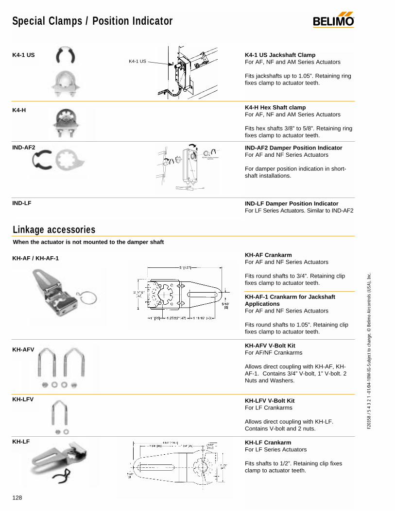
128
F203
58 /
5 4
3 2
1 -0
1/04
-10M
-IG-S
ubje
ct to
cha
nge.
© B
elim
o Ai
rcon
trols
(USA
), In
c.
Special Clamps / Position Indicator
Linkage accessoriesWhen the actuator is not mounted to the damper shaft
®
K4-1 US Jackshaft ClampFor AF, NF and AM Series Actuators
Fits jackshafts up to 1.05”. Retaining ringfixes clamp to actuator teeth.
K4-H Hex Shaft clampFor AF, NF and AM Series Actuators
Fits hex shafts 3/8” to 5/8”. Retaining ringfixes clamp to actuator teeth.
IND-AF2 Damper Position IndicatorFor AF and NF Series Actuators
For damper position indication in short-shaft installations.
IND-LF Damper Position IndicatorFor LF Series Actuators. Similar to IND-AF2
KH-AF CrankarmFor AF and NF Series Actuators
Fits round shafts to 3/4”. Retaining clipfixes clamp to actuator teeth.
KH-AF-1 Crankarm for JackshaftApplicationsFor AF and NF Series Actuators
Fits round shafts to 1.05”. Retaining clipfixes clamp to actuator teeth.
KH-AFV V-Bolt Kit For AF/NF Crankarms
Allows direct coupling with KH-AF, KH-AF-1. Contains 3/4” V-bolt, 1” V-bolt. 2Nuts and Washers.
KH-LFV V-Bolt Kit For LF Crankarms
Allows direct coupling with KH-LF.Contains V-bolt and 2 nuts.
KH-LF CrankarmFor LF Series Actuators
Fits shafts to 1/2”. Retaining clip fixesclamp to actuator teeth.
IND-AF2 Position Indicator(optional)
K4-1 US
K4-H
KH-AF / KH-AF-1
KH-AFV
KH-LFV
KH-LF
K4-1 US
IND-AF2
IND-LF
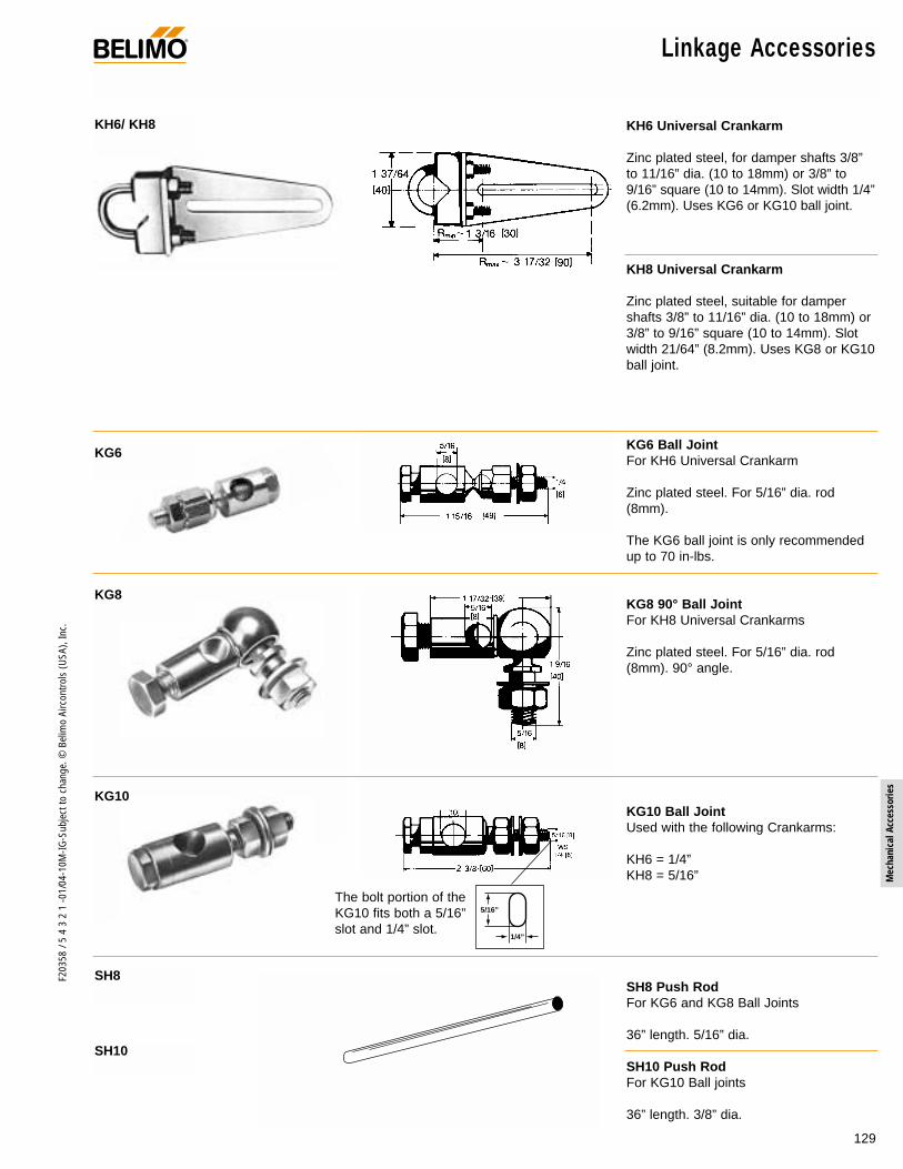
129
F203
58 /
5 4
3 2
1 -0
1/04
-10M
-IG-S
ubje
ct to
cha
nge.
© B
elim
o Ai
rcon
trols
(USA
), In
c.
Mec
hani
cal A
cces
sorie
s
Linkage Accessories®
KH6 Universal Crankarm
Zinc plated steel, for damper shafts 3/8”to 11/16” dia. (10 to 18mm) or 3/8” to9/16” square (10 to 14mm). Slot width 1/4”(6.2mm). Uses KG6 or KG10 ball joint.
KH8 Universal Crankarm
Zinc plated steel, suitable for dampershafts 3/8” to 11/16” dia. (10 to 18mm) or3/8” to 9/16” square (10 to 14mm). Slotwidth 21/64” (8.2mm). Uses KG8 or KG10ball joint.
KG6 Ball JointFor KH6 Universal Crankarm
Zinc plated steel. For 5/16” dia. rod(8mm).
The KG6 ball joint is only recommendedup to 70 in-lbs.
KG8 90° Ball JointFor KH8 Universal Crankarms
Zinc plated steel. For 5/16” dia. rod(8mm). 90° angle.
KG10 Ball JointUsed with the following Crankarms:
KH6 = 1/4”KH8 = 5/16”
SH8 Push RodFor KG6 and KG8 Ball Joints
36” length. 5/16” dia.
SH10 Push RodFor KG10 Ball joints
36” length. 3/8” dia.
KH6/ KH8
KG6
KG10
KG8
SH8
SH10
5/16”
1/4”
The bolt portion of theKG10 fits both a 5/16”slot and 1/4” slot.

130
F203
58 /
5 4
3 2
1 -0
1/04
-10M
-IG-S
ubje
ct to
cha
nge.
© B
elim
o Ai
rcon
trols
(USA
), In
c.
ZG-LF2
Linkage Accessories
Crankarm adaptor kitsWhen the actuator is not mounted to the damper shaft
®
ZG-DC1 Damper ClipMounts to damper blade - 3.5”
ZG-DC2 Damper ClipMounts to damper blade - 6”
The ZG-DC1 and ZG-DC2 damper clipsare designed to mount to damper bladesand work as crankarms in damper linkageapplications. The ZG-DC1 is designed tobe used in applications where the actua-tor is located in front of the damper. TheZG-DC2 is designed to be used when theactuator is located above or below thedamper.
ZG-AF Crankarm Adaptor KitFor AF and NF Series Actuators
Kit contains: 1 KH-AF crankarm with retaining ring
2 stand-off brackets4 mounting feet2 bolts with nuts2 self-tapping metal screws2 KG8 ball jointsInstructions
ZG-AF108 Crankarm Adaptor KitFor AF and NF Series Actuators
Kit contains: 1 KH-AF crankarm with retaining ring
1 ZG-108 mounting bracket(see page 10)
4 bolts with nutsNote: May require crankarm and balljoints.
ZG-LF112 Crankarm Adaptor KitFor LF Series Actuators
Kit contains: 1 KH-LF crankarm with retaining ring
1 ZG-112 mounting bracket(see page 63)
2 bolts with nutsNote: May require crankarm and balljoints.
ZG-LF2 Crankarm Adaptor KitFor LF Series Actuators
Kit contains: 1 KH-LF crankarm with retaining clip1 mounting bracket3 bolts with nutsInstructions
Note: May require crankarm and balljoints.
ZG-DC1
ZG-DC2
ZG-AF US
ZG-AF108
ZG-LF112
ZG-DC2clip
ZG-DC1 clip
ZG-AF US
ZG-106 orZG-107 withKH-AF
ZG-112
KH-LFcrankarm

131
F203
58 /
5 4
3 2
1 -0
1/04
-10M
-IG-S
ubje
ct to
cha
nge.
© B
elim
o Ai
rcon
trols
(USA
), In
c.
Mec
hani
cal A
cces
sorie
s
Shaft Adaptors®
AV10-18 Universal Shaft ExtensionFor damper operating shafts
Approx. 9 1/2” (240mm) extension for shafts3/8” to 11/16” dia. (10 to 18mm), or 3/8” to9/16” square (10 to 14mm).
AV1 Shaft Extension for AM SeriesActuators
Approx. 3” (75mm) extension for shafts 3/8”to 3/4” dia. (10 to 20mm), or 3/8” to 9/16”square (10 to 14mm).
ZG-NMSA-1 Shaft AdaptorFor NM Series Actuators
For 1/2” dia. shafts shorter than 3/4”. 3”long, 13/16” outside dia. 2 set screws. Shaftextends 1” inside ZG-NMSA-1.
ZG-LMSA Shaft AdaptorFor LM, LF Series Actuators
For 1/2” dia. shafts shorter than 3/4”. 3”long, 5/8” outside dia. 2 set screws. Shaftextends 3/4” inside ZG-LMSA.
ZDB Angle of Rotation LimiterFor SM Series Actuators
Remove nuts on V-bolt and install ZDB toclamp assembly with indicator in 0 position.Remove clip holding clamp assembly toactuator. Pull out clamp assembly androtate to the number of graduations youwould like to limit rotation by. Each gradua-tion is 9°. Reinstall clamp assembly.
ZDB-GM Angle of Rotation LimiterFor GM Series Actuators
Disengage gears with manual release andturn clamp indicator to 0 position. Pull outretaining clip and remove clamp. LocateZDB-GM at desired graduation (eachapprox. 10°). Reinstall clamp.
ZG-LFC114
AV10-18
AV1
ZG-NMSA-1
ZG-LMSA
ZDB
ZDB-GM
Rotation limiters
min. 3/4"AV1
ZG-LFC114
ZG-LFC114 Mounting KitSpecifically for Trane Voyager unit retrofit
Kit contains: 1-Mounting bracket1-Shaft adaptor2-Actuator mounting bolts
and nuts4-Mounting bracket screws
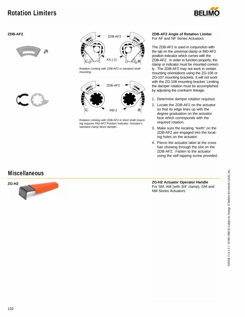
132
F203
58 /
5 4
3 2
1 -0
1/04
-10M
-IG-S
ubje
ct to
cha
nge.
© B
elim
o Ai
rcon
trols
(USA
), In
c.
Rotation Limiters ®
9080
7060
50
40
30
20
100
-5
908070
6050
4030
20
10
0-5
908 90
L R
9080
7060
50
40
30
20
100
-5
908070
6050
4030
20
10
0-5
908 90
L RIND-2
ZDB-AF2
K4 (-1)
ZDB-AF2ZDB-AF2 Angle of Rotation LimiterFor AF and NF Series Actuators
The ZDB-AF2 is used in conjunction withthe tab on the universal clamp or IND-AF2position indicator which comes with theZDB-AF2. In order to function properly, theclamp or indicator must be mounted correct-ly. The ZDB-AF2 may not work in certainmounting orientations using the ZG-106 orZG-107 mounting brackets. It will not workwith the ZG-108 mounting bracket. Limitingthe damper rotation must be accomplishedby adjusting the crankarm linkage.
1. Determine damper rotation required.
2. Locate the ZDB-AF2 on the actuatorso that its edge lines up with thedegree graduation on the actuatorface which corresponds with therequired rotation.
3. Make sure the locating “teeth” on theZDB-AF2 are engaged into the locat-ing holes on the actuator.
4. Pierce the actuator label at the crosshair showing through the slot on theZDB-AF2. Fasten to the actuatorusing the self tapping screw provided.
ZG-H2 Actuator Operator HandleFor SM, AM (with 3/4” clamp), GM andNM Series Actuators
Rotation Limiting with ZDB-AF2 in standard shaftmounting.
Rotation Limiting with ZDB-AF2 in short shaft mount-ing requires IND-AF2 Position Indicator. Actuator’sstandard clamp faces damper.
ZDB-AF2
ZG-H2
Miscellaneous
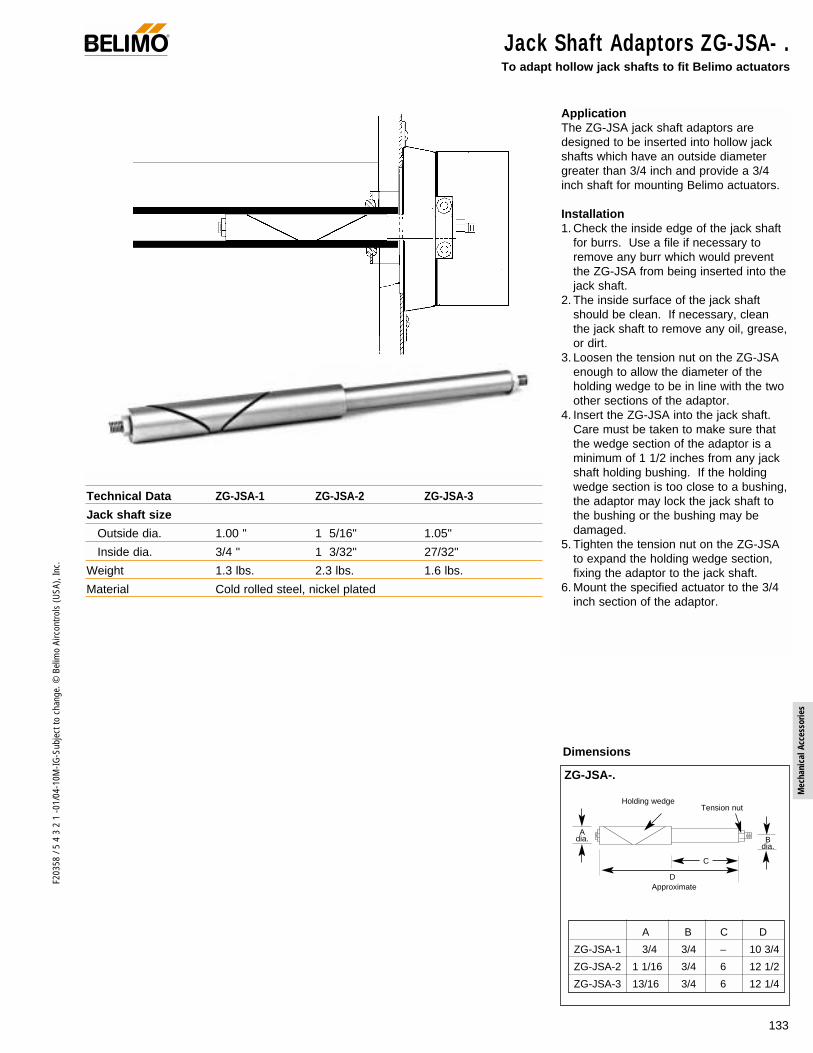
133
F203
58 /
5 4
3 2
1 -0
1/04
-10M
-IG-S
ubje
ct to
cha
nge.
© B
elim
o Ai
rcon
trols
(USA
), In
c.
Mec
hani
cal A
cces
sorie
s
ApplicationThe ZG-JSA jack shaft adaptors aredesigned to be inserted into hollow jackshafts which have an outside diametergreater than 3/4 inch and provide a 3/4inch shaft for mounting Belimo actuators.
Installation1. Check the inside edge of the jack shaft
for burrs. Use a file if necessary toremove any burr which would preventthe ZG-JSA from being inserted into thejack shaft.
2. The inside surface of the jack shaftshould be clean. If necessary, cleanthe jack shaft to remove any oil, grease,or dirt.
3. Loosen the tension nut on the ZG-JSAenough to allow the diameter of theholding wedge to be in line with the twoother sections of the adaptor.
4. Insert the ZG-JSA into the jack shaft.Care must be taken to make sure thatthe wedge section of the adaptor is aminimum of 1 1/2 inches from any jackshaft holding bushing. If the holdingwedge section is too close to a bushing,the adaptor may lock the jack shaft tothe bushing or the bushing may bedamaged.
5. Tighten the tension nut on the ZG-JSAto expand the holding wedge section,fixing the adaptor to the jack shaft.
6. Mount the specified actuator to the 3/4inch section of the adaptor.
Jack Shaft Adaptors ZG-JSA- . To adapt hollow jack shafts to fit Belimo actuators
Technical Data ZG-JSA-1 ZG-JSA-2 ZG-JSA-3
Jack shaft size
Outside dia. 1.00 " 1 5/16" 1.05"
Inside dia. 3/4 " 1 3/32" 27/32"
Weight 1.3 lbs. 2.3 lbs. 1.6 lbs.
Material Cold rolled steel, nickel plated
Dimensions
ZG-JSA-.
A B C D
ZG-JSA-1 3/4 3/4 – 10 3/4
ZG-JSA-2 1 1/16 3/4 6 12 1/2
ZG-JSA-3 13/16 3/4 6 12 1/4
Adia. B
dia.
DApproximate
Holding wedge Tension nut
C
®

ZG-100 Universal Mounting Bracket For SM, AM, GM, NF, and AF series actuators
ApplicationThe ZG-100 universal mounting bracket is designed for appli-cations where the actuator cannot be mounted directly to thedamper shaft, and no proper mounting surface is available. Itmay be used for outside or inside the duct mounting, fastenedto the ductwork or directly to the damper assembly. It mayalso be used to mount to other surfaces rather than the duct.
The ZG-100 is provided with prepunched hole patterns for theSM, GM, NF and AF series actuators and their associatedcrankarm adaptor brackets. The hole pattern layout allowsmounting these actuators in three, different, mounting orienta-tions. The ZG-100 may also be field drilled for special ormore exact mounting of linkage components.
Installation1. Mount the appropriate set of crankarm adaptor kit brackets
and crankarm to the actuator to be used. When using springreturn actuators, care must be taken to select the propermounting orientation for the correct fail-safe operation.
ACTUATOR CRANKARMSERIES KIT FOR ZG-100
SM ZG-SM2AM ZG-AMGM ZG-GM2NF ZG-AFAF ZG-AF
Note: Follow the instructions for mounting the adaptor kitsto the actuator or the actuator may be damaged.
2. Position the ZG-100 mounting bracket in the planned mount-ing location. If possible, do not fasten at this time. TheZG-100 can be mounted by using either the four 1/4 inchdiameter holes on its base or five 1/4 x 5/8 inch oval holeson its edge. Additional holes may be drilled if necessary.
3. Position the actuator/adaptor assembly in the desired mount-ing location against the ZG-100 and see if one of the existinghole patterns can be used for the actuator mounting. If theexisting hole patterns cannot be used, mark the correct holepositions and drill the desired holes. Do not mount.
4. With the actuator mounting position established, positionthe ZG-100 bracket in the best position for propercrankarm/linkage alignment. Fasten the ZG-100 to themounting surface.
5. Mount the actuator/adaptor assembly to the ZG-100.
6. Install the crankarm linkage between the actuator and damper.
7. Cycle the actuator through its operational range to verifycorrect linkage setup. The SM, GM, and AF actuatorseries may be manually operated without power available.
OTHER UNIVERSAL MOUNTING BRACKETS
MODEL ACTUATOR USED WITHZG-101 SM, AM, GM, NF, AFZG-103 SM, AM, GMZG-104 SM, AM, GMZG-105 NMZG-106 NF, AFZG-107 NF, AFZG-108 NF, AF
134
F203
58 /
5 4
3 2
1 -0
1/04
-10M
-IG-S
ubje
ct to
cha
nge.
© B
elim
o Ai
rcon
trols
(USA
), In
c.
®
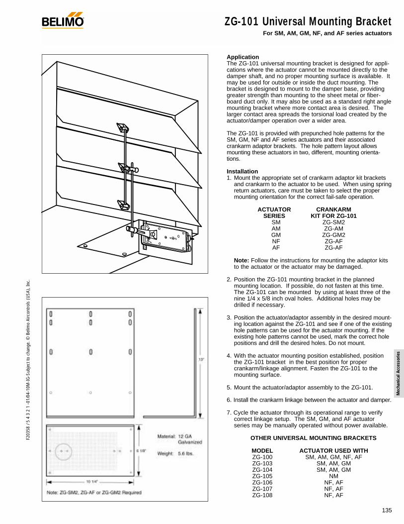
135
F203
58 /
5 4
3 2
1 -0
1/04
-10M
-IG-S
ubje
ct to
cha
nge.
© B
elim
o Ai
rcon
trols
(USA
), In
c.
Mec
hani
cal A
cces
sorie
s
ZG-101 Universal Mounting Bracket For SM, AM, GM, NF, and AF series actuators
®
ApplicationThe ZG-101 universal mounting bracket is designed for appli-cations where the actuator cannot be mounted directly to thedamper shaft, and no proper mounting surface is available. Itmay be used for outside or inside the duct mounting. Thebracket is designed to mount to the damper base, providinggreater strength than mounting to the sheet metal or fiber-board duct only. It may also be used as a standard right anglemounting bracket where more contact area is desired. Thelarger contact area spreads the torsional load created by theactuator/damper operation over a wider area.
The ZG-101 is provided with prepunched hole patterns for theSM, GM, NF and AF series actuators and their associatedcrankarm adaptor brackets. The hole pattern layout allowsmounting these actuators in two, different, mounting orienta-tions.
Installation1. Mount the appropriate set of crankarm adaptor kit brackets
and crankarm to the actuator to be used. When using springreturn actuators, care must be taken to select the propermounting orientation for the correct fail-safe operation.
ACTUATOR CRANKARMSERIES KIT FOR ZG-101
SM ZG-SM2AM ZG-AMGM ZG-GM2NF ZG-AFAF ZG-AF
Note: Follow the instructions for mounting the adaptor kitsto the actuator or the actuator may be damaged.
2. Position the ZG-101 mounting bracket in the plannedmounting location. If possible, do not fasten at this time.The ZG-101 can be mounted by using at least three of thenine 1/4 x 5/8 inch oval holes. Additional holes may bedrilled if necessary.
3. Position the actuator/adaptor assembly in the desired mount-ing location against the ZG-101 and see if one of the existinghole patterns can be used for the actuator mounting. If theexisting hole patterns cannot be used, mark the correct holepositions and drill the desired holes. Do not mount.
4. With the actuator mounting position established, positionthe ZG-101 bracket in the best position for propercrankarm/linkage alignment. Fasten the ZG-101 to themounting surface.
5. Mount the actuator/adaptor assembly to the ZG-101.
6. Install the crankarm linkage between the actuator and damper.
7. Cycle the actuator through its operational range to verifycorrect linkage setup. The SM, GM, and AF actuatorseries may be manually operated without power available.
OTHER UNIVERSAL MOUNTING BRACKETS
MODEL ACTUATOR USED WITHZG-100 SM, AM, GM, NF, AFZG-103 SM, AM, GMZG-104 SM, AM, GMZG-105 NMZG-106 NF, AFZG-107 NF, AFZG-108 NF, AF

136
F203
58 /
5 4
3 2
1 -0
1/04
-10M
-IG-S
ubje
ct to
cha
nge.
© B
elim
o Ai
rcon
trols
(USA
), In
c.
ZG-102 Multiple Actuator Mounting Bracket For GM and AF series actuators
®
ApplicationThe multiple actuator mounting bracket is designed for caseswhere it is necessary to mount two actuators to one shaft toprovide extra torque.The dual mounting bracket is typically used with the AF andGM series actuators. This is due to the fact that each ofthese series are the highest torque range available.
Installation1. Determine if the second actuator will mount on top of
(Figure A) or 180° opposed to (Figure B) the first actuator.2. Mount the first actuator as you would normally; but, do
not wire at this time. Make sure the shaft clamp assem-bly on the actuator is positioned correctly for properdamper operation.
3. Mount the actuator rear mounting bracket to the top ofthe multiple actuator mounting bracket. There are twolocations for the mounting of this bracket. Hole set A isthe preferred location. Hole set B is to be used if addi-tional clearances are required to route flexible conduit tothe actuators.
4. Loosen the three locking screws located in the slots ofthe mounting bracket.
5. Adjust the top section of the bracket to a height whichclears the top of the first actuator by approximately 1/8". Tighten the three locking screws.
6. Mount the second actuator on the shaft and slide themounting bracket under the second actuator so the rear mounting bracket stud engages the slot at the rear of theactuator.
7. Transfer the thru hole locations from the multiple actuatormounting bracket base to the mounting surface.
8. Drill the three holes. (Use a No. 2 drill if you are using theNo. 8 sheet metal screws provided.)
9. Fasten the multiple mounting bracket.10. After verifying the correct orientation of the shaft clamp
assembly of the second actuator, tighten the fastening nuts on the clamp.
11. Wire the actuators in parallel to the controller.12. Power the actuators and check for proper operation.
AccessoryAV10 - 18 Universal shaft extension
Hole set B Hole set A
7"
3 3/8"
5 3/4"
1 15/16"
Material: 12 GA Galvanized
Weight: 1.8 lbs.
Note: The majoradvantage with thismethod is it requiresless mounting area.The manual override,if available, cannotbe used in this configuration.
Note: The major advantagesare that a shorter shaft isrequired and a lower profileis achieved.
Figure A Figure B
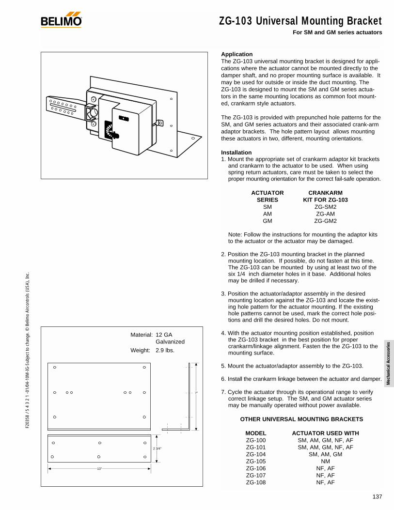
137
F203
58 /
5 4
3 2
1 -0
1/04
-10M
-IG-S
ubje
ct to
cha
nge.
© B
elim
o Ai
rcon
trols
(USA
), In
c.
Mec
hani
cal A
cces
sorie
s
ZG-103 Universal Mounting Bracket For SM and GM series actuators
ApplicationThe ZG-103 universal mounting bracket is designed for appli-cations where the actuator cannot be mounted directly to thedamper shaft, and no proper mounting surface is available. Itmay be used for outside or inside the duct mounting. TheZG-103 is designed to mount the SM and GM series actua-tors in the same mounting locations as common foot mount-ed, crankarm style actuators.
The ZG-103 is provided with prepunched hole patterns for theSM, and GM series actuators and their associated crank-armadaptor brackets. The hole pattern layout allows mountingthese actuators in two, different, mounting orientations.
Installation1. Mount the appropriate set of crankarm adaptor kit brackets
and crankarm to the actuator to be used. When usingspring return actuators, care must be taken to select theproper mounting orientation for the correct fail-safe operation.
ACTUATOR CRANKARMSERIES KIT FOR ZG-103
SM ZG-SM2AM ZG-AMGM ZG-GM2
Note: Follow the instructions for mounting the adaptor kitsto the actuator or the actuator may be damaged.
2. Position the ZG-103 mounting bracket in the plannedmounting location. If possible, do not fasten at this time.The ZG-103 can be mounted by using at least two of thesix 1/4 inch diameter holes in it base. Additional holesmay be drilled if necessary.
3. Position the actuator/adaptor assembly in the desiredmounting location against the ZG-103 and locate the exist-ing hole pattern for the actuator mounting. If the existinghole patterns cannot be used, mark the correct hole posi-tions and drill the desired holes. Do not mount.
4. With the actuator mounting position established, positionthe ZG-103 bracket in the best position for propercrankarm/linkage alignment. Fasten the the ZG-103 to themounting surface.
5. Mount the actuator/adaptor assembly to the ZG-103.
6. Install the crankarm linkage between the actuator and damper.
7. Cycle the actuator through its operational range to verifycorrect linkage setup. The SM, and GM actuator seriesmay be manually operated without power available.
OTHER UNIVERSAL MOUNTING BRACKETS
MODEL ACTUATOR USED WITHZG-100 SM, AM, GM, NF, AFZG-101 SM, AM, GM, NF, AFZG-104 SM, AM, GMZG-105 NMZG-106 NF, AFZG-107 NF, AFZG-108 NF, AF
13"
2 3/4"
7"
Material: 12 GA Galvanized
Weight: 2.9 lbs.
®

138
F203
58 /
5 4
3 2
1 -0
1/04
-10M
-IG-S
ubje
ct to
cha
nge.
© B
elim
o Ai
rcon
trols
(USA
), In
c.
ZG-104 Universal Mounting Bracket For SM, AM and GM series actuators
ApplicationThe ZG-104 universal mounting bracket is designed for appli-cations where the actuator cannot be mounted directly to thedamper shaft, and no proper mounting surface is available. Itmay be used for outside or inside the duct mounting. TheZG-104 is designed to mount the SM, and GM series actua-tors in the same mounting locations as common foot mount-ed, crankarm style actuators.
The ZG-104 is provided with prepunched hole patterns for theSM and GM series actuators and their associated crankarmadaptor brackets. The hole pattern layout allows mountingthese actuators in 2, different, mounting orientations.
Installation1. Mount the appropriate set of crankarm adaptor kit brackets
and crankarm to the actuator to be used. When usingspring return actuators, care must be taken to select theproper mounting orientation for the correct fail-safe operation.
ACTUATOR CRANKARMSERIES KIT FOR ZG-104
SM ZG-SM2AM ZG-AMGM ZG-GM2
Note: Follow the instructions for mounting the adaptor kitsto the actuator or the actuator may be damaged.
2. Position the ZG-104 mounting bracket in the plannedmounting location. If possible, do not fasten at this time.The ZG-104 can be mounted by using at least three of thenine 1/4 inch diameter holes in it base. Additional holesmay be drilled if necessary.
3. Position the actuator/adaptor assembly in the desiredmounting location against the ZG-104 and locate the exist-ing hole pattern for the actuator mounting. If the existinghole patterns cannot be used, mark the correct hole posi-tions and drill the desired holes. Do not mount.
4. With the actuator mounting position established, positionthe ZG-104 bracket in the best position for propercrankarm/linkage alignment. Fasten the ZG-104 to themounting surface.
5. Mount the actuator/adaptor assembly to the ZG-104.
6. Install the crankarm linkage between the actuator and damper.
7. Cycle the actuator through its operational range to verifycorrect linkage setup. The SM, and GM actuator seriesmay be manually operated without power available.
OTHER UNIVERSAL MOUNTING BRACKETS
MODEL ACTUATOR USED WITHZG-100 SM, AM, GM, NF, AFZG-101 SM, AM, GM, NF, AFZG-103 SM, AM, GMZG-105 NMZG-106 NF, AFZG-107 NF, AFZG-108 NF, AF
13"
6 1/8"
4"
Material: 12 GA Galvanized
Weight: 3.0 lbs.
®

139
F203
58 /
5 4
3 2
1 -0
1/04
-10M
-IG-S
ubje
ct to
cha
nge.
© B
elim
o Ai
rcon
trols
(USA
), In
c.
Mec
hani
cal A
cces
sorie
s
ZG-105 Universal Mounting Bracket For NM series actuators
4"
2"
8"
Material: 16 GA Galvanized
Weight: 0.7 lbs.
ApplicationThe ZG-105 universal mounting bracket is designed for appli-cations where the actuator cannot be mounted directly to thedamper shaft, and no proper mounting surface is available. Itmay be used for outside or inside the duct mounting. The ZG-105 is designed to mount the NM series actuators in the samemounting locations as common foot mounted, crankarm styleactuators.
The ZG-105 is provided with prepunched hole patterns for usewith the NM series actuators with the ZG-NM3 crankarmadaptor kit. The hole pattern layout allows mounting theseactuators in two, different, mounting orientations.
Installation1. Position the ZG-105 mounting bracket in the planned
mounting location. If possible, do not fasten at this time.The ZG-105 can be mounted by using the three 9/64 inchdiameter holes in its base. Additional holes may be drilledif necessary.
2. Using a number 10 tamper-proof torx screwdriver, removethe four torx head screws on the base of the actuator.
3. Position the actuator in the desired mounting locationagainst the ZG-105 and locate the existing hole pattern forthe actuator mounting.
4. Align the screw holes in the base of the actuator to theselected hole set in the ZG-105 and fasten the actuator tothe bracket using the four screws removed in step 2.
5. Mount the NM crankarm into the universal mounting clampat the desired starting angle. Fasten the ZG-105 to themounting surface.
6. Install the crankarm linkage between the actuator anddamper.
7. Cycle the actuator through its operational range to verifycorrect linkage setup. The NM actuator series may bemanually operated without power available.
OTHER UNIVERSAL MOUNTING BRACKETS
MODEL ACTUATOR USED WITHZG-100 SM, GM, NF, AFZG-101 SM, GM, NF, AFZG-103 SM, GMZG-104 SM, GMZG-106 NF, AFZG-107 NF, AFZG-108 NF, AF
AccessoryTOOL-03 #10, Tamper-proof TORX screwdriver
®

140
F203
58 /
5 4
3 2
1 -0
1/04
-10M
-IG-S
ubje
ct to
cha
nge.
© B
elim
o Ai
rcon
trols
(USA
), In
c.
ZG-106 / ZG-107 Universal Mounting Bracket For AF and NF series actuators
ApplicationThe ZG-106 and ZG-107 universal mounting brackets aredesigned for applications where the actuator cannot bemounted directly to the damper shaft. They may be used foroutside or inside the duct mounting. The ZG-106 and ZG-107are designed to mount the NF and AF series actuators in thesame mounting locations as common foot mounted, crankarmstyle actuators. Hole patterns in the base match commonHoneywell™ and Johnson Controls™ actuators for easy retro-fit. The ZG-106 and ZG-107 are designed with different actua-tor mounting heights. The ZG-106 is designed to place the KH-AFcrankarm in the same relative position as the Honeywell™Mod IV actuators. The ZG-107 will place the crankarm in thesame relative position as the Honeywell™ Mod III actuators.
The ZG-106 and ZG-107 are provided with hole patterns tomount the NF and AF series actuators in either a horizontal orvertical position to meet space requirements. The KH-AFcrankarm is required to fully convert the NF or AF forcrankarm operation.
Installation1. When using spring return actuators, care must be taken to
select the proper mounting orientation for the correct fail-safe operation.
2. If this is a new installation, position the ZG-106 or ZG-107mounting bracket in the planned mounting location. Do notfasten at this time.
If this a retrofit installation replacing common Honeywell™or Johnson Control™ actuators, and the bolt pattern of thebracket matches the pattern of the previous actuator, fas-ten the bracket to the mounting surface. Mount the KH-AFcrankarm to the actuator. Proceed to step 6.
3. Position the actuator in the desired mounting position (hori-zontal or vertical) in the ZG-106 or ZG-107. Slide in themounting bolts to temporarily hold the actuator to the bracket.
4. Mount the KH-AF crankarm to the actuator in the requiredoperating position.
5. Position the bracket/actuator assembly in the best positionfor proper crankarm/linkage alignment. Mark the bracketposition. Remove the actuator. Fasten the bracket to themounting surface.
6. Mount the actuator to the bracket using the 2 mountingbolts and lock nuts.
7. Install the linkage assembly between the damper and actuator.
8. Cycle the actuator through its operational range to verifycorrect linkage setup. The AF actuator series may be man-ually operated without power available.
OTHER UNIVERSAL MOUNTING BRACKETS
MODEL ACTUATOR USED WITHZG-100 SM, GM, NF, AFZG-101 SM, GM, NF, AFZG-103 SM, GMZG-104 SM, GMZG-105 NMZG-108 NF, AF
5 1/2"
A
2 1/4"
B
MODEL NO. A B ZG-106 1.50" 1.02" ZG-107 2.25" 1.77"
MODEL NO. A B ZG-106 1.50" 1.02" ZG-107 2.25" 1.77"
Material: 12 GA Galvanized
Weight: ZG-106 0.7 lbs.ZG-107 0.9 lbs.
®
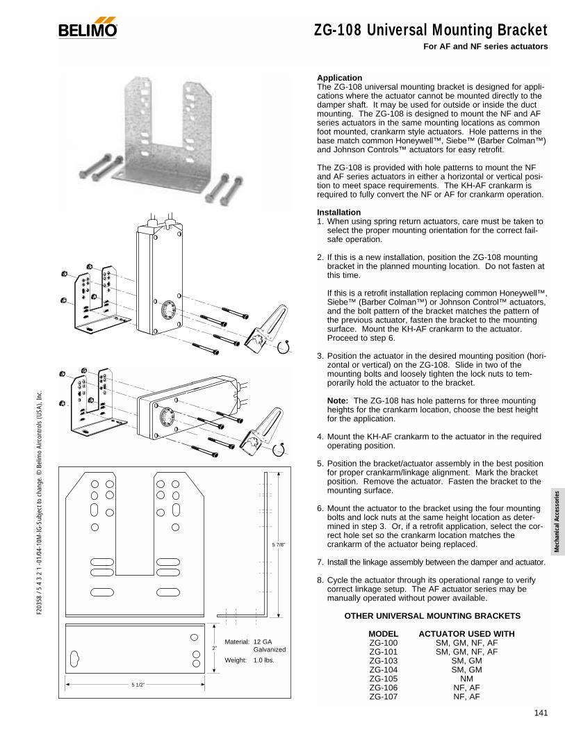
141
F203
58 /
5 4
3 2
1 -0
1/04
-10M
-IG-S
ubje
ct to
cha
nge.
© B
elim
o Ai
rcon
trols
(USA
), In
c.
Mec
hani
cal A
cces
sorie
s
ZG-108 Universal Mounting Bracket For AF and NF series actuators
ApplicationThe ZG-108 universal mounting bracket is designed for appli-cations where the actuator cannot be mounted directly to thedamper shaft. It may be used for outside or inside the ductmounting. The ZG-108 is designed to mount the NF and AFseries actuators in the same mounting locations as commonfoot mounted, crankarm style actuators. Hole patterns in thebase match common Honeywell™, Siebe™ (Barber Colman™)and Johnson Controls™ actuators for easy retrofit.
The ZG-108 is provided with hole patterns to mount the NFand AF series actuators in either a horizontal or vertical posi-tion to meet space requirements. The KH-AF crankarm isrequired to fully convert the NF or AF for crankarm operation.
Installation1. When using spring return actuators, care must be taken to
select the proper mounting orientation for the correct fail-safe operation.
2. If this is a new installation, position the ZG-108 mountingbracket in the planned mounting location. Do not fasten atthis time.
If this is a retrofit installation replacing common Honeywell™,Siebe™ (Barber Colman™) or Johnson Control™ actuators,and the bolt pattern of the bracket matches the pattern ofthe previous actuator, fasten the bracket to the mountingsurface. Mount the KH-AF crankarm to the actuator.Proceed to step 6.
3. Position the actuator in the desired mounting position (hori-zontal or vertical) on the ZG-108. Slide in two of themounting bolts and loosely tighten the lock nuts to tem-porarily hold the actuator to the bracket.
Note: The ZG-108 has hole patterns for three mountingheights for the crankarm location, choose the best heightfor the application.
4. Mount the KH-AF crankarm to the actuator in the requiredoperating position.
5. Position the bracket/actuator assembly in the best positionfor proper crankarm/linkage alignment. Mark the bracketposition. Remove the actuator. Fasten the bracket to themounting surface.
6. Mount the actuator to the bracket using the four mountingbolts and lock nuts at the same height location as deter-mined in step 3. Or, if a retrofit application, select the cor-rect hole set so the crankarm location matches thecrankarm of the actuator being replaced.
7. Install the linkage assembly between the damper and actuator.
8. Cycle the actuator through its operational range to verifycorrect linkage setup. The AF actuator series may bemanually operated without power available.
OTHER UNIVERSAL MOUNTING BRACKETS
MODEL ACTUATOR USED WITHZG-100 SM, GM, NF, AFZG-101 SM, GM, NF, AFZG-103 SM, GMZG-104 SM, GMZG-105 NMZG-106 NF, AFZG-107 NF, AF
5 7/8"
2"
5 1/2"
Material: 12 GA Galvanized
Weight: 1.0 lbs.
®

142
F203
58 /
5 4
3 2
1 -0
1/04
-10M
-IG-S
ubje
ct to
cha
nge.
© B
elim
o Ai
rcon
trols
(USA
), In
c.
ZG-108 Universal Mounting Bracket Mounting Positions for Typical Replacements
Barber Colman™ MA Type - Vertical Barber Colman™ MA Type - Horizontal (left) Barber Colman™ MA Type - Horizontal (right)
Honeywell™ Mod. IV Type- Vertical Honeywell™ Mod. IV Type - Horizontal (left) Honeywell™ Mod. IV Type - Horizontal (right)
Johnson Control™ 100 Series Type and Honeywell™ Mod. III Type
Vertical
Johnson Control™ 100 Series Type and Honeywell™ Mod. III Type
Horizontal (left)
Johnson Control™ 100 Series Type and Honeywell™ Mod. III Type
Horizontal (right)
Black holes represent correct bolt locations.
®

143
F203
58 /
5 4
3 2
1 -0
1/04
-10M
-IG-S
ubje
ct to
cha
nge.
© B
elim
o Ai
rcon
trols
(USA
), In
c.
Mec
hani
cal A
cces
sorie
s
® ZS-100 Weather ShieldFor all damper actuators
Material: 16 GA Galvanized
Weight: 3.5 lbs.
Note: The ZS-100 is supplied disassembled
3/16" dia.10 holes
ApplicationThe ZS-100 weather shield provides mod-erate protection to actuators which aremounted outdoors. This product is notdesigned as a water tight enclosure. Theweather shield will work with all damperactuators.
InstallationThe ZS-100 weather shield is supplieddisassembled. Supplying it in this manormakes it applicable to a wider range offield applications.It may be assembled with 2 sides, 2 endsand the cover to completely conceal theactuator. A hole punch can be used toprovide a hole to mount a wire conduit. Afoam gasket is also provided to achieve abetter seal between the cover and sidesor from the base to the mounting surface.If desired, a side or end can be deletedfrom the assembly to provide easy accessfrom the bottom of the enclosure.
General Instructions:1. The actuator mounting strap must be
shortened by 1 1/8 inches on both ends. (At the closest oblong slot to the end).
2. Install the actuator following the instructions for the actuator used.
3. Determine which side of the enclosurerequires holes for wiring. To ease installation, holes should be made in the housing prior to assembly.
4. Assemble the ends and sides together first, then attach the cover.
5. If using the gasket, peel off the backing from the gasket and lay it onto the surface without stretching it. If stretched, it may pull loose with age.
6. Thread the wiring temporarily throughthe wiring hole(s).
7. Center the housing over the actuator and mount the housing to the mounting surface with self-drilling screws.
8. Remove the cover from the housing and install conduit/fittings to the housing.
9. Check the operation of the actuator prior to re-installing the cover.
10. Re-install the cover.
AccessoriesZS-101 Base mounting plate
14 3/8"
6"
13" 8"
9 1/2"

144
F203
58 /
5 4
3 2
1 -0
1/04
-10M
-IG-S
ubje
ct to
cha
nge.
© B
elim
o Ai
rcon
trols
(USA
), In
c.
®ZS-150 Weather ShieldFor all damper actuators
ApplicationThe ZS-150 weather shield provides moder-ate protection to actuators which are mount-ed outdoors. This product is not designedas a water tight enclosure. The one piece,smoke tinted, polycarbonate housing allowseasy mounting over all damper actuators.The tinted, clear housing allows easy view-ing of the actuator in operation.
InstallationThe ZS-150 weather shield is supplied as aone piece enclosure. Two 7/8 inch wiringholes are pre-drilled to allow easy connec-tions of conduit to the housing. If connec-tions must be made to a different spot onthe enclosure or only one hole is required,two plastic plugs are provided to seal theholes. A foam gasket is also provided toachieve a better seal between the base ofthe enclosure to the mounting surface.
General Instructions:1. The actuator anti-rotation strap must be
shortened by 2 inches on both ends.2. Install the actuator following the
instructions for the actuator used.3. If using the gasket, peel off the backing
and lay it onto the housings flange sur-face without stretching it. If stretched, itmay pull away with age.
4. Attach the conduit fitting(s), if used, tothe housing and thread the cable(s)through the fitting(s).
5. Center the housing over the actuatorand fasten the housing to the mountingsurface with self-drilling screws.
12 3/4" [324]
8 3/8"[213]
4"[102]
5 1/4" [146]
7/8" dia. [22.2]
2 holes
3/16" dia. [4.8] 6 holes
16" [406]
Material: Polycarbonate
Color: Clear, smoke tinted
Weight: .8 lbs [.4 kg]

145
F203
58 /
5 4
3 2
1 -0
1/04
-10M
-IG-S
ubje
ct to
cha
nge.
© B
elim
o Ai
rcon
trols
(USA
), In
c.
Mec
hani
cal A
cces
sorie
s
ZS-260 Explosion-proof HousingFor GM…, AM…, SM…, AF…, NF…, LF… actuators
®
Dimensions (All ratings in brackets are metric.)
Application
The ZS-260 explosion-proof housing may be used with theGM…, AM…, SM…, AF…, NF…, LF… series actuators. Thishousing is not designed for direct coupling. It is for use inClass I, II and III hazardous locations, and to meet the require-ments for NEMA 4, 7 & 9 type enclosures.
OperationThe ZS-260 enclosure is designed so that the required actua-tor may be easily field mounted into the enclosure. The actua-tor is fastened on to the internal portion of the operating shaftand secured at the end with an anti-rotation strap. A crank-arm, such as the KH8, is mounted to the external portion ofthe operating shaft for connection to connection to the damperlinkage. ZG-109 right angle, and ZG-110 standoff mountingbrackets may be used (see back).
The ZS-260 is designed so that the operating shaft can bemounted on either the front or rear side of the housing.
AccessoriesKH8 Universal crankarmKG8 Universal ball jointKG10 Universal ball jointZG-109 Right angle mounting bracketZG-110 Stand-off mounting bracket
Technical Data ZS-260Material Housing: cast, copper-free, aluminum,
Cover bolts: stainless steelOperating shaft: stainless steel
Conduit holes 3/4”–14 NPT (2 supplied) see Note 1
Operating shaft diameter 1/2 inchOperating shaft location Front or rear side of housing
(Field selected)Approved applications UL & CSA, Class I, II & III;
Group B, C, D, E, F & GNEMA 7, Class I, Groups B, C & DNEMA 9, Class II, Groups E, F & GNEMA 4
Weight 31.0 lb. (14.0 kg) without actuator
Note 1: Fittings that meet the requirements of the hazardouslocation must be used. All applications must comply withapplicable local and/or national electric code.
Note: Since conditions of use of this product are outside thecontrol of Belimo, the purchaser should determine suitability ofthe product for their intended use, and assumes all risk andliability in connection therewith.
8 1/4
3 3/16
16.00
9.500
10.000
8
6.435 (REF)
2 3/8 (REF)
0.690 (REF)
0.690 (REF)

146
F203
58 /
5 4
3 2
1 -0
1/04
-10M
-IG-S
ubje
ct to
cha
nge.
© B
elim
o Ai
rcon
trols
(USA
), In
c.
ZS-260 Explosion-proof Housing ®
Drive Shaft
Front
Back
Bolt Housing
Conduit Holes3/4-14 NPT
Rear Shaft Location Plug
Anti-Rotation Strap
Pan
10
7
8
4
6
5
2
3
9
–AM
–LF
–SM
–GM
–AF/NF
–FM
ZS-260 Mounting Instructions
1. Determine proper operating shaft location.
2. Remove threaded plug from the hole in which theoperating shaft will be mounted.
3. Install the anti-rotation strap, mounting plate, to theside of the housing where the operating shaft will bemounted.
4. From the inside surface of the housing, insert the oper-ating shaft, short length first, into the mounting hole.
5. Hand tighten the shaft bushing into the housing untilthe star nut/seal is in contact with the face of thehousing.
6. Using a screw driver blade, drive the star nut/sealclockwise until the bushing is locked into place.
7. Install the anti-rotation strap into the mounting plateat the designated holes for the actuator to be used.
8. Install actuator
9. Wire actuator (per electrical code).
10. Bolt housing together
KH8 Crankarmwith Ball Joint (KG8 or KG10)(order separately)
Push Rod (SH8 or SH10)
(order separately)
ZG-109
ZS-260 Housing
Mounting Hardware(included with ZG-109)
Duct
–AM
–LF
–SM
–GM
–AF/NF
–FM
ZS-260 Shaft Thru Front
Typical Mounting Sequence
Nut
Washer Casting
WasherBolt
LockWasher
KH8 Crankarmwith Ball Joint (KG8 or KG10)(order separately)
Push Rod (SH8 or SH10 )
(order separately)
ZG-110
ZS-260 Housing(shaft through rear)
Mounting Hardware(included with ZG-110)
Typical ZG-110 MountingTypical ZG-109 Mounting

147
F203
58 /
5 4
3 2
1 -0
1/04
-10M
-IG-S
ubje
ct to
cha
nge.
© B
elim
o Ai
rcon
trols
(USA
), In
c.
Mec
hani
cal A
cces
sorie
s
Technical Data ZS-300 (-1) (-5)
Material All 304 stainless steel housing, door, (with neoprene gasket),shaft, coupling, universal mounting plate, and hardware.
Conduit holes Field drilled as required. U.L. listed electrical fittings forNEMA 4X conditions must be used.
Operating shaft 1/2” by 5 15/16” long 304 stainless steel with integral cou-pling for direct mounting to 1/2” round or hexagonal driveshafts. Square head set screws are 304 stainless steel.
Optional shafts ZS-300-C1 1/2” shaft adaptor (standard with housing)ZS-300-C2 3/4” shaft adaptorZS-300-C3 1” shaft adaptor
Rotating shaft seal Machined PVC hub, bronze oilite bearings, 10 PSI,Nitrile, bi-rotational, hydrodynamic, radial lip Wave seal.
Industry standards The Belimo ZS-300 NEMA 4X enclosure and Belimo modelSM, GM, AM, AF, NF and LF are U.L. listed as an assem-bly. These enclosures conform to the NEMA standard forType 4X (water-, dust-tight and corrosion resistant).
Weight 11 lbs. [5 kg] without actuator or mounting brackets.
2 holes 5/16" dia. typ.
5"
3"2"
8 3/4"
17 1/4" 3 3/8" max.
4 1/8"
Drive Shaft/Coupler
15 7/8"
4 7/16"
5 1/2"
4"
1 1/2"
2 1/2" Adjustment
Optional AdjustableMounting BracketTop and Bottom
FRONT VIEW
SIDE VIEW
PLAN VIEW
Bearing and Shaft Seal
7 1/4"
ZS-300 ZS-300 NEMA 4X HousingFor AM, SM, GM, AF, NF, LF Series Actuators
ApplicationThe ZS-300 (-1) NEMA 4X enclosuresmay be used with SM, GM, AM, AF, NFand LF Belimo actuators. They areintended for use primarily to provide pro-tection against corrosion, windblown dustand rain, splashing water, hose-directedwater; undamaged by the formation of iceon the enclosure. Type 304 stainlesssteel enclosures resist moisture, dust, salt,and corrosive chemicals, and are easy tokeep clean for sanitary applications.
OperationThe ZS-300 enclosures are designed sothat the required actuator may be easilymounted in the enclosure. The operatingshaft and coupling are inserted from thebackside through the rotating shaft seal.The actuator is fastened on the end of theoperating shaft and secured at the endwith an anti-rotation strap. Adjustablemounting brackets, if supplied, areassembled to the fixed mounting holes atthe top and bottom of the enclosure withstainless steel nuts, bolts and lock wash-ers. The direct drive coupling is designedfor a 1/2” round or hexagonal shaft andsecured with two square head set screws.Mounting brackets are adjusted andsecured in place.
Ordering InformationZS-300 Housing with mounting bracketsZS-300-1 Housing without mounting
bracketsZS-300-5 316L enclosures, custom
mounting brackets and operating shaft/couplings are available. Consult Belimo.
AccessoriesZS-300-BK Mounting bracket setZS-300-C1 1/2” shaft adaptor
(standard with housing)ZS-300-C2 3/4” shaft adaptorZS-300-C3 1” shaft adaptor
ZS-300 Protective Housing®
(Ordered separately)

148
F203
58 /
5 4
3 2
1 -0
1/04
-10M
-IG-S
ubje
ct to
cha
nge.
© B
elim
o Ai
rcon
trols
(USA
), In
c.
ZS-300 Mounting instructions
1. The damper operating shaft should extend approximately 1 1/2 inches from the damper assembly or duct side. Mount thedrive shaft/coupler ➀ to the damper operating shaft ➁ . Fasten the coupler to the damper operating shaft by tightening thetwo 3/8 inch square head set screws ➂ .
2. Determine the housing mounting orientation for the application.
3. Locate the housing hole position(s) for the control wiring of the actuator.
4. Make the necessary holes in the housing for the electrical fittings. All fittings must be rated for use in NEMA 4X applications.
5. Install (if ordered with) the 2 mounting brackets ➃ to the housing using the four 1/4-20 screws, washers, and nuts ➄ . Do nottighten.
6. Carefully slide the housing over the drive shaft.
7. Place the housing in the desired mounting position. Transfer the mounting hole locations from the mounting bracket to themounting surface.
8. Drill the 4 holes and fasten the brackets to the surface.
9. Install the anti-rotation strap to the housing in the correct location for the actuator which is being used.
10. Mount the actuator to the drive shaft using the instructions for the actuator being used. Finger tighten the nuts of the universalclamp. Make sure the back of the actuator is parallel to the back of the housing.
11. The operating shaft must pass through the mounting clamp at least 3/8 of an inch. It must not extend beyond the front of thehousing. Slide the actuator/housing assembly in the mounting brackets to obtain the proper position.
12. Tighten the mounting brackets to the housing. Verify that the back of the actuator is still parallel to the back of the housing.Tighten the nuts on the universal clamp.
13. Make all of the required electrical connections.
14. Test the actuator/damper operation.
15. Fasten the housing cover ➅ using the 6 swivel clamps.
ZS-300 (-1, -5) NEMA 4X, stainless steel, corrosion resistant enclosures for SM…, GM…, AF…, and NF… actuators
®
SMLF
GMAF/NFFM/SF
Anti-Rotation Strap Mounting Locations
1
2
3
4
56
Inner plate, see detail below.
Swivel clamps (6)

149
F203
58 /
5 4
3 2
1 -0
1/04
-10M
-IG-S
ubje
ct to
cha
nge.
© B
elim
o Ai
rcon
trols
(USA
), In
c.
Mec
hani
cal A
cces
sorie
s
Notes/Work Pad®
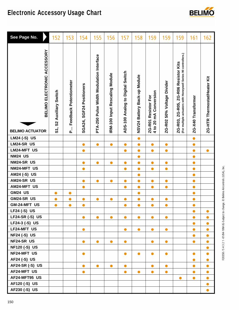
150
F203
58 /
5 4
3 2
1 -0
1/04
-10M
-IG-S
ubje
ct to
cha
nge.
© B
elim
o Ai
rcon
trols
(USA
), In
c.
S1,
S2
Au
xilia
ry S
wit
ch
P…
Fee
db
ack
Po
ten
tio
met
er
SG
A24
, SG
F24
Po
siti
on
ers
PT
A-2
50 P
uls
e W
idth
Mo
du
lati
on
Inte
rfac
e
IRM
-100
Inp
ut
Res
calin
g M
od
ule
AD
S-1
00 A
nal
og
to
Dig
ital
Sw
itch
NS
V24
Bat
tery
Bac
k-u
p M
od
ule
ZG
-R01
Res
isto
r F
or
4 to
20
mA
Co
nve
rsio
n
ZG
-R02
50%
Vo
ltag
e D
ivid
er
ZG
-R03
, ZG
-R05
, ZG
-R06
Res
isto
r K
its
(Fo
r m
ult
iple
act
uat
ors
wit
h H
on
eyw
ell S
erie
s 90
co
ntr
olle
rs.)
ZG
-X40
Tra
nsf
orm
er
ZG
-HT
R T
her
mo
stat
/Hea
ter
Kit
LM24 (-S) US
LM24-SR US
LM24-MFT US
NM24 US
NM24-SR US
NM24-MFT US
AM24 (-S) US
AM24-SR US
AM24-MFT US
GM24 US
GM24-SR US
GM-24-MFT US
LF24 (-S) US
LF24-SR (-S) US
LF24-3 (-S) US
LF24-MFT US
NF24 (-S) US
NF24-SR US
NF120 (-S) US
NF24-MFT US
AF24 (-S) US
AF24-SR (-S) US
AF24-MFT US
AF24-MFT95 US
AF120 (-S) US
AF230 (-S) US
• •• • • • • • • •• • • • • • •
• •• • • • • • • •• • • • • •
• •• • • • • • • •• • • • • •
• • • •• • • • • • • • • •• • • • • • • •
• •• • • • • • • • •
• •• • • • • • •
• •• • • • • • • •
•• • • • • • •
• •• • • • • • • •• • • • • • •
• • •••
152 153 154 155 156 157 158 159 159 159 161 162
BELIMO ACTUATOR
BE
LIM
O E
LE
CT
RO
NIC
AC
CE
SS
OR
Y
See Page No.
Electronic Accessory Usage Chart ®

151
F203
58 /
5 4
3 2
1 -0
1/04
-10M
-IG-S
ubje
ct to
cha
nge.
© B
elim
o Ai
rcon
trols
(USA
), In
c.
Elec
troni
c Ac
cess
orie
s
Electronic Accessories®
We’ll help solve any application problem with a wide rangeof accessories and unparalleled customer service.
A CLOSER LOOK…
The Belimo Difference
Customer Commitment.Extensive product range. Competitive project pricing. Application assistance. Same-day shipments. Free technical support. Five year warranty.
Low Installation and Life-Cycle Cost.Easy installation. Accuracy and repeatability. Low power consumption. No maintenance.
Long Service Life.Components tested before assembly. Every product tested before shipment. 20+ years direct coupled actuator design.

152
F203
58 /
5 4
3 2
1 -0
1/04
-10M
-IG-S
ubje
ct to
cha
nge.
© B
elim
o Ai
rcon
trols
(USA
), In
c.
S1, S2 Auxiliary SwitchesFor the direct coupled actuator SM2…/ GM2…
®
ApplicationThe S1 and S2 auxiliary switches are used to indicate when adesired position of a damper is reached or to interface addi-tional controls for a specific control sequence.
OperationThe S1 and S2 auxiliary switches are mounted onto the directcoupled actuator. A spindle transmits the rotary motion of theactuator positively to the switching segments. Any switchingpoint on the micro-switches over the full scale of 0 to 10 canbe selected by means of the slotted disc, which can be lockedby the fixing screw in the hub of the disc. The position of theswitch can be read at any time.If required, the S1 and S2 can also be mounted on a P…feedback potentiometer, but 2 auxiliary switch units cannot bemounted on top of each other.
AssemblyUse the 4 long bolts, where a S1, S2 auxiliary switch ismounted on top of a P… potentiometer.
Switch setting1, Turn actuator by hand to the 0 setting.2. Loosen fixing screw in the center of the slotted disc.3. Select the desired switching point on the scale marked 0 to
10 by rotating the slotted disc.4. Re-lock the fixing screws.5. Check the switching points by turning the actuator by hand.
The slotted disc follows rotation. The micro-switches oper-ate when the arrow passed the positions 0 or 10 (whiteline). The switching symbols indicate the actual switchingpositions.
Note: with the S1, S2 auxiliary switches, the reversible indi-cator cannot be used. Use the 4 long bolts when the S1, S2auxiliary switches are used with the SM24-SR US or GM24-SR US.
Technical Data S1 S2
Number of switches 1 SPDT 2 SPDT
Switching capacity 7A (2.5 A) 250 VAC
Switching point adjustable over full actuator rotation 0to 10. Pre-setting with scale possible.Set switching points lockable.
Electrical connection 3 ft, 18 GA appliance cable
Humidity 5 to 95% RH non-condensing
Ambient temperature -22°F to +122°F [-30°C to +50°C]
Storage temperature -40°F to +176°F [-40°C to +80°C]
Housing NEMA type 2
Housing rating UL94V-0 (flammability rating)
Servicing maintenance free
Agency listings CE
Quality standard ISO 9001
Weight 5.3 oz [150 g] 7.4 oz [210 g]
Wiring diagram
S2
S1
S2
S3
S4
S5
S6
S1
NC
NO
S1
S2
S3
N.C.
N.O.
N.C.
N.O.
N.C.
N.O.
Voltage Resistive Inductive120 7 A 5.0 A250 7 A 2.5 A

153
F203
58 /
5 4
3 2
1 -0
1/04
-10M
-IG-S
ubje
ct to
cha
nge.
© B
elim
o Ai
rcon
trols
(USA
), In
c.
Elec
troni
c Ac
cess
orie
s
P… Feedback Potentiometer For the direct coupled actuator SM2…/ GM2…
®
ApplicationThe P… feedback potentiometers are used for continuousdamper control in conjunction with normal commercial P–con-trollers with feedback signals. The P… units can also be usedin conjunction with moving coil instruments for position indica-tion, or they can serve as a positioner for parallel operatingactuators when used with normal commercial controllers.
OperationThe P… feedback potentiometer is mounted onto the damperactuators. A spindle transmits the rotary motion of the motorpositively to the potentiometer, and no adjustments whatsoev-er are necessary. If required, 2 potentiometer units P… canbe mounted on top of each other.
AssemblyUse the 4 long bolts, where 2 P… units are mounted on top ofeach other.
Types
P500 Feedback potentiometer 500ΩP1000 Feedback potentiometer 1000ΩP2800 Feedback potentiometer 2800Ω
Technical Data P…
Resistance values as above
Output 1W
Tolerance ± 5%
Linearity ± 2%
Resolution min. 1%
Residual resistance max. 5% on both sides
Electrical connection 3 ft, 18 GA appliance cable1/2” conduit connector
Humidity 5 to 95% RH non-condensing
Ambient temperature -22°F to +122°F [-30°C to +50°C]
Storage temperature -40°F to +176°F [-40°C to +80°C]
Housing NEMA type 2
Housing rating UL94V-0 (flammability rating)
Servicing maintenance free
Quality standard ISO 9001
Weight 5.3 oz [150 g]
P1
P2
P3
P…
0
10
Wiring diagram
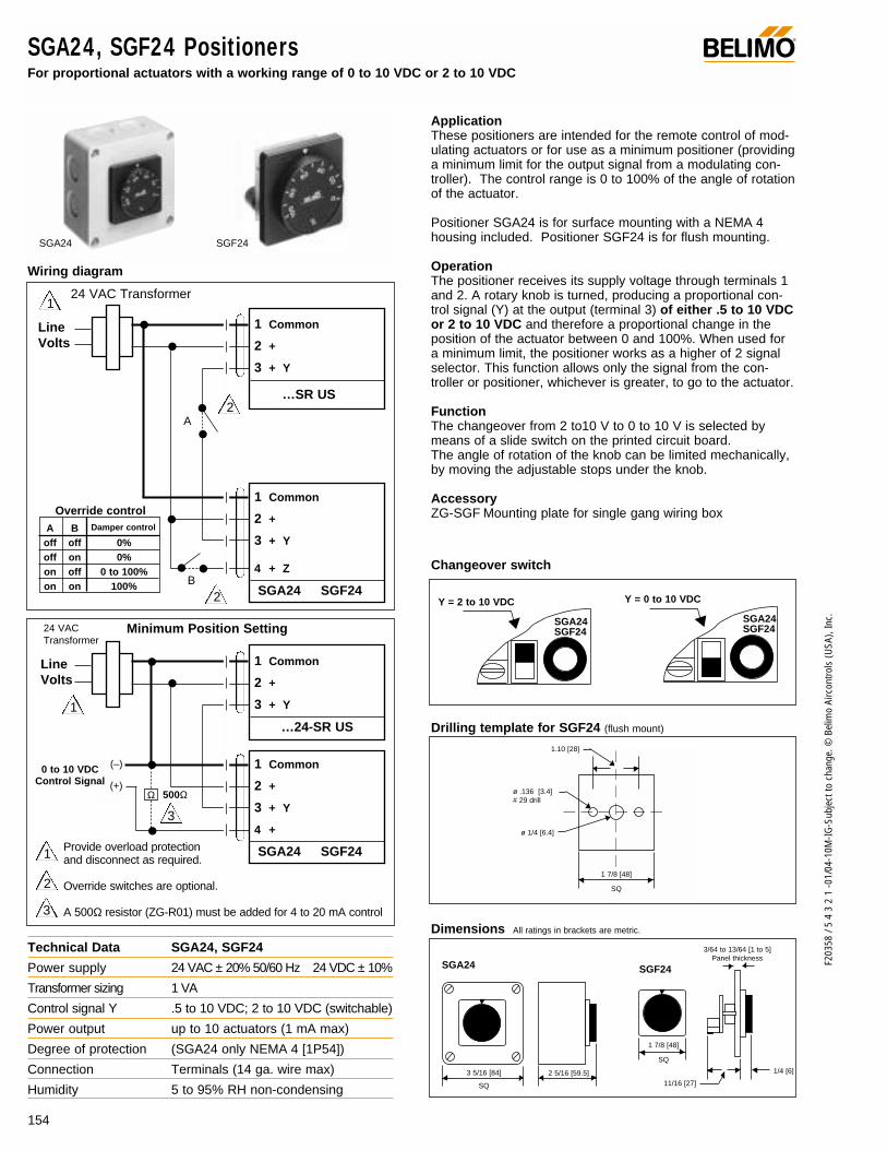
154
F203
58 /
5 4
3 2
1 -0
1/04
-10M
-IG-S
ubje
ct to
cha
nge.
© B
elim
o Ai
rcon
trols
(USA
), In
c.
3 5/16 [84]
SQ
2 5/16 [59.5]
1 7/8 [48]
SQ
SGA24
Technical Data SGA24, SGF24
Power supply 24 VAC ± 20% 50/60 Hz 24 VDC ± 10%
Transformer sizing 1 VA
Control signal Y .5 to 10 VDC; 2 to 10 VDC (switchable)
Power output up to 10 actuators (1 mA max)
Degree of protection (SGA24 only NEMA 4 [1P54])
Connection Terminals (14 ga. wire max)
Humidity 5 to 95% RH non-condensing
SGF24
1/4 [6]
11/16 [27]
3/64 to 13/64 [1 to 5]Panel thickness
Y = 0 to 10 VDC
SGA24SGF24
Y = 2 to 10 VDC
SGA24SGF24
SGA24, SGF24 Positioners For proportional actuators with a working range of 0 to 10 VDC or 2 to 10 VDC
®
ApplicationThese positioners are intended for the remote control of mod-ulating actuators or for use as a minimum positioner (providinga minimum limit for the output signal from a modulating con-troller). The control range is 0 to 100% of the angle of rotationof the actuator.
Positioner SGA24 is for surface mounting with a NEMA 4housing included. Positioner SGF24 is for flush mounting.
OperationThe positioner receives its supply voltage through terminals 1and 2. A rotary knob is turned, producing a proportional con-trol signal (Y) at the output (terminal 3) of either .5 to 10 VDCor 2 to 10 VDC and therefore a proportional change in theposition of the actuator between 0 and 100%. When used fora minimum limit, the positioner works as a higher of 2 signalselector. This function allows only the signal from the con-troller or positioner, whichever is greater, to go to the actuator.
FunctionThe changeover from 2 to10 V to 0 to 10 V is selected bymeans of a slide switch on the printed circuit board.The angle of rotation of the knob can be limited mechanically,by moving the adjustable stops under the knob.
AccessoryZG-SGF Mounting plate for single gang wiring box
Wiring diagram
Dimensions All ratings in brackets are metric.
Drilling template for SGF24 (flush mount)
Changeover switch
ø .136 [3.4]# 29 drill
ø 1/4 [6.4]
1 7/8 [48]
SQ
1.10 [28]
24 VAC Transformer
Line Volts
1 Common
2 +
3 + Y
…SR US
A
B
1 Common
2 +
3 + Y
4 + Z
SGA24 SGF24
24 VAC Transformer
Line Volts
1 Common
2 +
3 + Y
…24-SR US
1 Common
2 +
3 + Y
4 +
SGA24 SGF24
(–)
(+)
0 to 10 VDCControl Signal
A Boff off 0%off on 0%on off 0 to 100%on on 100%
Override controlDamper control
SGA24 SGF24
Minimum Position Setting
Provide overload protection and disconnect as required.
Override switches are optional.
A 500Ω resistor (ZG-R01) must be added for 4 to 20 mA control
1
3
3
1
1
2
2
2
Ω 500Ω
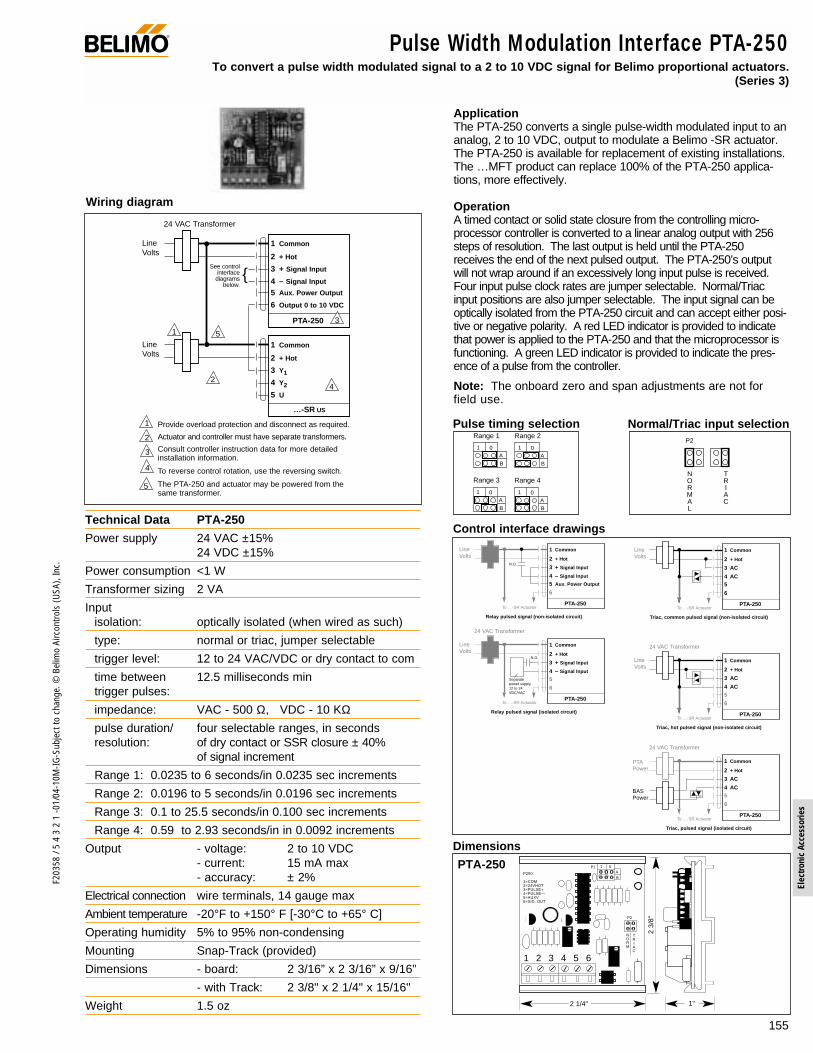
155
F203
58 /
5 4
3 2
1 -0
1/04
-10M
-IG-S
ubje
ct to
cha
nge.
© B
elim
o Ai
rcon
trols
(USA
), In
c.
Elec
troni
c Ac
cess
orie
s
P250
1=COM2=24VHOT3=PULSE+4=PULSE—5=AUXV6=SIG. OUT
A
B
1 0P1
P2
NORM
TRIAC
1 2 3 4 5 6
2 3/
8"
2 1/4" 1"
ApplicationThe PTA-250 converts a single pulse-width modulated input to ananalog, 2 to 10 VDC, output to modulate a Belimo -SR actuator.The PTA-250 is available for replacement of existing installations.The …MFT product can replace 100% of the PTA-250 applica-tions, more effectively.
OperationA timed contact or solid state closure from the controlling micro-processor controller is converted to a linear analog output with 256steps of resolution. The last output is held until the PTA-250receives the end of the next pulsed output. The PTA-250’s outputwill not wrap around if an excessively long input pulse is received.Four input pulse clock rates are jumper selectable. Normal/Triacinput positions are also jumper selectable. The input signal can beoptically isolated from the PTA-250 circuit and can accept either posi-tive or negative polarity. A red LED indicator is provided to indicatethat power is applied to the PTA-250 and that the microprocessor isfunctioning. A green LED indicator is provided to indicate the pres-ence of a pulse from the controller.
Note: The onboard zero and span adjustments are not forfield use.
42
5
5
24 VAC Transformer
Line Volts
1 Common
2 + Hot
3 + Signal Input
4 – Signal Input
5 Aux. Power Output
6 Output 0 to 10 VDC
PTA-2501
Line Volts
1 Common
2 + Hot
3 Y1
4 Y2
5 U
…-SR US
3
2
1 Provide overload protection and disconnect as required.
Actuator and controller must have separate transformers.
Consult controller instruction data for more detailedinstallation information.
To reverse control rotation, use the reversing switch.
The PTA-250 and actuator may be powered from thesame transformer.
3
4
See controlinterface
diagramsbelow.
Line Volts
1 Common
2 + Hot
3 AC
4 AC5
6
PTA-250To …-SR Actuator
Triac, common pulsed signal (non-isolated circuit)
24 VAC Transformer
Line Volts
1 Common
2 + Hot
3 AC
4 AC5
6
PTA-250To …-SR Actuator
Triac, hot pulsed signal (non-isolated circuit)
24 VAC Transformer
BASPower
PTAPower
1 Common
2 + Hot
3 AC
4 AC5
6
PTA-250To …-SR Actuator
Triac, pulsed signal (isolated circuit)
Line Volts
1 Common
2 + Hot
3 + Signal Input
4 – Signal Input
5 Aux. Power Output
6
PTA-250To …-SR Actuator
N.O.
Relay pulsed signal (non-isolated circuit)
24 VAC Transformer
Line Volts
1 Common
2 + Hot
3 + Signal Input
4 – Signal Input
5
6
PTA-250To …-SR Actuator
N.O.
Relay pulsed signal (isolated circuit)
Separatepower supply12 to 24VDC/VAC
Pulse Width Modulation Interface PTA-250 To convert a pulse width modulated signal to a 2 to 10 VDC signal for Belimo proportional actuators.
(Series 3)
®
Technical Data PTA-250
Power supply 24 VAC ±15%24 VDC ±15%
Power consumption <1 W
Transformer sizing 2 VA
Inputisolation: optically isolated (when wired as such)
type: normal or triac, jumper selectable
trigger level: 12 to 24 VAC/VDC or dry contact to com
time between 12.5 milliseconds mintrigger pulses:
impedance: VAC - 500 Ω, VDC - 10 KΩpulse duration/ four selectable ranges, in secondsresolution: of dry contact or SSR closure ± 40%
of signal increment
Range 1: 0.0235 to 6 seconds/in 0.0235 sec increments
Range 2: 0.0196 to 5 seconds/in 0.0196 sec increments
Range 3: 0.1 to 25.5 seconds/in 0.100 sec increments
Range 4: 0.59 to 2.93 seconds/in in 0.0092 increments
Output - voltage: 2 to 10 VDC- current: 15 mA max- accuracy: ± 2%
Electrical connection wire terminals, 14 gauge max
Ambient temperature -20°F to +150° F [-30°C to +65° C]
Operating humidity 5% to 95% non-condensing
Mounting Snap-Track (provided)
Dimensions - board: 2 3/16” x 2 3/16” x 9/16”
- with Track: 2 3/8" x 2 1/4" x 15/16"
Weight 1.5 oz
Wiring diagram
A
B
1 0
A
B
1 0A
B
1 0
Range 1 Range 2
Range 3 Range 4
A
B
1 0
Pulse timing selection Normal/Triac input selection
PTA-250
Dimensions
Control interface drawings
NORMAL
P2
TRIAC

156
F203
58 /
5 4
3 2
1 -0
1/04
-10M
-IG-S
ubje
ct to
cha
nge.
© B
elim
o Ai
rcon
trols
(USA
), In
c.
SE
OU
TP
UT
T
SP
AN
Zero Offset adjustment
Span adjustment
1 2 3 44= O
UT
PU
T
PO
TS
= IN
CR
EA
SE
OU
TP
UT
1= C
OM
2
= 2
4V H
OT
3= IN
PU
T
BE
LIM
O I
RM
-100
SP
AN
4/20M
IRM-100
2 3/8"
1 7/8" 15/16”
ApplicationThe IRM-100 input rescaling module is designed to change non-standard voltage or current signal levels into a 2 to 10 VDC out-put to modulate Belimo -SR type actuators. The IRM-100 is avail-able for replacement of existing installations. The …MFT productcan replace 100% of the IRM-100 applications, more effectively.
OperationThe IRM-100 is installed between a controller and a Belimo...-SR actuator. The module can be adjusted to work with azero offset of 0 to 18 VDC and a span range of 2.6 to 17 VDC.The IRM-100 has a 2 pin jumper mounted to the circuit board.When the jumper is connected between these 2 pins, a 4 to20 mA signal can be fed directly into the IRM. The resultbeing the conversion of a wide range of analog control signalsto a 2 to 10 VDC range.
The IRM-100 may also be used to sequence several actuatorsfrom one signal source. This is done by adjusting the IRMunits to work at different input ranges. (Example: 2 to 5 VDC,5 to 8 VDC, 8 to 11 VDC, etc.)
Calibration1. Attach a variable signal source to the input and power wires
to the IRM-100.2. Apply power.3. Input the minimum signal level.4. Adjust the offset potentiometer to produce a 2 VDC signal
at the output. A clockwise rotation of the potentiometerscrew will increase the output signal.
5. Input the maximum signal level.6. Adjust the span adjustment to produce a 10 VDC signal at
the output. A clockwise rotation of the potentiometer screwwill increase the output signal.
7. Double check the input-output calibration and install.
2
To otheractuators
24 VAC Transformer
Line Volts
Control Signal
1 Common
2 + Hot
3 Signal Input
4 Output, 2 to 10 VDC
IRM-100
1
1
Line Volts
1 Common
2 + Hot
3 Y1
4 Y2
5 U
…-SR US
(–)(+)
3
2
1 Provide overload protection and disconnect as required.
The controller should be powered from a separatetransformer.
The actuator and IRM-100 may be powered from thesame transformer.
Consult controller instruction data for more detailedinstallation information.
To reverse control rotation, use the reversing switch.
3
4
5
5
4
IRM-100 Input Rescaling Module To adjust the zero start point and working span of Belimo proportional ( . . –SR) actuators.(Series 3)
®
Technical Data IRM-100
Power supply supply voltage: 24 VAC ± 15%24 VDC ± 15%
Power consumption < 1 watt
Transformer sizing 1 VA
Input voltage: max voltage: 25 VDCzero (starting point): 0 to 18 VDCspan adjustment: 2.6 to 17 VDCimpedance: 400 KΩ0 to 20 mAimpedance: 500 Ω
Output voltage: 2 to 10 VDC current: 15 mA max
Electrical connection wire terminals, 14 gauge max
Ambient temperature -20° F to +150°F [-30° C to +65° C]
Humidity 5 to 95% RH non-condensing
Mounting Snap-Track (provided)
Dimensions board: 1 3/16" x 2 3/16" x 9/16"
w/Snap-Track: 1 7/8" x 2 3/8" x 15/16"
Weight .9 oz.
Wiring diagram
Dimensions
Jumper not connected toboth pins forvoltage appli-cations (asshipped)
Jumper onboth pins for4 to 20 mAapplications
current:
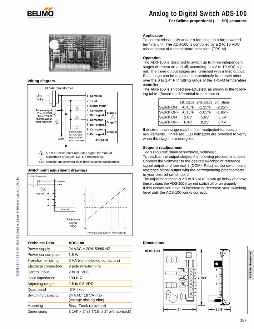
157
F203
58 /
5 4
3 2
1 -0
1/04
-10M
-IG-S
ubje
ct to
cha
nge.
© B
elim
o Ai
rcon
trols
(USA
), In
c.
Elec
troni
c Ac
cess
orie
s
ApplicationTo control reheat coils and/or a fan stage in a fan-poweredterminal unit. The ADS-100 is controlled by a 2 to 10 VDCreheat output of a temperature controller. (TRS-M)
OperationThe ADS-100 is designed to switch up to three independentstages of reheat on and off, according to a 2 to 10 VDC sig-nal. The three output stages are furnished with a triac output.Each stage can be adjusted independently from each otherover the 0 to 2.4° F throttling range of the TRS-M temperaturecontroller.The ADS-100 is shipped pre-adjusted, as shown in the follow-ing table. (Based on differential from setpoint)
If desired, each stage may be field readjusted for specialrequirements. Three red LED indicators are provided to verifywhen the stages are energized.
Setpoint readjustmentTools required: small screwdriver, voltmeter.To readjust the output stages, the following procedure is used:Connect the voltmeter to the desired switchpoint referencesignal output and terminal 1 (COM). Readjust the switch pointreference signal output with the corresponding potentiometerto your desired switch point.The adjustment range is 2.5 to 9.5 VDC. If you go below or abovethese values the ADS-100 may not switch off or on properly.If this occurs you have to increase or decrease your switchinglevel until the ADS-100 works correctly.
24 VAC Transformer
Line Volts
1 Common
2 + Hot
3 Signal Input
4 Contactor
5 Ref. signal
6 Contactor
7 Ref. signal
8 Contactor
9 Ref. signal
ADS-100COM
∩ ∩∩
∩ ∩∩
∩ ∩∩
Reheat output(2 to 10 VDC)
from TRS-Mthermostat or
other controller
Reheat stage(24 VAC con-tactors 10 VAmax. per stage)
5,7,9 = Switch point reference signal for manualadjustment of stages 1,2, & 3 respectively.
Actuator and controller must have separate transformers.
Stage 1
#1
#2
#3
1
1
Stage 2Stage 3
2
(–)(+)
2
Analog to Digital Switch ADS-100 For Belimo proportional ( . . –SR) actuators.
®
Wiring diagram
Dimensions
1st. stage 2nd. stage 3rd. stageSwitch ON -0.45°F -1.35°F -2.25°FSwitch OFF -0.15°F -1.05°F -1.95°FSwitch ON 2.8V 5.8V 8.8VSwitch OFF 0.4V 0.2V 0.4V
ADS-100
3 7/16"
2" 1 3/8"
12
34
56
78
9
24 VAC Transformer
s1 Common
2 + Hot
3
45
6
7
8
9
ADS-100
– +
Voltmeter
ReferenceSignalVDC
Reheat stage turn on from setpoint
Switchpoint adjustment drawings
Technical Data ADS-100
Power supply 24 VAC ± 20% 50/60 HZ
Power consumption 1.5 W
Transformer sizing 3 VA (not including contactors)
Electrical connection 9 pole wire-terminal
Control input 2 to 10 VDC
Input impedance 100 K ΩAdjusting range 2.5 to 9.5 VDC
Dead band .3°F fixed
Switching capacity 24 VAC 10 VA max. (voltage sinking triac)
Mounting Snap-Track (provided)
Dimensions 3 1/4" x 2" (3 7/16" x 2" w/snap-track)

158
F203
58 /
5 4
3 2
1 -0
1/04
-10M
-IG-S
ubje
ct to
cha
nge.
© B
elim
o Ai
rcon
trols
(USA
), In
c.
2 3 10 9
1 11 NSV 24
max4A (T)
SM24 US( + ) ( + ) ( – )~ ~ COM
3 2 1
+
–
NSV-BAT (2) or equiv.
24 VACCOM ~
2 3 10 9
1 11 NSV 24
+
–
max4A (T)
SM24-SR US ( + ) ( – ) HOT COM
3 2 1
NSV-BAT (2) or equiv.
Y1
24 VACCOM ~
Wiring diagram
ApplicationSeveral Belimo damper actuators can be used either with 24VAC or 24 VDC.In case of a power failure, the NSV24 battery back-up unitswitches the damper actuator from its main AC power supplyover to the 24 VDC battery to drive the actuators to their safe-ty position.For easy maintenance, the battery back-up system is placedin the control panel, not in the actuator.Several actuators may be powered by one back-up module.The batteries are separate from the NSV24.
OperationThe NSV24 is connected to the same 24 VAC power source as the damper actuators. It alsocharges the 24 V (2-12 volt batteries) storage battery. Itscharge current is limited to 150 mA maximum, and the maxi-mum charge voltage is temperature compensated.In case of a power failure, the NSV24 switches immediatelyover to the battery power source, and according to the controlfunction, the actuators will move to their safety position.After 250 seconds, the batteries are disconnected from theactuators to prolong battery life. Because of this, a safe bat-tery back-up can be provided for several short-term failures.The main power source operation is indicated by a greenLED, and the battery power source by a red LED.
Connectable ActuatorsModel Maximum per moduleGM24 US 20GM24-MFT US 15GM24-SR US 15AM24 US 30AM24-MFT US 30AM24-SR US 30NM24 US 30NM24-MFT US 30NM24-SR US 30LM24-3 US 30LM24-MFT US 30LM24-SR-2.0 US 30
AccessoriesNSV-BAT 12 VDC 1.3 Ah battery (2 required)
Battery Back-up Module NSV24 ®
3" 2 5/16"
3 3/
16"
1"
Dimensions
Technical Data NSV24
Power supply 24 VAC ± 20% 50/60 Hz
Fusing 4A slow blow fuse
Power consumption Min. 5W (without actuator load)
Transformer 8 VA
Batteries 24 V Nominal 1.2 Ah (2-12 volt lead-acid batteries; batteries not suppliedwith module)
Maintenance The batteries should be checkedannually (approximate life is 6 years)
Charging circuit Charge current max. 150 mACharge voltage 24-27 V, temperaturecompensated
Battery back-up operation 24 V nominal 1.2 Ah, max. 60 Wauto shut off after 250 seconds
Indication LED Green - Main power source operation(battery will be charged)Red - Battery back-up operation
Mounting Mounted in the control panel with an11 terminal plug-in base (not suppliedwith module)
Ambient temperature 14°F to +122°F [-10°C . . . +50°C]
Note: Fail-safe direction must havenormally closed contact.
AM24-SR US
AM24 USThis diagram is shown in the“failed” mode and prior to the250 sec time-out function.
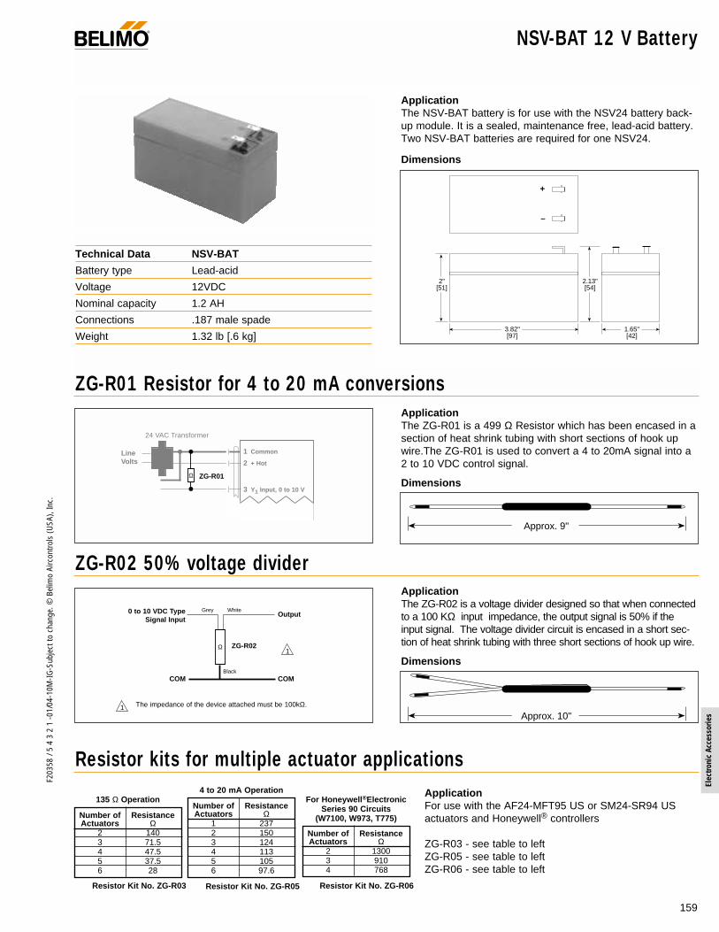
ApplicationThe NSV-BAT battery is for use with the NSV24 battery back-up module. It is a sealed, maintenance free, lead-acid battery.Two NSV-BAT batteries are required for one NSV24.
NSV-BAT 12 V Battery
Dimensions
Technical Data NSV-BAT
Battery type Lead-acid
Voltage 12VDC
Nominal capacity 1.2 AH
Connections .187 male spade
Weight 1.32 lb [.6 kg]
®
2.13"[54]
2"[51]
3.82"[97]
1.65"[42]
+
–
ApplicationThe ZG-R01 is a 499 Ω Resistor which has been encased in asection of heat shrink tubing with short sections of hook upwire.The ZG-R01 is used to convert a 4 to 20mA signal into a2 to 10 VDC control signal.
ZG-R01 Resistor for 4 to 20 mA conversions
Dimensions
Approx. 9"
24 VAC Transformer
Line Volts
1 Common
2 + Hot
3 Y1 Input, 0 to 10 V
4
5
Ω ZG-R01
ApplicationThe ZG-R02 is a voltage divider designed so that when connectedto a 100 KΩ input impedance, the output signal is 50% if theinput signal. The voltage divider circuit is encased in a short sec-tion of heat shrink tubing with three short sections of hook up wire.
ApplicationFor use with the AF24-MFT95 US or SM24-SR94 US actuators and Honeywell® controllers
ZG-R03 - see table to leftZG-R05 - see table to leftZG-R06 - see table to left
ZG-R02 50% voltage divider
Dimensions
Resistor kits for multiple actuator applications
Approx. 10"
1
1
ZG-R02Ω
Output0 to 10 VDC TypeSignal Input
COMCOM
Grey
Black
White
The impedance of the device attached must be 100kΩ.
Number of ResistanceActuators Ω
2 1403 71.54 47.55 37.56 28
135 Ω OperationNumber of ResistanceActuators Ω
1 2372 1503 1244 1135 1056 97.6
4 to 20 mA Operation
Number of ResistanceActuators Ω
2 13003 9104 768
For Honeywell®ElectronicSeries 90 Circuits
(W7100, W973, T775)
Resistor Kit No. ZG-R03 Resistor Kit No. ZG-R05 Resistor Kit No. ZG-R06
159
F203
58 /
5 4
3 2
1 -0
1/04
-10M
-IG-S
ubje
ct to
cha
nge.
© B
elim
o Ai
rcon
trols
(USA
), In
c.
Elec
troni
c Ac
cess
orie
s

160
F203
58 /
5 4
3 2
1 -0
1/04
-10M
-IG-S
ubje
ct to
cha
nge.
© B
elim
o Ai
rcon
trols
(USA
), In
c.
ApplicationThe ZG-CBNS US accessory is used when the applicationrequires the wiring terminations to be made at the actuator.
OperationThe ZG-CBNS US serves as an electrical junction box. Theproducts that can be used with this accessory are as follows:
NF24 US, NF24-S US, NF120 US NF120-S USNF24-SR US, NF24-MFT US
AF24 US, AFR24 US, AFR24-S USAF120 US, AFR120 US, AFR120-S USAF230 USAF24-SR US, AFR24-SR US. AF24-MFT US
Due to the internal volume of this junction box, according toUL requirements, The ZG-CBNS US CANNOT be used withthe following products:
NF24-S2 USAF24-S USAF120-S USAF230-S US
Technical Data ZG-CBNS US
Voltage rating 250 VAC
Electrical connection Maximum 5 line voltage connection
Housing rating UL94 5V
Material type FR/ABS CYCOLAC KJW4051
Ambient temperature -22°F to+122°F [-30°C to +50°C]
Storage temperature -40°F to +176°F [-40°C to +80°C]
Agency listing UL 873 (pending)
Quality standards ISO 9001
Weight <.5 lbs
ZG-CBNS US Junction Box for NF…(-S) and AF…*Actuators
®
ZG-CBNS US Junction box
Assembly and Installation1. Remove supply voltage from the actuator and / or the auxil-
iary switch.2. Remove the plastic insert from the actuator conduit fitting.
(1)3. Cut the actuator cable (s) to approximately 6 inches.
Remove approximately 4 inches of the black cable insula-tion. Be sure not to damage the insulation of the conduc-tors inside. This will void the actuators warranty.
4. Insert the actuator cable (s) into the junction box holes (Aand B). Slide the housing towards the actuator.
5. Insert the cable (s) through strain relief assembly (3),thread strain relief assembly to the actuator conduit fitting(1) and tighten. Thread the nut (4) over the cable andtighten. Repeat process for the second cable. If no secondcable is present, use the plug (5) with the nut (4). The sec-ond strain relief assembly is required to properly secure thehousing to the actuator.
6. Assemble the cover and gasket: Knock out the appropriateconduit hole in the junction box cover (7). Pull field wiringthrough the hole in the cover and install the field suppliedconduit fitting. Optional, knockouts are available at thesides of the junction box.
7. When wiring connections are completed, secure the boxcover in place with the supplied screws (8).
8. Install the actuator.

161
F203
58 /
5 4
3 2
1 -0
1/04
-10M
-IG-S
ubje
ct to
cha
nge.
© B
elim
o Ai
rcon
trols
(USA
), In
c.
Elec
troni
c Ac
cess
orie
s
ApplicationThe PS-100 power supply and signal simulator is designed tooperate most proportional, floating, and on-off style actuatorswithout the presence of a controller.The PS-100 can produce 24 VAC on-off and floating controlsignal along with a 0 to 10 VDC and 135Ω proportional sig-nal. A multi-function digital display is provided which can readeither the 0 to 10 VDC output or a 0 to 10 VDC feedback sig-nal either as voltage or percentage of control.The PS-100 comes with a 120 to 24 VAC, plug into the walltransformer for power. Both the PS-100 and transformer aresupplied in a black fabric carrying case.
Replacement Power Supply: PS-XFMR
3.75"[9.5]
2" [5]6.25"[16]
2.75" [7]
Dimensions
Power supply, signal simulator PS-100
Technical Data PS-100
Power supply 120 VAC 50/60 Hz
Power consumption < 4 W without actuator
Transformer Primary: 120 VAC, 35 WSecondary: 24 VAC, Class 2 trans.PN: PS-XFMR
Terminal outputs Push-button, wire terminals (12)On-off, Floating Point135Ω, 0 to 10 VDC
Input 0 to 10 VDC
Display LCD
Readouts, Output 0 to 10 VDC in volts or percentagebased on a 2 to 10 VDC control span
Readouts, Input 0 to 10 VDC in volts or percentagebased on a 2 to 10 VDC control span
Weight 3 lbs [1.4 kg] with case
Wiring diagram
ApplicationThe ZG-X40 is a 40 VA, 120 to 24 VAC transformer. It isdesigned so that both the primary and secondary leads exitthrough the same side of a 4 1/4" square outlet box cover.With this design, all wiring can be done inside a standard J-box with a minimum amount of labor.
Wire Specification
No. 18 AWG leads, 6 1/2" lengthTermination ColorPrimary White-BlackSecondary Yellow-Yellow
Maximum Number of Like Actuators per Transformer
Transformer ZG-X4040 VA, 120 to 24 VAC Transformer
ZG-X40
120 VAC 24 VAC
Yellow
Yellow
White
Black
4 1/4
4 1/4
2 3/4
Technical Data ZG-X40
Primary Voltage 120 VAC 50/60 Hz
Secondary Voltage 24 VAC
Max VA Rating 40 VA
Connections 6 1/2" leads with stripped ends
Type Class 2
Mounting Method 4 1/4" square outlet box cover
Agency Approvals UL 1585, CSA 22.2 #66
®
Model # QtyNM24 US 11NM24-SR US 13AM24 US 8SM24-S US 3AM24-SR US 8SM24-SR94 US 8GM24 US 6
Model # QtyGM24-SR US 5AF24. . US 4NF24 (-S) US 5NF 120 (-S) US 5NF24-SR US 6LF24 US 8LF24-SR US 8
Dimensions
Refers to appropriate actuator documentation for specific VA ratings.
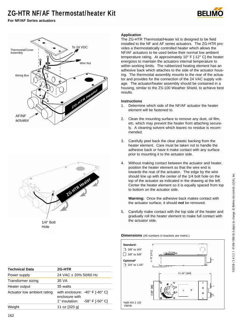
162
F203
58 /
5 4
3 2
1 -0
1/04
-10M
-IG-S
ubje
ct to
cha
nge.
© B
elim
o Ai
rcon
trols
(USA
), In
c.
ZG-HTR NF/AF Thermostat/heater Kit For NF/AF Series actuators
ApplicationThe ZG-HTR Thermostat/Heater kit is designed to be fieldinstalled to the NF and AF series actuators. The ZG-HTR pro-vides a thermostatically controlled heater which allows theNF/AF actuators to be used below their normal low ambienttemperature rating. At approximately 10° F [-12° C] the heaterenergizes to maintain the actuators internal temperature towithin working limits. The rubberized heating element has anadhesive back which attaches to the side of the actuator hous-ing. The thermostat assembly mounts to the rear of the actua-tor and provides for the connection of the 24 VAC supply volt-age. The actuator/heater assembly should be contained in ahousing, similar to the ZS-100 Weather Shield, to achieve bestresults.
Instructions1. Determine which side of the NF/AF actuator the heater
element will be fastened to.
2. Clean the mounting surface to remove any dust, oil film,etc. which may prevent the heater from attaching secure-ly. A cleaning solvent which leaves no residue is recom-mended.
3. Carefully peel back the clear plastic backing from theheater element. Care must be taken not to handle theadhesive back or have it make contact with any surfaceprior to mounting it to the actuator side.
4. Without making contact between the actuator and heater,position the heater element so that the wire end istowards the rear of the actuator. The edge by the wireshould line up with the center of the 1/4 bolt hole on thetop of the actuator as indicated in the drawing at the left.Center the heater element so it is equally spaced from topto bottom on the actuator side.
Warning: Once the adhesive back makes contact withthe actuator surface, it should not be removed.
5. Carefully make contact with the top side of the heater andgradually roll the heater element to make full contact withthe actuator side.
Technical Data ZG-HTR
Power supply 24 VAC ± 20% 50/60 Hz
Transformer sizing 35 VA
Heater output 35 watts
Actuator low ambient rating with enclosure: -40° F [-40° C]enclosure with1” insulation: -58° F [-50° C]
Weight 11 oz [320 g]
ZG-HTR H
eater
To 24 VDC
Wiring Box
Thermostat/CoverAssembly
Wire Nut
3/8” to 3/4”
3/8” to 5/8”
3/4” to 1.05”
Standard:
Optional*
*with K4-1 US clamp
Dimensions (All numbers in brackets are metric.)
AF/NFactuator
1/4” BoltHole
ZG-HTR Heater
®

163
F203
58 /
5 4
3 2
1 -0
1/04
-10M
-IG-S
ubje
ct to
cha
nge.
© B
elim
o Ai
rcon
trols
(USA
), In
c.
Elec
troni
c Ac
cess
orie
s
6. If a conduit fitting is supplied with the actuator, on the sideof the actuator which will have the wiring box, remove anddiscard the 2 screws which fasten the conduit fitting to theactuator.
7. Position the wiring box at the rear of the actuator. Mountthe wiring box to the rear of the actuator using only theleft screw, the one shown without a washer.
Note: If the conduit fitting is not provided on the modelactuator being used, use the nuts provided to secure thewiring box to the actuator.
8. Feed the cable from the heater element through the slotat the rear of the actuator into the hole in the bottom ofthe wiring box.
9. Slip the cable through the wire clamp removing any slackin the wire from the heater to the fastening point in thewiring box. Fasten the clamp to the actuator using theremaining screw and washer.
10. Determine which conduit fitting hole in the wiring box willbe used to provide the power source to the heater circuit.
11. Remove the desired knock-out in the wiring box and, ifused, fasten the conduit fitting.
12. Install the actuator following the actuator installationinstructions.
13. Fasten one of the red heater wires to one of the blackthermostat wires using the wire nut supplied.
14. Connect 24 VAC power to the remaining wires.
15. Fasten the thermostat/cover assembly to the wiring box.
NF/AF tThermostat/heater Kit ZG-HTRFor NF/AF Series actuators
Wiring diagram
2
2
3
31
1
24 VAC Transformer
Line Volts
Provide overload protection and disconnect as required.
The ZG-HTR may be wired to the same transformer asthe actuator. Total VA ratings must be observed.
Power to the ZG-HTR must be applied continuouslyduring the heating season. Do not wire the ZG-HTR tothe on-off control signal when on-off type actuators arebeing used.
ZG-HTR HEATER STRIP
Thermo-stat
COM
HOT
To other actuators
®

164
F203
58 /
5 4
3 2
1 -0
1/04
-10M
-IG-S
ubje
ct to
cha
nge.
© B
elim
o Ai
rcon
trols
(USA
), In
c.
Application Information ®
Special Control Range Applications
24 VAC Transformer
Line Volts
1 Common
2 + Hot
3 Input, 2 to 6 V
4 Output
(–)
(+)
Control Signal0 to 10 VDC
4
2
3
1
IRM-100
1 Common
2 + Hot
3 Input, 6 to 10 V
4 Output
3
500Ω
IRM AAdjusted for 2 to 6 VDC range.
IRM BAdjusted for 6 to 10 VDC range.
IRM-100
1 Common
2 + Hot
3 Y1 Input, 2 to 6 V
4 Y2
5 U
3
…-SR US
…-SR US
1 Common
2 + Hot
3 Y1 Input, 6 to 10 V
4 Y2
5 U
3
ACTUATOR AAdjusted for 2 to 6 VDC range.
ACTUATOR BAdjusted for 6 to 10 VDC range.
mA VDC4 25 2.56 37 3.58 49 4.510 511 5.512 613 6.514 715 7.516 817 8.519 9.520 10
IRM-100Voltage Settings
Based on 4 to 20 mA
2
1 Provide overload protection and disconnect asrequired.
Actuator and controller must have separatetransformers.
Consult controller instruction data for moredetailed installation information.
500Ω resistor if signal provided is 4 to 20 mA
3
4
Control Signal Belimo Actuator Accessory Notes1 to 5 VDC LM24-MFT US None Preset at factory or use MFT Handy device
NM24-MFT US Set start point for 1 VDC, span for 4 VDCAM24-MFT USGM24-MFT USNF24-MFT USAF24-MFT USLF24-MFT US
4 to 20 mA Any -MFT,-SR Actuator ZG-R01, or Wire the ZG-R01 across the wires #1 and #3500Ω, 1/2 w resistor
10.5 to 13.5 VDC LM24-MFT US None Preset at factory or use MFT Handy deviceNM24-MFT US Set start point for 10.5 VDC, span for 3 VDCAM24-MFT USAM24-MFT USGM24-MFT USNF24-MFT USAF24-MFT USLF24-MFT US
14 to 17 VDC LM24-MFT US None Preset at factory or use MFT Handy deviceNM24-MFT US Set start point for 14 VDC, span for 3 VDCAM24-MFT USSM24-MFT USGM24-MFT USNF24-MFT USAF24-MFT USLF24-MFT US
Pulse Width LM24-MFT US None Preset at factory or use MFT Handy deviceModulation NM24-MFT US
AF24-MFT USAM24-MFT USSM24-MFT USNF24-MFT US AF24-MFT USLF24-MFT US
*Preset at factory or use MFT Handy device IRM-100 Calibrate the IRM-100 for an input range of 1 to 5 VDC. Calibrate IRM-100 2-10 in 2 to 10 out for signal amplification.
Sequencing Two or More Actuators With One Control Signal using the IRM-100

165
F203
58 /
5 4
3 2
1 -0
1/04
-10M
-IG-S
ubje
ct to
cha
nge.
© B
elim
o Ai
rcon
trols
(USA
), In
c.
Elec
troni
c Ac
cess
orie
s
Application Information®
IRM-100 used as a current amplifierIn some applications, the capacity of a controller output maynot have current available to control multiple end devices. Anexample would be a controller which has an output current of.5 mA maximum. If 10 AFR24-SR US actuators have to bedriven from the same output, the current requirement wouldbe I = E/R = (10 volts)/(100000 Ω) = .1 mA for each actuator.For the 10 actuators, 1 mA of current would be necessary toproperly control the actuators.
The IRM-100 may be used as an interface to provide a highercurrent capacity to the system. The IRM-100 has an outputcapacity of 15 mA. This higher level output can handle agreater number of actuators. By calibrating the IRM-100 for a2 to 10 VDC input to achieve a 2 to 10 VDC output, IRM-100provides this added capacity for the system.
The same circuit will also work if a 4 to 20 mA signal is used.A 500 Ω resistor is placed across terminal #1 and #3 whichconverts the 4 to 20 mA to 2 to 10 VDC.
24 VAC Transformer
Line Volts
1 Common
2 + Hot
3 Y1 Input, 0 to 10 V
4 Y2 Output, 2 to 10 V
(–)
(+)
Control Signal0 to 10 VDC
4
2
3
1
IRM-100
1 Common
2 + Hot
3 Y1 Input, 0 to 10 V
4 Y2
5 U
3
500Ω
…-SR US
2
1 Provide overload protection and disconnect asrequired.
Actuator and controller must have separatetransformers.
Consult controller instruction data for moredetailed installation information.
500Ω resistor if signal provided is 4 to 20 mA
3
4
Signal to OtherActuators
ADS-100 used as an auxiliary switchThe ADS-100 was originally designed as an accessory to switchon stages of electric reheat from an electronic thermostat.However, it can also function as an electronic auxiliary switchfrom any device which can provide 0 to 10 VDC signal, such asany feedback wire 5 from any …SR or …MFT type actuator.
The ADS-100 has 3 triac outputs rated at 10 VA maximum eachwhich will turn on, in sequence, with an increasing voltage.
1
24 VAC Transformer
Line Volts
1 Common
2 + Hot
3 Signal Input
4 Contactor
5 Ref. signal
6 Contactor
7 Ref. signal
8 Contactor
9 Ref. signal
ADS-100
∩ ∩∩
∩ ∩∩
∩ ∩∩
Control Signal0 to 10 VDC
Provide overload protection and disconnect asrequired.
Actuator and controller must have separate transformers.
Stage 1
#1
#2
#3
1
Stage 2Stage 3
2
(–)(+)
2
…SR US…MFT US

166
F203
58 /
5 4
3 2
1 -0
1/04
-10M
-IG-S
ubje
ct to
cha
nge.
© B
elim
o Ai
rcon
trols
(USA
), In
c.
Notes/Work Pad ®
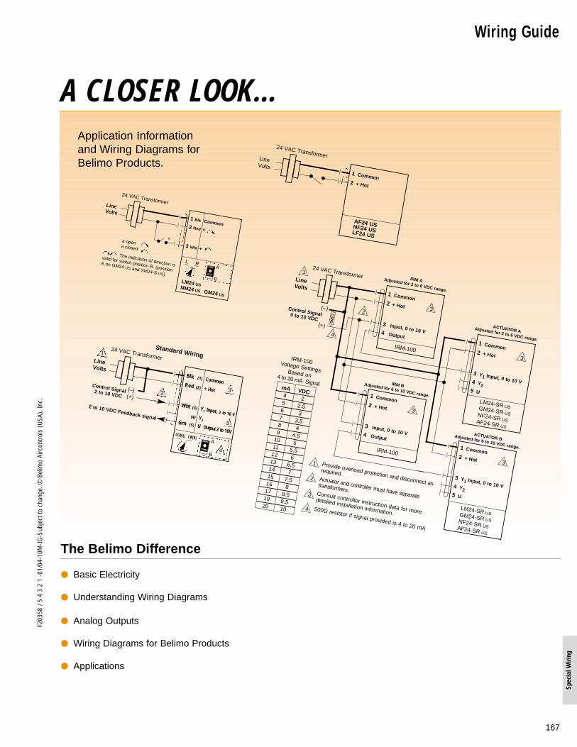
167
F203
58 /
5 4
3 2
1 -0
1/04
-10M
-IG-S
ubje
ct to
cha
nge.
© B
elim
o Ai
rcon
trols
(USA
), In
c.
Spec
ial W
iring
AF24-S
NO
24 VAC TransformerLine Volts
1 Common2 + Hot
3 Input, 0 to 10 V4 Output
(–)
(+)
Control Signal0 to 10 VDC
4
2 3
1
IRM-100
1 Common2 + Hot
3 Input, 0 to 10 V4 Output
3
500Ω
IRM AAdjusted for 2 to 6 VDC range.
IRM BAdjusted for 6 to 10 VDC range.
IRM-100
1 Common2 + Hot
3 Y1 Input, 0 to 10 V4 Y25 U
3
LM24-SR USGM24-SR USNF24-SR USAF24-SR US
1 Common2 + Hot
3 Y1 Input, 0 to 10 V4 Y25 U
3
ACTUATOR AAdjusted for 2 to 6 VDC range.
ACTUATOR BAdjusted for 6 to 10 VDC range.
LM24-SR USGM24-SR USNF24-SR USAF24-SR US
mA VDC4 25 2.56 37 3.58 49 4.5
10 511 5.512 613 6.514 715 7.516 817 8.519 9.520 10
IRM-100Voltage SettingsBased on 4 to 20 mA Signal
2
1 Provide overload protection and disconnect as
required.Actuator and controller must have separate
transformers.Consult controller instruction data for more
detailed installation information.500Ω resistor if signal provided is 4 to 20 mA
3
4
Wiring Guide
Application Informationand Wiring Diagrams forBelimo Products.
A CLOSER LOOK…
The Belimo Difference
Basic Electricity
Understanding Wiring Diagrams
Analog Outputs
Wiring Diagrams for Belimo Products
Applications
24 VAC TransformerLine Volts
1 Common2 + Hot
AF24 USNF24 USLF24 US
24 VAC TransformerLine Volts
1 Blk Common2 Red +
3 Wht +
L R
The indication of direction is
valid for switch position R. (position
A on GM24 US and SM24-S US)
aa opena closed
LM24 US NM24 US GM24 US
A
B
24 VAC Transformer
2 to 10 VDC Feedback signal
Line Volts
Blk (1) CommonRed (2) + Hot
Wht (3) Y1 Input, 2 to 10 V(4) Y2Grn (5) U Output 2 to 10V
(–)(+)
Control Signal2 to 10 VDC
Standard Wiring
4
CCW(L) CW(R)A
B
2 3
1
5

168
F203
58 /
5 4
3 2
1 -0
1/04
-10M
-IG-S
ubje
ct to
cha
nge.
© B
elim
o Ai
rcon
trols
(USA
), In
c.
Wiring Guide ®
INDEX
I. BASIC ELECTRICITYA. Abbreviations .....................................................................................................................169B. Current ...............................................................................................................................169C. Voltage ...............................................................................................................................169D. Resistance .........................................................................................................................169E. Ohm’s Law .........................................................................................................................169F. Power .................................................................................................................................169G. Power Calculations ............................................................................................................169H. Series Connection of Resistors..........................................................................................170I. Parallel Connection of Resistors........................................................................................170J. Impedance .........................................................................................................................170K. Power Consumption...........................................................................................................170L. Wire Sizing .........................................................................................................................171M. Multi-conductor Wire Types ...............................................................................................172N. Ground Loops ....................................................................................................................172
II. UNDERSTANDING WIRING DIAGRAMSA. Electrical Symbols..............................................................................................................173B. Compatibility of Different Power Supplies..........................................................................173C. Connection of Actuators.....................................................................................................174D. Long Distance Wiring.........................................................................................................176E. Wiring Mistakes..................................................................................................................176
III. ANALOG OUTPUTSA. 2 to 10 V Analog Output ....................................................................................................177B. Sourcing 4 to 20 mA Analog Output ..................................................................................177C. Sinking 4 to 20 mA Analog Output ....................................................................................177D. Parallel Operation ..............................................................................................................178E. Master-Slave Operation .....................................................................................................178F. Remote Position Monitoring...............................................................................................178G. One Output/Multiple Transformer ......................................................................................178
IV. WIRING DIAGRAMS FOR BELIMO PRODUCTSA. Spring Return, on/off .........................................................................................................179B. Non-Spring-Return on/off ..................................................................................................180C. Floating Point ....................................................................................................................180D. Proportional .......................................................................................................................182F. Auxiliary Switch Wiring.......................................................................................................183G. Accessories:
Mid position Switch, Feedback Potentiometer ...............................................................................190Positioner, Range Controller ..............................................................................................190Input Rescaling Module, Analog to Digital Switch .............................................................190Pulse Width Modulation Interface, Digital Position Indicator .............................................191Transformer, Battery Backup Module ................................................................................191Resistor Kits .......................................................................................................................191
V. APPLICATIONSA. Wiring for Multiple Actuators on a Single Shaft .................................................................186E. Floating Point Control Using Proportional Spring Return Actuators ..................................188F. Operating Two 2 to 10 VDC Actuators with the Higher of Two Control Signals ...............188G. Minimum Position with 0 to 10 VDC Actuators ..................................................................188H. Wiring to Johnson Controls A350P Controller ...................................................................188I. Wiring to Honeywell T775 Controller .................................................................................189

169
F203
58 /
5 4
3 2
1 -0
1/04
-10M
-IG-S
ubje
ct to
cha
nge.
© B
elim
o Ai
rcon
trols
(USA
), In
c.
Spec
ial W
iring
® Basic Electricity
I. BASIC ELECTRICITY
I-A. Abbreviations
DC = Direct CurrentAC = Alternating CurrentVDC = Direct Current VoltageVAC = Alternating Current Voltage
I-B. Current
A = AmperemA = Milliampere = Thousandths of an ampere. (Example: 12mA = 12/1000 = .012A)I = The symbol for current in mathematical formulas.
I-C. Voltage
V = Volt*mV = Millivolt = Thousandths of a volt. (Example: 5mV = 5/1000 = .005V)E = The symbol for voltage in mathematical formulas.
I-D. Resistance
Ω = Ohm = ResistancekΩ = Kilo ohm = Thousands of ohms. 1kΩ = 1,000ΩMΩ = Megohm = Millions of ohms. 1MΩ = 1,000kΩ = 1,000,000ΩR = The symbol for resistance in mathematical formulas.
I-E. OHM's Law
E = Voltage I = Current R = Resistance
E = I x R Example: I = 20mA, R = 500Ω Therefore, E = .020 x 500 = 10V
R = E/I Example: E = 1.35V, I = 10mA Therefore, R = 1.35/.010 = 135Ω
I = E/R Example: E = 120V, R = 50Ω Therefore, 120/50 = 2.4A
I-F. Power
W = Watt*mW = Milliwatt = Thousandths of a watt (Example: 7mW = 7/1000 = .007W)kW = Kilowatt = Thousands of watts (Example: 1kW = 1,000W)
I-G. Power Calculations
W = E x I Example: V = 24V, I = 260mA Therefore, W = 24 x .260 = 6.24W
W = R x I2 Example 1: R = 100Ω, I = 3AW = 100 x 32 = 100 x 3 x 3 = 900W
Example 2: R = 500Ω, I = 20mA = .020AW = 500 x .0202 = 500 x .020 x .020 = 500 x .0004 = .2W or 200mW.
W = E2/R Example: V = 24V, R = 100, Therefore, W = 242/100 = 24 x 24/100 = 5.76W
* I.S.O. standard indicates “U” be used for voltage and “P” for power.
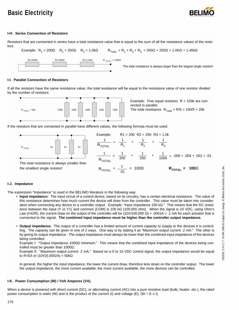
170
F203
58 /
5 4
3 2
1 -0
1/04
-10M
-IG-S
ubje
ct to
cha
nge.
© B
elim
o Ai
rcon
trols
(USA
), In
c.
I-H. Series Connection of Resistors
Resistors that are connected in series have a total resistance value that is equal to the sum of all the resistance values of the resis-tors.
Example: R1 = 200Ω R2 = 250Ω R3 = 1.0kΩ RTotal = R1 + R2 + R3 = 200Ω + 250Ω + 1.0KΩ = 1.45kΩ
I-I. Parallel Connection of Resistors
If all the resistors have the same resistance value, the total resistance will be equal to the resistance value of one resistor dividedby the number of resistors.
Example: Five equal resistors R = 100k are con-nected in parallel. The total resistance RTotal = R/5 = 100/5 = 20k
If the resistors that are connected in parallel have different values, the following formula must be used:
Example: R1 = 200 R2 = 250 R3 = 1.0k
I-J. Impedance
The expression “impedance” is used in the BELIMO literature in the following way:• Input impedance: The input circuit of a control device, based on its circuitry, has a certain electrical resistance. The value of
this resistance determines how much current the device will draw from the controller. This value must be taken into consider-ation when connecting any device to a controller output. Example: “Input impedance 100 kΩ.” This means that the DC resist-ance between the input (Y or Y1) and common (COM) is 100 kΩ (100,000 ohm). When the signal is 10 VDC, using Ohm’s Law (I=E/R), the current draw on the output of the controller will be (10V/100,000 Ω) = .0001A = .1 mA for each actuator that isconnected to the signal. The combined input impedance must be higher than the controller output impedance.
• Output impedance: The output of a controller has a limited amount of current capacity to supply to the devices it is control-ling. The capacity can be given in one of 2 ways. One way is by stating it as “Maximum output current .2 mA.” The other isby giving its output impedance. The output impedance must always be lower than the combined input impedance of the devicesbeing controlled.Example I: “Output impedance 1000Ω minimum.” This means that the combined input impedance of the devices being con-trolled must be greater than 1000Ω.Example II: “Maximum output current .2 mA.” Based on a 0 to 10 VDC control signal, the output impedance would be equalto R=E/I or (10V)/(.0002A) = 50kΩ
In general, the higher the input impedance, the lower the current draw, therefore less strain on the controller output. The lowerthe output impedance, the more current available; the more current available, the more devices can be controlled.
I-K. Power Consumption (W) / Volt Amperes (VA)
When a device is powered with direct current (DC), or alternating current (AC) into a pure resistive load (bulb, heater, etc.), the ratedpower consumption is watts (W) and is the product of the current (I) and voltage (E), (W = E x I).
R1=200Ω R TOTAL = 1.45kΩR2=250Ω R3=1.0kΩ
The total resistance is always larger than the largest single resistor!
100k 100k 100k 100k 100kR TOTAL = 20k
R1R TOTAL R2 R3
1 1 1 1_______ = ____ + ____ + ____R1 R2 R3RTOTAL
1 1 1 1_______ = ____ + ____ + ____200 250 1000RTOTAL
RTOTAL RTOTAL = 100Ω= 100Ω
.005 + .004 + .001 = .01
1
.01
=
=
The total resistance is always smaller thanthe smallest single resistor!
Basic Electricity ®
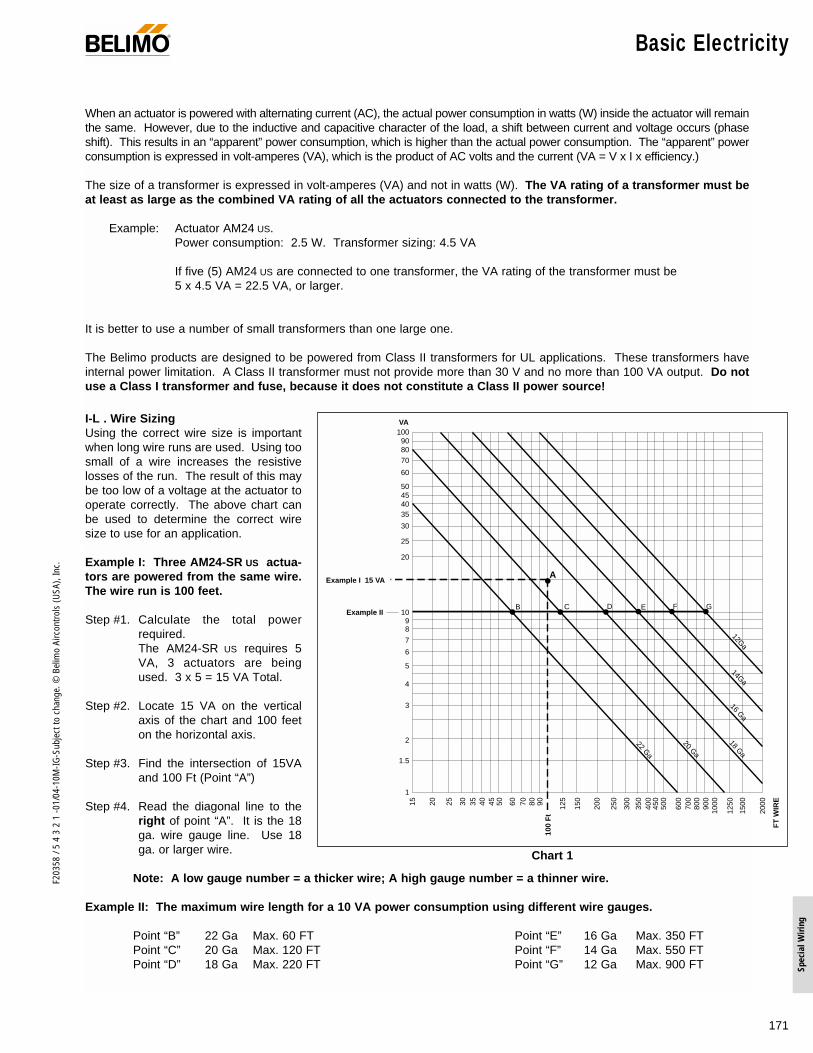
171
F203
58 /
5 4
3 2
1 -0
1/04
-10M
-IG-S
ubje
ct to
cha
nge.
© B
elim
o Ai
rcon
trols
(USA
), In
c.
Spec
ial W
iring
When an actuator is powered with alternating current (AC), the actual power consumption in watts (W) inside the actuator will remainthe same. However, due to the inductive and capacitive character of the load, a shift between current and voltage occurs (phaseshift). This results in an “apparent” power consumption, which is higher than the actual power consumption. The “apparent” powerconsumption is expressed in volt-amperes (VA), which is the product of AC volts and the current (VA = V x I x efficiency.)
The size of a transformer is expressed in volt-amperes (VA) and not in watts (W). The VA rating of a transformer must beat least as large as the combined VA rating of all the actuators connected to the transformer.
Example: Actuator AM24 US. Power consumption: 2.5 W. Transformer sizing: 4.5 VA
If five (5) AM24 US are connected to one transformer, the VA rating of the transformer must be 5 x 4.5 VA = 22.5 VA, or larger.
It is better to use a number of small transformers than one large one.
The Belimo products are designed to be powered from Class II transformers for UL applications. These transformers haveinternal power limitation. A Class II transformer must not provide more than 30 V and no more than 100 VA output. Do notuse a Class I transformer and fuse, because it does not constitute a Class II power source!
I-L . Wire SizingUsing the correct wire size is importantwhen long wire runs are used. Using toosmall of a wire increases the resistivelosses of the run. The result of this maybe too low of a voltage at the actuator tooperate correctly. The above chart canbe used to determine the correct wiresize to use for an application.
Example I: Three AM24-SR US actua-tors are powered from the same wire.The wire run is 100 feet.
Step #1. Calculate the total powerrequired.The AM24-SR US requires 5VA, 3 actuators are beingused. 3 x 5 = 15 VA Total.
Step #2. Locate 15 VA on the verticalaxis of the chart and 100 feeton the horizontal axis.
Step #3. Find the intersection of 15VAand 100 Ft (Point “A”)
Step #4. Read the diagonal line to theright of point “A”. It is the 18ga. wire gauge line. Use 18ga. or larger wire.
Note: A low gauge number = a thicker wire; A high gauge number = a thinner wire.
Example II: The maximum wire length for a 10 VA power consumption using different wire gauges.
Point “B” 22 Ga Max. 60 FT Point “E” 16 Ga Max. 350 FTPoint “C” 20 Ga Max. 120 FT Point “F” 14 Ga Max. 550 FTPoint “D” 18 Ga Max. 220 FT Point “G” 12 Ga Max. 900 FT
Chart 1
100908070
60
50454035
30
25
20
15
1098
7
6
5
4
3
2
1.5
1
15 20 25 30 35 40 45 50 60 70 80 90 125
150
200
250
300
350
400
450
500
600
700
800
900
1000
1250
1500
2000
FT
WIR
E
VA
47 Ft
100
Ft
Example II
A
B C D E F G
12Ga
14Ga
16 Ga
18 Ga
20 Ga
22 Ga
Example I 15 VA
® Basic Electricity

172
F203
58 /
5 4
3 2
1 -0
1/04
-10M
-IG-S
ubje
ct to
cha
nge.
© B
elim
o Ai
rcon
trols
(USA
), In
c.
I-M. Multi-Conductor Wire Types
• “BELL WIRE” has parallel wires, which may act as an antenna and is therefore sensitive to elec-trical noise. This type of wire should not be used for control circuits.
• “TWISTED PAIR” cancels out most of the electrical noise because the wires alternate their posi-tions. This is the type of wire that is used for most control circuits.
• “SHIELDED WIRE” is a twisted pair that is surrounded by a metal foil or wire mesh which acts asa shield and prevents electrical noise from reaching the wires inside.
Shielded wires are used for the BELIMO actuators only if the electrical noise is very severe. Normally twisted pairs are sufficient.Remember! The shield must be grounded in one point only!
I-N. Ground Loops
If a shield is grounded at both ends of a shielded wire, a ground loop is created. Ground loops will defeat the purpose of shielding,and aggravate the electrical noise problem.
Ground loops can also be created by using more than one wire for signal common (COM ⊥ ). The (-) signal common terminals on thecontroller are usually interconnected. Therefore, a ground loop is formed when two or more signal common terminals of the controllerare wired to the same transformer. (See Fig. 11-5 and 11-6, page 175.)
Signal common (COM ⊥ ) is necessary, as a reference, but only one connection should be used.
Redundant signal common terminals should not be connected.
A ground loop acts as an antenna and will pick up electrical noise. This should be avoided, by using the correct wiring practice.
BELL WIRE
TWISTED PAIR
SHIELDED WIRE
SHIELDED WIRE
SHIELDED WIRE
SHIELDED WIRE
GROUND IN ONE POINT ONLY!(CONNECT THE SHIELD TO GROUND)
GROUND ONE END ONLY! AT EACH JOINT, THE SHIELD HAS TO BE GROUNDED. (BUT IN ONE END ONLY!)
THIS IS WRONG! THE SHIELD MUST BE GROUNDED IN ONE END ONLY, OTHERWISE THERE WILL BE A GROUND LOOP.
GROUND LOOP!
Basic Electricity ®

173
F203
58 /
5 4
3 2
1 -0
1/04
-10M
-IG-S
ubje
ct to
cha
nge.
© B
elim
o Ai
rcon
trols
(USA
), In
c.
Spec
ial W
iring
Understanding Wiring Diagrams ®
II-B. Compatibility of Different Power Supplies
Power Supply with Half-Wave Rectifier
Half-wave rectifiers offer the advantage of using the same connectionfor the AC common and DC common. Therefore, the common of dif-ferent devices using half-wave rectifiers can be interconnected anduse the same power source.
Some devices, typically DDC controllers, have full-wave rectifiers. In this case, always use a separate transformer for the controller.
Power Supply with Full-Wave Rectifier
Full-wave rectifiers provide more current capacity. Their disad-vantage is that the AC and DC sides cannot be interconnected.
Every device which has a full-wave rectifier must be powered fromits own separate transformer, if the COM ⊥ wire is connected tothe Common of other devices.
Note: If a device with a full-wave rectifier is powered from the same transformer as a device with a half-wave rectifier, a short cir-cuit will result if the commons (COM ⊥) are interconnected.
The Belimo products use half-wave rectifiers. Therefore, they may be connected to the same transformer as long as all commons(COM ⊥ ) are connected to the same leg of the transformer. However, anytime actuators are connected to a controller a separatetransformer should be used for the controller power supply unless you know that the controller also uses a half-wave rectifier.
+ DC Voltage
COM ⊥
2
1
24 VAC
DIODE
CAPACITOR
DIODE
DIODE
DIODE
DIODE
CAPACITOR
+ DC Voltage
COM ⊥
24 VAC
II-A. Electrical Symbols
U.S. Electrical Symbols for Contacts International Symbols for Contacts
Traditional Electronic Symbols for Contacts Belimo Proportional Actuators- Wire Symbols and Numbers
If a feedback is available at the actuator, we recommend that thissignal be brought back to the control panel. Even if it is notrequired for the control sequence, it is a useful signal to haveavailable for possible troubleshooting in the future.
N.O.(NORMALLY OPEN)
N.C.(NORMALLY CLOSED)
N.O. N.C.SWITCHING
NORMALLY OPEN NORMALLY CLOSED SWITCHING
NORMALLY OPEN NORMALLY CLOSED
SWITCHING TRI-STATEFLOATINGCENTER OFF
1
2
3
4
5
BELIMOACTUATOR
COMMON
24VAC POWER
0…10VDC SIGNAL
0…20V Phase-cut Signal
2…10VDC Feedback Signal
⊥
Not applicable for NM24 SR
and NM24 SRS
1
2
3
4
NM24 SRor
NM24 SRS
COMMON
24VAC POWER
0…10VDC SIGNAL
2…10VDC Feedback Signal
⊥
II. UNDERSTANDING WIRING DIAGRAMS

174
F203
58 /
5 4
3 2
1 -0
1/04
-10M
-IG-S
ubje
ct to
cha
nge.
© B
elim
o Ai
rcon
trols
(USA
), In
c.
Understanding Wiring Diagrams ®
II-C. Connection of Actuators
0 to 10 V Control Signals
Signal Loss
Due to the high input impedance (100kΩ) of the actuators, the current through the signal wire is very low. Therefore, the loss of signal will be negligible, even if with long wire runs.Example: Three actuators are connected via a 330 ft. (100 meters) long pair of 22 Ga. wires. Each wire has a resistance of 5Ω.The current draw from each actuator is (I = E/R) 10/100,000 = 0.1 mA, when the signal is 10 VDC.The current in the wire will be 3 x 0.1 = 0.3 mA. Because 2 wires, the Common and the Source, go to the actuator,the resistance in the wires is 2 x 5Ω = 10Ω. The loss of signal will be (E = R x I) 10 x 0.3 = 3 mV = -.003V.
4 to 20 mA Control Signals
The controller will regulate the output current (signal) to the desired value, regardless of the resistance (up to a specified value) in the wires and the load resistor.
The resistance in the wires will only cause the output voltage of the controller to be slightly higher than the input of the actuators. The advantage with a 4 to 20 mA output signal to the actuators is that wire resistance does not cause any error to the control signal,and that electrical interference is rejected.
The input impedance of the actuators will reduce the resulting resistance of the load resistor. However, the error is so small that there is no need to compensate for this by using a slightly higher resistance value. A 500Ω load resistor will give an adequate accu-racy. Use a 499Ω, 1%, 1/2w resistor or two 1kΩ, 1%, 1/4 w resistors in parallel.
TRANSFORMER
CONTROLLERAnalog Output Board
4 to 20mALOAD
RESISTOR
4 to 20mA3
2
1
3
2
1
3
2
1
(+)
(–)
(+)
(–)
500Ω
CO
M ⊥
24 VA
C
HO
T ~
LINE
L I N E
ALWAYS USE A SEPARATE TRANSFORMER FOR THE CONTROLLER UNLESS YOU KNOW A HALF-WAVE RECTIFIER IS USED!
BELIMO*ACTUATOR
BELIMO*ACTUATOR
BELIMO*ACTUATOR
TRANSFORMER
ALWAYS USE A SEPARATE TRANSFORMER FOR THE CONTROLLER UNLESS YOU KNOW A HALF-WAVE RECTIFIER IS USED!
CONTROLLERAnalog Output Board
0 to 10V
I = .3 mA
330 ft., 22 Ga.(+)
(–)
(+)
(–)C
OM
⊥
24 VA
C
HO
T ~
3
2
1
3
2
1
3
2
1
BELIMOACTUATOR
LINE
L I N E
10 V
10.0 - .003 = 9.997 V
BELIMOACTUATOR
BELIMOACTUATOR
* up to 4 actuators may bewired to one load resistorwithout a significantrange shift.

175
F203
58 /
5 4
3 2
1 -0
1/04
-10M
-IG-S
ubje
ct to
cha
nge.
© B
elim
o Ai
rcon
trols
(USA
), In
c.
Spec
ial W
iring
Understanding Wiring Diagrams
Fig. II-3 Multiple Outputs to Multiple Actuators Using 2 Transformers for Actuators
**
* USE ONLY ONE CONNECTION BETWEEN COMMON ON THE CONTROLLER AND THE COMMON OF A GROUP OF ACTUATORS POWERED BY ONE TRANSFORMER! (REFER TO FIG. 11 - 5 FOR A COMMON WIRING MISTAKE.).
EACH ACTUATOR OR GROUP OF ACTUATORS POWERED BY A SEPARATE TRANSFORMER NEEDS TO BE CONNECTED TO COMMON ON THE CONTROLLER.
TRANSFORMER
CO
M ⊥
24 VA
C
HO
T ~
(+)
(–)
OUTPUT 2
OUTPUT 3
OUTPUT 4
CONTROLLERAnalog Output Board
0 to 10 V
(+)
OUTPUT 1
*
**
⊥
(+)
(–)
(+)
(–)⊥
TRANSFORMER
CO
M ⊥
24 VA
C
HO
T ~
3
2
1
3
2
1
3
2
1
3
2
1
COM ⊥
0 to 10 V
0 to 10 V
0 to 10 V
COM ⊥
0 to 10 V
LINE
ALL THE COMMON ON THE CONTROLLER ARE ASSUMED TO BE INTERNALLY CONNECTED.
L I N E
L I N E
⊥
⊥
(–)
(+)
(–)
ALWAYS USE A SEPARATE TRANSFORMER FOR THE CONTROLLER UNLESS YOU KNOW A HALF-WAVE RECTIFIER IS USED!
BELIMOACTUATOR
BELIMOACTUATOR
BELIMOACTUATOR
BELIMOACTUATOR
Fig. II-1 Single Output to Single Actuator
CONTROLLERAnalog Output Board
COM ⊥
0 to 10 V 3
2
1
(+)
(–)
(+)
(–)
CO
M ⊥
24 VA
C
HO
T ~
LINE
TRANSFORMER
L I N E
ALWAYS USE A SEPARATE TRANSFORMER FOR THE CONTROLLER UNLESS YOU KNOW A HALF-WAVE RECTIFIER IS USED!
BELIMOACTUATOR
Fig. II-2 Multiple Outputs to Multiple Actuators Using 1 Transformerfor Actuators
3
2
1
ALL THE COMMONSON THECONTROLLER AREASSUMED TO BEINTERNALLYINTERCONNECTED.
(+)
TRANSFORMER
CONTROLLERAnalog Output Board
0 to 10 V
(+)
CHECK THE WIRE LENGTH/SIZINGSEE SECTION 1-L..
3
2
1
CO
M ⊥
24 VA
C
HO
T ~
(–)
3
2
1
(–) COM ⊥
0 to 10 V
HOT ~
COM ⊥
0 to 10 V
HOT ~
LINE
L I N E
ALWAYS USE A SEPARATETRANSFORMER FOR THECONTROLLER UNLESS YOUKNOW A HALF-WAVERECTIFIER IS USED!
BELIMOACTUATOR
BELIMOACTUATOR
BELIMOACTUATOR
Modulating Control Signal Wiring
®

176
F203
58 /
5 4
3 2
1 -0
1/04
-10M
-IG-S
ubje
ct to
cha
nge.
© B
elim
o Ai
rcon
trols
(USA
), In
c.
Understanding Wiring Diagrams ®
Fig. II-4
COM ⊥
(+)
(–)
0 to 10 V
OUTPUT 2
OUTPUT 3
CONTROLLERAnalog Output Board
0 to 10 V
(+)
(–)
(+)
(–)
OUTPUT 1
0 to 10 V
0 to 10 V
**
⊥
⊥
⊥
* JUNCTION BOX
3
2
1
3
2
1
3
2
1
COM ⊥
24 VAC
HOT ~
TRANSFORMER
LINE
ALL THECOMMON ONTHECONTROLLERARE ASSUMEDTO BEINTERNALLYCONNECTED.
LINE
ALWAYS USE A SEPARATETRANSFORMER FOR THECONTROLLER UNLESS YOUKNOW A HALF-WAVERECTIFIER IS USED!
BELIMOACTUATOR
BELIMOACTUATOR
BELIMOACTUATOR
THESE WIRES SHOULD BE RELATIVELYSHORT, BECAUSE THE WIRES BETWEENTHE JUNCTION BOX AND THEACTUATORS CARRY AC POWER.SEE SECTION I-L FOR WIRE SIZING.
THESE WIRES CAN BE LONG BECAUSETHE WIRES BETWEEN THE CONTROLLERAND THE JUNCTION BOX CARRY A VERYLOW LOAD (SEE SECTION IIC “SIGNALLOSS”. THEREFORE, THE WIRE LENGTHAND SIZE IS OF NO CONCERN.
(MAKE CERTAIN THAT A SUFFICIENTNUMBER OF WIRES ARE AVAILABLE.ESPECIALLY IN THE CABLE BETWEENTHE CONTROLLER AND THE JUNCTIONBOX. IT IS PRUDENT TO HAVE A FEWEXTRA WIRES, JUST IN CASE.)
*
**
II-D. Long Distance Wiring
Fig. II-5 A Common Wiring Problem
(+)
(+)
OUTPUT 2
OUTPUT 3
CONTROLLERAnalog Output Board
0 to 10 V
(+)
OUTPUT 1
0 to 10 V
0 to 10 V
*
*
GROUNDLOOP
CO
M ⊥
24 VA
C
HO
T ~
TRANSFORMER
(–)⊥
(–)⊥
⊥(–)
3
2
1
3
2
1
3
2
1
GROUNDLOOP
L I N E
LINE
ALL THECOMMON ONTHECONTROLLERARE ASSUMEDTO BEINTERNALLYCONNECTED.
COM ⊥
ALWAYS USE A SEPARATETRANSFORMER FOR THECONTROLLER UNLESS YOUKNOW A HALF-WAVERECTIFIER IS USED!
BELIMOACTUATOR
BELIMOACTUATOR
BELIMOACTUATOR
* DO NOT CONNECTREDUNDANTCOMMON WIRES!Wiring in this manner willcause ground loops. Also,there will be a short if theconnections to terminals #1and #2 on one of the actuatorsare crossed by mistake. Thismay damage the controller,actuator or transformer.
II-E. Wiring Mistakes
Fig. II-6 Correct Wiring
(+)
(+)
OUTPUT 2
OUTPUT 3
CONTROLLERAnalog Output Board
0 to 10 V
(+)
OUTPUT 1
0 to 10 V
0 to 10 V
CO
M ⊥
24 VA
C
HO
T ~
TRANSFORMER
(–)⊥
(–)⊥
⊥(–)
3
2
1
3
2
1
3
2
1
L I N E
LINE
ALL THE COMMONON THECONTROLLERARE ASSUMED TOBE INTERNALLYCONNECTED.
COM ⊥
0 to 10 V
ALWAYS USE A SEPARATETRANSFORMER FOR THECONTROLLER UNLESS YOUKNOW A HALF-WAVERECTIFIER IS USED!
BELIMOACTUATOR
BELIMOACTUATOR
BELIMOACTUATOR
Wiring in this manner givesthe following advantages:
Ground loops are eliminated.
The number of wires isreduced.
If wires #1 and #2 of anactuator are crossed bymistake, the actuator will notwork properly but no damagewill occur. Resolve theproblem by rewiring in thecorrect manner.
••
•
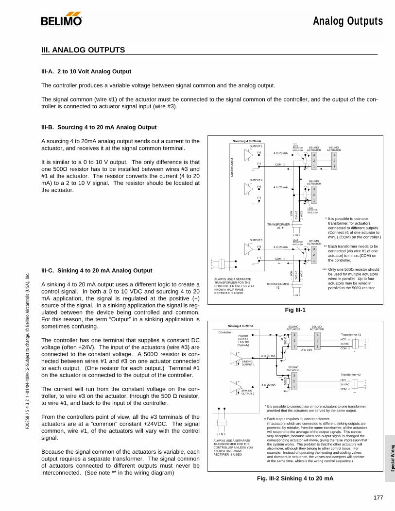
177
F203
58 /
5 4
3 2
1 -0
1/04
-10M
-IG-S
ubje
ct to
cha
nge.
© B
elim
o Ai
rcon
trols
(USA
), In
c.
Spec
ial W
iring
Analog Outputs®
III. ANALOG OUTPUTS
III-A. 2 to 10 Volt Analog Output
The controller produces a variable voltage between signal common and the analog output.
The signal common (wire #1) of the actuator must be connected to the signal common of the controller, and the output of the con-troller is connected to actuator signal input (wire #3).
III-B. Sourcing 4 to 20 mA Analog Output
A sourcing 4 to 20mA analog output sends out a current to theactuator, and receives it at the signal common terminal.
It is similar to a 0 to 10 V output. The only difference is thatone 500Ω resistor has to be installed between wires #3 and#1 at the actuator. The resistor converts the current (4 to 20mA) to a 2 to 10 V signal. The resistor should be located atthe actuator.
III-C. Sinking 4 to 20 mA Analog Output
A sinking 4 to 20 mA output uses a different logic to create acontrol signal. In both a 0 to 10 VDC and sourcing 4 to 20mA application, the signal is regulated at the positive (+)source of the signal. In a sinking application the signal is reg-ulated between the device being controlled and common.For this reason, the term “Output” in a sinking application issometimes confusing.
The controller has one terminal that supplies a constant DCvoltage (often +24V). The input of the actuators (wire #3) areconnected to the constant voltage. A 500Ω resistor is con-nected between wires #1 and #3 on one actuator connectedto each output. (One resistor for each output.) Terminal #1on the actuator is connected to the output of the controller.
The current will run from the constant voltage on the con-troller, to wire #3 on the actuator, through the 500 Ω resistor,to wire #1, and back to the input of the controller.
From the controllers point of view, all the #3 terminals of theactuators are at a “common” constant +24VDC. The signalcommon, wire #1, of the actuators will vary with the controlsignal.
Because the signal common of the actuators is variable, eachoutput requires a separate transformer. The signal commonof actuators connected to different outputs must never beinterconnected. (See note ** in the wiring diagram)
Fig III-1
Con
trol
Out
put
Sourcing 4 to 20 mA
LINE
It is possible to use onetransformer, for actuatorsconnected to different outputs.(Connect #1 of one actuator tominus (COM) on the controller.)
Each transformer needs to beconnected (via wire #1 of oneactuator) to minus (COM) onthe controller.
Only one 500Ω resistor shouldbe used for multiple actuatorswired in parallel. Up to fouractuators may be wired inparallel to the 500Ω resistor.
*
**
***
(+)
(–)
3
2
1
(+)
(–)
4 to 20 mA
COM ⊥
**
LOADRESISTOR500Ω, 0.5W
TRANSFORMER#2
CO
M ⊥
24 VA
C
HO
T ~
L I N E
+
(+)
(–)
3
2
1
(+)
(–)
4 to 20 mA
LOADRESISTOR500Ω, 0.5W
TRANSFORMER #1
CO
M ⊥
24 VA
C
HO
T ~
L I N E
+
(+)
(–)
3
2
1
(+)
(–)
4 to 20 mA
COM ⊥
OUTPUT 1 LOADRESISTOR500Ω, 0.5W+
3
2
1
***
OUTPUT 2
OUTPUT 3
ALWAYS USE A SEPARATETRANSFORMER FOR THECONTROLLER UNLESS YOUKNOW A HALF-WAVERECTIFIER IS USED!
BELIMOACTUATOR
BELIMOACTUATOR
BELIMOACTUATOR
BELIMOACTUATOR
*
Fig. III-2 Sinking 4 to 20 mA
+
HOT ~
24 VAC
COM ⊥
3
2
1
3
2
1
3
2
1
Sinking 4 to 20mA
ControllerPOWERSUPPLY+ 24V DC(Typically)
4 to 20 mA
4 to 20 mA
Transformer #1
Transformer #2
*
**
500
Ω50
0 Ω
2 to 10V
+
SINKINGOUTPUT 2
SINKINGOUTPUT 1
(–) (+)
LINE
L I N E
LINE
ALWAYS USE A SEPARATETRANSFORMER FOR THECONTROLLER UNLESS YOUKNOW A HALF-WAVERECTIFIER IS USED!
BELIMOACTUATOR
BELIMOACTUATOR
BELIMOACTUATOR
HOT ~
24 VAC
COM ⊥
It is possible to connect two or more actuators to one transformer,provided that the actuators are served by the same output.
Each output requires its own transformer.
*
**(If actuators which are connected to different sinking outputs arepowered, by mistake, from the same transformer, all the actuatorswill respond to the average of the output signals. This can bevery deceptive, because when one output signal is changed thecorresponding actuator will move, giving the false impression thatthe system works. The problem is that the other actuators willalso move, although they belong to other control loops. Forexample: Instead of operating the heating and cooling valvesand dampers in sequence, the valves and dampers will operateat the same time, which is the wrong control sequence.)

178
F203
58 /
5 4
3 2
1 -0
1/04
-10M
-IG-S
ubje
ct to
cha
nge.
© B
elim
o Ai
rcon
trols
(USA
), In
c.
Analog Outputs ®
III-D. Parallel Operation III-E. Master-Slave operation
III-F. Monitoring feedback with a remote indicator
III-G. One Output/Multiple Transformers
Fig III-3
COM ⊥
L I N E
(+)
(–)(+)
(–)
5
4
3
2
1
Output 5 used to parallel a 2nd actuator.
Direct and reverse acting are possible.
5
4
3
2
1
TRANSFORMER
CO
M ⊥
24 VA
C
HO
T ~
(+)
(–)
Input
Output
COMLINE
CONTROLLERFeedback
(Optional)
2 to 10 V
NOTE: Master-Slave operation should be used when it is important that one damper tracks the movement of another.
ALWAYS USE A SEPARATE TRANSFORMER FOR THE CONTROLLER UNLESS YOU KNOW A HALF-WAVE RECTIFIER IS USED!
BELIMOACTUATOR
BELIMOACTUATOR
Fig III-4
(+)
(–)(+)
(–)
5
4
3
2
1
5
4
3
2
1
TRANSFORMER
CO
M ⊥
24 VA
C
HO
T ~
(+)
(–)
Input
Output
COM
LINE
L I N E
COM ⊥
CONTROLLERFeedback
(Optional)
2 to 10 V
NOTE: The outputimpedance of thecontroller must beobserved.
ALWAYS USE ASEPARATETRANSFORMER FORTHE CONTROLLERUNLESS YOU KNOW AHALF-WAVE RECTIFIERIS USED!
BELIMOACTUATOR
BELIMOACTUATOR
Fig. III-5
(+)
(–)(+)
(–)
5
4
3
2
1
TRANSFORMER
CO
M ⊥
24 VA
C
HO
T ~
(+)
(–)
Input
Output
COM
Output wire 5 can be used as afeedback for true position indication.
COM
Input
PositionFeedbackMonitor
Note: NM24-SR wire 4 is signal out.Belimo TypesAM, LF, LM, SM, GM, AF, NF, -SR Proportional
LINE
2 to 10 V
COM ⊥
L I N E
2 to 10 V
ALWAYS USE A SEPARATETRANSFORMER FOR THECONTROLLER UNLESS YOUKNOW A HALF-WAVERECTIFIER IS USED!
BELIMOACTUATOR
Fig. III-6
(+)
(–)(+)
(–)
TRANSFORMER
CO
M ⊥
24 VA
C
HO
T ~
(+)
(–)
Input
Output
COM
LINE
L I N E
COM ⊥
CONTROLLER
2 to 10 V3
2
1
CO
M ⊥
24 VA
C
HO
T ~
L I N E
3
2
1
3
2
1
CO
M ⊥
24 VA
C
HO
T ~
L I N E
3
2
1
3
2
1
3
2
1
ALWAYS USE A SEPARATE TRANSFORMER FOR THE CONTROLLER UNLESS YOU KNOW A HALF-WAVE RECTIFIER IS USED!
BELIMOACTUATORS
BELIMOACTUATORS
BELIMOACTUATORS
Note: If multiple actuatorsare on one shaft, seeSection V-A.
Note: If multiple actuatorsare on one shaft, seeSection V-A.
Note: If multiple actuatorsare on one shaft, seeSection V-A.
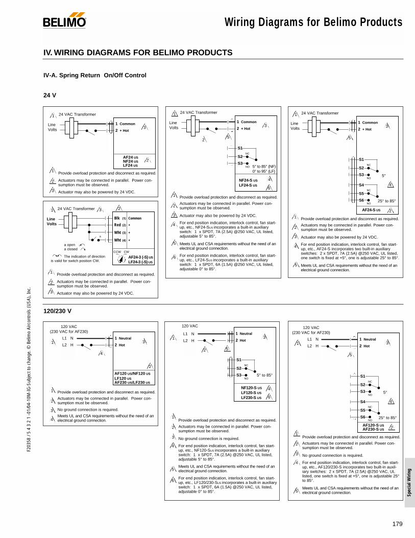
179
F203
58 /
5 4
3 2
1 -0
1/04
-10M
-IG-S
ubje
ct to
cha
nge.
© B
elim
o Ai
rcon
trols
(USA
), In
c.
Spec
ial W
iring
Wiring Diagrams for Belimo Products®
24 V
120/230 V
IV. WIRING DIAGRAMS FOR BELIMO PRODUCTS
IV-A. Spring Return On/Off Control
2
3
3
1
1
2
24 VAC Transformer
Line Volts
Provide overload protection and disconnect as required.
Actuators may be connected in parallel. Power con-sumption must be observed.
Actuator may also be powered by 24 VDC.
2
3
1 Provide overload protection and disconnect as required.
Actuators may be connected in parallel. Power con-sumption must be observed.
Actuator may also be powered by 24 VDC.
1 Common
2 + Hot
AF24 USNF24 USLF24 US
2
3
1
1
2
6
4
4
5
6
24 VAC Transformer
Line Volts
1 Common
2 + Hot
NF24-S US
LF24-S US
NC
NO 5° to 85° (NF)0° to 95° (LF)
Provide overload protection and disconnect as required.
Actuators may be connected in parallel. Power con-sumption must be observed.
Actuator may also be powered by 24 VDC.
For end position indication, interlock control, fan start-up, etc., NF24-SUS incorporates a built-in auxiliaryswitch: 1 x SPDT, 7A (2.5A) @250 VAC, UL listed,adjustable 5° to 85°.
Meets UL and CSA requirements without the need of anelectrical ground connection.
For end position indication, interlock control, fan start-up, etc., LF24-SUS incorporates a built-in auxiliaryswitch: 1 x SPDT, 6A (1.5A) @250 VAC, UL listed,adjustable 0° to 85°.
3
5
S1
S2
S3
2
3
1
1
2
4
4
5
24 VAC Transformer
Line Volts
1 Common
2 + Hot
AF24-S US
NC
5°NO
NC
25° to 85°NO
S1
S2
S3
S4
S5
S6
Provide overload protection and disconnect as required.
Actuators may be connected in parallel. Power con-sumption must be observed.
Actuator may also be powered by 24 VDC.
For end position indication, interlock control, fan start-up, etc., AF24-S incorporates two built-in auxiliaryswitches: 2 x SPDT, 7A (2.5A) @250 VAC, UL listed,one switch is fixed at +5°, one is adjustable 25° to 85°.
Meets UL and CSA requirements without the need of anelectrical ground connection.
3
5
2
1
1
2
120 VAC(230 VAC for AF230)
Provide overload protection and disconnect as required.
Actuators may be connected in parallel. Power con-sumption must be observed.
No ground connection is required.
Meets UL and CSA requirements without the need of anelectrical ground connection.
1 Neutral
2 Hot3
3
AF120 US/NF120 US
LF120 USAF230 US/LF230 US
L1 N
L2 H
4
4
1
120 VAC
L1 N
L2 H
2
3
1Provide overload protection and disconnect as required.
Actuators may be connected in parallel. Power con-sumption must be observed.
No ground connection is required.
For end position indication, interlock control, fan start-up, etc., NF120-SUS incorporates a built-in auxiliaryswitch: 1 x SPDT, 7A (2.5A) @250 VAC, UL listed,adjustable 5° to 85°.
Meets UL and CSA requirements without the need of anelectrical ground connection.
For end position indication, interlock control, fan start-up, etc., LF120/230-SUS incorporates a built-in auxiliaryswitch: 1 x SPDT, 6A (1.5A) @250 VAC, UL listed,adjustable 0° to 85°.
4
5
6
2
6
4
1 Neutral
2 Hot
NF120-S US
LF120-S US
LF230-S US
NC
NO5° to 85°
3
5
S1
S2
S3
2
3
1
2
Provide overload protection and disconnect as required.
Actuators may be connected in parallel. Power con-sumption must be observed.
No ground connection is required.
For end position indication, interlock control, fan start-up, etc., AF120/230-S incorporates two built-in auxil-iary switches: 2 x SPDT, 7A (2.5A) @250 VAC, ULlisted, one switch is fixed at +5°, one is adjustable 25°to 85°.
Meets UL and CSA requirements without the need of anelectrical ground connection.
1 Neutral
2 Hot
AF120-S USAF230-S US
NC
5°NO
NC
25° to 85°NO
S1
S2
S3
S4
S5
S6
1
120 VAC(230 VAC for AF230)
L1 N
L2 H
4
4
5
3
5
21 24 VAC Transformer
Line Volts
Blk (1) Common
Red (2) +
Wht (3) +
Wht (4) +
AF24-3 (-S) US
LF24-3 (-S) US
CCW CW
The indication of directionis valid for switch position CW.
a
a opena closed
3
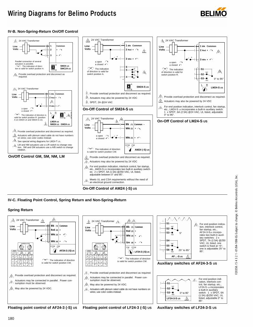
180
F203
58 /
5 4
3 2
1 -0
1/04
-10M
-IG-S
ubje
ct to
cha
nge.
© B
elim
o Ai
rcon
trols
(USA
), In
c.
Wiring Diagrams for Belimo Products ®
On/Off Control GM, SM, NM, LM
IV-B. Non-Spring-Return On/Off Control
IV-C. Floating Point Control, Spring Return and Non-Spring-Return
Spring Return
On-Off Control of SM24-S US
On-Off Control of AM24 (-S) US
On-Off Control of LM24-S US
Auxiliary switches of AF24-3-S US
Auxiliary switches of LF24-3-S US
1
1
24 VAC Transformer
Line Volts
Provide overload protection and disconnect asrequired.
1 Common
2 +
3 +
Parallel connection of severalactuators is possible.
The indication of direc-tion is valid for switch position A.
A
B
A
B
SM24 US
SMC24 US
2
2
3
3
4
4
1
1
24 VAC Transformer
Line Volts
Provide overload protection and disconnect as required.
Actuators with plenum rated cable do not have numberson wires; use color codes instead.
See special wiring diagrams for LM24-T US.
LM and NM actuators use a L/R switch to change rota-tion. SM and GM actuators use a A/B switch to changerotation.
1 Blk Common
2 Red +
3 Wht +
L R
The indication of direction isvalid for switch position R. (positionA on GM24 US and SM24-S US)
a
a opena closed
LM24 US
NM24 US GM24 US
A
B
2
3
1 Provide overload protection and disconnect as required.
Actuators may also be powered by 24 VDC
SPDT, 2A @24 VAC
2
1 24 VAC Transformer
Line Volts
1 Blk Common
2 Red +
3 Wht +
SM24-S US
The indicationof direction is valid forswitch position A.
a
a opena closed
2
3
1 Provide overload protection and disconnect as required.
Actuators may also be powered by 24 VDC
For end position indication, interlock control, fan startup,etc., LM24-S US incorporates a built-in auxiliary switch:1 x SPDT, 6A (2.5A) @24 VAC, UL listed, adjustable0° to 95°.
2
1 24 VAC Transformer
Line Volts
1 Blk Common
2 Red +
3 Wht +
LM24-S USL R
The indicationof direction is valid forswitch position R.
a
a opena closed
NC
0° to 95°NO
S1
S2
S3
12
424 VAC Transformer
Line Volts
Blk (1) Common –
Wht (2) +
Wht (3) +
AM24 (-S) US
CCW CW
The indication of directionis valid for switch position CW.
aa opena closed
3
4
2
1 Provide overload protection and disconnect as required.
Actuators may also be powered by 24 VDC
For end position indication, interlock control, fan startup,etc., AM24-S US incorporates two built-in auxiliary switch-es: 2 x SPDT, 6A (1.5A) @250 VAC, UL listed,adjustable between 0° and 95°.
Meets UL and CSA requirements without the need of an electrical ground connection.
CCWCW
stop
a(3)
b(4)
stop stop stop
Installation Side
Direction of Rotation Switch
xxxx
xxxx
xx
xx
xx
xx
xxx
xxxx
xxxx
xx
xx
xx
xx
xxx
CWCCWSwitch
Positions
CCWCW CCWCW
stop
a(3)
b(4)
stop stop stop
Installation Side
Direction of Rotation Switch
xxxx
xxxx
xx
xx
xx
xx
xxx
xxxx
xxxx
xx
xx
xx
xx
xxx
CWCCWSwitch
Positions
CCWCW
Floating point control of AF24-3 (-S) US Floating point control of LF24-3 (-S) US
3 21 24 VAC Transformer
Line Volts
Blk (1) Common
Red (2) +
Wht (3) +
Wht (4) +
AF24-3 (-S) US
CCW CW
The indication of directionis valid for switch position CW.
2
3
1 Provide overload protection and disconnect as required.
Actuators may be connected in parallel. Power con-sumption must be observed.
May also be powered by 24 VDC.
2
3
4
1 Provide overload protection and disconnect as required.
Actuators may be connected in parallel. Power con-sumption must be observed.
May also be powered by 24 VDC.
Actuators with plenum rated cable do not have numbers onwires; use color codes instead.
3 21 24 VAC Transformer
Line Volts
Blk (1) Common
Red (2) +
Wht (3) +
Grn (4) +
LF24-3 (-S) US
CW CCW
The indication of directionis valid for switch position CW.
4
a
b
LF24-3-S US
NC
0° to 95°NO
S1
S2
S3
1
1
1 For end position indica-tion, interlock control,fan startup, etc., AF24-3-SUS incorpo-rates two built-in auxil-iary switches: 2 xSPDT, 7A (2.5A) @250VAC, UL listed, oneswitch is fixed at +5°,one is adjustable 25° to85°.
For end position indi-cation, interlock con-trol, fan startup, etc., LF24-S US incorporatesa built-in auxiliaryswitch: 1 x SPDT, 6A(1.5A) @250 VAC, ULlisted, adjustable 0° to85°.
AF…-S US
NC
5°NO
S1
S2
S3
NC
25° to 85°NO
S4
S5
S6
1
3
0°
80°
10°
0°
6 5
4
3

181
F203
58 /
5 4
3 2
1 -0
1/04
-10M
-IG-S
ubje
ct to
cha
nge.
© B
elim
o Ai
rcon
trols
(USA
), In
c.
Spec
ial W
iring
Wiring Diagrams for Belimo Products®
Standard Floating Point Control
Non-Spring Return
Floating Point Control of LM24-3-T USFloating Point Control of AM24 (-S) US
1
1
24 VAC Transformer
Line Volts
Provide overload protection and disconnect asrequired.
1 Common
2 +
3 +
Parallel connection of severalactuators is possible.
The indication of direc-tion is valid for switch position A.
stop
A
B
SM24 US
SMC24 US
GM24 US
2
2
1
1
24 VAC Transformer
Line Volts
Provide overload protection and disconnect as required.
Actuators with plenum rated cable do not have num-bers on wires; use color codes instead.
1 Blk Common
2 Red +
3 Wht +
L R
The indication of direc-tion is valid for switch position R.
stop
LM24-3 US
NM24 US
4
2
3
3
4
1 Provide overload protection and disconnect as required.
Actuators may also be powered by 24 VDC
The LM24-TUS actuator has terminals instead of wires.
The LM24-T US actuator does not have a direction ofrotation switch.
21 24 VAC Transformer
Line Volts
1 Common
2 +
3 +
LM24-3-T US
Swapping wires 2, 3 changes thedirection of rotation.
Stop
3
4
2
1 Provide overload protection and disconnect as required.
Actuators may also be powered by 24 VDC
For end position indication, interlock control, fan startup,etc., AM24-S US incorporates two built-in auxiliary switch-es: 2 x SPDT, 6A (1.5A) @250 VAC, UL listed,adjustable between 0° and 95°.
Meets UL and CSA requirements without the need of an electrical ground connection.
AM24 (-S) US
CCW CW
1 42
24 VAC Transformer
Line Volts
The indication of directionis valid for switch position CW.
Blk (1) Common –
Wht (2) +
Wht (3) +
Floating point control of AF24-3(-S) US and LF24-3(-S) US from triac
(Triac Source)
(Triac Sink)
(Triac Sink with Separate Transformers)24 VAC Transformer
Line Volts
Blk (1) Common
Red (2) + Hot
Wht (3) +
Wht (4) +/Grn
AF24-3 (-S) US
LF24-3 (-S) US
Hot COM
Controller
CCW CW
2
6
1
The indication of directionis valid for switch position CW.
24 VAC Transformer
Line Volts
Hot COM
Controller
2
6
1
Blk (1) Common
Red (2) + Hot
Wht (3) +
Wht (4) +/Grn
AF24-3 (-S) US
LF24-3 (-S) US
CCW CW
4
5
The indication of directionis valid for switch position CW.
24 VAC Transformer
Line Volts
24 VAC Transformer
Line Volts
Hot COM
Controller
1
1
Blk (1) Common
Red (2) + Hot
Wht (3) +
Wht (4) +/Grn
AF24-3 (-S) US
LF24-3 (-S) US
2
6
5
The indication of directionis valid for switch position CW.
2
3
4
5
6
1 Provide overload protection and disconnect as required.
Actuators may be connected in parallel. Power consumption must be observed.
May also be powered by 24 VDC.
The Common connection from the actuator must be connected to the Hot connection ofthe controller.
The actuator Hot must be connected to the control board Common.
Actuators with plenum rated cable do not have numbers on wires; use color codes instead.AF… No. 4 wire is white; LF… No. 4 wire is green.
CCW CW

182
F203
58 /
5 4
3 2
1 -0
1/04
-10M
-IG-S
ubje
ct to
cha
nge.
© B
elim
o Ai
rcon
trols
(USA
), In
c.
Wiring Diagrams for Belimo Products ®
IV-D. Proportional Control
4 to 20 mA Control Signal
Notes
24 VAC Transformer
2 to 10 VDC Feedback signal
Line Volts
Blk (1) Common
Red (2) + Hot
Wht (3) Y1 Input, 2 to 10 V
Grn (5) U Output 2 to 10V
(–)(+)
24 VAC Transformer
Line Volts
Control Signal2 to 10 VDC
A
(–)(+)
Control Signal2 to 10 VDC
Blk (1) Common
Red (2) + Hot
Wht (3) Y1 Input, 2 to 10 V
Override to zero position
A Open = 0 V PositionA Closed = Normal Operation
(–)
(+)
24 VAC Transformer
Line Volts
Control Signal2 to 10 VDC
B
C
Blk (1) Common
Red (2) + Hot
Wht (3) Y1 Input, 2 to 10 V
Override to 10 V position
Standard Wiring
B Closed = 10 V PositionC Closed = Normal Operation
CCW(L) CW(R)
2
3
3
1
3
1
23
1
23
1
(–)(+)
24 VAC Transformer
Line Volts
Control Signal4 to 20 mA
A
Blk (1) Common
Red (2) + Hot
Wht (3) Y1 Input, 2 to 10 V
Grn (5) U Output 2 to 10V
A Open = 4 mA PositionA Closed = Normal Operation
2 to 10 VDC Feedback Signal
B
C
B Closed = 20 mA PositionC Closed = Normal Operation
24 VAC Transformer
Blk (1) Common
Red (2) + Hot
Wht (3) Y1 Input, 2 to 10 V
Override control to min, mid, max, positions
Ω500Ω
1/4 watt
(–)(+)
Line Volts
Control Signal2-10 VDC or 4 to 20 mA
Ω
500Ω1/4 watt
(–)(+)
24 VAC Transformer
Line Volts
Control Signal4 to 20 mA
Blk (1) Common
Red (2) + Hot
Wht (3) Y1 Input, 2 to 10 V
4
5
Override to zero position
Ω500Ω1/4watt
(–)
(+)
24 VAC Transformer
Line Volts
Control Signal4 to 20 mA
Blk (1) Common
Red (2) + Hot
Wht (3) Y1 Input, 2 to 10 V
Override to 20 mA position
Standard Wiring
Ω
500Ω1/4 watt
CCW(L) CW(R)
4
3
2
3
1 Provide overload protection and disconnect as required.
Actuators may be connected in parallel. Power con-sumption and input impedance must be observed.
Actuator may also be powered by 24 VDC.
ZG-R01 may be used.4
4
1
3
2
3
4
2
3
1
4
2
With a 4-20 mA Input, up to 4 actuators may be wired in parallel. A 2% shift in the signal is seen when using a 500Ω resistor. Power consumption must be observed.
C
B
A
Min*
50%
ca bFunctions
Control mode acc. to Y
0%
100%
Mid*
Max*
Normal**
* Default selectable 0-100%. See Configuration Data Sheet.**Customizable. See Configuration Data Sheet.
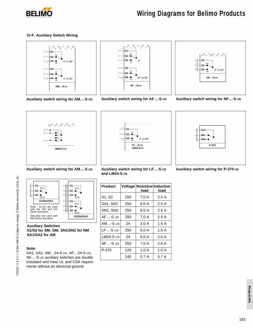
183
F203
58 /
5 4
3 2
1 -0
1/04
-10M
-IG-S
ubje
ct to
cha
nge.
© B
elim
o Ai
rcon
trols
(USA
), In
c.
Spec
ial W
iring
Wiring Diagrams for Belimo Products®
IV-F. Auxiliary Switch Wiring
Auxiliary SwitchesS1/S2 for SM, GM; SN1/SN2 for NMSA1/SA2 for AM
Note: S1,S2 are usedwith the SM and GmSeries actuators.
SN1,SN2 are used withNM Series actuators
S2/SN2/SA2
S1
S2
S3
S4
S5
S6
S1/SN1/SA1
NC
NO
S1
S2
S3
N.C.
N.O.
N.C.
N.O.
N.C.
N.O.
Note:SA1, SA2, AM…24-S US, AF…24-S US,NF…-S US auxiliary switches are doubleinsulated and meet UL and CSA require-ments without an electrical ground.
AM…-S US
NC
0° to 95°NO
S1
S2
S3
NC
0° to 95°NO
S4
S5
S6
AF…-S US
NC
5°NO
S1
S2
S3
NC
25° to 85°NO
S4
S5
S6
Auxiliary switch wiring for AM…-S US
Auxiliary switch wiring for AM…-S US Auxiliary switch wiring for LF…-S US
and LM24-S US
Auxiliary switch wiring for P-370 US
Auxiliary switch wiring for AF…-S US Auxiliary switch wiring for NF…-S US
LF…-S US
LM24-S US
NC
0° to 95°NO
S1
S2
S3
NF…-S US
NC
5° to 85°NO
S1
S2
S3
SM24-S US
P-370
NC
NO
Grn
Blk
Wht
Product Voltage Resistive Inductiveload load
S1, S2 250 7.0 A 2.5 A
SA1, SA2 250 6.0 A 2.5 A
SN1, SN2 250 6.0 A 2.5 A
AF…-S US 250 7.0 A 2.5 A
AM…-S US 24 3.0 A 1.5 A
LF…-S US 250 6.0 A 1.5 A
LM24-S US 24 6.0 A 2.5 A
NF…-S US 250 7.0 A 2.5 A
P-370 120 1.0 A 1.0 A
240 0.7 A 0.7 A
0°
80°
10°
0°
6 5
4
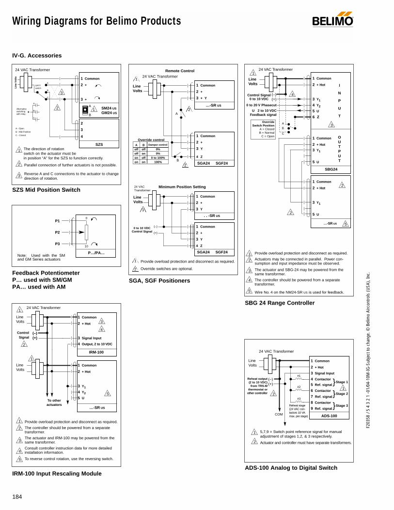
184
F203
58 /
5 4
3 2
1 -0
1/04
-10M
-IG-S
ubje
ct to
cha
nge.
© B
elim
o Ai
rcon
trols
(USA
), In
c.
Wiring Diagrams for Belimo Products ®
IV-G. Accessories
Feedback PotentiometerP… used with SM/GMPA… used with AM
Note: Used with the SMand GM Series actuators
The direction of rotationswitch on the actuator must be in position “A” for the SZS to function correctly.
24 VAC Transformer
Lin
e V
olts 1 Common
2 +
3 +
SM24 US
GM24 US
A
B
1
2
3
4
SZS
1
2
3
3
2
A
B
C
A - Open
B - Mid-Position
C - Closed
Parallel connection of further actuators is not possible.
Reverse A and C connections to the actuator to changedirection of rotation.
A
B
C
+Alternativeswitchingwith relay.
SPTTswitch
SZS Mid Position Switch
2
To otheractuators
24 VAC Transformer
Line Volts
Control Signal
1 Common
2 + Hot
3 Signal Input
4 Output, 2 to 10 VDC
IRM-100
1
1
Line Volts
1 Common
2 + Hot
3 Y1
4 Y2
5 U
…-SR US
(–)(+)
3
2
1 Provide overload protection and disconnect as required.
The controller should be powered from a separatetransformer.
The actuator and IRM-100 may be powered from thesame transformer.
Consult controller instruction data for more detailedinstallation information.
To reverse control rotation, use the reversing switch.
3
4
5
5
4
IRM-100 Input Rescaling Module
24 VAC Transformer
Line Volts
1 Common
2 + Hot
3 Signal Input
4 Contactor
5 Ref. signal
6 Contactor
7 Ref. signal
8 Contactor
9 Ref. signal
ADS-100COM
∩ ∩∩
∩ ∩∩
∩ ∩∩
Reheat output(2 to 10 VDC)
from TRS-Mthermostat or
other controller
Reheat stage(24 VAC con-tactors 10 VAmax. per stage)
5,7,9 = Switch point reference signal for manualadjustment of stages 1,2, & 3 respectively.
Actuator and controller must have separate transformers.
Stage 1
#1
#2
#3
1
1
Stage 2Stage 3
2
(–)(+)
2
ADS-100 Analog to Digital Switch
2
2
1 Provide overload protection and disconnect as required.
Actuators may be connected in parallel. Power con-sumption and input impedance must be observed.
The actuator and SBG-24 may be powered from thesame transformer.
The controller should be powered from a separatetransformer.
Wire No. 4 on the NM24-SR US is used for feedback.
3
4
4
24 VAC Transformer
U 2 to 10 VDC Feedback signal
0 to 20 V Phasecut
Line Volts
1 Common
2 + Hot
3 Y1
4 Y2
5 U
6 Z
1 Common
2 + Hot
3 Y1
5 U
1 Common
2 + Hot
3 Y1
5 U
(–)(+)
Control Signal0 to 10 VDC
2
1
A
B
C
OverrideSwitch Position
A = ClosedB = Normal
C = Open
…-SR US
SBG24
I
N
P
U
T
OUTPUT
5
3
5
SBG 24 Range Controller
SGA, SGF Positioners
Remote Control
P1
P2
P3
P…/PA…
0
10
24 VAC Transformer
Line Volts
1 Common
2 +
3 + Y
…-SR US
A
B
1 Common
2 +
3 Y
4 Z
SGA24 SGF24
24 VAC Transformer
Line Volts
1 Common
2 +
3 Y
. . -SR US
1 Common
2 +
3 Y
4 Z
SGA24 SGF24
(–)
(+)
0 to 10 VDCControl Signal
A Boff off 0%off on 0%on off 0 to 100%on on 100%
Override controlDamper control
Minimum Position Setting
Provide overload protection and disconnect as required.
Override switches are optional.
1
1
1
2
2
2

185
F203
58 /
5 4
3 2
1 -0
1/04
-10M
-IG-S
ubje
ct to
cha
nge.
© B
elim
o Ai
rcon
trols
(USA
), In
c.
Spec
ial W
iring
Wiring Diagrams for Belimo Products®
IV-F. Accessories (continued)
2 3 10 9
1 11 NSV 24
max4A (T)
SM24 US( + ) ( + ) ( – )~ ~ COM
2 3 10 9
1 11 NSV 24
+
–
max4A (T)
SM24-SR US ( + ) ( – ) HOT COM
3 2 1
3 2 1
+
–
NSV-BAT (2) or equiv. NSV-BAT (2) or equiv.
Y1
24 VACCOM ~
24 VACCOM ~
NSV 24 Battery Back-up Module
ZAD24 Digital Position Indicator
ZG-X40
120 VAC 24 VAC
Yellow
Yellow
White
Black
ZG-X40 Transformer
24 VAC Transformer
Line Volts
1 Common
2 + Hot
3 Y1 Input, 0 to 10 V
4
5
Ω ZG-R01
1
1
ZG-R02Ω
Output0 to 10 VDC TypeSignal Input
COMCOM
Grey
Black
White
The impedance of the device attached must be 100kΩ.
ZG-R01, ZG-R02 Resistor Kits
24 VAC Transformer
Line Volts
1 Common
2 + Hot
3 AC
4 AC5
6
PTA-250To …-SR Actuator
Triac, common pulsed signal (non-isolated circuit)
24 VAC Transformer
Line Volts
1 Common
2 + Hot
3 AC
4 AC5
6
PTA-250To …-SR Actuator
Triac, hot pulsed signal (non-isolated circuit)
24 VAC Transformer
BASPower
PTAPower
1 Common
2 + Hot
3 AC
4 AC5
6
PTA-250To …-SR Actuator
Triac, pulsed signal (isolated circuit)
PTA-250 Pulse Width Modulation Interface
Control interface diagrams
Control interface diagrams
Failsafe directionmust have a normal-ly closed contact.
42
5
5
24 VAC Transformer
Line Volts
1 Common
2 + Hot
3 + Signal Input
4 – Signal Input
5 Aux. Power Output
6 Output 2 to 10 VDC
PTA-2501
Line Volts
1 Common
2 + Hot
3 Y1
4 Y2
5 U
…-SR US
3
2
1 Provide overload protection and disconnect as required.
Actuator and controller must have separate transformers.
Consult controller instruction data for more detailedinstallation information.
To reverse control rotation, use the reversing switch.
The PTA-250 and actuator may be powered from thesame transformer.
3
4
See controlinterface
diagramsbelow.
24 VAC Transformer
Line Volts
1 Common
2 + Hot
3 + Signal Input
4 – Signal Input
5 Aux. Power Output
6
PTA-250To …-SR Actuator
N.O.
Relay pulsed signal (non-isolated circuit)
24 VAC Transformer
Line Volts
1 Common
2 + Hot
3 + Signal Input
4 – Signal Input
5
6
PTA-250To …-SR Actuator
N.O.
Relay pulsed signal (isolated circuit)
Separatepower supply12 to 24VDC/VAC
24 VAC Transformer
Line Volts
1 Common
2 + Hot
3 Y1 Input, 0 to 10 V
4 Y2
5 U Output 2 to 10 V
(–)(+)
Control Signal0 to 10 VDC
1 Common
2 + Hot
3 –
4 +
2
1
4
4
5
5 …SR US
ZAD24
2
3
3
1 Provide overload protection and disconnect asrequired.
Actuator and controller must have separate transformers.
Actuators may be connected in parallel. Power con-sumption must be observed.
Actuator may also be powered by 24 VDC.
Wire #4 is used for feedback on the NM24-SR US.
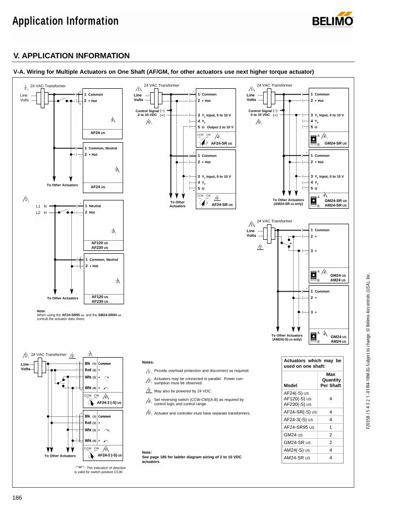
186
F203
58 /
5 4
3 2
1 -0
1/04
-10M
-IG-S
ubje
ct to
cha
nge.
© B
elim
o Ai
rcon
trols
(USA
), In
c.
Application Information ®
V. APPLICATION INFORMATION
V-A. Wiring for Multiple Actuators on One Shaft (AF/GM, for other actuators use next higher torque actuator)
Actuators which may beused on one shaft:
MaxQuantity
Model Per Shaft
AF24(-S) US
AF120(-S) US 4AF230(-S) US
AF24-SR(-S) US 4
AF24-3(-S) US 4
AF24-SR95 US 1
GM24 US 2
GM24-SR US 2
AM24(-S) US 4
AM24-SR US 4
124 VAC Transformer
Line Volts
1 Common
2 + Hot
AF24 US
1 Common, Neutral
2 + Hot
AF24 US
3
3
1
1 Neutral
2 Hot
AF120 US
AF230 US
1 Common, Neutral
2 + Hot
AF120 US
AF230 US
3
3
L1 N
L2 H
3 2
4
4
1 24 VAC Transformer
Line Volts
Blk (1) Common
Red (2) +
Wht (3) +
Wht (4) +
AF24-3 (-S) US
CCW CW
Blk (1) Common
Red (2) +
Wht (3) +
Wht (4) +
AF24-3 (-S) US
CCW CW
The indication of directionis valid for switch position CCW.
2
3
4
5
1 Provide overload protection and disconnect as required.
Actuators may be connected in parallel. Power con-sumption must be observed.
May also be powered by 24 VDC.
Set reversing switch (CCW-CW)(A-B) as required bycontrol logic and control range.
Actuator and controller must have separate transformers.
Notes:
Note:See page 185 for ladder diagram wiring of 2 to 10 VDCactuators.
24 VAC Transformer
Line Volts
1 Common
2 + Hot
3 Y1 Input, 0 to 10 V
4 Y2
5 U
(–)(+)
Control Signal0 to 10 VDC
4
5
1
GM24-SR US
1 Common
2 + Hot
3 Y1 Input, 0 to 10 V
4 Y2
5 U
4A
B
A
B
GM24-SR US
AM24-SR US
24 VAC Transformer
Line Volts
1 Common
2 +
3 +
4
2
1
GM24 US
AM24 US
1 Common
2 +
3 +
4A
B
A
B
GM24 US
AM24 US
24 VAC Transformer
Line Volts
1 Common
2 + Hot
3 Y1 Input, 0 to 10 V
4 Y2
5 U Output 2 to 10 V
(–)(+)
Control Signal2 to 10 VDC
4
5
1
AF24-SR US
1 Common
2 + Hot
3 Y1 Input, 0 to 10 V
4 Y2
5 U
4
AF24-SR US
CCW CW
CCW CW
To OtherActuators
To Other Actuators
To Other Actuators
Note:When using the AF24-SR95 US and the SM24-SR94 US
consult the actuator data sheet.
To Other Actuators(AM24(-S) US only)
To Other Actuators(AM24-SR US only)
To Other Actuators

187
F203
58 /
5 4
3 2
1 -0
1/04
-10M
-IG-S
ubje
ct to
cha
nge.
© B
elim
o Ai
rcon
trols
(USA
), In
c.
Spec
ial W
iring
Application Information®
V-A. (continued) Wiring for Multiple Actuators on One Shaft (AF/GM, for other actuators use next higher torque actuator)
24 VAC Transformer
Note:See table on page 23 for maximum number ofactuators allowed.
Line Volts
(–)(+)
Control Signal
12
35
12
35
12
35
12
35
All actuators except AF24-SR US
24 VAC Transformer
Note:AF24-SR US must be wired in thismanner when more than one actua-tor is mounted on a single shaft.
A maximum of 4 actuators may bemounted to a single shaft.
Line Volts
(–)(+)
Control Signal
12
35
12
35
12
35
12
35
AF24-SR US
24 VAC Transformer DAMPER 1 DAMPER 2 24 VAC Transformer
Note:Shown with typical 2 transformer wiring, if one transformerdoes not have enough capacity for 6 actuators.
Line Volts
Line Volts
(–)(+)
Control Signal
12
35
12
35
12
35
12
35
12
35
12
35
Typical wiring of multiple dampers with more than one AF24-SR US mounted on a single shaft.

188
F203
58 /
5 4
3 2
1 -0
1/04
-10M
-IG-S
ubje
ct to
cha
nge.
© B
elim
o Ai
rcon
trols
(USA
), In
c.
Application Information ®
V-F. Operating two 0 to 10 VDCControllers with the Higher of TwoControl Signals
V-H Wiring to Johnson Controls A350PController
24 VAC Transformer
Line Volts
1 Common
2 + Hot
3 Y1 Input, 0 to 10 V
4 Y2
5 U
(–)
(+)
Control Signal0 to 10 VDCController A
1
1
…-SR US
(–)
(+)
Control Signal0 to 10 VDCController B
1 IN4001, IN4003 diode or equivalent, observe polarity.
Explanation: The diode allows the positive (+) signal topass through it and does not allow a higher level posi-tive signal to back feed to the other controller. Only thehighest controller signal is seen by the actuator. Thereis a .7 VDC voltage loss across the diode. This makesthe actual voltage range 2.7 to 10.7 VDC.
V-G. Minimum Position with 0 to 10VDC Actuators
24 VAC Transformer
Line Volts
1 Common
2 +
3 Y
. . -SR US
1 Common
2 +
3 Y
4 Z
SGA24 SGF24
(–)
(+)
0 to 10 VDCControl Signal
Minimum Position Setting
Provide overload protection and disconnect as required.
Override switches are optional.
1
1
2
V-E. Floating Control Using a 2-wireDC Control Signal
1 Common
2 +
3 +
1
LM24 USNM24 USSM24 USGM24 US
1 IN4001, IN4003 diode or equivalent, observe polarity.
– +
+ –
Stop
24 V
DC
Note: Direction of rotationshown for the R or A position.
24 VAC Transformer
Line Volts
1 Common
2 + Hot
3 Y1 Input, 0 to 10 V
4 Y2
5 U
…-SR US
Johnson Controls A350P ControllerMultiple Power Source Wiring
1 Power polarity must be correct
24 VAC Transformer
Line Volts
1 Common
2 + Hot
3 Y1 Input, 0 to 10 V
4 Y2
5 U
1
…-SR US
Johnson Controls A350P ControllerSingle Transformer Wiring
24 VAC Transformer
Line Volts
V I SN
VD
CC 24
V
V I SN
VD
CC 24
V
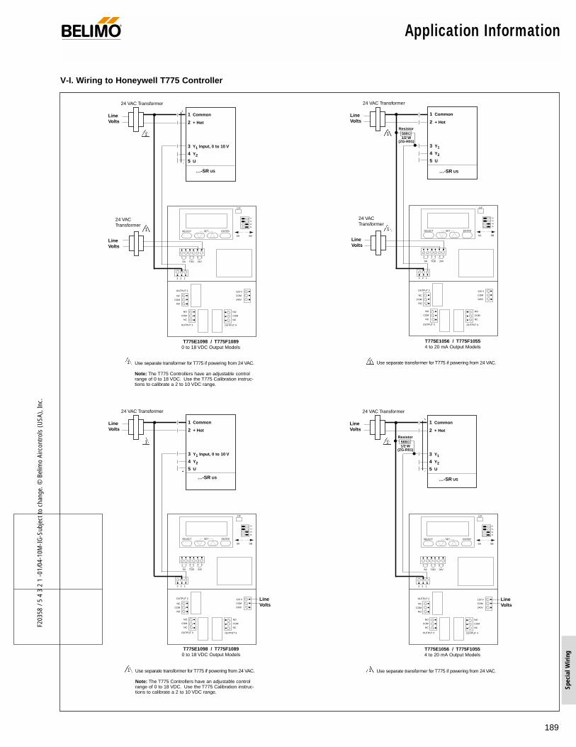
189
F203
58 /
5 4
3 2
1 -0
1/04
-10M
-IG-S
ubje
ct to
cha
nge.
© B
elim
o Ai
rcon
trols
(USA
), In
c.
Spec
ial W
iring
Application Information®
V-I. Wiring to Honeywell T775 Controller
1 Use separate transformer for T775 if powering from 24 VAC.
Note: The T775 Controllers have an adjustable controlrange of 0 to 18 VDC. Use the T775 Calibration instruc-tions to calibrate a 2 to 10 VDC range.
24 VAC Transformer
Line Volts
24 VAC Transformer
Line Volts
1 Common
2 + Hot
3 Y1 Input, 0 to 10 V
4 Y2
5 U
1
1
…-SR US
120 V
COM
240V
NO
COM
NC
NC
COM
NO
NO
COM
NC
OUTPUT 4OUTPUT 3
OUTPUT 2
C/F
1 2
3 4
SELECT SET ENTER
SA SB
3 2 1
1 2 3 4 5 6
SA TOD 24V
T775E1098 / T775F10890 to 18 VDC Output Models
1 Use separate transformer for T775 if powering from 24 VAC.
24 VAC Transformer
Line Volts
1 Common
2 + Hot
3 Y1
4 Y2
5 U
1
1
…-SR US
120 V
COM
240V
NO
COM
NC
NC
COM
NO
NO
COM
NC
OUTPUT 4OUTPUT 3
OUTPUT 2
C/F
1 2
3 4
SELECT SET ENTER
SA SB
3 2 1
1 2 3 4 5 6
SA TOD 24V
T775E1056 / T775F10554 to 20 mA Output Models
Resistor500Ω1/2 W
(ZG-R01)
24 VAC Transformer
Line Volts
1 Use separate transformer for T775 if powering from 24 VAC.
24 VAC Transformer
Line Volts
Line Volts
1 Common
2 + Hot
3 Y1
4 Y2
5 U
1
…-SR US
120 V
COM
240V
NO
COM
NC
NC
COM
NO
NO
COM
NC
OUTPUT 4OUTPUT 3
OUTPUT 2
C/F
1 2
3 4
SELECT SET ENTER
SA SB
3 2 1
1 2 3 4 5 6
SA TOD 24V
T775E1056 / T775F10554 to 20 mA Output Models
Resistor500Ω1/2 W
(ZG-R01)
1 Use separate transformer for T775 if powering from 24 VAC.
Note: The T775 Controllers have an adjustable controlrange of 0 to 18 VDC. Use the T775 Calibration instruc-tions to calibrate a 2 to 10 VDC range.
24 VAC Transformer
Line Volts
Line Volts
1 Common
2 + Hot
3 Y1 Input, 0 to 10 V
4 Y2
5 U
1
…-SR US
120 V
COM
240V
NO
COM
NC
NC
COM
NO
NO
COM
NC
OUTPUT 4OUTPUT 3
OUTPUT 2
C/F
1 2
3 4
SELECT SET ENTER
SA SB
3 2 1
1 2 3 4 5 6
SA TOD 24V
T775E1098 / T775F10890 to 18 VDC Output Models

190
F203
58 /
5 4
3 2
1 -0
1/04
-10M
-IG-S
ubje
ct to
cha
nge.
© B
elim
o Ai
rcon
trols
(USA
), In
c.
®Actuator/Valve SpecificationTo download specifications, see www.belimo.com
I. GENERALA. Warranty all actuators for a period of five years from the production date
as stated in the Terms and Conditions of Sale and Warranty. B. Electronic valve and damper actuators shall be as manufactured, brand
labeled, or distributed by Belimo.C. Electronic control valves, as specified, shall be Belimo or other brands
manufactured, brand labeled or distributed by Belimo.D. Other manufacturers must be approved, in writing, 10 days prior to the
bid date.
II. PRODUCTSA. Electronic Damper Actuators1. Electronic actuators, less than 600 in-lb. of rated torque, shall have ISO
9001 quality certification and be UL listed under standard 873, CSAC22.2 No. 24 and have CE certification.
2. Electronic actuators used on valves or dampers shall be designed todirectly couple and mount to a stem, shaft or ISO style-mounting pad.Actuator mounting clamps shall be a V-bolt with a toothed V-clamp cre-ating a cold weld, positive grip effect. Single point, bolt, or single screwactuator type fastening techniques or direct-coupled actuators requiringfield assembly of the universal clamp is not acceptable.
3. Actuators shall be fully modulating/proportional, pulse width, floating/tri-state, or two position as required and be factory or field selectable.Actuators shall have visual position indicators and shall operate insequence with other devices if required.
4. Optional auxiliary switches shall be available. 5. Actuators shall have an operating range of –22° to 122°F. 6. Proportional actuators shall accept a 0-10 VDC or 0-20 mA input signal
and provide a 2-10 VDC or 4-20 mA (with a load resistor) operatingrange.
7. Actuators shall be capable of operating on 24, 120 or 230VAC, or24VDC and Class 2 wiring as dictated by the application. Power con-sumption shall not exceed 10 VA for AC, including 120VAC actuators,and 8 watts per actuator for DC applications.
8. NEMA 2 rated actuators shall be provided with a three foot (minimum),pre-wired, electrical cable. Actuators requiring removal of the actuatorcover for access to wiring terminals, exposing electronic, printed circuitboards to damage, are unacceptable.
9. Actuators shall have electronic overload protection or digital rotationsensing circuitry to prevent actuator damage throughout the entire rota-tion. End switches to deactivate the actuator at the end of rotation ormagnetic clutches are not acceptable.
10. For power-failure/safety applications, an internal mechanical springreturn mechanism shall be built into the actuator housing. Spring returnactuators shall be capable of CW or CCW mounting orientation. Springreturn models > 60 in-lbs. will be capable of mounting on shafts up to1.05” in diameter. Spring return actuators with more than 60 in-lb. oftorque shall have a metal, manual override crank.
11. Actuators using “on-board” chemical storage systems, capacitors, orother “on-board” non-mechanical forms of fail-safe operation are unac-ceptable.
12. Upon loss of control signal, a proportional actuator shall fail open orclosed based on the minimum control signal. Upon loss of power, anon-spring return actuator shall maintain the last position.
13. Actuators shall be capable of being mechanically and electrically paral-leled to increase torque if required. Valves and dampers requiringgreater torque or higher close off may be assembled with multiple lowtorque actuators.
14. Dual mounted actuators using additional anti-rotation strap mechanicallinkages, or special factory wiring to function are not acceptable.Actuators in a tandem pair must be "off the shelf," standard actuatorsready for field wiring.
15. Damper and valve actuators will not produce more than 62 dB (A) whenfurnished with a mechanical fail-safe spring. Non-spring return actuatorsshall conform to a maximum noise rating of 45 dB(A) with power on or inthe running or driving mode.
16. Proportional actuators shall be fully programmable. Control input, posi-tion feedback and running time shall be factory or field programmable.Diagnostic feedback shall provide indications of hunting or oscillation,mechanical overload, mechanical travel and mechanical load limit. Theactuators shall also provide actuator service data, at minimum, numberof hours powered and number of hours in motion.
17. Proportional actuators shall be capable of digital communication, as built.
B. Electronic Valve Actuators1. Electronic actuators, less than 600 in-lb. of rated torque, shall have ISO
9001 quality certification and be UL listed under standard 873, CSAC22.2 No. 24 and have CE certification.
2. Electronic actuators used on valves shall be designed to directly coupleand mount to a stem, shaft or ISO style-mounting pad.
3. Actuators shall be fully modulating/proportional, pulse width, floating/tri-state, or two position as required and be factory or field selectable.Actuators shall have visual position indicators and shall operate insequence with other devices if required.
4. Optional auxiliary switches shall be available. 5. Actuators shall have an operating range of –22° to 122°F except NR
series with range of -22° to 160°F. 6. Proportional actuators shall accept a 0-10 VDC or 0-20 mA input signal
and provide a 2-10 VDC or 4-20 mA (with a load resistor) operatingrange.
7. Actuators shall be capable of operating on 24, 120 or 230VAC, or24VDC and Class 2 wiring as dictated by the application. Power con-sumption shall not exceed 10 VA for AC, including 120VAC actuators,and 8 watts per actuator for DC applications.
8. NEMA 2 rated actuators shall be provided with a three foot (minimum),pre-wired, electrical cable. Actuators requiring removal of the actuatorcover for access to wiring terminals, exposing electronic, printed circuitboards to damage, are unacceptable.
9. For power-failure/safety applications, an internal mechanical springreturn mechanism shall be built into the actuator housing. Spring returnactuators shall be capable of CW or CCW mounting orientation. Springreturn actuators with more than 60 in-lb. of torque shall have a metal,manual override crank.
10. Actuators using “on-board” chemical storage systems, capacitors, orother “on-board” non-mechanical forms of fail-safe operation are unac-ceptable.
11. Upon loss of control signal, a proportional actuator shall fail open orclosed based on the minimum control signal. Upon loss of power, anon-spring return actuator shall maintain the last position.
12. Actuators shall be capable of being mechanically and electrically paral-leled to increase torque if required. Valves requiring greater torque orhigher close off may be assembled with multiple low torque actuators.
13. Dual mounted actuators using additional anti-rotation strap mechanicallinkages, or special factory wiring to function are not acceptable.Actuators in a tandem pair must be "off the shelf," standard actuatorsready for field wiring.
14. Valve actuators will not produce more than 62 dB (A) when furnishedwith a mechanical fail-safe spring. Non-spring return actuators shall con-form to a maximum noise rating of 45 dB(A) with power on or in the run-ning or driving mode.
15. Proportional actuators shall be fully programmable. Control input, posi-tion feedback and running time shall be factory or field programmable.Diagnostic feedback shall provide indications of hunting or oscillation,mechanical overload, mechanical travel and mechanical load limit. Theactuators shall also provide actuator service data, at minimum, numberof hours powered and number of hours in motion.
16. Proportional actuators shall be capable of digital communication, as built.
®
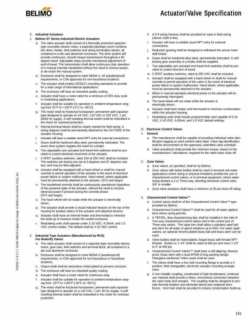
191
F203
58 /
5 4
3 2
1 -0
1/04
-10M
-IG-S
ubje
ct to
cha
nge.
© B
elim
o Ai
rcon
trols
(USA
), In
c.
® Actuator/Valve Specification
C. Industrial Actuators1. Belimo SY Series Industrial Electric Actuators
a. The valve actuator shall consist of a thermally protected capacitor-type reversible electric motor, a patented planetary worm combina-tion drive, heater, limit switches and wiring termination blocks, allcontained in a die cast aluminum enclosure. The drive system willprovide continuous, smooth torque transmission throughout a 90degree travel. Adjustable stops provide mechanical adjustment ofend-of-travel. The transmission shall allow continuous duty operationof a manual override handwheel without the need to remove power,or de-clutch the manual system.
b. Enclosure shall be designed to meet NEMA 4, 4X (weatherproof)requirements, or CSA approved for non-hazardous locations.
c. The actuator shall employ ISO5211 mounting standards to providefor a wide range of international applications.
d. The enclosure will have an industrial quality coating.e. Actuator shall have a motor rated for a minimum of 25% duty cycle
in modulating applications.f. Actuator shall be suitable for operation in ambient temperature rang-
ing from 22°F to +150°F [-5°C to +65°C].g. The motor shall be fractional horsepower; permanent split capacitor
type designed to operate on 24 VAC, 110 VAC or 220 VAC, 1 pH,50/60 Hz supply. A self resetting thermal switch shall be imbedded inthe motor for overload protection.
h. Internal terminal blocks shall be clearly marked for field wiring. Awiring diagram shall be permanently attached to the OUTSIDE of theactuator housing.
i. Actuator will have a suitable sized NPT entry for external connections.j. Gears shall be hardened alloy steel, permanently lubricated. The
worm drive system negates the need for a brake. k. Two adjustable cam actuated end travel limit switches shall be pro-
vided to control electrical movement of the actuator. l. 2 SPDT auxiliary switches, rated 10A at 250 VAC shall be included.
The switches are factory pre-set at 3 degrees and 87 degrees rota-tion, and may be field adjusted.
m. Actuator shall be equipped with a hand wheel or shaft for manualoverride to permit operation of the actuator in the event of electricalpower failure or system malfunction. Hand wheel, where applicable,must be permanently attached to the actuator. (SY2 and larger)
n. The handwheel override shall be continuously operational regardlessof the powered state of the actuator, without the need to removeelectrical power if present during the override phase. (SY2 and larger)
o. The hand wheel will not rotate while the actuator is electrically driven.
p. The actuator shall provide a visual indicator beacon on the top of thehousing for position status of the actuator and attached devices.
q. Actuator shall have an internal heater and thermostat to minimizethe build-up of moisture inside the sealed enclosure.
r. Modulating units shall operate under 2-10 VDC, 4-20mA, and 1-5VDC control modes. The default shall be 2-10 VDC control.
2. Industrial Type Actuators (Manufactured by RCS) For Butterfly Valvesa. The valve actuator shall consist of a capacitor-type reversible electric
motor, gear train, limit switches and terminal block, all contained in adie cast aluminum enclosure.
b. Enclosure shall be designed to meet NEMA 4 (weatherproof)requirements, or CSA approved for non-hazardous or hazardouslocations.
c. Output shaft shall be electroless nickel plated to prevent corrosion.d. The enclosure will have an industrial quality coating.e. Actuator shall have a motor rated for continuous duty.f. Actuator shall be suitable for operation in ambient temperature rang-
ing from -22°F to +150°F [-30°C to +65°C].g. The motor shall be fractional horsepower; permanent split capacitor
type designed to operate on a 120 VAC, 1 pH, 60 Hz supply. A selfresetting thermal switch shall be imbedded in the motor for overloadprotection.
h. A 6 ft wiring harness shall be provided for ease in field wiring (Above 1500 in-lbs).
i. Actuator will have a suitable sized NPT entry for external connections.
j. Reduction gearing shall be designed to withstand the actual motorstall torque.
k. Gears shall be hardened alloy steel, permanently lubricated. A self-locking gear assembly or a brake shall be supplied.
l. Two adjustable cam actuated end travel limit switches shall be pro-vided to control direction of travel.
m. 2 SPDT auxiliary switches, rated at 250 VAC shall be included.n. Actuator shall be equipped with a hand wheel or shaft for manual
override to permit operation of the valve in the event of electricalpower failure or system malfunction. Hand wheel, where applicable,must be permanently attached to the actuator.
o. When in manual operation electrical power to the actuator will bepermanently interrupted.
p. The hand wheel will not rotate while the actuator is electrically driven.
q. Actuator shall have heater and thermostat to minimize condensationwithin the actuator housing.
r. Modulating units shall include programmable card capable of 0-10VDC, 2-10 VDC, 4-20mA, and 1-5 VDC default settings.
D. Electronic Control Valves1. General
a. The manufacturer shall be capable of providing individual valve iden-tification tagging on each printed valve label. Valve tag identificationshall be documented on the approved, submitted valve schedule.
b. Valve actuator(s) shall provide the minimum torque, based on themanufacturers’ calculations, required for the rated valve close off.
2. Zone Valvesa. Zone valves, as specified, shall be by Belimo. b. Zone valves with brass bodies shall be used in terminal unit water
applications where sizing or physical limitations prohibit the use ofcharacterized control valves, or in terminal equipment, where watersizing dictates a 2 or Three-way, diverting electronic control valve3/4” or smaller.
c. Zone valve actuators shall have a minimum of 30 psi close-off rating.
3. Characterized Control Valves™a. Control valves shall be of the Characterized Control Valve™ type
provided by Belimo. b. Characterized Control Valves™ shall be used for all water applica-
tions where sizing permits. c. A TEFZEL‚ flow-characterizing disc shall be installed in the inlet of
Two-way characterized control valves and in the control port ofThree-way valves. The valve trim shall utilize a stainless steel balland stem for all water or glycol solutions up to 60%. For water appli-cations, an optional chrome plated brass ball and brass stem can beused.
d. Valve bodies shall be nickel-plated, forged brass with female NPTthreads. Bodies to 1-1/4” shall be rated at 600 psi and sizes 1-1/2”to 3” at 400 psi.
e. Characterized Control Valves™ shall have a self-aligning, blowoutproof, brass stem with a dual EPDM O-ring packing design.Fiberglass reinforced Teflon seats shall be used.
f. The valves shall have a four bolt mounting flange to provide a 4position, field changeable, electronic actuator mounting arrange-ment.
g. A non-metallic coupling, constructed of high temperature, continualuse material shall provide a direct, mechanical connection betweenthe valve body and actuator. The coupling shall be designed to pro-vide thermal isolation and eliminate lateral and rotational stemforces. Vent hole shall be provided to reduce condensation build-up.
®

192
F203
58 /
5 4
3 2
1 -0
1/04
-10M
-IG-S
ubje
ct to
cha
nge.
© B
elim
o Ai
rcon
trols
(USA
), In
c.
Actuator/Valve Specification ®
4. Globe Valves:a. Globe valves, as specified, shall be by Belimo. b. Two-way and Three-way globe valves may be used only if charac-
terized control valves do not fit the sizing criteria or application. c. Globe valves may be used for chilled or hot water, steam, or glycol
solutions to 60%. Screwed and flanged water valves shall haveequal percentage or linear flow characteristics for Two-way or Three-way valves, respectively. All stems shall be stainless steel.
d. Screwed globe valves 1/2” through 2” shall have bronze bodies ratedat ANSI Class 250. For water or steam up to 35 psi, trim shallinclude a brass plug, a spring-loaded TFE packing, and a bronzeseat. The maximum differential shall be 35 psi for water and 20 psifor steam.
e. Two-way and Three-way flanged globe valves 2-1/2” to 6” shall havecast iron bodies rated for ANSI Class 125 or ANSI 250. The maxi-mum differential shall be 25 psi for water and 10 psi for steam. Trimshall include stainless steel stems, bronze plugs, bronze seats, anda TFE V-ring packing.
f. For steam inlet pressures higher than those stated above, furnishglobe valves with stainless steel trim specifically rated for the appli-cation.
5. Direct Coupled Globe Valve Actuator and Adaptor Bracket:a. Actuator shall be designed with an integrated adaptor bracket that
will direct mount to the valve. b. Actuator shall provide a linear force capable of fulfilling the required
close-off of the valve. c. Actuator shall include an automatic valve coupling device that shall
lock securely to the valve stem. d. Proportional and spring return actuators shall adapt upon powering
the actuator. This adaptation will determine stroke length andenable the actuator to set the minimum and maximum limits of thesupplied control signal, thereby utilizing the entire control signalrange. Feedback, running time and other parameters are automati-cally adjusted to the effective stroke.
e. Actuator shall have a manual override equipped with an interlockingdevice to protect the actuator from over-torque of the manual override.
6. Butterfly Valvesa. Butterfly valves, as specified, shall be by Belimo.b. Butterfly valves 2” to 12” shall have a fully lugged, drilled and tapped,
cast iron body, rated to 200 psi body pressure, with 14” and largervalves having a body pressure rating of 150 psi. Flanges shall meetANSI 125/150 standards. The one-piece body shall feature anextended neck allowing sufficient clearance for flanges and 2” of pip-ing insulation. The disc shall be stainless steel and provide bi-direc-tional bubble-tight close off in either direction for water or 60% glycolapplications. The disc shall be polished and contoured to minimizetorque and wear. The flow characteristic shall be modified equal per-centage for Two-way valves and linear for Three-way valves. Valves2” through 12” shall be rated for standard HVAC service of up to 50psi close-off, or for heavy commercial service of up to 200 psi close-off. Valves 14” and larger shall be rated for up to 150 psi close-off.
c. The disc shall have full 360-degree concentric seating. Valves upthrough 12” shall utilize an internal spline for the disc-to-stem con-nection. External mechanical methods to achieve this mechanicalconnection, such as pins or screws, shall not be employed. Valves14” and larger will utilize a dual-pin method to prevent the heavy discfrom settling onto the liner, causing distortion. A phenolic backed,non-collapsing, EPDM seat shall be field replaceable and shall cre-ate a positive seal between flange face and valve body. No gasketsshall be required between the valve and flange faces. The shaft shallbe supported at four locations by RPTFE bushings.
d. Butterfly valves may be used in all two-position applications andmodulating applications larger than 2”, or where the close off ratingof other valve styles does not meet the design requirements.
e. Butterfly valves shall be sized primarily by using velocity calculationsto prevent fluid velocities from exceeding 12 feet per second. Formodulating applications, CV factors at sixty (60) degrees shall beused for determining delta P once size has been determined by thevelocity calculations.
f. High torque industrial valve actuators, >300 in-lb. of rated torque,may be used where low torque actuators are not suitable. Hightorque actuators shall be as manufactured or provided by Belimo.

193
F203
58 /
5 4
3 2
1 -0
1/04
-10M
-IG-S
ubje
ct to
cha
nge.
© B
elim
o Ai
rcon
trols
(USA
), In
c.Terms and Conditions of Sale and Warranty
I . GENERALUntil otherwise arranged, in writing, the following conditionsare valid. The Seller as referred to in the terms of sale isBelimo Aircontrols (USA) Inc. or Belimo Aircontrols (CAN) Inc.
II. PRICE1. Our prices are net, FOB Point of Origin in US currency
for sales made by Belimo Aircontrols (USA), Inc. andCAN currency for sales made by Belimo Aircontrols(CAN) Inc.
2. Freight and packaging (wooden crates, pallets etc) willbe charged at cost for each shipment.
3. Orders with a net value of less than US$300 (CAN$450)will be subject to a US$20 (CAN$35) handling fee.
4. No handling fee will be applied to orders placed throughthe Belimo Internet ordering system (www.belimo.com).
5. We reserve the right to make partial deliveries which canbe invoiced separately.
6. Wiring diagrams, installation, and commissioning are notincluded in our prices.
III. PAYMENT1. Invoices are payable in US currency for sales made by
Belimo Aircontrols (USA), Inc. and in CAN currency forsales made by Belimo Aircontrols (CAN) Inc. within 30 days from the date of invoice without any deductions.
2. Accounts with balances exceeding 60 days will be subject to an interest charge of 2% per month.
3. Accounts with balances exceeding 45 days will be subject to restricted shipments or COD status.
IV. TITLETitle in and property to the goods shall not pass to the Buyeruntil the Seller has received payment in full.
V. DAMAGE OR LOSS IN TRANSITSeller assumes no liability for damage or loss of shipment.All shipments should be unpacked and examined immedi-ately upon receipt. Any external evidence or loss or dam-age must be noted on the freight bill or carrier’s receipt andsigned by the carrier’s agent at the time of delivery. Failureto do so will result in the carrier’s refusal to honor the claim.Buyer then should notify Seller with copy of freight bill ordamage report so that Seller then can file claim for loss ordamage in transit with the carrier. If damage does notbecome apparent until shipment is unpacked, customermust make a request for inspection by the carrier’s agentand file with the carrier within 15 days after receipt of prod-uct and notify Seller. Seller is not liable for consequentialdamages resulting from the installation of damaged product.
VI. DELIVERY We undertake to make every attempt to adhere to our deliv-ery promise(s), but do not accept cancellation of contract orliability for any direct or indirect losses which may arise, forany reason whatsoever, due to our failure to adhere to suchpromise(s).
VII. RETURN OF GOODS1. Goods received by the Buyer cannot be returned unless
previously agreed upon with Seller. Buyer must acquireReturn Material Authorization (RMA) number fromBelimo prior to return of the goods. At this time, Buyerwill also receive instructions to where product is to bereturned. Only products returned to proper location withRMA number will be considered for credit.
2. Only goods in original packaging can be accepted.Goods returned must be in condition for resale as newequipment to qualify for credit. A minimum restockingcharge of 10% for actuators and 15% for valve productsand valve assemblies of the invoice value will be applied.Return material must be shipped prepaid.
3. Returns resulting from errors by the Seller will not besubject to re-stocking charges.
VIII. WARRANTY1. Belimo offers a five-year warranty for product listed in
our literature and shipped after May 1, 2000 for productshipped to locations within the USA and Canada. Someproducts may carry less than a 5-year warranty. Pleasesee documentation for specific reference to productswith a warranty of less than five years.
2. The Belimo warranty is unconditional for the first twoyears from the date of production. For the followingthree years, a conditional warranty applies. Under thisconditional warranty, the consequences of ordinary wearand tear, damage due to negligence or improper use, orother causes beyond our control are excluded from war-ranty coverage. Product specific terms of warranty withregard to warranty period or conditions of warranty mayapply to certain specified products as stated in the doc-umentation for those products.
3. The warranty shall be null and void should the Buyer or anyother persons modify or repair any part of our equipment.
4. Buyer must acquire a Return Material Authorization (RMA)number from Belimo prior to receiving warranty replace-ment or credit for product. Product return is not required inall cases to complete the warranty process. Ask ourCustomer Service department for detailed information.
5. Products found to be defective for which warranty isapplicable will be replaced or repaired at Seller’s discre-tion. Seller is not responsible for charges resulting fromthe removal and/or replacement of product.
IX. NONSTOCK AND NONCATALOG ITEMSProducts not listed in the current price list or catalogs areconsidered to be special order items and subject to mini-mum order quantities, special handling charges, and/orother conditions stipulated to us by suppliers. Such itemsnormally are subject to longer delivery times. Special orderitems may carry cancellation charges once an order isplaced and may also be subject to a restricted return policy.
X. PROPER LAW AND JURISDICTIONFor sales made by Belimo Aircontrols (USA) Inc., this con-tract is and shall be deemed to have been made in theUnited States, shall in all respects be governed by the lawsof the State of CT. For sales made by Belimo Aircontrols(CAN) Inc., this contract is and shall be deemed to havebeen made in Canada, shall in all respects be governed bythe laws of the Province of Ontario.
®
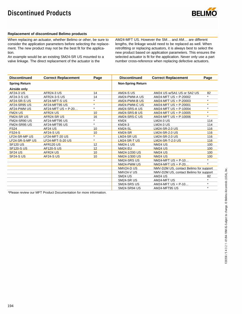
194
F203
58 /
5 4
3 2
1 -0
1/04
-10M
-IG-S
ubje
ct to
cha
nge.
© B
elim
o Ai
rcon
trols
(USA
), In
c.
Discontinued Products ®
Discontinued Correct Replacement Page
Spring Return
Airside onlyAF24-3 US AFR24-3 US 14AF24-3-S US AFR24-3-S US 14AF24-SR-S US AF24-MFT-S US *AF24-SR95 US AF24-MFT95 US *AF24-PWM US AF24-MFT US + P-20… *FM24 US AFR24 US 10FM24-SR US AFR24-SR US 16FM24-SR90 US AF24-MFT95 US *FM24-SR95 US AF24-MFT95 US *FS24 AF24 US 10FS24-S AF24-S US 10LF24-SR-MP US LF24-MFT-20 US *LF24-SR-S-MP US LF24-MFT-S-20 US *SF120 US AFR120 US 12SF120-S US AF120-S US 12SF24 US AFR24 US 10SF24-S US AF24-S US 10
*Please review our MFT Product Documentation for more information.
Discontinued Correct Replacement Page
Non-Spring Return
AM24-S US AM24 US w/SA1 US or SA2 US 82AM24-PWM-A US AM24-MFT US + P-20002 *AM24-PWM-B US AM24-MFT US + P-20003 *AM24-PWM-C US AM24-MFT US + P-20001 *AM24-SRS-A US AM24-MFT US + P-10004 *AM24-SRS-B US AM24-MFT US + P-10005 *AM24-SRS-C US AM24-MFT US + P-10006 *KM24 LM24-3 US 114KM24-3 LM24-3 US 114KM24-SL LM24-SR-2.0 US 116KM24-SR LM24-SR-2.0 US 116LM24-SR US LM24-SR-2.0 US 116LM24-SR-T US LM24-SR-T-2.0 US 116NM24-1 US NM24 US 100NM24 EU NM24 US 100NM24-1/200 US NM24 US 100NM24-1/300 US NM24 US 100NM24-SRS US NM24-MFT US + P-10… *NM24-PWM US NM24-MFT US + P-20… *NMV24-D US NMV-D2M US, contact Belimo for supportNMV24-V US NMV-D2M US, contact Belimo for supportSM24 US AM24 US 82SM24-SR US AM24-MFT US *SM24-SRS US AM24-MFT US + P-10… *SM24-SR94 US AM24-MFT95 US *
Replacement of discontinued Belimo products
When replacing an actuator, whether Belimo or other, be sure toconsider the application parameters before selecting the replace-ment. The new product may not be the best fit for the applica-tion.An example would be an existing SM24-SR US mounted to avalve linkage. The direct replacement of the actuator is the
AM24-MFT US. However the SM… and AM… are differentlengths, the linkage would need to be replaced as well. Whenretrofitting or replacing actuators, it is always best to select thenew product based on application parameters. This ensures theselected actuator is fit for the application. Never only use a partnumber cross-reference when replacing defective actuators.
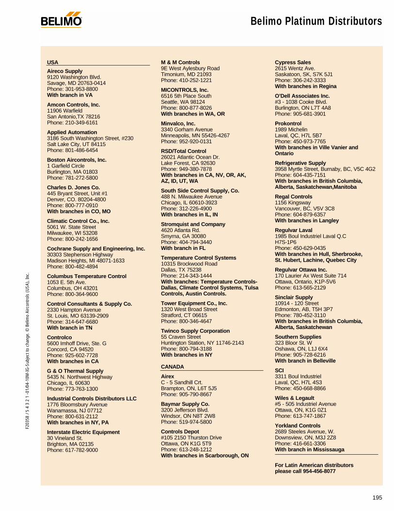
195
F203
58 /
5 4
3 2
1 -0
1/04
-10M
-IG-S
ubje
ct to
cha
nge.
© B
elim
o Ai
rcon
trols
(USA
), In
c.Belimo Platinum Distributors®
USA
Aireco Supply9120 Washington Blvd.Savage, MD 20763-0414Phone: 301-953-8800With branch in VA
Amcon Controls, Inc.11906 WarfieldSan Antonio,TX 78216Phone: 210-349-6161
Applied Automation3186 South Washington Street, #230Salt Lake City, UT 84115Phone: 801-486-6454
Boston Aircontrols, Inc.1 Garfield CircleBurlington, MA 01803Phone: 781-272-5800
Charles D. Jones Co.445 Bryant Street, Unit #1Denver, CO. 80204-4800Phone: 800-777-0910With branches in CO, MO
Climatic Control Co., Inc.5061 W. State StreetMilwaukee, WI 53208Phone: 800-242-1656
Cochrane Supply and Engineering, Inc.30303 Stephenson HighwayMadison Heights, MI 48071-1633Phone: 800-482-4894
Columbus Temperature Control1053 E. 5th Ave.Columbus, OH 43201Phone: 800-364-9600
Control Consultants & Supply Co.2330 Hampton AvenueSt. Louis, MO 63139-2909Phone: 314-647-6680With branch in TN
Controlco5600 Imhoff Drive, Ste. GConcord, CA 94520Phone: 925-602-7728With branches in CA
G & O Thermal Supply5435 N. Northwest HighwayChicago, IL 60630Phone: 773-763-1300
Industrial Controls Distributors LLC1776 Bloomsbury AvenueWanamassa, NJ 07712Phone: 800-631-2112With branches in NY, PA
Interstate Electric Equipment30 Vineland St.Brighton, MA 02135 Phone: 617-782-9000
M & M Controls9E West Aylesbury RoadTimonium, MD 21093Phone: 410-252-1221
MICONTROLS, Inc.6516 5th Place SouthSeattle, WA 98124Phone: 800-877-8026With branches in WA, OR
Minvalco, Inc.3340 Gorham AvenueMinneapolis, MN 55426-4267Phone: 952-920-0131
RSD/Total Control26021 Atlantic Ocean Dr.Lake Forest, CA 92630Phone: 949-380-7878With branches in CA, NV, OR, AK, AZ, ID, UT, WA
South Side Control Supply, Co. 488 N. Milwaukee AvenueChicago, IL 60610-3923Phone: 312-226-4900With branches in IL, IN
Stromquist and Company4620 Atlanta Rd.Smyrna, GA 30080Phone: 404-794-3440With branch in FL
Temperature Control Systems10315 Brockwood RoadDallas, TX 75238Phone: 214-343-1444With branches: Temperature Controls-Dallas, Climate Control Systems, TulsaControls, Austin Controls.
Tower Equipment Co., Inc.1320 West Broad StreetStratford, CT 06615Phone: 800-346-4647
Twinco Supply Corporation55 Craven StreetHuntington Station, NY 11746-2143Phone: 800-794-3188With branches in NY
CANADA
AirexC - 5 Sandhill Crt.Brampton, ON, L6T 5J5 Phone: 905-790-8667
Baymar Supply Co.3200 Jefferson Blvd.Windsor, ON N8T 2W8Phone: 519-974-5800
Controls Depot#105 2150 Thurston DriveOttawa, ON K1G 5T9 Phone: 613-248-1212 With branches in Scarborough, ON
Cypress Sales2615 Wentz Ave. Saskatoon, SK, S7K 5J1 Phone: 306-242-3333 With branches in Regina
O’Dell Associates Inc.#3 - 1038 Cooke Blvd.Burlington, ON L7T 4A8 Phone: 905-681-3901
Prokontrol1989 MichelinLaval, QC, H7L 5B7 Phone: 450-973-7765 With branches in Ville Vanier andOntario
Refrigerative Supply 3958 Myrtle Street, Burnaby, BC, V5C 4G2 Phone: 604-435-7151 With branches in British Columbia,Alberta, Saskatchewan,Manitoba
Regal Controls 1156 Kingsway Vancouver, BC, V5V 3C8 Phone: 604-879-6357 With branches in Langley
Regulvar Laval1985 Boul Industriel Laval Q.CH7S-1P6Phone: 450-629-0435With branches in Hull, Sherbrooke,St. Hubert, Lachine, Quebec City
Regulvar Ottawa Inc.170 Laurier Ax West Suite 714Ottawa, Ontario, K1P-5V6 Phone: 613-565-2129
Sinclair Supply10914 - 120 StreetEdmonton, AB, T5H 3P7 Phone: 780-452-3110 With branches in British Columbia,Alberta, Saskatchewan
Southern Supplies323 Bloor St. WOshawa, ON, L1J 6X4 Phone: 905-728-6216 With branch in Belleville
SCI3311 Boul Industriel Laval, QC, H7L 4S3 Phone: 450-668-8866
Wiles & Legault#5 - 505 Industriel AvenueOttawa, ON, K1G 0Z1 Phone: 613-747-1867
Yorkland Controls2689 Steeles Avenue, W. Downsview, ON, M3J 2Z8 Phone: 416-661-3306 With branch in Mississauga
For Latin American distributors please call 954-456-8077

®
For information and to place an order, contact the Belimo customer service and technicalsupport office near you, or visit:
www.belimo.com
Belimo and You...
Together to the Top
Belimo Aircontrols (USA), Inc.
43 Old Ridgebury Road 1675 East Prater WayDanbury, CT 06810 Suite 101Toll Free: (800) 543-9038 Sparks, NV 89434(203) 791-9915 Toll Free: (800) 987-9042Fax: (800) 228-8283 (775) 857-4243
(800-ACTUATE) Fax: (775) 857-4255(203) 791-9919 (800) 987-8875
Belimo Servomoteur, Inc.2790 Chemin du LacLongueuil, Québec J4N 1B8Toll Free: (866) 928-1440(450) 928-1440Fax: (450) 928-0050
Belimo Aircontrols (CAN), Inc.
14/16 – 5716 Coopers Ave.Mississauga, Ontario L4Z 2E8Toll Free: (866) 805-7089(905) 712-3118Fax: (905) 712-3124
Belimo in Latin America
1250 E. Hallandale Beach Blvd.Suite 802Hallandale Beach, FL 33009(954) 456-8077 Fax: (954) 456-8092
3151 E. Thomas StreetInverness, FL 34453Toll Free: (888) 829-3166(352) 637-9280Fax: (352) 637-9634
(888) 829-3412
651 South Roselle RoadSchaumburg, IL 60193Toll Free: (877) 833-1647(847) 352-0528Fax: (847) 352-1442
(877) 833-1663
F203
58 /
5 4
3 2
1 -0
1/04
-10M
-IG-S
ubje
ct to
cha
nge.
© B
elim
o Ai
rcon
trols
(USA
), In
c.
Related Documents