KOMITE NASIONAL KESELAMATAN TRANSPORTASI REPUBLIC OF INDONESIA 2015 FINAL KNKT.14.12.29.04 KOMITE NASIONAL KESELAMATAN TRANSPORTASI PT. Indonesia Air Asia Airbus A320-216; PK-AXC Karimata Strait Coordinate 3°37’19”S - 109°42’41”E Republic of Indonesia 28 December 2014 Aircraft Accident Investigation Report

Welcome message from author
This document is posted to help you gain knowledge. Please leave a comment to let me know what you think about it! Share it to your friends and learn new things together.
Transcript

KOMITE NASIONAL KESELAMATAN TRANSPORTASI REPUBLIC OF INDONESIA 2015
FINAL KNKT.14.12.29.04
KOMITE NASIONAL KESELAMATAN TRANSPORTASI
PT. Indonesia Air Asia Airbus A320-216; PK-AXC
Karimata Strait Coordinate 3°37’19”S - 109°42’41”E
Republic of Indonesia 28 December 2014
Aircraft Accident Investigation Report

i
This final report was produced by the Komite Nasional Keselamatan Transportasi (KNKT), 3rd Floor Ministry of Transportation, Jalan Medan Merdeka Timur No. 5 Jakarta 10110, Indonesia.
The report is based upon the investigation carried out by the KNKT in accordance with Annex 13 to the Convention on International Civil Aviation, the Indonesian Aviation Act (UU No. 1/2009) and Government Regulation (PP No. 62/2013).
Readers are advised that the KNKT investigates for the sole purpose of enhancing aviation safety. Consequently, the KNKT reports are confined to matters of safety significance and may be misleading if used for any other purpose.
As the KNKT believes that safety information is of greatest value if it is passed on for the use of others, readers are encouraged to copy or reprint for further distribution, acknowledging the KNKT as the source.
When the KNKT makes recommendations as a result of its investigations or research, safety is its primary consideration.
However, the KNKT fully recognizes that the implementation of recommendations arising from its investigations will in some cases incur a cost to the industry.
States participating in KNKT investigation should note that the information in KNKT reports and recommendations is provided to promote aviation safety. In no case is it intended to imply blame or liability.
1
TABLE OF CONTENTS TABLE OF CONTENTS ...................................................................................................... 1
TABLE OF FIGURES ........................................................................................................... 5
ABBREVIATIONS AND DEFINITIONS ........................................................................... 6
INTRODUCTION................................................................................................................ 13
1 FACTUAL INFORMATION ...................................................................................... 14
1.1 History of Flight .................................................................................................. 14
1.2 Injuries to Persons ............................................................................................... 17
1.3 Damage to Aircraft .............................................................................................. 18
1.4 Other Damage ..................................................................................................... 19
1.5 Personnel Information ......................................................................................... 19
1.5.1 Pilot in Command .................................................................................. 19
1.5.2 The PIC background and flight experience ........................................... 20
1.5.3 The PIC exposure to Rudder Travel Limiter problem ........................... 21
1.5.4 Second in Command .............................................................................. 22
1.5.5 The SIC flight experience background .................................................. 22
1.6 Aircraft Information ............................................................................................ 23
1.6.1 General ................................................................................................... 23
1.6.2 Engines .................................................................................................. 24
1.6.3 Maintenance History related to RTLU .................................................. 24
1.6.3.1 Maintenance Report 1 (MR1) and Maintenance Report 2 (MR2) ... 24
1.6.3.2 Defect Handling in Line Maintenance using Post Flight Report (PFR) ................................................................................................ 25
1.6.3.3 Summary of PK-AXC 1 Year Maintenance Report ......................... 26
1.6.3.4 Reliability Report Issued on November 2014 .................................. 27
1.6.3.5 Last Three Day Records ................................................................... 27
1.6.3.6 FAC Shop Finding Report ............................................................... 28
1.6.3.7 Summary .......................................................................................... 28
1.6.4 Weight and Balance (Load and Trim Sheet) ......................................... 29
1.6.5 Aircraft Systems .................................................................................... 29
1.6.5.1 Flight Control System ...................................................................... 29
1.6.5.2 Control Law ..................................................................................... 31
1.6.5.3 Lateral Consoles ............................................................................... 33

2
1.6.5.4 Characteristic of pitch and lateral .................................................... 34
1.6.5.5 Rudder Travel Limitation ................................................................. 36
1.6.5.6 Flight Augmentation Computer (FAC) ............................................ 37
1.6.5.7 The location of FAC 1-2 Push Button and Circuit Breakers ........... 38
1.6.5.8 Display Management Switching Panel ............................................ 39
1.6.5.9 Air Data System Schematic ............................................................. 39
1.6.5.10 ECAM control panel ........................................................................ 40
1.7 Meteorological Information ................................................................................ 42
1.8 Aids to Navigation .............................................................................................. 43
1.9 Communications ................................................................................................. 44
1.10 Aerodrome Information ...................................................................................... 44
1.11 Flight Recorders .................................................................................................. 44
1.11.1 Flight Data Recorder .............................................................................. 44
1.11.2 Recorded system failure ........................................................................ 52
1.11.3 Cockpit Voice Recorder ........................................................................ 54
1.11.4 Selected significant events based on CVR and FDR ............................. 56
1.12 Wreckage and Impact Information ..................................................................... 60
1.13 Medical and Pathological Information ................................................................ 63
1.14 Fire ...................................................................................................................... 63
1.15 Survival Aspects ................................................................................................. 63
1.16 Tests and Research .............................................................................................. 64
1.16.1 Flight Simulation ................................................................................... 64
1.16.2 The RTLU examination ......................................................................... 65
1.17 Organisation and Management Information ....................................................... 67
1.17.1 Summary of Management Interview ..................................................... 67
1.17.2 Summary of Maintenance Management Interview ................................ 67
1.17.3 Company Manuals ................................................................................. 69
1.17.3.1 Company Operation Manual (COM) ............................................... 69
1.17.3.2 FCOM - Normal Checklist ............................................................... 70
1.17.3.3 FCOM - Auto Flight Rudder Limiter System .................................. 71
1.17.3.4 Flight Crew Training Manual (FCTM) ............................................ 72
1.17.3.5 FCTM - Abnormal Attitudes ............................................................ 78
1.17.3.6 FCTM - Side-stick and takeover Priority Button ............................. 79

3
1.17.3.7 OTM - Upset Training Syllabus ....................................................... 79
1.17.3.8 Standard Operating Procedures ........................................................ 80
1.17.3.9 SOP-Standard Call Outs ................................................................... 82
1.17.3.10 QRH - General ............................................................................. 82
1.17.3.11 QRH - Stall Recovery .................................................................. 85
1.17.3.12 QRH - Tripped Circuit Breaker Re-Engagement ........................ 86
1.17.3.13 Company Maintenance Manual (CMM) ..................................... 86
1.17.3.14 Engineering Procedure Manual ................................................... 90
1.17.3.15 Reliability Manual ....................................................................... 92
1.17.3.16 Troubleshooting Manual (TSM) .................................................. 94
1.17.4 Directorate General of Civil Aviation (DGCA) .................................... 94
1.18 Additional Information ....................................................................................... 95
1.18.1 Stall ........................................................................................................ 95
1.18.2 Stall ........................................................................................................ 98
1.18.3 Rudder deflection ................................................................................... 99
1.18.7 ICAO Annex 6: Duties of pilot in command ....................................... 102
1.18.8 Civil Aviation Safety Regulation (CASR) part 121 ............................ 102
1.19 Useful or Effective Investigation Techniques ................................................... 102
2 ANALYSIS .................................................................................................................. 103
2.1 Un-commanded aircraft roll .............................................................................. 103
2.2 Electrical interruption ....................................................................................... 104
2.3 RUD TRV LIM SYS Message Handling .......................................................... 106
2.4 Side stick inputs ................................................................................................ 107
2.4.1 First Aural Stall warning ..................................................................... 108
2.4.2 Second Aural Stall Warning ................................................................ 109
2.5 Pilot recognition of stall .................................................................................... 110
2.6 Crew Resource Management ............................................................................ 112
2.7 Maintenance handling on aircraft system problem ........................................... 114
2.7.1 The Line Maintenance ......................................................................... 114
2.7.2 The Maintenance Organization ............................................................ 116
3 CONCLUSION ........................................................................................................... 117
3.1 Findings ............................................................................................................. 117
3.2 Contributing factors .......................................................................................... 121

4
4 SAFETY ACTION ...................................................................................................... 123
4.1 Aircraft operator ................................................................................................ 123
5 SAFETY RECOMMENDATIONS ........................................................................... 125
5.1 Aircraft Operator ............................................................................................... 125
5.2 Directorate General Civil Aviation ................................................................... 125
5.3 Aircraft Manufacturer ....................................................................................... 125
5.4 United States Federal Aviation Administration and European Aviation Safety Agency ................................................................................................... 125
6 APPENDICES ............................................................................................................. 126
6.1 Air Operator Safety Action .................................. Error! Bookmark not defined. 6.2 Operation Training Manual: upset recovery training ........................................ 150
6.3 Safety First, Airbus Safety Magazines January 2011 ....................................... 151
6.4 Upset Recovery Industry Team......................................................................... 157
6.5 Airbus Upset Recovery Training ...................................................................... 158
6.6 Airbus A320 Type Qualification Training-Handling Phase FFS 4 ................... 161
6.7 Summary of “PK-AXC Defect 1 Year” Report ................................................ 166
6.8 PFR Summary ................................................................................................... 169
6.9 Troubleshooting Manual (TSM) Task 22-61-00-810-803-A ............................ 172
6.10 Reliability Report November 2014 ................................................................... 175
6.11 Startle Reflex..................................................................................................... 175
6.12 Ebbinghaus Curve and Review ......................................................................... 177
6.13 Accredited Representatives Comments ............................................................ 179
7 REFERENCES ............................................................................................................ 204
5
TABLE OF FIGURES Figure 1: Archive photo of the aircraft ....................................................................................................... 14
Figure 2: The aircraft flight track ................................................................................................................ 17
Figure 4: One section of passenger seats .................................................................................................... 18
Figure 5: Centre fuselage section including the wings and main landing gears ......................................... 19
Figure 6: Typical Printed Post Flight Report (PFR) ................................................................................... 25
Figure 7: Numbers of the RTLU Occurrences in 2014 ............................................................................... 27
Figure 9: The overhead panel shows the location of FAC 1 CBs, FAC 1 and 2 push buttons ................... 38
Figure 10: The location of FAC 2 CB, behind the First Officer‟s seat (red line) ....................................... 38
Figure 11: Switching panel on pedestal ...................................................................................................... 39
Figure 12: The Pitot Static Configuration ................................................................................................... 39
Figure 13: line probes schematic ................................................................................................................ 40
Figure 14: ECAM control panel ................................................................................................................. 40
Figure 16: The cloud height (in meter) view along the airways of M635 .................................................. 42
Figure 17: Automatic Dependent Surveillance – Broadcast (ADS-B) data superimposed to Google earth .......................................................................................................................................... 43
Figure 18: ADS-B data ............................................................................................................................... 44
Figure 20: RTLU problems and pilot actions ............................................................................................. 47
Figure 21: FDR parameters after the fifth Master Caution ......................................................................... 48
Figure 23: Thrust levers and side-sticks movement .................................................................................... 51
Figure 24: The FDR parameters of FAC fault followed by CB reset on the ground at 25 December 2014 .......................................................................................................................................... 52
Figure 26: The first aural Stall warning activated ....................................................................................... 57
Figure 28: Aircraft in upsetsituation ........................................................................................................... 59
Figure 29: Attitude recovered ..................................................................................................................... 59
Figure 30: Wreckage Diagram superimposed on Google Map ................................................................... 61
Figure 32: Pictures of identified parts and its original position .................................................................. 62
Figure 33: The page 1 and 2 of the ECAM messages after CBs of FAC 1 and 2 being reset .................... 64
Figure 34: The ECAM messages after RTLU 1 and 2 fault ....................................................................... 65
Figure 36: Reducing thrust leads to a decrease in AOA ............................................................................. 96

6
ABBREVIATIONS AND DEFINITIONS
AAA : Air Asia Academy
AAIB (Singapore)
: Air Accident Investigation Bureau of Singapore
AAIB (UK) : Air Accidents Investigation Branch of United Kingdom
AD : Airworthiness Directive
ADIRS : Air Data and Inertial Reference System
ADS-B : Automatic Dependent Surveillance-Broadcast
AFM : Aircraft Flight Manual
Airplane Upset:
: An airplane in flight unintentionally exceeding the parameters normally experienced in line operations or training:
• Pitch attitude greater than 25 degree, nose up. • Pitch attitude greater than 10 degree, nose down. • Bank angle greater than 45 degree. • Within the above parameters, but flying at airspeeds inappropriate for
the conditions. ALERFA : Phase activates the Search & Rescue and State Security Forces and all
ATC units along the whole route are contacted
ALT : Altitude
AMM : Aircraft Maintenance Manual
AMO : Approved Maintenance Organization
AMOS : Airlines Maintenance and Operational System AOA : Angle of attack is the angle between the oncoming air or relative wind, and
some reference line on the airplane or wing. A/P : Autopilot
AOC : Air Operator Certificate a commercial transport license for airlines
ARAIB : Aviation and Rail Accident Investigation Board
ATC : Air Traffic Control
A/THR : Auto thrust
ATM : Air Traffic Management
ATPL : Air Transport Pilot License is the highest level of aircraft pilot licence
ATS : Air Traffic Service
ATSB : Australian Transport Safety Bureau
BEA : Bureau d‟Enquêtes et d‟Analyses BMKG : Badan Meterologi Klimatologi dan Geofisika (Metrological Climatology
and Geophysical Agency)

7
BASARNAS : Badan Search and Rescue Nasional (National Search and rescue Agency)
BSCU : Braking Steering Control Unit
°C : Degrees Celsius
CAA China : Civil Aviation Administration of China
CAS : Calibrated Airspeed
CB : Circuit breaker
CB : Cumulonimbus cloud
CFDS : Centralized Fault Display System
CG : Centre of gravity
Cl : Lift Coefficient
CMM : Company Maintenance Manual
COM : Company Operation Manual
CRM : Crew resources Management
CVR : Cockpit Voice Recorder
daN : Deka Newton
DGCA : Directorate General of Civil Aviation of Indonesia
DMC : Display Management Computer
DNA : Deoxyribonucleic Acid
DOA : Design Organization Approval
DVI : Disaster Victim Identification
EASA : European Aviation Safety Agency
EC : European Community
ECB : Electronic Control Box (APU)
ECAM : Electronic Centralized Aircraft Monitoring
EI : Engineering Instruction
EIS : Electronic Instruments System
EIU : Engine Interface Unit
EFIS : Electronic Flight Instruments System
EGT : Exhaust Gas Temperature
ELAC : Elevator Aileron Computer
EPM : Engineering Procedure Manual
ETOPS : Extended Twin Engine Operations
E/WD : Engine Warning Display

8
FAA : Federal Aviation Administration
FAC : Flight Augmentation Computer
FCDC : Flight Control Data Concentrators
FCOM : Flight Crew Operation Manual
FCTM : Flight Crew Training manual
FCU : Flight Control Unit
FD : Flight Director
FDR : Flight Data Recorder
FDU : Fire Detection Unit FFS : Full Flight Simulator
FL : Flight Level
FMGS : Flight Management and Guidance System.
ft : Feet a unit of length
FWC : Flight Warning Computer
GW/CG : Gross Weight/Centre of Gravity
IAA : Indonesia Air Asia
IC : Inspection Card
ICAO : International Civil Aviation Organization
INAFIS : Indonesia Automatic Fingerprint Identification System
INCERFA : It is a situation in which there is uncertainty as to the safety of an aircraft and its occupants.
In Hg : Inch Hydrargyrum
ISIS : Integrated Standby Instrument System
Kg : Kilogram (s)
Km : Kilo meter (s)
KNKT : Komite Nasional Keselamatan Transportasi
Kts : Knots (Nm/hours)
LFUS : Line Flying Under-Supervision
lbs : Libs (pound)
LT : Local time
MAA : Malaysia Air Asia
MAC : Mean Aerodynamic Chord.
mbs : Millibars

9
MC : Master Cautions
MCDU : Multipurpose Control and Display Unit
MEL : Minimum Equipment List.
MHz : Mega Hertz is the unit of frequency in the International System of Units(SI) and is defined as one cycle per second
mm : Millimetre(s) is a unit of length in the metric system
MMO : Maximum Operating Mach
MOC : Maintenance Operation Centre
MOM : Maintenance Operation Manager
MOT : Ministry of Transport (Malaysia)
MPA : Marine Port Authority (Singapore)
N1 : Rotation speed of low pressure compressor (%).
N2 : Rotation speed of high pressure compressor (%)
ND : Navigation Display
Nm : Nautical mile(s)
NOTAM : Notice to Airman
NTC : Notice to crew
OEB : Operation Engineering Bulletin
OR : Occurrence Report
PF : Pilot Flying
PFD : Primary flight display
PFR : Post Flight Report is an automatic reporting system shows on the Centralized Fault Display System (CFDS) consist of ECAM message which contains any ECAM Warning related with system malfunction during the flight and Failure Message which states the failure component. The PFR message can be printed after completion of a flight.
PIC : Pilot in Command
PM : Pilot Monitoring
PNF : Pilot Non flying
P/N : Part Number
PSU : Passenger Services Unit
QNH : Height above mean sea level based on local station pressure
QRH : Quick Reference Handbook
RTLU : Rudder Travel Limiter Unit

10
RTLACT : Rudder Travel Actuator
RVSM : Reduced Vertical Separation Minima SB : Service bulletin
SEC : Spoilers Elevator Computer
S/N : Serial Number is a unique code assigned to uniquely identify an item
SFCC : Slat/Flap Control Computer
SIC : Second in Command
Stall : An airplane is stalled when the angle of attack is beyond the stalling angle. A stall is characterized by any of, or a combination of, the following:
a. Buffeting, which could be heavy at times, b. A lack of pitch authority, c. A lack of roll control, d. Inability to arrest descent rate.
STPI : Sekolah Tinggi Penerbangan Indonesia (Indonesia Civil Aviation Institute)
SW : Stall Warning
TCAS : Traffic Collision Avoidance Systems
TE : Trailing Edge
TEM : Threat and Error Management
TFU : Technical Follow Up
THS : Trimmable Horizontal Stabilizer
TOGA : Takeoff Go Around
TQ Type Qualification
TSM : Trouble Shooting Manual
ULB : Underwater Locator Beacon or underwater acoustic beacon is a device fitted to aviation flight recorders such as the Cockpit Voice Recorder and Flight Data Recorder.
UTC : Universal Time Coordinate
VLE : Maximum Landing Gear Extended Speed
VLS : Lowest Selectable Speed
VHF : Very High Frequency
VS : Vertical speed
WD : Windshear Detection
WQAR : Wireless Wireless Quick Access Recorder

11
YDF : Yaw Damper Fault
ZFW : Zero Fuel Weight
ABBREVIATION OF FDR PARAMETERS
Note 1 or 2 indicated respective position.
AILDA : Aileron Deflection Angle
AOA IRS3 : Angle of Attack data based on Inertia Reference System 3 source
AP : Auto Pilot
ATHR : Auto Thrust
CFAC : Captain (left) Flight Augmentation Computer
CPTMC : Captain (Left) Master Caution
FAC(1/2)F : Flight Augmentation Computer (1 or 2) Fault
FFAC : First Officer (right) Flight Augmentation Computer
FOMC : First Officer (right) Master Caution
HPFSOV : High Pressure Fuel Shut Off Valve
ISISALT : Altitude data taken from Integrated Standby Instrument System source
ISISCAS : Calibrated Airspeed data taken from Integrated Standby Instrument System source
N1A : N1 (engine rotation)
PITCH : Pitch angle
PDLAW : Pitch Direct Law
PNLAW : Pitch Normal Law
RDLAW : Rudder Direct Law
RNLAW : Rudder Normal Law
ROLL : Roll angle
RTLACT : Rudder Travel Actuator
RUDT : Rudder Travel
STALLW : stall warning
STKCINOP : Sidestick Captain Inoperative
STKFINOP : Sidestick First Officer Inoperative
STKPC : Sidestick Pitch Captain (left)

12
STKPF : Sidestick Pitch First Officer (right)
STKRC : Sidestick Roll Captain (Left)
STKRF : Sidestick Roll First Officer (right)
TLA : Thrust Lever Angle
TLU : Travel Limiter Unit
VERTG : Vertical G
VSPD : Vertical Speed
WSD : Windshear Detection
YDF : Yaw Damper Fault

13
INTRODUCTION Synopsis On 28 December 2014 an Airbus A320-216 aircraft registered as PK-AXC was cruising at 32,000 feet on a flight from Juanda Airport, Surabaya, Indonesia to Changi Airport, Singapore with total occupants of 162 persons. The Pilot in Command (PIC) acted as Pilot Monitoring (PM) and the Second in Command (SIC) acted as Pilot Flying (PF).
The Flight Data Recorder (FDR) recorded that 4 master cautions activated following the failure of the Rudder Travel Limiter which triggered Electronic Centralized Aircraft Monitoring (ECAM) message of AUTO FLT RUD TRV LIM SYS. The crew performed the ECAM procedure on the first three master caution activations. After the 4th master caution, the FDR recorded different pilot action and the parameters showed similar signature to those on 25 December 2014 when the FAC CBs were pulled on the ground. This pilot action resulted on the 5th and 6th master caution activations which correspond respectively to ECAM message of AUTO FLT FAC 1 FAULT and AUTO FLT FAC 1+2 FAULT
Following two FAC fault, the autopilot and auto-thrust disengaged and the flight control reverted to Alternate Law which means the aircraft lost several protections available in Normal Law. The aircraft entered an upset condition and the stall warning activated until the end of recording.
Participating in the investigation of this accident were Australian ATSB, French BEA, Singapore AAIB and MOT Malaysia as accredited representatives.
The investigation concluded that contributing factors to this accident were: The cracking of a solder joint of both channel A and B resulted in loss of electrical
continuity and led to RTLU failure. The existing maintenance data analysis led to unresolved repetitive faults occurring with
shorter intervals. The same fault occurred 4 times during the flight. The flight crew action to the first 3 faults in accordance with the ECAM messages.
Following the fourth fault, the FDR recorded different signatures that were similar to the FAC CB‟s being reset resulting in electrical interruption to the FAC‟s.
The electrical interruption to the FAC caused the autopilot to disengage and the flight control logic to change from Normal Law to Alternate Law, the rudder deflecting 2° to the left resulting the aircraft rolling up to 54° angle of bank.
Subsequent flight crew action leading to inability to control the aircraft in the Alternate Law resulted in the aircraft departing from the normal flight envelope and entering prolonged stall condition that was beyond the capability of the flight crew to recover.
Issues such as flight approval considered did not contribute to the accident and was not investigated. The FDR data did not show any indication of the weather condition affecting the aircraft. Following this accident, the Indonesia Air Asia has performed several safety actions. KNKT issued several recommendations to Indonesia Air Asia, Director General of Civil Aviation (DGCA), US Federal Aviation Administration and European Aviation Safety Administration (EASA) and Airbus.

14
1 FACTUAL INFORMATION
1.1 History of Flight On 28 December 2014, an Airbus A320-216 aircraft registered as PK-AXC was being operated by PT. Indonesia Air Asia on a scheduled flight from Juanda International Airport Surabaya, Indonesia to Changi International Airport, Singapore. The aircraft departed at 0535 LT (2235 UTC1, 27 December 2014) and was cruising at 32,000 feet (FL320) via ATS (Air Traffic Services) route Mike 635 (M635).
The Pilot in Command (PIC) acted as Pilot Monitoring (PM) and the Second in Command (SIC) acted as Pilot Flying (PF).
The totals of 162 persons were on board this flight consisted of two pilots, four flight attendants and 156 passengers including one company engineer.
Figure 1: Archive photo of the aircraft
The sequence of events retrieved from both of Flight Data Recorder (FDR) and Cockpit Voice Recorder (CVR) were as follows:
2231 UTC, the aircraft started to taxi.
2235 UTC, the aircraft took off.
2249 UTC, the flight reached cruising altitude of 32000 feet (Flight Level 320).
At 2257 UTC, the PF asked for anti-ice ON and the flight attendant announced to the passengers to return to their seat and fasten the seat belt due to weather condition and possibility of turbulence.
At 2300 UTC, the Electronic Centralized Aircraft Monitoring (ECAM) amber advisory AUTO FLT RUD TRV LIM 1 appeared. The PF asked “ECAM action”.
1 UTC (Universal Time Coordinate) is the primary time standard by which the world regulates clocks and time.
It is, within about 1 second, mean solar time at 0° longitude; it does not observe daylight saving time. It is one of several closely related successors to Greenwich Mean Time (GMT). Local time of the point of departure and the accident site was UTC + 7.

15
At 2301 UTC, FDR recorded failure on both Rudder Travel Limiter Units and triggered a chime and master caution light. The ECAM message showed “AUTO FLT RUD TRV LIM SYS” (Auto Flight Rudder Travel Limiter System). The PIC read and performed the ECAM action of AUTO FLT RUD TRV LIM SYS to set Flight Augmentation Computer (FAC) 1 and 2 push-buttons on the overhead panel to OFF then to ON one by one. Both Rudder Travel Limiter Units returned to function normally. At 2304 UTC, the PM requested to the Ujung Pandang Upper West2 controller to deviate 15 miles left of track for weather avoidance and was approved by the controller. The aircraft then flew on a heading of 310°. At 2306UTC, the SIC conducted cruise crew briefing including in the case of one engine inoperative or emergency descent and that Semarang Airport would be the alternate airport. At 2309 UTC, the FDR recorded the second failure on both Rudder Travel Limiter Units and triggered a chime and master caution light. The pilots repeated the ECAM action and both Rudder Travel Limiter Units returned to function normally. At 2311 UTC, the pilot contacted the Jakarta Upper Control3 controller and informed that the flight turned to the left off the M635 to avoid weather. The information was acknowledged and identified on the radar screen by the Jakarta Radar controller. The Jakarta Radar controller instructed the pilot to report when clear of the weather. At 2312 UTC, the pilot requested for a higher level to FL 380 when possible and the Jakarta Radar controller asked the pilot to standby. At 2313:41 UTC, the single chime sounded and the amber ECAM message “AUTO FLT RUD TRV LIM SYS” was displayed. This was the third failure on both Rudder Travel Limiter Units on this flight. The pilots performed the ECAM actions and the system returned to function normally. At 2315:36 UTC, the fourth failure on both Rudder Travel Limiter Units and triggered ECAM message “AUTO FLT RUD TRV LIM SYS”, chime and master caution light. At 2316 UTC, the Jakarta Radar controller issued a clearance to the pilot to climb to FL 340 but was not replied by the pilot. The Jakarta Radar controller then called the pilot for several times but was not replied. At 2316:27 UTC, the fifth Master Caution which was triggered by FAC 1 FAULT followed by FDR signature of alteration 4of parameters of components controlled by
2 Ujung Pandang Upper West Control sector controls air traffic at Ujung Pandang upper west FIR area which
commonly called as “Ujung Radar”.
3 Jakarta Upper Control sector upper Tanjung Pandan, controls air traffic on the one sectors of Jakarta FIR area which commonly called as “Jakarta Radar”.
4 These specific FDR parameter pattern occurs when data to be recorded is not available at the FDR entry interface. This parameter unavailability could be due to the emitter equipment is set OFF, or de-energized, or due to wiring or other issue making that the information do not arrive at the FDR interface. In such situation the FDR applies alternative recording of binary recorded data, for example, at one sample it records the minimum parameter value then, at the next sample records the maximum parameter value and so on, as soon as the parameter is not refresh or not provided by the relevant equipment.

16
FAC 1 such as RTLU 1, Windshear Detection 1 and Rudder Travel Limiter Actuator 1.
At 2316:44 UTC, the sixth Master Caution triggered by AUTO FLT FAC 1 + 2 FAULT and followed by FDR signature of alteration of parameters of components controlled by FAC 2 such as RTLU 2, Windshear Detection 2 and Rudder Travel Limiter Actuator 2. The Auto Pilot (A/P) and the Auto-thrust (A/THR) disengaged. Flight control law reverted from Normal Law to Alternate Law. The aircraft started to roll to the left up to 54° angle of bank.
Nine seconds after the autopilot disengaged, the right side-stick activated. The aircraft roll angle reduced to 9° left and then rolled back to 53° left. The input on the right side-stick was mostly pitch up and the aircraft climbed up to approximately 38,000 feet with a climb rate of up to 11,000 feet per minute.
At 2317:18 UTC, the stall warning activated and at 2317:22 UTC stopped for 1 second then continued until the end of recording. The first left side stick input was at 2317:03 UTC for 2 seconds and at 2317:15 UTC another input for 2 seconds, then since 2317:29 UTC the input continued until the end of the recording. The right side stick input was mostly at maximum pitch up until the end of recording. The lowest ISIS speed recorded was 55 knots. The ISIS speed recorded fluctuated at an average of 140 knots until the end of the recording. At 2317:41 UTC the aircraft reached the highest ISIS altitude of 38,500 feet and the largest roll angle of 104° to the left. The aircraft then lost altitude with a descent rate of up to 20,000 feet per minute.
At approximately 29,000 feet the aircraft attitude was wings level with pitch and roll angles of approximately zero with the airspeed varied between 100 and 160 knots. The Angle of Attack (AOA)5 was almost constant at approximately 40° up and the stall warning continued until the end of recording. The aircraft then lost altitude with an average rate of 12,000 feet per minute until the end of the recording.
5 Angle of Attack (AOA) is the angle between the oncoming air or relative wind, and some reference line on the airplane or wing.

17
Figure 2: The aircraft flight track
At 2318 UTC, the aircraft disappeared from the Jakarta Radar controller screen. The aircraft last position according to the Automatic Dependent Surveillance- Broadcasting (ADS-B) radar was on coordinate 3°36‟48.36”S - 109°41‟50.47”E and the aircraft altitude was approximately 24,000 feet.
The last data recorded by FDR was at 2320:35 UTC with ISIS airspeed of 132 kts, pitch 20° up, AOA 50° up, roll 8° to left, the rate of descent 8400 ft/minute and the radio altitude was 118 feet. No emergency message was transmitted by the crew.
1.2 Injuries to Persons
Injuries Flight crew Passengers Total in Aircraft Others
Fatal 6 156 162 - Serious - - - - Minor/None - - - -
TOTAL 6 156 162 -
The list of the person on board including the flight crew by nationality (in alphabetical order) is as follows;
France 1 Indonesia 155 Malaysia 1

18
Singapore 1 South Korea 3 United Kingdom 1
1.3 Damage to Aircraft The aircraft impacted the water, was destroyed and submerged into the sea bed. The recovered parts included the empennage section, including a part of the rear fuselage, including the vertical stabilizer and rudder. Another recovered part was the fuselage section which included the centre fuselage, the wings and both main landing gears.
Several smaller parts recovered consisted of a number of passenger seats, escape slides, and interior panels that floated and were recovered approximately 30 Nm southeast of the main wreckage.
Figure 3: The recovered tail section being transferred to Kumai Harbour
Figure 4: One section of passenger seats

19
Figure 5: Centre fuselage section including the wings and main landing gears
1.4 Other Damage There was no other damage.
1.5 Personnel Information 1.5.1 Pilot in Command
Gender : Male
Age : 53 years
Nationality : Indonesia
Marital status : Married
Date of joining company : 04 April 2008 License : ATP License
Date of issue : 21 April 1994
Aircraft type rating : Airbus 320
Instrument rating validity : 30 November 2015
Medical certificate : First Class
Last of medical : 8 July 2014
Validity : 8 January 2015
Medical limitation : Shall wear lenses correct for distant and possess glasses that correct the near vision
Last line check : 22 November 2014
Last proficiency check : 18 November 2014
20
Flying experience
Total hours : 20,537 hours
Total on type : 4,687 hours
Last 90 days : 239.87 hours
Last 60 days : 153.78 hours
Last 24 hours : 45 minutes
This flight : 45 minutes
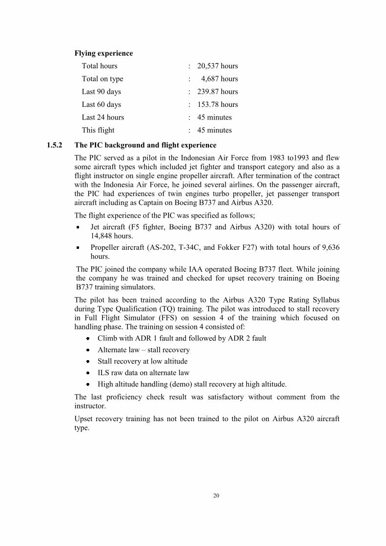
1.5.2 The PIC background and flight experience The PIC served as a pilot in the Indonesian Air Force from 1983 to1993 and flew some aircraft types which included jet fighter and transport category and also as a flight instructor on single engine propeller aircraft. After termination of the contract with the Indonesia Air Force, he joined several airlines. On the passenger aircraft, the PIC had experiences of twin engines turbo propeller, jet passenger transport aircraft including as Captain on Boeing B737 and Airbus A320.
The flight experience of the PIC was specified as follows; Jet aircraft (F5 fighter, Boeing B737 and Airbus A320) with total hours of
14,848 hours. Propeller aircraft (AS-202, T-34C, and Fokker F27) with total hours of 9,636
hours.
The PIC joined the company while IAA operated Boeing B737 fleet. While joining the company he was trained and checked for upset recovery training on Boeing B737 training simulators.
The pilot has been trained according to the Airbus A320 Type Rating Syllabus during Type Qualification (TQ) training. The pilot was introduced to stall recovery in Full Flight Simulator (FFS) on session 4 of the training which focused on handling phase. The training on session 4 consisted of:
Climb with ADR 1 fault and followed by ADR 2 fault Alternate law – stall recovery Stall recovery at low altitude ILS raw data on alternate law High altitude handling (demo) stall recovery at high altitude.
The last proficiency check result was satisfactory without comment from the instructor.
Upset recovery training has not been trained to the pilot on Airbus A320 aircraft type.

21
1.5.3 The PIC exposure to Rudder Travel Limiter problem On 25 December 2014, the PIC was conducting a scheduled passenger flight from Surabaya to Kuala Lumpur in PK-AXC. During push back and after both engines had been started, the AUTO FLT RUD TRV LIM SYS message appeared on the ECAM. The PIC decided to return the aircraft to the parking bay and reported the problem to the company engineer.
An engineer came to the cockpit to check and performed trouble shooting on the ECAM. The rectification was estimated to be completed in short time and the pilots stayed in the cockpit.
By referring to the TSM, the engineer then reset the Circuit Breakers (CBs) of the Flight Augmentation Computer (FAC) 1 and 2, and continued with BITE Test6 (Build in Test) which apparently addressed the issue.
The PIC and the engineer engaged in a discussion. The PIC asked whether he may perform the same reset action whenever the problem reappeared. The engineer stated that the pilot may reset whenever instructed on the ECAM.
The aircraft was then ready for departure and push back. During push back and after starting engine 2, the AUTO FLT RUD TRV LIM SYS message reappeared on the ECAM. The pilot performed the ECAM action, however the problem still existed. The engineer, who had performed the initial rectification, saw that the aircraft did not move, took over the interphone and communicated with the pilot.
A summary of the interphone communications between the engineer and the pilot was that the problem still existed and all ECAM actions had been performed. The PIC asked to the engineer whether he could reset the system by pulling the FAC CB. Thereafter the engineer saw that the SIC7 of this flight leaving his seat. After the CB was reset, the problem still existed and the engineer asked the pilot to return the aircraft to the gate.
After the aircraft parked, the engineer asked the PIC to disembark the passengers and waited in the terminal building, since the rectification might take a long time. After the FAC2 replacement, the engineer then asked the pilot to start both engines to ensure that there was no problem during the power interruption after starting the engines. After both engines started, the problem did not reappear. The captain was satisfied to the rectification and advised that they were ready to depart. The aircraft then flew from Surabaya to Kuala Lumpur and returned without any further problems.
6 BITE Test: Build in Test is a test for electrical and computer connection for a system.
7 The SIC of this flight was different person to the accident flight

22
1.5.4 Second in Command
Gender : Male
Age : 46 years
Nationality : French
Marital status : Single
Date of joining company : 01 December 2012
License : ATP License (issued by France Authority). Renewal validation by Indonesia DGCA at 21 November 2014
Date of issue : 05 November 2014
Aircraft type rating : Airbus 320
Instrument rating : 19 November 2014
Medical certificate : First class
Last of medical : 21 October 2014
Validity : 21 April 2015
Medical limitation : None
Last line check : 14 September 20138
Last proficiency check : 19 November 2014
Flying experience
Total hours : 2,247 hours
Total on type : 1,367 hours
Last 90 days : 151 hours
Last 60 days : 87.82 hours
Last 24 hours : 45 minutes
This flight : 45 minutes
1.5.5 The SIC flight experience background The SIC was a French citizen. Prior to training as a pilot, he worked as part of the management staff in several positions;
Technical Project Manager, in charge of the implementation of innovating and added value electronic business solutions for all the branches of the company groups.
8 Company policy stated that first officer only required line check on his first type qualification check and
first officer performance monitoring was conducted by six monthly simulator check.

23
Director of Strategy and Risk Assessment, Total corporate technology. Air Total International, Total France project coordinator.
He joined Air Asia Indonesia on 01 December 2012 as his first airline after completing training at the flying school. The SIC had total of 2,247 flying hours and most of his flight experience was on the A320 aircraft.
During a Proficiency Check on 11 May 2013 there was a remark stating that the SIC was to be paired with a senior captain for the next 200 hours. The last proficiency check was conducted on 19 November 2014 and the result was satisfactory.
1.6 Aircraft Information 1.6.1 General
Registration Mark : PK-AXC
Manufacturer : Airbus Company
Country of Manufacturer : France
Type/ Model : Airbus A320-216
Serial Number : 3648
Year of manufacture : 2008
Certificate of Airworthiness
Issued : 21 October 2014
Validity : Valid until 20 October 2015
Category : Transport
Limitations : None
Certificate of Registration
Number : 2531
Issued : 22 October 2014
Validity : Valid until 21 October 2015
Time Since New : 23,039 Flight Hours
Cycles Since New : 13,610 Cycles
Last Major Check : C-Check, 31 January 2014, 6 Years Check, 2-17 September 2014
Last Minor Check : E-Check, 16 November 2014

24
1.6.2 Engines
Manufacturer : SNECMA
Type/Model : CFM 56-5B6/3
Serial Number-1 engine : 697957
Time Since New : 23,039 Hours
Cycles Since New : 13,610 Cycles
Serial Number-2 engine : 697958
Time Since New : 23,039 Hours
Cycles Since New : 13,610 Cycles
1.6.3 Maintenance History related to RTLU The investigation collected four different maintenance records:
a) Maintenance Report 1 (MR1) records for the period of November and December 2014,
b) Copy of Post Flight Report (PFR) data between 27 November 2014 and 27 December 2014,
c) Summary of PK-AXC 1 Year Maintenance Report, and d) The Reliability Report issued November 2014.
1.6.3.1 Maintenance Report 1 (MR1) and Maintenance Report 2 (MR2) Referring to the operator Company Maintenance Manual (CMM) chapter 5.1 Technical Log, the Maintenance Report 1 (MR1) is a Technical Log book. Any technical problem arises during the flight should be written in this document and the engineer has to rectify and record the work performs. In chapter 5.1.4, stated “All maintenance work must be recorded and certified in the Technical Log”.
Maintenance Report 2 (MR2) is a Deferred Defect Log Book. Deferred defect is an identified aircraft defect which has been assessed as being within the requirement of the MEL or CDL and has had rectification deferred within a specified limit. The CMM chapter 3.7, “MEL/Dispatch Deviation Mandatory Guide”, stated in Chapter 3.7.2 “No direct entries into the Maintenance Report 2 shall be permitted unless the deferred defect already been entry in MR1 as a reference”. The procedure regarding deferring the trouble is stated in sub chapter 2.34 in the Engineering Procedure Manual (EPM) chapter 2 Line Maintenance Check. Defects may be deferred only under the following circumstances: i. Deferrable defects as per MEL categories. ii. Non-availability of spares. iii. Item is not listed in MEL but non-airworthy in nature. iv. Eg. Passenger convenience. v. Discovery of defects during the check but with insufficient ground time to rectify
may be deferred only if allowed by MEL, SRM or relevant manuals or documents.
25
Evaluation of MR1 data, in November 2014 found 5 pilot reports related to RTLU problem on 10, 13, 20, 22 and 24 November 2014 and in December 2014 found 9 pilot reports related to RTLU problem on 1, 12, 14, 19,21, 24, 25 (two cases), and 27 December 2014.
On 19 December 2014, the repetitive RTLU problem was inserted to Deferred Defect Log Book (MR2). After completion of the scheduled flight, on MR1 column action taken stated “Check on PFR nor ECAM NIL Fault related defect. Do operational test of AFS as per AMM -96-00-710-001-A result no fault recorded. MR2 closed”. The deferred item on MR2 was closed on the same day.
The MR1 data on 25 December 2014, the aircraft was Return to Apron (RTA) twice due to RTLU problem. The engineer replaced the FAC 2, taken from another aircraft that was on maintenance program.
On 26 December 2014, the FAC 2 was replaced with another FAC that was sent from Jakarta and the FAC 2 was put back to the original aircraft.
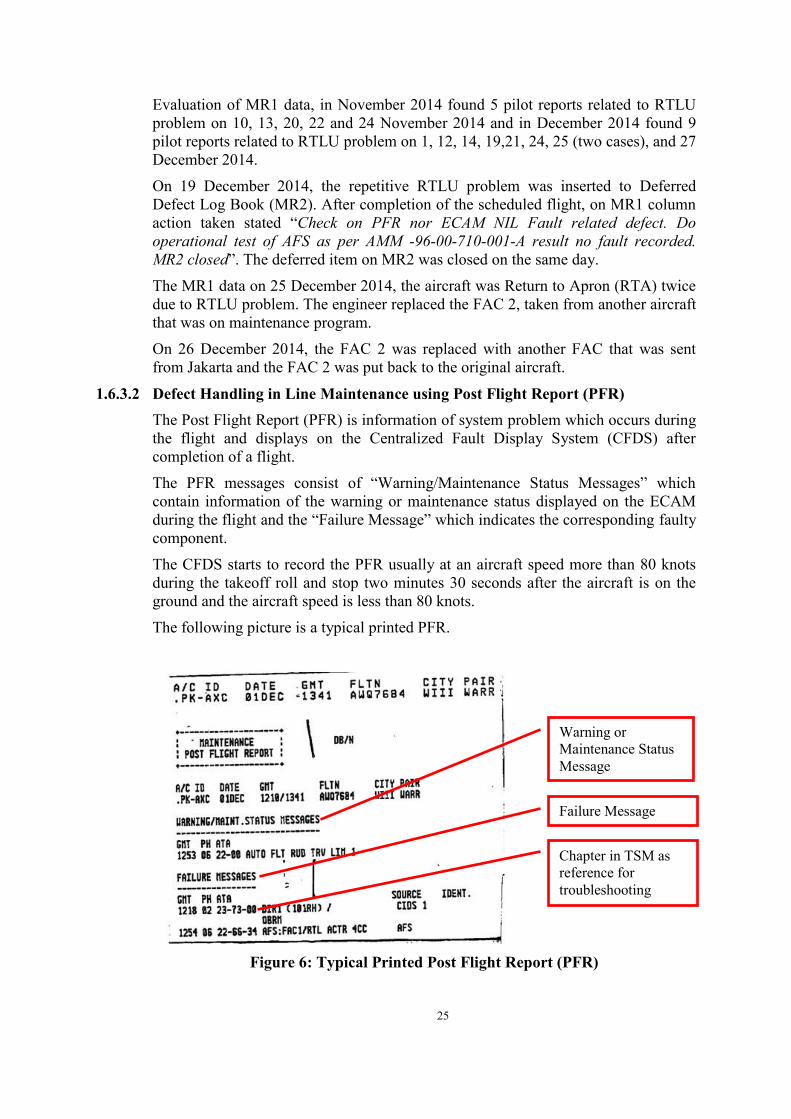
1.6.3.2 Defect Handling in Line Maintenance using Post Flight Report (PFR) The Post Flight Report (PFR) is information of system problem which occurs during the flight and displays on the Centralized Fault Display System (CFDS) after completion of a flight.
The PFR messages consist of “Warning/Maintenance Status Messages” which contain information of the warning or maintenance status displayed on the ECAM during the flight and the “Failure Message” which indicates the corresponding faulty component.
The CFDS starts to record the PFR usually at an aircraft speed more than 80 knots during the takeoff roll and stop two minutes 30 seconds after the aircraft is on the ground and the aircraft speed is less than 80 knots.
The following picture is a typical printed PFR.
Figure 6: Typical Printed Post Flight Report (PFR)
Warning or Maintenance Status Message
Failure Message
Chapter in TSM as reference for troubleshooting

26
The Trouble-Shooting Manual (TSM) which is included in the Airbus Manual application software stated that PFR is the main source of information used to initiate trouble-shooting and to decide on the required maintenance action. All IAA line maintenance stations have digital copy of the TSM.
The line maintenance personnel at each station are responsible to collect the PFR and store it at line maintenance station.
Any defect reported by the flight crew via MR1, the line maintenance personnel will check and verified the PFR. If the PFR confirmed of the defect, the maintenance personnel will refer the failure message on the PFR which identify the relevant chapter of the TSM and follow the maintenance action. If the PFR is not available following a defect reported via MR1 due to CFDS or PFR printer problem, the maintenance personnel will refer the TSM with manual searching the defective component. Any maintenance action performed without MR1 reference, the line maintenance personnel does not have obligation to record the maintenance action on the technical log.
Evaluation of the PFR data between 27 November and 27 December 2014 found 11 occurrences related to RTLU 1, RTLU 2 and both RTLU. The detail of the PFR is summarized in Appendix 6.6 of this report.
The PFR Failure Messages were dominated by the corresponding failed component of “AFS: FAC1/RTL ACTR 4CC”.
Other than the RTLU, the PFR data from 27 November to 27 December 2014 also showed repetitive warning messages and failure messages, of which were AIR BLEED and F/CTL ELAC 1 FAULT.
These problems have been inserted to MR2 in which F/CTL ELAC 1 FAULT problems were closed on 12 December 2014 and the AIR BLEED problems were closed on 22 December 2014.
1.6.3.3 Summary of PK-AXC 1 Year Maintenance Report The operator Planning and Technical Service department compiled the maintenance data of PK-AXC into PK-AXC 1 Year Maintenance Report to assist the investigation. This report was a system generated by Airline Maintenance and Operation System (AMOS). The data recorded is uploaded by the maintenance personnel at all line maintenance stations. This report consists of the information collected from MR1, Cabin Maintenance and Scheduled Inspection.
The summary of the PK-AXC 1 Year Maintenance Report is available in Appendix 6.6 of this report.
The PK-AXC 1 Year Maintenance Report recorded 23 occurrences related with the RTLU problem. The composition of the warning messages is as follows:
- AUTO FLT RUD TRV LIM 1 11 occurrences - AUTO FLT RUD TRV LIM 2 3 occurrences - AUTO FLT RUD TRV LIM SYS 9 occurrences
The numbers RTLU occurrences as per PK-AXC 1 Year Maintenance Report were summarized in the following graph.

27
Figure 7: Numbers of the RTLU Occurrences in 2014
The workaround solution of the maintenance staff on the RTLU problems were mostly by resetting computer by either resetting the FAC push button and followed by AFS test or pulling the associated CBs and the rectification was performed according to the A320 TSM.
1.6.3.4 Reliability Report Issued on November 2014 The repetitive problems of RTLU were also stated in the Reliability Report issued on November 2014.
Chapter 4.1 Repetitive Defect at sub chapter 4.1.1 of this Reliability Report stated that there were 4 pilot reports regarding the RTL problem. The complete statement in the Reliability Report regarding the repetitive troubles is as follows:
4.1.1. DEFECT REPORTED: AUTO FLT RUD TRV LIM 1 – ATA 22 - 4 Pireps (Pilot Report) were reported on PK-AXC Common Part: Auto Flight System
Action: the trouble shoot of AFS as per TSM 22-61-00-810-803-A is performed the operational test as per AMM 22-99-00-710-0019. No further action required.
The Airbus Maintenance Manual (AMM) chapter 22-96-00-710-001 is to perform the Operational Test of Auto Flight System (AFS) that can be done by maintenance personnel at line maintenance.
1.6.3.5 Last Three Day Records The last three days prior to the occurrence, the maintenance history related to the RTLU were as follows:
- 25 December 2014: After two occurrences of AUTO FLT RUD TRV LIM SYS problem, referring to the ECAM and Trouble Shooting Manual (TSM). The
9 The AMM 22-99-00-710-001 is incorrect due to typographical error, the correct references is AMM 22-96-00-
710-001

28
engineer then reset the Circuit Breakers (CBs) of the Flight Augmentation Computer (FAC) 1 and 2, and continued with BITE Test10 (Build in Test) which in accordance with TSM 22-61-00-810-803-A and AMM 22-66-34 PB 401 was satisfactorily resolved.
- The aircraft was then ready for departure and push back. During push back and after starting engine 2, the AUTO FLT RUD TRV LIM SYS fault reappeared. The pilot performed the ECAM action, however the problem still existed. The engineer then asked the pilot to return the aircraft to the gate.
- The engineer performed troubleshooting by referring to TSM 22-66-00-810-818-A and the manual stated that the FAC 2 shall be replaced. The engineer noticed that a spare FAC was not available in the maintenance store in Surabaya. The engineer removed the FAC 2 from another aircraft that was on maintenance program. The removal and installation of the component referred to AMM 22-66-34 PB 401.
- 26 December 2014: The aircraft performed a series of flights and arrived at Surabaya at 1508 UTC (2208 LT) without any problem. The FAC 2 which was taken from another aircraft was removed and put back to the original aircraft. The FAC 2 of PK-AXC was replaced by new spare FAC that had been arrived from Jakarta. A BITE test was performed and the result was satisfactory. After the installation of FAC 2, the aircraft performed flights from Surabaya to Kuala Lumpur and there was no problem reported related to the Rudder Travel Limiter.
- 27 December 2014: The pilot wrote on MR1 after arrival from Kuala Lumpur, that during taxi-in at Surabaya, the AUTO FLT RUD TRV LIM SYS illuminated on ECAM momentarily. The maintenance personnel examined the information on the Centralized Fault Display System (CFDS) print-out but there was no PFR message. The maintenance personnel continued to reset the FAC 1 and 2 and performed the AFS check with a PASS result and the RTLU fault message did not reappear further 4 sectors.
1.6.3.6 FAC Shop Finding Report The removed FAC on 25 December 2014 from PK-AXC was sent to an approved workshop. The reason of removal as stated on the shop finding report was “AUTO FLT RUD TRV LIM SYS”. The inspection did not find any problem and stated “REPORTED FAULT NOT CONFIRMED” and the unit was returned to service on 26 January 2015.
1.6.3.7 Summary An evaluation of the maintenance data showed that the maintenance action following the RTLU problems were in accordance with the TSM. The actions were mostly resolved by resetting the computer by either pulling the associated CB or resetting the FAC push button and followed by an AFS test. The replacement of FAC2 was the only different action taken by the line maintenance personnel.
10 BITE Test or Build in Test is a test for electrical and computer connection for a system.

29
1.6.4 Weight and Balance (Load and Trim Sheet) The weight and balance information available in the Load and Trim Sheet issued by the Flight Operation at Surabaya prior to dispatch contained the following data:
- The total payload 14,220 kg - Cargo Nil - Zero Fuel Weight 57,100 kg - Fuel on board 7,725 kg - Takeoff weight 64,825 kg (Maximum 73500 kg) - Burn fuel 5,121 kg (for complete flight) - Estimated Landing Weight 59,704 kg (Maximum 66000 kg) - Remaining fuel at arrival 2,604 kg
The weight and balance sheet showed that the total baggage on board of 1258 kg all were located in the compartment 3 while the maximum capacity for this compartment was 2268 kg (5000 lbs).
The takeoff Centre of Gravity (CG) was 31.5% of the mean Aerodynamic Chord (MAC) and the pitch trim was 0.7 down and the MAC of the Zero Fuel Weight (ZFW) was 33.6% of the MAC indicating that the aircraft was operated within the approved weight and balance envelope.
1.6.5 Aircraft Systems This sub-chapter describes the relevant aircraft system discussed in this report. Some descriptions are general outline of aircraft system and those written in italics are quotes from the aircraft operator or manufacturer‟s manuals.
1.6.5.1 Flight Control System The Flight Control System of the Airbus A320 has a „fly by wire‟ concept. The fly-by-wire system was designed and certified to render the new generation of aircraft even more safe, cost effective, and pleasant to fly.
Flight control surfaces are all electrically-controlled, and hydraulically-activated.
Pitch axis is controlled by the elevators which are electrically operated and Trimmable Horizontal Stabilizer (THS) which is electrically operated for normal or alternate control and mechanically operated for manual trim control.
The maximum elevator deflection is 30 ° nose up, and 17 ° nose down. The maximum THS deflection is 13.5 ° nose up, and 4 ° nose down.
Roll axis is controlled by ailerons and spoilers which are electrically operated. Yaw axis is controlled by the rudder which is mechanically operated, however control for yaw damping, turn coordination and trim is electrical. The stabilizer and rudder can also be mechanically-controlled.
Pilots use side-sticks to fly the aircraft in pitch and roll (and in yaw, indirectly, through turn coordination).

30
Cockpit Controls Each pilot has a side-stick controller with which to exercise manual control of pitch and roll. These are on their respective lateral consoles. The two side-stick controllers are not coupled mechanically, and they send separate sets of electronic signals to the flight control computers. Two pairs of pedals, which are rigidly interconnected, give the pilots mechanical control of the rudder.
The pilots use mechanically interconnected hand wheels on each side of the centre pedestal to control the trimmable horizontal stabilizer.
The pilots use a single control on the centre pedestal to set the rudder trim. There is no manual switch for trimming the ailerons.
Computers Seven flight control computers process the pilot and autopilot inputs according to normal, alternate, or direct flight control laws. Computers interpret pilot input and move the flight control surfaces, as necessary, to follow the pilot inputs.
2 units of ELAC (Elevator Aileron Computer) for normal elevator and stabilizer control.
3 units of SEC (Spoilers Elevator Computer) for spoilers control. Standby elevator and stabilizer control.
2 units of FAC (Flight Augmentation Computer) for electrical rudder control. In addition to those, 2 units of Flight Control Data Concentrators (FCDC) acquire data from the ELACs and SECs and send it to the electronic instrument system (EIS) and the centralized fault display system (CFDS). A detailed discussion of FAC is described in chapter 1.6.5.6 of this report.
In normal operations, ELAC2 controls the elevators and the horizontal stabilizer, and the green and yellow hydraulic jacks drive the left and right elevator surfaces respectively.
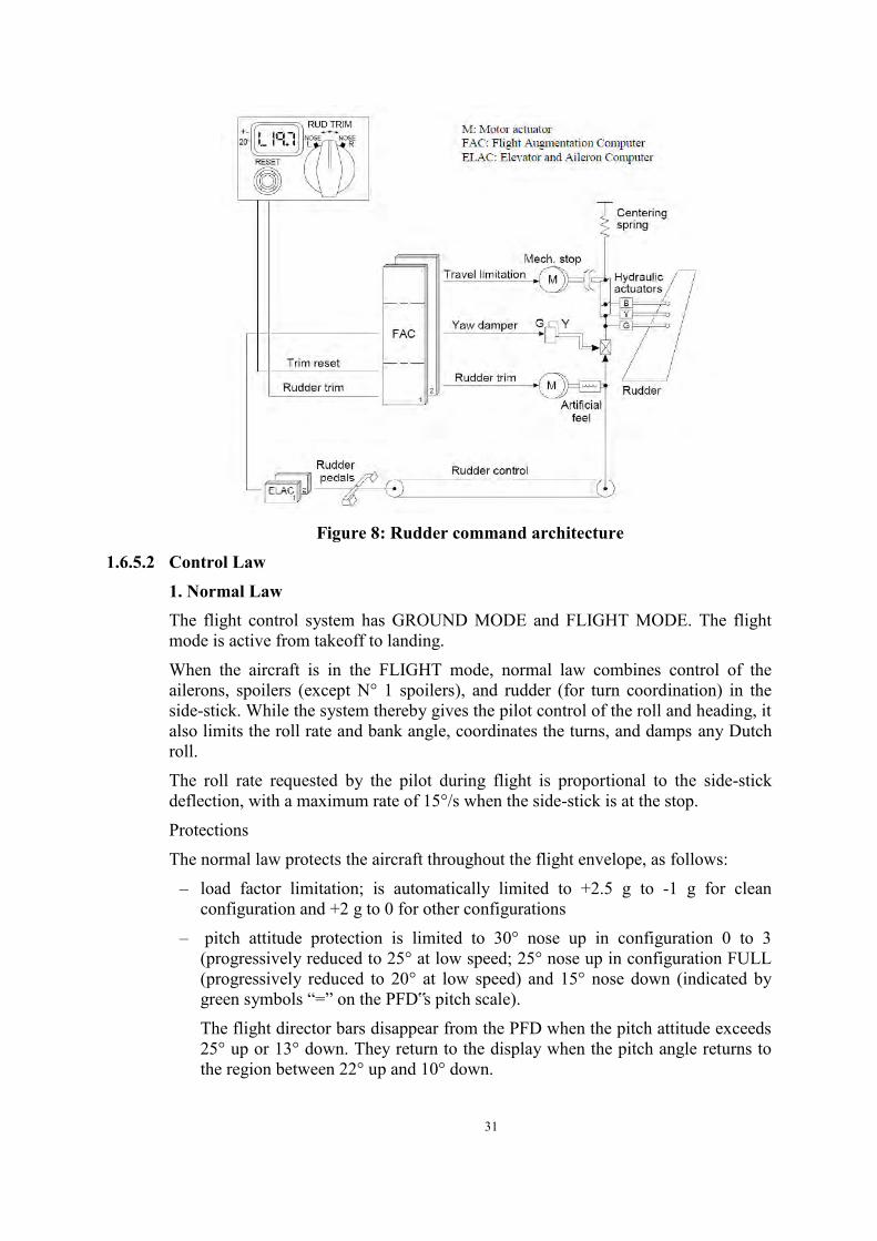
Yaw Control One rudder surface controls yaw. The yaw damping and turn coordination functions are automatic.
The ELACs compute yaw orders for coordinating turns and damping yaw oscillations, and transmit them to the FACs. The pilots can use conventional rudder pedals to control the rudder.
Three independent hydraulic servo jacks, operating in parallel, actuate the rudder. In automatic operation (yaw damping, turn coordination) the green servo actuator drives all three servo jacks. A yellow servo actuator remains synchronized and takes over if there is a failure.
31
Figure 8: Rudder command architecture
1.6.5.2 Control Law 1. Normal Law The flight control system has GROUND MODE and FLIGHT MODE. The flight mode is active from takeoff to landing.
When the aircraft is in the FLIGHT mode, normal law combines control of the ailerons, spoilers (except N° 1 spoilers), and rudder (for turn coordination) in the side-stick. While the system thereby gives the pilot control of the roll and heading, it also limits the roll rate and bank angle, coordinates the turns, and damps any Dutch roll.
The roll rate requested by the pilot during flight is proportional to the side-stick deflection, with a maximum rate of 15°/s when the side-stick is at the stop.
Protections
The normal law protects the aircraft throughout the flight envelope, as follows:
– load factor limitation; is automatically limited to +2.5 g to -1 g for clean configuration and +2 g to 0 for other configurations
– pitch attitude protection is limited to 30° nose up in configuration 0 to 3 (progressively reduced to 25° at low speed; 25° nose up in configuration FULL (progressively reduced to 20° at low speed) and 15° nose down (indicated by green symbols “=” on the PFD‟s pitch scale).
The flight director bars disappear from the PFD when the pitch attitude exceeds 25° up or 13° down. They return to the display when the pitch angle returns to the region between 22° up and 10° down.

32
– high Angle of Attack (AOA) protection: Under normal law, when the angle-of-attack becomes greater than αprot (Alpha Protection), the system switches elevator control from normal mode to a protection mode, in which the angle-of-attack is proportional to side-stick deflection. That is, in the αprot range, from αprot to α MAX, the side-stick commands α directly. However, the angle-of-attack will not exceed α MAX, even if the pilot gently pulls the side-stick all the way back. If the pilot releases the side-stick, the angle-of-attack returns to αprot and stays there. This protection against stall and wind shear has priority over all other protections. The autopilot will disconnect if the αprot is active.
– High-speed protection: The aircraft automatically recovers, following a high speed upset. Depending on the flight conditions (high acceleration, low pitch attitude), High Speed Protection is activated at/or above VMO/MMO. The autopilot disconnects, when High Speed Protection becomes active. High Speed Protection is deactivated, when the aircraft speed decreases below VMO/MMO, where the usual normal control laws are recovered.
– LOW ENERGY WARNING: The low energy warning is computed by the FAC.
Bank angle protection Inside the normal flight envelope, the system maintains positive spiral static stability for bank angles above 33°. If the pilot releases the side-stick at a bank angle greater than 33°, the bank angle automatically reduces to 33°. Up to 33°, the system holds the roll attitude constant when the side-stick is at neutral. If the pilot holds full lateral side-stick deflection, the bank angle goes to 67° and no further.
If Angle-of-Attack protection is active, and the pilot maintains full lateral deflection on the side-stick, the bank angle will not go beyond 45°. If High Speed Protection is active, and the pilot maintains full lateral deflection on the side-stick, the bank angle will not go beyond 40°. If high speed protection is operative, the system maintains positive spiral static stability from a bank angle of 0°, so that with the side-stick released, the aircraft always returns to a bank angle of 0°.
If the bank angle exceeds 45°, the autopilot disconnects and the FD bars disappear. The FD bars return when the bank angle decreases to less than 40°.
2. Alternate Law Depending on the failures occurring to the flight control system, or on its peripherals, there are 3 levels of reconfiguration:
– Alternate law
They are two levels of alternate law with and without reduced protections. – Direct law – Mechanical
In flight, the alternate law pitch mode follows a load-factor demand law much as the normal law pitch mode does, but it has less built-in protection (reduced protections). When the aircraft is flying in pitch alternate law, lateral control follows the roll direct law associated with yaw alternate or mechanical. Referring to DSC-27-20-20 Direct Law, only the yaw damping function is available. Damper authority is limited

33
to ±5° of rudder deflection. The load factor limitation is similar to that under normal law. There is no pitch attitude protection. Amber Xs replace the green double bars “=” on the PFD.
During the Alternate Law, Bank Angle Protection is not provided.
Note: The AP (auto-pilot) will disconnect, if speed exceeds VMO/MMO, or if the bank angle exceeds 45°.
Low Speed Stability Artificial low speed stability replaces the normal angle-of-attack protection. It is available for all slat/flap configurations, and the low speed stability is active from about 5 kts up to about 10 kts above stall warning speed, depending on the aircraft‟s gross weight and slats/flaps configuration.
A gentle progressive nose down signal is introduced, which tends to keep the speed from falling below these values.
The system also injects bank-angle compensation, so that operation effectively maintains a constant angle of attack.
In addition, audio stall warning (crickets + “STALL” synthetic voice message) is activated at an appropriate margin from the stall condition.
The PFD speed scale is modified to show a black/red barber pole below the stall warning.
The α floor protection is inoperative.
3. Direct Law Pitch control: The pitch direct law is a direct stick-to-elevator relationship (elevator deflection is proportional to stick deflection).
In all configurations the maximum elevator deflection varies as a function of CG Control with the CG aft. There is no automatic trim the pilot must trim manually.
1.6.5.3 Lateral Consoles
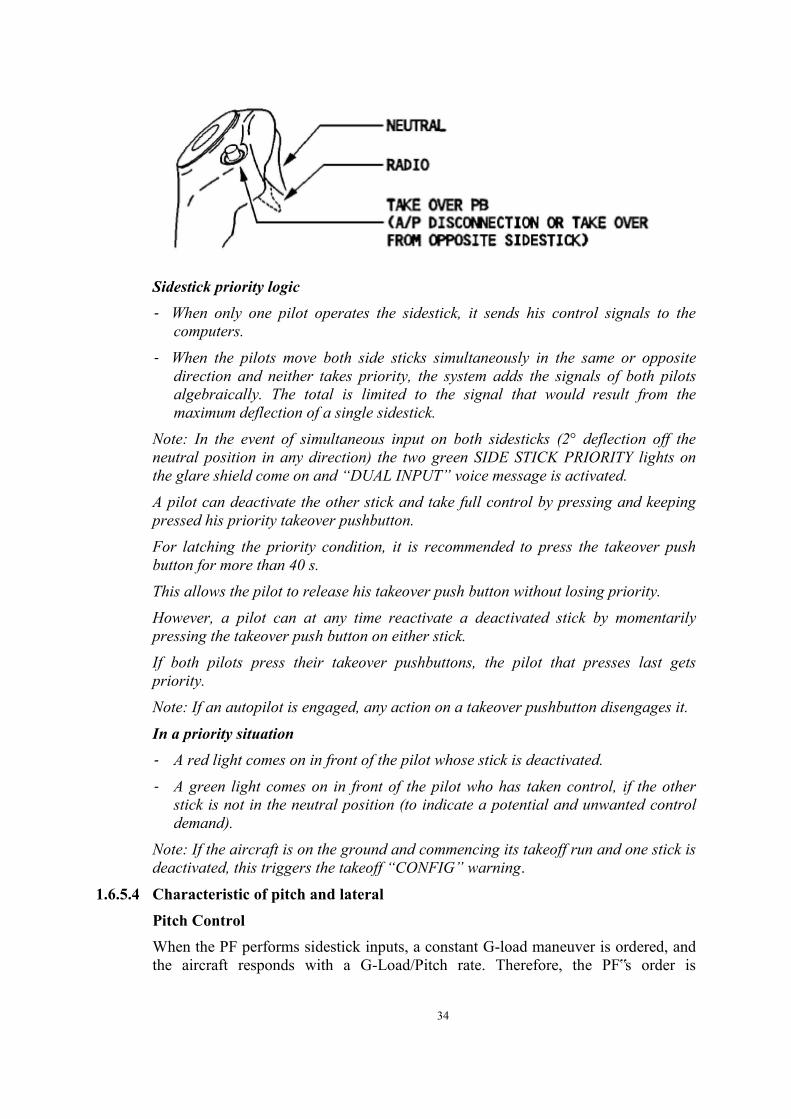
SIDESTICKS Each pilot has on his lateral console a sidestick he can use to control pitch and roll manually. Each sidestick is spring-loaded to neutral. When the autopilot is engaged, a solenoid-operated detent locks both sidesticks in the neutral position. If the pilot applies a force above a given threshold (5 daN in pitch, 3.5 daN in roll) the stick becomes free and the autopilot disengages. The hand grip has two switches: ‐ Autopilot disconnect and sidestick takeover pushbutton. ‐ Push-to-talk button.
34
Sidestick priority logic ‐ When only one pilot operates the sidestick, it sends his control signals to the
computers.
‐ When the pilots move both side sticks simultaneously in the same or opposite direction and neither takes priority, the system adds the signals of both pilots algebraically. The total is limited to the signal that would result from the maximum deflection of a single sidestick.
Note: In the event of simultaneous input on both sidesticks (2° deflection off the neutral position in any direction) the two green SIDE STICK PRIORITY lights on the glare shield come on and “DUAL INPUT” voice message is activated. A pilot can deactivate the other stick and take full control by pressing and keeping pressed his priority takeover pushbutton. For latching the priority condition, it is recommended to press the takeover push button for more than 40 s. This allows the pilot to release his takeover push button without losing priority. However, a pilot can at any time reactivate a deactivated stick by momentarily pressing the takeover push button on either stick. If both pilots press their takeover pushbuttons, the pilot that presses last gets priority. Note: If an autopilot is engaged, any action on a takeover pushbutton disengages it.
In a priority situation ‐ A red light comes on in front of the pilot whose stick is deactivated.
‐ A green light comes on in front of the pilot who has taken control, if the other stick is not in the neutral position (to indicate a potential and unwanted control demand).
Note: If the aircraft is on the ground and commencing its takeoff run and one stick is deactivated, this triggers the takeoff “CONFIG” warning.
1.6.5.4 Characteristic of pitch and lateral Pitch Control When the PF performs sidestick inputs, a constant G-load maneuver is ordered, and the aircraft responds with a G-Load/Pitch rate. Therefore, the PF‟s order is

35
consistent with the response that is "naturally" expected from the aircraft: Pitch rate at low speed; Flight Path Rate or G, at high speed.
So, if there is no input on the stick:
• The aircraft maintains the flight path, even in case of speed changes
• In case of configuration changes or thrust variations, the aircraft compensates for the pitching moment effects
• In turbulence, small deviations occur on the flight path. However, the aircraft tends to regain a steady condition.
Airbus Pitch Characteristic
Operational Recommendation:
From the moment the aircraft is stable and auto-trimmed, the PF needs to perform minor corrections on the sidestick, if the aircraft deviates from its intended flight path. The PF should not force the sidestick, or over control it. If the PF suspects an over control, they should release the sidestick.
Lateral Control When the PF performs a lateral input on the sidestick, a roll rate is ordered and naturally obtained.
Therefore, at a bank angle of less than 33°, with no input on the sidestick, a zero roll rate is ordered, and the current bank angle is maintained. Consequently, the aircraft is laterally stable, and no aileron trim is required. However, lateral law is also a mixture of roll and yaw demand with: ‐ Automatic turn coordination ‐ Automatic yaw damping ‐ Initial yaw damper response to a major aircraft asymmetry.
In addition, if the bank angle is less than 33°, pitch compensation is provided. If the bank angle is greater than 33°, spiral stability is reintroduced and pitch compensation is no longer available. This is because, in normal situations, there is

36
no operational reason to fly with such high bank angles for a long period of time.
Airbus Lateral Characteristic
Operational Recommendation: During a normal turn (bank angle less than 33°), in level flight: • The PF moves the sidestick laterally (the more the sidestick is moved laterally, the
greater the resulting roll rate - e.g. 15°/s at max deflection) • It is not necessary to make a pitch correction • It is not necessary to use the rudder. In the case of steep turns (bank angle greater than 33°), the PF must apply: • Lateral pressure on the sidestick to maintain bank • Aft pressure on the sidestick to maintain level flight.
1.6.5.5 Rudder Travel Limitation This function limits rudder deflection based on speed in order to avoid high structural loads. It is governed by the following law:
If both FACs lose the rudder travel limitation function, the value of the rudder deflection limit is locked at the time of the second failure.
When the slats are extended, the FACs automatically set the rudder deflection limit at the low-speed setting (maximum authorized deflection).

37
1.6.5.6 Flight Augmentation Computer (FAC) Referring to the Flight Crew Operation Manual (FCOM) revision on 7 April 2012, on Chapter AIRCRAFT SYSTEMS sub chapter AUTO FLIGHT – FLIGHT AUGMENTATION, it is described:
The aircraft has two flight augmentation computers (FACs) that perform four main functions: • Yaw function
‐ Yaw damping and turn coordination ‐ Rudder trim ‐ Rudder travel limitation
• Flight envelope function ‐ PFD speed scale management
▪ Minimum/maximum speed computation ▪ Manoeuvring speed computation
‐ Alpha-floor protection • Low-Energy Warning function • Windshear detection function In performing these functions the FAC uses independent channels:
Yaw damper Rudder trim Rudder travel limit Flight envelope
Each FAC interfaces with the elevator aileron computers (ELACs) when the autopilots (AP) are disengaged or with the FMGS when at least one AP is engaged. Both FACs engage automatically at power-up. The pilot can disengage or reset each FAC (in case of failure) by means of a pushbutton on the flight control overhead panel. When a FAC is disengaged (FAC pushbutton set off) but still valid, the flight envelope function of the FAC remains active. If both FACs are valid, FAC1 controls the yaw damper, turn coordination, rudder trim, and rudder travel limit, and FAC2 is in standby. FAC1 keeps the aircraft within the flight envelope through FD1; FAC2 performs this function through FD2.If a failure is detected on any channel of FAC1, FAC2 takes over the corresponding channel. Yaw damping stabilizes the aircraft in yaw and coordinates its turns. In automatic flight (AP engaged) during takeoff and go around, it assists rudder application after an engine failure (short-term yaw compensation). Note: When the AP is engaged, the FMGS sends orders to the FAC to give:
Yaw damping during approach Yaw control for runway alignment in ROLL OUT mode.
38
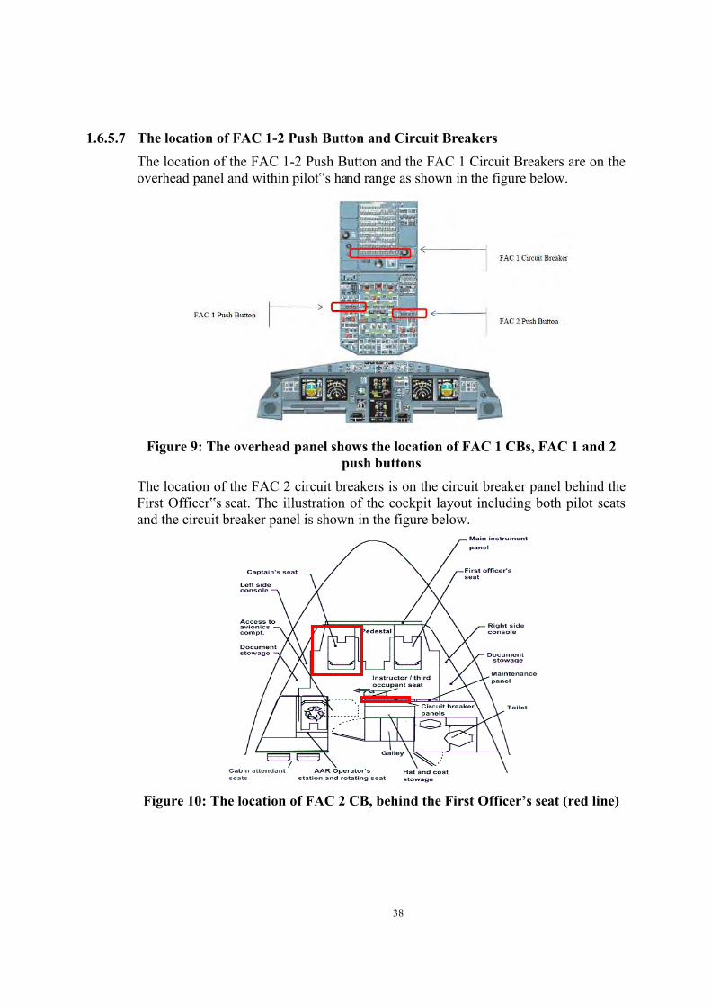
1.6.5.7 The location of FAC 1-2 Push Button and Circuit Breakers The location of the FAC 1-2 Push Button and the FAC 1 Circuit Breakers are on the overhead panel and within pilot‟s hand range as shown in the figure below.
Figure 9: The overhead panel shows the location of FAC 1 CBs, FAC 1 and 2
push buttons The location of the FAC 2 circuit breakers is on the circuit breaker panel behind the First Officer‟s seat. The illustration of the cockpit layout including both pilot seats and the circuit breaker panel is shown in the figure below.
Figure 10: The location of FAC 2 CB, behind the First Officer’s seat (red line)
39
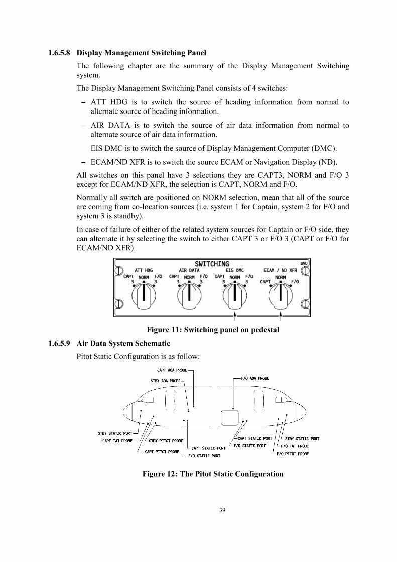
1.6.5.8 Display Management Switching Panel The following chapter are the summary of the Display Management Switching system.
The Display Management Switching Panel consists of 4 switches:
ATT HDG is to switch the source of heading information from normal to alternate source of heading information.
AIR DATA is to switch the source of air data information from normal to alternate source of air data information.
EIS DMC is to switch the source of Display Management Computer (DMC).
ECAM/ND XFR is to switch the source ECAM or Navigation Display (ND). All switches on this panel have 3 selections they are CAPT3, NORM and F/O 3 except for ECAM/ND XFR, the selection is CAPT, NORM and F/O.
Normally all switch are positioned on NORM selection, mean that all of the source are coming from co-location sources (i.e. system 1 for Captain, system 2 for F/O and system 3 is standby).
In case of failure of either of the related system sources for Captain or F/O side, they can alternate it by selecting the switch to either CAPT 3 or F/O 3 (CAPT or F/O for ECAM/ND XFR).
Figure 11: Switching panel on pedestal
1.6.5.9 Air Data System Schematic Pitot Static Configuration is as follow:
Figure 12: The Pitot Static Configuration

40
The Air Data and Inertial Reference System (ADIRS) supply the data of temperature, anemometric, barometric and inertial parameters to the EFIS system (PFD and ND) and to other systems. The 3 (three) ADIRS obtained the air data information from 3 (three) Pitot Probes and 6 (six) Static Pressure Probes. Primary pitot and static pressure probes are obtained from Captain and F/O Pitot Probes. The standby information or Integrated Standby Instrument System (ISIS) is obtained from Standby Pitot and Statics Probes, common with ADIRU3.
The line probes schematic is as follows:
Figure 13: line probes schematic
1.6.5.10 ECAM control panel FCTM revision 16 July 2014; Chapter; ECAM: Operation philosophy.
Figure 14: ECAM control panel

41
(5) CLR pb (Clear push button)
This pushbutton remains lit as long as the E/WD is displaying a warning or caution message, or a status message on the SD. If it is lit, pressing it changes the ECAM display. (7) EMER CANC pb (Emergency Cancel pushbutton) This pushbutton affects the following:
Warnings: Cancel (stop) an aural warning for as long as the failure condition
continues Extinguish the MASTER WARNING lights Does not affect the ECAM message display.
Caution Cancel any present caution (single chime, MASTER CAUTION lights,
ECAM message) for the rest of the flight Automatically calls up the STATUS page, which displays “CANCELLED
CAUTION” and the title of the failure that is inhibited. The inhibition is automatically suppressed when Flight Phase 1 is initiated. The pilot may restore it manually by pressing the RCL pb for more than 3 s. Note: This pushbutton should only be used to suppress spurious MASTER CAUTIONS.
SPURIOUS CAUTION Any spurious caution can be deleted with the EMER CANCEL pushbutton. When pressed, the EMER CANCEL pushbutton deletes both the aural alert, and the caution for the remainder of the flight. This is indicated on the STATUS page, by the "CANCELLED CAUTION" title. The EMER CANCEL pushbutton inhibits any aural warning that is associated with a red warning, but does not affect the warning itself.
RCL (Recall) PUSHBUTTON The RCL pushbutton allows to call up all ECAM alerts and the STATUS page that may have been suppressed by the CLR pushbutton or by the flight-phase-related inhibition. Any alerts that have been inhibited by the EMER CANCEL pushbutton are displayed when the fly crew holds the RCL pushbutton down for more than three seconds. The procedure on the QRH which include the operation of the EMER CANC pushbutton:
Note: ‐ If the approach is flown at less than 750 ft RA, the “L/G NOT DOWN” warning will be triggered. The pilot can cancel the aural warning by pressing the EMER CANC pb, located on the ECAM control panel.

42
1.7 Meteorological Information On the day of occurrence the weather report obtained from Badan Meteorologi Klimatologi dan Geofisika (BMKG – Bureau of Meteorology, Climatology and Geophysics) showed partial area of towering cumulonimbus clouds formation with the top of clouds approximate 24,000 feet up to 44,000 feet on the vicinity where the aircraft was flying.
The wind direction when the aircraft was flying mostly westerly with 15 – 20 kts, with the outside air temperature ranging from -56° C to - 62° C (see the circles on the figure below).
Figure 15: The BMKG satellite weather image at 2300 UTC
Figure 16: The cloud height (in meter) view along the airways of M635
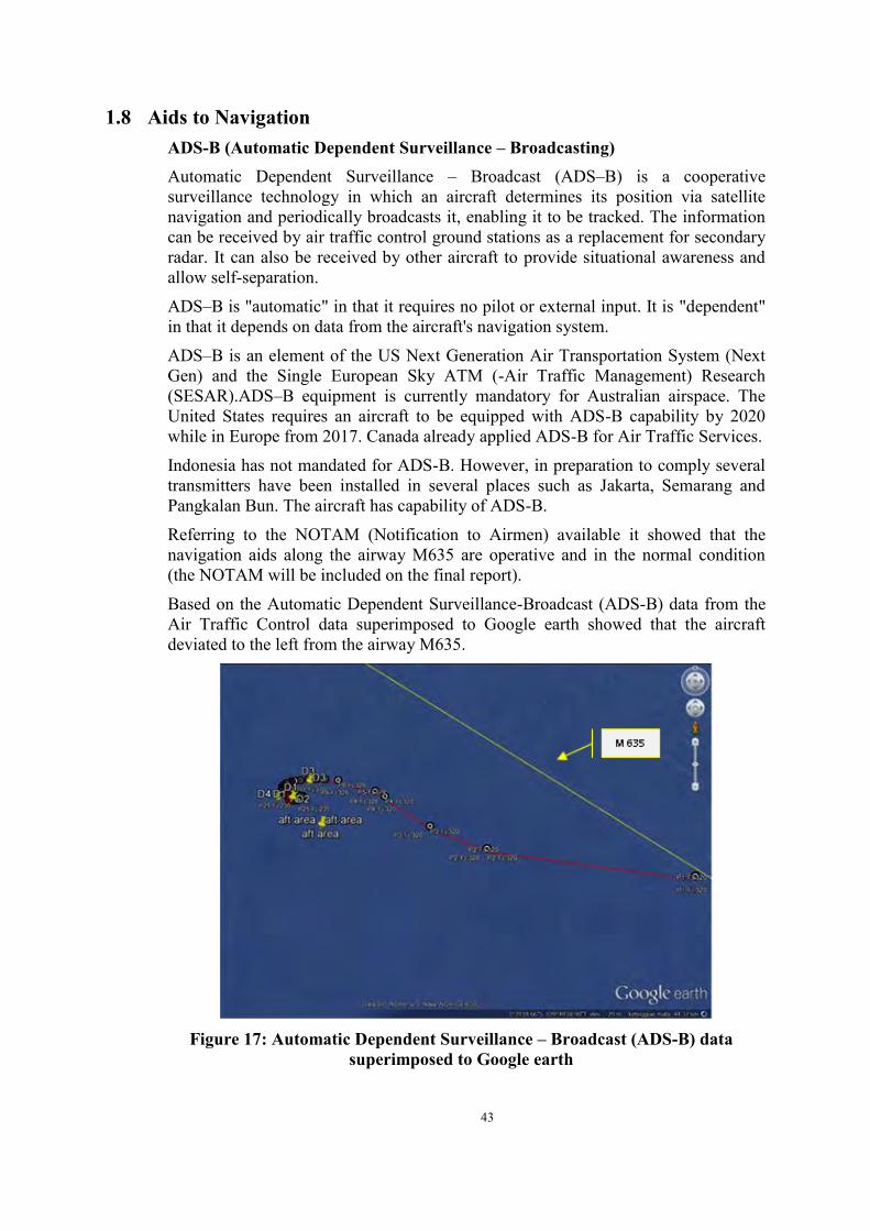
43
1.8 Aids to Navigation ADS-B (Automatic Dependent Surveillance – Broadcasting) Automatic Dependent Surveillance – Broadcast (ADS–B) is a cooperative surveillance technology in which an aircraft determines its position via satellite navigation and periodically broadcasts it, enabling it to be tracked. The information can be received by air traffic control ground stations as a replacement for secondary radar. It can also be received by other aircraft to provide situational awareness and allow self-separation.
ADS–B is "automatic" in that it requires no pilot or external input. It is "dependent" in that it depends on data from the aircraft's navigation system.
ADS–B is an element of the US Next Generation Air Transportation System (Next Gen) and the Single European Sky ATM (-Air Traffic Management) Research (SESAR).ADS–B equipment is currently mandatory for Australian airspace. The United States requires an aircraft to be equipped with ADS-B capability by 2020 while in Europe from 2017. Canada already applied ADS-B for Air Traffic Services.
Indonesia has not mandated for ADS-B. However, in preparation to comply several transmitters have been installed in several places such as Jakarta, Semarang and Pangkalan Bun. The aircraft has capability of ADS-B.
Referring to the NOTAM (Notification to Airmen) available it showed that the navigation aids along the airway M635 are operative and in the normal condition (the NOTAM will be included on the final report).
Based on the Automatic Dependent Surveillance-Broadcast (ADS-B) data from the Air Traffic Control data superimposed to Google earth showed that the aircraft deviated to the left from the airway M635.
Figure 17: Automatic Dependent Surveillance – Broadcast (ADS-B) data
superimposed to Google earth
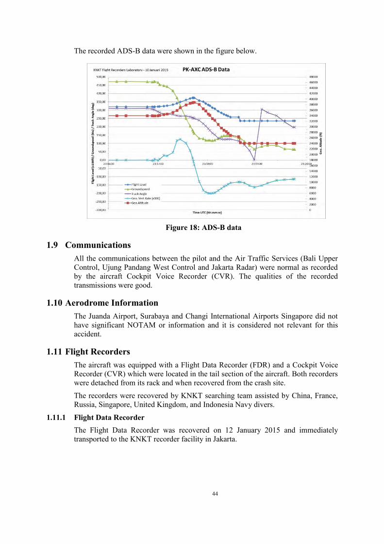
44
The recorded ADS-B data were shown in the figure below.
Figure 18: ADS-B data
1.9 Communications All the communications between the pilot and the Air Traffic Services (Bali Upper Control, Ujung Pandang West Control and Jakarta Radar) were normal as recorded by the aircraft Cockpit Voice Recorder (CVR). The qualities of the recorded transmissions were good.
1.10 Aerodrome Information The Juanda Airport, Surabaya and Changi International Airports Singapore did not have significant NOTAM or information and it is considered not relevant for this accident.
1.11 Flight Recorders The aircraft was equipped with a Flight Data Recorder (FDR) and a Cockpit Voice Recorder (CVR) which were located in the tail section of the aircraft. Both recorders were detached from its rack and when recovered from the crash site.
The recorders were recovered by KNKT searching team assisted by China, France, Russia, Singapore, United Kingdom, and Indonesia Navy divers.
1.11.1 Flight Data Recorder The Flight Data Recorder was recovered on 12 January 2015 and immediately transported to the KNKT recorder facility in Jakarta.

45
The recorders read-out was performed at KNKT recorder facility with the participation of the Australian Transport Safety Bureau (ATSB, Australia) and the Bureau d‟ Enquêtes et d‟ Analyses (BEA, France) as Accredited Representatives.
The FDR data were as follows:
Manufacturer : L-3 Communication
Type/Model : FA2100FDR
Part Number : 2100-4043-02
Serial Number : 000556583
The FDR recorded approximately 1200 parameters and about 174 hours of aircraft operation containing 74 flights including the accident flight.
It is noted that in some specific circumstances, some parameters alternations patterns could be recorded and observed on FDR Data. These specific FDR parameter patterns occur when a data to be recorded is not available at the FDR entry interface. This parameter unavailability could be due to the emitter equipment is set OFF, de-energized, wiring problem or other issue resulting in the information do not arrive at the FDR interface.
In such situation, for example for FDR binary recorded data, the alternative recording at one sample will record the minimum parameter value then, at the next sample will record the maximum parameter value and so on, indicate this parameter unavailability, as soon as the parameter is not refresh or not provided by the relevant equipment.
In particular, this situation was observed when the FAC 1 and the FAC 2 were de-energized during the accident flight.
The FDR data showed that while the aircraft was cruising at an altitude of 32,000 feet in normal condition, the aircraft then deviated to the left from airway M635. The master caution triggered by both RTLU problems activated 4 times. The fifth master caution was related to the FAC 1 FAULT activating. The sixth master caution was triggered by the FAC 1+2 FAULT and followed by the autopilot and auto-thrust disengaged and flight control law reverted from Normal Law to Alternate Law.
Subsequently the aircraft entered a steep turn and climb, eventually reaching high angle of attack, the stall warning activated and continued until the end of the recording. The FDR and CVR recording ended at 2320:35 UTC.

46
Figure 19: Flight path based on FDR data superimposed to the Google Earth
Detail information of the FDR is shown on the following graphs.
Note: abbreviation of FDR parameter indication available in the list of abbreviation of FDR parameters.
Airways M635
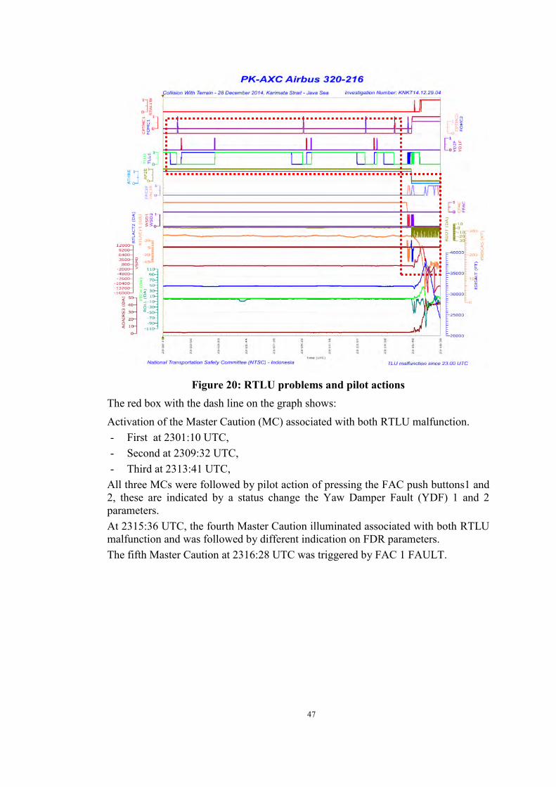
47
Figure 20: RTLU problems and pilot actions
The red box with the dash line on the graph shows:
Activation of the Master Caution (MC) associated with both RTLU malfunction. - First at 2301:10 UTC, - Second at 2309:32 UTC, - Third at 2313:41 UTC,
All three MCs were followed by pilot action of pressing the FAC push buttons1 and 2, these are indicated by a status change the Yaw Damper Fault (YDF) 1 and 2 parameters. At 2315:36 UTC, the fourth Master Caution illuminated associated with both RTLU malfunction and was followed by different indication on FDR parameters. The fifth Master Caution at 2316:28 UTC was triggered by FAC 1 FAULT.

48
Figure 21: FDR parameters after the fifth Master Caution
The graph showed: - At 2316:28 UTC: The fifth Master Caution was triggered by FAC 1 FAULT,
and followed by fluctuation of parameters of component controlled by FAC 1 such as RTLU 1, Wind Shear Detection 1 and Rudder Travel Limiter Actuator 1. Rudder deflected 1° and ailerons were also deflected.
- At 2316:39 the FAC 1 was back to ON and all fluctuating parameters stopped. - At 2316:44 UTC, the sixth Master Caution was triggered by FAC 1+2 FAULT
and followed by: o Fluctuation of parameters of component controlled by FAC 2 such as
RTLU 2, Wind Shear Detection 2 and Rudder Travel Limiter Actuator 2 o The autopilot and auto-thrust disengaged o Flight control law reverted from Normal Law to Alternate Law o Rudder deflected 2° and aileron deflection 0°.
- The aircraft started to roll.
- At 2316:54 UTC the FAC 2 was back to ON and all fluctuating parameters stopped. The autopilot and auto thrust remained disengaged. Flight control law remained in Alternate Law.

49
Figure 22: Pilots inputs on side stick
The FDR graphs for the Calibrated Airspeed (CAS) and Altitude (ALT) were taken from the Integrated Standby Instrument System (ISIS) and not the ADIRU1 which was the source of the left PFD, as the data from this source became unavailable from a certain time.
The FDR graph showed: At 2316:43 UTC, the autopilot and auto-thrust disengaged and the aircraft
started to roll to the left up to 54°. At 2316:52 UTC, the first right side-stick input was recorded with pitch up input
of 15° and one second latter roll input to the right 19° was recorded. The aircraft roll angle then decreased to 9° to the left.
At 2316:55 UTC, the right side-stick input was to the left at maximum deflection and the aircraft rolled back to 53° to the left.
At 2316:56 UTC, the pitch was at 9° up while the Angle of Attack (AOA) reached 8°and triggered the Stall Warning which immediately disappeared as the AOA decreased to below 8°.
The input on the right side-stick was continuously pitching up and the aircraft climbed to approximately 38,000 feet with a rate of up to 11,000 feet per minute.

50
At 2317:17 UTC, the stall warning activated when the aircraft altitude was passing 32,880 feet, stopped for 1 second at 2317:22 UTC and then continued until the end of recording.
The first left side stick input was at 2317:03 UTC for 2 seconds, then 15 seconds later another input for 2 seconds, and at 2317:29 the input continued until the end of the recording.
Since 2317:29 UTC, the right side stick input was constantly at maximum pitch up until the end of recording.
At 2317:33 UTC the pitch recorded was at the highest value of 45° up. The left priority button was pressed for 2 seconds, and at 2318:43 was pressed again for 5 seconds.
The pitch gradually increased and between 2317:28 UTC until 2317:33 UTC was constantly up at approximately 44°.
At 2317:38 UTC the aircraft reached the lowest speed recorded of 55 knots. Afterward the recorded speed fluctuated between 100 and 170 knots until the end of recording.
At 2317:39 UTC the AOA reached 44° up, afterward decreased and constantly at approximately 40° up while the pitch constantly at 1° up until the end of recording
At 2317:41 UTC the aircraft reached the highest altitude of 38,500 feet (ISIS) and largest roll angle at 104° to the left. The aircraft then descended with a rate up to 20,000 feet per minute momentarily afterward the rate of descent was recorded at average of 12,000 feet per minute until the end of recording.

51
Figure 23: Thrust levers and side-sticks movement
The FDR graph showed:
- At 2317:39 UTC, the thrust levers angle retarded from 25° to 0° followed by decreasing of the Exhaust Gauge Temperature (EGT) and N111.
- At 2317:58 UTC, the thrust levers angle increased to 25° followed by increasing EGT and N1 and thereafter at 2318:31 UTC, the thrust lever angle increased to 44°, the N1 value remained relatively constant, while the EGT increased.
11 N1 is the rotation speed of low pressure compressor (%).

52
Figure 24: The FDR parameters of FAC fault followed by CB reset on the
ground at 25 December 2014 The graph of the FDR data shown in figure above was the event where the FAC CBs were reset by the maintenance crew while the aircraft was on the ground on 25 December 2014. The red dash lined square shows the FAC OFF, and parameters of component controlled by FAC such as the Rudder Travel Limiter Unit (RTLU), Windshear Detection (WD) and Rudder Travel Actuator (RTLACT) fluctuated, affected by the FAC CB resetting.
1.11.2 Recorded system failure The FDR contained data of the last 74 flights including the accident flight. The failure of the RTL unit and FAC recorded on the FDR were as follows:
Table of RTLU ECAM messages recorded on FDR on the 74 previous flights prior to the accident flight.
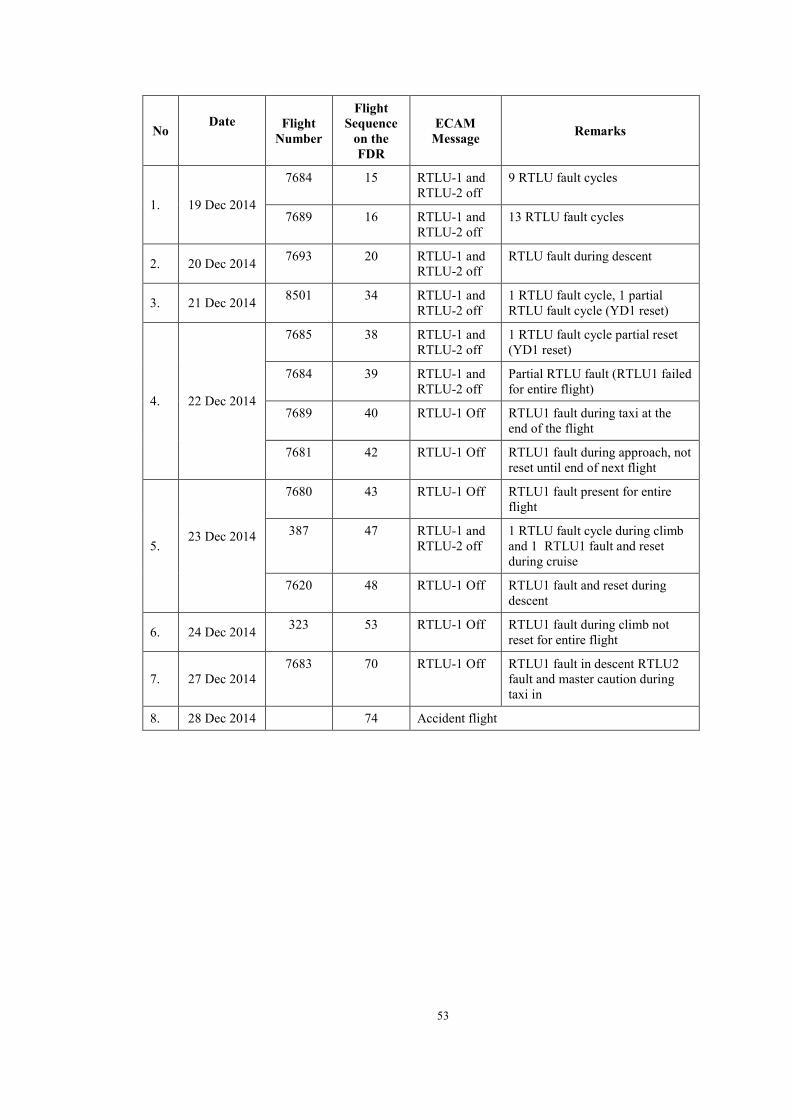
53
No Date
Flight
Number
Flight Sequence
on the FDR
ECAM Message Remarks
1. 19 Dec 2014
7684 15 RTLU-1 and RTLU-2 off
9 RTLU fault cycles
7689 16 RTLU-1 and RTLU-2 off
13 RTLU fault cycles
2. 20 Dec 2014 7693 20 RTLU-1 and RTLU-2 off
RTLU fault during descent
3. 21 Dec 2014 8501 34 RTLU-1 and RTLU-2 off
1 RTLU fault cycle, 1 partial RTLU fault cycle (YD1 reset)
4. 22 Dec 2014
7685 38 RTLU-1 and RTLU-2 off
1 RTLU fault cycle partial reset (YD1 reset)
7684 39 RTLU-1 and RTLU-2 off
Partial RTLU fault (RTLU1 failed for entire flight)
7689 40 RTLU-1 Off RTLU1 fault during taxi at the end of the flight
7681 42 RTLU-1 Off RTLU1 fault during approach, not reset until end of next flight
5. 23 Dec 2014
7680 43 RTLU-1 Off RTLU1 fault present for entire flight
387 47 RTLU-1 and RTLU-2 off
1 RTLU fault cycle during climb and 1 RTLU1 fault and reset during cruise
7620 48 RTLU-1 Off RTLU1 fault and reset during descent
6. 24 Dec 2014 323 53 RTLU-1 Off RTLU1 fault during climb not reset for entire flight
7. 27 Dec 2014 7683 70 RTLU-1 Off RTLU1 fault in descent RTLU2
fault and master caution during taxi in
8. 28 Dec 2014 74 Accident flight

54
On the 19 December 2014, PK-AXC operated flights QZ7684, from Jakarta (Soekarno-Hatta) Airport to Surabaya Airport, and QZ7689 from Surabaya Airport to Jakarta (Soekarno-Hatta) Airport. During these two flights the RTLU system faulted twenty two times resulting in a master caution alert. Each RTLU fault was satisfactorily resolved by the crew using the ECAM FAC reset procedure.
Although the fault occurred multiple times, it did not follow any regular pattern or phase of flight. During flight QZ7684 the RTLU faults occurred during climb and initial cruise. However, during flight QZ7689 the faults occurred during cruise and descent, including two faults during the landing approach.
The aircraft defect reporting system logged the RTLU system faults as a single event, item 32 work order number 1931242. The defect report logged “AUTO FLIGHT RUD TRV LIM SYS” ECAM message. The MR1 showed that the PFR was checked and an operational check of the auto-flight system was performed. The operational check was satisfactory and the defect maintenance action was closed.
1.11.3 Cockpit Voice Recorder The Cockpit Voice Recorder (CVR) was recovered on 13 January 2015 and immediately transported to KNKT recorder facility in Jakarta.
The CVR read-out was performed at KNKT recorder facility with the participation of the Australian Transport Safety Bureau (ATSB, Australia) and the Bureau d‟Enquêtes et d‟Analyses (BEA, France) as Accredited Representatives.

55
Manufacturer : L-3 Communication
Type/Model : FA2100CVR
Part Number : 2100-1020-02
Serial Number : 000539059
The CVR contained 2 hours and 4 minutes of good quality recording data. The significant excerpts from the CVR are as follow:
TIME (UTC) FROM TO DESCRIPTION
2257:39 FA Flight Attendant announcement to the passenger related to bad weather condition.
2304:59 PIC SIC
The pilot requested to deviate to the left of the track 15 miles. The SIC conducted cruise briefing.
2311:44 JKT RAD QZ8501 Informing that the flight had been identified by Jakarta Radar and requested to the pilot to report when clear of the bad weather.
2311:49 QZ8501 JKT RAD The pilot acknowledged and requested a higher cruising flight level
2311:55 JKT RAD QZ8501 The Jakarta Radar controller asked about the pilot intended altitude
2312:01 QZ8501 JKT RAD The pilot requested to climb to 38,000 feet
23:12:05 JKT RAD QZ8501 The Jakarta Radar informed the pilot to standby for climb.
2313:40 The sound of single chime
2315:35 The sound of single chime
2315:35 JKT RAD Provided clearance to climb to 340
2316:28 The sound of single chime
2316:30 The sound of single chime
2316:44 The sound of single chime
2316:46 The sound similar auto pilot off
2316:55 The sound of stall warning for 1 second
2317:03 PIC SIC “level...level...level” (repeated 4 times)
2317:15 PIC SIC “pull down... pull down..” (repeated 4 times).
2317:17 The sound of stall warning for 4 seconds

56
2317:23 The sound of stall warning until the end of recording.
2317:33 SIC TOGA
2317:51 PIC SIC “Slowly...slowly....” repeated 5 times
2319:58 PIC SIC The PIC requested to select Display Management Computer to CAPT 3.
2320:36 End of recording
1.11.4 Selected significant events based on CVR and FDR The following figures and table show significant events extracted from the FDR animation combined with the pilot conversation excerpt recorded on the CVR.
The events initiated when the autopilot (A/P) and auto-thrust (A/THR) disengaged, flight control on Alternate Law without several protections available as on Normal Law which occurred at 2316:43 UTC.
The speed information is available from two types of devices. The primary device type is the ADIRU (total 3 pieces) which is displayed on the PFDs. The other device type is the Integrated Standby Instrument System (ISIS) which will be displayed on the instrument when CAPT3 or FO3 selected.
Under normal functioning:
ISIS parameters are always displayed on ISIS display
ADIRU1 is displayed on PFD1
ADIRU2 is displayed on PFD2
To display the ADIRU3 parameters on PFD1 or PFD2 the crew has to use the Air Data Switching (CAPT on 3 or F/O on 3).
Note: Sidestick Pitch (P) input Positive (+) value means nose down input
Sidestick Roll (R) input Positive (+) value means aircraft rolls to the left
Rudder Position Positive (+) means left rudder input (left yaw)
Elevator Position Positive (+) means TE down (nose-down)
Trimmable Stabilizer (THS) Position Range: -13.5° to +4° Positive: trailing edge (TE) up (nose-down)
Aileron Position Positive (+) means trailing edge (TE) down (nose up).

57
Figure 25: Aircraft rolled 54° to the left
Time
(UTC) From To Description
23:16:43 Warning Auto pilot disengaged followed by cavalry charge (autopilot disengaged warning)
23:16:53 P1 “Oh my God”
23:16:54 The FAC 2 was re-energized
23:16:56 Warning Stall warning activated for 1 second
Figure 26: The first aural Stall warning activated Time
(UTC) From To Description
2317:02 P1 Gave instruction “level...level...level...” (4 times)
2317:15 P1 Gave instruction “pull down...pull down” (2 times)
Conditions: Speed (knots)
277 (ISIS)
282 (CAS)
Alt (feet) 31952 Rudder 2° Roll 54° Pitch -1.1° AOA 3.5° VS(fpm) -1088 N1 83% EGT 622 °C Sidesticks PIC
P: 0° R: 0°
SIC P: -15° R: +19
Speed (Knots)
268 (ISIS)
272 (CAS)
Altitude (Feet)
31980 (ISIS)
33900 (GPS)
Rudder 2° Roll 19.7° Pitch 9.5° AOA 8° VS (fpm) 2624 N1 83% EGT 621 °C Side-sticks
PIC P: 0° R: 0°
SIC P: 7° R: +10°

58
2317:17 Warning Aural stall warning announced with cricket sound. Change of external airflow sound.
2317:22 P1 P2 Gave instruction “pull down...pull down” (3 times)
Figure 27: The aircraft attitude at the highest pitch angle
Time
(UTC) From To Description
2317:23 Warning Aural stall warning activated with cricket sound and a sound similar to aircraft buffet continued until the end of recording.
2317:25 P1 Gave instruction “pull down...pull down”
2317:29 P2 in French: “What is going wrong”
The left side stick input continued until the end of recording. Dual input on the side sticks continued until the end of recording.
Speed (Knots)
159 (ISIS)
147 (CAS)
Alt (feet)
35568 (ISIS)
Rudder 2° Roll 0.4° Pitch 44.3° AOA 21° VS (fpm) 10192 N1 83% EGT 609 °C Sidesticks PIC
P: 0° R: 0°
SIC P: -15° R:-2°

59
Figure 28: Aircraft in upset13situation
Time
(UTC) From To Description
2317:41 P1 “My God.”
Figure 29: Attitude recovered
13 Airplane Upset: An airplane in flight unintentionally exceeding the parameters normally experienced in line
operations or training: • Pitch attitude greater than 25 degree, nose up. • Pitch attitude greater than 10 degree, nose down. • Bank angle greater than 45 degree. • Within the above parameters, but flying at airspeeds inappropriate for the conditions.
Conditions: Speed (knots)
118 (ISIS)
0 (CAS)
Alt (Feet)
37796 (ISIS)
Rudder -5° Roll -104 ° Pitch -20.7° AOA 46° VS (fpm) -4784 N1 52% EGT 563 °C Sidesticks PIC
P: -4° R: -20°
SIC P: -16° R: -17°
Conditions: Speed (knots)
170 (ISIS)
37 (CAS)
Alt (feet)
28340
Rudder 0° Roll -2 ° Pitch 0 AOA 41.1° VS (fpm)
-15500
N1 73 % EGT 589°C TLA 44.3 Sidestick PIC
P: 15° R: 14°
SIC P: -16° R: -7°
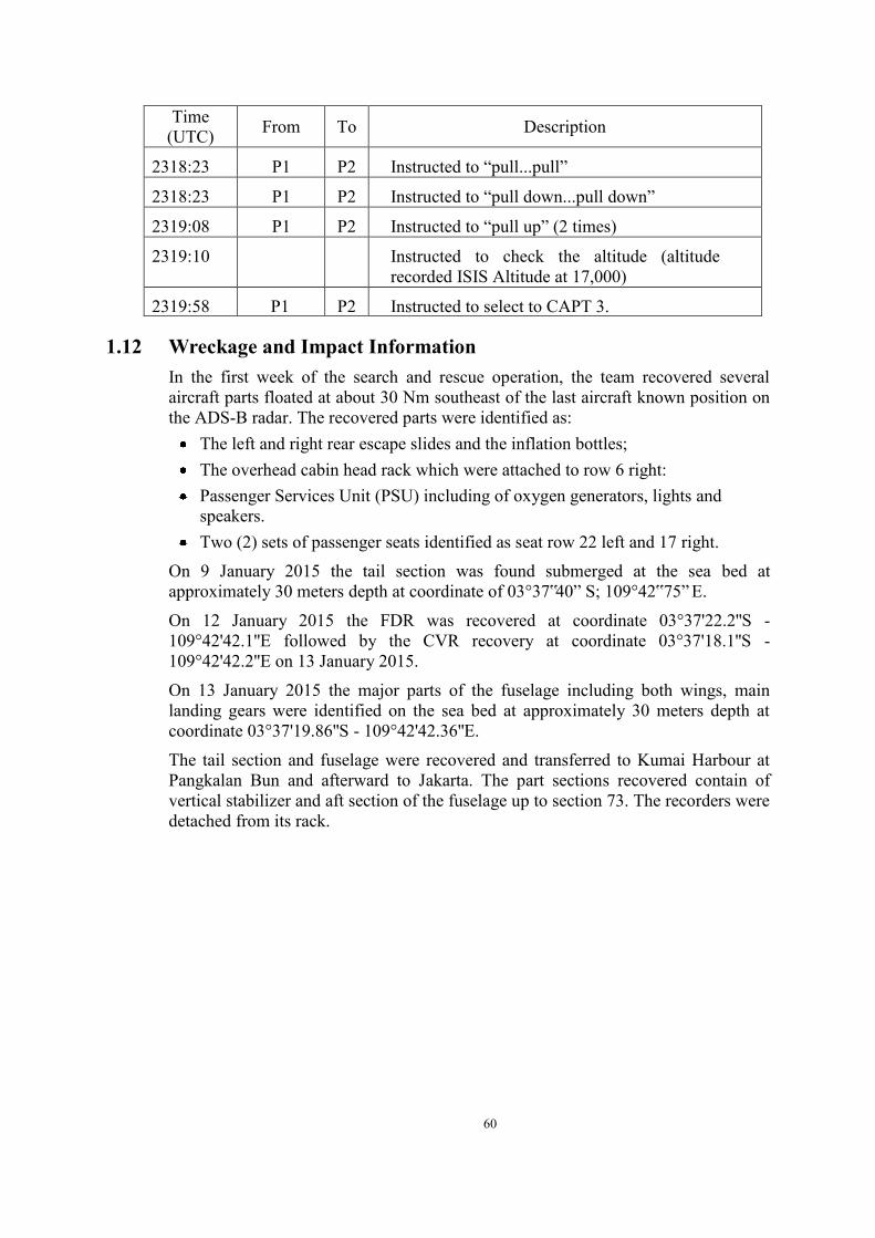
60
Time (UTC) From To Description
2318:23 P1 P2 Instructed to “pull...pull”
2318:23 P1 P2 Instructed to “pull down...pull down”
2319:08 P1 P2 Instructed to “pull up” (2 times)
2319:10 P1 P2 Instructed to check the altitude (altitude recorded ISIS Altitude at 17,000)
2319:58 P1 P2 Instructed to select to CAPT 3.
1.12 Wreckage and Impact Information In the first week of the search and rescue operation, the team recovered several aircraft parts floated at about 30 Nm southeast of the last aircraft known position on the ADS-B radar. The recovered parts were identified as:
The left and right rear escape slides and the inflation bottles; The overhead cabin head rack which were attached to row 6 right: Passenger Services Unit (PSU) including of oxygen generators, lights and
speakers. Two (2) sets of passenger seats identified as seat row 22 left and 17 right.
On 9 January 2015 the tail section was found submerged at the sea bed at approximately 30 meters depth at coordinate of 03°37‟40” S; 109°42‟75” E.
On 12 January 2015 the FDR was recovered at coordinate 03°37'22.2''S - 109°42'42.1''E followed by the CVR recovery at coordinate 03°37'18.1''S - 109°42'42.2''E on 13 January 2015.
On 13 January 2015 the major parts of the fuselage including both wings, main landing gears were identified on the sea bed at approximately 30 meters depth at coordinate 03°37'19.86''S - 109°42'42.36''E.
The tail section and fuselage were recovered and transferred to Kumai Harbour at Pangkalan Bun and afterward to Jakarta. The part sections recovered contain of vertical stabilizer and aft section of the fuselage up to section 73. The recorders were detached from its rack.

61
Figure 30: Wreckage Diagram superimposed on Google Map
The locations of the wreckage are as follows:
No Description Latitude Longitude
1 Tail 3 38‟ 1.70”S 109 43‟ 10.47” E
2 FDR 3 37‟ 22.2”S 109 42‟ 42.1” E
3 CVR 3 37‟ 18.1”S 109 42‟ 42.2” E
4 Fuselage & Wing 3 37‟ 19.86”S 109 42‟ 42.36” E
5 One passenger seat 3 37‟ 20.10”S 109 42‟ 44.1” E
6 Engine 3 37‟ 20.04”S 109 42‟ 43.44” E
The distance between Tail to FDR and CVR was about 1500 m. The distance between FDR and CVR was about 135 m.

62
Figure 31: The FDR and CVR racks
Figure 32: Pictures of identified parts and its original position
Right Aft door cut out
63
1.13 Medical and Pathological Information The total person on board were 162, included two pilots, four flight attendants and one company engineer. They were 79 male and 83 female; 22 of them were children under 15 years old. Total recovered at the end of search operation were 116 bodies, 100 of them were identified and 16 could not be identified. The 100 identified bodies were 54 male and 46 female; consisted of 93 Indonesians, 1 France, 1 Malaysian, 1 Singaporean, 3 South Koreans, and 1 United Kingdom.
1.14 Fire There was no evidence of fire in-flight or after the aircraft impacted.
1.15 Survival Aspects Level 1 alarm - INCERFA (Uncertainty Phase) A situation where in uncertainty exists as to the safety of an aircraft and its occupants.
Whenever the time of last contact between an aircraft and ATC exceeds 30 minutes, or if an aircraft has not landed 30 minutes after the pilot has received landing clearance at an airfield and no other contact was established, a Level 1 Alarm internationally known as 'INCERFA' (Uncertainty Phase) is activated. The rescue coordination centre requests the flight plan of the particular aircraft via the FIC (Flight Information Centre), from which details such as aircraft type, registration, persons on board, route, alternate aerodrome or endurance can be taken.
Level 2 alarm - ALERFA (Alert Phase) A situation where in apprehension exists as to the safety of an aircraft and its Occupants.
If initial investigations do not give any useful information about the position of the aircraft and if further investigations were unsuccessful, a Level 2 Alarm internationally known as 'ALERFA' (Alert Phase), is activated.
Level 3 alarm - DETRESFA (Distress Phase) A situation where in there is reasonable certainty that an aircraft and its occupants are threatened by grave and imminent danger or require immediate assistance.
If the evaluation of further specific data (e.g. Radar Tracks, Flight plan details, etc.) does not give any adequate information confirming the position and/or safety of the distressed aircraft, a Level 3 Alarm, internationally known as 'DETRESFA' is activated. An extensive search procedure begins. At 0008 UTC (0708 LT) Air Traffic Services Unit in Jakarta declared INCERFA and informed the situation to BASARNAS and KNKT.
At 0028 UTC (0728 LT) the status revised to ALERFA.
At 0055 UTC (0755 LT) the status revised to DISTRESFA.

64
Upon receiving the information about the loss contact of flight QZ 8501, BASARNAS initiated search and rescue (SAR) operation by collecting initial data.
At 28th December 2014 as the day of the accident, BASARNAS deployed aircraft to initiate search operation around Belitung Island and South West part of Kalimantan with three defined searching areas.
On the second day (29th December 2014), The SAR operation continued with additional four search areas which was centered to the last radar contact position, involving 14 aircrafts, 16 helicopters and 12 ships.
On 30 December 2014, the searching area was extended. Significant evidences of the aircraft were recovered at 30 nm south east of the last radar position which consisted of passenger luggage, deceased bodies and emergency escape slide. The searching operation moved to Pangkalan Bun.
The SAR operation continued under coordination of BASARNAS involving Indonesia Navy, Army, Police and other government and private agencies. Some other countries assisted for the SAR operation were Australia, China, Malaysia, Russia, Singapore, South Korea, and United States of America. The SAR operation involved 42 aircraft and 78 ships.
1.16 Tests and Research 1.16.1 Flight Simulation
KNKT performed 2 simulator exercises on Airbus A320 training simulator at STPI – Curug (Sekolah Tinggi Penerbangan Indonesia – Indonesia Civil Aviation Institute) and Air Asia Academy (AAA) training simulator in Kuala Lumpur.
The purposes of these simulations were to understand Airbus A320 systems and recreate the ECAM messages.
The scenario was by setting the RTLU malfunction and recorded the ECAM messages. Afterward, the pilot actions performed instructions displayed on the ECAM and recorded the result. In the simulation, the investigator also recreated the FAC CBs resetting and recorded the ECAM message result.
The ECAM displays on the simulator were as follows:
Figure 33: The page 1 and 2 of the ECAM messages after CBs of FAC 1 and 2 being reset

65
The ECAM displayed:
“AUTO FLT FAC 1+2 FAULT”,
“RUD WITH CARE ABV 160 KT”
"FAC 1…... OFF THEN ON”
"FAC 2…... OFF THEN ON”
As requested by ECAM action on page 2, following a FAC CB reset the FACs push button on overhead panel should be reset to OFF then ON to reactivate the functions.
The RTLU failure as recorded on the FDR could be recreated Similar ECAM messages to the data recorded on the FDR appeared when the
FAC CBs were pulled. Dual input resulted in rapid movement of the aircraft compared to single input Dual input in different direction of the side-sticks reduced the ability to control
the aircraft. The Emergency Cancel Button was effective to prevent pilot distraction for a
repetitive malfunction. As requested by the KNKT, BEA and Airbus performed the simulator session which referred to FDR data on the engineering simulator. The simulation intended to recreate ECAM messages appeared on the accident flight. The ECAM message during the RUD TRIM LIM SYS problem is presented in the following figure:
Figure 34: The ECAM messages after RTLU 1 and 2 fault
1.16.2 The RTLU examination The RTLU which was recovered from the accident site was sent by KNKT to BEA for special inspection on behalf of KNKT. On 16 June 2015, the RTLU arrived at Artus Facilities with presence of BEA and Airbus.
The summary of the inspection report BEA2014-0058_tec03 is as follows:
The RTLU is composed of two main parts:
- A main case which includes the two motors and various other mechanical pieces
- An electronic module fixed by screws on the main case

66
The examination was carried out by performing visual and other inspection of the external part as well as the internal part, including the electronic modules of the RTLU.
The channel A and channel B boards were visually examined under magnification at BEA.
The presence of cracks on solders was confirmed on the surface of both channels (Figure 35).
The summary of the examination found the electronic cards shows the evidence of cracking of soldering of both channel A and channel B. Those cracks could generate loss of electrical continuity and lead to a TLU failure.
Thermal cycles associated to powered/not-powered conditions and ground/flight conditions, generate fatigue phenomenon of the soldering, and may result in soldering cracking. Soldering cracking could induce a disconnection of components from the circuit. The disconnections could create a loss of the affected RTLU channel.
The electronic module pictures are shown below.
Figure 35: Electronic Module of RTLU
According to the Airbus information, there were three Technical Follow-Ups (TFUs) regarding the AUTO FLT RUD TRV LIM 1(2) (SYS) problems that were issued since 1993. TFU No. 27.23.51.004 was opened in 1993 regarding the problem of fatigue rupture of solder and closed on 1996. The problem found was “fatigue rupture of soldering” and the improvement made was “new electronic module”.
Another TFU 27.23.00.004 was opened in 2000 with the same problem of “Rupture of soldering” and closed in 2014 with the improvement of the “Electronic board process” which was available since 2002. The third TFU (number 27.23.00.007) “Mechanical stop failure” was opened in January 2015 following this accident. Airbus informed that the installed RTLU on PK-AXC had been improved with both Technical Follow-Ups (TFUs).
Cracking
Photo of one electronic module

67
1.17 Organisation and Management Information
Aircraft Owner : Doric 10 Labuan Limited Company
Address : Unit Level 13 (E) Main Office Tower, Financial Park Labuan, Jl. Merdeka 87000 FT Labuan – Malaysia
Aircraft Operator : PT. Indonesia AirAsia
Address : Jl. Marsekal Suryadarma No. 1 Selapajang Jaya Neglasari Tangerang, Republic of Indonesia
Operator Certificate Number : AOC/121-009
Indonesia Air Asia is an airline based in Indonesia with several bases of operation which are Jakarta, Surabaya, Bali, Medan and Bandung. The airline operates domestic and regional routes with 30 Airbus A320 aircrafts including the accident aircraft. Indonesia Air Asia is a member of the Air Asia group.
1.17.1 Summary of Management Interview During the interview with the Indonesia AirAsia management, one of the discussion topics was related to upset recovery training. The approved Operation Training Manual covers the upset recovery training in Chapter 8. The module consisted of ground and simulator training. The ground training provides the flight crew with the background, definition, cause of aircraft upset, aerodynamic and aircraft systems in relation with aircraft upset. Recovery methods consider various aircraft attitude and speed including post upset conditions.
The upset recovery training had not been implemented on Airbus A320 training, since it is not required according to the Flight Crew Training Manual and has not been mandated by the DGCA.
1.17.2 Summary of Maintenance Management Interview The maintenance data of the Indonesia Air Asia such as maintenance manuals and handling repetitive problem had made the investigation to find similar issues on the sister company Malaysia AirAsia (MAA).
The agenda to visit MAA was to discuss the topics of the relationship between MAA and IAA in maintenance area, AD/SB management, and management of aircraft problem and rectified (including the repetitive trouble).
The engineering discussion was conducted between KNKT and MAA Engineering represented by MAA Technical Service Manager.
The summary of the discussions are as follows:
(a) The relationship of MAA and IAA
MAA and IAA Technical Service are the same level management with different regulatory basis. In term of corporation, basically MAA applied the centralized and decentralized system for the maintenance management to IAA.

68
The centralized management was applied to corporate policy such as spare part procurement.
The decentralized management was applied regarding the technical trouble management including the communication to the manufactures and vendors. The communication with the manufacturer also applied in flight operations.
The MAA provides the following services to IAA:
o Line Maintenance service as Approved Maintenance Organization (AMO).
o Provides technical data as Design Organization which covers class B with scope the major repair and major change.
The maintenance management was assisted by AMOS maintenance management application system. All the aircraft maintenance management and control are included in this system.
The similar application systems are also utilized by IAA. Design organization has not been established as it was not required by existing regulation.
Note: AMOS (Airline Maintenance and Operating Systems) is software for assisting the maintenance records and manual management.
(b) AD/SB Management and Controls
MAA manage the AD issued by EASA and FAA. MAA utilizes the AMOS and EASA Web to assist the AD/SB management. MAA also utilizes the Airbus Web for world Airbus operator to discuss the technical matter.
For any AD issued by EASA or FAA, MAA will conduct document assessment review before issuing the Engineering Instruction (EI). The EI will also be distributed to IAA for implementation. IAA will perform the assessment for the EI before it implements to comply with local regulators that may have different requirements.
If the AD requires SB implementation that has impact to safety, MAA will provide immediate documentation to implement including communication to operation department if the modification has not been performed due to part availability. (Note: IAA had a procedure to communicate with the operation department using the Notice to Crew (NTC)).
(c) Handling Repetitive Trouble
These troubles are normally addressed through the following methods:
An automatic communication to transfer the PFR from air to ground by the system called “AIRMAN”. This system utilizes the Aircraft VHF Communication to transfer any PFR issued by the CFDS from the aircraft to ground station or Maintenance Operation Centre (MOC). At the time of accident, IAA retrieved the PFR by manual downloading or printing out and collected to the MOC.
WQAR (Wireless Quick Access Recorder) to expedite the collection of the aircraft limited for engine and APU only by utilizing the Flight Data

69
Recorder parameter during aircraft on the ground. Both MAA and IAA utilize this system, however, IAA had only implemented the system on PK-AXF and PK-AXR.
MAA implements FDA (Flight Data Analysis) team to examine the trouble (including repetitive trouble) thoroughly by the expert personnel.
Prognosis system that will be proposed for the next implementation by MAA.
If any repetitive trouble exists MAA collects information by all methods above and conducts detail analysis. The Trouble Shooting Manual (TSM) is the basic document to follow but in any circumstances, the sequence of TSM may be overridden to avoid circling without any solution including communication with the aircraft manufacturer to seek assistance.
1.17.3 Company Manuals All Indonesia AirAsia company manuals have been approved by Indonesia Directorate General of Civil Aviation (DGCA). Relevant excerpts of the manuals are described in the following section.
1.17.3.1 Company Operation Manual (COM) Crew Coordination during Emergencies or Abnormalities (chapter 4.10.1.7) Emergency and abnormal Procedures are to be initiated on command of the Pilot Flying. The following assignment of tasks is recommended, provided the auto pilot operative.
PF (Pilot flying) is responsible for :
PM (Pilot Monitoring) is responsible for :
• Throttles • Flight path and airspeed • Aircraft configuration • Navigation • Communication
• Checklist reading • Execution of required actions on PF
Request • Engine fuel levers, fire handles and
guarded switches or any irreversible actions/systems, with confirmation
The Pilot in Command may change over the control at any time to ensure that the highest level of safety is maintained. Malfunction of flaps, which required approach and landing with zero degrees flaps setting shall be flown by the Pilot in Command. The approach and landing following other emergency or abnormal situations shall be conducted such that highest level of safety is achieved. Following an in-flight emergency or abnormal situation, all approach either instrument or visual should not be commenced or should be discontinued, until the Emergency Memory Items procedures or such action would increase the potential risk have been completed. For more detail see AFM/FCOM. During an emergency or abnormal situation, the Pilot in Command must allocate

70
crew duties to ensure that the highest level of situation awareness is maintained in the cockpit and cabin. This will prevent all attention being totally directed at resolving the emergency or abnormal situation to the detriment of safe flight. Any ambiguities, confusion, unresolved discrepancies or use of improper procedures must be discussed immediately, and if necessary a missed approach initiated to allow remedial action at safe altitude
Crew Resources Management (CRM) Task Sharing and Duties Allocation Air Asia does not practice full role reversal in its operations. With reference Normal Procedures (NP) of the QRH, during the Before Start, Engine Start, After Start, Taxi, Before Takeoff, After Landing and Parking phases, the duties ascribed to the PF are CM1, and the duties ascribed to the PNF is CM2. Exceptions to the rule, if any are specified in this document and that section of the QRH. CM1 is the flight crew seated on the LHS. CM2 is the flight crew seated on the RHS. Although in flight procedures in this chapter reflect duties for PF and PNF, the PIC retains final authority and responsibility for all actions directed and performed.
Crew Resource Management CRM is the effective utilization of all available resources, e.g. crew (both flight crew and flight attendant), aircraft systems, and supporting facilities, to achieve safe and efficient flight operations. CRM is not just the domain of the PIC. It is designed to raise each crew’s awareness and skill in coping with a wide variety of operational situations and problems. CRM demands that when necessary, the PIC should assign the aircraft control to the Co-pilot make maximum use of the auto-flight system and thereby retain sufficient capacity to manage events successfully. These principles will form an integral element of the Air Asia Operating Policy and Task sharing duties. These collectively form the Standard Operating Procedures.
1.17.3.2 FCOM - Normal Checklist Normal C/L are initiated by the PF and read by the PNF. The PF shall respond after having checked the existing configuration. When both pilots have to respond, "BOTH" is indicated. DEFINITIONS OF WARNINGS, CAUTIONS AND NOTES The following are the official definitions of warnings, cautions and notes taken directly from the JAR25/CS-25 and applicable to Airbus flight operation documentation: WARNING: An operating procedure, technique, etc. that may result in personal injury or loss of life if not followed.

71
CAUTION: An operating procedure, technique, etc. that may result in damage to equipment if not followed. NOTE: An operating procedure, technique, etc. considered essential to emphasize. Information contained in notes may also be safety related.
1.17.3.3 FCOM - Auto Flight Rudder Limiter System

72
1.17.3.4 Flight Crew Training Manual (FCTM)
FAILURE LEVELS (Operational Philosophy, ECAM) The ECAM has three levels of warnings and cautions. Each level is based on the associated operational consequence(s) of the failure. Failures will appear in a specific color, according to a defined color-coding system, that advises the flight crew of the urgency of a situation in an instinctive, unambiguous manner. In addition, Level 2 and 3 failures are accompanied by a specific aural warning: A Continuous Repetitive Chime (CRC) indicates a Level 3 failure, and a Single Chime (SC) indicates a Level 2 failure.

73
Failure Level Priority Color
Coding Aural
Warning Recommended Crew
Action Level 3 Safety Red CRC Immediate Level 2 Abnormal Amber SC Awareness, then action Level 1 Degradation Amber None Awareness, then
Monitoring
When there are several failures, the FWC displays them on the Engine Warning Display (E/WD) in an order of priority, determined by the severity of the operational consequences. This ensures that the flight crew sees the most important failures first.
FEEDBACK The ECAM provides the flight crew with feedback, after action is taken on affected controls:
The System Synoptic: Displays the status change of affected components.
The Memo: Displays the status of a number of systems selected by the flight crew (e.g. anti-ice).
The Procedures: When the flight crew performs a required action on the cockpit panel, the ECAM usually clears the applicable line of the checklist (except for some systems or actions, for which feedback is not available).
The ECAM reacts to both failures and pilot action.
ECAM HANDLING ABNORMAL OPERATIONS TASK SHARING RULES When the ECAM displays a warning or a caution, the first priority is to ensure that a safe flight path is maintained. The successful outcome of any ECAM procedure depends on: Correct reading and application of the procedure, effective task sharing, and conscious monitoring and crosschecking. It is important to remember that, after ECAM ACTIONS announcement by the PF:
• The PF’s task is to fly the aircraft, navigate, and communicate. • The PNF’s task is to manage the failure, on PF command.
The PF usually remains the PF for the entire flight, unless the Captain decides to take control. The PF will then control the aircraft’s flight path, speed, configuration, and engines. The PF will also manage navigation and communication, and initiate the ECAM actions to be performed by the PNF, and check that the actions are completed correctly. The PNF has a considerable workload: Managing ECAM actions and assisting the PF on request. The PNF reads the ECAM and checklist, performs ECAM

74
actions on PF command, requests PF confirmation to clear actions, and performs actions required by the PF. The PNF never touches the thrust levers, even if requested by the ECAM. Some selectors or pushbuttons (including the ENG MASTER switch, FIRE pushbutton, IR, IDG and, in general, all guarded switches) must be crosschecked by both the PF and PNF (except on ground), before they are moved or selected, to prevent the flight crew from inadvertently performing irreversible actions. As a general rule, any computer reset must be also crosschecked by both the PF and PNF. To avoid mistakes in identifying the switches, Airbus’ overhead panels are designed to be uncluttered. When the ECAM requires action on overhead panel pushbuttons or switches, the correct system panel can be identified by referring to the white name of the system on the side of each panel. Before performing any action, the PNF should keep this sequence in mind: "System, then procedure/selector, then action" (e.g. "air, cross-bleed, close"). This approach, and announcing an intended selection before action, enables the PNF to keep the PF aware of the progress of the procedure. It is important to remember that, if a system fails, the associated FAULT light on the system pushbutton (located on the overhead panel) will come on in amber, and enable correct identification. When selecting a system switch or pushbutton, the PNF should check the SD to verify that the selected action has occurred (e.g. closing the cross-bleed valve should change the indications that appear on the SD).
Crew Coordination
1. The PNF should review the overhead panel and/or associated SD to analyze and confirm the failure, prior to taking any action, and should bear in mind

75
that the sensors used for the SD may be different from the sensors that trigger the failure. The flight crew must always rely on the CAB PR EXCESS CAB ALT warning, even if not confirmed on the CAB PRESS SD page, as the warning can be triggered by a cabin pressure sensor different from the one used to control the pressure and display the cabin altitude on the SD page.
2. In case of a failure during takeoff or go-around, ECAM actions should be delayed until the aircraft reaches approximately 400 ft, and is stabilized on a safe trajectory. This is an appropriate compromise between stabilizing the aircraft and delaying action.
3. When the ECAM displays several failures, the sequence (action, then request and confirmation, before clearance) should be repeated for each failure. When all necessary actions are completed, amber messages and red titles will no longer appear on the E/WD.
4. When the ECAM displays several system pages, the sequence (request and confirmation before clearance) should be repeated for each system page.
5. The PF may call out "STOP ECAM" at any time, if other specific actions must be performed (normal C/L, or performing a computer reset). When the action is completed, the PF must callout: "CONTINUE ECAM".
6. When slats are extended, the SD automatically displays the STATUS, unless if the page is empty. The STS should be carefully reviewed, and the required procedure applied.
7. When ECAM actions have been completed, and the ECAM status has been reviewed, the PNF may refer to the FCOM procedure for supplementary information, if time permits. However, in critical situations the flight should not be prolonged only to consult the FCOM.
IF THE ECAM WARNING (OR CAUTION) DISAPPEARS WHILE APPLYING THE PROCEDURE If an ECAM warning disappears, while a procedure is being applied, the warning can be considered no longer applicable. Application of the procedure can be stopped. For example, during the application of an engine fire procedure, if the fire is successfully extinguished with the first fire extinguisher bottle, the ENG FIRE warning disappears, and the procedure no longer applies. Any remaining ECAM procedures should be performed as usual.
STALL RECOVERY Definition of the Stall The stall is a condition in aerodynamics where the Angle of Attack (AOA) increases beyond a point such that the lift begins to decrease. As per basic aerodynamic rules, the lift coefficient (CL) increases linearly with the AOA up to a point where the airflow starts to separate from the upper surface of the wing. At and beyond this point, the flight crew may observe:

76
Buffeting, which depends on the slats/flaps configuration and increases at high altitude due to the high Mach number
Pitch up effect, mainly for swept wings and aft CG. This effect further increases the AOA.
Lift Coefficient versus Angle of Attack.
If the AOA further increases up to a value called AOAstall, the lift coefficient will reach a maximum value called CL MAX. When the AOA is higher than AOAstall, the airflow separates from the wing surface and the lift Coefficient decreases. This is the stall. The stall will always occur at the same AOA for a given configuration, Mach number and altitude.
Influence of Slats and Flaps on Lift Coefficient versus Angle of Attack, Slats and Flaps have a different impact on the Lift coefficient obtained for a given AOA. Both Slats and Flaps create an increase in the maximum lift coefficient. Influence of Speed Brakes and Icing on Lift Coefficient versus Angle of Attack.
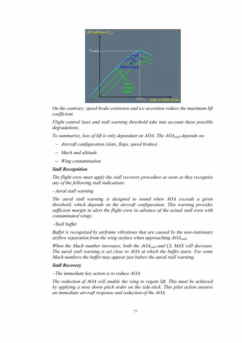
77
On the contrary, speed brake extension and ice accretion reduce the maximum lift coefficient. Flight control laws and stall warning threshold take into account these possible degradations. To summarize, loss of lift is only dependant on AOA. The AOAstall depends on:
Aircraft configuration (slats, flaps, speed brakes)
Mach and altitude
Wing contamination
Stall Recognition The flight crew must apply the stall recovery procedure as soon as they recognize any of the following stall indications:
‐ Aural stall warning The aural stall warning is designed to sound when AOA exceeds a given threshold, which depends on the aircraft configuration. This warning provides sufficient margin to alert the flight crew in advance of the actual stall even with contaminated wings.
‐ Stall buffet Buffet is recognized by airframe vibrations that are caused by the non-stationary airflow separation from the wing surface when approaching AOAstall. When the Mach number increases, both the AOAstall and CL MAX will decrease. The aural stall warning is set close to AOA at which the buffet starts. For some Mach numbers the buffet may appear just before the aural stall warning.
Stall Recovery
‐ The immediate key action is to reduce AOA: The reduction of AOA will enable the wing to regain lift. This must be achieved by applying a nose down pitch order on the side-stick. This pilot action ensures an immediate aircraft response and reduction of the AOA.

78
In case of lack of pitch down authority, it may be necessary to reduce thrust. Simultaneously, the flight crew must ensure that the wings are level in order to reduce the lift necessary for the flight, and as a consequence, the required AOA. As a general rule, minimizing the loss of altitude is secondary to the reduction of the AOA as the first priority is to regain lift. As AOA reduces below the AOAstall, lift and drag will return to their normal values.
‐ The secondary action is to increase energy: When stall indications have stopped, the flight crew should increase thrust smoothly as needed and must ensure that the speed brakes are retracted. Immediate maximum thrust application upon stall recognition is not appropriate. Due to the engine spool up time, the aircraft speed increase that results from thrust increase, is slow and does not enable to reduce the AOA instantaneously. Furthermore, for under wing mounted engines, the thrust increase generates a pitch up that may prevent the required reduction of AOA. When stall indications have stopped, and when the aircraft has recovered sufficient energy, the flight crew can smoothly recover the initial flight path. If in clean configuration and below FL 200, during flight path recovery, the flight crew must select FLAPS 1 in order to increase the margin to AOAstall.
Stall Warning at Lift-Off At lift-off, a damaged AOA probe may cause a stall warning to spuriously sound in the cockpit. f the aural stall warning sounds at liftoff, the flight crew must fly the appropriate thrust and pitch for takeoff in order to attempt to stop the aural stall warning and ensure a safe flight path. The flight crew applies TOGA thrust in order to get the maximum available thrust. Simultaneously, the pilot flying must target a pitch angle of 15 ° and keep the wings level in order to ensure safe climb. Then, when a safe flight path and speed are achieved, if the aural stall warning is still activated the flight crew must consider that it is a spurious warning.
1.17.3.5 FCTM - Abnormal Attitudes If the aircraft is, for any reason, far outside the normal flight envelope and reaches an abnormal attitude, the normal controls are modified and provide the PF with maximum efficiency in regaining normal attitudes. (An example of a typical reason for being far outside the normal flight envelope would be a mid-air collision). The so-called "abnormal attitude" law is: Pitch alternate with load factor protection (without auto-trim) Lateral direct law with yaw alternate.

79
These laws trigger, when extreme values are reached:
Pitch (50 ‹ up, 30 ‹ down)
Bank (125 ‹),
AOA (30 to 40 ‹, -10 ‹),
Speed (440 kt, 60 to 90 kt),
Mach (M 0.91). It is very unlikely that the aircraft will reach these attitudes, because fly-by-wire provides protection to ensure rapid reaction far in advance. This will minimize the effect and potential for such aerodynamic upsets. The effectiveness of fly-by-wire architecture and the existence of control laws eliminate the need for upset recovery maneuvers to be trained on protected Airbus aircraft.
1.17.3.6 FCTM - Side-stick and takeover Priority Button When the Pilot Flying (PF) makes an input on the sidestick, an order (an electrical signal) is sent to the fly-by-wire computer. If the Pilot Not Flying (PNF) also acts on the stick, then both signals/orders are added. Therefore, as on any other aircraft type, PF and PNF must not act on their sidesticks at the same time. If the PNF (or Instructor) needs to take over, the PNF must press the sidestick takeover pushbutton, and announce: "I have control". If a flight crewmember falls on a sidestick, or a mechanical failure leads to a jammed stick (there is no associate ECAM caution), the "failed" sidestick order is added to the "non-failed" sidestick order. In this case, the other not affected flight crewmember must press the sidestick takeover pushbutton for at least 40 s, in order to deactivate the "failed" sidestick. A pilot can at any time reactivate a deactivated stick by momentarily pressing the takeover pushbutton on either stick. In case of a "SIDE STICK FAULT" ECAM warning, due to an electrical failure, the affected sidestick order (sent to the computer) is forced to zero. This automatically deactivates the affected sidestick. This explains why there is no procedure associated with this warning (Source: FCTM OP-020 Page 16/20).
1.17.3.7 OTM - Upset Training Syllabus 8.11.1 OBJECTIVE
Upon successful completion of training the trainee will be capable satisfactorily develop knowledge and ability for preventing and coping of aircraft upset.
8.11.2 APPLICABILITY
Upset Recovery Training is intended for Flight Crew.
80
8.11.3 MODULES 1. Ground Training
A. Background. B. Definitions C. Causes of Aircraft Upset D. Aerodynamic & Aircraft Systems in relation with aircraft upset E. Recovery methods by considering various aircraft attitude and speed F. Post upset conditions
2. Simulator A. Flight Training (included malfunctions) Practicing Nose High, Nose Low and High Bank Angle Recovery B. Debriefing An adequate post-flight critique will be accomplished.
The aircraft operator advised the KNKT that the flight crew of PK-AXC had not received the upset recovery training on Airbus A320 training simulator.
1.17.3.8 Standard Operating Procedures The following statements are significant quotations from the operator manual page PRO-NOR-SOP-22, page 6.
STANDARD CALLOUTS To take control: The pilot calls out “I HAVE CONTROL”. The other pilot accepts this transfer by calling out “YOU HAVE CONTROL”, before assuming PNF duties. To transfer communication, flight crewmembers must use the following callouts: To handover communication: The pilot calls out “YOU HAVE RADIOS”. The other pilot accepts this transfer by calling out “I HAVE RADIOS”. To takeover communication: The pilot calls out "I HAVE RADIOS”. The other pilot accepts this transfer by calling out “YOU HAVE RADIOS”.
ABNORMAL AND EMERGENCY CALLOUTS ECAM Procedures
"ECAM ACTION" is commanded by PF when required.
"CLEAR (title of the system)?" is asked by the PNF for confirmation by the PF that all actions have been taken/reviewed on the present ECAM WARNING/CAUTION or SYSTEM PAGE. e.g.: CLEAR HYDRAULIC?
"CLEAR (title of the system)" is the command by the PF that the action and review is confirmed. For status page; REMOVE STATUS will be used.
"ECAM ACTIONS COMPLETE" is the announcement by the PNF that all APPLICABLE ACTIONS have been completed.

81
Should the PF require an action from the PNF during ECAM procedures, the order "STOP ECAM" will be used.
When ready to resume the ECAM the order "CONTINUE ECAM" will be used.
STANDARD OPERATING PROCEDURES STANDARD CALLOUTS The "SET" command means using an FCU knob to set a value, but not to change a mode. SET is accomplished by only rotating the appropriate selection knob. Example:
"SET GO AROUND ALTITUDE"
"SET QNH "
"SET FL"
"SET HDG"
MANAGE/PULL The "MANAGE" command means pushing an FCU knob to engage, or arm, a managed mode or target. The "PULL" command means pulling an FCU knob to engage a selected mode or target. Example:
"PULL HDG 090"
"MANAGE NAV"
"FL 190 PULL"
"FL 190 MANAGE"
"PULL SPEED 250 KNOTS"
"MANAGE SPEED" Note: If the value was previously set, there is no requirement to repeat the figure. Simply call e.g. PULL HDG: PULL SPEED: FL PULL The VS/FPA selector knob has no managed function. The standard callouts for the use of this knob are as follows:
V/S Plus (or Minus) 700 PULL or
FPA Minus 3° PULL (VIS (FPA) knob is turned and pulled)
PUSH TO LEVEL OFF (VIS (FPA) knob is pushed)
ARM The "ARM" command means arming a system by pushing the specified FCU button. Example:
"ARM APPROACH"
"ARM LOC."

82
1.17.3.9 SOP-Standard Call Outs Flight Parameters in Approach Standard operating procedures chapter Standard Call outs page NOR-SOP-90 Page 5 describes standard call outs for approach and go around related to flight parameter such as:
Final Approach
SPEED - if the speed decreases below the speed target - 5kts or increases above the speed target + 10kts
SINK RATE when V/S is greater than -1 000 ft/min.
BANK when bank angle becomes greater than 7°.
PITCH when pitch attitude becomes lower than -2.5° or higher than +10°.
RNAV (RNP) Approach
"SINK RATE" when V/S is greater that -1 200 ft/min.
"BANK" when the bank angle goes above 30 °.
During a go-around, the PM will make a callout for the following conditions:
”BANK”: If the bank angle becomes greater than 7°,
”PITCH”: If the pitch attitude becomes greater than 20° up or less than 10° up,
”SINK RATE”: If there is no climb rate. These standard call outs are only applicable for approach and go around
phase.
1.17.3.10 QRH - General GENERAL SCOPE The QRH contains some specific procedures which are not displayed on the ECAM.As a general rule, the procedures displayed on the ECAM are not provided in the QRH (refer to FCOM PRO/ABN).
TASKSHARING FOR ABN/EMER PROC For all abnormal/emergency procedures, the task sharing is as follows:
‐ PF - Pilot flying - Responsible for the:
Thrust levers
Flight path and airspeed control
Aircraft configuration (request configuration change)
Navigation
Communications

83
‐ PNF - Pilot non flying - Responsible for the:
Monitoring and reading aloud the ECAM and checklists
Performing required actions or actions requested by the PF, if applicable
Using engine master switches, cockpit C/Bs, IR and guarded switches with PF's confirmation (except on ground).
ECAM CLEAR DO NOT CLEAR ECAM WITHOUT CROSS-CONFIRMATION OF BOTH PILOTS.
ABN/EMER PROC INITIATION Procedures are initiated on pilot flying command. No action will be taken (apart from audio warning cancel through MASTER WARN light) until:
The appropriate flight path is established, and
The aircraft is at least 400 ft above the runway, if a failure occurs during takeoff, approach, or go-around. (In some emergency cases, provided the appropriate flight path is established, the pilot flying may initiate actions before this height).
COMPUTER RESET When a digital computer behaves abnormally, as a result of an electrical transient, for example, the Operator can stop the abnormal behaviour by briefly interrupting the power supply to its processor. The flight crew can reset most of the computers in this aircraft with a normal cockpit control (selector or pushbutton). However, for some systems, the only way to cut off electrical power is to pull the associated circuit breaker. To perform a computer reset:
- Select the related normal cockpit control OFF, or pull the corresponding circuit breaker.
- Wait 3s if a normal cockpit control is used, or 5s if a circuit breaker is used (unless a different time is indicated)
- Select the related normal cockpit control ON, or push the corresponding circuit breaker
- Wait 3s for the end of the reset. WARNING: Do not reset more than one computer at the same time, unless instructed to do so. Note: In flight, before taking any action on the cockpit C/Bs, both the PF and PNF must:
- Consider and fully understand the consequences of taking action - Crosscheck and ensure that the C/B label corresponds to the affected system.

84
The computers most prone to reset are listed in the table below, along with the associated reset procedure. Specific reset procedures included in OEB or TDUs are not referenced in this table and, when issued, supersede this table.
- On ground, almost all computers can be reset and are not limited to the ones indicated in the table.
The following computers are not allowed to be reset in specific circumstances: • ECU (Engine Control Unit on CFM engines), or EEC (Electronic Engine
Control on IAE engines), and EIU (Engine Interface Unit) while the engine is running.
• BSCU (Brake Steering Control Unit), if the aircraft is not stopped. - In flight, as a general rule, the crew must restrict computer resets to those
listed in the table, or to those in applicable TDUs or OEBs. Before taking any action on other computers, the flight crew must consider and fully understand the consequences.
CAUTION: Do not pull the following circuit breakers:
‐ SFCC (could lead to SLATS/FLAPS locked).
‐ ECU or EEC, EIU.

85
1.17.3.11 QRH - Stall Recovery
Stall Recovery was described in the Abnormal and Emergency procedure 80.08A. It indicated that as soon as any stall indication such as aural warning or buffet recognized, the pilot should push the side-stick forward to change the aircraft pitch down. This action could reduce the aircraft angle of attack.
The detail steps of the procedures shows as follow;

86
1.17.3.12 QRH - Tripped Circuit Breaker Re-Engagement Tripped Circuit Breaker Re-Engagement was described in the Abnormal and Emergency procedure 80.16A, stated that: “in flight not to reengage a circuit breaker that has tripped by itself, unless the Captain judges it necessary to do so for the safe continuing of the flight.” The detail of the procedures shows as follow;
1.17.3.13 Company Maintenance Manual (CMM) 3.5. Defect Report PURPOSE To ensure all defects reported are collated and significant technical problems investigated for the development of appropriate corrective action program. Liaison with Regulatory Authorities / OEM on adverse defect findings. Deferred defect policy.
Scope Defect Reports for the purpose of this procedure shall cover the following: All flight defects recorded by Flight Crew in the Technical Log and the rectification carried out. Defects and rectifications recorded in the AMOS.(AMOS – Airlines Maintenance and Operational System).
3.6. Reliability Program Purpose To measure, monitor and control aircraft fleet performance and effectiveness of Indonesia Air Asia maintenance program, a system of continuous monitoring, alerting and problem analysis/ corrective action, provide monthly reliability report and conduct quarterly Maintenance Review Board Meeting.

87
Scope This program shall apply in the operation of the Reliability Program in ensuring that all the maintenance processes are performed continuously and effectively to maintain aircraft in an airworthiness state.
Policy 3.6.1. Detailed procedures outlining the statistical technique, policy guidelines
on usage of statistical methods for verification of process capabilities in order to ensure continued airworthiness are reflected in Maintenance Reliability Program.
3.6.2. MRB of reliability will be chaired by Planning & Technical Services Manager which will be conducted quarterly.
3.6.3. Data collection and analysis is carried out by Air Asia Berhad Technical.
Record Department by computerized system as per Maintenance Agreement between Indonesia Air Asia and Air Asia Berhad Malaysia and shall review and evaluate the following as required:
PIREPS Technical logs Maintenance Work sheet Workshop report Report on functional checks or special inspections Store Issues /Report (e.g. Spare consumption) Occurrence Report Repetitive Defects Other Source (e.g. ETOPS, RVSM, ILS CAT I/II)
3.6.4. As part of reliability program, Engine Condition Monitoring (ECM) policy ensures that engine deterioration at an early stage is detected to allow corrective action before safe operation is affected by ensuring that engine limit margins are maintained.
ECM procedure calls for daily collection of the ECM data to monitor on-wing engine performance by the ground-based system. A report based on the daily data collection is generated daily.
3.7. MEL / DISPATCH DEVIATION MANDATORY GUIDE Purpose To establish a system of control and monitoring of MEL Maintenance Report 2 defects and its rectification to prevent exceeding MEL Repair Interval Limits.
POLICY/PROCEDURE 3.7.1. The control and reporting of all MEL Maintenance Report 2 is the

88
responsibility of the License Aircraft Maintenance Engineer / Authorized Holder.
3.7.2. No direct entries into the Maintenance Report 2 shall be permitted unless the deferred defect already been entry in MR1 as a reference.
3.7.3. For defects to be transferred to the Maintenance Report 2 (MR2), a cross-reference shall be made to the MEL when applicable.
5.1 Technical Log Purpose To ensure that technical log is correctly completed and appropriately take action by an authorized person. Scope All activities pertaining to the usage of the technical log in accordance with Technical Log Procedure and to ensure that technical log is correctly completed and appropriately auctioned by an authorized person. Indonesia AirAsia aircraft Technical Log which consists of the following: 1. Maintenance Report 1 (MR1) - Technical Log Book 2. Maintenance Report 2 (MR2) - Deferred Defect Log Book 3. Transit Check and Fuel & Oil Log - Fuel & Oil records during transit
activities 4. Cabin Condition Log – Records Cabin Condition
General of the instruction usage and filling guidance of the Technical Log are described in Quality Notice (QN-G-038) and also available on each of Log.
Policy 5.1.4. All maintenance work must be recorded and certified in the Technical
Log.
5.3 Defect & Repetitive Defect Defect 5.3.1 All defects found during Hangar Maintenance and routine check shall be
recorded on the Inspection Cards (IC). 5.3.2 All defects still open in the Technical Log Book or Deferred Defects log
book shall be transferred to the Inspection Cards (IC) for rectifications during the base maintenance input.
5.3.3 The Inspection Card (IC) is the Maintenance & Engineering Department document on which defects arising are recorded and rectified whilst an aircraft is undergoing Base Maintenance. It provides for nature of defect entry, action taken, by whom, parts replacement if any etc. and certification that such action has cleared the defect.

89
5.3.4 The issue and return of Inspection Cards (IC) shall be controlled and monitored by Planning by tracking the sequential number allotted to each Inspection Card (IC) and each and every card issued against the maintenance input shall become part of the Maintenance Policy.
5.3.5 All defects must be rectified and certified by an appropriately Licensed Aircraft Engineer or a person holding an authorization issued by the Quality Assurance Manager for that particular function.
5.3.6 Defects found during Maintenance may be deferred under the following conditions: a) The defect is deferrable in accordance to the Indonesia Air Asia
Minimum Equipment List (MEL). b) Non–availability of spares or insufficient downtime to rectify the defect
without adversely affecting the operating schedule. 5.3.7 Items not listed in the Indonesia Air Asia MEL, which are not
airworthiness or safety related such as aesthetics, cosmetics, passenger comfort or convenience related may be deferred due to non-availability of spares or downtime constraints.
5.3.8 All completed Inspection Cards (IC) shall become part of the Maintenance and shall be sent to Technical Records to enable update of records and safekeeping.
Repetitive Defect 5.3.9 All defects reported in the Technical Log must be rectified and certified by
the authorized person. However permissible MEL or CDL items may be deferred subject non–availability of spares, manpower or insufficient ground time but in any event, such defects can only be deferred by an appropriately authorized person.
5.3.10 When deferring a defect or monitoring a repetitive defect, it must be necessary to keep flight crews or engineers at line stations informed of any non–standard configuration or limitations such as altitude, passenger load, fuel uplift etc. This being the case, entry into “notice to crew and engineers” in the Technical Log and inform Flight Operations.
5.3.11 A defect is deemed to be repetitive when it has been reported more than once in 7 flight sectors or 3 days where 3 rectification attempts have not positively cleared the defects. The Maintenance Manager will monitor and carry out follow up actions to ensure rectification of the repetitive object.
5.3.12 The cabin log shall not be used to enter any airworthiness defects. The Captain will sign the cabin log at the end of a flight. Any airworthiness defect found in the cabin log will be transferred to the technical log by the Captain/License /Approval Holders.
5.3.13 Monthly PIREPS statistics are reviewed by Maintenance Operation Manager to identify trends, repetitive component failure rate, high failure rate etc. to improve dispatch reliability and reduce cost.

90
5.3.14 Communicate all MEL items raised to main base by fax or e-mail. 5.3.15 Maintenance Control Procedures are contained in the EPM volume 2
explicitly provides for this. 5.3.16 The Maintenance Operation Manager is responsible to monitor all
deferred defects and recurring defects. The priority for rectification shall be as follows: a) Time limited MEL. b) Potential AOG e.g. single failure in a dual system etc. c) Defects that imposes restrictions on aircraft e.g. altitude restriction etc. d) Defects that affect passenger comfort and are not airworthiness related.
Responsibilities a. Rectification of Defects: Maintenance Operation Manager b. Issue and Control of Work Cards: Planning Officer.
1.17.3.14 Engineering Procedure Manual Chapter: 2. Line Maintenance Procedure 2.20 Repetitive Defects 2.20.1 Purpose - To identify line maintenance defects of repetitive nature. - To provide a procedure for the effective control, monitoring and rectification
of repetitive defects in the shortest and most economical manner without sacrificing reliability and airworthiness of the aircraft.
2.20.2 Field of Application The procedure applies to only repetitive defects that are deferrable and permissible in accordance to the Indonesia Air Asia Minimum Equipment List but closely monitored and plan for their rectification action. When monitoring of repetitive defects, flights crews and engineers at line stations need to be duly informed including the limitations associated with it such as altitude, runway requirement, fuel uplift and passenger load, flight profile, weather etc.
2.20.3 General This procedure involves the following personnel: i. Maintenance Operation Manager - MOM ii. Maintenance Operation Controller - MOC ii Aircraft Maintenance Supervisor - AMS iii Licensed Aircraft Engineer/Authorization Holder - LAE/AH
2.20.4 Definition A defect is categorized to be repetitive in nature under the following definitions: i. Has been reported more than once in 7 flight sectors.

91
ii. 3 rectification attempts within a period of 3 days have not positively cleared the defect.
2.20.5 Procedure a) When reported defects falls into the repetitive category as defined above,
MOC/AMS to extract AMOS-Work order Information system data to review the troubleshooting/rectification has been done.
b) With comprehensive data from AMOS- Work order Information system, further rectification action can now be planned and formulated to clear the defect at all available opportunities.
c) Each shift MOC / AMS shall appoint a LAE as the Engineer-in-charge of the defect from his shift to ensure continuity of the troubleshooting. The shift AMS together with his Engineer-in-charge, shall advise MOC and/or MOM on the progress.
d) All rectification must be guided using the respective AMM / TSM troubleshooting guide for systematic remedial action.
e) All work carried out must be entered in the Tech Log MR1 for accountability. f) The MOC and/or MOM shall ensure that all the part/tooling/equipment
required for continued troubleshooting are available and to expedite if they are not readily available by liaising with the Purchasing and Supplies department.
g) The shift AMS of the night shift shall allocate the LAE’s with the required number of men to continue rectification on the recurring defect.
h) When an aircraft is scheduled for a minor or major maintenance check, rectify any recurring defect when longer ground time available.
i) When a recurring defect is identified, the MOC and/or MOM must be duly informed by AMS. The MOC and/or MOM will monitor and ensure that rectification process is progressing systematically up to final rectification.
j) The Recurring Defect will be considered closed after 7 days from the date of final rectification if nil re-occurrence is confirmed.
k) MOC and/or MOM will work closely with Flight Operations by updating them on any flight profile limitations resulting from the recurring defect of the particular aircraft to ensure smooth operation.
l) Upon rectification of the recurring defect, MOC and/or MOM shall advise Flight Operations to remove any restrictions or limitations imposed earlier as a result of this recurring defect.
m) All parts and components replaced or normalized after each defect evaluation are to be appropriately tagged to affect the component status to facilitate follow-up action by Material Department.
n) In the event that the defect still persists after all avenues of rectification have been pursued and exhausted, MOC and/or AMS shall promptly refer to Technical Services Department to seek further assistance from the respective

92
manufacturer by providing the details of work scope carried out that was compiled during the course of troubleshooting for necessary reference.
2.34 LINE MAINTENANCE CHECKS 2.34.3 PROCEDURE f) Defects may be deferred only under the following circumstances:
i. Deferrable defects as per MEL categories. ii. Non-availability of spares. iii. Item is not listed in MEL but non-airworthy in nature. iv. Eg. Passenger convenience. v. Discovery of defects during the check but with insufficient ground time
to rectify may be deferred only if allowed by MEL, SRM or relevant manuals or documents.
1.17.3.15 Reliability Manual 2.2. DATA SOURCES During aircraft maintenance, data is gathered and this becomes the source of reference to evaluate and/or judge the reliability of the aircraft, its system, structures, components and power plants. Information and data used in Reliability Program are collected from Indonesia AirAsia forms and reports. A. Aircraft Flight and Maintenance Logs:
The Aircraft Flight and Maintenance Log is filled by 1. Flight Crew: On Flight Record, Engine Monitoring and Flight & Ground Finding section. Pilot is responsible for the report. Pilots should ensure that problem description/ flight remark information is adequate and factual. 2. Engineer: On Flight and Ground Finding, Maintenance Action, Component Replacement Record, Airframe hours, fuel, oil, hydraulic fluid, Pre-Flight/Transit/Daily check and Periodic Inspection section.
B. Cabin Crew Log: This log is generated and completed by Cabin Crew.
C. Technical Delay Report: This report is issued by Flight Operations Department and contains information concerning aircraft delays and cancellations, including reason of delay and its classifications.
The following table illustrates the types of data collected.

93
Chapter 3: Data analysis & corrective action 3.1. Reliability Parameters Reliability Measures – Primary The primary measure of aircraft reliability will be the Pilot Reports and Technical Delays, Cancellations and Incidents. 1. Pilot’s Report.
The Program recognizes pilot reports which are related to the number of flight hours as a primary measure of systems/component reliability. Pilot Reports present the results of continuous operational monitoring and have proven to be a most logical and significant reliability measure.
2. Technical Delays and Cancellations, Under the Reliability Program, maintenance delays and cancellations per 100 departures are also a primary measure of systems/component reliability. Technical delays and cancellations reflect problems that are affecting the day-by-day schedule reliability of the airline. The improvement to the program utilizing the result of the analysis of these problems will significantly increase the program ability to monitor aircraft systems/components and maintain a maximum state of fleet airworthiness.
3. Unscheduled engine and APU removals will also be the part of the primary reliability measures.
3.2. Data Analysis Methods and Applications A. GENERAL When a performance parameter arrives at the alert status, Technical Services issues an alert notice. Engineering will identify or determine appropriate corrective actions as well as preventive measures to avoid the occurrence of the same defect. When conditions warrant, any of records listed on paragraph 3.2.B will be utilized to help substantiate/justify:

94
1. Aircraft Maintenance Reliability. 2. Improvement of:
a. Operation procedures, b. Troubleshooting techniques, c. Scope and frequency of maintenance processes (maintenance program), d. Technical Publications, e. Storage and Purchasing;
3. Evaluate : a. Materials, fuels, and/or lubricants, b. Existing repair organizations, c. Existing of sources of spares;
4. The effectiveness of the modifications; 5. The evaluation and inventory of existing spares to support reliable operations. MSG2 and MSG3 analysis will also be used to determine the effectiveness of the correct maintenance interval and processes. It will be the responsibility of the Engineering Support Department to determine the proper records and to establish substantiating method to be used in each case.
1.17.3.16 Troubleshooting Manual (TSM) 8. How to Use the CFDS E. Maintenance functions (1) First group: the PFR Description of the PFR A maintenance report on the last flight is automatically printed after touchdown, 2 minutes and 30 seconds after the aircraft speed decreases below 80 kts. This document is the Post Flight Report (PFR). The PFR is a result of the CFDS automatic operating mode. This report is the main source of information used to initiate trouble shooting and to decide on the required maintenance actions.
1.17.4 Directorate General of Civil Aviation (DGCA) The DGCA was responsible for regulatory oversight of the aircraft operator. This included the approval of the air operators certificate (AOC), approval of the operational and maintenance manuals and assessment of regulatory compliance.

95
1.18 Additional Information 1.18.1 Stall
Some important things to remember about the stall
For a given configuration and at a given Mach number, a wing stalls at a given Angle of Attack (AOA) called AOA STALL. When the Mach number increases, the value of the AOA STALL decreases.
When approaching the AOA STALL, the wing generates a certain level of buffeting, which tends to increase in level at high Mach number.
When the AOA increases and approaches the AOA STALL, in certain cases, a phenomenon of pitch up occurs as a result of a change in the distribution of the lift along the wingspan. The effect of the pitch up is a self-tendency of the aircraft to increase its Angle of Attack without further inputs on the elevators. Generally, for a given wing, this phenomenon occurs at a lower Angle of Attack and is more prominent when the Mach number is higher.
The only means to counter the pitch up is to apply a nose down elevator input.
When the aerodynamic flow on the wing is stalled, the only possible means to recover a normal flow regime is to decrease the AOA at a value lower than the AOA STALL.
Stall is an AOA problem only. It is NOT directly a speed issue. Knowing those two last characteristics is absolutely paramount, as they dictate the only possible way to get out of a stall.
6. Protections against the stall in ALTERNATE and DIRECT LAW on FBW (Fly by Wire) and conventional aircraft on FBW aircraft, following certain malfunctions, in particular in case of sensor or computer failure, the flight controls cannot ensure the protections against the stall. Depending on the nature of the failure, they revert to ALTERNATE LAW or to DIRECT LAW. In both cases, the pilot has to ensure the protection against the stall, based upon the aural Stall Warning (SW), or a strong buffeting which, if encountered, is an indication of an incipient stall condition. The conventional aircraft are permanently in DIRECT LAW, and regarding the stall protection, they are in the same situation as the FBW aircraft in DIRECT LAW. In both ALTERNATE and DIRECT LAW, the aural SW is set at a value called AOA Stall Warning (AOA SW), which is lower than the AOA STALL. The triggering of the Stall Warning just means that the AOA has reached the AOA SW, which is by definition lower than the AOA STALL, and that the AOA has to be reduced. Knowing what the SW is, there is no reason to overreact to its triggering. It is absolutely essential for the pilots to know that the onset of the aural Stall Warning does not mean that the aircraft is stalling, that there is no reason to be scared, and that just a gentle and smooth reaction is needed.

96
The value of the AOA SW depends on the Mach number. At high Mach number, the AOA SW is set at a value such that the warning occurs just before encountering the pitch up effect and the buffeting. If the anemometric information used to set the AOA SW is erroneous, the SW will not sound at the proper AOA. In that case, as mentioned above, the clue indicating the approach of the stall is the strong buffeting. In the remainder of this document, for this situation, “SW” must be read as “strong buffeting”.
9. How to react What is paramount is to decrease the AOA. This is obtained directly by decreasing the pitch order. The pitch control is a direct AOA command (fig. 3). The AOA decrease may be obtained indirectly by increasing the speed, but adding thrust in order to increase the speed leads to an initial adverse longitudinal effect, which trends to increase further the AOA (fig. 4). It is important to know that if such a thrust increase was applied when the aircraft is already stalled, the longitudinal effect would bring the aircraft further into the stall, to a situation possibly unrecoverable. Conversely, the first effect of reducing the thrust is to reduce the AOA (fig. 5).
Figure 3 Pitch control is a direct AOA command
Figure 4 Adding thrust leads to an increase in AOA
Figure 36: Reducing thrust leads to a decrease in AOA
In summary: FIRST: The AOA MUST BE REDUCED. If anything, release the back pressure on stick or column and apply a nose down pitch input until out of stall (no longer have

97
stall indications). In certain cases, an action in the same direction on the longitudinal trim may be needed. Don’t forget that thrust has an adverse effect on AOA for aircraft with engines below the wings. SECOND: When the stall clues have disappeared, increase the speed if needed. Progressively increase the thrust with care, due to the thrust pitch effect. In practice, in straight flight without stick input, the first reaction when the SW is triggered should be to gently push on the stick so as to decrease the pitch attitude by about two or three degrees in order to decrease the AOA below the AOA SW. During manoeuvres, the reduction of the AOA is generally obtained just by releasing the backpressure on the stick; applying a progressive forward stick inputs ensures a quicker reduction of the AOA. If the SW situation occurs with high thrust, in addition to the stick reaction, reducing the thrust may be necessary.
10. Procedure As an answer to the stall situation, a working group gathering the FAA and the main aircraft manufacturers, including Airbus, ATR, Boeing, Bombardier and Embraer, have established a new generic procedure titled “Stall Warning or Aerodynamic Stall Recovery Procedure” applicable to all aircraft types. This generic procedure will be published as an annex to the FAA AC 120. This new procedure has been established in the following spirit:
One single procedure to cover ALL stall conditions
Get rid of TOGA as first action
Focus on AOA reduction.
Generic Stall Warning or Aerodynamic Stall Recovery Procedure Immediately do the following at the first indication of stall (buffet, stick shaker, stick pusher, or aural or visual indication) during any flight phases except at lift off. 1. Autopilot and auto-throttle ............................. Disconnect
Rationale: While maintaining the attitude of the aircraft, disconnect the autopilot and auto-throttle. Ensure the pitch attitude does not change adversely when disconnecting the autopilot. This may be very important in mis-trim situations. Manual control is essential to recovery in all situations. Leaving one or the other connected may result in in-advertent changes or adjustments that may not be easily recognized or appropriate, especially during high workload situations.
2. a) Nose down pitch control… Apply until out of stall (no longer have stall indications) b) Nose down pitch trim .................................. As needed
Rationale: a) The priority is reducing the angle of attack. There have been

98
numerous situations where flight crews did not prioritize this and instead prioritized power and maintaining altitude. This will also address autopilot induced full back trim. b) If the control column does not provide the needed response, stabilizer trim may be necessary. However, excessive use of trim can aggravate the condition, or may result in loss of control or in high structural loads.
3. Bank ...............................................................Wings Level Rationale: This orientates the lift vector for recovery. 4. Thrust ...............................................................As Needed
Rationale: During a stall recovery, many times maximum power is not needed. When stalling, the thrust can be at idle or at high thrust, typically at high altitude. Therefore, the thrust is to be adjusted accordingly during the recovery. For engines installed below the wing, applying maximum thrust can create a strong nose up pitching moment, if speed is low.
For aircraft with engines mounted above the wings, thrust application creates a helpful pitch down tendency. For propeller driven aircraft, thrust application energizes the air flow around the wing, assisting in stall recovery.
5. Speed Brakes .........................................................Retract Rationale: This will improve lift and stall margin. 6. Bank ...............................................................Wings Level Rationale: Apply gentle action for recovery to avoid secondary stalls then return to desired flight path. (Airbus, 2011)
1.18.2 Stall Fundamental to understanding angle of attack and stalls is the realization that an airplane wing can be stalled at any airspeed and any altitude. Moreover, attitude has no relationship to the aerodynamic stall. Even if the airplane is in descent with what appears like ample airspeed, the wing surface can be stalled. If the angle of attack is greater than the stall angle, the surface will stall. Most pilots are experienced in simulator or even airplane exercises that involve approach to stall. This is a dramatically different condition than a recovery from an actual stall because the technique is not the same. The present approach to stall technique being taught for testing is focused on “powering” out of the near-stalled condition with emphasis on minimum loss of altitude. At high altitude this technique may be totally inadequate due to the lack of excess thrust. It is impossible to recover from a stalled condition without reducing the angle of attack and that will certainly result in a loss of altitude, regardless of how close the airplane is to the ground. Although the thrust vector may supplement the recovery it is not the primary control. At stall angles of attack, the drag is very high and thrust available may be marginal. Also, if the engine(s) are at idle, the acceleration could be very slow, thus extending the recovery. At high altitudes, where the available thrust is reduced, it is even less of a benefit to the pilot. The elevator is the primary control to recover from a stalled

99
condition, because, without reducing the angle of attack, the airplane will remain in a stalled condition until ground impact, regardless of the altitude at which it started. Effective stall recovery requires a deliberate and smooth reduction in wing angle of attack. The elevator is the primary pitch control in all flight conditions, not thrust (FAA, 2008).
1.18.3 Rudder deflection Refer to the technical systems discussion with the Airbus team on March 2015 the maximum speed of the Rudder Trim electrical motor is 5°/sec.
When the 26VAC CBs of both FAC were pulled, the loss of the 26VAC was detected by the FAC monitoring. However the FAC logic associated to the computation time and rudder movement inertia created a rudder movement of about 2°.
As both FAC were unavailable this rudder movement was not automatically compensated.
If the 28VDC C/B is pulled before the 26VAC C/B, the FAC is immediately powered off and no rudder movement can be ordered.
The rudder movement can only occur if the 26VAC C/B is pulled before the 28VDC C/B. The ECAM message “AUTO FLT FAC1+2 FAULT” is generated with the associated ECAM procedure asking to reset the FAC through the P/B on overhead panel.
After the FAC2 26VAC and 28VDC CBs have been pushed, there is no more rudder trim function available as no FAC was reset through the P/B on overhead panel. The message “AUTO FLT FAC1+2 FAULT” was still displayed.
1.18.4 Spatial disorientation and the Startle Reflex Spatial disorientation (SD) (Ernsting, 2003)is a term used to describe a variety of incidents occurring in flight where the pilot fails to sense correctly the position, motion or attitude of his aircraft or of himself within the fixed coordinate system provided by the surface of the earth and the gravitational vertical. In addition, errors in perception by the pilot of his position, motion or attitude with respect to his aircraft, or of his own aircraft relative to other aircraft, may also be embraced within a broader definition of SD in flight.
If the disorientation phenomenon is not recognized immediately, it may lead to loss of control of the aircraft or controlled flight into terrain with disastrous consequences. Prevention of SD is thus an important step in enhancing flight safety.
If a pilot flying by reference to the aircraft‟s instruments is distracted from maintaining awareness of the aircraft‟s attitude, then gradual changes to the aircraft‟s orientation may go unnoticed. This is because changes at a rate below a certain threshold will not be perceived, possibly leading to spatial disorientation.

100
Mulder‟s Law (Dehart, 2002) describes a threshold (called Mulder’s Constant) below which accelerations are not sensed by the human vestibular system. For an angular acceleration to be perceived, the product of the intensity or magnitude of acceleration (deg/s²) and time (seconds) of application must reach a threshold value. The best way to illustrate the meaning of Mulder’s Law is with a few examples, where Mulder’s Constant is assumed to be 2.5°/s: 1. If a person experiences an acceleration of 1°/s² for 1 second, he or she will
probably not sense that acceleration because the product (1°/s) does not exceed Mulder’s Constant.
2. If the same acceleration occurs for 3 seconds, however, it will likely be detected (because the product, 3°/s, exceeds Mulder’s Constant).
3. Even a large acceleration of 10°/s² will not be felt, if its duration is less than 0.2 seconds. The same acceleration will be felt, if its duration is 0.25 seconds or greater.
Startle Reflex The human startle reflex was investigated by Landis and Hunt (1939) who filmed the reactions of people to an unexpected pistol shot occurring just behind them. There is a reflex-like event (startle reflex) that blinks the eyes and causes a whole body „jerk‟ to occur (similar to that sometimes caused in sleep). This reflex has a relatively basic neural pathway from the sense organ. Many things can cause (or contribute to) a startle reflex, including sudden noises, unexpected tactile sensations, abrupt shocking perceptions, the sensation of falling or an abrupt visual stimulus.
There is little evidence that a startle reflex alone creates much of a sustained or lasting impact on cognitive functions (although there are some minor and short lived physiological changes such as raised heart rate). A skilled motor task will be momentarily disrupted by a startle reflex but return to normal within five to ten seconds (Thackray & Touchstone, 1970)
For pilots, the main effects of the startle reflex are the interruption of the on-going process and distraction of attention towards the stimulus. These happen almost immediately, and can be quickly dealt with if the cause is found to be non-threatening. However, the distraction can potentially reduce a pilot‟s concentration on flight critical tasks.
When we perceive a serious and imminent threat we react with an increased heart rate and breathing, secretion of adrenaline, and increased sweating, called the alarm reaction or „fight or flight‟ response (stress). These changes immediately prepare the body for action to maximize the chances of survival in the anticipated imminent encounter. No startle is required to activate the fight or flight response, although a startling stimulus may be part of, or coincident with, the same threat
The details of related articles are attached in the appendix 6.8 of this report.

101
1.18.5 Airplane Upset The Transportation Safety Board of Canada (TSB) report of the investigation of an inflight upset involving an Airbus A310 highlights the possibility of loss of control associated with unusual aircraft attitude14 (Transportation Safety Board of Canada, 2008).
Over the past few years, several accidents and incidents have occurred in which flight crew had to deal with an unusual aircraft attitude. Airline pilots seldom encounter very steep bank or pitch angles associated with this type of loss of control. There are many explanations for these losses of control, including factors related to the environment, the equipment and the crew, and a large portion of them can be attributed to environmental factors that cannot always be avoided or controlled. Despite some variations depending on aircraft model, a loss of control occurs when one or more of the following situations arise:
Nose-up angle greater than 25°
Nose-down angle greater than 10°
Bank angle greater than 45°
An angle within these parameters, but at an inappropriate speed for the flight conditions.
1.18.6 Decision Making in a Dynamic Environment The Transportation Safety Board of Canada report also discusses the crucial aspect of pilot decision making. (Transportation Safety Board of Canada, 2008)
Pilots make decisions in changing conditions where the information available reflects the dynamic environment in which the aircraft is operating. Studies have established that the decision-making process is a loop made up of three sequential steps: situational awareness, decision making and observation of the performance resulting from the decision. The crew must be aware of the actual situation to make an appropriate decision. In a cockpit, counterchecks and effective communication between flight crew members mitigate perception errors. Situational awareness involves perceiving the elements of the actual situation, understanding the situation, and projecting the situation in time. Among other things, the training, knowledge, experience and preconceived notions of pilots are individual factors that influence their understanding of the situation. Mental workload is an element that affects the decision-making process. It can be defined as the quantity of information to be analysed at a given time. Mental workload increases according to the quantity and complexity of the information received. In abnormal or urgent situations, pilots must analyse complex and
14 Transportation Safety Board of Canada Aviation Investigation Report A08Q0051, Out-of-Trim Nose Down
Condition Leading to an Airplane Upset, Air Transat Airbus A310, Québec International Airport/Jean Lesage, Quebec, 5 March 2008. http://www.tsb.gc.ca/eng/rapports-reports/aviation/2008/a08w0007/a08w0007.asp

102
potentially conflicting information before arriving at an exact understanding of the situation, which is essential for implementing a suitable plan. An information overload can contribute to incorrect situational awareness. When pilots experience information overload, they frequently concentrate on one part of the information to the detriment of the overall situation. Channelling information this way is beneficial only if the pilot has chosen the relevant information.
1.18.7 ICAO Annex 6: Duties of pilot in command ICAO Annex 6: 4.5 Duties of pilot in command 4.5.5 The pilot in command shall be responsible for reporting all known or suspected defects in the aeroplane, to the operator, at the termination of the flight.
1.18.8 Civil Aviation Safety Regulation (CASR) part 121 121.406 Crew Resource Management Training (a)No air carrier shall assign a person to act as a crewmember on any aircraft
unless that person has received crew resource management training in accordance with the following:
(1) Initial training for all crewmembers shall cover the following subjects: (i) attitudes and behaviors, (ii) communication skills, (iii) problem solving, (iv) human factors, (v) conflict resolution, (vi) decision making, (vii) team building and maintenance, and (viii) workload management.
(2) Recurrent training as prescribed herein, shall be given every 12 months and cover safety and emergency procedures and where possible, include joint participation of pilots and flight attendants:
(i) relationship of crew members, (ii) review of incidents/accidents of air carriers, (iii) presentation and discussion of selected coordinated emergency
procedures, and (iv) crewmember evacuation drills and debriefing.
1.19 Useful or Effective Investigation Techniques The investigation conducted in accordance with the KNKT approved policies and procedures, and in accordance with the standards and recommended practices of Annex 13 to the Chicago Convention.
103
2 ANALYSIS The analysis will discuss the relevant events that led the aircraft while cruising at FL 320 encountered upset conditions.
The investigation found several maintenance records associated with the Rudder Traveller Limiter System in the last 12 months. Furthermore, the records also showed that the interval of the malfunctions became shorter in the last 3 months even though maintenance actions had been performed since the first malfunction was identified in January 2014.
The investigation also utilized information provided by Airbus and the aircraft operator including flight simulation on A320 level D training simulator to recreate the significant flight events recorded in the FDR.
The aircraft had deviated from the planned route to avoid weather and the recorders did not show any indication of the weather condition affecting the aircraft. The investigation considered that the weather conditions at the time did not contribute to the accident therefore weather issue will not be discussed in the analysis.
The display on the right PFD was not recorded in the FDR, therefore the analysis assumed that the right PFD display was similar with the left PFD, before the selection of CAPT 3.
The display of the left PFD was not available at some stages of the flight. For the analysis purposes, several parameters were taken from the Integrated Standby Instrument System (ISIS) and not the ADIRU1 which was the source of the Left PFD, as the data from this sources became unavailable from a certain time.
The analysis will therefore examine and discuss the events relating to the following issues:
- Un-commanded aircraft roll - Electrical interruption - RUD TRV LIM SYS message handling - Side stick inputs - Pilot recognition of stall - Crew Resource Management - Maintenance handling on aircraft system problem
2.1 Un-commanded aircraft roll Between 2301 UTC to 2313 UTC the FDR and CVR recordings indicated three Rudder Travel Limiter Unit failures occurred and triggered the chime and master caution, followed by PIC actions to ECAM actions to reset FAC 1 and 2 push-buttons on the overhead panel to OFF then to ON. Thereafter both of Rudder Travel Limiter Units returned to function normally.
At 2315:36 UTC, the fourth failure on both Rudder Travel Limiter Units and triggered ECAM message “AUTO FLT RUD TRV LIM SYS” and triggered the chime and master caution light.

104
At 2316:29 UTC, the FDR recorded parameters which indicate that FAC 1 was de-energized leading to the ECAM FAC 1 FAULT message associated with the 5th master caution. 17 seconds later the FDR recorded parameters indicate that FAC 2 was also de-energized leading to the FAC 1+2 FAULT message associated with the 6th master caution. The FAC 1+2 FAULT was followed by rudder deflected 2° to the left, the aircraft flight control status reverted from Normal Law to Alternate Law and the Auto Pilot (A/P) and the Auto thrust (A/THR) disengaged. As consequence, the pilot should fly the aircraft manually.
The fault on FACs was associated with electrical interruption due to loss of 26VAC and 28VDC. Refer to the information provided by Airbus, when the loss of 26VAC was detected by the FAC, the FAC logic associated to the computation time and rudder movement inertia created a Rudder movement of about 2°. As both FAC were disengaged this rudder movement was not automatically compensated.
The FDR recorded that when FAC 1 was de-energized, the rudder deflected of about 0.6° at this time the FAC 2 took over the function of FAC 1 and the auto-pilot was still engaged. The FDR also showed the deflection of aileron to compensate the aerodynamic roll caused by rudder deflection hence the FDR did not record any heading change. The FDR did not record re-engagement of the FAC 1.
Seventeen seconds after the FAC 1 being de-energized, the FDR recorded that the FAC 2 was also de-energized leading to the FAC 1+2 FAULT message. As a consequence the A/P and A/THR disengaged, flight control law reverted from Normal Law to Alternate Law, and the rudder deflected 2° to the left causing the aircraft rolled to the left with rate of 6°/second.
After the auto pilot disengaged the pilot had to fly the aircraft manually. However when the aircraft rolled, neither pilots input the side stick to counter the aircraft roll until nine seconds later thereby the aircraft rolled left up to 54°.
The investigation concluded that the un-commanded roll was caused by the rudder deflection, the autopilot disengaged and no pilot input for nine seconds.
2.2 Electrical interruption At 2316:29 UTC, the FDR recorded parameters indicating that FAC 1 was de-energized leading to the ECAM message FAC 1 FAULT, associated with the 5th master caution. At this time, the FDR also recorded rudder deflection of about 0.6°. FAC 1 de-energized situation lead to the unavailability of the following parameters indicated by parameter alternation between minimum and maximum parameter value: Rudder Travel Limited Unit (RTLU) 1, Wind shear Detection 1 and Rudder Travel Limiter Actuator 1.
At 2316:39 UTC, the FDR recorded that the FAC 1 was re-energized indicated by stopping of parameter alternation. However because the FAC1 pushbutton on overhead panel was not reset by put to OFF then ON, the FAC1 functions remained unavailable and all equipment controlled by FAC 1 did not operating.
At 2316:46 UTC, the FDR parameters indicated that FAC 2 was also de-energized leading to the FAC 1+2 FAULT message associated with the 6th master caution and followed by:

105
1. Autopilot and Auto-thrust disengaged; 2. Rudder deflection 2° to the left; 3. FAC 2 de-energized situation lead to the unavailability of the following
parameters indicated by parameter alternation between minimum and maximum value: Rudder Travel Limited Unit (RTLU) 2, Rudder Travel Limiter Actuator 2, Wind shear Detection 2
4. Flight control law reverted from Normal Law to Alternate Law 5. Aircraft started to roll to the left.
At 2316:54 UTC the FAC 2 was re-energized indicated by stopping of parameter alternation.
The examination of the FDR parameters signature was similar to that of the flight on 25 December 2014, when the aircraft had RTLU problem on the ground and the CBs were reset by pulling out and pushing back in.
The FDR recorded that the FACs were re-energized meaning that the FACs 1&2 28VDC CB were reengaged indicated by stopping of parameter alternation. However because the FACs 1&2 pushbuttons on overhead panel were not reset by put to OFF then ON, the FACs 1&2 functions remained unavailable. Re-energizing of the FAC 1&2 indicated that the CBs had been pushed back in. The FAC has two CBs which were 26 V AC and 28 V DC. A CB may pop out when electrical short circuit occurs, however to push it back in cannot be automatic, it requires external input.
Returning FAC CB back in during flight does not automatically make the FAC functions to be re-engaged and recover the function of the FAC, it requires resetting the FAC push button on the overhead panel as mentioned on ECAM Procedures. Without resetting the FAC pushbutton the FAC and all related systems remain not engaged even though the FDR shows some FAC FDR parameters are re-computed and recorded.
The FAC FAULT was due to electrical interruption which was likely due to the FAC CB being reset.
The activation of master caution was triggered by malfunction of RTLU. Examination of the RTLU concluded that the failure of the unit was caused by cracked soldering of the electronic module of both channel A and B as result of the thermal cycles associated to ON /OFF power and ground/flight conditions and generated a fatigue phenomenon of the soldering. The crack of soldering electronic module resulted to intermittent failure of the RTLU.
The intermittent failure of RTLU triggered the ECAM message AUTO FLT RUD TRV LIM SYS. The examination of the FAC 2 which was removed from the aircraft prior to the accident did not find any abnormality with the FAC.

106
2.3 RUD TRV LIM SYS Message Handling The ECAM message of RUD TRV LIM SYS, the action was to push the FAC push button OFF then ON one by one. The action was intended to reset the FAC computers. The FDR recorded that following the activation of the master caution that was triggered by RUD TRV LIM SYS, the pilot performed actions as stated in the ECAM. After conducting the ECAM actions, the problem reappeared in shorter intervals. The pilot repeated the ECAM actions for three activations of the master caution. Unsuccessful result after taking the ECAM actions of RUD TRV LIM SYS may have led the crew to consider a different action.
On 25 December 2014, the PIC performed a flight from Surabaya to Kuala Lumpur with this aircraft. Prior to the flight a RTLU malfunction occurred on ground and the pilot witnessed resetting CB. The RTLU malfunction had not occurred until returning to Surabaya.
After completed this flight schedule and returned on 26 December 2014, the PIC‟s next flight assignment was on the 28 December 2014. The previous experience of seeing resetting the FAC CB may have triggered the PIC to perform a similar action in flight.
The Airbus A320 QRH chapter „Computer Reset‟ stated that: In flight, as a general rule, the crew must restrict computer resets to those listed in the table, or to those in applicable TDUs or OEBs. Before taking any action on other computers, the flight crew must consider and fully understand the consequences.
The investigation considered the above statement can be interpreted that only the computer‟s CB listed in the TDU or OEBs were allowed to be reset in flight, however another statements allows to pull other computer CB as long as the pilot aware of the consequences.
The Airbus developed the statement to open the possibility for the operator in some circumstances allowed to reset another computer CB when “fully understand the consequences”. One way of doing this is by consulting to Airbus.
The PIC had seen the engineer resetting the FAC CB on the ground. Having experience of witnessing and performing FAC CB reset, the PIC might consider that he “fully understand the consequences”. Resetting the FAC CB on the ground and in flight has different consequences. The FAC CBs were not included in the list of the CB allowed in OEB and TDUs to be reset in flight. The consequences of resetting FAC CBs in flight are not described in Airbus documents. It requires good understanding of the aircraft system to be aware of the consequences.
Failure of both RTLUs will stop the rudder limiter at the last position, while the operation of the rudder will not be affected. The failure does not affect the continuity of the safe flight as the autopilot, auto-thrust and other systems controlled by the FAC are still available.
In the case of a failure occurs and the pilot willing to postpone solving the problem and decided to continue the flight except during take-off or go-around, several buttons on the ECAM panel may be used such as EMER CANC (emergency cancel) button and CLR (clear) button.
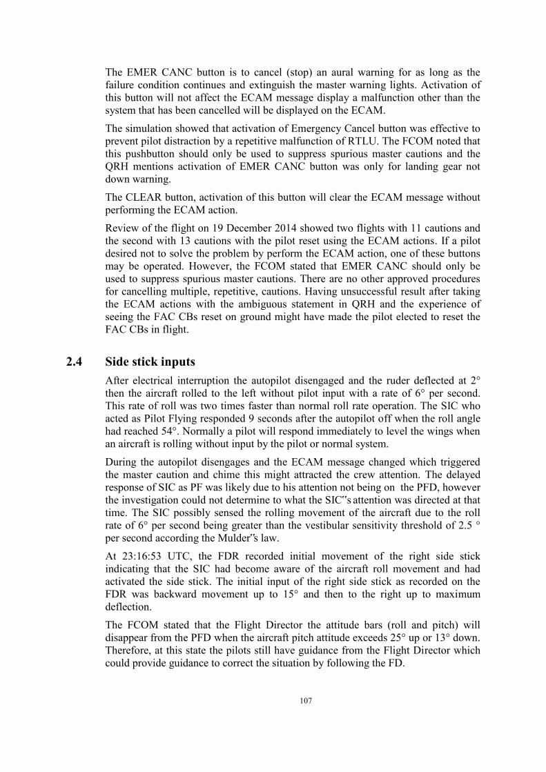
107
The EMER CANC button is to cancel (stop) an aural warning for as long as the failure condition continues and extinguish the master warning lights. Activation of this button will not affect the ECAM message display a malfunction other than the system that has been cancelled will be displayed on the ECAM.
The simulation showed that activation of Emergency Cancel button was effective to prevent pilot distraction by a repetitive malfunction of RTLU. The FCOM noted that this pushbutton should only be used to suppress spurious master cautions and the QRH mentions activation of EMER CANC button was only for landing gear not down warning.
The CLEAR button, activation of this button will clear the ECAM message without performing the ECAM action.
Review of the flight on 19 December 2014 showed two flights with 11 cautions and the second with 13 cautions with the pilot reset using the ECAM actions. If a pilot desired not to solve the problem by perform the ECAM action, one of these buttons may be operated. However, the FCOM stated that EMER CANC should only be used to suppress spurious master cautions. There are no other approved procedures for cancelling multiple, repetitive, cautions. Having unsuccessful result after taking the ECAM actions with the ambiguous statement in QRH and the experience of seeing the FAC CBs reset on ground might have made the pilot elected to reset the FAC CBs in flight.
2.4 Side stick inputs
After electrical interruption the autopilot disengaged and the ruder deflected at 2° then the aircraft rolled to the left without pilot input with a rate of 6° per second. This rate of roll was two times faster than normal roll rate operation. The SIC who acted as Pilot Flying responded 9 seconds after the autopilot off when the roll angle had reached 54°. Normally a pilot will respond immediately to level the wings when an aircraft is rolling without input by the pilot or normal system.
During the autopilot disengages and the ECAM message changed which triggered the master caution and chime this might attracted the crew attention. The delayed response of SIC as PF was likely due to his attention not being on the PFD, however the investigation could not determine to what the SIC‟s attention was directed at that time. The SIC possibly sensed the rolling movement of the aircraft due to the roll rate of 6° per second being greater than the vestibular sensitivity threshold of 2.5 ° per second according the Mulder‟s law.
At 23:16:53 UTC, the FDR recorded initial movement of the right side stick indicating that the SIC had become aware of the aircraft roll movement and had activated the side stick. The initial input of the right side stick as recorded on the FDR was backward movement up to 15° and then to the right up to maximum deflection.
The FCOM stated that the Flight Director the attitude bars (roll and pitch) will disappear from the PFD when the aircraft pitch attitude exceeds 25° up or 13° down. Therefore, at this state the pilots still have guidance from the Flight Director which could provide guidance to correct the situation by following the FD.

108
Observation on the FDR data during the straight and level flight with the A/P and A/THR engaged for existing aircraft weight and condition, the pitch attitude indicated almost steady at approximately 1.8° up. The initial SIC action on side stick input of up to 15.1° backward resulting in pitch attitude of 9° within 3 seconds (2316:55 UTC) was beyond the normal angle to regain the pre-set altitude 32,000 ft while the guidance from the Flight Director was still available.
The FDR recorded that the right side stick input was resulted to the aircraft roll to 9° to the left then to 53° to the left and the aircraft climbing. At this time, the FDR did not record any PIC side stick input in order to counter the situation.
The SIC might have been startled when he realized the unusual attitude of the aircraft, and this may have affected his reaction to the developing situation. At about the same time the CVR recorded the PIC said “oh my God”, expressing surprise. The startled reaction of the SIC may induce spontaneous or involuntary action and may degrade human performance17. The degraded human performance may impair the pilot‟s situational awareness, decision making and problem solving, and also decrease critical skills in the handling of a complex emergency.
The initial SIC reaction was to pull the stick backward (pitch up command) then to the right up to maximum deflection. The result of this action was that the aircraft rapidly rolled to the right from 54° left to 9° left bank within 2 seconds. This rapid right rolling movement might have caused an excessive roll sensation to the right. Moreover the rudder deflection of 2° which was not recognized by the SIC, the deflection would tend the aircraft roll to the left might add more handling difficulty to level off the aircraft.
The SIC may have experienced spatial disorientation and over-corrected by shifting the side stick to the left which caused the aircraft to roll back to the left up to 53°. The SIC then shifted the stick to the right side with slower rate. This slower roll rate did not create an over-correction sensation. The aircraft then rolled to 2.5º to the left and pitch 5° up and the aircraft continued to climb.
2.4.1 First Aural Stall warning Following the pitch up input on the right side stick, the aircraft continued climb then at 2316.56 the stall warning activated. The aural stall warning is designed to active when the aircraft reaches 8° AOA. This will provide sufficient margin to alert the flight crew in advance the actual of aerodynamic stall.
The operator manual (FCOM and QRH) stated that at this condition, the flight crew must apply the stall recovery procedure by lowering the nose to reduce AOA as soon as they recognized any stall indication either the stall warning or aircraft buffet. Stall recovery procedures have been trained for both pilots.
During the stall warning activated, the right side stick was at neutral then moved forward for two seconds. It caused the AOA decreased below 8°, and the aural stall warning stopped.
17 Human performance is the human capabilities both physical and psychological this include human
information processing, situational awareness, stress, fatigue, etc.

109
The pitch up input of the right side stick has made the aircraft AOA increase and activated the stall warning which ceased after pitch down action was performed
2.4.2 Second Aural Stall Warning One second after the first stall warning ceased, the right side stick command was at 12° backward causing the aircraft pitch up and climbing at a rate up to 11,000 feet/minute. The FDR did not record input of the PIC side stick.
The FDR recorded that after the first stall warning, the right side stick input was consistently back ward. This resulted in the aircraft continuously pitching up. The PIC commanded to the SIC “level...level”, which might refer to the previous condition of high roll angle. The stressful situation and instruction of the PIC likely made the SIC focus his attention to levelling the wings and less attention to the pitch input. The first left side stick input was at 2317:03 UTC for 2 seconds, then 15 seconds later another input for 2 seconds, and at 2317:29 continued in dual input until the end of the recording.
The sidestick priority logic, when one pilot operates the sidestick, it will send the control signals to the computers. When both pilots move both sidesticks simultaneously in the same or opposite direction and neither takes priority, the system adds the signals algebraically. When this occurred, the two green Side Stick Priority lights are ON and followed by “DUAL INPUT” voice message activation. If this occurred, the PF or depending on the PIC instruction, should stop provides input on the sidestick or a pilot should stop the „dual input‟ by pressing the priority pushbutton for 40 seconds or more to latch the priority condition. The FDR did not record neither pilots pressed such button for more than 40 seconds. The CVR did not record “DUAL INPUT” voice message as it was supressed by “STALL” voice warning.
The FDR recorded at 2317:15 UTC the aircraft pitch reached 24° up. The PIC commanded „pull down...pull down‟ and at 2317:17 UTC the FDR recorded second Stall Warning. Following the command „pull down...pull down‟ the FDR recorded the SIC side stick backward input increased. The aircraft pitch and AOA were increasing.
The average of the side stick inputs recorded on the FDR since the A/P and A/THR disengaged until the aircraft encountered the second stall warning indicated that the SIC was pulling almost full back input while the PIC was slightly pushing nose-down. The sum of both side stick inputs commanded nose up pitch.
The pitch up input resulted in the AOA reaching a maximum of 48° which was beyond the flight director envelope and the flight director would have been disappeared from the PFD. The pilot would no longer have guidance from the flight director.
The pilot training for stall was intended to introduce the indications of approach to stall condition and recover it. While the aircraft system designed to prevent the stall by providing early warning. The pilot training and the aircraft system were intended to avoid stall.

110
The condition of AOA 40° as recorded on the FDR was beyond any airline pilot training competency as they never been trained or experienced.
The degraded SIC performance and ambiguous command of the PIC may have decreased the SIC‟s situational awareness. Consequently, the SIC did not react appropriately in this complex emergency situation. This resulted in an aircraft upset from which recovery was beyond the procedures and philosophy of training that was provided to flight crew and the increasing difficulty of aircraft handling as the result of the rudder deflection which provided roll tendency.
2.5 Pilot recognition of stall Pilot training for stall in the flying school or during the training with the airlines normally is performed by conducting a level flight and then reduced the engine power, as the speed decreases the pilot increases the angle of attack in order to maintain the lift. When the aircraft reached the condition that may trigger the stall warning, the pilot then executes the recovery action. The aircraft may have not reached stall condition during the activation of the stall warning, which may give time to pilot to perform stall prevention action. This condition is known as approaching to stall. The purpose of this training is to introduce the symptom of initial stall condition and to avoid it by performing correct recovery action.
During the training, the pilot recognizes the stall or approaching stall condition occurs when the pitch (aircraft nose) is at up position.
Based on the aerodynamic principles stall occurs when the turbulence of the airflow above the wing occurs and the wing no longer produces adequate lift to counter aircraft weight. The main cause of stall is the angle of attack. The angle of attack is the angle between the airflow and the wing chord19. The action to recover from stall condition is by reducing the angle of attack which is normally performed by lowering the aircraft nose.
The FDR recorded: - At 23:16:56, after the first STALL WARNING and buffet, the SIC applies nose
down orders. The pitch stabilizes for 3 seconds. - At 23:17:17, after the STALL WARNING, and buffet, the SIC releases back
pressure or pitches down for 3 or 4 seconds. - From 23:17:16, the “pull down” calls repeated many times and at short intervals
followed by a majority of pitch up reactions of the PF (except at 23:17:17 after the second STALL WARNING).
- At 23:17:23 STALL WARNING and buffet become permanent. The SIC maintains a permanent pitch up order.
On this accident flight, the aircraft stall occurred when the aircraft climbed prior to reach the upset condition. While reaching the highest recorded altitude the aircraft was on upset condition with large bank angle, low speed and abnormal pitch attitude. The crew then focused on recovery of this condition.
19 Wing chord is the imaginary line between the leading edge and the trailing edge of the wing

111
The crew managed to recover the aircraft to level state (wing and pitch level), however the high AOA was still exist. The aircraft speed was below the aircraft stalling speed, engines were on cruise power, and the Vertical Speed Indicator (VSI) indicated the aircraft descent with the average rate of 12,000 feet per minute.
After this point, the FDR recorded that the aircraft pitch and roll were oscillating at relatively zero (level) position. The FDR did not record the signature of the pilot action to recover stall condition by lowering the nose (pitch down) as stated in the QRH Stall Recovery.
In normal condition, with the pitch and roll at close to 0°and both engines at cruise power will result in the aircraft at straight and level flight, not descending. Even if the aircraft is descending, at constant cruise power it will result in acceleration, enabling it to recover speed and lift. However, the indicated airspeed was constantly below the aircraft stall speed, the aircraft continued to lose altitude and the stall warning persisted to activate. This condition is obviously contradicting to what the pilot might have expected, which might have made the pilot failing to identify the stall condition as the pilot might have not had experience of stall at such aircraft attitude. The condition of stall at relatively zero pitch was not a standard on pilot training as the training for stall is performed on high pitch attitude. The Angle of Attack (AOA) which at a later stage was reaching 40° up was not indicated in the cockpit. The pilot might have not recognized the high AOA despite the stall warning and the buffet.
The pilot training was exercise to approach to stall which means that the aircraft has not entered stall condition. The condition of stall on this accident flight might have not been recognized by the pilot.
The CVR recorded that the Captain commanded to select air data to „CAPT3‟. This action would result in the transfer of the air data source from ADIRU1 to ADIRU3. The captain might have assumed that air data error had triggered the rapidly fluctuating airspeed indication of the PFD as recorded in the FDR.
The aircraft flight condition that is contrary to the normally expected condition and the pilots having not been introduce to stall condition might have made the pilot failing to identify the stall and did not initiate recovery action.
Some articles related to stall describes that aircraft attitude has no relation to the aerodynamic stall. Even if the airplane is in descent with what appears like ample airspeed, the wing surface can be stalled. If the angle of attack is greater than the stall angle, the surface will stall. Stall is an AOA problem only. It is NOT directly a speed issue. The first respond to stall prevention and recovery is to reduce AOA by performing a nose down pitch.
The AOA decrease may be obtained indirectly by increasing the speed, but adding thrust in order to increase the speed leads to an initial adverse longitudinal effect, which trends to increase further the AOA. It is important to know that if such a thrust increase was applied when the aircraft is already stalled, the longitudinal effect would bring the aircraft further into the stall, to a situation possibly unrecoverable. Conversely, the first effect of reducing the thrust is to reduce the AOA (Airbus, 2011)

112
The Upset Recovery training was included in the aircraft operators training manual. The aircraft operator advised the KNKT that the flight crew had not been trained for the upset recovery training on Airbus A320, and this referred to FCTM Operational Philosophy: “The effectiveness of fly-by-wire architecture, and the existence of control laws, eliminates the need for upset recovery maneuvers to be trained on protected Airbus”. There was no evidence of DGCA findings for this incompliance of training.
2.6 Crew Resource Management The CASR part 121.406 stated the requirement subjects for the Initial and Recurrent training. The flight crew records showed that both pilots had performed the initial and recurrent CRM training. The simulator recurrent and proficiency check also assess the CRM.
The flight crew CRM assessment records during Proficiency checks showed that the PIC was graded standard. The SIC had remarks in situational awareness, workload management and communication which were later corrected and graded as Satisfactory with Briefing.
This chapter of this analysis will discuss on the coordination between the pilots which refer to the Crew Resources Management (CRM). The analysis will focus on communication, coordination and leadership.
Communication and coordination Resetting the FAC CB caused the autopilot and auto-thrust to disengage and flight control to revert to Alternate Law. The 6th master caution illuminated followed by the AUTO FLT FAC 1+2 FAULT ECAM message.
The FAC CB was not in the list of CB that were approved to be reset in flight and required for the pilot to understand the consequences. Following the CB reset, the ECAM displayed several messages that required pilot action. The consequences of resetting the FAC CB such as disengagement of the autopilot or flight control law reverted to Alternate Law might have not been anticipated by the pilots.
The consequences of resetting the CB should have been discussed by the crew to consider the risks and action plan by referring to Crew Coordination during Emergencies or Abnormalities (COM Chapter 4.10.1.7). The crew coordination includes the PF responsibility for handling the flight and PM for checklist reading and execution of required actions on PF request.
The recorder showed that the FAC 1 CB was reset 54 seconds after the activation of the 4th master caution. During this period communication between the SIC and PIC recorded on the CVR was unintelligible. Assuming that during these 54 seconds both pilots discussed the plan and consequences of resetting the FAC CB, the time available would not have been sufficient. The discussion should have included a review of the CB‟s allowed to be reset in flight in the TDU and OEB table. The evidence of the SIC delayed action when the autopilot disengaged indicated that the SIC did not anticipate the autopilot disengagement.
The unanticipated condition might have made both pilots focus on correcting the
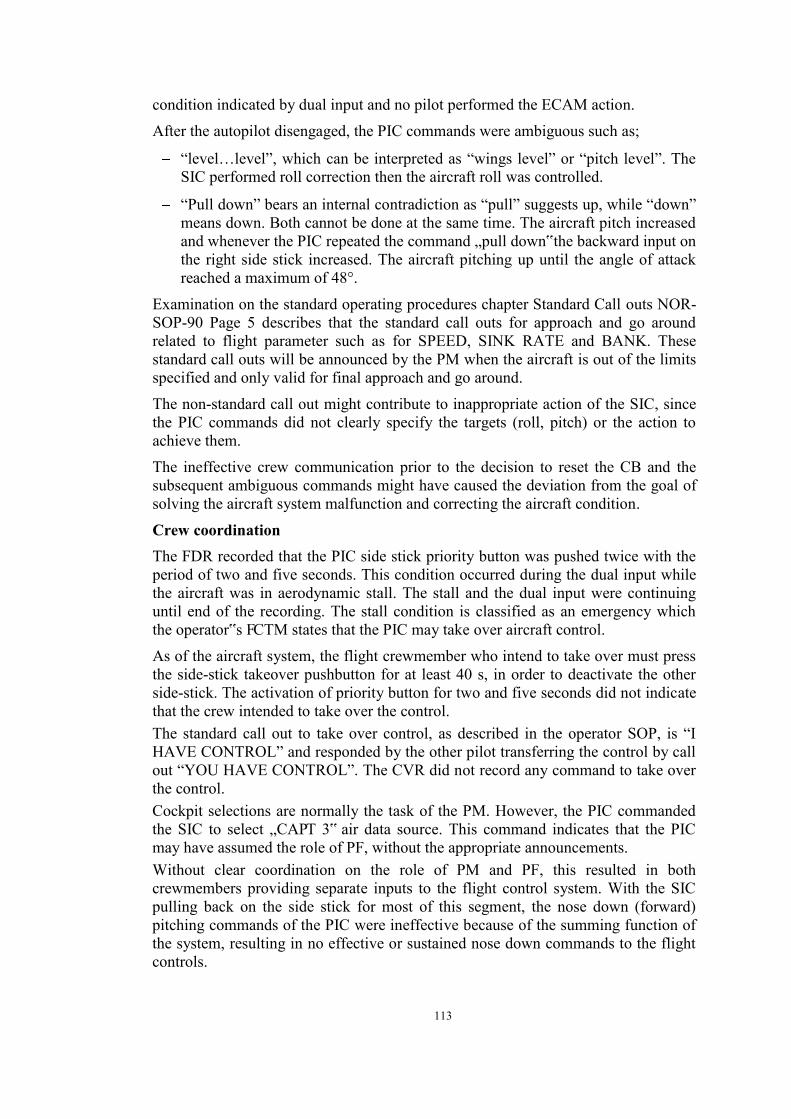
113
condition indicated by dual input and no pilot performed the ECAM action.
After the autopilot disengaged, the PIC commands were ambiguous such as;
“level…level”, which can be interpreted as “wings level” or “pitch level”. The SIC performed roll correction then the aircraft roll was controlled.
“Pull down” bears an internal contradiction as “pull” suggests up, while “down” means down. Both cannot be done at the same time. The aircraft pitch increased and whenever the PIC repeated the command „pull down‟ the backward input on the right side stick increased. The aircraft pitching up until the angle of attack reached a maximum of 48°.
Examination on the standard operating procedures chapter Standard Call outs NOR-SOP-90 Page 5 describes that the standard call outs for approach and go around related to flight parameter such as for SPEED, SINK RATE and BANK. These standard call outs will be announced by the PM when the aircraft is out of the limits specified and only valid for final approach and go around.
The non-standard call out might contribute to inappropriate action of the SIC, since the PIC commands did not clearly specify the targets (roll, pitch) or the action to achieve them.
The ineffective crew communication prior to the decision to reset the CB and the subsequent ambiguous commands might have caused the deviation from the goal of solving the aircraft system malfunction and correcting the aircraft condition.
Crew coordination The FDR recorded that the PIC side stick priority button was pushed twice with the period of two and five seconds. This condition occurred during the dual input while the aircraft was in aerodynamic stall. The stall and the dual input were continuing until end of the recording. The stall condition is classified as an emergency which the operator‟s FCTM states that the PIC may take over aircraft control.
As of the aircraft system, the flight crewmember who intend to take over must press the side-stick takeover pushbutton for at least 40 s, in order to deactivate the other side-stick. The activation of priority button for two and five seconds did not indicate that the crew intended to take over the control. The standard call out to take over control, as described in the operator SOP, is “I HAVE CONTROL” and responded by the other pilot transferring the control by call out “YOU HAVE CONTROL”. The CVR did not record any command to take over the control. Cockpit selections are normally the task of the PM. However, the PIC commanded the SIC to select „CAPT 3‟ air data source. This command indicates that the PIC may have assumed the role of PF, without the appropriate announcements. Without clear coordination on the role of PM and PF, this resulted in both crewmembers providing separate inputs to the flight control system. With the SIC pulling back on the side stick for most of this segment, the nose down (forward) pitching commands of the PIC were ineffective because of the summing function of the system, resulting in no effective or sustained nose down commands to the flight controls.

114
As of CRM perspective, the investigation concludes that there was ineffective communications and absence of coordination both prior to and during the flight encountering the upset. Such particular conditions contributed to the missing of tasks priority to achieve when in the critical and limited time. The condition continued and created more pilot workload.
2.7 Maintenance handling on aircraft system problem The factual information revealed that during the flight, four times activation of master caution initiated from the unresolved RTLU problem. Therefore the investigation divided the analysis in two areas which focus on Line Maintenance and Maintenance Organization.
2.7.1 The Line Maintenance The aircraft daily maintenance activity is performed by line maintenance personnel who are responsible to maintain the aircraft serviceability. When aircraft problem cannot be resolved by line maintenance personnel, the rectification will handle with special method by another department.
The aircraft maintenance handling rely on the manufacture manual including in the execution of the rectification action to any defect either reported by the flight crew or maintenance personnel.
The Airbus A320 equipped with the Centralized Fault Display System (CFDS) that provide information of current or historical problem arises during the operational of the aircraft. The maintenance personnel can access the data through the display system or printed Post Flight Report (PFR).
Airbus also provides the maintenance personnel with the Trouble Shooting Manual (TSM) which contain information to troubleshoot the effected system stated in the PFR and identified the suspected defective part.
The Airbus TSM stated that PFR is the main source of information use to initiate trouble-shooting and to decide on the required maintenance action.
The PFR Failure Messages between 27 November until 27 December 2014 were dominated by the Failure Messages of “AFS: FAC1/RTL ACTR 4CC” or "FAC2/RTL ACTR 4CC”. For these PFR Failure Messages, the TSM stated that two tasks are applicable:
- Task 22-61-00-810-803-A Loss of the Rudder Limiting Function on the FAC1.
- Task 22-61-00-810-804-A Loss of the Rudder Limiting Function on the FAC2.
These two tasks require replacement of the electronic module of the RTLU if problem persists. Apparently the replacement was never considered because at every occurrence the maintenance action taken by performing the BITE test was passed with satisfactory result. The BITE test was according to the TSM 22-61-00-810-803-A point 1, therefore, further step of the TSM was considered not necessary. The maintenance actions related to the PFR were not inserted to MR1, therefore any recurring problem was not considered as repetitive problem.

115
During the interview, the management IAA stated that the company policy is referring to the pilot report or Maintenance Report 1 (MR1) as the main source of the defect handling and the maintenance action performed must be recorded in the Technical Log.
The ICAO Annex 6 stated that one of the duties of pilot in command is to report all known or suspected defects in the aircraft after completion of the flight. This requirement had not been implemented in the Indonesian CASRs. In fact, not all pilot reported the defect occurs during flight.
If a defect is reported by the flight crew via an MR1 entry in the technical log book, the line maintenance personnel will check and verify the PFR in order to confirm the defect. From the PFR the relevant chapter on the TSM can be identified and relevant maintenance action taken to rectify the defect. If the PFR is not available due to a CFDS or PFR printer failure, then the relevant troubleshooting procedures can also be found in the TSM. There was no requirement for the Line Maintenance Personnel to record on the technical log for rectification based on PFR.
The technical log contains maintenance action based on MR1. Maintenance action without MR1 reference was not recorded on the technical log. This condition might result in line maintenance personnel not aware that the problem has been arose several time and the maintenance action taken by previous line maintenance personnel. This condition might also result in unrecorded several problems as repetitive defects that was reported on the PFR but not reported on MR1.
MR1 record on 21 December to 27 December 2014 found 2 pilot reports related to RTLU while the FDR recorded at least 9 problems appeared on the PFR.
Based on PK-AXC 1 Year report, 23 occurrences related with the RTLU problem were recorded since January 2014. The line maintenance personnel performed similar action by resetting the FAC and doing the AFS Operational test which resulted satisfactory and the problem was considered close. Any repeating defect was treated as a new defect.
Refer to the CMM chapter 5.3 Defect & Repetitive Defect stated : A defect is deemed to be repetitive when it has been reported more than once in 7 flight sectors or 3 days where 3 rectification attempts have not positively cleared the defects. Evaluation of MR1 data December 2014 found 10 pilot reports related to RTLU occurred on 1, 12, 14, 19, 21, 24, 25 (two cases), 26 and 27 December 2014. On 19 December 2014, the repetitive RTLU problem was inserted to MR2.
Repetitions of the problem were not classified as repetitive problem as the rectification by AFS test were resulted satisfactory and the problems were considered solved. Actually the rectification by AFS test did not completely solve the problem.
The RTL trouble was inserted to the MR2 on 19 December 2014 and was closed at the same day after completion of the flight. The rectification was performed by resetting the FAC and doing the AFS Operational test. The result of the AFS test was satisfactory and the MR2 was closed.

116
The MR1 showed that on 23 December 2014, there was an entry report to update the aircraft document while the PFR data recorded 4 RTLU problems, which was not reported in the MR1. Since there was no requirement for the Line Maintenance Personnel to record on the technical log for rectification based on PFR therefore, the RTLU problems were not recorded on the technical log.
The company did not clearly state the policy of recording defect handling captured by the CFDS system or printed PFR and mainly based on MR1. It resulted in the line maintenance personnel did not aware of similar problem and repeat similar maintenance action, and also the problem was not recorded as a repetitive problem. None of the issues reported was identified as meeting the repetitive defect definition which would have triggered maintenance actions under the CMM requirements.
2.7.2 The Maintenance Organization The IAA maintenance organization utilizes an integrated system Aircraft Maintenance and Operation System (AMOS) for the maintenance management including defect management and repetitive problem. The AMOS collects the information from MR1, Cabin Maintenance and Scheduled Inspection. The line maintenance personnel are responsible to enter the defect report recorded in the MR1 into the AMOS including the rectification action taken. The licensed aircraft maintenance engineer is responsible to enter the problem to MR2 when it meets the criteria. The Line Maintenance is managed by Maintenance Operation Manager (MOM). MOM responsibility includes to monitor the rectification of the problem and the preparation of the spare part if required, utilizing the AMOS data. The analysis of the defect for the purpose of Reliability Monitoring is controlled by Planning & Technical Service Manager (PTM) using data from AMOS. The summary and analysis of the problem or repetitive problem recorded in the MR1 will be reported in the monthly Reliability Report. The Reliability Report of November 2014 for PK-AXC contained information of the RTL 1 problem that was occurred 4 times and were considered closed and noted “No further action required”. Meanwhile the „PK-AXC 1 Year Report‟ recorded 3 problems of RTL 1, 1 problem of RTL 2 and 1 problem of RTL SYS in the same period. The AMOS does not utilize PFR data. The unclear policy of inserting maintenance action into the MR1 for the rectification following PFR message resulted in not all PFR data are recorded. The analysis of the Reliability Report without optimizing PFR data resulted in un-comprehensive conclusion and led to the unresolved of repetitive occurrences. The Airbus Troubleshooting Manual (TSM) stated that the PFR is the main source of information used to initiate trouble shooting and to decide on the required maintenance actions. The operator maintenance system only recorded partial report of PFR data including the associated maintenance action, resulted in inadequate data to identify and analyse the defects. Thereafter it resulted in a missed opportunity to identify and rectify a series of recurring RTLU faults.

117
3 CONCLUSION
3.1 Findings These findings should not be read as apportioning blame or liability to any organization or individual. The KNKT determines that the findings of this investigation are listed as follows:
Operation 1. The aircraft was airworthy prior to the occurrence and was operated within the
weight and balance envelope. 2. The crew held valid licenses and medical certificates. The PIC last proficiency
check was on 18 November 2014 and the SIC was on 19 November 2014, both were assessed as satisfactory.
3. In this flight, the Second in Command acted as Pilot Flying (PF) and the Pilot in Command (PIC) acted as Pilot Monitoring (PM).
4. The aircraft took off from Surabaya at 2235 UTC and cruised at flight level 320 with intended destination of Singapore via airways M635.
5. The weather on route of M635 partially covered by the Cumulonimbus clouds formation between 12,000 feet up 44,000 feet. The FDR data indicated that the flight was not affected by the weather condition and investigation concludes that the weather was not factor to the accident.
6. When the aircraft was cruising, there were three master caution activations associated with Rudder Travel Limiter Units (RTLU) and the amber ECAM messages “AUTO FLT RUD TRV LIM SYS” between 2301 and 2313:41 and the pilots performed the ECAM actions and the system returned to function normally.
7. At 2315:36 UTC, the fourth master caution and triggered ECAM message “AUTO FLT RUD TRV LIM SYS”, the recorder did not record any ECAM actions.
8. At 2316 UTC, the Jakarta Radar controller issued a clearance to the pilot to climb to FL 340 but was not replied to by the pilot.
9. At 2316:27 UTC, the fifth Master Caution illuminated which was triggered by FAC 1 FAULT followed by FDR signature of alteration of parameters of components controlled by FAC 1 such as RTLU 1, Windshear Detection 1 and Rudder Travel Limiter Actuator 1. Twelve seconds later, the FAC 1 parameter back to ON and all fluctuating parameters stopped.
10. At 2316:44 UTC, the sixth Master Caution triggered by AUTO FLT FAC 1 + 2 FAULT and followed by FDR signature of alteration of parameters of components controlled by FAC 2. The Auto Pilot (A/P) and the Auto-thrust (A/THR) disengaged, and the Flight control law reverted from Normal Law to Alternate Law. The rudder deflected 2° to the left.
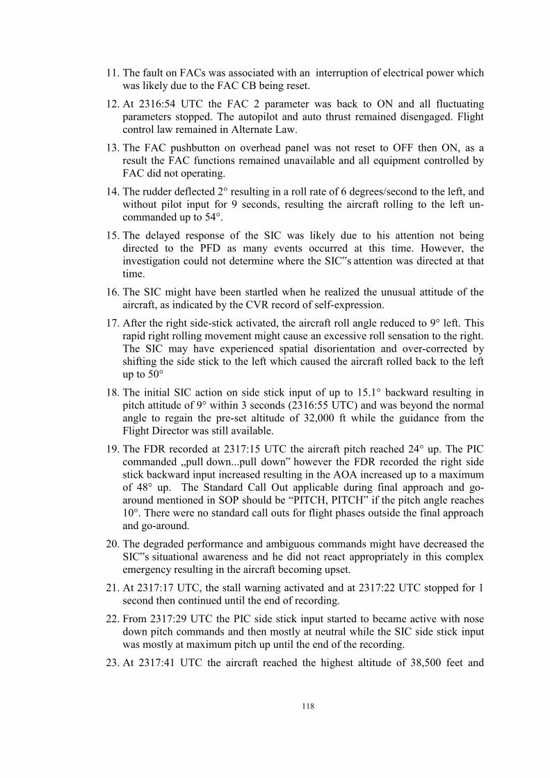
118
11. The fault on FACs was associated with an interruption of electrical power which was likely due to the FAC CB being reset.
12. At 2316:54 UTC the FAC 2 parameter was back to ON and all fluctuating parameters stopped. The autopilot and auto thrust remained disengaged. Flight control law remained in Alternate Law.
13. The FAC pushbutton on overhead panel was not reset to OFF then ON, as a result the FAC functions remained unavailable and all equipment controlled by FAC did not operating.
14. The rudder deflected 2° resulting in a roll rate of 6 degrees/second to the left, and without pilot input for 9 seconds, resulting the aircraft rolling to the left un-commanded up to 54°.
15. The delayed response of the SIC was likely due to his attention not being directed to the PFD as many events occurred at this time. However, the investigation could not determine where the SIC‟s attention was directed at that time.
16. The SIC might have been startled when he realized the unusual attitude of the aircraft, as indicated by the CVR record of self-expression.
17. After the right side-stick activated, the aircraft roll angle reduced to 9° left. This rapid right rolling movement might cause an excessive roll sensation to the right. The SIC may have experienced spatial disorientation and over-corrected by shifting the side stick to the left which caused the aircraft rolled back to the left up to 50°
18. The initial SIC action on side stick input of up to 15.1° backward resulting in pitch attitude of 9° within 3 seconds (2316:55 UTC) and was beyond the normal angle to regain the pre-set altitude of 32,000 ft while the guidance from the Flight Director was still available.
19. The FDR recorded at 2317:15 UTC the aircraft pitch reached 24° up. The PIC commanded „pull down...pull down‟ however the FDR recorded the right side stick backward input increased resulting in the AOA increased up to a maximum of 48° up. The Standard Call Out applicable during final approach and go-around mentioned in SOP should be “PITCH, PITCH” if the pitch angle reaches 10°. There were no standard call outs for flight phases outside the final approach and go-around.
20. The degraded performance and ambiguous commands might have decreased the SIC‟s situational awareness and he did not react appropriately in this complex emergency resulting in the aircraft becoming upset.
21. At 2317:17 UTC, the stall warning activated and at 2317:22 UTC stopped for 1 second then continued until the end of recording.
22. From 2317:29 UTC the PIC side stick input started to became active with nose down pitch commands and then mostly at neutral while the SIC side stick input was mostly at maximum pitch up until the end of the recording.
23. At 2317:41 UTC the aircraft reached the highest altitude of 38,500 feet and
119
largest roll angle of 104° to the left. The aircraft then lost altitude with a rate of up to 20,000 feet per minute.
24. At 2318 UTC, the aircraft disappeared from the Jakarta Radar controller screen at the coordinates of 3°36‟48.36”S - 109°41‟50.47”E.
25. The last data recorded by the FDR were at 2320:35 UTC with the airspeed of 83 kts, pitch 20° up, AOA 50°, roll 8° to left, with the rate of descend of 8,400 ft/minute at a radio altitude of 187 feet.
26. After the A/P disengaged, there was no communication between pilot and ATC until the end of recording.
27. The recorded FDR parameter fluctuations were similar to those recorded on 25 December 2014 when the aircraft had a RTLU problem on the ground and the CBs were reset.
28. The experience of the PIC witnessing problem solving by resetting the FAC CBs on 25 December 2014 might have influenced the PIC to adopt the same procedure when confronted with the same problem.
29. The FAC1 CBs were located on the overhead panel, while the FAC2 CBs were behind the right pilot seat. To be able to pull or push the FAC2 CBs, a pilot has to leave the control seat.
30. Observation on the Airbus A320 QRH, in the chapter „Computer Reset‟ it is stated that: In flight, as a general rule, the crew must restrict computer resets to those listed in the table. Before taking any action on other computers, the flight crew must consider and fully understand the consequences. This statement was potentially ambiguous to the readers and might be open for multiple interpretations.
31. Prior to the decision to reset FAC CBs the CVR recorded unintelligible discussion.
32. The flight crew had not received the operator upset recovery training on Airbus A320 as it was not required according to the Airbus FCTM.
33. The stall warning is designed to activate at 8° AOA and known as approaching to stall and this will provide sufficient margin to alert the flight crew and take the correct action prior to the actual aerodynamic stall which will occurs well beyond the AOA of stall warning. The aircraft system and the pilot training were intended to avoid stall.
34. The pilots were trained and had experience of recover from the approaching stall. The condition of stall at zero pitch had never been trained as the training for stall was always with a high pitch attitude.
35. The stall condition is classified as an emergency which required the PIC to take over control. The CVR did not record any command by the PIC that they were taking over control of the aircraft using the standard call out. The standard call out to take over control described in the operator SOP, is “I HAVE CONTROL” and responded by the other pilot transferring the control by call out “YOU HAVE CONTROL” or by activating the priority button for 40 seconds.
120
36. The approved Operation Training Manual for flight crew, Chapter 8: described the Special Training, sub-chapter 8.11 the upset recovery. The upset training has not been implemented on Airbus A320 as described in this manual.
37. The FCTM stated that the effectiveness of fly-by-wire architecture and the existence of control laws eliminate the need for upset recovery manoeuvres to be trained on protected Airbus.
38. Since 2317:29 UTC, both left and right side stick input were continuously active until the end of the recording. The input were different where the right sidestick was pulled for most of this segment, the nose down (forward) pitching commands of the left sidestick became ineffective because of the summing function of the system, resulting in ineffective control the aircraft
39. There was no approved means for flight crews to handle multiple or repeated Master Caution alarms in order to reduce distraction.
40. ICAO Annex 6 stated that one of the duties of pilot in command is to report all known or suspected defects in the aircraft after completion of the flight. This requirement has not been included on the current Indonesia Civil Aviation Safety Regulation (CASR).
Maintenance 41. The maintenance records showed that there were 23 Rudder Travel Limiter
problems starting from January 2014 to 27 December 2014.
42. The Reliability Report November 2014 recorded 4 pilot reports regarding the RTLU problem.
43. On 19 December 2014, the repetitive RTLU problem was inserted to MR2. After completing the scheduled flight, the maintenance personnel performed Auto Flight System (AFS) and the MR2 was considered closed.
44. On 21 December to 27 December 2014, the MR1 recorded 2 pilot reports on 25 December 2014 and on 27 December 2014 related to RTLU while the FDR recorded at least 9 problems.
45. The operator maintenance management utilized AMOS to manage maintenance activities. The data was uploaded by the maintenance personnel in all line maintenance stations. The information is collected from MR1, Cabin Maintenance and Scheduled Inspection.
46. Maintenance data analysis related to RTLU problem was inadequate because it was only based on the MR1 which are available in the AMOS, while other information such as from the PFR was not utilized.
47. The existing maintenance data analysis led to unresolved repetitive faults occurring with shorter intervals.
48. Evaluation of the maintenance data showed that the maintenance action following the RTLU problems were mostly by resetting computer by either resetting the FAC push button and followed by AFS test or resetting the associated CBs.

121
49. The examination of the RTLU found electronic module shown the evidence of cracking of solder on both channel A and channel B. The crack could generate loss of electrical continuity and led to RTLU failure.
50. The company policy stated that maintenance personnel shall enter to the MR1 after the performance of rectification based on pilot report while for the rectification initiated by the PFR was not clearly stated. While the Airbus Trouble Shooting Manual stated that PFR is the main source of information used to initiate trouble shooting and to decide on the required maintenance actions.
51. The CMM chapter 5.3 Defect & Repetitive Defect stated: A defect is deemed to be repetitive when it has been reported more than once in 7 flight sectors or 3 days where 3 rectification attempts have not positively cleared the defects.
52. The company policy did not clearly state to record the PFR. This resulted in the line maintenance stations not being aware of occurrence of similar problems. The line maintenance stations might repeat similar actions. None of the issues reported was identified as meeting the repetitive defect definition which would have triggered maintenance actions under the CMM requirements.
53. The available maintenance data record and analysis unable to identify repetitive defects and analyse their consequences.
Other findings 54. The DGCA audit process did not identify that the operator had not performed
upset recovery training. Also, the audit process did not identify the inadequate maintenance processes relating to recurring faults.
55. The Indonesian CASR did not regulate the requirement for the pilot in command to report all known or suspected defects, as specified by ICAO Annex 6.
3.2 Contributing factors20 The cracking of a solder joint of both channel A and B resulted in loss of
electrical continuity and led to RTLU failure.
The existing maintenance data analysis led to unresolved repetitive faults occurring with shorter intervals. The same fault occurred 4 times during the flight.
The flight crew action to the first 3 faults in accordance with the ECAM messages. Following the fourth fault, the FDR recorded different signatures that were similar to the FAC CB‟s being reset resulting in electrical interruption to the FAC‟s.
20“Contributing Factors” are those events in which alone, or in combination with others, resulted in injury or damage. This
can be an act, omission, conditions, or circumstances if eliminated or avoided would have prevented the occurrence or would have mitigated the resulting injuries or damages.

122
The electrical interruption to the FAC caused the autopilot to disengage and the flight control logic to change from Normal Law to Alternate Law, the rudder deflecting 2° to the left resulting the aircraft rolling up to 54° angle of bank.
Subsequent flight crew action leading to inability to control the aircraft in the Alternate Law resulted in the aircraft departing from the normal flight envelope and entering prolonged stall condition that was beyond the capability of the flight crew to recover.

123
4 SAFETY ACTION
4.1 Aircraft operator As a result of this accident, the aircraft operator informed the KNKT of safety actions that they had taken.
At meetings between the aircraft operator and the KNKT, the operator advised that the safety actions had been generated from the preliminary recommendations that were published by the KNKT in the Preliminary Report.
In general, the safety actions covered several improvement plans for the flight operation relating to upset training, Safety Management System (SMS) and Crew Resource Management (CRM). Moreover, the operator had also provided several safety improvements for the maintenance aspects related to repetitive problems, Post Flight Report (PFR) as well the Trouble Shooting Manual (TSM).
The detail of the Safety Actions is attached in the Appendix 6.1 of this report. The summary of the Safety Actions is as follow:
1. 22 safety actions addressed the safety sensitive personnel and Aviation Security on the compliance to Standard Operating Procedures (SOP); integration enhancement for the Safety Management System implementation; Safety & Security Promotions through safety and security circulars and Flight Data Analysis statistic review; Human Factors development focusing on the communication enhancement and evidence Based CRM Training; Critical Incident Stress Management (CISM) training and campaign; Internal surveillance to the SOP compliance for pilots, flight attendants and Flight Operations Officers (FOO).
2. 11 safety actions on maintenance area addressed to all engineers at all stations especially on repetitive faulty report raised by the pilots when the engineers perform “Bite-Test” to the system computer; Bite test procedure review, and creation of a dedicated folder in server to save the printed copies of BITE Test and PFR; updating the flowchart procedures for repetitive defect handling and monitoring, AIRMAN system activation, assign aircraft custodian to monitor aircraft defect, and enhance engineer/technician skill and knowledge; optimum usage of IPC; optimum usage of AMM Task reference; Engineering and Maintenance Department planning on usage of Mobile devices such as iPad / Tablet devices, as a mobile Library which contain latest revision of AMM, IPC, TSM and SRM for every line maintenance stations for efficiency of handling during transit or maintenance activities; Requirement of Trouble Shooting Training for all certifying staff.
3. 18 safety actions on flight operations to address an enhancement program regarding significant weather phenomena through enhanced training for FOO, proactive action to visit BMKG office and establish cooperation and collaboration with BMKG, participate on the regional forum on meteorological services for aviation safety in South-east Asia, training on enhancement of weather radar usage for IAA pilots; Optimum flight plan weather data, and

124
include the aircraft defect performance penalties on flight planning stage; Review the SOP on pilot recruitment processes, including the Psychological/profiling test as part of pilot recruitment, review on the standard training timeframe and syllabus; review on the jet transition syllabus to fill any gap or lack of knowledge to operate Airbus A320, Upset Recovery and stall Recovery training, high altitude flying review, manual flying handling, Threat and error management, LOFT PPC and annual line check policy, Circuit Breaker policy; recording aircraft defect policy, Review on the A320 MEL update process, and Navigation: ISIS and Standby Compass should not be degraded during dispatch.

125
5 SAFETY RECOMMENDATIONS While the KNKT acknowledges the safety actions taken by the aircraft operator, there still remain safety issues that need to be considered. The KNKT issues the following Safety Recommendations addressed to:
5.1 Aircraft Operator 1. The KNKT recommends that Indonesia AirAsia to re-emphasize the importance
of the Standard Call-Outs in all phases of flight.
2. The KNKT recommends that Indonesia AirAsia to re-emphasize the taking over control procedure in various critical situations of flight.
5.2 Directorate General Civil Aviation 1. The KNKT recommends that the Directorate General Civil Aviation to ensure
the implementation of air operators‟ training of flight crew is in accordance with the approved operations manual.
2. The KNKT recommends that the Directorate General Civil Aviation to ensure that air operators under CASR 121 conduct simulator upset recovery training in timely manner.
3. The KNKT recommends that the Directorate General Civil Aviation ensures that air operator maintenance system has the ability to detect and address all repetitive faults appropriately.
4. The KNKT recommends the Directorate General Civil Aviation ensures the Indonesian Civil Aviation Safety Regulations to regulate the duties of the pilot in command as specified by ICAO Annex 6.
5.3 Aircraft Manufacturer 1. The KNKT recommends that Airbus to consider in developing a means for
flight crews to effectively manage multiple and repetitive Master Caution alarms to reduce distraction.
2. The KNKT recommends that Airbus to consider and review the FCTM concerning the Standard Call-Outs in all phases of flight.
5.4 United States Federal Aviation Administration and European Aviation Safety Agency 1. The KNKT supports the previous French BEA recommendation
(Recommendation FRAN-2015-024) on ensuring that future programs to include initial and recurrent training relating to taking over control of aircraft equipped with non-coupled control stick.
2. The KNKT recommend expediting the implementation of mandatory for upset recovery training earlier than 2019.

126
6 APPENDICES
6.1 Air Operator Safety Action

127

128

129

130

131
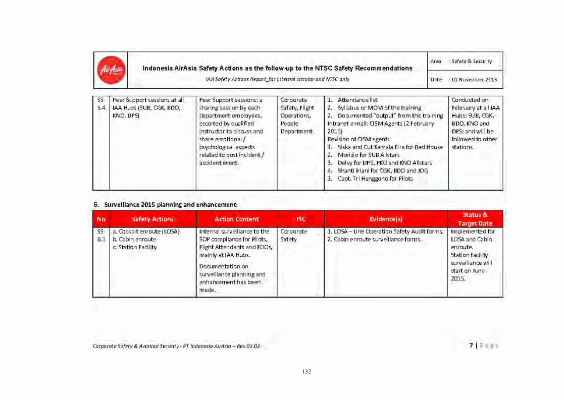
132

133
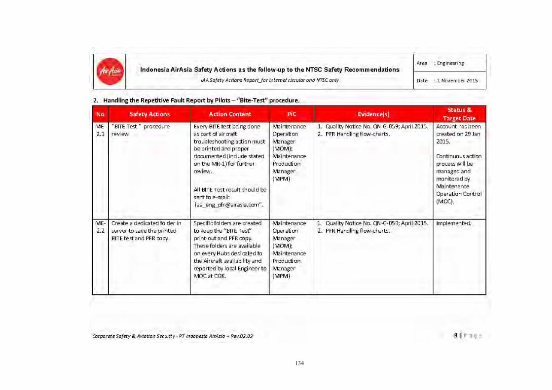
134

135

136

137

138

139
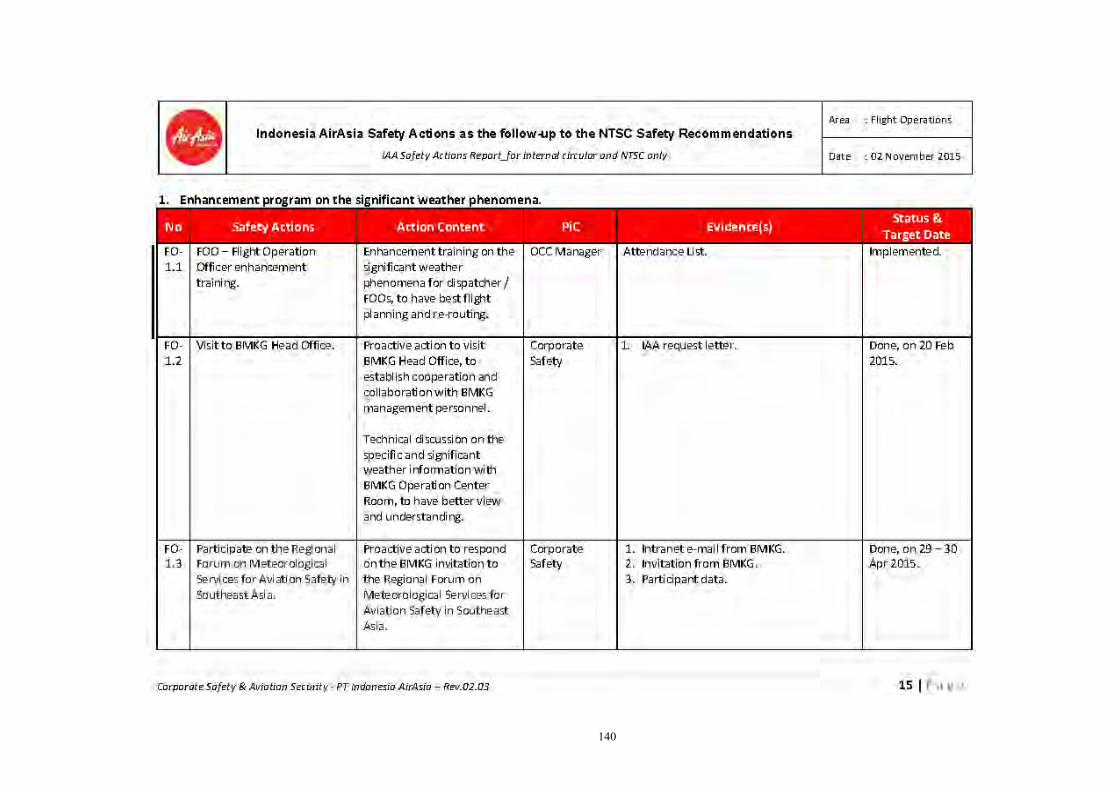
140

141

142

143
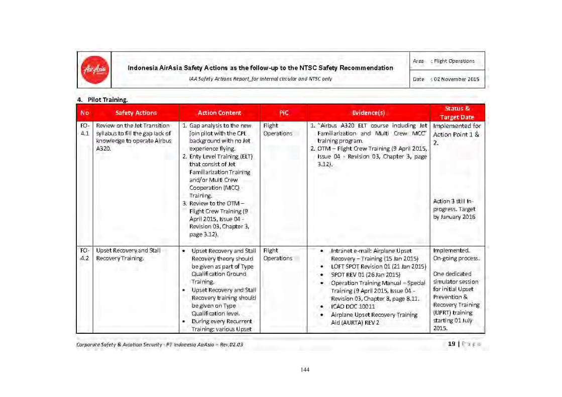
144
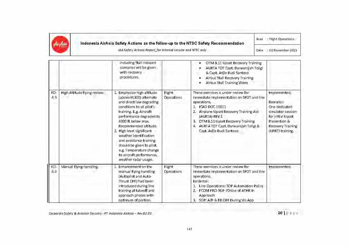
145

146
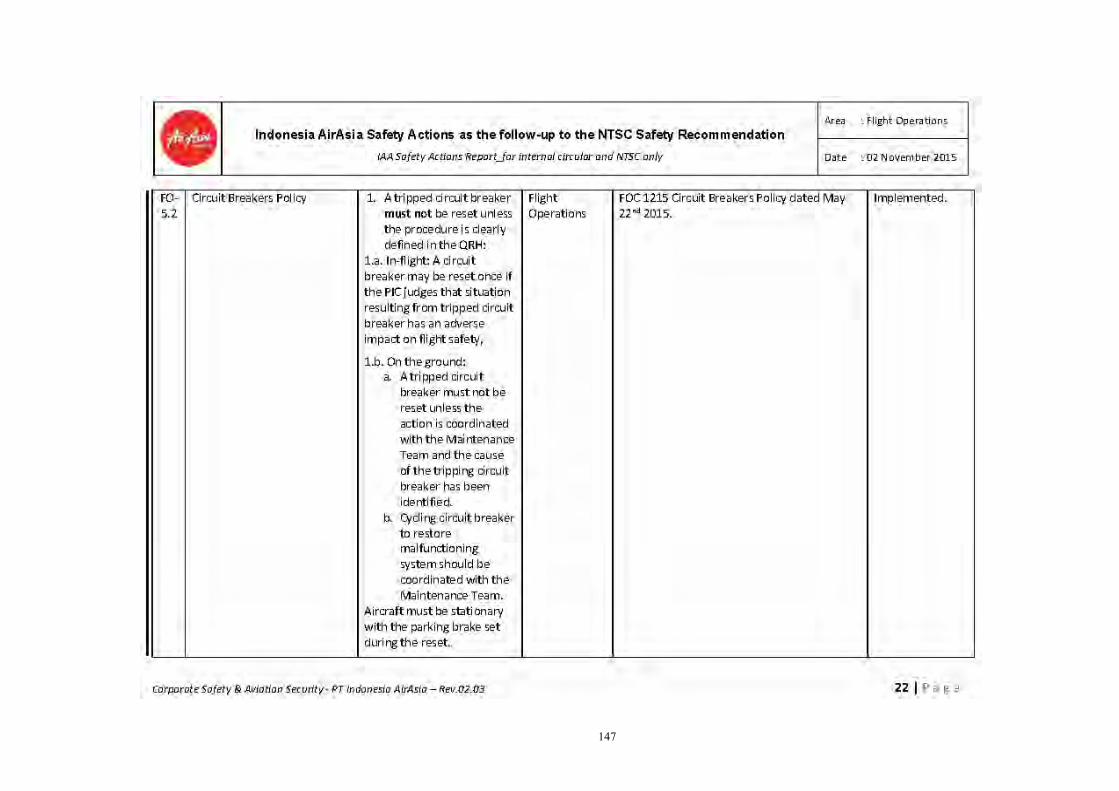
147

148
149

150
6.2 Operation Training Manual: upset recovery training
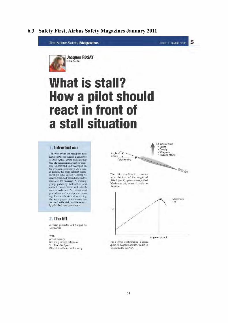
151
6.3 Safety First, Airbus Safety Magazines January 2011

152
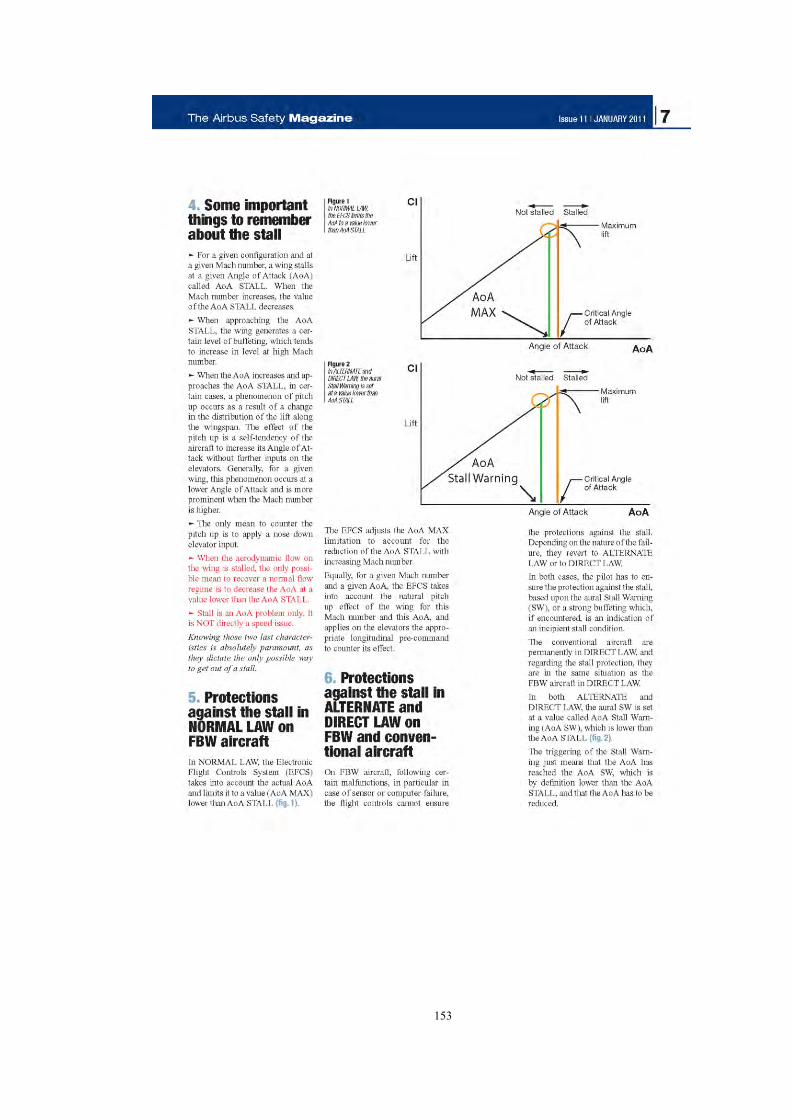
153

154

155

156

157
6.4 Upset Recovery Industry Team

158
6.5 Airbus Upset Recovery Training

159

160

161
6.6 Airbus A320 Type Qualification Training-Handling Phase FFS 4

162

163

164

165

166
6.7 Summary of “PK-AXC Defect 1 Year” Report
The last one year maintenance recorded related to the RTLU problems are shown in the table below;
No DATE PILOT REPORT OR PFR RECTIFICATION TSM/AMM
REFERENCE
1 10 Jan 2014
AUTO FLIGHT: RUDER TRV LIMITER 1 (ECAM)
BITE test of AFS result satisfactory check ECAM messages disappear as per AMM 22-96-00-710-001
AMM 22-96-00-710-001
2 18 FEB 2014
AUTO FLT RUDDER TRV LIM 2
As per TSM 22-61-00-810-804-A do open CB AUTO FLT/FAC2/28VDC FIN 5CC2 M19 and do operational test AFS via MCDU as per AMM 22-96-00-710-001-A defect result satisfactory.
TSM 22-61-00-810-804-A AMM 22-96-00-710-001-A
3 16 MAY 2014
RUD TRV LIM 1 FAULT
Do AFS test AMM 22-96-00-710-001-A, SATIS
AMM 22-96-00-710-001-A
4 29 JUN 2014
AUTOFLT : RUDDER TRV LIM 1 appeared on app.
AFS test as per AMM 22-96-00-710-001 carried out result satisfactory, message disappear
AMM 22-96-00-710-001
5 28 JUL 2014
AUTO FLT RUD TRV LIM 1 appear on ECAM
Do AFS test AS PER AMM 22-96-710-001A result pass ECAM message disappear
AMM 22-96-710-001A
6 08 AUG 2014
During cruise on first sector, AUTO FLIGHT RUDER TRIM LIMITER 1 FAULT appear on ECAM
TSM 22-61-00--810-802 do reset CB 5CC1 and after test as per AMM 22-96-00-710-001 result satisfactory
TSM 22-61-00--810-802 AMM 22-96-00-710-001
7 26 SEP 2014
AUTO FLT RUD TRV LIM 2
1 and 2 CB recycled. AFS test carried pass. Test carried out pass, hydraulic pressurise nil fault AMM 22-96-00
AMM 22-96-00
8 25 OCT 2014
AUTO FLT RUD TRV LIM SYS , appeared after shutting down engine 1 and APU
No related message was capture on PFR. Perform AFS test, resulting: 22-66-34 FAC1/RTL engage change over, FAC1 puch
TSM 22-66-00-810-817A

167
No DATE PILOT REPORT OR PFR RECTIFICATION TSM/AMM
REFERENCE establish (single engine taxi)
button, CB B03&B04 recycled, message clear, AFS test passed REFF TSM 22-66-00-810-817A
9 27 OCT 2014
- AUTO FLT RUD TRV LIM SYS APP170 1903821 AXC Closed 13.Nov.2014 13.Nov.2014 22 P AXI122
- AUTO FLT RUD
TRV LIM 1
- Refer to TSM 22-61-00-810-803-A, do operational test of the AFS as per AMM 22-96-00-710-001. Result passed on ECAM
- BITE test of auto flight
system as per AMM 22-66-34. message clear
TSM 22-61-00-810-803-A AMM 22-96-00-710-001 AMM 22-66-34
10 10 NOV 2014
AUTO FLIGHT RUD TRV LIM 1
Do fault confirmation refer to TSM task 22-61-00-810-2013A with do the operational test of the AFS AS PER AMM 22-96-00-710-001 result pass
TSM 22-61-00-810-2013A AMM 22-96-00-710-001
11 13 NOV 2014
AUTO FLT RUD TRV LIM 1
Refer to TSM 22-61-00-810-803-A, do operational test of the AFS as per AMM 22-96-00-710-001. result passed
TSM 22-61-00-810-803-A AMM 22-96-00-710-001
12 20 NOV 2014
AUTO FLT RUD TRV LIM SYS
Fault carried out the reset of CB nil further fault EFCS ground scanning carried out as per AMM 27-96-00. Found satisfactory, crew to further monitor
AMM 27-96-00
13 22 NOV 2014
AUTO FLT RUDDER TRV LIMIT 1
Operational test of AFS as per AMM 22-96-00-710-001A result satisfactory
AMM 22-96-00-710-001A
14 24 NOV 2014
AUTO FLIGHT RUDDER TRV LIMITER 2
Do BITE test of AUTO FLIGHT system result satisfactory. Message disappear. IAW AMM 22-96-00-71-001-A
AMM 22-96-00-71-001-A
15 01 DEC AUTO FLT RUD Operational test of AFS as AMM 22-9600-710-
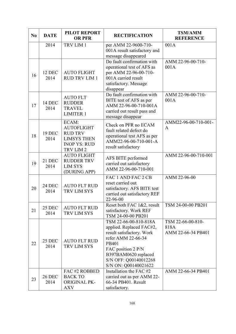
168
No DATE PILOT REPORT OR PFR RECTIFICATION TSM/AMM
REFERENCE 2014 TRV LIM 1 per AMM 22-9600-710-
001A result satisfactory and message disappeared
001A
16 12 DEC 2014
AUTO FLIGHT RUD TRV LIM 1
Do fault confirmation with operational test of AFS as per AMM 22-96-00-710-001A carried result satisfactory. Message disappear
AMM 22-96-00-710-001A
17 14 DEC 2014
AUTO FLT RUDDER TRAVEL LIMITER 1
Do fault confirmation with BITE test of AFS as per AMM 22-96-00-710-001A carried out result pass and message disappear
AMM 22-96-00-710-001A
18 19 DEC 2014
ECAM: AUTOFLIGHT RUD TRV LIMSYS THEN INOP YS: RUD TRV LIM 2
Check on PFR no ECAM fault related defect do operational test AFS as per AMM22-96-00-710-001-A result satisfactory
AMM22-96-00-710-001-A
19 21 DEC 2014
AUTO FLIGHT RUDDER TRV LIM SYS (DURING APP)
AFS BITE performed carried out satisfactory AMM 22-96-00-710-001
AMM 22-96-00-710-001
20 24 DEC 2014
AUTO FLT RUD TRV LIM SYS
FAC 1 AND FAC 2 CB reset carried out satisfactory. AFS BITE test carried out satisfactory REF 22-96-00
AMM 22-96-00
21 25 DEC 2014
AUTO FLT RUD TRV LIM SYS
Reset both FAC 1&2, result satisfactory. Work REF TSM 24-00-00 PB201
TSM 24-00-00 PB201
22 25 DEC 2014
AUTO FLT RUD TRV LIM SYS
TSM 22-66-00-810-818A applied. Replaced FAC#2, result satisfactory. Work refer AMM 22-66-34 PB401 FAC position 2 P/N B397BAM0620 replaced S/N OFF: Q00140012268 S/N ON: Q00140021622
TSM 22-66-00-810-818A AMM 22-66-34 PB401
23 26 DEC 2014
FAC #2 ROBBED BACK TO ORIGINAL PK-AXV
Installation the FAC #2 carried out as per AMM 22-66-34 PB401. Result satisfactory.
AMM 22-66-34 PB401

169
No DATE PILOT REPORT OR PFR RECTIFICATION TSM/AMM
REFERENCE
24 27 DEC 2014
During taxi in ON WARR AUTO FLT RUD TRV LIM SYS ILL
Do check on PFR no relate message on failure message. Continue reset of FAC 1 and FAC 2 as per AMM 24-00-00 PB 401 result satisfied. Please continue monitor further
AMM 24-00-00 PB 401
6.8 PFR Summary Table of PFR Summary 27 November 2014 – 27 December 2014.
No Date City pair Flight Phase
Msg. Time
(GMT) Warning Message Failure Message
1 01-12-2014 WIII – WARR 6 12.53 AUTO FLT RUD TRV LIM 1
AFS: FAC1/RTL ACTR
2 12-12-2014 WIII – WARR 2 07.55 AUTO FLT RUD TRV LIM 1
AFS: FAC2/RTL ACTR
12-12-2014 WIII – WARR 2 07.55 AUTO FLT RUD TRV LIM SYS
AFS: FAC1/RTL ACTR
12-12-2014 WIII – WARR 2 07.56 AUTO FLT RUD TRV LIM 2
AFS: FAC1/P-B SW
12-12-2014 WIII – WARR 2 07.56 AUTO FLT RUD TRV LIM 1
AFS: FAC2/P-B SW
3 21-12-2014 WARR – WSSS 6 23.05 AUTO FLT RUD TRV LIM 1
AFS: FAC1/RTL ACTR
21-12-2014 WARR – WSSS 6 23.06 AUTO FLT RUD TRV LIM SYS
AFS: FAC2/RTL ACTR
21-12-2014 WARR – WSSS 6 23.06 AUTO FLT RUD TRV LIM 2
AFS: FAC1/P-B SW
21-12-2014 WARR – WSSS 6 23.13 AUTO FLT RUD TRV LIM 1
AFS: FAC2/P-B SW
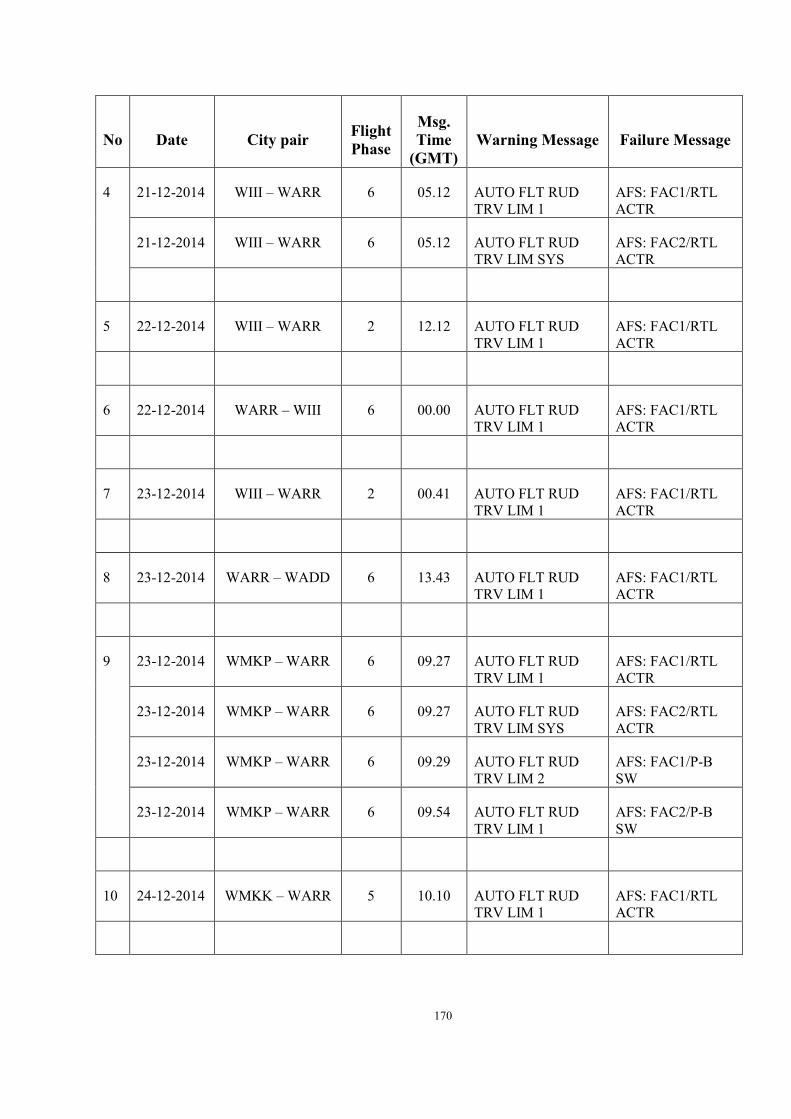
170
No Date City pair Flight Phase
Msg. Time
(GMT) Warning Message Failure Message
4 21-12-2014 WIII – WARR 6 05.12 AUTO FLT RUD TRV LIM 1
AFS: FAC1/RTL ACTR
21-12-2014 WIII – WARR 6 05.12 AUTO FLT RUD TRV LIM SYS
AFS: FAC2/RTL ACTR
5 22-12-2014 WIII – WARR 2 12.12 AUTO FLT RUD TRV LIM 1
AFS: FAC1/RTL ACTR
6 22-12-2014 WARR – WIII 6 00.00 AUTO FLT RUD TRV LIM 1
AFS: FAC1/RTL ACTR
7 23-12-2014 WIII – WARR 2 00.41 AUTO FLT RUD TRV LIM 1
AFS: FAC1/RTL ACTR
8 23-12-2014 WARR – WADD 6 13.43 AUTO FLT RUD TRV LIM 1
AFS: FAC1/RTL ACTR
9 23-12-2014 WMKP – WARR 6 09.27 AUTO FLT RUD TRV LIM 1
AFS: FAC1/RTL ACTR
23-12-2014 WMKP – WARR 6 09.27 AUTO FLT RUD TRV LIM SYS
AFS: FAC2/RTL ACTR
23-12-2014 WMKP – WARR 6 09.29 AUTO FLT RUD TRV LIM 2
AFS: FAC1/P-B SW
23-12-2014 WMKP – WARR 6 09.54 AUTO FLT RUD TRV LIM 1
AFS: FAC2/P-B SW
10 24-12-2014 WMKK – WARR 5 10.10 AUTO FLT RUD TRV LIM 1
AFS: FAC1/RTL ACTR

171
No Date City pair Flight Phase
Msg. Time
(GMT) Warning Message Failure Message
11 25-12-2014 WARR – WMKK 2 11.53 AUTO FLT RUD TRV LIM SYS
PFR Summary (page 145) in the table, failure messages of the December 25th flight are missing, especially messages that report “AFS: FAC1/RTL ACTR 4CC” or "FAC2/RTL ACTR 4CC” failures
25-12-2014 WARR – WMKK 2 11.54 AUTO FLT RUD TRV LIM SYS
25-12-2014 WARR – WMKK 2 11.55 AUTO FLT RUD TRV LIM 2
25-12-2014 WARR – WMKK 2 11.55 AUTO FLT RUD TRV LIM SYS
25-12-2014 WARR – WMKK 2 11.55 AUTO FLT RUD TRV LIM SYS
25-12-2014
WARR – WMKK
2 11.55 AUTO FLT RUD TRV LIM 1
25-12-2014
WARR – WMKK
2 11.55 AUTO FLT RUD TRV LIM SYS
25-12-2014
WARR – WMKK
2 11.56 AUTO FLT RUD TRV LIM 2
25-12-2014
WARR – WMKK
2 11.56 AUTO FLT RUD TRV LIM 1
25-12-2014
WARR – WMKK
2 11.56 AUTO FLT RUD TRV LIM SYS

172
6.9 Troubleshooting Manual (TSM) Task 22-61-00-810-803-A

173

174

175
6.10 Reliability Report November 2014
6.11 Startle Reflex The human startle reflex was famously investigated by Landis and Hunt (1939) who filmed the reactions of people to an unexpected pistol shot occurring just behind them. It is now well established that there is a reflex-like event (startle reflex) that blinks the eyes and causes a whole body „jerk‟ to occur (similar to that sometimes caused in sleep). This reflex has a relatively basic neural pathway from the sense organ. Many things can cause (or contribute to) a startle reflex, including sudden noises, unexpected tactile sensations, abrupt shocking perceptions, the sensation of falling or an abrupt visual stimulus.
There is little evidence that a startle reflex alone creates much of a sustained or lasting impact on cognitive functions (although there are some minor and short lived physiological changes such as raised heart rate). A skilled motor task will be momentarily disrupted by a startle reflex but return to normal within five to ten seconds. For more details see Thackray & Touchstone (1970).
For pilots, the main effects of the startle reflex are the interruption of the on going process and distraction of attention towards the stimulus. These happen almost immediately, and can be quickly dealt with if the cause is found to be non-threatening; for more detail see Graham (1979), Herbert, Kissler, Junghöfer, Peyk & Rockstroh (2006) or Schupp, Cuthbert, Bradley, Birbaumer & Lang (1997). A

176
further possibility is that any „primed‟ motor action may be triggered. For more detail see Valls-Sole, Kumru, Kofler (2008).
Reaction to Fear A perception of fear can cause a startle reflex to be potentiated (more pronounced) should it occur and attention to become more focused. In a state of fear, very little is required to trigger a full „fight or flight‟ response (a startle will probably be sufficient at this point).
Fight or Flight When we perceive a serious and imminent threat (whether we are already in a high state of fear or not) the hypothalamus initiates a cascade of events (nervous and hormonal) such as increased heart rate and breathing, secretion of adrenaline, and increased sweating. This is called the alarm reaction and is part of „fight or flight‟ (stress). These changes immediately prepare the body for action to maximize the chances of survival in the anticipated imminent encounter. No startle is required to activate the fight or flight response, although a startling stimulus may be part of, or coincident with, the same threat
Importantly the alarm element of the fight or flight response also appears to have an immediate and sustained impact on our cognition. All mental capacity becomes focused on the threat and/or the escape from it. As long as the required response to the threat is to engage in a single basic task (i.e. a single learned skill or set of easy steps) then this focusing of attention resource can be beneficial. The senses can appear heightened to the threat and the level of attention is very high but very focused.
Some experimental evidence has suggested a decrease in memory performance of recently learned information (using memory tests) during fight or flight. But there is little evidence that long-term memory or skills are negatively affected, except in terms of manipulation issues (coordinating the skill, e.g. with tremor). So it is probable that old established learning and innate knowledge trumps new learning during fight or flight. This may be part of the explanation for an effect often called „primacy‟ whereby individuals report that in difficult situations they reverted to early (or previous) learning, even when it was inappropriate to do so (for example reverting to the handling characteristics of a previous aircraft type).
A vicious circle Hypothetically and anecdotally, during fight or flight pilots can get mentally „stuck‟ within a situation (unable to interpret or resolve a situation, and unable to move on, even if that situation would present no problems under normal circumstances). This usually happens when the situation is ambiguous or requires problem solving.
In a fight or flight state, time is key to survival. In modern humans, the fight or flight response is accompanied by an urge to be engaged in the active solution. But to do this the person must know (or be told) what response to take. In ambiguous cases this might not be obvious, and might require problem solving or complex thinking to assess the situation or response required. But in fight or flight, the brain wants to quickly establish a very basic mental model then drop any assessment process in

177
order to concentrate all attention to the response. But if resources are not given to assessment and problem solving then the person cannot decide the best response. This situation would be best described as a vicious circle. As part of this, during the fight or flight response the brain favours sources of information that require the minimum of processing. This means simple „real-world‟ cues or conditioned cues and responses.
All this worked well in nature, over millennia. However it is a problematic strategy when dealing with new technology (within which humans have not evolved). Human processes are not perfectly adapted to perceive the cues and information from modern interfaces. Such information requires more mental processing than does „real world‟ information, particularly in new situations.
Taking all the above into account, it can be helpful to hypothesise a vicious circle occurring during ambiguous situations on modern flight decks, as follows: The brain requires a basic and quick understanding of the problem in order to act at once. But because flight deck information is often abstract and unnatural, the pilot requires more time to work out the problem than they would if the cues were natural real-world ones; time that they are unconsciously not willing to allow. Unless this conflict is resolved, the pilot becomes mentally „stuck‟ (the start of the vicious circle).
Let us take a simple example: an unusual attitude. While easy enough normally, when experiencing extreme fight or flight, a pilot may glance at the attitude indicator but be unable to make sense of it (particularly an unusual and unfamiliar attitude) because the brain does not want to dwell on assessment, but wants to be engaged in the task resolution. The pilot (consciously) does not know the attitude and needs a little more resource and time before acting or responding. The pilot is stuck. Anecdotally, this feels like a mental blank. There is no easy solution:
1. If the pilot yields to the unconscious urge and breaks the vicious circle by making a spurious or guessed response then this could solve the situation by lucky chance (an action was effective) but also risks disaster (such as a fatally wrong control input). In any case, if the action does not solve the situation (or leads to a further threatening situation) the fight or flight continues, and nothing is resolved.
2. Alternatively, if the pilot continues trying to process the information then they may not receive the resource to process it while in that state, and so remain stuck.
6.12 Ebbinghaus Curve and Review The first experimental research on retention was conducted between 1879 and 1885 by Hermann Ebbinghaus, a German psychologist. Realizing that memory is strongly affected by both meaning and association, Ebbinghaus decided to test his memory capabilities by using nonsense words of the same length. He discovered that whatever is 'learned' suffers a rapid initial decrease in memory followed by a slower decrease over time. That is, most forgetting occurs immediately after learning.
To summarize his research, he produced a graphic representation, which has become known as the Ebbinghaus Curve (Ebbinghaus, 1885). While this is a very old study, and loses some credibility based on the fact that Ebbinghaus used nonsense words

178
rather than real content, it is still important information and fascinating that the concept was known over a hundred years ago. Modern psychologists have replicated his six-year experiment many times and have discovered that their results are the same.

179
6.13 Accredited Representatives Comments

180

181
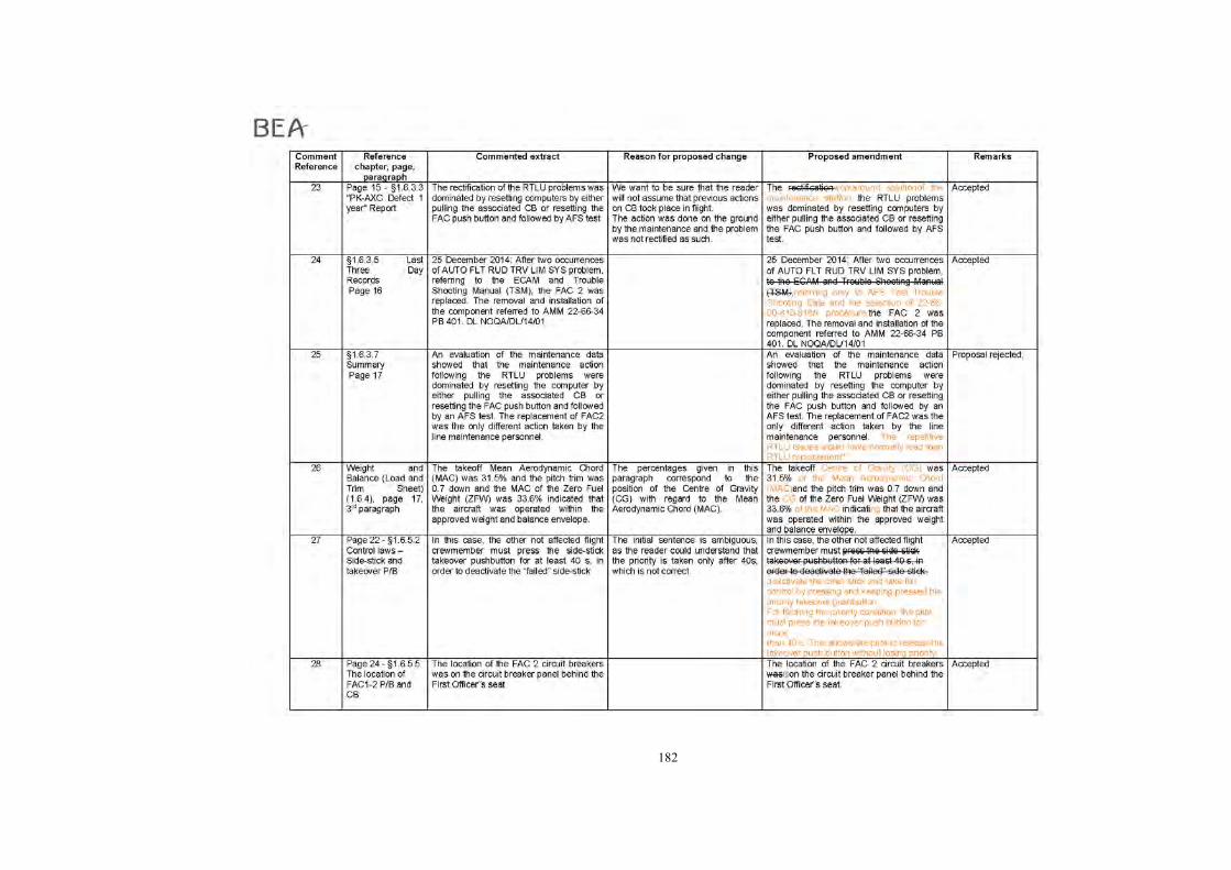
182

183

184

185
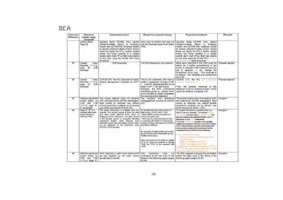
186

187
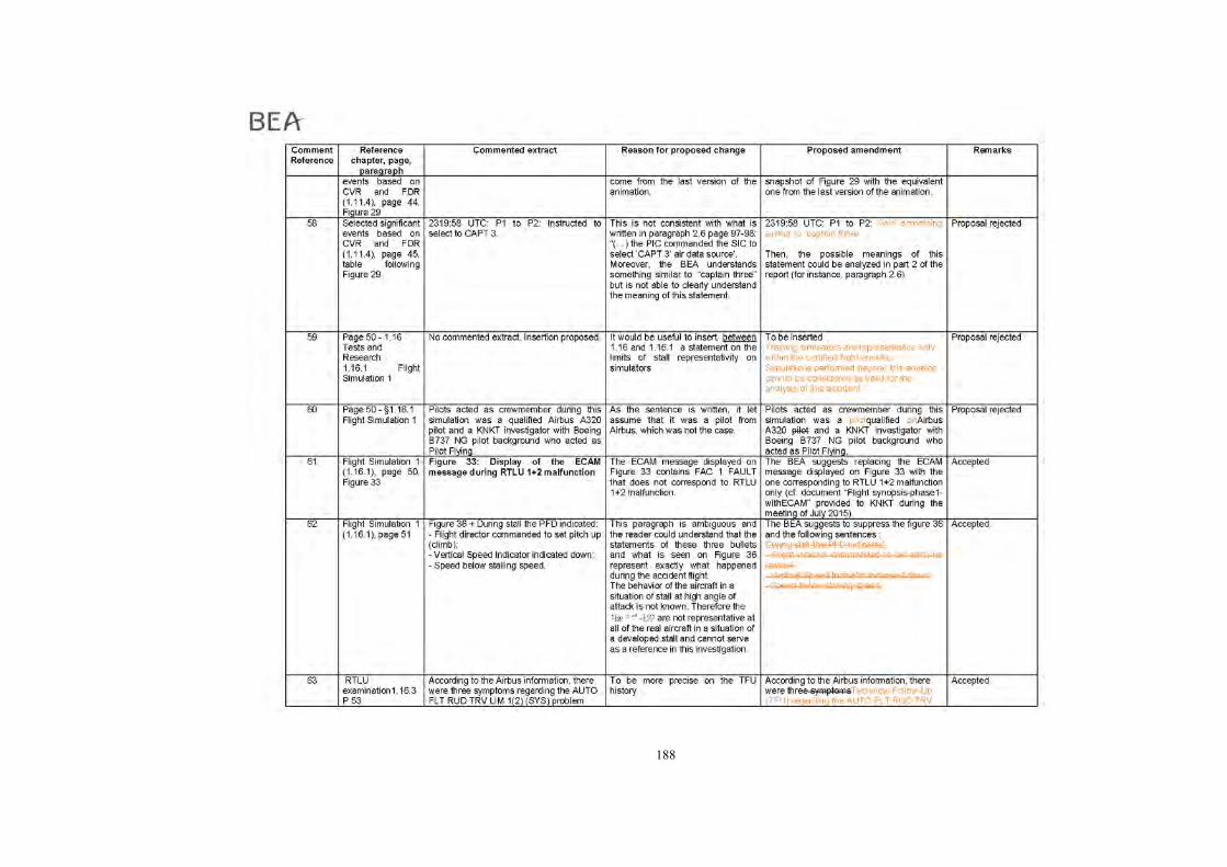
188

189

190
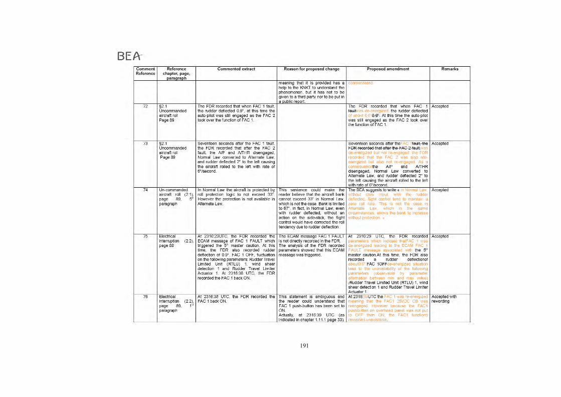
191

192

193

194
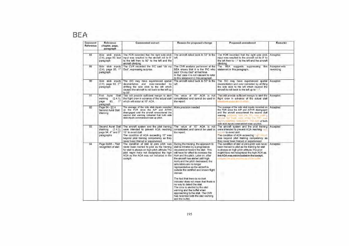
195
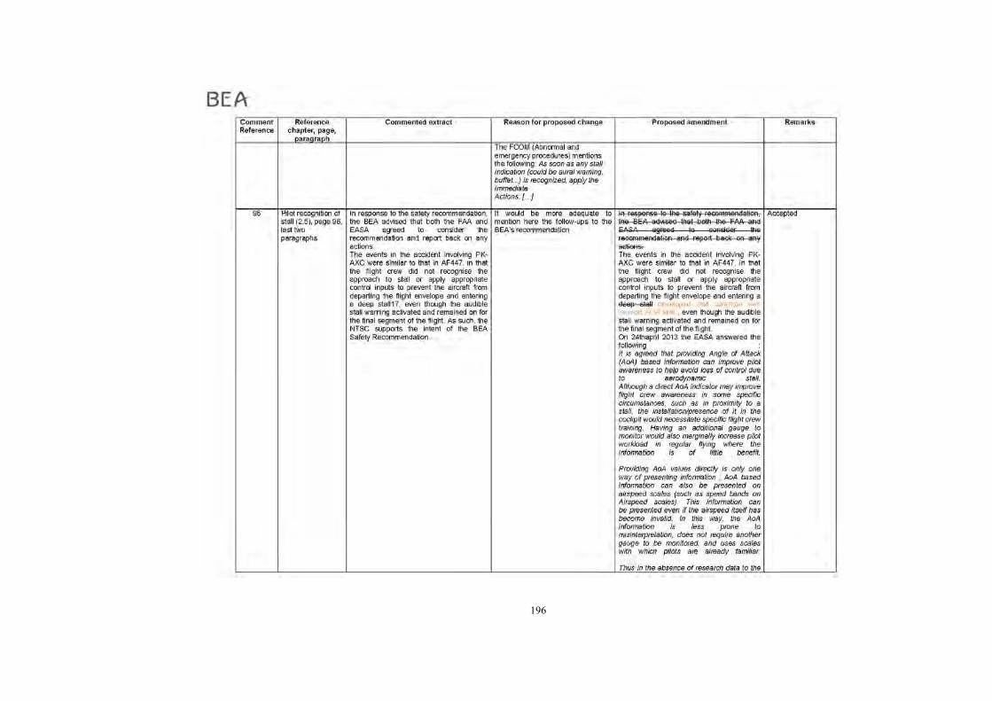
196

197

198

199

200

201

202

203

204
7 REFERENCES
Airbus. (2014). Quick Reference Handbook, AirAsia PK-AXC. Indonesia AirAsia.
Airbus. (2014). Flight Crew Training Manual rev.09. AirAsia.
Airbus. (2014). Flight Crew Operating Manual . AirAsia.
Airbus. (2006). A320 Airplane Flight Manual. Airbus.
Dehart, R. L. (2002). Fundamentals of Aerospace Medicine, 3rd Edition. Baltimore: Lippincott Williams & Wilkins.
Director of Flight Operations. (2014). Company Operations Manual rev.09. PT. Indonesia AirAsia.
Director of Flight Operations. (2013). Operations Training Manual issue 4 Rev 00. PT. Indonesia AirAsia.
Director of Flight Operations. (2012). Standard Operating Procedures issue 02 rev.0. PT. Indonesia AirAsia.
Ernsting, J. (2003). Aviation Medicine, 3rd Edition.
FAA. (2008). Upset Recovery Book Rev. 2. November. Federal Aviation Administration.
Rosay, Jacques. (2011, January). What is stall? How a pilot should react in front of stall situation. Safety First, Airbus Safety Magazine.
Thackray, R., & Touchstone, R. (1970). Recovery of motor performance following startle. Perceptual motor skills,. Oklahoma City: Civil Aeromedical Institute, FAA.
Transportation Safety Board of Canada. (2008). Aviation Investigation Report A08Q0051, Out-of-Trim Nose Down Condition Leading to an Airplane Upset. Transportation Safety Board of Canada.
Related Documents