Service Manual Version A.1

Welcome message from author
This document is posted to help you gain knowledge. Please leave a comment to let me know what you think about it! Share it to your friends and learn new things together.
Transcript
5/17/2018 KIP 7100 Service Manual Ver A_1 - slidepdf.com
http://slidepdf.com/reader/full/kip-7100-service-manual-ver-a1 1/674

5/17/2018 KIP 7100 Service Manual Ver A_1 - slidepdf.com
http://slidepdf.com/reader/full/kip-7100-service-manual-ver-a1 2/674
This service manual includes the basic information about the KIP 7100 Multi-Function Printer,which is required when you during field service to maintain the product’s quality and reliability.
Chapter 1 Introduction Overview(Features, specifications, name of parts andetc.)
Chapter 2 Installation Installation requirements, method of installation, connection with PC & printer
Chapter 3 Print / Scan Process explanation for the steps of the print and
scan process
Chapter 4 Electrical Circuit diagrams, image process system,electric parts location and etc.
Chapter 5 Mechanical Parts replacement and mechanicaldisassembly
Chapter 6 Maintenance Field maintenance information
Chapter 7 Troubleshooting Problem resolution
Chapter 8 Service Mode / Utility Service Mode settings, Diagnosis and etc.
Chapter 9 Appendix General Circuit Diagram
Some of the information included in this manual may be changed by product upgrades. Suchinformation will be informed to you through Technical Bulletins or Engineering Change Orders.Read this service manual and these TBs / ECOs to understand the KIP 7100 correctly, and you willbe able to maintain the product quality for a long period of time.
5/17/2018 KIP 7100 Service Manual Ver A_1 - slidepdf.com
http://slidepdf.com/reader/full/kip-7100-service-manual-ver-a1 3/674
Chapter 1
Introduction
page1. 1 Features 1- 2
1. 2 Specifications 1- 31. 2. 1 General 1- 31. 2. 2 Printer part 1- 41. 2. 3 Scanner part 1- 6
1. 3 Specifications for Originals 1- 71. 3. 1 Original - Standard 1- 71. 3. 2 Special Documents 1- 71. 3. 3 “Do Not Scan” Originals 1- 7
1. 4 Appearance 1- 81. 4. 1 Front 1- 81. 4. 2 Rear 1- 9
1. 5 Specifications for Scan Original 1-10
1. 6 Specifications for Printing Media 1-13
1. 6. 1 Papers not available to use 1-131. 6. 2 Keeping the paper in the custody 1-141. 6. 3 Treatment against environmental condition 1-15
5/17/2018 KIP 7100 Service Manual Ver A_1 - slidepdf.com
http://slidepdf.com/reader/full/kip-7100-service-manual-ver-a1 4/674
1. 1 Features
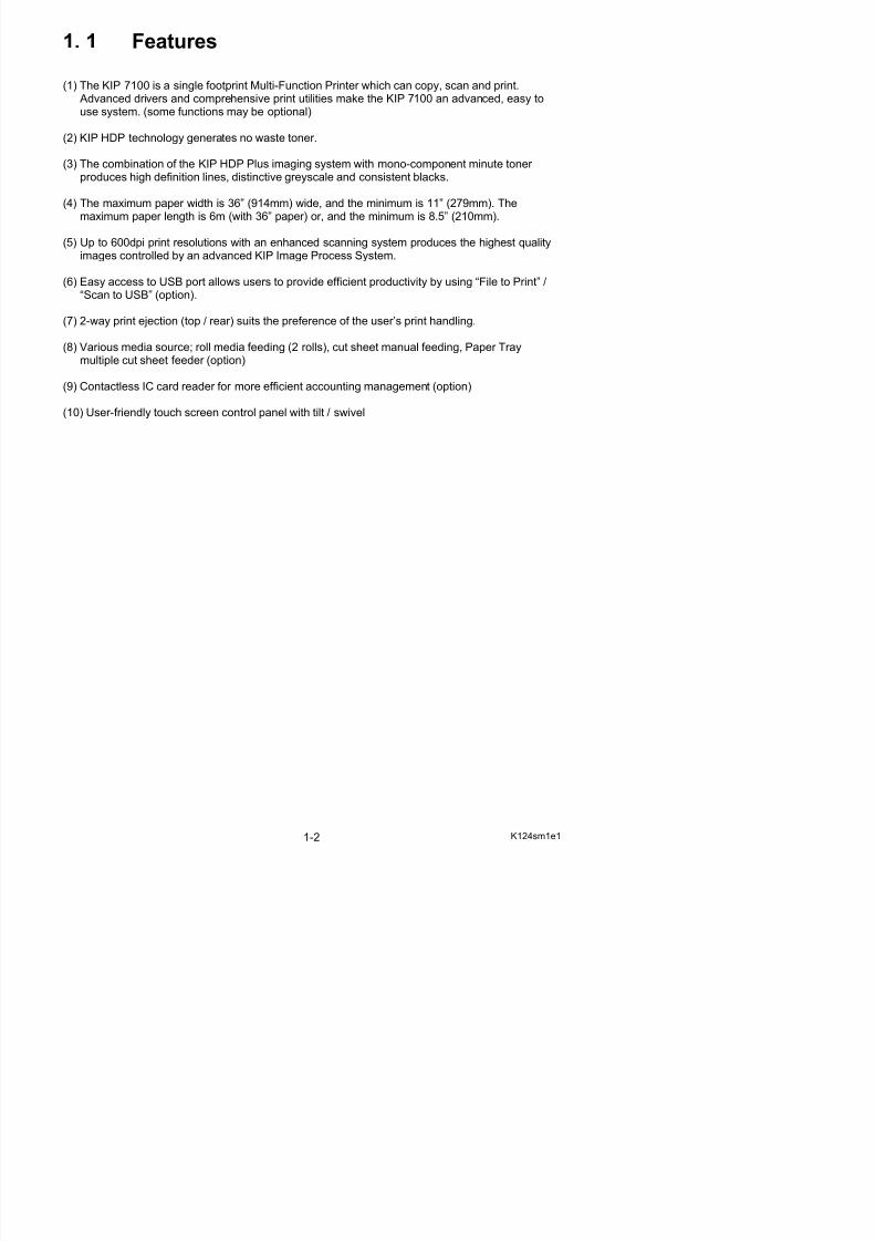
(1) The KIP 7100 is a single footprint Multi-Function Printer which can copy, scan and print. Advanced drivers and comprehensive print utilities make the KIP 7100 an advanced, easy to
use system. (some functions may be optional)
(2) KIP HDP technology generates no waste toner.
(3) The combination of the KIP HDP Plus imaging system with mono-component minute toner produces high definition lines, distinctive greyscale and consistent blacks.
(4) The maximum paper width is 36” (914mm) wide, and the minimum is 11” (279mm). The
maximum paper length is 6m (with 36” paper) or, and the minimum is 8.5” (210mm).
(5) Up to 600dpi print resolutions with an enhanced scanning system produces the highest qualityimages controlled by an advanced KIP Image Process System.
(6) Easy access to USB port allows users to provide efficient productivity by using “File to Print” /“Scan to USB” (option).
(7) 2-way print ejection (top / rear) suits the preference of the user’s print handling.
(8) Various media source; roll media feeding (2 rolls), cut sheet manual feeding, Paper Traymultiple cut sheet feeder (option)
(9) Contactless IC card reader for more efficient accounting management (option)
(10) User-friendly touch screen control panel with tilt / swivel
5/17/2018 KIP 7100 Service Manual Ver A_1 - slidepdf.com
http://slidepdf.com/reader/full/kip-7100-service-manual-ver-a1 5/674
1. 2 Specifications
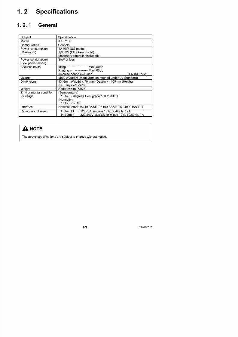
1. 2. 1 General
Subject Specification
Model KIP 7100
Configuration Console
Power consumption(Maximum)
1,440W (US model)1,680W (EU / Asia model)(scanner / controller included)
Power consumption(Low power mode)
30W or less
Acoustic noise Idling Max. 60dbPrinting Max. 65db(impulse sound excluded) EN ISO 7779
Ozone Max. 0.05ppm (Measurement method under UL Standard)
Dimensions 1346mm (Width) x 704mm (Depth) x 1105mm (Height)(UI, Tray excluded)
Weight About 244kg (538lb)Environmental conditionfor usage
(Temperature)10 to 32 degrees Centigrade / 50 to 89.6 F
(Humidity)15 to 85% RH
Interface Network Interface (10 BASE-T / 100 BASE-TX / 1000 BASE-T)
Rating Input Power In the US : 120V plus/minus 10%, 50/60Hz, 12AIn Europe : 220-240V plus 6% or minus 10%, 50/60Hz, 7A
NOTE
The above specifications are subject to change without notice.
5/17/2018 KIP 7100 Service Manual Ver A_1 - slidepdf.com
http://slidepdf.com/reader/full/kip-7100-service-manual-ver-a1 6/674
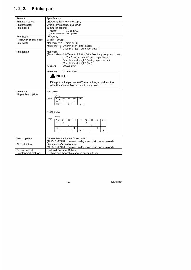
1. 2. 2. Printer part
Subject Specification
Printing method LED Array Electro photography
Photoreceptor Organic Photoconductive Drum
Print speed 80mm per second(Metric) 3.3ppm/A0(Inch) 3.4ppm/E
Print head LED Array
Resolution of print head 600dpi x 600dpi
Print width Maximum 914mm or 36”Minimum 297mm or 11” (Roll paper)
210mm or 8.5” (Cut sheet paper)
Print length Maximum(Standard) 6,000mm / 19.7ft for 36” / A0 wide (plain paper / bond)
or “5 x Standard length” (plain paper / bond) “2 x Standard length” (tracing paper / vellum) “1 x Standard length” (film)
(Option) 200,000mm
Minimum 210mm / 8.5”
Print size
(Paper Tray, option)
ISO (mm)
WidthLength
ANSI (inch)
WidthLength
NOTE
If the print is longer than 6,000mm, its image quality or thereliability of paper feeding is not guaranteed.
594 420 297 210
420 X X
297 X X
24 22 18 17 12 11 9 8.5
18 X X
17 X X
12 X X
11 X X

5/17/2018 KIP 7100 Service Manual Ver A_1 - slidepdf.com
http://slidepdf.com/reader/full/kip-7100-service-manual-ver-a1 7/674
Subject Specification
Media source 2 Roll DecksManual Feeder (single cut sheet)
Paper Tray (multiple cut sheet, option)Media (Recommended Media)US model:
Bond 64g/m2 to 80g/m2, US Bond (PB-20)Vellum US Vellum (XV-20)Film 4MIL (PF-4DDME)
Europe/Asia model:Plain Paper 64g/m2 to 80g/m2, Oce Red Label (75g/m2)Tracing Paper Transparent Paper (80g/m2)Film 3.5MIL
Storage of consumables (Toner cartridge)Store the cartridge within the temperature range from 0 to35 degrees Centigrade and within the humidity range from 35to 85% RH.
NOTE
The above specifications are subject to change without notice.
5/17/2018 KIP 7100 Service Manual Ver A_1 - slidepdf.com
http://slidepdf.com/reader/full/kip-7100-service-manual-ver-a1 8/674
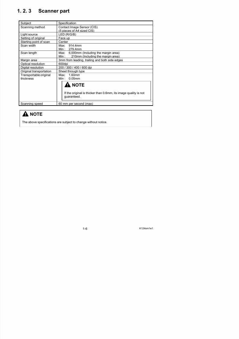
1. 2. 3 Scanner part
Subject Specification
Scanning method Contact Image Sensor (CIS)
(5 pieces of A4 sized CIS)Light source LED (R/G/B)
Setting of original Face up
Starting point of scan Center
Scan width Max: 914.4mmMin : 279.4mm
Scan length Max: 6,000mm (Including the margin area)Min : 210mm (Including the margin area)
Margin area 3mm from leading, trailing and both side edgesOptical resolution 600dpi
Digital resolution 200 / 300 / 400 / 600 dpi
Original transportation Sheet through type
Transportable originalthickness
Max: 1.60mmMin : 0.05mm
Scanning speed 60 mm per second (max)
NOTE
The above specifications are subject to change without notice.
NOTE
If the original is thicker than 0.6mm, its image quality is notguaranteed.
5/17/2018 KIP 7100 Service Manual Ver A_1 - slidepdf.com
http://slidepdf.com/reader/full/kip-7100-service-manual-ver-a1 9/674
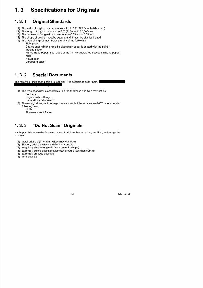
1. 3 Specifications for Originals
1. 3. 1 Original Standards
(1) The width of original must range from 11” to 36” (275.0mm to 914.4mm).(2) The length of original must range 8.5” (210mm) to 25,000mm(3) The thickness of original must range from 0.05mm to 0.65mm.(4) The shape of original must be square, and it must be standard sized.(5) The type of original must belong to any of the followings.
Plain paper Coated paper (High or middle class plain paper is coated with the paint.)
Tracing paper Pansy Trace Paper (Both sides of the film is sandwiched between Tracing paper.)FilmNewspaper Cardboard paper
1. 3. 2 Special DocumentsThe following kinds of originals are “special”. It is possible to scan them, but the image qualityand feed reliability are not guaranteed.
(1) The type of original is acceptable, but the thickness and type may not be:BookletsOriginal with a Hanger
Cut and Pasted originals(2) These original may not damage the scanner, but these types are NOT recommended:
following ones.Cloth Aluminium Kent Paper
1. 3. 3 “Do Not Scan” OriginalsIt is impossible to use the following types of originals because they are likely to damage thescanner.
(1) Metal originals (The Scan Glass may damage)
5/17/2018 KIP 7100 Service Manual Ver A_1 - slidepdf.com
http://slidepdf.com/reader/full/kip-7100-service-manual-ver-a1 10/674
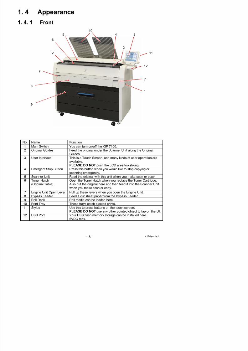
1. 4 Appearance
1. 4. 1 Front
No. Name Function
1 Main Switch You can turn on/off the KIP 7100.
2 Original Guides Feed the original under the Scanner Unit along the Original
Guides.3 User Interface This is a Touch Screen, and many kinds of user operation are
available.PLEASE DO NOT push the LCD area too strong.
4 Emergent Stop Button Press this button when you would like to stop copying or scanning emergently.
1
45
2
9
3
7
112
6
7
10
12
8
5/17/2018 KIP 7100 Service Manual Ver A_1 - slidepdf.com
http://slidepdf.com/reader/full/kip-7100-service-manual-ver-a1 11/674
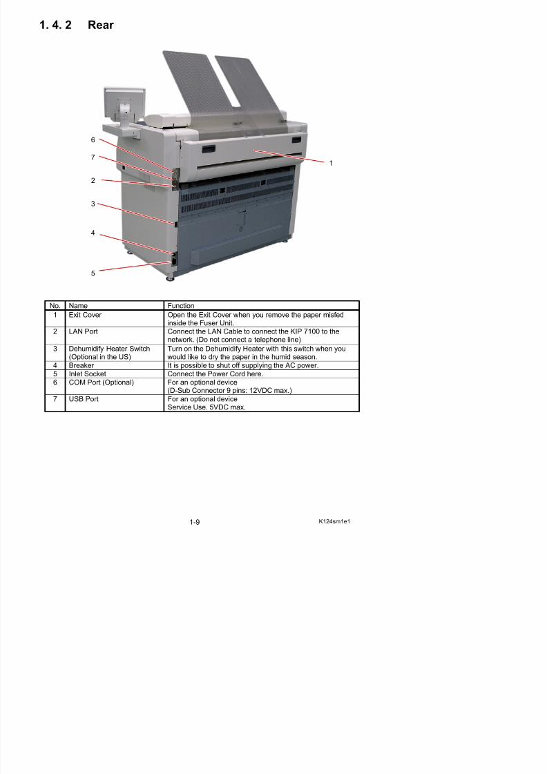
1. 4. 2 Rear
No. Name Function
1 Exit Cover Open the Exit Cover when you remove the paper misfedinside the Fuser Unit.
2 LAN Port Connect the LAN Cable to connect the KIP 7100 to the
network. (Do not connect a telephone line)3 Dehumidify Heater Switch
(Optional in the US)Turn on the Dehumidify Heater with this switch when youwould like to dry the paper in the humid season.
4 Breaker It is possible to shut off supplying the AC power.
5 Inlet Socket Connect the Power Cord here.
6 COM Port (Optional) For an optional device
1
2
4
5
3
7
6
5/17/2018 KIP 7100 Service Manual Ver A_1 - slidepdf.com
http://slidepdf.com/reader/full/kip-7100-service-manual-ver-a1 12/674
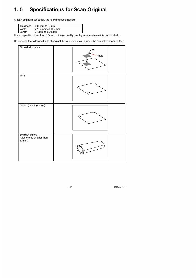
1. 5 Specifications for Scan Original
A scan original must satisfy the following specifications.
Thickness 0.05mm to 0.6mm
Width 279.4mm to 914.4mm
Length 210mm to 6,000mm
(If an original is thicker than 0.6mm, its image quality is not guaranteed even it is transported.)
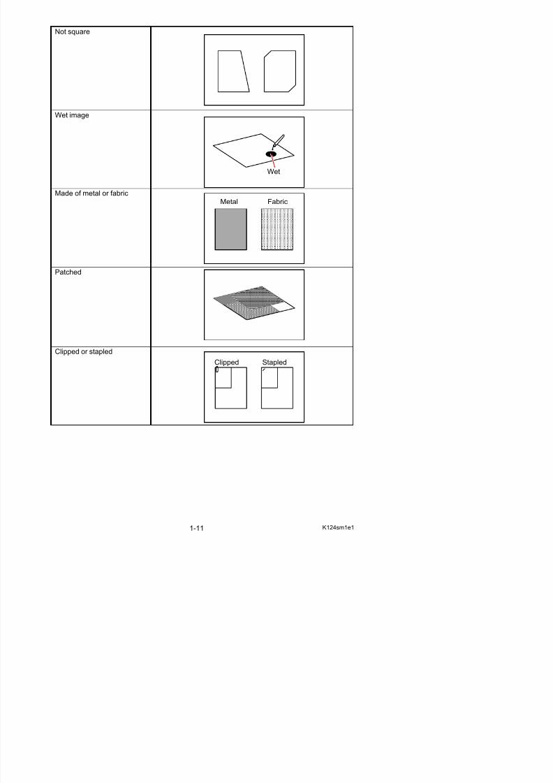
Do not scan the following kinds of original, because you may damage the original or scanner itself!
Sticked with paste
Torn
Folded (Leading edge)
So much curled(Diameter is smaller than
Paste
5/17/2018 KIP 7100 Service Manual Ver A_1 - slidepdf.com
http://slidepdf.com/reader/full/kip-7100-service-manual-ver-a1 13/674
Not square
Wet image
Made of metal or fabric
Patched
Clipped or stapled
Wet
Metal Fabric
Clipped Stapled

5/17/2018 KIP 7100 Service Manual Ver A_1 - slidepdf.com
http://slidepdf.com/reader/full/kip-7100-service-manual-ver-a1 14/674
The following kinds of originals can be read with using a carrier sheet.Image quality or the reliability of paper feeding for them is not guaranteed.
Rough surface(Carbon paper for example)
Punched
Rough surface
5/17/2018 KIP 7100 Service Manual Ver A_1 - slidepdf.com
http://slidepdf.com/reader/full/kip-7100-service-manual-ver-a1 15/674
1. 6 Specifications for Printing Media
1. 6. 1 Papers not available to use
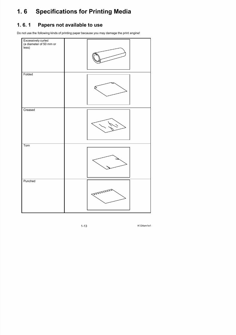
Do not use the following kinds of printing paper because you may damage the print engine!
Excessively curled(a diameter of 50 mm or less)
Folded
Creased
Torn
5/17/2018 KIP 7100 Service Manual Ver A_1 - slidepdf.com
http://slidepdf.com/reader/full/kip-7100-service-manual-ver-a1 16/674
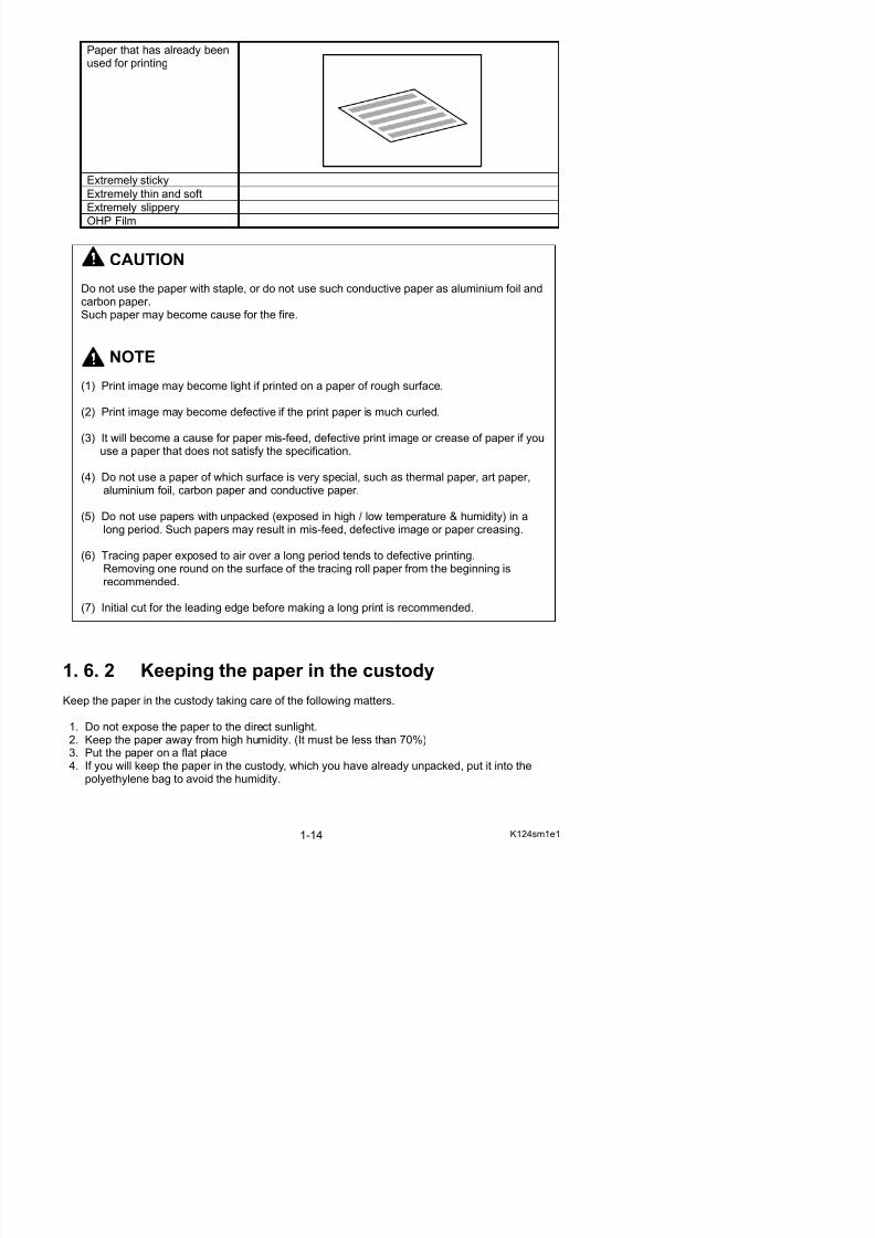
Paper that has already beenused for printing
Extremely sticky
Extremely thin and soft
Extremely slippery
OHP Film
CAUTION
Do not use the paper with staple, or do not use such conductive paper as aluminium foil andcarbon paper.Such paper may become cause for the fire.
NOTE
(1) Print image may become light if printed on a paper of rough surface.
(2) Print image may become defective if the print paper is much curled.
(3) It will become a cause for paper mis-feed, defective print image or crease of paper if youuse a paper that does not satisfy the specification.
(4) Do not use a paper of which surface is very special, such as thermal paper, art paper,aluminium foil, carbon paper and conductive paper.
(5) Do not use papers with unpacked (exposed in high / low temperature & humidity) in along period. Such papers may result in mis-feed, defective image or paper creasing.
(6) Tracing paper exposed to air over a long period tends to defective printing.Removing one round on the surface of the tracing roll paper from the beginning isrecommended.
(7) Initial cut for the leading edge before making a long print is recommended.
5/17/2018 KIP 7100 Service Manual Ver A_1 - slidepdf.com
http://slidepdf.com/reader/full/kip-7100-service-manual-ver-a1 17/674
1. 6. 3 Treatment against environmental condition
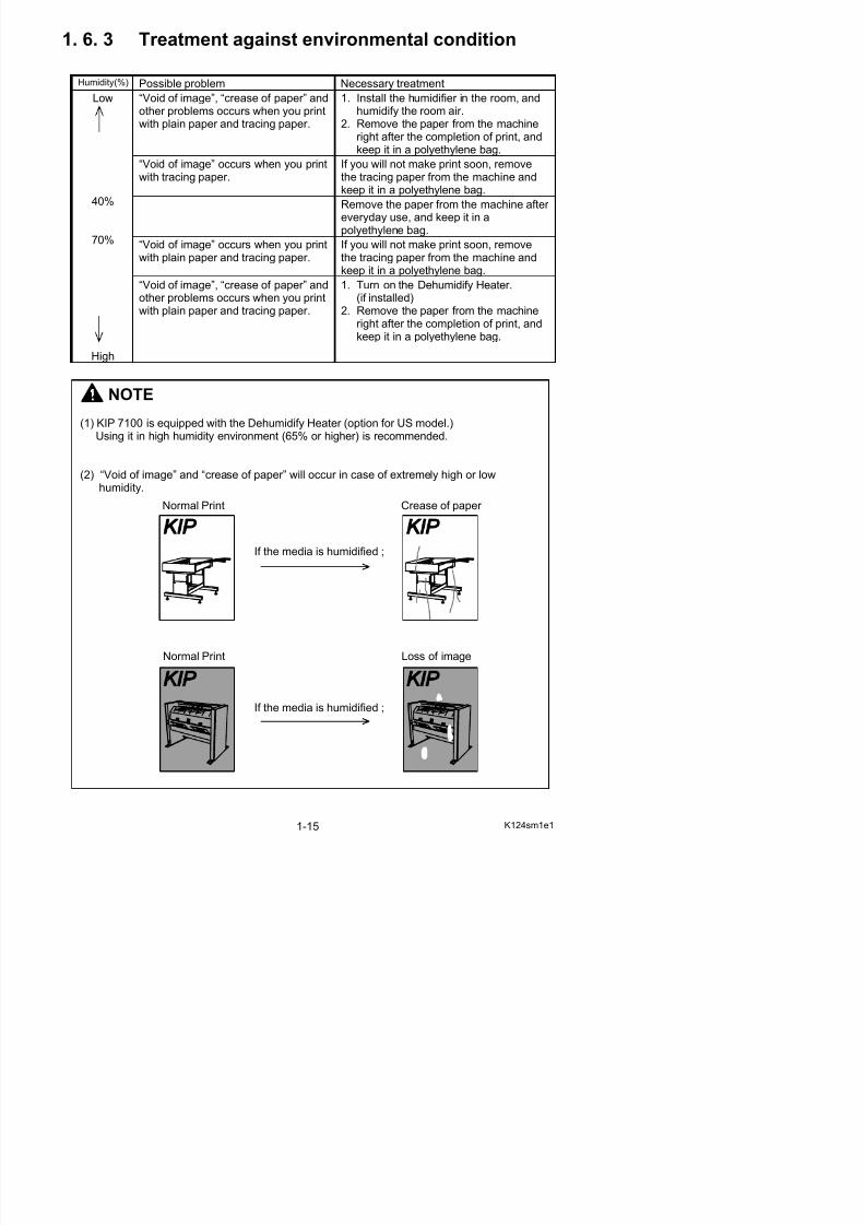
Humidity(%) Possible problem Necessary treatment
“Void of image”, “crease of paper” and
other problems occurs when you printwith plain paper and tracing paper.
1. Install the humidifier in the room, and
humidify the room air.2. Remove the paper from the machine
right after the completion of print, andkeep it in a polyethylene bag.
“Void of image” occurs when you printwith tracing paper.
If you will not make print soon, removethe tracing paper from the machine andkeep it in a polyethylene bag.
Remove the paper from the machine after
everyday use, and keep it in apolyethylene bag.
“Void of image” occurs when you printwith plain paper and tracing paper.
If you will not make print soon, removethe tracing paper from the machine andkeep it in a polyethylene bag.
Low
40%
70%
High
“Void of image”, “crease of paper” andother problems occurs when you printwith plain paper and tracing paper.
1. Turn on the Dehumidify Heater.(if installed)
2. Remove the paper from the machine
right after the completion of print, andkeep it in a polyethylene bag.
NOTE
(1) KIP 7100 is equipped with the Dehumidify Heater (option for US model.)Using it in high humidity environment (65% or higher) is recommended.
(2) “Void of image” and “crease of paper” will occur in case of extremely high or lowhumidity.
Normal Print
If the media is humidified ;
Crease of paper
5/17/2018 KIP 7100 Service Manual Ver A_1 - slidepdf.com
http://slidepdf.com/reader/full/kip-7100-service-manual-ver-a1 18/674
Chapter 2
Installation
Page2. 1 Installation Requirements 2- 1
2 2 Unpacking 2- 2
The machine had passed our strict inspection after careful adjustment in the factory, andthen it was packaged and shipped. Installation is an important work to make the machinework at customer’s site as same as it has passed our strict inspection before shipment. A service engineer has to understand machine’s function very well. Install the machine in agood environmental place in a correct way, and then check that it works perfectly.
5/17/2018 KIP 7100 Service Manual Ver A_1 - slidepdf.com
http://slidepdf.com/reader/full/kip-7100-service-manual-ver-a1 19/674
2. 1 Installation Requirements The following conditions are required for the installation of the equipment.
1. Power source should be rated as:U.S.A: 120V +/-10%, 50/60Hz, 15A or higher Europe and Asia: 220-240V+6% or -10%, 50/60Hz, 10A or higher
2. The equipment must be on a dedicated circuit.3. The outlet must be near the equipment and easily accessible.
1. Make sure to connect this equipment to a properly grounded outlet.2. The outlet shall be installed near the equipment and shall be easily accessible.
Site Environmental ConditionsTemperature Range
10 C to 32 C50 F to 89.6 F
Humidity Range
15% to 85% RH. (NON CONDENSING)
Keep the printer away from water sources, boilers, humidifiers or refrigerators.
1. The installation site must not have any open flames, dust or ammonia gases.2. The equipment must not be exposed to the air vents from heating/cooling systems.3. The equipment should not be exposed to the direct sunlight. Please draw curtains to block any sunlight.
When you open the printer (Upper Half), do not expose the Photoconductive Drum to strong (intense) light as this willdamage the Drum.
Ozone will be generated while this equipment is in use, although the quantity generated is within all safe levels.(see certifications)
Ventilate the room, if so required.
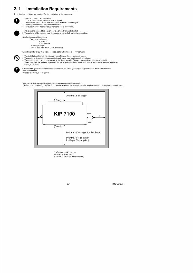
Keep ample space around the equipment to ensure comfortable operation.(Refer to the following figure.) The floor must be level and the strength must be ample to sustain the weight of the equipment.
L* R*
(Rear)
(Front)
300mm/12” or larger
800mm/32” or larger for Roll Deck
KIP 7100
5/17/2018 KIP 7100 Service Manual Ver A_1 - slidepdf.com
http://slidepdf.com/reader/full/kip-7100-service-manual-ver-a1 20/674
2. 2 Unpacking
2. 2. 1 Unpacking
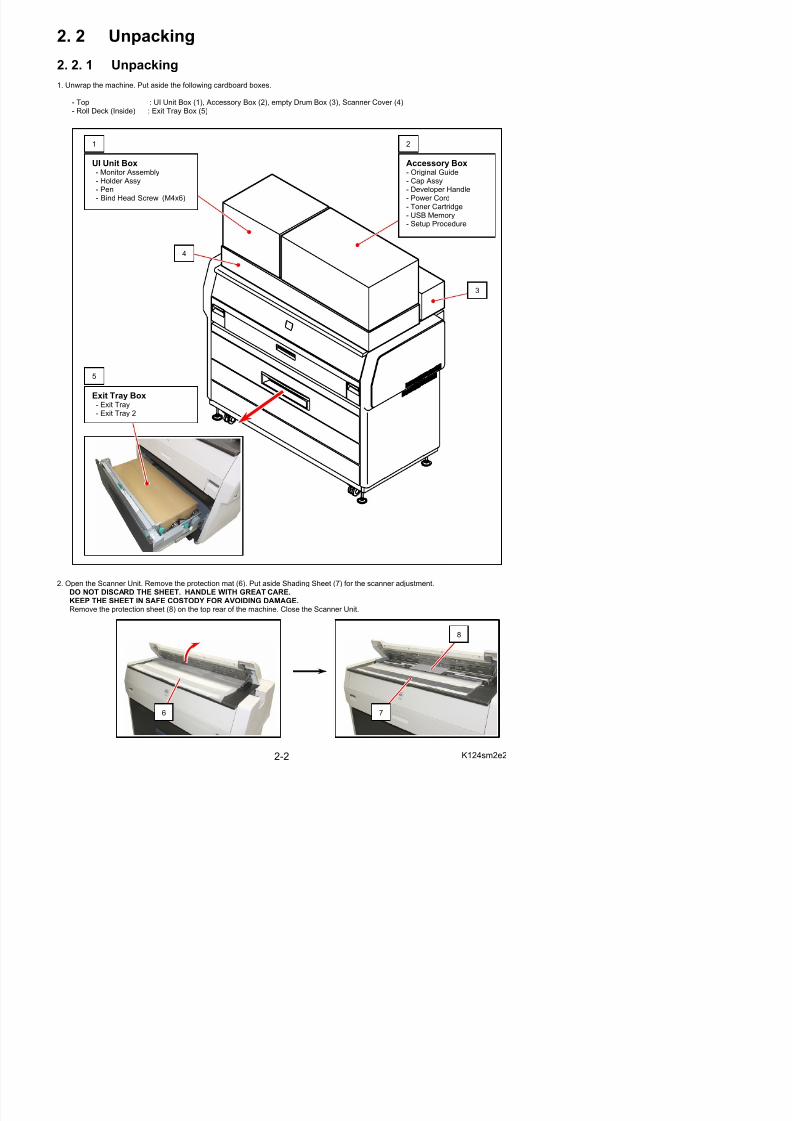
1. Unwrap the machine. Put aside the following cardboard boxes.
- Top : UI Unit Box (1), Accessory Box (2), empty Drum Box (3), Scanner Cover (4)- Roll Deck (Inside) : Exit Tray Box (5)
1 2
UI Unit Box- Monitor Assembly- Holder Assy- Pen
- Bind Head Screw (M4x6)
Accessory Box- Original Guide- Cap Assy- Developer Handle
- Power Cord- Toner Cartridge- USB Memory- Setup Procedure
4
3
5
Exit Tray Box- Exit Tray- Exit Tray 2
5/17/2018 KIP 7100 Service Manual Ver A_1 - slidepdf.com
http://slidepdf.com/reader/full/kip-7100-service-manual-ver-a1 21/674
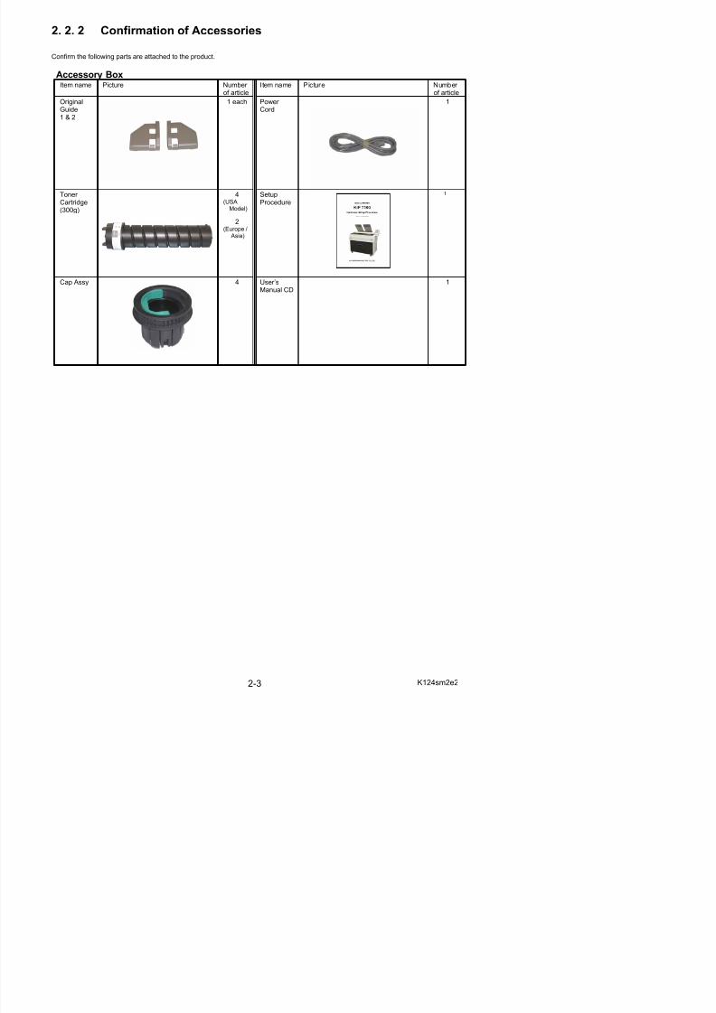
2. 2. 2 Confirmation of Accessories
Confirm the following parts are attached to the product.
Accessory BoxItem name Picture Number
of article
Item name Picture Number
of articleOriginalGuide1 & 2
1 each Power Cord
1
Toner Cartridge(300g)
4(USA
Model)
2(Europe /
Asia)
SetupProcedure
1
Cap Assy 4 User’sManual CD
1
5/17/2018 KIP 7100 Service Manual Ver A_1 - slidepdf.com
http://slidepdf.com/reader/full/kip-7100-service-manual-ver-a1 22/674
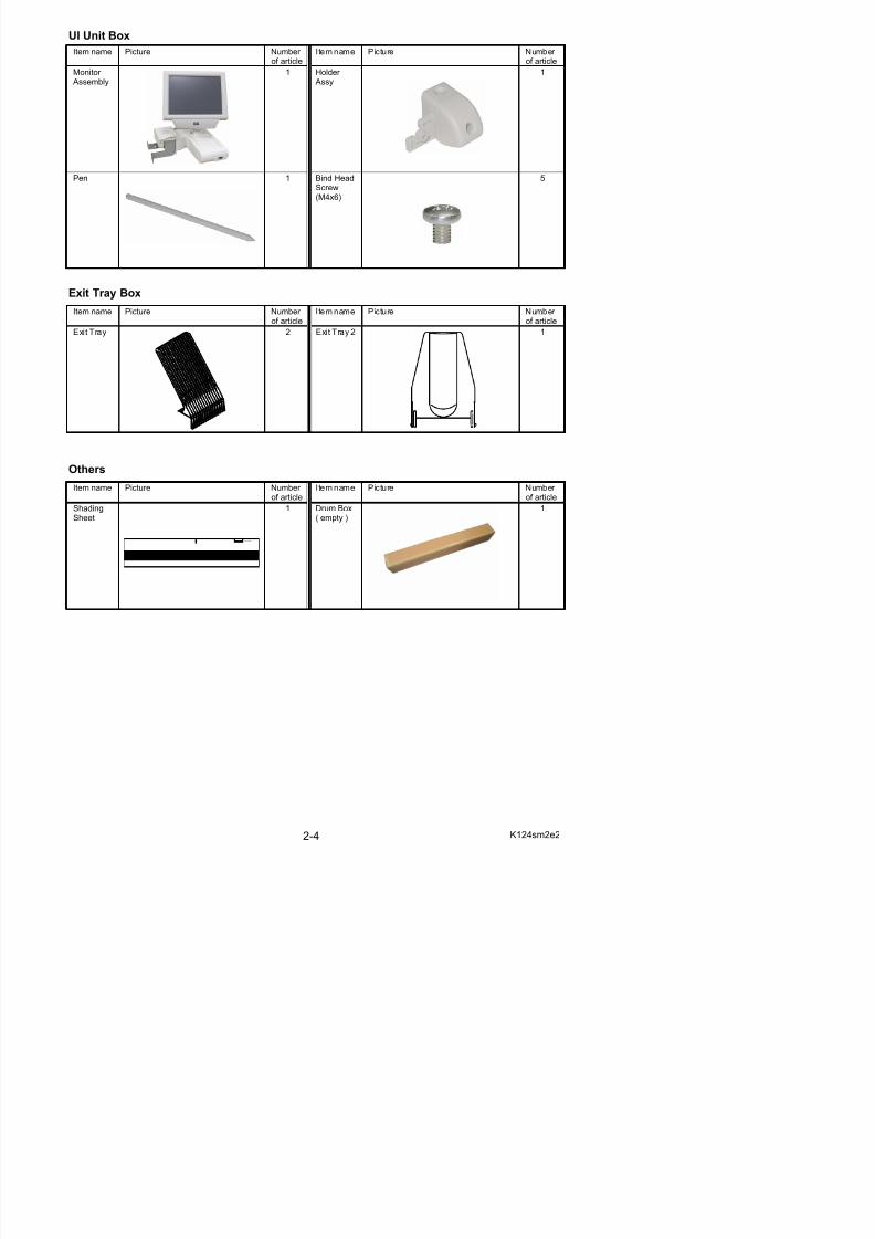
UI Unit Box
Item name Picture Number of article
Item name Picture Number of article
Monitor Assembly
1 Holder Assy
1
Pen 1 Bind HeadScrew(M4x6)
5
Exit Tray Box
Item name Picture Number of article
Item name Picture Number of article
Exit Tray 2 Exit Tray 2 1
Others
Item name Picture Number of article
Item name Picture Number of article
ShadingSheet
1 Drum Box( empty )
1
5/17/2018 KIP 7100 Service Manual Ver A_1 - slidepdf.com
http://slidepdf.com/reader/full/kip-7100-service-manual-ver-a1 23/674
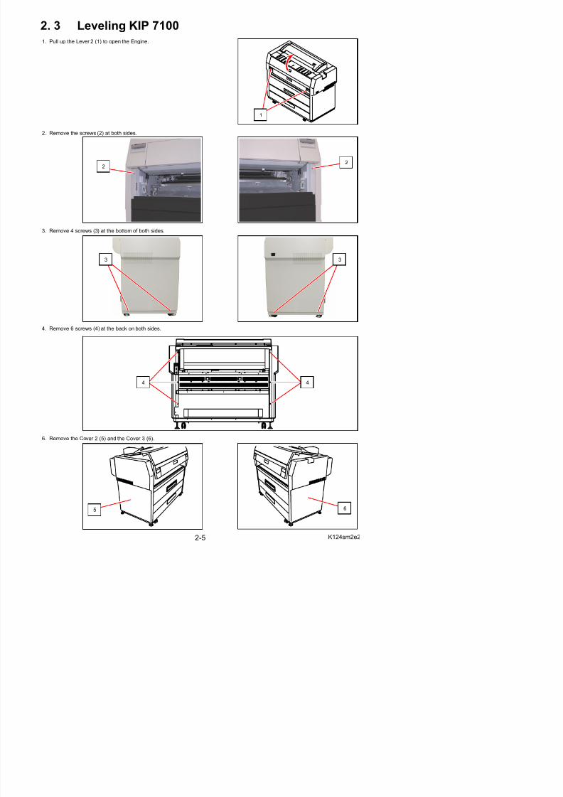
2. 3 Leveling KIP 7100 1. Pull up the Lever 2 (1) to open the Engine.
2. Remove the screws (2) at both sides.
3. Remove 4 screws (3) at the bottom of both sides.
4. Remove 6 screws (4) at the back on both sides.
2
1
22
44
33
7 Close the Engine Unit
5/17/2018 KIP 7100 Service Manual Ver A_1 - slidepdf.com
http://slidepdf.com/reader/full/kip-7100-service-manual-ver-a1 24/674
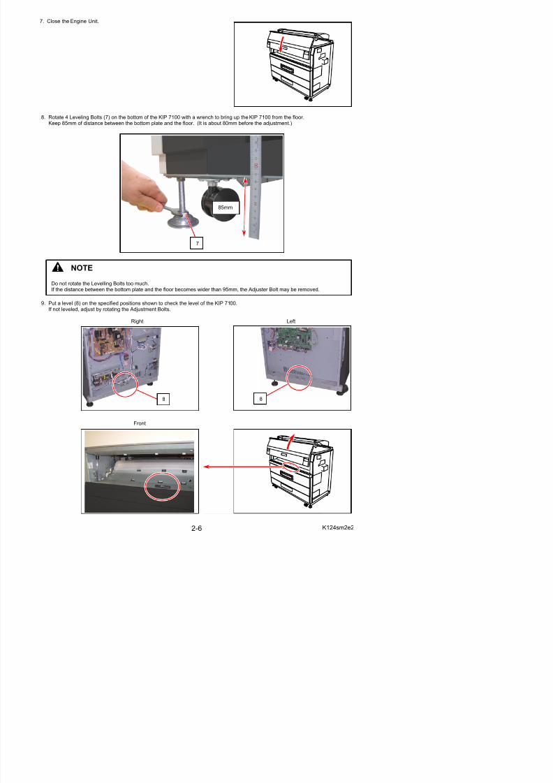
7. Close the Engine Unit.
8. Rotate 4 Leveling Bolts (7) on the bottom of the KIP 7100 with a wrench to bring up the KIP 7100 from the floor.Keep 85mm of distance between the bottom plate and the floor. (It is about 80mm before the adjustment.)
9. Put a level (8) on the specified positions shown to check the level of the KIP 7100.If not leveled, adjust by rotating the Adjustment Bolts.
Right Left
NOTE
Do not rotate the Levelling Bolts too much.If the distance between the bottom plate and the floor becomes wider than 95mm, the Adjuster Bolt may be removed.
85mm
7
2 4 S t f th M hi
5/17/2018 KIP 7100 Service Manual Ver A_1 - slidepdf.com
http://slidepdf.com/reader/full/kip-7100-service-manual-ver-a1 25/674
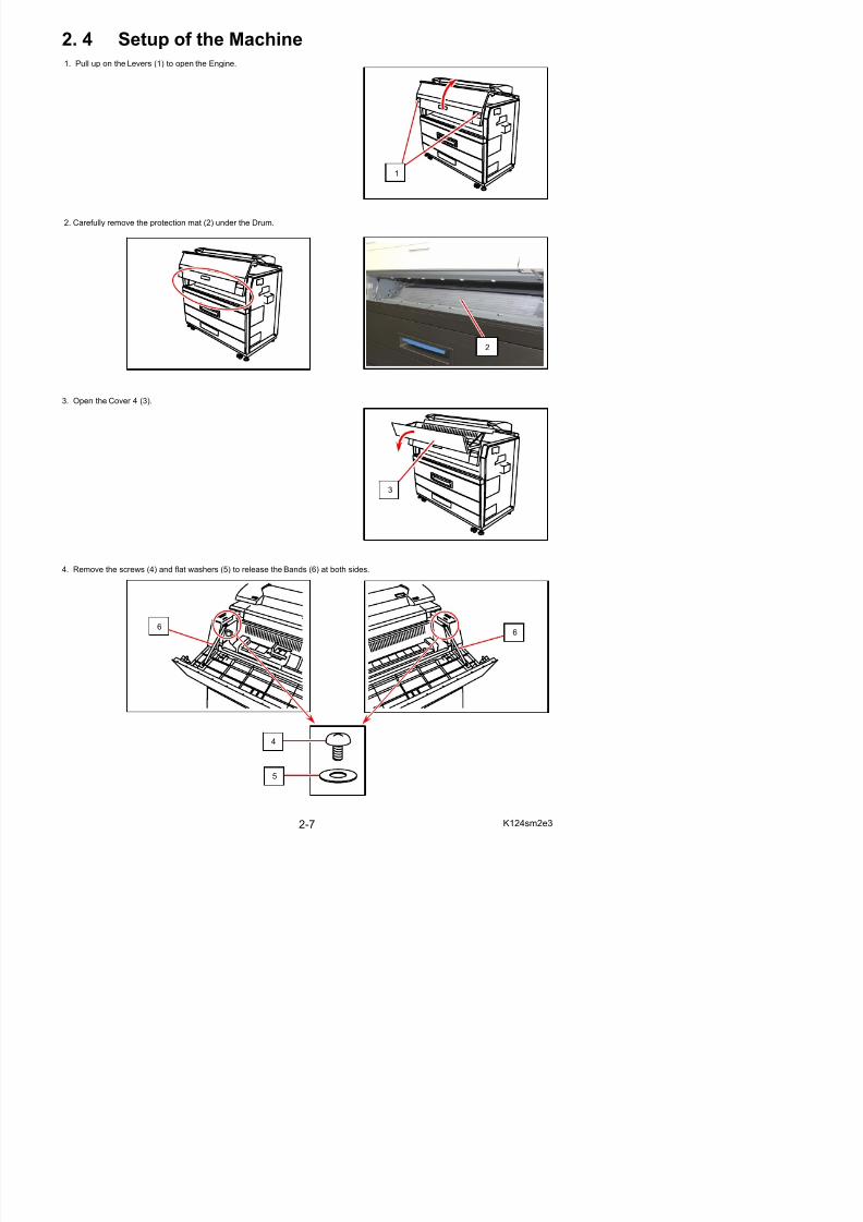
2. 4 Setup of the Machine1. Pull up on the Levers (1) to open the Engine.
2. Carefully remove the protection mat (2) under the Drum.
3. Open the Cover 4 (3).
4. Remove the screws (4) and flat washers (5) to release the Bands (6) at both sides.
1
3
2
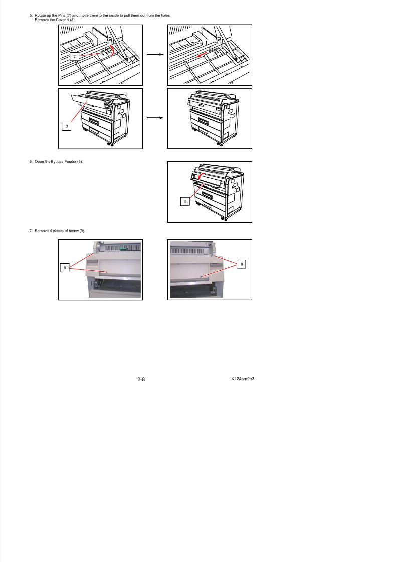
5. Rotate up the Pins (7) and move them to the inside to pull them out from the holes.
5/17/2018 KIP 7100 Service Manual Ver A_1 - slidepdf.com
http://slidepdf.com/reader/full/kip-7100-service-manual-ver-a1 26/674
p ( ) pRemove the Cover 4 (3).
6. Open the Bypass Feeder (8).
7. Remove 4 pieces of screw (9).
3
8
7
99
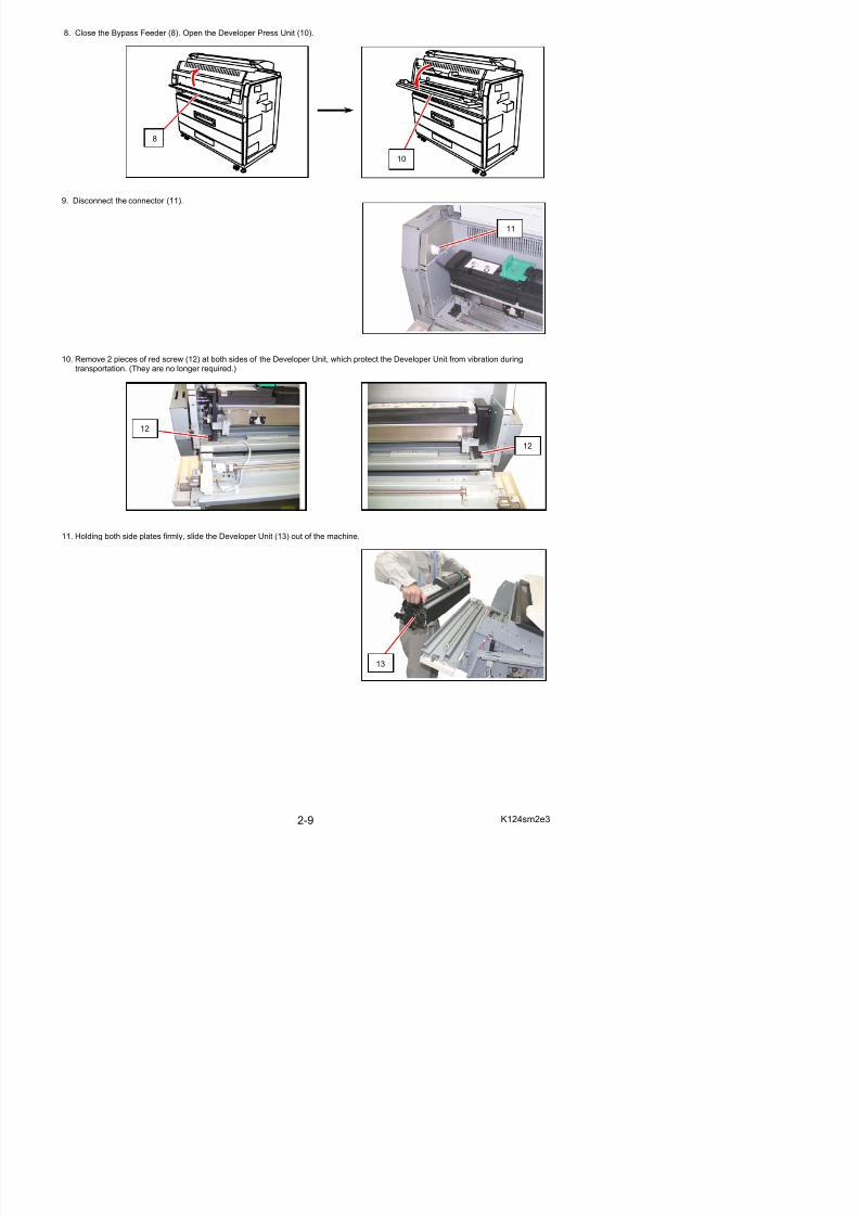
8. Close the Bypass Feeder (8). Open the Developer Press Unit (10).
5/17/2018 KIP 7100 Service Manual Ver A_1 - slidepdf.com
http://slidepdf.com/reader/full/kip-7100-service-manual-ver-a1 27/674
9. Disconnect the connector (11).
10. Remove 2 pieces of red screw (12) at both sides of the Developer Unit, which protect the Developer Unit from vibration duringtransportation. (They are no longer required.)
11. Holding both side plates firmly, slide the Developer Unit (13) out of the machine.
12
12
8
10
11
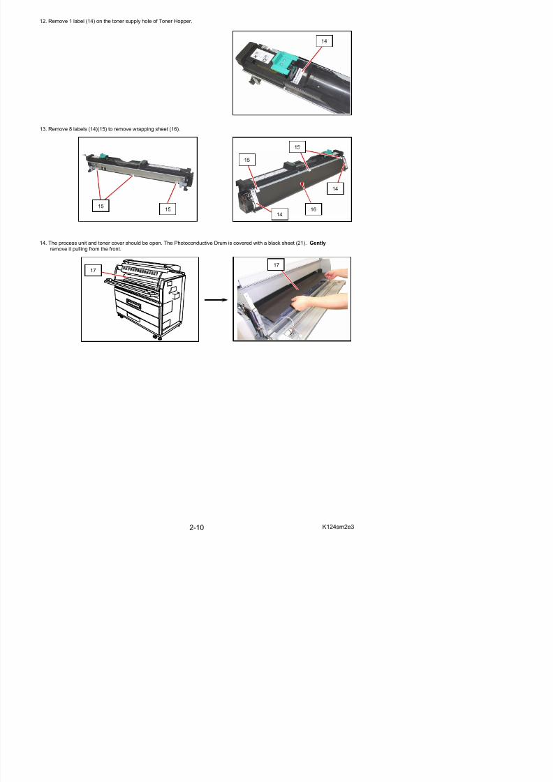
12. Remove 1 label (14) on the toner supply hole of Toner Hopper.
5/17/2018 KIP 7100 Service Manual Ver A_1 - slidepdf.com
http://slidepdf.com/reader/full/kip-7100-service-manual-ver-a1 28/674
13. Remove 8 labels (14)(15) to remove wrapping sheet (16).
14. The process unit and toner cover should be open. The Photoconductive Drum is covered with a black sheet (21). Gently remove it pulling from the front.
1515
1717
16
15
15
14
14
14
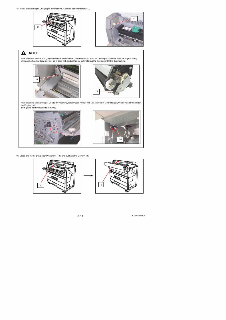
15. Install the Developer Unit (13) to the machine. Connect the connector (11).
5/17/2018 KIP 7100 Service Manual Ver A_1 - slidepdf.com
http://slidepdf.com/reader/full/kip-7100-service-manual-ver-a1 29/674
16. Close and fix the Developer Press Unit (10), and put back the Cover 4 (3).
NOTE
Both the Gear Helical 20T (18) on machine side and the Gear Helical 28T (19) on Developer Unit side must be in gear firmlywith each other, but they may not be in gear with each other by just installing the Developer Unit to the machine.
After installing the Developer Unit to the machine, rotate Gear Helical 34T (20: instead of Gear Helical 20T) by hand from under the Engine Unit.Both gears will be in gear by this way.
19
13
18
20
11
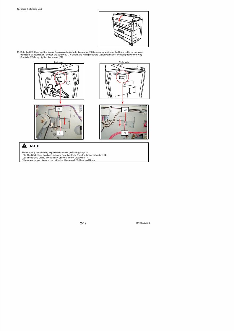
17. Close the Engine Unit.
5/17/2018 KIP 7100 Service Manual Ver A_1 - slidepdf.com
http://slidepdf.com/reader/full/kip-7100-service-manual-ver-a1 30/674
18. Both the LED Head and the Image Corona are locked with the screws (21) being separated from the Drum, not to be damagedduring the transportation. Loosen the screws (21) to unlock the Fixing Brackets (22) at both sides. Pressing down the FixingBrackets (22) firmly, tighten the screws (21).
Left side Right side
NOTE
Please satisfy the following requirements before performing Step 18.(1) The black sheet has been removed from the Drum. (See the former procedure 14.)(2) The Engine Unit is closed firmly. (See the former procedure 17.)
Otherwise a proper distance can not be kept between LED Head and Drum.
22
21
22
21
2. 5 Installing Monitor
5/17/2018 KIP 7100 Service Manual Ver A_1 - slidepdf.com
http://slidepdf.com/reader/full/kip-7100-service-manual-ver-a1 31/674
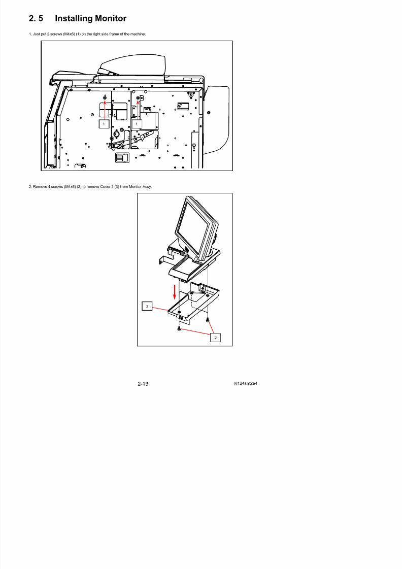
2. 5 Installing Monitor 1. Just put 2 screws (M4x6) (1) on the right side frame of the machine.
2. Remove 4 screws (M4x6) (2) to remove Cover 2 (3) f rom Monitor Assy.
11
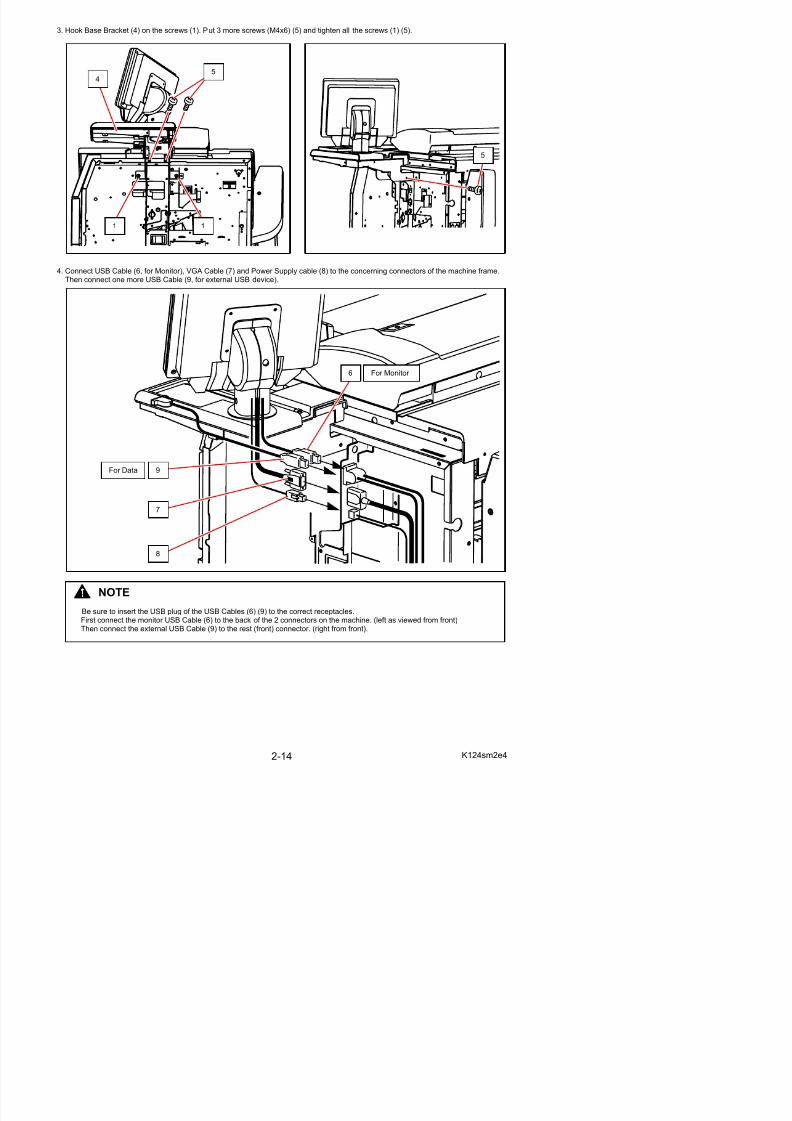
3. Hook Base Bracket (4) on the screws (1). Put 3 more screws (M4x6) (5) and tighten all the screws (1) (5).
5/17/2018 KIP 7100 Service Manual Ver A_1 - slidepdf.com
http://slidepdf.com/reader/full/kip-7100-service-manual-ver-a1 32/674
4. Connect USB Cable (6, for Monitor), VGA Cable (7) and Power Supply cable (8) to the concerning connectors of the machine frame. Then connect one more USB Cable (9, for external USB device).
11
54
5
6
9
7
8
For Data
For Monitor
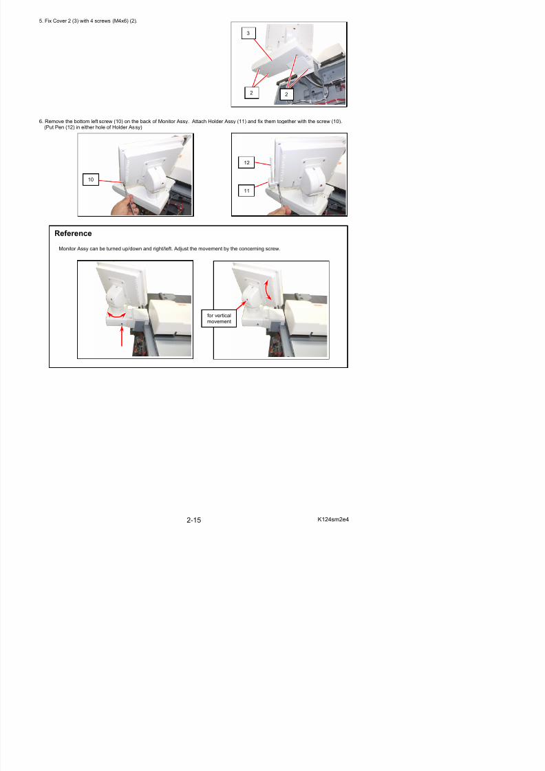
5. Fix Cover 2 (3) with 4 screws (M4x6) (2).
5/17/2018 KIP 7100 Service Manual Ver A_1 - slidepdf.com
http://slidepdf.com/reader/full/kip-7100-service-manual-ver-a1 33/674
6. Remove the bottom left screw (10) on the back of Monitor Assy. Attach Holder Assy (11) and fix them together with the screw (10).(Put Pen (12) in either hole of Holder Assy)
10
12
11
Reference
Monitor Assy can be turned up/down and right/left. Adjust the movement by the concerning screw.
for horizontal movement
for verticalmovement
2 2
3
2. 6 Installing Accessories
5/17/2018 KIP 7100 Service Manual Ver A_1 - slidepdf.com
http://slidepdf.com/reader/full/kip-7100-service-manual-ver-a1 34/674
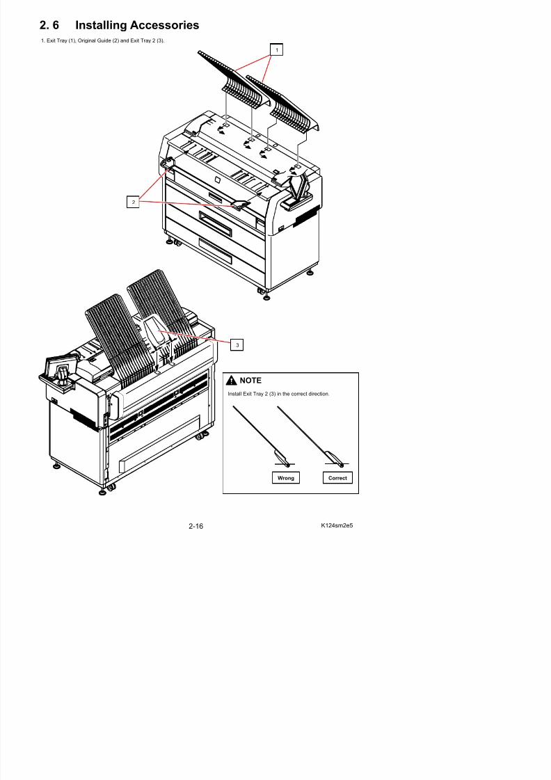
g1. Exit Tray (1), Original Guide (2) and Exit Tray 2 (3).
1
2
3
NOTE
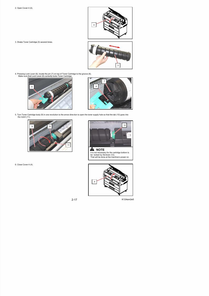
2. Open Cover 4 (4).
5/17/2018 KIP 7100 Service Manual Ver A_1 - slidepdf.com
http://slidepdf.com/reader/full/kip-7100-service-manual-ver-a1 35/674
3. Shake Toner Cartridge (5) several times.
4. Pressing Lock Lever (6), locate the pin (7) on top of Toner Cartridge to the groove (8).Make sure that Lock Lever (6) correctly locks Toner Cartridge.
5. Turn Toner Cartridge body (9) in one revolution to the arrow direction to open the toner supply hole so that the tab (10) goes intothe notch (11).
4
7
8
5
6
9 10
11
12
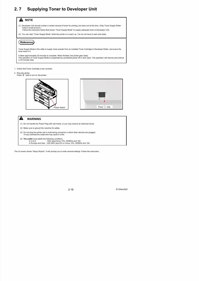
2. 7 Supplying Toner to Developer Unit
5/17/2018 KIP 7100 Service Manual Ver A_1 - slidepdf.com
http://slidepdf.com/reader/full/kip-7100-service-manual-ver-a1 36/674
1. Check that Toner Cartridge is set correctly.
2. Plug the printer.
Press “ ” side to turn on the printer.
NOTE
(1) Developer Unit should contain a certain amount of toner for printing, but does not at this time. (Only Toner Supply Roller holds a small amount.)Follow the instruction below that shows “Toner Supply Mode” to supply adequate toner to Developer Unit.
(2) You can start “Toner Supply Mode” while the printer is in warm up. You do not have to wait until ready.
Reference
Toner Supply Mode is the utility to supply toner powder from an installed Toner Cartridge to Developer Roller, and evens the
toner level in it.
It takes approximately 20 minutes to complete. When finished, the printer gets ready.The operation of Toner Supply Mode is suspended by accidental power off or door open. The operation will resume and ontinuein 20 minutes total.
Power Switch
Press “ | ” side.
WARNING
(1) Do not handle the Power Plug with wet hands, or you may receive an electrical shock.
(2) Make sure to ground the machine for safety.
(3) Do not plug the printer into a multi-wiring connector in which other devices are plugged.It may overheat the outlet and may result in a fire.
(4) The outlet must satisfy the following conditions
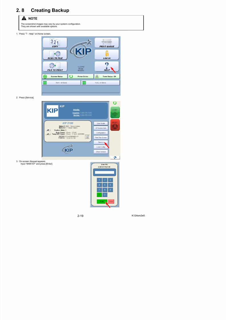
2. 8 Creating Backup
5/17/2018 KIP 7100 Service Manual Ver A_1 - slidepdf.com
http://slidepdf.com/reader/full/kip-7100-service-manual-ver-a1 37/674
1. Press “? - Help” on Home screen.
2. Press [Service].
NOTE
The screenshot images may vary by your system configuration.They are shown with available options.
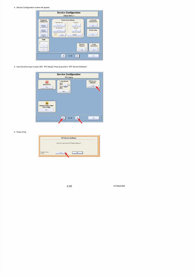
4. Service Configuration screen will appear.
5/17/2018 KIP 7100 Service Manual Ver A_1 - slidepdf.com
http://slidepdf.com/reader/full/kip-7100-service-manual-ver-a1 38/674
5. Use the arrow keys to open [5/6 IPS Setup]. Press [Launch] in “KIP Service Software”.
6. Press [Yes].
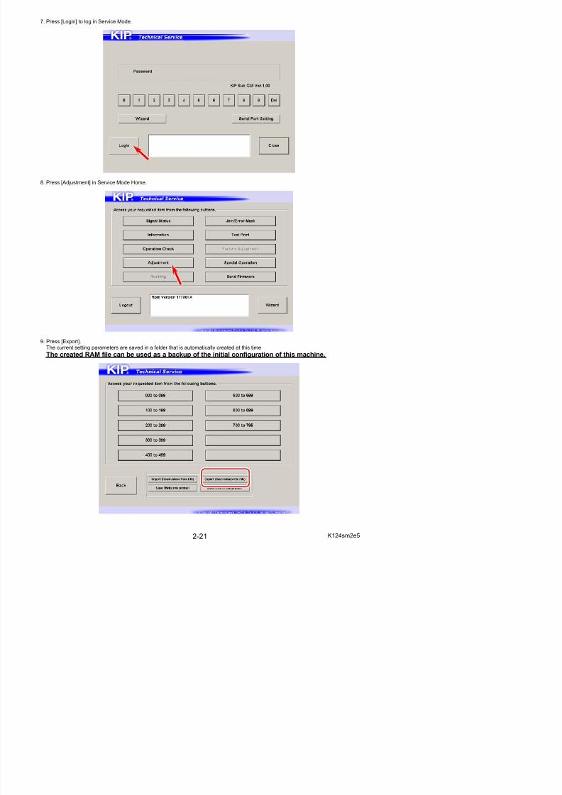
7. Press [Login] to log in Service Mode.
5/17/2018 KIP 7100 Service Manual Ver A_1 - slidepdf.com
http://slidepdf.com/reader/full/kip-7100-service-manual-ver-a1 39/674
8. Press [Adjustment] in Service Mode Home.
9. Press [Export].The current setting parameters are saved in a folder that is automatically created at this time.
The created RAM file can be used as a backup of the initial configuration of this machine.
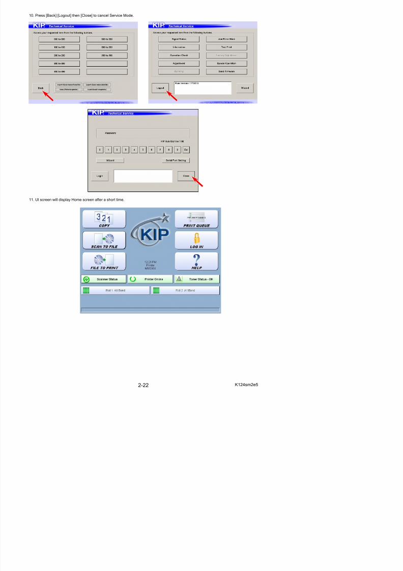
10. Press [Back] [Logout] then [Close] to cancel Service Mode.
5/17/2018 KIP 7100 Service Manual Ver A_1 - slidepdf.com
http://slidepdf.com/reader/full/kip-7100-service-manual-ver-a1 40/674
11. UI screen will display Home screen after a short time.
5/17/2018 KIP 7100 Service Manual Ver A_1 - slidepdf.com
http://slidepdf.com/reader/full/kip-7100-service-manual-ver-a1 41/674
Chapter 3
Print / Scan Process
Page3. 1 Print Process 3- 2
3. 1. 1 Characteristic of toner 3- 23. 1. 2 Each step of the print process 3- 3
3 1 2 1 Erasing (Removal of negative electric charges) 3- 5
3. 1 Print Process
5/17/2018 KIP 7100 Service Manual Ver A_1 - slidepdf.com
http://slidepdf.com/reader/full/kip-7100-service-manual-ver-a1 42/674
3. 1. 1 Characteristic of toner
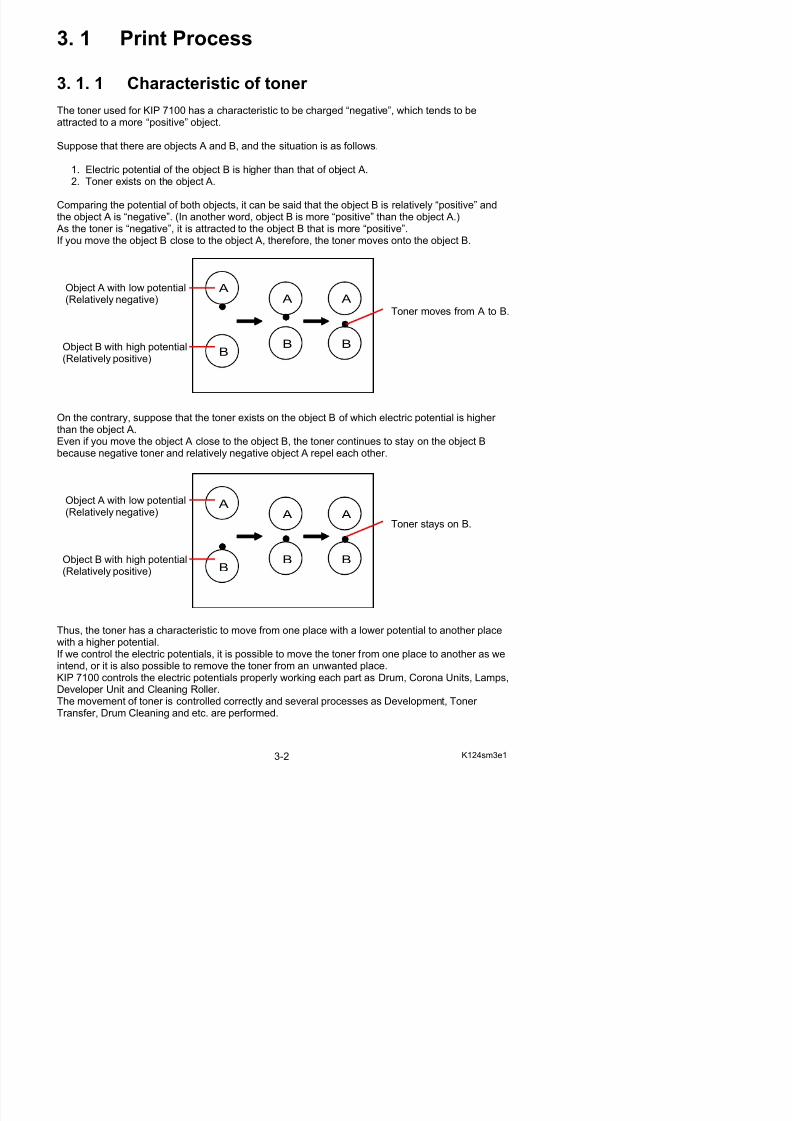
The toner used for KIP 7100 has a characteristic to be charged “negative”, which tends to beattracted to a more “positive” object.
Suppose that there are objects A and B, and the situation is as follows.
1. Electric potential of the object B is higher than that of object A.2. Toner exists on the object A.
Comparing the potential of both objects, it can be said that the object B is relatively “positive” andthe object A is “negative”. (In another word, object B is more “positive” than the object A.) As the toner is “negative”, it is attracted to the object B that is more “positive”.If you move the object B close to the object A, therefore, the toner moves onto the object B.
Object A with low potential
(Relatively negative) Toner moves from A to B.
Object B with high potential(Relatively positive)
On the contrary, suppose that the toner exists on the object B of which electric potential is higher than the object A.Even if you move the object A close to the object B, the toner continues to stay on the object Bbecause negative toner and relatively negative object A repel each other.
Object A with low potential(Relatively negative)
Toner stays on B.
Obj B i h hi h i l
A A
B
A
B
A
B
A
B
A
B
3. 1. 2 Each step of print process
5/17/2018 KIP 7100 Service Manual Ver A_1 - slidepdf.com
http://slidepdf.com/reader/full/kip-7100-service-manual-ver-a1 43/674
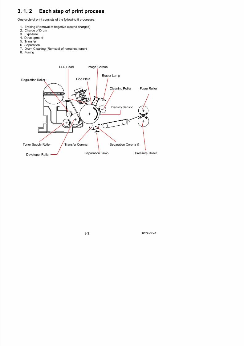
One cycle of print consists of the following 8 processes.
1. Erasing (Removal of negative electric charges)2. Charge of Drum
3. Exposure4. Development5. Transfer 6. Separation7. Drum Cleaning (Removal of remained toner)8. Fusing
Image CoronaLED Head
Cleaning Roller
Eraser Lamp
Regulation Roller
Toner Supply Roller
Developer Roller
Transfer Corona
Pressure Roller
Fuser Roller
Grid Plate
Separation Corona &
Separation Lamp
Density Sensor
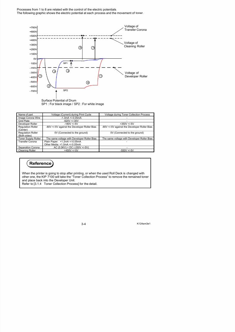
Processes from 1 to 8 are related with the control of the electric potentials.The following graphic shows the electric potential at each process and the movement of toner.
5/17/2018 KIP 7100 Service Manual Ver A_1 - slidepdf.com
http://slidepdf.com/reader/full/kip-7100-service-manual-ver-a1 44/674
Surface Potential of DrumSP1 : For black image / SP2 : For white image
Name of part Voltage (Current) during Print Cycle Voltage during Toner Collection Process
Image Corona Wire -1.3mA +/-0.05mA -Grid Plate -620V +/-30V -
Developer Roller -180V +/-5V +350V +/-5V
Regulation Roller (Center)
-80V +/-5V against the Developer Roller Bias -80V +/-5V against the Developer Roller Bias
Regulation Roller (Both sides)
0V (Connected to the ground) 0V (Connected to the ground)
Toner Supply Roller The same voltage with Developer Roller Bias The same voltage with Developer Roller Bias
Transfer Corona Plain Paper: +1.2mA +/-0.05mAOther Media: +1.0mA +/-0.05mA
-
Separation Corona AC (5.0KV) + DC (-250V +/-5V) -Cleaning Roller +450V +/-5V -550V +/-5V
0V
-100V
-200V
-300V
-400V
-500V
-600V
-700V
+400V
+300V
+200V
+100V
+500V
2
3 4
5
6
7
1
+600V
SP1
SP2
+700V
1
Reference
Voltage of Cleaning Roller
Voltage of Transfer Corona
Voltage of Developer Roller
3. 1. 2. 1 Erasing (Removal of negative electric charges)
As the first step of print cycle it is necessary to remove the negative electric charges from the
5/17/2018 KIP 7100 Service Manual Ver A_1 - slidepdf.com
http://slidepdf.com/reader/full/kip-7100-service-manual-ver-a1 45/674
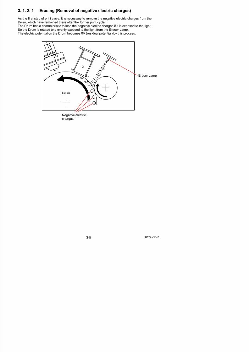
As the first step of print cycle, it is necessary to remove the negative electric charges from theDrum, which have remained there after the former print cycle.The Drum has a characteristic to lose the negative electric charges if it is exposed to the light.So the Drum is rotated and evenly exposed to the light from the Eraser Lamp.
The electric potential on the Drum becomes 0V (residual potential) by this process.
0V
0V
0V
Eraser Lamp
Drum
Negative electriccharges
3. 1. 2 .2 Charge of Drum
The Image Corona discharges negative electric charges which are given to the Drum.
5/17/2018 KIP 7100 Service Manual Ver A_1 - slidepdf.com
http://slidepdf.com/reader/full/kip-7100-service-manual-ver-a1 46/674
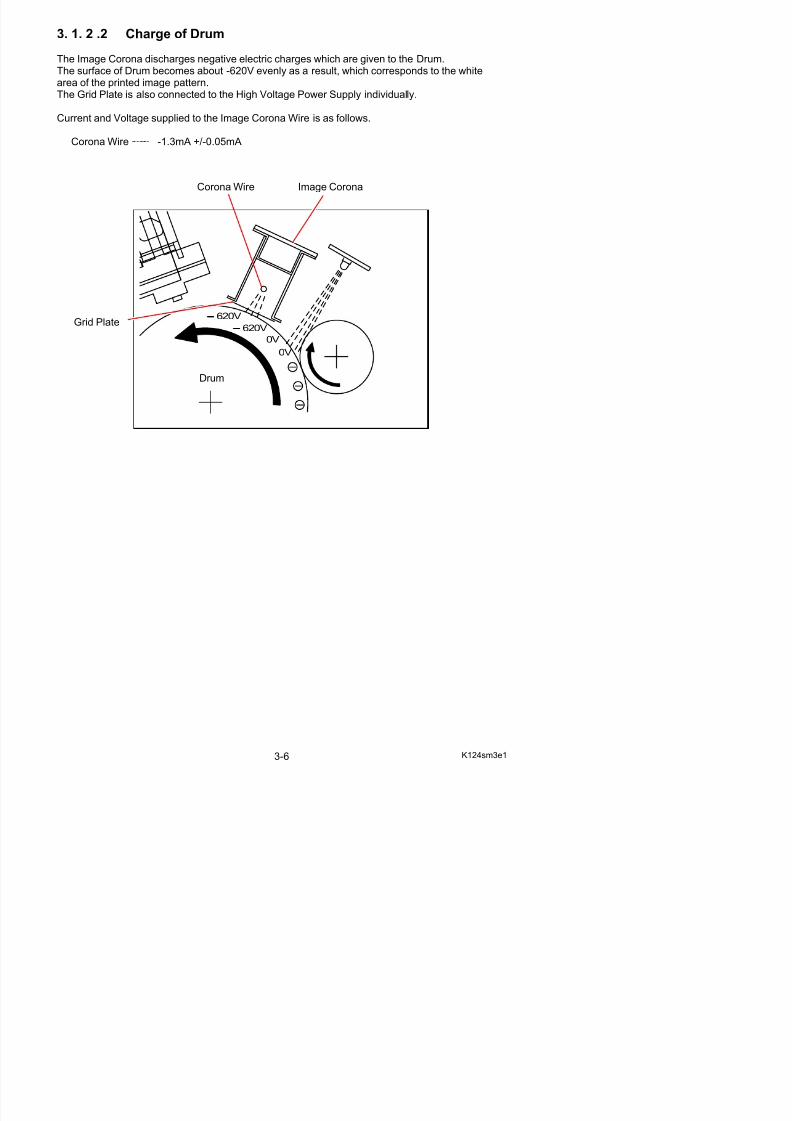
The Image Corona discharges negative electric charges which are given to the Drum.The surface of Drum becomes about -620V evenly as a result, which corresponds to the whitearea of the printed image pattern.The Grid Plate is also connected to the High Voltage Power Supply individually.
Current and Voltage supplied to the Image Corona Wire is as follows.
Corona Wire -1.3mA +/-0.05mA
0V
0V
620V
620V
Corona Wire
Drum
Grid Plate
Image Corona
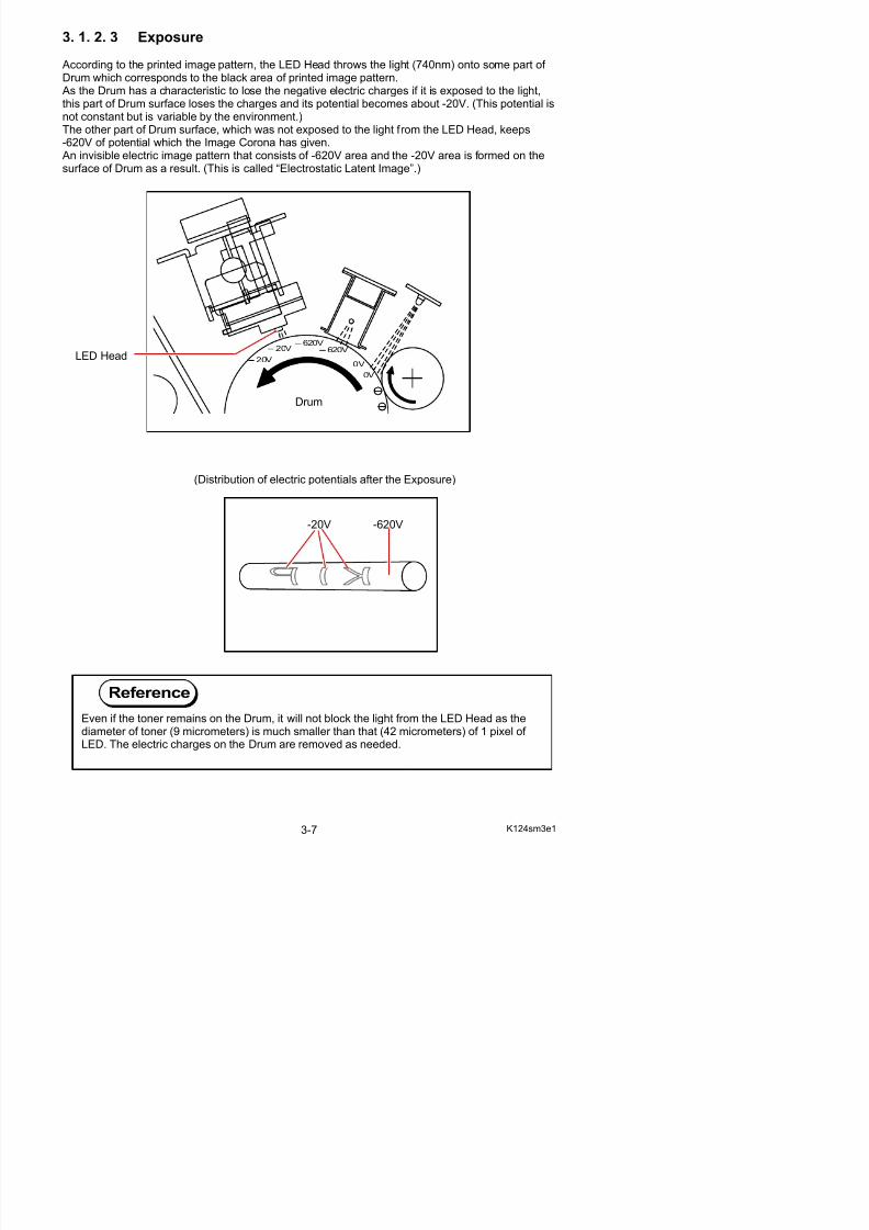
3. 1. 2. 3 Exposure
According to the printed image pattern, the LED Head throws the light (740nm) onto some part of
5/17/2018 KIP 7100 Service Manual Ver A_1 - slidepdf.com
http://slidepdf.com/reader/full/kip-7100-service-manual-ver-a1 47/674
g p g p , g ( ) pDrum which corresponds to the black area of printed image pattern. As the Drum has a characteristic to lose the negative electric charges if it is exposed to the light,this part of Drum surface loses the charges and its potential becomes about -20V. (This potential is
not constant but is variable by the environment.)The other part of Drum surface, which was not exposed to the light from the LED Head, keeps-620V of potential which the Image Corona has given. An invisible electric image pattern that consists of -620V area and the -20V area is formed on thesurface of Drum as a result. (This is called “Electrostatic Latent Image”.)
(Distribution of electric potentials after the Exposure)
0V
620V
0V
620V20V
20V
LED Head
Drum
-20V -620V
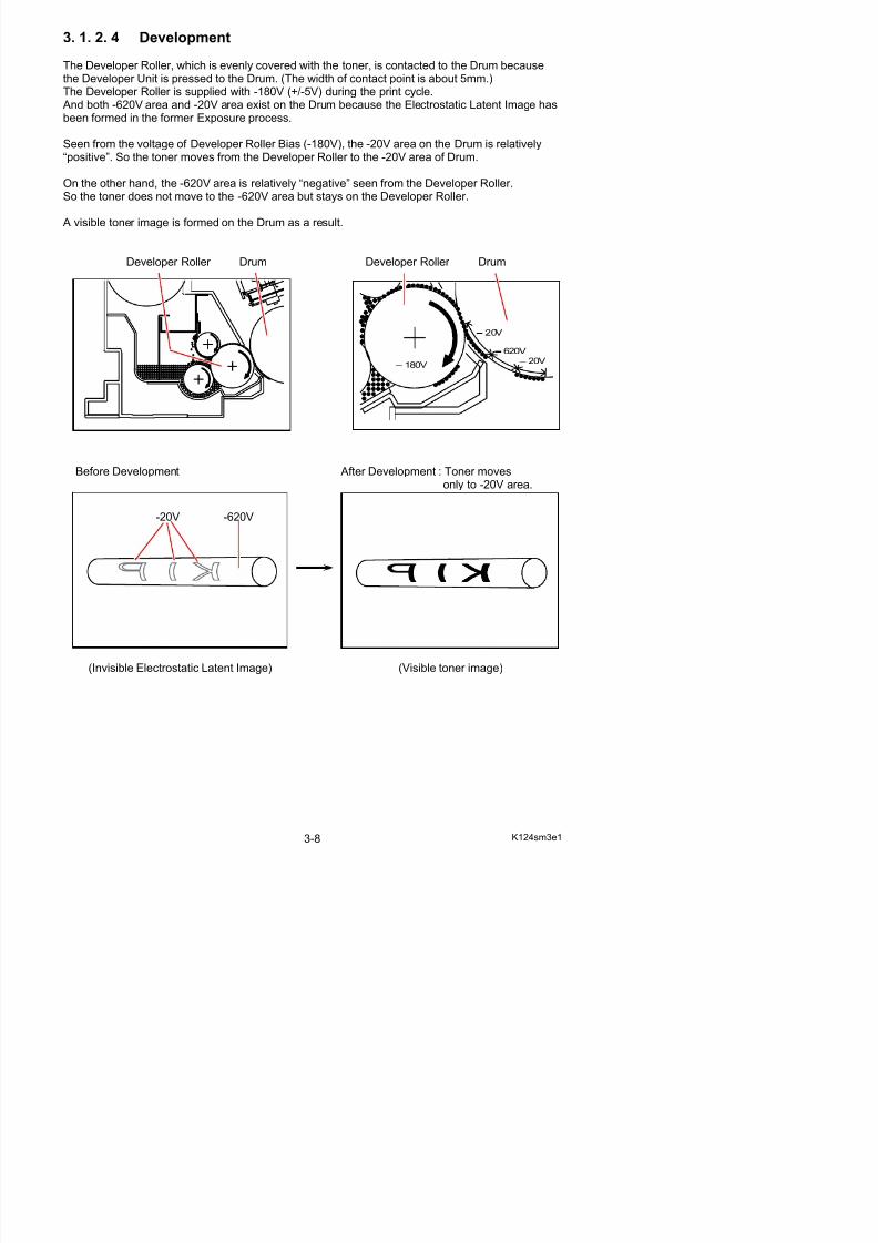
3. 1. 2. 4 Development
The Developer Roller, which is evenly covered with the toner, is contacted to the Drum because
5/17/2018 KIP 7100 Service Manual Ver A_1 - slidepdf.com
http://slidepdf.com/reader/full/kip-7100-service-manual-ver-a1 48/674
ythe Developer Unit is pressed to the Drum. (The width of contact point is about 5mm.)The Developer Roller is supplied with -180V (+/-5V) during the print cycle. And both -620V area and -20V area exist on the Drum because the Electrostatic Latent Image has
been formed in the former Exposure process.
Seen from the voltage of Developer Roller Bias (-180V), the -20V area on the Drum is relatively“positive”. So the toner moves from the Developer Roller to the -20V area of Drum.
On the other hand, the -620V area is relatively “negative” seen from the Developer Roller.So the toner does not move to the -620V area but stays on the Developer Roller.
A visible toner image is formed on the Drum as a result.
Developer Roller Drum Developer Roller Drum
Before Development After Development : Toner movesonly to -20V area.
620V
20V
20V180V
-20V -620V
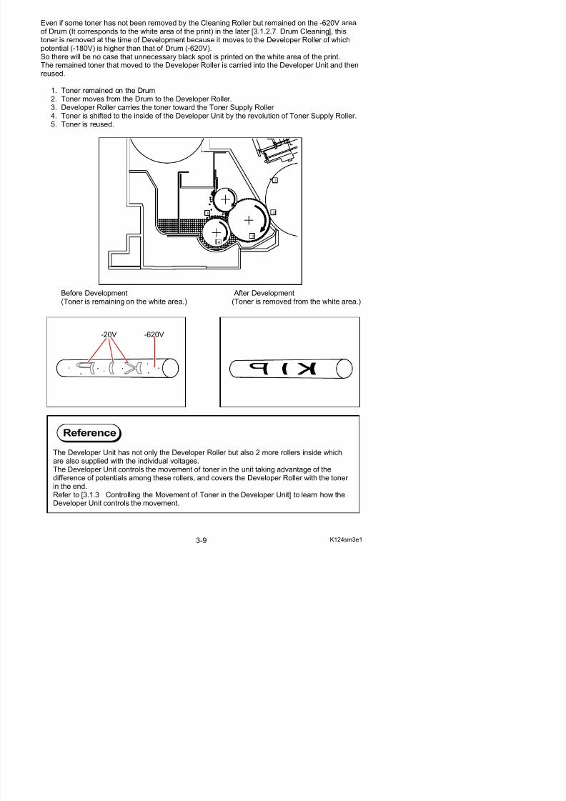
Even if some toner has not been removed by the Cleaning Roller but remained on the -620V areaof Drum (It corresponds to the white area of the print) in the later [3.1.2.7 Drum Cleaning], thistoner is removed at the time of Development because it moves to the Developer Roller of whichpotential ( 180V) is higher than that of Dr m ( 620V)
5/17/2018 KIP 7100 Service Manual Ver A_1 - slidepdf.com
http://slidepdf.com/reader/full/kip-7100-service-manual-ver-a1 49/674
potential (-180V) is higher than that of Drum (-620V).So there will be no case that unnecessary black spot is printed on the white area of the print.The remained toner that moved to the Developer Roller is carried into the Developer Unit and thenreused.
1. Toner remained on the Drum2. Toner moves from the Drum to the Developer Roller.3. Developer Roller carries the toner toward the Toner Supply Roller 4. Toner is shifted to the inside of the Developer Unit by the revolution of Toner Supply Roller.5. Toner is reused.
Before Development After Development(Toner is remaining on the white area.) (Toner is removed from the white area.)
-20V -620V
1
2
3
4
5
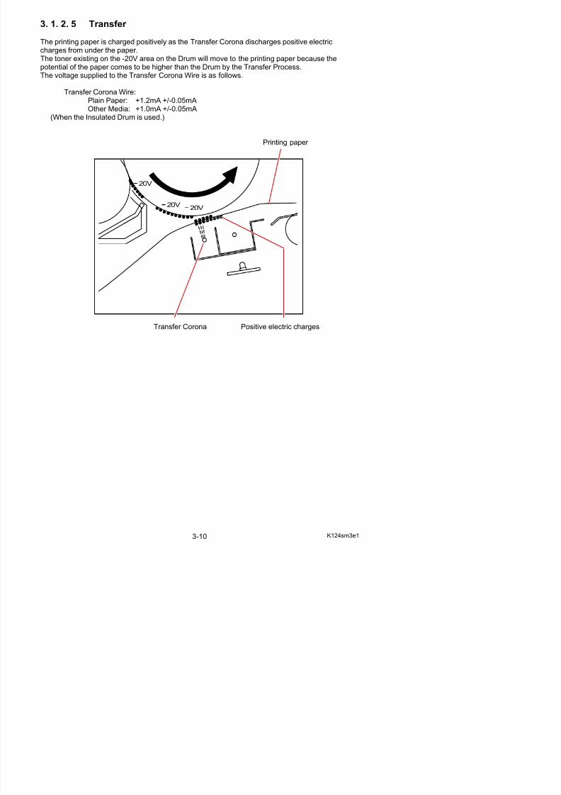
3. 1. 2. 5 Transfer
The printing paper is charged positively as the Transfer Corona discharges positive electrich f d th
5/17/2018 KIP 7100 Service Manual Ver A_1 - slidepdf.com
http://slidepdf.com/reader/full/kip-7100-service-manual-ver-a1 50/674
charges from under the paper.The toner existing on the -20V area on the Drum will move to the printing paper because thepotential of the paper comes to be higher than the Drum by the Transfer Process.
The voltage supplied to the Transfer Corona Wire is as follows.
Transfer Corona Wire:Plain Paper: +1.2mA +/-0.05mAOther Media: +1.0mA +/-0.05mA
(When the Insulated Drum is used.)
Printing paper
Transfer Corona Positive electric charges
20V20V
20V
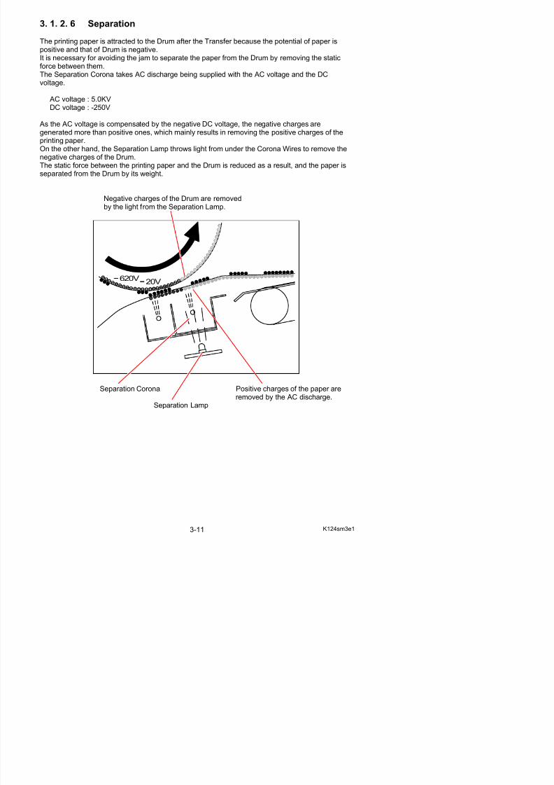
3. 1. 2. 6 Separation
The printing paper is attracted to the Drum after the Transfer because the potential of paper isiti d th t f D i ti
5/17/2018 KIP 7100 Service Manual Ver A_1 - slidepdf.com
http://slidepdf.com/reader/full/kip-7100-service-manual-ver-a1 51/674
positive and that of Drum is negative.It is necessary for avoiding the jam to separate the paper from the Drum by removing the staticforce between them.
The Separation Corona takes AC discharge being supplied with the AC voltage and the DCvoltage.
AC voltage : 5.0KVDC voltage : -250V
As the AC voltage is compensated by the negative DC voltage, the negative charges aregenerated more than positive ones, which mainly results in removing the positive charges of theprinting paper.On the other hand, the Separation Lamp throws light from under the Corona Wires to remove thenegative charges of the Drum.The static force between the printing paper and the Drum is reduced as a result, and the paper isseparated from the Drum by its weight.
Negative charges of the Drum are removedby the light from the Separation Lamp.
Drum
Separation Corona Positive charges of the paper are
20V620V
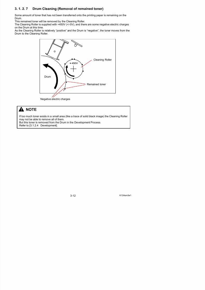
3. 1. 2. 7 Drum Cleaning (Removal of remained toner)
Some amount of toner that has not been transferred onto the printing paper is remaining on theDrum
5/17/2018 KIP 7100 Service Manual Ver A_1 - slidepdf.com
http://slidepdf.com/reader/full/kip-7100-service-manual-ver-a1 52/674
Drum.This remained toner will be removed by the Cleaning Roller.The Cleaning Roller is supplied with +450V (+/-5V), and there are some negative electric charges
on the Drum at this time. As the Cleaning Roller is relatively “positive” and the Drum is “negative”, the toner moves from theDrum to the Cleaning Roller.
450V
NOTE
If too much toner exists in a small area (like a trace of solid black image) the Cleaning Roller may not be able to remove all of them.But this toner is removed from the Drum in the Development Process.Refer to [3.1.2.4 Development].
Drum
Remained toner
Cleaning Roller
Negative electric charges
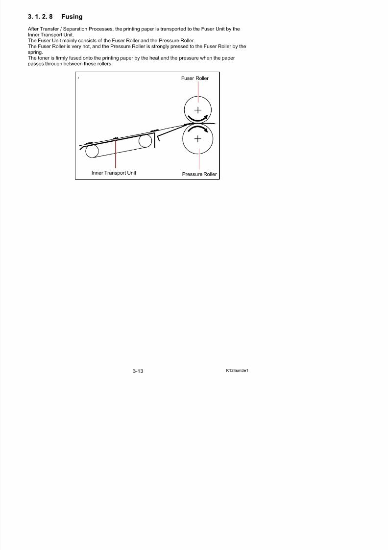
3. 1. 2. 8 Fusing
After Transfer / Separation Processes, the printing paper is transported to the Fuser Unit by theInner Transport Unit
5/17/2018 KIP 7100 Service Manual Ver A_1 - slidepdf.com
http://slidepdf.com/reader/full/kip-7100-service-manual-ver-a1 53/674
Inner Transport Unit.The Fuser Unit mainly consists of the Fuser Roller and the Pressure Roller.The Fuser Roller is very hot, and the Pressure Roller is strongly pressed to the Fuser Roller by the
spring.The toner is firmly fused onto the printing paper by the heat and the pressure when the paper passes through between these rollers.
Pressure Roller
Fuser Roller
Inner Transport Unit
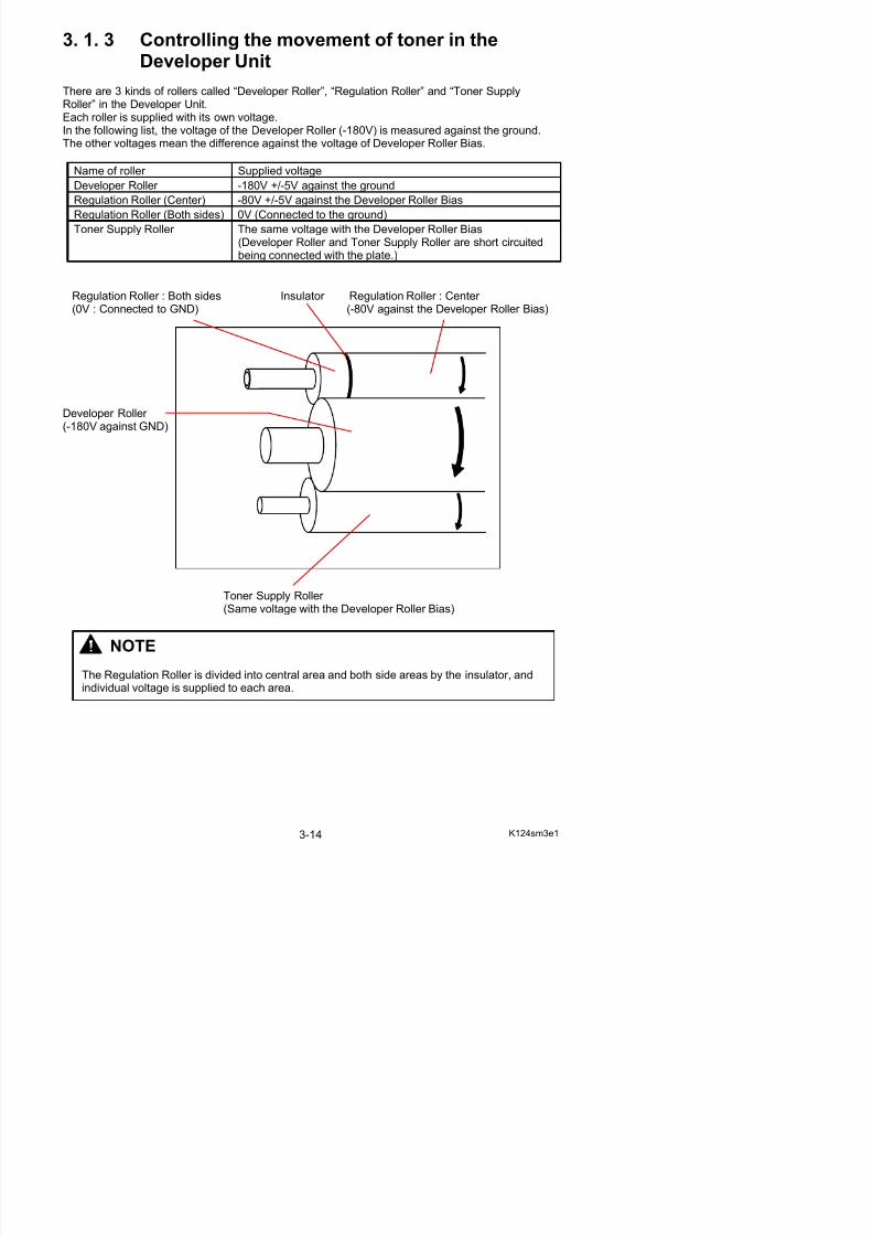
3. 1. 3 Controlling the movement of toner in theDeveloper Unit
5/17/2018 KIP 7100 Service Manual Ver A_1 - slidepdf.com
http://slidepdf.com/reader/full/kip-7100-service-manual-ver-a1 54/674
There are 3 kinds of rollers called “Developer Roller”, “Regulation Roller” and “Toner SupplyRoller” in the Developer Unit.
Each roller is supplied with its own voltage.In the following list, the voltage of the Developer Roller (-180V) is measured against the ground.The other voltages mean the difference against the voltage of Developer Roller Bias.
Name of roller Supplied voltage
Developer Roller -180V +/-5V against the ground
Regulation Roller (Center) -80V +/-5V against the Developer Roller Bias
Regulation Roller (Both sides) 0V (Connected to the ground)
Toner Supply Roller The same voltage with the Developer Roller Bias(Developer Roller and Toner Supply Roller are short circuitedbeing connected with the plate.)
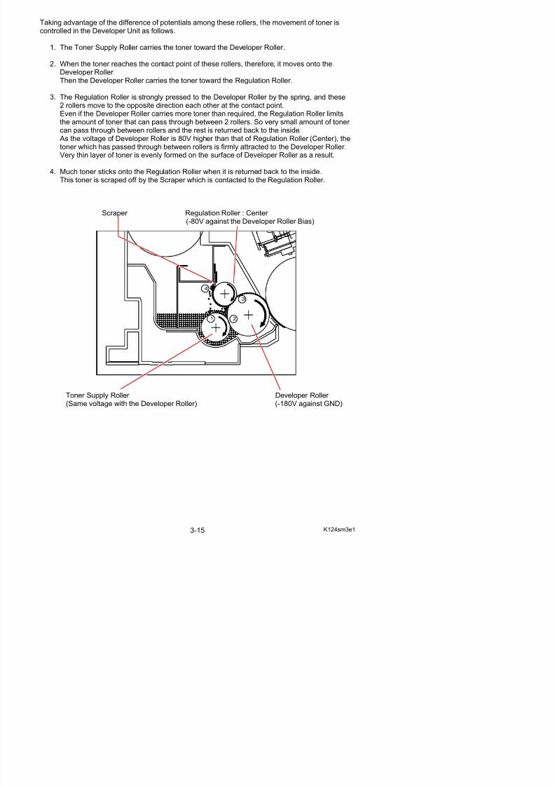
Regulation Roller : Both sides Insulator Regulation Roller : Center (0V : Connected to GND) (-80V against the Developer Roller Bias)
Developer Roller (-180V against GND)
Toner Supply Roller (Same voltage with the Developer Roller Bias)
Taking advantage of the difference of potentials among these rollers, the movement of toner iscontrolled in the Developer Unit as follows.
1. The Toner Supply Roller carries the toner toward the Developer Roller.
5/17/2018 KIP 7100 Service Manual Ver A_1 - slidepdf.com
http://slidepdf.com/reader/full/kip-7100-service-manual-ver-a1 55/674
2. When the toner reaches the contact point of these rollers, therefore, it moves onto theDeveloper Roller.Then the Developer Roller carries the toner toward the Regulation Roller.
3. The Regulation Roller is strongly pressed to the Developer Roller by the spring, and these2 rollers move to the opposite direction each other at the contact point.Even if the Developer Roller carries more toner than required, the Regulation Roller limitsthe amount of toner that can pass through between 2 rollers. So very small amount of toner can pass through between rollers and the rest is returned back to the inside. As the voltage of Developer Roller is 80V higher than that of Regulation Roller (Center), the
toner which has passed through between rollers is firmly attracted to the Developer Roller.Very thin layer of toner is evenly formed on the surface of Developer Roller as a result.
4. Much toner sticks onto the Regulation Roller when it is returned back to the inside.This toner is scraped off by the Scraper which is contacted to the Regulation Roller.
Scraper Regulation Roller : Center (-80V against the Developer Roller Bias)
1 2
3
4
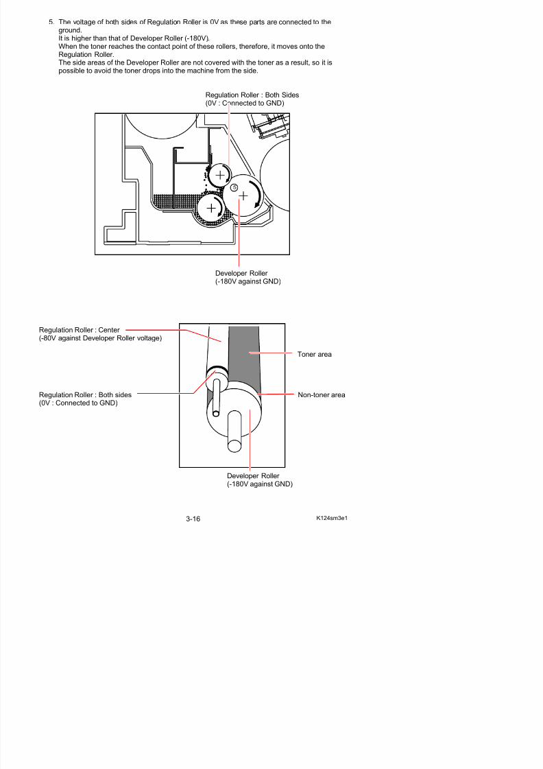
5. The voltage of both sides of Regulation Roller is 0V as these parts are connected to theground.It is higher than that of Developer Roller (-180V).When the toner reaches the contact point of these rollers, therefore, it moves onto theR l i R ll
5/17/2018 KIP 7100 Service Manual Ver A_1 - slidepdf.com
http://slidepdf.com/reader/full/kip-7100-service-manual-ver-a1 56/674
Regulation Roller.The side areas of the Developer Roller are not covered with the toner as a result, so it ispossible to avoid the toner drops into the machine from the side.
Regulation Roller : Both Sides(0V : Connected to GND)
Developer Roller (-180V against GND)
Regulation Roller : Center (-80V against Developer Roller voltage)
Toner area
5
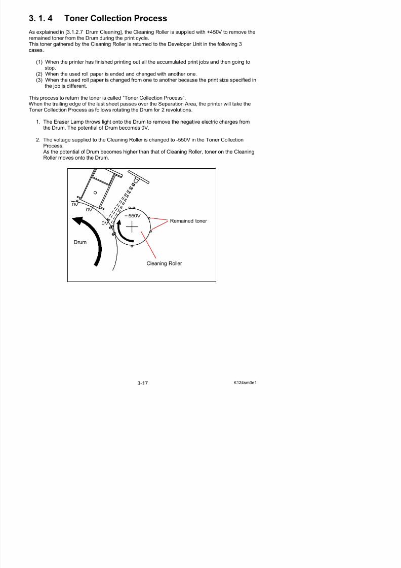
3. 1. 4 Toner Collection Process
As explained in [3.1.2.7 Drum Cleaning], the Cleaning Roller is supplied with +450V to remove theremained toner from the Drum during the print cycle
5/17/2018 KIP 7100 Service Manual Ver A_1 - slidepdf.com
http://slidepdf.com/reader/full/kip-7100-service-manual-ver-a1 57/674
remained toner from the Drum during the print cycle.This toner gathered by the Cleaning Roller is returned to the Developer Unit in the following 3cases.
(1) When the printer has finished printing out all the accumulated print jobs and then going tostop.
(2) When the used roll paper is ended and changed with another one.(3) When the used roll paper is changed from one to another because the print size specified in
the job is different.
This process to return the toner is called “Toner Collection Process”.
When the trailing edge of the last sheet passes over the Separation Area, the printer will take theToner Collection Process as follows rotating the Drum for 2 revolutions.
1. The Eraser Lamp throws light onto the Drum to remove the negative electric charges fromthe Drum. The potential of Drum becomes 0V.
2. The voltage supplied to the Cleaning Roller is changed to -550V in the Toner CollectionProcess. As the potential of Drum becomes higher than that of Cleaning Roller, toner on the CleaningRoller moves onto the Drum.
550V
0V
0V0V
Remained toner
Cleaning Roller
Drum
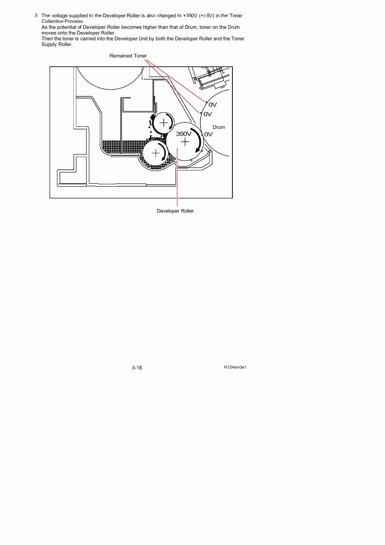
3. The voltage supplied to the Developer Roller is also changed to +350V (+/-5V) in the Toner Collection Process. As the potential of Developer Roller becomes higher than that of Drum, toner on the Drummoves onto the Developer Roller.Then the toner is carried into the Developer Unit by both the Developer Roller and the Toner
5/17/2018 KIP 7100 Service Manual Ver A_1 - slidepdf.com
http://slidepdf.com/reader/full/kip-7100-service-manual-ver-a1 58/674
Then the toner is carried into the Developer Unit by both the Developer Roller and the Toner Supply Roller.
Remained Toner
Developer Roller
350V 0V
0V
0V
Drum
Reference
5/17/2018 KIP 7100 Service Manual Ver A_1 - slidepdf.com
http://slidepdf.com/reader/full/kip-7100-service-manual-ver-a1 59/674
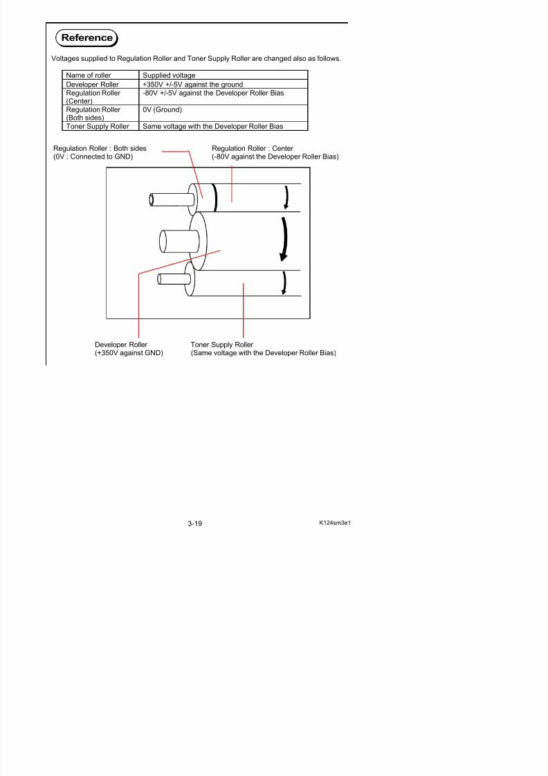
Voltages supplied to Regulation Roller and Toner Supply Roller are changed also as follows.
Regulation Roller : Both sides Regulation Roller : Center (0V : Connected to GND) (-80V against the Developer Roller Bias)
Developer Roller Toner Supply Roller (+350V against GND) (Same voltage with the Developer Roller Bias)
Name of roller Supplied voltageDeveloper Roller +350V +/-5V against the ground
Regulation Roller (Center)
-80V +/-5V against the Developer Roller Bias
Regulation Roller (Both sides)
0V (Ground)
Toner Supply Roller Same voltage with the Developer Roller Bias
3. 1. 5 Density Compensation Process
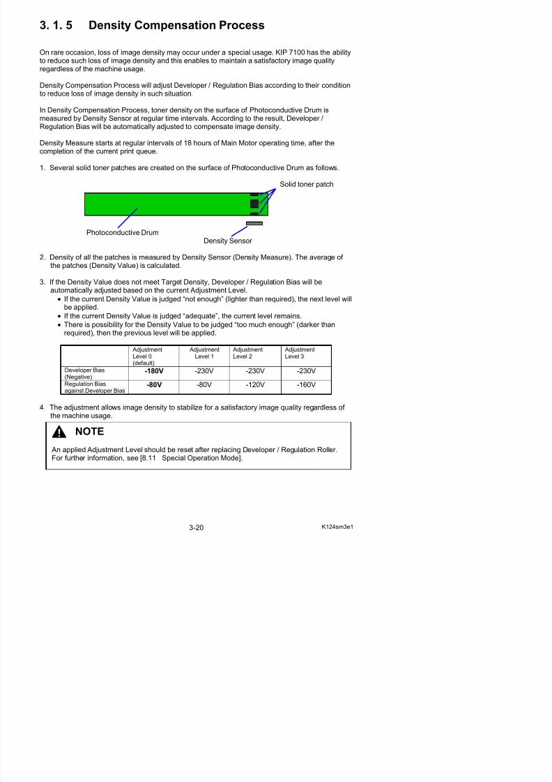
On rare occasion, loss of image density may occur under a special usage. KIP 7100 has the ability
5/17/2018 KIP 7100 Service Manual Ver A_1 - slidepdf.com
http://slidepdf.com/reader/full/kip-7100-service-manual-ver-a1 60/674
to reduce such loss of image density and this enables to maintain a satisfactory image qualityregardless of the machine usage.
Density Compensation Process will adjust Developer / Regulation Bias according to their conditionto reduce loss of image density in such situation.
In Density Compensation Process, toner density on the surface of Photoconductive Drum ismeasured by Density Sensor at regular time intervals. According to the result, Developer /Regulation Bias will be automatically adjusted to compensate image density.
Density Measure starts at regular intervals of 18 hours of Main Motor operating time, after thecompletion of the current print queue.
1. Several solid toner patches are created on the surface of Photoconductive Drum as follows.
Solid toner patch
Photoconductive DrumDensity Sensor
2. Density of all the patches is measured by Density Sensor (Density Measure). The average of the patches (Density Value) is calculated.
3. If the Density Value does not meet Target Density, Developer / Regulation Bias will beautomatically adjusted based on the current Adjustment Level.
• If the current Density Value is judged “not enough” (lighter than required), the next level willbe applied.
• If the current Density Value is judged “adequate”, the current level remains.
• There is possibility for the Density Value to be judged “too much enough” (darker thanrequired), then the previous level will be applied.
AdjustmentLevel 0(default)
AdjustmentLevel 1
AdjustmentLevel 2
AdjustmentLevel 3
Developer Bias(Negative)
-180V -230V -230V -230V
Regulation Bias -80V -80V -120V -160V
3. 2 Scan Process
3 2 1 Data flow in scan and copy
5/17/2018 KIP 7100 Service Manual Ver A_1 - slidepdf.com
http://slidepdf.com/reader/full/kip-7100-service-manual-ver-a1 61/674
3. 2. 1 Data flow in scan and copy
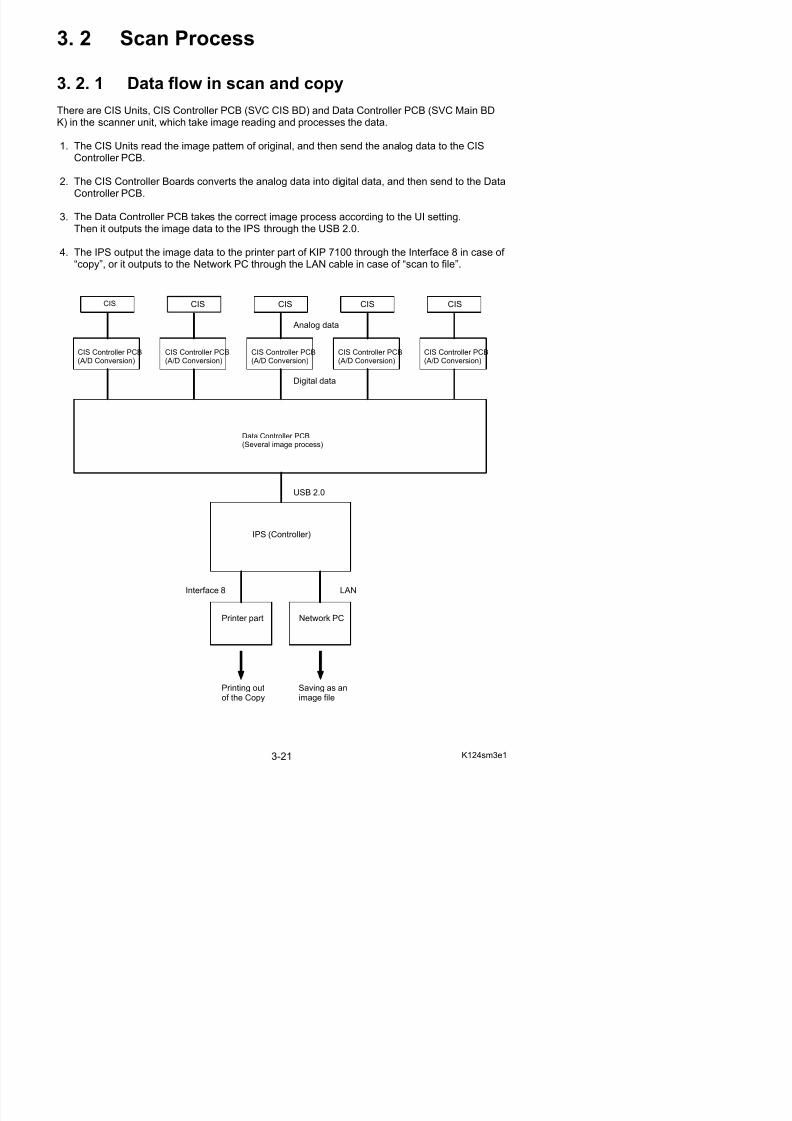
There are CIS Units, CIS Controller PCB (SVC CIS BD) and Data Controller PCB (SVC Main BDK) in the scanner unit, which take image reading and processes the data.
1. The CIS Units read the image pattern of original, and then send the analog data to the CISController PCB.
2. The CIS Controller Boards converts the analog data into digital data, and then send to the DataController PCB.
3. The Data Controller PCB takes the correct image process according to the UI setting.Then it outputs the image data to the IPS through the USB 2.0.
4. The IPS output the image data to the printer part of KIP 7100 through the Interface 8 in case of “copy”, or it outputs to the Network PC through the LAN cable in case of “scan to file”.
CIS CIS CIS CIS CIS
CIS Controller PCB(A/D Conversion)
Analog data
Digital data
CIS Controller PCB(A/D Conversion)
CIS Controller PCB(A/D Conversion)
CIS Controller PCB(A/D Conversion)
CIS Controller PCB(A/D Conversion)
Data Controller PCB(Several image process)
USB 2.0
IPS (Controller)
3. 2. 2 Positioning process of Image Block
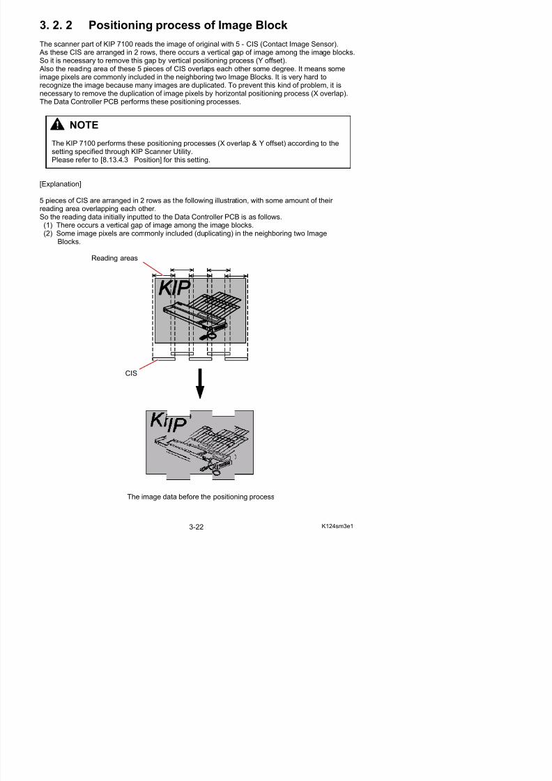
The scanner part of KIP 7100 reads the image of original with 5 - CIS (Contact Image Sensor). As these CIS are arranged in 2 rows, there occurs a vertical gap of image among the image blocks.S it i t thi b ti l iti i (Y ff t)
5/17/2018 KIP 7100 Service Manual Ver A_1 - slidepdf.com
http://slidepdf.com/reader/full/kip-7100-service-manual-ver-a1 62/674
So it is necessary to remove this gap by vertical positioning process (Y offset). Also the reading area of these 5 pieces of CIS overlaps each other some degree. It means some
image pixels are commonly included in the neighboring two Image Blocks. It is very hard torecognize the image because many images are duplicated. To prevent this kind of problem, it isnecessary to remove the duplication of image pixels by horizontal positioning process (X overlap).The Data Controller PCB performs these positioning processes.
[Explanation]
5 pieces of CIS are arranged in 2 rows as the following illustration, with some amount of their reading area overlapping each other.So the reading data initially inputted to the Data Controller PCB is as follows.(1) There occurs a vertical gap of image among the image blocks.(2) Some image pixels are commonly included (duplicating) in the neighboring two Image
Blocks.
Reading areas
CIS
NOTE
The KIP 7100 performs these positioning processes (X overlap & Y offset) according to thesetting specified through KIP Scanner Utility.Please refer to [8.13.4.3 Position] for this setting.
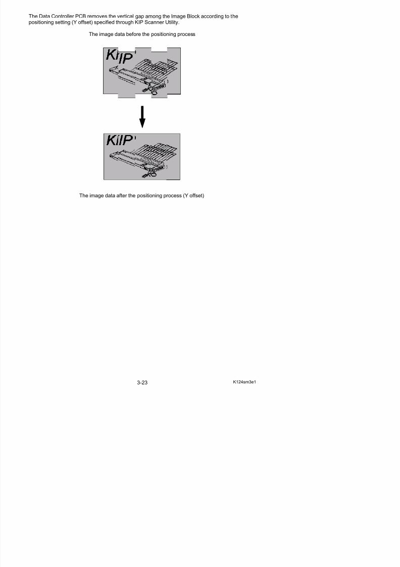
The Data Controller PCB removes the vertical gap among the Image Block according to thepositioning setting (Y offset) specified through KIP Scanner Utility.
The image data before the positioning process
5/17/2018 KIP 7100 Service Manual Ver A_1 - slidepdf.com
http://slidepdf.com/reader/full/kip-7100-service-manual-ver-a1 63/674
The image data after the positioning process (Y offset)
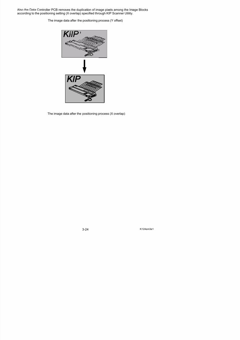
Also the Data Controller PCB removes the duplication of image pixels among the Image Blocksaccording to the positioning setting (X overlap) specified through KIP Scanner Utility.
The image data after the positioning process (Y offset)
5/17/2018 KIP 7100 Service Manual Ver A_1 - slidepdf.com
http://slidepdf.com/reader/full/kip-7100-service-manual-ver-a1 64/674
The image data after the positioning process (X overlap)
Chapter 4
5/17/2018 KIP 7100 Service Manual Ver A_1 - slidepdf.com
http://slidepdf.com/reader/full/kip-7100-service-manual-ver-a1 65/674
Electrical
Page4. 1 General Information 4- 2
4. 2 Electrical Components Location 4- 34. 2. 1 Right side 4- 34. 2. 2 Left side 4- 74. 2. 3 Back side 4- 84. 2. 5 LED Head Frame 4-124. 2. 6 Main Frame 4-144. 2. 7 Developer Unit 4-174. 2. 8 Fuser Unit 4-184. 2. 9 Roll Deck 4-204 2 10 Cutter Unit 4-23
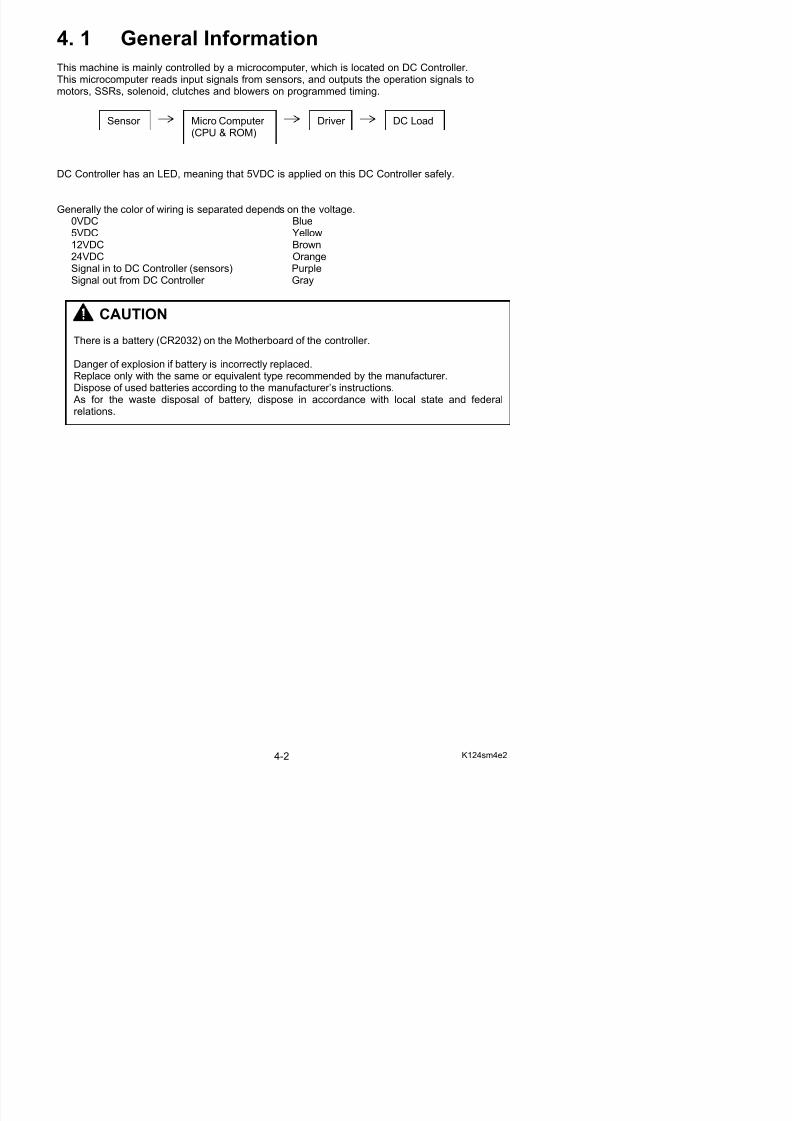
4. 1 General Information
This machine is mainly controlled by a microcomputer, which is located on DC Controller.This microcomputer reads input signals from sensors, and outputs the operation signals tomotors SSRs solenoid clutches and blowers on programmed timing
5/17/2018 KIP 7100 Service Manual Ver A_1 - slidepdf.com
http://slidepdf.com/reader/full/kip-7100-service-manual-ver-a1 66/674
motors, SSRs, solenoid, clutches and blowers on programmed timing.
DC Controller has an LED, meaning that 5VDC is applied on this DC Controller safely.
Generally the color of wiring is separated depends on the voltage.0VDC Blue5VDC Yellow12VDC Brown24VDC OrangeSignal in to DC Controller (sensors) PurpleSignal out from DC Controller Gray
Sensor Micro Computer (CPU & ROM)
DC LoadDriver
CAUTION
There is a battery (CR2032) on the Motherboard of the controller.
Danger of explosion if battery is incorrectly replaced.Replace only with the same or equivalent type recommended by the manufacturer.Dispose of used batteries according to the manufacturer’s instructions. As for the waste disposal of battery, dispose in accordance with local state and federalrelations.
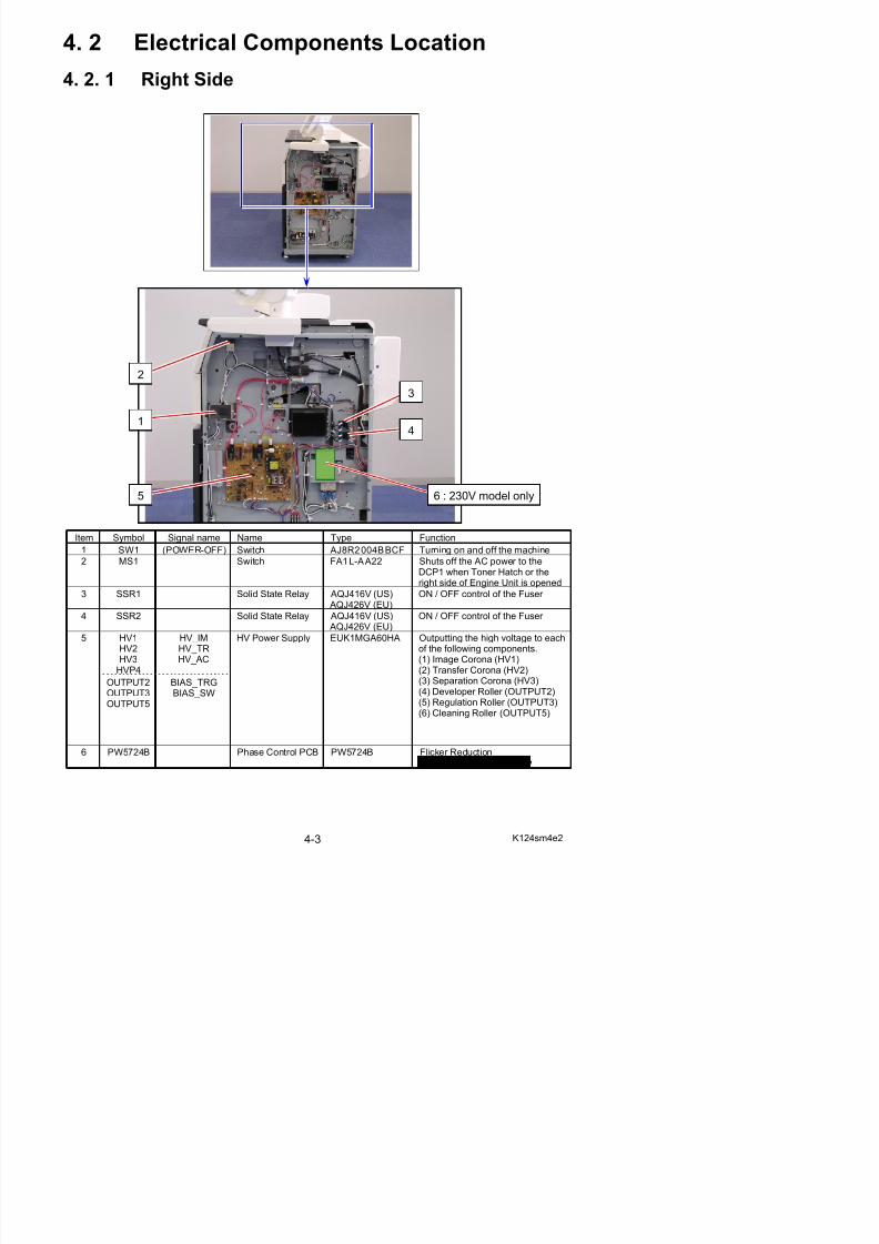
4. 2 Electrical Components Location
4. 2. 1 Right Side
5/17/2018 KIP 7100 Service Manual Ver A_1 - slidepdf.com
http://slidepdf.com/reader/full/kip-7100-service-manual-ver-a1 67/674
Item Symbol Signal name Name Type Function
1 SW1 (POWER-OFF) Switch AJ8R2004BBCF Turning on and off the machine
2 MS1 Switch FA1L-AA22 Shuts off the AC power to theDCP1 when Toner Hatch or theright side of Engine Unit is opened
3 SSR1 Solid State Relay AQJ416V (US) AQJ426V (EU)
ON / OFF control of the Fuser
4 SSR2 Solid State Relay AQJ416V (US) ON / OFF control of the Fuser
2
1
5
3
6 : 230V model only
4
NOTE
Developer Bias (OUTPUT 2, 3) is outputted (or stopped) by the signal “BIAS_TRG”.The polarity of Bias is decided by the signal “BIAS_SW”

5/17/2018 KIP 7100 Service Manual Ver A_1 - slidepdf.com
http://slidepdf.com/reader/full/kip-7100-service-manual-ver-a1 68/674
p y y g _
5/17/2018 KIP 7100 Service Manual Ver A_1 - slidepdf.com
http://slidepdf.com/reader/full/kip-7100-service-manual-ver-a1 69/674
8
7
10
1215
13
9
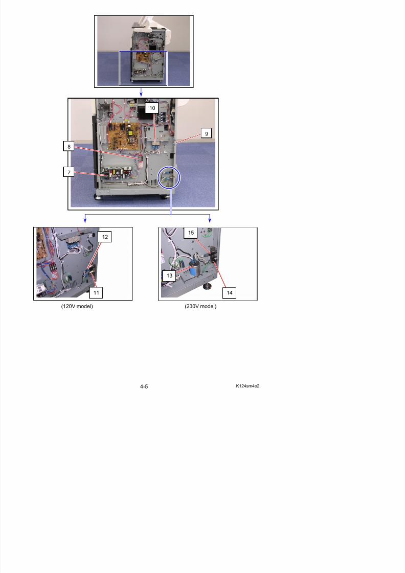
Item Symbol Signal name Name Type Function
7 DCP1 - DC Power Supply LEB225F-0524-U
Outputting each 24VDC, 5VDCand 0VDC
8 F1F2F3
- Fuse Walter TSC3.15AHor
Protecting the 24VDC from theover-currentIf you replace the fuses make
5/17/2018 KIP 7100 Service Manual Ver A_1 - slidepdf.com
http://slidepdf.com/reader/full/kip-7100-service-manual-ver-a1 70/674
F3 or LITTLE
0215 3.15MXP
If you replace the fuses, makesure to use one listed left.
9 SW2 - Switch (Option) SDDJE1 Turning on and off theDehumidify Heater
10 RY1 - Relay G7L-2A-TUB(DC24V)
Supplying the power to the Lamp(H1, H2).(It stops supplying the power tothe Lamp when Switch (MS3) or Thermostat (TS1, TS2) is open.)
11 LF1 - Noise Filter Removing the noise from the ACline
Used on 120V model 12 CB1 - Breaker X28-XQ1A-15 Protecting the AC line from the
over-currentUsed on 120V model
13 LF1 - Noise Filter RG-208F2 Removing the noise from the AClineUsed on 230V model
14 INLET - Inlet Inputting the AC Power Used on 230V model
15 CB1 - Breaker X28-XQ1A-10 Protecting the AC line from the
over-currentUsed on 230V model
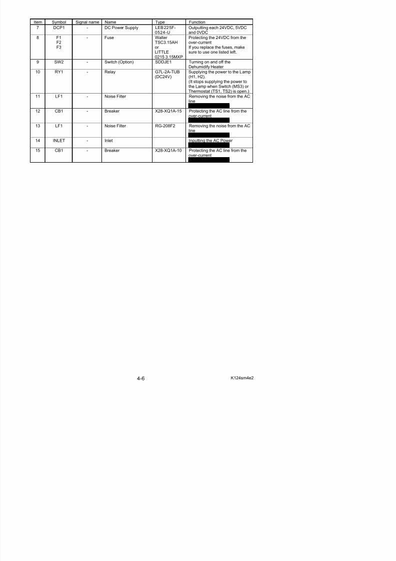
4. 2. 2 Left Side
5/17/2018 KIP 7100 Service Manual Ver A_1 - slidepdf.com
http://slidepdf.com/reader/full/kip-7100-service-manual-ver-a1 71/674
Item Symbol Signal name Name Type Function
1 PW12420 - PW12420 PCB Assy PW12420 Overall sequence control
2 PW6654B - Driver PCB B PW6654B Driver for the motors, clutchesand so on
3 MS4 - Switch V-162-1C2510E
Detecting whether or not theToner Hatch or the left side of Engine Unit is opened(The machine does not shut off the AC power even if the MS4
4
32
1
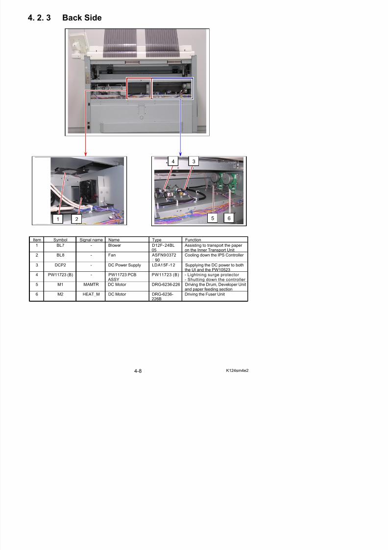
4. 2. 3 Back Side
5/17/2018 KIP 7100 Service Manual Ver A_1 - slidepdf.com
http://slidepdf.com/reader/full/kip-7100-service-manual-ver-a1 72/674
Item Symbol Signal name Name Type Function
1 BL7 - Blower D12F-24BL05
Assisting to transport the paper on the Inner Transport Unit
2 BL8 - Fan ASFN90372
90
Cooling down the IPS Controller
3 DCP2 - DC Power Supply LDA15F-12 Supplying the DC power to boththe UI and the PW10523
3
5 62
4
1
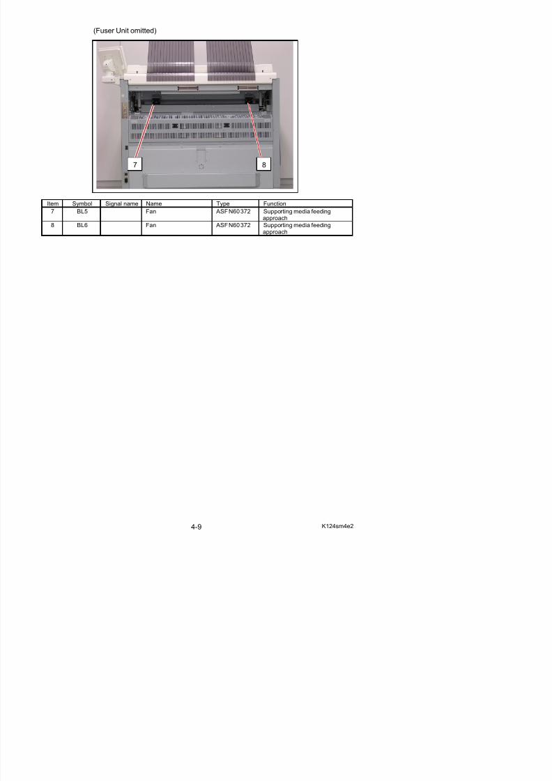
(Fuser Unit omitted)
5/17/2018 KIP 7100 Service Manual Ver A_1 - slidepdf.com
http://slidepdf.com/reader/full/kip-7100-service-manual-ver-a1 73/674
Item Symbol Signal name Name Type Function
7 BL5 Fan ASFN60372 Supporting media feedingapproach
8 BL6 Fan ASFN60372 Supporting media feedingapproach
7 8
5/17/2018 KIP 7100 Service Manual Ver A_1 - slidepdf.com
http://slidepdf.com/reader/full/kip-7100-service-manual-ver-a1 74/674
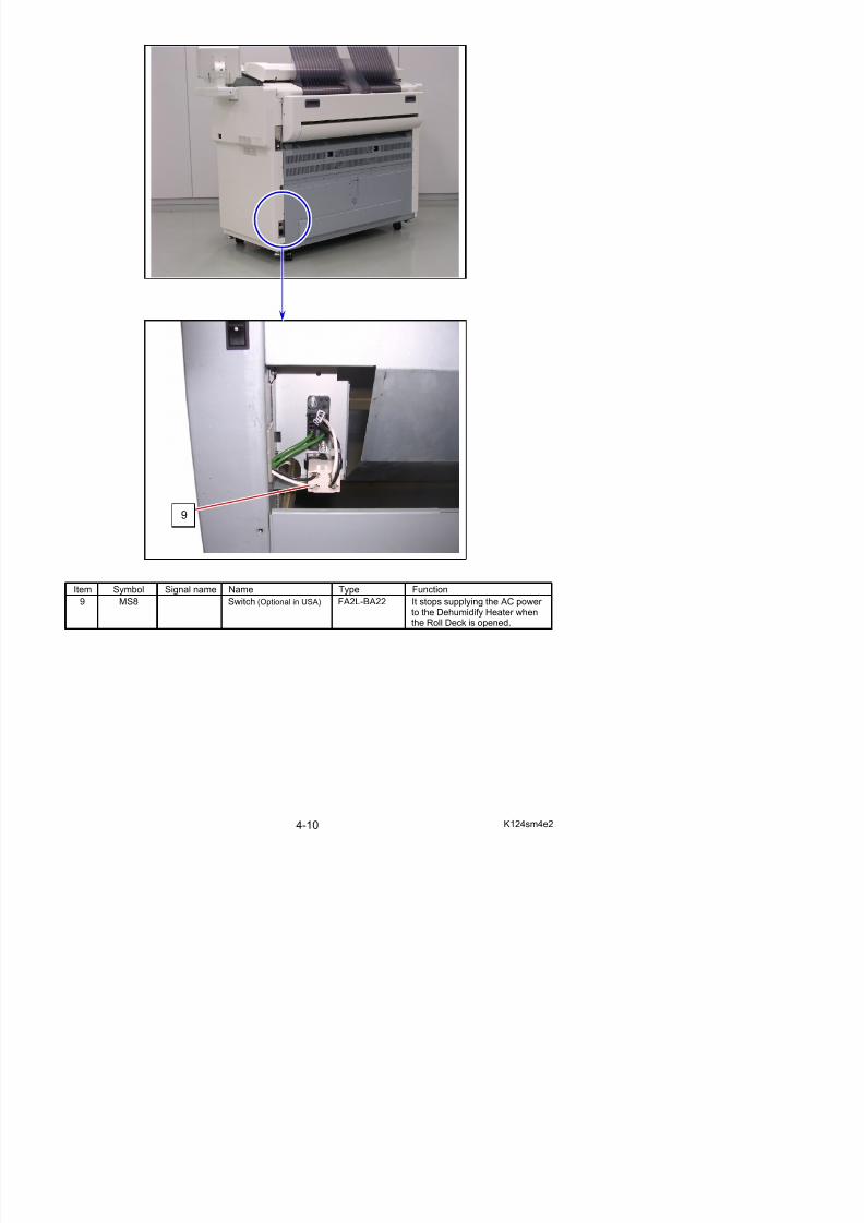
Item Symbol Signal name Name Type Function
9 MS8 Switch (Optional in USA) FA2L-BA22 It stops supplying the AC power
9
5/17/2018 KIP 7100 Service Manual Ver A_1 - slidepdf.com
http://slidepdf.com/reader/full/kip-7100-service-manual-ver-a1 75/674
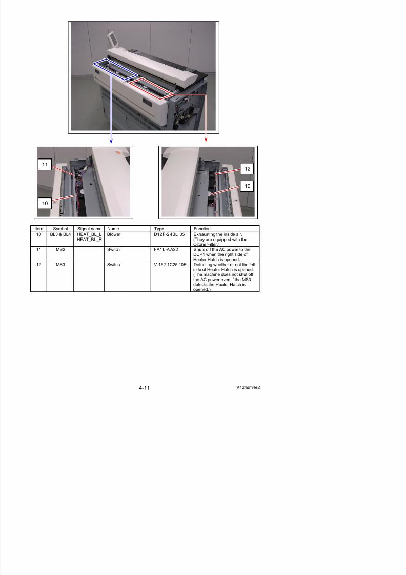
Item Symbol Signal name Name Type Function
10 BL3 & BL4 HEAT_BL_LHEAT_BL_R
Blower D12F-24BL 05 Exhausting the inside air.(They are equipped with theOzone Filter.)
11 MS2 Switch FA1L-AA22 Shuts off the AC power to theDCP1 when the right side of
Heater Hatch is opened.12 MS3 Switch V-162-1C25 10E Detecting whether or not the left
side of Heater Hatch is opened.(The machine does not shut off the AC power even if the MS3detects the Heater Hatch is
11
10
10
12
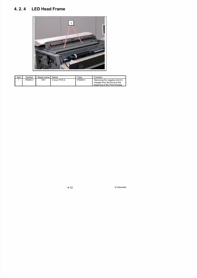
4. 2. 4 LED Head Frame
1
5/17/2018 KIP 7100 Service Manual Ver A_1 - slidepdf.com
http://slidepdf.com/reader/full/kip-7100-service-manual-ver-a1 76/674
Item Symbol Signal name Name Type Function1 PW6631 ER1 Eraser PCB A PW6631 Removing the negative electric
charges from the Drum at thebeginning of the Print Process
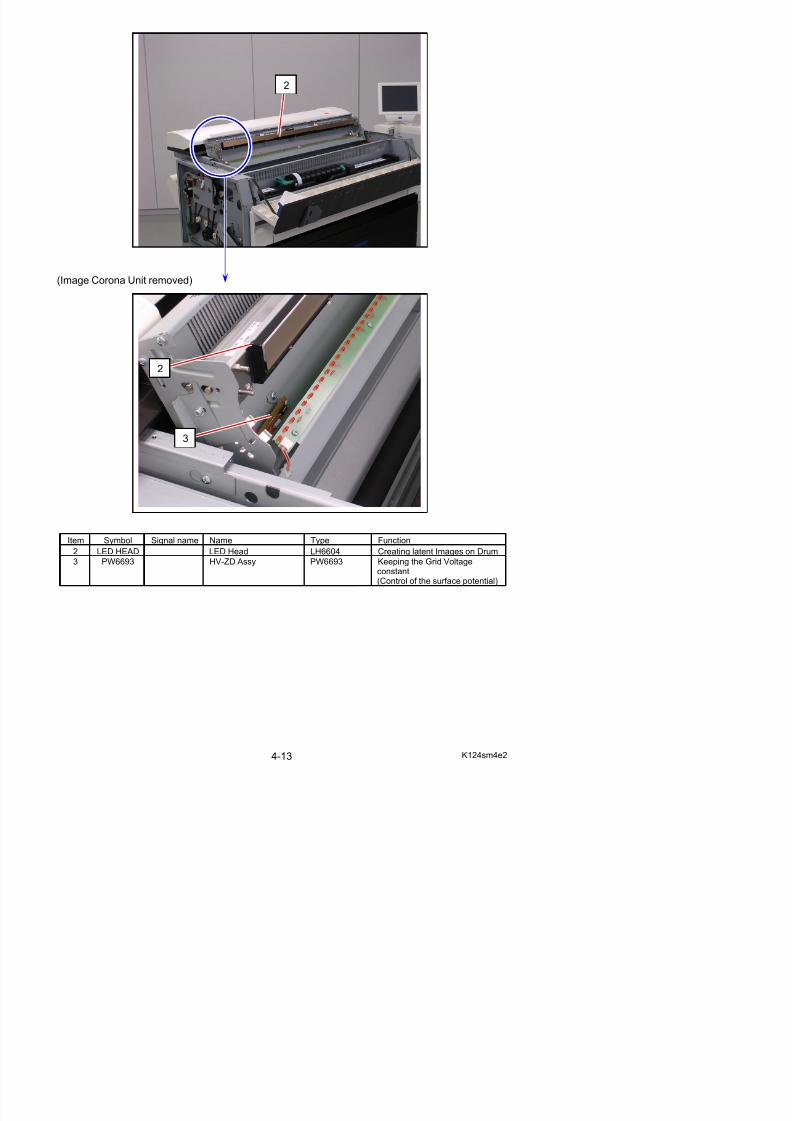
2
5/17/2018 KIP 7100 Service Manual Ver A_1 - slidepdf.com
http://slidepdf.com/reader/full/kip-7100-service-manual-ver-a1 77/674
(Image Corona Unit removed)
Item Symbol Signal name Name Type Function
2 LED HEAD LED Head LH6604 Creating latent Images on Drum
2
3
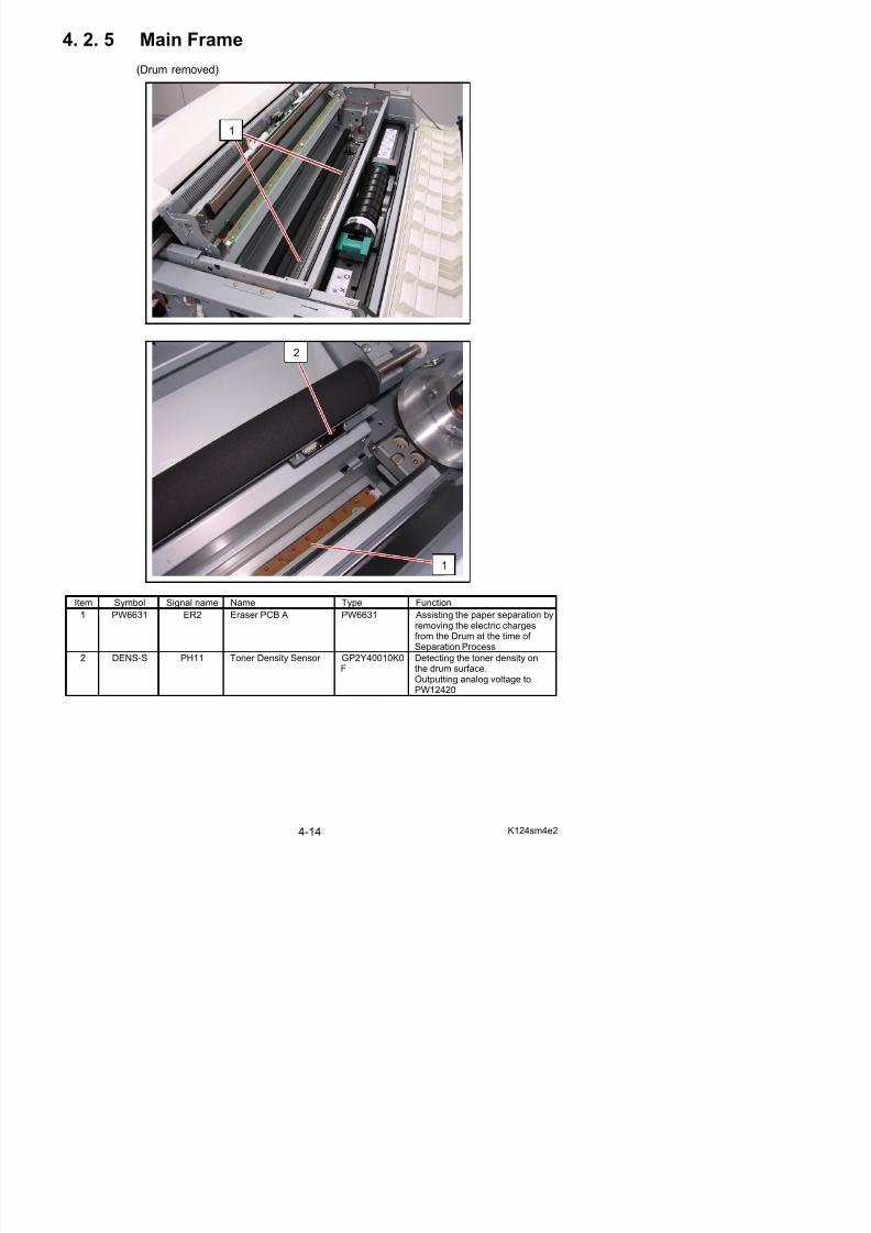
4. 2. 5 Main Frame
(Drum removed)
5/17/2018 KIP 7100 Service Manual Ver A_1 - slidepdf.com
http://slidepdf.com/reader/full/kip-7100-service-manual-ver-a1 78/674
Item Symbol Signal name Name Type Function
1
2
1
5/17/2018 KIP 7100 Service Manual Ver A_1 - slidepdf.com
http://slidepdf.com/reader/full/kip-7100-service-manual-ver-a1 79/674
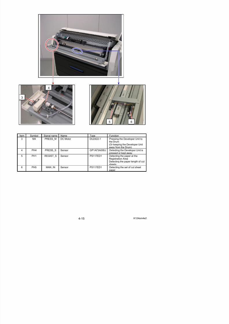
Item Symbol Signal name Name Type Function
3 M4 PRESS_M DC Motor DU2422-1 Pressing the Developer Unit tothe Drum(Or keeping the Developer Unit
away from the Drum)4 PH4 PRESS_S Sensor GP1A73A000J Detecting the Developer Unit is
pressed or kept away
5 PH1 REGIST_S Sensor PS117ED1 Detecting the paper at theRegistration Area
f
3
4
5 6
5/17/2018 KIP 7100 Service Manual Ver A_1 - slidepdf.com
http://slidepdf.com/reader/full/kip-7100-service-manual-ver-a1 80/674
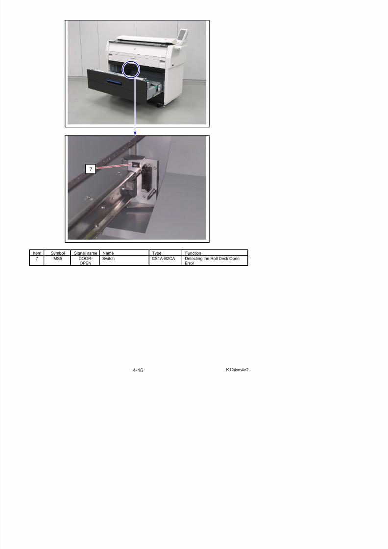
Item Symbol Signal name Name Type Function
7 MS5 DOOR-OPEN
Switch CS1A-B2CA Detecting the Roll Deck OpenError
7
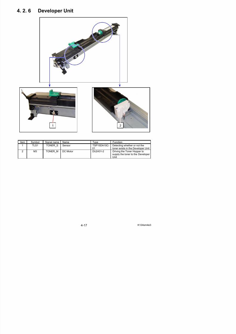
4. 2. 6 Developer Unit
5/17/2018 KIP 7100 Service Manual Ver A_1 - slidepdf.com
http://slidepdf.com/reader/full/kip-7100-service-manual-ver-a1 81/674
Item Symbol Signal name Name Type Function
1 TLS1 TONER_S Sensor TSP15DA10C-01
Detecting whether or not thetoner exists in the Developer Unit
2 M3 TONER_M DC Motor DU2431-2 Driving the Toner Hopper tosupply the toner to the Developer Unit
1 2
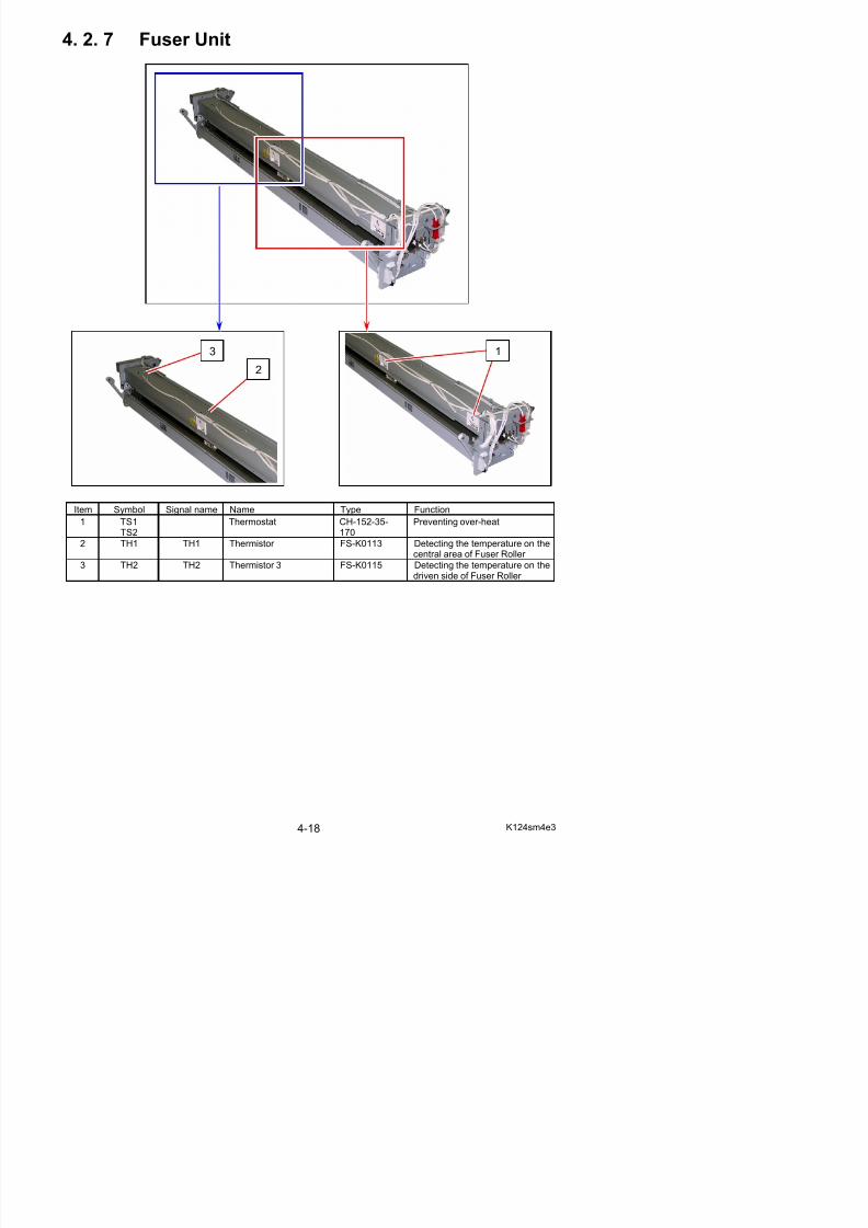
4. 2. 7 Fuser Unit
5/17/2018 KIP 7100 Service Manual Ver A_1 - slidepdf.com
http://slidepdf.com/reader/full/kip-7100-service-manual-ver-a1 82/674
Item Symbol Signal name Name Type Function
1 TS1TS2
Thermostat CH-152-35-170
Preventing over-heat
2 TH1 TH1 Thermistor FS-K0113 Detecting the temperature on the
central area of Fuser Roller 3 TH2 TH2 Thermistor 3 FS-K0115 Detecting the temperature on the
driven side of Fuser Roller
1
2
3
5/17/2018 KIP 7100 Service Manual Ver A_1 - slidepdf.com
http://slidepdf.com/reader/full/kip-7100-service-manual-ver-a1 83/674
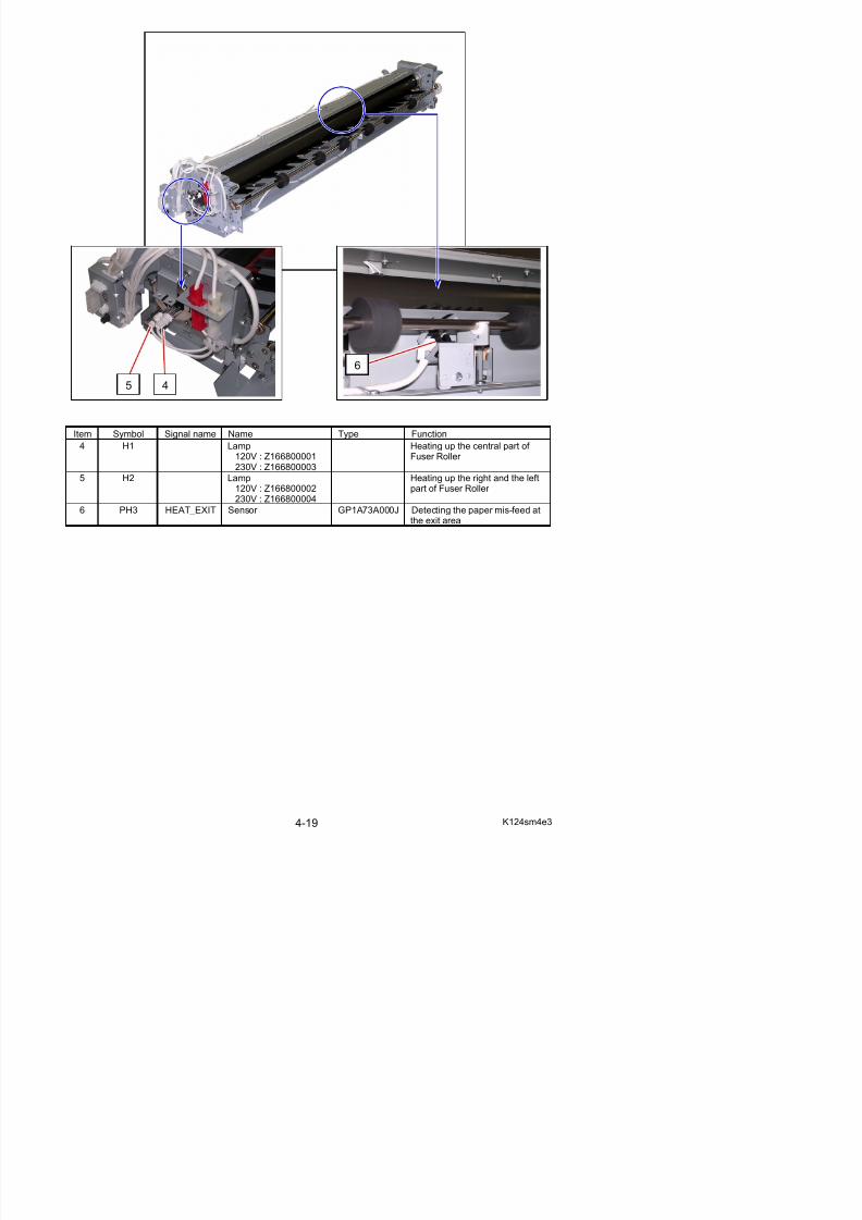
Item Symbol Signal name Name Type Function
4 H1 Lamp120V : Z166800001230V : Z166800003
Heating up the central part of Fuser Roller
5 H2 Lamp120V : Z166800002230V : Z166800004
Heating up the right and the leftpart of Fuser Roller
6 PH3 HEAT_EXIT Sensor GP1A73A000J Detecting the paper mis-feed atthe exit area
6
45
5/17/2018 KIP 7100 Service Manual Ver A_1 - slidepdf.com
http://slidepdf.com/reader/full/kip-7100-service-manual-ver-a1 84/674
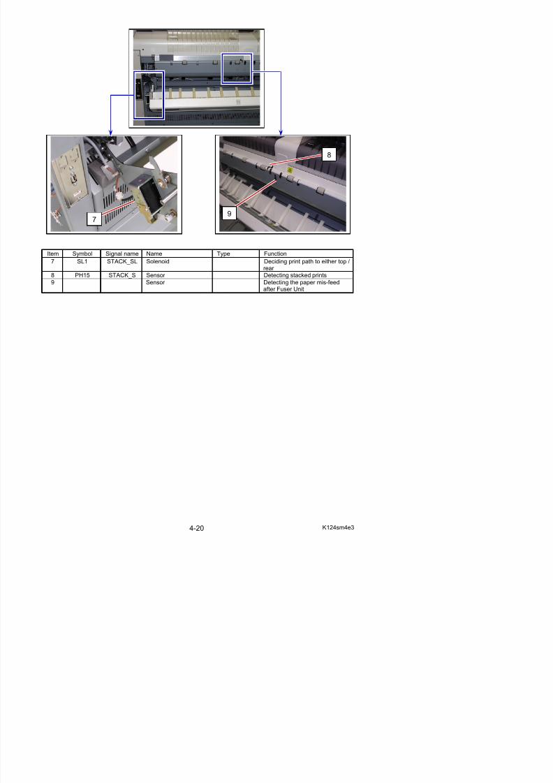
Item Symbol Signal name Name Type Function
7 SL1 STACK_SL Solenoid Deciding print path to either top /rear
8 PH15 STACK_S Sensor Detecting stacked prints
9 Sensor Detecting the paper mis-feedafter Fuser Unit
7
8
9
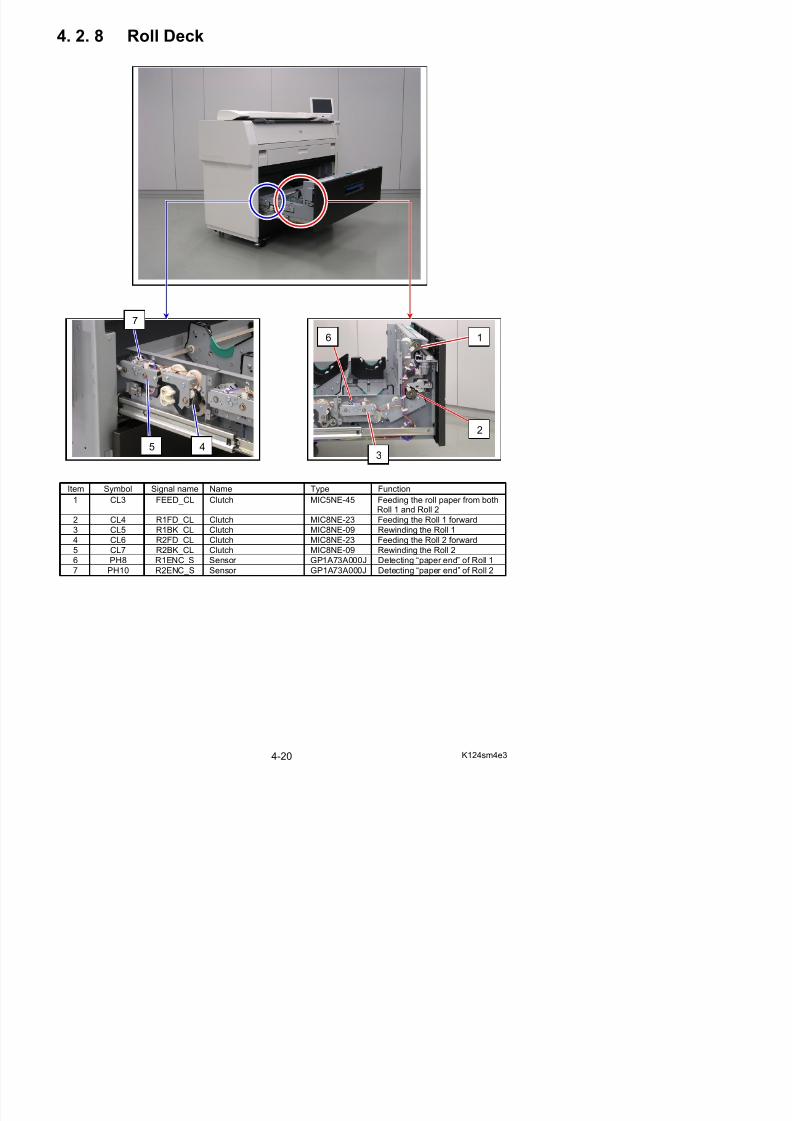
4. 2. 8 Roll Deck
5/17/2018 KIP 7100 Service Manual Ver A_1 - slidepdf.com
http://slidepdf.com/reader/full/kip-7100-service-manual-ver-a1 85/674
Item Symbol Signal name Name Type Function
1 CL3 FEED_CL Clutch MIC5NE-45 Feeding the roll paper from both
Roll 1 and Roll 22 CL4 R1FD_CL Clutch MIC8NE-23 Feeding the Roll 1 forward
3 CL5 R1BK_CL Clutch MIC8NE-09 Rewinding the Roll 1
4 CL6 R2FD_CL Clutch MIC8NE-23 Feeding the Roll 2 forward
5 CL7 R2BK_CL Clutch MIC8NE-09 Rewinding the Roll 2
3
2
1
45
6
7
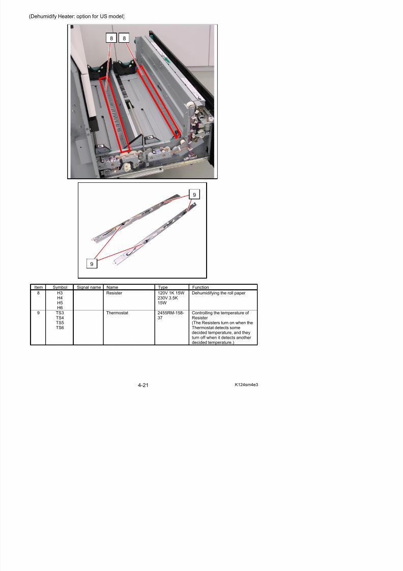
(Dehumidify Heater: option for US model)
88
5/17/2018 KIP 7100 Service Manual Ver A_1 - slidepdf.com
http://slidepdf.com/reader/full/kip-7100-service-manual-ver-a1 86/674
9
9
11
10
5/17/2018 KIP 7100 Service Manual Ver A_1 - slidepdf.com
http://slidepdf.com/reader/full/kip-7100-service-manual-ver-a1 87/674
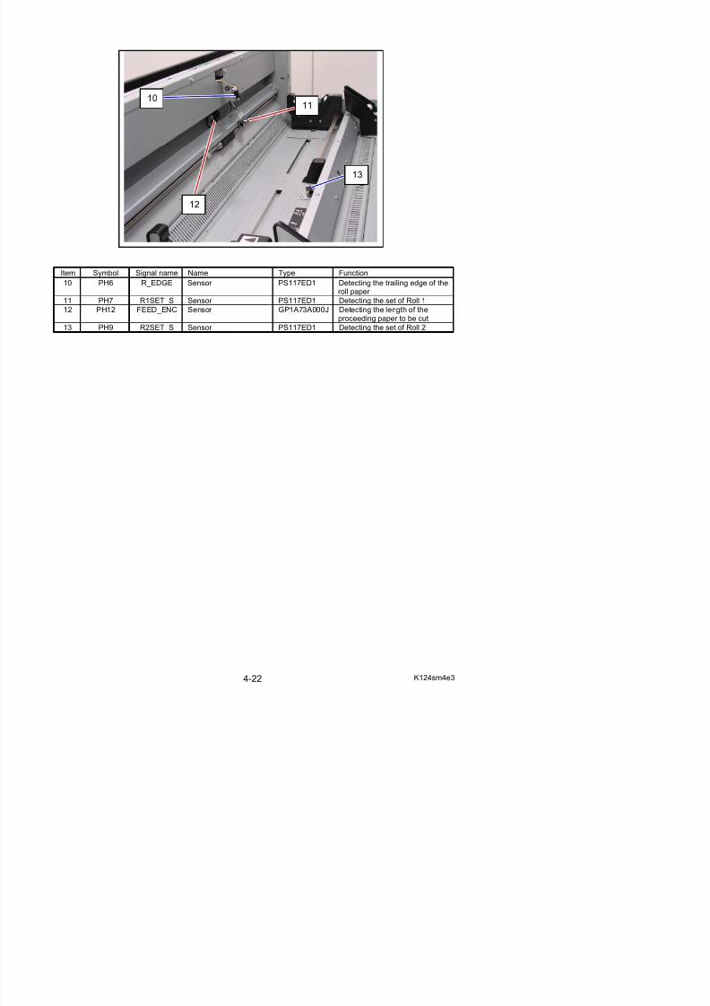
Item Symbol Signal name Name Type Function
10 PH6 R_EDGE Sensor PS117ED1 Detecting the trailing edge of theroll paper
11 PH7 R1SET_S Sensor PS117ED1 Detecting the set of Roll 1
12 PH12 FEED_ENC Sensor GP1A73A000J Detecting the length of theproceeding paper to be cut
13 PH9 R2SET_S Sensor PS117ED1 Detecting the set of Roll 2
13
11
12
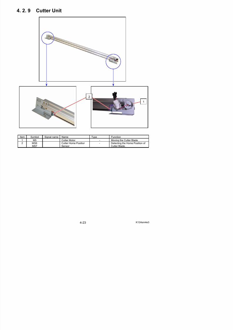
4. 2. 9 Cutter Unit
5/17/2018 KIP 7100 Service Manual Ver A_1 - slidepdf.com
http://slidepdf.com/reader/full/kip-7100-service-manual-ver-a1 88/674
Item Symbol Signal name Name Type Function
1 M5 Cutter Motor - Moving the Cutter Blade
2 MS6MS7
Cutter Home PositionSensor
- Detecting the Home Position of Cutter Blade.
1
2
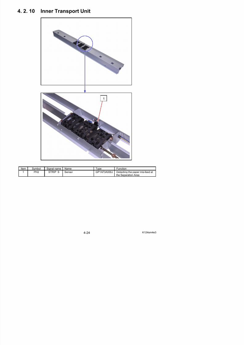
4. 2. 10 Inner Transport Unit
5/17/2018 KIP 7100 Service Manual Ver A_1 - slidepdf.com
http://slidepdf.com/reader/full/kip-7100-service-manual-ver-a1 89/674
Item Symbol Signal name Name Type Function
1
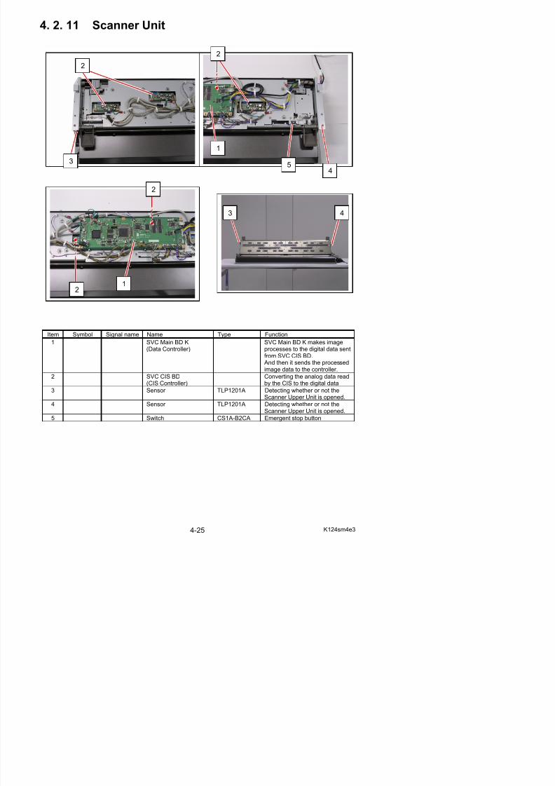
4. 2. 11 Scanner Unit
2
2
5/17/2018 KIP 7100 Service Manual Ver A_1 - slidepdf.com
http://slidepdf.com/reader/full/kip-7100-service-manual-ver-a1 90/674
Item Symbol Signal name Name Type Function
1 SVC Main BD K(Data Controller)
SVC Main BD K makes imageprocesses to the digital data sent
from SVC CIS BD. And then it sends the processedimage data to the controller.
2 SVC CIS BD(CIS Controller)
Converting the analog data readby the CIS to the digital data
3 Sensor TLP1201A Detecting whether or not the
3
21
2
45
1
3 4
5/17/2018 KIP 7100 Service Manual Ver A_1 - slidepdf.com
http://slidepdf.com/reader/full/kip-7100-service-manual-ver-a1 91/674
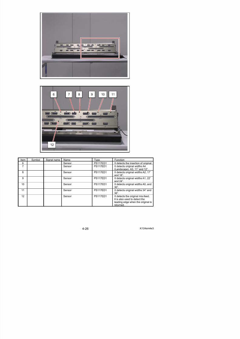
Item Symbol Signal name Name Type Function
6 Sensor PS117ED1 It detects the insertion of original.
7 Sensor PS117ED1 It detects original widths A4
6 7 9 10
12
8 11
13
13
5/17/2018 KIP 7100 Service Manual Ver A_1 - slidepdf.com
http://slidepdf.com/reader/full/kip-7100-service-manual-ver-a1 92/674
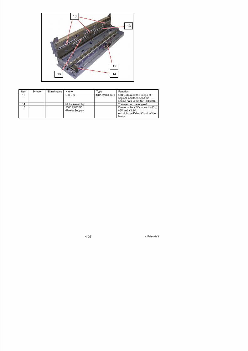
Item Symbol Signal name Name Type Function
13 CIS Unit CIPS218CF601 CIS Units read the image of
original, and then send theanalog data to the SVC CIS BD.
14 Motor Assembly Transporting the original.
15 SVC PWR BD(Power Supply)
Converts the +24V to each +12V,+5V and +3.3V. Also it is the Driver Circuit of theMotor.
13 14
15
4. 3 Check & Adjustment of AnalogOutput from HV Power Supply
4. 3. 1 Situations necessary to check the analogoutput
5/17/2018 KIP 7100 Service Manual Ver A_1 - slidepdf.com
http://slidepdf.com/reader/full/kip-7100-service-manual-ver-a1 93/674
output
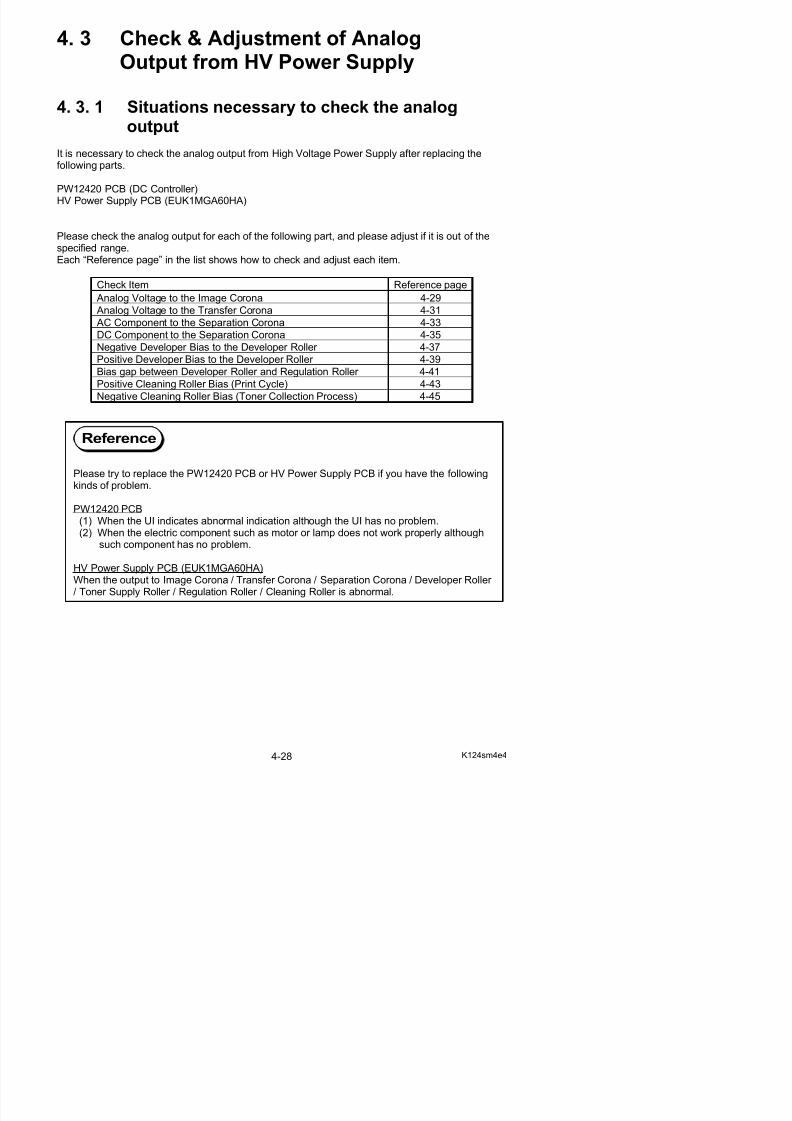
It is necessary to check the analog output from High Voltage Power Supply after replacing thefollowing parts.
PW12420 PCB (DC Controller)HV Power Supply PCB (EUK1MGA60HA)
Please check the analog output for each of the following part, and please adjust if it is out of thespecified range.Each “Reference page” in the list shows how to check and adjust each item.
Check Item Reference page
Analog Voltage to the Image Corona 4-29
Analog Voltage to the Transfer Corona 4-31 AC Component to the Separation Corona 4-33
DC Component to the Separation Corona 4-35
Negative Developer Bias to the Developer Roller 4-37
Positive Developer Bias to the Developer Roller 4-39
Bias gap between Developer Roller and Regulation Roller 4-41
Positive Cleaning Roller Bias (Print Cycle) 4-43
Negative Cleaning Roller Bias (Toner Collection Process) 4-45
Please try to replace the PW12420 PCB or HV Power Supply PCB if you have the followingkinds of problem.
PW12420 PCB(1) When the UI indicates abnormal indication although the UI has no problem.(2) When the electric component such as motor or lamp does not work properly although
such component has no problem.
Reference
4. 3. 2 Analog Voltage to Image Corona
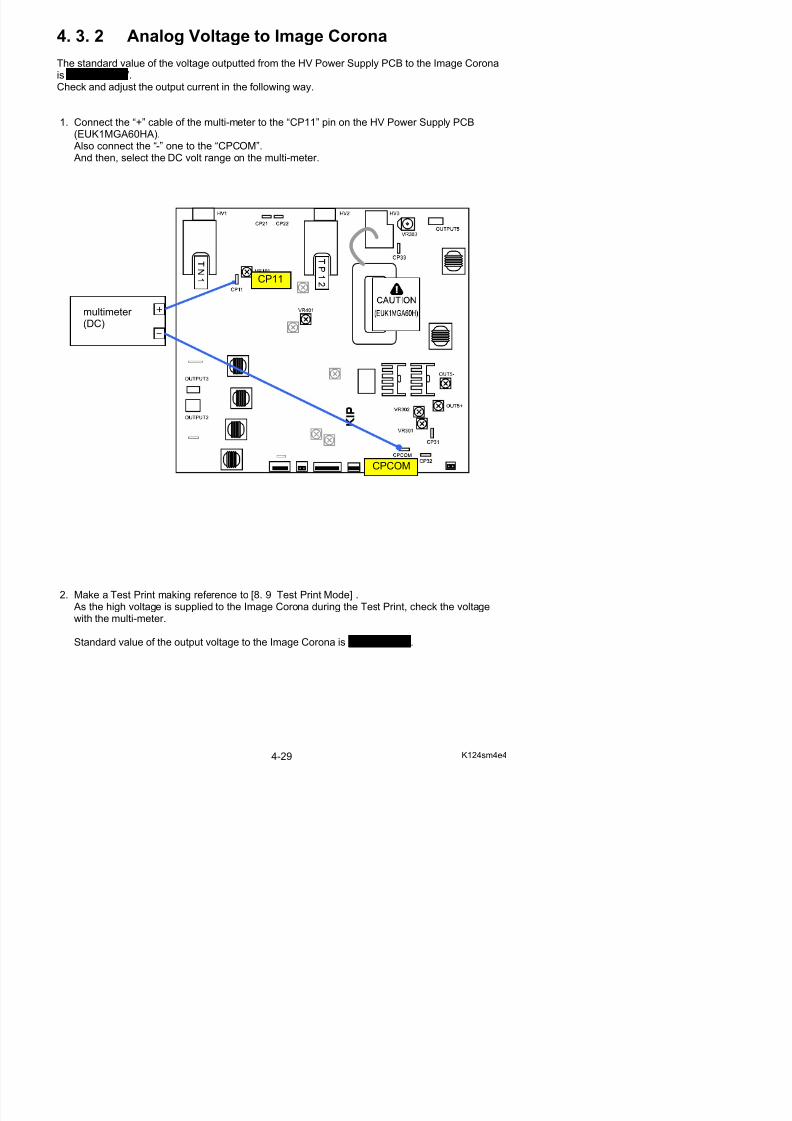
The standard value of the voltage outputted from the HV Power Supply PCB to the Image Coronais 1.30 +/-0.05V.Check and adjust the output current in the following way.
1. Connect the “+” cable of the multi-meter to the “CP11” pin on the HV Power Supply PCB
5/17/2018 KIP 7100 Service Manual Ver A_1 - slidepdf.com
http://slidepdf.com/reader/full/kip-7100-service-manual-ver-a1 94/674
p pp y(EUK1MGA60HA). Also connect the “-” one to the “CPCOM”. And then, select the DC volt range on the multi-meter.
CP11
multimeter (DC)
CPCOM
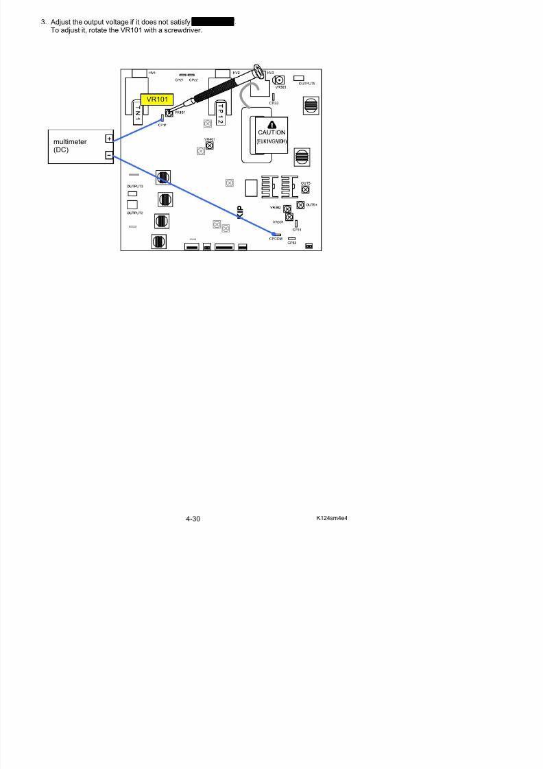
3. Adjust the output voltage if it does not satisfy 1.30 +/-0.05V.To adjust it, rotate the VR101 with a screwdriver.
5/17/2018 KIP 7100 Service Manual Ver A_1 - slidepdf.com
http://slidepdf.com/reader/full/kip-7100-service-manual-ver-a1 95/674
VR101
multimeter
(DC)
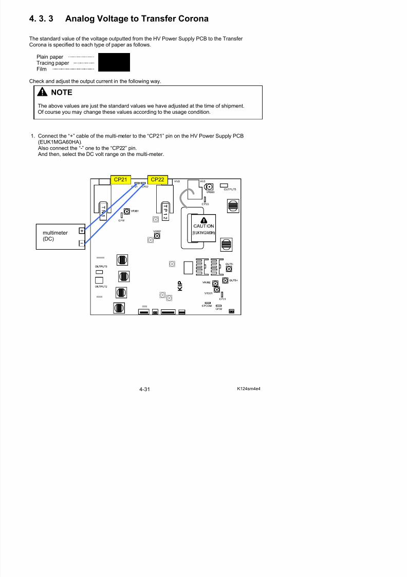
4. 3. 3 Analog Voltage to Transfer Corona
The standard value of the voltage outputted from the HV Power Supply PCB to the Transfer Corona is specified to each type of paper as follows.
Plain paper 1.20 +/-0.05V
Tracing paper 1.00 +/-0.05V Fil 1 00 +/ 0 05V
5/17/2018 KIP 7100 Service Manual Ver A_1 - slidepdf.com
http://slidepdf.com/reader/full/kip-7100-service-manual-ver-a1 96/674
Film 1.00 +/-0.05V
Check and adjust the output current in the following way.
1. Connect the “+” cable of the multi-meter to the “CP21” pin on the HV Power Supply PCB(EUK1MGA60HA). Also connect the “-” one to the “CP22” pin. And then, select the DC volt range on the multi-meter.
CP21 CP22
NOTE
The above values are just the standard values we have adjusted at the time of shipment.
Of course you may change these values according to the usage condition.
multimeter (DC)
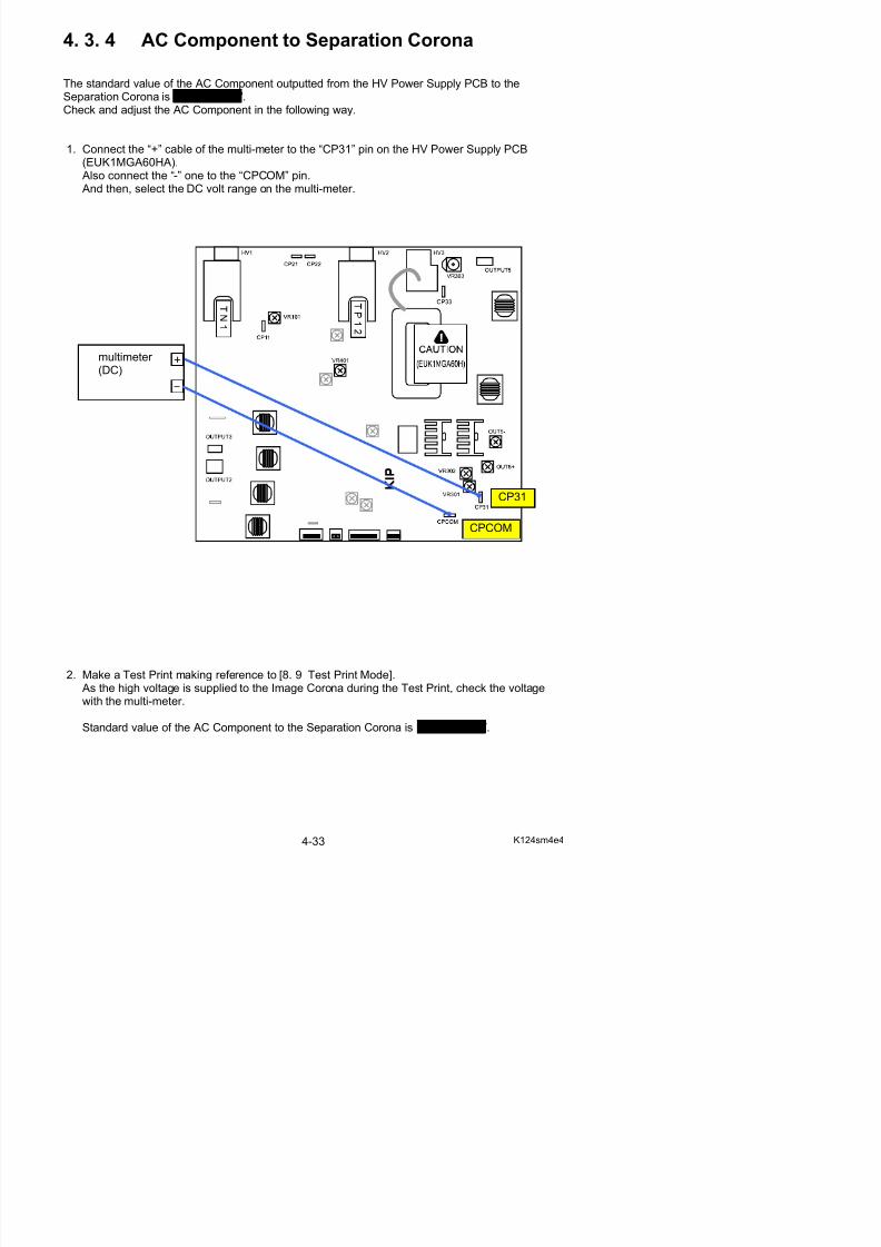
2. Select the Test Print Mode, and make a test print using each type of paper (plainpaper, tracing paper & Film) making reference to [8. 9 Test Print Mode].
As the high voltage is supplied to the Transfer Corona during the Test Print, check the voltagewith the multi-meter.
Standard values of the output voltages to the Transfer Corona are:Plain paper 1.20 +/-0.05V Tracing paper 1.00 +/-0.05V

5/17/2018 KIP 7100 Service Manual Ver A_1 - slidepdf.com
http://slidepdf.com/reader/full/kip-7100-service-manual-ver-a1 97/674
Film 1.00 +/-0.05V
3. Adjust the output voltage if it does not satisfy the above specifications.Select the Adjustment Mode, select each of following Sub Mode Numbers, andchange the setting value so that the output voltage satisfies the above specifications.
Refer to [8.6.3.15 Transfer Voltage (No.029 to 034)] for the detail.
Sub Mode No. Contents
029 Transfer Voltage (Plain paper)
030 Transfer Voltage (Tracing paper)
031 Transfer Voltage (Film)
032 Transfer Voltage (Plain paper : Special)
033 Transfer Voltage (Tracing paper : Special)
034 Transfer Voltage (Film : Special)
4. 3. 4 AC Component to Separation Corona
The standard value of the AC Component outputted from the HV Power Supply PCB to theSeparation Corona is 5.00 +/-0.05V.Check and adjust the AC Component in the following way.
1 Connect the “+” cable of the multi-meter to the “CP31” pin on the HV Power Supply PCB
5/17/2018 KIP 7100 Service Manual Ver A_1 - slidepdf.com
http://slidepdf.com/reader/full/kip-7100-service-manual-ver-a1 98/674
1. Connect the + cable of the multi-meter to the CP31 pin on the HV Power Supply PCB(EUK1MGA60HA). Also connect the “-” one to the “CPCOM” pin. And then, select the DC volt range on the multi-meter.
CP31
CPCOM
multimeter (DC)
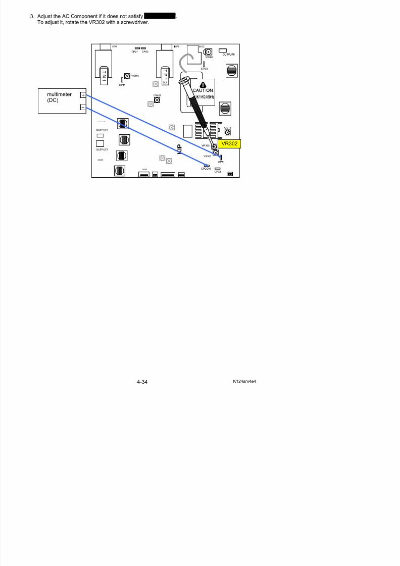
3. Adjust the AC Component if it does not satisfy 5.00 +/-0.05V.To adjust it, rotate the VR302 with a screwdriver.
5/17/2018 KIP 7100 Service Manual Ver A_1 - slidepdf.com
http://slidepdf.com/reader/full/kip-7100-service-manual-ver-a1 99/674
VR302
multimeter (DC)
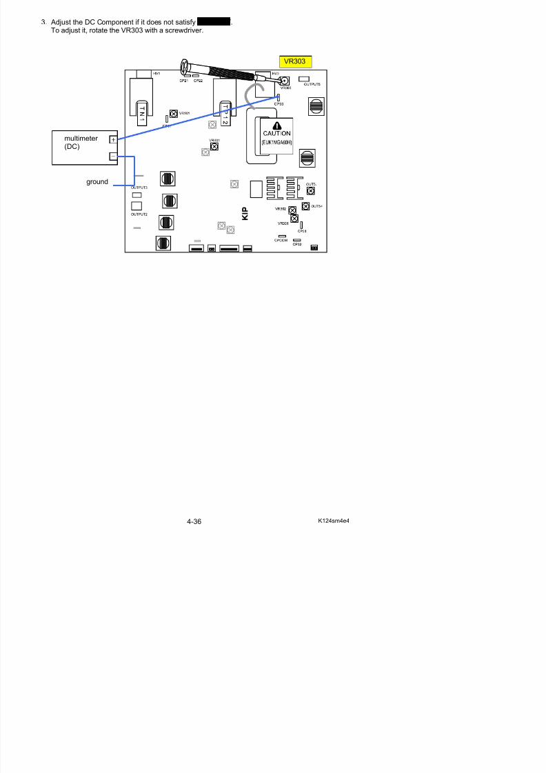
4. 3. 5 DC Component to Separation Corona
The standard value of the DC Component outputted from the HV Power Supply PCB to theSeparation Corona is -250 +/-5V.Check and adjust the DC Component in the following way.
1. Connect the “+” cable of the multi-meter to the “CP33” pin on the HV Power Supply PCB

5/17/2018 KIP 7100 Service Manual Ver A_1 - slidepdf.com
http://slidepdf.com/reader/full/kip-7100-service-manual-ver-a1 100/674
33 p pp y(EUK1MGA60HA). Also connect the “-” one to the ground. And then, select the DC volt range on the multi-meter.
CP33
multimeter (DC)
ground
3. Adjust the DC Component if it does not satisfy -250 +/-5V.To adjust it, rotate the VR303 with a screwdriver.
VR303
5/17/2018 KIP 7100 Service Manual Ver A_1 - slidepdf.com
http://slidepdf.com/reader/full/kip-7100-service-manual-ver-a1 101/674
multimeter (DC)
ground
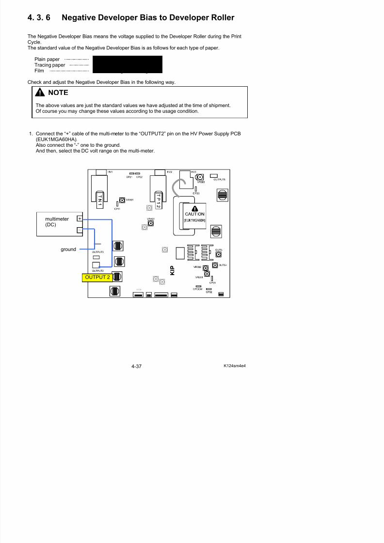
4. 3. 6 Negative Developer Bias to Developer Roller
The Negative Developer Bias means the voltage supplied to the Developer Roller during the PrintCycle.The standard value of the Negative Developer Bias is as follows for each type of paper.
Plain paper -180 +/-5V against the ground Tracing paper -180 +/-5V against the ground
5/17/2018 KIP 7100 Service Manual Ver A_1 - slidepdf.com
http://slidepdf.com/reader/full/kip-7100-service-manual-ver-a1 102/674
Film -180 +/-5V against the ground
Check and adjust the Negative Developer Bias in the following way.
1. Connect the “+” cable of the multi-meter to the “OUTPUT2” pin on the HV Power Supply PCB(EUK1MGA60HA). Also connect the “-” one to the ground. And then, select the DC volt range on the multi-meter.
NOTE
The above values are just the standard values we have adjusted at the time of shipment.Of course you may change these values according to the usage condition.
multimeter (DC)
ground
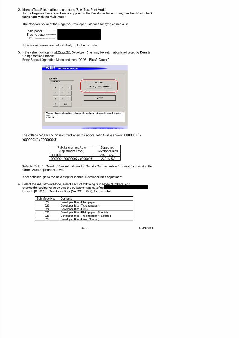
2. Make a Test Print making reference to [8. 9 Test Print Mode]. As the Negative Developer Bias is supplied to the Developer Roller during the Test Print, checkthe voltage with the multi-meter.
The standard value of the Negative Developer Bias for each type of media is:
Plain paper -180 +/-5V against the ground Tracing paper -180 +/-5V against the ground Film -180 +/-5V against the ground
5/17/2018 KIP 7100 Service Manual Ver A_1 - slidepdf.com
http://slidepdf.com/reader/full/kip-7100-service-manual-ver-a1 103/674
If the above values are not satisfied, go to the next step.
3. If the value (voltage) is -230 +/- 5V, Developer Bias may be automatically adjusted by DensityCompensation Process.
Enter Special Operation Mode and then “0006 Bias3 Count”.
The voltage “-230V +/- 5V” is correct when the above 7-digit value shows “0000001” /“0000002” / “0000003”.
7 digits (current Auto Adjustment Level)
SupposedDeveloper Bias
000000 -180 +/-5V0000001 / 0000002 / 0000003 -230 +/-5V
Refer to [8.11.3 Reset of Bias Adjustment by Density Compensation Process] for checking the
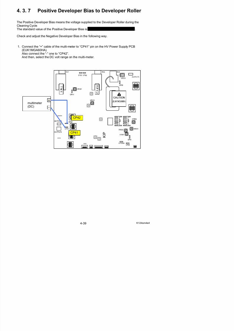
4. 3. 7 Positive Developer Bias to Developer Roller
The Positive Developer Bias means the voltage supplied to the Developer Roller during theCleaning Cycle.The standard value of the Positive Developer Bias is 0.350 +/-0.005V against the CP42.
Check and adjust the Negative Developer Bias in the following way.
5/17/2018 KIP 7100 Service Manual Ver A_1 - slidepdf.com
http://slidepdf.com/reader/full/kip-7100-service-manual-ver-a1 104/674
1. Connect the “+” cable of the multi-meter to “CP41” pin on the HV Power Supply PCB(EUK1MGA60HA). Also connect the “-” one to “CP42”. And then, select the DC volt range on the multi-meter.
multimeter (DC)
CP41
CP42
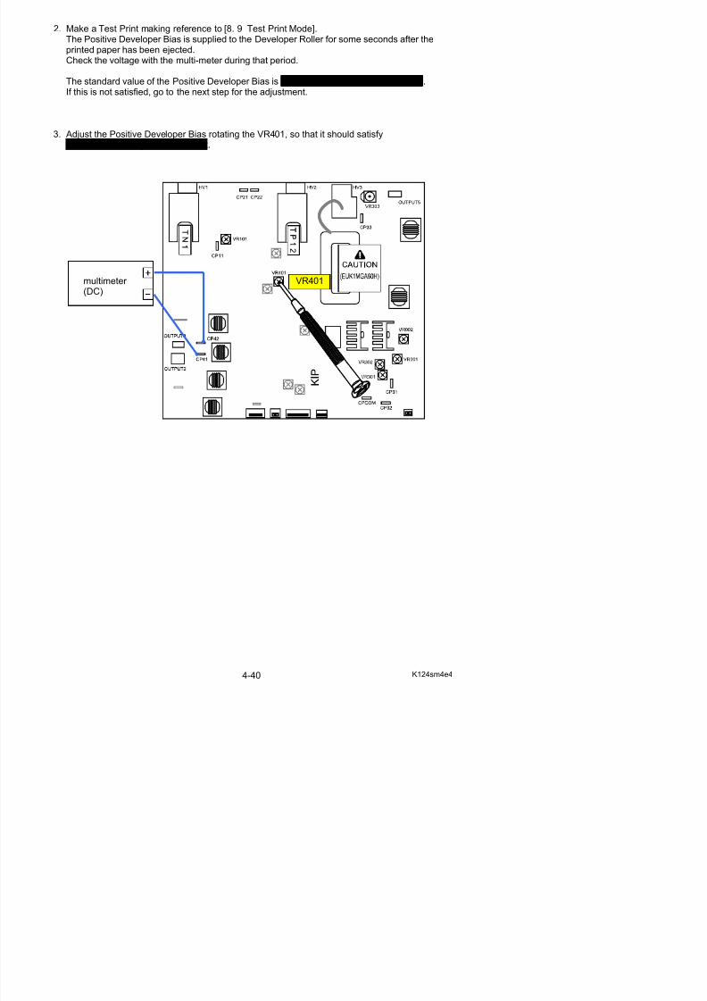
2. Make a Test Print making reference to [8. 9 Test Print Mode].The Positive Developer Bias is supplied to the Developer Roller for some seconds after theprinted paper has been ejected.Check the voltage with the multi-meter during that period.
The standard value of the Positive Developer Bias is 0.350 +/-0.005V against the CP42.If this is not satisfied, go to the next step for the adjustment.
5/17/2018 KIP 7100 Service Manual Ver A_1 - slidepdf.com
http://slidepdf.com/reader/full/kip-7100-service-manual-ver-a1 105/674
3. Adjust the Positive Developer Bias rotating the VR401, so that it should satisfy0.350 +/-0.005V against the CP42.
VR401multimeter (DC)
4. 3. 8 Bias gap between Developer Roller andRegulation Roller
The standard value of the Bias gap between Developer Roller and Regulation Roller is 80 +/-5V.Check and adjust it in the following way.
1. Connect the “+” cable of the multi-meter to the “OUTPUT3” pin on the HV Power Supply PCB
(EUK1MGA60HA).
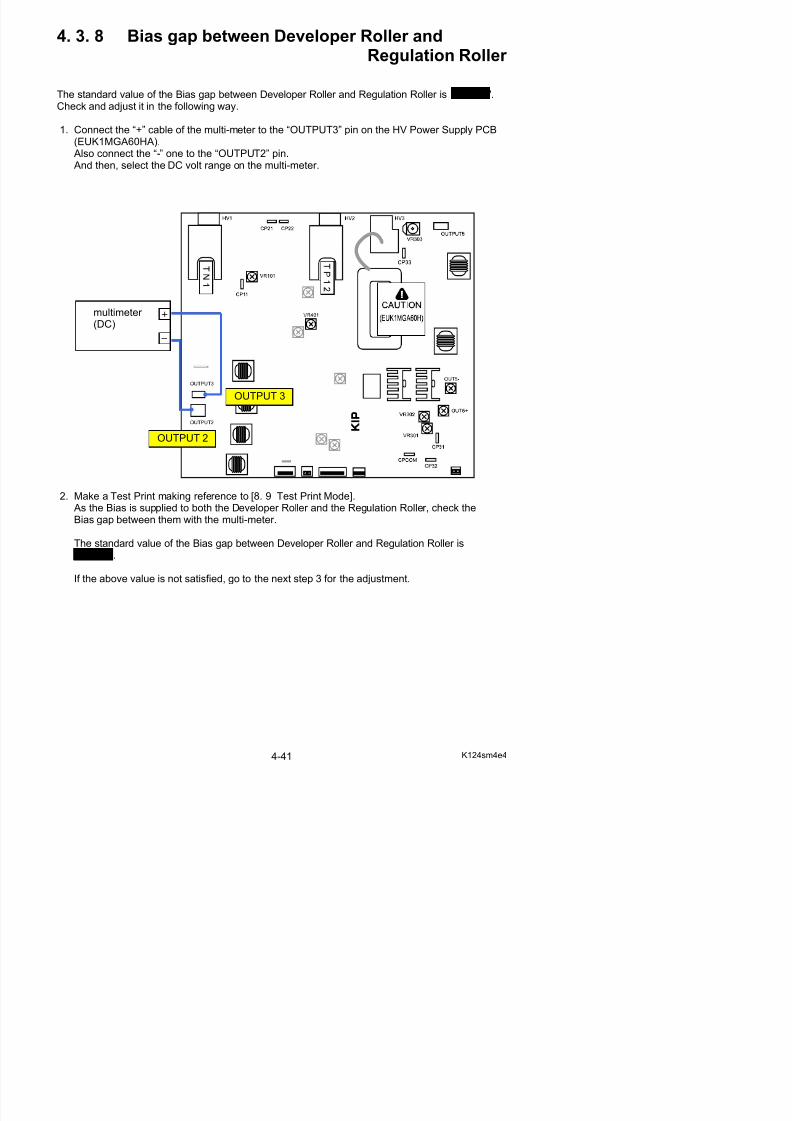
5/17/2018 KIP 7100 Service Manual Ver A_1 - slidepdf.com
http://slidepdf.com/reader/full/kip-7100-service-manual-ver-a1 106/674
( ) Also connect the “-” one to the “OUTPUT2” pin. And then, select the DC volt range on the multi-meter.
2. Make a Test Print making reference to [8. 9 Test Print Mode].
As the Bias is supplied to both the Developer Roller and the Regulation Roller, check theBias gap between them with the multi-meter.
The standard value of the Bias gap between Developer Roller and Regulation Roller is80 +/-5V
OUTPUT 2
OUTPUT 3
multimeter (DC)
3. If the value (voltage) is “120 +/-5V” or “160 +/- 5V”, Regulation Bias may be automaticallyadjusted by Density Compensation Process.
Enter Special Operation Mode and then “0006 Bias3 Count”.
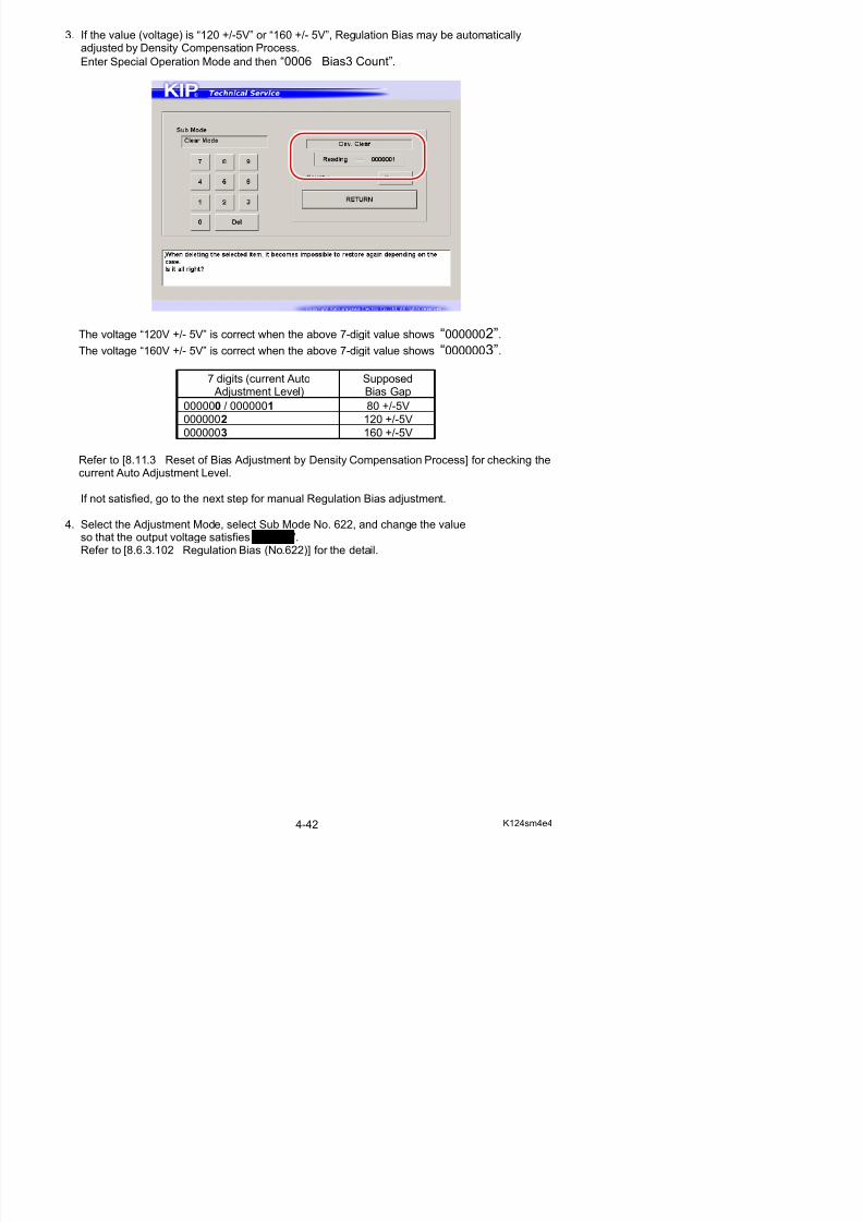
5/17/2018 KIP 7100 Service Manual Ver A_1 - slidepdf.com
http://slidepdf.com/reader/full/kip-7100-service-manual-ver-a1 107/674
The voltage “120V +/- 5V” is correct when the above 7-digit value shows “0000002”.
The voltage “160V +/- 5V” is correct when the above 7-digit value shows “0000003”.
7 digits (current Auto Adjustment Level)
SupposedBias Gap
000000 / 0000001 80 +/-5V
0000002 120 +/-5V
0000003 160 +/-5V
Refer to [8.11.3 Reset of Bias Adjustment by Density Compensation Process] for checking thecurrent Auto Adjustment Level.
If not satisfied, go to the next step for manual Regulation Bias adjustment.
4. Select the Adjustment Mode, select Sub Mode No. 622, and change the valueso that the output voltage satisfies 80 +/-5V.Refer to [8.6.3.102 Regulation Bias (No.622)] for the detail.
4. 3. 9 Positive Cleaning Roller Bias (Print Cycle)
The Positive Cleaning Roller Bias means the voltage supplied to the Cleaning Roller during thePrint Process.The standard value of the Positive Cleaning Roller Bias is +450 +/-5V.Check and adjust it in the following way.
1. Connect the “+” cable of the multi-meter to the “OUTPUT 5” pin on the HV Power Supply PCBAlso connect the “-” one to the ground.
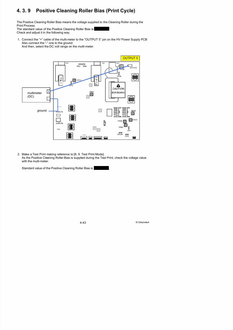
5/17/2018 KIP 7100 Service Manual Ver A_1 - slidepdf.com
http://slidepdf.com/reader/full/kip-7100-service-manual-ver-a1 108/674
Also connect the one to the ground. And then, select the DC volt range on the multi-meter.
2. Make a Test Print making reference to [8. 9 Test Print Mode]. As the Positive Cleaning Roller Bias is supplied during the Test Print, check the voltage valuewith the multi-meter.
OUTPUT 5
multimeter (DC)
ground
3. Adjust the Positive Cleaning Roller Bias if it does not satisfy +450 +/-5V.To adjust it, rotate the VR001 with a screwdriver.
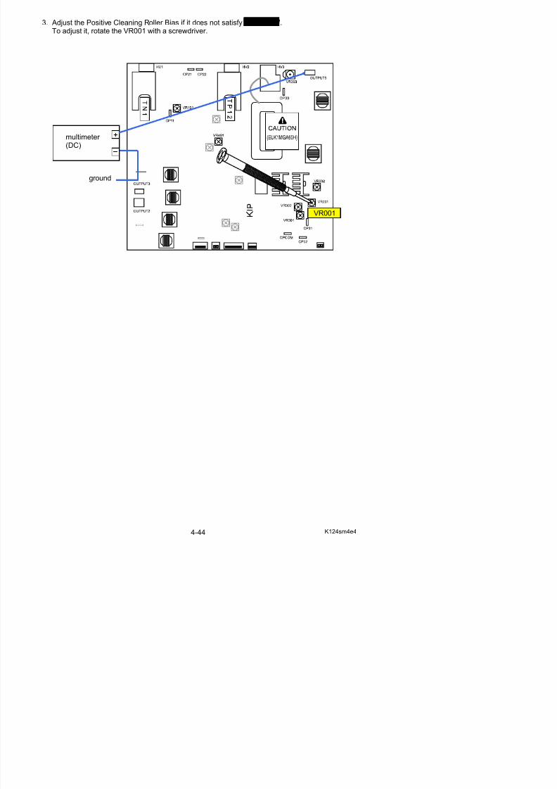
5/17/2018 KIP 7100 Service Manual Ver A_1 - slidepdf.com
http://slidepdf.com/reader/full/kip-7100-service-manual-ver-a1 109/674
VR001
multimeter (DC)
ground
4. 3.10 Negative Cleaning Roller Bias(Toner Collection Process)
The Negative Cleaning Roller Bias means the voltage supplied to the Cleaning Roller during theToner Collection Process, which is done after the completion of Print Process.The standard value of the Negative Cleaning Roller Bias is -550 +/-5V.Check and adjust it in the following way.
1 C t th “+” bl f th lti t t th “OUTPUT 5” pi th HV P S ppl PCB
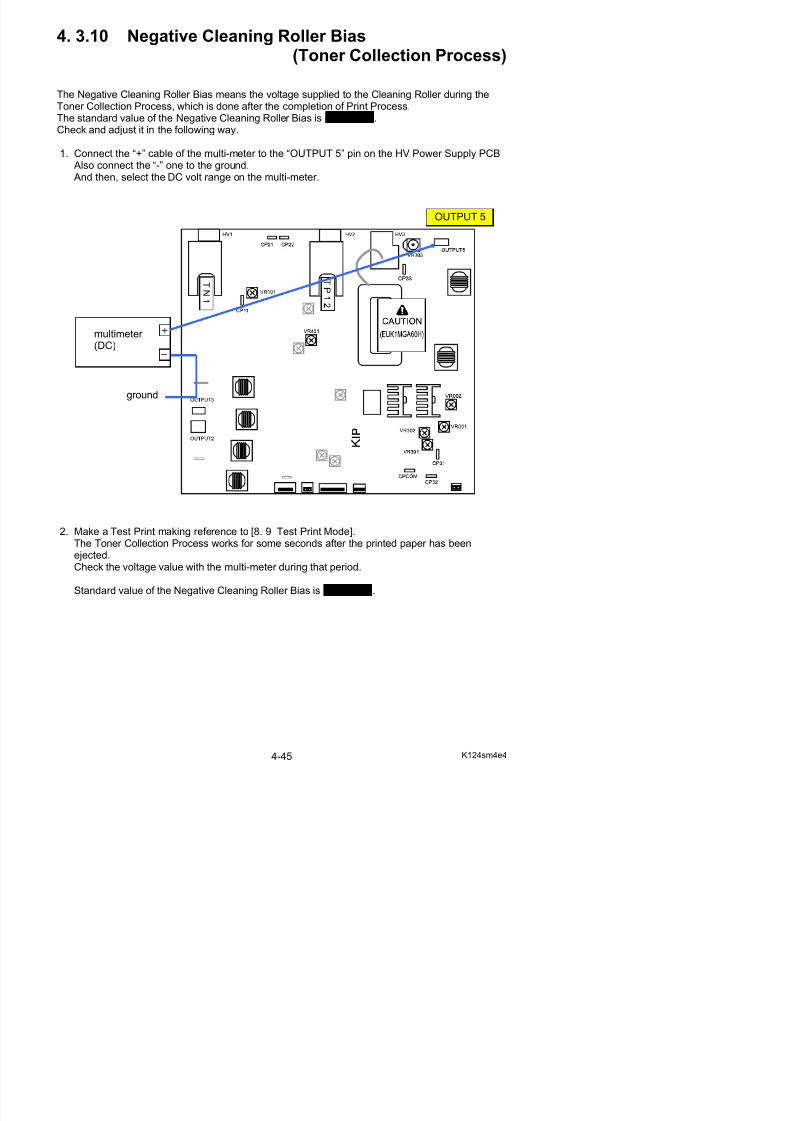
5/17/2018 KIP 7100 Service Manual Ver A_1 - slidepdf.com
http://slidepdf.com/reader/full/kip-7100-service-manual-ver-a1 110/674
1. Connect the “+” cable of the multi-meter to the “OUTPUT 5” pin on the HV Power Supply PCB Also connect the “-” one to the ground. And then, select the DC volt range on the multi-meter.
2. Make a Test Print making reference to [8. 9 Test Print Mode].The Toner Collection Process works for some seconds after the printed paper has beenejected
OUTPUT 5
multimeter (DC)
ground
3. Adjust the Negative Cleaning Roller Bias if it does not satisfy -550 +/-5V.To adjust it, rotate the VR002 with a screwdriver.
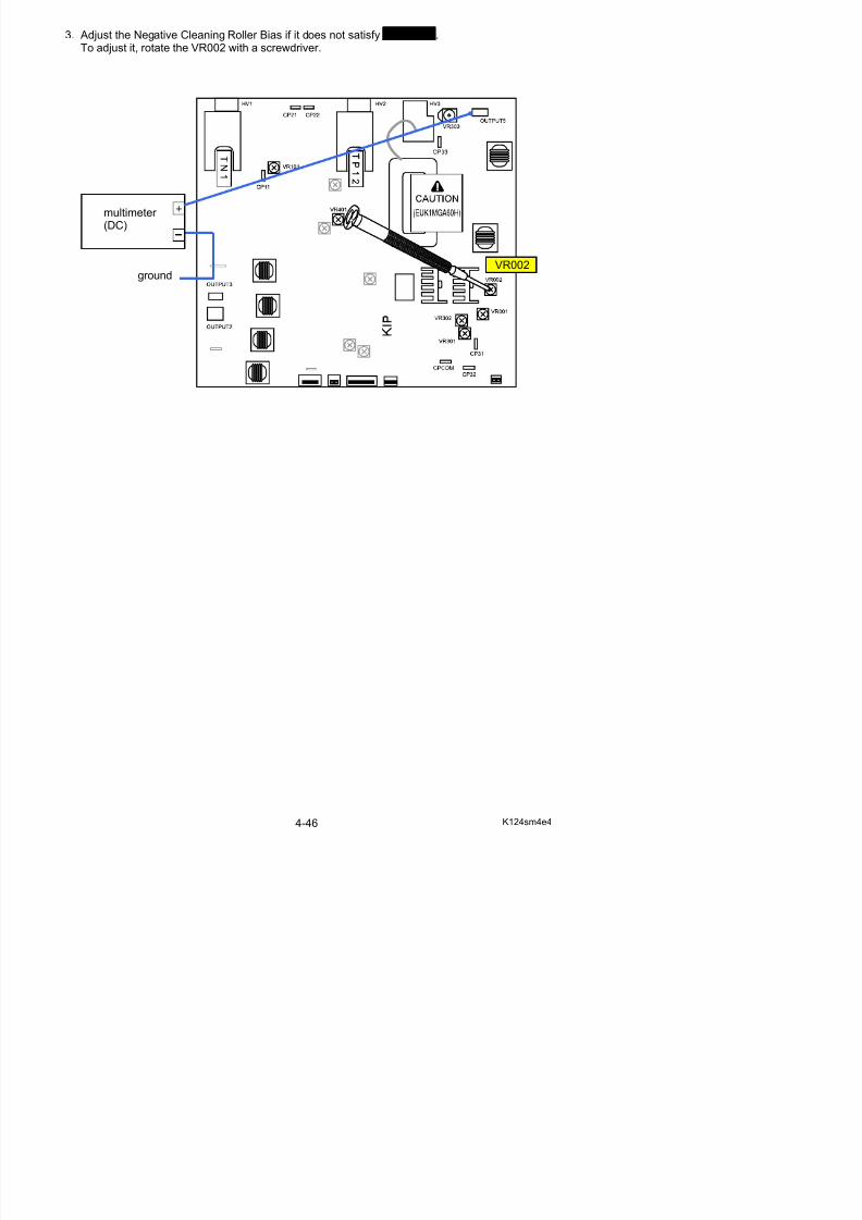
5/17/2018 KIP 7100 Service Manual Ver A_1 - slidepdf.com
http://slidepdf.com/reader/full/kip-7100-service-manual-ver-a1 111/674
multimeter (DC)
groundVR002
Chapter 5
Mechanical
page5 1 Outer Covers 5- 1
5/17/2018 KIP 7100 Service Manual Ver A_1 - slidepdf.com
http://slidepdf.com/reader/full/kip-7100-service-manual-ver-a1 112/674
5. 1 Outer Covers 5- 15. 1. 1 Removal of Side Covers 5- 15. 1. 2 Removal of Cover 15 5- 25. 1. 3 Removal of Cover 14 5- 3
5. 2 Developer Unit 5- 5
5. 2. 1 Removal of the Developer Unit 5- 55. 2. 2 Replacement of Recommended Periodic Replacement Parts 5- 85. 2. 3 Replacement of Roller Supply 5-355. 2. 4 Replacement of Screw Assy 5-385. 2. 5 Replacement of DC Motor 5-465. 2. 6 Replacement of Sensor (TLS1) 5-475. 2. 7 Adjustment of the space between gears
(Necessary to adjust after replacing the Developer Unit) 5-48
5. 2. 8 Readjustment of the pressure of Regulation Roller 5-54
5. 3 Fuser Unit 5-705. 3. 1 Removal of Fuser Unit 5-705. 3. 2 Reinstallation of Fuser Unit 5-765. 3. 3 Replacement of Recommended Periodic Replacement Parts 5-775. 3. 4 Replacement of Roller Pressure 5-905. 3. 5 Fuser Pressure Adjustment (NIP width check) 5-100
5. 3. 6 Replacement of Thermistor (TH1, TH2) 5-1015. 3. 7 Replacement of Thermostat (TS1, TS2) 5-1035. 3. 8 Replacement of Exit Sensor (PH3) 5-104
5. 4 Roll Deck 5-1075. 4. 1 Replacement of Cutter Assembly 5-1075. 4. 2 Replacement of Clutches (CL3, CL4, CL5) of Roll 1 5-1105. 4. 3 Replacement of Clutches (CL6, CL7) of Roll 2 5-1125. 4. 4 Replacement of Timing Belt 633 5-1145. 4. 5 Replacement of Timing Belt 453 5-1185. 4. 6 Replacement of Timing Belt 330 5-1205. 4. 7 Replacement of Sensors (PH6, PH7, PH9, PH12) 5-1215 4 8 Replacement of Sensors (PH8) 5-124
5. 6 LED Head 5-2495. 6. 1 Replacement of the LED Head Unit 5-2495. 6. 2 LED focus adjustment 5-257
5. 6. 2. 1 Check of the Test Pattern Image 5-2575. 6. 2. 2 Positioning of the Aluminum Blocks 5-2585. 6. 2. 3 Focus Adjustment with Spacers 5-274
5. 7 Image Corona 5-280
5. 7. 1 Removal of the Image Corona Unit 5-2805. 7. 2 Replacement of the Corona Wire 5-287
5/17/2018 KIP 7100 Service Manual Ver A_1 - slidepdf.com
http://slidepdf.com/reader/full/kip-7100-service-manual-ver-a1 113/674
5. 8 Transfer / Separation Corona 5-2925. 8. 1 Removal of the Transfer / Separation Corona 5-2925. 8. 2 Replacement of Corona Wires 5-293
5. 9 Engine Frame 5-296
5. 9. 1 Replacement of DC Motor (M4) and Developer Press Sensor (PH4) 5-2965. 9. 2 Replacement of Manual Set Sensor (PH5) & Registration Sensor (PH1) 5-3005. 9. 3 Replacement of Fans (BL5, BL6) 5-3025. 9. 4 Replacement of Blowers (BL3, BL4) 5-303
5.10 Inner Transport Unit 5-3055.10. 1 Removal of the Inner Transport Unit 5-3055.10. 2 Replacement of Sensor (PH2) & Belt 5-306
5.11 Main Frame 5-3095.11. 1 Replacement of DC Motors (M1, M2), Belt8, Belt9, Belt 7 5-3095.11. 2 Replacement of Clutch (CL1) 5-3175.11. 3 Replacement of Blower (BL7) 5-3215.11. 4 Replacement of Fan (BL8) 5-322
5.12 Scanner Unit 5-3235.12. 1 Removal of the Scanner Unit 5-3235.12. 2 Replacement of Belt 5-3295.12. 3 Replacement of Motor Assy 5-3315.12. 4 Replacement of Feed Roller 5-3345.12. 5 Replacement of Pinch Roller Assy 5-3425.12. 6 Replacement of CIS 5-3495.12. 7 Replacement of Scan Glass Assy 5-353
5. 1 Outer Covers
5. 1. 1 Removal of Side Covers
1. Pull up the Lever 2 (1) to open the Engine Unit.
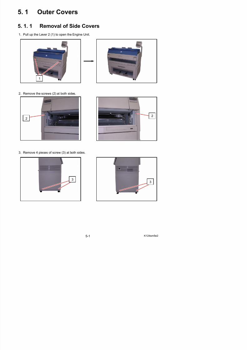
5/17/2018 KIP 7100 Service Manual Ver A_1 - slidepdf.com
http://slidepdf.com/reader/full/kip-7100-service-manual-ver-a1 114/674
2. Remove the screws (2) at both sides.
3. Remove 4 pieces of screw (3) at both sides.
1
22
4. Remove 5 pieces of screw (4) at both sides.(2 pieces on the right and 3 pieces on the left)
44
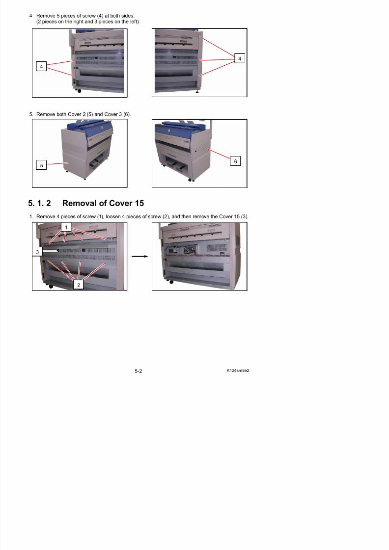
5/17/2018 KIP 7100 Service Manual Ver A_1 - slidepdf.com
http://slidepdf.com/reader/full/kip-7100-service-manual-ver-a1 115/674
5. Remove both Cover 2 (5) and Cover 3 (6).
5. 1. 2 Removal of Cover 151. Remove 4 pieces of screw (1), loosen 4 pieces of screw (2), and then remove the Cover 15 (3).
56
1
3
5. 1. 3 Removal of Cover 14
1. Remove 2 pieces of Guide 3 (1).1
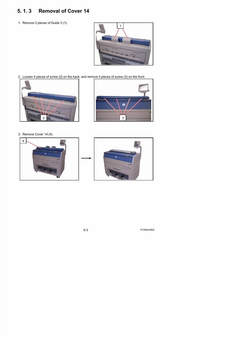
5/17/2018 KIP 7100 Service Manual Ver A_1 - slidepdf.com
http://slidepdf.com/reader/full/kip-7100-service-manual-ver-a1 116/674
2. Loosen 4 pieces of screw (2) on the back, and remove 4 pieces of screw (3) on the front.
3. Remove Cover 14 (4).
2 3
4
4. Remove 3 screws (5).
5
5
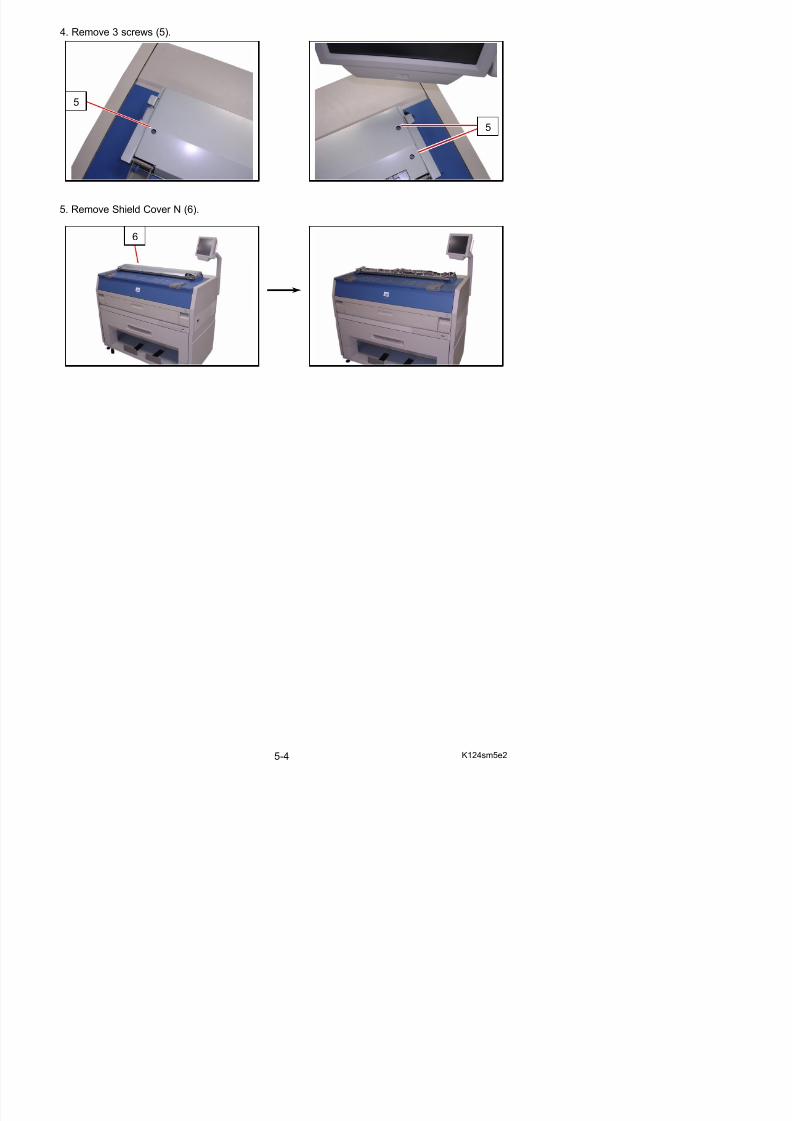
5/17/2018 KIP 7100 Service Manual Ver A_1 - slidepdf.com
http://slidepdf.com/reader/full/kip-7100-service-manual-ver-a1 117/674
5. Remove Shield Cover N (6).
6
5. 2 Developer Unit
5. 2. 1 Removal of the Developer Unit
1. Open the Cover 4 (1).
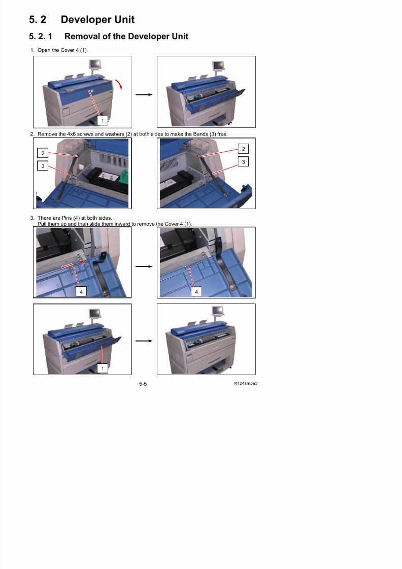
5/17/2018 KIP 7100 Service Manual Ver A_1 - slidepdf.com
http://slidepdf.com/reader/full/kip-7100-service-manual-ver-a1 118/674
2. Remove the 4x6 screws and washers (2) at both sides to make the Bands (3) free.
3. There are Pins (4) at both sides.Pull them up and then slide them inward to remove the Cover 4 (1).
1
2
3
2
3
4. Pull up the Lever 2 (5) to open the Engine Unit.
5
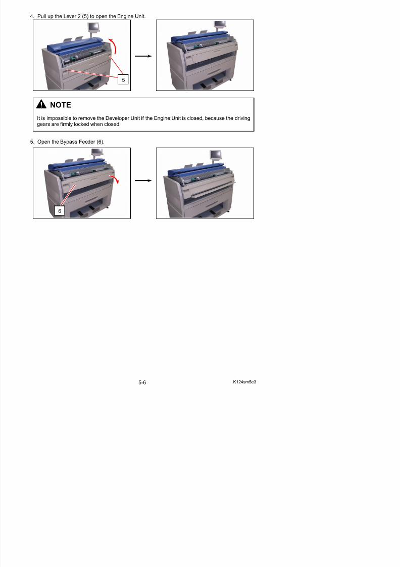
5/17/2018 KIP 7100 Service Manual Ver A_1 - slidepdf.com
http://slidepdf.com/reader/full/kip-7100-service-manual-ver-a1 119/674
5. Open the Bypass Feeder (6).
6
NOTE
It is impossible to remove the Developer Unit if the Engine Unit is closed, because the drivinggears are firmly locked when closed.
6. Remove 4 pieces of 4x8 screw (7).
7 7
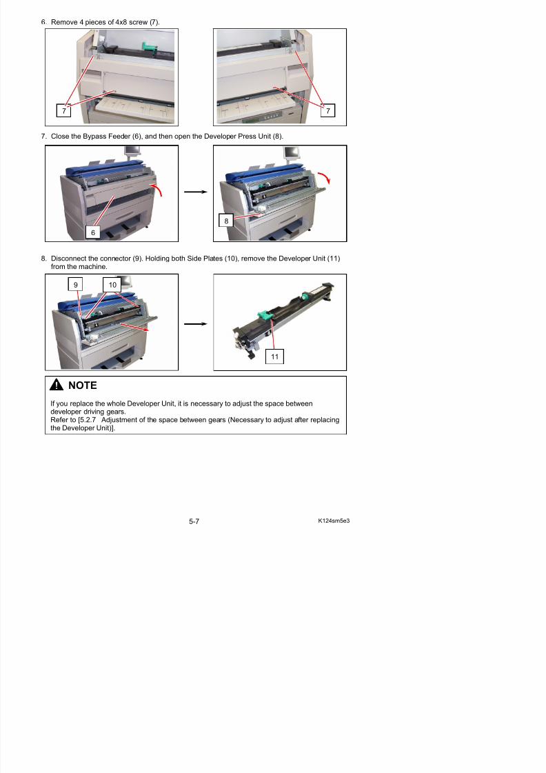
5/17/2018 KIP 7100 Service Manual Ver A_1 - slidepdf.com
http://slidepdf.com/reader/full/kip-7100-service-manual-ver-a1 120/674
7. Close the Bypass Feeder (6), and then open the Developer Press Unit (8).
8. Disconnect the connector (9). Holding both Side Plates (10), remove the Developer Unit (11)from the machine.
NOTE
6
10
8
9
11
5. 2. 2 Replacement of Recommended PeriodicReplacement Parts
NOTE
(1) A periodic replacement for the following parts is recommended.
This section shows how to replace all of them in one sequent operation.Refer to this section as well for replacement individual part listed below.
Item Number Remarks
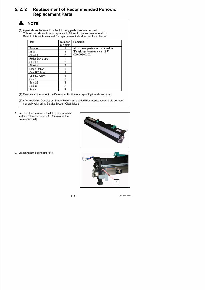
5/17/2018 KIP 7100 Service Manual Ver A_1 - slidepdf.com
http://slidepdf.com/reader/full/kip-7100-service-manual-ver-a1 121/674
1. Remove the Developer Unit from the machinemaking reference to [5.2.1 Removal of theDeveloper Unit].
(2) Remove all the toner from Developer Unit before replacing the above parts.
(3) After replacing Developer / Blade Rollers, an applied Bias Adjustment should be resetmanually with using Service Mode - Clear Mode.
of article
Scraper 1
Sheet 2
Sheet 2 2
Roller Developer 1Sheet 3 2
Sheet 4 2
Blade Roller 1
Seal R2 Assy 1
Seal L2 Assy 1
Seal 1 2
Seal 23 2Seal 3 2
Seal 4 2
All of these parts are contained in“Developer Maintenance Kit A”(Z160980020).
3. Remove 4 pieces of 4x6 screws (2) to remove the Hopper Assembly (3).
22
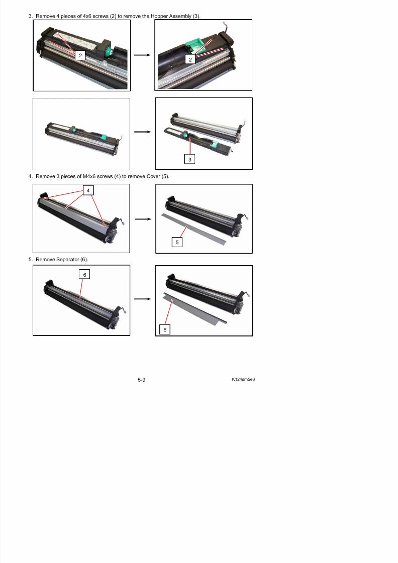
5/17/2018 KIP 7100 Service Manual Ver A_1 - slidepdf.com
http://slidepdf.com/reader/full/kip-7100-service-manual-ver-a1 122/674
4. Remove 3 pieces of M4x6 screws (4) to remove Cover (5).
5. Remove Separator (6).
5
4
3
6
6. Remove 4 pieces of 4x6 screw (7) to remove Scraper Assembly (8).
7
7
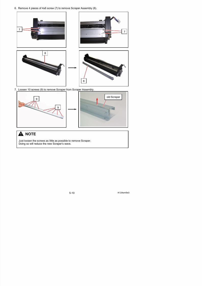
5/17/2018 KIP 7100 Service Manual Ver A_1 - slidepdf.com
http://slidepdf.com/reader/full/kip-7100-service-manual-ver-a1 123/674
7. Loosen 10 screws (9) to remove Scraper from Scraper Assembly.
8
8
9
9
NOTE
Just loosen the screws as little as possible to remove Scraper.
old Scraper
8. Put Scraper (10) in Scraper Assembly (8) and push Scraper’s edge to the inside.Scraper (10) should be placed that the numbers printed on one side face can be read in correctorientation.
10
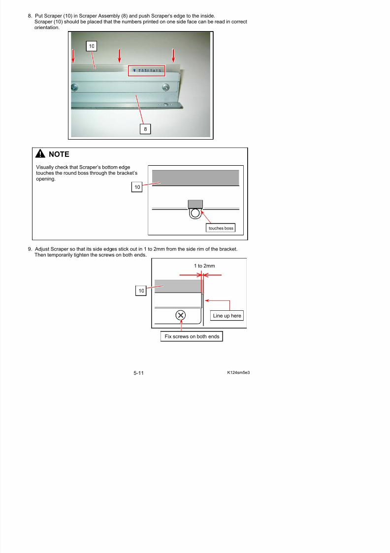
5/17/2018 KIP 7100 Service Manual Ver A_1 - slidepdf.com
http://slidepdf.com/reader/full/kip-7100-service-manual-ver-a1 124/674
9. Adjust Scraper so that its side edges stick out in 1 to 2mm from the side rim of the bracket.
Then temporarily tighten the screws on both ends.
NOTE
Visually check that Scraper’s bottom edgetouches the round boss through the bracket’sopening.
8
10
touches boss
1 to 2mm
10. Tighten the screws from the center to the sides with holding around each screw on the bracket.
Secure center to side Secure center to side
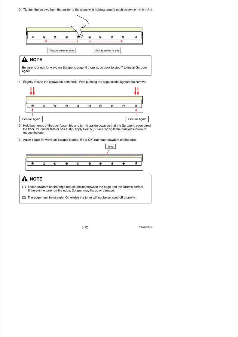
5/17/2018 KIP 7100 Service Manual Ver A_1 - slidepdf.com
http://slidepdf.com/reader/full/kip-7100-service-manual-ver-a1 125/674
11. Slightly loosen the screws on both ends. With pushing the edge inside, tighten the screws.
12. Hold both ends of Scraper Assembly and turn it upside down so that the Scraper’s edge directthe floor. If Scraper falls or has a slip, apply Seal 5 (Z054601260) to the bracket’s inside toreduce the gap.
13. Again check for wave on Scraper’s edge. If it is OK, rub toner powders on the edge.
NOTE
Be sure to check for wave on Scraper’s edge. If there is, go back to step 7 to install Scraper again.
Secure again Secure again
Toner
14. Remove all the toner from Developer Unit.
15. On the driving side, remove Retaining Ring-C (11: C6) to remove Gear Helical 30T (12),Parallel Pin (13: 2.5x10) and Collar 3 (14) from Blade Roller shaft.
1412
13 12
NOTE
Do not reuse the removed toner.
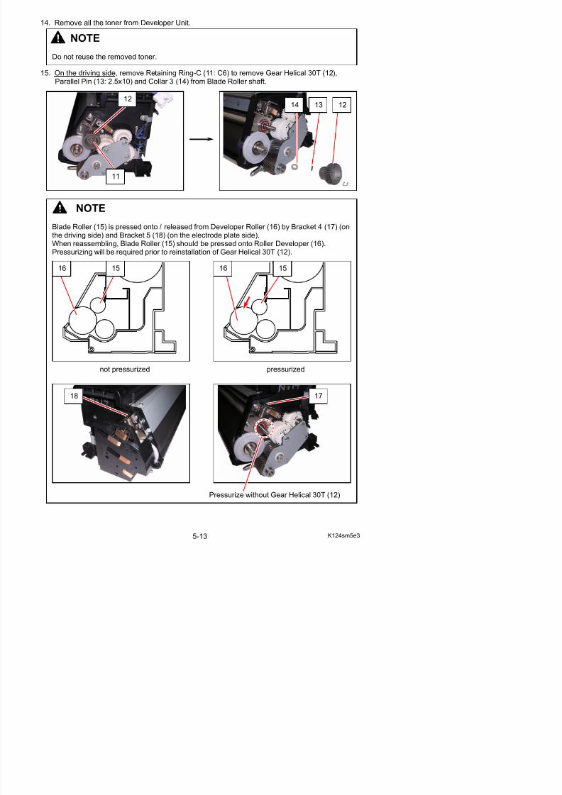
5/17/2018 KIP 7100 Service Manual Ver A_1 - slidepdf.com
http://slidepdf.com/reader/full/kip-7100-service-manual-ver-a1 126/674
NOTE
Blade Roller (15) is pressed onto / released from Developer Roller (16) by Bracket 4 (17) (onthe driving side) and Bracket 5 (18) (on the electrode plate side).When reassembling, Blade Roller (15) should be pressed onto Roller Developer (16).Pressurizing will be required prior to reinstallation of Gear Helical 30T (12).
not pressurized pressurized
11
16 15 1516
18 17
16. Remove 5 screws (19: M4x8) (20: M4x6) to remove Pin 4 (21), Plate 9 (22), Collar (23).
19
23
21
22
20
20
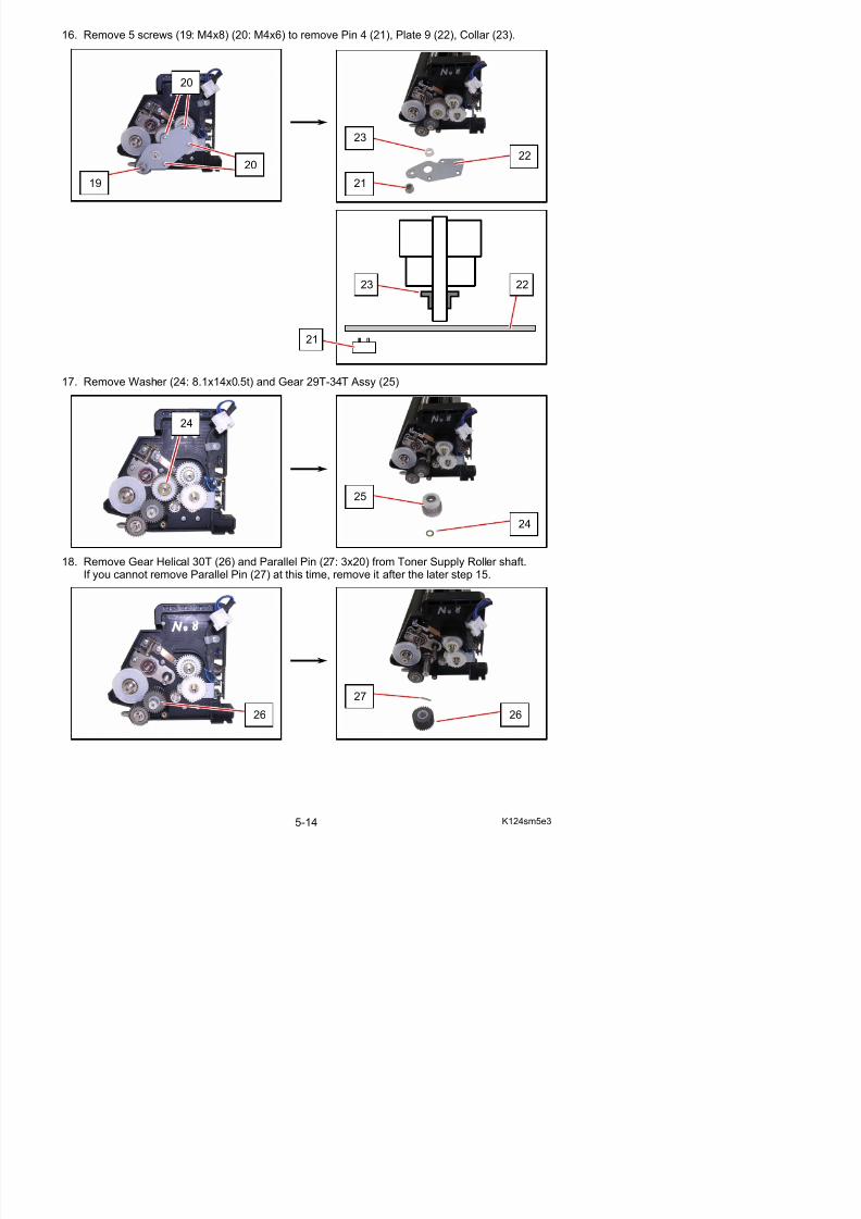
5/17/2018 KIP 7100 Service Manual Ver A_1 - slidepdf.com
http://slidepdf.com/reader/full/kip-7100-service-manual-ver-a1 127/674
17. Remove Washer (24: 8.1x14x0.5t) and Gear 29T-34T Assy (25)
18. Remove Gear Helical 30T (26) and Parallel Pin (27: 3x20) from Toner Supply Roller shaft.If you cannot remove Parallel Pin (27) at this time, remove it after the later step 15.
24
25
24
21
2223
19. Remove Retaining Ring-E (28: E7) to remove Washer (29: 8.1x12x0.2t) and Gear Helical 28T Assy (30).
28
30
29 28
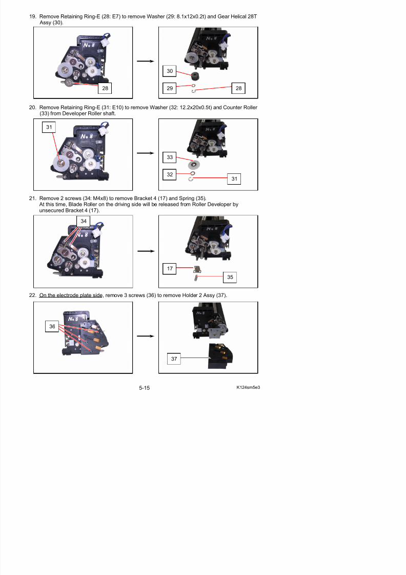
5/17/2018 KIP 7100 Service Manual Ver A_1 - slidepdf.com
http://slidepdf.com/reader/full/kip-7100-service-manual-ver-a1 128/674
20. Remove Retaining Ring-E (31: E10) to remove Washer (32: 12.2x20x0.5t) and Counter Roller
(33) from Developer Roller shaft.
21. Remove 2 screws (34: M4x8) to remove Bracket 4 (17) and Spring (35). At this time, Blade Roller on the driving side will be released from Roller Developer byunsecured Bracket 4 (17).
31
33
3231
17
35
34
23. Remove 3 screws (38: M4x6) and 2 Retaining Ring-E (39: E10) to remove Collar (40) andBracket 10 Assy (41).
40
39
41
39
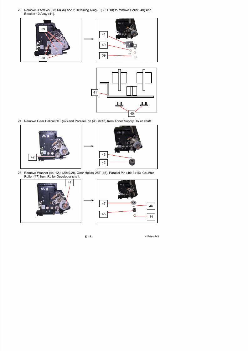
5/17/2018 KIP 7100 Service Manual Ver A_1 - slidepdf.com
http://slidepdf.com/reader/full/kip-7100-service-manual-ver-a1 129/674
24. Remove Gear Helical 30T (42) and Parallel Pin (43: 3x16) from Toner Supply Roller shaft.
25. Remove Washer (44: 12.1x20x0.2t), Gear Helical 25T (45), Parallel Pin (46: 3x16), Counter
3938
40
41
4243
42
26. Remove 2 screws (48: M4x6) to remove Bracket 5 (18) and Spring (49). At this time, Blade Roller on the electrode plate side will be released from Roller Developer byunsecured Bracket 5 (18).
18
48
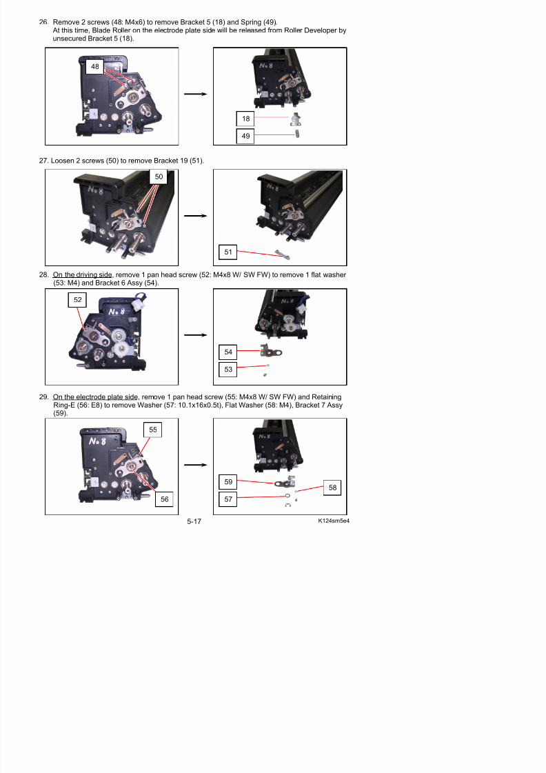
5/17/2018 KIP 7100 Service Manual Ver A_1 - slidepdf.com
http://slidepdf.com/reader/full/kip-7100-service-manual-ver-a1 130/674
27. Loosen 2 screws (50) to remove Bracket 19 (51).
28. On the driving side, remove 1 pan head screw (52: M4x8 W/ SW FW) to remove 1 flat washer (53: M4) and Bracket 6 Assy (54).
49
51
52
54
53
50
30. Remove Blade Roller (15) from Developer Unit.Do not install the new Blade Roller at this time.
15
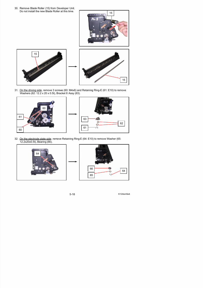
5/17/2018 KIP 7100 Service Manual Ver A_1 - slidepdf.com
http://slidepdf.com/reader/full/kip-7100-service-manual-ver-a1 131/674
31. On the driving side, remove 3 screws (60: M4x6) and Retaining Ring-E (61: E10) to removeWashers (62: 12.2 x 20 x 0.5t), Bracket 8 Assy (63).
32. On the electrode plate side, remove Retaining Ring-E (64: E10) to remove Washer (65:12.2x20x0.5t), Bearing (66).
15
15
61
60
63
61
60
62
33. Remove Roller Developer (16).Do not install the new Roller Developer at thistime.
16
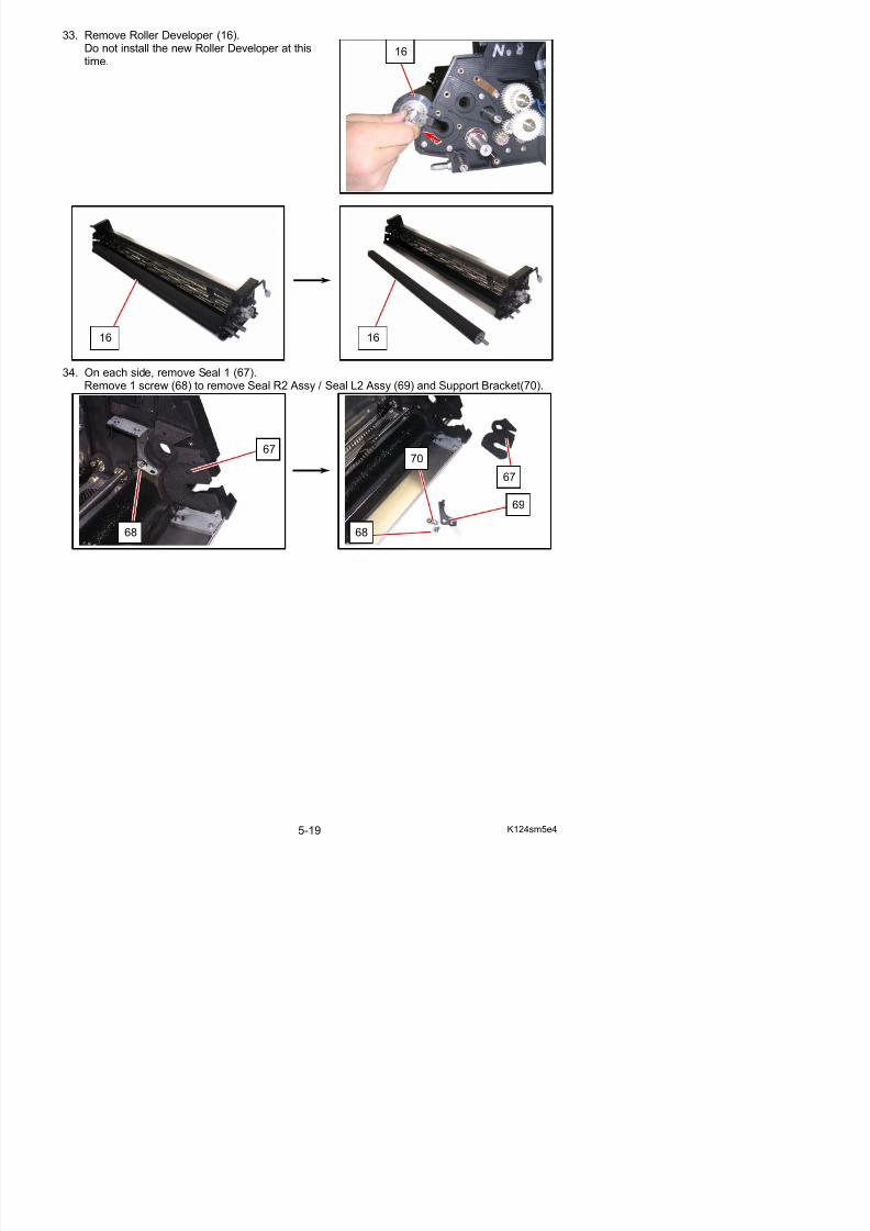
5/17/2018 KIP 7100 Service Manual Ver A_1 - slidepdf.com
http://slidepdf.com/reader/full/kip-7100-service-manual-ver-a1 132/674
34. On each side, remove Seal 1 (67).Remove 1 screw (68) to remove Seal R2 Assy / Seal L2 Assy (69) and Support Bracket(70).
16 16
68
67
67
69
68
70
35. On each side, remove Seal 23 (71: upper), Seal 4 (72: lower), Seal 3 (73: under).Replace Seal 23, Seal 4 and Seal 3 with new ones.
71
73 72
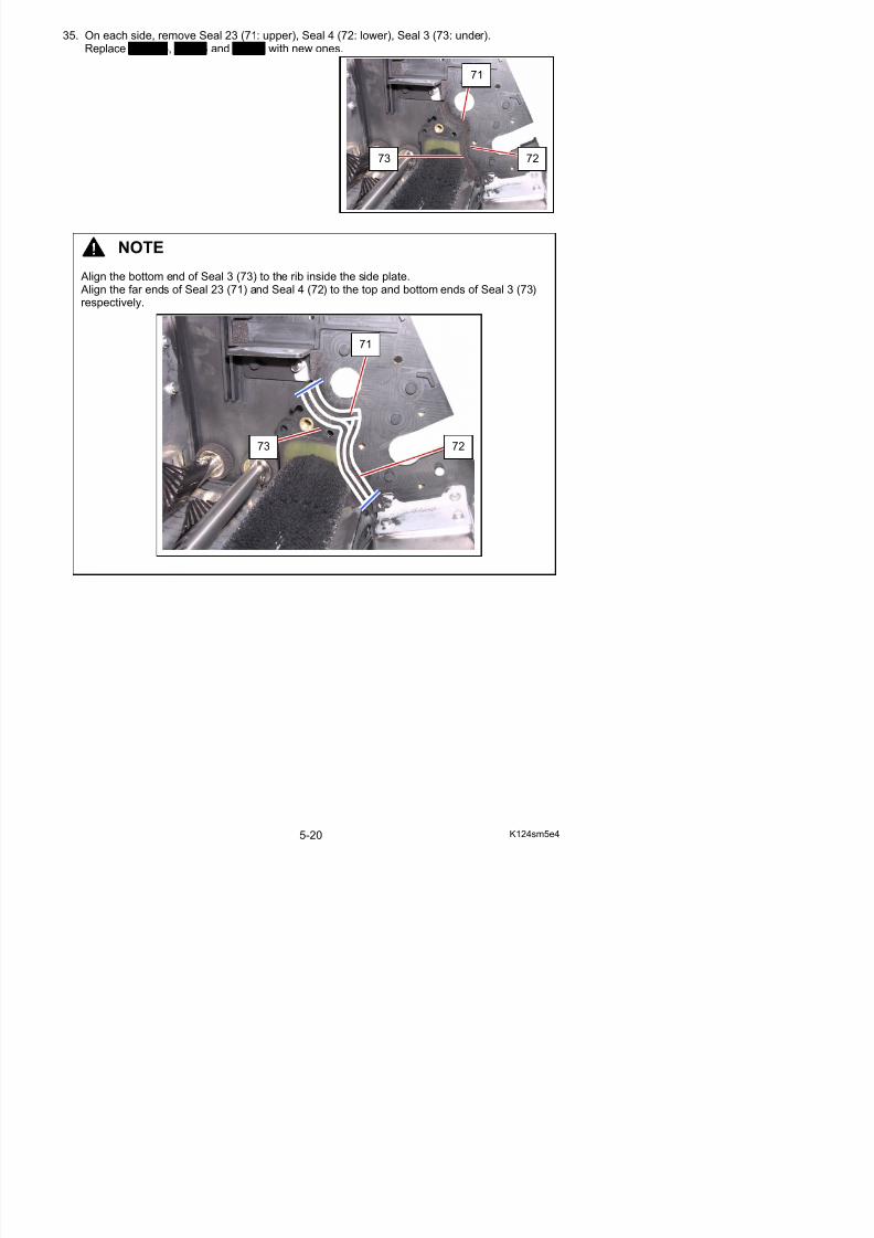
5/17/2018 KIP 7100 Service Manual Ver A_1 - slidepdf.com
http://slidepdf.com/reader/full/kip-7100-service-manual-ver-a1 133/674
NOTE Align the bottom end of Seal 3 (73) to the rib inside the side plate. Align the far ends of Seal 23 (71) and Seal 4 (72) to the top and bottom ends of Seal 3 (73)respectively.
73
71
72
36. Install the new Seal R2 Assy / Seal L2 Assy (74), Support Bracket (70), Seal 1 (75).
70
75
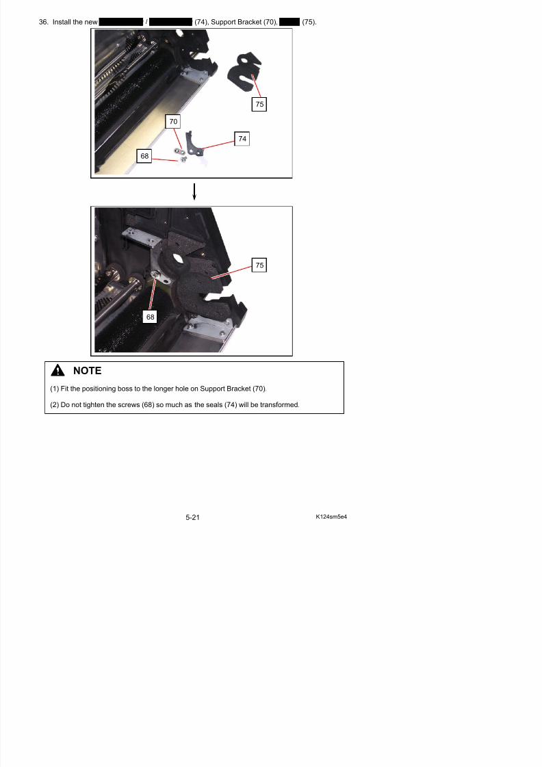
5/17/2018 KIP 7100 Service Manual Ver A_1 - slidepdf.com
http://slidepdf.com/reader/full/kip-7100-service-manual-ver-a1 134/674
NOTE
68
74
68
75
37. Apply the new Sheet 3 (76), Steet 4 (77)to both sides of the new Developer Roller.Keep water or grease away from betweenthe sheets.
38 Install the new Developer Roller to Developer Unit and fix it with the bearings
77
76
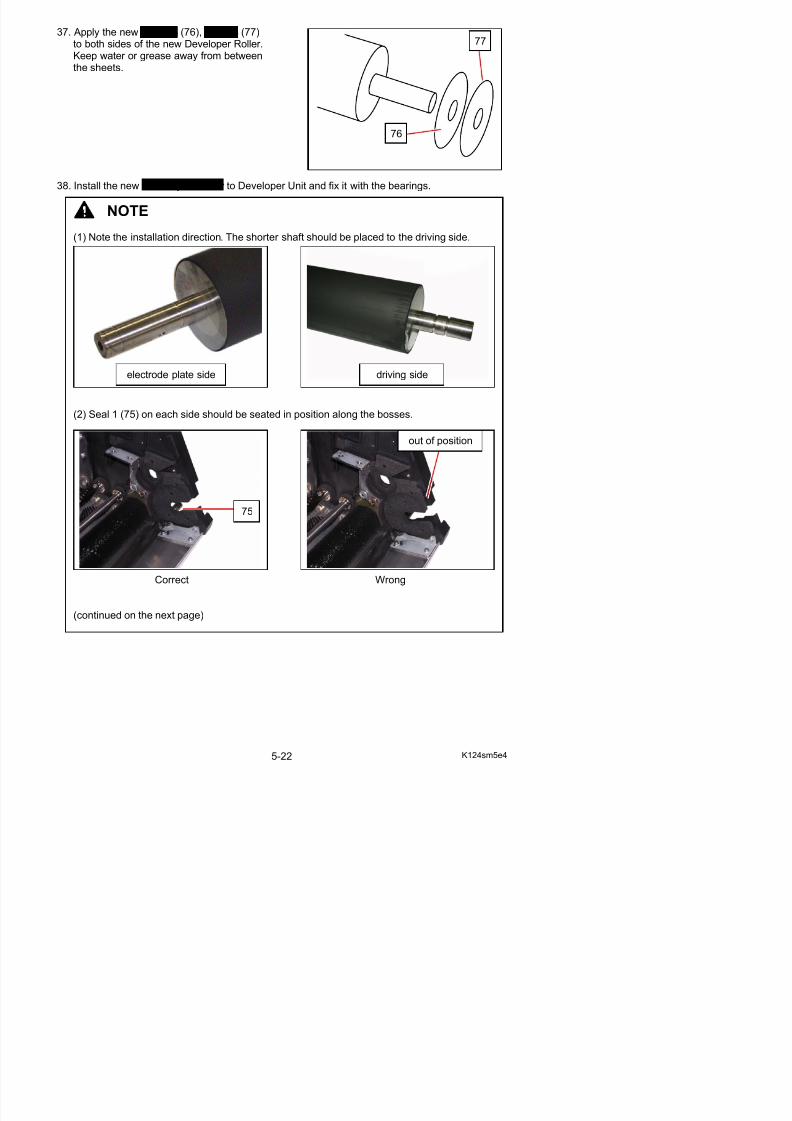
5/17/2018 KIP 7100 Service Manual Ver A_1 - slidepdf.com
http://slidepdf.com/reader/full/kip-7100-service-manual-ver-a1 135/674
38. Install the new Developer Roller to Developer Unit and fix it with the bearings.
NOTE
(1) Note the installation direction. The shorter shaft should be placed to the driving side.
(2) Seal 1 (75) on each side should be seated in position along the bosses.
75
out of position
electrode plate side driving side
NOTE
(3) Push Roller Developer against Seal 1 on the electrode plate side (A) to hold and keep itsoriginal position when reassembling.
A
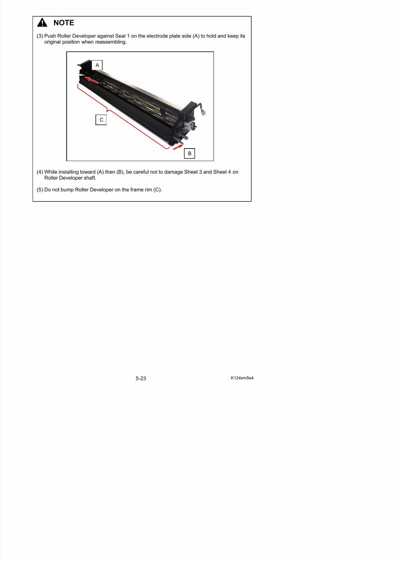
5/17/2018 KIP 7100 Service Manual Ver A_1 - slidepdf.com
http://slidepdf.com/reader/full/kip-7100-service-manual-ver-a1 136/674
(4) While installing toward (A) then (B), be careful not to damage Sheet 3 and Sheet 4 onRoller Developer shaft.
(5) Do not bump Roller Developer on the frame rim (C).
C
B
39. Reinstall Scraper Assembly.
NOTE
(1) For Scraper Assembly and Blade Roller, please reinstall Scraper Assembly first and thenlocate Blade Roller in position later. This will avoid making Scraper’s edge waving.
(2) After reinstalling Scraper Assembly, check that neither Scraper (10) nor Seal 1 (75) flips
up on both sides.
10
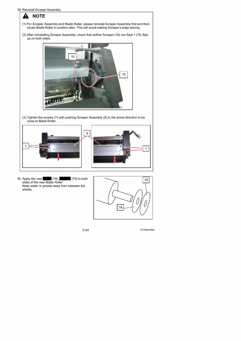
5/17/2018 KIP 7100 Service Manual Ver A_1 - slidepdf.com
http://slidepdf.com/reader/full/kip-7100-service-manual-ver-a1 137/674
(3) Tighten the screws (7) with pushing Scraper Assembly (8) to the arrow direction to beclose to Blade Roller.
0
75
77
8
41. Install the new Blade Roller to Developer Unit and fix it with the brackets.
NOTE
(1) Note the installation direction. The longer shaft should be placed to the driving side.
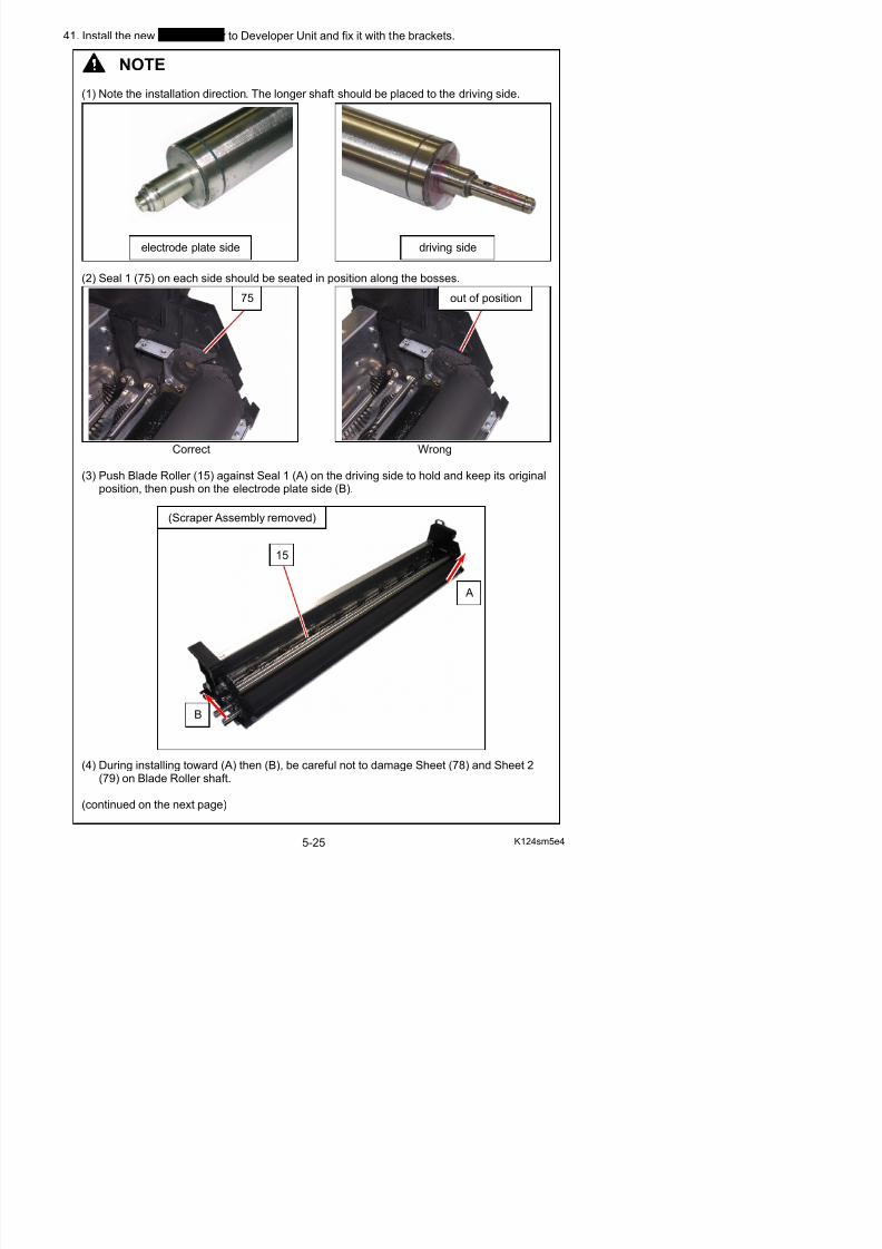
5/17/2018 KIP 7100 Service Manual Ver A_1 - slidepdf.com
http://slidepdf.com/reader/full/kip-7100-service-manual-ver-a1 138/674
(2) Seal 1 (75) on each side should be seated in position along the bosses.
Correct Wrong
(3) Push Blade Roller (15) against Seal 1 (A) on the driving side to hold and keep its originalposition, then push on the electrode plate side (B).
75 out of position
electrode plate side driving side
A
15
(Scraper Assembly removed)
NOTE
(5) After installing, check that Seal 1 (75), Sheet (78), Sheet 2 (79) are not damaged or deformed.
(6) After locating, check that Scraper (10) is notwavy.
10
75
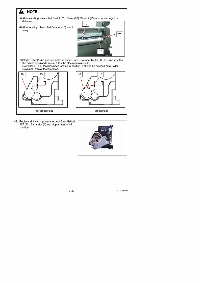
5/17/2018 KIP 7100 Service Manual Ver A_1 - slidepdf.com
http://slidepdf.com/reader/full/kip-7100-service-manual-ver-a1 139/674
42. Replace all the components except Gear Helical30T (12), Separator (4) and Hopper Assy (3) inposition.
(7) Blade Roller (15) is pressed onto / released from Developer Roller (16) by Bracket 4 (onthe driving side) and Bracket 5 (on the electrode plate side).Now Blade Roller (15) has been located in position, it should be pressed onto Roller Developer (16) at the later step.
not pressurized pressurized
16 15 1516
15
43. Make sure that the 6 screws (48) (55) (34) (52) are installed loose. If not, loosen them.
44 O h l d l id f ll d h f B k 5 (18) Wi h i i h 2
48 34
5255
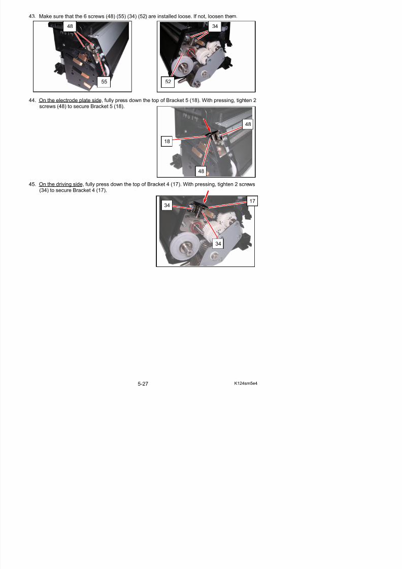
5/17/2018 KIP 7100 Service Manual Ver A_1 - slidepdf.com
http://slidepdf.com/reader/full/kip-7100-service-manual-ver-a1 140/674
44. On the electrode plate side, fully press down the top of Bracket 5 (18). With pressing, tighten 2screws (48) to secure Bracket 5 (18).
45. On the driving side, fully press down the top of Bracket 4 (17). With pressing, tighten 2 screws(34) to secure Bracket 4 (17).
18
48
48
3417
34
46. Press down the top of Bracket 7 Assy (59) and Bracket 6 Assy (54) at a time. This will allowBlade Roller to be seated in the correct position.
59
54
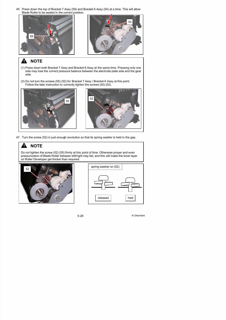
5/17/2018 KIP 7100 Service Manual Ver A_1 - slidepdf.com
http://slidepdf.com/reader/full/kip-7100-service-manual-ver-a1 141/674
47. Turn the screw (52) in just enough revolution so that its spring washer is held in the gap.
NOTE
(1) Press down both Bracket 7 Assy and Bracket 6 Assy at the same time. Pressing only oneside may lose the correct pressure balance between the electrode plate side and the gear side.
(2) Do not turn the screws (55) (52) for Bracket 7 Assy / Bracket 6 Assy at this point.Follow the later instruction to correctly tighten the screws (55) (52).
5552
NOTE
Do not tighten the screw (52) (55) firmly at this point of time. Otherwise proper and evenpressurization of Blade Roller between left/right may fail, and this will make the toner layer
R ll D l t thi k th i d
48. Turn the screw (55) in just enough revolution so that its spring washer is held in the gap.
55 spring washer on (55)
released held
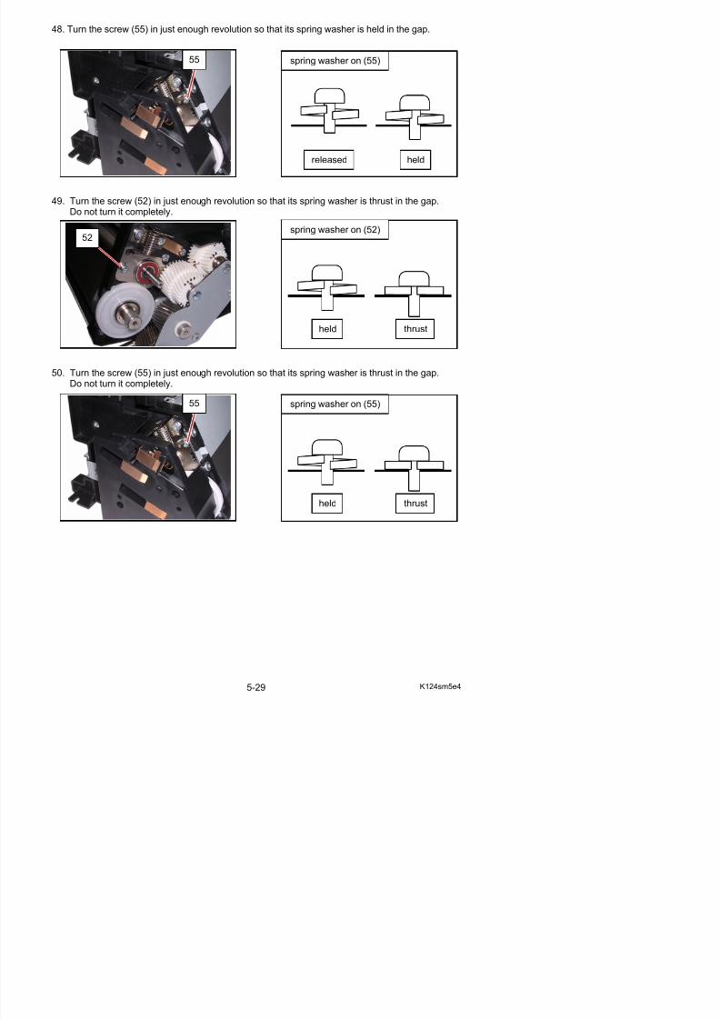
5/17/2018 KIP 7100 Service Manual Ver A_1 - slidepdf.com
http://slidepdf.com/reader/full/kip-7100-service-manual-ver-a1 142/674
49. Turn the screw (52) in just enough revolution so that its spring washer is thrust in the gap.
Do not turn it completely.
50. Turn the screw (55) in just enough revolution so that its spring washer is thrust in the gap.
Do not turn it completely.
52
55
spring washer on (52)
spring washer on (55)
held
held
thrust
thrust
51. Slowly tighten the screw (52) to secure Bracket 6 Assy (54).
52
54
NOTE
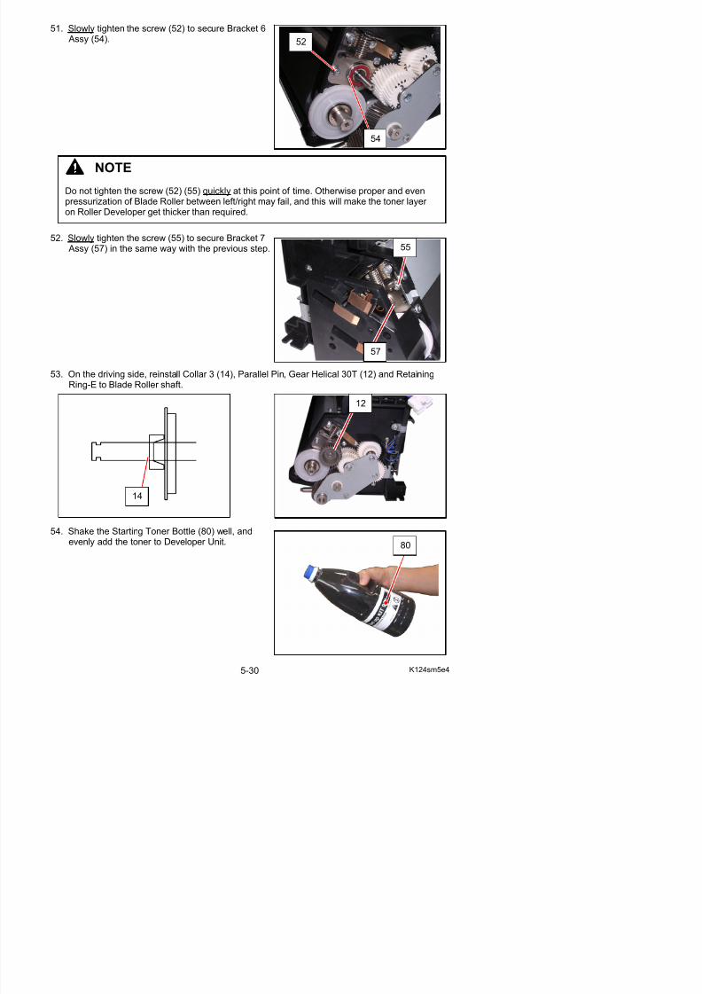
5/17/2018 KIP 7100 Service Manual Ver A_1 - slidepdf.com
http://slidepdf.com/reader/full/kip-7100-service-manual-ver-a1 143/674
52. Slowly tighten the screw (55) to secure Bracket 7 Assy (57) in the same way with the previous step.
53. On the driving side, reinstall Collar 3 (14), Parallel Pin, Gear Helical 30T (12) and RetainingRing-E to Blade Roller shaft.
14
12
55
57
Do not tighten the screw (52) (55) quickly at this point of time. Otherwise proper and even
pressurization of Blade Roller between left/right may fail, and this will make the toner layer on Roller Developer get thicker than required.
55. Along the guide on the side plates, gently place Separator (6) on the added toner.Do not push it in.
6
6
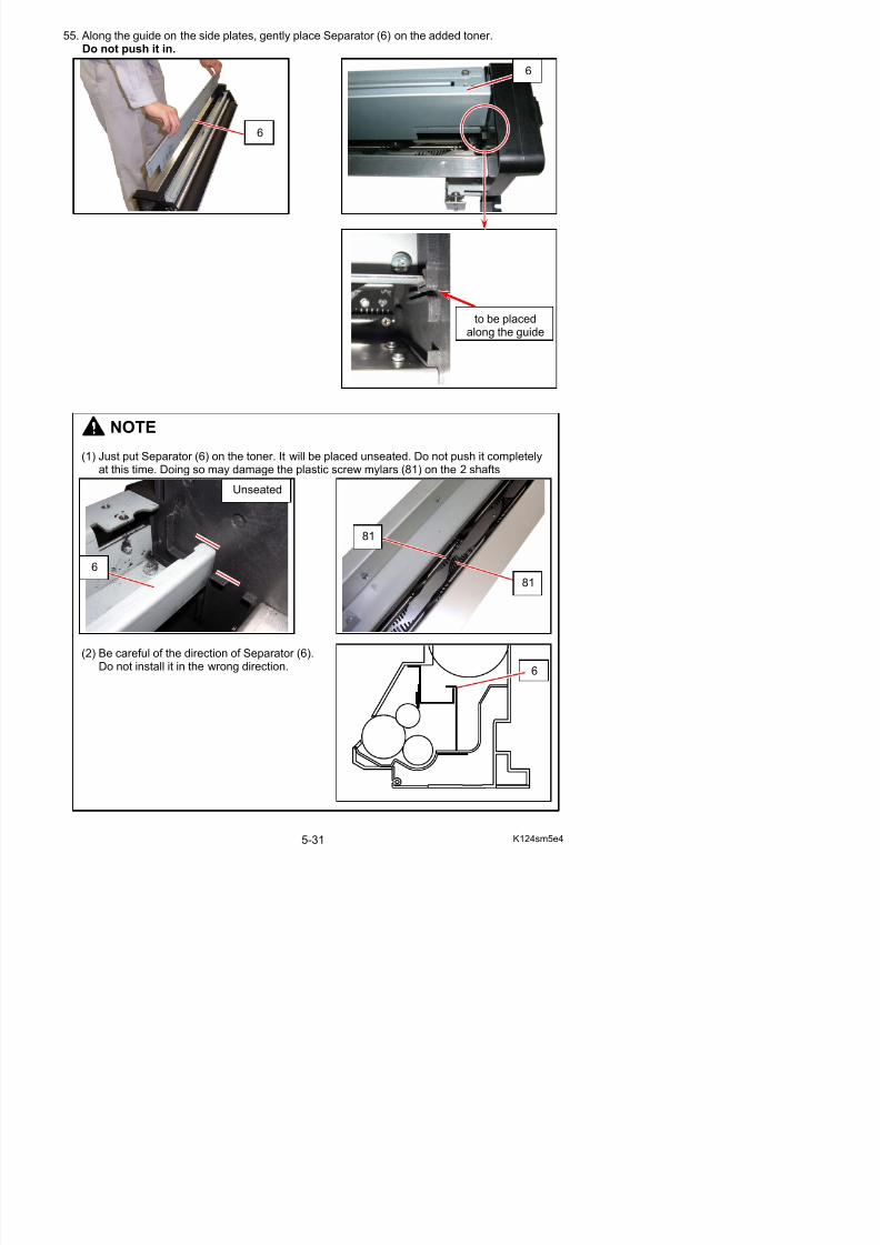
5/17/2018 KIP 7100 Service Manual Ver A_1 - slidepdf.com
http://slidepdf.com/reader/full/kip-7100-service-manual-ver-a1 144/674
NOTE
(1) Just put Separator (6) on the toner. It will be placed unseated. Do not push it completely
at this time. Doing so may damage the plastic screw mylars (81) on the 2 shaftsUnseated
to be placedalong the guide
6
81
81
56. Insert Developer Handle (82) to the shaft of Roller Developer, and gently turn Developer Handle (82).Separator will sink in the toner. Turn Developer Handle (82) until Separator sinks in position.
82 82

5/17/2018 KIP 7100 Service Manual Ver A_1 - slidepdf.com
http://slidepdf.com/reader/full/kip-7100-service-manual-ver-a1 145/674
57. Replace the Hopper Assembly (3) and connect the connector (1).
NOTE
(1) Slowly turn Developer Handle. Otherwise the toner may spill out.
(2) Make sure that Separator (6) completely sinks in position by a 1/2 or more rotation of Developer Handle.If not in position, the plastic screw mylars may be damaged at the next step.
Wrong:Unseated
6
Correct:Seated
6
58. Install Developer Handle (82) to Roller Developer shaft. Rotate Roller Developer several timesso that the roller surface is covered with the toner.
82
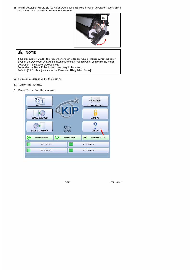
5/17/2018 KIP 7100 Service Manual Ver A_1 - slidepdf.com
http://slidepdf.com/reader/full/kip-7100-service-manual-ver-a1 146/674
59. Reinstall Developer Unit to the machine.
60. Turn on the machine.
61. Press “? - Help” on Home screen.
NOTE
If the pressures of Blade Roller on either or both sides are weaker than required, the toner layer on the Developer Unit will be much thicker than required when you rotate the Roller Developer in the above procedure 53.Pressurize the Blade Roller in the correct way in this case.Refer to [5.2.8 Readjustment of the Pressure of Regulation Roller].
62. Press [Service].
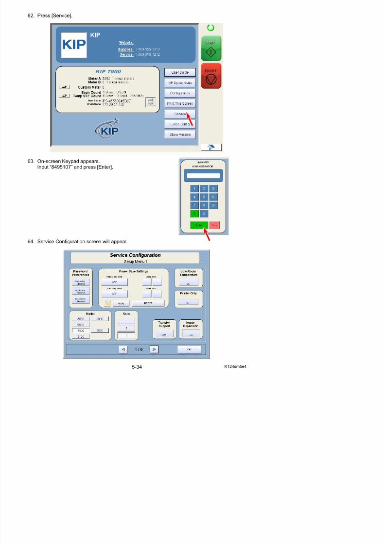
5/17/2018 KIP 7100 Service Manual Ver A_1 - slidepdf.com
http://slidepdf.com/reader/full/kip-7100-service-manual-ver-a1 147/674
63. On-screen Keypad appears.Input “8495107” and press [Enter].
64. Service Configuration screen will appear.
65. Use the arrow keys to open [5/6 IPS Setup]. Press [Launch] in “KIP Service Software”.
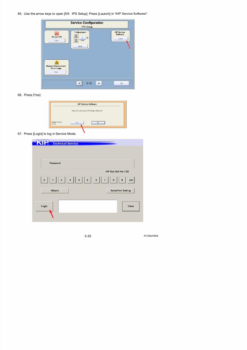
5/17/2018 KIP 7100 Service Manual Ver A_1 - slidepdf.com
http://slidepdf.com/reader/full/kip-7100-service-manual-ver-a1 148/674
66. Press [Yes].
67. Press [Login] to log in Service Mode.
68. Press [Special Operation] in Service Mode Home.Operation Target screen appears.
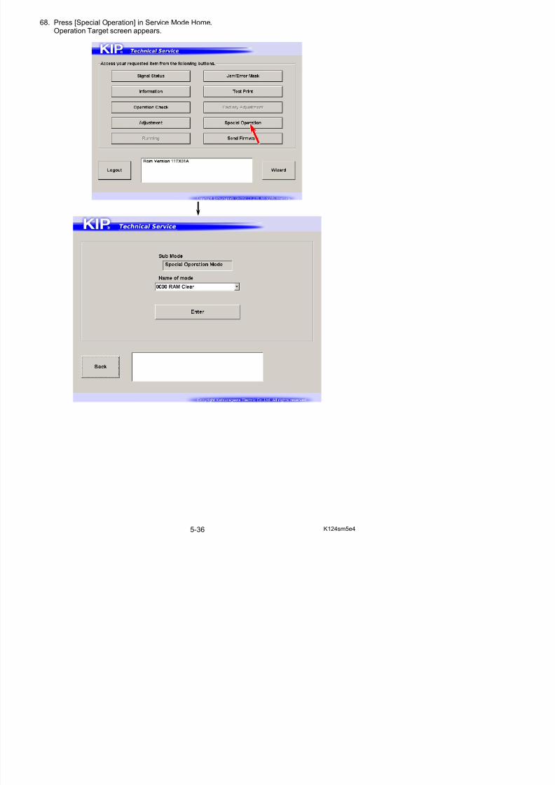
5/17/2018 KIP 7100 Service Manual Ver A_1 - slidepdf.com
http://slidepdf.com/reader/full/kip-7100-service-manual-ver-a1 149/674
69. Select [0006 Bias3 Count] from Name of mode menu. Press [Enter].

5/17/2018 KIP 7100 Service Manual Ver A_1 - slidepdf.com
http://slidepdf.com/reader/full/kip-7100-service-manual-ver-a1 150/674
0006 Bias3 Count Initializes Developer / Regulation Bias adjusted withDensity Compensation Process
70. Confirmation screen appears.Press [Agree] to reset Bias Adjustment by Density Compensation Process.Then the system starts recalculation of the possible best Developer/Regulation Bias.(This will take time.)
71. Input screen appears.Input “0000000” with On-screen Keypad.
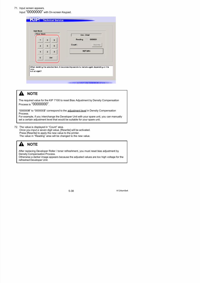
5/17/2018 KIP 7100 Service Manual Ver A_1 - slidepdf.com
http://slidepdf.com/reader/full/kip-7100-service-manual-ver-a1 151/674
72. The value is displayed in “Count” area.Once you input a seven digit value, [Rewrite] will be activated.
Press [Rewrite] to apply the new value to the printer.The value in “Reading” area will be changed to the new value.
NOTE
The required value for the KIP 7100 to reset Bias Adjustment by Density Compensation
Process is “0000000”.
“0000000” to “0000003” correspond to the adjustment level in Density CompensationProcess.For example, if you interchange the Developer Unit with your spare unit, you can manuallyset a certain adjustment level that would be suitable for your spare unit.
5. 2. 3 Replacement of Roller Supply
1. Remove Blade Roller and Roller Developer from Developer Unit making reference to[5. 2. 2 Replacement of Developer Unit Components]on the page 5-8.
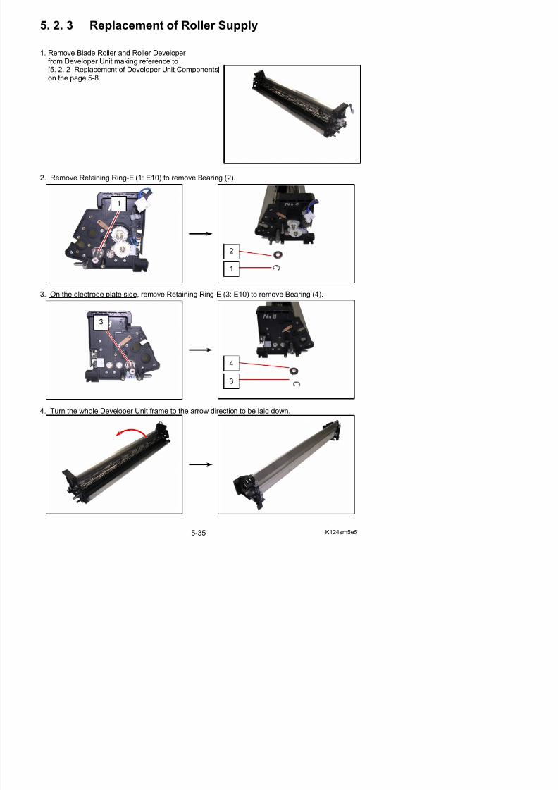
5/17/2018 KIP 7100 Service Manual Ver A_1 - slidepdf.com
http://slidepdf.com/reader/full/kip-7100-service-manual-ver-a1 152/674
2. Remove Retaining Ring-E (1: E10) to remove Bearing (2).
3. On the electrode plate side, remove Retaining Ring-E (3: E10) to remove Bearing (4).
1
2
1
3
4
3
5. Remove 9 screws (5) to remove Frame 2 (6).
5
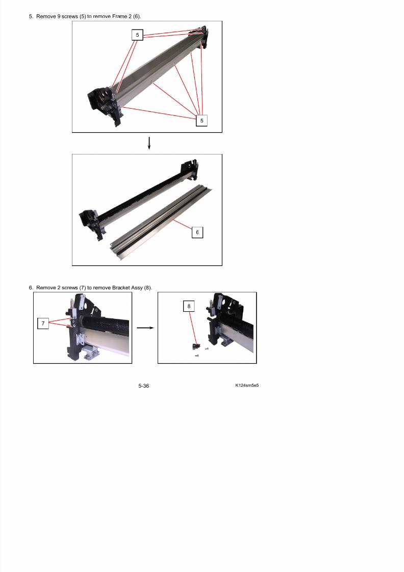
5/17/2018 KIP 7100 Service Manual Ver A_1 - slidepdf.com
http://slidepdf.com/reader/full/kip-7100-service-manual-ver-a1 153/674
6
5
7. Remove Toner Supply Roller (9).
9
9
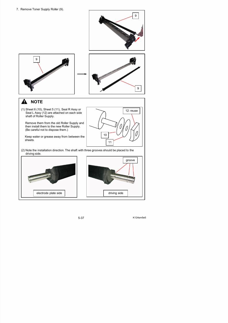
5/17/2018 KIP 7100 Service Manual Ver A_1 - slidepdf.com
http://slidepdf.com/reader/full/kip-7100-service-manual-ver-a1 154/674
NOTE
(1) Sheet 6 (10), Sheet 5 (11), Seal R Assy or Seal L Assy (12) are attached on each sideshaft of Roller Supply.
Remove them from the old Roller Supply andthen install them to the new Roller Supply.(Be careful not to dispose them.)
Keep water or grease away from between thesheets.
(2) Note the installation direction. The shaft with three grooves should be placed to thedriving side.
12: reuse
11
10
9
groove
5. 2. 4 Replacement of Screw Assy
1. Remove the Developer Unit (1) from the machinemaking reference to [5. 2. 1 Removal of theDeveloper Unit] on the page 5-5.
1
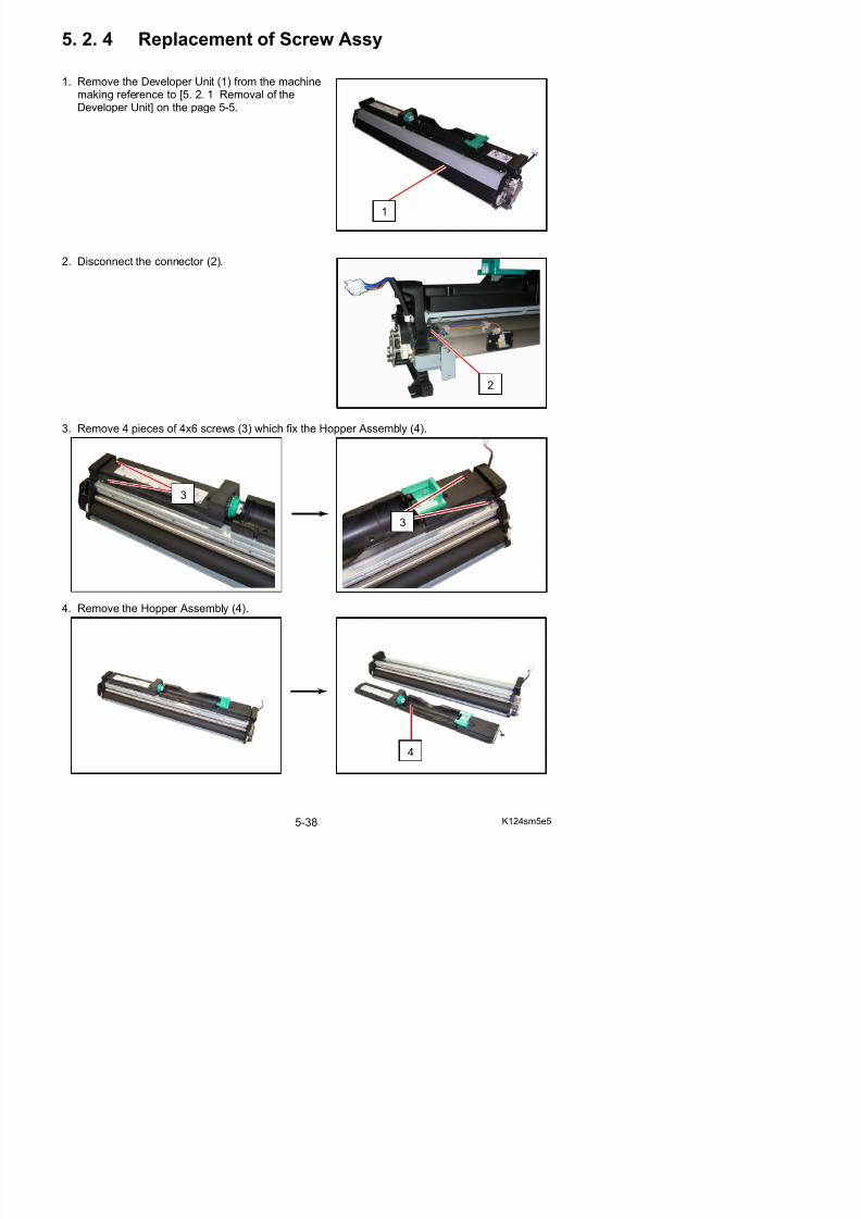
5/17/2018 KIP 7100 Service Manual Ver A_1 - slidepdf.com
http://slidepdf.com/reader/full/kip-7100-service-manual-ver-a1 155/674
2. Disconnect the connector (2).
3. Remove 4 pieces of 4x6 screws (3) which fix the Hopper Assembly (4).
4 R h H A bl (4)
2
3
3
5. Remove Separator (5).
6. Remove all the toner from Developer Unit.
5
5
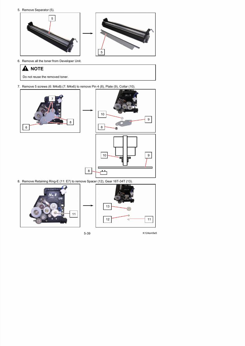
5/17/2018 KIP 7100 Service Manual Ver A_1 - slidepdf.com
http://slidepdf.com/reader/full/kip-7100-service-manual-ver-a1 156/674
7. Remove 5 screws (6: M4x8) (7: M4x6) to remove Pin 4 (8), Plate (9), Collar (10).
6
10
8
9
7
8
NOTE
Do not reuse the removed toner.
8
910
9. Remove Retaining Ring-E (14: E5) (15: E7) to remove Washer (16), Gear 15T (17), Gear 16T(18) and Parallel Pin (19).
10 R R t i i Ri E (20) t W h (21) d B h (22)
15
20
16
17
19
18
1516
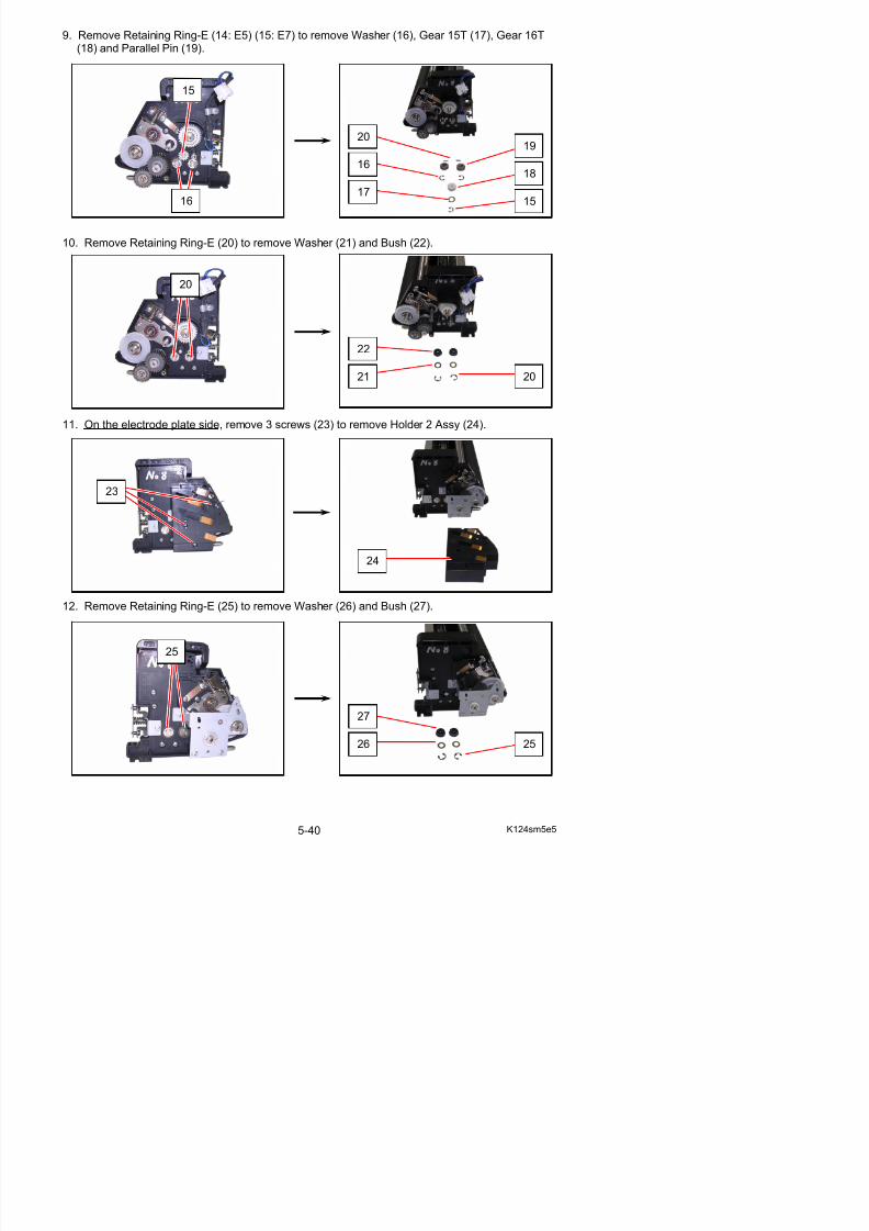
5/17/2018 KIP 7100 Service Manual Ver A_1 - slidepdf.com
http://slidepdf.com/reader/full/kip-7100-service-manual-ver-a1 157/674
10. Remove Retaining Ring-E (20) to remove Washer (21) and Bush (22).
11. On the electrode plate side, remove 3 screws (23) to remove Holder 2 Assy (24).
12. Remove Retaining Ring-E (25) to remove Washer (26) and Bush (27).
22
21 20
20
24
23
13. Remove Screw A Assy (28: near Roller Supply), Screw B Assy (29: far from Roller Supply).Remove Side Seal (30) and Washer (31) on both ends of Screw A Assy (28) and Screw B Assy (29).
28 29
31
29 28
31
30
30
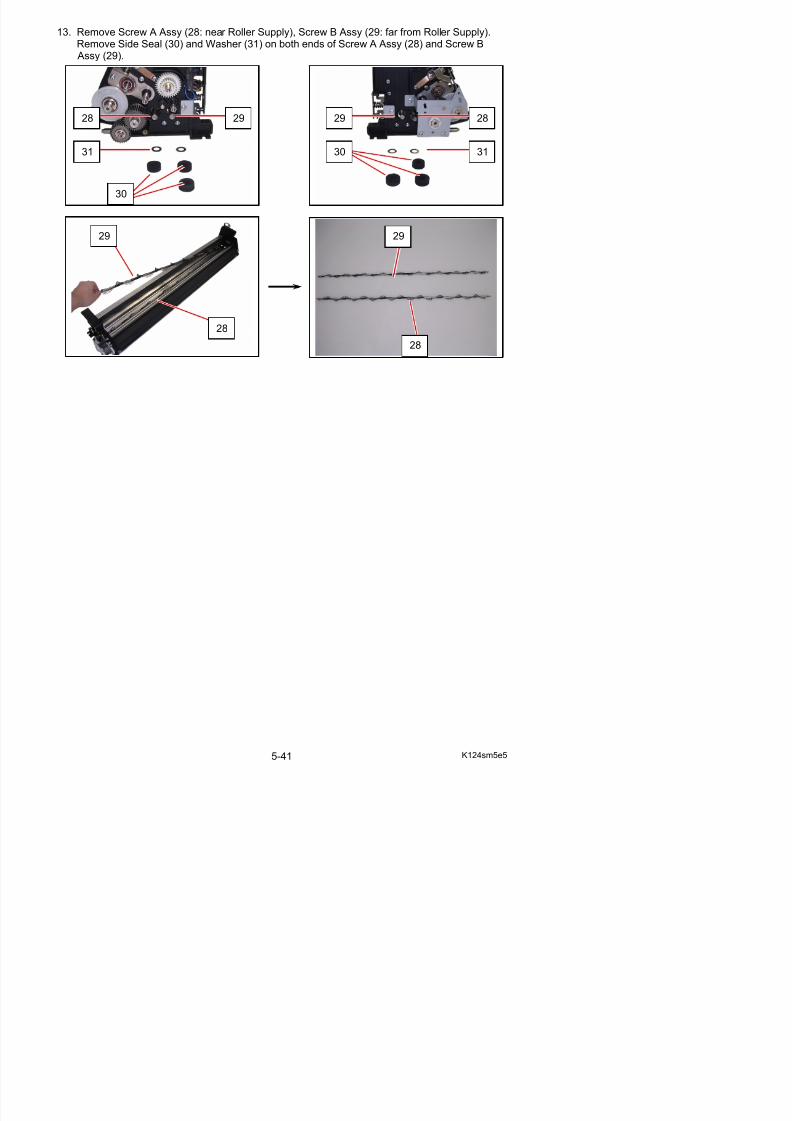
5/17/2018 KIP 7100 Service Manual Ver A_1 - slidepdf.com
http://slidepdf.com/reader/full/kip-7100-service-manual-ver-a1 158/674
29
28
29
28
14. Remove each 2 screws (32: M3x5) to remove Screw A (33) / Screw B (34).
34
33
32
32
NOTE
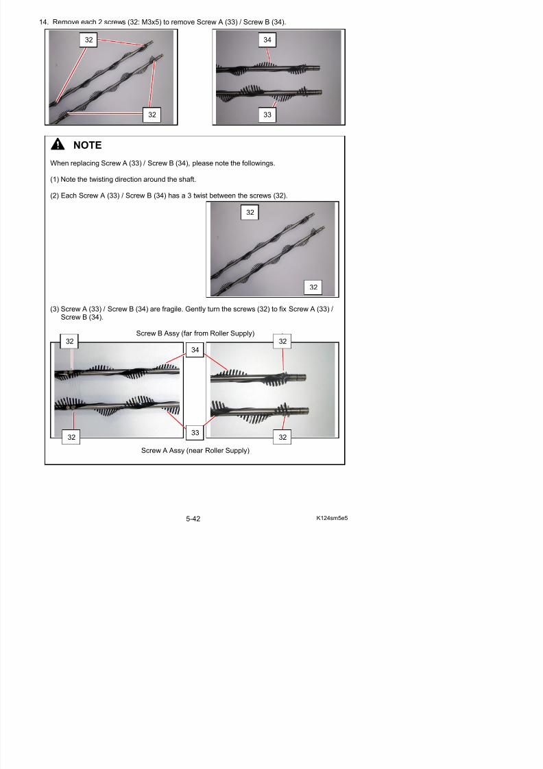
5/17/2018 KIP 7100 Service Manual Ver A_1 - slidepdf.com
http://slidepdf.com/reader/full/kip-7100-service-manual-ver-a1 159/674
When replacing Screw A (33) / Screw B (34), please note the followings.
(1) Note the twisting direction around the shaft.
(2) Each Screw A (33) / Screw B (34) has a 3 twist between the screws (32).
(3) Screw A (33) / Screw B (34) are fragile. Gently turn the screws (32) to fix Screw A (33) /Screw B (34).
Screw B Assy (far from Roller Supply)
32
32
34
32 32
15. Replace all the components except Separator (5) and Hopper Assy (4) in position.
16. Shake the Starting Toner Bottle (35) well, and evenly add the toner to Developer Unit.
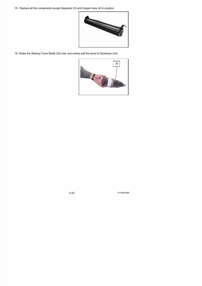
5/17/2018 KIP 7100 Service Manual Ver A_1 - slidepdf.com
http://slidepdf.com/reader/full/kip-7100-service-manual-ver-a1 160/674
35
17. Along the guide on the side plates, gently place Separator (5) on the added toner.Do not push it in.
5
5
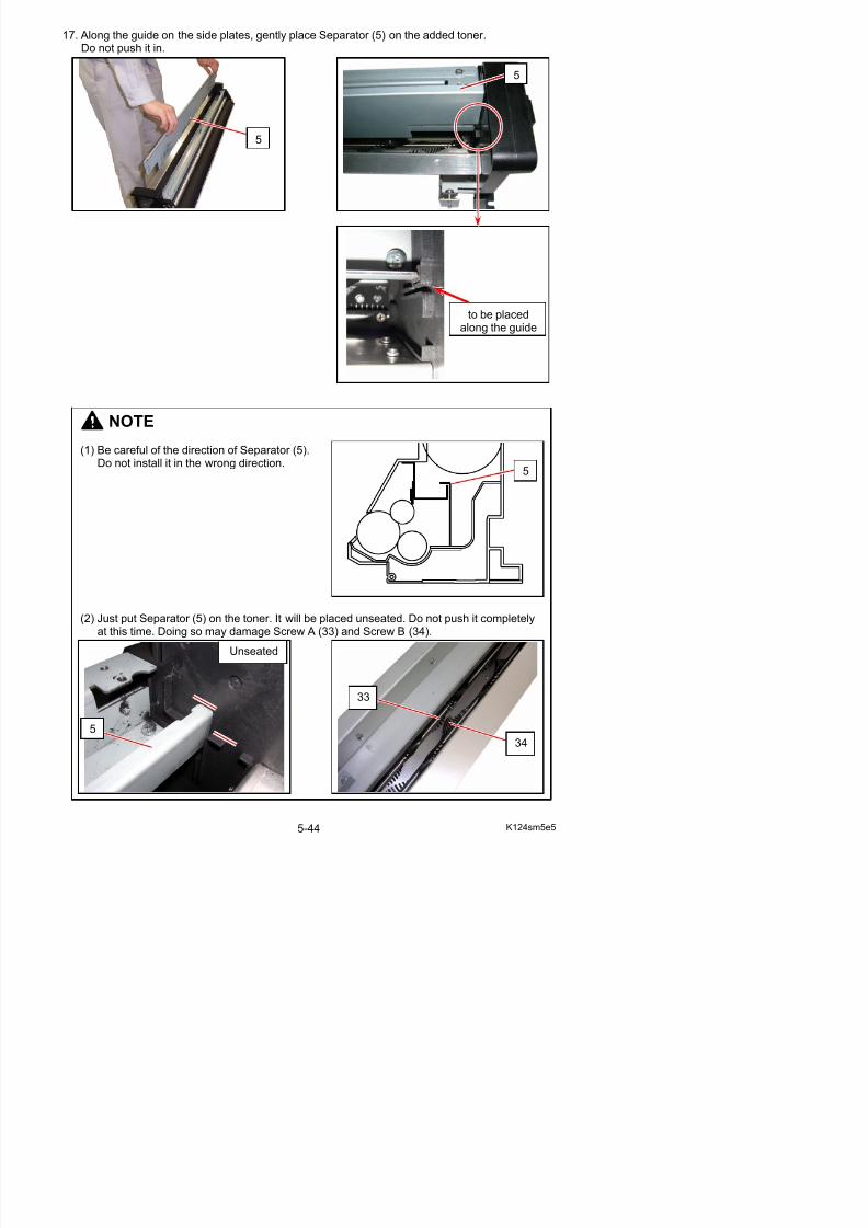
5/17/2018 KIP 7100 Service Manual Ver A_1 - slidepdf.com
http://slidepdf.com/reader/full/kip-7100-service-manual-ver-a1 161/674
NOTE
(1) Be careful of the direction of Separator (5).Do not install it in the wrong direction.
to be placedalong the guide
5
18. Insert Developer Handle (36) to the shaft of Roller Developer, and gently turn Developer Handle (36).Separator will sink in the toner. Turn Developer Handle (36) until Separator sinks in position.
36 36
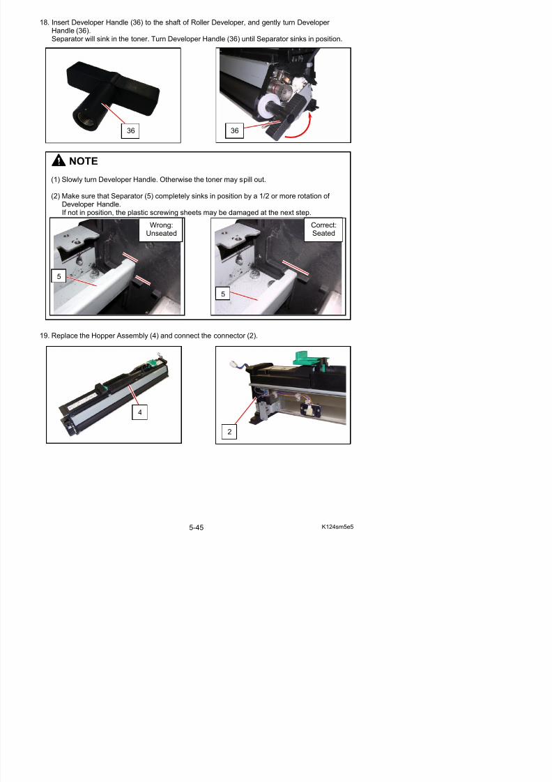
5/17/2018 KIP 7100 Service Manual Ver A_1 - slidepdf.com
http://slidepdf.com/reader/full/kip-7100-service-manual-ver-a1 162/674
19. Replace the Hopper Assembly (4) and connect the connector (2).
NOTE(1) Slowly turn Developer Handle. Otherwise the toner may spill out.
(2) Make sure that Separator (5) completely sinks in position by a 1/2 or more rotation of Developer Handle.If not in position, the plastic screwing sheets may be damaged at the next step.
Wrong:
Unseated
Correct:
Seated
5
5
5. 2. 5 Replacement of DC Motor 1. Remove 3 pieces of 4x6 screw (1) to remove the Cover 2 (2).
2 Di t th t (3) 2 i f 4 6 (4) d th th t
2
1
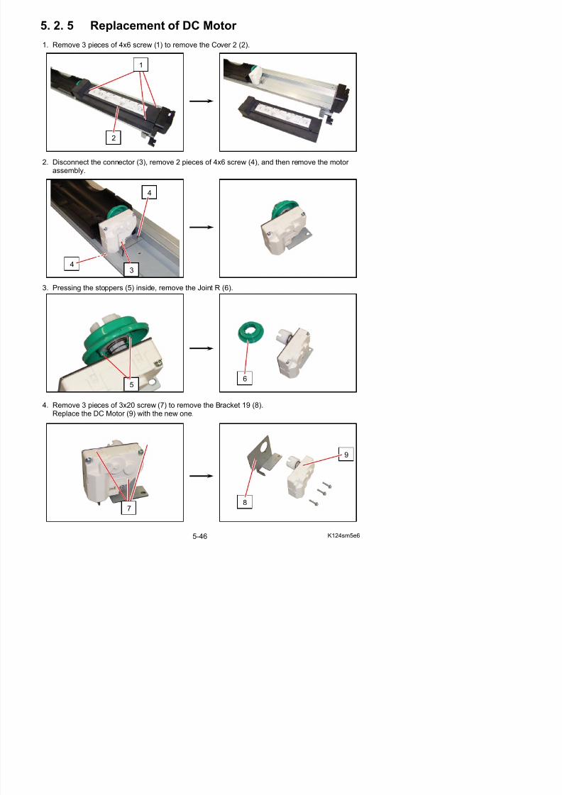
5/17/2018 KIP 7100 Service Manual Ver A_1 - slidepdf.com
http://slidepdf.com/reader/full/kip-7100-service-manual-ver-a1 163/674
2. Disconnect the connector (3), remove 2 pieces of 4x6 screw (4), and then remove the motor assembly.
3. Pressing the stoppers (5) inside, remove the Joint R (6).
3
4
4
56
5. 2. 6 Replacement of Sensor (TLS1)
1. Remove the Developer Unit (1) from the machinemaking reference to [5. 2. 1 Removal of theDeveloper Unit] on the page 5-5.
1
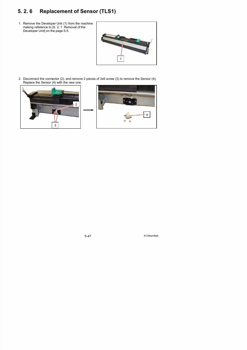
5/17/2018 KIP 7100 Service Manual Ver A_1 - slidepdf.com
http://slidepdf.com/reader/full/kip-7100-service-manual-ver-a1 164/674
2. Disconnect the connector (2), and remove 2 pieces of 3x6 screw (3) to remove the Sensor (4).Replace the Sensor (4) with the new one.
2
4
3
5. 2. 7 Adjustment of the space between gears(Necessary to adjust after replacing theDeveloper Unit)
The Developer Unit is driven by the Gear Helical 20T on the machine and the Gear Helical 28T onthe Developer Unit.There must be a little mechanical play between these gears. (In another word there must be a littlespace between them.)
NOTE
You do not have to adjust the space between gears basically as it has been adjusted in the
factory.But please do it only when you replace the whole Developer Unit.
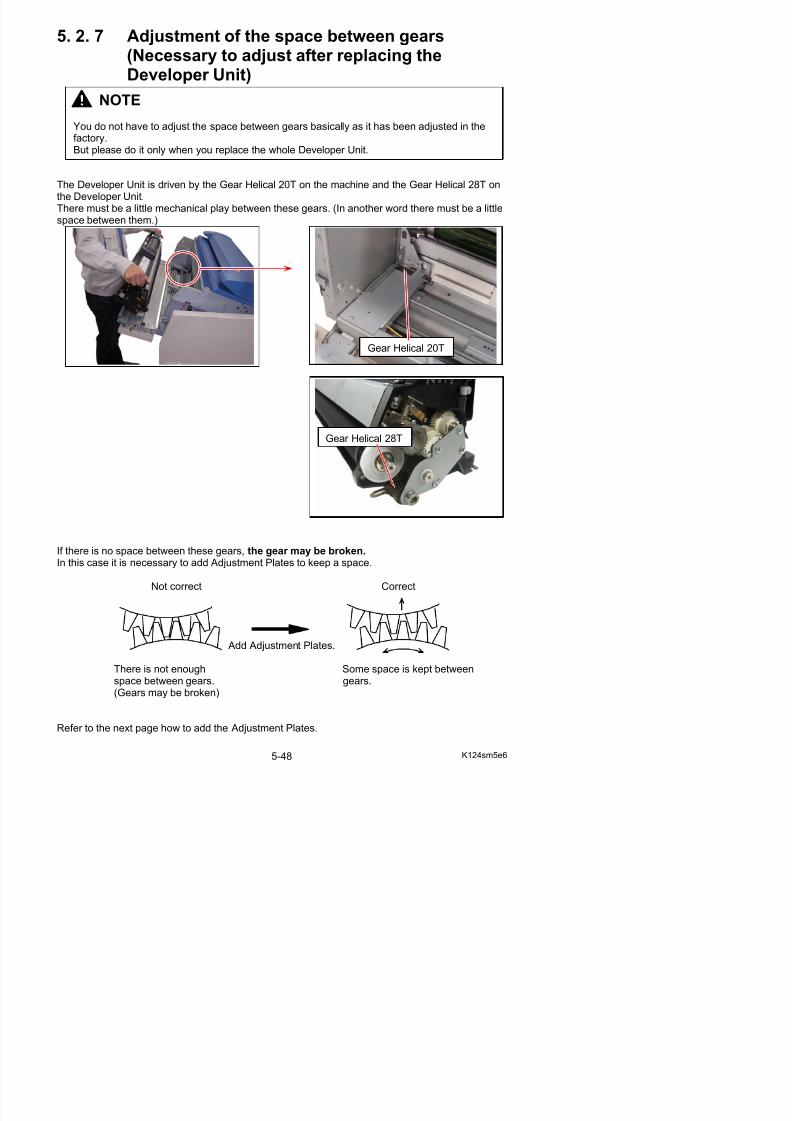
5/17/2018 KIP 7100 Service Manual Ver A_1 - slidepdf.com
http://slidepdf.com/reader/full/kip-7100-service-manual-ver-a1 165/674
If there is no space between these gears, the gear may be broken.
Gear Helical 20T
Gear Helical 28T
1. Remove the Developer Unit (1) from the machine
making reference to [5. 2. 1 Removal of theDeveloper Unit] on the page 5-5.
2. Remove 2 screws (2) to remove each Bracket 32 (3) on the left and Bracket 33 (4) on the right.You will find Adjustment Plate (5) and Adjustment Plate 2 (6).
1
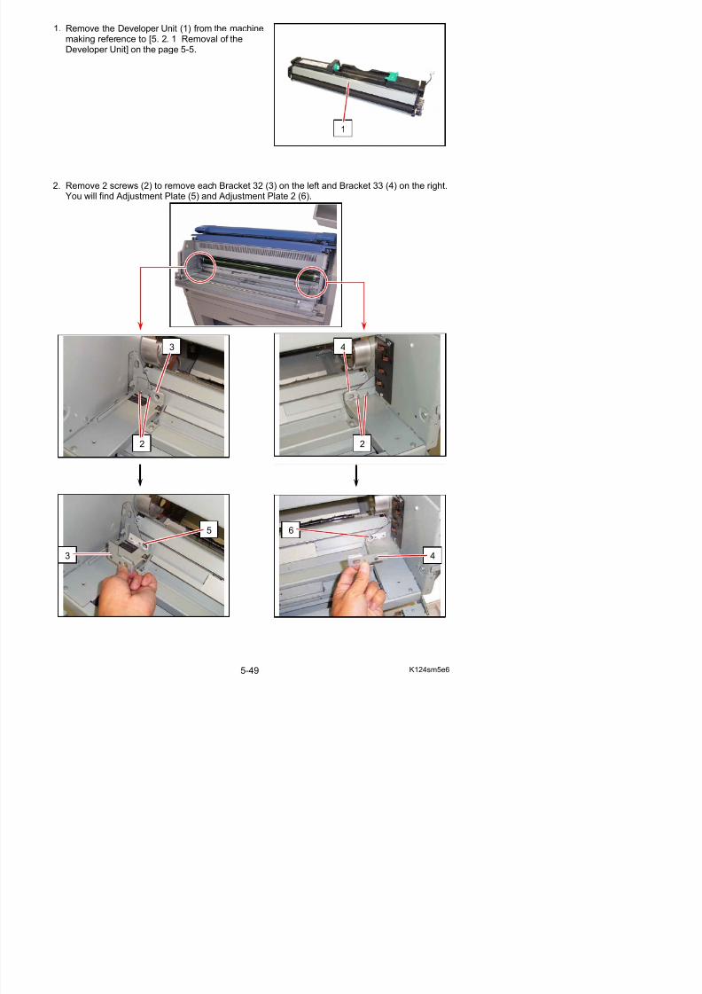
5/17/2018 KIP 7100 Service Manual Ver A_1 - slidepdf.com
http://slidepdf.com/reader/full/kip-7100-service-manual-ver-a1 166/674
2
3
2
4
3. On the left side, add (or remove) as many Adjustment Plate (5) as required, cover them with
the Bracket 32 (3), and then fix with 2 screws (2).
3
5
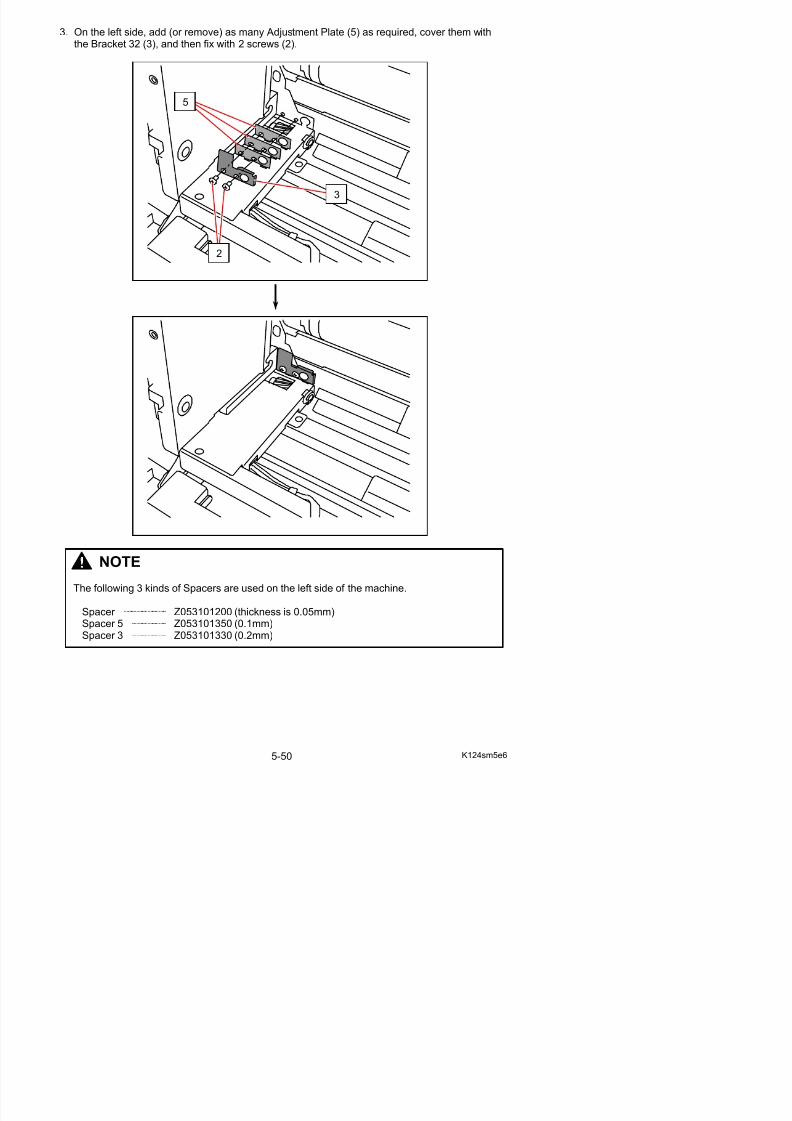
5/17/2018 KIP 7100 Service Manual Ver A_1 - slidepdf.com
http://slidepdf.com/reader/full/kip-7100-service-manual-ver-a1 167/674
2
4. On the right side, add (or remove) as many Adjustment Plate 2 (6) as required, cover them with
the Bracket 33 (4), and then fix with 2 screws (2).
3
6

5/17/2018 KIP 7100 Service Manual Ver A_1 - slidepdf.com
http://slidepdf.com/reader/full/kip-7100-service-manual-ver-a1 168/674
NOTE
2
5. Put back the Developer Unit (1) to the machine.
6. There is Gear Helical 28T (7) on Developer Unit side. There is Gear Helical 20T (8) on EngineUnit, and also there is Gear Helical 34T (9) on Engine Unit.
1
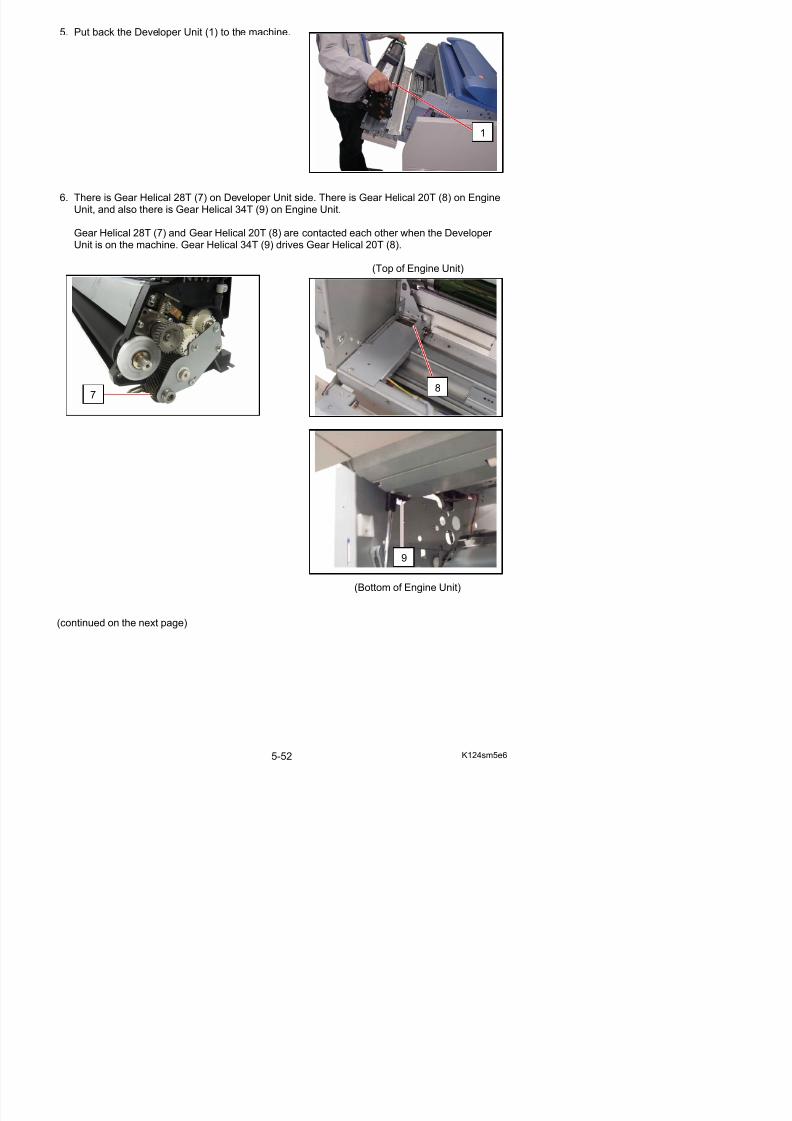
5/17/2018 KIP 7100 Service Manual Ver A_1 - slidepdf.com
http://slidepdf.com/reader/full/kip-7100-service-manual-ver-a1 169/674
Gear Helical 28T (7) and Gear Helical 20T (8) are contacted each other when the Developer Unit is on the machine. Gear Helical 34T (9) drives Gear Helical 20T (8).
(Top of Engine Unit)
7
9
8
Holding the Gear Helical 28T (7) firmly with one hand, move the Gear Helical 34T (9) with
another hand whether there is any mechanical play between Gear Helical 28T (7) andGear Helical 20T (8).
Hold the Gear Helical 28T with one hand.
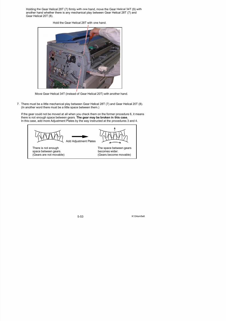
5/17/2018 KIP 7100 Service Manual Ver A_1 - slidepdf.com
http://slidepdf.com/reader/full/kip-7100-service-manual-ver-a1 170/674
Move Gear Helical 34T (instead of Gear Helical 20T) with another hand.
7. There must be a little mechanical play between Gear Helical 28T (7) and Gear Helical 20T (8).(In another word there must be a little space between them.)
If the gear could not be moved at all when you check them on the former procedure 6, it meansthere is not enough space between gears. The gear may be broken in this case. In this case, add more Adjustment Plates by the way instructed at the procedures 3 and 4.
Add Adjustment Plates
There is not enough The space between gears
space between gears. becomes wider.(Gears are not movable) (Gears become movable)
5. 2. 8 Readjustment of the Pressure of RegulationRoller
If the pressure of Blade Roller is weak, the toner layer on the Developer Unit will be much thicker than required when you rotate the Developer Roller.Pressurize the Blade Roller in the correct way as shown below in this case.(You will not be able to pressurize it successfully by the usual way of pressurization once a toothick toner layer is created.)
To correct the pressure of Blade Roller against Developer Roller, remove the thicker toner layer onthe contact point between Blade Roller and Developer Roller.
1. Remove the Developer Unit (1) from the machinemaking reference to [5. 2. 1 Removal of theDeveloper Unit] on the page 5-5.
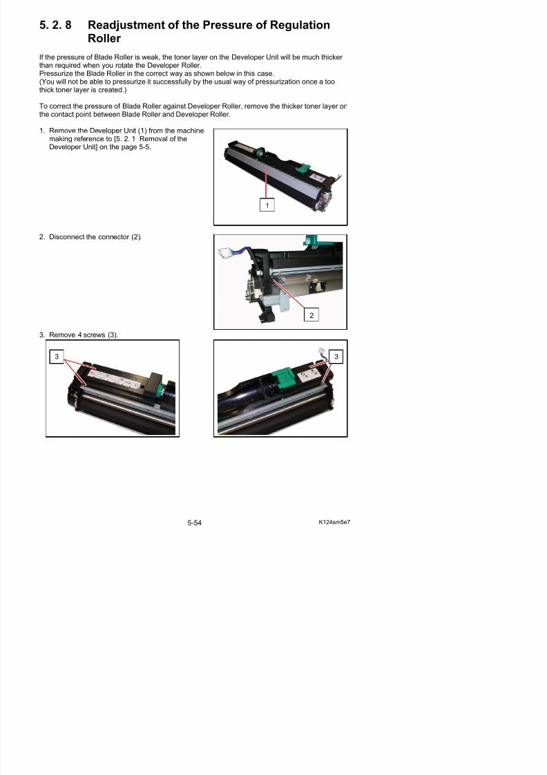
5/17/2018 KIP 7100 Service Manual Ver A_1 - slidepdf.com
http://slidepdf.com/reader/full/kip-7100-service-manual-ver-a1 171/674
2. Disconnect the connector (2).
3. Remove 4 screws (3).
2
3 3
1
4. Remove the Hopper Assembly (4).
5. Remove 3 pieces of M4x6 screws (5) to remove Cover (6).
4
5
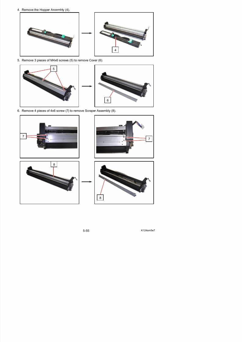
5/17/2018 KIP 7100 Service Manual Ver A_1 - slidepdf.com
http://slidepdf.com/reader/full/kip-7100-service-manual-ver-a1 172/674
6. Remove 4 pieces of 4x6 screw (7) to remove Scraper Assembly (8).
6
77
8
7. On the driving side, remove Retaining Ring-C (9: C6) to remove Gear Helical 30T (10), Parallel
Pin (11: 2.5x10) and Collar 3 (12) from Blade Roller shaft.
NOTE
12
9
1011 10
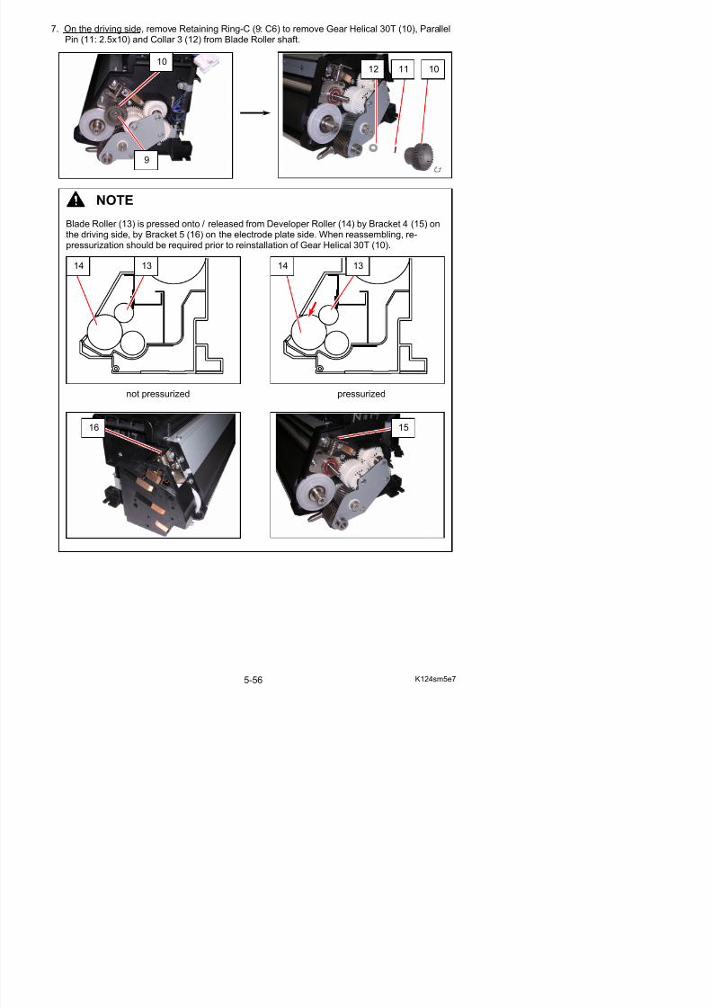
5/17/2018 KIP 7100 Service Manual Ver A_1 - slidepdf.com
http://slidepdf.com/reader/full/kip-7100-service-manual-ver-a1 173/674
Blade Roller (13) is pressed onto / released from Developer Roller (14) by Bracket 4 (15) onthe driving side, by Bracket 5 (16) on the electrode plate side. When reassembling, re-pressurization should be required prior to reinstallation of Gear Helical 30T (10).
not pressurized pressurized
14 13 1314
16 15
8. Remove 5 screws (17: M4x8) (18: M4x6) to remove Pin 4 (19), Plate 9 (20), Collar (21).
17
21
19
20
18
18

5/17/2018 KIP 7100 Service Manual Ver A_1 - slidepdf.com
http://slidepdf.com/reader/full/kip-7100-service-manual-ver-a1 174/674
9. Remove Washer (22: 8.1x14x0.5t) and Gear 29T-34T Assy (23)
10. Remove Helical 30T (24) and Parallel Pin (25: 3x20) from Toner Supply Roller shaft.
If you cannot remove Parallel Pin (25) at this time, remove it after the later step 12.
22
23
22
19
2021
11. Remove Retaining Ring-E (26: E7) to remove Washer (27: 8.1x12x0.2t) and Gear Helical 28T
Assy (28).
12. Remove Retaining Ring-E (29: E10) to remove Washer (30: 12.2x20x0.5t) and Counter Roller (31) from Developer Roller shaft.
26
28
27 26
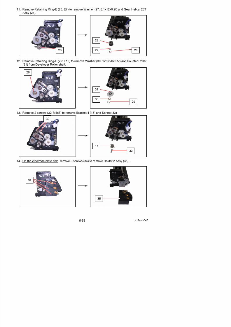
5/17/2018 KIP 7100 Service Manual Ver A_1 - slidepdf.com
http://slidepdf.com/reader/full/kip-7100-service-manual-ver-a1 175/674
13. Remove 2 screws (32: M4x8) to remove Bracket 4 (15) and Spring (33).
14. On the electrode plate side, remove 3 screws (34) to remove Holder 2 Assy (35).
29
31
3029
17
33
32
15. Remove 3 screws (36: M4x6) and 2 Retaining Ring-E (37: E10) to remove Collar (38) and
Bracket 10 Assy (39).
38
37
39
36
37
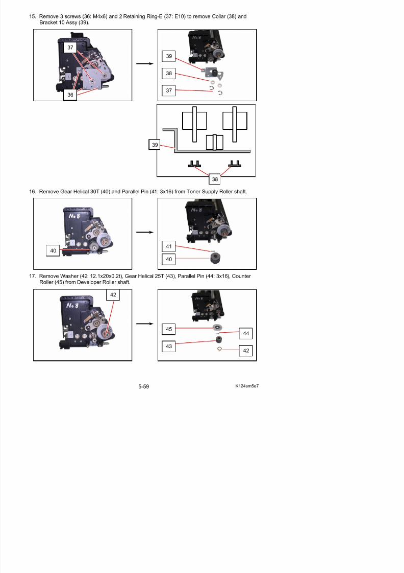
5/17/2018 KIP 7100 Service Manual Ver A_1 - slidepdf.com
http://slidepdf.com/reader/full/kip-7100-service-manual-ver-a1 176/674
16. Remove Gear Helical 30T (40) and Parallel Pin (41: 3x16) from Toner Supply Roller shaft.
17. Remove Washer (42: 12.1x20x0.2t), Gear Helical 25T (43), Parallel Pin (44: 3x16), Counter Roller (45) from Developer Roller shaft.
4041
40
38
39
18. Remove 2 screws (46: M4x6) to remove Bracket 5 (16) and Spring (47).
19. Loosen 2 screws (48) to remove Bracket 19 (49).
16
47
46
48
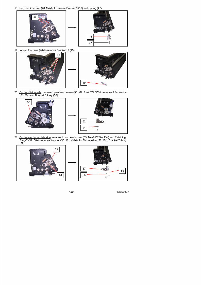
5/17/2018 KIP 7100 Service Manual Ver A_1 - slidepdf.com
http://slidepdf.com/reader/full/kip-7100-service-manual-ver-a1 177/674
20. On the driving side, remove 1 pan head screw (50: M4x8 W/ SW FW) to remove 1 flat washer (51: M4) and Bracket 6 Assy (52).
21. On the electrode plate side, remove 1 pan head screw (53: M4x8 W/ SW FW) and RetainingRing-E (54: E8) to remove Washer (55: 10.1x16x0.5t), Flat Washer (56: M4), Bracket 7 Assy
49
50
52
51
22. Remove Blade Roller (13) from Developer Unit.
Clean Blade Roller if it gets dirty.
NOTE
(1) Be careful not to damage Sheet (58) andSh t 2 (59) Bl d R ll h ft
13
13
59
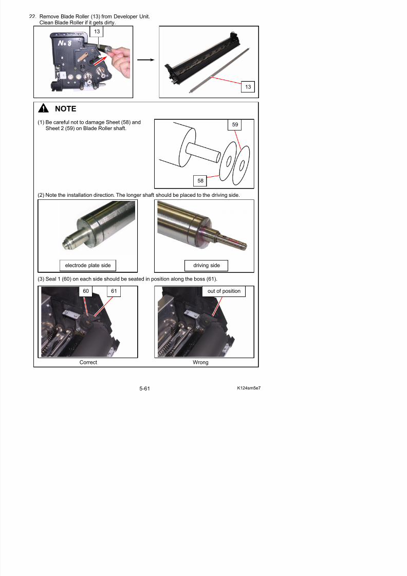
5/17/2018 KIP 7100 Service Manual Ver A_1 - slidepdf.com
http://slidepdf.com/reader/full/kip-7100-service-manual-ver-a1 178/674
( ) g ( )Sheet 2 (59) on Blade Roller shaft.
(2) Note the installation direction. The longer shaft should be placed to the driving side.
(3) Seal 1 (60) on each side should be seated in position along the boss (61).
electrode plate side driving side
58
23. On Developer Roller (14), vacuum the toner around the contact point against Blade Roller (13).
NOTE
If some toner remains on the surface of Roller Developer, the toner will cushion the pressureby Blade Roller. This will prevent a proper pressurization.
Vacuum toner stuckaround the contact area
13
14
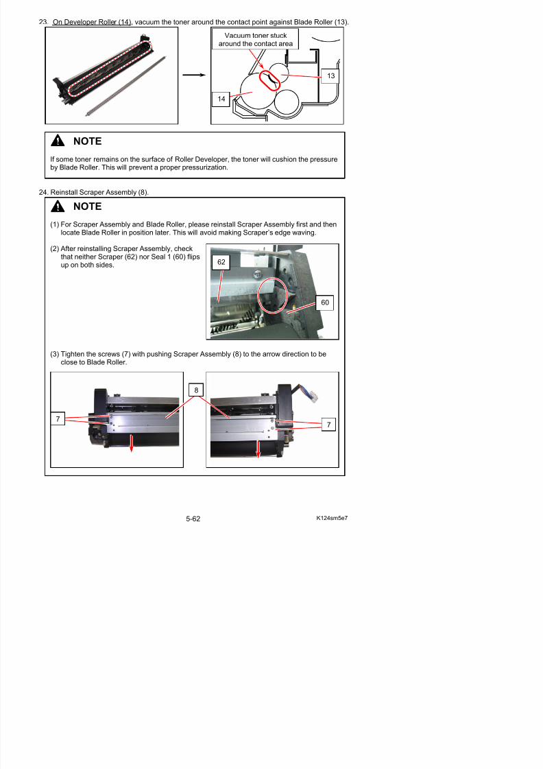
5/17/2018 KIP 7100 Service Manual Ver A_1 - slidepdf.com
http://slidepdf.com/reader/full/kip-7100-service-manual-ver-a1 179/674
24. Reinstall Scraper Assembly (8).
y p p p p
NOTE
(1) For Scraper Assembly and Blade Roller, please reinstall Scraper Assembly first and then
locate Blade Roller in position later. This will avoid making Scraper’s edge waving.
(2) After reinstalling Scraper Assembly, checkthat neither Scraper (62) nor Seal 1 (60) flipsup on both sides.
(3) Tighten the screws (7) with pushing Scraper Assembly (8) to the arrow direction to be
close to Blade Roller.
62
60
25. Reinstall Blade Roller (13).
60
NOTE
(1) Note the installation direction. The longer shaft should be placed to the driving side.
(2) Seal 1 (59) on each side should be seated in position along the bosses
electrode plate side driving side
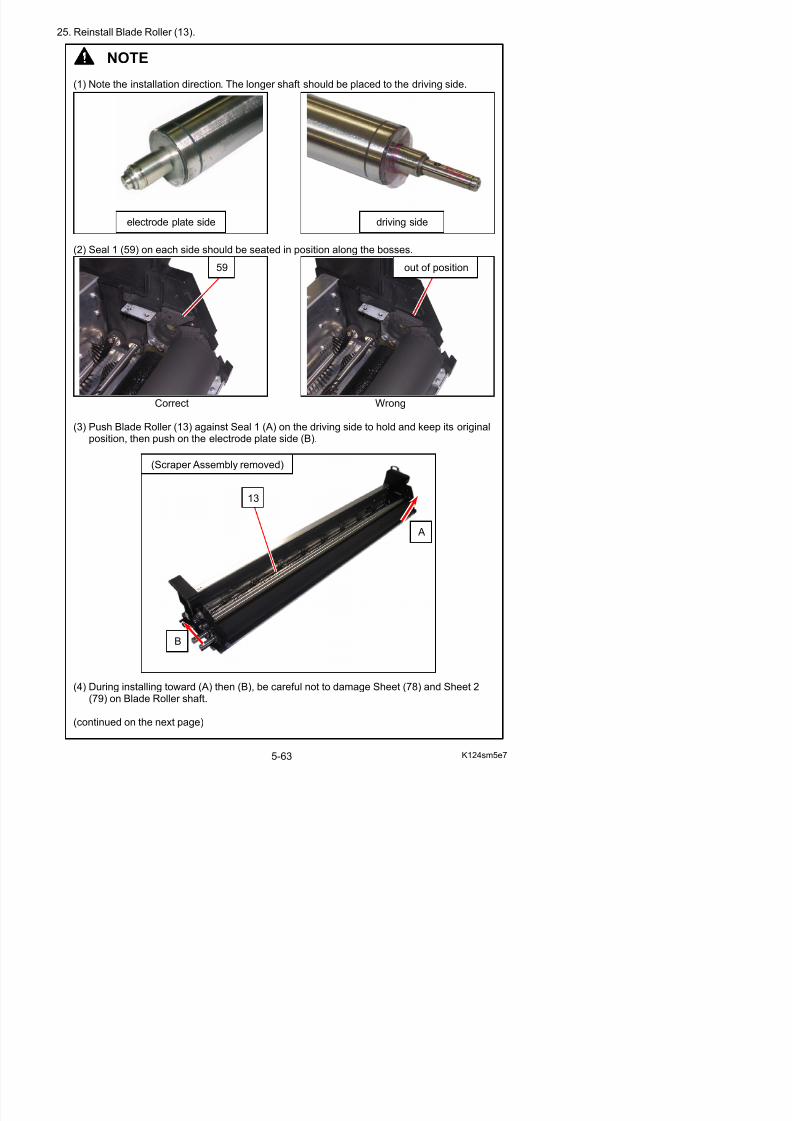
5/17/2018 KIP 7100 Service Manual Ver A_1 - slidepdf.com
http://slidepdf.com/reader/full/kip-7100-service-manual-ver-a1 180/674
(2) Seal 1 (59) on each side should be seated in position along the bosses.
Correct Wrong
(3) Push Blade Roller (13) against Seal 1 (A) on the driving side to hold and keep its originalposition, then push on the electrode plate side (B).
59 out of position
A
13
(Scraper Assembly removed)
NOTE
(5) After installing, check that Seal 1 (59), Sheet / Sheet 2 (on Blade Roller shaft) are notdamaged or deformed.
(6) After locating, check that Scraper (58) is notwavy.
(7) Blade Roller (13) is pressed onto / released from Developer Roller (14) by Bracket 4 (onthe driving side) and Bracket 5 (on the electrode plate side)
58
13
59
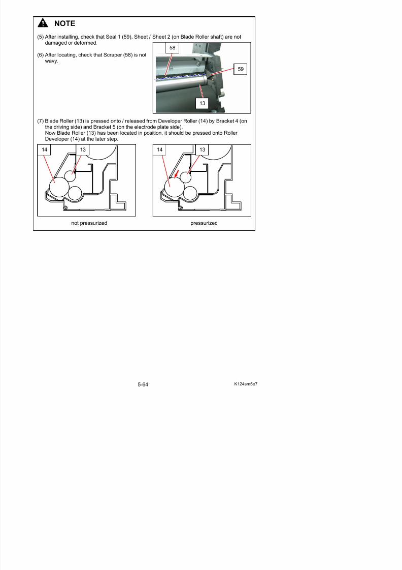
5/17/2018 KIP 7100 Service Manual Ver A_1 - slidepdf.com
http://slidepdf.com/reader/full/kip-7100-service-manual-ver-a1 181/674
the driving side) and Bracket 5 (on the electrode plate side).Now Blade Roller (13) has been located in position, it should be pressed onto Roller Developer (14) at the later step.
not pressurized pressurized
14 13 1314
26. Replace all the components except Gear Helical 30T (10) and Hopper Assy (4) in position.
27. Make sure that the 6 screws (46) (53) (32) (50) are installed loose.
28. On the electrode plate side, fully press down thetop of Bracket 5 (16). With pressing, tighten 2
(46) B k (16)
46 32
5053
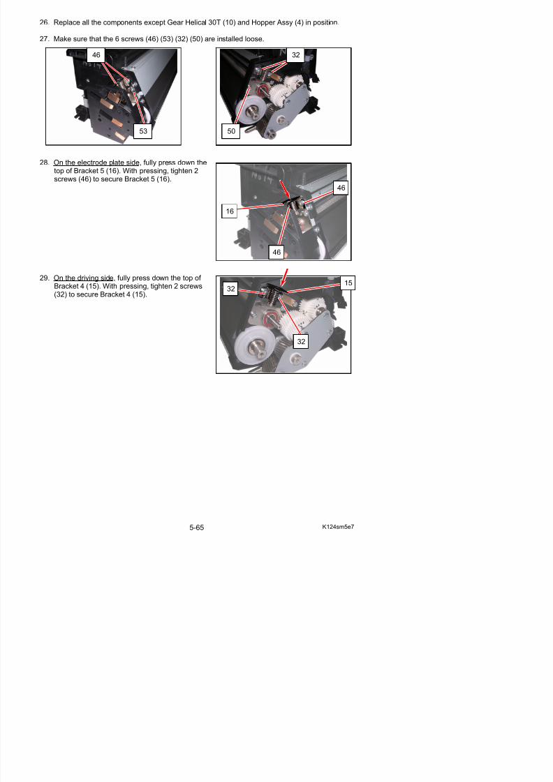
5/17/2018 KIP 7100 Service Manual Ver A_1 - slidepdf.com
http://slidepdf.com/reader/full/kip-7100-service-manual-ver-a1 182/674
screws (46) to secure Bracket 5 (16).
29. On the driving side, fully press down the top of Bracket 4 (15). With pressing, tighten 2 screws(32) to secure Bracket 4 (15).
16
46
46
3215
32
30. Press down the top of Bracket 7 Assy (57) and Bracket 6 Assy (52) at a time. This will allow
Blade Roller to be seated in the correct position.
NOTE
(1) Press down both Bracket 7 Assy and Bracket 6 Assy at the same time. Pressing only oneside may lose the correct pressure balance between the electrode plate side and the gear
57
52

5/17/2018 KIP 7100 Service Manual Ver A_1 - slidepdf.com
http://slidepdf.com/reader/full/kip-7100-service-manual-ver-a1 183/674
31. Turn the screw (50) in just enough revolution so that its spring washer is held in the gap.
y p p gside.
(2) Do not turn the screws (53) (50) for Bracket 7 Assy / Bracket 6 Assy at this point.Follow the later instruction to correctly tighten the screws (53) (50).
5350
NOTE
Do not tighten the screw (50) (53) firmly at this point of time. Otherwise proper and evenpressurization of Blade Roller between left/right may fail, and this will make the toner layer
R ll D l t thi k th i d
32. Turn the screw (53) in just enough revolution so that its spring washer is held in the gap.
33. Turn the screw (50) in just enough revolution so that its spring washer is thrust in the gap.Do not turn it completely.
53
50
spring washer on (50)
spring washer on (53)
released held
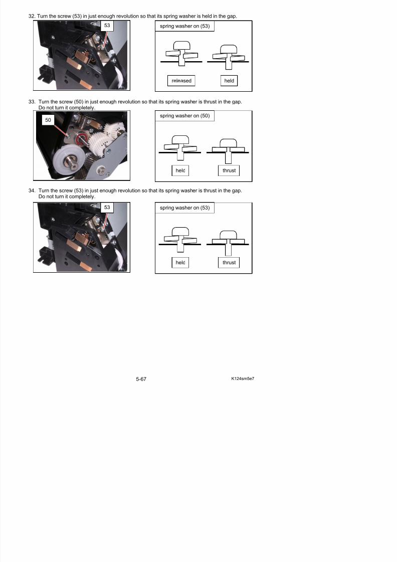
5/17/2018 KIP 7100 Service Manual Ver A_1 - slidepdf.com
http://slidepdf.com/reader/full/kip-7100-service-manual-ver-a1 184/674
34. Turn the screw (53) in just enough revolution so that its spring washer is thrust in the gap.Do not turn it completely.
53 spring washer on (53)
held
held
thrust
thrust
35. Slowly tighten the screw (50) to secure Bracket 6
Assy (52).
36. Slowly tighten the screw (53) to secure Bracket 7 Assy (57).
50
52
53
NOTE
Do not tighten the screw (50) quickly at thistime. Otherwise proper and even pressurizationof Blade Roller between both the sides may be
failed, and this will make the toner layer onDeveloper Roller get thicker than required.
NOTE
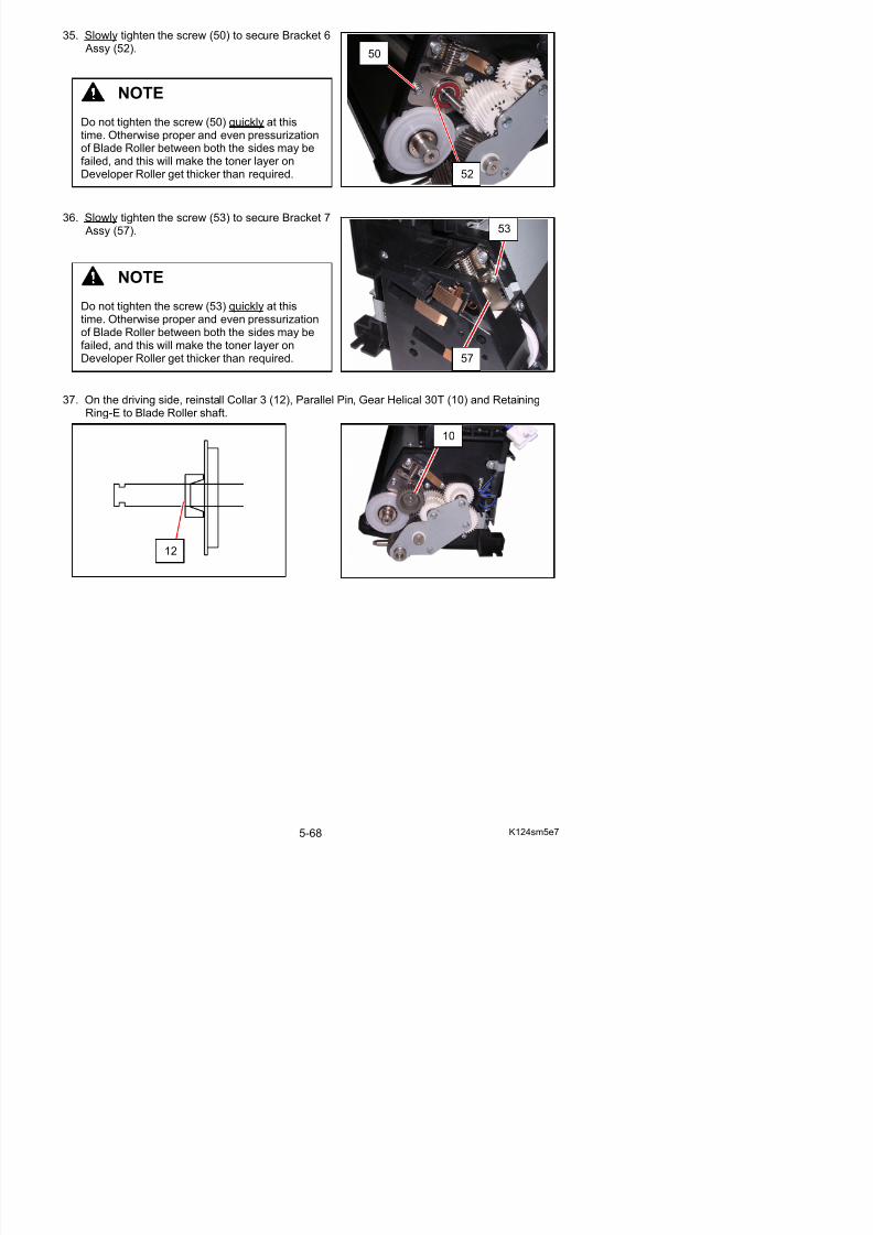
5/17/2018 KIP 7100 Service Manual Ver A_1 - slidepdf.com
http://slidepdf.com/reader/full/kip-7100-service-manual-ver-a1 185/674
37. On the driving side, reinstall Collar 3 (12), Parallel Pin, Gear Helical 30T (10) and RetainingRing-E to Blade Roller shaft.
57
12
10
Do not tighten the screw (53) quickly at thistime. Otherwise proper and even pressurizationof Blade Roller between both the sides may befailed, and this will make the toner layer onDeveloper Roller get thicker than required.
38. Install Developer Handle (63) to Developer Roller
shaft. Rotate Developer Roller several times sothat the roller surface is covered with the toner.
63
NOTE
If the pressures of Blade Roller on either or both sides are weaker than required, the toner layer on the Developer Unit will be much thicker than required when you rotate the Roller Developer.Retry to pressurize the Blade Roller in the correct way in this case
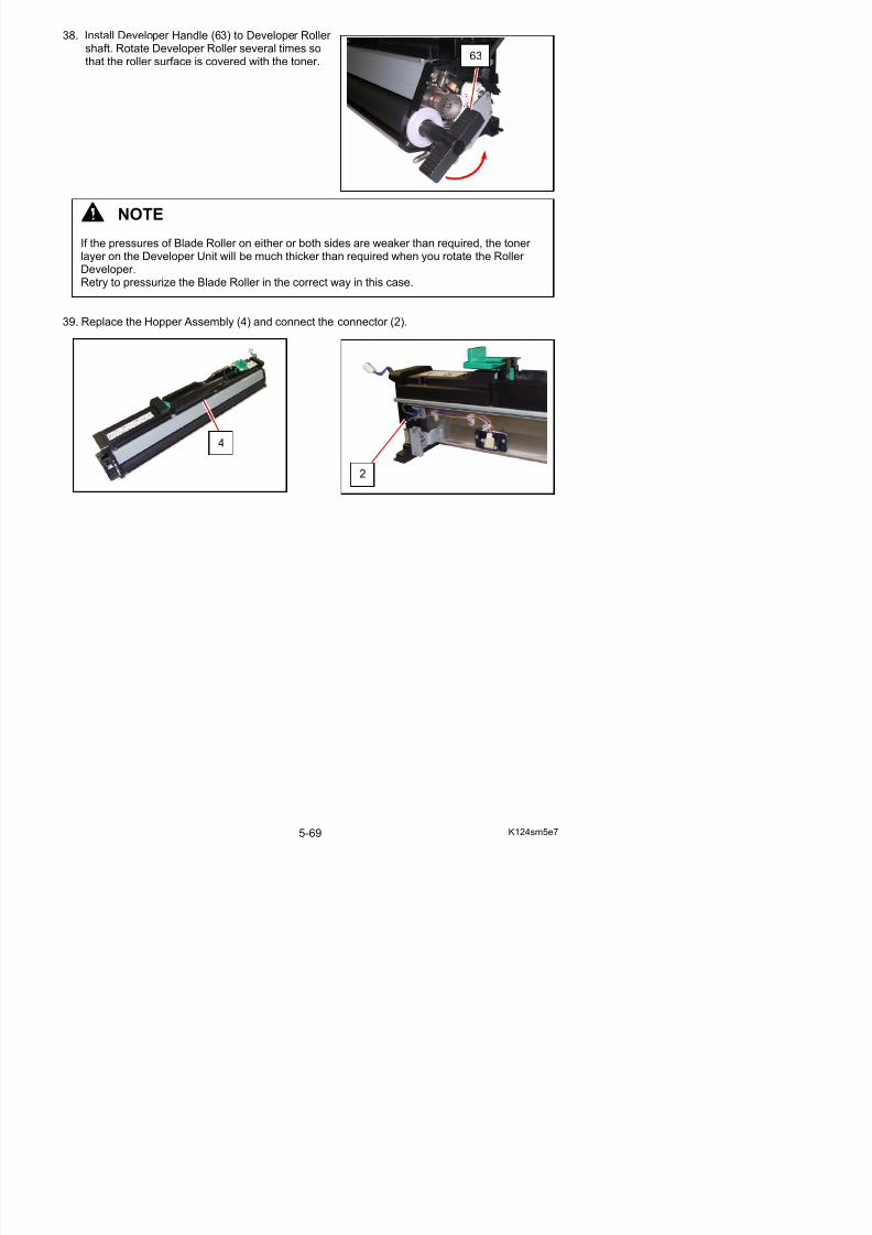
5/17/2018 KIP 7100 Service Manual Ver A_1 - slidepdf.com
http://slidepdf.com/reader/full/kip-7100-service-manual-ver-a1 186/674
39. Replace the Hopper Assembly (4) and connect the connector (2).
Retry to pressurize the Blade Roller in the correct way in this case.
4
2
5. 3 Fuser Unit5. 3. 1 Removal of Fuser Unit
1. Pull up the Lever 2 (1) to open the Engine Unit.
1
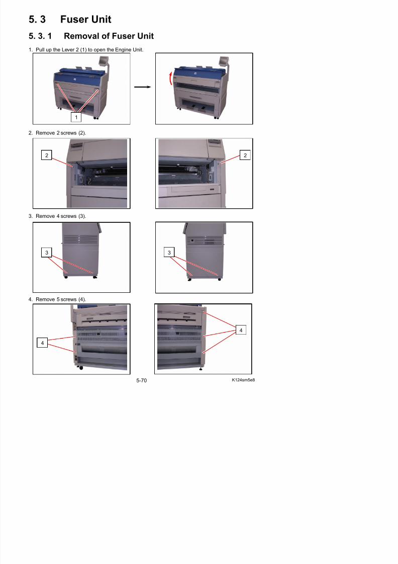
5/17/2018 KIP 7100 Service Manual Ver A_1 - slidepdf.com
http://slidepdf.com/reader/full/kip-7100-service-manual-ver-a1 187/674
2. Remove 2 screws (2).
3. Remove 4 screws (3).
2 2
33
5. Remove Cover 2 (5) and Cover 3 (6).
6. Disconnect 4 connectors (7).
65
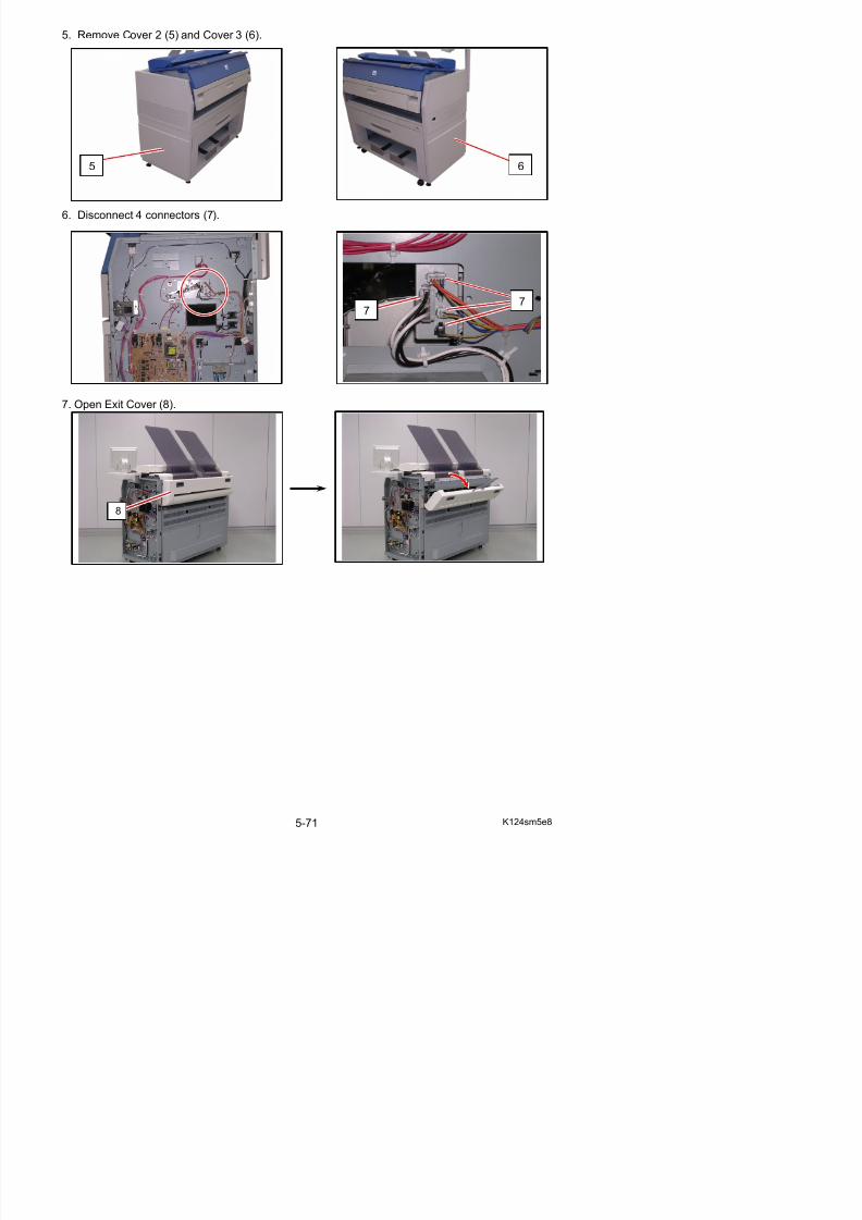
5/17/2018 KIP 7100 Service Manual Ver A_1 - slidepdf.com
http://slidepdf.com/reader/full/kip-7100-service-manual-ver-a1 188/674
7. Open Exit Cover (8).
77
8
8. Remove 2 screws (9) to remove Exit Side Cover R / L (10).
10
10
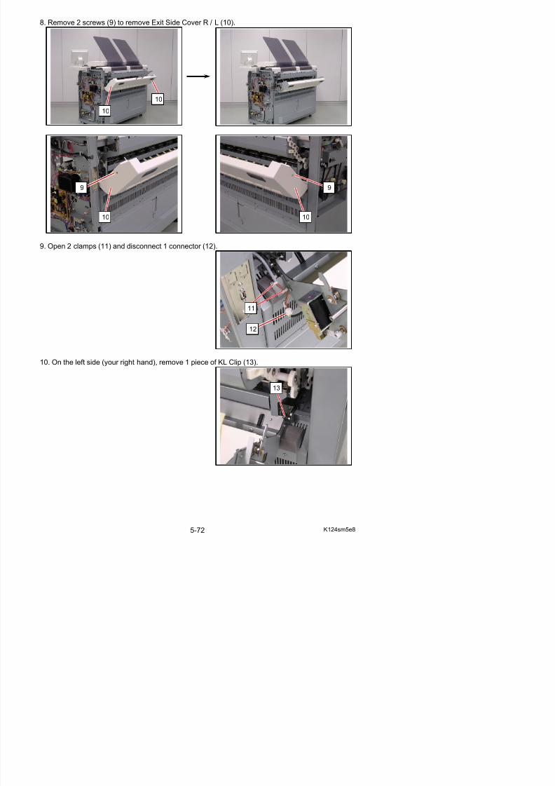
5/17/2018 KIP 7100 Service Manual Ver A_1 - slidepdf.com
http://slidepdf.com/reader/full/kip-7100-service-manual-ver-a1 189/674
9. Open 2 clamps (11) and disconnect 1 connector (12).
10. On the left side (your right hand), remove 1 piece of KL Clip (13).
10
9 9
10
11
12
13
11. Slide Exit Cover (8) to the arrow direction (right hand side) to remove it from the machine.
12. Release the springs (14) on both sides.
8
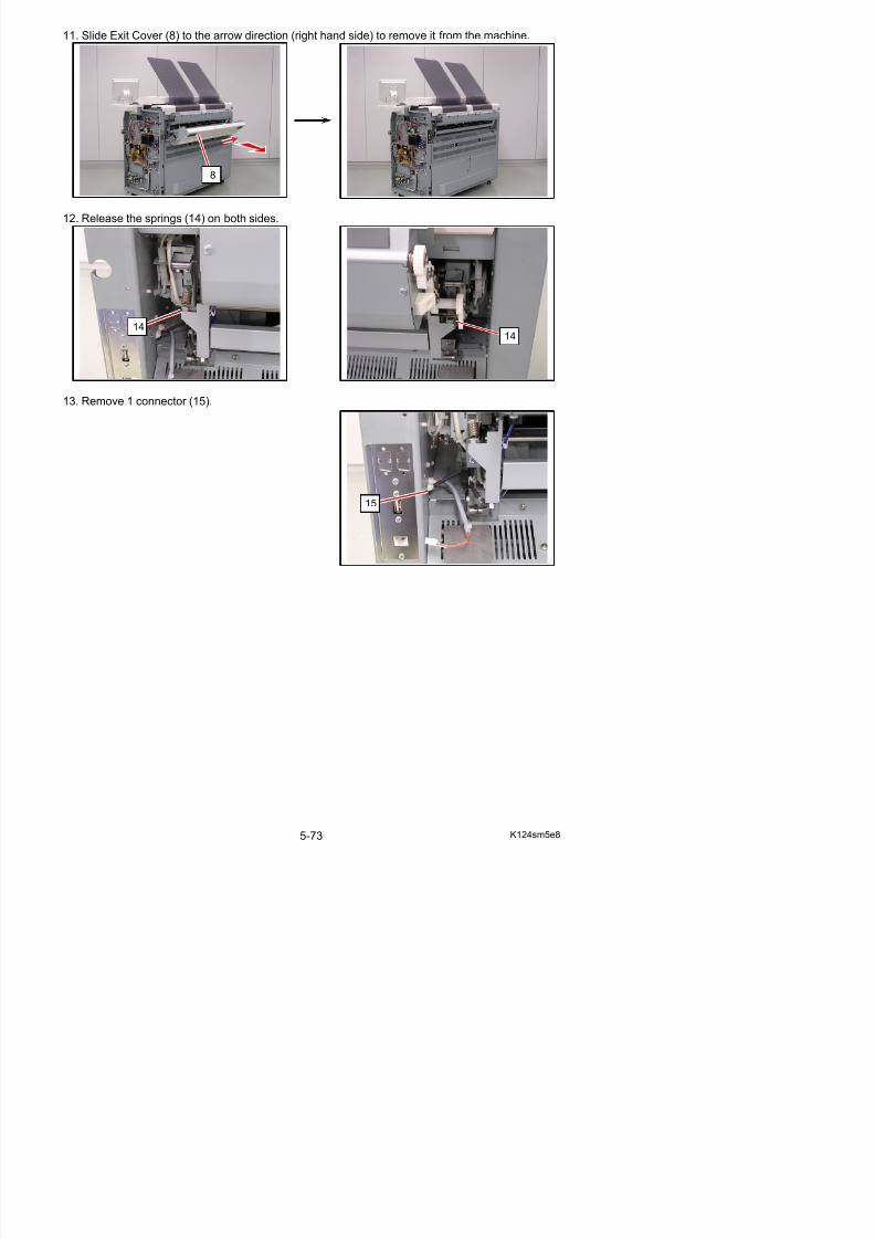
5/17/2018 KIP 7100 Service Manual Ver A_1 - slidepdf.com
http://slidepdf.com/reader/full/kip-7100-service-manual-ver-a1 190/674
13. Remove 1 connector (15).
1414
15
14. Remove 1 screw (16) to release the hinge bracket (17).
15 Fi l h ld F C (18) Sli htl it (A) d th hi b k t (17)
18
16
17
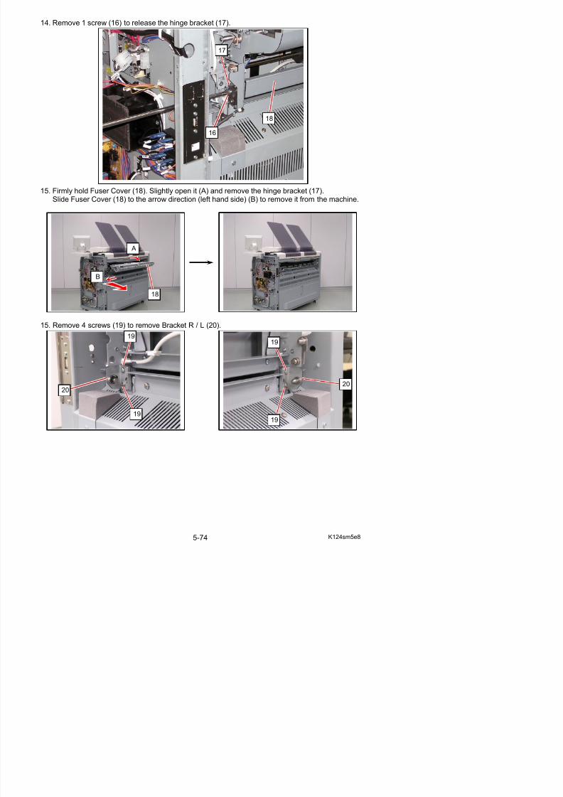
5/17/2018 KIP 7100 Service Manual Ver A_1 - slidepdf.com
http://slidepdf.com/reader/full/kip-7100-service-manual-ver-a1 191/674
15. Firmly hold Fuser Cover (18). Slightly open it (A) and remove the hinge bracket (17).Slide Fuser Cover (18) to the arrow direction (left hand side) (B) to remove it from the machine.
15. Remove 4 screws (19) to remove Bracket R / L (20).
18
1919
2020
A
B
16. Open the Engine Unit.
17. Loosen 1 screw (21) to release the drive side of Fuser Unit.
18. Pull and remove Fuser Unit (22) from the machine.
21
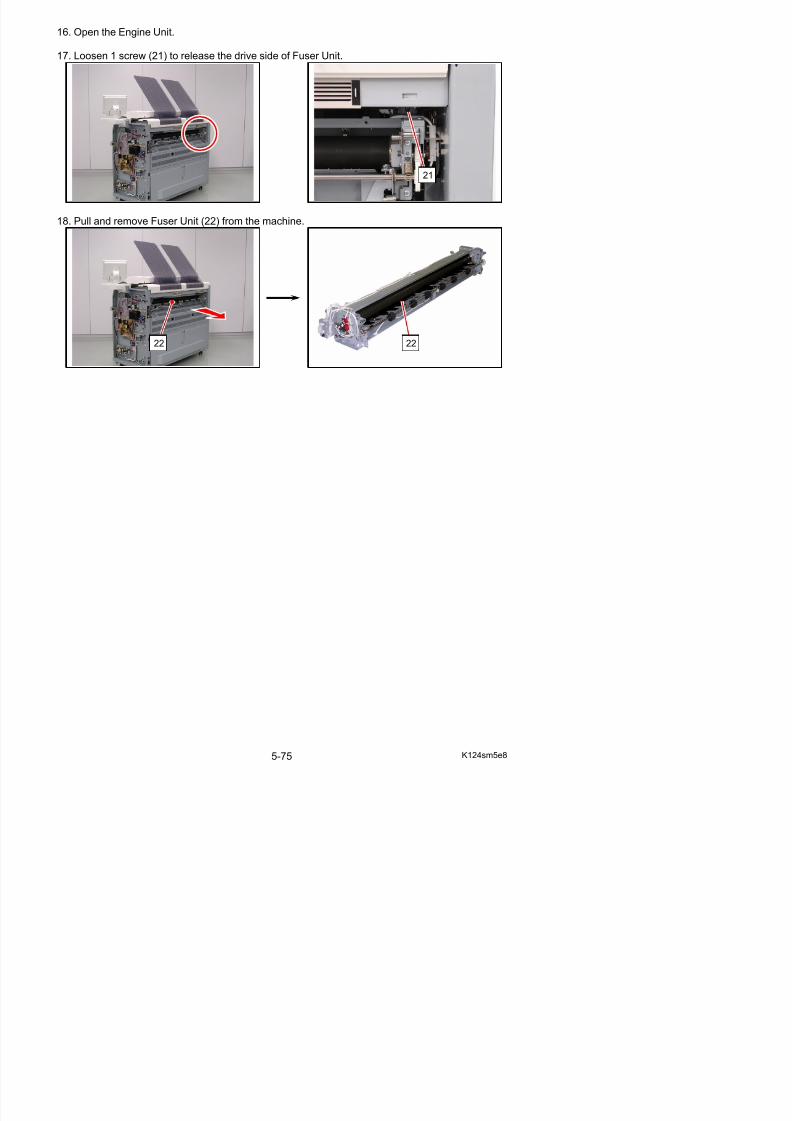
5/17/2018 KIP 7100 Service Manual Ver A_1 - slidepdf.com
http://slidepdf.com/reader/full/kip-7100-service-manual-ver-a1 192/674
22 22
5. 3. 2 Reinstallation of Fuser Unit
1. With Engine Unit open, fully mount Fuser Unit (1) to the machine
1
Reference
This section shows Fuser Unit with Paper Exit Assy removed for clarification.
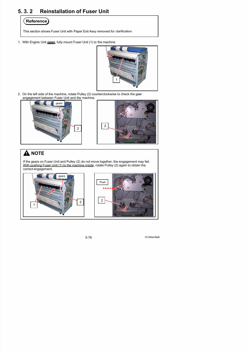
5/17/2018 KIP 7100 Service Manual Ver A_1 - slidepdf.com
http://slidepdf.com/reader/full/kip-7100-service-manual-ver-a1 193/674
2. On the left side of the machine, rotate Pulley (2) counterclockwise to check the gear engagement between Fuser Unit and the machine.
NOTE
If the gears on Fuser Unit and Pulley (2) do not move together, the engagement may fail.With pushing Fuser Unit (1) to the machine inside, rotate Pulley (2) again to obtain the
correct engagement.
2
gears
2
3. Install the brackets (3) with the screws (4) (5).
Tighten the lower one (4) and then the upper one (5).
4. Tighten the screw (6) to fix Fuser Unit (1) to the machine.
3
4: first
5: second
6
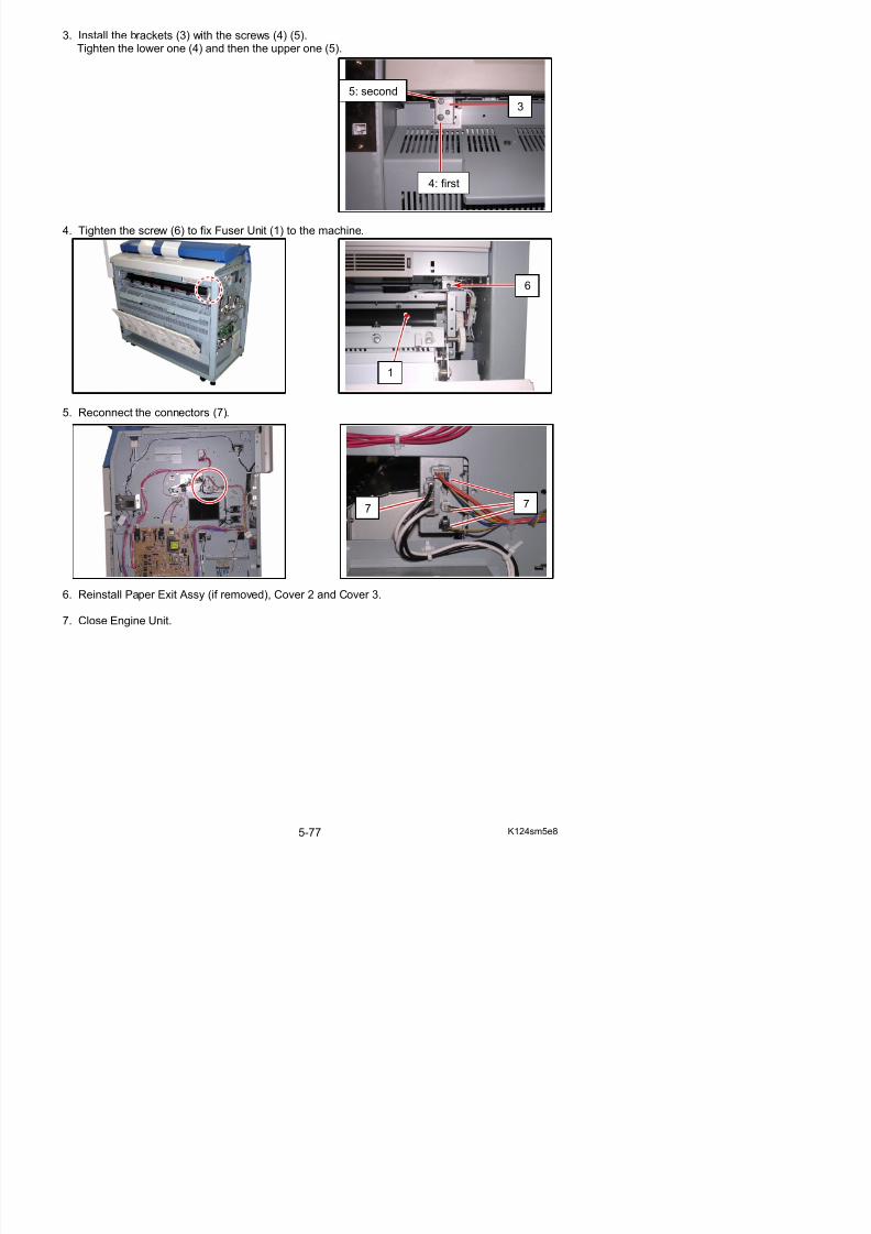
5/17/2018 KIP 7100 Service Manual Ver A_1 - slidepdf.com
http://slidepdf.com/reader/full/kip-7100-service-manual-ver-a1 194/674
5. Reconnect the connectors (7).
6. Reinstall Paper Exit Assy (if removed), Cover 2 and Cover 3.
7 7
1
5. 3. 3 Replacement of Recommended PeriodicReplacement Parts
1. Pull up the Lever 2 (1) to open the Engine Unit.
NOTE
A periodic replacement for them is recommended.This section shows how to replace all of them in one sequent operation.
Item Number of article
Remarks
Roller Fusing 1
Bush 2
Nail Stripping (Upper) 13
Nail Lower 6
All of these parts are contained in“Fuser Maintenance Kit” (Z160980040)
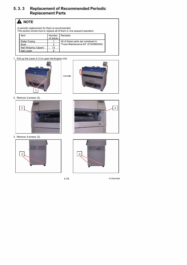
5/17/2018 KIP 7100 Service Manual Ver A_1 - slidepdf.com
http://slidepdf.com/reader/full/kip-7100-service-manual-ver-a1 195/674
2. Remove 2 screws (2).
1
2 2
4. Remove 5 screws (4).
5. Remove Cover 2 (5) and Cover 3 (6).
4
4
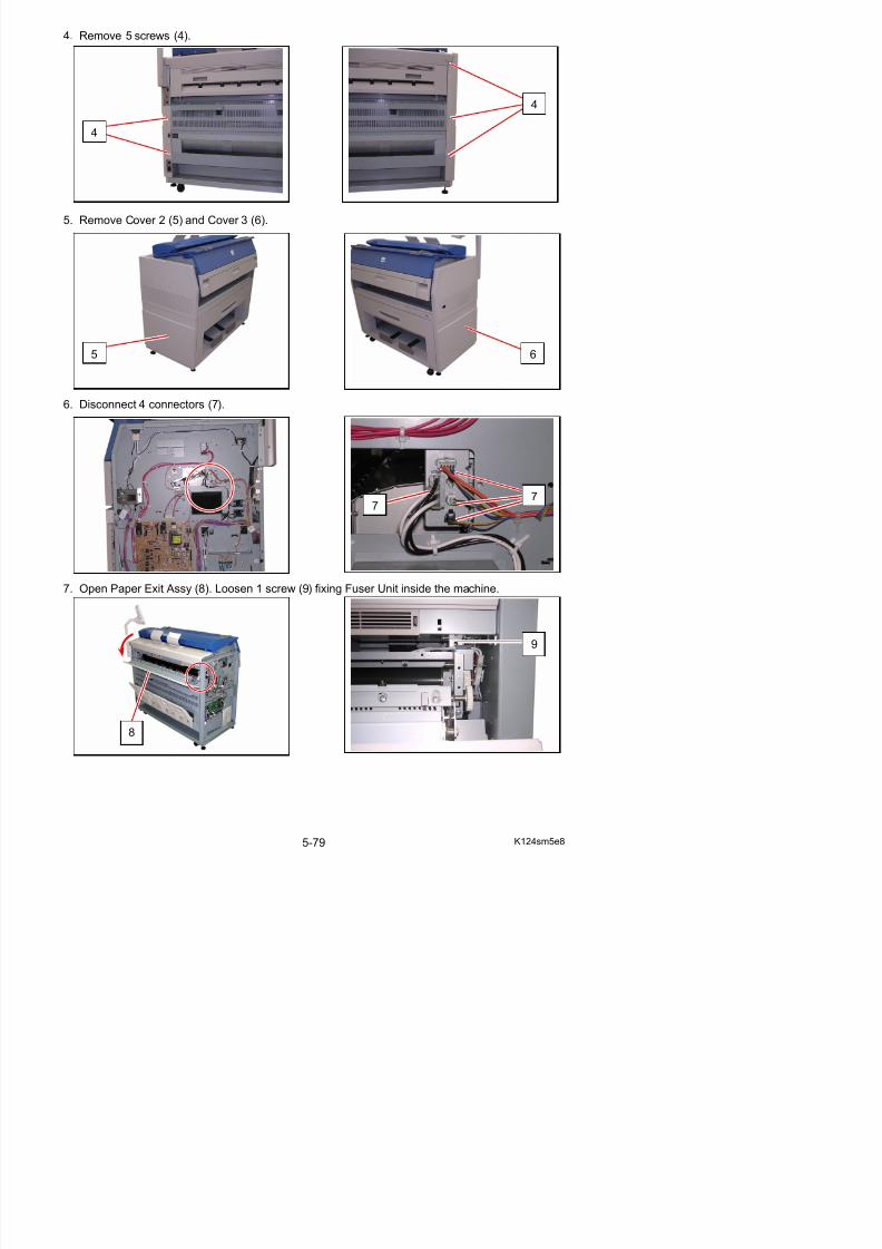
5/17/2018 KIP 7100 Service Manual Ver A_1 - slidepdf.com
http://slidepdf.com/reader/full/kip-7100-service-manual-ver-a1 196/674
6. Disconnect 4 connectors (7).
7. Open Paper Exit Assy (8). Loosen 1 screw (9) fixing Fuser Unit inside the machine.
6
77
5
8. Remove 1 screw (10: M4x6) to remove Plate (11) on the left side.
NOTE
(1) Please remove the Plate (11) with holding Paper Exit Assy (8).
Otherwise you may drop Paper Exit Assy.
(2) There is the Plate 2 on the right side of machine, which is a symmetric part of Plate (11).
10
11
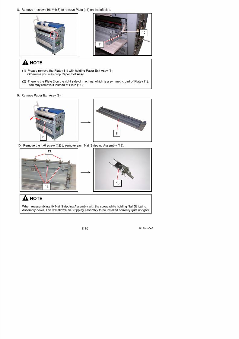
5/17/2018 KIP 7100 Service Manual Ver A_1 - slidepdf.com
http://slidepdf.com/reader/full/kip-7100-service-manual-ver-a1 197/674
9. Remove Paper Exit Assy (8).
10. Remove the 4x6 screw (12) to remove each Nail Stripping Assembly (13).
( ) g y p ( )You may remove it instead of Plate (11).
88
13
11. Disassemble the Nail Stripping Assembly as the following photo.
Replace the Nail Stripping (14) with the new one.
12. There are 2 pieces of the bracket (15) on the back of the machine.Remove the screws (16) to remove both Bracket (15).
14
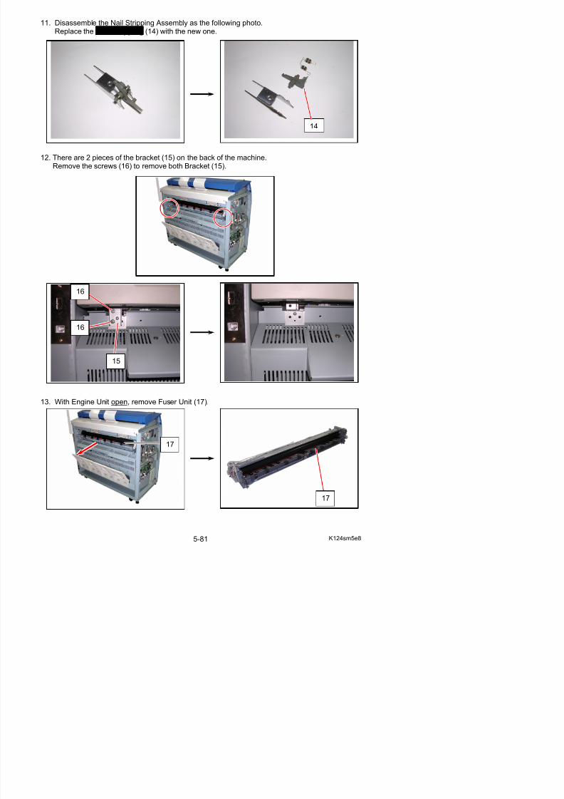
5/17/2018 KIP 7100 Service Manual Ver A_1 - slidepdf.com
http://slidepdf.com/reader/full/kip-7100-service-manual-ver-a1 198/674
16
16
15
NOTETo reinstall Fuser Unit, follow the instruction below.
(1) With Engine Unit open, fully mount Fuser Unit (17) to the machine.
(2) On the left side of the machine, rotate Pulley (18) counterclockwise to check the gear engagement between Fuser Unit and the machine.
If the gears on Fuser Unit and Pulley (18) do not move together, the engagement may fail.With pushing Fuser Unit (17) to the machine inside, rotate Pulley (18) again to obtain thecorrect engagement.
18
gears
17

5/17/2018 KIP 7100 Service Manual Ver A_1 - slidepdf.com
http://slidepdf.com/reader/full/kip-7100-service-manual-ver-a1 199/674
(3) Install Bracket (15) with the screws (16).Tighten the lower screw and then the upper.
(4) Tighten the screw (9) to fix Fuser Unit (17) to the machine.
17:Paper Exit Assyomitted
18
16
15
16
18
14. Disconnect the connectors (19). Remove 4 screws (20) to release IR Lamps (21).
Remove 2 screws (22) to release the connector brackets.
22
22
19
20 21
20 21
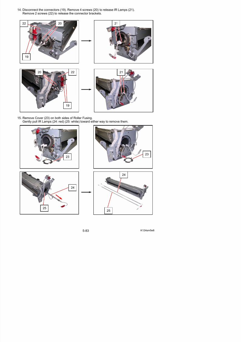
5/17/2018 KIP 7100 Service Manual Ver A_1 - slidepdf.com
http://slidepdf.com/reader/full/kip-7100-service-manual-ver-a1 200/674
15. Remove Cover (23) on both sides of Roller Fusing.Gently pull IR Lamps (24: red) (25: white) toward either way to remove them.
19
2323
NOTE(1) Do not touch the glass part of the Lamp with a bare hand.
(2) Do not interchange the IR Lamps (24) (25). One with red connectors (24) should beinstalled to the media entrance side and the other with white connectors (25) to the mediaexit side.
entranceexit entrance exit
24 2425 25
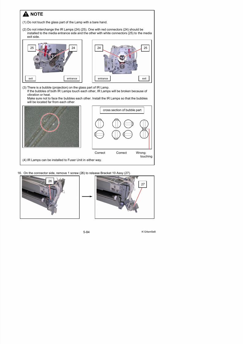
5/17/2018 KIP 7100 Service Manual Ver A_1 - slidepdf.com
http://slidepdf.com/reader/full/kip-7100-service-manual-ver-a1 201/674
(3) There is a bubble (projection) on the glass part of IR Lamp.If the bubbles of both IR Lamps touch each other, IR Lamps will be broken because of vibration or heat.Make sure not to face the bubbles each other. Install the IR Lamps so that the bubbleswill be located far from each other.
Correct Correct Wrong:touching
(4) IR Lamps can be installed to Fuser Unit in either way.
cross section of bubble part
17. On both sides, remove 4 KL Clips (28) to remove Arm 4 (29) and Arm 3 (30).
29
30
28
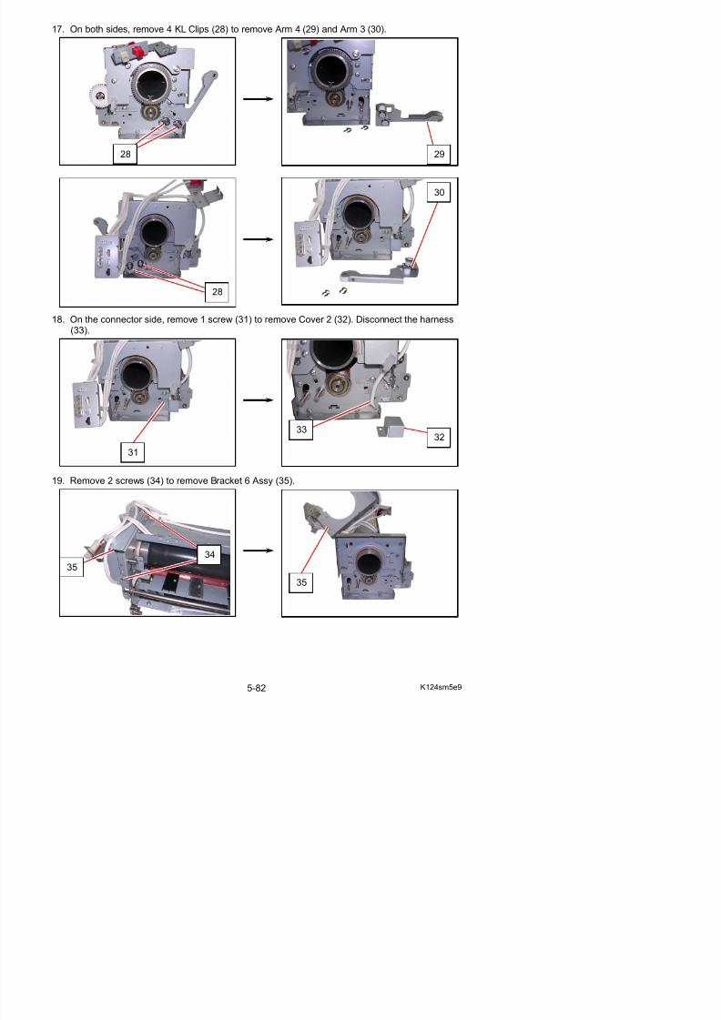
5/17/2018 KIP 7100 Service Manual Ver A_1 - slidepdf.com
http://slidepdf.com/reader/full/kip-7100-service-manual-ver-a1 202/674
18. On the connector side, remove 1 screw (31) to remove Cover 2 (32). Disconnect the harness(33).
19. Remove 2 screws (34) to remove Bracket 6 Assy (35).
31
3332
28
20. On the gear side, remove 1 screw (36) to remove Bracket 20 (37).
21. Remove 2 screws (38) to remove Bracket 7 Assy (39).
39
37
36
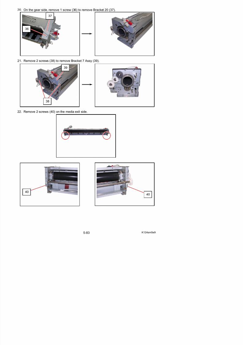
5/17/2018 KIP 7100 Service Manual Ver A_1 - slidepdf.com
http://slidepdf.com/reader/full/kip-7100-service-manual-ver-a1 203/674
22. Remove 2 screws (40) on the media exit side.
38
23. On the connector side, loosen 1 screw (41) to release Bracket 2 (42).
24. On the gear side, loosen 1 screw (43) to release Bracket 3 (44).
41
42
44
42
44
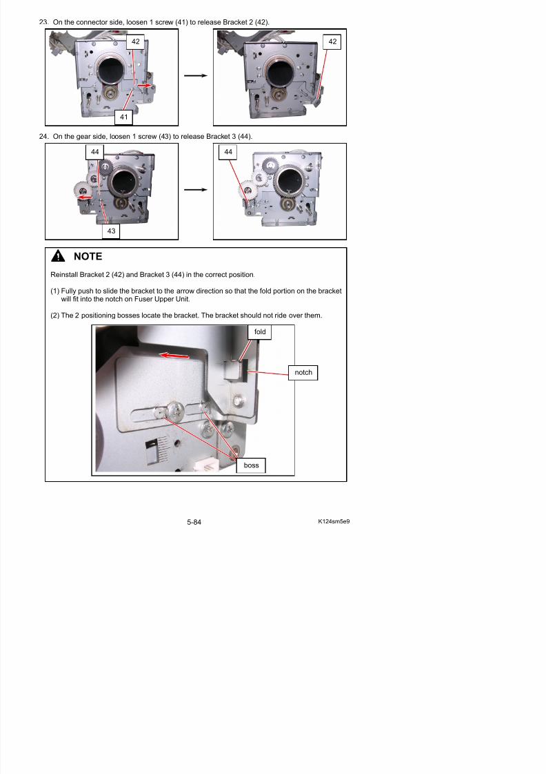
5/17/2018 KIP 7100 Service Manual Ver A_1 - slidepdf.com
http://slidepdf.com/reader/full/kip-7100-service-manual-ver-a1 204/674
43
NOTE
Reinstall Bracket 2 (42) and Bracket 3 (44) in the correct position.
(1) Fully push to slide the bracket to the arrow direction so that the fold portion on the bracketwill fit into the notch on Fuser Upper Unit.
(2) The 2 positioning bosses locate the bracket. The bracket should not ride over them.
fold
notch
25. On the media entrance side, remove 2 screws (45) to release Thermostat Bracket (46).
26. Turn Fuser Upper Unit (47) to the back. Lift Fuser Upper Unit (47) upward to remove it.
47
45 46
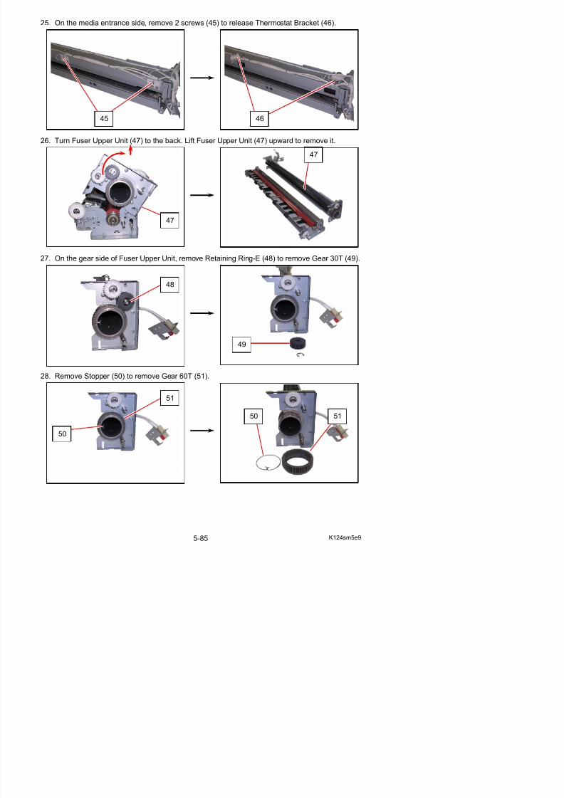
5/17/2018 KIP 7100 Service Manual Ver A_1 - slidepdf.com
http://slidepdf.com/reader/full/kip-7100-service-manual-ver-a1 205/674
27. On the gear side of Fuser Upper Unit, remove Retaining Ring-E (48) to remove Gear 30T (49).
28. Remove Stopper (50) to remove Gear 60T (51).
47
48
49
51
29. Remove 2 screws (52) to remove Bearing Holder (53).
30. On the connector side of Fuser Upper Unit, remove 2 screws (54) to remove Bearing Holder (55).
53
52
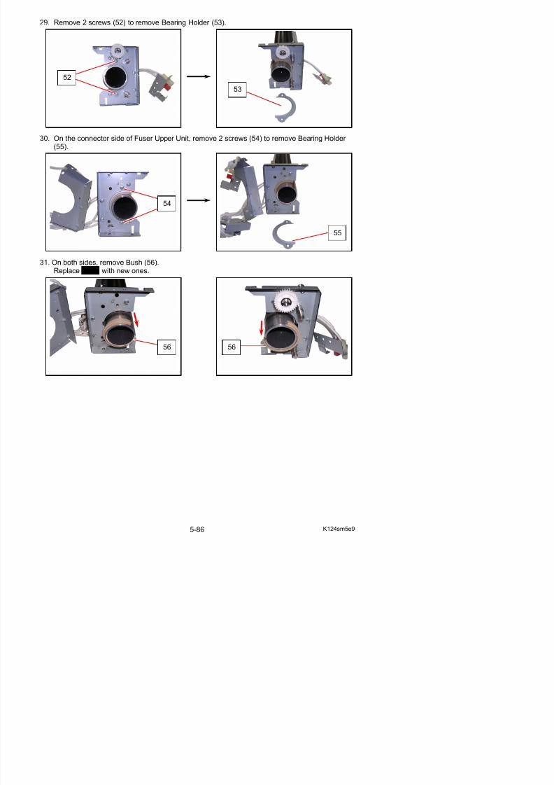
5/17/2018 KIP 7100 Service Manual Ver A_1 - slidepdf.com
http://slidepdf.com/reader/full/kip-7100-service-manual-ver-a1 206/674
31. On both sides, remove Bush (56).Replace Bush with new ones.
55
56 56
54
32. Remove Roller Fusing (57).
NOTE
Install Roller Fusing to Upper Fuser Assy in the
correct direction. One end with a cutting shouldbe placed to the gear side.
57 57
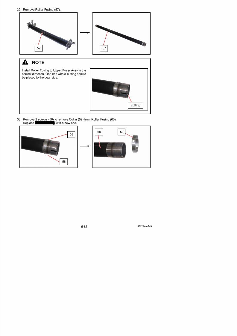
5/17/2018 KIP 7100 Service Manual Ver A_1 - slidepdf.com
http://slidepdf.com/reader/full/kip-7100-service-manual-ver-a1 207/674
33. Remove 2 screws (58) to remove Collar (59) from Roller Fusing (60).Replace Roller Fusing with a new one.
58 60 59
cutting
58
34. On the media exit side of Fuser Lower Unit, remove 2 screws (61) to remove Guide Plate 2 Assy (62).
61 61
62 62
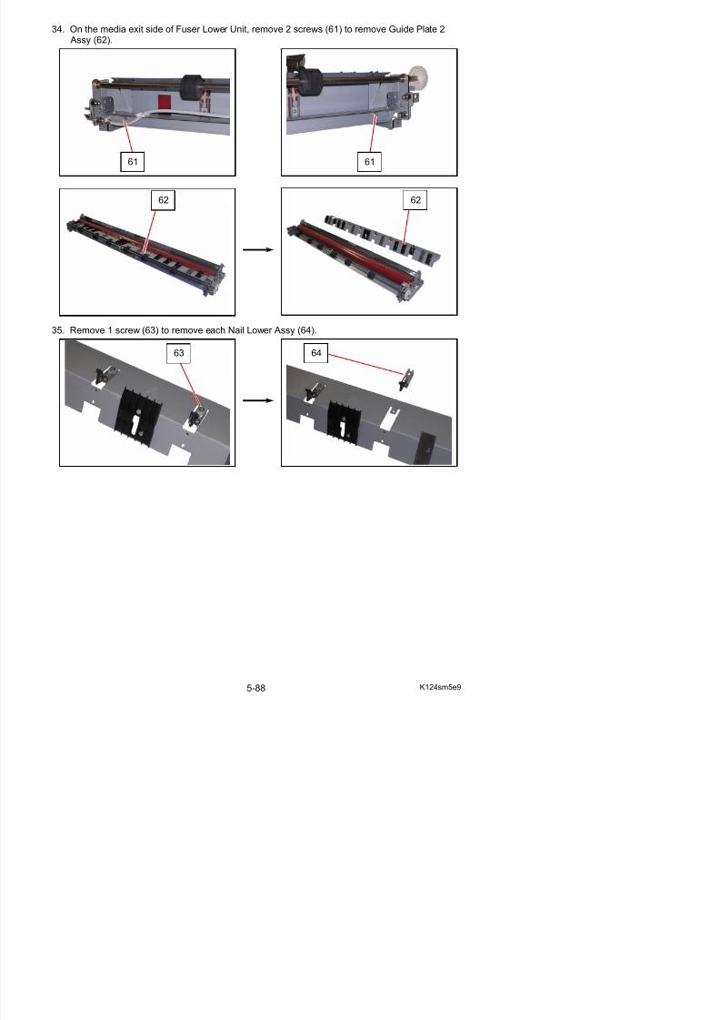
5/17/2018 KIP 7100 Service Manual Ver A_1 - slidepdf.com
http://slidepdf.com/reader/full/kip-7100-service-manual-ver-a1 208/674
35. Remove 1 screw (63) to remove each Nail Lower Assy (64).
63 64
36. Turn Nail Lower (65) to remove it from the bracket.Replace Nail Lower with a new one.
65
65
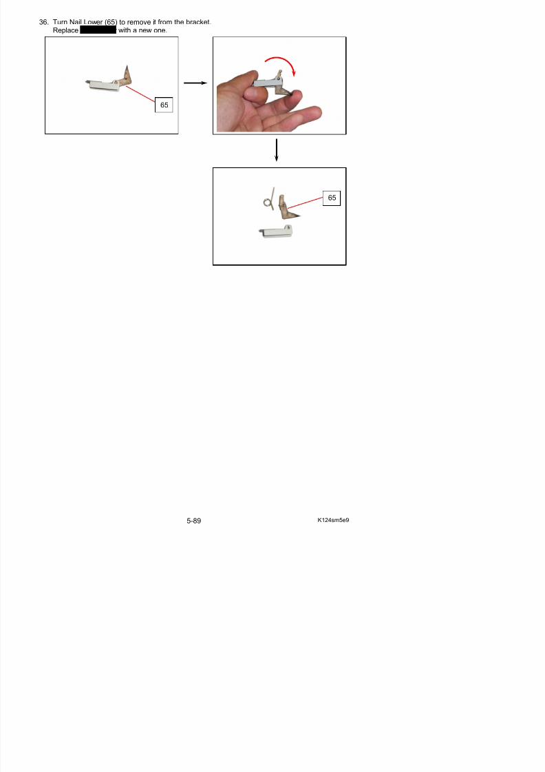
5/17/2018 KIP 7100 Service Manual Ver A_1 - slidepdf.com
http://slidepdf.com/reader/full/kip-7100-service-manual-ver-a1 209/674
5. 3. 4 Replacement of Roller Pressure
1. Pull up the Lever 2 (1) to open the Engine Unit.
2. Remove 2 screws (2).
1
2 2
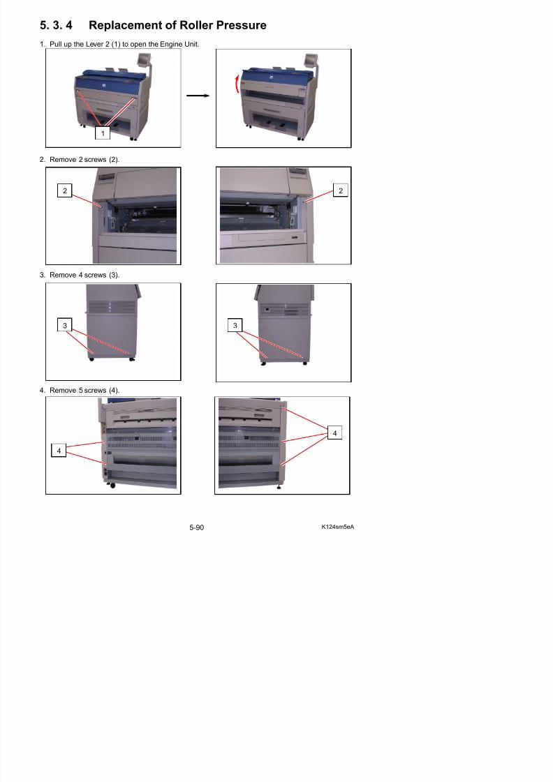
5/17/2018 KIP 7100 Service Manual Ver A_1 - slidepdf.com
http://slidepdf.com/reader/full/kip-7100-service-manual-ver-a1 210/674
3. Remove 4 screws (3).
4 R (4)
33
5. Remove Cover 2 (5) and Cover 3 (6).
6. Disconnect 4 connectors (7).
6
77
5
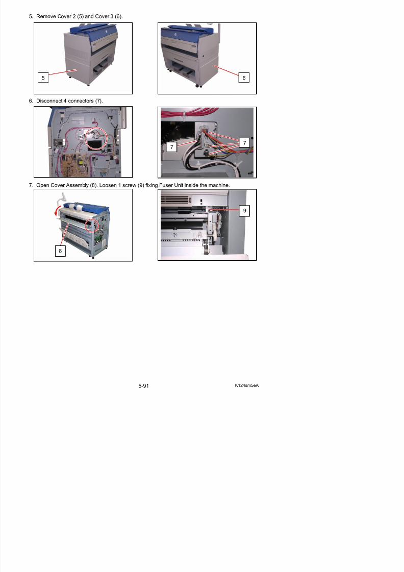
5/17/2018 KIP 7100 Service Manual Ver A_1 - slidepdf.com
http://slidepdf.com/reader/full/kip-7100-service-manual-ver-a1 211/674
7. Open Cover Assembly (8). Loosen 1 screw (9) fixing Fuser Unit inside the machine.
8
9
8. Remove 1 screw (10: M4x6) to remove Plate (11) on the left side.
NOTE
(1) Please remove the Plate (11) while holding Cover Assembly (8).
Otherwise you may drop the Cover Assembly.
(2) There is the Plate 2 on the right side of machine, which is a symmetric part of Plate (11).You may remove it instead of Plate (11).
10
11

5/17/2018 KIP 7100 Service Manual Ver A_1 - slidepdf.com
http://slidepdf.com/reader/full/kip-7100-service-manual-ver-a1 212/674
9. Remove the Cover Assembly (8).
88
10. There are 2 pieces of the brackets (12) on the back of the machine.Remove the screws (13) (14) to remove both Bracket (12).
13
14
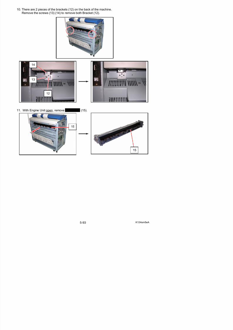
5/17/2018 KIP 7100 Service Manual Ver A_1 - slidepdf.com
http://slidepdf.com/reader/full/kip-7100-service-manual-ver-a1 213/674
11. With Engine Unit open, remove Fuser Unit (15).
12
15
15
NOTE
To reinstall Fuser Unit, follow the instruction below.
(1) With Engine Unit open, fully mount Fuser Unit (15) to the machine.
(2) On the left side of the machine, rotate Pulley (16) counterclockwise to check the gear engagement between Fuser Unit and the machine.
If the gears on Fuser Unit and Pulley (16) do not move together, the engagement may fail.With pushing Fuser Unit (15) to the machine inside, rotate Pulley (16) again to obtain thecorrect engagement.
15:
1616
15
gears
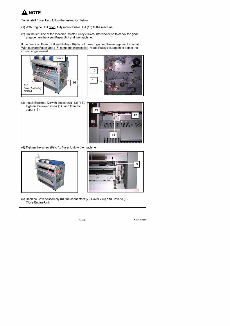
5/17/2018 KIP 7100 Service Manual Ver A_1 - slidepdf.com
http://slidepdf.com/reader/full/kip-7100-service-manual-ver-a1 214/674
(3) Install Bracket (12) with the screws (13) (14).Tighten the lower screw (14) and then theupper (13).
(4) Tighten the screw (9) to fix Fuser Unit to the machine.
Cover Assemblyomitted
13
12
14
12. On the connector side, remove 1 screw (17) to release Bracket 10 Assy (18).
13. On the connector side, remove 1 screw (19) to remove Cover 2 (20). Disconnect the harness(21).
17
18
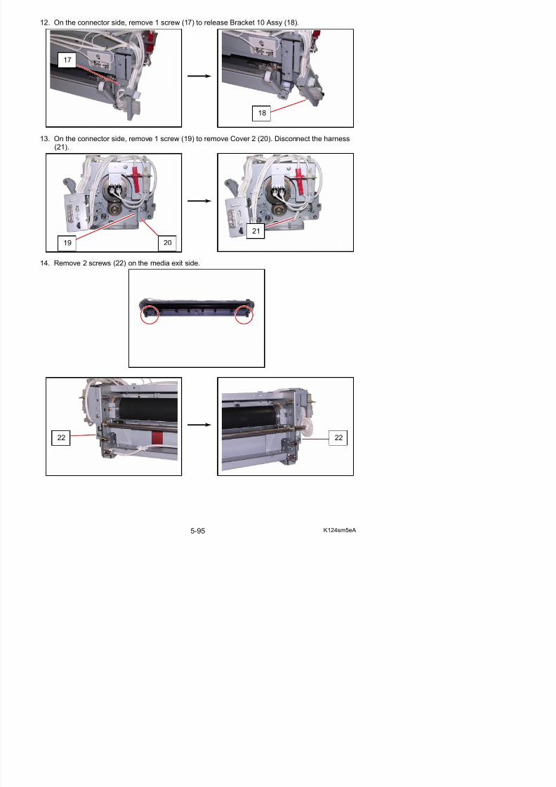
5/17/2018 KIP 7100 Service Manual Ver A_1 - slidepdf.com
http://slidepdf.com/reader/full/kip-7100-service-manual-ver-a1 215/674
14. Remove 2 screws (22) on the media exit side.
19
21
20
15. On both sides, remove 4 grip rings (23) to remove Arm 4 (24) and Arm 3 (25).
24
23
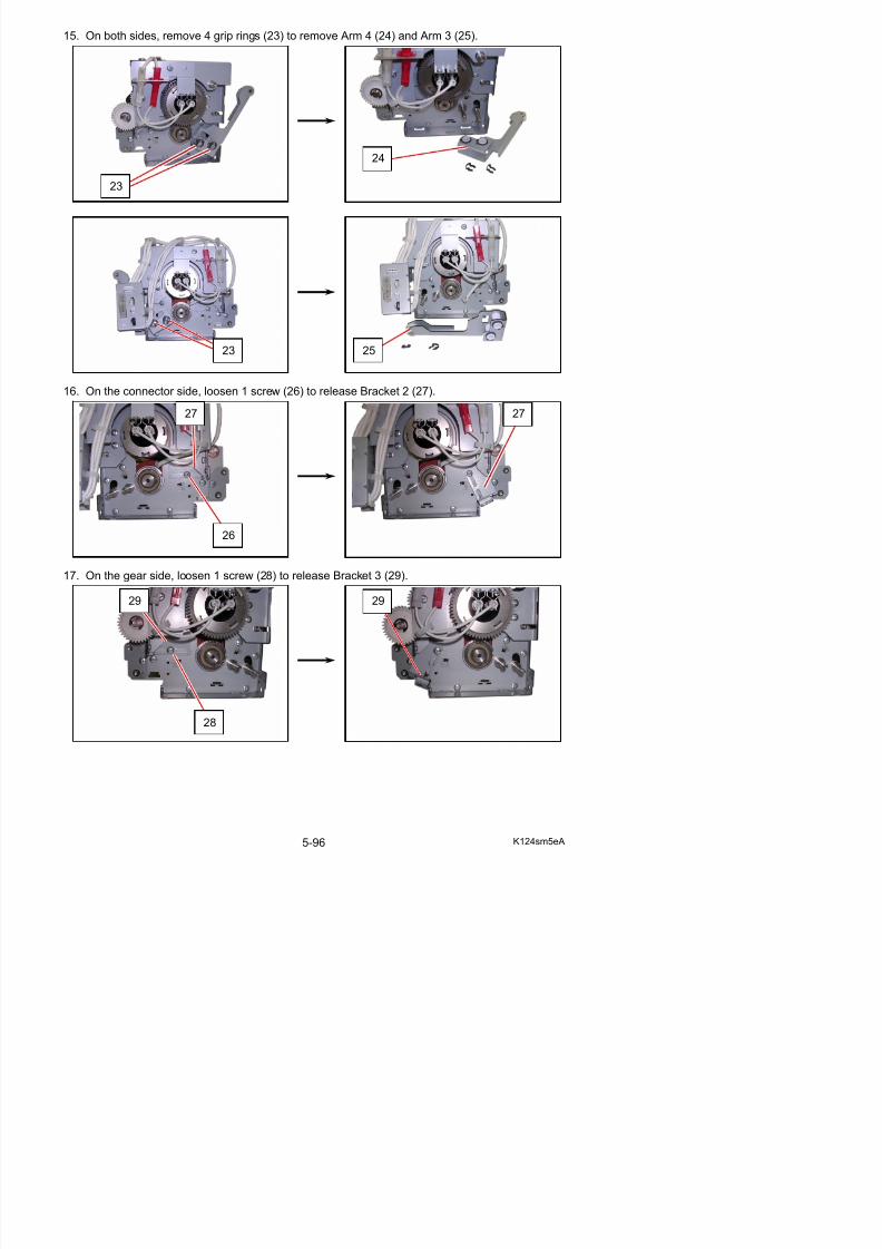
5/17/2018 KIP 7100 Service Manual Ver A_1 - slidepdf.com
http://slidepdf.com/reader/full/kip-7100-service-manual-ver-a1 216/674
16. On the connector side, loosen 1 screw (26) to release Bracket 2 (27).
17. On the gear side, loosen 1 screw (28) to release Bracket 3 (29).
26
27 27
29 29
2523
18 T rn F ser Upper Unit (30) to the back Lift F ser Upper Unit p ard to remo e it
NOTE
Reinstall Bracket 2 (27) and Bracket 3 (29) in the correct position.
(1) Fully push the bracket to the arrow direction so that the fold portion on the bracket will fitinto the notch on Fuser Upper Unit.
(2) The 2 positioning bosses locate the bracket.
The bracket should not ride over them.fold
boss
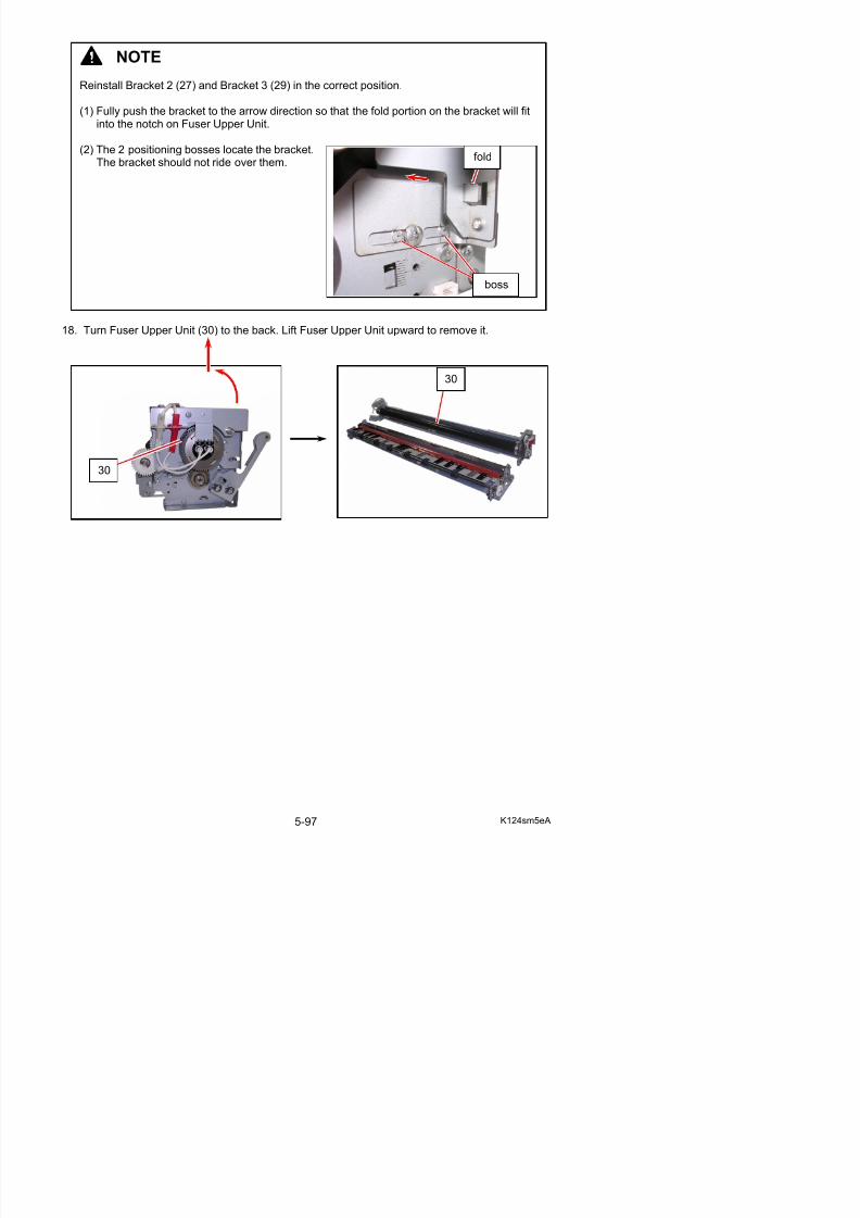
5/17/2018 KIP 7100 Service Manual Ver A_1 - slidepdf.com
http://slidepdf.com/reader/full/kip-7100-service-manual-ver-a1 217/674
18. Turn Fuser Upper Unit (30) to the back. Lift Fuser Upper Unit upward to remove it.
30
30
19. On the media exit side of Fuser Lower Unit, remove 2 screws (31) to remove Guide Plate 2 Assy (32).
31 31
32 32
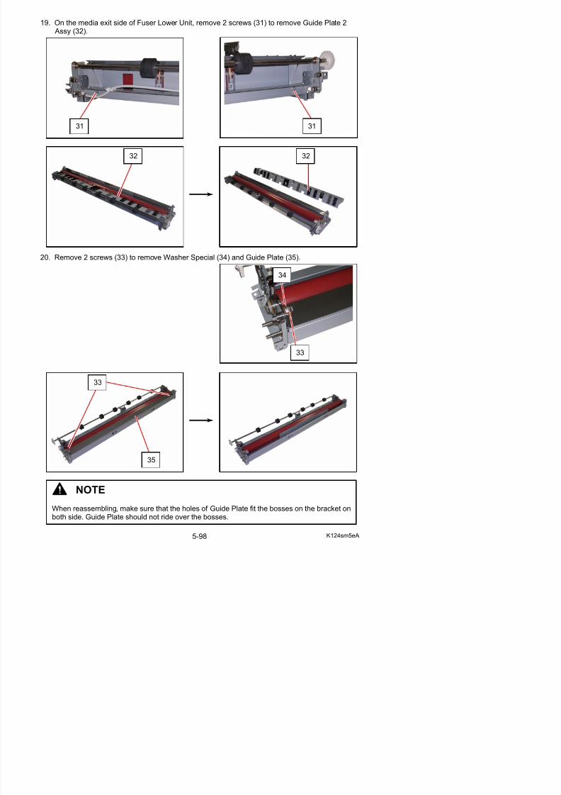
5/17/2018 KIP 7100 Service Manual Ver A_1 - slidepdf.com
http://slidepdf.com/reader/full/kip-7100-service-manual-ver-a1 218/674
20. Remove 2 screws (33) to remove Washer Special (34) and Guide Plate (35).
33
34
33
21. Remove Pressure Roller (36) from the unit.
22. Remove Retaining Ring-C (37) to remove Collar (38) (39: only on the gear side), Bearing (40)from each shaft end of Roller Pressure (41).Replace Roller Pressure with a new one.
36
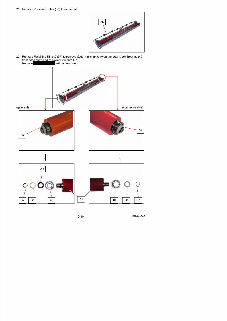
5/17/2018 KIP 7100 Service Manual Ver A_1 - slidepdf.com
http://slidepdf.com/reader/full/kip-7100-service-manual-ver-a1 219/674
(gear side) (connector side)
37
37
5. 3. 5 Fuser Pressure Adjustment (NIP width check)
1. Load a tracing paper roll in 36”/A0 width into any available Roll Deck.2. Make a test print in pattern No.2 S(0) with the roll in 297mm length.3. When the test print’s leading edge appears within 50mm at the exit cover, stop the print process
by opening any cover. At this point, the black area on the print will be nipped between Fuser Roller and Pressure Roller.
4. Leave the print there in 10 seconds. After that, remove the test print from the machine.5. The test print has a shiny band on its printing surface, which has been created by pressure
between Fuser Roller and Pressure Roller.Check that the nip widths at the reference points meet the following specification.
- Within 2mm inside from the side edges: 8.5 to 9.0mm
2mm 2mm
8.5 to 9.0mm
6. If the nip width at any point is not proper, adjust the fuser pressure with the pressure adjuster.
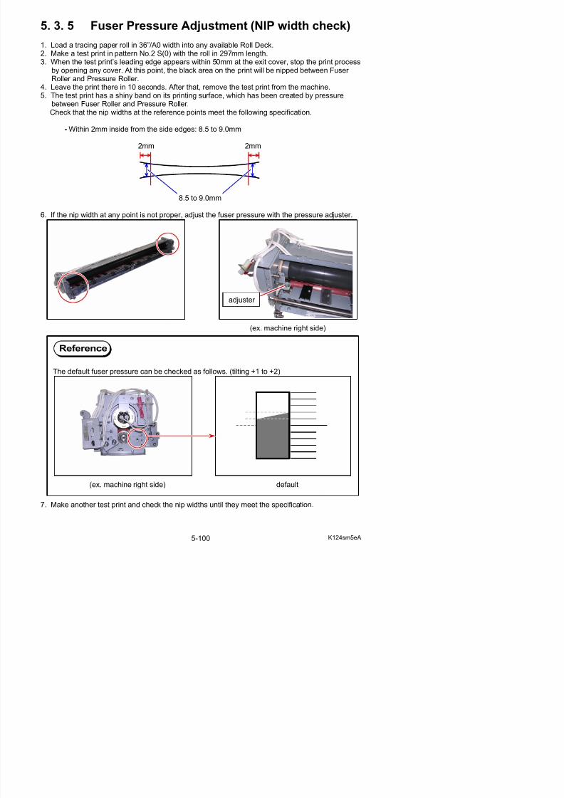
5/17/2018 KIP 7100 Service Manual Ver A_1 - slidepdf.com
http://slidepdf.com/reader/full/kip-7100-service-manual-ver-a1 220/674
p y p p p , j p p j
(ex. machine right side)
Reference
The default fuser pressure can be checked as follows. (tilting +1 to +2)
adjuster
5. 3. 6 Replacement of Thermistor (TH1, TH2)
1. Remove the Fuser Unit (1) from the machinemaking reference to [5. 3. 1 Removal of theFuser Unit] on the page 5-70.
2. Release the harness from the clamps (2).Remove the connectors (3: TH1, white) (4: TH2, black) from Bracket 10 Assy (5).
1
1
2
35
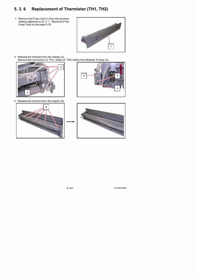
5/17/2018 KIP 7100 Service Manual Ver A_1 - slidepdf.com
http://slidepdf.com/reader/full/kip-7100-service-manual-ver-a1 221/674
3. Release the harness from the clapms (6).
4
2
6
4. Remove each 1 screw (7) to release Thermistor Assy (8: TH1, short harness) and Thermistor 3 Assy (9: TH3, long harness).
5. Remove 1 screw (10) to replace Thermistor (8: TH1) (9: TH2) with a new one.
9
7
8
10
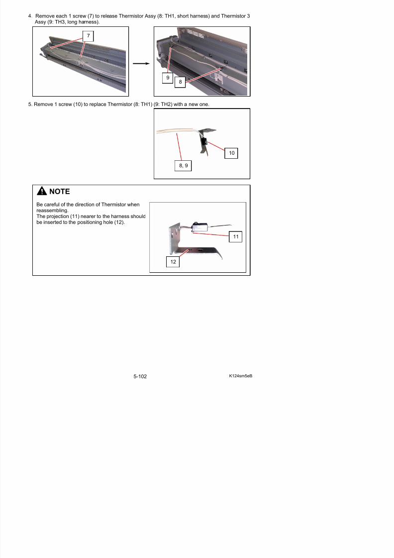
5/17/2018 KIP 7100 Service Manual Ver A_1 - slidepdf.com
http://slidepdf.com/reader/full/kip-7100-service-manual-ver-a1 222/674
NOTE
Be careful of the direction of Thermistor whenreassembling.The projection (11) nearer to the harness should
be inserted to the positioning hole (12).
10
8, 9
11
12
5. 3. 7 Replacement of Thermostat (TS1, TS2)
1. Remove the Fuser Unit (1) from the machinemaking reference to [5. 3. 1 Removal of theFuser Unit] on the page 5-70.
2. Remove 2 screws (2: M4x6) to remove Thermostat Assy (3).
1
3
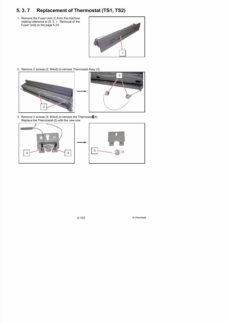
5/17/2018 KIP 7100 Service Manual Ver A_1 - slidepdf.com
http://slidepdf.com/reader/full/kip-7100-service-manual-ver-a1 223/674
3. Remove 2 screws (4: M3x4) to remove the Thermostat (5).Replace the Thermostat (5) with the new one.
4 45
2
5. 3. 8 Replacement of Exit Sensor (PH3)
1. Pull up the Lever 2 (1) to open the Engine Unit.
2. Remove 6 screws (2) to remove Cover 2 (3).
1
2
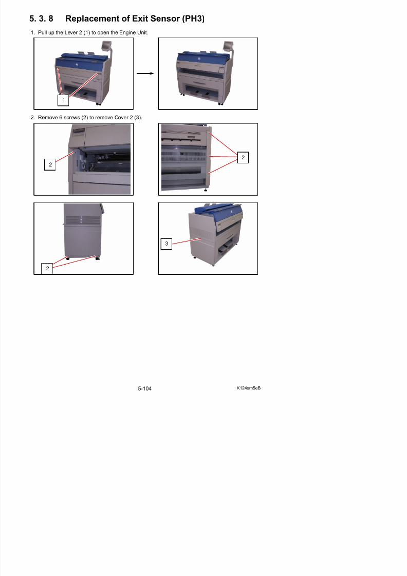
5/17/2018 KIP 7100 Service Manual Ver A_1 - slidepdf.com
http://slidepdf.com/reader/full/kip-7100-service-manual-ver-a1 224/674
2
3
2
3. Remove 1 screw (4: M4x6) to remove Plate (5) on the left side.
4 R th C A bl (3)
NOTE
(1) Please remove the Plate (5) while holding Cover Assembly (3).
Otherwise you may drop the Cover Assembly.
(2) There is the Plate 2 on the right side of machine, which is a symmetric part of Plate (5).You may remove it instead of Plate (5).
4
5
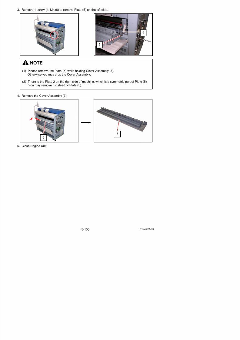
5/17/2018 KIP 7100 Service Manual Ver A_1 - slidepdf.com
http://slidepdf.com/reader/full/kip-7100-service-manual-ver-a1 225/674
4. Remove the Cover Assembly (3).
5. Close Engine Unit.
3 3
6. Remove the harness (6) and remove the screw (7) to remove Exit Sensor Assy (8).Remove Exit Sensor (9) form Exit Sensor Assy (8). Replace Exit Sensor with a new one.
6
7
8
9
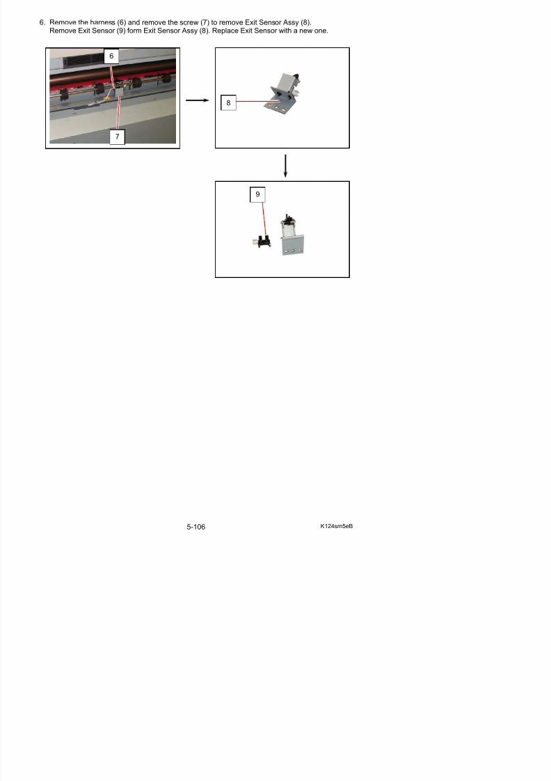
5/17/2018 KIP 7100 Service Manual Ver A_1 - slidepdf.com
http://slidepdf.com/reader/full/kip-7100-service-manual-ver-a1 226/674
5. 4 Roll Deck
5. 4. 1 Replacement of Cutter Assembly
1. Draw out the Roll Deck (1).
2. Remove 4 screws (2) to remove Cover 1 (3).
1
2
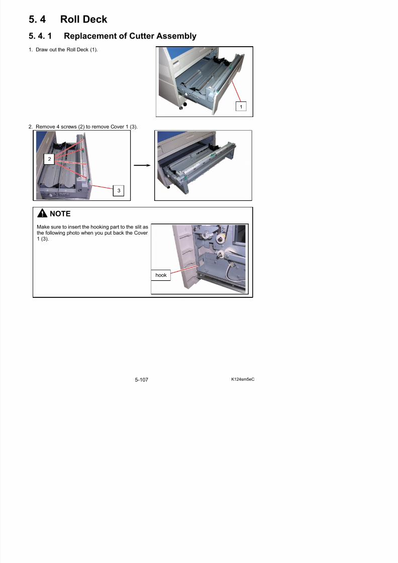
5/17/2018 KIP 7100 Service Manual Ver A_1 - slidepdf.com
http://slidepdf.com/reader/full/kip-7100-service-manual-ver-a1 227/674
NOTE
Make sure to insert the hooking part to the slit asthe following photo when you put back the Cover 1 (3).
3
hook
2
3. Remove 7 screws (4) to remove Cover 14 (5).
NOTE
Make sure that the step part on the bottom side of Cover 14 (5) is inside the bottom frame.
5
step
4
4
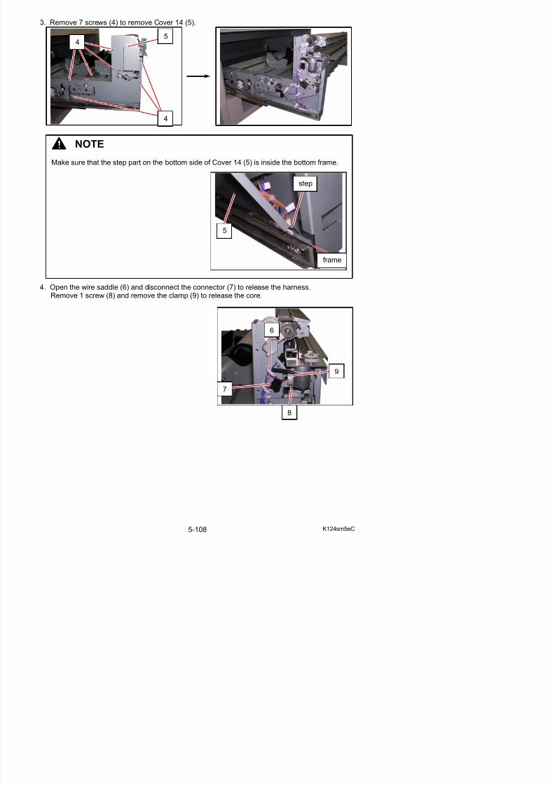
5/17/2018 KIP 7100 Service Manual Ver A_1 - slidepdf.com
http://slidepdf.com/reader/full/kip-7100-service-manual-ver-a1 228/674
4. Open the wire saddle (6) and disconnect the connector (7) to release the harness.Remove 1 screw (8) and remove the clamp (9) to release the core.
5
frame
7
6
9
5. Remove 2 screws on the front (10) to remove Cutter Assy (11).Replace the whole Cutter Assy with a new one.
NOTE
(1) Reuse the clamp (9) and the core for a new Cutter Assembly.
(2) Put the Cutter Assembly with the Cutter Motor up.If you put it with the Cutter Motor down, you will break the Cutter Motor Harness.
10
11
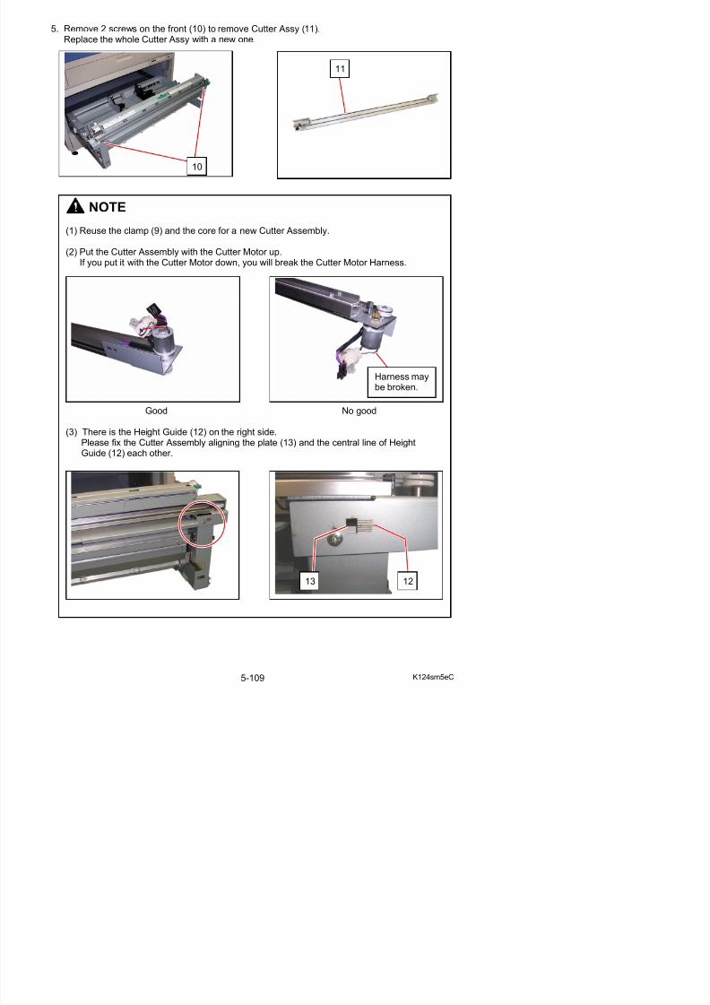
5/17/2018 KIP 7100 Service Manual Ver A_1 - slidepdf.com
http://slidepdf.com/reader/full/kip-7100-service-manual-ver-a1 229/674
Good No good
(3) There is the Height Guide (12) on the right side.Please fix the Cutter Assembly aligning the plate (13) and the central line of HeightGuide (12) each other.
Harness maybe broken.
5. 4. 2 Replacement of Clutches (CL3, CL4, CL5) of
Roll 1
1. Draw out the Roll Deck (1).
2. Remove 7 screws (2) to remove Cover 14 (3).
1
23

5/17/2018 KIP 7100 Service Manual Ver A_1 - slidepdf.com
http://slidepdf.com/reader/full/kip-7100-service-manual-ver-a1 230/674
NOTE
Make sure that the step part on the bottom side of Cover 14 (3) is inside the bottom frame.
3
step
2
3. Remove Retaining Ring-C (4) and disconnect the harness (5) to remove each Clutch (6: CL3)or Clutch (7: CL4).
Replace Clutch with a new one.
64
5
7
54
6, 7
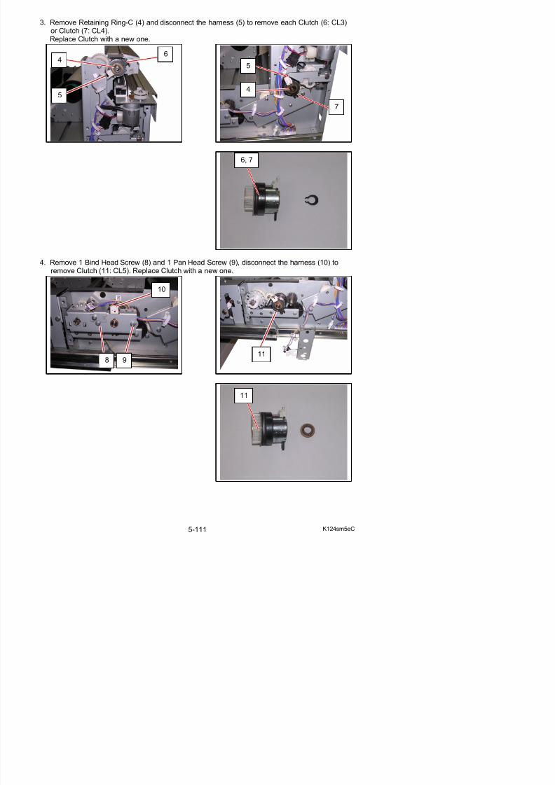
5/17/2018 KIP 7100 Service Manual Ver A_1 - slidepdf.com
http://slidepdf.com/reader/full/kip-7100-service-manual-ver-a1 231/674
4. Remove 1 Bind Head Screw (8) and 1 Pan Head Screw (9), disconnect the harness (10) toremove Clutch (11: CL5). Replace Clutch with a new one.
118 9
10
5. 4. 3 Replacement of Clutches (CL6, CL7) of Roll 2
1. Draw out the Roll Deck (1).
2. Remove 3 screws (2) to remove Cover 16 (3).
1
3
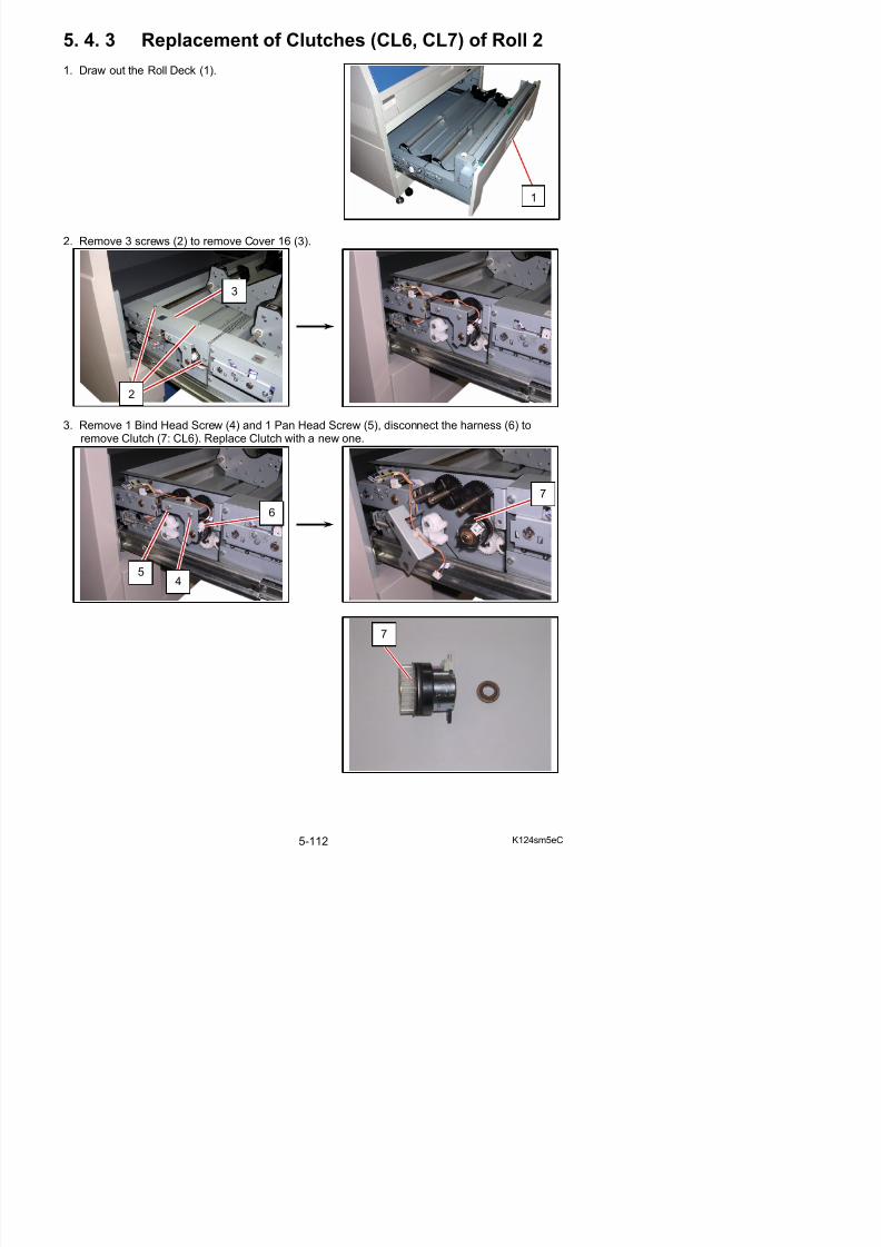
5/17/2018 KIP 7100 Service Manual Ver A_1 - slidepdf.com
http://slidepdf.com/reader/full/kip-7100-service-manual-ver-a1 232/674
3. Remove 1 Bind Head Screw (4) and 1 Pan Head Screw (5), disconnect the harness (6) toremove Clutch (7: CL6). Replace Clutch with a new one.
67
5
2
4
4. Remove 1 Bind Head Screw (8) and 1 Pan Head Screw (9), disconnect the harness (10) toremove Clutch (11: CL7). Replace Clutch with a new one.
8 9
10
11
11
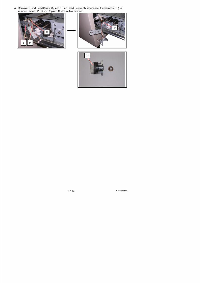
5/17/2018 KIP 7100 Service Manual Ver A_1 - slidepdf.com
http://slidepdf.com/reader/full/kip-7100-service-manual-ver-a1 233/674
5. 4. 4 Replacement of Timing Belt 633
1. Draw out the Roll Deck (1).
2. Remove 4 screws (2) to remove Cover 1 (3).
1
2
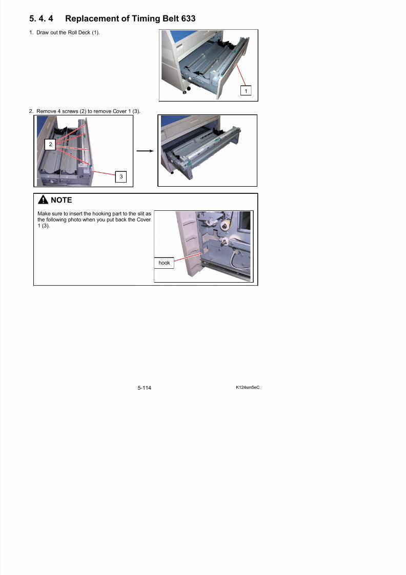
5/17/2018 KIP 7100 Service Manual Ver A_1 - slidepdf.com
http://slidepdf.com/reader/full/kip-7100-service-manual-ver-a1 234/674
NOTE
Make sure to insert the hooking part to the slit asthe following photo when you put back the Cover 1 (3).
3
hook
3. Remove 7 screws (4) to remove Cover 14 (5).
NOTE
Make sure that the step part on the bottom side of Cover 14 (5) is inside the bottom frame.
5
5
step
4
4

5/17/2018 KIP 7100 Service Manual Ver A_1 - slidepdf.com
http://slidepdf.com/reader/full/kip-7100-service-manual-ver-a1 235/674
4. Open the wire saddle (6) and disconnect the connector (7) to release the harness.Remove 1 screw (8) and remove the clamp (9) to release the core.
5
frame
7
6
9
5. Remove 2 screws on the front (10) to remove Cutter Assy (11).
6. Open 6 wire saddles (12) and release 3 connectors (13) to release the harness (14).
10
11
12
13
14
14
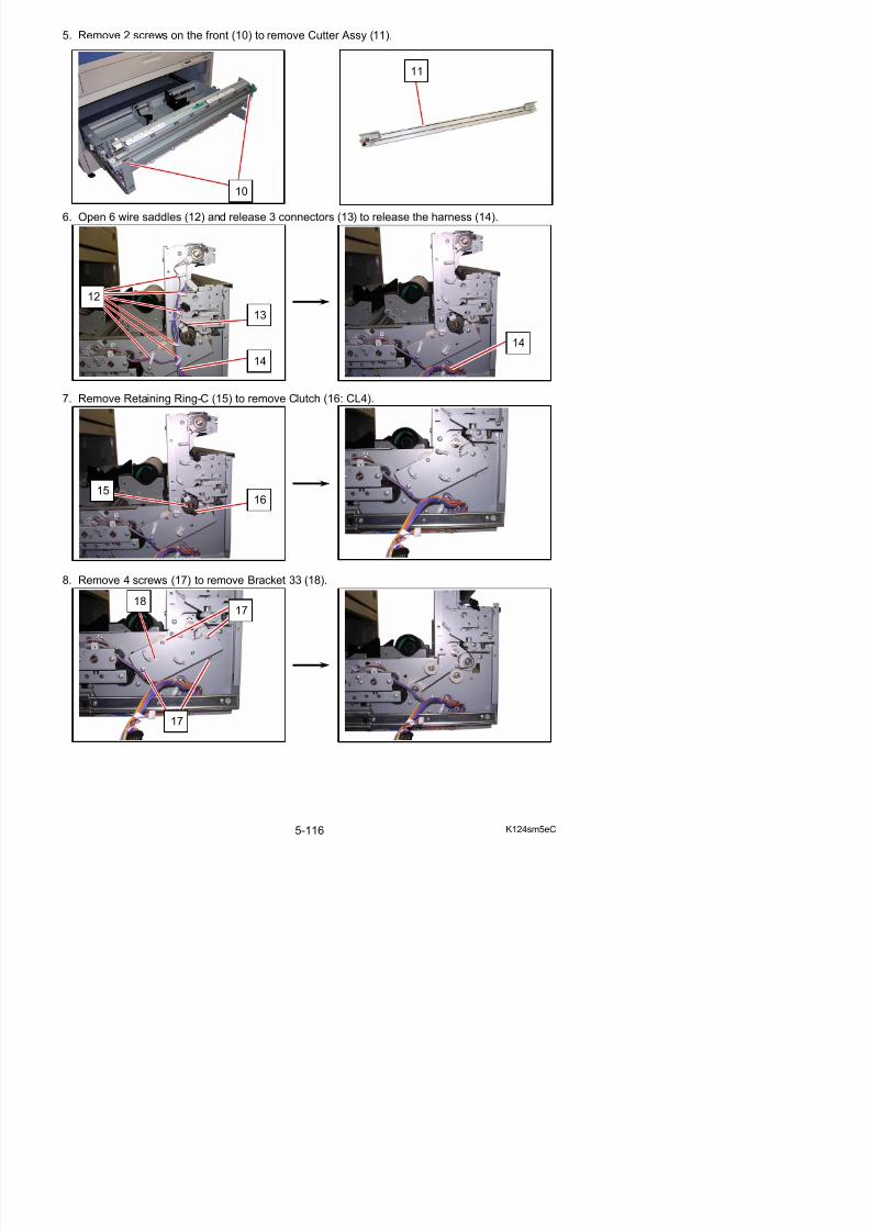
5/17/2018 KIP 7100 Service Manual Ver A_1 - slidepdf.com
http://slidepdf.com/reader/full/kip-7100-service-manual-ver-a1 236/674
7. Remove Retaining Ring-C (15) to remove Clutch (16: CL4).
8. Remove 4 screws (17) to remove Bracket 33 (18).
14
15 16
1817
9. Remove 3 screws (19) to remove Bracket 32 (20).
10. Loosen 1 screw (21) to release Pulley 3 (22). Push Pulley 3 (22) to the arrow direction and fixit. Replace Timing Belt 633 (23) with a new one.
20
21
22 22
23
19
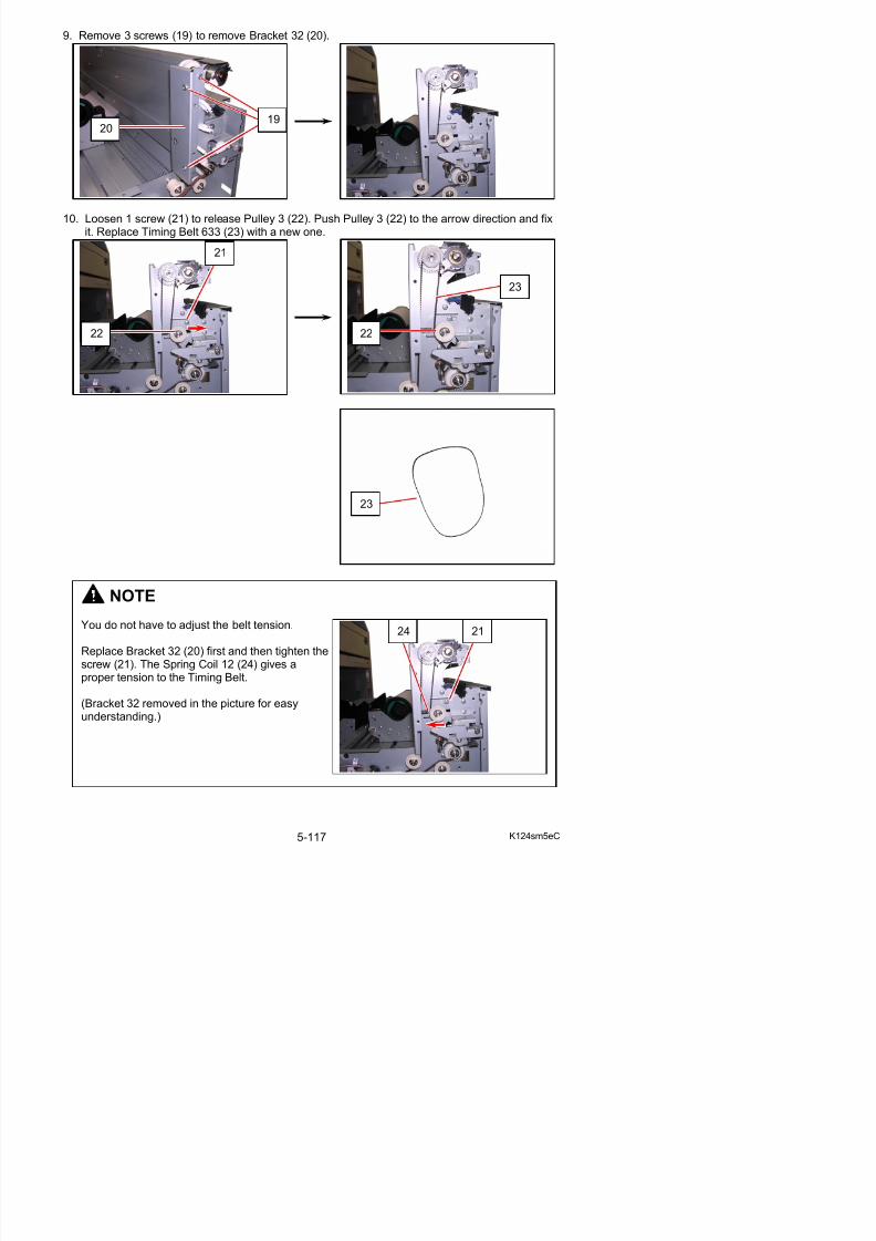
5/17/2018 KIP 7100 Service Manual Ver A_1 - slidepdf.com
http://slidepdf.com/reader/full/kip-7100-service-manual-ver-a1 237/674
NOTE
23
5. 4. 5 Replacement of Timing Belt 453
1. Draw out the Roll Deck (1).
2. Remove 7 screws (2) to remove Cover 22 (3).
3
2
2
1
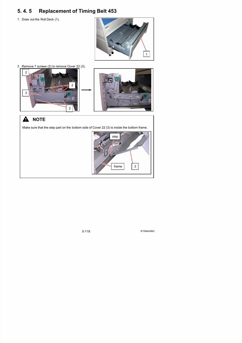
5/17/2018 KIP 7100 Service Manual Ver A_1 - slidepdf.com
http://slidepdf.com/reader/full/kip-7100-service-manual-ver-a1 238/674
2
NOTE
Make sure that the step part on the bottom side of Cover 22 (3) is inside the bottom frame.
step
frame 3
3. Loosen 1 screw (4) to release Pulley 3 (5). Move Pulley 3 (5) upward and fix it the screw (4) torelease Timing Belt 453.
4. Remove 1 Bind Head Screw (6) and 1 Pan Head Screw (7) to remove Bracket 12 (8).Replace Timing Belt 453 (9) with a new one.
4
5
8
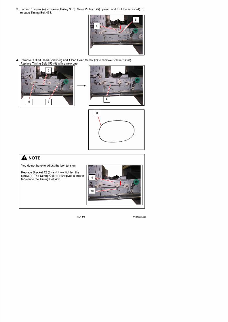
5/17/2018 KIP 7100 Service Manual Ver A_1 - slidepdf.com
http://slidepdf.com/reader/full/kip-7100-service-manual-ver-a1 239/674
NOTE
96
9
7
5. 4. 6 Replacement of Timing Belt 330
1. Draw out the Roll Deck (1).
2. Remove 7 screws (2) to remove Cover 22 (3).
1
3
2
2
2
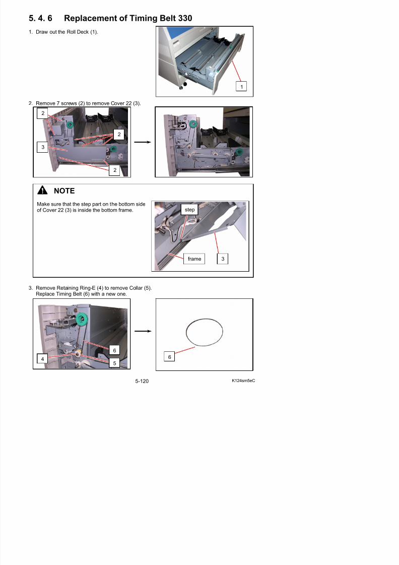
5/17/2018 KIP 7100 Service Manual Ver A_1 - slidepdf.com
http://slidepdf.com/reader/full/kip-7100-service-manual-ver-a1 240/674
2
NOTE
Make sure that the step part on the bottom sideof Cover 22 (3) is inside the bottom frame. step
frame 3
5. 4. 7 Replacement of Sensor (PH6, PH7, PH9, PH12)
1. Draw out the Roll Deck (1).Remove a roll media if mounted.
NOTE
(1) When reassembling, fit a boss or nails on the sensor into holes on the sensor bracket.
(2) When reassembling, fit positioning bosses on the frame (or the sensor bracket) into thecorresponding holes.
boss
nails
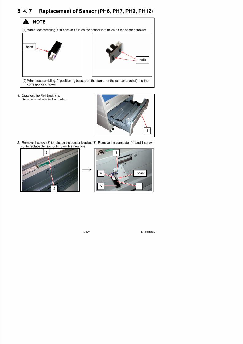
5/17/2018 KIP 7100 Service Manual Ver A_1 - slidepdf.com
http://slidepdf.com/reader/full/kip-7100-service-manual-ver-a1 241/674
2. Remove 1 screw (2) to release the sensor bracket (3). Remove the connector (4) and 1 screw(5) to replace Sensor (3: PH6) with a new one.
1
3 3
3. Remove 8 screws (7) to remove Plate (8).
4. Remove 1 screw (9) to release the sensor bracket (10). Remove the connector (11) to removethe bracket (10).
8
7
7
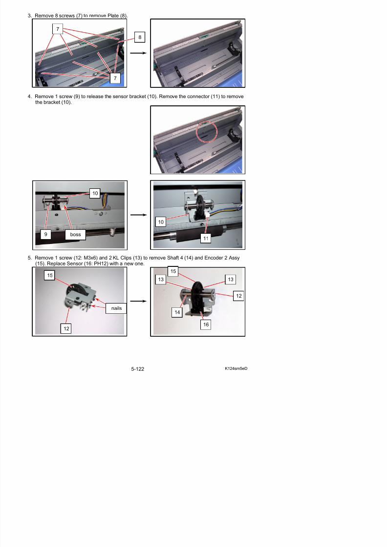
5/17/2018 KIP 7100 Service Manual Ver A_1 - slidepdf.com
http://slidepdf.com/reader/full/kip-7100-service-manual-ver-a1 242/674
5. Remove 1 screw (12: M3x6) and 2 KL Clips (13) to remove Shaft 4 (14) and Encoder 2 Assy(15). Replace Sensor (16: PH12) with a new one.
9
10
boss
10
11
15
6. Remove 1 screw (17) to release the sensor bracket (18). Remove the connector (19) and 1screw (20) to replace Sensor (21: PH7) with a new one.
18
17
boss boss
18
21
20 19
boss
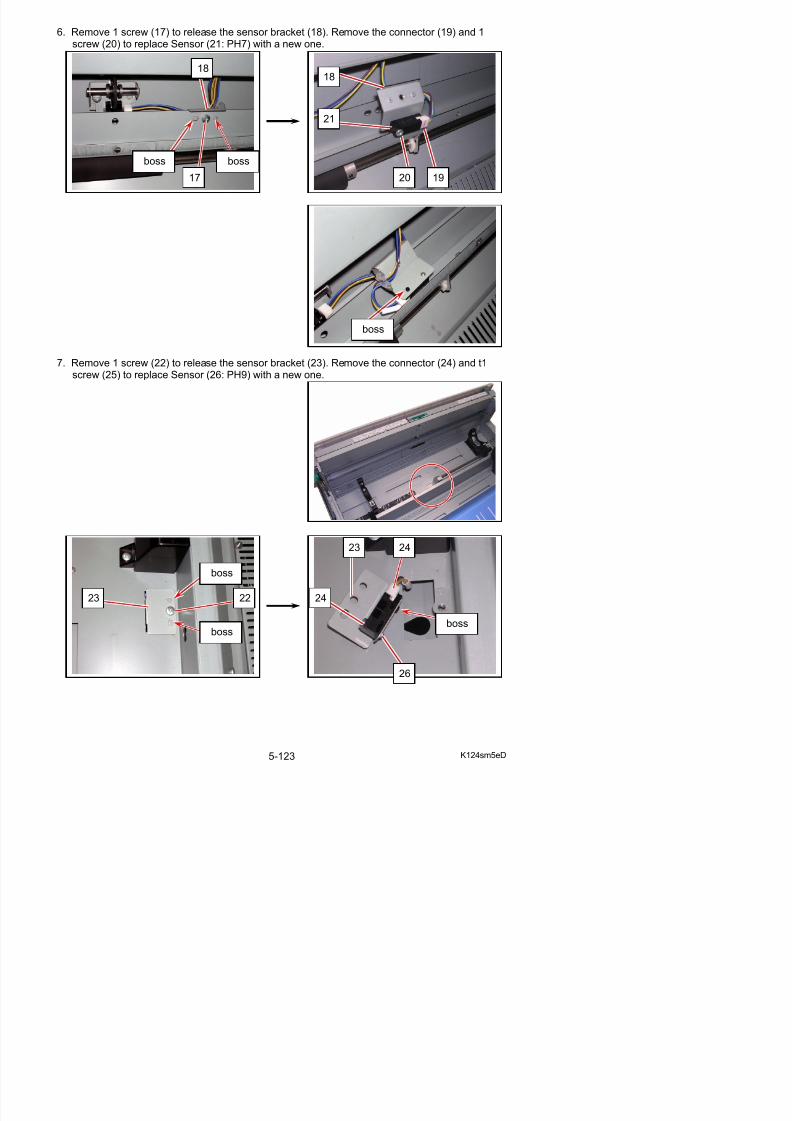
5/17/2018 KIP 7100 Service Manual Ver A_1 - slidepdf.com
http://slidepdf.com/reader/full/kip-7100-service-manual-ver-a1 243/674
7. Remove 1 screw (22) to release the sensor bracket (23). Remove the connector (24) and t1screw (25) to replace Sensor (26: PH9) with a new one.
23 24
5. 4. 8 Replacement of Sensor (PH8)
1. Draw out the Roll Deck (1).
2. Remove 7 screws (2) to remove Cover 14 (3).
1
23
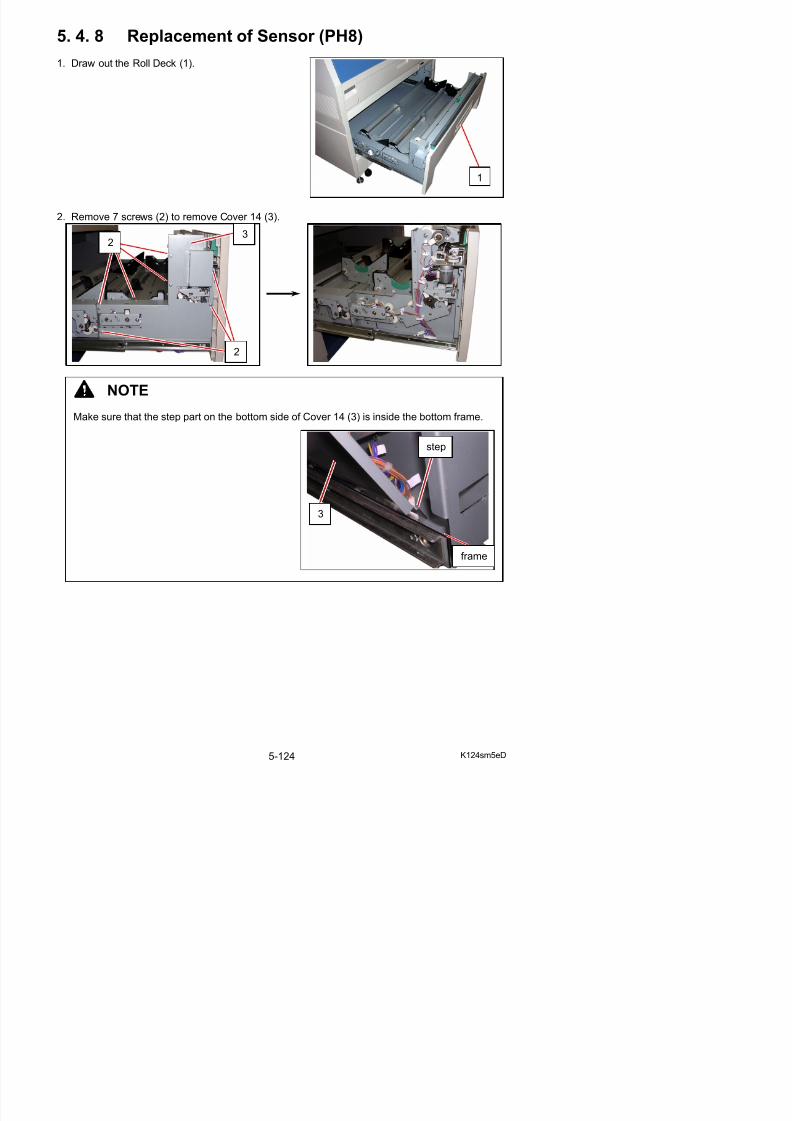
5/17/2018 KIP 7100 Service Manual Ver A_1 - slidepdf.com
http://slidepdf.com/reader/full/kip-7100-service-manual-ver-a1 244/674
NOTE
Make sure that the step part on the bottom side of Cover 14 (3) is inside the bottom frame.
3
step
frame
2
3. Remove 1 screw (4) to release the sensor bracket (5). Remove 1 connector (6) to replaceSensor (7: PH8) with a new one.
4
56
7
NOTE
(1) When reassembling, fit a boss or nails on the
sensor into holes on the sensor bracket.
nails
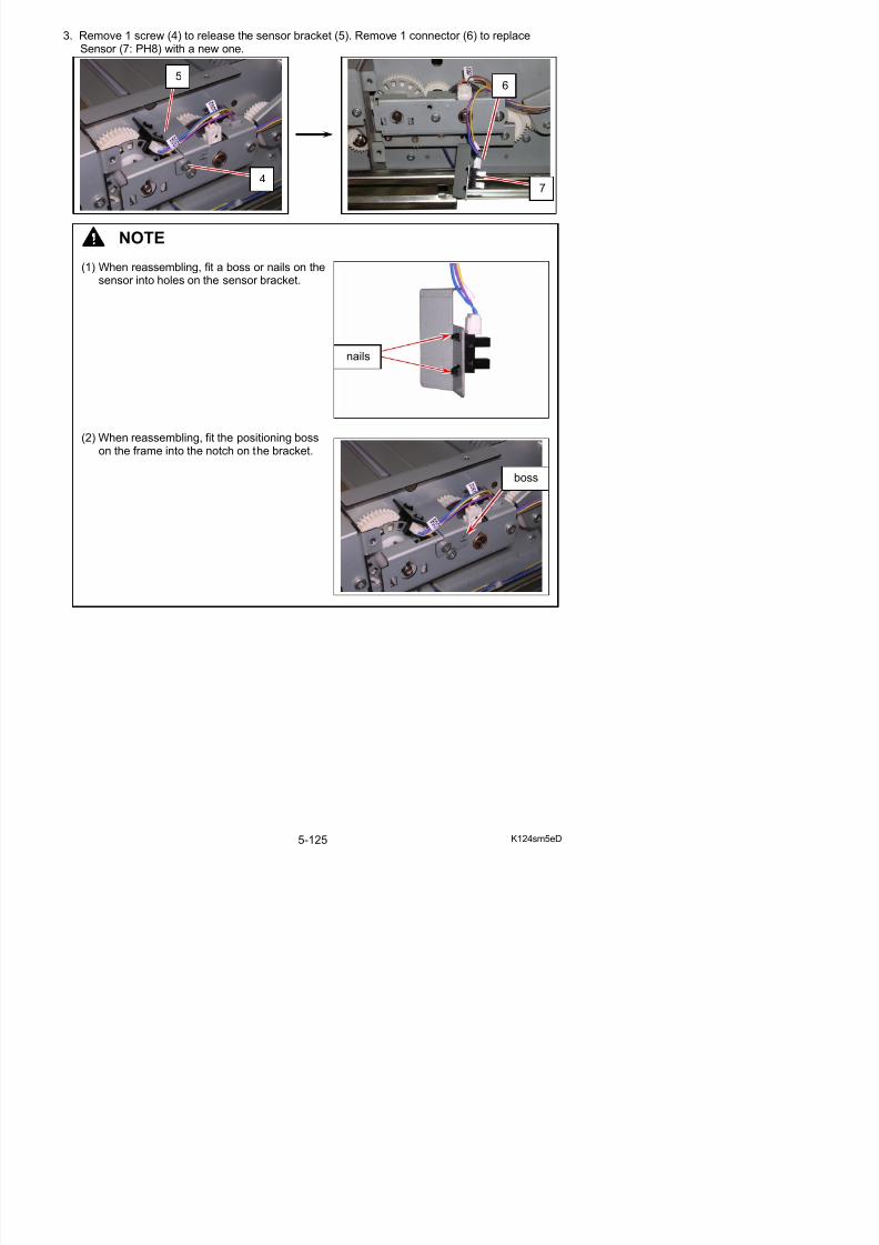
5/17/2018 KIP 7100 Service Manual Ver A_1 - slidepdf.com
http://slidepdf.com/reader/full/kip-7100-service-manual-ver-a1 245/674
(2) When reassembling, fit the positioning bosson the frame into the notch on the bracket.
boss
5. 4. 9 Replacement of Sensor (PH10)
1. Draw out the Roll Deck (1).
2. Remove 3 screws (2) to remove Cover (3).
1
3
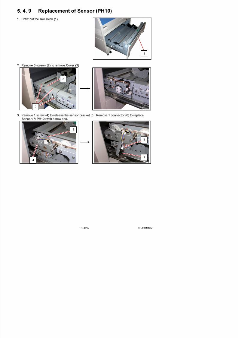
5/17/2018 KIP 7100 Service Manual Ver A_1 - slidepdf.com
http://slidepdf.com/reader/full/kip-7100-service-manual-ver-a1 246/674
3. Remove 1 screw (4) to release the sensor bracket (5). Remove 1 connector (6) to replaceSensor (7: PH10) with a new one.
4
5
2
6
7
NOTE
(1) When reassembling, fit a boss or nails on thesensor into holes on the sensor bracket.
(2) When reassembling, fit the positioning bosson the frame into the notch on the bracket.
boss
nails
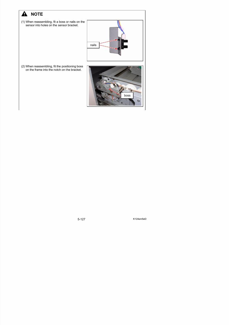
5/17/2018 KIP 7100 Service Manual Ver A_1 - slidepdf.com
http://slidepdf.com/reader/full/kip-7100-service-manual-ver-a1 247/674
5. 4. 10 Replacement of Dehumidify Heater (Roll 1)
1. Draw out the Roll Deck (1).Remove a roll media if mounted.
2. Move Slide Guide (2) toward the middle.
1
2
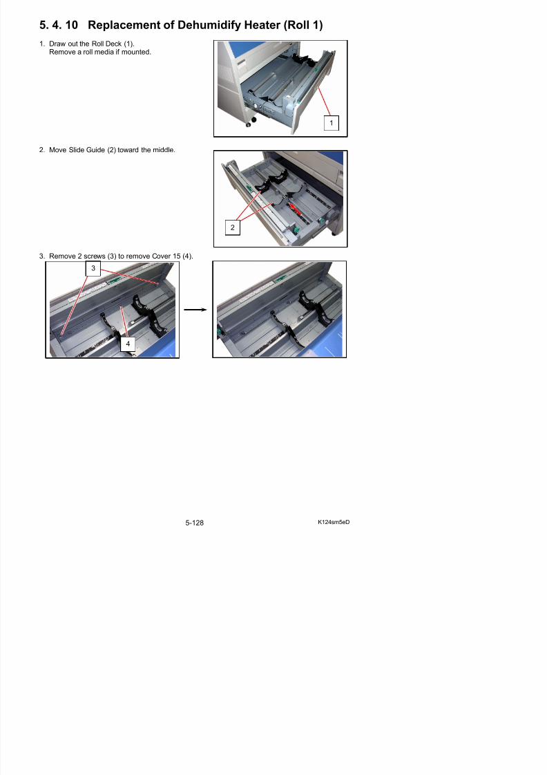
5/17/2018 KIP 7100 Service Manual Ver A_1 - slidepdf.com
http://slidepdf.com/reader/full/kip-7100-service-manual-ver-a1 248/674
3. Remove 2 screws (3) to remove Cover 15 (4).
4
3
4. Remove 7 screws (5) to remove Cover 22 (6).
6
5
5
5
NOTE
Make sure that the step part on the bottom side of Cover 22 (6) is inside the bottom frame.
step
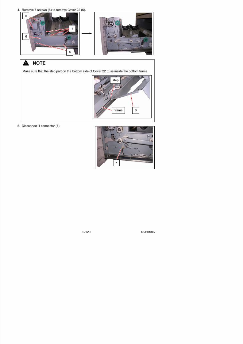
5/17/2018 KIP 7100 Service Manual Ver A_1 - slidepdf.com
http://slidepdf.com/reader/full/kip-7100-service-manual-ver-a1 249/674
5. Disconnect 1 connector (7).
7
frame 6
6. Remove 6 screws (8) to remove Roll 1 dehumidifier casing (9).
8
8
9
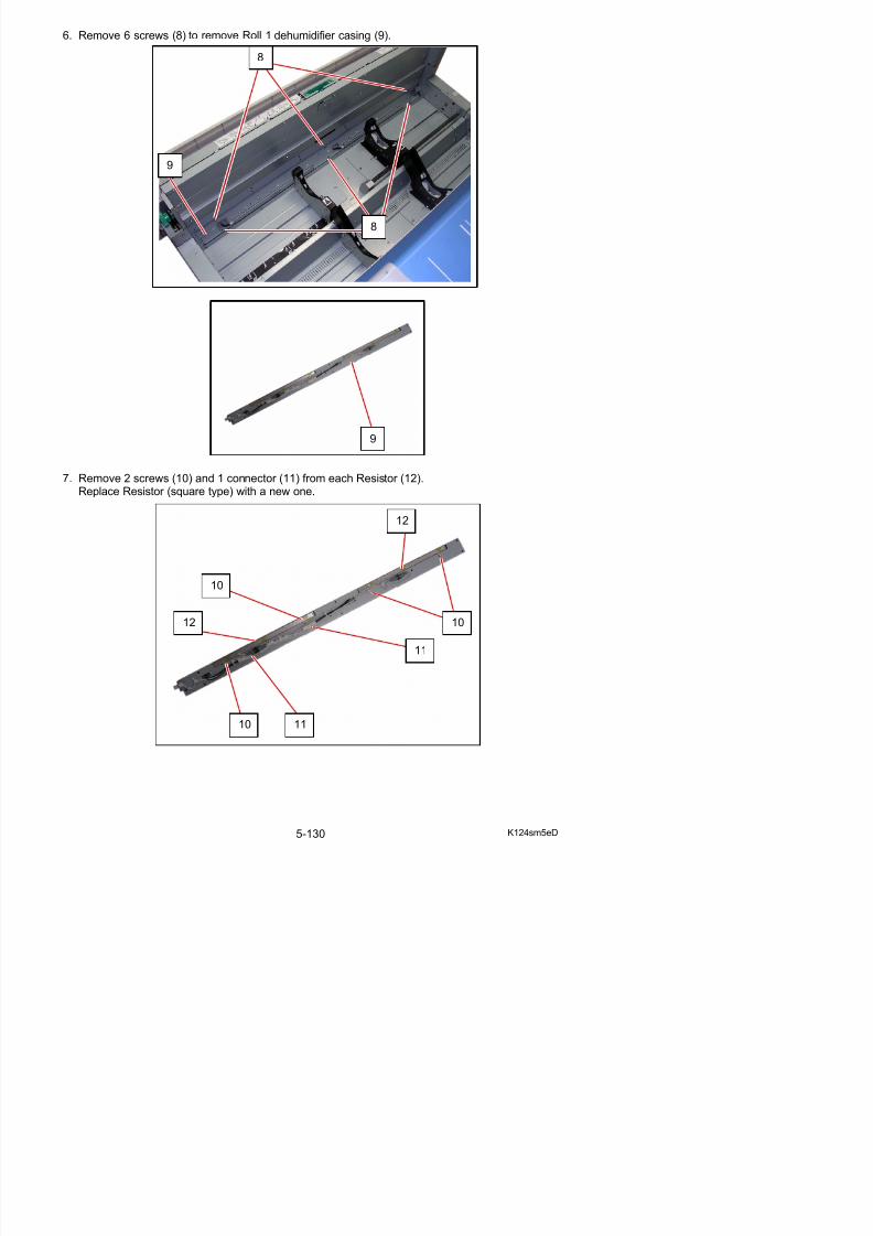
5/17/2018 KIP 7100 Service Manual Ver A_1 - slidepdf.com
http://slidepdf.com/reader/full/kip-7100-service-manual-ver-a1 250/674
7. Remove 2 screws (10) and 1 connector (11) from each Resistor (12).Replace Resistor (square type) with a new one.
9
12
10
5. 4. 11 Replacement of Dehumidify Heater (Roll 2)
1. Draw out the Roll Deck (1).Remove a roll media if mounted.
2. Move Slide Guide (2) toward the middle.
1
2
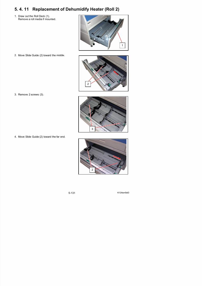
5/17/2018 KIP 7100 Service Manual Ver A_1 - slidepdf.com
http://slidepdf.com/reader/full/kip-7100-service-manual-ver-a1 251/674
3. Remove 2 screws (3).
4. Move Slide Guide (2) toward the far end.
3
5. Remove 2 screws (4) to remove Slide Guide 2 R Assy (5).
6. Remove 1 screw (6) to move Cover 7 (7).
5
6
7
7
4
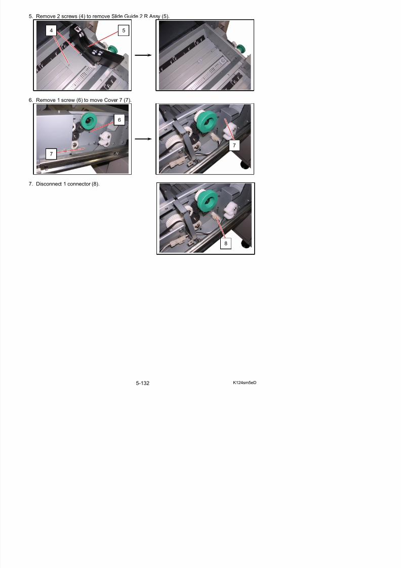
5/17/2018 KIP 7100 Service Manual Ver A_1 - slidepdf.com
http://slidepdf.com/reader/full/kip-7100-service-manual-ver-a1 252/674
7. Disconnect 1 connector (8).
8
8. Move Cover 4 (9) to the arrow direction to remove it.
9
9
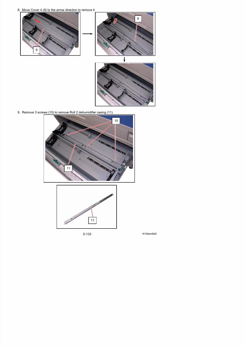
5/17/2018 KIP 7100 Service Manual Ver A_1 - slidepdf.com
http://slidepdf.com/reader/full/kip-7100-service-manual-ver-a1 253/674
9. Remove 3 screws (10) to remove Roll 2 dehumidifier casing (11).
10
11
10. Disconnect 1 connector (12). Remove 2 screws (13).Remove and replace Resistor (square type) (14) with a new one.
12
12
13
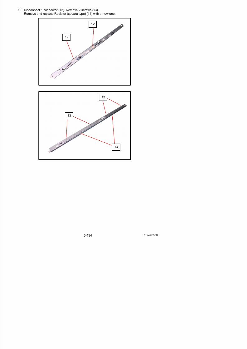
5/17/2018 KIP 7100 Service Manual Ver A_1 - slidepdf.com
http://slidepdf.com/reader/full/kip-7100-service-manual-ver-a1 254/674
13
14
5. 5 Photoconductive Drum
5. 5. 1 Replacement of the Photoconductive Drum
1. Pull up the Lever 2 (1) to open the Engine Unit.
2. Remove the screws (2) at both sides.
1
2
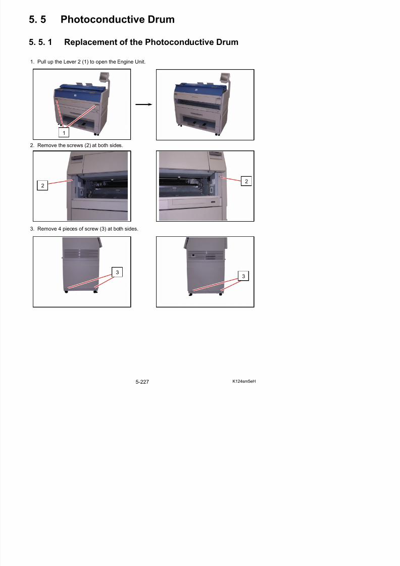
5/17/2018 KIP 7100 Service Manual Ver A_1 - slidepdf.com
http://slidepdf.com/reader/full/kip-7100-service-manual-ver-a1 255/674
3. Remove 4 pieces of screw (3) at both sides.
22
3
3
4. Remove 5 pieces of screw (4) at both sides.(2 pieces on the right and 3 pieces on the left)
5. Remove both Cover 2 (5) and Cover 3 (6).
4
4
56
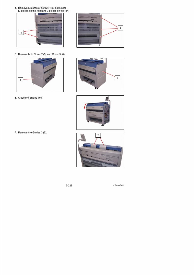
5/17/2018 KIP 7100 Service Manual Ver A_1 - slidepdf.com
http://slidepdf.com/reader/full/kip-7100-service-manual-ver-a1 256/674
6. Close the Engine Unit.
7. Remove the Guides 3 (7).
7
8. Remove 2 pieces of 4x6 screw (8) to remove the Cover 10 (9).
9. Disconnect the connector (10), and open the wiresaddles (11) to release the harness.
8
8
9
10
11
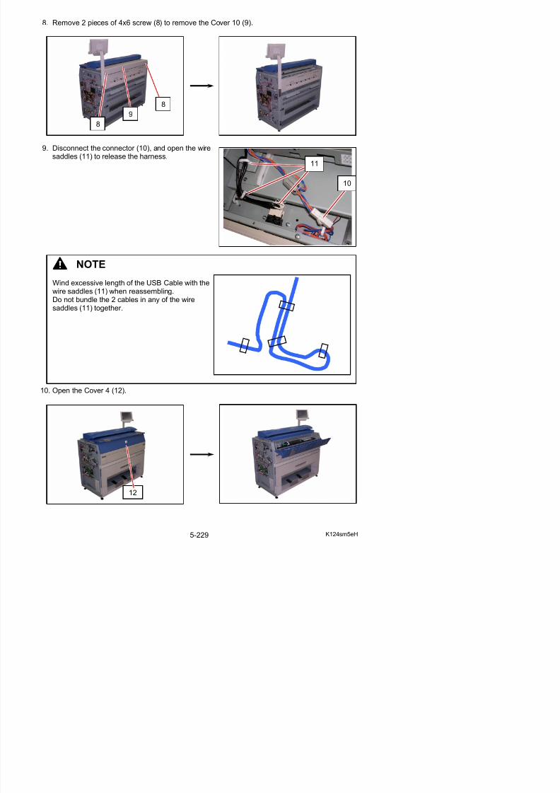
5/17/2018 KIP 7100 Service Manual Ver A_1 - slidepdf.com
http://slidepdf.com/reader/full/kip-7100-service-manual-ver-a1 257/674
10 Open the Cover 4 (12)
NOTE
Wind excessive length of the USB Cable with thewire saddles (11) when reassembling.Do not bundle the 2 cables in any of the wiresaddles (11) together.
11. Remove 4 pieces of 4x6 screw (13) and 2 pieces of washer screw (14).
12. Slide the Scanner Unit (15) fully backward.
13 Th 2 i f St (16) t b th id hi h l k th LED H d F
14
13
14
13
15

5/17/2018 KIP 7100 Service Manual Ver A_1 - slidepdf.com
http://slidepdf.com/reader/full/kip-7100-service-manual-ver-a1 258/674
13. There are 2 pieces of Stopper (16) at both sides, which lock the LED Head Frame.Loosen the screw (17) and then slide the Stoppers (16) outside to unlock the LED Head Frame.
16
14. Open the LED Head Frame (18).
NOTE
The Stopper 2 (19) comes out automaticallyto prevent the LED Head Frame from falling down.
19
18

5/17/2018 KIP 7100 Service Manual Ver A_1 - slidepdf.com
http://slidepdf.com/reader/full/kip-7100-service-manual-ver-a1 259/674
Press the Stopper 2 as the right photo if youwill close the LED Head Frame.
16. Remove 1 tooth washer screw (21: M4x8), and remove Plate 2 (22) and Pulley Gear (23).
NOTE
21
23
22
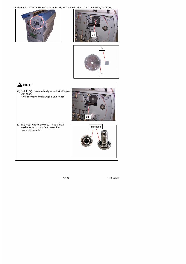
5/17/2018 KIP 7100 Service Manual Ver A_1 - slidepdf.com
http://slidepdf.com/reader/full/kip-7100-service-manual-ver-a1 260/674
NOTE
(1) Belt 4 (24) is automatically loosed with EngineUnit open.It will be strained with Engine Unit closed.
(2) The tooth washer screw (21) has a toothwasher of which burr face meets the
composition surface
24
burr face
17. Remove the Collar (25) from the left Drum Shaft.
18. There are 2 pieces of screw (26) on the left which fix the Block (27).Loosen these screws (26) and rotate the Block (27) as the arrow marks.
NOTE
The new (spare) Drum Assembly does not include the Collar (25).So please reuse it.
25
26
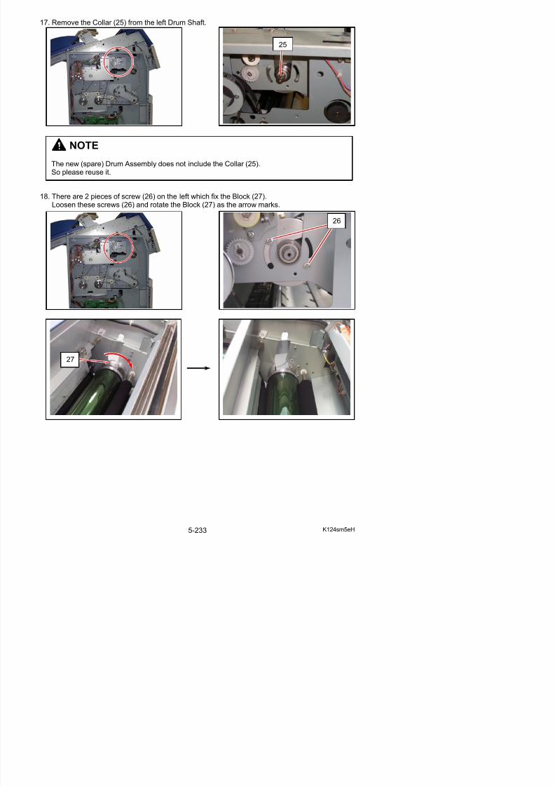
5/17/2018 KIP 7100 Service Manual Ver A_1 - slidepdf.com
http://slidepdf.com/reader/full/kip-7100-service-manual-ver-a1 261/674
27
19. Similarly loosen 2 pieces of screw (28) on the right and rotate the Block 2 (29) as thearrow marks.
28
29
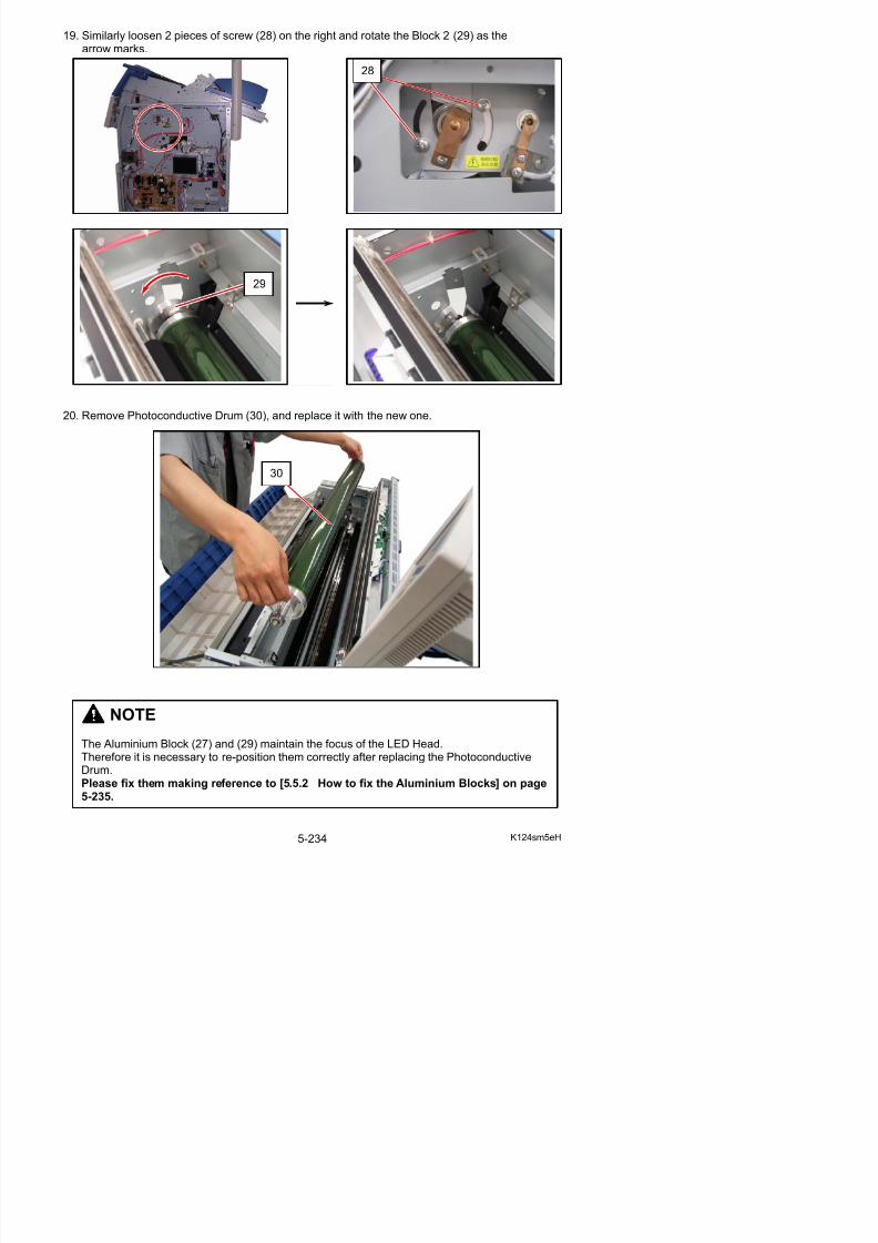
5/17/2018 KIP 7100 Service Manual Ver A_1 - slidepdf.com
http://slidepdf.com/reader/full/kip-7100-service-manual-ver-a1 262/674
20. Remove Photoconductive Drum (30), and replace it with the new one.
30
5. 5. 2 How to fix the Aluminium Blocks
There are Aluminium Blocks at both sides of the Drum Shaft. As they maintain the focus of LED Head, it is necessary to re-position them correctly after replacing the Photoconductive Drum.
Aluminium Blocks
Print out the Test Pattern No.3 to check if the Aluminium Blocks are fixed at the correct position.The density of halftone is uniform as the following left image if the Aluminium Blocks are fixed atthe correct positions (focus is good).But the density of halftone is different among image blocks as the following right image if blocksare not fixed correctly (focus is not good).
Good No good(G l k if ) (G l k t if )
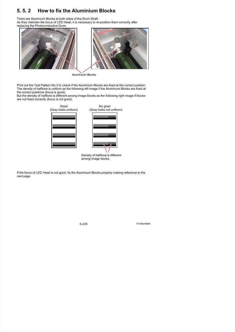
5/17/2018 KIP 7100 Service Manual Ver A_1 - slidepdf.com
http://slidepdf.com/reader/full/kip-7100-service-manual-ver-a1 263/674
(Gray looks uniform) (Gray looks not uniform)
Density of halftone is differentamong image blocks.
There are Aluminium Blocks (A) (B) at both sides, and each of them is fixed with 2 screws (C) (D).
Left side Right side
B
D
C
A
C
D
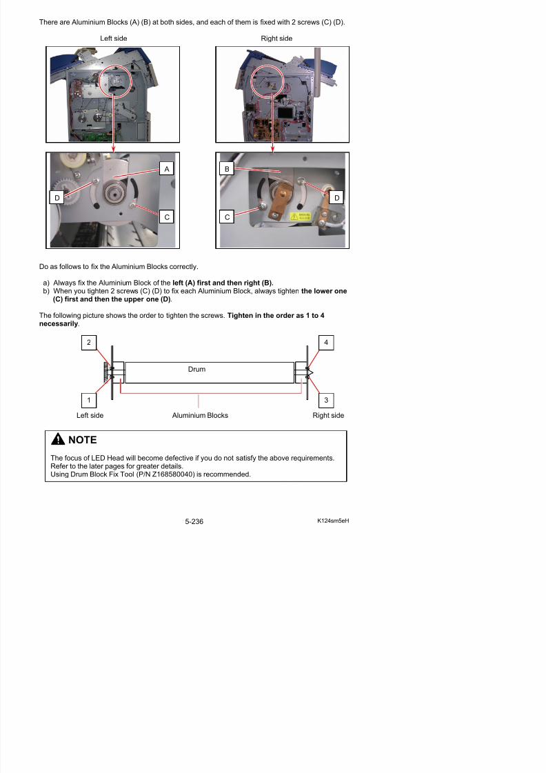
5/17/2018 KIP 7100 Service Manual Ver A_1 - slidepdf.com
http://slidepdf.com/reader/full/kip-7100-service-manual-ver-a1 264/674
Do as follows to fix the Aluminium Blocks correctly.
a) Always fix the Aluminium Block of the left (A) first and then right (B). b) When you tighten 2 screws (C) (D) to fix each Aluminium Block, always tighten the lower one
(C) first and then the upper one (D).
The following picture shows the order to tighten the screws. Tighten in the order as 1 to 4necessarily.
Drum
2 4
5. 5. 2. 1 Fixing Block with Drum Block Fix Tool
1. Rotate the left Block (1) fully to the arrow direction (A: to front) and also press it to the arrowdirection (B: to outside). This will remove any gap between Block (1) and the side frame of themachine.With holding Block (1), tighten the screws (2) (3) just enough turn to fix Block (1) temporarily.
A AB 1
3
2
no gap
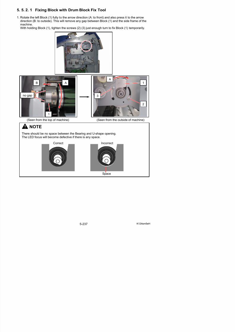
5/17/2018 KIP 7100 Service Manual Ver A_1 - slidepdf.com
http://slidepdf.com/reader/full/kip-7100-service-manual-ver-a1 265/674
(Seen from the top of machine) (Seen from the outside of machine)
NOTE
There should be no space between the Bearing and U-shape opening.The LED focus will become defective if there is any space.
Correct Incorrect
1
2. Loosen the screws (2) (3) in a (approximately)quarter turn to release Block (1). Check that noexcessive backlash to sideways appears.
3. Similarly to step 1, rotate the right Block (4) fully to the arrow direction (C: to front) and alsopress it to the arrow direction (D: to outside). This will remove any gap between Block (4) andthe side frame of the machine.With holding Block (4), tighten the screws (5) (6) just enough turn to fix Block (6) temporarily.
3
2
1
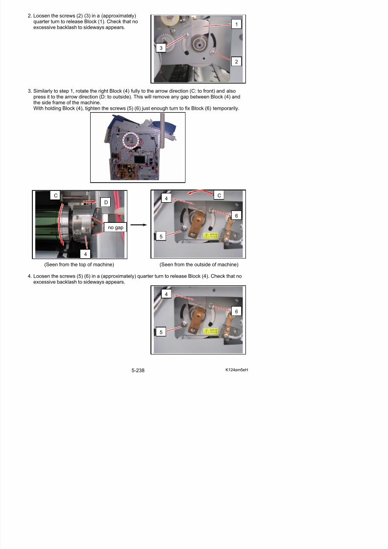
5/17/2018 KIP 7100 Service Manual Ver A_1 - slidepdf.com
http://slidepdf.com/reader/full/kip-7100-service-manual-ver-a1 266/674
(Seen from the top of machine) (Seen from the outside of machine)
C
D
C4
5
6
4
no gap
5. On the left side, hook Drum Block Fix Tool (7) on between the pin (8) on the frame and the U-shape opening (9) of Block (1).Hook the rear hook (10) the rim of the U-shape opening (9) and the front hook (11) in the groove
of the pin (8).
7
8
9
11 10
7
9
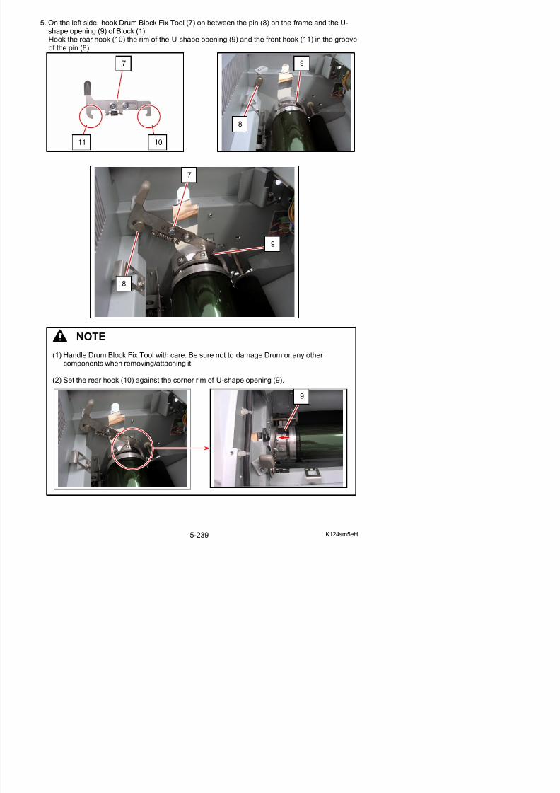
5/17/2018 KIP 7100 Service Manual Ver A_1 - slidepdf.com
http://slidepdf.com/reader/full/kip-7100-service-manual-ver-a1 267/674
8
NOTE
(1) Handle Drum Block Fix Tool with care. Be sure not to damage Drum or any other components when removing/attaching it.
(2) Set the rear hook (10) against the corner rim of U-shape opening (9).
6. With pressing Block (1) down (E), slightly turn Block to the arrow direction (F) and release it tolocate Block correctly by restoring spring.
7. Tighten the lower screw (2) and then the upper screw (3) to secure Block (1).
1
3
E
F
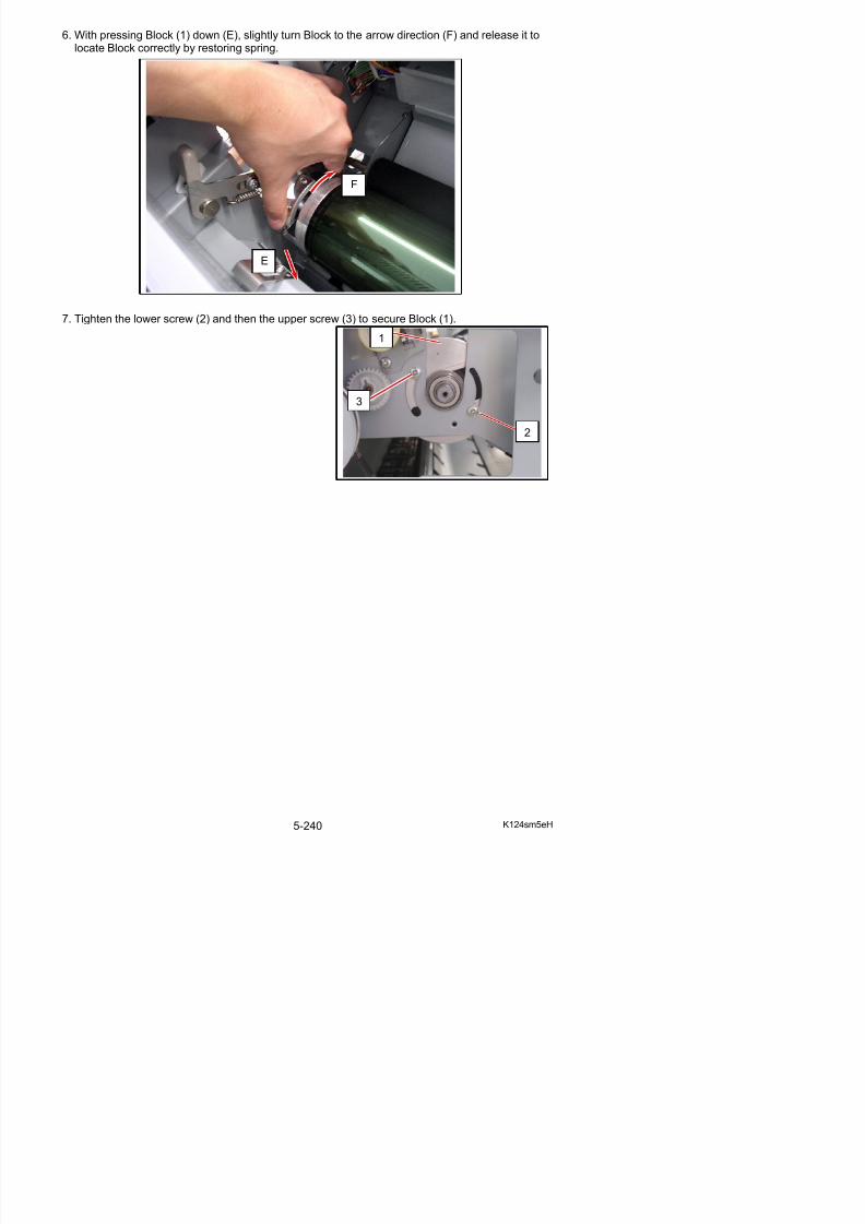
5/17/2018 KIP 7100 Service Manual Ver A_1 - slidepdf.com
http://slidepdf.com/reader/full/kip-7100-service-manual-ver-a1 268/674
2
8. Similarly to step 5, on the right side, hook Drum Block Fix Tool (7) on between the pin (12) onthe frame and the U-shape opening (13) of Block (4).
NOTE
(1) Handle Drum Block Fix Tool with care. Be sure not to damage Drum or any other components when removing/attaching it.
(2) Set the rear hook (10) against the corner rim of U-shape opening (13).
7
13
12

5/17/2018 KIP 7100 Service Manual Ver A_1 - slidepdf.com
http://slidepdf.com/reader/full/kip-7100-service-manual-ver-a1 269/674
(3) Set the front hook (11) against the step on the pin (12).
13
9. Similarly to step 6, with pressing Block (4) down (G), slightly turn Block to the arrow direction (H)and release it to locate Block correctly by restoring spring.
10. Tighten the lower screw (5) and then the upper screw (6) to secure Block (4).
G
H
4
6
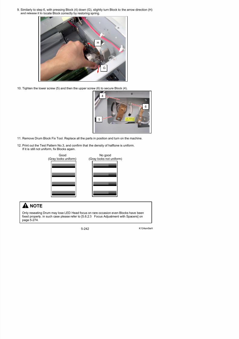
5/17/2018 KIP 7100 Service Manual Ver A_1 - slidepdf.com
http://slidepdf.com/reader/full/kip-7100-service-manual-ver-a1 270/674
11. Remove Drum Block Fix Tool. Replace all the parts in position and turn on the machine.
12. Print out the Test Pattern No.3, and confirm that the density of halftone is uniform.If it is still not uniform, fix Blocks again.
Good No good(Gray looks uniform) (Gray looks not uniform)
5
5. 5. 2. 2 Fixing Block by hand (w/o Drum Block Fix Tool)
1. Rotate the left Block (1) fully to the arrow direction (A: to front) and also press it to the arrowdirection (B: to outside). This will remove any gap between Block (1) and the side frame of themachine.With holding Block (1), tighten the screws (2) (3) just enough turn to fix Block (1) temporarily.
A AB 1
3
2
no gap
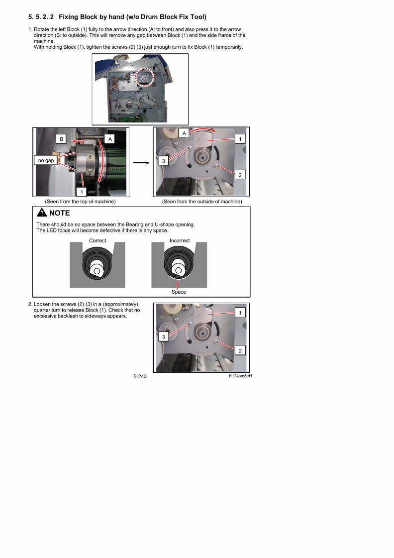
5/17/2018 KIP 7100 Service Manual Ver A_1 - slidepdf.com
http://slidepdf.com/reader/full/kip-7100-service-manual-ver-a1 271/674
(Seen from the top of machine) (Seen from the outside of machine)
NOTE
There should be no space between the Bearing and U-shape opening.The LED focus will become defective if there is any space.
Correct Incorrect
1
3. Put your finger inside the U-shape opening (4) of Block (1). Put the other finger on the pin (5) of the frame.Push the fingers toward each other (C: inside). Note that the entire Block (1) is shifted towards
the pin (5) by the finger at the U-shape opening (4).While pushing and holding, tighten the lower screw (2) and then the upper screw (3) to secureBlock (1).
1
5
4
5
4
C
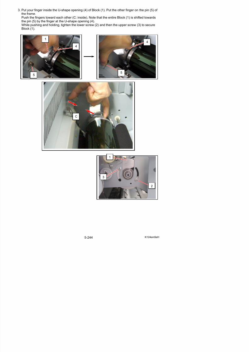
5/17/2018 KIP 7100 Service Manual Ver A_1 - slidepdf.com
http://slidepdf.com/reader/full/kip-7100-service-manual-ver-a1 272/674
1
4. Similarly to step 1, rotate the right Block (6) fully to the arrow direction (D: to front) and alsopress it to the arrow direction (E: to outside). This will remove any gap between Block (6) andthe side frame of the machine.
With holding Block (6), tighten the screws (7) (8) just enough turn to fix Block (6) temporarily.
D
E
D6
7
8
6
no gap
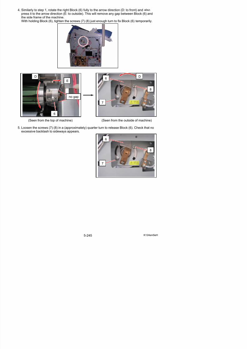
5/17/2018 KIP 7100 Service Manual Ver A_1 - slidepdf.com
http://slidepdf.com/reader/full/kip-7100-service-manual-ver-a1 273/674
(Seen from the top of machine) (Seen from the outside of machine)
5. Loosen the screws (7) (8) in a (approximately) quarter turn to release Block (6). Check that noexcessive backlash to sideways appears.
6
7
8
6. Similarly to step 3, put your finger inside the U-shape opening (9) of Block (6) and put the other finger on the pin (10) of the frame.Push the fingers toward each other (F: inside). Note that the entire Block (6) is shifted towards
the pin (10) by the finger at the U-shape opening (9).While pushing and holding, tighten the lower screw (7) and then the upper screw (8) to secureBlock (6).
9
6
10
9
10
F
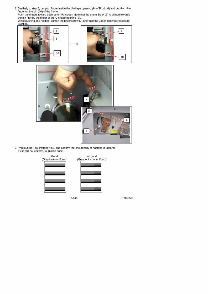
5/17/2018 KIP 7100 Service Manual Ver A_1 - slidepdf.com
http://slidepdf.com/reader/full/kip-7100-service-manual-ver-a1 274/674
F
6
7
8
5. 5. 3 Cleaning of Photoconductive Drum
1. Remove the Photoconductive Drum from themachine making reference to [5. 5. 1 Replacementof the Photoconductive Drum] on the page 5-227.
2. Wipe the surface of Photoconductive Drum with a dry cloth.
3. If the toner strongly sticks on the surface and it is impossible to remove it, wipe with the clothimpregnated with the alcohol.
4. After using the alcohol, wipe all surface of Drum with a cloth impregnated with water so thatthere should be no unevenness of cleaning.
5. Wipe all surface of Drum with a dry cloth, and dry the Drum leaving in a dark place for about10 minutes.
6. Put back the Drum to the machine.
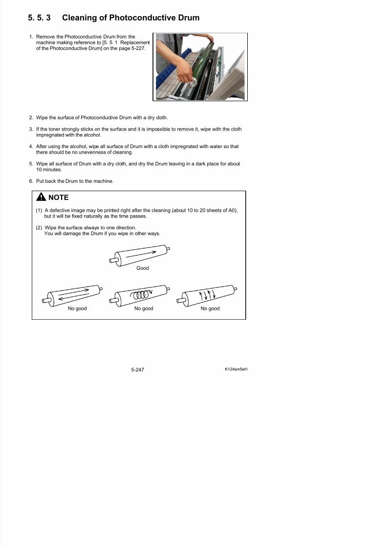
5/17/2018 KIP 7100 Service Manual Ver A_1 - slidepdf.com
http://slidepdf.com/reader/full/kip-7100-service-manual-ver-a1 275/674
NOTE
(1) A defective image may be printed right after the cleaning (about 10 to 20 sheets of A0),but it will be fixed naturally as the time passes.
(2) Wipe the surface always to one direction.You will damage the Drum if you wipe in other ways.
Good
5. 5. 4 Replacement of Belt 4
1. Pull up the Lever 2 (1) to open the Engine Unit.
2. Remove 6 screws (2) to remove Cover 2 (3).
2
1
2
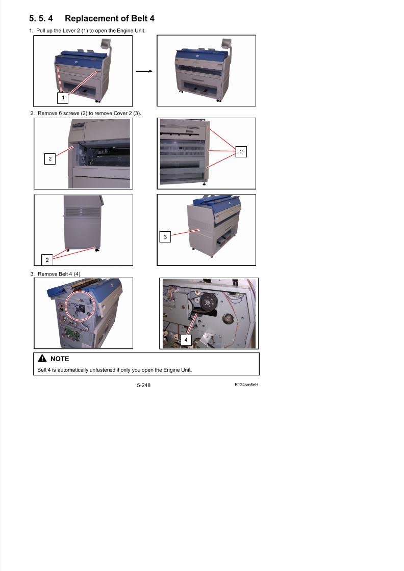
5/17/2018 KIP 7100 Service Manual Ver A_1 - slidepdf.com
http://slidepdf.com/reader/full/kip-7100-service-manual-ver-a1 276/674
3. Remove Belt 4 (4).
3
2
5. 6 LED Head
5. 6. 1 Replacement of the LED Head Unit
1. Pull up the Lever 2 (1) to open the Engine Unit.
2. Remove the screws (2) at both sides.
1
2 2

5/17/2018 KIP 7100 Service Manual Ver A_1 - slidepdf.com
http://slidepdf.com/reader/full/kip-7100-service-manual-ver-a1 277/674
3. Remove 4 pieces of screw (3) at both sides.
33
4. Remove 5 pieces of screw (4) at both sides.(2 pieces on the right and 3 pieces on the left)
5. Remove both Cover 2 (5) and Cover 3 (6).
4
4
56

5/17/2018 KIP 7100 Service Manual Ver A_1 - slidepdf.com
http://slidepdf.com/reader/full/kip-7100-service-manual-ver-a1 278/674
6. Close the Engine Unit.
7. Remove the Guides 3 (7).
8. Remove 2 pieces of 4x6 screw (8) to remove the Cover 10 (9).
9. Disconnect the connector (10), and open the wiresaddles (11) to release the harness.
8
8
9
10
11
NOTE

5/17/2018 KIP 7100 Service Manual Ver A_1 - slidepdf.com
http://slidepdf.com/reader/full/kip-7100-service-manual-ver-a1 279/674
Wind excessive length of the USB Cable with thewire saddles (11) when reassembling.Do not bundle the 2 cables in any of the wiresaddles (11) together.
11. Remove 4 pieces of 4x6 screw (13) and 2 pieces of washer screw (14).
12. Slide the Scanner Unit (15) fully backward.
13. There are 2 pieces of Stopper (16) at both sides, which lock the LED Head Frame.Loosen the screw (17) and then slide the Stoppers (16) outside to unlock the LED Head Frame.
14
13
14
13
15
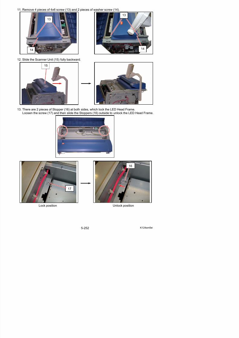
5/17/2018 KIP 7100 Service Manual Ver A_1 - slidepdf.com
http://slidepdf.com/reader/full/kip-7100-service-manual-ver-a1 280/674
16
14. Open the LED Head Frame (18).
NOTE
The Stopper 2 (19) comes out automaticallyto prevent the LED Head Frame from falling down.
Press the Stopper 2 as the right photo if you
19
18
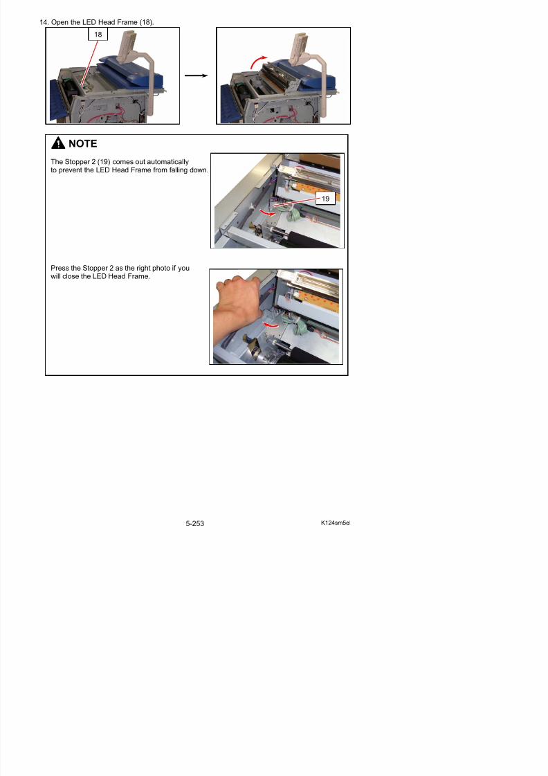
5/17/2018 KIP 7100 Service Manual Ver A_1 - slidepdf.com
http://slidepdf.com/reader/full/kip-7100-service-manual-ver-a1 281/674
pp g p ywill close the LED Head Frame.
15. Remove the 4x6 screw (20) to remove the Fixing Bracket (21) on the right.
16. Loosen 2 pieces of 4x10 screw (22) to make the Plate (23) enough movable.
NOTE
You do not have to put back the Fixing Bracket (21) at the time of reassembly, because it isa part required only before the delivery of machine.
20 21
2223

5/17/2018 KIP 7100 Service Manual Ver A_1 - slidepdf.com
http://slidepdf.com/reader/full/kip-7100-service-manual-ver-a1 282/674
22
NOTE
Be careful not to damage/deform/stretch Leaf Spring 2 (24).Doing so may damage LED Head Unit.
17. Move the Plate (23) to the right to release the pin (25) of Corona Block.Then remove the Image Corona Unit (26).
25
23
26
26
26
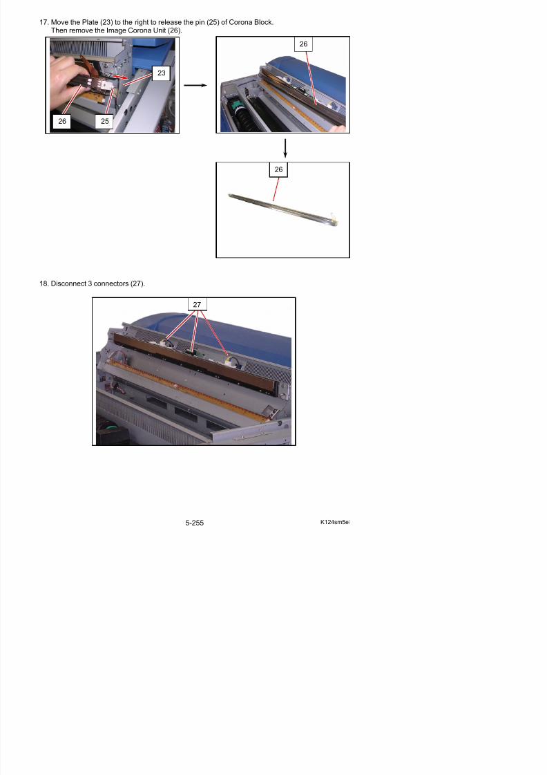
5/17/2018 KIP 7100 Service Manual Ver A_1 - slidepdf.com
http://slidepdf.com/reader/full/kip-7100-service-manual-ver-a1 283/674
18. Disconnect 3 connectors (27).
27
19. Remove the screw (28) to remove the Bracket 2 (29).
20. Move the right end of LED Head (30) a little to the front side, and then slide the whole unitto the right.Replace LED Head Unit (30) with the new one.
30
29
28
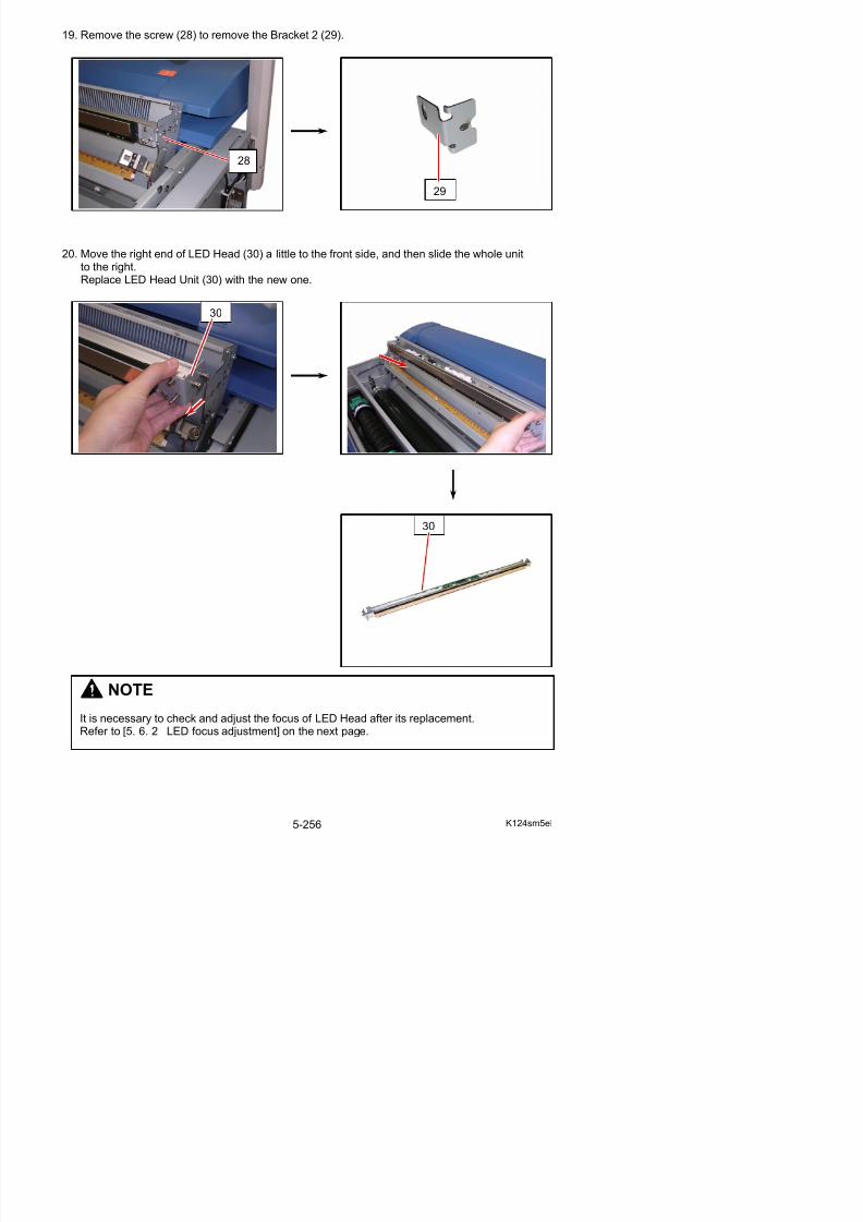
5/17/2018 KIP 7100 Service Manual Ver A_1 - slidepdf.com
http://slidepdf.com/reader/full/kip-7100-service-manual-ver-a1 284/674
30
5. 6. 2 LED focus adjustment
Please adjust the focus of LED Head after the replacement of LED Head. Also adjust it if you have lost the correct focus by some reason.
Adjust the focus by the following 3 steps.(1) Check of the Test Pattern Image(2) Positioning of the Aluminium Blocks(3) Focus Adjustment with Spacers
5. 6. 2. 1 Check of the Test Pattern Image
Print out the Test Pattern No.3 in the Service Mode, and check its halftone image.
If the density of halftone is uniform as the following left image, you do not have to make anythingbecause the focus is correctly adjusted.
But it is different among image blocks as the following right image, it is necessary to adjust thefocus.Go to [5. 6. 2. 2 Positioning of the Aluminium Blocks] on the next page in this case.
Good No good(Adjustment is required.)
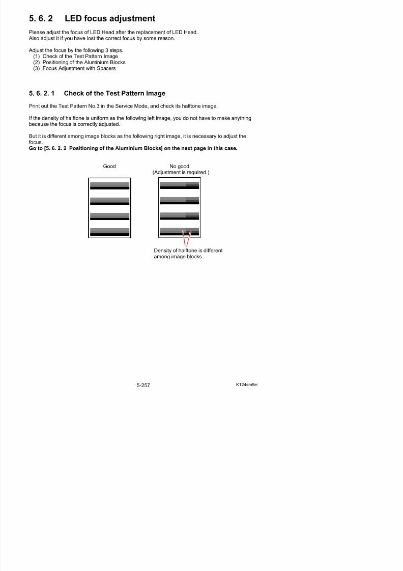
5/17/2018 KIP 7100 Service Manual Ver A_1 - slidepdf.com
http://slidepdf.com/reader/full/kip-7100-service-manual-ver-a1 285/674
Density of halftone is differentamong image blocks.
5. 6. 2. 2 Positioning of the Aluminium Blocks
There are Aluminium Blocks at both sides of the Drum, which adjust the distance between LED
Head and Drum. If the LED focus is not correct, at first it is necessary to place them at the correctpositions in the following way.
NOTE
Using Drum Block Fix Tool is recommended.
Blocks can be fix properly without Drum Block FixTool, in such case please follow the later step 23for further information.
Drum Block Fix ToolZ168580040
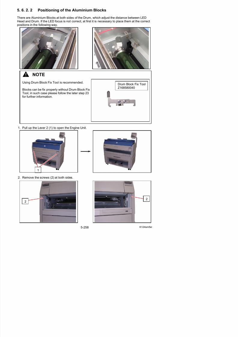
5/17/2018 KIP 7100 Service Manual Ver A_1 - slidepdf.com
http://slidepdf.com/reader/full/kip-7100-service-manual-ver-a1 286/674
1. Pull up the Lever 2 (1) to open the Engine Unit.
3. Remove 4 pieces of screw (3) at both sides.
4. Remove 5 pieces of screw (4) at both sides.(2 pieces on the right and 3 pieces on the left)
5. Remove both Cover 2 (5) and Cover 3 (6).
33
4
4
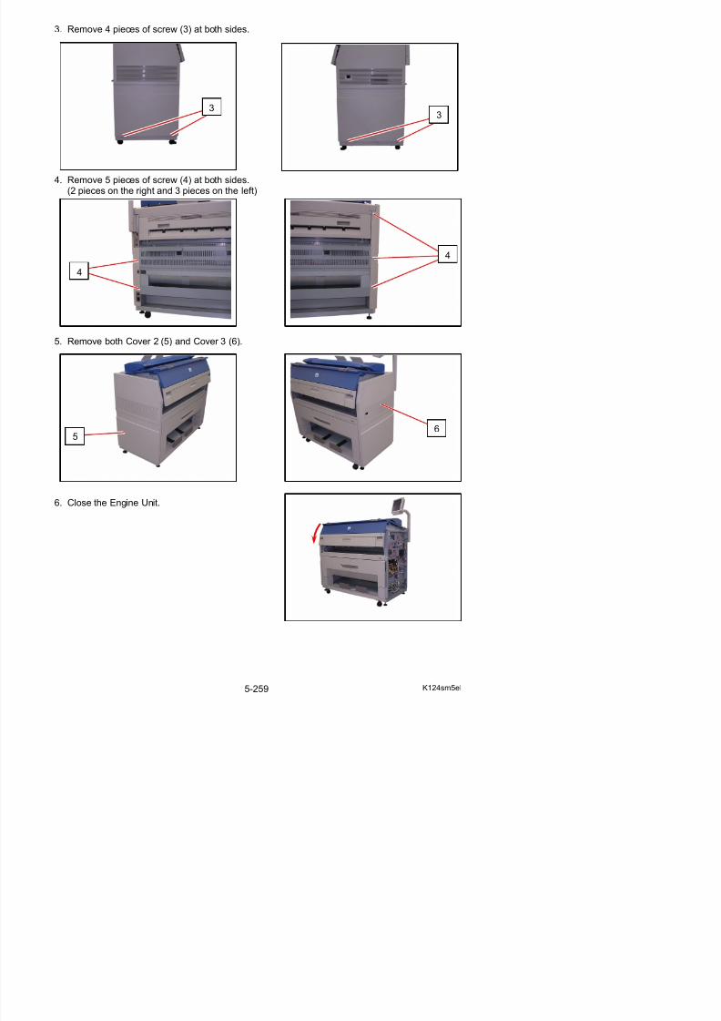
5/17/2018 KIP 7100 Service Manual Ver A_1 - slidepdf.com
http://slidepdf.com/reader/full/kip-7100-service-manual-ver-a1 287/674
6. Close the Engine Unit.
56
7. Remove the Guides 3 (7).
8. Remove 2 pieces of 4x6 screw (8) to remove the Cover 10 (9).
9. Disconnect the connector (10), and open the wire
saddles (11) to release the harness.
7
8
8
9
10
11
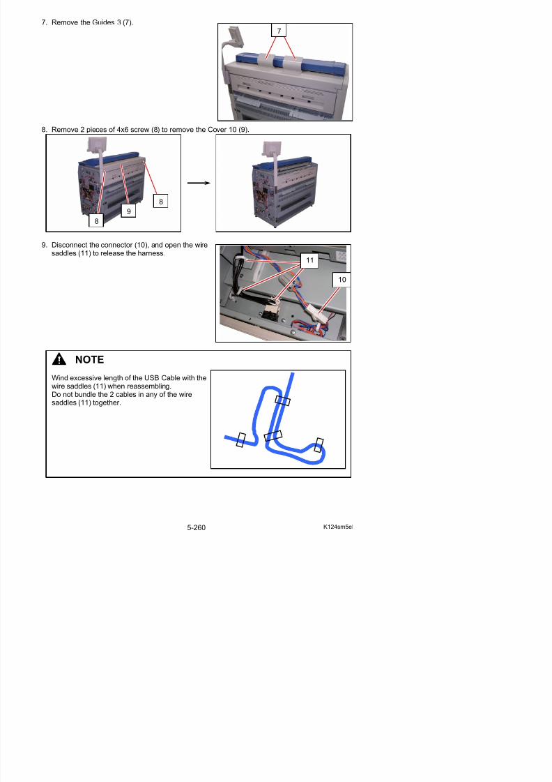
5/17/2018 KIP 7100 Service Manual Ver A_1 - slidepdf.com
http://slidepdf.com/reader/full/kip-7100-service-manual-ver-a1 288/674
10
NOTE
Wind excessive length of the USB Cable with the
10. Open the Cover 4 (12).
11. Remove 4 pieces of 4x6 screw (13) and 2 pieces of washer screw (14).
12. Slide the Scanner Unit (15) fully backward.
12
14
13
14
13
15
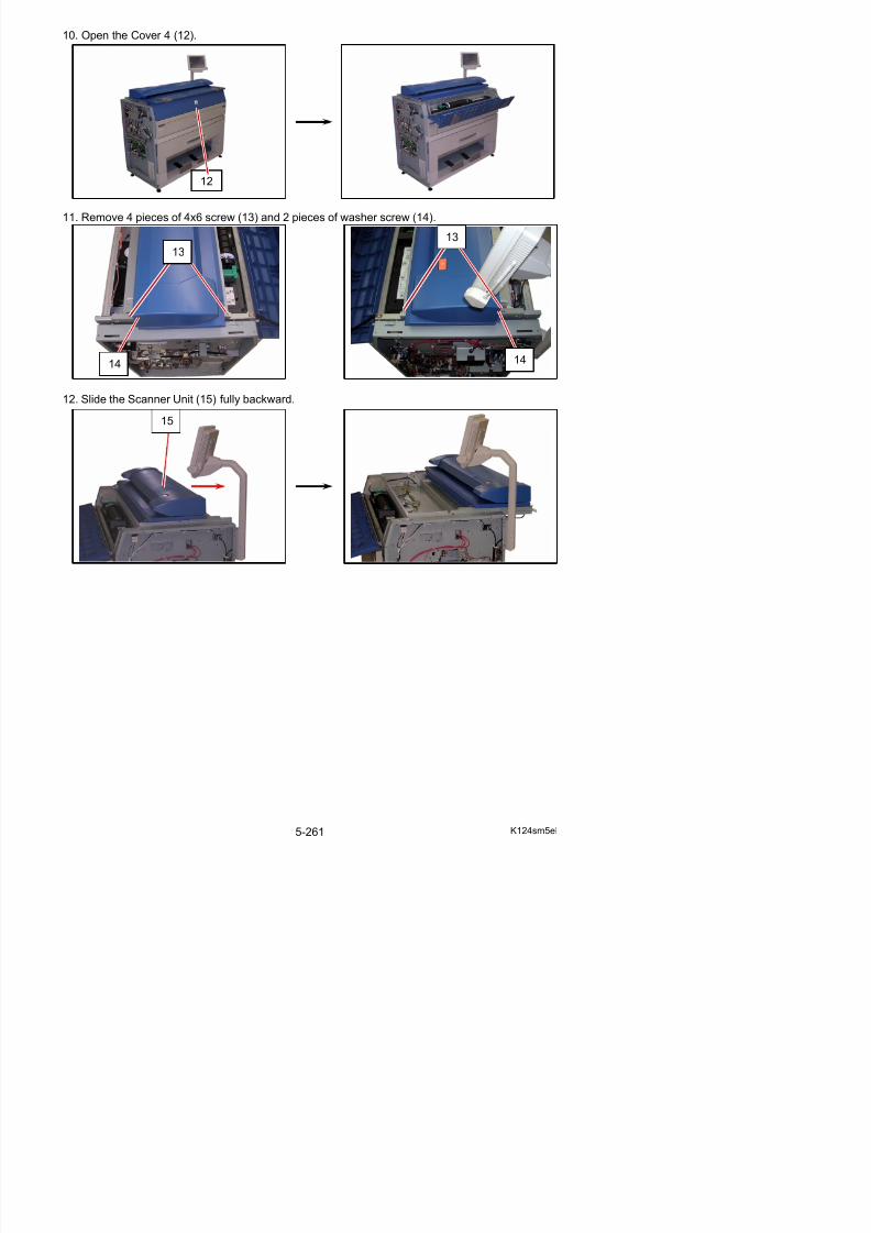
5/17/2018 KIP 7100 Service Manual Ver A_1 - slidepdf.com
http://slidepdf.com/reader/full/kip-7100-service-manual-ver-a1 289/674
13. There are 2 pieces of Stopper (16) at both sides, which lock the LED Head Frame.Loosen the screw (17) and then slide the Stoppers (16) outside to unlock the LED Head Frame.
Lock position Unlock position
16
17
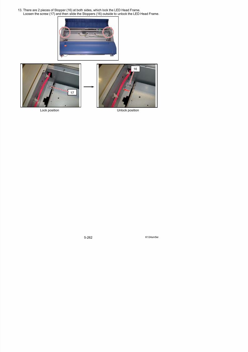
5/17/2018 KIP 7100 Service Manual Ver A_1 - slidepdf.com
http://slidepdf.com/reader/full/kip-7100-service-manual-ver-a1 290/674
14. Open the LED Head Frame (18).
NOTE
The Stopper 2 (19) comes out automaticallyto prevent the LED Head Frame from falling down.
Press the Stopper 2 as the right photo if youwill close the LED Head Frame.
19
18
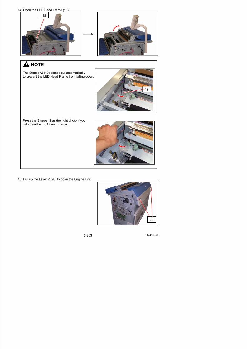
5/17/2018 KIP 7100 Service Manual Ver A_1 - slidepdf.com
http://slidepdf.com/reader/full/kip-7100-service-manual-ver-a1 291/674
16. Remove 1 tooth washer screw (21: M4x8), and remove Plate (22) and Pulley Gear (23).
21
22
NOTE(1) Belt 4 (24) is automatically loosed with Engine
Unit open.It ill b t i d ith E i U it l d
23
22

5/17/2018 KIP 7100 Service Manual Ver A_1 - slidepdf.com
http://slidepdf.com/reader/full/kip-7100-service-manual-ver-a1 292/674
It will be strained with Engine Unit closed.
(2) The tooth washer screw (21) has a toothwasher of which burr face meets thecomposition surface.
24
burr face
17. There are Aluminium Block (25: left) (26: right) and each of them is fixed with 2 screws (27).
Left side Right side
Do as follows to fix the Aluminium Blocks correctly.
a) Always fix the Aluminium Block of the left (25) first and then right (26)
26
27
27
25
27
27
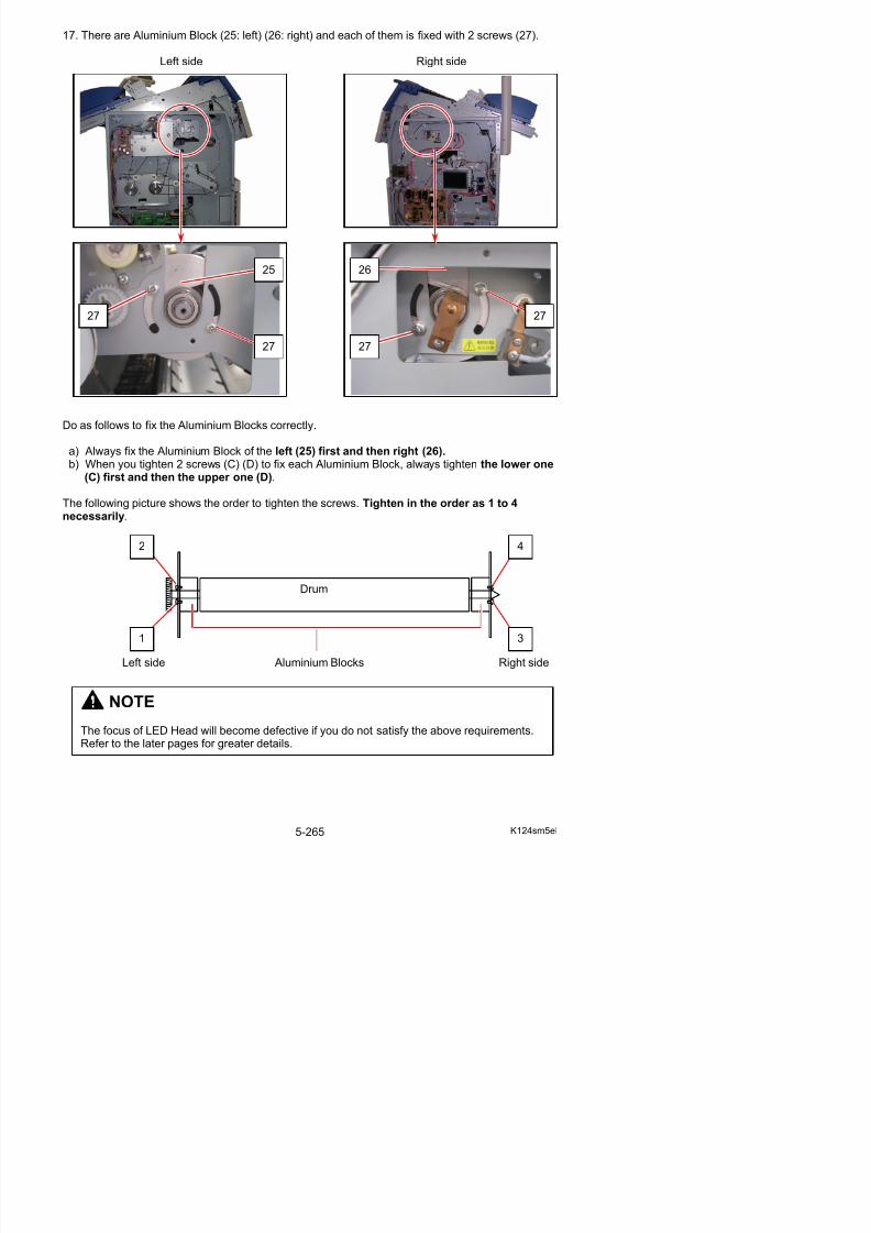
5/17/2018 KIP 7100 Service Manual Ver A_1 - slidepdf.com
http://slidepdf.com/reader/full/kip-7100-service-manual-ver-a1 293/674
a) Always fix the Aluminium Block of the left (25) first and then right (26). b) When you tighten 2 screws (C) (D) to fix each Aluminium Block, always tighten the lower one
(C) first and then the upper one (D).
The following picture shows the order to tighten the screws. Tighten in the order as 1 to 4necessarily.
Drum
2 4
18. Rotate the left Block (25) fully to the arrow direction (A: to front) and also press it to the arrowdirection (B: to outside). This will remove any gap between Block (25) and the side frame of themachine.
With holding Block (25), tighten the screws (28) (29) just enough turn to fix Block (25)temporarily.
(Seen from the top of machine) (Seen from the outside of machine)
NOTE
A
AB 25
29
28
25
no gap
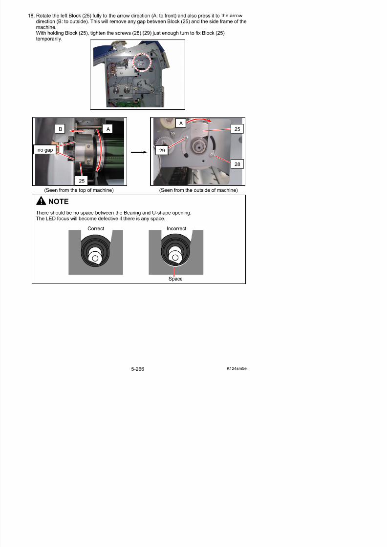
5/17/2018 KIP 7100 Service Manual Ver A_1 - slidepdf.com
http://slidepdf.com/reader/full/kip-7100-service-manual-ver-a1 294/674
NOTE
There should be no space between the Bearing and U-shape opening.The LED focus will become defective if there is any space.
Correct Incorrect
19. Loosen the screws (28) (29) in a (approximately)quarter turn to release Block (25). Check that noexcessive backlash to sideways appears.
20. Similarly to step 18, rotate the right Block (26) fully to the arrow direction (C: to front) and alsopress it to the arrow direction (D: to outside). This will remove any gap between Block (26) andthe side frame of the machine.With holding Block (26), tighten the screws (30) (31) just enough turn to fix Block (26)temporarily.
29
28
25
C C
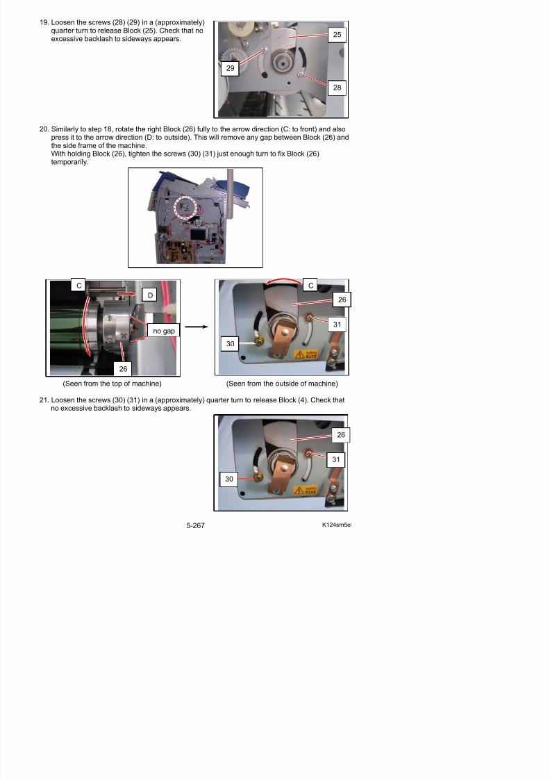
5/17/2018 KIP 7100 Service Manual Ver A_1 - slidepdf.com
http://slidepdf.com/reader/full/kip-7100-service-manual-ver-a1 295/674
(Seen from the top of machine) (Seen from the outside of machine)
C
D
C
26
30
31
26
no gap
22. Fix Blocks with Drum Block Fix Tool (or by hand). Go to step 22-1 for using Drum Block FixTool. Go to step 23 for without Drum Block Fix Tool.
22-1. On the left side, hook Drum Block Fix Tool (32) on between the pin (33) on the frame and theU-shape opening (34) of Block (25).Hook the rear hook (35) the rim of the U-shape opening (34) and the front hook (36) in thegroove of the pin (33).
32
33
34
36 35
32
34
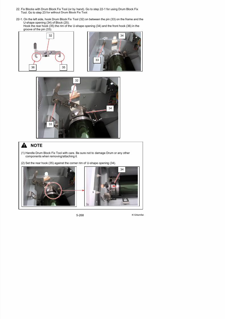
5/17/2018 KIP 7100 Service Manual Ver A_1 - slidepdf.com
http://slidepdf.com/reader/full/kip-7100-service-manual-ver-a1 296/674
33
NOTE
(1) Handle Drum Block Fix Tool with care. Be sure not to damage Drum or any other components when removing/attaching it.
22-2. With pressing Block (25) down (E), slightly turn Block to the arrow direction (F) and release itto locate Block correctly by restoring spring.
22-3. Tighten the lower screw (28) and then the upper screw (29) to secure Block (25).
25
29
28
E
F

5/17/2018 KIP 7100 Service Manual Ver A_1 - slidepdf.com
http://slidepdf.com/reader/full/kip-7100-service-manual-ver-a1 297/674
22-4. Similarly to step 22-2, on the right side, hook Drum Block Fix Tool (32) on between the pin(37) on the frame and the U-shape opening (38) of Block (26).
NOTE
(1) Handle Drum Block Fix Tool with care. Be sure not to damage Drum or any other components when removing/attaching it.
(2) Set the rear hook (35) against the corner rim of U-shape opening (38).
32
38
37
38
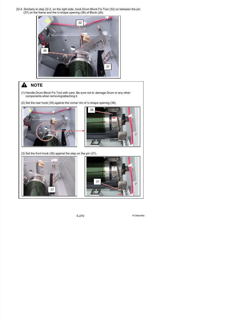
5/17/2018 KIP 7100 Service Manual Ver A_1 - slidepdf.com
http://slidepdf.com/reader/full/kip-7100-service-manual-ver-a1 298/674
(3) Set the front hook (36) against the step on the pin (37).
22-5. Similarly to step 22-2, with pressing Block (26) down (G), slightly turn Block to the arrowdirection (H) and release it to locate Block correctly by restoring spring.
22-6. Tighten the lower screw (30) and then the upper screw (31) to secure Block (26).
26
30
31
G
H
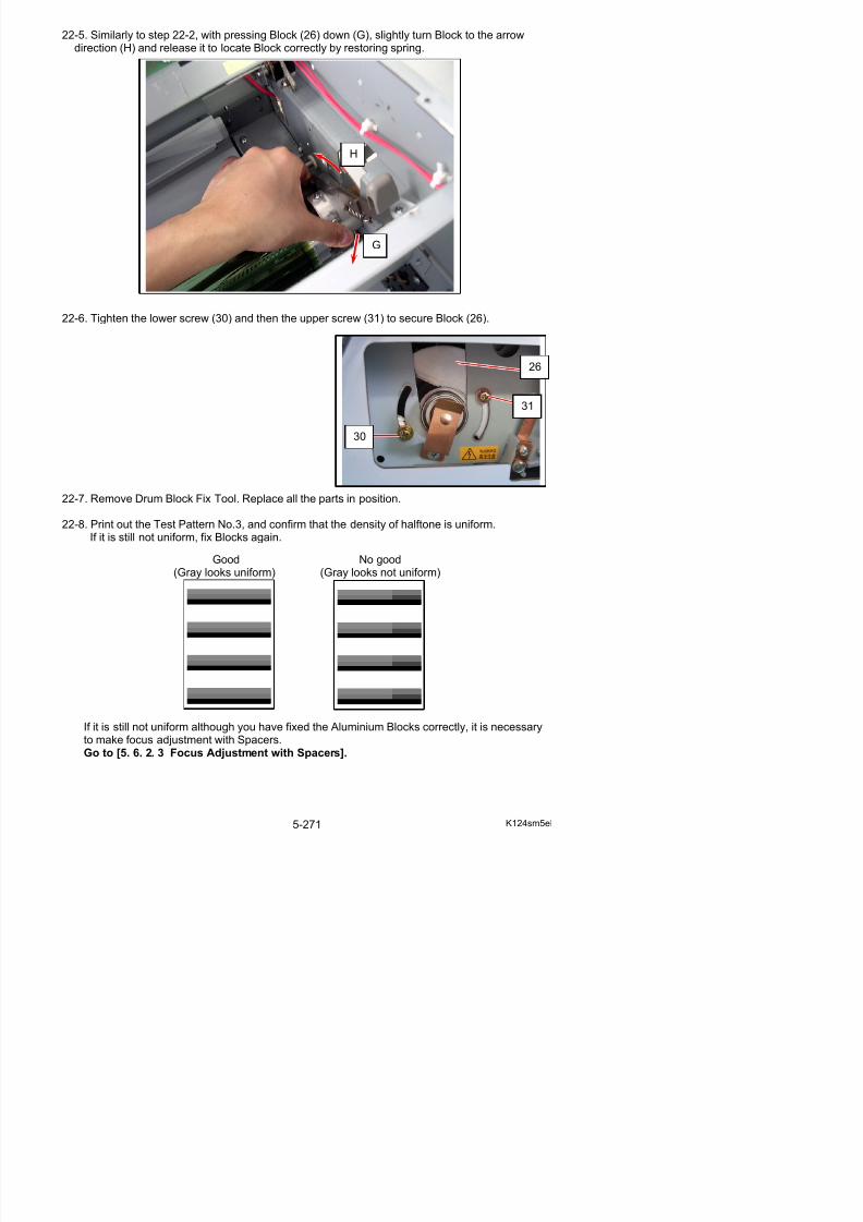
5/17/2018 KIP 7100 Service Manual Ver A_1 - slidepdf.com
http://slidepdf.com/reader/full/kip-7100-service-manual-ver-a1 299/674
22-7. Remove Drum Block Fix Tool. Replace all the parts in position.
22-8. Print out the Test Pattern No.3, and confirm that the density of halftone is uniform.If it is still not uniform, fix Blocks again.
Good No good(Gray looks uniform) (Gray looks not uniform)
23. Follow the instruction below to fix Blocks without Drum Block Fix Tool.
23-1. Put your finger inside the U-shape opening (32) of Block (25). Put the other finger on the pin(33) of the frame.Push the fingers toward each other (C: inside). Note that the entire Block (25) is shiftedtowards the pin (33) by the finger at the U-shape opening (32).While pushing and holding, tighten the lower screw (28) and then the upper screw (29) tosecure Block (25).
25
33
32
33
32
C
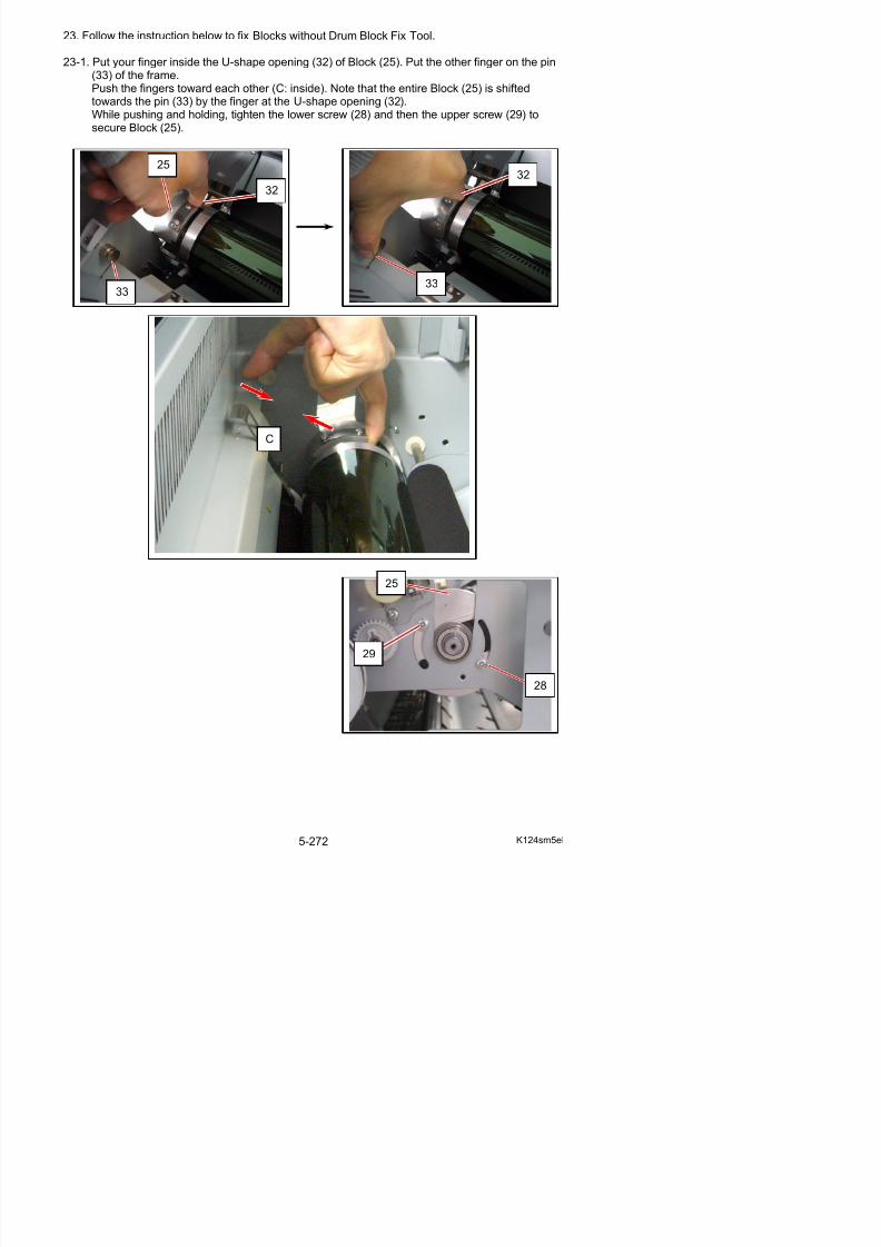
5/17/2018 KIP 7100 Service Manual Ver A_1 - slidepdf.com
http://slidepdf.com/reader/full/kip-7100-service-manual-ver-a1 300/674
25
23-2. Similarly to step 23-1, put your finger inside the U-shape opening (34) of Block (26) and putthe other finger on the pin (35) of the frame.Push the fingers toward each other (D: inside). Note that the entire Block (26) is shiftedtowards the pin (35) by the finger at the U-shape opening (34).While pushing and holding, tighten the lower screw (30) and then the upper screw (31) tosecure Block (26).
34
26
35
34
35
D
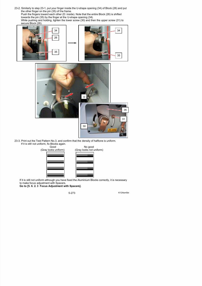
5/17/2018 KIP 7100 Service Manual Ver A_1 - slidepdf.com
http://slidepdf.com/reader/full/kip-7100-service-manual-ver-a1 301/674
23-3. Print out the Test Pattern No.3, and confirm that the density of halftone is uniform.
26
30
31
5. 6. 2. 3 Focus Adjustment with Spacers
There may be the case that the focus of LED is not correct even if you have placed the Aluminium
Blocks at both sides of the Drum Shaft correctly.This is because the height of the LED is mechanically different between left and right by somereason.In this case adjust the height by adding or removing the Spacers.
1. Remove the Guides 3 (1).
2. Remove 2 pieces of 4x6 screw (2) to remove the Cover 10 (3).
1
3
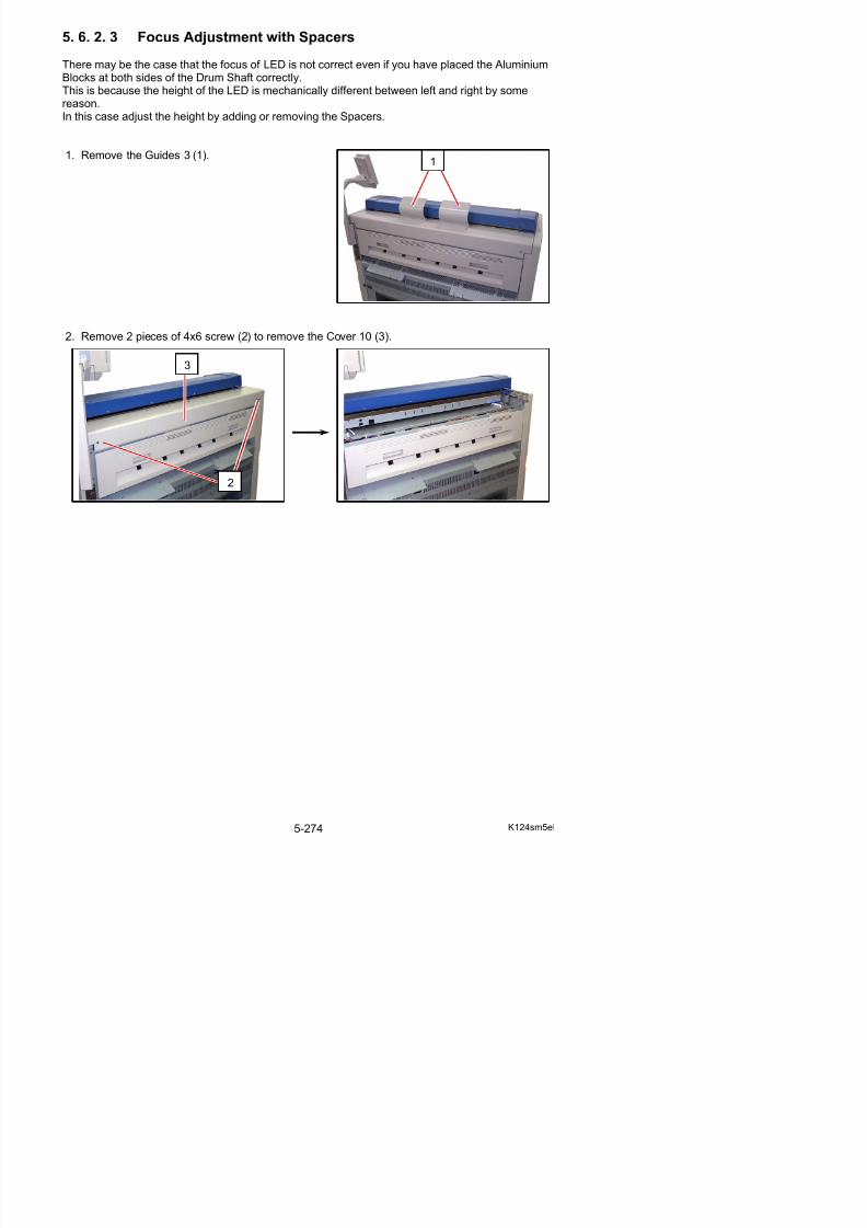
5/17/2018 KIP 7100 Service Manual Ver A_1 - slidepdf.com
http://slidepdf.com/reader/full/kip-7100-service-manual-ver-a1 302/674
2
3. Disconnect the connector (4), and open the wiresaddles (5) to release the harness.
4. Open the Cover 4 (6).
4
5
NOTE
Wind excessive length of the USB Cable with thewire saddles (5) when reassembling.Do not bundle the 2 cables in any of the wiresaddles (5) together.
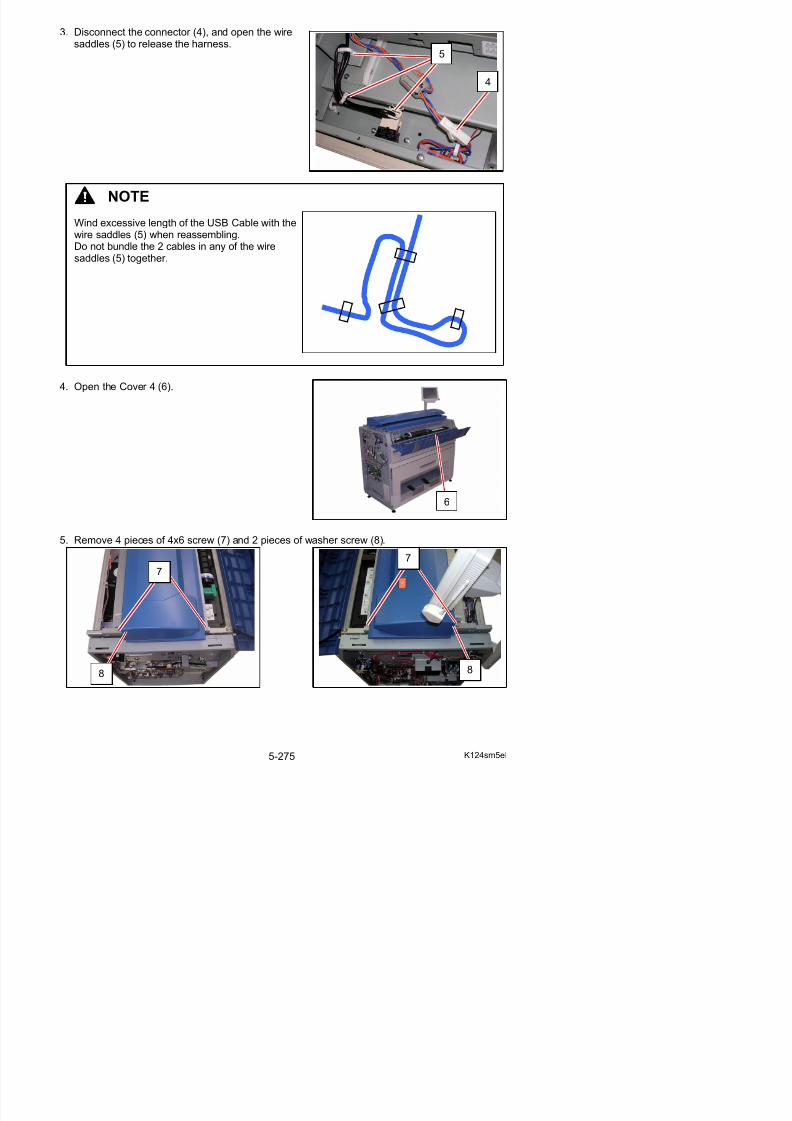
5/17/2018 KIP 7100 Service Manual Ver A_1 - slidepdf.com
http://slidepdf.com/reader/full/kip-7100-service-manual-ver-a1 303/674
5. Remove 4 pieces of 4x6 screw (7) and 2 pieces of washer screw (8).
6
6. Slide the Scanner Unit (9) fully backward.
7. There are 2 pieces of Stopper (10) at both sides, which lock the LED Head Frame.Loosen the screw (11) and then slide the Stoppers (10) outside to unlock the LED Head Frame.
10
9
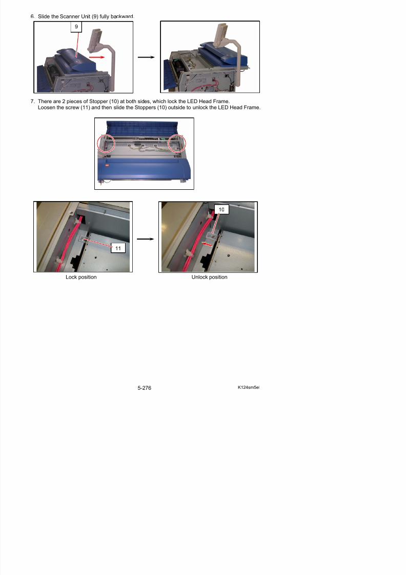
5/17/2018 KIP 7100 Service Manual Ver A_1 - slidepdf.com
http://slidepdf.com/reader/full/kip-7100-service-manual-ver-a1 304/674
Lock position Unlock position
11
8. Open the LED Head Frame (12).
NOTE
The Stopper 2 (13) comes out automaticallyto prevent the LED Head Frame from falling down.
Press the Stopper 2 as the right photo if youwill close the LED Head Frame.
13
12

5/17/2018 KIP 7100 Service Manual Ver A_1 - slidepdf.com
http://slidepdf.com/reader/full/kip-7100-service-manual-ver-a1 305/674
9. There are Spacers (14) on each Aluminium Block at both sides.The height of the LED Head can be adjusted by adding more Spacer or removing some of them.Remove the screw (15), and remove all Spacers (14) at first. And then adjust the height of LED Head adding or removing the Spacers (14).
NOTE
14 15
14
14
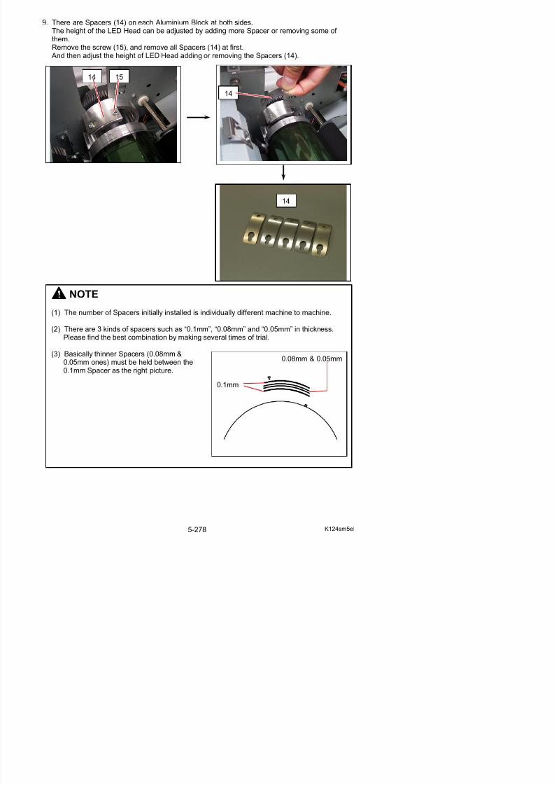
5/17/2018 KIP 7100 Service Manual Ver A_1 - slidepdf.com
http://slidepdf.com/reader/full/kip-7100-service-manual-ver-a1 306/674
(1) The number of Spacers initially installed is individually different machine to machine.
(2) There are 3 kinds of spacers such as “0.1mm”, “0.08mm” and “0.05mm” in thickness.Please find the best combination by making several times of trial.
(3) Basically thinner Spacers (0.08mm &0.05mm ones) must be held between the0.1mm Spacer as the right picture.
0.1mm
0.08mm & 0.05mm
NOTE
(4) It is quite not clear which of “addition” or “removal” of Spacer is effective to solve thefocus problem.(Even if the defective image caused by the focus problem looks same, for example, it isfixed by “addition” in some case but in another case it is fixed by “removal”.
Only the way to find the best focus is just “trial”.Please try both “removal” and “addition” to find which way the image becomes better. After finding the better way, try several combinations of Spacers to find the best height.
Removal of Spacer Addition of Spacer (Worse result) (Better result)
“Addition of Spacer” is the better way.
Try several combinations of Spacers by adding the Spacers gradually.
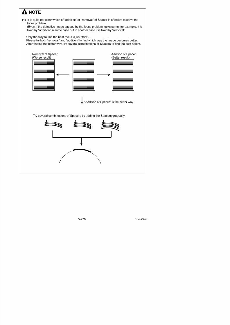
5/17/2018 KIP 7100 Service Manual Ver A_1 - slidepdf.com
http://slidepdf.com/reader/full/kip-7100-service-manual-ver-a1 307/674
5. 7 Image Corona
5. 7. 1 Removal of the Image Corona Unit
1. Pull up the Lever 2 (1) to open the Engine Unit.
2. Remove the screws (2) at both sides.
1
22

5/17/2018 KIP 7100 Service Manual Ver A_1 - slidepdf.com
http://slidepdf.com/reader/full/kip-7100-service-manual-ver-a1 308/674
3. Remove 4 pieces of screw (3) at both sides.
4. Remove 5 pieces of screw (4) at both sides.(2 pieces on the right and 3 pieces on the left)
5. Remove both Cover 2 (5) and Cover 3 (6).
6. Close the Engine Unit.
4
4
56
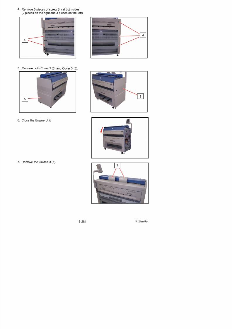
5/17/2018 KIP 7100 Service Manual Ver A_1 - slidepdf.com
http://slidepdf.com/reader/full/kip-7100-service-manual-ver-a1 309/674
7. Remove the Guides 3 (7).
8. Remove 2 pieces of 4x6 screw (8) to remove the Cover 10 (9).
9. Disconnect the connector (10), and open the wiresaddles (11) to release the harness.
8
8
9
10
11
NOTE
Wind excessive length of the USB Cable with thewire saddles (11) when reassembling.Do not bundle the 2 cables in any of the wire
ddl (11) t th

5/17/2018 KIP 7100 Service Manual Ver A_1 - slidepdf.com
http://slidepdf.com/reader/full/kip-7100-service-manual-ver-a1 310/674
10. Open the Cover 4 (12).
saddles (11) together.
11. Remove 4 pieces of 4x6 screw (13) and 2 pieces of washer screw (14).
12. Slide the Scanner Unit (15) fully backward.
13. There are 2 pieces of Stopper (16) at both sides, which lock the LED Head Frame.Loosen the screw (17) and then slide the Stoppers (16) outside to unlock the LED Head Frame.
14
13
14
13
15

5/17/2018 KIP 7100 Service Manual Ver A_1 - slidepdf.com
http://slidepdf.com/reader/full/kip-7100-service-manual-ver-a1 311/674
16
14. Open the LED Head Frame (18).
NOTE
The Stopper 2 (19) comes out automaticallyto prevent the LED Head Frame from falling down.
Press the Stopper 2 as the right photo if youwill close the LED Head Frame.
19
18

5/17/2018 KIP 7100 Service Manual Ver A_1 - slidepdf.com
http://slidepdf.com/reader/full/kip-7100-service-manual-ver-a1 312/674
15. Remove the 4x6 screw (20) to remove the Fixing Bracket (21) on the right.
16. Loosen 2 pieces of 4x10 screw (22) to make the Plate (23) enough movable.
NOTE
You do not have to put back the Fixing Bracket (21) at the time of reassembly, because it isa part required only before the delivery of machine.
20 21
22
23
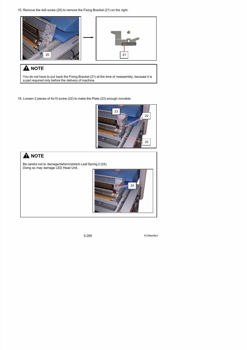
5/17/2018 KIP 7100 Service Manual Ver A_1 - slidepdf.com
http://slidepdf.com/reader/full/kip-7100-service-manual-ver-a1 313/674
22
NOTE
Be careful not to damage/deform/stretch Leaf Spring 2 (24).Doing so may damage LED Head Unit.
17. Move the Plate (23) to the right to release the pin (25) of Corona Block.Then remove the Image Corona Unit (26).
25
23
26
26
26
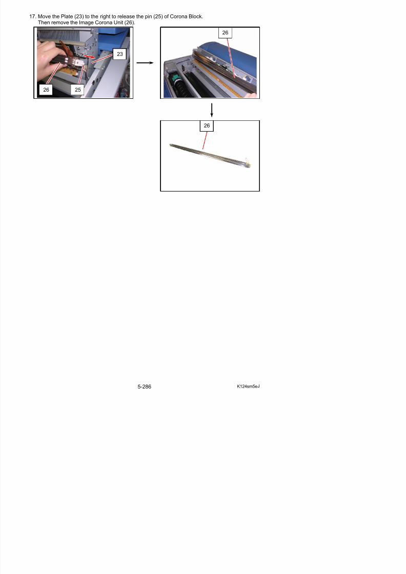
5/17/2018 KIP 7100 Service Manual Ver A_1 - slidepdf.com
http://slidepdf.com/reader/full/kip-7100-service-manual-ver-a1 314/674
5. 7. 2 Replacement of the Corona Wire
1. Remove the Image Corona Unit (1) from the machine making reference to [5. 7. 1 Removal of the Image Corona Unit] on the page 5-280.
2. Loosen the Set Screw (2) with hexagon wrench.
The Block 3 (3) moves to the arrow mark and the Grid Plate is unfastened.
1
NOTE
A periodic replacement for the following parts is recommended.
Item Number of article
Remarks
Corona Wire (1) Assy 1
Spring 2 1
All of these parts are contained in“Corona Wire Kit” (Z160980200)
1
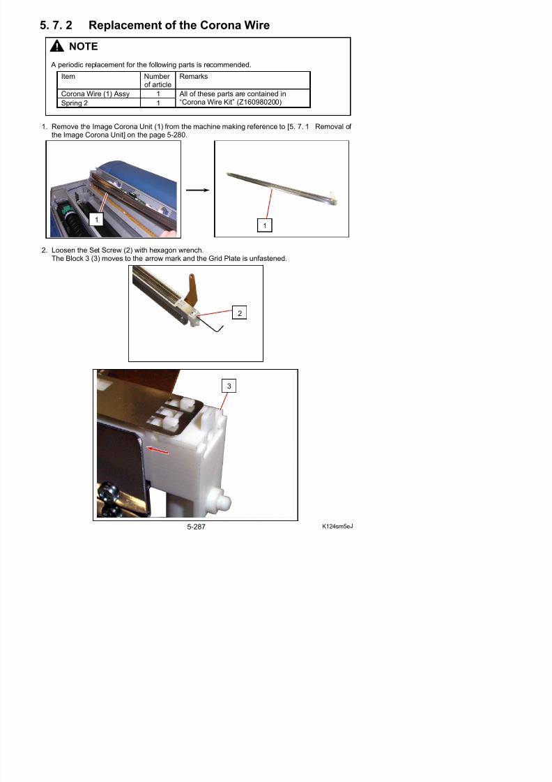
5/17/2018 KIP 7100 Service Manual Ver A_1 - slidepdf.com
http://slidepdf.com/reader/full/kip-7100-service-manual-ver-a1 315/674
2
3
NOTE
Check the following when reassembling.
(1) The side edge of Block 3 (3) should stop at 0.5mm short of the side face (4) of the coronablock for a proper tension.Rotate a hexagon wrench in either direction with pressing down Grid Plate (5).
0.5mm 0.5mm
(2) Carry Image Corona Unit (1) by both corona blocks so that Grid Plate (5) faces the floor.Make sure that Grid Plate (5) has no excess slack (in less than 1mm) on the middle of thehousing.
5
3
4
5
35
press down
4
1
1
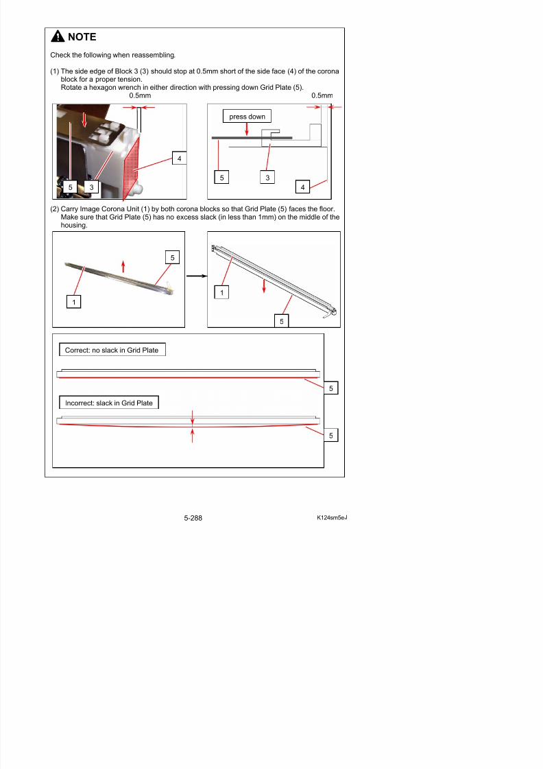
5/17/2018 KIP 7100 Service Manual Ver A_1 - slidepdf.com
http://slidepdf.com/reader/full/kip-7100-service-manual-ver-a1 316/674
Correct: no slack in Grid Plate
5
1
3. Remove the Grid Plate (5).
4. Loosen 3 pieces of 3x6 screw (6), and then remove Corona Housing (7) and PlateElectrode (8).
5
NOTE
If Grid Plate is dirty, wash it with the neutral detergent and then with water. Dry it well after washing.
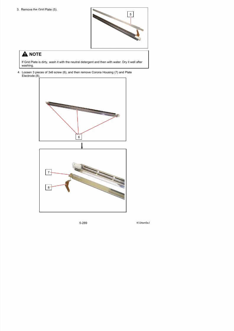
5/17/2018 KIP 7100 Service Manual Ver A_1 - slidepdf.com
http://slidepdf.com/reader/full/kip-7100-service-manual-ver-a1 317/674
6
5. Remove the Flush Head Screw (9), and remove each Cover (10) and Cover 2 (11).
6. Loosen the screws (12) to lower the Height Adjuster.(It becomes easy to remove the Corona Wire as it is unfastened by this treatment.)
9 9
11
10
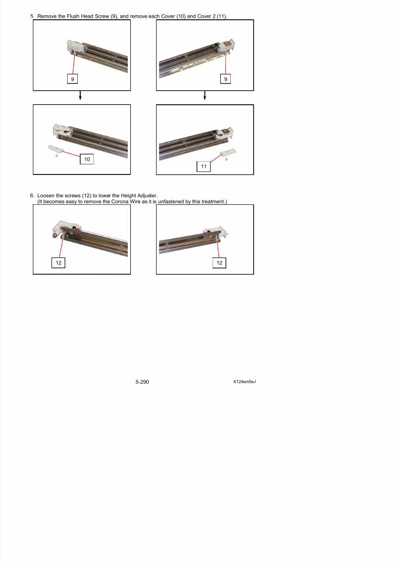
5/17/2018 KIP 7100 Service Manual Ver A_1 - slidepdf.com
http://slidepdf.com/reader/full/kip-7100-service-manual-ver-a1 318/674
12 12
7. Remove Spring 2 (13) and Corona Wire 1 Assy (14).Replace Spring 2 (13) and Corona Wire 1 Assy (14) with new ones.
NOTE
(1) Please keep 11mm between CoronaWire (14) and bottom plate of the Corona Unit
after the replacement.
11mm
(2) Fit the Corona Wire into the groove of Height Adjuster (15). Also fit the beads (16) into the correctpositions
13
14
15 16
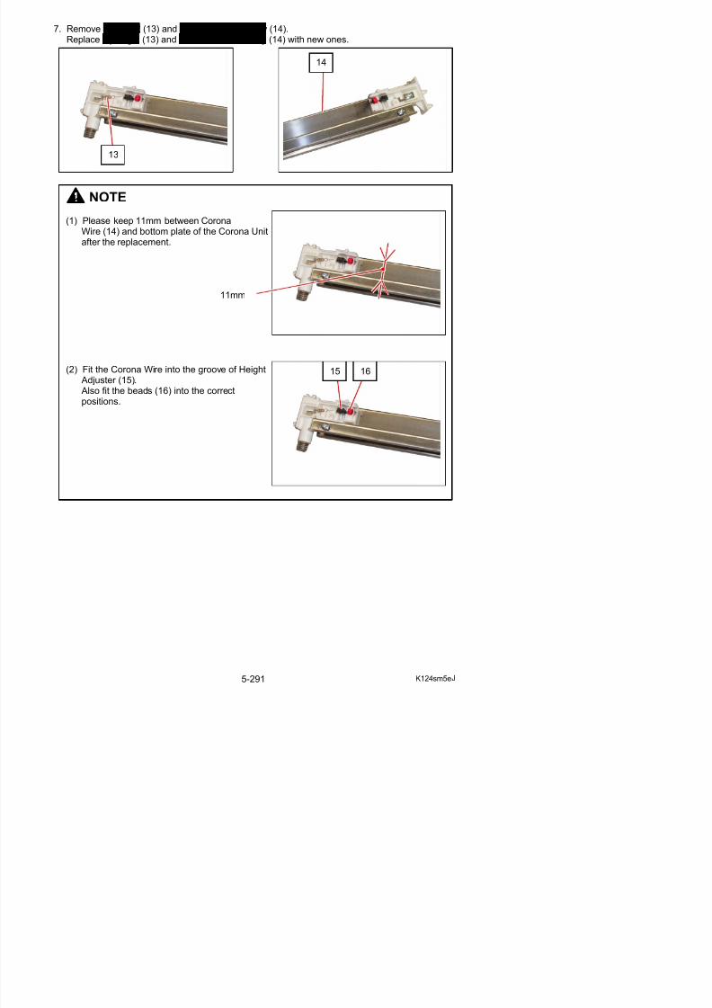
5/17/2018 KIP 7100 Service Manual Ver A_1 - slidepdf.com
http://slidepdf.com/reader/full/kip-7100-service-manual-ver-a1 319/674
positions.
5. 8 Transfer / Separation Corona
5. 8. 1 Removal of the Transfer / Separation Corona
1. Pull up the Lever 2 (1) to open the Engine Unit.
2. Holding both Corona Blocks (2: white plastic), remove the Transfer / Separation Corona (3)from the machine.
1
2 2
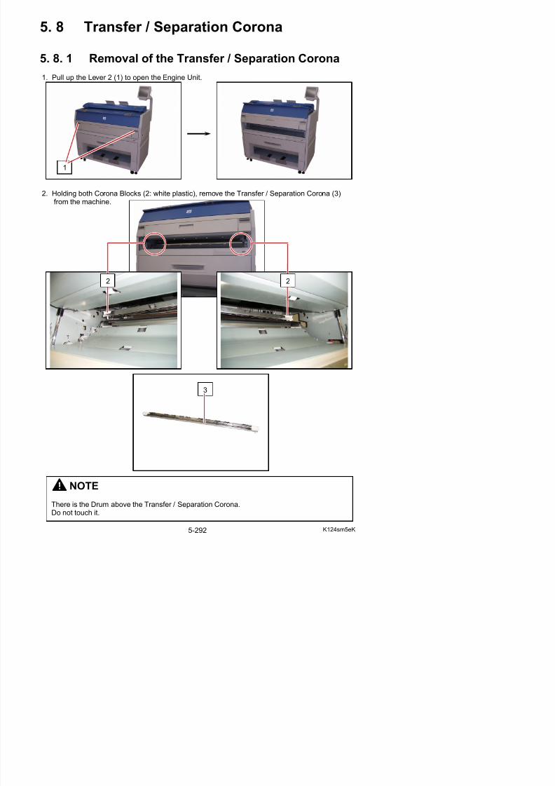
5/17/2018 KIP 7100 Service Manual Ver A_1 - slidepdf.com
http://slidepdf.com/reader/full/kip-7100-service-manual-ver-a1 320/674
3
5. 8. 2 Replacement of Corona Wires
1. Remove the Transfer / Separation Corona (1)making reference to [5. 8. 1 Removal of theTransfer / Separation Corona] on the page 5-292.
2. There are 5 pieces of Corona Guards A (2) and Corona Guards B (3) on the housing.Remove them pressing the stoppers (4) with such tool as a screwdriver.
1
4 2 3
NOTE
A periodic replacement for the following parts is recommended.
Item Number of article
Remarks
Corona Wire 2
Wire Spring 4
All of these parts are contained in“Corona Wire Kit” (Z160980200)
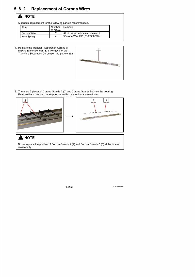
5/17/2018 KIP 7100 Service Manual Ver A_1 - slidepdf.com
http://slidepdf.com/reader/full/kip-7100-service-manual-ver-a1 321/674
NOTE
3. Remove both Covers 3 (5) (6) pulling their sides outward.
5 6
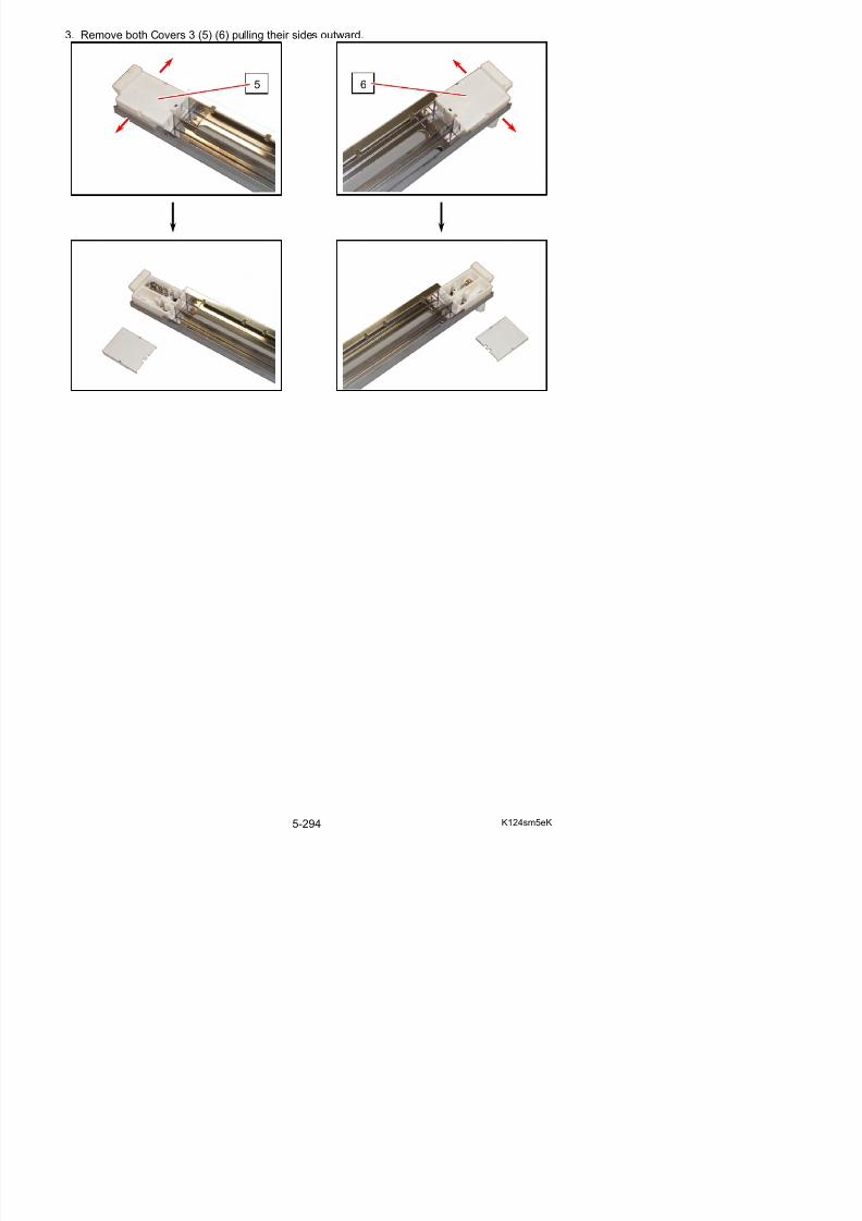
5/17/2018 KIP 7100 Service Manual Ver A_1 - slidepdf.com
http://slidepdf.com/reader/full/kip-7100-service-manual-ver-a1 322/674
4. Remove 4 pieces of Wire Springs (7) and Corona Wires (8).Replace Wire Springs (7) and Corona Wires (8) with new ones.
NOTE
(1) Do not touch the wire part. Pinch the hook part of both ends to handle Corona Wire.
(2) Keep 11mm distance (height) between each Corona Wire and bottom plate of thehousing.
To adjust the distance, rotate the screws (9)with a flathead screwdriver.
9
7
8
7
8
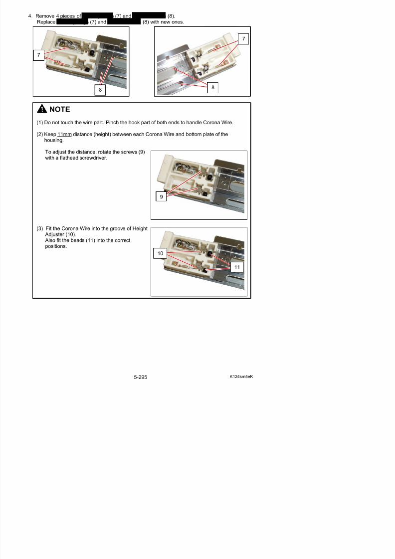
5/17/2018 KIP 7100 Service Manual Ver A_1 - slidepdf.com
http://slidepdf.com/reader/full/kip-7100-service-manual-ver-a1 323/674
(3) Fit the Corona Wire into the groove of Height
Adjuster (10). Also fit the beads (11) into the correctpositions.
10
11
5. 9 Engine Frame
5. 9. 1 Replacement of DC Motor (M4) andDeveloper Press Sensor (PH4)
1. Open the Cover 4 (1).
2. Remove the 4x6 screws and washers (2) at both sides to make the Bands (3) free.
1
2
3
2
3
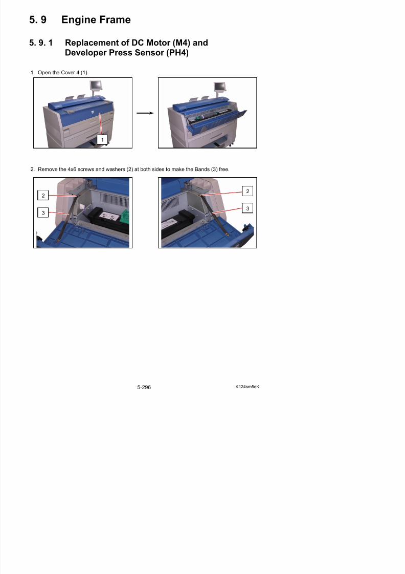
5/17/2018 KIP 7100 Service Manual Ver A_1 - slidepdf.com
http://slidepdf.com/reader/full/kip-7100-service-manual-ver-a1 324/674
3. There are Pins (4) at both sides.Slide them inside to remove the Cover 4 (1).
4. Open the Bypass Feeder (5).
1
44
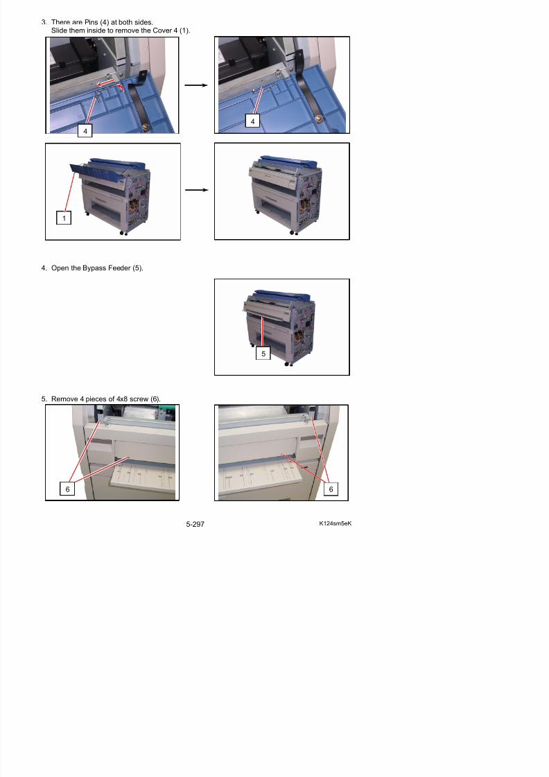
5/17/2018 KIP 7100 Service Manual Ver A_1 - slidepdf.com
http://slidepdf.com/reader/full/kip-7100-service-manual-ver-a1 325/674
5
6. Close the Bypass Feeder, and then open the Developer Press Unit (7).
7. Disconnect the connector (8) and remove 3 pieces of screw (9), and remove the DC Motor (10).Replace DC Motor (10) with the new one.
8
9
10
7
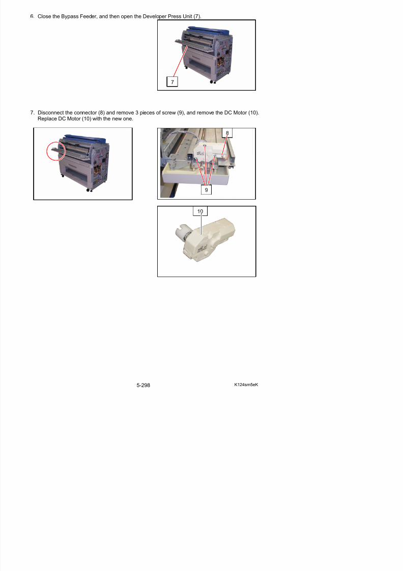
5/17/2018 KIP 7100 Service Manual Ver A_1 - slidepdf.com
http://slidepdf.com/reader/full/kip-7100-service-manual-ver-a1 326/674
8. Remove the 4x6 screw (11), release the harness from the Edge Saddle (12), and disconnectthe connector (13).
9. Pressing the stoppers (14) with such tool as a screwdriver, remove Developer Press Sensor (15).Replace Developer Press Sensor (15) with the new one.
11
12
13
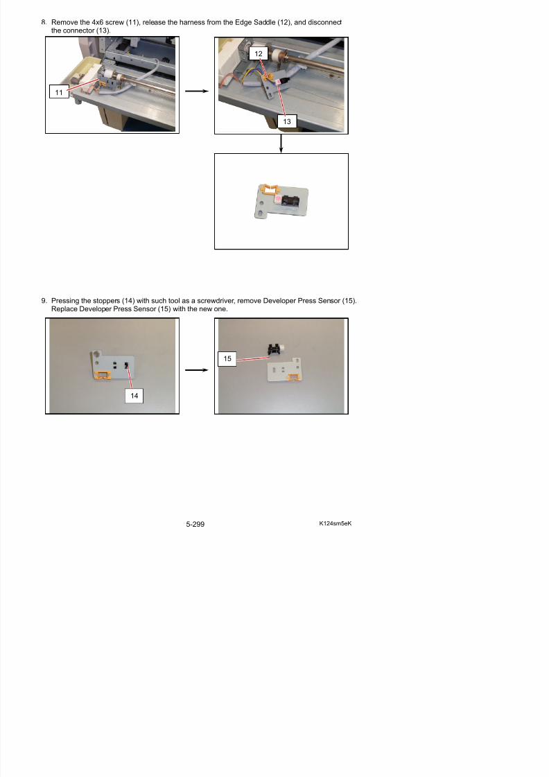
5/17/2018 KIP 7100 Service Manual Ver A_1 - slidepdf.com
http://slidepdf.com/reader/full/kip-7100-service-manual-ver-a1 327/674
15
5. 9. 2 Replacement of Manual Set Sensor (PH5) &Registration Sensor (PH1)
1. Remove the Developer Unit from the machine making reference to [5. 2. 1 Removal of theDeveloper Unit] on the page 5-8.
2. Remove 2 pieces of 3x6 screw (1), and then turn over the Bracket 11 (2).
12

5/17/2018 KIP 7100 Service Manual Ver A_1 - slidepdf.com
http://slidepdf.com/reader/full/kip-7100-service-manual-ver-a1 328/674
3. Remove the screw (3) and disconnect the connector (4) to remove each Sensor (5 : ManualSet Sensor or Registration Sensor).Replace Sensor (5) with the new one.
3
4
5
5
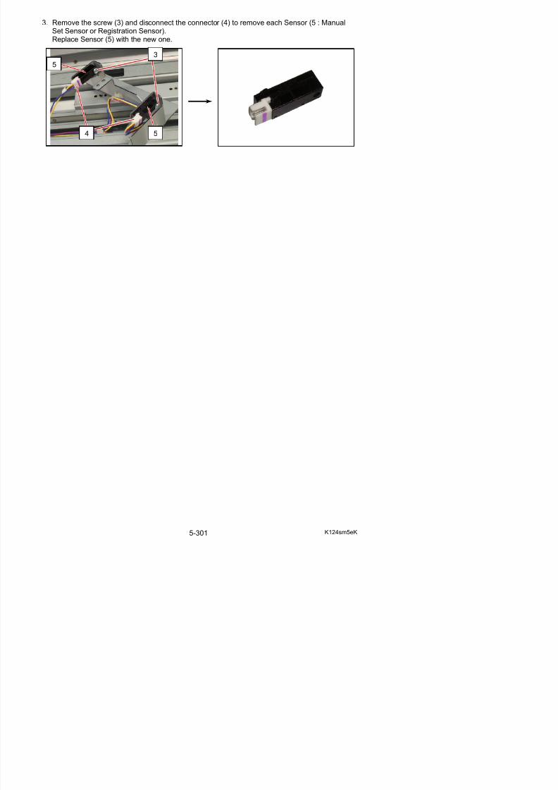
5/17/2018 KIP 7100 Service Manual Ver A_1 - slidepdf.com
http://slidepdf.com/reader/full/kip-7100-service-manual-ver-a1 329/674
5. 9. 3 Replacement of Fans (BL5, BL6)
1. Remove the Fuser Unit (1) from the machine making reference to [5. 3. 1 Removal of the
Fuser Unit] on the page 5-70.
2. Disconnect the connector (2), remove 2 screws (3), and remove each Fan (4) with the bracket.Remove 2 screws from the bracket and replace Fan(BL5 / BL6) with the new one.
1
2
3
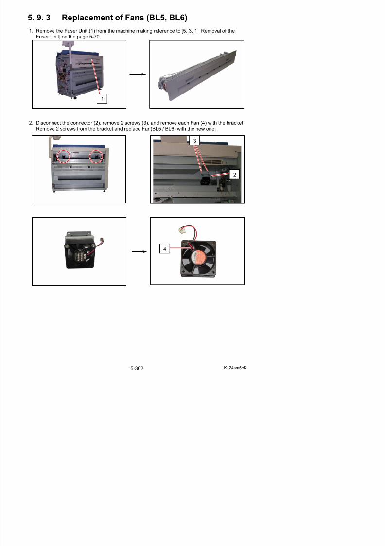
5/17/2018 KIP 7100 Service Manual Ver A_1 - slidepdf.com
http://slidepdf.com/reader/full/kip-7100-service-manual-ver-a1 330/674
4
5. 9. 4 Replacement of Blowers (BL3, BL4)
1. Remove 2 pieces of 4x6 screw (1) to remove the Cover 10 (2).
2. Open the Cover Assembly (3).
3. Moving the stopper levers (4) to the inside, remove each Duct 5 (5) with Filter 4.
1
2
3
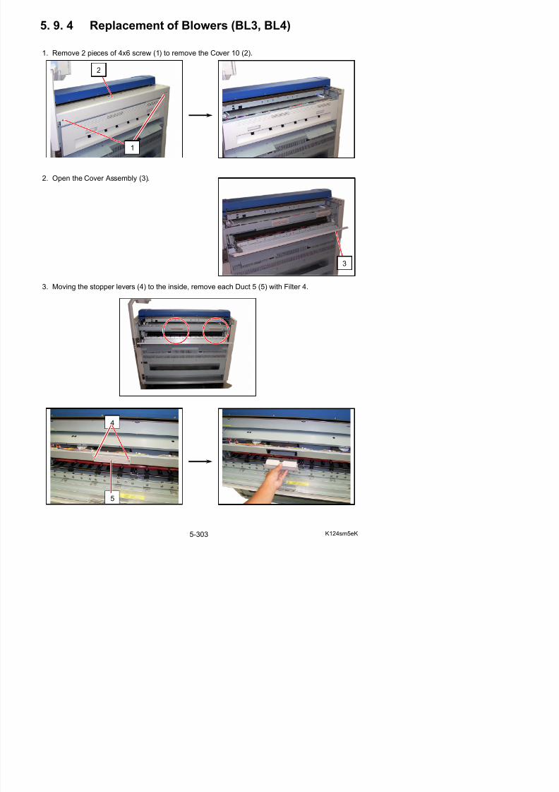
5/17/2018 KIP 7100 Service Manual Ver A_1 - slidepdf.com
http://slidepdf.com/reader/full/kip-7100-service-manual-ver-a1 331/674
4. Remove 2 pieces of 4x6 screw (6), and then slide the Duct 6 (7) to the left.
5. Remove 3 pieces of 4x35 screw (8).
6. Remove the Blower (9 : BL3 & BL4) moving as the following photos.
6
7
7
9
8
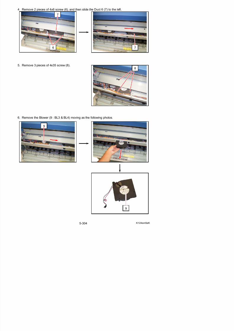
5/17/2018 KIP 7100 Service Manual Ver A_1 - slidepdf.com
http://slidepdf.com/reader/full/kip-7100-service-manual-ver-a1 332/674
5. 10 Inner Transport Unit
5. 10. 1 Removal of the Inner Transport Unit
1. Remove the Fuser Unit (1) from the machine making reference to [5. 3. 1 Removal of theFuser Unit] on the page 5-70.
2. Remove 2 pieces of 4x6 screw (2).
3. Disconnect the connector on the left (3), and then remove Inner Transport Unit (4).
2
1
3
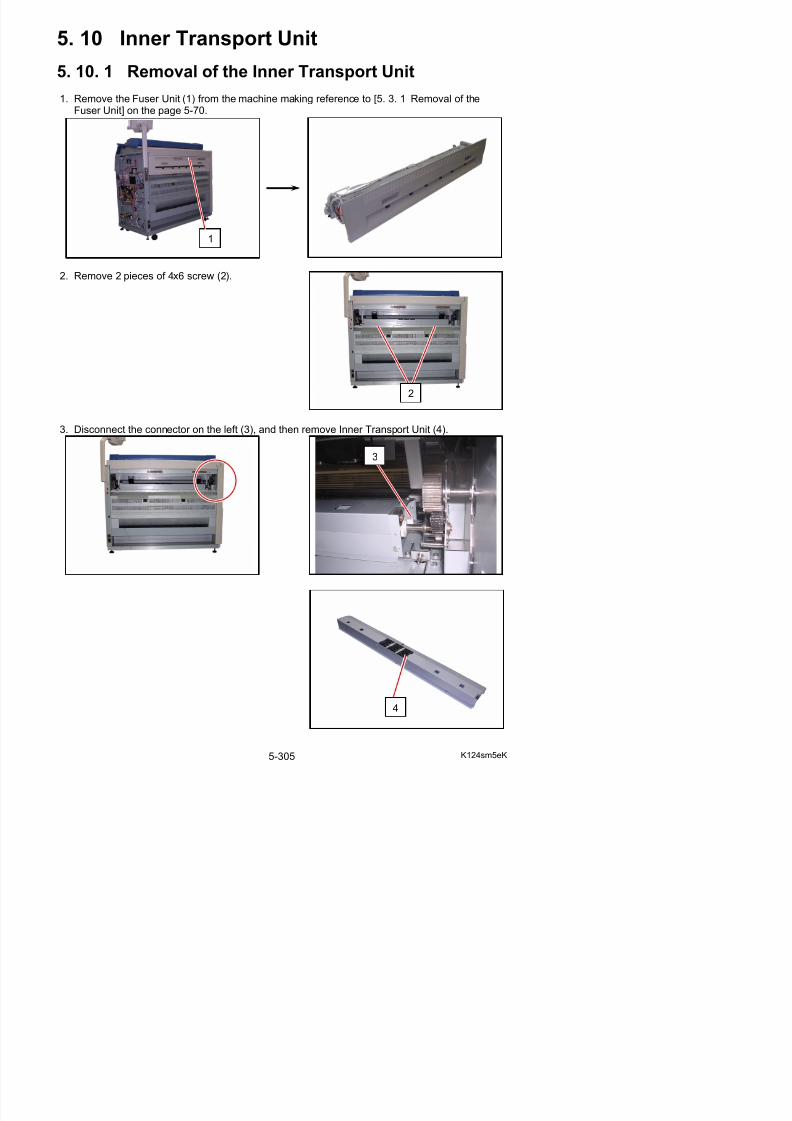
5/17/2018 KIP 7100 Service Manual Ver A_1 - slidepdf.com
http://slidepdf.com/reader/full/kip-7100-service-manual-ver-a1 333/674
5. 10. 2 Replacement of Sensor (PH2) & Belt
1. Remove the Inner Transport Unit (1) from the machine making reference to [5.10. 1 Removalof the Inner Transport Unit] on the page 5-305.
2. Tuck the rim of Belts (2) under the tab of Guide Plate (3)
3. Remove 7 pieces of 4x6 screw (4) to remove Guide Plate (5).
1 1
2
3
4
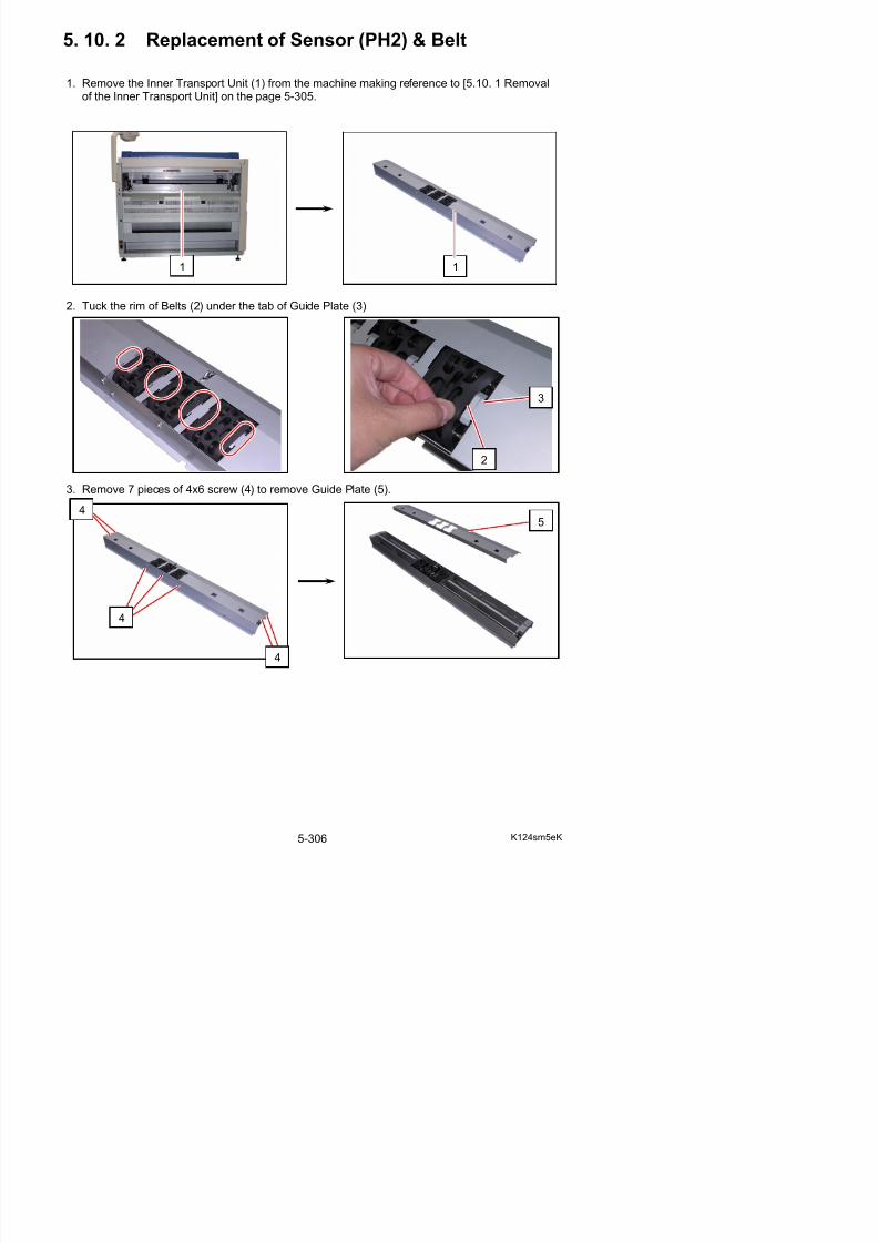
5/17/2018 KIP 7100 Service Manual Ver A_1 - slidepdf.com
http://slidepdf.com/reader/full/kip-7100-service-manual-ver-a1 334/674
5
4
4. Remove 1 screw (6) and the harness (7) to release the sensor bracket (8).Remove Sensor (9) from the bracket (8) and replace Sensor with a new one.
5. Remove Retaining Ring-E (10) to remove Gear (11) and Parallel Pin (12).
6. Remove Retaining Ring-E in the middle (13) to release Bearing (14).
10
11 12
14
6
7
8
9
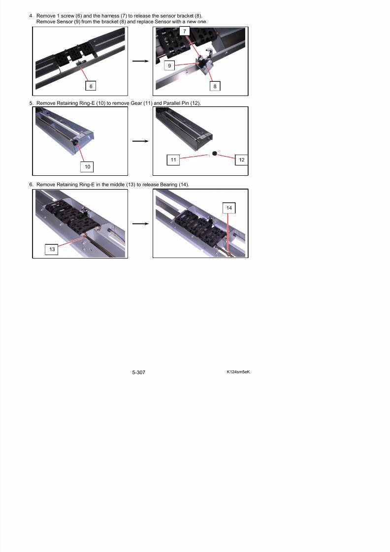
5/17/2018 KIP 7100 Service Manual Ver A_1 - slidepdf.com
http://slidepdf.com/reader/full/kip-7100-service-manual-ver-a1 335/674
13
7. Release Shaft 3 (15: shorter) to remove Shaft 2 (16: longer) from the unit.Remove and replace Belt (17) with new ones.
NOTE
Be careful of the outside/inside of the Belt (17).The smooth and shiny side of it should be inside.
15
16 16
17
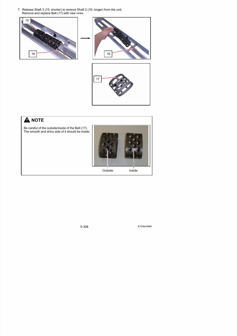
5/17/2018 KIP 7100 Service Manual Ver A_1 - slidepdf.com
http://slidepdf.com/reader/full/kip-7100-service-manual-ver-a1 336/674
5. 11 Main Frame
5. 11. 1 Replacement of DC Motors (M1, M2),Belt 8, Belt 9, Belt 7
1. Pull up the Lever 2 (1) to open the Engine Unit.
2. Remove 6 screws (2) to remove Cover 2 (3).
2
1
2
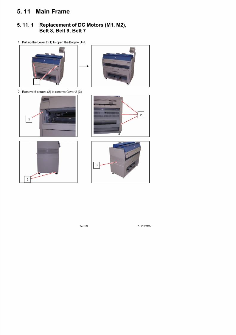
5/17/2018 KIP 7100 Service Manual Ver A_1 - slidepdf.com
http://slidepdf.com/reader/full/kip-7100-service-manual-ver-a1 337/674
3
3. Remove 4 pieces of 4x6 screw (4), loosen 4 pieces of 4x6 screw (5), and then remove theCover 15 (6).
4. Remove 5 screws (7) to remove Case 5 (8).
5. Disconnect 4 connectors (9).
4
5
6
7
7
8
9
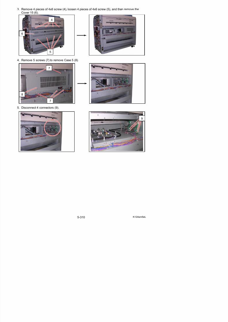
5/17/2018 KIP 7100 Service Manual Ver A_1 - slidepdf.com
http://slidepdf.com/reader/full/kip-7100-service-manual-ver-a1 338/674
6. Loosen the 4x6 screw (10). Move the Pulley 3 (11) toward the arrow mark and secure it toslacken Belt 8 (12).
NOTE
To adjust the tension of the Belt 8, do as follows.If you do not make the following works, Belt 8 may slip because the tension is notcorrect.
a) Replace Bracket (13) before tensioning.
b) Giving the spring tension to the Belt 8,tighten the screw (10) of Pulley 3 (11).
11
10 12
13
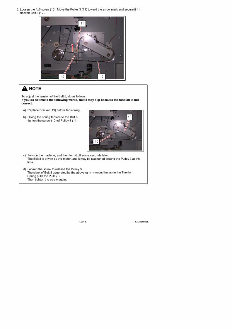
5/17/2018 KIP 7100 Service Manual Ver A_1 - slidepdf.com
http://slidepdf.com/reader/full/kip-7100-service-manual-ver-a1 339/674
c) Turn on the machine, and then turn it off some seconds later.The Belt 8 is driven by the motor, and it may be slackened around the Pulley 3 at thistime.
10
7. Remove 2 screws (14), Grip Ring and Bearing (15) to remove Bracket (13).Replace Belt 8 (12: 90S3M756) with the new one.
14
14
13 15
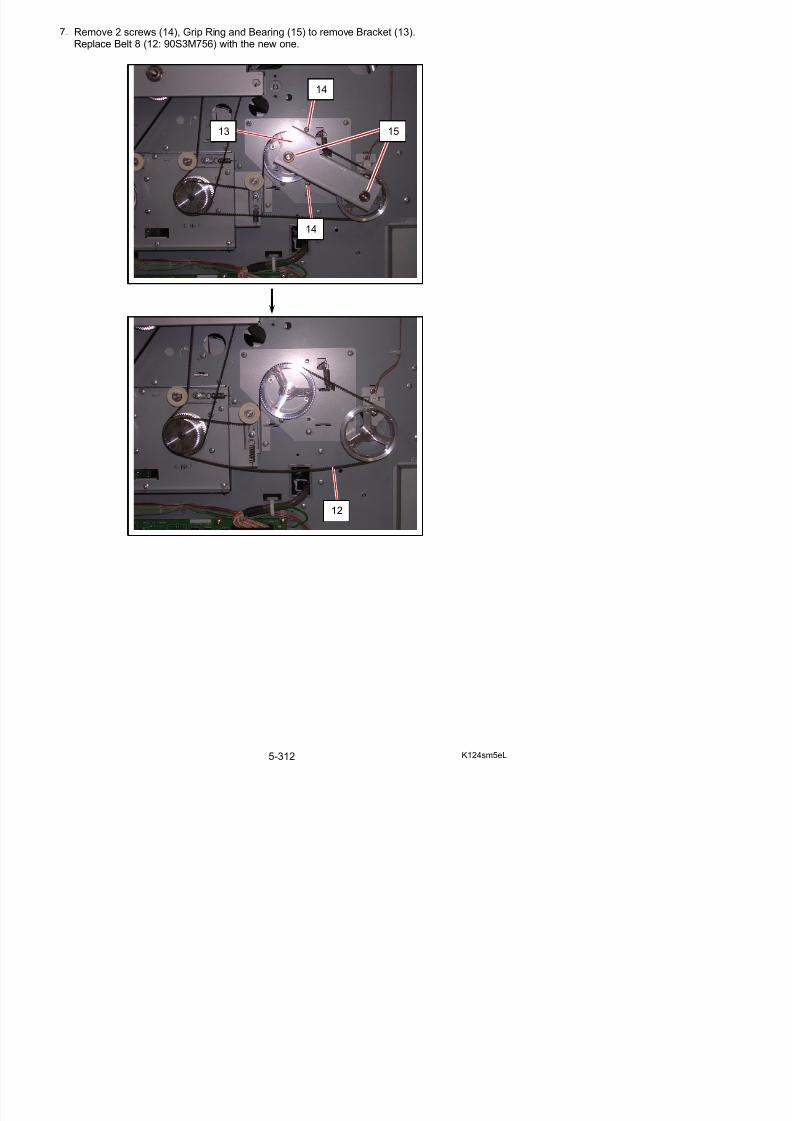
5/17/2018 KIP 7100 Service Manual Ver A_1 - slidepdf.com
http://slidepdf.com/reader/full/kip-7100-service-manual-ver-a1 340/674
12
8. Loosen 2 screws (16). Move the Pulley (17) (18) toward the arrow mark and secure them toslacken Belt 9 (19) and Belt 7 (20).
NOTE
To adjust the tension of the Belt 9 and Belt 7, do as follows.If you do not make the following works, the belts may slip because the tension is notcorrect.
a) Replace Bracket (21) before tensioning.
b) Giving the spring tension to the belt, tightenthe screw (16) of each Pulley.
16 16
1817
1920
21
1616
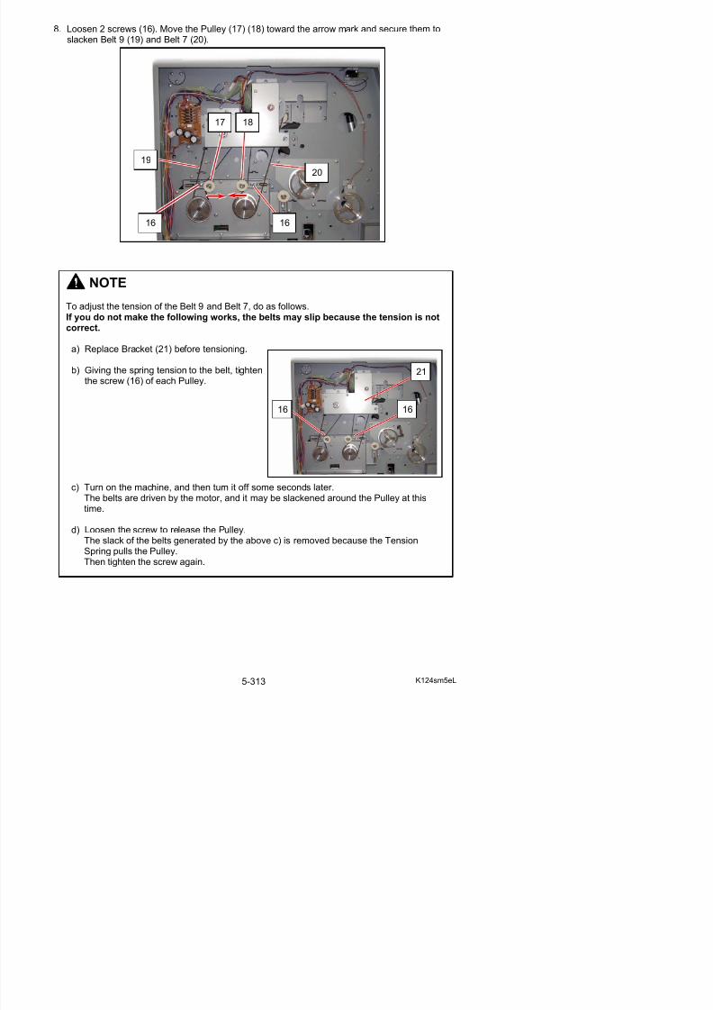
5/17/2018 KIP 7100 Service Manual Ver A_1 - slidepdf.com
http://slidepdf.com/reader/full/kip-7100-service-manual-ver-a1 341/674
c) Turn on the machine, and then turn it off some seconds later.The belts are driven by the motor, and it may be slackened around the Pulley at this
9. Remove 5 screws (22), Grip Ring and Bearing (23) to remove Bracket (21).Remove and replace Belt 9 (19: 90S3M576) and Belt 7 (20: 90S3M699) with new ones.
22
23
23
22
21
19 20
22
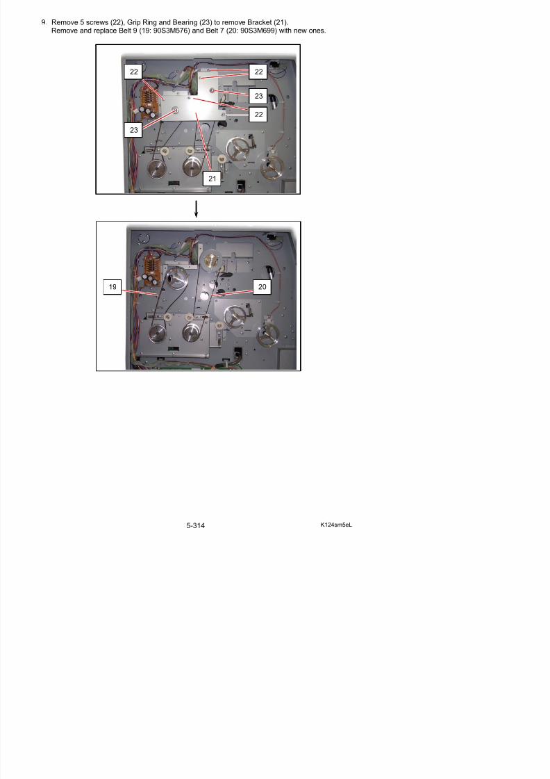
5/17/2018 KIP 7100 Service Manual Ver A_1 - slidepdf.com
http://slidepdf.com/reader/full/kip-7100-service-manual-ver-a1 342/674
10. Remove 7 pieces of 4x10 screw (24) to remove the Plate 6 Assembly (25).
24
25
24
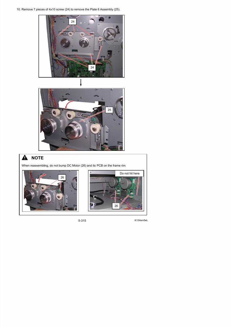
5/17/2018 KIP 7100 Service Manual Ver A_1 - slidepdf.com
http://slidepdf.com/reader/full/kip-7100-service-manual-ver-a1 343/674
NOTE
11. Remove Set Screws (27) on the side surface to remove each Pulley 4 (28).
12. Remove 4 pieces of 4x10 screws (29) to remove DC Motor (30: Main) (31: Fuser).Replace DC Motor (30) (31) with a new one.
NOTE
The tip of the motor shaft should be aligned with the outside surface of Pulley 4.
28
27
not sticked out
2929 31 30
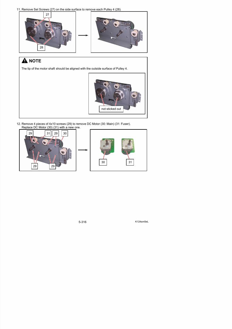
5/17/2018 KIP 7100 Service Manual Ver A_1 - slidepdf.com
http://slidepdf.com/reader/full/kip-7100-service-manual-ver-a1 344/674
30 31
5. 11. 2 Replacement of Clutch (CL1)
1. Pull up the Lever 2 (1) to open the Engine Unit.
2. Remove 6 screws (2) to remove Cover 2 (3).
2
3
1
2

5/17/2018 KIP 7100 Service Manual Ver A_1 - slidepdf.com
http://slidepdf.com/reader/full/kip-7100-service-manual-ver-a1 345/674
2
3. Loosen the 4x6 screw (4), move the Pulley 3 (5) toward the arrow mark and secure it toslacken Belt 8 (6).
NOTE
To adjust the tension of the Belt 8, do as follows.If you do not make the following works, Belt 8 may slip because the tension is notcorrect.
a) Replace Bracket (7) before tensioning.
b) Giving the spring tension to the Belt 8,tighten the screw (4) of Pulley 3 (5).
7
4
6
5
4
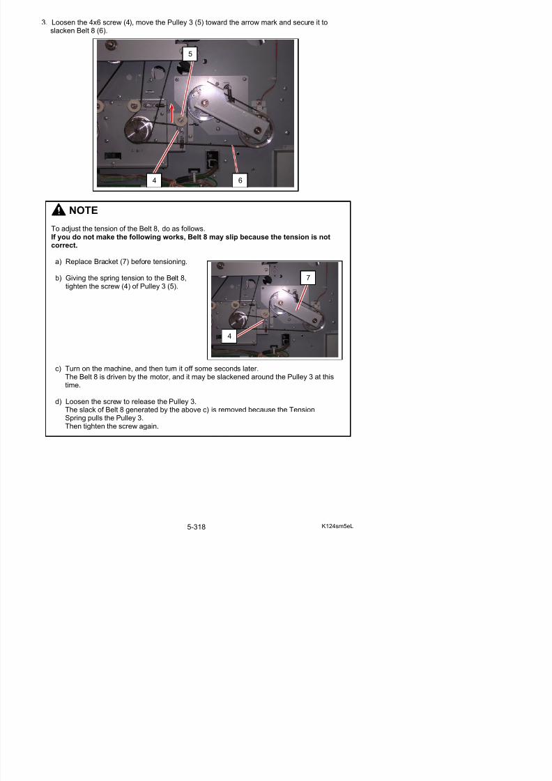
5/17/2018 KIP 7100 Service Manual Ver A_1 - slidepdf.com
http://slidepdf.com/reader/full/kip-7100-service-manual-ver-a1 346/674
c) Turn on the machine, and then turn it off some seconds later.The Belt 8 is driven by the motor, and it may be slackened around the Pulley 3 at thistime.
4
4. Remove 2 screws (8), Grip Ring and Bearing (9) to remove Bracket (7).Remove Belt 8 (6).
8
8
7 9
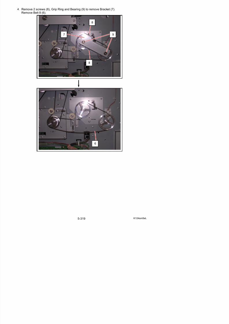
5/17/2018 KIP 7100 Service Manual Ver A_1 - slidepdf.com
http://slidepdf.com/reader/full/kip-7100-service-manual-ver-a1 347/674
6
5. Remove the Hex. Cap Screw (10) to removethe Pulley 13 (11).
6. Disconnect the connector (12), and remove the 4x6 screw (13) to remove Bracket Clutch (14),Clutch (15).Replace Clutch (15) with the new one.
12
13
14
15
11
10
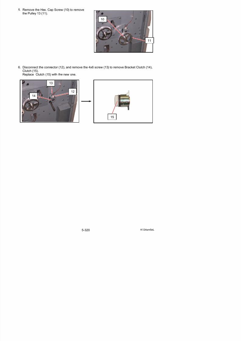
5/17/2018 KIP 7100 Service Manual Ver A_1 - slidepdf.com
http://slidepdf.com/reader/full/kip-7100-service-manual-ver-a1 348/674
5. 11. 3 Replacement of Blower (BL7)
1. Remove 4 pieces of 4x6 screw (1), loosen 4 pieces of 4x6 screw (2), and then remove theCover 15 (3).
2. Remove 5 screws (4) to remove Case 5 (5).
3. Disconnect the connector (6), remove 1 screw (7), and then remove the Bracket Blower (8).Remove 3 screws (9) to replace Blower (10) with the new one.
6
1
2
3
4
4
5
7
9
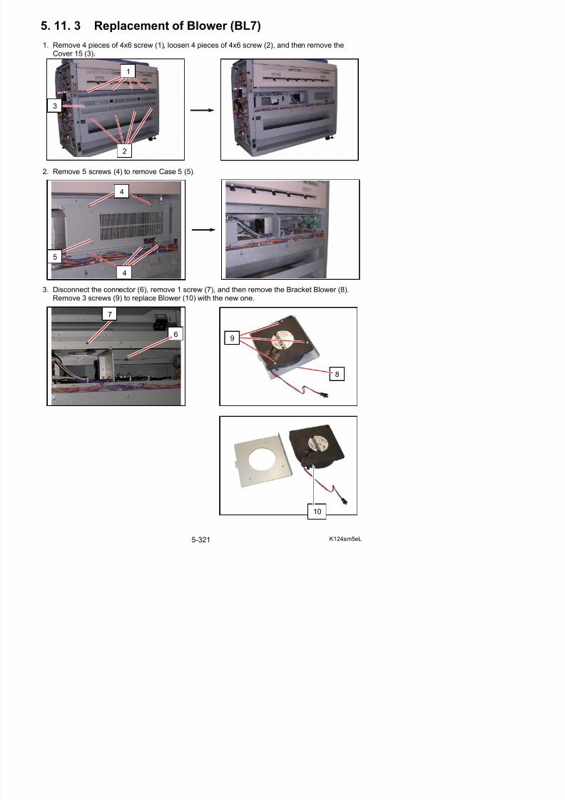
5/17/2018 KIP 7100 Service Manual Ver A_1 - slidepdf.com
http://slidepdf.com/reader/full/kip-7100-service-manual-ver-a1 349/674
8
5. 11. 4 Replacement of Fan (BL8)
1. Remove 4 pieces of 4x6 screw (1), loosen 4 pieces of 4x6 screw (2), and then remove theCover 15 (3).
2. Disconnect the connector (4), remove 1 screw (5), and then remove the Fan Bracket (6).Remove 4 screws (7) and 1 connector (8) to replace Fan (9) with a new one.
1
2
3
4
5
6
9
7 8
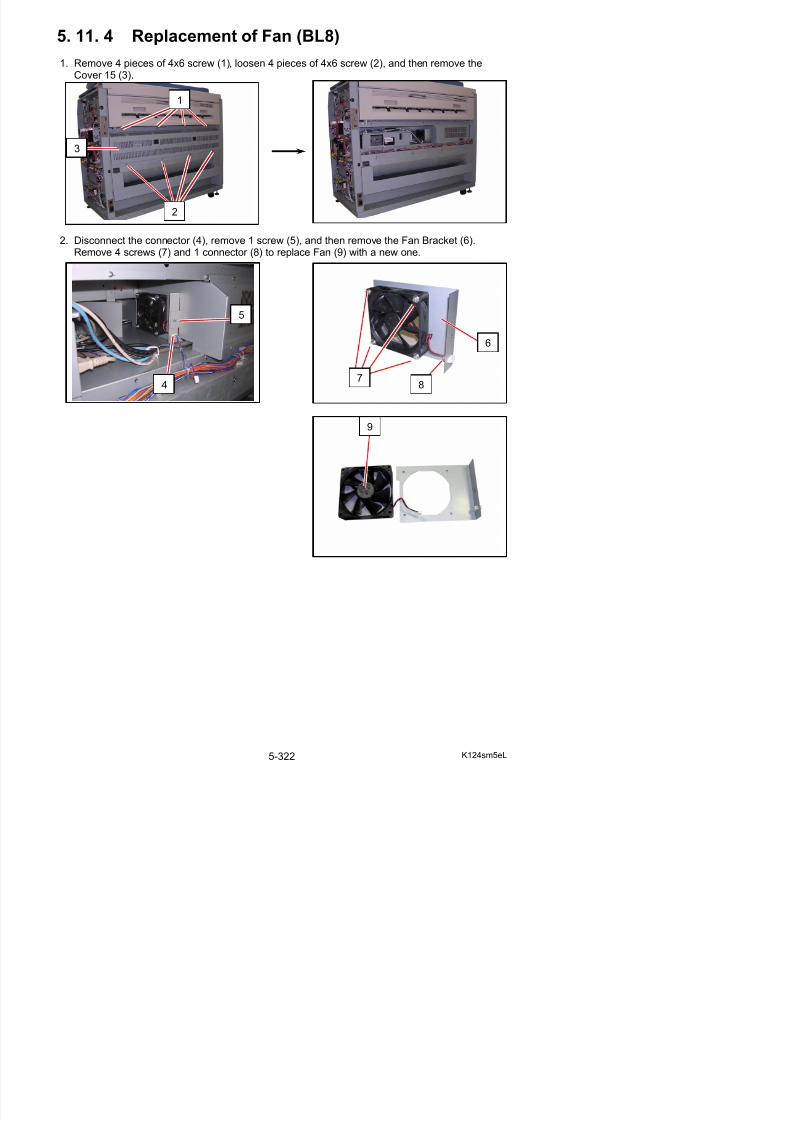
5/17/2018 KIP 7100 Service Manual Ver A_1 - slidepdf.com
http://slidepdf.com/reader/full/kip-7100-service-manual-ver-a1 350/674
5. 12 Scanner Unit
5. 12. 1 Removal of Scanner Unit
1. Remove 2 pieces of Guide 3 (1).
2. Remove 8 pieces of screws (2).
3 Remove Cover 14 (3)
1
2 2
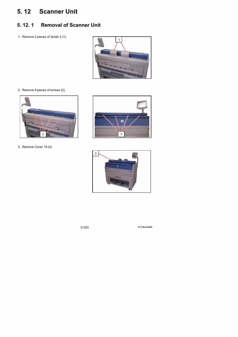
5/17/2018 KIP 7100 Service Manual Ver A_1 - slidepdf.com
http://slidepdf.com/reader/full/kip-7100-service-manual-ver-a1 351/674
3. Remove Cover 14 (3).
3
4. Remove 3 screws (4).
5. Remove Shield Cover N (5).
6. Remove 2 tooth washer screws (6) to remove Cover 10 (7)
4
4
5
7
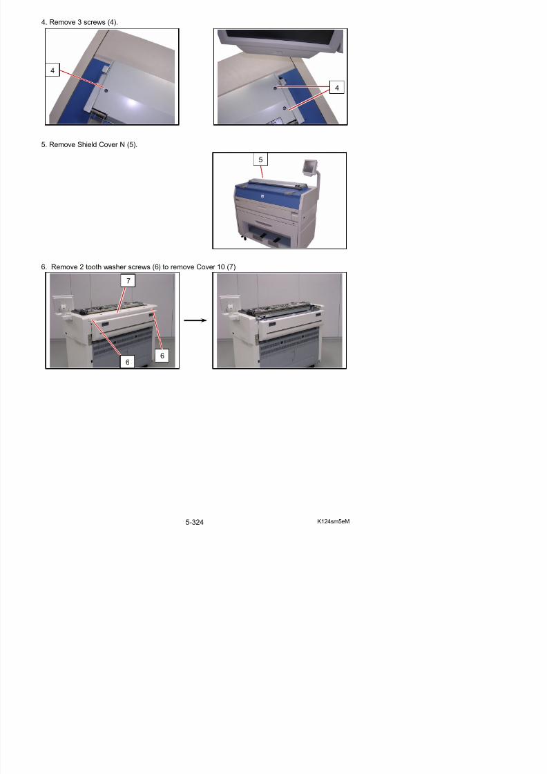
5/17/2018 KIP 7100 Service Manual Ver A_1 - slidepdf.com
http://slidepdf.com/reader/full/kip-7100-service-manual-ver-a1 352/674
66
7. Pull up Lever 2 (8) to open the Engine Unit.
8. Remove 5 screws (9).
9
9
9
8
8
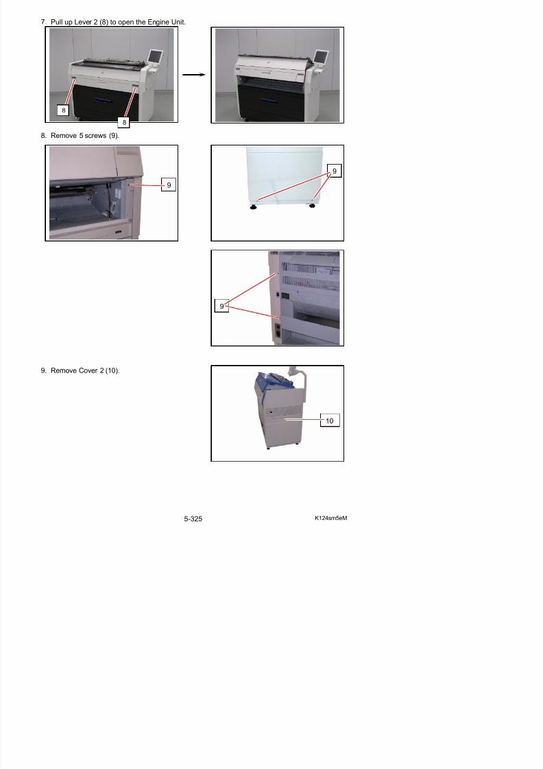
5/17/2018 KIP 7100 Service Manual Ver A_1 - slidepdf.com
http://slidepdf.com/reader/full/kip-7100-service-manual-ver-a1 353/674
9. Remove Cover 2 (10).
10. Open Cover 4 (11).
11. Remove 4 screws (12) to remove Cover 8 (13).
12. Remove 4 screws (14) to remove Cover (15).
11
13
11
12 12
12
13
14
14
14
15
15
13
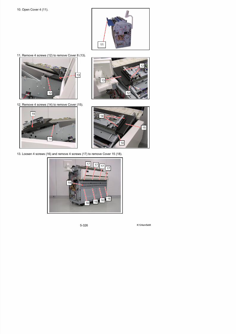
5/17/2018 KIP 7100 Service Manual Ver A_1 - slidepdf.com
http://slidepdf.com/reader/full/kip-7100-service-manual-ver-a1 354/674
13. Loosen 4 screws (16) and remove 4 screws (17) to remove Cover 15 (18).
17 17 17
14. Disconnect the Scanner USB Cable (19: with the label “SC”) from the upper right USB port of IPS.
15. Open 3 wire saddles (21) to release the Scanner USB Cable (19).
16. On the right side, open 3 wire saddles (22) to release the Scanner USB Cable (19).
19
21
19
22
2219
19
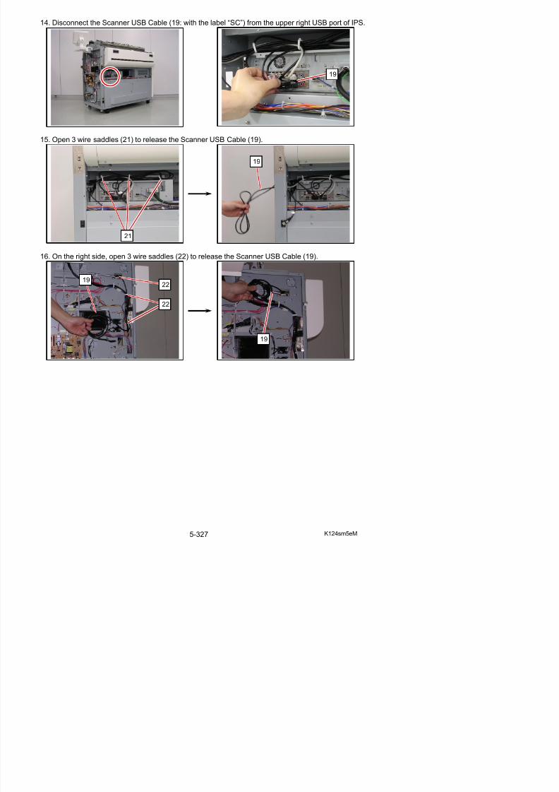
5/17/2018 KIP 7100 Service Manual Ver A_1 - slidepdf.com
http://slidepdf.com/reader/full/kip-7100-service-manual-ver-a1 355/674
17. Disconnect the connector (23). Open the wire saddles (24) to release the Scanner USB Cable (19).
18. Close the Engine Unit.
NOTE
Wind excessive length of the Scanner USB Cable(19) with the wire saddles (24) whenreassembling.
Do not bundle the 2 cables in any of the wiresaddles (24) together.
24
24
23
1919
19
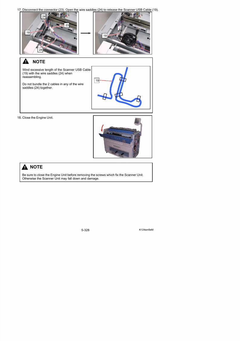
5/17/2018 KIP 7100 Service Manual Ver A_1 - slidepdf.com
http://slidepdf.com/reader/full/kip-7100-service-manual-ver-a1 356/674
NOTE
19. Remove 4 screws (25) which fix the Scanner Unit.
(Right side) (Left side)
19. Remove the Scanner Unit (26) from the machine.
CAUTION
Please carry the Scanner Unit by 2 persons as it is heavy.
25
25
2626
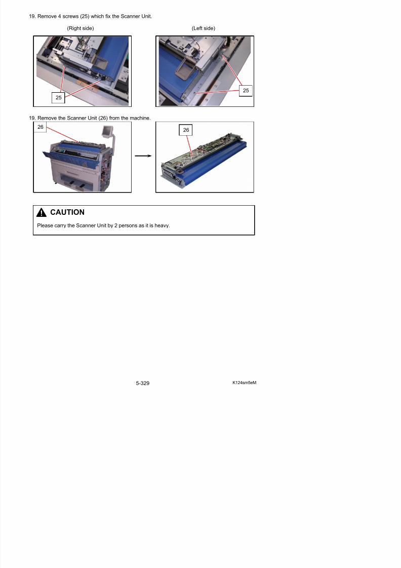
5/17/2018 KIP 7100 Service Manual Ver A_1 - slidepdf.com
http://slidepdf.com/reader/full/kip-7100-service-manual-ver-a1 357/674
5. 12. 2 Replacement of Belt
1. Remove the Scanner Unit (1) from the machine
making reference to [5.12. 1 Removal of theScanner Unit] on the page 5-323.
2. Pull up the Levers (2) and open Upper Unit.
3. Loosen 1 screw (3) to slide the stopper (4) and remove Spring (5) to remove Belt (6).Replace Belt with a new one.
1
2
4
4
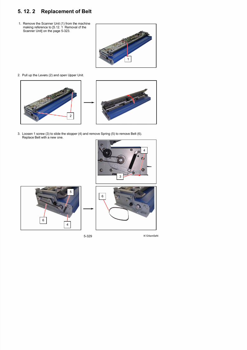
5/17/2018 KIP 7100 Service Manual Ver A_1 - slidepdf.com
http://slidepdf.com/reader/full/kip-7100-service-manual-ver-a1 358/674
NOTE
Belt (5) requires its tensioning when reassembling.
(1) Be sure to close Upper Unit prior to tensioning.Not doing so may prevent a proper tensioning.
Press down Upper Unit on both sides to closeit. Pressing only on one side may result intwisting the frame.
(2) Place Belt (6) in the original routing position.(No tension is applied to Belt at this time.)
(3) Replace Spring (5) in the original position.(A proper tension is applied to Belt.)
6
5
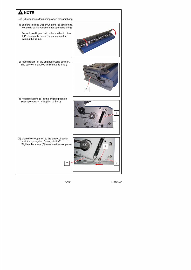
5/17/2018 KIP 7100 Service Manual Ver A_1 - slidepdf.com
http://slidepdf.com/reader/full/kip-7100-service-manual-ver-a1 359/674
5. 12. 3 Replacement of Motor Assy
1. Remove the Scanner Unit (1) from the machine
making reference to [5.12. 1 Removal of theScanner Unit] on the page 5-323.
2. Pull up the Levers (2) and open Upper Unit.
3. Loosen 1 screw (3) to slide the stopper (4) and remove Spring (5) to remove Belt (6).
1
2
4
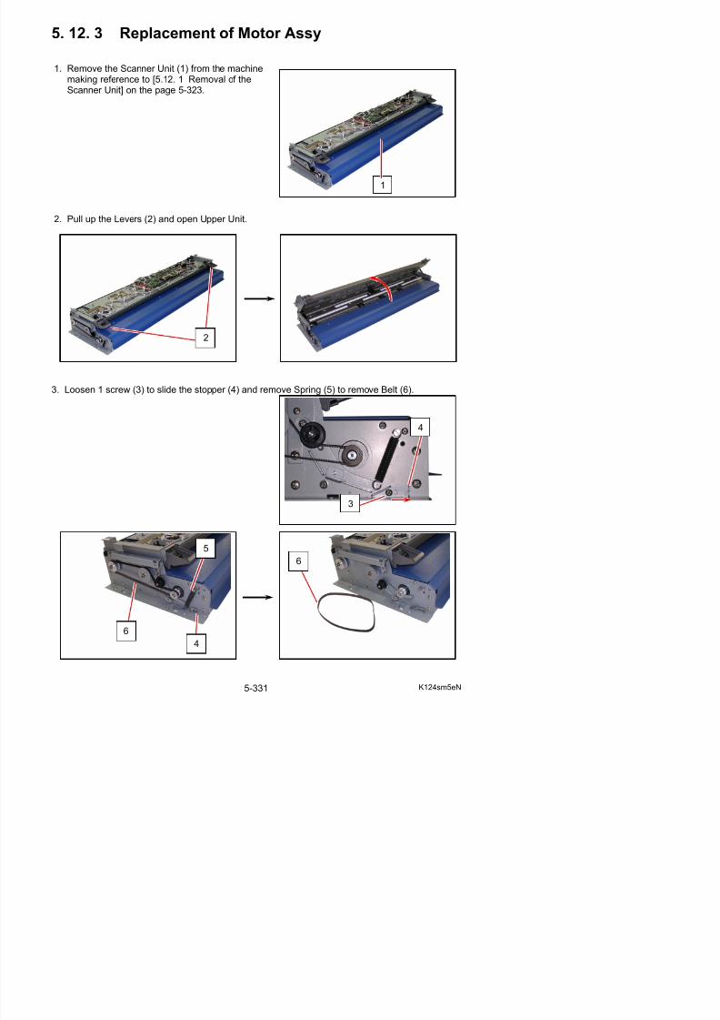
5/17/2018 KIP 7100 Service Manual Ver A_1 - slidepdf.com
http://slidepdf.com/reader/full/kip-7100-service-manual-ver-a1 360/674
3
NOTE
Belt (5) requires its tensioning when reassembling.
(1) Be sure to close Upper Unit prior to tensioning.Not doing so may prevent a proper tensioning.
Press down Upper Unit on both sides to closeit. Pressing only on one side may result intwisting the frame.
(2) Place Belt (6) in the original routing position.(No tension is applied to Belt at this time.)
(3) Replace Spring (5) in the original position.(A proper tension is applied to Belt.)
6
5

5/17/2018 KIP 7100 Service Manual Ver A_1 - slidepdf.com
http://slidepdf.com/reader/full/kip-7100-service-manual-ver-a1 361/674
4. Remove 2 screws (8: M3x6) and 4 screws (9: M3x6 w/ FW) to remove Sheet Guide (10).
5. Disconnect the harness (11) from Motor Assy (12).
8
8
9
10
11
12
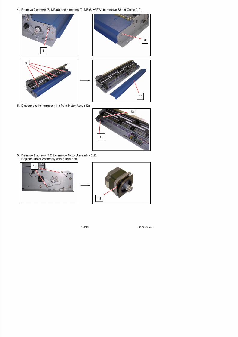
5/17/2018 KIP 7100 Service Manual Ver A_1 - slidepdf.com
http://slidepdf.com/reader/full/kip-7100-service-manual-ver-a1 362/674
6. Remove 2 screws (13) to remove Motor Assembly (12).Replace Motor Assembly with a new one.
13
5. 12. 4 Replacement of Feed Roller
1. Remove the Scanner Unit (1) from the machine
making reference to [5.12. 1 Removal of theScanner Unit] on the page 5-323.
2. Pull up the Levers (2) and open Upper Unit.
3. Loosen 1 screw (3) to slide the stopper (4) and remove Spring (5) to remove Belt (6).
1
2
4
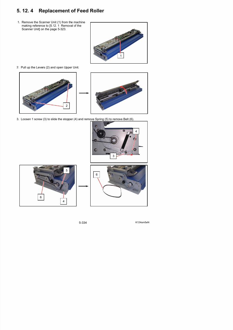
5/17/2018 KIP 7100 Service Manual Ver A_1 - slidepdf.com
http://slidepdf.com/reader/full/kip-7100-service-manual-ver-a1 363/674
3
NOTE
Belt (5) requires its tensioning when reassembling.
(1) Be sure to close Upper Unit prior to tensioning.Not doing so may prevent a proper tensioning.
Press down Upper Unit on both sides to closeit. Pressing only on one side may result intwisting the frame.
(2) Place Belt (6) in the original routing position.(No tension is applied to Belt at this time.)
(3) Replace Spring (5) in the original position.(A proper tension is applied to Belt.)
6
5

5/17/2018 KIP 7100 Service Manual Ver A_1 - slidepdf.com
http://slidepdf.com/reader/full/kip-7100-service-manual-ver-a1 364/674
4. Remove 2 screws (8: M3x6) and 4 screws (9: M3x6 w/ FW) to remove Sheet Guide (10).
5. Remove 1 screw (11) to remove Stay (12). Open Upper Unit fully.
8
8
9
10
11
12
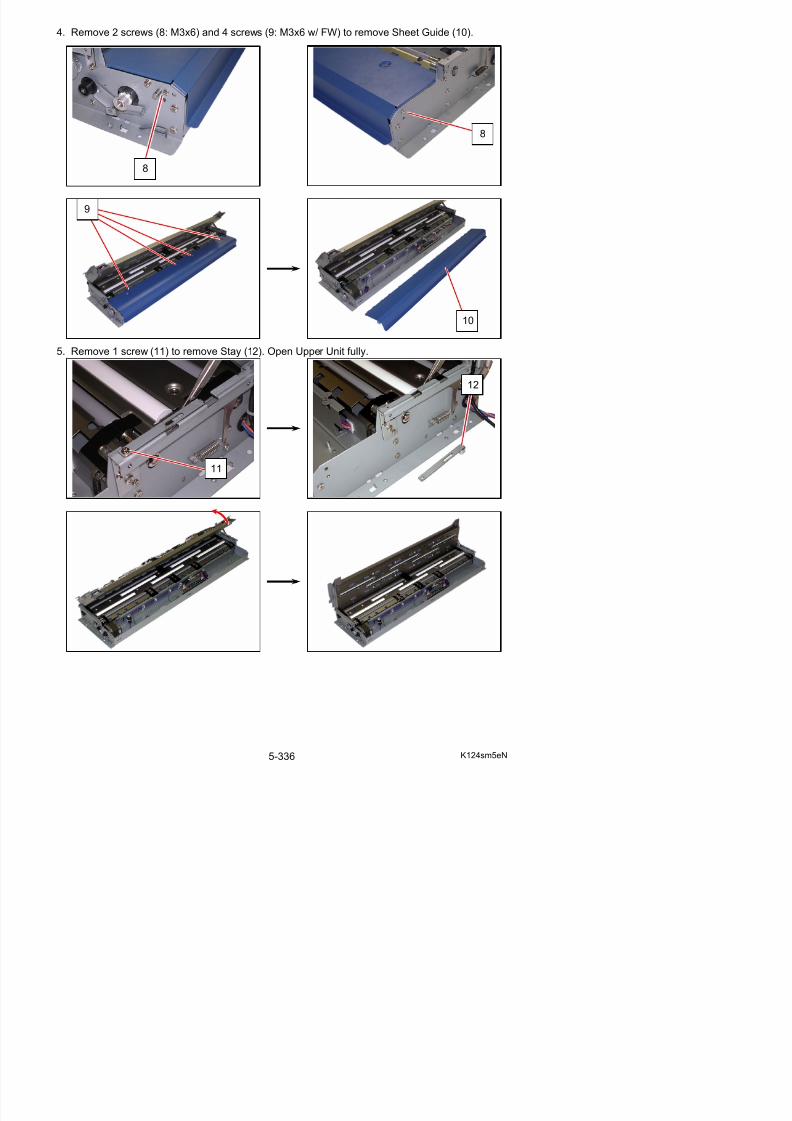
5/17/2018 KIP 7100 Service Manual Ver A_1 - slidepdf.com
http://slidepdf.com/reader/full/kip-7100-service-manual-ver-a1 365/674
6. Remove 7 screws (13). Release the black plastic sheets (14) from the frame to remove PressRoller Assy (15).
NOTE
When reassembling, make sure that the 3 black plastic sheets on the rear of Press Roller Assy (16) are in position. Do not flip them up.
15
15
13 13
14 14
16
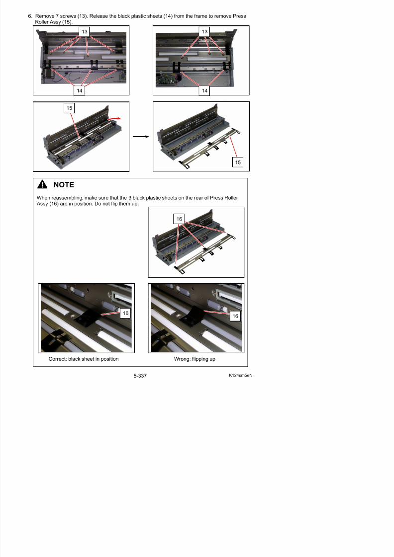
5/17/2018 KIP 7100 Service Manual Ver A_1 - slidepdf.com
http://slidepdf.com/reader/full/kip-7100-service-manual-ver-a1 366/674
7. On the left side, remove Retaining Ring-E (17), Set Screw (18) to remove Pulley (19) (20),Spacer (21), Bearing (22) from each roller shaft.
17
18
19
20
21
22
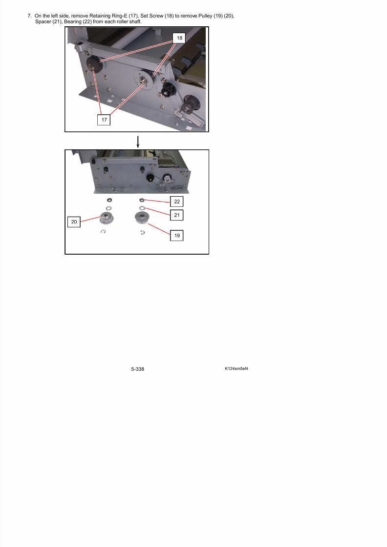
5/17/2018 KIP 7100 Service Manual Ver A_1 - slidepdf.com
http://slidepdf.com/reader/full/kip-7100-service-manual-ver-a1 367/674
8. On the right side, remove Retaining Ring-E (23) to remove Washer (24), Bearing (25) from eachroller shaft.
23
24
25
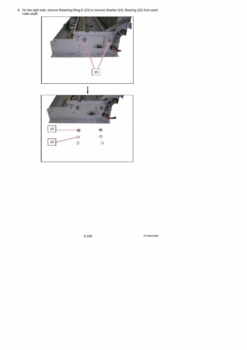
5/17/2018 KIP 7100 Service Manual Ver A_1 - slidepdf.com
http://slidepdf.com/reader/full/kip-7100-service-manual-ver-a1 368/674
9. Pressing Press Assys (26) down, slide Feed Roller F (27: front) and Feed Roller R (28: rear) tothe motor side and remove it.Replace Feed Roller F / Feed Roller R with a new one.
26
27
26
28
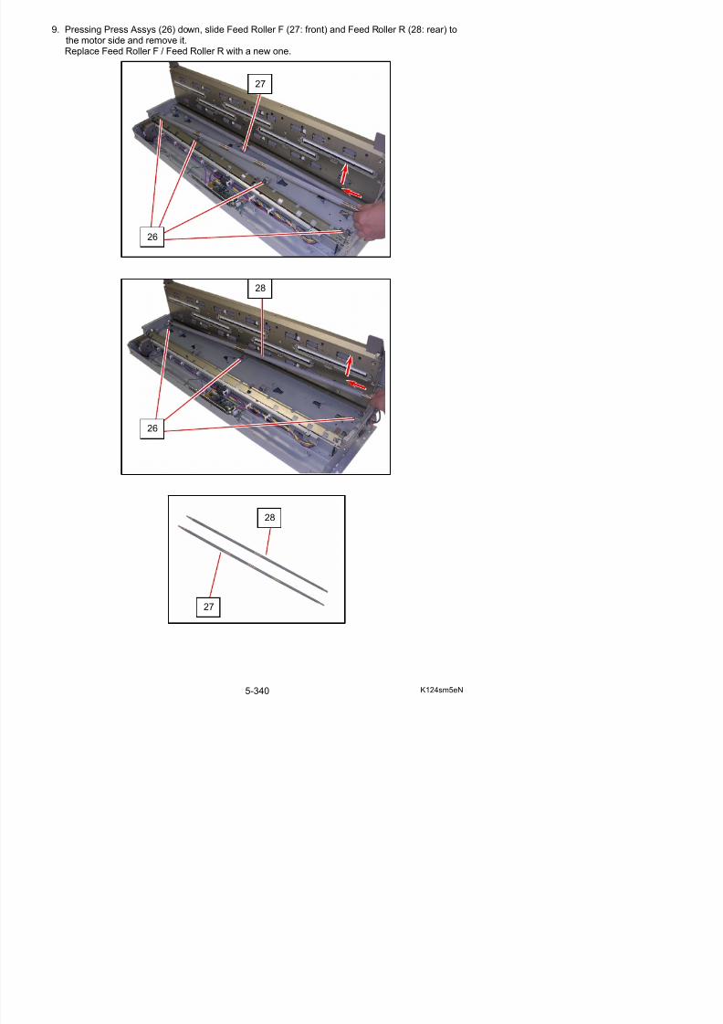
5/17/2018 KIP 7100 Service Manual Ver A_1 - slidepdf.com
http://slidepdf.com/reader/full/kip-7100-service-manual-ver-a1 369/674
10. Replace all the parts in position.
11. Install Scanner Unit to the machine. Connect the USB cable of Scanner Unit to your PC.
12. Perform Feed Distance adjustment.
NOTE
(1) The longer thin end of Feed Rollers should be placed at the left.
(2) Feed Roller F (27) and Feed Roller R (28) arenot interchangeable.The 2 rollers have different rubber belt
pattern.
(3) Use alcohol. Do not use water for cleaning Feed Rollers.
Left Right
40
NOTE
27
28
27
28
27: 4 bands
28: 2 bands
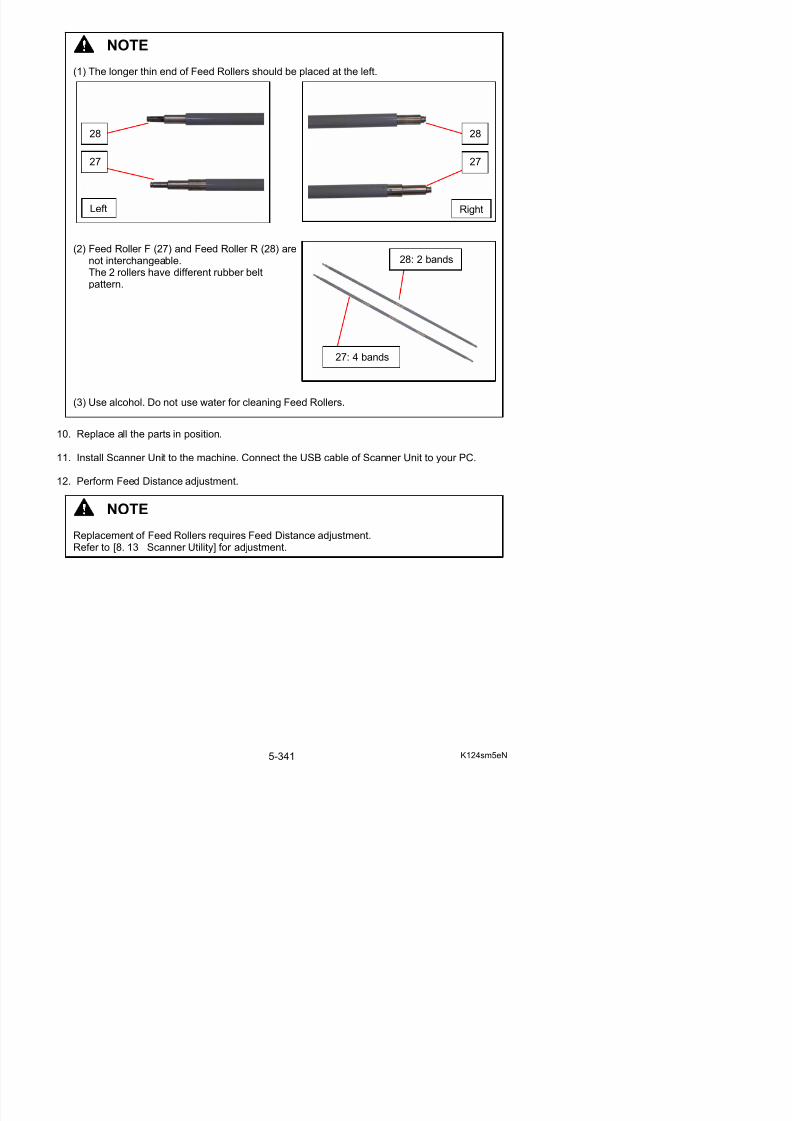
5/17/2018 KIP 7100 Service Manual Ver A_1 - slidepdf.com
http://slidepdf.com/reader/full/kip-7100-service-manual-ver-a1 370/674
Replacement of Feed Rollers requires Feed Distance adjustment.Refer to [8. 13 Scanner Utility] for adjustment.
5. 12. 5 Replacement of Pinch Roller Assy
1. Remove the Scanner Unit (1) from the machine
making reference to [5.12. 1 Removal of theScanner Unit] on the page 5-323.
2. Remove Retaining Ring-E (2) from the shaft of Pinch Roller.
1
2
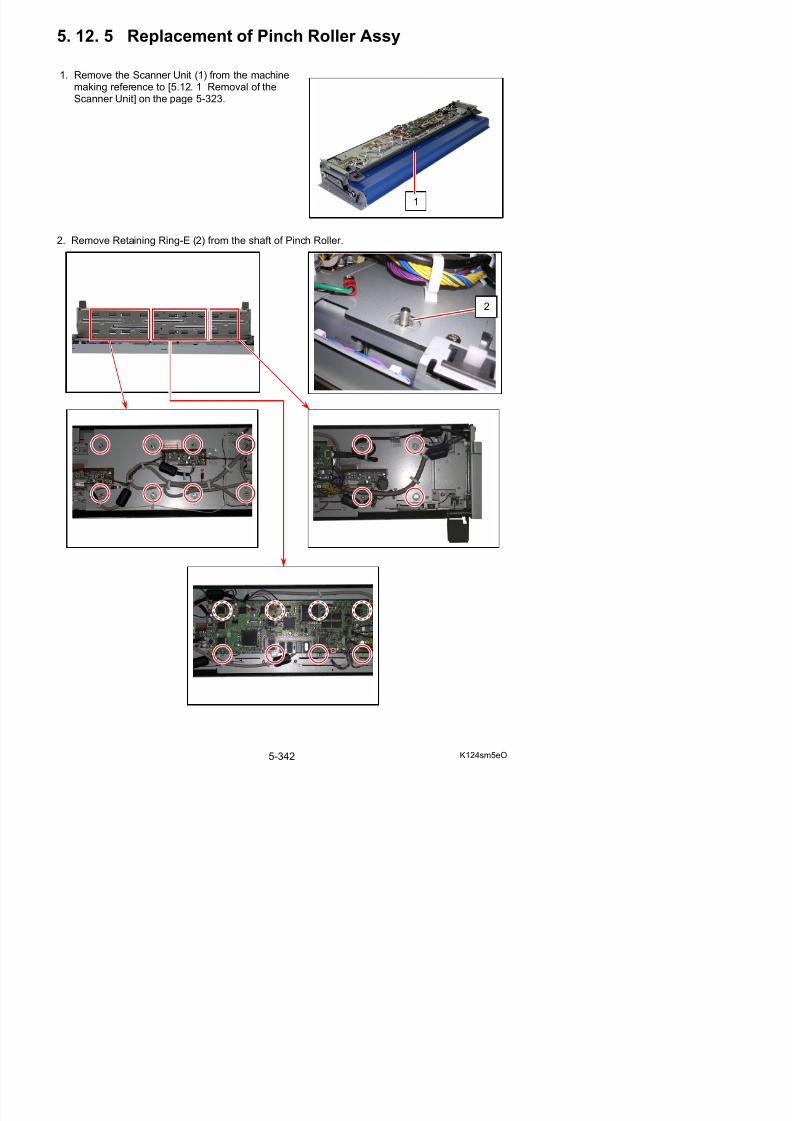
5/17/2018 KIP 7100 Service Manual Ver A_1 - slidepdf.com
http://slidepdf.com/reader/full/kip-7100-service-manual-ver-a1 371/674
NOTE
For replacement of Pinch Rollers beneath (or near) SVC Main BD K, remove Retaining Ring-E for the concerning Pinch Roller (shown below) after removing SVC Main BD K.
(1) Remove all the connectors (3) from SVC Main BD K (4).
4
3
3
3
3
3
3 3
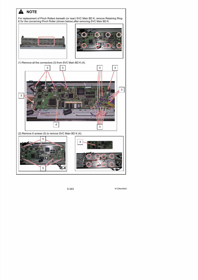
5/17/2018 KIP 7100 Service Manual Ver A_1 - slidepdf.com
http://slidepdf.com/reader/full/kip-7100-service-manual-ver-a1 372/674
(2) Remove 6 screws (5) to remove SVC Main BD K (4).
5
3. Pull up the Levers (6) and open Upper Unit slightly.Put your hand in between Upper and Lower Unit and hold the Pinch Roller Assy (7) not to fall itsSpring (8) inside Upper Unit.Remove Pinch Roller Assy (7) and Spring (8).Replace Pinch Roller Assy with a new one.
6
8
7
8
7
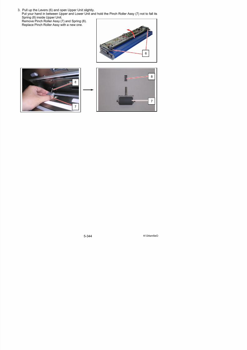
5/17/2018 KIP 7100 Service Manual Ver A_1 - slidepdf.com
http://slidepdf.com/reader/full/kip-7100-service-manual-ver-a1 373/674
5. 12. 6 Replacement of CIS
1. Remove the Scanner Unit (1) from the machinemaking reference to [5.12. 1 Removal of the
Scanner Unit] on the page 5-323.
NOTE A CIS is divided into several classes according to wavelength variations of their LED.
All the 5 pieces of CIS on a certain scanner should be the same class to assure even imagequality (brightness, color quality and etc) among image blocks.
Be sure to check which CIS class is used to the scanner before replacing to avoid class
mixing. Otherwise even image quality can not be expected.
Equipped CIS class can be identified on the label on the CIS unit, and can be checked withthe label on the rear of the scanner.
Label
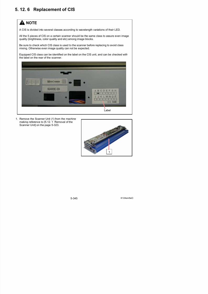
5/17/2018 KIP 7100 Service Manual Ver A_1 - slidepdf.com
http://slidepdf.com/reader/full/kip-7100-service-manual-ver-a1 374/674
2. Open the Scanner Upper Unit.On a CIS to be replaced, remove 2 small screws (2) with a sharp screwdriver.
3. Remove all the connectors (3) from SVC Main BD K (3).
2
3
3
3 3 3
4
3
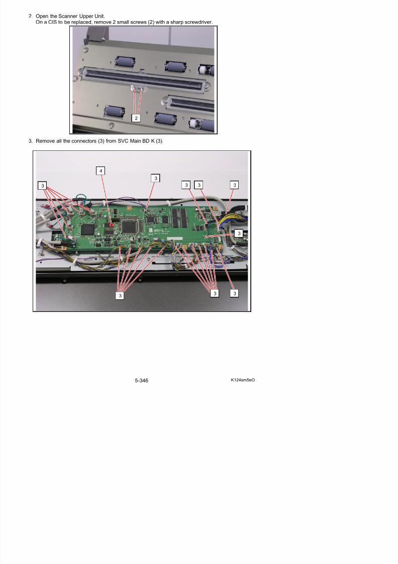
5/17/2018 KIP 7100 Service Manual Ver A_1 - slidepdf.com
http://slidepdf.com/reader/full/kip-7100-service-manual-ver-a1 375/674
4. Remove 6 screws (5) to Remove SVC Main BD K (4).
5. On all CIS Boards (6), remove 2 harnesses (7)
6. Remove 4 screws (8) and the harness to remove Switch Bracket R / L (9).
6
7
7
6
5 5 5
5 5 54
4
9
8 8
9
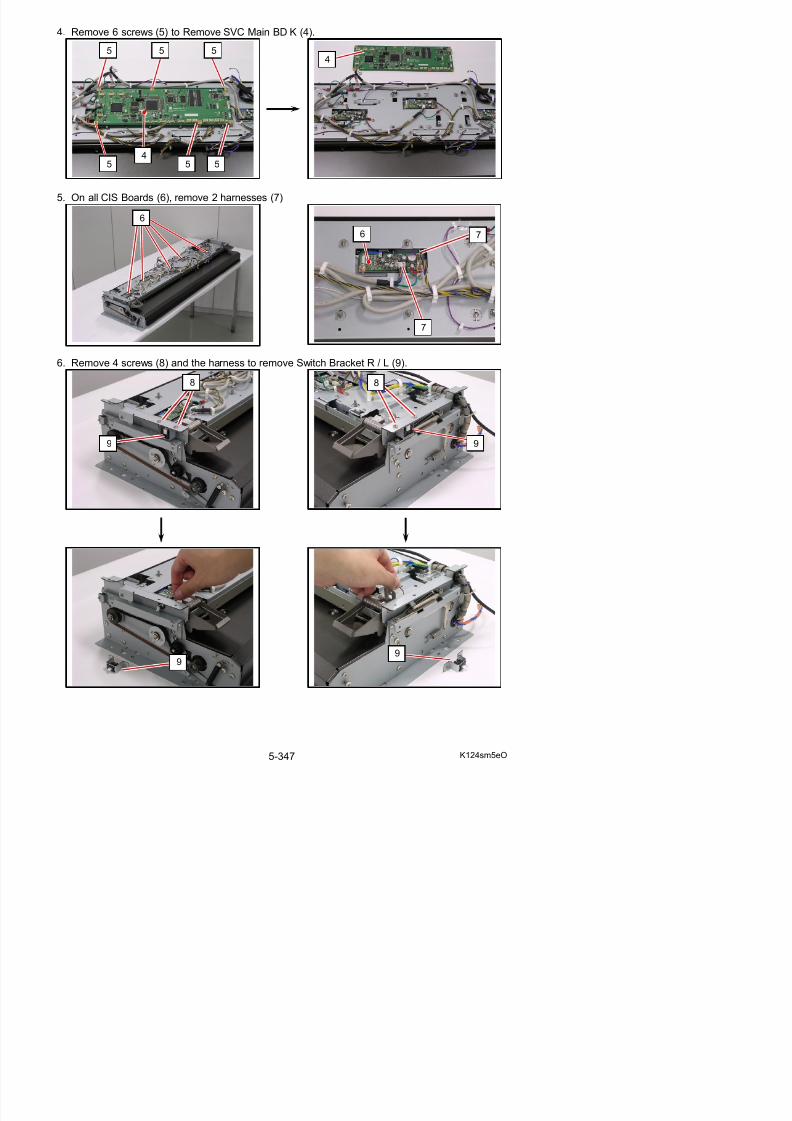
5/17/2018 KIP 7100 Service Manual Ver A_1 - slidepdf.com
http://slidepdf.com/reader/full/kip-7100-service-manual-ver-a1 376/674
7. Remove 9 screws (10, M3x6) and 2 screws (11, M4x6).
11
1010
10 10 11
10 10
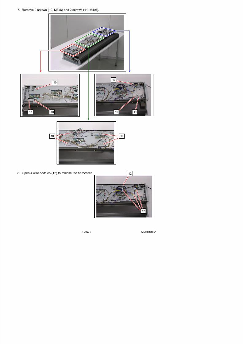
5/17/2018 KIP 7100 Service Manual Ver A_1 - slidepdf.com
http://slidepdf.com/reader/full/kip-7100-service-manual-ver-a1 377/674
9. Remove the Base Plate (13).
10. Remove 4 screws (14, M3x4 w/ TW) to remove the concerning CIS Bracket (15).
front
14
14
15
15
front
NOTE
Place CIS Bracket on a soft cloth or anything toavoid damage on the Scan Glass Assy (16).
If you remove the Scan Glass Assy just in case,still you should prepare such to avoid damageon the sensor array of the CIS (17).
16
17
13 13
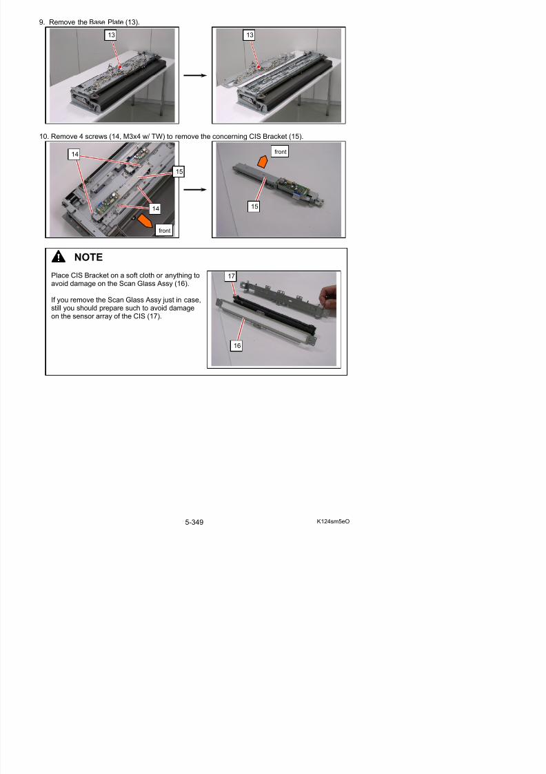
5/17/2018 KIP 7100 Service Manual Ver A_1 - slidepdf.com
http://slidepdf.com/reader/full/kip-7100-service-manual-ver-a1 378/674
11. Remove 2 screws (18) to release CIS Board (19).Carefully remove the flat cable (20) from CIS.
18front
19 20
20
19
front
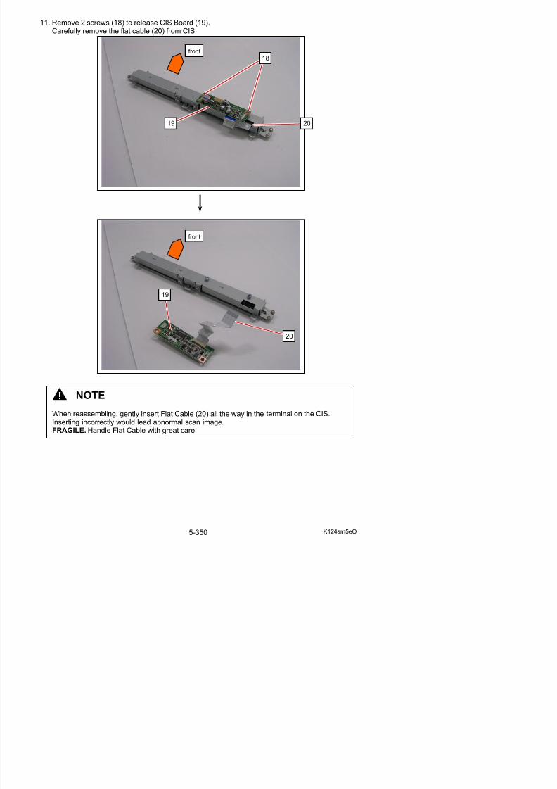
5/17/2018 KIP 7100 Service Manual Ver A_1 - slidepdf.com
http://slidepdf.com/reader/full/kip-7100-service-manual-ver-a1 379/674
12. Remove 6 screws (21: M3x4 w/ SW) and 2 screws (22: M3x4) disassemble the CIS Unit.- upper bracket (23)- small spacer (24)- CIS (17)- lower bracket with Scan Glass Assy (16)
13. Replace CIS with a new one.
14. Return all the parts in position.
15. Perform the scanner calibration. See [8.13.4 Scanner Utility].
front
front
23
22
21
21
21
21
21
24
16
17
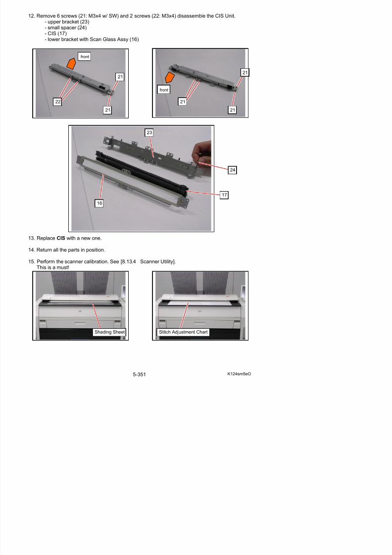
5/17/2018 KIP 7100 Service Manual Ver A_1 - slidepdf.com
http://slidepdf.com/reader/full/kip-7100-service-manual-ver-a1 380/674
15. Perform the scanner calibration. See [8.13.4 Scanner Utility].This is a must!
5. 12. 7 Replacement of Scan Glass Assy
1. Open the Scanner Upper Unit.Remove 4 screws (1) to remove Scan Glass Assy.
Reference
Dismounting Scanner Unit is not mandatory to remove Scan Glass Assy.
1
1
1
1
2
2
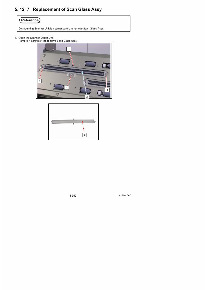
5/17/2018 KIP 7100 Service Manual Ver A_1 - slidepdf.com
http://slidepdf.com/reader/full/kip-7100-service-manual-ver-a1 381/674
Chapter 6
Maintenance
5/17/2018 KIP 7100 Service Manual Ver A_1 - slidepdf.com
http://slidepdf.com/reader/full/kip-7100-service-manual-ver-a1 382/674
KIP 7100 - PM Schedule r1
-Please keep this form with the KIP 7100 ; Please perform PMs as scheduled
-As the PM comes due and items replaced or cleaned, please denote with an "X" in the Confirmation box. Please note nomenclature below.
Part / Description Qty Part Number Square Feet X 1000
C o d e
50 C o m p l e t e
100 C o m p l e t e
150 C o m p l e t e
200 C o m p l e t e
250 C o m p l e t e
300 C o m p l e t e
350 C o m p l e t e
400 C o m p l e t e
450 C o m p l e t e
500 C o m p l e t e
Document Glass ( scanner ) # C C C C C C C C C C
Document Rollers ( scanner ) # C C C C CPhotoreceptor 1 SUP3000-101 R
Main Charge Wire 1 SUP9810-104 # C C C R C C C R C C
Transfer Wire 1 SUP3820-106 # C C C R C C C R C C
Separation Wire 1 SUP3820-106 # C C C R C C C R C C
Grid Screen # C C C C C
LED Head # C C C C C C C C C C
Developer Space Discs # C C C C C
Lube Gears L L L L L
Developer Roller - Kit 1 Z160980020 R R R
Roll Compartment & Interior @ C C C C C C C C C C
Knife @ C C
Filters - Kit 1 Z160980220 @ C C C C C C R C C C
Fuser - Kit 1 Z160980040 C C C
Lube Gears L L L L L
Fuser Fingers C C C C C C C C C C
Pressure Roller C C
Thermostat C C
Thermistor C C
Exterior Covers / GUI # C C C C C C C C C C
# = Clean with glass cleaner and wipe dry
@ = Clean with vacuum
Subject to change without notice
Actual intervals may vary due to customer requirements / installation location
L = LubricateC = Clean
I = Inspect
R = Replace
A = Adjust position
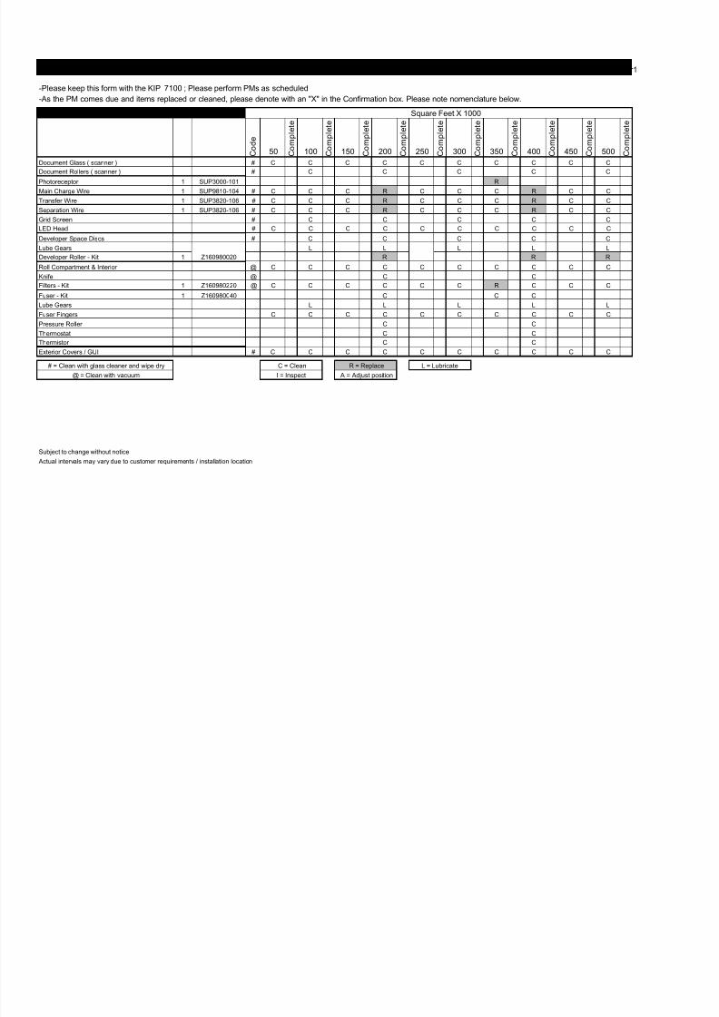
5/17/2018 KIP 7100 Service Manual Ver A_1 - slidepdf.com
http://slidepdf.com/reader/full/kip-7100-service-manual-ver-a1 383/674
KIP 7100 - PM Schedule
-Please keep this form with the KIP 7100 ; Please perform PMs as scheduled
-As the PM comes due and items replaced or cleaned, please denote with an "X" in the Confirmation box. Please note nomenclature below.
Part / Description Qty Part Number Square Feet X 1000
C o d e
550 C o m p l e t e
600 C o m p l e t e
650 C o m p l e t e
700 C o m p l e t e
750 C o m p l e t e
800 C o m p l e t e
850 C o m p l e t e
900 C o m p l e t e
950 C o m p l e t e
1000 C o m p l e t e
Document Glass ( scanner ) # C C C C C C C C C C
Document Rollers ( scanner ) # C C C C CPhotoreceptor 1 SUP3000-101 R
Main Charge Wire 1 SUP9810-104 # C R C C C R C C C R
Transfer Wire 1 SUP3820-106 # C R C C C R C C C R
Separation Wire 1 SUP3820-106 # C R C C C R C C C R
Grid Screen # C C C C
LED Head # C C C C C C C C C C
Developer Space Discs # C C C C
Lube Gears L L L L L
Developer Roller - Kit 1 Z160980020 R R R R
Roll Compartment & Interior @ C C C C C C C C C C
Knife @ C C C
Filter - Kit 1 Z160980220 @ C C C R C C C C C C
Fuser - Kit 1 Z160980040 C C C
Lube Gears L L L L L
Fuser Fingers C C C C C C C C C C
Pressure Roller C C C
Thermostat C C C
Thermistor C C C
Exterior Covers / GUI # C C C C C C C C C C
# = Clean with glass cleaner and wipe dry
@ = Clean with vacuum
Subject to change without notice
Actual intervals may vary due to customer requirements / installation location
I = Inspect A = Adjust position
C = Clean R = Replace L = Lubricate

5/17/2018 KIP 7100 Service Manual Ver A_1 - slidepdf.com
http://slidepdf.com/reader/full/kip-7100-service-manual-ver-a1 384/674
6. 2. 2 Lubrication
Please apply an adequate amount of grease to the components shown in the following section.Recommended lubrication term is in every 18,000m.Use silicone grease unless otherwise noted.
6. 2. 2. 1 Driving Gears on Machine Frame
Remove Developer Unit and Fuser Unit. Apply grease to Gear 3 (1), Gear Helical 34T (2), Gear Helical 20T (3). Apply heat-proof grease to Gear 36T (4).
Engine Unit from top, Developer Unit removed Engine Unit open, Developer Unit removed
3
2
1
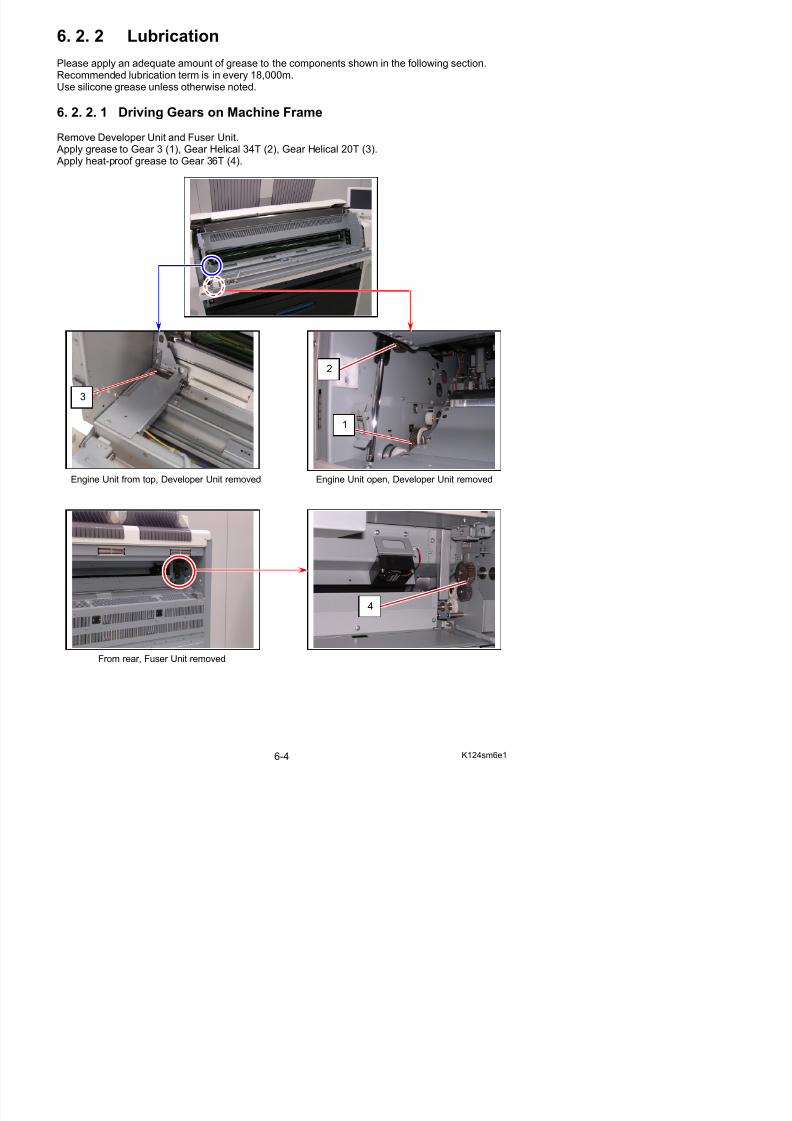
5/17/2018 KIP 7100 Service Manual Ver A_1 - slidepdf.com
http://slidepdf.com/reader/full/kip-7100-service-manual-ver-a1 385/674
6. 2. 2. 2 Developer Unit
Remove Developer Unit. Apply conductive grease to the contacting points for Developer/Blade/Toner Supply Rollers on themetal plates (1).
Apply grease to Gear Helical 28T (2).
6. 2. 2. 3 Terminal Plates on Machine Frame
Open Engine Unit. Apply conductive grease to the contacting points for Photoconductive Drum / Cleaning Roller onthe metal plates (1).
1
2
1
1
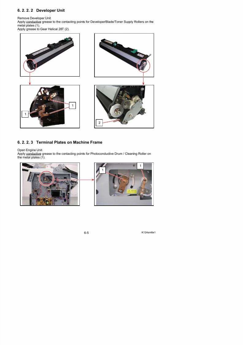
5/17/2018 KIP 7100 Service Manual Ver A_1 - slidepdf.com
http://slidepdf.com/reader/full/kip-7100-service-manual-ver-a1 386/674
1
1
KIP 7100Preventative Maintenance Procedure
- every 50,000 square feet -
Step #1 - Prepare Machine.
Ask User on Printer Performance / Image Quality
Run Test Print
Locate the “KIP 7100 PM Schedule” FormAnd check as each item completed.
Replace noted items as this procedure progresses.
Remove Drum (into Box)
Remove side and top covers.Step #2 - Corona Units
Clean Grid Screen (Simple Green, then rinse with water) let dry on paper towel.
Clean 1st Charge wires and case (Glass cleaner)
Clean transfer / separation wires and case. (Glass cleaner)Step #3 - LED Print Head.
Clean Selfoc lens. (Glass cleaner.) Step #4 - Clean Interior of Printer.
Separation fans / air guides.
Transport belts.
Transfer guide plates etc.Step #5 - Development Unit.
Clean spacing rollers.
Vacuum any toner dust from ends of developer unit.
Vacuum around toner hopper inlet.
Clean /` lube gears ( only as needed with G501 grease / Lithium grease. - see Chapter 6 inService Manual)
Step #6 - Paper Decks.
Vacuum paper dust.
Inspect media spools. Step #7 - Air Flow.
Vacuum Ozone Filters.
Confirm all fans and blowers are clean.Step #8 - Fuser Section.
Clean upper Nails.
Clean lower Nails.
Clean and lube gears. (as needed with High temp. grease - see Chapter 6 in Service
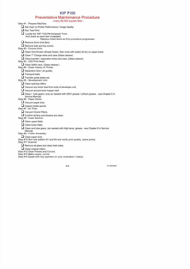
5/17/2018 KIP 7100 Service Manual Ver A_1 - slidepdf.com
http://slidepdf.com/reader/full/kip-7100-service-manual-ver-a1 387/674
Manual) Step #9 Cutter Assembly
6. 4 Service Tool List
Here is the table to list special tools for field service.It is recommended to check them through in Parts Manual and Publication Bulletin for the latest
information.
Part Name(Part Number)
Appearance / Usage Requirement Related Section
DEV HANDLE ASSY(Developer Handle)
(Z050320050)
5.2.2 Replacement of RecommendedReplacement Parts
5.2.3 Replacement of Toner SupplyRoller
5.2.8 Readjustment of the pressure
of Regulation Roller
DRUM BLOCK FIXTOOL
(Z168580040)
5.5.2 How to fix the Aluminum Blocks5.5.3 Cleaning of Photoconductive
Drum5.6.2 LED focus adjustment
SPACER SET(LED focus)
t0.1mmt0.08mmt0.05mm
(Z160980210)
5.6.2 LED focus adjustment
SHADING SHEET(mono/color calibration)
(Z178300360)
(w/ bar code)8.13.4.1 Shading (Calibration)
SCANNER
ADJUSTMENT CHART(Feed Distance)
(Z058501590)
8.13.4.2 Feed Distance (1:1)
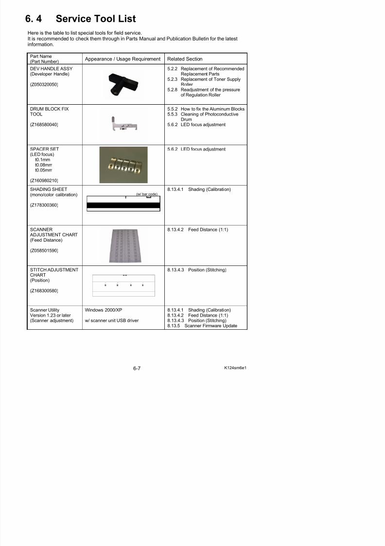
5/17/2018 KIP 7100 Service Manual Ver A_1 - slidepdf.com
http://slidepdf.com/reader/full/kip-7100-service-manual-ver-a1 388/674
STITCH ADJUSTMENT 8 13 4 3 Position (Stitching)
Chapter 7
Troubleshooting
Page7. 1 Troubleshooting - Printer Errors 7- 3
7. 1. 1 Countermeasures - Call Operator Errors 7- 37. 1. 1. 1 Roll 2 Feeding Jam “Delay” (J-0101) 7- 37. 1. 1. 2 Roll 1 Feeding Jam “Delay” (J-0102) 7- 47. 1. 1. 3 Feeding Jam “Delay” (J-0103) & “Early” (J-0303) 7- 57. 1. 1. 4 Reg. Jam “Delay” (J-0104), “Stay” (J-0204)
“Early” (J-0304), “Remained” (J-1004) 7- 67. 1. 1. 5 Internal Jam “Delay” (J-0106), “Stay” (J-0206)
“Early” (J-0306), “Remained” (J-1006) 7- 67. 1. 1. 6 Fuser Jam “Delay” (J-0107), “Stay” (J-0207)
“Early” (J-0307), “Remained” (J-1007) 7- 77. 1. 1. 7 Paper jam by opening the Roll Deck during printing (J-1100) 7- 77. 1. 1. 8 Paper jam by opening the Exit Cover during printing (J-1200) 7- 77. 1. 1. 9 Deck Open 7- 77. 1. 1.10 Deck Jam 7- 87. 1. 1.11 Manual Set NG 7- 97. 1. 1.12 Toner Empty 7-107. 1. 1.13 The door opened during the print 7-10
7. 1. 1.14 Abnormal variation in cut length 7-107. 1. 2 Countermeasures - Call Service Errors 7-11
7. 1. 2. 1 Fuser Error (E-000, E-002 & E-004) 7-137. 1. 2. 2 Fuser Error (E-001) 7-147. 1. 2. 3 Fuser Error (E-003) 7-157. 1. 2. 4 Main Motor Error (E-010) 7-157. 1. 2. 5 Fuser Motor Error (E-011) 7-167. 1. 2. 6 Developer Press Motor Error (E-012) 7-16
7. 1. 2. 7 Counter Error (E-020) 7-177. 1. 2. 8 High Voltage Output Error (E-031, E-032 & E-033) 7-177. 1. 2. 9 Bias Output Error (E-034) 7-187. 1. 2.10 Cutter Error (E-040) 7-187. 1. 2.11 FPGA Error (E-050) 7-197 1 2 12 Developer Error (E-070) 7-19
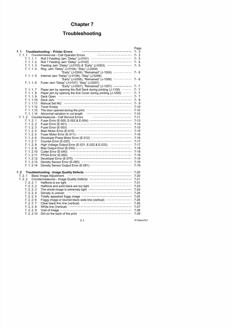
5/17/2018 KIP 7100 Service Manual Ver A_1 - slidepdf.com
http://slidepdf.com/reader/full/kip-7100-service-manual-ver-a1 389/674
7. 1. 2.12 Developer Error (E-070) 7-197 1 2 13 Density Sensor Error (E-080) 7-19
7. 2. 2.11 Defective fusing 7-297. 2. 2.12 Defective image placement, No Leading Edge 7-307. 2. 2.13 Jitter 7-307. 2. 2.14 Image looks not sharp 7-317. 2. 2.15 Uneven image density (vertical) 7-31
7. 2. 2.16 Completely white (No image) 7-327. 2. 2.17 Completely black 7-327. 2. 2.18 Crease of paper 7-337. 2. 2.19 Double image 7-347. 2. 2.20 Dirt on the print (Offset) 7-357. 2. 2.21 Image Void on Long Print without Crease 7-357. 2. 2.22 Crease on Long Print (and image void at a time) 7-36
7. 3 Troubleshooting - Scanner Defects 7-387. 3. 1 Countermeasures - scanner operation 7-38
7. 3. 1. 1 Original can not be set (Scanner does not transport) 7-387. 3. 1. 2 Scanner does not start scanning from the original set position 7-387. 3. 1. 3 Original can not be set (Original feeding does not stop) 7-387. 3. 1. 4 Original is mis-fed 7-397. 3. 1. 5 Motor rotates endlessly at the time of turning on 7-397. 3. 1. 6 Scanner is not recognized 7-39
7. 3. 2 Countermeasures - scanner image quality 7-40
7. 3. 2. 1 Completely black 7-407. 3. 2. 2 Vertical black lines 7-407. 3. 2. 3 Vertical white lines 7-417. 3. 2. 4 Some image is lost at the boundary of Image Blocks 7-417. 3. 2. 5 Vertical image gap between Image Blocks 7-417. 3. 2. 6 Image quality is not good 7-417. 3. 2. 7 Density is different between left and right 7-41
7. 4 Touch Screen Calibration 7-42
5/17/2018 KIP 7100 Service Manual Ver A_1 - slidepdf.com
http://slidepdf.com/reader/full/kip-7100-service-manual-ver-a1 390/674
7. 1 Troubleshooting - Printer Errors
7. 1. 1 Countermeasures - Call Operator Errors
7. 1. 1. 1 Roll 2 Feeding Jam “Delay” (J-0101)
Cause Checkingorder
Checking Result Treatment
Installation of rollpaper
1 Is the roll paper correctly installed to theRoll Deck 2?
No Install it correctly.
Roll 2 Set Sensor (PH9)
2 Check the status of Roll 2 Set Sensor inthe Signal Status Mode of the ServiceMode.
Signal Code : 106 (Roll 2 Set Sensor)
Is the status “H” when the roll paper isset?
No 1. Is there any problem withthe Drawer Connector which connects themachine and the Roll
Deck.
2. Check if there is anyproblem with the wireconnected to the Roll 2Set Sensor.
3. Replace the Roll 2 SetSensor if there is noproblem with the wire.
Roll 2 Feed Clutch(CL6) 3 Check the operation of Roll 2 FeedClutch in the Device Operation Mode of the Service Mode.
Device Code : 08 (Roll 2 Feed Clutch)
Does the clutch operate when youchange the output signal from “L” to “H”?
No 1. Check if there is anyproblem with the wireconnected to the Roll 2Feed Clutch.
2. Replace the Roll 2 FeedClutch if there is noproblem with the wire.
No 1. Check the driving belts of the Roll Deck.
2. Check if there is anyproblem with the wireconnected to the MainMotor.
3. Replace the Main Motor if th i bl ith
Main Motor (M1) 4 Check the status of Roll 2 Set Sensor inthe Signal Status Mode of the Service
Mode while making the followingoperation. (Signal Code : 106)
1. Set the leading edge of roll 2 betweenfeeding rollers. (Leading edge mustnot pass over the Roll 2 Set Sensor.)
2. Close the Roll Deck.
Delay : Paper arrives the sensor much later than required timing.Stay : Paper exists on the sensor for longer time than required.Early : Paper arrives the sensor much earlier than required timing.Remained : Paper has already existed on the sensor when turning on the machine.
Reference
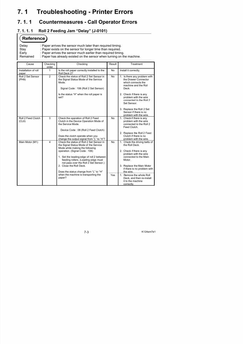
5/17/2018 KIP 7100 Service Manual Ver A_1 - slidepdf.com
http://slidepdf.com/reader/full/kip-7100-service-manual-ver-a1 391/674
if there is no problem with
7. 1. 1. 2 Roll 1 Feeding Jam “Delay” (J-0102)
Cause Checkingorder
Checking Result Treatment
Installation of rollpaper
1 Is the roll paper correctly installed to theRoll Deck 2?
No Install it correctly.
Roll 1 Set Sensor (PH7)
2 Check the status of Roll 1 Set Sensor inthe Signal Status Mode of the ServiceMode.
Signal Code : 105 (Roll 1 Set Sensor)
Is the status “H” when the roll paper isset?
No 1. Is there any problem withthe Drawer Connector which connects themachine and the RollDeck.
2. Check if there is anyproblem with the wireconnected to the Roll 1Set Sensor.
3. Replace the Roll 1 SetSensor if there is noproblem with the wire.
Roll 1 Feed Clutch(CL4)
3 Check the operation of Roll 1 FeedClutch in the Device Operation Mode of the Service Mode.
Device Code : 06 (Roll 1 Feed Clutch)
Does the clutch operate when youchange the output signal from “L” to “H”?
No 1. Check if there is anyproblem with the wireconnected to the Roll 1Feed Clutch.
2. Replace the Roll 1 Feed
Clutch if there is noproblem with the wire.
No 1. Check the driving belts of the Roll Deck.
2. Check if there is anyproblem with the wireconnected to the MainMotor.
3. Replace the Main Motor if there is no problem withthe wire.
Main Motor (M1) 4 Check the status of Roll 1 Set Sensor inthe Signal Status Mode of the ServiceMode while making the followingoperation. (Signal Code : 105)
1. Set the leading edge of roll 1 betweenfeeding rollers. (Leading edge mustnot pass over the Roll 1 Set Sensor.)
2. Close the Roll Deck.
Does the status change from “L” to “H”when the machine is transporting thepaper?
Yes 1. Remove the whole RollDeck, and then re-installit to the machinecorrectly.
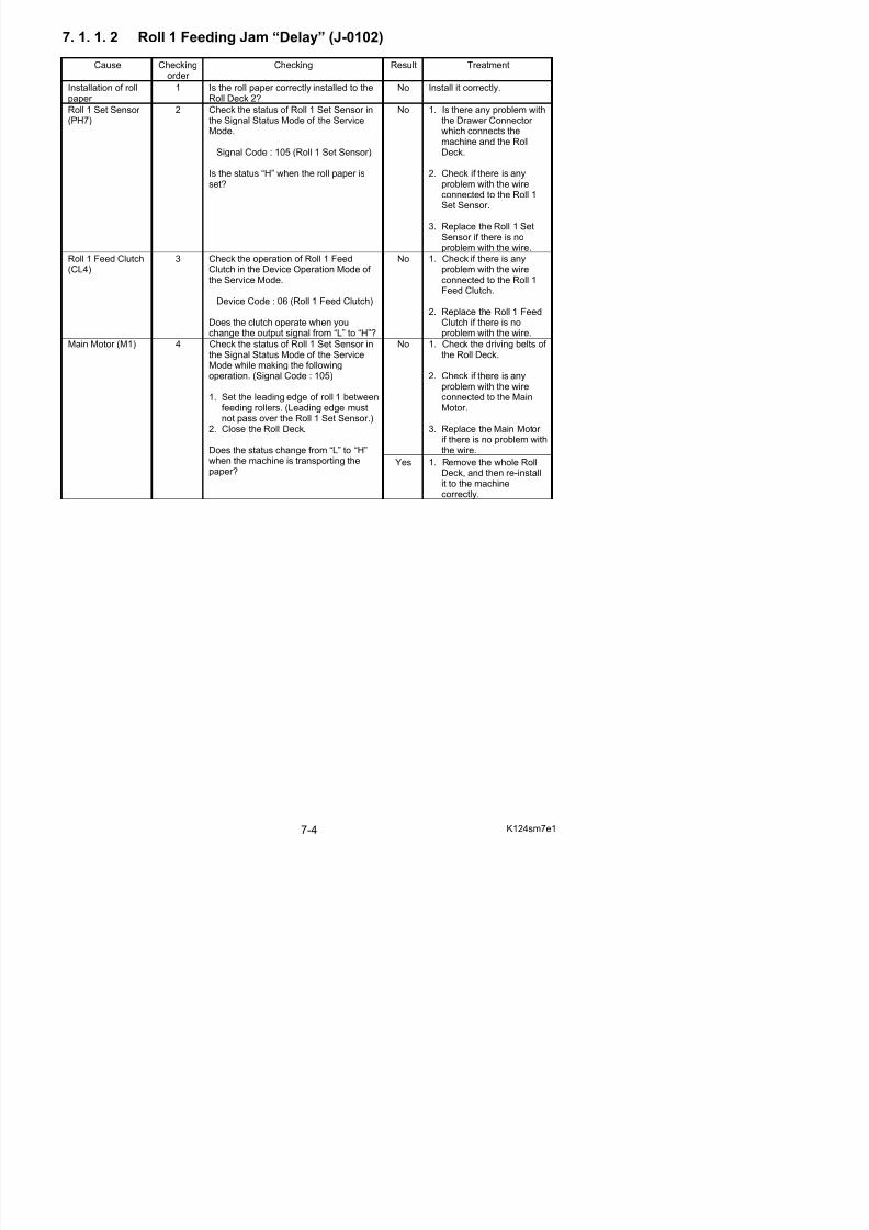
5/17/2018 KIP 7100 Service Manual Ver A_1 - slidepdf.com
http://slidepdf.com/reader/full/kip-7100-service-manual-ver-a1 392/674
7. 1. 1. 3 Feeding Jam “Delay” (J-0103) & “Early” (J-0303)
Cause Checkingorder
Checking Result Treatment
Mis-feed of paper 1 Does the paper mis-fed occur betweenRoll 1 Set Sensor and Feed Sensor?
Yes Remove the mis-fed paper.
Feed Sensor (PH6)
2 Check the status of Feed Sensor in theSignal Status Mode of the Service Mode.
Signal Code : 108 (Feed Sensor)
Is the status “L” when the paper is notpassing beside the sensor? And is it “H” when the paper is passingbeside the sensor?
No 1. Is there any problem withthe Drawer Connector which connects themachine and the RollDeck.
2. Check if there is anyproblem with the wireconnected to the FeedSensor.
3. Replace the Feed Sensor if there is no problem withthe wire.
Cutter HomePosition Sensor (MS6 & MS7)
3 Check the status of Cutter Home PositionSensors in the Signal Status Mode of theService Mode.
Signal Code :094 (Cutter Home Position Right)
095 (Cutter Home Position Left)
Is the status “H” when the Cutter is ateach home position? And is it “L” when the Cutter is not at thehome position?
No 1. Check if there is anyproblem with the wireconnected to the Cutter Home Position Sensor.
2. Replace the Cutter Home
Position Sensors if thereis no problem with thewire.
Driving mechanism 4 Check the operation of Feed Clutch inthe Device Operation Mode of theService Mode.
Device Code : 10 (Feed Clutch)
Also open and close the Roll Deck, andcheck if the Main Motor rotates correctly. Does each Feed Clutch and Main Motor operate correctly?
No Replace the Feed Clutch or Main Motor if it is defective.
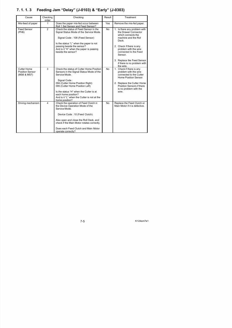
5/17/2018 KIP 7100 Service Manual Ver A_1 - slidepdf.com
http://slidepdf.com/reader/full/kip-7100-service-manual-ver-a1 393/674
7. 1. 1. 4 Reg. Jam “Delay” (J-0104), “Stay” (J-0204)“Early” (J-0304), “Remained” (J-1004)
Cause Checkingorder
Checking Result Treatment
Mis-feed of paper 1 Does the paper mis-fed occur around theRegistration Roller?
Yes Remove the mis-fed paper.
RegistrationSensor (PH1)
2 Check the status of Registration Sensor in the Signal Status Mode of the ServiceMode.
Signal Code : 100 (Registration Sensor) Is the status “L” when the paper is notpassing beside the sensor?
And is it “H” when the paper is passingbeside the sensor?
No 1. Check if there is anyproblem with the wireconnected to theRegistration Sensor.
2. Replace the RegistrationSensor if there is noproblem with the wire.
Engine Unit 3 Is the Engine Unit closed firmly until it islocked?(Is the pressure around the RegistrationRoller correct?)
No 1. Close the Engine Unitfirmly.
2. Adjust the pressurearound the RegistrationRoller.
Driving mechanism 4 Check the operation of RegistrationClutch in the Device Operation Mode of
the Service Mode.
Device Code : 11 (Registration Clutch) Also open and close the Roll Deck, andcheck if the Main Motor rotates correctly. Does each Registration Clutch and MainMotor operate correctly?
No Replace the RegistrationClutch or Main Motor if it is
defective.
7. 1. 1. 5 Internal Jam “Delay” (J-0106), “Stay” (J-0206)“Early” (J-0306), “Remained” (J-1006)
Cause Checkingorder
Checking Result Treatment
Mis-feed of paper 1 Does the paper mis-fed occur around theseparation area?
Yes Remove the mis-fed paper.
Separation Sensor
(PH2)
2 Check the status of Separation Sensor in
the Signal Status Mode of the ServiceMode.
Signal Code : 010 (Separation Sensor) Is the status “L” when the paper is notpassing beside the sensor?And is it “H” when the paper is passing
No 1. Check if there is any
problem with the wireconnected to theSeparation Sensor.
2. Replace the SeparationSensor if there is noproblem with the wire.
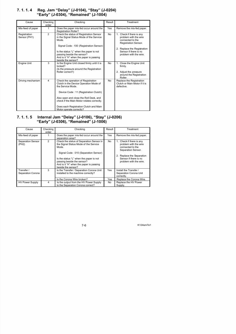
5/17/2018 KIP 7100 Service Manual Ver A_1 - slidepdf.com
http://slidepdf.com/reader/full/kip-7100-service-manual-ver-a1 394/674
And is it H when the paper is passing
7. 1. 1. 6 Fuser Jam “Delay” (J-0107), “Stay” (J-0207)“Early” (J-0307), “Remained” (J-1007)
Cause Checkingorder
Checking Result Treatment
Mis-feed of paper 1 Does the paper mis-fed occur around thefuser area?
Yes Remove the mis-fed paper.
Exit Sensor (PH3) 2 Check the status of Exit Sensor in theSignal Status Mode of the Service Mode.
Signal Code : 011 (Exit Sensor)
Is the status “L” when the paper is notpassing beside the sensor? And is it “H” when the paper is passing
beside the sensor?
No 1. Check if there is anyproblem with the wireconnected to the ExitSensor.
2. Replace the Exit Sensor if there is no problem withthe wire.
7. 1. 1. 7 Paper jam by opening the Roll Deck during printing (J-1100)
Cause Checkingorder
Checking Result Treatment
Opening the RollDeck 1 Did you open the Roll Deck before thecompletion of printing?(Roll paper will be rewound after printing.J-1100 will be indicated if you open thedeck at that time.)
Yes Wait until the roll paper iscompletely rewound.
Lock of Roll Deck 2 Is the Roll Deck firmly locked? No Close it firmly.
7. 1. 1. 8 Paper jam by opening the Exit Cover during printing (J-1200)Cause Checking
order Checking Result Treatment
Opening the ExitCover
1 Did you open the Exit Cover duringprinting?
Yes Do not open it duringprinting.
7. 1. 1. 9 Deck Open
Cause Checkingorder
Checking Result Treatment
Roll Deck 1 Is the Roll Deck opened? Yes Close it firmly.
Switch (MS5) 2 Check the status of the following signal in No 1. Check if there is any
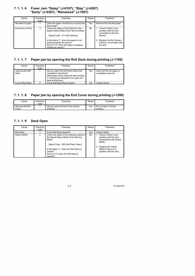
5/17/2018 KIP 7100 Service Manual Ver A_1 - slidepdf.com
http://slidepdf.com/reader/full/kip-7100-service-manual-ver-a1 395/674
th Si l St t M d f th S i bl ith th i
7. 1. 1.10 Deck Jam
Cause Checkingorder
Checking Result Treatment
Mis-feed of paper 1 Does the paper mis-fed occur in the RollDeck?
Yes Remove the mis-fed paper.
Installation of rollpaper
2 Is the roll paper correctly installed to theRoll Deck 2?
No Install it correctly.
Roll 1 Set Sensor (PH7)Roll 2 Set Sensor (PH9)
3 Check the status of Roll 1 Set Sensor and Roll 2 Set Sensor in the SignalStatus Mode of the Service Mode.
Signal Code : 105 (Roll 1 Set Sensor)106 (Roll 2 Set Sensor)
Is the status of each sensor “H” when
you set the roll paper?
No 1. Is there any problem withthe Drawer Connector which connects themachine and the RollDeck.
2. Check if there is anyproblem with the wire
connected to eachsensor.
3. Replace the concerningsensor if there is noproblem with the wire.
Roll 1 Feed Clutch(CL4)Roll 2 Feed Clutch(CL6)
Roll 1 Back Clutch(CL5)Roll 2 Back Clutch(CL7)
4 Check the operation of the followingclutches in the Device Operation Mode of the Service Mode.
Device Code :06 (Roll 1 Feed Clutch)07 (Roll 1 Back Clutch)08 (Roll 2 Feed Clutch)09 (Roll 2 Back Clutch)
Does each clutch operate correctly?
No 1. Check if there is anyproblem with the wireconnected to each clutch.
2. Replace the concerningclutch if there is noproblem with the wire.
No 1. Check the driving belts of the Roll Deck.
2. Check if there is anyproblem with the wireconnected to the MainMotor.
3. Replace the Main Motor if there is no problem withthe wire.
Main Motor (M1) 5 Check the status of Roll 1 Set Sensor and Roll 2 Set Sensor in the SignalStatus Mode of the Service Mode while
making the following operation.
Signal Code : 105 (Roll 1 Set Sensor)106 (Roll 2 Set Sensor)
1. Set the leading edge of each rollpaper between the concerningfeeding rollers. (Leading edge mustnot pass over each Roll 1 (2) SetSensor.)
2. Close the Roll Deck.
Does the status change from “L” to “H”when the machine is transporting thepaper?
Yes 1. Remove the whole RollDeck, and then re-install
it to the machinecorrectly.
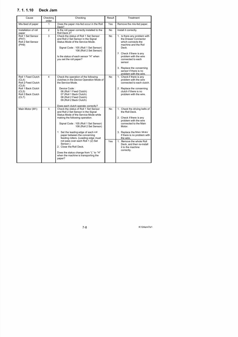
5/17/2018 KIP 7100 Service Manual Ver A_1 - slidepdf.com
http://slidepdf.com/reader/full/kip-7100-service-manual-ver-a1 396/674
7. 1. 1.11 Manual Set NG
Cause Checkingorder
Checking Result Treatment
Mis-feed 1 Have you already set the cut sheet paper to the Bypass Feeder before you turned
on the machine?
Yes Remove the paper.
Manual Set Sensor 2 Check the status of Manual Feed Sensor in the Signal Status Mode of the ServiceMode.
Signal Code : 008 (Manual Set Sensor) Is the status “L” when the paper is notpassing beside the sensor? And is it “H”when the paper is passing beside the
sensor?
No 1. Check if there is anyproblem with the wireconnected to the ManualSet Sensor.
2. Replace the Manual SetSensor if there is noproblem with the wire.
RegistrationSensor
3 Check the status of Registration Sensor in the Signal Status Mode of the ServiceMode.
Signal Code : 100 (RegistrationSensor)
Is the status “L” when the paper is notpassing beside the sensor? And is it “H”
when the paper is passing beside thesensor?
No 1. Check if there is anyproblem with the wireconnected to RegistrationSensor.
2. Replace the RegistrationSensor if there is noproblem with the wire.
Engine Unit 4 Is Engine Unit closed firmly?(Is the pressure around RegistrationRoller correct?)
No 1. Close Engine Unit firmly.2. Adjust the pressure
around Registration Roller.
Driving mechanism 5 Check the operation of RegistrationClutch in the Device Operation Mode of the Service Mode.
Device Code : 11 (Registration Clutch)
Open and close Roll Deck and check if Main Motor rotates correctly. Does eachRegistration Clutch and Main Motor operate correctly?
No Replace the RegistrationClutch or Main Motor if it isdefective.
7. 1. 1.12 Toner Empty
Cause Checkingorder
Checking Result Treatment
Toner Cartridge 1 Is there enough toner in the Toner Cartridge?
No Replace the Toner Cartridge.
Toner SupplyMotor (M3)
2 Check the operation of Toner SupplyMotor by the following 2 ways.
No 1. Check if there is anyproblem with the wiresamong Toner Supply
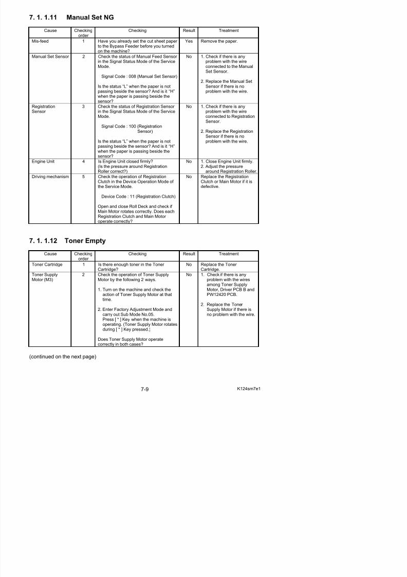
5/17/2018 KIP 7100 Service Manual Ver A_1 - slidepdf.com
http://slidepdf.com/reader/full/kip-7100-service-manual-ver-a1 397/674
Cause Checking
order Checking Result Treatment
No Replace the Toner Sensor.Toner Sensor (TLS1)
3 Confirm that the Toner Sensor is notburied in the toner.Then check the status of Toner Sensor in
the Input/Output Mode of the ServiceMode.
I/O Signal Code : 107 (Toner Sensor)
Is the status “H” when the Toner Sensor is covered with the toner? And is it “L” when the sensor is notcovered?
Yes Replace the PW12420 PCB.
7. 1. 1.13 The door opened during the print
Cause Checkingorder
Checking Result Treatment
Mis-feed of paper 1 Is there a paper anywhere in themachine?
Yes Open the Exit Cover and theEngine Unit, and then
remove the paper.(Cut the paper manually if ithas not been cut yet.)
Switch (MS5) 2 Check the status of the following signal inthe Signal Status Mode of the ServiceMode.
Signal Code : 009 (Roll Deck Open)
Is the status “L” when the Roll Deck is
closed? And is it “H” when the Roll Deck isopened?
No 1. Check if there is anyproblem with the wireconnected to the Switch(MS5).
2. Replace the Switch(MS5) if there is no
problem with the wire.
Fuse 3 Does the fuse (F2) have a proper conductivity?
No Replace the fuse (F2).
7. 1. 1.14 Abnormal variation in cut length
Cause Checkingorder
Checking Result Treatment
1 Check the status of the following signal inthe Signal Status Mode of the ServiceMode.
Signal Code : 109 (Feed Encoder)
No 1. Check if there is anyproblem with the wireconnected to the Sensor (PH12).
Sensor (PH12)with encoder
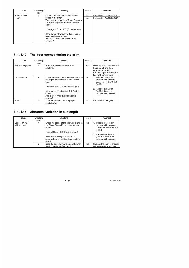
5/17/2018 KIP 7100 Service Manual Ver A_1 - slidepdf.com
http://slidepdf.com/reader/full/kip-7100-service-manual-ver-a1 398/674
7. 1. 2 Countermeasures - Call Service Errors
The followings are the names of Service Call Errors and the conditions that those errors occur.
Error Code Error Indication ConditionsE-000 Fuser Temperature Rising Error Fuser Temperature does not reach 50 oC
within 120 seconds after turning on.
E-001 Fuser Over Temperature Error Fuser Temperature reaches over 230 oC.
E-002 Fuser Low Temperature Error 1. Fuser Temperature at the time of turning on was 50 to 100 oC, but itdoes not rise up to 120 oC within 150seconds after that.
2. Fuser Temperature at the time of turning on was higher than 100 oC, butit does not rise up to the settingtemperature within 330 seconds after that.
E-003 Fuser Temperature Abnormal FallError
The difference of temperature betweencenter and side of fuser becomes 50 oC or more.
E-004 Fuser Temperature Abnormal FallError
The Lamp of fuser lights (Signal HEAT1is “H”) to heat up the Fuser Roller in theready condition, but even 1 oC of temperature rise can not beaccomplished within 30 seconds.
E-010 Main Motor Error The Main Motor Output Detection Signal(MAINM_LD) continues to be “H” for 3seconds or longer when the Main Motor is
rotating.E-011 Fuser Motor Error The Fuser Motor Output Detection Signal
(HEATM_LD) continues to be “H” for 3seconds or longer when the Fuser Motor is rotating.
E-012 Developer Press Motor Error The Developer Press Sensor Signal(PRESS_S) does not change to “L” within30 seconds after turning on.
E-020 Counter Error The Counter Connection Detection Signal(COUNT_OPN) continues to be “L” for 1second or longer after turning on.
E-031 Image Corona Output Error The Image Corona Output DetectionSignal (IM_LD) continues to be “L” for 1second or longer when the Image Coronais ON
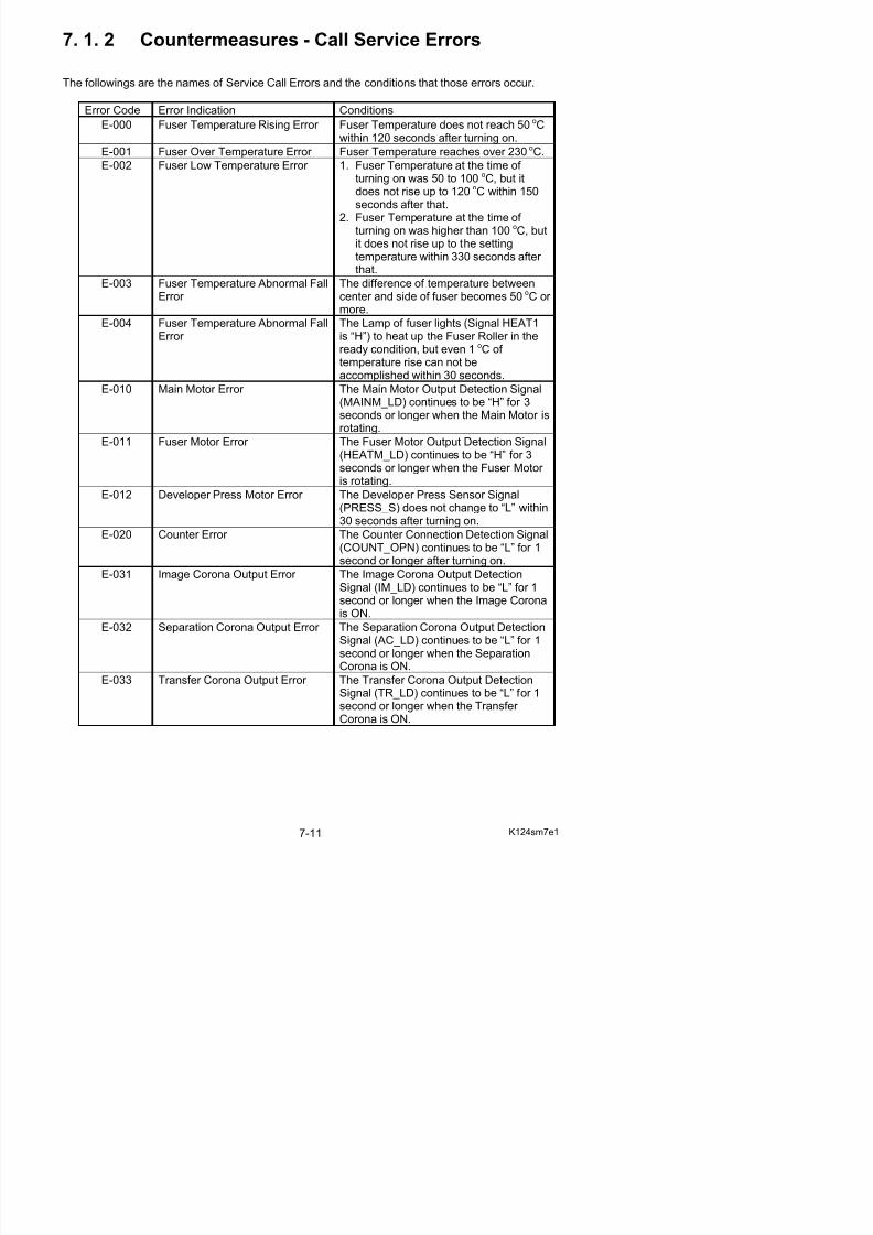
5/17/2018 KIP 7100 Service Manual Ver A_1 - slidepdf.com
http://slidepdf.com/reader/full/kip-7100-service-manual-ver-a1 399/674
Error Code Error Indication Conditions
E-034 Bias Output Error Bias Output Detection Signal (BIAS_LD)continues to be “L” for 1 second or longer when a specified bias is supplied to the
corresponding Developer Unitcomponents.
E-040 Cutter Error 1. The Cutter Home Sensor Signal(MSCUT_L or MSCUT_R) does notchange to “H” within 100 millisecondsince the Cutter has started theoperation.
2. The Cutter Home Sensor Signal(MSCUT_L or MSCUT_R) does notchange to “L” within 1 second sincethe Cutter has started the operation.
E-050 FPGA Error Initialization of FPGA is failed after turning on.
E-070 Developer Unit Set Error 1. The Connector J-253 is notconnected.
2. The Switch (MS4) is “open” condition,which detects open/close of Engine
Unit or Toner Hatch.E-080 Density Sensor Error The default output of Density Sensor
reaches less than 0.1V or more than1.3V.
E-081 Density Sensor Output Error The gap between the default output andthe standard output of Density Sensor reaches less than 2V.
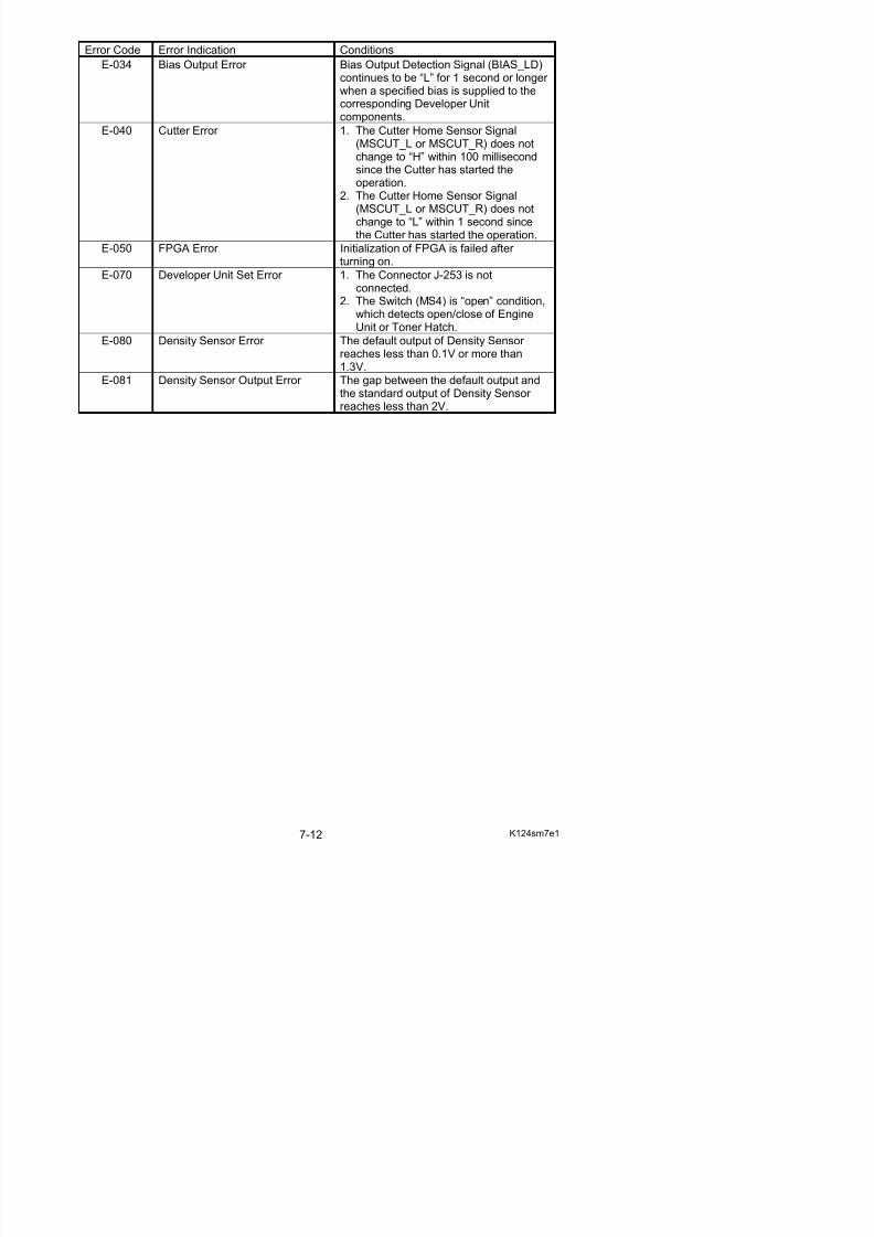
5/17/2018 KIP 7100 Service Manual Ver A_1 - slidepdf.com
http://slidepdf.com/reader/full/kip-7100-service-manual-ver-a1 400/674
7. 1. 2. 1 Fuser Error (E-000, E-002 & E-004)
E-000 : Fuser Temperature Rising Error E-002 : Fuser Low Temperature Error E-004 : Fuser Temperature Abnormal Fall Error
Cause Checkingorder
Checking Result Treatment
Error clearance 1 Have you cleared the fuser error in theError Clear Mode?
Yes Wait until the Fuser Unit isenough cooled down.Then select the Error Clear Mode and clear theconcerning error.
Wires 2 Are wires among Lamp (H1, H2), SolidState Relay (SSR1) and Thermistors
(TH1 & TH2) connected properly?
No Connect them properly.
Lamp (H1, H2) 3 Unplug the machine, and then check theresistance of Lamp (H1, H2) with themulti-meter.
Is it 15k ohm or lower?
No Replace the Lamp.
Thermistors(TH1 & TH2)
4 Select the Information Mode, and thencheck the temperature of fuser detectedby Thermistors (TH1 & TH2).
Item No. : 00 (Fuser temperature 1)01 (Fuser temperature 2)
Is each temperature normal?
No Replace the concerningThermistor.
Confirm that the machine is turned on,and then check the voltage of the orangeline (J220-4).
Is it 24V?
No Replace the DC Power Supply if there is no problemwith the wires.
DC Power Supply(DCP1)or Fuse
5
Confirm that the machine is turned off,and then check whether or not eachFuse is broken.
Is any Fuse broken?
Yes Replace the Fuse.
Relay (RY1) 6 Select the Device Operation Mode, andthen change the signal of the followingsignal to “H”.
Device Code : 22 (Fuser Relay)
And check the resistance between thefollowing points.
Between RY1-2 and RY1-4Between RY1-6 and RY1-8
Is the each resistance almost 0 ohm?
No Replace the Relay.
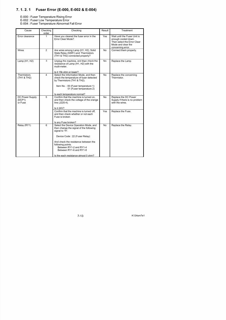
5/17/2018 KIP 7100 Service Manual Ver A_1 - slidepdf.com
http://slidepdf.com/reader/full/kip-7100-service-manual-ver-a1 401/674
Cause Checking
order Checking Result Treatment
Yes Replace the Solid StateRelay
Solid State Relay(SSR1)
7 Select the Device Operation Mode, andthen change the signal of the followingsignals to “H”.
Device Code : 22 (Fuser Relay)21 (Fuser Lamp 1)
Then check the voltage between J105-1and J105-2.Is it 0V?
CAUTIONChange the signal of “21” (Fuser
Lamp 1) to “L” after checking!
No Replace the PW12420 PCB.
7. 1. 2. 2 Fuser Error (E-001)
Cause Checkingorder
Checking Result Treatment
Error clearance 1 Have you cleared the fuser error in theError Clear Mode?
(Refer to the page 8-154 as for the Error Clear Mode.)
Yes Wait until the Fuser Unit isenough cooled down.Then select the Error Clear Mode and clear theconcerning error.
Wires 2 Are wires among Lamp (H1, H2), SolidState Relay (SSR1) and Thermistors(TH1 & TH2) connected properly?
No Connect them properly.
Solid State Relay(SSR1)
3 Does the error occur again even if youhave cleared it in the Error Clear Mode?
Yes Replace the Solid StateRelay.
Thermistors(TH1 & TH2)
4 Select the Information Mode, and thencheck the temperature of fuser detectedby Thermistors (TH1 & TH2).
Item No. : 00 (Fuser temperature 1)01 (Fuser temperature 2)
Is each temperature normal?
No Replace the concerningThermistor.
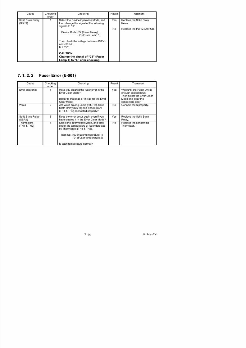
5/17/2018 KIP 7100 Service Manual Ver A_1 - slidepdf.com
http://slidepdf.com/reader/full/kip-7100-service-manual-ver-a1 402/674
7. 1. 2. 3 Fuser Error (E-003)
Cause Checkingorder
Checking Result Treatment
Error clearance 1 Have you cleared the fuser error in theError Clear Mode?
Yes Wait until the Fuser Unit isenough cooled down.
Then select the Error Clear Mode and clear theconcerning error.
Wires 2 Are wires among Lamp (H1, H2), SolidState Relay (SSR1) and Thermistors(TH1 & TH2) connected properly?
No Connect them properly.
Thermistors(TH1 & TH2)
3 Select the Information Mode, and thencheck the temperature of fuser detectedby Thermistors (TH1 & TH2).
Item No. : 00 (Fuser temperature 1)01 (Fuser temperature 2)
Is each temperature normal?
No Replace the concerningThermistor.
7. 1. 2. 4 Main Motor Error (E-010)
Cause Checkingorder
Checking Result Treatment
Wires 1 Is the wire between Main Motor andPW12420 PCB connected properly?
No Connect it properly.
Confirm that the machine is turned on,and then check the voltage of the orangeline (J220-4).
Is it 24V?
No Replace the DC Power Supply if there is no problemwith the wires.
DC Power Supply(DCP1)or Fuse
2
Confirm that the machine is turned off,and then check whether or not eachFuse is broken.
Is any Fuse broken?
Yes Replace the Fuse.
Main Motor (M1) 3 Check the operation of Main Motor in theDevice Operation Mode of the ServiceMode.
Device Code : 00 (Main Motor)
Does the Main Motor operate correctly?
No Replace the Main Motor.
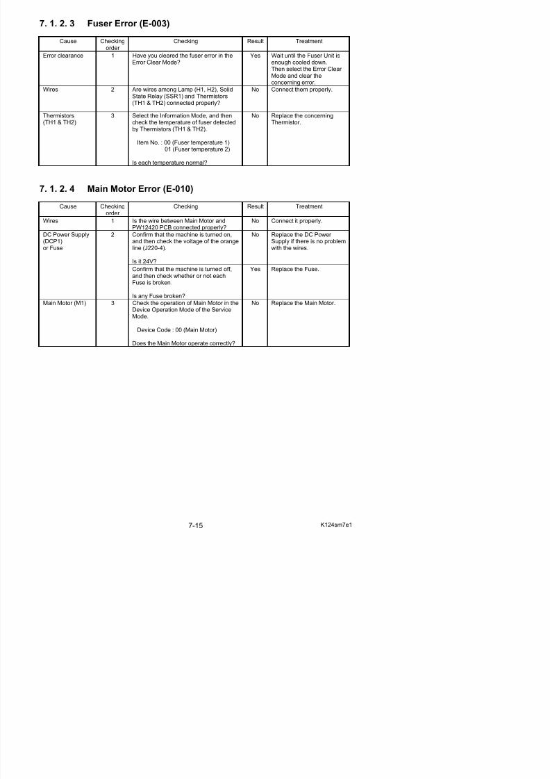
5/17/2018 KIP 7100 Service Manual Ver A_1 - slidepdf.com
http://slidepdf.com/reader/full/kip-7100-service-manual-ver-a1 403/674
7. 1. 2. 5 Fuser Motor Error (E-011)
Cause Checkingorder
Checking Result Treatment
Wires 1 Is the wire between Fuser Motor andPW12420 PCB connected properly?
No Connect it properly.
Confirm that the machine is turned on,and then check the voltage of the orangeline (J220-4).
Is it 24V?
No Replace the DC Power Supply if there is no problemwith the wires.
DC Power Supply(DCP1)or Fuse
2
Confirm that the machine is turned off,and then check whether or not eachFuse is broken.
Is any Fuse broken?
Yes Replace the Fuse.
Fuser Motor (M2) 3 Check the operation of Fuser Motor inthe Device Operation Mode of theService Mode.
Device Code : 01 (Fuser Motor)
Does the Fuser Motor operate correctly?
No Replace the Fuser Motor.
7. 1. 2. 6 Developer Press Motor Error (E-012)
Cause Checkingorder
Checking Result Treatment
Wires 1 Are the wires among Developer PressSensor (PH4), PW12420 PCB, Driver PCB B (PW6654) and Developer PressMotor (M4) connected properly?
No Connect them properly.
Developer PressMotor (M4)Driver PCB B(PW6654)
2 Turn off the machine, and then turn it onagain.Is the Developer Unit moved to the Drumside?
No Replace the Developer Press Motor or Driver PCBB.
Developer PressSensor (PH4)
3 Select the Signal Code “104” (Developer Press Sensor) in the Signal Status Mode,and then turn on the machine again.
Does the status change from “H” to “L”after turning on?
No Replace the Developer Press Sensor.
Fuse 4 Does the fuse (F3) have a proper conductivity?
No Replace the fuse (F3).
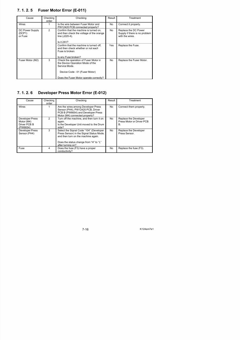
5/17/2018 KIP 7100 Service Manual Ver A_1 - slidepdf.com
http://slidepdf.com/reader/full/kip-7100-service-manual-ver-a1 404/674
7. 1. 2. 7 Counter Error (E-020)
Cause Checkingorder
Checking Result Treatment
Wires 1 Is the wire between Counter andPW12420 PCB connected properly?
No Connect it properly.
Confirm that the machine is turned on,and then check the voltage of the orangeline (J220-5).
Is it 24V?
No Replace the DC Power Supply if there is no problemwith the wires.
DC Power Supply(DCP1)or Fuse
2
Turn off the machine. Does the fuse (F1)have a proper conductivity?
No Replace the fuse (F1).
Counter 3 Check the operation of Counter in the
Device Operation Mode of the ServiceMode.
Device Code : 26 (Counter)
Does the Counter operate correctly?
No Replace the Counter.
7. 1. 2. 8 High Voltage Output Error (E-031, E-032 & E-033)
E-031 : Image Corona Output Error E-032 : Separation Corona Output Error E-033 : Transfer Corona Output Error
Cause Checkingorder
Checking Result Treatment
Wires 1 Are wires among Image Corona, HVPower Supply PCB and PW12420 PCBconnected properly?
No Connect them properly.
Is the Image Corona dirty? Yes Clean each Corona Wire,Grid Plate and housing.
Image Corona 2
Is the Corona Wire broken? Yes Replace the Corona Wire.
Does the bias terminal plate touch toCleaning Roller shaft properly?
No Remove and reapplyconductive grease toCleaning Roller shaft.Relocate the bias terminal
plates properly.
Cleaning Roller 3
Is grease applied enough? No Remove and reapplyconductive grease toCleaning Roller shaft.
Is the Transfer Corona dirty? Yes Clean each Corona Wireand housing.
Transfer Corona 4
Is the Corona Wire broken? Yes Replace the Corona Wire.
Is the Separation Corona dirty? Yes Clean each Corona WireSeparation Corona 5
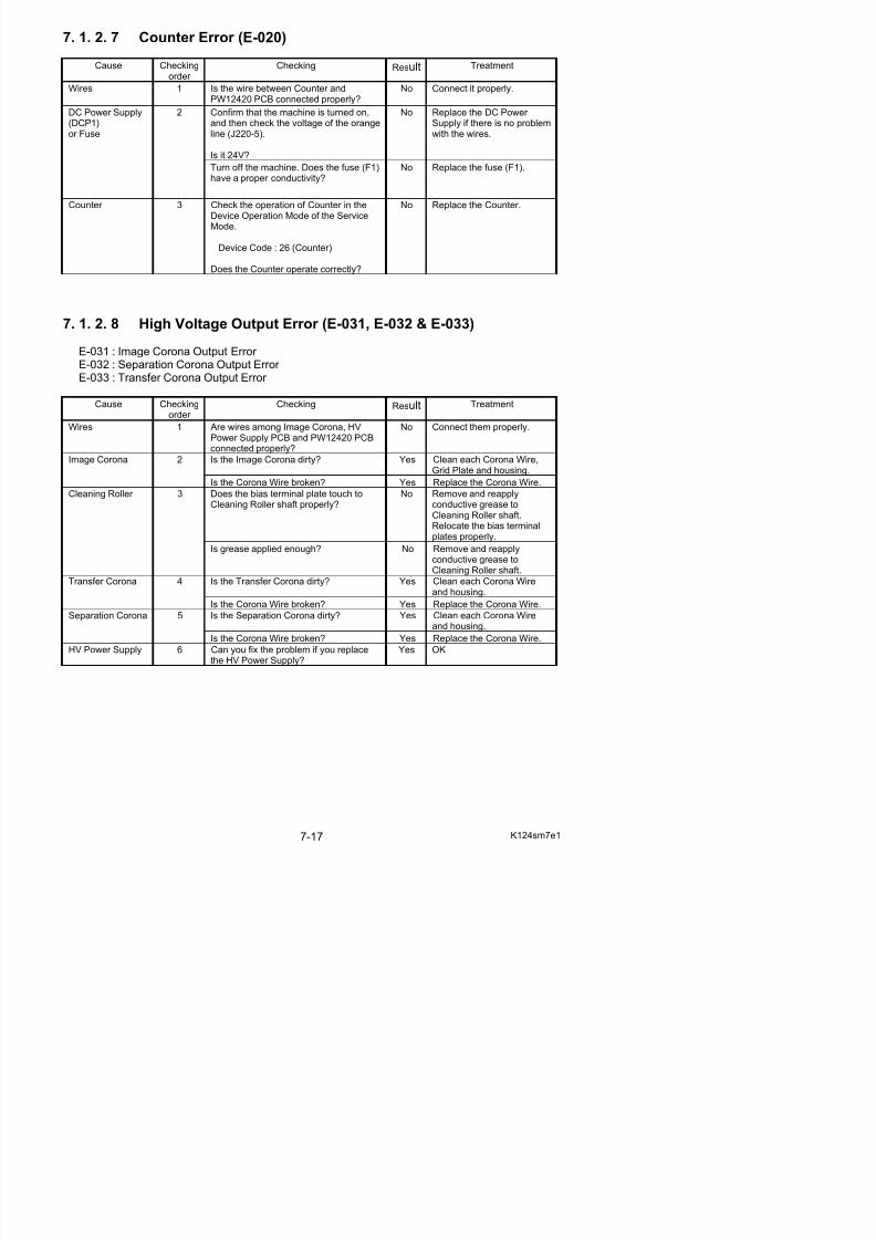
5/17/2018 KIP 7100 Service Manual Ver A_1 - slidepdf.com
http://slidepdf.com/reader/full/kip-7100-service-manual-ver-a1 405/674
7. 1. 2. 9 Bias Output Error (E-034)
Cause Checkingorder
Checking Result Treatment
Wires 1 Are wires among Developer Unit, HVPower Supply PCB and PW12420 PCB
connected properly?
No Connect them properly.
Is the toner spill out from the Developer Unit?(Or is there any similar problem?)
Yes Clean each Corona Wire,Grid Plate and housing.
Developer Unit 2
Is the high voltage of Regulation Roller leaking?(The resistance between the central partof Regulation Roller and the Ground is5 mega ohm or smaller if leaking.)
Yes Replace the RegulationRoller.
HV Power Supply 3 Can you fix the problem if you replacethe HV Power Supply?
Yes OK
7. 1. 2. 10 Cutter Error (E-040)Cause Checking
order Checking Result Treatment
Wires 1 Is the wire between Cutter Unit andPW12420 PCB connected properly?
No Connect it properly.
Cutter HomePosition Sensors(MS6 & MS7)
2 Check the status of the following signalsin the Signal Status Mode of the ServiceMode.
Signal Code :094 (Cutter Home Position Right)095 (Cutter Home Position Left)
Is the status “L” when the Cutter is ateach home position?
No Replace the Cutter Unit.
Developer Press 3 Check the operation of Cutter in the No Replace the Cutter Unit.
Multi-meter
GND
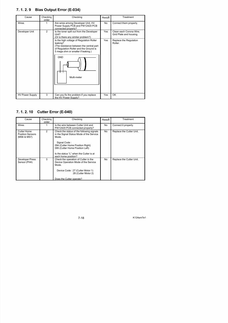
5/17/2018 KIP 7100 Service Manual Ver A_1 - slidepdf.com
http://slidepdf.com/reader/full/kip-7100-service-manual-ver-a1 406/674
7. 1. 2. 11 FPGA Error (E-050)
Cause Checkingorder
Checking Result Treatment
PW12420 PCB 1 Can you fix the problem if you replacethe PW12420 PCB?
Yes OK
7. 1. 2. 12 Developer Error (E-070)
Cause Checkingorder
Checking Result Treatment
Wires 1 Is the wire between Developer Unit and
PW12420 PCB connected properly?
No Connect it properly.
Switch (MS4) 2 Is the actuator of Switch correctlypressed down when you close theEngine Unit or Toner Hatch?
No Adjust the positions of Switch (or Toner Hatch andEngine Unit).
7. 1. 2. 13 Density Sensor Error (E-080)
Cause Checkingorder
Checking Result Treatment
Wires 1 Is the wire between Toner DensitySensor and PW12420 PCB connectedproperly?
No Connect it properly.
Density Sensor (PH11)
2 Can you fix the problem if you replaceDensity Sensor?
No Replace PW12420 with anew one.
7. 1. 2. 14 Density Sensor Output Error (E-081)
Cause Checkingorder
Checking Result Treatment
Wires 1 Is the wire between Toner DensitySensor and PW12420 PCB connectedproperly?
No Connect it properly.
Density Sensor (PH11)
2 Can you fix the problem if you replaceDensity Sensor?
No Replace PW12420 with anew one.
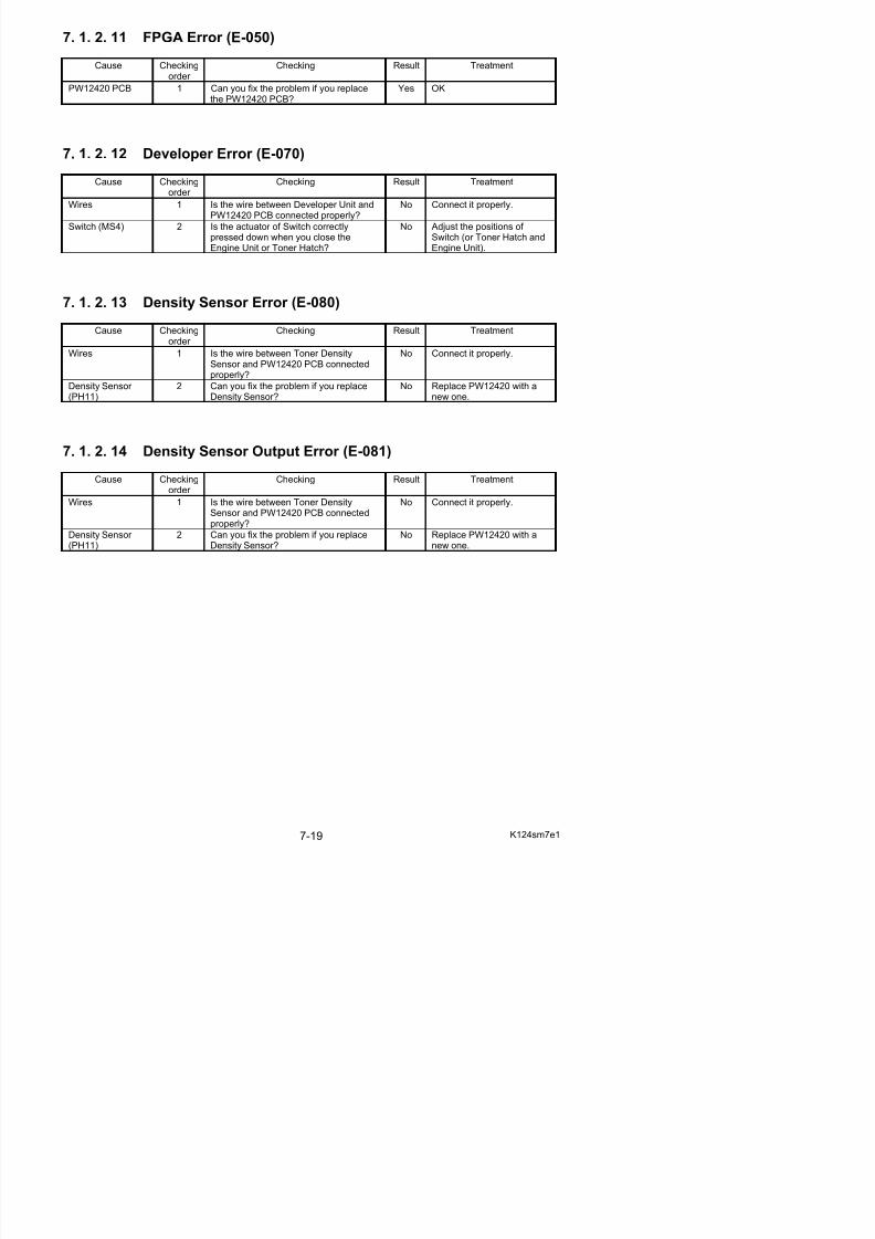
5/17/2018 KIP 7100 Service Manual Ver A_1 - slidepdf.com
http://slidepdf.com/reader/full/kip-7100-service-manual-ver-a1 407/674
7. 2 Troubleshooting - Image Quality
7. 2. 1 Basic Image Adjustment
The followings are the settings specified to the image creation components.When a defective image is printed out, please check whether or not these settings are satisfied for the beginning.
Component Check Point(PW12420)
Designated voltage Way of adjustment Corona Wire Height
Image Corona CP11 (+)CPCOM (-)
1.3 +/-0.05VDC VR101
Transfer Corona CP21 (+)CP22 (-)
Plain paper:1.2 +/-0.05VDCother media:1.0 +/-0.05VDC
Adjustment ModeNo.029 (Plain)No.030 (Tracing)No.031 (Film)
Separation Corona(AC)
CP31 (+)CPCOM (-)
5.0 +/-0.05V VR302
Separation Corona(DC)
CP33 (+)Ground (-)
-250 +/-5VDC VR303
Negative Developer Roller Bias
OUTPUT2 (+)Ground (-)
-180 +/-5VDC Adjustment ModeNo.022 (Plain)No.023 (Tracing)No.024 (Film)
Positive Developer Roller Bias
CP41 (+)CP42 (-)
0.350 +/-0.005V VR401
Toner Supply Roller
Bias
OUTPUT1 (+)
OUTPUT2 (-)
the same voltage as
Developer Bias
-
Regulation Roller Bias
OUTPUT2 (+)OUTPUT3 (-)
-80 +/-5VDC Adjustment ModeNo.622
Positive CleaningRoller Bias
OUTPUT5 (+)Ground (-)
+450 +/-5VDC VR001
Negative CleaningRoller Bias
OUTPUT5 (+)Ground (-)
-550 +/-5VDC VR002
11mm
11mm
11 mm
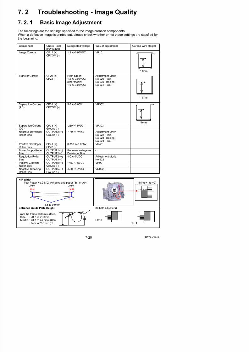
5/17/2018 KIP 7100 Service Manual Ver A_1 - slidepdf.com
http://slidepdf.com/reader/full/kip-7100-service-manual-ver-a1 408/674
7. 2. 2 Countermeasures - Image Quality
7. 2. 2. 1 Halftone is too light
Check the following matters with the Test Pattern No.1 S(0) and No.3 S(0).
If necessary use other Test Patterns.
Cause Checkingorder
Checking Result Treatment
1 Try to readjust each image creationcomponent according to [7.2.1 BasicImage Adjustment]. Is the problemfixed?
Yes OK
LED Head 2 Is the Lens Array of LED Head dirty? Yes Clean it.
Paper 3 Can you fix the problem if you use anewly unpacked paper?
Yes 1. If the paper washumidified, instruct thecustomer of the way storethe paper.
2. If the paper was not thespecified one, explain thecustomer that someimage problem mayoccur in that case.
Is the Image Corona dirty? Yes Clean each Corona Wire,
Grid Plate and housing, or replace the Corona Wire if itis too dirty.
Image Corona 4
Is the input voltage to the ImageCorona correct?
No Readjust the input voltagemaking reference to [4. 3. 2Check & Adjustment of Analog Voltage to the ImageCorona] on the page 4-31.Or replace the HV Power Supply PCB.
Eraser Lamp 5 Does the Eraser Lamp light properly? No 1. Check the wireconnected to the Eraser Lamp.
2. Check or replace theEraser Lamp.
Separation Lamp 6 Does the Separation Lamp lightproperly?
No 1. Check the wireconnected to theSeparation Lamp.
2. Check or replace theSeparation Lamp.
Is the Transfer / Separation Coronadirty?
Yes Clean each Corona Wireand housing, or replace theCorona Wire if it is too dirty.
Transfer Corona 7
Is the input voltage to the Transfer Corona correct?
No Readjust the input voltagemaking reference to[4. 3. 3 Check & Adjustment of AnalogV lt t th T f
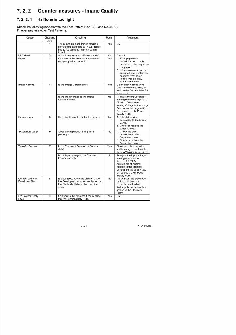
5/17/2018 KIP 7100 Service Manual Ver A_1 - slidepdf.com
http://slidepdf.com/reader/full/kip-7100-service-manual-ver-a1 409/674
Cause Checking
order Checking Result Treatment
Installation of Developer Unit
10 Is the driving gear on the left of theDeveloper Unit surely fitted to thedriving mechanism on machine side?
No Check whether or not theCam of Developer PressUnit surely presses theDeveloper Unit.Check the concerning gears.
No Check the whole Developer Unit to find the cause.
Developer Unit 11 Is the Developer Roller evenly coveredwith the toner?
Yes Replace thePhotoconductive Drum.

5/17/2018 KIP 7100 Service Manual Ver A_1 - slidepdf.com
http://slidepdf.com/reader/full/kip-7100-service-manual-ver-a1 410/674
7. 2. 2. 2 Halftone and solid black are too light
Check the following matters with the Test Pattern No.1 S(0) and No.3 S(0).If necessary use other Test Patterns.
Cause Checkingorder
Checking Result Treatment
1 Try to readjust each image creationcomponent according to [7.2.1 BasicImage Adjustment].Is the problem fixed?
Yes OK
Yes Go on to the step 3.2 Turn off the machine in the middle of printing, and then check the toner image on the Drum.
Is the toner image looks normal?
No Go on to the step 7.
Is the Transfer/Separation Coronainstalled to the machine correctly?
No Install it correctly.Transfer Corona 3
Is the high voltage of Transfer Coronaleaking?
Yes Clean the Transfer Corona.
Paper 4 Can you fix the problem if you use anewly unpacked paper?
Yes 1. If the paper washumidified, instruct thecustomer of the way storethe paper.
2. If the paper was not the
specified one, explain thecustomer that someimage problem mayoccur in that case.
Lead Wire 5 Is the resistance of Lead Wire about 10kilo ohm, which connects the HV Power Supply and the Transfer Corona?
No Replace the Lead Wire.
Input voltage to theTransfer Corona
6 Is a correct voltage supplied from theHV Power Supply to the Transfer Corona?
No Readjust the input voltagemaking reference to[4. 3. 3 Check &
Adjustment of AnalogVoltage to the Transfer Corona] on the page 4-33.Or replace the HV Power Supply PCB.
Dirt of the LEDHead
7 Is the LED Head dirty? Yes Clean it.
8 Is the Developer Roller evenly coveredwith the toner?
No Check the whole Developer Unit to find the cause.
Developer Unit
9 Is the Developer Unit firmly pressed
toward the Drum? (Do Counter Rollersat both sides of the Developer Roller touch the Drum Unit?)
No Remove the Developer Unit,
and then install it to themachine correctly.Check the Developer PressUnit.
Installation of Developer Unit
10 Is the driving gear on the left of theDeveloper Unit surely fitted to thedriving mechanism on machine side?
No Check whether or not theCam of Developer PressUnit surely presses theDe eloper Unit
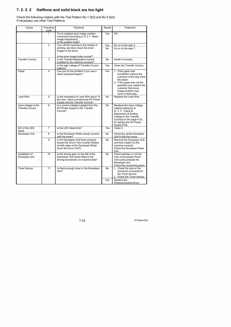
5/17/2018 KIP 7100 Service Manual Ver A_1 - slidepdf.com
http://slidepdf.com/reader/full/kip-7100-service-manual-ver-a1 411/674
7. 2. 2. 3 The whole image is extremely light
Check the following matters with the Test Pattern No.1 S(0) and No.3 S(0).If necessary use other Test Patterns.
Cause Checkingorder
Checking Result Treatment
1 Try to readjust each image creationcomponent according to [7.2.1 BasicImage Adjustment].Is the problem fixed?
Yes OK
Can you fix the problem if you use anewly unpacked paper?
Yes 1. If the paper washumidified, instruct thecustomer of the way storethe paper.
2. If the paper was not thespecified one, explain thecustomer that someimage problem mayoccur in that case.
Paper 2
Do you have the problem only whenyou use a film?
Yes Change the setting of ItemNo.067 (Transfer AssistSetting) in the AdjustmentMode of Service Mode, sothat the Separation Lamp
works for the film.Yes Go on to the step 4.3 Turn off the machine in the middle of printing, and then check the toner image on the Drum.
Is the toner image looks normal?
No Go on to the step 8.
Is the Transfer/Separation Coronainstalled to the machine correctly?
No Install it correctly.Transfer Corona 4
Is the high voltage of Transfer Coronaleaking?
Yes Clean the Transfer Corona.
Lead Wire 5 Is the resistance of Lead Wire about 10kilo ohms, which connects HV Power Supply and the Transfer Corona?
No Replace the Lead Wire.
Input voltage to theTransfer Corona
6 Is a correct voltage inputted from theHV Power Supply to the Transfer Corona?
No Readjust the input voltagemaking reference to[4. 3. 3 Check & Adjustmentof Analog Voltage to theTransfer Corona] on thepage 4-33.Or replace the HV Power
Supply PCB.Driving mechanismof Developer Unit
7 Is the Developer Unit driving normally? No Check the drivingmechanism.
Developer Unit 8 Is the Developer Unit firmly pressedtoward the Drum? (Are Counter Rollersat both sides of the Developer Roller touch the Drum Unit?)
No Remove the Developer Unit,and then install it to themachine correctly.
Lead Wire 9 Is the Lead Wire to s ppl the No Connect the Lead Wire
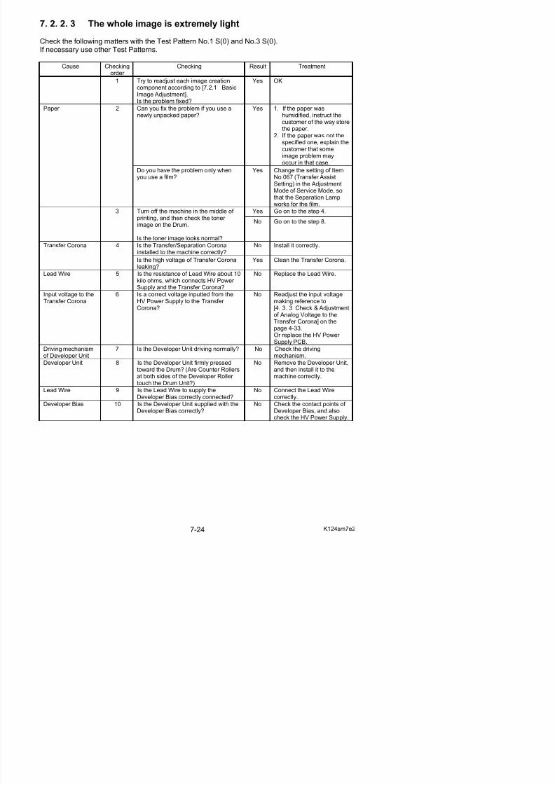
5/17/2018 KIP 7100 Service Manual Ver A_1 - slidepdf.com
http://slidepdf.com/reader/full/kip-7100-service-manual-ver-a1 412/674
7. 2. 2. 4 Density is uneven
Check the following matters with the Test Pattern No.1 S(0) and No.3 S(0).If necessary use other Test Patterns.
Cause Checkingorder
Checking Result Treatment
Is the Image Corona dirty? Yes Clean the Image Corona, or replace the Corona Wire.
Image Corona 1
Is the height of Corona Wire differentbetween left and right?
Yes Adjust the height properly.
Installation of Developer Unit
2 Is the Developer Unit firmly pressedtoward the Drum? (Do Counter Rollersat both sides of the Developer Roller touch the Drum Unit?)
No Remove the Developer Unit,and then install it to themachine correctly.Check the Developer Press
Unit.LED Head 3 Is the Lens Array dirty Yes Clean it.
Eraser Lamp 4 Are all LED of the Eraser Lamp lightproperly during the print?
No 1. Replace the Eraser Lamp.
2. Replace the PW12420PCB.
Is the Developer Roller evenly coveredwith the toner?
No 1. Clean Regulation Roller.2. Reinstall Scraper.
Developer Unit 5
Is the toner accumulating evenly in theDeveloper Unit?
No Level the machine correctly.
7. 2. 2. 5 Totally appeared foggy image
Check the following matters with the Test Pattern No.1 S(0) and No.4 S(0).If necessary use other Test Patterns.
Cause Checkingorder
Checking Result Treatment
1 Try to readjust each image creationcomponent according to [7.2.1 BasicImage Adjustment].Is the problem fixed?
Yes OK
Developer Unit 2 Is the Developer Roller insulated fromthe ground?
No Check the Developer Roller and connector.
Image Corona 3 Is the foggy image printed even if youprint a completely white pattern?
Yes Check the output voltagefrom the HV Power Supply
to the Image Corona.If it is not correct, readjust it.
Developer Bias 4 Is the Developer Unit supplied with acorrect Developer Bias during the print?
No Check the output voltagefrom the HV Power Supplyto the Developer Unit.If it is not correct, readjust it.Or replace the HV Power
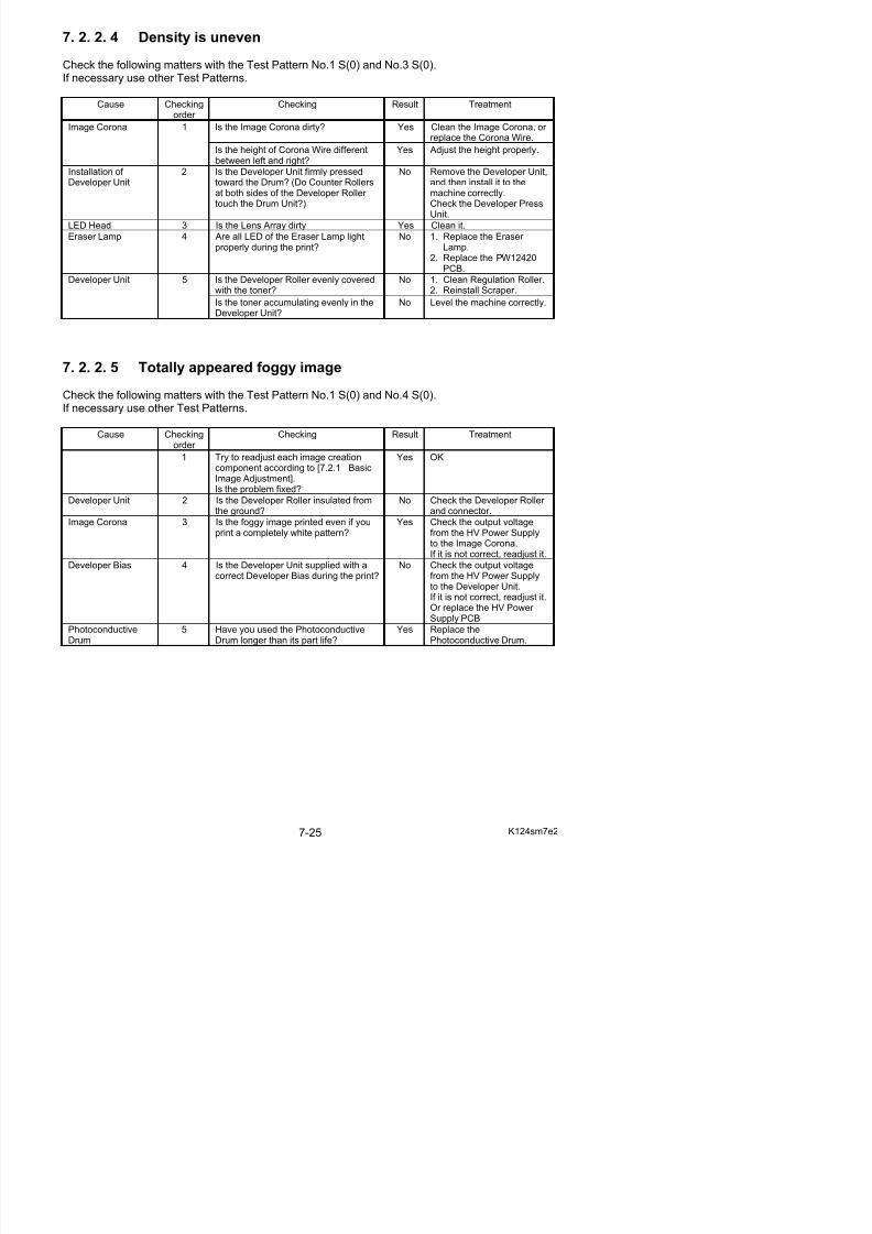
5/17/2018 KIP 7100 Service Manual Ver A_1 - slidepdf.com
http://slidepdf.com/reader/full/kip-7100-service-manual-ver-a1 413/674
7. 2. 2. 6 Foggy image or blurred black wide line (vertical)
Check the following matters with the Test Pattern No.1 S(0) and No.4 S(0).If necessary use other Test Patterns.
Cause Checkingorder
Checking Result Treatment
Light from theoutside
1 Is any light from the outside thrown ontothe Drum?
Yes Install the outer cover correctly.
Image Corona 2 Is the Image Corona dirty? Yes Clean the Image Corona, or replace the Corona Wire.
Developer Unit 3 Is the Developer Roller evenly coveredwith the toner?
No Check if the RegulationRoller is fixed at the proper position.If not, fix it at the correctposition.
7. 2. 2. 7 Clear black thin line (vertical)
Check the following matters with the Test Pattern No.1 S(0) and No.4 S(0).If necessary use other Test Patterns.
Cause Checkingorder
Checking Result Treatment
Is there something like filament on theGrid Plate, which is contacted to theDrum?
Yes Remove it.Image Corona 1
Is the Image Corona dirty? Yes Clean the Image Corona, or replace the Corona Wire.
Foreign substance 2 Is there some foreign substance oneach Corona Unit or LED Head, which
is contacted to the Drum?
Yes Remove it.
PhotoconductiveDrum
3 Is there any black line or damage onthe Drum, of which positioncorresponds with the black line on theprint?
Yes Clean the Drum makingreference to [5. 5. 2Cleaning of PhotoconductiveDrum].Replace the Drum if it isdamaged.Be sure to find the cause of the damage.
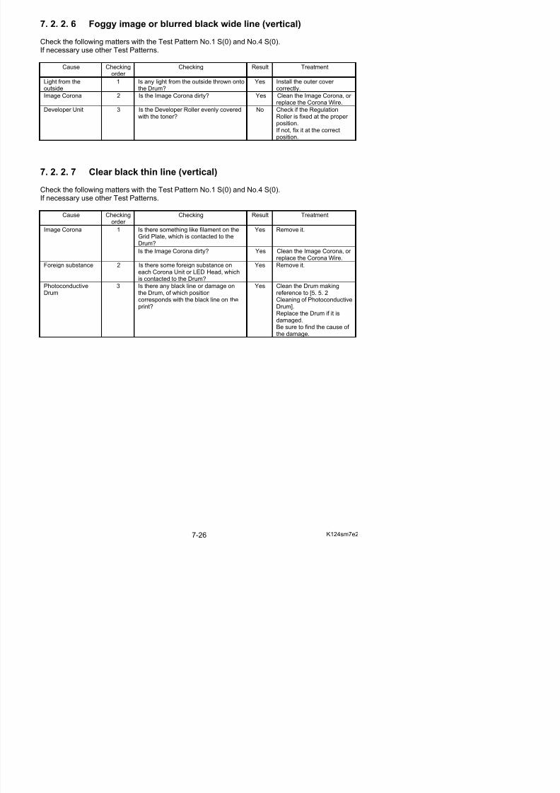
5/17/2018 KIP 7100 Service Manual Ver A_1 - slidepdf.com
http://slidepdf.com/reader/full/kip-7100-service-manual-ver-a1 414/674
7. 2. 2. 8 White line (Vertical)
Check the following matters with the Test Pattern No.1 S(0) and No.7 S(0).If necessary use other Test Patterns.
Cause Checking
order
Checking Result Treatment
Image Corona 1 Is there something like filament on theGrid Plate, which is contacted to theDrum?
Yes Remove it.
Dirt of the LEDHead
2 Can you fix the problem if you clean theLED Head?
Yes OK
Transfer/SeparationCorona
3 Is there any foreign substance or dirt onthe Transfer/Separation Corona?
Yes Clean the Transfer /Separation Corona.
Developer Unit 4 Is the Developer Roller evenly coveredwith the toner?
No Check whether or not thereis damage or foreignsubstance on the RegulationRoller.
Entrance of Fuser Unit
5 Is there any foreign substance or dirtaround the entrance area of the Fuser Unit?
Yes Clean it off
PhotoconductiveDrum
6 Is there any damage on the Drum,which runs to the direction of Drumrotation.
Yes Clean the Drum makingreference to [5. 5. 2Cleaning of PhotoconductiveDrum].Replace the Drum if it isdamaged.Be sure to find the cause of the damage.

5/17/2018 KIP 7100 Service Manual Ver A_1 - slidepdf.com
http://slidepdf.com/reader/full/kip-7100-service-manual-ver-a1 415/674
7. 2. 2. 9 Void of image
Check the following matters with the Test Pattern No.1 S(0) and No.7 S(0).If necessary use other Test Patterns.
Cause Checking
order
Checking Result Treatment
1 Print out the Test Patter No.7 (halftone).Can you find void of image on the print?
Yes Go to the step 2.
Paper 2 Can you fix the problem if you use anewly unpacked paper?
Yes 1. If the paper was humidified,instruct the customer of theway store the paper.
2. If the paper was not thespecified one, explain thecustomer that some imageproblem may occur in thatcase.
Does the void of image appear on theprint constantly Keeping about 160mmof interval?
Yes 1. Clean the Counter Rollersat both sides of theDeveloper Roller.
2. Wipe the Developer Roller with a dry cloth.
3. Replace the Developer Roller if damaged.
Developer Unit 3
Is the void of image mainly runsvertically as follows?
Yes 1. Check if there is enoughtoner in the Developer Unit.
2. Also select the DeviceStatus Mode and check theToner Sensor Signal(Device Code: 107).It must be “L” when thetoner is not covering theToner Sensor. If not,replace the Toner Sensor.
PhotoconductiveDrum
4 Does the void of image appear on theprint constantly Keeping about 251mmof interval?
Yes Clean Drum making referenceto [5. 5. 2 Cleaning of Photoconductive Drum].Replace Drum if damaged.Be sure to find the cause of the damage.
7. 2. 2.10 Dirt on the back of the print
Check the following matters with the Test Pattern No.1 S(0) and No.4 S(0).If necessary use other Test Patterns.
Cause Checkingorder
Checking Result Treatment
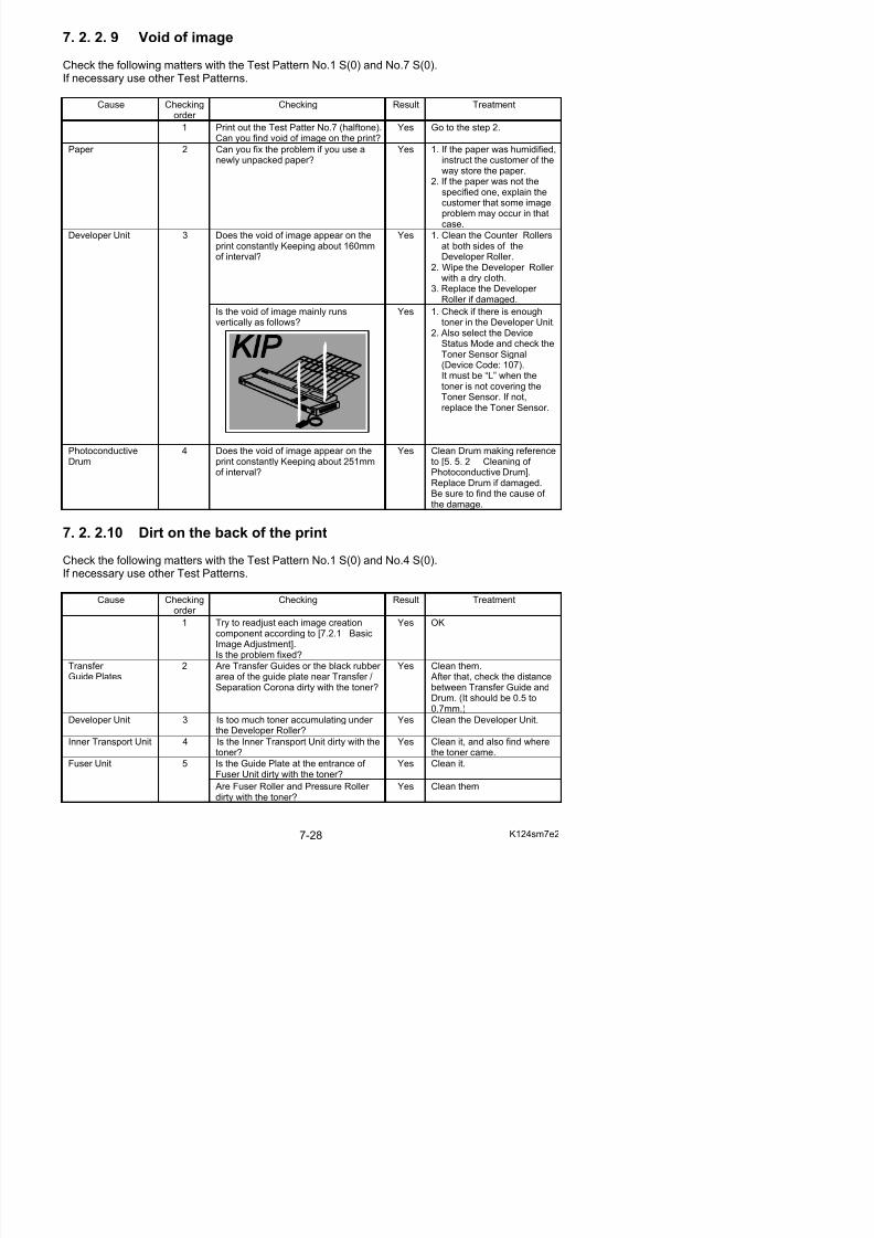
5/17/2018 KIP 7100 Service Manual Ver A_1 - slidepdf.com
http://slidepdf.com/reader/full/kip-7100-service-manual-ver-a1 416/674
7. 2. 2.11 Defective fusing
Check the following matters with the Test Pattern No.1 S(0) and No.3 S(0).If necessary use other Test Patterns.
Cause Checking
order
Checking Result Treatment
Fuser Unit 1 Is the Fuser Roller properly heated upafter turning on the machine?
No Refer to [7. 1. 2. 1 Fuser Error (E-001, E-002 &E-004)] to check the Fuser Unit.
Is the type of paper selected on the UIsame with that of actually installedpaper?
No Select the correct paper typeon the UI.
Paper 2
Can you fix the problem if you use anewly unpacked paper?
Yes 1. If the paper washumidified, instruct thecustomer of the way storethe paper.
2. If the paper was not thespecified one, explain thecustomer that someimage problem mayoccur in that case.
Yes Is there any part which isburnt? Replace that part if burnt.
Fusing temperaturesetting
3 Does the fusing temperature specifiedin the Service Mode suits with theweight (gram/square meter) of paper?
No Set the fusing temperaturecorrectly.
Fusing pressure(Nip)
4 Print the Test Patter No.2 S(0) with atracing paper (36” or A0), and turn off the machine in the middle of printing.Remove the print from the machine andcheck the “nip width”.Is it 8.5 to 9.0mm?(Measure at 2 mm from the edge.)
2mm 2mm
8.5 to 9.0mm
No Adjust the fusing pressurecorrectly.
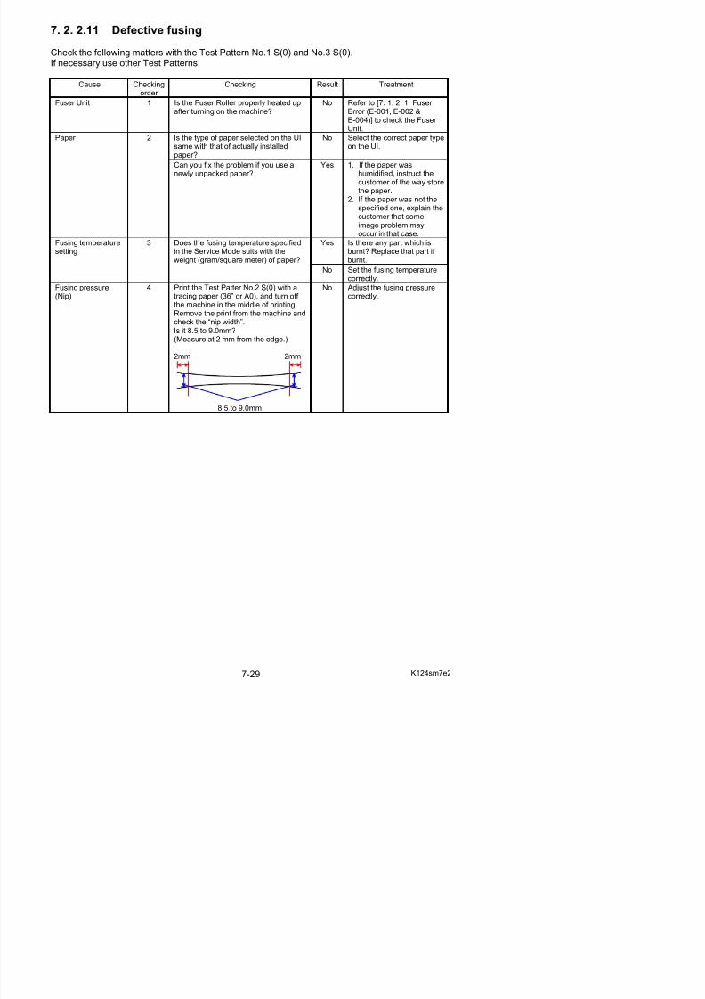
5/17/2018 KIP 7100 Service Manual Ver A_1 - slidepdf.com
http://slidepdf.com/reader/full/kip-7100-service-manual-ver-a1 417/674
7. 2. 2.12 Defective image placement, No Leading Edge
Correct leading margin is 5mm (+/-2mm).Check the following matters with the Test Pattern No.1 S(0) and No.7 S(0).If necessary use other Test Patterns.
Cause Checkingorder
Checking Result Treatment
Setting of LeadingRegistration
1 Is the Leading Registration or LeadingMargin properly adjusted in the ServiceMode?
No Adjust it properly.
Feed rollers 2 Have you used the feeding rollers for very long term?
Yes Replace them.
Registration Clutch 3 Does the Registration Clutch operatecorrectly without slipping?
No Replace Registration Clutch.
7. 2. 2.13 Jitter
Check the following matters with the Test Pattern No.1 S(0) and No.7 S(0).If necessary use other Test Patterns.
Cause Checking
order
Checking Result Treatment
Does the jitter appear on the printconstantly keeping about 251mm of interval?
Yes 1. Check if there is anydamage or foreignsubstance on Pulley onthe drum shaft.
2. Check if there is anyforeign substance betweenDrum and Counter Rollersof Developer Unit.
PhotoconductiveDrum and its drivingmechanism
1
Does the jitter appear on the print
constantly keeping about 3mm of interval?
Yes Check the engagement of
Pulley Gear on the Drumwith Belt 4.
Developer Roller 2 Does the void of image appear on theprint constantly keeping about 160mmof interval?
Yes Replace Developer Roller if damaged.
Does the jitter appear on the printconstantly keeping about 7.5mm of interval?
Yes Check if there is anydamage or foreignsubstance on 30T Gear onRegulation Roller shaft(driving side).
Does the jitter appear on the printconstantly keeping about 6.4mm of interval?
Yes Check if there is anydamage or foreignsubstance on 30T Gear onSupply Roller shaft (drivingside) or the driving gears(30T, 25T, 22T) on theelectrode plate side.
Developer Unit 3
7 2 2 14 I l k h
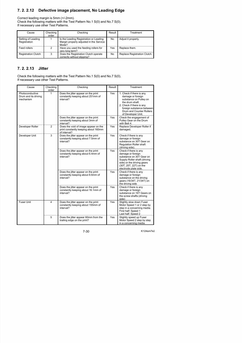
5/17/2018 KIP 7100 Service Manual Ver A_1 - slidepdf.com
http://slidepdf.com/reader/full/kip-7100-service-manual-ver-a1 418/674
7. 2. 2.14 Image looks not sharp
Check the following matters with the Test Pattern No.1 S(0).If necessary use other Test Patterns.
Cause Checking
order
Checking Result Treatment
Dirt of the LEDHead
1 Is the LED Head dirty? Yes Clean it.
Yes OKInstallation of LEDHead
2 Remove the LED Head, and then re-install it to the machine.Is the problem fixed?
No Adjust the gap between LEDHead and Drum by adding or removing the thin plates onthe Aluminium Block at bothsides of the Drum.
Transfer /Separation Corona
3 Is the Transfer / Separation Coronadirty?
Yes Clean it.
7. 2. 2.15 Uneven image density (vertical)
Check the following matters with the Test Pattern No.1 S(0) and No.7 S(0).If necessary use other Test Patterns.
Cause Checkingorder
Checking Result Treatment
Image Corona 1 Is the Image Corona dirty? Yes Clean it.
Transfer/SeparationCorona
2 Is the Transfer/Separation Coronadirty?
Yes Clean it.
3 Remove the LED Head, and then re-install it to the machine.Is the problem fixed?
Yes OK
4 Is the density of any image blockdifferent from that of other blocks?
Yes Adjust the gap between LEDHead and Drum by adding or removing the Spacers on the Aluminium Block.
Installation of LEDHead
5 Is the width of abnormal density areab t 8 f ll ?
Yes Replace the LED Head.
7 2 2 16 C l t l hit (N i )
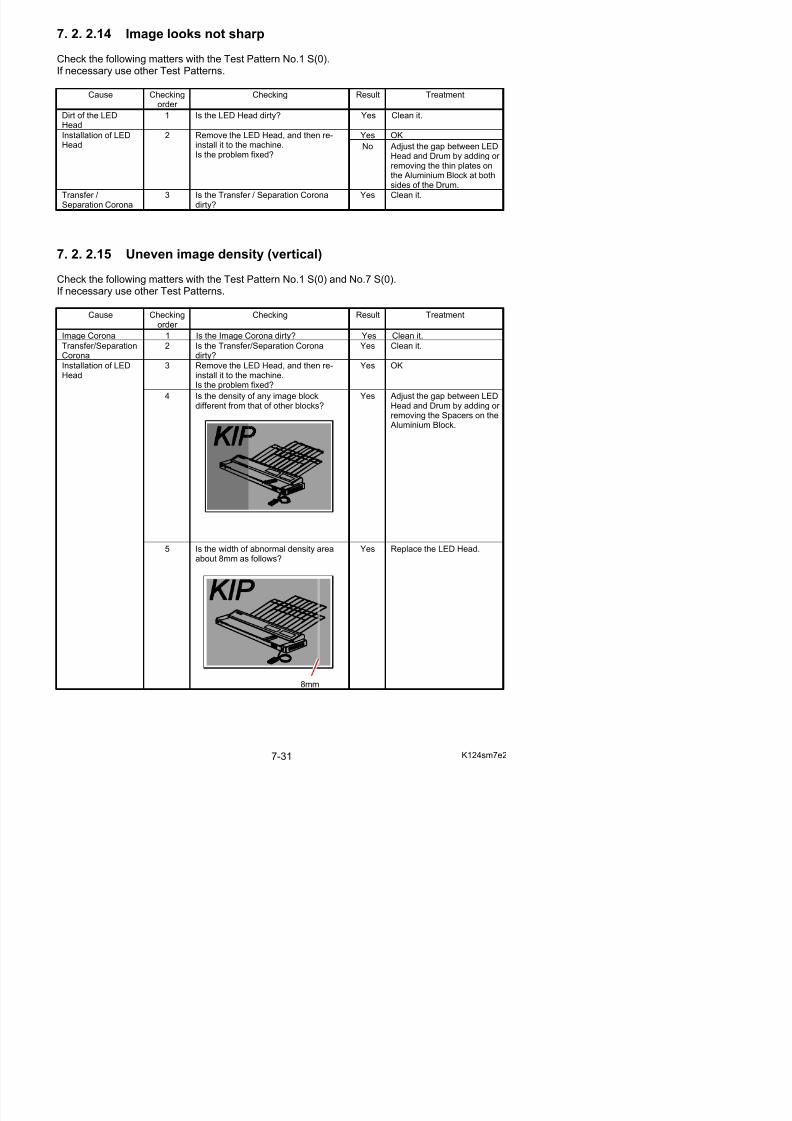
5/17/2018 KIP 7100 Service Manual Ver A_1 - slidepdf.com
http://slidepdf.com/reader/full/kip-7100-service-manual-ver-a1 419/674
7. 2. 2.16 Completely white (No image)
Check the following matters with the Test Pattern No.1 S(0).If necessary use other Test Patterns.
Cause Checking
order
Checking Result Treatment
Developer PressUnit
1 Is the Developer Unit correctly pressedto the Drum?
No Check the Developer PressUnit.
Driving mechanismof Developer Unit
2 Does the Developer Roller rotate duringthe print?
No Check the drivingmechanism of Process Unit.
Developer Bias 3 Is each Electrode Plate on the right of the Developer Unit surely contacted tothe Electrode Plate on the machineside?
No Try to install the Developer Unit so that they arecontacted each other. And supply the conductivegrease to the Electrode
Plates. Are connectors of signal cable firmlyconnected to the LED Head?
No Connect them firmly.LED Head 4
Turn off the machine in the middle of printing, and then check the toner image on the Drum.
Is there any toner image on the Drum?
No Replace the LED Head.
Is the Transfer Corona Wire broken? Yes Replace it.
Is the Transfer/Separation Corona Unitcorrectly installed to the machine? No Install it correctly.
Transfer/SeparationCorona
5
If the high voltage leaking from theTransfer Corona?
Yes Check the Transfer /Separation Corona to findthe cause for leaking.
Is the connection of Lead Wire correct? No Connect it correctly.Lead Wire of Transfer Corona
6
Is the resistance of Lead Wire about 10kilo ohms, which connects HV Power
Supply and the Transfer Corona?
No Replace the Lead Wire.
HV Power Supply 7 Can you fix the problem if you replacethe HV Power Supply?
Yes OK
PW12420 PCB 8 Can you fix the problem if you replacethe PW12420 PCB?
Yes OK
7. 2. 2.17 Completely black
Check the following matters with the Test Pattern No.1 S(0) and No.4 S(0).If necessary use other Test Patterns.
Cause Checkingorder
Checking Result Treatment
7 2 2 18 Crease of paper
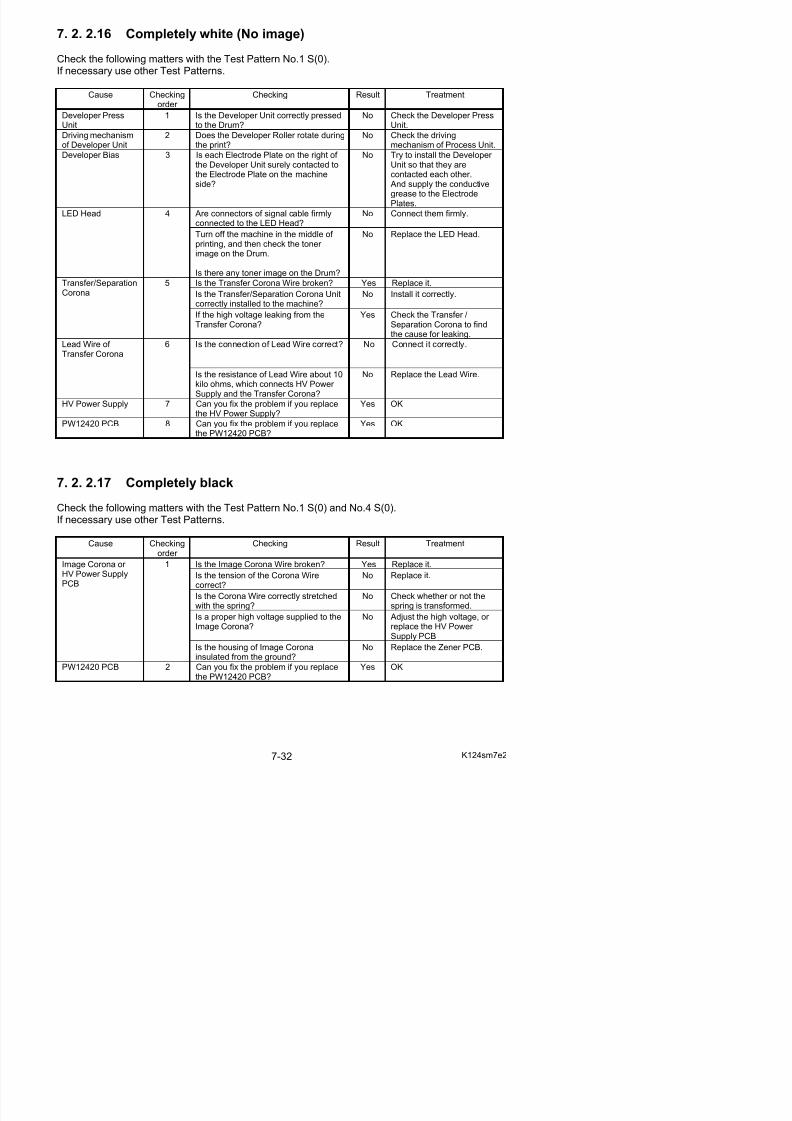
5/17/2018 KIP 7100 Service Manual Ver A_1 - slidepdf.com
http://slidepdf.com/reader/full/kip-7100-service-manual-ver-a1 420/674
7. 2. 2.18 Crease of paper
Check the following matters with the Test Pattern No.1 S(0).If necessary use other Test Patterns.
Cause Checking
order
Checking Result Treatment
1 Make a continuous printing.Can you find the crease on the 2nd or later prints?
Yes Go to the following “8”.
Is the type of paper selected on the UIsame with that of actually installedpaper?
No Select the correct paper typeon the UI.
Can you fix the problem if you use anewly unpacked paper?
Yes 1. If the paper washumidified, instruct thecustomer of the way storethe paper.
2. If the paper was not thespecified one, explain thecustomer that someimage problem mayoccur in that case.
Paper 2
Is the Dehumidify Heater ON althoughthe air is not humid.
Yes Turn off the DehumidifyHeater.
Lamp (H1, H2) of Fuser
3 Does the Lamp light correctly? No Replace it.
Blower (Separation) 4 Is the Blower working properly during aprint to help paper transportation?
No Replace it.
Blower (Fuser Cooler)
5 Is the Blower working properly during awide print (30”/ 34”/ 36”/ A0) to cooldown the Fuser?
No Replace it.
Is the Fuser Entrance Guidetransformed?Or Is there anything on the Fuser Entrance Guide?
Yes Clean or replace it.Fuser EntranceGuide
6
Remove Pressure Roller and measurethe location height of Fuser EntranceGuide. Is the height correct?
From the frame bottom surface,Side : 70.7 to 71.3mmMiddle : 73.7 to 74.3mm (US)
: 74.5 to 75.1mm (EU)
No Turn the adjuster screw(s) toreach the correct height.
Guide Plate Height Adjuster (to both sides)
US: +33rd from center
EU: +4highest
Fusing pressure(Nip)
7 Print the Test Patter No.2 S(0) with atracing paper (36” or A0), and turn off th hi i th iddl f i ti
No Adjust the fusing pressurecorrectly.
7 2 2 19 Double Image
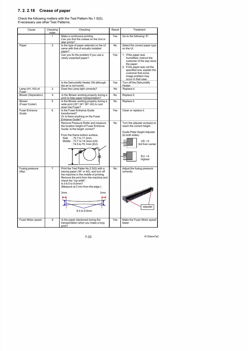
5/17/2018 KIP 7100 Service Manual Ver A_1 - slidepdf.com
http://slidepdf.com/reader/full/kip-7100-service-manual-ver-a1 421/674
7. 2. 2.19 Double Image
Check the following matters with the Test Pattern No.1 S(0).If necessary use other Test Patterns.
Cause Checking
order
Checking Result Treatment
Is the type of paper selected on the UIsame with that of actually installedpaper?
No Select the correct paper typeon the UI.
Paper 1
Can you fix the problem if you use anewly unpacked paper?
Yes 1. If the paper washumidified, instruct thecustomer of the way storethe paper.
2. If the paper was not thespecified one, explain the
customer that someimage problem mayoccur in that case.
Lamp (H1, H2) of Fuser
2 Does the Lamp light correctly? No Replace it.
Blower (Separation) 3 Is the Blower working properly duringthe print to help paper transportation?
No Replace it.
Blower (Fuser Cooler)
4 Is the Blower working properly during awide print (30”/ 34”/ 36”/ A0) to cooldown the Fuser?
No Replace it.
Is the Fuser Entrance Guidetransformed?Or Is there anything on the Fuser Entrance Guide?
Yes Clean or replace it.Fuser EntranceGuide
6
Remove Pressure Roller and measurethe location height of Fuser EntranceGuide. Is the height correct?
From the frame bottom surface,Side : 70.7 to 71.3mmMiddle : 73.7 to 74.3mm (US)
: 74.5 to 75.1mm (EU)
No Turn the adjuster screw(s) toreach the correct height.
Guide Plate Height Adjuster (to both sides)
US: +33rd from center
EU: +4highest
Fusing Pressure(Nip)
6 Print the Test Patter No.2 S(0) with atracing paper (36” or A0), and turn off the machine in the middle of printing.Remove the print from the machine andcheck the “nip width”.Is it 8.5 to 9.0mm?(Measure at 2 mm from the edge.)
No Adjust the fusing pressurecorrectly.
7 2 2 20 Dirt on the print (Offset)
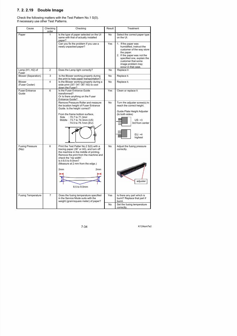
5/17/2018 KIP 7100 Service Manual Ver A_1 - slidepdf.com
http://slidepdf.com/reader/full/kip-7100-service-manual-ver-a1 422/674
7. 2. 2.20 Dirt on the print (Offset)
Check the following matters with the Test Pattern No.2 S(0).If necessary use other Test Patterns.
Cause Checking
order
Checking Result Treatment
Paper 1 Is the type of paper selected on the UIsame with that of actually installedpaper?
No Select the correct paper typeon the UI.
Developer Unit or Transfer/SeparationCorona
2 Does the paper have dirt before itenters the Fuser Unit?
Yes Check the Developer Unit or Transfer/Separation Coronato find the cause.
Yes Decrease the setting valueof fusing temperature (-3 to -5).
Fuser Unit 3 Clean the Fuser Roller.Do you still have the problem even after the cleaning?
No OK
7. 2. 2. 21 Image Void on Long Print without Crease
The following procedure may address image void on a long print without creases.Image void without creases would result from a too fast feeding speed.If you can see image void and a crease at a time, refer to [7.2.2.22 Crease (and image void at atime)].
Cause Checkingorder
Checking Result Treatment
Except feeding 1 Is everything on [7.2.2.9 Void of Image]clear?
No Refer to [7.2.2.9 Void of Image] and check all thepoints.
Yes Before 2x standard;Go to step 9.
Cause analysis withimage void location
2 Does image void appear before 2xstandard length?
No After 2x standard;Go to step 3.
3 Decrease Feed Clutch Off Timing in 30(for shorter clutch operation) on Adjustment Mode.
Sub Mode: 053(Feed Clutch Off Timing for Roll 1)
: 054(Feed Clutch Off Timing for Roll 2) Does this fix image void problem?
Yes OK
Yes OK
Feed Clutch Off Timing
lack of slack atcutter region
4 Again decrease the Feed Clutch Off Timing in another 30 (for shorter clutchoperation).
No Increase the Feed Clutch Off Timing in 60 to restore the
Fuser Motor 4th 7 Decrease the 4th Speed in another 1 No Increase the 4th Speed in 3
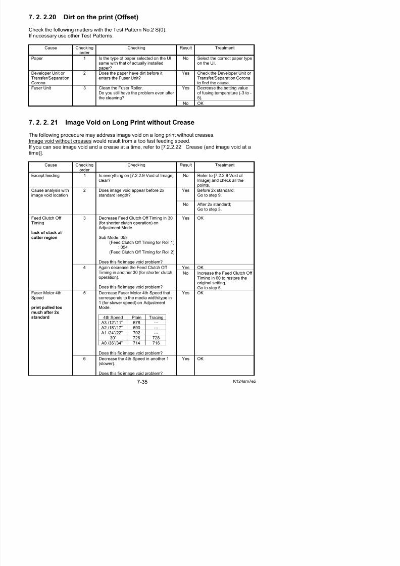
5/17/2018 KIP 7100 Service Manual Ver A_1 - slidepdf.com
http://slidepdf.com/reader/full/kip-7100-service-manual-ver-a1 423/674
Speed(cont.)
(slower).
Does this fix image void problem?
to restore the originalsetting.Go to step 8.
Yes OKFuser Motor 3rdSpeed
8 Decrease Fuser Motor 3rd Speed thatcorresponds to the media width/type in
1 (for slower speed) on AdjustmentMode.
3rd Speed Plain Tracing
A3 /12”/11” 074 080
A2 /18”/17” 110 116
A1 /24”/22” 146 152
30” 440 446
A0 /36”/34” 182 188
Does this fix image void problem?
No Go back to step 5.
Decrease the 4th Speed(slower) with remaining the3rd Speed decreased.
Follow step 5 to 8 untilimage void disappears.
Fuser Motor 3rdSpeed
print pulled toofast before 2xstandard
9 Decrease Fuser Motor 3rd Speed thatcorresponds to the media width/type in1 (for slower speed) on AdjustmentMode.
3rd Speed Plain Tracing
A3 /12”/11” 074 080
A2 /18”/17” 110 116
A1 /24”/22” 146 152
30” 440 446 A0 /36”/34” 182 188
Does this fix image void problem?
No Decrease the 3rd Speed inanother 1 (slower) untilimage void disappears.
7. 2. 2. 22 Crease on Long Print (and image void at a time)
The following procedure may address a crease on a long print.If a crease and image void can be seen at a time, follow this section.Creases (and image void seen at a time) would result from a slack on the feeding media, whichrequires feeding speed adjustment (slightly faster).
Cause Checkingorder
Checking Result Treatment
1 Is everything on [7.2.2.18 Crease of paper] clear?
No Refer to [7.2.2.18 Crease of paper] and check all the
points.
Except feeding
2 If image void appears at a time, iseverything on [7.2.2.9 Void of Image] onService Manual clear?
No Refer to [7.2.2.9 Void of Image] and check all thepoints.
Yes Before 2x standard;Go to step 4.
Cause analysis withimage void location
3 Does a crease appear before 2xstandard length?
Yes Image void remains, or hasImage Void Check 5 Is there any image void after 2x
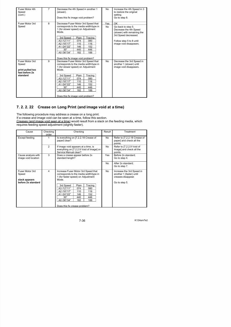
5/17/2018 KIP 7100 Service Manual Ver A_1 - slidepdf.com
http://slidepdf.com/reader/full/kip-7100-service-manual-ver-a1 424/674
just come after step 4;Go to step 6.
standard length?
Note that step 4 would result in imagevoid there.
No OK
Yes OKFuser Motor 4th
Speed
print pulled toofast before 2xstandard
6 Decrease Fuser Motor 4th Speed that
corresponds to the media width/type in1 (for slower speed) on AdjustmentMode.
4th Speed Plain Tracing
A3 /12”/11” 678 ---
A2 /18”/17” 690 ---
A1 /24”/22” 702 ---
30” 726 728
A0 /36”/34” 714 716
Does this fix image void problem?
No Decrease the 4th Speed inanother 1 (slower) untilimage void disappears.
7 Increase Fuser Motor 3rd Speed thatcorresponds to the media width/type in1 (for faster speed) on AdjustmentMode.
3rd Speed Plain Tracing
A3 /12”/11” 074 080
A2 /18”/17” 110 116
A1 /24”/22” 146 152
30” 440 446
A0 /36”/34” 182 188
Does this fix crease problem?
Yes Go to step 9.
Yes Go to step 10.
Fuser Motor 3rdSpeed
8 a) No image void seen up to step 7;
Is there any image void that has justcome after step 7?
b) Crease and image void seen at atime up to step 7;
Is there any image void shift from after 2x standard length to before 2xstandard?
No - no image void- no image void shiftGo back to step 7.
9 After crease disappears, is there anyimage void?
No OK
Fuser Motor 4th
Speed
slack appears after 2x standard
10 First decrease the 3rd Speed (slower)
in 1.
Increase Fuser Motor 4th Speed thatcorresponds to the media width/type in1 (for faster speed) on AdjustmentMode.
No Increase the 4th Speed in
another 1 (faster) untilcrease and image voiddisappear.
7 3 Troubleshooting - Scanner Defects
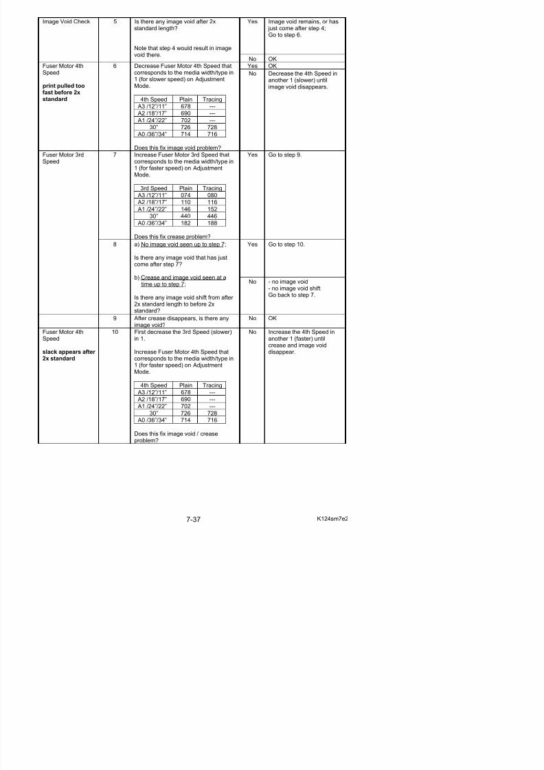
5/17/2018 KIP 7100 Service Manual Ver A_1 - slidepdf.com
http://slidepdf.com/reader/full/kip-7100-service-manual-ver-a1 425/674
7. 3 Troubleshooting - Scanner Defects
7. 3. 1 Countermeasures - Scanner operation
7. 3. 1. 1 Original can not be set (Scanner does not transport)Cause Checking
order Checking Result Treatment
Sensor 1 Is the original detected?(Is it shown on the UI?)
No 1. Tap the UI screen tocancel the sleep mode.
2. Switch the UI screen toCopy or Scan mode.
3. Check the sensor whichdetects the leading edgeof original.If broken replace it.
Check this sensor.
USB Cable 2 Is the USB Cable connected correctly? No Connect it correctly.
Data Controller Board
3 Can you fix the problem if you replacethe Data Controller Board?
Yes OK
7. 3. 1. 2 Scanner does not start scanning from the original setposition
Cause Checkingorder
Checking Result Treatment
Foreign substance 1 Is there any foreign substance under the Upper Unit?
Yes Remove it.
Motor 2 Does the Motor rotate? No Check the Motor, andreplace it if broken.
+24VDC 3 Is +24VDC supplied to the scanner? No Check the DC Power Supplyon the printer part.Replace it if broken.
Data Controller 4 Can you fix the problem if you replace Yes OK
7. 3. 1. 4 Original is mis-fed
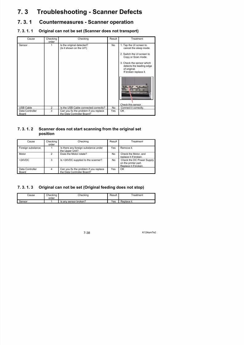
5/17/2018 KIP 7100 Service Manual Ver A_1 - slidepdf.com
http://slidepdf.com/reader/full/kip-7100-service-manual-ver-a1 426/674
g
Cause Checkingorder
Checking Result Treatment
Foreign substance 1 Is there any foreign substance under the Upper Unit?
Yes Remove it.
7. 3. 1. 5 Motor rotates endlessly at the time of turning on
Cause Checkingorder
Checking Result Treatment
Foreign substance 1 Is there any foreign substance under
the Upper Unit, which blocks the light of sensor?
Yes Remove it.
7. 3. 1. 6 Scanner is not recognized
Cause Checking
order
Checking Result Treatment
USB Driver 1 Does the PC recognize USB? No Check the USB Driver inDevice Manager.
USB Cable 2 Is there any problem with the USBcable, such as breakage, short-circuitand damage of connector pin?
Yes Replace the USB Cable.
DC Power Supply 3 Is the DC Power Supply on the printer part normal?
No Replace the DC Power Supply.
Data Controller Board
4 Prepare another PC which canrecognize another type of USB
Scanner.Is it also impossible to recognize theK124SC with this PC?
Yes Replace the Data Controller PCB.
7. 3. 2 Countermeasures – Scan Image Quality
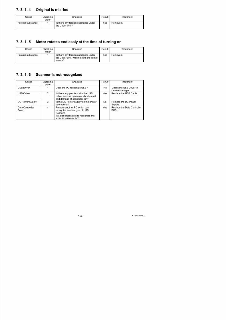
5/17/2018 KIP 7100 Service Manual Ver A_1 - slidepdf.com
http://slidepdf.com/reader/full/kip-7100-service-manual-ver-a1 427/674
g Q y
7. 3. 2. 1 Completely black
Cause Checkingorder
Checking Result Treatment
Calibration 1 Can you fix the problem if you makeShading (Calibration)?(Refer to [8.13.4.1 Shading].)
Yes OK
Cable of CIS 2 Is the cable of each CIS connectedproperly?
No Connect it properly, or replace the cable if it isbroken.
LED of CIS 3 Is the LED of each CIS lighting? No 1. Check the DC Power Supply (+24V) of theprinter part.
Replace it if broken.2. Replace the CIS.3. Replace the Data
Controller Board.
7. 3. 2. 2 Vertical black lines
Cause Checkingorder
Checking Result Treatment
Scan Glass 1 Is there any dirt or damage on the ScanGlass?
Yes Clean / replace it.
Calibration 2 Can you fix the problem if you makeShading (Calibration)?(Refer to [8.13.4.1 Shading].)
Yes OK
Feeding rollers 3 Are feeding rollers dirty? Yes Clean them.
CIS 4 Can you fix the problem if you replacethe CIS?
Yes OK
7. 3. 2. 3 Vertical white lines
Cause Checkingorder
Checking Result Treatment
Scan Glass 1 Is there any dirt or damage on the Scan
Glass?
Yes Clean / replace it.
Calibration 2 Can you fix the problem if you makeShading (Calibration)?(Refer to [8.13.4.1 Shading].)
Yes OK
Feeding rollers 3 Are feeding rollers dirty? Yes Clean them.
CIS 4 Can you fix the problem if you replacethe CIS?
Yes OK
7. 3. 2. 4 Some image is lost at the boundary of Image Blocks
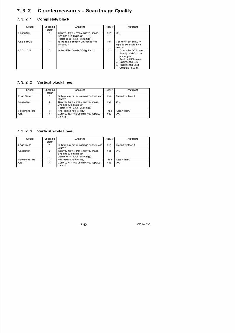
5/17/2018 KIP 7100 Service Manual Ver A_1 - slidepdf.com
http://slidepdf.com/reader/full/kip-7100-service-manual-ver-a1 428/674
Cause Checkingorder
Checking Result Treatment
Calibration 1 Can you fix the problem if you makePosition?(Refer to [8.13.4.3 Position].)
Yes OK
7. 3. 2. 5 Vertical image gap between Image Blocks
Cause Checkingorder
Checking Result Treatment
Calibration 1 Can you fix the problem if you make
Position?(Refer to [8.13.4.3 Position].)
Yes OK
7. 3. 2. 6 Image quality is not good
Cause Checking
order
Checking Result Treatment
Scan Glass 1 Is there any dirt or damage on the ScanGlass?
Yes Clean / replace it.
Resolution 2 Is the resolution setting proper? No Adjust it properly.
7. 3. 2. 7 Density is different between left and right
Cause Checkingorder
Checking Result Treatment
Calibration 1 Can you fix the problem if you makeShading (Calibration)?(Refer to [8.13.4.1 Shading].)
Yes OK
7. 4 Touch Screen Calibration
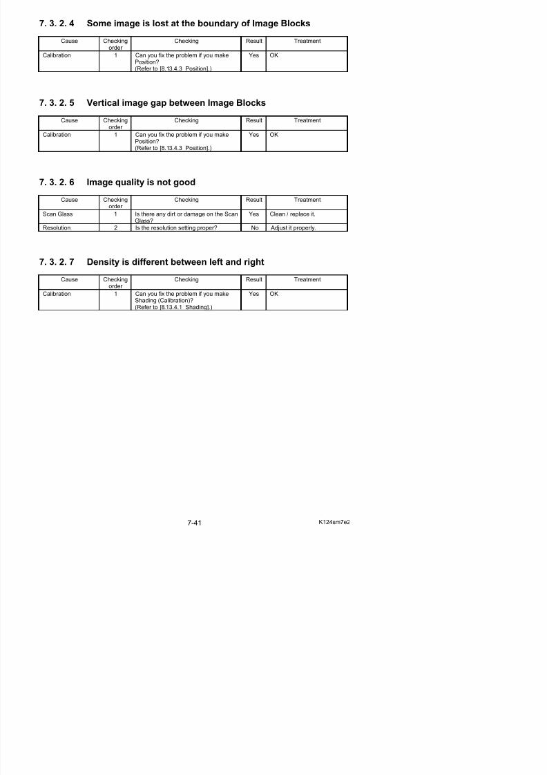
5/17/2018 KIP 7100 Service Manual Ver A_1 - slidepdf.com
http://slidepdf.com/reader/full/kip-7100-service-manual-ver-a1 429/674
7. 4 Touch Screen Calibration
If the cursor position in the screen does not correctly match the tapped position on the panel, thetouch screen should be calibrated so that the cursor is located directly underneath your finger or astylus.
1. Press “? - Help” on Home screen.
The screen shows any available options. This may vary from the actual one
2. Press [Service].
3. On-screen Keypad appears.Input “8495107” and press [Enter]
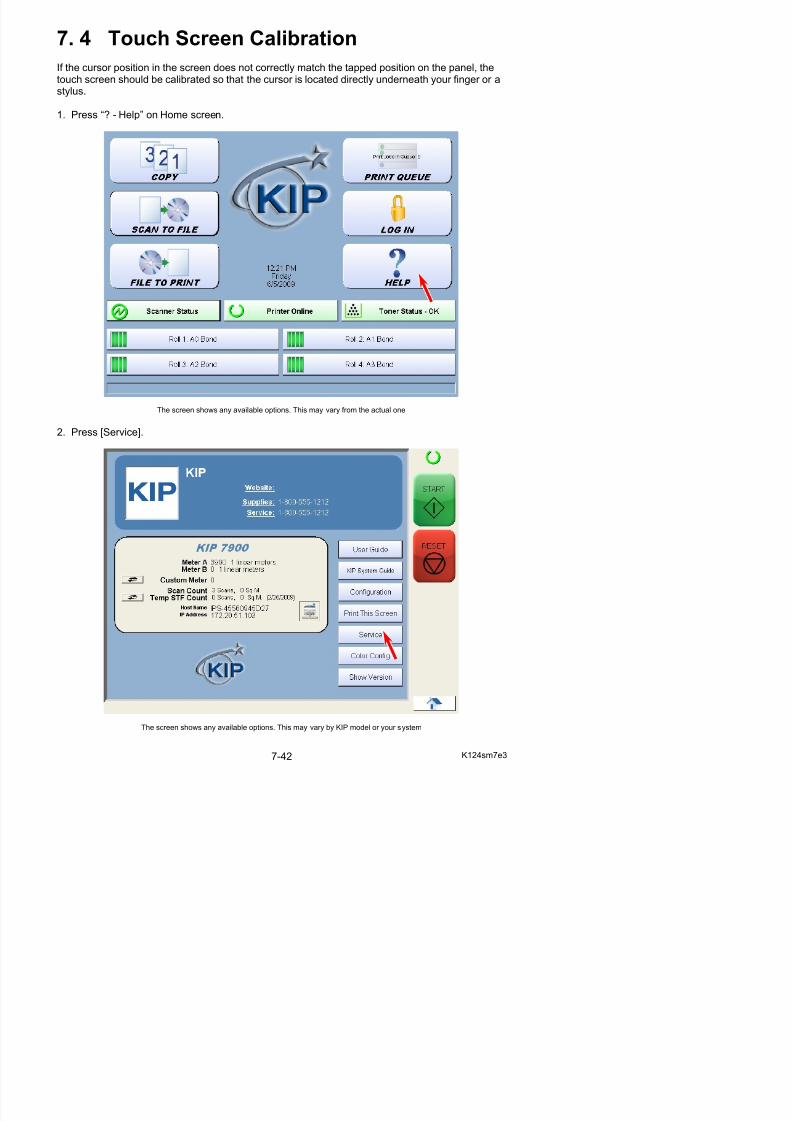
5/17/2018 KIP 7100 Service Manual Ver A_1 - slidepdf.com
http://slidepdf.com/reader/full/kip-7100-service-manual-ver-a1 430/674
Input 8495107 and press [Enter].
4. Service Configuration screen is displayed. Press [OK].
5. Make sure that a wrench symbol is indicated at the upper right of the screen.Press [Reset] to close UI operation window.
6. Tap Diagnostics folder twice as a double-click.Run the shortcut “TouchScreen Configure Utility” for touch screen calibration.
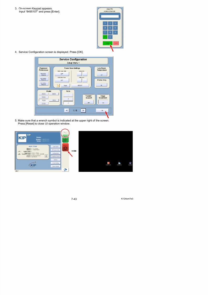
5/17/2018 KIP 7100 Service Manual Ver A_1 - slidepdf.com
http://slidepdf.com/reader/full/kip-7100-service-manual-ver-a1 431/674
g y
7. Select [Tools] tab.
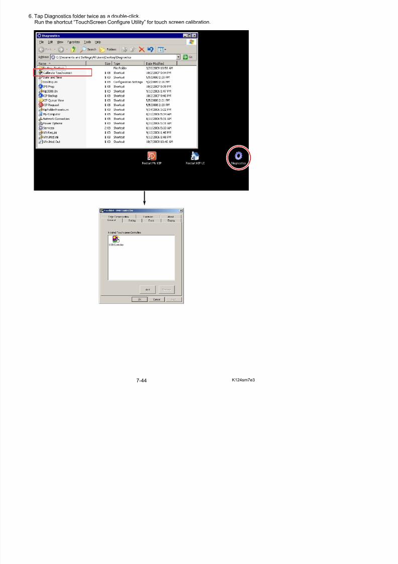
5/17/2018 KIP 7100 Service Manual Ver A_1 - slidepdf.com
http://slidepdf.com/reader/full/kip-7100-service-manual-ver-a1 432/674
8. Press [Draw Test] to check that the touch screencorrectly detects a tapped position.
9. Test screen will appear.
NOTE
Using a stylus is recommended for easy and accurate touch screen calibration.
Do not use any sharp instrument.
10. Tap a certain point and check the cursor appears directly underneath a stylus.
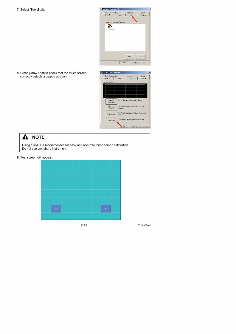
5/17/2018 KIP 7100 Service Manual Ver A_1 - slidepdf.com
http://slidepdf.com/reader/full/kip-7100-service-manual-ver-a1 433/674
For example, suppose you tap the point shownthe next figure.
The cursor will appear just underneath the tapped point in a correct condition (calibration is notnecessary).
If the cursor appears an unintended position, the touch screen should be calibrated.
Tap this cross
Cursor
Tap point
Cursor
Cursor matches the tap point
Cursor does not match the tap point
11. Tap [Quit] to close Test screen.
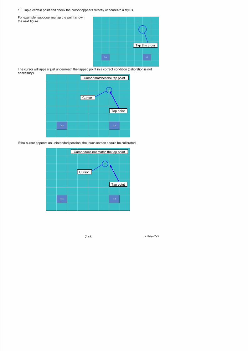
5/17/2018 KIP 7100 Service Manual Ver A_1 - slidepdf.com
http://slidepdf.com/reader/full/kip-7100-service-manual-ver-a1 434/674
12. Press [4 Points Calibration].
13. On Calibration screen, a blinking X symbol on the bottom left can be seen.Press the X until it stops blinking with a beep.
14. The X disappears and the next one will come in the following order:bottom right, top right, top left.P f th f th th 3 i t
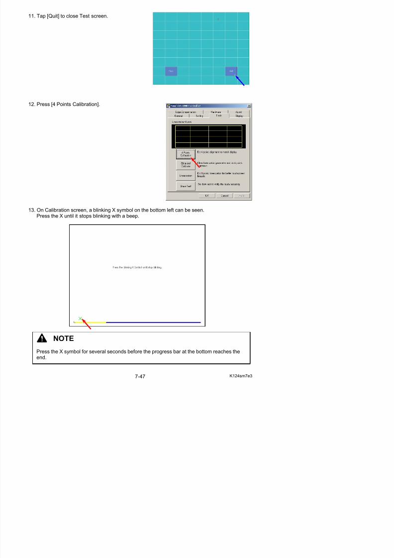
5/17/2018 KIP 7100 Service Manual Ver A_1 - slidepdf.com
http://slidepdf.com/reader/full/kip-7100-service-manual-ver-a1 435/674
Perform the same way for the other 3 points.
15. When all the 4 points are pressed successfully, Calibration screen disappears and the
following dialog appears. Press [OK].
16. Press [OK] to finish touch screen calibration.
17. Run the shortcut “Restart KIP UI” for KIP UI operation.
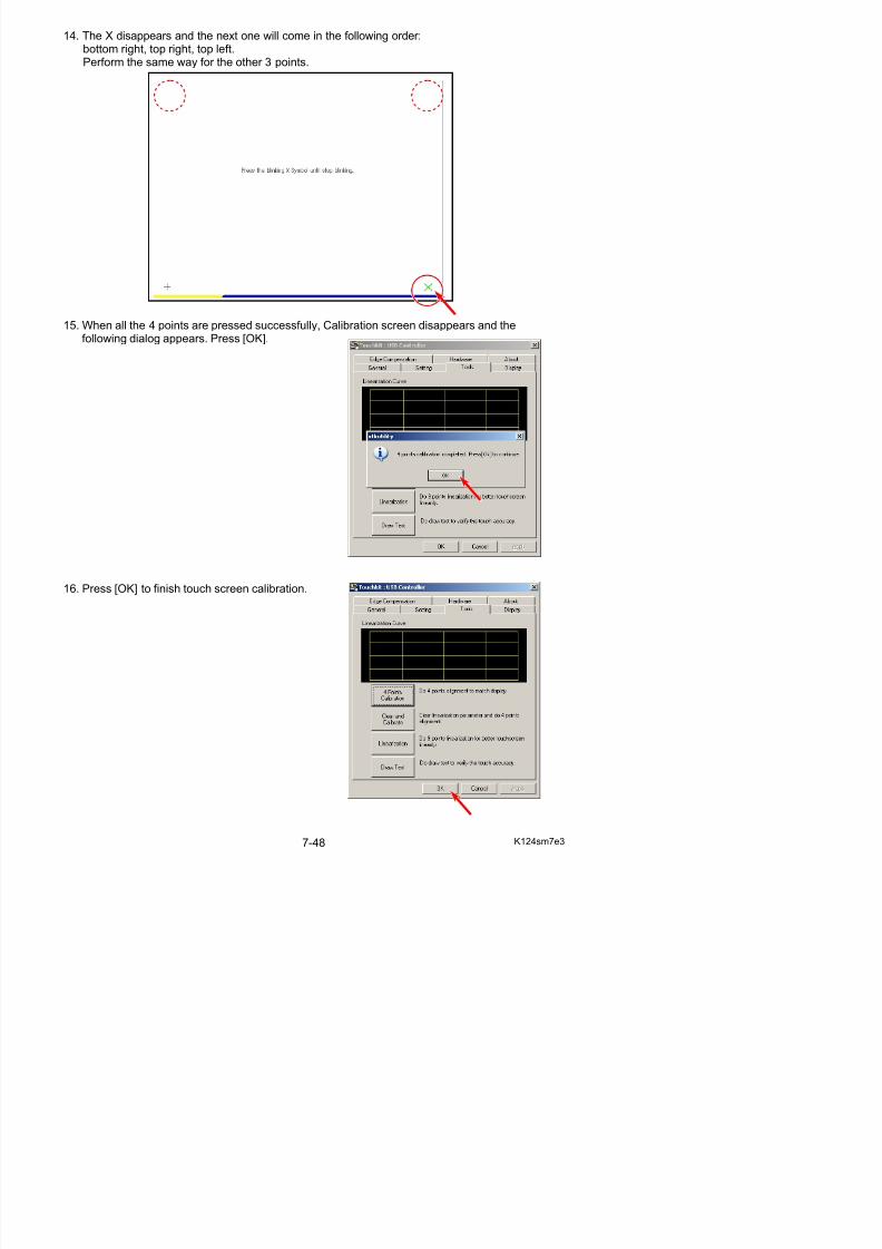
5/17/2018 KIP 7100 Service Manual Ver A_1 - slidepdf.com
http://slidepdf.com/reader/full/kip-7100-service-manual-ver-a1 436/674

5/17/2018 KIP 7100 Service Manual Ver A_1 - slidepdf.com
http://slidepdf.com/reader/full/kip-7100-service-manual-ver-a1 437/674
Chapter 8
Service Mode / Utility
8. 1 General Information of KIP Service Software 8- 1
8. 2 KIP Service Software Overview 8- 28. 2. 1 Launching KIP Service Software 8- 4
8. 2. 2 Closing KIP Service Software 8- 78. 2. 3 Log In screen 8- 88. 2. 4 Service Mode Home 8- 9
8. 3 Signal Status Mode 8-108. 3. 1 Monitoring Signal Status 8-118. 3. 2 Input / Output Signal List 8-14
8. 4 Information Mode 8-168. 4. 1 Monitoring Analog Data 8-208. 4. 2 List of Analog Data Monitor 8-228. 4. 3 Browsing Jam History 8-238. 4. 4 Browsing Error History 8-24
8. 5 Operation Check Mode 8-258. 5. 1 Checking Device Operation 8-268. 5. 2 Device List 8-28
8. 6 Adjustment Mode 8-29 8. 6. 1 Changing Setting Value 8-318. 6. 2 Setting Item List 8-368. 6. 3 Setting Item Explanation 8-52
8. 6. 3. 1 Leading Registration (No. 000 & 001) 8-528. 6. 3. 2 Trailing Margin (No. 002 & 003) 8-528. 6. 3. 3 Side Margin (Left & Right) (No. 004) 8-53
8. 6. 3. 4 Side Registration (No. 005 to 007) 8-548. 6. 3. 5 LED Strobe Time for Main Pixel of each Block (No.008 to 010) 8-558. 6. 3. 6 LED Strobe Time for IST (Supplemental Pixel) of each Block
(No.011 to 013) 8-578. 6. 3. 7 Vertical Alignment of Pixels between Blocks (No.014 & 015) 8-598 6 3 8 Cut Length 1 (length information provided) (No 016) 8-60
8. 6. 3.24 Toner Supply Motor ON Time (No.051) 8-728. 6. 3.25 Dot Enhancement Level (Dither) (No.052) 8-738 6 3 26 Feed Clutch (CL3) OFF time applied to long print (No 053 & 054) 8-74
5/17/2018 KIP 7100 Service Manual Ver A_1 - slidepdf.com
http://slidepdf.com/reader/full/kip-7100-service-manual-ver-a1 438/674
8. 6. 3.26 Feed Clutch (CL3) OFF time applied to long print (No.053 & 054) 8 748. 6. 3.27 Metric or Inch (No.055) 8-758. 6. 3.28 Language (No.056) 8-758. 6. 3.29 Interface Communication Setting (No.057) 8-75
8. 6. 3.30 Recognition of paper Tray (No.058) 8-758. 6. 3.31 Counter Value (No.059) 8-758. 6. 3.32 Maximum Length (No.060) 8-768. 6. 3.33 Stacking Device setting (No.061) 8-768. 6. 3.34 Operation of Fuser Roller (No.062) 8-768. 6. 3.35 Cut Length 5 & 6 (Compensation for Tracing Paper / Film)
(No. 063 & 064) 8-778. 6. 3.36 Drum Reverse Rotation Period (No.065) 8-788. 6. 3.37 Fuser Motor Reverse Setting (No.066) 8-788. 6. 3.38 Operation of Separation Lamp (No.067) 8-798. 6. 3.39 Compensation of Fuser Motor Speed for roll paper
(Plain paper / A3, 12” & 11”) (No.070 to 075, 678, 679) 8-808. 6. 3.40 Compensation of Fuser Motor Speed for roll paper
(Tracing paper / A3, 12” & 11”) (No.076 to 081, 680, 681) 8-838. 6. 3.41 Compensation of Fuser Motor Speed for roll paper
(Film / A3, 12” & 11”) (No.082 to 087, 682, 683) 8-848. 6. 3.42 Compensation of Fuser Motor Speed for roll paper
(Special plain paper / A3, 12” & 11”) (No.088 to 093, 684, 685) 8-858. 6. 3.43 Compensation of Fuser Motor Speed for roll paper
(Special tracing paper / A3, 12” & 11”) (No.094 to 099, 686, 687) 8-868. 6. 3.44 Compensation of Fuser Motor Speed for roll paper
(Special film / A3, 12” & 11”) (No.100 to 105, 688, 689) 8-878. 6. 3.45 Compensation of Fuser Motor Speed for roll paper
(Plain paper / A2, 18” & 17”) (No.106 to 111, 690, 691) 8-888. 6. 3.46 Compensation of Fuser Motor Speed for roll paper
(Tracing paper / A2, 18” & 17”) (No.112 to 117, 692, 693) 8-898. 6. 3.47 Compensation of Fuser Motor Speed for roll paper
(Film / A2, 18” & 17”) (No.118 to 123, 694, 695) 8-908. 6. 3.48 Compensation of Fuser Motor Speed for roll paper
(Special plain paper / A2, 18” & 17”) (No.124 to 129, 696, 697) 8-918. 6. 3.49 Compensation of Fuser Motor Speed for roll paper
(Special tracing paper / A2, 18” & 17”) (No.130 to 135, 698, 699) 8-928. 6. 3.50 Compensation of Fuser Motor Speed for roll paper
(Special film / A2, 18” & 17”) (No.136 to 141, 700, 701) 8-938. 6. 3.51 Compensation of Fuser Motor Speed for roll paper (Plain paper / A1, 24” & 22”) (No.142 to 147, 702, 703) 8-94
8. 6. 3.52 Compensation of Fuser Motor Speed for roll paper (Tracing paper / A1, 24” & 22”) (No.148 to 153, 704, 705) 8-95
8. 6. 3.53 Compensation of Fuser Motor Speed for roll paper
8. 6. 3.59 Compensation of Fuser Motor Speed for roll paper (Film / A0, 36” & 34”) (No.190 to 195, 718, 719) 8-102
8. 6. 3.60 Compensation of Fuser Motor Speed for roll paper
5/17/2018 KIP 7100 Service Manual Ver A_1 - slidepdf.com
http://slidepdf.com/reader/full/kip-7100-service-manual-ver-a1 439/674
8. 6. 3.60 Compensation of Fuser Motor Speed for roll paper (Special plain paper / A0, 36 & 34”) (No.196 to 201, 720, 721) 8-103
8. 6. 3.61 Compensation of Fuser Motor Speed for roll paper (Special tracing paper / A0, 36” & 34”) (No.202 to 207, 722, 723) 8-104
8. 6. 3.62 Compensation of Fuser Motor Speed for roll paper (Special film / A0, 36” & 34”) (No.208 to 213, 724, 725) 8-1058. 6. 3.63 Main Motor Speed (No.310 to 315) 8-1068. 6. 3.64 Fuser Motor Speed (36”/34”/30”/24”/22”/A0/B1/A1) (No.316 to 321) 8-1068. 6. 3.65 Separation Corona OFF Timing (No.322 to 327) 8-1068. 6. 3.66 Compensation of Fuser Motor Speed for cut sheet paper
(Plain paper / A3, A2, 12”, 11”, 18” & 17”) (No.328 to 333) 8-1078. 6. 3.67 Compensation of Fuser Motor Speed for cut sheet paper
(Tracing paper / A3, A2, 12”, 11”, 18” & 17”) (No.334 to 339) 8-1088. 6. 3.68 Compensation of Fuser Motor Speed for cut sheet paper
(Film / A3, A2, 12”, 11”, 18” & 17”) (No.340 to 345) 8-1098. 6. 3.69 Compensation of Fuser Motor Speed for cut sheet paper
(Special plain paper / A3, A2, 12”, 11”, 18” & 17”) (No.346 to 351) 8-1108. 6. 3.70 Compensation of Fuser Motor Speed for cut sheet paper
(Special tracing paper / A3, A2, 12”, 11”, 18” & 17”) (No.352 to 357) 8-1118. 6. 3.71 Compensation of Fuser Motor Speed for cut sheet paper
(Special film / A3, A2, 12”, 11”, 18” & 17”) (No.358 to 363) 8-112
8. 6. 3.72 Compensation of Fuser Motor Speed for cut sheet paper (Plain paper / A1, 24” & 22”) (No.364 to 369) 8-113
8. 6. 3.73 Compensation of Fuser Motor Speed for cut sheet paper (Tracing paper / A1, 24” & 22”) (No.370 to 375) 8-114
8. 6. 3.74 Compensation of Fuser Motor Speed for cut sheet paper (Film / A1, 24” & 22”) (No.376 to 381) 8-115
8. 6. 3.75 Compensation of Fuser Motor Speed for cut sheet paper (Special plain paper / A1, 24” & 22”) (No.382 to 387) 8-116
8. 6. 3.76 Compensation of Fuser Motor Speed for cut sheet paper (Special tracing paper / A1, 24” & 22”) (No.388 to 393) 8-117
8. 6. 3.77 Compensation of Fuser Motor Speed for cut sheet paper (Special film / A1, 24” & 22”) (No.394 to 399) 8-118
8. 6. 3.78 Compensation of Fuser Motor Speed for cut sheet paper (Plain paper / A0, 36” & 34”) (No.400 to 405) 8-119
8. 6. 3.79 Compensation of Fuser Motor Speed for cut sheet paper (Tracing paper / A0, 36” & 34”) (No.406 to 411) 8-120
8. 6. 3.80 Compensation of Fuser Motor Speed for cut sheet paper (Film / A0, 36” & 34”) (No.412 to 417) 8-1218. 6. 3.81 Compensation of Fuser Motor Speed for cut sheet paper
(Special plain paper / A0, 36 & 34”) (No.418 to 423) 8-1228. 6. 3.82 Compensation of Fuser Motor Speed for cut sheet paper
(Special tracing paper / A0, 36” & 34”) (No.424 to 429) 8-123
8. 6. 3.90 Compensation of Fuser Motor Speed for cut sheet paper (Plain paper / 30”) (No.472 to 477) 8-131
8. 6. 3.91 Compensation of Fuser Motor Speed for cut sheet paper
5/17/2018 KIP 7100 Service Manual Ver A_1 - slidepdf.com
http://slidepdf.com/reader/full/kip-7100-service-manual-ver-a1 440/674
p p p p(Tracing paper / 30”) (No.478 to 483) 8-132
8. 6. 3.92 Compensation of Fuser Motor Speed for cut sheet paper (Film / 30”) (No.484 to 489) 8-133
8. 6. 3.93 Compensation of Fuser Motor Speed for cut sheet paper (Special plain paper / 30”) (No.490 to 495) 8-1338. 6. 3.94 Compensation of Fuser Motor Speed for cut sheet paper
(Special tracing paper / 30”) (No.496 to 501) 8-1348. 6. 3.95 Compensation of Fuser Motor Speed for cut sheet paper
(Special film / 30”) (No.502 to 507) 8-1348. 6. 3.96 Transfer Voltage applied at 100mm from trailing edge
(Plain paper / Tracing paper / Film) (No.508 to 510) 8-1358. 6. 3.97 Transfer Voltage applied at 70mm from trailing edge
(Plain paper / Tracing paper / Film) (No.511 to 513) 8-1358. 6. 3.98 Fuser Motor Speed applied at 30mm from trailing edge
(Plain paper / Tracing paper / Film) (No.514 to 516) 8-1358. 6. 3.99 Judgment Value for Additional Cut Length
for Non-standard Size Prints (No.613 to 616) 8-1368. 6. 3.100 Additional Cut Length for Non-standard Size Prints
(No.617 to 620) 8-1388. 6. 3.101 Toner Supply Roller Bias (No.621) 8-138
8. 6. 3.102 Regulation Bias (No.622) 8-1388. 6. 3.103 Density Sensor Standard Output (No.623) 8-1398. 6. 3.104 Density Sensor Analog Voltage (No.624) 8-1398. 6. 3.105 Print - Fuser Temperature Side (12”/11”/A3) (No.625 to 630) 8-1408. 6. 3.106 Print - Fuser Temperature Side (18”/17”/15”/A2) (No.631 to 636) 8-1408. 6. 3.107 Print - Fuser Temperature Side (24”/22”/A1) (No.637 to 642) 8-1418. 6. 3.108 Print - Fuser Temperature Side (36”/34”/30”/A0/B1) (No.643 to 648) 8-1418. 6. 3.109 Density Sensor Output Monitor (No.649) 8-142
8. 6. 3.110 Regulation Bias Increment for Auto Adjustment Level 2 & 3 (No.650) 8-1428. 6. 3.111 Total Increment of Regulation Bias Adjustment (No.651) 8-1438. 6. 3.112 Density Compensation ON/OFF (No.652) 8-1448. 6. 3.113 Minimum Density (No.653) 8-1468. 6. 3.114 Regulation Bias Maximum (No.654) 8-1468. 6. 3.115 Density Measure Interval (No.655, 656) 8-1468. 6. 3.116 Developer Bias Increment for Auto Adjustment Level 1 (No.657) 8-1478. 6. 3.117 Ready - Fuser Temperature Center (No.660 to 665) 8-148
8. 6. 3.118 Ready - Fuser Temperature Side (No.666 to 671) 8-1488. 6. 3.119 Fuser Motor Speed (18”/17”/15”/12”/11”/A2/A3) (No.672 to 677) 8-1498. 6. 3.120 Compensation of Fuser Motor Speed 4 for Roll (No.678 to 736) 8-1498. 6. 3.121 Standby - Fuser Temperature (No.738, 739) 8-1508. 6. 3.122 Assist Fan Off Timing (No.740 to 742) 8-1508. 6. 3.123 Fuser Motor Speed applied at 100mm from trailing edge
8. 7 Running Mode (Factory Use Only) 8-159
8. 8 Jam/Error Mask Mode 8-159
5/17/2018 KIP 7100 Service Manual Ver A_1 - slidepdf.com
http://slidepdf.com/reader/full/kip-7100-service-manual-ver-a1 441/674
8. 8. 1 Mask List 8-1628. 8. 2 Masking Jam 8-1638. 8. 3 Masking Error 8-166
8. 9 Test Print Mode 8-1698. 9. 1 Making Test Print 8-1718. 9. 2 Built-in Test Pattern 8-173
8. 10 Factory Adjustment Mode (Factory Use Only) 8-173
8. 11 Special Operation Mode 8-1748.11.1 Special Operation List 8-176
8.11.2 Clearing Fuser Error, Jam/Error History 8-1778.11.3 Reset of Bias Adjustment by Density Compensation Process 8-1798.11.4 Toner Supply Mode 8-181
8. 12 Send Firmware Mode 8-1888.12.1 Sending Firmware to Printer 8-189
8. 13 KIP Scanner Utility 8-193
8.14. 1 Installation 8-1938.13. 1. 1 Installing USB Driver 8-1938.13. 1. 2 Installing KIP Scanner Utility 8-196
8.13. 2 Starting KIP Scanner Utility 8-1998.13. 3 Displaying Scanner Information 8-2008.13. 4 Scanner Adjustment 8-201
8.13. 4. 1 Shading (Calibration) 8-2018.13. 4. 2 Feed Distance (1:1) 8-208
8.13. 4. 3 Position (Stitching) 8-2168.13. 5 Updating Scanner Firmware 8-226
8. 1 General Information of Service Mode
5/17/2018 KIP 7100 Service Manual Ver A_1 - slidepdf.com
http://slidepdf.com/reader/full/kip-7100-service-manual-ver-a1 442/674
The system is equipped with advanced functions for field service to easily achieve its bestperformance.
Service Mode contains the following categories.
- Signal Status Mode
- Information Mode
- Operation Check Mode
- Adjustment Mode
- Running Mode
- Jam/Error Mask Mode
- Test Print Mode
- Factory Adjustment Mode
- Special Operation Mode
- Send Firmware Mode
Reference
“KIP Service Software” acts as an interface to efficiently utilize any functions in Service
Mode.For further information about how to operate KIP Service Software, see the next page.
NOTE
In Chapter 8, the screenshot images of KIP Service Software / UI screen / any other may
vary by KIP Printer model / your choice of optional features.They are shown with available options.
8. 2 KIP Service Software Overview
KIP Service Software is an integrated utility application that provides intuitive operability by using
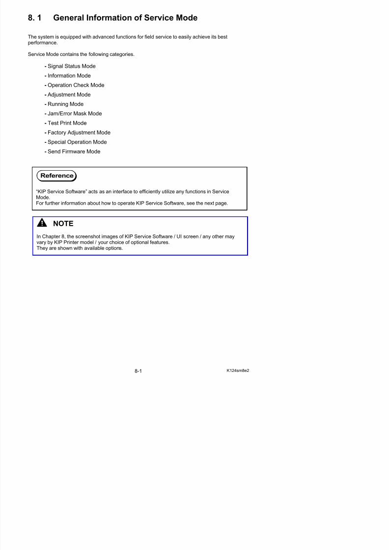
5/17/2018 KIP 7100 Service Manual Ver A_1 - slidepdf.com
http://slidepdf.com/reader/full/kip-7100-service-manual-ver-a1 443/674
KIP Service Software is an integrated utility application that provides intuitive operability by usingTouch Screen.KIP Service Software is included in the controller and operates as an interface for monitoring,checking and setting configuration for field service.
Canceling the UI program (controlling user operation such as Copy screen) allows Touch Screento be free to use Desktop on the controller’s operating system.Launch KIP Service Software and now it is ready to access the printer’s Service Mode.
KIP Service Software Login Screen
KIP Service Software Tree Diagram of screen menu hierarchy
Login screen
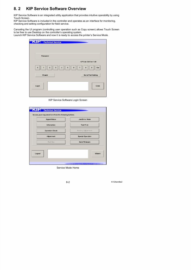
5/17/2018 KIP 7100 Service Manual Ver A_1 - slidepdf.com
http://slidepdf.com/reader/full/kip-7100-service-manual-ver-a1 444/674
Service Mode Home
(Signal Status Mode) Signal Status Monitor screen
(Information Mode) Information List screen
Data Monitor
Jam History
Error History
(Operation Check Mode) Operation Check screen
(Adjustment Mode) Adjustment Menu screen
Setting Configuration
Setting Backup/Restore
(Jam/Error Mask Mode) Mask Target screen
Jam Mask
Error Mask
(Test Print Mode) Basic Setting
Sub Setting
(Special Operation Mode) Operation Target screen
Confirmation Dialog
Counter Input screen
Fuser Unit Error Clear
Jam/Error History Clear
Bias Adjustment Reset
(Send Firmware Mode) Firmware screen
Running Mode, Factory Adjustment Mode (not available)
8. 2. 1 Launching KIP Service Software
1. Press “? - Help” on Home screen.
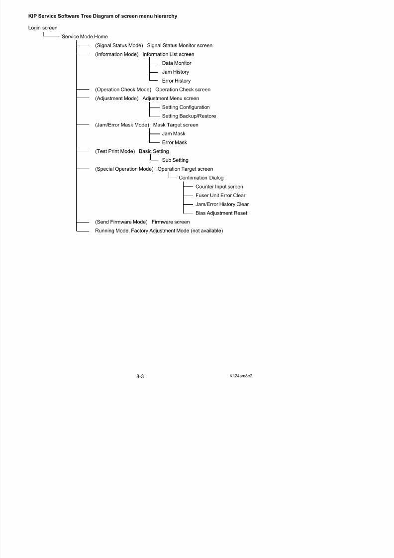
5/17/2018 KIP 7100 Service Manual Ver A_1 - slidepdf.com
http://slidepdf.com/reader/full/kip-7100-service-manual-ver-a1 445/674
2. Press [Service].
3. On-screen Keypad appears.Input “8495107” and press [Enter].
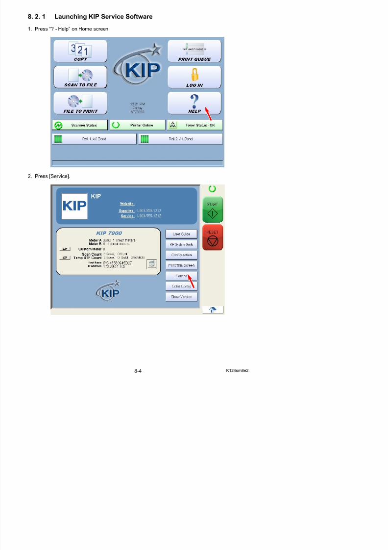
5/17/2018 KIP 7100 Service Manual Ver A_1 - slidepdf.com
http://slidepdf.com/reader/full/kip-7100-service-manual-ver-a1 446/674
4. Service Configuration screen will appear.
5. Use the arrow keys to open [5/6 IPS Setup]. Press [Launch] in “KIP Service Software”.
6. Press [Yes].
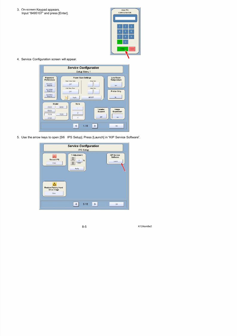
5/17/2018 KIP 7100 Service Manual Ver A_1 - slidepdf.com
http://slidepdf.com/reader/full/kip-7100-service-manual-ver-a1 447/674
7. Press [Login] to log in Service Mode.
8. 2. 2 Closing KIP Service Software
1. Return to Service Mode Home. Press [Logout].
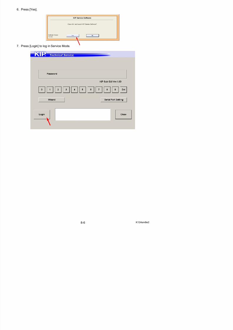
5/17/2018 KIP 7100 Service Manual Ver A_1 - slidepdf.com
http://slidepdf.com/reader/full/kip-7100-service-manual-ver-a1 448/674
2. In Login screen, press [Close].
Reference
Closing “KIP Service Software” automatically invoke UI Home screen to be ready for user operation.
8. 2. 3 Log In screen
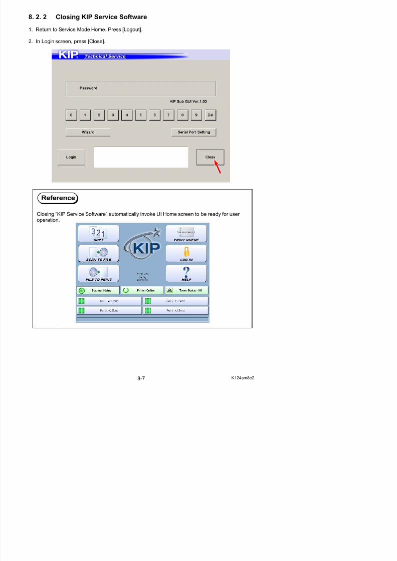
5/17/2018 KIP 7100 Service Manual Ver A_1 - slidepdf.com
http://slidepdf.com/reader/full/kip-7100-service-manual-ver-a1 449/674
Name Function
1 Login Log in Service Mode
2 Wizard not available
3 Serial PortSetting
Configures Communication Port Settings between the controller and DC Controller PCBIt is not necessary to use this button in normal condition.
4 Close Press here to close KIP Service Software.
1 4
32
8. 2. 4 Service Mode Home
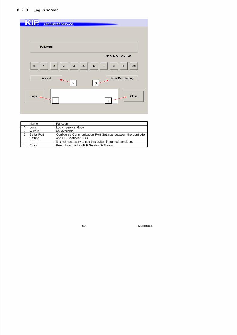
5/17/2018 KIP 7100 Service Manual Ver A_1 - slidepdf.com
http://slidepdf.com/reader/full/kip-7100-service-manual-ver-a1 450/674
Name Function
1 Mode Select Press one of Mode Category buttons that you want to enter.
Signal Status Input / Output signal monitor
Information Analog data status monitor
Operation Check Electric device check
Adjustment Printer settings
Running not availableJam/Error Mask Disables jam/error detection
Test Print Test pattern plot command
Factory Adjustment not available
Special OperationClears history, error status
1
3 2
8. 3 Signal Status Mode
It is possible to monitor the status of any device signal input to / output from DC Controller PCB
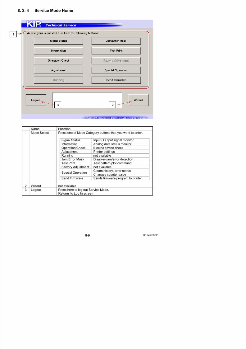
5/17/2018 KIP 7100 Service Manual Ver A_1 - slidepdf.com
http://slidepdf.com/reader/full/kip-7100-service-manual-ver-a1 451/674
It is possible to monitor the status of any device signal input to / output from DC Controller PCBwith making prints.For information about Signal Codes, Signal Names and their contents, see [8.3.2 Input / Output
Signal List].
Signal Status Monitor screen
Name Function
1 Signal Code /Name
Displays Signal Code / Name in drop-down menuSpecify one item that you want to monitor.
2 Signal Monitor Displays the current status of the selected signal
12
3
8. 3. 1 Monitoring Signal Status
1. Press [Device Status] in Service Mode Home.Signal Code Group screen appears.
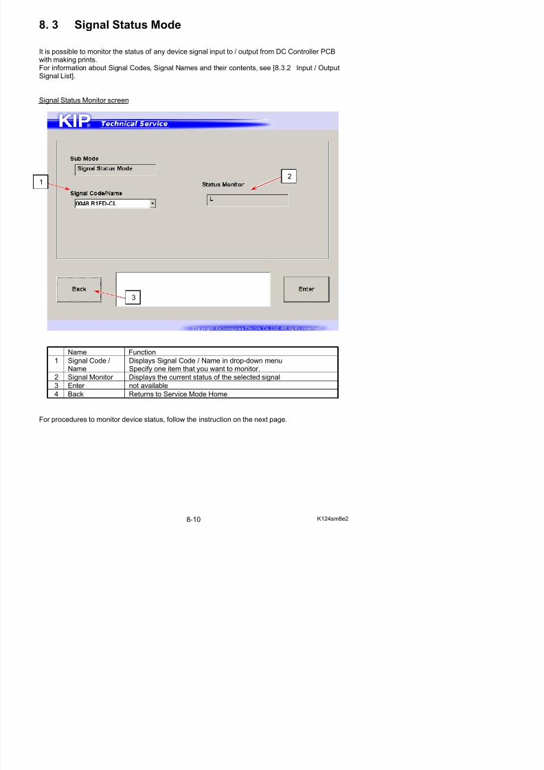
5/17/2018 KIP 7100 Service Manual Ver A_1 - slidepdf.com
http://slidepdf.com/reader/full/kip-7100-service-manual-ver-a1 452/674
2. Press one Code Group button that contains the signal code that you want to monitor.Signal Status Monitor screen appears.
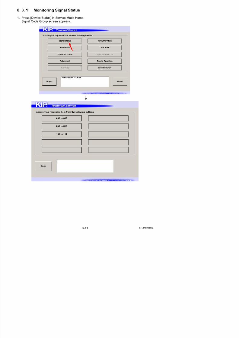
5/17/2018 KIP 7100 Service Manual Ver A_1 - slidepdf.com
http://slidepdf.com/reader/full/kip-7100-service-manual-ver-a1 453/674
3. Specify one signal item that you want to monitor from Signal Name menu.
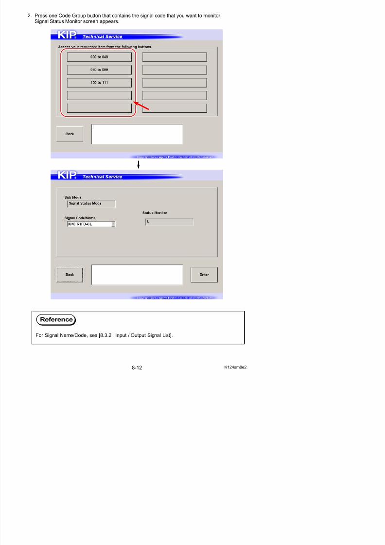
5/17/2018 KIP 7100 Service Manual Ver A_1 - slidepdf.com
http://slidepdf.com/reader/full/kip-7100-service-manual-ver-a1 454/674
4. The current status of the device you have chosen is displayed in Status Monitor.
8. 3. 2 Input / Output Signal List
SignalCode
Symbol IC Port Connector Signal Name Input /Output
Status
000 SW1 IC3 P20 J205 17 I t S it h 1 I t L ON
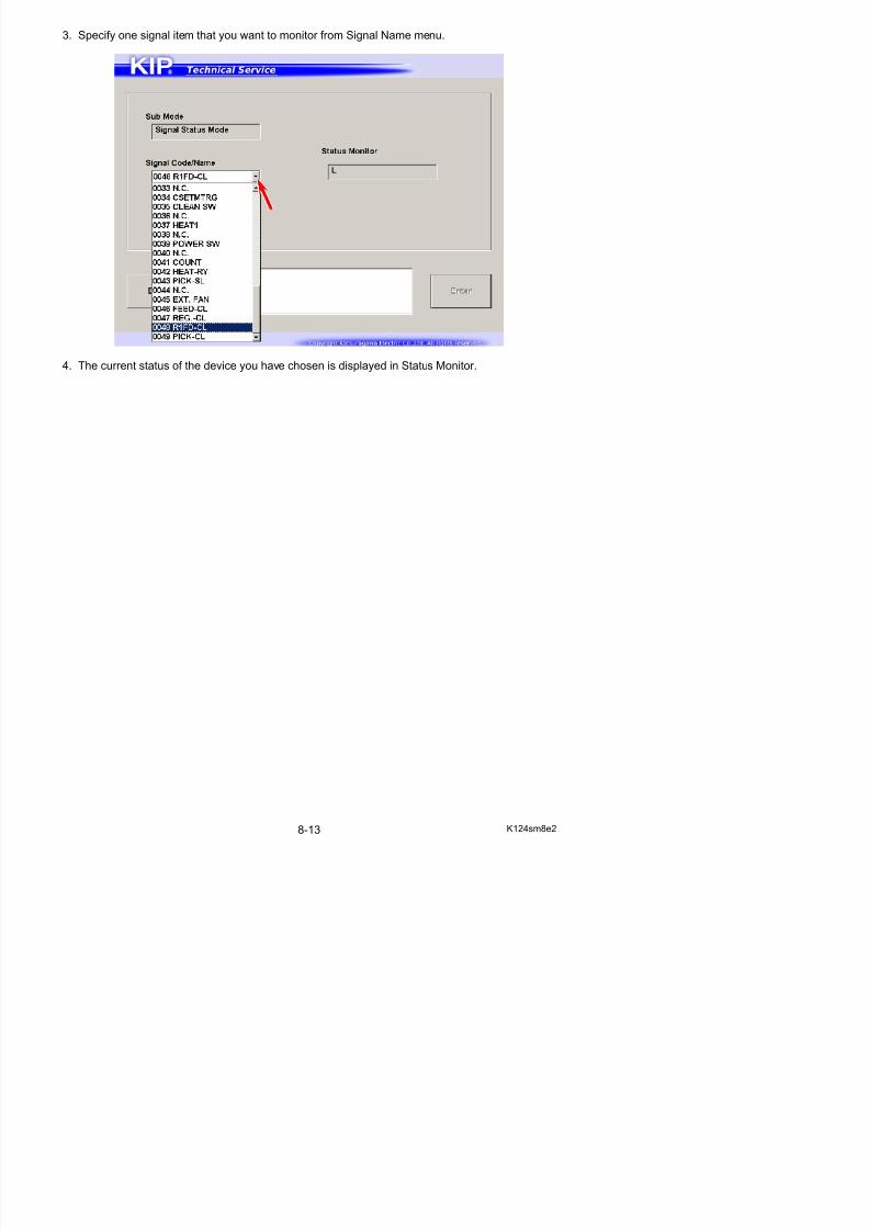
5/17/2018 KIP 7100 Service Manual Ver A_1 - slidepdf.com
http://slidepdf.com/reader/full/kip-7100-service-manual-ver-a1 455/674
000 SW1 IC3-P20 J205-17 Input Switch 1 Input L : ON
001 SW2 IC3-P21 J205-18 Input Switch 2 Input L : ON
002 SW3 IC3-P22 J205-19 Input Switch 3 Input L : ON
003 SW4 IC3-P23 J205-20 Input Switch 4 Input L : ON004 SW5 IC3-P24 J205-21 Input Switch 5 Input L : ON
005 --- IC3-P25 J202-7
006 --- IC3-P26 J202-8
007 --- IC3-P27 J215-3
008 MAN_S IC3-P40 J204-20 Manual Feed Sensor Input H : Paper detected
009 DOOR_OPN IC3-P41 J204-21 Roll Deck Open Input H : Open
010 SEP_S IC3-P42 J204-22 Separation Sensor Input L : Paper detected
011 HEAT_EXIT IC3-P43 J204-23 Exit Sensor Input L : Paper detected
012 --- IC3-P44 J204-24013 HEAT_DOOR IC3-P45 J207-16 Heater Hatch Open Input L : Open
014 --- IC3-P46 J207-15
015 SIG_IN IC3-P47 J204-27 Stacker Input Input
016 ONLINE_LED IC3-60 J205-15 Online LED Output H : ON
017 --- IC3-61 J207-14
018 --- IC3-62 J215-7
019 --- IC3-63 J215-8
020 --- IC3-64 J207-13
021 SIG_OUT IC3-65 J204-28 Stacker Output Output
022 HEAT_BL_L IC3-66 J207-12 Fuser Blower (Low) Output H : ON023 HEAT_BL_H IC3-67 J207-12 Fuser Blower (High) Output H : ON
024 MAMTR IC3-P10 J206-7 Main Motor Output H : Rotate
025 HEAT_M IC3-P11 J206-8 Fuser Motor Output H : Rotate
026 HV_1ST IC3-P12 J206-9 Image Corona Output H : Output
027 HV_TR IC3-P13 J206-10 Transfer Corona Output H : Output
028 HV_AC IC3-P14 J206-11 Separation Corona Output H : Output
029 BIAS_TRG IC3-P15 J206-12 Developer Bias Output H : Output
030 BIAS_SW IC3-P16 J206-13 Developer Bias Polarity Switch Output L : Positive Bias
031 --- IC3-P17 J206-14
032 H1_CW_CCW IC3-P30 J206-15 Main Motor Reversal Rotation Output H : Reverse033 PRESS_M IC3-P31 J206-16 Developer Press Motor Output H : Rotate
034 TONER_M IC3-P32 J206-17 Hopper Motor Output H : Rotate
035 CLEAN_SW IC3-P33 J206-18 Cleaning Roller VoltagePolarity Switch
Output L : Positive
036 FEED_BL IC3-P34 J206-22 Blower (BL7) Control Output H : Rotate
037 HEAT1 IC3-P35 J206-25 SSR ON/OFF Signal 1 Output H : Heater Lamplights
038 COOL_BL IC3-P36 J206-26 Fuser Cooling Fan Output H : Rotate
039 POWER_OFF IC3-P37 J206-27 Power Switch Output Output H : OFF040 ER2 IC3-P50 J207-3 Separation Lamp Control Output H : Lighting
041 COUNT IC3-P51 J207-4 Counter Output H : Counting up
042 HEAT_RY IC3-P52 J207-5 Fuser Relay Output H : ON
043 SLCT_CL IC3-P53 Clutch Selection (Roll 1 or 2) Output H : Roll 1
044 FOWE_CL IC3-P54 J207-6(R1)J207 8(R2)
Roll 1&2 Feed Clutch Output H : ON
SignalCode
Symbol IC Port Connector Signal Name Input /Output
Status
054 AC_LD IC3-P86 J203-19 Separation Corona OutputDetection
Input
055 BIAS LD IC3 P87 J203 20 D l Bi O t t I t
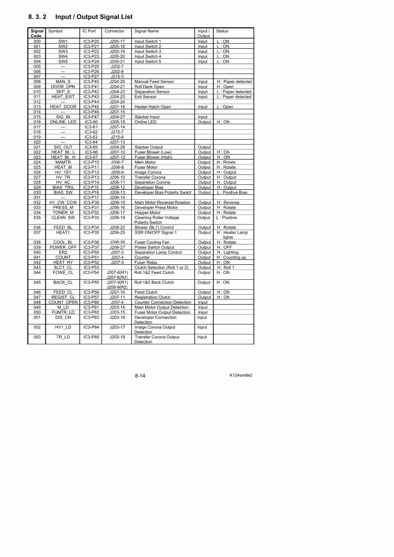
5/17/2018 KIP 7100 Service Manual Ver A_1 - slidepdf.com
http://slidepdf.com/reader/full/kip-7100-service-manual-ver-a1 456/674
055 BIAS_LD IC3-P87 J203-20 Developer Bias OutputDetection
Input
056 DA CLOCK IC3-P70 DA Conversion Clock
057 DA DI1 IC3-P71 DA Enable 1058 DA BS1 IC3-P72 DA Data 1
059 DA DI2 IC3-P73 DA Enable 2
060 DA BS2 IC3-P74 DA Data 2
061 H2_CW_CCW IC3-P75 J215-4 Fuser Motor Reverse Output H : Reverse
062 HEAT2 IC3-P76 J215-5 SSR ON/OFF 2 Output H : Heater Lamplights
063 --- IC3-P77
064 --- IC3-P90 J215-9
065 --- IC3-P91 J215-10066 --- IC3-P92 J215-12
067 DENS_SNS1 IC3-P93 J215-13 Density Sensor Output 1 H: On
068 --- IC3-P94 J215-14
069 --- IC3-P95 J215-15
070 --- IC3-P96 J215-16
071 LED2 IC3-P97 PW12420 PCB LED Output H: Lights
072 IBUSY_H IC1-P10 Data Output Busy Output H : Busy
073 IPRADY_L IC1-P11 Printer Ready Output L : Ready
074 IPREQ_L IC1-P12 Print Request Output L : Requested
075 PAGEBL IC1-P13 Print Request Output L : Print ON076 TEST_H IC1-P14 Test Print Output H : Test Printing
077 I_POW_ON_A IC1-P15
078 LED_EN IC1-P16 LED Enable
079 CLEAN BIAS IC1-P17 J206-5 Cleaning Roller Bias Output H : Output
080 LCD_CLK IC1-P20 LCD Clock
081 LCD_DATA IC1-P21 LCD Data
082 LCD_EN IC1-P23 J205-6 LCD Enable083 LCD_RW IC1-P24 J205-5 Data Read / Write Selection Output
084 LCD_RS IC1-P22 J205-4 LCD Input Selection Output
085 IC1-P25 J206-28 Main Motor Clock
086 IC1-P26 J206-6 Fuser Motor Clock
087 RESET_SIG IC1-P27 Reset Signal Output
088 RXD0 IC1-P32 Serial 0 Input Input
089 RXD1 IC1-P33 Serial 1 Input Input
090 RXD2 IC1-P51 Serial 2 Input Input
091 TXD0 IC1-P30 Serial 0 Output Output
092 TXD1 IC1-P31 Serial 1 Output Output
093 TXD2 IC1-P50 Serial 2 Output Output
094 MSCUTR IC1-P60 J204-5 Cutter Home Position Sensor (Right) Input L : Staying atHome Position
095 MSCUTL IC1-P61 J204-6 Cutter Home Position Sensor (Left)
Input L : Staying atHome Position
096 MCUTL IC1-P63 J207-1 Cutter Motor 1 Output H : Rotate
097 MCUTR IC1-P62 J207-2 Cutter Motor 2 Output H : Rotate
8. 4 Information Mode
It is possible to monitor the analog voltage input sent by devices (such as Thermistor) to DCC t ll PCB It i l ibl t it th t F t t hi h i l l t d
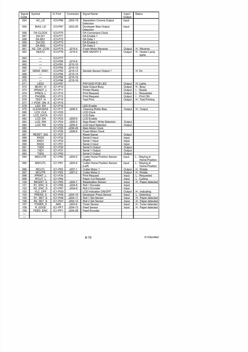
5/17/2018 KIP 7100 Service Manual Ver A_1 - slidepdf.com
http://slidepdf.com/reader/full/kip-7100-service-manual-ver-a1 457/674
Controller PCB. It is also possible to monitor the current Fuser temperature which is calculatedfrom the input voltage.
Information Mode includes the list of the latest 100 jam / service call error records.
Information Home screen
Name Function
7
1 2 3 4
5 6
Monitor screen
3
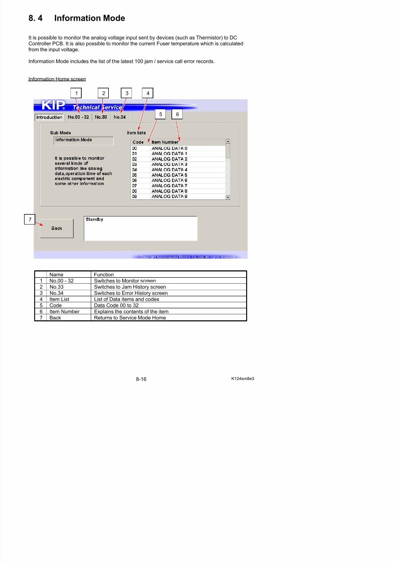
5/17/2018 KIP 7100 Service Manual Ver A_1 - slidepdf.com
http://slidepdf.com/reader/full/kip-7100-service-manual-ver-a1 458/674
Name Function
1 Code Data Code 00 to 32
2 Item Number Explains the contents of the listed items
3 CurrentInformation
Displays the current Analog Voltage and its calculated value for the items to be monitored
4 Introduction Returns to Information Home screen
For information about items to be monitored, see [8.4.2 List of Analog Data Monitor].
4
1
2
Jam History screen
4
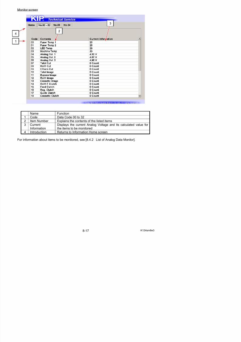
5/17/2018 KIP 7100 Service Manual Ver A_1 - slidepdf.com
http://slidepdf.com/reader/full/kip-7100-service-manual-ver-a1 459/674
Name Function
1 Jam Information Displays the latest 100 jam records
2 Code Displays Jam Code “J-****”3 Count Displays the counter value that the concerning jam occurred
4 Export Saves the records as a file
5 Introduction Returns to Information Home screen
4
1
5
2 3
Error History screen
4
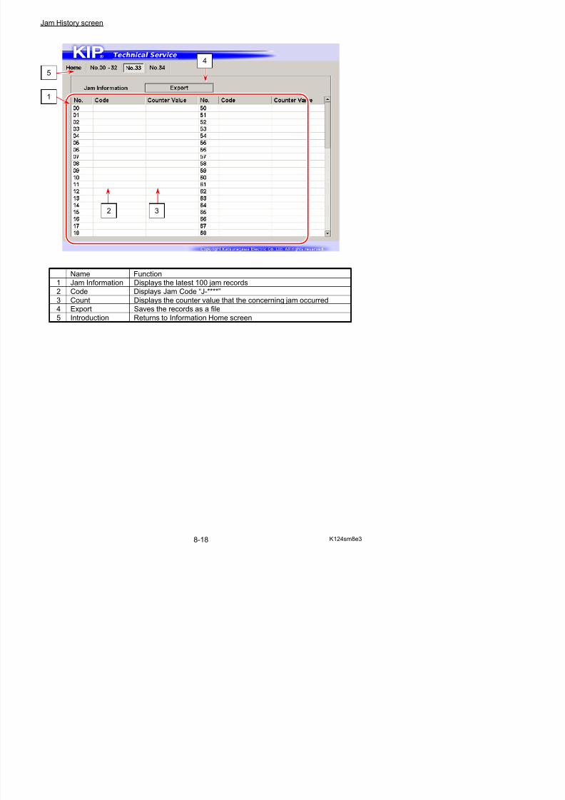
5/17/2018 KIP 7100 Service Manual Ver A_1 - slidepdf.com
http://slidepdf.com/reader/full/kip-7100-service-manual-ver-a1 460/674
Name Function
1 Error Information Displays the latest 100 service call error records
2 Code Displays Jam Code “E-****”
3 Count Displays the counter value that the concerning error occurred4 Export Saves the records as a file
5 Introduction Returns to Information Home screen
1
5
2 3
8. 4. 1 Monitoring Analog Data
1. Press [Information] in Service Mode Home.Information Home screen appears.
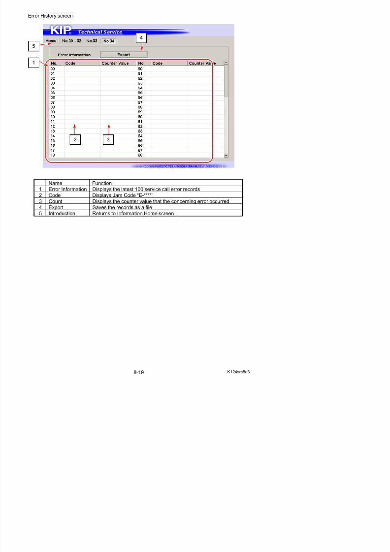
5/17/2018 KIP 7100 Service Manual Ver A_1 - slidepdf.com
http://slidepdf.com/reader/full/kip-7100-service-manual-ver-a1 461/674
2. To monitor any available Analog Data value, open [No.00 - 32] tab to display Monitor screen.
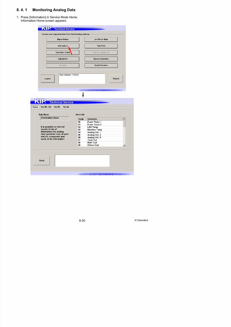
5/17/2018 KIP 7100 Service Manual Ver A_1 - slidepdf.com
http://slidepdf.com/reader/full/kip-7100-service-manual-ver-a1 462/674
8. 4. 2 List of Analog Data Monitor
DataCode
Item Unit Remarks Contents
00 F T 1 C ti d C l l t d V l t t d t t d b th th i t th t f
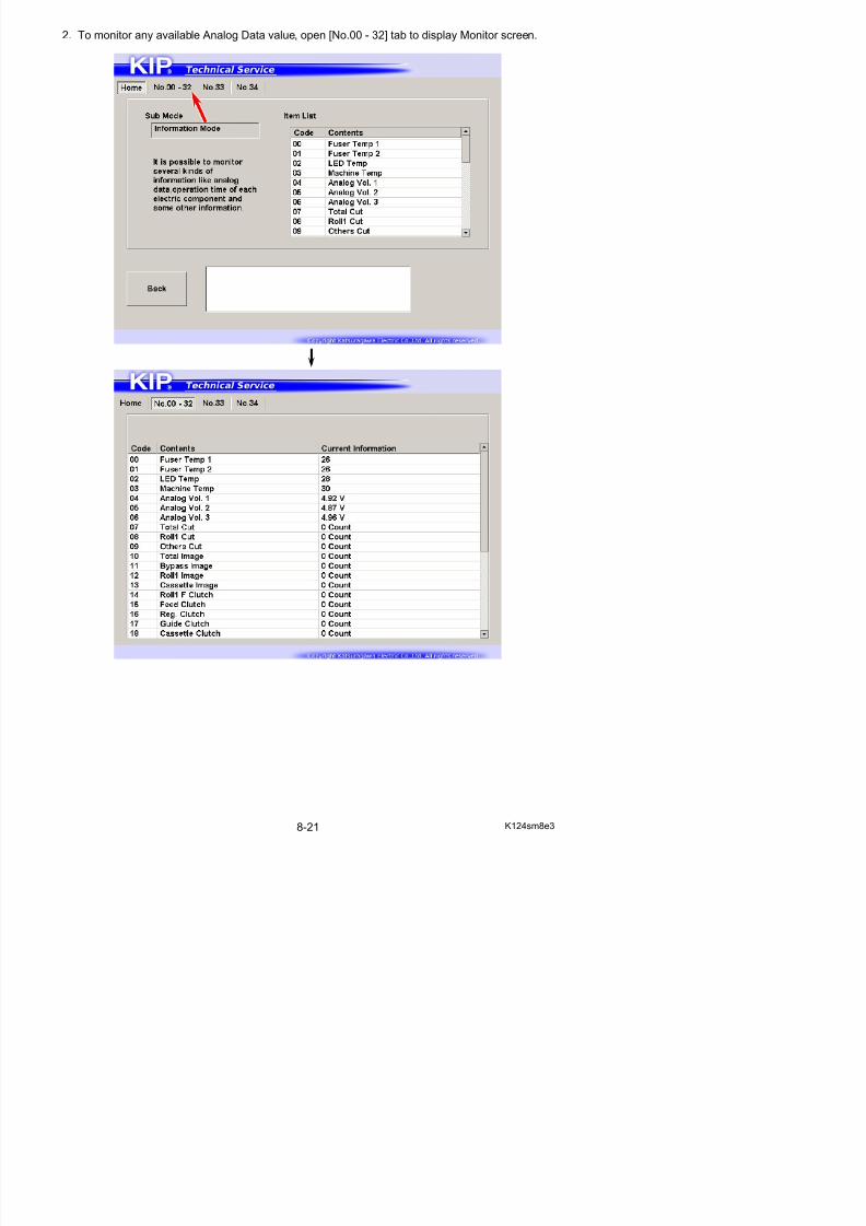
5/17/2018 KIP 7100 Service Manual Ver A_1 - slidepdf.com
http://slidepdf.com/reader/full/kip-7100-service-manual-ver-a1 463/674
00 Fuser Temp 1 Centigrade Calculated Value temperature detected by the thermistor on the center of the Fuser Unit
01 Fuser Temp 2 Centigrade Calculated Value temperature detected by the thermistor on the right of the Fuser Unit
02 (Reserved) - - -
03 Machine Temp Centigrade Calculated Value temperature detected on PW12420
04 (Reserved) - - -
05 Total Cut number of operation times in total for media cut withany source / situation
06 Roll 1 Cit number of operation times for media cutting from Roll 1
07 Roll 2 Cit number of operation times for media cutting from Roll 208 Others Cut number of operation times for media cutting for trim cut
09 Total Image number of operation times in total for printing operationwith any source
10 R1 Image number of operation times for printing operationon Roll 1
11 R2 Image number of operation times for printing operationon Roll 2
12 M Image number of operation times for printing operation
on Bypass Feeder 13 Cassette Image number of operation times for printing operation
on Paper Tray
14 R1F Clutch number of operation times of Roll 1 Feed Clutch
15 R2F Clutch number of operation times of Roll 2 Feed Clutch
16 R1B Clutch number of operation times of Roll 1 Back Clutch
17 R2B Clutch number of operation times of Roll 2 Back Clutch
18 Feed Clutch number of operation times of Feed Clutch
19 Reg. Clutch number of operation times of Registration Clutch
20 Pickup Solenoid number of operation times of Pickup Solenoid21 (Reserved) - - -
22 Stack Solenoid number of operation times of Stack Solenoid
23 Motor 1 Time minute total operation time of Main Motor
24 Motor 2 Time minute total operation time of Fuser Motor
25 LED ON Time minute total lighting-up time of LED Head
26 Motor 3 Time minute total operation time of Paper Tray Motor
27 Bias 3 Time minute operation time of Main Motor from the last Density
Measure28 Density V0 no use
29 Density V1 no use
30 Density Vr no use
31 Density W Level no use
8. 4. 3 Browsing Jam History
To browse the machine’s jam history, open [No.33] tab to display Jam History screen.
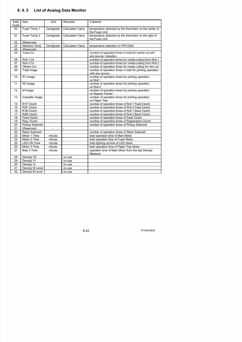
5/17/2018 KIP 7100 Service Manual Ver A_1 - slidepdf.com
http://slidepdf.com/reader/full/kip-7100-service-manual-ver-a1 464/674
[Export] creates “jaminfo.dat” that contains the currently recorded Jam History.
Reference
To clear the entire jam history record, see [8.11.1 Clearing Fuser Error, Jam/Error History].
8. 4. 4 Browsing Error History
To browse the machine’s service call error history, open [No.34] tab to display Error History screen.
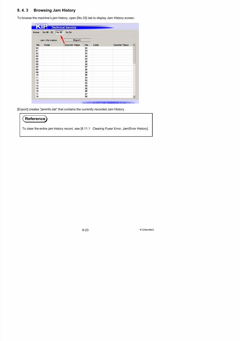
5/17/2018 KIP 7100 Service Manual Ver A_1 - slidepdf.com
http://slidepdf.com/reader/full/kip-7100-service-manual-ver-a1 465/674
[Export] creates “errinfo.dat” that contains the currently recorded Error History.
Reference
To clear the entire service call error history record, see [8.11.1 Clearing Fuser Error,Jam/Error History].
8. 5 Operation Check Mode
It is possible to operate several electrical components independently, such as motor, clutch, andfans.
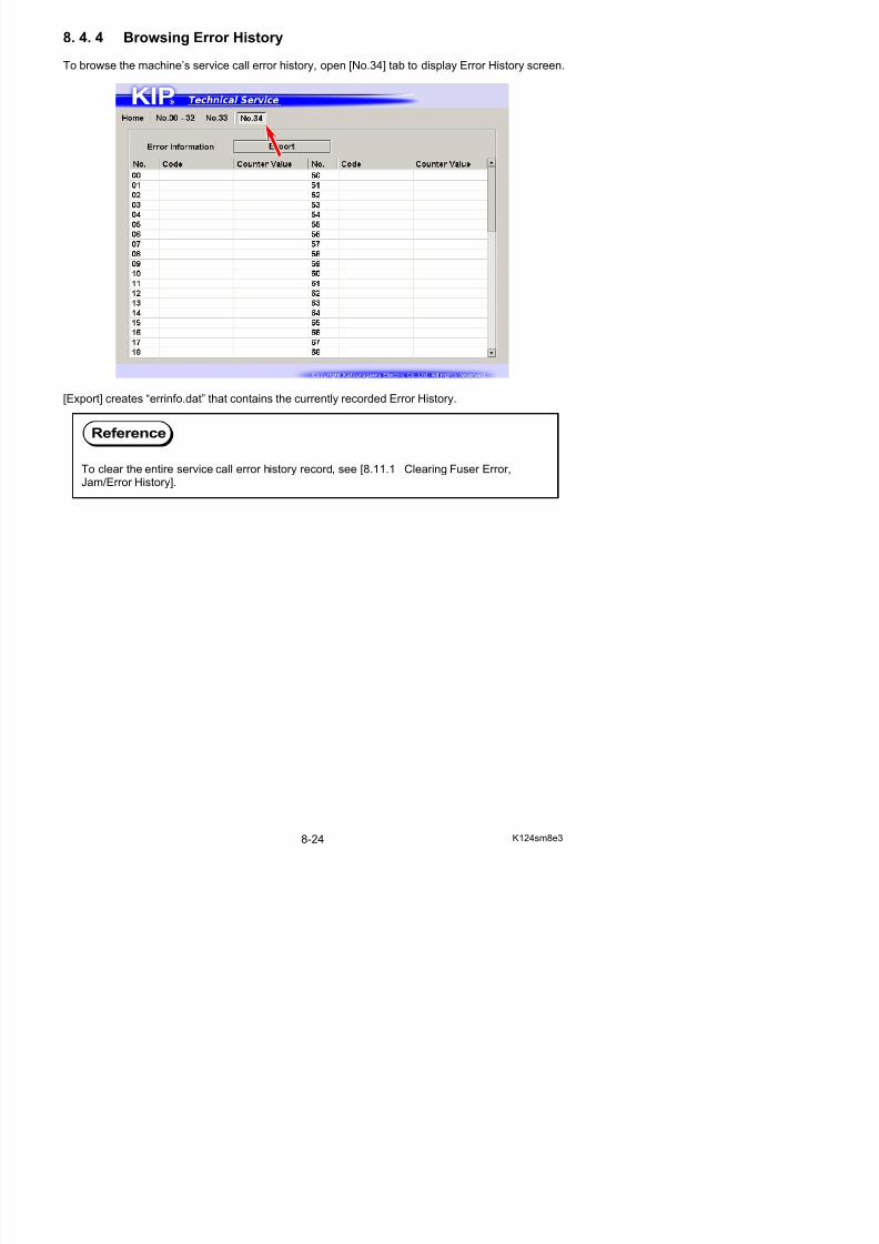
5/17/2018 KIP 7100 Service Manual Ver A_1 - slidepdf.com
http://slidepdf.com/reader/full/kip-7100-service-manual-ver-a1 466/674
Operation Check screen
Name Function
1 Signal Code /
Name
Displays Signal Code/Name in drop-down menu
Specify one item that you want to check.2 Signal Status Displays the current status of the selected signal
3 Start Operates the electric device you have chosennot available for sensors
4 Back Returns to Service Mode Home
1
4 3
2
8. 5. 1 Checking Device Operation
1. Press [Operation Check] in Service Mode Home.Operation Check screen appears.
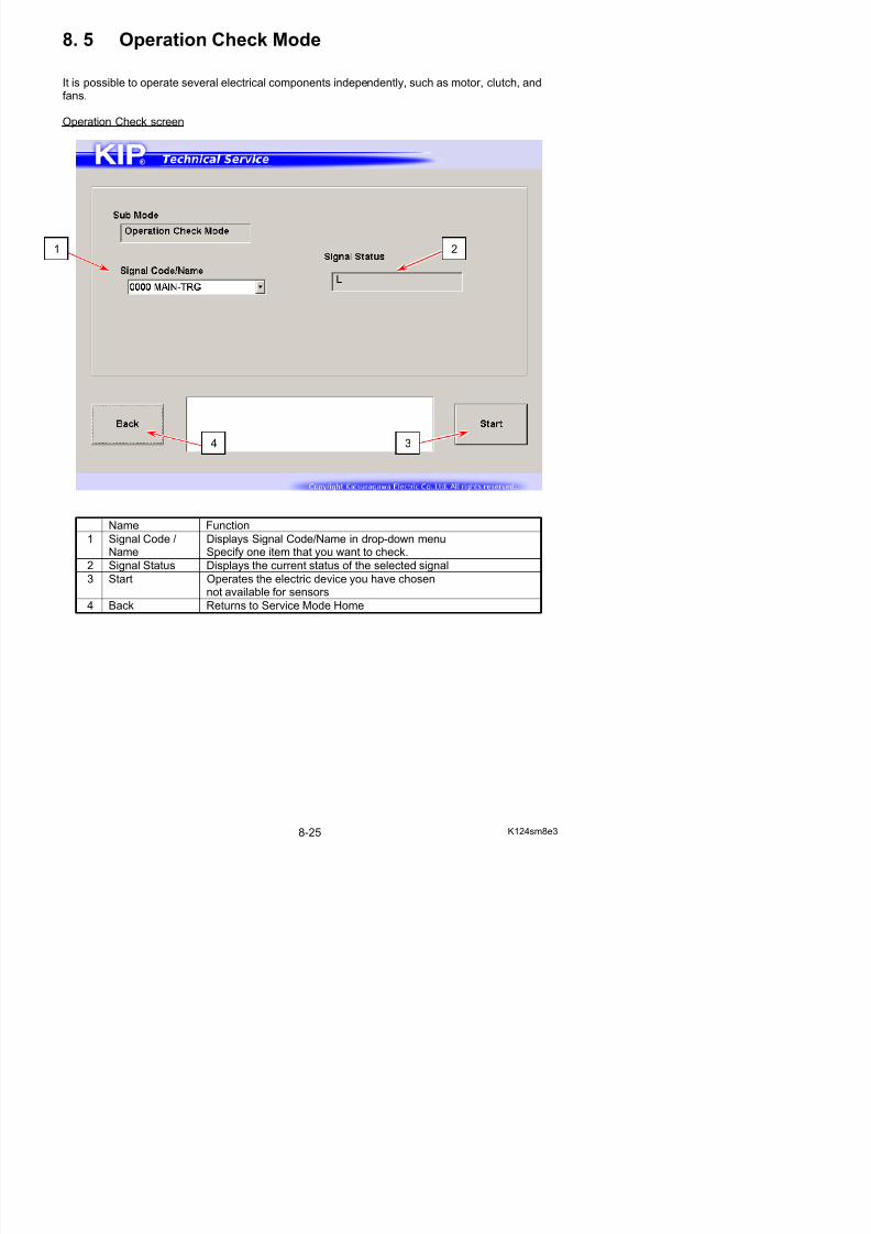
5/17/2018 KIP 7100 Service Manual Ver A_1 - slidepdf.com
http://slidepdf.com/reader/full/kip-7100-service-manual-ver-a1 467/674
2. Specify one signal item that you want to monitor from Signal Code/Name menu.
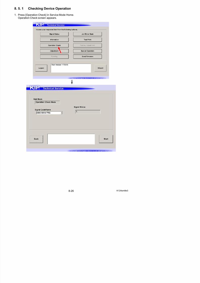
5/17/2018 KIP 7100 Service Manual Ver A_1 - slidepdf.com
http://slidepdf.com/reader/full/kip-7100-service-manual-ver-a1 468/674
3. The current status of the device you have chosen is displayed in Signal Status field.Press [Enter] to operate / stop the device alone alternately.
8. 5. 2 Device List
SignalCode
Signal Name Target item
00 MAIN-TRG Main Motor
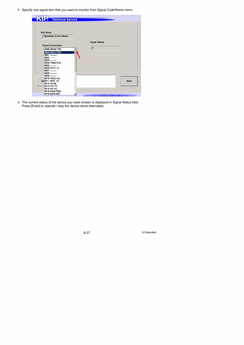
5/17/2018 KIP 7100 Service Manual Ver A_1 - slidepdf.com
http://slidepdf.com/reader/full/kip-7100-service-manual-ver-a1 469/674
01 FMTR-TRG Fuser Motor
02 FMTR-REV Fuser Motor (reversal rotation)03 PRESS-M Developer Press Motor
04 TONER-M Toner Supply Motor
05 --- Reserved
06 R1FD-CL Roll 1 Feed Clutch
07 R1BK-CL Roll 1 Back Clutch
08 R2FD-CL Roll 2 Feed Clutch
09 R2BK-CL Roll 2 Back Clutch
10 FEED-CL Feed Clutch
11 REG.-CL Registration Clutch
12 HV-IM Image Corona
13 HV-TR Transfer Corona
14 HV-AC Separation Corona
15 BIAS-TRG Developer Bias
16 BIAS-SW Positive/Negative selection of Developer Bias
17 CLEANTRG Cleaning Roller Bias
18 CLEAN-SW Positive/Negative selection of Cleaning Roller
Voltage19 --- Reserved
20 TR LED Transfer Assist LED
21 HEAT1 Fuser Lamp 1
22 HEAT-RY Fuser Relay
23 H BLW(L) Fuser Blower (Low speed)
24 H BLW(H) Fuser Blower (High speed)
25 FEED-BLW Paper Feed Blower
26 COUNT Counter
27 M5_CUTL Cutter Motor (blade moves to left)28 M5_CUTR Cutter Motor (blade moves to right)
29 POWER-SW Main Switch
30 --- Reserved
31 COOLERBL Cooling Fan
32 HEAT2 Fuser Lamp 2
33 DENS_S Density Sensor
34 --- Reserved
35 CMTR-TRG Paper Tray Motor
36 PICK-SL Pickup Solenoid37 --- Reserved
38 STACK_SL Stacker Solenoid
8. 6 Adjustment Mode
It is possible to configure fundamental settings on the printer.Every setting item has the corresponding Sub Mode Number.
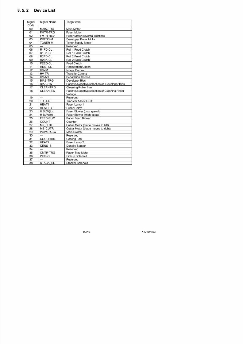
5/17/2018 KIP 7100 Service Manual Ver A_1 - slidepdf.com
http://slidepdf.com/reader/full/kip-7100-service-manual-ver-a1 470/674
Adjustment Menu screen
Name Function
1 Sub Mode Number Group Button
Press one Code Group button that contains the signal code that
you want to configure.2 Export Stores the current parameters in a RAM file for backup measure
3 Import Reads parameters stored in RAM file
4 Save Applies the parameters read by [Import]
5 Load Reads the current parameters on the printer
23
6
1
4 5
Setting Configuration screen
5
2
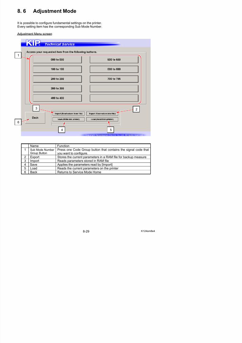
5/17/2018 KIP 7100 Service Manual Ver A_1 - slidepdf.com
http://slidepdf.com/reader/full/kip-7100-service-manual-ver-a1 471/674
Name Function
1 Signal Name Displays Signal Code/Name in drop-down menuSpecify one item that you want to configure.
2 Preset Displays the current value of the selected item
3 Modify Displays an input value by using On-screen Keypad
4 Range Value An input value must be set within this range.
5 Numeric Key Use On-screen Keypad to input a value to be configured.
6 Apply Applies a value in “Modify” to the selected item
7 Back Returns to Service Mode Home
1
3
4
7 6
8. 6. 1 Changing Setting Value
1. Press [Adjustment] in Service Mode Home. Adjustment Menu screen appears.
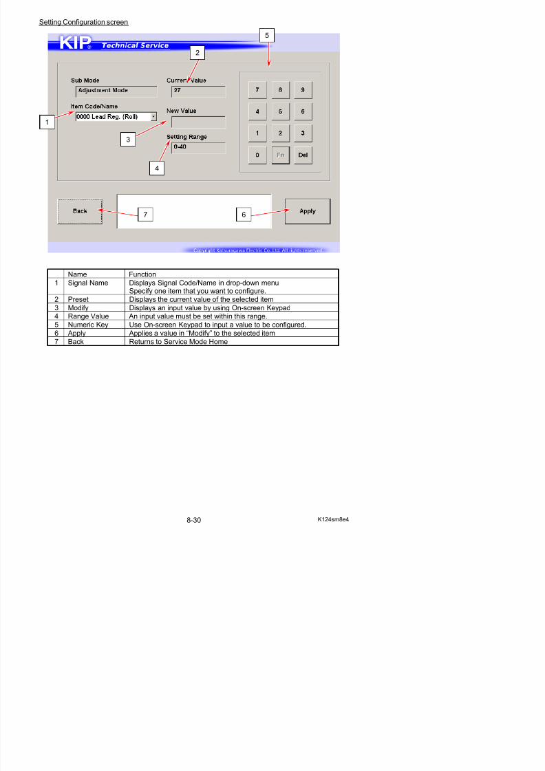
5/17/2018 KIP 7100 Service Manual Ver A_1 - slidepdf.com
http://slidepdf.com/reader/full/kip-7100-service-manual-ver-a1 472/674
2. Press one Code Group button that contains the signal code that you want to configure.Setting Configuration screen appears.
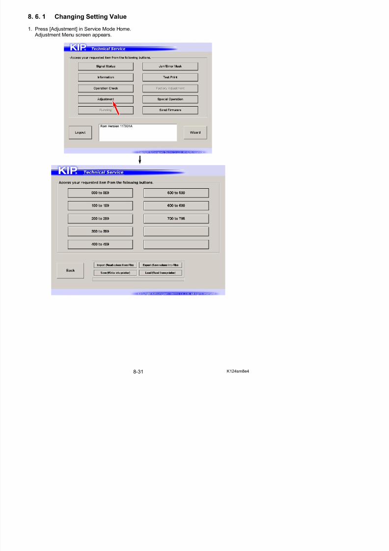
5/17/2018 KIP 7100 Service Manual Ver A_1 - slidepdf.com
http://slidepdf.com/reader/full/kip-7100-service-manual-ver-a1 473/674
3. Specify one signal item that you want to configure from Signal Name menu.
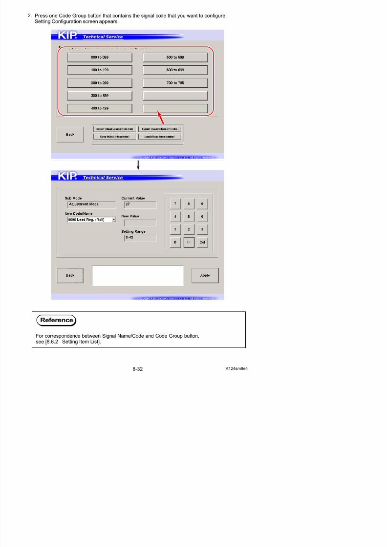
5/17/2018 KIP 7100 Service Manual Ver A_1 - slidepdf.com
http://slidepdf.com/reader/full/kip-7100-service-manual-ver-a1 474/674
4. The current value and available setting range of the item you have chosen are displayed.
5. To change a setting value, input a desired value with On-screen Keypad.The value will be displayed in “Modify” area.
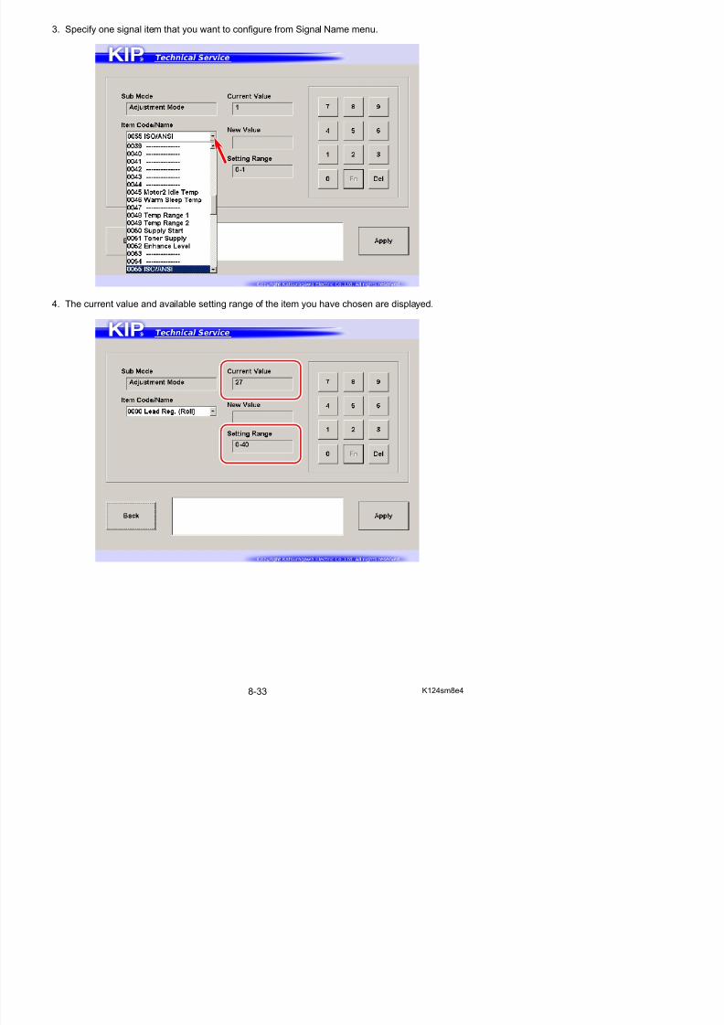
5/17/2018 KIP 7100 Service Manual Ver A_1 - slidepdf.com
http://slidepdf.com/reader/full/kip-7100-service-manual-ver-a1 475/674
The setting item you have chosen is in hexadecimal, press [Fn] to input alphabetic characters A to F.
6. Press [Enter] to apply the new value to the printer.The value in “preset” area will be changed to the new value.
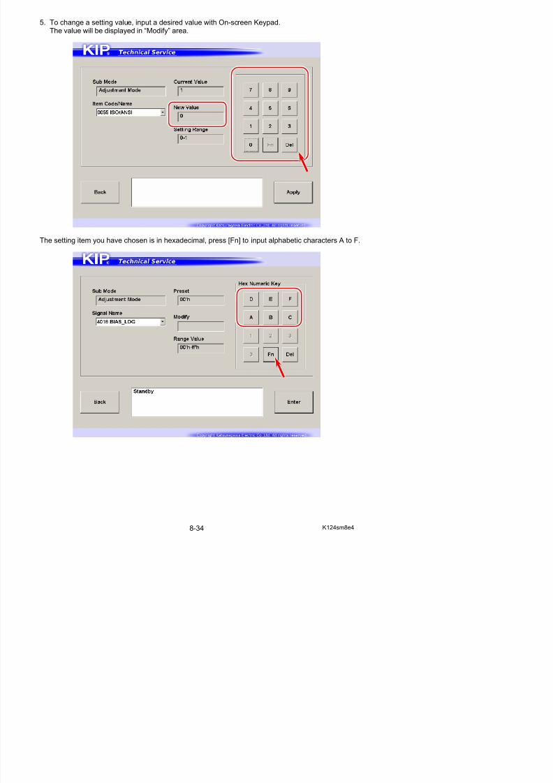
5/17/2018 KIP 7100 Service Manual Ver A_1 - slidepdf.com
http://slidepdf.com/reader/full/kip-7100-service-manual-ver-a1 476/674
8. 6. 2 Setting Item List
NOTE: All items grayed are not generally for field technician useDefaultValue
ItemNo.
Setting Item Unit
USA EUR/ AS
Settingrange
000 Leading Registration (Roll paper) 1mm 19 19 1 to 40
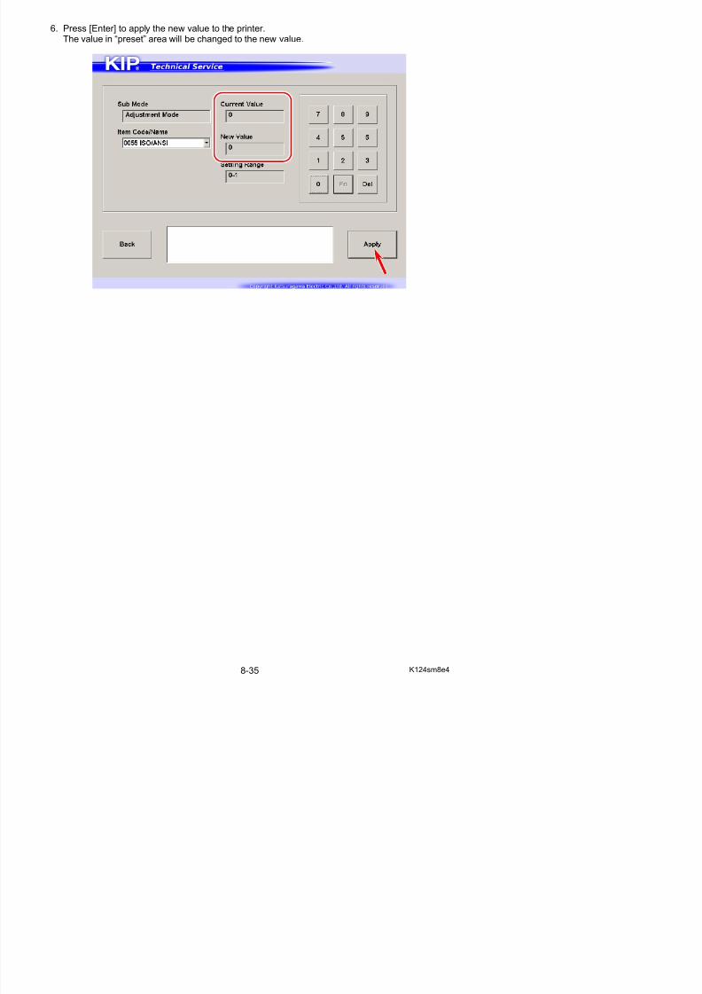
5/17/2018 KIP 7100 Service Manual Ver A_1 - slidepdf.com
http://slidepdf.com/reader/full/kip-7100-service-manual-ver-a1 477/674
001 Leading Registration (Cut sheet paper) 1mm 19 19 1 to 40002 Trailing Margin (Roll paper) 1mm 9 9 1 to 40
003 Trailing Margin (Cut sheet paper) 1mm 10 10 1 to 40
004 Side Margin (Left and right) 1mm 3 3 0 to 20
005 Side Registration (Cutsheet) 0.1mm 50 50 0 to 100
006 Side Registration (Roll 1) 0.1mm 50 50 0 to 100
007 Side Registration (Roll 2) 0.1mm 50 50 0 to 100
008 LED Strobe Time for Main Pixel (Block A) 1 microsecond 6 6 0 to 9
009 LED Strobe Time for Main Pixel (Block B) 1 microsecond 6 6 0 to 9
010 LED Strobe Time for Main Pixel (Block C) 1 microsecond 6 6 0 to 9
011 LED Strobe Time for IST (Supplemental Pixel) (Block A) 1 microsecond 0 0 0 to 9
012 LED Strobe Time for IST (Supplemental Pixel) (Block B) 1 microsecond 0 0 0 to 9013 LED Strobe Time for IST (Supplemental Pixel) (Block C) 1 microsecond 0 0 0 to 9
014 Vertical Alignment of Pixels between Image Blocks A & B - 8 8 2 to 14
015 Vertical Alignment of Pixels between Image Blocks B & C - 8 8 2 to 14
016 Cut Length 1 (length information provided) 1mm 50 50 0 to 100
017 Cut Length 2 (length information not provided) 1mm 50 50 0 to 100
018 Cut Length 3 (Compensation of the length of a long print) 0.1mm 475 475 0 to 999
019 Leading Margin 0.1mm 30 30 0 to 50
020 Cut Length 4 (Individual Compensation for Roll 2) 0.16mm 50 50 0 to 100
021 Reserved
022 Developer Bias (Plain Paper) - 161 161 0 to 4FF
023 Developer Bias (Tracing Paper) - 161 161 0 to 4FF
024 Developer Bias (Film) - 161 161 0 to 4FF
025 Developer Bias (Special Media/Plain Paper) - 161 161 0 to 4FF
026 Developer Bias (Special Media/Tracing Paper) - 161 161 0 to 4FF
027 Developer Bias (Special Media/Film) - 161 161 0 to 4FF
028 Developer Bias compensation - 1st Drum revolution - 0 0 0 to 255
029 Transfer Voltage (Plain Paper) - 366 366 0 to 4FF
030 Transfer Voltage (Tracing Paper) - 28A 28A 0 to 4FF
031 Transfer Voltage (Film) - 28A 28A 0 to 4FF
032 Transfer Voltage(Special Media/Plain Paper)
- 292 292 0 to 4FF
033 Transfer Voltage(Special Media/Tracing Paper)
- 292 292 0 to 4FF
034 Transfer Voltage(Special Media/Film)
- 292 292 0 to 4FF
035 Separation Corona ON Timing 1mm 50 50 0 to 100
036 Reserved
037 Transfer Corona ON Timing 1mm 48 48 0 to 100
038 Transfer Corona OFF Timing 1mm 20 20 0 to 100
039 Print - Fuser Temperature Center (Plain) 1oC 160 165 120 to 180
040 Print - Fuser Temperature Center (Tracing) 1oC 160 170 120 to 180
041 Print - Fuser Temperature Center (Film) 1
o
C 177 170 120 to 180042 Print - Fuser Temperature Center (Special / Plain) 1oC 160 160 120 to 180
043 Print - Fuser Temperature Center (Special / Tracing) 1oC 160 160 120 to 180
044 Print - Fuser Temperature Center (Special / Film) 1oC 177 177 120 to 180
045 Fuser temperature to Start Idling 1oC 120 120 100 to 140
046 Warm Sleep - Fuser Temperature 1oC 100 100 100 to 160
047 R d
NOTE: All items grayed are not generally for field technician use
DefaultValue
ItemNo.
Setting Item Unit
USA EUR/ AS
Settingrange
058 Recognition of Paper Tray - 0 0 0 to 1
059 Counter Value - 5 0 0 to 5
060 Maximum Length - 1 1 0 to 1
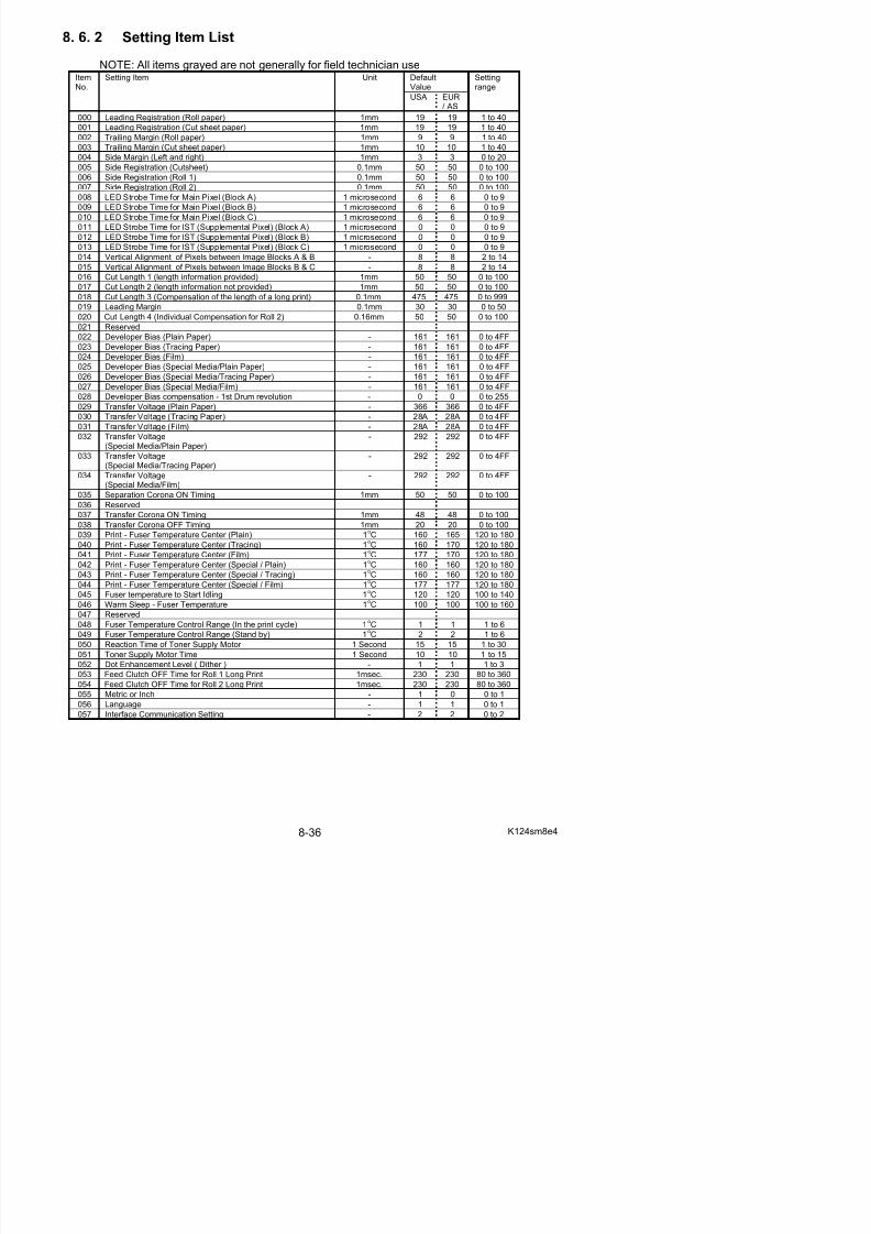
5/17/2018 KIP 7100 Service Manual Ver A_1 - slidepdf.com
http://slidepdf.com/reader/full/kip-7100-service-manual-ver-a1 478/674
g
061 Stacking Device Setting - 0 0 0 to 1062 Operation of Fuser Roller - 0 0 0 to 1
063 Cut length 5 (Compensation for Tracing Paper) - 100 100 0 to 200
064 Cut length 6 (Compensation for Film) - 100 86 0 to 200
065 Drum Reverse Time 1 millisecond 30 30 10 to 70
066 Fuser Motor Reverse Setting - 0 0 0 to 1
067 Operation of Separation Lamp - 5 5 1 to 7
068 Reserved
069 Reserved
070 Fuser Motor 1st Speed (Roll)(Plain Paper / A3, 12” & 11”)
0.04mm/s 34 39 0 to 80
071 Switch Timing to Fuser Motor 1st Speed (Roll)(Plain Paper / A3, 12” & 11”)
0.5 seconds 1 1 0 to 300
072 Fuser Motor 2nd Speed (Roll)(Plain Paper / A3, 12” & 11”)
0.04mm/s 35 42 0 to 80
073 Switch Timing to Fuser Motor 2nd Speed (Roll)(Plain Paper / A3, 12” & 11”)
0.5 seconds 1 1 0 to 300
074 Fuser Motor 3rd Speed (Roll)(Plain Paper / A3, 12” & 11”)
0.04mm/s 50 48 0 to 80
075 Switch Timing to Fuser Motor 3rd Speed (Roll)(Plain Paper / A3, 12” & 11”)
0.5 seconds 5 5 0 to 300
076 Fuser Motor 1st Speed (Roll)
(Tracing / A3, 12” & 11”)
0.04mm/s 33 36 0 to 80
077 Switch Timing to Fuser Motor 1st Speed (Roll)(Tracing / A3, 12” & 11”)
0.5 seconds 1 1 0 to 300
078 Fuser Motor 2nd Speed (Roll)(Tracing / A3, 12” & 11”)
0.04mm/s 39 44 0 to 80
079 Switch Timing to Fuser Motor 2nd Speed (Roll)(Tracing / A3, 12” & 11”)
0.5 seconds 1 3 0 to 300
080 Fuser Motor 3rd Speed (Roll)(Tracing / A3, 12” & 11”)
0.04mm/s 44 44 0 to 80
081 Switch Timing to Fuser Motor 3rd Speed (Roll)(Tracing / A3, 12” & 11”)
0.5 seconds 5 5 0 to 300
082 Fuser Motor 1st Speed (Roll)(Film / A3, 12” & 11”)
0.04mm/s 50 50 0 to 80
083 Switch Timing to Fuser Motor 1st Speed (Roll)(Film / A3, 12” & 11”)
0.5 seconds 2 2 0 to 300
084 Fuser Motor 2nd Speed (Roll)(Film / A3, 12” & 11”)
0.04mm/s 50 50 0 to 80
085 Switch Timing to Fuser Motor 2nd Speed (Roll)(Film / A3, 12” & 11”)
0.5 seconds 4 4 0 to 300
086 Fuser Motor 3rd Speed (Roll)(Film / A3, 12” & 11”)
0.04mm/s 40 40 0 to 80
087 Switch Timing to Fuser Motor 3rd Speed (Roll)
(Film / A3, 12” & 11”)
0.5 seconds 0 0 0 to 300
088 Fuser Motor 1st Speed (Roll)(Special Media / Plain Paper / A3, 12” & 11”)
0.04mm/s 40 40 0 to 80
089 Switch Timing to Fuser Motor 1st Speed (Roll)(Special Media / Plain Paper / A3, 12” & 11”)
0.5 seconds 0 0 0 to 300
090 Fuser Motor 2nd Speed Setting (Roll) 0.04mm/s 40 40 0 to 80
NOTE: All items grayed are not generally for field technician use
DefaultValue
ItemNo.
Setting Item Unit
USA EUR/ AS
Settingrange
094 Fuser Motor 1st Speed (Roll)(Special Media / Tracing / A3, 12” & 11”)
0.04mm/s 40 40 0 to 80
095 Switch Timing to Fuser Motor 1st Speed (Roll) 0.5 seconds 0 0 0 to 300
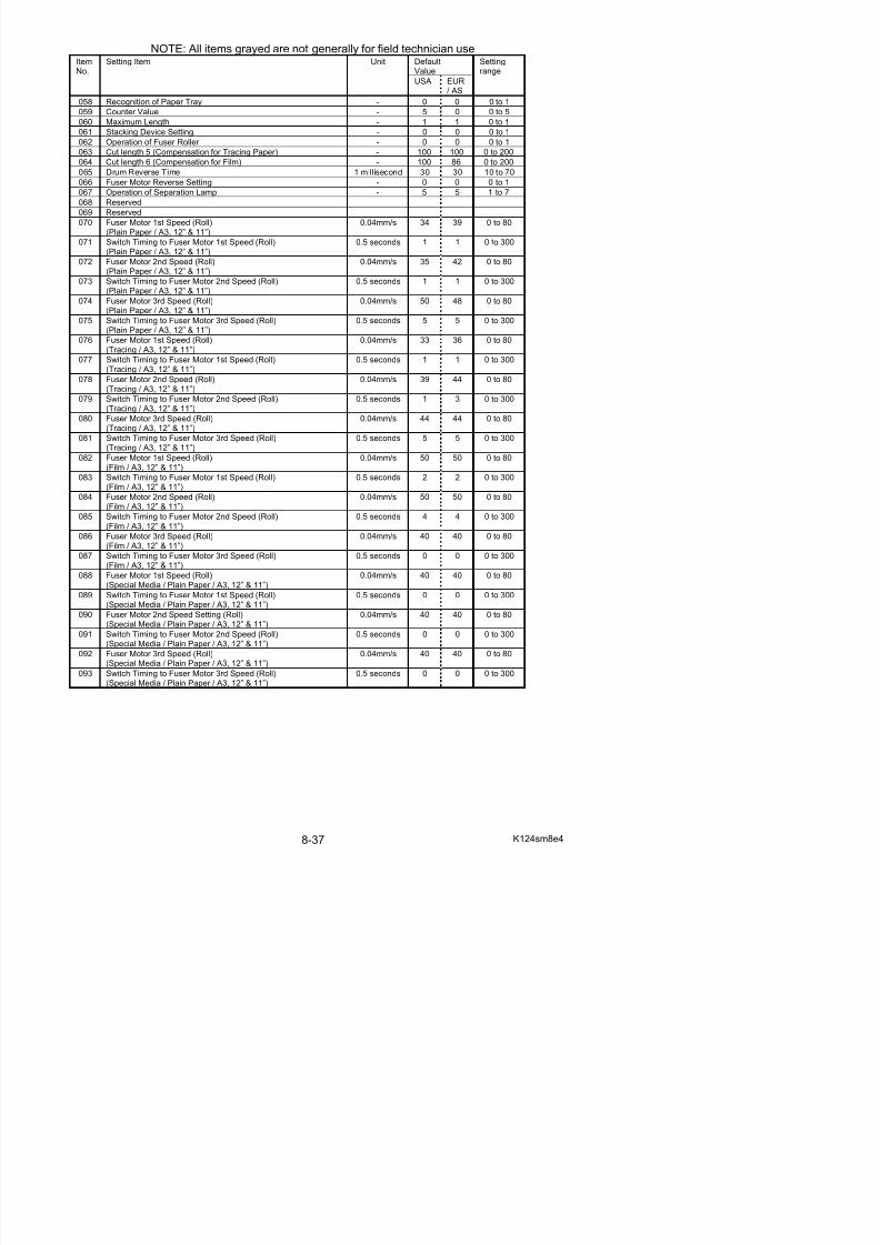
5/17/2018 KIP 7100 Service Manual Ver A_1 - slidepdf.com
http://slidepdf.com/reader/full/kip-7100-service-manual-ver-a1 479/674
(Special Media / Tracing / A3, 12” & 11”)096 Fuser Motor 2nd Speed (Roll)
(Special Media / Tracing / A3, 12” & 11”)0.04mm/s 40 40 0 to 80
097 Switch Timing to Fuser Motor 2nd Speed (Roll)(Special Media / Tracing / A3, 12” & 11”)
0.5 seconds 0 0 0 to 300
098 Fuser Motor 3rd Speed (Roll)(Special Media / Tracing / A3, 12” & 11”)
0.04mm/s 40 40 0 to 80
099 Switch Timing to Fuser Motor 3rd Speed (Roll)(Special Media / Tracing / A3, 12” & 11”)
0.5 seconds 0 0 0 to 300
100 Fuser Motor 1st Speed (Roll)(Special Media / Film / A3, 12” & 11”)
0.04mm/s 40 40 0 to 80
101 Switch Timing to Fuser Motor 1st Speed (Roll)(Special Media / Film / A3, 12” & 11”)
0.5 seconds 0 0 0 to 300
102 Fuser Motor 2nd Speed (Roll)(Special Media / Film / A3, 12” & 11”)
0.04mm/s 40 40 0 to 80
103 Switch Timing to Fuser Motor 2nd Speed (Roll)(Special Media / Film / A3, 12” & 11”)
0.5 seconds 0 0 0 to 300
104 Fuser Motor 3rd Speed (Roll)(Special Media / Film / A3, 12” & 11”)
0.04mm/s 40 40 0 to 80
105 Switch Timing to Fuser Motor 3rd Speed (Roll)(Special Media / Film / A3, 12” & 11”)
0.5 seconds 0 0 0 to 300
106 Fuser Motor 1st Speed (Roll)
(Plain Paper / A2, 18” & 17”)
0.04mm/s 30 31 0 to 80
107 Switch Timing to Fuser Motor 1st Speed (Roll)(Plain Paper / A2, 18” & 17”)
0.5 seconds 3 3 0 to 300
108 Fuser Motor 2nd Speed (Roll)(Plain Paper / A2, 18” & 17”)
0.04mm/s 32 36 0 to 80
109 Switch Timing to Fuser Motor 2nd Speed (Roll)(Plain Paper / A2, 18” & 17”)
0.5 seconds 4 4 0 to 300
110 Fuser Motor 3rd Speed (Roll)(Plain Paper / A2, 18” & 17”)
0.04mm/s 31 38 0 to 80
111 Switch Timing to Fuser Motor 3rd Speed (Roll)(Plain Paper / A2, 18” & 17”)
0.5 seconds 6 6 0 to 300
112 Fuser Motor 1st Speed (Roll)(Tracing / A2, 18” & 17”)
0.04mm/s 33 40 0 to 80
113 Switch Timing to Fuser Motor 1st Speed (Roll)(Tracing / A2, 18” & 17”)
0.5 seconds 3 1 0 to 300
114 Fuser Motor 2nd Speed (Roll)(Tracing / A2, 18” & 17”)
0.04mm/s 38 44 0 to 80
115 Switch Timing to Fuser Motor 2nd Speed (Roll)(Tracing / A2, 18” & 17”)
0.5 seconds 3 5 0 to 300
116 Fuser Motor 3rd Speed (Roll)(Tracing / A2, 18” & 17”)
0.04mm/s 38 45 0 to 80
117 Switch Timing to Fuser Motor 3rd Speed (Roll)
(Tracing / A2, 18” & 17”)
0.5 seconds 5 5 0 to 300
118 Fuser Motor 1st Speed (Roll)(Film / A2, 18” & 17”)
0.04mm/s 50 50 0 to 80
119 Switch Timing to Fuser Motor 1st Speed (Roll)(Film / A2, 18” & 17”)
0.5 seconds 2 2 0 to 300
120 Fuser Motor 2nd Speed (Roll) 0.04mm/s 50 50 0 to 80
NOTE: All items grayed are not generally for field technician use
DefaultValue
ItemNo.
Setting Item Unit
USA EUR/ AS
Settingrange
124 Fuser Motor 1st Speed (Roll)(Special Media / Plain Paper / A2, 18” & 17”)
0.04mm/s 40 40 0 to 80
125 Switch Timing to Fuser Motor 1st Speed (Roll) 0.5 seconds 0 0 0 to 300
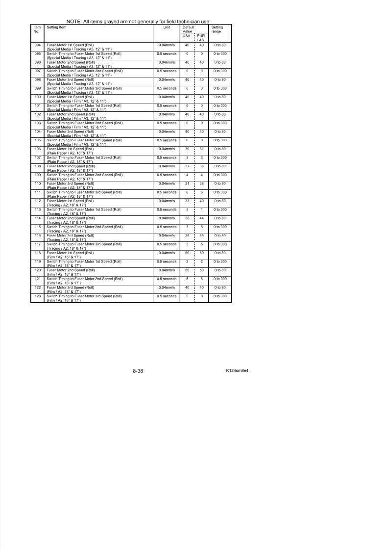
5/17/2018 KIP 7100 Service Manual Ver A_1 - slidepdf.com
http://slidepdf.com/reader/full/kip-7100-service-manual-ver-a1 480/674
(Special Media / Plain Paper / A2, 18” & 17”)126 Fuser Motor 2nd Speed (Roll)
(Special Media / Plain Paper / A2, 18” & 17”)0.04mm/s 40 40 0 to 80
127 Switch Timing to Fuser Motor 2nd Speed (Roll)(Special Media / Plain Paper / A2, 18” & 17”)
0.5 seconds 0 0 0 to 300
128 Fuser Motor 3rd Speed (Roll)(Special Media / Plain Paper / A2, 18” & 17”)
0.04mm/s 40 40 0 to 80
129 Switch Timing to Fuser Motor 3rd Speed (Roll)(Special Media / Plain Paper / A2, 18” & 17”)
0.5 seconds 0 0 0 to 300
130 Fuser Motor 1st Speed (Roll)(Special Media / Tracing / A2, 18” & 17”)
0.04mm/s 40 40 0 to 80
131 Switch Timing to Fuser Motor 1st Speed (Roll)(Special Media / Tracing / A2, 18” & 17”)
0.5 seconds 0 0 0 to 300
132 Fuser Motor 2nd Speed (Roll)(Special Media / Tracing / A2, 18” & 17”)
0.04mm/s 40 40 0 to 80
133 Switch Timing to Fuser Motor 2nd Speed (Roll)(Special Media / Tracing / A2, 18” & 17”)
0.5 seconds 0 0 0 to 300
134 Fuser Motor 3rd Speed (Roll)(Special Media / Tracing / A2, 18” & 17”)
0.04mm/s 40 40 0 to 80
135 Switch Timing to Fuser Motor 3rd Speed (Roll)(Special Media / Tracing / A2, 18” & 17”)
0.5 seconds 0 0 0 to 300
136 Fuser Motor 1st Speed (Roll)
(Special Media / Film / A2, 18” & 17”)
0.04mm/s 40 40 0 to 80
137 Switch Timing to Fuser Motor 1st Speed (Roll)(Special Media / Film / A2, 18” & 17”)
0.5 seconds 0 0 0 to 300
138 Fuser Motor 2nd Speed (Roll)(Special Media / Film / A2, 18” & 17”)
0.04mm/s 40 40 0 to 80
139 Switch Timing to Fuser Motor 2nd Speed (Roll)(Special Media / Film / A2, 18” & 17”)
0.5 seconds 0 0 0 to 300
140 Fuser Motor 3rd Speed (Roll)(Special Media / Film / A2, 18” & 17”)
0.04mm/s 40 40 0 to 80
141 Switch Timing to Fuser Motor 3rd Speed (Roll)(Special Media / Film / A2, 18” & 17”)
0.5 seconds 0 0 0 to 300
142 Fuser Motor 1st Speed (Roll)(Plain Paper / A1, 24” & 22”)
0.04mm/s 37 35 0 to 80
143 Switch Timing to Fuser Motor 1st Speed (Roll)(Plain Paper / A1, 24” & 22”)
0.5 seconds 3 3 0 to 300
144 Fuser Motor 2nd Speed (Roll)(Plain Paper / A1, 24” & 22”)
0.04mm/s 30 33 0 to 80
145 Switch Timing to Fuser Motor 2nd Speed (Roll)(Plain Paper / A1, 24” & 22”)
0.5 seconds 6 8 0 to 300
146 Fuser Motor 3rd Speed (Roll)(Plain Paper / A1, 24” & 22”)
0.04mm/s 40 41 0 to 80
147 Switch Timing to Fuser Motor 3rd Speed (Roll)
(Plain Paper / A1, 24” & 22”)
0.5 seconds 6 8 0 to 300
148 Fuser Motor 1st Speed (Roll)(Tracing / A1, 24” & 22”)
0.04mm/s 36 42 0 to 80
149 Switch Timing to Fuser Motor 1st Speed (Roll)(Tracing / A1, 24” & 22”)
0.5 seconds 3 3 0 to 300
150 Fuser Motor 2nd Speed (Roll) 0.04mm/s 41 43 0 to 80
NOTE: All items grayed are not generally for field technician use
DefaultValue
ItemNo.
Setting Item Unit
USA EUR/ AS
Settingrange
154 Fuser Motor 1st Speed (Roll)(Film / A1, 24” & 22”)
0.04mm/s 42 42 0 to 80
155 Switch Timing to Fuser Motor 1st Speed (Roll) 0.5 seconds 2 2 0 to 300
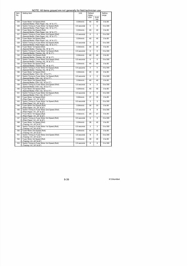
5/17/2018 KIP 7100 Service Manual Ver A_1 - slidepdf.com
http://slidepdf.com/reader/full/kip-7100-service-manual-ver-a1 481/674
(Film / A1, 24” & 22”)156 Fuser Motor 2nd Speed (Roll)
(Film / A1, 24” & 22”)0.04mm/s 42 42 0 to 80
157 Switch Timing to Fuser Motor 2nd Speed (Roll)(Film / A1, 24” & 22”)
0.5 seconds 14 14 0 to 300
158 Fuser Motor 3rd Speed (Roll)(Film / A1, 24” & 22”)
0.04mm/s 40 40 0 to 80
159 Switch Timing to Fuser Motor 3rd Speed (Roll)(Film / A1, 24” & 22”)
0.5 seconds 0 0 0 to 300
160 Fuser Motor 1st Speed (Roll)(Special Media / Plain Paper / A1, 24” & 22”)
0.04mm/s 40 40 0 to 80
161 Switch Timing to Fuser Motor 1st Speed (Roll)(Special Media / Plain Paper / A1, 24” & 22”)
0.5 seconds 0 0 0 to 300
162 Fuser Motor 2nd Speed (Roll)(Special Media / Plain Paper / A1, 24” & 22”)
0.04mm/s 40 40 0 to 80
163 Switch Timing to Fuser Motor 2nd Speed (Roll)(Special Media / Plain Paper / A1, 24” & 22”)
0.5 seconds 0 0 0 to 300
164 Fuser Motor 3rd Speed (Roll)(Special Media / Plain Paper / A1, 24” & 22”)
0.04mm/s 40 40 0 to 80
165 Switch Timing to Fuser Motor 3rd Speed (Roll)(Special Media / Plain Paper / A1, 24” & 22”)
0.5 seconds 0 0 0 to 300
166 Fuser Motor 1st Speed (Roll)
(Special Media / Tracing / A1, 24” & 22”)
0.04mm/s 40 40 0 to 80
167 Switch Timing to Fuser Motor 1st Speed (Roll)(Special Media / Tracing / A1, 24” & 22”)
0.5 seconds 0 0 0 to 300
168 Fuser Motor 2nd Speed (Roll)(Special Media / Tracing / A1, 24” & 22”)
0.04mm/s 40 40 0 to 80
169 Switch Timing to Fuser Motor 2nd Speed (Roll)(Special Media / Tracing / A1, 24” & 22”)
0.5 seconds 0 0 0 to 300
170 Fuser Motor 3rd Speed (Roll)(Special Media / Tracing / A1, 24” & 22”)
0.04mm/s 40 40 0 to 80
171 Switch Timing to Fuser Motor 3rd Speed (Roll)(Special Media / Tracing / A1, 24” & 22”)
0.5 seconds 0 0 0 to 300
172 Fuser Motor 1st Speed (Roll)(Special Media / Film / A1, 24” & 22”)
0.04mm/s 40 40 0 to 80
173 Switch Timing to Fuser Motor 1st Speed (Roll)(Special Media / Film / A1, 24” & 22”)
0.5 seconds 0 0 0 to 300
174 Fuser Motor 2nd Speed (Roll)(Special Media / Film / A1, 24” & 22”)
0.04mm/s 40 40 0 to 80
175 Switch Timing to Fuser Motor 2nd Speed (Roll)(Special Media / Film / A1, 24” & 22”)
0.5 seconds 0 0 0 to 300
176 Fuser Motor 3rd Speed (Roll)(Special Media / Film / A1, 24” & 22”)
0.04mm/s 40 40 0 to 80
177 Switch Timing to Fuser Motor 3rd Speed (Roll)
(Special Media / Film / A1, 24” & 22”)
0.5 seconds 0 0 0 to 300
178 Fuser Motor 1st Speed (Roll)(Plain Paper / A0, 36” & 34”)
0.04mm/s 26 26 0 to 80
179 Switch Timing to Fuser Motor 1st Speed (Roll)(Plain Paper / A0, 36” & 34”)
0.5 seconds 4 3 0 to 300
180 Fuser Motor 2nd Speed (Roll) 0.04mm/s 27 27 0 to 80
NOTE: All items grayed are not generally for field technician use
DefaultValue
ItemNo.
Setting Item Unit
USA EUR/ AS
Settingrange
184 Fuser Motor 1st Speed (Roll)(Tracing / A0, 36” & 34”)
0.04mm/s 29 42 0 to 80
185 Switch Timing to Fuser Motor 1st Speed (Roll)
(T i / A0 36” & 34”)
0.5 seconds 3 3 0 to 300
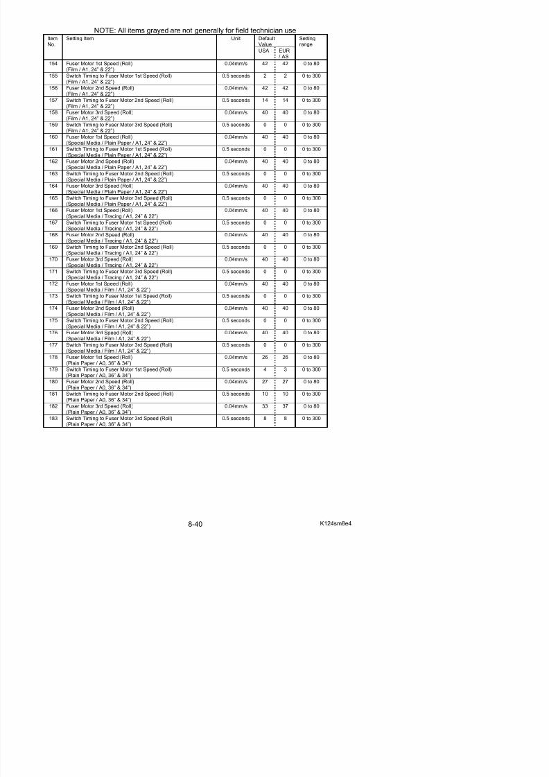
5/17/2018 KIP 7100 Service Manual Ver A_1 - slidepdf.com
http://slidepdf.com/reader/full/kip-7100-service-manual-ver-a1 482/674
(Tracing / A0, 36” & 34”)186 Fuser Motor 2nd Speed (Roll)
(Tracing / A0, 36” & 34”)0.04mm/s 35 38 0 to 80
187 Switch Timing to Fuser Motor 2nd Speed (Roll)(Tracing / A0, 36” & 34”)
0.5 seconds 13 13 0 to 300
188 Fuser Motor 3rd Speed (Roll)(Tracing / A0, 36” & 34”)
0.04mm/s 36 39 0 to 80
189 Switch Timing to Fuser Motor 3rd Speed (Roll)(Tracing / A0, 36” & 34”)
0.5 seconds 8 8 0 to 300
190 Fuser Motor 1st Speed (Roll)(Film / A0, 36” & 34”)
0.04mm/s 35 38 0 to 80
191 Switch Timing to Fuser Motor 1st Speed (Roll)(Film / A0, 36” & 34”)
0.5 seconds 2 2 0 to 300
192 Fuser Motor 2nd Speed (Roll)(Film / A0, 36” & 34”)
0.04mm/s 40 43 0 to 80
193 Switch Timing to Fuser Motor 2nd Speed (Roll)(Film / A0, 36” & 34”)
0.5 seconds 18 18 0 to 300
194 Fuser Motor 3rd Speed (Roll)(Film / A0, 36” & 34”)
0.04mm/s 40 40 0 to 80
195 Switch Timing to Fuser Motor 3rd Speed (Roll)(Film / A0, 36” & 34”)
0.5 seconds 0 0 0 to 300
196 Fuser Motor 1st Speed (Roll)
(Special Media / Plain Paper / A0, 36” & 34”)
0.04mm/s 40 40 0 to 80
197 Switch Timing to Fuser Motor 1st Speed (Roll)(Special Media / Plain Paper / A0, 36” & 34”)
0.5 seconds 0 0 0 to 300
198 Fuser Motor 2nd Speed (Roll)(Special Media / Plain Paper / A0, 36” & 34”)
0.04mm/s 40 40 0 to 80
199 Switch Timing to Fuser Motor 2nd Speed (Roll)(Special Media / Plain Paper / A0, 36” & 34”)
0.5 seconds 0 0 0 to 300
200 Fuser Motor 3rd Speed (Roll)(Special Media / Plain Paper / A0, 36” & 34”)
0.04mm/s 40 40 0 to 80
201 Switch Timing to Fuser Motor 3rd Speed (Roll)(Special Media / Plain Paper / A0, 36” & 34”)
0.5 seconds 0 0 0 to 300
202 Fuser Motor 1st Speed (Roll)(Special Media / Tracing / A0, 36” & 34”)
0.04mm/s 40 40 0 to 80
203 Switch Timing to Fuser Motor 1st Speed (Roll)(Special Media / Tracing / A0, 36” & 34”)
0.5 seconds 0 0 0 to 300
204 Fuser Motor 2nd Speed (Roll)(Special Media / Tracing / A0, 36” & 34”)
0.04mm/s 40 40 0 to 80
205 Switch Timing to Fuser Motor 2nd Speed (Roll)(Special Media / Tracing / A0, 36” & 34”)
0.5 seconds 0 0 0 to 300
206 Fuser Motor 3rd Speed (Roll)(Special Media / Tracing / A0, 36” & 34”)
0.04mm/s 40 40 0 to 80
207 Switch Timing to Fuser Motor 3rd Speed (Roll)
(Special Media / Tracing / A0, 36” & 34”)
0.5 seconds 0 0 0 to 300
208 Fuser Motor 1st Speed (Roll)(Special Media / Film / A0, 36” & 34”)
0.04mm/s 40 40 0 to 80
209 Switch Timing to Fuser Motor 1st Speed (Roll)(Special Media / Film / A0, 36” & 34”)
0.5 seconds 0 0 0 to 300
210 Fuser Motor 2nd Speed (Roll) 0.04mm/s 40 40 0 to 80
NOTE: All items grayed are not generally for field technician use
DefaultValue
ItemNo.
Setting Item Unit
USA EUR/ AS
Settingrange
310 Main Motor Speed (Plain paper) - 36 36 0 to 80
311 Main Motor Speed (Tracing paper) - 40 40 0 to 80
312 Main Motor Speed (Film) - 40 40 0 to 80
313 Main Motor Speed (Special plain paper) 40 40 0 to 80
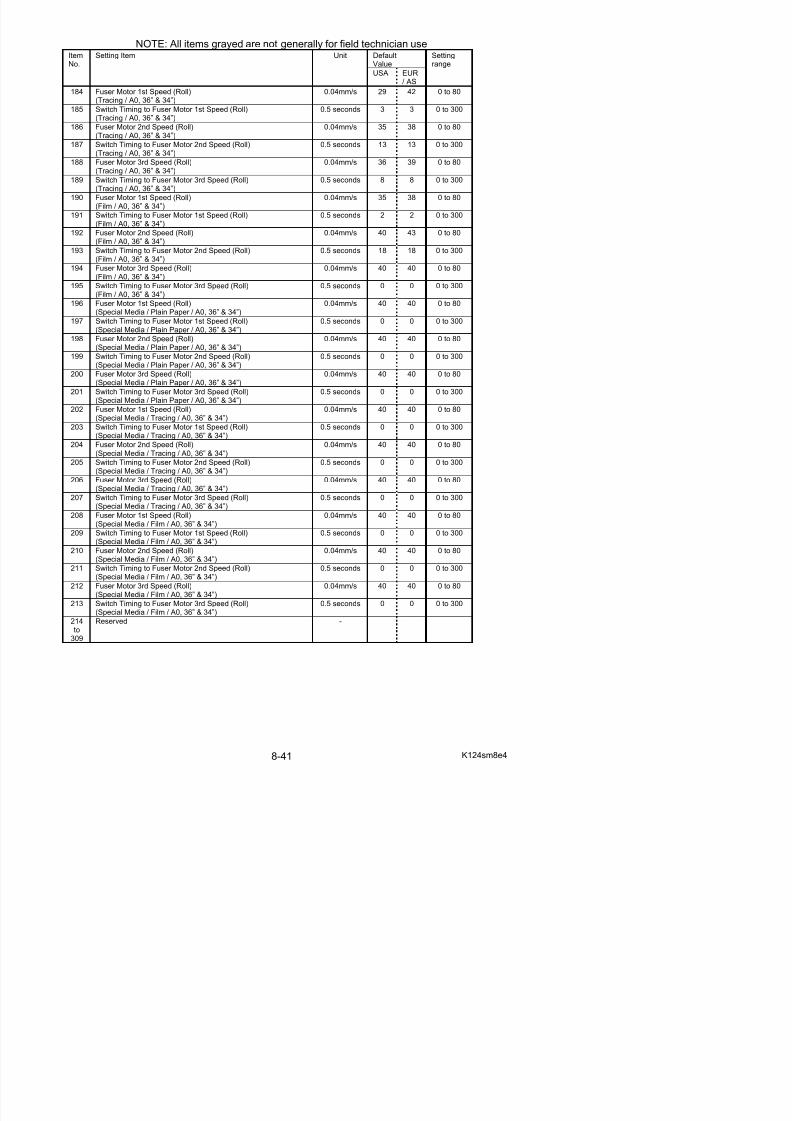
5/17/2018 KIP 7100 Service Manual Ver A_1 - slidepdf.com
http://slidepdf.com/reader/full/kip-7100-service-manual-ver-a1 483/674
313 Main Motor Speed (Special plain paper) - 40 40 0 to 80314 Main Motor Speed (Special tracing paper) - 40 40 0 to 80
315 Main Motor Speed (Special film) - 40 40 0 to 80
316 Fuser Motor Speed(36” / 34” / 30” / 24” / 22” / A0 / B1 / A1) (Plain)
- 31 35 0 to 80
317 Fuser Motor Speed(36” / 34” / 30” / 24” / 22” / A0 / B1 / A1) (Tracing)
- 39 50 0 to 80
318 Fuser Motor Speed(36” / 34” / 30” / 24” / 22” / A0 / B1 / A1) (Film)
- 50 50 0 to 80
319 Fuser Motor Speed(36” / 34” / 30” / 24” / 22” / A0 / B1 / A1) (Special / Plain)
- 40 40 0 to 80
320 Fuser Motor Speed(36” / 34” / 30” / 24” / 22” / A0 / B1 / A1) (Special / Tracing)
- 40 40 0 to 80
321 Fuser Motor Speed(36” / 34” / 30” / 24” / 22” / A0 / B1 / A1) (Special / Film)
- 40 40 0 to 80
322 Separation Corona OFF Timing (Plain paper) 1mm 25 25 0 to 100
323 Separation Corona OFF Timing (tracing paper) 1mm 25 25 0 to 100
324 Separation Corona OFF Timing (Film) 1mm 22 25 0 to 100
325 Separation Corona OFF Timing (Special plain paper) 1mm 18 18 0 to 100
326 Separation Corona OFF Timing (Special tracing paper) 1mm 18 18 0 to 100
327 Separation Corona OFF Timing (Special film) 1mm 23 23 0 to 100
328 Fuser Motor 1st Speed (Cut sheet)
(Plain Paper / A3, A2, 12”, 11”, 18” & 17”)
0.04mm/s 30 31 0 to 80
329 Switch Timing to Fuser Motor 1st Speed (Cut sheet)(Plain Paper / A3, A2, 12”, 11”, 18” & 17”)
0.5 seconds 3 3 0 to 300
330 Fuser Motor 2nd Speed (Cut sheet)(Plain Paper / A3, A2, 12”, 11”, 18” & 17”)
0.04mm/s 32 36 0 to 80
331 Switch Timing to Fuser Motor 2nd Speed (Cut sheet)(Plain Paper / A3, A2, 12”, 11”, 18” & 17”)
0.5 seconds 4 4 0 to 300
332 Fuser Motor 3rd Speed (Cut sheet)(Plain Paper / A3, A2, 12”, 11”, 18” & 17”)
0.04mm/s 31 38 0 to 80
333 Switch Timing to Fuser Motor 3rd Speed (Cut sheet)(Plain Paper / A3, A2, 12”, 11”, 18” & 17”)
0.5 seconds 6 6 0 to 300
334 Fuser Motor 1st Speed (Roll)(Tracing / A3, 12” & 11”)
0.04mm/s 33 40 0 to 80
335 Switch Timing to Fuser Motor 1st Speed (Cut sheet)(Tracing / A3, A2, 12”, 11”, 18” & 17”)
0.5 seconds 2 1 0 to 300
336 Fuser Motor 2nd Speed (Cut sheet)(Tracing / A3, A2, 12”, 11”, 18” & 17”)
0.04mm/s 38 44 0 to 80
337 Switch Timing to Fuser Motor 2nd Speed (Cut sheet)(Tracing / A3, A2, 12”, 11”, 18” & 17”)
0.5 seconds 3 5 0 to 300
338 Fuser Motor 3rd Speed (Cut sheet)(Tracing / A3, A2, 12”, 11”, 18” & 17”)
0.04mm/s 38 45 0 to 80
339 Switch Timing to Fuser Motor 3rd Speed (Cut sheet)
(Tracing / A3, A2, 12”, 11”, 18” & 17”)
0.5 seconds 5 2 0 to 300
340 Fuser Motor 1st Speed (Cut sheet)(Film / A3, A2, 12”, 11”, 18” & 17”)
0.04mm/s 50 50 0 to 80
341 Switch Timing to Fuser Motor 1st Speed (Cut sheet)(Film / A3, A2, 12”, 11”, 18” & 17”)
0.5 seconds 2 6 0 to 300
342 Fuser Motor 2nd Speed (Cut sheet) 0.04mm/s 50 40 0 to 80
NOTE: All items grayed are not generally for field technician use
DefaultValue
ItemNo.
Setting Item Unit
USA EUR/ AS
Settingrange
352 Fuser Motor 1st Speed (Cut sheet)(Special Media / Tracing / A3, A2, 12”, 11”, 18” & 17”)
0.04mm/s 40 40 0 to 80
353 Switch Timing to Fuser Motor 1st Speed (Cut sheet)
(Special Media / Tracing / A3 A2 12” 11” 18” & 17”)
0.5 seconds 0 0 0 to 300
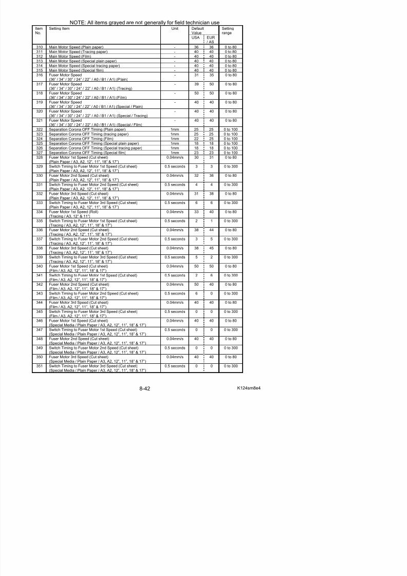
5/17/2018 KIP 7100 Service Manual Ver A_1 - slidepdf.com
http://slidepdf.com/reader/full/kip-7100-service-manual-ver-a1 484/674
(Special Media / Tracing / A3, A2, 12 , 11 , 18 & 17 )354 Fuser Motor 2nd Speed (Cut sheet)
(Special Media / Tracing / A3, A2, 12”, 11”, 18” & 17”)0.04mm/s 40 40 0 to 80
355 Switch Timing to Fuser Motor 2nd Speed (Cut sheet)(Special Media / Tracing / A3, A2, 12”, 11”, 18” & 17”)
0.5 seconds 0 0 0 to 300
356 Fuser Motor 3rd Speed (Cut sheet)(Special Media / Tracing / A3, A2, 12”, 11”, 18” & 17”)
0.04mm/s 40 40 0 to 80
357 Switch Timing to Fuser Motor 3rd Speed (Cut sheet)(Special Media / Tracing / A3, A2, 12”, 11”, 18” & 17”)
0.5 seconds 0 0 0 to 300
358 Fuser Motor 1st Speed (Cut sheet)(Special Media / Film / A3, A2, 12”, 11”, 18” & 17”)
0.04mm/s 40 40 0 to 80
359 Switch Timing to Fuser Motor 1st Speed (Cut sheet)(Special Media / Film / A3, A2, 12”, 11”, 18” & 17”)
0.5 seconds 0 0 0 to 300
360 Fuser Motor 2nd Speed (Cut sheet)(Special Media / Film / A3, A2, 12”, 11”, 18” & 17”)
0.04mm/s 40 40 0 to 80
361 Switch Timing to Fuser Motor 2nd Speed (Cut sheet)(Special Media / Film / A3, A2, 12”, 11”, 18” & 17”)
0.5 seconds 0 0 0 to 300
362 Fuser Motor 3rd Speed (Cut sheet)(Special Media / Film / A3, A2, 12”, 11”, 18” & 17”)
0.04mm/s 40 40 0 to 80
363 Switch Timing to Fuser Motor 3rd Speed (Cut sheet)(Special Media / Film / A3, A2, 12”, 11”, 18” & 17”)
0.5 seconds 0 0 0 to 300
364 Fuser Motor 1st Speed (Cut sheet)
(Plain Paper / A1, 24” & 22”)
0.04mm/s 37 35 0 to 80
365 Switch Timing to Fuser Motor 1st Speed (Cut sheet)(Plain Paper / A1, 24” & 22”)
0.5 seconds 3 3 0 to 300
366 Fuser Motor 2nd Speed (Cut sheet)(Plain Paper / A1, 24” & 22”)
0.04mm/s 30 33 0 to 80
367 Switch Timing to Fuser Motor 2nd Speed (Cut sheet)(Plain Paper / A1, 24” & 22”)
0.5 seconds 6 8 0 to 300
368 Fuser Motor 3rd Speed (Cut sheet)(Plain Paper / A1, 24” & 22”)
0.04mm/s 40 41 0 to 80
369 Switch Timing to Fuser Motor 3rd Speed (Cut sheet)(Plain Paper / A1, 24” & 22”)
0.5 seconds 6 8 0 to 300
370 Fuser Motor 1st Speed (Cut sheet)(Tracing / A1, 24” & 22”) 0.04mm/s 36 42 0 to 80
371 Switch Timing to Fuser Motor 1st Speed (Cut sheet)(Tracing / A1, 24” & 22”)
0.5 seconds 3 3 0 to 300
372 Fuser Motor 2nd Speed (Cut sheet)(Tracing / A1, 24” & 22”)
0.04mm/s 41 43 0 to 80
373 Switch Timing to Fuser Motor 2nd Speed (Cut sheet)(Tracing / A1, 24” & 22”)
0.5 seconds 9 9 0 to 300
374 Fuser Motor 3rd Speed (Cut sheet)(Tracing / A1, 24” & 22”)
0.04mm/s 39 40 0 to 80
375 Switch Timing to Fuser Motor 3rd Speed (Cut sheet)
(Tracing / A1, 24” & 22”)
0.5 seconds 8 8 0 to 300
376 Fuser Motor 1st Speed (Cut sheet)(Film / A1, 24” & 22”)
0.04mm/s 42 42 0 to 80
377 Switch Timing to Fuser Motor 1st Speed (Cut sheet)(Film / A1, 24” & 22”)
0.5 seconds 2 2 0 to 300
378 Fuser Motor 2nd Speed (Cut sheet) 0.04mm/s 42 42 0 to 80
NOTE: All items grayed are not generally for field technician use
DefaultValue
ItemNo.
Setting Item Unit
USA EUR/ AS
Settingrange
386 Fuser Motor 3rd Speed (Cut sheet)(Special Media / Plain Paper / A1, 24” & 22”)
0.04mm/s 40 40 0 to 80
387 Switch Timing to Fuser Motor 3rd Speed (Cut sheet)
(Special Media / Plain Paper / A1 24” & 22”)
0.5 seconds 0 0 0 to 300
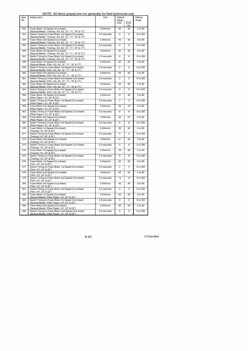
5/17/2018 KIP 7100 Service Manual Ver A_1 - slidepdf.com
http://slidepdf.com/reader/full/kip-7100-service-manual-ver-a1 485/674
(Special Media / Plain Paper / A1, 24 & 22 )388 Fuser Motor 1st Speed (Cut sheet)
(Special Media / Tracing / A1, 24” & 22”)0.04mm/s 40 40 0 to 80
389 Switch Timing to Fuser Motor 1st Speed (Cut sheet)(Special Media / Tracing / A1, 24” & 22”)
0.5 seconds 0 0 0 to 300
390 Fuser Motor 2nd Speed (Cut sheet)(Special Media / Tracing / A1, 24” & 22”)
0.04mm/s 40 40 0 to 80
391 Switch Timing to Fuser Motor 2nd Speed (Cut sheet)(Special Media / Tracing / A1, 24” & 22”)
0.5 seconds 0 0 0 to 300
392 Fuser Motor 3rd Speed (Cut sheet)(Special Media / Tracing / A1, 24” & 22”)
0.04mm/s 40 40 0 to 80
393 Switch Timing to Fuser Motor 3rd Speed (Cut sheet)(Special Media / Tracing / A1, 24” & 22”)
0.5 seconds 0 0 0 to 300
394 Fuser Motor 1st Speed (Cut sheet)(Special Media / Film / A1, 24” & 22”)
0.04mm/s 40 40 0 to 80
395 Switch Timing to Fuser Motor 1st Speed (Cut sheet)(Special Media / Film / A1, 24” & 22”)
0.5 seconds 0 0 0 to 300
396 Fuser Motor 2nd Speed (Cut sheet)(Special Media / Film / A1, 24” & 22”)
0.04mm/s 40 40 0 to 80
397 Switch Timing to Fuser Motor 2nd Speed (Cut sheet)(Special Media / Film / A1, 24” & 22”)
0.5 seconds 0 0 0 to 300
398 Fuser Motor 3rd Speed (Cut sheet)
(Special Media / Film / A1, 24” & 22”)
0.04mm/s 40 40 0 to 80
399 Switch Timing to Fuser Motor 3rd Speed (Cut sheet)(Special Media / Film / A1, 24” & 22”)
0.5 seconds 0 0 0 to 300
400 Fuser Motor 1st Speed (Cut sheet)(Plain Paper / A0, 36” & 34”)
0.04mm/s 26 26 0 to 80
401 Switch Timing to Fuser Motor 1st Speed (Cut sheet)(Plain Paper / A0, 36” & 34”)
0.5 seconds 4 3 0 to 300
402 Fuser Motor 2nd Speed (Cut sheet)(Plain Paper / A0, 36” & 34”)
0.04mm/s 27 27 0 to 80
403 Switch Timing to Fuser Motor 2nd Speed (Cut sheet)(Plain Paper / A0, 36” & 34”)
0.5 seconds 10 10 0 to 300
404 Fuser Motor 3rd Speed (Cut sheet)(Plain Paper / A0, 36” & 34”) 0.04mm/s 33 37 0 to 80
405 Switch Timing to Fuser Motor 3rd Speed (Cut sheet)(Plain Paper / A0, 36” & 34”)
0.5 seconds 8 8 0 to 300
406 Fuser Motor 1st Speed (Cut sheet)(Tracing / A0, 36” & 34”)
0.04mm/s 29 42 0 to 80
407 Switch Timing to Fuser Motor 1st Speed (Cut sheet)(Tracing / A0, 36” & 34”)
0.5 seconds 3 3 0 to 300
408 Fuser Motor 2nd Speed (Cut sheet)(Tracing / A0, 36” & 34”)
0.04mm/s 35 38 0 to 80
409 Switch Timing to Fuser Motor 2nd Speed (Cut sheet)
(Tracing / A0, 36” & 34”)
0.5 seconds 13 13 0 to 300
410 Fuser Motor 3rd Speed (Cut sheet)(Tracing / A0, 36” & 34”)
0.04mm/s 36 39 0 to 80
411 Switch Timing to Fuser Motor 3rd Speed (Cut sheet)(Tracing / A0, 36” & 34”)
0.5 seconds 8 8 0 to 300
412 Fuser Motor 1st Speed (Cut sheet) 0.04mm/s 35 38 0 to 80
NOTE: All items grayed are not generally for field technician use
DefaultValue
ItemNo.
Setting Item Unit
USA EUR/ AS
Settingrange
419 Switch Timing to Fuser Motor 1st Speed (Cut sheet)(Special Media / Plain Paper / A0, 36” & 34”)
0.5 seconds 0 0 0 to 300
420 Fuser Motor 2nd Speed (Cut sheet)
(Special Media / Plain Paper / A0, 36” & 34”)
0.04mm/s 40 40 0 to 80
421 S it h Ti i t F M t 2 d S d (C t h t) 0 5 d 0 0 0 t 300
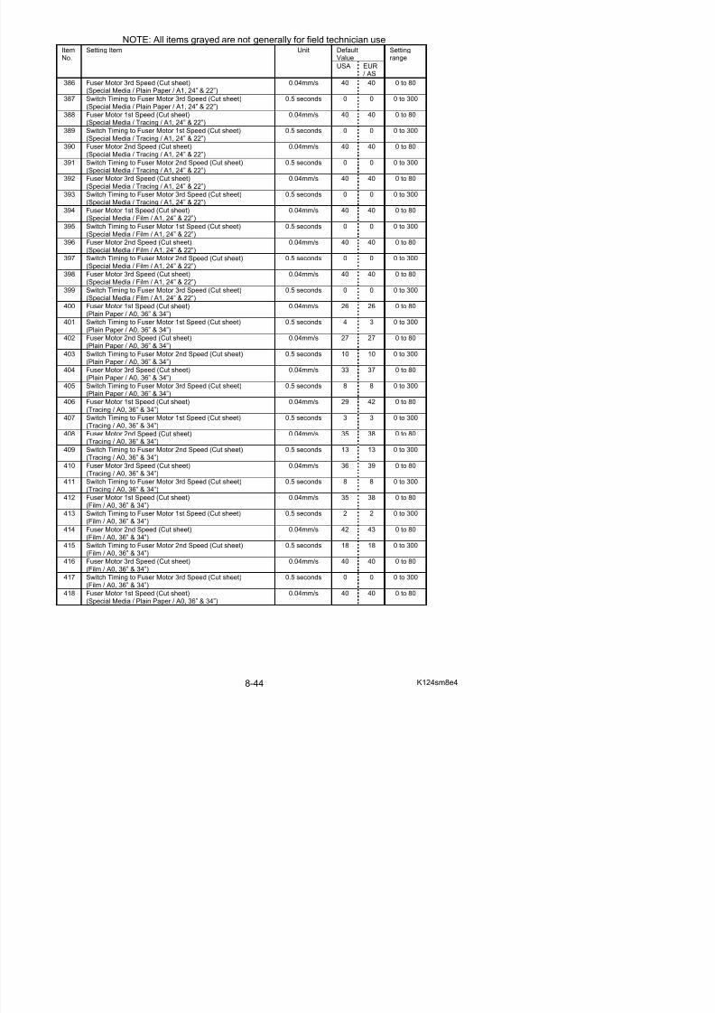
5/17/2018 KIP 7100 Service Manual Ver A_1 - slidepdf.com
http://slidepdf.com/reader/full/kip-7100-service-manual-ver-a1 486/674
( p p , )421 Switch Timing to Fuser Motor 2nd Speed (Cut sheet)
(Special Media / Plain Paper / A0, 36” & 34”)0.5 seconds 0 0 0 to 300
422 Fuser Motor 3rd Speed (Cut sheet)(Special Media / Plain Paper / A0, 36” & 34”)
0.04mm/s 40 40 0 to 80
423 Switch Timing to Fuser Motor 3rd Speed (Cut sheet)(Special Media / Plain Paper / A0, 36” & 34”)
0.5 seconds 0 0 0 to 300
424 Fuser Motor 1st Speed (Cut sheet)(Special Media / Tracing / A0, 36” & 34”)
0.04mm/s 40 40 0 to 80
425 Switch Timing to Fuser Motor 1st Speed (Cut sheet)(Special Media / Tracing / A0, 36” & 34”)
0.5 seconds 0 0 0 to 300
426 Fuser Motor 2nd Speed (Cut sheet)(Special Media / Tracing / A0, 36” & 34”)
0.04mm/s 40 40 0 to 80
427 Switch Timing to Fuser Motor 2nd Speed (Cut sheet)(Special Media / Tracing / A0, 36” & 34”)
0.5 seconds 0 0 0 to 300
428 Fuser Motor 3rd Speed (Cut sheet)(Special Media / Tracing / A0, 36” & 34”)
0.04mm/s 40 40 0 to 80
429 Switch Timing to Fuser Motor 3rd Speed (Cut sheet)(Special Media / Tracing / A0, 36” & 34”)
0.5 seconds 0 0 0 to 300
430 Fuser Motor 1st Speed (Cut sheet)(Special Media / Film / A0, 36” & 34”)
0.04mm/s 40 40 0 to 80
431 Switch Timing to Fuser Motor 1st Speed (Cut sheet)
(Special Media / Film / A0, 36” & 34”)
0.5 seconds 0 0 0 to 300
432 Fuser Motor 2nd Speed (Cut sheet)(Special Media / Film / A0, 36” & 34”)
0.04mm/s 40 40 0 to 80
433 Switch Timing to Fuser Motor 2nd Speed (Cut sheet)(Special Media / Film / A0, 36” & 34”)
0.5 seconds 0 0 0 to 300
434 Fuser Motor 3rd Speed (Cut sheet)(Special Media / Film / A0, 36” & 34”)
0.04mm/s 40 40 0 to 80
435 Switch Timing to Fuser Motor 3rd Speed (Cut sheet)(Special Media / Film / A0, 36” & 34”)
0.5 seconds 0 0 0 to 300
436 Fuser Motor 1st Speed (Roll)(Plain Paper / 30”)
0.04mm/s 28 28 0 to 80
437 Switch Timing to Fuser Motor 1st Speed (Roll)(Plain Paper / 30”) 0.5 seconds 5 5 0 to 300
438 Fuser Motor 2nd Speed (Roll)(Plain Paper / 30”)
0.04mm/s 30 33 0 to 80
439 Switch Timing to Fuser Motor 2nd Speed (Roll)(Plain Paper / 30”)
0.5 seconds 9 9 0 to 300
440 Fuser Motor 3rd Speed (Roll)(Plain Paper / 30”)
0.04mm/s 34 36 0 to 80
441 Switch Timing to Fuser Motor 3rd Speed (Roll)(Plain Paper / 30”)
0.5 seconds 7 7 0 to 300
442 Fuser Motor 1st Speed (Roll)
(Tracing / 30”)
0.04mm/s 34 33 0 to 80
443 Switch Timing to Fuser Motor 1st Speed (Roll)(Tracing / 30”)
0.5 seconds 4 4 0 to 300
444 Fuser Motor 2nd Speed (Roll)(Tracing / 30”)
0.04mm/s 38 44 0 to 80
445 Switch Timing to Fuser Motor 2nd Speed (Roll) 0.5 seconds 11 11 0 to 300
NOTE: All items grayed are not generally for field technician use
DefaultValue
ItemNo.
Setting Item Unit
USA EUR/ AS
Settingrange
452 Fuser Motor 3rd Speed (Roll)(Film / 30”)
0.04mm/s 40 40 0 to 80
453 Switch Timing to Fuser Motor 3rd Speed (Roll)
(Film / 30”)
0.5 seconds 0 0 0 to 300
454 Fuser Motor 1st Speed (Roll) 0 04mm/s 40 40 0 to 80
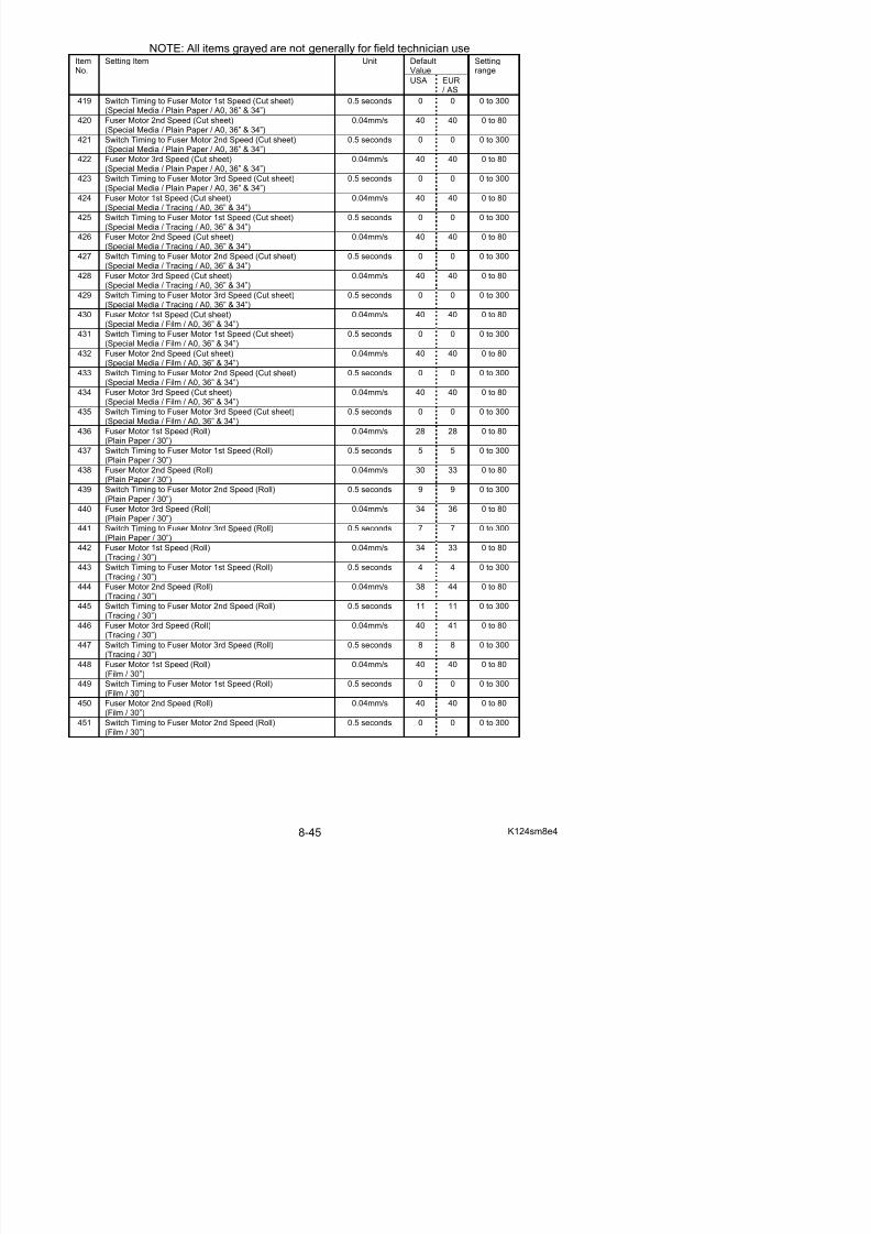
5/17/2018 KIP 7100 Service Manual Ver A_1 - slidepdf.com
http://slidepdf.com/reader/full/kip-7100-service-manual-ver-a1 487/674
( )454 Fuser Motor 1st Speed (Roll)
(Special Media / Plain Paper / 30”)0.04mm/s 40 40 0 to 80
455 Switch Timing to Fuser Motor 1st Speed (Roll)(Special Media / Plain Paper / 30”)
0.5 seconds 0 0 0 to 300
456 Fuser Motor 2nd Speed (Roll)(Special Media / Plain Paper / 30”)
0.04mm/s 40 40 0 to 80
457 Switch Timing to Fuser Motor 2nd Speed (Roll)(Special Media / Plain Paper / 30”)
0.5 seconds 0 0 0 to 300
458 Fuser Motor 3rd Speed (Roll)(Special Media / Plain Paper / 30”)
0.04mm/s 40 40 0 to 80
459 Switch Timing to Fuser Motor 3rd Speed (Roll)(Special Media / Plain Paper / 30”)
0.5 seconds 0 0 0 to 300
460 Fuser Motor 1st Speed (Roll)(Special Media / Tracing / 30”)
0.04mm/s 40 40 0 to 80
461 Switch Timing to Fuser Motor 1st Speed (Roll)(Special Media / Tracing / 30”)
0.5 seconds 0 0 0 to 300
462 Fuser Motor 2nd Speed (Roll)(Special Media / Tracing / 30”)
0.04mm/s 40 40 0 to 80
463 Switch Timing to Fuser Motor 2nd Speed (Roll)(Special Media / Tracing / 30”)
0.5 seconds 0 0 0 to 300
464 Fuser Motor 3rd Speed (Roll)
(Special Media / Tracing / 30”)
0.04mm/s 40 40 0 to 80
465 Switch Timing to Fuser Motor 3rd Speed (Roll)(Special Media / Tracing / 30”)
0.5 seconds 0 0 0 to 300
466 Fuser Motor 1st Speed (Roll)(Special Media / Film / 30”)
0.04mm/s 40 40 0 to 80
467 Switch Timing to Fuser Motor 1st Speed (Roll)(Special Media / Film / 30”)
0.5 seconds 0 0 0 to 300
468 Fuser Motor 2nd Speed (Roll)(Special Media / Film / 30”)
0.04mm/s 40 40 0 to 80
469 Switch Timing to Fuser Motor 2nd Speed (Roll)(Special Media / Film / 30”)
0.5 seconds 0 0 0 to 300
470 Fuser Motor 3rd Speed (Roll)(Special Media / Film / 30”) 0.04mm/s 40 40 0 to 80
471 Switch Timing to Fuser Motor 3rd Speed (Roll)(Special Media / Film / 30”)
0.5 seconds 0 0 0 to 300
472 Fuser Motor 1st Speed (Cut sheet)(Plain Paper / 30”)
0.04mm/s 28 28 0 to 80
473 Switch Timing to Fuser Motor 1st Speed (Cut sheet)(Plain Paper / 30”)
0.5 seconds 5 5 0 to 300
474 Fuser Motor 2nd Speed (Cut sheet)(Plain Paper / 30”)
0.04mm/s 30 33 0 to 80
475 Switch Timing to Fuser Motor 2nd Speed (Cut sheet)
(Plain Paper / 30”)
0.5 seconds 9 9 0 to 300
476 Fuser Motor 3rd Speed (Cut sheet)(Plain Paper / 30”)
0.04mm/s 34 36 0 to 80
477 Switch Timing to Fuser Motor 3rd Speed (Cut sheet)(Plain Paper / 30”)
0.5 seconds 7 7 0 to 300
478 Fuser Motor 1st Speed (Cut sheet) 0.04mm/s 34 33 0 to 80
NOTE: All items grayed are not generally for field technician use
DefaultValue
ItemNo.
Setting Item Unit
USA EUR/ AS
Settingrange
486 Fuser Motor 2nd Speed (Roll) (Cut sheet)(Film / 30”)
0.04mm/s 40 40 0 to 80
487 Switch Timing to Fuser Motor 2nd Speed (Cut sheet)
(Film / 30”)
0.5 seconds 0 0 0 to 300
488 Fuser Motor 3rd Speed (Cut sheet) 0 04mm/s 40 40 0 to 80
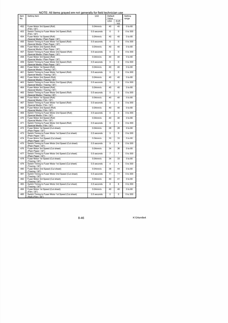
5/17/2018 KIP 7100 Service Manual Ver A_1 - slidepdf.com
http://slidepdf.com/reader/full/kip-7100-service-manual-ver-a1 488/674
488 Fuser Motor 3rd Speed (Cut sheet)(Film / 30”)
0.04mm/s 40 40 0 to 80
489 Switch Timing to Fuser Motor 3rd Speed (Cut sheet)(Film / 30”)
0.5 seconds 0 0 0 to 300
490 Fuser Motor 1st Speed (Cut sheet)(Special Media / Plain Paper / 30”)
0.04mm/s 40 40 0 to 80
491 Switch Timing to Fuser Motor 1st Speed (Cut sheet)(Special Media / Plain Paper / 30”)
0.5 seconds 0 0 0 to 300
492 Fuser Motor 2nd Speed (Cut sheet)(Special Media / Plain Paper / 30”)
0.04mm/s 40 40 0 to 80
493 Switch Timing to Fuser Motor 2nd Speed (Cut sheet)(Special Media / Plain Paper / 30”) 0.5 seconds 0 0 0 to 300
494 Fuser Motor 3rd Speed (Cut sheet)(Special Media / Plain Paper / 30”)
0.04mm/s 40 40 0 to 80
495 Switch Timing to Fuser Motor 3rd Speed (Cut sheet)(Special Media / Plain Paper / 30”)
0.5 seconds 0 0 0 to 300
496 Fuser Motor 1st Speed (Cut sheet)(Special Media / Tracing / 30”)
0.04mm/s 40 40 0 to 80
497 Switch Timing to Fuser Motor 1st Speed (Cut sheet)(Special Media / Tracing / 30”)
0.5 seconds 0 0 0 to 300
498 Fuser Motor 2nd Speed (Cut sheet)
(Special Media / Tracing / 30”)
0.04mm/s 40 40 0 to 80
499 Switch Timing to Fuser Motor 2nd Speed (Cut sheet)(Special Media / Tracing / 30”)
0.5 seconds 0 0 0 to 300
500 Fuser Motor 3rd Speed (Cut sheet)(Special Media / Tracing / 30”)
0.04mm/s 40 40 0 to 80
501 Switch Timing to Fuser Motor 3rd Speed (Cut sheet)(Special Media / Tracing / 30”)
0.5 seconds 0 0 0 to 300
502 Fuser Motor 1st Speed (Cut sheet)(Special Media / Film / 30”)
0.04mm/s 40 40 0 to 80
503 Switch Timing to Fuser Motor 1st Speed (Cut sheet)(Special Media / Film / 30”)
0.5 seconds 0 0 0 to 300
504 Fuser Motor 2nd Speed (Cut sheet)(Special Media / Film / 30”) 0.04mm/s 40 40 0 to 80
505 Switch Timing to Fuser Motor 2nd Speed (Cut sheet)(Special Media / Film / 30”)
0.5 seconds 0 0 0 to 300
506 Fuser Motor 3rd Speed (Cut sheet)(Special Media / Film / 30”)
0.04mm/s 40 40 0 to 80
507 Switch Timing to Fuser Motor 3rd Speed (Cut sheet)(Special Media / Film / 30”)
0.5 seconds 0 0 0 to 300
508 Transfer Voltage applied at 100mm from trailing edge(Plain paper)
- 4ff 4ff 9fe
509 Transfer Voltage applied at 100mm from trailing edge
(Tracing paper)
- 4ff 4ff 9fe
510 Transfer Voltage applied at 100mm from trailing edge(Film)
- 4ff 4ff 9fe
511 Transfer Voltage applied at 70mm from trailing edge(Plain paper)
- 62f 62f 9fe
512 Transfer Voltage applied at 70mm from trailing edge - 69f 69f 9fe
NOTE: All items grayed are not generally for field technician use
DefaultValue
ItemNo.
Setting Item Unit
USA EUR/ AS
Settingrange
613 Judgement Value for Additional Cut Length for Non-standardSize Prints (36”/ 34”/ 30”/ A0 / B1)
1mm 1 1 1 to 20
614 Judgement Value for Additional Cut Length for Non-standard
Size Prints (24”/ 20”/ A1)
1mm 1 1 1 to 20
615 Judgement Value for Additional Cut Length for Non-standard 1mm 1 1 1 to 20
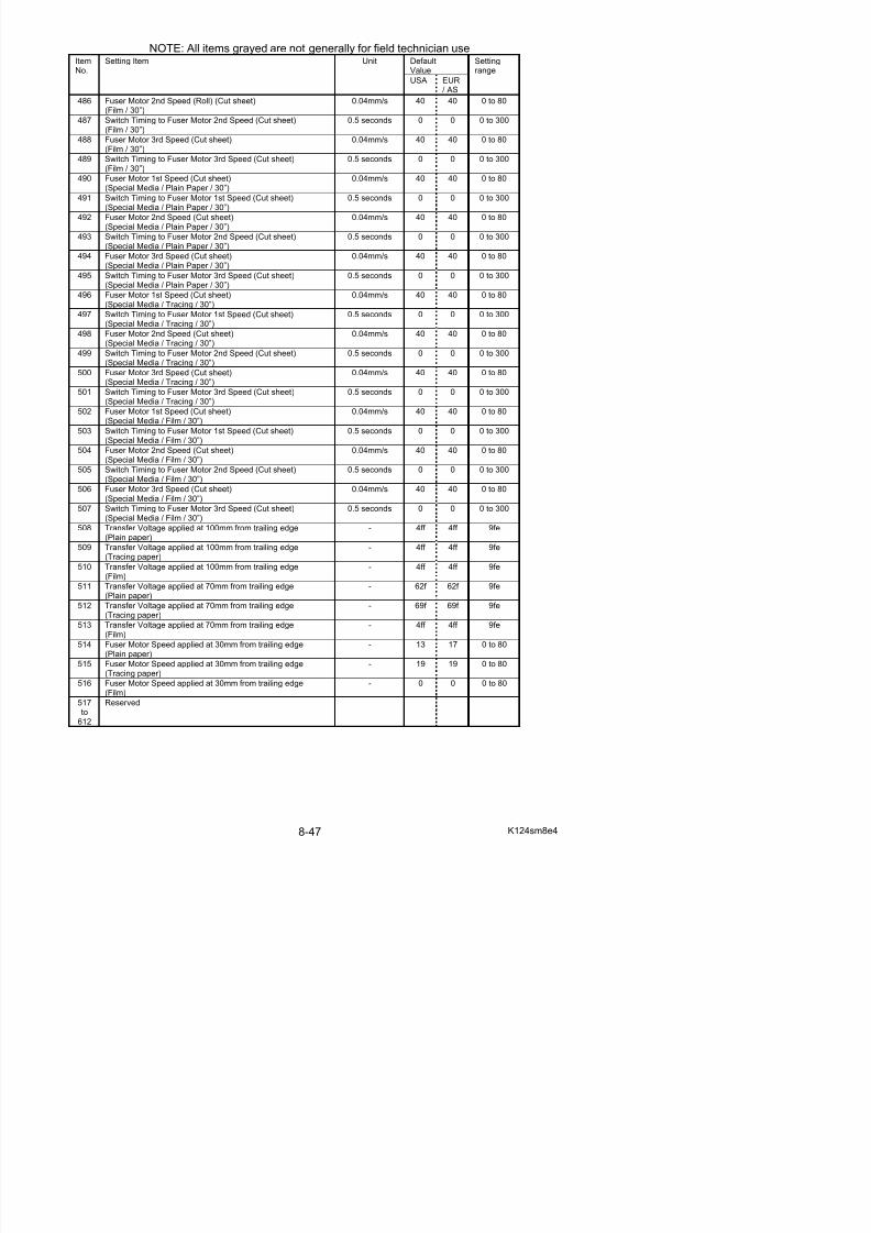
5/17/2018 KIP 7100 Service Manual Ver A_1 - slidepdf.com
http://slidepdf.com/reader/full/kip-7100-service-manual-ver-a1 489/674
615 Judgement Value for Additional Cut Length for Non standardSize Prints (18”/ 17”/ 15”/ A2)
1mm 1 1 1 to 20
616 Judgement Value for Additional Cut Length for Non-standardSize Prints (12”/ 11”/ A3)
1mm 1 1 1 to 20
617 Additional Cut Length for Non-standard Size Prints(36”/ 34”/ 30”/ A0 / B1)
1mm 0 0 0 to 35
618 Additional Cut Length for Non-standard Size Prints(24”/ 22”/ A2)
1mm 0 0 0 to 35
619 Additional Cut Length for Non-standard Size Prints(18”/ 17”/ 15”/ A2)
1mm 0 0 0 to 35
620 Additional Cut Length for Non-standard Size Prints(12”/ 11”/ A3) 1mm 0 0 0 to 35
621 Toner Supply Roller Bias 286 286 0 to 800
622 Regulation Bias 270 270 0 to 800
623 Density Sensor Standard Output 0 0 0 to 614
624 Density Sensor Analog Voltage 0 0 0 to 614
625 Print - Fuser Temperature Side(Plain) (12” / 11” / A3)
1oC 160 145 120 to 180
626 Print - Fuser Temperature Side(Tracing) (12” / 11” / A3)
1oC 160 150 120 to 180
627 Print - Fuser Temperature Side
(Film) (12” / 11” / A3)
1oC 177 170 120 to 180
628 Print - Fuser Temperature Side(Special / Plain) (12” / 11” / A3)
1oC 160 160 120 to 180
629 Print - Fuser Temperature Side(Special / Tracing) (12” / 11” / A3)
1oC 160 160 120 to 180
630 Print - Fuser Temperature Side(Special media / Film) (12” / 11” / A3)
1oC 177 170 120 to 180
631 Print - Fuser Temperature Side(Plain) (18” / 17” / 15” / A2)
1oC 160 165 120 to 180
632 Print - Fuser Temperature Side(Tracing) (18” / 17” / 15” / A2)
1oC 160 170 120 to 180
633 Print - Fuser Temperature Side(Film) (18” / 17” / 15” / A2) 1
o
C 177 170 120 to 180
634 Print - Fuser Temperature Side(Special / Plain) (18” / 17” / 15” / A2)
1oC 160 160 120 to 180
635 Print - Fuser Temperature Side(Special / Tracing) (18” / 17” / 15” / A2)
1oC 160 160 120 to 180
636 Print - Fuser Temperature Side(Special / Film) (18” / 17” / 15” / A2)
1oC 177 170 120 to 180
637 Print - Fuser Temperature Side(Plain) (24” / 22” / A1)
1oC 160 165 120 to 180
638 Print - Fuser Temperature Side
(Tracing) (24” / 22” / A1)
1oC 160 170 120 to 180
639 Print - Fuser Temperature Side(Film) (24” / 22” / A1)
1oC 177 170 120 to 180
640 Print - Fuser Temperature Side(Special / Plain) (24” / 22” / A1)
1oC 160 160 120 to 180
641 Print - Fuser Temperature Side 1oC 160 160 120 to 180
NOTE: All items grayed are not generally for field technician use
DefaultValue
ItemNo.
Setting Item Unit
USA EUR/ AS
Settingrange
650 Regulation Bias Increment forAuto Adjustment Level 2 and 3 0.5V 80 80 0 to 200
651 Total Increment of Regulation Bias Adjustment 0.5V 0 0 0 to 800
652 Density Compensation On/Off - 1 1 0 to 1
653 Minimum Density 135 135 110 to 150654 Regulation Bias Maximum 500 500 160 to 800
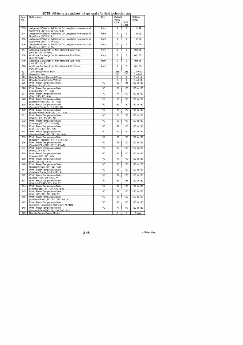
5/17/2018 KIP 7100 Service Manual Ver A_1 - slidepdf.com
http://slidepdf.com/reader/full/kip-7100-service-manual-ver-a1 490/674
g
655 Density Measure Interval at power on 1 hour 18 18 1 to 100
656 Density Measure Interval at Print Completion 1 hour 18 18 1 to 100
657 Developer Bias Increment for Auto Adjustment Level 1 and after 158 158 0 to 400
658 Reserved
659 Reserved
660 Ready - Fuser Temperature Center (Plain) 1oC 160 160 120 to 180
661 Ready - Fuser Temperature Center (Tracing) 1oC 160 170 120 to 180
662 Ready - Fuser Temperature Center (Film) 1oC 177 177 120 to 180
663 Ready - Fuser Temperature Center (Special / Plain) 1oC 160 160 120 to 180
664 Ready - Fuser Temperature Center (Special / Tracing) 1oC 160 160 120 to 180665 Ready - Fuser Temperature Center (Special / Film) 1
oC 177 170 120 to 180
666 Ready - Fuser Temperature Side (Plain) 1oC 159 159 120 to 180
667 Ready - Fuser Temperature Side (Tracing) 1oC 159 180 120 to 180
668 Ready - Fuser Temperature Side (Film) 1oC 177 170 120 to 180
669 Ready - Fuser Temperature Side (Special / Plain) 1oC 159 159 120 to 180
670 Ready - Fuser Temperature Side (Special / Tracing) 1oC 159 159 120 to 180
671 Ready - Fuser Temperature Side (Special / Film) 1oC 177 170 120 to 180
672 Fuser Motor Speed(18” / 17” / 15” / 12” / 11” / A2 / A3) (Plain)
50 50 0 to 80
673 Fuser Motor Speed
(18” / 17” / 15” / 12” / 11” / A2 / A3) (Tracing)
57 60 0 to 80
674 Fuser Motor Speed(18” / 17” / 15” / 12” / 11” / A2 / A3) (Film)
50 50 0 to 80
675 Fuser Motor Speed(18” / 17” / 15” / 12” / 11” / A2 / A3) (Special / Plain)
40 40 0 to 80
676 Fuser Motor Speed(18” / 17” / 15” / 12” / 11” / A2 / A3) (Special / Tracing)
40 40 0 to 80
677 Fuser Motor Speed(18” / 17” / 15” / 12” / 11” / A2 / A3) (Special / Fi lm)
40 40 0 to 80
678 Fuser Motor 4th Speed (Roll)(Plain Paper / A3, 12” & 11”)
0.04mm/s 34 37 0 to 80
679 Switch Timing to Fuser Motor 4th Speed (Roll)(Plain Paper / A3, 12” & 11”)
0.5 seconds 6 8 0 to 300
680 Fuser Motor 4th Speed (Roll)(Tracing / A3, 12” & 11”)
0.04mm/s 40 40 0 to 80
681 Switch Timing to Fuser Motor 4th Speed (Roll)(Tracing / A3, 12” & 11”)
0.5 seconds 0 0 0 to 300
682 Fuser Motor 4th Speed (Roll)(Film / A3, 12” & 11”)
0.04mm/s 40 40 0 to 80
683 Switch Timing to Fuser Motor 4th Speed (Roll)(Film / A3, 12” & 11”)
0.5 seconds 0 0 0 to 300
684 Fuser Motor 4th Speed (Roll)
(Special Media / Plain Paper / A3, 12” & 11”)
0.04mm/s 40 40 0 to 80
685 Switch Timing to Fuser Motor 4th Speed (Roll)(Special Media / Plain Paper / A3, 12” & 11”)
0.5 seconds 0 0 0 to 300
686 Fuser Motor 4th Speed (Roll)(Special Media / Tracing / A3, 12” & 11”)
0.04mm/s 40 40 0 to 80
687 Switch Timing to Fuser Motor 4th Speed (Roll) 0 5 seconds 0 0 0 to 300
NOTE: All items grayed are not generally for field technician use
DefaultValue
ItemNo.
Setting Item Unit
USA EUR/ AS
Settingrange
696 Fuser Motor 4th Speed (Roll)(Special Media / Plain Paper / A2, 18” & 17”)
0.04mm/s 40 40 0 to 80
697 Switch Timing to Fuser Motor 4th Speed (Roll)
(Special Media / Plain Paper / A2, 18” & 17”)
0.5 seconds 0 0 0 to 300
698 Fuser Motor 4th Speed (Roll) 0.04mm/s 40 40 0 to 80

5/17/2018 KIP 7100 Service Manual Ver A_1 - slidepdf.com
http://slidepdf.com/reader/full/kip-7100-service-manual-ver-a1 491/674
(Special Media / Tracing / A2, 18” & 17”)
699 Switch Timing to Fuser Motor 4th Speed (Roll)(Special Media / Tracing / A2, 18” & 17”)
0.5 seconds 0 0 0 to 300
700 Fuser Motor 4th Speed (Roll)(Special Media / Film / A2, 18” & 17”)
0.04mm/s 40 40 0 to 80
701 Switch Timing to Fuser Motor 4th Speed (Roll)(Special Media / Film / A2, 18” & 17”)
0.5 seconds 0 0 0 to 300
702 Fuser Motor 4th Speed (Roll)(Plain Paper / A1, 24” & 22”)
0.04mm/s 35 36 0 to 80
703 Switch Timing to Fuser Motor 4th Speed (Roll)(Plain Paper / A1, 24” & 22”) 0.5 seconds 16 16 0 to 300
704 Fuser Motor 4th Speed (Roll)(Tracing / A1, 24” & 22”)
0.04mm/s 40 40 0 to 80
705 Switch Timing to Fuser Motor 4th Speed (Roll)(Tracing / A1, 24” & 22”)
0.5 seconds 0 0 0 to 300
706 Fuser Motor 4th Speed (Roll)(Film / A1, 24” & 22”)
0.04mm/s 40 40 0 to 80
707 Switch Timing to Fuser Motor 4th Speed (Roll)(Film / A1, 24” & 22”)
0.5 seconds 0 0 0 to 300
708 Fuser Motor 4th Speed (Roll)
(Special Media / Plain Paper / A1, 24” & 22”)
0.04mm/s 40 40 0 to 80
709 Switch Timing to Fuser Motor 4th Speed (Roll)(Special Media / Plain Paper / A1, 24” & 22”)
0.5 seconds 0 0 0 to 300
710 Fuser Motor 4th Speed (Roll)(Special Media / Tracing / A1, 24” & 22”)
0.04mm/s 40 40 0 to 80
711 Switch Timing to Fuser Motor 4th Speed (Roll)(Special Media / Tracing / A1, 24” & 22”)
0.5 seconds 0 0 0 to 300
712 Fuser Motor 4th Speed (Roll)(Special Media / Film / A1, 24” & 22”)
0.04mm/s 40 40 0 to 80
713 Switch Timing to Fuser Motor 4th Speed (Roll)(Special Media / Film / A1, 24” & 22”)
0.5 seconds 0 0 0 to 300
714 Fuser Motor 4th Speed (Roll)(Plain Paper / A0, 36” & 34”) 0.04mm/s 30 30 0 to 80
715 Switch Timing to Fuser Motor 4th Speed (Roll)(Plain Paper / A0, 36” & 34”)
0.5 seconds 20 20 0 to 300
716 Fuser Motor 4th Speed (Roll)(Tracing / A0, 36” & 34”)
0.04mm/s 34 40 0 to 80
717 Switch Timing to Fuser Motor 4th Speed (Roll)(Tracing / A0, 36” & 34”)
0.5 seconds 20 0 0 to 300
718 Fuser Motor 4th Speed (Roll)(Film / A0, 36” & 34”)
0.04mm/s 40 40 0 to 80
719 Switch Timing to Fuser Motor 4th Speed (Roll)(Film / A0, 36” & 34”)
0.5 seconds 0 0 0 to 300
720 Fuser Motor 4th Speed (Roll)(Special Media / Plain Paper / A0, 36” & 34”)
0.04mm/s 40 40 0 to 80
721 Switch Timing to Fuser Motor 4th Speed (Roll)(Special Media / Plain Paper / A0, 36” & 34”)
0.5 seconds 0 0 0 to 300
722 Fuser Motor 4th Speed (Roll) 0.04mm/s 40 40 0 to 80
NOTE: All items grayed are not generally for field technician use
DefaultValue
ItemNo.
Setting Item Unit
USA EUR/ AS
Settingrange
732 Fuser Motor 4th Speed (Roll)(Special Media / Plain Paper / 30”)
0.04mm/s 40 40 0 to 80
733 Switch Timing to Fuser Motor 4th Speed (Roll)
(Special Media / Plain Paper / 30”)
0.5 seconds 0 0 0 to 300
734 Fuser Motor 4th Speed (Roll)(S i l M di / T i / 30”)
0.04mm/s 40 40 0 to 80
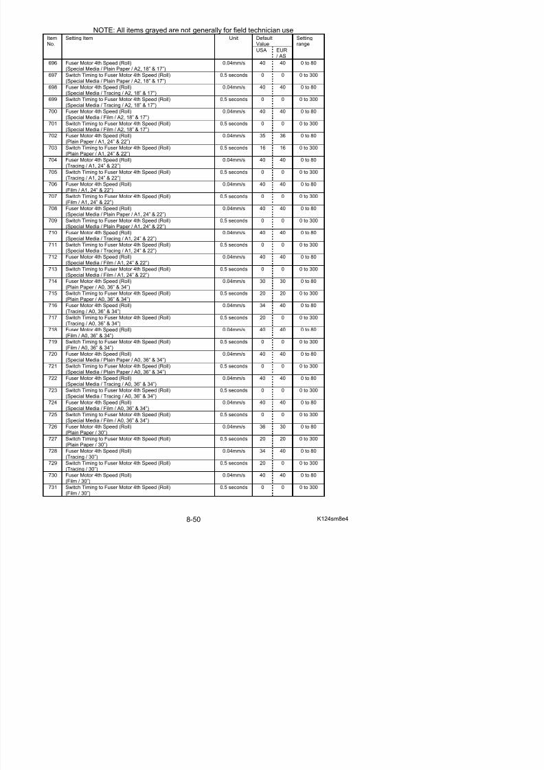
5/17/2018 KIP 7100 Service Manual Ver A_1 - slidepdf.com
http://slidepdf.com/reader/full/kip-7100-service-manual-ver-a1 492/674
(Special Media / Tracing / 30”)
735 Switch Timing to Fuser Motor 4th Speed (Roll)(Special Media / Tracing / 30”)
0.5 seconds 0 0 0 to 300
736 Fuser Motor 4th Speed (Roll)(Special Media / Film / 30”)
0.04mm/s 40 40 0 to 80
737 Switch Timing to Fuser Motor 4th Speed (Roll)(Special Media / Film / 30”)
0.5 seconds 0 0 0 to 300
738 Standby - Fuser Temperature Center 1oC 167 167 120 to 180
739 Standby - Fuser Temperature Side 1oC 155 155 120 to 180
740 Assist Fan Off Timing (18” / 17” / 15” / A2) 8 4 0 to 8741 Assist Fan Off Timing (24” / 22” / A1) 8 4 0 to 8
742 Assist Fan Off Timing (36” / 34” / 30” / A0 / B1) 8 6 0 to 8
743 Fuser Motor Speed applied at 100mm from trailing edge(36” / 34” / 30” / A0 / B1) (Plain)
0 0 0 to 80
744 Fuser Motor Speed applied at 100mm from trailing edge(36” / 34” / 30” / A0 / B1) (Tracing)
0 0 0 to 80
745 Fuser Motor Speed applied at 100mm from trailing edge(36” / 34” / 30” / A0 / B1) (Film)
0 0 0 to 80
746 Roll 2 Forward Standby 0 0 0 to 1
747 Roll 2 Forward Standby Position Adjustment mm 0 0 0 to 50
748 Roll 2 Rewind Timer minute 15 15 1 to 15749 Tracing Mode 0 0 0 to 1
750 Roll 1 Setting Mode 0 0 0 to 1
751 Disable HV Error Detection Mode 0 0 0 to 1
752 (Reserved)
753 Auto Initial Cut After Long Print (Length) 100mm 10 10 10 to 60
754 Auto Initial Cut After Long Print (Number of sheet) 0 0 0 to 3
755 Length for Forced Initial Cut Before Print mm 594 594 210 to 600
756 Leading Registration for Paper Tray mm
757 Trailing Margin for Paper Tray mm
758 Side Registration for Paper Tray mm
8. 6. 3 Setting Item Explanation
Item No. starts with “4”. For example, KIP Service Software shows 4000, this section shows“No.000”.
8. 6. 3. 1 Leading Registration (No. 000 & 001)
It is possible to specify where to start printing the image at the leading edge of the media.If i th tti l b “ 1 “ th h d f i i hift d 1 d d t d th
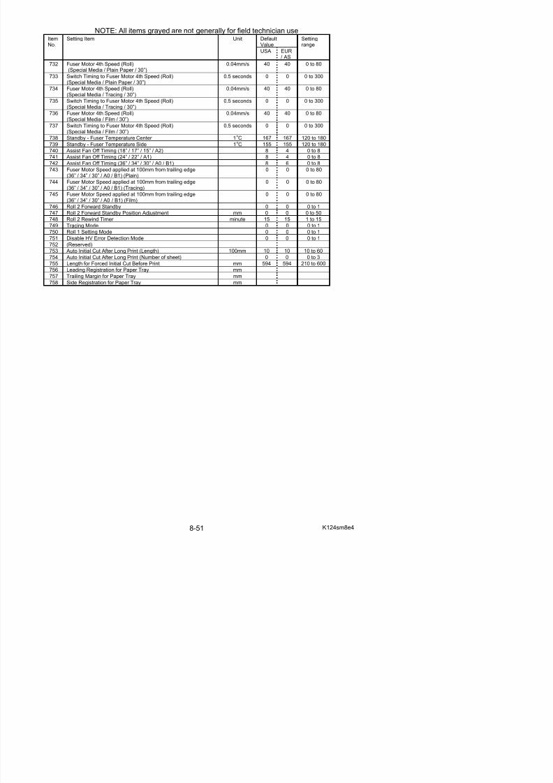
5/17/2018 KIP 7100 Service Manual Ver A_1 - slidepdf.com
http://slidepdf.com/reader/full/kip-7100-service-manual-ver-a1 493/674
If you increase the setting value by “+1 “, the head of image is shifted 1mm downward toward thetrailing edge As a result the leading margin becomes larger.
Default valueItem No. Setting Item
USA EUR/ASIA
Settingrange
Step of increment
000 Leading Registration (Roll paper) 19 19 1 to 40 1mm001 Leading Registration (Cut sheet paper) 19 19 1 to 40 1mm
Leading Registration
value is increased. value is decreased.
8. 6. 3. 2 Trailing Margin (No. 002 & 003)It is possible to adjust the length of trailing margin.The length of trailing margin becomes 1mm longer if you Increase the setting value by “+1 “.
Default valueItem No. Setting ItemUSA EUR/ASIA
Settingrange
Step of increment
002 Trailing Margin (Roll paper) 9 9 1 to 40 1mm
003 Trailing Margin (Cut sheet paper) 10 10 1 to 40 1mm
Setting value is increased. Setting value is decreased.
8. 6. 3. 3 Side Margin (Left & Right) (No. 004)
It is possible to adjust the amount of side margin. (Both left and right)Each side margin becomes 1mm wider if you increase the setting value.(As a result the width of print image becomes 2mm narrower.)
Default value
USA EUR/ASIA
Setting range Step of increment
3 3 0 to 20 1mm
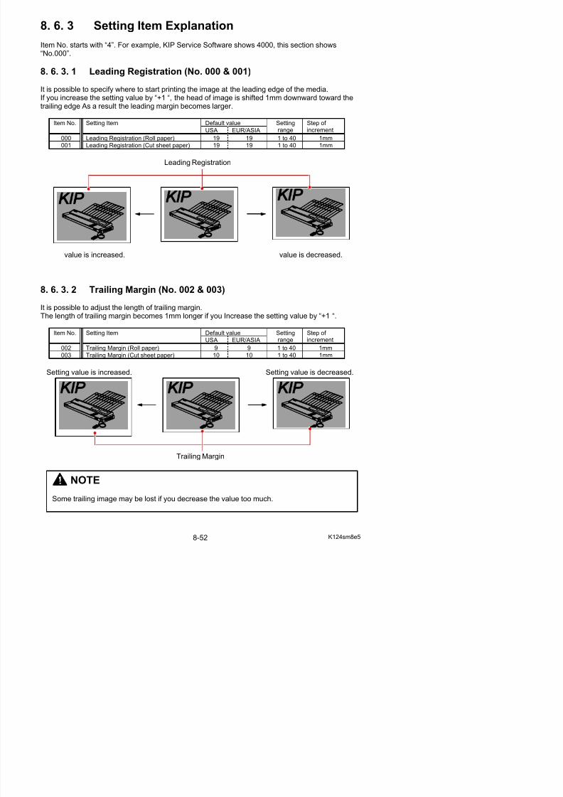
5/17/2018 KIP 7100 Service Manual Ver A_1 - slidepdf.com
http://slidepdf.com/reader/full/kip-7100-service-manual-ver-a1 494/674
Setting value is increased.
Side Margin
Setting value is decreased.
NOTE
Image quality created with a reduced side margin (less than 3 in the setting value) is notguaranteed.
8. 6. 3. 4 Side Registration (No. 005 to 007)
It is possible to specify where to start printing the image at the side edge of the media.If you increase the setting value by “+1 “, image is shifted 0.1mm to the right.
Default valueItem No. Setting Item
USA EUR/ASIA
Settingrange
Step of increment
005 Side Registration (Cutsheet) 50 50 0 to 100 0.1mm
006 Side Registration (Roll 1) 50 50 0 to 100 0.1mm
007 Side Registration (Roll 2) 50 50 0 to 100 0 1mm
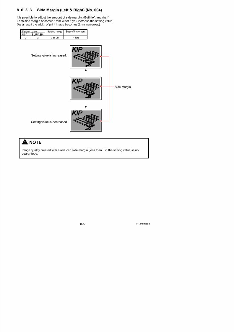
5/17/2018 KIP 7100 Service Manual Ver A_1 - slidepdf.com
http://slidepdf.com/reader/full/kip-7100-service-manual-ver-a1 495/674
007 Side Registration (Roll 2) 50 50 0 to 100 0.1mm
Setting value is increased.
Side Registration
Setting value is decreased.
8. 6. 3. 5 LED Strobe Time for Main Pixel of each Block(No.008 to 010)
It is possible to make the whole image of each Image Block (A, B and C) darker or lighter independently by changing the LED Strobe Time for the Main Pixels. As a result an even image density can be accomplished among 3 Image Blocks.The whole image of the concerning Image Block becomes darker if you increase the setting value.
Default valueItem No. Setting Item Setting Step of
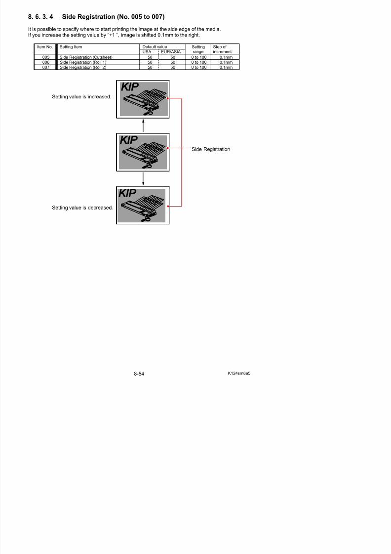
5/17/2018 KIP 7100 Service Manual Ver A_1 - slidepdf.com
http://slidepdf.com/reader/full/kip-7100-service-manual-ver-a1 496/674
USA EUR/ASIA range increment
008 LED Strobe Time for Main Pixel(Image Block A : Left)
6 6 0 to 9 1 micro second
009 LED Strobe Time for Main Pixel(Image Block B : Center)
6 6 0 to 9 1 micro second
010 LED Strobe Time for Main Pixel(Image Block C : Right)
6 6 0 to 9 1 micro second
Block A Block B Block C
Setting value is decreased. Default Setting value is increased.
Decrease the value of “008” to make the imageof Block A lighter.
Increase the value of “010” to make the imageof Block C darker.
Main pixel
Supplementalpixel
NOTE
(1) The LED Strobe Times specified in these 008, 009 and 010 are directly applied to theTest Print.If the setting values are 7 (for 008), 8 (for 009) and 9 (for 010), for example, theactual LED Strobe Times are also 7 (for block A), 8 (for block B) and 9 (for block C).
In case of Test Print008 7 i d
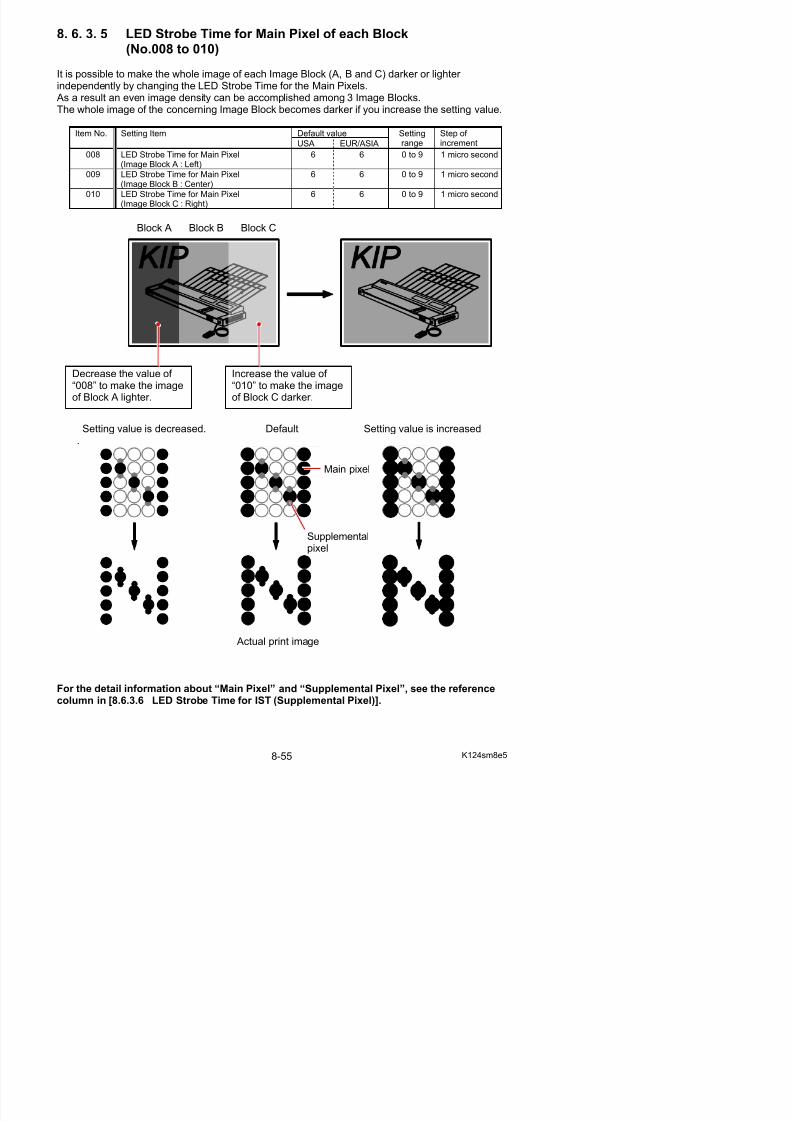
5/17/2018 KIP 7100 Service Manual Ver A_1 - slidepdf.com
http://slidepdf.com/reader/full/kip-7100-service-manual-ver-a1 497/674
008: 7 microseconds009: 8 microseconds010: 9 microseconds
Block A Block B Block C(7) (8) (9)
But in case of a copy or a plot, the density command (LED Strobe Time) sent from theoutput device (image scanner or controller) is applied to the Image Block A. And only the difference of setting values among 008, 009 and 010 are applied to theactual LED Strobe Time.If the density command from the output device is 5 microsecond and the setting values
are 7 (for 008), 8 (for 009) and 9 (for 010), for example, the actual LED Strobe Timesare 5 (for block A), 6 (for block B) and 7 (for block C).
In case of copy or plotDensity command from output device: 5 microseconds008: 7 microseconds009: 8 microseconds010: 9 microseconds
Block A Block B Block C(5) (6) (7)
8. 6. 3. 6 LED Strobe Time for IST (Supplemental Pixel) of each Block(No.011 to 013)
If such image as a diagonal line looks too weak, you can make it clearer by changing the LEDStrobe Time for the Supplemental Pixels.The adjustment is available for each Image Block independently. A diagonal line comes to look clearer if you increase the setting value, as the LED Strobe Time for
the Supplemental Pixels becomes longer.
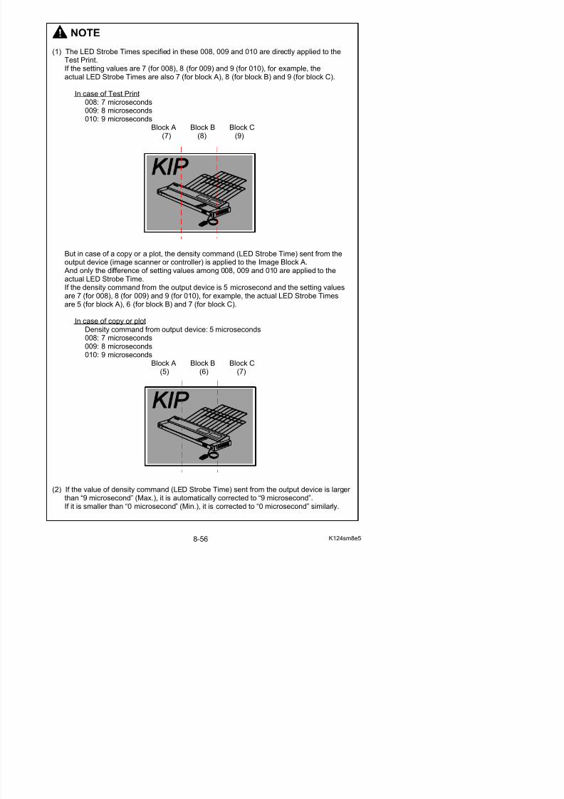
5/17/2018 KIP 7100 Service Manual Ver A_1 - slidepdf.com
http://slidepdf.com/reader/full/kip-7100-service-manual-ver-a1 498/674
Default valueItem No. Setting Item
USA EUR/ASIA
Settingrange
Step of increment
011 LED Strobe Time for Supplemental Pixel(Image Block A : Left)
0 0 0 to 9 1 micro second
012 LED Strobe Time for Supplemental Pixel(Image Block B : Center)
0 0 0 to 9 1 micro second
013 LED Strobe Time for Supplemental Pixel
(Image Block C : Right)
0 0 0 to 9 1 micro second
Block A Block B Block C
Increase the setting values of “011” and “013”to make the images of these blocks clearer.
Setting value is decreased. Default Setting value is increased.
Main pixel
Supplemental
Normally the KIP 7100 takes 600 times of image exposure per inch for the vertical directionas its resolution is 600DPI. Pixels created by this normal timing are called [Main Pixel].When a specific image pattern (like a diagonal line) is printed, however, the KIP 7100 will
make additional image exposure between vertically neighboring 2 Main Pixels. Thisadditional image exposure is completed within a very short time. The pixel created by thisadditional process is called [Supplemental Pixel]
Reference
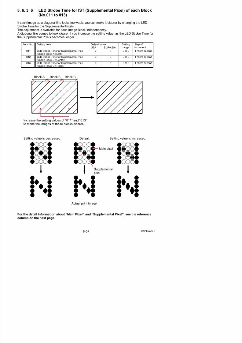
5/17/2018 KIP 7100 Service Manual Ver A_1 - slidepdf.com
http://slidepdf.com/reader/full/kip-7100-service-manual-ver-a1 499/674
additional process is called [Supplemental Pixel].
Normal image pattern In case of a certainimage pattern
Main PixelsSupplemental Pixels
Main Pixels
Supplemental Pixels are provided so as to fill the space between Main Pixels.When we compare a vertical / horizontal 1 dot line and a diagonal 1 dot line, for example, thediagonal one looks vague and rough although the vertical / horizontal one looks clear and
smooth.This is because the diagonal line has a wider space between Main Pixels than the vertical /horizontal one.If this space is filled with the Supplemental Pixel, diagonal line comes to look smoother andclearer.
No Supplemental Pixel Supplemental Pixels are provided.
Direction of print
8. 6. 3. 7 Vertical Alignment of Pixels between Image Blocks(No.014 & 015)
It is possible to align the pixels between Image Blocks if there is a gap of pixels.The Image Block B is the standard, and both the Image Blocks A and C can be shifted vertically.If you increase the setting value by “+1”, the whole pixels of the concerning Image Block is shifted“1 line (pixel)” to the trailing edge side.
These can be used if a horizontal line has a step at the border of the Blocks.
Default valueItem No Setting Item Setting Step of
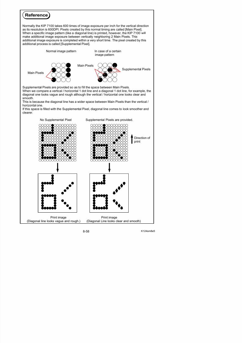
5/17/2018 KIP 7100 Service Manual Ver A_1 - slidepdf.com
http://slidepdf.com/reader/full/kip-7100-service-manual-ver-a1 500/674
Default valueItem No. Setting Item
USA EUR/ASIA
Settingrange
Step of increment
014 Horizontal Alignment of Pixels betweenImage Blocks A & B
8 8 2 to 14 1 pixel
015 Horizontal Alignment of Pixels betweenImage Blocks B & C
8 8 2 to 14 1 pixel
Decrease the value of “014” to shift the block Ato the leading edge side.
Decrease the value of “015” to shift the block Cto the trailing edge side.
8. 6. 3. 8 Cut Length 1 (length information provided)(No.016)
It is possible to make the print length longer or shorter.This setting is applied when the print command (plot & copy) is provided with the lengthinformation. (this is command used on all standard pages printed from the IPS)If you increase the setting value by “+1”, the print length becomes 1mm longer.
Default value
USA EUR/ASIA
Setting range Step of increment
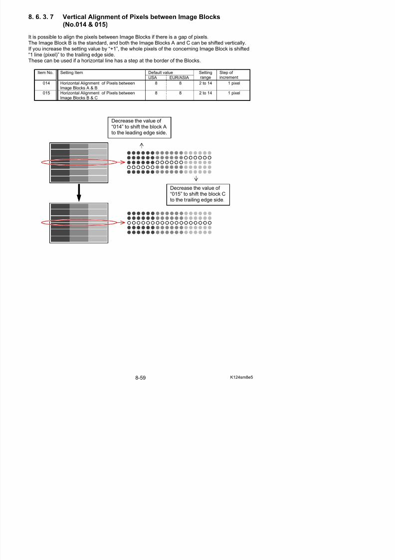
5/17/2018 KIP 7100 Service Manual Ver A_1 - slidepdf.com
http://slidepdf.com/reader/full/kip-7100-service-manual-ver-a1 501/674
USA EUR/ASIA
50 50 0 to 100 1mm
Setting value is increased. Setting value is decreased.
Cut length
8. 6. 3. 9 Cut Length 2 (length information not provided)(No.017)
It is possible to make the print length longer or shorter.This setting is applied when the print command (plot & copy) is not provided with the lengthinformation. (This is may only be used on LONG prints over 6 meters on the IPS) If you increase the setting value by “+1”, the print length becomes 1mm longer.
Default value
USA EUR/ASIA
Setting range Step of increment
50 50 0 to 100 1mm
Setting value is increased. Setting value is decreased.
8. 6. 3.10 Cut Length 3 (Compensation of the length of a long print)(No.018)
When you make a long print, the actual print length may become shorter than expected becausethe paper is likely to shrink. It is possible in this mode to compensate the print length manually.
The length of long print is not compensated directly, but it is indirectly compensated by correcting
the length of A1 print.If you increase the setting value by “+1”, the length of A1 print becomes 0.1mm longer per 10mm.
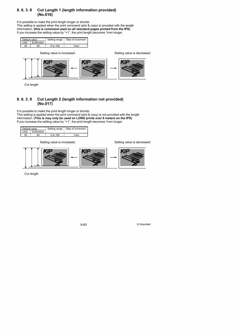
5/17/2018 KIP 7100 Service Manual Ver A_1 - slidepdf.com
http://slidepdf.com/reader/full/kip-7100-service-manual-ver-a1 502/674
Default valueUSA EUR/ASIA
Setting range Step of increment
475 475 0 to 999 0.1mm
[Example of adjustment]
1. Supposing the actual length of a long print is shorter than expected.
Expected length Actual length
Actual length is shorter than expected
0
1 0 0
5 0
A B C
0
1 0 0
5 0
A B C
NOTE
It is necessary to finish the adjustment of Cut Length 1 (No.016) before starting theadjustment in this Cut Length 3 (No.018).
2. Make an A1 (841mm long) or 34” long print.Measure the actual length of this A1 or 34” print to know how long millimeter it is shorter thanexpected.
(Example: Print out is 838mm, so it is 3mm shorter than expected.)
Expected length Actual length
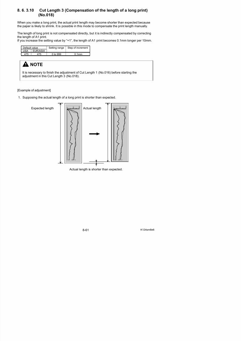
5/17/2018 KIP 7100 Service Manual Ver A_1 - slidepdf.com
http://slidepdf.com/reader/full/kip-7100-service-manual-ver-a1 503/674
A1 or 34”
3mm
3. Necessary value for the compensation is 10 times as long as the difference between actuallength and expected length.It is “30” in this example. (3mm x 10 = 30)
Specify “30” as the setting value of No.018.
4. Make a long print.The actual print out will be as long as expected.
Expected length Actual length 0
1 0 0
5 0 0
1 0 0
5 0
8. 6. 3.11 Leading Margin (No. 019)
It is possible to adjust the length of the leading margin. An image portion that corresponds to the given length of the leading margin is not printed.The length of the leading margin becomes 0.1mm longer if you Increase the setting value by “+1 “.
Changing the value to “0” removes whole the margin, thus a portion image on the leading edge willappear.
Default Value Setting Range Step of increment
30 0 t 50 0 1
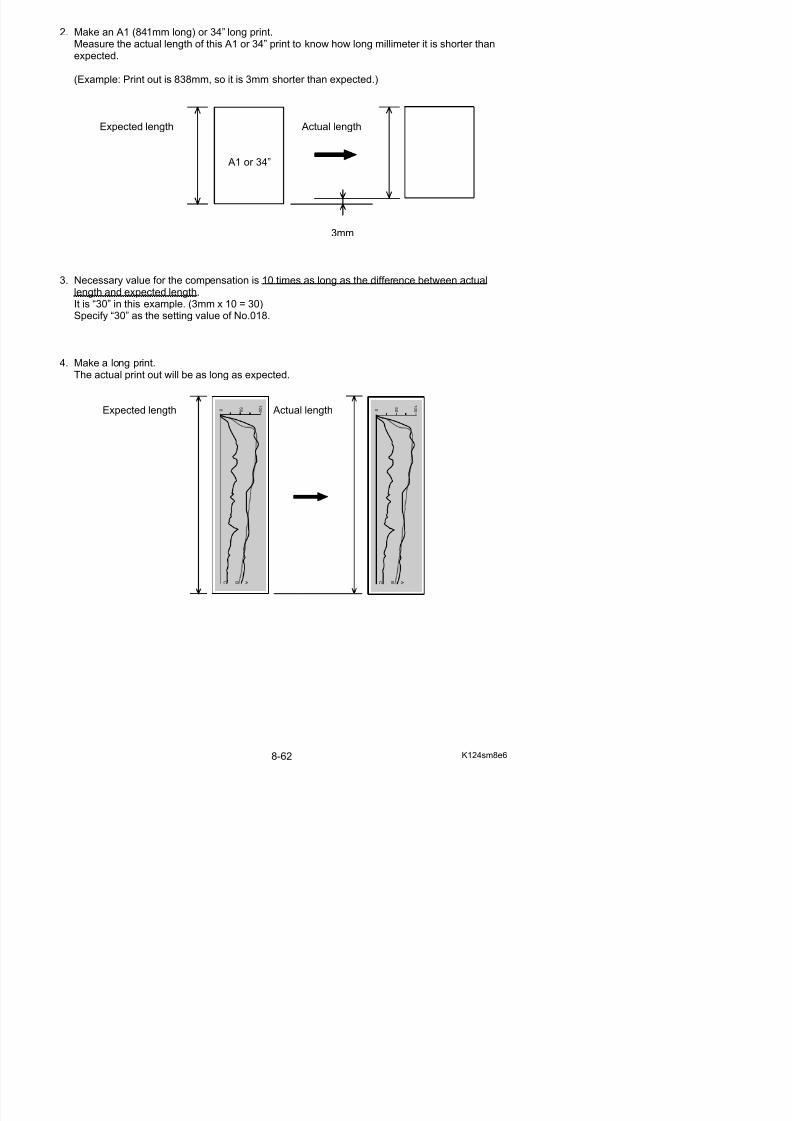
5/17/2018 KIP 7100 Service Manual Ver A_1 - slidepdf.com
http://slidepdf.com/reader/full/kip-7100-service-manual-ver-a1 504/674
30 0 to 50 0.1mm
Default: 30 A 3mm Leading Margin added to leading edge.
Hides the corresponding part of image.
Example: 0Leading Margin disappears.
Corresponding part of image printed.
8. 6. 3.12 Cut Length 4 (Individual Compensation for Roll 2) (No.020)
It is possible to compensate the print length of Roll 2 individually.This setting would be used if a different cut length is provided to Roll 1 and Roll 2.
Measure the length gap between a piece of A1 size sheet from each Roll 1 and 2.
If you increase the setting value by “+1”, the print length of Roll 2 becomes 0.16mm longer.
Default Value Setting Range Step of increment
50 0 to 100 0 16mm
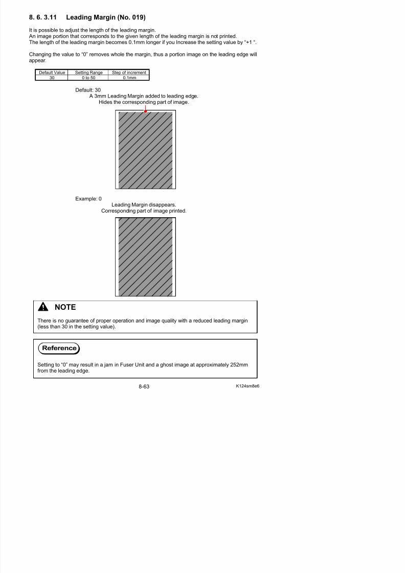
5/17/2018 KIP 7100 Service Manual Ver A_1 - slidepdf.com
http://slidepdf.com/reader/full/kip-7100-service-manual-ver-a1 505/674
50 0 to 100 0.16mm
Example: A1 from Roll 1 A1 from Roll 2
Sheet from Roll 2 is shorter
Increase the value
A1 from Roll 1 A1 from Roll 2 (compensated)
Same length
NOTE
8. 6. 3.13 Developer Bias (No.022 to 027)
It is possible to make the print density darker or lighter by adjusting the Developer Bias (NegativeDeveloper Roller Bias).The print density becomes lighter if you increase the setting value.
Default valueItem No. Setting Item
USA EUR/ASIA
Settingrange
Step of increment
022 Developer Bias (Plain paper) 161 161 0 to 4FF 1
023 Developer Bias (Tracing paper) 161 161 0 to 4FF 1
024 Developer Bias (Film) 161 161 0 to 4FF 1
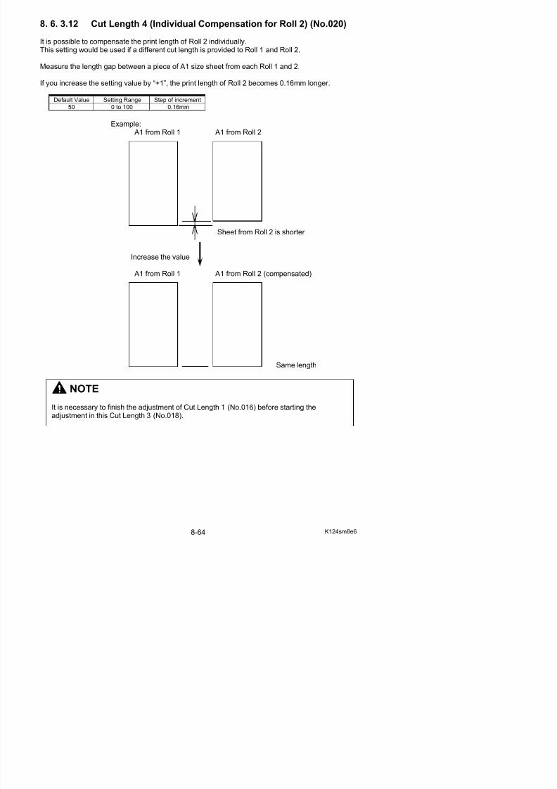
5/17/2018 KIP 7100 Service Manual Ver A_1 - slidepdf.com
http://slidepdf.com/reader/full/kip-7100-service-manual-ver-a1 506/674
025 Developer Bias(Special media / Plain paper)
161 161 0 to 4FF 1
026 Developer Bias(Special media / Tracing paper)
161 161 0 to 4FF 1
027 Developer Bias (Special media / Film) 161 161 0 to 4FF 1
Setting value is increased. Setting value is decreased.
8. 6. 3.14 Developer Bias compensation - 1st Drum revolution
(No.028)
It is possible to compensate the Developer Bias only for the 1st Drum revolution.The print density becomes lighter if you increase the setting value.(Developer Bias is not compensated at all if the setting value is “0”)
Default value
USA EUR/ASIA
Setting range Step of increment
0 0 0 to 255 1
Density of leading area is darker. Setting value is increased.(Even density)
NOTE
Please adjust the Developer Bias while checking the actual voltage with the multi-meter.
8. 6. 3.15 Transfer Voltage (No.029 to 034)
It is possible to adjust the analog voltage outputted to the Transfer Corona during the print cycle.
Default valueItem No. Setting Item
USA EUR/ASIA
Settingrange
Step of increment
029 Transfer Corona Analog Voltage (Plain paper) 366 366 0 to 4FF 1
030 Transfer Corona Analog Voltage (Tracing paper) 28A 28A 0 to 4FF 1
031 Transfer Corona Analog Voltage (Film) 28A 28A 0 to 4FF 1032 Transfer Corona Analog Voltage
(Special media / Plain paper)292 292 0 to 4FF 1
033 Transfer Corona Analog Voltage 292 292 0 to 4FF 1
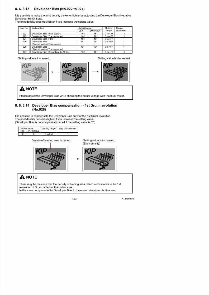
5/17/2018 KIP 7100 Service Manual Ver A_1 - slidepdf.com
http://slidepdf.com/reader/full/kip-7100-service-manual-ver-a1 507/674
033 Transfer Corona Analog Voltage(Special media / Tracing paper)
292 292 0 to 4FF 1
034 Transfer Corona Analog Voltage(Special media / Film)
292 292 0 to 4FF 1
8. 6. 3.16 Separation Corona ON Timing (No.035)
It is possible to adjust the timing that the Separation Corona starts discharging during the printcycle.If you increase the setting value by “+1”, the timing to start discharging is 1mm delayed.
Default value
USA EUR/ASIA
Setting range Step of increment
50 50 0 to 100 1mm
NOTEPlease adjust Transfer Corona Analog Voltage while checking the actual voltage with themulti-meter.
8. 6. 3.17 Transfer Corona ON Timing (No.037)
It is possible to adjust the timing that the Transfer Corona starts discharging during the print cycle.If you increase the setting value by “+1”, the timing to start discharging is 1mm delayed.
Default value
USA EUR/ASIA
Setting range Step of increment
48 48 0 to 100 1mm
NOTE
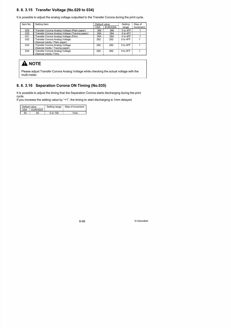
5/17/2018 KIP 7100 Service Manual Ver A_1 - slidepdf.com
http://slidepdf.com/reader/full/kip-7100-service-manual-ver-a1 508/674
You may lose some leading image as the following example if you increase the setting valuetoo much, because the timing to start discharging is too much delayed.
Normal Setting value is increased too much.
Transfer Corona startsdischarging at this point.
8. 6. 3.18 Transfer Corona OFF Timing (No.038)
It is possible to adjust the timing that the Transfer Corona stops discharging during the print cycle.If you increase the setting value by “+1”, the timing to stop discharging is 1mm delayed.
Default value
USA EUR/ASIA
Setting range Step of increment
20 20 0 to 100 1mm
NOTE
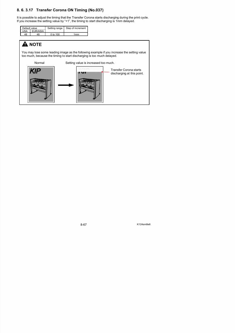
5/17/2018 KIP 7100 Service Manual Ver A_1 - slidepdf.com
http://slidepdf.com/reader/full/kip-7100-service-manual-ver-a1 509/674
You may lose some trailing image as the following example if you decrease the setting valuetoo much, because the Transfer Corona stops discharging too early.
Normal Setting value is increased too much.
Transfer Corona stopsdischarging at this point.
8. 6. 3.19 Print - Fuser Temperature Center (No.039 to 044)
It is possible to adjust the center part of Fuser Temperature in a print cycle.You can specify the temperature for each type of media separately.The Fuser Temperature becomes 1 degree higher if you increase the setting value by “+1”.
Default valueItem No. Setting Item
USA EUR/ASIA
Settingrange
Step of increment
039 Print - Fuser Temperature Center (Plain paper )
160 165 120 to 180 1oC
040 Print - Fuser Temperature Center (Tracing paper)
160 170 120 to 180 1oC
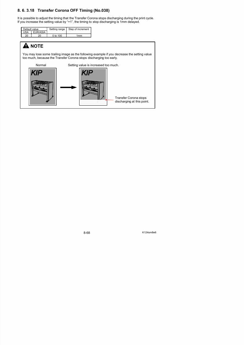
5/17/2018 KIP 7100 Service Manual Ver A_1 - slidepdf.com
http://slidepdf.com/reader/full/kip-7100-service-manual-ver-a1 510/674
(Tracing paper)
041 Print - Fuser Temperature Center (Film)
177 170 120 to 180 1oC
042 Print - Fuser Temperature Center (Special media / Plain paper)
160 160 120 to 180 1oC
043 Print - Fuser Temperature Center (Special media / Tracing paper)
160 160 120 to 180 1oC
044 Print - Fuser Temperature Center (Special media / Film)
177 177 120 to 180 1oC
Setting value of 039 to 044(Example: Film 170oC)
(oC)
0 (Time)
Turn on Ready Print Job
Reference
(1) The both sides part of Fuser Temperature will be controlled by Print - Fuser TemperatureSide (No. 625 to 648) separately.
8. 6. 3.20 Fuser Temperature to start idling (No.045)
It is possible to decide the temperature to start idling.When the Fuser Temperature reaches the value specified in this No.045 during the warming up,the Fuser Motor starts rotating to drive the Fuser Roller (idling).
Default value
USA EUR/ASIA
Setting range Step of increment
120 120 100 to 140 1oC
S tti l f 039 t 044
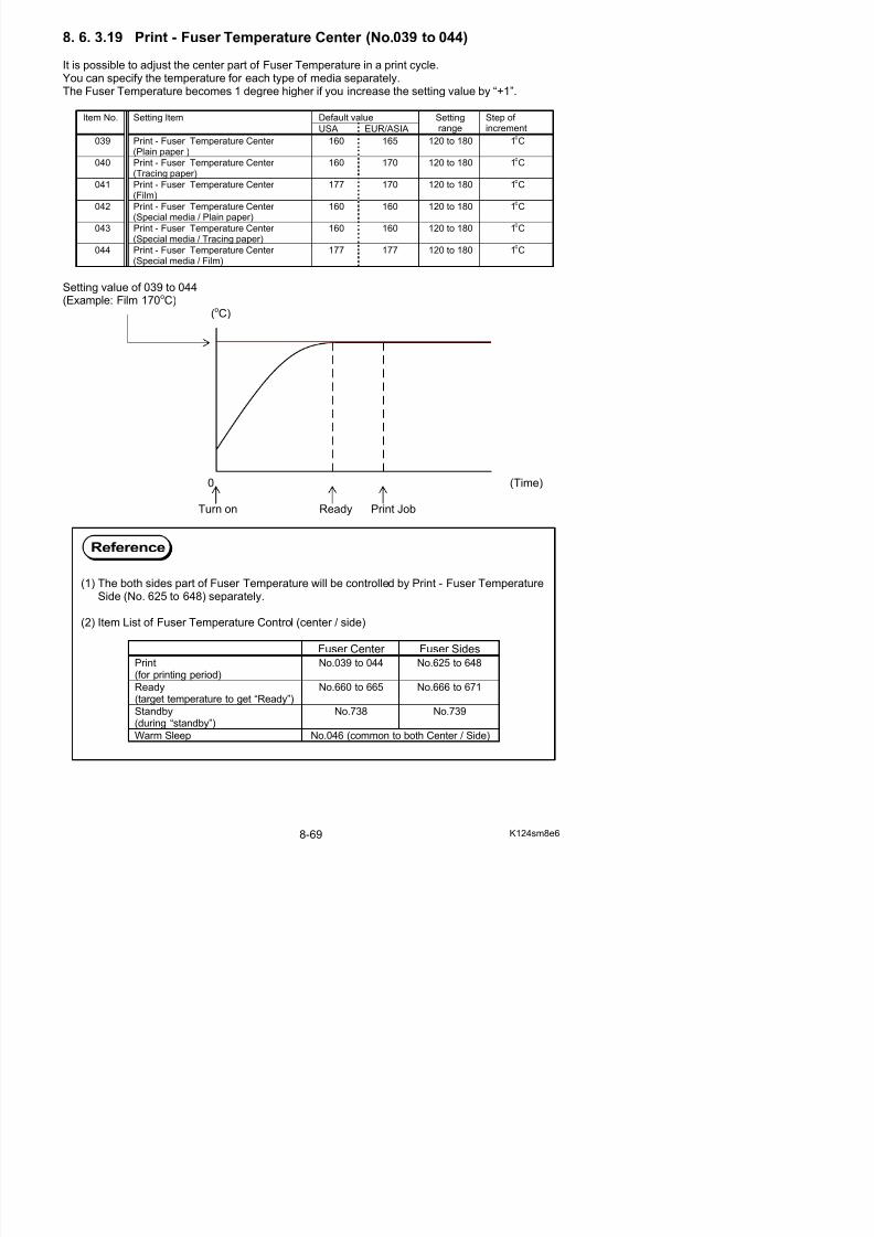
5/17/2018 KIP 7100 Service Manual Ver A_1 - slidepdf.com
http://slidepdf.com/reader/full/kip-7100-service-manual-ver-a1 511/674
Setting value of 039 to 044(Example : 160 oC)
(oC)
Setting value of 045(Example: 140 oC)
0 (Time)Ready (Idling stops.)
Turn on Idling starts.
8. 6. 3.21 Warm Sleep – Fuser Temperature (No.046)
It is possible to decide the temperature which is maintained in the Warm Sleep.
Default value
USA EUR/ASIA
Setting range Step of increment
100 100 100 to 160 1oC
Setting value of 738, 739(Example: 160 oC)
8. 6. 3.22 Fuser Temperature Control Range (No.048 & 049)
It is possible to specify the control range of temperature of Fuser Roller.
If you specify some setting value “X” on these No.048 and 049, for example, you can decide thehighest limit and the lowest one of the control range of temperature.The highest limit is “Fuser Temperature (Decided in No.039 to 044)” plus the setting value “X”. And the lowest one is “Fuser Temperature” minus “X”.
The Fuser Lamp continues to light up when the temperature of Fuser Roller is colder than thehighest limit, and it is put out when the temperature reaches the highest limit.
f
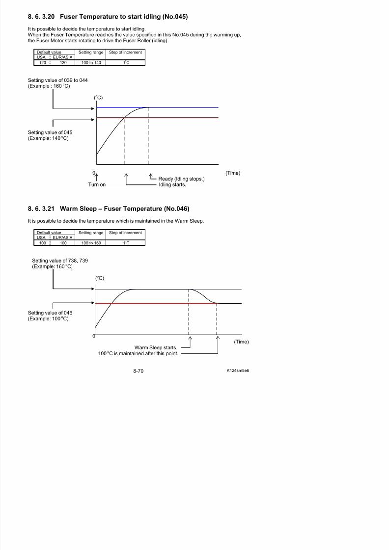
5/17/2018 KIP 7100 Service Manual Ver A_1 - slidepdf.com
http://slidepdf.com/reader/full/kip-7100-service-manual-ver-a1 512/674
The Fuser Roller gradually gets colder after that, and the Fuser Lamp lights again when thetemperature reaches the lowest limit.
Control range can be decided separately to each condition “in the print cycle” and “stand by”.
Default valueItem No. Setting ItemUSA EUR/ASIA
Settingrange
Step of increment
048 Fuser Temperature Control Range(In the print cycle)
1 1 1 to 6 1oC
049 Fuser Temperature Control Range(Stand by)
2 2 1 to 6 1oC
Example: Value of No.048 (Fuser Temperature Control Range) is “10”
Value of No.739 Standby - Fuser Temperature Side) is “160”
Highest limit of control range Standby Fuser Temperature(170 oC) (160 oC)
Fuser Lamp turns OFF.(oC)
Lowest limit of control range Fuser Lamp turns ON.(150 oC)
0 (Ti )
8. 6. 3.23 Reaction Time of Toner Supply Motor (No.050)
It is possible to change the reaction time of Toner Supply Motor.“Reaction time” is the time taken until the Toner Supply Motor starts working since “Toner Low”has been detected.The reaction time becomes 1 second longer if you increase the setting value by “+1”.
Default value
USA EUR/ASIA
Setting range Step of increment
15 15 1 to 30 1 second
Toner Low Motor starts working Motor stops
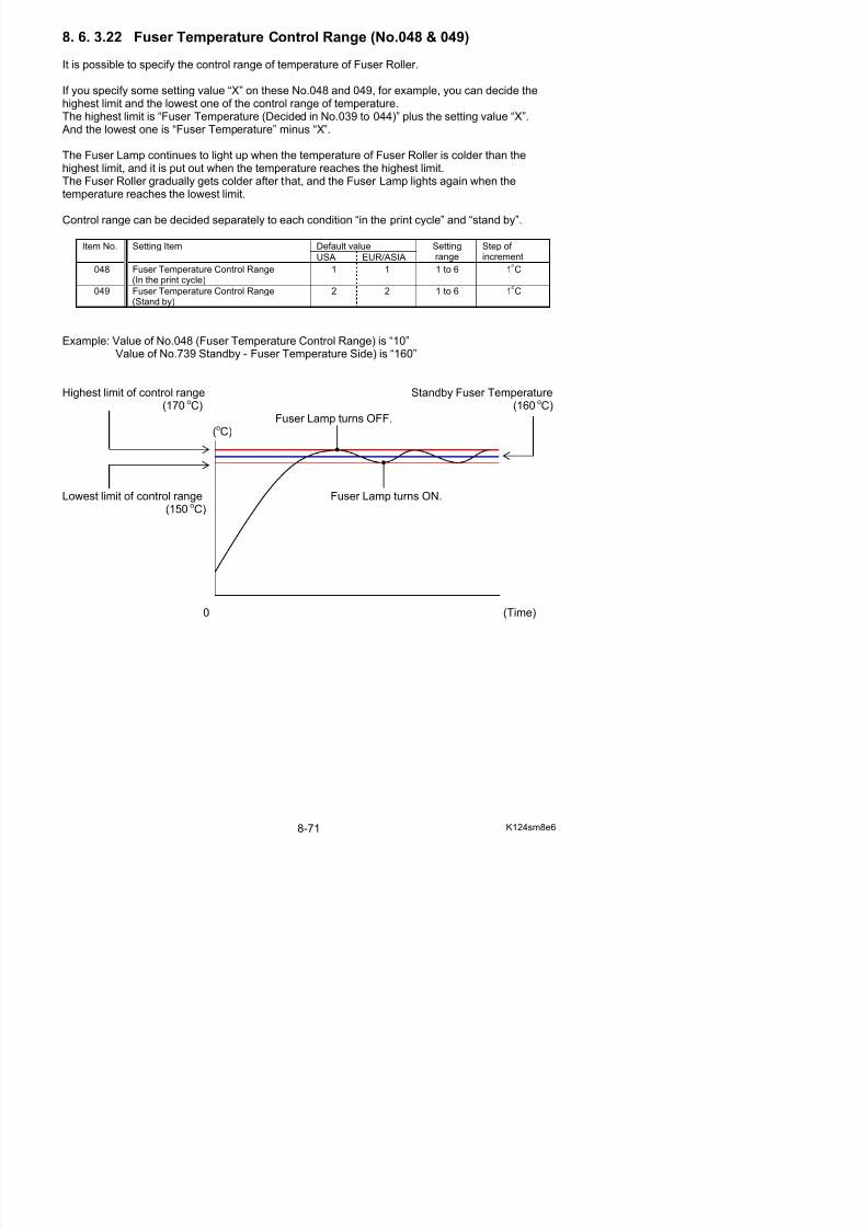
5/17/2018 KIP 7100 Service Manual Ver A_1 - slidepdf.com
http://slidepdf.com/reader/full/kip-7100-service-manual-ver-a1 513/674
Toner Low Motor starts working Motor stops
(Time)
Setting value of No.050
8. 6. 3.24 Toner Supply Motor ON Time (No.051)
It is possible change the time the Toner Supply Motor works (ON time).
The ON time becomes 1 second longer if you increase the setting value.
Default value
USA EUR/ASIA
Setting range Step of increment
10 10 1 to 15 1 second
Toner Low Motor starts working Motor stops
(Time)
NOTE
The reaction time may be too long if the image gets lighter and lighter when you make largevolume prints continuously.
In this case try to decrease the setting value of No.050 to shorten the reaction time.
8. 6. 3.25 Dot Enhancement Level (Dither) (No.052)
It is possible to validate the Dot Enhancement function which makes an isolated dot look clearer. An isolated dot image is more emphasized if you increase the setting value.
Setting value Contents
1(Default in USA, EUR & ASIA)
Emphasized
2 More emphasized3 Most emphasized
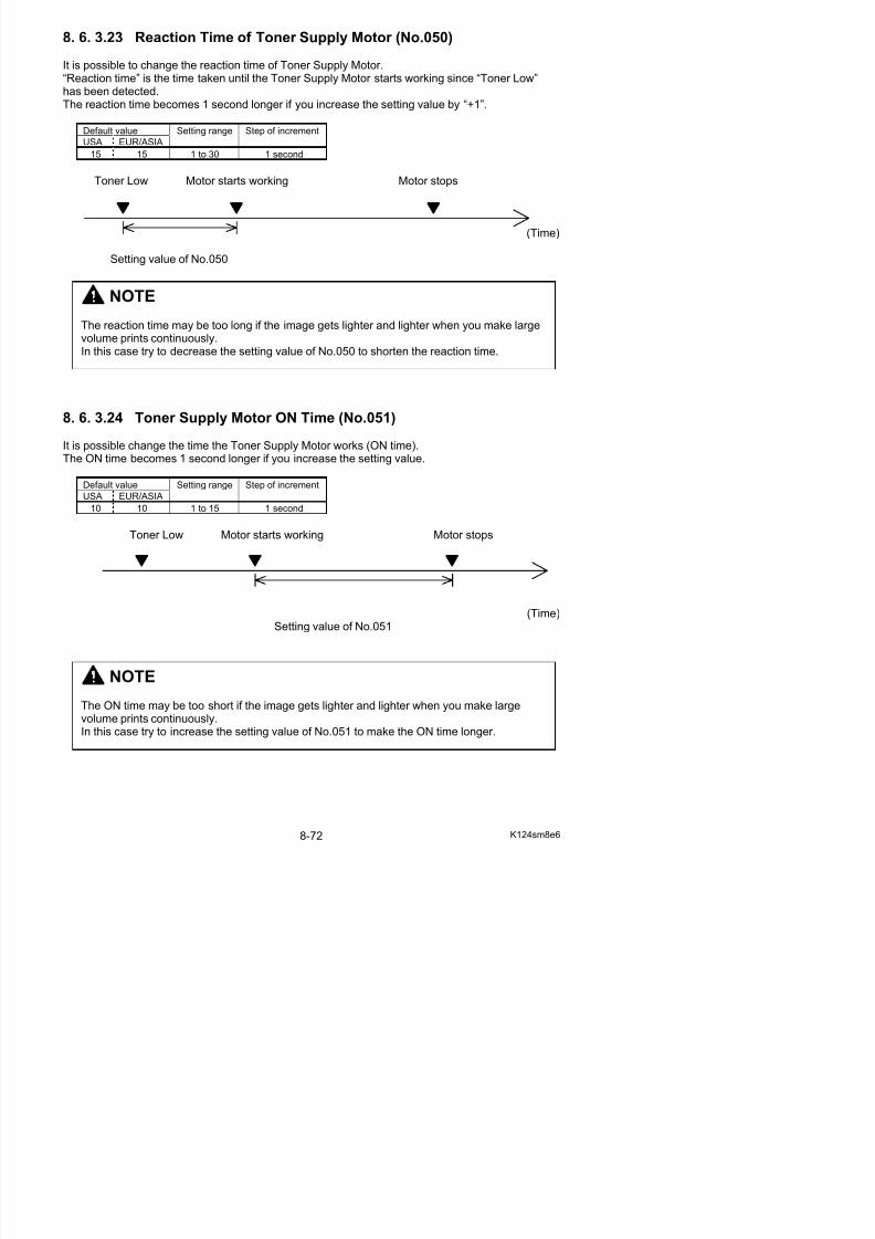
5/17/2018 KIP 7100 Service Manual Ver A_1 - slidepdf.com
http://slidepdf.com/reader/full/kip-7100-service-manual-ver-a1 514/674
(1) An isolated dot image tends to look so weak.
The Dot Enhancement function emphasizes the isolated dot so that it looks clear.(Dot Enhancement function emphasizes only the isolated dot. It will not emphasize thedots coming together some degree.)
Dot Enhancement function is OFF. Dot Enhancement function is ON.
(2) The Dot Enhancement function can be validated in the User Mode.It will not work if not validated.
Reference
8. 6. 3.26 Feed Clutch OFF time (No.053, 054)
The Feed Clutch turns OFF for a very short period whenever the machine transports the paper 2meters long, so as to remove the paper slack in a long printing.It is possible to specify how long period the Feed Clutch continues to be OFF.
Default valueItem No. Setting Item
USA EUR/ASIA
Settingrange
Step of increment
053 Feed Clutch Off Timing (Roll 1) 230 230 80 to 360 1msec.054 Feed Clutch Off Timing (Roll 2) 230 230 80 to 360 1msec.
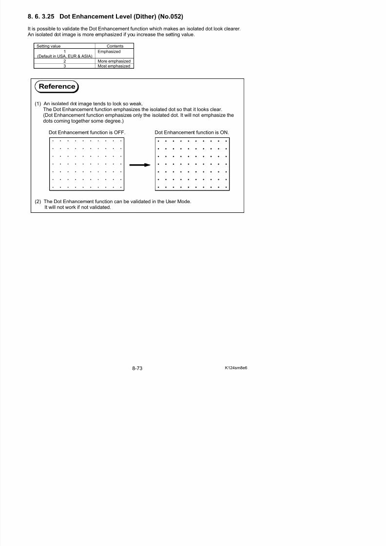
5/17/2018 KIP 7100 Service Manual Ver A_1 - slidepdf.com
http://slidepdf.com/reader/full/kip-7100-service-manual-ver-a1 515/674
2 meters
2 meters
2 meters
Feed Clutch turns OFF
Feed Clutch turns OFF
8. 6. 3.27 Metric or Inch (No.055)
It is possible to decide the base format of the print.
Setting value Contents
0(Default in EUR & ASIA)
Metric
1
(Default in USA)
Inch
NOTE
No.055 is effective only to the size format selection available in
the UI screen. This does not effect to the count unit.
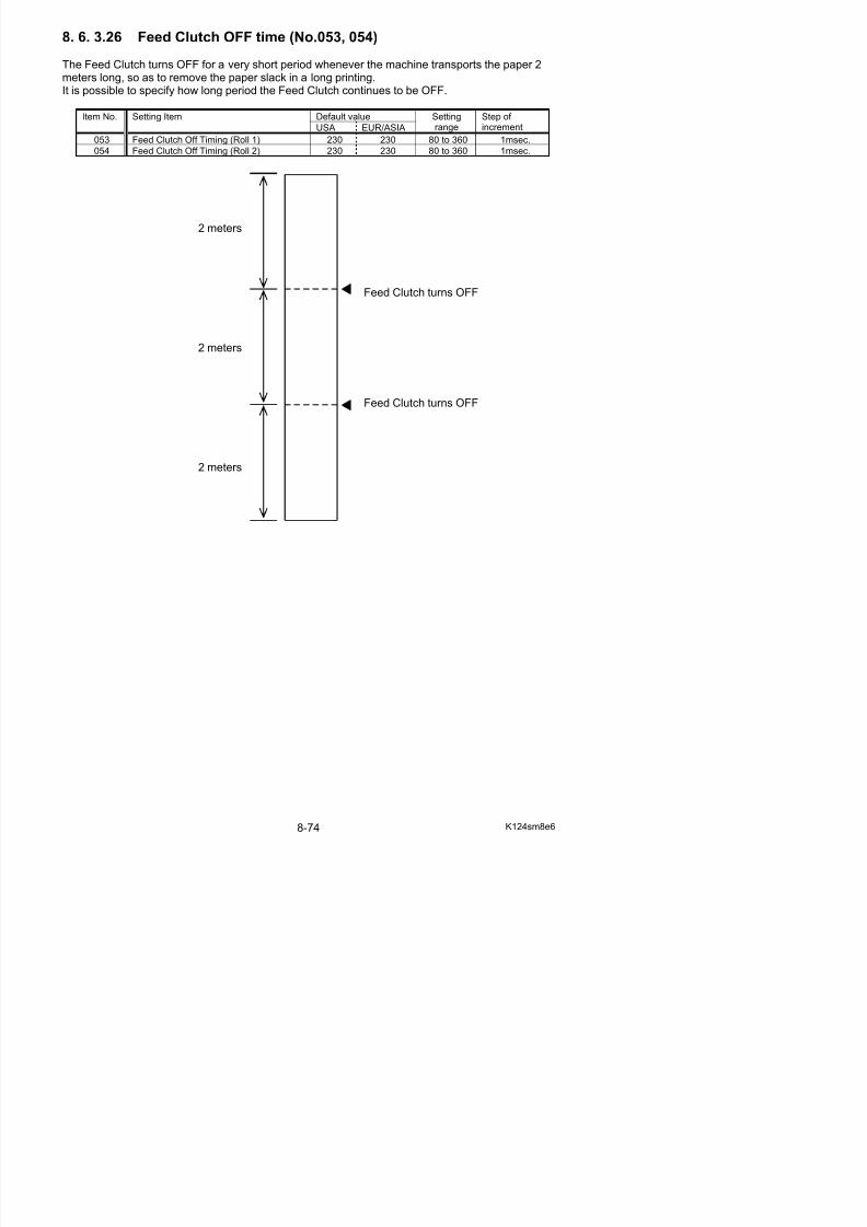
5/17/2018 KIP 7100 Service Manual Ver A_1 - slidepdf.com
http://slidepdf.com/reader/full/kip-7100-service-manual-ver-a1 516/674
8. 6. 3.28 Language (No.056)
8. 6. 3.29 Interface Communication Setting (No.057)
It is possible to specify the communication of Interface.
Setting value Contents0 Both the A Channel and the B Channel are used alternately.
Interface Board communicates with both the image scanner (through A Channel)and the controller (through B Channel) alternately.
1 The A Channel only is used.Interface Board communicates with image scanner through the A Channel.
2(Default in USA, EUR & ASIA)
The B Channel only is used.Interface Board communicates with controller through the B Channel.
8. 6. 3.30 Recognition of Paper Tray (No.058)
It is possible to make the machine recognize Paper Tray (multiple cut sheet feeder, option) if it isinstalled.
Setting value Contents
0(Default in USA, EUR & ASIA)
Paper Tray not installed.
1 Paper Tray installed.
8 6 3 31 Counter Value (No 059)
NOTE
This setting does not function. Keep the value unchanged.
8. 6. 3.32 Maximum Length (No.060)
It is possible to specify the maximum cut length.
Setting value Contents
0(Default in USA, EUR & ASIA)
Maximum cut length is 6.0m.
1 Maximum cut length is 200m.
NOTE
W ill t t th i t lit if th i t i l th th f ll i i
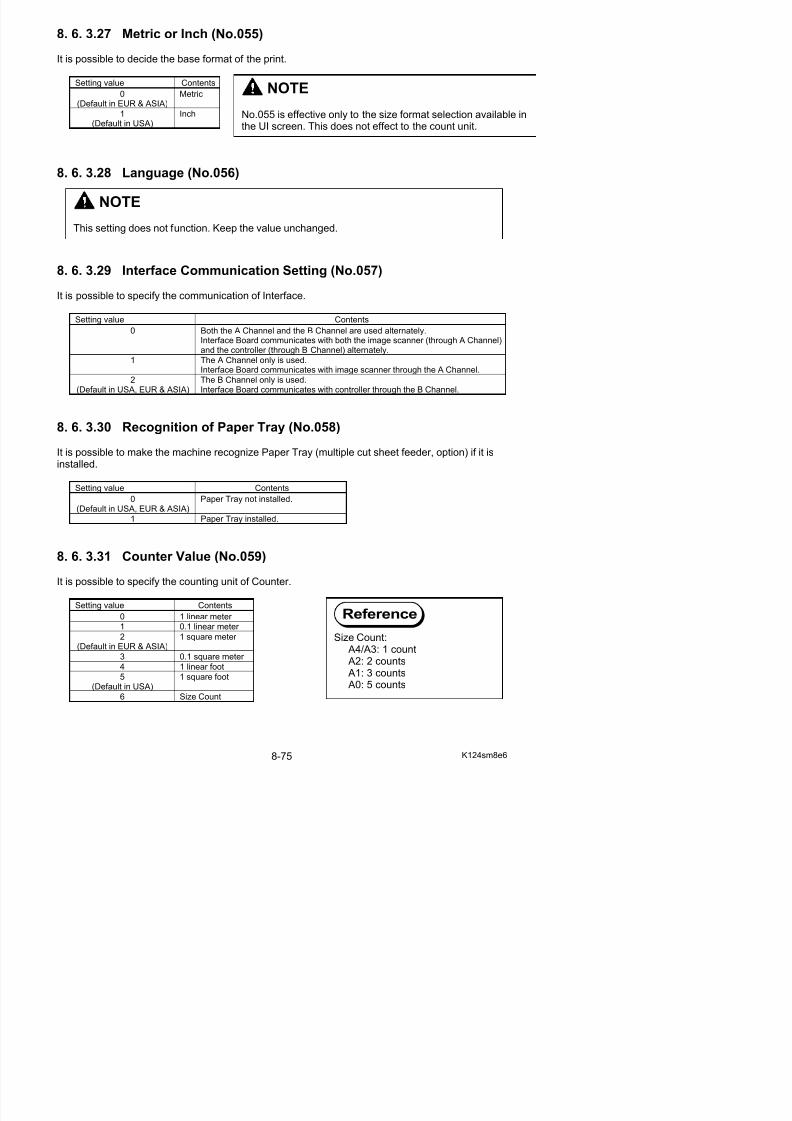
5/17/2018 KIP 7100 Service Manual Ver A_1 - slidepdf.com
http://slidepdf.com/reader/full/kip-7100-service-manual-ver-a1 517/674
8. 6. 3.33 Stacking Device setting (No.061)
It is possible to make the KIP 7100 recognize the optional device (stacker or folder) if connected.
Setting value Contents
0(Default in USA, EUR & ASIA)
Optional device is not connected.
1 Auto Stacker
8. 6. 3.34 Operation of Fuser Roller (No.062)
It is possible to decide whether or not the Fuser Roller should rotate periodically in the stand by
condition.
Setting value Contents
0(Default in USA, EUR & ASIA)
Fuser Roller rotates periodically in the stand by condition.
1 Fuser Roller does not rotate at all in the stand by condition.
We will not guarantee the print quality if the print is longer than the following sizes.
A0 / 36” plain paper 6.0mOther sizes of plain paper 5 times as long as each standard size
Tracing paper Twice as long as each standard sizeFilm Standard sizes
Fuser Roller periodically rotates and stops when the machine is ready, so as to equalize thei f F R ll If f l i i i l h i l
Reference
8. 6. 3.35 Cut Length 5 & 6(Length Compensation for Tracing Paper / Film)(No.063, 064)
It is possible to compensate the print length for the tracing paper and film.If you increase the setting value by “+1”, the length of the print becomes longer.
Default valueItem No. Setting Item
USA EUR/ASIA
Settingrange
Step of increment
063 Cut Length 5 (Tracing Paper) 100 100 0 to 200 depends onpaper length
064 Cut Length 6 (Film) 100 86 0 to 200 depends onpaper length
5/17/2018 KIP 7100 Service Manual Ver A_1 - slidepdf.com
http://slidepdf.com/reader/full/kip-7100-service-manual-ver-a1 518/674
An amount of the length to be added / removed against “1” increment of the setting value will varydepending on the length of the media length to be printed.“1” increment will correspond to the length listed below to be compensated.
paper lengthlength to be added /removed (Approx.)
A0 (1189mm) 0.16mm
A1 (841mm) 0.11mm
A2 (594mm) 0.08mm A3 (420mm) 0.05mm
A4 (297mm) 0.04mm
Expected length Actual length
Increasing the value
Expected length Actual length1 1
0
1 0 0
5 0
A B C
0
1 0 0
5 0
A B C
8. 6. 3.36 Drum Reverse Time (No.065)
It is possible to change the period for the Drum reverse rotation.
Developer Roller is strongly pressed to the Drum and that may cause an indentation on Developer Roller’s surface. The indentation may result in defective imaging.The Drum makes a reverse rotation in a given period twice after finishing a job.
Setting a bigger value for No.065 makes the reverse rotation period longer.
Default value
USA EUR/ASIA
Setting range Step of increment
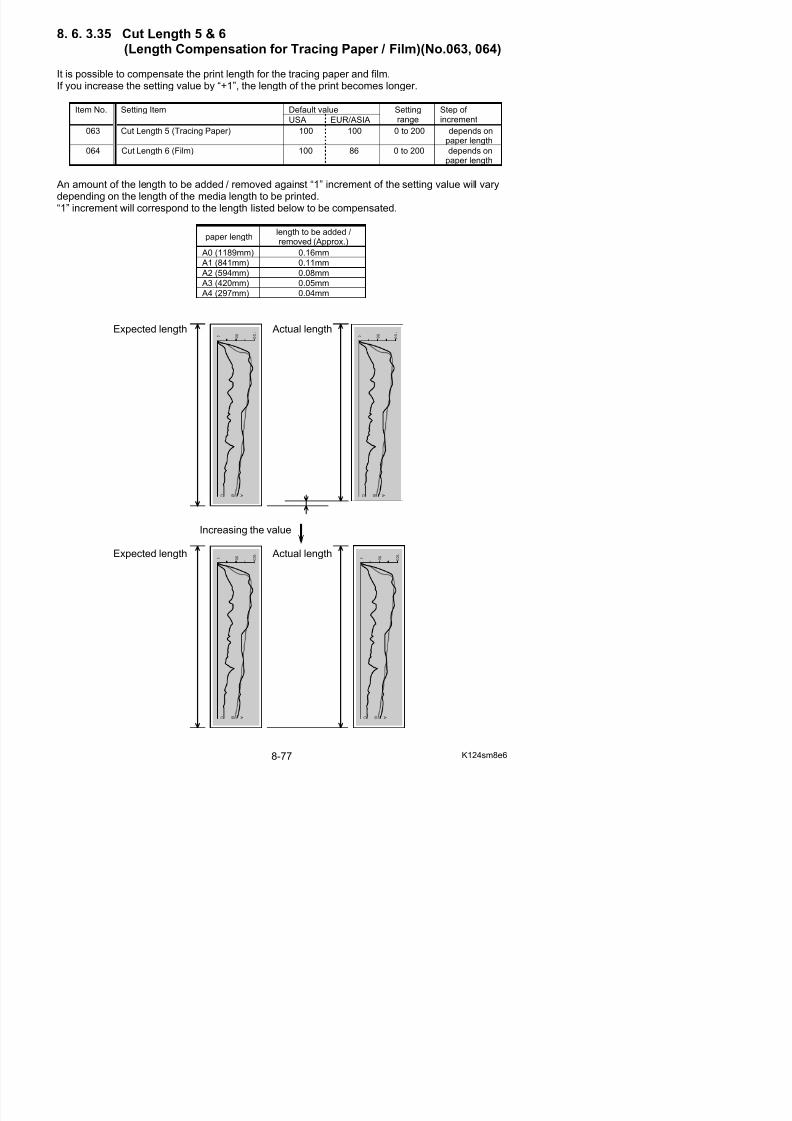
5/17/2018 KIP 7100 Service Manual Ver A_1 - slidepdf.com
http://slidepdf.com/reader/full/kip-7100-service-manual-ver-a1 519/674
30 30 10 to 70 1 millisecond
Print process endDrum reverse rotation starts stops / starts again stops
Value for No.065 (ms) Value for No.065 (ms)
8. 6. 3. 37 Fuser Motor Reverse Setting (No.066)
It is possible to make a decision to allow reverse operation of Fuser Motor at the time of DrumReverse.
Setting value Contents
0(default)
Fuser Motor does not make a reverse operation at all
1 Fuser Motor makes a reverse operation in conjunction
with Drum Reverse.
(1) Drum reverse rotations may produce a slight amount of toner sticking on Drum’s surface.This causes a black line about 50mm below the leading edge on a print.Setting a smaller value will reduce such a line.
(2) Setting an extremely small value may cause an indentation on Developer Roller.
Reference
8. 6. 3.38 Operation of Separation Lamp (No.067)
There may be the case that some type of printing paper has a difficulty in paper separation.In this case it is possible to assist paper separation by lighting the Separation Lamp.It is possible in this No.067 to decide to which type of paper the Separation Lamp should light.Selectable values are from 1 to 7
Setting value Contents
1 Separation Lamp lights for plain paper.2 Separation Lamp lights for tracing paper.
3 Separation Lamp lights for plain paper and tracing paper.
4 Separation Lamp lights for film.
5 Separation Lamp lights for plain paper and film.
5/17/2018 KIP 7100 Service Manual Ver A_1 - slidepdf.com
http://slidepdf.com/reader/full/kip-7100-service-manual-ver-a1 520/674
(Default in USA, EUR & ASIA)p p g p p p
6 Separation Lamp lights for tracing paper and film.
7 Separation Lamp lights for all kinds of paper.
Sometimes you can avoid “defect of transfer (light image)” by making the Separation Lampwork.So if you feel the print image is too light, try to make it work.You may be able to fix the problem.
Reference
8. 6. 3.39 Compensation of Fuser Motor Speed for roll paper (Plain paper / A3, 12” & 11”) (No.070 to 075, 678, 679)
It is possible to compensate the Fuser Motor speed specifying each Fuser Motor 1st, 2nd, 3rd, 4thSpeed. It is also possible to specify when to switch the speed. (Switch timing)These settings become effective when you use a plain paper of A3, 12” and 11” sizes by rollpaper feeding.
Default valueItemNo.
Setting Item
USA EUR/ASIA
Settingrange
Step of increment
070 Fuser Motor 1st Speed (Roll / Plain paper / A3, 12” & 11”) 34 39 0 to 80 0.04mm/s
071 Switch Timing to Fuser Motor 1st Speed(Roll / Plain paper / A3 12” & 11”)
1 1 0 to 300 0.5 sec

5/17/2018 KIP 7100 Service Manual Ver A_1 - slidepdf.com
http://slidepdf.com/reader/full/kip-7100-service-manual-ver-a1 521/674
(Roll / Plain paper / A3, 12 & 11 )
072 Fuser Motor 2nd Speed (Roll / Plain paper / A3, 12” & 11”) 35 42 0 to 80 0.04mm/s
073 Switch Timing to Fuser Motor 2nd Speed(Roll / Plain paper / A3, 12” & 11”)
1 1 0 to 300 0.5 sec
074 Fuser Motor 3rd Speed (Roll / Plain paper / A3, 12” & 11”) 50 48 0 to 80 0.04mm/s
075 Switch Timing to Fuser Motor 3rd Speed(Roll / Plain paper / A3, 12” & 11”)
5 5 0 to 300 0.5 sec
678 Fuser Motor 4th Speed (Roll / Plain paper / A3, 12” & 11”) 34 37 0 to 80 0.04mm/s
679 Switch Timing to Fuser Motor 4th Speed(Roll / Plain paper / A3, 12” & 11”)
6 8 0 to 300 0.5 sec
Please refer to the next page for further information.
NOTE
(1) Fuser Motor Speed is factory-adjusted based on an individual machine, and the result iswritten in the service sheet. Be sure to confirm the service sheet in case of a settingchange on Fuser Motor Speed.
(2) Fuser Motor Speed should be changed with visual check. Remove the right cover and
see inside of the machine to check the feeding balance (media not to be pulled too much/ without slack, etc).
“Paper creasing” or “image void” on a long print may be removed by Fuser Motor Speedcompensation.
Long Print without Fuser Motor Speed compensation
Leading edge
100
50
A
Reference
5/17/2018 KIP 7100 Service Manual Ver A_1 - slidepdf.com
http://slidepdf.com/reader/full/kip-7100-service-manual-ver-a1 522/674
Image Void Paper Creasing Fuser Motor Speed, Fuser Motor 1/2/3/4 Speed correspond to the area shown as follows.To remove “paper creasing” or “image void”, adjust Fuser Motor 3rd/4th Speed according to thesituation.
0
100
50
A
B
C
Standard Length
0
B
C
NOTE
(1) When “Switching Timing” is set to 0 the subsequent Fuser Motor Speed settings are not
Fuser Motor Speed
Fuser Motor 1st Speed
Fuser Motor 2nd Speed
Fuser Motor 3rd Speed
Fuser Motor 4th Speed
1st SpeedSwitch Timing
2nd SpeedSwitch Timing
3rd SpeedSwitch Timing
4th SpeedSwitch Timing
This page explains Fuser Motor Speed Compensation on A3/12”/11” width for example.
You can specify the Fuser Motor 1st Speed, 2nd, 3rd and 4th in each Item No.070, 072, 074, 678.If you increase the setting value by “+1”, each Fuser Motor Speed becomes 0.04mm/second faster.(The default setting value “40” corresponds to 80mm/second.)
(Example)Setting value of 070 is “41” Fuser Motor 1st Speed is 80.04mm/sec.
Setting value of 072 is “42” Fuser Motor 2nd Speed is 80.08mm/sec.Setting value of 074 is “43” Fuser Motor 3rd Speed is 80.12mm/sec.Setting value of 678 is “44” Fuser Motor 4th Speed is 80.16mm/sec.
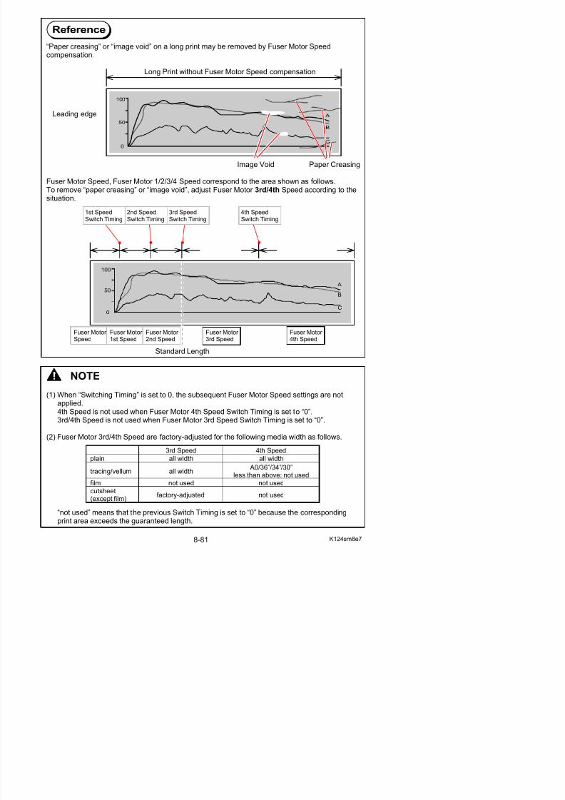
5/17/2018 KIP 7100 Service Manual Ver A_1 - slidepdf.com
http://slidepdf.com/reader/full/kip-7100-service-manual-ver-a1 523/674
Fuser Motor Fuser Motor Fuser Motor Fuser Motor 1st Speed 2nd Speed 3rd Speed 4th Speed(80.04mm/s) (80.08mm/s) (80.12mm/s) (80.16mm/s)
You can specify the switch timing to each Fuser Motor 1st Speed, 2nd, 3rd, 4th in each ItemNo.071, 073, 075, 679.If you increase the setting value by “+1”, the timing to switch the speed is 0.5 second delayed.(If you specify “0”, the Fuser Motor Speed does not change.)
(Example)Setting value of 071 is “8” Fuser Motor 1st Speed starts 4 seconds after the Registration
Sensor detects the leading edge.Setting value of 073 is “16” Fuser Motor 2nd Speed starts 8 seconds after the start of
Fuser Motor 1st Speed.Setting value of 075 is “24” Fuser Motor 3rd Speed starts 12 seconds after the start of
Fuser Motor 2nd Speed.Setting value of 678 is “32” Fuser Motor 4th Speed starts 16 seconds after the start of
Fuser Motor 3rd Speed.
4 seconds 8 seconds 12seconds 16 seconds(Fuser motor Speed) (1st Speed) (2nd Speed) (3rd Speed) (4th Speed)
0
100
50
A
B
C
8. 6. 3.40 Compensation of Fuser Motor Speed for roll paper (Tracing paper / A3, 12” & 11”) (No.076 to 081, 680, 681)
It is possible to compensate the Fuser Motor speed specifying each Fuser Motor 1st, 2nd, 3rd and4th Speed.It is also possible to specify when to switch the speed. (Switch timing)These settings become effective when you use a tracing paper of A3, 12” and 11” sizes byroll paper feeding.
Default valueItemNo.
Setting Item
USA EUR/ASIA
Settingrange
Step of increment
076 Fuser Motor 1st Speed (Roll / Tracing / A3, 12” & 11”) 33 36 0 to 80 0.04mm/s
077 Switch Timing to Fuser Motor 1st Speed 1 1 0 to 300 0 5 sec
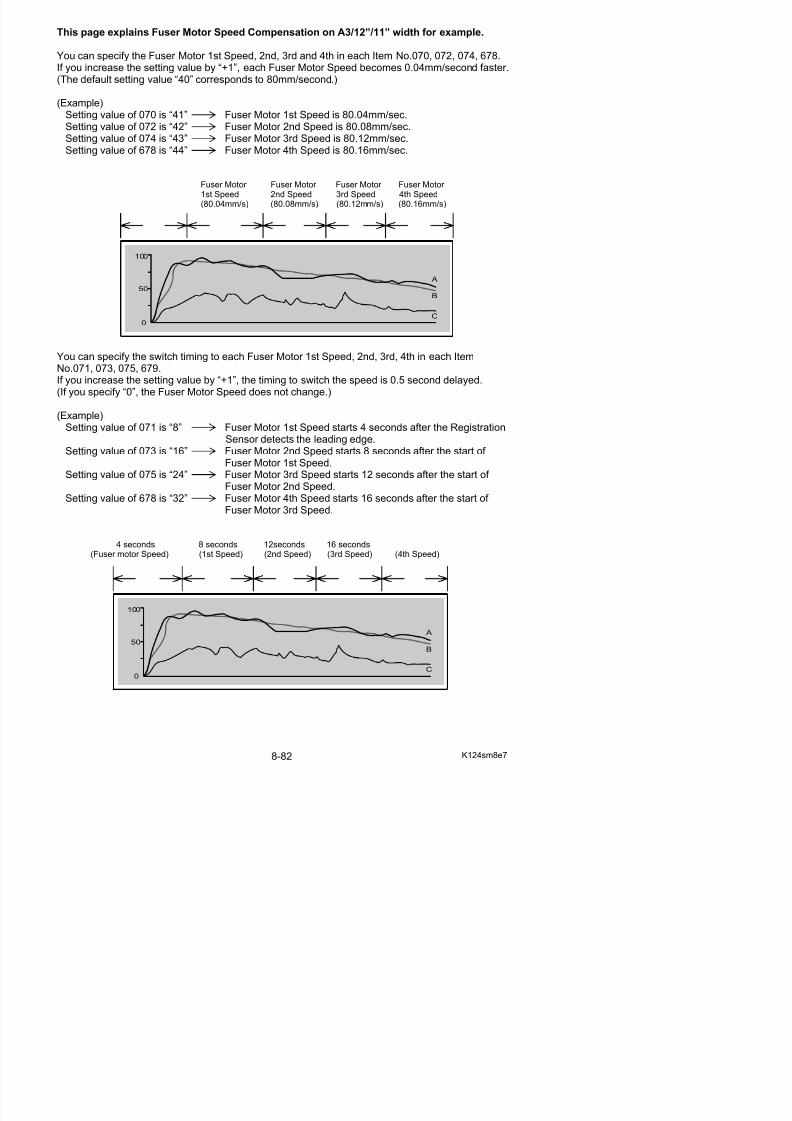
5/17/2018 KIP 7100 Service Manual Ver A_1 - slidepdf.com
http://slidepdf.com/reader/full/kip-7100-service-manual-ver-a1 524/674
077 Switch Timing to Fuser Motor 1st Speed(Roll / Tracing / A3, 12” & 11”)
1 1 0 to 300 0.5 sec
078 Fuser Motor 2nd Speed (Roll / Tracing / A3, 12” & 11”) 39 44 0 to 80 0.04mm/s
079 Switch Timing to Fuser Motor 2nd Speed(Roll / Tracing / A3, 12” & 11”)
1 3 0 to 300 0.5 sec
080 Fuser Motor 3rd Speed (Roll / Tracing / A3, 12” & 11”) 44 44 0 to 80 0.04mm/s081 Switch Timing to Fuser Motor 3rd Speed
(Roll / Tracing / A3, 12” & 11”)5 5 0 to 300 0.5 sec
680 Fuser Motor 4th Speed (Roll / Tracing / A3, 12” & 11”) 40 40 0 to 80 0.04mm/s
681 Switch Timing to Fuser Motor 4th Speed(Roll / Tracing / A3, 12” & 11”)
0 0 0 to 300 0.5 sec
You can specify Fuser Motor 1st Speed, 2nd, 3rd, 4th in each Item No.076, 078, 080, 680.
If you increase the setting value by “+1”, each Fuser Motor Speed becomes 0.04mm/second faster.
You can specify the switch timing to each Fuser Motor 1st Speed, 2nd, 3rd, 4th in each ItemNo.077, 079, 081, 681.If you increase the setting value by “+1”, the timing to switch the speed is 0.5 second delayed.
For the detail information above, see [8.6.5.39 Compensation of Fuser Motor Speed for roll
paper (Plain paper / A3, 12” & 11”) (No.070 to 075, 678, 679)].
8. 6. 3.41 Compensation of Fuser Motor Speed for roll paper (Film / A3, 12” & 11”) (No.082 to 087, 682, 683)
It is possible to compensate the Fuser Motor speed specifying each Fuser Motor 1st, 2nd, 3rd and4th Speed.It is also possible to specify when to switch the speed. (Switch timing)These settings become effective when you use a film of A3, 12” and 11” sizes by roll paper feeding.
Default valueItemNo.
Setting Item
USA EUR/ASIA
Settingrange
Step of increment
082 Fuser Motor 1st Speed (Roll / Film / A3, 12” & 11”) 50 50 0 to 80 0.04mm/s
083 Switch Timing to Fuser Motor 1st Speed 2 2 0 to 300 0.5 sec
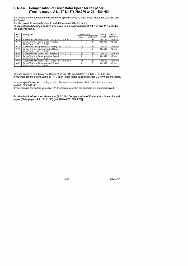
5/17/2018 KIP 7100 Service Manual Ver A_1 - slidepdf.com
http://slidepdf.com/reader/full/kip-7100-service-manual-ver-a1 525/674
g p(Roll / Film / A3, 12” & 11”)
084 Fuser Motor 2nd Speed (Roll / Film / A3, 12” & 11”) 50 50 0 to 80 0.04mm/s
085 Switch Timing to Fuser Motor 2nd Speed(Roll / Film / A3, 12” & 11”)
4 4 0 to 300 0.5 sec
086 Fuser Motor 3rd Speed (Roll / Film / A3, 12” & 11”) 40 40 0 to 80 0.04mm/s087 Switch Timing to Fuser Motor 4th Speed
(Roll / Film / A3, 12” & 11”)0 0 0 to 300 0.5 sec
682 Fuser Motor 4th Speed (Roll / Film / A3, 12” & 11”) 40 40 0 to 80 0.04mm/s
683 Switch Timing to Fuser Motor 4th Speed(Roll / Film / A3, 12” & 11”)
0 040 0 to 300 0.5 sec
You can specify Fuser Motor 1st Speed, 2nd, 3rd, 4th in each Item No.082, 084, 086, 682.
If you increase the setting value by “+1”, each Fuser Motor Speed becomes 0.04mm/second faster.
You can specify the switch timing to each Fuser Motor 1st Speed, 2nd, 3rd, 4th in each ItemNo.083, 085, 087, 683.If you increase the setting value by “+1”, the timing to switch the speed is 0.5 second delayed.
For the detail information above, see [8.6.5.39 Compensation of Fuser Motor Speed for roll
paper (Plain paper / A3, 12” & 11”) (No.070 to 075, 678, 679)].
8. 6. 3.42 Compensation of Fuser Motor Speed for roll paper (Special plain paper / A3, 12” & 11”) (No.088 to 093, 684, 685)
It is possible to compensate the Fuser Motor speed specifying each Fuser Motor 1st, 2nd, 3rd and4th Speed.It is also possible to specify when to switch the speed. (Switch timing)These settings become effective when you use a plain paper (special media) of A3, 12” and11” sizes by roll paper feeding.
Default valueItemNo.
Setting Item
USA EUR/ASIA
Settingrange
Step of increment
088 Fuser Motor 1st Speed(Roll / Special plain paper / A3, 12” & 11”)
40 40 0 to 80 0.04mm/s
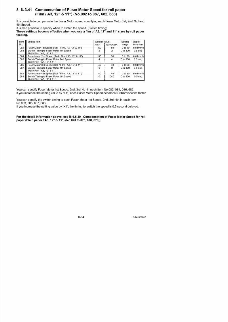
5/17/2018 KIP 7100 Service Manual Ver A_1 - slidepdf.com
http://slidepdf.com/reader/full/kip-7100-service-manual-ver-a1 526/674
089 Switch Timing to Fuser Motor 1st Speed(Roll / Special plain paper / A3, 12” & 11”)
0 0 0 to 300 0.5 sec
090 Fuser Motor 2nd Speed Setting(Roll / Special plain paper / A3, 12” & 11”)
40 40 0 to 80 0.04mm/s
091 Switch Timing to Fuser Motor 2nd Speed(Roll / Special plain paper / A3, 12” & 11”)
0 0 0 to 300 0.5 sec
092 Fuser Motor 3rd Speed(Roll / Special plain paper / A3, 12” & 11”)
40 40 0 to 80 0.04mm/s
093 Switch Timing to Fuser Motor 3rd Speed(Roll / Special plain paper / A3, 12” & 11”)
0 0 0 to 300 0.5 sec
684 Fuser Motor 4th Speed(Roll / Special plain paper / A3, 12” & 11”)
40 40 0 to 80 0.04mm/s
685 Switch Timing to Fuser Motor 4th Speed(Roll / Special plain paper / A3, 12” & 11”)
0 0 0 to 300 0.5 sec
You can specify the Fuser Motor 1st Speed, 2nd, 3rd, 4th in each Item No.088, 090, 092, 684.If you increase the setting value by “+1”, each Fuser Motor Speed becomes 0.04mm/second faster.
You can specify the switch timing to each Fuser Motor 1st Speed, 2nd, 3rd, 4th in each ItemNo.089, 091, 093, 685.If you increase the setting value by “+1”, the timing to switch the speed is 0.5 second delayed.
For the detail information above, see [8.6.5.39 Compensation of Fuser Motor Speed for rollpaper (Plain paper / A3, 12” & 11”) (No.070 to 075, 678, 679)].
8. 6. 3.43 Compensation of Fuser Motor Speed for roll paper (Special tracing paper / A3, 12” & 11”) (No.094 to 099)
It is possible to compensate the Fuser Motor speed specifying each Fuser Motor 1st, 2nd, 3rd and4th Speed.It is also possible to specify when to switch the speed. (Switch timing)These settings become effective when you use a tracing paper (special media) of A3, 12”and 11” sizes by roll paper feeding.
Default valueItemNo.
Setting Item
USA EUR/ASIA
Settingrange
Step of increment
094 Fuser Motor 1st Speed(Roll/ Special Media / Tracing / A3, 12” & 11”)
40 40 0 to 80 0.04mm/s
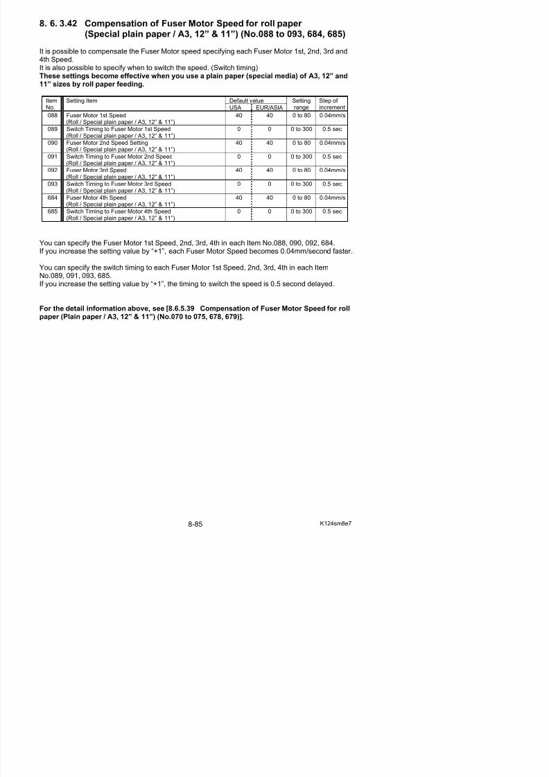
5/17/2018 KIP 7100 Service Manual Ver A_1 - slidepdf.com
http://slidepdf.com/reader/full/kip-7100-service-manual-ver-a1 527/674
095 Switch Timing to Fuser Motor 1st Speed(Roll/ Special Media / Tracing / A3, 12” & 11”)
0 0 0 to 300 0.5 sec
096 Fuser Motor 2nd Speed(Roll/ Special Media / Tracing / A3, 12” & 11”)
40 40 0 to 80 0.04mm/s
097 Switch Timing to Fuser Motor 2nd Speed(Roll/ Special Media / Tracing / A3, 12” & 11”)
0 0 0 to 300 0.5 sec
098 Fuser Motor 3rd Speed(Roll/ Special Media / Tracing / A3, 12” & 11”)
40 40 0 to 80 0.04mm/s
099 Switch Timing to Fuser Motor 3rd Speed(Roll/ Special Media / Tracing / A3, 12” & 11”)
0 0 0 to 300 0.5 sec
686 Fuser Motor 4th Speed(Roll/ Special Media / Tracing / A3, 12” & 11”)
40 40 0 to 80 0.04mm/s
687 Switch Timing to Fuser Motor 4th Speed(Roll/ Special Media / Tracing / A3, 12” & 11”)
0 0 0 to 300 0.5 sec
You can specify the Fuser Motor 1st Speed, 2nd, 3rd, 4th in each Item No.094, 096, 098, 686.If you increase the setting value by “+1”, each Fuser Motor Speed becomes 0.04mm/second faster.
You can specify the switch timing to each Fuser Motor 1st Speed, 2nd, 3rd, 4th in each ItemNo.095, 097, 099, 687.If you increase the setting value by “+1”, the timing to switch the speed is 0.5 second delayed.
For the detail information above, see [8.6.5.39 Compensation of Fuser Motor Speed for rollpaper (Plain paper / A3, 12” & 11”) (No.070 to 075, 678, 679)].
8. 6. 3.44 Compensation of Fuser Motor Speed for roll paper (Special film / A3, 12” & 11”) (No.100 to 105, 688, 689)
It is possible to compensate the Fuser Motor speed specifying each Fuser Motor 1st, 2nd, 3rd and4th Speed.It is also possible to specify when to switch the speed. (Switch timing)These settings become effective when you use a film (special media) of A3, 12” and 11”sizes by roll paper feeding.
Default valueItemNo.
Setting Item
USA EUR/ASIA
Settingrange
Step of increment
100 Fuser Motor 1st Speed (Roll / Special film / A3, 12” & 11”) 40 40 0 to 80 0.04mm/s
101 Switch Timing to Fuser Motor 1st Speed(R ll / S i l fil / A3 12” & 11”)
0 0 0 to 300 0.5 sec
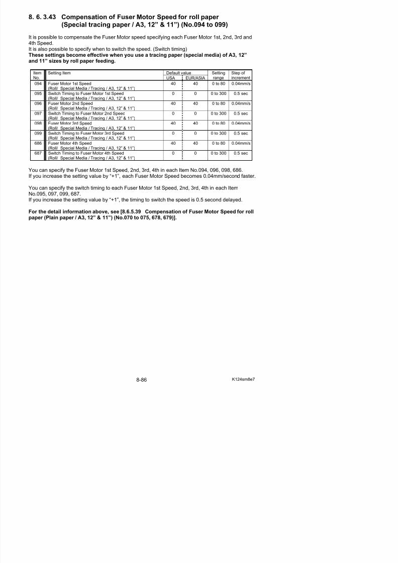
5/17/2018 KIP 7100 Service Manual Ver A_1 - slidepdf.com
http://slidepdf.com/reader/full/kip-7100-service-manual-ver-a1 528/674
(Roll / Special film / A3, 12” & 11”)
102 Fuser Motor 2nd Speed (Roll / Special film / A3, 12” & 11”) 40 40 0 to 80 0.04mm/s
103 Switch Timing to Fuser Motor 2nd Speed(Roll / Special film / A3, 12” & 11”)
0 0 0 to 300 0.5 sec
104 Fuser Motor 3rd Speed (Roll / Special film / A3, 12” & 11”) 40 40 0 to 80 0.04mm/s105 Switch Timing to Fuser Motor 3rd Speed
(Roll / Special film / A3, 12” & 11”)0 0 0 to 300 0.5 sec
688 Fuser Motor 4th Speed (Roll / Special film / A3, 12” & 11”) 40 40 0 to 80 0.04mm/s
689 Switch Timing to Fuser Motor 4th Speed(Roll / Special film / A3, 12” & 11”)
0 0 0 to 300 0.5 sec
You can specify the Fuser Motor 1st Speed, 2nd, 3rd, 4th in each Item No.100, 102, 104, 688.
If you increase the setting value by “+1”, each Fuser Motor Speed becomes 0.04mm/second faster.
You can specify the switch timing to each Fuser Motor 1st Speed, 2nd, 3rd, 4th in each ItemNo.101, 103, 105, 689.If you increase the setting value by “+1”, the timing to switch the speed is 0.5 second delayed.
For the detail information above, see [8.6.5.39 Compensation of Fuser Motor Speed for roll
paper (Plain paper / A3, 12” & 11”) (No.070 to 075, 678, 679)].
8. 6. 3.45 Compensation of Fuser Motor Speed for roll paper (Plain paper / A2, 18” & 17”) (No.106 to 111, 690, 691)
It is possible to compensate the Fuser Motor speed specifying each Fuser Motor 1st, 2nd, 3rd and4th Speed.It is also possible to specify when to switch the speed. (Switch timing)These settings become effective when you use a plain paper of A2, 18” and 17” sizes by rollpaper feeding.
Default valueItemNo.
Setting Item
USA EUR/ASIA
Settingrange
Step of increment
106 Fuser Motor 1st Speed (Roll / Plain paper / A2, 18” & 17”) 30 31 0 to 80 0.04mm/s
107 Switch Timing to Fuser Motor 1st Speed(Roll / Plain paper / A2 18” & 17”)
3 3 0 to 300 0.5 sec

5/17/2018 KIP 7100 Service Manual Ver A_1 - slidepdf.com
http://slidepdf.com/reader/full/kip-7100-service-manual-ver-a1 529/674
(Roll / Plain paper / A2, 18 & 17 )
108 Fuser Motor 2nd Speed (Roll / Plain paper / A2, 18” & 17”) 32 36 0 to 80 0.04mm/s
109 Switch Timing to Fuser Motor 2nd Speed(Roll / Plain paper / A2, 18” & 17”)
4 4 0 to 300 0.5 sec
110 Fuser Motor 3rd Speed (Roll / Plain paper / A2, 18” & 17”) 31 38 0 to 80 0.04mm/s111 Switch Timing to Fuser Motor 3rd Speed
(Roll / Plain paper / A2, 18” & 17”)6 6 0 to 300 0.5 sec
690 Fuser Motor 4th Speed (Roll / Plain paper / A2, 18” & 17”) 37 40 0 to 80 0.04mm/s
691 Switch Timing to Fuser Motor 4th Speed(Roll / Plain paper / A2, 18” & 17”)
10 0 0 to 300 0.5 sec
You can specify the Fuser Motor 1st Speed, 2nd, 3rd, 4th in each Item No.106, 108, 110, 690.
If you increase the setting value by “+1”, each Fuser Motor Speed becomes 0.04mm/second faster.
You can specify the switch timing to each Fuser Motor 1st Speed, 2nd, 3rd, 4th in each ItemNo.107, 109, 111, 691.If you increase the setting value by “+1”, the timing to switch the speed is 0.5 second delayed.
For the detail information above, see [8.6.5.39 Compensation of Fuser Motor Speed for roll
paper (Plain paper / A3, 12” & 11”) (No.070 to 075, 678, 679)].
8. 6. 3.46 Compensation of Fuser Motor Speed for roll paper (Tracing paper / A2, 18” & 17”) (No.112 to 117, 692, 693)
It is possible to compensate the Fuser Motor speed specifying each Fuser Motor 1st, 2nd, 3rd and4th Speed.It is also possible to specify when to switch the speed. (Switch timing)These settings become effective when you use a tracing paper of A2, 18” and 17” sizes byroll paper feeding.
Default valueItemNo.
Setting Item
USA EUR/ASIA
Settingrange
Step of increment
112 Fuser Motor 1st Speed (Roll / Tracing / A2, 18” & 17”) 33 40 0 to 80 0.04mm/s
113 Switch Timing to Fuser Motor 1st Speed(Roll / Tracing / A2 18” & 17”)
3 1 0 to 300 0.5 sec
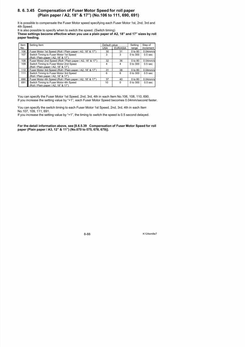
5/17/2018 KIP 7100 Service Manual Ver A_1 - slidepdf.com
http://slidepdf.com/reader/full/kip-7100-service-manual-ver-a1 530/674
(Roll / Tracing / A2, 18 & 17 )
114 Fuser Motor 2nd Speed (Roll / Tracing / A2, 18” & 17”) 38 44 0 to 80 0.04mm/s
115 Switch Timing to Fuser Motor 2nd Speed(Roll / Tracing / A2, 18” & 17”)
3 5 0 to 300 0.5 sec
116 Fuser Motor 3rd Speed (Roll / Tracing / A2, 18” & 17”) 38 45 0 to 80 0.04mm/s117 Switch Timing to Fuser Motor 3rd Speed
(Roll / Tracing / A2, 18” & 17”)5 5 0 to 300 0.5 sec
692 Fuser Motor 4th Speed (Roll / Tracing / A2, 18” & 17”) 40 40 0 to 80 0.04mm/s
693 Switch Timing to Fuser Motor 4th Speed(Roll / Tracing / A2, 18” & 17”)
0 0 0 to 300 0.5 sec
You can specify the Fuser Motor 1st Speed, 2nd, 3rd, 4th in each Item No.112, 114, 116, 692.
If you increase the setting value by “+1”, each Fuser Motor Speed becomes 0.04mm/second faster.
You can specify the switch timing to each Fuser Motor 1st Speed, 2nd, 3rd, 4th in each ItemNo.113, 115, 117, 693.If you increase the setting value by “+1”, the timing to switch the speed is 0.5 second delayed.
For the detail information above, see [8.6.5.39 Compensation of Fuser Motor Speed for roll
paper (Plain paper / A3, 12” & 11”) (No.070 to 075, 678, 679)].
8. 6. 3.47 Compensation of Fuser Motor Speed for roll paper (Film / A2, 18” & 17”) (No.118 to 123, 694, 695)
It is possible to compensate the Fuser Motor speed specifying each Fuser Motor 1st, 2nd, 3rd and4th Speed.It is also possible to specify when to switch the speed. (Switch timing)These settings become effective when you use a film of A2, 18” and 17” sizes by roll paper feeding.
Default valueItemNo.
Setting Item
USA EUR/ASIA
Settingrange
Step of increment
118 Fuser Motor 1st Speed (Roll / Film / A2, 18” & 17”) 50 50 0 to 80 0.04mm/s
119 Switch Timing to Fuser Motor 1st Speed(Roll / Film / A2 18” & 17”)
2 2 0 to 300 0.5 sec

5/17/2018 KIP 7100 Service Manual Ver A_1 - slidepdf.com
http://slidepdf.com/reader/full/kip-7100-service-manual-ver-a1 531/674
(Roll / Film / A2, 18 & 17 )
120 Fuser Motor 2nd Speed (Roll / Film / A2, 18” & 17”) 50 50 0 to 80 0.04mm/s
121 Switch Timing to Fuser Motor 2nd Speed(Roll / Film / A2, 18” & 17”)
6 6 0 to 300 0.5 sec
122 Fuser Motor 3rd Speed (Roll / Film / A2, 18” & 17”) 40 40 0 to 80 0.04mm/s123 Switch Timing to Fuser Motor 3rd Speed
(Roll / Film / A2, 18” & 17”)0 0 0 to 300 0.5 sec
694 Fuser Motor 4th Speed (Roll / Film / A2, 18” & 17”) 40 40 0 to 80 0.04mm/s
695 Switch Timing to Fuser Motor 4th Speed(Roll / Film / A2, 18” & 17”)
0 0 0 to 300 0.5 sec
You can specify the Fuser Motor 1st Speed, 2nd, 3rd, 4th in each Item No.118, 120, 122, 694.
If you increase the setting value by “+1”, each Fuser Motor Speed becomes 0.04mm/second faster.
You can specify the switch timing to each Fuser Motor 1st Speed, 2nd, 3rd, 4th in each ItemNo.119, 121, 123, 695.If you increase the setting value by “+1”, the timing to switch the speed is 0.5 second delayed.
For the detail information above, see [8.6.5.39 Compensation of Fuser Motor Speed for roll
paper (Plain paper / A3, 12” & 11”) (No.070 to 075, 678, 679)].
8. 6. 3.48 Compensation of Fuser Motor Speed for roll paper (Special plain paper / A2, 18” & 17”) (No.124 to 129, 696, 697)
It is possible to compensate the Fuser Motor speed specifying each Fuser Motor 1st, 2nd, 3rd and4th Speed.It is also possible to specify when to switch the speed. (Switch timing)These settings become effective when you use a plain paper (special media) of A2, 18” and17” sizes by roll paper feeding.
Default valueItemNo.
Setting Item
USA EUR/ASIA
Settingrange
Step of increment
124 Fuser Motor 1st Speed(Roll / Special plain paper / A2, 18” & 17”)
40 40 0 to 80 0.04mm/s
125 Switch Timing to Fuser Motor 1st Speed 0 0 0 to 300 0.5 sec

5/17/2018 KIP 7100 Service Manual Ver A_1 - slidepdf.com
http://slidepdf.com/reader/full/kip-7100-service-manual-ver-a1 532/674
g p(Roll / Special plain paper / A2, 18” & 17”)
126 Fuser Motor 2nd Speed(Roll / Special plain paper / A2, 18” & 17”)
40 40 0 to 80 0.04mm/s
127 Switch Timing to Fuser Motor 2nd Speed(Roll / Special plain paper / A2, 18” & 17”) 0 0 0 to 300 0.5 sec
128 Fuser Motor 3rd Speed(Roll / Special plain paper / A2, 18” & 17”)
40 40 0 to 80 0.04mm/s
129 Switch Timing to Fuser Motor 3rd Speed(Roll / Special plain paper / A2, 18” & 17”)
0 0 0 to 300 0.5 sec
696 Fuser Motor 4th Speed(Roll / Special plain paper / A2, 18” & 17”)
40 40 0 to 80 0.04mm/s
697 Switch Timing to Fuser Motor 4th Speed(Roll / Special plain paper / A2, 18” & 17”)
0 0 0 to 300 0.5 sec
You can specify the Fuser Motor 1st Speed, 2nd, 3rd, 4th in each Item No.124, 126, 128, 696.If you increase the setting value by “+1”, each Fuser Motor Speed becomes 0.04mm/second faster.
You can specify the switch timing to each Fuser Motor 1st Speed, 2nd, 3rd, 4th in each ItemNo.125, 127, 129, 697.If you increase the setting value by “+1”, the timing to switch the speed is 0.5 second delayed.
For the detail information above, see [8.6.5.39 Compensation of Fuser Motor Speed for rollpaper (Plain paper / A3, 12” & 11”) (No.070 to 075, 678, 679)].
8. 6. 3.49 Compensation of Fuser Motor Speed for roll paper (Special tracing paper / A2, 18” & 17”) (No.130 to 135, 698, 699)
It is possible to compensate the Fuser Motor speed specifying each Fuser Motor 1st, 2nd, 3rd and4th Speed.It is also possible to specify when to switch the speed. (Switch timing)These settings become effective when you use a tracing paper (special media) of A2, 18”and 17” size by roll paper feeding.
Default valueItemNo.
Setting Item
USA EUR/ASIA
Settingrange
Step of increment
130 Fuser Motor 1st Speed(Roll / Special tracing / A2, 18” & 17”)
40 40 0 to 80 0.04mm/s
131 Switch Timing to Fuser Motor 1st Speed 0 0 0 to 300 0.5 sec

5/17/2018 KIP 7100 Service Manual Ver A_1 - slidepdf.com
http://slidepdf.com/reader/full/kip-7100-service-manual-ver-a1 533/674
(Roll / Special tracing / A2, 18” & 17”)
132 Fuser Motor 2nd Speed(Roll / Special tracing / A2, 18” & 17”)
40 40 0 to 80 0.04mm/s
133 Switch Timing to Fuser Motor 2nd Speed(Roll / Special tracing / A2, 18” & 17”) 0 0 0 to 300 0.5 sec
134 Fuser Motor 3rd Speed(Roll / Special tracing / A2, 18” & 17”)
40 40 0 to 80 0.04mm/s
135 Switch Timing to Fuser Motor 3rd Speed(Roll / Special tracing / A2, 18” & 17”)
0 0 0 to 300 0.5 sec
698 Fuser Motor 4th Speed(Roll / Special tracing / A2, 18” & 17”)
40 40 0 to 80 0.04mm/s
699 Switch Timing to Fuser Motor 4th Speed(Roll / Special tracing / A2, 18” & 17”)
0 0 0 to 300 0.5 sec
You can specify the Fuser Motor 1st Speed, 2nd, 3rd, 4th in each Item No.130, 132, 134, 698.If you increase the setting value by “+1”, each Fuser Motor Speed becomes 0.04mm/second faster.
You can specify the switch timing to each Fuser Motor 1st Speed, 2nd, 3rd, 4th in each ItemNo.131, 133, 135, 699.If you increase the setting value by “+1”, the timing to switch the speed is 0.5 second delayed.
For the detail information above, see [8.6.5.39 Compensation of Fuser Motor Speed for rollpaper (Plain paper / A3, 12” & 11”) (No.070 to 075, 678, 679)].
8. 6. 3.50 Compensation of Fuser Motor Speed for roll paper (Special film / A2, 18” & 17”) (No.136 to 141, 700, 701)
It is possible to compensate the Fuser Motor speed specifying each Fuser Motor 1st, 2nd, 3rd and4th Speed.It is also possible to specify when to switch the speed. (Switch timing)These settings become effective when you use a film (special media) of A2, 18” and 17”sizes by roll paper feeding.
Default valueItemNo.
Setting Item
USA EUR/ASIA
Settingrange
Step of increment
136 Fuser Motor 1st Speed (Roll / Special film / A2, 18” & 17”) 40 40 0 to 80 0.04mm/s
137 Switch Timing to Fuser Motor 1st Speed(Roll / Special film / A2, 18” & 17”)
0 0 0 to 300 0.5 sec
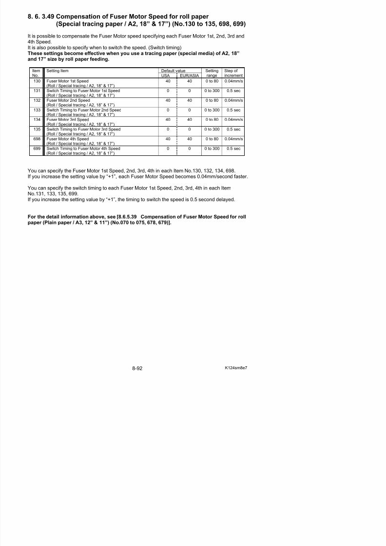
5/17/2018 KIP 7100 Service Manual Ver A_1 - slidepdf.com
http://slidepdf.com/reader/full/kip-7100-service-manual-ver-a1 534/674
138 Fuser Motor 2nd Speed (Roll / Special film / A2, 18” & 17”) 40 40 0 to 80 0.04mm/s
139 Switch Timing to Fuser Motor 2nd Speed(Roll / Special film / A2, 18” & 17”)
0 0 0 to 300 0.5 sec
140 Fuser Motor 3rd Speed (Roll / Special film / A2, 18” & 17”) 40 40 0 to 80 0.04mm/s141 Switch Timing to Fuser Motor 3rd Speed
(Roll / Special film / A2, 18” & 17”)0 0 0 to 300 0.5 sec
700 Fuser Motor 4th Speed (Roll / Special film / A2, 18” & 17”) 40 40 0 to 80 0.04mm/s
701 Switch Timing to Fuser Motor 4th Speed(Roll / Special film / A2, 18” & 17”)
0 0 0 to 300 0.5 sec
You can specify the Fuser Motor 1st Speed, 2nd, 3rd, 4th in each Item No.136, 138,140, 700.
If you increase the setting value by “+1”, each Fuser Motor Speed becomes 0.04mm/second faster.
You can specify the switch timing to each Fuser Motor 1st Speed, 2nd, 3rd, 4th in each ItemNo.137, 139, 141, 701.If you increase the setting value by “+1”, the timing to switch the speed is 0.5 second delayed.
For the detail information above, see [8.6.5.39 Compensation of Fuser Motor Speed for rollpaper (Plain paper / A3, 12” & 11”) (No.070 to 075, 678, 679)].
8. 6. 3.51 Compensation of Fuser Motor Speed for roll paper (Plain paper / A1, 24” & 22”) (No.142 to 147, 702, 703)
It is possible to compensate the Fuser Motor speed specifying each Fuser Motor 1st, 2nd, 3rd and4th Speed.It is also possible to specify when to switch the speed. (Switch timing)These settings become effective when you use a plain paper of A1, 24” and 22” sizes by rollpaper feeding.
Default valueItemNo.
Setting Item
USA EUR/ASIA
Settingrange
Step of increment
142 Fuser Motor 1st Speed (Roll / Plain paper / A1, 24” & 22”) 37 35 0 to 80 0.04mm/s
143 Switch Timing to Fuser Motor 1st Speed(Roll / Plain paper / A1, 24” & 22”)
3 3 0 to 300 0.5 sec
144 F M t 2 d S d (R ll / Pl i / A1 24” & 22”) 30 33 0 t 80 0 04 /

5/17/2018 KIP 7100 Service Manual Ver A_1 - slidepdf.com
http://slidepdf.com/reader/full/kip-7100-service-manual-ver-a1 535/674
144 Fuser Motor 2nd Speed (Roll / Plain paper / A1, 24” & 22”) 30 33 0 to 80 0.04mm/s
145 Switch Timing to Fuser Motor 2nd Speed(Roll / Plain paper / A1, 24” & 22”)
6 8 0 to 300 0.5 sec
146 Fuser Motor 3rd Speed (Roll / Plain paper / A1, 24” & 22”) 40 41 0 to 80 0.04mm/s147 Switch Timing to Fuser Motor 3rd Speed
(Roll / Plain paper / A1, 24” & 22”)6 8 0 to 300 0.5 sec
702 Fuser Motor 4th Speed (Roll / Plain paper / A1, 24” & 22”) 35 36 0 to 80 0.04mm/s
703 Switch Timing to Fuser Motor 4th Speed(Roll / Plain paper / A1, 24” & 22”)
16 16 0 to 300 0.5 sec
You can specify the Fuser Motor 1st Speed, 2nd, 3rd, 4th in each Item No.142, 144, 146, 702.
If you increase the setting value by “+1”, each Fuser Motor Speed becomes 0.04mm/second faster.
You can specify the switch timing to each Fuser Motor 1st Speed, 2nd, 3rd, 4th in each ItemNo.143, 145, 147, 703.If you increase the setting value by “+1”, the timing to switch the speed is 0.5 second delayed.
For the detail information above, see [8.6.5.39 Compensation of Fuser Motor Speed for rollpaper (Plain paper / A3, 12” & 11”) (No.070 to 075, 678, 679)].
8. 6. 3.52 Compensation of Fuser Motor Speed for roll paper (Tracing paper / A1, 24” & 22”) (No.148 to 153, 704, 705)
It is possible to compensate the Fuser Motor speed specifying each Fuser Motor 1st, 2nd, 3rd and4th Speed.It is also possible to specify when to switch the speed. (Switch timing)These settings become effective when you use a tracing paper of A1, 24” and 22” sizes byroll paper feeding.
Default valueItemNo.
Setting Item
USA EUR/ASIA
Settingrange
Step of increment
148 Fuser Motor 1st Speed (Roll / Tracing / A1, 24” & 22”) 36 42 0 to 80 0.04mm/s
149 Switch Timing to Fuser Motor 1st Speed(Roll / Tracing / A1, 24” & 22”)
3 3 0 to 300 0.5 sec
150 Fuser Motor 2nd Speed (Roll / Tracing / A1 24” & 22”) 41 43 0 to 80 0 04mm/s

5/17/2018 KIP 7100 Service Manual Ver A_1 - slidepdf.com
http://slidepdf.com/reader/full/kip-7100-service-manual-ver-a1 536/674
150 Fuser Motor 2nd Speed (Roll / Tracing / A1, 24 & 22 ) 41 43 0 to 80 0.04mm/s
151 Switch Timing to Fuser Motor 2nd Speed(Roll / Tracing / A1, 24” & 22”)
9 9 0 to 300 0.5 sec
152 Fuser Motor 3rd Speed (Roll / Tracing / A1, 24” & 22”) 39 40 0 to 80 0.04mm/s153 Switch Timing to Fuser Motor 3rd Speed(Roll / Tracing / A1, 24” & 22”)
8 8 0 to 300 0.5 sec
704 Fuser Motor 4th Speed (Roll / Tracing / A1, 24” & 22”) 40 40 0 to 80 0.04mm/s
705 Switch Timing to Fuser Motor 4th Speed(Roll / Tracing / A1, 24” & 22”)
0 0 0 to 300 0.5 sec
You can specify the Fuser Motor 1st Speed, 2nd, 3rd, 4th in each Item No.148, 150, 152, 704.
If you increase the setting value by “+1”, each Fuser Motor Speed becomes 0.04mm/second faster.
You can specify the switch timing to each Fuser Motor 1st Speed, 2nd, 3rd, 4th in each ItemNo.149, 151, 153, 705.If you increase the setting value by “+1”, the timing to switch the speed is 0.5 second delayed.
For the detail information above, see [8.6.5.39 Compensation of Fuser Motor Speed for rollpaper (Plain paper / A3, 12” & 11”) (No.070 to 075, 678, 679)].
8. 6. 3.53 Compensation of Fuser Motor Speed for roll paper (Film / A1, 24” & 22”) (No.154 to 159, 706, 707)
It is possible to compensate the Fuser Motor speed specifying each Fuser Motor 1st, 2nd, 3rd and4th Speed.It is also possible to specify when to switch the speed. (Switch timing)These settings become effective when you use a film of A1, 24” and 22” sizes by roll paper feeding.
Default valueItemNo.
Setting Item
USA EUR/ASIA
Settingrange
Step of increment
154 Fuser Motor 1st Speed (Roll / Film / A1, 24” & 22”) 42 42 0 to 80 0.04mm/s
155 Switch Timing to Fuser Motor 1st Speed(Roll / Film / A1, 24” & 22”)
2 2 0 to 300 0.5 sec
156 Fuser Motor 2nd Speed (Roll / Film / A1 24” & 22”) 42 42 0 to 80 0 04mm/s

5/17/2018 KIP 7100 Service Manual Ver A_1 - slidepdf.com
http://slidepdf.com/reader/full/kip-7100-service-manual-ver-a1 537/674
156 Fuser Motor 2nd Speed (Roll / Film / A1, 24 & 22 ) 42 42 0 to 80 0.04mm/s
157 Switch Timing to Fuser Motor 2nd Speed(Roll / Film / A1, 24” & 22”)
14 14 0 to 300 0.5 sec
158 Fuser Motor 3rd Speed (Roll / Film / A1, 24” & 22”) 40 40 0 to 80 0.04mm/s159 Switch Timing to Fuser Motor 3rd Speed(Roll / Film / A1, 24” & 22”)
0 0 0 to 300 0.5 sec
706 Fuser Motor 4th Speed (Roll / Film / A1, 24” & 22”) 40 40 0 to 80 0.04mm/s
707 Switch Timing to Fuser Motor 4th Speed(Roll / Film / A1, 24” & 22”)
0 0 0 to 300 0.5 sec
You can specify the Fuser Motor 1st Speed, 2nd, 3rd, 4th in each Item No.154, 156, 158, 706.
If you increase the setting value by “+1”, each Fuser Motor Speed becomes 0.04mm/second faster.
You can specify the switch timing to each Fuser Motor 1st Speed, 2nd, 3rd, 4th in each ItemNo.155, 157, 159, 707.If you increase the setting value by “+1”, the timing to switch the speed is 0.5 second delayed.
For the detail information above, see [8.6.5.39 Compensation of Fuser Motor Speed for rollpaper (Plain paper / A3, 12” & 11”) (No.070 to 075, 678, 679)].
8. 6. 3.54 Compensation of Fuser Motor Speed for roll paper (Special plain paper / A1, 24 & 22”) (No.160 to 165, 708, 709)
It is possible to compensate the Fuser Motor speed specifying each Fuser Motor 1st, 2nd, 3rd and4th Speed.It is also possible to specify when to switch the speed. (Switch timing)These settings become effective when you use a plain paper (special media) of A1, 24” and22” sizes by roll paper feeding.
Default valueItemNo.
Setting Item
USA EUR/ASIA
Settingrange
Step of increment
160 Fuser Motor 1st Speed(Roll / Special plain paper / A1, 24” & 22”)
40 40 0 to 80 0.04mm/s
161 Switch Timing to Fuser Motor 1st Speed(Roll / Special plain paper / A1 24” & 22”)
0 0 0 to 300 0.5 sec

5/17/2018 KIP 7100 Service Manual Ver A_1 - slidepdf.com
http://slidepdf.com/reader/full/kip-7100-service-manual-ver-a1 538/674
(Roll / Special plain paper / A1, 24 & 22 )
162 Fuser Motor 2nd Speed(Roll / Special plain paper / A1, 24” & 22”)
40 40 0 to 80 0.04mm/s
163 Switch Timing to Fuser Motor 2nd Speed(Roll / Special plain paper / A1, 24” & 22”) 0 0 0 to 300 0.5 sec
164 Fuser Motor 3rd Speed(Roll / Special plain paper / A1, 24” & 22”)
40 40 0 to 80 0.04mm/s
165 Switch Timing to Fuser Motor 3rd Speed(Roll / Special plain paper / A1, 24” & 22”)
0 0 0 to 300 0.5 sec
708 Fuser Motor 4th Speed(Roll / Special plain paper / A1, 24” & 22”)
40 40 0 to 80 0.04mm/s
709 Switch Timing to Fuser Motor 4th Speed(Roll / Special plain paper / A1, 24” & 22”)
0 0 0 to 300 0.5 sec
You can specify the Fuser Motor 1st Speed, 2nd, 3rd, 4th in each Item No.160, 162, 164, 708.If you increase the setting value by “+1”, each Fuser Motor Speed becomes 0.04mm/second faster.
You can specify the switch timing to each Fuser Motor 1st Speed, 2nd, 3rd, 4th in each ItemNo.161, 163, 165, 709.If you increase the setting value by “+1”, the timing to switch the speed is 0.5 second delayed.
For the detail information above, see [8.6.5.39 Compensation of Fuser Motor Speed for rollpaper (Plain paper / A3, 12” & 11”) (No.070 to 075, 678, 679)].
8. 6. 3.55 Compensation of Fuser Motor Speed for roll paper (Special tracing paper / A1, 24” & 22”) (No.166 to 171, 710, 711)
It is possible to compensate the Fuser Motor speed specifying each Fuser Motor 1st, 2nd, 3rd and4th Speed.It is also possible to specify when to switch the speed. (Switch timing)These settings become effective when you use a tracing paper (special media) of A1, 24”and 22” size by roll paper feeding.
Default valueItemNo.
Setting Item
USA EUR/ASIA
Settingrange
Step of increment
166 Fuser Motor 1st Speed(Roll / Special tracing / A1, 24” & 22”)
40 40 0 to 80 0.04mm/s
167 Switch Timing to Fuser Motor 1st Speed(Roll / Special tracing / A1, 24” & 22”)
0 0 0 to 300 0.5 sec

5/17/2018 KIP 7100 Service Manual Ver A_1 - slidepdf.com
http://slidepdf.com/reader/full/kip-7100-service-manual-ver-a1 539/674
( p g , )
168 Fuser Motor 2nd Speed(Roll / Special tracing / A1, 24” & 22”)
40 40 0 to 80 0.04mm/s
169 Switch Timing to Fuser Motor 2nd Speed(Roll / Special tracing / A1, 24” & 22”) 0 0 0 to 300 0.5 sec
170 Fuser Motor 3rd Speed(Roll / Special tracing / A1, 24” & 22”)
40 40 0 to 80 0.04mm/s
171 Switch Timing to Fuser Motor 3rd Speed(Roll / Special tracing / A1, 24” & 22”)
0 0 0 to 300 0.5 sec
710 Fuser Motor 4th Speed(Roll / Special tracing / A1, 24” & 22”)
40 40 0 to 80 0.04mm/s
711 Switch Timing to Fuser Motor 4th Speed(Roll / Special tracing / A1, 24” & 22”)
0 0 0 to 300 0.5 sec
You can specify the Fuser Motor 1st Speed, 2nd, 3rd, 4th in each Item No.166, 168, 170, 710.If you increase the setting value by “+1”, each Fuser Motor Speed becomes 0.04mm/second faster.
You can specify the switch timing to each Fuser Motor 1st Speed, 2nd, 3rd, 4th in each ItemNo.167, 169, 171, 711.If you increase the setting value by “+1”, the timing to switch the speed is 0.5 second delayed.
For the detail information above, see [8.6.5.39 Compensation of Fuser Motor Speed for rollpaper (Plain paper / A3, 12” & 11”) (No.070 to 075, 678, 679)].
8. 6. 3.56 Compensation of Fuser Motor Speed for roll paper (Special film / A1, 24” & 22”) (No.172 to 177, 712, 713)
It is possible to compensate the Fuser Motor speed specifying each Fuser Motor 1st, 2nd, 3rd and4th Speed.It is also possible to specify when to switch the speed. (Switch timing)These settings become effective when you use a film (special media) of A1, 24” and 22”sizes by roll paper feeding.
Default valueItemNo.
Setting Item
USA EUR/ASIA
Settingrange
Step of increment
172 Fuser Motor 1st Speed (Roll / Special film / A1, 24” & 22”) 40 40 0 to 80 0.04mm/s
173 Switch Timing to Fuser Motor 1st Speed(Roll / Special film / A1, 24” & 22”)
0 0 0 to 300 0.5 sec
174 Fuser Motor 2nd Speed (Roll / Special film / A1, 24” & 22”) 40 40 0 to 80 0.04mm/s

5/17/2018 KIP 7100 Service Manual Ver A_1 - slidepdf.com
http://slidepdf.com/reader/full/kip-7100-service-manual-ver-a1 540/674
175 Switch Timing to Fuser Motor 2nd Speed(Roll / Special film / A1, 24” & 22”)
0 0 0 to 300 0.5 sec
176 Fuser Motor 3rd Speed (Roll / Special film / A1, 24” & 22”) 40 40 0 to 80 0.04mm/s177 Switch Timing to Fuser Motor 3rd Speed(Roll / Special film / A1, 24” & 22”)
0 0 0 to 300 0.5 sec
712 Fuser Motor 4th Speed (Roll / Special film / A1, 24” & 22”) 40 40 0 to 80 0.04mm/s
713 Switch Timing to Fuser Motor 4th Speed(Roll / Special film / A1, 24” & 22”)
0 0 0 to 300 0.5 sec
You can specify the Fuser Motor 1st Speed, 2nd, 3rd, 4th in each Item No.172, 174, 176, 712.
If you increase the setting value by “+1”, each Fuser Motor Speed becomes 0.04mm/second faster.
You can specify the switch timing to each Fuser Motor 1st Speed, 2nd, 3rd, 4th in each ItemNo.173, 175, 177, 713.If you increase the setting value by “+1”, the timing to switch the speed is 0.5 second delayed.
For the detail information above, see [8.6.5.39 Compensation of Fuser Motor Speed for rollpaper (Plain paper / A3, 12” & 11”) (No.070 to 075, 678, 679)].
8. 6. 3.57 Compensation of Fuser Motor Speed for roll paper (Plain paper / A0, 36” & 34”) (No.178 to 183, 714, 715)
It is possible to compensate the Fuser Motor speed specifying each Fuser Motor 1st, 2nd, 3rd and4th Speed.It is also possible to specify when to switch the speed. (Switch timing)These settings become effective when you use a plain paper of A0, 36” and 34” sizes by rollpaper feeding.
Default valueItemNo.
Setting Item
USA EUR/ASIA
Settingrange
Step of increment
178 Fuser Motor 1st Speed (Roll / Plain paper / A0, 36” & 34”) 26 26 0 to 80 0.04mm/s
179 Switch Timing to Fuser Motor 1st Speed(Roll / Plain paper / A0, 36” & 34”)
4 3 0 to 300 0.5 sec
180 Fuser Motor 2nd Speed (Roll / Plain paper / A0, 36” & 34”) 27 27 0 to 80 0.04mm/s
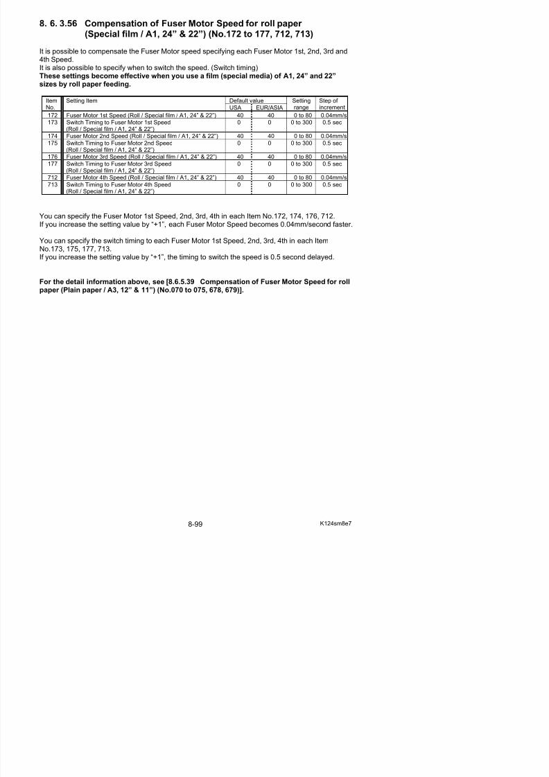
5/17/2018 KIP 7100 Service Manual Ver A_1 - slidepdf.com
http://slidepdf.com/reader/full/kip-7100-service-manual-ver-a1 541/674
181 Switch Timing to Fuser Motor 2nd Speed(Roll / Plain paper / A0, 36” & 34”)
10 10 0 to 300 0.5 sec
182 Fuser Motor 3rd Speed (Roll / Plain paper / A0, 36” & 34”) 33 37 0 to 80 0.04mm/s183 Switch Timing to Fuser Motor 3rd Speed(Roll / Plain paper / A0, 36” & 34”)
8 8 0 to 300 0.5 sec
714 Fuser Motor 4th Speed (Roll / Plain paper / A0, 36” & 34”) 30 30 0 to 80 0.04mm/s
715 Switch Timing to Fuser Motor 4th Speed(Roll / Plain paper / A0, 36” & 34”)
20 20 0 to 300 0.5 sec
You can specify the Fuser Motor 1st Speed, 2nd, 3rd, 4th in each Item No.178, 180, 182, 714.
If you increase the setting value by “+1”, each Fuser Motor Speed becomes 0.04mm/second faster.
You can specify the switch timing to each Fuser Motor 1st Speed, 2nd, 3rd, 4th in each ItemNo.179, 181, 183, 715.If you increase the setting value by “+1”, the timing to switch the speed is 0.5 second delayed.
For the detail information above, see [8.6.5.39 Compensation of Fuser Motor Speed for rollpaper (Plain paper / A3, 12” & 11”) (No.070 to 075, 678, 679)].
8. 6. 3.58 Compensation of Fuser Motor Speed for roll paper (Tracing paper / A0, 36” & 34”) (No.184 to 189, 716, 717)
It is possible to compensate the Fuser Motor speed specifying each Fuser Motor 1st, 2nd, 3rd and4th Speed.It is also possible to specify when to switch the speed. (Switch timing)These settings become effective when you use a tracing paper of A0, 36” and 34” sizes byroll paper feeding.
Default valueItemNo.
Setting Item
USA EUR/ASIA
Settingrange
Step of increment
184 Fuser Motor 1st Speed (Roll / Tracing / A0, 36” & 34”) 29 42 0 to 80 0.04mm/s
185 Switch Timing to Fuser Motor 1st Speed(Roll / Tracing / A0, 36” & 34”)
3 3 0 to 300 0.5 sec
186 Fuser Motor 2nd Speed (Roll / Tracing / A0, 36” & 34”) 35 38 0 to 80 0.04mm/s
187 S it h Ti i t F M t 2 d S d 13 13 0 t 300 0 5

5/17/2018 KIP 7100 Service Manual Ver A_1 - slidepdf.com
http://slidepdf.com/reader/full/kip-7100-service-manual-ver-a1 542/674
187 Switch Timing to Fuser Motor 2nd Speed(Roll / Tracing / A0, 36” & 34”)
13 13 0 to 300 0.5 sec
188 Fuser Motor 3rd Speed (Roll / Tracing / A0, 36” & 34”) 36 39 0 to 80 0.04mm/s189 Switch Timing to Fuser Motor 3rd Speed(Roll / Tracing / A0, 36” & 34”)
8 8 0 to 300 0.5 sec
716 Fuser Motor 4th Speed (Roll / Tracing / A0, 36” & 34”) 34 40 0 to 80 0.04mm/s
717 Switch Timing to Fuser Motor 4th Speed(Roll / Tracing / A0, 36” & 34”)
20 0 0 to 300 0.5 sec
You can specify the Fuser Motor 1st Speed, 2nd, 3rd, 4th in each Item No.184, 186, 188, 716.
If you increase the setting value by “+1”, each Fuser Motor Speed becomes 0.04mm/second faster.
You can specify the switch timing to each Fuser Motor 1st Speed, 2nd, 3rd, 4th in each ItemNo.185, 187, 189, 717.If you increase the setting value by “+1”, the timing to switch the speed is 0.5 second delayed.
For the detail information above, see [8.6.5.39 Compensation of Fuser Motor Speed for rollpaper (Plain paper / A3, 12” & 11”) (No.070 to 075, 678, 679)].
8. 6. 3.59 Compensation of Fuser Motor Speed for roll paper (Film / A0, 36” & 34”) (No.190 to 195, 718, 719)
It is possible to compensate the Fuser Motor speed specifying each Fuser Motor 1st, 2nd, 3rd and4th Speed.It is also possible to specify when to switch the speed. (Switch timing)These settings become effective when you use a film of A0, 36” and 34” sizes by roll paper feeding.
Default valueItemNo.
Setting Item
USA EUR/ASIA
Settingrange
Step of increment
190 Fuser Motor 1st Speed (Roll / Film / A0, 36” & 34”) 35 38 0 to 80 0.04mm/s
191 Switch Timing to Fuser Motor 1st Speed(Roll / Film / A0, 36” & 34”)
2 2 0 to 300 0.5 sec
192 Fuser Motor 2nd Speed (Roll / Film / A0, 36” & 34”) 40 43 0 to 80 0.04mm/s
193 Switch Timing to Fuser Motor 2nd Speed 18 18 0 to 300 0 5 sec

5/17/2018 KIP 7100 Service Manual Ver A_1 - slidepdf.com
http://slidepdf.com/reader/full/kip-7100-service-manual-ver-a1 543/674
193 Switch Timing to Fuser Motor 2nd Speed(Roll / Film / A0, 36” & 34”)
18 18 0 to 300 0.5 sec
194 Fuser Motor 3rd Speed (Roll / Film / A0, 36” & 34”) 40 40 0 to 80 0.04mm/s
195 Switch Timing to Fuser Motor 3rd Speed(Roll / Film / A0, 36” & 34”)
0 0 0 to 300 0.5 sec
718 Fuser Motor 4th Speed (Roll / Film / A0, 36” & 34”) 40 40 0 to 80 0.04mm/s
719 Switch Timing to Fuser Motor 4th Speed(Roll / Film / A0, 36” & 34”)
0 0 0 to 300 0.5 sec
You can specify the Fuser Motor 1st Speed, 2nd, 3rd, 4th in each Item No.190, 192, 194, 718.
If you increase the setting value by “+1”, each Fuser Motor Speed becomes 0.04mm/second faster.
You can specify the switch timing to each Fuser Motor 1st Speed, 2nd, 3rd, 4th in each ItemNo.191, 193, 195, 719.If you increase the setting value by “+1”, the timing to switch the speed is 0.5 second delayed.
For the detail information above, see [8.6.5.39 Compensation of Fuser Motor Speed for rollpaper (Plain paper / A3, 12” & 11”) (No.070 to 075, 678, 679)].
8. 6. 3.60 Compensation of Fuser Motor Speed for roll paper (Special plain paper / A0, 36 & 34”) (No.196 to 201, 720, 721)
It is possible to compensate the Fuser Motor speed specifying each Fuser Motor 1st, 2nd, 3rd and4th Speed.It is also possible to specify when to switch the speed. (Switch timing)These settings become effective when you use a plain paper (special media) of A0, 36” and34” sizes by roll paper feeding.
Default valueItemNo.
Setting Item
USA EUR/ASIA
Settingrange
Step of increment
196 Fuser Motor 1st Speed(Roll / Special plain paper / A0, 36” & 34”)
40 40 0 to 80 0.04mm/s
197 Switch Timing to Fuser Motor 1st Speed(Roll / Special plain paper / A0, 36” & 34”)
0 0 0 to 300 0.5 sec
198 Fuser Motor 2nd Speed 40 40 0 to 80 0 04mm/s

5/17/2018 KIP 7100 Service Manual Ver A_1 - slidepdf.com
http://slidepdf.com/reader/full/kip-7100-service-manual-ver-a1 544/674
198 Fuser Motor 2nd Speed(Roll / Special plain paper / A0, 36” & 34”)
40 40 0 to 80 0.04mm/s
199 Switch Timing to Fuser Motor 2nd Speed(Roll / Special plain paper / A0, 36” & 34”)
0 0 0 to 300 0.5 sec
200 Fuser Motor 3rd Speed(Roll / Special plain paper / A0, 36” & 34”)
40 40 0 to 80 0.04mm/s
201 Switch Timing to Fuser Motor 3rd Speed(Roll / Special plain paper / A0, 36” & 34”)
0 0 0 to 300 0.5 sec
720 Fuser Motor 4th Speed(Roll / Special plain paper / A0, 36” & 34”)
40 40 0 to 80 0.04mm/s
721 Switch Timing to Fuser Motor 4th Speed(Roll / Special plain paper / A0, 36” & 34”)
0 0 0 to 300 0.5 sec
You can specify the Fuser Motor 1st Speed, 2nd, 3rd, 4th in each Item No.196, 198, 200, 720.If you increase the setting value by “+1”, each Fuser Motor Speed becomes 0.04mm/second faster.
You can specify the switch timing to each Fuser Motor 1st Speed, 2nd, 3rd, 4th in each ItemNo.197, 199, 201, 721.If you increase the setting value by “+1”, the timing to switch the speed is 0.5 second delayed.
For the detail information above, see [8.6.5.39 Compensation of Fuser Motor Speed for rollpaper (Plain paper / A3, 12” & 11”) (No.070 to 075, 678, 679)].
8. 6. 3.61 Compensation of Fuser Motor Speed for roll paper (Special tracing paper / A0, 36” & 34”) (No.202 to 207, 722, 723)
It is possible to compensate the Fuser Motor speed specifying each Fuser Motor 1st, 2nd, 3rd and4th Speed.It is also possible to specify when to switch the speed. (Switch timing)These settings become effective when you use a tracing paper (special media) of A0, 36”and 34” size by roll paper feeding.
Default valueItemNo.
Setting Item
USA EUR/ASIA
Settingrange
Step of increment
202 Fuser Motor 1st Speed (Roll / Special tracing / A0, 36” &34”)
40 40 0 to 80 0.04mm/s
203 Switch Timing to Fuser Motor 1st Speed(Roll / Special tracing / A0, 36” & 34”)
0 0 0 to 300 0.5 sec
204 Fuser Motor 2nd Speed (Roll / Special tracing / A0 36” & 40 40 0 to 80 0 04mm/s

5/17/2018 KIP 7100 Service Manual Ver A_1 - slidepdf.com
http://slidepdf.com/reader/full/kip-7100-service-manual-ver-a1 545/674
204 Fuser Motor 2nd Speed (Roll / Special tracing / A0, 36 &34”)
40 40 0 to 80 0.04mm/s
205 Switch Timing to Fuser Motor 2nd Speed(Roll / Special tracing / A0, 36” & 34”)
0 0 0 to 300 0.5 sec
206 Fuser Motor 3rd Speed (Roll / Special tracing / A0, 36” &34”)
40 40 0 to 80 0.04mm/s
207 Switch Timing to Fuser Motor 3rd
Speed(Roll / Special tracing / A0, 36” & 34”)
0 0 0 to 300 0.5 sec
722 Fuser Motor 4th Speed (Roll / Special tracing / A0, 36” &34”)
40 40 0 to 80 0.04mm/s
723 Switch Timing to Fuser Motor 4th Speed(Roll / Special tracing / A0, 36” & 34”)
0 0 0 to 300 0.5 sec
You can specify the Fuser Motor 1st Speed, 2nd, 3rd, 4th in each Item No.202, 204, 206, 722.If you increase the setting value by “+1”, each Fuser Motor Speed becomes 0.04mm/second faster.
You can specify the switch timing to each Fuser Motor 1st Speed, 2nd, 3rd, 4th in each ItemNo.203, 205, 207, 723.If you increase the setting value by “+1”, the timing to switch the speed is 0.5 second delayed.
For the detail information above, see [8.6.5.39 Compensation of Fuser Motor Speed for rollpaper (Plain paper / A3, 12” & 11”) (No.070 to 075, 678, 679)].
8. 6. 3.62 Compensation of Fuser Motor Speed for roll paper (Special film / A0, 36” & 34”) (No.208 to 213, 724, 725)
It is possible to compensate the Fuser Motor speed specifying each Fuser Motor 1st, 2nd, 3rd and4th Speed.It is also possible to specify when to switch the speed. (Switch timing)These settings become effective when you use a film (special media) of A0, 24” and 22”sizes by roll paper feeding.
Default valueItemNo.
Setting Item
USA EUR/ASIA
Settingrange
Step of increment
208 Fuser Motor 1st Speed (Roll / Special film / A0, 36” & 34”) 40 40 0 to 80 0.04mm/s
209 Switch Timing to Fuser Motor 1st Speed(Roll / Special film / A0, 36” & 34”)
0 0 0 to 300 0.5 sec
210 Fuser Motor 2nd Speed (Roll / Special film / A0, 36” & 34”) 40 40 0 to 80 0.04mm/s
211 Switch Timing to Fuser Motor 2nd Speed 0 0 0 to 300 0.5 sec
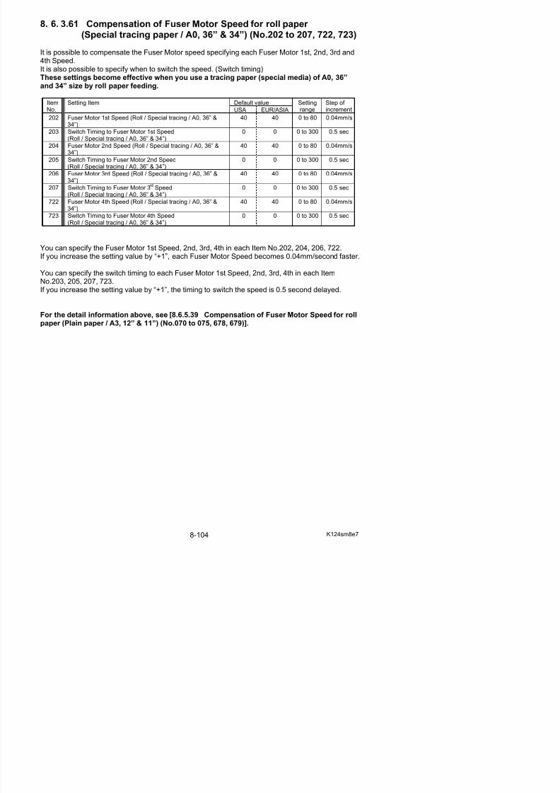
5/17/2018 KIP 7100 Service Manual Ver A_1 - slidepdf.com
http://slidepdf.com/reader/full/kip-7100-service-manual-ver-a1 546/674
g p(Roll / Special film / A0, 36” & 34”)
212 Fuser Motor 3rd Speed (Roll / Special film / A0, 36” & 34”) 40 40 0 to 80 0.04mm/s
213 Switch Timing to Fuser Motor 3rd Speed(Roll / Special film / A0, 36” & 34”)
0 0 0 to 300 0.5 sec
724 Fuser Motor 4th Speed (Roll / Special film / A0, 36” & 34”) 40 40 0 to 80 0.04mm/s
725 Switch Timing to Fuser Motor 4th Speed(Roll / Special film / A0, 36” & 34”)
0 0 0 to 300 0.5 sec
You can specify the Fuser Motor 1st Speed, 2nd, 3rd, 4th in each Item No.208, 210, 212, 724.If you increase the setting value by “+1”, each Fuser Motor Speed becomes 0.04mm/second faster.
You can specify the switch timing to each Fuser Motor 1st Speed, 2nd, 3rd, 4th in each ItemNo.209, 211, 213, 725.If you increase the setting value by “+1”, the timing to switch the speed is 0.5 second delayed.
For the detail information above, see [8.6.5.39 Compensation of Fuser Motor Speed for rollpaper (Plain paper / A3, 12” & 11”) (No.070 to 075, 678, 679)].
8. 6. 3.63 Main Motor Speed (No.310 to 315)
It is possible to adjust the speed of Main Motor for each type of paper separately.If you increase the setting value by “+1”, the motor speed becomes 0.04mm/second faster.
Default valueItemNo.
Setting Item
USA EUR/ASIA
Settingrange
Step of increment
310 Main Motor Speed (Plain paper) 36 36 0 to 80 0.04mm/s
311 Main Motor Speed (Tracing paper) 40 40 0 to 80 0.04mm/s
312 Main Motor Speed (Film) 40 40 0 to 80 0.04mm/s313 Main Motor Speed (Special plain paper) 40 40 0 to 80 0.04mm/s
314 Main Motor Speed (Special tracing paper) 40 40 0 to 80 0.04mm/s
315 Main Motor Speed (Special film) 40 40 0 to 80 0.04mm/s
CAUTION

5/17/2018 KIP 7100 Service Manual Ver A_1 - slidepdf.com
http://slidepdf.com/reader/full/kip-7100-service-manual-ver-a1 547/674
8. 6. 3.64 Fuser Motor Speed (36” / 34” / 30” / 24” / 22” / A0 / B1 / A1)(No.316 to 321)
It is possible to adjust the speed of Fuser Motor for each type of paper separately.
If you increase the setting value by “+1”, the motor speed becomes 0.04mm/second faster.
Default valueItemNo.
Setting Item
USA EUR/ASIA
Settingrange
Step of increment
316 Fuser Motor Speed (36” / 34” / 30” / 24” / 22” / A0 / B1 / A1)(Plain paper)
31 35 0 to 80 0.04mm/s
317 Fuser Motor Speed (36” / 34” / 30” / 24” / 22” / A0 / B1 / A1)(Tracing paper)
39 50 0 to 80 0.04mm/s
318 Fuser Motor Speed (36” / 34” / 30” / 24” / 22” / A0 / B1 / A1)(Film paper)
50 50 0 to 80 0.04mm/s
319 Fuser Motor Speed (36” / 34” / 30” / 24” / 22” / A0 / B1 / A1)(Special plain paper)
40 40 0 to 80 0.04mm/s
320 Fuser Motor Speed (36” / 34” / 30” / 24” / 22” / A0 / B1 / A1)(Special tracing paper)
40 40 0 to 80 0.04mm/s
321 Fuser Motor Speed (36” / 34” / 30” / 24” / 22” / A0 / B1 / A1)(Special film)
40 40 0 to 80 0.04mm/s
Refer to [8. 6. 3.119 Fuser Motor Speed] on page 8-134 for narrower originals than the above.
8 6 3 65 Separation Corona OFF Timing (No 322 to 327)
The Main Motor Speed is the basis for many other print settings.
So you have to re-adjust all of these print settings if you change the Main Motor Speed.
8. 6. 3.66 Compensation of Fuser Motor Speed for cut sheet paper (Plain paper / A3, A2, 12”, 11”, 18” & 17”) (No.328 to 333)
It is possible to compensate the Fuser Motor speed specifying each Fuser Motor 1st, 2nd and 3rdSpeed.It is also possible to specify when to switch the speed. (Switch timing)These settings become effective when you use a plain paper of A2, 18” and 17” sizes by cutsheet bypass feeding.
Default valueItemNo.
Setting Item
USA EUR/ASIA
Settingrange
Step of increment
328 Fuser Motor 1st Speed(Cut sheet / Plain paper / A3, A2, 12”, 11”, 18” & 17”)
30 31 0 to 80 0.04mm/s
329 Switch Timing to Fuser Motor 1st Speed(Cut sheet / Plain paper / A3, A2, 12”, 11”, 18” & 17”)
3 3 0 to 300 0.5 sec
330 Fuser Motor 2nd Speed 32 36 0 to 80 0.04mm/s
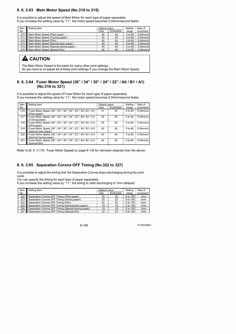
5/17/2018 KIP 7100 Service Manual Ver A_1 - slidepdf.com
http://slidepdf.com/reader/full/kip-7100-service-manual-ver-a1 548/674
(Cut sheet / Plain paper / A3, A2, 12”, 11”, 18” & 17”)
331 Switch Timing to Fuser Motor 2nd Speed(Cut sheet / Plain paper / A3, A2, 12”, 11”, 18” & 17”)
4 4 0 to 300 0.5 sec
332 Fuser Motor 3rd Speed(Cut sheet / Plain paper / A3, A2, 12”, 11”, 18” & 17”)
31 38 0 to 80 0.04mm/s
333 Switch Timing to Fuser Motor 3rd Speed(Cut sheet / Plain paper / A3, A2, 12”, 11”, 18” & 17”)
6 6 0 to 300 0.5 sec
You can specify the Fuser Motor 1st Speed, 2nd, 3rd in each Item No.328, 330 and 332.If you increase the setting value by “+1”, each Fuser Motor Speed becomes 0.04mm/second faster.
You can specify the switch timing to each Fuser Motor 1st Speed, 2nd, 3rd in each Item No.329,331 and 333.If you increase the setting value by “+1”, the timing to switch the speed is 0.5 second delayed.
For the detail information above, see [8.6.5.39 Compensation of Fuser Motor Speed for rollpaper (Plain paper / A3, 12” & 11”) (No.070 to 075, 678, 679)].
8. 6. 3.67 Compensation of Fuser Motor Speed for cut sheet paper (Tracing paper / A3, A2, 12”, 11”, 18” & 17”) (No.334 to 339)
It is possible to compensate the Fuser Motor speed specifying each Fuser Motor 1st, 2nd and 3rdSpeed.It is also possible to specify when to switch the speed. (Switch timing)These settings become effective when you use a tracing paper of A2, 18” and 17” sizes bycut sheet bypass feeding.
Default valueItemNo.
Setting Item
USA EUR/ASIA
Settingrange
Step of increment
334 Fuser Motor 1st Speed(Cut sheet / Tracing / A3, A2, 12”, 11”, 18” & 17”)
33 40 0 to 80 0.04mm/s
335 Switch Timing to Fuser Motor 1st Speed(Cut sheet / Tracing / A3, A2, 12”, 11”, 18” & 17”)
2 1 0 to 300 0.5 sec
336 Fuser Motor 2nd Speed(C t h t / T i / A3 A2 12” 11” 18” & 17”)
38 44 0 to 80 0.04mm/s
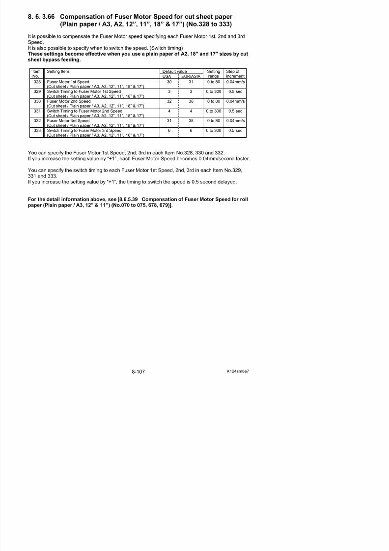
5/17/2018 KIP 7100 Service Manual Ver A_1 - slidepdf.com
http://slidepdf.com/reader/full/kip-7100-service-manual-ver-a1 549/674
(Cut sheet / Tracing / A3, A2, 12”, 11”, 18” & 17”)
337 Switch Timing to Fuser Motor 2nd Speed(Cut sheet / Tracing / A3, A2, 12”, 11”, 18” & 17”)
3 5 0 to 300 0.5 sec
338 Fuser Motor 3rd Speed(Cut sheet / Tracing / A3, A2, 12”, 11”, 18” & 17”)
38 45 0 to 80 0.04mm/s
339 Switch Timing to Fuser Motor 3rd Speed(Cut sheet / Tracing / A3, A2, 12”, 11”, 18” & 17”)
5 2 0 to 300 0.5 sec
You can specify the Fuser Motor 1st Speed, 2nd, 3rd in each Item No.334, 336 and 338.If you increase the setting value by “+1”, each Fuser Motor Speed becomes 0.04mm/second faster.
You can specify the switch timing to each Fuser Motor 1st Speed, 2nd, 3rd in each Item No.335,337 and 339.If you increase the setting value by “+1”, the timing to switch the speed is 0.5 second delayed.
For the detail information above, see [8.6.5.39 Compensation of Fuser Motor Speed for rollpaper (Plain paper / A3, 12” & 11”) (No.070 to 075, 678, 679)].
8. 6. 3.68 Compensation of Fuser Motor Speed for cut sheet paper (Film / A3, A2, 12”, 11”, 18” & 17”) (No.340 to 345)
It is possible to compensate the Fuser Motor speed specifying each Fuser Motor 1st, 2nd and 3rdSpeed.It is also possible to specify when to switch the speed. (Switch timing)These settings become effective when you use a film of A2, 18” and 17” sizes by cut sheetbypass feeding.
Default valueItemNo.
Setting Item
USA EUR/ASIA
Settingrange
Step of increment
340 Fuser Motor 1st Speed(Cut sheet / Film / A3, A2, 12”, 11”, 18” & 17”)
50 50 0 to 80 0.04mm/s
341 Switch Timing to Fuser Motor 1st Speed(Cut sheet / Film / A3, A2, 12”, 11”, 18” & 17”)
2 6 0 to 300 0.5 sec
342 Fuser Motor 2nd Speed(Cut sheet / Film / A3 A2 12” 11” 18” & 17”)
50 40 0 to 80 0.04mm/s

5/17/2018 KIP 7100 Service Manual Ver A_1 - slidepdf.com
http://slidepdf.com/reader/full/kip-7100-service-manual-ver-a1 550/674
(Cut sheet / Film / A3, A2, 12 , 11 , 18 & 17 )
343 Switch Timing to Fuser Motor 2nd Speed
(Cut sheet / Film / A3, A2, 12”, 11”, 18” & 17”)
6 0 0 to 300 0.5 sec
344 Fuser Motor 3rd Speed(Cut sheet / Film / A3, A2, 12”, 11”, 18” & 17”)
40 40 0 to 80 0.04mm/s
345 Switch Timing to Fuser Motor 3rd Speed(Cut sheet / Film / A3, A2, 12”, 11”, 18” & 17”)
0 0 0 to 300 0.5 sec
You can specify the Fuser Motor 1st Speed, 2nd, 3rd in each Item No.340, 342 and 344.If you increase the setting value by “+1”, each Fuser Motor Speed becomes 0.04mm/second faster.
You can specify the switch timing to each Fuser Motor 1st Speed, 2nd, 3rd in each Item No.341,343 and 345.If you increase the setting value by “+1”, the timing to switch the speed is 0.5 second delayed.
For the detail information above, see [8.6.5.39 Compensation of Fuser Motor Speed for rollpaper (Plain paper / A3, 12” & 11”) (No.070 to 075, 678, 679)].
8. 6. 3.69 Compensation of Fuser Motor Speed for cut sheet paper (Special plain paper / A3, A2, 12”, 11”, 18” & 17”)(No.346 to 351)
It is possible to compensate the Fuser Motor speed specifying each Fuser Motor 1st, 2nd and 3rdSpeed.It is also possible to specify when to switch the speed. (Switch timing)These settings become effective when you use a plain paper (special media) of A2, 18” and
17” sizes by cut sheet bypass feeding.
Default valueItemNo.
Setting Item
USA EUR/ASIA
Settingrange
Step of increment
346 Fuser Motor 1st Speed(Cut sheet / Special plain paper / A3, A2, 12”, 11”, 18” & 17”)
40 40 0 to 80 0.04mm/s
347 Switch Timing to Fuser Motor 1st Speed(Cut sheet / Special plain paper / A3, A2, 12”, 11”, 18” & 17”)
0 0 0 to 300 0.5 sec

5/17/2018 KIP 7100 Service Manual Ver A_1 - slidepdf.com
http://slidepdf.com/reader/full/kip-7100-service-manual-ver-a1 551/674
348 Fuser Motor 2nd Speed
(Cut sheet / Special plain paper / A3, A2, 12”, 11”, 18” & 17”)
40 40 0 to 80 0.04mm/s
349 Switch Timing to Fuser Motor 2nd Speed(Cut sheet / Special plain paper / A3, A2, 12”, 11”, 18” & 17”)
0 0 0 to 300 0.5 sec
350 Fuser Motor 3rd Speed(Cut sheet / Special plain paper / A3, A2, 12”, 11”, 18” & 17”)
40 40 0 to 80 0.04mm/s
351 Switch Timing to Fuser Motor 3rd Speed(Cut sheet / Special plain paper / A3, A2, 12”, 11”, 18” & 17”)
0 0 0 to 300 0.5 sec
You can specify the Fuser Motor 1st Speed, 2nd, 3rd in each Item No.346, 348 and 350.If you increase the setting value by “+1”, each Fuser Motor Speed becomes 0.04mm/second faster.
You can specify the switch timing to each Fuser Motor 1st Speed, 2nd, 3rd in each Item No.347,349 and 351.If you increase the setting value by “+1”, the timing to switch the speed is 0.5 second delayed.
For the detail information above, see [8.6.5.39 Compensation of Fuser Motor Speed for rollpaper (Plain paper / A3, 12” & 11”) (No.070 to 075, 678, 679)].
8. 6. 3.70 Compensation of Fuser Motor Speed for cut sheet paper (Special tracing paper / A3, A2, 12”, 11”, 18” & 17”)(No.352 to 357)
It is possible to compensate the Fuser Motor speed specifying each Fuser Motor 1st, 2nd and 3rdSpeed.It is also possible to specify when to switch the speed. (Switch timing)These settings become effective when you use a tracing paper (special media) of A2, 18”
and 17” size by cut sheet bypass feeding.
Default valueItemNo.
Setting Item
USA EUR/ASIA
Settingrange
Step of increment
352 Fuser Motor 1st Speed(Cut sheet / Special tracing / A3, A2, 12”, 11”, 18” & 17”)
40 40 0 to 80 0.04mm/s
353 Switch Timing to Fuser Motor 1st Speed(Cut sheet / Special tracing / A3, A2, 12”, 11”, 18” & 17”)
0 0 0 to 300 0.5 sec

5/17/2018 KIP 7100 Service Manual Ver A_1 - slidepdf.com
http://slidepdf.com/reader/full/kip-7100-service-manual-ver-a1 552/674
354 Fuser Motor 2nd Speed
(Cut sheet / Special tracing / A3, A2, 12”, 11”, 18” & 17”)
40 40 0 to 80 0.04mm/s
355 Switch Timing to Fuser Motor 2nd Speed(Cut sheet / Special tracing / A3, A2, 12”, 11”, 18” & 17”)
0 0 0 to 300 0.5 sec
356 Fuser Motor 3rd Speed(Cut sheet / Special tracing / A3, A2, 12”, 11”, 18” & 17”)
40 40 0 to 80 0.04mm/s
357 Switch Timing to Fuser Motor 3rd Speed(Cut sheet / Special tracing / A3, A2, 12”, 11”, 18” & 17”)
0 0 0 to 300 0.5 sec
You can specify the Fuser Motor 1st Speed, 2nd, 3rd in each Item No.352, 354 and 356.If you increase the setting value by “+1”, each Fuser Motor Speed becomes 0.04mm/second faster.
You can specify the switch timing to each Fuser Motor 1st Speed, 2nd, 3rd in each Item No.353,355 and 357.If you increase the setting value by “+1”, the timing to switch the speed is 0.5 second delayed.
For the detail information above, see [8.6.5.39 Compensation of Fuser Motor Speed for rollpaper (Plain paper / A3, 12” & 11”) (No.070 to 075, 678, 679)].
8. 6. 3.71 Compensation of Fuser Motor Speed for cut sheet paper (Special film / A3, A2, 12”, 11”, 18” & 17”) (No.358 to 363)
It is possible to compensate the Fuser Motor speed specifying each Fuser Motor 1st, 2nd and 3rdSpeed.It is also possible to specify when to switch the speed. (Switch timing)These settings become effective when you use a film (special media) of A2, 18” and 17”sizes by cut sheet bypass feeding.
Default valueItemNo.
Setting Item
USA EUR/ASIA
Settingrange
Step of increment
358 Fuser Motor 1st Speed(Cut sheet / Special film / A3, A2, 12”, 11”, 18” & 17”)
40 40 0 to 80 0.04mm/s
359 Switch Timing to Fuser Motor 1st Speed(Cut sheet / Special film / A3, A2, 12”, 11”, 18” & 17”)
0 0 0 to 300 0.5 sec
360 Fuser Motor 2nd Speed(Cut sheet / Special film / A3, A2, 12”, 11”, 18” & 17”)
40 40 0 to 80 0.04mm/s
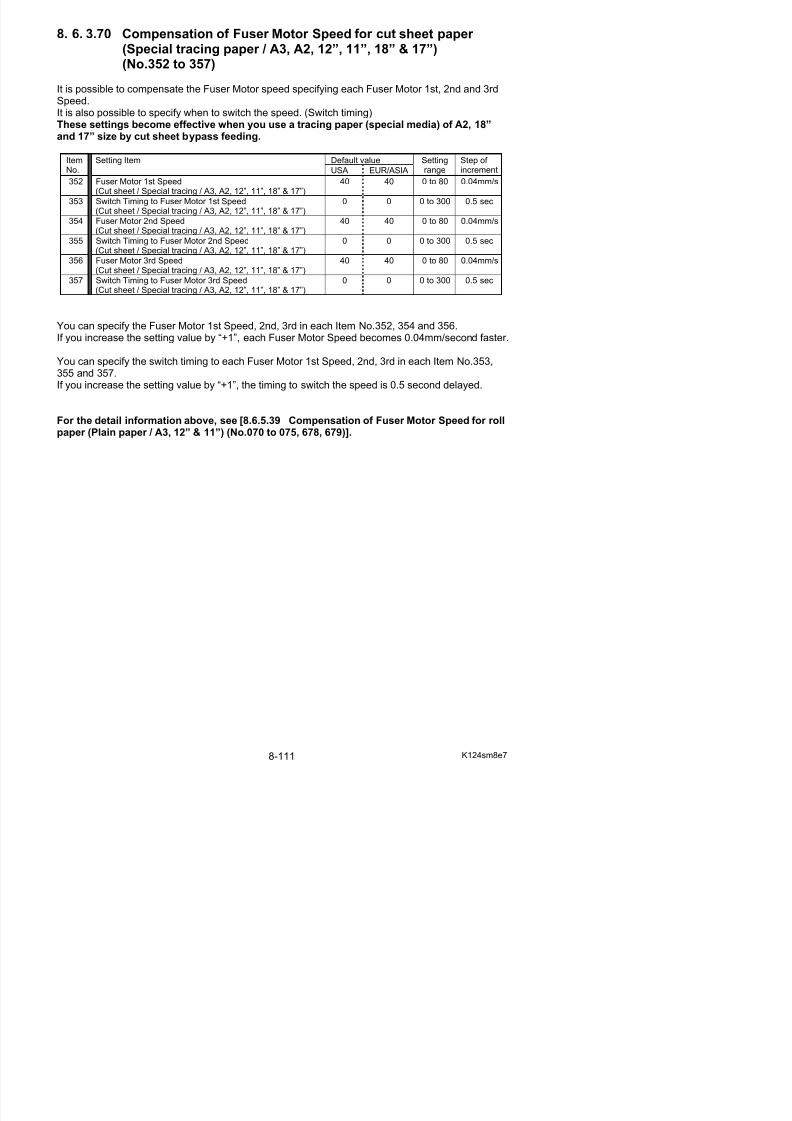
5/17/2018 KIP 7100 Service Manual Ver A_1 - slidepdf.com
http://slidepdf.com/reader/full/kip-7100-service-manual-ver-a1 553/674
( p , , , , )
361 Switch Timing to Fuser Motor 2nd Speed
(Cut sheet / Special film / A3, A2, 12”, 11”, 18” & 17”)
0 0 0 to 300 0.5 sec
362 Fuser Motor 3rd Speed(Cut sheet / Special film / A3, A2, 12”, 11”, 18” & 17”)
40 40 0 to 80 0.04mm/s
363 Switch Timing to Fuser Motor 3rd Speed(Cut sheet / Special film / A3, A2, 12”, 11”, 18” & 17”)
0 0 0 to 300 0.5 sec
You can specify the Fuser Motor 1st Speed, 2nd, 3rd in each Item No.358, 360 and 362.If you increase the setting value by “+1”, each Fuser Motor Speed becomes 0.04mm/second faster.
You can specify the switch timing to each Fuser Motor 1st Speed, 2nd, 3rd in each Item No.359,361 and 363.If you increase the setting value by “+1”, the timing to switch the speed is 0.5 second delayed.
For the detail information above, see [8.6.5.39 Compensation of Fuser Motor Speed for rollpaper (Plain paper / A3, 12” & 11”) (No.070 to 075, 678, 679)].
8. 6. 3.72 Compensation of Fuser Motor Speed for cut sheet paper (Plain paper / A1, 24” & 22”) (No.364 to 369)
It is possible to compensate the Fuser Motor speed specifying each Fuser Motor 1st, 2nd and 3rdSpeed.It is also possible to specify when to switch the speed. (Switch timing)These settings become effective when you use a plain paper of A1, 24” and 22” sizes by cutsheet bypass feeding.
Default valueItemNo.
Setting Item
USA EUR/ASIA
Settingrange
Step of increment
364 Fuser Motor 1st Speed (Cut sheet / Plain paper / A1, 24” &22”)
37 35 0 to 80 0.04mm/s
365 Switch Timing to Fuser Motor 1st Speed(Cut sheet / Plain paper / A1, 24” & 22”)
3 3 0 to 300 0.5 sec
366 Fuser Motor 2nd Speed (Cut sheet / Plain paper / A1, 24” &22”)
30 33 0 to 80 0.04mm/s

5/17/2018 KIP 7100 Service Manual Ver A_1 - slidepdf.com
http://slidepdf.com/reader/full/kip-7100-service-manual-ver-a1 554/674
367 Switch Timing to Fuser Motor 2nd Speed
(Cut sheet / Plain paper / A1, 24” & 22”)
6 8 0 to 300 0.5 sec
368 Fuser Motor 3rd Speed (Cut sheet / Plain paper / A1, 24” &22”)
40 41 0 to 80 0.04mm/s
369 Switch Timing to Fuser Motor 3rd Speed(Cut sheet / Plain paper / A1, 24” & 22”)
6 8 0 to 300 0.5 sec
You can specify the Fuser Motor 1st Speed, 2nd, 3rd in each Item No.364, 366 and 368.If you increase the setting value by “+1”, each Fuser Motor Speed becomes 0.04mm/second faster.
You can specify the switch timing to each Fuser Motor 1st Speed, 2nd, 3rd in each Item No.365,367 and 369.If you increase the setting value by “+1”, the timing to switch the speed is 0.5 second delayed.
For the detail information above, see [8.6.5.39 Compensation of Fuser Motor Speed for rollpaper (Plain paper / A3, 12” & 11”) (No.070 to 075, 678, 679)].
8. 6. 3.73 Compensation of Fuser Motor Speed for cut sheet paper (Tracing paper / A1, 24” & 22”) (No.370 to 375)
It is possible to compensate the Fuser Motor speed specifying each Fuser Motor 1st, 2nd and 3rdSpeed.It is also possible to specify when to switch the speed. (Switch timing)These settings become effective when you use a tracing paper of A1, 24” and 22” sizes bycut sheet bypass feeding.
Default valueItemNo.
Setting Item
USA EUR/ASIA
Settingrange
Step of increment
370 Fuser Motor 1st Speed (Cut sheet / Tracing / A1, 24” & 22”) 36 42 0 to 80 0.04mm/s
371 Switch Timing to Fuser Motor 1st Speed(Cut sheet / Tracing / A1, 24” & 22”)
3 3 0 to 300 0.5 sec
372 Fuser Motor 2nd Speed (Cut sheet / Tracing / A1, 24” & 22”) 41 43 0 to 80 0.04mm/s
373 Switch Timing to Fuser Motor 2nd Speed(Cut sheet / Tracing / A1, 24” & 22”)
9 9 0 to 300 0.5 sec
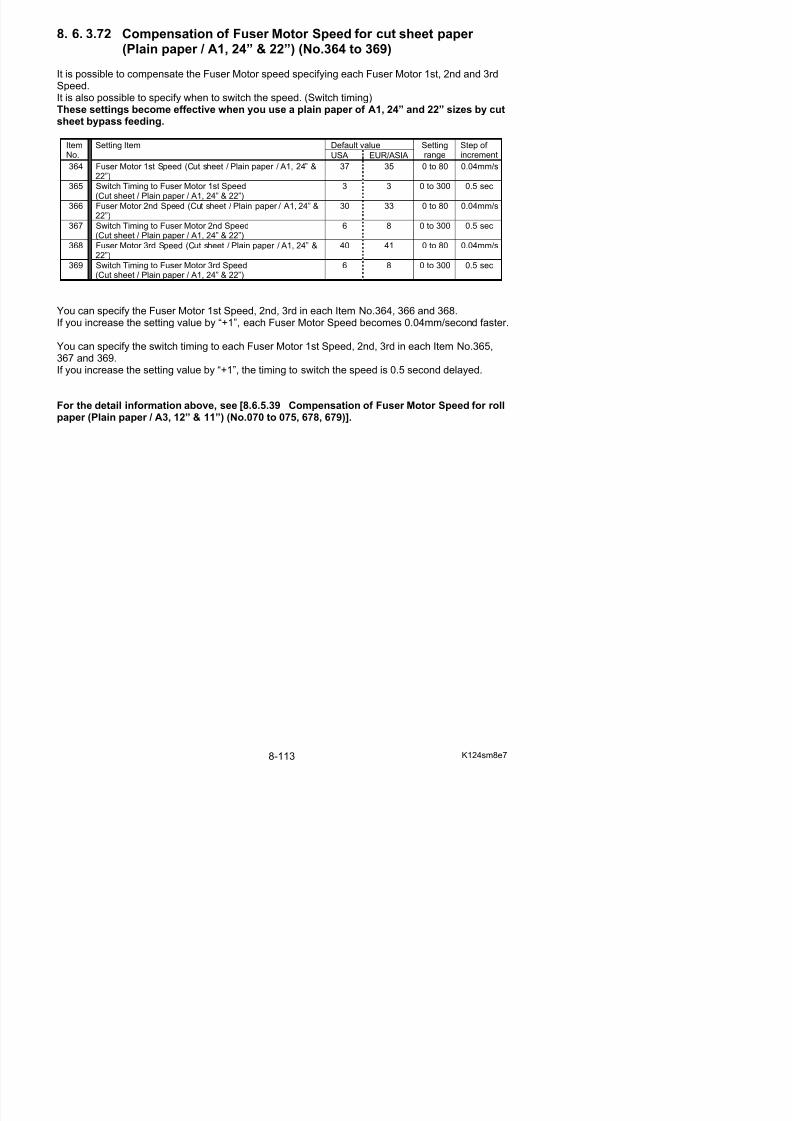
5/17/2018 KIP 7100 Service Manual Ver A_1 - slidepdf.com
http://slidepdf.com/reader/full/kip-7100-service-manual-ver-a1 555/674
374 Fuser Motor 3rd Speed (Cut sheet / Tracing / A1, 24” & 22”) 39 40 0 to 80 0.04mm/s
375 Switch Timing to Fuser Motor 3rd Speed(Cut sheet / Tracing / A1, 24” & 22”)
8 8 0 to 300 0.5 sec
You can specify the Fuser Motor 1st Speed, 2nd, 3rd in each Item No.370, 372 and 374.If you increase the setting value by “+1”, each Fuser Motor Speed becomes 0.04mm/second faster.
You can specify the switch timing to each Fuser Motor 1st Speed, 2nd, 3rd in each Item No.371,
373 and 375.If you increase the setting value by “+1”, the timing to switch the speed is 0.5 second delayed.
For the detail information above, see [8.6.5.39 Compensation of Fuser Motor Speed for rollpaper (Plain paper / A3, 12” & 11”) (No.070 to 075, 678, 679)].
8. 6. 3.74 Compensation of Fuser Motor Speed for cut sheet paper (Film / A1, 24” & 22”) (No.376 to 381)
It is possible to compensate the Fuser Motor speed specifying each Fuser Motor 1st, 2nd and 3rdSpeed.It is also possible to specify when to switch the speed. (Switch timing)These settings become effective when you use a film of A1, 24” and 22” sizes by cut sheetbypass feeding.
Default valueItemNo.
Setting Item
USA EUR/ASIA
Settingrange
Step of increment
376 Fuser Motor 1st Speed (Cut sheet / Film / A1, 24” & 22”) 42 42 0 to 80 0.04mm/s
377 Switch Timing to Fuser Motor 1st Speed(Cut sheet / Film / A1, 24” & 22”)
2 2 0 to 300 0.5 sec
378 Fuser Motor 2nd Speed (Cut sheet / Film / A1, 24” & 22”) 42 42 0 to 80 0.04mm/s
379 Switch Timing to Fuser Motor 2nd Speed(Cut sheet / Film / A1, 24” & 22”)
14 14 0 to 300 0.5 sec
380 F M t 3 d S d (C t h t / Fil / A1 24” & 22”) 40 40 0 t 80 0 04 /

5/17/2018 KIP 7100 Service Manual Ver A_1 - slidepdf.com
http://slidepdf.com/reader/full/kip-7100-service-manual-ver-a1 556/674
380 Fuser Motor 3rd Speed (Cut sheet / Film / A1, 24” & 22”) 40 40 0 to 80 0.04mm/s
381 Switch Timing to Fuser Motor 3rd Speed(Cut sheet / Film / A1, 24” & 22”)
0 0 0 to 300 0.5 sec
You can specify the Fuser Motor 1st Speed, 2nd, 3rd in each Item No.376, 378 and 380.If you increase the setting value by “+1”, each Fuser Motor Speed becomes 0.04mm/second faster.
You can specify the switch timing to each Fuser Motor 1st Speed, 2nd, 3rd in each Item No.377,
379 and 381.If you increase the setting value by “+1”, the timing to switch the speed is 0.5 second delayed.
For the detail information above, see [8.6.5.39 Compensation of Fuser Motor Speed for rollpaper (Plain paper / A3, 12” & 11”) (No.070 to 075, 678, 679)].
8. 6. 3.75 Compensation of Fuser Motor Speed for cut sheet paper (Special plain paper / A1, 24” & 22”) (No.382 to 387)
It is possible to compensate the Fuser Motor speed specifying each Fuser Motor 1st, 2nd and 3rdSpeed.It is also possible to specify when to switch the speed. (Switch timing)These settings become effective when you use a plain paper (special media) of A1, 24” and22” sizes by cut sheet bypass feeding.
Default valueItemNo.
Setting Item
USA EUR/ASIA
Settingrange
Step of increment
382 Fuser Motor 1st Speed(Cut sheet / Special plain paper / A1, 24” & 22”)
40 40 0 to 80 0.04mm/s
383 Switch Timing to Fuser Motor 1st Speed(Cut sheet / Special plain paper / A1, 24” & 22”)
0 0 0 to 300 0.5 sec
384 Fuser Motor 2nd Speed(Cut sheet / Special plain paper / A1, 24” & 22”)
40 40 0 to 80 0.04mm/s
385 Switch Timing to Fuser Motor 2nd Speed 0 0 0 to 300 0 5 sec

5/17/2018 KIP 7100 Service Manual Ver A_1 - slidepdf.com
http://slidepdf.com/reader/full/kip-7100-service-manual-ver-a1 557/674
385 Switch Timing to Fuser Motor 2nd Speed
(Cut sheet / Special plain paper / A1, 24” & 22”)
0 0 0 to 300 0.5 sec
386 Fuser Motor 3rd Speed(Cut sheet / Special plain paper / A1, 24” & 22”)
40 40 0 to 80 0.04mm/s
387 Switch Timing to Fuser Motor 3rd Speed(Cut sheet / Special plain paper / A1, 24” & 22”)
0 0 0 to 300 0.5 sec
You can specify the Fuser Motor 1st Speed, 2nd, 3rd in each Item No.382, 384 and 386.If you increase the setting value by “+1”, each Fuser Motor Speed becomes 0.04mm/second faster.
You can specify the switch timing to each Fuser Motor 1st Speed, 2nd, 3rd in each Item No.383,385 and 387.If you increase the setting value by “+1”, the timing to switch the speed is 0.5 second delayed.
For the detail information above, see [8.6.5.39 Compensation of Fuser Motor Speed for rollpaper (Plain paper / A3, 12” & 11”) (No.070 to 075, 678, 679)].
8. 6. 3.76 Compensation of Fuser Motor Speed for cut sheet paper (Special tracing paper / A1, 24” & 22”) (No.388 to 393)
It is possible to compensate the Fuser Motor speed specifying each Fuser Motor 1st, 2nd and 3rdSpeed.It is also possible to specify when to switch the speed. (Switch timing)These settings become effective when you use a tracing paper (special media) of A1, 24”and 22” size by cut sheet bypass feeding.
Default valueItemNo.
Setting Item
USA EUR/ASIA
Settingrange
Step of increment
388 Fuser Motor 1st Speed(Cut sheet / Special tracing / A1, 24” & 22”)
40 40 0 to 80 0.04mm/s
389 Switch Timing to Fuser Motor 1st Speed(Cut sheet / Special tracing / A1, 24” & 22”)
0 0 0 to 300 0.5 sec
390 Fuser Motor 2nd Speed(Cut sheet / Special tracing / A1, 24” & 22”)
40 40 0 to 80 0.04mm/s
391 Switch Timing to Fuser Motor 2nd Speed 0 0 0 to 300 0 5 sec

5/17/2018 KIP 7100 Service Manual Ver A_1 - slidepdf.com
http://slidepdf.com/reader/full/kip-7100-service-manual-ver-a1 558/674
391 Switch Timing to Fuser Motor 2nd Speed
(Cut sheet / Special tracing / A1, 24” & 22”)
0 0 0 to 300 0.5 sec
392 Fuser Motor 3rd Speed(Cut sheet / Special tracing / A1, 24” & 22”)
40 40 0 to 80 0.04mm/s
393 Switch Timing to Fuser Motor 3rd Speed(Cut sheet / Special tracing / A1, 24” & 22”)
0 0 0 to 300 0.5 sec
You can specify the Fuser Motor 1st Speed, 2nd, 3rd in each Item No.388, 390 and 392.If you increase the setting value by “+1”, each Fuser Motor Speed becomes 0.04mm/second faster.
You can specify the switch timing to each Fuser Motor 1st Speed, 2nd, 3rd in each Item No.389,391 and 393.If you increase the setting value by “+1”, the timing to switch the speed is 0.5 second delayed.
For the detail information above, see [8.6.5.39 Compensation of Fuser Motor Speed for rollpaper (Plain paper / A3, 12” & 11”) (No.070 to 075, 678, 679)].
8. 6. 3.77 Compensation of Fuser Motor Speed for cut sheet paper (Special film / A1, 24” & 22”) (No.394 to 399)
It is possible to compensate the Fuser Motor speed specifying each Fuser Motor 1st, 2nd and 3rdSpeed.It is also possible to specify when to switch the speed. (Switch timing)These settings become effective when you use a film (special media) of A1, 24” and 22”sizes by cut sheet bypass feeding.
Default valueItemNo.
Setting Item
USA EUR/ASIA
Settingrange
Step of increment
394 Fuser Motor 1st Speed (Cut sheet / Special film / A1, 24” &22”)
40 40 0 to 80 0.04mm/s
395 Switch Timing to Fuser Motor 1st Speed(Cut sheet / Special film / A1, 24” & 22”)
0 0 0 to 300 0.5 sec
396 Fuser Motor 2nd Speed (Cut sheet / Special film / A1, 24” &22”)
40 40 0 to 80 0.04mm/s
397 Switch Timing to Fuser Motor 2nd Speed 0 0 0 to 300 0 5 sec
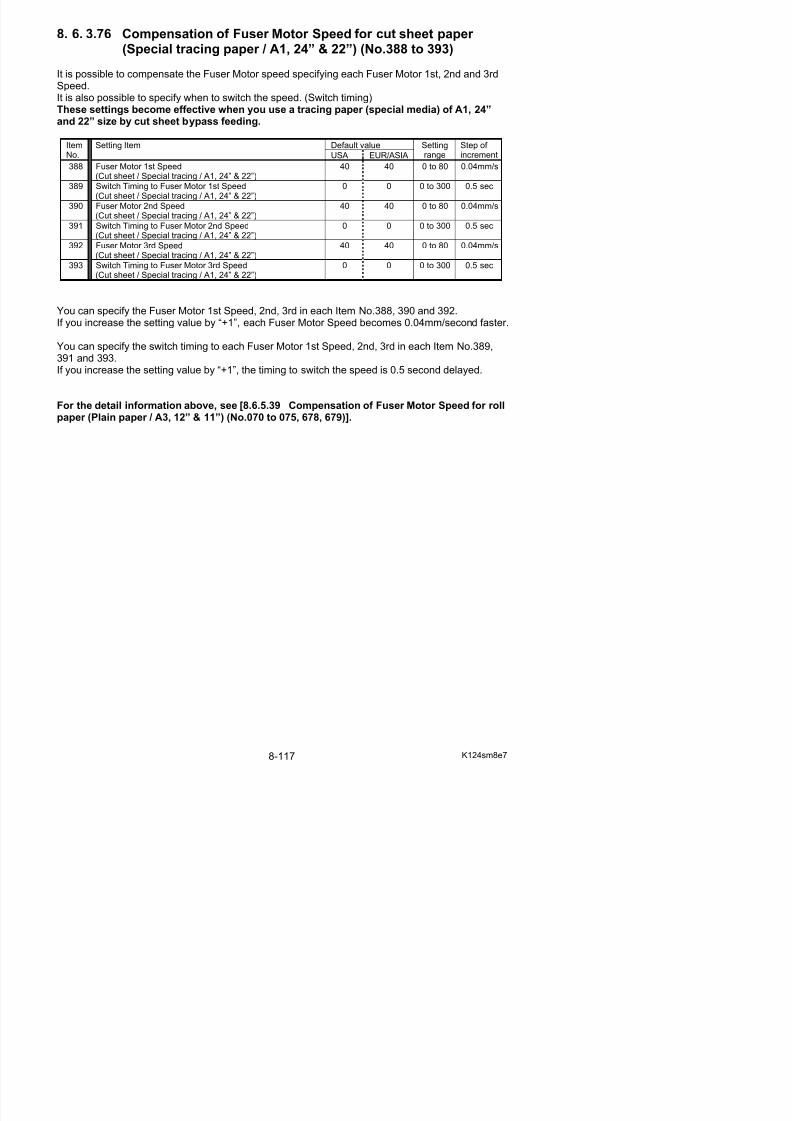
5/17/2018 KIP 7100 Service Manual Ver A_1 - slidepdf.com
http://slidepdf.com/reader/full/kip-7100-service-manual-ver-a1 559/674
397 Switch Timing to Fuser Motor 2nd Speed
(Cut sheet / Special film / A1, 24” & 22”)
0 0 0 to 300 0.5 sec
398 Fuser Motor 3rd Speed (Cut sheet / Special film / A1, 24” &22”)
40 40 0 to 80 0.04mm/s
399 Switch Timing to Fuser Motor 3rd Speed(Cut sheet / Special film / A1, 24” & 22”)
0 0 0 to 300 0.5 sec
You can specify the Fuser Motor 1st Speed, 2nd, 3rd in each Item No.394, 396 and 398.If you increase the setting value by “+1”, each Fuser Motor Speed becomes 0.04mm/second faster.
You can specify the switch timing to each Fuser Motor 1st Speed, 2nd, 3rd in each Item No.395,397 and 399.If you increase the setting value by “+1”, the timing to switch the speed is 0.5 second delayed.
For the detail information above, see [8.6.5.39 Compensation of Fuser Motor Speed for rollpaper (Plain paper / A3, 12” & 11”) (No.070 to 075, 678, 679)].
8. 6. 3.78 Compensation of Fuser Motor Speed for cut sheet paper (Plain paper / A0, 36” & 34”) (No.400 to 405)
It is possible to compensate the Fuser Motor speed specifying each Fuser Motor 1st, 2nd and 3rdSpeed.It is also possible to specify when to switch the speed. (Switch timing)These settings become effective when you use a plain paper of A0, 36” and 34” sizes by cutsheet bypass feeding.
Default valueItemNo.
Setting Item
USA EUR/ASIA
Settingrange
Step of increment
400 Fuser Motor 1st Speed (Cut sheet / Plain paper / A0, 36” &34”)
26 26 0 to 80 0.04mm/s
401 Switch Timing to Fuser Motor 1st Speed(Cut sheet / Plain paper / A0, 36” & 34”)
4 3 0 to 300 0.5 sec
402 Fuser Motor 2nd Speed (Cut sheet / Plain paper / A0, 36” &34”)
27 27 0 to 80 0.04mm/s
403 Switch Timing to Fuser Motor 2nd Speed 10 10 0 to 300 0.5 sec
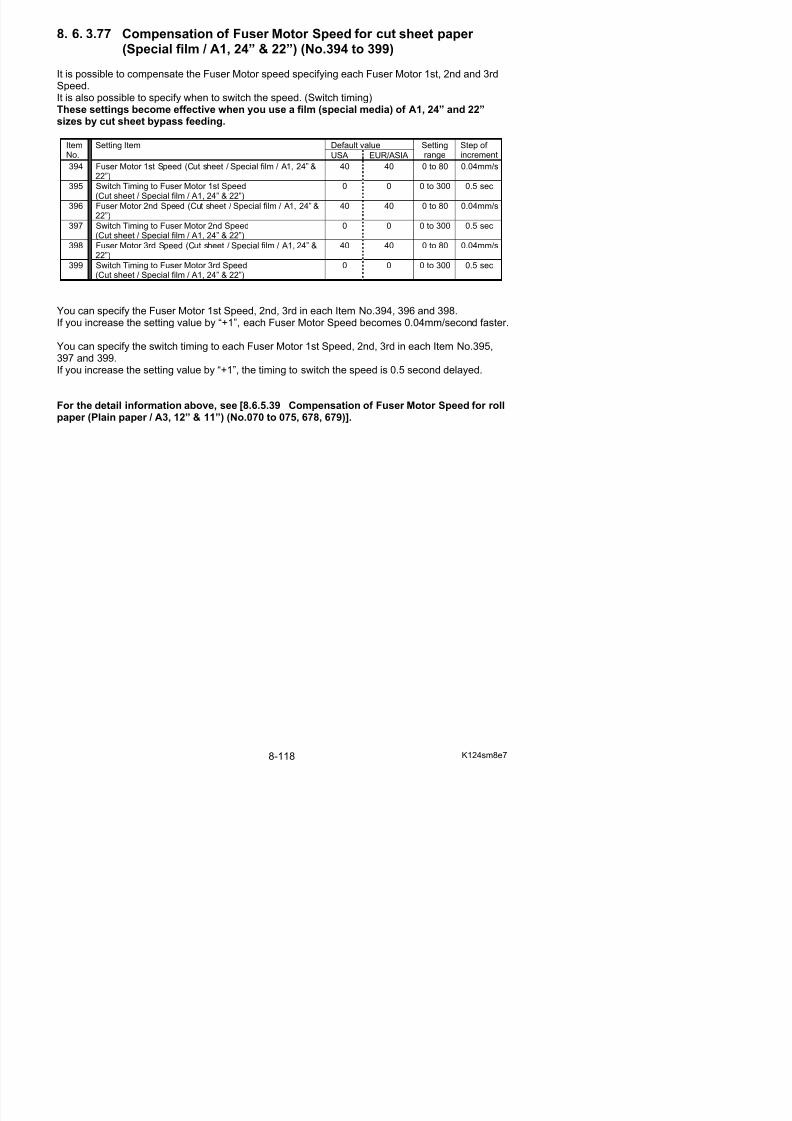
5/17/2018 KIP 7100 Service Manual Ver A_1 - slidepdf.com
http://slidepdf.com/reader/full/kip-7100-service-manual-ver-a1 560/674
g p
(Cut sheet / Plain paper / A0, 36” & 34”)404 Fuser Motor 3rd Speed (Cut sheet / Plain paper / A0, 36” &
34”)33 37 0 to 80 0.04mm/s
405 Switch Timing to Fuser Motor 3rd Speed(Cut sheet / Plain paper / A0, 36” & 34”)
8 8 0 to 300 0.5 sec
You can specify the Fuser Motor 1st Speed, 2nd, 3rd in each Item No.400, 402 and 404.If you increase the setting value by “+1”, each Fuser Motor Speed becomes 0.04mm/second faster.
You can specify the switch timing to each Fuser Motor 1st Speed, 2nd, 3rd in each Item No.401,403 and 405.If you increase the setting value by “+1”, the timing to switch the speed is 0.5 second delayed.
For the detail information above, see [8.6.5.39 Compensation of Fuser Motor Speed for rollpaper (Plain paper / A3, 12” & 11”) (No.070 to 075, 678, 679)].
8. 6. 3.79 Compensation of Fuser Motor Speed for cut sheet paper (Tracing paper / A0, 36” & 34”) (No.406 to 411)
It is possible to compensate the Fuser Motor speed specifying each Fuser Motor 1st, 2nd and 3rdSpeed.It is also possible to specify when to switch the speed. (Switch timing)These settings become effective when you use a tracing paper of A0, 36” and 34” sizes bycut sheet bypass feeding.
Default valueItemNo.
Setting Item
USA EUR/ASIA
Settingrange
Step of increment
406 Fuser Motor 1st Speed (Cut sheet / Tracing / A0, 36” & 34”) 29 42 0 to 80 0.04mm/s
407 Switch Timing to Fuser Motor 1st Speed(Cut sheet / Tracing / A0, 36” & 34”)
3 3 0 to 300 0.5 sec
408 Fuser Motor 2nd Speed (Cut sheet / Tracing / A0, 36” & 34”) 35 38 0 to 80 0.04mm/s
409 Switch Timing to Fuser Motor 2nd Speed(Cut sheet / Tracing / A0, 36” & 34”)
13 13 0 to 300 0.5 sec
410 Fuser Motor 3rd Speed (Cut sheet / Tracing / A0, 36” & 34”) 36 39 0 to 80 0.04mm/s

5/17/2018 KIP 7100 Service Manual Ver A_1 - slidepdf.com
http://slidepdf.com/reader/full/kip-7100-service-manual-ver-a1 561/674
p ( g )
411 Switch Timing to Fuser Motor 3rd Speed(Cut sheet / Tracing / A0, 36” & 34”)
8 8 0 to 300 0.5 sec
You can specify the Fuser Motor 1st Speed, 2nd, 3rd in each Item No.406, 408 and 410.If you increase the setting value by “+1”, each Fuser Motor Speed becomes 0.04mm/second faster.
You can specify the switch timing to each Fuser Motor 1st Speed, 2nd, 3rd in each Item No.407,
409 and 411.If you increase the setting value by “+1”, the timing to switch the speed is 0.5 second delayed.
For the detail information above, see [8.6.5.39 Compensation of Fuser Motor Speed for rollpaper (Plain paper / A3, 12” & 11”) (No.070 to 075, 678, 679)].
8. 6. 3.80 Compensation of Fuser Motor Speed for cut sheet paper (Film / A0, 36” & 34”) (No.412 to 417)
It is possible to compensate the Fuser Motor speed specifying each Fuser Motor 1st, 2nd and 3rdSpeed.It is also possible to specify when to switch the speed. (Switch timing)These settings become effective when you use a film of A0, 36” and 34” sizes by cut sheetbypass feeding.
Default valueItemNo.
Setting Item
USA EUR/ASIA
Settingrange
Step of increment
412 Fuser Motor 1st Speed (Cut sheet / Film / A0, 36” & 34”) 35 38 0 to 80 0.04mm/s
413 Switch Timing to Fuser Motor 1st Speed(Cut sheet / Film / A0, 36” & 34”)
2 2 0 to 300 0.5 sec
414 Fuser Motor 2nd Speed (Cut sheet / Film / A0, 36” & 34”) 42 43 0 to 80 0.04mm/s
415 Switch Timing to Fuser Motor 2nd Speed(Cut sheet / Film / A0, 36” & 34”)
18 18 0 to 300 0.5 sec
416 Fuser Motor 3rd Speed (Cut sheet / Film / A0, 36” & 34”) 40 40 0 to 80 0.04mm/s
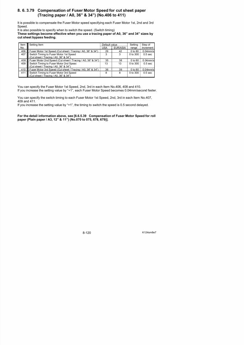
5/17/2018 KIP 7100 Service Manual Ver A_1 - slidepdf.com
http://slidepdf.com/reader/full/kip-7100-service-manual-ver-a1 562/674
417 Switch Timing to Fuser Motor 3rd Speed(Cut sheet / Film / A0, 36” & 34”)
0 0 0 to 300 0.5 sec
You can specify the Fuser Motor 1st Speed, 2nd, 3rd in each Item No.412, 414 and 416.If you increase the setting value by “+1”, each Fuser Motor Speed becomes 0.04mm/second faster.
You can specify the switch timing to each Fuser Motor 1st Speed, 2nd, 3rd in each Item No.413,
415 and 417.If you increase the setting value by “+1”, the timing to switch the speed is 0.5 second delayed.
For the detail information above, see [8.6.5.39 Compensation of Fuser Motor Speed for rollpaper (Plain paper / A3, 12” & 11”) (No.070 to 075, 678, 679)].
8. 6. 3.81 Compensation of Fuser Motor Speed for cut sheet paper (Special plain paper / A0, 36 & 34”) (No.418 to 423)
It is possible to compensate the Fuser Motor speed specifying each Fuser Motor 1st, 2nd and 3rdSpeed.It is also possible to specify when to switch the speed. (Switch timing)These settings become effective when you use a plain paper (special media) of A0, 36” and34” sizes by cut sheet bypass feeding.
Default valueItemNo.
Setting Item
USA EUR/ASIA
Settingrange
Step of increment
418 Fuser Motor 1st Speed(Cut sheet / Special plain paper / A0, 36” & 34”)
40 40 0 to 80 0.04mm/s
419 Switch Timing to Fuser Motor 1st Speed(Cut sheet / Special plain paper / A0, 36” & 34”)
0 0 0 to 300 0.5 sec
420 Fuser Motor 2nd Speed(Cut sheet / Special plain paper / A0, 36” & 34”)
40 40 0 to 80 0.04mm/s
421 Switch Timing to Fuser Motor 2nd Speed 0 0 0 to 300 0.5 sec

5/17/2018 KIP 7100 Service Manual Ver A_1 - slidepdf.com
http://slidepdf.com/reader/full/kip-7100-service-manual-ver-a1 563/674
(Cut sheet / Special plain paper / A0, 36” & 34”)422 Fuser Motor 3rd Speed
(Cut sheet / Special plain paper / A0, 36” & 34”)40 40 0 to 80 0.04mm/s
423 Switch Timing to Fuser Motor 3rd Speed(Cut sheet / Special plain paper / A0, 36” & 34”)
0 0 0 to 300 0.5 sec
You can specify the Fuser Motor 1st Speed, 2nd, 3rd in each Item No.418, 420 and 422.If you increase the setting value by “+1”, each Fuser Motor Speed becomes 0.04mm/second faster.
You can specify the switch timing to each Fuser Motor 1st Speed, 2nd, 3rd in each Item No.419,421 and 423.If you increase the setting value by “+1”, the timing to switch the speed is 0.5 second delayed.
For the detail information above, see [8.6.5.39 Compensation of Fuser Motor Speed for rollpaper (Plain paper / A3, 12” & 11”) (No.070 to 075, 678, 679)].
8. 6. 3.82 Compensation of Fuser Motor Speed for cut sheet paper (Special tracing paper / A0, 36” & 34”) (No.424 to 429)
It is possible to compensate the Fuser Motor speed specifying each Fuser Motor 1st, 2nd and 3rdSpeed.It is also possible to specify when to switch the speed. (Switch timing)These settings become effective when you use a tracing paper (special media) of A0, 36”and 34” size by cut sheet bypass feeding.
Default valueItemNo.
Setting Item
USA EUR/ASIA
Settingrange
Step of increment
424 Fuser Motor 1st Speed(Cut sheet / Special tracing / A0, 36” & 34”)
40 40 0 to 80 0.04mm/s
425 Switch Timing to Fuser Motor 1st Speed(Cut sheet / Special tracing / A0, 36” & 34”)
0 0 0 to 300 0.5 sec
426 Fuser Motor 2nd Speed(Cut sheet / Special tracing / A0, 36” & 34”)
40 40 0 to 80 0.04mm/s
427 Switch Timing to Fuser Motor 2nd Speed 0 0 0 to 300 0.5 sec
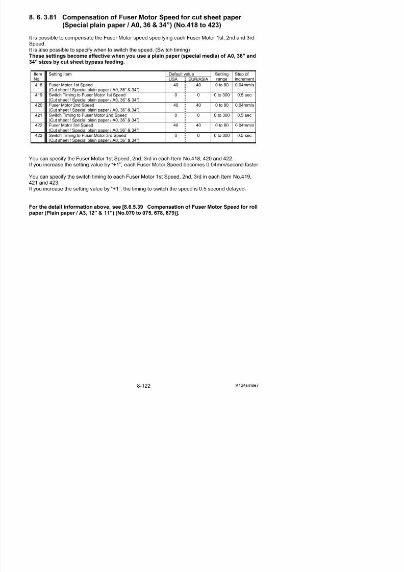
5/17/2018 KIP 7100 Service Manual Ver A_1 - slidepdf.com
http://slidepdf.com/reader/full/kip-7100-service-manual-ver-a1 564/674
(Cut sheet / Special tracing / A0, 36” & 34”)428 Fuser Motor 3rd Speed
(Cut sheet / Special tracing / A0, 36” & 34”)40 40 0 to 80 0.04mm/s
429 Switch Timing to Fuser Motor 3rd
Speed(Cut sheet / Special tracing / A0, 36” & 34”)
0 0 0 to 300 0.5 sec
You can specify the Fuser Motor 1st Speed, 2nd, 3rd in each Item No.424, 426 and 428.If you increase the setting value by “+1”, each Fuser Motor Speed becomes 0.04mm/second faster.
You can specify the switch timing to each Fuser Motor 1st Speed, 2nd, 3rd in each Item No.425,427 and 429.If you increase the setting value by “+1”, the timing to switch the speed is 0.5 second delayed.
For the detail information above, see [8.6.5.39 Compensation of Fuser Motor Speed for rollpaper (Plain paper / A3, 12” & 11”) (No.070 to 075, 678, 679)].
8. 6. 3.83 Compensation of Fuser Motor Speed for cut sheet paper (Special film / A0, 36” & 34”) (No.430 to 435)
It is possible to compensate the Fuser Motor speed specifying each Fuser Motor 1st, 2nd and 3rdSpeed.It is also possible to specify when to switch the speed. (Switch timing)These settings become effective when you use a film (special media) of A0, 24” and 22”sizes by cut sheet bypass feeding.
Default valueItemNo.
Setting Item
USA EUR/ASIA
Settingrange
Step of increment
430 Fuser Motor 1st Speed (Cut sheet / Special film / A0, 36” &34”)
40 40 0 to 80 0.04mm/s
431 Switch Timing to Fuser Motor 1st Speed(Cut sheet / Special film / A0, 36” & 34”)
0 0 0 to 300 0.5 sec
432 Fuser Motor 2nd Speed (Cut sheet / Special film / A0, 36” &34”)
40 40 0 to 80 0.04mm/s
433 Switch Timing to Fuser Motor 2nd Speed 0 0 0 to 300 0.5 sec

5/17/2018 KIP 7100 Service Manual Ver A_1 - slidepdf.com
http://slidepdf.com/reader/full/kip-7100-service-manual-ver-a1 565/674
(Cut sheet / Special film / A0, 36” & 34”)434 Fuser Motor 3rd Speed (Cut sheet / Special film / A0, 36” &
34”)40 40 0 to 80 0.04mm/s
435 Switch Timing to Fuser Motor 3rd Speed(Cut sheet / Special film / A0, 36” & 34”)
0 0 0 to 300 0.5 sec
You can specify the Fuser Motor 1st Speed, 2nd, 3rd in each Item No.430, 432 and 434.If you increase the setting value by “+1”, each Fuser Motor Speed becomes 0.04mm/second faster.
You can specify the switch timing to each Fuser Motor 1st Speed, 2nd, 3rd in each Item No.431,433 and 435.If you increase the setting value by “+1”, the timing to switch the speed is 0.5 second delayed.
For the detail information above, see [8.6.5.39 Compensation of Fuser Motor Speed for rollpaper (Plain paper / A3, 12” & 11”) (No.070 to 075, 678, 679)].
8. 6. 3.84 Compensation of Fuser Motor Speed for roll paper (Plain paper / 30”) (No.436 to 441, 726, 727)
It is possible to compensate the Fuser Motor speed specifying each Fuser Motor 1st, 2nd, 3rd and4th Speed.It is also possible to specify when to switch the speed. (Switch timing)These settings become effective when you use a plain paper of 30” size by roll paper feeding.
Default valueItemNo.
Setting Item
USA EUR/ASIA
Settingrange
Step of increment
436 Fuser Motor 1st Speed (Roll / plain paper / 30”) 28 28 0 to 80 0.04mm/s
437 Switch Timing to Fuser Motor 1st Speed(Roll / plain paper / 30”)
5 5 0 to 300 0.5 sec
438 Fuser Motor 2nd Speed (Roll / plain paper / 30”) 30 33 0 to 80 0.04mm/s
439 Switch Timing to Fuser Motor 2nd Speed(Roll / plain paper / 30”)
9 9 0 to 300 0.5 sec
440 Fuser Motor 3rd Speed (Roll / plain paper / 30”) 34 36 0 to 80 0.04mm/s
441 S it h Ti i t F M t 3 d S d 7 7 0 t 300 0 5
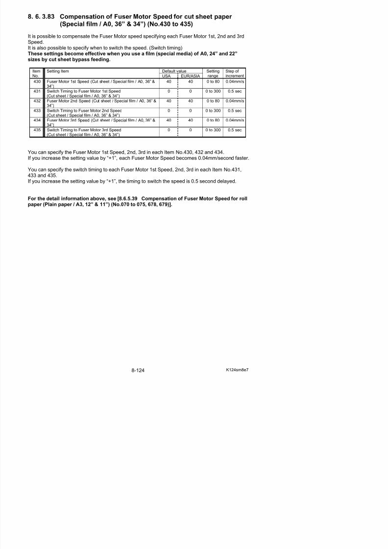
5/17/2018 KIP 7100 Service Manual Ver A_1 - slidepdf.com
http://slidepdf.com/reader/full/kip-7100-service-manual-ver-a1 566/674
441 Switch Timing to Fuser Motor 3rd Speed(Roll / plain paper / 30”)
7 7 0 to 300 0.5 sec
726 Fuser Motor 4th Speed (Roll / plain paper / 30”) 36 30 0 to 80 0.04mm/s
727 Switch Timing to Fuser Motor 4th Speed(Roll / plain paper / 30”)
20 20 0 to 300 0.5 sec
You can specify the Fuser Motor 1st Speed, 2nd, 3rd, 4th in each Item No.436, 438, 440, 726.If you increase the setting value by “+1”, each Fuser Motor Speed becomes 0.04mm/second faster.
You can specify the switch timing to each Fuser Motor 1st Speed, 2nd, 3rd, 4th in each ItemNo.437, 439, 441, 727.If you increase the setting value by “+1”, the timing to switch the speed is 0.5 second delayed.
For the detail information above, see [8.6.5.39 Compensation of Fuser Motor Speed for rollpaper (Plain paper / A3, 12” & 11”) (No.070 to 075, 678, 679)].
8. 6. 3.85 Compensation of Fuser Motor Speed for roll paper (Tracing paper / 30”) (No.442 to 447, 728, 729)
It is possible to compensate the Fuser Motor speed specifying each Fuser Motor 1st, 2nd, 3rd and4th Speed.It is also possible to specify when to switch the speed. (Switch timing)These settings become effective when you use a tracing paper of 30” size by roll paper feeding.
Default valueItemNo.
Setting Item
USA EUR/ASIA
Settingrange
Step of increment
442 Fuser Motor 1st Speed (Roll / tracing / 30”) 34 33 0 to 80 0.04mm/s
443 Switch Timing to Fuser Motor 1st Speed(Roll / tracing / 30”)
4 4 0 to 300 0.5 sec
444 Fuser Motor 2nd Speed (Roll / tracing / 30”) 38 44 0 to 80 0.04mm/s
445 Switch Timing to Fuser Motor 2nd Speed(Roll / tracing / 30”)
11 11 0 to 300 0.5 sec
446 Fuser Motor 3rd Speed (Roll / tracing / 30”) 40 41 0 to 80 0.04mm/s
447 Switch Timing to Fuser Motor 3rd Speed 8 8 0 to 300 0 5 sec
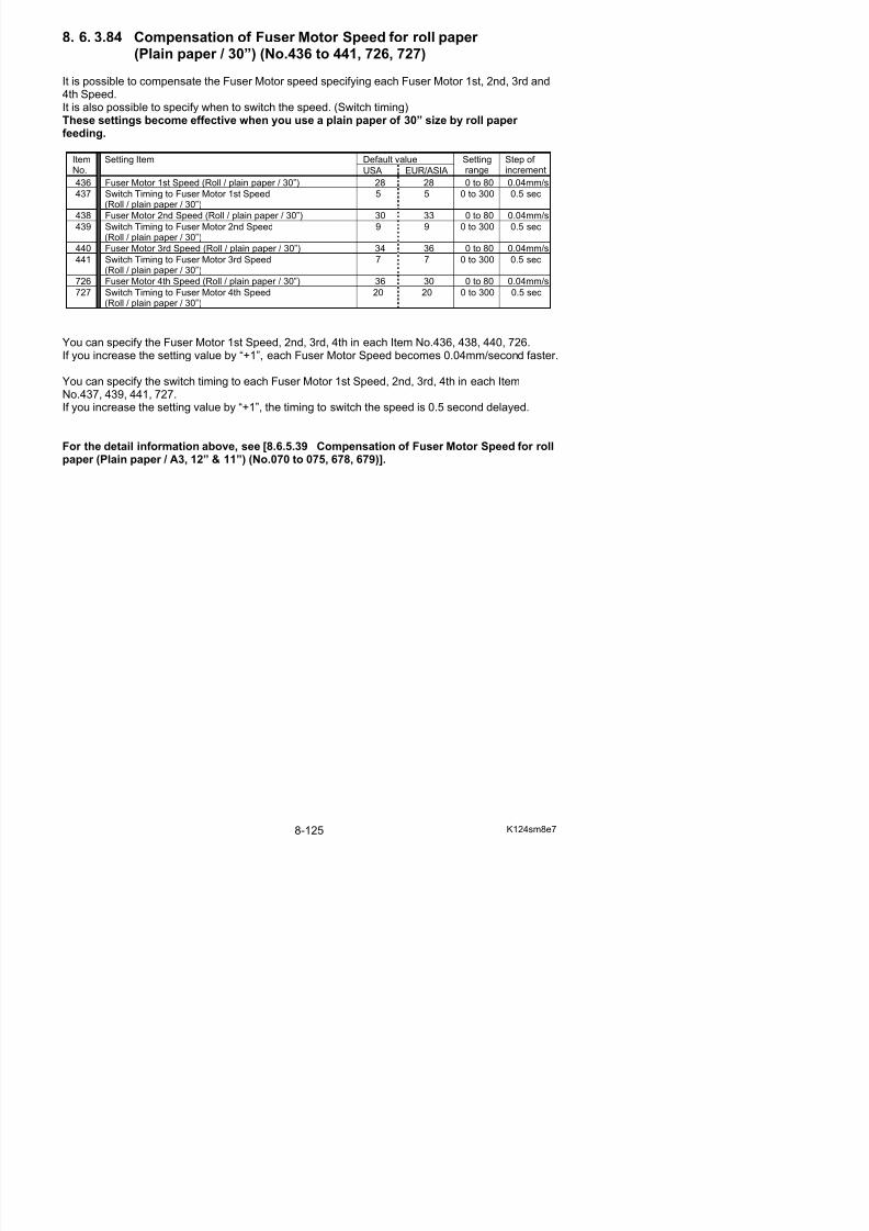
5/17/2018 KIP 7100 Service Manual Ver A_1 - slidepdf.com
http://slidepdf.com/reader/full/kip-7100-service-manual-ver-a1 567/674
447 Switch Timing to Fuser Motor 3rd Speed(Roll / tracing / 30”)
8 8 0 to 300 0.5 sec
728 Fuser Motor 4th Speed (Roll / tracing / 30”) 34 40 0 to 80 0.04mm/s
729 Switch Timing to Fuser Motor 4th Speed(Roll / tracing / 30”)
20 0 0 to 300 0.5 sec
You can specify the Fuser Motor 1st Speed, 2nd, 3rd, 4th in each Item No.442, 444, 446, 728.If you increase the setting value by “+1”, each Fuser Motor Speed becomes 0.04mm/second faster.
You can specify the switch timing to each Fuser Motor 1st Speed, 2nd, 3rd, 4th in each ItemNo.443, 445, 447, 729.If you increase the setting value by “+1”, the timing to switch the speed is 0.5 second delayed.
For the detail information above, see [8.6.5.39 Compensation of Fuser Motor Speed for rollpaper (Plain paper / A3, 12” & 11”) (No.070 to 075, 678, 679)].
8. 6. 3.86 Compensation of Fuser Motor Speed for roll paper (Film / 30”) (No.448 to 453, 730, 731)
It is possible to compensate the Fuser Motor speed specifying each Fuser Motor 1st, 2nd, 3rd and4th Speed.It is also possible to specify when to switch the speed. (Switch timing)These settings become effective when you use a film of 30” size by roll paper feeding.
Default valueItemNo.
Setting Item
USA EUR/ASIA
Settingrange
Step of increment
448 Fuser Motor 1st Speed (Roll / film / 30”) 40 40 0 to 80 0.04mm/s
449 Switch Timing to Fuser Motor 1st Speed (Roll / film / 30”) 0 0 0 to 300 0.5 sec
450 Fuser Motor 2nd Speed (Roll / film / 30”) 40 40 0 to 80 0.04mm/s
451 Switch Timing to Fuser Motor 2nd Speed (Roll / film / 30”) 0 0 0 to 300 0.5 sec452 Fuser Motor 3rd Speed (Roll / film / 30”) 40 40 0 to 80 0.04mm/s
453 Switch Timing to Fuser Motor 3rd Speed (Roll / film / 30”) 0 0 0 to 300 0.5 sec
730 Fuser Motor 4th Speed (Roll / film / 30”) 40 40 0 to 80 0.04mm/s
731 Switch Timing to Fuser Motor 4th Speed (Roll / film / 30”) 0 0 0 to 300 0.5 sec

5/17/2018 KIP 7100 Service Manual Ver A_1 - slidepdf.com
http://slidepdf.com/reader/full/kip-7100-service-manual-ver-a1 568/674
You can specify the Fuser Motor 1st Speed, 2nd, 3rd, 4th in each Item No.448, 450, 452, 730.If you increase the setting value by “+1”, each Fuser Motor Speed becomes 0.04mm/second faster.
You can specify the switch timing to each Fuser Motor 1st Speed, 2nd, 3rd, 4th in each ItemNo.449, 451, 453, 731.If you increase the setting value by “+1”, the timing to switch the speed is 0.5 second delayed.
For the detail information above, see [8.6.5.39 Compensation of Fuser Motor Speed for rollpaper (Plain paper / A3, 12” & 11”) (No.070 to 075, 678, 679)].
8. 6. 3.87 Compensation of Fuser Motor Speed for roll paper (Special plain paper / 30”) (No.454 to 459, 732, 733)
It is possible to compensate the Fuser Motor speed specifying each Fuser Motor 1st, 2nd, 3rd and4th Speed.It is also possible to specify when to switch the speed. (Switch timing)These settings become effective when you use a plain paper (special media) of 30” size byroll paper feeding.
Default valueItemNo.
Setting Item
USA EUR/ASIA
Settingrange
Step of increment
454 Fuser Motor 1st Speed (Roll / special plain paper / 30”) 40 40 0 to 80 0.04mm/s
455 Switch Timing to Fuser Motor 1st Speed(Roll / special plain paper / 30”)
0 0 0 to 300 0.5 sec
456 Fuser Motor 2nd Speed (Roll / special plain paper / 30”) 40 40 0 to 80 0.04mm/s
457 Switch Timing to Fuser Motor 2nd Speed(Roll / special plain paper / 30”)
0 0 0 to 300 0.5 sec
458 Fuser Motor 3rd Speed (Roll / special plain paper / 30”) 40 40 0 to 80 0.04mm/s
459 Switch Timing to Fuser Motor 3rd Speed 0 0 0 to 300 0 5 sec
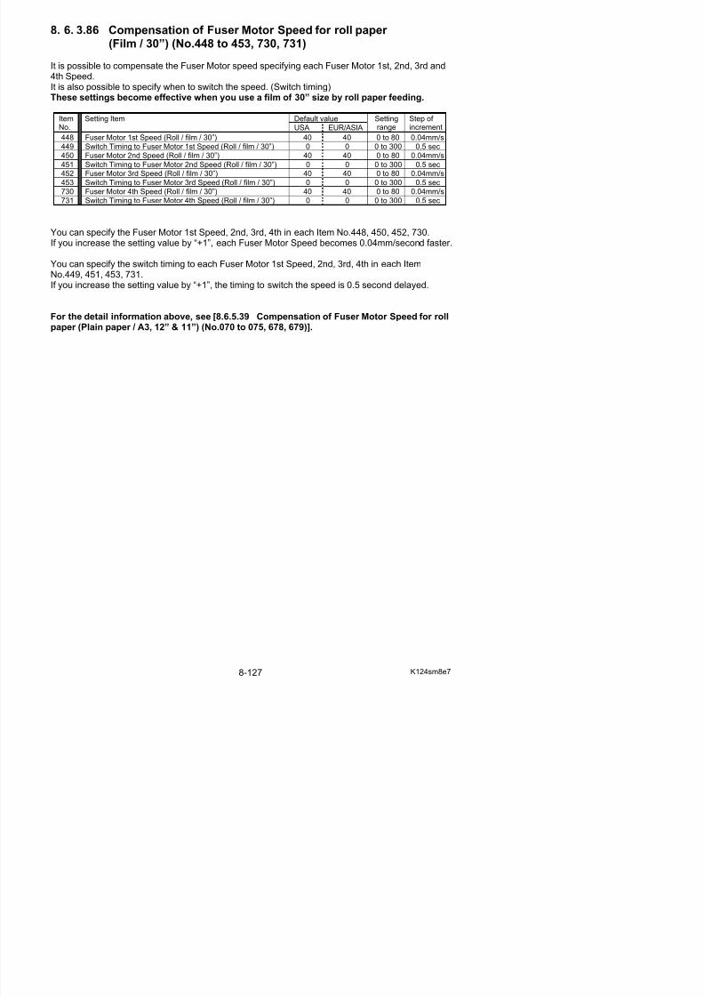
5/17/2018 KIP 7100 Service Manual Ver A_1 - slidepdf.com
http://slidepdf.com/reader/full/kip-7100-service-manual-ver-a1 569/674
459 Switch Timing to Fuser Motor 3rd Speed(Roll / special plain paper / 30”)
0 0 0 to 300 0.5 sec
732 Fuser Motor 4th Speed (Roll / special plain paper / 30”) 40 40 0 to 80 0.04mm/s
733 Switch Timing to Fuser Motor 4th Speed(Roll / special plain paper / 30”)
0 0 0 to 300 0.5 sec
You can specify the Fuser Motor 1st Speed, 2nd, 3rd, 4th in each Item No.454, 456, 458, 732.If you increase the setting value by “+1”, each Fuser Motor Speed becomes 0.04mm/second faster.
You can specify the switch timing to each Fuser Motor 1st Speed, 2nd, 3rd, 4th in each ItemNo.455, 457, 459, 733.If you increase the setting value by “+1”, the timing to switch the speed is 0.5 second delayed.
For the detail information above, see [8.6.5.39 Compensation of Fuser Motor Speed for rollpaper (Plain paper / A3, 12” & 11”) (No.070 to 075, 678, 679)].
8. 6. 3.88 Compensation of Fuser Motor Speed for roll paper (Special tracing paper / 30”) (No.460 to 465, 734, 735)
It is possible to compensate the Fuser Motor speed specifying each Fuser Motor 1st, 2nd, 3rd and4th Speed.It is also possible to specify when to switch the speed. (Switch timing)These settings become effective when you use a tracing paper (special media) of 30” sizeby roll paper feeding.
Default valueItemNo.
Setting Item
USA EUR/ASIA
Settingrange
Step of increment
460 Fuser Motor 1st Speed (Roll / special tracing / 30”) 40 40 0 to 80 0.04mm/s
461 Switch Timing to Fuser Motor 1st Speed(Roll / special tracing / 30”)
0 0 0 to 300 0.5 sec
462 Fuser Motor 2nd Speed (Roll / special tracing / 30”) 40 40 0 to 80 0.04mm/s
463 Switch Timing to Fuser Motor 2nd Speed(Roll / special tracing / 30”)
0 0 0 to 300 0.5 sec
464 Fuser Motor 3rd Speed (Roll / special tracing / 30”) 40 40 0 to 80 0.04mm/s
465 Switch Timing to Fuser Motor 3rd Speed(R ll / i l t i / 30”)
0 0 0 to 300 0 5 sec

5/17/2018 KIP 7100 Service Manual Ver A_1 - slidepdf.com
http://slidepdf.com/reader/full/kip-7100-service-manual-ver-a1 570/674
465 Switch Timing to Fuser Motor 3rd Speed(Roll / special tracing / 30”)
0 0 0 to 300 0.5 sec
734 Fuser Motor 4th Speed (Roll / special tracing / 30”) 40 40 0 to 80 0.04mm/s
735 Switch Timing to Fuser Motor 4th Speed(Roll / special tracing / 30”)
0 0 0 to 300 0.5 sec
You can specify the Fuser Motor 1st Speed, 2nd, 3rd, 4th in each Item No.460, 462, 464, 734.If you increase the setting value by “+1”, each Fuser Motor Speed becomes 0.04mm/second faster.
You can specify the switch timing to each Fuser Motor 1st Speed, 2nd, 3rd, 4th in each ItemNo.461, 463, 465, 735.If you increase the setting value by “+1”, the timing to switch the speed is 0.5 second delayed.
For the detail information above, see [8.6.5.39 Compensation of Fuser Motor Speed for rollpaper (Plain paper / A3, 12” & 11”) (No.070 to 075, 678, 679)].
8. 6. 3.89 Compensation of Fuser Motor Speed for roll paper (Special film / 30”) (No.466 to 471, 736, 737)
It is possible to compensate the Fuser Motor speed specifying each Fuser Motor 1st, 2nd, 3rd and4th Speed.It is also possible to specify when to switch the speed. (Switch timing)These settings become effective when you use a film (special media) of 30” size by rollpaper feeding.
Default valueItemNo.
Setting Item
USA EUR/ASIA
Settingrange
Step of increment
466 Fuser Motor 1st Speed (Roll / special film / 30”) 40 40 0 to 80 0.04mm/s
467 Switch Timing to Fuser Motor 1st Speed(Roll / special film / 30”)
0 0 0 to 300 0.5 sec
468 Fuser Motor 2nd Speed (Roll / special film / 30”) 40 40 0 to 80 0.04mm/s
469 Switch Timing to Fuser Motor 2nd Speed(Roll / special film / 30”)
0 0 0 to 300 0.5 sec
470 Fuser Motor 3rd Speed (Roll / special film / 30”) 40 40 0 to 80 0.04mm/s
471 Switch Timing to Fuser Motor 3rd Speed(R ll / i l fil / 30”)
0 0 0 to 300 0.5 sec

5/17/2018 KIP 7100 Service Manual Ver A_1 - slidepdf.com
http://slidepdf.com/reader/full/kip-7100-service-manual-ver-a1 571/674
g p(Roll / special film / 30”)
736 Fuser Motor 4th Speed (Roll / special film / 30”) 40 40 0 to 80 0.04mm/s
737 Switch Timing to Fuser Motor 4th Speed(Roll / special film / 30”)
0 0 0 to 300 0.5 sec
You can specify the Fuser Motor 1st Speed, 2nd, 3rd, 4th in each Item No.466, 468, 470, 736.If you increase the setting value by “+1”, each Fuser Motor Speed becomes 0.04mm/second faster.
You can specify the switch timing to each Fuser Motor 1st Speed, 2nd, 3rd, 4th in each ItemNo.467, 469, 471, 737.If you increase the setting value by “+1”, the timing to switch the speed is 0.5 second delayed.
For the detail information above, see [8.6.5.39 Compensation of Fuser Motor Speed for rollpaper (Plain paper / A3, 12” & 11”) (No.070 to 075, 678, 679)].
8. 6. 3.90 Compensation of Fuser Motor Speed for cut sheetpaper (Plain paper / 30”) (No.472 to 477)
It is possible to compensate the Fuser Motor speed specifying each Fuser Motor 1st, 2nd and 3rdSpeed.It is also possible to specify when to switch the speed. (Switch timing)These settings become effective when you use a plain paper of 30” size by cut sheetbypass feeding.
Default valueItemNo.
Setting Item
USA EUR/ASIA
Settingrange
Step of increment
472 Fuser Motor 1st Speed (Cut sheet / plain paper / 30”) 28 28 0 to 80 0.04mm/s
473 Switch Timing to Fuser Motor 1st Speed(Cut sheet / plain paper / 30”)
5 5 0 to 300 0.5 sec
474 Fuser Motor 2nd Speed (Cut sheet / plain paper / 30”) 30 33 0 to 80 0.04mm/s
475 Switch Timing to Fuser Motor 2nd Speed(Cut sheet / plain paper / 30”)
9 9 0 to 300 0.5 sec
476 Fuser Motor 3rd Speed (Cut sheet / plain paper / 30”) 34 36 0 to 80 0.04mm/s
477 Switch Timing to Fuser Motor 3rd Speed(Cut sheet / plain paper / 30”)
7 7 0 to 300 0.5 sec

5/17/2018 KIP 7100 Service Manual Ver A_1 - slidepdf.com
http://slidepdf.com/reader/full/kip-7100-service-manual-ver-a1 572/674
g(Cut sheet / plain paper / 30 )
You can specify the Fuser Motor 1st Speed, 2nd, 3rd in each Item No.472, 474 and 476.If you increase the setting value by “+1”, each Fuser Motor Speed becomes 0.04mm/second faster.
You can specify the switch timing to each Fuser Motor 1st Speed, 2nd, 3rd in each Item No.473,475 and 477.If you increase the setting value by “+1”, the timing to switch the speed is 0.5 second delayed.
For the detail information above, see [8.6.5.39 Compensation of Fuser Motor Speed for rollpaper (Plain paper / A3, 12” & 11”) (No.070 to 075, 678, 679)].
8. 6. 3.91 Compensation of Fuser Motor Speed for cut sheetpaper (Tracing paper / 30”) (No.478 to 483)
It is possible to compensate the Fuser Motor speed specifying each Fuser Motor 1st, 2nd and 3rdSpeed.It is also possible to specify when to switch the speed. (Switch timing)These settings become effective when you use a tracing paper of 30” size by cut sheetbypass feeding.
Default valueItemNo.
Setting Item
USA EUR/ASIA
Settingrange
Step of increment
478 Fuser Motor 1st Speed (Cut sheet / tracing / 30”) 34 33 0 to 80 0.04mm/s
479 Switch Timing to Fuser Motor 1st Speed(Cut sheet / tracing / 30”)
4 4 0 to 300 0.5 sec
480 Fuser Motor 2nd Speed (Cut sheet / tracing / 30”) 38 44 0 to 80 0.04mm/s
481 Switch Timing to Fuser Motor 2nd Speed(Cut sheet / tracing / 30”)
11 11 0 to 300 0.5 sec
482 Fuser Motor 3rd Speed (Cut sheet / tracing / 30”) 40 41 0 to 80 0.04mm/s
483 Switch Timing to Fuser Motor 3rd Speed(Cut sheet / tracing / 30”)
8 8 0 to 300 0.5 sec
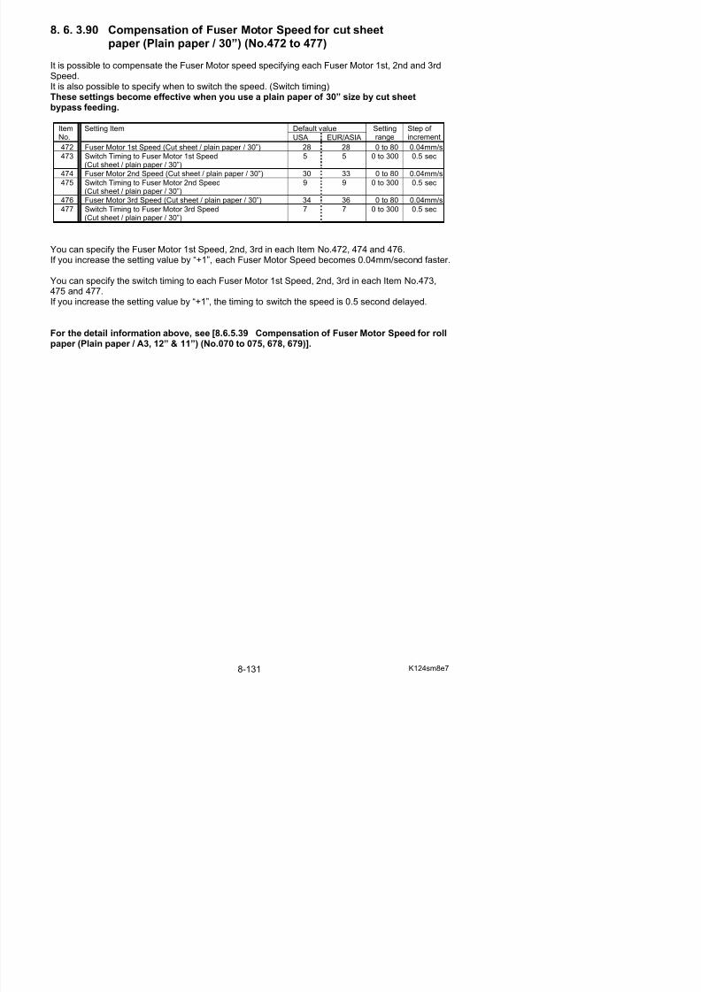
5/17/2018 KIP 7100 Service Manual Ver A_1 - slidepdf.com
http://slidepdf.com/reader/full/kip-7100-service-manual-ver-a1 573/674
(Cut sheet / tracing / 30 )
You can specify the Fuser Motor 1st Speed, 2nd, 3rd in each Item No.478, 480 and 482.If you increase the setting value by “+1”, each Fuser Motor Speed becomes 0.04mm/second faster.
You can specify the switch timing to each Fuser Motor 1st Speed, 2nd, 3rd in each Item No.479,481 and 483.If you increase the setting value by “+1”, the timing to switch the speed is 0.5 second delayed.
For the detail information above, see [8.6.5.39 Compensation of Fuser Motor Speed for rollpaper (Plain paper / A3, 12” & 11”) (No.070 to 075, 678, 679)].
8. 6. 3.92 Compensation of Fuser Motor Speed for cut sheetpaper (Film / 30”) (No.484 to 489)
It is possible to compensate the Fuser Motor speed specifying each Fuser Motor 1st, 2nd and 3rdSpeed.It is also possible to specify when to switch the speed. (Switch timing)These settings become effective when you use a film of 30” size by cut sheet bypassfeeding.
Default valueItemNo.
Setting Item
USA EUR/ASIA
Settingrange
Step of increment
484 Fuser Motor 1st Speed (Cut sheet / film / 30”) 40 40 0 to 80 0.04mm/s
485 Switch Timing to Fuser Motor 1st Speed(Cut sheet / film / 30”)
0 0 0 to 300 0.5 sec
486 Fuser Motor 2nd Speed (Cut sheet / film / 30”) 40 40 0 to 80 0.04mm/s
487 Switch Timing to Fuser Motor 2nd Speed(Cut sheet / film / 30”)
0 0 0 to 300 0.5 sec
488 Fuser Motor 3rd Speed (Cut sheet / film / 30”) 40 40 0 to 80 0.04mm/s
489 Switch Timing to Fuser Motor 3rd Speed(Cut sheet / film / 30”)
0 0 0 to 300 0.5 sec
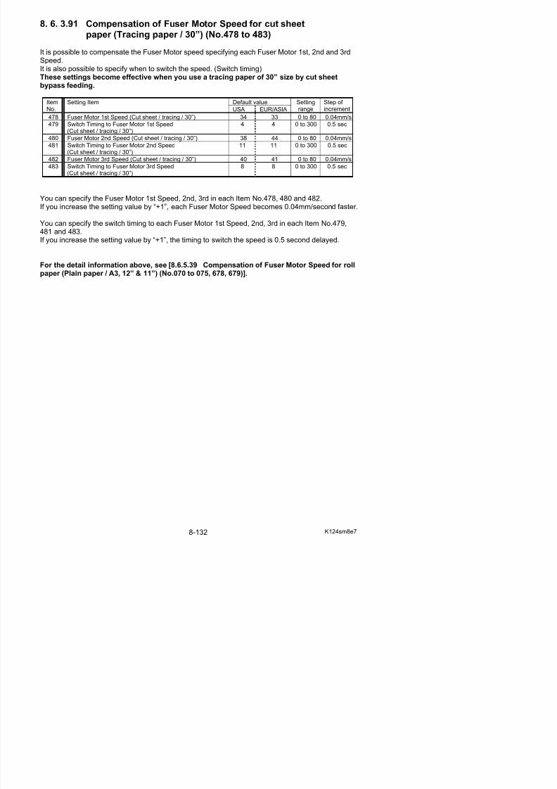
5/17/2018 KIP 7100 Service Manual Ver A_1 - slidepdf.com
http://slidepdf.com/reader/full/kip-7100-service-manual-ver-a1 574/674
(Cut sheet / film / 30 )
You can specify the Fuser Motor 1st Speed, 2nd, 3rd in each Item No.484, 486 and 488.If you increase the setting value by “+1”, each Fuser Motor Speed becomes 0.04mm/second faster.
You can specify the switch timing to each Fuser Motor 1st Speed, 2nd, 3rd in each Item No.48. 6.387 and 489.If you increase the setting value by “+1”, the timing to switch the speed is 0.5 second delayed.
For the detail information above, see [8.6.5.39 Compensation of Fuser Motor Speed for rollpaper (Plain paper / A3, 12” & 11”) (No.070 to 075, 678, 679)].
8. 6. 3.93 Compensation of Fuser Motor Speed for cut sheetpaper (Special plain paper / 30”) (No.490 to 495)
It is possible to compensate the Fuser Motor speed specifying each Fuser Motor 1st, 2nd and 3rdSpeed.It is also possible to specify when to switch the speed. (Switch timing)These settings become effective when you use a plain paper (special media) of 30” size bycut sheet bypass feeding.
Default valueItemNo.
Setting Item
USA EUR/ASIA
Settingrange
Step of increment
490 Fuser Motor 1st Speed (Cutsheet / special plain paper / 30”) 40 40 0 to 80 0.04mm/s491 Switch Timing to Fuser Motor 1st Speed
(Cutsheet / special plain paper / 30”)0 0 0 to 300 0.5 sec
8. 6. 3.94 Compensation of Fuser Motor Speed for cut sheetpaper (Special tracing paper / 30”) (No.496 to 501)
It is possible to compensate the Fuser Motor speed specifying each Fuser Motor 1st, 2nd and 3rdSpeed.It is also possible to specify when to switch the speed. (Switch timing)These settings become effective when you use a tracing paper (special media) of 30” sizeby cut sheet bypass feeding.
Default valueItemNo.
Setting Item
USA EUR/ASIA
Settingrange
Step of increment
496 Fuser Motor 1st Speed (Cut sheet / special tracing / 30”) 40 40 0 to 80 0.04mm/s
497 Switch Timing to Fuser Motor 1st Speed(Cut sheet / special tracing / 30”)
0 0 0 to 300 0.5 sec
498 Fuser Motor 2nd Speed (Cut sheet / special tracing / 30”) 40 40 0 to 80 0.04mm/s
499 Switch Timing to Fuser Motor 2nd Speed(Cut sheet / special tracing / 30”)
0 0 0 to 300 0.5 sec
500 Fuser Motor 3rd Speed (Cut sheet / special tracing / 30”) 40 40 0 to 80 0.04mm/s
501 Switch Timing to Fuser Motor 3rd Speed(Cut sheet / special tracing / 30”) 0 0 0 to 300 0.5 sec
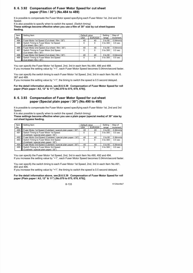
5/17/2018 KIP 7100 Service Manual Ver A_1 - slidepdf.com
http://slidepdf.com/reader/full/kip-7100-service-manual-ver-a1 575/674
( p g )
You can specify Fuser Motor 1st Speed, 2nd, 3rd in each Item No.496, 498 and 500.If you increase the setting value by “+1”, each Fuser Motor Speed becomes 0.04mm/second faster.
You can specify the switch timing to each Fuser Motor 1st Speed, 2nd, 3rd in each Item No.497,499 and 501.If you increase the setting value by “+1”, the timing to switch the speed is 0.5 second delayed.
For the detail information above, see [8.6.5.39 Compensation of Fuser Motor Speed for rollpaper (Plain paper / A3, 12” & 11”) (No.070 to 075, 678, 679)].
8. 6. 3.95 Compensation of Fuser Motor Speed for cut sheetpaper (Special film / 30”) (No.502 to 507)
It is possible to compensate the Fuser Motor speed specifying each Fuser Motor 1st, 2nd and 3rdSpeed.It is also possible to specify when to switch the speed. (Switch timing)These settings become effective when you use a film (special media) of 30” size by cutsheet bypass feeding.
Default valueItemNo.
Setting Item
USA EUR/ASIA
Settingrange
Step of increment
502 Fuser Motor 1st Speed (Cut sheet / special film / 30”) 40 40 0 to 80 0.04mm/s503 Switch Timing to Fuser Motor 1st Speed
(Cut sheet / special film / 30”)0 0 0 to 300 0.5 sec
8. 6. 3.96 Transfer Voltage applied at 100mm from trailing edge(Plain paper / Tracing paper / Film) (No.508 to 510)
It is possible to adjust the analog voltage to Transfer Corona on 100mm end of a print.This section does not function and is reserved for future update.
Default valueItemNo.
Setting Item
US A
EUR/ ASIA
Settingrange
Step of increment
508 Transfer Voltage applied at 100mm from trailing edge (Plain) 4FF 4FF 0 to 9FE -509 Transfer Voltage applied at 100mm from trailing edge (Tracing) 4FF 4FF 0 to 9FE -
510 Transfer Voltage applied at 100mm from trailing edge (Film) 4FF 4FF 0 to 9FE -
8. 6. 3.97 Transfer Voltage applied at 70mm from trailing edge(Plain paper / Tracing paper / Film) (No.511 to 513)
It is possible to adjust the analog voltage to Transfer Corona on 70mm end of a print
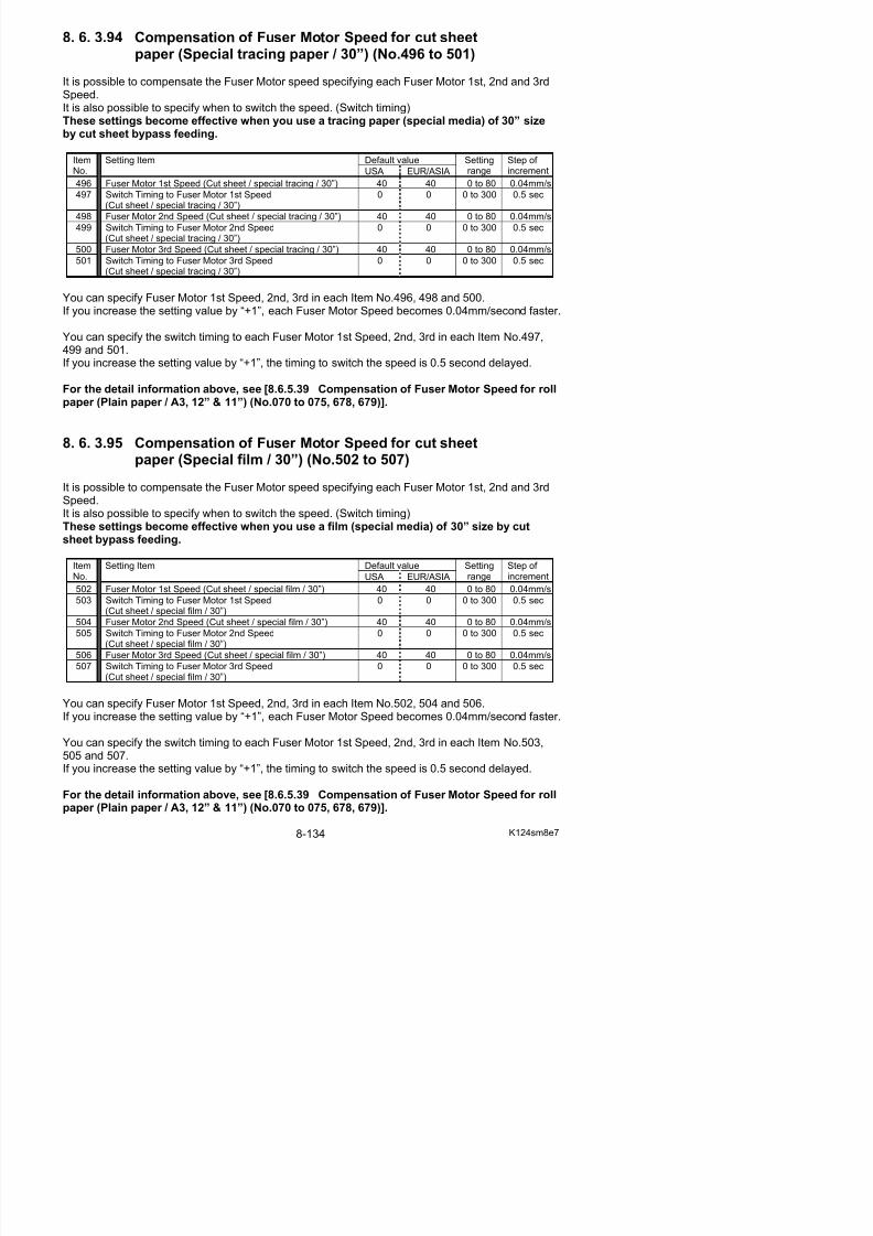
5/17/2018 KIP 7100 Service Manual Ver A_1 - slidepdf.com
http://slidepdf.com/reader/full/kip-7100-service-manual-ver-a1 576/674
It is possible to adjust the analog voltage to Transfer Corona on 70mm end of a print. A setting combination among No.511 to No.516 can reduce ghost images on the bottom area of aprint in some cases.
Default valueItemNo.
Setting Item
US A
EUR/ ASIA
Settingrange
Step of increment
511 Transfer Voltage applied at 70mm from trailing edge (Plain) 62F 62F 0 to 9FE -
512 Transfer Voltage applied at 70mm from trailing edge (Tracing) 69F 69F 0 to 9FE -513 Transfer Voltage applied at 70mm from trailing edge (Film) 4FF 4FF 0 to 9FE -
8. 6. 3.98 Fuser Motor Speed applied at 30mm from trailing edge(Plain paper / Tracing paper / Film) (No.514 to 516)
It is possible to adjust the speed of Fuser Motor driving on 30mm end of a print. A setting combination among No.511 to No.516 can reduce ghost images on the bottom area of aprint in some cases.
Default valueItemNo.
Setting Item
USA EUR/ ASIA
Settingrange
Step of increment
514 Fuser Motor Speed applied at 30mm from trailing edge (Plain) 13 17 0 to 80 0.04mm/s
515 Fuser Motor Speed applied at 30mm from trailing edge (Tracing) 19 19 0 to 80 0.04mm/s
516 Fuser Motor Speed applied at 30mm from trailing edge (Film) 0 0 0 to 80 0.04mm/s
8. 6. 3.99 Judgment value for Additional Cut Length
for Non-standard Size Prints (No.613 to 616)
It is possible to avoid the lack of trailing image on the non-standard size print, by providingadditional paper length by service modes 4-617 to 4-620 (Additional Cut Length for non-standardsize print).
Additional Cut Length specified by service mode 4-617 to 4-620 is not always provided.
Whether or not it is provided is judged by service mode 4-613 to 4-616 (Judgment value for “Additional Cut Length for non-standard size print”.)
Default valueItemNo.
Setting Item
USA EUR/ASIA
Settingrange
Step of increment
613 Judgment value for Additional Cut Length for Non-standardSize Prints (36”/ 34”/ 30”/ A0 / B1)
1 1 1 to 20 1mm
614 Judgment value for Additional Cut Length for Non-standardSize Prints (24”/ 20”/ A1)
1 1 1 to 20 1mm
615 Judgment value for Additional Cut Length for Non-standardSize Prints (18”/ 17”/ 15”/ A2)
1 1 1 to 20 1mm
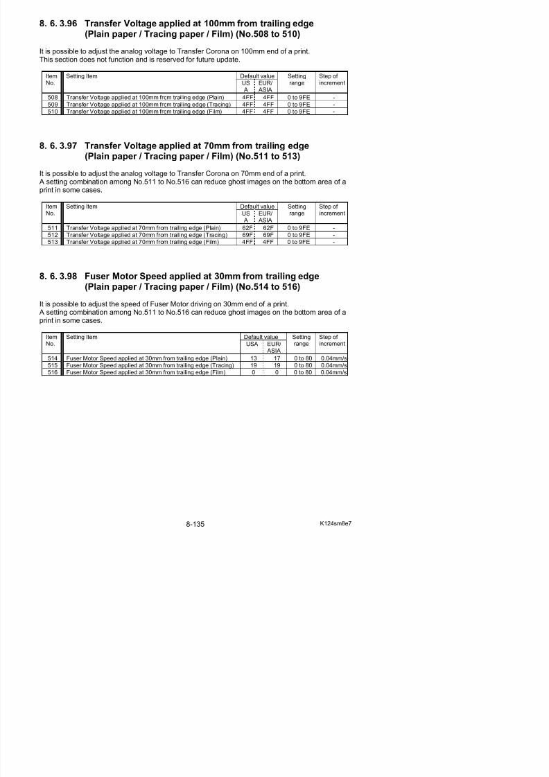
5/17/2018 KIP 7100 Service Manual Ver A_1 - slidepdf.com
http://slidepdf.com/reader/full/kip-7100-service-manual-ver-a1 577/674
( )
616 Judgment value for Additional Cut Length for Non-standardSize Prints (12”/ 11”/ A3)
1 1 1 to 20 1mm
Reference
(1) Which Judgement Value / Additional Cut Length setting is applied to a non-standard sizeprint depends on the corresponding roll width.
Roll Width Standard Size Standard Cut LengthJudgement
Value Additional
Length
36" 36"x48" 1219mm
841mm A0 1189mm34" 34"x44" 1118mm
30" 30"x42" 1067mm
728mm B1 1030mm
No.613 No.617
24" 24"x36" 914mm
22" 22"x34" 864mm
594mm A1 841mm
No.614 No.618
18" 18"x24" 610mm
420mm A2 594mm17" 17"x22" 559mm
15" 15"x21" 533mm
No.615 No.619
Reference
(2) If the actual image length is longer than (or equal to) “A+B”, “C” is provided to the trailingedge of non-standard size print.
A: Standard Cut Length (depends on roll width)B: Value of “Judgement Value for “Additional Cut Length for Non-standard Size Prints”
C: Value of “Additional Cut Length for Non-standard Size Prints”
<Example> Actual Image Length: 860mm A: 841mm (A1 roll width)B: 10C: 20
A (841mm) B (10)
Actual Image Length (860mm)
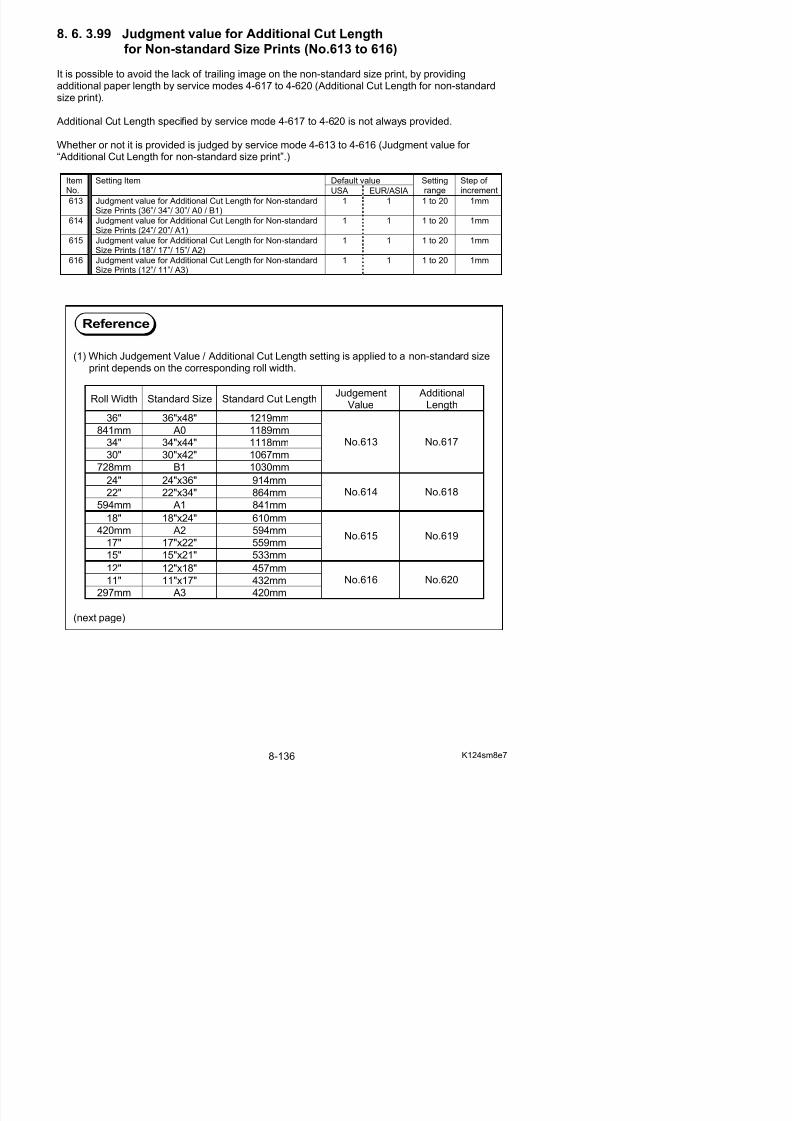
5/17/2018 KIP 7100 Service Manual Ver A_1 - slidepdf.com
http://slidepdf.com/reader/full/kip-7100-service-manual-ver-a1 578/674
Actual Image Length (860mm)
Print Length (880mm)
Actual Image Length (860mm) C (20)
(3) If the actual image length is shorter than “A+B”, the print is cut as long as the actualimage length. (“C” is not provided to the trailing edge of the print.)
A: Standard Cut Length (depends on roll width)B: Value of “Judgement Value for “Additional Cut Length for Non-standard Size Prints”C: Value of “Additional Cut Length for Non-standard Size Prints”
<Example> Actual Image Length: 845mm A: 841mm (A1 roll width)B: 10C: 20
A (841mm) B (10)
Actual Image Length (845mm)
8. 6. 3.100 Additional Cut Length for Non-standard Size Prints
(No.617 to 620)
It is possible to avoid the lack of trailing image on the non-standard size print, by providingadditional paper length by service modes 4-617 to 4-620 (Additional Cut Length for non-standardsize print).
Additional Cut Length specified by service mode 4-617 to 4-620 is not always provided.
Whether or not it is provided is judged by service mode 4-613 to 4-616 (Judgment value for “Additional Cut Length for non-standard size print”.)
Default valueItemNo.
Setting Item
USA EUR/ASIA
Settingrange
Step of increment
617 Additional Cut Length for Non-standard Size Prints(36”/ 34”/ 30”/ A0 / B1)
0 0 0 to 35 1mm
618 Additional Cut Length for Non-standard Size Prints(24”/ 22”/ A2)
0 0 0 to 35 1mm
619 Additional Cut Length for Non-standard Size Prints(18”/ 17”/ 15”/ A2)
0 0 0 to 35 1mm
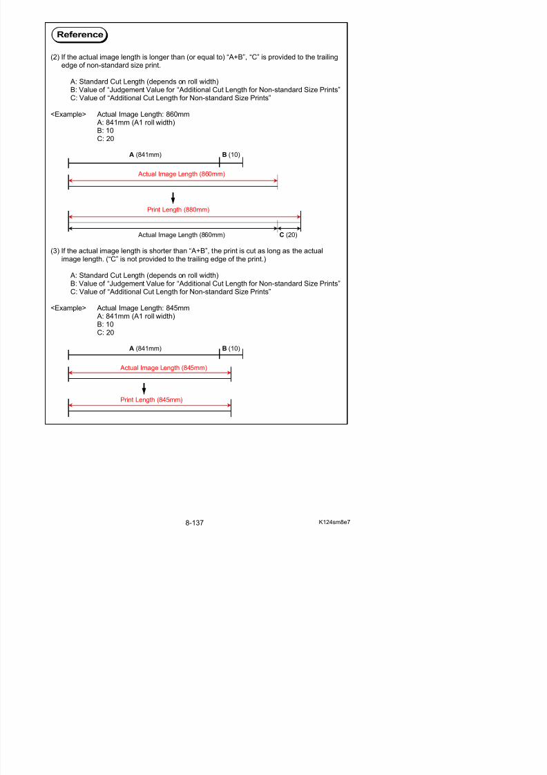
5/17/2018 KIP 7100 Service Manual Ver A_1 - slidepdf.com
http://slidepdf.com/reader/full/kip-7100-service-manual-ver-a1 579/674
( )
620 Additional Cut Length for Non-standard Size Prints(12”/ 11”/ A3)
0 0 0 to 35 1mm
Refer to page 8-121 and 122 for Additional Cut Length and its Judgment Value.
8. 6. 3. 101 Toner Supply Roller Bias (No.621)
It is possible to make bias adjustment for Toner Supply Roller.
Default Value Setting Range Step of increment
286 0 to 800 1
8. 6. 3. 102 Regulation Bias (No.622)
It is possible to make the print density darker or lighter by adjusting Regulation Bias (Center).The print density becomes darker if you increase the setting value
NOTE
This setting does not function. Change of this setting has no effect on the machine operation.
8. 6. 3. 103 Density Sensor Standard Output (No.623)
It is possible to change the default analog output of Density Sensor.“Density Sensor Standard Output” (No.623) and “Density Sensor Analog Voltage” (No.624) are
used for Density Measure.
Default Value Setting Range Step of increment
0 0 to 614 1
8. 6. 3. 104 Density Sensor Analog Voltage (No.624)
NOTE
NOTE
This setting has been factory-adjusted. Keep the value unchanged.
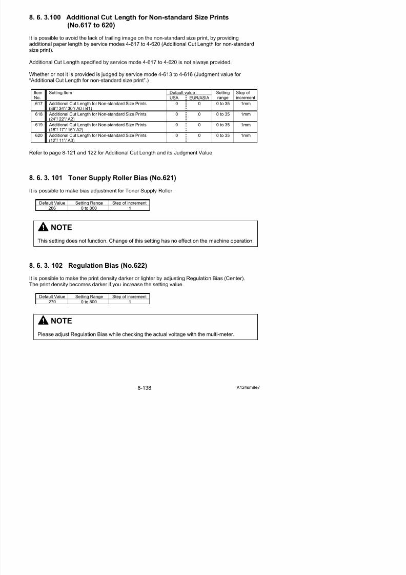
5/17/2018 KIP 7100 Service Manual Ver A_1 - slidepdf.com
http://slidepdf.com/reader/full/kip-7100-service-manual-ver-a1 580/674
It is possible to change the default analog output of Density Sensor.
“Density Sensor Standard Output” (No.623) and “Density Sensor Analog Voltage” (No.624) areused for Density Measure.
Default Value Setting Range Step of increment
0 0 to 614 1
NOTE
This setting has been factory-adjusted. Keep the value unchanged.
8. 6. 3. 105 Print - Fuser Temperature Side (12”/11”/A3) (No.625 to 630)
It is possible to adjust the side part of Fuser Temperature in a print cycle.You can specify the temperature for each type and size of media separately.The Fuser Temperature becomes 1 degree higher if you increase the setting value by “+1”.
Default valueItem No. Setting Item
USA EUR/ASIA
Settingrange
Step of increment
625 Print - Fuser Temperature Side(Plain) (12” / 11” / A3)
160 145 120 to 180 1oC
626 Print - Fuser Temperature Side(Tracing) (12” / 11” / A3)
160 150 120 to 180 1oC
627 Print - Fuser Temperature Side(Film) (12” / 11” / A3)
177 170 120 to 180 1oC
628 Print - Fuser Temperature Side(Special / Plain) (12” / 11” / A3)
160 160 120 to 180 1oC
629 Print - Fuser Temperature Side(Special / Tracing) (12” / 11” / A3)
160 160 120 to 180 1oC
630 Print - Fuser Temperature Side
(Special media / Film) (12” / 11” / A3)
177 170 120 to 180 1oC

5/17/2018 KIP 7100 Service Manual Ver A_1 - slidepdf.com
http://slidepdf.com/reader/full/kip-7100-service-manual-ver-a1 581/674
8. 6. 3. 106 Print - Fuser Temperature Side (18”/17”/15”/A2)(No.631 to 636)
It is possible to adjust the side part of Fuser Temperature in a print cycle.You can specify the temperature for each type and size of media separately.
The Fuser Temperature becomes 1 degree higher if you increase the setting value by “+1”.
Default valueItem No. Setting Item
USA EUR/ASIA
Settingrange
Step of increment
631 Print - Fuser Temperature Side(Plain) (18” / 17” / 15” / A2)
160 165 120 to 180 1oC
632 Print - Fuser Temperature Side(Tracing) (18” / 17” / 15” / A2)
160 170 120 to 180 1oC
633 Print - Fuser Temperature Side
(Film) (18” / 17” / 15” / A2)
177 170 120 to 180 1oC
634 Print - Fuser Temperature Side(Special / Plain) (18” / 17” / 15” / A2)
160 160 120 to 180 1oC
o
Reference
The center part of Fuser Temperature will be controlled by Print - Fuser Temperature Center (No. 039 to 044) separately.Refer to [8. 6. 3.19 Print - Fuser Temperature Center (No.039 to 044)] on page 8-53 for
further information.
8. 6. 3. 107 Print - Fuser Temperature Side (24”/22”/A1) (No.637 to 642)
It is possible to adjust the side part of Fuser Temperature in a print cycle.You can specify the temperature for each type and size of media separately.The Fuser Temperature becomes 1 degree higher if you increase the setting value by “+1”.
Default valueItem No. Setting Item
USA EUR/ASIA
Settingrange
Step of increment
637 Print - Fuser Temperature Side(Plain) (24” / 22” / A1)
160 165 120 to 180 1oC
638 Print - Fuser Temperature Side(Tracing) (24” / 22” / A1)
160 170 120 to 180 1oC
639 Print - Fuser Temperature Side(Film) (24” / 22” / A1)
177 170 120 to 180 1oC
640 Print - Fuser Temperature Side(Special / Plain) (24” / 22” / A1)
160 160 120 to 180 1oC
641 Print - Fuser Temperature Side(Special / Tracing) (24” / 22” / A1)
160 160 120 to 180 1oC
642 Print - Fuser Temperature Side
(Special / Film) (24” / 22” / A1)
177 170 120 to 180 1oC
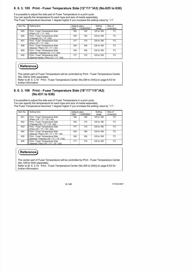
5/17/2018 KIP 7100 Service Manual Ver A_1 - slidepdf.com
http://slidepdf.com/reader/full/kip-7100-service-manual-ver-a1 582/674
8. 6. 3. 108 Print - Fuser Temperature Side (36”/34”/30”/A0/B1)(No.643 to 648)
It is possible to adjust the side part of Fuser Temperature in a print cycle.You can specify the temperature for each type and size of media separately.
The Fuser Temperature becomes 1 degree higher if you increase the setting value by “+1”.
Default valueItem No. Setting Item
USA EUR/ASIA
Settingrange
Step of increment
643 Print - Fuser Temperature Side(Plain) (36” / 34” / 30” / A0 / B1)
160 165 120 to 180 1oC
644 Print - Fuser Temperature Side(Tracing) (36” / 34” / 30” / A0 / B1)
160 170 120 to 180 1oC
645 Print - Fuser Temperature Side
(Film) (36” / 34” / 30” / A0 / B1)
177 170 120 to 180 1oC
646 Print - Fuser Temperature Side(Special / Plain) (36” / 34” / 30” / A0 / B1)
160 160 120 to 180 1oC
o
Reference
The center part of Fuser Temperature will be controlled by Print - Fuser Temperature Center (No. 039 to 044) separately.Refer to [8. 6. 3.19 Print - Fuser Temperature Center (No.039 to 044)] on page 8-53 for
further information.
8. 6. 3. 109 Density Sensor Output Monitor (No.649)
It is possible to change the mode to monitor the default analog output of Density Sensor.
Default Value Setting Range1 0 to 4
8. 6. 3. 110 Regulation Bias Incrementfor Auto Adjustment Level 2 and 3 (No.650)
NOTE
This setting is factory-use only. Keep the value unchanged.
NOTE

5/17/2018 KIP 7100 Service Manual Ver A_1 - slidepdf.com
http://slidepdf.com/reader/full/kip-7100-service-manual-ver-a1 583/674
It is possible to change the amount (increment) of Regulation Bias on Auto Adjustment. A specified increment of Regulation Bias will be applied at switching to Auto Adjustment Level 2and Level 3.
The default voltage value of the increment is about 40V (corresponding to “80” in the setting value)for switching to Auto Adjustment Level 2 and 3.
If you increase the setting value by “+1”, the increment of Regulation Bias Adjustment becomesabout 0.5V higher.
Default Value Setting Range Step of increment
80 0 to 200 0.5V
This setting has been factory-adjusted. Keep the value unchanged.
8. 6. 3. 111 Total Increment of Regulation Bias Adjustment (No.651)
It is possible to check the total amount (increment) of currently applied Regulation Bias Adjustment
by Density Compensation.
It is possible to add a 0.5V to the total amount of Regulation Roller Bias Adjustment directly.
Default Value Setting Range Step of increment
0 0 to 800 0.5V
NOTE
This setting can be used for checking purpose only.Setting change is allowed to factory-use only. Keep the value unchanged.
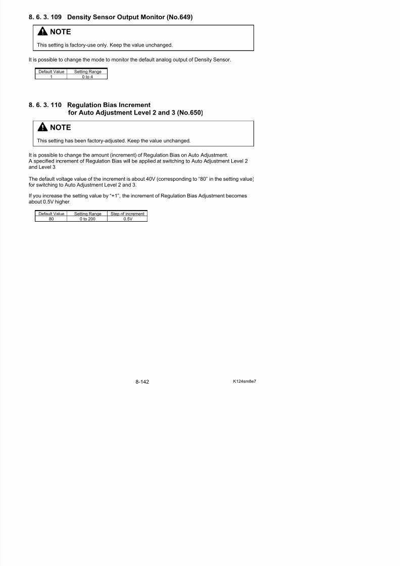
5/17/2018 KIP 7100 Service Manual Ver A_1 - slidepdf.com
http://slidepdf.com/reader/full/kip-7100-service-manual-ver-a1 584/674
8. 6. 3. 112 Density Compensation ON/OFF (No.652)
It is possible to decide whether Density Compensation is enabled.
Setting value Contents
0 Density Compensation Process is disabled
1(default)
Density Compensation Process is enabled
Reference
Density Compensation Process is performed as follows.
1. Several solid patches are created on Drum and are measured by Density Sensor at aregular interval of Main Motor operating time (No.655).This is called Density Measure.
2. If the current density value (calculated based on Density Measure) does not meet TargetDensity (No.653), one of the Adjustment Level listed below will be applied.
3 D l Bi d R l ti Bi (N 650) ill b dj t d b d th t

5/17/2018 KIP 7100 Service Manual Ver A_1 - slidepdf.com
http://slidepdf.com/reader/full/kip-7100-service-manual-ver-a1 585/674
3. Developer Bias and Regulation Bias (No.650) will be adjusted based on the current Adjustment Level.
AdjustmentLevel 0 (Default)
AdjustmentLevel 1
AdjustmentLevel 2
AdjustmentLevel 3
Developer Bias(Negative)
-180V -230V -230V -230V
Regulation Biasagainst Developer Bias
-80V -80V -120V -160V
Adjustment Adjustment Adjustment AdjustmentLevel 0 (Default) Level 1 Level 2 Level 3
50V
40V
40V
- 180V
0V
- 100V
- 200V
- 300V
- 230V - 230V - 230V
160
120
80
80
Developer Bias
Regulation Bias
againstDeveloper Bias
8. 6. 3. 113 Target Density (No.653)
It is possible to change Target Density that should be achieved and maintained for consistent printdensity.
If the current density does not meet Target Density, Regulation (Developer) Bias will beautomatically adjusted based on the current Adjustment Level.
• If the current Density Value is judged “not enough” (lighter than required), the next level will beapplied.
• If the current Density Value is judged “adequate”, the current level remains.
• There is possibility for the Density Value to be judged “too much enough” (darker thanrequired), then the previous level will be applied.
If you increase the setting value by “+1”, Target Density will rise and thus Auto Adjustment Levelwould be switched to the next level earlier.
NOTE
This setting has been factory-adjusted. Keep the value unchanged.
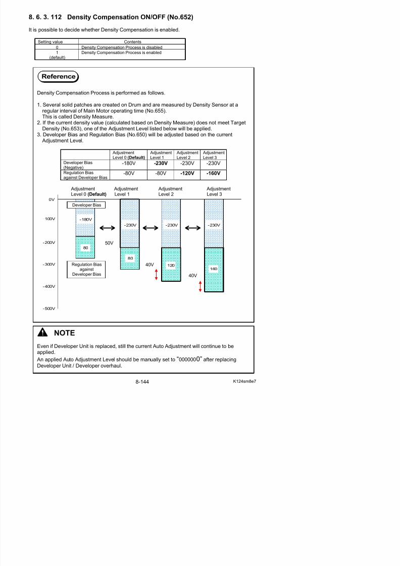
5/17/2018 KIP 7100 Service Manual Ver A_1 - slidepdf.com
http://slidepdf.com/reader/full/kip-7100-service-manual-ver-a1 586/674
8. 6. 3. 114 Regulation Bias Maximum (No.654)
It is possible to change the maximum of Regulation Bias.When the total value amount of Regulation Bias (No.622) and Total Increment of Regulation Bias Adjustment (No.641) reaches to the value of this setting, Regulation Bias cannot raise any more.
If you increase the setting value by “+1”, the maximum of Regulation Bias increases.
Default Value Setting Range Step of increment
500 160 to 800 1
8. 6. 3. 115 Density Measure Interval (No.655, 656)
NOTE
This setting has been factory-adjusted. Keep the value unchanged.
NOTE
This setting has been factory-adjusted. Keep the value unchanged.
8. 6. 3. 116 Developer Bias Increment
for Auto Adjustment Level 1 and after (No.657)
It is possible to change the amount (increment) of Developer Bias Adjustment.
A specified increment of Developer Bias will be applied at switching to and as of Auto AdjustmentLevel 1.
The default voltage value of the increment is approximately 50V (corresponding to “80” in thesetting value) for switching to Auto Adjustment Level 1. The increased Developer Bias will beapplied to the subsequent Auto Adjustment Level.
If you increase the setting value by “+1”, the increment of Developer Bias Adjustment becomes
higher.
Default Value Setting Range Step of increment
NOTE
This setting has been factory-adjusted. Keep the value unchanged.
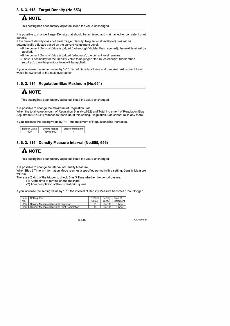
5/17/2018 KIP 7100 Service Manual Ver A_1 - slidepdf.com
http://slidepdf.com/reader/full/kip-7100-service-manual-ver-a1 587/674
158 0 to 400 1
8. 6. 3. 117 Ready - Fuser Temperature Center (No.660 to 665)
It is possible to specify “Ready” temperature.You can specify the temperature for each type of media separately.This setting will be applied only when Fuser Temperature is below 50oC at turning on the machine.The Fuser Temperature becomes 1 degree higher if you increase the setting value by “+1”.
Default valueItem No. Setting Item
USA EUR/AS
Settingrange
Step of increment
660 Ready - Fuser Temperature Center (Plain) 160 160 120 to 180 1oC
661 Ready - Fuser Temperature Center (Tracing) 160 170 120 to 180 1oC
662 Ready - Fuser Temperature Center (Film) 177 177 120 to 180 1oC
663 Ready - Fuser Temperature Center (Special / Plain)
160 160 120 to 180 1oC
664 Ready - Fuser Temperature Center (Special / Tracing)
160 160 120 to 180 1oC
665 Ready - Fuser Temperature Center (Special / Film)
177 170 120 to 180 1oC
After reaching “Ready”, fuser temperature will rise 10 oC higher than “Ready” (Overshoot) in 10minutes. Then it will be maintained within “Standby” temperature.

5/17/2018 KIP 7100 Service Manual Ver A_1 - slidepdf.com
http://slidepdf.com/reader/full/kip-7100-service-manual-ver-a1 588/674
Fuser Temperature Overshootin 10 minutes after Ready
(oC) StandbyOvershoot
Setting value of “Ready - Temperature”
50
o
C
0 (Time)
Turn on Ready
8. 6. 3. 118 Ready - Fuser Temperature Side (No.666 to 671)
It is possible to specify “Ready” temperature.You can specify the temperature for each type of media separately.This setting will be applied only when Fuser Temperature is below 50oC at turning on the machine
8. 6. 3. 119 Fuser Motor Speed (18” / 17” / 15” / 12” / 11” / A2 / A3)
(No. 672 to 677)
It is possible to adjust the speed of Fuser Motor for each type of paper separately.If you increase the setting value by “+1”, the motor speed becomes 0.04mm/second faster.
Default valueItemNo.
Setting Item
USA EUR/ASIA
Settingrange
Step of increment
672 Fuser Motor Speed (18” / 17” / 15” / 12” / 11” / A2 / A3)
(Plain paper)
50 50 0 to 80 0.04mm/s
673 Fuser Motor Speed (18” / 17” / 15” / 12” / 11” / A2 / A3)(Tracing paper)
57 60 0 to 80 0.04mm/s
674 Fuser Motor Speed (18” / 17” / 15” / 12” / 11” / A2 / A3)(Film paper)
50 50 0 to 80 0.04mm/s
675 Fuser Motor Speed (18” / 17” / 15” / 12” / 11” / A2 / A3)(Special plain paper)
40 40 0 to 80 0.04mm/s
676 Fuser Motor Speed (18” / 17” / 15” / 12” / 11” / A2 / A3)(Special tracing paper)
40 40 0 to 80 0.04mm/s
677 Fuser Motor Speed (18” / 17” / 15” / 12” / 11” / A2 / A3)
(Special film)
40 40 0 to 80 0.04mm/s
For Fuser Motor Speed in larger size, refer to [8. 6. 3.64 Fuser Motor Speed (36” / 34” / 30” / 24” /
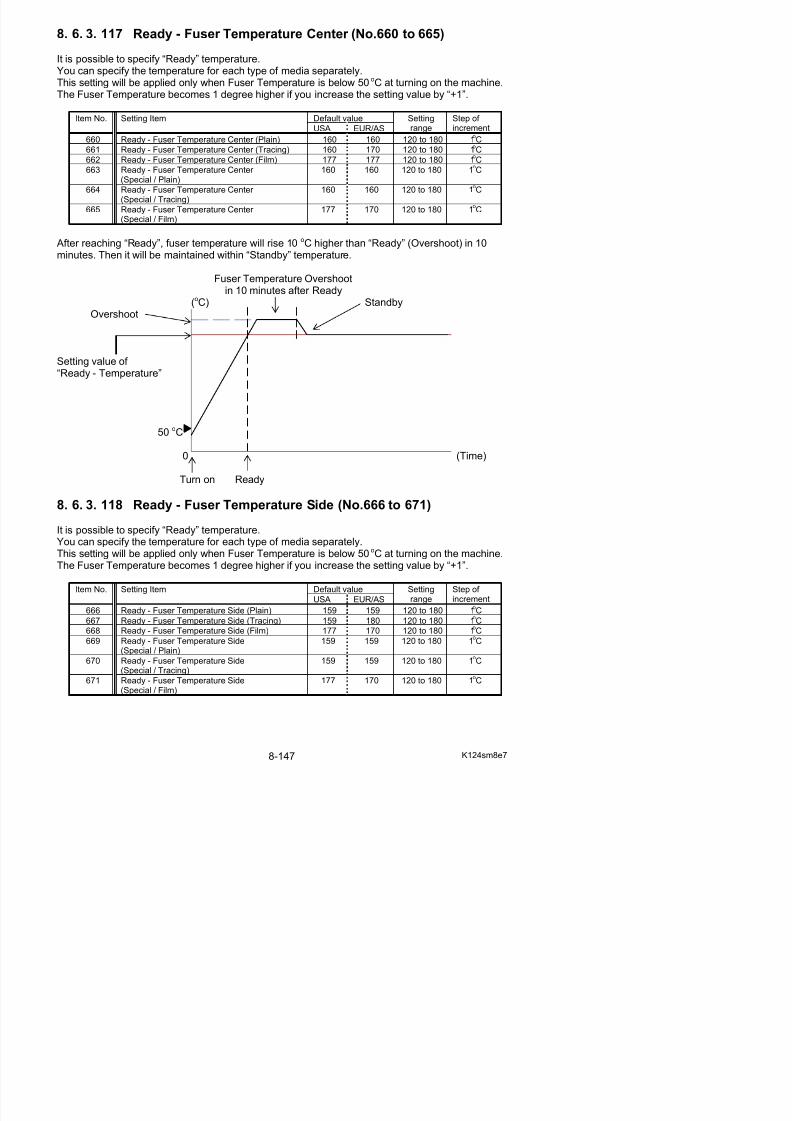
5/17/2018 KIP 7100 Service Manual Ver A_1 - slidepdf.com
http://slidepdf.com/reader/full/kip-7100-service-manual-ver-a1 589/674
22” / A0 / B1 / A1) (No.316 to 321) on page 8-90.
8. 6. 3. 120 Compensation of Fuser Motor Speed 4 (No.678 to 737)
Fuser Motor Speed 4 and its switch timing are explained on Fuser Motor Speed 1, 2, 3 together.Please refer to [8. 6. 3.39 Compensation of Fuser Speed 1 (No.070 to 075)] on page 8-64 to 66and the concerning pages for media type / size.
8. 6. 3. 121 Standby - Fuser Temperature (No.738, 739)
It is possible to adjust the Fuser Temperature to be maintained while waiting for a print job. Youcan specify the temperature for the center and the sides separately.This setting is applied after the period of Fuser Temperature Overshoot (+10oC against “Ready -Temperature” in 10 minutes).The Fuser Temperature becomes 1 degree higher if you increase the setting value by “+1”.
Default valueItem No. Setting Item
USA EUR/ASIA
Settingrange
Step of increment
738 Standby - Fuser Temperature Center 167 167 120 to 180 1oC739 Standby - Fuser Temperature Side 155 155 120 to 180 1
oC
Fuser Temperature Overshootin 10 minutes after Ready
(oC)
Setting value of
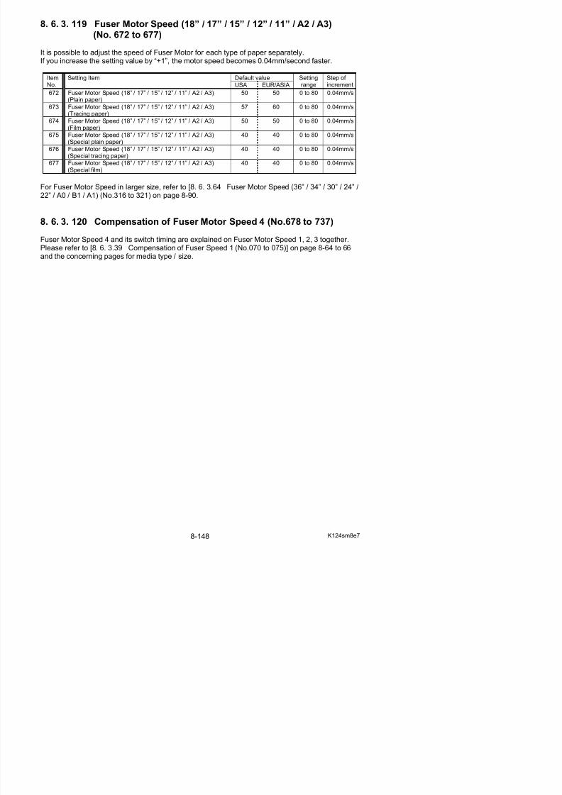
5/17/2018 KIP 7100 Service Manual Ver A_1 - slidepdf.com
http://slidepdf.com/reader/full/kip-7100-service-manual-ver-a1 590/674
“Standby - Temperature”(Example 160oC)
0 (Time)
Turn on Ready Standby
8. 6. 3. 122 Assist Fan Off Timing (No.740 to 742)
Assist Fan stops at a regular period after the trailing edge of a print of in 15” or wider reachesRegistration Sensor. It is possible to change the timing of Assist Fan off.This setting may be a solution for image void on the trailing center.
If you increase the setting value by “+1”, the timing of Assist Fan off becomes 0.125 seconds later.
Default valueItemNo.
Setting ItemUSA EUR/AS
Settingrange
Step of increment
740 Assist Fan Off Timing (18” / 17” / 15” / A2) 8 4 0 to 8 0 125 sec
8. 6. 3. 123 Fuser Motor Speed applied at 100mm from trailing edge
(36” / 34” / 30” / A0 / B1 width) (No.743 to 745)
It is possible to adjust the speed of Fuser Motor driving on 100mm end of a print in 36” / 34” / 30” / A0 / B1 width.This setting may be a solution for image void on the trailing center.
If you increase the setting value by “+1”, speed of Fuser Motor driving becomes 0.04mm/s slower than the applied speed at that point.
Default valueItemNo.
Setting ItemUSA EUR/AS
Settingrange
Step of increment
743 Fuser Motor Speed applied at 100mm from trailingedge (36” / 34” / 30” / A0 / B1 width) (Plain)
0 0 0 to 80 0.04mm/s
744 Fuser Motor Speed applied at 100mm from trailingedge (36” / 34” / 30” / A0 / B1 width) (Tracing)
0 0 0 to 80 0.04mm/s
745 Fuser Motor Speed applied at 100mm from trailingedge (36” / 34” / 30” / A0 / B1 width) (Film)
0 0 0 to 80 0.04mm/s
8 6 3 124 R ll 2 F d St db ON/OFF (N 746)
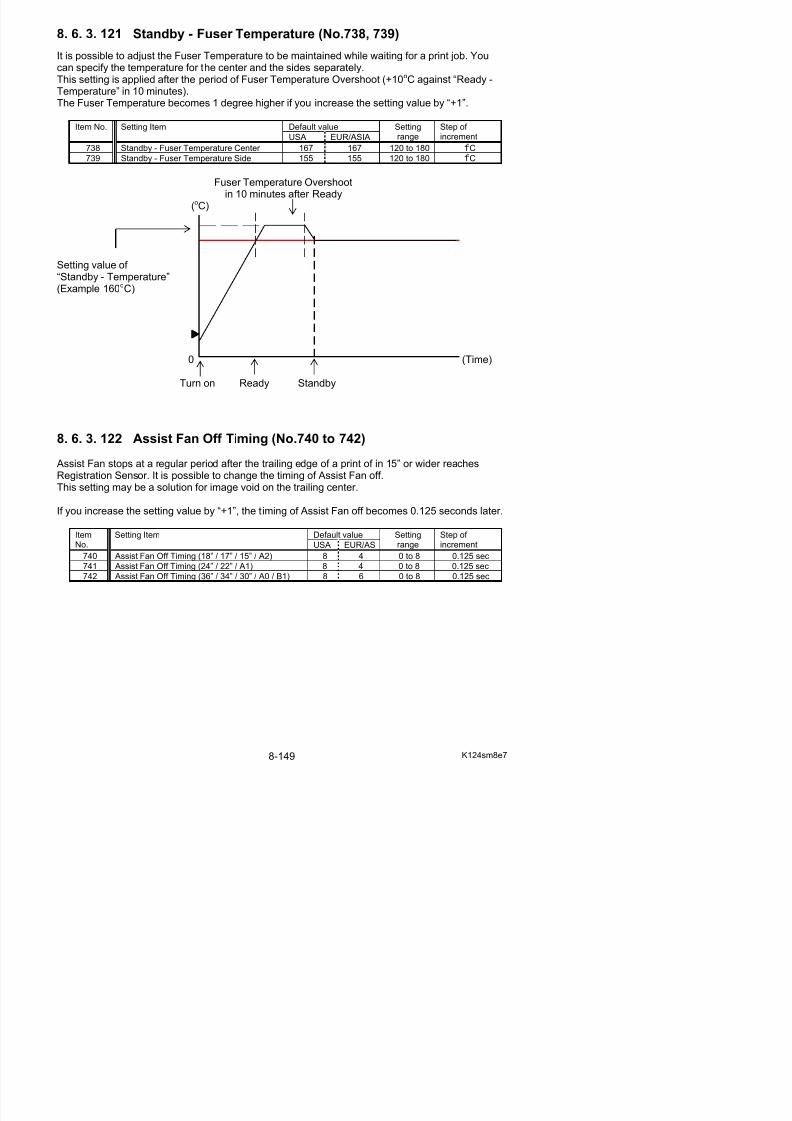
5/17/2018 KIP 7100 Service Manual Ver A_1 - slidepdf.com
http://slidepdf.com/reader/full/kip-7100-service-manual-ver-a1 591/674
8. 6. 3. 124 Roll 2 Forward Standby ON/OFF (No.746)
The default Standby Position for the leading edge of Roll 2 is located directly below the set sensor (PH9). This setting will feed the leading edge to Forward Standby Position (approximately 252mmforward from the default Standby Position).
Setting value Contents
0(default)
Roll 2 Leading Edge stays at the set sensor
1 Roll 2 Leading Edge goes Forward Standby Position
8. 6. 3. 125 Roll 2 Forward Standby Position Adjustment (No.747)
This setting can adjust Roll 2 Forward Standby Position (approximately 202 to 252mm forwardfrom the default Roll 2 Standby Position) with Roll 2 Forward Standby on. When the setting valueincreases by 1, Roll 2 Forward Standby Position will shift backward to the default Standby Positionin 1mm. (“0” for 252mm forward, “50” for 202mm forward)
Default Value Setting Range Step of increment
0 0 to 50 1mm
8. 6. 3. 127 Tracing Mode (No. 749)
Even in “ready” condition, the fuser temperature is controlled slightly lower than “Print” temperaturein order to reduce inside temperature.It quickly rises up to “Print” temperature at the same time as the printer starts printing an output job.This setting will keep media feeding wait for the completion of the fuser temperature recovery.
Note that Tracing Mode is effective only for an extremely thin tracing paper (off-specification).
Setting value Contents0
(default)Fuser temperature starts recovery as soon as aprint job is sent.
1 A print on tracing paper will start after recovery of fuser temperature.
8. 6. 3. 128 Roll 1 Setting Mode (No. 750)
The default Standby Position for the leading edge of Roll 1 is located directly below the set sensor (PH7). This setting will allow the leading edge of a roll media that has kept waiting a long period in
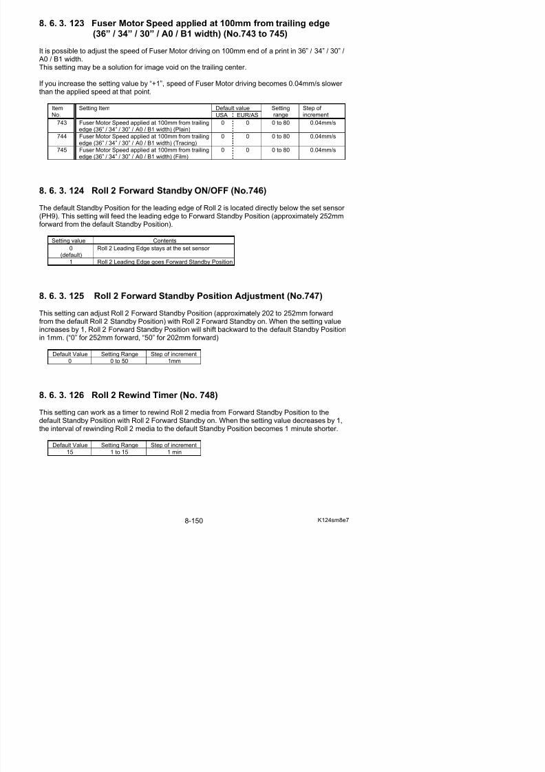
5/17/2018 KIP 7100 Service Manual Ver A_1 - slidepdf.com
http://slidepdf.com/reader/full/kip-7100-service-manual-ver-a1 592/674
( ) g g g p g g pa special circumstance to move about 20mm forward from the default Standby Position.This will keep the edge from waving.
Note that Roll 1 Setting Mode is effective only for an extremely thin roll media (off-specification).
Setting value Contents0
(default)Roll 1 Leading Edge stays at the set sensor
1 Roll 1 Leading Edge goes 20mm forward from theset sensor.
8. 6. 3. 129 Disable HV Error Detection Mode (No. 751)
“Disable HV Error Detection Mode” functions just as Error Mask Mode for high voltage errors.This allows the system to ignore service call errors regarding high voltage power supply (E-31, E-32, E-33, E-34) and prevents the concerning error code from being displayed both on the sub UIand the touch screen.“Disable HV Error Detection Mode” ON is not canceled by turning off the machine, but remainsuntil set to OFF manually.
Setting value Contents0
(d f l )HV error detection works normally.
8. 6. 3. 130 Auto Initial Cut After Long Print (No. 753, 754)
Trimming the leading edge maintains feeding stability for the subsequent print right after a longprint longer than the guarantee length.
“Auto Initial Cut After Long Print” ejects a 210mm sheet for initial cut right after completion of along print that exceeds a specified length and number of sheets.(The cut length is fixed in 210mm)
Default valueItemNo. Setting Item USA EUR/AS Settingrange Step of increment
753 Auto Initial Cut After Long Print (Length) 10 10 10 to 60 100mm
754 Auto Initial Cut After Long Print (Number of sheet) 0 0 0 to 3 *number of sheets
* “Auto Initial Cut After Long Print” counts long prints (longer than No.753) beyond print jobs.It makes Initial Cut while the printer is proceeding only long prints (longer than No.753). If a print job contains a “Non long print” (shorter than No.753), the count will be reset.
Such short print obtains the accurate cut length and just works as a “trim cut” for the next long print.
8 6 3 131 L th f F d I iti l C t B f P i t (N 755)
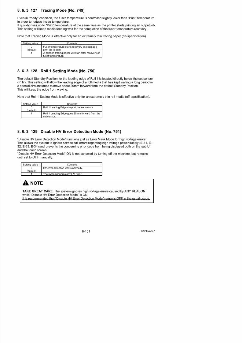
5/17/2018 KIP 7100 Service Manual Ver A_1 - slidepdf.com
http://slidepdf.com/reader/full/kip-7100-service-manual-ver-a1 593/674
8. 6. 3. 131 Length for Forced Initial Cut Before Print (No. 755)
Under a certain usage environment, the first print of a job sometimes would have a wrinkle or animage void if the prints are made with a roll media left in the deck for a long period.“Forced Initial Cut Before Print” makes an automatic initial cut (almost 1 revolution of a roll media)
at the leading edge before processing a job to obtain image quality and feed balance in suchconditions.
Which media type to have “Forced Initial Cut Before Print” can be specified on the UI screen.(For further information of Configuration on the UI, see KIP IPS Touchscreen Operator’s Guide)
No.755 can specify the length to be cut and ejected prior to start printing.
Default Value Setting Range Step of increment594 210 to 600 1mm
8. 6. 3. 132 Leading Registration for Paper Tray (No. 756)
It is possible to specify where to start printing the image at the leading edge of a sheet from thePaper Tray.If you increase the setting value by “+1 “, the head of image is shifted 1mm downward toward thetrailing edge As a result the leading margin becomes larger.
Default Value Setting Range Step of increment
not decided 1 to 40 1mm
Leading Registration
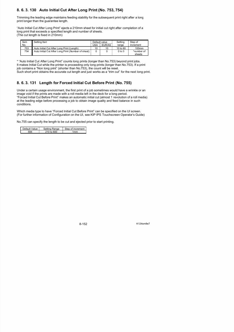
5/17/2018 KIP 7100 Service Manual Ver A_1 - slidepdf.com
http://slidepdf.com/reader/full/kip-7100-service-manual-ver-a1 594/674
value is increased. value is decreased.
8. 6. 3. 133 Trailing Margin for Paper Tray (No. 757)
It is possible to adjust the length of trailing margin of a sheet from the Paper Tray.The length of trailing margin becomes 1mm longer if you Increase the setting value by “+1 “.
Default Value Setting Range Step of increment
not decided 1 to 40 1mm
Setting value is increased. Setting value is decreased.
Trailing Margin
8. 6. 3. 134 Side Registration for Paper Tray (No. 758)
It is possible to specify where to start printing the image at the side edge of a sheet from the Paper Tray.If you increase the setting value by “+1 “, image is shifted 0.1mm to the right.
Default Value Setting Range Step of increment
not decided 0 to 100 0.1mm
Setting value is increased.
Side Registration
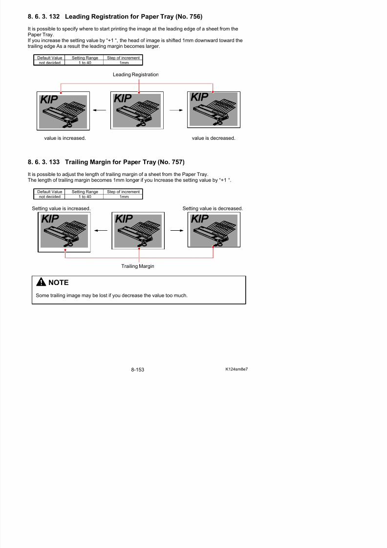
5/17/2018 KIP 7100 Service Manual Ver A_1 - slidepdf.com
http://slidepdf.com/reader/full/kip-7100-service-manual-ver-a1 595/674
Setting value is decreased.
8. 6. 4 Creating Backup
It is possible to save the current parameters in Adjustment Mode as RAM file.RAM file can be used for backup measure.
1. Press [Export] in Adjustment Menu screen.
NOTE
Prior to any attempts at significant changes on Adjustment Mode, export the currentparameters to .RAM file.
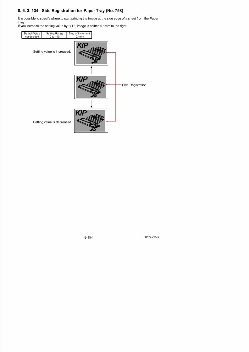
5/17/2018 KIP 7100 Service Manual Ver A_1 - slidepdf.com
http://slidepdf.com/reader/full/kip-7100-service-manual-ver-a1 596/674
2. Specify a place to save the current parameter.It will be saved as both *.txt and *.ram in a folder that is automatically created there at this time.The printer’s serial number will be automatically added to the folder.
*.ram is used for backup of the current parameter. You can use it to import the parameter tomachines.
*.txt” is only used for simplified confirmation with an appropriate application such as Notepad.
8. 6. 5 Restoring Configuration from Backup
It is possible to restore the parameters by using a RAM file that has been saved before.This can be used for the following possible cases.
- If the current parameters have loss or damage of data.- To apply parameters of a certain printer to another.
1. Press [Import] in Adjustment Menu screen.
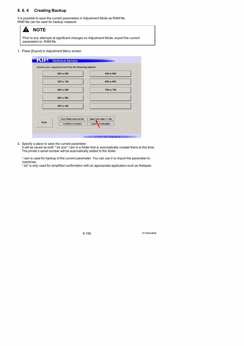
5/17/2018 KIP 7100 Service Manual Ver A_1 - slidepdf.com
http://slidepdf.com/reader/full/kip-7100-service-manual-ver-a1 597/674
2. Locate and open a RAM file that you want to apply.
3. The system reads all the parameters in the RAM file.Then the parameters will be applied to “New Value” field.
NOTE
At this point, KIP Service Software just reads and displays the parameters in the RAMfile, but the parameters do not take effect on the printer yet.
Follow the later step to apply the read parameters to the printer
4. Press [Save]. After confirmation, the read parameters will be sent to the printer.
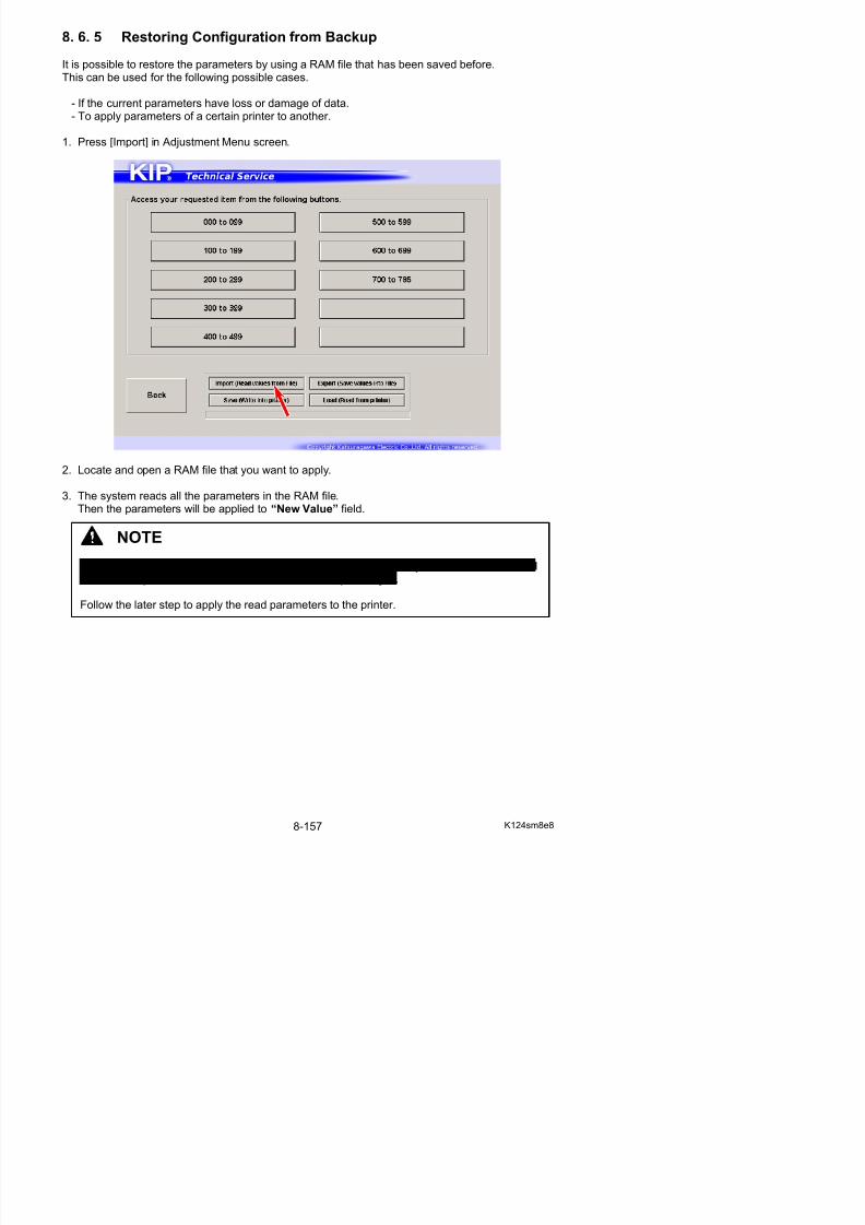
5/17/2018 KIP 7100 Service Manual Ver A_1 - slidepdf.com
http://slidepdf.com/reader/full/kip-7100-service-manual-ver-a1 598/674
8. 7 Running Mode
In Running Mode, the printer takes usual printing operation with no print media loaded.If you install any roll media, it is transported and ejected from the printer as usual as normal print.Note that the printer will continue printing till the media empty.
8. 8 Jam/Error Mask Mode
If the printer indicates any error (J-****/E-****), it is possible to mask (ignore, not to detect) it inJam/Error Mask Mode. The error (J-****/E-****) you have chosen to mask will not be detected by
masking. You can temporarily operate the printer as usual as normal condition even if a cause of the error is not removed yet.
NOTE
Running Mode is not available in Service Mode. Factory Use Only.
NOTE

5/17/2018 KIP 7100 Service Manual Ver A_1 - slidepdf.com
http://slidepdf.com/reader/full/kip-7100-service-manual-ver-a1 599/674
Mask Target screen
NOTE
Masking condition will be automatically canceled once you quit KIP Service Software or turnoff the printer.
1 2
Jam Mask screen
5
2
1
3
4
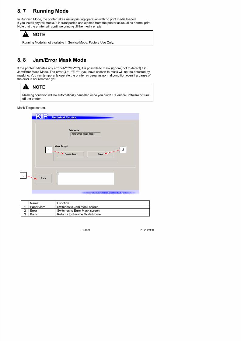
5/17/2018 KIP 7100 Service Manual Ver A_1 - slidepdf.com
http://slidepdf.com/reader/full/kip-7100-service-manual-ver-a1 600/674
Name Function1 Mask List Displays Mask items in drop-down menu
Choose one item that you want to mask.
2 Check All Starts jam masking against all the items
3 Uncheck All Cancels jam masking against checked items
4 media situationto be masked
Specifies which situation to be masked.
5 Back Returns to Service Mode Home
Error Mask screen
4
32
1
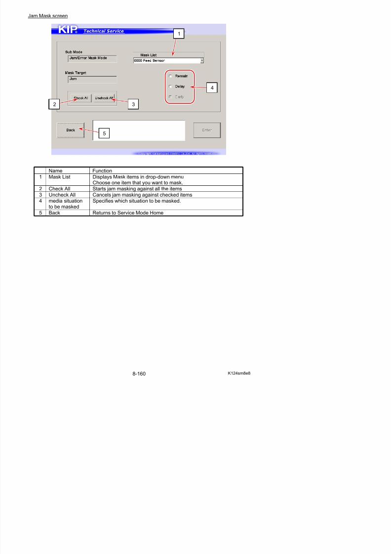
5/17/2018 KIP 7100 Service Manual Ver A_1 - slidepdf.com
http://slidepdf.com/reader/full/kip-7100-service-manual-ver-a1 601/674
Name Function1 Mask List Displays Mask items in the list
Select mask target(s) that you want to mask.Starts error masking while item(s) is checked
2 Check All Starts error masking against all the items
3 Uncheck All Cancels error masking against checked items
4 Back Returns to Service Mode Home
8. 8. 1 Mask List
Jam Mask
0000 Roll 2 Set Roll 2 Deck Jam PH9
0001 Roll 1 Set Roll 1 Deck Jam PH7
0002 Feed Feeding Jam PH6
0003 Regist Registration Jam PH1
0004 Manual Manual Jam PH5
0005 Sep Internal Jam PH2
0006 Exit Fuser / Exit Cover Jam PH30007 Pickup Pickup Jam (Paper Tray) PH13
Error Mask
Main Motor Main Motor Error E-0010
Fuser Motor Fuser Motor Error E-0011
Press Motor Developer Press Motor Error E-0012
Dev. Set Developer Unit Set Error E-0070
Counter Counter Error E-0020Im Corona Image Corona Output Error E-0031
Tr Corona Transfer Corona Output Error E-0033
Sp Corona Separation Corona Output Error E-0032
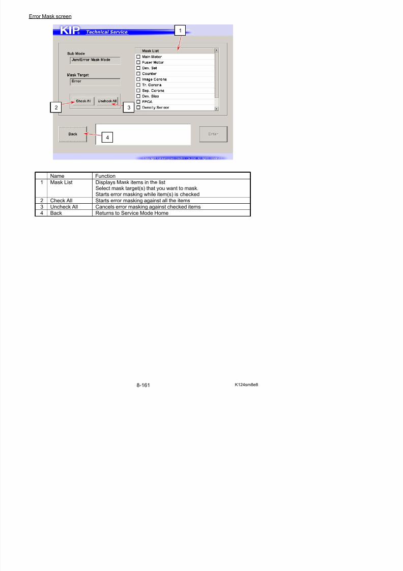
5/17/2018 KIP 7100 Service Manual Ver A_1 - slidepdf.com
http://slidepdf.com/reader/full/kip-7100-service-manual-ver-a1 602/674
Sp Corona Separation Corona Output Error E 0032
Dev. Bias Developer Bias Error E-0034
FPGA FPGA Error E-0050
Density Sensor Density Sensor Error E-0080E-0081
8. 8. 2 Masking Jam
1. Press [Jam Error Mask] in Service Mode Home.Mask Target screen appears.
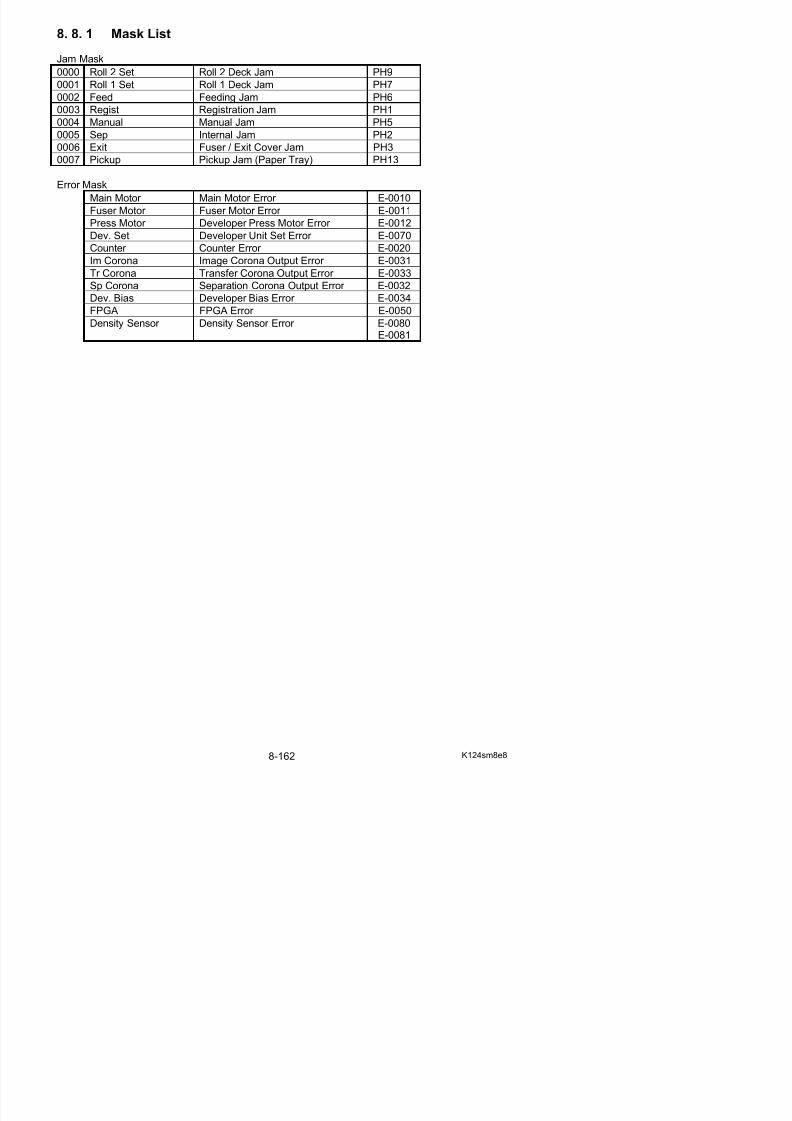
5/17/2018 KIP 7100 Service Manual Ver A_1 - slidepdf.com
http://slidepdf.com/reader/full/kip-7100-service-manual-ver-a1 603/674
2. Press [Paper Jam].

5/17/2018 KIP 7100 Service Manual Ver A_1 - slidepdf.com
http://slidepdf.com/reader/full/kip-7100-service-manual-ver-a1 604/674
3. Select the desired target from the pull-down menu.Check any of “Remain” / “Delay” / “Early” then the concerning sensor starts to ignore thechecked jam.
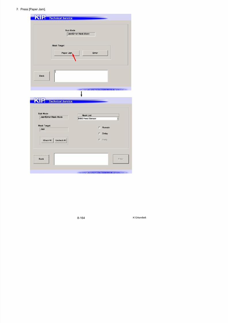
5/17/2018 KIP 7100 Service Manual Ver A_1 - slidepdf.com
http://slidepdf.com/reader/full/kip-7100-service-manual-ver-a1 605/674
8. 8. 3 Masking Error
1. Press [Jam Error Mask] in Service Mode Home.Mask Target screen appears.
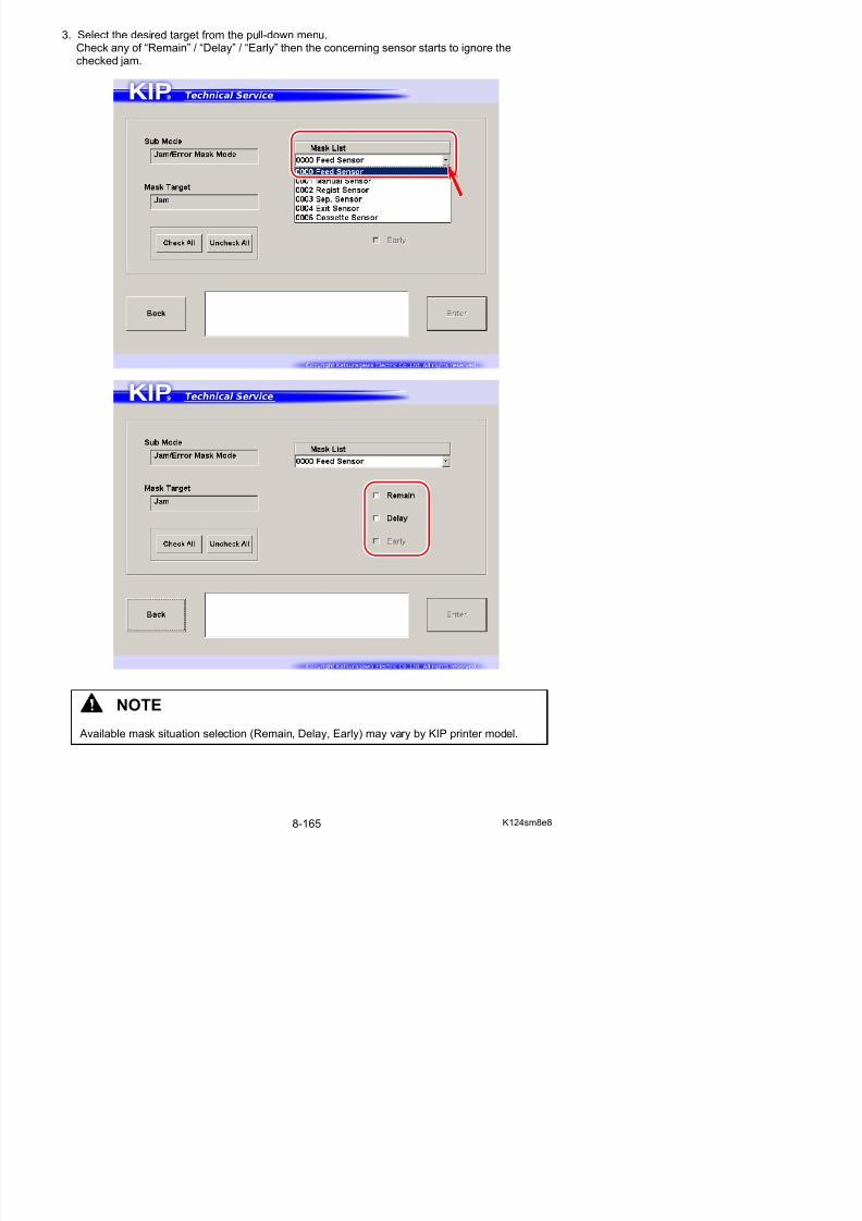
5/17/2018 KIP 7100 Service Manual Ver A_1 - slidepdf.com
http://slidepdf.com/reader/full/kip-7100-service-manual-ver-a1 606/674
2. Press [Error].
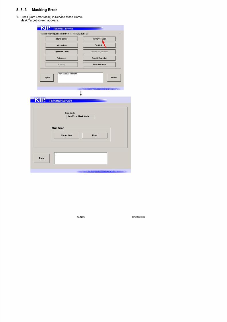
5/17/2018 KIP 7100 Service Manual Ver A_1 - slidepdf.com
http://slidepdf.com/reader/full/kip-7100-service-manual-ver-a1 607/674
3. Check items that you want to mask. Then the concerning sensor starts to ignore the checkedError.
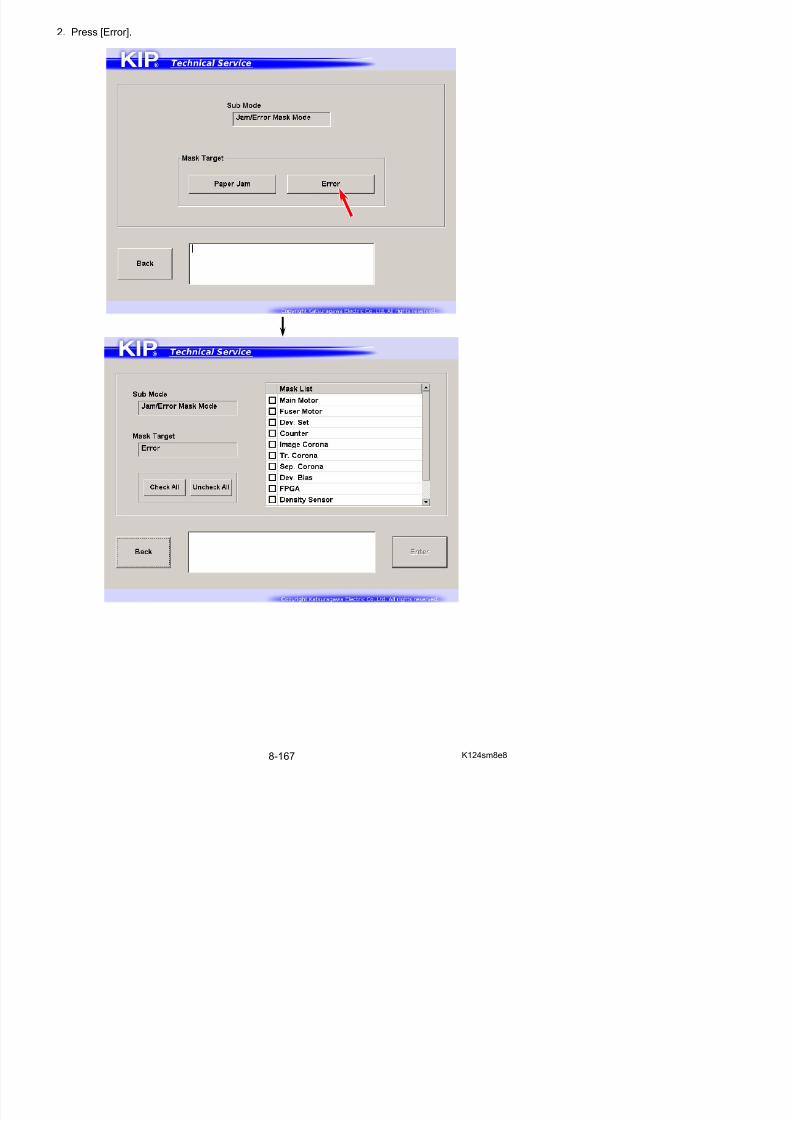
5/17/2018 KIP 7100 Service Manual Ver A_1 - slidepdf.com
http://slidepdf.com/reader/full/kip-7100-service-manual-ver-a1 608/674
NOTE
No “Door Open” mask is available.
8. 9 Test Print Mode
It is possible to output some built-in test patterns as a stand alone plotter.No external device (controller / scanner / network connection) is required for test pattern plotting.
Basic Setting screen
7
6
510
1
2
3
4
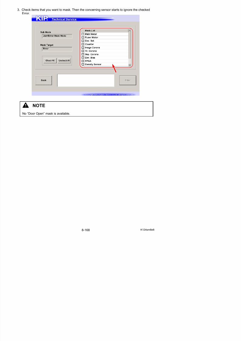
5/17/2018 KIP 7100 Service Manual Ver A_1 - slidepdf.com
http://slidepdf.com/reader/full/kip-7100-service-manual-ver-a1 609/674
Name Function
1 Deck Displays media source in drop-down menuChoose one item that you want to use for test print.
2 Width Displays media width of the selected media source in drop-downmenuYou can set a different width from the actual media.
3 Length Displays print length of the test print in drop-down menuSpecify one item for test print.
11 9
8
4
Option screen
5
1
2
3
4
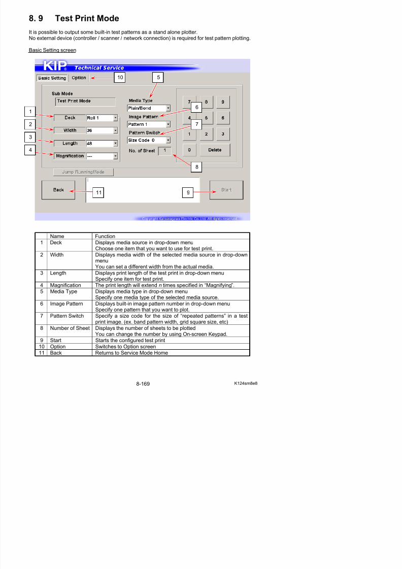
5/17/2018 KIP 7100 Service Manual Ver A_1 - slidepdf.com
http://slidepdf.com/reader/full/kip-7100-service-manual-ver-a1 610/674
Name Function
1 Positive /Negative
Choose “Negative” for B/W inverting.
2 ImageEnhancement
Displays Image Enhancement Level
3 Mirror Enables horizontal reverse image
4 Add Scale Adds scales on the test print
5 Basic Setting Switches to Basic Setting screen
6 Back Returns to Service Mode Home
6
8. 9. 1 Making Test Print
1. Press [Test Print] in Service Mode home.
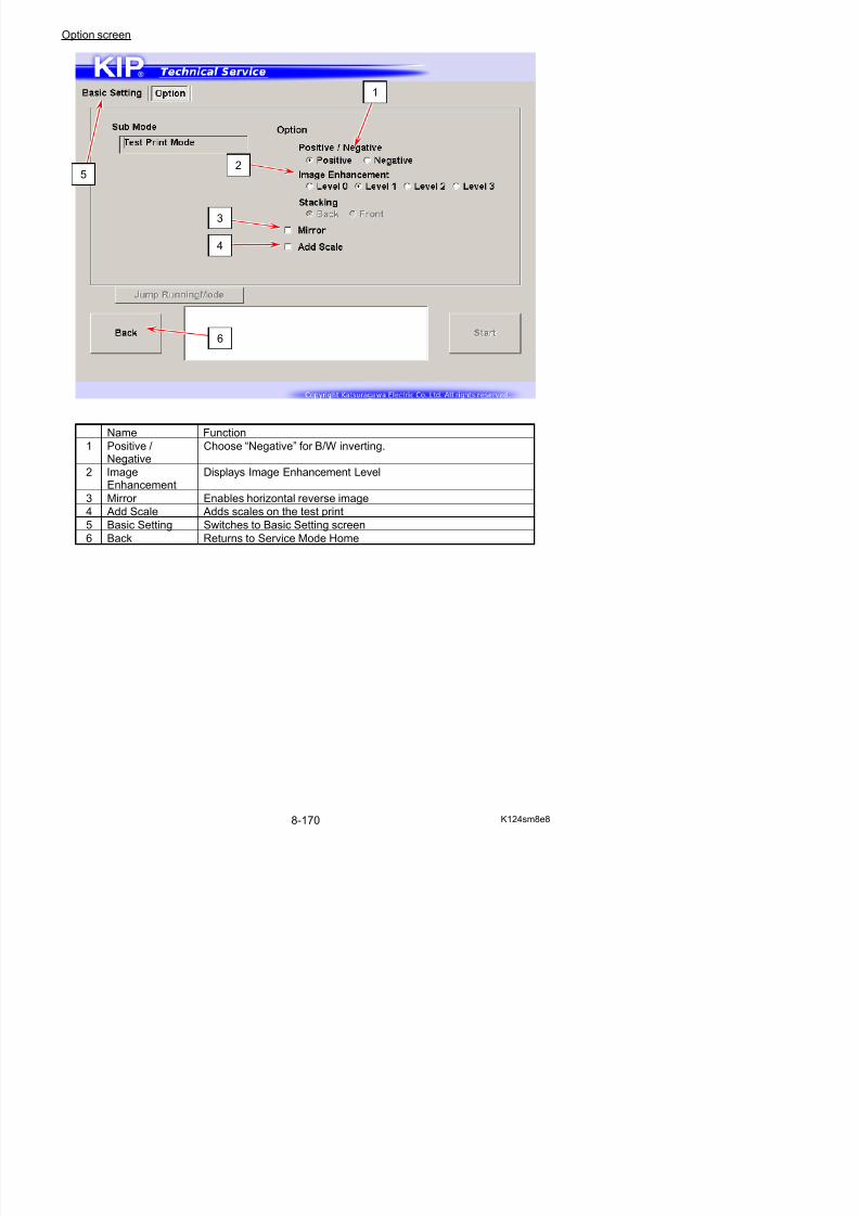
5/17/2018 KIP 7100 Service Manual Ver A_1 - slidepdf.com
http://slidepdf.com/reader/full/kip-7100-service-manual-ver-a1 611/674
2. Configure a test print job.In Basic Setting tab, you can configure media source, type, length, image pattern selection,
number of sheets.
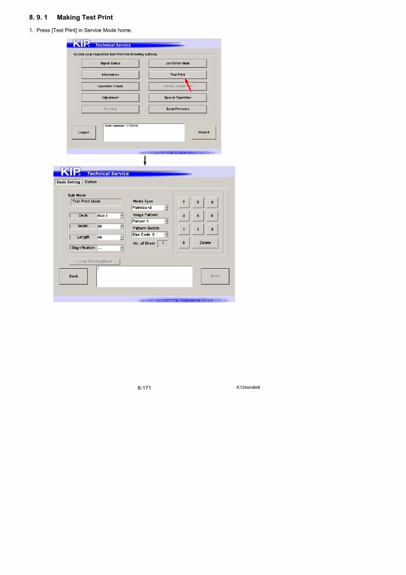
5/17/2018 KIP 7100 Service Manual Ver A_1 - slidepdf.com
http://slidepdf.com/reader/full/kip-7100-service-manual-ver-a1 612/674
3. If necessary, open Sub Setting tab to configure some other settings.
8. 9. 2 Built-in Test Pattern
Pattern No.1
Pattern No.2
Pattern No.3
Pattern No.4
Pattern No.5
Pattern No.6
Pattern No.7
Pattern No.8
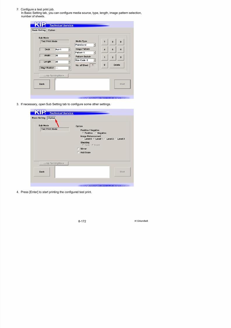
5/17/2018 KIP 7100 Service Manual Ver A_1 - slidepdf.com
http://slidepdf.com/reader/full/kip-7100-service-manual-ver-a1 613/674
8. 10 Factory Adjustment Mode
This mode is mainly used at factory for adjustment and product operation test.
NOTE
Factory Adjustment Mode is not available in Service Mode. Factory Use Only.
8. 11 Special Operation Mode
Special Operation Mode has several kinds of special important functions to the machine.
(1) Clears the following recorded error - E-0000 Fuser Temperature Rising Error - E-0001 Fuser Over Temperature Error - E-0002 Fuser Low Temperature Error - E-0003 / 0004 Fuser Temperature Abnormal Fall Error
(2) Clears the following history- Jam History- Error History
(3) Resets bias adjustment by Density Compensation Process(4) Starts Toner Supply for initial toner (5) Resets any counting parameters in Information Mode
NOTE
E-0000 / 0001 / 0002 / 0003 / 0004 (regarding Fuser Error) do not disappear automaticallyeven if you remove any cause of these errors.
You should clear the error in Special Operation Mode to allow the printer to be ready for printing
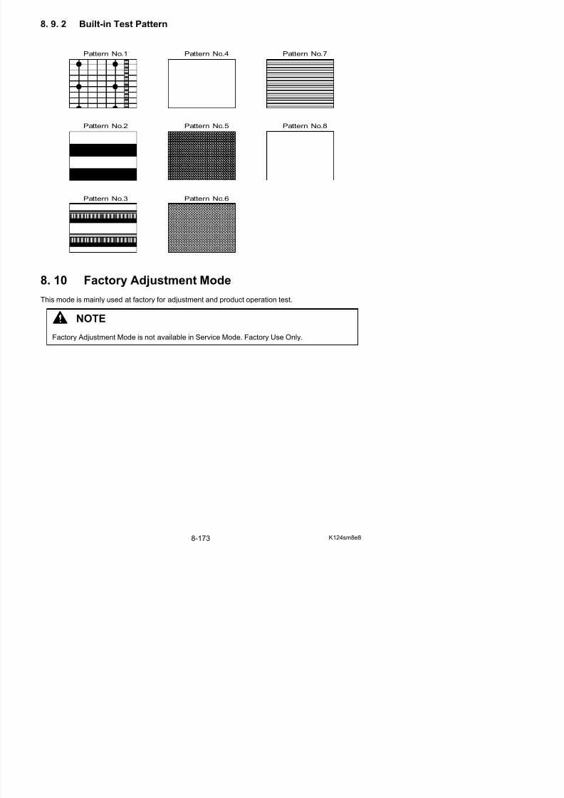
5/17/2018 KIP 7100 Service Manual Ver A_1 - slidepdf.com
http://slidepdf.com/reader/full/kip-7100-service-manual-ver-a1 614/674
Operation Target screen
printing.
1
2
Counter Input screen
1
3
2 4
5
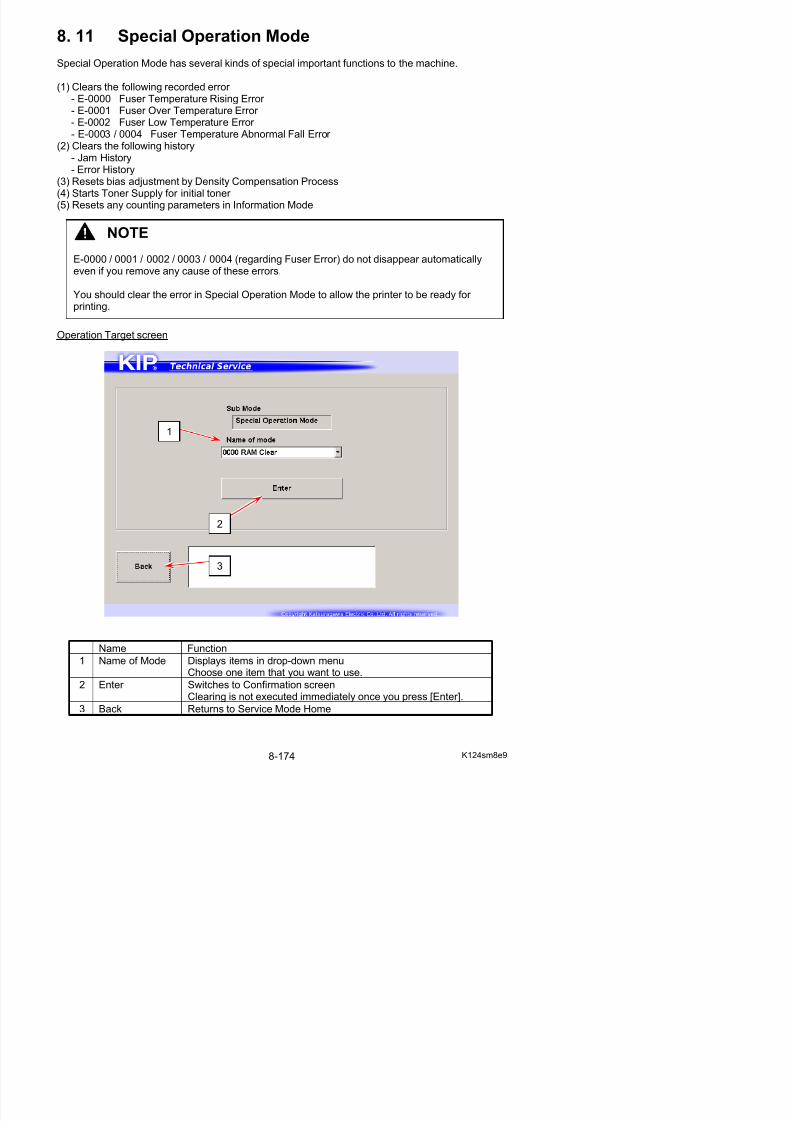
5/17/2018 KIP 7100 Service Manual Ver A_1 - slidepdf.com
http://slidepdf.com/reader/full/kip-7100-service-manual-ver-a1 615/674
Name Function
1 Counter Name Displays the counter name you have chosen
2 Reading Displays the current counter value stored in the memory
3 Count Displays an input counter value by using On-screen Keypad
4 Rewrite Applies a new counter value in “Count” to the selected counter
5 Return Returns to Clear Target screen
8. 11. 1 List of Special Operation
Item No. Name Contents
0000 RAM Clear Clears any stored data in the memory
0001 Error Clear Clears E-0000 / 0001 / 0002 / 0003 / 0004from the memory
0002 Jam History Clears Jam records J-**** in Jam History list
0003 Error History Clears Error records E-**** in Error History list
0004 Print Count Changes the counter value for Print Count (unit selectable)
0005 Total Count Changes the counter value for Total Count (linear meter)0006 Bias3 Count Initializes Developer / Regulation Bias adjusted withDensity Compensation Process
0007 Toner Supply1 Starts toner supply / agitation in Developer Unit
0008 (Reserved)
0009 (Reserved)
0010 (Reserved)
0011 Info Data Clear Clears the Items 0012 to 0033 at a time
0012 Total Cut Clears each Item used in Information Mode0013 Roll1 Cut See [8.4 Information Mode]
0014 Roll2 Cut
0015 Others Cut
0016 Total Image
0017 Manual1 Image
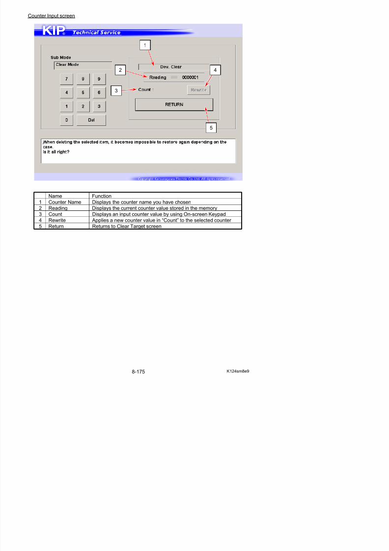
5/17/2018 KIP 7100 Service Manual Ver A_1 - slidepdf.com
http://slidepdf.com/reader/full/kip-7100-service-manual-ver-a1 616/674
0017 Manual1 Image
0018 Roll1 Image
0019 Roll2 Image
0020 Cassette Image0021 Roll1F CL
0022 Roll2F CL
0023 Roll1B CL
0024 Roll2B CL
0025 Feed CL
0026 Reg. CL
0027 Pickup SL
0028 Sep. SL0029 Stack SL
0030 Motor1 Time
0031 Motor2 Time
0032 LED Head on Time
0033 Motor3 Time
NOTE
8. 11. 2 Clearing Fuser Error, Jam/Error History
1. Press [Special Operation] in Service Mode Home.Operation Target screen appears.
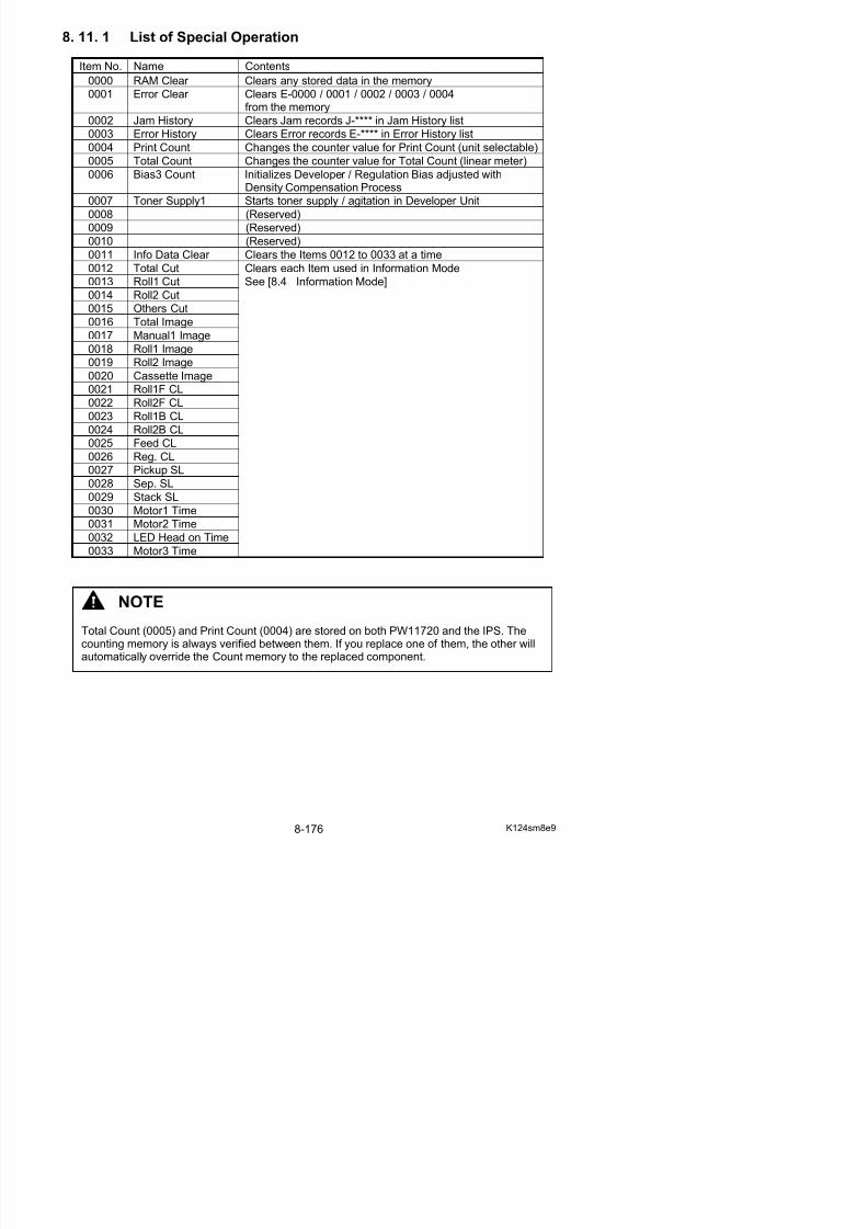
5/17/2018 KIP 7100 Service Manual Ver A_1 - slidepdf.com
http://slidepdf.com/reader/full/kip-7100-service-manual-ver-a1 617/674
2. Specify one item that you want to use from Name of mode menu. Press [Enter].
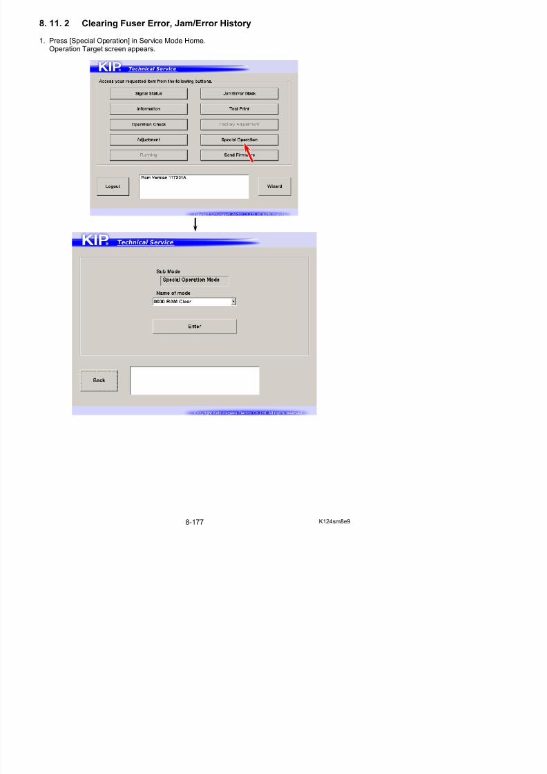
5/17/2018 KIP 7100 Service Manual Ver A_1 - slidepdf.com
http://slidepdf.com/reader/full/kip-7100-service-manual-ver-a1 618/674
Item No. Clear Item Contents0001 Error Clear Clears E-0000 / 0001 / 0002 / 0003 / 0004
from the memory
0002 Jam History Clears Jam records J-**** in Jam History list
0003 Error History Clears Error records E-**** in Error History list
3. Confirmation screen appears.Press [Agree] to clear the concerning record(s).
8. 11. 3 Reset of Bias Adjustment by Density Compensation Process
1. Press [Special Operation] in Service Mode Home.Operation Target screen appears.
NOTE
After replacing Developer Roller / toner refreshment, you must reset bias adjustment byDensity Compensation Process.Otherwise a darker image appears because the adjusted values are too high voltage for therefreshed Developer Unit.
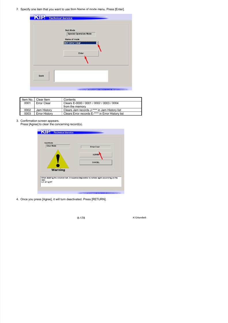
5/17/2018 KIP 7100 Service Manual Ver A_1 - slidepdf.com
http://slidepdf.com/reader/full/kip-7100-service-manual-ver-a1 619/674
2. Select [0006 Bias3 Count] from Name of mode menu. Press [Enter].
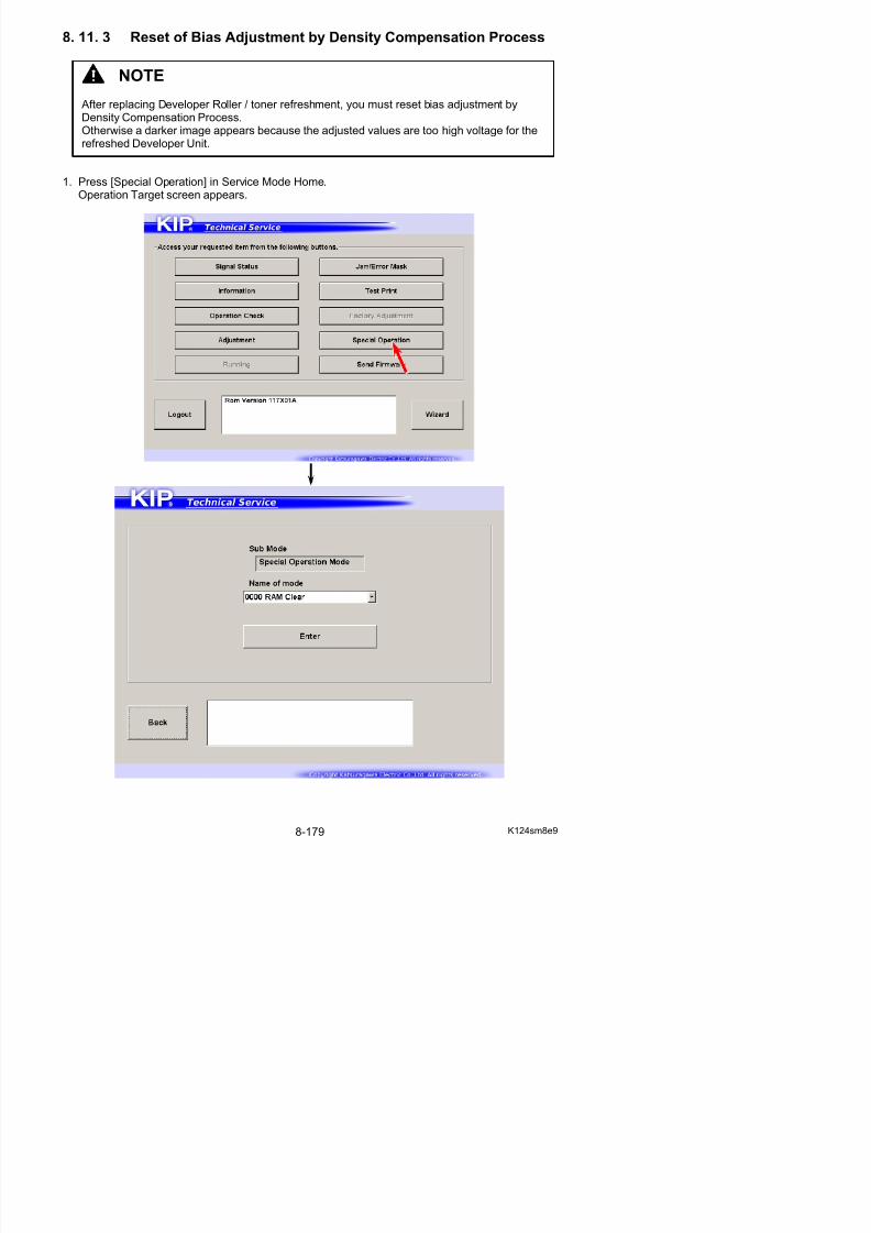
5/17/2018 KIP 7100 Service Manual Ver A_1 - slidepdf.com
http://slidepdf.com/reader/full/kip-7100-service-manual-ver-a1 620/674
0006 Bias3 Count Initializes Developer / Regulation Bias adjusted withDensity Compensation Process
3. Confirmation screen appears.Press [Agree] to reset Bias Adjustment by Density Compensation Process.Then the system starts recalculation of the possible best Developer/Regulation Bias.(This will take time.)
4. Input screen appears.
Input “0000000” with On-screen Keypad.
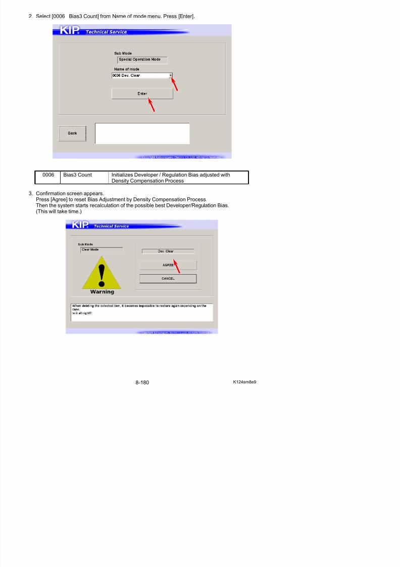
5/17/2018 KIP 7100 Service Manual Ver A_1 - slidepdf.com
http://slidepdf.com/reader/full/kip-7100-service-manual-ver-a1 621/674
5. The value is displayed in “Count” area.Once you input a seven digit value, [Rewrite] will be activated.Press [Rewrite] to apply the new value to the printer.
The value in “Reading” area will be changed to the new value.
NOTE
The required value for the KIP 7100 to reset Bias Adjustment by Density Compensation
Process is “0000000”.
“0000000” to “0000003” correspond to the adjustment level in Density CompensationProcess.For example, if you interchange the Developer Unit with your spare unit, you can manuallyset a certain adjustment level that would be suitable for your spare unit.
8. 11. 4 Toner Supply Mode
1. Press [Special Operation] in Service Mode Home.Operation Target screen appears.
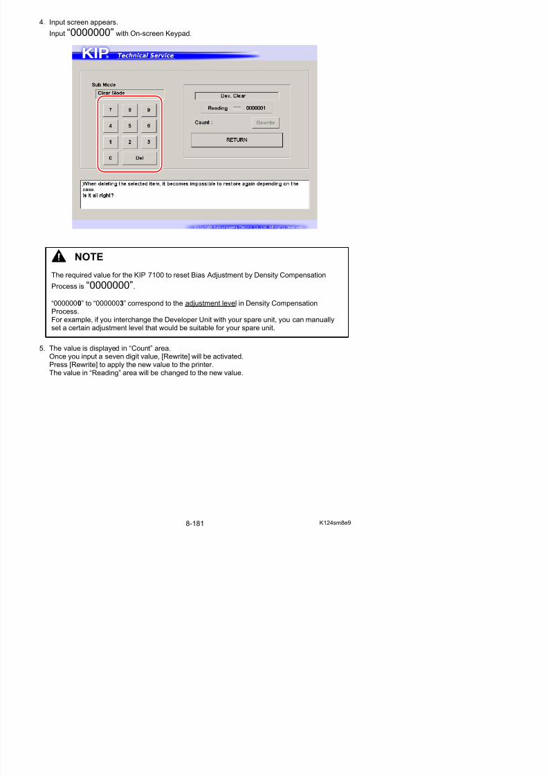
5/17/2018 KIP 7100 Service Manual Ver A_1 - slidepdf.com
http://slidepdf.com/reader/full/kip-7100-service-manual-ver-a1 622/674
2. Select [0007 Toner Supply1] from Name of mode menu. Press [Enter].
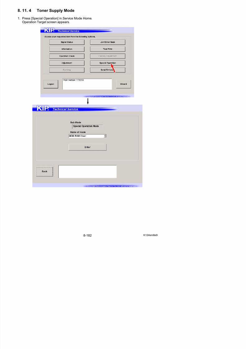
5/17/2018 KIP 7100 Service Manual Ver A_1 - slidepdf.com
http://slidepdf.com/reader/full/kip-7100-service-manual-ver-a1 623/674
0007 Toner Supply1 Starts toner supply / agitation in Developer Unit
3. Confirmation screen appears. Press [Agree].Toner supply / agitation starts. This will take minutes to complete.
4. Once you press [Agree], it will turn deactivated. Press [Return].
5. The screen goes back to Operation Target Screen. The status window shows “warm up” duringtoner supply / agitation. After the completion, it changes to “standby”.
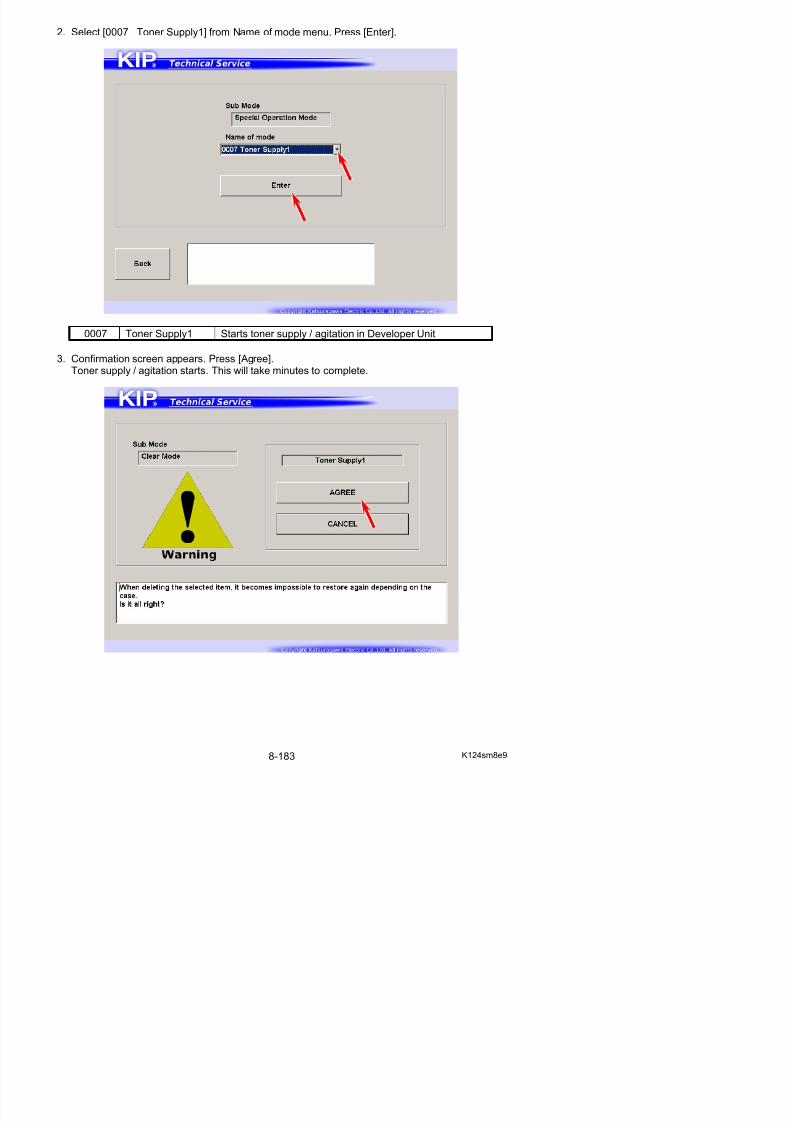
5/17/2018 KIP 7100 Service Manual Ver A_1 - slidepdf.com
http://slidepdf.com/reader/full/kip-7100-service-manual-ver-a1 624/674
8. 11. 5 Changing Counter Value
1. Press [Special Operation] in Service Mode Home.
Reference
For any counting parameters, pressing [Enter] switches to Counter Input screen.This does not effect to the current counter value.
NOTETotal Count (0005) / Print Count (0004) are stored on both PW12420 and the controller. If you replace one of them, the other will automatically copy the stored Count memory to thereplacement. For Total Count (0005) and Print Count (0004), this section would be requiredonly if you replace both PW12420 and the controller at a time.
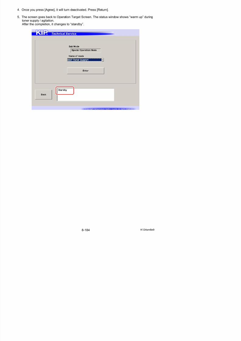
5/17/2018 KIP 7100 Service Manual Ver A_1 - slidepdf.com
http://slidepdf.com/reader/full/kip-7100-service-manual-ver-a1 625/674
2. Specify one item that you want to use from Name of mode menu. Press [Enter].
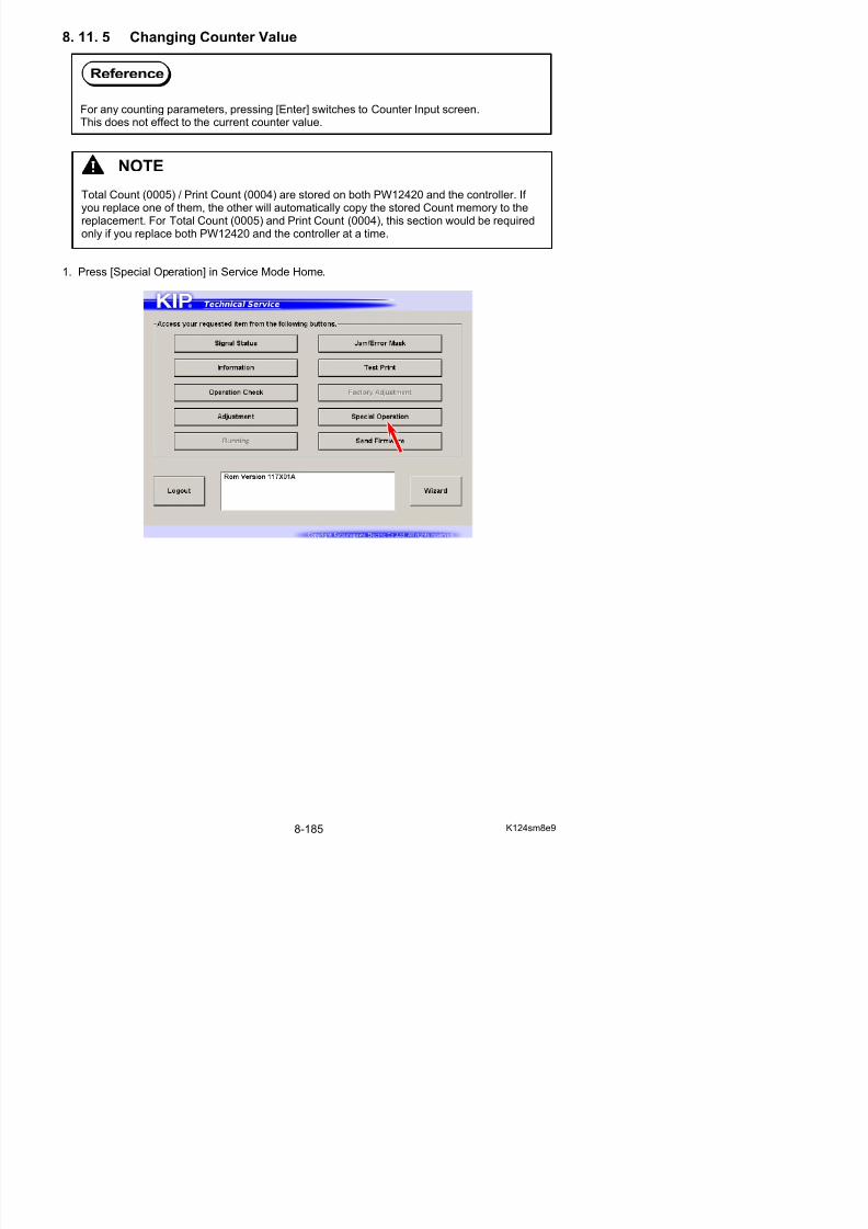
5/17/2018 KIP 7100 Service Manual Ver A_1 - slidepdf.com
http://slidepdf.com/reader/full/kip-7100-service-manual-ver-a1 626/674
3. Confirmation screen appears.
Reference
For any counting parameters, pressing [Enter] switches to Counter Input screen.This does not effect to the current counter value.

5/17/2018 KIP 7100 Service Manual Ver A_1 - slidepdf.com
http://slidepdf.com/reader/full/kip-7100-service-manual-ver-a1 627/674
4. Input a desired value with On-screen Keypad.The value is displayed in “Count” area.
Once you input a seven digit value, [Rewrite] will be activated.Press [Rewrite] to apply the new value to the printer.The value in “Reading” area will be changed to the new value.
Example: 0000000 0006706
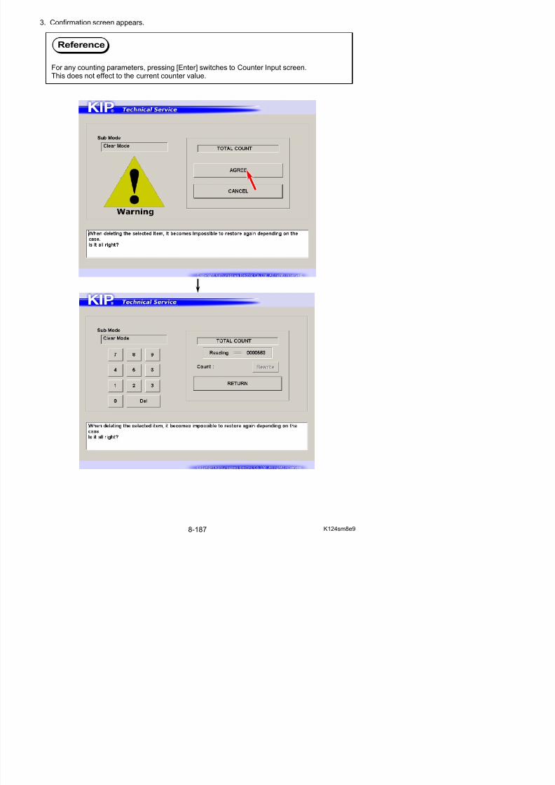
5/17/2018 KIP 7100 Service Manual Ver A_1 - slidepdf.com
http://slidepdf.com/reader/full/kip-7100-service-manual-ver-a1 628/674
8. 12 Send Firmware Mode
You can send a new version firmware program provided by the manufacturer to the printer.Note that the firmware program is named “K124X##A.mot”.
Send Firmware screen
NOTE
A firmware update does not effect to the current parameters. They remain unchanged.But please be sure to make a backup in .RAM prior to any firmware update just in case.
1
2
5
7
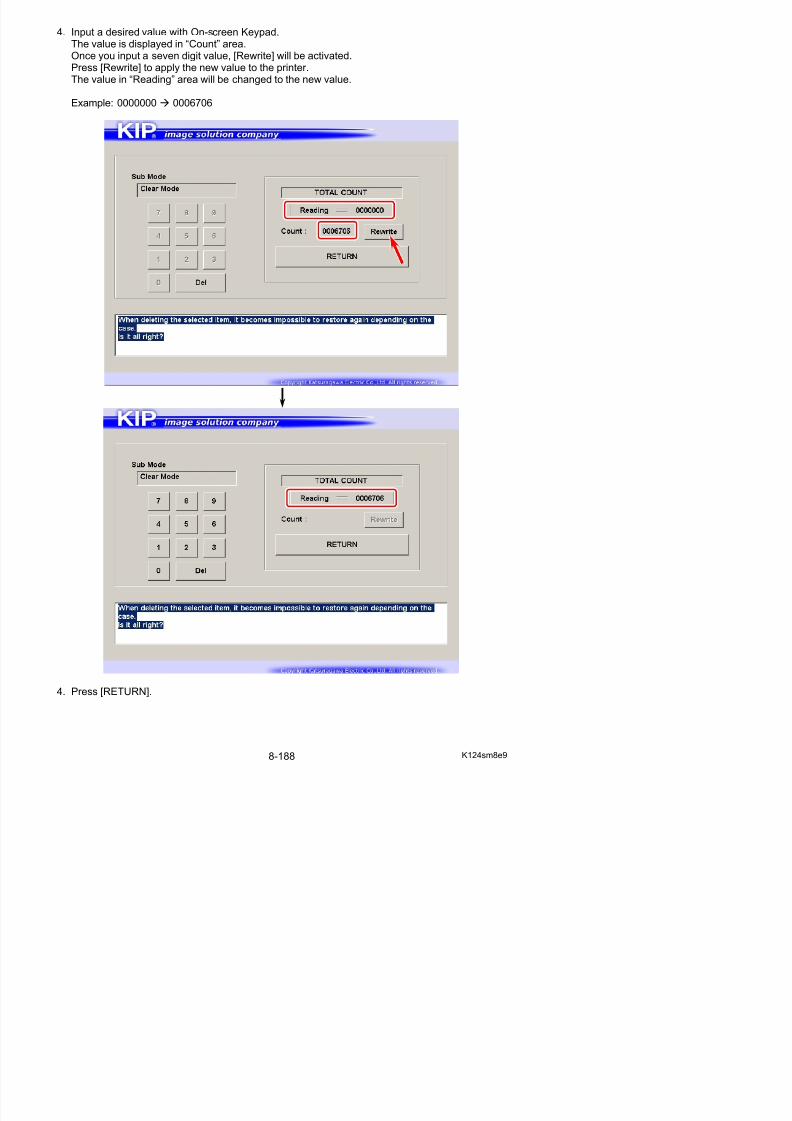
5/17/2018 KIP 7100 Service Manual Ver A_1 - slidepdf.com
http://slidepdf.com/reader/full/kip-7100-service-manual-ver-a1 629/674
Name Function
1 Mode Select Use “Program Mode” only.
3 4
6
8
8. 12. 1 Sending Firmware to Printer
1. Press [Send Firmware] in Service Mode Home.Send Firmware screen appears.
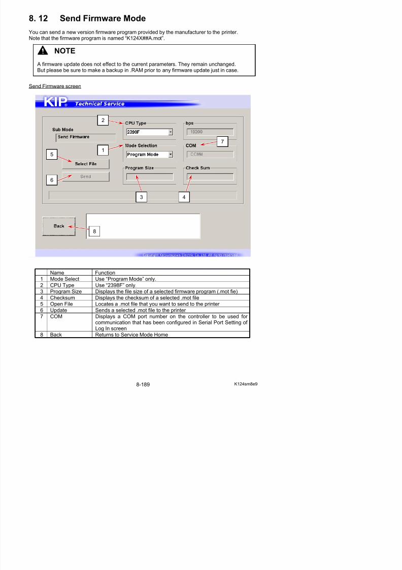
5/17/2018 KIP 7100 Service Manual Ver A_1 - slidepdf.com
http://slidepdf.com/reader/full/kip-7100-service-manual-ver-a1 630/674
2. Choose “Program Mode” from Mode Select menu if not displayed.
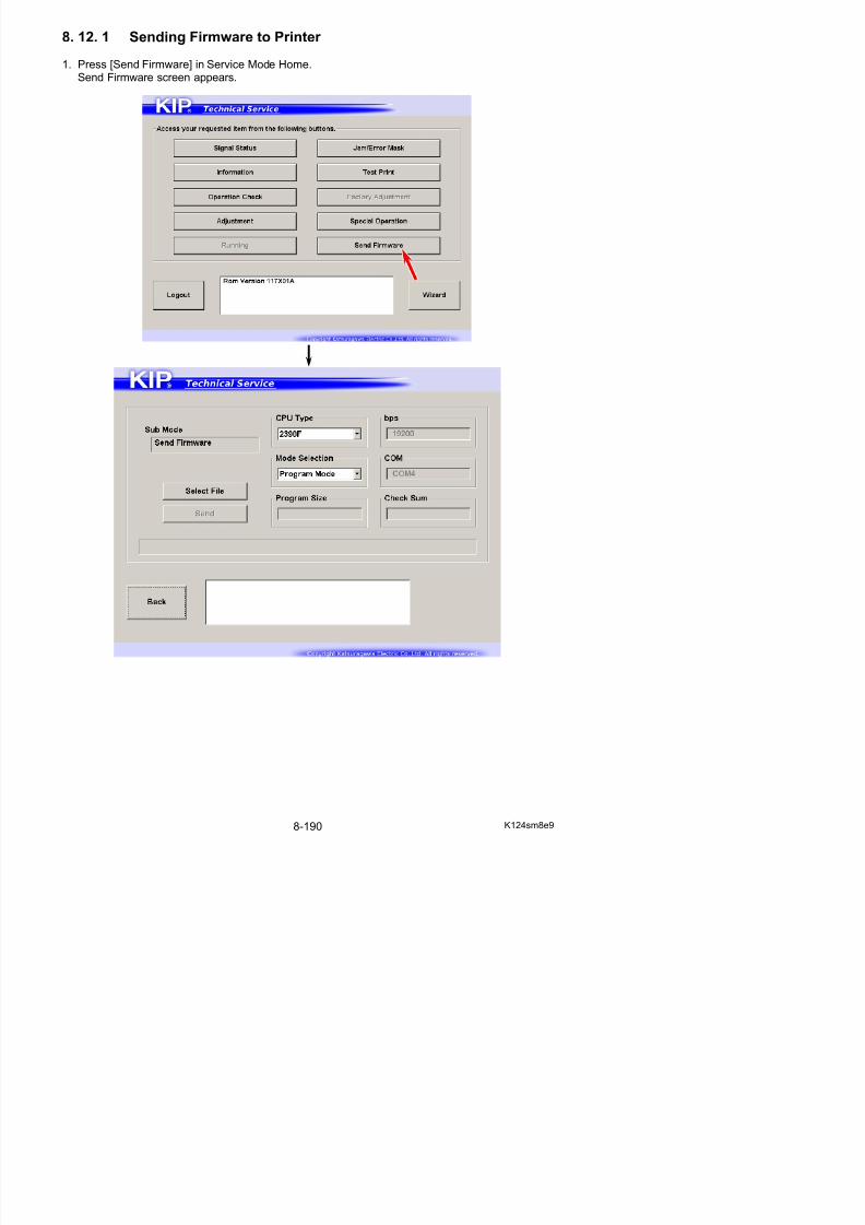
5/17/2018 KIP 7100 Service Manual Ver A_1 - slidepdf.com
http://slidepdf.com/reader/full/kip-7100-service-manual-ver-a1 631/674
3. Press [Select File] to locate and open a .mot file that you want to apply.

5/17/2018 KIP 7100 Service Manual Ver A_1 - slidepdf.com
http://slidepdf.com/reader/full/kip-7100-service-manual-ver-a1 632/674
4. Check for the program size and its checksum of the .mot file you have chosen.Press [Update] to send it to the printer.
NOTE
(1) “Program Size” and “Checksum” vary by the firmware version.
(2) If you accidentally send an incorrect file to the printer, send a correct one when thecurrent transmission is completed.
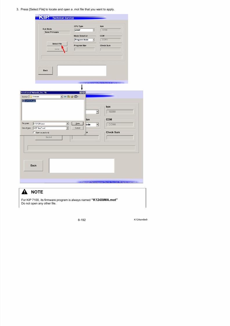
5/17/2018 KIP 7100 Service Manual Ver A_1 - slidepdf.com
http://slidepdf.com/reader/full/kip-7100-service-manual-ver-a1 633/674
8. 13 KIP Scanner Utility
KIP Scanner Utility is a program that provides several scanner adjustments.- Shading (mono/color calibration)- Feed Distance (1:1)- Position (stitch)
8. 13. 1 Installation
8. 13. 1. 1 Installing USB Driver
NOTE: Contact your KIP partner for the latest software and save it to any available storageon your service PC.
1. Loosen 4 screws (M4x6) (1), remove 4 screws (M4x6) (2), and then remove Cover 10 (3).
2
NOTE
Below are the system requirements to operate KIP Scanner Utility.
• Windows 2000 / XP operating system
• USB 2.0 support

5/17/2018 KIP 7100 Service Manual Ver A_1 - slidepdf.com
http://slidepdf.com/reader/full/kip-7100-service-manual-ver-a1 634/674
2. Disconnect Scanner USB Cable (4) from IPS Assy and connect it to your PC.
11
2
3
4
3. Turn on both your PC and the KIP 7100.[Found New Hardware Wizard] starts automatically. Click [Next].
If the following message appears, choose “No, not this time” and click [Next].
4. Choose “Install the software automatically [Recommended]”. Click [Next].
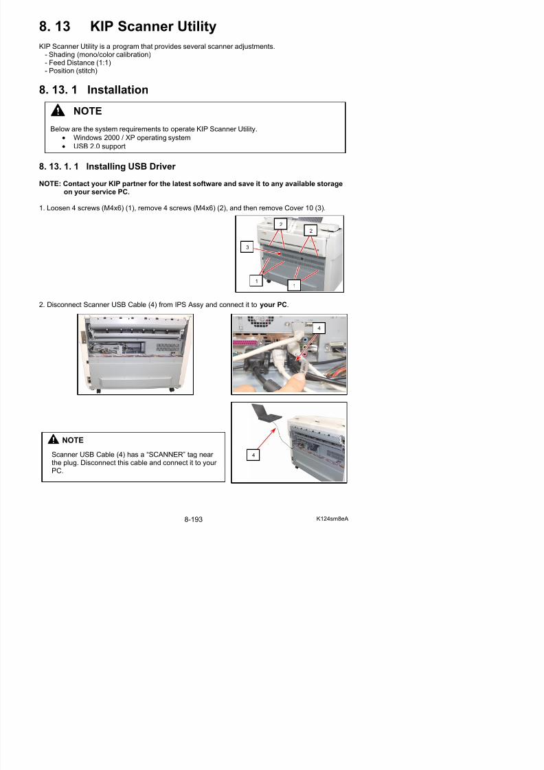
5/17/2018 KIP 7100 Service Manual Ver A_1 - slidepdf.com
http://slidepdf.com/reader/full/kip-7100-service-manual-ver-a1 635/674
NOTE
If the auto detection does not work properly, click “Install from a list of specific location
[Advanced]” to locate the driver software (.ini).
5. Click [Continue Anyway] when the following message is indicated.
6. Click [Finish] to close [Found New Hardware Wizard].
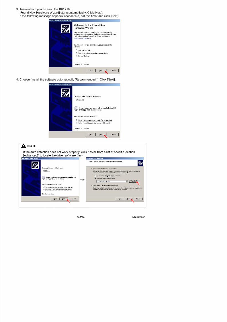
5/17/2018 KIP 7100 Service Manual Ver A_1 - slidepdf.com
http://slidepdf.com/reader/full/kip-7100-service-manual-ver-a1 636/674
7. Open Device Manager, and confirm that “KIP K124SC” is operating properly.
8. 13. 1. 2 Installing KIP Scanner Utility
NOTE: Contact your KIP partner for the latest software and save it to any available storageon your service PC.
1. Locate your SETUP.EXE for Scanner Utility and execute it.
2. The Setup program starts. Click [Next].
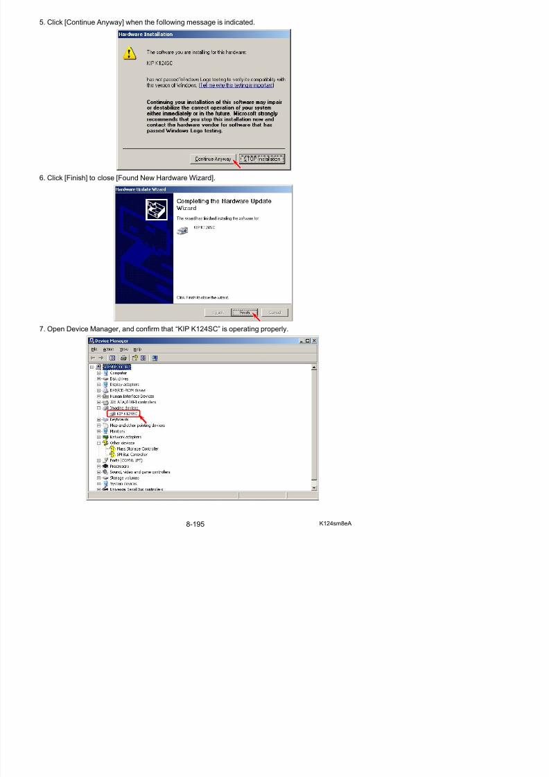
5/17/2018 KIP 7100 Service Manual Ver A_1 - slidepdf.com
http://slidepdf.com/reader/full/kip-7100-service-manual-ver-a1 637/674
3. The destination of the software can be changed. Click [Next].
4. The name of the program folder can be changed. Click [Next].
5. The following message is indicated when all files have been copied. Click [Finish].
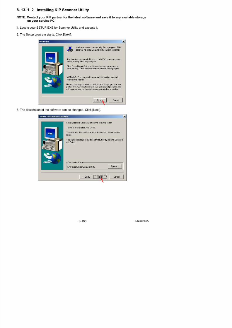
5/17/2018 KIP 7100 Service Manual Ver A_1 - slidepdf.com
http://slidepdf.com/reader/full/kip-7100-service-manual-ver-a1 638/674
6. Open the properties panel for the “Scanner Utility” shortcut on “Start” _”Program” _ “Scanner Utility” _ “Scanner Utility”. (ex. right click on the shortcut)
7. Add the following text to the end of the target path. Click [Apply].
“(one byte space)/Maintenance”
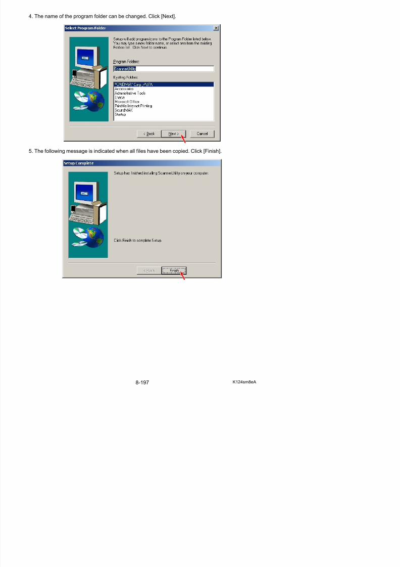
5/17/2018 KIP 7100 Service Manual Ver A_1 - slidepdf.com
http://slidepdf.com/reader/full/kip-7100-service-manual-ver-a1 639/674
8. 13. 2 Starting KIP Scanner Utility
Start KIP Scanner Utility by; “Start” _”Program” _ “ScannerUtility” _ “ScannerUtility”
(KIP Scanner Utility’s initial screen)
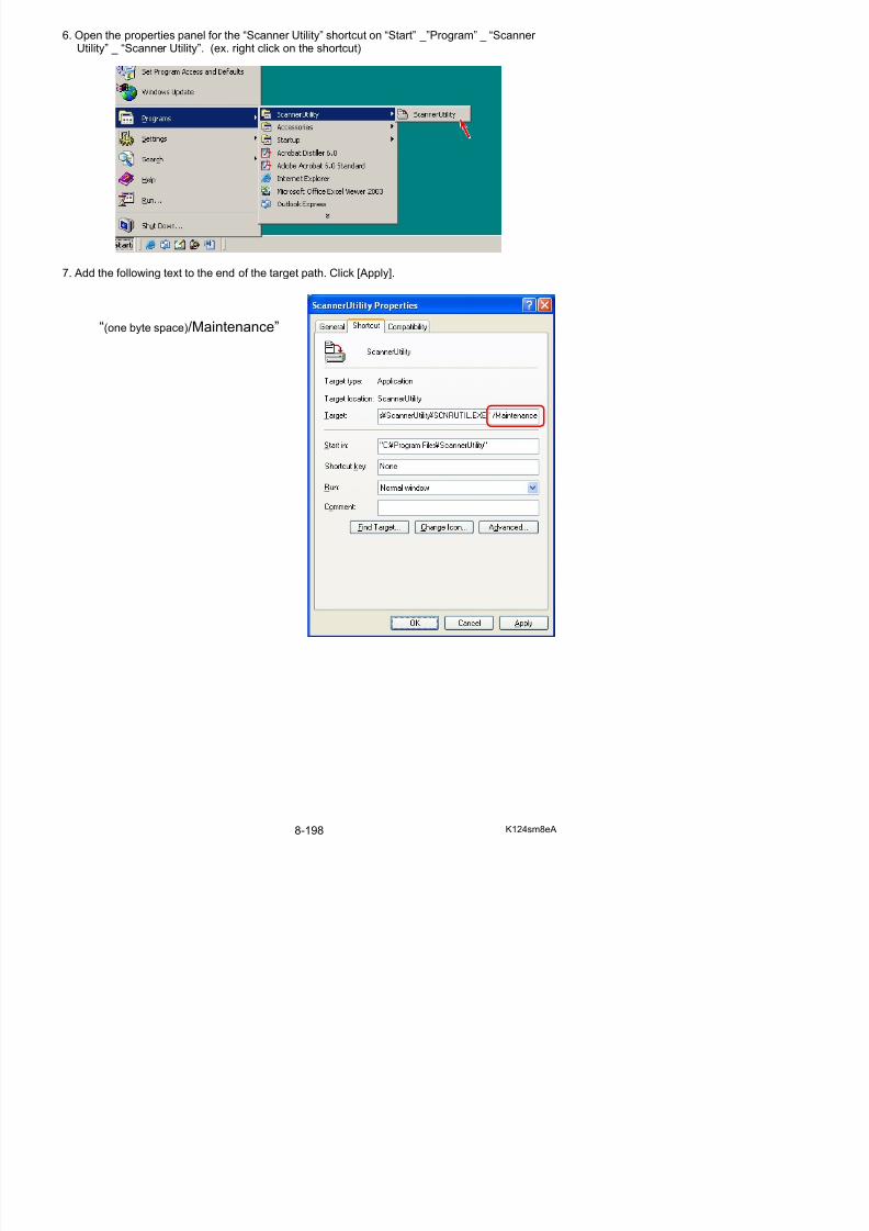
5/17/2018 KIP 7100 Service Manual Ver A_1 - slidepdf.com
http://slidepdf.com/reader/full/kip-7100-service-manual-ver-a1 640/674
8. 13. 3 Displaying Scanner Information
It is possible to display the scanner information in the following way.
1. Select [Information] under [Scanner].
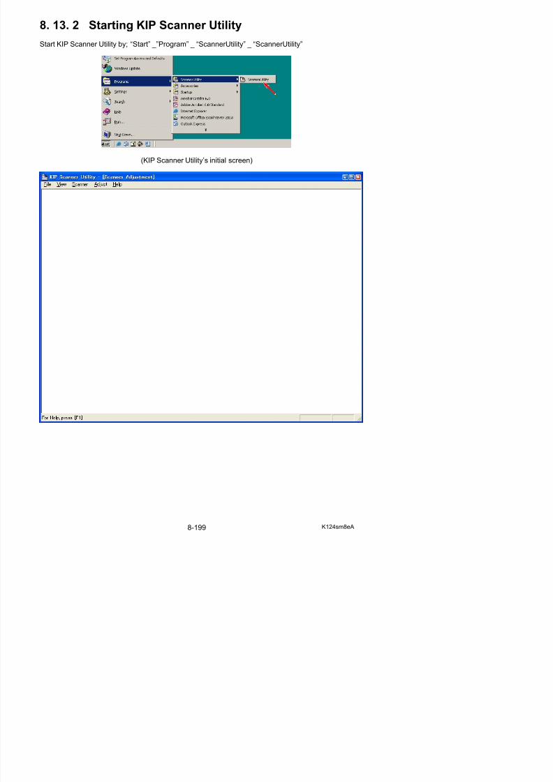
5/17/2018 KIP 7100 Service Manual Ver A_1 - slidepdf.com
http://slidepdf.com/reader/full/kip-7100-service-manual-ver-a1 641/674
2. KIP Scanner Utility acquires the scanner information and displays it.
8. 13. 4 Scanner Adjustment Procedure
It is possible to make the following scanner adjustment with KIP Scanner Utility.• Shading (calibration)
• Feed Distance (1:1)
• Position (stitching)
These adjustments are very important because they are greatly related with the image quality.
8. 13. 4. 1 Shading (calibration)
[Purpose of Shading (calibration)]
The pixels on the CIS are not same but they have their own characteristic.This may be a problem because the inputs (density) from those pixels are uneven although theyread the same image (density).
But the Shading compensates the input from each pixel properly to remove the unevenness
among the pixels. As a result the even level of input can be expected from every pixel after Shading.
Original (even density)
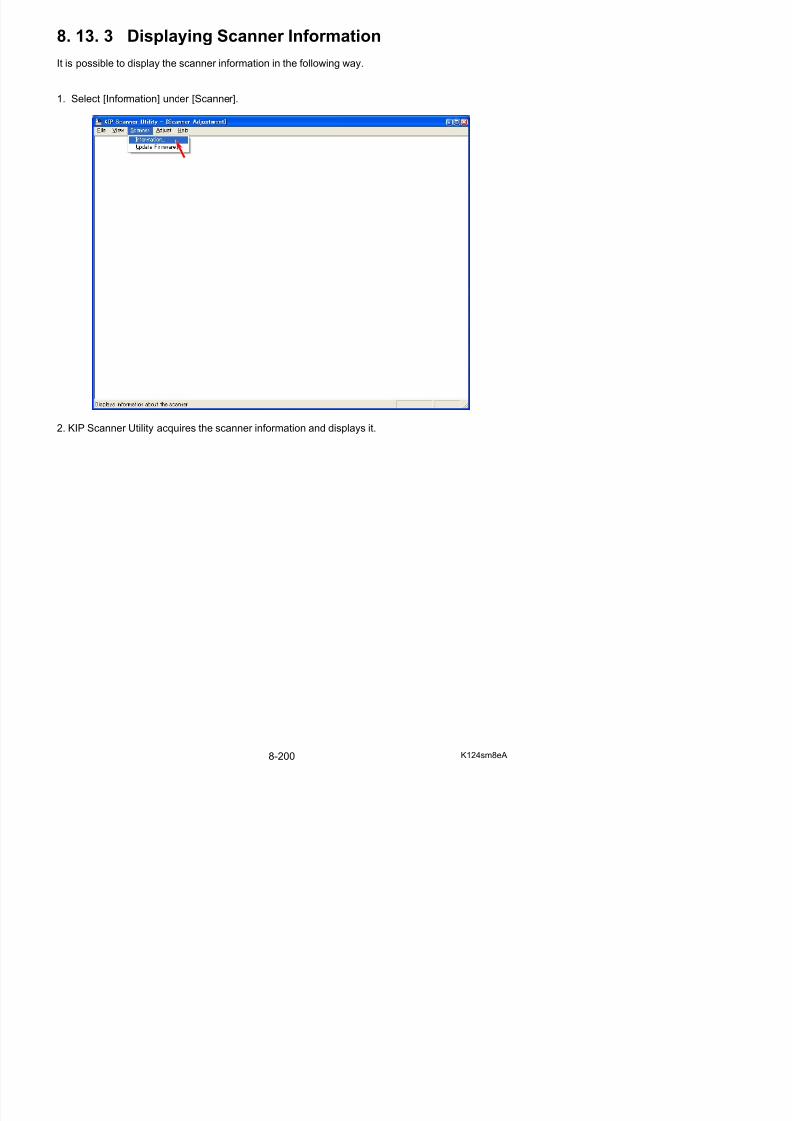
5/17/2018 KIP 7100 Service Manual Ver A_1 - slidepdf.com
http://slidepdf.com/reader/full/kip-7100-service-manual-ver-a1 642/674
Dark Dark
Light LightBefore Shading After Shading(Uneven inputs) (Even inputs)
On Shading adjustment, the pixels on the CIS will be calibrated in the default for R/G/B lightsource by using input gaps between black and white on Shading Sheet.
White Area
Black Area
Shading Sheet
Bar Code
[Operation]
1. Connect the scanner unit and the PC directly with the USB 2.0 Cable.2. Start KIP Scanner Utility.3. Select [Calibration] under [Adjust].
NOTE
(1) Shading adjustment should be performed with Shading Sheet (P/N: Z178300360, with abar code).1 sheet of Shading Sheet is included in the product accessary. Keep it in safe custody.
(2) Shading adjustment should be performed with “KIP Scanner Utility 1.23 (or later)”.No “K105Utility”.
(3) Please clean Scan Glasses before Shading.
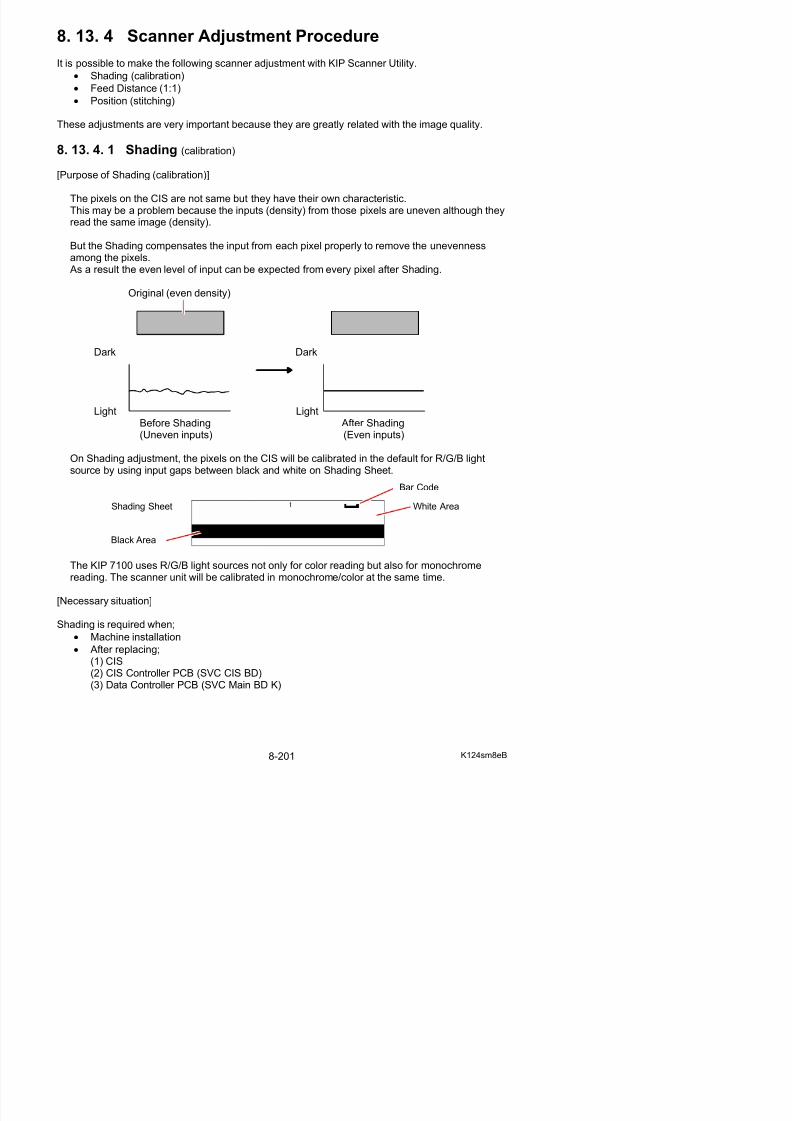
5/17/2018 KIP 7100 Service Manual Ver A_1 - slidepdf.com
http://slidepdf.com/reader/full/kip-7100-service-manual-ver-a1 643/674
5. Set Shading Sheet in the KIP 7100 accessory to the scanner noting the arrow direction.
NOTE
(1) Use the Shading Sheet in the KIP 7100 Accessory. The ShadingSheet has a bar code on the top right. A shading sheet without the bar code cannot properly calibrate theKIP 7100 Scanner Unit. Bar code
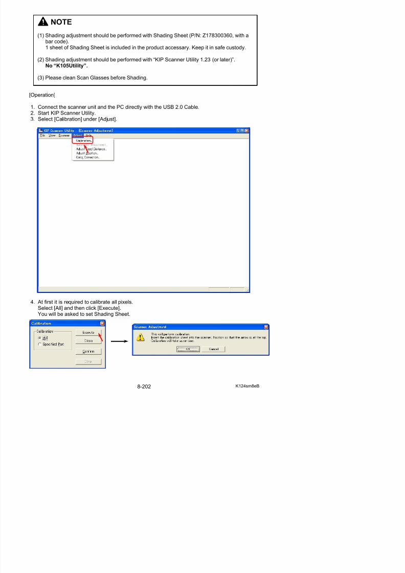
5/17/2018 KIP 7100 Service Manual Ver A_1 - slidepdf.com
http://slidepdf.com/reader/full/kip-7100-service-manual-ver-a1 644/674
6. Click [OK] after setting Shading Sheet, and the scanner reads it.
(2) Handle Shading Sheet with great care. Keep it in safe custody for avoiding dirt, fold or tear.
NOTE
(1) It takes about 7 minutes to complete Shading adjustment.
7. When Shading is finished, the following message appears. Click [OK].Open the scanner and reload Shading Sheet to the scanner and click [Confirm] to check the
result of Shading.
8. The scan image of Shading Sheet is displayed. (It looks gray due to “calibrating” scan)
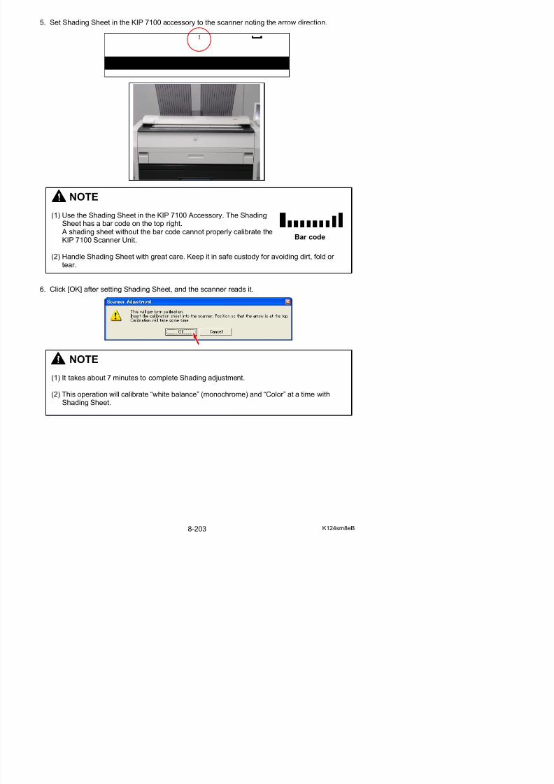
5/17/2018 KIP 7100 Service Manual Ver A_1 - slidepdf.com
http://slidepdf.com/reader/full/kip-7100-service-manual-ver-a1 645/674
9. Scroll the image right and left to find a strong black/white line that runs vertically in one pixelwide. If there is no such line in the whole image, click [Close] to finish Shading.
The following picture is an example of the line (due to “defective pixel”). A defective pixel needs individual pixel calibration in the later steps.
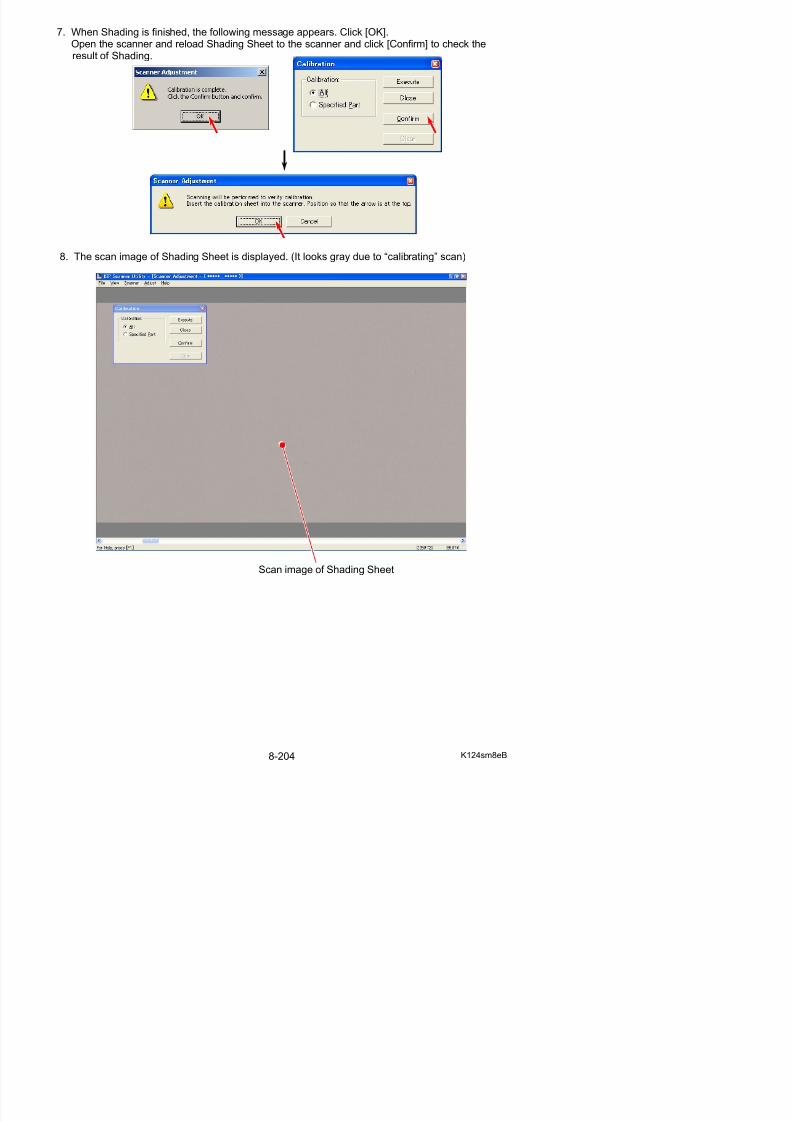
5/17/2018 KIP 7100 Service Manual Ver A_1 - slidepdf.com
http://slidepdf.com/reader/full/kip-7100-service-manual-ver-a1 646/674
Defective pixel
NOTE
Sometimes the density may be different between left and right as the following image.This is not a problem but it is just the border of image blocks.
10. If you will calibrate an individual pixel, select [Specified part].
11. Move the pointer onto the scan image, and you will find a kind of red cursor.
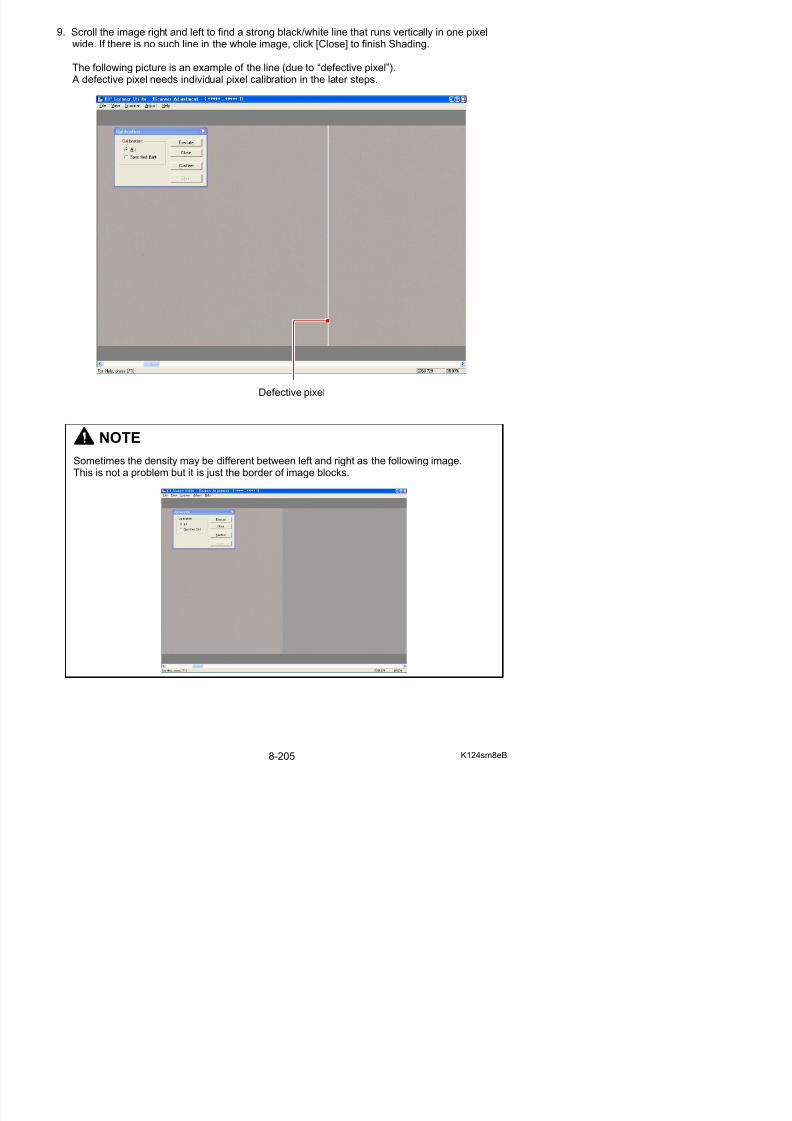
5/17/2018 KIP 7100 Service Manual Ver A_1 - slidepdf.com
http://slidepdf.com/reader/full/kip-7100-service-manual-ver-a1 647/674
red cross cursor defective pixel
12. Move the red cursor so that its vertical line matches the defective pixel and click it.The defective pixel is selected by this operation.If there are some more defective pixels, select them in the same way.
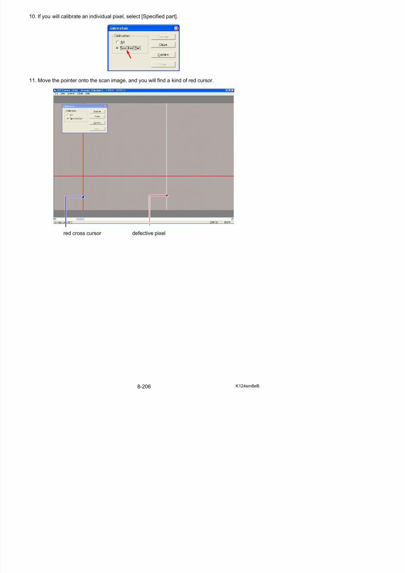
5/17/2018 KIP 7100 Service Manual Ver A_1 - slidepdf.com
http://slidepdf.com/reader/full/kip-7100-service-manual-ver-a1 648/674
Match the vertical line to a defective pixel.
13. Click [Execute], and the selected “defective pixel” is compensated individually.
14. You will be asked to set Shading Sheet again.Set Shading Sheet to the scanner and click [OK].Check the result of Shading again.When finished click [Close]
8. 13. 4. 2 Feed Distance (1:1)
[Purpose of Feed Distance (1:1)]
The lengths between actual original image and scan image may become different each other if youreplace the Feed Roller of the Scanner Unit.This is caused by the mechanical play that each Feed Roller has.
Actual original image Scan image
“Feed Distance” is the solution for this phenomenon.It compares the actual original image and the scan image to know how much their lengths aredifferent.
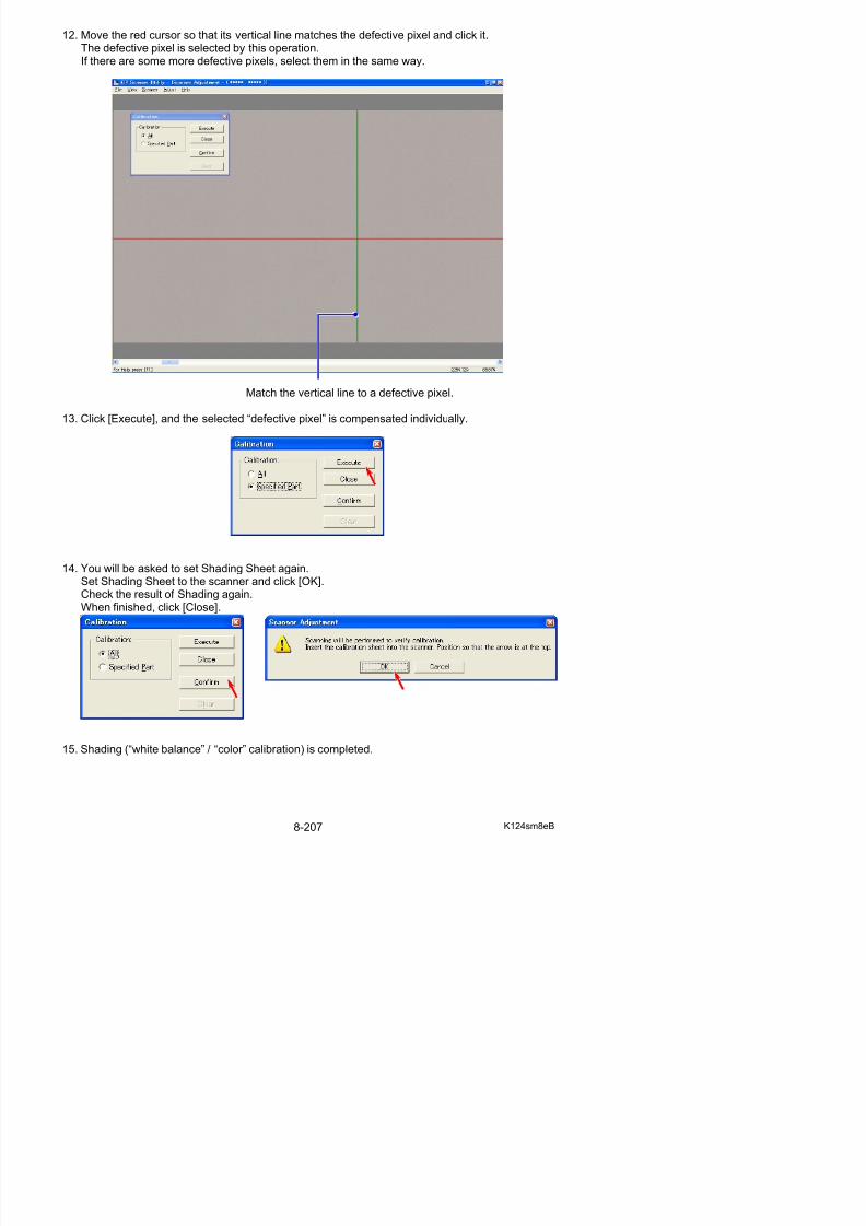
5/17/2018 KIP 7100 Service Manual Ver A_1 - slidepdf.com
http://slidepdf.com/reader/full/kip-7100-service-manual-ver-a1 649/674
Then “Feed Distance” calculates the best compensation (motor speed) automatically so that bothimages should become as long as each other.
[Necessary situation]
Feed Distance is required when;
• After replacing;
(1) Feed Roller R(2) Feed Roller F
Also you need to check whether the Feed Distance is proper after replacing the following parts.(Please record the current setting value before the replacement and input the same value after thereplacement.)
(1) CIS(2) Data Controller PCB (SVC Main BD K)
[Operation]
1. Measure the actual distance between “a point” and “c point” on the far left area of Scanner Adjustment Chart, and between “b point” and “d point” on the far right area.
Let’s suppose that each distance is as follows.Between “a point” and “c point (800)” is “799.7mm”Between “b point” and “d point (800)” is 799.8mm
Scanner Adjustment Chart
b
d 1000
a
c 800
c 1000
a
c 800 d 800
b
d 800
d 1100c 1100
d 1150c 1150
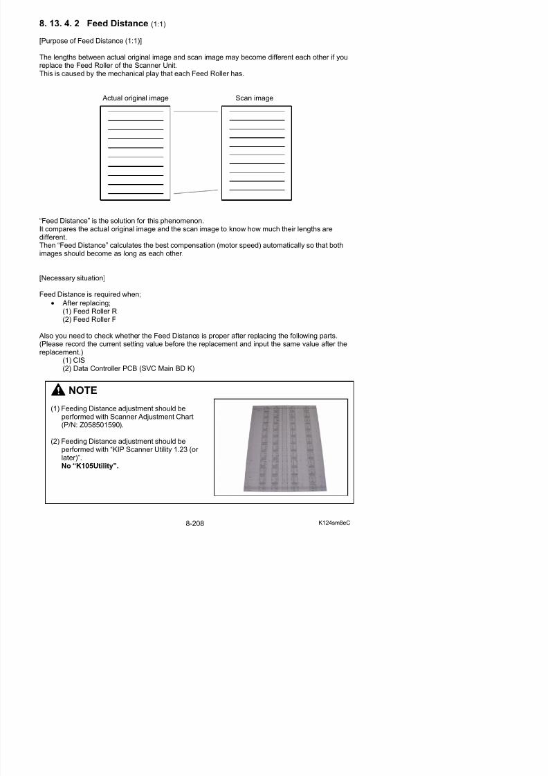
5/17/2018 KIP 7100 Service Manual Ver A_1 - slidepdf.com
http://slidepdf.com/reader/full/kip-7100-service-manual-ver-a1 650/674
Measure between these 2 points. Measure between these 2 points.
2. Connect the scanner unit and the PC directly with the USB 2.0 Cable.
3. Start KIP Scanner Utility.
NOTE
There are some number of “c point X” and “d point X” on the chart.You can select any one, but better adjustment can be expected if you measure a longer distance.
4. Select [Adjust Feed Distance] from [Adjust]. Adjust Feed Distance Dialog is indicated.
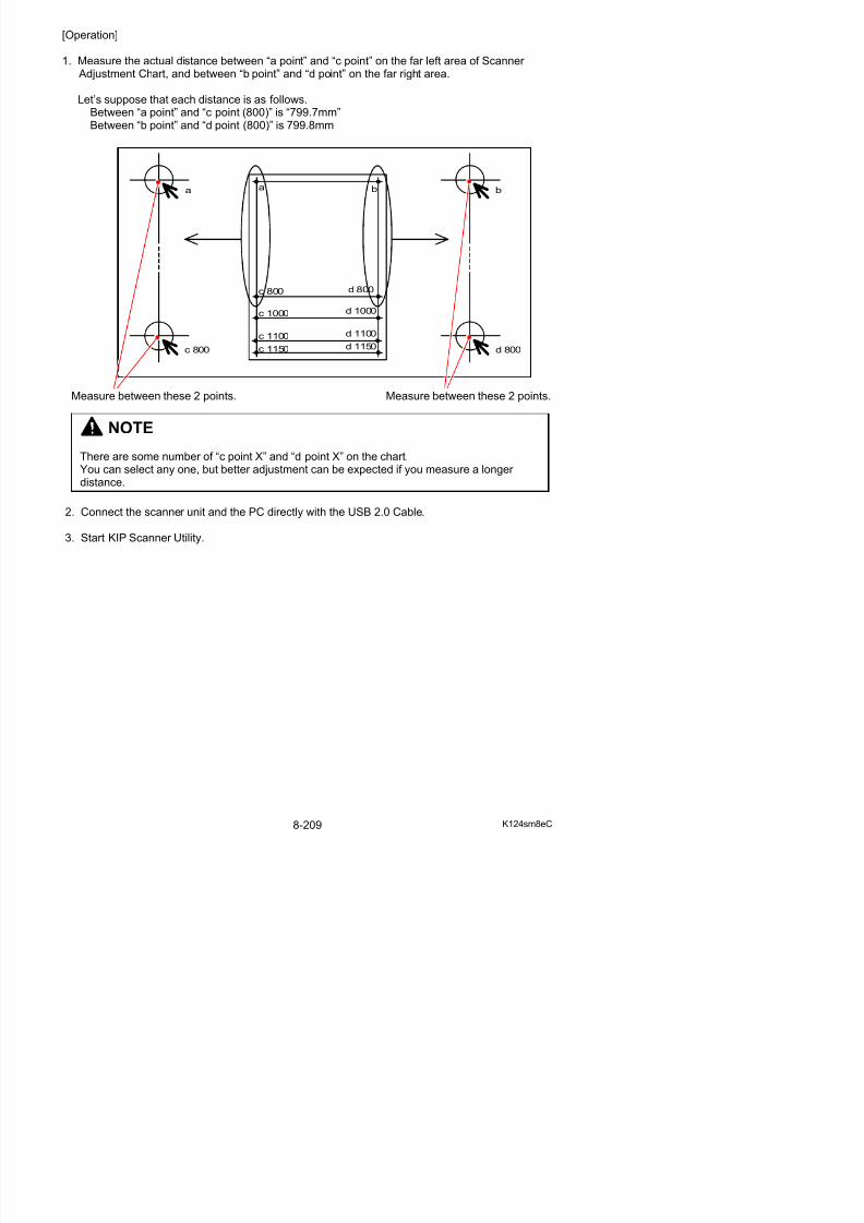
5/17/2018 KIP 7100 Service Manual Ver A_1 - slidepdf.com
http://slidepdf.com/reader/full/kip-7100-service-manual-ver-a1 651/674
NOTE
(1) If [Adjust Feed Distance] does not appear, follow the instruction below.
a) Open the properties panel for a KIP Scanner Utility shortcut. (ex. right click on the shortcut)
b) Add the following text to the end of the target path.
“(one byte space) /Maintenance”
c) Click [Apply]
5. At first, input the actual distance between “a point” and “c point” in [Actual Distance],which you have measured at the former step “1”.
Actual distance between “a” and “b”
6. Set Scanner Adjustment Chart to the scanner unit, and then click [Scan].
7 A dialog to specify the scan settings is indicated
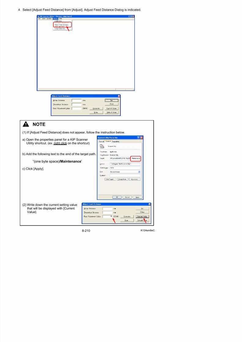
5/17/2018 KIP 7100 Service Manual Ver A_1 - slidepdf.com
http://slidepdf.com/reader/full/kip-7100-service-manual-ver-a1 652/674
7. A dialog to specify the scan settings is indicated.Simply click [Scan] to scan the chart. (You do not have to change any setting this time.)
8. The scan image of Scanner Adjustment Chart is indicated in the screen of KIP Scanner Utility.
Scan image of the chart
Reference
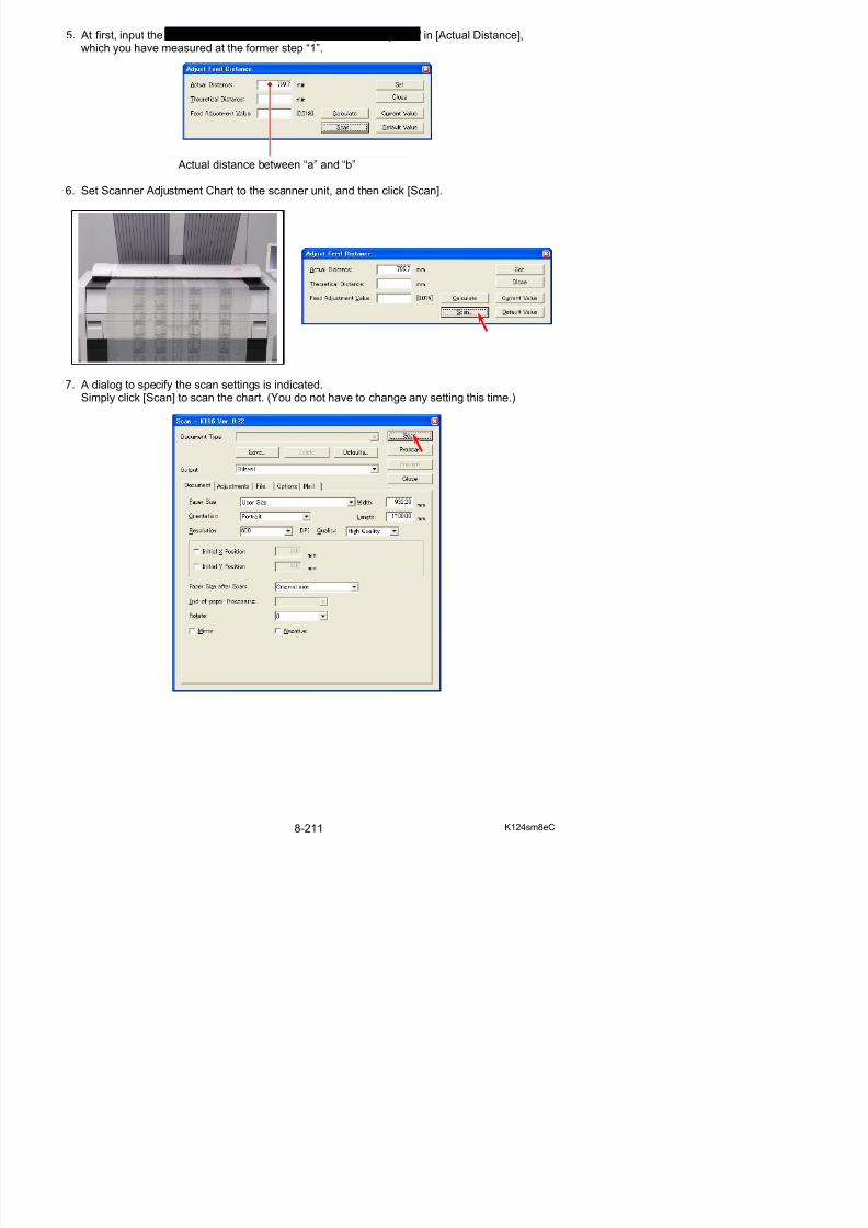
5/17/2018 KIP 7100 Service Manual Ver A_1 - slidepdf.com
http://slidepdf.com/reader/full/kip-7100-service-manual-ver-a1 653/674
9. Indicate the enlarged image of “a point” on the screen, which was the measuring point at theformer step “1”.
You can enlarge the scan image by dragging with the right button of mouse.Press the F2 Key when you would like to go back to the reduced image.
Reference
10. Click the input window of [Theoretical Distance]. A red cursor appears on the screen.
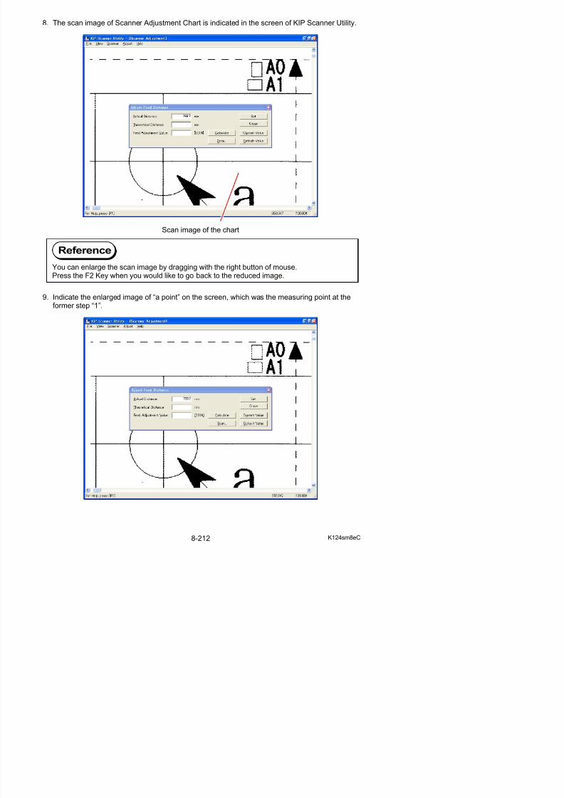
5/17/2018 KIP 7100 Service Manual Ver A_1 - slidepdf.com
http://slidepdf.com/reader/full/kip-7100-service-manual-ver-a1 654/674
11. Click the mouse once at the measuring point.
12. Similarly indicate the enlarged image of “c point” and click the mouse at the measuring point.
Click on the measuring point “c”.
13. Some value is indicated in [Theoretical Distance] according to 2 measuring points you
specified at both steps “9” and “10”This value means the distance between “a point” and “b point” of the resulting scan image
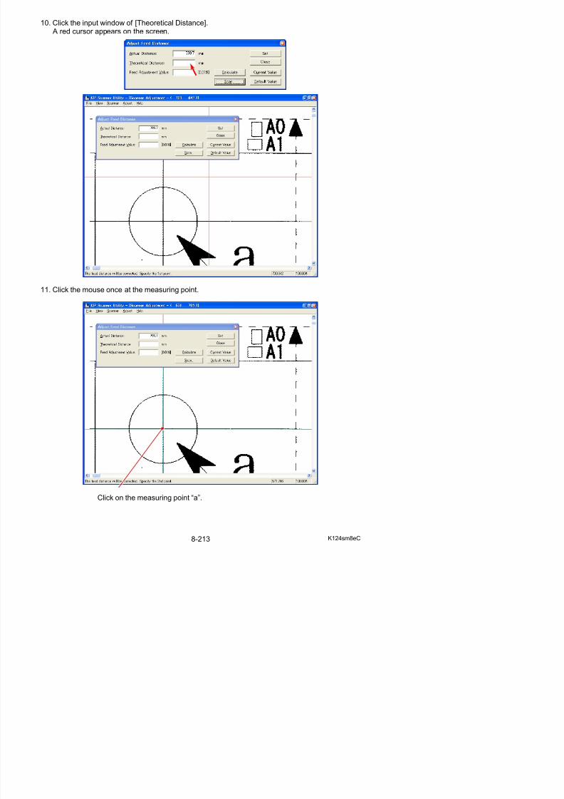
5/17/2018 KIP 7100 Service Manual Ver A_1 - slidepdf.com
http://slidepdf.com/reader/full/kip-7100-service-manual-ver-a1 655/674
specified at both steps 9 and 10 .This value means the distance between a point and b point of the resulting scan image.
14. Click [Calculate].The program automatically calculates the best compensation value considering the differenceof “Actual Distance” and “Theoretical Distance”.The calculated compensation value (motor speed) is indicated in [Feed Adjustment Value].
15. Click [Set], and the calculated Feed Adjustment Value is validated.
16. It is necessary to check the balance of original feeding between left and right after validatingthe new setting.(Left side means “a-c points” side, and right side means “b-d points” side.)
Repeat the former steps from “3” to “12” also for the right side (between “b point” and “d point”),and compare the values of Feed Adjustment Value between left (a-c points) and right(b-d points).You do not have to do anymore thing if the difference between left and right is within 0.2%.(“within 0.2%” means the difference of indicated values is within +/-20.)Please click [Close] without clicking [Set].
17. If the difference of the values of Feed Adjustment Value between left and right is larger than0.2%, do as follows.
a) Measure the actual distance between the center of a-b points and that of c-d points on the chart
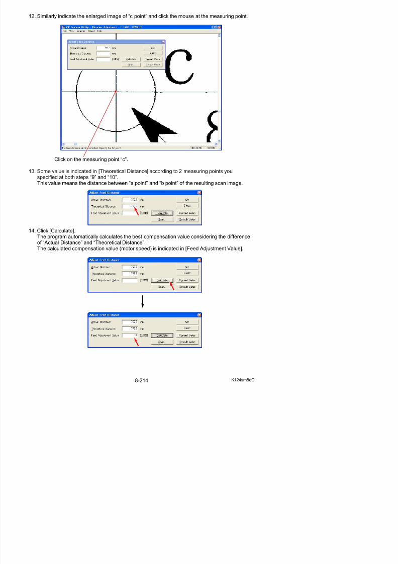
5/17/2018 KIP 7100 Service Manual Ver A_1 - slidepdf.com
http://slidepdf.com/reader/full/kip-7100-service-manual-ver-a1 656/674
a) Measure the actual distance between the center of a b points and that of c d points on the chart.
Center of a-b points
Center of c-d points
b
d 1000
a
c 800
c 1000
d 800
d 1100c 1100
d 1150c 1150
8. 13. 4. 3 Position (stitching)
[Purpose of Position (stitching)]
The scanner part of KIP 7100 reads the image of original with 5 - CIS (Contact Image Sensor). As these CIS are arranged in 2 rows, there occurs a vertical gap of image among the image blocks. Also the reading area of these 5 pieces of CIS overlaps each other some degree. As a result thereoccurs the duplication of image between neighboring Image Block (same image is commonlyincluded in the neighboring two Image Blocks).
Gap of CIS position
Overlaps of reading area
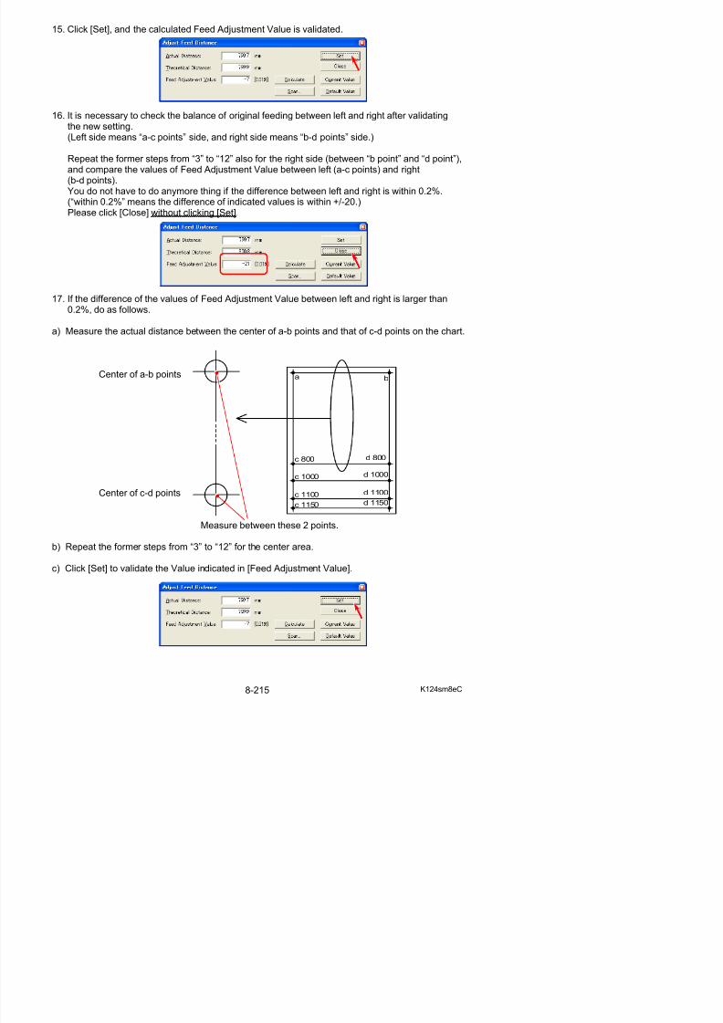
5/17/2018 KIP 7100 Service Manual Ver A_1 - slidepdf.com
http://slidepdf.com/reader/full/kip-7100-service-manual-ver-a1 657/674
“Position” is the solution for these kinds of phenomenon.It is possible remove the vertical gap of image by vertical positioning process (Y offset). And it is also possible to remove the duplication of image by horizontal positioning process(X overlap).KIP 7100 has the function to adjust X/Y positioning by automatic. After X/Y positioning, adjustmentfor the LE (leading edge) positioning should be performed manually.
Duplications of image
Vertical gap of image
[Operation]
1. Connect the scanner unit and the PC directly with the USB 2.0 Cable.
2. Start KIP Scanner Utility.
3. Select [Automatic Adjustment] from [Adjust]. Scanner Adjustment Dialog is indicated.
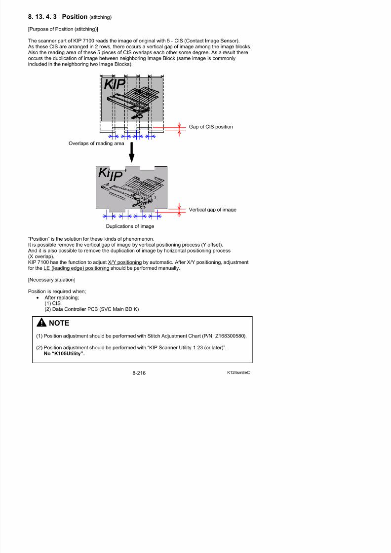
5/17/2018 KIP 7100 Service Manual Ver A_1 - slidepdf.com
http://slidepdf.com/reader/full/kip-7100-service-manual-ver-a1 658/674
NOTE
If [Automatic Adjustment] does not appear, follow the instruction below.
a) Open the properties panel for KIP Scanner
Utility shortcut (ex right click on the shortcut)
4. Set Stitch Adjustment Chart to the scanner noting the set direction and press [OK].
Stitch Adjustment Chart
NOTE
An incorrect feeding of Stitch Adjustment Chart may resultin an error. Position Stitch Adjustment Chart with the center
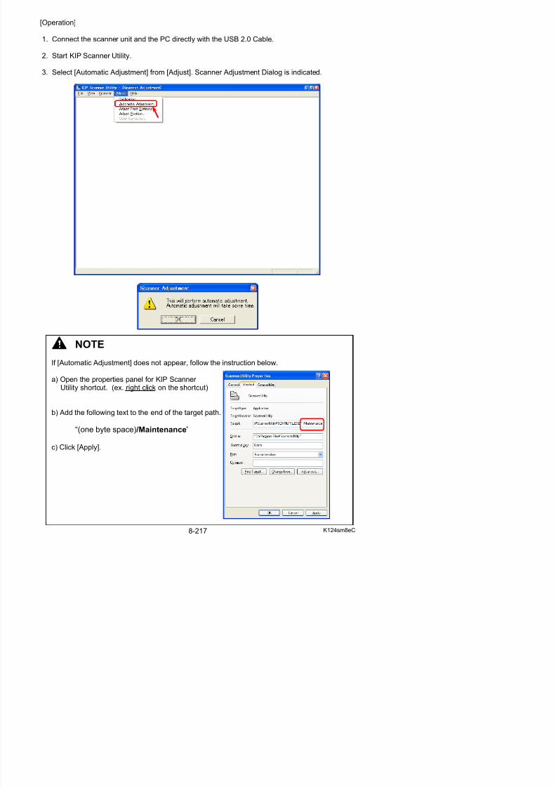
5/17/2018 KIP 7100 Service Manual Ver A_1 - slidepdf.com
http://slidepdf.com/reader/full/kip-7100-service-manual-ver-a1 659/674
5. After completing the scan, the following window will be displayed. Press [Close].
of Original Table and avoid skewing.
7. Select [Adjust Position] from [Adjust]. Adjust Position subscreen is indicated.
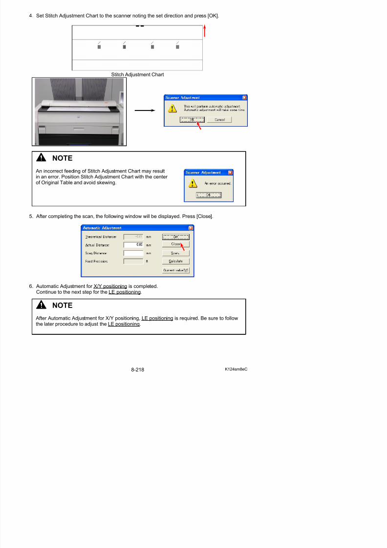
5/17/2018 KIP 7100 Service Manual Ver A_1 - slidepdf.com
http://slidepdf.com/reader/full/kip-7100-service-manual-ver-a1 660/674
8. Set Stitch Adjustment Chart to the scanner again and press [Scan].
9. A dialog to specify the scan settings is indicated.Simply click [Scan] to scan the chart. (You do not have to change any setting this time.)
10. The scan image of Scanner Adjustment Chart is indicated in the screen of KIP Scanner Utility.
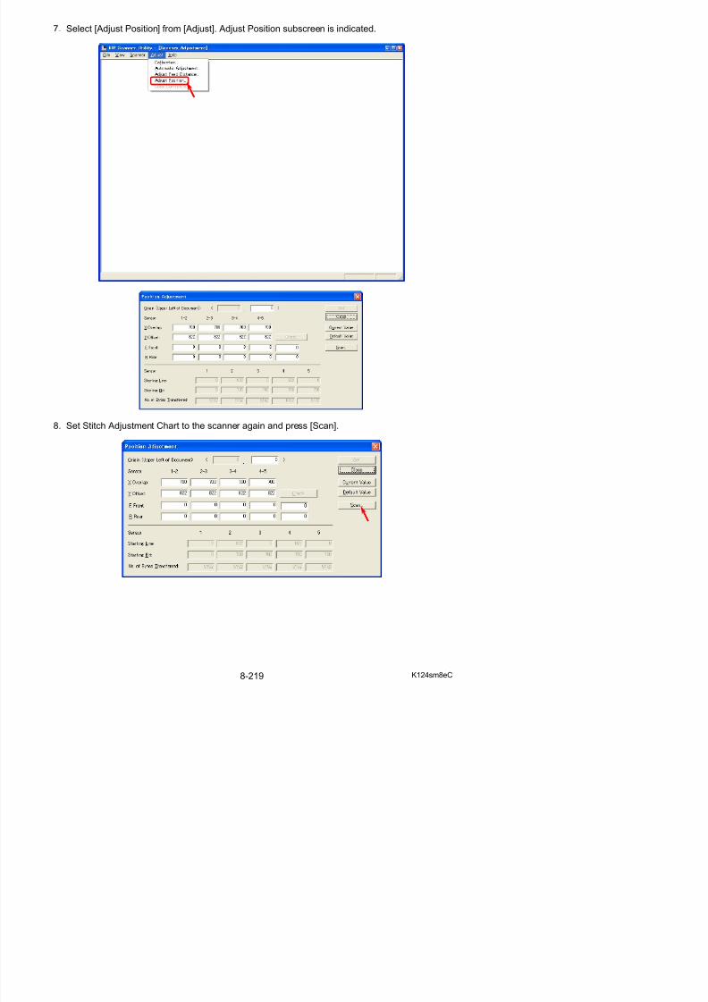
5/17/2018 KIP 7100 Service Manual Ver A_1 - slidepdf.com
http://slidepdf.com/reader/full/kip-7100-service-manual-ver-a1 661/674
11. Enlarge the top center area by right dragging.
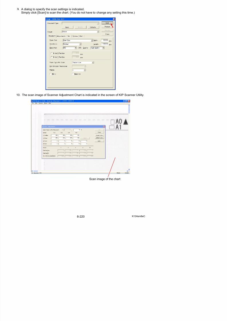
5/17/2018 KIP 7100 Service Manual Ver A_1 - slidepdf.com
http://slidepdf.com/reader/full/kip-7100-service-manual-ver-a1 662/674
Reference
There is a gap between the leading edge of the scan image and the leading edge of thechart at this time. This band area shows that both of the edges do not match together.The gap will be removed after the completion of Position adjustment for the leading edge.
Leading edge
of original
Leading edgeof image
gap (band)
12. Click “Origin” entry field of the subscreen. A red cross cursor appears on the scan image.
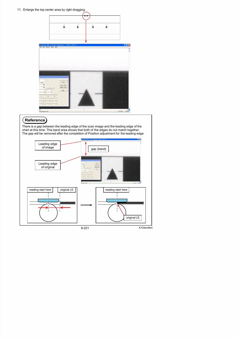
5/17/2018 KIP 7100 Service Manual Ver A_1 - slidepdf.com
http://slidepdf.com/reader/full/kip-7100-service-manual-ver-a1 663/674
13. Click once on the top center of the chart in the scan image. A value appears in the field.
Top center
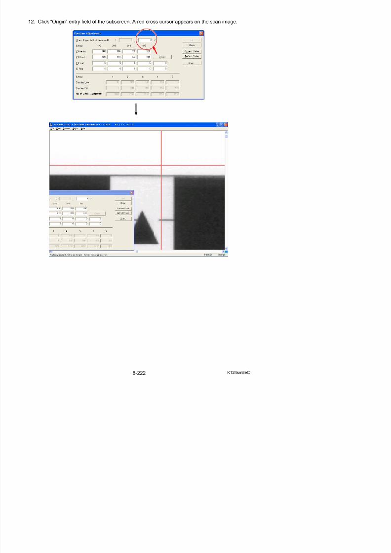
5/17/2018 KIP 7100 Service Manual Ver A_1 - slidepdf.com
http://slidepdf.com/reader/full/kip-7100-service-manual-ver-a1 664/674
NOTE
14. Press [Check] then [Set].
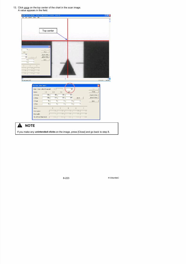
5/17/2018 KIP 7100 Service Manual Ver A_1 - slidepdf.com
http://slidepdf.com/reader/full/kip-7100-service-manual-ver-a1 665/674
15. A dialog appears to prompt confirmation of the result. Press [OK].
16. Start Adjust Position again. Make a rescan of Stitch Adjustment Chart.Confirm the result of the adjustment. If the gap disappears, LE positioning is completed.
NOTE
If the rescan image still has a gap, go back to step 11 to remove it completely.Every scan image has a blank band on the leading edge by the gap.Be sure to remove the gap completely.
No gap (band area)
gap (band)
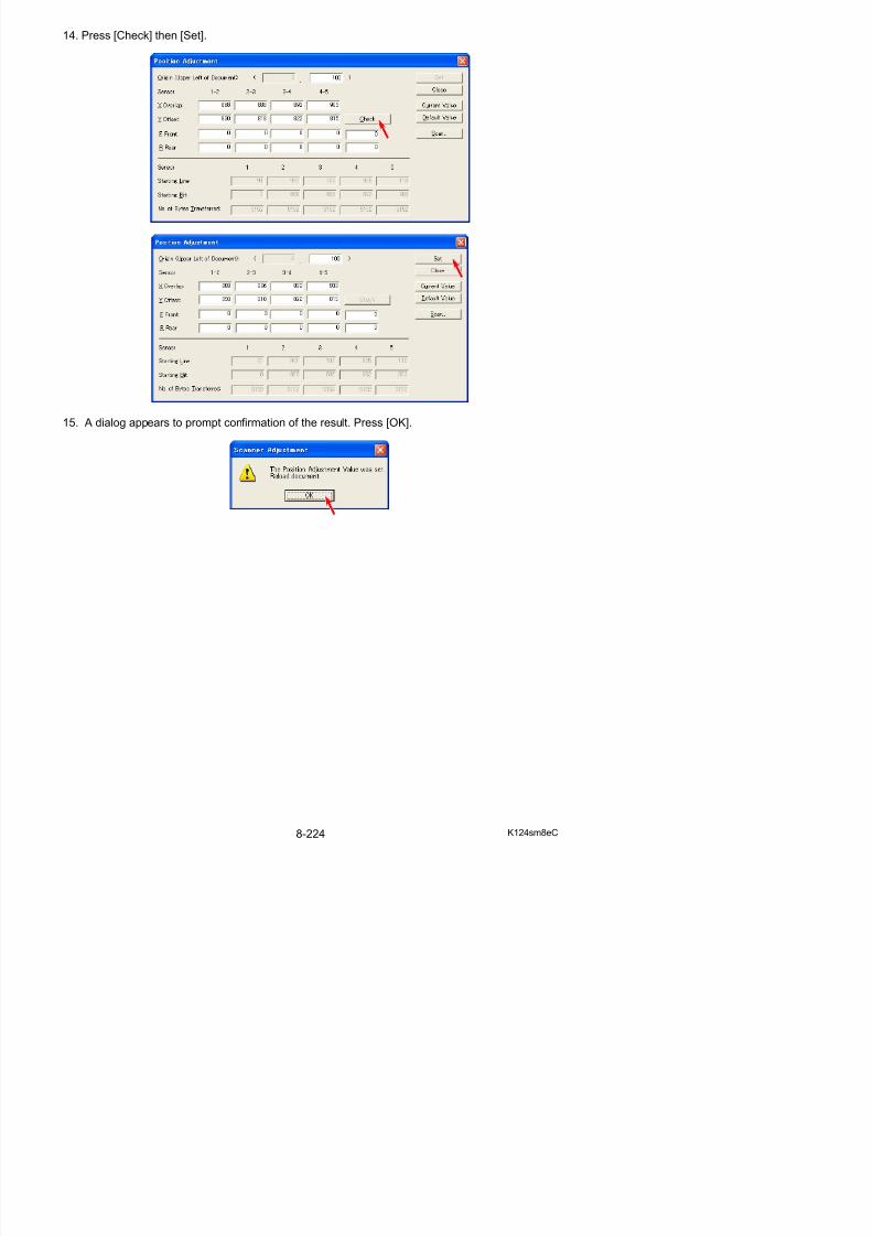
5/17/2018 KIP 7100 Service Manual Ver A_1 - slidepdf.com
http://slidepdf.com/reader/full/kip-7100-service-manual-ver-a1 666/674
If the image on the leading edge is missing, the reading start is too late. Go back to step 4.
gap (band)
reading start herereading start here
8. 13. 5 Updating Scanner Firmware
It is possible to install a new Firmware to the KIP 7100 with KIP Scanner Utility.
1. Select [Update Firmware] under [Scanner].
2 Fi D l d Utilit i di l d
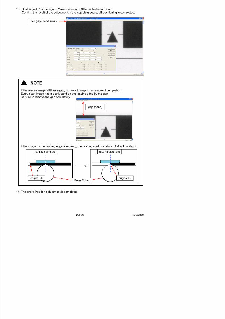
5/17/2018 KIP 7100 Service Manual Ver A_1 - slidepdf.com
http://slidepdf.com/reader/full/kip-7100-service-manual-ver-a1 667/674
2. Firmware Download Utility is displayed.Click [Browse].
3. Select the Firmware component on the hard drive (or another drive). Click [Open].
4. Confirm that the file name you will install is displayed.Click [Start].(The name of the firmware file or the CRC value may vary as the picture below is an example)
NOTE
(1) A firmware file for KIP 7100 scanner unit should be named “k124_***.x”.
(2) Do not send any other file.Doing so may result in malfunction of the scanner.
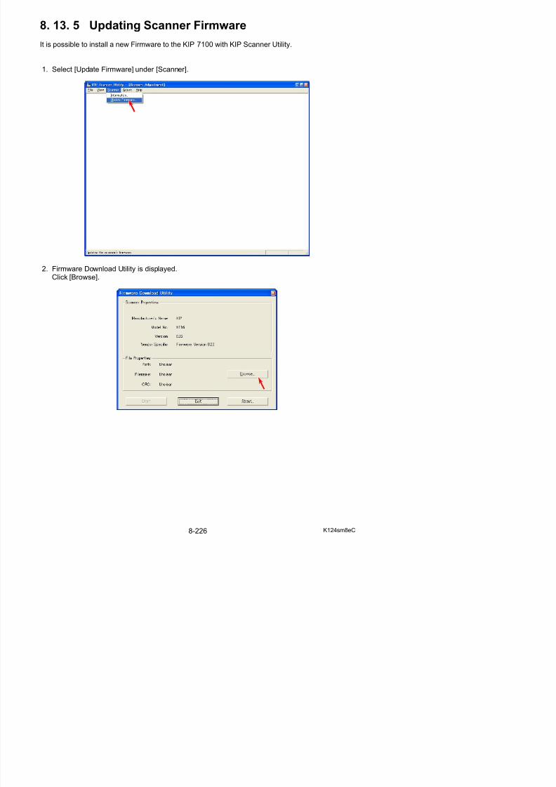
5/17/2018 KIP 7100 Service Manual Ver A_1 - slidepdf.com
http://slidepdf.com/reader/full/kip-7100-service-manual-ver-a1 668/674
name of firmware file
5. A dialog is displayed, which request you to turn off the KIP 7100.Turn off the machine.
Chapter 9
Appendix
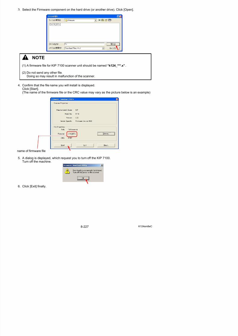
5/17/2018 KIP 7100 Service Manual Ver A_1 - slidepdf.com
http://slidepdf.com/reader/full/kip-7100-service-manual-ver-a1 669/674
9. 1 Schematic Wiring around Controller
IPS Assy for KIP 7100 (DC1 type)
VGA (UI) COM (UPS)
IPS Power
Interface 8Ethernetvacant
USB(PW12420)
USB(UI)
USB(relay at rear)
USB(relay at UI front)
USB(scanner)
OPTION: COM(folder)

5/17/2018 KIP 7100 Service Manual Ver A_1 - slidepdf.com
http://slidepdf.com/reader/full/kip-7100-service-manual-ver-a1 670/674
Interface 8
IPS Power
Ethernet
USB to PW12420
USB Relay at rear
USB f S
( ) ( )( )
9. 2 Overall Diagram
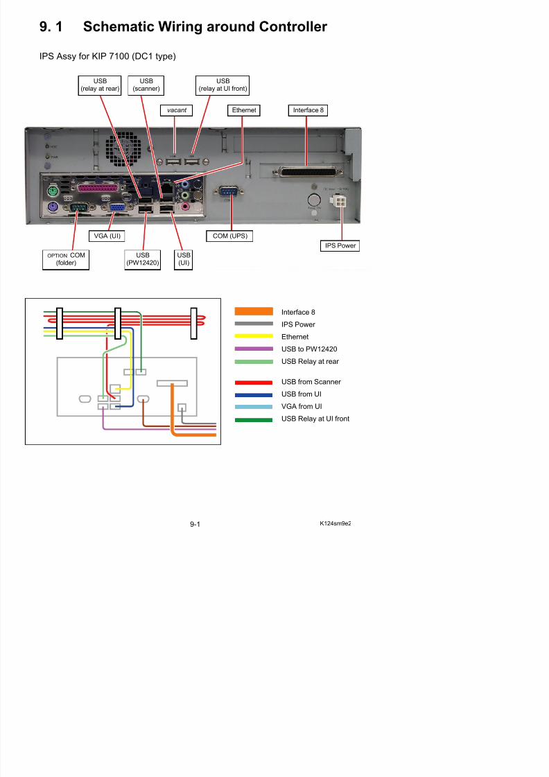
5/17/2018 KIP 7100 Service Manual Ver A_1 - slidepdf.com
http://slidepdf.com/reader/full/kip-7100-service-manual-ver-a1 671/674

5/17/2018 KIP 7100 Service Manual Ver A_1 - slidepdf.com
http://slidepdf.com/reader/full/kip-7100-service-manual-ver-a1 672/674
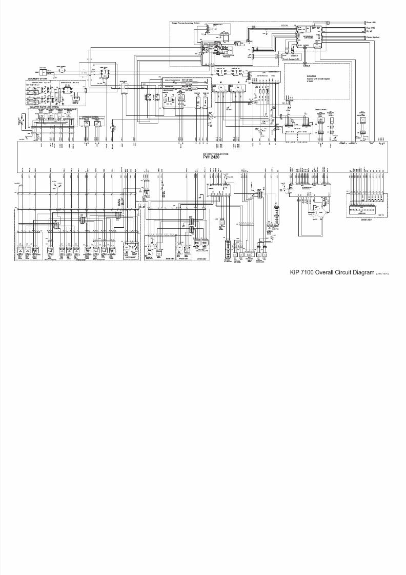
5/17/2018 KIP 7100 Service Manual Ver A_1 - slidepdf.com
http://slidepdf.com/reader/full/kip-7100-service-manual-ver-a1 673/674
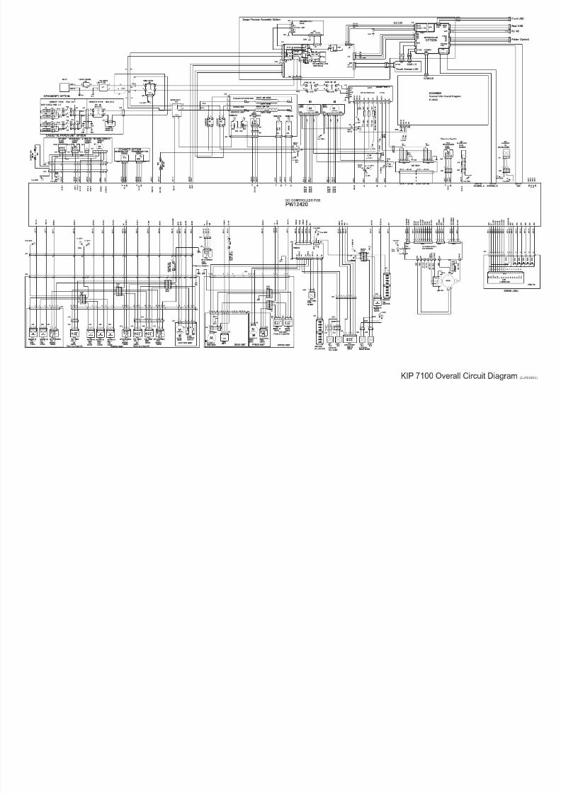
5/17/2018 KIP 7100 Service Manual Ver A_1 - slidepdf.com
http://slidepdf.com/reader/full/kip-7100-service-manual-ver-a1 674/674
Related Documents