KEYSTONE FIGURE 55 DOUBLE FLANGED BUTTERFLY VALVE Double flanged valve design for services in the water treatment industry FEATURES • The centric disc offers bidirectional service and allows with its symmetric shape high K v (C v ) values. • Dry shaft design. • The inside body is protected by a bonded rubber liner extending over the flanges. • Primary stem sealing by preloaded contact between flatted seat surface and rounded polished disc-hub area exceeds the pressure rating of the valve and prevents leakage through shaft area to atmosphere. • A secondary sealing is provided by the interference fit between shaft and shafthole in seat at all positions. • Dirtscraper prevents moisture penetrating into the shaft area. • Bubble-tight shut off at full pressure rating. • Rounded, polished disc edge provides concentric sealing. • Actuator flange acc. ISO 5211. • Double flanged body design per EN 558 series 13 (short), series 14 (long) on request. • Excellent performance in media with sedimentation and contamination. • Suitable for severe vacuum applications and up to 16 bar (230 psi) drop tight shut off. • Flat facing for GRP flanges as option. GENERAL APPLICATION • Waterwork industries where a double flanged valve is required. • Fire fighting systems. • Sea water applications. • For drinking water applications a certified EPDM compound and certified coatings available. • Approvals: KIWA, KTW, WRC, PED/CE, FDA. TECHNICAL DATA Sizes: DN 100 - 1200 (NPS 4 - 48) Pressure: 16 bar (230 psi) Temperature: -40°C to +120°C (-40°F to +250°F) Flange accommodation: PN 10/16 ASME 150 ISO, JIS, BS, API Emerson.com/FinalControl © 2017 Emerson. All Rights Reserved. VCTDS-00031-EN 17/02

Welcome message from author
This document is posted to help you gain knowledge. Please leave a comment to let me know what you think about it! Share it to your friends and learn new things together.
Transcript
KEYSTONE FIGURE 55 DOUBLE FLANGED BUTTERFLY VALVE
Double flanged valve design for services in the water treatment industry
FEATURES
• The centric disc offers bidirectional service and allows with its symmetric shape high Kv (Cv) values.
• Dry shaft design.• The inside body is protected by a bonded
rubber liner extending over the flanges.• Primary stem sealing by preloaded contact
between flatted seat surface and rounded polished disc-hub area exceeds the pressure rating of the valve and prevents leakage through shaft area to atmosphere.
• A secondary sealing is provided by the interference fit between shaft and shafthole in seat at all positions.
• Dirtscraper prevents moisture penetrating into the shaft area.
• Bubble-tight shut off at full pressure rating.• Rounded, polished disc edge provides
concentric sealing.• Actuator flange acc. ISO 5211.• Double flanged body design per EN 558 series
13 (short), series 14 (long) on request.• Excellent performance in media with
sedimentation and contamination.• Suitable for severe vacuum applications and
up to 16 bar (230 psi) drop tight shut off.• Flat facing for GRP flanges as option.
GENERAL APPLICATION
• Waterwork industries where a double flanged valve is required.
• Fire fighting systems.• Sea water applications.• For drinking water applications a certified
EPDM compound and certified coatings available.
• Approvals: KIWA, KTW, WRC, PED/CE, FDA.
TECHNICAL DATA
Sizes: DN 100 - 1200 (NPS 4 - 48)Pressure: 16 bar (230 psi)Temperature: -40°C to +120°C
(-40°F to +250°F)Flangeaccommodation: PN 10/16 ASME 150 ISO, JIS, BS, API
Emerson.com/FinalControl © 2017 Emerson. All Rights Reserved. VCTDS-00031-EN 17/02
2
100 100 220 220 180 127 - 116 138 - 30 16 11 - - F-07 90 55 4 12 70 9.0 4 45.0 18 -150 151 285 285 210 140 210 168 192 61 30 20 14 - - F-07 90 55 4 12 70 9.0 4 45.0 24 28200 196 340 340 240 152 230 209 245 130 50 25 18 - - F-12 150 85 4 18 125 13.5 4 45.0 35 41250 246 405 405 275 165 250 264 300 189 50 30 22 - - F-12 150 85 4 18 125 13.5 4 45.0 50 59300 293 445 460 310 178 270 314 350 243 50 30 22 - - F-12 150 85 4 18 125 13.5 4 45.0 65 77350 325 505 520 325 190 290 364 400 267 70 35 - 30.0 10x8 F-12 150 85 4 18 125 13.5 4 45.0 90 106400 380 565 580 360 216 310 412 450 316 70 40 - 35.0 12x8 F-16 210 130 6 25 165 22.0 4 45.0 120 138450 440 615 640 395 222 330 466 505 377 70 40 - 35.0 12x8 F-16 210 130 6 25 165 22.0 4 45.0 145 170500 486 670 715 430 229 350 517 555 432 70 50 - 44.5 14x9 F-16 210 130 6 25 165 22.0 4 45.0 170 202550 535 730 775 475 267 357 567 605 468 70 50 - 44.5 14x9 F-16 210 130 6 25 165 22.0 4 45.0 210 247600 586 780 840 500 267 390 617 655 525 70 50 - 44.5 14x9 F-16 210 130 6 25 165 22.0 4 45.0 250 292700 685 895 910 570 292 (430) 722 760 624 100 70 - 62.5 20x12 F-25 300 200 6 30 254 17.5 8 22.5 385 (455)750 735 965 970 605 318 (450) 772 810 667 100 70 - 62.5 20x12 F-25 300 200 6 30 254 17.5 8 22.5 485 (537)800 785 1015 1025 640 318 (470) 838 866 722 100 70 - 62.5 20x12 F-25 300 200 6 30 254 17.5 8 22.5 536 (628)900 885 1115 1125 715 330 (510) 937 975 825 100 80 - 71.0 22x14 F-25 300 200 6 30 254 17.5 8 22.5 726 (854)1000 985 1230 1255 780 410 (550) 1028 1066 900 129 90 - 81.0 25x14 F-30 350 230 6 35 298 22.0 8 22.5 1040 (1161)1100 1085 1345 1370 870 470 (630) 1141 1179 980 129 100 - 90.0 28x16 F-30 350 230 6 35 298 22.0 8 22.5 1230 (1370)1200 1185 1455 1485 920 470 (630) 1241 1279 1093 129 100 - 90.0 28x16 F-30 350 230 6 35 298 22.0 8 22.5 1419 (1601)
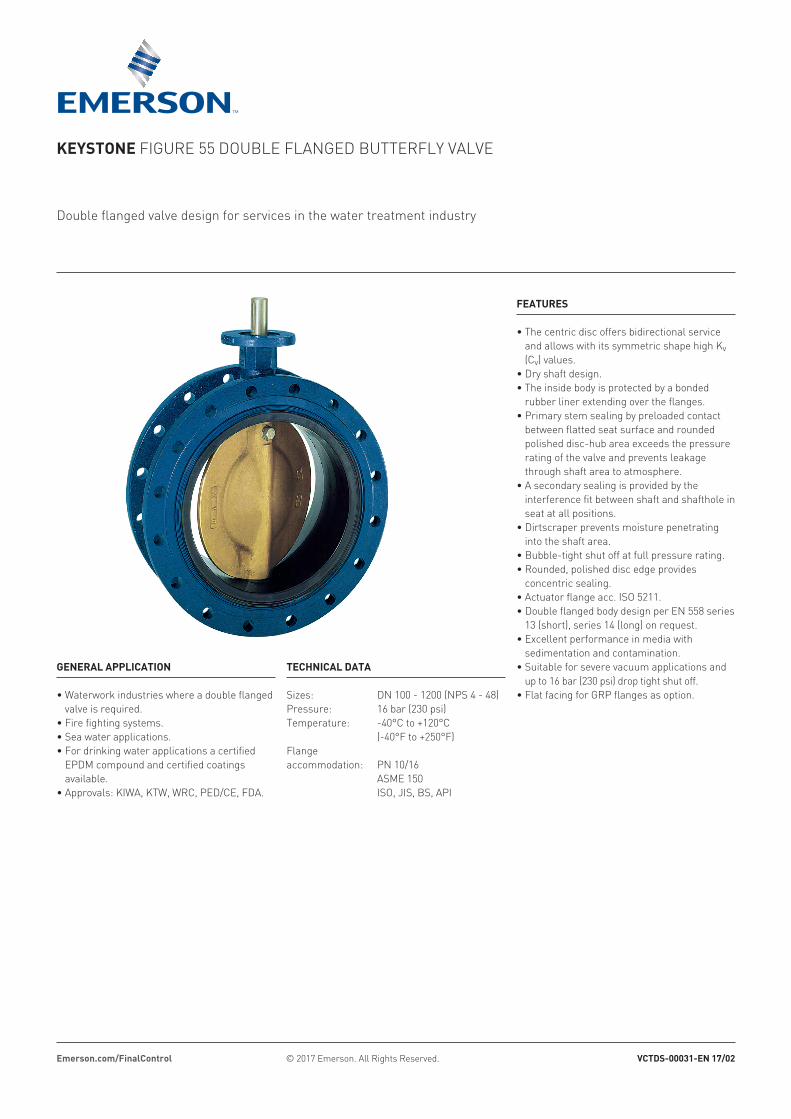
KEYSTONE FIGURE 55 DOUBLE FLANGED BUTTERFLY VALVE VALVE DATA - METRIC
Part Name Part Name1. Body 7. Bushing2. Disc 8. Plug3. Seat 9. O-ring4. Shaft 10. Circlip5. Disc-screw 11. Dirt scraper6. O-ring
NOTES1. Dimension B is according PN10/16 EN 1092-2. For DN 550: ISO 2084.2. Flange accommodation must be specified when ordering.3. Valve shown is the DN 300 ISO short.4. Flange dimensions and mass will vary with flange accommodations.5. Q is the disc chordal dimension at face of valve for disc clearance into pipe fitting or equipment.6. ISO long larger than DN 600 is available on request.
VALVE DIMENSIONS (mm)B D Stemhead Actuator flange according ISO 5211 Mass (kg)
Size ISO ISO ISO short
ISO long
Key-size[1]
Hole dia
No of holes
ISO ISODN A PN 10 PN 16 C H YY Q F G K R Type E J L P PCD α short long
Mounting hole
DN 100-300 only
PCD
Key-way sizesDN 350-1200
Parallel flats sizesDN 100-300
D short
D long
Top view
1. Keysize width x height
3
4 3.94 8.67 8.67 7.09 5.00 - 4.57 5.44 - 1.19 0.6299 0.4331 - - F-07 3.55 2.166 0.15 0.47 2.76 0.35 4 45 40 -6 5.94 11.23 11.23 8.27 5.51 8.27 6.61 7.56 2.41 1.19 0.7874 0.5512 - - F-07 3.55 2.166 0.15 0.47 2.76 0.35 4 45 53 628 7.72 13.39 13.39 9.45 5.98 9.06 8.23 9.65 5.12 1.97 0.9843 0.7087 - - F-12 5.91 3.347 0.15 0.71 4.92 0.53 4 45 77 9010 9.69 15.95 15.95 10.83 6.50 9.84 10.39 11.82 7.45 1.97 1.1811 0.8661 - - F-12 5.91 3.347 0.15 0.71 4.92 0.53 4 45 110 13012 11.54 17.52 18.12 12.21 7.01 10.63 12.36 13.78 9.57 1.97 1.1811 0.8661 - - F-12 5.91 3.347 0.15 0.71 4.92 0.53 4 45 143 17014 12.80 19.89 20.48 12.80 7.48 11.42 14.33 15.75 10.52 2.76 1.3780 - 1.181 0.394 x 0.315 F-12 5.91 3.347 0.15 0.71 4.92 0.53 4 45 198 23416 14.96 22.25 22.84 14.18 8.50 12.20 16.22 17.72 12.45 2.76 1.5748 - 1.378 0.472 x 0.315 F-16 8.27 5.119 0.23 0.98 6.50 0.87 4 45 265 30418 17.32 24.22 25.20 15.56 8.74 12.99 18.35 19.89 14.85 2.76 1.5748 - 1.378 0.472 x 0.315 F-16 8.27 5.119 0.23 0.98 6.50 0.87 4 45 320 37520 19.13 26.38 28.15 16.93 9.02 13.78 20.35 21.86 17.01 2.76 1.9685 - 1.752 0.551 x 0.354 F-16 8.27 5.119 0.23 0.98 6.50 0.87 4 45 375 44522 21.06 28.75 30.52 18.71 10.51 14.06 22.32 23.82 18.43 2.76 1.9685 - 1.752 0.551 x 0.354 F-16 8.27 5.119 0.23 0.98 6.50 0.87 4 45 463 54524 23.07 30.71 33.08 19.69 10.51 15.35 24.29 25.79 20.67 2.76 1.9685 - 1.752 0.551 x 0.354 F-16 8.27 5.119 0.23 0.98 6.50 0.87 4 45 551 64428 26.97 35.24 35.83 22.45 11.50 (16.93) 28.43 29.93 24.57 3.94 2.7559 - 2.461 0.787 x 0.472 F-25 11.82 7.875 0.23 1.18 10.00 0.69 8 22.5 849 (1003)30 28.94 38.00 38.19 23.82 12.52 (17.72) 30.39 31.89 26.26 3.94 2.7559 - 2.461 0.787 x 0.472 F-25 11.82 7.875 0.23 1.18 10.00 0.69 8 22.5 1069 (1184)32 30.91 39.97 40.36 25.20 12.52 (18.50) 32.99 34.10 28.43 3.94 2.7559 - 2.461 0.787 x 0.472 F-25 11.82 7.875 0.23 1.18 10.00 0.69 8 22.5 1182 (1385)36 34.84 43.90 44.30 28.15 12.99 (20.08) 36.89 38.39 32.49 3.94 3.1496 - 2.795 0.866 x 0.551 F-25 11.82 7.875 0.23 1.18 10.00 0.69 8 22.5 1601 (1883)40 38.78 48.43 49.41 30.71 16.14 (21.65) 40.47 41.97 35.44 5.08 3.5433 - 3.189 0.984 x 0.551 F-30 13.78 9.056 0.23 1.38 11.73 0.87 8 22.5 2293 (2560)44 42.72 52.96 53.94 34.26 18.50 (24.80) 44.92 46.42 38.59 5.08 3.9370 - 3.543 1.102 x 0.630 F-30 13.78 9.056 0.23 1.38 11.73 0.87 8 22.5 2712 (3020)48 46.65 57.29 58.47 36.23 18.50 (24.80) 48.86 50.36 43.04 5.08 3.9370 - 3.543 1.102 x 0.630 F-30 13.78 9.056 0.23 1.38 11.73 0.87 8 22.5 3128 (3530)
VALVE DIMENSIONS (inches)Size
NPS
B D Stemhead Actuator flange according ISO 5211 Mass (lb)ISO ISO ISO
shortISO long Keysize[1]
Hole dia
No of holes
ISO short
ISO longA PN 10 PN 16 C H YY Q F G K R Type E J L P PCD α
Top view
D long
D short
Parallel flats sizesNPS 4-12
Key-way sizesNPS 14 - 48
PCD
NPS 4-12 only
Mounting hole
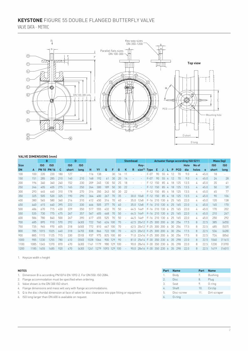
NOTES1. Dimension B is according PN 10/16 EN 1092-2. For NPS 22: ISO 2084.2. Flange accommodation must be specified when ordering.3. Valve shown is the NPS 12 ISO short.4. Flange dimensions and mass will vary with flange accommodations.5. Q is the disc chordal dimension at face of valve for disc clearance into pipe fitting or equipment.6. ISO long larger than NPS 24 is available on request.
Part Name Part Name1. Body 7. Bushing2. Disc 8. Plug3. Seat 9. O-ring4. Shaft 10. Circlip5. Disc-screw 11. Dirt scraper6. O-ring
KEYSTONE FIGURE 55 DOUBLE FLANGED BUTTERFLY VALVE VALVE DATA - IMPERIAL
1. Keysize width x height
4
10° 5 15 21 33 49 119 155 196 242 293 349 475 545 620 785 969 1173 139620° 25 52 95 155 220 304 397 503 621 751 894 1216 1396 1589 2011 2483 3004 357630° 54 120 220 340 510 637 832 1053 1300 1573 1871 2547 2924 3327 4211 5197 6288 748440° 95 220 380 610 860 1142 1492 1888 2331 2821 3357 4569 5245 5968 7553 9325 11283 1342850° 150 340 590 950 1460 1936 2529 3200 3951 4781 5689 7744 8890 10114 12801 15803 19121 2275660° 240 550 950 1550 2320 3110 4062 5141 6347 7680 9140 12440 14281 16248 20564 25389 30720 3656070° 400 950 1550 2580 3780 5010 6544 8288 10224 12371 14723 20040 23005 26174 33127 40897 49485 5889280° 620 1380 2410 3960 5850 8969 11714 14826 18303 22147 26357 35875 41183 46857 59303 73214 88588 10542890° 710 1630 2840 4640 6880 10407 13592 17203 21238 25698 30583 41626 47785 54369 68811 84953 102792 122332
10° 2.7 6.1 13 28 39 - - - - - - - - - - - - -20° 3.4 8.7 20 40 61 21 32 46 63 83 108 172 211 256 365 500 665 86430° 4.8 13 30 61 95 64 96 137 188 250 324 515 633 768 1094 1500 1198 259240° 6.4 20 47 94 153 124 186 264 363 483 626 995 1223 1485 2114 2900 3860 501150° 10 30 71 141 230 236 352 501 688 915 1188 1887 2320 2816 4010 5500 7320 950460° 15 48 112 220 380 416 621 884 1213 1614 2095 3327 4092 4966 7071 9700 12911 1676270° 24 76 176 350 610 733 1094 1558 2138 2845 3694 5865 7214 8755 12466 17100 22760 2954980° 34 112 260 520 890 1346 2010 2861 3925 5224 6782 10770 13247 16077 22891 31400 41793 54259
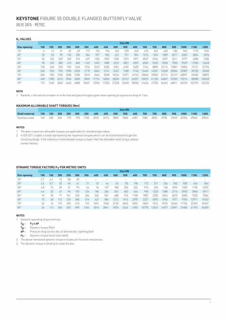
KEYSTONE FIGURE 55 DOUBLE FLANGED BUTTERFLY VALVE VALVE DATA - METRIC
Kv VALUES
Disc openingSize DN
100 150 200 250 300 350 400 450 500 550 600 700 750 800 900 1000 1100 1200
MAXIMUM ALLOWABLE SHAFT TORQUES (Nm)
Shaft materialSize DN
100 150 200 250 300 350 400 450 500 550 600 700 750 800 900 1000 1100 1200 Stainless steel 160 320 545 970 970 1760 2012 3472 3858 3858 6587 7685 8234 8782 15949 22956 29843 29843
DYNAMIC TORQUE FACTORS FT FOR METRIC UNITS
Disc openingSize DN
100 150 200 250 300 350 400 450 500 550 600 700 750 800 900 1000 1100 1200
NOTE1. Rated Kv = the volume of water in m3/hr that will pass through a given valve opening at a pressure drop of 1 bar.
NOTES1. The given maximum allowable torques are applicable for standard type valves.2. In ISO 5211 a table is listed representing the maximum torques which can be transmitted through the
mounting flange. If the maximum transmittable torque is lower than the allowable shaft torque, please contact factory.
NOTES1. Dynamic operating torque formula: TD = FT x ΔP TD = Dynamic torque (Nm) ΔP = Pressure drop across disc at desired disc-opening (bar) FT = Dynamic torque factor (see table)2. The above mentioned dynamic torque includes all frictional resistances.3. The dynamic torque is tending to close the disc.
5
10° 6 17 24 38 57 138 179 227 280 339 403 549 630 717 908 1120 1356 161420° 29 60 110 179 254 351 459 582 718 868 1034 1406 1614 1837 2325 2871 3473 413430° 62 139 254 393 590 736 962 1217 1503 1818 2163 2945 3380 3846 4868 6008 7269 865240° 110 254 439 705 994 1320 1725 2183 2695 3261 3881 5282 6064 6899 8732 10780 13044 1552450° 173 393 682 1098 1688 2238 2924 3699 4568 5527 6577 8953 10277 11692 14799 18269 22105 2630860° 277 636 1098 1792 2682 3595 4696 5943 7338 8879 10566 14382 16510 18784 23773 29351 35514 4226670° 462 1098 1792 2983 4370 5792 7565 9582 11820 14302 17021 23168 26595 30259 38297 47280 57208 6808380° 717 1595 2786 4578 6763 10369 13542 17140 21160 25603 30471 41474 47610 54170 68558 84640 102414 12188290° 821 1884 3283 5364 7954 12031 15713 19888 24553 29709 35356 48123 55243 62854 79550 98212 118835 141424
10° 1.6 3.7 8 17 24 - - - - - - - - - - - - -20° 2.1 5.3 12 24 37 13 20 28 38 51 66 105 129 156 223 305 406 52730° 2.9 8 18 37 58 39 59 84 115 153 198 314 386 469 668 915 731 158240° 3.9 12 29 57 93 76 114 161 222 295 382 607 746 906 1290 1770 2356 305850° 6 18 43 86 140 144 215 306 420 558 725 1152 1416 1718 2447 3356 4467 580060° 9 29 68 134 232 254 379 539 740 985 1278 2030 2497 3030 4315 5919 7879 1022970° 15 46 107 214 372 447 668 951 1305 1736 2254 3579 4402 5343 7607 10435 13889 1803280° 21 68 159 317 543 821 1227 1746 2395 3188 4139 6572 8084 9811 13969 19161 25504 33111
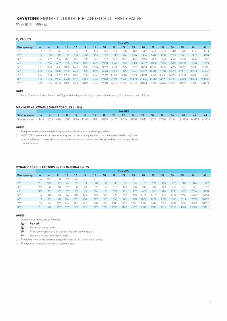
DYNAMIC TORQUE FACTORS FT FOR IMPERIAL UNITS
Disc openingSize NPS
4 6 8 10 12 14 16 18 20 22 24 28 30 32 36 40 44 48
NOTES1. Dynamic operating torque formula: TD = FT x ∆P TD = Dynamic torque (in lbs) ∆P = Pressure drop across disc at desired disc-opening (psi) FT = Dynamic torque factor (see table)2. The above mentioned dynamic torque includes all frictional resistances.3. The dynamic torque is tending to close the disc.
NOTES1. The given maximum allowable torques are applicable for standard type valves.2. In ISO 5211 a table is listed representing the maximum torques which can be transmitted through the
mounting flange. If the maximum transmittable torque is lower than the allowable shaft torque, please contact factory.
NOTE1. Rated Cv = the volume of water in USgpm that will pass through a given valve opening at a pressure drop of 1 psi.
Cv VALUES
Disc openingSize NPS
4 6 8 10 12 14 16 18 20 22 24 28 30 32 36 40 44 48
MAXIMUM ALLOWABLE SHAFT TORQUES (in lbs)
Shaft materialSize NPS
4 6 8 10 12 14 16 18 20 22 24 28 30 32 36 40 44 48Stainless steel 1417 2833 4824 8586 8586 15578 17808 30730 34147 34147 58300 68019 72878 77728 141161 203178 264133 264133
KEYSTONE FIGURE 55 DOUBLE FLANGED BUTTERFLY VALVE VALVE DATA - IMPERIAL
6
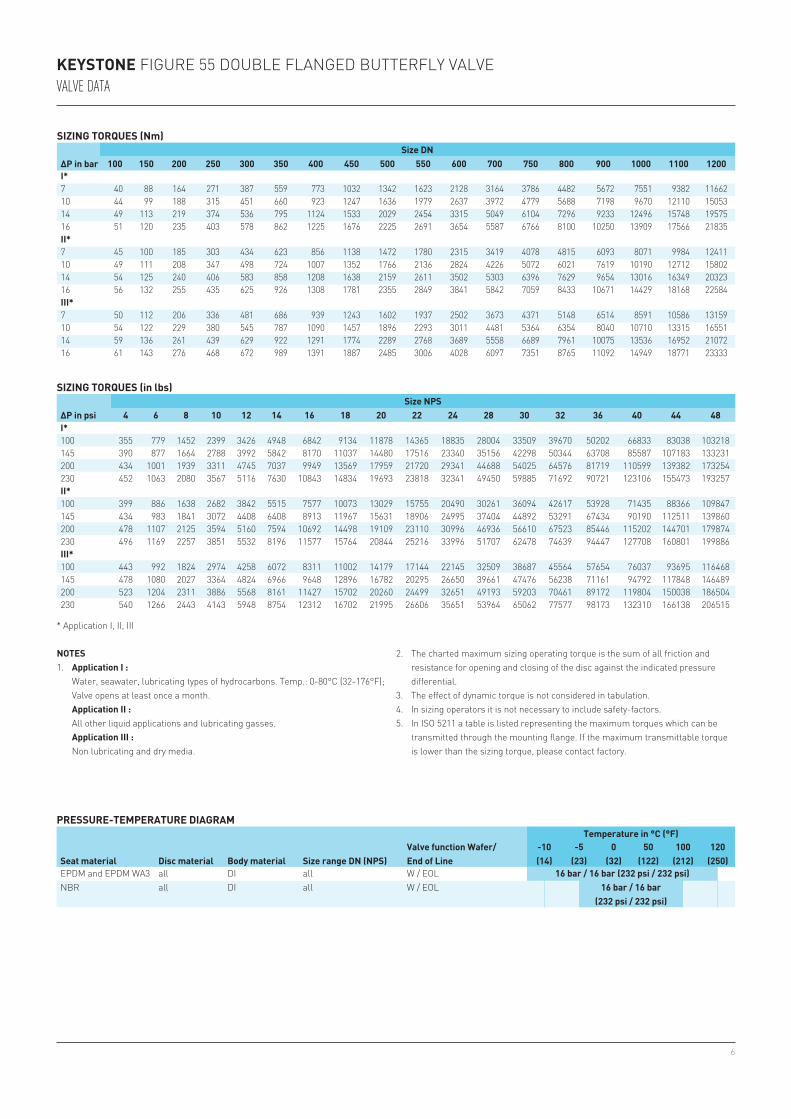
I*100 355 779 1452 2399 3426 4948 6842 9134 11878 14365 18835 28004 33509 39670 50202 66833 83038 103218145 390 877 1664 2788 3992 5842 8170 11037 14480 17516 23340 35156 42298 50344 63708 85587 107183 133231200 434 1001 1939 3311 4745 7037 9949 13569 17959 21720 29341 44688 54025 64576 81719 110599 139382 173254230 452 1063 2080 3567 5116 7630 10843 14834 19693 23818 32341 49450 59885 71692 90721 123106 155473 193257II*100 399 886 1638 2682 3842 5515 7577 10073 13029 15755 20490 30261 36094 42617 53928 71435 88366 109847145 434 983 1841 3072 4408 6408 8913 11967 15631 18906 24995 37404 44892 53291 67434 90190 112511 139860200 478 1107 2125 3594 5160 7594 10692 14498 19109 23110 30996 46936 56610 67523 85446 115202 144701 179874230 496 1169 2257 3851 5532 8196 11577 15764 20844 25216 33996 51707 62478 74639 94447 127708 160801 199886III*100 443 992 1824 2974 4258 6072 8311 11002 14179 17144 22145 32509 38687 45564 57654 76037 93695 116468145 478 1080 2027 3364 4824 6966 9648 12896 16782 20295 26650 39661 47476 56238 71161 94792 117848 146489200 523 1204 2311 3886 5568 8161 11427 15702 20260 24499 32651 49193 59203 70461 89172 119804 150038 186504230 540 1266 2443 4143 5948 8754 12312 16702 21995 26606 35651 53964 65062 77577 98173 132310 166138 206515
I*7 40 88 164 271 387 559 773 1032 1342 1623 2128 3164 3786 4482 5672 7551 9382 11662 10 44 99 188 315 451 660 923 1247 1636 1979 2637 3972 4779 5688 7198 9670 12110 15053 14 49 113 219 374 536 795 1124 1533 2029 2454 3315 5049 6104 7296 9233 12496 15748 19575 16 51 120 235 403 578 862 1225 1676 2225 2691 3654 5587 6766 8100 10250 13909 17566 21835 II*7 45 100 185 303 434 623 856 1138 1472 1780 2315 3419 4078 4815 6093 8071 9984 12411 10 49 111 208 347 498 724 1007 1352 1766 2136 2824 4226 5072 6021 7619 10190 12712 15802 14 54 125 240 406 583 858 1208 1638 2159 2611 3502 5303 6396 7629 9654 13016 16349 20323 16 56 132 255 435 625 926 1308 1781 2355 2849 3841 5842 7059 8433 10671 14429 18168 22584 III*7 50 112 206 336 481 686 939 1243 1602 1937 2502 3673 4371 5148 6514 8591 10586 13159 10 54 122 229 380 545 787 1090 1457 1896 2293 3011 4481 5364 6354 8040 10710 13315 16551 14 59 136 261 439 629 922 1291 1774 2289 2768 3689 5558 6689 7961 10075 13536 16952 21072 16 61 143 276 468 672 989 1391 1887 2485 3006 4028 6097 7351 8765 11092 14949 18771 23333
KEYSTONE FIGURE 55 DOUBLE FLANGED BUTTERFLY VALVEVALVE DATA
SIZING TORQUES (Nm)
ΔP in barSize DN
100 150 200 250 300 350 400 450 500 550 600 700 750 800 900 1000 1100 1200
NOTES1. Application I : Water, seawater, lubricating types of hydrocarbons. Temp.: 0-80°C (32-176°F); Valve opens at least once a month. Application II : All other liquid applications and lubricating gasses. Application III : Non lubricating and dry media.
* Application I, II, III
PRESSURE-TEMPERATURE DIAGRAM
Seat material Disc material Body material Size range DN (NPS)Valve function Wafer/End of Line
Temperature in °C (°F)-10(14)
-5(23)
0(32)
50(122)
100(212)
120(250)
EPDM and EPDM WA3 all DI all W / EOL 16 bar / 16 bar (232 psi / 232 psi)NBR all DI all W / EOL 16 bar / 16 bar
(232 psi / 232 psi)
SIZING TORQUES (in lbs)
∆P in psiSize NPS
4 6 8 10 12 14 16 18 20 22 24 28 30 32 36 40 44 48
2. The charted maximum sizing operating torque is the sum of all friction and resistance for opening and closing of the disc against the indicated pressure differential.
3. The effect of dynamic torque is not considered in tabulation.4. In sizing operators it is not necessary to include safety-factors.5. In ISO 5211 a table is listed representing the maximum torques which can be
transmitted through the mounting flange. If the maximum transmittable torque is lower than the sizing torque, please contact factory.
7
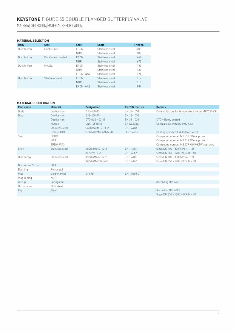
MATERIAL SPECIFICATIONPart name Material Designation EN/DIN mat. no. RemarkBody Ductile iron GJS-400-15 EN JS-1030 Consult factory for temperature below -10°C (14°F)Disc Ductile iron GJS-400-15 EN JS-1030
Ductile iron CTD GJS-400-15 EN JS-1030 CTD = Epoxy coatedNiAlBz CuAl10Fe5Ni5 EN CC333G Comparable with BS 1400 AB2Stainless steel GX5CrNiMo19-11-2 EN 1.4408Uranus (B6) G-X2NiCrMoCuN25-20 DIN 1.4536 Casting quality (SEW 410) of 1.4539
Seat EPDM Compound number MS 512 FDA approvedNBR Compound number MS 511 FDA approvedEPDM-WA3 Compound number MS 539 KIWA/KTW approved
Shaft Stainless steel X5CrNiMo17-12-2 EN 1.4401 Sizes DN 100 - 300 (NPS 4 - 12)X17CrNi16-2 EN 1.4057 Sizes DN 350 - 1200 (NPS 14 - 48)
Disc screw Stainless steel X5CrNiMo17-12-2 EN 1.4401 Sizes DN 100 - 300 (NPS 4 - 12)X2CrNiMoN22-5-3 EN 1.4462 Sizes DN 350 - 1200 (NPS 14 - 48)
Disc screw O-ring NBRBushing PolyacetalPlug Carbon steel C45-QT EN 1.0503 QTPlug O-ring NBRCirclip Springsteel According DIN 472Dirt scraper NBR steelKey Steel According DIN 6885
Sizes DN 350 - 1200 (NPS 14 - 48)
KEYSTONE FIGURE 55 DOUBLE FLANGED BUTTERFLY VALVE MATERIAL SELECTION/MATERIAL SPECIFICATION
MATERIAL SELECTIONBody Disc Seat Shaft Trim no.Ductile iron Ductile iron EPDM Stainless steel 288
NBR Stainless steel 289Ductile iron Ductile iron coated EPDM Stainless steel 648
NBR Stainless steel 673Ductile iron NiAlBz EPDM Stainless steel 135
NBR Stainless steel 137EPDM-WA3 Stainless steel 774
Ductile iron Stainless steel EPDM Stainless steel 112NBR Stainless steel 116EPDM-WA3 Stainless steel 884

8
Neither Emerson, Emerson Automation Solutions, nor any of their affiliated entities assumes responsibility for the selection, use or maintenance of any product. Responsibility for proper selection, use, and maintenance of any product remains solely with the purchaser and end user.
Keystone is a mark owned by one of the companies in the Emerson Automation Solutions business unit of Emerson Electric Co. Emerson Automation Solutions, Emerson and the Emerson logo are trademarks and service marks of Emerson Electric Co. All other marks are the property of their respective owners.
The contents of this publication are presented for informational purposes only, and while every effort has been made to ensure their accuracy, they are not to be construed as warranties or guarantees, express or implied, regarding the products or services described herein or their use or applicability. All sales are governed by our terms and conditions, which are available upon request. We reserve the right to modify or improve the designs or specifications of such products at any time without notice.
Emerson.com/FinalControl
Related Documents