o u. tr ^- Q O K O a a. o 1 n o 05 I CD V) W PROJECT 03-1118-ooe RECORD OF BOREHOLE: 03-01 SHEET i OF i LOCATION: 5334209.62 N . 513229 21 E BORING DATE: APRIL 3, 2003 DATUM Geodetic SAMPLER HAMMER, 64kg, DROP. 760mm PENETRATION TEST HAMMER, 64kg: DROP, 760mm UJ < rn Ou Q-5 S . ' . ' . ' - - 6 - 7 8 9 10 11 12 Q O ^ UJ 5 0 Z tr 8 t u t l n ' UJ c g - i C ; SOIL PROFILE DESCRIPTION GROUND SURFACE Dark brown fibrous PEAT : (ORGANIC) \ - Dark to lighl brown SILT, some sand (GLACIO-FLUV1AL) Light brown varved SILTY CLAY, trace fine sand (GLACIO- LACUSTRINE) Very soft, grey varved SILTY CLAY, trace fine sand - (GLACIO-LACUSTRINE) ; ; ji T END OF BOREHOLE f~/ Notes: /* C 1 . Borehole dry upon completionX, ^ 2. Piezometer 19mm l. D. pvc, stickupV. 1.14m. 3. Water level in piezometer at 2.50m "* April 9. 2003 ^i ,#t***'****i *^f \\ ^ X X /' *' XV t- : ^ ELEV J DE PT - (m) w 272.06 Z O.I -^ 271 fi 04 271 09 0.9 '' 26896 ', 3.1 a5S 36 r^ f j"*"™** "x. * x 7 SAMPLES or UJ ac *- 2 3 4 5 6 ^ X UJ c h- 5 DO 50 DO TO SO DO 50 DO 50 00 y e g \ a 4 PH WH f* HH WR DYNAMIC PENETRATION N RESISTANCE. BLOWS/0 3m L v 20 40 60 80 SHEAR STRENGTH nat V + Q - 1 Cu, kPa rem V © U - C 10 20 30 40 9 e e e •^^. ^C"*"*- \ V e ^ e ^^ * ^•^. ^*ts 7y 1 -t- /* x. ^*~f ***/ r * : , ? /' X"'^ "vv ^ * jy f 'H, \. X/ . l Illlll Hill Illlll llll III II III llll II Illlll Hill Hill Hill Hill Hill Hill Hill Hill HIM III l llll Illlll III Illlll llll Hill II III II II Illlll Hill Hill III II Hill Hill Hill Hill Hill llll llll llll l Illlll Hill Illlll llll IIIHIIIIIIIIIIIIIII Hill Illllilllllll Hill Hill Hill fill Hill llll llll 42A10SW2031 2.25803 GERMAN 010 HYDRAULIC CONDUCTIVITY, k. cm/s 10* 10 s 1C"1 10 1 V W VATER CONTENT PERCENT Pi —————— 8^ ———— 1 "" Wl 20 40 60 80 f ^ # z F GE Off*, f f / ^K x 0 ; E j SCI v ^S \ 2 wl N NO n ^ " o o 5 EI 1 AS FICI 8 /E oo: ES! ^ g 5 0 c ME PIEZOMETER OR STANDPIPE INSTALLATION BE 1 1 " H 1 ' NTONITE SEAL 1 1 1 B~ H H ~ 1 1 ' J" Piezo -^- S l CLt (April 9, 2003) j J - i ' - r : V BACKFILL . 5 ; ' 3 ' i l ; ! 5 " 5 - 5 - i l 1 Q- P M M ENTONITE SEAL 1 1- EZOMETERTIP \".-9",-\ - AND FILTER | •'•'-] r.-fVi ' - - i " - 3 T ^^Bk : - ~ - - - DEPTH SCALE ^SBBL~i f j LOGGED: ES 1 : so ^dissociates CHECKED: DGR

Welcome message from author
This document is posted to help you gain knowledge. Please leave a comment to let me know what you think about it! Share it to your friends and learn new things together.
Transcript

ou.
tr
^-QO
KO
a
a.o
1n o05ICD
V)W
PROJECT 03-1118-ooe RECORD OF BOREHOLE: 03-01 SHEET i OF i
LOCATION: 5334209.62 N . 513229 21 E BORING DATE: APRIL 3, 2003 DATUM Geodetic
SAMPLER HAMMER, 64kg, DROP. 760mm PENETRATION TEST HAMMER, 64kg: DROP, 760mm
UJ< rnOu
Q-5
S
.'
.'
.'-
- 6
- 7
8
9
10
11
12
Q O
^UJ50Ztr8
tut
ln '
UJ cg -iC
;
SOIL PROFILE
DESCRIPTION
GROUND SURFACE
Dark brown fibrous PEAT :(ORGANIC) \
-Dark to lighl brown SILT, some sand(GLACIO-FLUV1AL)
Light brown varved SILTY CLAY, tracefine sand(GLACIO- LACUSTRINE)
Very soft, grey varved SILTY CLAY, trace fine sand -(GLACIO-LACUSTRINE) ;
;
ji
TEND OF BOREHOLE f~/
Notes: /* C1 . Borehole dry upon completionX, ^ 2. Piezometer 19mm l. D. pvc, stickupV.1.14m.3. Water level in piezometer at 2.50m "*April 9. 2003
i,#t***'****i* f
\\ X X /' *'XV
t-:^ ELEV
J DE PT- (m)w
272.06Z O.I
-^ 271 fi04
271 090.9
'' 26896
', 3.1
a5S 36r^f j"*"™**"x.
* x 7
SAMPLES
orUJac
*-
2
3
4
5
6
^
X
UJch-
5DO
50 DO
TO
SODO
50 DO
50 00
y
e g\a
4
PH
WH
f*
HH
WR
DYNAMIC PENETRATION N RESISTANCE. BLOWS/0 3m L
v20 40 60 80
SHEAR STRENGTH nat V + Q - 1 Cu, kPa rem V © U - C
10 20 30 40
9
e
e
e•^^.
^C"*"*-
\
Ve ^
e
^^
*
^•^.^*ts
7y
1
-t-
/*
x.
^*~f***/
r
* :
,?/'
X"'^"vv
^
*
jy f'H,
\.X/
.
l Illlll Hill Illlll llll III II III llll II Illlll Hill Hill Hill Hill Hill Hill Hill Hill HIM III l llll
Illlll III Illlll llll Hill II III II II Illlll Hill Hill III II Hill Hill Hill Hill Hill llll llll lllll Illlll Hill Illlll llll IIIHIIIIIIIIIIIIIII Hill Illllilllllll Hill Hill Hill fill Hill llll llll42A10SW2031 2.25803 GERMAN 010
HYDRAULIC CONDUCTIVITY, k. cm/s
10* 10 s 1C"1 10 1
V
W
VATER CONTENT PERCENT
Pi —————— 8^ ———— 1 ""Wl
20 40 60 80
f
^ #
zF
GE
Off*,
ff /
^K
x
0 ;
Ej
SCI
vS
\
2wl
N
NOn
"
o
o
5EI
1AS
FICI
8/Eoo:ES!
^
g5
0
cME
PIEZOMETEROR
STANDPIPE INSTALLATION
BE
1 1 "H 1 '
NTONITE SEAL 1 1
1 B~H H ~1 1 '
J"Piezo -^- S l
CLt
(April 9, 2003) j J -i ' -r:
V BACKFILL . 5 ;
' 3 '
i l ;
! 5 "5 -5 -i l1 Q-
PM M
ENTONITE SEAL 1 1-
EZOMETERTIP \".-9",-\ -AND FILTER | •'•'-]r.-fVi '
-
-i"
-
3
T
^^Bk
:-~---
DEPTH SCALE ^SBBL~i f j LOGGED: ES
1 : so ^dissociates CHECKED: DGR

oLL,-)
S(fi
t-DOzo orooo!oCOooCO
CO
toImto'CO
PROJECT: 03-1118-008 RECORD OF BOREHOLE: 03-02 SHEET 1 OF 3LOCATION: 5384050 42 N . 513226 93 E BORING DATE: APRIL 4.5&15. 2003 DATUM: Geodetic
SAMPLER HAMMER, 64kg; DROP. 760mm
UJ
DEPTH SCAl METRES
- 0
;
.
- 1
:
.'-
- 2
;
-- 3
— 4
— 5
- 6
- 7
— a
— 9
— 10
— n
QO
ORING METH
m
ei
U)ffiUJOra<
5
o
xQ
D
SOIL PROFILE
DESCRIPTION
GROUND SURFACE
Dark brown fibrous PEAT :(ORGANIC) :
\
\:
^,;;
;j;-
Loose to compact, grey SILT, trace finesand with occasional fine sand seams(GLACIO-FLIMAL)
Stiff to very soft, grey SILTY CLAY, trace j fine sand with occasional silt seams ' (GLACIO-FLLMAL) ;
;;
\ m
5i ELEV
5 DEPTH5 (f"l/i
272 1
'5 0 0
25
;f
zzIB'•z
^. 270201 98
26928- ^ 2 90
; ;
;;
j;ywffimkVYfjftWAWMWwijjji
/"^m\J*" ^* KKfyElS Jf^1™**
iff. Pj^KaH
^^^^^^••f|H^^"
.//^\\ Hs. x. J 1 ^^s. x/ x sv\/
;;;
'
;;;
^ J
CONTINUED NEXT PACE
i!
j',
\;
j;;
PENETRATION TEST HAMMER, 64kg: DROP, 760m
SAMPLES
NUMBER
1
2
3a
3b
4
S
6
7
N
B
9
0
UJ Q.t-
50 DO
50 DO
50 DO
50DO
50 DO
50 DO
50^
DO
50 DO
y50 DO
50 DO
SO DO
LOWS/0 3m
CD
21
2
2
10
9
S
WR
WR
INK
WR
DYNAMIC PENETRATION N RESISTANCE. BLOWS/0 3m ^
20 40 60 80 i i
SHEAR STRENGTH nal V + Q - * Cu. kPa rem V ffi U - O
10 20 30 40
a
r^\\,X"~e \
e
e
e
s
e
e
*?' y\J*
*
-i
j,/
\
"*"*!
^
"l"
j"Sr
,/J1*'
V j•C' N
±
/X ?
X
HYDRAULIC CONDUCTIVITY, -r k cm/s
10* 10 s 10"1 10 1 i
W
wATER CONTENT PERCE p, —————— eiV ———— ,
.NT
Wl
20 40 60 80
/*
V
1
Xs•f'/x *"
x
3
O
V
X'x \?"V,'
c
0
o
o
610
440
569
j0 PIEZOMETER OR
STANDPIPE INSTALLATION
|~|
l
f
ROUT
DEPTH SCALE ^HB*-. 1J LOGGED: ESf MMF Golder1 : 60 ^^UTtVSSOCiiVtCS CHECKED: DGR
m
I .
\
.~-
-.
:.~.:
-
-
-
-
-
'-
_-.-'-
.:-'~
O H.
1(O
K Oo•z.0cr3O-i Q.O
1CO
tfjICDWCO
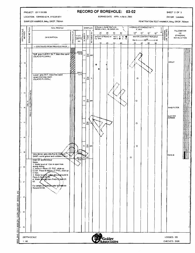
PROJECT: 03-1118-008 RECORD OF BOREHOLE: 03-02 SHEET 2 OF 3LOCATION: 5384050 42 N . 513226 93 E BORING DATE: APRIL 4.5&15. 2003 DATUM: Geodetic
SAMPLER HAMMER. 64kg; DROP. 760mm
LU
DEPTH SCAL METRES
:
-
-
13
::
~ 14
.
- 16
- 17
— 18
— 19
— 20
— 21
— 22
- 23
24
8ORINGMETh
m
S
O
Cflo:EM AUGf
wscciq
1
SOIL PROFILE
DESCRIPTION
— CONTINUED FROM PREVIOUS PAGE —
Soft grey CLAYEY SILT, trace fine sand ,(GLACIO-FLUVIAL)
,
Loose, grey SILT, trace fine sand occasional day seam (GLACIO-FLUVIAL)
X/f ./'
Very dense, grey silty fine to me&um "V^ - SAND, some gravel and cobbles ff*lt,L) **
END OF BOREHOLE SNotes:1. Water level at 1.5m in open holeduring drilling.2. Piezo A 19mm I.D. PVC. stick-up0.73m. Piezo B 50mm I.D PVC, stick-up0.70m. X**"~^*X.3. Water lev^at I^JSsiaboveaflround *nPiezo A Aprif^S/Oa. ^v \ 4. Water JBwja6 from Piezo 6,,ApS| 25,03. f SL \ f
For detailso^Qrillhoferefer lgt)rilfrole Record 03-8A ^,^ ^,/ Jf"X, . "'~
7
i ELEVJ DEPTH - (m)
en
2598412.34
2584137
^
:" 25313
4 252 73•t, 19.45
SAMPLES
IUMBER
11
12
13
14
15
""S
*x16
UJ 0.
50DO
50 DO
50 DO
50 DO
50 DO
AS
LOWS/0 3m
m
WR
5
WR
,-
\
WR
PENETRATION TEST HAMMER, 64kg; DROP, 760mm
DYNAMIC PENETRATION ^ RESISTANCE. BLOWS/0 3m ^
20 40 60 80 i i
SHEAR STRENGTH nat V + Q - * Cu kPa fern V ® U - O
10 20 30 40
ee
^x*****
V^/"\V*
t/"
^
^
x y.ir
X/
^N
J\
?
""X
S/
HYDRAULIC CONDUCTIVITY. T k. cm/s
10* 10 s 10"1 10 !
W
W
ATER CONTENT PERCE
PI ————— g* ———— lNT
Wl
20 40 60 60
si, f
o
/*
f f
\'"\
O
0
o
o
P"
\J?"
liPIEZOMETER
OR STANDPIPE
INSTALLATION
GROUT
SAND FILTER
LOTTEDGREEN
EZOB
-
-
-
l—
~-
--
]-
-
;
7
;
-
-
^--.-
.
-
'
-|
-
-
-
-
.^E8kDEPTH SCALE /•Hi/-' M*- LOGGED: ES
m ^^B|B^ \2f\JAQjCr1 '60 ^ A ccffc.ojcfc^'fto CHECKED' DGR

PROJECT: 03-1118-008
LOCATION:
INCLINATION: -90' AZIMUTH:
RECORD OF DRILLHOLE: 03-02DRILLING DATE: APRIL 4.5&15. 2003
SHEET 3 OF 3
DATUM
DRILLING CONTRACTOR: ALL-TERRAIN DRILLING
PTH SCA METRES
DESCRIPTIONELEV
DEPTH (m)
FR/FX-FRACTUREF-FAULT SM-SMOOTH FL-FLEXURED BC-BROKEN~CORI
CL-CLEAVAGE JJOINT R-ROUGH UE-UNEVEN MB-MECM BREAK
SH-SHEAR P-POL1SHED ST-STEPPED W-WAVY B-6EDDING
VN-VEIN S-SLICKENSIDED PL-PLANAR C-CURVED
RECOVERYRQO
FRACT INDEX
PER O 3
DISCONTINUITY DATA
TYPE AND SURFACE ASCRIPTION
HYDRAULIC CONDUCTIVITY
K cm/see f -? T -? o o o o
NOTESWATER LEVELS
INSTRUMENTATION
Light to medium grey, thin bedded SILTSTONE/ARGILLITE. Occasional cleavage plane along bedding with servicite slippage, minor irregular quartz vein/trace pyrite
END OF DRILLHOLE
..t** f
of of
8|- 29 tX
SRJ& jfo
ol ol K! DEPTH SCALE
1 :50
LOGGED: ES
CHECKED: DGR

D311 18008 GPJ GLDR CAN.GOT 30/5/03 JFC
wI m
lCOto
PROJECT 03-1118-oos RECORD OF BOREHOLE: 03-03B SHEET i OF 1LOCATION: 5383994.73 N . 512721 .54 E BORING DATE: APRIL 16. 2003 DATUM: Geodetic
SAMPLER HAMMER. 64kg; DROP. 760mm PENETRATION TEST HAMMER. 64kg: DROP. 760mm
DEPTH SCALE METRES
- 2
- 3
- 4
- S
- 6
- 7
— 8
— 9
— 10
— 11
— 12
BORING METHOD
CME-75
1 0Bmm I.D. HOLLOW STEM AUGERS
SOIL PROFILE
DESCRIPTION
GROUND SURFACE
Dark brown fibrous PEAT ; (ORGANIC) \
Loose, light brown SILT, some fine sand (GLACIO-FLUVIAL)
Stiff to firm very soft, with depth grey and ' light grey varved SILTY CLAY, trace fine sand (GLACIO-LACUSTRINE)
//
Soft, grey layered CLAYEY SILT, trace fine sand (GLACIO-FLUVIAL)
Compac/gr^SANDYSILT 1"! :
Very dense, fine to medium SAND, — some silt, trace gravel and cobbles t
UTILL) lEND OF BOREHOLE
Notes: 1. Water level in piezometer at 1.22m during drilling. 2. Piezometer 32mm I.D. pvc, stick-up 0.6m 3. Water level in piezometer at 1 .2m below ground surface April 23. 2003
5 ^ ELEVt DEPTH- (m) ft
27582-~ 000
~Z 275370.45
27460j 1.22
h, , ,jrf-*
266968W
26576
1013
SAMPLES
NUMBER
l
2
3
4
5
6
X"N,
7
6
9
ai-
50 DO
50 DO
50 DO
50 DO
50^ DO
50 DO
y
50 DO
50 DO
50 DO
BLOWS /03m
2
e
4
1
r
i
3
10
50
DYNAMIC PENETRATION S RESISTANCE BLOWS/0 3m ^
20 40 60 80
SHEAR STRENGTH nat V 4- Q - * Cu. kPa rem V ® U - O
10 20 30 40
e
e H
e
v ^X
e
e
e
"--^
^ *.
-i
^
/y
x/4,
\
7
HYDRAULIC CONDUCTIVITY, T k, cm/s
10* 10 s 10J 10'
VI
W
0
x/
o
ATER CONTENT PERCE
'0 40 60
/' f*"\.
•x"i,
l
o
\
0
>
0
o
NT
Wl
JO
1(O oli
PIEZOMETER OR
STANDPIPE INSTALLATION
BENTONITE SEAL 1
Piezo 1 21
(April 23. 2003)1
i iN
CLAY BACKFILL '
ENTONITE SEAL 1
AND FILTER K
LOTTED GREEN
^I'l-
.
-
DEPTH SCALE t^KDr* JJ LOGGED: ES

oLL
en9LO
QOZO
o:Q-j oQ.0
SCOIm wCO
PROJECT 03-1118-008 RECORD OF BOREHOLE: 03-04 SHEET 1 OF 2LOCATION: 5384378 89 N , 513254.13 E BORING DATE: APRIL 16, 2003 DATUM Geodetic
SAMPLER HAMMER. 64kg; DROP. 760mm
uu
wi0.5LU O
- 0-.-
.1
:
:2
- 3
- 4
- S
- 6
- 7
— 8
— 9
— 10
— 11
— 12
ost—LUSo
CD
sCJ
ciC
5H
!co—
1s
SOIL PROFILE
DESCRIPTION
GROUND SURFACE
Dark brown fibrous PEAT :z
Light brown silty fine SANDSoft to firm, light brown SILTY CLAY.trace fine sand occasional fine sand andsilt seams(GLACIO-FLLMAL)
Very soft to soft, grey SILTY CLAY, tracefine sand occasional sand and siltseams(GLACIO-LACUSTRINE)
,5; ""* S
f
/ t? '
,/ f\;N
/vl^'X/* ff "^ ^
X, Hx j lVery soft, gTtevlaylh^ CLAY.6Y SILT,trace fine sandx Vi\ , ' X (GLACIO-LACUS'nSiNEf' ,'
v-.,'*
Loose, grey SILT, trace to some finesand, with occasional clay seams(GLACIO-FLUVIAL)
CONTINUED NEXT PAGE
—
;^ ELEV
5 DEPTH - (m)n
272.22~ 000^Z 271 96
0304
; 27028' 1 98
\
\\^e***"
:?t''-*IR^
^
263.129.14
261.5910.67
PENETRATION TEST HAMMER, 64kg, DROP. 760mm
SAMPLES
o:UJ CD5
Z
2
3
4
5
G
——
7
*"V
•v.
B
9
to
UJ Q.
AS
50 DO
50DO
50 DO
SO DO
SOj DO
50 DO
"?
SO DO
50 DO
SODO
6
S
C 0
4
5
4
13
WH
/•*
Prf
\
WR
WH
WR
5
DYNAMIC PENETRATION ^\ RESISTANCE. BLOWS/0 3m ^
20 40 60 80
SHEAR STRENGTH nat V 4- O - i Cu, kPa rem V ffi U - O
10 20 30 40
e
e
xV ST-
\\
e
e
e
'**-''*-fe*/ j*,"~*~S"1 "
V
-t
,
;/
/*"*t|*:X
"*"
.^.
/*\t
Vf
x
'?f
"X.N/
HYDRAULIC CONDUCTIVITY, T k, cm/s
10* 10 ! 10J 10 !
(A
W
/ATER CONTENT PERCE
P l —————— ©^ ———— l
NT
Wl
20 40 60 BO
/'
4^ 4'
/*\
/' ^^ ^
X•e^, NX
o
l ——
(
o
x,Nv
o
—— IO
V
S
-o
o
< -^
tt
1
PIEZOMETEROR
STANDPIPE INSTALLATION
-
-
5April 16. 2003
-
-j
'.
~
—i-
-
-~
.
:-
;^^B^
DEPTH SCALE fllHffinllllM- LOGGED: ES
1 "60 ^^^ES^/V C*CfV* i 5\ frf*C. CHECKED" DGR

ou.
CO
1o o
o a ooa.a
SCOI mCO CO
PROJECT 03-1118-008 RECORD OF BOREHOLE: 03-04 SHEET 2 OF 2LOCATION. 53B4378 89 N .513254.13 E BORING DATE: APRIL 16. 2003 DATUM: Geodetic
SAMPLER HAMMER. 64kg: DROP, 760mm
DEPTH SCALE
METRES
- 12
- 13
- 14
- 15
- 16
- 17
- 18
- 19
— 20
— 21
— 22
— 23
24
BORING METHOD
STEM AUGERS
i cc
S
SOIL PROFILE
DESCRIPTION
— CONTINUED FROM PREVIOUS PAGE —
Loose, grey SILT, trace to some fine sand, with occasional clay seams (GLACIO-FLUV1AL)
END OF BOREHOLE
Notes: 1 .Water level at 6. 1 m in open hole at completion of drilling. 2 Surface water seeping into hole during drilling.
/V "'""•s.^ "' V
f'"'~"" ""'"'•*v
f l \ \
^"^y
3 ^ ELEVJ DEPTH- (m) n
256.9415.32
-sV
'f
X/'
SAMPLES
| NUMBER
11
12
TT
Nx,
fft
60 DO
TO
50•oe-
I BLOWS/0. 3m
WR
PH
50/-o-
\
DYNAMIC PENETRATION ^ RESISTANCE. BLOWS/0 3m ^
20 40 60 80i t i
SHEAR STRENGTH nat V + Q - * Cu. kPa rem V. ffi U - O
10 20 30 40
^
*-^
y/V
xK
/y
"N7\,
PENETRATION TEST HAMMER. 64kg: DROP. 760mm
HYDRAULIC CONDUCTIVITY, T k. cm/s
10* 10 s 10' 10 !
V\
W
7 V
ATER CONTENT PERCE
pi —————— 6^ ———— l
•0 40 60
f
'X
o
r
\N>
NT
Wl
iO
IIII
PIEZOMETER OR
STANDPIPE INSTALLATION
;
-;
;-
.
-
-
-
;
^
':
-
j
-
-
-
DEPTH SCALE Wm^fdfH^r LOGGED: ES

ou.
1mt— 00Z
OccQ
O
Q?O
g OCD
CO
toxCD
Ww
PROJECT 03-1118-ooa RECORD OF BOREHOLE: 03-06 SHEET 1 OF 3
LOCATION: 5384370.36 N , 513193 99 E BORING DATE: APRIL 1-2. 2003 DATUM: Geodetic
SAMPLER HAMMER, 64kg; DROP, 760mm
LLJ
i!UJ Q
.
\-
:.~ '.;- 2
- 3
7 4
- 5
- 6
- 7
— 8
— 9
10
It
12
8I i— UJ
0 z o: Om
u trLI
is
n W
J "
1 ri
J"~
SOIL PROFILE
DESCRIPTION
GROUND SURFACE
Dark brown fibrous PEAT ~
\Very loose, dark brown SILT, some finesand, trace organics
Firm, light brown varved silty CLAY.trace fine sand(GLACIO-LACUSTRINE)
becoming grey at 1.83m
fi/v
'•'-.., "^1
/' /'"" ""'X \
,/ f ''i \\. *"'''^- ':- }X.X. /r/
Very loose to loose^|LT, Ifac^fo somefine sand, occasional clta^ se^ms (GLACIO-FLUV1AL) X'
CONTINUED A/EXT PACE
go- ELEV5 DEPTH 2 (m)LO
27234:s oo
-^ 271 804
271 1122
27051 8
\
1', j^^
/^
^^:..
^"-, f
26290944
SAMPLES
o:LLm
2
1
2
3
4
5
——
——
6
^
V.
7
8
9
UJ
1—
SO DO
50 DO
50DO
50DO
TO
50DO
V./*
TO
SODO
50 DO
E
fd3
5
7
1
r
\
t
PM
3
2
PENETRATION TEST HAMMER. 64kg; DROP. 760mm
DYNAMIC PENETRATION N RESISTANCE BLOWS/0 3m i^
20 40 SO BO
SHEAR STRENGTH nal V + Q- t Cu. kPa rem V ffi U - O
10 20 30 40
e
1^
.\\. \
\9\
e
e
e
e
9
e
e
4
**-*.
^* f^ ^
fff
\ *fV
±
+
^
'""^a
^^
^x/sxx/
HYDRAULIC CONDUCTIVITY, T k. cm/s
10* 10' 10^ 10' L
\A
W
/A TER CONTENT PERCE Pi —————— O®- ———— l
NT
W1
20 40 60 80
**
'v~?'
S•'"' cr'V
0
o
os*
\\
c
sVT
o
o
-.0
liPIEZOMETER
ORSTAMDPIPE
INSTALLATION
1 1 [1 1
1 1 :BENTONITE SEAL H H
1 1 '1 1 '
li.
i!islif'i:
ROUT
; i;;
1li 1
: l
•i;
1
1-
-
.
—--
I
—
.
-:-
'.
;
.~
-'~
.-'
-
:-.
jtea^DEPTH SCALE /IHHP/^ tA LOGGED ESl '•B^r ^jQluCr1 ' 60 ^^^^rjVv^OFJj^C*^ CHECKED: DGR

oLL.
CO
1Haozoor o—ioCL0
8
COImCOCO
PROJECT: 03-H18-008 RECORD OF BOREHOLE: 03-06 SHEET 2 OF 3LOCATION. 5384370. 36 N. 513193.99 E
SAMPLER HAMMER. 64kg: DROP, 760mm
UJ
5ftDEPTH S METR
- 12
-
'
.
— 14
- 15
- 16
- 17
- 18
- 19
— 20
— 21
— 22
— 23
— 24
8iH LUORING M
m
o
io
in a:u. C4
1W
5ccp
CDo
SOIL PROFILE
DESCRIPTION
— CONTINUED FROM PREVIOUS PAGE —
Very loose to loose. SILT, trace lo somefine sand, occasional clay seams(GLACIO-FLLMAL)
Loose to compact, grey SILT, trace finesand, some gravel, trace to some finesand and occasional clay seams below 17.83m(GLACIO-FLUVIAL)
;/'f
J ^""v^
//•""••x'N/' f* ^
*V "'X, 1 l"X "X. /' /""X '"" f
Loose, layered fine to medium SAND, trace gravel trace silt (TILL)
CONTINUED NEXT PAGE
— 3rf ELEV
5 DEPTH f (m)t/i
255121722
)H^
:' ^
''"'S
249462286
2485723 77
SAMPLES
NUMBEF
10
li
12
——
13
14
X
^
15
IE
17
UJ O.
50 DO
50 DO
50 DO
50 DO
50 DO
y
50 DO
50 DO
50 DO
Enows/o :
OJ
4
WH
4
\
16
5
16
7
BORING DATE: APRIL 1-2. 2003 DATUM: Geodetic
PENETRATION TEST HAMMER, 64kg: DROP. 760mm
DYNAMIC PENETRATION ^\ RESISTANCE BLOWS'0 3m i^
20 40 60 BO
SHEAR STRENGTH nal V + Q-* Cu. kPa rem V ffi U - O
10 20 30 40
*\
V
\
DEPTH SCALE fm
1 :60 ^j
v\l/
/tN
^
\/•^
4
?"X/
HYDRAULIC CONDUCTIVITY, T k, cnVs
10* 10 ! 10 4 10'
^
W
ATER CONTENT PERCE p l —————— O^ ———— l
NT
W!
20 40 60 60
V
c
f2
o
o
D
0
O
O
f
x>
O
Oto
MH
MH
MH
PIEZOMETER OR
STANDPIPE INSTALLATION
GROUT
ATIVE BACKFILL
-
~
' -
-
—
H|
mf Gc .j LOGGED: EStlderXASSOCiateS CHECKED: DGR

ou.—3
m
1t—QOZ
0E3o0.o
len owI mwCO
PROJECT 03-1118-008 RECORD OF BOREHOLE: 03-06 SHEET 3 OF 3LOCATION: 5384370.36 N , 513193.99 E BORING DATE: APRIL 1-2, 2003 DATUM: Geodetic
SAMPLER HAMMER, 64kg: DROP, 760mm
UJ
DEPTH SCf METRES
- 24-'
'
— 25
i\- 26
- 27
- 28
- 29
- 30
- 31
- 32
— 33
— 34
— 35
— 36
O 0xt-LU5 0z
m
n
io
OLUJC•c sw3ccQ
iES*~
SOIL PROFILE
DESCRIPTION
— CONTINUED FROM PREVIOUS PAGE —
Very dense, layered fine to medium iSAND, some gravel trace silt andcobbles (TILL)
',
;
i
; t' H1 '
i ,
• !
e
/' /' '
''"V. i -
"r, ••
'\
^^z,^END OF BORptfOLE ""N^
Notes: /* f N. \1 . Water^vejA 5.5m in operlfioli on completion of 3fi|Jipg. l '2. Moniloraljwell'^mm I.D.^vcistick-up 0.91nt-t -^ /' /' 3. Water level non*cordS*fn /piezometer due to acfcs^s dit|6jlties.
D
J ELEV
J DEPTH - (m)ft
!
5
\
'*
'
- '
|
11
1
|
1
|
1 l
v ,- -'"""-^
1
^^^
2399632.38
SAMPLES
NUMBER
,a
19
20
21
22•*n
X
23
UJ 0.
50 DO
50 DO
50 DO
SODO
50DO
7
50 DO
LOWS/0 3m
m
so/05
30/ 03
SO/ .1
^*
^'S
52/02
SO/02
501 025
PENETRATION TEST HAMMER. 64kg: DROP. 760mm
DYNAMIC PENETRATION ^ RESISTANCE. BLOWS/0 3m i
20 40 60 80 i i i
SHEAR STRENGTH nat V + Q - * Cu, kPa rem V ® U - O
10 20 30 40
"•*o*^
\\1
^\ ^
\
*a***!*a**fc,
•*Hsv,
,* r J^
"ji /f
C^
^^^sp
v^ty vs 3
\N
7x/
HYDRAULIC CONDUCTIVITY. — k, cm/s
10^ 10 s 10J 10J
V\
W
/ATER CONTENT PERCE
pi —————— e^ ———— l
NT
W!
20 40 60 80
O
Xs/
o
c
(
o
/*
f /
r\
s*
\\>V
OK
II
MH
MH
MM
PIEZOMETEROR
STANDPIPE INSTALLATION
||
l
jl
l
l (
]
|
j
i
j
NATIVE BACKFILL ji lii i ii
|
!1jl
iSAND FILTER
LOTTEDGREEN
\
--
:-
'.
-
'.
;
-
;—
'.
* —
- -' '
; ; ;
.;-
'\ —
•;* -\ \
-
;'.
.~
;-
;-—.~--
-
^^•kDEPTH SCALE M^^tir' 1A LOGGED ESi ^jBMr ^jvmicr1 : 60 V^^VsSOCiatCS CHECKED: DGR

oU-
rogoro
Q0Z
otro0
Q.OOD
1
8C/)X03
1WW
PROJECT 03-1118-008 RECORD OF BOREHOLE: 03-07 SHEET 1 OF 1LOCATION. 53841 13.52 N, 512786. 51 E BORING DATE: APRIL 3, 2003 DATUM Geodetic
SAMPLER HAMMER, 64kg, DROP. 760mm
LU
< inD m
aSUJQ
- 0
'.
.
'.
- 1
- 2
-
~ 3
— 4
— 5
- 6
— 7
— 8
— 9
— 10
— 11
— 12
8Ii— UJ
OR ING
CD
Ut
O
CI (EUJc:
\Gt—w
C
CIQ
I
SOIL PROFILE
DESCRIPTION
GROUND SURFACE
Dark brown fibrous PEAT -:(ORGANIC) ::
Z:
;[?\
Stiff, brown varved SILTY CLAY, trace \ \ fine sand ; ; (GLACIO-LACUSTRINE) ;;
becoming soft to very soft and grey at ; ;2.13m. '/,
''/,
; ^
; ;END OF BOREHOLE
Notes:1. Piezometer 19mm l. D. PVC. stick-up1.52m. /' ,i2 Hole dry upon completion of drilling X
^-,., "'* K j
/" s-"*""-' :. , *\
'"' /' '"''^s x
V Vvt } l\v.. *^w;7 /'"\ -*fi'
"
3
^ ELEVJ DEPTH - (m)n
274 92;^ 0 00~^
:^yi
Vi 27375* 1 17
' 272.79. 2.13
;:
; ;'t \'/,
/:
|^ ;
; ;
'/,''t \','* 269 02
610
^' 'i
\
i 1"""
/'
PENETRATION TEST HAMMER. 64kg: DROP. 760mm
SAMPLES
o:LUmS
i
2
3
4
5
sx
LU 0-
50 00
50 DO
50 DO
50 DO
50 DO
y
1eOm
10
6
2
WR
\
WR
DYNAMIC PENETRATION 'N RESISTANCE, BLOWS/0 3m ^
^20 40 60 80
SHEAR STRENGTH nal V + Q-* Cu, kPa rem V ffi U - O
10 20 30 40
e
9
e
\', \,
"^
"' ,/"
\f
+ O Q
K'?
4J
^
'"~*
,i*V
f^
.f\/'
4
\^
80^
^V r ^fe
7,/xN.
HYDRAULIC CONDUCTIVITY. T k. cm/s
10^ 10 5 10 J 10'
W
W
ATER CONTENT PERCE Pi —————— ©^ ———— l
NT
Wl
20 40 60 80
y1
/S^r
'X
N.
#
\
N
0
>
O
o
605
gl
1
PIEZOMETEFOR
STANDPIPE INSTALLATION
BENTONITE SEAL 1
M M ^;jM M
CLAY BACKFILL ;
Piezo -^- M(April 9, 2003) f
8lg
BENTONITE SEAL B
FILTER SAND p
PIEZOMETER TIP TV
j^^^
DEPTH SCALE /•HPrf™' 1*1 LOGGED; ESl i^fjSj^F .VC^ICIO r1 ' 60 ^^^t2F\ 3 *S O f1 1 j\ f(*^ CHECKED DGR
1I-
hl -
lC [i -8 -g ':
1
1
-
;--
-
.
.—
.-".
-"
-
,
.-
-
-

ou-
gS en
Q OZ
uoro—joa.O
1
n
CO
0COCOS
PROJECT: 03-1118-008 RECORD OF BOREHOLE: 03-08 SHEET 1 OF 1LOCATION: 5383994.73 N . 512721.54 E BORING DATE: APRIL 1 1-13. 2003 DATUM: Geodetic
SAMPLER HAMMER. 64kg: DROP, 760mm
LU
fa,Uu;too:f w Q.SUJo
— 0
:-
;
- 1
:
r 3
— 4
5
- 6
7
— 8
— 9
— ID
— It
— 12
8i-LU
ORINGM
m
io
c/jcc.UJo3
13ooxQ
S
SOIL PROFILE
DESCRIPTION
GROUND SURFACE
Dark brown fibrous PEAT :\IORGANIC) /Firm to stiff, brown varved SILTY CLAY.trace fine sand(GLACIO-LACUSTRINE) ;
;
;
Firm to stiff, light brown and grey varved ;SILTY CLAY, trace fine sand occasional ;silt layers ;(GLACIO-LACUSTRINE) ;
Very loose lo loose, grey SILT, trace tosome fine sand occasional clay seams(GLACIO-FLUVIAL)
-"'' Vj' ,.-'*"-*.,v \
•C *X \ ;Loose to compact. gT*^SILTY*A*lD. some gravel ano^gbble^iTItt) /
**S. " r"*S. fEND OF BOREHOLE ^
Notes:1. Water level at 7 5m in open hole oncompletion of drilling2 Piezo A 19mm l. D. pvc, stick-up1 52m
g1 ELEV
5 DEPTH - (m)n
277 9-^ 0.0
01
275702.29
"' 273.274.72
"\
'": 'f ,.-..
\
268859 14
266249.75
SAMPLES
[T UJm5
1
2
3
4
5
6
7
s
B
9
UJ Q.
t-
50 DO
50 DO
50DO
5C DO
SO DO
50DO
50 DO
"**/
50 DO
50DO
ELows/o :
m
5
10
10
6
5
5
3
2
PENETRATION TEST HAMMER. 64kg. DROP, 760mm
DYNAMIC PENETRATION N, RESISTANCE BLOWS/0 3m L
v20 40 60 80
i iSHEAR STRENGTH nat V + Q-* Cu kPa rem V ffi U - O
10 20 30 40
S
"~""^,"^,.
V
^ \
\
b*s**t^*-*i,^•v-/* /*\\•v/
/
f 's**i^•'..,/
/^/"'^'*x 9
HYDRAULIC CONDUCTIVITY, T k, cm/s
10* 10' 10' 10 Ji i i i
V\
W
/ATER CONTENT PERCE
Pi —————— B& ———— 1
NT
Wl
20 40 60 80
^
O
Z./so
0
o
0
0
c
\
\s/
-.0
ZK
D
PIEZOMETEROR
STANDPIPE INSTALLATION
BENTONITE SEAL 1 1
SI
CLAY BACKFILL
'lezo A -*- (Apnl23.2003)
ri ., 5 5 sc5: S : \ :' *-t -
c .C;
:hli
Piezo A 5- H II-(Apnl 13.2003)H M
BENTONITE SEAL H H
m Hli
iCLAY BACKFILL i
iKO A 2 j(Apnl 12. 2003)
ENTONITE SEAL 1
i1fs
is-
iAND FILTER H M~
1EZOMETERTIP '^|H '
-
——
'
;-;-.~.,-
j-
^filftk
DEPTH SCALE ^s8BL"i i j LOGGED: ESi H^BB? \jvM-dor1 60 ^^^^^\ V^OfJj\l'f*V CHECKED: DGR

oU.
8int— Q0Z
Oo:Q
o
OJ
SWxm ww S
PROJECT 03-1118-008 RECORD OF BOREHOLE: 03-08A SHEET i OF 3LOCATION: 5383948.80 N, 512945.32 E BORING DATE: APRIL 11. 2003 DATUM Geodetic
SAMPLER HAMMER. 64kg; DROP. 760mm
LLJ-JM"O uj WQ;
a5UJD
- 0
1
.
- i
- 2
— 3
— 4
- 5
- 6
— 7
— 8
— 9
— 10
- 11
12
D OIt-LUSo5 0(D
ttG
LU
1 0I dEES
SOIL PROFILE
DESCRIPTION
GROUND SURFACE
Dark brown fibrous PEAT zSofl to stiff, reddish brown SILTY CLAY.trace fine sand(GLACIO-FLUV1AL)
Firm to stiff, light brown and grey varved ;SILTY CLAY, trace fine sand. Frequent \silt layering. ^ (GLACIO-LACUSTRINE) ;
Very loose to loose, grey SILT, trace tosome fine sand Occasion silt seams. (GLACIO-FLLMAL)
c x
/V"""'^, "N
4* "x, *'
"K, Nt ^ J
Very loose to vlty.jdensX.oWy sjjty fine to medium SAND, sbqie gravel^ndcobbles (TILL). \Z ,/
CONTINUED NEXT PAGE
51 ELEV
5 DEPTH - (m)/j
27S34-^ 0 00
01
27590244
'. 273 774.57
'j.
,.'"~"
269059.29
PENETRATION TEST HAMMER, 64kg; DROP, 760mm
SAMPLES
o:UJm
z
1
2
3
4
5
——
6
X
7
6
g
UJ Q.
50DO
50 DO
50DO
50DO
50 DO
50 DO
7
50 DO
50 DO
50DO
Sigm
3
6
10
5
f"
\
s
6
3
38
DYNAMIC PENETRATION N1 RESISTANCE, BLOWS/0 3m i
20 40 60 80
SHEAR STRENGTH nat V 4- Q-* Cu, kPa rem V ffi U - O
10 20 30 40
'"^*^
^\"
•*, \
\
j
©
**5*
' /"
\/'
^
\^
""?
'"*"
/yj\/^ :*^v
9f
9H...SNN/
HYDRAULIC CONDUCTIVITY, T k. cm/s
10 4 10' 10" 10 1
\A
v^
/ATER CONTENT PERCEP i ——— e1^1 —— i
NT
Wl
20 40 60 60
6
h
0
O
y
^
1 ——— "C
— 10
1 O
o
\ \
— 1
o
>
O w
II
MM
MM
PIEZOMETEROR
STANDPIPE INSTALLATION
I H H -r H "[J [J ~
in
Piez?APiezo B
GROUT
r
.~.-
~
'----.
~
^ENTONITE SEAL III'
1 1 l~
1 rH 1 [ | 'CREEN ; : ;
AND FILTER
•:-
1 1 -M -
—-
; :-
,- -
- -- ~-
^tej^DEPTH SCALE f^ttur^ l J LOGGED: ESI^HrGoldcr

oLL
h- QO Z
O
orQ
O
Q.O
18WT CD
lWW
PROJECT 03-1118-008 RECORD OF BOREHOLE: 03-08A SHEET i OF 3LOCATION: 5383948 80 N, 512945.32 E BORING DATE APRIL 11. 2003 DATUM: Geodetic
SAMPLER HAMMER. 64kg: DROP. 760mm
UJ
5S
aSsUJ D
'
~ 13
- H
— 16
- 17
- 18
— 19
— 20
— 21
— 22
23
24
8T. t—UJ
O-z. tr 0tn
in
ia
Wa:u.C
G(~
ccI c
l
SOIL PROFILE
DESCRIPTION f1
— CONTINUED FROM PREVIOUS PAGE —Very loose to very dense, grey silty fine i 1to medium SAND, some gravel and -cobbles (TILL). .
-,*1
'' i
i
4
' *
' 4
t
' f
'(
j
'
,
i .
END OF BOREHOLE /' , Notes: -C '•, 1 Piezometer A 19mm PVC. Piezometer v B 50mm pvc. lockable steel protective . casing at surface. 2. Water level in piezo A at 3.28m belowground surface on April 23. 2003.3. Water level in piezo B at 3.34m belowground surface on April 23, 2003
For details of DpHfioteTefeT^ Drillhole Record 03-8A^' ,x*""*,v N
^V **"*V ^ i
x^/
D
"- ELEV
l DEPTH - (m)o
Ji
.
;
i
L
i
1
i
i
i
i
r
, ^..K,
~"
SAMPLES
o:LJJmS D 2
10
11
12
-^
CL
50DO
50 DO
50 DO
f
E m
Oto
17
53
\
DYNAMIC PENETRATION ^ RESISTANCE, BLOWS/0 3m c^
20 40 60 80
SHEAR STRENGTH nat V. -(- Q-* Cu, kPa rem V ffi U - O
10 20 30 40
""**~*
\"*
\ \
\
•^,'7- #
\
/'\
7
./v^i" txX/
N
/xXN
PENETRATION TEST HAMMER, 64kg; DROP. 760mm
HYDRAULIC CONDUCTIVITY, T k, cm/s
10* 10 s 10J 10 1
W
W
ATER CONTENT PERCE
Pi ————— S^ ———— 1
NT
W1
20 40 60 80
0
XK/
0
o
fa
\^
^
\
\^
-j t3
lg
MH
PIEZOMETER OR
STANDPIPE INSTALLATION
SAND FILTER f-'
Jj|~
^H 1 -BENTONITE SEAL H | '
'/;
'.X
SAND FILTER
'S; ;
"^
•'.-'
*iezo A
i \
:-
;-
-
;
"li,
-j
;—
i
:-
*JM^
DEPTH SCALE g^fff^ ,,lAn. LOGGED: ESK ^^ff^r *jCMici*K r1 ' 60 ^^^f3F\ 5j5iOf* j S-jfPS CHECKED DGR
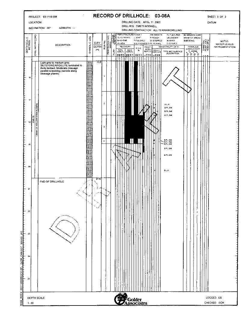
RECORD OF DRILLHOLE: 03-08APROJECT: 03-1118-008
LOCATION:
INCLINATION: -90" AZIMUTH
DRILLING DATE: APRIL 11. 2003
DRILL RIG: CME75 NODWELL
DRILLING CONTRACTOR: ALL-TERRAIN DRILLING
FR/FX-FRACTURE F-FAULT SM-SMOOTH CL-CLtAVAGE J-JOINT R-ROUGH SH-SHEAR P-POUSHED ST-STEPPED VN-VE1N S-SLICKENSIOED PL-PLANAR
FL-FLEXURED BC-BROKEN COR UE-UNEVEN MB-MECH BREAK
W-WAVY B-BEDDING C-CURVED
NOTESWATER LEVELS
INSTRUMENTATIONHYDRAULICCONDUCTIVITY
K cm/secTYPE AND SURFACE DESCRIPTION
Light grey to medium grey. SILTSTONE/ARGILLITE laminated to thinly bedded. Moderate cleavage parallel to bedding (sericite along cleavage planes)
B.PL.SM BPLSM B.PL.SM
END OF DRILLHOLE
LOGGED: ES
CHECKED DGR
DEPTH SCALE
1:50Golder
Associates

LIST OF ABBREVIATIONS
The abbreviations commonly employed on Records of Boreholes, on figures and in the text of the report are as follows:
L SAMPLE TYPE
AS Auger sampleBS Block sampleCS Chunk sampleDO Drive openDS Denison type sampleFS Foil sampleRC Rock coreSC Soil coreST Slotted tubeTO Thin-walled, openTP Thin-walled, pistonWS Wash sample
H. PENETRATION RESISTANCE
Standard Penetration Resistance (SPT), N:The number of blows by a 63.5 kg. (140 Ib.) hammer dropped 760 mm (30 in.) required to drive a 50 mm (2 in.) drive open sampler for a distance of 300 mm (12 in.).
Dynamic Penetration Resistance; Nd:The number of blows by a 63.5 kg (140 Ib.) hammer dropped 760 nun (30 in.) to drive uncased a 50 mm (2 in.) diameter, 60" cone attached to "A" size drill rods for a distance of 300 mm (12 in.).
PH: Sampler advanced by hydraulic pressure PM: Sampler advanced by manual pressure WH: Sampler advanced by static weight of hammer WR: Sampler advanced by weight of sampler and
rod
Piezo-Cone Penetration Test (CPT):An electronic cone penetrometer with a 60" conical tip and a projected end area of 10 cm2 pushed through ground at a penetration rate of 2 cm/s. Measure ments of tip resistance (Qt), porewater pressure (PWP) and friction along a sleeve are recorded electronically at 25 mm penetration intervals.
m. SOIL DESCRIPTION
(a) Cohesionless Soils
Density Index N(Relative Density) Blows/300 mm
Very looseLooseCompactDenseVery dense
(b)Consistency
Very softSoftFirmStiffVery stiffHard
Cohesive Soils
kPaOtol212 to 2525 to 5050 to 100100 to 200over 200
or Blows/ft.Oto4
4 to 1010 to 3030 to 50over 50
Cu.Su
Esf0 to 250
250 to 500500 to 1,000
1,000 to 2,0002,000 to 4,000
over 4,000
IV. SOIL TESTS
w water content Wp plastic limit Wi liquid limit C consolidation (oedometer) test CHEM chemical analysis (refer to text) CID consolidated isotropically drained triaxial test 1 CIU consolidated isotropically undrained triaxial
test with porewater pressure measurement1 DR relative density (specific gravity, Gs) DS direct shear test M sieve analysis for particle size MH combined sieve and hydrometer (H) analysis MFC Modified Proctor compaction test SPC Standard Proctor compaction test OC organic content test SO4 concentration of water-soluble sulphates UC unconfined compression test UU unconsolidated undrained triaxial test V field vane test (LV-laboratory vane test) y unit weight
Note:l. Tests which are anisotropically consolidated prior to
shear are shown as CAD, CAU.
Golder Associates

LITHOLOGICAL AND GEOTECHNICAL ROCK DESCRIPTION TERMINOLOGY
WEATHERING STATE
Fresh: no visible sign of weathering.
Faintly weathered: weathering limited to the surface of major discontinuities.
Slightly weathered: penetrative weathering developed on open discontinuity surfaces but only slight weathering of rock material.
Moderately weathered: weathering extends throughout the rock mass but the rock material is not friable.
Highly weathered: weathering extends throughout rock mass and the rock material is partly friable.
Completely weathered: rock is wholly decomposed and in a friable condition but the rock texture and structure are preserved.
CORE CONDITION
Total Core Recovery
The percentage of solid drill core recovered regardless of quality or length, measured relative to the length of the total core run.
Solid Core Recovery (SCR)
The percentage of solid drill core, regardless of length, recovered at full diameter, measured relative to the length of the total core run.
Rock Quality Designation (RQD)
The percentage of solid drill core, greater than 100 mm length, recovered at full diameter, measured relative to the length of the total core run. RQD varies from 096 for completely broken core to 10096 for core in solid sticks.
BEDDING THICKNESS
Description
Very thickly bedded
Thickly bedded
Medium bedded
Thinly bedded Very thinly bedded
Laminated
Thinly laminated
Bedding Plane Spacing
> 2m0.6 m to 2m
0.2 m to 0.6 m
60 mm to 0.2 m
20 mm to 60 mm
6 mm to 20 mm< 6 mm
DISCONTINUITY DATA
Fracture Index
A count of the number of discontinuities (physical separations) in the rock core, including both naturally occurring fractures and mechanically induced breaks caused by drilling.
Dip with Respect to (W.R.T.) Core Axis
The angle of the discontinuity relative to the axis (length) of the core. In a vertical borehole a discontinuity with a 90" angle is horizontal.
CO
OC
**
qE o
JOINT OR FOLIATION SPACING
Description
Very wide
Wide
Moderately close
Close
Very close
GRAIN SIZE
Term
Very Coarse Grained
Coarse Grained
Medium Grained Fine Grained
Very Fine Grained
Spacing
Size*
> 60 mm
2-60 mm
60 microns - 2 mm
2-60 microns
< 2 microns
Description and Notes
An abbreviated description of the discontinuities, whether naturally occurring separations such as fractures, bedding planes and foliation planes or mechanically induced features caused by drilling such as ground or shattered core and mechanically separated bedding, or foliation surfaces. Additional information concerning the nature of fracture surfaces and infillings are also noted.
Note: * Grains >60 microns diameter are visible to the naked eye.
Abbreviations
B - Bedding
FO - Foliation/Schistosity
C L - Cleavage
SH - Shear Plane/Zone
VN - Vein
F - Fault
CO - ContactJ - .Joint
FR - Fracture
MF - Mechanical Fracture
II - Parallel To
\~[ - Perpendicular To
P - Polished
S - Slickensided
SM - Smooth
R - Ridged /Rough
ST - Stepped
PL - Planar
FL - Flexured UE - Uneven W - Wavy
C - Curved
Golder Associates

LIST OF SYMBOLS
Unless otherwise stated, the symbols employed in the report are as follows:
I. General
Tt 3.1416in x, natural logarithm of xlogio x or log x, logarithm of x to base l Og acceleration due to gravityt timeF factor of safetyV volumeW weight
II. STRESS AND STRAIN
y shear strainA change in, e.g. in stress: A aE linear strainev volumetric straint) coefficient of viscosityv Poisson's ratioo total stresso' effective stress (a' = o-u)CT' VO initial effective overburden stressGI, o2 , a5 principal stress (major, intermediate,
minor) aocl mean stress or octahedral stress
= (01+02+03)73 T shear stress u porewater pressure E modulus of deformation G shear modulus of deformation K bulk modulus of compressibility
III. SOIL PROPERTIES
(a) Index Properties
p(y) bulk density (bulk unit weight*)Pd(Yd) dry density (dry unit weight)Pw(Yw) density (unit weight) of waterPs(Ys) density (unit weight) of solid particlesY unit weight of submerged soil (y' = y- yw))DR relative density (specific gravity) of solid
particles (DR = ps/ pw) (formerly G s) e void ratio n porosity S degree of saturation
* Density symbol is p. Unit weight symbol is y where y = pg (i.e. mass density x acceleration due to gravity)
p ws
leema* emin ID
QC,CsCamvcvTvUcy'p
OCR
Tp , Tr
c'
cu ,su
pp'
qquS,
(a) Index Properties (continued)
water contentliquid limitplastic limitplasticity index = (w, - wp)shrinkage limitliquidity index sr (w- Wp)7I pconsistency index = (w, - w) /I pvoid ratio in loosest statevoid ratio in densest statedensity index ^ (emax - e) l (emax - emin )(formerly relative density)
(b) Hydraulic Propertieshydraulic head or potentialrate of flowvelocity of flowhydraulic gradienthydraulic conductivity (coefficient of permeability)seepage force per unit volume
(c) Consolidation (one-dimensional)
compression index (normally consolidated range)recompression index (over-consolidated range)swelling indexcoefficient of secondary consolidationcoefficient of volume changecoefficient of consolidationtime factor (vertical direction)degree of consolidationpre-consolidation pressureover-consolidation ratio = o'p7a' vo
(d) Shear Strength
peak and residual shear strength effective angle of internal friction angle of interface friction coefficient of friction = tan 8 effective cohesionundrained shear strength (iji = O analysis) mean total stress (ai + a3 )72 mean effective stress (c', 4- a'3)72 (o, + a3 )72 or (a', + a'^/2 compressive strength (a, + a3 ) sensitivity
Notes: l T = c' + a' tan tf2 Shear strength = (Compressive strength)72
Golder Associates

OKTMIO MINISTRY OF NORTHERN DEVELOPMENT AND MINES
Work Report Summary
Transaction No: W0360.00990 Status: APPROVED
Recording Date: 2003-JUN-10 Work Done from: 2003-APR-01
Approval Date: 2003-JUN-23 to: 2003-APR-30
Client(s):130666300210
999530
Survey Type(s):
Work Report Details:
Claim* Perform
G 6060042 326,920G 6060043 S1 0,990
P 1245302 SOP 1245323 SOP 1245324 SO
S37.910
External Credits:
Reserve:
KINROSS GOLD CORPORATION
PLACER DOME (CLA) LIMITED/PLACER DOME (CLA) LIMITEEUNITED TEX-SOL MINES INC.
POVERB
Perform Applied Assign Approve Applied Approve Assign Approve Reserve
526,920 SO SO 57,200 7,200 S1 9,720510,990 SO SO SO 0 S1 0,990
SO S3.200 S3, 200 SO 0 SOSO S2.400 S2.400 SO 0 SOSO 51,600 51,600 50 0 SO
537,910 57,200 57,200 57,200 S7.200 S30.710
50
S30.710 Reserve of Work Report*: W0360.00990
S30.710 Total Remaining
Status of claim is based on information currently on record.
Reserve Approve Due Date
S19.720
S10.990SO 2004-JUN-11
SO 2004-JUL-26SO 2004-JUL-26
S30.710
42A10SW2031 2.25803 GERMAN 900
2003-Jun-27 10:35 Armstrong-d Page 1 of 1

Ministry ofNorthern Developmentand Mines
Date: 2003-JUN-23
Ministere du Developpement du Nord et des Mines Ontario
GEOSCIENCE ASSESSMENT OFFICE 933 RAMSEY LAKE ROAD, 6th FLOOR SUDBURY, ONTARIO P3E 6B5
PLACER DOME (CLA) LIMITED/PLACER DOME(CLA) LIMITEE130 ADELAIDE STREET WESTP.O. BOX 43, SUITE 3201TORONTO, ONTARIOM5H 3P5 CANADA
Dear Sir or Madam
Tel: (888) 415-9845 Fax:(877)670-1555
Submission Number: 2.25803 Transaction Number(s): W0360.00990
Subject: Approval of Assessment Work
We have approved your Assessment Work Submission with the above noted Transaction Number(s). The attached Work Report Summary indicates the results of the approval.
At the discretion of the Ministry, the assessment work performed on the mining lands noted in this work report may be subject to inspection and/or investigation at any time.
If you have any question regarding this correspondence, please contact STEVEN BENETEAU by email at [email protected] or by phone at (705) 670-5855.
Yours Sincerely,
Sheila Lessard (for)Ron Gashinski.Senior Manager, Mining Lands Section
Gc: Resident Geologist
Kinross Gold Corporation (Claim Holder)
Placer Dome (Cla) Limited/Placer Dome (Cla)Limitee(Assessment Office)
Assessment File Library
Placer Dome (Cla) Limited/Placer Dome (Cla)Limitee(Claim Holder)United Tex-Sol Mines Inc. (Claim Holder)
Visit our website at http://www.gov.on.ca/MNDM/LANDS/mlsmnpge.htm Page: 1 Correspondence 10:18422

42A10SW2031 2.25803 GERMAN 200
ONTAHUOCANADAOiVItOPlHIIT AMB M
HIOOMMH'V Of f Hit
Mining Land Tenure Map
sttoue
93MMON
ppH|lltfl|lh|INWMWWMMMNMM ;vXvX.^''v:^-:; :-: : ;:-:\^:^-K-
81(00*
DM* l Tim* oT I*MM: Wad Jun 28 14:12:20 EOT 2003
TOWNSHIP l AREA PLAN GERMAN 0-3992
ADMINISTRATIVE DISTRICTS 7 DIVISIONS
Mining DivisionLand Tlttos/RegHtry DivisionMinistry of Natural Resource* District
PorcupineCOCHRANETIMMINS
TOPOGRAPHIC UndTtnur*
Cmiwton, Ul
Bemr, MI* w*
___ Contour
B MMiHlM
Mftny
MMMgNgMtOMy
[p]
FS* ft*( In Council (Not opm tor i
riM Only MWnt CUM*
LAND TENURE WITHDRAWALS
U34 l Aim WMrMM
Wm
IMPORTANT NOTICE
IMH 1:HIM
2.25803 PBORE
ThM* wishing le Hub* mining dilmt *ouia contutt wttti th* Provlndal Mnlng RscordW OMnaT aw Mlnltlfy of Northwn OcvMoonwnt ml Uum tar (dtfWaniU 0*Mm) Information and LlmltatlontInfemttlon on Hw "Wtut ofth* Itndi ihown nmon, Thlt m*p It not int^idod tor iwvlaMloniil, lunwy, or tanO Mf* d*t*rmln.llon purpoom uttM Information ContiM Wormxlwi:•hovm on tMt flllp li cocnpM tom vwteut MUttm. Complrtwieu md nixuncy tr* not pwranhwa. AOdlllonil kifomjtloo nuy ilio be ofcUlnM through th* Proving! Mining Rteonltni' Oflte*kKrtl.KidTWMofK^|1ttyO(lli.,wm.Minl*yofNrtUr.lRMoureM. VWrtOrwwMlll*CMilr.(MRBMi
to* Fra* M.p lutum: NAD U td: 1 (MD) 415-SWS Mi 57*fcj**on: UT
TMt map mty no( *ow unr*gM*nM Una unur* and (ntwwtt In land Indenting oortiln pit*in, twmn, iHMnMntt, Heht ef w*w, Hooding ilghtt. lionnom. Of olh*r fcmn o( dUpoOlon of rlghtt and Inttntt Mm thi Crown. Alto Mrttbi tind Unur* md land mn
Th.lnto^.llon.l.dfron,^^Ulnlrvn Lmi) TMIUM SOUK*' Prnvtndil Mlnlrm R*cord*fj' OHM^^

oH tN
2
Sample Station
0704 SECi i SAL
United Tex-Sol Mines Inc. (St Andrew Goldfields Ltd.)
Overburden Bore Hote Layout
MINE ENG. - Barry Hope
GEOLOGIST - Wayne Reid
SCALE See bar scale
DRAWN BY BH
DATE; June 4, 2003
O 200 400
5748 O/B Hole #512,786x5,384,11
O/B H #3b[12,721x5,383,994
12820 SEC
29895
O/B Hole #4513,254x9,384,379
lOi
17O/B Hole #6513,192x5,384^69
O/B Hole #1ir513,229 x 5,384,209
O/B Hole #220m or Brxi13,226 x 5,384,052
1281
O/B Hole #8a ft #8
512,945x5^383,949 512,946 x/5,383,935
P296
12 SEC
P29600
713 SEC
9 sec
P28
4e*t***;9 AK ^1*5
Related Documents


