_______________________________________________________________________________________________________________ JP Jensen Ventilation AB Tel: +46 46 16 02 00 [email protected] Borgs Väg 7, SE – 223 55 LUND Fax: +46 46 16 02 10 www.jensenventilation.com

Welcome message from author
This document is posted to help you gain knowledge. Please leave a comment to let me know what you think about it! Share it to your friends and learn new things together.
Transcript
_______________________________________________________________________________________________________________
JP Jensen Ventilation AB Tel: +46 46 16 02 00 [email protected]
Borgs Väg 7, SE – 223 55 LUND Fax: +46 46 16 02 10 www.jensenventilation.com

_______________________________________________________________________________________________________________
JP Jensen Ventilation AB Tel: +46 46 16 02 00 [email protected]
Borgs Väg 7, SE – 223 55 LUND Fax: +46 46 16 02 10 www.jensenventilation.com
Jensen Ventilation with head office and production in Malmoe, Sweden, is part of the AB Chr Jensen group. The company was formed in 1879, and is one of the oldest companies in the world specialising in processing PVC-coated material. The group produces and finishes various types of PVC-coated fabric. It manufactures storage structure halls, tarpaulins, party marquees, protection against weather and flooding, truck covers and a wide range of tailor-made products. Since the 70s, Jensen Ventilation has been producing and marketing flexible ducting systems. The products are represented by agents around the world.
Together with Bends, Y- and T-branches and cones, which are made out of extremely solid fabrics with welded seams, Jensen Ventilation offers a complete and dependable ventilation system.
Manufacturing methods Jensen Ventilation is using a welding system, based on a superior welding method developed in our company and patented in 1981 in Sweden. The advantages with this superior welding system is partly a 40 mm wide welding seam giving the seam almost the same strength as the material itself.
Materials Long experience and major research work enable
us to produce fabrics with minimal elongation of
the base fabric. The result of this development is
to be found in our today’s qualities JP 551,
JP 651 and JP 753, which will give you less
elongation in the length direction and practically
no extension of the diameter of the ducting. All
qualities are fire retardant and we also supply
antistatic alternatives.
The ductings are as standard available in dimensions from 300-3000 mm diameter, with 100 mm interval. Lengths 10, 20, 25, 50, 100 and 200 m are available.

_______________________________________________________________________________________________________________
JP Jensen Ventilation AB Tel: +46 46 16 02 00 [email protected]
Borgs Väg 7, SE – 223 55 LUND Fax: +46 46 16 02 10 www.jensenventilation.com
For connecting, Jensen Ventilation offers three options:
Changes in air speed will result in an alteration of the dynamic pressure, to the disadvantage
for efficient ventilation with loss of energy as a consequence. A straighter and tighter tube in
the coupling area will lead to better results at the end of the ventilation canal and reduced
costs for high kW performance of the fan and reduced operative expenses on account of
energy-saving.
- A True Breath of Fresh Air
1. Traditionally with a galvanized coupling clamp outside and one or two steel rings welded in the end of the ducting.
2. A special made zip-
connection; very strong and durable.
3. Strong and easy-handled
velcro connection.
Suspension The galvanized steel hooks are packed in boxes and placed together with ducting. The hooks are to be hooked on a longitudinal steel wire on the tunnel ceiling. The suspension is constructed in such way, that if there would be an extraordinary force on the ducting, the steel hooks will break and leave the reinforcements without damage. Steel hooks are available as spare parts and can easily be reassembled on the ducting.
1 1
2 3
_______________________________________________________________________________________________________________
JP Jensen Ventilation AB Tel: +46 46 16 02 00 [email protected]
Borgs Väg 7, SE – 223 55 LUND Fax: +46 46 16 02 10 www.jensenventilation.com
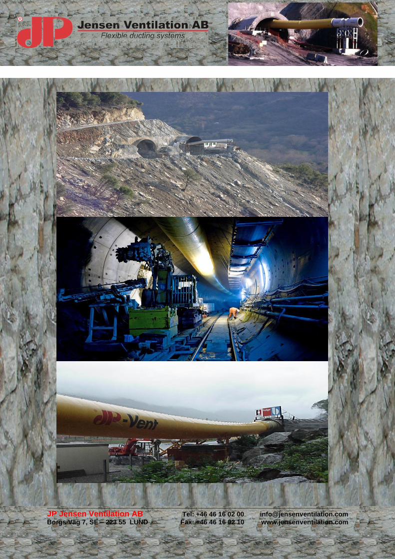
Bends – Y branch – T branch – Reduction cone
Kvalitet JP 752FR. Kopplingar eller dragkedja beställes separat.
Material quality JP753FR.
_______________________________________________________________________________________________________________
JP Jensen Ventilation AB Tel: +46 46 16 02 00 [email protected]
Borgs Väg 7, SE – 223 55 LUND Fax: +46 46 16 02 10 www.jensenventilation.com
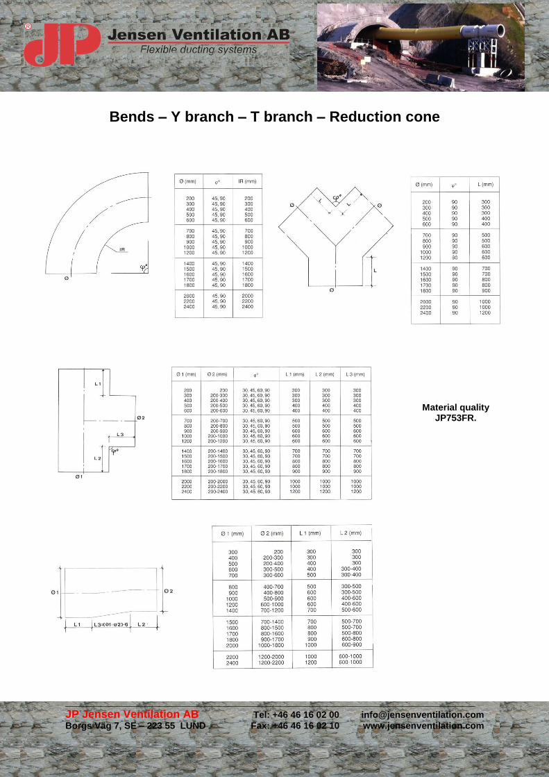
Every duct length is marked with information of quality, length, diameter, bursting pressure
point (BPP) order no, air direction and manufacturing date.
JP 551 FR
Yellow JP 651 FR
Yellow JP 753 FR
White JP 651 FRA
Black & White
Base fabric: Polyester
Yarn thickness (dtex) 1100 1430 1430 x 2200 1430
Yarn / inch Warp Weft
12 12 20 12
12 12 20 12
Coating: Plasticized PVC
Tensile strength: (N/5 cm) Warp (DIN 53354) Weft
1700 2100 2350 2100
1700 2100 2550 2100
Tear strength: Warp (DIN 53356) Weft
400 500 500 500
400 500 700 500
Welding strength N/5 cm: (DIN 53357) 1550 1900 2200 1900
Total weight g/m2 (DIN 53 352) 550 670 750 650
Flame Resistance: (EN 13501-1) YES
Conductivity (ISO 284) < 108 Ω
Diameter (mm) Bursting Pressure Point (kPa )
300 203,9 250,1 309,4 250,1
400 152,9 188,7 232,1 188,7
500 122,3 150,9 185,6 150,9
600 102,1 125,7 154,7 125,7
700 87,4 107,8 132,6 107,8
800 76,4 94,3 116,1 94,3
900 67,9 83,8 103,1 83,8
1000 61,1 75,5 92,8 75,5
1100 55,5 68,6 84,4 68,6
1200 50,9 62,9 77,3 62,9
1300 47,1 58,1 71,4 58,1
1400 43,6 53,9 66,3 53,9
1500 40,8 50,3 61,9 50,3
1600 38,2 47,2 58,1 47,2
1700 35,9 44,4 54,6 44,4
1800 33,9 41,9 51,5 41,9
1900 32,1 39,7 48,8 39,7
2000 30,5 37,7 46,4 37,7
2100 29,1 35,9 44,2 35,9
2200 27,8 34,3 42,2 34,3
2300 26,5 32,9 40,4 32,9
2400 25,5 31,4 38,7 31,4
2500 24,4 30,2 37,1 30,2
2600 23,5 29,1 35,6 29,1
2700 22,6 27,9 34,3 27,9
2800 21,8 26,9 33,1 26,9
2900 21,1 25,8 31,4 25,8
3000 20,3 25,2 30,4 25,2
The above figures are average values +- 10% valid for test of new material.
_______________________________________________________________________________________________________________
JP Jensen Ventilation AB Tel: +46 46 16 02 00 [email protected]
Borgs Väg 7, SE – 223 55 LUND Fax: +46 46 16 02 10 www.jensenventilation.com
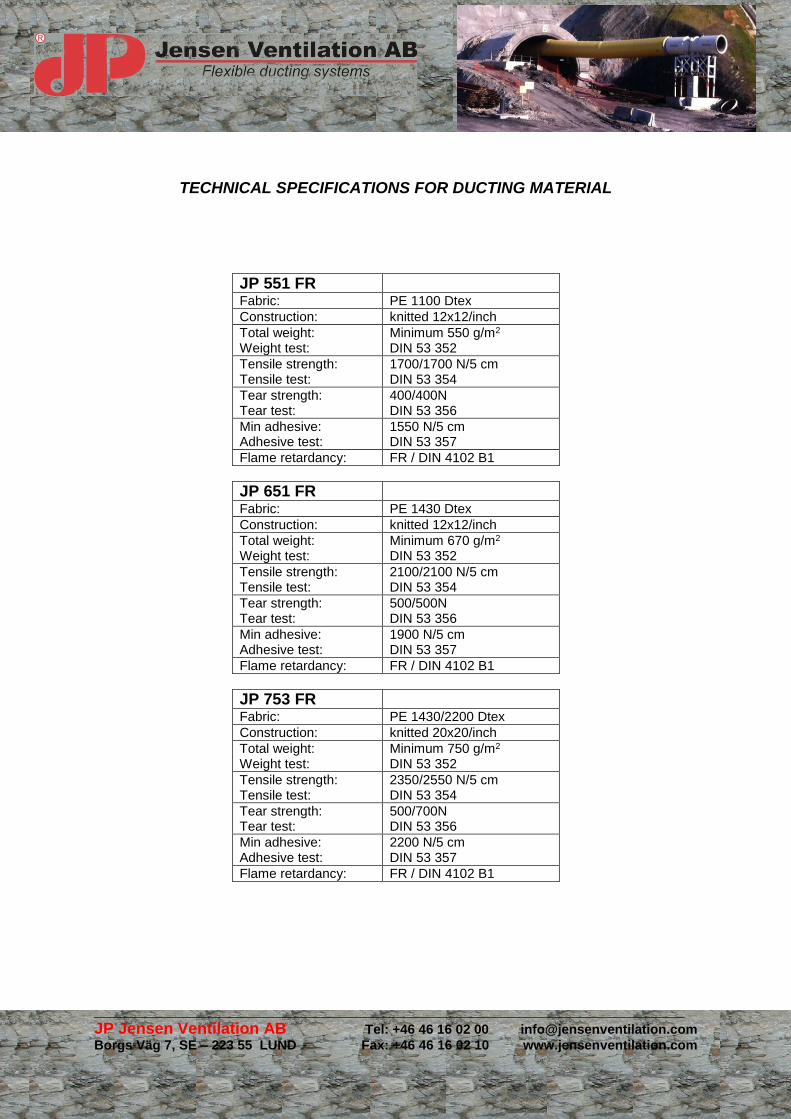
TECHNICAL SPECIFICATIONS FOR DUCTING MATERIAL
JP 551 FR Fabric: PE 1100 Dtex
Construction: knitted 12x12/inch
Total weight: Weight test:
Minimum 550 g/m2
DIN 53 352
Tensile strength: Tensile test:
1700/1700 N/5 cm DIN 53 354
Tear strength: Tear test:
400/400N DIN 53 356
Min adhesive: Adhesive test:
1550 N/5 cm DIN 53 357
Flame retardancy: FR / DIN 4102 B1
JP 651 FR Fabric: PE 1430 Dtex
Construction: knitted 12x12/inch
Total weight: Weight test:
Minimum 670 g/m2
DIN 53 352
Tensile strength: Tensile test:
2100/2100 N/5 cm DIN 53 354
Tear strength: Tear test:
500/500N DIN 53 356
Min adhesive: Adhesive test:
1900 N/5 cm DIN 53 357
Flame retardancy: FR / DIN 4102 B1
JP 753 FR Fabric: PE 1430/2200 Dtex
Construction: knitted 20x20/inch
Total weight: Weight test:
Minimum 750 g/m2
DIN 53 352
Tensile strength: Tensile test:
2350/2550 N/5 cm DIN 53 354
Tear strength: Tear test:
500/700N DIN 53 356
Min adhesive: Adhesive test:
2200 N/5 cm DIN 53 357
Flame retardancy: FR / DIN 4102 B1

_______________________________________________________________________________________________________________
JP Jensen Ventilation AB Tel: +46 46 16 02 00 [email protected]
Borgs Väg 7, SE – 223 55 LUND Fax: +46 46 16 02 10 www.jensenventilation.com
JP Jensen Ventilation Repair Kit
Incl. Repair fabric, PVC-glue, glue brush,
glue spatula, cleaning, needles, thread and
suspension hooks.
(extra: hot air gun, not incl)
Four methods: 1) Needles / thread 2) Glue 3) Needle / thread & glue 4) Hot air gun
Always have clean and dry fabric to work on. If you sew, use double thread
and choose distance between each thread depended on damage. For better
results, sew “up and down”. This method is for quick repairing and should not
be permanent because of leakage. For better durability and density use glue
after sewing. It is also common to use glue only. When using glue, always have
something on the inside to press against until the glue dries. At the same time
you avoid that the ducting fixative together on the inside.
As extra we can deliver the repair kit with a hot air gun. Repairing with a hot
air gun is the most professional and optimal way to repair ducting. The result is
a strong repair with no leakage. When using hot air gun, always have some
protective base direct under the area you are repairing! It’s very hot, be careful
when using it and protect yourself!
_______________________________________________________________________________________________________________
JP Jensen Ventilation AB Tel: +46 46 16 02 00 [email protected]
Borgs Väg 7, SE – 223 55 LUND Fax: +46 46 16 02 10 www.jensenventilation.com
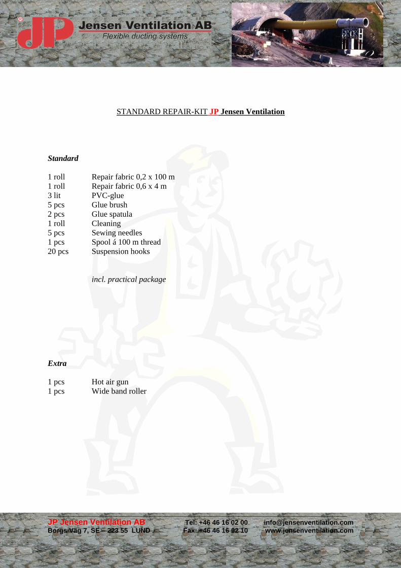
STANDARD REPAIR-KIT JP Jensen Ventilation
Standard
1 roll Repair fabric 0,2 x 100 m
1 roll Repair fabric 0,6 x 4 m
3 lit PVC-glue
5 pcs Glue brush
2 pcs Glue spatula
1 roll Cleaning
5 pcs Sewing needles
1 pcs Spool á 100 m thread
20 pcs Suspension hooks
incl. practical package
Extra
1 pcs Hot air gun
1 pcs Wide band roller
_______________________________________________________________________________________________________________
JP Jensen Ventilation AB Tel: +46 46 16 02 00 [email protected]
Borgs Väg 7, SE – 223 55 LUND Fax: +46 46 16 02 10 www.jensenventilation.com
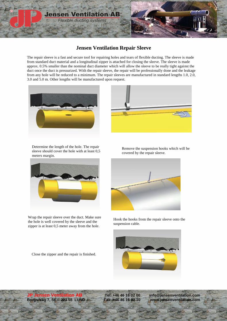
Determine the length of the hole. The repair
sleeve should cover the hole with at least 0,5
meters margin.
Remove the suspension hooks which will be
covered by the repair sleeve.
Hook the hooks from the repair sleeve onto the
suspension cable.
Wrap the repair sleeve over the duct. Make sure
the hole is well covered by the sleeve and the
zipper is at least 0,5 meter away from the hole.
Close the zipper and the repair is finished.
Jensen Ventilation Repair Sleeve
The repair sleeve is a fast and secure tool for repairing holes and tears of flexible ducting. The sleeve is made
from standard duct material and a longitudinal zipper is attached for closing the sleeve. The sleeve is made
approx. 0.5% smaller than the nominal duct diameter which will allow the sleeve to be really tight against the
duct once the duct is pressurized. With the repair sleeve, the repair will be professionally done and the leakage
from any hole will be reduced to a minimum. The repair sleeves are manufactured in standard lengths 1.0, 2.0,
3.0 and 5.0 m. Other lengths will be manufactured upon request.
_______________________________________________________________________________________________________________
JP Jensen Ventilation AB Tel: +46 46 16 02 00 [email protected]
Borgs Väg 7, SE – 223 55 LUND Fax: +46 46 16 02 10 www.jensenventilation.com
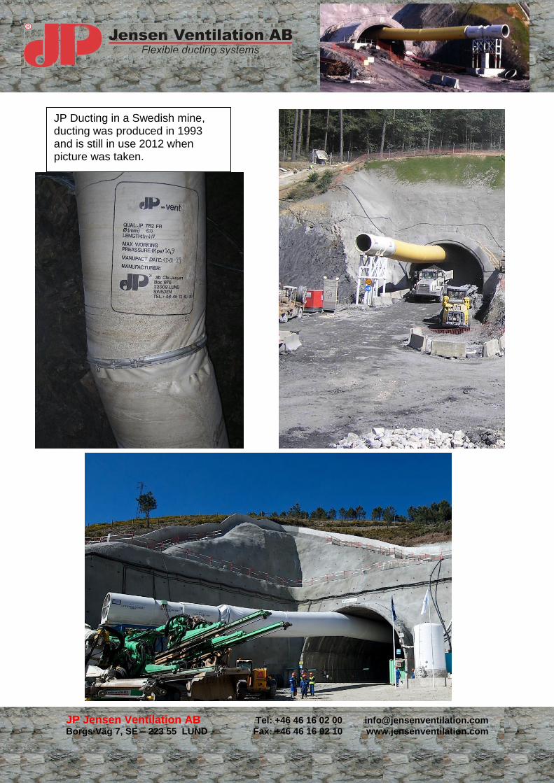
JP Ducting in a Swedish mine, ducting was produced in 1993 and is still in use 2012 when picture was taken.
_______________________________________________________________________________________________________________
JP Jensen Ventilation AB Tel: +46 46 16 02 00 [email protected]
Borgs Väg 7, SE – 223 55 LUND Fax: +46 46 16 02 10 www.jensenventilation.com

_______________________________________________________________________________________________________________
JP Jensen Ventilation AB Tel: +46 46 16 02 00 [email protected]
Borgs Väg 7, SE – 223 55 LUND Fax: +46 46 16 02 10 www.jensenventilation.com
References
Projekt
Meter
Motorway Tunnel Albania 3 800
TBM operation Algeria Algeria 2 500
Dos Valires Andorra 11 000
Epos / Angola, Hidroelectrico Lauca Angola 8 000
Mitterpichling Tunnel Austria 2 000
Galgenberg Tunnel Austria 2 000
Lainbergtunnel Austria 1 000
Passürtunnel, Arlberg Austria 2 000
Vomp-Terfens Tunnel Austria 4 000
Tradenbergtunnel Austria 1 400
Tala Hydro Electric Project Bhutan 11 000
Road Tunnel Bulgaria 400
Mining Project Bulgaria 3 000
Ute Acciona - Ossa Mina Chuquicamata Chile 9 800
Ute Ossa - EI Metro Santiago Chile 2 300
Ute Acciona - Brotex Metro Santiago Chile 6 500
Ute Concorcioa L 3 Metro Santiago Chile 3 000
Proyecta Mina Manto La Luna Chile 1 200
C.T.M Mina El Teniente Chile 2 000
Mina Carola Copiapo Chile 800
Sacyr - Costanera Santiago Chile 500
Qin Ling Railway Project China 37 000
Yellow River Diversion China 1 000
URRA Water Hydro Project Colombia 2 000
Dragados Colombia 1 200
Aocisa Colombia 1 200
Cariblanco Costa Rica 3 000
Lagadembi Goldmine Ethiopia 1 500
Hydro Power Tunnel Georgien 3 500
Hydro Power Tunnel Georgien 5 500
Hydro Power Tunnel Georgien 12 000
Bibra Tunnel, Karsdorf Germany 3 000
Atens Metro Greece 5 000
Driskos Tunnel Greece 2 500
Gonnoi, Larissa-Hellas Greece 5 280
Obras Subterraneas Guatemala 1 600
OHL Guatemala 4 300
Tai Lam Tunnel Hong-Kong 1 000

_______________________________________________________________________________________________________________
JP Jensen Ventilation AB Tel: +46 46 16 02 00 [email protected]
Borgs Väg 7, SE – 223 55 LUND Fax: +46 46 16 02 10 www.jensenventilation.com
Project Meter
LKJV-project Hong-Kong 13 000
Bremer Hill Gas Pipe Line Hong-Kong 2 500
Tunnelkette M6, Bataszek Hungaria 1 500
Road Tunnel Iceland 5 000
Eyjabakkar Iceland 2 250
Chamera Project India 21 000
Costal Project India 2 000
Malana HE-project India 3 100
Nathpa Jhakri Hydro India 18 000
Nathpa Jhakri Hydro India 21 000
Nathpa Jhakri Hydro India 3 000
Parbati Project India 1 500
Hydro Power Tunnel Singkarak Indonesia 13 000
Hydro Power Tunnel MUSI Indonesia 12 400
Karaj Project Iran 4 000
Energy & Water Project Iran 2 000
Galleria Trivigno-Acerenza Italy 2 500
Linea "A" Metro Roma Italy 700
Cantiere di Raiano Italy 5 000
Cogolo-Centrale Enel Italy 1 600
Hydro Power Tunnel Italy 6 000
Passante Ferroviario -TO Italy 1 800
Statale Road Tunnel Italy 5 000
Metro Project Kong-Kong 6 000
Tunnel Project Korea 14 000
Skopje Macedonia 600
Tunnel Project Mexico 3 300
Sozina Tunnel Monte Negro 2 000
Aga Persellen Norway 600
Fjaerland Road Tunnel Norway 1000
Gjeleraas Tunnel Norway 2 000
Ravneheiatunnelen Bjørnestad Norway 3 000
Vinterbro-Vassum Road Tunnel Norway 3 000
Haukelifjell Norway 1 100
Glomfjord Fykan Norway 1 000
Obras Subterraneas - Oslo Norway 2 000
Obras Subterraneas Panama 1 400
Tunnel Project Peru 6 000
Venda Nova Portugal 7 700
Venda Nova Portugal 6 200
Venda Nova Portugal 4 100

_______________________________________________________________________________________________________________
JP Jensen Ventilation AB Tel: +46 46 16 02 00 [email protected]
Borgs Väg 7, SE – 223 55 LUND Fax: +46 46 16 02 10 www.jensenventilation.com
Project Meter
Venda Nova Portugal 1 900
Venda Nova Portugal 1 600
Venda Nova Portugal 2 000
Venda Nova Portugal 1 375
Venda Nova Portugal 500
Marão // Epos Portugal 6 200
Marão // Epos Portugal 5 800
Marão // Epos Portugal 2 000
Marão // Epos Portugal 1 600
Epos // Salamonde Portugal 1 000
Epos // Salamonde Portugal 3 200
Epos // Salamonde Portugal 1 000
Epos // Salamonde Portugal 1 000
Epos // Salamonde Portugal 800
Tunnel Marão // Epos Portugal 8 000
FCC Rumania 1 100
Underground storage Saudi Arabia 2 000
Galleri in Sicillia Sicilia 250
Circle Line 1 Singapore 2 000
Abdalajís Tunnel Spain 14 000
Arlabán Spain 8 000
Bracons Spain 9 000
Cortes de Pallars Central Hidraulica Spain 3 060
Copcisa - Comsa Spain 5 000
Copisa Spain 600
Cordoba - Malaga Spain 7 100
Coruna Spain 2 900
Dragados Talave Spain 7 500
Proacon Gerona Spain 5 000
Pueblas San Lugo Spain 200
Girona Spain 2 000
Granada Spain 800
Guadarrama Tunnel Spain 30 000
Metro Barcelona Ligero Spain 1 000
Metro Barcelona Line 9 Spain 6 000
Metro Madrid Spain 5 100
Metro Sevilla Spain 3 100
Obras Subteraneas Spain 3 300
OHL Obras Mostoles Spain 2 200
Nortunel San Marcial Spain 3 200
Pontevedra Spain 4 000
_______________________________________________________________________________________________________________
JP Jensen Ventilation AB Tel: +46 46 16 02 00 [email protected]
Borgs Väg 7, SE – 223 55 LUND Fax: +46 46 16 02 10 www.jensenventilation.com
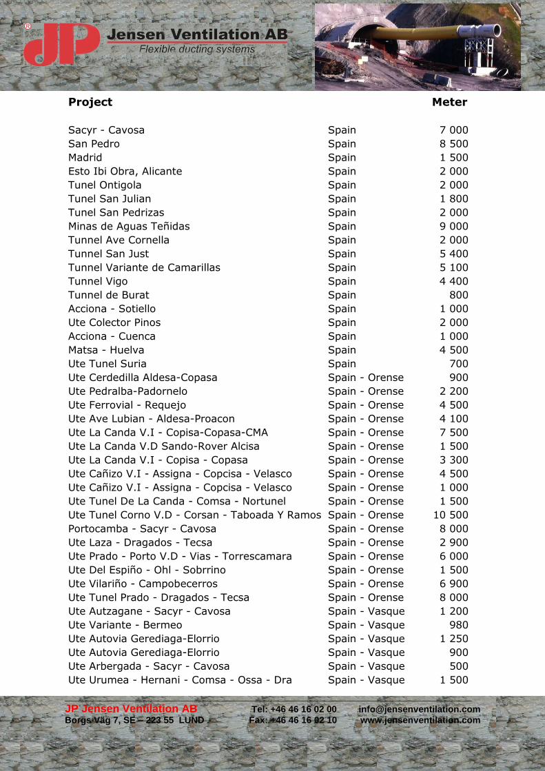
Project Meter
Sacyr - Cavosa Spain 7 000
San Pedro Spain 8 500
Madrid Spain 1 500
Esto Ibi Obra, Alicante Spain 2 000
Tunel Ontigola Spain 2 000
Tunel San Julian Spain 1 800
Tunel San Pedrizas Spain 2 000
Minas de Aguas Teñidas Spain 9 000
Tunnel Ave Cornella Spain 2 000
Tunnel San Just Spain 5 400
Tunnel Variante de Camarillas Spain 5 100
Tunnel Vigo Spain 4 400
Tunnel de Burat Spain 800
Acciona - Sotiello Spain 1 000
Ute Colector Pinos Spain 2 000
Acciona - Cuenca Spain 1 000
Matsa - Huelva Spain 4 500
Ute Tunel Suria Spain 700
Ute Cerdedilla Aldesa-Copasa Spain - Orense 900
Ute Pedralba-Padornelo Spain - Orense 2 200
Ute Ferrovial - Requejo Spain - Orense 4 500
Ute Ave Lubian - Aldesa-Proacon Spain - Orense 4 100
Ute La Canda V.I - Copisa-Copasa-CMA Spain - Orense 7 500
Ute La Canda V.D Sando-Rover Alcisa Spain - Orense 1 500
Ute La Canda V.I - Copisa - Copasa Spain - Orense 3 300
Ute Cañizo V.I - Assigna - Copcisa - Velasco Spain - Orense 4 500
Ute Cañizo V.I - Assigna - Copcisa - Velasco Spain - Orense 1 000
Ute Tunel De La Canda - Comsa - Nortunel Spain - Orense 1 500
Ute Tunel Corno V.D - Corsan - Taboada Y Ramos Spain - Orense 10 500
Portocamba - Sacyr - Cavosa Spain - Orense 8 000
Ute Laza - Dragados - Tecsa Spain - Orense 2 900
Ute Prado - Porto V.D - Vias - Torrescamara Spain - Orense 6 000
Ute Del Espiño - Ohl - Sobrrino Spain - Orense 1 500
Ute Vilariño - Campobecerros Spain - Orense 6 900
Ute Tunel Prado - Dragados - Tecsa Spain - Orense 8 000
Ute Autzagane - Sacyr - Cavosa Spain - Vasque 1 200
Ute Variante - Bermeo Spain - Vasque 980
Ute Autovia Gerediaga-Elorrio Spain - Vasque 1 250
Ute Autovia Gerediaga-Elorrio Spain - Vasque 900
Ute Arbergada - Sacyr - Cavosa Spain - Vasque 500
Ute Urumea - Hernani - Comsa - Ossa - Dra Spain - Vasque 1 500
_______________________________________________________________________________________________________________
JP Jensen Ventilation AB Tel: +46 46 16 02 00 [email protected]
Borgs Väg 7, SE – 223 55 LUND Fax: +46 46 16 02 10 www.jensenventilation.com
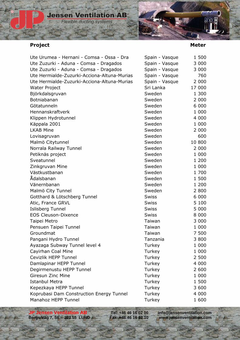
Project Meter
Ute Urumea - Hernani - Comsa - Ossa - Dra Spain - Vasque 1 500
Ute Zuzurki - Aduna - Comsa - Dragados Spain - Vasque 3 000
Ute Zuzurki - Aduna - Comsa - Dragados Spain - Vasque 3 000
Ute Hermialde-Zuzurki-Acciona-Altuna-Murias Spain - Vasque 760
Ute Hermialde-Zuzurki-Acciona-Altuna-Murias Spain - Vasque 2 000
Water Project Sri Lanka 17 000
Björkdalsgruvan Sweden 1 300
Botniabanan Sweden 2 000
Götatunneln Sweden 6 000
Hennanskraftverk Sweden 1 000
Klippen Hydrotunnel Sweden 4 000
Käppala 2001 Sweden 1 000
LKAB Mine Sweden 2 000
Lovisagruvan Sweden 600
Malmö Citytunnel Sweden 10 800
Norrala Railway Tunnel Sweden 2 000
Petiknäs project Sweden 1 000
Sveatunnel Sweden 1 200
Zinkgruvan Mine Sweden 1 000
Västkustbanan Sweden 1 700
Ådalsbanan Sweden 1 500
Vänernbanan Sweden 1 200
Malmö City Tunnel Sweden 2 800
Gotthard & Lötschberg Tunnel Swiss 6 000
Atic, France GRVL Swiss 5 100
Islisberg Tunnel Swiss 5 000
EOS Cleuson-Dixence Swiss 8 000
Taipei Metro Taiwan 3 000
Pensuen Taipei Tunnel Taiwan 1 000
Groundmat Taiwan 7 500
Pangani Hydro Tunnel Tanzania 3 800
Ayazaga Subway Tunnel level 4 Turkey 1 000
Cayirhan Coal Mine Turkey 1 000
Cevizlik HEPP Tunnel Turkey 2 500
Damlapinar HEPP Tunnel Turkey 4 000
Degirmenustu HEPP Tunnel Turkey 2 600
Giresun Zinc Mine Turkey 1 000
Istanbul Metra Turkey 1 500
Kepezkaya HEPP Tunnel Turkey 3 600
Koprubasi Dam Construction Energy Tunnel Turkey 4 000
Manahoz HEPP Tunnel Turkey 1 600

_______________________________________________________________________________________________________________
JP Jensen Ventilation AB Tel: +46 46 16 02 00 [email protected]
Borgs Väg 7, SE – 223 55 LUND Fax: +46 46 16 02 10 www.jensenventilation.com
Project Meter
Marmaray Project Turkey 14 000
Nata HEPP Tunnel Turkey 2 000
Tirebolu Giresun Tunnel Turkey 1 200
Uluabat Energy Tunnel Turkey 11 500
Uzundere HEPP Tunnel Turkey 2 000
Otogar Bagcilar Subway Tunnel Turkey 7 300
Sarmasik HEPP Tunnel Project Turkey 5 200
Sirt Copper Mine Turkey 3 000
Blacksea Motorway Tunnel Turkey 1 500
Sargin Insaat a.s Istanbul Turkey 2 000
Water Project Uganda 17 500
Cross Rail Dragados London UK 9 500
Asignia Venezuela 4 500
Epos // Baralt Tnnel Venezuela 2 800
Rock Cavity Zimbabwe 2 000
_______________________________________________________________________________________________________________
JP Jensen Ventilation AB Tel: +46 46 16 02 00 [email protected]
Borgs Väg 7, SE – 223 55 LUND Fax: +46 46 16 02 10 www.jensenventilation.com
VENTILATION
GENERAL
The primary objective should be to reduce emissions of contaminants at source and hence reduce the need for ventilation.
Where atmospheric contaminants remain, a purpose-built forcing, exhausting or circulation ventilation system should be employed, depending on the contaminants which have to be rendered harmless.
The concentration of oxygen, dust, toxic or potentially explosive fumes or harmful gases in the tunnel atmosphere should be routinely monitored and steps taken as necessary to ensure contaminant levels do not exceed those laid down by national legislation or guidance. Where a specific work activity known to generate significant contamination, such as shotcreting or welding, is being carried out, local monitoring with additional ventilation as necessary should be undertaken.
In the absence of national legislation or guidance, legislation or guidance from another nation giving contaminant exposure levels should be selected as the base standard. Records of all routine monitoring should be maintained.
As a guide, the quantity of air supplied or extracted from the face should be such that the average flow in the full cross section of the tunnel or shaft should be between 0,3 m/s and 2m/s at all times.
Minimum quantity of air for personnel to be 1,5m3 per minute per man and 4m3 per minute per kW rated power for diesel machines. Additional air may be required for cooling purposes.
Ventilation air entering a tunnel should be free from dust, smoke or other impurity.
Ventilation should be such that in every underground working area, safe and healthy conditions exist and fumes or gases shall be diluted to the extent that they are rendered harmless. A minimum oxygen concentration of 19% should be maintained at all times when persons are at work underground. No-one should remain underground when the ventilation system is not operating.
The wet globe bulb temperature (WBGT) should not exceed 28o C. Ventilation can be used as a means of removing excess heat from the workings.
_______________________________________________________________________________________________________________
JP Jensen Ventilation AB Tel: +46 46 16 02 00 [email protected]
Borgs Väg 7, SE – 223 55 LUND Fax: +46 46 16 02 10 www.jensenventilation.com
To minimize dust generation, wet drilling techniques should be used in a tunnel in preference to drilling machines fitted with appropriate dust collection equipment.
Dust generated during shotcrete spraying should be minimized as part of the mix design process. Other machines and processes creating dust should be fitted with appropriate dust suppression and collection equipment.
Diesel-driven internal combustion machines should be fitted with particulate filters. These machines should be kept in good order and should not be left idling in the tunnel.
In a tunnel with a risk of a potentially explosive atmosphere occurring, safety critical equipment such as firefighting equipment, pumping equipment, ventilation equipment, communications and atmospheric monitoring equipment should be explosion protected as necessary so that it remains operational even when potentially explosive gases are present.
For guidance on selection of duct material see ITA Report # 8
VENTILATION LAYOUT
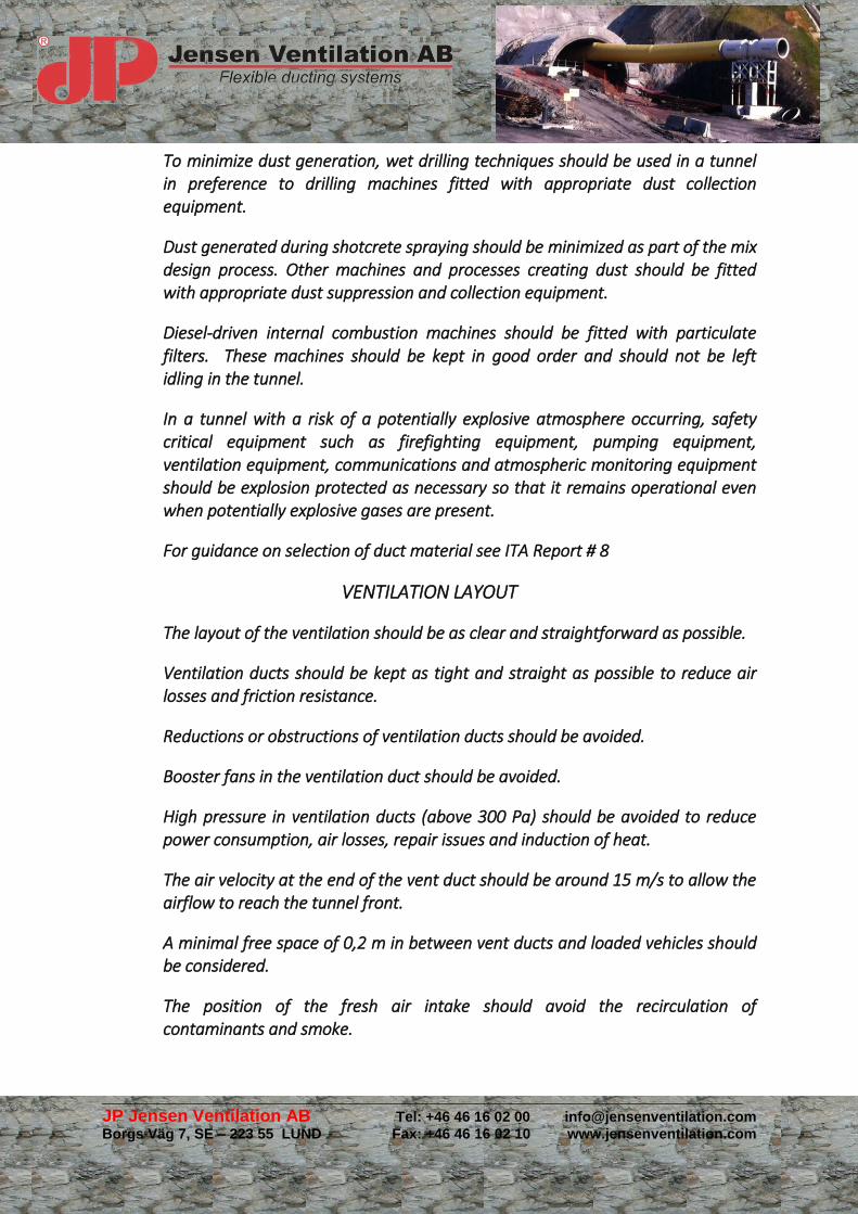
The layout of the ventilation should be as clear and straightforward as possible.
Ventilation ducts should be kept as tight and straight as possible to reduce air losses and friction resistance.
Reductions or obstructions of ventilation ducts should be avoided.
Booster fans in the ventilation duct should be avoided.
High pressure in ventilation ducts (above 300 Pa) should be avoided to reduce power consumption, air losses, repair issues and induction of heat.
The air velocity at the end of the vent duct should be around 15 m/s to allow the airflow to reach the tunnel front.
A minimal free space of 0,2 m in between vent ducts and loaded vehicles should be considered.
The position of the fresh air intake should avoid the recirculation of contaminants and smoke.
_______________________________________________________________________________________________________________
JP Jensen Ventilation AB Tel: +46 46 16 02 00 [email protected]
Borgs Väg 7, SE – 223 55 LUND Fax: +46 46 16 02 10 www.jensenventilation.com
Related Documents