June7-8, 2001 A. R. Raffray, et al., Completion of Assessment of Dry Chamber Wall Option Without Protective Gas, and Initial Planning Activity for Assessment of Wetted Wall Option 1 1. Completion of Assessment of Dry Chamber Wall Option Without Protective Gas 2. Initial Planning Activity for Assessment of Wetted Wall Option A. R. Raffray, M. S. Tillack, X. Wang, M. Zaghloul University of California, San Diego ARIES Meeting UCSD June 7-8, 2001

June7-8, 2001 A. R. Raffray, et al., Completion of Assessment of Dry Chamber Wall Option Without Protective Gas, and Initial Planning Activity for Assessment.
Dec 22, 2015
Welcome message from author
This document is posted to help you gain knowledge. Please leave a comment to let me know what you think about it! Share it to your friends and learn new things together.
Transcript
June7-8, 2001A. R. Raffray, et al., Completion of Assessment of Dry Chamber Wall Option Without Protective Gas,
and Initial Planning Activity for Assessment of Wetted Wall Option 1
1. Completion of Assessment of Dry Chamber Wall Option Without Protective Gas
2. Initial Planning Activity for Assessment of Wetted Wall Option
A. R. Raffray, M. S. Tillack, X. Wang, M. Zaghloul
University of California, San Diego
ARIES Meeting
UCSD
June 7-8, 2001
June7-8, 2001A. R. Raffray, et al., Completion of Assessment of Dry Chamber Wall Option Without Protective Gas,
and Initial Planning Activity for Assessment of Wetted Wall Option 2
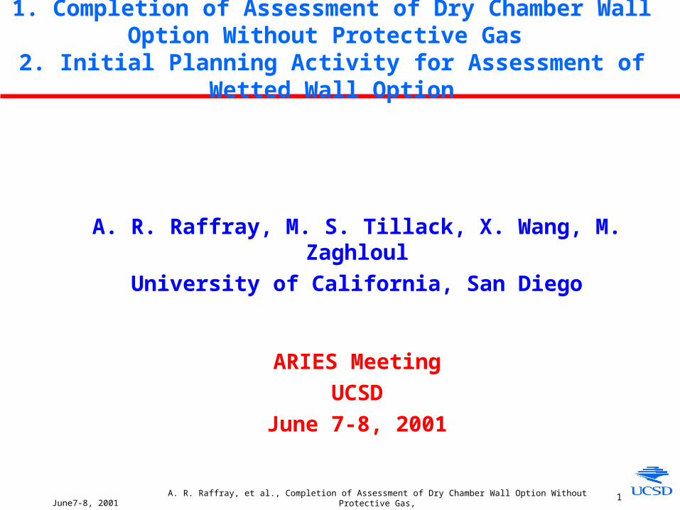
Outline of Presentation
Dry Walls (from last ARIES meeting’s action items)• Direct-drive target (without protective chamber gas)
- Sensitivity study of thermal behavior for different chamber radii (different time of flights and different energy deposition per unit volume)
- Thermal/erosion effect on chamber wall of reflective light from laser (~10%)
• Indirect-drive target- Thermal/mass transfer analysis for C and W without protective gas
• Start documentation- Outline of dry chamber wall report and first draft write-up over next 3 months
Wetted Walls • Initial Planning for Assessment for Direct-Drive and Indirect-Drive Targets
June7-8, 2001A. R. Raffray, et al., Completion of Assessment of Dry Chamber Wall Option Without Protective Gas,
and Initial Planning Activity for Assessment of Wetted Wall Option 3
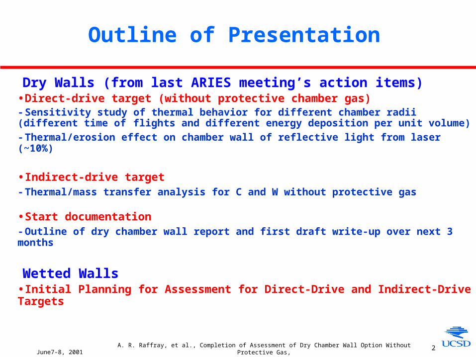
Changing Chamber Radius Affects Photon and Ion Times of Flight and Energy Deposition Density
Time of Flight Rchamber
10.0x10³
1.0x10⁵
1.0x10⁶
1.0x10⁷
1.0x10⁸
1.0x10⁹
1.0x10¹⁰
1.0x10⁻⁶ 1.0x10⁻⁵ 1.0x10⁻⁴ 1.0x10⁻³ 1.0x10⁻²
Penetration Depth (m)
Photons, C
Photons, W
Fast ions, C
Fast ions, W
Debri ions, C
Debri ions, W
Energy Deposition per Unit Volume 1/(Rchamber)2
Temporal Distribution for Ions Based on
Direct Drive Spectra and 6.5 m Chamber
Debris Ions
Time10ns 0.2s 1s 2.5s
FastIonsP
hot
ons
Energy Deposition
• Perform Sensitivity Analysis for for 3 chamber radii: 3.5 m, 5 m and 6.5 m
Energy Deposition for 6.5 m Chamber and Direct Drive Spectra

June7-8, 2001A. R. Raffray, et al., Completion of Assessment of Dry Chamber Wall Option Without Protective Gas,
and Initial Planning Activity for Assessment of Wetted Wall Option 4
Effect of Changing Chamber Radius on Thermal Behavior of Carbon Flat Wall
• Annual Sublimation Loss > 1-10 m for Chamber Radius < ~ 5 m• Corresponding Maximum Surface Temperature > ~2500°C
0
500
1000
1500
2000
2500
3000
3500
4000
4500
5000
1E-141E-131E-121E-111E-101E-91E-81E-71E-61E-51E-41E-31E-21E-11E+01E+1
3.0 3.5 4.0 4.5 5.0 5.5 6.0 6.5
Chamber Radius (m)
• Initial Temperature = 500°C • k= f(T)• q’’(sublimation) = f(T)
June7-8, 2001A. R. Raffray, et al., Completion of Assessment of Dry Chamber Wall Option Without Protective Gas,
and Initial Planning Activity for Assessment of Wetted Wall Option 5
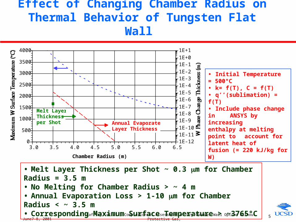
Effect of Changing Chamber Radius on Thermal Behavior of Tungsten Flat Wall
• Melt Layer Thickness per Shot ~ 0.3 m for Chamber Radius = 3.5 m • No Melting for Chamber Radius > ~ 4 m• Annual Evaporation Loss > 1-10 m for Chamber Radius < ~ 3.5 m• Corresponding Maximum Surface Temperature > ~3765°C
0
500
1000
1500
2000
2500
3000
3500
4000
1E-121E-111E-101E-91E-81E-71E-61E-51E-41E-31E-21E-11E+01E+1
3.0 3.5 4.0 4.5 5.0 5.5 6.0 6.5
Chamber Radius (m)
Annual EvaporatedLayer Thickness
Melt LayerThicknessper Shot
• Initial Temperature = 500°C • k= f(T), C = f(T)• q’’(sublimation) = f(T)• Include phase change in
ANSYS by increasing enthalpy at melting point to account for latent heat of fusion (= 220 kJ/kg for W)

June7-8, 2001A. R. Raffray, et al., Completion of Assessment of Dry Chamber Wall Option Without Protective Gas,
and Initial Planning Activity for Assessment of Wetted Wall Option 6
Temperature History and Snap-shot Profile for Tungsten Flat Wall Under Energy Deposition from NRL Direct-Drive Spectra
and Chamber Wall Radius of 3.5 m
Temperature History
Separation = 1 m
Temperature profile at the end of X-ray energy deposition:• Time = 5.4 ns• W melting point = 3410°C• W max. temp. = 3765°C• Melt layer thickness ~ 0.3 m
June7-8, 2001A. R. Raffray, et al., Completion of Assessment of Dry Chamber Wall Option Without Protective Gas,
and Initial Planning Activity for Assessment of Wetted Wall Option 7
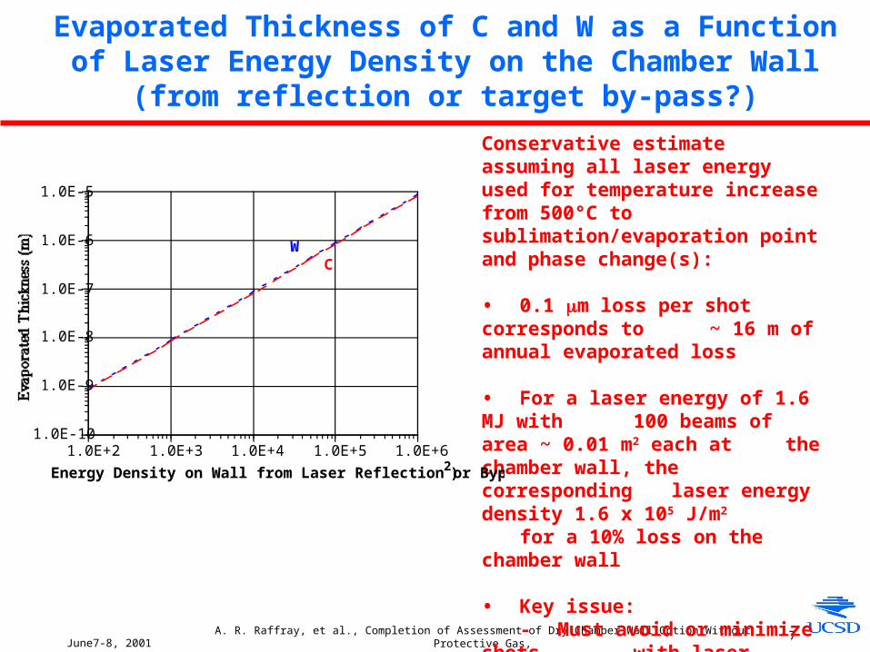
Evaporated Thickness of C and W as a Function of Laser Energy Density on the Chamber Wall (from reflection or target by-pass?)
Conservative estimate assuming all laser energy used for temperature increase from 500°C to sublimation/evaporation point and phase change(s):
• 0.1 m loss per shot corresponds to ~ 16 m of annual evaporated loss
• For a laser energy of 1.6 MJ with 100 beams of area ~ 0.01 m2 each at the chamber wall, the corresponding laser energy density 1.6 x 10⁵ J/m2
for a 10% loss on the chamber wall
• Key issue: - Must avoid or minimize shots
with laser reflection or target by-pass on the chamber wall
- Must find in-situ repair measure for threatened region
1.0E-10
1.0E-9
1.0E-8
1.0E-7
1.0E-6
1.0E-5
1.0E+2 1.0E+3 1.0E+4 1.0E+5 1.0E+6
CW
Energy Density on Wall from Laser Reflection or Bypass (J/m 2)
June7-8, 2001A. R. Raffray, et al., Completion of Assessment of Dry Chamber Wall Option Without Protective Gas,
and Initial Planning Activity for Assessment of Wetted Wall Option 8
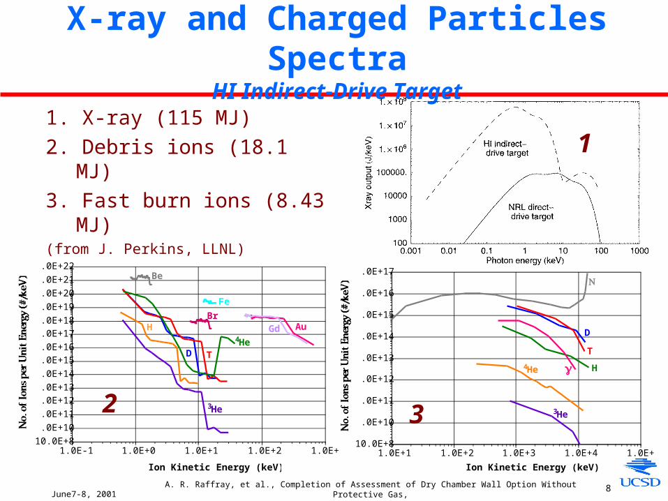
X-ray and Charged Particles SpectraHI Indirect-Drive Target
1. X-ray (115 MJ)
2. Debris ions (18.1 MJ)
3. Fast burn ions (8.43 MJ)(from J. Perkins, LLNL)
1
10.0E+81.0E+101.0E+111.0E+121.0E+131.0E+141.0E+151.0E+161.0E+171.0E+181.0E+191.0E+201.0E+211.0E+22
1.0E-1 1.0E+0 1.0E+1 1.0E+2 1.0E+3
4HeD T
H Au
Ion Kinetic Energy (keV)
3He
Gd
Fe
Br
Be
210.0E+8
1.0E+10
1.0E+11
1.0E+12
1.0E+13
1.0E+14
1.0E+15
1.0E+16
1.0E+17
1.0E+1 1.0E+2 1.0E+3 1.0E+4 1.0E+5
4He
D
T
H
Ion Kinetic Energy (keV)
3He
γ
N
3
June7-8, 2001A. R. Raffray, et al., Completion of Assessment of Dry Chamber Wall Option Without Protective Gas,
and Initial Planning Activity for Assessment of Wetted Wall Option 9
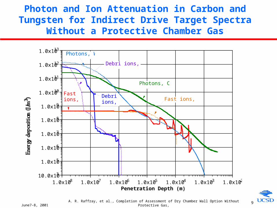
Photon and Ion Attenuation in Carbon and Tungsten for Indirect Drive Target Spectra Without a Protective Chamber Gas
10.0x10³
1.0x10⁵
1.0x10⁶
1.0x10⁷
1.0x10⁸
1.0x10⁹
1.0x10¹⁰
1.0x10¹¹
1.0x10¹²
1.0x10¹³
1.0x10⁻⁸ 1.0x10⁻⁷ 1.0x10⁻⁶ 1.0x10⁻⁵ 1.0x10⁻⁴ 1.0x10⁻³ 1.0x10⁻²
Penetration Depth (m)
Photons, C
Photons, W
Fastions, C Fast ions, WDebri
ions, C
Debri ions, W
June7-8, 2001A. R. Raffray, et al., Completion of Assessment of Dry Chamber Wall Option Without Protective Gas,
and Initial Planning Activity for Assessment of Wetted Wall Option 10
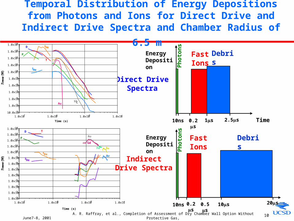
Temporal Distribution of Energy Depositions from Photons and Ions for Direct Drive and Indirect Drive Spectra and Chamber
Radius of 6.5 m
Direct Drive Spectra
Ph
oton
s
Debris Ions
Time10ns 0.2s 1s 2.5s
FastIons
Energy Deposition
10.0x10³
1.0x10⁵
1.0x10⁶
1.0x10⁷
1.0x10⁸
1.0x10⁹
1.0x10¹⁰
1.0x10¹¹
1.0x10¹²
1.0x10¹³
1.0x10¹⁴
1.0x10⁻⁷ 1.0x10⁻⁶ 1.0x10⁻⁵ 1.0x10⁻⁴
4HeD
T
P
Au
Time (s)
3He
12C
1.0x10²
1.0x10³
1.0x10⁴
1.0x10⁵
1.0x10⁶
1.0x10⁷
1.0x10⁸
1.0x10⁹
1.0x10¹⁰
1.0x10¹¹
1.0x10¹²
1.0x10¹³
1.0x10¹⁴
1.0x10⁻⁷ 1.0x10⁻⁶ 1.0x10⁻⁵ 1.0x10⁻⁴
4He
D T
P
Be
Time (s)
3HeBr
Fe
Au
Gd
Indirect Drive Spectra
Ph
oton
s
Debris Ions
10ns 0.2s 10s 20s
FastIons
Energy Deposition
0.5s
June7-8, 2001A. R. Raffray, et al., Completion of Assessment of Dry Chamber Wall Option Without Protective Gas,
and Initial Planning Activity for Assessment of Wetted Wall Option 11
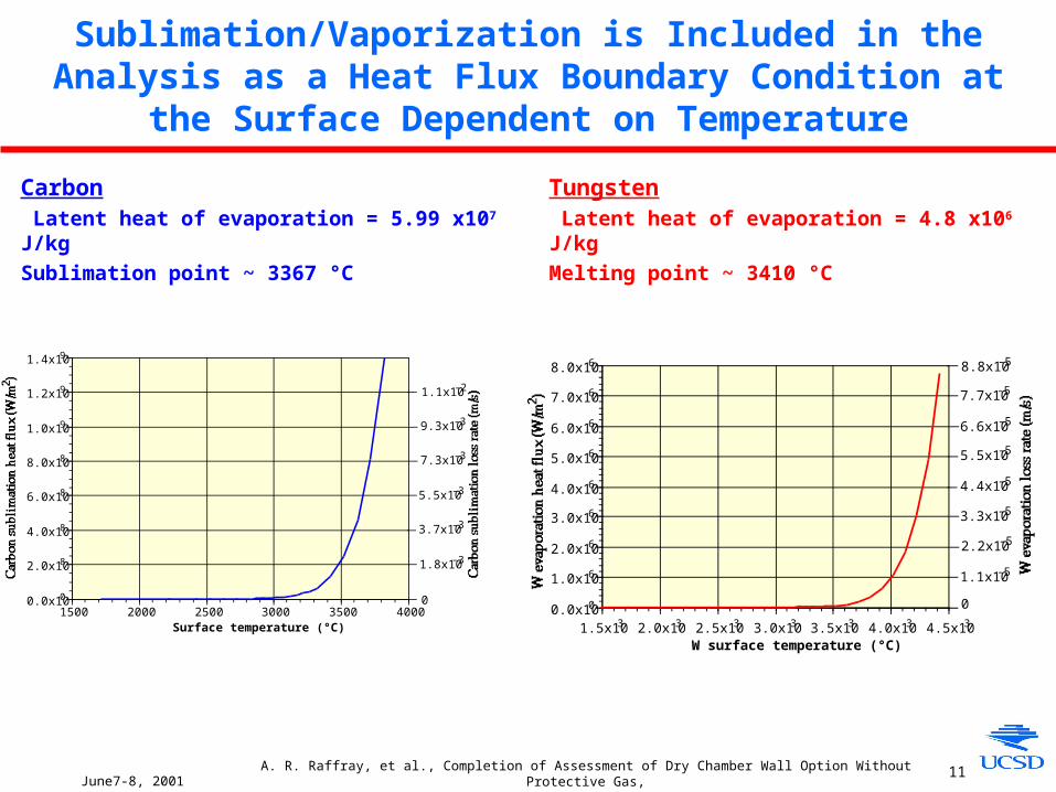
Sublimation/Vaporization is Included in the Analysis as a Heat Flux Boundary Condition at the Surface Dependent on
Temperature
0.0x100
2.0x10⁸
4.0x10⁸
6.0x10⁸
8.0x10⁸
1.0x10⁹
1.2x10⁹
1.4x10⁹
1500 2000 2500 3000 3500 4000Surface temperature (°C)
1.1x10⁻²
9.3x10⁻³
7.3x10⁻³
5.5x10⁻³
3.7x10⁻³
1.8x10⁻³
00.0x100
1.0x10⁶
2.0x10⁶
3.0x10⁶
4.0x10⁶
5.0x10⁶
6.0x10⁶
7.0x10⁶
8.0x10⁶
1.5x10³ 2.0x10³ 2.5x10³ 3.0x10³ 3.5x10³ 4.0x10³ 4.5x10³
W surface temperature (°C)
8.8x10⁻⁵
7.7x10⁻⁵
6.6x10⁻⁵
5.5x10⁻⁵
4.4x10⁻⁵
3.3x10⁻⁵
2.2x10⁻⁵
1.1x10⁻⁵
0
Carbon Latent heat of evaporation = 5.99 x10⁷ J/kg
Sublimation point ~ 3367 °C
Tungsten Latent heat of evaporation = 4.8 x10⁶ J/kg
Melting point ~ 3410 °C
June7-8, 2001A. R. Raffray, et al., Completion of Assessment of Dry Chamber Wall Option Without Protective Gas,
and Initial Planning Activity for Assessment of Wetted Wall Option 12
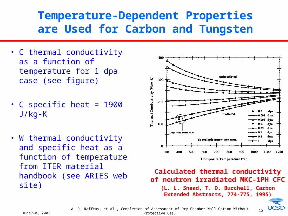
Temperature-Dependent Properties are Used for Carbon and Tungsten
• C thermal conductivity as a function of temperature for 1 dpa case (see figure)
• C specific heat = 1900 J/kg-K
• W thermal conductivity and specific heat as a function of temperature from ITER material handbook (see ARIES web site)
Calculated thermal conductivity of neutron irradiated MKC-1PH CFC
(L. L. Snead, T. D. Burchell, Carbon Extended Abstracts, 774-775, 1995)
June7-8, 2001A. R. Raffray, et al., Completion of Assessment of Dry Chamber Wall Option Without Protective Gas,
and Initial Planning Activity for Assessment of Wetted Wall Option 13
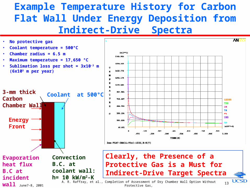
Example Temperature History for Carbon Flat Wall Under Energy Deposition from Indirect-Drive Spectra
• No protective gas
• Coolant temperature = 500°C
• Chamber radius = 6.5 m
• Maximum temperature = 17,650 °C
• Sublimation loss per shot = 3x10⁻³ m (6x10⁵ m per year)
Coolant at 500°C3-mm thick Carbon Chamber Wall
EnergyFront
Evaporation heat flux B.C at incident wall
Convection B.C. at coolant wall:h= 10 kW/m2-K
Clearly, the Presence of a Protective Gas is a Must for Indirect-Drive Target Spectra

June7-8, 2001A. R. Raffray, et al., Completion of Assessment of Dry Chamber Wall Option Without Protective Gas,
and Initial Planning Activity for Assessment of Wetted Wall Option 14
Example Temperature History for Tungsten Flat Wall Under Energy Deposition from Indirect-Drive Spectra
• No protective gas
• Coolant temperature = 500°C
• Chamber radius = 6.5 m
• Maximum temperature = 86,300 °C
• Sublimation loss per shot = 0.63x10⁻³ m (105 m per year)
Again, the Presence of a Protective Gas is a Must for Indirect-Drive Target Spectra
Coolant at 500°C3-mm thick W Chamber Wall
EnergyFront
Evaporation heat flux B.C at incident wall
Convection B.C. at coolant wall:h= 10 kW/m2-K
June7-8, 2001A. R. Raffray, et al., Completion of Assessment of Dry Chamber Wall Option Without Protective Gas,
and Initial Planning Activity for Assessment of Wetted Wall Option 15
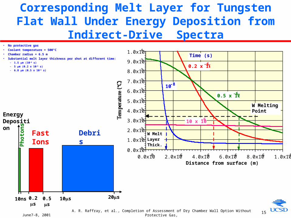
Corresponding Melt Layer for Tungsten Flat Wall Under Energy Deposition from Indirect-Drive Spectra
• No protective gas• Coolant temperature = 500°C• Chamber radius = 6.5 m• Substantial melt layer thickness per shot at different time:
– 1.5 m (10-8 s)
– 5 m (0.2 x 10⁻⁶ s)
– 6.8 m (0.5 x 10⁻⁶ s)
0.0x100
1.0x10³
2.0x10³
3.0x10³
4.0x10³
5.0x10³
6.0x10³
7.0x10³
8.0x10³
9.0x10³
1.0x10⁴
0.0x100 2.0x10⁻⁶ 4.0x10⁻⁶ 6.0x10⁻⁶ 8.0x10⁻⁶ 1.0x10⁻⁵
Distance from surface (m)
Time (s)
10-8
0.2 x 10⁻⁶
0.5 x 10⁻⁶
10 x 10-6
W MeltingPoint
W MeltLayerThick.P
hot
ons
Debris Ions
10ns 0.2s 10s 20s
FastIons
Energy Deposition
0.5s
June7-8, 2001A. R. Raffray, et al., Completion of Assessment of Dry Chamber Wall Option Without Protective Gas,
and Initial Planning Activity for Assessment of Wetted Wall Option 16
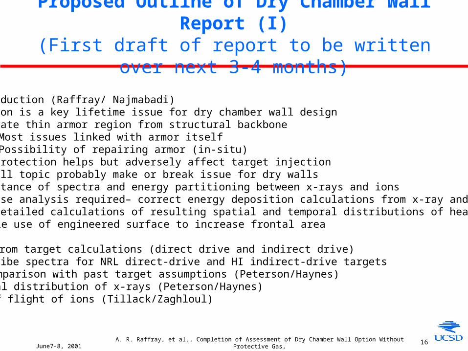
Proposed Outline of Dry Chamber Wall Report (I)(First draft of report to be written over next 3-4 months)
1. Introduction (Raffray/ Najmabadi)• Erosion is a key lifetime issue for dry chamber wall design • Separate thin armor region from structural backbone
- Most issues linked with armor itself- Possibility of repairing armor (in-situ)
• Gas protection helps but adversely affect target injection• Overall topic probably make or break issue for dry walls• Importance of spectra and energy partitioning between x-rays and ions• Precise analysis required– correct energy deposition calculations from x-ray and ion spectrum
and detailed calculations of resulting spatial and temporal distributions of heat fluxes• Possible use of engineered surface to increase frontal area
2. Spectra from target calculations (direct drive and indirect drive) • Describe spectra for NRL direct-drive and HI indirect-drive targets
- Comparison with past target assumptions (Peterson/Haynes)• Temporal distribution of x-rays (Peterson/Haynes)• Time of flight of ions (Tillack/Zaghloul)

June7-8, 2001A. R. Raffray, et al., Completion of Assessment of Dry Chamber Wall Option Without Protective Gas,
and Initial Planning Activity for Assessment of Wetted Wall Option 17
Outline of Dry Chamber Wall Report (II)
3. Calculations of spatial distribution of energy deposition with (Peterson/Haynes) and without (Zaghloul/Raffray) protective gas
3.1 Direct drive NRL target• x-rays• fast ions• slow ions• Importance of fine grids
- Calculations of temporal variation of energy deposition- As a function of protective gas pressure- Sensitivity analysis for model assumption (e.g. for lower energy ions)
3.2 Indirect drive target• Same as for direct drive
4. Material properties at temperature and under irradiation (Billone)• Carbon• W
June7-8, 2001A. R. Raffray, et al., Completion of Assessment of Dry Chamber Wall Option Without Protective Gas,
and Initial Planning Activity for Assessment of Wetted Wall Option 18
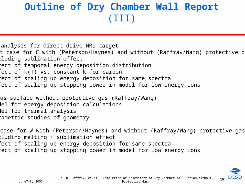
Outline of Dry Chamber Wall Report (III)
5. Thermal analysis for direct drive NRL target• Flat case for C with (Peterson/Haynes) and without (Raffray/Wang) protective gas- Including sublimation effect - Effect of temporal energy deposition distribution - Effect of k(T) vs. constant k for carbon- Effect of scaling up energy deposition for same spectra- Effect of scaling up stopping power in model for low energy ions
• Fibrous surface without protective gas (Raffray/Wang)- Model for energy deposition calculations - Model for thermal analysis - Parametric studies of geometry
• Flat case for W with (Peterson/Haynes) and without (Raffray/Wang) protective gas- Including melting + sublimation effect - Effect of scaling up energy deposition for same spectra- Effect of scaling up stopping power in model for low energy ions
June7-8, 2001A. R. Raffray, et al., Completion of Assessment of Dry Chamber Wall Option Without Protective Gas,
and Initial Planning Activity for Assessment of Wetted Wall Option 19
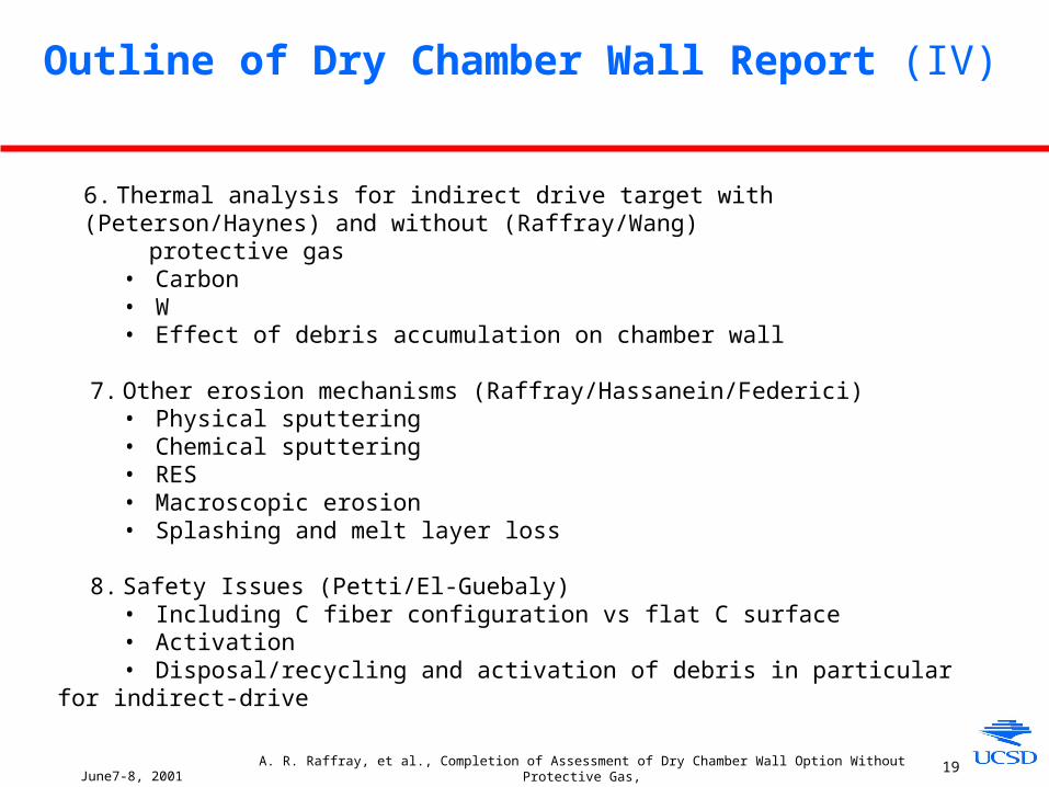
Outline of Dry Chamber Wall Report (IV)
6. Thermal analysis for indirect drive target with (Peterson/Haynes) and without (Raffray/Wang) protective gas
• Carbon• W• Effect of debris accumulation on chamber wall
7. Other erosion mechanisms (Raffray/Hassanein/Federici)• Physical sputtering• Chemical sputtering• RES• Macroscopic erosion• Splashing and melt layer loss
8. Safety Issues (Petti/El-Guebaly) • Including C fiber configuration vs flat C surface
• Activation• Disposal/recycling and activation of debris in particular for indirect-drive
June7-8, 2001A. R. Raffray, et al., Completion of Assessment of Dry Chamber Wall Option Without Protective Gas,
and Initial Planning Activity for Assessment of Wetted Wall Option 20
Outline of Dry Chamber Wall Report (V)
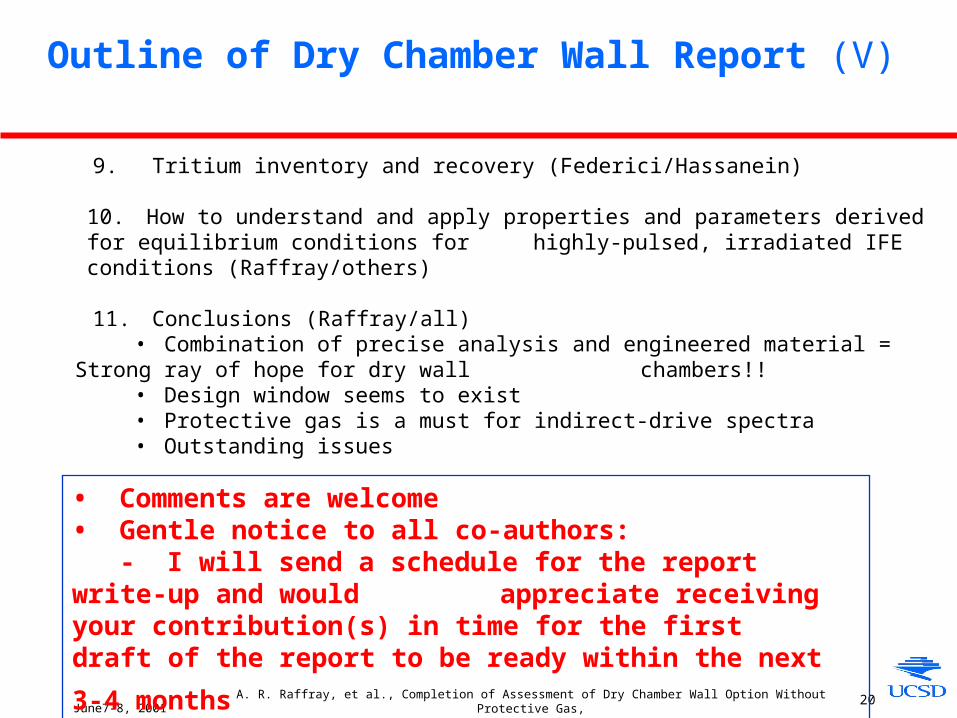
9. Tritium inventory and recovery (Federici/Hassanein)
10. How to understand and apply properties and parameters derived for equilibrium conditions for highly-pulsed, irradiated IFE conditions (Raffray/others)
11. Conclusions (Raffray/all)• Combination of precise analysis and engineered material = Strong ray of hope for dry
wall chambers!!• Design window seems to exist• Protective gas is a must for indirect-drive spectra• Outstanding issues
• Comments are welcome• Gentle notice to all co-authors:
- I will send a schedule for the report write-up and would appreciate receiving your contribution(s) in time for the first
draft of the report to be ready within the next 3-4 months
June7-8, 2001A. R. Raffray, et al., Completion of Assessment of Dry Chamber Wall Option Without Protective Gas,
and Initial Planning Activity for Assessment of Wetted Wall Option 21
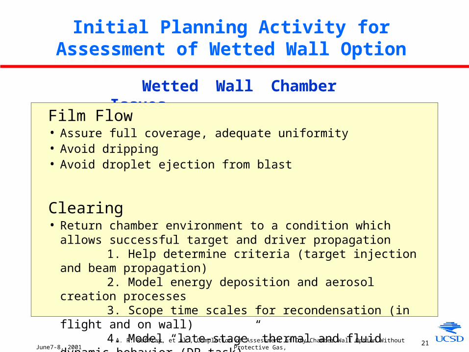
Initial Planning Activity for Assessment of Wetted Wall Option
Wetted Wall Chamber Issues
Film Flow• Assure full coverage, adequate uniformity• Avoid dripping• Avoid droplet ejection from blast
Clearing• Return chamber environment to a condition which allows successful target and
driver propagation1. Help determine criteria (target injection and beam propagation)2. Model energy deposition and aerosol creation processes3. Scope time scales for recondensation (in flight and on wall)4. Model “late-stage” thermal and fluid dynamic behavior (DP task)
June7-8, 2001A. R. Raffray, et al., Completion of Assessment of Dry Chamber Wall Option Without Protective Gas,
and Initial Planning Activity for Assessment of Wetted Wall Option 22
liquid
vapor
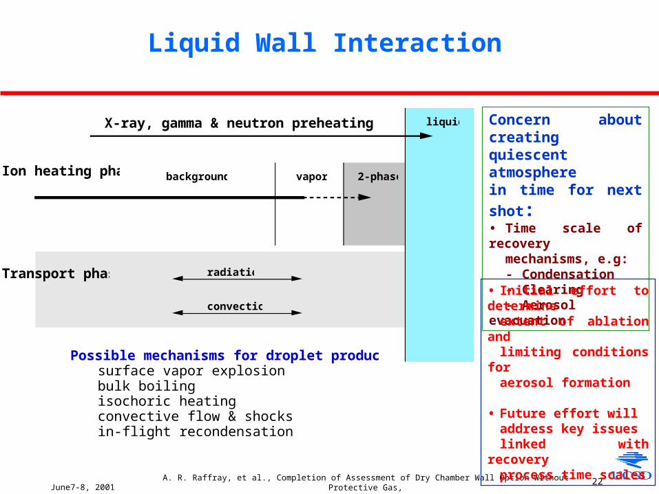
X-ray, gamma & neutron preheating phase:
Ion heating phase: background 2-phase
Possible mechanisms for droplet production:surface vapor explosionbulk boilingisochoric heatingconvective flow & shocksin-flight recondensation
Transport phase: radiation
convection
Liquid Wall Interaction
Concern about creating quiescent atmosphere
in time for next shot:• Time scale of recovery
mechanisms, e.g:- Condensation- Clearing- Aerosol evacuation
• Initial effort to determineextent of ablation andlimiting conditions foraerosol formation
• Future effort will address key issues linked with recovery process time scales
June7-8, 2001A. R. Raffray, et al., Completion of Assessment of Dry Chamber Wall Option Without Protective Gas,
and Initial Planning Activity for Assessment of Wetted Wall Option 23
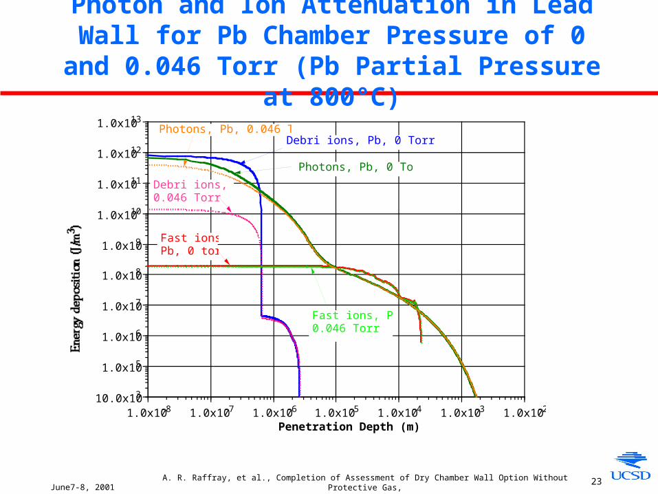
Photon and Ion Attenuation in Lead Wall for Pb Chamber Pressure of 0 and 0.046 Torr (Pb Partial
Pressure at 800°C)
10.0x10³
1.0x10⁵
1.0x10⁶
1.0x10⁷
1.0x10⁸
1.0x10⁹
1.0x10¹⁰
1.0x10¹¹
1.0x10¹²
1.0x10¹³
1.0x10⁻⁸ 1.0x10⁻⁷ 1.0x10⁻⁶ 1.0x10⁻⁵ 1.0x10⁻⁴ 1.0x10⁻³ 1.0x10⁻²
Penetration Depth (m)
Photons, Pb, 0 Torr
Photons, Pb, 0.046 Torr
Fast ions,Pb, 0 torr
Fast ions, Pb,0.046 Torr
Debri ions, Pb, 0 Torr
Debri ions, Pb,0.046 Torr
Related Documents