JOURNAL OF L A T E X CLASS FILES, VOL. 6, NO. 1, JANUARY 2007 1 A Projector-based Movable Hand-held Display System for Interactive 3D Model Exhibition Authors Abstract—Traditional display systems usually display objects on static screens (monitors, walls etc) and the interaction between the displaying object and the viewer can only be via keyboard and mouse. It will be attractive if we display the object to a hand-held screen and interact with it using our hands as we do in our daily lives. In this paper, we propose a prototype system by projecting the object to a hand-held foam sphere. The target is to develop an interactive 3D model exhibition tool without the viewer having to wear spectacles. In our system, the viewer holds the sphere with his hands and moves it freely. Meanwhile we project well-tailored images onto the sphere coincident with the movement of it, giving the viewer a virtual perception as if the object is sitting inside the sphere and being moved by the viewer. The design goals of our system are low-cost, real-time, live, and 3D. An off-the-shelf projector-camera pair is first calibrated via a simple but efficient algorithm. Vision based algorithms are proposed to detect the sphere and track its subsequent motion. To adapt to different application scenarios, we develop two kinds of configurations to track the sphere. The projection image is generated based on the projective geometry among the projector, sphere, camera and the viewer. We discuss how to allocate the view spot and warp the projection image. We also present the result and the performance evaluation of the system. Index Terms—Virtual and augmented reality, 3D interactive display, projector-camera system, object tracking. I. I NTRODUCTION T RADITIONAL 2D display systems usually display ob- jects on static screens and the viewer interacts with it using keyboard and mouse, thus having the disadvantage of unnatural user interaction and low perceived level of reality. Projector is a good choice to improve the freedom and interaction of these systems, but existing ones usually display 2D information.Moveover, special hardware such as magnetic sensors are usually included in these system. Polarization techniques are popular to create 3D perception, but it require the viewer to wear specially-designed spectacles. It is still challenging to develop an interactive 3D display system in low-cost and easily-built fashion. As an attempt, this paper proposes a system for interactive 3D object exhibition, in which we display the 3D model of the object to a hand-held screen and we can interact with it using own hands directly as we do in our daily lives. The proposed system finds many applications in real life. For instance, in a museum mounted with many projectors, the visitor can use this hand-held sphere to explore the computer- generated copy of the original relics which are not available to the visitor for touching. In this way, the visitor have a realistic feeling about the relics just like holding it in the hands while the relics is protected from damage. Manufacturers can also Manuscript received October, 2009. (a) (b) (c) (d) Fig. 1. The configuration of our system: (a) The rig; (b) The projector, camera and Wiimote; (c) The sphere with 4 IR LEDs. (d) The sphere and the cardboard. use this tool to examine a new product which is still in the design stage and a real product is not available. It will help the designer to have a better evaluation of the product before it is put on stream. The objective of our work is to build a low cost, easily-built and workable 3D interactive object exhibition tool without the viewer to wear spectacles. Instead of using magnetic sensors or specially-designed hardwares, we use several low- cost off-the-shelf devices and computer vision techniques to build the system. The main idea of the system is to project the displaying object onto a hand-held sphere. When the viewer moves and rotates the sphere, we use object tracking techniques to track the translation and rotation of the sphere. Meanwhile, based on the pre-calibrated projective geometry among the camera, sphere, projector and the viewer, we project well-tailored images of the object onto the sphere depending on the translation and rotation of it. By continuously adjusting the images projected to the sphere as it moves and rotates, the motion parallax gives the viewer a virtual 3D perception as if the object is sitting inside the sphere and being moved and rotated by the user directly. This gives the viewer a direct, natural and realistic experience. The devices used in our system include a projector, a webcam, a Nintendo Wiimote and a foam sphere. To adapt to different application scenarios, we design two kinds of configurations to track the sphere. In the first configuration, we embed four IR LEDs on the

Welcome message from author
This document is posted to help you gain knowledge. Please leave a comment to let me know what you think about it! Share it to your friends and learn new things together.
Transcript

JOURNAL OF LATEX CLASS FILES, VOL. 6, NO. 1, JANUARY 2007 1
A Projector-based Movable Hand-held DisplaySystem for Interactive 3D Model Exhibition
Authors
Abstract—Traditional display systems usually display objectson static screens (monitors, walls etc) and the interaction betweenthe displaying object and the viewer can only be via keyboardand mouse. It will be attractive if we display the object to ahand-held screen and interact with it using our hands as we doin our daily lives. In this paper, we propose a prototype systemby projecting the object to a hand-held foam sphere. The targetis to develop an interactive 3D model exhibition tool withoutthe viewer having to wear spectacles. In our system, the viewerholds the sphere with his hands and moves it freely. Meanwhilewe project well-tailored images onto the sphere coincident withthe movement of it, giving the viewer a virtual perception as ifthe object is sitting inside the sphere and being moved by theviewer. The design goals of our system are low-cost, real-time, live,and 3D. An off-the-shelf projector-camera pair is first calibratedvia a simple but efficient algorithm. Vision based algorithms areproposed to detect the sphere and track its subsequent motion.To adapt to different application scenarios, we develop two kindsof configurations to track the sphere. The projection image isgenerated based on the projective geometry among the projector,sphere, camera and the viewer. We discuss how to allocate theview spot and warp the projection image. We also present theresult and the performance evaluation of the system.
Index Terms—Virtual and augmented reality, 3D interactivedisplay, projector-camera system, object tracking.
I. INTRODUCTION
TRADITIONAL 2D display systems usually display ob-jects on static screens and the viewer interacts with it
using keyboard and mouse, thus having the disadvantage ofunnatural user interaction and low perceived level of reality.Projector is a good choice to improve the freedom andinteraction of these systems, but existing ones usually display2D information.Moveover, special hardware such as magneticsensors are usually included in these system. Polarizationtechniques are popular to create 3D perception, but it requirethe viewer to wear specially-designed spectacles. It is stillchallenging to develop an interactive 3D display system inlow-cost and easily-built fashion. As an attempt, this paperproposes a system for interactive 3D object exhibition, inwhich we display the 3D model of the object to a hand-heldscreen and we can interact with it using own hands directlyas we do in our daily lives.
The proposed system finds many applications in real life.For instance, in a museum mounted with many projectors, thevisitor can use this hand-held sphere to explore the computer-generated copy of the original relics which are not available tothe visitor for touching. In this way, the visitor have a realisticfeeling about the relics just like holding it in the hands whilethe relics is protected from damage. Manufacturers can also
Manuscript received October, 2009.
(a) (b)
(c) (d)Fig. 1. The configuration of our system: (a) The rig; (b) The projector,camera and Wiimote; (c) The sphere with 4 IR LEDs. (d) The sphere and thecardboard.
use this tool to examine a new product which is still in thedesign stage and a real product is not available. It will helpthe designer to have a better evaluation of the product beforeit is put on stream.
The objective of our work is to build a low cost, easily-builtand workable 3D interactive object exhibition tool withoutthe viewer to wear spectacles. Instead of using magneticsensors or specially-designed hardwares, we use several low-cost off-the-shelf devices and computer vision techniques tobuild the system. The main idea of the system is to projectthe displaying object onto a hand-held sphere. When theviewer moves and rotates the sphere, we use object trackingtechniques to track the translation and rotation of the sphere.Meanwhile, based on the pre-calibrated projective geometryamong the camera, sphere, projector and the viewer, we projectwell-tailored images of the object onto the sphere dependingon the translation and rotation of it. By continuously adjustingthe images projected to the sphere as it moves and rotates,the motion parallax gives the viewer a virtual 3D perceptionas if the object is sitting inside the sphere and being movedand rotated by the user directly. This gives the viewer adirect, natural and realistic experience. The devices used inour system include a projector, a webcam, a Nintendo Wiimoteand a foam sphere. To adapt to different application scenarios,we design two kinds of configurations to track the sphere.In the first configuration, we embed four IR LEDs on the
khwong
Typewriter
Zhaorong Li , KH Wong, MC Leung, HF Ko, KK Lee and MMYuen Chang, Multimedia Systems, Springer, Volume 17, Number 5, 435-447, February 2011.
khwong
Rectangle
2 JOURNAL OF LATEX CLASS FILES, VOL. 6, NO. 1, JANUARY 2007
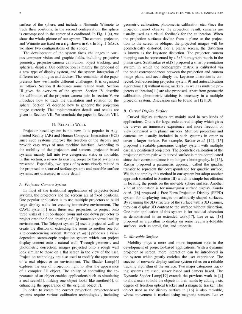
surface of the sphere, and include a Nintendo Wiimote totrack their positions. In the second configuration, the sphereis encompassed in the center of a cardboard. In Fig. 1 (a), weshow the whole picture of our system. The camera, projector,and Wiimote are fixed on a rig, shown in (b). In Fig. 1 (c),(d),we show two configurations of the sphere.
The development of the system faces challenges in vari-ous computer vision and graphic fields, including projectivegeometry, projector-camera calibration, object tracking, andspherical display. Our contribution is mainly the proposal ofa new type of display system, and the system integration ofdifferent technologies and devices. The remainder of the paperpresents how we handle different challenges. It is organizedas follows. Section II discusses some related work. SectionIII gives the overview of the system. Section IV describethe calibration of the projector-camera pair. In section V, weintroduce how to track the translation and rotation of thesphere. Section VI describe how to generate the projectionimage correctly. The implementation details and results aregiven in Section VII. We conclude the paper in Section VIII.
II. RELATED WORK
Projector based system is not new. It is popular in Aug-mented Reality (AR) and Human Computer Interaction (HCI)since such systems improve the freedom of the display andprovide easy ways of man machine interface. According tothe mobility of the projectors and screens, projector basedsystems mainly fall into two categories: static or movable.In this section, a review to existing projector based systems ispresented. Especially, two types of systems closely related tothe proposed one, curved-surface systems and movable-surfacesystems, are discussed in more detail.
A. Projector Camera System
In most of the traditional applications of projector-basedsystems, the projectors and the screens are at fixed positions.One popular application is to use multiple projectors to buildlarge display walls for creating immersive environment. TheCAVE system[1] uses three rear projectors to project ontothree walls of a cube-shaped room and one down projector toproject onto the floor, creating a fully immersive virtual realityenvironment. The Teleport system[2] uses a projected wall tocreate the illusion of extending the room to another one fora teleconferencing system. Bimber et. al[3] proposes a view-dependent stereoscopic projection system which can projectdisplay content onto a natural wall. Through geometric andphotometric correction, images projected onto a rough walllook similar to those on a flat screen in the view of the user.Projection technology are also used to modify the appearanceof a real object or an environment. The Shader Lamp[4]explores the use of projection light to alter the appearanceof a complex 3D object. The ability of controlling the ap-pearance of an object enables applications such as simulatinga real scene[5], making one object looks like another[6], orenhancing the appearance of the original object[7].
In order to create the correct projection, projector-basedsystems require various calibration technologies , including
geometric calibration, photometric calibration etc. Since theprojector cannot observe the projection result, cameras areusually used as a visual feedback for the calibration. Whenthe projection surfaces deviate from a plane or the projec-tion to the screen is oblique, the projected images will begeometrically distorted. For a planar screen, the distortionis known as the keystone distortion. The projector cameramapping can be represented by a 3x3 homograph matrix in theplanar case. Sukthankar et al.[8] proposed a smart presentationsystem, in which the homography matrix is calibrated viathe point correspondences between the projection and cameraimage plane, and accordingly the keystone distortion is cor-rected. Self-correcting projector system[9] and autocalibrationalgorithms[10] without using markers, as well as multiple pro-jectors calibration[11] are also proposed. Apart from geometriccalibration, photometric stiching is necessary in a multipleprojector system. Discussion can be found in [12][13].
B. Curved Display Surface
Curved display surfaces are mainly used in two kinds ofapplications. One is for large scale curved display which givesthe viewer an immersive experience and more freedom ofview compared with planar surfaces. Multiple projectors andcameras are usually included in such systems in order tocover a larger surface. For example, Raskar et al. [14], [15]proposed a scalable panoramic display system with multiplecasually positioned projectors. The geometric calibration of theprojector-camera pair with curved surface is more complicatedsince their correspondence is no longer a homography. In [15],Raskar proposed a parametric approach called the quadrictransfer to represent the correspondence for quadric surface.We do not employ this method in our system but adopt anotherapproach (detailed in Section III) which is simple but efficientin locating the points on the movable sphere surface. Anotherkind of application is for non-regular surface display. Kondoet al. [16] proposed a Free Form Projection Display (FFPD)system for displaying images on arbitrarily-shaped surfaces.By scanning the 3D structure of the surface with a 3D scanner,they can display 3D content to the surface without distortion.One main application of this system is for medical educationas demonstrated in an extended work[17]. Lee et al. [18]proposed an algorithm to display on some regularly-foldablesurfaces, such as scroll, fan, and umbrella.
C. Moveable Surface
Mobility plays a more and more important role in thedevelopment of projector-based applications. With a dynamicprojector or screen, more interaction can be introduced inthe system which greatly enriches the user experience. Thesuccess of movable display surface system relies on a reliabletracking algorithm of the surface. Two major categories track-ing systems are used, sensor based and camera based. TheDynamic Shader Lamp[19] extends the previous work in [4]to allow users to hold the objects in their hands by adding a sixdegree of freedom optical tracker and a magnetic tracker. Theobject used as the display surface in [16] is also movable,whose movement is tracked using magnetic sensors. Lee et
SHELL et al.: BARE DEMO OF IEEETRAN.CLS FOR JOURNALS 3
Offline system calibration
Sphere rotation and
translation tracking
Movement and view
dependent projection
Sphere size, camera
parameters, Wiimote
paramters,
Live capture Live projection
TR,
c
pM
3D object Model to display
Texture Shape
c
pM
Camera
Projector
Wiimote
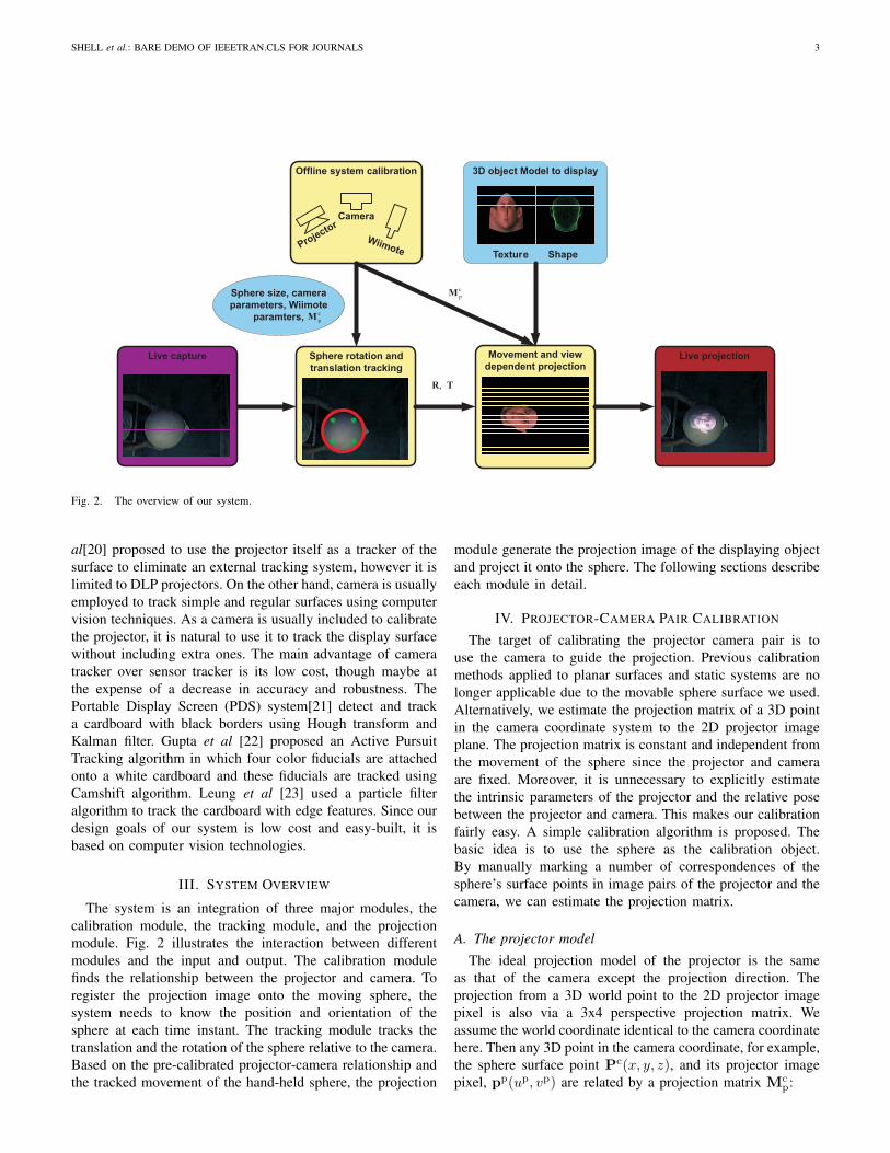
Fig. 2. The overview of our system.
al[20] proposed to use the projector itself as a tracker of thesurface to eliminate an external tracking system, however it islimited to DLP projectors. On the other hand, camera is usuallyemployed to track simple and regular surfaces using computervision techniques. As a camera is usually included to calibratethe projector, it is natural to use it to track the display surfacewithout including extra ones. The main advantage of cameratracker over sensor tracker is its low cost, though maybe atthe expense of a decrease in accuracy and robustness. ThePortable Display Screen (PDS) system[21] detect and tracka cardboard with black borders using Hough transform andKalman filter. Gupta et al [22] proposed an Active PursuitTracking algorithm in which four color fiducials are attachedonto a white cardboard and these fiducials are tracked usingCamshift algorithm. Leung et al [23] used a particle filteralgorithm to track the cardboard with edge features. Since ourdesign goals of our system is low cost and easy-built, it isbased on computer vision technologies.
III. SYSTEM OVERVIEW
The system is an integration of three major modules, thecalibration module, the tracking module, and the projectionmodule. Fig. 2 illustrates the interaction between differentmodules and the input and output. The calibration modulefinds the relationship between the projector and camera. Toregister the projection image onto the moving sphere, thesystem needs to know the position and orientation of thesphere at each time instant. The tracking module tracks thetranslation and the rotation of the sphere relative to the camera.Based on the pre-calibrated projector-camera relationship andthe tracked movement of the hand-held sphere, the projection
module generate the projection image of the displaying objectand project it onto the sphere. The following sections describeeach module in detail.
IV. PROJECTOR-CAMERA PAIR CALIBRATION
The target of calibrating the projector camera pair is touse the camera to guide the projection. Previous calibrationmethods applied to planar surfaces and static systems are nolonger applicable due to the movable sphere surface we used.Alternatively, we estimate the projection matrix of a 3D pointin the camera coordinate system to the 2D projector imageplane. The projection matrix is constant and independent fromthe movement of the sphere since the projector and cameraare fixed. Moreover, it is unnecessary to explicitly estimatethe intrinsic parameters of the projector and the relative posebetween the projector and camera. This makes our calibrationfairly easy. A simple calibration algorithm is proposed. Thebasic idea is to use the sphere as the calibration object.By manually marking a number of correspondences of thesphere’s surface points in image pairs of the projector and thecamera, we can estimate the projection matrix.
A. The projector model
The ideal projection model of the projector is the sameas that of the camera except the projection direction. Theprojection from a 3D world point to the 2D projector imagepixel is also via a 3x4 perspective projection matrix. Weassume the world coordinate identical to the camera coordinatehere. Then any 3D point in the camera coordinate, for example,the sphere surface point Pc(x, y, z), and its projector imagepixel, pp(up, vp) are related by a projection matrix Mc
p:

4 JOURNAL OF LATEX CLASS FILES, VOL. 6, NO. 1, JANUARY 2007
cP
x
zo
cS
y
cp
pp
Fig. 3. The projective geometry between the project camera pair.
sp̃p = McpP
c (1)
and
Mcp =
m11 m12 m13 m14
m21 m22 m23 m24
m31 m32 m33 m34
=
fu 0 u0
0 fv v0
0 0 1
(
R T)
(2)
Here, fu, fv, u0, v0 are the intrinsic parameters of theprojector. R and T are the rotation matrix and translationvector from the camera to the projector. In our system, wedon’t need to explicitly estimate the intrinsic and extrinsicparameters, but instead we only need to estimate the projectionmatrix Mc
p.
B. Estimation of the projection matrix
The projective geometry of the projector camera pair isshown in Fig. 3. The light from some pixel pp(up, vp) in theprojector image intersects the sphere at Pc(x, y, z) (in cameracoordinate), and then create pixel pc(uc, vc) in the camera.These three points (pp,Pc,pc) form a correspondence. Thebasic idea of estimating the projection matrix is to collect anumber of such correspondences. We collect each correspon-dence in this way: we project a cross onto the sphere surfaceand observe the cross using the camera. An example of theprojection cross image and the corresponding image observedby the camera is shown in Fig. 4. The 2D coordinates ofthe points pp, and pc can be manually labeled while the 3Dcoordinates of the points on the sphere surface Pc cannot bedirectly obtained. In order to calculate Pc, we first need tolocate the 3D position of the sphere’s center in the cameracoordinate.
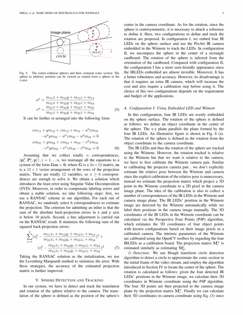
The 3D position of the sphere can be located based onits image in the camera. According to [24], the image of asphere is a conic section under the pinhole perspective cameramodel. Since the depth information is lost in perspectiveprojection, the conic section could be created by a familyof center-collinear spheres. Only given the conic section, wecannot uniquely recognize the true sphere out of the family.However, once the physical radius of the sphere is given, wecan uniquely locate the sphere. We use the geometric method
(a) (b)Fig. 4. Finding correspondence between the projector and camera image.(a) The cross image projected to the sphere; (b) The cross image observedby the camera.
proposed in [25] to locate the sphere’s center. The basic ideaof the method is to investigate the relationship between thegeneral case where the sphere locates in arbitrary position andthe special case where the sphere lies at some position alongthe z-axis of the camera. In the special case, the image of thesphere is a circle and the sphere’s center can be easily locatedgiven the circle. The sphere in arbitrary position can be viewedas rotated from a sphere in the z-axis. Accordingly, the imageof the sphere changes from a circle to a conic section due tothe rotation. This is illustrated in Fig. 5. So given the conicsection, we first regulate it to a circle and obtain the rotation.Then we locate the sphere’s center in the special case based onthe circle and rotate it to get the sphere’s center in the generalcase with the same rotation. In our implementation, we use theHough transform circle detection algorithm to detect a circleas the approximation of the conic section.
After the sphere’s center is located, we can locate thecorresponding point on the sphere surface for each pixel withinthe conic section. For each correspondence (pp,Pc,pc), thesphere surface point Pc in camera coordinate should satisfythe following equations:
sp̃c = KcPc
‖Pc − Sc‖22 = R2 (3)
where s is a scale factor, p̃c is the homogeneous coordinateof pc, and Kc is the intrinsic parameter matrix of the camerawhich is calibrated beforehand using the OpenCV toolbox.The first equation is the projection equation, and the secondis to constrain the distance between the surface point andthe sphere center. We solve them to obtain Pc for eachcorrespondence. Note that two solutions can be obtained butwe simply discard the one further from the camera centerbecause it is irreasonable.
Now for each calculated correspondence, we can write aprojection equation according to Eq. (1) and Eq. (2):
s
up
vp
1
=
m11 m12 m13 m14
m21 m22 m23 m24
m31 m32 m33 m34
xyz1
(4)
We rewrite it in the equivalent form by eliminating the scalefactor:
SHELL et al.: BARE DEMO OF IEEETRAN.CLS FOR JOURNALS 5
o
R
z
R
)(0,0,d
C
circle
cs
Fig. 5. The center-collinear spheres and their common conic section. Thesphere in arbitrary position can be viewed as rotated from a sphere in thez-axis.
up =m11x + m12y + m13z + m14
m31x + m32y + m33z + m34
vp =m21x + m22y + m23z + m24
m31x + m32y + m33z + m34(5)
It can be further re-arranged into the following form:
xm11 + ym12 + zm13 + m14 − upxm31
−upym32 − upzm33 − upm34 = 0xm21 + ym22 + zm23 + m24 − vpxm31
−vpym32 − vpzm33 − vpm34 = 0 (6)
Assuming that we collect totally n correspondences,(pp
i ,Pci ,p
ci ) , i = 1 . . . n, we rearrange all the equations to a
system of the form Gm = 0, where G is a 2n×12 matrix, mis a 12 × 1 vector arrangement of the rows of the projectionmatrix. There are totally 12 variables, so n ≥ 6 correspon-dences are enough to solve it. We obtain a solution whichintroduces the least error using Singular Value Decomposition(SVD). Moreover, in order to compensate labeling errors andobtain a stable solution, we take following steps: first, weuse a RANSAC scheme in our algorithm. For each run ofRANSAC, we randomly select 6 correspondences to estimatethe projection. The criterion for admitting an inlier is that thesum of the absolute back-projection errors in x and y axisis below 10 pixels. Second, a fine adjustment is carried outon the RANSAC result. It minimize the following sum of thesquared back-projection errors:
n∑
i=1
(upi −
m11xi + m12yi + m13zi + m14
m31xi + m32yi + m33zi + m34)2 +
(vpi −
m21xi + m22yi + m23zi + m24
m31xi + m32yi + m33zi + m34)2 (7)
Taking the RANSAC solution as the initialization, we usethe Levenberg-Marquardt method to minimize the error. Withthese strategies, the accuracy of the estimated projectionmatrix is further improved.
V. SPHERE DETECTION AND TRACKING
In our system, we have to detect and track the translationand rotation of the sphere relative to the camera. The trans-lation of the sphere is defined as the position of the sphere’s
center in the camera coordinate. As for the rotation, since thesphere is centrisymmetric, it is necessary to attach a referenceto define it. Here, two configurations to define and track therotation are proposed. In configuration I, we embed four IRLEDs on the sphere surface and use the PixArt IR cameraembedded in the Wiimote to track the LEDs. In configurationII, we encompass the sphere in the center of a rectanglecardboard. The rotation of the sphere is inferred from theorientation of the cardboard. Compared with configuration II,the configuration I has a more user-friendly appearance sincethe IRLEDs embedded are almost invisible. Moreover, It hasa better robustness and accuracy. However, its disadvantage isthat it requires an extra IR camera, which will increase thecost and also require a calibration step before using it. Thechoice of this two configurations depends on the requirementand budget of the applications.
A. Configuration I: Using Embedded LED and Wiimote
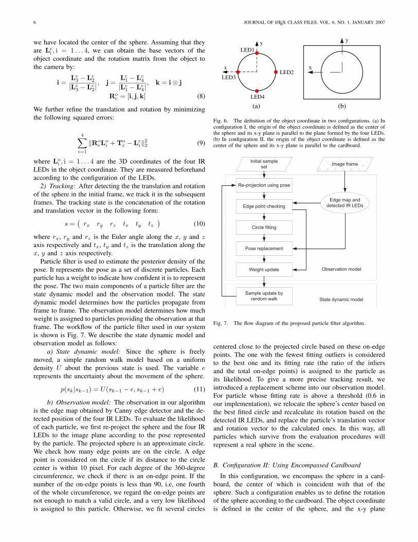
In this configuration, four IR LEDs are evenly embeddedon the sphere surface. The rotation of the sphere is definedas follows: we define an object coordinate in the center ofthe sphere. The x-y plane parallels the plane formed by thefour IR LEDs. An illustrative figure is shown in Fig. 6 (a).The rotation of the sphere is defined as the rotation from theobject coordinate to the camera coordinate.
The IR LEDs and thus the rotation of the sphere are trackedusing the Wiimote. However, the rotation tracked is relativeto the Wiimote but that we want is relative to the camera,we have to first calibrate the Wiimote camera pair. Similarto calibrating the projector camera pair , we don’t explicitlyestimate the relative pose between the Wiimote and camerasince the explicit calibration of the relative pose is unnecessary,instead we estimate the projection matrix which project a 3Dpoint in the Wiimote coordinate to a 2D pixel in the cameraimage plane. The idea of the calibration is also to collect anumber of correspondences of the IR LEDs in the Wiimote andcamera image plane. The IR LEDs’ position in the Wiimoteimage are detected by the Wiimote automatically while welabel their positions in the camera image manually. The 3Dcoordinates of the IR LEDs in the Wiimote coordinate can becalculated via the Perspective Four Points (P4P) algorithm,which estimates the 3D coordinates of four object pointswith known configurations based on their image pixels in acalibrated camera. The intrinsic parameters of the Wiimoteare calibrated using the OpenCV toolbox by regarding the fourIRLEDs as a calibration board. The projection matrix Mw
c isestimated similarly as estimating Mc
p.1) Detection: We use Hough transform circle detection
algorithm to detect a circle to approximate the conic section inthe initial frame of the video stream, and employ the algorithmintroduced in Section IV to locate the center of the sphere. Therotation is calculated as follows: given the four detected IRLEDs’ positions in the Wiimote image, we calculate their 3Dcoordinates in Wiimote coordinate using the P4P algorithm.The four 3D points are then projected to the camera imageplane by the projection matrix Mw
c . Finally we can calculatetheir 3D coordinates in camera coordinate using Eq. (3) since
6 JOURNAL OF LATEX CLASS FILES, VOL. 6, NO. 1, JANUARY 2007
we have located the center of the sphere. Assuming that theyare Lc
i , i = 1 . . . 4, we can obtain the base vectors of theobject coordinate and the rotation matrix from the object tothe camera by:
i =Lc
3 − Lc2
|Lc3 − Lc
2|, j =
Lc1 − Lc
4
|Lc1 − Lc
4|, k = i⊗ j
Roc = [i, j,k] (8)
We further refine the translation and rotation by minimizingthe following squared errors:
4∑
i=1
‖RocL
oi + To
c − Lci‖22 (9)
where Loi , i = 1 . . . 4 are the 3D coordinates of the four IR
LEDs in the object coordinate. They are measured beforehandaccording to the configuration of the LEDs.
2) Tracking: After detecting the the translation and rotationof the sphere in the initial frame, we track it in the subsequentframes. The tracking state is the concatenation of the rotationand translation vector in the following form:
s =(
rx ry rz tx ty tz)
(10)
where rx, ry and rz is the Euler angle along the x, y and zaxis respectively and tx, ty and tz is the translation along thex, y and z axis respectively.
Particle filter is used to estimate the posterior density of thepose. It represents the pose as a set of discrete particles. Eachparticle has a weight to indicate how confident it is to representthe pose. The two main components of a particle filter are thestate dynamic model and the observation model. The statedynamic model determines how the particles propagate fromframe to frame. The observation model determines how muchweight is assigned to particles providing the observation at thatframe. The workflow of the particle filter used in our systemis shown is Fig. 7. We describe the state dynamic model andobservation model as follows:
a) State dynamic model: Since the sphere is freelymoved, a simple random walk model based on a uniformdensity U about the previous state is used. The variable erepresents the uncertainty about the movement of the sphere.
p(sk|sk−1) = U(sk−1 − e, sk−1 + e) (11)
b) Observation model: The observation in our algorithmis the edge map obtained by Canny edge detector and the de-tected position of the four IR LEDs. To evaluate the likelihoodof each particle, we first re-project the sphere and the four IRLEDs to the image plane according to the pose representedby the particle. The projected sphere is an approximate circle.We check how many edge points are on the circle. A edgepoint is considered on the circle if its distance to the circlecenter is within 10 pixel. For each degree of the 360-degreecircumference, we check if there is an on-edge point. If thenumber of the on-edge points is less than 90, i.e, one fourthof the whole circumference, we regard the on-edge points arenot enough to match a valid circle, and a very low likelihoodis assigned to this particle. Otherwise, we fit several circles
y
x
LED1
LED2LED3
LED4
y
x
(a) (b)
Fig. 6. The definition of the object coordinate in two configurations. (a) Inconfiguration I, the origin of the object coordinate is defined as the center ofthe sphere and its x-y plane is parallel to the plane formed by the four LEDs.(b) In configuration II, the origin of the object coordinate is defined as thecenter of the sphere and its x-y plane is parallel to the cardboard.
Re-projection using pose
Edge point checking
Circle fitting
Pose replacement
Weight update
Initial sample
setImage frame
Edge map and
detected IR LEDs
Sample update by
random walk
Observation model
State dynamic model
Fig. 7. The flow diagram of the proposed particle filter algorithm.
centered close to the projected circle based on these on-edgepoints. The one with the fewest fitting outliers is consideredto the best one and its fitting rate (the ratio of the inliersand the total on-edge points) is assigned to the particle asits likelihood. To give a more precise tracking result, weintroduced a replacement scheme into our observation model.For particle whose fitting rate is above a threshold (0.6 inour implementation), we relocate the sphere’s center based onthe best fitted circle and recalculate its rotation based on thedetected IR LEDs, and replace the particle’s translation vectorand rotation vector to the calculated ones. In this way, allparticles which survive from the evaluation procedures willrepresent a real sphere in the scene.
B. Configuration II: Using Encompassed Cardboard
In this configuration, we encompass the sphere in a card-board, the center of which is coincident with that of thesphere. Such a configuration enables us to define the rotationof the sphere according to the cardboard. The object coordinateis defined in the center of the sphere, and the x-y plane

SHELL et al.: BARE DEMO OF IEEETRAN.CLS FOR JOURNALS 7
of it parallels the cardboard. An illustrative figure is shownin Fig. 6 (b). The rotation of the sphere is defined as therotation from the object coordinate to the camera coordinate.We track the sphere and the cardboard together to calculateits translation and rotation. Compared with configuration I, noWiimote or extra camera is required. However, it inevitablycauses a decrease in tracking accuracy and robustness sincethe Wiimote can track the IR LEDs very robustly.
1) Detection: The detection of the cardboard and sphereis combined to calculated the translation and rotation. Wefirst use Hough transform line detection algorithm to detectthe possible line segments in the initial frame and then usesome simple criteria to check if four line segments form aquadrangle. The quadrangle is then used to calculate both thetranslation and orientation of the cardboard using the methodproposed in [26]. The sphere is then projected to the imageusing the calculated pose. We evaluate the likelihood of theprojected sphere using the method discussed in the last section.If the likelihood is above a threshold, we consider the detectedpose is correct.
2) Tracking: The pose is tracked using particle filter sim-ilarly as in configuration I. The work flow and the dynamicmodel of the particle filter is almost the same. The differenceis the observation model, i.e, how to evaluate the likelihoodof the particle. We re-project the cardboard and the sphere tothe image according to the pose represented by the particle,and evaluate its likelihood based on the edge map and theline segments detected by the Hough transform. Firstly, wematch each side of the projected cardboard to a segment. Sincesome sides of the cardboard may be occluded by the sphereduring the movement, not all sides can match to a segment.We discuss different cases according to the number of thesegments matched.
a) 4 segments matched: The likelihood is set to the sumof two parts, the matching rate of cardboard to the matchedsegments, and the likelihood of the sphere. The likelihood ofthe sphere is calculated using the method introduced in lastsection. The matching rate of the cardboard is discuss in detailin [23]. If both the parts are above a threshold, that meansthe cardboard and sphere are matched correctly with a highconfidence. We calculate the pose using the method in thedetection stage, and replace the pose of the particle to it.
b) 3 or 2 segments matched: The likelihood is set simi-larly and the replacement is also conducted if the likelihood isabove a threshold. However, the method using the quadrangleto calculate the pose is not applicable. In this case, we solveit as follows: we first calculate the translation via the fittingof the sphere. The rotation is then solved by minimizing thefollowing back-projection errors of the corners:
I∑
i=1
‖pci − p̂c
i (K, tx, ty, tz, rx, ry, rz,Poi )‖22 +
J∑
j=1
f(p̂cj(K, tx, ty, tz, rx, ry, rz,Po
j ), aj , bj , cj)2 (12)
The first term describes the errors of the corners whoseprojections are the intersections of the matched segments.
The second term describes the errors of the corners whoseprojections are not known exactly but only known to lie inthe segments. The function f(p(u, v), aj , bj , cj) = 0 are theequations of the segments, i.e, aju + bjv + cj = 0. For thecase of 3 segments matched, there are 2 corners in the firstterm, and 2 corners in the second term, i.e, I = 2 and J = 2.For the case of 2 segments matched, I = 1 and J = 2.
c) 1 segments matched: In this case, we simply set thelikelihood to a low number and no replacement is done.
VI. MOVEMENT AND VIEW DEPENDANT PROJECTION
From the tracking algorithm, we know the relative pose ofthe sphere to the camera at each frame. We also have to knowthe position of the viewer’s head in order to make the correctprojection. Head tracking algorithms is a way to obtain thehead position, but it may be not robust and accurate enough touse in our application. Alternatively, we create a fixed positionwhere the viewer can view the projection correctly. We referthis position as the view spot. We discuss how to calibratea view spot and generate the view and movement dependantprojection.
A. View spot allocation
The allocation of the view spot is simply finding the 3Dlocation of the view position in the camera coordinate. Oursolution is to place another camera (referred as the viewcamera)in the view spot. By calibrating this view cameraand the guide camera, we know the location and orientationof the view camera in the guide camera coordinate. Thecalibration is also similar. We use the sphere as the calibrationobject, and project a cross to the sphere surface. The crossobserved by these two cameras form a correspondence. Usingthe estimation method before, we can calibrate the projectionmatrix from the guide camera to the view camera. The intrinsicparameters and the relative pose are obtained by decomposingthe projection matrix. The solution are then refined by mini-mizing the back projection errors using LM algorithm. In thisway, we allocate the view spot.
B. Projection image warping
Now, the translation toc and rotation Ro
c of the object withrespect to the guide camera, the relative pose from the guidecamera to the view camera, denoted as tc
e, Rce are all obtained.
We can make the movement and view dependant projection.The projection model from the object coordinate to the viewcamera can be given by:
sp̃e = Ke(Rce(R
ocV
o + toc) + tc
e) (13)
where pe is the vertex’s image in the view camera.The next step to generate the projection image. The light
path among the object, the projector, and the view camerais shown in Fig.8. An intuitive way to generate the projectionimage is that for each vertex of the object in object coordinate,first to find the intersection of the light path ~VoOe, say Pc,and the sphere surface, and then project it to the projector

8 JOURNAL OF LATEX CLASS FILES, VOL. 6, NO. 1, JANUARY 2007
Projector
Camera 1
Camera 2
(sweet spot)
eO
ep
pp
cP
oV
pO
o o c c c
c c e e pR ,T ,R ,T ,M
Fig. 8. Movement and view dependent projection.
image pixelpp. In principle, these three points should have thesame color. However, this procedure may cause some pixelsof the projector image not covered, i.e, cause some holes inthe projector image. To overcome this problem, we invert theprocedure. We first project all vertexes of the object to the viewcamera using Eq. (13). Then, for each pixel in the projectionimage pp, we find its correspondence, i.e, the correspondencepoint on the surface of the sphere in camera coordinate Pc,and the correspondence point in the view camera pe. The pointPc can be found by solving the following equations:
sp̃p = McpP̃c
‖Pc − toc‖22 = R2 (14)
If the equations have a solution, we project it to the viewcamera to obtain pe, and set the color of pp to that of pe.Otherwise, it means pp has no correspondence point on thesphere surface. We set its pixel color to 0 in this case.
VII. IMPLEMENTATION AND RESULTS
We build a prototype system with the following devices:an off-the-shelf projector with resolution of 1280 × 1024,
two Logitech Quickcam Pro 4000 webcams with resolutionof 320 × 240 (one as the guide camera, and the other asthe view camera) , a Nintendo Wiimote with resolution of1024 × 768, and two foam spheres with radius of 150 mm(one for configuration I, and the other for configuration II).Four IR LEDs are embedded in a square shape on the spheresurface. The length of the arc between the diagonal LEDs is160 mm. The size of the cardboard encompassing the sphere is455× 370 mm. A dual core 2.16GHz PC with 1GB memoryis used as the testing platform. Since we are not using anyspecial high-end devices, the cost of our system is low.
A. Projector camera pair calibration
We place the sphere in several positions to collect enoughcorrespondences. At each position, we project the crossesevenly within the screen. Depending on the relative pose,10∼30 correspondences are collected at each position. In ourimplementation, we place the sphere to 7 positions, and collecttotally 186 correspondences. We run RANSAC estimation10000 iterations. The result with minimum number of outliers
SHELL et al.: BARE DEMO OF IEEETRAN.CLS FOR JOURNALS 9
0 2 4 6 8 10 12 14 16 18 200
102030405060708090
100
Back−projection error (pixels)
Per
cent
age
of in
liers
(%
)
0 1 2 3 4 5 6 7 820
30
40
50
60
70
80
90
100
Number of positions
Per
cent
age
of in
liers
(%
)
(a) (b)
Fig. 9. (a) The accuracy of the projector camera calibration. (b) The accuracyvs. the number of calibration positions.
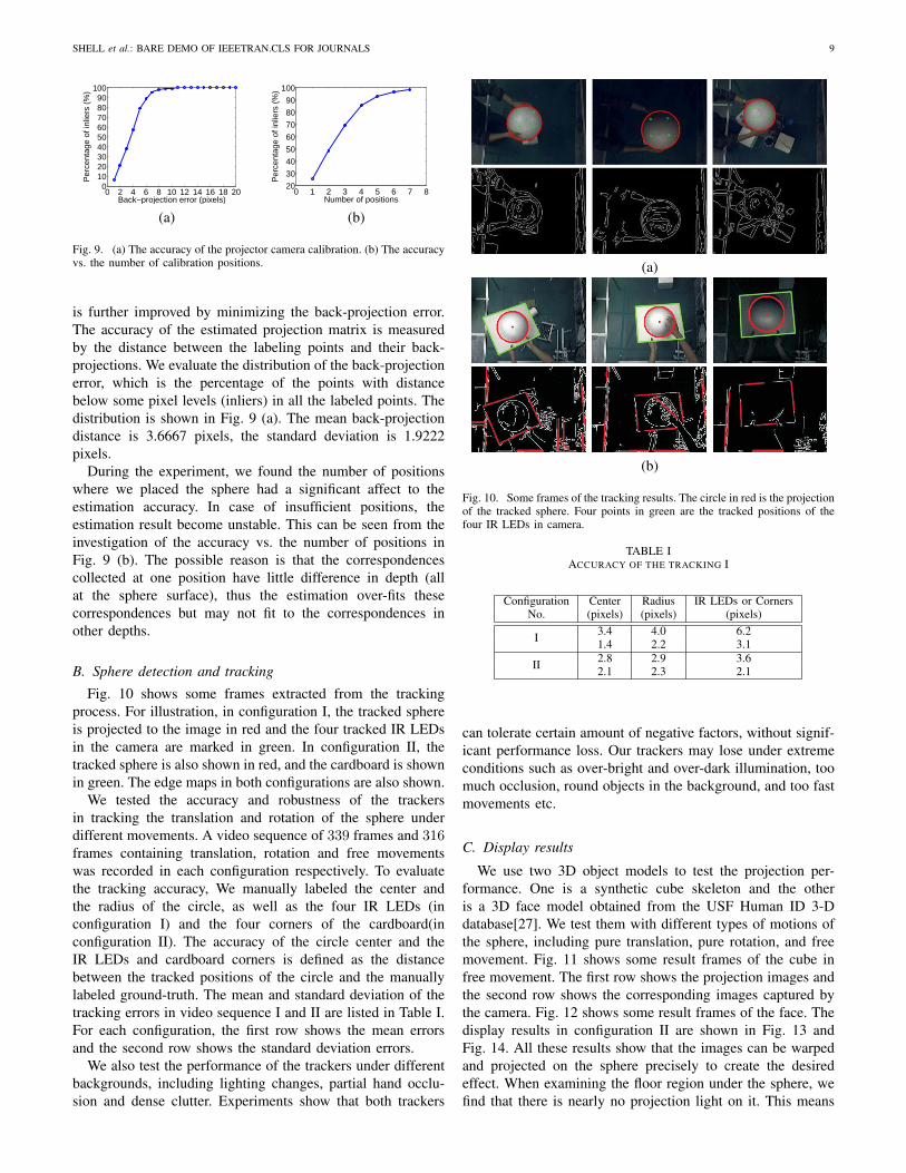
is further improved by minimizing the back-projection error.The accuracy of the estimated projection matrix is measuredby the distance between the labeling points and their back-projections. We evaluate the distribution of the back-projectionerror, which is the percentage of the points with distancebelow some pixel levels (inliers) in all the labeled points. Thedistribution is shown in Fig. 9 (a). The mean back-projectiondistance is 3.6667 pixels, the standard deviation is 1.9222pixels.
During the experiment, we found the number of positionswhere we placed the sphere had a significant affect to theestimation accuracy. In case of insufficient positions, theestimation result become unstable. This can be seen from theinvestigation of the accuracy vs. the number of positions inFig. 9 (b). The possible reason is that the correspondencescollected at one position have little difference in depth (allat the sphere surface), thus the estimation over-fits thesecorrespondences but may not fit to the correspondences inother depths.
B. Sphere detection and tracking
Fig. 10 shows some frames extracted from the trackingprocess. For illustration, in configuration I, the tracked sphereis projected to the image in red and the four tracked IR LEDsin the camera are marked in green. In configuration II, thetracked sphere is also shown in red, and the cardboard is shownin green. The edge maps in both configurations are also shown.
We tested the accuracy and robustness of the trackersin tracking the translation and rotation of the sphere underdifferent movements. A video sequence of 339 frames and 316frames containing translation, rotation and free movementswas recorded in each configuration respectively. To evaluatethe tracking accuracy, We manually labeled the center andthe radius of the circle, as well as the four IR LEDs (inconfiguration I) and the four corners of the cardboard(inconfiguration II). The accuracy of the circle center and theIR LEDs and cardboard corners is defined as the distancebetween the tracked positions of the circle and the manuallylabeled ground-truth. The mean and standard deviation of thetracking errors in video sequence I and II are listed in Table I.For each configuration, the first row shows the mean errorsand the second row shows the standard deviation errors.
We also test the performance of the trackers under differentbackgrounds, including lighting changes, partial hand occlu-sion and dense clutter. Experiments show that both trackers
(a)
(b)
Fig. 10. Some frames of the tracking results. The circle in red is the projectionof the tracked sphere. Four points in green are the tracked positions of thefour IR LEDs in camera.
TABLE IACCURACY OF THE TRACKING I
Configuration Center Radius IR LEDs or CornersNo. (pixels) (pixels) (pixels)
I 3.4 4.0 6.21.4 2.2 3.1
II 2.8 2.9 3.62.1 2.3 2.1
can tolerate certain amount of negative factors, without signif-icant performance loss. Our trackers may lose under extremeconditions such as over-bright and over-dark illumination, toomuch occlusion, round objects in the background, and too fastmovements etc.
C. Display results
We use two 3D object models to test the projection per-formance. One is a synthetic cube skeleton and the otheris a 3D face model obtained from the USF Human ID 3-Ddatabase[27]. We test them with different types of motions ofthe sphere, including pure translation, pure rotation, and freemovement. Fig. 11 shows some result frames of the cube infree movement. The first row shows the projection images andthe second row shows the corresponding images captured bythe camera. Fig. 12 shows some result frames of the face. Thedisplay results in configuration II are shown in Fig. 13 andFig. 14. All these results show that the images can be warpedand projected on the sphere precisely to create the desiredeffect. When examining the floor region under the sphere, wefind that there is nearly no projection light on it. This means

10 JOURNAL OF LATEX CLASS FILES, VOL. 6, NO. 1, JANUARY 2007
Fig. 11. Some frames of the projection results of a cube skeleton. The first row shows the generated projection images and the second row shows thecorresponding images captured by the camera.
Fig. 12. Some frames of the projection results of a 3D face model.
Fig. 13. Some frames of the projection results of a cube skeleton. The first row shows the generated projection images and the second row shows thecorresponding images captured by the camera.

SHELL et al.: BARE DEMO OF IEEETRAN.CLS FOR JOURNALS 11
Fig. 14. Some frames of the projection results of a 3D face model.
that the image is projected to the sphere without mismatch. Inall of our experiments, our system can track the sphere andgenerate the projection image with satisfactory accuracy androbustness. More results can be found in the supplementaryvideo.
D. Performance
In the 2.1GHz CPU and 1GB memory platform, our sytemcan achieve real-time processing (about 20 fps) smoothly inboth configuration. The configuration II is slower than the con-figuration I because it is necessary to evaluate the likelihoodof both the sphere and the cardboard. The running time mainlydistributes in the edge and line feature detection, the particlefilter tracking and the projection image warping. Table IIshows the partition of the running time. The particle filtertracking consumes the major part of the time. It varies withthe number of particles used. Fig. 15 shows the processingtime against the number of particles in configuration II. Theprocessing time increases linearly with the number of particles.In our system, the number of particles is set to 80 and 60 in thetwo configurations respectively. The number of line features isalso an influence factor of the processing time in configurationII. We fix it to 20 in our experiments.
TABLE IIRUNNING TIME PER FRAME I
Process Configuration I Configuration IIEdge and line detection about 5 ms about 15 msParticle filter tracking 25 ∼ 50 ms 30 ∼ 60 ms
Projection image warping about 5 ms about 5 ms
E. Limitations
There are several limitations of our system. First, thereis limitation on the resolution of the projection. Since theresolution of the projection image depends on the distancebetween the sphere and the projector, the projection imageis inevitably downsampled when the sphere is further away
0 40 80 120 160 200 24020
25
30
35
40
45
50
55
60
Number of particles
Ave
rage
pro
cess
ing
time
(ms)
20,24.67
40,28.93
60,32.0880,34.52
100,38.27
120,41.23
140,44.29
160,48.78
180,51.63
200,56.35
Fig. 15. The processing time of the sphere and cardboard tracking algorithmin configuration II against the number of particles.
from the projector. Such limitation make the small detailsof the displaying object unobservable or blurred. High res-olution projector is a simply solution to this problem. Withthe reducing prices of high resolution projectors in recentyears, we believe that the limitation can be overcome easily.Second, the depth field of the projector is another problem.We use a single projector in our system. The depth of filedis quite limited, making the projection in focus only withina particular range of depth. When the sphere become bigger,some parts of the sphere may become blurred. One solution tothis problem is to use multiple projectors. Third, the trackingrobustness and the processing time may also be limitations ofour system. The unstable tracking will cause the projectionresults shaking, and the processing time may cause apparentlatency to the projection results, especially when the sphere ismoved quickly. Increasing the number of particles can improvethe robustness of the tracker, but more particles mean moreprocessing time. A tradeoff between the tracking robustnessand the processing time should be made. The latency is alsodue to the physical latency of the projector and the camera.

12 JOURNAL OF LATEX CLASS FILES, VOL. 6, NO. 1, JANUARY 2007
High quality projector and camera can be a solution to reducereduce the latency.
VIII. CONCLUSION
We have proposed an interactive projector-camera based 3DModel exhibition system using low-cost devices and computervision techniques. The particle filter technique and a commer-cially available tracking product (Wiimote) are used to trackthe translation and rotation of the sphere respectively. Thegeneration of the projection image is based on the transla-tion and rotation of the sphere as well as the pre-calibratedprojective geometry. Extensive experiments show that oursystem can robustly track the movement of the sphere andcorrectly generate the projection image. It successfully createsthe effect with satisfactory accuracy and robustness in differentlighting environments. Future work will be done to improvethe accuracy, robustness and interactiveness of the system,including improving the motion tracker, and developing analgorithm to track the position of the viewer’s head etc.
ACKNOWLEDGMENT
The authors would like to thank...
REFERENCES
[1] C. Cruz-Neira, D. J. Sandin, and T. A. Defanti, “Surround-screenprojection-based virtual reality: the design and implementation of thecave,” in Proceedings of ACM SIGGRAPH, 1993, pp. 135–142.
[2] S. J. Gibbs, C. Arapis, and C. J. Breiteneder, “Teleport – towardsimmersive copresence,” Multimedia System, vol. 7, no. 3, pp. 214–221,1999.
[3] O. Bimber, G. Wetzstein, A. Emmerling, and C. Nitschke, “Enablingview-depedent stereoscopic projection in real environments,” in IEEEand ACM International Symposium on Mixed and Augmented Reality,2005, pp. 14–23.
[4] R. Raskar, K. Low, and G. Welch, “Shader lamps: Animating real objectswith image based illumination,” Techinal report, Chapel Hill, NC, USA,2000.
[5] K. L. Low, G. Welch, A. Lastra, and H. Fuchs, “Life-sized projector-based dioramas,” in ACM symposium on Virtual reality software andtechnology, 2001, pp. 91–101.
[6] M. Grossberg, H. Peri, S. Nayar, and P. Belhumeur, “Making one objectlook like another: controllling appearance using a projector-camerasystem,” in CVPR, 2004.
[7] T. Amano and H. Kato, “Appearance enhancement using a projector-camera feedback system,” in ICPR, 2008.
[8] R. Sukthankar, R. G. Stockton, and M. D. Mullin, “Smarter pre-sentations: Exploiting homography in camera-projector systems,” inProceedings of ICCV, 2001.
[9] R. Raskar and P. Beardsley, “A self-correcting projector,” in CVPR, 2008,pp. 504–508.
[10] T. Okatani and K. Deguchi, “Autocalibration of a projector-camerasystem,” IEEE Trans. PAMI, 2005.
[11] A. Raij and M. Pollefeys, “Auto-calibration of multi-projector displaywalls,” in ICPR, 2004, pp. 14–17.
[12] M. Brown, A. Majumder, and R. Yang, “Camera-based calibrationtechniques for seamless multiprojector displays,” IEEE Trans. TVCG,2005.
[13] O. Bimber, D. Iwai, G. Wetzstein, and A. Grundhofer, “The visualcomputing of projector-camera systems,” in SIGGRAPH 2008, 2008,pp. 1–25.
[14] R. Raskar, M. S. Brown, R. G. Yang, W. C. Chen, G. Welch, H. Towles,W. B. Seales, and H. Fuchs, “Multi-projector displays using camera-based registration,” in IEEE Visualization, 1999, pp. 161–168.
[15] R. Raskar and van B. Jeroen, “Low-cost multi-projector curved screendisplays,” in International Symposium Society for Information Display(SID), 2005.
[16] D. Kondoh and R. Kijima, “Proposal of a free form projection displayusing the principle of duality rendering,” in Proceedings of VSMM, 2002,pp. 346–352.
[17] D. Kondo, R. Kijima, and Y. Takahashi, “Dynamic anatomical modelfor medical education using free form projection display,” in Intl Conf.on Virtual System and Multimedia, 2007, pp. 346–352.
[18] J. C. Lee, S. E. Hudson, and E. Tse, “Foldable interactive displays,” inACM symposium on User Interface Software and Technology, 2008, pp.287–290.
[19] D. Bandyopadhyay, R. Raskar, and H. Fuchs, “Dynamic shader lamps:Painting on movable objects,” in In Proceedings of Int. Symp. OnAugmented Reality, 2001, pp. 207–216.
[20] J. C. Lee, S. E. Hudson, J. W. Summer, and P. H. Dietz, “Moveable inter-active projected displays using projector based tracking,” in Proceedingsof the ACM Symposium on User Interface Software and Technology.
[21] S. Borkowski, O. Riff, and J. L. Crowley, “Projecting rectified imagesin an augmented environment,” in International workshop on ProjectorCamera System, 2003.
[22] S. Gupta and C. Jaynes, “Active pursuit tracking in a projector-camerasystem with application to augmented reality,” in CVPR workshop, 2005.
[23] K. H. W. M. C. Leung, K. K. Lee and M. M. Y. Chang, “A projectorbased movable hand-held display system,” in CVPR, 2009.
[24] R. I. Hartley and A. Zisserman, Multiple View Geometry in ComputerVision, 2nd ed. Cambridge University Press, ISBN: 0521540518, 2004.
[25] K. Y. Wong, D. Schnieders, and S. Li, “Recovering light directions andcamera poses from a single sphere,” in Proceedings of ECCV, 2008, pp.631–642.
[26] Z. Y. Zhang, “A flexible new technique for camera calibration,” IEEETrans. Pattern Anal. Mach. Intell., vol. 22, no. 11, pp. 1330–1334, 2000.
[27] V. Blanz and T. Vetter, “A morphable model for the synthesis of 3d-faces,” in Proceedings of ACM SIGGRAPH, 1999, pp. 187–194.
PLACEPHOTOHERE
Michael Shell Biography text here.
John Doe Biography text here.
Jane Doe Biography text here.
Related Documents