iX Developer Reference Manual English MAEN831Y,2021-06

Welcome message from author
This document is posted to help you gain knowledge. Please leave a comment to let me know what you think about it! Share it to your friends and learn new things together.
Transcript

iX DeveloperReference Manual
EnglishMAEN831Y, 2021-06

Foreword
Reference manual for iX Developer
ForewordThe iXDeveloper software is used to configure iX panels andPCoperated controlapplications, including applications for IPCs (Industrial PCs).The iXDevelopermakes it easy to create logical, flexible and effectiveHMIapplications that provide the right information on the right occasion to operatorsand to other systems.Thismanual describes the configuration software in detail.Please see the iXDeveloperUser’sGuide (MAEN832x) for function-baseddescriptions.Themanual assumes that themost recent versions of the systemprogram (image)and iXDeveloper are used.For specific details of a connected controller refer to the help file for the controllerdriver. The function of a project application in an operator panel is not affected bythe choice of controller.The information in thismanual is also available by pressing F1while using iXDeveloper.The present revision of thismanual is valid for version 2.40 SP6 of iXDeveloper.
Order no: MAEN831Y
Copyright©2021-06Beijer Electronics AB.All rights reserved.
The information in this document is subject to changewithout notice and is provided as available at thetime of printing. Beijer Electronics AB reserves the right to change any informationwithout updating thispublication. Beijer Electronics AB assumes no responsibility for any errors thatmay appear in this document.All examples in this document are only intended to improve understanding of the functionality and handlingof the equipment. Beijer Electronics AB cannot assume any liability if these examples are used in realapplications.In view of thewide range of applications for this software, usersmust acquire sufficient knowledge themselvesin order to ensure that it is correctly used in their specific application. Persons responsible for the applicationand the equipmentmust themselves ensure that each application is in compliancewith all relevantrequirements, standards, and legislation in respect to configuration and safety. Beijer Electronics ABwillaccept no liability for any damage incurred during the installation or use of equipmentmentioned in thisdocument. Beijer Electronics AB prohibits allmodification, changes, or conversion of the equipment.
Beijer Electronics, MAEN831Y

Contents
Contents1 TheConfigurationTool .. . . . . . . . . . . . . . . . . . . . . . . . . . . . . . . . . . . . . . . . . . . . . . . 12
1.1 Introduction .. . . . . . . . . . . . . . . . . . . . . . . . . . . . . . . . . . . . . . . . . . . . . . . . . . . . 121.1.1 Operator Panels . . . . . . . . . . . . . . . . . . . . . . . . . . . . . . . . . . . . . . . . . . . . . . . . . .121.1.2 Controller . . . . . . . . . . . . . . . . . . . . . . . . . . . . . . . . . . . . . . . . . . . . . . . . . . . . . . .131.1.3 Tags . . . . . . . . . . . . . . . . . . . . . . . . . . . . . . . . . . . . . . . . . . . . . . . . . . . . . . . . . . . . . .131.1.4 SystemRequirements and Limitations . . . . . . . . . . . . . . . . . . . . . . . . . .141.1.5 Getting Started . . . . . . . . . . . . . . . . . . . . . . . . . . . . . . . . . . . . . . . . . . . . . . . . . .151.1.6 Installation . . . . . . . . . . . . . . . . . . . . . . . . . . . . . . . . . . . . . . . . . . . . . . . . . . . . . . .171.1.7 Configured Features . . . . . . . . . . . . . . . . . . . . . . . . . . . . . . . . . . . . . . . . . . . . .181.1.8 Project . . . . . . . . . . . . . . . . . . . . . . . . . . . . . . . . . . . . . . . . . . . . . . . . . . . . . . . . . . .181.1.9 File Structure . . . . . . . . . . . . . . . . . . . . . . . . . . . . . . . . . . . . . . . . . . . . . . . . . . . .18
2 WorkingwithProjects . . . . . . . . . . . . . . . . . . . . . . . . . . . . . . . . . . . . . . . . . . . . . . . . . . 222.1 Creating a Project . . . . . . . . . . . . . . . . . . . . . . . . . . . . . . . . . . . . . . . . . . . . . . . . 22
2.1.1 Connecting to aController . . . . . . . . . . . . . . . . . . . . . . . . . . . . . . . . . . . . . .222.1.2 Designing a Screen Set . . . . . . . . . . . . . . . . . . . . . . . . . . . . . . . . . . . . . . . . . . .222.1.3 DesigningAdditional Functions . . . . . . . . . . . . . . . . . . . . . . . . . . . . . . . .23
2.2 Importing an InformationDesigner Project .. . . . . . . . . . . . . . . . . . 252.2.1 InformationDesigner Import Settings . . . . . . . . . . . . . . . . . . . . . . . . . .26
2.3 Importing anH-Designer/ADPProject . . . . . . . . . . . . . . . . . . . . . . . . 272.3.1 Exporting theH-Designer/ADPProject . . . . . . . . . . . . . . . . . . . . . . . .272.3.2 Importing the a2i File . . . . . . . . . . . . . . . . . . . . . . . . . . . . . . . . . . . . . . . . . . . .272.3.3 Limitations . . . . . . . . . . . . . . . . . . . . . . . . . . . . . . . . . . . . . . . . . . . . . . . . . . . . . .27
2.4 Optimizing Performance .. . . . . . . . . . . . . . . . . . . . . . . . . . . . . . . . . . . . . . . 292.4.1 Communication Performance . . . . . . . . . . . . . . . . . . . . . . . . . . . . . . . . . .292.4.2 CommunicationDesign . . . . . . . . . . . . . . . . . . . . . . . . . . . . . . . . . . . . . . . .292.4.3 Performance in the operator panel . . . . . . . . . . . . . . . . . . . . . . . . . . . . . . .31
2.5 MovingObjectswith theTouch Screen .. . . . . . . . . . . . . . . . . . . . . . . 352.5.1 OperateObjects . . . . . . . . . . . . . . . . . . . . . . . . . . . . . . . . . . . . . . . . . . . . . . . . .35
2.6 Peripherals . . . . . . . . . . . . . . . . . . . . . . . . . . . . . . . . . . . . . . . . . . . . . . . . . . . . . . . . 362.6.1 USB . . . . . . . . . . . . . . . . . . . . . . . . . . . . . . . . . . . . . . . . . . . . . . . . . . . . . . . . . . . . . .362.6.2 Ethernet . . . . . . . . . . . . . . . . . . . . . . . . . . . . . . . . . . . . . . . . . . . . . . . . . . . . . . . . .362.6.3 MemoryCard . . . . . . . . . . . . . . . . . . . . . . . . . . . . . . . . . . . . . . . . . . . . . . . . . . . .362.6.4 SD card tests iXDeveloper . . . . . . . . . . . . . . . . . . . . . . . . . . . . . . . . . . . . . .36
3 Development Environment .. . . . . . . . . . . . . . . . . . . . . . . . . . . . . . . . . . . . . . . . . . . 383.1 Starting iXDeveloper . . . . . . . . . . . . . . . . . . . . . . . . . . . . . . . . . . . . . . . . . . . . 38
3.1.1 Creating aNewProject . . . . . . . . . . . . . . . . . . . . . . . . . . . . . . . . . . . . . . . . . .393.1.2 Opening a Project . . . . . . . . . . . . . . . . . . . . . . . . . . . . . . . . . . . . . . . . . . . . . . . .423.1.3 Getting Familiar with iXDeveloper . . . . . . . . . . . . . . . . . . . . . . . . . . . . .423.1.4 Starting iXDeveloper from theCommandLine . . . . . . . . . . . . . . . .443.1.5 FileMenu . . . . . . . . . . . . . . . . . . . . . . . . . . . . . . . . . . . . . . . . . . . . . . . . . . . . . . . .453.1.6 Quick Access Toolbar . . . . . . . . . . . . . . . . . . . . . . . . . . . . . . . . . . . . . . . . . . . .503.1.7 RibbonTabs . . . . . . . . . . . . . . . . . . . . . . . . . . . . . . . . . . . . . . . . . . . . . . . . . . . . .513.1.8 Additional Properties . . . . . . . . . . . . . . . . . . . . . . . . . . . . . . . . . . . . . . . . . . . .52
3.2 DesktopArea .. . . . . . . . . . . . . . . . . . . . . . . . . . . . . . . . . . . . . . . . . . . . . . . . . . . . 52
Beijer Electronics, MAEN831Y

Contents
3.2.1 ScreenView inDesktopArea . . . . . . . . . . . . . . . . . . . . . . . . . . . . . . . . . . . .533.2.2 DesktopViewModes . . . . . . . . . . . . . . . . . . . . . . . . . . . . . . . . . . . . . . . . . . . .543.2.3 PositioningWindows . . . . . . . . . . . . . . . . . . . . . . . . . . . . . . . . . . . . . . . . . . . .593.2.4 Configuration Pages . . . . . . . . . . . . . . . . . . . . . . . . . . . . . . . . . . . . . . . . . . . . .61
3.3 Screens .. . . . . . . . . . . . . . . . . . . . . . . . . . . . . . . . . . . . . . . . . . . . . . . . . . . . . . . . . . . 633.3.1 ScreenName and ScreenTitle . . . . . . . . . . . . . . . . . . . . . . . . . . . . . . . . . . .643.3.2 Background andForeground Screen . . . . . . . . . . . . . . . . . . . . . . . . . . . .643.3.3 Startup Screen . . . . . . . . . . . . . . . . . . . . . . . . . . . . . . . . . . . . . . . . . . . . . . . . . . .663.3.4 ScreenTemplate . . . . . . . . . . . . . . . . . . . . . . . . . . . . . . . . . . . . . . . . . . . . . . . . .663.3.5 Screen Security . . . . . . . . . . . . . . . . . . . . . . . . . . . . . . . . . . . . . . . . . . . . . . . . . .673.3.6 Popup Screen . . . . . . . . . . . . . . . . . . . . . . . . . . . . . . . . . . . . . . . . . . . . . . . . . . . .673.3.7 Importing Screens . . . . . . . . . . . . . . . . . . . . . . . . . . . . . . . . . . . . . . . . . . . . . . .683.3.8 ScreenCaching . . . . . . . . . . . . . . . . . . . . . . . . . . . . . . . . . . . . . . . . . . . . . . . . . .683.3.9 Grid . . . . . . . . . . . . . . . . . . . . . . . . . . . . . . . . . . . . . . . . . . . . . . . . . . . . . . . . . . . . . .69
3.4 Objects . . . . . . . . . . . . . . . . . . . . . . . . . . . . . . . . . . . . . . . . . . . . . . . . . . . . . . . . . . . 703.4.1 HandlingObjects . . . . . . . . . . . . . . . . . . . . . . . . . . . . . . . . . . . . . . . . . . . . . . . .70
3.5 NavigationManager . . . . . . . . . . . . . . . . . . . . . . . . . . . . . . . . . . . . . . . . . . . . . 743.5.1 ScreenRelations . . . . . . . . . . . . . . . . . . . . . . . . . . . . . . . . . . . . . . . . . . . . . . . . .753.5.2 Add Screen . . . . . . . . . . . . . . . . . . . . . . . . . . . . . . . . . . . . . . . . . . . . . . . . . . . . . . .753.5.3 Links in theNavigationManager . . . . . . . . . . . . . . . . . . . . . . . . . . . . . . . .753.5.4 NavigationOverview . . . . . . . . . . . . . . . . . . . . . . . . . . . . . . . . . . . . . . . . . . . .76
3.6 Project Explorer . . . . . . . . . . . . . . . . . . . . . . . . . . . . . . . . . . . . . . . . . . . . . . . . . . 763.6.1 Project ExplorerGroups . . . . . . . . . . . . . . . . . . . . . . . . . . . . . . . . . . . . . . . . .77
3.7 Component Library .. . . . . . . . . . . . . . . . . . . . . . . . . . . . . . . . . . . . . . . . . . . . 813.7.1 Components . . . . . . . . . . . . . . . . . . . . . . . . . . . . . . . . . . . . . . . . . . . . . . . . . . . . .823.7.2 Add andUseComponents . . . . . . . . . . . . . . . . . . . . . . . . . . . . . . . . . . . . . . .833.7.3 Component LibraryWindow . . . . . . . . . . . . . . . . . . . . . . . . . . . . . . . . . . .833.7.4 XAML Import into iXDeveloper . . . . . . . . . . . . . . . . . . . . . . . . . . . . . . .87
3.8 PropertyGrid .. . . . . . . . . . . . . . . . . . . . . . . . . . . . . . . . . . . . . . . . . . . . . . . . . . . 913.8.1 Search . . . . . . . . . . . . . . . . . . . . . . . . . . . . . . . . . . . . . . . . . . . . . . . . . . . . . . . . . . . .923.8.2 Toggling views . . . . . . . . . . . . . . . . . . . . . . . . . . . . . . . . . . . . . . . . . . . . . . . . . . .923.8.3 Favorites . . . . . . . . . . . . . . . . . . . . . . . . . . . . . . . . . . . . . . . . . . . . . . . . . . . . . . . . .933.8.4 Copy Properties . . . . . . . . . . . . . . . . . . . . . . . . . . . . . . . . . . . . . . . . . . . . . . . . . .93
3.9 Object Browser . . . . . . . . . . . . . . . . . . . . . . . . . . . . . . . . . . . . . . . . . . . . . . . . . . . 943.10 Output .. . . . . . . . . . . . . . . . . . . . . . . . . . . . . . . . . . . . . . . . . . . . . . . . . . . . . . . . . . 943.11 Error List . . . . . . . . . . . . . . . . . . . . . . . . . . . . . . . . . . . . . . . . . . . . . . . . . . . . . . . . . 943.12 Help .. . . . . . . . . . . . . . . . . . . . . . . . . . . . . . . . . . . . . . . . . . . . . . . . . . . . . . . . . . . . . 94
4 Tags .. . . . . . . . . . . . . . . . . . . . . . . . . . . . . . . . . . . . . . . . . . . . . . . . . . . . . . . . . . . . . . . . . . . . . . 954.1 AddingTags .. . . . . . . . . . . . . . . . . . . . . . . . . . . . . . . . . . . . . . . . . . . . . . . . . . . . . 95
4.1.1 RemovingUnusedTags . . . . . . . . . . . . . . . . . . . . . . . . . . . . . . . . . . . . . . . . .954.1.2 Basic Settings . . . . . . . . . . . . . . . . . . . . . . . . . . . . . . . . . . . . . . . . . . . . . . . . . . . .984.1.3 Scaling . . . . . . . . . . . . . . . . . . . . . . . . . . . . . . . . . . . . . . . . . . . . . . . . . . . . . . . . . . .994.1.4 Data Exchange . . . . . . . . . . . . . . . . . . . . . . . . . . . . . . . . . . . . . . . . . . . . . . . . . . .994.1.5 Others . . . . . . . . . . . . . . . . . . . . . . . . . . . . . . . . . . . . . . . . . . . . . . . . . . . . . . . . . . .994.1.6 AddingTags during Editing . . . . . . . . . . . . . . . . . . . . . . . . . . . . . . . . . . . . .100
Beijer Electronics, MAEN831Y

Contents
4.1.7 SelectingMultiple Tags . . . . . . . . . . . . . . . . . . . . . . . . . . . . . . . . . . . . . . . . . .1014.2 TagActions .. . . . . . . . . . . . . . . . . . . . . . . . . . . . . . . . . . . . . . . . . . . . . . . . . . . . . . 1014.3 Internal Tags . . . . . . . . . . . . . . . . . . . . . . . . . . . . . . . . . . . . . . . . . . . . . . . . . . . . . 1034.4 SystemTags .. . . . . . . . . . . . . . . . . . . . . . . . . . . . . . . . . . . . . . . . . . . . . . . . . . . . . 1034.5 ArrayTags .. . . . . . . . . . . . . . . . . . . . . . . . . . . . . . . . . . . . . . . . . . . . . . . . . . . . . . . 106
4.5.1 ArrayTag SetUp . . . . . . . . . . . . . . . . . . . . . . . . . . . . . . . . . . . . . . . . . . . . . . . . .1064.6 Cross Reference .. . . . . . . . . . . . . . . . . . . . . . . . . . . . . . . . . . . . . . . . . . . . . . . . . 1074.7 Triggers . . . . . . . . . . . . . . . . . . . . . . . . . . . . . . . . . . . . . . . . . . . . . . . . . . . . . . . . . . . 1074.8 PollGroups .. . . . . . . . . . . . . . . . . . . . . . . . . . . . . . . . . . . . . . . . . . . . . . . . . . . . . . 1084.9 StationHandling .. . . . . . . . . . . . . . . . . . . . . . . . . . . . . . . . . . . . . . . . . . . . . . . 1094.10 IndexRegisters . . . . . . . . . . . . . . . . . . . . . . . . . . . . . . . . . . . . . . . . . . . . . . . . . . . 110
4.10.1 IndexAddressing Example . . . . . . . . . . . . . . . . . . . . . . . . . . . . . . . . . . . . . .1114.10.2 Using IndexRegisters for StationHandling . . . . . . . . . . . . . . . . . . . . .114
4.11 Expressions .. . . . . . . . . . . . . . . . . . . . . . . . . . . . . . . . . . . . . . . . . . . . . . . . . . . . . . 1164.11.1 Definition . . . . . . . . . . . . . . . . . . . . . . . . . . . . . . . . . . . . . . . . . . . . . . . . . . . . . . .1164.11.2 UsingExpressions . . . . . . . . . . . . . . . . . . . . . . . . . . . . . . . . . . . . . . . . . . . . . . .1164.11.3 Library Expressions . . . . . . . . . . . . . . . . . . . . . . . . . . . . . . . . . . . . . . . . . . . . . .1174.11.4 Limitations . . . . . . . . . . . . . . . . . . . . . . . . . . . . . . . . . . . . . . . . . . . . . . . . . . . . . .118
4.12 TagExpressions .. . . . . . . . . . . . . . . . . . . . . . . . . . . . . . . . . . . . . . . . . . . . . . . . . 1184.13 Data Exchange .. . . . . . . . . . . . . . . . . . . . . . . . . . . . . . . . . . . . . . . . . . . . . . . . . . 1194.14 Importing andExportingTags .. . . . . . . . . . . . . . . . . . . . . . . . . . . . . . . . . 122
4.14.1 HandlingColumns . . . . . . . . . . . . . . . . . . . . . . . . . . . . . . . . . . . . . . . . . . . . . .1224.14.2 Saving the Import Configuration . . . . . . . . . . . . . . . . . . . . . . . . . . . . . . .1224.14.3 Tag Import Example . . . . . . . . . . . . . . . . . . . . . . . . . . . . . . . . . . . . . . . . . . . . .1224.14.4 ImportingTags from theCommandLine . . . . . . . . . . . . . . . . . . . . . . .125
4.15 FilteringTags . . . . . . . . . . . . . . . . . . . . . . . . . . . . . . . . . . . . . . . . . . . . . . . . . . . . . 1264.16 Tag Format .. . . . . . . . . . . . . . . . . . . . . . . . . . . . . . . . . . . . . . . . . . . . . . . . . . . . . . 1264.17 Aliases .. . . . . . . . . . . . . . . . . . . . . . . . . . . . . . . . . . . . . . . . . . . . . . . . . . . . . . . . . . . . 128
4.17.1 CreatingAliases . . . . . . . . . . . . . . . . . . . . . . . . . . . . . . . . . . . . . . . . . . . . . . . . . .1284.17.2 Instances . . . . . . . . . . . . . . . . . . . . . . . . . . . . . . . . . . . . . . . . . . . . . . . . . . . . . . . . .129
5 Controller . . . . . . . . . . . . . . . . . . . . . . . . . . . . . . . . . . . . . . . . . . . . . . . . . . . . . . . . . . . . . . . . 1315.1 Adding aController . . . . . . . . . . . . . . . . . . . . . . . . . . . . . . . . . . . . . . . . . . . . . 131
5.1.1 NotifyWindow . . . . . . . . . . . . . . . . . . . . . . . . . . . . . . . . . . . . . . . . . . . . . . . . . .1325.2 DEMOController . . . . . . . . . . . . . . . . . . . . . . . . . . . . . . . . . . . . . . . . . . . . . . 1325.3 ExternalOPCServer . . . . . . . . . . . . . . . . . . . . . . . . . . . . . . . . . . . . . . . . . . . . 133
5.3.1 OPCClassic Client . . . . . . . . . . . . . . . . . . . . . . . . . . . . . . . . . . . . . . . . . . . . . .1335.3.2 OPCUAClient . . . . . . . . . . . . . . . . . . . . . . . . . . . . . . . . . . . . . . . . . . . . . . . . . .133
5.4 UpdatingDrivers . . . . . . . . . . . . . . . . . . . . . . . . . . . . . . . . . . . . . . . . . . . . . . . . 1435.4.1 UpdatingDrivers from Internet . . . . . . . . . . . . . . . . . . . . . . . . . . . . . . . . .1435.4.2 UpdatingDrivers fromFile . . . . . . . . . . . . . . . . . . . . . . . . . . . . . . . . . . . . . .144
5.5 Synchronizing theControllerClock .. . . . . . . . . . . . . . . . . . . . . . . . . . . 1456 WebServer .. . . . . . . . . . . . . . . . . . . . . . . . . . . . . . . . . . . . . . . . . . . . . . . . . . . . . . . . . . . . . . 146
6.1 Web ServerConfiguration ... . . . . . . . . . . . . . . . . . . . . . . . . . . . . . . . . . . . 1466.1.1 Web SiteConfiguration . . . . . . . . . . . . . . . . . . . . . . . . . . . . . . . . . . . . . . . . .1466.1.2 Login Form . . . . . . . . . . . . . . . . . . . . . . . . . . . . . . . . . . . . . . . . . . . . . . . . . . . . . .146
Beijer Electronics, MAEN831Y

Contents
6.2 Javascript SDK ... . . . . . . . . . . . . . . . . . . . . . . . . . . . . . . . . . . . . . . . . . . . . . . . . 1476.2.1 Javascript SDKOverview . . . . . . . . . . . . . . . . . . . . . . . . . . . . . . . . . . . . . . . .147
6.3 Web Service API .. . . . . . . . . . . . . . . . . . . . . . . . . . . . . . . . . . . . . . . . . . . . . . . . 1576.3.1 RESTfulWeb Service API . . . . . . . . . . . . . . . . . . . . . . . . . . . . . . . . . . . . . . .1576.3.2 General . . . . . . . . . . . . . . . . . . . . . . . . . . . . . . . . . . . . . . . . . . . . . . . . . . . . . . . . . .1576.3.3 RESTAPI . . . . . . . . . . . . . . . . . . . . . . . . . . . . . . . . . . . . . . . . . . . . . . . . . . . . . . . .157
7 Objects . . . . . . . . . . . . . . . . . . . . . . . . . . . . . . . . . . . . . . . . . . . . . . . . . . . . . . . . . . . . . . . . . . . 1617.1 BlinkingObjects . . . . . . . . . . . . . . . . . . . . . . . . . . . . . . . . . . . . . . . . . . . . . . . . . 162
7.1.1 Limitations for operator panel Targets . . . . . . . . . . . . . . . . . . . . . . . . . .1637.2 Shapes . . . . . . . . . . . . . . . . . . . . . . . . . . . . . . . . . . . . . . . . . . . . . . . . . . . . . . . . . . . . 1637.3 HMIControls . . . . . . . . . . . . . . . . . . . . . . . . . . . . . . . . . . . . . . . . . . . . . . . . . . . 164
7.3.1 ActionMenuObject . . . . . . . . . . . . . . . . . . . . . . . . . . . . . . . . . . . . . . . . . . . . .1657.3.2 AlarmViewerObject . . . . . . . . . . . . . . . . . . . . . . . . . . . . . . . . . . . . . . . . . . . .1667.3.3 AnalogNumericObject . . . . . . . . . . . . . . . . . . . . . . . . . . . . . . . . . . . . . . . . .1677.3.4 AnimatedGIF . . . . . . . . . . . . . . . . . . . . . . . . . . . . . . . . . . . . . . . . . . . . . . . . . . .1687.3.5 Animated LabelObject . . . . . . . . . . . . . . . . . . . . . . . . . . . . . . . . . . . . . . . . . .1697.3.6 Audit Trail ViewerObject . . . . . . . . . . . . . . . . . . . . . . . . . . . . . . . . . . . . . . .1707.3.7 ButtonObject . . . . . . . . . . . . . . . . . . . . . . . . . . . . . . . . . . . . . . . . . . . . . . . . . . .1707.3.8 CircularMeterObject . . . . . . . . . . . . . . . . . . . . . . . . . . . . . . . . . . . . . . . . . . .1737.3.9 ChartObject . . . . . . . . . . . . . . . . . . . . . . . . . . . . . . . . . . . . . . . . . . . . . . . . . . . . .1767.3.10 DatabaseViewerObject . . . . . . . . . . . . . . . . . . . . . . . . . . . . . . . . . . . . . . . .1797.3.11 Digital ClockObject . . . . . . . . . . . . . . . . . . . . . . . . . . . . . . . . . . . . . . . . . . . .1797.3.12 LinearMeterObject . . . . . . . . . . . . . . . . . . . . . . . . . . . . . . . . . . . . . . . . . . . . .1807.3.13 Multi PictureObject . . . . . . . . . . . . . . . . . . . . . . . . . . . . . . . . . . . . . . . . . . . . .1817.3.14 PictureObject . . . . . . . . . . . . . . . . . . . . . . . . . . . . . . . . . . . . . . . . . . . . . . . . . . .1827.3.15 Roller PanelObject . . . . . . . . . . . . . . . . . . . . . . . . . . . . . . . . . . . . . . . . . . . . . .1837.3.16 SliderObject . . . . . . . . . . . . . . . . . . . . . . . . . . . . . . . . . . . . . . . . . . . . . . . . . . . . .1847.3.17 TagMonitorObject . . . . . . . . . . . . . . . . . . . . . . . . . . . . . . . . . . . . . . . . . . . . .1857.3.18 TextObject . . . . . . . . . . . . . . . . . . . . . . . . . . . . . . . . . . . . . . . . . . . . . . . . . . . . . .1867.3.19 TouchComboBoxObject . . . . . . . . . . . . . . . . . . . . . . . . . . . . . . . . . . . . . .1867.3.20 Touch List BoxObject . . . . . . . . . . . . . . . . . . . . . . . . . . . . . . . . . . . . . . . . . . .1877.3.21 TrendViewerObject . . . . . . . . . . . . . . . . . . . . . . . . . . . . . . . . . . . . . . . . . . . .188
7.4 MediaControls . . . . . . . . . . . . . . . . . . . . . . . . . . . . . . . . . . . . . . . . . . . . . . . . . . 1887.4.1 Media PlayerObject . . . . . . . . . . . . . . . . . . . . . . . . . . . . . . . . . . . . . . . . . . . . .1897.4.2 PDFViewerObject . . . . . . . . . . . . . . . . . . . . . . . . . . . . . . . . . . . . . . . . . . . . . .1907.4.3 WebBrowserObject . . . . . . . . . . . . . . . . . . . . . . . . . . . . . . . . . . . . . . . . . . . . .191
7.5 MiscellaneousControlObjects . . . . . . . . . . . . . . . . . . . . . . . . . . . . . . . . . 1937.5.1 QRCode object . . . . . . . . . . . . . . . . . . . . . . . . . . . . . . . . . . . . . . . . . . . . . . . . .193
7.6 SpecialControls . . . . . . . . . . . . . . . . . . . . . . . . . . . . . . . . . . . . . . . . . . . . . . . . . . 1957.6.1 Navigation List BoxObject . . . . . . . . . . . . . . . . . . . . . . . . . . . . . . . . . . . . . .1957.6.2 ScreenCarouselObject . . . . . . . . . . . . . . . . . . . . . . . . . . . . . . . . . . . . . . . . . .196
7.7 DebugTools . . . . . . . . . . . . . . . . . . . . . . . . . . . . . . . . . . . . . . . . . . . . . . . . . . . . . . 1977.7.1 AlarmDistributorViewerObject . . . . . . . . . . . . . . . . . . . . . . . . . . . . . . .197
7.8 WindowsControls . . . . . . . . . . . . . . . . . . . . . . . . . . . . . . . . . . . . . . . . . . . . . . . 1977.8.1 Check BoxObject . . . . . . . . . . . . . . . . . . . . . . . . . . . . . . . . . . . . . . . . . . . . . . .198
Beijer Electronics, MAEN831Y
Contents
7.8.2 ComboBoxObject . . . . . . . . . . . . . . . . . . . . . . . . . . . . . . . . . . . . . . . . . . . . . .1987.8.3 GroupBoxObject . . . . . . . . . . . . . . . . . . . . . . . . . . . . . . . . . . . . . . . . . . . . . . .1997.8.4 List BoxObject . . . . . . . . . . . . . . . . . . . . . . . . . . . . . . . . . . . . . . . . . . . . . . . . . .1997.8.5 Progress BarObject . . . . . . . . . . . . . . . . . . . . . . . . . . . . . . . . . . . . . . . . . . . . . .2007.8.6 Radio ButtonObject . . . . . . . . . . . . . . . . . . . . . . . . . . . . . . . . . . . . . . . . . . . .2007.8.7 Text BoxObject . . . . . . . . . . . . . . . . . . . . . . . . . . . . . . . . . . . . . . . . . . . . . . . . . .202
7.9 AdditionalControls . . . . . . . . . . . . . . . . . . . . . . . . . . . . . . . . . . . . . . . . . . . . . 2027.9.1 Target Platform . . . . . . . . . . . . . . . . . . . . . . . . . . . . . . . . . . . . . . . . . . . . . . . . . .2037.9.2 AddingControls to the iXDeveloperToolbox . . . . . . . . . . . . . . . . . .2037.9.3 DefaultControls and InstalledControls . . . . . . . . . . . . . . . . . . . . . . . .205
7.10 WPFControls . . . . . . . . . . . . . . . . . . . . . . . . . . . . . . . . . . . . . . . . . . . . . . . . . . . 2067.10.1 WPFUserControls . . . . . . . . . . . . . . . . . . . . . . . . . . . . . . . . . . . . . . . . . . . . . .2067.10.2 WPFCustomControls . . . . . . . . . . . . . . . . . . . . . . . . . . . . . . . . . . . . . . . . . .2067.10.3 Creating aWPFUserControl withTagConnection . . . . . . . . . . . .2067.10.4 Creating aWindows FormsUserControl for a PCTarget . . . . . .2087.10.5 Creating aWindows FormsUserControl for aCETarget . . . . . .211
8 RibbonTabs .. . . . . . . . . . . . . . . . . . . . . . . . . . . . . . . . . . . . . . . . . . . . . . . . . . . . . . . . . . . . 2148.1 HomeRibbonTab .. . . . . . . . . . . . . . . . . . . . . . . . . . . . . . . . . . . . . . . . . . . . . . 214
8.1.1 ClipboardGroup . . . . . . . . . . . . . . . . . . . . . . . . . . . . . . . . . . . . . . . . . . . . . . . .2158.1.2 ScreenGroup . . . . . . . . . . . . . . . . . . . . . . . . . . . . . . . . . . . . . . . . . . . . . . . . . . . .2168.1.3 ObjectsGroup . . . . . . . . . . . . . . . . . . . . . . . . . . . . . . . . . . . . . . . . . . . . . . . . . . .2168.1.4 ObjectVariations . . . . . . . . . . . . . . . . . . . . . . . . . . . . . . . . . . . . . . . . . . . . . . . .2178.1.5 FontGroup . . . . . . . . . . . . . . . . . . . . . . . . . . . . . . . . . . . . . . . . . . . . . . . . . . . . . .2208.1.6 FormatGroup . . . . . . . . . . . . . . . . . . . . . . . . . . . . . . . . . . . . . . . . . . . . . . . . . . .2218.1.7 Tag/SecurityGroup . . . . . . . . . . . . . . . . . . . . . . . . . . . . . . . . . . . . . . . . . . . . .2248.1.8 NameGroup . . . . . . . . . . . . . . . . . . . . . . . . . . . . . . . . . . . . . . . . . . . . . . . . . . . . .2258.1.9 Design LanguageGroup . . . . . . . . . . . . . . . . . . . . . . . . . . . . . . . . . . . . . . . . .226
8.2 Project RibbonTab .. . . . . . . . . . . . . . . . . . . . . . . . . . . . . . . . . . . . . . . . . . . . . 2268.2.1 RunGroup . . . . . . . . . . . . . . . . . . . . . . . . . . . . . . . . . . . . . . . . . . . . . . . . . . . . . . .2268.2.2 TransferGroup . . . . . . . . . . . . . . . . . . . . . . . . . . . . . . . . . . . . . . . . . . . . . . . . . .2278.2.3 ProjectGroup . . . . . . . . . . . . . . . . . . . . . . . . . . . . . . . . . . . . . . . . . . . . . . . . . . . .2348.2.4 CommandWindow inTransferClient . . . . . . . . . . . . . . . . . . . . . . . . . .244
8.3 SystemRibbonTab .. . . . . . . . . . . . . . . . . . . . . . . . . . . . . . . . . . . . . . . . . . . . . 2458.3.1 Date, Time, andRegionGroup . . . . . . . . . . . . . . . . . . . . . . . . . . . . . . . . .2458.3.2 BuzzerGroup . . . . . . . . . . . . . . . . . . . . . . . . . . . . . . . . . . . . . . . . . . . . . . . . . . . .2478.3.3 BacklightGroup . . . . . . . . . . . . . . . . . . . . . . . . . . . . . . . . . . . . . . . . . . . . . . . . .2478.3.4 Serial PortsGroup . . . . . . . . . . . . . . . . . . . . . . . . . . . . . . . . . . . . . . . . . . . . . . .2478.3.5 ServersGroup . . . . . . . . . . . . . . . . . . . . . . . . . . . . . . . . . . . . . . . . . . . . . . . . . . . .2488.3.6 OutputDevicesGroup . . . . . . . . . . . . . . . . . . . . . . . . . . . . . . . . . . . . . . . . . .2528.3.7 ServiceMenuGroup . . . . . . . . . . . . . . . . . . . . . . . . . . . . . . . . . . . . . . . . . . . . .255
8.4 Insert RibbonTab .. . . . . . . . . . . . . . . . . . . . . . . . . . . . . . . . . . . . . . . . . . . . . . . 2568.4.1 FunctionsGroup . . . . . . . . . . . . . . . . . . . . . . . . . . . . . . . . . . . . . . . . . . . . . . . .256
8.5 ViewRibbonTab .. . . . . . . . . . . . . . . . . . . . . . . . . . . . . . . . . . . . . . . . . . . . . . . 2578.5.1 WindowsGroup . . . . . . . . . . . . . . . . . . . . . . . . . . . . . . . . . . . . . . . . . . . . . . . . .257
8.6 DynamicsRibbonTab .. . . . . . . . . . . . . . . . . . . . . . . . . . . . . . . . . . . . . . . . . . 2588.6.1 LayoutGroup . . . . . . . . . . . . . . . . . . . . . . . . . . . . . . . . . . . . . . . . . . . . . . . . . . . .258
Beijer Electronics, MAEN831Y

Contents
8.6.2 ColorGroup . . . . . . . . . . . . . . . . . . . . . . . . . . . . . . . . . . . . . . . . . . . . . . . . . . . . .2608.6.3 GeneralGroup . . . . . . . . . . . . . . . . . . . . . . . . . . . . . . . . . . . . . . . . . . . . . . . . . . .261
8.7 General RibbonTab .. . . . . . . . . . . . . . . . . . . . . . . . . . . . . . . . . . . . . . . . . . . . 2688.8 ActionsRibbonTab .. . . . . . . . . . . . . . . . . . . . . . . . . . . . . . . . . . . . . . . . . . . . . 269
8.8.1 ClickActionTrigger . . . . . . . . . . . . . . . . . . . . . . . . . . . . . . . . . . . . . . . . . . . . .2698.8.2 Mouse ButtonActionTriggers . . . . . . . . . . . . . . . . . . . . . . . . . . . . . . . . . .2698.8.3 FunctionKeyActionTriggers . . . . . . . . . . . . . . . . . . . . . . . . . . . . . . . . . . .2708.8.4 ValueChangedActionTriggers . . . . . . . . . . . . . . . . . . . . . . . . . . . . . . . . . .2708.8.5 Tags ActionTriggers . . . . . . . . . . . . . . . . . . . . . . . . . . . . . . . . . . . . . . . . . . . . .2718.8.6 Focus ActionTriggers . . . . . . . . . . . . . . . . . . . . . . . . . . . . . . . . . . . . . . . . . . . .2718.8.7 NavigationActionTriggers . . . . . . . . . . . . . . . . . . . . . . . . . . . . . . . . . . . . . .2718.8.8 Data Logger ActionTriggers . . . . . . . . . . . . . . . . . . . . . . . . . . . . . . . . . . . . .2718.8.9 AlarmServer ActionTriggers . . . . . . . . . . . . . . . . . . . . . . . . . . . . . . . . . . . .2718.8.10 ActionGroups . . . . . . . . . . . . . . . . . . . . . . . . . . . . . . . . . . . . . . . . . . . . . . . . . . .2718.8.11 Script Action . . . . . . . . . . . . . . . . . . . . . . . . . . . . . . . . . . . . . . . . . . . . . . . . . . . . .2768.8.12 Multiple Actions . . . . . . . . . . . . . . . . . . . . . . . . . . . . . . . . . . . . . . . . . . . . . . . . .277
9 TrendViewer .. . . . . . . . . . . . . . . . . . . . . . . . . . . . . . . . . . . . . . . . . . . . . . . . . . . . . . . . . . . 2799.1 DefiningTrendViewerObjects . . . . . . . . . . . . . . . . . . . . . . . . . . . . . . . . . 279
9.1.1 Adding aTrendViewerObject . . . . . . . . . . . . . . . . . . . . . . . . . . . . . . . . . .2799.1.2 TrendViewer Legend . . . . . . . . . . . . . . . . . . . . . . . . . . . . . . . . . . . . . . . . . . . .281
9.2 HistoricalMode inTrendViewer .. . . . . . . . . . . . . . . . . . . . . . . . . . . . . . 28210 Data Logger .. . . . . . . . . . . . . . . . . . . . . . . . . . . . . . . . . . . . . . . . . . . . . . . . . . . . . . . . . . . . . 283
10.1 Data Logging Strategies . .. . . . . . . . . . . . . . . . . . . . . . . . . . . . . . . . . . . . . . . 28310.1.1 LoggingBased onTime Interval . . . . . . . . . . . . . . . . . . . . . . . . . . . . . . . . .28310.1.2 LoggingBased onChangedTagValue . . . . . . . . . . . . . . . . . . . . . . . . . . .28310.1.3 Maximizing the Lifetime of the StorageMedia . . . . . . . . . . . . . . . . . .284
10.2 Adding aData Logger .. . . . . . . . . . . . . . . . . . . . . . . . . . . . . . . . . . . . . . . . . . 28410.2.1 General Settings . . . . . . . . . . . . . . . . . . . . . . . . . . . . . . . . . . . . . . . . . . . . . . . . .28510.2.2 Actions . . . . . . . . . . . . . . . . . . . . . . . . . . . . . . . . . . . . . . . . . . . . . . . . . . . . . . . . . . .286
11 Scheduler . . . . . . . . . . . . . . . . . . . . . . . . . . . . . . . . . . . . . . . . . . . . . . . . . . . . . . . . . . . . . . . . 28711.1 Scheduler SetUp .. . . . . . . . . . . . . . . . . . . . . . . . . . . . . . . . . . . . . . . . . . . . . . . . 287
11.1.1 Adding a Scheduler . . . . . . . . . . . . . . . . . . . . . . . . . . . . . . . . . . . . . . . . . . . . . .28712 Reports . . . . . . . . . . . . . . . . . . . . . . . . . . . . . . . . . . . . . . . . . . . . . . . . . . . . . . . . . . . . . . . . . . . 288
12.1 ReportsTemplate Set up ... . . . . . . . . . . . . . . . . . . . . . . . . . . . . . . . . . . . . . . 28812.1.1 Limitations . . . . . . . . . . . . . . . . . . . . . . . . . . . . . . . . . . . . . . . . . . . . . . . . . . . . . .28812.1.2 DatabaseDrivenReports . . . . . . . . . . . . . . . . . . . . . . . . . . . . . . . . . . . . . . . .289
12.2 Reports SetUp ... . . . . . . . . . . . . . . . . . . . . . . . . . . . . . . . . . . . . . . . . . . . . . . . . 29012.3 Adding aReport . . . . . . . . . . . . . . . . . . . . . . . . . . . . . . . . . . . . . . . . . . . . . . . . . . 290
13 RecipeManagement .. . . . . . . . . . . . . . . . . . . . . . . . . . . . . . . . . . . . . . . . . . . . . . . . . . . 29113.1 Recipe Setup .. . . . . . . . . . . . . . . . . . . . . . . . . . . . . . . . . . . . . . . . . . . . . . . . . . . . 291
13.1.1 Adding aRecipeManager . . . . . . . . . . . . . . . . . . . . . . . . . . . . . . . . . . . . . . .29113.2 RecipeManagement in iXDesignTime .. . . . . . . . . . . . . . . . . . . . . . . 293
13.2.1 Recipe Import . . . . . . . . . . . . . . . . . . . . . . . . . . . . . . . . . . . . . . . . . . . . . . . . . . .29313.2.2 Recipe Export . . . . . . . . . . . . . . . . . . . . . . . . . . . . . . . . . . . . . . . . . . . . . . . . . . . .294
13.3 Recipes in the iX panel .. . . . . . . . . . . . . . . . . . . . . . . . . . . . . . . . . . . . . . . . . . 296
Beijer Electronics, MAEN831Y
Contents
13.3.1 LoadingRecipes . . . . . . . . . . . . . . . . . . . . . . . . . . . . . . . . . . . . . . . . . . . . . . . . .29713.3.2 SavingRecipes . . . . . . . . . . . . . . . . . . . . . . . . . . . . . . . . . . . . . . . . . . . . . . . . . . .29713.3.3 CreatingRecipes in the iX panel . . . . . . . . . . . . . . . . . . . . . . . . . . . . . . . . .29713.3.4 EditingRecipesOffline . . . . . . . . . . . . . . . . . . . . . . . . . . . . . . . . . . . . . . . . . .297
13.4 Recipe Export .. . . . . . . . . . . . . . . . . . . . . . . . . . . . . . . . . . . . . . . . . . . . . . . . . . . 29813.4.1 Recipe Export from anOperator Panel Target . . . . . . . . . . . . . . . . . .29913.4.2 Recipe Export from a PCTarget . . . . . . . . . . . . . . . . . . . . . . . . . . . . . . . . .300
13.5 Recipe Import .. . . . . . . . . . . . . . . . . . . . . . . . . . . . . . . . . . . . . . . . . . . . . . . . . . . 30013.5.1 Recipe Import to anOperator Panel Target . . . . . . . . . . . . . . . . . . . . .30113.5.2 Recipe Import to a PCTarget . . . . . . . . . . . . . . . . . . . . . . . . . . . . . . . . . . . .302
14 FunctionKeys .. . . . . . . . . . . . . . . . . . . . . . . . . . . . . . . . . . . . . . . . . . . . . . . . . . . . . . . . . . 30314.1 Definitions .. . . . . . . . . . . . . . . . . . . . . . . . . . . . . . . . . . . . . . . . . . . . . . . . . . . . . . 30314.2 Configuring FunctionKeys .. . . . . . . . . . . . . . . . . . . . . . . . . . . . . . . . . . . . 303
14.2.1 FunctionKeyActions . . . . . . . . . . . . . . . . . . . . . . . . . . . . . . . . . . . . . . . . . . . .30314.2.2 FunctionKey Scripts . . . . . . . . . . . . . . . . . . . . . . . . . . . . . . . . . . . . . . . . . . . .30414.2.3 Momentary Function . . . . . . . . . . . . . . . . . . . . . . . . . . . . . . . . . . . . . . . . . . .305
15 AlarmManagement .. . . . . . . . . . . . . . . . . . . . . . . . . . . . . . . . . . . . . . . . . . . . . . . . . . . . 30715.1 AlarmConditions .. . . . . . . . . . . . . . . . . . . . . . . . . . . . . . . . . . . . . . . . . . . . . . . 30715.2 AlarmServer . . . . . . . . . . . . . . . . . . . . . . . . . . . . . . . . . . . . . . . . . . . . . . . . . . . . . . 307
15.2.1 General Settings . . . . . . . . . . . . . . . . . . . . . . . . . . . . . . . . . . . . . . . . . . . . . . . . .30815.2.2 AlarmServer Events andActions . . . . . . . . . . . . . . . . . . . . . . . . . . . . . . . .30915.2.3 AlarmDistribution Settings . . . . . . . . . . . . . . . . . . . . . . . . . . . . . . . . . . . . .310
15.3 Alarm Indicator . . . . . . . . . . . . . . . . . . . . . . . . . . . . . . . . . . . . . . . . . . . . . . . . . . 31115.4 Alarm Items .. . . . . . . . . . . . . . . . . . . . . . . . . . . . . . . . . . . . . . . . . . . . . . . . . . . . . 312
15.4.1 Exporting and Importing Alarm Items . . . . . . . . . . . . . . . . . . . . . . . . . .31315.5 AlarmGroups .. . . . . . . . . . . . . . . . . . . . . . . . . . . . . . . . . . . . . . . . . . . . . . . . . . . 314
15.5.1 DefiningAlarmGroups . . . . . . . . . . . . . . . . . . . . . . . . . . . . . . . . . . . . . . . . .31415.6 Actions andEvents for Alarm Items andAlarmGroups .. . . . . . 315
15.6.1 Actions andEvents . . . . . . . . . . . . . . . . . . . . . . . . . . . . . . . . . . . . . . . . . . . . . . .31515.6.2 Example . . . . . . . . . . . . . . . . . . . . . . . . . . . . . . . . . . . . . . . . . . . . . . . . . . . . . . . . .315
15.7 RemoteAlarmServer . . . . . . . . . . . . . . . . . . . . . . . . . . . . . . . . . . . . . . . . . . . . 31615.7.1 RemoteAlarmServer Limitations . . . . . . . . . . . . . . . . . . . . . . . . . . . . . . .31615.7.2 RemoteAlarmServer Properties . . . . . . . . . . . . . . . . . . . . . . . . . . . . . . . . .31615.7.3 RemoteAlarmClient . . . . . . . . . . . . . . . . . . . . . . . . . . . . . . . . . . . . . . . . . . . .317
15.8 AlarmDistributor . . . . . . . . . . . . . . . . . . . . . . . . . . . . . . . . . . . . . . . . . . . . . . . . 31815.8.1 AlarmDistributionRoles . . . . . . . . . . . . . . . . . . . . . . . . . . . . . . . . . . . . . . . .31815.8.2 Adding anAlarmDistributor . . . . . . . . . . . . . . . . . . . . . . . . . . . . . . . . . . . .31915.8.3 ConfigureDistributionDevices . . . . . . . . . . . . . . . . . . . . . . . . . . . . . . . . .323
15.9 AlarmDistributorViewer .. . . . . . . . . . . . . . . . . . . . . . . . . . . . . . . . . . . . . . 32615.10 AlarmViewer . . . . . . . . . . . . . . . . . . . . . . . . . . . . . . . . . . . . . . . . . . . . . . . . . . . . . 327
15.10.1 ButtonsGroup . . . . . . . . . . . . . . . . . . . . . . . . . . . . . . . . . . . . . . . . . . . . . . . . . . .32715.10.2 Display SettingsGroup . . . . . . . . . . . . . . . . . . . . . . . . . . . . . . . . . . . . . . . . . .32815.10.3 AlarmViewerCommands . . . . . . . . . . . . . . . . . . . . . . . . . . . . . . . . . . . . . . .328
15.11 AlarmManagement inRuntime .. . . . . . . . . . . . . . . . . . . . . . . . . . . . . . . 32815.11.1 AlarmAcknowledgement . . . . . . . . . . . . . . . . . . . . . . . . . . . . . . . . . . . . . . .32915.11.2 Sorting . . . . . . . . . . . . . . . . . . . . . . . . . . . . . . . . . . . . . . . . . . . . . . . . . . . . . . . . . . .329
Beijer Electronics, MAEN831Y

Contents
15.11.3 Filtering . . . . . . . . . . . . . . . . . . . . . . . . . . . . . . . . . . . . . . . . . . . . . . . . . . . . . . . . . .32915.11.4 Play/Pause Button . . . . . . . . . . . . . . . . . . . . . . . . . . . . . . . . . . . . . . . . . . . . . . .32915.11.5 Info Button . . . . . . . . . . . . . . . . . . . . . . . . . . . . . . . . . . . . . . . . . . . . . . . . . . . . . .32915.11.6 Modifying AlarmDistribution Settings inRuntime . . . . . . . . . . . .33015.11.7 Enable/Disable SelectedAlarm . . . . . . . . . . . . . . . . . . . . . . . . . . . . . . . . . .33015.11.8 ManageAlarms . . . . . . . . . . . . . . . . . . . . . . . . . . . . . . . . . . . . . . . . . . . . . . . . . .331
16 SecurityManagement .. . . . . . . . . . . . . . . . . . . . . . . . . . . . . . . . . . . . . . . . . . . . . . . . . . 33316.1 General Security Settings .. . . . . . . . . . . . . . . . . . . . . . . . . . . . . . . . . . . . . . . 333
16.1.1 PasswordRules Properties . . . . . . . . . . . . . . . . . . . . . . . . . . . . . . . . . . . . . . .33416.2 SecurityGroups .. . . . . . . . . . . . . . . . . . . . . . . . . . . . . . . . . . . . . . . . . . . . . . . . . 334
16.2.1 Creating SecurityGroups . . . . . . . . . . . . . . . . . . . . . . . . . . . . . . . . . . . . . . .33416.3 Users . . . . . . . . . . . . . . . . . . . . . . . . . . . . . . . . . . . . . . . . . . . . . . . . . . . . . . . . . . . . . . 335
16.3.1 Logging In and LoggingOut . . . . . . . . . . . . . . . . . . . . . . . . . . . . . . . . . . . .33616.4 Object Security andVisibility . . . . . . . . . . . . . . . . . . . . . . . . . . . . . . . . . . . 33616.5 Cyber Security Best Practice . . . . . . . . . . . . . . . . . . . . . . . . . . . . . . . . . . . . . 337
16.5.1 Web Server Security . . . . . . . . . . . . . . . . . . . . . . . . . . . . . . . . . . . . . . . . . . . . .33816.5.2 FTPServer Security . . . . . . . . . . . . . . . . . . . . . . . . . . . . . . . . . . . . . . . . . . . . .33816.5.3 Remote Server Security . . . . . . . . . . . . . . . . . . . . . . . . . . . . . . . . . . . . . . . . . .33816.5.4 OPCUASecurity . . . . . . . . . . . . . . . . . . . . . . . . . . . . . . . . . . . . . . . . . . . . . . . .33916.5.5 Project Transfer Security . . . . . . . . . . . . . . . . . . . . . . . . . . . . . . . . . . . . . . . . .33916.5.6 Email (Alarmdistributor) . . . . . . . . . . . . . . . . . . . . . . . . . . . . . . . . . . . . . . .33916.5.7 Ethernet PrinterDevices . . . . . . . . . . . . . . . . . . . . . . . . . . . . . . . . . . . . . . . .33916.5.8 Password Settings . . . . . . . . . . . . . . . . . . . . . . . . . . . . . . . . . . . . . . . . . . . . . . . .34016.5.9 Define SecurityUsers . . . . . . . . . . . . . . . . . . . . . . . . . . . . . . . . . . . . . . . . . . . .34016.5.10 ServiceMenuPassword Setting . . . . . . . . . . . . . . . . . . . . . . . . . . . . . . . . . .34016.5.11 Audit Trail . . . . . . . . . . . . . . . . . . . . . . . . . . . . . . . . . . . . . . . . . . . . . . . . . . . . . . .34116.5.12 Antivirus program . . . . . . . . . . . . . . . . . . . . . . . . . . . . . . . . . . . . . . . . . . . . . . .341
16.6 Physical Security .. . . . . . . . . . . . . . . . . . . . . . . . . . . . . . . . . . . . . . . . . . . . . . . . 34216.7 OpenPorts . . . . . . . . . . . . . . . . . . . . . . . . . . . . . . . . . . . . . . . . . . . . . . . . . . . . . . . 34216.8 Client ports . . . . . . . . . . . . . . . . . . . . . . . . . . . . . . . . . . . . . . . . . . . . . . . . . . . . . . . 343
17 LanguageManagement .. . . . . . . . . . . . . . . . . . . . . . . . . . . . . . . . . . . . . . . . . . . . . . . . 34417.1 SettingUpMultiple Languages . . . . . . . . . . . . . . . . . . . . . . . . . . . . . . . . . 344
17.1.1 Adding Languages . . . . . . . . . . . . . . . . . . . . . . . . . . . . . . . . . . . . . . . . . . . . . . .34417.2 SystemTexts . . . . . . . . . . . . . . . . . . . . . . . . . . . . . . . . . . . . . . . . . . . . . . . . . . . . . . 34617.3 UserTexts . . . . . . . . . . . . . . . . . . . . . . . . . . . . . . . . . . . . . . . . . . . . . . . . . . . . . . . . . 34717.4 Text ID ... . . . . . . . . . . . . . . . . . . . . . . . . . . . . . . . . . . . . . . . . . . . . . . . . . . . . . . . . 347
17.4.1 Text IDBrowser . . . . . . . . . . . . . . . . . . . . . . . . . . . . . . . . . . . . . . . . . . . . . . . . .34817.5 AutomaticTranslation .. . . . . . . . . . . . . . . . . . . . . . . . . . . . . . . . . . . . . . . . . . 35017.6 Exporting Languages . . . . . . . . . . . . . . . . . . . . . . . . . . . . . . . . . . . . . . . . . . . . 35217.7 Importing Languages . . . . . . . . . . . . . . . . . . . . . . . . . . . . . . . . . . . . . . . . . . . . 352
18 AuditTrail . . . . . . . . . . . . . . . . . . . . . . . . . . . . . . . . . . . . . . . . . . . . . . . . . . . . . . . . . . . . . . . 35418.1 Logging Strategies . . . . . . . . . . . . . . . . . . . . . . . . . . . . . . . . . . . . . . . . . . . . . . . 35418.2 Using theAuditTrail Function .. . . . . . . . . . . . . . . . . . . . . . . . . . . . . . . . . 354
18.2.1 Audit TrailDescription . . . . . . . . . . . . . . . . . . . . . . . . . . . . . . . . . . . . . . . . . .35518.3 Audit Trail Viewer . . . . . . . . . . . . . . . . . . . . . . . . . . . . . . . . . . . . . . . . . . . . . . . 35618.4 Audit Trail Export . . . . . . . . . . . . . . . . . . . . . . . . . . . . . . . . . . . . . . . . . . . . . . . . 356
Beijer Electronics, MAEN831Y
Contents
18.4.1 Audit Trail Export from an iX panel Target . . . . . . . . . . . . . . . . . . . . . .35718.4.2 Audit Trail Export from aPC .. . . . . . . . . . . . . . . . . . . . . . . . . . . . . . . . . . .358
19 Text Library .. . . . . . . . . . . . . . . . . . . . . . . . . . . . . . . . . . . . . . . . . . . . . . . . . . . . . . . . . . . . . 35919.1 ConnectingObjects toText LibraryTexts . . . . . . . . . . . . . . . . . . . . . . 36019.2 Exporting and ImportingText LibraryTexts .. . . . . . . . . . . . . . . . . . 360
20 Database Export .. . . . . . . . . . . . . . . . . . . . . . . . . . . . . . . . . . . . . . . . . . . . . . . . . . . . . . . . 36120.1 Setting upDatabase Export . . . . . . . . . . . . . . . . . . . . . . . . . . . . . . . . . . . . . 361
20.1.1 Database Export fromoperator panel Target . . . . . . . . . . . . . . . . . . . .36220.1.2 Database Export fromPC .. . . . . . . . . . . . . . . . . . . . . . . . . . . . . . . . . . . . . .363
21 BackupDatabases (Action) .. . . . . . . . . . . . . . . . . . . . . . . . . . . . . . . . . . . . . . . . . . . . 36422 RestoreDatabases (Action) .. . . . . . . . . . . . . . . . . . . . . . . . . . . . . . . . . . . . . . . . . . . . 36623 DatabaseCleanup ... . . . . . . . . . . . . . . . . . . . . . . . . . . . . . . . . . . . . . . . . . . . . . . . . . . . . 36824 MultipleControllers . . . . . . . . . . . . . . . . . . . . . . . . . . . . . . . . . . . . . . . . . . . . . . . . . . . . 369
24.1 Adding aController . . . . . . . . . . . . . . . . . . . . . . . . . . . . . . . . . . . . . . . . . . . . . 36924.1.1 Addressing . . . . . . . . . . . . . . . . . . . . . . . . . . . . . . . . . . . . . . . . . . . . . . . . . . . . . . .37024.1.2 Examples . . . . . . . . . . . . . . . . . . . . . . . . . . . . . . . . . . . . . . . . . . . . . . . . . . . . . . . . .370
25 Configuration settings for BoX2 ... . . . . . . . . . . . . . . . . . . . . . . . . . . . . . . . . . . . 37225.1 EnableDiagnostic page .. . . . . . . . . . . . . . . . . . . . . . . . . . . . . . . . . . . . . . . . . 37325.2 LED ... . . . . . . . . . . . . . . . . . . . . . . . . . . . . . . . . . . . . . . . . . . . . . . . . . . . . . . . . . . . . 376
26 Troubleshooting .. . . . . . . . . . . . . . . . . . . . . . . . . . . . . . . . . . . . . . . . . . . . . . . . . . . . . . . . 37726.1 Project Build Failure . . . . . . . . . . . . . . . . . . . . . . . . . . . . . . . . . . . . . . . . . . . . . 37726.2 BackUpProject Issues .. . . . . . . . . . . . . . . . . . . . . . . . . . . . . . . . . . . . . . . . . . 37726.3 InvalidNames .. . . . . . . . . . . . . . . . . . . . . . . . . . . . . . . . . . . . . . . . . . . . . . . . . . . 37726.4 ExpressionCannotBe Found .. . . . . . . . . . . . . . . . . . . . . . . . . . . . . . . . . . 37726.5 Performance IssueRelated toGraphicsCard .. . . . . . . . . . . . . . . . . . 37726.6 Error Related toThird PartyControls . . . . . . . . . . . . . . . . . . . . . . . . . . 37826.7 Performance IssueWhenNavigating in ScriptTreeView .. . . 378
Beijer Electronics, MAEN831Y
TheConfigurationTool
1 The Configuration Tool
1.1 IntroductionThe iXDeveloper software is used to configure operator panels andPCoperatedcontrol applications, including applications for IPCs (Industrial PCs) fromBeijer Electronics.iXDeveloper contains all basic functions needed in an application. The functionsare tested anddevelopedwith customer needs and preferences in focus.Pre-defined objects in iXDeveloper can be used to create complete processimages, providing an overview of a complex application. You can customize thepre-defined objects or create objects of your own.Communication drivers for a large number of controllers and automationequipment are available.The help file assumes that themost recent versions of the systemprogram (image)and iXDeveloper are used.
1.1.1 Operator Panels
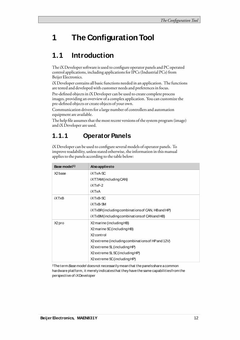
iXDeveloper can be used to configure severalmodels of operator panels. Toimprove readability, unless stated otherwise, the information in thismanualapplies to the panels according to the table below:
Base model1) Also applies to
X2 base iX TxA-SC
iX T7AM (including CAN)
iX TxF-2
iX TxA
iX TxB iX TxB-SC
iX TxB-SM
iX TxBR (including combinations of CAN, HB and HP)
iX TxBM (including combinations of CAN and HB)
X2 pro X2 marine (including HB)
X2 marine SC (including HB)
X2 control
X2 extreme (including combinations of HP and 12V)
X2 extreme SL (including HP)
X2 extreme SL SC (including HP)
X2 extreme SC (including HP)
1The term Base model does not necessarily mean that the panels share a commonhardware platform, it merely indicates that they have the same capabilities from theperspective of iX Developer
Beijer Electronics, MAEN831Y 12
TheConfigurationTool
1.1.2 Controller
iXDeveloper operator panels can be connected tomany types of automationequipment, such as PLCs, servos, and drives. Further on, the expression controlleris used as a general term for the connected equipment.
Related information
Controller
1.1.3 Tags
Data values in a controller are referred to as tags.Tagsmay also belong to the systemor be internal. A tag has a symbolic name andcan be of different data types.Objects connected to tags can change values in the controller, and tag values can bereflected by changing object appearance in variousways. Objects in a screenwillremain static until connected to a tag.
Related information
Tags
Beijer Electronics, MAEN831Y 13

TheConfigurationTool
1.1.4 System Requirements andLimitations
iX Developer
iX Developer System Requirements
Parameter Recommendation
RAM 2 GB
Processor 2 GHz or higher
Operating system Microsoft Windows 10 Home, Pro and Enterprise editions.
Supported versions: 1909, 2004 and 20H2.
Tier 2:
DirectX version: 9.0 or higher
Video RAM: 120MB or higher
Pixel shader: version level 2.0 or higher
Vertex shader: version level 2.0 or higher
Graphics card
Multitexture units: 4 or more
Updates
Software, drivers andprotocolsmay have been updated since theUSB stickwasproduced. Therefore, it is recommended that you use the built-in update functionin iXDeveloper before creating a project.
Related information
Update Software
Updating Drivers
iX Runtime
iX Runtime System Requirements
Parameter Recommendation
RAM 1 GB
Processor 1.3 GHz or higher
Operating system Microsoft Windows 10 Home, Pro and Enterprise editions.
Supported versions: 1909, 2004 and 20H2.
Microsoft Windows 10 IoT Enterprise 2019 LTSC.
Tier 2:
DirectX version: 9.0 or higher
Video RAM: 120MB or higher
Pixel shader: version level 2.0 or higher
Vertex shader: version level 2.0 or higher
Graphics card
Multitexture units: 4 or more
Beijer Electronics, MAEN831Y 14
TheConfigurationTool
Updating the Panel Image in an operator panel
ThePanel Image is pre-loaded in every operator panel on delivery. If necessary,this could be upgraded to a newer version using the Image Loader application.
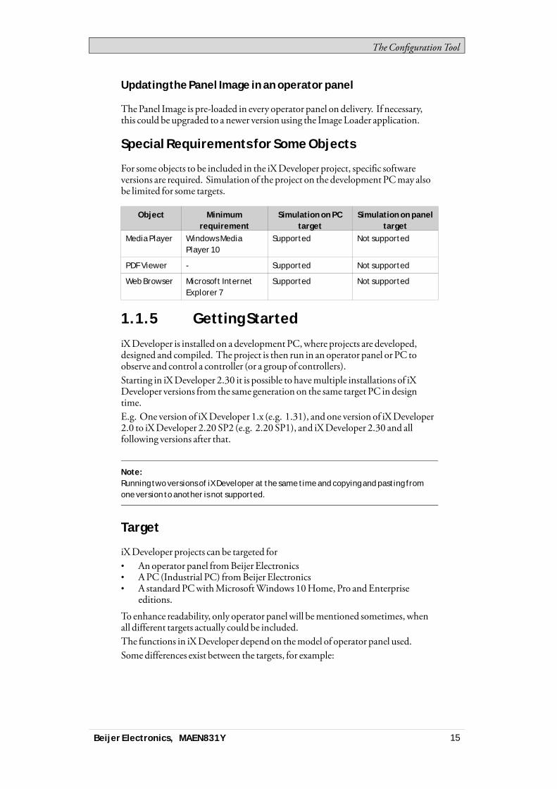
Special Requirements for Some Objects
For some objects to be included in the iXDeveloper project, specific softwareversions are required. Simulation of the project on the development PCmay alsobe limited for some targets.
Object Minimumrequirement
Simulation on PCtarget
Simulation on paneltarget
Media Player Windows MediaPlayer 10
Supported Not supported
PDF Viewer - Supported Not supported
Web Browser Microsoft InternetExplorer 7
Supported Not supported
1.1.5 Getting Started
iXDeveloper is installed on a development PC,where projects are developed,designed and compiled. The project is then run in an operator panel or PC toobserve and control a controller (or a group of controllers).Starting in iXDeveloper 2.30 it is possible to havemultiple installations of iXDeveloper versions from the same generation on the same target PC in designtime.E.g. One version of iXDeveloper 1.x (e.g. 1.31), and one version of iXDeveloper2.0 to iXDeveloper 2.20 SP2 (e.g. 2.20 SP1), and iXDeveloper 2.30 and allfollowing versions after that.
Note:Running two versions of iX Developer at the same time and copying and pasting fromone version to another is not supported.
Target
iXDeveloper projects can be targeted for• Anoperator panel fromBeijer Electronics• APC (Industrial PC) fromBeijer Electronics• A standard PCwithMicrosoftWindows 10Home, Pro andEnterprise
editions.
To enhance readability, only operator panelwill bementioned sometimes, whenall different targets actually could be included.The functions in iXDeveloper dependon themodel of operator panel used.Somedifferences exist between the targets, for example:
Beijer Electronics, MAEN831Y 15
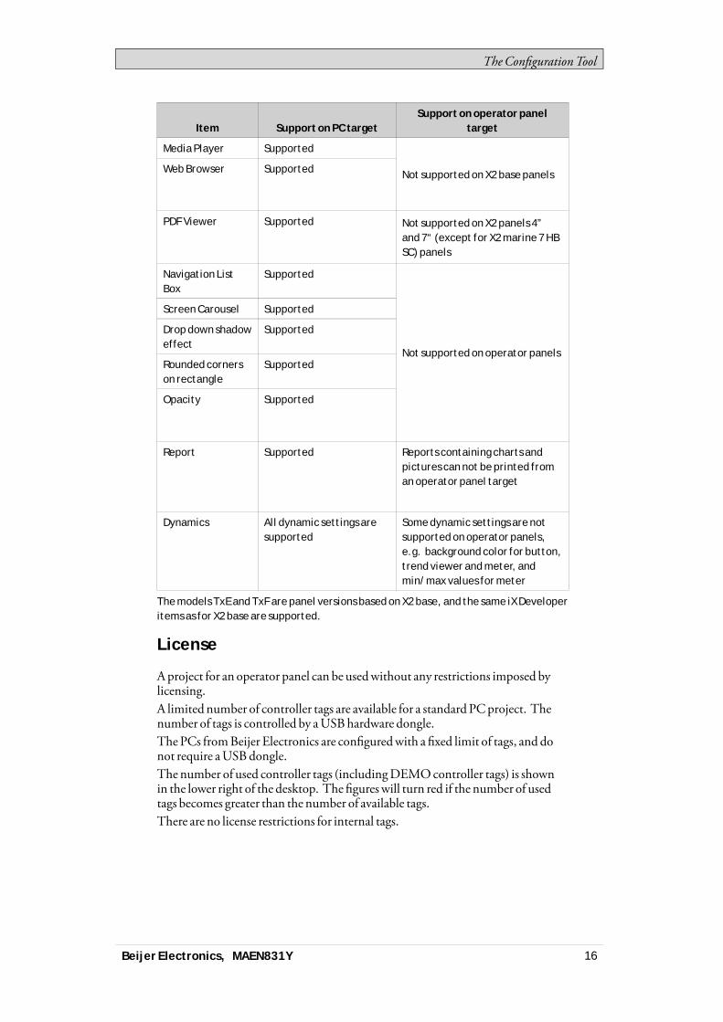
TheConfigurationTool
Item Support on PC targetSupport on operator panel
target
Media Player Supported
Web Browser Supported Not supported on X2 base panels
PDF Viewer Supported Not supported on X2 panels 4”and 7“ (except for X2 marine 7 HBSC) panels
Navigation ListBox
Supported
Screen Carousel Supported
Drop down shadoweffect
Supported
Rounded cornerson rectangle
Supported
Opacity Supported
Not supported on operator panels
Report Supported Reports containing charts andpictures can not be printed froman operator panel target
Dynamics All dynamic settings aresupported
Some dynamic settings are notsupported on operator panels,e.g. background color for button,trend viewer and meter, andmin/max values for meter
The models TxE and TxF are panel versions based on X2 base, and the same iX Developeritems as for X2 base are supported.
License
Aproject for an operator panel can be usedwithout any restrictions imposed bylicensing.A limited number of controller tags are available for a standardPCproject. Thenumber of tags is controlled by aUSBhardware dongle.The PCs fromBeijer Electronics are configuredwith a fixed limit of tags, and donot require aUSBdongle.The number of used controller tags (includingDEMOcontroller tags) is shownin the lower right of the desktop. The figureswill turn red if the number of usedtags becomes greater than the number of available tags.There are no license restrictions for internal tags.
Beijer Electronics, MAEN831Y 16

TheConfigurationTool
Note:The license system does not work without internet connection after activation on avirtual machine. This is a safety measure to ensure that a key is not activated on avirtual machine and the virtual machine is then cloned. Please install iX Developer on aphysical machine or make sure the virtual machine has internet connection.
Note:The USB hardware dongle will not be detected when using Remote DesktopConnection in Windows to connect remotely.A third party VNC based remote connection is recommended when remote connectionsare required.
Related information
Internal Tags
DEMO Controller
Product Registration
Thefirst time iXDeveloper is started, a registration dialog is displayed. Enteringthe registration key provides unlimited access to all program functionality andsoftware updates.Alternatively, select to continue using a trial version of the software. Youmayevaluate iXDeveloperwith full functionality for 30 days. When the evaluationperiod has expired, it will still be possible to use the software, but the functions intheRun andTransfer groupswill be disabled.
Note:If you have already used a Demo version of iX Developer for 30 days, you will not beissued another 30 days for evaluation.
Project Size
The project size is shown in the lower right of the desktop areawhen designing anoperator panel project. The sizewas calculated at the latest validation.
1.1.6 Installation
The iXDeveloper software is downloaded from https://smartstore.beijerelectron-ics.com.The installation creates an icon for iXDeveloper in the groupnamed iXDeveloper.
Note:The iX Developer must be installed on a development PC, a iX TxC target can not beused to develop projects.
Beijer Electronics, MAEN831Y 17

TheConfigurationTool
Installation of iX Runtime
To install iXRuntime on a PC, start the iXRuntime installer. To run the program,a dongle or software license is required that is supplied byBeijer Electronics.
1.1.7 Configured Features
iXDeveloper offers the possibility to add customer-specific features in theprogram. This is done through the use of registration keys that are entered afterthe iXDeveloper software installation has been done.Clicking onShowFeaturesdisplays a list of enabled features. To install a newfeature, enter the feature registration key underConfiguredFeatures and clickOK.A restart of the program is required to activate the function.
Related information
About
1.1.8 Project
The top folder for a specific application designedwith iXDeveloper is referredto as the project folder.During runtime, project database files can be updated, for examplewith newrecipes. Thismeans that to completely reproduce a project that has been inoperation, itmay be necessary to combine source fileswith files retrieved fromthe operator panel.
1.1.9 File Structure
Aproject contains a set of files related to the functional and graphical design anda set of files related to the runtime operation of the project, where the latter iscompiled from the design files.
Project Folder
When anewproject is created, a folderwith the project name is created as thetop-level container, theProject folder. The files that define the functional andgraphical design reside in the top level of the project folder. Other folders arecreated as a result of validation and build.
Beijer Electronics, MAEN831Y 18

TheConfigurationTool
Symbols
Pictures that are used in projects are converted to .png files when the project isvalidated.Pictures are resized to the largest static usage in any of the project screens, inorder to savememory space in the panel. If a picture is enlarged in runtime usingdynamics, the enlarged picturewill have a lower effective resolution.Project pictures are stored in theSymbols folder as a compressed folder namedSymbols.zip.
Temp
TheTemp folder contains intermediate build files fromproject compilation.TheTemp folder also includes theOutput folder. TheOutput folder contains allfiles needed to run the project in the target. These files are copied to an operatorpanel when theDownload command is used. For a PC, theExport command isused to copy the necessary files to aUSB stick to the runtimePCvia a networkconnection.When theWindows firewall is used, ports required by the iXRuntime are openedautomatically by the installer. If your operating system is protected by anotherfirewall product, this step needs to be donemanually.
Beijer Electronics, MAEN831Y 19
TheConfigurationTool
NeoRT_TCP• Protocol: tcp• Port: 9999• Scope: any• Application: CommunicationServer.exe
And:NeoRT_UDP• Protocol: udp• Port: 9999• Scope: any• Application: TargetControlService.exe
Moving Design Files
Tomove the project files needed for the design:1. Create a new folder for the project design files.2. Copy all single files (files not included in any folders) aswell as all folders,
except theTemp folder, in the project folder.3. Paste the files in the new folder.
Moving Application Project
The runtime project can be downloaded to the operator panel using the transfer orexport commands, but can also bemovedmanually:1. Create the new folder for the project files.2. Copy theOutput folder.3. Paste it in the new folder.
Database
iXDeveloper uses SQLite as database.The contents of the database can bemanagedwith third-party databasemanagement tools. iXDeveloper includes a database viewer object that can beused to display database contents in runtime.Some changes in the project will lead to data being lostwhen the updated project isdownloaded to the operator panel. These changes include:• Renaming a recipe• Changing the data type or name of a recipe's items or runtime data• Renaming a data logger• Changing the data type or name of a data logger's items
A copy of the database can bemadewith theUploadDatabase command. Someof the databases can be exported individually in csv, comma separated values,format using theDatabase Export action. If possible, it is recommended to use theDatabase Export action rather than theBackUpDatabases action.
Related information
Database Viewer Object
Download
Beijer Electronics, MAEN831Y 20
TheConfigurationTool
Related information
Export
Upload Database
Database Export
Beijer Electronics, MAEN831Y 21
Workingwith Projects
2 Working with Projects
This section describes iXDeveloper and explains how toworkwith a project foran operator panel.In iXDeveloper, ribbon tabs are used instead ofmenu commands. This reducesthe number of steps needed to design complex components, and also supplies anattractive user interface.Ribbon tabs are located in the top section of the tool window. Each ribbon tabholds one or several control groups. Each group contains a set of related controls.Controls aremade to design screens, and tomake settings for objects and controlsin the project.
2.1 Creating a ProjectAproject can be created according to the following sections, but thework processcan be adapted and rearranged if needed.
2.1.1 Connecting to a Controller
Establishing communication between an operator panel and controller isnecessary to allowoperator observation and control. The larger the project is, themore important it is to ensure that there is a suitable communication design.There is a built-inDEMOcontroller in iXDeveloper. It can be used for test andsimulation purposes.
Related information
Creating a New Project
Select Controller
Communication Design
DEMO Controller
2.1.2 Designing a Screen Set
It is important to organize the applicationwell and to considerwhich functions arenecessary. Startwith an overall view and thenwork down to a detailed level.A project contains a number of screenswith objects that can exchange datawiththe controller. Screens can be arranged in hierarchies to achieve a structuredapplication, or organized as sequence controls. Whendecidingwhich structureto use, consider how to best describe the process at hand and how to simplifyprocedures for themachine operator.The complete application, or parts of it, can be tested in the developmentenvironment before downloading it to the operator panel.
Related information
Screens
Beijer Electronics, MAEN831Y 22
Workingwith Projects
2.1.3 Designing Additional Functions
Alarms
Alarms are used tomake the operator aware of events that require immediateaction. An alarm is set when a certain condition ismet. An alarm condition isdesigned as a logical evaluation of a tag value. Alarms can be divided into groupsto create an order of priority.
Related information
Alarm Management
Function Keys
Function keys can be used to performactions and execute scripts. This allowsoperator control of data and screen functionality independent ofwhich screenis active.
Related information
Function Keys
Multiple Languages
Translation of texts and system texts can be performed directly in the application,or via export to a text file to be translated in other software. The file is importedto the application after translation. The application language can be changed inruntime, for example based on a tag value.
Note:Pre-translated system texts are provided with iX Developer. These texts are adaptedfor a PC, which means that they contain more strings than what is available for paneltargets. This results in warnings when importing the system texts to projects createdfor a panel, but these warnings can safely be ignored.
Related information
Language Management
Security
Access to objects and actions in the project can be limited using security groupsand user passwords.
Related information
Security Management
Text Library
With the text library function, text tables can be created,where values are linkedto texts.
Beijer Electronics, MAEN831Y 23

Workingwith Projects
Related information
Text Library
Audit Trail
TheAudit Trail function allows tracking of operator actions.
Related information
Audit Trail
Data Logger
Data can be logged and saved to file. Bit, 16-bit, 32-bit andReal (Float) values canbe logged. Be aware that logging of data consumes system resources andmemory.
Related information
Data Logger
Scheduler
Setting and resetting digital tags in relation to the real-time clock can be performedusing a scheduler, in order to control events in the process at special calendar times.
Related information
Scheduler
Recipes
Recipes are used to set or save a predefined group of tags in one operation.Values can be predefined or collected from the controller, and then saved to arecipe in the operator panel. The operator can download the recipe at any time tothe controller, whichwill start workingwith the recipe values. Recipe handlingmakes it possible to reuse large parameter sets, to improve efficiency of time criticalproductionwhere a change of productsmust bemade quickly. Recipe files can becreated in the development project orwith the operator panel.
Related information
Recipe Management
Reports
The reports function allows adding excel report templates to the project.
Related information
Reports
Beijer Electronics, MAEN831Y 24
Workingwith Projects
2.2 Importing an Information DesignerProject
Existing InformationDesigner projects can be imported to iXDeveloper.InformationDesigner is the previous software used to design projects for theEXTERoperator panels.
Note:This is not applicable if there is no Existing Information Designer projects.
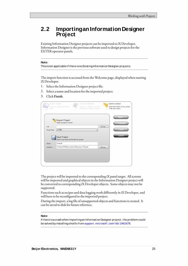
The import function is accessed from theWelcomepage, displayedwhen startingiXDeveloper.1. Select the InformationDesigner project file.2. Select a name and location for the imported project.3. ClickFinish.
The project will be imported to the corresponding iXpanel target. All screenswill be imported and graphical objects in the InformationDesigner project willbe converted to corresponding iXDeveloper objects. Some objectsmay not besupported.Functions such as recipes and data loggingwork differently in iXDeveloper, andwill have to be reconfigured in the imported project.During the import, a log file of unsupported objects and functions is created. Itcan be saved to disk for future reference.
Note:If there is a crash when importing an Information Designer project, the problem couldbe solved by installing a hotfix from support.microsoft.com/kb/2461678.
Beijer Electronics, MAEN831Y 25
Workingwith Projects
2.2.1 Information Designer ImportSettings
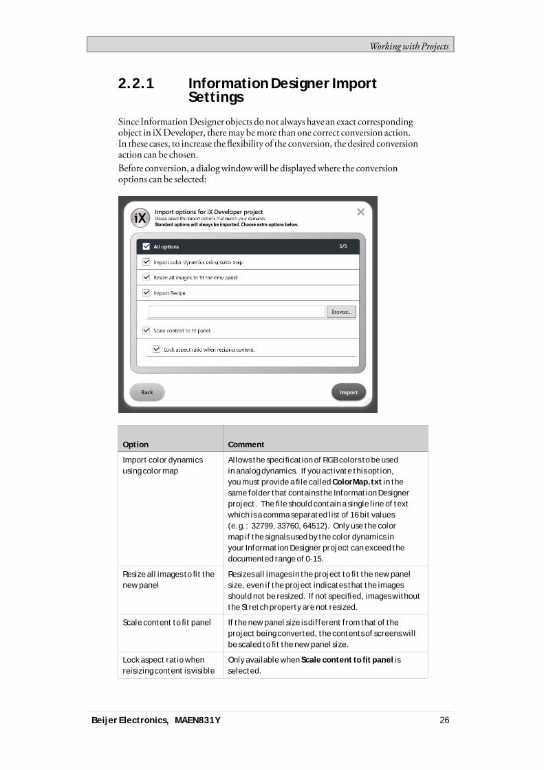
Since InformationDesigner objects do not always have an exact correspondingobject in iXDeveloper, theremay bemore than one correct conversion action.In these cases, to increase the flexibility of the conversion, the desired conversionaction can be chosen.Before conversion, a dialogwindowwill be displayedwhere the conversionoptions can be selected:
Option Comment
Import color dynamicsusing color map
Allows the specification of RGB colors to be usedin analog dynamics. If you activate this option,you must provide a file called ColorMap.txt in thesame folder that contains the Information Designerproject. The file should contain a single line of textwhich is a comma separated list of 16 bit values(e.g.: 32799, 33760, 64512). Only use the colormap if the signals used by the color dynamics inyour Information Designer project can exceed thedocumented range of 0-15.
Resize all images to fit thenew panel
Resizes all images in the project to fit the new panelsize, even if the project indicates that the imagesshould not be resized. If not specified, images withoutthe Stretch property are not resized.
Scale content to fit panel If the new panel size is different from that of theproject being converted, the contents of screens willbe scaled to fit the new panel size.
Lock aspect ratio whenreisizing content is visible
Only available when Scale content to fit panel isselected.
Beijer Electronics, MAEN831Y 26
Workingwith Projects
2.3 Importing an H-Designer/ADPProject
ExistingH-Designer/ADPprojects can be imported to iXDeveloper.H-Designer/ADP is the previous software used to design projects for theH-/PWS-series operator panels.The following software versions are required:
Software Version
ADP 6.50 build 184
iX Developer 2.0 or higher
2.3.1 Exporting the H-Designer/ADPProject
First, theH-Designer/ADPproject has to be converted to an a2i file fromwithinADPby following the steps below:1. SelectFile/Export iX.2. Select a name and location for the export file, and clickOK.
Amessage box confirms that the export is finished, and after clickingOK, youare asked if youwant to see the log file. The log file is saved to the same locationas the project file.
The log file declares successfully converted items aswell as unsupported objectsand functions.
2.3.2 Importing the a2i File
Then, the exported file is imported into iXDeveloper using the import functionthat is accessed from theWelcomepage, displayedwhen starting iXDeveloper.1. Select the a2i file.2. Select a name and location for the imported project.3. ClickFinish.The project will be imported to the corresponding iXpanel target. All screenswill be imported and graphical objects in theH-Designer/ADPproject will beconverted to corresponding iXDeveloper objects. Some objects and functionsmaynot be supported at all, and some objects and functions need reconfiguring inthe imported project.During the import, a log file of unsupported objects and functions is created. Itcan be saved to disk for future reference.
2.3.3 Limitations
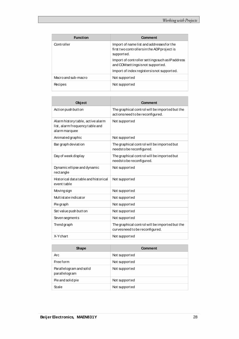
All parts of the originalH-Designer/ADPproject will not be fully supported in iXDeveloper. For example, for objects that use individual controller registers for readandwrite, only the register selected forwrite will be connected. Also, patterns andother decoration of objectsmaynot be included in the imported project.The following functions and objectswill not be converted, orwill needreconfiguration:
Beijer Electronics, MAEN831Y 27
Workingwith Projects
Function Comment
Controller Import of name list and addresses for thefirst two controllers in the ADP project issupported.
Import of controller settings such as IP addressand COM settings is not supported.
Import of index registers is not supported.
Macro and sub-macro Not supported
Recipes Not supported
Object Comment
Action push button The graphical control will be imported but theactions need to be reconfigured.
Alarm history table, active alarmlist, alarm frequency table andalarm marquee
Not supported
Animated graphic Not supported
Bar graph deviation The graphical control will be imported butneeds to be reconfigured.
Day of week display The graphical control will be imported butneeds to be reconfigured.
Dynamic ellipse and dynamicrectangle
Not supported
Historical data table and historicalevent table
Not supported
Moving sign Not supported
Multistate indicator Not supported
Pie graph Not supported
Set value push button Not supported
Seven segments Not supported
Trend graph The graphical control will be imported but thecurves need to be reconfigured.
X-Y chart Not supported
Shape Comment
Arc Not supported
Free form Not supported
Parallelogram and solidparallelogram
Not supported
Pie and solid pie Not supported
Scale Not supported
Beijer Electronics, MAEN831Y 28

Workingwith Projects
Shape Comment
Shape Not supported
Solid polygon The graphical control will be imported butneeds to be reconfigured.
2.4 Optimizing PerformanceThe following section presents a couple of issues to consider in order to optimizethe iXDeveloper project. Someparts are related to the communication driver;other parts concernCPU load andflash operations.
2.4.1 Communication Performance
Signal Types
Tags used for driver communication can be static or dynamic. These are updatedin differentmanners.
Static Tags
Static tags are updated continuously, even if they are not currently shownon thepanel display.Additionally, the operator panel reads the following items continuously:• Alarm tags• Data logger tags• Multiple languages tags• Controller tagswith value change events
The communication time is not affected by the following:• Alarmmessages• Schedulers• Tags linked to function keys
Dynamic Tags
Dynamic tags are updated onlywhen they are presented on the display. An analognumeric object serves as an example ofwhen a dynamic tag is used.
2.4.2 Communication Design
This section describes how tags are read and how the reading can be optimized tomake the communication between the operator panel and the controller fast andefficient.
Keeping Tags in Consecutive Order
Define controller tags consecutively, for exampleM0.0-M11.7. If the tags arespread (e.g. I0.4,Q30.0,M45.3 etc.) a complete updatewill take longer time.The number of tags in each package depends on the used driver and informationabout this can be found in the driver help file.
Beijer Electronics, MAEN831Y 29

Workingwith Projects
Tag Packages
Tags to be transferred are not all transferred at the same time, but are groupedinto packages. The number of tags in each package depends on the driver for thecontroller.Tomake communication as fast as possible the number of packages should beminimized. Consecutive tags require aminimumnumber of packages, but it isperhaps not always possible to program it this way. In such cases there is a “waste”between two tags.
Waste is themaximumdistance between two tags that can be kept in the samepackage. The size of thewaste depends on the driver used, and is included in thedriver help file, e.g as in the table below:
Driver x Analog signals Digital signals
Number of signals/package 29 124
Waste 20 0
Bit-Addressed Words vs. Regular Bit Devices
Inmost drivers it is better to use bit-addressedwords than regular bit devices, sinceyou can fitmore digital devices in one telegramwhen using bit-addressedwords,thanwhenusing bit devices.
Example
Driver x Analog signals Digital signals
Number of signals/package 29 124
Waste 20 0
This specific driver can have 29 analog devices or 124 digital devices in onetelegram. If you use bit-addressedwords in the selected driver, you canfit 464(29 × 16) digital devices in one package. This is almost four times asmany devices.
ASCII Strings
ASCII strings are transmitted in separate telegrams, and having a large numberof stringswill affect the communication performance negatively. If anASCIIstring only has a small number of different string values, itmay be a good idea touse theText Library function in iXDeveloperwith predetermined contents, thusminimizing impact ondriver performance.
Related information
Text Library
Beijer Electronics, MAEN831Y 30
Workingwith Projects
2.4.3 Performance in the operator panel
It is important to understand that due to the complex nature of a running system,there are several things that affects the overall performance. The following listgives some examples of things to consider, when it is necessary to optimize theperformance of the operator panel:• Number of tags• Number of sampled tags in trend viewers and data logger• Number of alarms• Driver performance• Multiple drivers• Type of panel• Alarm list size• Size of pictures• Scripts
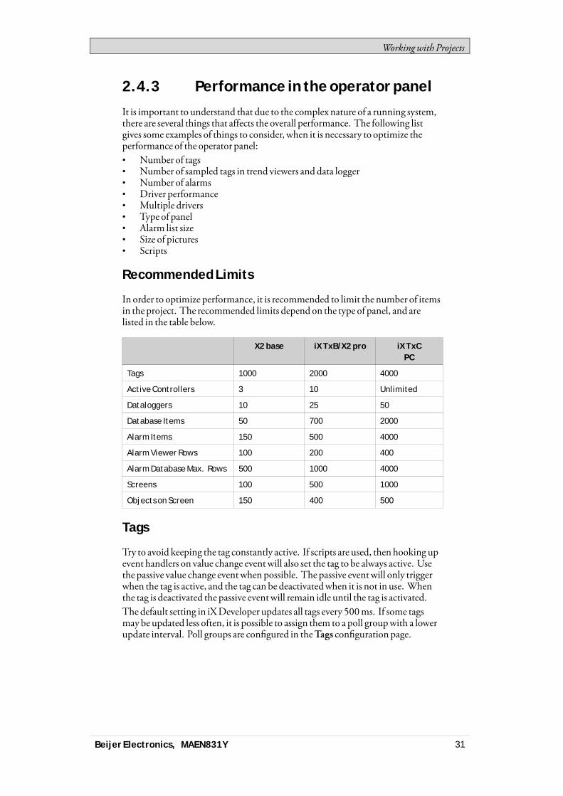
Recommended Limits
In order to optimize performance, it is recommended to limit the number of itemsin the project. The recommended limits depend on the type of panel, and arelisted in the table below.
X2 base iX TxB/X2 pro iX TxCPC
Tags 1000 2000 4000
Active Controllers 3 10 Unlimited
Dataloggers 10 25 50
Database Items 50 700 2000
Alarm Items 150 500 4000
Alarm Viewer Rows 100 200 400
Alarm Database Max. Rows 500 1000 4000
Screens 100 500 1000
Objects on Screen 150 400 500
Tags
Try to avoid keeping the tag constantly active. If scripts are used, then hooking upevent handlers on value change eventwill also set the tag to be always active. Usethe passive value change eventwhen possible. The passive eventwill only triggerwhen the tag is active, and the tag can be deactivatedwhen it is not in use. Whenthe tag is deactivated the passive eventwill remain idle until the tag is activated.The default setting in iXDeveloper updates all tags every 500ms. If some tagsmay be updated less often, it is possible to assign them to a poll groupwith a lowerupdate interval. Poll groups are configured in theTags configuration page.
Beijer Electronics, MAEN831Y 31
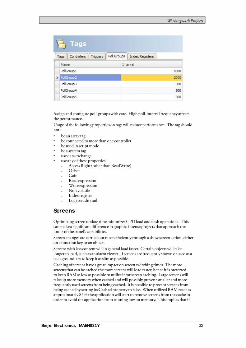
Workingwith Projects
Assign and configure poll-groupswith care. Highpoll-interval frequency affectsthe performance.Usage of the following properties on tagswill reduce performance. The tag shouldnot:• be an array tag• be connected tomore than one controller• be used in scriptmode• be a system tag• use data exchange• use any of these properties:
– Access Right (other thanReadWrite)– Offset– Gain– Read expression– Write expression– Non volatile– Index register– Log to audit trail
Screens
Optimizing screen update timeminimizesCPU load andflash operations. Thiscanmake a significant difference in graphic-intense projects that approach thelimits of the panel’s capabilities.Screen changes are carried outmost efficiently through a show screen action, eitheron a function key or an object.Screenswith less contentwill in general load faster. Certain objects will takelonger to load, such as an alarmviewer. If screens are frequently shownor used as abackground, try to keep it as slim as possible.Caching of screens have a great impact on screen switching times. Themorescreens that can be cached themore screenswill load faster, hence it is preferredto keepRAMas low as possible to utilize it for screen caching. Large screenswilltake upmorememorywhen cached andwill possibly prevent smaller andmorefrequently used screens frombeing cached. It is possible to prevent screens frombeing cached by setting itsCachedproperty to false. When utilizedRAMreachesapproximately 85% the applicationwill start to remove screens from the cache inorder to avoid the application from running lowonmemory. This implies that if
Beijer Electronics, MAEN831Y 32
Workingwith Projects
the application utilizemore than 85%without caching the applicationwill notbe able to cache any screens and therefore not experience faster screen switchingtimes.
Trend Viewers and Data Loggers
Several trend viewers can showdata from the same log item.In order to optimize performance in the panel, it is strongly recommended to placeall log items logged on the same frequency/event in the same data logger or at leastreduce the amount of data loggers.Try to avoid having one data logger for each trend viewer.Data logging in general have impact on the performance. Reconsider the datalogger settings, the log frequency and the amount of log items. Heavy data loggingwill increase theCPUusage andwill influence performance across thewholeapplication.Data logging is queuedup ifmore logging is done than the database can handleat themoment. If the queue reaches a too high level, thewarning “Data logginghas too high load. Datamight be lost.” is shownon the screen in the top left notifierwindow. If the queue reaches a critical level, there is a risk that the systemwillmalfunction. If this happens, alarm anddata logging are turned off, the errormessage “Data logging is overloaded. Data logging is now disabled.” is shown in thedialog and the system tagDatabase ErrorActive is set. The system tagDatabaseErrorMessage contains the errormessage.The system tag is not reset by the system. It is up to the user to reset it when thesystem error is taken care of.Alarm anddata logging are turned on againwhen the queue is below the criticallevel.
Storage Media
If the storagemedia reaches a critically low level, there is a risk that the systemwillmalfunction. If this happens, alarm anddata logging is turned off. The errormessage “99%of disk used. Alarm logging is now disabled. Data logging is nowdisabled.” is shown and the system tagDatabase Error Active is set. The system tagDatabase ErrorMessage contains the errormessage.The system tag is never reset by the system. It is up to the user to reset it when thesystem error is taken care of.Alarm anddata logging are turned on againwhen the storage usage is below thecritical level.You can avoid this situation by using theMaxSize setting for the database. Whenthe limit is reached youwill be informedby awarningmessage.
Database
If there is a risk of the database running out of storagemedia, then awarning isshownon the screen. If the usage reaches a critical level, risking the system to crash,alarm anddata logging is turned off, an errormessage is shown and the system tagDatabase ErrorActive is set. The system tagDatabase ErrorMessage containsthe errormessage. Alarm anddata logging are turned on againwhen the storageusage is below the critical level.
Beijer Electronics, MAEN831Y 33

Workingwith Projects
Gradients
Using objects with gradients creates a slightly higher load on theCPU. If a largenumber of objects use gradients, this willmake the screen update time significantlyslower. Pay special attention to objects with gradients that are updated frequently,e.g. a bar graphwith a stylewith gradients connected to a tag that changes at shortintervals.
Polygons
Avoid excessive use of polygons. Polygons are usually complex and are drawn eachtime the screen is shown, hence theywill not benefit from caching the screen.
Buttons
Froma performance perspective it is preferred to use styled buttons instead of thedefault button.
Transparency
Drawing transparent objects (circularmeter, slider etc.) without transparencywillresult in improved performance. In order to do so these objects should not overlapother objects within their bounding box. Also, avoid gradients in backgroundsand dynamics on screens containing these types of objects.
A circularmeter and its bounding box
Related information
Database
Action Groups
Trend Viewer
Reports
Data Logging Strategies
Symbols
Screen Caching
Beijer Electronics, MAEN831Y 34

Workingwith Projects
2.5 Moving Objects with the TouchScreen
iX panelwith touch screens do not have a built-in keyboard. Allmaneuvering isdonewith the touch screen by pressing distinctlywith a finger. Because of theresistive touch technology, the screen can only apprehend pressing on one place onthe panel at the time. Pressing two points at the same time is interpreted by thepanel as a pointmidway between the twopressed points.
Related information
2.5.1 Operate Objects
For an object to react, it is necessary to specify the behavior, typically by assigninga tag anddefining an action. All objects can have actions linked tomouse down,mouse up,mouse enter andmouse leave events. Some objects have a predefinedbehavior, like sliders setting values, but can also have actions linked tomousedown andmouse up events.
Button
Pressing a button triggers a click- andmouse button event.
Text Box
Pressing on a text box object displays a virtual alpha-numeric keyboard on thepanel screen. Type a text using this keyboard and finish by pressing [ENTER].
Analog Numeric
Pressing on an analog numeric object displays a virtual keyboard on the panelscreen. The keyboard type depends on the format chosen for theAnalogNumeric—String, Integer,Decimal,Hex orBinary. Enter a value using this keyboard andfinish by pressing [ENTER].In runtime a validation of the value is done. If the value entered is out of bounds,the corresponding limit value for the object will be shown.
Slider
Pressing on the desired value position of a slider object sets it to the pressedposition.
Related information
Actions Ribbon Tab
Mouse Button Action Triggers
Click Action Trigger
Virtual Keyboard
Validation Group
Beijer Electronics, MAEN831Y 35

Workingwith Projects
2.6 Peripherals
2.6.1 USB
External devices such as aUSBhub, flash drive,mouse, or keyboard can beconnected to theUSBhost port.
2.6.2 Ethernet
The operator panel has built-in Ethernet port(s) for connection to controllers viaTCP/IP.The number of ports varies bymodel.
Related information
2.6.3 Memory Card
An externalmemory card can be used as storage of e.g. pdf files,media files anddatabases to reduce used internalmemory.Limitations forDatabases Location Setting: This setting is onlymade availablefor high performance panels with SDCard slot. It is also important to ensure theSDCard is already in the correct format (FAT32) before inserting it in the panel.If during startup an errormessage “Disk IO error” is displayed and the chosenDatabase Location is set to SDCard, please ensure the SDCardhas an ampleamount of space available on it.If during the runtime of the panel, the SDCard is removed and the chosenlocation for theDatabase(s) is the SDCard then the panel will close theapplication andwill continue to attempt to reboot until either an SDCardis reinserted into the panel or a project is downloaded to the panel with thelocation set toHard disk. If the SDCard is chosen as the desired location to storetheDatabase(s), during the transfer of the project to the panel theAudit TrailDatabasewill not appear in the confirmation dialog of files to be kept on the panel.As a result, it will continue to use the existingAudit TrailDatabase. To avoid thisthe SDCard should be removed and theAudit TrailDatabase should be deletedvia a PC.Anypre-existing scripts towards a databasemay not function as intendedif the database location is changed andno build error orwarningwill be given.
Related information
Project Group
2.6.4 SD card tests iX Developer
Recommendations of use:• Always use IndustrialGrade both for SD card andUSB.• Use SD/USBwithmemory transfer rate x32/4.8 or higher.• Filling thewhole SD/USBwith datawill effect the performance.
Tested brands:• Trancend Industrial 2GB.• SanDiskUltra 4GBC:10.• SanDiskExtreme 64GBC:4
Beijer Electronics, MAEN831Y 36

Workingwith Projects
• Inodisk Industrial 2GBC:10.
Beijer Electronics, MAEN831Y 37

Development Environment
3 Development Environment
This section describes how toworkwith iXDeveloper.Clicking theOptions button in the Filemenu allows adapting the tool behavior.
Related information
File Menu
Options
3.1 Starting iX DeveloperClick on Start/All Programs/iXDeveloper/iXDeveloper to start iXDeveloper.iXDeveloper can also be started from the command line.When starting a newly installed version for the first time the user gets the option toimport the settings from the previous version.This could also be done later from the Filemenu: Import settingsThe following settings are imported:• License key• Recent Projects• Added items inComponent Library• AdditionalControls
After importing settings from previous version, information aboutwhat has beenimported is displayed.
When iXDeveloper is started, it is possible to:• Create a newproject using awizard• Open an existing project - a list of recently opened projects is displayed• Open a sample project• Upload a project from a target• Import a project created in InformationDesigner• View theUser’sGuide, based on an example project that serves as an
instructive introduction to iXDeveloper
Beijer Electronics, MAEN831Y 38

Development Environment
Projects can also be created or opened later from the Filemenu.
Related information
Creating a New Project
Importing an Information Designer Project
Starting iX Developer from the Command Line
Upload from Target
3.1.1 Creating a New Project
To create a newproject using thewizard includes the following steps:1. Start iXDeveloper.2. Select to create a newproject.3. Select target for the project.4. Select controller brand andmodel.5. Name the project anddefinewhere files are to be saved in the PC environment.
Select operator panel
Select the appropriate target from the presented set of operator panel/PC.
Beijer Electronics, MAEN831Y 39

Development Environment
The target can be changed later, from the Settings group on theProject ribbon tab.Formost panels it is possible to select a rotated view.Whenworkingwith a project for a standard PC, it is possible to select resolutionfrom a drop-down list. The PC resolution can be changed later, by enftering theSettings group on theProject ribbon tab.
Related information
Changing Project Target
Select Controller
Select the appropriate controller for the project.
Beijer Electronics, MAEN831Y 40

Development Environment
The demo controller, including regular tags (data containers) and counters, is usedto design and test a project directly on the development PCwithout connection toan external controller.Internal tags thatwork like controller tags, but are independent of an externalcontroller, can be defined.It is also possible to connect to an externalOPC server.The controller can be changed later by clicking theController button on theControllers tab of the tags configuration page.A project can connect tomore than one controller.
Note:OPC Classic is not supported for X2 pro series (OPC Classic is no longer supported byWindows Embedded Compact 2013).
Related information
Controller
DEMO Controller
Internal Tags
External OPC Server
Multiple Controllers
Select Location
TheSelect Location dialog controls naming of the project andwhere project filesare saved in the computer environment.
1. Change the project name, if desired.
Beijer Electronics, MAEN831Y 41
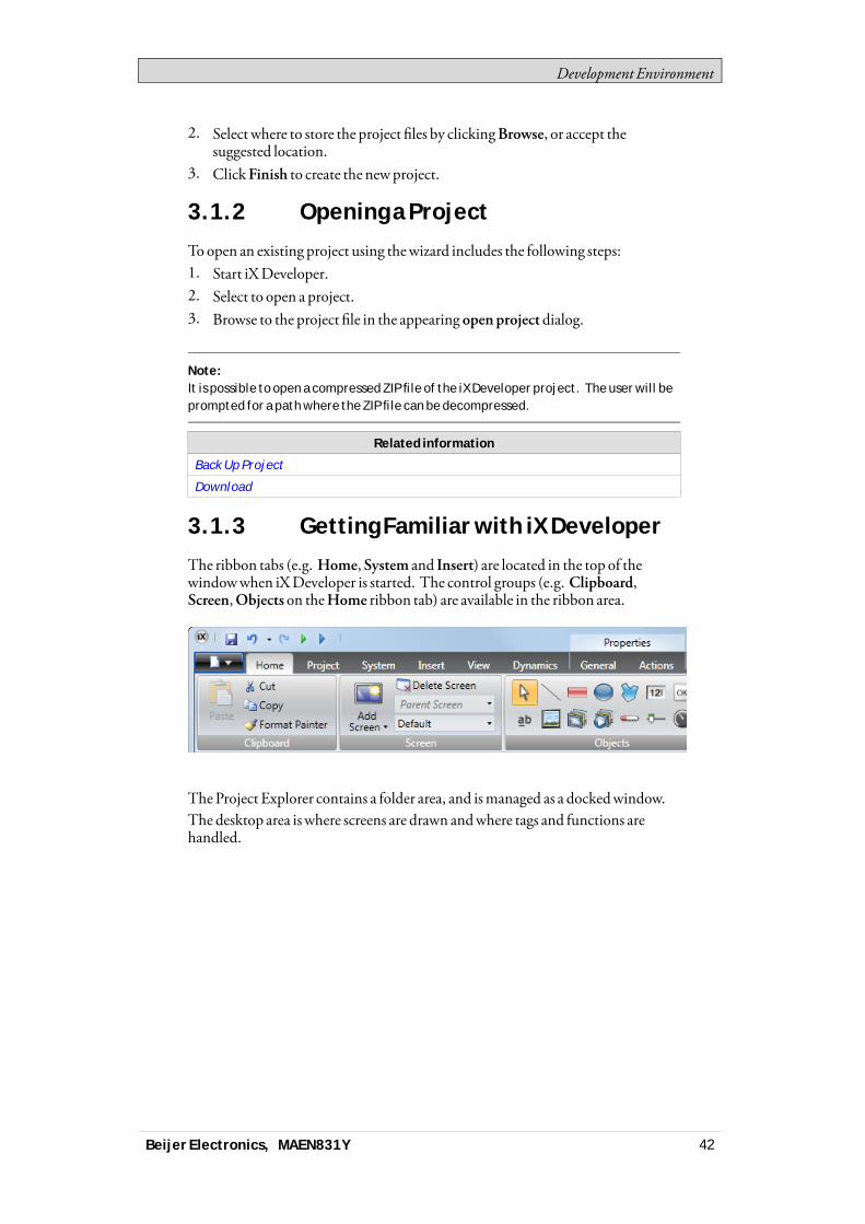
Development Environment
2. Select where to store the project files by clickingBrowse, or accept thesuggested location.
3. ClickFinish to create the newproject.
3.1.2 Opening a Project
Toopen an existing project using thewizard includes the following steps:1. Start iXDeveloper.2. Select to open a project.3. Browse to the project file in the appearing open project dialog.
Note:It is possible to open a compressed ZIP file of the iX Developer project. The user will beprompted for a path where the ZIP file can be decompressed.
Related information
Back Up Project
Download
3.1.3 Getting Familiar with iX Developer
The ribbon tabs (e.g. Home,System and Insert) are located in the top of thewindowwhen iXDeveloper is started. The control groups (e.g. Clipboard,Screen,Objects on theHome ribbon tab) are available in the ribbon area.
The Project Explorer contains a folder area, and ismanaged as a dockedwindow.The desktop area iswhere screens are drawn andwhere tags and functions arehandled.
Beijer Electronics, MAEN831Y 42
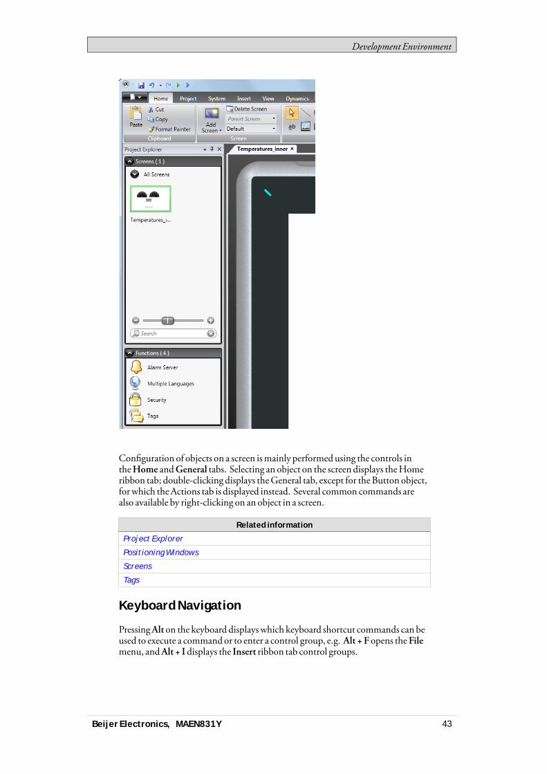
Development Environment
Configuration of objects on a screen ismainly performed using the controls intheHome andGeneral tabs. Selecting an object on the screen displays theHomeribbon tab; double-clicking displays theGeneral tab, except for theButton object,for which theActions tab is displayed instead. Several common commands arealso available by right-clicking on an object in a screen.
Related information
Project Explorer
Positioning Windows
Screens
Tags
Keyboard Navigation
PressingAlt on the keyboard displayswhich keyboard shortcut commands can beused to execute a command or to enter a control group, e.g. Alt + F opens theFilemenu, andAlt + I displays the Insert ribbon tab control groups.
Beijer Electronics, MAEN831Y 43
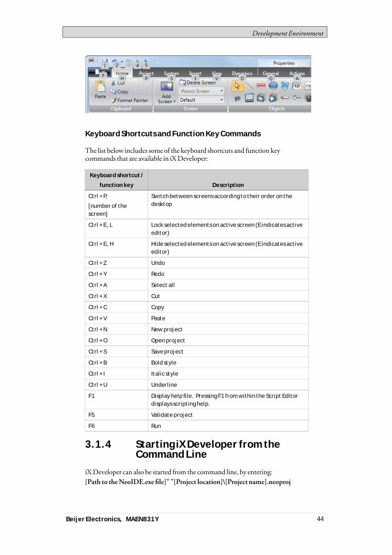
Development Environment
Keyboard Shortcuts and Function Key Commands
The list below includes some of the keyboard shortcuts and function keycommands that are available in iXDeveloper:
Keyboard shortcut /
function key Description
Ctrl + P,
[number of thescreen]
Switch between screens according to their order on thedesktop
Ctrl + E, L Lock selected elements on active screen (E indicates activeeditor)
Ctrl + E, H Hide selected elements on active screen (E indicates activeeditor)
Ctrl + Z Undo
Ctrl + Y Redo
Ctrl + A Select all
Ctrl + X Cut
Ctrl + C Copy
Ctrl + V Paste
Ctrl + N New project
Ctrl + O Open project
Ctrl + S Save project
Ctrl + B Bold style
Ctrl + I Italic style
Ctrl + U Underline
F1 Display help file. Pressing F1 from within the Script Editordisplays scripting help.
F5 Validate project
F6 Run
3.1.4 Starting iX Developer from theCommand Line
iXDeveloper can also be started from the command line, by entering:[Path to theNeoIDE.exe file]" "[Project location]\[Project name].neoproj
Beijer Electronics, MAEN831Y 44
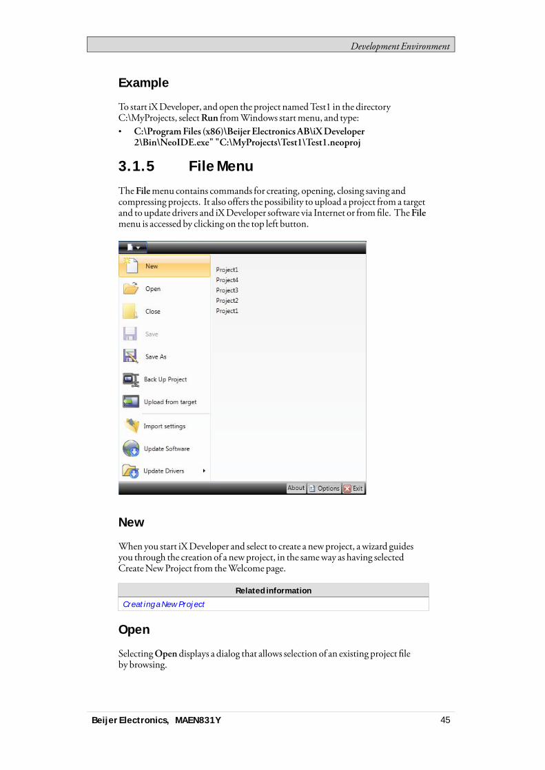
Development Environment
Example
To start iXDeveloper, and open the project namedTest1 in the directoryC:\MyProjects, selectRun fromWindows startmenu, and type:• C:\ProgramFiles (x86)\Beijer Electronics AB\iXDeveloper
2\Bin\NeoIDE.exe" "C:\MyProjects\Test1\Test1.neoproj
3.1.5 File Menu
TheFilemenu contains commands for creating, opening, closing saving andcompressing projects. It also offers the possibility to upload a project from a targetand to update drivers and iXDeveloper software via Internet or fromfile. TheFilemenu is accessed by clicking on the top left button.
New
When you start iXDeveloper and select to create a newproject, a wizard guidesyou through the creation of a newproject, in the sameway as having selectedCreateNewProject from theWelcomepage.
Related information
Creating a New Project
Open
SelectingOpen displays a dialog that allows selection of an existing project fileby browsing.
Beijer Electronics, MAEN831Y 45
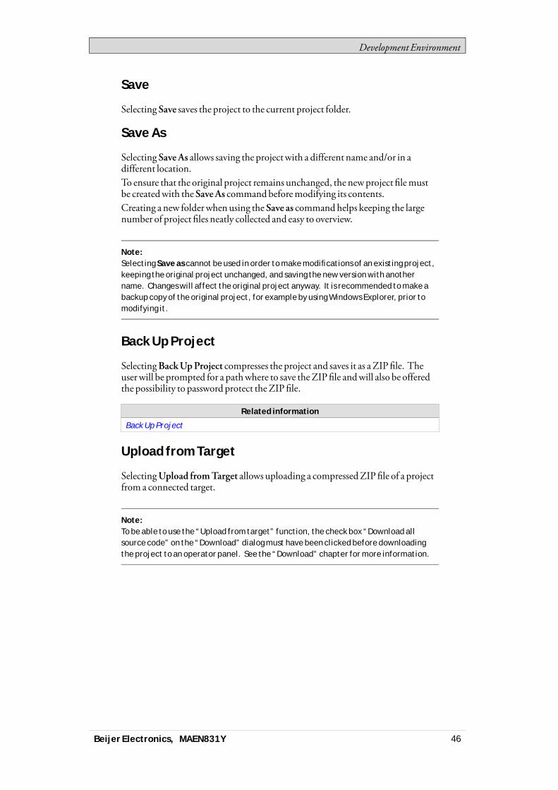
Development Environment
Save
Selecting Save saves the project to the current project folder.
Save As
Selecting SaveAs allows saving the projectwith a different name and/or in adifferent location.To ensure that the original project remains unchanged, the newproject filemustbe createdwith theSaveAs commandbeforemodifying its contents.Creating a new folderwhen using the Save as commandhelps keeping the largenumber of project files neatly collected and easy to overview.
Note:Selecting Save as cannot be used in order to make modifications of an existing project,keeping the original project unchanged, and saving the new version with anothername. Changes will affect the original project anyway. It is recommended to make abackup copy of the original project, for example by using Windows Explorer, prior tomodifying it.
Back Up Project
SelectingBackUpProject compresses the project and saves it as aZIP file. Theuserwill be prompted for a pathwhere to save theZIPfile andwill also be offeredthe possibility to password protect theZIPfile.
Related information
Back Up Project
Upload from Target
SelectingUpload fromTarget allows uploading a compressedZIPfile of a projectfrom a connected target.
Note:To be able to use the “Upload from target” function, the check box “Download allsource code” on the “Download” dialog must have been clicked before downloadingthe project to an operator panel. See the “Download” chapter for more information.
Beijer Electronics, MAEN831Y 46
Development Environment
Parameter Description
Connected targets Choose the target type to transfer the project from.
Upload Starts the transfer of the ZIP file from the selected target.
The user will be prompted for a path where to decompressthe ZIP file. If the ZIP file is password protected, theuser must enter the password to be able to upload anddecompress the ZIP file.
Log Show the data being logged during the upload and verifyprocess.
Related information
Download
Close Project
SelectingCloseProject closes the current project and activates the startwizard.
Update Software
The latest updates and patches for iXDeveloper can be downloaded directly viaan Internet connection.
Update Drivers
Drivers can be updated via Internet or fromfile.
Related information
Updating Drivers
Beijer Electronics, MAEN831Y 47
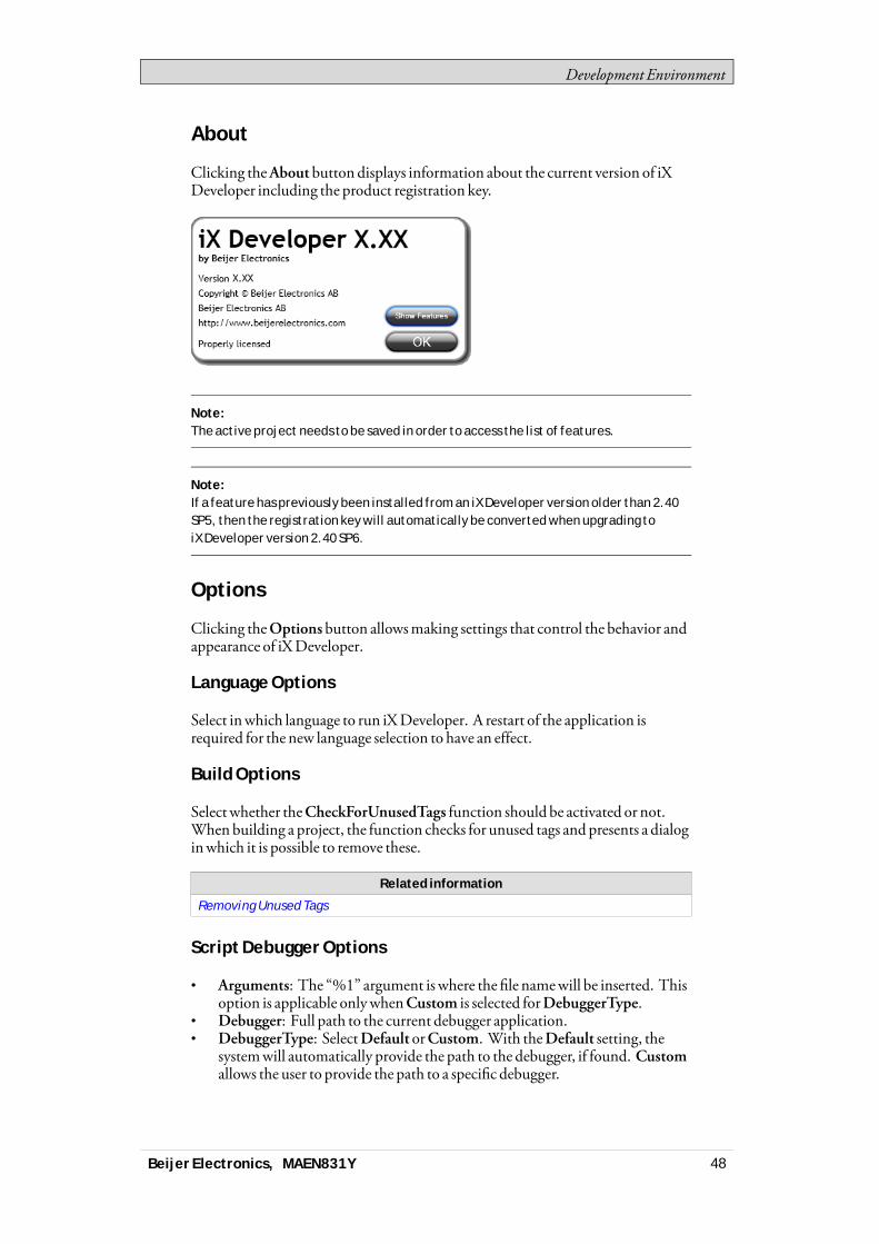
Development Environment
About
Clicking theAbout button displays information about the current version of iXDeveloper including the product registration key.
Note:The active project needs to be saved in order to access the list of features.
Note:If a feature has previously been installed from an iX Developer version older than 2.40SP5, then the registration key will automatically be converted when upgrading toiX Developer version 2.40 SP6.
Options
Clicking theOptions button allowsmaking settings that control the behavior andappearance of iXDeveloper.
Language Options
Select inwhich language to run iXDeveloper. A restart of the application isrequired for the new language selection to have an effect.
Build Options
Selectwhether theCheckForUnusedTags function should be activated or not.When building a project, the function checks for unused tags and presents a dialoginwhich it is possible to remove these.
Related information
Removing Unused Tags
Script Debugger Options
• Arguments: The “%1” argument is where the file namewill be inserted. Thisoption is applicable onlywhenCustom is selected forDebuggerType.
• Debugger: Full path to the current debugger application.• DebuggerType: SelectDefault orCustom. With theDefault setting, the
systemwill automatically provide the path to the debugger, if found. Customallows the user to provide the path to a specific debugger.
Beijer Electronics, MAEN831Y 48
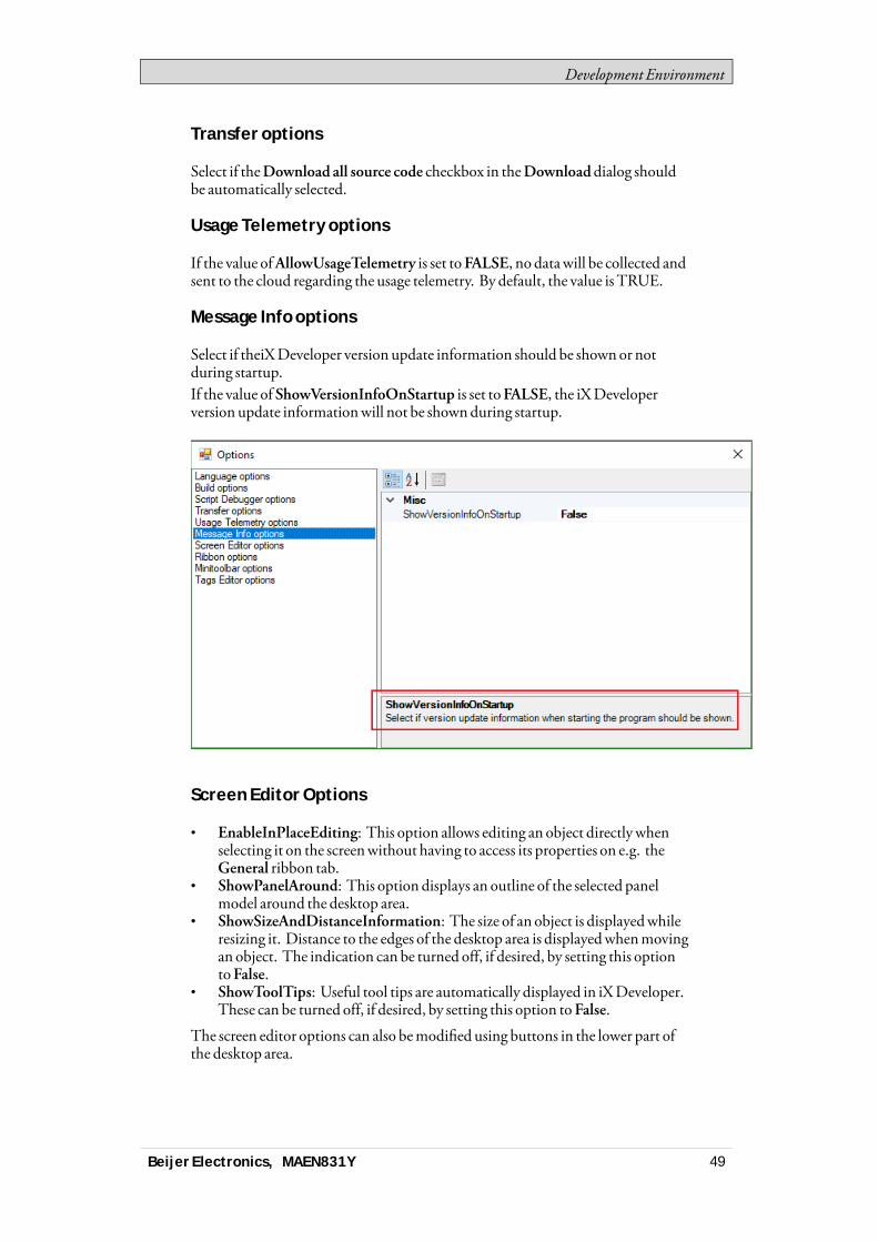
Development Environment
Transfer options
Select if theDownload all source code checkbox in theDownloaddialog shouldbe automatically selected.
Usage Telemetry options
If the value ofAllowUsageTelemetry is set toFALSE, no datawill be collected andsent to the cloud regarding the usage telemetry. By default, the value is TRUE.
Message Info options
Select if theiXDeveloper version update information should be shownor notduring startup.If the value of ShowVersionInfoOnStartup is set toFALSE, the iXDeveloperversion update informationwill not be shownduring startup.
Screen Editor Options
• EnableInPlaceEditing: This option allows editing an object directlywhenselecting it on the screenwithout having to access its properties on e.g. theGeneral ribbon tab.
• ShowPanelAround: This option displays an outline of the selected panelmodel around the desktop area.
• ShowSizeAndDistanceInformation: The size of an object is displayedwhileresizing it. Distance to the edges of the desktop area is displayedwhenmovingan object. The indication can be turned off, if desired, by setting this optiontoFalse.
• ShowToolTips: Useful tool tips are automatically displayed in iXDeveloper.These can be turned off, if desired, by setting this option to False.
The screen editor options can also bemodified using buttons in the lower part ofthe desktop area.
Beijer Electronics, MAEN831Y 49

Development Environment
Related information
Screen View in Desktop Area
Ribbon Options
• GoToDefaultRibbonStrategy: This option changes the active ribbonbasedon the context of the selection in the desktop. When an object is created orselected, theGeneral tab becomes active in the ribbon area.
• SimpleRibbonStrategy: This is the default setting, and does not swap theactive ribbonwhen the context of the current desktop selection changes.Clicking on an object opens theHome ribbon, and double-clicking openstheGeneral ribbon formost objects, but for buttons theActions ribbon isactivated.
Mini Toolbar Options
Themini toolbar is a contextmenu additionwith a subset of common controlsfrom theFormat,Tag/Security andName groups.• ShowMinitoolbarAutomatic: When this option is set toTrue themini
toolbar part of the contextmenu is displayed alreadywhen an object isselected. Themini toolbarwill always show in combinationwith the contextmenu. Themini toolbarwill remain active for a selected object, also afterit has disappeared, until the selection or the pointermoves away. To showthemini toolbar againmove themouse pointer to the upper right of theobject. With the default setting,False, themini toolbarwill only show incombinationwith the contextmenu for an object.
Tags Editor Options
Selections underTags EditorOptionsmakes it possible to customizewhichcolumns to showby default in the tags configurationwindow.
Exit
Clicking theExit button closes the application. If there are unsaved changes, youare asked if youwant to save thembefore exiting.
3.1.6 Quick Access Toolbar
TheQuickAccessToolbar contains controls, expected to be used frequently. Thetoolbar can be customized to include other buttons.
Save
Saves the current project to the location specifiedwhen the project was created.
Beijer Electronics, MAEN831Y 50

Development Environment
Undo
Executed commands can be undone using theUndo button. Clicking the smallarrow at the right of theUndobutton lists recentlymade changes for selection ofthe undo operation.
The keyboard shortcut forUndo isCtrl +Z.
Redo
Acommand that has been undonewithUndo can be redonewithRedo. Thekeyboard shortcut forRedo isCtrl +Y.
Run
Performs a validation of script code and compiles the project. If the project is valid,a simulation is started on the development PCwith connection to the selectedcontroller. Also available from theTransfer group on theProject ribbon tab.
Simulate
Performs a validation of script code and compiles the project. If the project is valid,a simulation is started on the development PCwithout connection to the selectedcontroller. Also available from theTransfer group on theProject ribbon tab.
Related information
Project Ribbon Tab
Customizing Quick Access Toolbar
Some of the ribbon controls can be added to theQuickAccess Toolbar. Right-clickon the desired control and selectAdd toQuickAccessToolbar orRemove fromQuickAccessToolbar.
3.1.7 Ribbon Tabs
The ribbon tabs contain grouped controls for editing andmaintaining a project,screens and objects. Click on any ribbon tab to display the ribbon.UseMinimize theRibbon andMaximize theRibbon to collapse and expand theribbon control tabs, or double-click on a ribbon tab. This can also be done fromtheQuickAccess toolbar.
Beijer Electronics, MAEN831Y 51

Development Environment
Related information
Home Ribbon Tab
Project Ribbon Tab
System Ribbon Tab
Insert Ribbon Tab
View Ribbon Tab
Dynamics Ribbon Tab
General Ribbon Tab
Actions Ribbon Tab
Quick Access Toolbar
3.1.8 Additional Properties
Some ribbon groups include additional properties that can be configured byclicking the small arrow in the lower right corner of the current group.
The propertieswindowdisplays available property groups available for selectionat the left. The property groups available differ depending onwhich object isselected.
3.2 Desktop AreaThe desktop area displays screens and configuration pages for project componentssuch as controllers and functions. The desktop area shows only one screen orcomponent at a time. Whenmultiple screens or components are opened a rowoftabs are shown in the upper part of the desktop area. Clicking on a tab activatesits contents for editing.
Beijer Electronics, MAEN831Y 52

Development Environment
If there aremore tabs open than can be displayed, navigation arrows in the upperpart of the desktop area can be used to scroll between them.
3.2.1 Screen View in Desktop Area
Object appearance aswell as size and appearance of the current screen can bemanaged by controls in the lower part of the desktop area. It is also possible toturn on and off the in-place editing function that allows editing text in an objectdirectlywhen selecting it on the screen.
Show/Hide Size and Distance Information
The size of an object is displayedwhile resizing it. Distance to the edges of thedesktop area is displayedwhenmoving an object.
ShowSize andDistance Information is activated
Show/Hide Info
It is possible to show information aboutwhich tag each object is connected to, andif dynamics or actions are configured for the object, by clicking on the Show/HideInfo button.
Show Info is activated
Show/Hide Screen Tooltips
A semi-transparent tooltip is displayed for each object when the cursor is rested onit, if ShowScreenTooltips is selected. Tooltips for e.g. menu commands are notaffected by this setting; only tooltips for objects on the screen.
Beijer Electronics, MAEN831Y 53
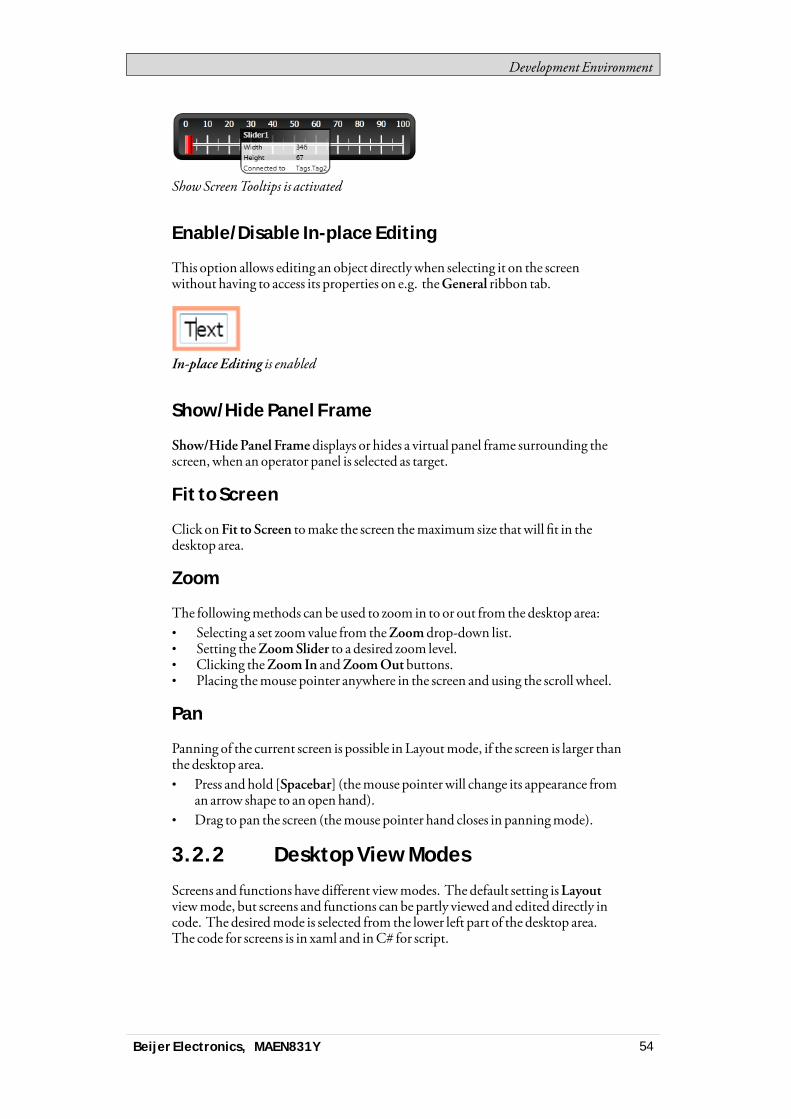
Development Environment
ShowScreenTooltips is activated
Enable/Disable In-place Editing
This option allows editing an object directlywhen selecting it on the screenwithout having to access its properties on e.g. theGeneral ribbon tab.
In-place Editing is enabled
Show/Hide Panel Frame
Show/HidePanel Frame displays or hides a virtual panel frame surrounding thescreen, when an operator panel is selected as target.
Fit to Screen
Click onFit to Screen tomake the screen themaximum size thatwill fit in thedesktop area.
Zoom
The followingmethods can be used to zoom in to or out from the desktop area:• Selecting a set zoomvalue from theZoom drop-down list.• Setting theZoomSlider to a desired zoom level.• Clicking theZoom In andZoomOutbuttons.• Placing themouse pointer anywhere in the screen and using the scroll wheel.
Pan
Panning of the current screen is possible in Layoutmode, if the screen is larger thanthe desktop area.• Press and hold [Spacebar] (themouse pointer will change its appearance from
an arrow shape to an open hand).• Drag to pan the screen (themouse pointer hand closes in panningmode).
3.2.2 Desktop View Modes
Screens and functions have different viewmodes. The default setting isLayoutviewmode, but screens and functions can be partly viewed and edited directly incode. The desiredmode is selected from the lower left part of the desktop area.The code for screens is in xaml and inC# for script.
Beijer Electronics, MAEN831Y 54
Development Environment
Caution:Incorrect code entered in text mode (Xaml and Script) may result in errors that are notpossible to recognize during analysis and build.Erroneous code may result in unpredictable behavior and loss of data.
Layout
Screens and objects are usually edited inLayout viewmode.
XAML
A screen layout is defined inXAML (eXtensible ApplicationMarkupLanguage)code. The .xaml files are stored in the project folder.XAMLcode can be added and changed in theXaml viewmode. Any changes donein theXAMLcodewill affect the screen layout.
Script
In Script viewmode scripted actions can be configured for screens, objects, tags,function keys etc.
Note:To display a script guide that describes iX Developer scripting possibilities in detail,select Script view mode, click anywhere in the code, and press F1.
Note:To be able to script inside iX Developer, any open Visual Studio Debug sessions needsto be closed first.
Caution:Beijer Electronics only offers support for scripting for the included examples in iXDeveloper
Objects that can trigger events will showwith expandable nodes in theScript view.Clicking the [+] of such a node expands it and shows the trigger events for theobject. Double-clicking on an event inserts itsmethod headingwith an emptycode body. Scripts arewritten inC# syntax.When actions are defined for an object, this will have precedence over script code.
Note:Avoid using multiple trigger methods as this may lead to undesired behavior.Use either a script or define actions with the controls on the Actions tab. Avoid usingClick Action Trigger actions in combination with Mouse Button Action Triggers.
Beijer Electronics, MAEN831Y 55

Development Environment
Note:Creating scripts that block execution, waiting for other resources or user input, is notsupported.
Note:The ValueOff and ValueOn events for internal variables are available for selection inscript mode, but they are not executed when running the project.
Note:The ValueChangeOrError event is available in script mode, but it should only be usedwith controller tags. It does not support internal variables or system tags.
Note:If an external editor, e.g. Visual Studio, is used for editing a script, the cross-referencewill not be updated when building the project in iX Developer. The Remove UnusedTags function will report tags used in these scripts as unused.For iX Developer to recognize a change made with an external editor, the script fileneeds to be opened in iX Developer and provided with just any small change using thescript editor in iX Developer. Save the project once more before build.
Note:Avoid static state when using script since this might cause memory leaks.Always remember to unsubscribe events previously subscribed to, in order to avoidmemory leaks.
Complex behavior can be created using script code.Selectionsmade inLayout viewmode are keptwhen switching toScript viewmode and vice versa.Nodeswith edited script code are highlighted in the expanded tree view.
Highlight of an edited node in the tree view
Beijer Electronics, MAEN831Y 56
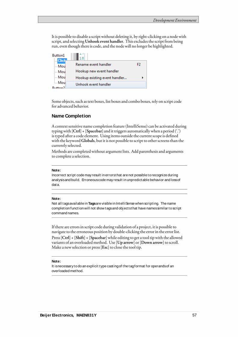
Development Environment
It is possible to disable a scriptwithout deleting it, by right-clicking on a nodewithscript, and selectingUnhook event handler. This excludes the script frombeingrun, even though there is code, and the nodewill no longer be highlighted.
Some objects, such as text boxes, list boxes and comboboxes, rely on script codefor advanced behavior.
Name Completion
Acontext sensitive name completion feature (IntelliSense) can be activated duringtypingwith [Ctrl] + [Spacebar] and it triggers automaticallywhen a period (‘.’)is typed after a code element. Using items outside the current scope is definedwith the keywordGlobals, but it is not possible to script to other screens than thecurrently selected.Methods are completedwithout argument lists. Add parenthesis and argumentsto complete a selection.
Note:Incorrect script code may result in errors that are not possible to recognize duringanalysis and build. Erroneous code may result in unpredictable behavior and loss ofdata.
Note:Not all tags available in Tags are visible in IntelliSense when scripting. The namecompletion function will not show tags and objects that have names similar to scriptcommand names.
If there are errors in script code during validation of a project, it is possible tonavigate to the erroneous position by double-clicking the error in the error list.Press [Ctrl] + [Shift] + [Spacebar] while editing to get a tool tipwith the allowedvariants of an overloadedmethod. Use [Uparrow] or [Down arrow] to scroll.Make a new selection or press [Esc] to close the tool tip.
Note:It is necessary to do an explicit type casting of the tag format for operands of anoverloaded method.
Beijer Electronics, MAEN831Y 57
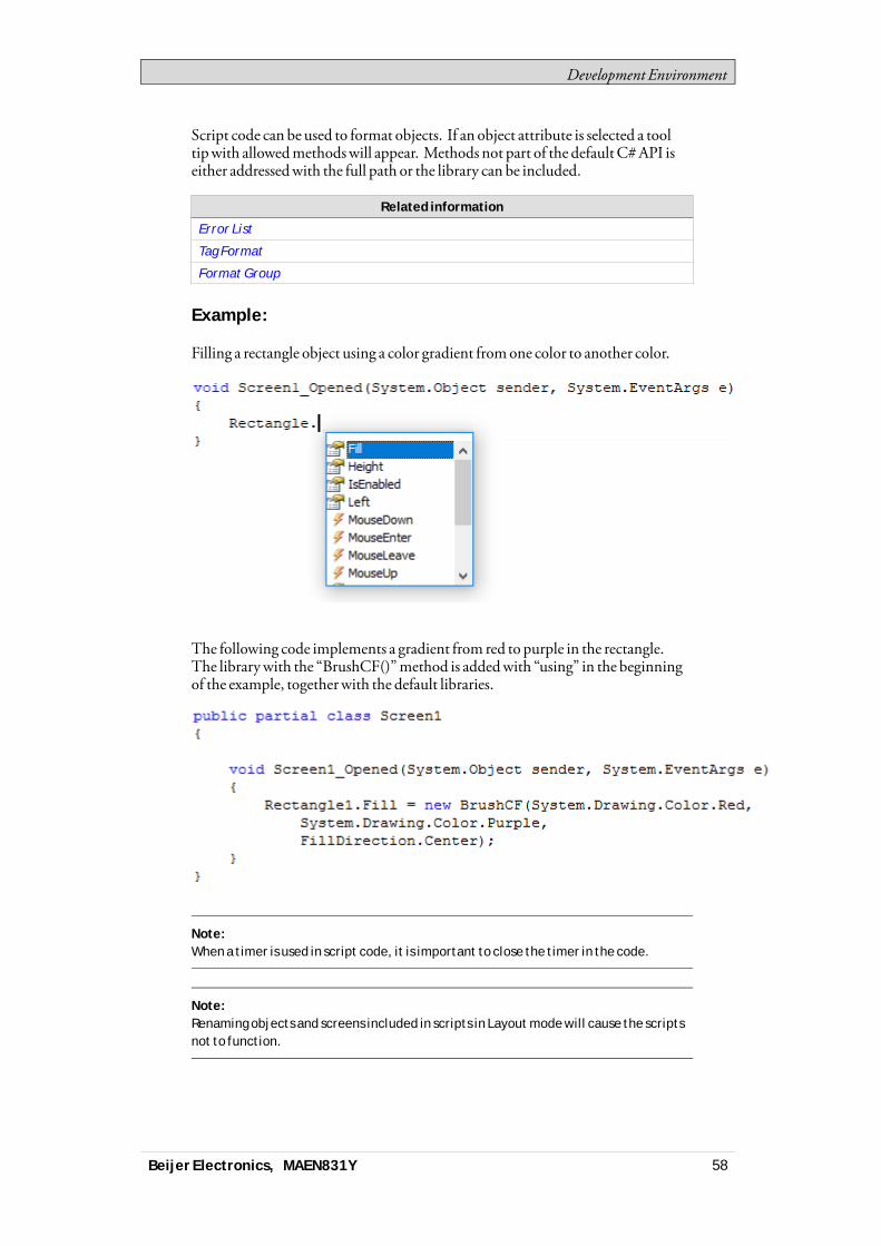
Development Environment
Script code can be used to format objects. If an object attribute is selected a tooltipwith allowedmethodswill appear. Methods not part of the defaultC#API iseither addressedwith the full path or the library can be included.
Related information
Error List
Tag Format
Format Group
Example:
Filling a rectangle object using a color gradient fromone color to another color.
The following code implements a gradient from red to purple in the rectangle.The librarywith the “BrushCF()”method is addedwith “using” in the beginningof the example, togetherwith the default libraries.
Note:When a timer is used in script code, it is important to close the timer in the code.
Note:Renaming objects and screens included in scripts in Layout mode will cause the scriptsnot to function.
Beijer Electronics, MAEN831Y 58
Development Environment
Referenced Assemblies
Third-party components and objects that are added to the project viaReferencedAssemblieswill bemade availablewhen scripting. Theirmethods and propertieswill be included by the name completion function, in the sameway as for built-incomponents.
Related information
Referenced Assemblies
Name Completion
Aliases
Aliases can be configured in theAliases viewmode.
Import/Export for Alias
Alias instances can be exported and imported using the Import/Export button intheAlias Instances configuration page. The procedure is similar to exporting andimporting tags. NewAlias instances can be added by adding a row in the importfile. Similarly, new aliases can be added by adding new columns in the import file.When exporting theAlias instances, the default values for the aliases will appearas a row in the exported filewith the nameDefaultValue. If theDefaultValue rowexistswhen anAlias instance is imported, the values can be used to update thedefault values for the aliases.
Note:For DefaultValue, use the Overwrite or Merge option to update the existing aliasdefault values and to solve the name conflict.The default value will not be updated if the Change option is chosen for DefaultValue.Instead a new Alias instance is created with the changed name.
Related information
Importing and Exporting Tags
Tag Import Example
3.2.3 Positioning Windows
The behavior ofmanywindows can be adapted in order to suit the user; forexample shownor hidden, ormoved to another position on the desktop.Dockedwindows representing control tools can be converted to floatingwindows.Control tools can be docked separately or bemanaged as a tabbed group in awindow. Adocked toolwindow supports auto-hide.When awindow is dockable, a guide diamond appears when thewindow ismovedon the desktop. Extended position arrows appear at the desktop edges. The guidediamondmakes it possible to dock a tool window to one of the four sides of thedesktop area. When a toolwindow is undocked, it floats on top of the desktop.Dropping a tool at the center of a guide diamond creates a tabbed group of thetools inside thewindow that the guide diamondbelongs to.
Beijer Electronics, MAEN831Y 59
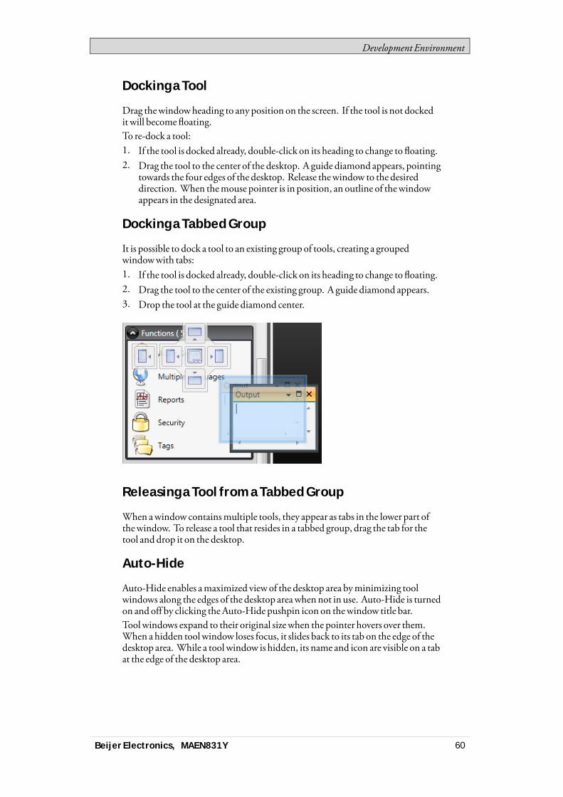
Development Environment
Docking a Tool
Drag thewindowheading to any position on the screen. If the tool is not dockedit will becomefloating.To re-dock a tool:1. If the tool is docked already, double-click on its heading to change to floating.2. Drag the tool to the center of the desktop. A guide diamond appears, pointing
towards the four edges of the desktop. Release thewindow to the desireddirection. When themouse pointer is in position, an outline of thewindowappears in the designated area.
Docking a Tabbed Group
It is possible to dock a tool to an existing group of tools, creating a groupedwindowwith tabs:1. If the tool is docked already, double-click on its heading to change to floating.2. Drag the tool to the center of the existing group. A guide diamond appears.3. Drop the tool at the guide diamond center.
Releasing a Tool from a Tabbed Group
When awindow containsmultiple tools, they appear as tabs in the lower part ofthewindow. To release a tool that resides in a tabbed group, drag the tab for thetool and drop it on the desktop.
Auto-Hide
Auto-Hide enables amaximized viewof the desktop area byminimizing toolwindows along the edges of the desktop areawhennot in use. Auto-Hide is turnedon and off by clicking theAuto-Hide pushpin icon on thewindow title bar.Toolwindows expand to their original sizewhen the pointer hovers over them.When a hidden toolwindow loses focus, it slides back to its tab on the edge of thedesktop area. While a tool window is hidden, its name and icon are visible on a tabat the edge of the desktop area.
Beijer Electronics, MAEN831Y 60

Development Environment
Note:The Auto-Hide function has to be turned off before a tool can be moved.
3.2.4 Configuration Pages
Many functions, such asAlarmServer andData Logger, are configured via tablestyle configuration pages.In some cases there aremultiple configuration pages for a feature. Whenapplicable, the configuration page for a feature can be opened to allowdirectaccess. For example, it is possible not only to select a tag, but also to declare newtags, directly through theSelectTagfield for an object.
Home
In a configuration page, theHome tab is used to add and remove items in afunction or controller.
Edit Table Cells
Use theAddbutton to append a new item in the table viewof the configurationpage.Use theDeletebutton in theHome tab or theDelete button on the keyboard toremove the active row in the table. Multiple rows can be selected using the [Ctrl]or [Shift] keys.
Beijer Electronics, MAEN831Y 61

Development Environment
Keyboard Navigation
Navigation in configuration pages can bemade using arrow keys orwith [Tab].PressingF4 inside a table cell will in some cases open selection list.Pressing [Enter] acknowledges a selection, and pressing [Esc] cancels a selection.Press [Delete] to remove a valuewhen editing in a field. If a row is selectedwhenpressing [Delete], the entire rowwill be removed from the table.Use [Spacebar] to toggle a value in a check box.Press [Ctrl] + [Tab] to shift focus from the table.
Navigation in Layered Pages
A layered configuration page (for example the alarm items page) has some specificnavigation functions.Keyboard navigation down ismade by pressing [Ctrl] + [DownArrow]. This willnavigate into an expanded group, and out againwhen at the last of the expandedrows.Keyboard navigation up and out of a group is done by pressing [UpArrow].Expand a groupwith [Ctrl] + [+], collapsewith [Ctrl] + [-].Keyboard navigation betweenfields inside a group ismadewith [RightArrow]or [Left Arrow].Pressing [Enter] acknowledges a selection, and pressing [Esc] cancels a selection.
Auto Fill
Fields in the configuration tables arewhenpossible automatically filled inwhen[DownArrow] is pressedwhen at the last table row. Whenneeded, names andtag identifiers are incremented to avoid exact copies of symbolic names and tagidentifiers. Incrementing is done if the last part of the string is an integer number.A “1”will be appended to the string if no numeral character ends the string. This isuseful when there are consecutive tags of the same type in the controller data.
Filtering Items
Items in configuration pages can be filtered by selectingShowSelection from theShowSelection/ShowAll button.
Beijer Electronics, MAEN831Y 62
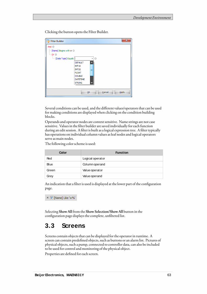
Development Environment
Clicking the button opens the Filter Builder.
Several conditions can be used, and the different values/operators that can be usedformaking conditions are displayedwhen clicking on the condition buildingblocks.Operands and operator nodes are context sensitive. Name strings are not casesensitive. Values in the filter builder are saved individually for each functionduring an edit session. A filter is built as a logical expression tree. A filter typicallyhas operations on individual column values as leaf nodes and logical operatorsserve asmain nodes.The following color scheme is used:
Color Function
Red Logical operator
Blue Column operand
Green Value operator
Grey Value operand
An indication that a filter is used is displayed at the lower part of the configurationpage.
Selecting ShowAll from the ShowSelection/ShowAllbutton in theconfiguration page displays the complete, unfiltered list.
3.3 ScreensScreens contain objects that can be displayed for the operator in runtime. Ascreen can contain predefined objects, such as buttons or an alarm list. Pictures ofphysical objects, such a pump, connected to controller data, can also be includedto be used for control andmonitoring of the physical object.Properties are defined for each screen.
Beijer Electronics, MAEN831Y 63
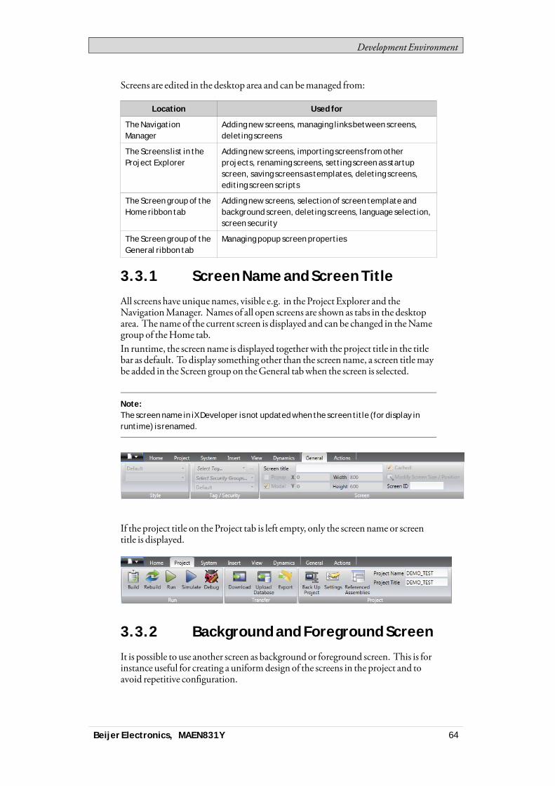
Development Environment
Screens are edited in the desktop area and can bemanaged from:
Location Used for
The NavigationManager
Adding new screens, managing links between screens,deleting screens
The Screens list in theProject Explorer
Adding new screens, importing screens from otherprojects, renaming screens, setting screen as startupscreen, saving screens as templates, deleting screens,editing screen scripts
The Screen group of theHome ribbon tab
Adding new screens, selection of screen template andbackground screen, deleting screens, language selection,screen security
The Screen group of theGeneral ribbon tab
Managing popup screen properties
3.3.1 Screen Name and Screen Title
All screens have unique names, visible e.g. in the Project Explorer and theNavigationManager. Names of all open screens are shown as tabs in the desktoparea. The name of the current screen is displayed and can be changed in theNamegroup of theHome tab.In runtime, the screenname is displayed togetherwith the project title in the titlebar as default. Todisplay something other than the screenname, a screen titlemaybe added in the Screen group on theGeneral tabwhen the screen is selected.
Note:The screen name in iX Developer is not updated when the screen title (for display inruntime) is renamed.
If the project title on the Project tab is left empty, only the screenname or screentitle is displayed.
3.3.2 Background and Foreground Screen
It is possible to use another screen as background or foreground screen. This is forinstance useful for creating a uniformdesign of the screens in the project and toavoid repetitive configuration.
Beijer Electronics, MAEN831Y 64
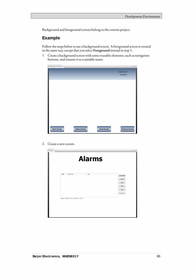
Development Environment
Background and foreground screens belong to the current project.
Example
Follow the steps below to use a background screen. A foreground screen is createdin the sameway, except that you selectForeground instead in step 5.1. Create a background screenwith some reusable elements, such as navigation
buttons, and rename it to a suitable name.
2. Create a new screen.
Beijer Electronics, MAEN831Y 65

Development Environment
3. Keep the new screen open on the desktop, and click onParent Screen from theScreen group of theHome ribbon tab.
4. Click the screen youwant to use as background.5. SelectBackground.6. ClickOK.The background screen is nowused for the screen.Anymodificationmade to the background screenwill be reflected in all screensusing it.
3.3.3 Startup Screen
The startup screen is the first screen that openswhen a project is executed. Bydefault, Screen1 is set as startup screen.Another startup screen can be set at any time by right-clicking on the screen on thedesktop or in the Project Explorer and selectingSet as Startup Screen.The selected startup screen is easily distinguished from the other screens in theProject Explorer by a blue outlinewhen in focus.
3.3.4 Screen Template
The installation of iXDeveloper includes a number of screen templates with basicfunctionality. It is also possible to save your own screens as screen templates, byright-clicking on the current screen and selecting Save Screen asTemplate.The screen template can be used in the current or other iXDeveloper projects.If a selected screen template contains tags thatwere not previously included in theproject, you can select to automatically add these to theTags list.To use a template screen, click the lower part of theAdd Screen button in theScreen group of theHome ribbon tab. Apreview of screen templates is displayed.
Beijer Electronics, MAEN831Y 66

Development Environment
User-created aswell as predefined screen templatesmay be deleted byright-clicking on the template in the preview and selectingDelete ScreenTemplate. The folder of the selected screen is then permanently deleted fromdisk.
3.3.5 Screen Security
Using security settings for screensmakes it possible to restrict access to screensbased onuser security groups, similarly to object security.It is not possible to set security for the Startup screen.Whenusing a background screen, the security settings of the top level screen areapplied.When screens are imported fromother iXDeveloper projects or fromInformationDesigner, security settings are included andwill be used in thecurrent project.
Related information
Object Security and Visibility
3.3.6 Popup Screen
Normally, only one screen is visible in the operator panel in runtime. Sometimes, apopup screen that behaves like as a floatingwindowmaybe useful. Any screen canbe configured as a popup screen:1. CheckPopup screen in the Screen group of theGeneral tab.2. Set the start position coordinates (X, Y) to determinewhere the screenwill
open. The position (1,1) corresponds to the upper left corner of the screen.3. Set the desiredwidth and height in pixels of the screen resolution.ClickingModify Screen Size/Position allows changing the popup screensize and position by dragging itwith the cursor. The coordinates are updatedautomatically.
Modal Popup Screen
Checking theModal optionmakes the selected popup screenmodal, whichmeansthat the user cannot interact with other screenswhile this screen is visible. Allother screenswill still be updated.
Note:It is not recommended to have more than two parallel modal popup screens open atthe same time.
Note:Do not use multiple modal popups triggered by background events such as alarms, tagvalue changes, etc.
Style
Different styles can be selected for popup screens for PC targets.
Beijer Electronics, MAEN831Y 67
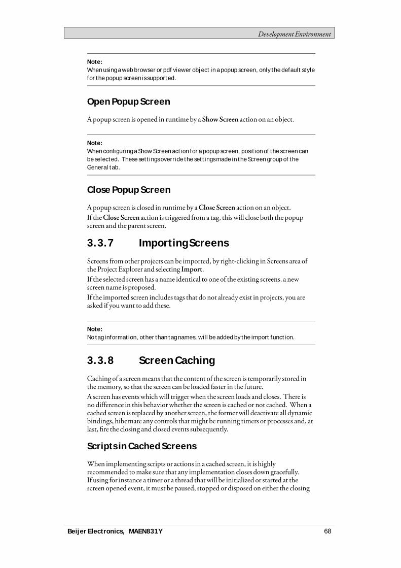
Development Environment
Note:When using a web browser or pdf viewer object in a popup screen, only the default stylefor the popup screen is supported.
Open Popup Screen
Apopup screen is opened in runtime by a ShowScreen action on an object.
Note:When configuring a Show Screen action for a popup screen, position of the screen canbe selected. These settings override the settings made in the Screen group of theGeneral tab.
Close Popup Screen
Apopup screen is closed in runtime by aClose Screen action on an object.If theClose Screen action is triggered from a tag, this will close both the popupscreen and the parent screen.
3.3.7 Importing Screens
Screens fromother projects can be imported, by right-clicking in Screens area ofthe Project Explorer and selecting Import.If the selected screen has a name identical to one of the existing screens, a newscreen name is proposed.If the imported screen includes tags that do not already exist in projects, you areasked if youwant to add these.
Note:No tag information, other than tag names, will be added by the import function.
3.3.8 Screen Caching
Caching of a screenmeans that the content of the screen is temporarily stored inthememory, so that the screen can be loaded faster in the future.A screen has eventswhichwill triggerwhen the screen loads and closes. There isno difference in this behaviorwhether the screen is cached or not cached. When acached screen is replaced by another screen, the formerwill deactivate all dynamicbindings, hibernate any controls thatmight be running timers or processes and, atlast, fire the closing and closed events subsequently.
Scripts in Cached Screens
When implementing scripts or actions in a cached screen, it is highlyrecommended tomake sure that any implementation closes down gracefully.If using for instance a timer or a thread thatwill be initialized or started at thescreen opened event, itmust be paused, stopped or disposed on either the closing
Beijer Electronics, MAEN831Y 68
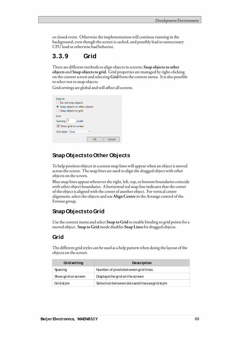
Development Environment
or closed event. Otherwise the implementationwill continue running in thebackground, even though the screen is cached, and possibly lead to unnecessaryCPU load or otherwise bad behavior.
3.3.9 Grid
There are differentmethods to align objects in screens; Snap objects to otherobjects and Snap objects to grid. Grid properties aremanaged by right-clickingon the current screen and selectingGrid from the contextmenu. It is also possibleto select not to snap objects.Grid settings are global andwill affect all screens.
Snap Objects to Other Objects
Tohelp position objects in a screen snap lineswill appearwhen an object ismovedacross the screen. The snap lines are used to align the dragged object with otherobjects on the screen.Blue snap lines appearwhenever the right, left, top, or bottomboundaries coincidewith other object boundaries. A horizontal red snap line indicates that the centerof the object is alignedwith the center of another object. For vertical centeralignment, select the objects and useAlignCenter in theArrange control of theFormat group.
Snap Objects to Grid
Use the contextmenu and select Snap toGrid to enable binding to grid points for amoved object. Snap toGridmode disables SnapLines for dragged objects.
Grid
The different grid styles can be used as a help patternwhen doing the layout of theobjects on the screen.
Grid setting Description
Spacing Number of pixels between grid lines
Show grid on screen Displays the grid on the screen
Grid style Selection between dots and lines as grid style
Beijer Electronics, MAEN831Y 69

Development Environment
3.4 ObjectsObjects that can be created in a screen are available from theObjects group andtheComponent Library.Snap lines are used to position objects in a screen and align amoved object withother objects.Information about tag connections aswell as size and distance information forobjects on the current screen can be displayed by using the buttons in the lowerpart of the desktop area.
Related information
Objects
3.4.1 Handling Objects
Create
To insert a default-sized object, click the position on the screenwhere youwant toplace the object.To give the object a specific size and shape, press themouse button and drag tocreate the object on the screen. Press andhold [Shift] while creating an object toretain the aspect ratio of the object.When creating a line object, press and hold [Shift] to constrain the line at 45degrees angles.
Select
TheSelect tool is available at top left in theObjects groupwhen the group is notexpanded. The Select tool is the default toolwhen editing screens. After applyingany other object control, themouse pointer will return to the Select tool. Whenthe Select tool hovers over a selected object themouse pointer changes to a crosswith arrowheads.
Move
The position of an object is part of the properties for the object. The position of anobject can be changed in differentways:• Click and drag an object tomove it to the desired position.• Open the property grid and edit theLeft andTop coordinates.Tomove the selected object one pixel at the time, select the object and use thearrow keys on the keyboard.
Copy and Move
Use [Ctrl] + drag tomake a copy of the selected object, and tomove it to thedesired position.
Beijer Electronics, MAEN831Y 70
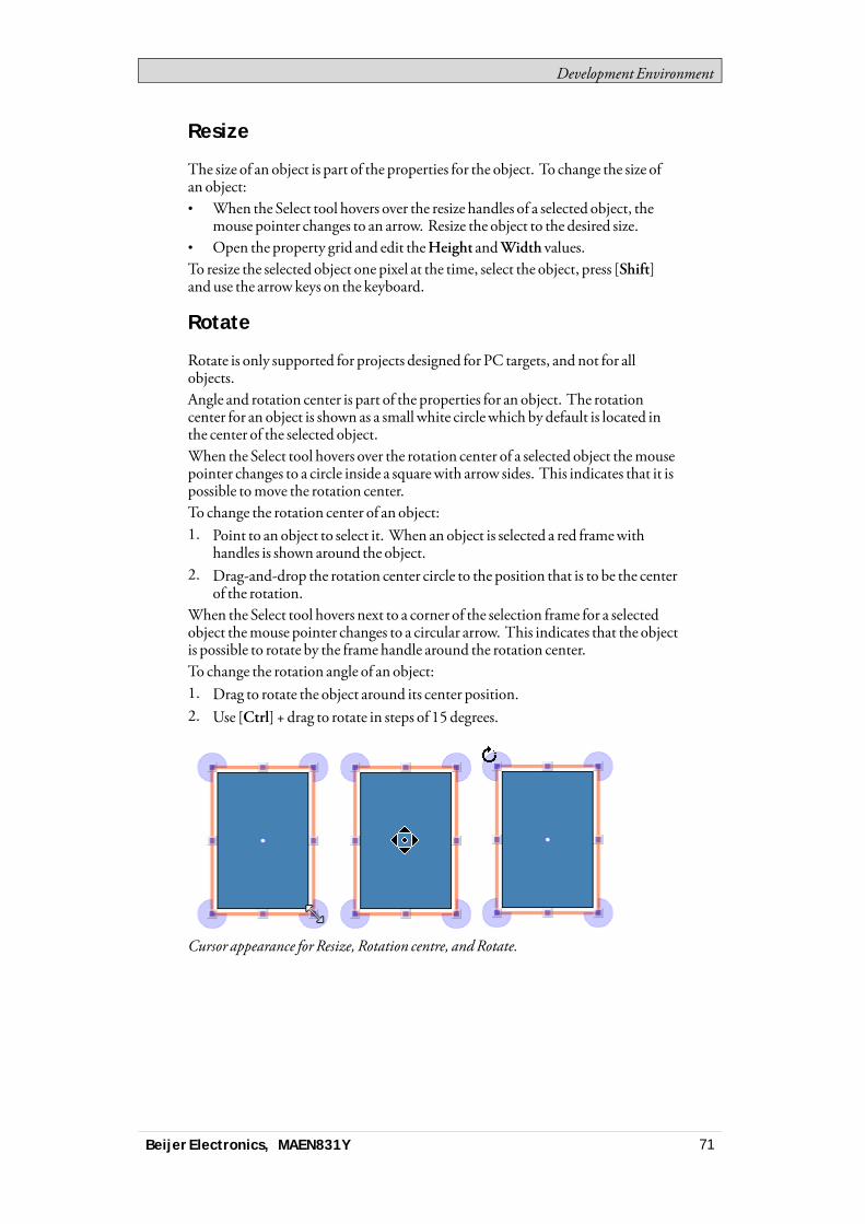
Development Environment
Resize
The size of an object is part of the properties for the object. To change the size ofan object:• When the Select tool hovers over the resize handles of a selected object, the
mouse pointer changes to an arrow. Resize the object to the desired size.• Open the property grid and edit theHeight andWidth values.To resize the selected object one pixel at the time, select the object, press [Shift]and use the arrow keys on the keyboard.
Rotate
Rotate is only supported for projects designed for PC targets, and not for allobjects.Angle and rotation center is part of the properties for an object. The rotationcenter for an object is shown as a small white circlewhich by default is located inthe center of the selected object.When the Select tool hovers over the rotation center of a selected object themousepointer changes to a circle inside a squarewith arrow sides. This indicates that it ispossible tomove the rotation center.To change the rotation center of an object:1. Point to an object to select it. When an object is selected a red framewith
handles is shown around the object.2. Drag-and-drop the rotation center circle to the position that is to be the center
of the rotation.When the Select tool hovers next to a corner of the selection frame for a selectedobject themouse pointer changes to a circular arrow. This indicates that the objectis possible to rotate by the frame handle around the rotation center.To change the rotation angle of an object:1. Drag to rotate the object around its center position.2. Use [Ctrl] + drag to rotate in steps of 15 degrees.
Cursor appearance for Resize, Rotation centre, andRotate.
Beijer Electronics, MAEN831Y 71
Development Environment
Selecting Multiple Objects
Multiple objects on the current screen can be selected at the same time, with theuse of themouse pointer to draw a frame that touches the objects. Alternatively,select one object and thenuse [Ctrl] + click to select or de-select other objects.Amultiple selection can be used to arrange objects, by using theArrange controlon the Format ribbon tab. The object with the primary selection is used as guideobject.Whenmultiple objects are selected, the primary selection is shownwith a redframe,while all other objects in the grouphave blue frames.Click on any object in the group to change this to the primary selection. A click ordouble-click on any objectwillmake it the primary selection, and, if applicable,change the ribbon focus according to the selected ribbon behavior.The groups shown in theGeneral and theActions tabs are dependent on theselection. Whenmultiple objects are selected the tabswill showonly the propertiesthat are common for the objects in the selection. Property changeswill affect allselected objects.
Hiding and Locking Objects
Objects can easily be hidden and locked using theObject Browser, but thecommands are also available from the contextmenu. Tomake a hidden objectvisible again, or to unlock a locked object, theObject Browser can be used.
Related information
Object Browser
Property Grid
Creating Series
TheCreate series function facilitates creating a number of identical objects. Thefunction handles adding graphic elements aswell as controller connections.The following example creates a series of analog numeric objects quickly andeasily:1. Create an analog numeric object and connect it to a tag (in this example;D0).2. Right-click on the object and selectCreate series from the contextmenu.
Beijer Electronics, MAEN831Y 72
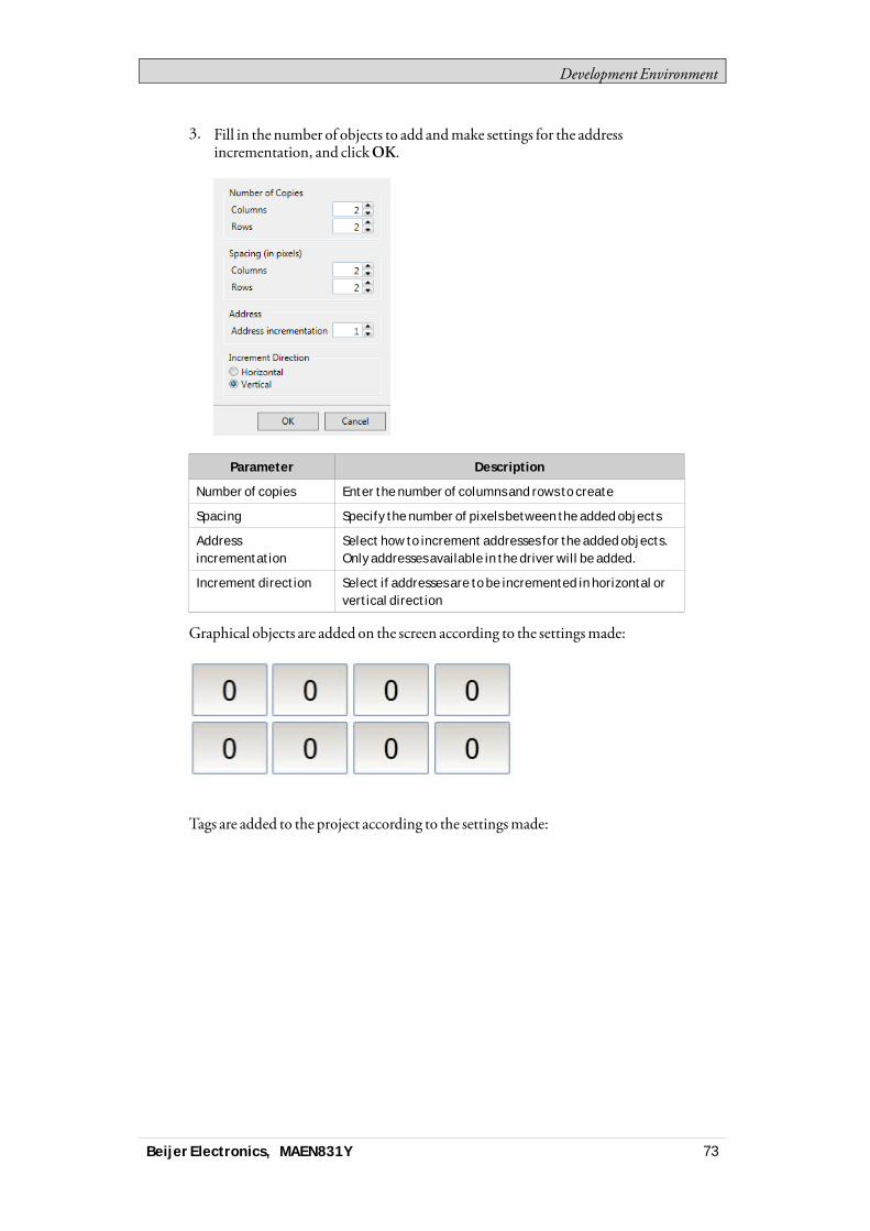
Development Environment
3. Fill in the number of objects to add andmake settings for the addressincrementation, and clickOK.
Parameter Description
Number of copies Enter the number of columns and rows to create
Spacing Specify the number of pixels between the added objects
Addressincrementation
Select how to increment addresses for the added objects.Only addresses available in the driver will be added.
Increment direction Select if addresses are to be incremented in horizontal orvertical direction
Graphical objects are added on the screen according to the settingsmade:
Tags are added to the project according to the settingsmade:
Beijer Electronics, MAEN831Y 73
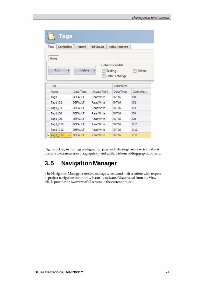
Development Environment
Right-clicking in theTags configuration page and selectingCreate seriesmakes itpossible to create a series of tags quickly and easily, without adding graphic objects.
3.5 Navigation ManagerTheNavigationManager is used tomanage screens and their relationswith respectto project navigation in runtime. It can be activated/deactivated from theViewtab. It provides an overview of all screens in the current project.
Beijer Electronics, MAEN831Y 74

Development Environment
3.5.1 Screen Relations
TheNavigationManager is used to create relationships between screens.Dragging themouse pointer fromone screen to another screen creates a relation. Abuttonwith aClick action is defined in the first screen. This ShowScreen actionhas the second screen as target, andwhen clicking it in runtime, the second screenis opened.Double-click on a screen to open the screen for editing in the desktop area.
3.5.2 Add Screen
New screens can be added directly in theNavigationManager.Dragging themouse pointer from an existing screen to an empty location in theNavigationManager area creates a new screen,with a relation to the originalscreen. A buttonwith aClick action is defined in the first screen. ThisShowScreen action has the second screen as target, andwhen clicking it in runtime, thesecond screen is opened. The buttonmust be removed or changedmanually ifthe new screen is deleted later.
3.5.3 Links in the Navigation Manager
A structure of screens and their relations to other screenswill be imposed andshown in theNavigationManager. TheNavigationManagerwill provide anoverview to help add screens andmanage the link relations between projectscreens.Right-click anywhere in theNavigationManager to change link appearance.
Beijer Electronics, MAEN831Y 75

Development Environment
Link setting Description
Show Same LevelReferences
Filters out links to screens on the same hierarchical level.
Show Back References Shows navigation links to higher hierarchical levels. Whennot selected, only links to screens on lower levels andlinks between screens on the same level are shown.
Directed Links Draws straight link lines between screens, using theshortest way.
Orthogonal Links Draws link lines in an orthogonal pattern.
Changing the setting or the type affects the appearance in theNavigationManageronly.
3.5.4 Navigation Overview
It is also possible to display theNavigationOverview by selecting it from theViewribbon tab. It provides an overviewof all screens included in the project, withzooming facilities.
3.6 Project ExplorerTheProject Explorer shows all screens and components included in theapplication. It can be activated/deactivated from theView tab.The Project Explorer is divided into five groups; . Screens,Functions,DataLoggers,ScriptModules andRecipes.
Beijer Electronics, MAEN831Y 76
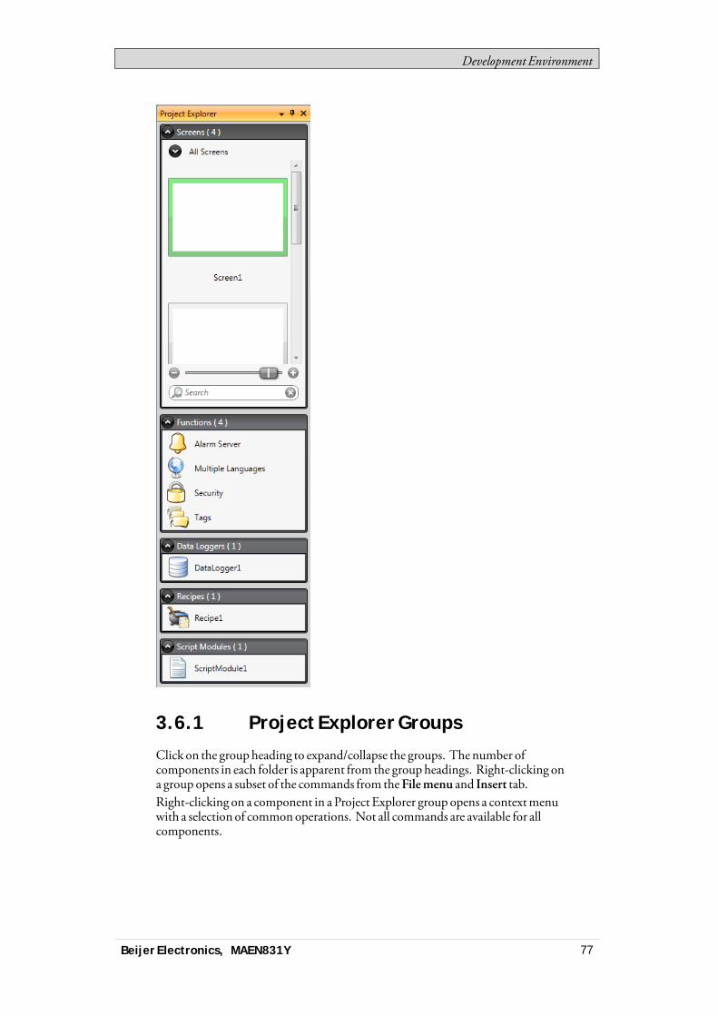
Development Environment
3.6.1 Project Explorer Groups
Click on the groupheading to expand/collapse the groups. The number ofcomponents in each folder is apparent from the groupheadings. Right-clicking ona group opens a subset of the commands from theFilemenu and Insert tab.Right-clicking on a component in a Project Explorer group opens a contextmenuwith a selection of commonoperations. Not all commands are available for allcomponents.
Beijer Electronics, MAEN831Y 77

Development Environment
Context menucommand
Description
Show Opens the selected project component for editing in thedesktop area
Rename Renames the selected project component
Add Adds a new project component to the project
Import Imports a project component via browsing the hard disk; e.g. ascreen from another project
Delete Deletes the selected component from the project
Screens
TheScreens explorer lists the screens included in the application. Clicking on ascreen opens it for editing in the desktop area.
Screen Context Menu
Right-clicking a screen opens a contextmenuwith a selection of availableoperations:• Show• Rename• Import• Delete• Set as startup screen• Save screen as template screen• Add to screen group• Remove from screen group
The screen set to be the startup screen ismarkedwith a green frame in the screensexplorer.
Groups
TheScreens explorer offers a possibility to assign screens to groups.• Right-click on theAll screensheading in theScreens explorer and selectAdd
group followedby entering a unique name for the group in the appearingdialog.
• To assign a screen to a group, simply right-click a screen in the Screensexplorer and select “Add to ScreenGroup” from the contextmenu. Select agroup to add the screen to from the appearing “Select Screen group” dialog.
• To show available groups, double-click theAll screensheading in the Screensexplorer. Screens not assigned to a groupwill be listed asungrouped screens.
• Right-clicking a group enables a contextmenu fromwhich you can choose torename or delete the group.
Note:Deleting a Screen group also deletes all of its assigned screens.
Beijer Electronics, MAEN831Y 78

Development Environment
It is also possible to assign a screen to a group by a simple drag and drop operation.Drag the screen symbol and release it on the group.
Zoom Slider
TheZoom slider is found in theScreens explorer and provides away to quicklyzoom in andout of your screens explorer.
Search
The search function provides the option to search for screens using the screenname or screen-id.The search searches across all columns.
Functions
TheAlarmServer,Multiple Languages and Security functions are predefined, aswell as Tags, and cannot be deleted from the Functions folder. The other functionscan be added from the Insertmenu. Most functionswill be available from theFunctions folder after having added them to the project, but some functions areassigned folders of their own.Clicking on the function in the Functions folder opens its configuration pagesfor editing in the desktop area.
Alarm Distributor
Alarms can be distributed between operator panels, with notification via printer,SMSor e-mail using the alarmdistributor.
Related information
Alarm Distributor
Alarm Server
TheAlarmServer handles alarm groups and alarm items.
Related information
Alarm Server
Alarm Groups
Alarm Items
Audit Trail
TheAudit Trail function enables tracking of operator actions.
Related information
Audit Trail
Beijer Electronics, MAEN831Y 79
Development Environment
Function Keys
Function keys for operator panels as well as for the regular PCkeyboard can beconfigured.
Related information
Function Keys
Multiple Languages
Configuringmultiple languages for user texts and system texts are supported. Thetexts can be exported, edited and reimported to the project. A tool for automatictranslations is also included.
Related information
Language Management
Reports
The reports function allows adding excel report templates to the project.
Related information
Reports
Scheduler
A scheduler can be used to control events in the process at special times.
Related information
Scheduler
Security
Users and groups of users can be set up for security purposes.
Related information
Security Management
Tags
Clicking onTags in the Functions folder displays the tags configuration page inthe desktopwith all the tags that are used in the application. Tags are added byclicking on theAddTag/Add SystemTag button.Tags can belong to a connected controller, or be internal. Internal tags can be usedand selected in the sameway as a regular controller tags.System tags are used tomonitor or access variables from the system, for exampleUsedRAM orDateTime. System tags are indicated by blue color in the tag list.
Beijer Electronics, MAEN831Y 80
Development Environment
Related information
Tags
Internal Tags
System Tags
Text Library
With the text library function, text tables can be created,where values are linkedto texts.
Related information
Text Library
Recipes
Several recipes can be inserted in the project. Each recipe function handles apre-defined set of recipe items.
Related information
Recipe Management
Script Modules
Clicking on a scriptmodule in the ScriptModules folder opens the script editorin the desktop area. A scriptmodule can be included to program features notcovered by included functions and actions, or to be used to share functionalityamong functions.There is also a script action function that can be used to apply scriptmodules to anobject in the sameway aswith other trigger actions.
Related information
Script
Script Action
Data Loggers
Data can be logged and saved to a database on time intervals or depending onchanged values.
Related information
Data Logger
3.7 Component LibraryTheComponent Library contains reusable components for a project.
Beijer Electronics, MAEN831Y 81
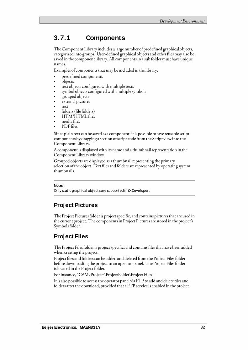
Development Environment
3.7.1 Components
TheComponent Library includes a large number of predefined graphical objects,categorized into groups. User-defined graphical objects and other filesmay also besaved in the component library. All components in a sub foldermust have uniquenames.Examples of components thatmay be included in the library:• predefined components• objects• text objects configuredwithmultiple texts• symbol objects configuredwithmultiple symbols• grouped objects• external pictures• text• folders (file folders)• HTM/HTMLfiles• media files• PDFfiles
Since plain text can be saved as a component, it is possible to save reusable scriptcomponents by dragging a section of script code from the Script view into theComponent Library.A component is displayedwith its name and a thumbnail representation in theComponent Librarywindow.Grouped objects are displayed as a thumbnail representing the primaryselection of the object. Text files and folders are represented by operating systemthumbnails.
Note:Only static graphical objects are supported in iX Developer.
Project Pictures
TheProject Pictures folder is project specific, and contains pictures that are used inthe current project. The components in Project Pictures are stored in the project’sSymbols folder.
Project Files
TheProject Files folder is project specific, and contains files that have been addedwhen creating the project.Project files and folders can be added and deleted from the Project Files folderbefore downloading the project to an operator panel. The Project Files folderis located in the Project folder.For instance, “C:\MyProjects\ProjectFolder\Project Files”.It is also possible to access the operator panel via FTP to add and delete files andfolders after the download, provided that a FTP service is enabled in the project.
Beijer Electronics, MAEN831Y 82
Development Environment
Note:Avoid using special characters (e.g %, & ,#) within the filename/filepath.
Related information
FTP
Download
3.7.2 Add and Use Components
Drag-and-drop any component from the library to the current screen, or use copy[Ctrl +C] and paste [Ctrl +V] commands.Objects can be copied ormoved to theComponent Library.A text file, that is saved in theComponent Librarywill be converted to a text boxobject when pasted into a screen.A component (picture or group) that is originally copied from an object with a tagconnectionwill keep its tag connection and any dynamic propertieswhen usedfrom theComponent Library.
Note:If a component with a tag association is reused in another project then all referencedtags must be present in the new project.
3.7.3 Component Library Window
The component library is available as a tab at the right-hand side of thedesktop. Thewindow is configuredwith auto-hide functions, and can also beactivated/deactivated from theView ribbon tab. Its appearance can bemanagedjust as other tools; as docked or floatingwindows.TheComponent Library is also accessible when selecting andplacing the Pictureobject from theHome ribbon tab.
Beijer Electronics, MAEN831Y 83
Development Environment
User-Defined Categories
Right-click on an empty space of theComponent Librarywindow and selectAddComponents to add a component to the library. To create a new category, selectAdd category and choose a name of your preference. A category could also berenamed or deleted.User-defined categories are not project specific. Thismeans that all objects savedin a user-defined categorywill be available in all iXDeveloper projects.
Exporting and Importing Components
Byusing the Import andExport functions in theComponent Library, categoriesof components can easily be copied andmoved between projects. Right-click onthe category folder and select Import orExport. Find the location in the projectfile fromwhere the components should be imported or towhere they should beexported. The programwill not indicatewhere the component files are located.Single objects can not be exported or imported.
Expand and Collapse Folders
The top area is a contents frame that is used to navigate through the folders of theComponent Library. The contents heading displays the name of the currentlyselected folder. The folder view can be expanded and collapsedwith the control tothe left of the displayed folder name.The display of the components is filtered through the selection of the folders, i.e.all components are displayed if the top folder is selected.
Search
TheSearch feature provides a case-insensitive and alphabetical search, based onthe component label, in the current folder and in all sub folders.
Zoom
TheZoom slider at the bottom area of the tool window can be used to change thesize of the displayed components. Resting themouse pointer over a componentdisplays a full-size picture of the component.
Beijer Electronics, MAEN831Y 84

Development Environment
Component Librarywindow, displaying full size of a selected component
XAML Guidelines
All information, including the image,must be containedwithin theXAML-file.Links to external objects will result inmissing objects. Furthermore, theappearance of theXAML-filemay not be dependent of external inputs, like forexample a parameter controlling amulti-picture based on internal logicwithin theXAML-file.
Beijer Electronics, MAEN831Y 85

Development Environment
Naming Controls in XAML
Not supported
Supported
Specify Width and Height
The root controlmust specify awidth and a height.
Not supported
Supported
Beijer Electronics, MAEN831Y 86

Development Environment
Bindings
These are the only properties that are supported forXAML-bindingwithincomponents:• ISymbolViewboxSignature.Fill is presented as “Fill”within the property grid• ISymbolViewboxSignature.Stroke is presented as “Outline”within the
property grid• ISymbolViewboxSignature.StrokeThickness is presented as
“OutlineThickness”within the property grid
It is not supported to bind to anything outside of the component.Supported:
3.7.4 XAML Import into iX Developer
It is possible to import vector graphics, XAMLcomponents, into iXDeveloper.
Basic – Import XAML into iX Developer
Install Inkscape. The software is free and can be downloaded at https://inkscape.org.
Note:The file needs to be opened as .svg and then saved to XAML before importing.
Beijer Electronics, MAEN831Y 87
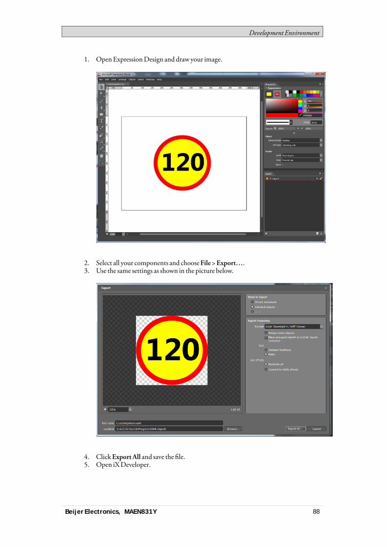
Development Environment
1. OpenExpressionDesign and draw your image.
2. Select all your components and chooseFile>Export….3. Use the same settings as shown in the picture below.
4. ClickExportAll and save the file.5. Open iXDeveloper.
Beijer Electronics, MAEN831Y 88

Development Environment
6. Right-click on a node in theComponent Library and chooseAddComponents.
7. Select theXAMLfile that you exported fromExpressionDesign.
Advanced – XAML bindings in iX Developer
It is possible to bind some of the component’s properties to tags directly in iXDeveloper’s property grid. The following properties are supported:• Fill• Outline• Outline thickness
Kaxaml tool
1. DownloadKaxaml tool.2. Open your exported xaml file inKaxaml.3. Localizewhich part of the graphic that youwant to control with fill, outline
and outline thickness. Changing the fill color for each sectionmakes it easierto findwhich parts of theXAMLcode that needs to bemodified.
Dynamic properties
The following dynamic properties are supported by iXDeveloper:
Beijer Electronics, MAEN831Y 89
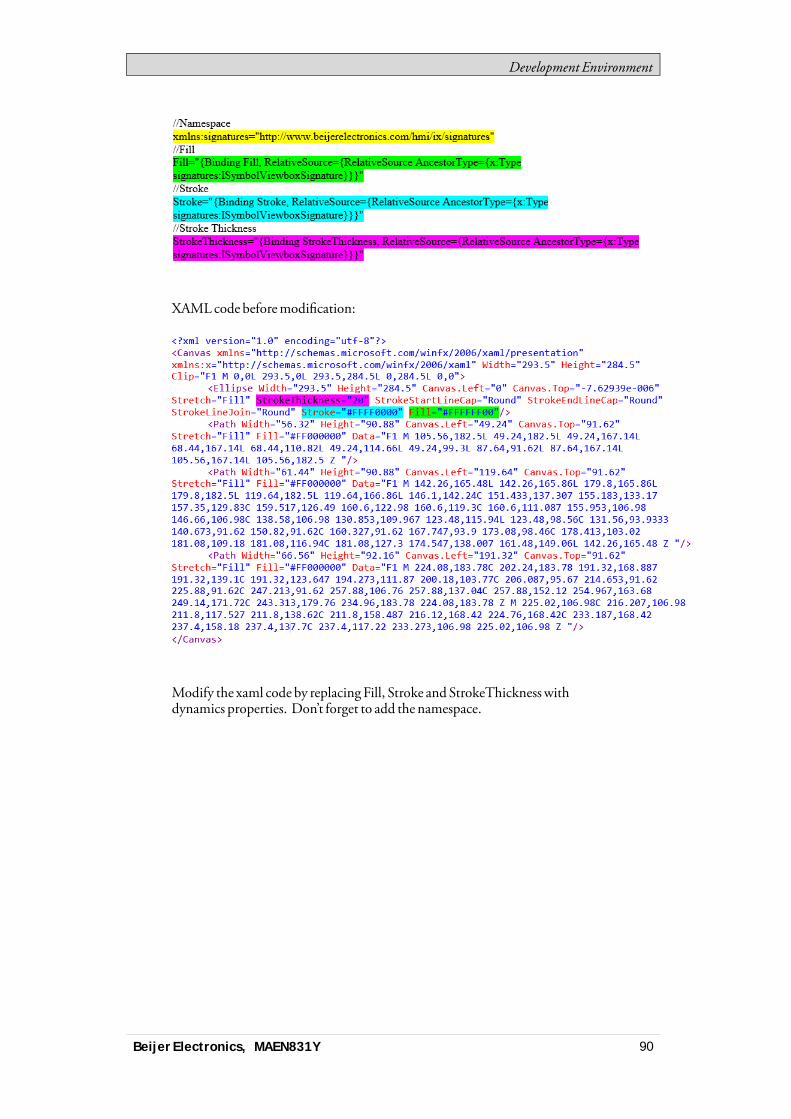
Development Environment
XAMLcode beforemodification:
Modify the xaml code by replacing Fill, Stroke and StrokeThickness withdynamics properties. Don’t forget to add the namespace.
Beijer Electronics, MAEN831Y 90

Development Environment
Import to iX Developer
1. Open iXDeveloper.2. Right-click on a node in theComponent Library and selectAdd
Components.3. Select theXAMLfile that youmodified inKaxaml.
Observe howyour component’s appearance is alteredwhen changing fill/outlinecolor or outline thickness.When you havemodified the component you can easily copy it to theComponentLibrary. This will allow you to reuse the graphic/component later on.
3.8 Property GridMost properties and settings for an object or screen are defined from itsGeneralandHome tabs.A detailed overview of object properties is available by selectingPropertyGridfrom theView ribbon tab or by selectingProperties from the contextmenu.The property grid includesmore properties and settings than the ribbon tabs, forexample size andposition of objects, and delay ofmouse and touch screen input inruntime.Property groups can be collapsed/expanded.
Beijer Electronics, MAEN831Y 91
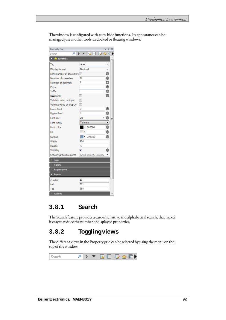
Development Environment
Thewindow is configuredwith auto-hide functions. Its appearance can bemanaged just as other tools; as docked or floatingwindows.
3.8.1 Search
The Search feature provides a case-insensitive and alphabetical search, thatmakesit easy to reduce the number of displayed properties.
3.8.2 Toggling views
The different views in the Property grid can be selected by using themenuon thetop of thewindow.
Beijer Electronics, MAEN831Y 92
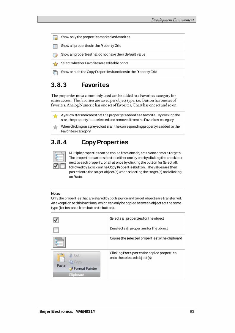
Development Environment
Show only the properties marked as favorites
Show all properties in the Property Grid
Show all properties that do not have their default value
Select whether Favorites are editable or not
Show or hide the Copy Properties functions in the Property Grid
3.8.3 Favorites
The propertiesmost commonly used can be added to a Favorites-category foreasier access. The favorites are saved per object type, i.e. Button has one set offavorites, AnalogNumeric has one set of favorites, Chart has one set and so on.
A yellow star indicates that the property is added as a favorite. By clicking thestar, the property is deselected and removed from the Favorites-category
When clicking on a greyed out star, the corresponding property is added to theFavorites-category
3.8.4 Copy Properties
Multiple properties can be copied from one object to one or more targets.The properties can be selected either one by one by clicking the check boxnext to each property, or all at once by clicking the button for Select all,followed by a click on the Copy Propertiesbutton. The values are thenpasted onto the target object(s) when selecting the target(s) and clickingon Paste.
Note:Only the properties that are shared by both source and target objects are transferred.An exception to this is actions, which can only be copied between objects of the sametype (for instance from button to button).
Selects all properties for the object
Deselects all properties for the object
Copies the selected properties to the clipboard
Clicking Paste pastes the copied propertiesonto the selected object(s)
Beijer Electronics, MAEN831Y 93
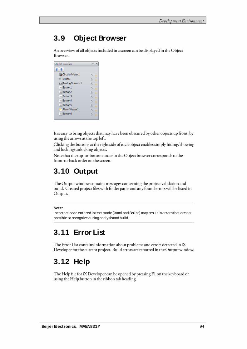
Development Environment
3.9 Object BrowserAnoverviewof all objects included in a screen can be displayed in theObjectBrowser.
It is easy to bring objects thatmay have been obscured by other objects up front, byusing the arrows at the top left.Clicking the buttons at the right side of each object enables simply hiding/showingand locking/unlocking objects.Note that the top-to-bottomorder in theObject browser corresponds to thefront-to-back order on the screen.
3.10 OutputTheOutputwindow containsmessages concerning the project validation andbuild. Created project files with folder paths and any found errors will be listed inOutput.
Note:Incorrect code entered in text mode (Xaml and Script) may result in errors that are notpossible to recognize during analysis and build.
3.11 Error ListTheError List contains information about problems and errors detected in iXDeveloper for the current project. Build errors are reported in theOutputwindow.
3.12 HelpTheHelp file for iXDeveloper can be opened by pressingF1 on the keyboard orusing theHelp button in the ribbon tab heading.
Beijer Electronics, MAEN831Y 94

Tags
4 Tags
Objects connected to tags can change values in a controller, and controller valuescan be reflected by changing object appearance in variousways. Objects in a screenwill remain static until connected to a tag.A tag has a symbolic name and can be of different data types.Tags can belong to a connected controller, be internal or belong to the system.Internal tags are used to handle local data values, and can be viewed and treated inscreens just like regular controller tags.The global tag list provides an overviewof all used tags, regardless of controller.Thismakes it easy to develop projects that can be usedwith a variety of controllers.It is also possible to connect a tag tomore than one controller simultaneously.
4.1 Adding TagsTags are handled by clicking onTags in the Functions folder in the ProjectExplorer.
Clicking theAddTag/AddSystemTagbutton adds a new tag to the list. Makesettings for each added tag. When predefined values are available, these can beselected by clicking the arrow at the right of the table cell.
4.1.1 Removing Unused Tags
TheDeletebutton inTags can be used to detect unused tags for immediateremoval via theRemoveUnusedTags dialog.
Beijer Electronics, MAEN831Y 95
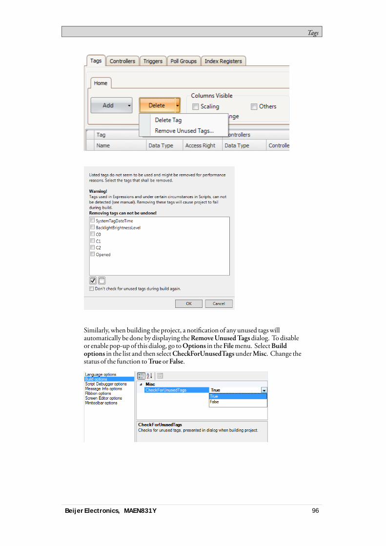
Tags
Similarly, when building the project, a notification of any unused tagswillautomatically be done by displaying theRemoveUnusedTagsdialog. To disableor enable pop-up of this dialog, go toOptions in theFilemenu. SelectBuildoptions in the list and then selectCheckForUnusedTagsunderMisc. Change thestatus of the function toTrue orFalse.
Beijer Electronics, MAEN831Y 96

Tags
Note:Always review the candidates for removal prior to removing unused tags, sinceremoving tags that are used in e.g. a script can result in a corrupt project.
Tobe able to detect tags used in scripts, a certain syntaxmust be used. It isrecommended to use the IScriptTag interfacewithin the arguments list for theScriptModule, thus enabling theScriptModule to be used and reusedwithoutbeing locked to a specific tag setup. Use the syntaxGlobals.Tags.TagName fordirect tag referenceswithin scripts and expressions.If an external editor, e.g. Visual Studio, is used for editing a script, thecross-referencewill not be updatedwhenbuilding the project in iXDeveloper.TheRemoveUnusedTags functionwill report tags used in these scripts as unused.For iXDeveloper to recognize a changemadewith an external editor, the script fileneeds to be opened in iXDeveloper and providedwith just any small change usingthe script editor in iXDeveloper. Save the project oncemore before build.
TheSummethod inside the script can be utilized inmany different contexts. Thefollowing picture shows howTag3will contain the sumofTag1 andTag2when thebutton is clicked. Notice that the tags used in scriptsmust be activated toworkas expected.
Beijer Electronics, MAEN831Y 97
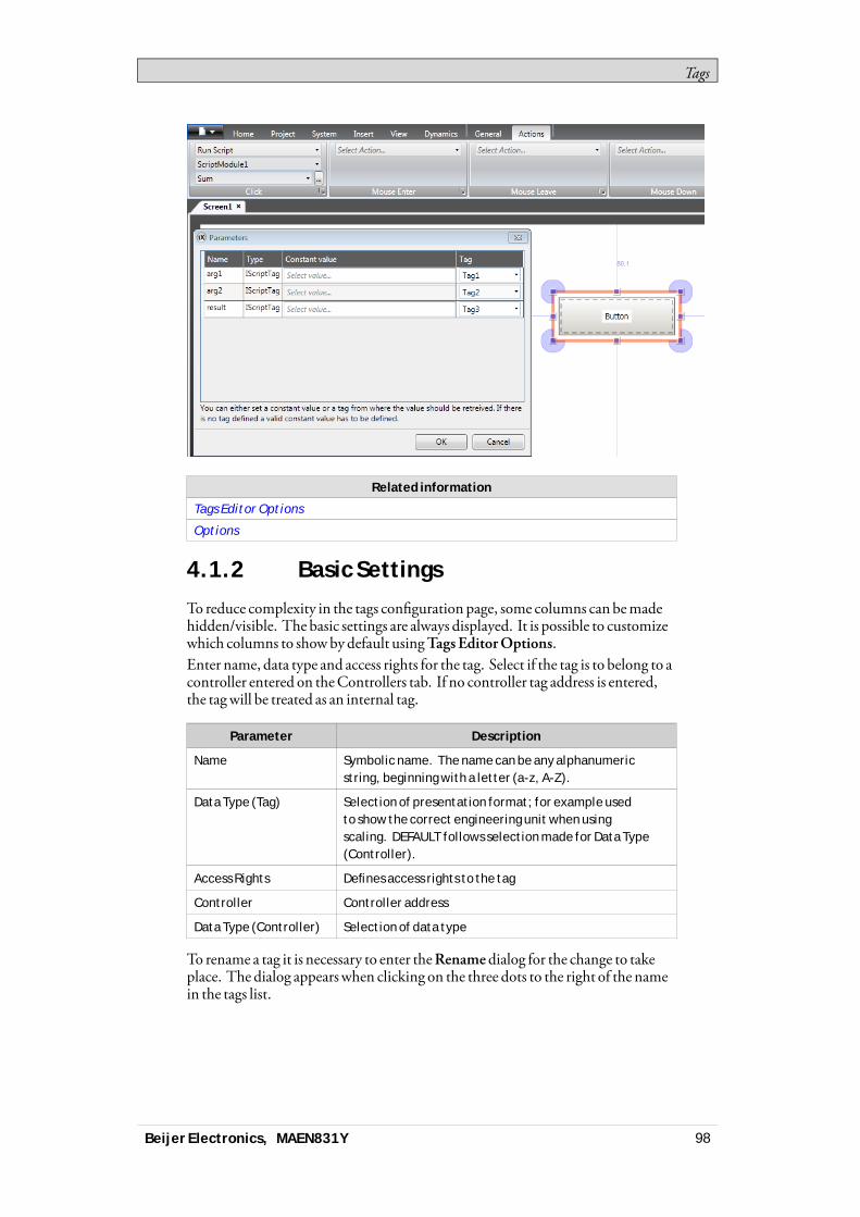
Tags
Related information
Tags Editor Options
Options
4.1.2 Basic Settings
To reduce complexity in the tags configuration page, some columns can bemadehidden/visible. The basic settings are always displayed. It is possible to customizewhich columns to showbydefault usingTags EditorOptions.Enter name, data type and access rights for the tag. Select if the tag is to belong to acontroller entered on theControllers tab. If no controller tag address is entered,the tagwill be treated as an internal tag.
Parameter Description
Name Symbolic name. The name can be any alphanumericstring, beginning with a letter (a-z, A-Z).
Data Type (Tag) Selection of presentation format; for example usedto show the correct engineering unit when usingscaling. DEFAULT follows selection made for Data Type(Controller).
Access Rights Defines access rights to the tag
Controller Controller address
Data Type (Controller) Selection of data type
To rename a tag it is necessary to enter theRenamedialog for the change to takeplace. The dialog appearswhen clicking on the three dots to the right of the namein the tags list.
Beijer Electronics, MAEN831Y 98

Tags
Related information
Scaling
4.1.3 Scaling
Scaling affects only tags connected to a controller.Checking the Scalingbox displays theOffset andGain columns. Theseparameters are used to change the scale of the controller value to a value shown inaccordancewith the following equation:Panel value =Offset + (Gain×Register value)When the value for an object is changed from the operator panel, the scale ischanged to the value shown in accordancewith the following equation:Register value = (Panel value -Offset)/GainScaling does not affect the definedmaximumandminimumvalues, or the numberof decimals.
4.1.4 Data Exchange
Checking theDataExchangebox displays theDirection andWhen columns.Data exchange supports real time data exchange between different controllers; alsoof different brands. The data exchange can be performedwhen a digital tag is set orat a certain time interval, set up on theTriggers tab. Data exchange can be selectedfor individual tags, array tags or for the complete range of tags.
Related information
Data Exchange
4.1.5 Others
Checking theOthers boxmakes it possible to configure a number of additionaltag properties.
Beijer Electronics, MAEN831Y 99

Tags
Parameter Description
Description An optional description of the tag. Description of system tagsis added automatically.
Please note that the description can not be more than 200characters long. Descriptions longer than that will cause builderrors.
Poll Group Makes it possible to poll groups of tags at different intervals.
Always Active Prevents the tag from becoming inactive. This may be useful foractions and scripting purposes. Note: The Active setting for thecontroller on the Controllers tab is predominant over the AlwaysActive setting for a particular tag.
Non Volatile Keeps the last tag value in memory even when the panel or PC ispowered off. Only available for internal tags.
Initial Value Makes it possible to assign a tag an initial value at systemstartup. Only available for internal tags.
Index Register Makes it possible to select a register from which an object is tocollect the shown value.
Action Makes it possible to configure actions based on a condition of atag.
Log to Audit Trail Logs operator actions on the tag. Only available if the Audit Trailfunction is activated in the project.
Audit TrailDescription
Optional static or dynamic descriptions for operator tagactions, that are saved in the Audit Trail database and visiblein the Audit Trail Viewer. If Dynamic Description is selected,value before change can be included in the description by using{0}; value after change by using {1}. Only available if the AuditTrail function is activated in the project.
4.1.6 Adding Tags during Editing
Tags can be added directlywhen editing objects. When an object is selected, thetag association can bemanaged from theTag/Security group in theHomeorGeneral ribbon tabs, or by right-clicking on the object and using theMiniToolbar.In both cases, tags are added by clicking theAdd button.
Beijer Electronics, MAEN831Y 100
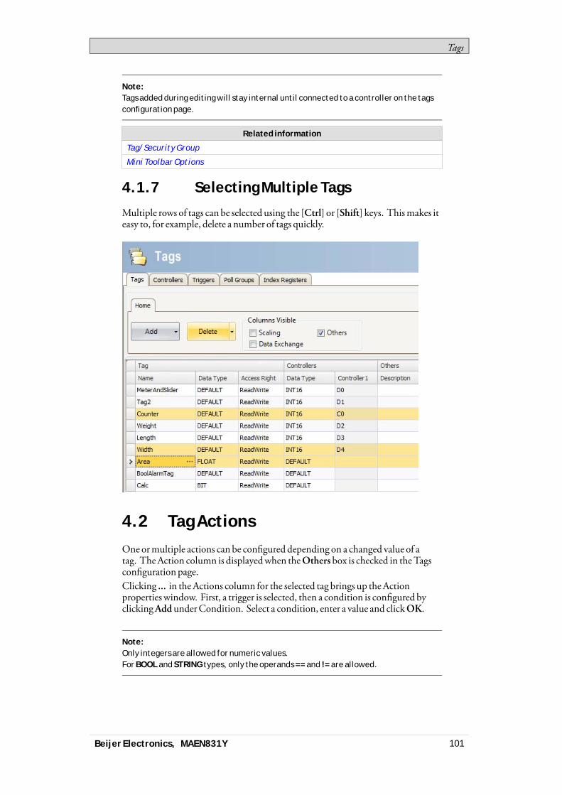
Tags
Note:Tags added during editing will stay internal until connected to a controller on the tagsconfiguration page.
Related information
Tag/Security Group
Mini Toolbar Options
4.1.7 Selecting Multiple Tags
Multiple rows of tags can be selected using the [Ctrl] or [Shift] keys. Thismakes iteasy to, for example, delete a number of tags quickly.
4.2 Tag ActionsOneormultiple actions can be configured depending on a changed value of atag. TheAction column is displayedwhen theOthers box is checked in theTagsconfiguration page.Clicking ... in the Actions column for the selected tag brings up theActionproperties window. First, a trigger is selected, then a condition is configured byclickingAddunderCondition. Select a condition, enter a value and clickOK.
Note:Only integers are allowed for numeric values.For BOOL and STRING types, only the operands == and != are allowed.
Beijer Electronics, MAEN831Y 101
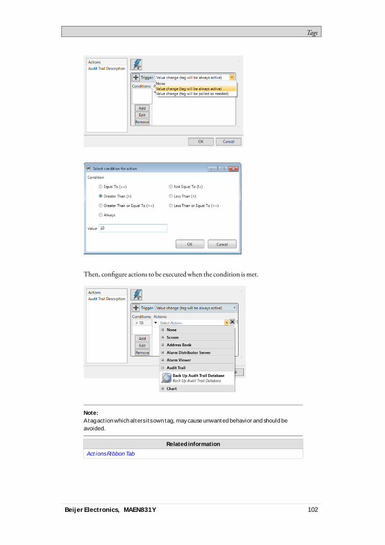
Tags
Then, configure actions to be executedwhen the condition ismet.
Note:A tag action which alters its own tag, may cause unwanted behavior and should beavoided.
Related information
Actions Ribbon Tab
Beijer Electronics, MAEN831Y 102

Tags
4.3 Internal TagsInternal tags can be used to calculate values that need not be represented in thecontroller, for example information only for the operator. Internal tags are selectedin the sameway as an external controller tags. Any number of volatile user definedtags can be created.
Note:Internal tag values will not be saved in the operator panel when the project isrestarted, unless the Non Volatile option is used.
Unlike the regular drivers, it does notmatter if internal tags are used in consecutiveorder or not.
4.4 System TagsSystem tags are used tomonitor or access variables from the system. System tagsare handled as regular controller tags, i.e. can be used in screens, logged, includedin scripts etc. TheDate andTime system tags can be usedwhen youwant to usethe controller clock in the panel project. The following system tags are available:
System taggroup System tag Description
Communication ErrorMessage
Latest communication error message
Communication Errors Number of active communication errors onall controllers
Communi-cation
Remote Alarm ServerConnection Errors
Number of remote alarm servers withconnection errors, e.g. disconnectedservers
Database Error Active Set to 1 when there is an active databaseerror
Database ErrorMessage
Latest database error message
Database
Database Max SizeExceeded
Set to 1 when the database maximum size isexceeded
DateTime Current date and time
Day Day component of current date
Day of Week Day of current week (1-7 where 1 is Sunday)
Hour Hour component of current time
Minute Minute component of current time
Month Month component of current date
Second Second component of current time
Date andTime
Year Year component of current date
Beijer Electronics, MAEN831Y 103
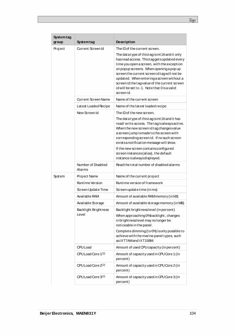
Tags
System taggroup System tag Description
Current Screen Id The ID of the current screen.
The data type of this tag is int16 and it onlyhas read access. This tag gets updated everytime you open a screen, with the exceptionon popup screens. When opening a pop upscreen the current screen id tag will not beupdated. When entering a screen without ascreen id the tag value of the current screenid will be set to -1. Note that 0 is a validscreen id.
Current Screen Name Name of the current screen
Latest Loaded Recipe Name of the latest loaded recipe
New Screen Id The ID of the new screen.
The data type of this tag is int16 and it hasread/write access. The tag is always active.When the new screen id tag changes valuea screen jump is made to the screen withcorresponding screen id. If no such screenexists a notification message will show.
If the new screen contains configuredscreen instances (alias), the defaultinstance is always displayed.
Project
Number of DisabledAlarms
Read the total number of disabled alarms
Project Name Name of the current project
Runtime Version Runtime version of framework
Screen Update Time Screen update time (in ms)
Available RAM Amount of available RAM memory (in kB)
Available Storage Amount of available storage memory (in MB)
Backlight BrightnessLevel
Backlight brightness level (in percent)
When approaching 0% backlight, changesin brightness level may no longer benoticeable in the panel.
Complete dimming (to 0%) is only possible toachieve with the marine panel types, suchas iX T7AM and iX T15BM.
CPU Load Amount of used CPU capacity (in percent)
CPU Load Core 1(2) Amount of capacity used in CPU Core 1 (inpercent)
CPU Load Core 2(2) Amount of capacity used in CPU Core 2 (inpercent)
CPU Load Core 3(2) Amount of capacity used in CPU Core 3 (inpercent)
System
Beijer Electronics, MAEN831Y 104
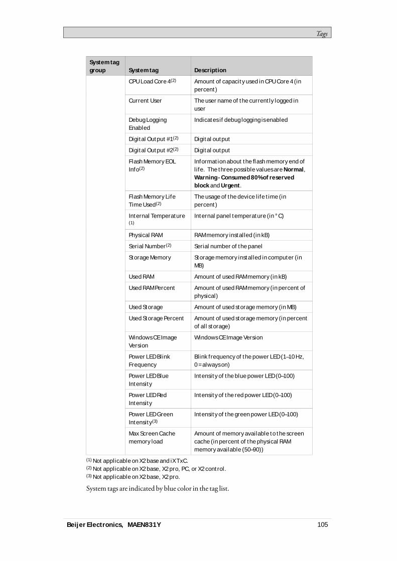
Tags
System taggroup System tag Description
CPU Load Core 4(2) Amount of capacity used in CPU Core 4 (inpercent)
Current User The user name of the currently logged inuser
Debug LoggingEnabled
Indicates if debug logging is enabled
Digital Output #1(2) Digital output
Digital Output #2(2) Digital output
Flash Memory EOLInfo(2)
Information about the flash memory end oflife. The three possible values are Normal,Warning - Consumed 80% of reservedblock and Urgent.
Flash Memory LifeTime Used(2)
The usage of the device life time (inpercent)
Internal Temperature(1)
Internal panel temperature (in °C)
Physical RAM RAM memory installed (in kB)
Serial Number(2) Serial number of the panel
Storage Memory Storage memory installed in computer (inMB)
Used RAM Amount of used RAM memory (in kB)
Used RAM Percent Amount of used RAM memory (in percent ofphysical)
Used Storage Amount of used storage memory (in MB)
Used Storage Percent Amount of used storage memory (in percentof all storage)
Windows CE ImageVersion
Windows CE Image Version
Power LED BlinkFrequency
Blink frequency of the power LED (1–10 Hz,0 = always on)
Power LED BlueIntensity
Intensity of the blue power LED (0–100)
Power LED RedIntensity
Intensity of the red power LED (0–100)
Power LED GreenIntensity(3)
Intensity of the green power LED (0–100)
Max Screen Cachememory load
Amount of memory available to the screencache (in percent of the physical RAMmemory available (50–90))
(1) Not applicable on X2 base and iX TxC.(2) Not applicable on X2 base, X2 pro, PC, or X2 control.(3) Not applicable on X2 base, X2 pro.
System tags are indicated by blue color in the tag list.
Beijer Electronics, MAEN831Y 105
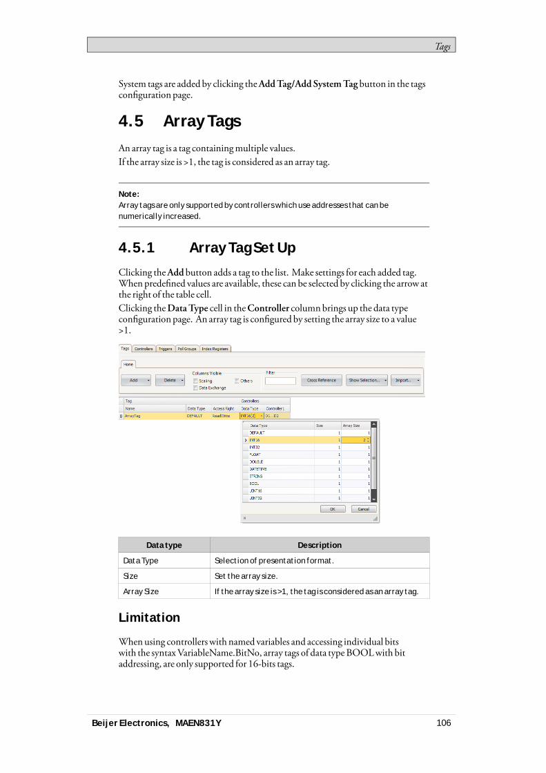
Tags
System tags are added by clicking theAddTag/AddSystemTag button in the tagsconfiguration page.
4.5 Array TagsAn array tag is a tag containingmultiple values.If the array size is >1, the tag is considered as an array tag.
Note:Array tags are only supported by controllers which use addresses that can benumerically increased.
4.5.1 Array Tag Set Up
Clicking theAdd button adds a tag to the list. Make settings for each added tag.When predefined values are available, these can be selected by clicking the arrow atthe right of the table cell.Clicking theDataType cell in theController columnbrings up the data typeconfiguration page. An array tag is configured by setting the array size to a value>1.
Data type Description
Data Type Selection of presentation format.
Size Set the array size.
Array Size If the array size is >1, the tag is considered as an array tag.
Limitation
Whenusing controllerswith named variables and accessing individual bitswith the syntaxVariableName.BitNo, array tags of data typeBOOLwith bitaddressing, are only supported for 16-bits tags.
Beijer Electronics, MAEN831Y 106
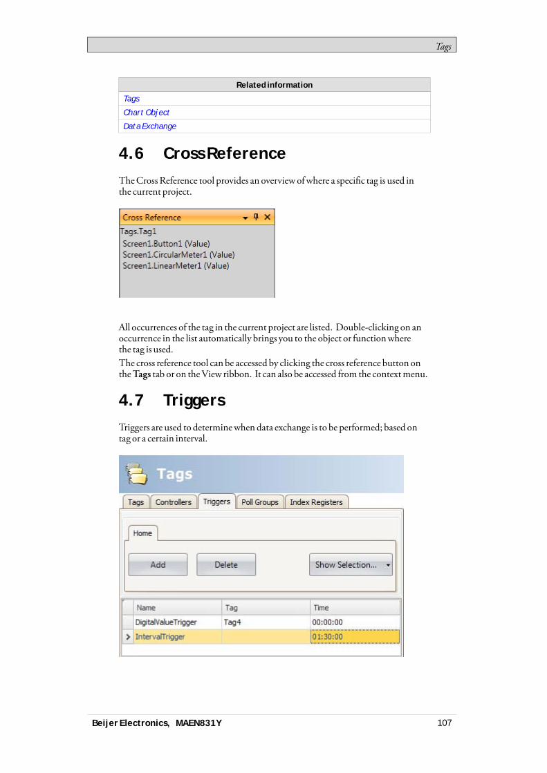
Tags
Related information
Tags
Chart Object
Data Exchange
4.6 Cross ReferenceTheCrossReference tool provides an overview ofwhere a specific tag is used inthe current project.
All occurrences of the tag in the current project are listed. Double-clicking on anoccurrence in the list automatically brings you to the object or functionwherethe tag is used.The cross reference tool can be accessed by clicking the cross reference button ontheTags tab or on theView ribbon. It can also be accessed from the contextmenu.
4.7 TriggersTriggers are used to determinewhen data exchange is to be performed; based ontag or a certain interval.
Beijer Electronics, MAEN831Y 107
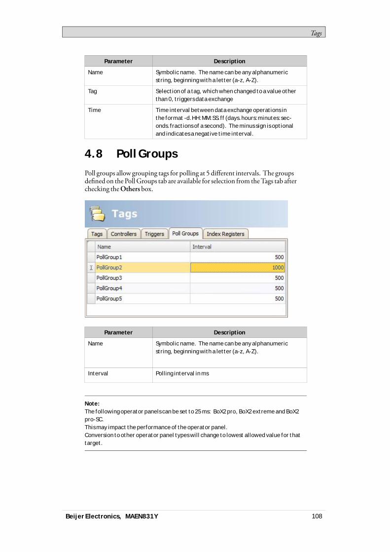
Tags
Parameter Description
Name Symbolic name. The name can be any alphanumericstring, beginning with a letter (a-z, A-Z).
Tag Selection of a tag, which when changed to a value otherthan 0, triggers data exchange
Time Time interval between data exchange operations inthe format -d.HH:MM:SS.ff (days.hours:minutes:sec-onds.fractions of a second). The minus sign is optionaland indicates a negative time interval.
4.8 Poll GroupsPoll groups allow grouping tags for polling at 5 different intervals. The groupsdefined on the PollGroups tab are available for selection from theTags tab afterchecking theOthers box.
Parameter Description
Name Symbolic name. The name can be any alphanumericstring, beginning with a letter (a-z, A-Z).
Interval Polling interval in ms
Note:The following operator panels can be set to 25 ms: BoX2 pro, BoX2 extreme and BoX2pro-SC.This may impact the performance of the operator panel.Conversion to other operator panel types will change to lowest allowed value for thattarget.
Beijer Electronics, MAEN831Y 108

Tags
4.9 Station HandlingFor some controllers, it is possible for the operator to define fromwhich controllerstation to read orwrite values. The station number is given as a prefix to thecontroller address.The stationnumber for each controller is defined on theControllers tab of theTags configuration page, by clicking the Settings button.The default station is set on the Settings tab, and the stations are defined on theStations tab.
In this example, from anEthernet driver, Station 0 is the default station.
The default station is the station addressedwithout using a prefix. The otherstations can be addressed either as a fixednumber or as an index register. Withfixed stationnumbers, an object is always connected to the same controlleraddress, and only the value of this controller address can be used in the object.When addressing for exampleD10 in station 2, the following syntax is used:2:D10
Beijer Electronics, MAEN831Y 109
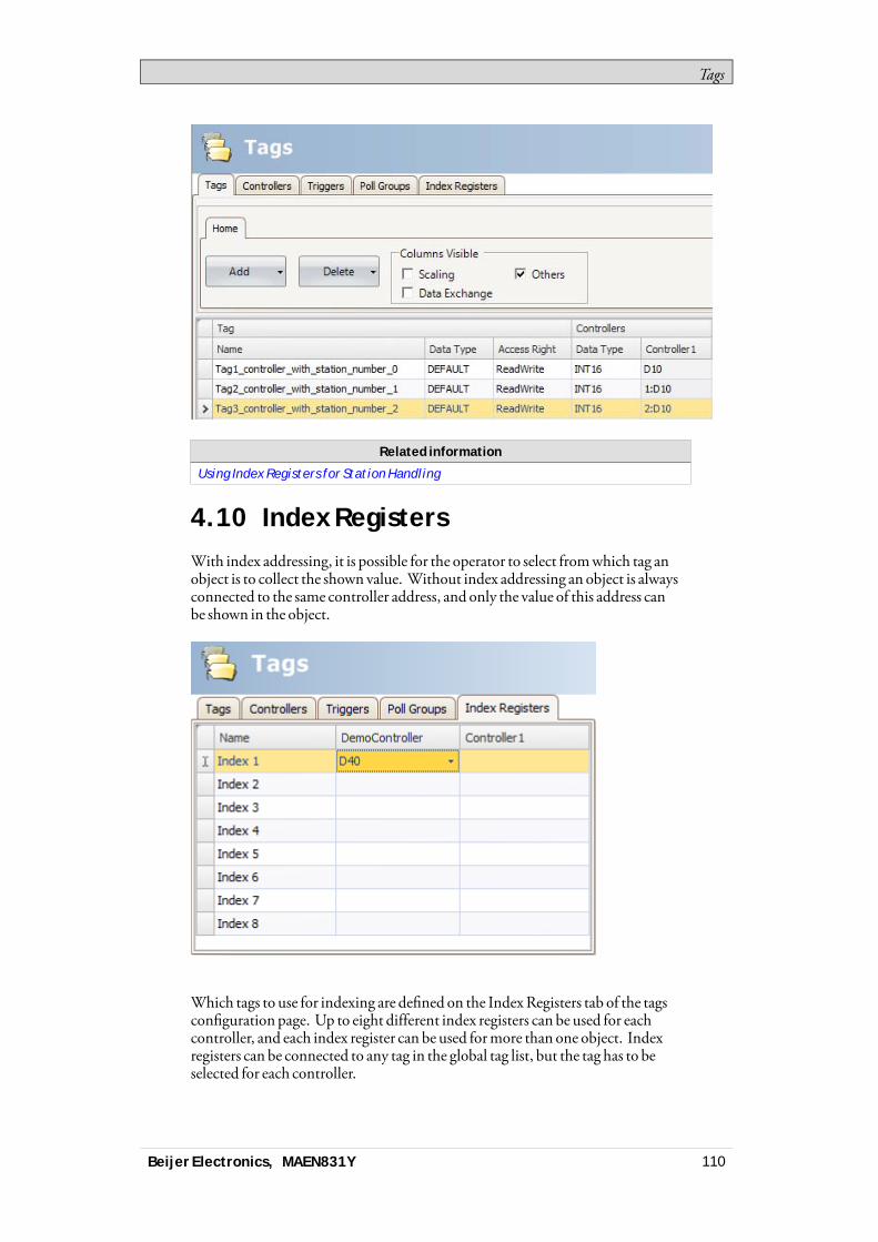
Tags
Related information
Using Index Registers for Station Handling
4.10 Index RegistersWith index addressing, it is possible for the operator to select fromwhich tag anobject is to collect the shown value. Without index addressing an object is alwaysconnected to the same controller address, and only the value of this address canbe shown in the object.
Which tags to use for indexing are defined on the IndexRegisters tab of the tagsconfiguration page. Up to eight different index registers can be used for eachcontroller, and each index register can be used formore than one object. Indexregisters can be connected to any tag in the global tag list, but the tag has to beselected for each controller.
Beijer Electronics, MAEN831Y 110
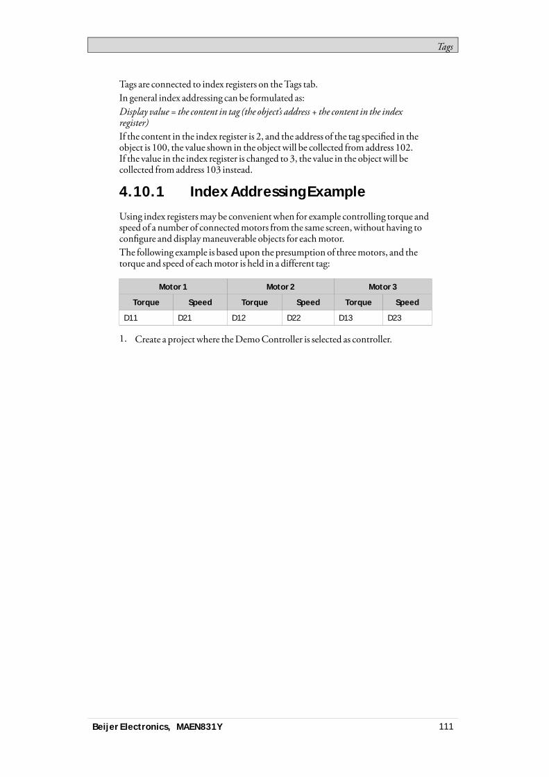
Tags
Tags are connected to index registers on theTags tab.In general index addressing can be formulated as:Display value = the content in tag (the object’s address + the content in the indexregister)If the content in the index register is 2, and the address of the tag specified in theobject is 100, the value shown in the object will be collected from address 102.If the value in the index register is changed to 3, the value in the object will becollected from address 103 instead.
4.10.1 Index Addressing Example
Using index registersmay be convenientwhen for example controlling torque andspeed of a number of connectedmotors from the same screen,without having toconfigure and displaymaneuverable objects for eachmotor.The following example is based upon the presumption of threemotors, and thetorque and speed of eachmotor is held in a different tag:
Motor 1 Motor 2 Motor 3
Torque Speed Torque Speed Torque Speed
D11 D21 D12 D22 D13 D23
1. Create a project where theDemoController is selected as controller.
Beijer Electronics, MAEN831Y 111

Tags
2. Add tags and labels and connect them toDemoController tags according tobelow:
3. Select the IndexRegisters tab and connect Index 1 to theMotorIndex tag(D0).
Beijer Electronics, MAEN831Y 112
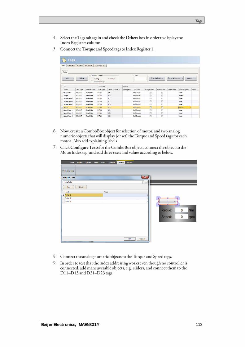
Tags
4. Select theTags tab again and check theOthers box in order to display theIndexRegisters column.
5. Connect theTorque and Speed tags to IndexRegister 1.
6. Now, create aComboBox object for selection ofmotor, and two analognumeric objects thatwill display (or set) theTorque and Speed tags for eachmotor. Also add explaining labels.
7. ClickConfigureTexts for theComboBox object, connect the object to theMotorIndex tag, and add three texts and values according to below.
8. Connect the analog numeric objects to theTorque andSpeed tags.9. In order to test that the index addressingworks even thoughno controller is
connected, addmaneuverable objects, e.g. sliders, and connect them to theD11–D13 andD21–D23 tags.
Beijer Electronics, MAEN831Y 113
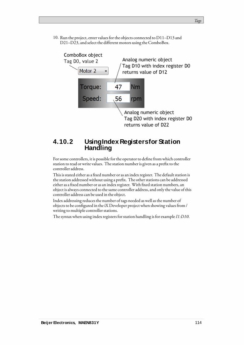
Tags
10. Run the project, enter values for the objects connected toD11–D13 andD21–D23, and select the differentmotors using theComboBox.
4.10.2 Using Index Registers for StationHandling
For some controllers, it is possible for the operator to define fromwhich controllerstation to read orwrite values. The station number is given as a prefix to thecontroller address.This is stated either as a fixed number or as an index register. The default station isthe station addressedwithout using a prefix. The other stations can be addressedeither as a fixed number or as an index register. With fixed station numbers, anobject is always connected to the same controller address, and only the value of thiscontroller address can be used in the object.Index addressing reduces the number of tags needed aswell as the number ofobjects to be configured in the iXDeveloper project when showing values from /writing tomultiple controller stations.The syntaxwhenusing index registers for station handling is for example I1:D10.
Beijer Electronics, MAEN831Y 114
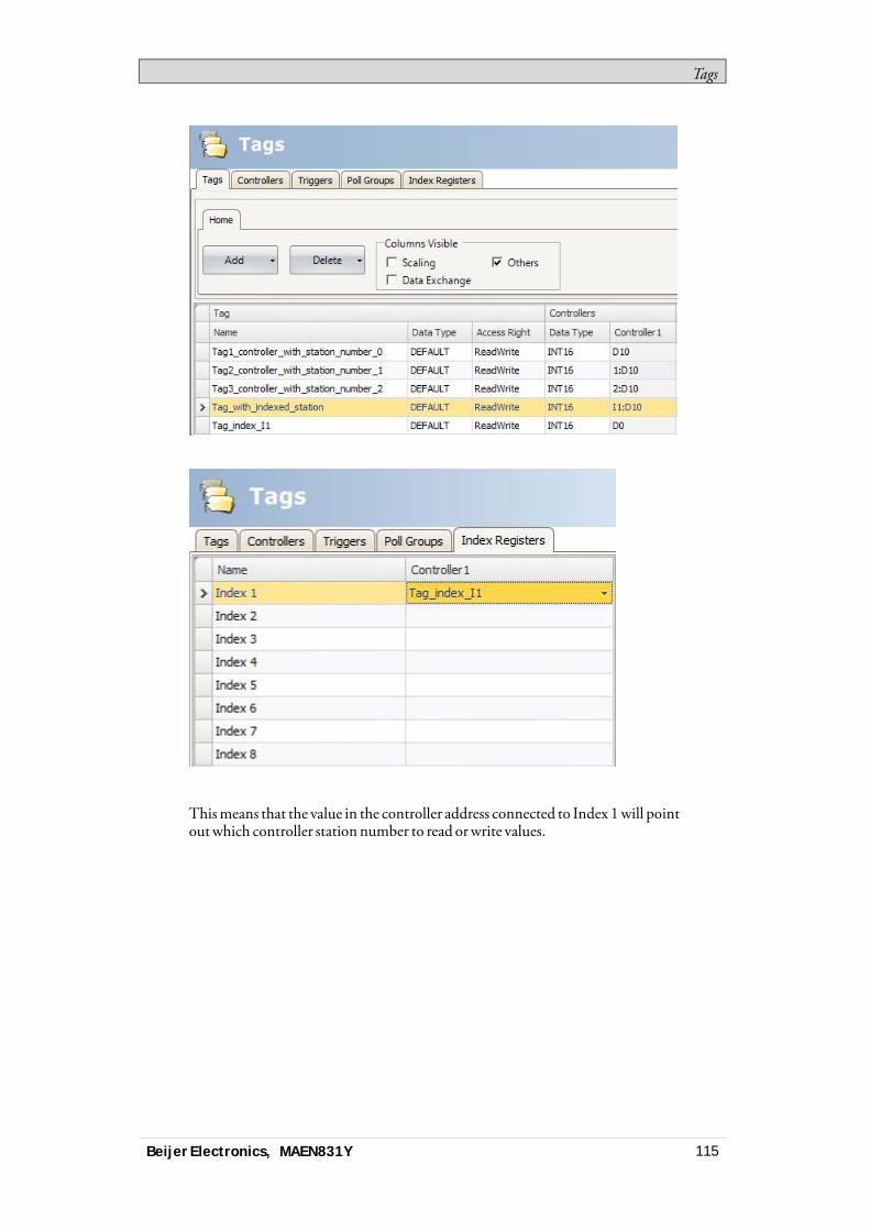
Tags
Thismeans that the value in the controller address connected to Index 1will pointoutwhich controller station number to read orwrite values.
Beijer Electronics, MAEN831Y 115

Tags
Related information
Station Handling
4.11 ExpressionsTheExpressions functionality is usedwhen connecting an object to a tag andthe purpose is not to use the tag value as it is. Expressions enable the user to e.g.extract a bit froma tag, add a dynamic offset or gain, and then to use this value fora specific object.
Note:Static offset and gain for a tag is set in the tags configuration page.
The same expression can be connected tomore than one object in the project.
4.11.1 Definition
An expression is a one line return statement inC#. The default expression code is“value”.
4.11.2 Using Expressions
Right-click on an object and then click the button ... next to SelectTag. TheExpressions dialog is displayed.
Beijer Electronics, MAEN831Y 116
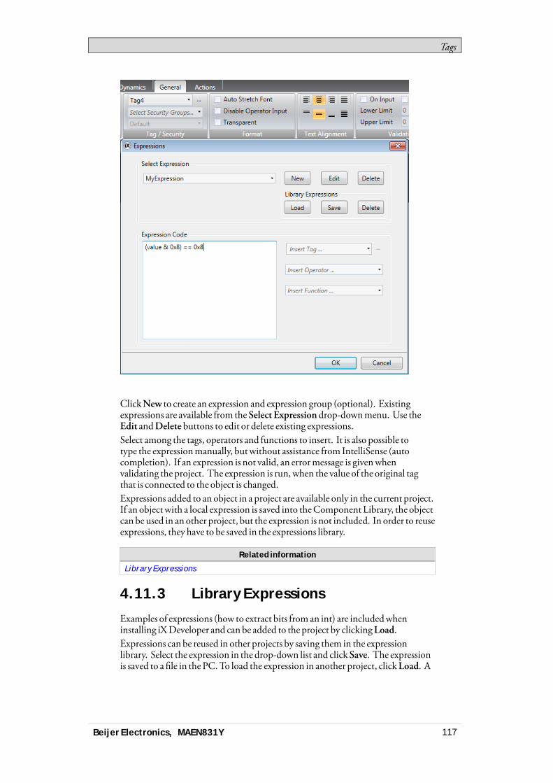
Tags
ClickNew to create an expression and expression group (optional). Existingexpressions are available from the Select Expressiondrop-downmenu. Use theEdit andDelete buttons to edit or delete existing expressions.Select among the tags, operators and functions to insert. It is also possible totype the expressionmanually, butwithout assistance from IntelliSense (autocompletion). If an expression is not valid, an errormessage is givenwhenvalidating the project. The expression is run, when the value of the original tagthat is connected to the object is changed.Expressions added to an object in a project are available only in the current project.If an object with a local expression is saved into theComponent Library, the objectcan be used in an other project, but the expression is not included. In order to reuseexpressions, they have to be saved in the expressions library.
Related information
Library Expressions
4.11.3 Library Expressions
Examples of expressions (how to extract bits from an int) are includedwheninstalling iXDeveloper and can be added to the project by clickingLoad.Expressions can be reused in other projects by saving them in the expressionlibrary. Select the expression in the drop-down list and clickSave. The expressionis saved to a file in the PC.To load the expression in another project, clickLoad. A
Beijer Electronics, MAEN831Y 117
Tags
selection dialog is displayed. Select the expression in the drop-down list and clickOK.If you have saved expressions to the library that youwant to remove, clickDeleteand select among the saved expressions in a dialog. Expressions includedwheninstalling iXDeveloper are not listed, since these cannot be deleted.
4.11.4 Limitations
An expression is executed only on read, i.e. when the value is changed in thecontroller.Whenwriting a value (from e.g. an analog numeric tag), the expression is notexecuted.If another tag than the original tag is used in the expression, the expression is nottriggered on its value change.If an expression that is used inmore than one location is either renamed or deleted,references are not updated. A build error is given.Expressions can be used for all data connections except for• actions• the Property grid• recipe item tags• current language tag inMultiple languages configuration• trigger tags• index tags• scheduler tags• dynamic text for alarm items
Expressions use explicit bool comparison.
Example:Do not use: value; Globals.Tags.Tag1.ValueUse: value != 0; GlobalsTags.Tag1.Vaule == 1
4.12 Tag ExpressionsTag expressions are applied before reading orwriting a tag value. Tag expressionsshould only be used on tags that have an associated address on a controller.There are two different tag expressions, referred to as read expressions andwriteexpressions. A read expression is applied to a tagwhen the tag value is changedfrom the controller. Awrite expression is applied to a tagwhen the tag value ischanged from the user interface or script. Whenboth a read expression and awriteexpression are assigned to a tag it is strongly recommended that the read expressionis the inverse of thewrite expression and vice versa.Whenusing awrite expressionmake sure the controller's data typematches anypossible result from the expression. For example, the data type float should be usedif the expressionwouldmultiply an integer valuewith 0.1.
Beijer Electronics, MAEN831Y 118

Tags
4.13 Data ExchangeData exchange betweendifferent controllers is supported; also between controllersof different brands. The data exchange can be performedwhen a digital tag is set,or at a certain time interval. Data exchange can be selected for individual tags,array tags or for the complete range of tags.
Note:The data exchange function is isolated from general tag/controller settings. Forexample, a tag assigned read access only for the operator, may still be read and writtenby the data exchange function.
Follow the steps below to set up data exchangewith three different controllersinvolved:1. Select theControllers tab of the tags configuration page and enter short
names for the controllers in the ID column, andmake sure that all controllersare active.
2. Select theTags tab and checkData Exchange to display theDirection andWhen columns.
Beijer Electronics, MAEN831Y 119
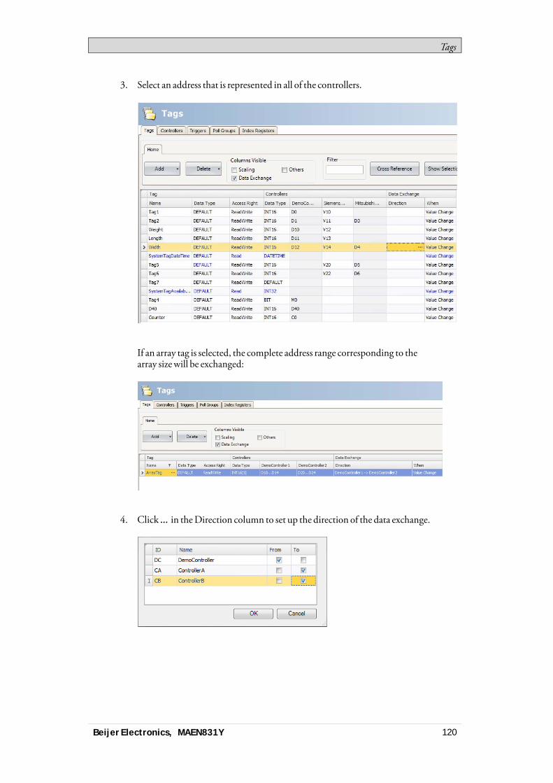
Tags
3. Select an address that is represented in all of the controllers.
If an array tag is selected, the complete address range corresponding to thearray sizewill be exchanged:
4. Click ... in theDirection column to set up the direction of the data exchange.
Beijer Electronics, MAEN831Y 120
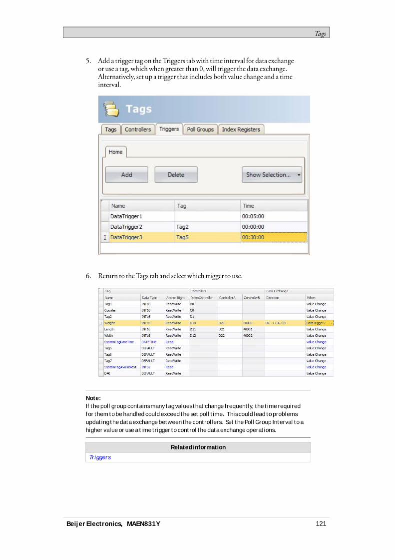
Tags
5. Add a trigger tag on theTriggers tabwith time interval for data exchangeor use a tag, whichwhen greater than 0,will trigger the data exchange.Alternatively, set up a trigger that includes both value change and a timeinterval.
6. Return to theTags tab and select which trigger to use.
Note:If the poll group contains many tag values that change frequently, the time requiredfor them to be handled could exceed the set poll time. This could lead to problemsupdating the data exchange between the controllers. Set the Poll Group Interval to ahigher value or use a time trigger to control the data exchange operations.
Related information
Triggers
Beijer Electronics, MAEN831Y 121

Tags
4.14 Importing and Exporting TagsTags can be imported to and exported from an iXDeveloper project, to, forexample, be edited inExcel or a text editor, or to be transferred to another project.The complete tag listmay be imported and exported, or the actions can be basedon connected controllers.The import function also allows selecting individual tags for import.
4.14.1 Handling Columns
The import function allows skipping columns, or binding columns in the importfile to any column in theTags configuration page.TheName andDataType columnsmust always be bound.A columnmay only be bound once.
4.14.2 Saving the Import Configuration
For repetitive import actions the import configuration, e.g. how columns arebound and fromwhich row to start the import, can be saved and reused. Theimport configuration is saved by clicking the Savemapping as importmodulebutton prior to performing the import. Next time the ImportTags dialog isopened, the configuration is available from the Importmoduledrop-down list.Saving import configurations is valid only for files in text or Excel format.
4.14.3 Tag Import Example
If the controller in the project is changed to a systemwith other names for the tagsused, thesemust be changed:1. Click onTags in the Project Explorer.2. Click on the arrow to the right of the Import/Exportbutton to display the
available options of import and export operations.
Beijer Electronics, MAEN831Y 122
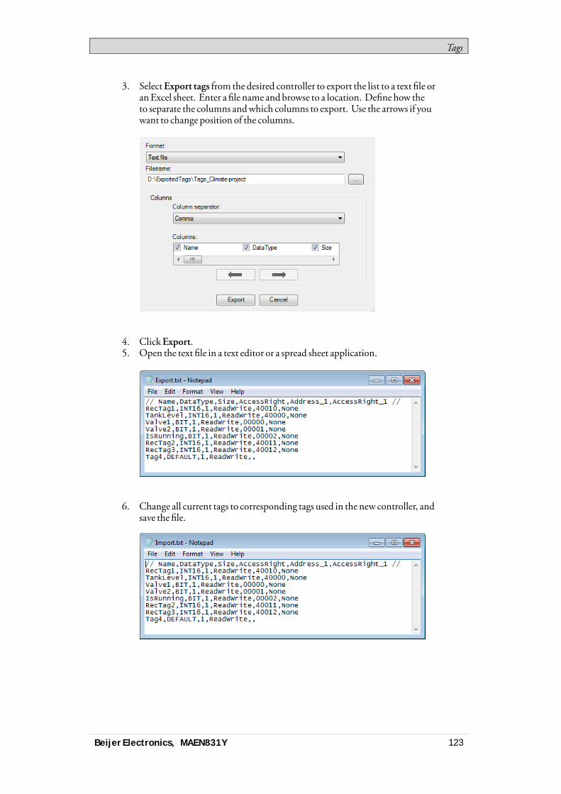
Tags
3. SelectExport tags from the desired controller to export the list to a text file oranExcel sheet. Enter a file name andbrowse to a location. Define how theto separate the columns andwhich columns to export. Use the arrows if youwant to change position of the columns.
4. ClickExport.5. Open the text file in a text editor or a spread sheet application.
6. Change all current tags to corresponding tags used in the new controller, andsave the file.
Beijer Electronics, MAEN831Y 123
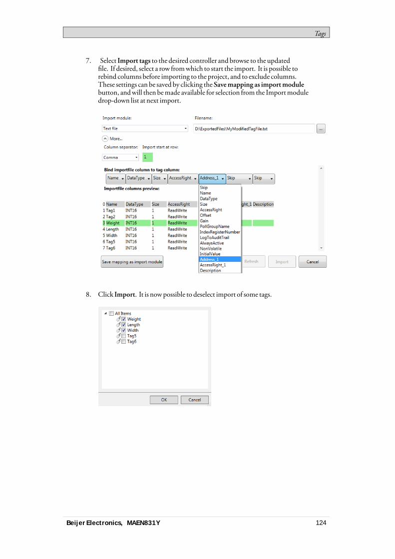
Tags
7. Select Import tags to the desired controller and browse to the updatedfile. If desired, select a row fromwhich to start the import. It is possible torebind columns before importing to the project, and to exclude columns.These settings can be saved by clicking the Savemapping as importmodulebutton, andwill then bemade available for selection from the Importmoduledrop-down list at next import.
8. Click Import. It is nowpossible to deselect import of some tags.
Beijer Electronics, MAEN831Y 124

Tags
9. In case there are name conflicts, these can be handled by changing the name,overwriting,merging or skipping conflicting items. The actions taken aresaved to a log file for future reference.
Note:If you select Overwrite, all settings for the existing tag will be overwritten. If youselect Merge between empty data to data with value, the data with value is kept, toavoid tags with no address.For example: Tag1 with address C1, merging a CSV or TXT file with Tag1 with an emptyaddress, results in a Tag1 with address C1. Tag2 with an empty address, merging a CSVor TXT file with Tag2 and address C2, results in a Tag2 with address C2.
The imported tags are now added to the current project.
Related information
Basic Settings
4.14.4 Importing Tags from the CommandLine
Tags can also be added to the current iXDeveloper project using a command lineswitch, by entering the following:[Executable file] “Project location]\[Project name].neoproj”/ImportTags=”[Tag filelocation]\Tag file”In this case, no applicationwindow is displayed, as long as the import is successful.To open the project namedTest1with the tag fileVarFile.txt in the directoryC:\MyProjects, run iXDeveloper from the command linewith the followingarguments:NeoIDE.exe “C:\MyProjects\Test1\Test1.neoproj” /ImportTags=“C:\MyPro-jects\VarFile.txt”
Beijer Electronics, MAEN831Y 125
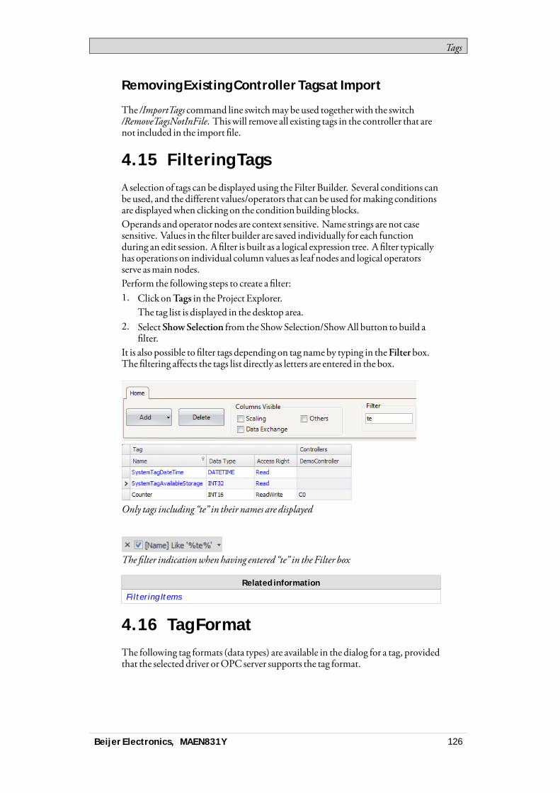
Tags
Removing Existing Controller Tags at Import
The /ImportTags command line switchmay be used togetherwith the switch/RemoveTagsNotInFile. This will remove all existing tags in the controller that arenot included in the import file.
4.15 Filtering TagsA selection of tags can be displayed using the Filter Builder. Several conditions canbe used, and the different values/operators that can be used formaking conditionsare displayedwhen clicking on the condition building blocks.Operands and operator nodes are context sensitive. Name strings are not casesensitive. Values in the filter builder are saved individually for each functionduring an edit session. A filter is built as a logical expression tree. A filter typicallyhas operations on individual column values as leaf nodes and logical operatorsserve asmain nodes.Perform the following steps to create a filter:1. Click onTags in the Project Explorer.
The tag list is displayed in the desktop area.2. Select ShowSelection from the ShowSelection/ShowAll button to build a
filter.It is also possible to filter tags depending on tag nameby typing in theFilterbox.The filtering affects the tags list directly as letters are entered in the box.
Only tags including “te” in their names are displayed
The filter indicationwhen having entered “te” in the Filter box
Related information
Filtering Items
4.16 Tag FormatThe following tag formats (data types) are available in the dialog for a tag, providedthat the selected driver orOPC server supports the tag format.
Beijer Electronics, MAEN831Y 126

Tags
Format Data type Range
- DEFAULT Treated as INT16
Bit BIT 0 and 1
Bit BOOL Values can be “false” (0) or “true” (1)(1)
Signed 16-bit INT16 -32,768 – +32,767
Unsigned 16-bit UINT16 0 – +65,535
Signed 32-bit INT32 -2,147,483,648 – +2,147,483,647(2)
Unsigned 32-bit UINT32 0– +4,294,967,295(2)
Float withexponent,64-bit
DOUBLE 1.7 × 10308 (1)
Float withexponent,32-bit
FLOAT ±3.4 × 1038 (1)
7 × Signed 16-bit DATETIME An Analog Numeric object can present the timeformat(1)
Syntax(3): <yyyy-MM-dd hh:mm:ss> 7 consecutiveregisters are used to store a time:
Dx, seconds, 0–59
Dx+1, minutes, 0–59
Dx+2, hours, 0–23
Dx+3, day, 1–31
Dx+4, month, 1–12
Dx+5, year, 100–9999
Dx+6, weekday, 1–7
String STRING Storing character strings in tags. For this data type,size can be selected.
(1)Controller representation for this type is dependent on the driver software.(2)Regarding resolution of values in 32-bit format: both iX Developer and the operatorpanel can handle up to six decimal digits of an integer 32-bit value. Remaining digitswill be truncated or changed into zeros.(3)yyyy=year, MM=month, dd=date, hh=hour, mm=minute, ss=second.
For use in script code, the following table shows the type representation inC#.This is usedwhen there is a need to do a type casting, for example in calculationsthat are using overloaded operators.
C# type Data type Description
– DEFAULT Treated as INT16
uint BIT C# does not have a “bit” type. In the controller thisis a bit.
bool BOOL C# bool type that can have the values “false” (0)and “true” (1)
int INT16 16 bit, -32,768 – +32,767
uint UINT16 16 bit, 0–+65,535
Beijer Electronics, MAEN831Y 127

Tags
C# type Data type Description
int INT32 32 bit, -2,147,483,648 – +2,147,483,647
uint UINT32 32 bit, 0 – +4,294,967,295
float FLOAT 32 bit, ±3.4 × 1038
double DOUBLE 64 bit, ±1.7 × 10308
DateTime DATETIME 7 elements are used to store a time
string STRING Storing character strings in tags
Related information
Script
4.17 AliasesAn alias should be treated as a property of a screen and can act as a stand-in for atag. The alias can be used to reference a tagwherever that tag can be referenceddirectly. An exception to this are foreground and background screens, where tagscan be used but aliases not. Whenused, iXDeveloperwill act the same as if theoriginal tag had been used. Each screen using aliases can be configuredwith adifferent instancewith different tag references.Using aliases will enable reuse of screenswithout having to create a newduplicatedscreen.
4.17.1 Creating Aliases
Aliases are handled by clickingAliases on the desktop viewmode tab.
Clicking theAdd button adds an alias to the list. Make settings for each addedalias. When predefined values are available, these can be selected by clicking thearrow at the right of the table cell.
Basic Settings
EnterAlias name andDefault value for the alias. If no default value is entered, thealiaswill be treated as a local screen variable.
Beijer Electronics, MAEN831Y 128
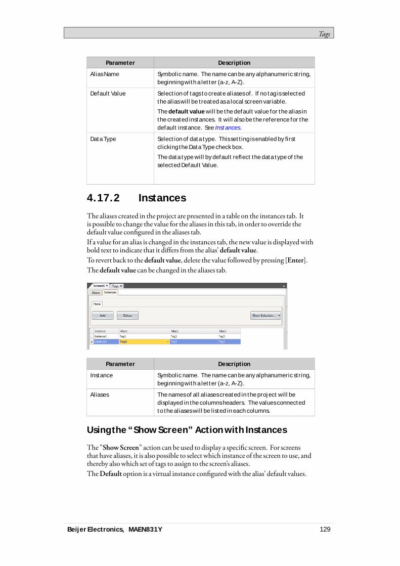
Tags
Parameter Description
Alias Name Symbolic name. The name can be any alphanumeric string,beginning with a letter (a-z, A-Z).
Default Value Selection of tags to create aliases of. If no tag is selectedthe alias will be treated as a local screen variable.
The default value will be the default value for the alias inthe created instances. It will also be the reference for thedefault instance. See Instances.
Data Type Selection of data type. This setting is enabled by firstclicking the Data Type check box.
The data type will by default reflect the data type of theselected Default Value.
4.17.2 Instances
The aliases created in the project are presented in a table on the instances tab. Itis possible to change the value for the aliases in this tab, in order to override thedefault value configured in the aliases tab.If a value for an alias is changed in the instances tab, the new value is displayedwithbold text to indicate that it differs from the alias’ default value.To revert back to thedefault value, delete the value followed by pressing [Enter].Thedefault value can be changed in the aliases tab.
Parameter Description
Instance Symbolic name. The name can be any alphanumeric string,beginning with a letter (a-z, A-Z).
Aliases The names of all aliases created in the project will bedisplayed in the columns headers. The values connectedto the aliases will be listed in each columns.
Using the “Show Screen” Action with Instances
The "ShowScreen” action can be used to display a specific screen. For screensthat have aliases, it is also possible to select which instance of the screen to use, andthereby alsowhich set of tags to assign to the screen’s aliases.TheDefault option is a virtual instance configuredwith the alias’ default values.
Beijer Electronics, MAEN831Y 129

Tags
“ShowScreen” Action Parameters.
Related information
Action Groups
Limitations
• Aliases do not support array tags.• Aliases can not be used in connectionwith expressions.• Aliases can not be usedwith theTrendViewer object.• Aliases can not be used on background screens.• No scripting support for value changed event on an alias.
Beijer Electronics, MAEN831Y 130
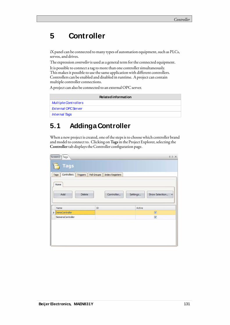
Controller
5 Controller
iX panel can be connected tomany types of automation equipment, such as PLCs,servos, and drives.The expression controller is used as a general term for the connected equipment.It is possible to connect a tag tomore than one controller simultaneously.Thismakes it possible to use the same applicationwith different controllers.Controllers can be enabled anddisabled in runtime. A project can containmultiple controller connections.A project can also be connected to an externalOPC server.
Related information
Multiple Controllers
External OPC Server
Internal Tags
5.1 Adding a ControllerWhen anewproject is created, one of the steps is to choosewhich controller brandandmodel to connect to. Clicking onTags in the Project Explorer, selecting theController tab displays theController configuration page.
Beijer Electronics, MAEN831Y 131

Controller
Parameter Description
Name Symbolic name. The name can be any alphanumeric string,beginning with a letter (a-z, A-Z).
ID Optional short name for controller; displayed in functions such asData exchange.
Active Selection of which controllers are to be active in runtime. Change ofactive controllers can also be performed in runtime using an actionor script.
Controllers are added and deleted using theAdd andDelete buttons.ClickingController allows selecting another controller, andSettingsdisplayssettings for the selected driver.ClickingHelp in the driver settings dialog opens the help file for the driver.
Related information
Select Controller
5.1.1 Notify Window
If a communication error between the application and the controller is detectedin runtime, this will result in a communication error, and aNotifyWindowwillbe displayed in the operator panel. TheNotifyWindow is a floatingwindow thatstarts in the upper left corner of the screen. It is also used to display the alarmindicator.TheNotifyWindow can bemoved to any position on the current screen.
5.2 DEMO ControllerTheDEMOcontroller is used and selected in the sameway as a regular controllerdriver, to design and test a project directly on the development PCwithoutconnection to an external controller.A number of predefined tags can be selected:
Data type Tag ID Description
BIT, BOOL M0 - M99 Digital tags
INT16, UINT16 D0 - D99 Analog tags
TheDEMOcontroller also includes counters anddigital tagswith predefinedfunctions:
Data type Tag ID Description
BIT M100 - M104 Toggles OFF and ON every 1,000 ms
INT16 C0 - C4 Counts from 0 to 100 with 1,000 ms intervalby default; min/max values can be defined
Beijer Electronics, MAEN831Y 132
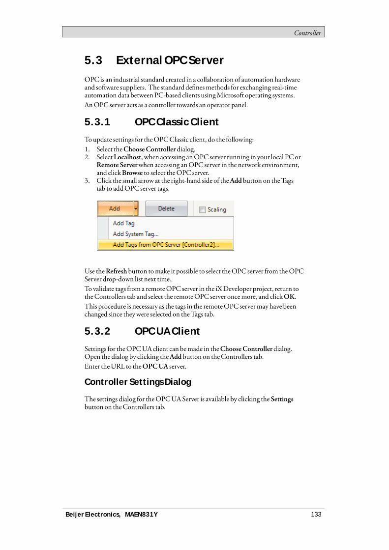
Controller
5.3 External OPC ServerOPC is an industrial standard created in a collaboration of automation hardwareand software suppliers. The standard definesmethods for exchanging real-timeautomation data betweenPC-based clients usingMicrosoft operating systems.AnOPC server acts as a controller towards an operator panel.
5.3.1 OPC Classic Client
Toupdate settings for theOPCClassic client, do the following:1. Select theChooseController dialog.2. SelectLocalhost, when accessing anOPC server running in your local PCor
Remote Serverwhen accessing anOPC server in the network environment,and clickBrowse to select theOPC server.
3. Click the small arrow at the right-hand side of theAdd button on theTagstab to addOPC server tags.
Use theRefresh button tomake it possible to select theOPC server from theOPCServer drop-down list next time.To validate tags from a remoteOPC server in the iXDeveloper project, return totheControllers tab and select the remoteOPC server oncemore, and clickOK.This procedure is necessary as the tags in the remoteOPC servermayhave beenchanged since theywere selected on theTags tab.
5.3.2 OPC UA Client
Settings for theOPCUAclient can bemade in theChooseControllerdialog.Open the dialog by clicking theAddbutton on theControllers tab.Enter theURL to theOPCUA server.
Controller Settings Dialog
The settings dialog for theOPCUAServer is available by clicking theSettingsbutton on theControllers tab.
Beijer Electronics, MAEN831Y 133
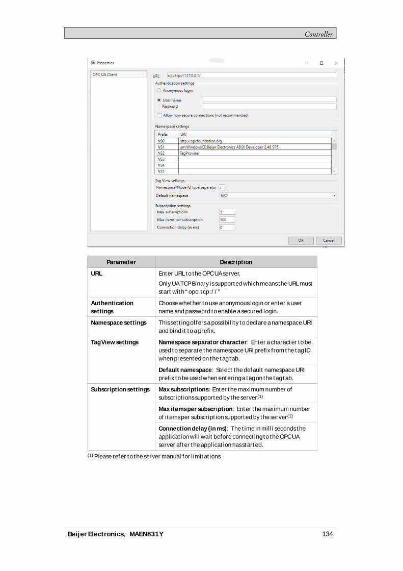
Controller
Parameter Description
URL Enter URL to the OPC UA server.
Only UA TCP Binary is supported which means the URL muststart with “opc.tcp://”
Authenticationsettings
Choose whether to use anonymous login or enter a username and password to enable a secured login.
Namespace settings This setting offers a possibility to declare a namespace URIand bind it to a prefix.
Namespace separator character: Enter a character to beused to separate the namespace URI prefix from the tag IDwhen presented on the tag tab.
Tag View settings
Default namespace: Select the default namespace URIprefix to be used when entering a tag on the tag tab.
Max subscriptions: Enter the maximum number ofsubscriptions supported by the server(1)
Max items per subscription: Enter the maximum numberof items per subscription supported by the server(1)
Subscription settings
Connection delay (in ms): The time in milli seconds theapplication will wait before connecting to the OPC UAserver after the application has started.
(1) Please refer to the server manual for limitations
Beijer Electronics, MAEN831Y 134

Controller
Note:When option user name and password is chosen it will also be possible to make asecondary choice, Allow non-secure connections. This option should be used withgreat caution and only when a connection is made to an OPC UA server that is based on2.40 SP4 or older version.See warning message below.
Add Tags from OPC UA Server
You can add tags fromOPCUAServer in three differentways.Option 1, do the following:1. ClickTags -Add to add tags fromOPCUA server.2. Enter theBrowseName alongwith the preferred namespaceURI prefix,
defined in the controller settings dialog. Make sure to separate the valueswiththe separator character.
Example:“NS3:tag”
If no namespaceURI prefix is entered, the default namespaceURI prefix asdefined in the controller settings dialogwill be used.
Option 2, do the following:1. ClickTags -Add to add tags fromOPCUA server.
Beijer Electronics, MAEN831Y 135
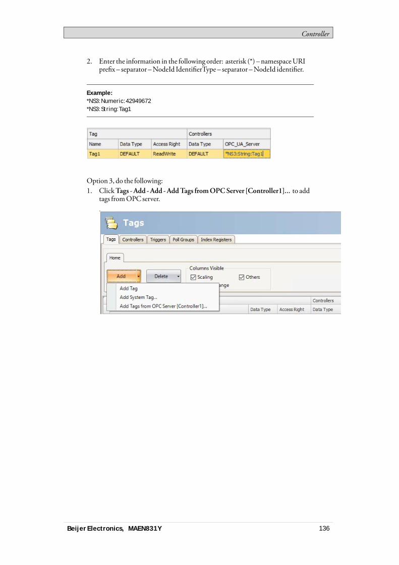
Controller
2. Enter the information in the following order: asterisk (*) – namespaceURIprefix – separator –NodeId IdentifierType – separator –NodeId identifier.
Example:*NS3:Numeric:42949672*NS3:String:Tag1
Option 3, do the following:1. ClickTags -Add -Add -AddTags fromOPCServer [Controller1]... to add
tags fromOPC server.
Beijer Electronics, MAEN831Y 136

Controller
2. BrowseOPCServer dialog, select tags and clickOK.
Note:Array tags are not supported by OPC UA controllers.The button Sync Namespace can be used to import/sync namespace settings withoutimporting any tags.
Supported Functions
DataAccess (UApart 8) is supported.Read /write of objects, structs and arrays is not supported.
Beijer Electronics, MAEN831Y 137

Controller
Limitations
Limitation Description
Address input in GUI When using NameSpace and BrowseName to identify avariable in the server, this combination must be unique.Otherwise, the client cannot identify the variable.
This is not a problem when connecting to an iX Developerserver, since all tag names (variables) are unique.
In those situations, NodeId Identifier can be used foridentification.
NodeId Identifier type Supported NodeId Identifier types are Numeric and String.Nodes with unsupported types, such as Guid and Opaque,will be skipped during import.
Tags with dynamicdata type
OPC UA controller does not support tags with dynamic datatypes. This can lead to unexpected values during runtime.
Related information
OPC UA Server
Beijer Electronics, MAEN831Y 138
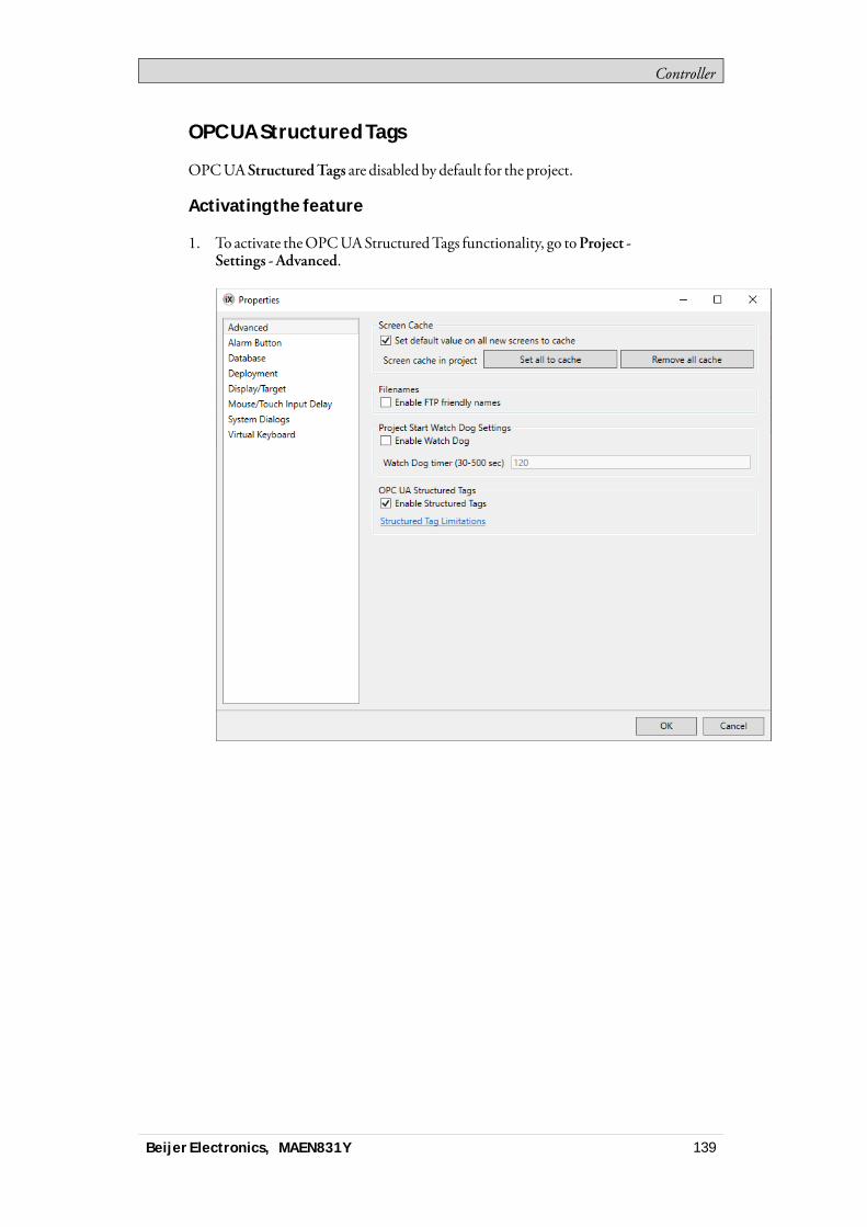
Controller
OPC UA Structured Tags
OPCUA StructuredTags are disabled by default for the project.
Activating the feature
1. To activate theOPCUAStructuredTags functionality, go toProject -Settings - Advanced.
Beijer Electronics, MAEN831Y 139

Controller
2. When the feature is active, two new tabs (StructuredTags / StructuredTypes)will appear in theTags editor.
Note:Read the Limitations document before enabling structured tags.
Importing Structured Tags
Structured tags are added in the sameway as otherOPCUA tags. If one ormoretree structures are selected in the browse dialog, the imported structurewill endup in the StructuredTags tab. If only leaf nodes are selected however, theywill behandled as if StructuredTagswere not active, and end up in a flat list under theTags tab.1. ClickTags -Add -AddTags fromOPCServer [Controller name]... to add
tags fromOPC server.
Beijer Electronics, MAEN831Y 140

Controller
2. BrowseOPCServer dialog, select a tree stucture or leaf nodes and clickOK.
3. The nodes of imported structured tags can be accessed from tag lists in thesameway as other tags. Filtering is also possible.
Beijer Electronics, MAEN831Y 141
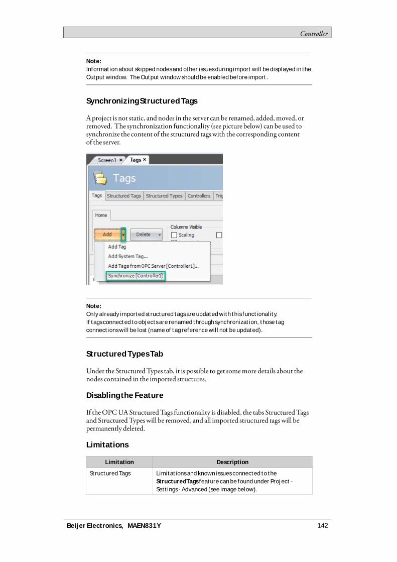
Controller
Note:Information about skipped nodes and other issues during import will be displayed in theOutput window. The Output window should be enabled before import.
Synchronizing Structured Tags
Aproject is not static, and nodes in the server can be renamed, added,moved, orremoved. The synchronization functionality (see picture below) can be used tosynchronize the content of the structured tagswith the corresponding contentof the server.
Note:Only already imported structured tags are updated with this functionality.If tags connected to objects are renamed through synchronization, those tagconnections will be lost (name of tag reference will not be updated).
Structured Types Tab
Under the StructuredTypes tab, it is possible to get somemore details about thenodes contained in the imported structures.
Disabling the Feature
If theOPCUAStructuredTags functionality is disabled, the tabs StructuredTagsand StructuredTypeswill be removed, and all imported structured tagswill bepermanently deleted.
Limitations
Limitation Description
Structured Tags Limitations and known issues connected to theStructuredTags feature can be found under Project -Settings - Advanced (see image below).
Beijer Electronics, MAEN831Y 142

Controller
Related information
Tags
5.4 Updating Drivers
Note:Run as Administrator for iX Developer when downloading or updating drivers.Administrator user rights are needed since files in the Program Files folder arechanged.
Drivers can be updated via Internet or fromfile.Each driver takes up approximately 3.0MB.Touse the downloaded drivers, iXDevelopermust be restarted.
5.4.1 Updating Drivers from Internet
Awebbrowser is not required to update drivers via an Internet connection. A listof drivers that can be downloaded via Internet is displayedwhen the connectionis established.
Beijer Electronics, MAEN831Y 143
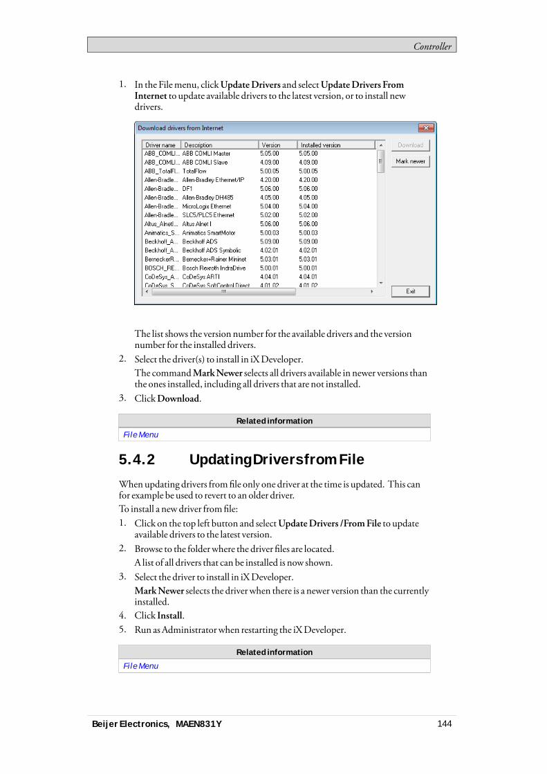
Controller
1. In the Filemenu, clickUpdateDrivers and selectUpdateDrivers FromInternet to update available drivers to the latest version, or to install newdrivers.
The list shows the version number for the available drivers and the versionnumber for the installed drivers.
2. Select the driver(s) to install in iXDeveloper.The commandMarkNewer selects all drivers available in newer versions thanthe ones installed, including all drivers that are not installed.
3. ClickDownload.
Related information
File Menu
5.4.2 Updating Drivers from File
Whenupdating drivers fromfile only one driver at the time is updated. This canfor example be used to revert to an older driver.To install a newdriver fromfile:1. Click on the top left button and selectUpdateDrivers /FromFile to update
available drivers to the latest version.2. Browse to the folderwhere the driver files are located.
A list of all drivers that can be installed is now shown.3. Select the driver to install in iXDeveloper.
MarkNewer selects the driver when there is a newer version than the currentlyinstalled.
4. Click Install.5. Run asAdministratorwhen restarting the iXDeveloper.
Related information
File Menu
Beijer Electronics, MAEN831Y 144
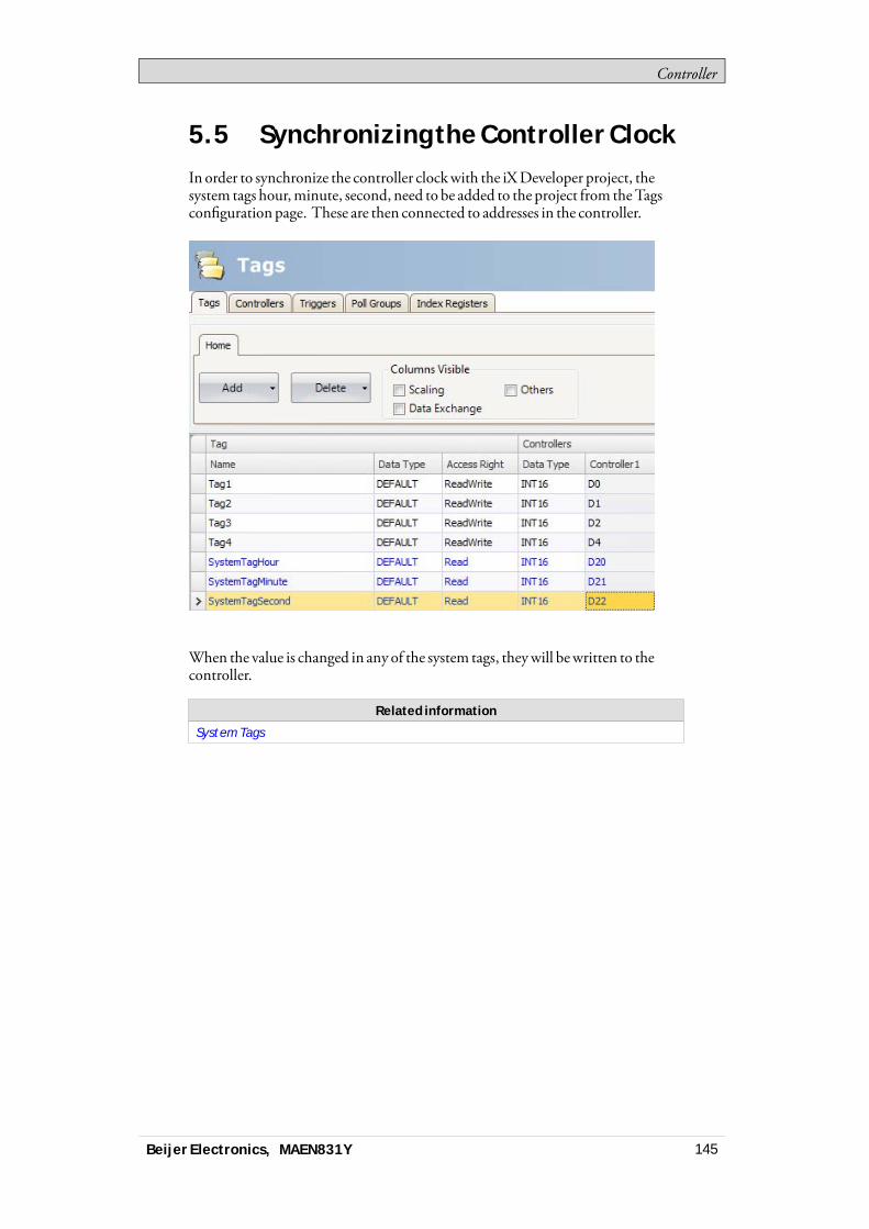
Controller
5.5 Synchronizing the Controller ClockIn order to synchronize the controller clockwith the iXDeveloper project, thesystem tags hour,minute, second, need to be added to the project from theTagsconfiguration page. These are then connected to addresses in the controller.
When the value is changed in any of the system tags, theywill bewritten to thecontroller.
Related information
System Tags
Beijer Electronics, MAEN831Y 145
WebServer
6 Web Server
TheWebServer adds the possibility to use a server-sideApplicationProgrammingInterface (API) to interact with a running project. TheAPI operates over theHyperTextTransfer Protocol (HTTP) and can be accessed from any compatibledevice. In addition, theweb server can hostweb pages and relatedmedia to beconsumed byweb browsers.The bundled Javascript SoftwareDevelopmentKit (SDK)makes it easy to buildinteractiveweb pages that utilize theAPI.Login settings for theweb server are available fromServer group on the Systemribbon tab.
6.1 Web Server ConfigurationTheweb server can be configured for hostingweb pages. It also provides a loginform for authentication.
6.1.1 Web Site Configuration
For theweb server to be able to host web pages, the content of theweb sitemustbe transferred using FTP to a folder named “WebSite” residing in the FTP rootdirectory.The FTP servermust be enabled and theweb content can only be transferred afterthe application has been deployed and started on the panel.
6.1.2 Login Form
Theweb server provides a default login form that is used for clients toauthenticate. It is also possible to override the default and provide a customwebpage thatmatches your overall design.To override the login form, create anHTMLfile called “login.html” and place it ina folder named “Website” in the root of the FTP root directory.This filewill be used instead of the default when clients access the address “/login”.The Javascript SDKprovides tools for creating the formusing a few conventions.Note that this only applies if you have authentication enabled in theweb serversettings.
Authentication Script
Reference the authentication script
Username and Password Field
Mark the username andpassword fieldwith the predefined id’s “login.username“and “login.password”:
Beijer Electronics, MAEN831Y 146

WebServer
Login Button
Mark a login buttonwith the predefined id “ix-login”. Any element can be used.
Invalid Credentials
Optionally add an elementwith the predefined id “ix-invalid-credentials” thatwill be shown if the login fails.
6.2 Javascript SDKThe JavaScript SDKprovides a rich set of client-side functionality for accessingthe server-sideAPI calls.
6.2.1 Javascript SDK Overview
Javascript SDKmakes it possible to build highly interactiveweb pages that usestags defined in the project.1. The first step to build an interactiveweb page is to reference the SDKby
inserting the following script into the header of theHTML.
Note:The SDK is bundled with jQuery 1.7 (http://jquery.com/).
2. Next, the SDKneeds to be initialized. In its simplest form the following linesneed to be added after the reference to the SDK:
Thiswillmake it possible to use the defined tagmetadata attributes to incorporatethe project tags into theweb page.The following linewill, for example, insert the value ofTag1 into theHTMLdocument:
Beijer Electronics, MAEN831Y 147
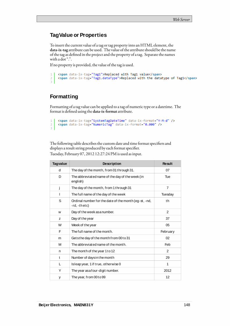
WebServer
Tag Value or Properties
To insert the current value of a tag or tag property into anHTMLelement, thedata-ix-tag attribute can be used. The value of the attribute should be the nameof the tag as defined in the project and the property of a tag. Separate the nameswith a dot “.”.If no property is provided, the value of the tag is used.
Formatting
Formatting of a tag value can be applied to a tag of numeric type or a datetime. Theformat is defined using thedata-ix-format attribute.
The following table describes the customdate and time format specifiers anddisplays a result string produced by each format specifier.Tuesday, February 07, 2012 12:27:24 PM is used as input.
Tag value Description Result
d The day of the month, from 01 through 31. 07
D The abbreviated name of the day of the week (inenglish)
Tue
j The day of the month, from 1 through 31 7
l The full name of the day of the week Tuesday
S Ordinal number for the date of the month (eg -st, -nd,-rd, -th etc)
th
w Day of the week as a number. 2
z Day of the year 37
W Week of the year 05
F The full name of the month. February
m Gets the day of the month from 00 to 31 02
M The abbreviated name of the month. Feb
n The month of the year 1 to 12 2
t Number of days in the month 29
L Is leap year, 1 if true, otherwise 0 1
Y The year as a four-digit number. 2012
y The year, from 00 to 99 12
Beijer Electronics, MAEN831Y 148

WebServer
Tag value Description Result
a The AM/PM designator lower case. pm
A The AM/PM designator upper case. PM
g The hour, using a 12-hour clock from 1 to 12. 12
G The hour, using a 24-hour clock from 0 to 23. 12
h The hour, using a 12-hour clock from 01 to 12. 12
H The hour, using a 24-hour clock from 00 to 23. 12
i The minute, from 00 through 59 27
s The second, from 00 through 59. 24
X The milliseconds, from 000 through 999. 000
O Hours offset from GMT, with a leading zero for asingle-digit value.
+0100
Z Timezone offset, in seconds 3600
q Quarter 1
Beijer Electronics, MAEN831Y 149

WebServer
The following table describes the customnumeric format specifiers and displayssample output produced by each format specifier:
ResultTagValue
DescriptionValue Format
4 00 → 04
4.5 0.00 → 4.50
0 Digit
.1 0.00 × 1000 → 1.00 × 10-01
# Digit, zero shows as absent 4 ## → 4
. Decimal separator or monetarydecimal separator
4.5 0.00 → 4.50
5.55 0.0 × 1000 → 5.6 × 1000E Separates mantissa and exponentin scientific notation 1000000 0.0 × 1000 → 1.0 × 1006
1000 0,0 → 1,000, Grouping separator
1000 0,# → 1,000
-5 plus;minus → minus
5 plus;minus → plus
0 plus;minus;zero → zero
; Separates positive and negativesubpatterns
-5 0;(0.0);0.000 → (5.0)
700 [>500]###.##;[<1000]###;###.# → 700.00
400 [>500]medium;[>1000]###;###.# → 400
[] Custom subpatterns
1001 [>2000]high;[>1000]nor-mal;[>500]low → normal
Setting Tag Value
To set the value of a tag, two elementsmust be defined.The first element have thedata-ix-setter attribute on the positionwhere the tagvalue can be entered.The second element has thedata-ix-submitbutton attribute used to submit thenew tag value.Thedata-ix-submitbutton attribute takes the tag names, separated by comma“,”, to be submittedwhen the button is clicked. To submit all tags an asterisk “*”can be used.
Beijer Electronics, MAEN831Y 150
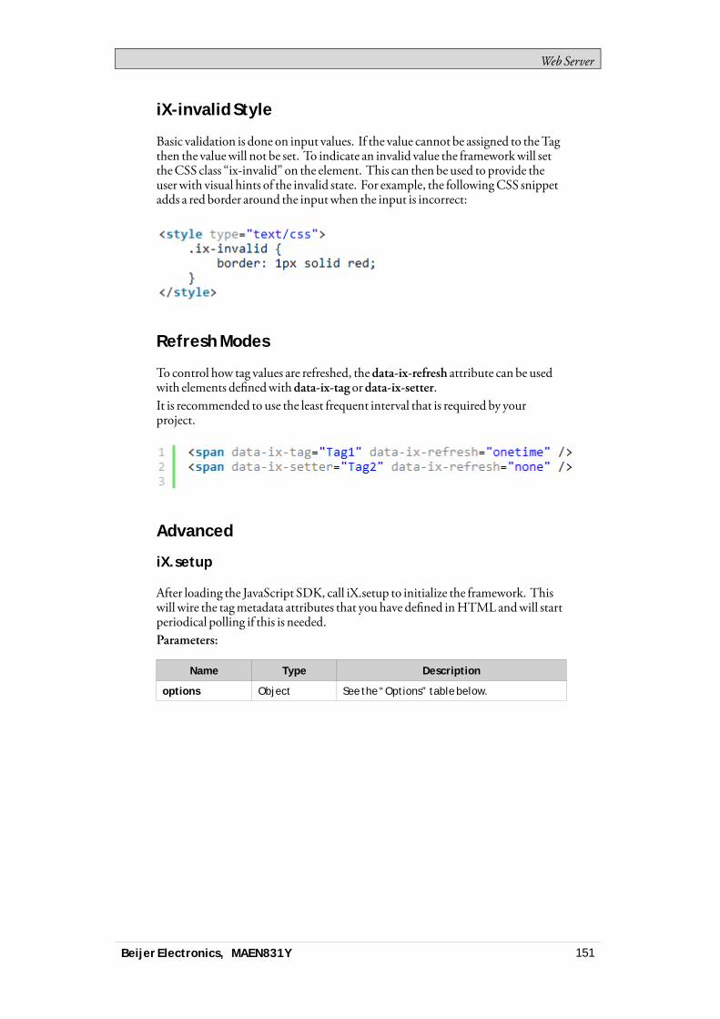
WebServer
iX-invalid Style
Basic validation is done on input values. If the value cannot be assigned to theTagthen the valuewill not be set. To indicate an invalid value the frameworkwill settheCSS class “ix-invalid” on the element. This can then be used to provide theuserwith visual hints of the invalid state. For example, the followingCSS snippetadds a red border around the inputwhen the input is incorrect:
Refresh Modes
To control how tag values are refreshed, thedata-ix-refresh attribute can be usedwith elements definedwithdata-ix-tag ordata-ix-setter.It is recommended to use the least frequent interval that is required by yourproject.
Advanced
iX.setup
After loading the JavaScript SDK, call iX.setup to initialize the framework. Thiswill wire the tagmetadata attributes that you have defined inHTMLandwill startperiodical polling if this is needed.Parameters:
Name Type Description
options Object See the “Options” table below.
Beijer Electronics, MAEN831Y 151

WebServer
Options
Property Type Description ArgumentDe-
fault
refreshInterval Int The refresh interval of tag valuesin ms. For performance reasonsit is recommended not to use lowvalues for this setting.
Optional 5000
refreshMode String Overrides the default refreshmode of tag values.
Accepted modes are: none,onetime, interval.
Optional one-time
refreshMode-Setter
String Overrides the default refreshmode of tag setters.
Accepted modes are: none,onetime, interval.
Optional one-time
Example:This examplewill set periodical refresh interval to 10 seconds, set the refreshmodeofHTMLelementsmarkedwith thedata-ix-tag attribute to interval and set therefreshmode ofHTMLelementsmarkedwith thedata-ix-setter attribute torefresh only once.
iX.refreshElements
Refreshes the tag values of the provided elementsmanually. The attributedata-ix-refreshbutton can be used to achieve the same function.
Note:Only an element that have been marked with a valid data-ix-tag or data-ix-setter canbe refreshed. The value will be refreshed regardless of the refresh mode set on theelement.
Parameters:
Name Type Description
elementIds Array A list of strings containing the HTML elementids. If not provided all tag elements areupdated.
Example:This example showhowyouprogrammatically can achieve the same behaviorasmarking an elementwithdata-ix-refreshbutton. In the example, theHTMLelementwith id "tag1Id"will be updatedwhen the elementwith id
Beijer Electronics, MAEN831Y 152
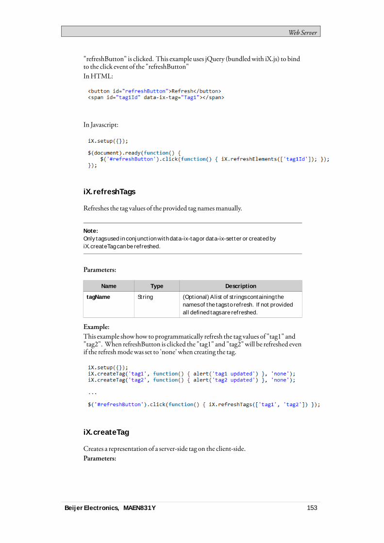
WebServer
"refreshButton" is clicked. This example uses jQuery (bundledwith iX.js) to bindto the click event of the "refreshButton"InHTML:
In Javascript:
iX.refreshTags
Refreshes the tag values of the provided tag namesmanually.
Note:Only tags used in conjunction with data-ix-tag or data-ix-setter or created byiX.createTag can be refreshed.
Parameters:
Name Type Description
tagName String (Optional) A list of strings containing thenames of the tags to refresh. If not providedall defined tags are refreshed.
Example:This example showhow to programmatically refresh the tag values of "tag1" and"tag2". When refreshButton is clicked the "tag1" and "tag2"will be refreshed evenif the refreshmodewas set to 'none' when creating the tag.
iX.createTag
Creates a representation of a server-side tag on the client-side.Parameters:
Beijer Electronics, MAEN831Y 153
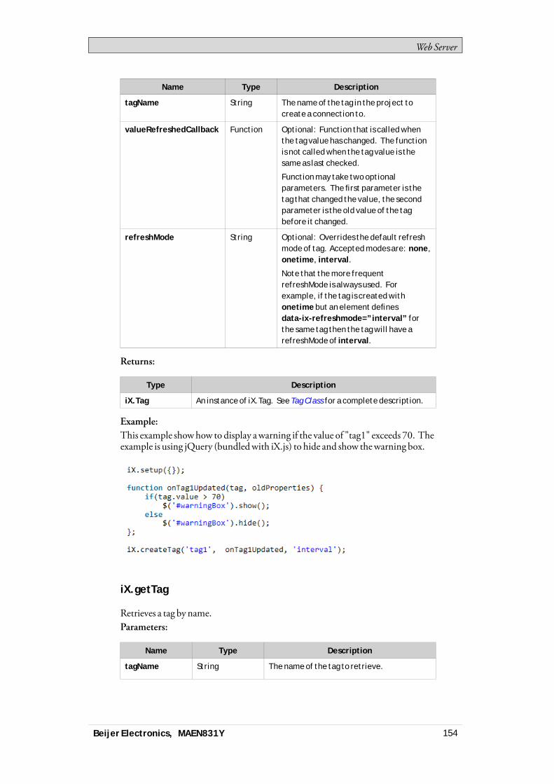
WebServer
Name Type Description
tagName String The name of the tag in the project tocreate a connection to.
valueRefreshedCallback Function Optional: Function that is called whenthe tag value has changed. The functionis not called when the tag value is thesame as last checked.
Function may take two optionalparameters. The first parameter is thetag that changed the value, the secondparameter is the old value of the tagbefore it changed.
refreshMode String Optional: Overrides the default refreshmode of tag. Accepted modes are: none,onetime, interval.
Note that the more frequentrefreshMode is always used. Forexample, if the tag is created withonetime but an element definesdata-ix-refreshmode=”interval” forthe same tag then the tag will have arefreshMode of interval.
Returns:
Type Description
iX.Tag An instance of iX.Tag. See Tag Class for a complete description.
Example:This example showhow to display awarning if the value of "tag1" exceeds 70. Theexample is using jQuery (bundledwith iX.js) to hide and show thewarning box.
iX.getTag
Retrieves a tag by name.Parameters:
Name Type Description
tagName String The name of the tag to retrieve.
Beijer Electronics, MAEN831Y 154
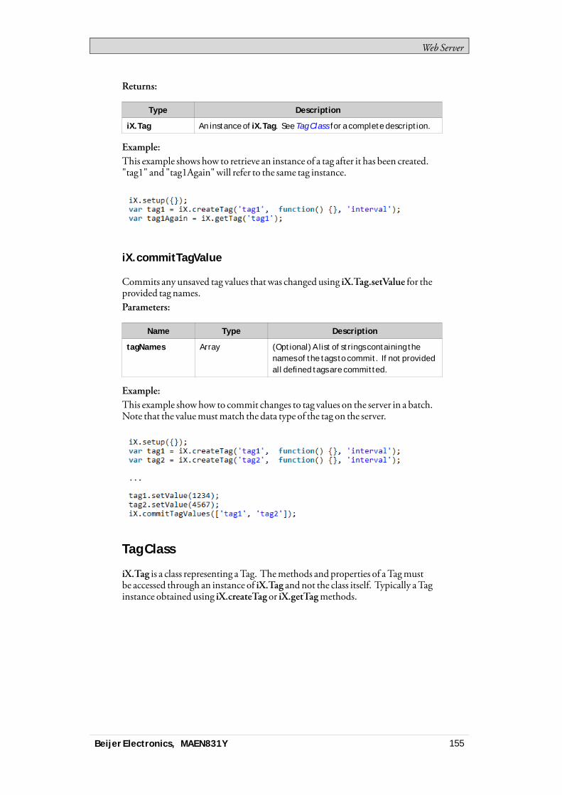
WebServer
Returns:
Type Description
iX.Tag An instance of iX.Tag. See Tag Class for a complete description.
Example:This example shows how to retrieve an instance of a tag after it has been created."tag1" and "tag1Again"will refer to the same tag instance.
iX.commitTagValue
Commits any unsaved tag values thatwas changed using iX.Tag.setValue for theprovided tag names.Parameters:
Name Type Description
tagNames Array (Optional) A list of strings containing thenames of the tags to commit. If not providedall defined tags are committed.
Example:This example showhow to commit changes to tag values on the server in a batch.Note that the valuemustmatch the data type of the tag on the server.
Tag Class
iX.Tag is a class representing aTag. Themethods and properties of aTagmustbe accessed through an instance of iX.Tag and not the class itself. Typically aTaginstance obtained using iX.createTag or iX.getTagmethods.
Beijer Electronics, MAEN831Y 155
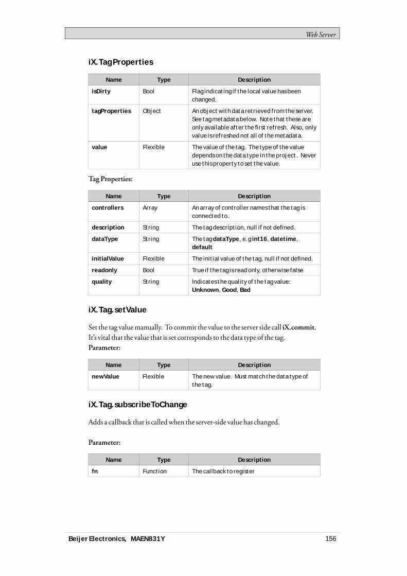
WebServer
iX.Tag Properties
Name Type Description
isDirty Bool Flag indicating if the local value has beenchanged.
tagProperties Object An object with data retrieved from the server.See tag metadata below. Note that these areonly available after the first refresh. Also, onlyvalue is refreshed not all of the metadata.
value Flexible The value of the tag. The type of the valuedepends on the data type in the project. Neveruse this property to set the value.
TagProperties:
Name Type Description
controllers Array An array of controller names that the tag isconnected to.
description String The tag description, null if not defined.
dataType String The tag dataType, e.g int16, datetime,default
initialValue Flexible The initial value of the tag, null if not defined.
readonly Bool True if the tag is read only, otherwise false
quality String Indicates the quality of the tag value:Unknown, Good, Bad
iX.Tag.setValue
Set the tag valuemanually. To commit the value to the server side call iX.commit.It’s vital that the value that is set corresponds to the data type of the tag.Parameter:
Name Type Description
newValue Flexible The new value. Must match the data type ofthe tag.
iX.Tag.subscribeToChange
Adds a callback that is calledwhen the server-side value has changed.
Parameter:
Name Type Description
fn Function The callback to register
Beijer Electronics, MAEN831Y 156
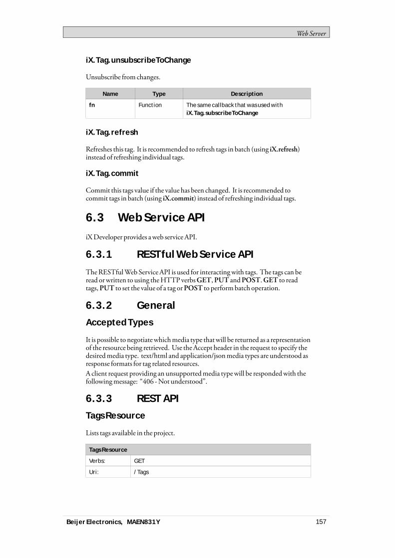
WebServer
iX.Tag.unsubscribeToChange
Unsubscribe from changes.
Name Type Description
fn Function The same callback that was used withiX.Tag.subscribeToChange
iX.Tag.refresh
Refreshes this tag. It is recommended to refresh tags in batch (using iX.refresh)instead of refreshing individual tags.
iX.Tag.commit
Commit this tags value if the value has been changed. It is recommended tocommit tags in batch (using iX.commit) instead of refreshing individual tags.
6.3 Web Service APIiXDeveloper provides aweb serviceAPI.
6.3.1 RESTful Web Service API
TheRESTfulWebServiceAPI is used for interactingwith tags. The tags can beread orwritten to using theHTTPverbsGET,PUT andPOST.GET to readtags,PUT to set the value of a tag orPOST to performbatch operation.
6.3.2 General
Accepted Types
It is possible to negotiatewhichmedia type thatwill be returned as a representationof the resource being retrieved. Use theAccept header in the request to specify thedesiredmedia type. text/html and application/jsonmedia types are understood asresponse formats for tag related resources.A client request providing an unsupportedmedia typewill be respondedwith thefollowingmessage: “406 -Not understood”.
6.3.3 REST API
Tags Resource
Lists tags available in the project.
Tags Resource
Verbs: GET
Uri: /Tags
Beijer Electronics, MAEN831Y 157
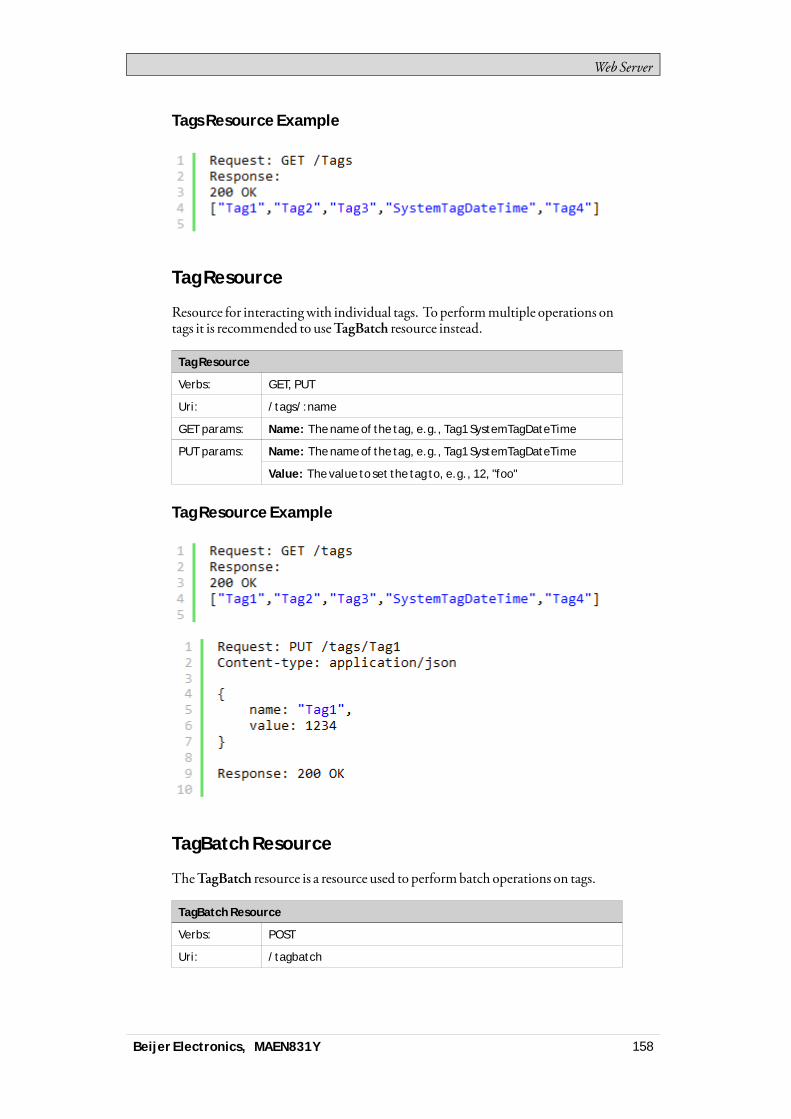
WebServer
Tags Resource Example
Tag Resource
Resource for interactingwith individual tags. Toperformmultiple operations ontags it is recommended to useTagBatch resource instead.
Tag Resource
Verbs: GET, PUT
Uri: /tags/:name
GET params: Name: The name of the tag, e.g., Tag1 SystemTagDateTime
Name: The name of the tag, e.g., Tag1 SystemTagDateTimePUT params:
Value: The value to set the tag to, e.g., 12, "foo"
Tag Resource Example
TagBatch Resource
TheTagBatch resource is a resource used to performbatch operations on tags.
TagBatch Resource
Verbs: POST
Uri: /tagbatch
Beijer Electronics, MAEN831Y 158

WebServer
TagBatch Resource
includeMetadata: boolean indicating if only the tag value or thefull tag metadata should be fetched
getTags: List of tag names to return
POST params:
setTags: List name, value pairs representing new tag values.
Beijer Electronics, MAEN831Y 159
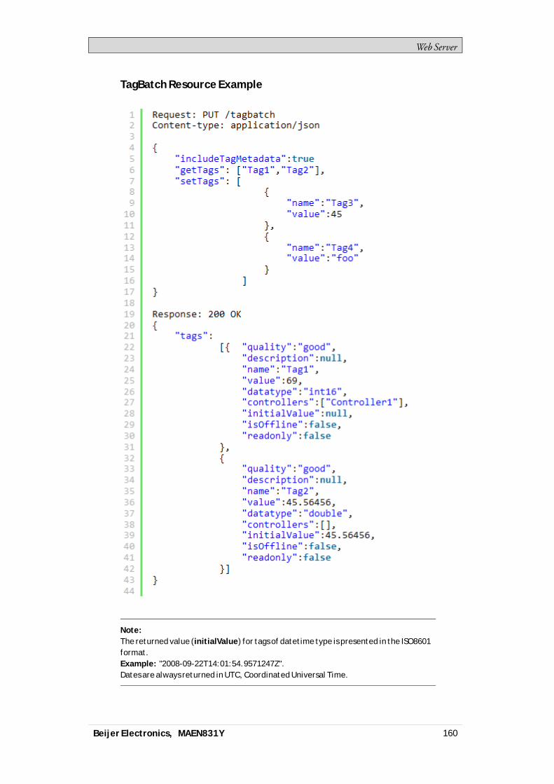
WebServer
TagBatch Resource Example
Note:The returned value (initialValue) for tags of datetime type is presented in the ISO8601format.Example: "2008-09-22T14:01:54.9571247Z".Dates are always returned in UTC, Coordinated Universal Time.
Beijer Electronics, MAEN831Y 160
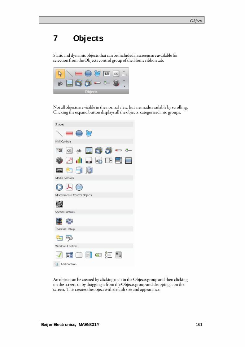
Objects
7 Objects
Static and dynamic objects that can be included in screens are available forselection from theObjects control group of theHome ribbon tab.
Not all objects are visible in the normal view, but aremade available by scrolling.Clicking the expand button displays all the objects, categorized into groups.
An object can be created by clicking on it in theObjects group and then clickingon the screen, or by dragging it from theObjects group and dropping it on thescreen. This creates the object with default size and appearance.
Beijer Electronics, MAEN831Y 161
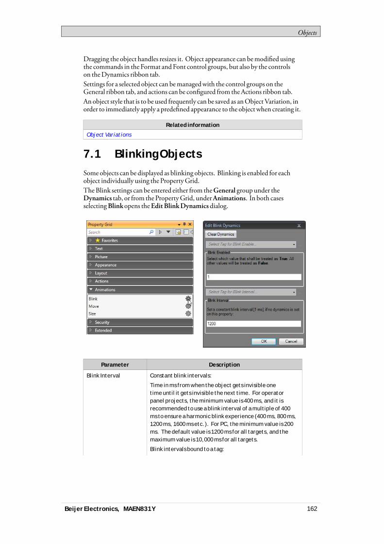
Objects
Dragging the object handles resizes it. Object appearance can bemodified usingthe commands in the Format andFont control groups, but also by the controlson theDynamics ribbon tab.Settings for a selected object can bemanagedwith the control groups on theGeneral ribbon tab, and actions can be configured from theActions ribbon tab.An object style that is to be used frequently can be saved as anObjectVariation, inorder to immediately apply a predefined appearance to the object when creating it.
Related information
Object Variations
7.1 Blinking ObjectsSome objects can be displayed as blinking objects. Blinking is enabled for eachobject individually using the PropertyGrid.TheBlink settings can be entered either from theGeneral group under theDynamics tab, or from the PropertyGrid, underAnimations. In both casesselectingBlink opens theEdit BlinkDynamicsdialog.
Parameter Description
Blink Interval Constant blink intervals:
Time in ms from when the object gets invisible onetime until it gets invisible the next time. For operatorpanel projects, the minimum value is 400 ms, and it isrecommended to use a blink interval of a multiple of 400ms to ensure a harmonic blink experience (400 ms, 800 ms,1200 ms, 1600 ms etc.). For PC, the minimum value is 200ms. The default value is 1200 ms for all targets, and themaximum value is 10,000 ms for all targets.
Blink intervals bound to a tag:
Beijer Electronics, MAEN831Y 162

Objects
Parameter Description
Select Tag for Blink Interval changes blink frequencybased on the selected tag value.
Blink Enabled Select Tag for Blink Enable makes it possible to enable anddisable blinking depending on the selected tag value:
When the tag value is equal to the given value (=True),blink is enabled. When the tag value is not equal to thegiven value (=False), blink is disabled.
Security has higher priority than blink, and an object hidden by security cannotbemade visible through blink.It is not recommended to useBlink on objects that should be used for userinteraction.
Related information
General Group
7.1.1 Limitations for operator panelTargets
Blink is not supported for the following objects in operator panel targets:
Alarm DistributorViewer
Alarm Viewer Audit Trail Viewer
Check Box Combo Box Database Viewer
Group Box List Box Media Player
PDF Viewer Progress Bar Radio Button
Web Browser - -
Related information
General Group
7.2 ShapesStatic shapes such as Line, Rectangle andPoly Line can be used to drawbackground graphics. Tags can be linked to shapes underDynamics, to changetheir appearance (e.g. color andposition) depending on value changes ofcontroller tags.Points for an existing Poly Line object can be adjusted by selectingEdit Pointsfrom the contextmenu.
Ellipse Line Polyline Rectangle
Beijer Electronics, MAEN831Y 163

Objects
Note:Bevel for Poly Line and Ellipse is only supported for projects designed for PC targets.
7.3 HMI ControlsDynamic objects such as buttons, analog numerics, sliders,meters and trendviewers are linked to tags in order to create control andmonitoring functions.The tag associatedwith an object can be selected and changed from theTag/Security group on theHomeorGeneral ribbon tabs, or from the contextmenu. Links to tags (controller tags, internal tags or system tags) are selected intheTag drop-down list.Objects containing text can be edited directly from the keyboard, either when justcreated, orwhen a single selection is done on the text area of the object.It is also possible to use script code to control the text contents of buttons, textsor text boxes.
Note:Use of braces around digits, such as ‘{0}’, is not allowed in text objects. This will resultin an error when opening the screen.
The followingHMI controls are described:
Action MenuObject
Alarm ViewerObject
Analog NumericObject
Animated GIF
Animated LabelObject
Audit Trail Viewer Button Object Circular MeterObject
Chart Object Database ViewerObject
Digital ClockObject
Linear MeterObject
Multi PictureObject
Picture Object Roller PanelObject
Slider Object
Beijer Electronics, MAEN831Y 164
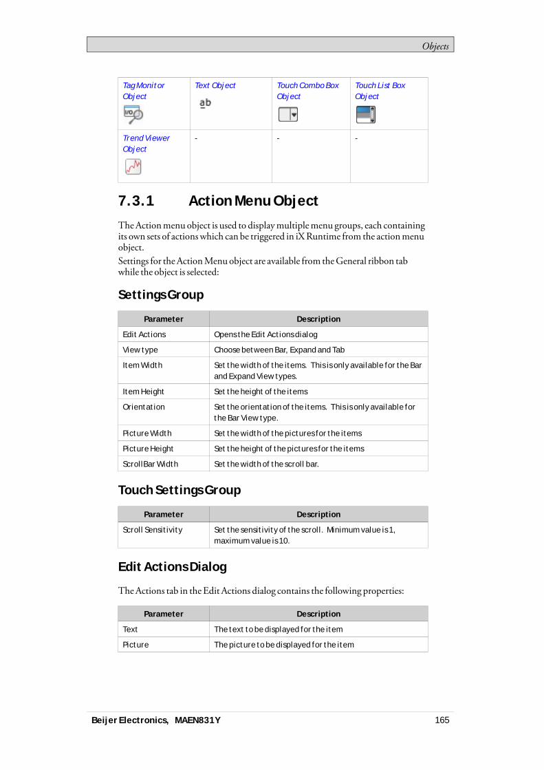
Objects
Tag MonitorObject
Text Object Touch Combo BoxObject
Touch List BoxObject
Trend ViewerObject
- - -
7.3.1 Action Menu Object
TheActionmenuobject is used to displaymultiplemenu groups, each containingits own sets of actionswhich can be triggered in iXRuntime from the actionmenuobject.Settings for theActionMenuobject are available from theGeneral ribbon tabwhile the object is selected:
Settings Group
Parameter Description
Edit Actions Opens the Edit Actions dialog
View type Choose between Bar, Expand and Tab
Item Width Set the width of the items. This is only available for the Barand Expand View types.
Item Height Set the height of the items
Orientation Set the orientation of the items. This is only available forthe Bar View type.
Picture Width Set the width of the pictures for the items
Picture Height Set the height of the pictures for the items
ScrollBar Width Set the width of the scroll bar.
Touch Settings Group
Parameter Description
Scroll Sensitivity Set the sensitivity of the scroll. Minimum value is 1,maximum value is 10.
Edit Actions Dialog
TheActions tab in theEdit Actions dialog contains the following properties:
Parameter Description
Text The text to be displayed for the item
Picture The picture to be displayed for the item
Beijer Electronics, MAEN831Y 165
Objects
Parameter Description
Make Transparent Set transparency on the item
Action Configure the action when the item is clicked
TheMenuGroups tab in the Edit Actions dialog contains the followingproperties:
Parameter Description
Menu Group Name The name of the menu group
Picture The picture to be displayed for the menu group
Make Transparent Set transparency on the menu group
Note:Make sure not to use semi-transparent pictures in projects targeted for operator panel.Since these targets do not fully support opacity, semi-transparent pictures may turnout unclear.
Adding a New Action
In theEdit Actionsdialog select theActions tab. Click theAddbutton. Anewitemwill be added and placed last in the list. To configure the actions for the item,click the “…”button in theAction column.
Adding a New Menu Group
In theEdit Actionsdialog select theMenuGroups tab. Click theAdd button. Anewmenu groupwill be added andplaced last in the list. Themenu groupwill bedisplayed in theActions tab as a newmenu group tab.
Action Menu Dynamics
It is also possible to set dynamics, i.e. tag dependent values for theActionMenuproperties. These can be found in theDynamics tab in the ribbon bar.
Related information
Dynamics Ribbon Tab
7.3.2 Alarm Viewer Object
TheAlarmViewer is used to display andmanage alarm items, for exampleindication of out-of-bounds tag values. The viewer consists of a list area and abutton area.
Related information
Alarm Management
Alarm Viewer
Beijer Electronics, MAEN831Y 166

Objects
7.3.3 Analog Numeric Object
TheAnalogNumeric object displays a boxwith a numeric or alphanumeric value.The value can be connected to a tag.Settings for the analog numeric object are available from theGeneral ribbon tabwhile the object is selected:
Display Format Group
Parameter Description
Type Selection of Integer, Decimal, String, Hex or Binary displayformat
Number of Decimals Maximum number of decimals to display in the object.
Only available when Type = Decimal. The number ofdecimals will be represented by a “#” symbol on the analognumeric object.
Limit Characters to Makes it possible to maximize the number of displayedcharacters. The number of characters will be representedby a “#” symbol on the analog numeric object.
Zero Fill Fills empty character positions with zeros, to let themaximum number of characters always be displayed
Note:The “Limit Characters to” function, in combination with the string format type isnot supported for the Traditional Chinese, Simplified Chinese and Simplified Chinese(Compact) languages.
Prefix/Suffix Group
Parameter Description
Prefix/Suffix Text value that will precede/follow the object value
Tag/Security Group
Parameter Description
Select Tag Connection to a tag from the tags configuration page
Select Security Groups Allows limiting access of the object based on securitygroups. If left empty, the object can be accessed byanyone.
Select Visibility Configuration of visibility:
Default: The visibility specified on the General tab of theSecurity Manager is used.
Disabled: The object is disabled for users with insufficientaccess rights
Beijer Electronics, MAEN831Y 167
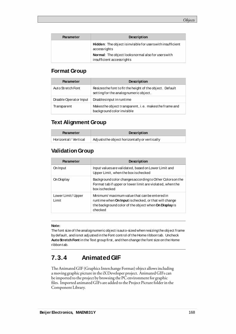
Objects
Parameter Description
Hidden: The object is invisible for users with insufficientaccess rights
Normal: The object looks normal also for users withinsufficient access rights
Format Group
Parameter Description
Auto Stretch Font Resizes the font to fit the height of the object. Defaultsetting for the analog numeric object.
Disable Operator Input Disables input in runtime
Transparent Makes the object transparent, i.e. makes the frame andbackground color invisible
Text Alignment Group
Parameter Description
Horizontal / Vertical Adjusts the object horizontally or vertically
Validation Group
Parameter Description
On Input Input values are validated, based on Lower Limit andUpper Limit, when the box is checked
On Display Background color changes according to Other Colors on theFormat tab if upper or lower limit are violated, when thebox is checked
Lower Limit/UpperLimit
Minimum/maximum value that can be entered inruntime when On Input is checked, or that will changethe background color of the object when On Display ischecked
Note:The font size of the analog numeric object is auto-sized when resizing the object frameby default, and is not adjusted in the Font control of the Home ribbon tab. UncheckAuto Stretch Font in the Text group first, and then change the font size on the Homeribbon tab.
7.3.4 Animated GIF
TheAnimatedGIF (Graphics Interchange Format) object allows includingamoving graphic picture in the iXDeveloper project. AnimatedGIFs canbe imported to the project by browsing the PC environment for graphicfiles. Imported animatedGIFs are added to the Project Picture folder in theComponent Library.
Beijer Electronics, MAEN831Y 168
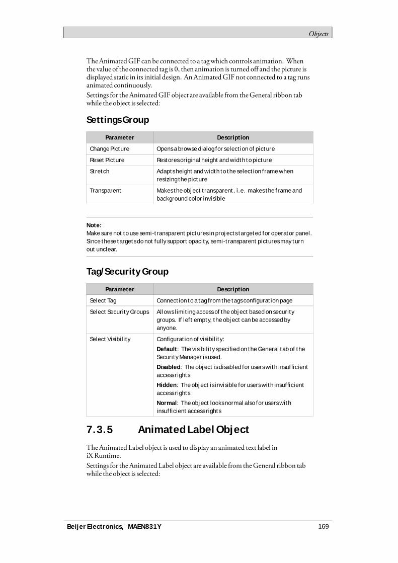
Objects
TheAnimatedGIF can be connected to a tagwhich controls animation. Whenthe value of the connected tag is 0, then animation is turned off and the picture isdisplayed static in its initial design. AnAnimatedGIFnot connected to a tag runsanimated continuously.Settings for theAnimatedGIF object are available from theGeneral ribbon tabwhile the object is selected:
Settings Group
Parameter Description
Change Picture Opens a browse dialog for selection of picture
Reset Picture Restores original height and width to picture
Stretch Adapts height and width to the selection frame whenresizing the picture
Transparent Makes the object transparent, i.e. makes the frame andbackground color invisible
Note:Make sure not to use semi-transparent pictures in projects targeted for operator panel.Since these targets do not fully support opacity, semi-transparent pictures may turnout unclear.
Tag/Security Group
Parameter Description
Select Tag Connection to a tag from the tags configuration page
Select Security Groups Allows limiting access of the object based on securitygroups. If left empty, the object can be accessed byanyone.
Select Visibility Configuration of visibility:
Default: The visibility specified on the General tab of theSecurity Manager is used.
Disabled: The object is disabled for users with insufficientaccess rights
Hidden: The object is invisible for users with insufficientaccess rights
Normal: The object looks normal also for users withinsufficient access rights
7.3.5 Animated Label Object
TheAnimated Label object is used to display an animated text label iniXRuntime.Settings for theAnimated Label object are available from theGeneral ribbon tabwhile the object is selected:
Beijer Electronics, MAEN831Y 169
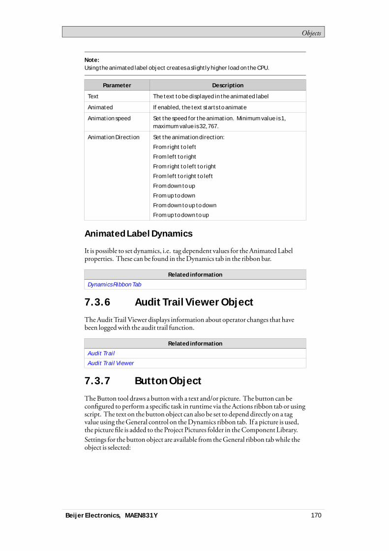
Objects
Note:Using the animated label object creates a slightly higher load on the CPU.
Parameter Description
Text The text to be displayed in the animated label
Animated If enabled, the text starts to animate
Animation speed Set the speed for the animation. Minimum value is 1,maximum value is 32,767.
Animation Direction Set the animation direction:
From right to left
From left to right
From right to left to right
From left to right to left
From down to up
From up to down
From down to up to down
From up to down to up
Animated Label Dynamics
It is possible to set dynamics, i.e. tag dependent values for theAnimated Labelproperties. These can be found in theDynamics tab in the ribbon bar.
Related information
Dynamics Ribbon Tab
7.3.6 Audit Trail Viewer Object
TheAudit Trail Viewer displays information about operator changes that havebeen loggedwith the audit trail function.
Related information
Audit Trail
Audit Trail Viewer
7.3.7 Button Object
TheButton tool draws a buttonwith a text and/or picture. The button can beconfigured to performa specific task in runtime via theActions ribbon tab or usingscript. The text on the button object can also be set to depend directly on a tagvalue using theGeneral control on theDynamics ribbon tab. If a picture is used,the picture file is added to the Project Pictures folder in theComponent Library.Settings for the button object are available from theGeneral ribbon tabwhile theobject is selected:
Beijer Electronics, MAEN831Y 170
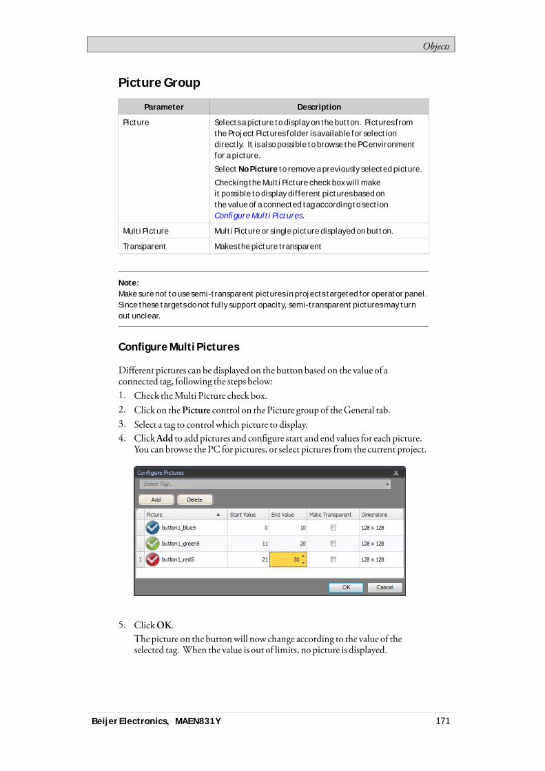
Objects
Picture Group
Parameter Description
Picture Selects a picture to display on the button. Pictures fromthe Project Pictures folder is available for selectiondirectly. It is also possible to browse the PC environmentfor a picture.
Select No Picture to remove a previously selected picture.
Checking the Multi Picture check box will makeit possible to display different pictures based onthe value of a connected tag according to sectionConfigure Multi Pictures.
Multi Picture Multi Picture or single picture displayed on button.
Transparent Makes the picture transparent
Note:Make sure not to use semi-transparent pictures in projects targeted for operator panel.Since these targets do not fully support opacity, semi-transparent pictures may turnout unclear.
Configure Multi Pictures
Different pictures can be displayed on the button based on the value of aconnected tag, following the steps below:1. Check theMulti Picture check box.2. Click on thePicture control on the Picture group of theGeneral tab.3. Select a tag to control which picture to display.4. ClickAdd to addpictures and configure start and end values for each picture.
You can browse the PC for pictures, or select pictures from the current project.
5. ClickOK.The picture on the buttonwill now change according to the value of theselected tag. When the value is out of limits, no picture is displayed.
Beijer Electronics, MAEN831Y 171
Objects
Picture Alignment Group
Parameter Description
Vertical Alignment/Horizontal Alignment
Set alignment for the picture
Clicking the small arrow in the lower right corner of the PictureAlignment groupdisplays the picture propertieswith a number of additional picture settings.
Style Group
Parameter Description
Style Predefined graphical styles for the button
Appearance The appearance of the button, including possibility tomake the button rounded and settings for each corner ofthe button.
Additional predefined styles for this object are found in theObjectVariationsgroup.
Note:When editing default button style properties, for example corner radius, appearancein runtime may sometimes differ from when designing the project in iX Developer.
Related information
Object Variations
Text Group
Parameter Description
Text Text displayed on the button
Multiline Lets the text run over more than one line, using [Enter].
Confirm the text entry by pressing [Ctrl] + [Enter].
Word Wrap Wraps the text to fit the width of the button
Configure Texts Links the displayed text to a tag. The Text field value isshown if the selected tag is not within the set limits
Text Alignment Group
Parameter Description
Horizontal / Vertical Adjusts the text on the button horizontally or vertically
Beijer Electronics, MAEN831Y 172

Objects
Visibility Group
Parameter Description
Transparent Makes the object transparent
Creating a Button with Momentary Function
In order to create a buttonwith amomentary function, youneed to combine a SetTag action forMouseDownwith aResetTag action forMouseUp .
Related information
Actions Ribbon Tab
Script
Component Library
7.3.8 Circular Meter Object
TheCircularMeter represents a numeric value, and displays the value of aconnected tag.Different styles can be used to change the graphical profile of themeter, and also ifthemeter is to be full, half or quarter.
Circularmeters in Black Full style, ChromeHalf style andVintageQuarter style
Settings for themeter object are available from theGeneral ribbon tabwhile theobject is selected:
Beijer Electronics, MAEN831Y 173
Objects
Angular Settings Group
Parameter Description
Start Angle / End Angle Determines the placement of the scale on the meter.The angular value is based on a start (0 degrees) at threeo’clock, in a counter clockwise direction from there. TheStart Angle must differ from the End Angle.
Text Rotation Select Parallel to let the numbers follow the outlineof the meter, or None to display the numbers alignedhorizontally.
Clockwise Determines rotation orientation, clockwise or counterclockwise.
Region Settings Group
Parameter Description
Low Region / MediumRegion / High RegionMin/Max
Define colors for up to 3 regions, and at which values tostart and stop each region. Entering 0 for both minimumand maximum values displays no region color.
Value Scale Group
Parameter Description
Min Value / Max Value Start/end value of scale.
These values can consist of one decimal digit.
Major Ticks Number of labeled scale marks on the meter
Minor Ticks Number of scale ticks between two adjacent major ticks
Style Group
Parameter Description
Style Predefined graphical styles for the meter. The smallerstyles are intended in particular to allow full visibility inthe smaller operator panels.
Appearance The appearance of the meter; full, half or quarter
Additional predefined styles for this object are found in theObjectVariationsgroup.
Related information
Object Variations
Beijer Electronics, MAEN831Y 174
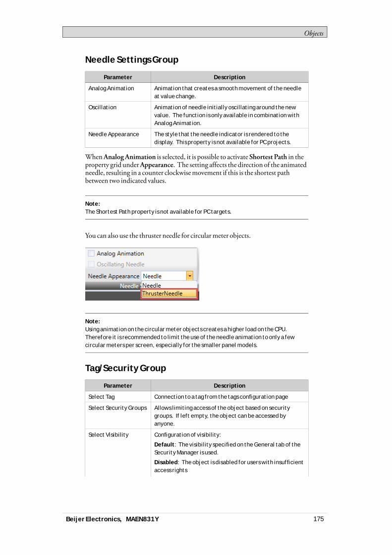
Objects
Needle Settings Group
Parameter Description
Analog Animation Animation that creates a smooth movement of the needleat value change.
Oscillation Animation of needle initially oscillating around the newvalue. The function is only available in combination withAnalog Animation.
Needle Appearance The style that the needle indicator is rendered to thedisplay. This property is not available for PC projects.
WhenAnalogAnimation is selected, it is possible to activateShortest Path in theproperty grid underAppearance. The setting affects the direction of the animatedneedle, resulting in a counter clockwisemovement if this is the shortest pathbetween two indicated values.
Note:The Shortest Path property is not available for PC targets.
You can also use the thruster needle for circularmeter objects.
Note:Using animation on the circular meter objects creates a higher load on the CPU.Therefore it is recommended to limit the use of the needle animation to only a fewcircular meters per screen, especially for the smaller panel models.
Tag/Security Group
Parameter Description
Select Tag Connection to a tag from the tags configuration page
Select Security Groups Allows limiting access of the object based on securitygroups. If left empty, the object can be accessed byanyone.
Select Visibility Configuration of visibility:
Default: The visibility specified on the General tab of theSecurity Manager is used.
Disabled: The object is disabled for users with insufficientaccess rights
Beijer Electronics, MAEN831Y 175

Objects
Parameter Description
Hidden: The object is invisible for users with insufficientaccess rights
Normal: The object looks normal also for users withinsufficient access rights
Visibility Group
Parameter Description
Transparent Makes the object transparent
Scale When unchecked, the scale color of the meter is madetransparent. Scale color is set from Other Colors on theFormat tab.
7.3.9 Chart Object
The chart object is used to display values of connected array tags.Settings for the chart object are available from theGeneral ribbon tabwhile theobject is selected:
Chart Settings Group
Parameter Description
Edit Series Add, remove and edit the current series for this chart
Chart Types Choose chart type. Available types are:
Area
Area Horizontal
Bar
Bar Join
Donut
Histogram
Kagi
Line
Line Fast
Line Horizontal
Line Point
Pie
Points
Radar
Header Set the name that is displayed above the chart
Show Labels If selected, then the chart will show labels adjacent toeach plotted data item indicating its value. If not selectedthe labels will be hidden.
3D View Set a 3D look and feel for the chart
Beijer Electronics, MAEN831Y 176

Objects
X Axis Settings Group
Parameter Description
Visible Set the visibility of the X axis
Grid Visible Set the visibility of the X axis grid lines.
Automatic Automatically calculates the minimum and maximumX axis values. Overrides the Minimum and Maximumproperties
Minimum Set the minimum value of the X axis. If automatic is set,this value is ignored
Maximum Set the maximum value of the X axis. If automatic is set,this value is ignored
Y1 Axis Settings Group
Parameter Description
Visible Set the visibility of the Y1 axis
Grid Visible Set the visibility of the Y1 axis grid lines.
Automatic Automatically calculates the minimum and maximumY1 axis values. Overrides the Minimum and Maximumproperties.
Minimum Set the minimum value of the Y1 axis. If automatic is set,this value is ignored.
Maximum Set the maximum value of the Y1 axis. If automatic is set,this value is ignored. When using charts with visible labelson curves the maximum value is extended to make roomfor label.
Y2 Axis Settings Group
Parameter Description
Visible Set the visibility of the Y2 axis
Grid Visible Set the visibility of the Y2 axis grid lines.
Automatic Automatically calculates the minimum and maximumY2 axis values. Overrides the Minimum and Maximumproperties.
Minimum Set the minimum value of the Y2 axis. If automatic is set,this value is ignored.
Maximum Set the maximum value of the Y2 axis. If automatic is set,this value is ignored. When using charts with visible labelson curves the maximum value is extended to make roomfor label.
Beijer Electronics, MAEN831Y 177
Objects
Style Group
Parameter Description
Style Set the style of the chart
Visibility Group
Parameter Description
Scale Set the visibility of the scale
Transparent Make the chart transparent
Header Set the header visibility
Legend Set the legend visibility
The Edit Series Dialog
Clicking theEdit Series control in theChart SettingsGroupwill open theEditSeriesDialog. The Edit SeriesDialog contains the following settings:
Parameter Description
Name The name of the Series, as shown in the legend in the chart.
X Tag The X Tag values.
The tag must be an array tag.
The number of elements shown will be the lowest commondenominator of the X Tag array size and the Y Tag array size.
Y Tag Optional: The Y Tag values for the chart.
The tag must be an array tag.
If this value is not chosen, the X Tag Values will still be visible andthe Y Axis will be set automatically. The number of elementsshown will be the lowest common denominator of the X Tag arraysize and the Y Tag array size.
Size Optional: The number of elements in the tag arrays. This propertyoverrides the sizes of the X Tag array size and Y Tag array size. Ifthis value is not set, the lowest common denominator of the XTags array size and the Y Tags array size will be chosen as size.
Labels Set a label for each point in the chart. There is one label for eachavailable tag value.
Color Choose the color of the series. Applies to all chart types exceptPie and Donut.
Colors Select the colors to be used for the pie/donut graphic that will begenerated for the series. Applies to the Pie and Donut chart types.
Thickness Set the thickness of the series. This applies for the chart typesLine, Line Fast, Line Horizontal and Line Point.
Axis Type Select the Y Axis that this series will use.
Beijer Electronics, MAEN831Y 178
Objects
Note:Chart objects with large arrays where values are frequently changing may affectperformance.
Related information
Array Tags
7.3.10 Database Viewer Object
TheDatabaseViewer can be used to display database contents in runtime.For operator panel projects, only databases included in the current project areavailable. For PC targets, it is possible to access databases from anywhere in thenetwork environment.Settings for the database viewer object are available from theGeneral ribbon tabwhile the object is selected:
Settings Group
Parameter Description
Show Controls When the box is checked, the user is able to selectdatabase and database table in runtime
Database Path to database to be loaded automatically in runtime(1)
Table Name The table in the selected database to be loadedautomatically in runtime(1)
Browse Data Table Opens a browse dialog for selection of database anddatabase table in design time. The path and table namewill be added to the Database and Table Name fields.
(1) If the entered database or table does not exist or is not valid, an empty databaseviewer is displayed in runtime.
Note:Simulation of the object on the development PC is supported only for PC targets.
Related information
Database
7.3.11 Digital Clock Object
The digital clock displays date, time and/or day ofweek.The time zone is selected on the System ribbon tab and is transferred to the targetwhen the project is downloaded to it. If no time zone is selected, the time zone thathas been selected for the panel or PCwill be retained.The date and time display format (for example usingAM/PM for time) is basedon the operating system settings. For operator panel projects, this formatmay bealtered by selecting another region on the System ribbon tab.
Beijer Electronics, MAEN831Y 179
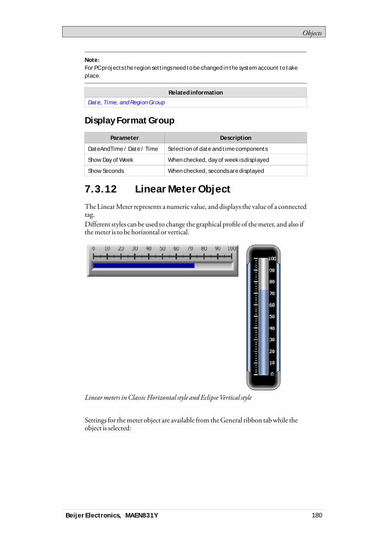
Objects
Note:For PC projects the region settings need to be changed in the system account to takeplace.
Related information
Date, Time, and Region Group
Display Format Group
Parameter Description
DateAndTime / Date / Time Selection of date and time components
Show Day of Week When checked, day of week is displayed
Show Seconds When checked, seconds are displayed
7.3.12 Linear Meter Object
TheLinearMeter represents a numeric value, and displays the value of a connectedtag.Different styles can be used to change the graphical profile of themeter, and also ifthemeter is to be horizontal or vertical.
Linearmeters inClassicHorizontal style andEclipse Vertical style
Settings for themeter object are available from theGeneral ribbon tabwhile theobject is selected:
Beijer Electronics, MAEN831Y 180
Objects
Value Scale Group
Parameter Description
Min Value / Max Value Start/end value of scale
These values can consist of one decimal digit.
Major Ticks Number of labeled scale marks on the meter
Minor Ticks Number of scale ticks between two adjacent major ticks
Style Group
Parameter Description
Style Predefined graphical styles for the meter. The smallerstyles are intended in particular to allow full visibility inthe smaller operator panels.
Appearance The appearance of the meter; horizontal or vertical
Tag/Security Group
Parameter Description
Select Tag Connection to a tag from the tags configuration page
Select Security Groups Allows limiting access of the object based on securitygroups. If left empty, the object can be accessed byanyone.
Select Visibility Configuration of visibility:
Default: The visibility specified on the General tab of theSecurity Manager is used.
Disabled: The object is disabled for users with insufficientaccess rights
Hidden: The object is invisible for users with insufficientaccess rights
Normal: The object looks normal also for users withinsufficient access rights
Visibility Group
Parameter Description
Transparent Makes the object transparent; only indicator bar and scalewill be visible
Scale When unchecked, the scale color of the meter is madetransparent. Scale color and indicator color are set fromOther Colors on the Format tab.
7.3.13 Multi Picture Object
TheMulti Picture object allows using a set of pictures as an object. The pictureschange in runtime depending on intervals of a tag value.
Beijer Electronics, MAEN831Y 181
Objects
Pictures can be imported to the project by browsing the hard disk for graphic files.Imported pictures are added to the Project Pictures folder in theComponentLibrary.Settings for theMulti Picture object are available from theGeneral ribbon tabwhile the object is selected:
Settings Group
Parameter Description
Configure Pictures Configuration of start/end values of intervals andselection of pictures for each interval. Pictures can beselected from the Project Pictures folder or from the harddisk. Transparency can also be set. Original picture size isdisplayed. The Add/Delete buttons are used to add andremove items to/from the object.
Reset Picture Restores original height and width to picture.
Stretch Adapts height and width to the selection frame whenresizing the picture.
Lock Aspect Ratio Maintains the height/width ratio of the object.
Note:Make sure not to use semi-transparent pictures in projects targeted for operatorpanels. Since these targets do not fully support opacity, semi-transparent picturesmay turn out unclear.
Related information
Component Library
7.3.14 Picture Object
ThePicture object allows using a picture as an object. Pictures can be imported tothe project by browsing the PC environment for graphic files. Imported picturesare added to the Project Pictures folder in theComponent Library.The displayed picture can also be dynamic; depending of a set of pictures that havebeen linked to intervals in a tag value.Settings for the picture object are available from theGeneral ribbon tabwhile theobject is selected:
Settings Group
Parameter Description
Change Picture Opens a browse dialog for selection of picture
Reset Picture Restores original height and width to picture
Stretch Adapts height and width to the selection frame whenresizing the picture
Transparent Makes the object transparent, i.e. makes the frame andbackground color invisible
Beijer Electronics, MAEN831Y 182
Objects
Note:Make sure not to use semi-transparent pictures in projects targeted for operatorpanels. Since these targets do not fully support opacity, semi-transparent picturesmay turn out unclear.
Related information
Component Library
7.3.15 Roller Panel Object
TheRoller Panel object is used to display predefined texts for certain tag values.Settings for theRoller Panel object are available from theGeneral ribbon tabwhilethe object is selected:
Settings Group
Parameter Description
Title Set the title for the Roller Panel
Title Visible Determines if the title is visible or not
Loop Scroll Determines if the values will loop around or not
Disable Operator Input Determines if the Roller Panel is editable or not
Touch Settings Group
Parameter Description
Scroll Sensitivity Set the sensitivity of the scroll
Scroll Friction Set the friction of the scroll
Text Group
Parameter Description
Configure Texts Opens the Configure Texts dialog
Configure Text Dialog
TheConfigureTexts dialog contains the following properties:
Parameter Description
Text The text to be displayed for the item
Start Value The starting value for when this item should be selected
End Value The ending value for when this item should be selected
Roller Panel Dynamics
It is also possible to set dynamics, i.e. tag dependent values for theRoller Panelproperties. These can be found in theDynamics tab in the ribbon bar.
Beijer Electronics, MAEN831Y 183
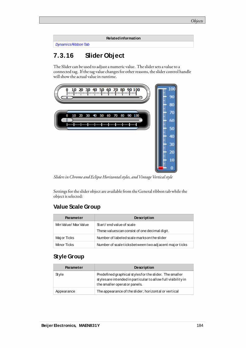
Objects
Related information
Dynamics Ribbon Tab
7.3.16 Slider Object
The Slider can be used to adjust a numeric value. The slider sets a value to aconnected tag. If the tag value changes for other reasons, the slider control handlewill show the actual value in runtime.
Sliders inChrome andEclipseHorizontal styles, andVintage Vertical style
Settings for the slider object are available from theGeneral ribbon tabwhile theobject is selected:
Value Scale Group
Parameter Description
Min Value/Max Value Start/end value of scale
These values can consist of one decimal digit.
Major Ticks Number of labeled scale marks on the slider
Minor Ticks Number of scale ticks between two adjacent major ticks
Style Group
Parameter Description
Style Predefined graphical styles for the slider. The smallerstyles are intended in particular to allow full visibility inthe smaller operator panels.
Appearance The appearance of the slider; horizontal or vertical
Beijer Electronics, MAEN831Y 184
Objects
Tag/Security Group
Parameter Description
Select Tag Connection to a tag from the tags configuration page
Select Security Groups Allows limiting access of the object based on securitygroups. If left empty, the object can be accessed byanyone.
Select Visibility Configuration of visibility:
Default: The visibility specified on the General tab of theSecurity Manager is used.
Disabled: The object is disabled for users with insufficientaccess rights
Hidden: The object is invisible for users with insufficientaccess rights
Normal: The object looks normal also for users withinsufficient access rights
Visibility Group
Parameter Description
Transparent Makes the object transparent
Scale When unchecked, the scale color of the slider is madetransparent. Scale color and indicator color (color of thehandle) are set from Other Colors on the Format tab.
7.3.17 Tag Monitor Object
TheTagMonitor objectmakes it possible to show and set the values of tags in thesystem. This is useful formaking a systemdiagnosis.Settings for theTagMonitor object are available from theGeneral ribbon tabwhile the object is selected:
Button Group
Parameter Description
Del Selected Delete the selected tag
Add Add a tag
Clear Delete all the tags
Display Settings Group
Parameter Description
Configure columns Opens a dialog where it is possible to configure the columnsin the tag monitor object
Show Column Headers Select if the column headers are to be shown in the tagmonitor object
Beijer Electronics, MAEN831Y 185
Objects
7.3.18 Text Object
TheText object is used to display read-only information for the operator. Thedisplayed text can be static, or linked to intervals in a tag value that containdifferent strings. The text object can also be set to dependdirectly on a tag valueusing theGeneral control on theDynamics ribbon tab.Settings for the text object are available from theGeneral ribbon tabwhile theobject is selected:
Text Group
Parameter Description
Text Text that the object displays
Multiline Lets the text run over more than one line, using [Enter].
Confirm the text entry by pressing [Ctrl] + [Enter].
Word Wrap Wraps the text to fit the width of the object. Not availableif Autosize is selected.
Configure Texts Links the displayed text to a tag. The Text field value isshown if the selected tag is not within the set limits.
Auto Stretch Font Resizes the font to fit the height of the object. Notavailable if Autosize is selected.
Auto Size Resizes the object according to the size of the default textstring length and font size. Default setting for the textobject.
Text Alignment Group
Parameter Description
Horizontal / Vertical Adjusts the text in the object horizontally or vertically.Not available if Autosize is selected.
7.3.19 Touch Combo Box Object
TheTouchComboBox object is used to create text selections from a drop-downlist.Settings for theTouchComboBox object are available from theGeneral ribbontabwhile the object is selected:
Settings Group
Parameter Description
Auto Size Item Height The Touch Combo Box will ignore the Item Height value andsize the values automatically
Item Height Set the height of the individual items in the Touch ComboBox
ArrowBox Width Set the width of the Arrow Box
ScrollBar Width Set the width of the scroll bar
Beijer Electronics, MAEN831Y 186
Objects
Text Group
Parameter Description
Configure Texts Opens the Configure Texts dialog
Configure Text Dialog
TheConfigureTexts dialog contains the following properties:
Parameter Description
Text The text to be displayed for the item
Start Value The starting value for when this item should be selected
End Value The ending value for when this item should be selected
Touch Settings Group
Parameter Description
Scroll Sensitivity Set the sensitivity of the scrolling
Touch Combo Box Dynamics
It is also possible to set dynamics, i.e. tag dependent values for theTouchComboBox properties. These can be found in theDynamics tab in the ribbon bar.
Related information
Dynamics Ribbon Tab
7.3.20 Touch List Box Object
TheTouchList Box object is used to handle a list of predefined texts.Settings for theTouchList Box object are available from theGeneral ribbon tabwhile the object is selected:
Settings Group
Parameter Description
Separator Visible Show or hide a separator between the items in the TouchList Box
Item Height Set the height of the individual items in the Touch List Box
ScrollBar Width Set the width of the scroll bar
Touch Settings Group
Parameter Description
Scroll Sensitivity Set the sensitivity of the scrolling
Beijer Electronics, MAEN831Y 187
Objects
Text Group
Parameter Description
Configure Texts Opens the Configure Texts dialog
Configure Texts Dialog
TheConfigureTexts dialog contains the following properties:
Parameter Description
Text The text to be displayed for the item
Start Value The starting value for when this item should be selected
End Value The ending value for when this item should be selected
Touch List Box dynamics
It is also possible to set dynamics, i.e. tag dependent values for theTouchList Boxproperties. These can be found in theDynamics tab in the ribbon bar.
Related information
Dynamics Ribbon Tab
7.3.21 Trend Viewer Object
Trend viewers are used to display values of connected tags. Trend viewer curvesrepresent tag values over time. A trend viewer object can show any number oftrend viewer curves.
Note:A large number of trend viewer pens and short sampling intervals may affectcommunication performance.
Related information
Trend Viewer
Curves Group
Communication Performance
7.4 Media ControlsThemedia controls are used to displaymedia files, pdf files andweb pages inruntime. The followingmedia controls are described:
Media Player Object PDF Viewer Object Web Browser Object
Beijer Electronics, MAEN831Y 188
Objects
7.4.1 Media Player Object
Media files can be connected to themedia player object, which allows selecting,starting and stopping the files in runtime. The table below shows the supportedmedia formats for the various panels.
Panel Supported Media Formats
X2 base
iX TxA
No media player object
iX TxB
iX TxC
.mpeg1, .wmv
X2 pro 4
X2 pro 7
X2 control 4/7
X2 marine 7 (includingSC)
.mpeg1
X2 marine 7 HB(including SC)
X2 marine 15(including SC and HB)
X2 pro 10/12/15/21
X2 control10/12/15/21
X2 extreme 7/15(including SL, SC andHP)
.mpeg1, .avi, .wmv, .mpeg4*.
* Only mpeg4 simple profile partial codec (included in WMV lib) is supported. Morecompressed/advanced codecs of mpeg4, for example AVC, is not supported.
Browse Folders Group
Parameter Description
Project Files Default option for browsing. The project files are listedin the Component Library. At least one of the folders hasto be chosen.
External Memory Card Select this option for browsing if project files are placed onan external memory card. At least one of the folders hasto be chosen.
Settings Group
Parameter Description
Media Source Select a media file to add to the media player, from theproject files folder or by browsing the PC
Beijer Electronics, MAEN831Y 189
Objects
Note:The object is not supported on X2 base targets. Simulation of the object on thedevelopment PC is supported only for PC targets.
Note:Connecting a tag to a Media Player Object will cause the media player to try to play amedia clip with a name that corresponds to the tag’s value, ignoring the configuredMedia Source parameter.
Scripting to the Media Player Object
When scripting to theMedia Player object, the name of the currentmedia file hasto be stated, for example:MediaPlayer1.Source = “Bear.wmv”;Prior to running the script, themedia file has to be addedmanually to the ProjectFiles folder. When the script is executed, the file will be copied to the outputdirectory.Events for themedia player can be used, for example:MediaPlayer1.Play();
Related information
Component Library
7.4.2 PDF Viewer Object
PDFfiles can be displayed in runtime using the PDFviewer object. The addedfiles are available from theComponent Library.
Note:PDF Viewer on X2 pro is not fully supported. There are some limitations for display oftable of contents, headings, table text and scroll bar.
Browse Folders Group
Parameter Description
Project Files Default option for browsing. The project files are listedin the Component Library. At least one of the folders hasto be chosen.
External Memory Card Select this option for browsing if project files are placed onan external memory card. At least one of the folders hasto be chosen.
Beijer Electronics, MAEN831Y 190
Objects
Settings Group
Parameter Description
PDF File Select a PDF file to add to the PDF viewer, from the projectfiles folder or by browsing the PC
Buttons Select which buttons to make available in runtime
In an operator panel, all PDFfiles in the project files folderwill be available forselection in runtime, if theOpen button is checked.
Note:When using a PDF viewer object in a popup screen, only the default style for the popupscreen is supported.
Note:The object is not supported on X2 base or X2 panels 4” and 7“ (except for X2 marine 7 HBSC) targets. Simulation of the object on the development PC is supported only for PCtargets.
Related information
Component Library
Popup Screen
Troubleshooting
7.4.3 Web Browser Object
Webpages can be displayed using theweb browser. It is possible to set up thewebbrowserwith regular web browsing functionality, with selection ofweb addressesin a list or input via the virtual keyboard. It is also possible to allow showing certaindefinedweb pages only, or a localHTM/HTMLfile.If certain characters are displayed incorrectly in theweb browser, it is because thepanel does not support the font in that language.The virtual keyboard in iXDeveloper is not used in theweb browser object. ForiXTxCpanels andPC targetswe recommendusing theTablet PC Input Panel inWindows (found underAccessories >Tablet PC).Otherwisewe recommendusingan external keyboard.
Note:Microsoft Internet Explorer 9 or later is required.
Settings Group
Settings for theWebBrowser object are available from theGeneral ribbon tabwhile theWebBrowser object is selected:
Beijer Electronics, MAEN831Y 191
Objects
Parameter Description
Address The default web page of the web browser object.
Home The web page that will be displayed when the Home buttonis pressed.
Favorites Addition of web pages that will be available for selectionfrom the drop-down address field in runtime.
Address Read Only Checking the box disables entering text in the address field
Address Field Unchecking the box removes the address field in runtime
Go Button Unchecking the box removes the Go button in runtime
Home Button Unchecking the box removes the Home button in runtime
Back Button/ForwardButtons
Unchecking the box removes the navigation buttons inruntime
Referring to a localHTM/HTMLfile can be useful for examplewhen the operatorpanel is not connected to Internet. The local file—a .HTM-or .HTML-file—has to be located in the Project Files folder of the current project, and is addressedin the following format: “File://filename.html”where “filename.html” representsthe actual file”, e.g. File://ReadMe.html.
Web Browser Limitations
Theweb browser object functionality is limited under some circumstances:
Function Limitation description PC targets operator panel targets
Web browserobject
Supported Not supported on X2base targets
Popupwindows
Opening popup windowsfrom the web browser inruntime
Not supported Not supported
Web browserin a popupscreen
Other styles than thedefault style for thepopup screen
Not supported Not supported
Simulationof the webbrowser
Simulation on thedevelopment PC
Supported Not supported
Support ofsome webpages
Access of some webpages from within theweb browser.
Supported May not be supported.If the web browserdoes not behaveas expected, it isrecommended to usethe standard InternetExplorer, available inthe iX panel, instead.The standard InternetExplorer can be startedusing the Run actionand executing theiesample.exe file.
Beijer Electronics, MAEN831Y 192
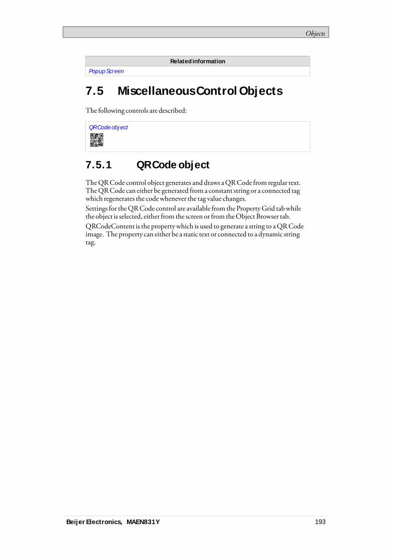
Objects
Related information
Popup Screen
7.5 Miscellaneous Control ObjectsThe following controls are described:
QR Code object
7.5.1 QR Code object
TheQRCode control object generates and draws aQRCode from regular text.TheQRCode can either be generated froma constant string or a connected tagwhich regenerates the codewhenever the tag value changes.Settings for theQRCode control are available from the PropertyGrid tabwhilethe object is selected, either from the screen or from theObject Browser tab.QRCodeContent is the propertywhich is used to generate a string to aQRCodeimage. The property can either be a static text or connected to a dynamic stringtag.
Beijer Electronics, MAEN831Y 193

Objects
How to setup a QR Code generated from a tag
Example:In this example we are using an internal string tag with initial value configured. Whenthe tag is changed in runtime, the QR Code image will be generated on the screen.
Example ofQRCode generated from an internal tag. Tag value changes willautomatically update theQR code image on the screen.
To configure the QR Code object to generate image from static text:1. Place a QR Code object on the screen surface.2. Edit the text in the QRCodeContent textbox in the Property Grid. The QR Code
image (on the screen) will only be regenerated when the QRCodeContent text ischanged.
To configure the QR Code object to dynamically generate image from a tag:1. Configure an internal tag in the tag editor by setting the Data Type to STRING. For
convenience, make sure that the tag has a suitable initial value.2. Place a QR Code object on the screen surface.3. Open up the Edit General Dynamics dialog by clicking on the gear button to the
right side of the QRCodeContent textbox in the Property Grid.4. Select Raw Converter. Select the tag from section 1 above.5. Optionally, edit the Default value for design mode.
Note:Creating a QR Code object without any content will create an empty object. This isshown in Runtime as an invisible QR Code object on a PC, and as a grey QR Code objecton a operator panel, since operator panel targets do not fully support opacity.
Using QR Code in script
In cases where theQRCode image is to be generated from a script, use an internaltag binding as in the example above andwrite content data to the tag value in ascript function.
Beijer Electronics, MAEN831Y 194
Objects
7.6 Special ControlsThe special controls are used to create attractive navigation facilities in runtime.
Navigation List Box Object Screen Carousel Object
7.6.1 Navigation List Box Object
Screennavigation using theNavigation List Box object is performed viathumbnails, and scripting can be used for advanced functionality.
Note:The object is supported only for iX TxC and PC targets.
General Group
Parameter Description
Orientation Select horizontal or vertical orientation for runtime scrolling.
Scroll Tolerance Defines tolerance of pressing the touch screen (or scrollingwith the cursor) slightly outside of a navigation list box item inruntime before the navigation is actually carried out.
Item Settings Group
Parameter Description
Configure Items Definition of items included in the navigation list box object;see below.
Height/Width Size of the items in the navigation list box.
Margin Margin between navigation list box items.
Border Width Width of navigation list box item borders.
Corner Radius Corner radius of navigation list box items.
Show Text Selection of whether to show text below navigation list boxitems.
The individual items in the navigation list box object are handled by clickingConfigure Items. Use theAdd andDeletebuttons to add and remove itemsto/from the navigation list box.
Parameter Description
Picture Selection of picture by browsing the PC environment or amongthe project files.
Screen Selection of screen to navigate to.
Beijer Electronics, MAEN831Y 195
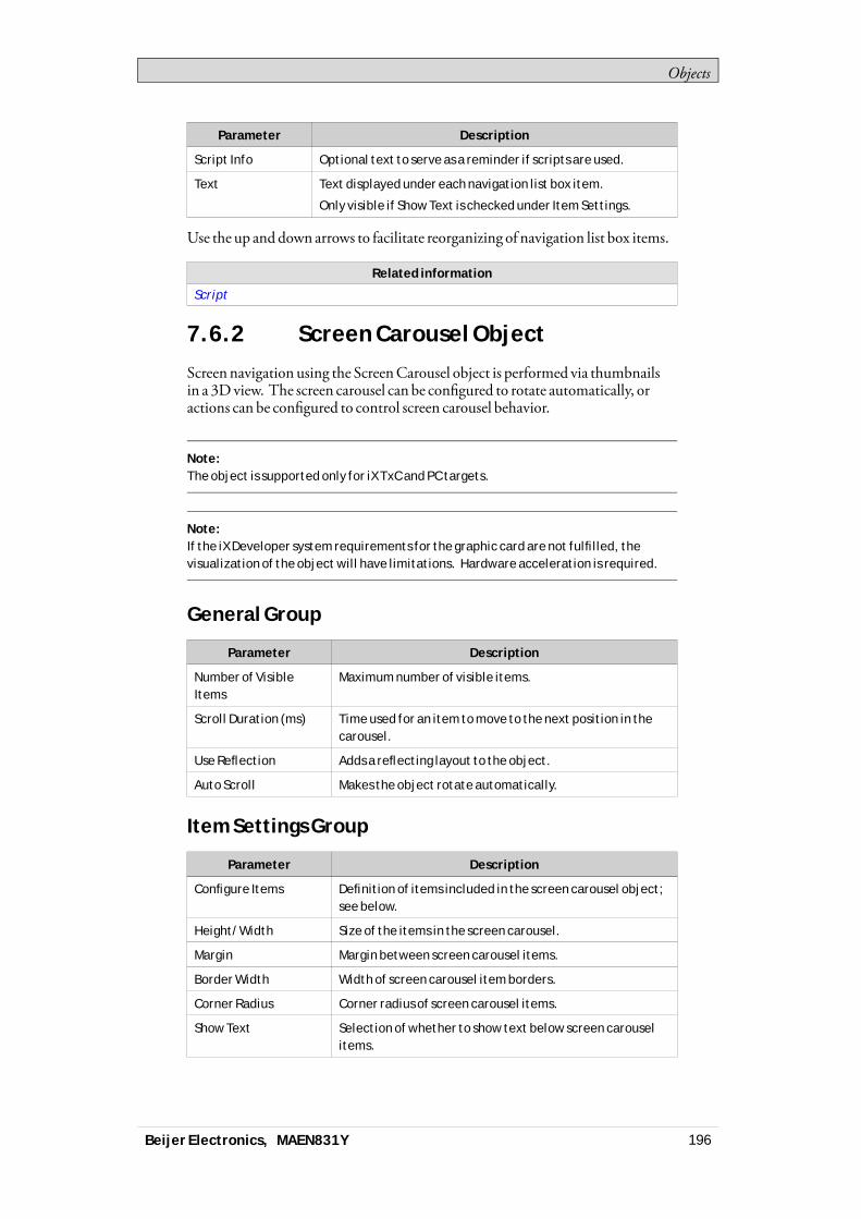
Objects
Parameter Description
Script Info Optional text to serve as a reminder if scripts are used.
Text Text displayed under each navigation list box item.
Only visible if Show Text is checked under Item Settings.
Use the up and down arrows to facilitate reorganizing of navigation list box items.
Related information
Script
7.6.2 Screen Carousel Object
Screennavigation using the ScreenCarousel object is performed via thumbnailsin a 3Dview. The screen carousel can be configured to rotate automatically, oractions can be configured to control screen carousel behavior.
Note:The object is supported only for iX TxC and PC targets.
Note:If the iX Developer system requirements for the graphic card are not fulfilled, thevisualization of the object will have limitations. Hardware acceleration is required.
General Group
Parameter Description
Number of VisibleItems
Maximum number of visible items.
Scroll Duration (ms) Time used for an item to move to the next position in thecarousel.
Use Reflection Adds a reflecting layout to the object.
Auto Scroll Makes the object rotate automatically.
Item Settings Group
Parameter Description
Configure Items Definition of items included in the screen carousel object;see below.
Height/Width Size of the items in the screen carousel.
Margin Margin between screen carousel items.
Border Width Width of screen carousel item borders.
Corner Radius Corner radius of screen carousel items.
Show Text Selection of whether to show text below screen carouselitems.
Beijer Electronics, MAEN831Y 196

Objects
The individual items in the screen carousel object are handled by clickingConfigure Items. Use theAdd andDeletebuttons to add and remove itemsto/from the screen carousel.
Parameter Description
Picture Selection of picture by browsing the PC environment oramong the project files.
Screen Selection of screen to navigate to.
Script Info Optional text to serve as a reminder if scripts are used.
Text Text displayed under each screen carousel item.
Only visible if Show Text is checked under Item Settings.
Use the up and down arrows to facilitate reorganizing of screen carousel items.
Related information
Actions Ribbon Tab
7.7 Debug ToolsDebug tools are used for troubleshooting andmonitoring.
Alarm Distributor Viewer Object
–
7.7.1 Alarm Distributor Viewer Object
TheAlarmDistributorViewer is a debug tool, used to display information fromtheAlarmDistributor function.
Related information
Alarm Management
Alarm Distributor Viewer
7.8 Windows ControlsThe followingWindows controls are described:
Check Box Object Combo Box Object Group Box Object List Box Object
Progress BarObject
Radio ButtonObject
Text Box Object
–
Beijer Electronics, MAEN831Y 197
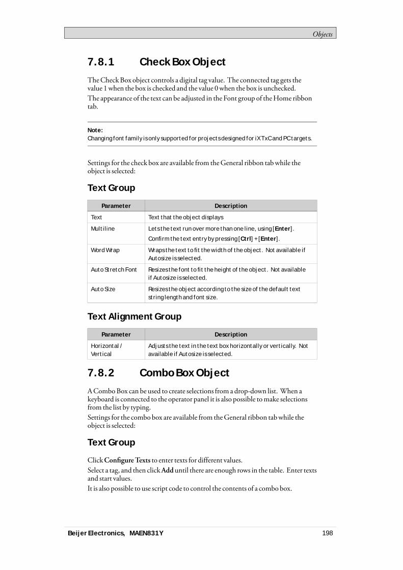
Objects
7.8.1 Check Box Object
TheCheckBox object controls a digital tag value. The connected tag gets thevalue 1when the box is checked and the value 0when the box is unchecked.The appearance of the text can be adjusted in the Font group of theHome ribbontab.
Note:Changing font family is only supported for projects designed for iX TxC and PC targets.
Settings for the check box are available from theGeneral ribbon tabwhile theobject is selected:
Text Group
Parameter Description
Text Text that the object displays
Multiline Lets the text run over more than one line, using [Enter].
Confirm the text entry by pressing [Ctrl] + [Enter].
Word Wrap Wraps the text to fit the width of the object. Not available ifAutosize is selected.
Auto Stretch Font Resizes the font to fit the height of the object. Not availableif Autosize is selected.
Auto Size Resizes the object according to the size of the default textstring length and font size.
Text Alignment Group
Parameter Description
Horizontal /Vertical
Adjusts the text in the text box horizontally or vertically. Notavailable if Autosize is selected.
7.8.2 Combo Box Object
AComboBox can be used to create selections from a drop-down list. When akeyboard is connected to the operator panel it is also possible tomake selectionsfrom the list by typing.Settings for the combobox are available from theGeneral ribbon tabwhile theobject is selected:
Text Group
ClickConfigureTexts to enter texts for different values.Select a tag, and then clickAdduntil there are enough rows in the table. Enter textsand start values.It is also possible to use script code to control the contents of a combo box.
Beijer Electronics, MAEN831Y 198

Objects
Example
The following script code relies on the existence of a combobox (ComboBox1)and a set of predefined recipes (“Book” and “TV”).
When the screen opens, the script clears the box andwrites the recipe name stringsin the box. Selection from the combobox triggers loading of a recipe.
Related information
Script
Recipe Management
7.8.3 Group Box Object
TheGroupBox is used to draw a labeled frame around a group of objects.
7.8.4 List Box Object
TheList Box handles a list of predefined texts.
Text Group
ClickConfigureTexts to enter texts for different values.Select a tag, and then clickAdduntil there are enough rows in the table. Enter textsand start values.It is also possible to use script code to control the contents of a list box.
Example
The following script code includes two objects on Screen1, a button (Button1)and a list box (ListBox1).
Beijer Electronics, MAEN831Y 199
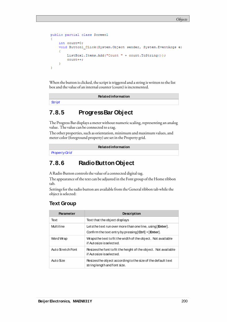
Objects
When the button is clicked, the script is triggered and a string is written to the listbox and the value of an internal counter (count) is incremented.
Related information
Script
7.8.5 Progress Bar Object
TheProgress Bar displays ameter without numeric scaling, representing an analogvalue. The value can be connected to a tag.The other properties, such as orientation,minimumandmaximumvalues, andmeter color (foreground property) are set in the Property grid.
Related information
Property Grid
7.8.6 Radio Button Object
ARadioButton controls the value of a connected digital tag.The appearance of the text can be adjusted in the Font group of theHome ribbontab.Settings for the radio button are available from theGeneral ribbon tabwhile theobject is selected:
Text Group
Parameter Description
Text Text that the object displays
Multiline Lets the text run over more than one line, using [Enter].
Confirm the text entry by pressing [Ctrl] + [Enter].
Word Wrap Wraps the text to fit the width of the object. Not availableif Autosize is selected.
Auto Stretch Font Resizes the font to fit the height of the object. Not availableif Autosize is selected.
Auto Size Resizes the object according to the size of the default textstring length and font size.
Beijer Electronics, MAEN831Y 200
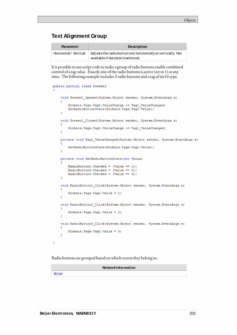
Objects
Text Alignment Group
Parameter Description
Horizontal / Vertical Adjusts the radio button text horizontally or vertically. Notavailable if Autosize is selected.
It is possible to use script code tomake a group of radio buttons enable combinedcontrol of a tag value. Exactly one of the radio buttons is active (set to 1) at anytime. The following example includes 3 radio buttons and a tag of int16 type.
Radio buttons are grouped based onwhich screen they belong to.
Related information
Script
Beijer Electronics, MAEN831Y 201
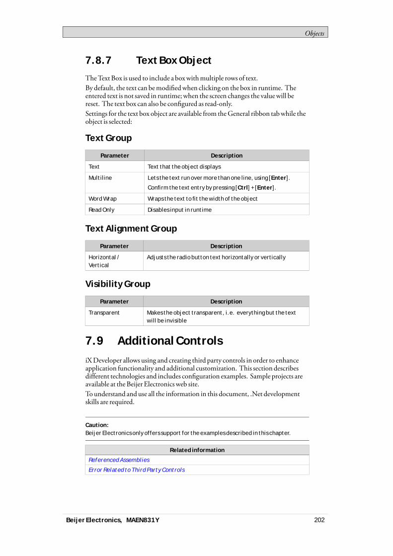
Objects
7.8.7 Text Box Object
TheTextBox is used to include a boxwithmultiple rows of text.By default, the text can bemodifiedwhen clicking on the box in runtime. Theentered text is not saved in runtime;when the screen changes the valuewill bereset. The text box can also be configured as read-only.Settings for the text box object are available from theGeneral ribbon tabwhile theobject is selected:
Text Group
Parameter Description
Text Text that the object displays
Multiline Lets the text run over more than one line, using [Enter].
Confirm the text entry by pressing [Ctrl] + [Enter].
Word Wrap Wraps the text to fit the width of the object
Read Only Disables input in runtime
Text Alignment Group
Parameter Description
Horizontal /Vertical
Adjusts the radio button text horizontally or vertically
Visibility Group
Parameter Description
Transparent Makes the object transparent, i.e. everything but the textwill be invisible
7.9 Additional ControlsiXDeveloper allows using and creating third party controls in order to enhanceapplication functionality and additional customization. This section describesdifferent technologies and includes configuration examples. Sample projects areavailable at theBeijer Electronics web site.To understand and use all the information in this document, .Net developmentskills are required.
Caution:Beijer Electronics only offers support for the examples described in this chapter.
Related information
Referenced Assemblies
Error Related to Third Party Controls
Beijer Electronics, MAEN831Y 202
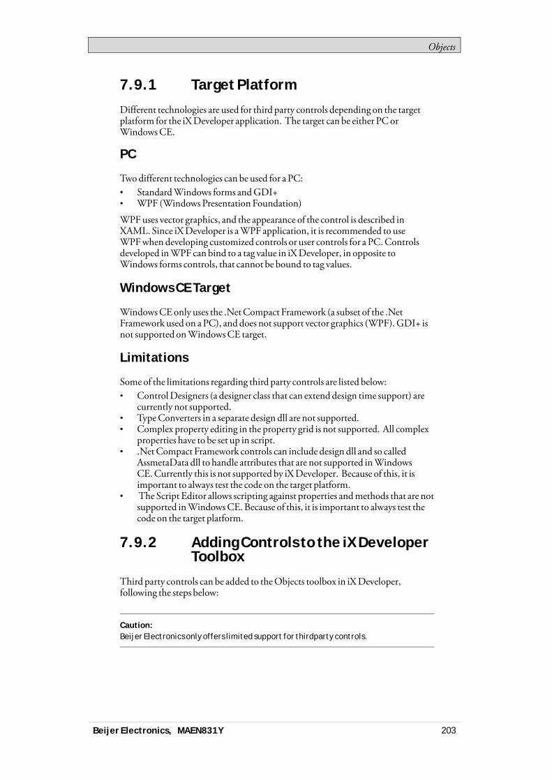
Objects
7.9.1 Target Platform
Different technologies are used for third party controls depending on the targetplatform for the iXDeveloper application. The target can be either PCorWindowsCE.
PC
Twodifferent technologies can be used for a PC:• StandardWindows forms andGDI+• WPF (Windows Presentation Foundation)
WPFuses vector graphics, and the appearance of the control is described inXAML. Since iXDeveloper is aWPF application, it is recommended to useWPFwhen developing customized controls or user controls for a PC.Controlsdeveloped inWPF canbind to a tag value in iXDeveloper, in opposite toWindows forms controls, that cannot be bound to tag values.
Windows CE Target
WindowsCEonly uses the .NetCompact Framework (a subset of the .NetFramework used on aPC), anddoes not support vector graphics (WPF).GDI+ isnot supported onWindowsCE target.
Limitations
Some of the limitations regarding third party controls are listed below:• ControlDesigners (a designer class that can extend design time support) are
currently not supported.• TypeConverters in a separate design dll are not supported.• Complex property editing in the property grid is not supported. All complex
properties have to be set up in script.• .NetCompact Framework controls can include design dll and so called
AssmetaData dll to handle attributes that are not supported inWindowsCE.Currently this is not supported by iXDeveloper. Because of this, it isimportant to always test the code on the target platform.
• The Script Editor allows scripting against properties andmethods that are notsupported inWindowsCE.Because of this, it is important to always test thecode on the target platform.
7.9.2 Adding Controls to the iX DeveloperToolbox
Third party controls can be added to theObjects toolbox in iXDeveloper,following the steps below:
Caution:Beijer Electronics only offers limited support for thirdparty controls.
Beijer Electronics, MAEN831Y 203

Objects
1. Select theObjects group on theHome ribbon tab, and fully expand theObjects toolbox by clicking the lower right arrow.
2. ClickAddControl.
Beijer Electronics, MAEN831Y 204
Objects
3. Select controls to add among the default controls, or clickBrowse to addcustomized controls.
Note:Additional controls are possible to use "as is" in iX Developer but are not officiallysupported by Beijer Electronics. iX Developer users are responsible for the use andfunctionality of all Additional controls.
4. ClickOK.The added controls are now available underAdditionalControls in theObjectstoolbox.
7.9.3 Default Controls and InstalledControls
Default controls include controls added by the user and the .Net 4 controlsinstalledwith the .Net Framework.Installed controls include all controls that are installed in theGAC (GlobalAssemblyCache) on your computer.
Note:Third party controls that are used in a project are not copied to the project folder. Thismeans that it is not possible to open a project with third party controls on anotherdevelopment PC without installing the controls. But the application will work inruntime on another target, since references are copied to the output folder whenbuilding the project.
Beijer Electronics, MAEN831Y 205
Objects
7.10 WPF ControlsWPF (Windows PresentationFoundation) uses vector graphics, and theappearance of the control is described inXAML. Since iXDeveloper is aWPFapplication, it is recommended to useWPFwhen developing customized controlsor user controls for a PC.Controls developed inWPF can bind to a tag value iniXDeveloper.User controls and customcontrols are supported inWPF.
7.10.1 WPF User Controls
AWPFuser control can be described as a composition of different user interfacecontrols. Creating aWPFuser control is similar to creating awindow:• Youhave aXAMLfile andC# class file for a user control.• The class file extends the user control class, adding additional behavior and
properties.• TheXAMLfile encapsulates the composing controls; styles, templates,
animations andwhatever necessary for “Look&Feel”.
7.10.2 WPF Custom Controls
WPFcustom controls aremore flexible, but aremore complicated than a usercontrol, and require a profoundunderstanding of theWPFuser interfacemodel.• Anumber of certain user interface controls, such as button, progress bar or
speedometer has to be extended.• The appearance of the custom control has to be defined inXAML, as the
custom control itself has no look.
Most of the controls in iXDeveloper are custom controls, whichmakes it possibleto restyle them to various different layoutswithout changing the code files; just theXAML.
A roundedmeter in different styles
7.10.3 Creating a WPF User Control withTag Connection
The following example describes how to create aWPFuser control that can beconnected to a tag.
Beijer Electronics, MAEN831Y 206
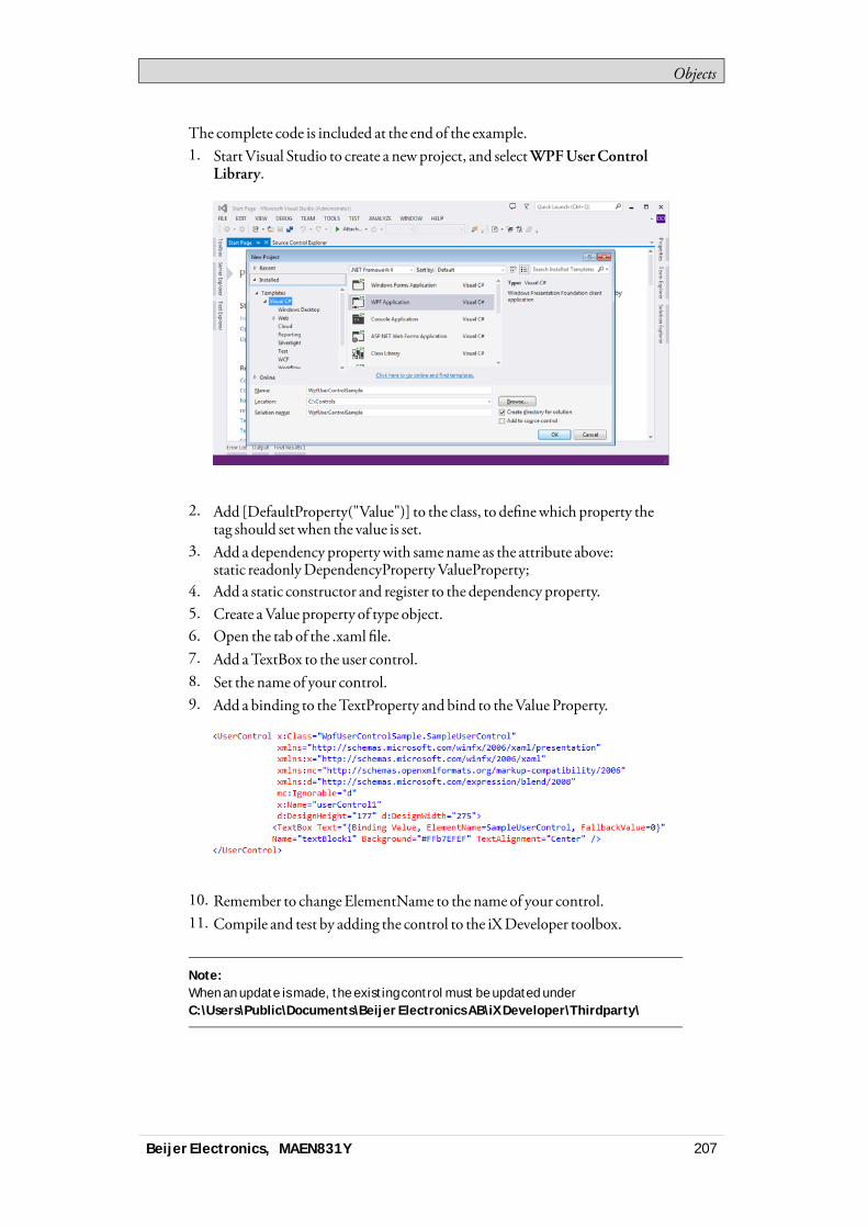
Objects
The complete code is included at the end of the example.1. Start Visual Studio to create a newproject, and selectWPFUserControl
Library.
2. Add [DefaultProperty("Value")] to the class, to definewhich property thetag should set when the value is set.
3. Add a dependency propertywith samename as the attribute above:static readonlyDependencyPropertyValueProperty;
4. Add a static constructor and register to the dependency property.5. Create aValue property of type object.6. Open the tab of the .xaml file.7. Add aTextBox to the user control.8. Set the name of your control.9. Add a binding to theTextProperty and bind to theValue Property.
10. Remember to changeElementName to the name of your control.11. Compile and test by adding the control to the iXDeveloper toolbox.
Note:When an update is made, the existing control must be updated underC:\Users\Public\Documents\Beijer Electronics AB\iX Developer\Thirdparty\
Beijer Electronics, MAEN831Y 207
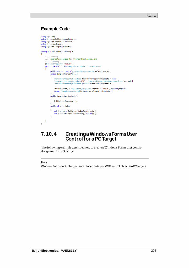
Objects
Example Code
7.10.4 Creating a Windows Forms UserControl for a PC Target
The following example describes how to create aWindows Forms user controldesignated for a PC target.
Note:Windows Forms control objects are placed on top of WPF control objects in PC targets.
Beijer Electronics, MAEN831Y 208

Objects
1. Start Visual Studio to create a newproject, and selectWindows FormsControl Library.
2. Add aTextBox and aButton to the design surface.3. AddEventHandler for Button click.4. AddEventHandler forTextBox lost focus.
Beijer Electronics, MAEN831Y 209
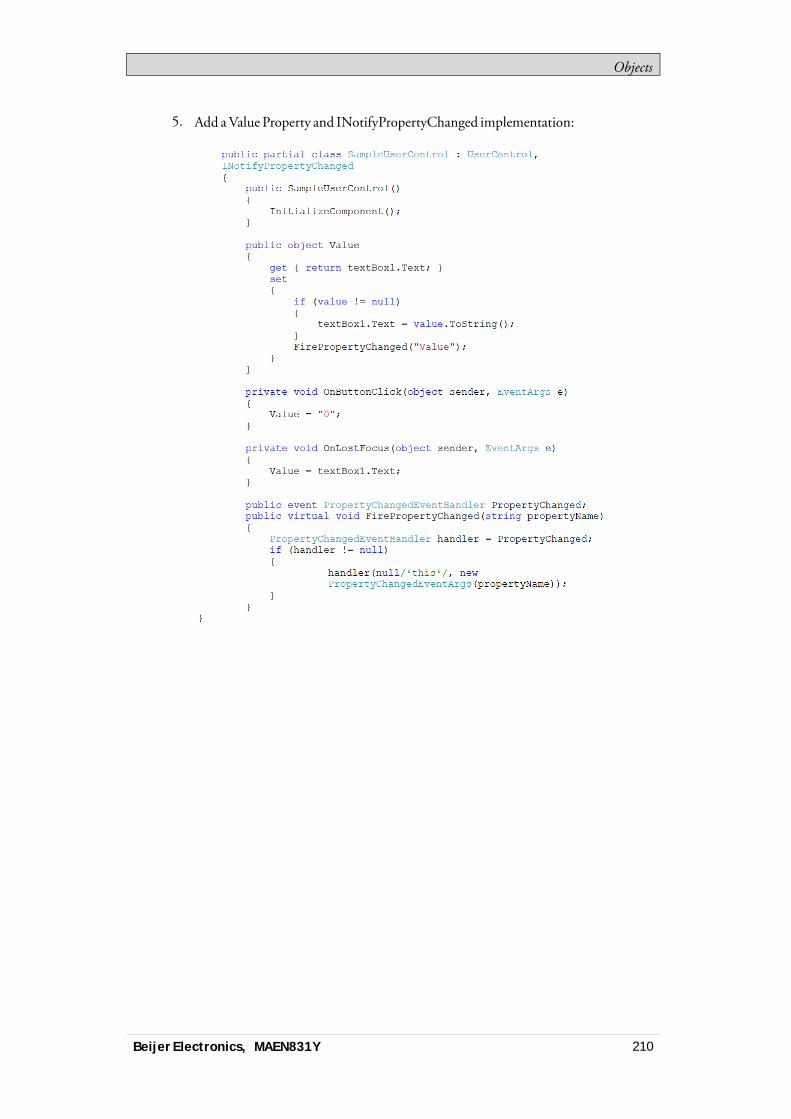
Objects
5. Add aValue Property and INotifyPropertyChanged implementation:
Beijer Electronics, MAEN831Y 210
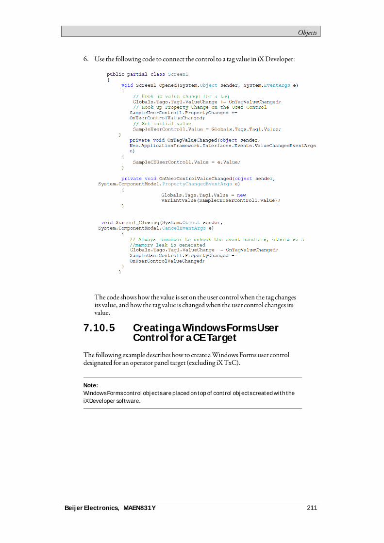
Objects
6. Use the following code to connect the control to a tag value in iXDeveloper:
The code shows how the value is set on the user control when the tag changesits value, andhow the tag value is changedwhen the user control changes itsvalue.
7.10.5 Creating a Windows Forms UserControl for a CE Target
The following example describes how to create aWindows Forms user controldesignated for an operator panel target (excluding iXTxC).
Note:Windows Forms control objects are placed on top of control objects created with theiX Developer software.
Beijer Electronics, MAEN831Y 211

Objects
1. Start Visual Studio 2005 or 2008 to create a newSmartDevice Project.
2. SelectWindowsCE for Target platform.3. SelectControl Library.
4. Use the same code as in theCreating aWindows FormsUserControl for a PCTarget example.
Beijer Electronics, MAEN831Y 212

Objects
Note:Always test your code on the target platform, as properties/methods currently notsupported may be included in the code. See Limitations for details.
Beijer Electronics, MAEN831Y 213
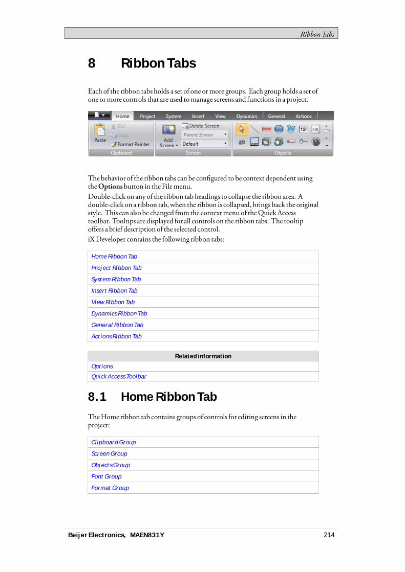
RibbonTabs
8 Ribbon Tabs
Each of the ribbon tabs holds a set of one ormore groups. Each group holds a set ofone ormore controls that are used tomanage screens and functions in a project.
The behavior of the ribbon tabs can be configured to be context dependent usingtheOptions button in the Filemenu.Double-click on any of the ribbon tab headings to collapse the ribbon area. Adouble-click on a ribbon tab, when the ribbon is collapsed, brings back the originalstyle. This can also be changed from the contextmenu of theQuickAccesstoolbar. Tooltips are displayed for all controls on the ribbon tabs. The tooltipoffers a brief description of the selected control.iXDeveloper contains the following ribbon tabs:
Home Ribbon Tab
Project Ribbon Tab
System Ribbon Tab
Insert Ribbon Tab
View Ribbon Tab
Dynamics Ribbon Tab
General Ribbon Tab
Actions Ribbon Tab
Related information
Options
Quick Access Toolbar
8.1 Home Ribbon TabTheHome ribbon tab contains groups of controls for editing screens in theproject:
Clipboard Group
Screen Group
Objects Group
Font Group
Format Group
Beijer Electronics, MAEN831Y 214
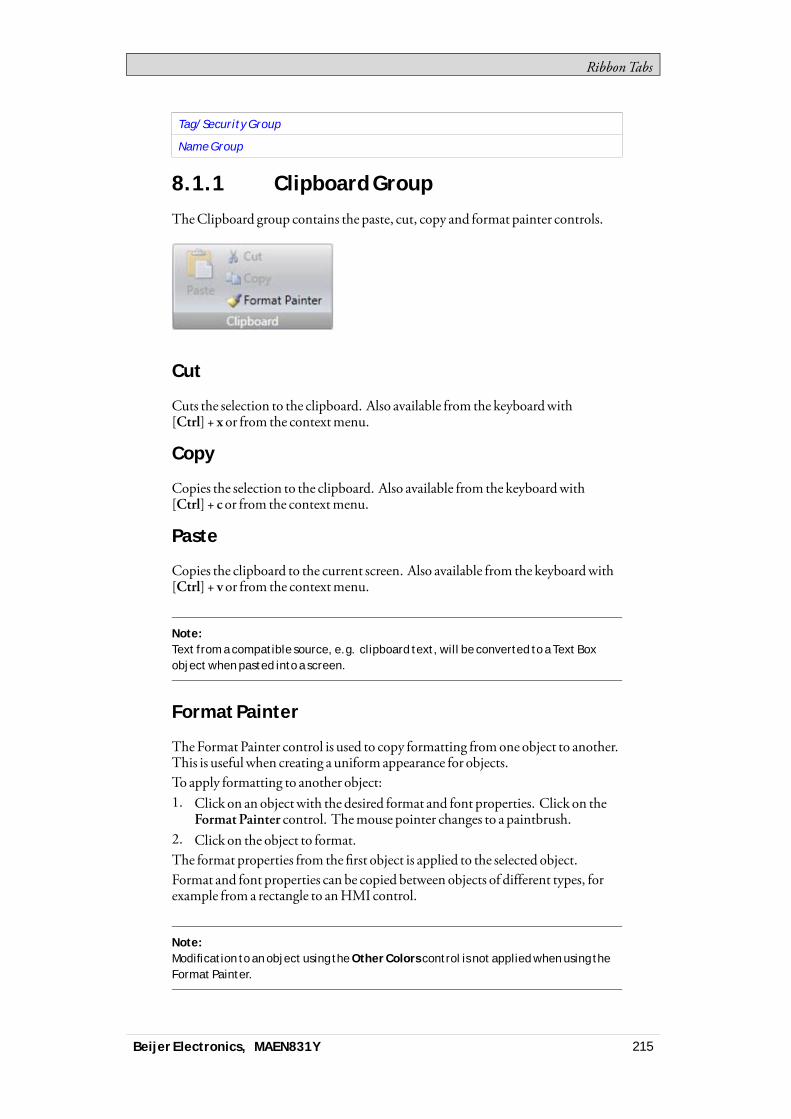
RibbonTabs
Tag/Security Group
Name Group
8.1.1 Clipboard Group
TheClipboard group contains the paste, cut, copy and format painter controls.
Cut
Cuts the selection to the clipboard. Also available from the keyboardwith[Ctrl] + x or from the contextmenu.
Copy
Copies the selection to the clipboard. Also available from the keyboardwith[Ctrl] + c or from the contextmenu.
Paste
Copies the clipboard to the current screen. Also available from the keyboardwith[Ctrl] + v or from the contextmenu.
Note:Text from a compatible source, e.g. clipboard text, will be converted to a Text Boxobject when pasted into a screen.
Format Painter
TheFormat Painter control is used to copy formatting fromone object to another.This is useful when creating a uniformappearance for objects.To apply formatting to another object:1. Click on an objectwith the desired format and font properties. Click on the
FormatPainter control. Themouse pointer changes to a paintbrush.2. Click on the object to format.The format properties from the first object is applied to the selected object.Format and font properties can be copied between objects of different types, forexample from a rectangle to anHMI control.
Note:Modification to an object using the Other Colors control is not applied when using theFormat Painter.
Beijer Electronics, MAEN831Y 215

RibbonTabs
Related information
Other Colors
8.1.2 Screen Group
The Screen control group contains the add screen, background screen anddeletescreen. Screens can also be added and deleted fromother controls, such as theNavigationManager and the contextmenu of the Project Explorer.
Add Screen
TheAddScreen command creates a new empty screen that opens for editing.Clicking the lower part of theAdd Screen button shows a selection of screentemplates that are available for selection.
Delete Screen
TheDelete Screen command removes the current screen from the project, andalso disconnects any associations fromother screens to the removed screen.
Note:A deleted screen cannot be restored with the Undo command.
Background Screen
Any screen can be used as background to the current screen.All objects in a background screenwill work as designed in the project application.Objects in a background screenmust be edited in the screen that they residein. Objects in a background screenwill be dimmed in the current screen in thedevelopment environment.
Related information
Screens
Language Management
8.1.3 Objects Group
TheObjects control group contains static anddynamic objects that can be addedto a screen.
Related information
Objects
Beijer Electronics, MAEN831Y 216

RibbonTabs
8.1.4 Object Variations
Formany of the objects it is possible to apply a preset style, using theObjectVariations feature. For theButton object and theCircularMeter object there is alarge number of different styles available as default, whereas formost other objectsit is possible to save user-defined styles.
To display theObjectVariationsmenu, click on one of the objects in theObjectsmenu. TheObject Variationsmenu appears to the right of theObjectsmenu,provided that there are some styles available for the selected object.To add user-defined styles in theObject Variationsmenu:1. Select an object to start from.2. Modify the object, using the tools under theHome ribbon tab or theProperty
Grid.3. Select the designed object and right-click to open the contextmenu.4. Select SaveVariations to save themodification.
Beijer Electronics, MAEN831Y 217
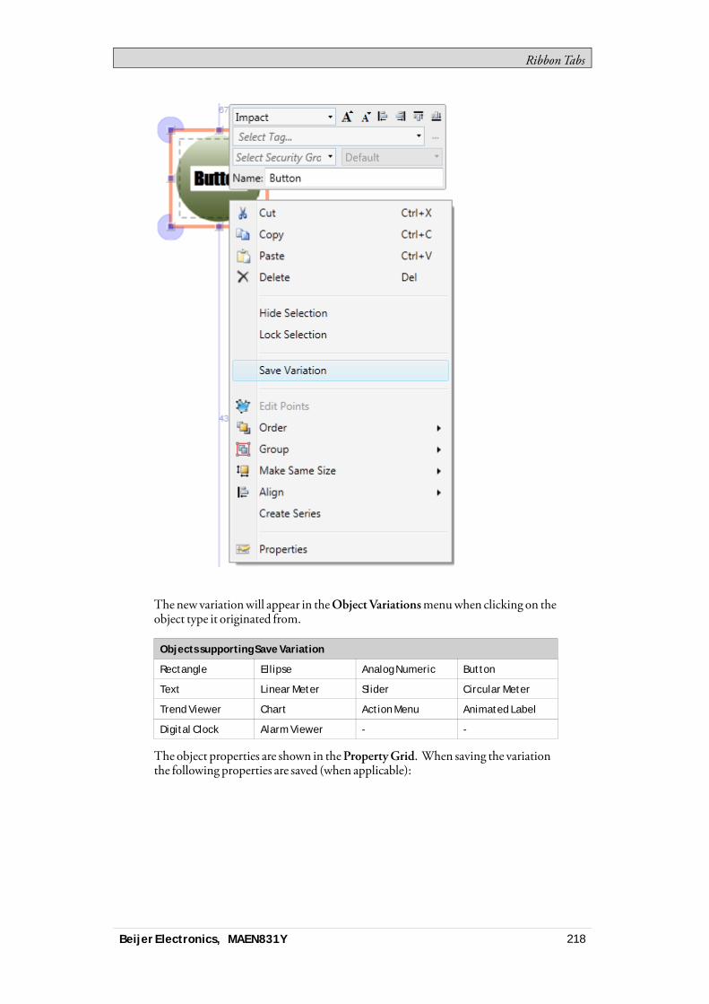
RibbonTabs
Thenew variationwill appear in theObject Variationsmenuwhen clicking on theobject type it originated from.
Objects supporting Save Variation
Rectangle Ellipse Analog Numeric Button
Text Linear Meter Slider Circular Meter
Trend Viewer Chart Action Menu Animated Label
Digital Clock Alarm Viewer - -
The object properties are shown in thePropertyGrid. When saving the variationthe following properties are saved (when applicable):
Beijer Electronics, MAEN831Y 218

RibbonTabs
Variations saved (where applicable)
Color Font Rotation Size
Visibility Security groupsrequired
Audit traildescription
Delay Mouse/Touch Input
Visibility on accessdenied
Opacity Horizontal andvertical alignment
Picture horizontaland verticalalignment
In addition to the general properties listed above, a number of object specificproperties are saved:
Object Property
Action Menu Object View type
Orientation
Alarm Viewer Object Button position
Analog Numeric Object Limit number of characters
Number of characters
Number of decimals
Prefix
Suffix
Animated Label Object Animation direction
View type
Chart Object Chart type
3D view
Show header
Show legend
Show scale
Digital Clock Object Display format
Show seconds
Linear Meter Object Orientation
Scale
Transparency
Slider Object Orientation
Scale
Transparency
Text Object Horizontal alignment
Vertical alignment
Trend Viewer Object Major value ticks
Minor value ticks
Rectangle Radius
Effects
Beijer Electronics, MAEN831Y 219

RibbonTabs
Note:Features only supported in PC environment might not work on other platforms.
Related information
Objects
8.1.5 Font Group
All fonts available in the development PC are available for selectionwhendesigning the project. All fonts used in the project are includedwhen downloadingthe project to the target.
Note:For PC and iX TxC non-standard fonts are not transferred or installed to the target.Install non-standard fonts manually on the target.
Note:The number of fonts needs to be considered when calculating the total size of aproject.
Note:The default font Tahoma does not support Chinese characters in operator panelprojects in runtime. The font has to be changed to a font that supports Chinesecharacters, e.g. MS Song. Keep in mind that some fonts require a lot of project memory.
TheFont group is used to change text style. The text style is defined for thecurrently selected object.
Font and Font Size
Select font from the drop-down list. Use the increase/decrease font size buttons orset a specific font size.
Note:Objects, for which Auto Stretch Font is selected, will not be affected by thesesettings. The font size will be autosized when resizing the object height.
Beijer Electronics, MAEN831Y 220
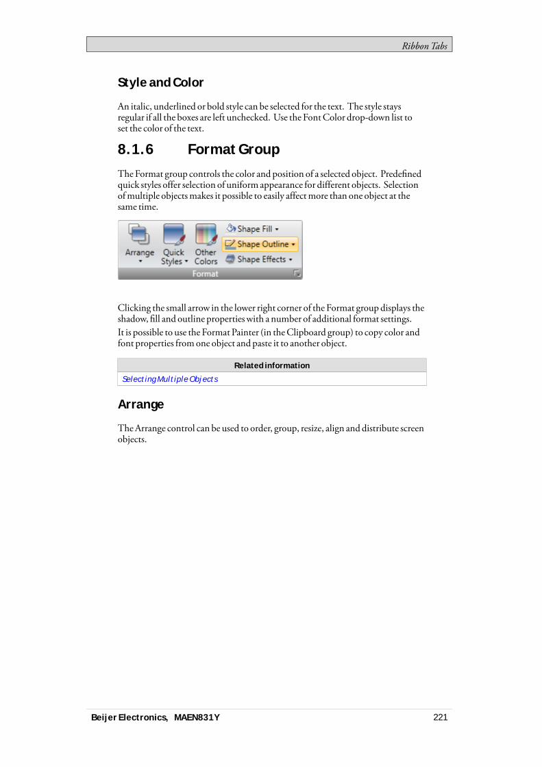
RibbonTabs
Style and Color
An italic, underlined or bold style can be selected for the text. The style staysregular if all the boxes are left unchecked. Use the FontColor drop-down list toset the color of the text.
8.1.6 Format Group
TheFormat group controls the color and position of a selected object. Predefinedquick styles offer selection of uniform appearance for different objects. Selectionofmultiple objectsmakes it possible to easily affectmore than one object at thesame time.
Clicking the small arrow in the lower right corner of the Format group displays theshadow, fill and outline propertieswith a number of additional format settings.It is possible to use the Format Painter (in theClipboard group) to copy color andfont properties fromone object andpaste it to another object.
Related information
Selecting Multiple Objects
Arrange
TheArrange control can be used to order, group, resize, align anddistribute screenobjects.
Beijer Electronics, MAEN831Y 221

RibbonTabs
Order Objects
The commands in theOrderObjects group are used to send objects to the front orback of each other.
Command Description
Bring to Front Positions the selected object on top of any overlappingobjects
Send to Back Positions the selected object behind any overlapping objects
Bring Forward Makes the selected object swap place with the nearestoverlapping object
Send Backward Makes the selected object swap place with the nearestobscured object
Beijer Electronics, MAEN831Y 222
RibbonTabs
Note:The Object Browser offers an easy way of arranging objects to the front or back of eachother.
Related information
Object Browser
Group Objects
TheGroupObjects commands are used tomanage selections ofmultiple objects.A grouped object ismoved and treated as one object with respect to formatting andresizing, and can also be stored in theComponent Library for reuse.Any selection of objects on the screen can be grouped.Whenmultiple objects are selected, one object is the primary selection. This isshownwith an orange frame,while other objects in the group have blue frames.Click on any object in the group to change this to the primary selection.A grouped object can be resolved into individual objects using theUngroupcommand. A property thatwas given to the groupwill be kept by each of theobject, provided that the property is applicable.
Make Same Size
TheMake Same Size commands are used to adjust the size of a group of selectedobjects. The sizewill be determined by the primary selection (the guide object).
Position Objects
ThePositionObjects commands can be used to align and distributemultipleobjects neatly. Objects can be aligned vertically and horizontally using the primaryselection for the group as guide object. Objects can be alignedwith respect to theircenter (center/middle) or their edges (top/bottom/right/left).
Related information
Component Library
Snap Objects to Other Objects
Grid
Quick Styles
TheQuick Styles control contains a number of preset visual object color schemesthat can be applied to screen objects.The predefined graphical stylesmake it possible to achieve a uniformappearanceon items likemeters and trend viewers. An object that has a style applied can befurther customized, for examplewith font settings.It is also possible to customize the predefined styles to styles of your ownpreference. The quick styles are not specific to the current project. Theywill beavailable for all iXDeveloper projects.
Beijer Electronics, MAEN831Y 223
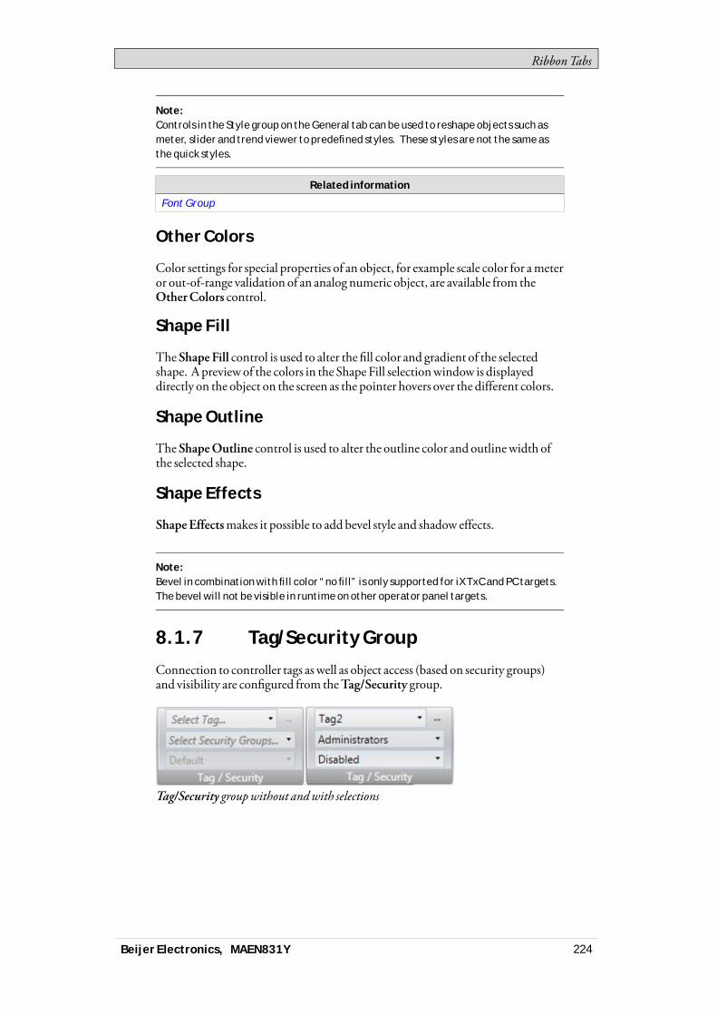
RibbonTabs
Note:Controls in the Style group on the General tab can be used to reshape objects such asmeter, slider and trend viewer to predefined styles. These styles are not the same asthe quick styles.
Related information
Font Group
Other Colors
Color settings for special properties of an object, for example scale color for ameteror out-of-range validation of an analog numeric object, are available from theOtherColors control.
Shape Fill
TheShape Fill control is used to alter the fill color and gradient of the selectedshape. A previewof the colors in the Shape Fill selectionwindow is displayeddirectly on the object on the screen as the pointer hovers over the different colors.
Shape Outline
TheShapeOutline control is used to alter the outline color and outlinewidth ofthe selected shape.
Shape Effects
ShapeEffectsmakes it possible to add bevel style and shadow effects.
Note:Bevel in combination with fill color “no fill” is only supported for iX TxC and PC targets.The bevel will not be visible in runtime on other operator panel targets.
8.1.7 Tag/Security Group
Connection to controller tags as well as object access (based on security groups)and visibility are configured from theTag/Security group.
Tag/Security groupwithout andwith selections
Beijer Electronics, MAEN831Y 224
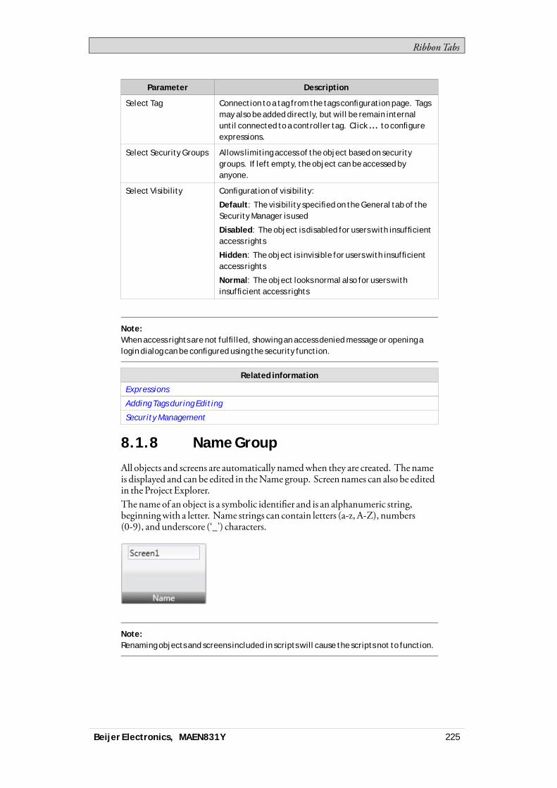
RibbonTabs
Parameter Description
Select Tag Connection to a tag from the tags configuration page. Tagsmay also be added directly, but will be remain internaluntil connected to a controller tag. Click ... to configureexpressions.
Select Security Groups Allows limiting access of the object based on securitygroups. If left empty, the object can be accessed byanyone.
Select Visibility Configuration of visibility:
Default: The visibility specified on the General tab of theSecurity Manager is used
Disabled: The object is disabled for users with insufficientaccess rights
Hidden: The object is invisible for users with insufficientaccess rights
Normal: The object looks normal also for users withinsufficient access rights
Note:When access rights are not fulfilled, showing an access denied message or opening alogin dialog can be configured using the security function.
Related information
Expressions
Adding Tags during Editing
Security Management
8.1.8 Name Group
All objects and screens are automatically namedwhen they are created. The nameis displayed and can be edited in theName group. Screen names can also be editedin the Project Explorer.The name of an object is a symbolic identifier and is an alphanumeric string,beginningwith a letter. Name strings can contain letters (a-z, A-Z), numbers(0-9), and underscore (‘_’) characters.
Note:Renaming objects and screens included in scripts will cause the scripts not to function.
Beijer Electronics, MAEN831Y 225
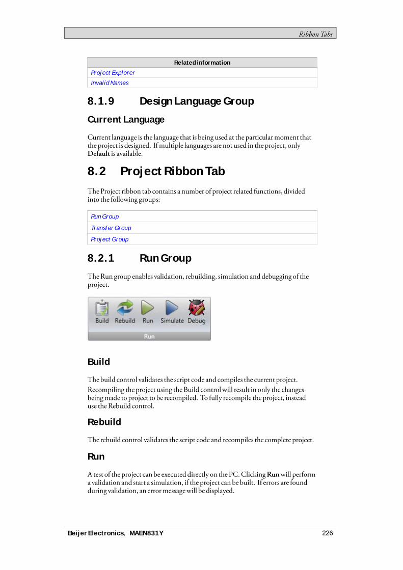
RibbonTabs
Related information
Project Explorer
Invalid Names
8.1.9 Design Language Group
Current Language
Current language is the language that is being used at the particularmoment thatthe project is designed. Ifmultiple languages are not used in the project, onlyDefault is available.
8.2 Project Ribbon TabTheProject ribbon tab contains a number of project related functions, dividedinto the following groups:
Run Group
Transfer Group
Project Group
8.2.1 Run Group
TheRun group enables validation, rebuilding, simulation and debugging of theproject.
Build
The build control validates the script code and compiles the current project.Recompiling the project using theBuild control will result in only the changesbeingmade to project to be recompiled. To fully recompile the project, insteaduse theRebuild control.
Rebuild
The rebuild control validates the script code and recompiles the complete project.
Run
A test of the project can be executed directly on the PC.ClickingRunwill performa validation and start a simulation, if the project can be built. If errors are foundduring validation, an errormessagewill be displayed.
Beijer Electronics, MAEN831Y 226
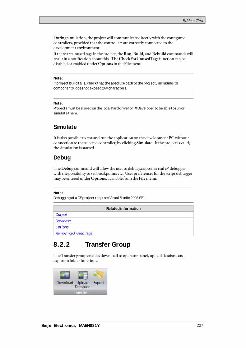
RibbonTabs
During simulation, the projectwill communicate directlywith the configuredcontrollers, provided that the controllers are correctly connected to thedevelopment environment.If there are unused tags in the project, theRun,Build, andRebuild commandswillresult in a notification about this. TheCheckForUnusedTags function can bedisabled or enabled underOptions in theFilemenu.
Note:If project build fails, check that the absolute path to the project, including itscomponents, does not exceed 260 characters.
Note:Projects must be stored on the local hard drive for iX Developer to be able to run orsimulate them.
Simulate
It is also possible to test and run the application on the development PCwithoutconnection to the selected controller, by clickingSimulate. If the project is valid,the simulation is started.
Debug
TheDebug commandwill allow the user to debug scripts in a real c# debuggerwith the possibility to set breakpoints etc. User preferences for the script debuggermay be entered underOptions, available from theFilemenu.
Note:Debugging of a CE project requires Visual Studio 2008 SP1.
Related information
Output
Database
Options
Removing Unused Tags
8.2.2 Transfer Group
TheTransfer group enables download to operator panel, upload database andexport to folder functions.
Beijer Electronics, MAEN831Y 227

RibbonTabs
Note:Time zone, region or daylight saving settings will not be transferred if these settingshave been changed manually in the panel.
Download
TheDownload control sends the project to an operator panel or a PCwith aniXRuntime installation, in the network environment.
Do the following:1. Choose a target type to transfer the project to.2. Start the project transfer.3. Click the “Download all source code ( for later upload) ” check box to
compress the project and save it as a ZIP file on target.4. Click the “Password protected” check box and enter a password to protect
theZIPfile.5. Click the “Copydownloaded project toMemoryCard” check box to copy
the downloaded project and the targets IP settings to thememory card. Whenproject is copied tomemory card, it can be used for restoring the project.
The verify function enables the user to check if a target platform configuration isidentical to the project configuration.
Beijer Electronics, MAEN831Y 228
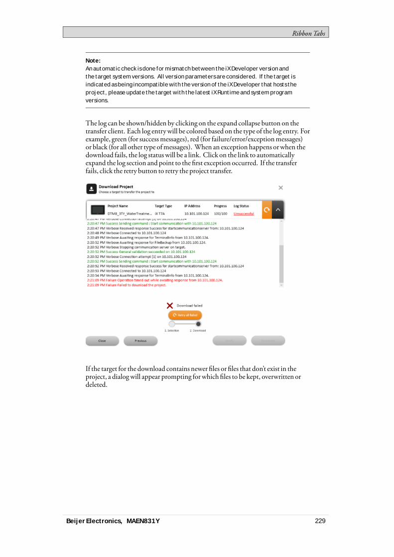
RibbonTabs
Note:An automatic check is done for mismatch between the iX Developer version andthe target system versions. All version parameters are considered. If the target isindicated as being incompatible with the version of the iX Developer that hosts theproject, please update the target with the latest iX Runtime and system programversions.
The log can be shown/hidden by clicking on the expand collapse button on thetransfer client. Each log entrywill be colored based on the type of the log entry. Forexample, green (for successmessages), red (for failure/error/exceptionmessages)or black (for all other type ofmessages). When an exception happens orwhen thedownload fails, the log statuswill be a link. Click on the link to automaticallyexpand the log section and point to the first exception occurred. If the transferfails, click the retry button to retry the project transfer.
If the target for the download contains newer files or files that don’t exist in theproject, a dialogwill appear prompting forwhichfiles to be kept, overwritten ordeleted.
Beijer Electronics, MAEN831Y 229
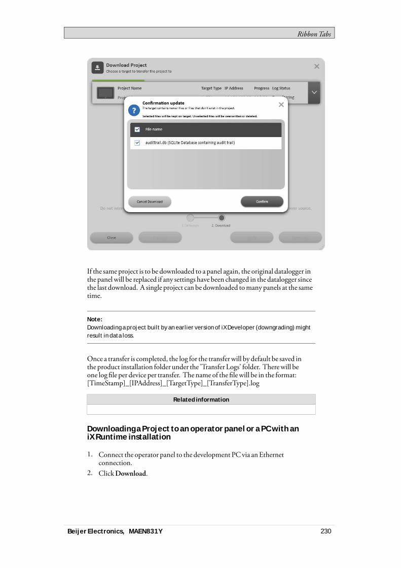
RibbonTabs
If the sameproject is to be downloaded to a panel again, the original datalogger inthe panel will be replaced if any settings have been changed in the datalogger sincethe last download. A single project can be downloaded tomany panels at the sametime.
Note:Downloading a project built by an earlier version of iX Developer (downgrading) mightresult in data loss.
Once a transfer is completed, the log for the transfer will by default be saved inthe product installation folder under the 'Transfer Logs' folder. Therewill beone log file per device per transfer. The name of the filewill be in the format:[TimeStamp]_[IPAddress]_[TargetType]_[TransferType].log
Related information
Downloading a Project to an operator panel or a PC with aniX Runtime installation
1. Connect the operator panel to the development PCvia anEthernetconnection.
2. ClickDownload.
Beijer Electronics, MAEN831Y 230

RibbonTabs
3. The download dialog opens and all panels connected in the network arelistedwith information about IP address and panel type. Select the panel todownload to in the list.
4. Check that the IP address is correct and clickDownload.a. Optional: Click the “Include compressed project” check box to compress
the project and save it as aZIPfile.b. Optional: Click the “Password protected” check box and enter a
password to protect theZIPfile.c. Optional: Click the “Copy downloadedproject toMemory card” check
box to enable SD card backup of operator panel project and settings.The panel responds to a download request by stopping any current project.The panel displays that it is ready for project download. When the download iscompleted, the newproject automatically starts running.The project folder is located at the following path. Only for PC targets!%public%\Documents\Beijer Electronics AB\iXDeveloperRuntime\Project.The panel settings can be controlled from the Servicemenu in the panel.
Note:It is necessary to open TCP port 9999 and UDP port 9999 in the firewall for the runtimePC application.
Note:Do not attempt to use the Download command if a project opened with the .exe file isopen. This might fail to close the project and the transfer will not be completed.
Note:If Chinese or Korean languages are to be used in the operator panel, then firewallsin Windows must be configured to allow TransferClient.exe full access on all ports,otherwise project transfer might fail.
Related information
Starting an iX Runtime project on a PC
Downloading a Project to an operator panel or a PC with aniX Runtime installation Using FTP
Aproject can be loaded to the panel via FTP.To be able to load a project remotelyan external storage device (SDcard orUSB stick)must be attached, and aconfigurationfile namedProjectCopy.configmust be present in the root directoryof the storage device.Set up the configurationfile as follows. Use # for parameters to be ignored.
Beijer Electronics, MAEN831Y 231
RibbonTabs
Parameter Description
automatic the download of the project automatically starts,without any dialogs, when a project file is loaded tothe storage device and the panel is rebooted
path "\StorageCard\Project3"
the path to the project, if multiple projects arestored on the storage device. SD cards use the path\StorageCard\ and devices attached to USB use\HardDisk\
applyipsettings applies saved IP settings
deletesource deletes the source file from the storage device afterthe download
deleteconfigfile deletes the configuration file after the download. Ifthe configuration file is left on the storage device it isinitiated each time the panel is rebooted.
Note:This is only supported in the latest released images.
Example:In the following example, without displaying any dialogs, the project found in thefolder Project_5 located on the USB stick is loaded, the project is deleted from the USBstick, and the configuration file is deleted. The IP-settings are not updated.• automatic• path "\HardDisk\Project_5"• #applyipsettings• deletesource• deleteconfigfile
Upload Database
TheUploadDatabase commandwill collect the database fromanoperator panelin the network environment to a file on the development PC.The panel will pauseduring the upload, andwill be started automatically afterwards.The databasemay only be collected froma panel running the same project (i.e.a project with the same name andof the same size) as the current iXDeveloperproject.
Collecting a Database from an operator panel
1. Connect the operator panel to the development PCvia anEthernetconnection.
2. ClickUploadDatabase.3. TheUploadDatabase dialog opens and all panels connected in the network
are listedwith information about IP address and panel type. Select the panel tocollect from in the list.
4. Check that the IP address is correct and clickBackUp.5. Select location of the saved database.
Beijer Electronics, MAEN831Y 232
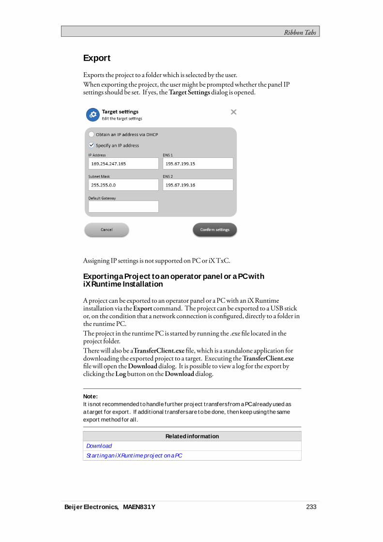
RibbonTabs
Export
Exports the project to a folderwhich is selected by the user.When exporting the project, the usermight be promptedwhether the panel IPsettings should be set. If yes, theTarget Settingsdialog is opened.
Assigning IP settings is not supported onPCor iXTxC.
Exporting a Project to an operator panel or a PC withiX Runtime Installation
Aproject can be exported to an operator panel or a PCwith an iXRuntimeinstallation via theExport command. The project can be exported to aUSB stickor, on the condition that a network connection is configured, directly to a folder inthe runtimePC.The project in the runtimePC is started by running the .exe file located in theproject folder.Therewill also be aTransferClient.exefile, which is a standalone application fordownloading the exported project to a target. Executing theTransferClient.exefilewill open theDownload dialog. It is possible to view a log for the export byclicking theLogbutton on theDownloaddialog.
Note:It is not recommended to handle further project transfers from a PC already used asa target for export. If additional transfers are to be done, then keep using the sameexport method for all.
Related information
Download
Starting an iX Runtime project on a PC
Beijer Electronics, MAEN831Y 233
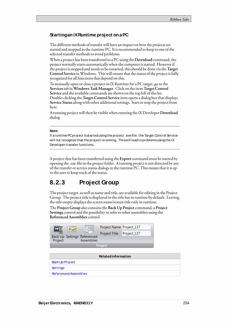
RibbonTabs
Starting an iX Runtime project on a PC
The differentmethods of transferwill have an impact onhow the projects arestarted and stopped in the runtimePC. It is recommended to keep to one of theselected transfermethods to avoid problems.When a project has been transferred to a PCusing theDownload command, theproject normally starts automaticallywhen the computer is started. However ifthe project is stopped andneeds to be restarted, this should be done via theTargetControl Service inWindows. This will ensure that the status of the project is fullyrecognized for all functions that depend on this.Tomanually open or close a project in iXRuntime for a PC target, go to theServices tab inWindowsTaskManager. Click on the itemTargetControlService and the available commands are shownon the top left of the list.Double-clicking theTargetControl Service itemopens a dialog box that displaysService Status alongwith other additional settings. Start or stop the project fromhere.A running projectwill then be visiblewhen entering the iXDeveloperDownloaddialog.
Note:If a runtime PC project is started using the project .exe file, the Target Control Servicewill not recognize that the project is running. This will lead to problems using the iXDeveloper transfer functions.
Aproject that has been transferred using theExport commandmust be started byopening the .exe-file in the project folder. A running project is not detected by anyof the transfer or service status dialogs in the runtimePC.Thismeans that it is upto the user to keep track of the status.
8.2.3 Project Group
The project target, as well as name and title, are available for editing in the ProjectGroup. The project title is displayed in the title bar in runtime by default. Leavingthe title empty displays the screenname/screen title only in runtime.TheProjectGroup also contains theBackUpProject command, aProjectSettings control and the possibility to refer to other assemblies using theReferencedAssemblies control.
Related information
Back Up Project
Settings
Referenced Assemblies
Beijer Electronics, MAEN831Y 234

RibbonTabs
Back Up Project
The project source files can be compressed into aZip file using theBackUpProject command. TheZip file can be saved to aUSB stick or, on the conditionthat a network connection is configured, directly to a folder in the runtimePC.
Parameter Description
Path to Zip file Browse to the location to save the Zip file.
Password protected Optional password protection of the Zip file.
Related information
Opening a Project
Settings
Properties such as application behavior in runtime, system font, and settings formouse and keyboard can be edited by clicking Settings in the Project group.
Related information
Deployment
Display/Target
Mouse/Touch Input Delay
System Dialogs
Virtual Keyboard
Screen Name and Screen Title
Memory Card
Database
Beijer Electronics, MAEN831Y 235
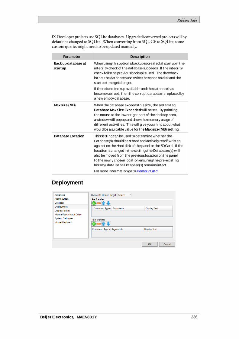
RibbonTabs
iXDeveloper projects use SQLite databases. Upgraded/converted projects will bydefault be changed to SQLite. When converting fromSQLCE to SQLite, somecustomqueriesmight need to be updatedmanually.
Parameter Description
Back up database atstartup
When using this option a backup is created at startup if theintegrity check of the database succeeds. If the integritycheck fails the previous backup is used. The drawbackis that the databases use twice the space on disk and thestartup time gets longer.
If there is no backup available and the database hasbecome corrupt, then the corrupt database is replaced bya new empty database.
Max size (MB) When the database exceeds this size, the system tagDatabase Max Size Exceeded will be set. By pointingthe mouse at the lower right part of the desktop area,a window will popup and show the memory usage ofdifferent activities. This will give you a hint about whatwould be a suitable value for the Max size (MB) setting.
Database Location This setting can be used to determine whether theDatabase(s) should be stored and actively read/writtenagainst on the Hard disk of the panel or the SD Card. If thelocation is changed in the settings the Databases(s) willalso be moved from the previous location on the panelto the newly chosen location ensuring the pre-existinghistory/data in the Database(s) remains intact.
For more information go to Memory Card.
Deployment
Beijer Electronics, MAEN831Y 236

RibbonTabs
Parameter Description
Overwrite Files onTarget
This setting can be used to determine the default behaviorwhen transferring projects and the transfer finds criticalfiles already present on the target.
Pre Transfer Add commands to be executed before the file transfer.Only available for standard PC targets.
Post Transfer Add commands to be executed after the file transfer. Onlyavailable for standard PC targets.
Related information
Pre Transfer
Post Transfer
Pre Transfer
The following commands can be executed before the file transfer:
Command Description
Reboot Reboots the target. Possible arguments: True and False.Using True, the target tries to start any project present.The argument False, or no argument, prevents the targetfrom starting the project automatically.
Wait Pauses the execution of the commands. This can be usefulif the user runs commands that takes time for the target torecover from. Possible arguments: a number, indicatinghow many whole seconds to wait.
Run Starts any given process. The first argument must alwaysbe the path to the executable to be run. Keep it insidequotes if it contains spaces.
Other arguments:
/p: or -p: are parameters for the process to start. Theparameters must be inside quotes and separated byspaces.
/noshell or -noshell means that the process should be runoutside of the command shell.
/wd: or -wd: means working directory for the process torun. If left empty defaults to active projects directory.The parameters must be inside quotes.
/wait: or -wait: means that the TargetControlServiceshould wait until the process has exited before continuing.If the process does not exit by itself, this argument shouldbe left out.
It is possible to use the followingmacros in conjunctionwith theRun commands:
Beijer Electronics, MAEN831Y 237
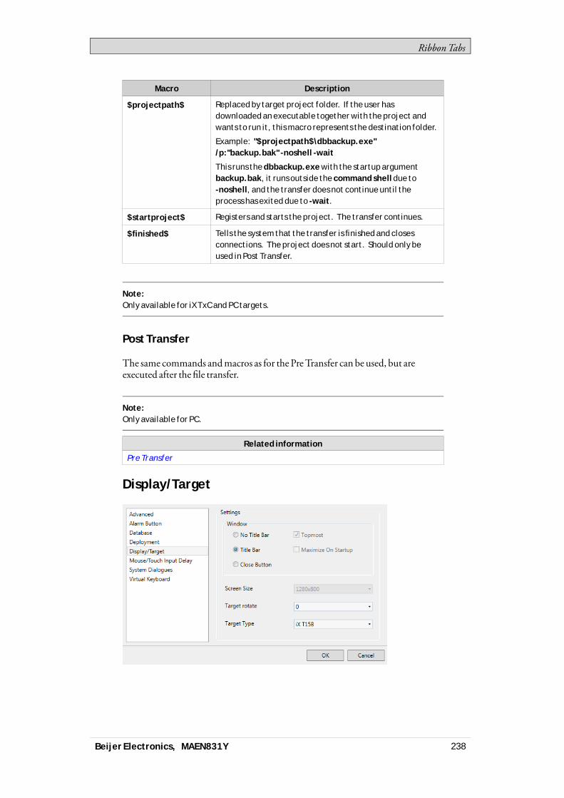
RibbonTabs
Macro Description
$projectpath$ Replaced by target project folder. If the user hasdownloaded an executable together with the project andwants to run it, this macro represents the destination folder.
Example: "$projectpath$\dbbackup.exe"/p:"backup.bak" -noshell -wait
This runs the dbbackup.exe with the startup argumentbackup.bak, it runs outside the command shell due to-noshell, and the transfer does not continue until theprocess has exited due to -wait.
$startproject$ Registers and starts the project. The transfer continues.
$finished$ Tells the system that the transfer is finished and closesconnections. The project does not start. Should only beused in Post Transfer.
Note:Only available for iX TxC and PC targets.
Post Transfer
The same commands andmacros as for the PreTransfer can be used, but areexecuted after the file transfer.
Note:Only available for PC.
Related information
Pre Transfer
Display/Target
Beijer Electronics, MAEN831Y 238
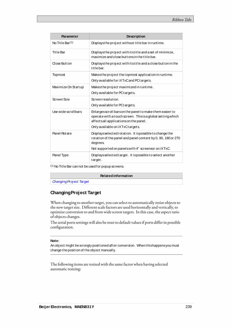
RibbonTabs
Parameter Description
No Title Bar(1) Displays the project without title bar in runtime.
Title Bar Displays the project with its title and a set of minimize,maximize and close buttons in the title bar.
Close Button Displays the project with its title and a close button in thetitle bar.
Topmost Makes the project the topmost application in runtime.
Only available for iX TxC and PC targets.
Maximize On Startup Makes the project maximized in runtime.
Only available for PC targets.
Screen Size Screen resolution.
Only available for PC targets.
Use wide scrollbars Enlarges scroll bars on the panel to make them easier tooperate with a touch screen. This is a global setting whichaffects all applications on the panel.
Only available on iX TxC targets.
Panel Rotate Displays selected rotation. It is possible to change therotation of the panel and panel content by 0, 90, 180 or 270degrees.
Not supported on panels with 4” screensor on iX TxC.
Panel Type Displays selected target. It is possible to select anothertarget.
(1) No Title Bar can not be used for popup screens.
Related information
Changing Project Target
Changing Project Target
When changing to another target, you can select to automatically resize objects tothe new target size. Different scale factors are used horizontally and vertically, tooptimize conversion to and fromwide screen targets. In this case, the aspect ratioof objects changes.The serial ports settingswill also be reset to default values if ports differ in possibleconfiguration.
Note:An object might be wrongly positioned after conversion. When this happens you mustchange the position of the object manually.
The following items are resizedwith the same factorwhen having selectedautomatic resizing:
Beijer Electronics, MAEN831Y 239

RibbonTabs
Item
Graphical objects
Popup screens
Font(1)
Dynamics size and move
(1)A minimum scaled font of 10 pixels ensures readability in the smaller operatorpanels.
Not all objects and styles are supported for all project targets. When changing toanother project target, objects and styles that are not supported in the new targetare deleted and are possible to restore. Removed objects are logged, and displayedin awindow after the transformation. The logmay be saved to file. Build files arealways cleaned and project saved after transformation.
Note:Changing back to the previous target does not restore removed objects.
Mouse/Touch Input Delay
It is possible to configure delay ofmouse and touch screen input in runtime. Thedelay used is either global and affects all objects forwhichDelayMouse/TouchInput is selected, butwith no specific delay configured, or can be set individuallyon each object. The Property grid is used to enable and configure delay ofmouseand touch screen input for individual objects.To revert to the global setting, enter 0 asDelay Period.
Related information
Property Grid
Advanced
Parameter Description
Set default value on allnew screens to cache
When this is checked, all the new screens created in theproject will have the value for Cached (under generalsettings for the screen) as checked by default. When thisis unchecked, all the new screens will have the Cachedoption set to false. As before, this is not applicable to startscreen and popup screens. Start screen will always be
Beijer Electronics, MAEN831Y 240
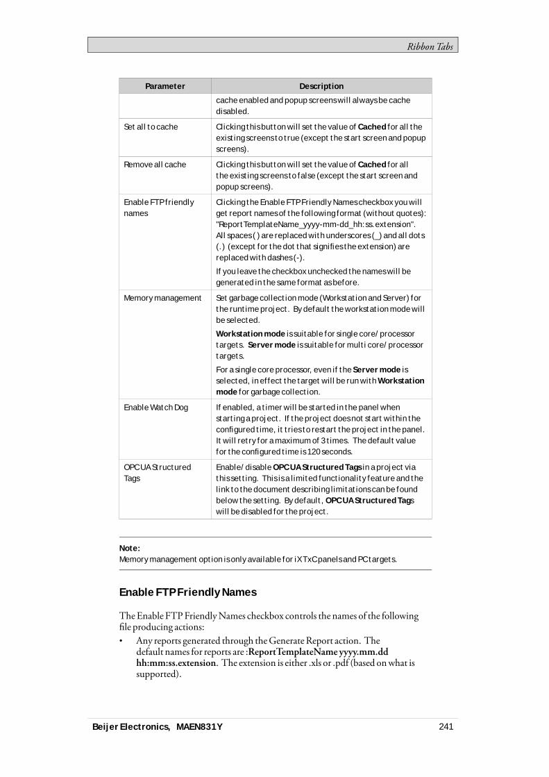
RibbonTabs
Parameter Description
cache enabled and popup screens will always be cachedisabled.
Set all to cache Clicking this button will set the value of Cached for all theexisting screens to true (except the start screen and popupscreens).
Remove all cache Clicking this button will set the value of Cached for allthe existing screens to false (except the start screen andpopup screens).
Enable FTP friendlynames
Clicking the Enable FTP Friendly Names checkbox you willget report names of the following format (without quotes):"ReportTemplateName_yyyy-mm-dd_hh:ss.extension".All spaces ( ) are replaced with underscores (_) and all dots(.) (except for the dot that signifies the extension) arereplaced with dashes (-).
If you leave the checkbox unchecked the names will begenerated in the same format as before.
Memory management Set garbage collection mode (Workstation and Server) forthe runtime project. By default the workstation mode willbe selected.
Workstation mode is suitable for single core/processortargets. Server mode is suitable for multi core/processortargets.
For a single core processor, even if the Server mode isselected, in effect the target will be run with Workstationmode for garbage collection.
Enable Watch Dog If enabled, a timer will be started in the panel whenstarting a project. If the project does not start within theconfigured time, it tries to restart the project in the panel.It will retry for a maximum of 3 times. The default valuefor the configured time is 120 seconds.
OPC UA StructuredTags
Enable/disable OPC UA Structured Tags in a project viathis setting. This is a limited functionality feature and thelink to the document describing limitations can be foundbelow the setting. By default, OPC UA Structured Tagswill be disabled for the project.
Note:Memory management option is only available for iX TxC panels and PC targets.
Enable FTP Friendly Names
TheEnable FTPFriendlyNames checkbox controls the names of the followingfile producing actions:• Any reports generated through theGenerateReport action. The
default names for reports are :ReportTemplateName yyyy.mm.ddhh:mm:ss.extension. The extension is either .xls or .pdf (based onwhat issupported).
Beijer Electronics, MAEN831Y 241
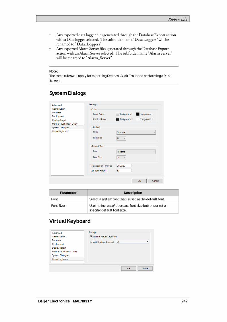
RibbonTabs
• Any exported data logger files generated through theDatabase Export actionwith aData logger selected. The subfolder name "DataLoggers"will berenamed to "Data_Loggers"
• Any exportedAlarmServer files generated through theDatabase Exportactionwith anAlarmServer selected. The subfolder name "AlarmServer"will be renamed to "Alarm_Server"
Note:The same rules will apply for exporting Recipes, Audit Trails and performing a PrintScreen.
System Dialogs
Parameter Description
Font Select a system font that is used as the default font.
Font Size Use the increase/decrease font size buttons or set aspecific default font size.
Virtual Keyboard
Beijer Electronics, MAEN831Y 242
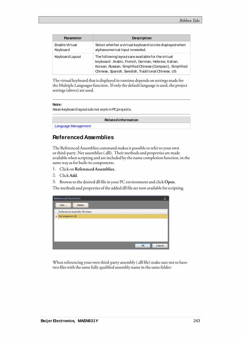
RibbonTabs
Parameter Description
Enable VirtualKeyboard
Select whether a virtual keyboard is to be displayed whenalphanumerical input is needed.
Keyboard Layout The following layouts are available for the virtualkeyboard: Arabic, French, German, Hebrew, Italian,Korean, Russian, Simplified Chinese (Compact), SimplifiedChinese, Spanish, Swedish, Traditional Chinese, US
The virtual keyboard that is displayed in runtime depends on settingsmade fortheMultiple Languages function. If only the default language is used, the projectsettings (above) are used.
Note:Asian keyboard layouts do not work in PC projects.
Related information
Language Management
Referenced Assemblies
TheReferencedAssemblies commandmakes it possible to refer to your ownor third-party .Net assemblies (.dll). Theirmethods and properties aremadeavailablewhen scripting and are included by the name completion function, in thesameway as for built-in components.1. Click onReferencedAssemblies.2. ClickAdd.3. Browse to the desired dll file in your PC environment and clickOpen.Themethods and properties of the added dll file are now available for scripting.
When referencing your own third-party assembly (.dll file)make sure not to havetwo fileswith the same fully qualified assembly name in the same folder:
Beijer Electronics, MAEN831Y 243
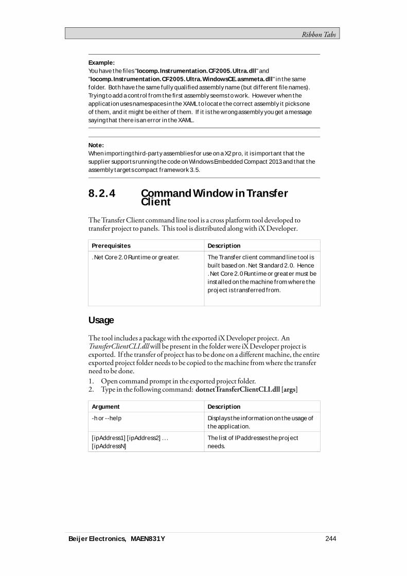
RibbonTabs
Example:You have the files "Iocomp.Instrumentation.CF2005.Ultra.dll" and"Iocomp.Instrumentation.CF2005.Ultra.WindowsCE.asmmeta.dll" in the samefolder. Both have the same fully qualified assembly name (but different file names).Trying to add a control from the first assembly seems to work. However when theapplication uses namespaces in the XAML to locate the correct assembly it picks oneof them, and it might be either of them. If it is the wrong assembly you get a messagesaying that there is an error in the XAML.
Note:When importing third-party assemblies for use on a X2 pro, it is important that thesupplier supports running the code on Windows Embedded Compact 2013 and that theassembly targets compact framework 3.5.
8.2.4 Command Window in TransferClient
TheTransferClient command line tool is a cross platform tool developed totransfer project to panels. This tool is distributed alongwith iXDeveloper.
Prerequisites Description
.Net Core 2.0 Runtime or greater. The Transfer client command line tool isbuilt based on .Net Standard 2.0. Hence.Net Core 2.0 Runtime or greater must beinstalled on the machine from where theproject is transferred from.
Usage
The tool includes a packagewith the exported iXDeveloper project. AnTransferClientCLI.dllwill be present in the folderwere iXDeveloper project isexported. If the transfer of project has to be done on a differentmachine, the entireexported project folder needs to be copied to themachine fromwhere the transferneed to be done.1. Open commandprompt in the exported project folder.2. Type in the following command: dotnetTransferClientCLI.dll [args]
Argument Description
-h or --help Displays the information on the usage ofthe application.
[ipAddress1] [ipAddress2] ...[ipAddressN]
The list of IP addresses the projectneeds.
Beijer Electronics, MAEN831Y 244
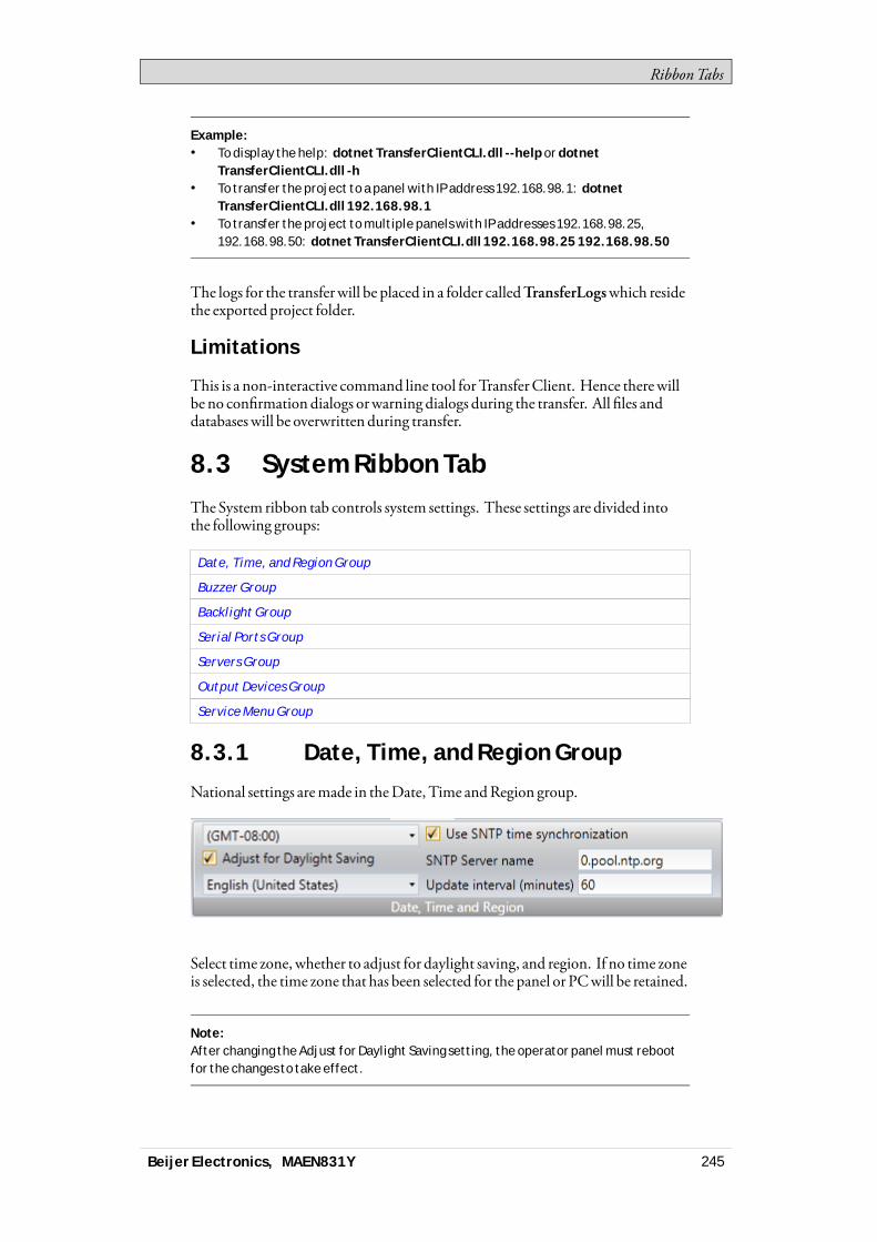
RibbonTabs
Example:• To display the help: dotnet TransferClientCLI.dll --help or dotnet
TransferClientCLI.dll -h• To transfer the project to a panel with IP address 192.168.98.1: dotnet
TransferClientCLI.dll 192.168.98.1• To transfer the project to multiple panels with IP addresses 192.168.98.25,
192.168.98.50: dotnet TransferClientCLI.dll 192.168.98.25 192.168.98.50
The logs for the transfer will be placed in a folder calledTransferLogswhich residethe exported project folder.
Limitations
This is a non-interactive command line tool forTransferClient. Hence therewillbe no confirmation dialogs orwarning dialogs during the transfer. All files anddatabases will be overwritten during transfer.
8.3 System Ribbon TabThe System ribbon tab controls system settings. These settings are divided intothe following groups:
Date, Time, and Region Group
Buzzer Group
Backlight Group
Serial Ports Group
Servers Group
Output Devices Group
Service Menu Group
8.3.1 Date, Time, and Region Group
National settings aremade in theDate, Time andRegion group.
Select time zone, whether to adjust for daylight saving, and region. If no time zoneis selected, the time zone that has been selected for the panel or PCwill be retained.
Note:After changing the Adjust for Daylight Saving setting, the operator panel must rebootfor the changes to take effect.
Beijer Electronics, MAEN831Y 245
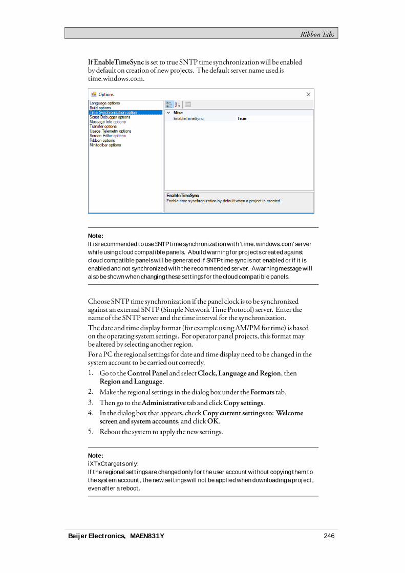
RibbonTabs
IfEnableTimeSync is set to true SNTP time synchronizationwill be enabledby default on creation of newprojects. The default server nameused istime.windows.com.
Note:It is recommended to use SNTP time synchronization with 'time.windows.com' serverwhile using cloud compatible panels. A build warning for projects created againstcloud compatible panels will be generated if SNTP time sync is not enabled or if it isenabled and not synchronized with the recommended server. A warning message willalso be shown when changing these settings for the cloud compatible panels.
Choose SNTP time synchronization if the panel clock is to be synchronizedagainst an external SNTP (SimpleNetworkTimeProtocol) server. Enter thename of the SNTP server and the time interval for the synchronization.The date and time display format (for example usingAM/PM for time) is basedon the operating system settings. For operator panel projects, this formatmaybe altered by selecting another region.For a PC the regional settings for date and time display need to be changed in thesystem account to be carried out correctly.1. Go to theControl Panel and selectClock, Language andRegion, then
Region andLanguage.2. Make the regional settings in the dialog box under theFormats tab.3. Then go to theAdministrative tab and clickCopy settings.4. In the dialog box that appears, checkCopy current settings to: Welcome
screen and system accounts, and clickOK.5. Reboot the system to apply the new settings.
Note:iX TxC targets only:If the regional settings are changed only for the user account without copying them tothe system account, the new settings will not be applied when downloading a project,even after a reboot.
Beijer Electronics, MAEN831Y 246

RibbonTabs
8.3.2 Buzzer Group
Selectwhether to let a key beep soundwhenmaking keyboard input in runtime.Only availablewhen an operator panel is selected as target.
8.3.3 Backlight Group
Select to automatically turn off the backlight after a certain number of seconds,andwhether to keep the backlight on if a notifierwindow (e.g. alarm indicator orcommunication errormessage) is visible.Backlight settings are supported only for operator panel targets. For other targets,theMicrosoftWindows screen savermay be used.
8.3.4 Serial Ports Group
For each of theCOMports, select if it is to be configured as anRS232,RS422 orRS485 port. Only availablewhen an operator panel is selected as target.The number of available ports and possible configuration differ depending onselected target.For example, onX2base, iXTxB, iXTxC, and IPC fourCOMports can beconfigured:
Note:When running 2xRS485 (COM2 & COM3) the serial ports are switched. COM 2 runs onCOM B(2) and COM 3 runs on COM A(1).
Beijer Electronics, MAEN831Y 247
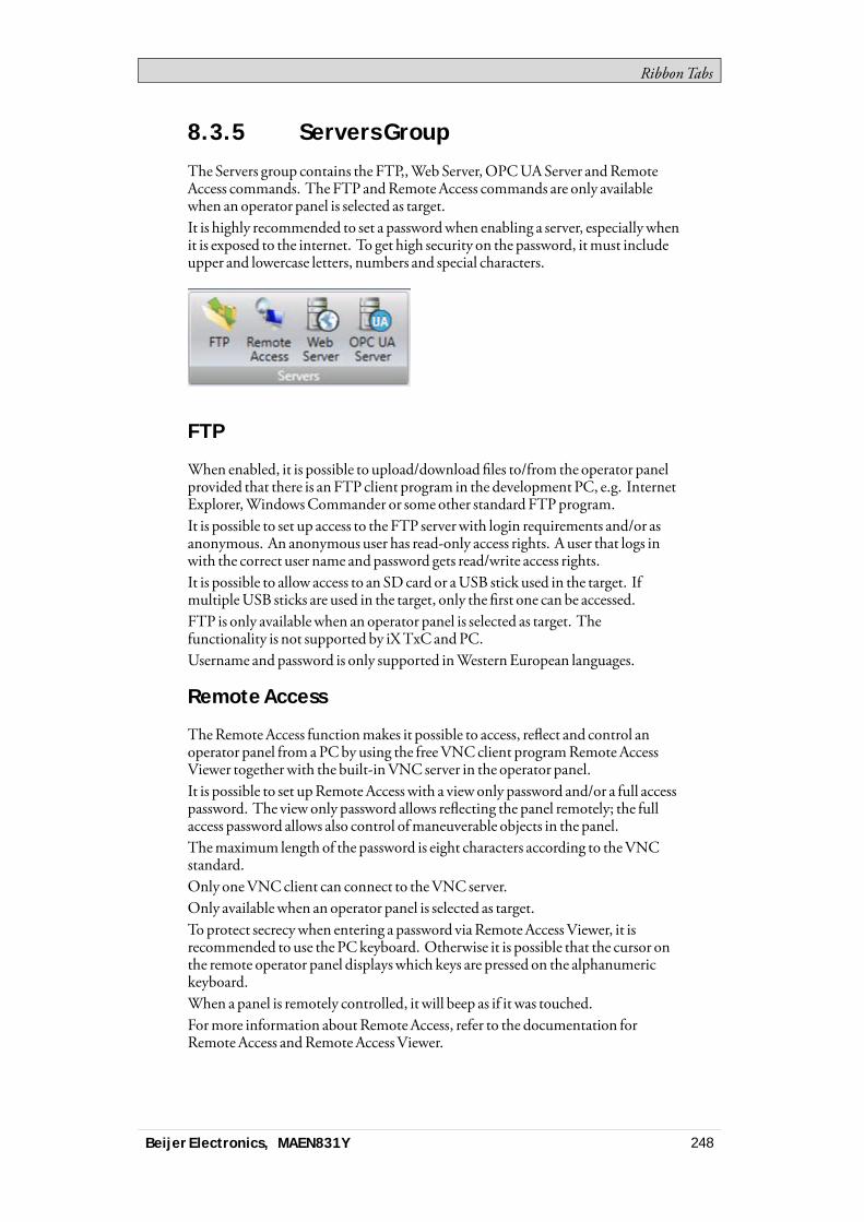
RibbonTabs
8.3.5 Servers Group
The Servers group contains the FTP,,Web Server,OPCUAServer andRemoteAccess commands. The FTP andRemoteAccess commands are only availablewhen an operator panel is selected as target.It is highly recommended to set a passwordwhen enabling a server, especiallywhenit is exposed to the internet. To get high security on the password, itmust includeupper and lowercase letters, numbers and special characters.
FTP
When enabled, it is possible to upload/download files to/from the operator panelprovided that there is anFTP client program in the development PC, e.g. InternetExplorer,WindowsCommander or some other standard FTPprogram.It is possible to set up access to the FTP serverwith login requirements and/or asanonymous. An anonymous user has read-only access rights. A user that logs inwith the correct user name andpassword gets read/write access rights.It is possible to allow access to an SDcard or aUSB stick used in the target. IfmultipleUSB sticks are used in the target, only the first one can be accessed.FTP is only availablewhen an operator panel is selected as target. Thefunctionality is not supported by iXTxC andPC.Username and password is only supported inWesternEuropean languages.
Remote Access
TheRemoteAccess functionmakes it possible to access, reflect and control anoperator panel from aPCby using the freeVNCclient programRemoteAccessViewer togetherwith the built-inVNC server in the operator panel.It is possible to set upRemote Access with a viewonly password and/or a full accesspassword. The view only password allows reflecting the panel remotely; the fullaccess password allows also control ofmaneuverable objects in the panel.Themaximum length of the password is eight characters according to theVNCstandard.Only oneVNCclient can connect to theVNC server.Only availablewhen an operator panel is selected as target.To protect secrecywhen entering a password viaRemoteAccessViewer, it isrecommended to use the PCkeyboard. Otherwise it is possible that the cursor onthe remote operator panel displayswhich keys are pressed on the alphanumerickeyboard.When a panel is remotely controlled, it will beep as if it was touched.Formore information aboutRemoteAccess, refer to the documentation forRemoteAccess andRemoteAccessViewer.
Beijer Electronics, MAEN831Y 248
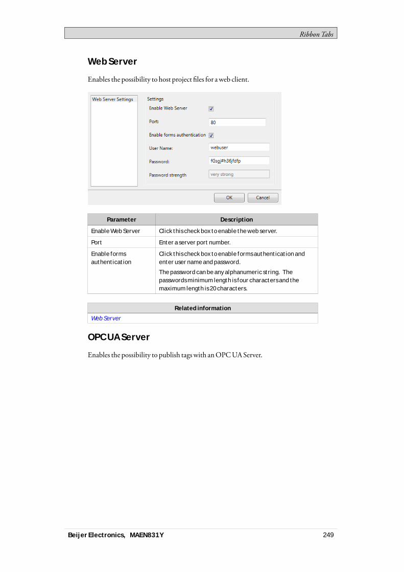
RibbonTabs
Web Server
Enables the possibility to host project files for aweb client.
Parameter Description
Enable Web Server Click this check box to enable the web server.
Port Enter a server port number.
Enable formsauthentication
Click this check box to enable forms authentication andenter user name and password.
The password can be any alphanumeric string. Thepasswords minimum length is four characters and themaximum length is 20 characters.
Related information
Web Server
OPC UA Server
Enables the possibility to publish tagswith anOPCUAServer.
Beijer Electronics, MAEN831Y 249
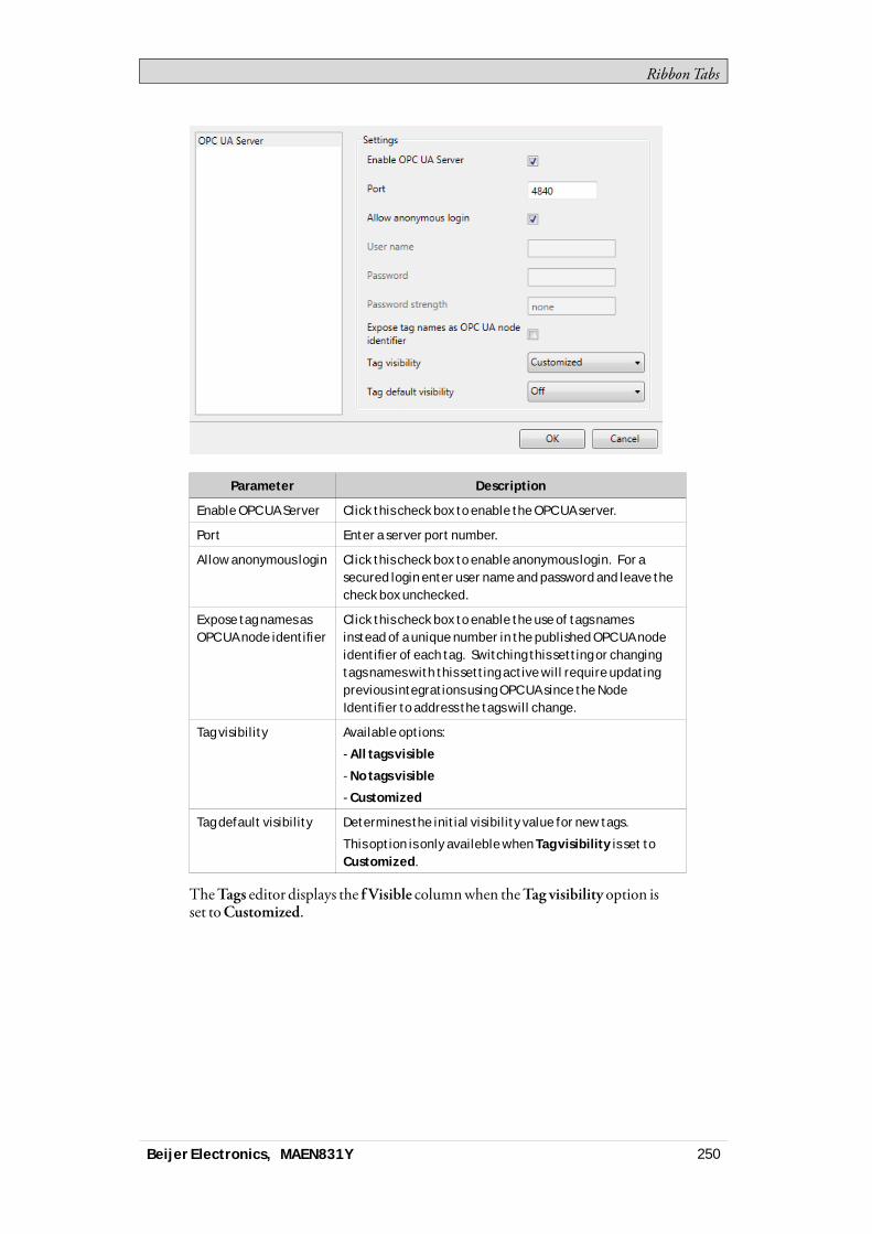
RibbonTabs
Parameter Description
Enable OPC UA Server Click this check box to enable the OPC UA server.
Port Enter a server port number.
Allow anonymous login Click this check box to enable anonymous login. For asecured login enter user name and password and leave thecheck box unchecked.
Expose tag names asOPC UA node identifier
Click this check box to enable the use of tags namesinstead of a unique number in the published OPC UA nodeidentifier of each tag. Switching this setting or changingtags names with this setting active will require updatingprevious integrations using OPC UA since the NodeIdentifier to address the tags will change.
Tag visibility Available options:
- All tags visible
- No tags visible
- Customized
Tag default visibility Determines the initial visibility value for new tags.
This option is only availeble when Tag visibility is set toCustomized.
TheTags editor displays the f Visible columnwhen theTag visibility option isset toCustomized.
Beijer Electronics, MAEN831Y 250

RibbonTabs
Address space
All tags, except array tags, defined in project will be shown.The tagswill be put in a folder namedTags inNamespaceTagProvider on theserver.TheNodeClass of all tagswill beVariable.All tag valueswill be published scaledwith the offset and gain of the tag.
Tag Properties Mapping
Parameter Description
Tag property UA Server Attribute
Name DisplayName /
BrowseName
Data Type DataType
Access Right AccessLevel /
UserAccessLevel
Description Description
Poll Group Interval MinimumSamplingInterval
Note:Data type BIT is not supported by OPC UA. Tags of this type will be handled as INT16 typein the server. For best result, use BOOL type instead.
Certificate
Acertificatewill be auto generated and self-signedwhen the server first starts up.The certificatewill be valid for 20 years.
Beijer Electronics, MAEN831Y 251
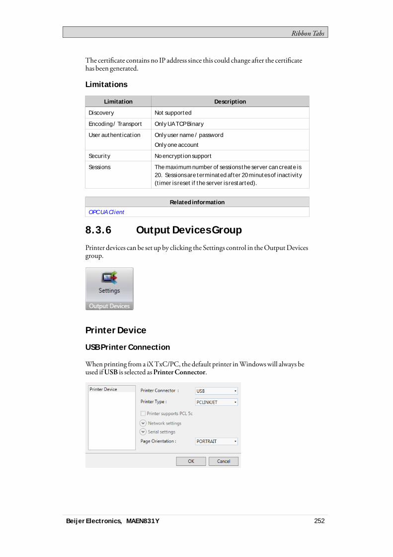
RibbonTabs
The certificate contains no IP address since this could change after the certificatehas been generated.
Limitations
Limitation Description
Discovery Not supported
Encoding / Transport Only UA TCP Binary
User authentication Only user name / password
Only one account
Security No encryption support
Sessions The maximum number of sessions the server can create is20. Sessions are terminated after 20 minutes of inactivity(timer is reset if the server is restarted).
Related information
OPC UA Client
8.3.6 Output Devices Group
Printer devices can be set up by clicking the Settings control in theOutputDevicesgroup.
Printer Device
USB Printer Connection
Whenprinting from a iXTxC/PC, the default printer inWindowswill always beused ifUSB is selected asPrinterConnector.
Beijer Electronics, MAEN831Y 252
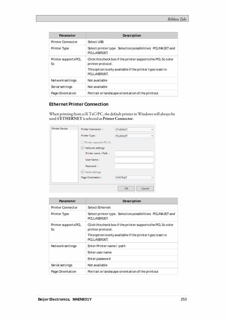
RibbonTabs
Parameter Description
Printer Connector Select USB
Printer Type Select printer type. Selection possibilities: PCLINKJET andPCLLASERJET.
Printer supports PCL5c
Click this check box if the printer supports the PCL 5c colorprinter protocol.
This option is only available if the printer type is set toPCLLASERJET.
Network settings Not available
Serial settings Not available
Page Orientation Portrait or landscape orientation of the printout
Ethernet Printer Connection
Whenprinting from a iXTxC/PC, the default printer inWindowswill always beused ifETHERNET is selected asPrinterConnector.
Parameter Description
Printer Connector Select Ethernet
Printer Type Select printer type. Selection possibilities: PCLINKJET andPCLLASERJET.
Printer supports PCL5c
Click this check box if the printer supports the PCL 5c colorprinter protocol.
This option is only available if the printer type is set toPCLLASERJET.
Enter Printer name / path
Enter user name
Network settings
Enter password
Serial settings Not available
Page Orientation Portrait or landscape orientation of the printout
Beijer Electronics, MAEN831Y 253
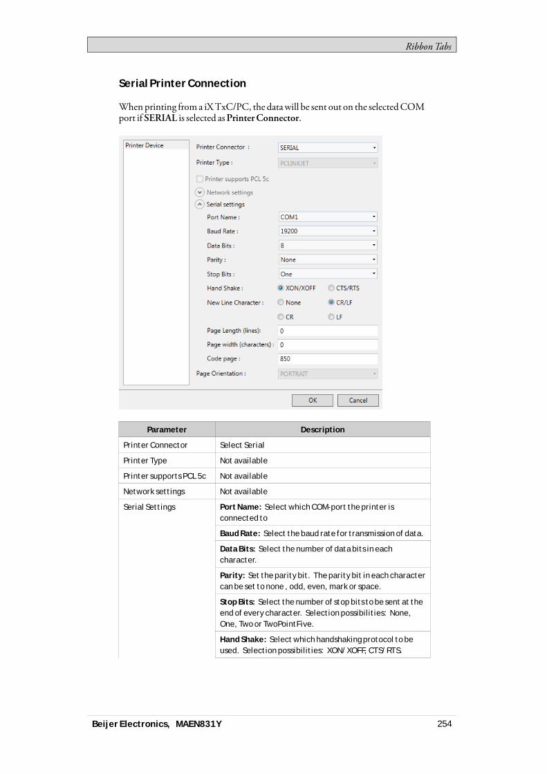
RibbonTabs
Serial Printer Connection
Whenprinting from a iXTxC/PC, the datawill be sent out on the selectedCOMport if SERIAL is selected asPrinterConnector.
Parameter Description
Printer Connector Select Serial
Printer Type Not available
Printer supports PCL 5c Not available
Network settings Not available
Port Name: Select which COM-port the printer isconnected to
Baud Rate: Select the baud rate for transmission of data.
Data Bits: Select the number of data bits in eachcharacter.
Parity: Set the parity bit. The parity bit in each charactercan be set to none , odd, even, mark or space.
Stop Bits: Select the number of stop bits to be sent at theend of every character. Selection possibilities: None,One, Two or TwoPointFive.
Hand Shake: Select which handshaking protocol to beused. Selection possibilities: XON/XOFF, CTS/RTS.
Serial Settings
Beijer Electronics, MAEN831Y 254
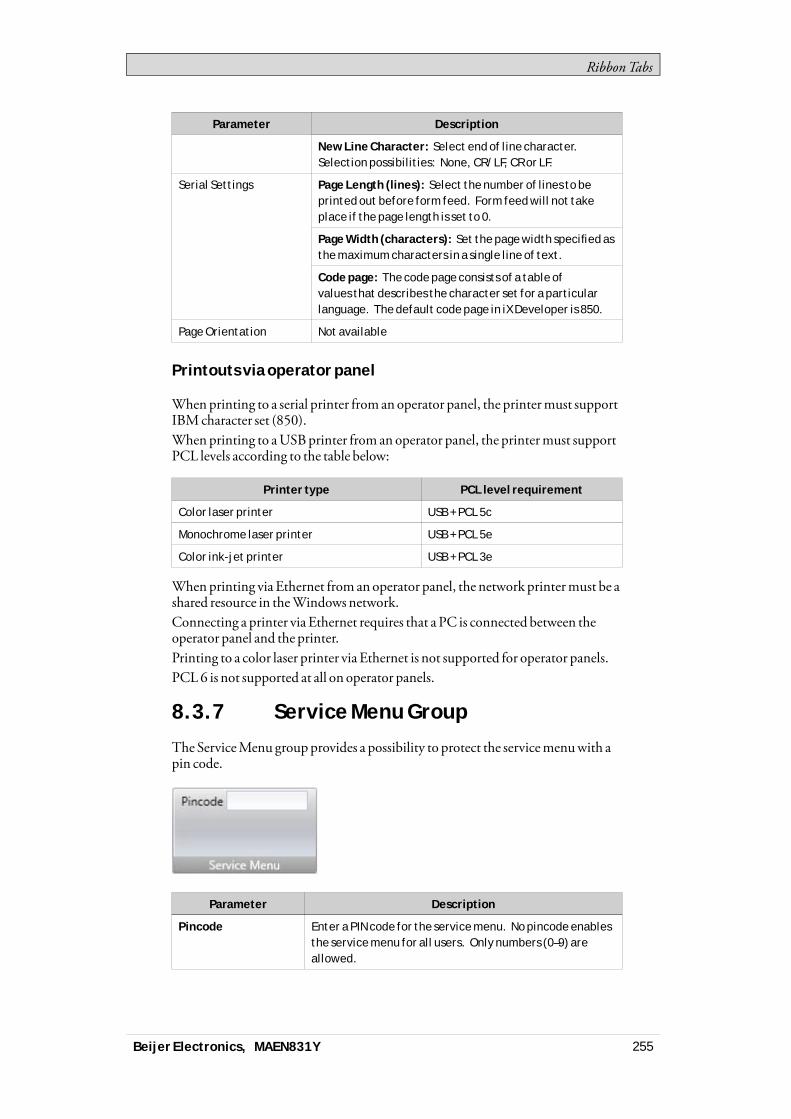
RibbonTabs
Parameter Description
New Line Character: Select end of line character.Selection possibilities: None, CR/LF, CR or LF.
Page Length (lines): Select the number of lines to beprinted out before form feed. Form feed will not takeplace if the page length is set to 0.
Page Width (characters): Set the page width specified asthe maximum characters in a single line of text.
Serial Settings
Code page: The code page consists of a table ofvalues that describes the character set for a particularlanguage. The default code page in iX Developer is 850.
Page Orientation Not available
Printouts via operator panel
Whenprinting to a serial printer from anoperator panel, the printermust supportIBMcharacter set (850).When printing to aUSBprinter from an operator panel, the printermust supportPCL levels according to the table below:
Printer type PCL level requirement
Color laser printer USB + PCL 5c
Monochrome laser printer USB + PCL 5e
Color ink-jet printer USB + PCL 3e
Whenprinting via Ethernet from anoperator panel, the network printermust be ashared resource in theWindows network.Connecting a printer via Ethernet requires that a PC is connected between theoperator panel and the printer.Printing to a color laser printer via Ethernet is not supported for operator panels.PCL6 is not supported at all on operator panels.
8.3.7 Service Menu Group
The ServiceMenu groupprovides a possibility to protect the servicemenuwith apin code.
Parameter Description
Pincode Enter a PIN code for the service menu. No pincode enablesthe service menu for all users. Only numbers (0–9) areallowed.
Beijer Electronics, MAEN831Y 255

RibbonTabs
Related information
8.4 Insert Ribbon TabTheFunctions group, available from the Insert ribbon tab, contains functions andscreen that can be added to the project.
Functions Group
8.4.1 Functions Group
All added components are available fromProject Explorer folders. The ProjectExplorer already includes alarm server,multiple languages, security functions andtags. All functions aremanaged through their configuration pages.
Parameter Description
Text Library With the text library function, text tables can be created,where values are linked to texts.
Data Logger Data can be logged and saved to a database on timeintervals or depending on changed values.
Alarm Distributor Alarms can be distributed between operator panels, withnotification via printer, SMS or e-mail using the alarmdistributor.
Script A script module can be included to program features notcovered by included functions and actions, or to be used toshare functionality among functions.
Recipe Management Several recipes can be inserted in the project. Each recipefunction handles a pre-defined set of recipe items.
Function Keys Function keys for operator panels as well as for the regularPC keyboard can be configured.
Scheduler A scheduler can be used to control events in the processat special times.
Audit Trail The Audit Trail function enables tracking of operatoractions.
Reports The reports function allows adding Excel report templatesto the project.
Screens The Screen control adds new screens to the currentproject.
Beijer Electronics, MAEN831Y 256
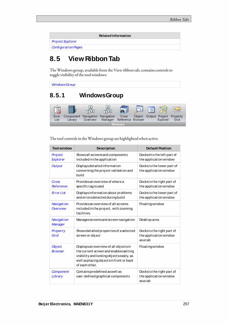
RibbonTabs
Related information
Project Explorer
Configuration Pages
8.5 View Ribbon TabTheWindows group, available from theView ribbon tab, contains controls totoggle visibility of the tool windows:
Windows Group
8.5.1 Windows Group
The tool controls in theWindows group are highlightedwhen active.
Tool window Description Default Position
ProjectExplorer
Shows all screens and componentsincluded in the application
Docked to the left part ofthe application window
Output Displays detailed informationconcerning the project validation andbuild
Docks to the lower part ofthe application window
CrossReference
Provides an overview of where aspecific tag is used
Docks to the right part ofthe application window
Error List Displays information about problemsand errors detected during build
Docks to the lower part ofthe application window
NavigationOverview
Provides an overview of all screensincluded in the project, with zoomingfacilities.
Floating window
NavigationManager
Manages screens and screen navigation Desktop area
PropertyGrid
Shows detailed properties of a selectedscreen or object
Docks to the right part ofthe application windowas a tab
ObjectBrowser
Displays an overview of all objects inthe current screen and enables settingvisibility and locking objects easily, aswell as placing objects in front or backof each other.
Floating window
ComponentLibrary
Contains predefined as well asuser-defined graphical components
Docks to the right part ofthe application windowas a tab
Beijer Electronics, MAEN831Y 257
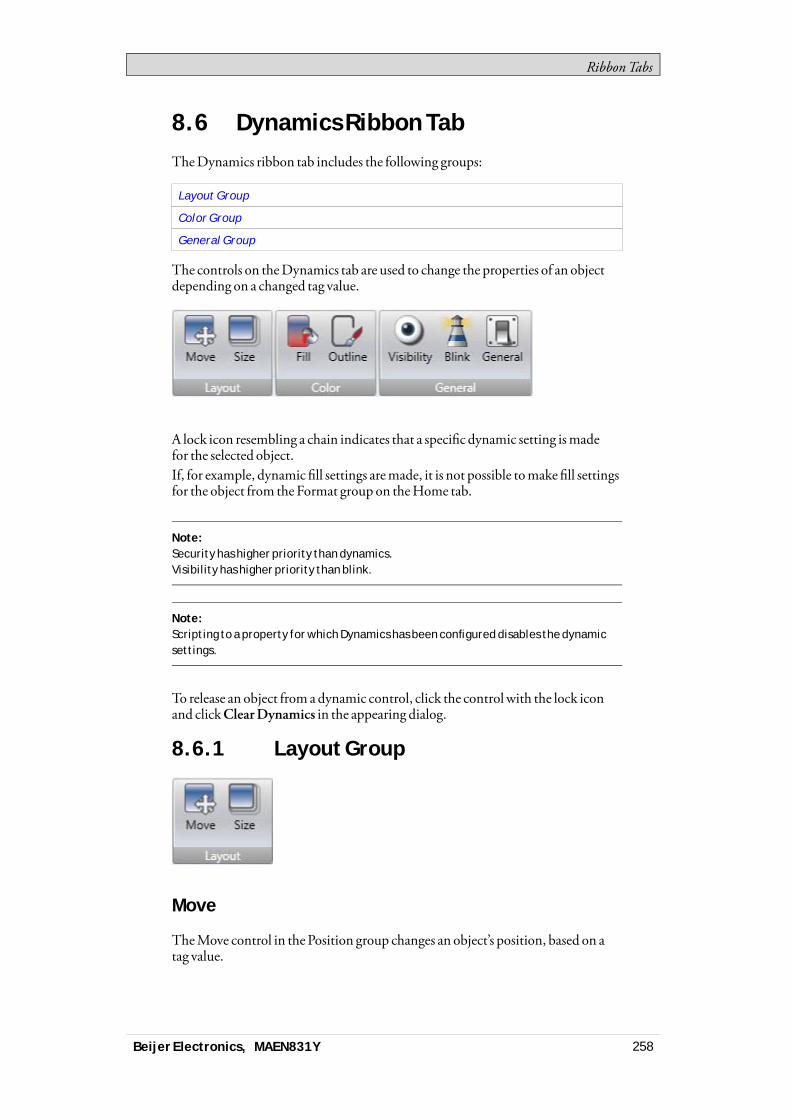
RibbonTabs
8.6 Dynamics Ribbon TabTheDynamics ribbon tab includes the following groups:
Layout Group
Color Group
General Group
The controls on theDynamics tab are used to change the properties of an objectdepending on a changed tag value.
A lock icon resembling a chain indicates that a specific dynamic setting ismadefor the selected object.If, for example, dynamic fill settings aremade, it is not possible tomake fill settingsfor the object from the Format group on theHome tab.
Note:Security has higher priority than dynamics.Visibility has higher priority than blink.
Note:Scripting to a property for which Dynamics has been configured disables the dynamicsettings.
To release an object from adynamic control, click the control with the lock iconand clickClearDynamics in the appearing dialog.
8.6.1 Layout Group
Move
TheMove control in the Position group changes an object’s position, based on atag value.
Beijer Electronics, MAEN831Y 258

RibbonTabs
Position coordinates on the screen are given in pixels of the screen resolution. Theposition 0,0 corresponds to the upper left corner of the screen.Tomove an object verticallywhen a tag value changes:1. Draw and position the object at the start position. Keep the object selected.2. Click onMove on theDynamics tab to open theMoveDynamics Editor.3. Select the tag to control themovement.4. Enter a start and end value for the tag.
Start and endpositions are suggested based on the current start position. Aghost object will appear at the suggested finish position. A guide line thatconnects the center of the original object with the ghost object appears.
5. Move the ghost object in the screen to its final position.The coordinates for the object is updated. An animation of themove appearson the screen. Coordinate values can also be updated directly in the numericalfields (EndTop, EndLeft). The coordinates for start and finishwill limit themovement of the object irrespective if the tag value is outside its start and endvalue.
6. ClickOK to save and close theMoveDynamics Editor.
WhenPosition or Size dynamics is applied,moving or resizing of the object willbe disabled. A lock icon resembling a chain in the upper left corner of the object(when selected) indicates that the object has a dynamic control applied and thatit cannot bemoved or resized.
Size
The Size control in the Size group changes an object’s size, based on a tag value.
Beijer Electronics, MAEN831Y 259
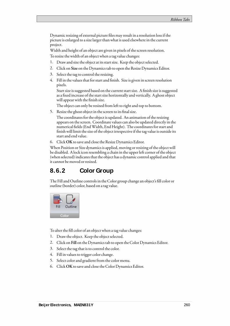
RibbonTabs
Dynamic resizing of external picture filesmay result in a resolution loss if thepicture is enlarged to a size larger thanwhat is used elsewhere in the currentproject.Width and height of an object are given in pixels of the screen resolution.To resize thewidth of an object when a tag value changes:1. Draw and size the object at its start size. Keep the object selected.2. Click on Size on theDynamics tab to open theResizeDynamics Editor.3. Select the tag to control the resizing.4. Fill in the values that for start and finish. Size is given in screen resolution
pixels.Start size is suggested based on the current start size. A finish size is suggestedas a fixed increase of the start size horizontally and vertically. A ghost objectwill appearwith the finish size.The object can only be resized from left to right and top to bottom.
5. Resize the ghost object in the screen to its final size.The coordinates for the object is updated. An animation of the resizingappears on the screen. Coordinate values can also be updated directly in thenumerical fields (EndWidth, EndHeight). The coordinates for start andfinishwill limit the size of the object irrespective if the tag value is outside itsstart and end value.
6. ClickOK to save and close theResizeDynamics Editor.WhenPosition or Size dynamics is applied,moving or resizing of the object willbe disabled. A lock icon resembling a chain in the upper left corner of the object(when selected) indicates that the object has a dynamic control applied and thatit cannot bemoved or resized.
8.6.2 Color Group
TheFill andOutline controls in theColor group change an object’s fill color oroutline (border) color, based on a tag value.
To alter the fill color of an object when a tag value changes:1. Draw the object. Keep the object selected.2. Click onFill on theDynamics tab to open theColorDynamics Editor.3. Select the tag that is to control the color.4. Fill in values to trigger color change.5. Select color and gradient from the colormenu.6. ClickOK to save and close theColorDynamics Editor.
Beijer Electronics, MAEN831Y 260
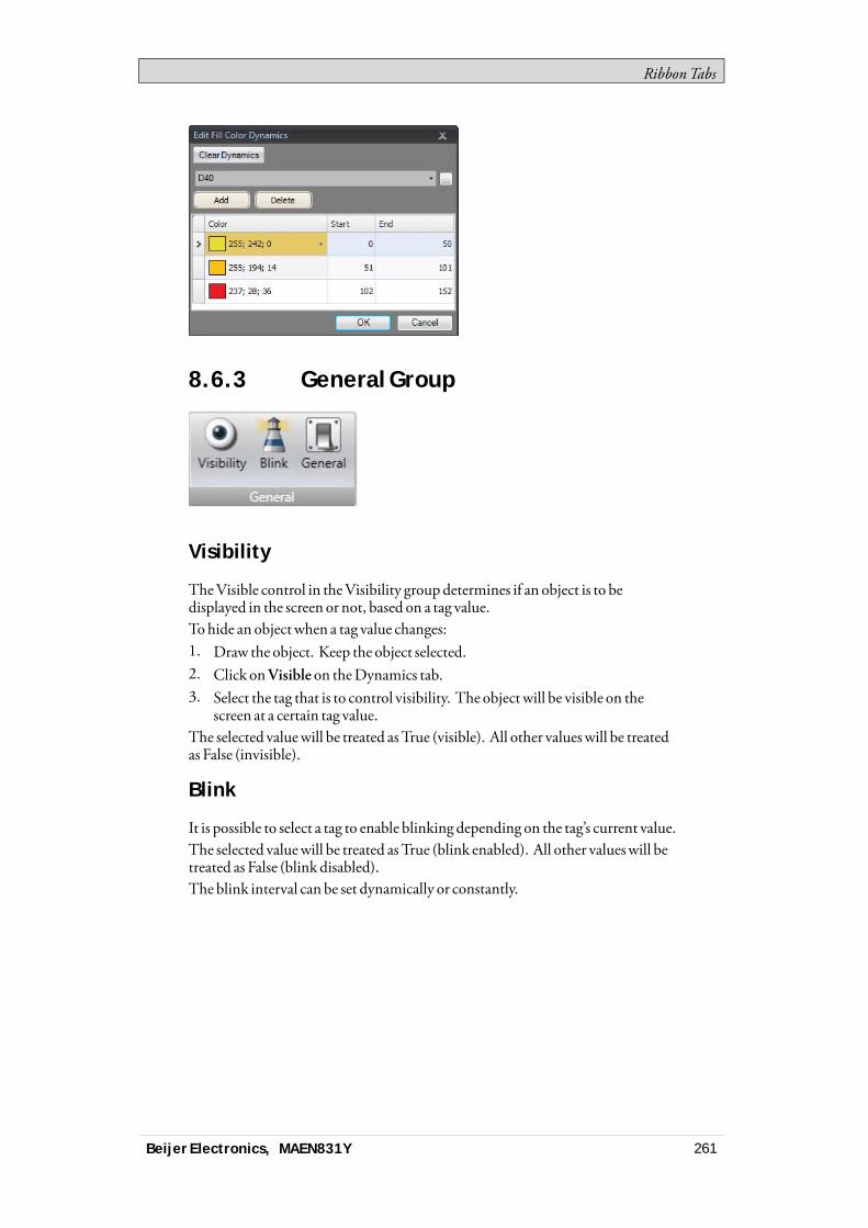
RibbonTabs
8.6.3 General Group
Visibility
TheVisible control in theVisibility groupdetermines if an object is to bedisplayed in the screen or not, based on a tag value.To hide an object when a tag value changes:1. Draw the object. Keep the object selected.2. Click onVisible on theDynamics tab.3. Select the tag that is to control visibility. The object will be visible on the
screen at a certain tag value.The selected valuewill be treated asTrue (visible). All other valueswill be treatedas False (invisible).
Blink
It is possible to select a tag to enable blinking depending on the tag’s current value.The selected valuewill be treated asTrue (blink enabled). All other valueswill betreated as False (blink disabled).The blink interval can be set dynamically or constantly.
Beijer Electronics, MAEN831Y 261

RibbonTabs
Note:Security has higher priority than dynamics.Visibility has higher priority than blink.
Related information
Blinking Objects
General
The general control offers a possibility to alter the properties of objects iniXRuntime.
Converter Operators
Converter operators are used to alter the properties of the objects. The converteroperators can be selected from theEdit general dynamicsdialog.
Parameter Description
Bool Converter Converts 0 to false and all other values totrue.
Color Converter Converts value intervals to specifiedcolors.
Linear Converter Converts values according to the linearequation.
Raw Converter Converts the value to a new valuematching the target type.
Text Library Group converter Converts a value to a text.
Beijer Electronics, MAEN831Y 262
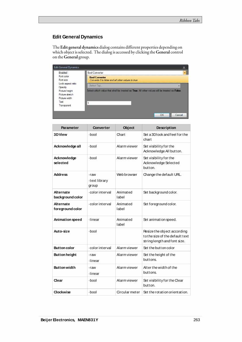
RibbonTabs
Edit General Dynamics
TheEdit general dynamicsdialog contains different properties depending onwhich object is selected. The dialog is accessed by clicking theGeneral controlon theGeneral group.
Parameter Converter Object Description
3D View ·bool Chart Set a 3D look and feel for thechart
Acknowledge all ·bool Alarm viewer Set visibility for theAcknowledge All button.
Acknowledgeselected
·bool Alarm viewer Set visibility for theAcknowledge Selectedbutton.
Address ·raw
·text librarygroup
Web browser Change the default URL.
Alternatebackground color
·color interval Animatedlabel
Set background color.
Alternateforeground color
·color interval Animatedlabel
Set foreground color.
Animation speed ·linear Animatedlabel
Set animation speed.
Auto-size ·bool Resize the object accordingto the size of the default textstring length and font size.
Button color ·color interval Alarm viewer Set the button color
Button height ·raw
·linear
Alarm viewer Set the height of thebuttons.
Button width ·raw
·linear
Alarm viewer Alter the width of thebuttons.
Clear ·bool Alarm viewer Set visibility for the Clearbutton.
Clockwise ·bool Circular meter Set the rotation orientation.
Beijer Electronics, MAEN831Y 263
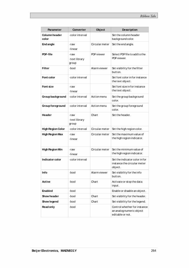
RibbonTabs
Parameter Converter Object Description
Column headercolor
·color interval Set the column headerbackground color.
End angle ·raw
·linear
Circular meter Set the end angle.
PDF-file ·raw
·text librarygroup
PDF viewer Select PDF file to add to thePDF viewer.
Filter ·bool Alarm viewer Set visibility for the filterbutton.
Font color ·color interval Set font color in for instancethe text object.
Font size ·raw
·linear
Set font size in for instancethe text object.
Group background ·color interval Action menu Set the group backgroundcolor.
Group foreground ·color interval Action menu Set the group foregroundcolor.
Header ·raw
·text librarygroup
Chart Set the header.
High Region Color ·color interval Circular meter Set the high region color.
High Region Max ·raw
·linear
Circular meter Set the maximum value ofthe high region indicator.
High Region Min ·raw
·linear
Circular meter Set the minimum value ofthe high region indicator.
Indicator color ·color interval Set the indicator color in forinstance the circular meterobject.
Info ·bool Alarm viewer Set visibility for the infobutton.
Active ·bool Chart Activate or stop the datainput.
Enabled ·bool Enable or disable an object.
Show header ·bool Chart Set visibility for the header.
Show legend ·bool Chart Set visibility for the legend.
Read only ·bool Control whether for instancean analog numeric objecteditable or not.
Beijer Electronics, MAEN831Y 264

RibbonTabs
Parameter Converter Object Description
Auto-scale X-axis ·bool Chart Used with the chartobject to toggle whetheriX Runtime automaticallyshould calculate theminimum and maximumX Axis values or not.
Show X-axis grid ·bool Chart Set visibility for the X Axisgrid.
Show X-axis ·bool Chart Set visibility for the X Axis.
Auto-scale Y1-axis ·bool Chart Used with the chartobject to toggle whetheriX Runtime automaticallyshould calculate theminimum and maximumY1 Axis values or not.
Show Y1-axis grid ·bool Chart Set visibility for the Y1 Axisgrid.
Show Y1-axis ·bool Chart Set visibility for the Y1 Axis.
Auto-scale Y2-axis ·bool Chart The bool converter can beused with the chart object totoggle whether iX Runtimeautomatically shouldcalculate the minimumand maximum Y2 Axis valuesor not.
Show Y2-axis grid ·bool Chart Set visibility for the Y2 Axisgrid.
Show Y2-axis ·bool Chart Set visibility for the Y2 Axis.
Lock aspect ratio ·bool Multi picture Used with the multi pictureobject to toggle theheight/width ratio of theobject.
Low region color ·color interval Circular meter Set the low region color.
Low region max ·raw
·linear
Circular meter Set the maximum value ofthe low region indicator.
Low region min ·raw
·linear
Circular meter Set the minimum value ofthe low region indicator.
Major ticks ·raw
·linear
Set the number of labeledtime marks in for instancethe linear meter object.
Maximum ·raw
·linear
Set the end value of thescale in for instance thelinear meter object.
Major value tics ·raw
·linear
Trend viewer Set the number of labeledscale marks on the scale.
Beijer Electronics, MAEN831Y 265
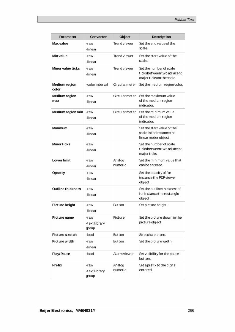
RibbonTabs
Parameter Converter Object Description
Max value ·raw
·linear
Trend viewer Set the end value of thescale.
Min value ·raw
·linear
Trend viewer Set the start value of thescale.
Minor value ticks ·raw
·linear
Trend viewer Set the number of scaleticks between two adjacentmajor ticks on the scale.
Medium regioncolor
·color interval Circular meter Set the medium region color.
Medium regionmax
·raw
·linear
Circular meter Set the maximum valueof the medium regionindicator.
Medium region min ·raw
·linear
Circular meter Set the minimum valueof the medium regionindicator.
Minimum ·raw
·linear
Set the start value of thescale in for instance thelinear meter object.
Minor ticks ·raw
·linear
Set the number of scaleticks between two adjacentmajor ticks.
Lower limit ·raw
·linear
Analognumeric
Set the minimum value thatcan be entered.
Opacity ·raw
·linear
Set the opacity of forinstance the PDF viewerobject.
Outline thickness ·raw
·linear
Set the outline thickness offor instance the rectangleobject.
Picture height ·raw
·linear
Button Set picture height.
Picture name ·raw
·text librarygroup
Picture Set the picture shown in thepicture object.
Picture stretch ·bool Button Stretch a picture.
Picture width ·raw
·linear
Button Set the picture width.
Play/Pause ·bool Alarm viewer Set visibility for the pausebutton.
Prefix ·raw
·text librarygroup
Analognumeric
Set a prefix to the digitsentered.
Beijer Electronics, MAEN831Y 266
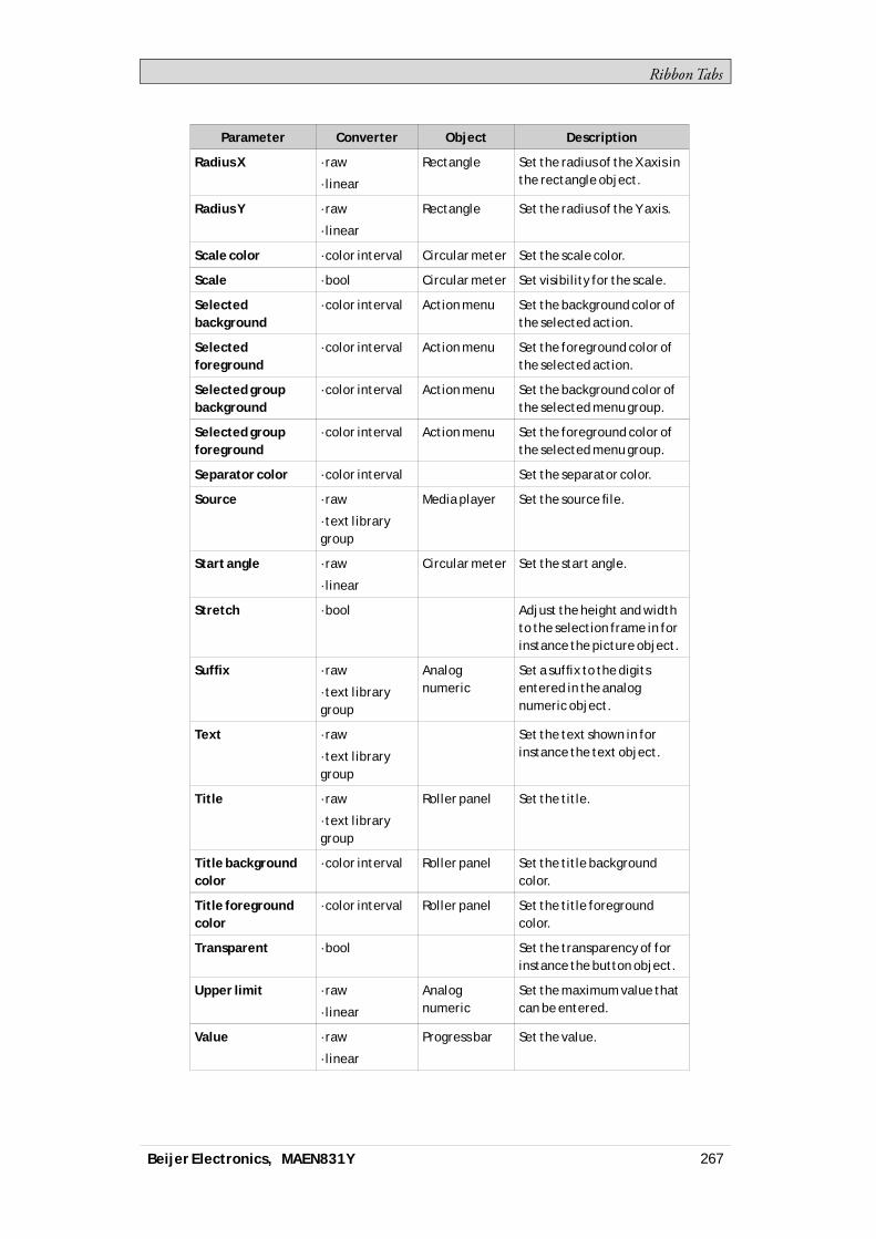
RibbonTabs
Parameter Converter Object Description
Radius X ·raw
·linear
Rectangle Set the radius of the X axis inthe rectangle object.
Radius Y ·raw
·linear
Rectangle Set the radius of the Y axis.
Scale color ·color interval Circular meter Set the scale color.
Scale ·bool Circular meter Set visibility for the scale.
Selectedbackground
·color interval Action menu Set the background color ofthe selected action.
Selectedforeground
·color interval Action menu Set the foreground color ofthe selected action.
Selected groupbackground
·color interval Action menu Set the background color ofthe selected menu group.
Selected groupforeground
·color interval Action menu Set the foreground color ofthe selected menu group.
Separator color ·color interval Set the separator color.
Source ·raw
·text librarygroup
Media player Set the source file.
Start angle ·raw
·linear
Circular meter Set the start angle.
Stretch ·bool Adjust the height and widthto the selection frame in forinstance the picture object.
Suffix ·raw
·text librarygroup
Analognumeric
Set a suffix to the digitsentered in the analognumeric object.
Text ·raw
·text librarygroup
Set the text shown in forinstance the text object.
Title ·raw
·text librarygroup
Roller panel Set the title.
Title backgroundcolor
·color interval Roller panel Set the title backgroundcolor.
Title foregroundcolor
·color interval Roller panel Set the title foregroundcolor.
Transparent ·bool Set the transparency of forinstance the button object.
Upper limit ·raw
·linear
Analognumeric
Set the maximum value thatcan be entered.
Value ·raw
·linear
Progress bar Set the value.
Beijer Electronics, MAEN831Y 267
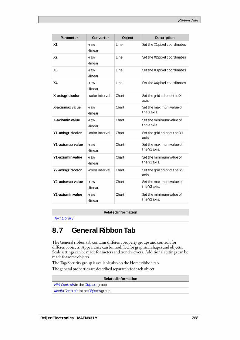
RibbonTabs
Parameter Converter Object Description
X1 ·raw
·linear
Line Set the X1 pixel coordinates
X2 ·raw
·linear
Line Set the X2 pixel coordinates
X3 ·raw
·linear
Line Set the X3 pixel coordinates
X4 ·raw
·linear
Line Set the X4 pixel coordinates
X-axis grid color ·color interval Chart Set the grid color of the Xaxis.
X-axis max value ·raw
·linear
Chart Set the maximum value ofthe X axis.
X-axis min value ·raw
·linear
Chart Set the minimum value ofthe X axis
Y1-axis grid color ·color interval Chart Set the grid color of the Y1axis.
Y1-axis max value ·raw
·linear
Chart Set the maximum value ofthe Y1 axis.
Y1-axis min value ·raw
·linear
Chart Set the minimum value ofthe Y1 axis.
Y2-axis grid color ·color interval Chart Set the grid color of the Y2axis.
Y2-axis max value ·raw
·linear
Chart Set the maximum value ofthe Y2 axis.
Y2-axis min value ·raw
·linear
Chart Set the minimum value ofthe Y2 axis.
Related information
Text Library
8.7 General Ribbon TabTheGeneral ribbon tab contains different property groups and controls fordifferent objects. Appearance can bemodified for graphical shapes and objects.Scale settings can bemade formeters and trend viewers. Additional settings can bemade for some objects.TheTag/Security group is available also on theHome ribbon tab.The general properties are described separately for each object.
Related information
HMI Controls in the Objects group
Media Controls in the Objects group
Beijer Electronics, MAEN831Y 268

RibbonTabs
Related information
Special Controls in the Objects group
Windows Controls in the Objects group
Tag/Security Group on the Home Ribbon Tab
8.8 Actions Ribbon TabActions can be triggered in variousways, for example by clicking a button. TheActions tab controls are used to define actions for objects. Alternatively, a scriptcan be used to trigger an action.An action is something that is performed, for example closing a screen. An actiontrigger is the act that generates an action, for example clicking a button.TheActions ribbon tab contains different control groups for different objects.
AClick action configured for a button
Note:It is not recommended to use multiple trigger methods, as this may lead to undesiredbehavior. It is recommended either to use a script or to program actions withthe controls in the Actions tab. For example, avoid using Click Action Trigger incombination with Mouse Button Action Triggers.
Related information
Script
8.8.1 Click Action Trigger
Most objects can be assigned click actions, thatwill be executedwhen the object isclicked in runtime.
8.8.2 Mouse Button Action Triggers
TheMouseDown andMouseUp action triggers can be used to create two-stepactionswhen clickingwith the leftmouse button on an object.
Parameter Description
Mouse Down A Mouse Down action will be performed when the left mousebutton is pressed down on the object in runtime.
Mouse Up A Mouse Up action will be performed when the left mousebutton is released from the object in runtime.
Beijer Electronics, MAEN831Y 269
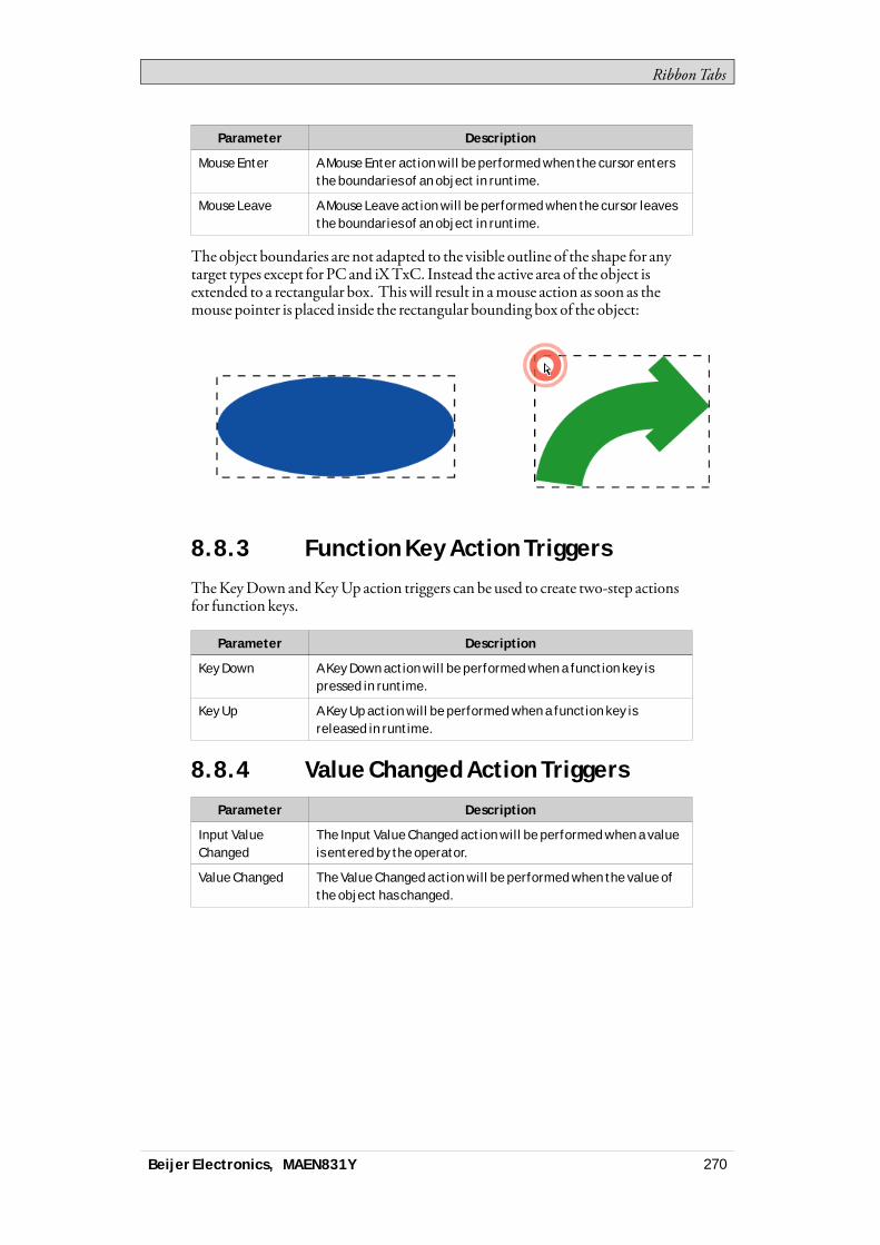
RibbonTabs
Parameter Description
Mouse Enter A Mouse Enter action will be performed when the cursor entersthe boundaries of an object in runtime.
Mouse Leave A Mouse Leave action will be performed when the cursor leavesthe boundaries of an object in runtime.
The object boundaries are not adapted to the visible outline of the shape for anytarget types except for PC and iXTxC. Instead the active area of the object isextended to a rectangular box. This will result in amouse action as soon as themouse pointer is placed inside the rectangular bounding box of the object:
8.8.3 Function Key Action Triggers
TheKeyDown andKeyUp action triggers can be used to create two-step actionsfor function keys.
Parameter Description
Key Down A Key Down action will be performed when a function key ispressed in runtime.
Key Up A Key Up action will be performed when a function key isreleased in runtime.
8.8.4 Value Changed Action Triggers
Parameter Description
Input ValueChanged
The Input Value Changed action will be performed when a valueis entered by the operator.
Value Changed The Value Changed action will be performed when the value ofthe object has changed.
Beijer Electronics, MAEN831Y 270

RibbonTabs
8.8.5 Tags Action Triggers
Parameter Description
Value Changed(tag will alwaysbe active)
The tag will always be active.
Value Changed(tag will bepolled as needed)
The event will only trigger if the tag is active. The tag can bedeactivated if it is not in use by anything else. When the tag isdeactivated the event will remain idle until the tag is activated.
8.8.6 Focus Action Triggers
Parameter Description
Got Focus The Got Focus action will be performed when the object isselected.
Lost Focus The Lost Focus action will be performed when the object is nolonger selected.
8.8.7 Navigation Action Triggers
Parameter Description
Navigated The Navigated action will be performed when having navigatedto the address entered in the address field of the Web browserobject.
Navigating The Navigating action will be performed when having entered,but not reached, an address in the address field of the Webbrowser object.
8.8.8 Data Logger Action Triggers
TheLogItemValueChanged andLogValuesUpdated are available for theDataLogger.
8.8.9 Alarm Server Action Triggers
Alarm server actions can be configured for the entire alarm server, for alarm groupsor for individual alarm items. The actionswill be activated upon alarm statuschanges.
Related information
Alarm Server Events and Actions
Actions and Events for Alarm Items and Alarm Groups
8.8.10 Action Groups
Actions are divided into action groups.
Beijer Electronics, MAEN831Y 271
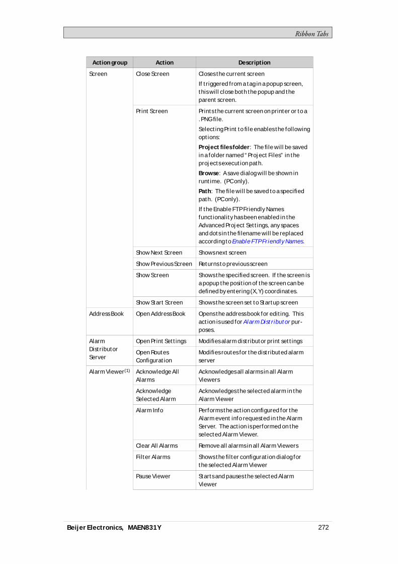
RibbonTabs
Action group Action Description
Close Screen Closes the current screen
If triggered from a tag in a popup screen,this will close both the popup and theparent screen.
Print Screen Prints the current screen on printer or to a.PNG file.
Selecting Print to file enables the followingoptions:
Project files folder: The file will be savedin a folder named “Project Files” in theprojects execution path.
Browse: A save dialog will be shown inruntime. (PC only).
Path: The file will be saved to a specifiedpath. (PC only).
If the Enable FTP Friendly Namesfunctionality has been enabled in theAdvanced Project Settings, any spacesand dots in the filename will be replacedaccording to Enable FTP Friendly Names.
Show Next Screen Shows next screen
Show Previous Screen Returns to previous screen
Show Screen Shows the specified screen. If the screen isa popup the position of the screen can bedefined by entering (X,Y) coordinates.
Screen
Show Start Screen Shows the screen set to Startup screen
Address Book Open Address Book Opens the address book for editing. Thisaction is used for Alarm Distributor pur-poses.
Open Print Settings Modifies alarm distributor print settingsAlarmDistributorServer
Open RoutesConfiguration
Modifies routes for the distributed alarmserver
Acknowledge AllAlarms
Acknowledges all alarms in all AlarmViewers
AcknowledgeSelected Alarm
Acknowledges the selected alarm in theAlarm Viewer
Alarm Info Performs the action configured for theAlarm event info requested in the AlarmServer. The action is performed on theselected Alarm Viewer.
Clear All Alarms Remove all alarms in all Alarm Viewers
Filter Alarms Shows the filter configuration dialog forthe selected Alarm Viewer
Pause Viewer Starts and pauses the selected AlarmViewer
Alarm Viewer(1)
Beijer Electronics, MAEN831Y 272
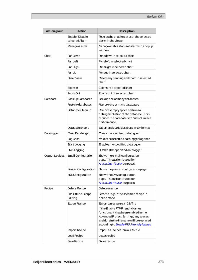
RibbonTabs
Action group Action Description
Enable/Disableselected Alarm
Toggles the enable status of the selectedalarm in the viewer
Manage Alarms Manage enable status of alarms in a popupwindow
Pan Down Pans down in selected chart
Pan Left Pans left in selected chart
Pan Right Pans right in selected chart
Pan Up Pans up in selected chart
Reset View Resets any panning and zoom in selectedchart
Zoom In Zooms into selected chart
Chart
Zoom Out Zooms out of selected chart
Back Up Databases Backup one or many databases
Restore databases Restore one or many databases
Database Cleanup Removes empty space and runs adefragmentation of the database. Thisreduces the database size and optimizesperformance.
Database
Database Export Exports selected database in csv format
Clear Datalogger Clears the specified datalogger
Log Once Makes the specified datalogger log once
Start Logging Enables the specified datalogger
Datalogger
Stop Logging Disables the specified datalogger
Email Configuration Shows the e-mail configurationpage. This action is used forAlarm Distributor purposes.
Printer Configuration Shows the printer configuration page.
Output Devices
SMS Configuration Shows the SMS configurationpage. This action is used forAlarm Distributor purposes.
Delete Recipe Deletes recipe
End Offline RecipeEditing
Sets the tags in the specified recipe inonline mode.
Export Recipe Exports a recipe to a .CSV file
If the Enable FTP Friendly Namesfunctionality has been enabled in theAdvanced Project Settings, any spacesand dots in the filename will be replacedaccording to Enable FTP Friendly Names.
Import Recipe Imports a recipe from a .CSV file
Load Recipe Loads recipe
Save Recipe Saves recipe
Recipe
Beijer Electronics, MAEN831Y 273
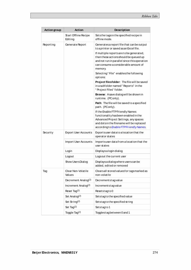
RibbonTabs
Action group Action Description
Start Offline RecipeEditing
Sets the tags in the specified recipe inoffline mode.
Reporting Generate Report Generates a report file that can be outputto a printer or saved as an Excel file.
If multiple reports are to be generated,then these actions should be queued upand not run in parallel since this operationcan consume a considerable amount ofmemory.
Selecting “File” enables the followingoptions:
Project files folder: The file will be savedin a subfolder named ”Reports” in the“Project Files” folder.
Browse: A save dialog will be shown inruntime. (PC only).
Path: The file will be saved to a specifiedpath. (PC only).
If the Enable FTP Friendly Namesfunctionality has been enabled in theAdvanced Project Settings, any spacesand dots in the filename will be replacedaccording to Enable FTP Friendly Names.
Export User Accounts Exports user data to a location that theoperator states
Import User Accounts Imports user data from a location that theuser states
Login Displays a login dialog
Logout Logs out the current user
Security
Show Users Dialog Displays a dialog where users can beadded, edited or removed
Clear Non-VolatileValues
Clears all stored values for tags marked asnon-volatile
Decrement Analog(2) Decrements tag value
Increment Analog(2) Increments tag value
Reset Tag(2) Resets tag to 0
Set Analog(2) Sets tag to the specified value
Set String(2) Sets tag to the specified string
Set Tag(2) Sets tag to 1
Tag
Toggle Tag(2) Toggles tag between 0 and 1
Beijer Electronics, MAEN831Y 274
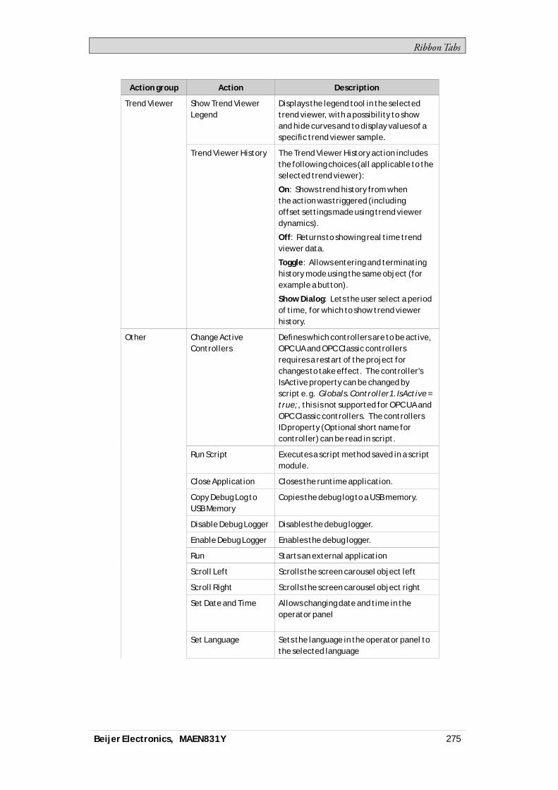
RibbonTabs
Action group Action Description
Show Trend ViewerLegend
Displays the legend tool in the selectedtrend viewer, with a possibility to showand hide curves and to display values of aspecific trend viewer sample.
Trend Viewer
Trend Viewer History The Trend Viewer History action includesthe following choices (all applicable to theselected trend viewer):
On: Shows trend history from whenthe action was triggered (includingoffset settings made using trend viewerdynamics).
Off: Returns to showing real time trendviewer data.
Toggle: Allows entering and terminatinghistory mode using the same object (forexample a button).
Show Dialog: Lets the user select a periodof time, for which to show trend viewerhistory.
Change ActiveControllers
Defines which controllers are to be active,OPC UA and OPC Classic controllersrequires a restart of the project forchanges to take effect. The controller'sIsActive property can be changed byscript e.g. Globals.Controller1.IsActive =true;, this is not supported for OPC UA andOPC Classic controllers. The controllersID property (Optional short name forcontroller) can be read in script.
Run Script Executes a script method saved in a scriptmodule.
Close Application Closes the runtime application.
Copy Debug Log toUSB Memory
Copies the debug log to a USB memory.
Disable Debug Logger Disables the debug logger.
Enable Debug Logger Enables the debug logger.
Run Starts an external application
Scroll Left Scrolls the screen carousel object left
Scroll Right Scrolls the screen carousel object right
Set Date and Time Allows changing date and time in theoperator panel
Set Language Sets the language in the operator panel tothe selected language
Other
Beijer Electronics, MAEN831Y 275

RibbonTabs
Action group Action Description
Set Time Zone,Region and DaylightSaving
Allows changing time zone, region anddaylight saving settings in the operatorpanel
Show BacklightSettings
Allows changing backlight settings in theoperator panel
When approaching 0% backlight, changesin brightness level may no longer benoticeable in the panel.
Complete dimming (to 0%) is only possibleto achieve with the marine panel types,such as iX T7AM and iX T15BM .
If a panel is restarted, the backlightsettings will only be saved if the systemtag SystemTagBacklightBrightnessLevelis used in the project and set tonon-volatile.
Show IP Settings Shows the IP settings in the operator panel
(1)All Alarm Viewer actions must be associated with an Alarm Viewer in the same screenas the object with the action configured. This also applies to actions that affect allAlarms.(2)This action can be used with Aliases.
8.8.11 Script Action
Script actions are used to execute scriptmethods in scriptmodules, triggered byactions. Scriptmodules in the project can be selected, and for each scriptmoduleallmethods are listed alongwith their exposed parameters. Staticmethods arenot supported.
To apply a script to a selected object:1. Go to theActions group and select the appropriate action trigger.2. Select actionRunScriptunderOther.3. Select one of the scripts fromScriptModules.4. This results in a list of available scriptmethods for that specific scriptmodule.
Select scriptmethod.5. The parameters for the script appears in a dialogwith information about the
parameter name and type. Complete the settings by entering a tag or a fixedvalue for each parameter, and clickOK.
Beijer Electronics, MAEN831Y 276

RibbonTabs
The script actionwill nowbe executedwhen the object is triggered.
Note:Script actions will have precedence over other script code for an object.
Related information
Script
8.8.12 Multiple Actions
Multiple actions can be configured by clicking small arrow in the lower rightcorner of any action group.
Note the small arrow in the lower right corner
The propertieswindow allows configuring and sorting additional actions. Theactions available dependofwhich object is selected in the screen prior to selectingtheActions ribbon tab.
Beijer Electronics, MAEN831Y 277
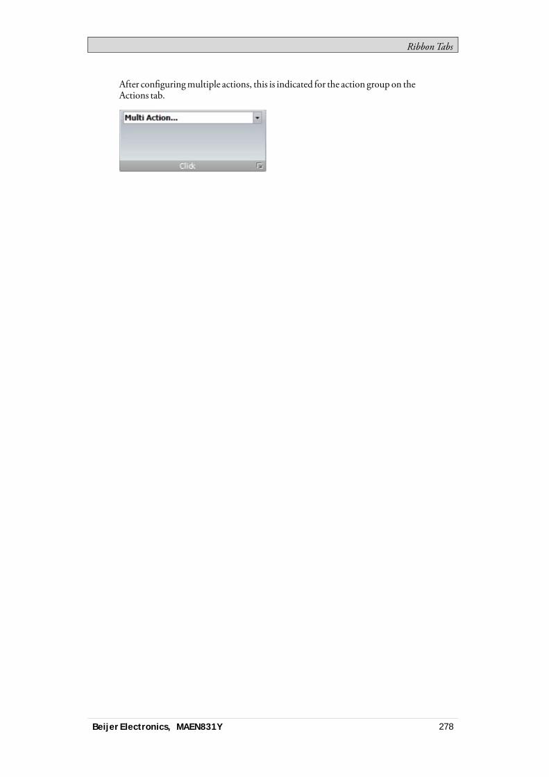
RibbonTabs
After configuringmultiple actions, this is indicated for the action group on theActions tab.
Beijer Electronics, MAEN831Y 278

TrendViewer
9 Trend Viewer
This section describes the trend viewer object. TrendViewers are used to presentchronological data from controller tags. The curves in a trend viewer can havedifferent sources of data.The source of data can be a log item for a data logger. The values of the tagconnected to the log item is then stored in the projects database.The source can also be aTag. The trend viewer curve then only shows real-timevalues and is stored in aRAMcache.When changing the system time in the panel to a later time, then datawill beloggedwith the new time. In the trend viewer therewill be a straight line betweenthe last point logged for the old time and the first point logged for the new time.If the power to the panel is cut or if there is a communication error, then therewillbe a gap in the trend viewer curve for the time periodwhere no signalwas received.
Related information
Database
Database Export
9.1 Defining Trend Viewer ObjectsIt is possible to define several independent trend viewer objects, in the same screenor in different screens. The number of trend viewer curves is limited only by theavailable amount ofmemory in the panel.
Note:A large number of trend viewer pens and short sampling intervals may affectcommunication performance.
Related information
Communication Performance
9.1.1 Adding a Trend Viewer Object
A trend viewer object is added to a screen from theObjects group on theHomeribbon tab.Settings for the trend viewer object are available from theGeneral ribbon tabwhilethe trend viewer object is selected:
Curves Group
Trend viewer curves are defined using theEditCurves control.
Beijer Electronics, MAEN831Y 279
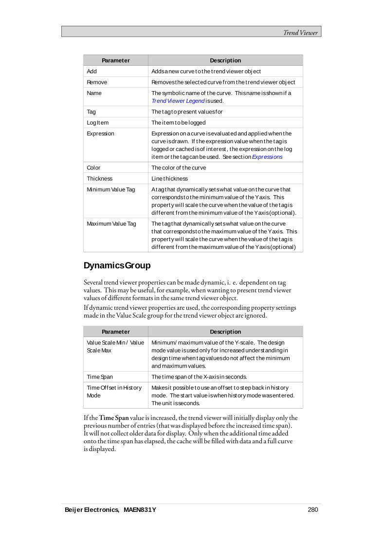
TrendViewer
Parameter Description
Add Adds a new curve to the trend viewer object
Remove Removes the selected curve from the trend viewer object
Name The symbolic name of the curve. This name is shown if aTrend Viewer Legend is used.
Tag The tag to present values for
Log Item The item to be logged
Expression Expression on a curve is evaluated and applied when thecurve is drawn. If the expression value when the tag islogged or cached is of interest, the expression on the logitem or the tag can be used. See section Expressions
Color The color of the curve
Thickness Line thickness
Minimum Value Tag A tag that dynamically sets what value on the curve thatcorresponds to the minimum value of the Y axis. Thisproperty will scale the curve when the value of the tag isdifferent from the minimum value of the Y axis (optional).
Maximum Value Tag The tag that dynamically sets what value on the curvethat corresponds to the maximum value of the Y axis. Thisproperty will scale the curve when the value of the tag isdifferent from the maximum value of the Y axis (optional)
Dynamics Group
Several trend viewer properties can bemade dynamic, i. e. dependent on tagvalues. Thismay be useful, for example, whenwanting to present trend viewervalues of different formats in the same trend viewer object.If dynamic trend viewer properties are used, the corresponding property settingsmade in theValue Scale group for the trend viewer object are ignored.
Parameter Description
Value Scale Min / ValueScale Max
Minimum/maximum value of the Y-scale. The designmode value is used only for increased understanding indesign time when tag values do not affect the minimumand maximum values.
Time Span The time span of the X-axis in seconds.
Time Offset in HistoryMode
Makes it possible to use an offset to step back in historymode. The start value is when history mode was entered.The unit is seconds.
If theTimeSpan value is increased, the trend viewerwill initially display only theprevious number of entries (thatwas displayed before the increased time span).It will not collect older data for display. Onlywhen the additional time addedonto the time span has elapsed, the cachewill be filledwith data and a full curveis displayed.
Beijer Electronics, MAEN831Y 280
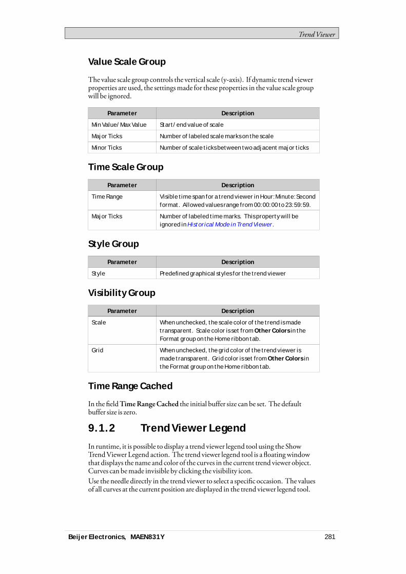
TrendViewer
Value Scale Group
The value scale group controls the vertical scale (y-axis). If dynamic trend viewerproperties are used, the settingsmade for these properties in the value scale groupwill be ignored.
Parameter Description
Min Value/Max Value Start/end value of scale
Major Ticks Number of labeled scale marks on the scale
Minor Ticks Number of scale ticks between two adjacent major ticks
Time Scale Group
Parameter Description
Time Range Visible time span for a trend viewer in Hour:Minute:Secondformat. Allowed values range from 00:00:00 to 23:59:59.
Major Ticks Number of labeled time marks. This property will beignored in Historical Mode in Trend Viewer.
Style Group
Parameter Description
Style Predefined graphical styles for the trend viewer
Visibility Group
Parameter Description
Scale When unchecked, the scale color of the trend is madetransparent. Scale color is set from Other Colors in theFormat group on the Home ribbon tab.
Grid When unchecked, the grid color of the trend viewer ismade transparent. Grid color is set from Other Colors inthe Format group on the Home ribbon tab.
Time Range Cached
In the fieldTimeRangeCached the initial buffer size can be set. The defaultbuffer size is zero.
9.1.2 Trend Viewer Legend
In runtime, it is possible to display a trend viewer legend tool using the ShowTrendViewer Legend action. The trend viewer legend tool is a floatingwindowthat displays the name and color of the curves in the current trend viewer object.Curves can bemade invisible by clicking the visibility icon.Use the needle directly in the trend viewer to select a specific occasion. The valuesof all curves at the current position are displayed in the trend viewer legend tool.
Beijer Electronics, MAEN831Y 281
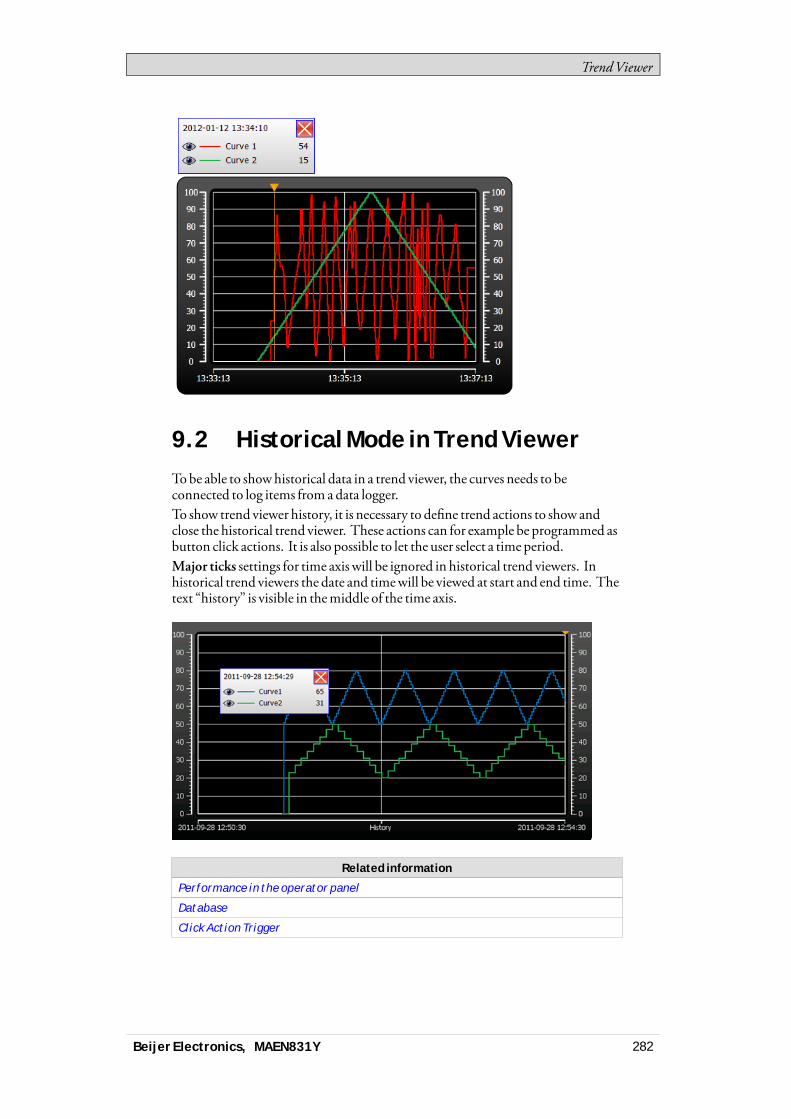
TrendViewer
9.2 Historical Mode in Trend ViewerTobe able to showhistorical data in a trend viewer, the curves needs to beconnected to log items from a data logger.To show trend viewer history, it is necessary to define trend actions to show andclose the historical trend viewer. These actions can for example be programmed asbutton click actions. It is also possible to let the user select a time period.Major ticks settings for time axis will be ignored in historical trend viewers. Inhistorical trend viewers the date and timewill be viewed at start and end time. Thetext “history” is visible in themiddle of the time axis.
Related information
Performance in the operator panel
Database
Click Action Trigger
Beijer Electronics, MAEN831Y 282
Data Logger
10 Data Logger
Data can be logged and saved in the iXDeveloper database.Anynumber of tags can be connected to a data logger, and data values irrespectiveof type can be logged. A project can havemultiple data loggers with differentsampling alternatives.If youwant to open a database file to inspect logged data, then youneed to installan appropriate third party database viewer tool.Logged data can also be viewed in the trend viewer object by selecting a LogItemfor a curve in the EditCurves dialog.If iXRuntime is restarted at somepoint during the data logging, an additionalempty row is added in theData Logger table in order to clearly visualize theinterruption in theTrendViewer.
Note:Logging of data consumes system resources and memory. To save memory, it ispreferable that all LogItems that should be logged with the same sampling intervals areplaced in the same data logger.
Any individual data logger database can be exported in csv format using theDatabase Export action. It is recommended to use the database exportmethodrather than the backupmethod.
Related information
Database
Database Export
Adding a Trend Viewer Object
10.1 Data Logging StrategiesLogging of data can bemade at time intervals or based on changed tag values.Logging of data can bemade either by collecting all samples at every log event, orby collecting only changed values. Collecting only changed values savesmemoryand improves performance.
10.1.1 Logging Based on Time Interval
To collect data that changes frequently, logging data based on time interval isrecommended.
10.1.2 Logging Based on Changed Tag Value
To control sampling of data by othermeans than regular time interval, you haveto set up a separate tag to be used as a trigger. When the value of the trigger tagchanges the log item is logged.
Beijer Electronics, MAEN831Y 283

Data Logger
10.1.3 Maximizing the Lifetime of theStorage Media
The storagemedia in the iXpanel is based onFlash SSD (Solid StateDrive).Flash SSDhas nomoving ormechanical parts, which gives high and reliableperformance. The Flash SSDcan handle data very fast and efficiently and thedata is controlled by the drivemanufacturers’ confidential algorithm. As thealgorithm is intellectual property it is not possible to calculate the lifetime, thedrivemanufacturers only publish the numbers of reads andwrites.Best practice is tominimize number ofwrites tomaximize the lifetime of the FlashSSD. Follow the advice below to reduce the risk of prematurewear out (before theestimated lifetime). Anonworking Flash SSD stops the panel fromoperating.• Donot log valueswith higher accuracy than needed. For example, avoid
logging of floating point values.• Reduce high fluctuating values by using the hysteresis functionality in the
connected controller.• Collect valueswith high fluctuating values in the same logger and do notmix
with stable values. Collect slow changing values in other loggers.• Donot logwith higher refresh rate thanneeded.• Disable logging completelywhen information is not needed, for example
when themachine is not running.• Use default settingLog changes only in the property setting of the logger.• Keep the log size to aminimum, as few rows as needed.• Avoid extensive filewritingwhen controlling storage via script.
10.2 Adding a Data LoggerAdata logger can be added to the project from the Insert ribbon tab. The datalogger configuration pages are used to set upwhich values to log.
Parameter Description
Name Symbolic name for the logged tag
Tag Tag to log
Expression See section Expressions
Beijer Electronics, MAEN831Y 284
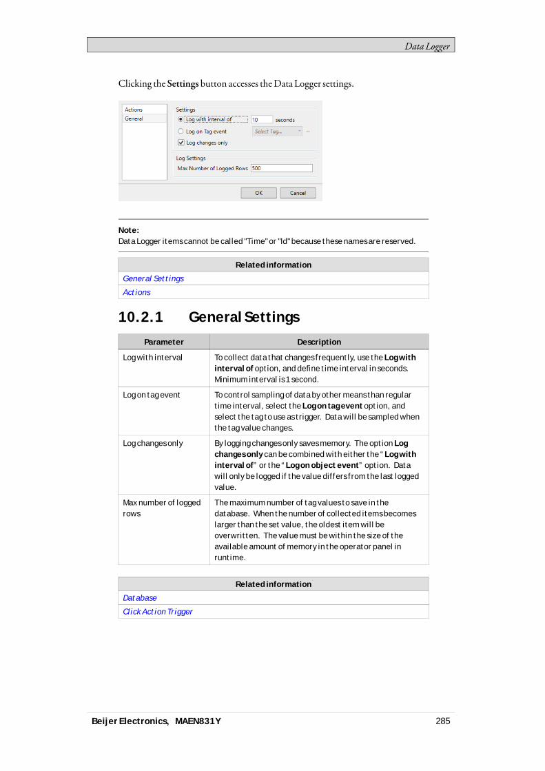
Data Logger
Clicking the Settings button accesses theData Logger settings.
Note:Data Logger items cannot be called "Time" or "Id" because these names are reserved.
Related information
General Settings
Actions
10.2.1 General Settings
Parameter Description
Log with interval To collect data that changes frequently, use the Log withinterval of option, and define time interval in seconds.Minimum interval is 1 second.
Log on tag event To control sampling of data by other means than regulartime interval, select the Log on tag event option, andselect the tag to use as trigger. Data will be sampled whenthe tag value changes.
Log changes only By logging changes only saves memory. The option Logchanges only can be combined with either the “Log withinterval of” or the “Log on object event” option. Datawill only be logged if the value differs from the last loggedvalue.
Max number of loggedrows
The maximum number of tag values to save in thedatabase. When the number of collected items becomeslarger than the set value, the oldest item will beoverwritten. The value must be within the size of theavailable amount of memory in the operator panel inruntime.
Related information
Database
Click Action Trigger
Beijer Electronics, MAEN831Y 285

Data Logger
10.2.2 Actions
Event Description
Log item Valuechanged
When a value of an particular log item has changed
Log values updated When any log value is updated
Beijer Electronics, MAEN831Y 286
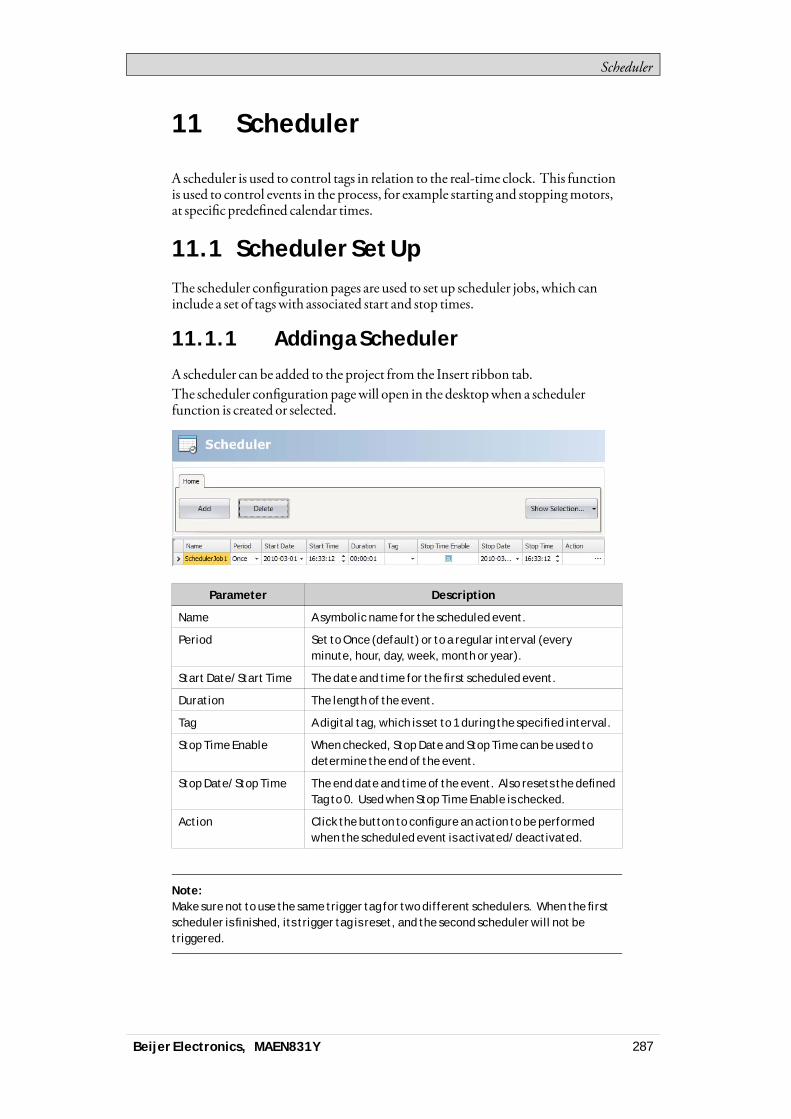
Scheduler
11 Scheduler
A scheduler is used to control tags in relation to the real-time clock. This functionis used to control events in the process, for example starting and stoppingmotors,at specific predefined calendar times.
11.1 Scheduler Set UpThe scheduler configuration pages are used to set up scheduler jobs, which caninclude a set of tagswith associated start and stop times.
11.1.1 Adding a Scheduler
A scheduler can be added to the project from the Insert ribbon tab.The scheduler configuration pagewill open in the desktopwhen a schedulerfunction is created or selected.
Parameter Description
Name A symbolic name for the scheduled event.
Period Set to Once (default) or to a regular interval (everyminute, hour, day, week, month or year).
Start Date/Start Time The date and time for the first scheduled event.
Duration The length of the event.
Tag A digital tag, which is set to 1 during the specified interval.
Stop Time Enable When checked, Stop Date and Stop Time can be used todetermine the end of the event.
Stop Date/Stop Time The end date and time of the event. Also resets the definedTag to 0. Used when Stop Time Enable is checked.
Action Click the button to configure an action to be performedwhen the scheduled event is activated/deactivated.
Note:Make sure not to use the same trigger tag for two different schedulers. When the firstscheduler is finished, its trigger tag is reset, and the second scheduler will not betriggered.
Beijer Electronics, MAEN831Y 287

Reports
12 Reports
The report generator allows generatingExcel reports based on anMicrosoft Excelmade report template.The generated report can be output to a printer or saved as anExcel file or asimplified PDFfile.
12.1 Reports Template Set upThe tag data to be displayed in the report file are set up in the template file using“placeholders”.The placeholders acts as substitute for the actual tag data that is to be insertedwhen the report is generated in iXRuntime.To add a placeholder, enter the following text inside a cell in the Excel reporttemplate:<#Tag(TagName)>Replace “TagName”with the actual name of the tag to be displayed.When the template file is complete it needs to be added to the iXDeveloperproject.
Note:The tag placeholders can only be used in the cells of the Excel template file, they cannot be used in, for example, Microsoft Excel WordArt texts.
12.1.1 Limitations
• Microsoft Excel xlsx format is not supported by the report generator.• Microsoft Excel xls format only supports 65536 rows. Ifmore data is stored in
the report, informationmay be lost.• Reports containing charts and pictures can not be printed from apanel target.• The report generation is not an instant process. Itmay elapse a shorter period
of time between the first sampled tag and the last sampled tag, depending onthe number of tags to process.
• ThePDF conversion cannot convert diagrams.• ThePDF conversion donot support simplifiedChinese orKorean.• If the content of an excel-cell is large enough to overflow the document,
generating a PDFfilewill trim the data exceeding the pagewidth.
Only the following excel features are supported:• Text in the following fonts: Helvetica, TimesNewRoman,Courier, Arial,
Verdana, Symbol andZapfDingbats• Text size• Text styles: italic, bold, underscore• Bitmap images• Cell borders• Cell background color• Print scale (File->Print->Settings)• PageHeader/Footer
Beijer Electronics, MAEN831Y 288
Reports
12.1.2 Database Driven Reports
Tobe able to create database driven reports, the report templatemust be preparedas described in these instructions:
Note:Queries have to be written in a language supported by the selected database. SeeDatabase for more information.
Configuration Sheet
The configuration sheet is a repositorywhere configurations on theMicrosoftExcel report template can bemade. This sheet is not visible in the generatedreport.1. Create a newworksheet in the report template. Name the sheet <#Config>.2. Row10, and all rows below, in columnA andB canbe used to configure the
SQLqueries. Enter the SQLquery in columnB.Use the corresponding cellin columnA to enter a name for the query. The name is used to refer to thequery in the report template.
Enter the SQLqueries in the following format:SQL(DatabaseName; SQLquery)Example: SQL(General; SELECT*FROMDataLogger1)There are two available databases: General andAuditTrail.
Present the Database Data in the Report
The data retrieved from the SQLdatabase, using the queries in the configurationsheet, can be presented in the report using “named ranges” inMicrosoft Excel.A named range is created inMicrosoft Excel by following these steps:1. Select the cells to be included in a named range.2. Click theDefinename command from the Insertmenu. (InExcel 2007, go
to theFormulas tab and chooseNameManager).3. Enter a name for the range. The namemust be entered in the following
format:“__QueryName__”.Replace “QueryName”with the name that you have chosen for your SQLquery.
To present the data in the report, enter the following syntax into the cells includedin the named range:<#QueryName.DatabaseColumnName>Replace the “DatabaseColumnName” entrywith the actual name of the table inthe SQLdatabase that youwish to present in the report.
Note:It is possible to use the named range cells in Microsoft Excel charts and functions.To be able to use the named range in functions, an empty row must be inserted underthe named range cells. This empty row must also be included in the function.
Beijer Electronics, MAEN831Y 289
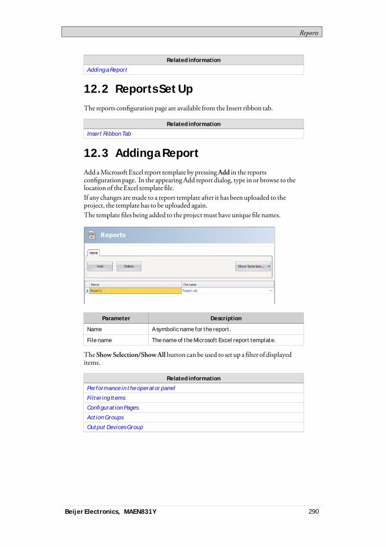
Reports
Related information
Adding a Report
12.2 Reports Set UpThe reports configuration page are available from the Insert ribbon tab.
Related information
Insert Ribbon Tab
12.3 Adding a ReportAdd aMicrosoft Excel report template by pressingAdd in the reportsconfiguration page. In the appearingAdd report dialog, type in or browse to thelocation of the Excel template file.If any changes aremade to a report template after it has been uploaded to theproject, the template has to be uploaded again.The template files being added to the projectmust have unique file names.
Parameter Description
Name A symbolic name for the report.
File name The name of the Microsoft Excel report template.
TheShowSelection/ShowAll button can be used to set up a filter of displayeditems.
Related information
Performance in the operator panel
Filtering Items
Configuration Pages
Action Groups
Output Devices Group
Beijer Electronics, MAEN831Y 290
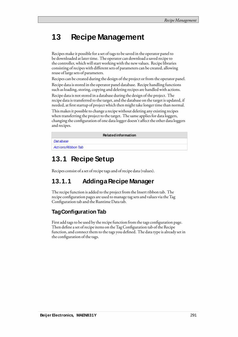
RecipeManagement
13 Recipe Management
Recipesmake it possible for a set of tags to be saved in the operator panel tobe downloaded at later time. The operator can download a saved recipe tothe controller, whichwill start workingwith the new values. Recipe librariesconsisting of recipeswith different sets of parameters can be created, allowingreuse of large sets of parameters.Recipes can be created during the design of the project or from the operator panel.Recipe data is stored in the operator panel database. Recipe handling functionssuch as loading, storing, copying and deleting recipes are handledwith actions.Recipe data is not stored in a database during the design of the project. Therecipe data is transferred to the target, and the database on the target is updated, ifneeded, at first startup of project which thenmight take longer time than normal.Thismakes it possible to change a recipewithout deleting any existing recipeswhen transferring the project to the target. The same applies for data loggers,changing the configuration of one data logger doesn't affect the other data loggersand recipes.
Related information
Database
Actions Ribbon Tab
13.1 Recipe SetupRecipes consist of a set of recipe tags and of recipe data (values).
13.1.1 Adding a Recipe Manager
The recipe function is added to the project from the Insert ribbon tab. Therecipe configuration pages are used tomanage tag sets and values via theTagConfiguration tab and theRuntimeData tab.
Tag Configuration Tab
First add tags to be used by the recipe function from the tags configuration page.Then define a set of recipe items on theTagConfiguration tab of theRecipefunction, and connect them to the tags you defined. The data type is already set inthe configuration of the tags.
Beijer Electronics, MAEN831Y 291
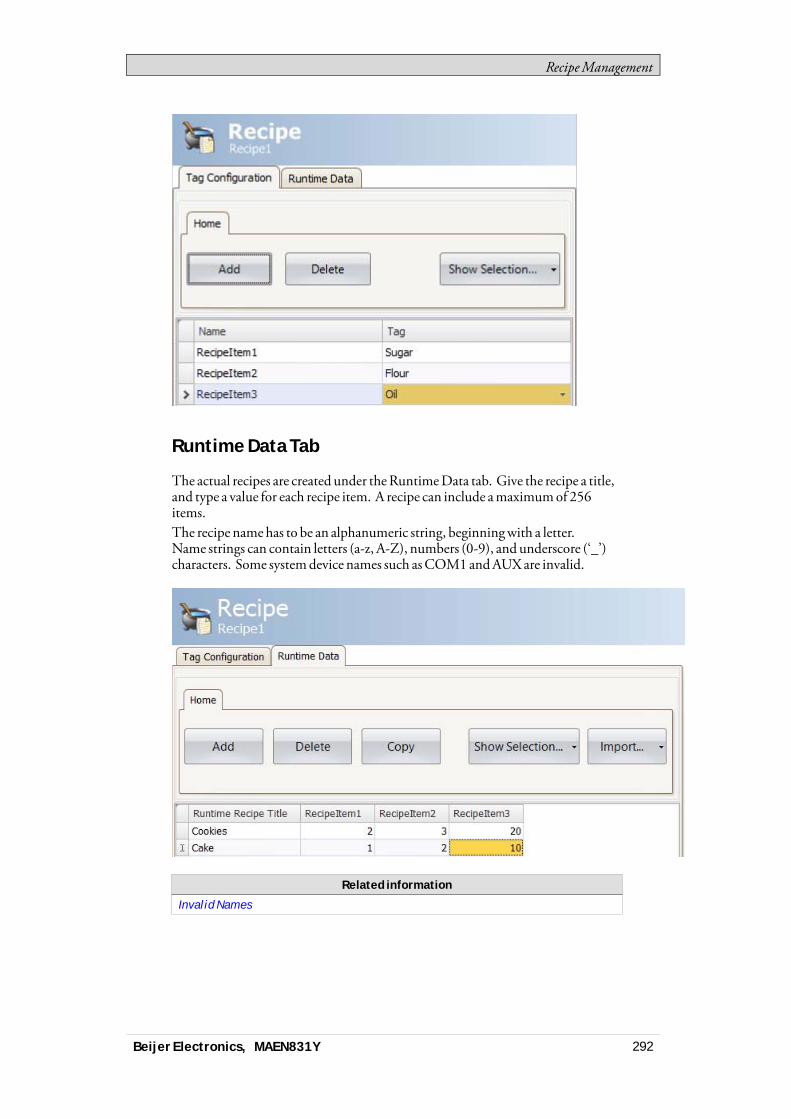
RecipeManagement
Runtime Data Tab
The actual recipes are created under theRuntimeData tab. Give the recipe a title,and type a value for each recipe item. A recipe can include amaximumof 256items.The recipe namehas to be an alphanumeric string, beginningwith a letter.Name strings can contain letters (a-z, A-Z), numbers (0-9), and underscore (‘_’)characters. Some systemdevice names such asCOM1andAUXare invalid.
Related information
Invalid Names
Beijer Electronics, MAEN831Y 292
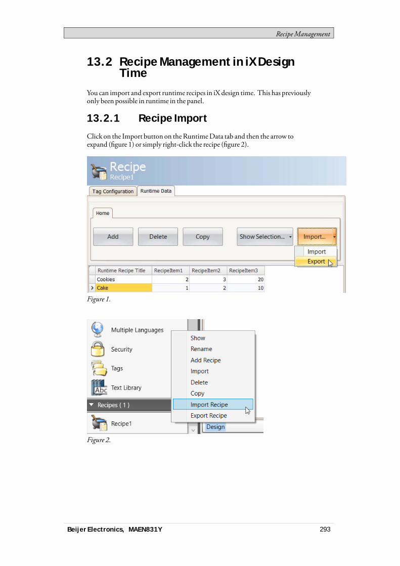
RecipeManagement
13.2 Recipe Management in iX DesignTime
You can import and export runtime recipes in iX design time. This has previouslyonly been possible in runtime in the panel.
13.2.1 Recipe Import
Click on the Import button on theRuntimeData tab and then the arrow toexpand (figure 1) or simply right-click the recipe (figure 2).
Figure 1.
Figure 2.
Beijer Electronics, MAEN831Y 293
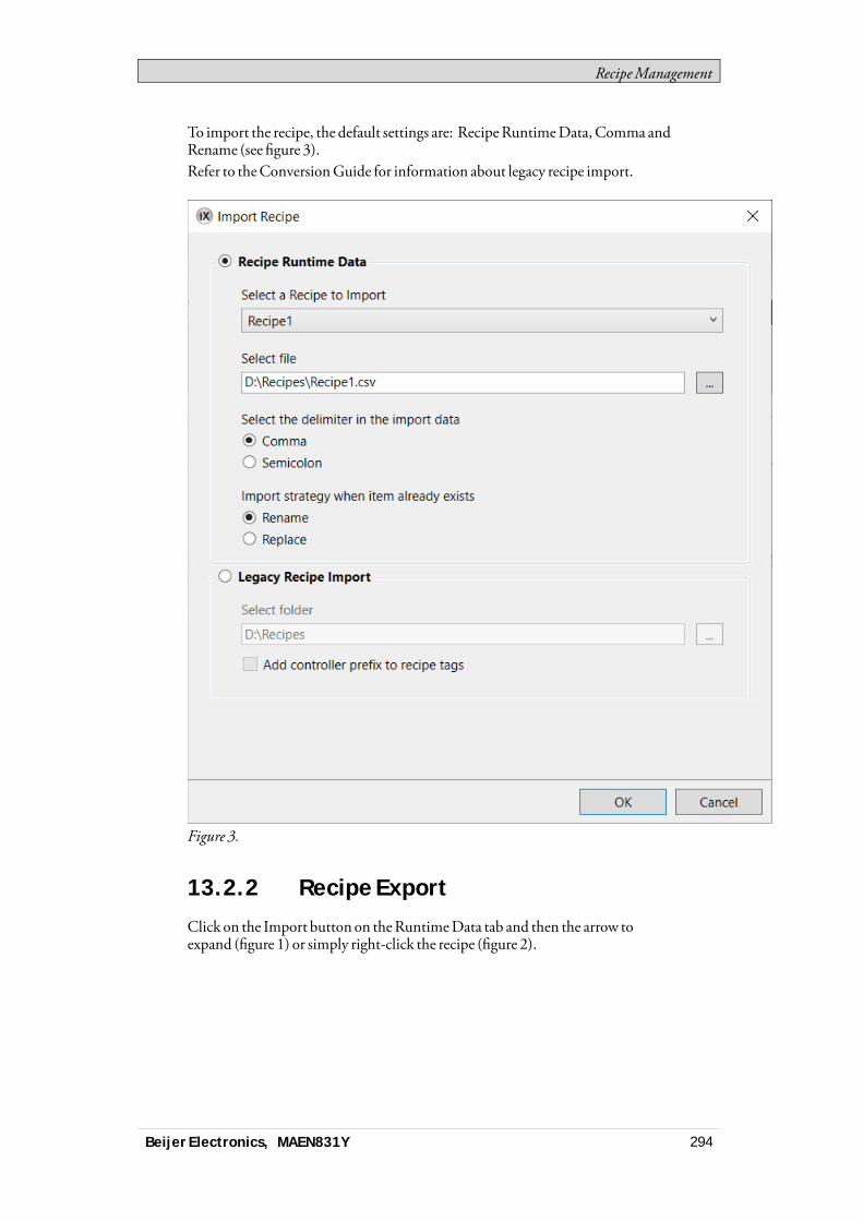
RecipeManagement
To import the recipe, the default settings are: RecipeRuntimeData, Comma andRename (see figure 3).Refer to theConversionGuide for information about legacy recipe import.
Figure 3.
13.2.2 Recipe Export
Click on the Import button on theRuntimeData tab and then the arrow toexpand (figure 1) or simply right-click the recipe (figure 2).
Beijer Electronics, MAEN831Y 294

RecipeManagement
Figure 1.
Figure 2.
To export the recipe the setting shall beComma as delimiter (figure 3). Thisexports the runtime recipe to csv in iX.
Beijer Electronics, MAEN831Y 295
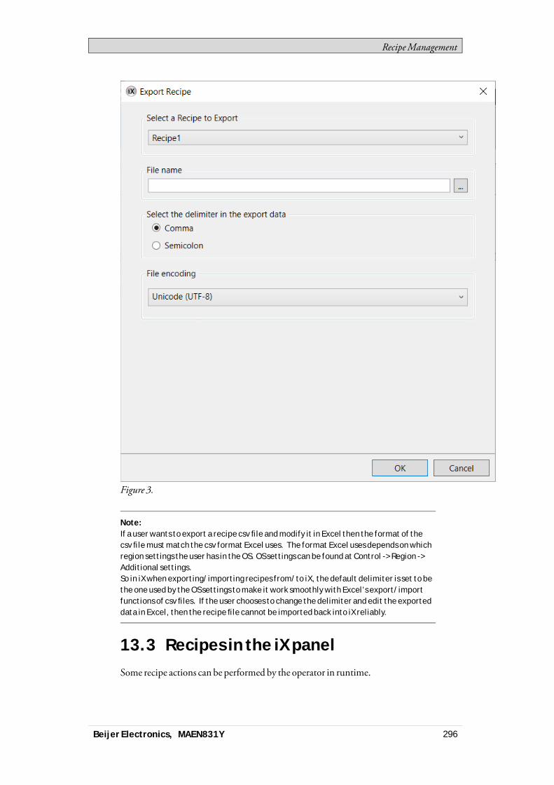
RecipeManagement
Figure 3.
Note:If a user wants to export a recipe csv file and modify it in Excel then the format of thecsv file must match the csv format Excel uses. The format Excel uses depends on whichregion settings the user has in the OS. OS settings can be found at Control -> Region ->Additional settings.So in iX when exporting/importing recipes from/to iX, the default delimiter is set to bethe one used by the OS settings to make it work smoothly with Excel’s export/importfunctions of csv files. If the user chooses to change the delimiter and edit the exporteddata in Excel, then the recipe file cannot be imported back into iX reliably.
13.3 Recipes in the iX panelSome recipe actions can be performed by the operator in runtime.
Beijer Electronics, MAEN831Y 296

RecipeManagement
13.3.1 Loading Recipes
Recipes can be transferred to the controller using aLoad recipe actionwhen theoperator panel is running. Thismeans that the recipe values are transferred to thecontroller. A list of available recipes is displayedwhen theLoad recipe action isactivated. Select a recipe in the list and press [Enter] tomake the controller runwith the downloaded values.
13.3.2 Saving Recipes
TheSave recipe action can be usedwhen the operator panel is running. Tagsdefined on theTagConfiguration tab are included in the recipe. Correspondingtag values are stored in the selected recipe filewhen Save recipe is performed. It ispossible to define an explicit recipe, thatwill be overwritten if it already exists whenperforming the SaveRecipe action.
13.3.3 Creating Recipes in the iX panel
The Save recipe action is also used to create recipes in runtime. Instead of definingan explicit recipe to overwrite, the recipe data field is left open. In this case, theoperatorwill be prompted to save the recipewith anyname, or to overwrite anexisting recipe.
13.3.4 Editing Recipes Offline
It is possible to edit existing recipes in the panel without transferring values to thecontroller, by setting the recipe tags in offlinemode. Recipe tags in offlinemodewill not receive any data from the controller, and no valueswill bewritten to thecontroller.In offlinemode, the Load recipe and Save recipe actionswill not affect values inthe controller.Internal tagsmay be used for recipes, butwill not be affected by offlinemode.Actions are used to start and endofflinemode:
Beijer Electronics, MAEN831Y 297
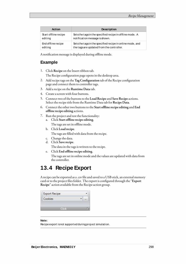
RecipeManagement
Action Description
Start offline recipeediting
Sets the tags in the specified recipe in offline mode. Anotification message is shown.
End offline recipeediting
Sets the tags in the specified recipe in online mode, andthe tags are updated from the controller.
Anotificationmessage is displayed during offlinemode.
Example
1. ClickRecipe on the Insert ribbon tab.TheRecipe configuration page opens in the desktop area.
2. Add recipe tags on theTagConfiguration tab of theRecipe configurationpage and connect them to controller tags.
3. Add a recipe on theRuntimeData tab.4. Create a screenwith four buttons.5. Connect two of the buttons to theLoadRecipe and SaveRecipe actions.
Select the recipe title from theRuntimeData tab forRecipeData.6. Connect the other two buttons to the Start offline recipe editing andEnd
offline recipe editing actions.7. Run the project and test the functionality:
a. Click Start offline recipe editing.The tags are set in offlinemode.
b. ClickLoad recipe.The tags are filledwith data from the recipe.
c. Change the data.d. Click Save recipe.
The data in the tags is written to the recipe.e. ClickEndoffline recipe editing.
The tags are set in onlinemode and the values are updatedwith data fromthe controller.
13.4 Recipe ExportA recipe can be exported as a .csv file and saved to aUSB stick, an externalmemorycard or to the project files folder. The export is configured through the “ExportRecipe” action available from theRecipe action group.
Note:Recipe export is not supported during project simulation.
Beijer Electronics, MAEN831Y 298

RecipeManagement
13.4.1 Recipe Export from an OperatorPanel Target
It is possible to selectExport to the Project Files Folder,Export toUSB, orExportto externalmemory card, and also to set another name of the export file.It is also possible to select the requested delimiter in the .csv file (commaorsemicolon).
Beijer Electronics, MAEN831Y 299
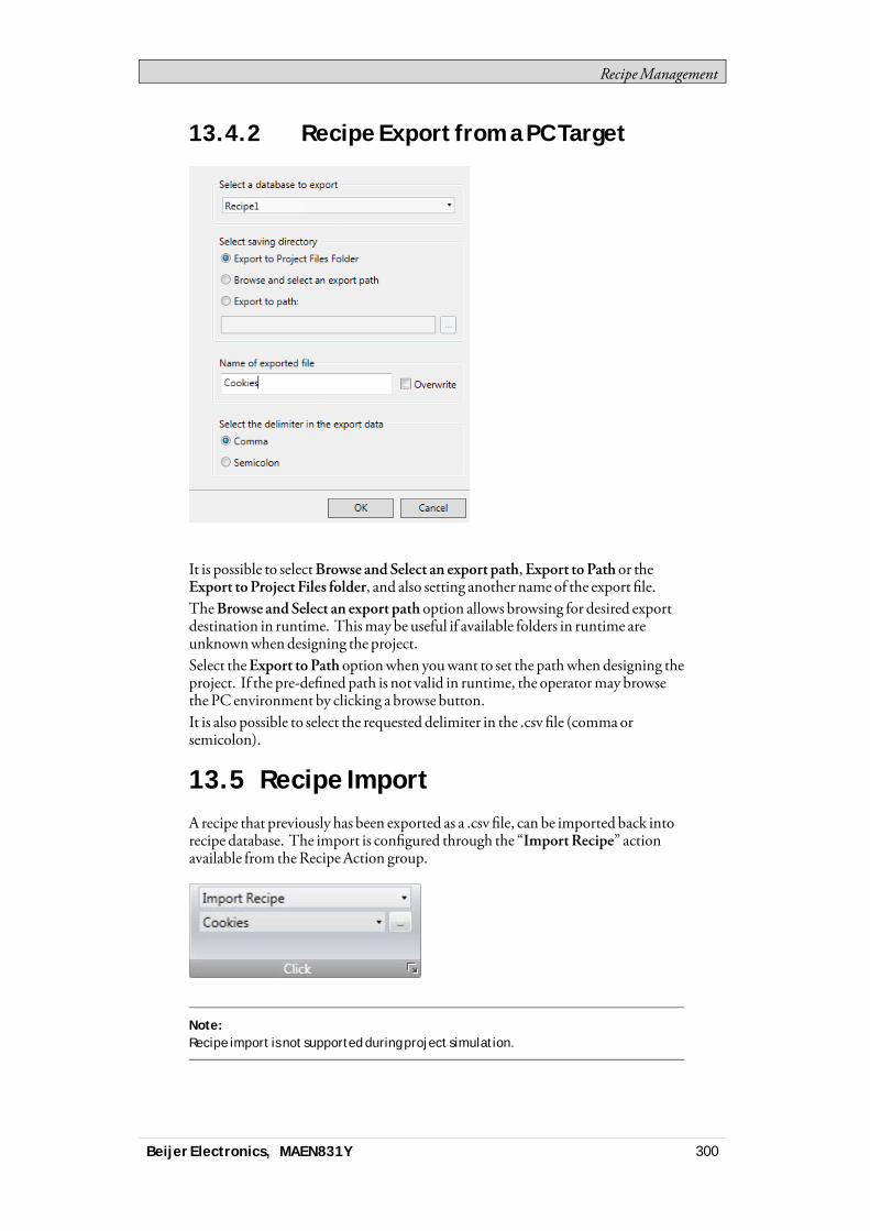
RecipeManagement
13.4.2 Recipe Export from a PC Target
It is possible to selectBrowse and Select an export path,Export to Path or theExport toProject Files folder, and also setting another name of the export file.TheBrowse andSelect an export path option allows browsing for desired exportdestination in runtime. Thismay be useful if available folders in runtime areunknownwhendesigning the project.Select theExport toPath optionwhen youwant to set the pathwhen designing theproject. If the pre-defined path is not valid in runtime, the operatormay browsethe PC environment by clicking a browse button.It is also possible to select the requested delimiter in the .csv file (commaorsemicolon).
13.5 Recipe ImportA recipe that previously has been exported as a .csv file, can be imported back intorecipe database. The import is configured through the “ImportRecipe” actionavailable from theRecipeAction group.
Note:Recipe import is not supported during project simulation.
Beijer Electronics, MAEN831Y 300

RecipeManagement
13.5.1 Recipe Import to an Operator PanelTarget
It is possible to import the csv file using the Import fromUSB, Import fromexternalmemory card or the Import fromProject Files folder selections and alsosetting the name of the import file.It is also possible to select the requested delimiter in the .csv file (commaorsemicolon).It can be selectedwhether to ignore the newdata or replace the old data, if therecipe data already exists.
Beijer Electronics, MAEN831Y 301
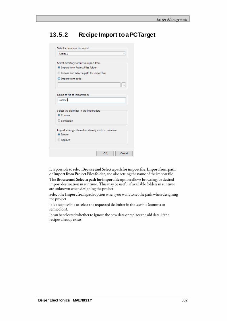
RecipeManagement
13.5.2 Recipe Import to a PC Target
It is possible to selectBrowse and Select a path for import file, Import frompathor Import fromProject Files folder, and also setting the name of the import file.TheBrowse andSelect a path for import file option allows browsing for desiredimport destination in runtime. Thismay be useful if available folders in runtimeare unknownwhen designing the project.Select the Import frompath optionwhen youwant to set the pathwhen designingthe project.It is also possible to select the requested delimiter in the .csv file (commaorsemicolon).It can be selectedwhether to ignore the newdata or replace the old data, if therecipes already exists.
Beijer Electronics, MAEN831Y 302

FunctionKeys
14 Function Keys
Function keys can be configured to run actions or to run scripts.
14.1 DefinitionsA standardPCkeyboard has 12 function keys, F1 - F12.A function key can be configured to affect only a particular screen or to be global.Global function keys behave identically for all screens. A global definition canalways be accessedwhen the operator panel is running, provided that the currentscreen does not have a screen definition for that function key. Screen functionkeys have higher priority than global function keys. Function keys included inbackground screens have lower priority than screen function keys, but higherpriority than global function keys.For touch panel andPC targets, the Function keys function is added via theInsert ribbon tab, and allows configuration of up to 24 function keys (even if theconnected keyboard does not supportmore than 12 function keys).
Related information
Security Management
14.2 Configuring Function KeysFunction keys can be configured to run actions or to run scripts.
14.2.1 Function Key Actions
Todefine function key actions:1. Click onFunctionKeys in the Project Explorer to open the function keys
configuration page.2. SelectGlobal orScreen.3. Select the function key to be defined.
Beijer Electronics, MAEN831Y 303
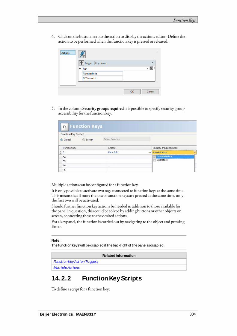
FunctionKeys
4. Click on the buttonnext to the action to display the actions editor. Define theaction to be performedwhen the function key is pressed or released.
5. In the column Security groups required it is possible to specify security groupaccessibility for the function key.
Multiple actions can be configured for a function key.It is only possible to activate two tags connected to function keys at the same time.Thismeans that ifmore than two function keys are pressed at the same time, onlythe first twowill be activated.Should further function key actions be needed in addition to those available forthe panel in question, this could be solved by adding buttons or other objects onscreen, connecting these to the desired actions.For a keypanel, the function is carried out by navigating to the object and pressingEnter.
Note:The function keys will be disabled if the backlight of the panel is disabled.
Related information
Function Key Action Triggers
Multiple Actions
14.2.2 Function Key Scripts
Todefine a script for a function key:
Beijer Electronics, MAEN831Y 304
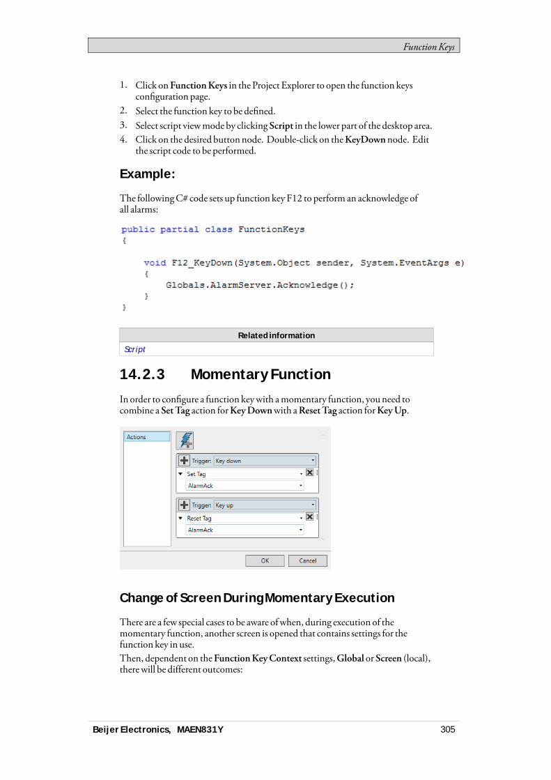
FunctionKeys
1. Click onFunctionKeys in the Project Explorer to open the function keysconfiguration page.
2. Select the function key to be defined.3. Select script viewmode by clicking Script in the lower part of the desktop area.4. Click on the desired buttonnode. Double-click on theKeyDownnode. Edit
the script code to be performed.
Example:
The followingC# code sets up function key F12 to perform an acknowledge ofall alarms:
Related information
Script
14.2.3 Momentary Function
In order to configure a function keywith amomentary function, youneed tocombine a SetTag action forKeyDownwith aResetTag action forKeyUp.
Change of Screen During Momentary Execution
There are a few special cases to be aware ofwhen, during execution of themomentary function, another screen is opened that contains settings for thefunction key in use.Then, dependent on theFunctionKeyContext settings,Global orScreen (local),therewill be different outcomes:
Beijer Electronics, MAEN831Y 305

FunctionKeys
• Case 1: A local function key is pressed.A change to another screen occurs.Result: The up action for the local key is executed. Nonewdownor upactions are executed on the second screen as long as the key is pressed.
• Case 2: Aglobal function key is pressed.A change to another screen occurs, inwhich there is no local setting for thesame key.Result: Nothing happens at screen change. The up action for the global keyis executedwhen the key is released.
• Case 3: Aglobal function key is pressed.A change to another screen occurs, inwhich there is a local setting for the samekey.Result: The up action for the global key is executed. Nonewdownor upactions are executed on the second screen as long as the key is pressed.
Note:A Screen (local) function key command has priority over a Global function keycommand.
Beijer Electronics, MAEN831Y 306
AlarmManagement
15 Alarm Management
An alarm is used to call attention to an event that requires immediate action. Analarm is set when a certain condition ismet. An alarm condition is designed as alogical evaluation of a tag value. Alarms can be divided into groups to create anorder of priority.Alarmnotification can bemade in the followingways:
Alarm Indicator
Alarm Viewer
Distribution via SMS, e-mail or printer via the Alarm Distributor
The alarm server database can be exported in csv format using theDatabaseExport action.
Related information
Database Export
15.1 Alarm ConditionsAlarms can assume the following conditions:
Alarm condition Description
Active The alarm condition is met, and the alarm is notacknowledged
Inactive The alarm has returned to normal condition, but has notbeen acknowledged
Acknowledged The alarm condition is still met, but the alarm isacknowledged
Normal The alarm has returned to normal condition and has beenacknowledged
15.2 Alarm ServerThe alarm server function is predefined in the Project Explorer. Clicking on itopens the alarm server configuration pages in the desktop.General alarm server properties are available by clicking the Settings button.
Beijer Electronics, MAEN831Y 307
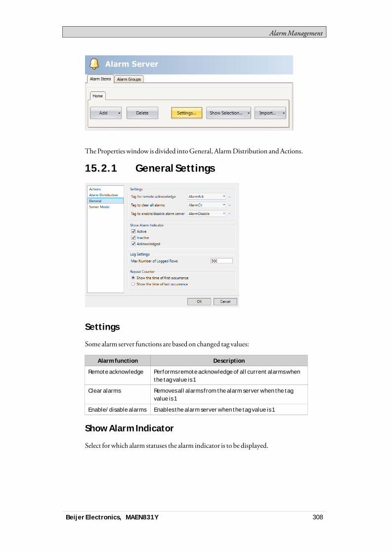
AlarmManagement
TheProperties window is divided intoGeneral, AlarmDistribution andActions.
15.2.1 General Settings
Settings
Some alarm server functions are based on changed tag values:
Alarm function Description
Remote acknowledge Performs remote acknowledge of all current alarms whenthe tag value is 1
Clear alarms Removes all alarms from the alarm server when the tagvalue is 1
Enable/disable alarms Enables the alarm server when the tag value is 1
Show Alarm Indicator
Select forwhich alarm statuses the alarm indicator is to be displayed.
Beijer Electronics, MAEN831Y 308

AlarmManagement
Log Settings
Parameter Description
Max Number of LoggedRows
The maximum number of alarms to save in the database. Ifthe number of collected items becomes larger than the setvalue, the oldest item will be deleted. The value must bewithin the size of the available amount of memory in theoperator panel in runtime.
Repeat Counter
To avoid that an alarm that is triggered repeatedly results inmultiple entries in thealarm list,RepeatCount can be used. The current alarmwill then only appearonce in the alarm list, and number of times the alarm is triggeredwill be includedin the alarm text. For display in theAlarmViewer and for logging, select whetherto show the time of the first or last occurrence of the alarm.
15.2.2 Alarm Server Events and Actions
Actions can be configured for the entire alarm server. One ormultiple actions canbe configuredwhen a particular alarm server event occurs.SelectActions in theAlarmServer properties page to configure actions for thealarm server.Actions for the following alarm server events can be configured:
Alarm Acknowledge
The specified actions are triggered once for every alarm that is acknowledged.
Alarm Active
The specified actions are triggered once for every alarm that becomes active.
Alarm Deleted
The specified actions are triggered oncewhen theClear button in theAlarmViewer is pressed, if at least one alarm is deleted.
Alarm Event Info Requested
The specified actions for the selected alarm are triggeredwhen the Infobutton intheAlarmViewer is pressed.The actions are applied for the individual alarmfirst. If no action is specified forthe alarm, the actions are applied for the group. If no action is specified for thegroup, the actions are applied for the alarm server.
Alarm Inactive
The specified actions are triggered once for each alarm, forwhich the alarmcondition is no longermet.
Beijer Electronics, MAEN831Y 309
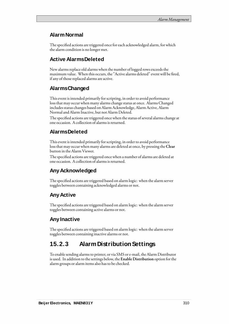
AlarmManagement
Alarm Normal
The specified actions are triggered once for each acknowledged alarm, forwhichthe alarm condition is no longermet.
Active Alarms Deleted
Newalarms replace old alarmswhen the number of logged rows exceeds themaximumvalue. When this occurs, the "Active alarms deleted" eventwill be fired,if any of those replaced alarms are active.
Alarms Changed
This event is intended primarily for scripting, in order to avoid performanceloss thatmay occurwhenmany alarms change status at once. AlarmsChangedincludes status changes based onAlarmAcknowledge, AlarmActive, AlarmNormal andAlarm Inactive, but notAlarmDeleted.The specified actions are triggered oncewhen the status of several alarms change atone occasion. A collection of alarms is returned.
Alarms Deleted
This event is intended primarily for scripting, in order to avoid performanceloss thatmay occurwhenmany alarms are deleted at once, by pressing theClearbutton in theAlarmViewer.The specified actions are triggered oncewhen a number of alarms are deleted atone occasion. A collection of alarms is returned.
Any Acknowledged
The specified actions are triggered based on alarm logic: when the alarm servertoggles between containing acknowledged alarms or not.
Any Active
The specified actions are triggered based on alarm logic: when the alarm servertoggles between containing active alarms or not.
Any Inactive
The specified actions are triggered based on alarm logic: when the alarm servertoggles between containing inactive alarms or not.
15.2.3 Alarm Distribution Settings
To enable sending alarms to printer, or via SMSor e-mail, theAlarmDistributoris used. In addition to the settings below, theEnableDistribution option for thealarm groups or alarm items also has to be checked.
Beijer Electronics, MAEN831Y 310

AlarmManagement
Parameter Description
Internal/External Selection of internal or external alarm distributor
IP Number Server The IP address of the external alarm distributor
Queue Length The number of alarms to be kept in queue for the externalalarm distributor. When the queue is full, no more alarmswill be added to the queue.
Port Number The port number of the external alarm distributor
Related information
Alarm Distributor
Alarm Groups
Alarm Items
15.3 Alarm IndicatorAs long as there are active alarms in the alarm server, the alarm indicator notifywindowwill be displayed, regardless of which screen is active. The color showsthe current alarm status, and can be configured for each of the alarm groups. Theindicator starts in the upper left corner of the screen in runtime, but can bemovedto any position on themonitor in runtime.The appearance of the alarm indicator depends on the current alarm status. Itwill show themost severe status of the alarms in the list. TheAlarm Indicatordisappears when all alarms have been acknowledged, and all alarms have returnedto inactive status.SelectGeneral settings in alarm server properties page to decide forwhich alarmstatuses to show the alarm indicator.
Alarm condition DescriptionDefault alarm
indication
Active The alarm condition is met, and the alarmis not acknowledged
Flashing red
Inactive The alarm has returned to normal condition,but has not been acknowledged
Flashing green
Beijer Electronics, MAEN831Y 311

AlarmManagement
Alarm condition DescriptionDefault alarm
indication
Acknowledged The alarm condition is met, and the alarmis acknowledged
Flashing green
Normal The alarm has returned to normal condition,and has been acknowledged
-
Related information
General Settings
15.4 Alarm ItemsAlarm items are added from theAlarm Items tab of the alarm server configurationpages.ClickAdd to define a new alarm.
Parameter Description
Name Symbolic name for the alarm item that will show in anAlarm Viewer.
Text An optional alarm text that will be shown in the AlarmViewer. Parts of the text can be made dynamic by clicking...
The dynamic text can also be linked to a Text Library.
Tag The tag (digital or analog), which generates the alarmwhen it assumes the specified status.
Expression See section Expressions
Condition Equal to/Not equal to: The alarm is set when the valueof the tag is equal/not equal to the value specified in theTrigger Value field.
Greater than/Less than: The alarm is set when the valueof the tag is greater/less than the value specified in theTrigger Value field.
Equal to greater than/Equal to less than: The alarm is setwhen the value of the tag is equal to or greater/less thanthe value specified in the Trigger Value field.
Rising/Falling Edge: The alarm is set when the specifiedtag goes to one/zero.
Beijer Electronics, MAEN831Y 312

AlarmManagement
Parameter Description
Trigger Value Numeric value to trigger alarm with when:
<tag value> <condition> <trigger value> = true.
History Specifies when the alarm is to be removed from the alarmlist. Checking this box means that the alarm will remainin the list until the list is full. Leaving it unchecked meansthat the alarm will be removed from the list when it isacknowledged and no longer active. If AcknowledgeRequired is not checked, the alarm will be removed fromthe list as soon as it is no longer active.
AcknowledgeRequired
Indicates whether the alarm is to be acknowledged ornot. Checking the box means that the alarm must beacknowledged, leaving it unchecked means that the alarmreturns to normal directly when the alarm status becomesinactive.
Remote Acknowledge A digital tag that acknowledges all the alarm when set to 1
Remote AckExpression
See section Expressions
Enable Distribution Enables distribution of the alarm via printer/SMS/e-mail.Only available if alarm distribution is enabled for the alarmserver. If the Enable Distribution option for the alarmgroup is checked, distribution of individual alarms in thegroup are automatically enabled.
Repeat Count To avoid that an alarm that is triggered repeatedly resultsin multiple entries in the alarm list, Repeat Count can beused. The current alarm will then only appear once in thealarm list, and the number of times the alarm is triggeredwill be included in the alarm text. It is also possible to showa Count column in the Alarm Viewer. The active time canbe shown either for the first time or for the last time thealarm occurred.
Action Makes it possible to configure one or multiple actions whena particular alarm event occurs for the current alarm.
Note:An alarm condition is triggered by a fixed value. The trigger value defined for an analogalarm tag cannot be controlled from a register. It is not supported to trigger alarmson intervals.
Related information
Actions and Events for Alarm Items and Alarm Groups
15.4.1 Exporting and Importing AlarmItems
Alarm items can be exported and imported using the Import/Export button in theAlarms configuration page. The procedure is similar to exporting and importingtags.
Beijer Electronics, MAEN831Y 313

AlarmManagement
Related information
Importing and Exporting Tags
Tag Import Example
15.5 Alarm GroupsAlarms can be divided into groups, for example to indicate the priority of thealarms. One alarm group is defined by default.Color attributes can be individually set for each alarm group. Alarms can be sortedby group in theAlarmViewer.
15.5.1 Defining Alarm Groups
Alarmgroups are added from theAlarmGroups tab of the alarm serverconfiguration pages.
Parameter Description
Name An optional name for the alarm group.
Text An optional text for the alarm group.
Colors Select foreground and background color for each alarmstatus
RemoteAcknowledge
A digital tag that acknowledges all the alarms in the groupwhen set to 1
Remote AckExpression
See section Expressions
Enable Distribution Enables distribution of the alarms in the group viaprinter/SMS/e-mail. Only available if alarm distribution isenabled for the alarm server.
Action Makes it possible to configure one or multiple actions when aparticular alarm event occurs for the current alarm group.
Note:Alarm Filters will revert to default settings if the filteredAlarm Group is renamed.
Related information
Actions and Events for Alarm Items and Alarm Groups
Beijer Electronics, MAEN831Y 314

AlarmManagement
15.6 Actions and Events for Alarm Itemsand Alarm Groups
Actions can be configured for individual alarms or for alarm groups. One ormultiple actions can be configuredwhen a particular alarm event occurs for thecurrent alarmor alarm group.Actions for individual alarms are configured from theAction column for the alarmon theAlarm Items tab.Actions for alarm groups are configured from theAction column for the alarmgroup on theAlarmGroups tab.
15.6.1 Actions and Events
Actions for the following alarm events and alarm group events can be configured:
Alarm Acknowledge
The specified actionswill be triggeredwhen the selected alarm/an alarm in theselected alarm group is acknowledged.
Alarm Active
The specified actionswill be triggeredwhen the selected alarm/an alarm in theselected alarm groupbecomes active.
Alarm Event Info Requested
The specified actions are triggeredwhen the Info button in theAlarmViewer ispressed.These actions are applied for the individual alarmfirst. If no action is specified forthe alarm, the actions are applied for the group. If no action is specified for thegroup, the actions are applied for the alarm server.
Alarm Inactive
The specified actions are triggeredwhen the alarm/an alarm in the selected alarmgroupbecomes inactive.
15.6.2 Example
The following picture shows two actions configured forwhen the current alarmgoes active, and another action forwhen the operator presses the Infobutton inruntime.
Beijer Electronics, MAEN831Y 315
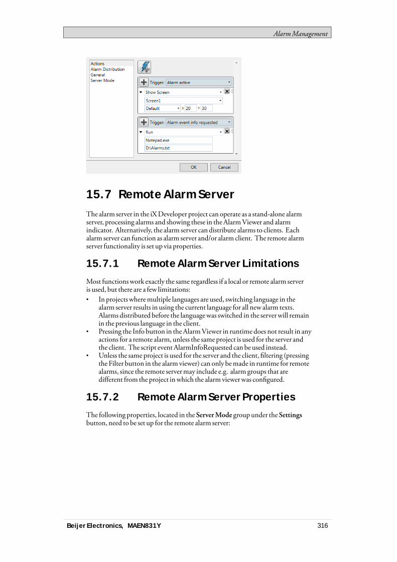
AlarmManagement
15.7 Remote Alarm ServerThe alarm server in the iXDeveloper project can operate as a stand-alone alarmserver, processing alarms and showing these in theAlarmViewer and alarmindicator. Alternatively, the alarm server can distribute alarms to clients. Eachalarm server can function as alarm server and/or alarm client. The remote alarmserver functionality is set up via properties.
15.7.1 Remote Alarm Server Limitations
Most functionswork exactly the same regardless if a local or remote alarm serveris used, but there are a few limitations:• In projectswheremultiple languages are used, switching language in the
alarm server results in using the current language for all new alarm texts.Alarms distributed before the languagewas switched in the serverwill remainin the previous language in the client.
• Pressing the Info button in theAlarmViewer in runtime does not result in anyactions for a remote alarm, unless the same project is used for the server andthe client. The script event AlarmInfoRequested can be used instead.
• Unless the same project is used for the server and the client, filtering (pressingthe Filter button in the alarm viewer) can only bemade in runtime for remotealarms, since the remote servermay include e.g. alarm groups that aredifferent from the project inwhich the alarm viewerwas configured.
15.7.2 Remote Alarm Server Properties
The following properties, located in theServerMode groupunder theSettingsbutton, need to be set up for the remote alarm server:
Beijer Electronics, MAEN831Y 316
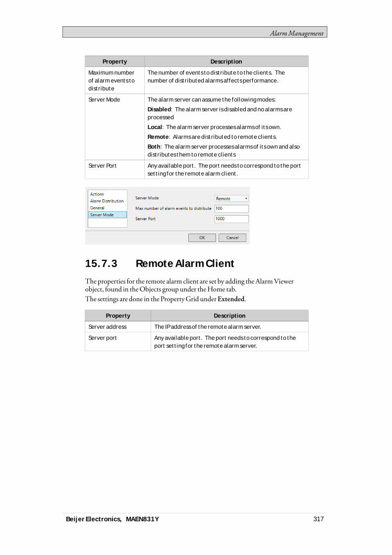
AlarmManagement
Property Description
Maximum numberof alarm events todistribute
The number of events to distribute to the clients. Thenumber of distributed alarms affects performance.
Server Mode The alarm server can assume the following modes:
Disabled: The alarm server is disabled and no alarms areprocessed
Local: The alarm server processes alarms of its own.
Remote: Alarms are distributed to remote clients.
Both: The alarm server processes alarms of its own and alsodistributes them to remote clients
Server Port Any available port. The port needs to correspond to the portsetting for the remote alarm client.
15.7.3 Remote Alarm Client
Theproperties for the remote alarm client are set by adding theAlarmViewerobject, found in theObjects group under theHome tab.The settings are done in the PropertyGrid underExtended.
Property Description
Server address The IP address of the remote alarm server.
Server port Any available port. The port needs to correspond to theport setting for the remote alarm server.
Beijer Electronics, MAEN831Y 317
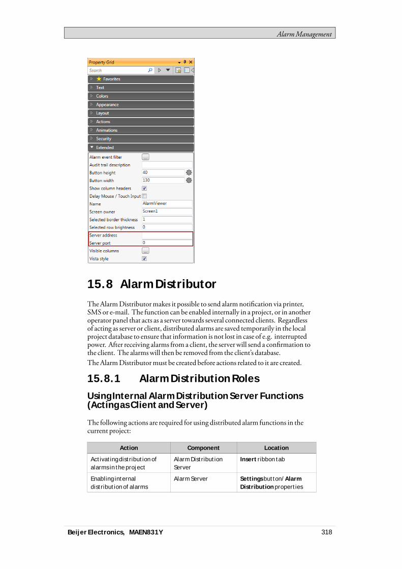
AlarmManagement
15.8 Alarm DistributorTheAlarmDistributormakes it possible to send alarmnotification via printer,SMSor e-mail. The function can be enabled internally in a project, or in anotheroperator panel that acts as a server towards several connected clients. Regardlessof acting as server or client, distributed alarms are saved temporarily in the localproject database to ensure that information is not lost in case of e.g. interruptedpower. After receiving alarms froma client, the serverwill send a confirmation tothe client. The alarmswill then be removed from the client’s database.TheAlarmDistributormust be created before actions related to it are created.
15.8.1 Alarm Distribution Roles
Using Internal Alarm Distribution Server Functions(Acting as Client and Server)
The following actions are required for using distributed alarm functions in thecurrent project:
Action Component Location
Activating distribution ofalarms in the project
Alarm DistributionServer
Insert ribbon tab
Enabling internaldistribution of alarms
Alarm Server Settings button/AlarmDistribution properties
Beijer Electronics, MAEN831Y 318

AlarmManagement
Action Component Location
Enabling distribution ofalarm groups or individualalarms
Alarm Server Alarm Groups or AlarmItems tab
Configuration of alarmdistribution routes
Alarm DistributionServer
Receivers, Alarm Filterand Scheduler tabs
Configuration of alarmdistribution devices
Alarm DistributionServer
Configure DistributionDevices button (e-mail,printer and/or SMS)
Using External Alarm Distribution Server Functions(Acting as Client)
The following actions are required for using distributed alarm functions inanother operator panel/PCproject:
Action Component Location
Activating distribution ofalarms in the project
Alarm DistributionServer
Insert ribbon tab
Enabling externaldistribution of alarms
Alarm Server Settings button/AlarmDistribution properties
Enabling distribution ofalarm groups or individualalarms
Alarm Server Alarm Groups or AlarmItems tab
Collecting Alarms for Distribution (Acting as Server)
The following actions are required for using distributed alarm functions inanother operator panel/PCproject:
Action Component Location
Activating distribution ofalarms in the project
Alarm DistributionServer
Insert ribbon tab
Configuration of alarmdistribution routes
Alarm DistributionServer
Receivers, Alarm Filterand Scheduler tabs
Configuration of alarmdistribution devices
Alarm DistributionServer
Configure DistributionDevices button (e-mail,TCP server, printer and/orSMS)
15.8.2 Adding an Alarm Distributor
TheAlarmDistributor can be added to the project from the Insert ribbon tab. Theconfiguration pages are opened in the desktop area.
Beijer Electronics, MAEN831Y 319
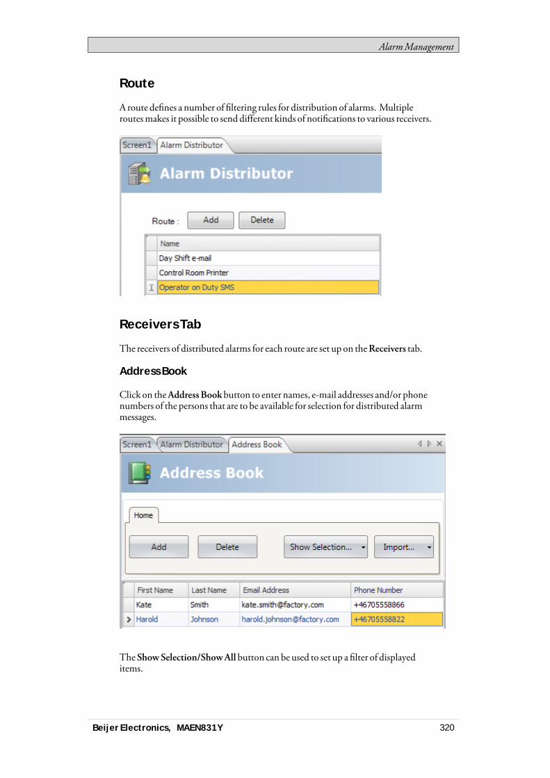
AlarmManagement
Route
A route defines a number of filtering rules for distribution of alarms. Multipleroutesmakes it possible to send different kinds of notifications to various receivers.
Receivers Tab
The receivers of distributed alarms for each route are set up on theReceivers tab.
Address Book
Click on theAddress Bookbutton to enter names, e-mail addresses and/or phonenumbers of the persons that are to be available for selection for distributed alarmmessages.
TheShowSelection/ShowAll button can be used to set up a filter of displayeditems.
Beijer Electronics, MAEN831Y 320
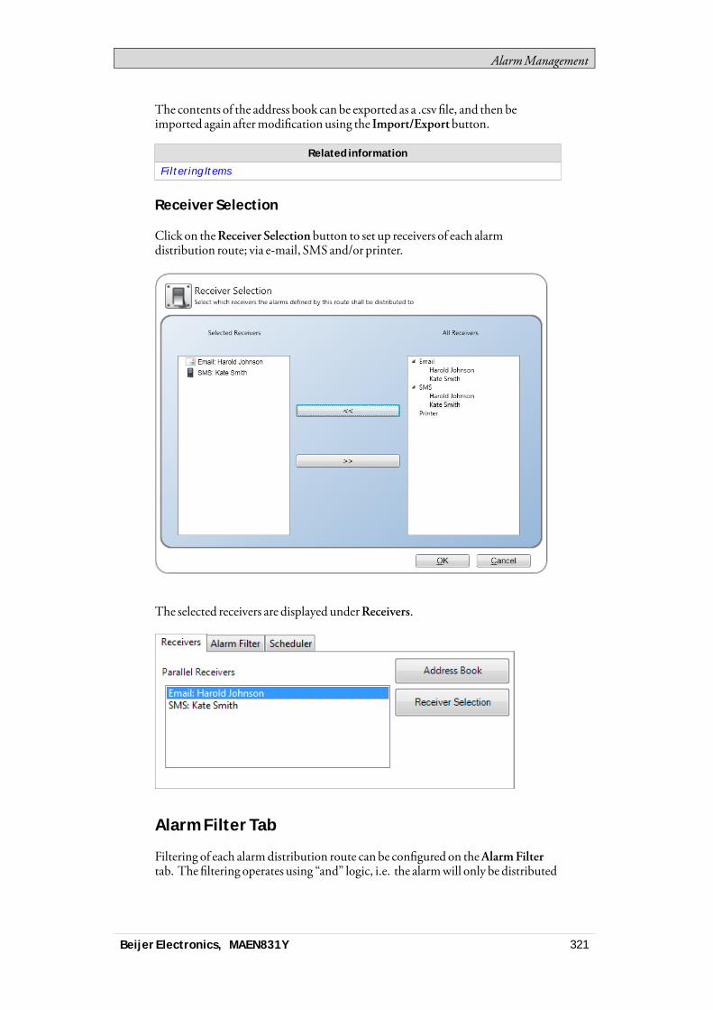
AlarmManagement
The contents of the address book can be exported as a .csv file, and then beimported again aftermodification using the Import/Exportbutton.
Related information
Filtering Items
Receiver Selection
Click on theReceiver Selection button to set up receivers of each alarmdistribution route; via e-mail, SMS and/or printer.
The selected receivers are displayed underReceivers.
Alarm Filter Tab
Filtering of each alarmdistribution route can be configured on theAlarmFiltertab. The filtering operates using “and” logic, i.e. the alarmwill only be distributed
Beijer Electronics, MAEN831Y 321
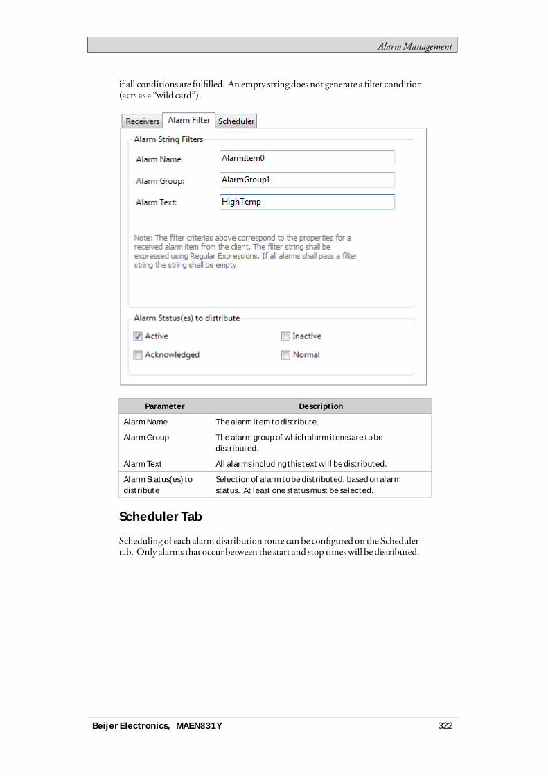
AlarmManagement
if all conditions are fulfilled. An empty string does not generate a filter condition(acts as a “wild card”).
Parameter Description
Alarm Name The alarm item to distribute.
Alarm Group The alarm group of which alarm items are to bedistributed.
Alarm Text All alarms including this text will be distributed.
Alarm Status(es) todistribute
Selection of alarm to be distributed, based on alarmstatus. At least one status must be selected.
Scheduler Tab
Scheduling of each alarmdistribution route can be configured on the Schedulertab. Only alarms that occur between the start and stop timeswill be distributed.
Beijer Electronics, MAEN831Y 322
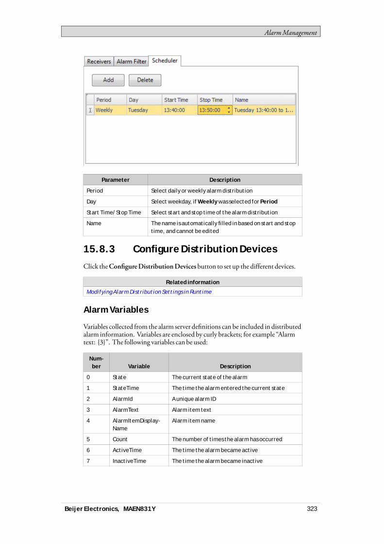
AlarmManagement
Parameter Description
Period Select daily or weekly alarm distribution
Day Select weekday, if Weekly was selected for Period
Start Time/Stop Time Select start and stop time of the alarm distribution
Name The name is automatically filled in based on start and stoptime, and cannot be edited
15.8.3 Configure Distribution Devices
Click theConfigureDistributionDevices button to set up the different devices.
Related information
Modifying Alarm Distribution Settings in Runtime
Alarm Variables
Variables collected from the alarm server definitions can be included in distributedalarm information. Variables are enclosed by curly brackets; for example “Alarmtext: {3}”. The following variables can be used:
Num-ber Variable Description
0 State The current state of the alarm
1 StateTime The time the alarm entered the current state
2 AlarmId A unique alarm ID
3 AlarmText Alarm item text
4 AlarmItemDisplay-Name
Alarm item name
5 Count The number of times the alarm has occurred
6 ActiveTime The time the alarm became active
7 InactiveTime The time the alarm became inactive
Beijer Electronics, MAEN831Y 323
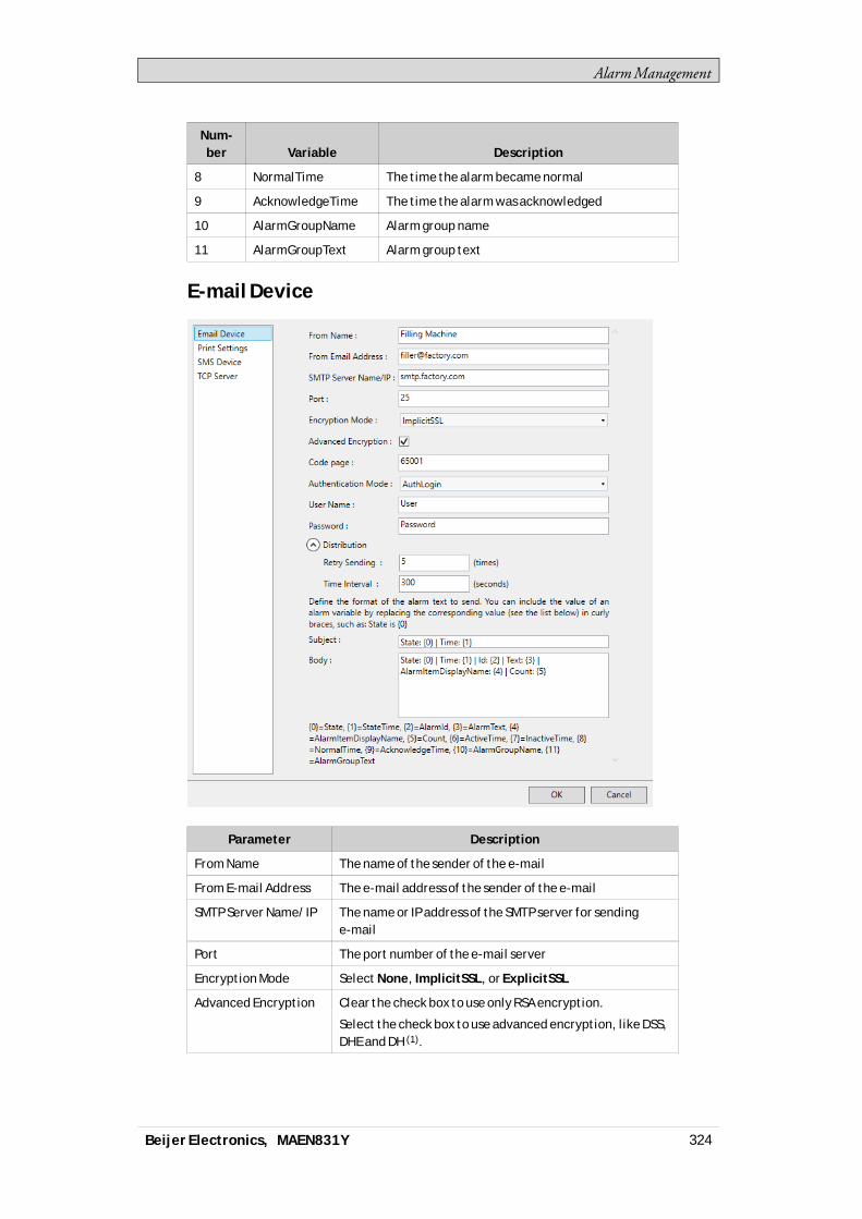
AlarmManagement
Num-ber Variable Description
8 NormalTime The time the alarm became normal
9 AcknowledgeTime The time the alarm was acknowledged
10 AlarmGroupName Alarm group name
11 AlarmGroupText Alarm group text
E-mail Device
Parameter Description
From Name The name of the sender of the e-mail
From E-mail Address The e-mail address of the sender of the e-mail
SMTP Server Name/IP The name or IP address of the SMTP server for sendinge-mail
Port The port number of the e-mail server
Encryption Mode Select None, ImplicitSSL, or ExplicitSSL
Advanced Encryption Clear the check box to use only RSA encryption.
Select the check box to use advanced encryption, like DSS,DHE and DH (1).
Beijer Electronics, MAEN831Y 324

AlarmManagement
Parameter Description
Code Page The code page consists of a table of values that describesthe character set for a particular language. The defaultcode page in iX Developer is 65001 (UTF-8).
Authentication Mode Select None or Authenticated Login
User Name/Password User name and password if Authenticated Login wasselected
Retry Sending Number of retries if the e-mail cannot be delivered
Time Interval Number of seconds between retries
Subject The e-mail subject; Alarm Variables can be used
Body The e-mail body; Alarm Variables can be used
(1) Note that using Advanced Encryption has a negative effect on the performanceon CE targets.
Printer Device
Parameter Description
Buffer settings Set up the printers buffer settings
Text Font Size The font size of the text to be printed
Body The body of the printout; Alarm Variables can be used
Related information
Output Devices Group
SMS Device
Tobe able to send alarms via SMS, youhave to purchase an SMSGateway Service.
Beijer Electronics, MAEN831Y 325
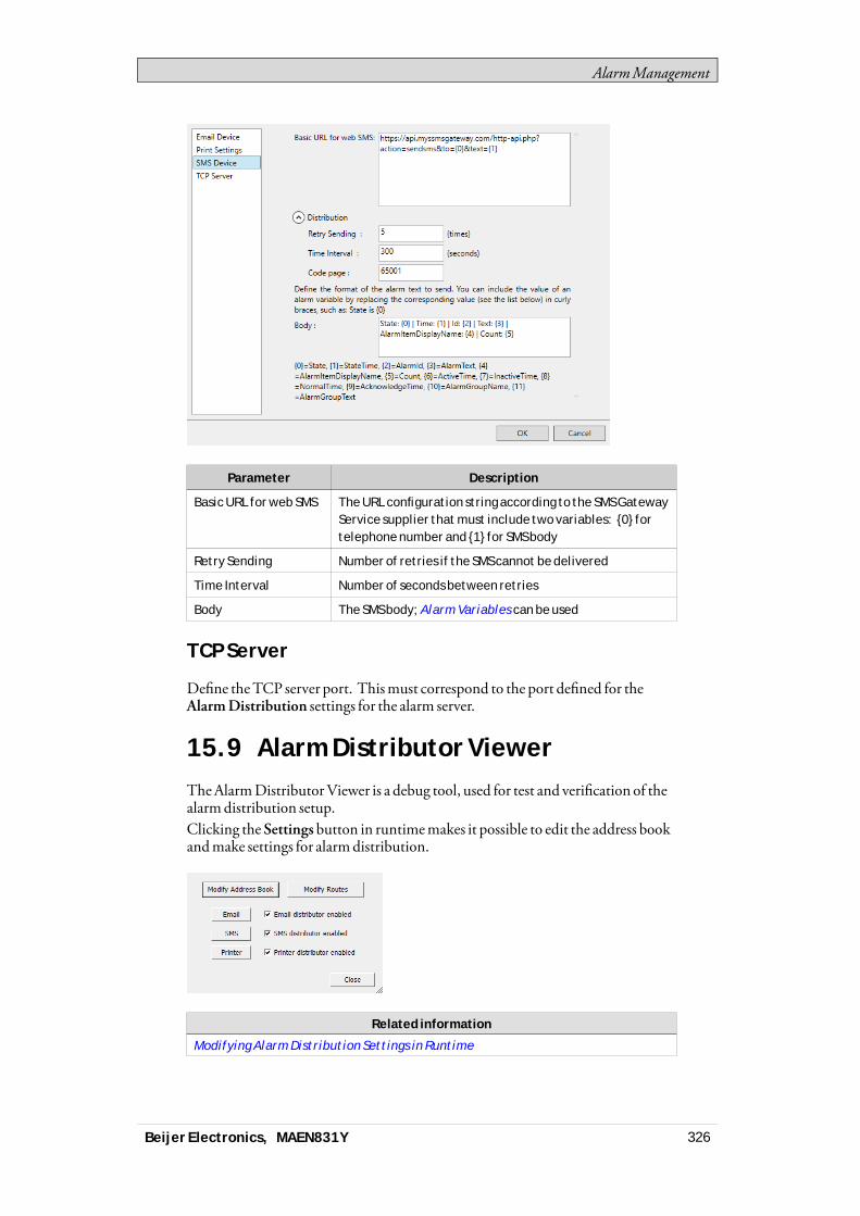
AlarmManagement
Parameter Description
Basic URL for web SMS The URL configuration string according to the SMS GatewayService supplier that must include two variables: {0} fortelephone number and {1} for SMS body
Retry Sending Number of retries if the SMS cannot be delivered
Time Interval Number of seconds between retries
Body The SMS body; Alarm Variables can be used
TCP Server
Define theTCP server port. Thismust correspond to the port defined for theAlarmDistribution settings for the alarm server.
15.9 Alarm Distributor ViewerTheAlarmDistributorViewer is a debug tool, used for test and verification of thealarmdistribution setup.Clicking the Settings button in runtimemakes it possible to edit the address bookandmake settings for alarmdistribution.
Related information
Modifying Alarm Distribution Settings in Runtime
Beijer Electronics, MAEN831Y 326
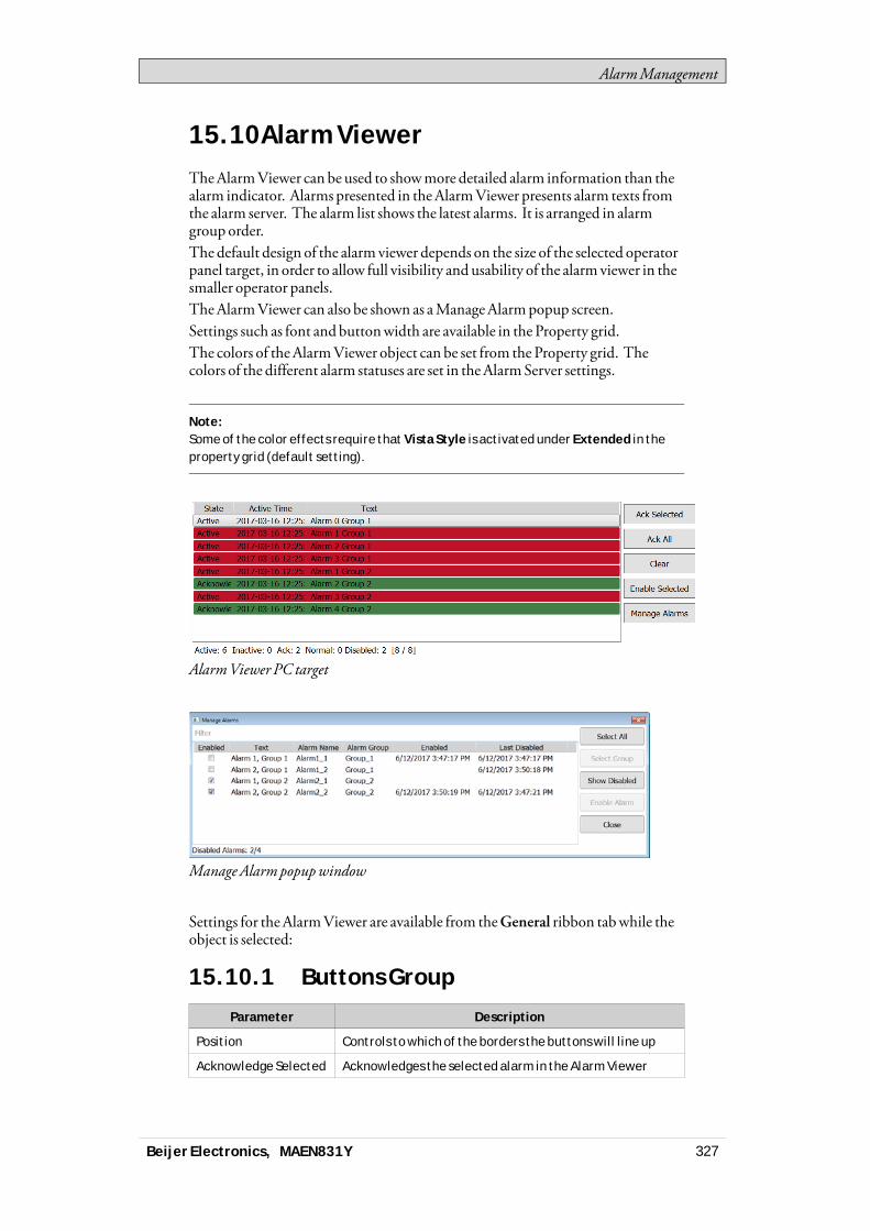
AlarmManagement
15.10Alarm ViewerTheAlarmViewer can be used to showmore detailed alarm information than thealarm indicator. Alarms presented in theAlarmViewer presents alarm texts fromthe alarm server. The alarm list shows the latest alarms. It is arranged in alarmgroup order.The default design of the alarm viewer depends on the size of the selected operatorpanel target, in order to allow full visibility and usability of the alarm viewer in thesmaller operator panels.TheAlarmViewer can also be shown as aManageAlarmpopup screen.Settings such as font andbuttonwidth are available in the Property grid.The colors of theAlarmViewer object can be set from the Property grid. Thecolors of the different alarm statuses are set in theAlarmServer settings.
Note:Some of the color effects require that Vista Style is activated under Extended in theproperty grid (default setting).
AlarmViewer PC target
Manage Alarm popupwindow
Settings for theAlarmViewer are available from theGeneral ribbon tabwhile theobject is selected:
15.10.1 Buttons Group
Parameter Description
Position Controls to which of the borders the buttons will line up
Acknowledge Selected Acknowledges the selected alarm in the Alarm Viewer
Beijer Electronics, MAEN831Y 327
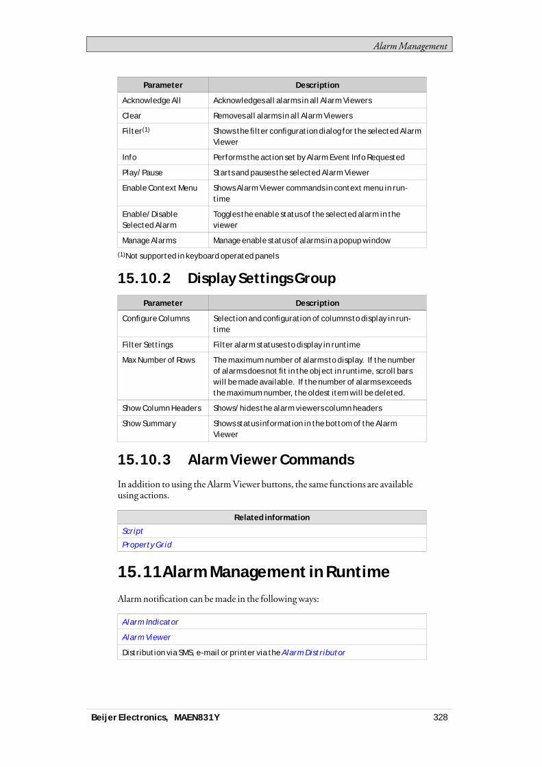
AlarmManagement
Parameter Description
Acknowledge All Acknowledges all alarms in all Alarm Viewers
Clear Removes all alarms in all Alarm Viewers
Filter(1) Shows the filter configuration dialog for the selected AlarmViewer
Info Performs the action set by Alarm Event Info Requested
Play/Pause Starts and pauses the selected Alarm Viewer
Enable Context Menu Shows Alarm Viewer commands in context menu in run-time
Enable/DisableSelected Alarm
Toggles the enable status of the selected alarm in theviewer
Manage Alarms Manage enable status of alarms in a popup window
(1)Not supported in keyboard operated panels
15.10.2 Display Settings Group
Parameter Description
Configure Columns Selection and configuration of columns to display in run-time
Filter Settings Filter alarm statuses to display in runtime
Max Number of Rows The maximum number of alarms to display. If the numberof alarms does not fit in the object in runtime, scroll barswill be made available. If the number of alarms exceedsthe maximum number, the oldest item will be deleted.
Show Column Headers Shows/hides the alarm viewers column headers
Show Summary Shows status information in the bottom of the AlarmViewer
15.10.3 Alarm Viewer Commands
In addition to using theAlarmViewer buttons, the same functions are availableusing actions.
Related information
Script
Property Grid
15.11Alarm Management in RuntimeAlarmnotification can bemade in the followingways:
Alarm Indicator
Alarm Viewer
Distribution via SMS, e-mail or printer via the Alarm Distributor
Beijer Electronics, MAEN831Y 328

AlarmManagement
15.11.1 Alarm Acknowledgement
An alarm canbe acknowledged in the followingways:• right-clicking on the alarm line and selectingAcknowledge• selecting the alarm line and pressing on theAcknowledge Selected button• pressing theAcknowledgeAll button to acknowledge all current alarms• script actions
Inactive alarms that have been acknowledged can be removed from the list bypressing theClear button.
15.11.2 Sorting
Pressing on the columnheading in runtime sorts the alarm list by that column.This pauses theAlarmViewer.
15.11.3 Filtering
Pressing the Filter button in theAlarmViewer opens a dialog that allows the userto enter a filtering profile to control which alarms to display in the alarm list. TheFilter button,when clicked, only show the panels whose target typematches theprojects panel type.Filtering can bemade based on any combination of the following conditions:• Alarmgroup: The first column in the filter window shows the alarm group
name. Check theEnable box to show alarms from the group.• Alarm status: Displays alarmswith the status corresponding to the checked
status values.
Note:Alarm Filters will revert to default settings if the filtered Alarm Group is renamed.
15.11.4 Play/Pause Button
TheAlarmViewerwindow canbe paused frombeing updatedwith incomingalarms using the Play/Pause button. This allows the operator to inspect and sortthe list without interference from any incoming alarms. The list also pauseswhenan alarm is selected.The alarm list starts updating againwhen• the Play button is pressed• the operator changes screen and returns to the same screen (or goes to another
screen showing theAlarmViewer)• after a 5minute time-out
15.11.5 Info Button
Pressing the Info button in theAlarmViewer triggers the action specified in theAlarmEvent InfoRequested group on theActions tab,when an item in the alarmserver is selected.Any action in the list can be selected.
Beijer Electronics, MAEN831Y 329

AlarmManagement
This actionwill be applied for the individual alarmfirst. If no action is specified forthe alarm, the actionwill be applied for the group. If no action is specified for thegroup, the actionwill be applied for the alarm server.
Related information
Alarm Groups
Alarm Conditions
Alarm Event Info Requested
15.11.6 Modifying Alarm DistributionSettings in Runtime
It is possible to configure actions, or to use theAlarmDistributionViewer tomodify the address book and alarmdistribution settings in runtime.
Note:If the Alarm Distribution Viewer or alarm distribution actions are used in runtime, it ispossible that alarm distribution settings have been modified. Next time you downloada project to the operator panel, you will get a notification, and selection to overwritepanel settings or not.
Related information
Address Book Action Groups
Output Devices Action Groups
15.11.7 Enable/Disable Selected Alarm
If an alarm for some reason is continuously going on and off, and to avoid thattheAlarmServerwill be filledwith irrelevant alarms, alarms can be disabled (andenabled) in theAlarmViewer.When disabled, the alarm is added to the disabled list with a time stamp. Themainalarmpage shows the number disabled alarms under the list of alarms.
Beijer Electronics, MAEN831Y 330
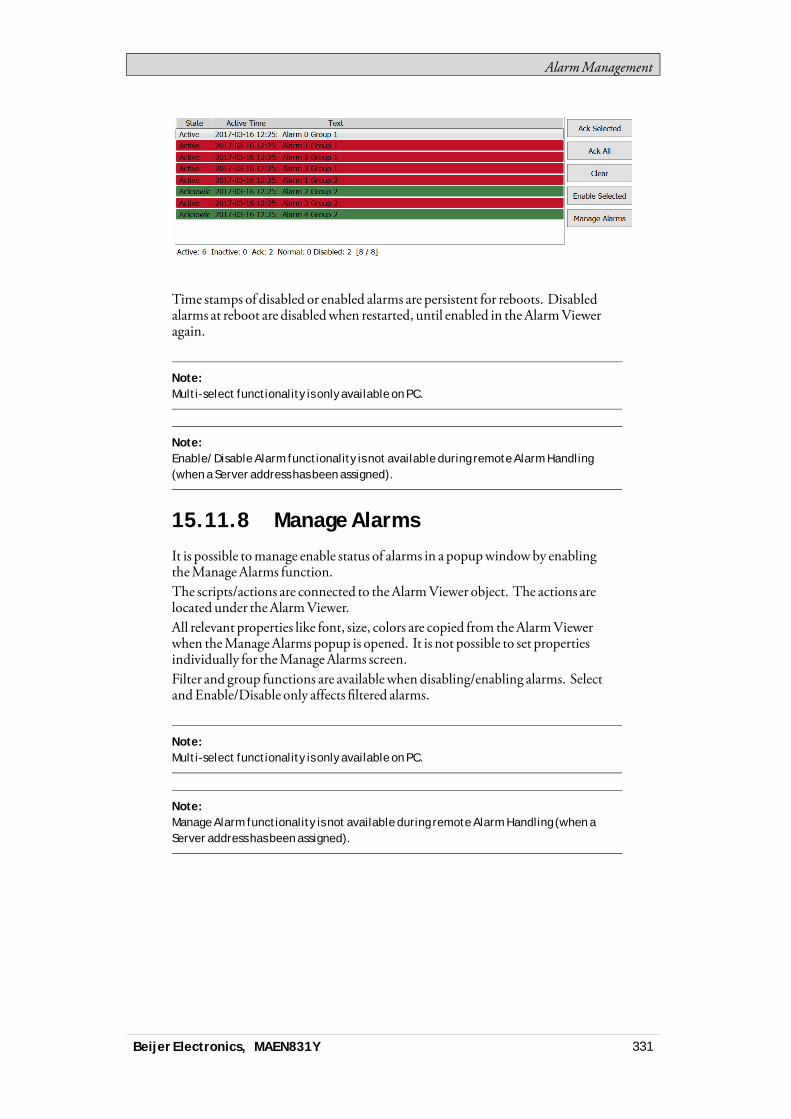
AlarmManagement
Time stamps of disabled or enabled alarms are persistent for reboots. Disabledalarms at reboot are disabledwhen restarted, until enabled in theAlarmVieweragain.
Note:Multi-select functionality is only available on PC.
Note:Enable/Disable Alarm functionality is not available during remote Alarm Handling(when a Server address has been assigned).
15.11.8 Manage Alarms
It is possible tomanage enable status of alarms in a popupwindowby enablingtheManageAlarms function.The scripts/actions are connected to theAlarmViewer object. The actions arelocated under theAlarmViewer.All relevant properties like font, size, colors are copied from theAlarmViewerwhen theManageAlarms popup is opened. It is not possible to set propertiesindividually for theManageAlarms screen.Filter and group functions are availablewhen disabling/enabling alarms. SelectandEnable/Disable only affects filtered alarms.
Note:Multi-select functionality is only available on PC.
Note:Manage Alarm functionality is not available during remote Alarm Handling (when aServer address has been assigned).
Beijer Electronics, MAEN831Y 331
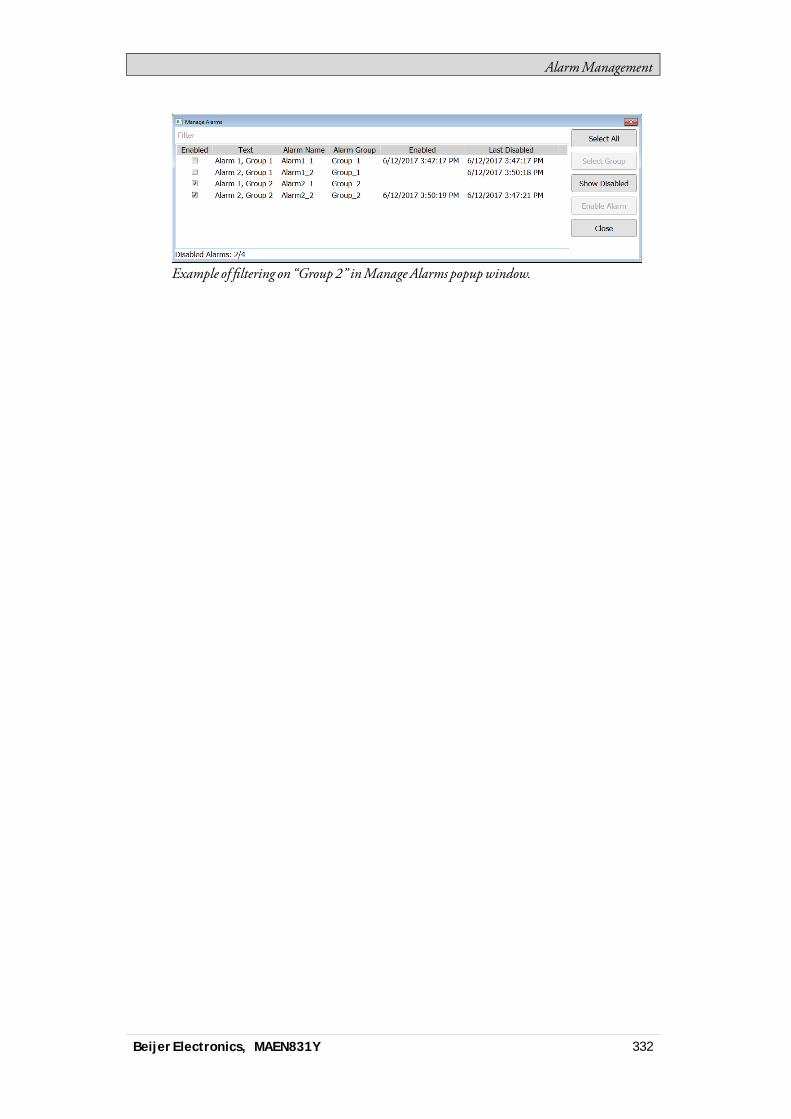
AlarmManagement
Example of filtering on “Group 2” inManage Alarms popupwindow.
Beijer Electronics, MAEN831Y 332
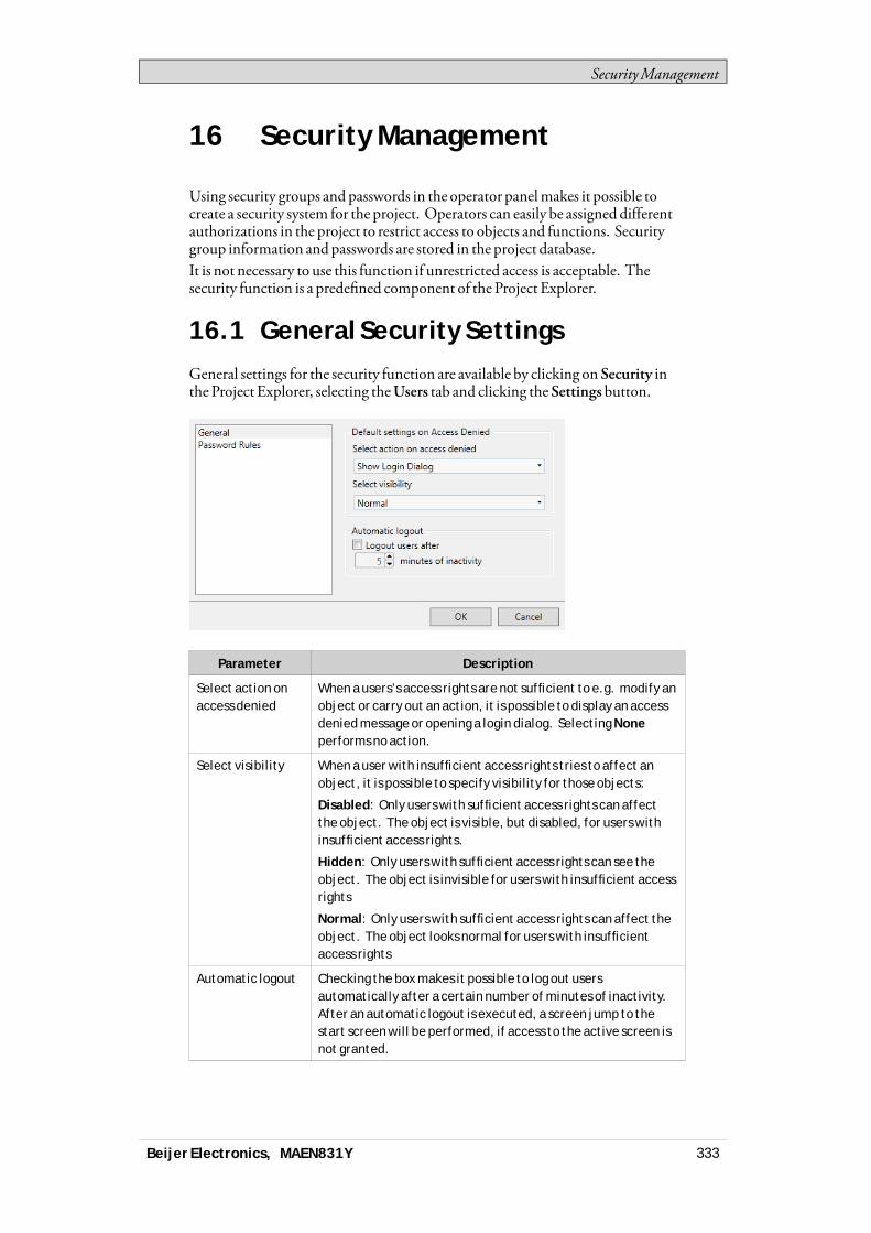
SecurityManagement
16 Security Management
Using security groups and passwords in the operator panelmakes it possible tocreate a security system for the project. Operators can easily be assigned differentauthorizations in the project to restrict access to objects and functions. Securitygroup information andpasswords are stored in the project database.It is not necessary to use this function if unrestricted access is acceptable. Thesecurity function is a predefined component of the Project Explorer.
16.1 General Security SettingsGeneral settings for the security function are available by clicking on Security inthe Project Explorer, selecting theUsers tab and clicking the Settings button.
Parameter Description
Select action onaccess denied
When a users’s access rights are not sufficient to e.g. modify anobject or carry out an action, it is possible to display an accessdenied message or opening a login dialog. Selecting Noneperforms no action.
Select visibility When a user with insufficient access rights tries to affect anobject, it is possible to specify visibility for those objects:
Disabled: Only users with sufficient access rights can affectthe object. The object is visible, but disabled, for users withinsufficient access rights.
Hidden: Only users with sufficient access rights can see theobject. The object is invisible for users with insufficient accessrights
Normal: Only users with sufficient access rights can affect theobject. The object looks normal for users with insufficientaccess rights
Automatic logout Checking the box makes it possible to log out usersautomatically after a certain number of minutes of inactivity.After an automatic logout is executed, a screen jump to thestart screen will be performed, if access to the active screen isnot granted.
Beijer Electronics, MAEN831Y 333

SecurityManagement
Note:The automatic logout will not be carried out if a communication error (COM error)is active in the panel. After removing the communication error from the panel, theautomatic logout will be performed within the specified time, calculated from whenthe communication was reestablished.
16.1.1 Password Rules Properties
Allows setting aminimumnumber of characters for passwords.
Related information
Logging In and Logging Out
16.2 Security GroupsSecurity groups are defined on theGroups tab of the security configuration page.When objects and screens have been set upwith restricted access, the currentusermust belong to a specific security group in order to control or see the objector screen.
16.2.1 Creating Security Groups
Anew security group in a project is defined by clicking on Security in the ProjectExplorer, selecting theGroups tab and clickingAdd.
Beijer Electronics, MAEN831Y 334

SecurityManagement
Parameter Description
Name Any alphanumeric string, beginning with a letter (a-z, A-Z)
Users Selection of users defined on the Users tab to be includedin the group
Users Invisible inRuntime
When the box is checked, the users in the current groupwill not be available for selection from the Login dialog inruntime. It will still be possible to type in the user nameand password to login.
operator panel targets only: In order to enable thepossibility to manually enter a user name and password, itis necessary to click the “Login” header on the Login dialogin runtime. Doing so and then clicking on the User—fieldwill present the user with a keyboard on which a user namecan be entered.
16.3 UsersUsers and passwords for login are defined on theUsers tab of the securityconfiguration page.
Parameter Description
Name Any alphanumeric string, beginning with a letter (a-z, A-Z)
Password Any alphanumeric string; minimum length according toPassword Rules properties. The password is converted toasterisks as you leave the password input cell.
Description An optional description of the user
Groups Selection of security groups for the user
It is also possible to addusers and change passwords directly in a running project,using theShowUsersDialog action.
Beijer Electronics, MAEN831Y 335
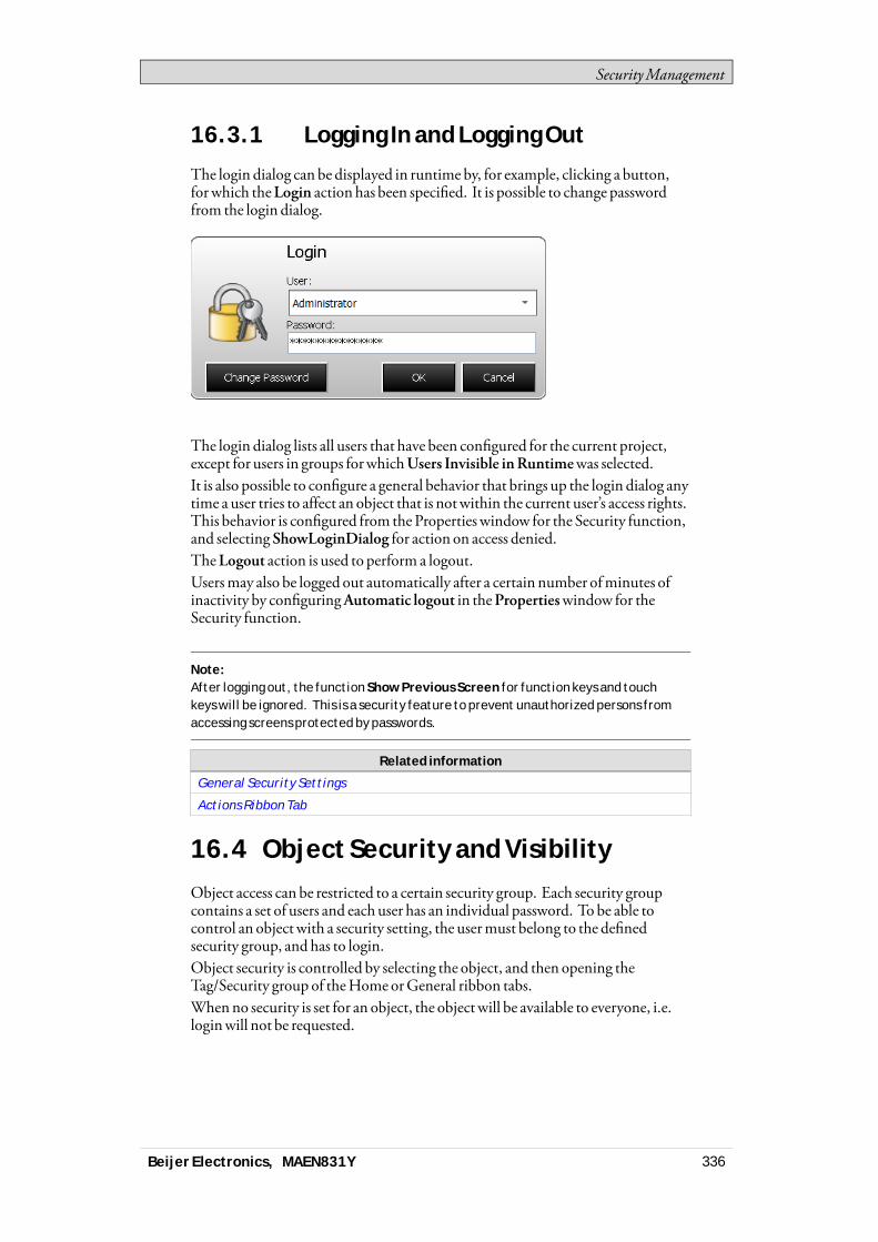
SecurityManagement
16.3.1 Logging In and Logging Out
The login dialog can be displayed in runtime by, for example, clicking a button,forwhich theLogin action has been specified. It is possible to change passwordfrom the login dialog.
The login dialog lists all users that have been configured for the current project,except for users in groups forwhichUsers Invisible inRuntimewas selected.It is also possible to configure a general behavior that brings up the login dialog anytime a user tries to affect an object that is notwithin the current user’s access rights.This behavior is configured from the Properties window for the Security function,and selectingShowLoginDialog for action on access denied.TheLogout action is used to perform a logout.Usersmay also be logged out automatically after a certain number ofminutes ofinactivity by configuringAutomatic logout in thePropertieswindow for theSecurity function.
Note:After logging out, the function Show Previous Screen for function keys and touchkeys will be ignored. This is a security feature to prevent unauthorized persons fromaccessing screens protected by passwords.
Related information
General Security Settings
Actions Ribbon Tab
16.4 Object Security and VisibilityObject access can be restricted to a certain security group. Each security groupcontains a set of users and eachuser has an individual password. To be able tocontrol an object with a security setting, the usermust belong to the definedsecurity group, and has to login.Object security is controlled by selecting the object, and then opening theTag/Security group of theHomeorGeneral ribbon tabs.Whenno security is set for an object, the object will be available to everyone, i.e.loginwill not be requested.
Beijer Electronics, MAEN831Y 336

SecurityManagement
Note:Security has higher priority than dynamics.It is not possible to set security on function keys.
The visibility and behavior settings specified in the securitymanagerwill be usedwhen a security group is set but no explicit visibility is specified. The followingoptions can be set:
Visibility Description
Default The object looks normal and is visible for anyone.
Disabled Only users in the selected security groups can affect theobject. The object is visible but disabled and greyed out,for users with insufficient access rights.
Hidden Only users in the selected security groups can see theobject. The object is invisible for users with insufficientaccess rights.
Normal Only users in the selected security groups can affect theobject. The object looks normal for users with insufficientaccess rights.
Related information
Tag/Security Group
Function Keys
Screen Security
16.5 Cyber Security Best PracticeIt is recommended to configure network firewalls to restrict access to the panel.Formore information, contact your IT administrator. Someprocedures, forexample updating Image, requires access to panel and is then specified in thecorresponding instructions in the referencemanual.
Caution:Any security measures described in this manual, for example, for user access, passwordsecurity, network security, firewalls, virus protection, etc., represent possible stepsthat a user of iX Developer, iX Developer and Runtime may want to consider based on arisk assessment for a particular application and installation. This risk assessment,as well as a proper implementation, configuration, installation, operation,administration, and maintenance of all relevant security related equipment, softwareand procedures are the responsibility of the user of the iX Developer.
Caution:It is the responsibility of the user of the iX Developer to deploy the productappropriate, including procedures/policies regarding organizational measures withrequired precautions and measures to ensure iX Developer functionality.
Beijer Electronics, MAEN831Y 337
SecurityManagement
16.5.1 Web Server Security
Theweb server is disabled by default. It can be enabled on request using theEnableWeb server option available in iXDeveloper. Formore information onaccessing theEnableWeb server option in iXDeveloper and general handling ofweb server in controller, refer to iXDeveloperWeb server configuration formoreinformation.Theweb server provides a login form, that is used for clients to authenticate, bydefault. Refer to section Login Form formore information. Replace this witha password that conformswith your organization's security policy at the firstpossible opportunity. See your organization security policy for setting a password,refer to customer password security configuration.
Caution:If the default password is not replaced, the system will be susceptible to unauthorizedaccess.
The password can be any alphanumeric string. The passwordsminimum length isfour characters and themaximum length is 20 characters.
16.5.2 FTP Server Security
TheFTPServer Security is disabled by default. When enabled, it is possibleto upload/downloadfiles to/from the operator panel provided that there is anFTP client program in the development PC, e.g. Internet Explorer,WindowsCommander or some other standardFTPprogram.It is possible to set up access to the FTP serverwith login requirements and/or asanonymous. An anonymous user has read-only access rights. A user that logs inwith the correct user name andpassword gets read/write access rights. Refer toSection ServersGroup formore information.
16.5.3 Remote Server Security
TheRemoteAccess function is disabled by default. TheRemoteAccess functionmakes it possible to access, reflect and control an operator panel from aPCbyusing the freeVNCclient programRemoteAccessViewer togetherwith thebuilt-inVNC server in the operator panel.It is possible to set upRemote Access with a viewonly password and/or a full accesspassword. The view only password allows reflecting the panel remotely; the fullaccess password allows also control ofmaneuverable objects in the panel.Only oneVNCclient can connect to theVNC server.Only availablewhen an operator panel is selected as target.
Caution:To protect secrecy when entering a password via Remote Access Viewer, it isrecommended to use the PC keyboard. Otherwise it is possible that the cursor on theremote operator panel displays which keys are pressed on the alphanumeric keyboard.Refer to Section Refer to Section Servers Group for more information.
Beijer Electronics, MAEN831Y 338

SecurityManagement
16.5.4 OPC UA Security
TheOPCUAServer is disabled by default. When enabled by theEnableOPCUAServer option available in iX panel it is possible to publish tagswith anOPCUAServer.A certificatewill be auto generated and self-signedwhen the server first starts up.The certificatewill be valid for 20 years. The certificate contains no IP addresssince this could change after the certificate has been generated.
Note:When a Project is re-downloaded to a panel containing an OPC UA certificate, the usercan choose to keep the pki folder (containing the OPC UA certificate). Otherwise, thecertificate is deleted and a new one is created.
Limitations
Discovery Not supported
Encoding/Transport Only UATCP Binary
User authentication Only user name/password. Only one account.
Security No encryption support.
Refer to Section Servers Group for more information.
16.5.5 Project Transfer Security
SelectingBackUpProject compresses the project and saves it as aZIPfile. Theuserwill be prompted for a pathwhere to save theZIPfile andwill also be offeredthe possibility to password protect theZIPfile.Upload: Starts the transfer of theZIPfile from the selected target. The userwill beprompted for a pathwhere to decompress theZIPfile. If theZIPfile is passwordprotected, the usermust enter the password to be able to upload anddecompresstheZIP file. Upload is not supported for all panels. If greyed out, please update tolatest “Systemprogram”.Verify: The verify function enables the user to check if a target platformconfiguration is identical to the project configuration. Verify is not supported forall panels. If greyed out, please update to latest “Systemprogram”.
16.5.6 Email (Alarm distributor)
User name and password protected if Authenticated Login is selected. Referto SectionConfigureDistributionDevices inReferencemanual formoreinformation.
16.5.7 Ethernet Printer Devices
User name and password protected if Authenticated Login is selected. Refer toSectionOutputDevicesGroup inReferencemanual formore information.
Beijer Electronics, MAEN831Y 339
SecurityManagement
16.5.8 Password Settings
Password protection forRemoteAccess,Web server,OPCUAServer , FTP serveris set in design timewhen creating projects. Any changes to passwords has to bedone to the project in design time and the project has to be re-downloaded.Password protection forDefine SecurityUser andAlarmDistributor Security isset in runtime, but can be set in design time aswell. Default setting is set to “Nopassword”when enabling a function.
Caution:It is highly recommended to set a password when enabling a new function, especiallywhen it is exposed to the internet.To get high security, the password must include upper and lowercase letters, numbersand special characters.
16.5.9 Define Security Users
Using security groups and passwords in the operator panelmakes it possible tocreate a security system for the project. Operators can easily be assigned differentauthorizations in the project to restrict access to objects and functions.Security group information and passwords are stored in the project. Securitylevel is set per user group. The security groups are set in design time, and onlythemembers of a security group can bemodified in runtime. Refer to SectionSecurityManagement formore information.When a user with insufficient access rights tries to affect an object, it is possible tospecify visibility for those objects:Disabled: Only users with sufficient access rights can affect the object. The objectis visible, but disabled, for users with insufficient access rights.Hidden: Only userswith sufficient access rights can see the object. The object isinvisible for users with insufficient access rights.Normal: Only userswith sufficient access rights can affect the object. The objectlooks normal for users with insufficient access rights.It is recommended to use visibilityHidden for sensitive functions only visiblefor example service engineers. Refer to Section SecurityManagement formoreinformation.
Note:Security users created in designtime is not possible to remove in runtime.
16.5.10 Service Menu Password Setting
Enter a pin code for the servicemenu. Nopin code enables the servicemenu for allusers. Only numbers (0–9) are allowed. Refer to Section ServiceMenuGroup formore information.
Beijer Electronics, MAEN831Y 340

SecurityManagement
16.5.11 Audit Trail
TheAudit Trail functionmakes it possible to track operator actions. Whenenabling theAudit trail function to a project, select which actions to log. Noactions are set in the default setting. Refer to SectionAudit Trail formoreinformation.The following actions that can be logged, are specified in the table below:
Show unitconversion dialog
Acknowledge AllAlarms
AcknowledgeSelected Alarm
Alarm Info
Clear all Alarms Filter Alarms Pause Viewer Enable/DisableAlarms
Zoom In Zoom Out Pan Down Pan Up
Pan Right Pan Left Trend ViewerHistory
Show BacklightSettings
Set Date and Time Set Time Zone,Region andDaylight Saving
Copy Debug Log ToUSB Memory
Disable DebugLogger
Enable DebugLogger
Show IP Settings Print Screen Close Application
Run Show Next Screen Show PreviousScreen
Show Start Screen
Back Up databases Restore databases — Database Cleanup
Database Export Decrement Analog Increment Analog Reset Tag
Set Analog Set String Set Tag Toggle Tag
Open Address Book Open PrintSettings
Open RoutesConfigurations
—
Clear Data Logger Log Once Start logging Stop logging
EmailConfiguration
Set Language Change ActiveControllers
Clear Non-volatileValues
PrinterConfiguration
Delete Recipe Load Recipe End Offline RecipeEditing
Export Recipe Import Recipe Save Recipe Start OfflineRecipe Editing
Generate Report Show Screen Close screen Run Script
Login Export UserAccounts
Import UserAccounts
Logout
Show User Dialog SMS Configuration Storage devicedetection
—
16.5.12 Antivirus program
It is recommended to have a antivirus program installed on your PC.
Beijer Electronics, MAEN831Y 341

SecurityManagement
Note:iX Developer has been tested with the following antivirus software:• McAfee Virusscan Enterprise• Symantec Endpoint Protection
16.6 Physical SecurityPhysical security considerations elaboratemeasures that shall be in place toprevent unauthorized access via physical channels into the system. Measures canbe security guards, locks, limitations in access to the equipment and similar.iXDeveloper runtime is supported both on virtual and on physicalmachines.There is the possibility that removable assets/communication lines can be usedin both these systems.
Caution:The user shall implement necessary physical precautions to prevent unauthorizedaccess to the system and to removable assets/communication lines.
iXDeveloper uses differentmodules for power supply, communication, IO’s andCPU.Thesemodules can be replacedwith spare parts if needed
16.7 Open PortsCommunication drivers uses either dynamic ports or static ports and both areopened for communication. It is not always a fixed port that opens, this differsfromdriver to driver. Refer to specific driver help file.
Type Description (Port) Open by default
TCP FTP (21) Only on X2 base1)
TCP SSH (22) No
TCP HTTP (80) No1)
TCP DCOM (135) Yes
TCP OPC UA (Default 4840) No1)
TCP Remote access viewer (Default5800)
No1)
TCP Remote access viewer (Default5900)
No1)
TCP Alarm distributor, send Email.(Depends on the server)
No1)
UDP Project Transfer (9999) Yes
UDP Netbios (137) Yes
UDP Netbios (138) Yes
TCP Transfer download (9999) No2)
Beijer Electronics, MAEN831Y 342

SecurityManagement
Type Description (Port) Open by default
TCP Alarm server (Default 1000) No1
TCP/UDP HASP (1947) Yes2
TCP MCER (6510) Yes3
UDP IPv6 Support (3544) Yes3
UDP IPsec (4500/500) Yes3
1) Opened by configuring iX Developer.2) Opened by the iX Runtime installer.3)Openeddepending on the target type and image version.
16.8 Client portsThe iXDeveloper can use the ports, presented in the table below,when acting as aclient to a server.
Type Description (Port)
TCP DHCP (135)
TCP DNS (135)
TCP WINS (135)
Beijer Electronics, MAEN831Y 343

LanguageManagement
17 Language Management
iXDeveloper supportsmultilingual applications. Translation of texts and systemtexts can be performed directly in the application, or via export to a text file tobe translated in other software. The file is imported to the application aftertranslation.The application language can be changed in runtime, for example based on a tagvalue.
17.1 Setting Up Multiple LanguagesThemultiple languages function is included in the application by default and islocated in the Functions folder in the Project Explorer.Themultiple languages configuration pages consist of theTexts, SystemTextsandLanguages tabs.
17.1.1 Adding Languages
1. Click on theMultiple Languages function to open its configuration pages.2. Select theLanguages tab.3. Add languages by selecting them from the drop-down list.
TheUse inRuntime settingmakes the language available in runtime. UnderKeyboard Layout, it is possible to select different layouts for the virtual keyboard,used for alphanumerical input in runtime.
Beijer Electronics, MAEN831Y 344

LanguageManagement
Note:The size of the virtual keyboards vary between languages.Examples of keyboard sizes (the values are approximative)• Arabic: 18 MB• Chinese - simplified: 12 MB• Chinese - traditional: 36 MB• Hebrew: 6 MB• Korean: 21 MB• Latin alphabets: 0.1 MB.
Each added language is assigned an index number. Index number 0 is reserved forthe default language (the language that the applicationwas first created in).TheAdd andDelete buttons can be used to add and delete languages.TheSettings button allows connecting the language to a tag. Thismakes itpossible to change the project language based on a changed value.Use theShowSelection/ShowAll button if youwant to filter the languages in thecurrent view.
Note:If scripting is done against texts which are mentioned in the Multiple Languages, thevalue mentioned by scripting can be overridden by the text value in the Multi LanguageServer.
If the user tries to change the text value through scripting, there is a risk of it beingoverridden by the valuesmentioned in theTexts tab in theMultiple Languagesscreen.If the user want the valuementioned through the script to have priority, the entryfor those texts in theText column in theTexts tab should be left empty. Make sureto add allmulti lingual alternatives in the script.
Related information
Virtual Keyboard
Filtering Items
Beijer Electronics, MAEN831Y 345
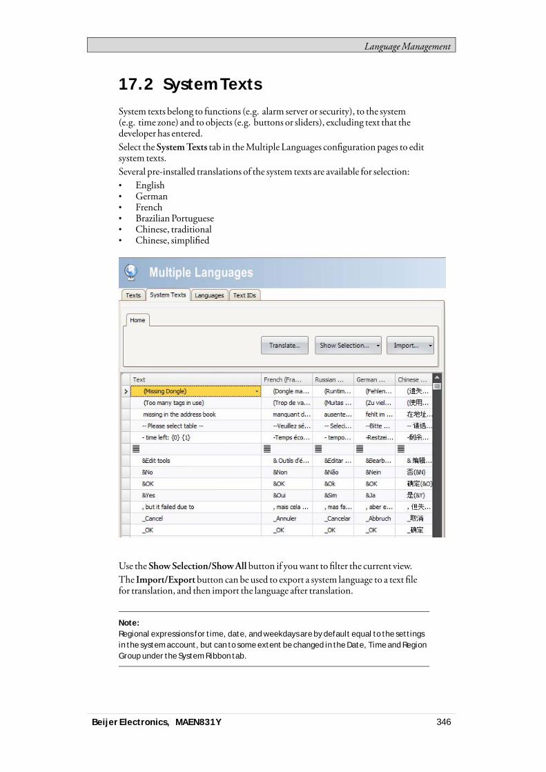
LanguageManagement
17.2 System TextsSystem texts belong to functions (e.g. alarm server or security), to the system(e.g. time zone) and to objects (e.g. buttons or sliders), excluding text that thedeveloper has entered.Select theSystemTexts tab in theMultiple Languages configuration pages to editsystem texts.Several pre-installed translations of the system texts are available for selection:• English• German• French• Brazilian Portuguese• Chinese, traditional• Chinese, simplified
Use theShowSelection/ShowAll button if youwant to filter the current view.The Import/Exportbutton can be used to export a system language to a text filefor translation, and then import the language after translation.
Note:Regional expressions for time, date, and weekdays are by default equal to the settingsin the system account, but can to some extent be changed in the Date, Time and RegionGroup under the System Ribbon tab.
Beijer Electronics, MAEN831Y 346
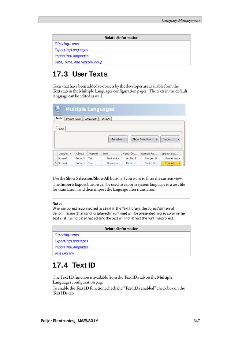
LanguageManagement
Related information
Filtering Items
Exporting Languages
Importing Languages
Date, Time, and Region Group
17.3 User TextsTexts that have been added to objects by the developer are available from theTexts tab in theMultiple Languages configuration pages. The texts in the defaultlanguage can be edited aswell.
Use theShowSelection/ShowAll button if youwant to filter the current view.The Import/Exportbutton can be used to export a system language to a text filefor translation, and then import the language after translation.
Note:When an object is connected to a text in the Text library, the object’s internaldenomination (that is not displayed in runtime) will be presented in grey color in theTexts list, to indicate that editing the text will not affect the runtime project.
Related information
Filtering Items
Exporting Languages
Importing Languages
Text Library
17.4 Text IDTheText ID function is available from theText IDs tab on theMultipleLanguages configuration page.To enable theText ID function, check the “Text IDs enabled” check box on theText IDs tab.
Beijer Electronics, MAEN831Y 347
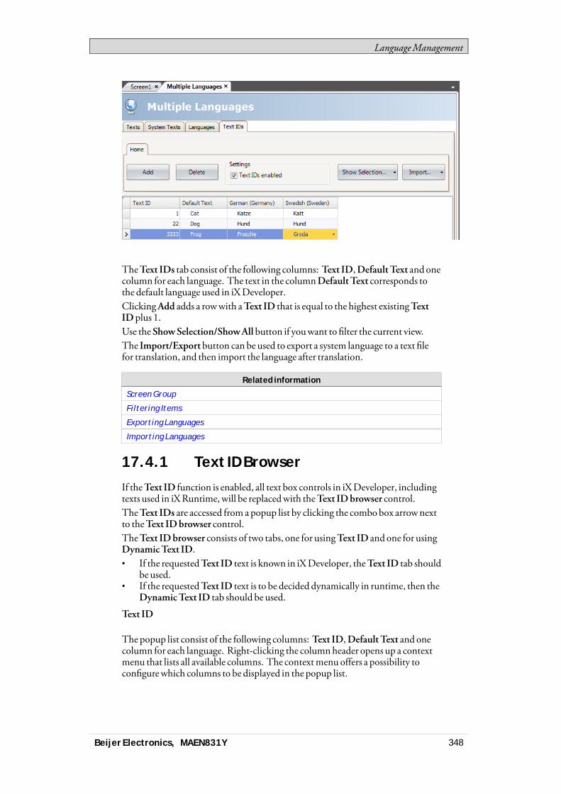
LanguageManagement
TheText IDs tab consist of the following columns: Text ID,DefaultText and onecolumn for each language. The text in the columnDefault Text corresponds tothe default language used in iXDeveloper.ClickingAdd adds a rowwith aText ID that is equal to the highest existingTextIDplus 1.Use theShowSelection/ShowAll button if youwant to filter the current view.The Import/Exportbutton can be used to export a system language to a text filefor translation, and then import the language after translation.
Related information
Screen Group
Filtering Items
Exporting Languages
Importing Languages
17.4.1 Text ID Browser
If theText ID function is enabled, all text box controls in iXDeveloper, includingtexts used in iXRuntime,will be replacedwith theText IDbrowser control.TheText IDs are accessed from apopup list by clicking the combobox arrownextto theText IDbrowser control.TheText IDbrowser consists of two tabs, one for usingText ID and one for usingDynamicText ID.• If the requestedText ID text is known in iXDeveloper, theText ID tab should
be used.• If the requestedText ID text is to be decided dynamically in runtime, then the
DynamicText ID tab should be used.
Text ID
The popup list consist of the following columns: Text ID,Default Text and onecolumn for each language. Right-clicking the columnheader opens up a contextmenu that lists all available columns. The contextmenu offers a possibility toconfigurewhich columns to be displayed in the popup list.
Beijer Electronics, MAEN831Y 348
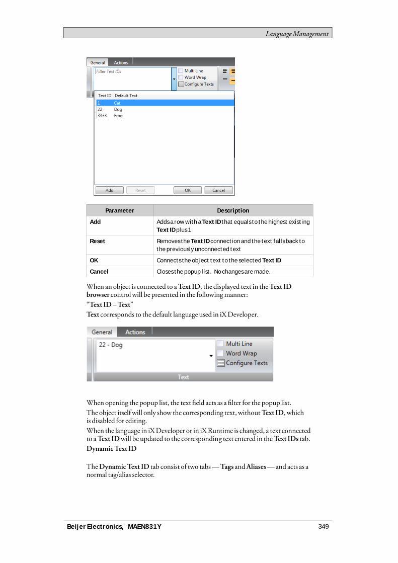
LanguageManagement
Parameter Description
Add Adds a row with a Text ID that equals to the highest existingText ID plus 1
Reset Removes the Text ID connection and the text falls back tothe previously unconnected text
OK Connects the object text to the selected Text ID
Cancel Closes the popup list. No changes are made.
When an object is connected to aText ID, the displayed text in theText IDbrowser control will be presented in the followingmanner:“Text ID –Text”Text corresponds to the default language used in iXDeveloper.
When opening the popup list, the text field acts as a filter for the popup list.The object itself will only show the corresponding text, withoutText ID, whichis disabled for editing.When the language in iXDeveloper or in iXRuntime is changed, a text connectedto aText IDwill be updated to the corresponding text entered in theText IDs tab.DynamicText ID
TheDynamicText ID tab consist of two tabs—Tags andAliases—and acts as anormal tag/alias selector.
Beijer Electronics, MAEN831Y 349
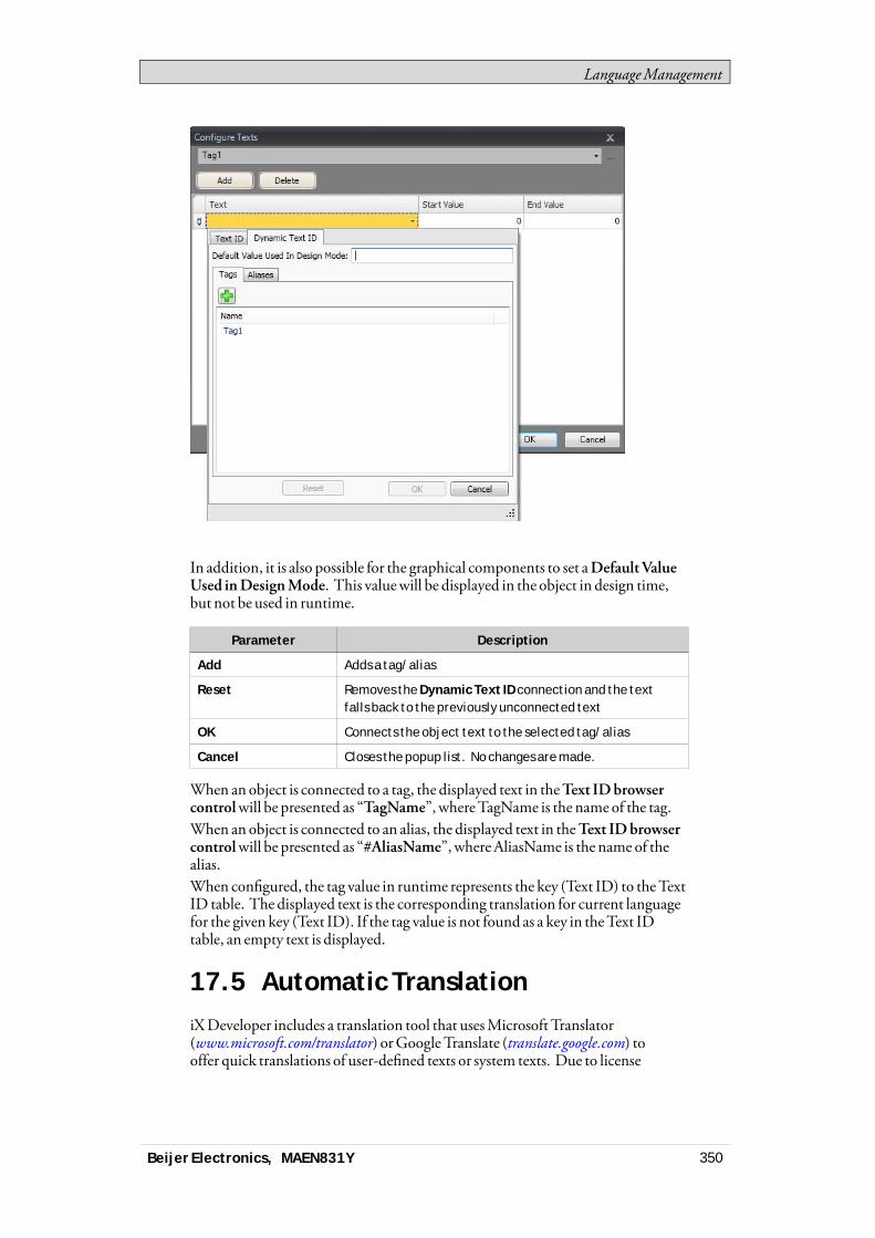
LanguageManagement
In addition, it is also possible for the graphical components to set aDefaultValueUsed inDesignMode. This valuewill be displayed in the object in design time,but not be used in runtime.
Parameter Description
Add Adds a tag/alias
Reset Removes the Dynamic Text ID connection and the textfalls back to the previously unconnected text
OK Connects the object text to the selected tag/alias
Cancel Closes the popup list. No changes are made.
When an object is connected to a tag, the displayed text in theText IDbrowsercontrolwill be presented as “TagName”, whereTagName is the name of the tag.When an object is connected to an alias, the displayed text in theText IDbrowsercontrolwill be presented as “#AliasName”, whereAliasName is the name of thealias.When configured, the tag value in runtime represents the key (Text ID) to theTextID table. The displayed text is the corresponding translation for current languagefor the given key (Text ID). If the tag value is not found as a key in theText IDtable, an empty text is displayed.
17.5 Automatic TranslationiXDeveloper includes a translation tool that usesMicrosoft Translator(www.microsoft.com/translator) orGoogle Translate (translate.google.com) tooffer quick translations of user-defined texts or system texts. Due to license
Beijer Electronics, MAEN831Y 350
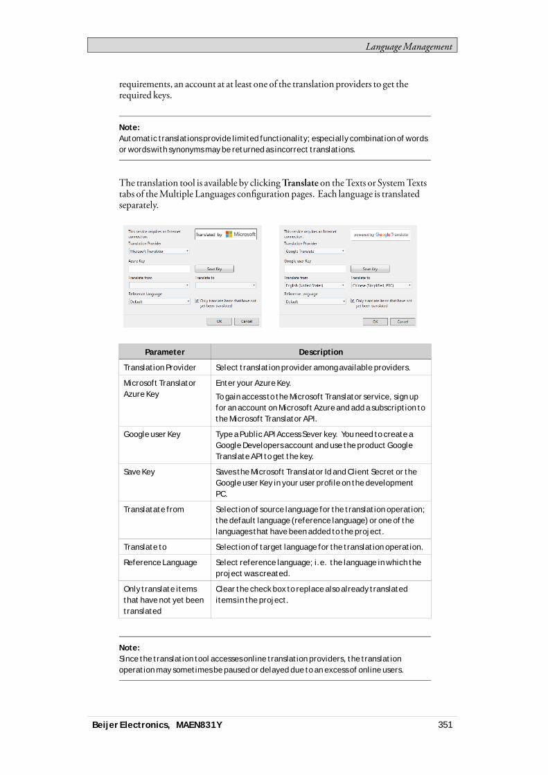
LanguageManagement
requirements, an account at at least one of the translation providers to get therequired keys.
Note:Automatic translations provide limited functionality; especially combination of wordsor words with synonyms may be returned as incorrect translations.
The translation tool is available by clickingTranslate on theTexts or SystemTextstabs of theMultiple Languages configuration pages. Each language is translatedseparately.
Parameter Description
Translation Provider Select translation provider among available providers.
Microsoft TranslatorAzure Key
Enter your Azure Key.
To gain access to the Microsoft Translator service, sign upfor an account on Microsoft Azure and add a subscription tothe Microsoft Translator API.
Google user Key Type a Public API Access Sever key. You need to create aGoogle Developers account and use the product GoogleTranslate API to get the key.
Save Key Saves the Microsoft Translator Id and Client Secret or theGoogle user Key in your user profile on the developmentPC.
Translatate from Selection of source language for the translation operation;the default language (reference language) or one of thelanguages that have been added to the project.
Translate to Selection of target language for the translation operation.
Reference Language Select reference language; i.e. the language in which theproject was created.
Only translate itemsthat have not yet beentranslated
Clear the check box to replace also already translateditems in the project.
Note:Since the translation tool accesses online translation providers, the translationoperation may sometimes be paused or delayed due to an excess of online users.
Beijer Electronics, MAEN831Y 351
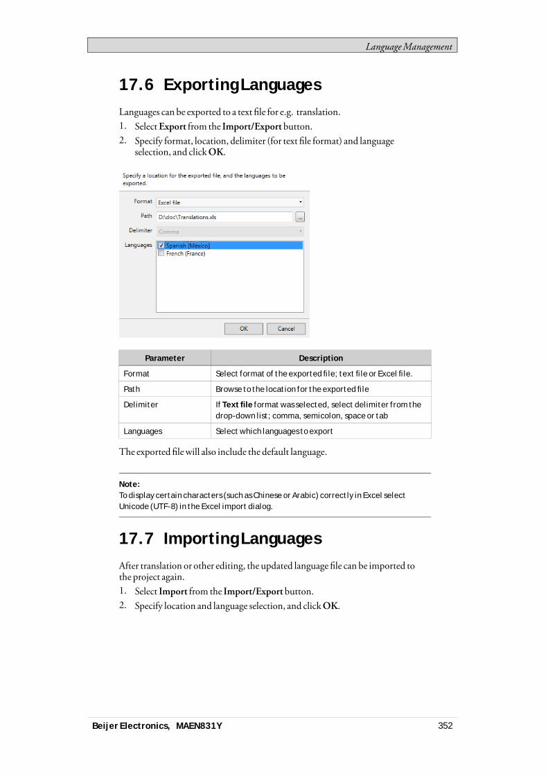
LanguageManagement
17.6 Exporting LanguagesLanguages can be exported to a text file for e.g. translation.1. SelectExport from the Import/Export button.2. Specify format, location, delimiter (for text file format) and language
selection, and clickOK.
Parameter Description
Format Select format of the exported file; text file or Excel file.
Path Browse to the location for the exported file
Delimiter If Text file format was selected, select delimiter from thedrop-down list; comma, semicolon, space or tab
Languages Select which languages to export
The exported filewill also include the default language.
Note:To display certain characters (such as Chinese or Arabic) correctly in Excel selectUnicode (UTF-8) in the Excel import dialog.
17.7 Importing LanguagesAfter translation or other editing, the updated language file can be imported tothe project again.1. Select Import from the Import/Export button.2. Specify location and language selection, and clickOK.
Beijer Electronics, MAEN831Y 352
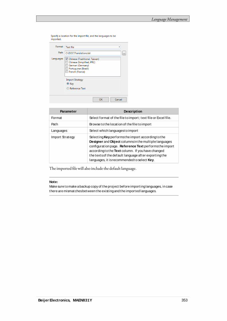
LanguageManagement
Parameter Description
Format Select format of the file to import; text file or Excel file.
Path Browse to the location of the file to import
Languages Select which languages to import
Import Strategy Selecting Key performs the import according to theDesigner and Object columns in the multiple languagesconfiguration page. Reference Text performs the importaccording to the Text column. If you have changedthe texts of the default language after exporting thelanguages, it is recommended to select Key.
The imported filewill also include the default language.
Note:Make sure to make a backup copy of the project before importing languages, in casethere are mismatches between the existing and the imported languages.
Beijer Electronics, MAEN831Y 353
Audit Trail
18 Audit Trail
TheAudit Trail functionmakes it possible to track operator actions.TheAudit Trail database can be exported in csv format using theDatabase Exportaction. It is recommended to use the database exportmethod rather than thebackupmethod.
Related information
Database Export
18.1 Logging StrategiesTomeet FDA (Food andDrugAdministration) demands, it is possible to logactions in a strictmanner. FDA logging implies that no log entries will everbe overwritten. If the size of the audit trail database is close to being exceeded(approximately 80%of the limit), a notificationwindowwill be displayed,wherethe user is warned, anddemanded to export the data.Alternatively, the size of theAudit Trail database can be increased. If the limit ofthe database is exceeded, the logging is terminated and the operator panel will beblocked for any further operator actions. This is indicated by an errormessage.With circular buffering, the oldest log entry is overwrittenwhen the database isfull. Nowarningmessage is displayedwhen reaching the limit of the database.The database can be exported using an action, regardless of logging strategy.The log entries are saved in theAudit Trail database, and the information can bedisplayed using theAudit Trail Viewer.
18.2 Using the Audit Trail FunctionThe function is enabled by selectingAuditTrail from the Insert ribbon tab. Theconfiguration page opens in the desktop area. All actions available for loggingare listed. It is possible to log all or only some actions. It is also possible to log tagchanges only (without logging actions).
Beijer Electronics, MAEN831Y 354
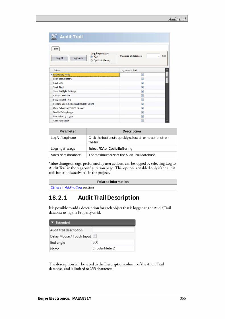
Audit Trail
Parameter Description
Log All/Log None Click the buttons to quickly select all or no actions fromthe list
Logging strategy Select FDA or Cyclic Buffering
Max size of database The maximum size of the Audit Trail database
Value change on tags, performed by user actions, can be logged by selectingLog toAuditTrail in the tags configuration page. This option is enabled only if the audittrail function is activated in the project.
Related information
Others in Adding Tags section
18.2.1 Audit Trail Description
It is possible to add a description for each object that is logged to theAuditTraildatabase using the PropertyGrid.
The descriptionwill be saved to theDescription columnof theAudit Traildatabase, and is limited to 255 characters.
Beijer Electronics, MAEN831Y 355

Audit Trail
18.3 Audit Trail ViewerTheAudit Trail Viewer is selected from theObjects group on theHome ribbontab. It displays the information from theAudit Trail database.SelectingConfigureColumns on theGeneral tabwhen theAudit Trail Viewerobject is selectedmakes it possible to choose and configure columns to display inruntime.
18.4 Audit Trail ExportAn audit trail database can be exported as a .csv file and saved to aUSB stick,an externalmemory card or to the project files folder. The export is configuredthrough theDatabase Export action available from theDatabase action group.
Note:The export will not delete the audit trail log from the project.
Related information
Action Groups
Beijer Electronics, MAEN831Y 356
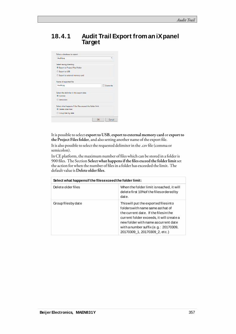
Audit Trail
18.4.1 Audit Trail Export from an iX panelTarget
It is possible to select export toUSB, export to externalmemory card or export totheProject Files folder, and also setting another name of the export file.It is also possible to select the requested delimiter in the .csv file (commaorsemicolon).InCEplatform, themaximumnumber of files which can be stored in a folder is900 files. The Section Selectwhat happens if the files exceed the folder limit setthe action forwhen the number of files in a folder has exceeded the limit. Thedefault value isDelete older files.
Select what happens if the files exceed the folder limit:
Delete older files When the folder limit is reached, it willdelete first 10% of the files ordered bydate.
Group files by date This will put the exported files intofolders with name same as that ofthe current date. If the files in thecurrent folder exceeds, it will create anew folder with name as current datewith a number suffix (e.g.: 20170309,20170309_1, 20170309_2, etc.)
Beijer Electronics, MAEN831Y 357

Audit Trail
18.4.2 Audit Trail Export from a PC
It is possible to selectBrowse and Select an export path,Export to Path or theExport toProject Files folder, and also setting another name of the export file.TheBrowse andSelect an export path option allows browsing for desired exportdestination in runtime. Thismay be useful if available folders in runtime areunknownwhendesigning the project.Select theExport toPath optionwhen youwant to set the pathwhen designing theproject. If the pre-defined path is not valid in runtime, the operatormay browsethe PC environment by clicking a browse button.It is also possible to select the requested delimiter in the .csv file (commaorsemicolon).
Beijer Electronics, MAEN831Y 358

Text Library
19 Text Library
With the text library function, text tables can be created,where values are linkedto texts. The text library function can be used for presentation of each sequencestep in sequence control. Another possible application is to present error codes,where an analog signal generates error codes connected to texts in a text library.The function can also be used to give analog values specific values, depending onthe selected texts.The text library function is activated by selecting it from the Insert ribbon tab.
Texts and groups can be added from theAdd button.It is also possible to add start and end values for eachmessage, thatmakes the textin the connected object change depending on the value of the tag.
Note:The Start Value and End Value can only be given as integers. This could result inproblems updating the text when the input value is entered with decimals, especially ifthe input value jumps in and out of the given range. If this is the case, use the ConfigureText function instead. This is available under the General tab when the object isselected.
Note:A default text that has been entered in Configure Text will not be presented outsidea range that has been defined in the Text Library. In this case, use Configure Text todefine all text presentations for the object.
Related information
HMI Controls
Beijer Electronics, MAEN831Y 359
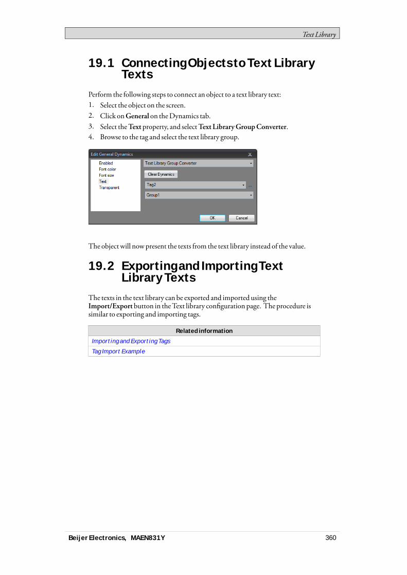
Text Library
19.1 Connecting Objects to Text LibraryTexts
Perform the following steps to connect an object to a text library text:1. Select the object on the screen.2. Click onGeneral on theDynamics tab.3. Select theText property, and selectText LibraryGroupConverter.4. Browse to the tag and select the text library group.
The object will nowpresent the texts from the text library instead of the value.
19.2 Exporting and Importing TextLibrary Texts
The texts in the text library can be exported and imported using theImport/Export button in theText library configuration page. The procedure issimilar to exporting and importing tags.
Related information
Importing and Exporting Tags
Tag Import Example
Beijer Electronics, MAEN831Y 360
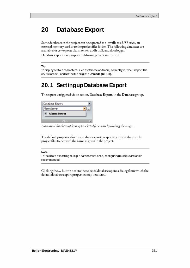
Database Export
20 Database Export
Somedatabases in the project can be exported as a .csv file to aUSB stick, anexternalmemory card or to the project files folder. The following databases areavailable for csv export: alarm server, audit trail, and data logger.Database export is not supported during project simulation.
Tip:To display certain characters (such as Chinese or Arabic) correctly in Excel, import thecsv file as text, and set the file origin to Unicode (UTF-8).
20.1 Setting up Database ExportThe export is triggered via an action,Database Export, in theDatabase group.
Individual database tablesmay be selected for export by clicking the + sign.
The default properties for the database export is exporting the database to theproject files folderwith the name as given in the project.
Note:To facilitate exporting multiple databases at once, configuring multiple actions isrecommended.
Clicking the ... button next to the selected database opens a dialog fromwhich thedefault database export propertiesmay be altered.
Beijer Electronics, MAEN831Y 361
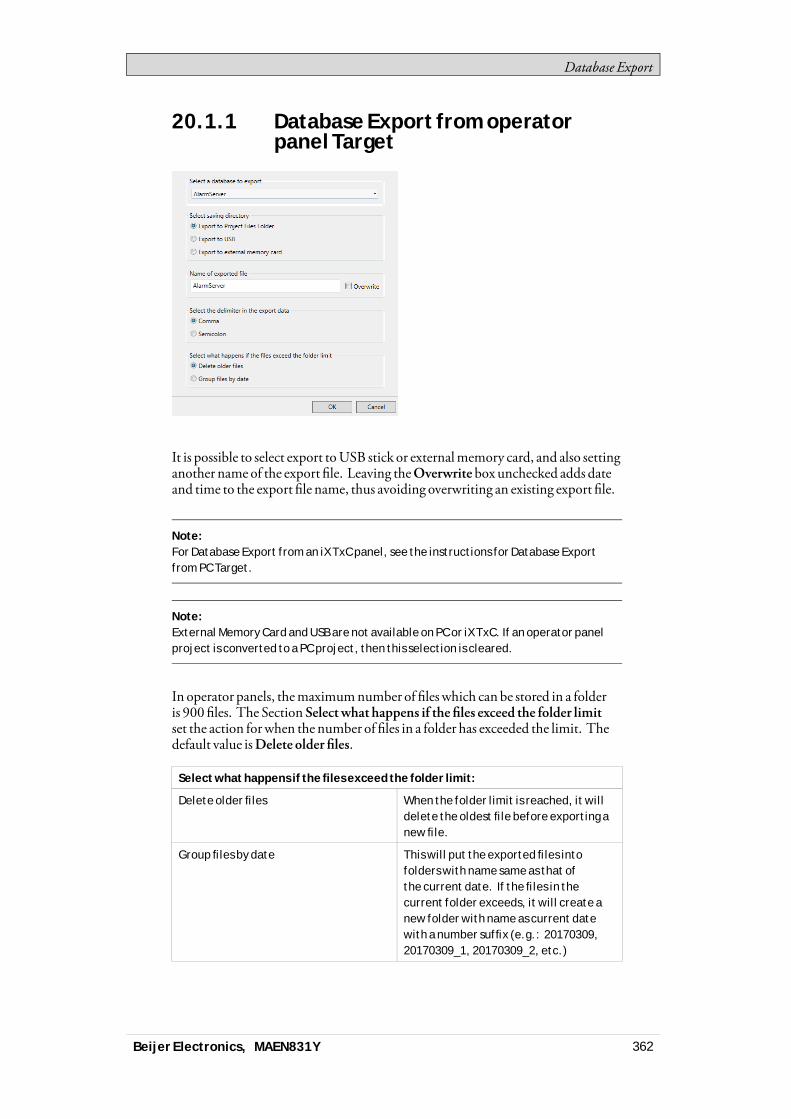
Database Export
20.1.1 Database Export from operatorpanel Target
It is possible to select export toUSB stick or externalmemory card, and also settinganother name of the export file. Leaving theOverwrite box unchecked adds dateand time to the export file name, thus avoiding overwriting an existing export file.
Note:For Database Export from an iX TxC panel, see the instructions for Database Exportfrom PC Target.
Note:External Memory Card and USB are not available on PC or iX TxC. If an operator panelproject is converted to a PC project, then this selection is cleared.
In operator panels, themaximumnumber of fileswhich can be stored in a folderis 900 files. The Section Selectwhat happens if the files exceed the folder limitset the action forwhen the number of files in a folder has exceeded the limit. Thedefault value isDelete older files.
Select what happens if the files exceed the folder limit:
Delete older files When the folder limit is reached, it willdelete the oldest file before exporting anew file.
Group files by date This will put the exported files intofolders with name same as that ofthe current date. If the files in thecurrent folder exceeds, it will create anew folder with name as current datewith a number suffix (e.g.: 20170309,20170309_1, 20170309_2, etc.)
Beijer Electronics, MAEN831Y 362
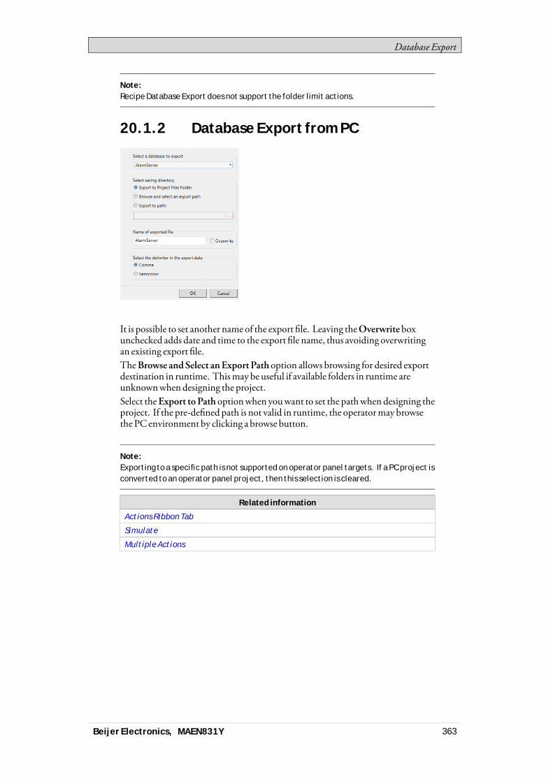
Database Export
Note:Recipe Database Export does not support the folder limit actions.
20.1.2 Database Export from PC
It is possible to set another name of the export file. Leaving theOverwriteboxunchecked adds date and time to the export file name, thus avoiding overwritingan existing export file.TheBrowse andSelect anExport Pathoption allows browsing for desired exportdestination in runtime. Thismay be useful if available folders in runtime areunknownwhendesigning the project.Select theExport toPath optionwhen youwant to set the pathwhen designing theproject. If the pre-defined path is not valid in runtime, the operatormay browsethe PC environment by clicking a browse button.
Note:Exporting to a specific path is not supported on operator panel targets. If a PC project isconverted to an operator panel project, then this selection is cleared.
Related information
Actions Ribbon Tab
Simulate
Multiple Actions
Beijer Electronics, MAEN831Y 363
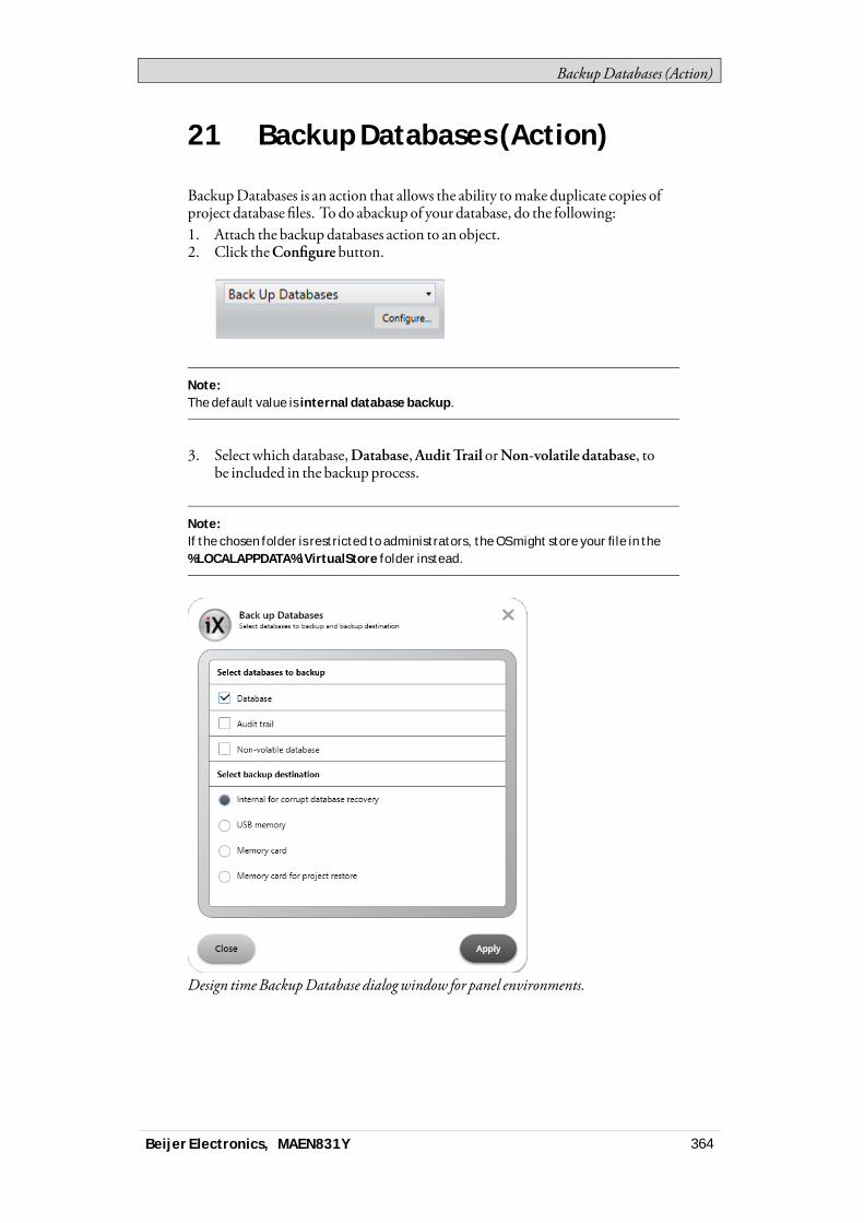
BackupDatabases (Action)
21 Backup Databases (Action)
BackupDatabases is an action that allows the ability tomake duplicate copies ofproject database files. To do abackup of your database, do the following:1. Attach the backupdatabases action to an object.2. Click theConfigure button.
Note:The default value is internal database backup.
3. Select which database,Database,AuditTrail orNon-volatile database, tobe included in the backupprocess.
Note:If the chosen folder is restricted to administrators, the OS might store your file in the%LOCALAPPDATA%\VirtualStore folder instead.
Design timeBackupDatabase dialogwindow for panel environments.
Beijer Electronics, MAEN831Y 364
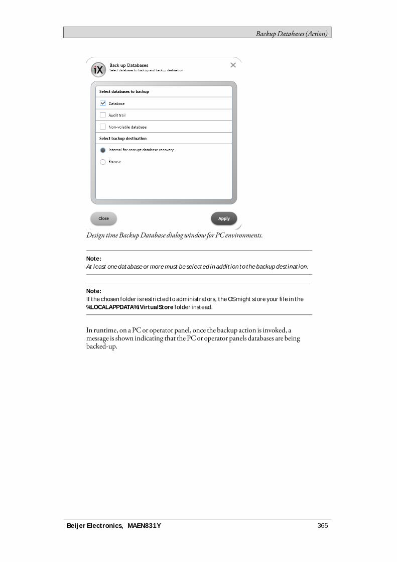
BackupDatabases (Action)
Design timeBackupDatabase dialogwindow for PC environments.
Note:At least one database or more must be selected in addition to the backup destination.
Note:If the chosen folder is restricted to administrators, the OS might store your file in the%LOCALAPPDATA%\VirtualStore folder instead.
In runtime, on aPCor operator panel, once the backup action is invoked, amessage is shown indicating that the PCor operator panels databases are beingbacked-up.
Beijer Electronics, MAEN831Y 365
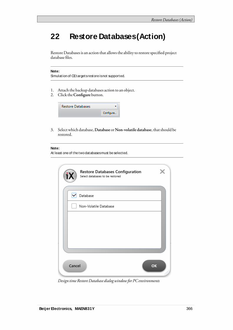
RestoreDatabases (Action)
22 Restore Databases (Action)
RestoreDatabases is an action that allows the ability to restore specified projectdatabase files.
Note:Simulation of CE targets restore is not supported.
1. Attach the backupdatabases action to an object.2. Click theConfigure button.
3. Select which database,Database orNon-volatile database, that should berestored.
Note:At least one of the two databases must be selected.
Design timeRestoreDatabase dialogwindow for PC environments
Beijer Electronics, MAEN831Y 366
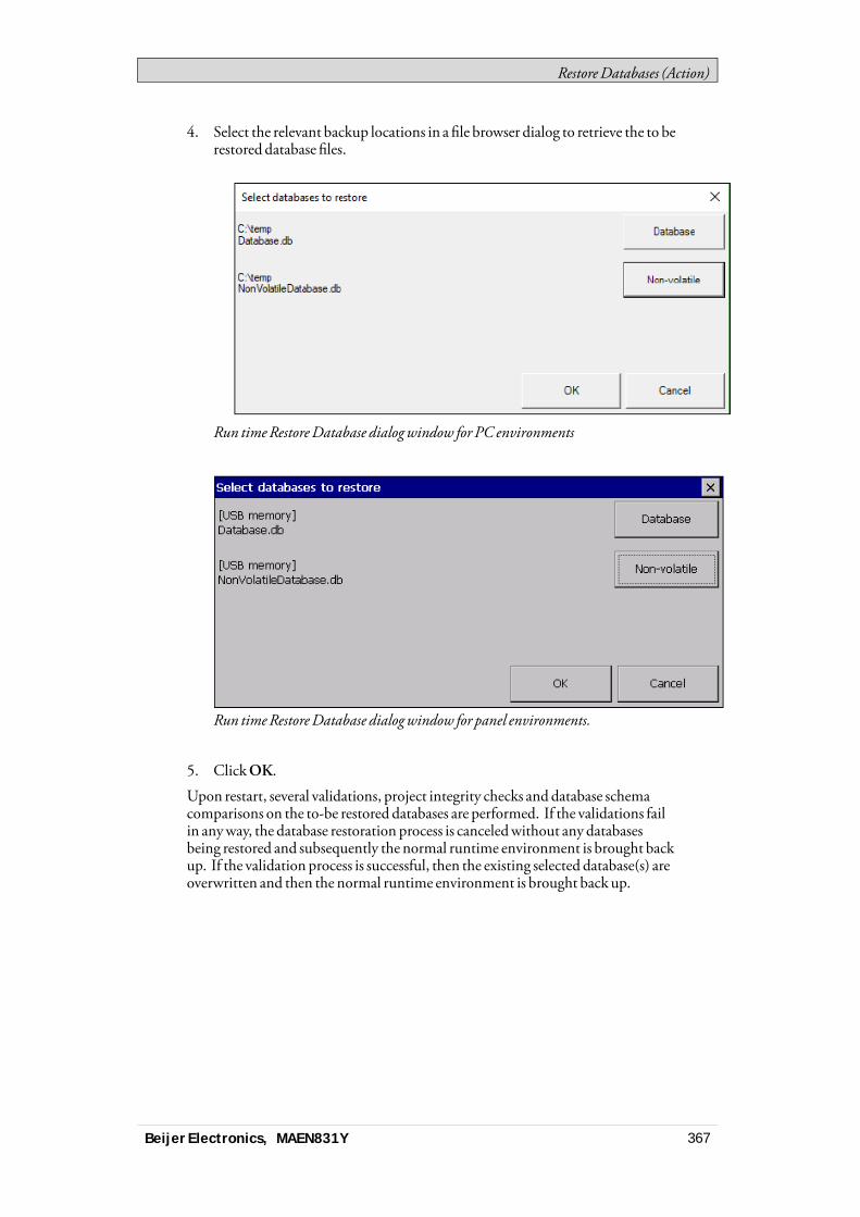
RestoreDatabases (Action)
4. Select the relevant backup locations in a file browser dialog to retrieve the to berestored database files.
Run timeRestoreDatabase dialogwindow for PC environments
Run timeRestoreDatabase dialogwindow for panel environments.
5. ClickOK.
Upon restart, several validations, project integrity checks and database schemacomparisons on the to-be restored databases are performed. If the validations failin anyway, the database restoration process is canceledwithout any databasesbeing restored and subsequently the normal runtime environment is brought backup. If the validation process is successful, then the existing selected database(s) areoverwritten and then the normal runtime environment is brought back up.
Beijer Electronics, MAEN831Y 367
Database Cleanup
23 Database Cleanup
TheDatabaseCleanup action can result in reduced database size and betterdatabase performance. The following are some scenarioswhere this action couldbe used:• When a large amount of data is deleted from the database file it leaves behind
empty space. Thismeans the database filemight be larger than necessary.Running theDatabaseCleanup action reclaims this space and reduces thesize of the database file.
• Frequent inserts, updates, and deletes can cause the database file to becomefragmented,where data for a single table or index is scattered around thedatabase file. Running theDatabaseCleanup action ensures that each tableand index is stored continuouslywithin the database file. Having indexes inorder improves performance.
Note:The Database Cleanup action works by copying the contents of the database into atemporary database file and then overwriting the original with the contents of thetemporary file. When overwriting the original, a rollback journal or write-ahead logWAL file is used just as it would be for any other database transaction. This means thatwhen performing a Database Cleanup action on a database, as much as twice the sizeof the original database file is required in free disk space.
Note:The Database Cleanup action will fail if there is an open transaction, or if there are oneor more active SQL statements when it is run.
Example:Before performing an export of a project the project size could be shrunk. This is doneby first using the Clear Datalogger action, and then the Database Cleanup action.
Example:If an unusually big amount of database transactions has been performed, a DatabaseCleanup could help boost database performance.
Beijer Electronics, MAEN831Y 368
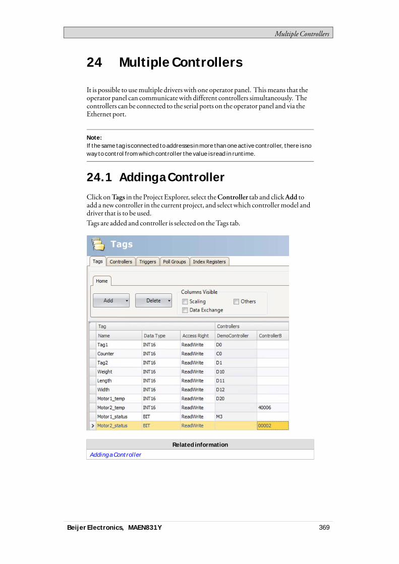
Multiple Controllers
24 Multiple Controllers
It is possible to usemultiple drivers with one operator panel. Thismeans that theoperator panel can communicatewith different controllers simultaneously. Thecontrollers can be connected to the serial ports on the operator panel and via theEthernet port.
Note:If the same tag is connected to addresses in more than one active controller, there is noway to control from which controller the value is read in runtime.
24.1 Adding a ControllerClick onTags in the Project Explorer, select theController tab and clickAdd toadd a new controller in the current project, and selectwhich controllermodel anddriver that is to be used.Tags are added and controller is selected on theTags tab.
Related information
Adding a Controller
Beijer Electronics, MAEN831Y 369
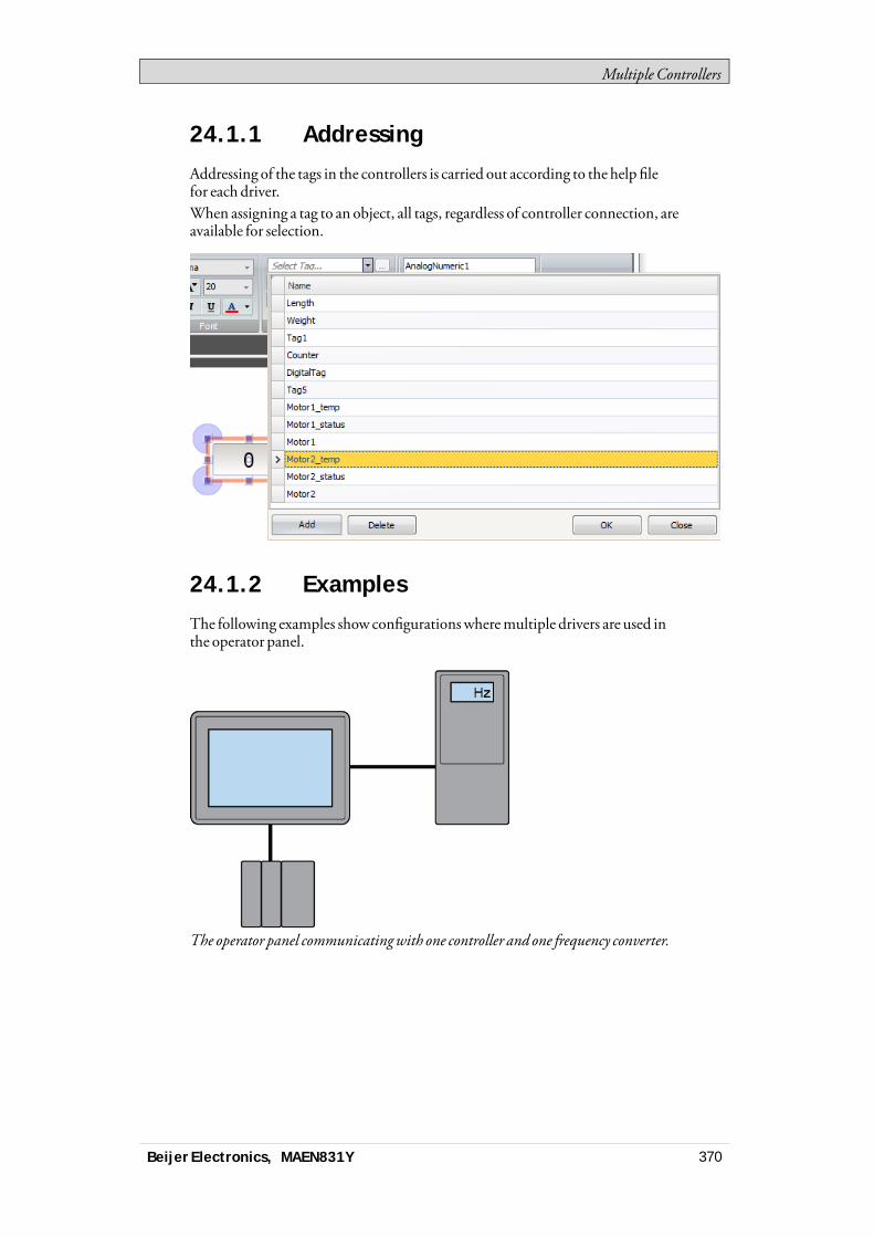
Multiple Controllers
24.1.1 Addressing
Addressing of the tags in the controllers is carried out according to the help filefor each driver.When assigning a tag to an object, all tags, regardless of controller connection, areavailable for selection.
24.1.2 Examples
The following examples show configurationswheremultiple drivers are used inthe operator panel.
The operator panel communicatingwith one controller and one frequency converter.
Beijer Electronics, MAEN831Y 370
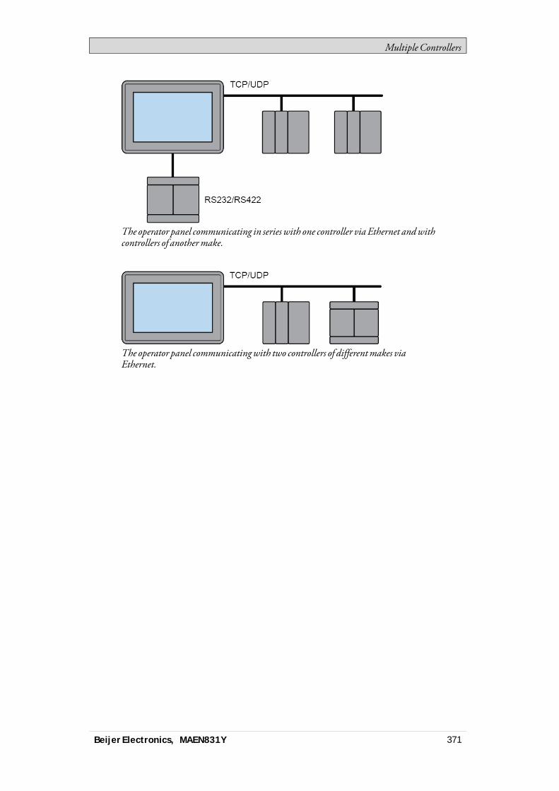
Multiple Controllers
The operator panel communicating in series with one controller via Ethernet andwithcontrollers of anothermake.
The operator panel communicatingwith two controllers of differentmakes viaEthernet.
Beijer Electronics, MAEN831Y 371

Configuration settings for BoX 2
25 Configuration settings for BoX 2
BoX2does not have any displays. BoX2 is a series of IoT gatewayswith thepossibility to add optional smart functions:• Share data betweenPLCs of different brands.• Create IoT solutions to store and access data in the cloud (not for BoX2 base).• Integrate localCODESYScontrol.• Add smart functions usingC# scripting.
Note:It is not possible to convert a Display panel project to a BoX2 project.
Excluded funtions for BoX2:• Security• Audit trail• Text Libraries• VNC(Remote access)• Zoom in/out• Recipe
Unavailable ribbon items:• Clipboard• Screen• Objects• Font• Format
Beijer Electronics, MAEN831Y 372
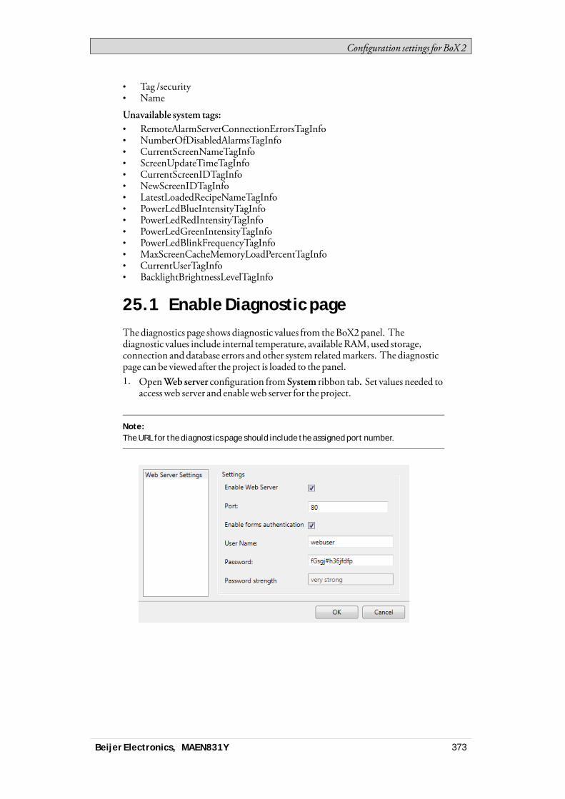
Configuration settings for BoX 2
• Tag /security• Name
Unavailable system tags:• RemoteAlarmServerConnectionErrorsTagInfo• NumberOfDisabledAlarmsTagInfo• CurrentScreenNameTagInfo• ScreenUpdateTimeTagInfo• CurrentScreenIDTagInfo• NewScreenIDTagInfo• LatestLoadedRecipeNameTagInfo• PowerLedBlueIntensityTagInfo• PowerLedRedIntensityTagInfo• PowerLedGreenIntensityTagInfo• PowerLedBlinkFrequencyTagInfo• MaxScreenCacheMemoryLoadPercentTagInfo• CurrentUserTagInfo• BacklightBrightnessLevelTagInfo
25.1 Enable Diagnostic pageThe diagnostics page shows diagnostic values from theBoX2panel. Thediagnostic values include internal temperature, availableRAM,used storage,connection anddatabase errors and other system relatedmarkers. The diagnosticpage can be viewed after the project is loaded to the panel.1. OpenWeb server configuration from System ribbon tab. Set values needed to
access web server and enableweb server for the project.
Note:The URL for the diagnostics page should include the assigned port number.
Beijer Electronics, MAEN831Y 373

Configuration settings for BoX 2
2. Add system tags, used on the page,manually to the project. If the system tag ismissing, ‘-’ will be displayed on the page.
Note:The following system tags are available:• Communication Errors (count) (SystemTagCommunicationErrorMessage)• Communication Error Message (SystemTagCommunicationErrorMessage)• Database Error Active (SystemTagStorageErrorActive)• Database Error Message (SystemTagStorageErrorMessage)• Database Max Size Exceeded (SystemTagStorageMaxSizeExceeded)• Current Date and Time (SystemTagDateTime)• Debug Logging Enabled (SystemTagDebugLoggingEnabled)
Beijer Electronics, MAEN831Y 374
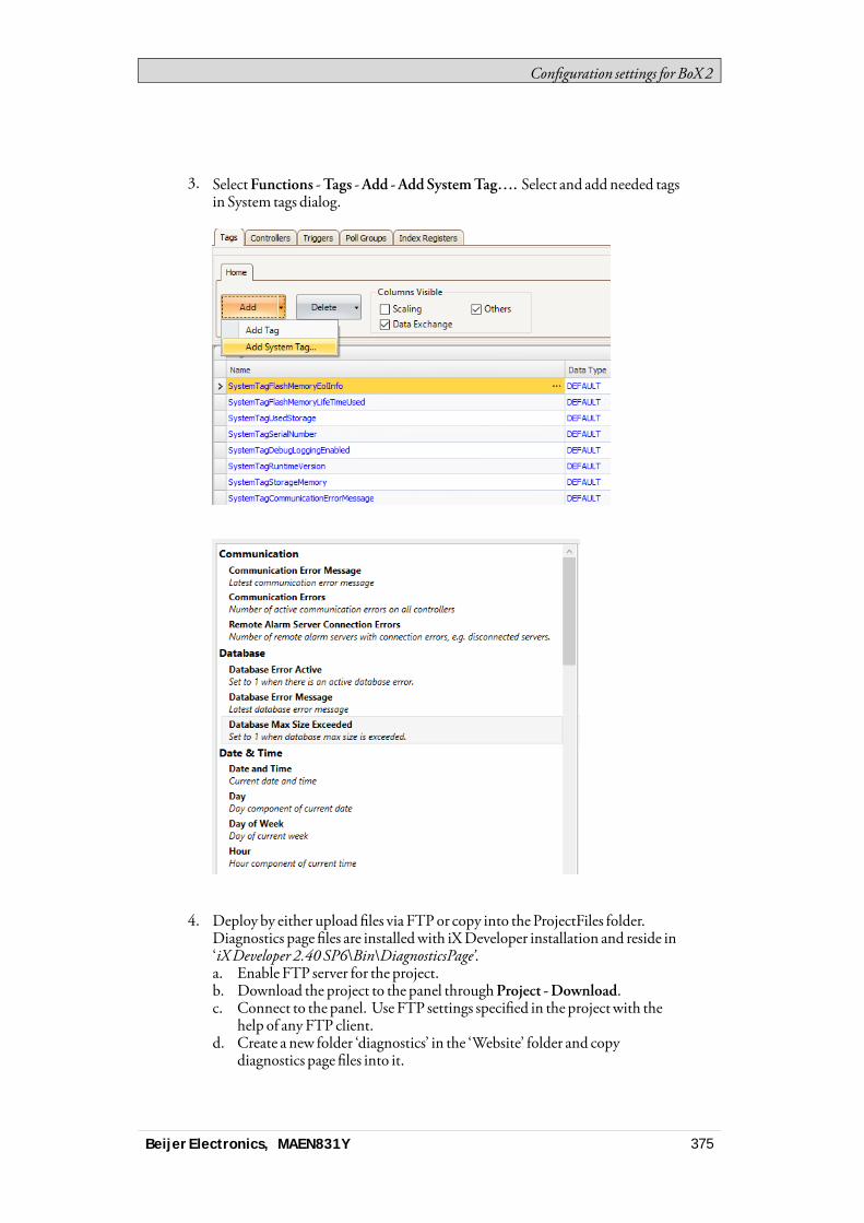
Configuration settings for BoX 2
3. SelectFunctions -Tags -Add -AddSystemTag…. Select and addneeded tagsin System tags dialog.
4. Deploy by either uploadfiles via FTPor copy into the ProjectFiles folder.Diagnostics page files are installedwith iXDeveloper installation and reside in‘iXDeveloper 2.40 SP6\Bin\DiagnosticsPage’.a. Enable FTP server for the project.b. Download the project to the panel throughProject -Download.c. Connect to the panel. Use FTP settings specified in the project with the
help of any FTP client.d. Create a new folder ‘diagnostics’ in the ‘Website’ folder and copy
diagnostics page files into it.
Beijer Electronics, MAEN831Y 375
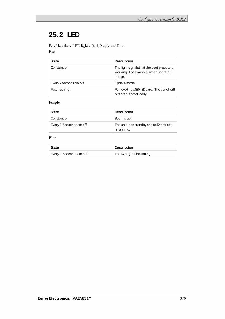
Configuration settings for BoX 2
25.2 LEDBox2 has three LED lights; Red, Purple andBlue.Red
State Description
Constant on The light signals that the boot process isworking. For example, when updatingimage.
Every 2 seconds on/off Update mode.
Fast flashing Remove the USB / SD card. The panel willrestart automatically.
Purple
State Description
Constant on Booting up.
Every 0.5 seconds on/off The unit is on standby and no iX projectis running.
Blue
State Description
Every 0.5 seconds on/off The iX project is running.
Beijer Electronics, MAEN831Y 376
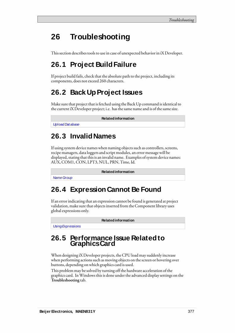
Troubleshooting
26 Troubleshooting
This section describes tools to use in case of unexpected behavior in iXDeveloper.
26.1 Project Build FailureIf project build fails, check that the absolute path to the project, including itscomponents, does not exceed 260 characters.
26.2 Back Up Project IssuesMake sure that project that is fetched using theBackUp command is identical tothe current iXDeveloper project; i.e. has the samename and is of the same size.
Related information
Upload Database
26.3 Invalid NamesIf using systemdevice nameswhennaming objects such as controllers, screens,recipemanagers, data loggers and scriptmodules, an errormessagewill bedisplayed, stating that this is an invalid name. Examples of systemdevice names:AUX,COM1,CON,LPT3,NUL, PRN,Time, Id.
Related information
Name Group
26.4 Expression Cannot Be FoundIf an error indicating that an expression cannot be found is generated at projectvalidation,make sure that objects inserted from theComponent library usesglobal expressions only.
Related information
Using Expressions
26.5 Performance Issue Related toGraphics Card
Whendesigning iXDeveloper projects, theCPU loadmay suddenly increasewhen performing actions such asmoving objects on the screen or hovering overbuttons, depending onwhich graphics card is used.This problemmay be solved by turning off the hardware acceleration of thegraphics card. InWindows this is done under the advanced display settings on theTroubleshooting tab.
Beijer Electronics, MAEN831Y 377
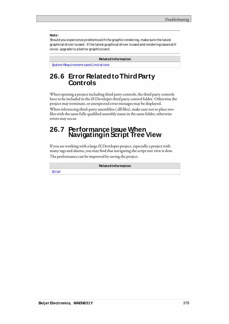
Troubleshooting
Note:Should you experience problems with the graphic rendering, make sure the latestgraphical driver is used. If the latest graphical driver is used and rendering issues stilloccur, upgrade to a better graphics card.
Related information
System Requirements and Limitations
26.6 Error Related to Third PartyControls
Whenopening a project including third party controls, the third party controlshave to be included in the iXDeveloper third party control folder. Otherwise theprojectmay terminate, or unexpected errormessagesmay be displayed.When referencing third-party assemblies (.dll files),make sure not to place twofileswith the same fully qualified assembly name in the same folder, otherwiseerrorsmay occur.
26.7 Performance Issue WhenNavigating in Script Tree View
If you areworkingwith a large iXDeveloper project, especially a project withmany tags and alarms, youmay find that navigating the script tree view is slow.The performance can be improved by saving the project.
Related information
Script
Beijer Electronics, MAEN831Y 378

Head office
Beijer Electronics AB
Box 426
201 24 Malmö, Sweden
www.beijerelectronics.com / +46 40 358600
Related Documents