INTERNATIONAL TELECOMMUNICATION UNION ITU-T G.783 TELECOMMUNICATION STANDARDIZATION SECTOR OF ITU (04/97) SERIES G: TRANSMISSION SYSTEMS AND MEDIA, DIGITAL SYSTEMS AND NETWORKS Digital transmission systems – Terminal equipments – Principal characteristics of multiplexing equipment for the synchronous digital hierarchy Characteristics of synchronous digital hierarchy (SDH) equipment functional blocks ITU-T Recommendation G.783 (Previously CCITT Recommendation)

Welcome message from author
This document is posted to help you gain knowledge. Please leave a comment to let me know what you think about it! Share it to your friends and learn new things together.
Transcript

INTERNATIONAL TELECOMMUNICATION UNION
ITU-T G.783TELECOMMUNICATIONSTANDARDIZATION SECTOROF ITU
(04/97)
SERIES G: TRANSMISSION SYSTEMS AND MEDIA,DIGITAL SYSTEMS AND NETWORKS
Digital transmission systems – Terminal equipments –Principal characteristics of multiplexing equipment for thesynchronous digital hierarchy
Characteristics of synchronous digital hierarchy(SDH) equipment functional blocks
ITU-T Recommendation G.783(Previously CCITT Recommendation)

ITU-T G-SERIES RECOMMENDATIONS
TRANSMISSION SYSTEMS AND MEDIA, DIGITAL SYSTEMS AND NETWORKS
For further details, please refer to ITU-T List of Recommendations.
INTERNATIONAL TELEPHONE CONNECTIONS AND CIRCUITS G.100–G.199
INTERNATIONAL ANALOGUE CARRIER SYSTEM
GENERAL CHARACTERISTICS COMMON TO ALL ANALOGUE CARRIER-TRANSMISSION SYSTEMS
G.200–G.299
INDIVIDUAL CHARACTERISTICS OF INTERNATIONAL CARRIER TELEPHONESYSTEMS ON METALLIC LINES
G.300–G.399
GENERAL CHARACTERISTICS OF INTERNATIONAL CARRIER TELEPHONESYSTEMS ON RADIO-RELAY OR SATELLITE LINKS AND INTERCONNECTIONWITH METALLIC LINES
G.400–G.449
COORDINATION OF RADIOTELEPHONY AND LINE TELEPHONY G.450–G.499
TRANSMISSION MEDIA CHARACTERISTICS
DIGITAL TRANSMISSION SYSTEMS
TERMINAL EQUIPMENTS G.700–G.799
General G.700–G.709
Coding of analogue signals by pulse code modulation G.710–G.719
Coding of analogue signals by methods other than PCM G.720–G.729
Principal characteristics of primary multiplex equipment G.730–G.739
Principal characteristics of second order multiplex equipment G.740–G.749
Principal characteristics of higher order multiplex equipment G.750–G.759
Principal characteristics of transcoder and digital multiplication equipment G.760–G.769
Operations, administration and maintenance features of transmission equipment G.770–G.779
Principal characteristics of multiplexing equipment for the synchronous digitalhierarchy
G.780–G.789
Other terminal equipment G.790–G.799
DIGITAL NETWORKS G.800–G.899
General aspects G.800–G.809
Design objectives for digital networks G.810–G.819
Quality and availability targets G.820–G.829
Network capabilities and functions G.830–G.839
SDH network characteristics G.840–G.849
Telecommunications management network G.850–G.859
DIGITAL SECTIONS AND DIGITAL LINE SYSTEM G.900–G.999
General G.900–G.909
Parameters for optical fibre cable systems G.910–G.919
Digital sections at hierarchical bit rates based on a bit rate of 2048 kbit/s G.920–G.929
Digital line transmission systems on cable at non-hierarchical bit rates G.930–G.939
Digital line systems provided by FDM transmission bearers G.940–G.949
Digital line systems G.950–G.959
Digital section and digital transmission systems for customer access to ISDN G.960–G.969
Optical fibre submarine cable systems G.970–G.979
Optical line systems for local and access networks G.980–G.999

Recommendation G.783 (04/97) i
ITU-T RECOMMENDATION G.783
CHARACTERISTICS OF SYNCHRONOUS DIGITAL HIERARCHY (SDH)EQUIPMENT FUNCTIONAL BLOCKS
Summary
This Recommendation is a merged, revised version of Recommendations G.781, G.782 and G.783 approved under theWTSC Resolution No. 1 procedure in January, 1994.
This Recommendation defines the interfaces and functions to be supported by SDH equipment. The description is genericand no particular physical partitioning of functions is implied. The input/output information flows associated with thefunctional blocks serve for defining the functions of the blocks and are considered to be conceptual, not physical.
Not every atomic function defined in this Recommendation is required for every application. Different subsets of atomicfunctions may be assembled in different ways according to the combination rules given in this Recommendation toprovide a variety of different capabilities. Network operators and equipment suppliers may choose which functions mustbe implemented for each application.
Background
Source
ITU-T Recommendation G.783 was revised by ITU-T Study Group 15 (1997-2000) and was approved under the WTSCResolution No. 1 procedure on the 8th of April 1997.
Recommendation
Issue Notes
1997 Second revision adds new protection and Tandem Connection monitoring applications.The modelling techniques used are converted to use atomic functions to be consistentwith Recommendation G.803.
1994 First revision added specifications to cover cross-connect as well as multiplexequipment.
1990 Initial version.

ii Recommendation G.783 (04/97)
FOREWORD
ITU (International Telecommunication Union) is the United Nations Specialized Agency in the field of telecommuni-cations. The ITU Telecommunication Standardization Sector (ITU-T) is a permanent organ of the ITU. The ITU-T isresponsible for studying technical, operating and tariff questions and issuing Recommendations on them with a view tostandardizing telecommunications on a worldwide basis.
The World Telecommunication Standardization Conference (WTSC), which meets every four years, establishes thetopics for study by the ITU-T Study Groups which, in their turn, produce Recommendations on these topics.
The approval of Recommendations by the Members of the ITU-T is covered by the procedure laid down in WTSCResolution No. 1.
In some areas of information technology which fall within ITU-T’s purview, the necessary standards are prepared on acollaborative basis with ISO and IEC.
NOTE
In this Recommendation, the expression "Administration" is used for conciseness to indicate both a telecommunicationadministration and a recognized operating agency.
INTELLECTUAL PROPERTY RIGHTS
The ITU draws attention to the possibility that the practice or implementation of this Recommendation may involve theuse of a claimed Intellectual Property Right. The ITU takes no position concerning the evidence, validity or applicabilityof claimed Intellectual Property Rights, whether asserted by ITU members or others outside of the Recommendationdevelopment process.
As of the date of approval of this Recommendation, the ITU had not received notice of intellectual property, protected bypatents, which may be required to implement this Recommendation. However, implementors are cautioned that this maynot represent the latest information and are therefore strongly urged to consult the TSB patent database.
ITU 1998
All rights reserved. No part of this publication may be reproduced or utilized in any form or by any means, electronic ormechanical, including photocopying and microfilm, without permission in writing from the ITU.

Recommendation G.783 (04/97) iii
CONTENTS
Page
1 General............................................................................................................................................................ 11.1 References ......................................................................................................................................... 31.2 Abbreviations .................................................................................................................................... 31.3 Definitions ......................................................................................................................................... 111.4 Reference point naming..................................................................................................................... 161.5 Reference point information naming ................................................................................................. 171.6 Atomic function naming and diagrammatic conventions................................................................... 191.7 Atomic function process allocation ................................................................................................... 221.8 Combination rules.............................................................................................................................. 251.9 Fault management and performance monitoring naming................................................................... 281.10 Fault management and performance monitoring specification techniques......................................... 291.11 Performance and reliability................................................................................................................ 29
2 Supervision processes and management information flows ............................................................................ 302.1 Information flow (XXX_MI) across the XXX_MP reference points ................................................ 302.2 Supervision ........................................................................................................................................ 322.3 Generic processes .............................................................................................................................. 49
3 SDH physical layer.......................................................................................................................................... 543.1 Connection......................................................................................................................................... 553.2 Termination: OSn_TT and ESn_TT .................................................................................................. 563.3 Adaptation ......................................................................................................................................... 603.4 Sublayer functions (N/A)................................................................................................................... 64
4 Regenerator section layer ................................................................................................................................ 644.1 Connection (Not/Applicable)............................................................................................................. 654.2 Termination: RSn_TT ....................................................................................................................... 654.3 Adaptation ......................................................................................................................................... 684.4 Sublayer functions (N/A)................................................................................................................... 76
5 Multiplex section layer.................................................................................................................................... 765.1 Connection (N/A) .............................................................................................................................. 775.2 Termination: MSn_TT....................................................................................................................... 775.3 Adaptation ......................................................................................................................................... 815.4 Sublayer functions ............................................................................................................................. 90
6 Higher order SDH path (Sn) layer................................................................................................................... 946.1 Connection Functions: Sn_C ............................................................................................................. 996.2 Termination functions: Sn_TT, Snm_TT and Sns_TT ...................................................................... 1036.3 Adaptation functions.......................................................................................................................... 1116.4 Sublayer functions ............................................................................................................................. 117
7 Lower order SDH path (Sm) layer .................................................................................................................. 1387.1 Connection functions: Sm_C ............................................................................................................. 1477.2 Termination functions: Sm_TT, Smm_TT and Sms_TT ................................................................... 1527.3 Adaptation functions.......................................................................................................................... 1607.4 Sublayer functions ............................................................................................................................. 163
8 Compound functions ....................................................................................................................................... 1778.1 Transport Terminal Function (TTF) .................................................................................................. 1778.2 Higher Order Interface (HOI) ............................................................................................................ 1788.3 Lower Order Interface (LOI) ............................................................................................................. 1788.4 Higher Order Assembler (HOA)........................................................................................................ 179

iv Recommendation G.783 (04/97)
Page
9 Timing functions ............................................................................................................................................. 179
9.1 Synchronous Equipment Timing Source (SETS) function ................................................................ 179
9.2 Synchronous Equipment Timing Physical Interface (SETPI) function.............................................. 181
10 Specification of jitter and wander ................................................................................................................... 182
10.1 STM-N interfaces ........................................................................................................... ................... 182
10.2 PDH interfaces............................................................................................................. ...................... 184
11 Overhead Access Function (OHA).................................................................................................................. 190
Annex A – Multiplex Section Protection (MSP) protocol, commands and operation ............................................... 191
A.1 MSP Protocol .................................................................................................................................... 191
A.2 MSP commands................................................................................................................................. 195
A.3 Switch operation................................................................................................................................ 196
Annex B – Multiplex section protection (MSP) 1 + 1 optimized protocol, commands and operation ...................... 200
B.1 1 + 1 bidirectional switching optimized for a network using predominantly 1 + 1 bidirectionalswitching............................................................................................................................................ 200
B.2 Switch commands.............................................................................................................................. 202
B.3 Switch operation................................................................................................................................ 202
Annex C – Algorithm for pointer detection................................................................................................................ 204
C.1 Pointer interpretation ......................................................................................................................... 204
C.2 Concatenated payloads ...................................................................................................................... 205
C.3 Pointer processing flow chart ............................................................................................................ 206
Annex D – PDH physical section layers..................................................................................................................... 208
D.1 PDH physical section layer (Eq)........................................................................................................ 208
Appendix I – Example of F1 byte usage..................................................................................................................... 213
Appendix II – CM configuration examples ................................................................................................................ 214
Appendix III – Example of remote indication operation ............................................................................................ 218
III.1 Remote Defect Indication (RDI)........................................................................................................ 218
III.2 Remote Error Indication (REI) .......................................................................................................... 218
Appendix IV – Alarm Indication Signal (AIS)........................................................................................................... 222
Appendix V – Signal Fail (SF) and Signal Degrade (SD) .......................................................................................... 224
V.1 Server Signal Fail (SSF) signal.......................................................................................................... 224
V.2 Server Signal Degrade (aSSD) signal ................................................................................................ 224
V.3 Trail Signal Fail (TSF) signal ............................................................................................................ 224
V.4 Trail Signal Degrade (TSD) signal .................................................................................................... 224
Appendix VI – Data Communications Channel (DCC).............................................................................................. 224
Appendix VII – Atomic function modelling of basic functions from 1994 G.783 ..................................................... 225

Recommendation G.783 (04/97) 1
Recommendation G.783
Recommendation G.783 (04/97)
CHARACTERISTICS OF SYNCHRONOUS DIGITAL HIERARCHY (SDH)EQUIPMENT FUNCTIONAL BLOCKS
(revised in 1997)
1 General
Since they have first been approved within CCITT Study Group (SG) XV, Recommendations G.781, G.782 and G.783have formed together a coherent set of Recommendations containing the basic specifications for the development ofsynchronous digital hierarchy network equipments. While revising these three Recommendations, CCITT SG XV first,and then ITU-T SG 15, have brought quite a number of changes (new features have been added, original ones have beendifferently specified, new modelling method has been developed) to the Recommendations. It has therefore been feltnecessary to restructure the Recommendations, and the solution that consisted of merging them in a singleRecommendation has been favoured. This has led to developing a new G.783 Recommendation with the aim of alignmentwith the functional modelling method defined in Recommendations G.803 and G.805.
This Recommendation specifies a library of basic building blocks and a set of rules by which they may be combined inorder to describe a digital transmission equipment. The library is comprised of the functional building blocks needed tospecify completely the generic functional structure of the synchronous digital hierarchy. These building blocks areillustrated in Figure 1-1. In order to be compliant with this Recommendation, equipment needs to be describable as aninterconnection of a subset of these functional blocks contained within this Recommendation. The interconnections ofthese blocks should obey the combination rules given.
This Recommendation specifies both the components and the methodology that should be used in order to specify SDHprocessing; it does not specify an individual SDH equipment as such.
The specification method is based on functional decomposition of the equipment into atomic, and compound functions.The equipment is then described by its Equipment Functional Specification (EFS) which lists the constituent atomic andcompound functions, their interconnection, and any overall performance objectives (e.g. transfer delay, availability, etc.).
The internal structure of the implementation of this functionality (equipment design) need not be identical to the structureof the functional model, as long as all the details of the externally observable behaviour comply with the EFS.
The equipment functionality is consistent with the SDH multiplexing structure given in Recommendation G.707.
Equipment developed prior to the production of the revision of this Recommendation may not comply in all details withthis Recommendation.
Equipment which is normally stated to be compliant with this Recommendation may not fulfil all the requirements in thecase that it is interworking with old equipment that is not compliant with this Recommendation.

2 Recommendation G.783 (04/97)
T1525250-97/d001
Lower order path layer
Higher order path layer
SDH physical layers
Regenerator section layer
Multiplex section layer
Figure 1-1/G.783 – General functional block diagram
TO_TP
OSn_CP
OSn
OSn
OSn/RSn OSn/RSn
OSn
ES1
ES1_CP
ES1/RS1
ES1
ES1/RS1
ES1
RSn
RSn RSn
MSn/DCC MSn/OW
MSn/SD
RSn/MSn
MSn/SD MSn/OW MSn/DCC
RSn_CP RS1_CP
D4-D12 E2 F1 F1 E2 D1-D3
MSn
MSn MSn
MSn/DCC MSn/OW
RSn/User RSn/MSn RSn/User RSn/OW RSn/DCC
MSn_CP MSn_CP
MSn/Sn MSn/Sn
D4-D12 E2 S1[5-8] D4-D12E2S1[5-8]Sn_CP Sn_CP
Sn
SnD/Sn
SnD
SnD/Sn
SnD
SnD_AP
Sn_RI
SnDm TSFSD
Sn SnSn_RI
Snm SnsSnsSn_RI
TSFTSD
TSFTSD
Sn/Sm Sn/Pqx Sn/User Sn/Sm Sn/Pqx Sn/User
Sm_CP
Pqx_CP User_CP
Sm_CP
Pqx_CP User_CP
Sm
Sm_RI
TSFSD SM_RI Sm_RI
SmD SmD SmDm Sm Sm Smm Sms Sms
TSFTSD
TSFTSDSmD_AP
SmD/Sm SmD/Sm Sm/Pqx Sm/Pqs Sm/Pqx Sm/Pqs
Pqx_CP Pqx_CPPqs_CP Pqs_CP
FIGURE 1-1/G.783...[D01] = 24 cm
Recommendation G.783 (04/97) 3
1.1 References
The following ITU-T Recommendations and other references contain provisions which, through reference in this text,constitute provisions of this Recommendation. At the time of publication, the editions indicated were valid. AllRecommendations and other references are subject to revision; all users of this Recommendation are thereforeencouraged to investigate the possibility of applying the most recent edition of the Recommendations and otherreferences listed below. A list of the currently valid ITU-T Recommendations is regularly published.
– CCITT Recommendation G.703 (1991), Physical electrical characteristics of hierarchical digital interfaces.
– ITU-T Recommendation G.704 (1995), Synchronous frame structures used at 1544, 6312, 2048, 8488 and44 736 kbit/s hierarchical levels.
– CCITT Recommendation G.706 (1991), Frame alignment and Cyclic Redundancy Check (CRC) proceduresrelating to basic frame structures defined in Recommendation G.704.
– ITU-T Recommendation G.707 (1996), Network node interface for the Synchronous Digital Hierarchy (SDH).
– CCITT Recommendation G.743 (1988), Second order digital multiplex equipment operating at 6312 kbit/s andusing positive justification.
– CCITT Recommendation G.752 (1980), Characteristics of digital multiplex equipments based on a second order bitrate of 6312 kbit/s and using positive justification.
– ITU-T Recommendation G.775 (1994), Loss of Signal (LOS) and Alarm Indication Signal (AIS) defect detectionand clearance criteria.
– ITU-T Recommendation G.784 (1994), Synchronous Digital Hierarchy (SDH) management.
– ITU-T Recommendation G.803 (1997), Architecture of transport networks based on the Synchronous DigitalHierarchy (SDH).
– ITU-T Recommendation G.805 (1995), Generic functional architecture of transport networks.
– ITU-T Recommendation G.810 (1996), Definitions and terminology for synchronization networks.
– CCITT Recommendation G.812 (1988), Timing requirements at the outputs of slave clocks suitable forplesiochronous operation of international digital links.
– ITU-T Recommendation G.813 (1996), Timing characteristics of SDH equipment slave clocks (SEC).
– ITU-T Recommendation G.823 (1993), The control of jitter and wander within digital networks which are based onthe 2048 kbit/s hierarchy.
– ITU-T Recommendation G.824 (1993), The control of jitter and wander within digital networks which are based onthe 1544 kbit/s hierarchy.
– ITU-T Recommendation G.825 (1993), The control of jitter and wander within digital networks which are based onthe Synchronous Digital Hierarchy (SDH).
– ITU-T Recommendation G.826 (1996), Error performance parameters and objectives for international, constant bitrate digital paths at or above the primary rate.
– ITU-T Recommendation G.831 (1996), Management capabilities of transport networks based on the SynchronousDigital Hierarchy (SDH).
– ITU-T Recommendation G.841 (1995), Types and characteristics of SDH network protection architectures.
– ITU-T Recommendation G.957 (1995), Optical interfaces for equipment and systems relating to synchronousdigital hierarchy.
– ITU-T Recommendation G.958 (1994), Digital line systems based on the synchronous digital hierarchy for use onoptical fibre cables.
– ITU-T Recommendation M.3010 (1996), Principles for a telecommunications management network.
1.2 Abbreviations
This Recommendation uses the following abbreviations:
A Adaptation function
AcSL Accepted Signal Label

4 Recommendation G.783 (04/97)
AcTI Accepted Trace Identifier
ADM Add-Drop Multiplexer
AI Adapted Information
AIS Alarm Indication Signal
ALS Automatic Laser Shutdown
AP Access Point
APId Access Point Identifier
APS Automatic Protection Switching
ATM Asynchronous Transfer Mode
AU Administrative Unit
AU-n Administrative Unit, level n
AUG Administrative Unit Group
BER Bit Error Ratio
BBER Background Block Error Ratio
BIP Bit Interleaved Parity
C Connection function
CI Characteristic Information
CK Clock
CM Connection Matrix
CMISE Common Management Information Service Element
CP Connection Point
CRC Cyclic Redundancy Check
CRC-N Cyclic Redundancy Check, width N
CSES Consecutive Severely Errored Seconds
D Data
DCC Data Communications Channel
DEC Decrement
DEG Degraded
DEGTHR Degraded Threshold
DS Defect Second
DXC Digital Cross Connect
E0 Electrical interface signal 64 kbit/s
E11 Electrical interface signal 1544 kbit/s
E12 Electrical interface signal 2048 kbit/s
E22 Electrical interface signal 8448 kbit/s
E31 Electrical interface signal 34 368 kbit/s
E32 Electrical interface signal 44 736 kbit/s
E4 Electrical interface signal 139 264 kbit/s
EBC Errored Block Count

Recommendation G.783 (04/97) 5
EDC Error Detection Code
EDCV Error Detection Code Violation
EMF Equipment Management Function
EQ Equipment
ES Electrical Section
ES1 Electrical Section, level 1
ES Errored Second
Eq Recommendation G.703 type electrical signal, bit rate order q (q = 11, 12, 21, 22, 31, 32, 4)
ExSL Expected Signal Label
ExTI Expected Trace Identifier
F_B Far-end Block
F_DS Far-end Defect Second
F_EBC Far-end Errored Block Count
FAS Frame Alignment Signal
FIFO First In First Out
FM Fault Management
FOP Failure of Protocol
FS Forced Switch
FS Frame Start signal
HO Higher Order
HOA Higher Order Assembler
HOI Higher Order Interface
HOVC Higher Order Virtual Container
HP Higher order Path
HPA Higher order Path Adaptation
HPC Higher order Path Connection
HPOM Higher order Path Overhead Monitor
HPP Higher order Path Protection
HPT Higher order Path Termination
HSUT Higher order path Supervisory Unequipped Termination
HTCA Higher order path Tandem Connection Adaptation
HTCM Higher order path Tandem Connection Monitor
HTCT Higher order path Tandem Connection Termination
ID Identifier
IF In Frame state
INC Increment

6 Recommendation G.783 (04/97)
LC Link Connection
LO Lockout
LO Lower Order
LOA Loss of Alignment; generic for LOF, LOM, LOP
LOF Loss of Frame
LOI Lower Order Interface
LOM Loss of Multiframe
LOP Loss of Pointer
LOS Loss of Signal
LOVC Lower Order Virtual Container
LP Lower order Path
LPA Lower order Path Adaptation
LPC Lower order Path Connection
LPOM Lower order Path Overhead Monitor
LPP Lower order Path Protection
LPT Lower order Path Termination
LSUT Lower order path Supervisory Unequipped Termination
LTCA Lower order path Tandem Connection Adaptation
LTCM Lower order path Tandem Connection Monitor
LTCT Lower order path Tandem Connection Termination
LTI Loss of all Incoming Timing references
MC Matrix Connection
MCF Message Communications Function
MI Management Information
MON Monitored
MP Management Point
MRTIE Maximum Relative Time Interval Error
MS Manual Switch
MS Multiplex Section
MSA Multiplex Section Adaptation
MSB Most Significant Bit
MSn Multiplex Section layer, level n (n = 1, 4, 16)
MSOH Multiplex Section OverHead
MSP Multiplex Section Protection
MST Multiplex Section Termination
MTIE Maximum Time Interval Error
N_B Near-end Block

Recommendation G.783 (04/97) 7
N_BBE Near-end Background Block Error
N_DS Near-end Defect Second
N_EBC Near-end Errored Block Count
NC Network Connection
N.C. Not Connected
NDF New Data Flag
NE Network Element
NEF Network Element Function
NMON Not Monitored
NNI Network Node Interface
NU National Use
OAM Operation, Administration and Maintenance
ODI Outgoing Defect Indication
OEI Outgoing Error Indication
OFS Out-of-Frame Second
OHA OverHead Access
OOF Out of Frame
OS Optical Section
OSn Optical Section layer, level n (n = 1, 4, 16)
OW Order Wire
P0x 64 kbit/s layer (transparent)
P11x 1544 kbit/s layer (transparent)
P12s 2048 kbit/s PDH path layer with synchronous 125 µs frame structure according to Recommenda-tion G.704
P12x 2048 kbit/s layer (transparent)
P21x 6312 kbit/s layer (transparent)
P22e 8448 kbit/s PDH path layer with 4 plesiochronous 2048 kbit/s
P22x 8448 kbit/s layer (transparent)
P31e 34 368 kbit/s PDH path layer with 4 plesiochronous 8448 kbit/s
P31s 34 368 kbit/s PDH path layer with synchronous 125 µs frame structure according to Recommenda-tion G.832
P31x 34 368 kbit/s layer (transparent)
P32x 44 736 kbit/s layer (transparent)
P4a 139 264 kbit/s PDH path layer with 3 plesiochronous 44 736 kbit/s
P4e 139 264 kbit/s PDH path layer with 4 plesiochronous 34 368 kbit/s

8 Recommendation G.783 (04/97)
P4s 139 264 kbit/s PDH path layer with synchronous 125 µs frame structure according to Recommenda-tion G.832
P4x 139 264 kbit/s layer (transparent)
PDH Plesiochronous Digital Hierarchy
PJC Pointer Justification Count
PJE Pointer Justification Event
PLM PayLoad Mismatch
PM Performance Monitoring
POH Path OverHead
PPI PDH Physical Interface
Pq PDH path layer, bit rate order q (q = 11, 12, 21, 22, 31, 32, 4)
PRC Primary Reference Clock
PS Protection Switching
PSC Protection Switch Count
PSD Protection Switch Duration
PSE Protection Switch Event
PSS Protection Switch Second
PTR Pointer
RDI Remote Defect Indication
REI Remote Error Indication
RI Remote Information
RP Remote Point
RS Regenerator Section
RSn Regenerator Section layer, level n (n = 1, 4, 16)
RSOH Regenerator Section OverHead
RST Regenerator Section Termination
RxSL Received Signal Label
RxTI Received Trace Identifier
S11 VC-11 path layer
S11D VC-11 tandem connection sublayer
S11P VC-11 path protection sublayer
S12 VC-12 path layer
S12D VC-12 tandem connection sublayer
S12P VC-12 path protection sublayer
S2 VC-2 path layer
S2D VC-2 tandem connection sublayer
S2P VC-2 path protection sublayer
S3 VC-3 path layer

Recommendation G.783 (04/97) 9
S3D VC-3 tandem connection sublayer using TCM definition according to Annex D/G.707 (option 2)
S3P VC-3 path protection sublayer
S3T VC-3 tandem connection sublayer using TCM definition according to Annex C/G.707 (option 1)
S4 VC-4 path layer
S4D VC-4 tandem connection sublayer using TCM definition according to Annex D/G.707 (option 2)
S4P VC-4 path protection sublayer
S4T VC-4 tandem connection sublayer using TCM definition according to Annex C/G.707 (option 1)
SD Signal Degrade
SDH Synchronous Digital Hierarchy
SDXC Synchronous Digital hierarchy Cross-Connect
SEC SDH Equipment Clock
SEMF Synchronous Equipment Management Function
SES Severely Errored Second
SETG Synchronous Equipment Timing Generator
SETPI Synchronous Equipment Timing Physical Interface
SETS Synchronous Equipment Timing Source
SF Signal Fail
Sk Sink
Sm lower order VC-m layer (m = 11, 12, 2, 3)
SmD VC-m (m = 11, 12, 2, 3) tandem connection sublayer
Smm VC-m (m = 11, 12, 2, 3) path layer non-intrusive monitor
SmP VC-m (m = 11, 12, 2, 3) path protection sublayer
Sms VC-m (m = 11, 12, 2, 3) path layer supervisory-unequipped
Sn Higher order VC-n layer (n = 3, 4)
SnD VC-n (n = 3, 4) tandem connection sublayer using TCM definition according to Annex D/G.707(option 2)
Snm VC-n (n = 3, 4) path layer non-intrusive monitor
SnP VC-n (n = 3, 4) path protection sublayer
Sns VC-n (n = 3, 4) path layer supervisory-unequipped

10 Recommendation G.783 (04/97)
SnT VC-n (n = 3, 4) tandem connection sublayer using TCM definition according to Annex C/G.707(option 1)
SNC SubNetwork Connection
SNC/I Inherently monitored SubNetwork Connection protection
SNC/N Non-intrusively monitored SubNetwork Connection protection
SNC/S Sublayer (tandem connection) monitored SubNetwork Connection protection
So Source
SOH Section OverHead
SPI SDH Physical Interface
SPRING Shared Protection Ring
SSD Server Signal Degrade
SSF Server Signal Fail
SSM Synchronization Status Message
SSU Synchronization Supply Unit
STM Synchronous Transport Module
TCM Tandem Connection Monitor
TCP Termination Connection Point
TD Transmit Degrade
TF Transmit Fail
TFAS trail Trace identifier Frame Alignment Signal
TI Timing Information
TIM Trace Identifier Mismatch
TMN Telecommunications Management Network
TP Timing Point
TPmode Termination Point mode
TS Time Slot
TSD Trail Signal Degrade
TSF Trail Signal Fail
TSL Trail Signal Label
TT Trail Termination function
TTs Trail Termination supervisory function
TTI Trail Trace Identifier
TTP Trail Termination Point
TU Tributary Unit
TU-m Tributary Unit, level m
TUG Tributary Unit Group
TUG-m Tributary Unit Group, level m

Recommendation G.783 (04/97) 11
TxSL Transmitted Signal Label
TxTI Transmitted Trace Identifier
UNEQ UnEquipped
UNI User Network Interface
USR User channels
VC Virtual Container
VC-n Virtual Container, level n
VP Virtual Path
W Working
1.3 Definitions
This Recommendation defines the following terms.
NOTE 1 – The following definitions are relevant in the context of SDH-related Recommendations.
NOTE 2 – References to G.703 signals are intended to refer only to PDH signals, and specifically not to an electrical STM-1 interface.The notation G.703 (PDH) has been used to convey this interpretation.
1.3.1 1 + 1 (protection) architecture: A 1+1 protection architecture has one normal traffic signal, one workingSNC/trail, one protection SNC/trail and a permanent bridge.
At the source end, the normal traffic signal is permanently bridged to both the working and protection SNC/trail. At thesink end, the normal traffic signal is selected from the better of the two SNCs/trails.
Due to the permanent bridging, the 1+1 architecture does not allow an extra unprotected traffic signal to be provided.
1.3.2 1:n (protection) architecture (n ≥ 1): A 1:n protection architecture has n normal traffic signals, n workingSNCs/trails and one protection SNC/trail. It may have one extra traffic signal.
The signals on the working SNCs/trails are the normal traffic signals.
The signal on the protection SNC/trail may either be one of the normal traffic signals, an extra traffic signal, or the nullsignal (e.g. an all-ONEs signal, a test signal, one of the normal traffic signals). At the source end, one of these signals isconnected to the protection SNC/trail. At the sink end, the signals from the working SNCs/trails are selected as thenormal signals. When a defect condition is detected on a working SNC/trail or under the influence of certain externalcommands, the transported signal is bridged to the protection SNC/trail. At the sink end, the signal from this protectionSNC/trail is then selected instead.
1.3.3 access point (AP): See Recommendation G.805.
1.3.4 access point identifier (APId): See Recommendation G.831.
1.3.5 active trail/path/section/SNC/NC: The trail/path/section/SNC from which the signal is selected by theprotection selector.
1.3.6 adaptation function (A): See Recommendation G.805.
1.3.7 adapted information (AI): The information passing across an AP.
1.3.8 administrative unit (AU): See Recommendation G.707.
1.3.9 administrative unit group (AUG): See Recommendation G.707.
1.3.10 alarm: A human observable indication that draws attention to a failure (detected fault) usually giving anindication of the severity of the fault.
1.3.11 all-ONEs: The entire capacity of the adapted or characteristic information is set to logic "1".

12 Recommendation G.783 (04/97)
1.3.12 anomaly: The smallest discrepancy which can be observed between the actual and desired characteristics of anitem. The occurrence of a single anomaly does not constitute an interruption in the ability to perform a required function.Anomalies are used as the input for the Performance Monitoring (PM) process and for the detection of defects.
1.3.13 atomic function: A function which if divided into simpler functions would cease to be uniquely defined fordigital transmission hierarchies. It is therefore indivisible from a network point of view. The following atomic functionsare defined in each network layer:
– bidirectional Trail Termination function (..._TT), Trail Termination Source function (..._TT_So), Trail TerminationSink function (..._TT_Sk) and Connection function (..._Co);
– between client and server layer networks three adaptation functions are defined: Adaptation Sink function ..._A_Sk,Adaptation Source function ..._A_So, and the bidirectional Adaptation function ..._A.
1.3.14 AUn-AIS: See Recommendation G.707.
1.3.15 automatic laser shutdown (ALS): See Recommendation G.958.
1.3.16 automatic protection switching (APS): Autonomous switching of a signal between and including twoMS_TT, Sn_TT, or Sm_TT functions, from a failed working trail/SNC to a protection trail/SNC and subsequentrestoration using control signals carried by the K-bytes in the MSOH, HO POH, or LO POH.
1.3.17 basic function: A generic functionality consisting of combinations of atomic functions. The 1994 version ofthis Recommendation defined these functions.
1.3.18 bidirectional trail/connection type: A two-way trail/connection through a transport network.
1.3.19 bidirectional (protection) switching: For a unidirectional fault, both directions (of the trail, subnetworkconnection, etc.), including the affected and unaffected direction, are switched.
1.3.20 bit interleaved parity (BIP): See Recommendation G.707.
1.3.21 broadcast connection type: An input CP is connected to more than one output CP.
1.3.22 characteristic information (CI): The information passing across a CP or TCP. See also Recommenda-tion G.805.
1.3.23 client/server layer: Any two adjacent network layers are associated in a client/server relationship. Eachtransport network layer provides transport to the layer above and uses transport from the layers below. The layerproviding transport is termed a server, the layer using transport is termed client.
1.3.24 connection: See Recommendation G.805.
1.3.25 connection function (C): An atomic function within a layer which, if connectivity exists, relays a collection ofitems of information between groups of atomic functions. It does not modify the members of this collection of items ofinformation although it may terminate any switching protocol information and act upon it. Any connectivity restrictionsbetween inputs and outputs shall be stated.
1.3.26 connection matrix (CM): A connection matrix is a matrix of appropriate dimensions which describe theconnection pattern for assigning VC-ns on one side of an LPC or HPC function to VC-n capacities on the other side andvice versa.
1.3.27 connection point (CP): A reference point where the output of a trail termination source or a connection isbound to the input of another connection, or where the output of a connection is bound to the input of a trail terminationsink or another connection. The connection point is characterized by the information which passes across it. Abidirectional connection point is formed by the association of a contra-directional pair.
NOTE – In the information model the connection point is called Connection Termination Point (CTP).
1.3.28 consolidation: The allocation of server layer trails to client layer connections which ensure that each serverlayer trail is full before the next is allocated. Consolidation minimizes the number of partially filled server layer trails. Ittherefore maximizes the fill factor.

Recommendation G.783 (04/97) 13
Thus a number of partially filled VC-4 paths may be consolidated into a single, fully filled VC-4.
1.3.29 common management information service element (CMISE): See Recommendation X.710 andISO/IEC 9595.
1.3.30 compound function: A function which represents a collection of atomic functions within one or more layer(s).
Example 1 – A combination of several atomic adaptation functions within a certain layer (each serving one client layer) isa compound adaptation function. A combination of a (compound) adaptation function and the layer’s termination functionis a compound function.
Example 2 – The atomic functions in the Optical Section (OS), Multiplex Section (MS) and Regenerator Section (RS)layers may be combined to form a major compound function.
The compound functions facilitate simplified descriptions of equipment. Standardized compound functions attach aunique name to a common combination of atomic functions.
1.3.31 data communications channel (DCC): See Recommendation G.784.
1.3.32 defect: The density of anomalies has reached a level where the ability to perform a required function has beeninterrupted. Defects are used as input for PM, the control of consequent actions, and the determination of fault cause.
1.3.33 desynchronizer: The desynchronizer function smoothes out the timing gaps resulting from decoded pointeradjustments and VC payload demapping in the time domain.
1.3.34 extra traffic signal: A signal that can be routed via the protection trail/path/section/SNC/NC if it is standby.
1.3.35 failure: The fault cause persisted long enough to consider the ability of an item to perform a required functionto be terminated. The item may be considered as failed; a fault has now been detected.
1.3.36 fault: A fault is the inability of a function to perform a required action. This does not include an inability due topreventive maintenance, lack of external resources, or planned actions.
1.3.37 fault cause: A single disturbance or fault may lead to the detection of multiple defects. A fault cause is theresult of a correlation process which is intended to identify the defect that is representative of the disturbance or fault thatis causing the problem.
1.3.38 function: A process defined for digital transmission hierarchies (e.g. PDH, SDH) which acts on a collection ofinput information to produce a collection of output information. A function is distinguished by the way in whichcharacteristics of the collection of output information differs from the collection of input information.
1.3.39 grooming: The allocation of server layer trails to client layer connections which groups together client layerconnections whose characteristics are similar or related.
Thus it is possible to groom Virtual Container, level 12 (VC-12) paths by service type, by destination, or by protectioncategory into particular VC-4 paths which can then be managed accordingly. It is also possible to groom VC-4 pathsaccording to similar criteria into Synchronous Transport Module (STM-N) sections.
1.3.40 holdoff time: See Recommendation G.841.
1.3.41 layer: A concept used to allow the transport network functionality to be described hierarchically as successivelevels; each layer being solely concerned with the generation and transfer of its characteristic information.
1.3.42 management information (MI): The signal passing across an access point.
1.3.43 management point (MP): A reference point where the output of an atomic function is bound to the input of theelement management function, or where the output of the element management function is bound to the input of anatomic function.
NOTE – The MP is not the TMN Q3 interface.

14 Recommendation G.783 (04/97)
1.3.44 multiplex section (MS): A multiplex section is the trail between and including two multiplex section trailtermination functions.
1.3.45 multiplex section alarm indication signal (MS-AIS): See Recommendation G.707.
1.3.46 multiplex section remote defect indication (MS-RDI): See Recommendation G.707.
1.3.47 multiplex section overhead (MSOH): See Recommendation G.707.
1.3.48 network connection (NC): See Recommendation G.805.
1.3.49 network element function (NEF): See Recommendation G.784.
1.3.50 network node interface (NNI): See Recommendation G.707.
1.3.51 non-revertive (protection) operation: In non-revertive operation, the traffic signal (service) does not return tothe working SNC/trail if the switch requests are terminated.
1.3.52 normal signal: A signal that is transmitted via a protected trail/section/path/SNC/NC.
1.3.53 overhead access (OHA): The OHA function provides access to transmission overhead functions.
1.3.54 path: A trail in a path layer.
1.3.55 path overhead (POH): See Recommendation G.707.
1.3.56 pointer justification event (PJE): A PJE is an inversion of the I- or D-bits of the pointer, together with anincrement or decrement of the pointer value to signify a frequency justification.
1.3.57 process: A generic term for an action or a collection of actions.
1.3.58 protection trail/path/section/SNC/NC: A specific trail/path/section/SNC/NC that is part of a protection groupand is labelled protection.
1.3.59 reference point: The delimiter of a function.
1.3.60 regenerator section (RS): A regenerator section is the trail between and including two regenerator sectionterminations.
1.3.61 regenerator section overhead (RSOH) : See Recommendation G.707.
1.3.62 remote defect indication (RDI): A signal which conveys the defect status of the characteristic informationreceived by the trail termination sink function back to the network element which originated the characteristicinformation.
1.3.63 remote error indication (REI): A signal which conveys either the exact or truncated number of error detectioncode violations of the characteristic information as detected by the trail termination sink function back to the networkelement which originated the characteristic information.
1.3.64 remote information (RI): The information passing across an RP; e.g. RDI and REI.
1.3.65 remote point (RP): A reference point where the output of a trail termination sink function of a bidirectionaltrail termination is bound to the input of its trail termination source function, for the purpose of conveying information tothe remote end.
1.3.66 revertive (protection) operation: In revertive operation, the traffic signal (service) always returns to (orremains on) the working SNC/trail if the switch requests are terminated; i.e. when the working SNC/trail has recoveredfrom the defect or the external request is cleared.
1.3.67 section: A trail in a section layer.
1.3.68 server signal degrade (SSD): A signal degrade indication output at the CP of an adaptation function.
1.3.69 server signal fail (SSF): A signal fail indication output at the CP of an adaptation function.
Recommendation G.783 (04/97) 15
1.3.70 signal degrade (SD): A signal indicating the associated data has degraded in the sense that a degraded defect(dDEG) condition is active.
1.3.71 signal fail (SF): A signal indicating the associated data has failed in the sense that a near-end defect condition(not being the degraded defect) is active.
1.3.72 standby trail/path/section/SNC: The trail/path/section/SNC from which the signal is not selected by theprotection selector.
1.3.73 subnetwork connection (SNC): See Recommendation G.805.
1.3.74 supervisory-unequipped VC: See Recommendation G.707.
1.3.75 synchronous transport module (STM): See Recommendation G.707.
1.3.76 telecommunications management network (TMN): See Recommendation M.3010.
1.3.77 termination connection point (TCP): A special case of a connection point where a trail termination functionis bound to an adaptation function or a connection function.
NOTE – In the information model the termination connection point is called Trail Termination Point (TTP).
1.3.78 timing information (TI): The information passing across a TP.
1.3.79 timing point (TP): A reference point where an output of the synchronization distribution layer is bound to theinput of an adaptation source or connection function, or where the output of an adaptation sink function is bound to aninput of the synchronization distribution layer.
1.3.80 trail: See Recommendation G.805.
1.3.81 trail signal degrade (TSD): A signal degrade indication output at the AP of a termination function.
1.3.82 trail signal fail (TSF): A signal fail indication output at the AP of a termination function.
1.3.83 trail termination function (TT): An atomic function within a layer which generates, adds, and monitorsinformation concerning the integrity and supervision of adapted information.
1.3.84 trail trace identifier (TTI): See Recommendation G.707.
1.3.85 NE transit delay: NE transit delay is defined as the period of time taken for an information bit arriving at anNE input port to reappear at an output port on the same NE via a defect free trail.
Transit delay is affected by e.g.:
• time slot interchange;
• relationship of actual clock frequencies in all layers;
• synchronizers and desynchronizers;
• physical path (internal route) taken through the NE.
A transit delay measurement should define under which conditions the measurement was made to establish minimum andmaximum values in seconds.
The specification of transit delays for NEs is outside the scope of this Recommendation.
1.3.86 tributary unit (TU-m): See Recommendation G.707.
1.3.87 TUm-AIS: See Recommendation G.707.
1.3.88 virtual container (VC-n): See Recommendation G.707.
1.3.89 working trail/path/section/SNC/NC: A specific trail/path/section/SNC/NC that is part of a protection groupand is labelled working.
1.3.90 unequipped VC: See Recommendation G.707.
1.3.91 undefined bit: If a bit is undefined, its value is set to a logical "0" or a logical "1".

16 Recommendation G.783 (04/97)
1.3.92 undefined byte: If a byte is undefined, it contains eight undefined bits.
NOTE – See regional standards for further specifications of the value of undefined bits.
1.3.93 unidirectional trail/connection type: A one-way trail/connection through a transport network.
1.3.94 unidirectional (protection) switching: For a unidirectional fault (i.e. a fault affecting only one direction oftransmission), only the affected direction (of the trail, subnetwork connection, etc.) is switched.
1.3.95 wait to restore time: A period of time that must elapse before a – from a fault recovered – trail/connection canbe used again to transport the normal traffic signal and/or to select the normal traffic signal from.
1.4 Reference point naming
The atomic functions of this Recommendation are defined between fixed reference points at which specified informationis assumed to be present. That is, at a given reference point, specific types of information can always be assumed to bepresent. There are several different types of reference points within the functional model, including reference points for:
• transmission signals;
• management information;
• timing references;
• DCC channels;
• synchronization status messaging;
• user overhead bytes.
Some of these reference points are designated by a single capital letter, usually followed by a number designating whichreference point of that type is being referred to. These are:
• timing references T
• DCC channels P or N
• synchronization status messaging Y
• user overhead bytes U
1.4.1 Transmission reference points
Because they are so numerous, and their detailed characteristics are so important to the functional model, transmissionreference points are designated with a more complex naming convention. A transmission reference point name is formedby a transmission layer designation, followed by an underscore character, followed by either AP or CP, depending onwhether that reference point is an Access Point (AP) or a Connection Point (CP). As described in Recommenda-tion G.805, the information at an access point is a signal into which the client signal(s) have been mapped, but which doesnot include the full complement of overhead information for the given layer. The information at a connection point is asignal which includes the full complement of overhead information. The access point is at the server side of adaptationfunctions and the client side of termination functions. The connection point is at the client side of adaptation functionsand the server side of termination functions (Figure 1-1). Thus, a transmission reference point name is formed accordingto the syntax:
<TransmissionReferencePointName> = <LayerName>_<AP or CP>
The layer names are:
ESn STM-n Electrical Section (n = 1).
OSn STM-n Optical Section (n = 1, 4, 16).
RSn STM-n Regenerator Section (n = 1, 4, 16).
MSn STM-n Multiplex Section (n = 1, 4, 16).
Sn Higher order path (n = 3, 4).

Recommendation G.783 (04/97) 17
SnD Higher order path, tandem connection sublayer (n = 3, 4) using TCM definition according to Annex D/G.707(option 2).
SnT Higher order path, tandem connection sublayer (n = 3, 4) using TCM definition according to Annex C/G.707(option 1).
Sm Lower order path (m = 11, 12, 2, 3).
SmD Lower order path, tandem connection sublayer (m = 11, 12, 2, 3).
Pqs PDH synchronous user data (q = 11 for 1.5 Mbit/s, q = 12 for 2 Mbit/s).
Pqx PDH user data (q = 11 for 1.5 Mbit/s, q = 12 for 2 Mbit/s, q = 2 for 6 Mbit/s, q = 31 for 34 Mbit/s, q = 32 for45 Mbit/s, q = 4 for 140 Mbit/s).
Eq PDH Electrical Section (q = 11 for 1.5 Mbit/s, q = 12 for 2 Mbit/s, q = 2 for 6 Mbit/s, q = 31 for 34 Mbit/s,q = 32 for 45 Mbit/s, q = 4 for 140 Mbit/s).
As an example of the application of this transmission reference point naming strategy, the following is the succession ofreference points that a signal at a 2 Mbit/s electrical interface would progress through in the functional model of thisRecommendation when being multiplexed into an optical STM-1:
E12_CP→E12_AP→P12x_CP→S12_AP→S12_CP→S4_AP→S4_CP→MS1_AP→MS1_CP→RS1_AP→RS1_CP→OS1_AP→OS1_CP
Note also that it would be possible to define PDH path layers which would exist between the PDH electrical section anduser data layers. However, their characteristics are not described in this Recommendation. The definition of theprocessing for the PDH layers is for further study, for inclusion in this or another Recommendation.
1.4.2 Management reference points
Management reference points are also quite numerous, and are therefore named directly after the name of the associatedfunction according to the syntax (see Figure 1-1):
<ManagementReferencePointName> = <FunctionName>_MP
Thus, for example, the management reference point for the OS_TT function is named OS_TT_MP.
1.4.3 Timing reference points
Timing reference points are named directly after the name of the associated layer according to the syntax (seeFigure 1-1):
<TimingReferencePointName> = <LayerName>_TP
Thus, for example, the timing reference point for the VC-4 layer is named S4_TP.
1.4.4 Remote reference points
Remote reference points are named directly after the name of the associated function layer to the syntax (see Figure 1-1):
<RemoteReferencePointName> = <LayerName>_RP
Thus, for example, the remote reference point for the VC-12 layer is named S12_RP.
1.5 Reference point information naming
The information passing a CP is called Characteristic Information (CI), the information passing an AP is calledAdapted Information (AI), the information passing an MP is called Management Information (MI), and theinformation passing a TP is called Timing Information (TI).

18 Recommendation G.783 (04/97)
1.5.1 Transmission reference point information naming
The coding of the Characteristic Information (CI) and Adapted Information (AI) in the model follows the followingrules:
<layer>[/<client layer>] _<information type>[ _<direction>] _<signal type>[/<number>].
[ ... ] optional term;
<layer> represents one of the layer names (e.g. RS1);
<client layer> represents one of the client layer names (e.g. MS1 is a client of RS1);
<information type> CI or AI;
<direction> So (Source) or Sk (Sink);
<signal type> CK (clock); or
D (data); or
FS (Frame Start); or
SSF (Server Signal Fail); or
TSF (Trail Signal Fail); or
SSD (Server Signal Degrade); or
TSD (Trail Signal Degrade);
<number> indication of multiplex number; e.g. (1, 1, 1) for the case of a TU-12 within a VC-4.
AI and CI coding examples are: MS1_CI_D, RS16_AI_CK, S12/P12x_AI_D, S4/S2_AI_So_D/(2, 3, 0).
T1525260-97/d002
Layer Z
Layer Y
Layer X
Connection Point (CP)
TimingPoint (TP)
Layer Y to layer Z adaptation sink
Layer Y to layer Z adaptation source
MP
Access Point (AP)
ManagementPoint (MP)
Remote Point(maintenance signals)
Termination ConnectionPoint (TCP)
ConnectionTP MP
Connection Point (CP)
Unidirectional representation
Layer Y to layer Zadaptation
Trail termination
Connection
Bidirectional representation
Trailtermination
sink
Trailtermination
source
Figure 1-2/G.783 – Reference points in relation to atomic functions in a layer
FIGURE 1-2/G.783...[D02] = 13 cm

Recommendation G.783 (04/97) 19
Within the network each access point is uniquely identified by means of its Access Point Identifier (APId). SeeRecommendation G.831. The Termination Connection Point (TCP) – see Figure 1-2 – can be uniquely identified bymeans of the same APId. The Connection Point (CP) – see Figure 1-2 – can be uniquely identified by the APId extendedwith the multiplex number, e.g. the AU or TU number.
Example – A VC-12 CP (S12_CP) can be identified by means of the APId of the S4_AP, extended with the TU-12 TUGnumber (K, L, M).
1.5.2 Management reference point information naming
The coding of the MI signals follows the following rule:
<atomic function>_MI_<MI signal type>.
1.5.3 Timing reference point information naming
The coding of the TI signals follows the following rule:
<layer>_TI_<TI signal type: CK or FS>.
1.5.4 Remote reference point information naming
The coding of the RI signals follows the following rule:
<layer>_RI_<RI signal type: RDI, REI, ODI, or OEI>.
1.6 Atomic function naming and diagrammatic conventions
The naming of adaptation, trail termination and connection functions follows the following rules:
• Adaptation function <layer>/<client layer>_A[ _<direction>]
• Trail termination function <layer>_TT[ _<direction>]
• Connection function <layer>_C
Examples are – MS1/S4_A, S12/P12s_A_So, P4e_TT, RS16_TT_Sk, S3_C.
The diagrammatic conventions and nomenclature for adaptation, termination and connection functions (used to describethe atomic functions) are shown in Figure 1-3.
As an example of the use of this diagrammatic nomenclature, Figure 1-4 shows an example of a unidirectional VC-4 pathin an SDH network.
As an example of the use of this diagrammatic nomenclature, Figure 1-5 shows an example of a transport level fragmentof an Equipment Functional Specification (EFS).
The equipment represented by the EFS supports the following interfaces: two optical STM-4, one electrical STM-1, one140 Mbit/s, a number of 2 Mbit/s.
The STM-4 interfaces contain the MS-DCC signal and SSM signal. The STM-4 interfaces can contribute to thesynchronization reference selection process in synchronization layers.
NOTE 1 – RS-DCC, RS-USER, RS-OW and MS-OW signals are not supported by the STM-4 interfaces.
NOTE 2 – RS-DCC, RS-USER, RS-OW, MS-DCC, MS-OW and contribution to the synchronization reference selection process arenot supported by the STM-1 interface. SSM is neither supported on the output STM-1 signal.
The 140 Mbit/s signal is asynchronous mapped into a VC-4.
NOTE 3 – VC4-USER signals are not supported by the VC-4 processing.
The 2 Mbit/s signal is either asynchronous or byte synchronous mapped into the VC-12.
The VC-4 matrix contains 12 inputs and outputs: three towards a VC-4 termination function and the other nine to MSn toVC-4 adaptation functions.

20 Recommendation G.783 (04/97)
NOTE 4 – Connectivity restrictions related to the VC-4 connection function are not represented in this presentation of the EFS. Ifapplicable, connectivity restrictions can be presented in a further decomposed connection function representation, or by means ofconnectivity tables as shown in Appendix II.
NOTE 5 – The VC-4 connection function can support SNC protection switching. Such can be represented by means of a "roundedbox" around the ellipse, as defined in Recommendation G.803.
Two VC-4 signals can be terminated when they contain a TUG structure with sixty-three TU-12s. The resulting126 VC-12 signals are connected to the VC-12 connection function, that is also connected to a number of VC-12termination functions.
NOTE 6 – Connectivity restrictions related to the VC-12 connection function are not represented in this presentation of the EFS. Ifapplicable, connectivity restrictions can be presented in a further decomposed connection function representation, or by means ofconnectivity tables as shown in Appendix II.
NOTE 7 – The VC-12 connection function can support SNC protection switching. Such can be represented by means of a "roundedbox" around the ellipse, as defined in Recommendation G.803.
T1525270-97/d003
Adaptation functions from server layer Y to client layer Z
Sink Source Bidirectional
Trail termination functions in layer Y
Sink Source Bidirectional
Unidirectional Bidirectional
Connection functions in layer Y
Trail termination function in layer Y and adaptation function to layer Z
Sink Source Bidirectional
NOTE – If the above symbols are used for generic figures, i.e. not for specific layers, the layer references Y and Z may be omitted. Alternatively, the references may be to the type of function or layer, e.g. supervision, protection.
Figure 1-3/G.783 – Symbols and diagrammatic conventions
Y Y Y
YY
Y/Z
Y Y Y
Y/Z Y/Z Y/Z
Y/Z Y/Z
FIGURE 1-3/G.783...[D03] = 18.5 cm

Recommendation G.783 (04/97) 21
T1525280-97/d004
S4_AI signal S4_AI signalVC-4 path
Figure 1-4/G.783 – Example of a unidirectional VC-4 path in an SDH network
S4 S4
S4 S4
MS16/S4 MS16/S4
MS16 MS16
RS16/MS16 RS16/MS16
RS16RS16
OS16/RS16 OS16/RS16
OS16 OS16
FIGURE 1-4/G.783...[D04] = 17.5 cm
Examples of possible connectivity are:
• a VC-4 from an STM-4 interface can be passed through to the other STM-4 interface, with or without time slotinterchange;
• a VC-4 from an STM-4 interface can be passed through (or dropped) to the STM-1 interface;
• a VC-4 from an STM-4 interface can be terminated, making the 140 Mbit/s payload available at the 140 Mbit/sinterface;
• a VC-4 from an STM-4 interface can be terminated, making the TUG payload accessible for further processing;
• a VC-12 from an STM-4 interface can be passed through to the other STM-4 interface, with or without time slotinterchange between the VC-4 server signals;

22 Recommendation G.783 (04/97)
• a VC-12 from an STM-4 or the STM-1 interface can be terminated (after VC-4 termination), making the 2 Mbit/spayload available at a 2 Mbit/s interface. Either asynchronous or byte synchronous mapping into the VC-12 issupported;
• a VC-12 from an STM-4 interface can be passed through (dropped) to the STM-1 interface (after VC-4 termination),with or without time slot interchange between the VC-4 server signals;
• VC-4 SNC/I protection could be supported between, for example, two VC-4s within the two STM-4 signals, orbetween an VC-4 within a STM-4 signal and the VC-4 in the STM-1 signal;
• VC-12 SNC/I protection could be supported between two VC-12s within the two TUG structured terminated VC-4signals. These two VC-4 signals can come from the two STM-4 signals or one STM-4 signal and the STM-1 signal.
1.7 Atomic function process allocation
1.7.1 Connection function
The connection function provides flexibility within a layer. It may be used by the network operator to provide routing,grooming, protection and restoration.
NOTE – The connection function’s flexibility process is modelled as a timing transparent switch, also referred to as "space switch". Inequipment the switch matrix type may be either a "space switch" or a combination of "space and time switches". If a time switch isinvolved, the adaptation source functionality shall be located at the input of the switch matrix (connection function) rather than at theoutput (as in the functional model).
The location of the adaptation source functionality (i.e. elastic store and pointer generator) with respect to the connectionfunctionality (i.e. switch matrix) is observable at the STM-N interface when the matrix connection is changed (e.g. due toSNC protection switch). A pointer with "enabled NDF" is generated when the adaptation source functionality is located atthe output of the connection functionality. A pointer without "enabled NDF" is generated when the adaptation sourcefunctionality is located at the input of the connection functionality.
1.7.2 Trail termination function
The trail termination function performs the signal integrity supervision of the layer. In the source direction it generatesand adds some or all of the following:
– error detection code [e.g. Bit Interleaved Parity (BIP), Cyclic Redundancy Check (CRC)];
– trail trace identifier (i.e. source address).
It conveys back the following remote information:
– remote error indicator signal (e.g. REI, OEI, E-bit), containing the number of detected error detection codeviolations in the received signal;
– remote defect indicator signal (e.g. RDI, ODI, A-bit), representing the defect status of the received signal.
In the sink direction, it monitors for some or all of the following:
– bit errors;
– (mis)connection;
– near-end performance;
– far-end performance;
– server signal fail [i.e. Alarm Indication Signal (AIS) instead of data];
– signal loss (disconnection, idle signal, unequipped signal).
NOTE – Functionality is reduced in the physical section layer termination functions, which can only monitor the signal loss. Thephysical section termination source function performs in addition logical/optical or logical/electrical conversion. The physical sectiontermination sink function performs in addition optical/logical or electrical/logical conversion.
Bit errors are detectable via line code violations, parity violations or CRC violations; i.e. error detection code violations.

Recom
mendation G
.783 (04/97)23
T1525290-97/d005
to/fromMCF
to/fromSD layer
to/fromSD layer
to/fromMCF
Figure 1-5/G.783 – Example of an SDH equipment functional specification
E12
E12/P12x E12/P12s
S12
S12
S12/P12x S12/P12s
63x 63x
S4/S12 S4/S12
S4 S4
S4OS4 RS4 MS4 MS4 RS4 OS4
E4
ES1
RS1
MS1
S4MS1/S4
S4/P4x
E4/P4x
MS4/
DCC
MS4/
SD
MS4/
S4
MS4/
DCC
MS4/
SD
MS4/
S4
STM-1Rec. G.703, Rec. G.707
STM-4Rec. G.957Rec. G.707
STM-4Rec. G.957Rec. G.707
2 Mbit/s Rec. G.703 (Rec. G.704)
FIGU
RE
1-5/G.783...[D
05] =

24 Recommendation G.783 (04/97)
To monitor the provisioning of flexibility within an SDH network, Access Points (APs) will be identified(named/numbered). The APId is inserted in the signal, by the trail termination source function, in the Trail TraceIdentifier (TTI). The trail termination sink function checks the received name/number with the expected one (provisionedby the network manager).
To enable single ended maintenance, the defect status and number of error detection code violations detected at the sinktrail termination are conveyed back to the source trail termination; the defect status via the Remote Defect Indication(RDI) signal and the number of error detection code violations via the Remote Error Indication (REI) signal. The RDIand REI signals are part of the trail overhead.
Degradation of the signal results in the detection of anomalies and defects. As a consequent action of the detection ofcertain near-end defects, the signal is replaced by the all-ONEs (AIS) signal and RDI is inserted in the return direction.The defects are reported to the fault management process.
The number of near-end block errors1 per second is counted. The number of far-end block errors2 per second is counted.A second is indicated as a near-end defect second in cases where a signal fail condition was detected in that second. Asecond is indicated as a far-end defect second in cases where an RDI defect was detected in that second.
Refer to the anomaly process description (see clause 2) for detailed specifications.
1.7.3 Adaptation function
An adaptation function represents the conversion process between a server and a client layer. One or more of thefollowing processes may be present in an adaptation function:
– scrambling/descrambling;
– encoding/decoding;
– alignment (framing, pointer interpretation, FAS/PTR generation);
– bit-rate adaptation;
– frequency justification;
– multiplexing/demultiplexing;
– timing recovery;
– smoothing;
– payload identification;
– payload composition selection.
The scrambling process alters digital data in a predefined way to ensure the resulting bit stream has a sufficient densityof 0 → 1 and 1 → 0 transitions to allow bit clock recovery from it. The descrambling process recovers the originaldigital data from the scrambled bit stream.
NOTE 1 – The scrambling/descrambling process would be adaptation processes. The historical definition of signals in existingstandards causes a violation of this process allocation, hence the scrambling/descrambling processes are often located in the trailtermination functions. Refer to the individual atomic functions for details.
The encoding/decoding process adapts a digital data stream to the characteristics of the physical medium over which it ismeant to be transported. The decoding process recovers the original digital data from the medium specific form in whichit is received.
The alignment process locates the first bit/byte of the framed signal [Frame Start (FS)] by means of a search for theFrame Alignment Signal (FAS) or the interpretation of the Pointer (PTR). If the FAS cannot be found or the PTR iscorrupted for a specific period, an alignment defect is detected (LOF, LOP). The alignment defect may be the result ofthe reception of the all-ONEs (AIS) signal. If so, the AIS defect is detected also. The defects are reported to the faultmanagement layer/process.
_______________1 Detected by means of error detection code violation monitoring.
2 Received via REI.

Recommendation G.783 (04/97) 25
NOTE 2 – The insertion of a frame alignment signal would be an A_So process. The (historical) definition of the many signals inexisting standards causes a violation of this process allocation, hence the frame alignment insertion process is often located in theTT_So function. Refer to the individual atomic functions for details.
The bit-rate adaptation process accepts input information at a certain bit rate and outputs that same information at adifferent bit rate. In the source direction, this process creates gaps in which other adaptation functions can add theirsignals. An example is the S12/P12s_A_So function; the 2 Mbit/s signal input to this function is output at a higher bitrate. The created gaps will be filled with the VC-12 POH.
The frequency justification process accepts an input information at a certain frequency and outputs that sameinformation either at the same or at a different frequency. In the source direction, in order to accommodate any frequency(and/or phase) differences between input and output signals, this process may write data into a specific "justification"bit/byte in the outgoing frame structure when the elastic store (buffer) is going to overflow. It will skip data writing whenthe elastic store is going to underflow. Examples are the S4/S12_A_So and P4e/P31e_A_So functions.
NOTE 3 – The commonly used terms mapping and demapping are covered by bit-rate adaptation and frequency justificationprocesses.
The multiplexing/demultiplexing process is modelled by means of multiple adaptation functions, connected to one AP(see 6.3). The information applied by the connected adaptation source functions ends up in pre-allocated time slots of theresulting time division multiplexed signal. Adaptation sink functions extract their associated adapted information from thecommon access point. Adaptation source/sink functions receive the necessary information allowing determination ofcorrect write/read timing.
For the case multiple adaptation functions are connected to the same AP and accessing the same time slots (bits/bytes), aselection process controls the actual access to the AP. In the atomic functions this is modelled via theactivation/deactivation signal (MI_active).
For the case only one adaptation function is present, it is selected. Control is not required.
The timing recovery process extracts a clock signal, the "recovered clock", from the incoming data signal. The timingrecovery process is performed in the adaptation sink function in the physical section layer; e.g. in OS16/RS16_A_Sk.
The smoothing process filters the phase step of "gapped input signals". The smoothing process is performed in theadaptation sink functions; e.g. in Sm/Xm_A_Sk, Pn/Pm_A_Sk.
Many layers are able to transport a variety of client signals applied to the layer via different adaptation functions. Tomonitor the provisioning process the source Adaptation inserts the appropriate code in the Trail Signal Label (TSL). Thesink adaptation will check the composition of the payload comparing the received TSL number with its own one.
1.8 Combination rules
1.8.1 General
In general, any functions which share the same characteristic or adapted information may be combined.
1.8.2 Binding at connection points
The connection point input (output) of an adaptation function may be bound to the connection point output (input) ofeither a connection function or an adaptation function, as shown in Figure 1-6.

26 Recommendation G.783 (04/97)
Example – An S12_CP of an S12_C function may be connected to an S12_CP of an S4/S12_A function.
T1525300-97/d006
CPCP
Figure 1-6/G.783 – Binding of connection points (CP-CP binding)
FIGURE 1-6/G.783...[D06] = 6 cm
1.8.3 Binding at (termination) connection points
The termination connection point output (input) of a trail termination function may be bound to the connection pointinput (output) of either an adaptation function or a connection function or the termination connection point input (output)of a trail termination function, as shown in Figure 1-7.
NOTE – Once bound, the CP and TCP are referred to as a termination connection point.
Example – An S12_TCP of an S12_TT function may be connected to an S12_CP of an S12_C function.
T1525310-97/d007
TCP TCPTCP
Figure 1-7/G.783 – Binding involving a termination connection point (TCP-CP and TCP-TCP binding)
FIGURE 1-7/G.783...[D07] = 6 cm
1.8.4 Binding at access points
The AP input (output) of a trail termination function may be bound to the AP output (input) of an adaptation function asshown in Figure 1-8.

Recommendation G.783 (04/97) 27
Example – An S4_AP of an S4/S12_A function may be connected to an S4_AP of an S4_TT function.
T1525320-97/d008
AP
Figure 1-8/G.783 – Binding of access points (AP-AP binding)
FIGURE 1-8/G.783...[D08] = 6.5
1.8.5 Alternative binding representations
The binding at reference points can continue, according to the above rules, and create a path such as the one shown inFigure 1-9.
NOTE – The binding at reference points may also be represented as illustrated in Figure 1-9. In an equipment functional specification,the explicit reference to the reference points is not required if the atomic functions are named. In such a case, the names of thereference points are obvious.
T1525330-97/d009
Figure 1-9/G.783 – Alternative binding representation
FIGURE 1-9/G.783...[D09] = 6 cm
1.8.6 Directionality
One source atomic function and one sink atomic function, with their associated RDI/REI maintenance channels connectedmay be associated as a bidirectional pair (when a function is referred to without the directionality qualifier it can be takento be bidirectional). Bidirectional servers may support bidirectional or unidirectional clients but unidirectional serversmay only support unidirectional clients.
1.8.7 Compound functions
Combinations of atomic functions in one or more layer(s) may be identified by a special symbol, a compound function.Three examples are shown in Figures 1-10, 1-11 and 1-12.

28 Recommendation G.783 (04/97)
T1525340-97/d010
Layer Y to layer Zadaptation
Trailtermination
Figure 1-10/G.783 – Compound termination/adaptation function
FIGURE 1-10/G.783...[D10] = 5.5
T1525350-97/d011
BA CLayer Y to layer Aadaptation
Layer Y to layer Badaptation
Layer Y to layer Cadaptation Compound
adaptation
Figure 1-11/G.783 – Compound adaptation function
FIGURE 1-11/G.783...[D11] = 4 cm
T1525360-97/d012
Z
Y
Layer Z
Layer Y
Figure 1-12/G.783 – Compound function spanning multiple layers
FIGURE 1-12/G.783...[D12] = 5.5 cm
1.9 Fault management and performance monitoring naming
The naming of supervision variables follow the following rules:
The supervision variables are defined as "yZZZ", with:
y defect: y = d
fault cause (i.e. correlated defect): y = c
failure: y = f
consequent action request: y = a
performance parameter: y = p
anomaly: y = n
ZZZ kind of defect, fault cause, failure, consequent action, performance parameter or command.

Recommendation G.783 (04/97) 29
dZZZ, cZZZ, and fZZZ represent Boolean variables with states TRUE or FALSE. pZZZ represents an integer variable.aZZZ, except aREI, represents a Boolean variable; aREI represents an integer variable.
1.10 Fault management and performance monitoring specification techniques
The defect correlation and consequent action specifications make use of the following supervision equation techniques:
– aX ← A or B or C
– cY ← D and (not E) and (not F) and G
– pZ ← H or J
"aX" represents the control of consequent action "X". The associated consequent action will be performed if the booleanequation "A or B or C" is true. Otherwise, if the equation is false, the consequent action will not be performed.Consequent actions are e.g.: insertion of all-ONEs (AIS) signal, insertion of RDI signal, insertion of REI signal,activation of signal fail or signal degrade signals.
"cY" represents the fault cause "Y" which is (will be) declared if the boolean expression "D and (not E) and (not F) andG" is true. Otherwise (expression is false), the fault cause is (will be) cleared. MON will often be a term in this equation(see 2.2.1).
"pZ" represents the performance monitoring primitive "Z" which value at the end of a one second period represents thenumber of errored blocks (or error detection code violations) or the occurrence of a defect in that second.
"A" to "H" represent either defects (e.g. dLOS), reporting control parameters (e.g. AIS_Reported), consequent actions(e.g. aTSF), or the number of errored blocks over a one second period (e.g. Σ nN_B).
NOTE – Hardware faults causing signal transfer interruption are represented by "dEQ". Such faults contribute to the near-endperformance monitoring primitive pN_DS.
1.11 Performance and reliability
1.11.1 Transit delay
To derive the total transit delay of a signal through an SDH network element, all processes which could contribute non-negligible delay must be taken into account. Since it is only possible to measure transit delay from NNI to NNI, that valueis the only one which must be derived.
The contributing processes which have been identified to date are:
– Pointer buffer processing. (A distinction could be made between pointer buffer threshold spacing and pointeradjustment processes.)
– Fixed stuff processing. SOH and POH could be regarded as fixed stuffing for a particular VC level.
– Processing which is implementation-dependent, e.g. internal interface processing.
– Connection processing.
– Mapping processing.
– Demapping processing.
Depending on NNIs and processing levels, various of the above-mentioned processes must be taken into account. Thetotal delay is then calculated as the sum of the processes involved. These values could be given as minimum, average, ormaximum values under normal operating conditions or in worst case failure scenarios.
Another parameter associated with delay is the differential transit delay of path signals within the same server trail.
NOTE – Specifications of transit delay and differential transit delay are outside the scope of this Recommendation.

30 Recommendation G.783 (04/97)
1.11.2 Response times
Matrix set-up delay is the time taken from generation of primitive within the SEMF to the change of transport informationat NNI. It may be necessary to distinguish between preset configurations, subject to an execute primitive and a normalset.
Message processing delay is the time from the end of message at Q until the primitive is generated within the SEMF;i.e. the message has been decoded to an actionable level.
NOTE – Specifications of response times are outside the scope of this Recommendation.
1.11.3 Availability and reliability
For a network provider, the reliability of network elements is of prime concern as it directly influences the availability ofconnections. However, the availability of a connection depends not only on the reliability of the network elementsthemselves but also on the level of network redundancy. Furthermore, it depends on the restoration times of theequipment involved. The restoration times depend to a great extent on the Operation, Administration and Maintenance(OAM) philosophy of the network provider.
A manufacturer has, in most cases, requirements from several operators to take into account. Requirements from a certainnetwork provider will depend on the level of economic development of the country concerned, the degree of marketcompetition, customer requirements, the level of network redundancy, the level of maintenance support, etc.
The basis for determining the availability of a network element should be the analytical method for dependability asdescribed in Recommendation E.862.
The main point of the analytical method is that dependability aspects are taken into account as an economic factor. Thelevel of availability is thus dimensioned according to cost-benefit analyses rather than by beforehand stated objectives.
The application of the method to network components is shown in the ITU-T Handbook "Handbook on Quality ofService and Network Performance".
Calculation of Mean Time Between Failure (MTBF) values based on Failure In Time (FIT) values should use themethodology described in Recommendation G.911.
NOTE – Availability and reliability specifications for SDH network elements and trail/connections are outside the scope of thisRecommendation.
2 Supervision processes and management information flows
The information flows described in this clause are functional and defined at the internal MP reference point. Informationreceived via the TMN may be pre-processed by the SEMF before it is forwarded to an MP reference point. Informationreceived via an MP reference point may be post-processed by the SEMF before it is forwarded to the TMN interface.
The generic information flow and its related processing is described hereafter.
2.1 Information flow (XXX_MI) across the XXX_MP reference points
Table 2-1 summarizes the generic (superset) of configuration, provisioning and reporting information (MI) that is passedacross the XXX_MP reference points for the three types of atomic functions. The information listed under Input ("Set")in this table refers to configuration and provisioning data that is passed from the SEMF to the other functional blocks.The information listed under Output ("Get") refers to (autonomous) status reports to the SEMF from the atomic functions.
NOTE – The configuration, provisioning and reporting information for a specific atomic function is listed in the I/O table in theatomic function specification itself.
As an example we may consider the higher order path trace. The higher order path termination sink function may beprovisioned for the HO path trace for what it should expect by an "MI_ExTI" command received from the manager. If theHO path trace that is received does not match the expected HO path trace, this will give rise to a report of a mismatch ofthe HO path trace across the Sn_TT_MP reference point (MI_cTIM). Having received this mismatch indication, therelevant managed object may then decide to request a report of the HO path trace ID that has been received by an"MI_AcTI" report.

Recommendation G.783 (04/97) 31
Table 2-1/G.783 – Generic command, configuration, provisioning and reporting information flowover the XXX_MP reference points
Managementpoint
Process withinatomic function
Input ("Set") Output ("Get")
TT_So_MP Transmitter Transmit signal fail fault cause(MI_cTF)
Transmit signal degrade fault cause(MI_cTD)
Trace identifier Transmitted trail trace identifier(MI_TxTI) value
TT_Sk_MP Terminationpoint/port mode
Termination point mode control(MI_TPmode: MON, NMON)
Port mode control (MI_Portmode:MON, (AUTO), NMON)
Signal presence Signal loss fault cause (MI_cLOS,MI_cUNEQ)
Trace identifier Expected trail trace identifier(MI_ExTI) value
Misconnected traffic defect detectioncontrol (MI_TIMdis: true, false)
Accepted (received) trail trace identifiervalue (MI_AcTI)
Misconnected traffic fault cause(MI_cTIM)
Bit errormonitoring
Poisson based excessive defectthreshold selection (MI_EXC_X:10–3,10–4, 10–5)
Poisson based degraded defectthreshold selection (MI_DEG_X: 10–5,10–6, 10–7, 10–8, 10–9)
Burst based degraded defect intervalthreshold selection(MI_DEGTHR: 0..(30)..100%) (Note 1)
Burst based degraded defect monitorperiod selection (MI_DEGM: 2..10)
Poisson based excessive errors faultcause (MI_cEXC)
Poisson based degraded errors faultcause (MI_cDEG)
Burst based degraded errors fault cause(MI_cDEG)
AIS monitoringand reporting
AIS fault cause reporting control(MI_AIS_Reported: true, false)
AIS fault cause (MI_cAIS)
RDI monitoringand reporting
RDI fault cause reporting control(MI_RDI_Reported: true, false)
RDI fault cause (MI_cRDI)
ODI monitoringand reporting
ODI fault cause reporting control(MI_ODI_Reported: true, false)
ODI fault cause (MI_cODI)
Performancemonitoring
1 second period indications(MI_1second)
Performance monitoring primitives(MI_pN_EBC, MI_pN_DS,MI_pF_EBC, MI_pF_DS, ...)
A_So_MP Selection Payload composition selection(MI_Active: true, false)
Performancemonitoring
Performance monitoring justificationactions (MI_pPJC+, MI_pPJC–)

32 Recommendation G.783 (04/97)
Table 2-1/G.783 – Generic command, configuration, provisioning and reporting information flowover the XXX_MP reference points (concluded)
2.2 Supervision
Transmission and equipment supervision processes are concerned with the management of the transmission resources inthe network, and they are only interested in the functionality which is being provided by a Network Element (NE). Theyrequire a functional representation of an NE that is implementation-independent.
The supervision process describes the way in which the actual occurrence of a disturbance or fault is analysed with thepurpose of providing an appropriate indication of performance and/or detected fault condition to maintenance personnel.The following terms are used to describe the supervision process: anomaly, defect, consequent action, fault cause, failureand alarm. Supervision terms and variables used throughout this Recommendation are defined in 1.3.
Managementpoint
Process withinatomic function
Input ("Set") Output ("Get")
A_Sk_MP Selection Payload composition selection(MI_Active: true, false)
AIS monitoringand reporting
AIS fault cause reporting control(MI_AIS_Reported: true, false)
AIS fault cause (MI_cAIS)
Payloadmonitoring
Accepted (received) payload type value(MI_AcSL)
Miscomposed traffic fault cause(MI_cPLM)
Frame alignment Alignment loss fault cause (MI_cLOF,MI_cLOM, MI_cLOP)
C_MP Connectionmanagement
Matrix connection selection
protection Protection group selection (set ofconnection points, protectionarchitecture: 1+1/1:n/m:n, switchingtype: uni/bidirectional, operation type:revertive/non-revertive, APS usage:true/false, extra traffic: true/false)
External switch commands(MI_EXTCMD: LO, FS, MS, EXER,CLR)
External control command (LOW)
HoldOff time value (MI_HOtime)
WaitToRestore value (MI_WTRtime:0..(5)..12 minutes)
Protocol fault cause (MI_cFOP)
Performance monitoring protectionswitch actions (MI_pPSC)
Performance monitoring protectionswitched seconds (MI_pPSSw,MI_pPSSp)
Protection status (for further study)
NOTE 1 – The granularity for the degraded defect threshold selection is for further study. See 2.2.2.5.2.
NOTE 2 – Underscored values are suggested defaults.

Recommendation G.783 (04/97) 33
Any equipment faults are represented by the unavailability of the affected functions because the transmissionmanagement has no knowledge of the equipment as such. Most functions monitor the signals they are processing forcertain characteristics and provide performance information or alarm conditions based on these characteristics. Therefore,transmission supervision processing provides information on the external interface signals that are processed by an NE.
The supervision processes and their inter-relationships within atomic functions are depicted in Figures 2-1 and 2-2. Theinter-relations between the supervision processes in atomic functions and the equipment management function is specifiedin clause 5/G.784.
T1525370-97/d013
Consequentaction
Defect1 second
latch
1 secondlatch
1 secondcounter
1 secondcounter
Defectcorrelation
Consequentaction
Defect
Defect
Defect
Defect
ConsequentactionsaZZZ
Report options(ZZZ_Reported,
MON/NMON)enable/disable
Far-end anomaly(RDI)
Far-end anomalies(REI)
Far-end defectdRDI
Near-endanomalies
Near-end defectsdZZZ
EDC violations
Fault causecZZZ
MI_TPmodeMI_ZZZ_Reported
Figure 2-1/G.783 – Supervision process within trail termination functions
CI_D
CI_D
RI_REI
CI_D
RI_RDI
AI_TSF
AI_TSD
pFDS
pFEBC
pNDS
pNEBCaTSF
MI_pF_DS
MI_pF_EBC
MI_pN_DS
MI_cZZZ
SSF
CI_SSF
MI_pN_EBC
aAIS
aRDI
aTSF
aTSD
aREI
FIGURE 2-1/G.783...[D13] = 14.5 cm
The filtering functions provide a data reduction mechanism within atomic functions on the anomalies and defects beforebeing presented at the XXX_MP reference points. Four types of techniques can be distinguished:
– trail termination point and port modes;
– one second integration;
– defect detection;
– fault management and performance monitoring correlations.
2.2.1 Trail termination point mode and port mode
To prevent alarms from being raised and failures being reported during trail provisioning actions, trail terminationfunctions shall have the ability to enable and disable fault cause declaration. This shall be controlled via their terminationpoint mode or port mode parameter.

34 Recommendation G.783 (04/97)
The termination point mode (see Figure 2-3) shall be either "monitored" (MON) or "not monitored" (NMON). The stateshall be MON if the termination function is part of a trail and provides service, and NMON if the termination function isnot part of a trail or is part of a trail which is in the process of set-up, break-down or re-arrangement.
T1525380-97/d014
Figure 2-2/G.783 – Supervision process within adaptation functions
1 secondcounter
DefectcorrelationDefect
Defect
Defect
Defect
ConsequentactionsaZZZ
Report options(ZZZ_Reported,
MON/NMON)enable/disable
Near-endanomalies
Consequentaction
Fault causecZZZ
MI_ZZZ_Reported
Near-end defects dZZZ
TSF
aAIS
aSSF
p...CMI_p._..C
AI_D
CI_SSF
AI_TSF
MI_cZZZ
FIGURE 2-2/G.783...[D14] = 11 cm
T1525390-97/d015
Provisioning by network manager
Provisioning by network manager
Figure 2-3/G.783 – Trail termination point modes
MON NMON
FIGURE 2-3/G.783...[D15] = 5 cm
In physical section layers, the termination point mode is called the port mode. It has three modes (Figure 2-4): MON,AUTO, and NMON. The AUTO mode is like the NMON mode with one exception: if the LOS defect clears, the portmode is automatically changed to MON. This allows for alarm-free installation without the burden of using amanagement system to change the monitor mode. The AUTO mode is optional. When it is supported, it shall be thedefault mode; otherwise, NMON shall be the default mode.
2.2.2 Defect filter
The (anomaly to) defect filter will provide a persistency check on the anomalies that are detected while monitoring thedata stream; when passed, the defect is being detected. Since all of the defects will appear at the input of the defectcorrelation filter (Figures 2-1 and 2-2) it provides correlation to reduce the amount of information offered as failureindications to the SEMF. See 2.2.4.

Recommendation G.783 (04/97) 35
In addition to the transmission fault causes listed in Table 2-1, hardware faults with signal transfer interruption are alsoreported at the input of the defect filter for further processing.
T1525400-97/d016
MON
AUTO
NMON
Automatic bynetwork element
on clearing of dLOSProvisioning by
network manager
Provisioning bynetwork manager
Provisioning bynetwork manager
Provisioning bynetwork manager
Provisioning bynetwork manager
Figure 2-4/G.783 – Port modes
FIGURE 2-4/G.783...[D16] = 6.5 cm
2.2.2.1 Loss Of Signal defect (dLOS)
STM-N optical interfaces: See Recommendation G.958.
STM-1 electrical interfaces: Similar to the specification for 140 Mbit/s signals in Recommendation G.775.
PDH G.703 interfaces: See Recommendation G.775.
2.2.2.2 Signal label processing: unequipped defect (dUNEQ)
Basic function sink direction
Byte C2/bits V5[5-7] signal label (TSL) is recovered from the CP.
VC-3, VC-4: The unequipped defect (dUNEQ) shall be detected if five consecutive VC-n (n = 3, 4) frames contain the"00000000" pattern in byte C2. The dUNEQ defect shall be cleared if in five consecutive VC-n frames any pattern otherthan the "00000000" is detected in byte C2.
VC-11, VC-12, VC-2: The unequipped defect (dUNEQ) shall be detected if five consecutive VC-m (m = 11, 12, 2) framescontain the "000" pattern in bits 5 to 7 of byte V5. The dUNEQ defect shall be cleared if in five consecutive VC-mframes any pattern other than the "000" is detected in bits 5 to 7 of byte V5.
NOTE – Some regional standards require a burstproof algorithm of the UNEQ defect.
2.2.2.3 Signal label processing: VC-AIS defect (dAIS)
Basic function sink direction
Byte C2/bits V5[5-7] signal label (TSL) is recovered from the CP.
VC-3, VC-4: The VC-AIS defect will be detected by monitoring byte C2 for code "all-ONEs". If five consecutive framescontain the "all-ONEs" pattern in C2, the dAIS defect shall be declared. dAIS shall be cleared if in five consecutiveframes any pattern other than the "all-ONEs" is detected in C2.
VC-11, VC-12, VC-2: The VC-AIS defect will be detected by monitoring bits 5 to 7 of byte V5 for code "all-ONEs". Iffive consecutive frames contain the "all-ONEs" pattern in V5[5-7], the dAIS defect shall be declared. dAIS shall becleared if in five consecutive frames any pattern other than the "all-ONEs" is detected in the V5[5-7].
NOTE 1 – Equipment designed prior to this Recommendation may be able to perform VC-AIS detection either as specified abovewith "frames" being replaced by "samples (not necessarily frames)", or by a comparison of the accepted signal label with the all-onespattern. If the accepted signal label is not equal to all-ones, the VC-AIS defect is cleared.
NOTE 2 – In networks that do not support/allow the transport of VC-n/VC-m signals with tandem connection overhead, VC-AISdefect is not defined and VC-AIS defect is assumed to be false.

36 Recommendation G.783 (04/97)
2.2.2.4 Trail trace identifier processing and Trace Identifier Mismatch defect (dTIM)Recommendation G.783 (04/97)
Basic function source direction
The generation of Trail Trace Identifier (TTI) is optional and in the province of regional standards.
For the case TTI generation is not required, the contents of the J0/J1/J2 byte is not configurable.
NOTE 1 – In order to distinguish between unequipped and supervisory unequipped, the fixed code 00000000 in J1/J2 should not beused in the supervisory unequipped termination source function.
For the case TTI generation is required, the TTI information derived from the management reference point (MI_TxTI) isplaced in the J0/J1/J2 byte position.
Basic function sink direction
Byte J0/J1/J2 trail trace identifier (TTI) is recovered from the CP.
The detection of a Trace Identifier Mismatch defect (dTIM) is optional and in the province of the regional standards.
For the case dTIM detection is not required, the receiver shall be able to ignore the received J0/J1/J2 values, and dTIM isconsidered "false".
For the case dTIM detection is required, the following applies: The detection of dTIM is based on a comparison betweenthe expected TTI, configured via the management reference point (MI_ExTI), and the accepted TTI (AcTI). If dTIMdetection is disabled via an input ("Set") command (MI_TIMdis) at the management reference point, then dTIM isconsidered "false".
NOTE 2 – Acceptance criteria and defect specification for the TTI is for further study to ensure integrity, and robustness to errorsfor TIM.
NOTE 3 – A mismatch in the CRC-7 or TFAS signal of the 16-byte trace identifier results in the detection of the dTIM defect.
The accepted TTI shall be reported via the management point (MI_AcTI) to the SEMF.
SEMF interface
J0: A TTI received by the SEMF via the V reference point is a 1- or 16-byte string. The handling of a string shorter than16 bytes is for further study.
J1: A TTI received by the SEMF via the V reference point is a 16- or 64-byte string. The handling of a string shorter than16 or 64 characters, respectively, is for further study.
J2: A TTI received by the SEMF via the V reference point is a 16-byte string. The handling of a string shorter than16 characters is for further study.
If the expected TTI received by the SEMF is NULL, the TIM disable command at the management reference point is setto "true"; otherwise, the TIM disable command (MI_TIMdis) is set to "false" for the corresponding atomic function.
NOTE 4 – Expected TTI NULL is a special value (empty string). It is not a 1-, 16- or 64-byte string with "0" characters or binary"0000 0000".
2.2.2.5 Excessive error and degraded signal defects (dEXC, dDEG)
For networks where the network operator assumes a Poisson distribution of errors, an excessive error defect and adegraded signal defect are to be detected.
For networks where the operator assumes a bursty distribution of errors, a degraded signal defect is to be detected. Theexcessive error defect, for this case, is assumed to be false.
The applicability of the two is in the province of the regional standards.
2.2.2.5.1 Excessive error and degraded signal defects assuming Poisson distribution of errors
Excessive error and degraded signal defects are to be detected according to the following process:
An excessive error defect (dEXC) shall be detected if the equivalent BER exceeds a preset threshold of 10–x, x = 3, 4or 5. The excessive error defect shall be cleared if the equivalent BER is better than 10–(x+1).

Recommendation G.783 (04/97) 37
With BER ≥ 10–x the probability of defect detection within the measuring time shall be ≥ 0.99.
With BER ≤ 10–(x+1) the probability of defect detection within the measuring time shall be ≤ 10–6.
With BER ≥ 10–x the probability of defect clearing within the measuring time shall be ≤ 10–6.
With BER ≤ 10–(x+1) the probability of defect clearing within the measuring time shall be ≥ 0.99.
A degraded signal defect (dDEG) shall be detected if the equivalent BER exceeds a preset threshold of 10–x, x = 5, 6, 7,8 or 9. The degraded signal defect shall be cleared if the equivalent BER is better than 10–(x+1).
With BER ≥ 10–x the probability of defect detection within the measuring time shall be ≥ 0.99.
With BER ≤ 10–(x+1) the probability of defect detection within the measuring time shall be ≤ 10–6.
With BER ≥ 10–x the probability of defect clearing within the measuring time shall be ≤ 10–6.
With BER ≤ 10–(x+1) the probability of defect clearing within the measuring time shall be ≥ 0.99.
Maximum detection and clearing time requirements for the BER calculations are listed in Table 2-2.
NOTE – The specification in the previous revision of this Recommendation could have been interpreted as listed in Table 2-3.
2.2.2.5.2 Excessive error and degraded signal defects assuming bursty distribution of errors
The excessive error defect is not defined, and dEXC is assumed to be false.
The degraded signal defect (dDEG) shall be declared if DEGM consecutive bad intervals (interval is the 1 second periodused for performance monitoring) are detected. An interval is declared bad if the percentage of detected errored blocks inthat interval ≥ degraded threshold (DEGTHR). The granularity for provisioning of the DEGTHR is for further studysince, for higher rate interfaces, one per cent is equal to a large number of blocks per frame. For example, in an STM-16interface, 1% is equal to a step of 30 720 blocks/frame. One proposal has been to allow provisioning the DEGTHR as anumber of errored blocks rather than a percentage.
NOTE – For the case of dDEG in the MSn layer, the errored block is equal to a BIP violation.
The degraded signal defect shall be cleared if M consecutive good intervals are detected. An interval shall be declaredgood if the percentage of detected errored blocks in that interval < DEGTHR.
The parameter DEGM shall be provisionable in the range 2 to 10. The parameter DEGTHR shall be in the range0 < DEGTHR ≤ 100%.
2.2.2.6 Remote defect indication processing and Remote Defect Indication defect (dRDI)
Basic function source direction
The generation of RDI is required for bidirectional trail termination functions. The value inserted is the value received viaRI_RDI from the associated basic sink function.
NOTE 1 – For unidirectional trail termination functions not being paired with a termination sink function, the RDI signal outputshould be inactive, but can be undefined in old equipment not explicitly supporting unidirectional transport.
NOTE 2 – For the case of STM-16/STM-64 MS-RDI, the above specification should be enhanced to support the use of these bits forMS SPring APS during inactive RDI periods. For the case of higher and lower order path RDI, the above specification should beenhanced to support the use of these bits for the transport of "RDI-LCD" as defined in Recommendation G.707. This is for furtherstudy.
Basic function sink direction
Bits K2[6-8] are recovered from the CP for the case of an MSn_CP. Bit G1[5]/V5[8] is recovered from the CP for thecase of an Sn_CP/Sm_CP.
MSn: If z consecutive STM-N frames contain the pattern "110" in K2[6-8], a dRDI defect shall be detected. The dRDIdefect shall be cleared if z consecutive STM-N frames contain any pattern other than "110" in K2[6-8]. z is in the rangeof 3 to 5. z is not configurable.

38 Recommendation G.783 (04/97)
Table 2-2a/G.783 – Maximum detection time requirements for VC-4 and VC-3
Table 2-2b/G.783 – Maximum detection time requirementsfor VC-2, VC-12 and VC-11
Table 2-2c/G.783 – Clearing time requirements
Table 2-3/G.783 – Alternative interpretation of maximumdetection and clearing time requirements in previous revision
of this Recommendation
DetectorActual BER
threshold≥ 10–3 10–4 10–5 10–6 10–7 10–8 10–9
10–3 10 ms
10–4 10 ms 100 ms
10–5 10 ms 100 ms 1 s
10–6 10 ms 100 ms 1 s 10 s
10–7 10 ms 100 ms 1 s 10 s 100 s
10–8 10 ms 100 ms 1 s 10 s 100 s 1000 s
10–9 10 ms 100 ms 1 s 10 s 100 s 1000 s 10 000 s
DetectorActual BER
threshold≥ 10–3 10–4 10–5 10–6 10–7 10–8
10–3 40 ms
10–4 40 ms 400 ms
10–5 40 ms 400 ms 4 s
10–6 40 ms 400 ms 4 s 40 s
10–7 40 ms 400 ms 4 s 40 s 400 s
10–8 40 ms 400 ms 4 s 40 s 400 s 4000 s
Detectorthreshold
Set/clear values associatedwith detector threshold
Multiplex sectionVC-4VC-3
VC-2VC-12VC-11
10–3 10–3/10–4 10 ms 40 ms
10–4 10–4/10–5 100 ms 400 ms
10–5 10–5/10–6 1 s 4 s
10–6 10–6/10–7 10 s 40 s
10–7 10–7/10–8 100 s 400 s
10–8 10–8/10–9 1000 s 4000 s
10–9 10–9/10–10 10 000 s
Detector threshold Multiplex sectionVC-4VC-3
VC-2VC-12VC-11
10–3 10 ms 40 ms
10–4 100 ms 400 ms
10–5 1 s 4 s
10–6 10 s 40 s
10–7 100 s 400 s
10–8 1000 s 4000 s
10–9 10 000 s

Recommendation G.783 (04/97) 39
VC-3, VC-4: If z consecutive VC-n frames contain the value "1" in G1[5], a dRDI defect shall be detected. The dRDIdefect shall be cleared if z consecutive VC-n frames contain the value "0" in G1[5]. z is 3, 5 or 10. z is not configurable.
VC-11, VC-12, VC-2: If z consecutive VC-n frames contain the value "1" in V5[8], a dRDI defect shall be detected. ThedRDI defect shall be cleared if z consecutive VC-n frames contain the value "0" in V5[8]. z is 3, 5 or 10. z is notconfigurable.
The defect shall be cleared during an SSF condition.
2.2.2.7 Signal label processing: payload composition and payload mismatch defect (dPLM)
Basic function source direction
The generation of payload identifier in the signal label is required. The value is bound to and represents the selected(activated) adaptation function, as specified in Recommendation G.707.
Basic function sink direction
Byte C2/bits V5[5-7] signal label (TSL) is recovered from the AP.
The detection of dPLM is based on a comparison between the expected TSL, representing the selected/activatedadaptation function, and the accepted TSL.
NOTE – Acceptance criteria and defect specification for the PLM is for further study to ensure integrity, and robustness to errorsfor PLM.
The value of the signal label passed to the management system should be an accepted value rather than the receivedvalue. The acceptance criteria are for further study.
The defect shall be cleared during a TSF condition.
The defect shall be suppressed (cleared) if the incoming TSL code is "1" (equipped non-specific).
2.2.2.8 Loss of Frame defect (dLOF)
STM-N signals: If the OOF state persists for [TBD] milliseconds, a Loss of Frame (LOF) state shall be declared. Toprovide for the case of intermittent OOFs, the integrating timer shall not be reset to zero until an in-frame conditionpersists continuously for [TBD] milliseconds. Once in a LOF state, this state shall be left when the in-frame state persistscontinuously for [TBD] milliseconds.
NOTE – Time intervals [TBD] are for further study. Values in the range 0 to 3 ms have been proposed.
2 Mbit/s signal: See Recommendation G.706.
2.2.2.9 HOVC Loss of Multiframe defect (dLOM)
If the multiframe alignment process (see 2.3.2) is in the OOM state and the H4 multiframe is not recovered within X ms,a dLOM defect shall be declared. Once in a dLOM state, this state shall be exited when the multiframe is recovered(multiframe alignment process enter the IM state). X shall be a value in the range 1 ms to 5 ms. X is not configurable.
2.2.2.10 Loss of Pointer defect (dLOP)
AU-n dLOP: See Annex C.
TU-m dLOP: See Annex C.
2.2.2.11 AIS defect (dAIS)
MS-n dAIS: See MSn_TT_Sk.
AU-n dAIS: See Annex C.
TU-m dAIS: See Annex C.
1.5 Mbit/s and 2 Mbit/s G.704 signal : See Recommendation G.775.

40 Recommendation G.783 (04/97)
2.2.2.12 TC Loss of Tandem Connection defect (dLTC)
VC-3, VC-4 TCM option 2: The function shall detect for the presence/absence of the tandem connection overhead in thebyte N1/N2 by evaluating the multiframe alignment signal in bits 7 and 8 of byte N1. The Loss of Tandem Connectiondefect (dLTC) shall be detected if the multiframe alignment process is in the OOM state. The dLTC shall be cleared if themultiframe alignment process is in the IM state.
VC-11, VC-12, VC-2: The function shall detect for the presence/absence of the tandem connection overhead in the byteN1/N2 by evaluating the multiframe alignment signal in bits 7 and 8 of byte N2. The Loss of Tandem Connection defect(dLTC) shall be detected if the multiframe alignment process is in the OOM state. The dLTC shall be cleared if themultiframe alignment process is in the IM state.
2.2.2.13 TC unequipped defect (dUNEQ)
Byte N1/N2 is recovered from the CP.
VC-3, VC-4 TCM option 2: The unequipped tandem connection defect (dUNEQ) shall be detected if five consecutiveVC-n (n = 3, 4) frames contain the "00000000" pattern in byte N1. The dUNEQ defect shall be cleared if in fiveconsecutive VC-n frames any pattern other than the "00000000" is detected in byte N1.
VC-11, VC-12, VC-2: The unequipped tandem connection defect (dUNEQ) shall be detected if five consecutive VC-n(n = 11, 12, 2) frames contain the "00000000" pattern in byte N2. The dUNEQ defect shall be cleared if in fiveconsecutive VC-n frames any pattern other than the "00000000" is detected in byte N2.
2.2.2.14 TC Trace Identifier Mismatch defect (dTIM)
Basic function Source direction
VC-3, VC-4 TCM option 2: The TTI information derived from the management reference point (MI_TxTI) is placed inthe trace identifier bits in bits 7 and 8 of byte N1.
VC-11, VC-12, VC-2: The TTI information derived from the management reference point (MI_TxTI) is placed in thetrace identifier bits in bits 7 and 8 of byte N2.
Basic function Sink direction
VC-3, VC-4 TCM option 2: The Trail Trace Identifier (TTI) in bits 7 and 8 of byte N1 is recovered from the CP.
VC-11, VC-12, VC-2: The Trail Trace Identifier (TTI) in bits 7 and 8 of byte N2 is recovered from the CP.
The detection of dTIM is based on a comparison between the expected TTI, configured via the management referencepoint (MI_ExTI), and the accepted TTI (AcTI). If dTIM detection is disabled via an input ("Set") command(MI_TIMdis) at the management reference point, then dTIM is considered "false".
NOTE 1 – Acceptance criteria and defect specification for the TTI is for further study to ensure integrity, and robustness to errorsfor TIM.
NOTE 2 – A mismatch in the CRC-7 or TFAS signal of the 16-byte trace identifier results in the detection of the dTIM defect.
The accepted TTI shall be reported via the management point (MI_AcTI) to the SEMF.
The Trace Identifier Mismatch defect (dTIM) shall be detected and cleared within a maximum period of 1 s in theabsence of bit errors. The defect shall be cleared during the receipt of SSF.
SEMF interface
A TC TTI received by the SEMF via the V reference point is a 16- or 64-character string. The handling of a string shorterthan 16 or 64 characters, respectively, is for further study.

Recommendation G.783 (04/97) 41
If the expected TTI received by the SEMF is NULL, the TIM disable command at the management reference point is setto "true"; otherwise, the TIM disable command (MI_TIMdis) is set to "false" for the corresponding atomic function.NOTE 3 – Expected TTI NULL is a special value (empty string). It is not a 16- or 64-byte string with "0" characters or binary"0000 0000".
2.2.2.15 TC Remote Defect Indication defect (dRDI)
VC-3, VC-4 TCM option 2: The function shall detect for a TC remote defect indication defect condition by monitoring theRDI signal. dRDI shall be detected if five consecutive N1 [8] [73] contain the value "1". dRDI shall be cleared if fiveconsecutive N1[8][73] contain the value "0". The defect shall be cleared during an SSF condition.
VC-11, VC-12, VC-2: The function shall detect for a TC remote defect indication defect condition by monitoring the RDIsignal. dRDI shall be detected if five consecutive N2[8][73] contain the value "1". dRDI shall be cleared if fiveconsecutive N2[8][73] contain the value "0". The defect shall be cleared during an SSF condition.
2.2.2.16 TC Remote Outgoing VC defect (dODI)
VC-3, VC-4 TCM option 2: The TC remote outgoing VC defect (dODI) shall be detected if five consecutivebits N1[7][74] contain the value "1". dODI shall be cleared if five consecutive N1[7][74] contain the value "0". Thedefect shall be cleared during an SSF condition.
VC-11, VC-12, VC-2: The TC remote outgoing VC defect (dODI) shall be detected if five consecutive bits N2[7][74]contain the value "1". dODI shall be cleared if five consecutive N2[7][74] contain the value "0". The defect shall becleared during an SSF condition.
2.2.2.17 TC Incoming AIS defect (dIncAIS)
VC-3, VC-4 TCM Option 2: The TC incoming AIS defect (dIncAIS) shall be detected if five consecutive frames containthe "1110" pattern in the IEC bits (N1[1-4]). dIncAIS shall be cleared if in five consecutive frames any pattern other thanthe "1110" is detected in the IEC bits.NOTE – Bits 1 to 4 of byte N1 support two applications: conveying the incoming error information and conveying the incoming AISinformation to the TC tail end. Codes 0000 to 1101, 1111 represent IncAIS is false, code 1110 represents IncAIS is true.
VC-11, VC-12, VC-2: The TC incoming AIS defect (dIncAIS) shall be detected if five consecutive frames contain the "1"in bit 4 of byte N2. dIncAIS shall be cleared if in five consecutive frames value "0" is detected in bit 4 of byte N2.
2.2.2.18 Transmit Fail (dTF)
See Recommendation G.958.
2.2.2.19 Transmit Degrade (dTD)
See Recommendation G.958.
2.2.3 Consequent actions
This subclause presents in generic terms the generation and control of the set of consequent actions. Specific details arepresented in each atomic function.
After a defect3 is detected, one or more of the following consequent actions may be requested:
– all-ONEs (AIS) insertion;
– RDI insertion;
– REI insertion;
– ODI insertion;
– OEI insertion;
– unequipped signal insertion;
_______________3 For the case of REI, it is after anomaly detection.

42 Recommendation G.783 (04/97)
– generation of "Server Signal Fail (SSF)" signal;
– generation of "Trail Signal Fail (TSF)" signal;
– generation of "Trail Signal Degrade (TSD)" signal.
Figure 2-5 shows how the aAIS, aRDI and aREI consequent action request signals control the associated consequentactions: insertion of all-ONEs, insertion of RDI code and insertion of REI value. Figure 2-5 also shows the location ofaSSF, aTSF and aTSD consequent action requests.
Certain detected near-end defects cause the insertion of the all-ONEs signal in trail termination sink functions. Detecteddefects cause the insertion of the all-ONEs signal in adaptation sink functions. The reception of a Server Signal Fail(SSF) indication causes the insertion of all-ONEs in the adaptation source.
In cases where the all-ONEs signal is inserted either in a trail termination sink or in the previous adaptation sink function,the RDI code is inserted in the associated trail termination source signal. That is, the RDI code is inserted on detecteddefects or the reception of an SSF indication in a trail termination sink function (aRDI).
Every frame, the number of detected EDC violations (aREI) in the trail termination sink function is inserted in the REIbits in the associated trail termination source signal.
A connection function inserts the unequipped VC signal at one of its outputs if that output is not connected to one of itsinputs.
T1525410-97/d017
Data
all-ONEs
AdaptationSink
AdaptationSource
TrailTermination
Sink
Data
Data
Data
Data
Figure 2-5/G.783 – Consequent action control: AIS, RDI and REI
Data
all-ONEs
TrailTermination
Source
all-ONEs
Data
Data
CI_D CI_DCI_SSF CI_SSF
aAIS aSSF
TSF
AI_D AI_TSF AI_D
SSF
AUaAISTUaAIS
AI_D AI_TSFAI_TSDAI_D
aTSF
aAIS
aRDIaREI
SSF
RI_RDI
RI_REI
CI_D CI_DCI_SSF
aTSD
aAIS
FIGURE 2-5/G.783...[D017] = CM

Recommendation G.783 (04/97) 43
2.2.3.1 Alarm Indication Signal (AIS)
The all-ONEs (AIS) signal replaces the received signal under certain detected near-end defect conditions in order toprevent downstream failures being declared and alarms being raised. See Appendix IV for a description of the applicationand the insertion control.
Specific details with respect to all-ONEs (AIS) insertion are defined in the individual atomic functions. Generically, thelogic equations and the time requirement for the all-ONEs (aAIS) insertion request are:
Adaptation sink functions: aAIS ← dPLM or dAIS/AI_TSF or dLOA
NOTE 1 – dLOA represents either dLOF, or dLOM or dLOP, whichever is applicable in the atomic function.
NOTE 2 – Certain adaptation sink functions do not detect dAIS. To ensure that the adaptation sink function is aware of the receptionof the all-ONEs signal, the termination sink function (which inserted the all-ONEs signal on detected defect conditions) informs theadaptation sink about this condition by means of the AI_TSF signal. In such a case the dAIS term, in the aAIS expression, is replacedby AI_TSF.
NOTE 3 – In the case of 45 Mbit/s interface, the AIS signal is defined in Recommendation M.20.
Termination sink functions: aAIS ← dAIS or dUNEQ/dLOS or dTIM
NOTE 4 – The term dAIS is applicable for the MS_TT function. The term dLOS is applicable for physical section layer terminationfunctions while dUNEQ represents a similar condition for the (SDH) path layers.
Adaptation source functions: aAIS ← CI_SSF
The termination sink, and adaptation sink and source functions shall insert the all-ONEs (AIS) signal within2 (multi)frames after AIS request generation (aAIS), and cease the insertion within 2 (multi)frames after the AIS requesthas cleared.
2.2.3.2 Remote Defect Indication (RDI)
If the all-ONEs signal is inserted either in a trail termination sink or in the previous adaptation sink function, the RDIcode is inserted in the associated trail termination source signal. See Appendix III for a description of the RDI applicationand the insertion control.
Specific details with respect to RDI insertion are defined in the individual atomic functions. Generically, the logicequations and the time requirement for the RDI insertion is:
Termination sink functions: aRDI ← dAIS/CI_SSF or dUNEQ or dTIM
Supervisory termination sink functions: aRDI ← CI_SSF or dTIM
NOTE 1 – Some trail termination functions do not detect dAIS. To ensure that the trail termination function is aware of the receptionof the all-ONEs signal, the server layer (which inserted the all-ONEs signal on detected defect conditions) informs the client layerabout this condition by means of the CI_SSF signal. In such a case the dAIS term, in the aRDI expression, is replaced by CI_SSF.
NOTE 2 – For the case of supervisory-unequipped termination functions, dUNEQ cannot be used to activate aRDI; an expectedsupervisory-unequipped VC signal will have the signal label set to all-0s, causing a continuous detection of dUNEQ. If an unequippedVC signal is received, dTIM will be activated and can serve as a trigger for aRDI instead of dUNEQ.
Upon the declaration of aRDI the termination sink function shall activate RI_RDI (RI_RDI = true) within2 (multi)frames, and deactivate RI_RDI (RI_RDI = false) within 2 (multi)frames after the RDI request has cleared.
The trail termination source function shall insert the RDI code within X (multi)frames after the RDI request generation(RI_RDI) in the trail termination sink function. It ceases RDI code insertion within X (multi)frames after the RDI requesthas cleared.
NOTE 3 – RDI is undefined and should be ignored by the receiver (TT_Sk) for the case of a unidirectional trail.
NOTE 4 – The value of X is for further study. X = 0 (immediate) is used in previous versions of this Recommendation.

44 Recommendation G.783 (04/97)
2.2.3.3 Remote Error Indication (REI)
Every frame, the number of detected EDC violations in the trail termination sink function is inserted in the REI bits in thesignal generated by the associated trail termination. See Appendix III for a description of the REI application and theinsertion control.
Specific details with respect to REI insertion are defined in the individual atomic functions. Generically, the logicequations and the time requirement for the REI insertion is:
Termination sink function: aREI ← "number of error detection code violations"
Upon the declaration of aREI the termination sink function shall activate RI_REI (RI_REI = true) within 2 (multi)frames,and deactivate RI_REI (RI_REI = false) within 2 (multi)frames after the REI request has cleared.
The trail termination source function inserts the REI value in the next REI bit(s).
NOTE – REI is undefined and should be ignored by the receiver (TT_Sk) for the case of a unidirectional trail.
2.2.3.4 Server Signal Fail (SSF)
SSF signals are used to forward the defect condition of the server to the client in the next (sub)layer, to:
– prevent defect detection in layers without incoming AIS detectors in trail termination sink functions (e.g. S4_TT,S12_TT);
– report the server signal fail condition in layers without incoming AIS detectors in trail termination sink functions;
– control the link connection AIS (e.g. AU_AIS) insertion in adaptation source functions;
– initiate protection switching/restoration in the (protection-)connection function.
Specific details with respect to SSF generation are defined in the individual atomic functions. Generically, the logicequations and the time requirement for the SSF generation is:
Adaptation sink function: aSSF ← dPLM or dAIS/AI_TSF or dLOA
NOTE 1 – In case the adaptation function does not detect the AIS defect, the dAIS term will be replaced by AI_TSF generated by theprevious TT_Sk.
NOTE 2 – The term dLOA is the general indication for dLOF, dLOM or dLOP, whichever is applicable.
Upon the declaration of aSSF the function shall activate CI_SSF (CI_SSF = true) within X (multi)frames, and deactivateCI_SSF (CI_SSF = false) within X (multi)frames after the SSF request has cleared.
NOTE 3 – The value of X is for further study. X = 0 (immediate) is used in previous versions of this Recommendation.
2.2.3.5 Trail Signal Fail (TSF)
TSF signals are used to forward the defect condition of the trail to the:
– adaptation sink function, to control all-ONEs (AIS) insertion in the function, when the function does not performAIS defect detection; e.g. in S12/P12x_A_Sk.
Specific details with respect to TSF generation are defined in the individual atomic functions. Generically, the logicequations and the time requirement for the TSF generation is:
Termination sink function: aTSF ← dAIS/CI_SSF or dUNEQ/dLOS or dTIM
Supervisory termination sink function: aTSF ← CI_SSF or dTIM
NOTE 1 – Some trail termination functions do not detect dAIS. To ensure that the trail termination function is aware of the receptionof the all-ONEs signal, the server layer (which inserted the all-ONEs signal on detected defect conditions) informs the client layerabout this condition by means of the aSSF signal. In such a case the dAIS term, in the aTSF expression, is replaced by aSSF.

Recommendation G.783 (04/97) 45
NOTE 2 – For the case of supervisory-unequipped termination functions, dUNEQ cannot be used to activate; an expectedsupervisory-unequipped VC signal will have the signal label set to all-0s, causing a continuous detection of dUNEQ. If an unequippedVC signal is received, dTIM will be activated and can serve as a trigger for aTSF instead of dUNEQ.
Upon the declaration of aTSF the function shall activate AI_TSF (AI_TSF = true) within X (multi)frames, and deactivateAI_TSF (AI_TSF = false) within X (multi)frames after the TSF request has cleared.
NOTE 3 – The value of X is for further study. X = 0 (immediate) is used in previous versions of this Recommendation.
2.2.3.6 Trail Signal Fail protection (TSFprot)
TSFprot signals are used to forward the defect condition of the trail to the:
– protection-connection function in the trail protection sublayer, to initiate trail protection switching in that function;
– connection function in the same layer which performs a non-intrusively monitored SNC (SNC/N) protection scheme,to initiate SNC protection switching in that function.
Specific details with respect to TSFprot generation are defined in the individual atomic functions. Generically, the logicequations and the time requirement for the TSF generation is:
Termination sink function: aTSFprot ← aTSF or dEXC
NOTE 1 – aTSFprot and aTSF will be identical for network elements that support error defects assuming bursty distribution of errors.For such networks, dEXC is assumed to be permanently false (see 2.2.2.5.2).
Upon the declaration of aTSFprot the function shall activate AI_TSFprot (AI_TSFprot = true) within X (multi)frames,and deactivate AI_TSFprot (AI_TSFprot = false) within X (multi)frames after the TSFprot request has cleared.
NOTE 2 – The value of X is for further study. X = 0 (immediate) is used in previous versions of this Recommendation.
2.2.3.7 Trail Signal Degrade (TSD)
TSD signals are used to forward the signal degrade defect condition of the trail to the:
– protection-connection function in the trail protection sublayer, to initiate trail protection switching in that function;
– connection function in the layer to initiate subnetwork connection protection switching in that function for the caseof a non-intrusive monitored SNC (SNC/N) protection scheme.
Specific details with respect to TSD generation are defined in the individual atomic functions. Generically, the logicequations and the time requirement for the TSD generation is:
Termination sink function: aTSD ← dDEG
Upon the declaration of aTSD the function shall activate AI_TSD (AI_TSD = true) within X (multi)frames, anddeactivate AI_TSD (AI_TSD = false) within X (multi)frames after the TSD request has cleared.
NOTE – The value of X is for further study. X = 0 (immediate) is used in previous versions of this Recommendation.
2.2.3.8 Outgoing Defect Indication (ODI)
Specific details with respect to ODI insertion are defined in the individual atomic functions. Generically, the logicequations and the time requirement for the ODI insertion is:
Termination sink functions: aODI ← CI_SSF or dUNEQ or dTIM or dIncAIS or dLTC
Upon the declaration of aODI the termination sink function shall activate RI_ODI (RI_ODI = true) within 2 multiframes,and deactivate RI_ODI (RI_ODI = false) within 2 multiframes after the ODI request has cleared.

46 Recommendation G.783 (04/97)
The function shall insert the ODI code within X multiframes (9.5 ms/38 ms) after the ODI request generation (RI_ODI)in the tandem connection trail termination sink function. It ceases ODI code insertion at the first opportunity after theODI request has cleared.
NOTE 1 – ODI is undefined and should be ignored by the receiver (TT_Sk) for the case of a unidirectional TC trail.
NOTE 2 – The value of X is for further study.
2.2.3.9 Outgoing Error Indication (OEI)
Every frame, the number of detected EDC violations in the VC signal in the TC trail termination sink function is insertedin the OEI bit in the signal generated by the associated TC trail termination.
Specific details with respect to OEI insertion are defined in the individual atomic functions. Generically, the logicequations and the time requirement for the OEI insertion is:
TC Termination sink function: aOEI ← "number of error detection code violations in the VC"
Upon the declaration of aOEI the termination sink function shall activate RI_OEI (RI_OEI = true) within 2 (multi)frames,and deactivate RI_OEI (RI_OEI = false) within 2 (multi)frames after the OEI request has cleared.
The trail termination source function inserts the OEI value in the next OEI bit.
NOTE – OEI is undefined and should be ignored by the receiver (TT_Sk) for the case of a unidirectional TC trail.
2.2.3.10 Unequipped Virtual Container (VC) signal
Unequipped indicating signals are generated by (virtual) connection functions.
If the output of a VC connection function is not connected to an input of that VC connection function, the VC originatesat that connection function. In this case an unequipped VC shall be generated by the connection function.
NOTE – In cases where a VC originates at a "terminal multiplexer" or "line system" network element which has only a limited numberof tributary port units (containing the path termination functions) installed, the STM-N aggregate signal could contain undefined VCs.To prevent such conditions, which cause failures and alarms, an unequipped VC or supervisory-unequipped VC should be inserted inthe unoccupied VC time slots.
2.2.4 Defect correlations
This subclause presents in generic terms the defect correlations within trail termination, adaptation and connectionfunctions. Specific details are presented in each atomic function. See 1.10 for a description of the applied specificationtechnique.
Since all of the defects will appear at the input of the defect correlation filter (Figures 2-1 and 2-2), it provides correlationto reduce the amount of information offered to the SEMF. Table 2-1 lists the transmission fault cause indications that willbe provided by the atomic functions.
A fault may cause multiple defect detectors to be activated. To determine, from the activated defects, which fault ispresent, the activated defects are correlated to obtain the fault cause.
The cZZZ fault causes (correlated defects) shall be activated if the expression is true. cZZZ shall be deactivated if theexpression is false.
2.2.4.1 Termination sink functions
Trail termination sink: cUNEQ ← dUNEQ and MON
Supervisory trail termination sink: cUNEQ ← dUNEQ and dTIM and (AcTI = all "0"s) and MON
Trail termination sink: cTIM ← dTIM and (not dUNEQ) and MON
Supervisory trail termination sink: cTIM ← dTIM and not (dUNEQ and AcTI = all "0"s) and MON

Recommendation G.783 (04/97) 47
cDEG ← dDEG and (not dTIM) and MON
cRDI ← dRDI and (not dUNEQ) and (not dTIM) and RDI_Reported and MON
cSSF ← aSSF/dAIS and MON
cLOS ← dLOS and MON
cAIS ← dAIS and AIS_Reported and MON
The reporting of the following defects is an option: AIS, RDI, ODI. These defects are "secondary defects" in that they arethe result of a consequent action on a "primary defect" in another network element.
Example: A single STM-16 LOS defect (dLOS) may cause a few thousand AIS defects (e.g. AU4dAISs, TU12dAISs) tobe detected in the network and about one thousand RDI defects (e.g. MS16dRDI, VC4dRDIs, VC12dRDIs).
It shall therefore be an option to report AIS, RDI, or ODI as a fault cause. This is controlled by means of the parametersAIS_Reported, RDI_Reported, and ODI_Reported, respectively. The default for these parameters is "false".
NOTE 1 – dUNEQ, dTIM, dDEG and dRDI are cleared during an SSF/TSF condition.
NOTE 2 – In the MS_TT function, defects of the server layer are detected by dAIS from the K2 byte and not through SSF.
NOTE 3 – By default, AIS as such is not reported. Instead trail terminations shall report (as an option) that the server (layer) failed topass the signal (Server Signal Fail) if they receive the all-ONEs (AIS) signal. This reduces the declaration of "AIS failures" to onefailure (fSSF) at the Trail Termination NE. No failures are generated at intermediate nodes in the (long) trail.
NOTE 4 – Refer to 2.2.1 for a MON description.
NOTE 5 – The detection of an unequipped VC signal is possible in a termination supervisory sink function despite both thesupervisory-unequipped VC signal and the unequipped VC signal having signal label code "0". A trace identifier mismatch will bedetected with the accepted trace identifier being all-ZEROs. This combination is the signature of the reception of an unequipped VC.
2.2.4.2 Adaptation sink function
cPLM ← dPLM and (not aTSF)
cAIS ← dAIS and (not aTSF) and (not dPLM) and AIS_Reported
cLOA ← dLOA and (not dAIS) and (not dPLM)
It shall be an option to report AIS as a fault cause. This is controlled by means of the parameter AIS_Reported. Thedefault shall be AIS_Reported = false.
NOTE 1 – dLOA represents dLOF, dLOP or dLOM, whichever is applicable.
NOTE 2 – The specification of the Pointer Interpreter algorithm is such that either dAIS or dLOP can be declared, not both at thesame time. Refer to Annex C.
2.2.4.3 Connection function
cFOP ← dFOP and (not CI_SSF)
2.2.5 One second window for performance monitoring
The one second filters perform a simple integration of reported anomalies and defects by counting during a one-secondinterval. At the end of each one-second interval the contents of the counters is made available to the performancemonitoring processes within the SEMF for further processing (see clause 5/G.784). Generically the following (supersetof) counter outputs will be provided:
– near-end/far-end/outgoing errored block counts (e.g. HO path, LO path), or BIP violation counts (e.g. MS section);
– near-end/far-end/outgoing defect seconds;
– pointer justification counts;
– protection switch counts and protection switch seconds;
– out-of-frame seconds.

48 Recommendation G.783 (04/97)
This subclause presents in generic terms the performance monitoring primitive generation within atomic functions.Specific details are presented in each atomic function.
2.2.5.1 Near-end Errored Block Count (pN_EBC)
VC-11, VC-12, VC-2, VC-3, VC-4: Every second, the number of errored near-end blocks (N_Bs) within that second iscounted as the Near-end Error Block Count (pN_EBC).
A "Near-end Block" (N_B) is errored if one or more EDC violations are detected.
For backward compatibility the specification is as follows: Every second, the number of EDCVs is counted and"translated" into the pN_EBC according to Annex C/G.826.
MS1, MS4, MS16: Every second, the number of BIP violations within that second is counted as the Near-end Error BlockCount (pN_EBC).
RS1: Every second, the number of errored near-end blocks within that second is counted as the Near-end Errored BlockCount (pN_EBC).
A "Near-end Block"(N_B) is errored (nN_B) if one or more EDC violations are detected.
RS4, RS16: The definition of pN_EBC is for further study.
2.2.5.2 Near-end Defect Second (pN_DS)
Every second with at least one occurrence of aTSF (e.g. CI_SSF, dAIS, dTIM, dUNEQ) or dEQ shall be indicated as aNear-end Defect Second (pN_DS).
pN_DS ← aTSF or dEQ
2.2.5.3 Far-end Errored Block Count (pF_EBC)
VC-11, VC-12, VC-2, VC-3, VC-4: Every second, the number of errored far-end blocks (F_Bs) within that second iscounted as the Far-end Error Block Count (pF_EBC).
A "Far-end Block" (F_B) is errored if the REI count indicates one or more errors.
For backward compatibility the specification is as follows: Every second, the number of errors conveyed back via REI iscounted and "translated" into the pF_EBC according to Annex C/G.826.
MS1, MS4, MS16: Every second, the number of BIP violations conveyed via REI within that second is counted as theFar-end Error Block Count (pF_EBC).
2.2.5.4 Far-end Defect Second (pF_DS)
Every second with at least one occurrence of dRDI shall be indicated as a Far-end Defect Second (pF_DS).
pF_DS ← dRDI
2.2.5.5 Out-of-Frame Seconds (pOFS)
An Out-of-Frame Second (pOFS) is a second in which the frame alignment process was in the OOF state for the full or apart of that second.
2.2.5.6 Protection Switch Count (pPSC)
The definition of Protection Switch Count (pPSC) is for further study.
2.2.5.7 Protection Switch Second (pPSSw, pPSSp)
The definition of Protection Switch Second (pPSSw, pPSSp) is for further study.

Recommendation G.783 (04/97) 49
2.2.5.8 Pointer Justification Counts (pPJC+, pPJC–)
A positive Pointer Justification Count (pPJC+) is a count of the number of Generated Pointer Increments in a one-secondperiod.
A negative Pointer Justification Count (pPJC–) is a count of the number of Generated Pointer Decrements in aone-second period.
NOTE – pPJC is the input for the 15-minute and 24-hour PJE (Pointer Justification Event) counts.
2.3 Generic processes
2.3.1 STM-N frame alignment
The frame alignment shall be found by searching for the A1, A2 bytes contained in the STM-N signal. The framingpattern searched for may be a subset of the A1 and A2 bytes contained in the STM-N signal. The frame signal shall becontinuously checked with the presumed frame start position for the alignment. If in the In Frame state (IF), the maximumOut of Frame (OOF) detection time shall be 625 µs for a random unframed signal, the algorithm used to check thealignment shall be such that, under normal conditions, a 10–3 (Poisson type) error ratio will not cause a false OOF morethan once per 6 minutes. If in the OOF state, the maximum frame alignment time shall be 250 µs for an error-free signalwith no emulated framing patterns, the algorithm used to recover from the OOF state shall be such that, the probabilityfor false frame recovery with a random unframed signal shall be no more than 10–5 per 250 µs time interval.
2.3.2 Lower order VC-1, VC-2 multiframe alignment
If the TUG structure contains TUG-2s, the 500 µs (multi)frame start phase shall be recovered performing multiframealignment on bits 7 and 8 of byte H4. Out of Multiframe (OOM) shall be assumed once when an error is detected in theH4 bits 7 and 8 sequence. Multiframe alignment shall be assumed to be recovered, and the In Multiframe (IM) state shallbe entered, when in four consecutive VC-n frames an error free H4 sequence is found.
2.3.3 STM-N scrambling and descrambling
Scrambling is performed according to Recommendation G.707, which excludes the first row of the STM-N RSOH(9 × N bytes, including the A1, A2, J0 and bytes reserved for national use or future international standardization) fromscrambling.
Descrambling is performed according to Recommendation G.707, which excludes the first row of the STM-N RSOH(9 × N bytes, including the A1, A2, J0 and bytes reserved for national use or future international standardization) fromdescrambling.
2.3.4 Tandem connection multiframe alignment
VC-3, VC-4: Multiframe alignment shall be performed on bits 7 and 8 of byte N1 to recover the TTI, RDI, and ODIsignals transported within the multiframed bits. The multiframe alignment shall be found by searching for the pattern"1111 1111 1111 1110" within the bits 7 and 8 of byte N1. The signal shall be continuously checked with the presumedmultiframe start position for the alignment.
NOTE – The frame alignment process described above for the VC-4 and VC-3 is only applicable for TCM option 2.
VC-11, VC-12, VC-2: Multiframe alignment shall be performed on bits 7 and 8 of byte N2 to recover the TTI, RDI, andODI signals transported within the multiframed bits. The multiframe alignment shall be found by searching for the pattern"1111 1111 1111 1110" within the bits 7 and 8 of byte N2. The signal shall be continuously checked with the presumedmultiframe start position for the alignment.
Frame alignment is deemed to have been lost [entering Out of Multiframe (OOM) state] when two consecutive FAS aredetected in error (i.e. 1 error in each FAS).
Frame alignment is deemed to have been recovered [entering In Multiframe (IM) state] when one non-errored FAS isfound.

50 Recommendation G.783 (04/97)
2.3.5 Tandem connection BIP compensation
VC-3, VC-4: The VC-3/4 BIP-8 (byte B3) shall be compensated for the addition/removal of tandem connection overheadaccording to the rule found in D.4/G.707 and illustrated in Figure 2-6.
T1525420-97/d018
frame t-1 incoming frame t incoming
frame t-1 outgoing frame t outgoing
Figure 2-6/G.783 – B3[i], i = 1...8 compensating process
B3
N1
B3
N1
B3
N1
B3
N1
B3[i](t-1)
N1[i](t-1)
B3[i]’(t-1) B3[i](t)
B3[i]’(t)
N1{i}’(t-1)
FIGURE 2-6/G.783...[D018] = CM

Recommendation G.783 (04/97) 51
VC-11, VC-12, VC-2: The VC-1/2 BIP-2 (in bits 1 and 2 of byte V5) shall be compensated for the addition/removal oftandem connection overhead according to the rule found in E.4/G.707 and illustrated in Figure 2-7.
T1525430-97/d019
frame t-1incoming
frame t-1outgoing
frame tincoming
frame toutgoing
Figure 2-7/G.783 – V5[1-2] compensating process
V5
N2
V5
N2
V5’
N2’
V5’
N2’
V5[1](t-1) V5[1]’(t-1) V5[1](t) V5[1]’(t)
N2[1](t-1)N2[3](t-1)N2[5](t-1)N2[7](t-1) N2[1]’(t-1)
N2[3]’(t-1)N2[5]’(t-1)N2[7]’(t-1)
FIGURE 2-7/G.783...[D019] = CM

52 Recommendation G.783 (04/97)
2.3.6 Tandem connection BIP violation determination
VC-3, VC-4: Even bit parity shall be computed for each bit n of every byte of the preceding HOVC and compared withbit n of B3 recovered from the current frame (n = 1 to 8 inclusive). A difference between the computed and recovered B3values shall be taken as evidence of one or more errors in the computation block (ON_B). The magnitude (absolutevalue) of the difference between this calculated number of errors and the number of errors written into the IEC (see TableD.5/G.707) at the trail termination source shall be used to determine the error performance of the tandem connection foreach transmitted VC-n (Figure 2-8). If this magnitude of the difference is one or more, an errored TC block is detected(N_B).
NOTE – The B3 data and the IEC read in the current frame both apply to the previous frame.
B3
N1
B3
N1BIP-8
RI_OEI
RI_REI
T1525440-97/d020
frame t-1 frame t
Compare
BIP-8computing
Difference
ErroredBlock
VC-n BIP-8violations
ErroredBlock
TC BIP-8violations
Figure 2-8/G.783 – TC and BIP-8 computing and comparison
FIGURE 2-8/G.783...[D020] = CM

Recommendation G.783 (04/97) 53
VC-11, VC-12, VC-2: Even BIP-2 is computed for each bit pair of every byte of the preceding VC-1/2 including V5 andcompared with bit N2 and 2 of V5 recovered from the current frame. A difference between the computed and recoveredBIP-2 values is taken as evidence of one or more errors (ON_B) in the computation block. See Figure 2-9.
V5
N2
BIP-2
V5
N2
aOEI
aREI
T1525450-97/d021
Compare
TC-1/2 BIP-2violations
ErroredBlock
BIP-2computing
VC-1/2 BIP-2violations
ErroredBlock
frame t-1 frame t
Compare
Figure 2-9/G.783 – TC-1/2 and VC-1/2 BIP-2 computing and comparison
FIGURE 2-9/G.783...[D021] = CM

54 Recommendation G.783 (04/97)
2.3.7 VC-3/4 tandem connection incoming error code determination
Even BIP-8 shall be computed for each bit n of every byte of the preceding VC-n (n = 3, 4) including B3 and comparedwith byte B3 recovered from the current frame. A difference between the computed and recovered BIP-8 values shall betaken as evidence of one or more errors in the computation block, and shall be inserted in bits 1 to 4 of byte N1 (Figure 2-10, Table D.2/G.707). If SF condition is present, code "1110" for option 2 TCM and code "1111" for option 1 TCM shallbe inserted in bits 1 to 4 of byte N1 instead of the number of incoming BIP-8 violations.
NOTE – Zero BIP-8 violations detected in the tandem connection incoming signal must be coded with a non-all-ZEROs IEC code.This allows this IEC field to be used at the TC trail end as differentiator between TC incoming unequipped VC and unequipped TC.
T1525460-97/d022
frame t-1 frame t
Compare
BIP-8computing
Figure 2-10/G.783 – HTC-IEC computing and insertion
B3
N1
B3
N1BIP-8
FIGURE 2-10/G.783...[D022] = CM
3 SDH physical layer
The atomic functions defining the SDH physical interface layer are described below. They describe the physical andlogical characteristics of the optical and electrical interfaces used within SDH equipment at the ES1_CP or OSn_CP(where n = 1, 4, 16, 64) as specified in Recommendations G.703, G.707, G.957. See Figures 3-1 and 3-2.
T1525470-97/d023
Figure 3-1/G.783 – STM-N optical section atomic functions
OSn
OSn/RSn
SD_CI_CK RSn_CI
OSn_AI
OSn_CI
OSn
OSn/RSn
OSn_AI
RSn_CI
OSn_CI
OS1
OSn_CIOSn_CI
FIGURE 3-1/G.783...[D023] = CM

Recommendation G.783 (04/97) 55
T1525480-97/d024
Figure 3-2/G.783 – STM-1 electrical section atomic functions
ES1
ES1/RS1
SD_CI_CK RS1_CI
ES1_AI
ES1_CI
ES1
ES1/RS1
ES1_AI
RS1_CI
ES1_CI
ES1_CI ES1_CI
ES1
FIGURE 3-2/G.783...[D024] = CM
STM-N electrical/optical section layer CP
Characteristic information OSn_CI ES1_CI of the layer CP is a digital, optical or electrical (coded) signal of definedpower, bit rate, pulse width and wavelength. A range of such characteristic signals are defined.
The optical interface signals are specified in Recommendation G.957. The electrical interface signals are specified inRecommendation G.703.
Relationship to previous versions of Recommendation G.783
The 1994 version of Recommendation G.783 refers to the SPI basic function. Table 3-1 shows the relationship betweenthe basic functions and the atomic functions in the SDH Physical Layer.
Table 3-1/G.783 – SDH Physical Layer basic and atomic functions
3.1 Connection
Not applicable. There are no connection functions defined for this layer.
Basic function Atomic function
SPI OSn_TTES1_TTOSn/RSn_AES1/RS1_A

56 Recommendation G.783 (04/97)
3.2 Termination: OSn_TT and ESn_TT
3.2.1 STM-N optical section trail termination source (OSn_TT_So)
Symbol
See Figure 3-3.
T1525490-97/d025
Figure 3-3/G.783 – OSn_TT_So symbol
OSn_AI
OSn
OSn_CI
OSn_TT_So_MI
FIGURE 3-3/G.783...[D025] = CM
Interfaces
See Table 3-2.
Table 3-2/G.783 – OSn_TT_So input and output signals
Processes
Data at the RSn_CP is fully formatted STM-N data as specified in Recommendation G.707. Data is presented togetherwith associated timing at the RSn_CP by the RSn_TT_So function. The termination function conditions the data fortransmission over the optical medium and presents it at the OSn_CP.
Defects
Parameters relating to the physical status of the interface such as transmit fail or transmit degraded shall be reported at theOSn_TT_So_MP. For optical systems, these defect parameters are specified in 2.2.
Consequent actions
None.
Defect correlations
cTD ← dTD and (not dTF)
cTF ← dTF
Performance monitoring
None.
Input(s) Output(s)
OSn_AI_Data OSn_CI_DataOSn_TT_So_MI_cTDOSn_TT_So_MI_cTF

Recommendation G.783 (04/97) 57
3.2.2 STM-N optical section trail termination sink OSn_TT_Sk
Symbol
See Figure 3-4.
T1525500-97/d026
Figure 3-4/G.783 – OSn_TT_Sk symbol
OSn_TT_Sk_MI
OSn-AI
OSn
OSn_CI
FIGURE 3-4/G.783...[D026] = CM
Interfaces
See Table 3-3.
Table 3-3/G.783 – OSn_TT_Sk input and output signals
Processes
The STM-N signal at the OSn_CP is a similarly formatted and conditioned signal (as described in XXX) which isdegraded within specific limits by transmission over the physical medium.
The operation of Port mode is described in 2.2.1.
Defects
dLOS: See 2.2.
Consequent actions
aTSF ← dLOS
Defect correlations
cLOS ← dLOS and MON
Performance monitoring
None.
Input(s) Output(s)
OSn_CI_Data
OSn_TT_Sk_MP_PortMode
OSn_AI_DataOSn_AI_TSFOSn_TT_Sk_MI_cLOS

58 Recommendation G.783 (04/97)
3.2.3 STM-1 electrical section trail termination source ES1_TT_So
Symbol
See Figure 3-5.
T1525510-97/d027
Figure 3-5/G.783 – ES1_TT_So symbol
ES1_AI
ES1
ES1_CI
FIGURE 3-5/G.783...[D027] = CM
Interfaces
See Table 3-4.
Table 3-4/G.783 – ES1_TT_So input and output signals
Processes
Data at the ES1_AP is fully formatted STM-1 data stream as specified in Recommendation G.707. Data is presentedtogether with associated timing at the ES1_CP by the ES1_RS1_A function. The termination function conditions the datafor transmission over electrical medium and presents it at the ES1_CP.
Defects
None.
Consequent actions
None.
Defect correlations
None.
Performance monitoring
None.
Input(s) Output(s)
ES1_AI_Data ES1_CI_Data

Recommendation G.783 (04/97) 59
3.2.4 STM-1 electrical section trail termination sink ES1_TT_Sk
Symbol
See Figure 3-6.
T1525520-97/d028
Figure 3-6/G.783 – ES1_TT_Sk symbol
ESn_AI
ESn
ESn_CI
ESn_TT_Sk_MI
FIGURE 3-6/G.783...[D028] = CM
Interfaces
See Table 3-5.
Table 3-5/G.783 – ES1_TT_Sk input and output signals
Processes
The STM-1 signal at the ES1_CP is a similarly formatted and conditioned signal (as described in Recommen-dation G.703) which is degraded within specific limits by transmission over the physical medium.
The operation of Port mode is described in 2.2.1.
Defects
dLOS: See 2.2.
Consequent actions
The function shall perform the following consequent actions:
aTSF ← dLOS
Defect correlations
The function shall perform the following defect correlations to determine the most probable fault cause. This fault causeshall be reported to the SEMF.
cLOS ← dLOS and MON
Performance monitoring
None.
Input(s) Output(s)
ES1_CI_Data
ES1_TT_Sk_MI_PortMode
ES1_AI_DataES1_AI_TSFES1_TT_Sk_MI_cLOS

60 Recommendation G.783 (04/97)
3.3 Adaptation
3.3.1 OSn/RSn_A
3.3.1.1 Optical section to regenerator section adaptation source OSn/RSn_A_So
Symbol
See Figure 3-7.
T1525530-97/d029
Figure 3-7/G.783 – OSn/RSn_A_So symbol
OSn/RSn
RSn_CI
OSn_AI
FIGURE 3-7/G.783...[D029] = CM
Interfaces
See Table 3-6.
Table 3-6/G.783 – OSn/RSn_A_So input and output signals
Processes
Defects
None.
Consequent actions
None.
Defect correlations
None.
Performance monitoring
None.
3.3.1.2 Optical section to regenerator section adaptation sink OSn/RSn_A_Sk
Symbol
See Figure 3-8.
T1525540-97/d030
Figure 3-8/G.783 – OSn/RSn_A_Sk symbol
OSn/RSn
RSn_CI
OSn_AI
OSn/RSn_A_Sk_MI
SD_CI_CK
FIGURE 3-8/G.783...[D030] = CM
Input(s) Output(s)
RSn_CI_DataRSn_CI_Clock
OSn_AI_Data

Recommendation G.783 (04/97) 61
Interfaces
See Table 3-7.
Table 3-7/G.783 – OSn/RSn_A_Sk input and output signals
Processes
Fully formatted and regenerated STM-N data and associated timing is received by the RSn_CP from the OSn_TT_Skfunction. The OSn/RSn function regenerates this signal to form data and associated timing at the RSn_CP. The recoveredtiming is also made available at reference point T1 to the synchronous equipment timing source for the purpose ofsynchronizing the synchronous equipment reference clock. The function also recovers frame alignment and identifies theframe start positions in the data of the MSn_CP. The STM-N signal is then descrambled (except for the first row of theRSOH) and then the RSOH bytes are recovered before presenting the framed STM-N data and timing at the MSn_CP.
The frame alignment process is described in 2.3.1.
Defects
dLOF: See 2.2.
Consequent actions
The function shall perform the following consequent actions:
aAIS ← dLOF or AI_TSF
aSSF ← dLOF or AI_TSF
Defect correlations
The function shall perform the following defect correlations to determine the most probable fault cause. This fault causeshall be reported to the SEMF.
cLOF ← dLOF and (not dLOS)
Performance monitoring
The function shall perform the following performance monitoring primitives processing.
Any second with at least one OOF event shall be reported as a pOFS optional in Recommendation G.784.
Input(s) Output(s)
OSn_AI_DataOSn_AI_TSF
RSn_CI_DataRSn_CI_ClockRSn_CI_FSRSn_CI_SSFOSn/RSn_A_Sk_MI_cLOFOSn/RSn_A_Sk_MI_pOFS

62 Recommendation G.783 (04/97)
3.3.2 ES1/RS1_A
3.3.2.1 STM-1 electrical section to regenerator section adaptation source ES1/RS1_A_So
Symbol
See Figure 3-9.
T1525550-97/d031
Figure 3-9/G.783 – ES1/RS1_A_So symbol
ES1/RS1
RS1_CI
ES1_AI
FIGURE 3-9/G.783...[D031] = CM
Interfaces
See Table 3-8.
Table 3-8/G.783 – ES1/RS1_A_So input and output signals
Processes
This function provides CMI encoding for STM-1 signals.
Defects
None.
Consequent actions
None.
Defect correlations
None.
Performance monitoring
None.
Input(s) Output(s)
RS1_CI_DataRS1_CI_Clock
ES1_AI_Data

Recommendation G.783 (04/97) 63
3.3.2.2 STM-1 electrical section to regenerator section adaptation sink (ES1/RS1_A_Sk)
Symbol
See Figure 3-10.
T1525560-97/d032
Figure 3-10/G.783 – ES1/RS1_A_Sk symbol
ES1/RS1
RS1_CI
ES1_AI
ES1/RS1_A_Sk_MP
FIGURE 3-10/G.783...[D032] = CM
Interfaces
See Table 3-9.
Table 3-9/G.783 – ES1/RS1_A_Sk input and output signals
Processes
This function provides CMI decoding for STM-1 signals (n = 1). It also regenerates this signal to form data andassociated timing at the RSn_CP. The recovered timing is also made available at reference point T1 to the synchronousequipment timing source for the purpose of synchronizing the synchronous equipment reference clock if selected.
Fully formatted and regenerated STM-N data and associated timing is received by the RSn_CP from the ES1_TT_Skfunction. The RST function recovers frame alignment and identifies the frame start positions in the data at the MSn_CP.
The STM-N frame alignment process is described in 2.3.1.
Defects
dLOF: See 2.2.
Consequent actions
The function shall perform the following consequent actions:
aAIS ← dLOF
aSSF ← dLOF
If Loss of Frame (LOF) is detected, then a logical all-ones (AIS) signal shall be applied at the data signal output within2 frames (250 µs). Upon termination of the above defect conditions, the logical all-ones signal shall be removed within2 frames (250 µs).
Input(s) Output(s)
ESn_AI_DataESn_AI_TSF
RSn_CI_DataRSn_CI_ClockRSn_CI_FSRSn_CI_SSFESn/RSn_A_Sk_MI_cLOFESn/RSn_A_Sk_MI_pOFS

64 Recommendation G.783 (04/97)
Defect correlations
The function shall perform the following defect correlations to determine the most probable fault cause. This fault causeshall be reported to the SEMF.
cLOF ← dLOF and (not AI_TSF)
Performance monitoring
Any second with at least one OOF event shall be reported as a pOFS (optional in the Recommendation G.784).
3.4 Sublayer functions (N/A)
There are no sublayer functions applicable to this subclause.
4 Regenerator section layer
The data at the regenerator section layer CP (RS CI) is octet structured with codirectional timing and 125 microsecondframe length. The format is shown in Figures 4-1 and 4-2.
The RS CI consists of the A1, A2 framing bytes, the J0 RS trace byte, the B1 BIP-8 byte, the E1 order-wire byte, theF1 RS user byte, the D1-D3 RS DCC bytes and the NU bytes, together with the MS CI as defined in Recommen-dation G.707.
T1525570-97/d033
1 to n 1 to n1 to n1 to n1 to n1 to n1 to n1 to n1 to n
Figure 4-1/G.783 – Regenerator section CI data format in S(b,c) format
(value of b coordinate)(value of c coordinate)
2 3 4 5 6 7 8 91
NU NUB1
D1
E1
D2 D3
F1
NU NUJOA2A2A1A1 A1 A2
FIGURE 4-1/G.783...[D033] = CM
T1525580-97/d034
Figure 4-2/G.783 – Regenerator section AI data format in S(b,c) format
NOTE to Figures 4-1 and 4-2 – The D1-D3, J0, B1, E1 and F1 bytes are only present in columns S(a,b,1).
NU NU
NUNUF1
D3D2
E1
D1
FIGURE 4-2/G.783...[D034] = CM

Recommendation G.783 (04/97) 65
NOTE – This Recommendation is intended for the general case of an interstation interface. A reduced functionality requirement for anintrastation interface is for further study.
T1525590-97/d035
Figure 4-3/G.783 – Regenerator section functions
RSn/DCC RSn/OW RSn/MSn RSn/DCCRSn/OWRSn/MSn
RSn_TT
RSn_C
D1-D3 E1 F1 MSn_CI D1-D3E1F1MSn_CI
RSn_CI RSn_CI
RSn_AI RSn_AIRSn_TT
RSn/User RSn/User
FIGURE 4-3/G.783...[D035] = CM
Relationship to previous versions of Recommendation G.783
The 1994 version of Recommendation G.783 refers to the RST basic function. Table 4-1 shows the relationship betweenthe basic functions and the atomic functions in the regenerator section layer.
Table 4-1/G.783 – Regenerator section layer basic and atomic functions
4.1 Connection (Not/Applicable)
4.2 Termination: RSn_TT
The RSn_TT function acts as a source and sinks for the Regenerator Section OverHead (RSOH). A regenerator section isa maintenance entity between and including two RSn_TT functions. The information flows associated with the RSn_TTfunction are described with reference to Figures 4-4, 4-5, 4-6 and Tables 4-2 and 4-3.
NOTE – In regenerators, the A1, A2 and J0 bytes may be relayed (i.e. passed transparently through the regenerator) instead of beingterminated and generated as described below. Refer to Recommendation G.958.
Basic function Atomic function
RST RSn_TTRSn/DCC_ARSn/OW_ARSn/Aux_ARSn/MSn_A

66 Recommendation G.783 (04/97)
Symbol
T1525600-97/d036
Figure 4-4/G.783 – Regenerator section termination function
RSn_TT
RSn_AI
RSn_CI
RSn_TT_Sk_MI
RSn_TT
RSn_TT_So_MI
RSn_RI
RSn_TI
FIGURE 4-4/G.783...[D036] = CM
4.2.1 Source direction
Symbol
T1525610-97/d037
Figure 4-5/G.783 – RSn_TT_So function
RSn_AI
RSn_CI
RSn_TTRSn_TT_So_MI
FIGURE 4-5/G.783...[D037] = CM
Interfaces
Table 4-2/G.783 – RSn_TT_So function inputs and outputs
Processes
Data at the RSn_AP is an STM-N signal as specified in Recommendation G.707 timed from the T0 reference point andhaving a valid Multiplex Section OverHead (MSOH) and E1, D1-D3, F1 and NU bytes. However, the bytes A1, A2, B1,and J0 are indeterminate in this signal. A1, A2, B1, and J0 bytes are set in accordance with Recommendation G.707 aspart of the RSn_TT function to give a fully formatted STM-N data and associated timing at the RSn_CP. After thesebytes have been set, the RSn_TT function scrambles the STM-N signal before it is presented to the RSn_CP. Scramblingis performed according to Recommendation G.707, which excludes the first row of the STM-N RSOH (9 × N bytes,including the A1, A2, J0 and bytes reserved for national use or future international standardization) from scrambling.
Input(s) Output(s)
RSn_AI_DataRSn_AI_ClockRSn_AI_FrameStartRSn_TT_So_MI_TxTI
RSn_CI_DataRSn_CI_Clock

Recommendation G.783 (04/97) 67
A1, A2: Frame alignment bytes A1 and A2 (3 × N of each) are generated and inserted in the first row of the RSOH.
J0: Regenerator section trace information (RSn_TT_So_MI_TxTI) derived from reference point RSn_TT_MP is placedin J0 byte position. The RS trace format is described in Recommendation G.707.
B1: The error monitoring byte B1 is allocated in the STM-N for a regenerator section bit error monitoring function. Thisfunction shall be a Bit Interleaved Parity 8 (BIP-8) code using even parity as defined in Recommendation G.707. TheBIP-8 is computed over all bits of the previous STM-N frame at the RSn_CP after scrambling. The result is placed inbyte B1 position of the RSOH before scrambling.
Defects
None.
Consequent actions
None.
Defect correlations
None.
Performance monitoring
None.
4.2.2 Sink direction
Symbol
T1525620-97/d038
Figure 4-6/G.783 – RSn_TT_Sk function
RSn_AI
RSn_CI
RSn_TTRSn_TT_Sk_MI
FIGURE 4-6/G.783...[D038] = CM
Interfaces
Table 4-3/G.783 – RSn_TT_Sk function inputs and outputs
Input(s) Output(s)
RSn_CI_DataRSn_CI_ClockRSn_CI_FrameStartRSn_CI_SSFRSn_TT_Sk_MI_ExTIRSn_TT_Sk_MI_TPmodeRSn_TT_Sk_MI_TIMdisRSn_TT_Sk_MI_ExTImodeRSn_TT_Sk_MI_1second
RSn_AI_DataRSn_AI_ClockRSn_AI_FrameStartRSn_AI_TSFRSn_TT_Sk_MI_AcTIRSn_TT_Sk_MI_cTIMRSn_TT_Sk_MI_pN_EBCRSn_TT_Sk_MI_pN_DS

68 Recommendation G.783 (04/97)
Processes
Fully formatted and regenerated STM-N data and associated timing is received at the RSn_CP from the OSn/RSn_A orESn/RSn_A function. The B1 bytes are terminated before presenting the framed STM-N data and timing at the RSn_AP.
J0: Bytes J0 (RS path trace) is recovered from the RSOH at the RSn_CP. If an RS trace identifier mismatch(RSn_TT_Sk_MI_cTIM) is detected, then it shall be reported via reference point RS_TT_MP. The accepted value ofJ0 (RSn_TT_Sk_MI_AcTI) is also available at the RS_TT_MP. For a description of trace identifier mismatchprocessing (J0), see 2.2.2.4.
B1: Even bit parity is computed for each bit n of every byte of the preceding scrambled STM-N frame and comparedwith bit n of B1 recovered from the current frame (n = 1 to 8 inclusive). For the case of STM-1, a difference between thecomputed and recovered B1 values is taken as evidence of one errored block (nN_B). For the case of STM-4 andSTM-16, the definition of errored block is for further study.
Defects
dTIM: See 2.2.
Consequent actions
The function shall perform the following consequent actions:
aAIS ← CI_SSF or dTIM
aTSF ← CI_SSF or dTIM
Defect correlations
The function shall perform the following defect correlations to determine the most probable fault cause. This fault causeshall be reported to the SEMF.
cTIM ← dTIM and MON
Performance monitoring
The function shall perform the following performance monitoring primitives processing:
pN_DS ← aTSF or dEQ
pN_EBC ← RΣnN_B
4.3 Adaptation
4.3.1 RSn/MSn_A
The information flows associated with the RSn/MSn adaptation function are described with reference to Figures 4-7and 4-8 and Tables 4-4 and 4-5.
4.3.1.1 Source direction
Symbol
T1525630-97/d039
Figure 4-7/G.783 – Fonction RSn/MSn_A_So
RSn/MSn
MSn_CI
RSn_AI
FIGURE 4-7/G.783...[D039] = CM

Recommendation G.783 (04/97) 69
Interfaces
Table 4-4/G.783 – RSn/MSn_A_So function inputs and outputs
Processes
The function multiplexes the MSn_CI data into the STM-N byte locations defined in Recommendation G.707.
On declaration of aAIS the function shall output all-ONEs signal within 250 µs; on clearing of aAIS the function shalloutput normal data within 250 µs. The frequency of the all-ONEs signal shall be within 155 520 kHz ± 20 ppm.
Defects
None.
Consequent actions
aAIS ← CI_SSF
NOTE – If CI_SSF is not connected (when RSn/MSn_A_So is connected to an MSn_TT_So), SSF is assumed to be false.
Defect correlations
None.
Performance monitoring
None.
4.3.1.2 Sink direction
Symbol
T1525640-97/d040
Figure 4-8/G.783 – RSn/MSn_A_Sk function
MSn_CI
RSn_AI
RSn/MSn
FIGURE 4-8/G.783...[D040] = CM
Input(s) Output(s)
MSn_CI_DataMSn_CI_ClockMSn_CI_FrameStartMSn_CI_SSF
RSn_AI_DataRSn_AI_ClockRSn_AI_FrameStart

70 Recommendation G.783 (04/97)
Interfaces
Table 4-5/G.783 – RSn/MSn_A_Sk function inputs and outputs
Processes
The function separates MSn_CI data from RSn_AI as depicted in Figures 4-1 and 4-2.
Defects
None.
Consequent actions
aSSF ← AI_TSF
Defect correlations
None.
Performance monitoring
None.
4.3.2 RSn/DCC_A
The information flows associated with the RSn/DCC_A function are described with reference to Figures 4-9 and 4-10 andTables 4-6 and 4-7.
4.3.2.1 Source direction
Symbol
T1525650-97/d041
Figure 4-9/G.783 – RSn/DCC_A_So function
RSn/DCC
DCC_CI_Data
RSn_AI
DCC_CI_Clock
FIGURE 4-9/G.783...[D041] = CM
Interfaces
Table 4-6/G.783 – RSn/DCC_A_So function inputs and outputs
Input(s) Output(s)
RSn_AI_DataRSn_AI_ClockRSn_AI_FrameStartRSn_AI_TSF
MSn_CI_DataMSn_CI_ClockMSn_CI_FrameStartMSn_CI_SSF
Input(s) Output(s)
DCC_CI_DataRSn_AI_ClockRSn_AI_FrameStart
RSn_AI_DataDCC_CI_Clock

Recommendation G.783 (04/97) 71
Processes
The three data communications channel bytes derived from the message communications function at reference point Nare placed in bytes D1-D3 positions of the RSOH. These bytes are allocated for data communication and shall be used asone 192 kbit/s message-oriented channel for alarms, maintenance, control, monitor, administration, and othercommunication needs between RST functions. This channel is available for internally generated, externally generated,and manufacturer specific messages. The protocol stack used shall be as specified in Recommendation G.784.
Defects
None.
Consequent actions
None.
Defect correlations
None.
Performance monitoring
None.
4.3.2.2 Sink Direction
Symbol
T1525660-97/d042
Figure 4-10/G.783 – RSn/DCC_A_Sk function
DCC_CI
RSn_AI
RSn/DCC
FIGURE 4-10/G.783...[D042] = CM
Interfaces
Table 4-7/G.783 – RSn/DCC_A_Sk function inputs and outputs
Processes
The data communications channel bytes D1-D3 are recovered from the RSOH and passed to the messagecommunications function at reference point N.
Defects
None.
Input(s) Output(s)
RSn_AI_DataRSn_AI_ClockRSn_AI_FrameStartRSn_AI_TSF
DCC_CI_DataDCC_CI_ClockDCC_CI_SSF

72 Recommendation G.783 (04/97)
Consequent actions
aSSF ← AI_TSF
Defect correlations
None.
Performance monitoring
None.
4.3.3 RSn/OW_A
The information flows associated with the RSn/OW_A function are described with reference to Figures 4-11 and 4-12and Tables 4-8 and 4-9.
4.3.3.1 Source direction
Symbol
T1525670-97/d043
Figure 4-11/G.783 – RSn/OW_A_So function
OW_CI
RSn_AI
RSn/OW
FIGURE 4-11/G.783...[D043] = CM
Interfaces
Table 4-8/G.783 – RSn/OW_A_So function inputs and outputs
Processes
The order-wire byte E1 derived from the OHA function at reference point U1 is placed in byte E1 position of the RSOH.It provides an optional 64 kbit/s unrestricted channel and is reserved for voice communication between network elements.
Defects
None.
Consequent actions
None.
Defect correlations
None.
Performance monitoring
None.
Input(s) Output(s)
OW_CI_DataOW_CI_ClockOW_CI_FrameStart
RSn_AI_Data

Recommendation G.783 (04/97) 73
4.3.3.2 Sink direction
Symbol
T1525680-97/d044
Figure 4-12/G.783 – RSn/OW_A_Sk function
OW_CI
RSn_AI
RSn/OW
FIGURE 4-12/G.783...[D044] = CM
Interfaces
Table 4-9/G.783 – RSn/OW_A_Sk function inputs and outputs
Processes
The order-wire byte E1 is recovered from the RSOH and passed to the OHA function at reference point U1.
On declaration of aAIS the function shall output an all-ONEs (AIS) signal – complying to the frequency limits for thissignal (a bit rate in range 64 kbit/s ± 100 ppm) within 2 frames (250 microseconds). Upon termination of the abovefailure conditions the all-ONEs shall be removed within two frames (250 microseconds).
Defects
None.
Consequent actions
aSSF ← AI_TSF
aAIS ← AI_TSF
Defect correlations
None.
Performance monitoring
None.
Input(s) Output(s)
RSn_AI_Data OW_CI_DataOW_CI_ClockOW_CI_FrameStart

74 Recommendation G.783 (04/97)
4.3.4 RSn/User_A
The information flows associated with the RSn/User_A function are described with respect to Figures 4-13 and 4-14 andTables 4-10 and 4-11.
4.3.4.1 Source direction
Symbol
T1525690-97/d045
Figure 4-13/G.783 – RSn/User_A_So function
RSn/User
User_CI
RSn_AI
FIGURE 4-13/G.783...[D045] = CM
Interfaces
Table 4-10/G.783 – RSn/User_A_So function inputs and outputs
Processes
The user channel byte F1 derived from the OHA function at reference point U1 is placed in byte F1 position of theRSOH. It is reserved for the network provider (for example, for network operations). Access to the F1 byte is optional atregenerators. User channel specifications are for further study. Special usage, such as the identification of a failed sectionin a simple backup mode while the operations support system is not deployed or not working, is for further study. Anexample of such usage is given in Appendix I.
Defects
None.
Consequent actions
None.
Defect correlations
None.
Performance monitoring
None.
Input(s) Output(s)
User_CI_DataUser_CI_Clock
RSn_AI_Data

Recommendation G.783 (04/97) 75
4.3.4.2 Sink direction
Symbol
T1525700-97/d046
Figure 4-14/G.783 – RSn/User_A_Sk function
RSn/User
User_CI
RSn_AI
FIGURE 4-14/G.783...[D046] = CM
Interfaces
Table 4-11/G.783 – RSn/User_A_Sk function inputs and outputs
Processes
The user channel byte F1 is recovered from the RSOH and passed to the OHA function at reference point U1.
Defects
None.
Consequent actions
aSSF ← AI_TSF
aAIS ← AI_TSF
On declaration of aAIS the function shall output an all-ONEs (AIS) signal – complying to the frequency limits for thissignal (a bit rate in range 64 kbit/s ± 100 ppm) within 2 frames (250 microseconds). Upon termination of the abovefailure conditions the all-ONES shall be removed within two frames (250 microseconds).
Defect correlations
None.
Performance monitoring
None.
4.3.5 RSn/AUX_A
Certain RSOH bytes are presently reserved for national use, media-dependent use or for future internationalstandardization, as defined in Recommendation G.707. One or more of these bytes may be derived from the OHAfunction at reference point U1. The unused bytes in the first row of the STM-N signal, which are not scrambled fortransmission, shall be set to 10101010 when not used for a particular purpose. No pattern is specified for the other unusedbytes when not used for a particular purpose.
Input(s) Output(s)
RSn_AI_DataRSn_AI_ClockRSn_AI_FrameStartRSn_AI_TSF
User_CI_DataUser_CI_ClockUser_CI_SSF

76 Recommendation G.783 (04/97)
One or more of the bytes for national use or future international standardization may be recovered from the STM-N andmay be passed to the OHA function at reference point U1. The RSn/AUX_A function shall be capable of ignoring thesebytes.
Recommendation G.783 (04/97)
4.4 Sublayer functions (N/A)
5 Multiplex section layer
The data at the Multiplex Section Layer CP is octet structured with co-directional timing and 125 microsecond framelength. The format is shown in Figures 5-1, 5-2 and 5-3.
The MS CI consists of the B2 BIP-24 byte, the E2 orderwire byte, the K1/K2 APS bytes, the D4-D12 MS DCC bytes, theS1 SSM byte and the NU bytes, together with the Sn CI as defined in Recommendation G.707.
T1525710-97/d047
Figure 5-1/G.783 – Multiplex section CI data format
1 2 3 4 5 7 8 96
1 to n 1 to n 1 to n 1 to n 1 to n 1 to n 1 to n 1 to n 1 to n
(value of b coordinate)(value of c coordinate)
H1 Y Y H2 1 1 H3 H3 H3
B2 B2 B2 K1 K2
D4 D5 D6
D7 D8 D9
D10 D11 D12S1 M1 E2 NU NU
FIGURE 5-1/G.783...[D047] = CM
T1525720-97/d048
Figure 5-2/G.783 – Multiplex section AI data format
K1 K2
D4 D5 D6
D7 D8 D9
D10 D11 D12
S1 E2 NU NU
FIGURE 5-2/G.783...[D048] = CM

Recommendation G.783 (04/97) 77
T1525730-97/d049
Figure 5-3/G.783 – Multiplex section function
MSn/DCC MSn/OW MSn/SD MSn/Sn
MSn_TT
MSn/DCCMSn/OWMSn/UserMSn/Sn
MSn_TT
MSn_C
D4-D12 E2 S1[5-8] Sn_CI D4-D12E2S1[5-8]Sn_CI
MSn_CI MSn_CI
MSn_AI MSn_AI
FIGURE 5-3/G.783...[D049] = CM
Relationship to previous versions of Recommendation G.783
The 1994 version of Recommendation G.783 refers to the MST, MSP and MSA basic functions. Table 5-1 shows therelationship between the basic functions and the atomic functions in the Multiplex Section layer.
Table 5-1/G.783 – Multiplexer section layer basic and atomic functions
5.1 Connection (N/A)
5.2 Termination: MSn_TT
The MSn_TT function acts as a source and sink for the B2 and M1 bytes of the Multiplex Section OverHead (MSOH).The information flows associated with the MSn_TT function are described with reference to Figures 5-4, 5-5 and 5-6 andTables 5-2 and 5-3.
Basic function Atomic function
MST MSn_TTMSn/DCC_AMSn/OW_AMSn/Aux_AMSn/SD_A
MSP MSnP_TTMSnP_AMSnP_C
MSA MSn/Sn_A

78 Recommendation G.783 (04/97)
Symbol
T1525740-97/d050
Figure 5-4/G.783 – Multiplex section termination function
MSn_TT
MSn_AI
MSn_CI
MSn_TT_Sk_MI
MSn_TT
MSn_TT_So_MI
MSn_RI
MSn_TI
FIGURE 5-4/G.783...[D050] = CM
5.2.1 Source direction
Symbol
T1525750-97/d051
Figure 5-5/G.783 – MSn_TT_So function
MSn_AI
MSn_CI
MSn_TT
MSn_RI
FIGURE 5-5/G.783...[D051] = CM
Interfaces
Table 5-2/G.783 – MSn_TT_So function inputs and outputs
Processes
Data at the MSn_AP is an STM-N signal as specified in Recommendation G.707 timed from the T0 reference point,having a payload constructed as in Recommendation G.707, but with indeterminate B2 and M1 MSOH bytes andindeterminate RSOH bytes. The B2 and M1 bytes are set in accordance with Recommendation G.707 as part of theMSn_TT_So function. The resulting STM-N data and associated timing are presented at the MSn_CP.
Inputs Outputs
MSn_AI_Data MSn_CI_DataMSn_AI_Clock MSn_CI_ClockMSn_AI_FrameStart MSn_CI_FrameStartMSn_RI_RDIMSn_RI_REI

Recommendation G.783 (04/97) 79
B2: The error monitoring byte B2 is allocated in the STM-N for a multiplex section bit error monitoring function. Thisfunction shall be a bit interleaved parity (BIP-24N) code using even parity as defined in Recommendation G.707. TheBIP-24N is computed over all bits (except those in the RSOH bytes) of the previous STM-N frame and placed in the3 × N respective B2 byte positions of the current STM-N frame.
M1: The number of errors detected by monitoring B2 in the sink side (see 3.3.1) is passed to the source side via the aREIand is encoded in the MS-REI (byte M1) according to 9.2.2.12/G.707.
K2[6-8]: These bits represent the defect status of the associated MSn_TT_Sk. The indication shall be set to 110 within250 microseconds following activation of the MSn_RI_RDI by the MSn_TT_Sk. The indication shall be set to 000 uponclearing of the MSn_RI_RDI.
Defects
None.
Consequent actions
If an MS-AIS defect at the MSn_AP (see 3.3.2) is detected in the sink side, then it is passed to the source side via theaRDI (part of the MSn_RI) and MS-RDI shall be applied within 250 microseconds at the data signal output at referencepoint MSn_CP. MS-RDI is defined as an STM-N signal with the code 110 in bit positions 6, 7 and 8 of byte K2. Onclearing of the defect the function shall output normal data within 250 microseconds.
Defect correlations
None.
Performance monitoring
None.
5.2.2 Sink direction
Symbol
T1525760-97/d052
Figure 5-6/G.783 – MSn_TT_Sk function
MSn_AI
MSn_CI
MSn_TT
FIGURE 5-6/G.783...[D052] = CM

80 Recommendation G.783 (04/97)
Interfaces
Table 5-3/G.783 – MSn_TT_Sk function inputs and outputs
Processes
The MSn_CI is received at reference point MSn_CP. The MSn_TT function recovers the B2, M1, and K2[6-8] bytes.Then, the STM-N data and associated timing are presented at reference point MSn_AP.
B2: The 3 x N error monitoring B2 bytes are recovered from the MSOH. A BIP-24N code is computed for the STM-Nframe. The computed BIP-24N value for the current frame is compared with the recovered B2 bytes from the followingframe and errors are reported at reference point MSn_TT_MP as number of errors within the B2 bytes per frame forperformance monitoring filtering in the synchronous equipment management function. The BIP-24N errors are alsoprocessed within the MSn_TT function to detect Signal Degrade (SD) defect. The process for detecting signal degrade isdescribed in 2.2.4.1.
M1: MS-REI information is decoded from byte M1 and reported as a 1 second count (pF_EBC) at the MSn_TT_MP.
Defects
dAIS: An MS-AIS defect shall be detected by the MSn_TT function when the pattern 111 is observed in bits 6, 7 and 8of byte K2 in at least three consecutive frames. Removal of the MS-AIS defect shall take place when any pattern otherthan the code 111 in bits 6, 7 and 8 of byte K2 received in at least three consecutive frames.
dRDI: See 2.2.
dDEG: See 2.2.
dEXC: See 2.2.
Consequent actions
The function shall perform the following consequent actions:
aAIS ← dAIS
aRDI ← dAIS
aREI ← Σ nN_B
aTSF ← dAIS
aTSD ← dDEG
aTSFprot ← aTSF or dEXC
Inputs Outputs
MSn_CI_Data MSn_AI_Data
MSn_CI_Clock MSn_AI_ClockMSn_CI_FrameStart MSn_AI_FrameStartMSn_CI_SSF MSn_AI_TSF
MSn_AI_TSD
MSn_TT_Sk_MI_DEGTHR MSn_TT_Sk_MI_cAISMSn_TT_Sk_MI_DEGM MSn_TT_Sk_MI_cDEGMSn_TT_Sk_MI_DEG_X MSn_TT_Sk_MI_cRDIMSn_TT_Sk_MI_EXC_X MSn_TT_Sk_MI_cSSFMSn_TT_Sk_MI_1secondpulse MSn_TT_Sk_MI_cEXCMSn_TT_Sk_MI_TPMode MSn_TT_Sk_MI_pNEBCMSn_TT_Sk_MI_AIS_Reported MSn_TT_Sk_MI_pFEBCMSn_TT_Sk_SSF_ReportedMSn_TT_Sk_MI_RDI_Reported MSn_TT_Sk_MI_pNDSMSn_TT_Sk_AIS_ReportedMSn_TT_Sk_RDI_Reported MSn_TT_Sk_MI_pFDS

Recommendation G.783 (04/97) 81
The MS-AIS and MS-RDI defects shall be reported at reference point MSn_TT_MP for alarm filtering in thesynchronous equipment management function. If MS-AIS defect is detected, then a logical all-ONEs (AIS) data signalshall be applied at reference point MSn_AP within 250 microseconds. Upon termination of the above defect condition,the logical all-ONEs signal shall be removed within 250 microseconds.
If MS-AIS is detected, then a Trail Signal Fail (TSF) condition shall be applied at reference point MSn_AP within250 microseconds. Upon termination of the above defect conditions, the signal fail condition shall be removed within 250microseconds.
If MS-DEG is detected, then a Trail Signal Degrade (TSD) condition shall be applied at the MSn_AP within250 microseconds. Upon termination of the above defect condition, the TSD condition shall be removed within250 microseconds.
Defect correlations
The function shall perform the following defect correlations to determine the most probable fault cause. This fault causeshall be reported to the SEMF.
cAIS ← dAIS and (not SSF) and AIS_Reported and MON
cDEG ← dDEG and MON
cRDI ← dRDI and RDI_Reported and MON
cEXC ← dEXC and MON
Performance monitoring
The function shall perform the following performance primitives processing:
pN_DS ← aTSF or dEQ
pF_DS ← dRDI
pN_EBC ← ∑nN_B
pF_EBC ← ∑nF_B
5.3 Adaptation
5.3.1 MSn/Sn_A
This function provides adaptation of higher order paths into Administrative Units (AUs), assembly and disassembly ofAU groups, byte interleaved multiplexing and demultiplexing, and pointer generation, interpretation and processing. Thesignal flow associated with the MSn/Sn_A function is described with reference to Figures 5-7 and 5-8 and Tables 5-4 and5-5.
5.3.1.1 Source direction
Symbol
T1525770-97/d053
Figure 5-7/G.783 – MSn/Sn_A_So function
MSn/Sn
MSn_CI
MSn_AI
T0_TI
FIGURE 5-7/G.783...[D053] = CM

82 Recommendation G.783 (04/97)
Interfaces
Table 5-4/G.783 – MSn/Sn_A_So function inputs and outputs
Processes
The PP function provides accommodation for wander and plesiochronous offset in the received signal with respect to thesynchronous equipment timing reference. This function may be null in some applications where the timing reference isderived from the incoming STM-N signal, i.e. loop timing or if the HP container is generated with the same timing sourceas the multiplex section.
The PP function can be modelled as a data buffer which is being written with data, timed from the received VC clock,and read by a VC clock derived from reference point T0. When the write clock rate exceeds the read clock rate the buffergradually fills and vice versa. Upper and lower buffer occupancy thresholds determine when pointer adjustment shouldtake place. The buffer is required to reduce the frequency of pointer adjustments in a network. The pointer hysteresisthreshold spacing allocation is specified in 10.1.4.1. When the data in the buffer rise above the upper threshold for aparticular VC, the associated frame offset is decremented by one byte for a VC-3 or three bytes for a VC-4, and thecorresponding number of bytes is read from the buffer. When the data in the buffer fall below the lower threshold for aparticular VC, the associated frame offset is incremented by one byte for a VC-3 or three bytes for a VC 4 and thecorresponding number of read opportunities is cancelled.
It may be possible to detect network synchronization degradation by monitoring pointer increments and decrements.Outgoing Pointer Justification Events (PJEs), i.e. pointer values that have been either incremented or decremented, arecounted and reported at reference point MSn/Sn_A_MP for performance monitoring filtering. PJE counts are to bereported separately for pointer increments (positive events) and decrements (negative events). PJEs need only be reportedfor one selected AU-3/4 out of an STM-N signal.
The higher order paths at the Sn_CP are mapped into AUs which are incorporated into AU groups. N such AUGs arebyte interleaved to form an STM-N payload at the MSn_AP. The byte interleaving process shall be as specified inRecommendation G.707. The frame offset information is used by the PG function to generate pointers according topointer generation rules in Recommendation G.707. STM-N data, in the MSn_AP, is synchronized to timing from the T0reference point.
Defects
None.
Consequent actions
The function shall perform the following consequent actions:
aAIS ← SSF
When an all-ONEs signal is applied at reference point Sn_CP, an all-ONEs (AU-AIS) signal shall be applied at referencepoint MSn_AP within 2 frames (250 microseconds). Upon termination of the all-ONEs signal at the Sn_CP, the all-ONEs(AU-AIS) signal shall be terminated within 2 frames (250 microseconds).
Inputs Outputs
Sn_CI_Data MSn_AI_DataSn_CI_Clock MSn_AI_ClockSn_CI_FrameStart MSn_AI_FrameStartSn_CI_SSF
MSn/Sn_A_So_MI_pPJE+T0_TI_Clock MSn/Sn_A_So_MI_pPJE–T0_TI_FrameStart

Recommendation G.783 (04/97) 83
Defect correlations
None.
Performance monitoring
Every second, the number of generated pointer justification increments within that second shall be counted as thepPJE+. Every second, the number of generated pointer justification decrements within that second shall be counted as thepPJE–.
5.3.1.2 Sink direction
Symbol
T1525780-97/d054
Figure 5-8/G.783 – MSn/Sn_A_Sk function
MSn/Sn
Sn_CI
MSn_AI
FIGURE 5-8/G.783...[D054] = CM
Interfaces
Table 5-5/G.783 – MSn/Sn_A_Sk function inputs and outputs
Processes
The algorithm for pointer detection is defined in Annex C. Two defect conditions can be detected by the pointerinterpreter:
– Loss of Pointer (LOP);
– AU-AIS.
If either of these defect conditions are detected, then a logical all-ONEs (AIS) signal shall be applied at referencepoint Sn_CP within 2 frames (250 µs). Upon termination of these defects, the all-ONEs signal shall be removed within2 frames (250 µs). These defects shall be reported at reference point MS/Sn_A_MP for alarm filtering at the synchronousequipment management function.
It should be noted that a persistent mismatch between provisioned and received AU type will result in a LOP defect andalso that AU-3 and AU-4 structures can be differentiated by checking the Y bytes in the pointer area.
Inputs Outputs
MSn_AI_Data Sn_CI_DataMSn_AI_Clock Sn_CI_ClockMSn_AI_FrameStart Sn_CI_FrameStartMSn_AI_TSF Sn_CI_SSF
MSn/Sn_A_Sk_MI_AIS_Reported MSn/Sn_A_Sk_MI_cAISMSn/Sn_A_Sk_MI_cLOP

84 Recommendation G.783 (04/97)
Sn payloads received at the MSn_AP are de-interleaved and the phase of the VC-3/4s recovered using the AU pointers.The latter process must allow for the case of continuously variable frame offset which occurs when the received STM-Nsignal has been derived from a source which is plesiochronous with the local clock reference. The algorithm for pointerinterpretation is given in C.3.
Defects
dAIS: See Annex C.
dLOP: See Annex C.
Consequent actions
The function shall perform the following consequent actions:
aAIS ← dAIS or dLOP
aSSF ← dAIS or dLOP
When an SF condition is present at the MSn_AP, an SF condition shall be applied at the Sn_CP within 250microseconds. Upon termination of the above defect condition at the MSn_AP, the SF condition shall be removed within250 microseconds.
Defect correlations
The function shall perform the following defect correlations to determine the most probable fault cause. This fault causeshall be reported to the SEMF.
cAIS ← dAIS and (not TSF) and AIS_Reported
cLOP ← dLOP
Performance monitoring
None.
5.3.2 MSn/DCC_A
The MSn/DCC_A adaptation function multiplexes the D4-D12 bytes of the Multiplex Section OverHead (MSOH) intothe MSn_AI in the source direction and demultiplexes the D4-D12 bytes from the MSn_AI in the sink direction. Theinformation flows associated with the MSn/DCC_A function are described with reference to Figures 5-9 and 5-10 andTables 5-6 and 5-7.
5.3.2.1 Source direction
Symbol
T1525790-97/d055
Figure 5-9/G.783 – MSn/DCC_A_So function
MSn/DCC
DCC_CI
MSn_AI
FIGURE 5-9/G.783...[D055] = CM

Recommendation G.783 (04/97) 85
Interfaces
Table 5-6/G.783 – MSn/DCC_A_So function inputs and outputs
Processes
The nine data communications channel bytes issued by the message communications function via the P reference pointare placed consecutively in the D4 to D12 byte positions. This should be considered as a single message-based channelfor alarms, maintenance, control, monitoring, administration, and other communication needs. It is available for internallygenerated, externally generated, and manufacturer specific messages. The protocol stack used shall be in accordance withthe specifications given in Recommendation G.784. Regenerators are not required to access this DCC. The nine DCCbytes may alternatively be issued by the overhead access function via the U2 reference point to provide a transparent datachannel by using an appropriate OHA interface.
Defects
None.
Consequent actions
None.
Defect correlations
None.
Performance monitoring
None.
5.3.2.2 Sink direction
Symbol
T1525800-97/d056
Figure 5-10/G.783 – MSn/DCC_A_Sk function
MSn/DCC
DCC_CI
MSn_AI
FIGURE 5-10/G.783...[D056] = CM
Inputs Outputs
DCC_CI_Data MSn_CI_DataSTM-N_TI_FrameStart DCC_CI_ClockSTM-N_TI_Clock

86 Recommendation G.783 (04/97)
Interfaces
Table 5-7/G.783 – MSn/DCC_A_Sk function inputs and outputs
Processes
The multiplex section data communications channel bytes D4 to D12 are recovered from the MS_AI and are passed tothe message communications function at reference point P. Alternatively, they may be passed to the overhead accessfunction via reference point U2.
Defects
None.
Consequent actions
aSSF ← dTSF
Defect correlations
None.
Performance monitoring
None.
5.3.3 MSn/OW_A
The MSn/OW_A adaptation function multiplexes the E2 bytes of the Multiplex Section OverHead (MSOH) into theMSn_AI in the source direction and demultiplexes the E2 bytes from the MSn_AI in the sink direction. The informationflows associated with the MSn/OW_A function are described with reference to Figures 5-11 and 5-12 and Tables 5-8 and5-9.
5.3.3.1 Source direction
Symbol
T1525810-97/d057
Figure 5-11/G.783 – MSn/OW_A_So function
MSn/OW
OW_CI
MSn_AI
FIGURE 5-11/G.783...[D057] = CM
Inputs Outputs
MSn_AI_Data DCC_CI_DataMSn_AI_Clock DCC_CI_ClockMSn_AI_FrameStart DCC_CI_SSFMSn_AI_TSF

Recommendation G.783 (04/97) 87
Interfaces
Table 5-8/G.783 – MSn/OW_A_So function inputs and outputs
Processes
The order-wire byte is issued by the OHA function at reference point U2 and is placed in the E2 byte position. It providesan optional 64 kbit/s unrestricted channel and is reserved for voice communications between terminal locations.
Defects
None.
Consequent actions
None.
Defect correlations
None.
Performance monitoring
None.
5.3.3.2 Sink direction
Symbol
T1525820-97/d058
Figure 5-12/G.783 – MSn/OW_A_Sk function
MSn/OW
OW_CI
MSn_AI
FIGURE 5-12/G.783...[D058] = CM
Interfaces
Table 5-9/G.783 – MSn/OW_A_Sk function inputs and outputs
Inputs Outputs
OW_CI_Data MSn_AI_DataOW_CI_ClockOW_CI_FrameStart
Inputs Outputs
MSn_AI_Data OW_CI_DataMSn_AI_Clock OW_CI_ClockMSn_AI_FrameStart OW_CI_FrameStartMSn_AI_TSF OW_CI_SSF

88 Recommendation G.783 (04/97)
Processes
The order-wire byte E2 is recovered from the MS_AI and is passed to the OHA function at reference point U2.
Defects
None.
Consequent actions
aSSF ← dTSF
Defect correlations
None.
Performance monitoring
None.
5.3.4 MSn/SD_A
The information flows associated with the MSn/SD_A function are described with reference to Figures 5-13 and 5-14 andTables 5-10 and 5-11.
5.3.4.1 Source direction
Symbol
T1525830-97/d059
Figure 5-13/G.783 – MSn/SD_A_So function
MSn/SD
SD_CI
MSn_AI
FIGURE 5-13/G.783...[D059] = CM
Interfaces
Table 5-10/G.783 – MSn/SD_A_So function inputs and outputs
Processes
Bits 5-8 of the byte S1(9.1.1) are set to indicate the synchronization status message. These bits are coded perRecommendation G.707 based on the synchronization quality level indicated by the Y reference point.
Defects
None.
Inputs Outputs
SD_CI_Data MSn_AI_DataSD_CI_ClockSD_CI_SSF

Recommendation G.783 (04/97) 89
Consequent actions
None.
Defect correlations
None.
Performance monitoring
None.
5.3.4.2 Sink direction
Symbol
T1525840-97/d060
Figure 5-14/G.783 – MSn/SD_A_Sk function
MSn/SD
SD_CI
MSn_AI
FIGURE 5-14/G.783...[D060] = CM
Interfaces
Table 5-11/G.783 – MSn/SD_A_Sk function inputs and outputs
Processes
The synchronization status message is recovered from bits 5-8 of the byte S1(9.1.1) and the synchronization quality levelis reported to the SETS at reference point Y. A persistency check for the detection of the synchronization status messageis for further study.
Defects
None.
Consequent actions
aSSF ← dTSF
Defect correlations
None.
Performance monitoring
None.
Inputs Outputs
MSn_AI_Data SD_CI_DataMSn_AI_Clock SD_CI_ClockMSn_AI_FrameStart SD_CI_SSFMSn_AI_TSF

90 Recommendation G.783 (04/97)
5.3.5 MSn/AUX_A
Certain MSOH bytes are presently reserved for national use, media dependent use or for future internationalstandardization, as defined in Recommendation G.707. One or more of these bytes may be derived from the OHAfunction at reference point U1. No pattern is specified for the other unused bytes when not used for a particular purpose.
One or more of the bytes for national use or future international standardization may be recovered from the STM-N andmay be passed to the OHA function at reference point U1. The MSn_TT_Sk function shall be capable of ignoring thesebytes.
5.4 Sublayer functions
5.4.1 Multiplex Section Protection (MSP) function
The MSP function provides protection for the STM-N signal against channel-associated failures within a multiplexsection, i.e. the RST, SPI functions and the physical medium from one MSn_TT function where section overhead isinserted to the other MSn_TT function where that overhead is terminated.
The MSP functions at both ends operate the same way, by monitoring STM-N signals for failures, evaluating the systemstatus taking into consideration the priorities of failure conditions and of external and remote switch requests, andswitching the appropriate channel to the protection section. The two MSP functions communicate with each other via abit-oriented protocol defined for the MSP bytes (K1 and K2 bytes in the MSOH of the protection section). This protocolis described in A.1 or B.1, for the various protection switching architectures and modes.
NOTE – The use of the MSP protocol as described in Annex A and in 5.4.1.1.2 over long multiplex sections such as satellite systems,submarine cable systems, radio relay systems, and transmission systems with a large number of regenerators or optical amplifiers, isfor further study. However, the use of MSP over such systems may result in longer switching times due to the additional propagationdelay introduced by the physical section. Thus in some applications, it may not be possible to meet the network objective of a 50 msswitching time.
The signal flow associated with the MSP function is described with reference to Table 5-12. The MSP functions receivecontrol parameters and external switch requests at the MSP_MP reference point from the synchronous equipmentmanagement function and outputs status indicators at the MSP_MP to the synchronous equipment management function,as a result of switch commands described in A.2 or B.2.
5.4.1.1 MSPC
Interfaces
Table 5-12/G.783 – MSnP_C function inputs and outputs
Input(s) Output(s)
For connection points W and P:MSnP_CI_DataMSnP_CI_ClockMSnP_CI_FrameStartMSnP_CI_SSFMSnP_CI_SSDMSnP_C_MI_SFpriorityMSnP_C_MI_SDpriority
For connection points N and E:MSnP_CI_DataMSnP_CI_ClockMSnP_CI_FrameStartPer function:MSnP_CI_APS
MSnP_C_MI_SWtypeMSnP_C_MI_EXTRAtrafficMSnP_C_MI_WTRTimeMSnP_C_MI_EXTCMD
For connection points W and P:MSnP_CI_DataMSnP_CI_ClockMSnP_CI_FrameStart
For connection points N and E:MSnP_CI_DataMSnP_CI_ClockMSnP_CI_FrameStartMSnP_CI_SSF
NOTE – Protection status reporting signals are forfurther study.
Per function:MSnP_CI_APS
MSnP_C_MI_cFOPMSnP_C_MI_pPSCMSnP_C_MI_pPSSwMSnP_C_MI_pPSSp

Recommendation G.783 (04/97) 91
Processes
Data at the MSn_AP is an STM-N signal, timed from the T0 reference point, with indeterminate MSOH and RSOHbytes.
In the source direction for 1 + 1 architecture, the signal received at the MSn_AP from the MSn/Sn_A function is bridgedpermanently at the MSn_AP to both working and protection MSn_TT functions. For 1 : n architecture, the signalreceived at the MSn_AP from each working MSn/Sn_A is passed at the MSn_AP to its corresponding MSn_TT. Thesignal from an extra traffic MSn/Sn_A (if provisioned) is connected to the protection MSn_TT. When a bridge is neededto protect a working channel, the signal at the MSn_AP from that working MSn/Sn_A is bridged at the MSn_AP to theprotection MSn_TT and the extra traffic channel is terminated.
In the sink direction framed STM-N signals (data) whose RSOH and MSOH bytes have already been recovered arepresented at the reference point MSn_AP along with incoming timing references. The failure conditions SF and SD arealso received at the reference point MSn_AP from all MSn_TT functions.
Under normal conditions, MSnP_C passes the data and timing from the working MSn_TT functions to theircorresponding working MSn/Sn_A functions at the reference point MSn_AP. The data and timing from the protectionsection is passed to the extra traffic MSn/Sn_A, if provisioned in a 1 : n MSP architecture, or else it is terminated.
If a switch is to be performed, then the data and timing received from the protection MSn_TT at reference point D isswitched to the appropriate working channel MSn/Sn_A function at the MSn_AP, and the signal received from theworking MSn_TT at the MSn_AP is terminated.
5.4.1.1.1 Switch initiation criteria
Automatic protection switching is based on the failure conditions of the working and protection sections. Theseconditions, Signal Fail (SF) and Signal Degrade (SD), are provided by the MSn_TT functions at the MSn_AP. Detectionof these conditions is described in 5.2.
The protection switch can also be initiated by switch commands received via the synchronous equipment managementfunction.
5.4.1.1.2 Switching time
Protection switching shall be completed within 50 ms of detection of an SF or SD condition that initiates a switch.
Protection switching shall be completed within 50 milliseconds for manual commands (Forced Switch, Manual Switch, orLOCKOUT). This time shall be measured from the time the K1 byte request is issued from the originating networkelement.
Development of a budget dividing the protection switching time between network elements, transmission delays, andfixed protocol times is a topic for further study.
5.4.1.1.3 Switch restoration
In the revertive mode of operation, the working channel shall be restored, i.e. the signal on the protection section shall beswitched back to the working section, when the working section has recovered from failure. Restoration allows otherfailed working channels or an extra traffic channel to use the protection section.
To prevent frequent operation of the protection switch due to an intermittent failure (e.g. BER fluctuating around the SDthreshold), a failed section must become fault-free (i.e. BER less than a restoration threshold). After the failed sectionmeets this criterion, a fixed period of time shall elapse before it is used again by a working channel. This period, calledWait to Restore (WTR) period, should be of the order of 5-12 minutes and should be capable of being set. An SF or SDcondition shall override the WTR.
Defects
None.

92 Recommendation G.783 (04/97)
Consequent actions
For the case that neither an extra traffic nor a normal signal input is to be connected to the protection section output, theneither an all-ONEs, an Sn unequipped, a working signal input, or other suitable test signal will be connected to theprotection section output.
Defect correlations
cFOP ← dTSF
Performance monitoring
pPSC ← Refer to Annex A.
pPSD ← Refer to Annex A.
5.4.1.2 MSnP_TT
5.4.1.2.1 Source direction
Interfaces
See Table 5-13.
Table 5-13/G.783 – MSnP_TT_So function inputs and outputs
Processes
No information processing is required in the MSnP_TT_So, the MSn_AI at its output being identical to the MSnP_CI atits input.
Defects
None.
Consequent actions
None.
Defect correlations
None.
Performance monitoring
None.
5.4.1.2.2 Sink direction
Interfaces
See Table 5-14.
Table 5-14/G.783 – MSnP_TT_Sk function inputs and outputs
Input(s) Output(s)
MSn_AI_DataMSn_AI_ClockMSn_AI_FrameStart
MSnP_CI_DataMSnP_CI_ClockMSnP_CI_FrameStart
Input(s) Output(s)
MSnP_CI_DataMSnP_CI_ClockMSnP_CI_FrameStartMSnP_CI_SSF
MSn_AI_DataMSn_AI_ClockMSn_AI_FrameStartMSn_AI_TSFMSnP_TT_Sk_MI_cSSF

Recommendation G.783 (04/97) 93
Processes
The MSnP_TT_Sk function reports, as part of the MSn layer, the state of the protected MSn trail. In case all connectionsare unavailable, the MSnP_TT_Sk reports the signal fail condition of the protected trail.
Defects
None.
Consequent actions
aTSF ← CI_SSF
Defect correlations
cSSF ← CI_SSF
Performance monitoring
None.
5.4.1.3 MSn/MSnP_A
5.4.1.3.1 Source direction
Interfaces
See Table 5-15.
Table 5-15/G.783 – MSn/MSnP_A_So function inputs and outputs
Processes
The K1 and K2 bytes generated according to the rules in A.1 are presented the MSn_AP to the protection MSn_TT.These bytes may also be presented to the working MSn_TT functions.
Defects
None.
Consequent actions
None.
Defect correlations
None.
Performance monitoring
None.
Input(s) Output(s)
MSnP_CI_DataMSnP_CI_ClockMSnP_CI_FrameStartMSnP_CI_APS
MSn_AI_DataMSn_AI_ClockMSn_AI_FrameStart

94 Recommendation G.783 (04/97)
5.4.1.3.2 Sink direction
Interfaces
See Table 5-16.
Table 5-16/G.783 – MSn/MSnP_A_Sk function inputs and outputs
Processes
The recovered K1 and K2 bytes from the protection MST function are presented at the reference point MSn_AP.Working MST functions may also present these bytes to the MSP. The MSP must be able to ignore these bytes from theworking MST functions.
Defects
None.
Consequent actions
aSSF ← AI_TSF
aSSD ← AI_TSD
Defect correlations
None.
Performance monitoring
None.
6 Higher order SDH path (Sn) layer
The higher order path layers are those layers in which the signals have a higher order VC-3 (7.1.3/G.707) or a VC-4(7.1.2/G.707) logical structure. See Figure 6-1.
Higher order Sn layer characteristic information
The Characteristic Information Sn_CI has co-directional timing and is octet structured with a 125 µs frame, as shown inFigures 6-2 to 6-7, left frames. Its format is characterized as the VC-n [n = (3 or 4)] trail termination overhead in the J1,B3, and G1 bytes as defined in Recommendation G.707 plus the Sn Adapted Information given in the next section.Alternatively it may be an unequipped signal as defined in Recommendation G.707.
For the case of a signal within the tandem connection sublayer, the Characteristic Information has defined Sm tandemconnection trail termination overhead in location N1 as shown in Figures 6-3, 6-4, 6-6 and 6-7.
Higher order Sn layer adaptation information
The Adaptation Information AI is octet structured with a 125 µs frame as shown in Figures 6-2 to 6-7, right frames. Itrepresents adapted client layer information consisting of client layer information, the signal label, and client specificinformation combined with 1 byte user channels F2 and F3. For the case the signal has passed the trail protection sublayer(SnP), Sn_AI has defined APS bits (1 to 4) in byte K3.
Input(s) Output(s)
MSn_AI_DataMSn_AI_ClockMSn_AI_FrameStartMSn_AI_TSFMSn_AI_TSD
MSnP_CI_DataMSnP_CI_ClockMSnP_CI_FrameStartMSnP_CI_SSFMSnP_CI_SSDMSnP_CI_APS (for Protection signal only)

Recom
mendation G
.783 (04/97)95
T1528020-97/d061
Figure 6-1/G.783 – Higher order path layer atomic functions
Sn Sn
Sn/Sm
Sn_RI
Sn_CP
Sn_CP
Sn_RI
SnDSnD
SnD/Sn SnD/Sn
Sn
Sm_CP
Snm
SnsSns
SnDm
Sn_AP
SnD_AP SnD_AP
T0_TP
Sn_AP
Sn/Sm
Sm_CP
TSF, TSD
TSF, TSD
Sm_RI
Sn/Pqx
Pqx_CP
Sn/Pqx
Pqx_CP
TSF,TSD
Sn/User
User_CP
Sn/User
User_CP
SnT/DL SnT/Sn SnT/DL SnT/Sn SnTm/DL
SnTmSnTSnT
DL_CI DL_CI DL_CI
TSF,TSD
FIGU
RE
6-1/G.783...[D
061] = PA
GE
PLE
INE

96 Recommendation G.783 (04/97)
T1525860-97/d062
Figure 6-2/G.783 – S3_CI_D (left) and S3_AI_D (right)
a) APS Automatic Protection Switching.
ReservedReserved
Higher OrderVC-3 payload(9 × 84 bytes)
Higher OrderVC-3 payload(9 × 84 bytes)
1
2
9
J1
C2
B3
F2
H4
G1
F3
K3
N1
5
1 2 85 1 2 85
1
2
9
6-8 1-4 5-8
1RDI APSa) K3
K3
1-4
G1 REI
H4
F2
C2
F3
FIGURE 6-2/G.783...[D062] = 8 CM
T1525870-97/d063
IEC/IncAIS
Figure 6-3/G.783 – S3_CI_D (left) with defined N1 and S3T_AI_D (right)
Data LinkUnassigned
First VC in Tandem connectionAll other VCs
Higher OrderVC-3 payload(9 × 84 bytes)
Higher OrderVC-3 payload(9 × 84 bytes)
1
2
J1
C2
B3
F2
H4
G1
F3
K3
1-4 5-8
1 2 85
J1
C2
B3
F2
H4
G1
F3
K3
1 2 85
1
2
99N1
FIGURE 6-3/G.783...[D063] = 7.5 CM

Recommendation G.783 (04/97) 97
9T1525880-97/d064
H igher OrderVC-3 payload(9 × 84 bytes)
H igher OrderVC-3 payload(9 × 84 bytes)
FASTrace
res RDIODI res
Reserved
Figure 6-4/G.783 – S3_CI_D (left) with defined N1 and S3D_AI_D (right)
1
2
J1
C2
B3
F2
H4
G1
F3
K3
N1
1-4 5 6 7-8
1 2 85
J1
C2
B3
F2
H4
G1
F3
K3
1 2 85
1
2
9
1-89-727374
75-76
IEC/IncAIS REI OEI
FIGURE 6-4/G.783...[D064] = 8.5 CM
T1525890-97/d065
VC-4 payload(9 × 260 bytes)
VC-4 payload(9 × 260 bytes)
Figure 6-5/G.783 – S4_CI_D (left) and S4_AI_D (right)
Reserved Reserved
1
2
9
J1
C2
B3
F2
H4
G1
1-4 5
1 2 261
C2
F2
H4
F3
K3
1 2 261
1
2
9
6-8 1-4 5-8
G1 APSK3
N1
F3
K3
REI RDI
FIGURE 6-5/G.783...[D065] = 7.5 CM

98 Recommendation G.783 (04/97)
T1525900-97/d066
IEC/IncAIS
VC-3 payload(9 × 84 bytes)
Data L inkUnassigned
First VC in Tandem connectionA ll other VCs
VC-3 payload(9 × 84 bytes)
Figure 6-6/G.783 – S3_CI_D (left) with defined N1 and S3T_AI_D (right)
1
2
9
J1
C2
B3
F2
H4
G1
F3
K3
N1
1-4 5-8
1 2 85
J1
C2
B3
F2
H4
G1
F3
K3
1 2 85
1
2
9
FIGURE 6-6/G.783...[D066] = 7.5 CM
T1525910-97/d067
VC-4 payload(9 x 260 bytes)
VC-4 payload(9 x 260 bytes)
FASTrace
res RDIODI res
Reserved
Figure 6-7/G.783 – S4_CI_D (left) with defined N1 and S4D_AI_D (right)
1
2
9
J1
C2
B3
F2
H4
G1
F3
N1
1-4 5 6 7-8
1 2 261
J1
C2
B3
F2
H4
G1
F3
1 2 261
1
2
9
1-89-727374
75-76
IEC/IncAIS REI OEI
K3 K3
FIGURE 6-7/G.783...[D067] = 8.5 CM
Layer functions
Sn_C Higher order path connection function
Sn_TT Higher order path trail termination function
Snm_TT Higher order non-intrusive monitor function
Sns_TT Higher order supervisory-unequipped termination function
Sn/Sm_A Higher order path adaptation functions
SnP_C Higher order path protection connection function
SnP_TT Higher order path protection trail termination function
Sn/SnP_A Higher order path protection adaptation function
Sn/User_A Higher order path user data adaptation function
Sn/Pqx_A Higher order trail adaptation function
SnD_TT Higher order tandem connection (option 2) termination function

Recommendation G.783 (04/97) 99
SnD/Sn_A Higher order tandem connection (option 2) adaptation function
SnDm_TT Higher order tandem connection (option 2) non-intrusive monitor function
SnT_TT Higher order tandem connection (option 1) termination function
SnT/Sn_A Higher order tandem connection (option 1) adaptation function
SnTm_TT Higher order tandem connection (option 1) non-intrusive monitor function
Relationship to previous versions of Recommendation G.783
The 1994 version of Recommendation G.783 refers to the HPC, HPT, HPA, HUG and HPOM basic functions. Table 6-1shows the relationship between these basic functions and the atomic functions in the Higher Order Path layers.
Table 6-1/G.783 – Higher order path layer basic and atomic functions
6.1 Connection Functions: Sn_C
6.1.1 Higher Order Trail Connection Function (Sn_C)
Sn_C is the function which assigns higher order VCs of level n (n = 3 or 4) at its input ports to higher order VCs oflevel n at its output ports.
The Sn_C connection process is an unidirectional function as illustrated in Figure 6-8. The signal formats at the input andoutput ports of the function are similar, differing only in the logical sequence of the VC-ns. As the process does not affectthe nature of the characteristic information of the signal, the reference point on either side of the Sn_C function is thesame, as illustrated in Figure 6-8.
Incoming VC-ns at the Sn_CP are assigned to available outgoing VC-n capacity at the Sn_CP.
An unequipped VC-n shall be applied at any outgoing VC-n which is not connected to an incoming VC-n.
T1525920-97/d068
Figure 6-8/G.783 – General higher order trail connection function
Sn_C_MP T0_TP
Sn_CP
Sn
Sn_CP
FIGURE 6-8/G.783...[D068] = CM
Basic function Atomic function
HPT
HPC
HPA
HUGHPOM
Sn_TT_SoSn_TT_SkSn/User_A_SoSn/User_A_Sk
Sn_C
Sn/Sm_A_SoSn/Sm_A_Sk
Sns_TT_SoSns_TT_SkSnm_TT_Sk

100 Recommendation G.783 (04/97)
Interfaces
See Table 6-2.
Table 6-2/G.783 – Sn_C input and output signals
Processes
In the Sn_C function VC-n Layer Characteristic Information is routed between input (termination) connectionpoints [(T)CPs] and output (T)CPs by means of matrix connections. (T)CPs may be allocated within a protection group.
NOTE 1 – Neither the number of input/output signals to the connection function, nor the connectivity is specified in thisRecommendation. That is a property of individual network elements. Examples of Sn_C are given in Appendix II.
Figure 6-1 presents a subset of the atomic functions that can be connected to this VC-n connection function: VC-n trailtermination functions, VC-m non-intrusive monitor trail termination sink function, VC-n unequipped-supervisory trailtermination functions, VC-n tandem connection trail termination and adaptation functions. In addition, adaptationfunctions in the VC-n server (e.g. MS1 or MS4) layers will be connected to this VC-n connection function.
Routing: The function shall be able to connect a specific input with a specific output by means of establishing a matrixconnection between the specified input and output. It shall be able to remove an established matrix connection.
Each (matrix) connection in the Sn_C function should be characterized by the:
NOTE 2 – Broadcast connections are handled as separate connections to the same input CP.
Input(s) Output(s)
Per Sn_CP, n x for the function:Sn_CI_DataSn_CI_ClockSn_CI_FrameStartSn_CI_SSFSn_AI_TSFSn_AI_TSD
1 x per function:T0_TI_ClockT0_TI_FrameStart
Per input and output connection point:Sn_C_MI_ConnectionPortIds
Per matrix connection:Sn_C_MI_ConnectionTypeSn_C_MI_Directionality
Per SNC protection group:Sn_C_MI_PROTtypeSn_C_MI_OPERtypeSn_C_MI_WTRtimeSn_C_MI_HOtimeSn_C_MI_EXTCMD
Per Sn_CP, m x per function:Sn_CI_DataSn_CI_ClockSn_CI_FrameStartSn_CI_SSF
Per SNC protection group:Sn_C_MI_pPSCSn_C_MI_pPSSwSn_C_MI_pPSSp
NOTE – protection status reporting signals are forfurther study.
Type of connection: Unprotected, 1 + 1 protected (SNC/I, SNC/N or SNC/S protection)
Traffic direction: Unidirectional, bidirectional
Input and output connection points: Set of connection point

Recommendation G.783 (04/97) 101
Provided no protection switching action is activated/required, the following changes to (the configuration of) aconnection shall be possible without disturbing the CI passing the connection:
– addition and removal of protection;
– addition and removal of connections to/from a broadcast connection;
– change between operation types;
– change of WTR time;
– change of Hold-off time.
Unequipped VC generation: The function shall generate an unequipped VC-n signal, as specified in Recommen-dation G.707.
Defects
None.
Consequent actions
If an output of this function is not connected to one of its inputs, the function shall connect the unequipped VC-n [withvalid frame start (FS) and SSF = false] to the output.
Defect correlation
None.
Performance monitoring
For each SNC protection group:
pPSC ← According to 2.2.5.6.
pPSSw ← According to 2.2.5.7.
pPSSp ← According to 2.2.5.7.
6.1.1.1 Higher order subnetwork connection protection process
Higher order subnetwork connection protection mechanism is described in Recommendation G.841.
Figure 6-9 gives the atomic functions involved in SNC protection. Bottom to the left is the two (working and protection)adaptation function (MSn/Sn_A) pairs. Above them is the non-intrusive monitoring functions (Snm_TT_Sk), in case ofSNC/N they are not present. To the right is either the trail termination functions (Sn_TT) or the adaptation functions(MSn/Sn_A) depending on if the Sn trail is terminated at the same point the SNC protection is terminated or at a laterpoint.
The Sn_C function may provide protection for the higher order trail against channel-associated defects within a higherorder (sub)network connection.
The Sn_C functions at both ends operate the same way, by monitoring higher order subnetwork connection for defects,evaluating the system status taking into consideration the priorities of defect conditions and of external switch requests,and switching the appropriate channel to the protection (sub)network connection.
The signal flow associated with the Sn_C SNC protection process is described with reference to Figures 6-10 and 6-11.The Sn_C protection process receives control parameters and external switch requests at the Sn_C_MP reference pointfrom the synchronous equipment management function and outputs status indicators at the Sn_C_MP reference pointfrom the synchronous equipment management function, as a result of switch commands described in Recommen-dation G.841.
6.1.1.1.1 Source direction
Data at the Sn_CP is a higher order trail signal.
For 1 + 1 architecture, the signal received at the Sn_CP from the MSn/Sn_A (or Sn_TT) function is bridged permanentlyat the Sn_CP to both working and protection MSn/Sn_A functions.
NOTE – The atomic function connected at the Sn_CP to the Sn_C is either an MSn/Sn_A or an Sn_TT. When the higher order trailsignal is terminated in this network element, it will be connected at the Sn_CP to an Sn_TT, otherwise it will be connected at theSn_CP to an MSn/Sn_A (for further transport).

102 Recommendation G.783 (04/97)
T1525930-97/d069
Sn_CPProtected
Sn_CPProtected
Sn_CPProtected
Sn_CPWorking
Figure 6-9/G.783 – Higher order SDH SNC/N protection atomic functions
Snm
Sn
Snm
MSn/Sn MSn/Sn MSn/Sn MSn/Sn MSn/Sn MSn/Sn
TSFTSD
Sn
Sn_RI
Sn_AP
Sn
TSFTSD
FIGURE 6-9/G.783...[D069] = 9.5 CM
T1525940-97/d070
Working ProtectionProtectionWorking
NormalSNC protection process
Normal(1+1 linear)
Figure 6-10/G.783 – Higher order inherent monitored subnetwork connection (SNC/I) protection process
Sn_CP Sn_CP
SSFSSF
Sn_CPSn_CP
Sn_CP Sn_CP
Sn_C_MP
FIGURE 6-10/G.783...[D070] = 7 CM
T1525950-97/d071
Working ProtectionWorking Protection
NormalSNC Protection process
Normal(1+1 linear)
Figure 6-11/G.783 – Higher order non-intrusive monitored subnetwork connection (SNC/N)protection process
Sn_CP Sn_CP
SSF SSF
Sn_CP Sn_CP
Sn_CP Sn_CP
Sn_C_MP
TSFTSD
TSFTSD
FIGURE 6-11/G.783...[D071] = 6.5 CM

Recommendation G.783 (04/97) 103
6.1.1.1.2 Sink direction
Framed higher order trail signals (data) are presented at the Sn_CP along with incoming timing references. The defectcondition(s) SSF (and TSF and TSD) are also received at the Sn_CP from all MSn/Sn_A (or Snm_TT_Sk) functions.
For the SNC/I protection (Figures 6-9 and 6-10), the higher order trail signals pass the MSn/Sn_A functions. The SSFsignals from the MSn/Sn_A_Sk are used by the Sn_C SNC protection process.
For SNC/N protection (Figures 6-9 and 6-11), the higher order trail signals are broadcasted to an Snm_TT_Sk functionfor non-intrusive monitoring of the higher order trail. The resultant TSF, TSD signals are used by the Sn_C SNCprotection process instead of the SSF signal from the MSn/Sn_A.
Under normal conditions, Sn_C passes the data and timing from the working MSn/Sn_A functions to the MSn/Sn_A (orSn_TT) function at the Sn_CP. The data and timing from the protection (sub)network connection is terminated.
If a switch is to be performed, then the data and timing received from the protection MSn/Sn_A at the Sn_CP is switchedto the MSn/Sn_A (or Sn_TT) function at the SnP_C, and the signal received from the working MSn/Sn_A at the Sn_CPis not forwarded.
6.1.1.1.3 Switch initiation criteria
Automatic protection switching is based on the defect conditions of the working and protection (sub)networkconnections. These condition(s) are for SNC/I Server Signal Fail (SSF) and for SNC/N Trail Signal Fail (TSF) and TrailSignal Degrade (TSD). Detection of these conditions is described in 5.2 for MSn/Sn_A_Sk and 6.2.3 for Snm_TT_Sk.
The protection switch can also be initiated by switch commands received via the synchronous equipment managementfunction. See the switch initiation criteria described in Recommendation G.841.
6.1.1.1.4 Switching time
Protection switching shall be completed within TBD ms of detection of an SSF, TSF or TSD condition that initiates aswitch.
The protection switch completion time (Tsw) is for further study. A proposal is a basic switch time (Tbs) (after defectdetection) of 100 ms increased by a provisionable holdoff time Tho, with 0 ≤ Tho ≤ 10 s.
6.1.1.1.5 Switch restoration
In the revertive mode of operation, the working channel shall be restored, i.e. the signal on the protection (sub)networkconnection shall be switched back to the working (sub)network connection, when the working (sub)network connectionhas recovered from the fault.
To prevent frequent operation of the protection switch due to an intermittent fault, a failed (sub)network connection mustbecome fault-free. After the failed (sub)network connection meets this criterion, a fixed period of time shall elapse beforeit is used again by a working channel. This period, called Wait to Restore (WTR) period should be of the order of 5-12 minutes and should be capable of being set. An SSF, TSF or TSD condition shall override the WTR.
6.2 Termination functions: Sn_TT, Snm_TT and Sns_TT
6.2.1 Higher order trail termination (Sn_TT)
The Higher order Path termination function comprises the atomic functions Higher order path trail termination source[Sn_TT_So, n = (3 or 4)] and sink [Sn_TT_Sk, n = (3 or 4)] as illustrated in Figure 6-12 and Tables 6-3 and 6-4.

104 Recommendation G.783 (04/97)
The Sn_TT source function creates a VC-n (n = 3 or 4) at the Sn_CP by generating and adding POH to a container C-nfrom the Sn_AP. In the other direction of transmission it terminates and processes the POH to determine the status of thedefined path attributes. The POH formats are defined in Recommendation G.707. The information flows associated withthe Sn_TT functions are described in Figure 6-12 and Tables 6-3 and 6-4.
T1525960-97/d072
Figure 6-12/G.783 – Higher order trail termination function
Sn_RI
Sn_APSn_AP
SnSn
Sn_CPSn_CP
Sn_TT_So_MPSn_TT_Sk_MP
FIGURE 6-12/G.783...[D072] = CM
Referring to Figure 6-12, data at the Sn_AP takes the form of a container C-n (n = 3 or 4) which is synchronized to thetiming reference T0_TP.
Synchronously adapted information in the form of synchronous containers (data) and the associated container frameoffset information (frame offset) are received at the Sn_AP.
6.2.1.1 Source direction
This function adds error monitoring and status overhead bytes to the Sn_AP.
Data at the Sn_AP is a VC-n (n = 3, 4), having a payload as described in Recommendation G.707, but with indeterminateVC-3/4 POH bytes: J1, B3, G1. These POH bytes are set as part of the Sn_TT function and the complete VC-n isforwarded to the Sn_CP.
Interfaces
Table 6-3/G.783 – Sn_TT_So input and output signals
Processes
J1: The trail trace identifier should be generated. Its value is derived from reference point Sn_TT_So_MP. The path traceformat is described in 2.2.2.4.
B3: Bit interleaved parity (BIP-8) is computed over all bits of the previous VC-n and placed in B3 byte position.
G1[1-4]: The number of errors indicated in RI_REI is encoded in the REI (bits 1 to 4 of the G1 byte).
Input(s) Output(s)
Sn_AI_DataSn_AI_ClockSn_AI_FrameStartSn_RI_RDISn_RI_REI
Sn_TT_So_MI_TxTI
Sn_CI_DataSn_CI_ClockSn_CI_FrameStart

Recommendation G.783 (04/97) 105
G1[5]: When there is an active RI_RDI, the RDI indication shall be sent in bit 5 of the G1 byte within 250 µs. Upontermination of the above conditions, the RDI indication shall be removed within 250 µs.
Defects
None.
Consequent actions
None.
Defect correlation
None.
Performance monitoring
None.
6.2.1.2 Sink direction
This function monitors the lower order VC-n [n = (3 or 4)] for errors, and recovers the trail termination status. It extractsthe payload independent overhead bytes/bits (J1, G1, B3) from the VC-n layer Characteristic Information.
Interfaces
Table 6-4/G.783 – Sn_TT_Sk input and output signals
Processes
J1: The trail trace identifier is recovered from VC-n POH at the Sn_CP and processed as specified in 2.2.2.4. Theaccepted value of J1 is also available at the Sn_TT_Sk_MP. For further description of trace identifier mismatchprocessing, see 2.2.2.4.
C2: The unequipped defect is processed as described in 2.2.2.2.
B3: The error monitoring byte B3 at the Sm_CP shall be recovered. BIP-8 is computed for the VC-n frame. Thecomputed BIP-8 value for the current frame is compared with the recovered B3 byte from the following frame. Theprocess for detecting excessive errors and signal degrade is described in section 2.2.2.5.
Input(s) Output(s)
Sn_CI_DataSn_CI_ClockSn_CI_FrameStartSn_CI_SSF
Sn_TT_Sk_MI_TPmodeSn_TT_Sk_MI_ExTISn_TT_Sk_MI_RDI_ReportedSn_TT_Sk_MI_DEGTHRSn_TT_Sk_MI_DEGMSn_TT_Sk_MI_1secondSn_TT_Sk_MI_TIMdis
Sn_AI_DataSn_AI_ClockSn_AI_FrameStartSn_AI_TSFSn_AI_TSD
Sn_RI_RDISn_RI_REI
Sn_TT_Sk_MI_cTIMSn_TT_Sk_MI_cUNEQSn_TT_Sk_MI_cEXCSn_TT_Sk_MI_cDEGSn_TT_Sk_MI_cRDISn_TT_Sk_MI_AcTISn_TT_Sk_MI_pN_EBCSn_TT_Sk_MI_pF_EBCSn_TT_Sk_MI_pN_DSSn_TT_Sk_MI_pF_DS

106 Recommendation G.783 (04/97)
G1[1-4]: The REI shall be recovered and the derived performance primitives should be reported at the Sn_TT_Sk_MP.
G1[5]: The RDI defect is processed as described in 2.2.2.6.
N1: The network operator byte N1 is defined for TC monitoring purposes. It shall be ignored by this function.
K3[5-8]: These bits are undefined and shall be ignored by this function.
Defects
The function shall detect for dUNEQ, dTIM, dEXC, dDEG and dRDI defects according to the specification in 2.2.2.
Consequent actions
The function shall perform the following consequent actions (see 2.2.3):
aAIS ← dUNEQ or dTIM
aRDI ← CI_SSF or dUNEQ or dTIM
aREI ← nN_B
aTSF ← CI_SSF or dUNEQ or dTIM
aTSFprot ← aTSF or dEXC
aTSD ← dDEG
On declaration of aAIS the function shall output an all-ONEs (AIS) signal – complying to the frequency limits for thissignal within 2 frames (250 microseconds). Upon termination of the above failure conditions the all-ONES shall beremoved within two frames (250 microseconds).
Defect correlations
The function shall perform the following defect correlations to determine the most probable fault cause (see 2.2.4). Thisfault cause shall be reported to the SEMF.
cUNEQ ← dUNEQ and MON
cTIM ← dTIM and (not dUNEQ) and MON
cEXC ← dEXC and (not dTIM) and MON
cDEG ← dDEG and (not dTIM) and MON
cRDI ← dRDI and (not dUNEQ) and (not dTIM) and MON and RDI_Reported
Performance monitoring
The function shall perform the following performance monitoring primitives processing (see 2.2.5). The performancemonitoring primitives shall be reported to the SEMF.
pN_DS ← aTSF or dEQ
pF_DS ← dRDI
pN_EBC ← ∑ nN_B
pF_EBC ← ∑ nF_B
6.2.2 Higher order non-intrusive monitor (Snm_TT)
The Higher order Path overhead monitor function comprises the atomic function Higher order non-intrusive monitor sink[Snm_TT_Sk, n = (3 or 4)] illustrated in Figure 6.13 and Table 6-5.
The Sn_TT function processes the POH to determine the status of the defined path attributes. The POH formats aredefined in Recommendation G.707. The information flows associated with the Snm_TT function are described inFigure 6-13 and Table 6-5.

Recommendation G.783 (04/97) 107
T1525970-97/d073
Figure 6-13/G.783 – Higher order path overhead monitor
Snm
Sn_CP
Snm_TT_Sk_MP
Sn_AI_TSFSn_AI_TSD
FIGURE 6-13/G.783...[D073] = CM
6.2.2.1 Sink direction
This function monitors the higher order VC-n [n = (3 or 4)] for errors, and recovers the trail termination status. It extractsthe payload independent overhead bytes/bits (J1, G1, B3) from the VC-n layer Characteristic Information.
Interfaces
Table 6-5/G.783 – Snm_TT_Sk input and output signals
Processes
J1: The trail trace identifier is recovered from VC-n POH at the Sn_CP. The accepted value of J1 is also available at theSnm_TT_Sk_MP. For a description of trace identifier mismatch processing, see 2.2.2.4.
C2: The signal label bits at the Sn_CP shall be recovered. For further description of unequipped defect processing,see 2.2.2.2. The function shall detect for an AIS VC (VC-AIS) condition by monitoring the VC PSL for code"1111 1111". For further description of VC-AIS defect processing, see 2.2.2.3.
B3: Byte B3 is recovered from the VC-n POH the Sn_CP. BIP-8 is computed for the VC-n frame. The computed BIP-8value for the current frame is compared with the recovered B3 byte from the following frame. The process for detectingexcessive errors and signal degrade is described in section 2.2.2.5.
Input(s) Output(s)
Sn_CI_DataSn_CI_ClockSn_CI_FrameStartSn_CI_SSF
Snm_TT_Sk_MI_TPmodeSnm_TT_Sk_MI_ExTISnm_TT_Sk_MI_RDI_ReportedSnm_TT_Sk_MI_DEGTHRSnm_TT_Sk_MI_DEGMSnm_TT_Sk_MI_1secondSnm_TT_Sk_MI_TIMdis
Sn_AI_TSFSn_AI_TSD
Snm_TT_Sk_MI_cTIMSnm_TT_Sk_MI_cUNEQSnm_TT_Sk_MI_cDEGSnm_TT_Sk_MI_cRDISnm_TT_Sk_MI_cAISSnm_TT_Sk_MI_AcTISnm_TT_Sk_MI_pN_EBCSnm_TT_Sk_MI_pF_EBCSnm_TT_Sk_MI_pN_DSSnm_TT_Sk_MI_pF_DS

108 Recommendation G.783 (04/97)
G1[1-4]: The REI shall be recovered and the derived performance primitives should be reported at the Snm_TT_Sk_MP.
G1[5]: The RDI defect is processed as described in 2.2.2.6.
Defects
The function shall detect for dUNEQ, dTIM, dEXC, dDEG, dAIS and dRDI defects according to the specificationin 2.2.2.
Consequent actions
The function shall perform the following consequent actions (see 2.2.3):
aTSF ← CI_SSF or dAIS or dUNEQ or dTIM
aTSFprot ← dEXC or aTSF
aTSD ← dDEG
Defect correlations
The function shall perform the following defect correlations to determine the most probable fault cause (see 2.2.4). Thisfault cause shall be reported to the SEMF.
cAIS ← dAIS and MON and AIS_Reported
cUNEQ ← dUNEQ and MON
cTIM ← dTIM and (not dUNEQ) and MON
cEXC ← dEXC and (not dTIM) and MON
cDEG ← dDEG and (not dTIM) and MON
cRDI ← dRDI and (not dUNEQ) and (not dTIM) and MON and RDI_Reported
Performance monitoring
The function shall perform the following performance monitoring primitives processing (see 2.2.5). The performancemonitoring primitives shall be reported to the SEMF.
pN_DS ← aTSF or dEQ
pF_DS ← dRDI
pN_EBC ← ∑ nN_B
pF_EBC ← ∑ nF_B
6.2.3 Higher order supervisory-unequipped termination (Sns_TT)
The Higher order Supervisory-unequipped function comprises the atomic functions Higher order Supervisory unequippedtermination source [Sns_TT_So, n 3 or 4)] and sink [Sns_TT_Sk, n = (3 or 4)] as illustrated in Figure 6-14 and Tables 6-6 and 6-7.
The Snm_TT function creates a VC-n at the Sn_CP by generating and adding POH to an undefined container C-n. In theother direction of transmission it terminates and processes the POH to determine the status of the defined path attributes.The POH formats are defined in Recommendation G.707. The information flows associated with the Snm_TT functionare described in Figure 6-14 and Tables 6-6 and 6-7.
NOTE – The Sns_TT [n = (3 or 4)] function generates and monitors supervisory-unequipped signals.

Recommendation G.783 (04/97) 109
T1525980-97/d074
Figure 6-14/G.783 – Higher order supervisory unequipped termination function
Sn_RI SnsSns
Sn_CPSn_CP
T0_TP
Sns_TT_So_MPSn_TT_Sk_MP
Sn_AI_TSFSn_AI_TSD
FIGURE 6-14/G.783...[D074] = CM
6.2.3.1 Source direction
This function generates error monitoring and status overhead bytes to an undefined VC-n [n = (3 or 4)].
Interfaces
Table 6-6/G.783 – Snm_So input and output signals
Processes
An undefined VC-n [n = (3 or 4)] should be generated.
C2: Signal label 0000 0000 (unequipped) should be inserted in the VC-n.
J1: The trail trace identifier should be generated. Its value is derived from reference point Sn_TT_So_MP. The path traceformat is described in 2.2.2.4.
B3: Bit interleaved parity (BIP-8) is computed over all bits of the previous VC-n and placed in B3 byte position.
G1[1-4]: The number of errors indicated in RI_REI is encoded in the REI (bits 1 to 4 of the G1 byte).
G1[5]: When there is an active RI_RDI, the RDI indication shall be sent in bit 5 of the G1 byte within 250 µs. Upontermination of the above conditions, the RDI indication shall be removed within 250 µs.
Defects
None.
Consequent actions
None.
Defect correlation
None.
Performance monitoring
None.
Input(s) Output(s)
Sn_RI_RDISn_RI_REIT0_TI_ClockT0_TI_FrameStart
Sns_TT_So_MI_TxTI
Sn_CI_DataSn_CI_ClockSn_CI_FrameStart

110 Recommendation G.783 (04/97)
6.2.3.2 Sink DirectionRecommendation G.783 (04/97)
Interfaces
Table 6-7/G.783 – Sns_TT_Sk input and output signals
Processes
J1: The trail trace identifier is recovered from VC-n POH at the Sn_CP and processed as specified in 2.2.2.4. Theaccepted value of J1 is also available at the Sn_TT_Sk_MP. For further description of trace identifier mismatchprocessing, see 2.2.2.4.
C2: The signal label at the Sn_CP shall be recovered. Note that the Sns_TT sink direction always expects an unequippedsignal label. For further description of unequipped defect processing, see 2.2.2.2.
B3: The error monitoring byte B3 at the Sm_CP shall be recovered. BIP-8 is computed for the VC-n frame. Thecomputed BIP-8 value for the current frame is compared with the recovered B3 byte from the following frame. Theprocess for detecting excessive errors and signal degrade is described in section 2.2.2.5.
G1[1-4]: The REI shall be recovered and the derived performance primitives should be reported at the Sns_TT_Sk_MP.
G1[5]: The RDI defect is processed as described in 2.2.2.6.
Defects
The function shall detect for dUNEQ, dTIM, dEXC, dDEG and dRDI defects according to the specification in 2.2.2.
Consequent actions
The function shall perform the following consequent actions (see 2.2.3):
aRDI ← SSF or dTIM
aREI ← "number of error detection code violations"
aTSF ← CI_SSF or dTIM
aTSFprot ← aTSF or dEXC
Defect correlations
The function shall perform the following defect correlations to determine the most probable fault cause (see 2.2.4). Thisfault cause shall be reported to the SEMF.
cUNEQ ← dTIM and (AcTI = all zeroes) and dUNEQ and MON
cTIM ← dTIM and [not (dUNEQ and AcTI = all zeroes)] and MON
cEXC ← dEXC and (not dTIM) and MON
Input(s) Output(s)
Sn_CI_DataSn_CI_ClockSn_CI_FrameStartSn_CI_SSF
Sns_TT_Sk_MI_TPmodeSns_TT_Sk_MI_ExTISns_TT_Sk_MI_RDI_ReportedSns_TT_Sk_MI_DEGTHRSns_TT_Sk_MI_DEGMSns_TT_Sk_MI_1secondSns_TT_Sk_MI_TIMdis
Sn_AI_TSFSn_AI_TSD
Sn_RI_RDISn_RI_REI
Sns_TT_Sk_MI_cTIMSns_TT_Sk_MI_cUNEQSns_TT_Sk_MI_cDEGSns_TT_Sk_MI_cRDISns_TT_Sk_MI_AcTISns_TT_Sk_MI_pN_EBCSns_TT_Sk_MI_pF_EBCSns_TT_Sk_MI_pN_DSSns_TT_Sk_MI_pF_DS

Recommendation G.783 (04/97) 111
cDEG ← dDEG and (not dTIM) and MON
cRDI ← dRDI and (not dTIM) and MON and RDI_Reported
Performance monitoring
The function shall perform the following performance primitives processing (see 2.2.5). The performance monitoringprimitives shall be reported to the SEMF.
pN_DS ← aTSF or dEQ
pF_DS ← dRDI
pN_EBC ← ∑ nN_B
pF_EBC ← ∑ nF_B
6.3 Adaptation functions
6.3.1 Higher order trail adaptation function (Sn/Sm_A)
The Sn/Sm_A provides the primary functionality within the Sn/Sm_A, (m = 11, 12, 2 or 3; n = 3 or 4). It defines the TUpointer processing, and may be divided into three functions:
– pointer generation;
– pointer interpretation;
– frequency justification.
The format for TU pointers, their roles for processing, and mappings of VCs are described in Recommendation G.707.
Figure 6-15 illustrates the Sn/Sm_A function.
T1525990-97/d075
Figure 6-15/G.783 – Higher order path adaptation function
Sm_CP Sm_CP
Sn_APSn_AP
T0_TP
Sn/Sm_A_So_MPSn/Sm_A_Sk_MP Sn/Sm Sn/Sm
FIGURE 6-15/G.783...[D075] = 5 CM
The Sn/Sm_A function also acts as a source and sink for bytes H4, and C2.
6.3.1.1 Source direction
Interfaces
See Table 6-8.
Table 6-8/G.783 – Sn/Sm_A_So input and output signals
Input(s) Output(s)
Sm_CI_DataSm_CI_ClockSm_CI_FrameStartSm_CI_MultiFrameSync
Sn/Sm_A_So_MI_Active
Sn_AI_DataSn_AI_ClockSn_AI_FrameStart

112 Recommendation G.783 (04/97)
Processes
The Sn/Sm_A function assembles VCs of lower order m (m = 11, 12, 2, 3) as TU-m into VCs of higher order n(n = 3 or 4).
The frame offset in bytes between a lower order VC and higher order VC is indicated by a TU pointer which is assignedto that particular lower order VC. The method of pointer generation is described in Recommendation G.707. LOVC dataat the Sm_CP is synchronized to timing from the T0 reference point.
The PP function provides accommodation for wander and plesiochronous offset in the received signal with respect to thesynchronous equipment timing reference. The PP function can be modelled as a data buffer which is being written withdata, timed from the received VC clock, and read by a VC clock derived from reference point T0. When the write clockrate exceeds the read clock rate, the buffer gradually fills and vice versa. Upper and lower buffer occupancy thresholdsdetermine when pointer adjustment should take place. The buffer is required to reduce the frequency of pointeradjustments in a network. The pointer hysteresis threshold spacing allocation is specified in 10.1.4.2. When the data inthe buffer rise above the upper threshold for a particular VC, the associated frame offset is decremented by one byte andan extra byte is read from the buffer. When the data in the buffer fall below the lower threshold for a particular VC, theassociated frame offset is incremented by one byte and the read opportunity is cancelled. Pointer processing in theMSn/Sn_A function is described in 5.3.1.
H4: A multiframe indicator is generated as described in Recommendation G.707 and placed in the H4 byte position.
C2: Signal label information derived directly from the Adaptation function type is placed in the C2 byte position.
Defects
None.
Consequent actions
The function shall perform the following consequent actions:
aAIS ← CI_SSF
When an all-ONEs (AIS) signal is applied at the Sm_CP, an all-ONEs (TU-AIS) signal shall be applied at the Sn_APwithin 2 (multi)frames. Upon termination of the all-ONEs signal at the Sm_CP, the all-ONEs (TU-AIS) signal shall beterminated within 2 (multi)frames.
Defect correlation
None.
Performance monitoring
None.
6.3.1.2 Sink direction
Interfaces
See Table 6-9.
Table 6-9/G.783 – Sn/Sm_A_Sk input and output signals
Input(s) Output(s)
Sn_AI_DataSn_AI_ClockSn_AI_FrameStartSn_AI_TSF
Sn/Sm_A_Sk_MI_Active
Sm_CI_DataSm_CI_ClockSm_CI_FrameStartSm_CI_MFSSm_CI_SSF
Sn/Sm_A_Sk_MI_cPLMSn/Sm_A_Sk_MI_cLOM

Recommendation G.783 (04/97) 113
Processes
The S4/Sm_A_Sk function disassembles VC-4 into VCs of lower order m (m = 11, 12, 2, 3), performing multiframealignment if necessary. S3/Sm_A_Sk disassembles VC-3 into VCs of lower order m (m = 11, 12, 2), performingmultiframe alignment if necessary. The TU pointer of each lower order VC is decoded to provide information about theframe offset in bytes between the higher order VC and the individual lower order VCs. The method of pointerinterpretation is described in Recommendation G.707. This process must allow for continuous pointer adjustments whenthe clock frequency of the node where the TU was assembled is different from the local clock reference. The frequencydifference between these clocks affects the required size of the data buffer whose function is described below.
The function shall perform TU pointer interpretation as specified in Annex C to recover the LOVC frame phase withinthe HOVC. Two defect conditions can be detected by the pointer interpreter:
– Loss of Pointer (LOP);
– TU-AIS.
It should be noted that a persistent mismatch between provisioned and received TU type will result in a Loss of Pointer(LOP) defect.
C2: Byte C2 is recovered from VC-n port at the Sn_AP. If a dPLM is detected (see 2.2.2.7), then it shall be reported viareference point Sn/Sm_A_Sk_MP. The accepted value of C2 is also available at the Sn/Sm_A_Sk_MP.
NOTE 1 – Acceptance criteria and defect detection specification for signal label is for further study.
H4: In the case of payloads requiring multiframe alignment, a multiframe indicator is derived from the H4 byte(see 2.3.2). The received H4 value is compared to the next expected value in the multiframe sequence. The H4 value isassumed to be in phase when it is coincident with the expected value. If several H4 values are received consecutively notas expected but correctly in sequence with a different part of the multiframe sequence, then subsequent H4 values shall beexpected to follow this new alignment. If several H4 values are received consecutively not correctly in sequence with anypart of the multiframe sequence, then a Loss of Multiframe (LOM) event shall be reported at the Sn/Sm_A_Sk_MP.When several H4 values have been received consecutively correctly in sequence with part of the multiframe sequence,then the event shall be ceased and subsequent H4 values shall be expected to follow the new alignment.
NOTE 2 – The meaning of several is that the number should be low enough to avoid excessive delay in re-framing but high enough toavoid re-framing due to errors; a value in the range 2 to 10 is suggested.
Defects
The function shall detect for dAIS, dLOP, dLOM and dPLM defects according to the specification in 2.2.2.
Consequent actions
The function shall perform the following consequent actions (see 2.2.3):
For VC-3:
aAIS ← dPLM or dAIS or dLOP
aSSF ← dPLM or dAIS or dLOP
For VC-11/VC-12/VC-2:
aAIS ← dPLM or dLOM or dAIS or dLOP
aSSF ← dPLM or dLOM or dAIS or dLOP
Upon the declaration of aAIS, a logical all-ONEs (AIS) signal shall be applied at the Sm_CP within 2 (multi)frames.Upon termination of these aAIS, the all-ONEs signal shall be removed within 2 (multi)frames.

114 Recommendation G.783 (04/97)
Defect correlations
The function shall perform the following defect correlations to determine the most probable fault cause (see 2.2.4). Thisfault cause shall be reported to the SEMF.
cPLM ← dPLM and (not TSF)
For VC-3:
cAIS ← dAIS and (not TSF) and (not dPLM) and AIS_Reported
cLOP ← dLOP and (not dPLM)
For VC-11/VC-12/VC-2:
cLOM ← dLOM and (not TSF) and (not dPLM)
cAIS ← dAIS and (not TSF) and (not dPLM) and (not dLOM) and AIS_Reported
cLOP ← dLOP and (not dPLM) and (not dLOM)
Performance monitoring
None.
6.3.2 Higher order trail adaptation function (Sn/Pqx_A)
Sn/Pqx_A [n = (3 or 4), q = (31, 32 or 4)] operates at the access port to a synchronous network or subnetwork and adaptsuser data for transport in the synchronous domain. Sn/Pqx_A function acts also as a source and sink for the POH payloaddependent information. The Sn/Pqx_A function directly maps G.703 (PDH) signals into a higher order container. Theinformation flows associated with the higher order adaptation function are shown in Figure 6-16 and Tables 6-11and 6-12.
The higher order path adaptation function comprises the atomic functions higher order path adaptation source and sink.
T1526000-97/d076
Figure 6-16/G.783 – Higher order path adaptation function
Pqx_CP Pqx_CP
Sn_APSn_AP
T0_TP
Sn/Pqx_A_So_MPSn/Pqx_A_Sk_MP Sn/Pqx Sn/Pqx
FIGURE 6-16/G.783...[D076] = 5 CM
Adaptation functions are defined for each of the levels in the existing plesiochronous hierarchies. Each adaptationfunction defines the manner in which a user signal can be mapped into one of a range of synchronous containers C-m ofappropriate size. The container sizes have been chosen for ease of mapping various combinations of sizes into high ordercontainers; see Table 6.10. Detailed specifications for mapping user data into containers are given in Recommen-dation G.707.
Table 6-10/G.783 – – Container sizes
Atomic functionServerlayer Client layer Signal label Container size HPA-n
S3/P31x_A S3 P31x 0000 0100 C-3 HPA-3 async.
S3/P32x_A S3 P32x 0000 0100 C-3 HPA-3 async.
S4/P4x_A S4 P4x 0001 0010 C-4 HPA-4 async.

Recommendation G.783 (04/97) 115
6.3.2.1 Source direction
Interfaces
Table 6-11 – Sn/Pqx_A_So input and output signals
Processes
Data at the Pqx_CP is the user information stream. Timing of the data is also delivered as timing at the CP. Data isadapted according to one of the adaptation functions referred to above. This involves synchronization and mapping of theinformation stream into a container as described in Recommendation G.707 and adding of payload dependent functions.
The container is passed to the Sn_AP as data together with frame offset which represents the offset of the container framewith respect to reference point T0_TP. This frame offset is constrained by the requirements of the client layer; e.g. forSDH equipment, the timing of the client layer is specified in Recommendation G.813.
Mapping of overhead and maintenance information from byte synchronously mapped G.703 (PDH) signals is for furtherstudy.
C2: The signal label shall be inserted according to the type of mapping used by the adaptation function, see Table 6-10.
Defects
None.
Consequent actions
None.
Defect correlation
None.
Performance monitoring
None.
6.3.2.2 Sink direction
Interfaces
Table 6-12/G.783 – Sn/Pqx_A_Sk input and output signals
Processes
The information stream data at the Sn_AP is presented as a container together with frame offset. The user informationstream is recovered from the container together with the associated clock suitable for tributary line timing and passed tothe reference point Pqx_CP as data and timing. This involves de-mapping and desynchronizing as described inRecommendation G.707 and payload dependent information.
Input(s) Output(s)
Pqx_CI_DataPqx_CI_ClockT0_TI_ClockT0_TI_FrameStartSn/Pqx_A_So_MI_Active
Sn_AI_DataSn_AI_ClockSn_AI_FrameStart
Input(s) Output(s)
Sn_AI_DataSn_AI_ClockSn_AI_FrameStartSn_AI_TSFSn/Pqx_A_Sk_MI_Active
Pqx_CI_DataPqx_CI_ClockSn/Pqx_A_Sk_MI_cPLMSn/Pqx_A_Sk_MI_AcSL

116 Recommendation G.783 (04/97)
NOTE – Other signals may be required from Sn_CP to generate overhead and maintenance information for byte-synchronouslymapped G.703 (PDH) signals. This is for further study.
C2: Signal label, byte C2 is recovered. For further description of signal label processing, see 2.2.2.7.
Defects
The function shall detect for dPLM defects according to the specification in 2.2.
Consequent actions
The function shall perform the following consequent actions:
aAIS ← AI_TSF or dPLM
aSSF ← AI_TSF or dPLM
When AIS is applied at the Sn_AP, or a dPLM defect is detected (mismatch between expected value of signal label andreceived value of signal label), the adaptation function shall generate an all-ONEs signal (AIS) in accordance with therelevant G.700-Series Recommendations.
NOTE – In the case of 45 Mbit/s interface, the AIS signal is defined in Recommendation M.20.
Defect correlation
The function shall perform the following defect correlation to determine the most probable fault cause. This fault causeshall be reported to the SEMF.
cPLM ← dPLM and (not AI_TSF)
Performance monitoring
None.
6.3.3 Sn/User_A
6.3.3.1 Source direction
Interfaces
See Table 6-13.
Table 6-13/G.783 – Sn/User_A_So function inputs and outputs
Processes
F2, F3: Two bytes per frame are allocated for user communication purposes. They are derived from reference point U5and placed in the F2 and F3 byte positions.
Defects
None.
Consequent actions
None.
Defect correlations
None.
Performance monitoring
None.
Input(s) Output(s)
User_CI_DataUser_CI_Clock
Sn_AI_Data

Recommendation G.783 (04/97) 117
6.3.3.2 Sink direction
Interfaces
See Table 6-14.
Table 6-14/G.783 – Sn/User_A_Sk function inputs and outputs
Processes
F2, F3: Two bytes per frame are allocated for user communication purposes. They are derived from the F2 and F3 bytesand passed via reference point U5 to the overhead access function.
Defects
None.
Consequent actions
aSSF ← AI_TSF
aAIS ← AI_TSF
On declaration of aAIS the function shall output an all-ONEs (AIS) signal – complying to the frequency limits for thissignal (a bit rate in range 64 kbit/s ± 100 ppm) within 2 frames (250 microseconds). Upon termination of the abovefailure conditions the all-ONEs shall be removed within two frames (250 microseconds).
Defect correlations
None.
Performance monitoring
None.
6.4 Sublayer functions
6.4.1 Higher order path protection sublayer functions
Processes
Higher order VC trail protection mechanism is described in Recommendation G.841.
The SnP_C function provides protection for the higher order trail against channel-associated defects within a higher ordertrail from trail termination source to trail termination sink.
The SnP_C function provides protection for the higher order trail against channel-associated defects within a lower ordertrail from trail termination source to trail termination sink. In Figure 6-17 the higher order trail protection sublayer isgiven. The protection is performed in the sublayer connection function (SnP_C).
The SnP_C functions at both ends operate the same way, by monitoring VC-n [n = (3 or 4)] signals for defects,evaluating the system status taking into consideration the priorities of defect conditions and of external and remote switchrequests, and selecting the signal from the appropriate path. The two SnP_C functions may communicate with each othervia a bit-oriented protocol defined for the SnP_C characteristic information byte K3 in the POH of the protection path.This protocol is described in Recommendation G.841.
In Figure 6-18 the higher order path protection function is explained. The working and protection paths are at the bottom.
Input(s) Output(s)
Sn_AI_DataSn_AI_ClockSn_AI_FrameStartSn_AI_TSF
User_CI_DataUser_CI_ClockUser_CI_SSF

118 Recommendation G.783 (04/97)
T1526010-97/d077
Figure 6-17/G.783 – Higher order path protection sublayer functions
Sn
Sn/SnP
Sn
Sn/SnP
SnP
Sn_CP Sn_CP
T0_TP
Sn/Sm
Sm_CP
Sn/Sm
Sm_CP
Sn/User
User_CP
Sn/User
User_CP
SnP SnP
SnP_AP
SnP_CP
SnP_CP
Sn_AP
SnP_AP
SnP_CP
SnP_CP
Sn_AP
Sn_RI
FIGURE 6-17/G.783...[D077] = 12 CM
T1526020-97/d078
Figure 6-18/G.783 – Higher order path protection atomic functions
Protected
Working Protection
SnP
Sn/SnP
Sn_AP Sn_AP
Sn_AP
SnP
SnP
Sn/SnP Sn/SnP Sn/SnP
SnSn_RI
Sn SnSn
Sn_RI
SnP_CP
Sn_CP
Sn_CP
FIGURE 6-18/G.783...[D078] = 10 CM

Recommendation G.783 (04/97) 119
6.4.1.1 Higher order path protection connection function (SnP_C)
The signal flow associated with the SnP_C function is described with reference to Figure 6-19 and Table 6-15. TheSnP_C function receives control parameters and external switch requests at the SnP_C_MP reference point from thesynchronous equipment management function and outputs status indicators at the SnP_C_MP to the synchronousequipment management function, as a result of switch commands described in Recommendation G.841.
T1526030-97/d079
Protection
NormalWorking
Working
NormalProtection
Figure 6-19/G.783 – Higher order path protection connection function
SnP_MP
SnP_CP SnP_CPSnP_CP SnP_CP
SnP_CPSnP_CP
SnP
SSFSSD
SSFSSD
APS APS
FIGURE 6-19/G.783...[D079] = 6 CM
Interfaces
Table 6-15/G.783 – SnP_C input and output signals
6.4.1.1.1 Source direction
Data at the Sn_CP is a higher order trail signal, timed from the T0_TP reference point, with indeterminate Sn layer POHbytes.
For 1 + 1 architecture, the signal received at the Sn_CP from the protection trail termination function SnP_TT_So isbridged permanently at the Sn_AP to both working and protection Sn_TT functions.
For connection points W and P:Sn_AI_DataSn_AI_ClockSn_AI_FrameStartSn_AI_SSFSn_AI_SSD
For connection point N:Sn_AI_DataSn_AI_ClockSn_AI_FrameStart
For connection point P:Sn_AI_APS
SnP_C_MI_OPERTypeSnP_C_MI_WTRTimeSnP_C_MI_HOTimeSnP_C_MI_EXTCMD
For connection points W and P:Sn_AI_DataSn_AI_ClockSn_AI_FrameStart
For connection point N:Sn_AI_DataSn_AI_ClockSn_AI_FrameStartSn_AI_SSF
For connection point P:Sn_AI_APS
SnP_C_MI_pPSCSnP_C_MI_pPSSwSnP_C_MI_pPSSw
NOTE – Protection status reporting signals are forfurther study.

120 Recommendation G.783 (04/97)
The APS information generated according to the rules in Recommendation G.841 is presented at the SnP_CP to theprotection trail. This APS information may also be presented to the working trails Protection trail termination(SnP_TT_So) functions.
6.4.1.1.2 Sink direction
Framed Higher order trail signals (data) SnP_CI whose Higher order trail POH bytes have already been recovered by theSm_TT_Sk are presented at the Sn_CP along with incoming timing references. The defect conditions SSF and SSD arealso received at the Sn_CP from all Sn_TT_Sk functions.
The recovered APS information from the protection trail’s adaptation function (Sn/SnP_A_Sk) is presented at theSnP_CP. Working trail’s adaptation functions may also present this APS information to the SnP_C. The SnP_C must beable to ignore this information from the working adaptation functions.
Under normal conditions, SnP_C passes the data, timing, and signal fail from the working Sn/SnP_A_Sk functions to thecorresponding SnP_TT_Sk at the SnP_TCP. The data, timing, and signal fail from the protection path is not forwarded.
Under a fault condition on the working path, SnP_C passes the data, timing, and signal fail from the protectionSn/SnP_A_Sk function to the corresponding SnP_TT_Sk at the SnP_TCP. The signal received from the workingSn/SnP_A_Sk is not forwarded.
6.4.1.1.3 Switch initiation criteria
Automatic protection switching is based on the TSF and TSD conditions of the working and protection paths. Detectionof these conditions is described in 6.2.1.2.
The protection switch can also be initiated by switch commands received via the synchronous equipment managementfunction. See Recommendation G.841.
6.4.1.1.4 Switching time
Protection switching shall be completed within TBD ms of detection of an SSF or SSD condition that initiates a switch.
The protection switch completion time is for further study. A proposal is a basic switch time Tbs of TBD ms increased bya holdoff time Tho provisionable from 0 to 10 s in step of 100 ms.
6.4.1.1.5 Switch restoration
Switch restoration is a function related to revertive operation, when the working path has recovered from defect. It is notapplicable to VC trail protection which supports non-revertive operation only. See the description of revertive 1 + 1unidirectional protection switching in Recommendation G.841.
Defects
None.
Consequent actions
None.
Defect correlation
None.
Performance monitoring
pPSC ← According to 2.2.5.6.
pPSSw ← According to 2.2.5.7.
pPSSp ← According to 2.2.5.7.

Recommendation G.783 (04/97) 121
6.4.1.2 Higher order path protection trail termination function (SnP_TT)
The Protection trail termination function comprises the atomic functions Protection trail termination source [SnP_TT_So,n = (3 or 4)] and sink [SnP_TT_Sk, n = (3 or 4)] as illustrated in Figure 6-20 and Table 6-16 and 6-17.
T1526040-97/d080
Figure 6-20/G.783 – Higher order path protection trail termination function
Sn_APSn_AP
SnPSnP
SnP_CPSnP_CP
SnP_TT_Sk_MP
FIGURE 6-20/G.783...[D080] = 6 CM
6.4.1.2.1 Source direction
Interfaces
Table 6-16/G.783 – SnP_TT_So input and output signals
Processes
No information processing is required in the SnP_TT_So since the Sn_AI at its output is identical to the SnP_CI.
Defects
None.
Consequent actions
None.
Defect correlation
None.
Performance monitoring
None.
Input(s) Output(s)
SnP_AI_DataSnP_AI_ClockSnP_AI_FrameStart
SnP_CI_DataSnP_CI_ClockSnP_CI_FrameStart

122 Recommendation G.783 (04/97)
6.4.1.2.2 Sink direction
Interfaces
Table 6-17/G.783 – SnP_TT_Sk input and output signals
Processes
The SnP_TT_Sk function report, as part of the Sm layer, the state of the protected Sn trail. In case all trails areunavailable, the SnP_TT_Sk reports the signal fail condition of the protected trail.
Defects
None.
Consequent actions
aTSF ← CI_SSF
Defect correlation
cSSF ← CI_SSF
Performance monitoring
None.
6.4.1.3 Higher order path protection adaptation function (Sn/SnP_A)
See Figure 6-21.
T1526050-97/d081
Figure 6-21/G.783 – Higher order path trail protection adaptation function
SnP_CP SnP_CP
Sn_APSn_AP
Sn/SnP Sn/SnP
D CK FS SSF SSD APS D CK FS APS
FIGURE 6-21/G.783...[D081] = 5 CM
6.4.1.3.1 Source direction
Interfaces
See Table 6-18.
Table 6-18/G.783 – Sn/SnP_A_So input and output signals
Input(s) Output(s)
SnP_CI_DataSnP_CI_ClockSnP_CI_FrameStartSnP_CI_SSF
SnP_AI_DataSnP_AI_ClockSnP_AI_FrameStartSnP_AI_TSFSnP_TT_Sk_MI_cSSF
Input(s) Output(s)
Sn_AI_DataSn_AI_ClockSn_AI_FrameStartSn_AI_APS
Sn_AI_DataSn_AI_ClockSn_AI_FrameStart

Recommendation G.783 (04/97) 123
Processes
The function shall multiplex the Sm APS signal and Sm data signal onto the Sn_AP.
K3[1-4]: The insertion of the lower order APS signal is for further study. This process is required only for the protectiontrail.
Defects
None.
Consequent actions
None.
Defect correlation
None.
Performance monitoring
None.
6.4.1.3.2 Sink direction
Interfaces
See Table 6-19.
Table 6-19/G.783 – SnP_A_Sk input and output signals
Processes
The function shall extract and output the SnP_CI_D signal from the SnP_AI_D signal.
K3[1-4]: The extraction and persistency processing of the lower order APS signal is for further study. This process isrequired only for the protection trail.
Defects
None.
Consequent actions
aSSF ← AI_TSF
aSSD ← AI_TSD
Defect correlation
None.
Performance monitoring
None.
6.4.2 Option 2 tandem connection sublayer functions
Two options for higher order tandem connection monitoring are currently defined in Recommendation G.707, where theyare referred to as "option 1" and "option 2". The functions defined in this subclause support option 2.
Input(s) Output(s)
Sn_AI_DataSn_AI_ClockSn_AI_FrameStartSn_AI_TSFSn_AI_TSD
Sn_AI_DataSn_AI_ClockSn_AI_FrameStartSn_AI_SSFSn_AI_SSDSn_AI_APS (for Protection signal only)

124 Recommendation G.783 (04/97)
6.4.2.1 Higher order tandem connection trail termination function (SnD_TT)
This function acts as a source and sink for the higher order Tandem Connection OverHead (TCOH) described inAnnex D/G.707 (TC monitoring protocol option 2). The information flows associated with the HTCT function aredescribed with reference to Figure 6-22, Tables 6-20 and 6-21.
T1526060-97/d082
Figure 6-22/G.783 – Higher order tandem connection trail termination function
SnD_RI
SnD_APSnD_AP
SnDSnD
Sn_CPSn_CP
SnD_TT_So_MPSnD_TT_Sk_MP
FIGURE 6-22/M.3020...[D082] = 3 CM
6.4.2.1.1 Source direction
Interfaces
Table 6-20/G.783 – SnD_TT_So input and output signals
Processes
N1[9][73]: The function shall insert the TC RDI code within 1 multiframe (9.5 ms) after the RDI request generation(RI_RDI) in sink direction. It ceases RDI code insertion within 1 multiframe (9.5 ms) after the RI_RDI request hascleared.
NOTE – N1[x][y] refers to bit x (x = 7,8) of byte N1 in frame y (y = 1..76) of the 76 frame multiframe.
N1[5]: The function shall insert the RI_REI value in the REI bit in the following frame.
N1[7][4]: The function shall insert the ODI code within 1 multiframe (9.5 ms) after the ODI request generation (RI_ODI)in the sink direction. It ceases ODI code insertion at the first opportunity after the RI_ODI request has cleared.
N1[6]: The function shall insert the RI_OEI value in the OEI bit in the following frame.
N1[7-8]: The function shall insert in the multiframed N1[7-8] channel:
– the Frame Alignment Signal (FAS) "1111 1111 1111 1110" in FAS bits in frames 1 to 8;
– the TC trace identifier, received via reference point HTCT_MP (SET Tx TC trace ID), in the TC trace ID bits inframes 9 to 72;
Input(s) Output(s)
SnD_AI_DataSnD_AI_ClockSnD_AI_FrameStartSnD_AI_SF
SnD_RI_RDISnD_RI_REISnD_RI_ODISnD_RI_OEI
SnD_TT_So_MI_TxTI
Sn_CI_DataSn_CI_ClockSn_CI_FrameStart

Recommendation G.783 (04/97) 125
– the RDI (N1[8][73]) and ODI (N1[7][74]) signals; and
– all-0s in the six reserved bits in frames 73 to 76.
N1[1-4]: See 2.3.7.
B3: The function shall compensate the VC-n BIP-8 (in B3) according to the rule found in D.4/G.707, and as specifiedin 2.3.5.
Defects
None.
Consequent actions
None.
Defect correlation
None.
Performance monitor
None.
6.4.2.1.2 Sink direction
Interfaces
Table 6-21/G.783 – SnD_TT_Sk input and output signals
Processes
TC EDC violations: See 2.3.6.
N1[1-4]: The function shall extract the Incoming Error Code (IEC). It shall accept the received code without furtherprocessing.
Input(s) Output(s)
Sn_CI_DataSn_CI_ClockSn_CI_FrameStartSn_CI_SSF
SnD_TT_Sk_MI_ExTISnD_TT_Sk_MI_RDI_ReportedSnD_TT_Sk_MI_ODI_ReportedSnD_TT_Sk_MI_TIMdisSnD_TT_Sk_MI_DEGMSnD_TT_Sk_MI_DEGTHRSnD_TT_Sk_MI_1secondSnD_TT_Sk_MI_TPmode
SnD_AI_DataSnD_AI_ClockSnD_AI_FrameStartSnD_AI_TSFSnD_AI_TSDSnD_AI_OSF
SnD_RI_RDISnD_RI_REISnD_RI_ODISnD_RI_OEI
SnD_TT_Sk_MI_cLTCSnD_TT_Sk_MI_cTIMSnD_TT_Sk_MI_cUNEQSnD_TT_Sk_MI_cDEGSnD_TT_Sk_MI_cRDISnD_TT_Sk_MI_cODISnD_TT_Sk_MI_AcTISnD_TT_Sk_MI_pN_EBCSnD_TT_Sk_MI_pF_EBCSnD_TT_Sk_MI_pN_DSSnD_TT_Sk_MI_pF_DSSnD_TT_Sk_MI_pON_EBCSnD_TT_Sk_MI_pOF_EBCSnD_TT_Sk_MI_pON_DSSnD_TT_Sk_MI_pOF_DS

126 Recommendation G.783 (04/97)
N1[7-8][9-72]: The Received Trail Trace Identifier shall be recovered from the tandem connection trail trace identifieroverhead. The accepted value of TC trace identifier is also available at the HTCT_MP.
N1[1-4]: The function shall extract the Incoming AIS code.
N1[5], N1[8][73]: The information carried in the REI, RDI bits in byte N1 shall be extracted to enable single-endedmaintenance of a bidirectional tandem connection Trail. The REI shall be used to monitor the error performance of theother direction of transmission, and the RDI shall be used to provide information as to the status of the remote receiver. A"1" indicates a Remote Defect Indication state, while a "0" indicates the normal, working state.
N1[6], M1[7][74]: The information carried in the OEI, ODI bits in byte N1 shall be extracted to enable single-ended(intermediate) maintenance of the VC-n egressing the tandem connection Trail. The OEI shall be used to monitor theerror performance of the other direction of transmission, and the ODI shall be used to provide information as to the statusof the remote receiver. A "1" indicates an Outgoing Defect Indication state, while a "0" indicates the normal, workingstate.
N1[7-8]: Multiframe alignment: see 2.3.4.
N1: The function shall terminate N1 channel by inserting an all-ZEROs pattern.
B3: The function shall compensate the VC-n BIP-8 in byte B3 according to the algorithm defined in the source direction.
Defects
The function shall detect for dUNEQ, dLTC, dTIM, dDEG, dRDI, dODI, IncAISI defects according to the specificationin 2.2.2.
Consequent actions
The function shall perform the following consequent actions (see 2.2.3):
aAIS ← dUNEQ or dTIM or dLTC
aTSF ← CI_SSF or dUNEQ or dTIM or dLTC
aTSD ← dDEG
aRDI ← CI_SSF or dUNEQ or dTIM or dLTC
aREI ← N_B (errored TC-m block)
aODI ← CI_SSF or dUNEQ or dTIM or dIncAIS or dLTC
aOEI ← ON_B (errored outgoing VC-m block)
aOSF ← CI_SSF or dUNEQ or dTIM or dLTC or IncAIS
The function shall insert the all-ONEs (AIS) signal within 250 µs after AIS request generation, and cease the insertionwithin 250 µs after the AIS request is cleared.
Defect correlation
The function shall perform the following defect correlations to determine the most probable cause (see 2.2.4). This faultcause shall be reported to the SEMF.
cUNEQ ← dUNEQ
cLTC ← (not dUNEQ) and dLTC
cTIM ← (not dUNEQ) and (not dLTC) and dTIM
cDEG ← (not dTIM) and (not dLTC) and dDEG
cRDI ← (not dUNEQ) and (not dTIM) and (not dLTC) and dRDI and RDI_Reported
cODI ← (not dUNEQ) and (not dTIM) and (not dLTC) and dODI and ODI_Reported

Recommendation G.783 (04/97) 127
Performance monitoring
The function shall perform the following performance monitoring primitives processing (see 2.2.5). The performancemonitoring primitives shall be reported to the SEMF.
pN_DS ← aTSF or dEQ
pF_DS ← dRDI
pN_EBC ← ∑ nN_B
pF_EBC ← ∑ nF_B
pON_DS ← aODI or dEQ
pOF_DS ← dODI
pON_EBC ← ∑ nON_B
pOF_EBC ← ∑ nOF_B
6.4.2.2 Higher order tandem connection non-intrusive monitor function (SnDm_TT)
This function acts as a non-intrusive monitor for the higher order Tandem Connection OverHead (TCOH) described inAnnex D/G.707 (HOTC monitoring protocol option 2).
The information flows associated with the SnDm_TT_Sk function are described with reference to Figure 6-23 andTable 6-22.
The timing signal is provided from the SETS at the T0_TP reference point.
T1526070-97/d083
Figure 6-23/G.783 – Higher order tandem connection monitor function
SnDm
Sn_CP
SnDm_TT_Sk_MP
SnD_AI_TSFSnD_AI_TSD
FIGURE 6-23/G.783...[D083] = 5.5 CM
This function can be used to perform the following:
1) single-ended maintenance of the TC by monitoring at an intermediate node, using remote information (RDI, REI);
2) aid in fault localization within TC trail by monitoring near-end defects;
3) monitoring of VC performance at TC egressing point (except for connectivity defects before the TC) using remoteoutgoing information (ODI, OEI);
4) performing non-intrusive monitor function within SNC/S protection.

128 Recommendation G.783 (04/97)
Interfaces
Table 6-22/G.783 – SnDm_TT_Sk input and output signals
Processes
TC EDC violations: See 2.3.6.
N1[1-4]: The function shall extract the Incoming Error Code (IEC). It shall accept the received code without furtherprocessing.
N1[7-8][9-72]: The Received Trail Trace Identifier shall be recovered from the tandem connection trail trace identifieroverhead. The accepted value of TC trace identifier is also available at the HTCM_MP.
N1[1-4]: The function shall extract the Incoming AIS code.
N1[5], N1[8][73]: The information carried in the REI, RDI bits in byte N1 shall be extracted to enable single-endedmaintenance of a bidirectional tandem connection Trail. The REI shall be used to monitor the error performance of theother direction of transmission, and the RDI shall be used to provide information as to the status of the remote receiver. A"1" indicates a Remote Defect Indication state, while a "0" indicates the normal, working state.
N1[6], N1[7][74]: The information carried in the OEI, ODI bits in byte N1 shall be extracted to enable single-ended(intermediate) maintenance of the HOVC egressing the tandem connection Trail. The OEI (nOF_B) shall be used tomonitor the error performance of the other direction transmission, and the ODI shall be used to provide information as tothe status of the remote receiver. A "1" indicates an Outgoing Defect Indication state, while a "0" indicates the normal,working state.
N1[7-8]: Multiframe alignment: See 2.3.4.
Defects
The function shall detect for dUNEQ, dLTC, dTIM, dDEG, dRDI, dODI, IncAISI defects according to the specificationin 2.2.2.
Consequent actions
The function shall perform the following consequent actions (see 2.2.3):
aTSF ← CI_SSF or dUNEQ or dTIM or dLTC
aTSD ← dDEG
Input(s) Output(s)
Sn_CI_DataSn_CI_ClockSn_CI_FrameStartSn_CI_SSF
SnD_TT_Sk_MI_ExTISnD_TT_Sk_MI_RDI_ReportedSnD_TT_Sk_MI_ODI_ReportedSnD_TT_Sk_MI_TIMdisSnD_TT_Sk_MI_DEGMSnD_TT_Sk_MI_DEGTHRSnD_TT_Sk_MI_1secondSnD_TT_Sk_MI_TPmode
SnD_AI_TSFSnD_AI_TSD
SnD_TT_Sk_MI_cLTCSnD_TT_Sk_MI_cTIMSnD_TT_Sk_MI_cUNEQSnD_TT_Sk_MI_cDEGSnD_TT_Sk_MI_cRDISnD_TT_Sk_MI_cODISnD_TT_Sk_MI_AcTISnD_TT_Sk_MI_pN_EBCSnD_TT_Sk_MI_pF_EBCSnD_TT_Sk_MI_pN_DSSnD_TT_Sk_MI_pF_DSSnD_TT_Sk_MI_pOF_EBCSnD_TT_Sk_MI_pOF_DS

Recommendation G.783 (04/97) 129
Defect correlation
The function shall perform the following defect correlations to determine the most probable cause (see 2.2.4). This faultcause shall be reported to the SEMF.
cUNEQ ← dUNEQ
cLTC ← (not dUNEQ) and dLTC
cTIM ← (not dUNEQ) and (not dLTC) and dTIM
cDEG ← (not dTIM) and (not dLTC) and dDEG
cRDI ← (not dUNEQ) and (not dTIM) and (not dLTC) and dRDI and RDI_Reported
cODI ← (not dUNEQ) and (not dTIM) and (not dLTC) and dODI and ODI_Reported
Performance monitoring
The function shall perform the following performance monitoring primitives processing (see 2.2.5). The performancemonitoring primitives shall be reported to the SEMF.
pN_DS ← aTSF or dEQ
pF_DS ← dRDI
pN_EBC ← ∑ nN_B
pF_EBC ← ∑ nF_B
pOF_DS ← dODI
pOF_EBC ← ∑ nOF_B
6.4.2.3 Higher order tandem connection adaptation function (SnD/Sn_A)
This function acts as a source and sink for the adaptation of HO Sn layer to HO SnD sublayer. This function is applicablefor networks that support the higher order tandem connection monitoring protocol option 2 described in Annex D/G.707.
The information flows associated with the SnD/Sn_A function are described with reference to Figure 6-24 andTable 6-23.
The timing signal is provided from the SETS at the T0_TP reference point.
T1526080-97/d084
Figure 6-24/G.783 – Higher order tandem connection adaptation function
Sn_CP Sn_CP
SnD_APSnD_AP
T0_TISnD/Sn SnD/Sn
FIGURE 6-24/G.783...[D084] = 5 CM

130 Recommendation G.783 (04/97)
6.4.2.3.1 Source direction
Interfaces
Table 6-23/G.783 – SnD/Sn_A_So input and output signals
Processes
NOTE 1 – The function has no means to verify the existence of a tandem connection within the incoming signal. Nested tandemconnections are not supported.
The function shall replace the incoming Frame Start signal by a local generated one (i.e. enter "holdover") if an all-ONEs(AIS) VC is received (i.e. this function replaces an all-ONEs incoming VC by a VC-AIS signal).
NOTE 2 – This replacement of the (invalid) incoming frame start signal results in the generation of a valid pointer in theMSn/Sn_A function.
Defects
None.
Consequent actions
This function shall perform the following consequent actions:
aSSF ← CI_SSF
Defect correlation:
None.
Performance monitoring:
None.
6.4.2.3.2 Sink direction
Interfaces
Table 6-24/G.783 – SnD/Sn_A_Sk input and output signals
Processes
The function shall restore the invalid frame start condition if that existed at the ingress of the tandem connection.
NOTE 3 – In addition, the invalid frame start condition is activated on a tandem connection connectivity defect condition that causesall-ONEs (AIS) insertion in the SnD_TT.
Input(s) Output(s)
Sn_CI_DataSn_CI_ClockSn_CI_FrameStartSn_CI_SSFT0_TI_Ck
SnD_AI_DataSnD_AI_ClockSnD_AI_FrameStartSnD_AI_SF
Input(s) Output(s)
SnD_AI_DataSnD_AI_ClockSnD_AI_FrameStartSnD_AI_OSF
Sn_CI_DataSn_CI_ClockSn_CI_FrameStartSn_CI_SSF

Recommendation G.783 (04/97) 131
Defects
None.
Consequent actions
This function shall perform the following consequent actions:
AIS ← AI_OSF
aSSF ← AI_OSF
NOTE 4 – CI_SSF = true will result in AU-AIS generation by MSn/Sn_A function.
The function shall insert the all-ONEs (AIS) signal within 250 µs after the AIS request has cleared.
Defect correlation
None.
Performance monitoring
None.
6.4.3 Option 1 tandem connection sublayer functions
Two options for higher order tandem connection monitoring are currently defined in Recommendation G.707, where theyare referred to as "option 1" and "option 2". The functions defined in this subclause support option 1 for a single higherorder VC-n.
6.4.3.1 Higher order tandem connection trail termination function (SnT_TT)
This function acts as a source and sink for the higher order Tandem Connection OverHead (TCOH) described inAnnex C/G.707 (TC monitoring protocol option 1). The information flows associated with the HTCT function aredescribed with reference to Figure 6-25, Tables 6-25 and 6-26.
T1528030-97/d085
Figure 6-25/G.783 – Higher order tandem connection trail termination function
SnT_APSnT_AP
SnTSnT
Sn_CPSn_CP
SnT_TT_So_MPSnT_TT_Sk_MP
FIGURE 6-25/G.783...[D085] = 6 CM
6.4.3.1.1 Source direction
Interfaces
Table 6-25/G.783 – SnT_TT_So input and output signals
Input(s) Output(s)
SnT_AI_DataSnT_AI_ClockSnT_AI_FrameStartSnT_AI_SF
Sn_CI_DataSn_CI_ClockSn_CI_FrameStart

132 Recommendation G.783 (04/97)
Processes
N1[1-4]: See 2.3.7.
B3: The function shall compensate the VC-n BIP-8 (in B3) according to the rule found in C.5/G.707 and as specifiedin 2.3.5.
Defects
None.
Consequent actions
None.
Defect correlation
None.
Performance monitoring
None.
6.4.3.1.2 Sink direction
Interfaces
Table 6-26/G.783 – SnT_TT_Sk input and output signals
Processes
TC EDC violations: See 2.3.6.
N1[1-4]: The function shall extract the Incoming Error Code (IEC). It shall accept the received code without furtherprocessing.
N1[1-4]: The function shall extract the Incoming AIS code.
N1[1-4]: The function shall terminate N1[1-4] by inserting an all-ZEROs pattern.
Defects
The function shall detect for dUNEQ, dDEG, dIncAIS defects according to the specification in 2.2.2.
Consequent actions
The function shall perform the following consequent actions (see 2.2.3):
aTSF ← CI_SSF
aTSD ← dDEG
aOSF ← CI_SSF or dIncAIS
The function shall insert the all-ONEs (AIS) signal within 250 µs after AIS request generation, and cease the insertionwithin 250 µs after the AIS request is cleared.
Input(s) Output(s)
Sn_CI_DataSn_CI_ClockSn_CI_FrameStartSn_CI_SSF
SnT_TT_Sk_MI_DEGMSnT_TT_Sk_MI_DEGTHRSnT_TT_Sk_MI_1secondSnT_TT_Sk_MI_TPmode
SnT_AI_DataSnT_AI_ClockSnT_AI_FrameStartSnT_AI_TSFSnT_AI_TSDSnT_AI_OSF
SnT_TT_Sk_MI_cUNEQSnT_TT_Sk_MI_cDEGSnT_TT_Sk_MI_pN_EBCSnT_TT_Sk_MI_pN_DS

Recommendation G.783 (04/97) 133
Defect correlation
The function shall perform the following defect correlations to determine the most probable cause (see 2.2.4). This faultcause shall be reported to the SEMF.
cUNEQ ← dUNEQ and MON
cDEG ← dDEG and MON
Performance monitoring
The function shall perform the following performance monitoring primitives processing (see 2.2.5). The performancemonitoring primitives shall be reported to the SEMF.
pN_DS ← aTSF or dEQ
pN_EBC ← ∑ nN_B
6.4.3.2 Higher order tandem connection non-intrusive monitor function (SnTm_TT)
This function acts as a non-intrusive monitor for the higher order Tandem Connection OverHead (TCOH) described inAnnex C/G.707 (HOTC monitoring protocol option 1).
The information flows associated with the SnTm_TT_Sk function are described with reference to Figure 6-26 andTable 6-27.
The timing signal is provided from the SETS at the T0_TP reference point.
T1528040-97/d086
Figure 6-26/G.783 – Higher order tandem connection monitor function
SnTm
Sn_CP
SnTm_TT_Sk_MP
SnT_AI_TSFSnT_AI_TSD
FIGURE 6-26/G.783...[D086] = 5.5 CM
This function can be used to aid in fault localization within a TC trail by monitoring near-end defects.
Interfaces
Table 6-27/G.783 – SnTm_TT_Sk input and output signals
Input(s) Output(s)
Sn_CI_DataSn_CI_ClockSn_CI_FrameStartSn_CI_SSF
SnT_TT_Sk_ MI_DEGMSnT_TT_Sk_ MI_DEGTHRSnT_TT_Sk_ MI_1secondSnT_TT_Sk_MI_TPmode
SnT_AI_TSFSnT_AI_TSD
SnT_TT_Sk_MI_cUNEQSnT_TT_Sk_MI_cDEGSnT_TT_Sk_MI_pN_EBCSnT_TT_Sk_MI_pN_DS
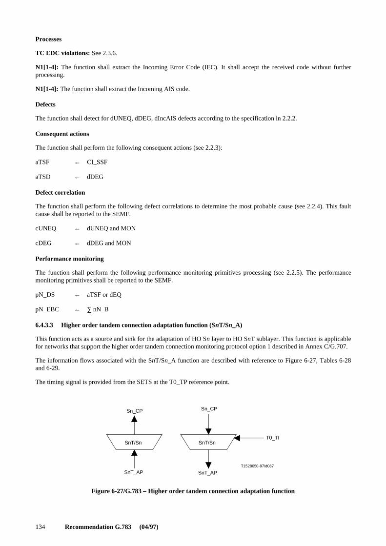
134 Recommendation G.783 (04/97)
Processes
TC EDC violations: See 2.3.6.
N1[1-4]: The function shall extract the Incoming Error Code (IEC). It shall accept the received code without furtherprocessing.
N1[1-4]: The function shall extract the Incoming AIS code.
Defects
The function shall detect for dUNEQ, dDEG, dIncAIS defects according to the specification in 2.2.2.
Consequent actions
The function shall perform the following consequent actions (see 2.2.3):
aTSF ← CI_SSF
aTSD ← dDEG
Defect correlation
The function shall perform the following defect correlations to determine the most probable cause (see 2.2.4). This faultcause shall be reported to the SEMF.
cUNEQ ← dUNEQ and MON
cDEG ← dDEG and MON
Performance monitoring
The function shall perform the following performance monitoring primitives processing (see 2.2.5). The performancemonitoring primitives shall be reported to the SEMF.
pN_DS ← aTSF or dEQ
pN_EBC ← ∑ nN_B
6.4.3.3 Higher order tandem connection adaptation function (SnT/Sn_A)
This function acts as a source and sink for the adaptation of HO Sn layer to HO SnT sublayer. This function is applicablefor networks that support the higher order tandem connection monitoring protocol option 1 described in Annex C/G.707.
The information flows associated with the SnT/Sn_A function are described with reference to Figure 6-27, Tables 6-28and 6-29.
The timing signal is provided from the SETS at the T0_TP reference point.
T1528050-97/d087
Figure 6-27/G.783 – Higher order tandem connection adaptation function
Sn_CP Sn_CP
SnT_APSnT_AP
T0_TISnT/Sn SnT/Sn
FIGURE 6-27/G.783...[D087] = 5 CM

Recommendation G.783 (04/97) 135
6.4.3.3.1 Source direction
Interfaces
Table 6-28/G.783 – SnT/Sn_A_So input and output signals
Processes
NOTE 1 – The function has no means to verify the existence of a tandem connection within the incoming signal. Nested tandemconnections are not supported.
The function shall replace the incoming Frame Start signal by a local generated one (i.e. enter "holdover") if an all-ONEs(AIS) VC is received (i.e. this function replaces an all-ONEs incoming VC by a VC-AIS signal).
NOTE 2 – This replacement of the (invalid) incoming frame start signal results in the generation of a valid pointer in the MSn/Sn_Afunction.
Defects
None.
Consequent actions
This function shall perform the following consequent actions:
aSSF ← CI_SSF
Defect correlation
None.
Performance monitoring
None.
6.4.3.3.2 Sink direction
Interfaces
Table 6-29/G.783 – SnT/Sn_A_Sk input and output signals
Processes
The function shall restore the invalid frame start condition if that existed at the ingress of the tandem connection.
NOTE 1 – In addition, the invalid frame start condition is activated on a tandem connection connectivity defect condition that causesall-ONEs (AIS) insertion in the SnT_TT.
N1[5-8]: The function shall terminate N1[5-8] by inserting an all-ZEROs pattern.
B3: The function shall compensate the VC-n BIP-8 in byte B3 according to the algorithm specified in 2.3.5.
Input(s) Output(s)
Sn_CI_DataSn_CI_ClockSn_CI_FrameStartSn_CI_SSFT0_TI_CK
SnT_AI_DataSnT_AI_ClockSnT_AI_FrameStartSnT_AI_SSF
Input(s) Output(s)
SnT_AI_DataSnT_AI_ClockSnT_AI_FrameStartSnT_AI_OSF
Sn_CI_DataSn_CI_ClockSn_CI_FrameStartSn_CI_SSF

136 Recommendation G.783 (04/97)
Defects
None.
Consequent actions
This function shall perform the following consequent actions:
aAIS ← AI_OSF
aSSF ← AI_OSF
NOTE 2 – CI_SSF = true will result in AU-AIS generation by MSn/Sn_A function.
The function shall insert the all-ONEs (AIS) signal within 250 µs after AIS request generation, and cease the insertionwithin 250 µs after the AIS request is cleared.
Defect correlation
None.
Performance monitoring
None.
6.4.3.4 Tandem connection datalink adaptation function (SnT/DL_A)
The SnT/DL_A adaptation function is applicable for networks that support the higher order tandem connectionmonitoring option 1 data link (DL) as described in Annex C/G.707. The SnT/DL_A adaptation function places bits 5-8 ofbyte N1 of the TCOH into the SnT_AI in the source direction and recovers the information from SnT_AI in the sinkdirection. The information flows associated with the SnT/DL_A function are described with reference to Figures 6-28 and6-29 and Tables 6-30 and 6-31.
6.4.3.4.1 Source direction
Symbol
T1528060-97/d088
Figure 6-28/G.783 – SnT/DL_A_So function
DL_CI
SnT_AI
SnT/DL
FIGURE 6-28/G.783...[D088] = 5 CM
Interfaces
Table 6-30/G.783 – SnT/DL_A_So function inputs and outputs
Processes
The Data Link (DL) bits are derived from the DL message communications function and placed in bits 5-8 of N1. Thebits shall be used as described in Annex C/G.707. The data link is a message based channel to support tandem connectionmaintenance.
Inputs Outputs
DL_CI_DataSnT_AI_FrameStartSnT_AI_Clock
SnT_AI_DataDL_CI_Clock

Recommendation G.783 (04/97) 137
Defects
None.
Consequent actions
None.
Defect correlations
None.
Performance monitoring
None.
6.4.3.4.2 Sink direction
Symbol
T1528070-97/d089
Figure 6-29/G.783 – SnT/DL_A_Sk function
DL_CI
SnT_AI
SnT/DL
FIGURE 6-29/G.783...[D089] = 5 CM
Interfaces
Table 6-31/G.783 – SnT/DL_A_Sk function inputs and outputs
Processes
The DL bits N1[5-8] are recovered from the TCOH and passed to the DL communications function.
Defects
None.
Consequent actions
aSSF ← AI_TSF
Defect correlations
None.
Performance monitoring
None.
Inputs Outputs
SnT_AI_DataSnT_AI_ClockSnT_AI_FrameStartSnT_AI_TSF
DL_CI_DataDL_CI_ClockDL_CI_SSF

138 Recommendation G.783 (04/97)
6.4.3.5 Tandem connection data link adaptation function for non-intrusive monitoring (SnTm/DL_A)
This function acts as a non-intrusive monitor for the higher order tandem connection overhead Data Link (DL) describedin Annex C/G.707 (option 1).
The information flows associated with the SnTm/DL_A function are described with reference to Figure 6-30 and Table 6-32.
6.4.3.5.1 Sink direction
Symbol
T1528080-97/d090
Figure 6-30/G.783 – SnTm/DL_A_Sk function
DL_CI
SnTm_AI
SnTm/DL
FIGURE 6-30/G.783...[D090] = 4.5 CM
Interfaces
Table 6-32/G.783 – SnTm/DL_A_Sk function inputs and outputs
Processes
The Data Link (DL) information from the bits 5-8 of N1 byte are recovered from the SnTm_AI and are passed to the DLcommunications function.
Defects
None.
Consequent actions
aSSF ← AI_TSF
Defect correlations
None.
Performance monitoring
None.
7 Lower order SDH path (Sm) layer
The lower order path layers are the VC-3, VC-2, VC-12 and VC-11 path layers. See Figure 7-1.
Inputs Outputs
SnTm_AI_DataSnTm_AI_ClockSnTm_AI_FrameStartSnTm_AI_TSF
DL_CI_DataDL_CI_ClockDL_CI_SSF

Recommendation G.783 (04/97) 139
T1526090-97/d091
Figure 7-1/G.783 – Low order SDH path layer atomic functions
Sm Sm
Sm/Pqs
Sm_RI
Sm_CP Sm_CP
Sm_RI
SmDSmD
SmD/Sm SmD/Sm
Sm
Pqs_CP
Smm
SmsSms
SmDm
Sm_AP Sm_AP
SmD_AP SmD_AP
Sm/Pqx
Pqx_CP
T0_TP
TSF, TSD
TSF, TSD
Sm/Pqs
Pqs_CP
Sm/Pqx
Pqx_CP
Sm_RI
TSF,TSD
FIGURE 7-1/G-783...[D091] = 10 CM
Lower order Sm layer characteristic information
The Characteristic Information Sm_CI has co-directional timing and is octet structured with a 125 µs or 500 µs frame, asshown in Figures 7-2 to 7-9, left frames. Its format is characterized as the VC-m [m = (11, 12, 2 or 3)] trail terminationoverhead in the V5 and J2 bytes or the J1, B3, and G1 bytes as defined in Recommendation G.707 plus the Sm AdaptedInformation given in the next section. Alternatively it may be an unequipped signal as defined in Recommendation G.707.
For the case of a signal within the tandem connection sublayer, the Characteristic Information has defined Sm tandemconnection trail termination overhead in location N2 or N1 as shown in Figures 7-3, 7-5, 7-7 and 7-9.
Lower order Sm layer adaptation information
The Adaptation Information AI is octet structured with an 125 or 500 µs frame as shown in Figures 7-2 to 7-9, rightframes. In the S3_AI case, it represents adapted label, and client specific information combined with 1 byte user channelsF2 and F3. For the case the signal has passed the trail protection sublayer (SmP), Sm_AI has defined APS bits (1 to 4) inbyte K4 or K3.

140 Recommendation G.783 (04/97)
T1526100-97/d092
Lower OrderVC-3 payload(9 × 84 bytes)
Reserved Reserved
Lower OrderVC-3 payload(9 × 84 bytes)
Figure 7-2/G.783 – S3_CI_D (left) and S3_AI_D (right)
1
2
J1
C2
B3
F2
H4
G1
F3
5
1 2 85
C2
F2
H4
F3
K3
1 2 85
1
2
9
6-8 1-4 5-8
1RDI APS K3
9
K3
N1
1-4
G1 REI
FIGURE 7-2/G.783...[D092] = 7 CM
T1526110-97/d093
Lower OrderVC-3 payload(9 × 84 bytes)
FASTrace
res RDIODI res
Reserved
Lower OrderVC-3 payload(9 × 84 bytes)
Figure 7-3/G.783 – S3_CI_D (left) with defined N1 and S3_AI_D (right)
IEC/IncAIS REI OEI
2
9
J1
C2
B3
F2
H4
G1
F3
K3
N1
1-4 5 6 7-8
1 2 85
J1
C2
B3
F2
H4
G1
F3
K3
1 2 85
1
2
9
1-89-727374
75-76
1
FIGURE 7-3/G.783...[D093] = 8.5 CM

Recommendation G.783 (04/97) 141
T1526120-97/d094
Undefined
VC-2 payload(106 bytes)
VC-2 payload(106 bytes)
VC-2 payload(106 bytes)
VC-2 payload(106 bytes)
VC-2 payload(106 bytes)
VC-2 payload(106 bytes)
VC-2 payload(106 bytes)
VC-2 payload(106 bytes)
Figure 7-4/G.783 – S2_CI_D (left) and S2_AI_D (right)
1
2
107
108
109
214
215
216
321
322
323
428
V5
K4
1
2
107
108
109
214
215
216
321
322
323
428
V5
J2
N2
K4
REI RFI PSL RDIV5
3 4 8
PSLV5
3 4 8
K4 APS
BIP-2
1-2 5-7 1-2 5-7
FIGURE 7-4/G.783...[D094] = 14 CM

142 Recommendation G.783 (04/97)
T1526130-97/d095
VC-2 payload(106 bytes)
FASTrace
res RDIODI resReserved
VC-2 payload(106 bytes)
VC-2 payload(106 bytes)
VC-2 payload(106 bytes)
VC-2 payload(106 bytes)
VC-2 payload(106 bytes)
VC-2 payload(106 bytes)
VC-2 payload(106 bytes)
Figure 7-5/G.783 – S2_CI_D (left) with defined N2 and S2_AI_D (right)
1
2
107
108
109
214
215
216
321
322
323
428
V5
K4
1
2
107
108
109
214
215
216
321
322
323
428
V5
J2
N2
K4
BIP-2 "1" REI OEIN2
1-2 3 4 5 6 7-8
IncAIS 1-89-727374
75-76
FIGURE 7-5/G.783...[D095] = 14 CM

Recommendation G.783 (04/97) 143
T1526140-97/d096
Undefined
VC-12 payload(34 bytes)
VC-12 payload(34 bytes)
VC-12 payload(34 bytes)
VC-12 payload(34 bytes)
VC-12 payload(34 bytes)
VC-12 payload(34 bytes)
VC-12 payload(34 bytes)
VC-12 payload(34 bytes)
Figure 7-6/G.783 – S12_CI_D (left) and S12 _AI_D (right)
V5
K4
V5
J2
N2
K4
BIP-2 REI RFI PSL RDIV5
3 4 8
K4 APS
1-2 5-7
PSLV5
3 4 81-2 5-7
70
106
1
2
35
36
37
71
72
105
107
140
70
71
1
2
35
36
37
72
105
106
107
140
FIGURE 7-6/G.783...[D096] = 14 CM

144 Recommendation G.783 (04/97)
T1526150-97/d097
VC-12 payload(34 bytes)
FASTrace
res RDIODI resReserved
VC-12 payload(34 bytes)
VC-12 payload(34 bytes)
VC-12 payload(34 bytes)
VC-12 payload(34 bytes)
VC-12 payload(34 bytes)
VC-12 payload(34 bytes)
VC-12 payload(34 bytes)
Figure 7-7/G.783 – S12_CI_D (left) with defined N2 and S12_AI_D (right)
V5
J2
K4
1
2
35
36
37
70
71
72
105
106
107
140
V5
J2
N2
K4
BIP-2 "1" REI OEIN2
1-2 3 4 5 6 7-8
IncAIS 1-89-727374
75-76
1
2
35
36
37
70
71
72
105
106
107
140
FIGURE 7-7/G.783...[D097] = 14 CM

Recommendation G.783 (04/97) 145
T1526160-97/d098
Reserved
VC-11 payload(25 bytes)
VC-11 payload(25 bytes)
VC-11 payload(25 bytes)
VC-11 payload(25 bytes)
VC-11 payload(25 bytes)
VC-11 payload(25 bytes)
VC-11 payload(25 bytes)
VC-11 payload(25 bytes)
Figure 7-8/G.783 – S11_CI_D (left) and S11_AI_D (right)
V5
K4
3
V5
J2
N2
K4
REI R PSL RDIV5
3 4 8
K4 APS
BIP-2
1-2 5-7
PSLV5
4 81-2 5-7
2
1
26
27
28
52
53
54
78
79
80
104
1
2
26
27
28
52
53
54
78
79
80
104
FIGURE 7-8/G.783...[D098] = 13.5 CM

146 Recommendation G.783 (04/97)
IncAIS
T1526170-97/d099
VC-11 payload(25 bytes)
FASTraza
res RDIODI resReserved
VC-11 payload(25 bytes)
VC-11 payload(25 bytes)
VC-11 payload(25 bytes)
VC-11 payload(25 bytes)
VC-11 payload(25 bytes)
VC-11 payload(25 bytes)
VC-11 payload(25 bytes)
Figure 7-9/G.783 – S11_CI_D (left) with defined N2 and S11D_AI_D (right)
1
2
26
27
28
52
53
54
78
79
80
104
V5
J2
N2
K4
BIP-2 "1" REI OEIN2
1-2 3 4 5 6 7-8
1-89-727374
75-76
1
2
26
27
28
52
53
54
78
79
80
104
V5
J2
K4
FIGURE 7-9/G.783...[D099] = 14 CM
Layer functions
Sm_C Lower order path connection function
Sm_TT Lower order path trail termination function
Smm_TT Lower order non-intrusive monitor function
Sms_TT Lower order supervisory-unequipped termination function
Sm/Pq_A Lower order path adaptation functions
Sm/User_A Lower order path user data adaptation function
Sm/RFI_A Lower order path remote failure indication adaptation function
SmP_C Lower order trail protection connection function
SmP_TT Lower order path protection trail termination function
Sm/SmP_A Lower order path protection adaptation function
SmD_TT Lower order tandem connection termination function
SmD/Sm_A Lower order tandem connection adaptation function
SmDm_TT Lower order tandem connection non-intrusive monitor function

Recommendation G.783 (04/97) 147
Relationship to previous versions of Recommendation G.783
The 1994 version of Recommendation G.783 refers to the LPT, LPC, LPA, LUG, LPOM basic functions. Table 7-1shows the relationship between the basic functions and the atomic functions in the Lower order path layers.
Table 7-1/G.783 – Lower order path layer basic and atomic functions
7.1 Connection functions: Sm_C
7.1.1 Lower order trail connection function (Sm_C)
Sm_C is the function which assigns lower order VCs of level m (m = 11, 12, 2 or 3) at its input ports to lower order VCsof level m at its output ports.
The Sm_C connection process is a unidirectional function as illustrated in Figure 7-10. The signal formats at the inputand output ports of the function are similar, differing only in the logical sequence of the VC-ms. As the process does notaffect the nature of the characteristic information of the signal, the reference point on either side of the Sm_C function isthe same, as illustrated in Figure 7-10.
Incoming VC-ms at the Sm_CP are assigned to available outgoing VC-m capacity at the Sm_CP.
An unequipped VC-m shall be applied at any outgoing VC-m which is not connected to an incoming VC-m.
T1526180-97/d100
Figure 7-10/G.783 – General lower order trail connection function
Sm
Sm_CP
Sm_C_MP
Sm_CP
T0_TP
FIGURE 7-10/G.783...[D100] = 5.5 CM
Basic function Atomic function
LPT
LPC
LPA
LUGLPOM
Sm_TT_SoSm_TT_SkSm/RFI_A_SoSm/RFI_A_SkSm/User_A_SoSm/User_A_Sk
Sm_C
Sm/Pq_A_SoSm/Pq_A_SkEq/Pqs_A_SoEq/Pqs_A_Sk
Sms_TT_SoSms_TT_SkSmm_TT_Sk

148 Recommendation G.783 (04/97)
Interface
See Table 7-2.
Table 7-2/G.783 – Sm_C input and output signals
Processes
In the Sm_C function VC-m Layer Characteristic Information is routed between input (termination) connection points[(T)CPs] and output (T)CPs by means of matrix connections. (T)CPs may be allocated within a protection group.
NOTE 1 – Neither the number of input/output signals to the connection function, nor the connectivity is specified in thisRecommendation. That is a property of individual network elements. Examples of Sm_C configurations are the same as the Sn_Cexamples given in Appendix II, except that they refer to the Sm_CP rather than the Sn_CP.
Figure 7-1 presents a subset of the atomic functions that can be connected to this VC-m connection function: VC-m trailtermination functions, VC-m non-intrusive monitor trail termination sink function, VC-m unequipped-supervisory trailtermination functions, VC-m tandem connection trail termination and adaptation functions. In addition, adaptationfunctions in the VC-m server (e.g. VC-4 or VC-3) layers will be connected to this VC-m connection function.
Routing: The function shall be able to connect a specific input with a specific output by means of establishing a matrixconnection between the specified input and output. It shall be able to remove an established matrix connection.
Input(s) Output(s)
Per Sm_CI, n x for the function:Sm_CI_DataSm_CI_ClockSm_CI_FrameStartSm_CI_SSFSm_AI_TSFSm_AI_TSD
1 x per function:T0_TI_ClockT0_TI_FrameStart
Per input and output connection point:Sm_C_MI_ConnectionPortIds
Per matrix connection:Sm_C_MI_ConnectionTypeSm_C_MI_Directionality
Per SNC protection group:Sm_C_MI_PROTtypeSm_C_MI_OPERtypeSm_C_MI_WTRtimeSm_C_MI_HOtimeSm_C_MI_EXTCMD
Per Sm_CI, m x per function:Sm_CI_DataSm_CI_ClockSm_CI_FrameStartSm_CI_SSF
Per SNC protection group:Sm_C_MI_pPSCSm_C_MI_pPSSwSm_C_MI_pPSSpNOTE – Protection status reporting signals are forfurther study.

Recommendation G.783 (04/97) 149
Each (matrix) connection in the Sm_C function should be characterized by the:
NOTE 2 – Broadcast connections are handled as separate connections to the same input CP.
Provided no protection switching action is activated/required, the following changes to (the configuration of) aconnection shall be possible without disturbing the CI passing the connection:
– addition and removal of protection;
– addition and removal of connections to/from a broadcast connection;
– change between operation types;
– change of WTR time;
– change of Hold-off time.
Unequipped VC generation: The function shall generate an unequipped VC-m signal, as specified in Recommen-dation G.707.
Defects
None.
Consequent actions
If an output of this function is not connected to one of its inputs, the function shall connect the unequipped VC-m [withvalid frame start (FS) and SSF = false] to the output.
Defect correlation
None.
Performance monitoring
For each SNC protection group:
pPSC ← According to 2.2.5.6.
pPSSw ← According to 2.2.5.7.
pPSSp ← According to 2.2.5.7.
7.1.1.1 Lower order subnetwork connection protection process
Lower order subnetwork connection protection mechanism is described in Recommendation G.841.
Figure 7-11 gives the atomic functions involved in SNC protection. Bottom to the left is the two (working and protection)adaptation function (Sn/Sm_A) pairs. Above them is the non-intrusive monitoring functions (Smm_TT_Sk), in case ofSNC/N they are not present. To the right is either the trail termination functions (Sm_TT) or the adaptation functions(Sn/Sm_A) depending on if the Sm trail is terminated at the same point the SNC protection is terminated or at a laterpoint.
Type of connection: Unprotected, 1 + 1 protected(SNC/I, SNC/N or SNC/S protection)
Traffic direction: Unidirectional, bidirectional
Input and output connection points: Set of connection point

150 Recommendation G.783 (04/97)
T1526190-97/d101
Sm_CPWorking
Sm_CPProtection
Sm_CPProtected
Sm_CPProtected
Figure 7-11/G.783 – Low order SDH SNC/N protection atomic functions
Sm
Sn/Sm
Smm
TSDSm_RI
Sm_AP
Sn/Sm Sn/Sm Sn/Sm
Sm
Smm
Sn/Sm Sn/Sm
TSF
Sm
TSFTSD
FIGURE 7-11/G.783...[D101] = 9.5 CM
The Sm_C function may provide protection for the lower order trail against channel-associated defects within a lowerorder (sub)network connection.
The Sm_C functions at both ends operate the same way, by monitoring the lower subnetwork connections for defects,evaluating the system status taking into consideration the priorities of defect conditions and of external switch requests,and switching the appropriate channel to the protection (sub)network connection.
The signal flow associated with the Sm_C SNC protection process is described with reference to Figures 7-12 and 7-13.The Sm_C SNC protection process receives control parameters and external switch requests at the Sm_C_MP referencepoint from the synchronous equipment management function and outputs status indicators at the Sm_C_MP to thesynchronous equipment management function, as a result of switch commands described in Recommendation G.841.
T1526200-97/d102
Working ProtectionProtectionWorking
NormalSNC Protection process
Normal(1 + 1 linear)
Figure 7-12/G.783 – Lower order inherent monitored subnetwork connection (SNC/I) protection process
Sm_CP Sm_CP
SSFSSF
Sm_CPSm_CP
Sm_CP Sm_CP
Sm_C_MP
FIGURE 7-12/G.783...[D102] = 6 CM

Recommendation G.783 (04/97) 151
T1526210-97/d103
Working ProtectionWorking Protection
NormalSNC Protection process
Normal(1 + 1 linear)
Figure 7-13/G.783 – Lower order non-intrusive monitored subnetwork connection (SNC/N) protection process
FIGURE 7-13/G.783...[D103] = 6 CM
7.1.1.1.1 Source direction
Data at the Sm_CP is a lower order trail signal.
For 1 + 1 architecture, the signal received at the Sm_CP from the Sn/Sm_A (or Sm_TT) function is bridged permanentlyat the Sm_CP to both working and protection Sn/Sm_A functions.
NOTE – The basic element connected at the Sm_CP to the Sm_C is either an Sn/Sm_A or an Sm_TT. When the LO VC-m signal isterminated in this network element, it will be connected at the Sm_CP to an Sm_TT, otherwise it will be connected at the Sm_CP toan Sn/Sm_A (for further transport).
7.1.1.1.2 Sink direction
Framed lower order trail signals (data) Sm_CI are presented at the Sm_CP along with incoming timing references. Thedefect condition(s) SSF (and TSF and TSD) are also received at the Sm_CP from all Sn/Sm_A [or Smm_TT_Sk,m = (11, 12, 2 or 3)] functions.
For the SNC/I protection (Figure 7-12) the lower order trail signals pass the Sn/Sm_A functions. The SSF signals fromthe Sn/Sm_A_Sk are used by the Sm_C SNC protection process.
For the SNC/N protection (Figure 7-13) the lower order trail signals are broadcast to Smm_TT_Sk function for non-intrusive monitoring of the lower order trail. The resultant TSF, TSD signals are used by the Sm_C SNC protectionprocess instead of the SSF signal from the Sn/Sm_A.
Under normal conditions, Sm_C passes the data and timing from the working Sn/Sm_A functions to the Sn/Sm_A (orSm_TT) function at the Sm_CP. The data and timing from the protection (sub)network connection is not forwarded.
If a switch is to be performed, then the data and timing received from the protection Sn/Sm_A at the Sm_CP is switchedto the Sn/Sm_A (or Sm_TT) function at the Sm_CP, and the signal received from the working Sn/Sm_A at the Sm_CP isnot forwarded.
7.1.1.1.3 Switch initiation criteria
Automatic protection switching is based on the defect conditions of the working and protection (sub)networkconnections. These condition(s) are for SNC/I server signal fail (SSF) and for SNC/N Trail Signal Fail (TSF) and TrailSignal Degrade (TSD). Detection of these conditions is described in 6.3.1 for Sn/Sm_A and 7.2.2 for Smm_TT_Sk,m = (11, 12, 2 or 3).
The protection switch can also be initiated by switch commands received via the synchronous equipment managementfunction. See the switch initiation criteria described in Recommendation G.841.

152 Recommendation G.783 (04/97)
7.1.1.1.4 Switching time
Protection switching shall be completed within TBD ms of detection of an SSF, TSF or SD condition that initiates aswitch.
The protection switch completion time is for further study. A proposal is a basic switch time (Tbs) (after defect detection)of 100 ms increased by a provisionable hold-off time Tho, with 0 ≤ Tho ≤ 10 s.
7.1.1.1.5 Switch restoration
In the revertive mode of operation, the working channel shall be restored, i.e. the signal on the protection (sub)networkconnection shall be switched back to the working (sub)network connection, when the working (sub)network connectionhas recovered from the fault.
To prevent frequent operation of the protection switch due to an intermittent fault, a failed (sub)network connection mustbecome fault-free. After the failed (sub)network connection meets this criterion, a fixed period of time shall elapse beforeit is used again by a working channel. This period, called Wait to Restore (WTR) period should be of the order of 5-12 minutes and should be capable of being set. An SSF, TSF or TSD condition shall override the WTR.
7.2 Termination functions: Sm_TT, Smm_TT and Sms_TT
7.2.1 Lower order trail termination (Sm_TT)
Recommendation G.783 (04/97)
The Lower order Path termination function comprises the atomic functions Lower order path trail termination source[Sm_TT_So, m = (11, 12, 2 or 3)] and sink [Sm_TT_Sk, m = (11, 12, 2 or 3)] as illustrated in Figure 7-14 and Tables 7-3and 7-4.
The Sm_TT source function creates a VC-m (m = 11, 12, 2, or 3) at the Sm_CP by generating and adding POH to acontainer C-m from the Sm_AP. In the other direction of transmission it terminates and processes the POH to determinethe status of the defined path attributes. The POH formats are defined in Recommendation G.707. The information flowsassociated with the Sm_TT functions are described in Figure 7-14 and Tables 7-3 and 7-4.
T1526220-97/d104
Figure 7-14/G.783 – Lower order trail termination function
Sm_RI
Sm_APSm_AP
SmSm
Sm_CPSm_CP
Sm_TT_So_MPSm_TT_Sk_MP
FIGURE 7-14/G.783...[D104] = 5.5 CM
Referring to Figure 7-14, data at the Sm_AP takes the form of a container C-m (m = 1, 2, 3) which is synchronized to thetiming reference T0_TP.
Synchronously adapted information in the form of synchronous containers (data) and the associated container frameoffset information (frame offset) are received at the Sm_AP.

Recommendation G.783 (04/97) 153
7.2.1.1 Case of VC-11, 12 and 2
The VC-1/VC-2 POH is carried in the J2, K4, N2, and V5 bytes as defined in Recommendation G.707.Recommendation G.783 (04/97)
7.2.1.1.1 Source direction
This function adds error monitoring and status overhead bits to the Sm_AP.
Data at the Sm_AP is a VC-m (m = 11, 12, 2 or 3), having a payload as described in Recommendation G.707, but withindeterminate VC-m POH bytes: J2, V5. These POH bytes are set as part of the Sm_TT function and the complete VC-mis forwarded to the Sm_CP.
Interfaces
Table 7-3/G.783 – Sm_TT_So input and output signals
Processes
J2: The trail trace identifier should be generated. Its value is derived from reference point Sm_TT_So_MP. The pathtrace format is described in 2.2.2.4.
V5[1-2]: BIP-2 shall be calculated on data at the Sm_CP on the previous frame and the result transmitted in bits 1 and 2of the V5 byte.
V5[3]: The number of errors indicated in RI_REI is encoded in the REI bit.
V5[8]: When there is an active RI_RDI, the RDI indication shall be sent in bit 8 of the V5 byte within 1000 µs. Upontermination of the above conditions, the RDI indication shall be removed within 1000 µs.
K4[5-8]: These bits are undefined.
N2: This byte is undefined.
Defects
None.
Consequent actions
None.
Defect correlation
None.
Performance monitoring
None.
7.2.1.1.2 Sink direction
This function monitors the lower order VC-m [m = (11, 12 or 2)] for errors, and recovers the trail termination status. Itextracts the payload independent overhead bytes/bits (J2, V5[1-2], V5[3], V5[5-7], V5[8]) from the VC-m layerCharacteristic Information.
Input(s) Output(s)
Sm_AI_DataSm_AI_ClockSm_AI_FrameStartSm_RI_RDISm_RI_REI
Sm_TT_So_MI_TxTI
Sm_CI_DataSm_CI_ClockSm_CI_FrameStart

154 Recommendation G.783 (04/97)
Interfaces
Table 7-4/G.783 – Sm_TT_Sk input and output signals
Processes
J2: The trail trace identifier is recovered from VC-m POH at the Sm_CP and processed as specified in 2.2.2.4. Theaccepted value of J2 is also available at the Sm_TT_Sk_MP. For further description of trace identifier mismatchprocessing, see 2.2.2.4.
V5[5-7]: The unequipped defect is processed as described in 2.2.2.2.
V5[1-2]: The error monitoring bits at the Sm_CP shall be recovered. BIP-2 is computed for the VC-m frame. Thecomputed BIP-2 value for the current frame is compared with the recovered bits 1 and 2 from the following frame.
The process for detecting excessive errors and signal degrade is described in 2.2.2.5.
V5[3]: The REI shall be recovered and the derived performance primitives should be reported at the Sm_TT_Sk_MP.
V5[8]: The RDI defect is processed as described in 2.2.2.6.
N2: The network operator byte is defined for TC monitoring. It shall be ignored by this function.
K4[5-8]: These bits are undefined.
Defects
The function shall detect for dUNEQ, dTIM, dEXC, dDEG and dRDI defects according to the specification in 2.2.2.
Consequent actions
The function shall perform the following consequent actions (see 2.2.3):
aAIS ← dUNEQ or dTIM
aRDI ← CI_SSF or dUNEQ or dTIM
aREI ← nN_B
aTSF ← CI_SSF or dUNEQ or dTIM
aTSFprot ← aTSF or dEXC
aTSD ← dDEG
Input(s) Output(s)
Sm_CI_DataSm_CI_ClockSm_CI_FrameStartSm_CI_SSF
Sm_TT_Sk_MI_TPmodeSm_TT_Sk_MI_ExTISm_TT_Sk_MI_RDI_ReportedSm_TT_Sk_MI_DEGTHRSm_TT_Sk_MI_DEGMSm_TT_Sk_MI_1secondSm_TT_Sk_MI_TIMdis
Sm_AI_DataSm_AI_ClockSm_AI_FrameStartSm_AI_TSFSm_AI_TSDSm_RI_RDISm_RI_REISm_TT_Sk_MI_cTIMSm_TT_Sk_MI_cUNEQSm_TT_Sk_MI_cEXCSm_TT_Sk_MI_cDEGSm_TT_Sk_MI_cRDISm_TT_Sk_MI_AcTISm_TT_Sk_MI_pN_EBCSm_TT_Sk_MI_pN_DSSm_TT_Sk_MI_pF_EBCSm_TT_Sk_MI_pF_DS

Recommendation G.783 (04/97) 155
Defect correlation
The function shall perform the following defect correlation to determine the most probable fault cause (see 2.2.4). Thisfault cause shall be reported to the SEMF.
cUNEQ ← dUNEQ and MON
cTIM ← dTIM and (not dUNEQ) and MON
cEXC ← dEXC and (not dTIM) and MON
cDEG ← dDEG and (not dTIM) and MON
cRDI ← dRDI and (not dUNEQ) and (not dTIM) and MON and RDI_Reported
Performance monitoring
The function shall perform the following performance monitoring primitives processing (see 2.2.5). The performancemonitoring primitives shall be reported to the SEMF.
pN_DS ← aTSF or dEQ
pF_DS ← dRDI
pN_EBC ← Σ nN_B
pF_EBC ← Σ nF_B
7.2.1.2 Case of VC-3
The VC-m path overhead (for m = 3) is the same as the path overhead for VC-n (n = 3) and is described in 6.2.1.
7.2.2 Lower order non-intrusive monitor (Smm_TT)
The Lower order Path overhead monitor function comprises the atomic function Lower order non-intrusive monitor sink[Smm_TT_Sk, m = (11, 12, 2 or 3)] illustrated in Figure 7-15 and Table 7-5.
The Sm_TT function processes the POH to determine the status of the defined path attributes. The POH formats aredefined in Recommendation G.707. The information flows associated with the Smm_TT function are described inFigure 7-15 and Table 7-5.
T1526230-97/d105
Figure 7-15/G.783 – Lower order non-intrusive monitor function
Smm
Smn_CP
Smm_TT_Sk_MP
Sm_AI_TSFSm_AI_TSD
FIGURE 7-15/G.783...[D105] = 3 CM
7.2.2.1 Case of VC-11, 12 and 2
7.2.2.1.1 Sink direction
This function monitors the lower order VC-m [m = (11, 12 or 2)] for errors, and recovers the trail termination status. Itextracts the payload independent overhead bytes/bits (J2, V5[1-2], V5[3], V5[5-7], V5[8]) from the VC-m layerCharacteristic Information.

156 Recommendation G.783 (04/97)
Interfaces
Table 7-5/G.783 – Smm_TT_Sk input and output signals
Processes
J2: The trail trace identifier is recovered from VC-m POH at the Sm_CP. The accepted value of J2 is also available at theSmm_TT_Sk_MP. For further description of trace identifier mismatch processing, see 2.2.2.4.
V5[5-7]: The signal label bits at the Sm_CP shall be recovered. For further description of unequipped defect processing,see 2.2.2.2. The function shall detect for an AIS VC (VC-AIS) condition by monitoring the VC_SL for code "111". Forfurther description of VC-AIS defect processing, see 2.2.2.3.
V5[1-2]: The error monitoring bits at the Sm_CP shall be recovered. BIP-2 is computed for the VC-m frame. Thecomputed BIP-2 value for the current frame is compared with the recovered bits 1 and 2 from the following frame.
The process for detecting excessive errors and signal degrade from V5 bit 1, 2 is described in 2.2.2.5.
V5[3]: REI in bit 3 shall be recovered and the derived performance primitives should be reported at the Smm_TT _MP.See below.
V5[8]: The path RDI information in bit 8 shall be recovered and reported at the Smm_TT_Sk_MP. For further descrip-tion of RDI defect processing, see 2.2.2.6.
N2: The network operator byte is defined for TC monitoring. It shall be ignored by this function.
Defects
The function shall detect for dUNEQ, dTIM, dEXC, dDEG, dAIS and dRDI defects according to the specificationin 2.2.2.
Consequent actions
The function shall perform the following consequent actions (see 2.2.3):
aTSF ← CI_SSF or dAIS or dUNEQ or dTIM
aTSFprot ← dEXC or aTSF
aTSD ← dDEG
Defect correlation
The function shall perform the following defect correlation to determine the most probable fault cause (see 2.2.4). Thisfault cause shall be reported to the SEMF.
cAIS ← dAIS and MON and AIS_Reported
cUNEQ ← dUNEQ and MON
Input(s) Output(s)
Sm_CI_DataSm_CI_ClockSm_CI_FrameStartSm_CI_SSF
Smm_TT_Sk_MI_TPmodeSmm_TT_Sk_MI_ExTISmm_TT_Sk_MI_RDI_ReportedSmm_TT_Sk_MI_DEGTHRSmm_TT_Sk_MI_DEGMSmm_TT_Sk_MI_1secondSmm_TT_Sk_MI_TIMdis
Sm_AI_TSFSm_AI_TSD
Smm_TT_Sk_MI_cTIMSmm_TT_Sk_MI_cUNEQSmm_TT_Sk_MI_cDEGSmm_TT_Sk_MI_cRDISmm_TT_Sk_MI_cAISSmm_TT_Sk_MI_AcTISmm_TT_Sk_MI_pN_EBCSmm_TT_Sk_MI_pF_EBCSmm_TT_Sk_MI_pN_DSSmm_TT_Sk_MI_pF_DS

Recommendation G.783 (04/97) 157
cTIM ← dTIM and (not dUNEQ) and MON
cEXC ← dEXC and (not dTIM) and MON
cDEG ← dDEG and (not dTIM) and MON
cRDI ← dRDI and (not dUNEQ) and (not dTIM) and MON and RDI_Reported
Performance monitoring
The function shall perform the following performance monitoring primitives processing (see 2.2.5). The performancemonitoring primitives shall be reported to the SEMF.
pN_DS ← aTSF or dEQ
pF_DS ← dRDI
pN_EBC ← Σ nN_B
pF_EBC ← Σ nF_B
7.2.2.2 Case of VC-3
The VC-m path overhead (for m = 3) is the same as the path overhead for VC-n (n = 3) and is described in 6.2.2.
7.2.3 Lower order supervisory-unequipped termination (Sms_TT)
The Lower order Supervisory-unequipped function comprises the atomic functions Lower order Supervisory unequippedtermination source [Sms_TT_So, m = (11, 12, 2 or 3)] and sink [Sms_TT_Sk, m = (11, 12, 2 or 3)] as illustrated inFigure 7-16 and Tables 7-6 and 7-7.
The Smm_TT function creates a VC-m (m = 11, 12, 2, or 3) at the Sm_CP by generating and adding POH to an undefinedcontainer C-m. In the other direction of transmission it terminates and processes the POH to determine the status of thedefined path attributes. The POH formats are defined in Recommendation G.707. The information flows associated withthe Sm_TT function are described in Figure 7-16 and Tables 7-6 and 7-7.
NOTE – The Sms_TT [m = (11, 12, 2 or 3)] function generates and monitors supervisory unequipped signals.
T1526240-97/d106
Figure 7-16/G.783 – Lower order supervisory unequipped termination function
Sm_RI SmsSms
Sm_CPSm_CP
T0_TP
Sms_TT_So_MPSm_TT_Sk_MP
Sm_AI_TSFSm_AI_TSD
FIGURE 7-16/G.783...[D106] = 3 CM
7.2.3.1 Case of VC-11, 12 and 2
7.2.3.1.1 Source direction
This function generates error monitoring and status overhead bytes to an undefined VC-m [m = (11, 12 or 2)].

158 Recommendation G.783 (04/97)
Interfaces
Table 7-6/G.783 – Sms_TT_So input and output signals
Processes
An undefined VC-m [m = (11, 12 or 2)] should be generated.
V5[5-7]: Signal label 000 (unequipped) should be inserted in the VC-m.
J2: The trail trace identifier should be generated. Its value is derived from reference point Sms_TT_MP. The trail traceformat is described in 2.2.2.4.
V5[1-2]: BIP-2 shall be calculated on data at the Sms_AP on the previous frame and the result transmitted in bits 1 and 2of the V5 byte.
V5[3]: The number of errors indicated in RI_REI is encoded in the REI.
V5[8]: Bit 8 of byte V5, an RDI indication, shall be set to "1" on activation of RI_RDI within 1000 µs, determined by theassociated Sms_TT_Sk function, and set to "0" within 1000 µs on clearing of RI_RDI.
N2: In the TCM byte, 00000000 should be inserted.
Defects
None.
Consequent actions
None.
Defect correlation
None.
Performance monitoring
None.
7.2.3.1.2 Sink direction
This function monitors VC-m [m = (11, 12 or 2)] for errors, and recovers the trail termination status. It extracts thepayload independent overhead bytes/bits (J2, V5[1-2], V5[3], V5[5-7], V5[8]) from the VC-12 layer CharacteristicInformation.
Input(s) Output(s)
Sms_RI_RDISms_RI_REIT0_TI_ClockT0_TI_FrameStartSm_RI_RDISm_RI_REI
Sms_TT_So_MI_TxTI
Sm_CI_DataSm_CI_ClockSm_CI_FrameStart

Recommendation G.783 (04/97) 159
Interfaces
Table 7-7/G.783 – Sms_TT_Sk input and output signals
Processes
J2: The trail trace identifier is recovered from VC-m POH at the Sm_CP. The accepted value of the trail trace identifier isalso available at the Sms_TT _MP. For further description of trace identifier mismatch processing, see 2.2.2.4.
V5[5-7]: The signal label at the Sm_CP shall be recovered. Note that the Sms_TT sink direction always expects anunequipped signal label. For further description of unequipped defect processing, see 2.2.2.2.
V5[1-2]: The error monitoring bits at the Sm_CP shall be recovered. BIP-2 is computed for the VC-m frame. Thecomputed BIP-2 value for the current frame is compared with the recovered bits 1 and 2 from the following frame.
The process for detecting excessive errors and signal degrade from BIP-2 is described in 2.2.2.5.
V5[3]: The REI shall be recovered and the derived performance primitives should be reported at the Sms_TT _MP. Seebelow.
V5[8]: The path RDI information shall be recovered and reported at the Sms_TT_MP. For further description of RDIdefect processing, see 2.2.2.6.
N2: The network operator byte is defined for TC monitoring. It shall be ignored by this function.
Defects
The function shall detect for dUNEQ, dTIM, dEXC, dDEG and dRDI defects according to the specification in 2.2.2.
Consequent actions
The function shall perform the following consequent actions (see 2.2.3):
aRDI ← CI_SSF or dTIM
aREI ← Σ nN_B
aTSF ← CI_SSF or dTIM
aTSFprot ← aTSF or dEXC
aTSD ← dDEG
Input(s) Output(s)
Sm_CI_DataSm_CI_ClockSm_CI_FrameStartSm_CI_SSF
Sms_TT_Sk_MI_TPmodeSms_TT_Sk_MI_ExTISms_TT_Sk_MI_RDI_ReportedSms_TT_Sk_MI_DEGTHRSms_TT_Sk_MI_DEGMSms_TT_Sk_MI_1secondSms_TT_Sk_MI_TIMdis
Sm_AI_TSFSm_AI_TSD
Sm_RI_RDISm_RI_REI
Sms_TT_Sk_MI_cTIMSms_TT_Sk_MI_cUNEQSms_TT_Sk_MI_cDEGSms_TT_Sk_MI_cRDISms_TT_Sk_MI_AcTI
Sms_TT_Sk_MI_pN_EBCSms_TT_Sk_MI_pF_EBCSms_TT_Sk_MI_pN_DSSms_TT_Sk_MI_pF_DS

160 Recommendation G.783 (04/97)
Defect correlation
The function shall perform the following defect correlation to determine the most probable fault cause (see 2.2.4). Thisfault cause shall be reported to the SEMF.
cUNEQ ← dTIM and (AcTI = all zeroes) and dUNEQ and MON
cTIM ← dTIM and [not (dUNEQ and AcTI = all zeroes)] and MON
cEXC ← dEXC and (not dTIM) and MON
cDEG ← dDEG and (not dTIM) and MON
cRDI ← dRDI and (not dTIM) and MON and RDI_Reported
Performance monitoring
The function shall perform the following performance monitoring primitives processing (see 2.2.5). The performancemonitoring primitives shall be reported to the SEMF.
pN_DS ← aTSF or dEQ
pF_DS ← dRDI
pN_EBC ← Σ nN_B
pF_EBC ← Σ nF_B
7.2.3.2 Case of VC-3
The VC-m path overhead (for m = 3) is the same as the path overhead for VC-n (n = 3) and is described in 6.2.3.
7.3 Adaptation functions
7.3.1 Lower order trail adaptation function (Sm/Pqx_A, Sm/Pqs_A)
Sm/Pqx_A or Sm/Pqs_A [m = (11, 12, 2 or 3), q = (11, 12, 21, 31, 32)] operates at the access port to a synchronousnetwork or subnetwork and adapts user data for transport in the synchronous domain. The Sm/Pqx_A or Sm/Pqs_Afunction acts also as a source and sink for the POH payload dependent information. For asynchronous user data, lowerorder path adaptation involves bit justification. The Sm/Pqx_A or Sm/Pqs_A function maps G.703 (PDH) signals intolower order containers which may subsequently be mapped into higher order containers. The information flowsassociated with the lower order adaptation function are shown in Figure 7-17 Tables 7-9, 7-10, 7-11 and 7-12.
The Lower order path adaptation function comprises the atomic functions Lower order path adaptation source and sink.
T1526250-97/d107
Figure 7-17/G.783 – Lower order path adaptation function
NOTE – In case of byte synchronous mappings, Pqx should be read as Pqs.
Pqx_CP Pqx_CP
Sm_APSm_AP
T0_TP
Sn/Pqx_A_So_MPSn/Pqx_A_Sk_MP Sm/Pqx Sm/Pqx
FIGURE 7-17/G.783...[D107] = 3 CM

Recommendation G.783 (04/97) 161
Adaptation functions are defined for each of the levels in the existing plesiochronous hierarchies. Each adaptationfunction defines the manner in which a user signal can be mapped into one of a range of synchronous containers C-m ofappropriate size. The container sizes have been chosen for ease of mapping various combinations of sizes into high ordercontainers; see Table 7-8. Detailed specifications for mapping user data into containers are given in Recommen-dation G.707.
Table 7-8/G.783 – Container sizes
7.3.1.1 Source direction
Interfaces
Table 7-9/G.783 – Sm/Pqx_A_So input and output signals
Table 7-10/G.783 – Sm/Pqs_A_So input and output signals
Processes
Data at the Pqx_CP (or Pqs_CP) is the user information stream. Timing of the data is also delivered as timing at the CP.Data is adapted according to one of the adaptation functions referred to above. This involves synchronization andmapping of the information stream into a container as described in Recommendation G.707 and adding of payloaddependent functions.
Atomic function Server layer Client layer Signal label Container size Mapping type
S11/P11x-bit_A S11 P11x 011 C-11 bit sync.
S11/P11s-b_A_SkS11/P11s-x_A_So
S11 P11s 100 C-11 byte sync.
S11/P11x_A S11 P11x or P11s 010 C-11 async.
S12/P12s-b_A_SoS12/P12s-x_A_Sk
S12 P12s 100 C-12 byte sync.
S12/P12x_A S12 P12x or P12s 010 C-12 async.
S2/P21x_A S2 P21x 010 C-2 async.
S3/P31x_A S3 P31x 0000 0100 C-3 async.
S3/P32x_A S3 P32x 0000 0100 C-3 async.
Input(s) Output(s)
Pqx_CI_DataPqx_CI_ClockT0_TI_ClockT0_TI_FrameStartSm/Pqx_A_So_MI_Active
Sm_AI_DataSm_AI_ClockSm_AI_FrameStart
Input(s) Output(s)
Pqs_CI_DataPqs_CI_ClockPqs_CI_FrameStartSm/Pqs_A_So_MI_Active
Sm_AI_DataSm_AI_ClockSm_AI_FrameStart
162 Recommendation G.783 (04/97)
The container is passed to the Sm_AP (or Sn_AP in the case of direct mapping) as data together with frame offset whichrepresents the offset of the container frame with respect to reference point T0_TP. In byte synchronous mappings, theframe offset is obtained from the associated framer in the PDH layer function (E11/P11s_A_Sk or E12/P12s_A_Sk). Thisframe offset is constrained by the requirements of the client layer; e.g. for SDH equipment, the timing of the client layeris specified in Recommendation G.813. In other mappings, a convenient fixed offset can be generated internally.
C2 or V5[5-8]: The signal label shall be inserted in C2 (in case of VC-3) or in bits 5, 6, and 7 of V5 byte (in case of VC-11, VC-12 or VC-2) according to the type of mapping used by the adaptation function, see Table 7-8.
Defects
None.
Consequent actions
None.
Defect correlation
None.
Performance monitoring
None.
7.3.1.2 Sink direction
Interfaces
Table 7-11/G.783 – Sm/Pqx_A_Sk input and output signals
Table 7-12/G.783 – Sm/Pqs_A_Sk input and output signals
Processes
The information stream data at the Sm_AP is presented as a container together with frame offset. The user informationstream is recovered from the container together with the associated clock suitable for tributary line timing and passed tothe reference point Pqx_CP (or Pqs_CP) as data and timing. This involves de-mapping and desynchronizing as describedin Recommendation G.707 and payload dependent information.
NOTE – Other signals may be required from Sm_CP to generate overhead and maintenance information for byte-synchronouslymapped G.703 (PDH) signals. This is for further study.
Input(s) Output(s)
Sm_AI_DataSm_AI_ClockSm_AI_FrameStartSm_AI_TSFSm/Pqx_A_Sk_MI_Active
Pqx_CI_DataPqx_CI_ClockSm/Pqx_A_Sk_MI_cPLMSm/Pqx_A_Sk_MI_AcSL
Input(s) Output(s)
Sm_AI_DataSm_AI_ClockSm_AI_FrameStartSm_AI_TSFSm/Pqx_A_Sk_MI_Active
Pqs_CI_DataPqs_CI_ClockSm/Pqs_A_Sk_MI_cPLMSm/Pqs_A_Sk_MI_AcSL

Recommendation G.783 (04/97) 163
C2 or V5[5-7]: Signal label, byte C2 (in case of VC-4 or VC-3) or in bits 5, 6, and 7 of V5 byte (in case of VC-11,VC-12 or VC-2), is recovered. For further description of signal label processing, see 2.2.2.7.
Defects
The function shall detect for dPLM defects according to the specification in 2.2.2.
Consequent actions
The function shall perform the following consequent actions (see 2.2.3):
aAIS ← AI_TSF or dPLM
aSSF ← AI_TSF or dPLM
When AIS is applied at the Sm_AP or Sn_AP, or a dPLM defect is detected (mismatch between expected value of signallabel and received value of signal label), the adaptation function shall generate an all-ONEs signal (AIS) in accordancewith the relevant G.700-Series Recommendations.
Defect correlation
The function shall perform the following defect correlation to determine the most probable fault cause (see 2.2.4). Thisfault cause shall be reported to the SEMF.
cPLM ← dPLM and (not AI_TSF)
Performance monitoring
None.
7.3.2 Sm/User_A
The user channel byte F2 processing is for further study.
7.3.3 Sm/RFI_A
The processing of Remote Failure Indication (RFI) bit (V5 bit 4) is for further study.
7.4 Sublayer functions
7.4.1 Lower order path protection sublayer functions
Processes
Lower order VC trail protection switching is described in Recommendation G.841.
The SmP_C function provides protection for the lower order trail against channel-associated defects within a lower ordertrail from trail termination source to trail termination sink. The lower order trail protection sublayer is given inFigure 7-18. The sublayering is performed at the Sm_AP creating the SmP sublayer. The protection is performed in thesublayered connection point (SmP_CP).
The SmP_C functions at both ends operate the same way, by monitoring lower order VC-m [m = (11, 12, 2 or 3)] signalsfor defects, evaluating the system status taking into consideration the priorities of defect conditions and of external andremote switch requests, and selecting the signal from the appropriate path. The two SmP_C functions may communicatewith each other via a bit-oriented protocol defined for the SmP_C characteristic information bytes [K3 (VC-3) or K4(VC-2, 12, 11) byte in the POH of the protection path]. This protocol is described in Recommendation G.841.
The lower order trail protection function is explained in Figure 7-19. The working and protection lines are at the bottom.
7.4.1.1 Lower order path protection connection function (SmP_C)
The signal flow associated with the SmP_C function is described with reference to Figure 7-20 and Table 7-13. TheSmP_C function receives control parameters and external switch requests at the SmP_C_MP reference point from thesynchronous equipment management function and outputs status indicators at the SmP_C_MP to the synchronousequipment management function, as a result of switch commands described in Recommendation G.841.

164 Recommendation G.783 (04/97)
T1526260-97/d108
Figure 7-18/G.783 – Lower order path protection sublayer functions
Sm
Sm/SmP
Sm
Sm/SmP
SmP
Sm_CP Sm_CP
T0_TP
Sm_RI
Sm/Pqx
Pqs_CP
Sm/Pqx
Pqs_CP
Sm/Pqx
Pqx_CP
Sm/Pqx
Pqx_CP
SmP SmP
SmP_AP
SmP_CP
SmP_CP
Sm_AP
SmP_AP
SmP_CP
SmP_CP
Sm_AP
FIGURE 7-18/G.783...[D108] = 3 CM
T1526270-97/d109
SmP_CPProtected
Sm_CP Sm_CP
Working Protection
Figure 7-19/G.783 – Lower order path protection atomic functions
SmP
Sm/SmP
Sm_AP Sm_AP
Sm_AP
SmP
SmP
SmSm_RI
Sm SmSmSm_RI
Sm/SmP Sm/SmP Sm/SmP
FIGURE 7-19/G.783...[D109] = 3 CM

Recommendation G.783 (04/97) 165
T1526280-97/d110
Protection
NormalWorking
Working
NormalProtection
Figure 7-20/G.783 – Lower order path protection connection function
SmP_MP
SmP_CP SmP_CPSmP_CP SmP_CP
SmP_CPSmP_CP
SmP
SSFSSD
SSFSSD
APS APS
FIGURE 7-20/G.783...[D110] = 3 CM
Interface
Table 7-13/G.783 – SmP_C input and output signals
7.4.1.1.1 Source direction
Data at the SmP_CP is a lower order trail signal, timed from the T0_TP reference point, with indeterminate Sm layerPOH bytes.
For 1 + 1 architecture, the signal received at the SmP_CP from the protection trail termination function (SmP_TT_So) isbridged permanently at the SmP_CP to both protection and working Protection trail termination (SmP_TT_So).
The APS information generated according to the rules in Recommendation G.841 are presented at the SmP_CP to theprotection trail. This APS signal may also be presented to the working trails Protection trail termination (SmP_TT_So).
7.4.1.1.2 Sink direction
Framed lower order trail signals (data) SmP_CI whose lower order trail POH bytes have already been recovered by theSm_TT_Sk are presented at the SmP_CP along with incoming timing references. The defect conditions SSF and SSD arealso received at the SmP_CP from all Sm_TT_Sk functions.
Input(s) Output(s)
For connection points W and P:SmP_CI_DataSmP_CI_ClockSmP_CI_FrameStartSmP_CI_SSFSmP_CI_SSD
For connection point N:SmP_CI_DataSmP_CI_ClockSmP_CI_FrameStart
For connection point P:SmP_CI_APS
SmP_C_MI_OPERTypeSmP_C_MI_WTRTimeSmP_C_MI_HOTimeSmP_C_MI_EXTCMD
For connection points W and P:SmP_CI_DataSmP_CI_ClockSmP_CI_FrameStart
For connection point N:SmP_CI_DataSmP_CI_ClockSmP_CI_FrameStartSmP_CI_SSF
For connection point P:SmP_CI_APS
SmP_C_MI_pPSCSmP_C_MI_pPSSwSmP_C_MI_pPSSw
NOTE – Protection status reporting signals are for further study.

166 Recommendation G.783 (04/97)
The recovered APS information from the protection trail’s adaptation function (Sm/SmP_A_Sk) is presented at theSmP_CP. Working trail’s adaptation functions may also present these bytes to the SmP_C. The SmP_C must be able toignore these bytes from the working adaptation functions.
Under normal conditions, SmP_C passes the data, timing, and signal fail from the working Sm/SmP_A_Sk functions tothe corresponding SmP_TT_Sk functions at the SmP_TCP. The data and timing from the protection trail is notforwarded.
Under a fault condition on the working path, SmP_C passed the data, timing, and signal fail from the protectionSm/SmP_A_Sk function to the corresponding SmP_TT_Sk at the SmP_TCP. The signal received from the workingSm/SmP_A_Sk is not forwarded.
7.4.1.1.3 Switch initiation criteria
Automatic protection switching is based on the TSF and TSD conditions of the working and protection paths. Detectionof these conditions is described in 7.2.1.2.
The protection switch can also be initiated by switch commands received via the synchronous equipment managementfunction. See the switch criteria described in Recommendation G.841.
7.4.1.1.4 Switching time
Protection switching shall be completed within TBD ms of detection of an SSF or SSD condition that initiates a switch.
The protection switch completion time is for further study. A proposal is a basic switch time Tbs of TBD ms increased bya hold-off time Tho provisionable from 0 to 10 s in steps of 100 ms.
7.4.1.1.5 Switch restoration
Switch restoration is a function related to revertive operation, when the working path has recovered from defect. It is notapplicable to lower order trail protection which supports non-revertive operation only. See the description of revertive1 + 1 unidirectional protection switching in Recommendation G.841.
Defects
None.
Consequent actions
None.
Defect correlation
None.
Performance monitoring
pPSC ← According to 2.2.5.6.
pPSSw ← According to 2.2.5.7.
pPSSp ← According to 2.2.5.7.
7.4.1.2 Lower order path protection trail termination (SmP_TT)
The Protection trail termination function comprises the atomic functions Protection trail termination source[SmP_TT_So, m = (11, 12, 2 or 3)] and sink [SmP_TT_Sk, m = (11, 12, 2 or 3)] as illustrated in Figure 7-21 andTables 7-14 and 7-15.

Recommendation G.783 (04/97) 167
T1526290-97/d111
Figure 7-21/G.783 – Lower order path protection trail termination function
Sm_APSm_AP
SmPSmP
SmP_CPSmP_CP
SmP_TT_Sk_MP
FIGURE 7-21/G.783...[D111] = 3 CM
7.4.1.2.1 Source direction
Interfaces
Table 7-14/G.783 – SmP_TT_So input and output signals
Processes
No information processing is required in the SmP_TT_So since the Sm_AI at its output is identical to the SmP_CI.
Defects
None.
Consequent actions
None.
Defect correlation
None.
Performance monitoring
None.
7.4.1.2.2 Sink direction
Interfaces
Table 7-15/G.783 – SmP_TT_Sk input and output signals
Input(s) Output(s)
SmP_AI_DataSmP_AI_ClockSmP_AI_FrameStart
SmP_CI_DataSmP_CI_ClockSmP_CI_FrameStart
Input(s) Output(s)
SmP_CI_DataSmP_CI_ClockSmP_CI_FrameStartSmP_CI_SSF
SmP_AI_DataSmP_AI_ClockSmP_AI_FrameStartSmP_AI_TSFSmP_TT_Sk_MI_cSSF

168 Recommendation G.783 (04/97)
Processes
The SmP_TT_Sk function reports, as part of the Sm layer, the state of the protected Sm trail. In case all trails areunavailable, the SmP_TT_Sk reports the signal fail condition of the protected trail.
Defects
None.
Consequent actions
aTSF ← CI_SSF
Defect correlation
cSSF ← CI_SSF
Performance monitoring
None.
7.4.1.3 Lower order path protection adaptation function (Sm/SmP_A)
See Figure 7-22.
T1526300-97/d112
Figure 7-22/G.783 – Lower order trail protection adaptation function
SmP_CP SmP_CP
Sm_APSm_AP
Sm/SmP Sm/SmP
D CK FS SSF SSD APS D CK FS APS
FIGURE 7-22/G.783...[D112] = 3 CM
7.4.1.3.1 Case of VC-11, 12 and 2
7.4.1.3.1.1 Source direction
Interfaces
See Table 7.16.
Table 7-16/G.783 – Sm/SmP_A_So input and output signals
Processes
The function shall multiplex the Sm APS signal and Sm data signal onto the Sm_AP.
K4[1-4]: The insertion of the lower order APS signal is for further study. This process is required only for the protectiontrail.
Defects
None.
Input(s) Output(s)
SmP_AI_DataSmP_AI_ClockSmP_AI_FrameStart
SmP_CI_DataSmP_CI_ClockSmP_CI_FrameStart

Recommendation G.783 (04/97) 169
Consequent actions
None.
Defect correlation
None.
Performance monitoring
None.
7.4.1.3.1.2 Sink direction
Interfaces
See Table 7-17.
Table 7-17/G.783 – Sm/SmP_A_Sk input and output signals
Processes
The function shall extract and output the SmP_CI_D signal from the SmP_AI_D signal.
K4[1-4]: The extraction and persistency processing of the lower order APS signal is for further study. This process isrequired only for the protection trail.
Defects
None.
Consequent actions
aSSF ← AI_TSF
aSSD ← AI_TSD
Defect correlation
None.
Performance monitoring
None.
7.4.1.3.2 Case of VC-3
The S3P_A functions are described in 6.4.1.
7.4.2 Lower order tandem connection sublayer functions
For the lower order VC-3 tandem connection functions, see 6.4.2.
7.4.2.1 Lower order tandem connection trail termination (SmD_TT)
This function acts as a source and sink for the lower order Tandem Connection OverHead (TCOH) described inAnnex E/G.707 in case of VC-1/2. The information flows associated with the SmD_TT function are described withreference to Figure 7-23 and Tables 7-18 and 7-19.
The timing signal is provided from the SETS at the T0_TP reference point.
Input(s) Output(s)
SmP_AI_DataSmP_AI_ClockSmP_AI_FrameStartSmP_AI_TSFSmP_SI_TSD
SmP_CI_DataSmP_CI_ClockSmP_CI_FrameStartSmP_CI_SSFSmP_CI_SSDSmP_CI_APS (for protection signal only)

170 Recommendation G.783 (04/97)
T1526310-97/d113
Figure 7-23/G.783 – Lower order tandem connection trail termination function
SmD_RI
SmD_APSmD_AP
SmDSmD
Sm_CPSm_CP
SmD_TT_So_MPSmD_TT_Sk_MP
FIGURE 7-23/G.783...[D113] = 3 CM
7.4.2.1.1 Source direction
Interface
Table 7-18/G.783 – SmD_TT_So input and output signals
Processes
N2[1-2]: The function shall calculate a BIP-2 over the SmD_AP, and insert this value in TC BIP-2 in the next frame(Figure 7-24).
N2[8][73]: The function shall insert the TC RDI code within 1 multiframe (38 ms) after the RDI request generation(RI_RDI) in the tandem connection trail termination sink function. It ceases RDI code insertion within 1 multiframe(38 ms) after the RI_RDI request has cleared.
N2[3]: The function shall insert a "1" in this bit.
N2[4]: The function shall insert an incoming AIS code in this bit. If AI_SF is true, this bit will be set to the value "1";otherwise, value "0" shall be inserted.
N2[5]: The function shall insert the RI_REI value in the REI bit in the following frame.
N2[7][74]: The function shall insert the ODI code at the first opportunity after the ODI request generation (RI_ODI) inthe sink direction. It ceases ODI code insertion at the first opportunity after the RI_ODI request has cleared.
N2[6]: The function shall insert the RI_OEI value in the OEI bit in the following frame.
N2[7-8]: The function shall insert in the multiframed N2[7-8] channel:
• the Frame Alignment Signal (FAS) "1111 1111 1111 1110" in FAS bits in frames 1 to 8;
• the TC trace identifier, received via reference point SmD_TT_So_MP, in the TC trace ID bits in frames 9 to 72;
Input(s) Output(s)
SmD_AI_DataSmD_AI_ClockSmD_AI_FrameStartSmD_AI_SFSmD_RI_RDISmD_RI_REISmD_RI_ODISmD_RI_OEISmD_TT_So_MI_TxTI
Sm_CI_DataSm_CI_ClockSm_CI_FrameStart

Recommendation G.783 (04/97) 171
• the TC RDI (N2[8][73]) and ODI (N2[7][74]) signals; and
• all-0s in the six reserved bits in frames 73 to 76.
V5[1-2]: The function shall compensate the VC-1/2 BIP-2 (in bits 1 and 2 of byte V5) as specified in 2.3.5.
Defects
None.
Consequent actions
None.
Defect correlation
None.
Performance monitoring
None.
T1526320-97/d114
frame t-1 frame t
BIP-2computing
Figure 7-24/G.783 – TC BIP-2 computing and insertion
V5
N2
BIP-2
V5
N2
FIGURE 7-24/G.783...[D114] = 3 CM

172 Recommendation G.783 (04/97)
7.4.2.1.2 Sink direction
Interface
Table 7-19/G.783 – SmD_TT_Sk input and output signals
Processes
N2[1-2]: See 2.3.6.
N2[7-8][9-72]: The Received Trail Trace Identifier shall be recovered from the tandem connection trail trace identifieroverhead. The accepted value of TC trace identifier is also available at the SmD_TT_MP.
N2[4]: The function shall extract the Incoming AIS code.
N2[5], N2[8][73]: The information carried in the REI, RDI bits in byte N2 shall be extracted to enable single-endedmaintenance of a bidirectional tandem connection Trail. The REI shall be used to monitor the error performance of theother direction of transmission, and the RDI shall be used to provide information as to the status of the remote receiver. A"1" indicates a Remote Defect Indication state, while a "0" indicates the normal, working state.
N2[6], N2[7][74]: The information carried in the OEI, ODI bits in byte N2 shall be extracted to enable single-ended(intermediate) maintenance of the VC-1/2 egressing the tandem connection Trail. The OEI (OF_B) shall be used tomonitor the error performance of the other direction of transmission, and the ODI shall be used to provide information asto the status of the remote receiver. A "1" indicates an Outgoing Defect Indication state, while a "0" indicates the normal,working state.
N2[7-8]: Multiframe alignment: see 2.3.4.
V5[1-2]: Even BIP-2 is computed for each bit par of every byte of the preceding VC-1/2 including V5 and comparedwith bit N2 and 2 of V5 recovered from the current frame. A difference between the computed and recovered BIP-2values is taken as evidence of one or more errors (ON_B) in the computation block.
N2: The function shall terminate N2 channel by inserting an all-ZEROs pattern.
V5[1-2]: The function shall compensate the VC-1/2 BIP-2 in bits 1 and 2 of byte V5 according to the algorithm definedin the source direction.
Input(s) Output(s)
Sm_CI_DataSm_CI_ClockSm_CI_FrameStartSm_CI_SSFSmD_TT_Sk_MI_ExTISmD_TT_Sk_MI_RDI_ReportedSmD_TT_Sk_MI_ODI_ReportedSmD_TT_Sk_MI_TIMdisSmD_TT_Sk_MI_DEGMSmD_TT_Sk_MI_DEGTHRSmD_TT_Sk_MI_1secondSmD_TT_Sk_MI_TPmode
SmD_AI_DataSmD_AI_ClockSmD_AI_FrameStartSmD_AI_TSFSmD_AI_TSDSmD_AI_OSFSmD_RI_RDISmD_RI_REISmD_RI_ODISmD_RI_OEISmD_TT_Sk_MI_cLTCSmD_TT_Sk_MI_cTIMSmD_TT_Sk_MI_cUNEQSmD_TT_Sk_MI_cDEGSmD_TT_Sk_MI_cRDISmD_TT_Sk_MI_cODISmD_TT_Sk_MI_AcTISmD_TT_Sk_MI_pN_EBCSmD_TT_Sk_MI_pF_EBCSmD_TT_Sk_MI_pN_DSSmD_TT_Sk_MI_pF_DSSmD_TT_Sk_MI_pON_EBCSmD_TT_Sk_MI_pOF_EBCSmD_TT_Sk_MI_pON_DSSmD_TT_Sk_MI_pOF_DS

Recommendation G.783 (04/97) 173
Defects
The function shall detect for dUNEQ, dLTC, dTIM, dDEG, dRDI, dODI, IncAISI defects according to the specificationin 2.2.2.
Consequent actions
The function shall perform the following consequent actions (see 2.2.3):
aAIS ← dUNEQ or dTIM or dLTC
aOSF ← CI_SSF or dUNEQ or dTIM or dLTC or IncAIS
aTSF ← CI_SSF or dUNEQ or dTIM or dLTC
aTSD ← dDEG
aRDI ← CI_SSF or dUNEQ or dTIM or dLTC
aREI ← Σ nN_B
aODI ← CI_SSF or dUNEQ or dTIM or IncAIS or dLTC
aOEI ← Σ nON_B
The function shall insert the all-ONEs (AIS) signal within 1 ms after AIS request generation, and cease the insertionwithin 1 ms after the AIS request has cleared.
Defect correlation
The function shall perform the following defect correlation to determine the most probable fault cause (see 2.2.4). Thisfault cause shall be reported to the SEMF.
cUNEQ ← dUNEQ and MON
cLTC ← (not dUNEQ) and dLTC
cTIM ← dTIM and (not dUNEQ) and (not dLTC) and MON
cDEG ← dDEG and (not dTIM) and (not dLTC) and MON
cRDI ← dRDI and (not dUNEQ) and (not dTIM) and (not dLTC) and MON and RDI_Reported
cODI ← dODI and (not dUNEQ) and (not dTIM) and (not dLTC) and MON and ODI_Reported
Performance monitoring
The function shall perform the following performance monitoring primitives processing (see 2.2.5). The performancemonitoring primitives shall be reported to the SEMF.
pN_DS ← aTSF or dEQ
pF_DS ← dRDI
pN_EBC ← Σ nN_B
pF_EBC ← Σ nF_B
pON_DS ← aODI or dEQ
pOF_DS ← dODI
pON_EBC ← Σ nON_B
pOF_EBC ← Σ nOF_B
7.4.2.2 Lower order tandem connection non-intrusive monitor function (SmDm_TT)
This function acts as a non-intrusive monitor for the lower order Tandem Connection OverHead (TCOH) described inAnnex E/G.707 in case of VC-1/2.
The information flows associated with the SmD/Sm_A function are described with reference to Figure 7-25.

174 Recommendation G.783 (04/97)
The timing signal is provided from the SETS at the T0_TP reference point.
T1526330-97/d115
Figure 7-25/G.783 – Lower order tandem connection monitor function
SmDm
Sm_CP
SmDm_TT_Sk_MP
SmD_AI_TSFSmD_AI_TSD
FIGURE 7-25/G.783...[D115] = 3 CM
This function can be used to perform the following:
1) single-ended maintenance of the TC by monitoring at an intermediate node, using remote information (RDI, REI);
2) aid in fault localisation within TC trail by monitoring near-end defects;
3) monitoring of VC performance at TC egressing point (except for connectivity defects before the TC) using remoteoutgoing information (ODI, OEI);
4) performing non-intrusive monitor function within SNC/S protection.
7.4.2.2.1 Sink direction
Interfaces
See Table 7-20.
Table 7-20/G.783 – SmDm_TT_Sk input and output signals
Processes
N2[1-2]: See 2.3.6.
N2[7-8][9-72]: The Received Trail Trace Identifier shall be recovered from the tandem connection trail trace identifieroverhead. The accepted value of TC trace identifier is also available at the SmDm_TT_MP. The mismatch detectionprocess shall be as specified below.
Input(s) Output(s)
Sm_CI_DataSm_CI_ClockSm_CI_FrameStartSm_CI_SSFSmD_TT_Sk_MI_ExTISmD_TT_Sk_MI_RDI_ReportedSmD_TT_Sk_MI_ODI_ReportedSmD_TT_Sk_MI_TIMdisSmD_TT_Sk_MI_DEGMSmD_TT_Sk_MI_DEGTHRSmD_TT_Sk_MI_1secondSmD_TT_Sk_MI_TPmode
SmD_AI_TSFSmD_AI_TSDSmD_TT_Sk_MI_cLTCSmD_TT_Sk_MI_cTIMSmD_TT_Sk_MI_cUNEQSmD_TT_Sk_MI_cDEGSmD_TT_Sk_MI_cRDISmD_TT_Sk_MI_cODISmD_TT_Sk_MI_AcTISmD_TT_Sk_MI_pN_EBCSmD_TT_Sk_MI_pF_EBCSmD_TT_Sk_MI_pN_DSSmD_TT_Sk_MI_pF_DSSmD_TT_Sk_MI_pOF_EBCSmD_TT_Sk_MI_pOF_DS

Recommendation G.783 (04/97) 175
N2[4]: The function shall extract the Incoming AIS code.
N2[5], N2[8][73]: The information carried in the REI, RDI bits in byte N2 shall be extracted to enable single-endedmaintenance of a bidirectional tandem connection Trail. The REI shall be used to monitor the error performance of theother direction of transmission, and the RDI shall be used to provide information as to the status of the remote receiver. A"1" indicates a Remote Defect Indication state, while a "0" indicates the normal, working state.
N2[6], N2[7][74]: The information carried in the OEI, ODI bits in byte N2 shall be extracted to enable single-ended(intermediate) maintenance of the VC-1/2 egressing the tandem connection Trail. The OEI (OF_B) shall be used tomonitor the error performance of the other direction of transmission, and the ODI shall be used to provide information asto the status of the remote receiver. A "1" indicates an Outgoing Defect Indication state, while a "0" indicates the normal,working state.
N2[7-8]: see 2.3.4.
Defects
The function shall detect for dUNEQ, dLTC, dTIM, dDEG, dRDI, dODI, IncAISI defects according to the specificationin 2.2.2.
Consequent actions
The function shall perform the following consequent actions (see 2.2.3):
aTSF ← CI_SSF or dUNEQ or dTIM or dLTC
aTSD ← dDEG
Defect correlation
The function shall perform the following defect correlation to determine the most probable cause (see 2.2.4). This faultcause shall be reported to the SEMF.
cUNEQ ← dUNEQ and MON
cLTC ← (not dUNEQ) and dLTC
cTIM ← (not dUNEQ) and (not dLTC) and dTIM and MON
cDEG ← (not dTIM) and (not dLTC) and dDEG and MON
cRDI ← (not dUNEQ) and (not dTIM) and (not dLTC) and dRDI and MON and RDI_Reported
cODI ← (not dUNEQ) and (not dTIM) and (not dLTC) and dODI and MON and ODI_Reported
Performance monitoring
The function shall perform the following performance monitoring primitives processing (see 2.2.5). The performancemonitoring primitives shall be forwarded to the SEMF.
pN_DS ← aTSF or dEQ
pF_DS ← dRDI
pN_EBC ← Σ nM_B
pF_EBC ← Σ nF_B
pOF_DS ← dODI
pOF_EBC ← Σ nOF_B
7.4.2.3 Lower order tandem connection adaptation function (SmD/Sm_A)
This function acts as a source and sink for the adaptation of LO Sm layer to LO SmD sublayer. This function is applicablefor networks that support the lower order tandem connection monitoring protocol option 2 described in Annex E/G.707 incase of VC-1/2.
The information flows associated with the SmD/Sm_A function are described with reference to Figure 7-26 andTables 7-21 and 7-22.

176 Recommendation G.783 (04/97)
The timing signal is provided from the SETS at the T0_TP reference point.
T1526340-97/d116
Figure 7-26/G.783 – Lower order tandem connection adaptation function
Sm_CP Sm_CP
SmD_APSmD_AP
T0_TISmD/Sm SmD/Sm
FIGURE 7-26/G.783...[D116] = 3 CM
7.4.2.3.1 Source direction
Interfaces
Table 7-21/G.783 – SmD/Sm_A_So input and output signals
Processes
NOTE 1 – The function has no means to verify the existence of a tandem connection within the incoming signal. Nested tandemconnections are not supported.
The function shall replace the incoming Frame Start signal by a local generated one (i.e. enter "holdover") if an all-ONEs(AIS) VC is received (i.e. this function replaces an all-ONEs incoming VC by a VC-AIS signal).
NOTE 2 – This replacement of the (invalid) incoming frame start signal results in the generation of a valid pointer in the Sn/Sm_A_Sofunction.
Defects
None.
Consequent actions
This function shall perform the following consequent actions:
aSSF ← CI_SSF
Defect correlation
None.
Performance monitoring
None.
Input(s) Output(s)
Sm_CI_DataSm_CI_ClockSm_CI_FrameStartSm_CI_SSFT0_TI_Clock
SmD_AI_DataSmD_AI_ClockSmD_AI_FrameStartSmD_AI_SF

Recommendation G.783 (04/97) 177
7.4.2.3.2 Sink direction
Interfaces
Table 7-22/G.783 – SmD/Sm_A_Sk input and output signals
Processes
The function shall restore the invalid frame start condition (i.e. output aSSF = true) if that existed at the ingress of thetandem connection.
NOTE 1 – In addition, the invalid frame start condition is activated on a tandem connection connectivity defect condition that causesall-ONEs (AIS) insertion in the SmD_TT.
Defects
None.
Consequent actions
aAIS ← AI_OSF
aSSF ← AI_OSF
NOTE 2 – CI_SSF = true will result in TU-AIS generation by SmD/Sm_A_Sk function.
The function shall insert the all-ONEs (AIS) signal within 1 ms after AIS request generation, and cease the insertionwithin 1 ms after the AIS request has cleared.
Defect correlation
None.
Performance monitoring
None.
8 Compound functions
Compound functions are currently characterized in terms of basic functions, which were predominately used in earlierversions of Recommendation G.783. Further work is needed to characterize the compound functions in terms of atomicfunctions. For the time being, it is necessary to use the tables at the beginning of clauses 3 through 7 to relate the basicfunctions to atomic functions.
8.1 Transport Terminal Function (TTF)
The Transport Terminal Function comprises as a compound function the basic functions SDH Physical Interface (SPI),Regenerator Section Termination (RST), Multiplex Section Termination (MST), Multiplex Section Protection (MSP) andMultiplex Section Adaptation (MSA) as illustrated in Figure 8-1. The basic and corresponding atomic functions and theinformation flows across their reference points are described in clauses 3, 4, and 5.
NOTE – The MSP function enables protection switching of multiplex sections. Since it has the identical information flows at thereference points at both sides, it may be optional or degenerate.
Input(s) Output(s)
SmD_AI_DataSmD_AI_ClockSmD_AI_FrameStartSmD_AI_OSF
Sm_CI_DataSm_CI_ClockSm_CI_FrameStartSm_CI_SSF

178 Recommendation G.783 (04/97)
T1526350-97/d117
VC-3/4FrameOffset
STM-Nout
STM-Nin
ESn_CP or OSN_CP
VC-3/4FrameOffset
Figure 8-1/G.783 – Transport terminal function
P U2 N U1
YT0 P, N U1, U2T1
MSA MSP MST RST SPI
Sn_CP
MSA_MP MSP_MP T0 Y MST_MP RST_MPT1 SPI_MP
MSA_MP, MSP_MPMST_MP, RST_MP SPI_MP
FIGURE 8-1/G.783...[D117] = 3 CM
8.2 Higher Order Interface (HOI)
The Higher Order Interface function comprises as a compound function the basic functions PDH Physical Interface (PPI),Lower order Path Adaptation (LPA) and Higher order Path Termination (HPT) as illustrated in Figure 8-2. The basic andcorresponding atomic functions and the information flows across their reference points are described in clause 6.
T1526360-97/d118
Tributarysignal out
Tributarysignal in
VC-3/4FrameOffset
VC-3/4FrameOffset
Figure 8-2/G.783 – Higher order interface function
U3, U6
U6
PPI_MP LPA_MP HPP_MP
T0
T0
U3
HPTLPA-n HPPPPI
HPT_MP
PPI_MP, LPA_MPHPP_MP, HPT_MP
En_CP Sn_CP
FIGURE 8-2/G.783...[D118] = 3 CM
8.3 Lower Order Interface (LOI)
The Lower Order Interface function comprises as a compound function the basic functions PDH Physical Interface (PPI),Lower order Path Adaptation (LPA) and Lower order Path Termination (LPT) as illustrated in Figure 8-3. The basic andcorresponding atomic functions and the information flows across their reference points are described in clause 7.

Recommendation G.783 (04/97) 179
T1526370-97/d119
Tributarysignal out
Tributarysignal in
VC-1/2/3Frameoffset
VC-1/2/3Frameoffset
Figure 8-3/G.783 – Lower order interface function
PPI_MP, LPA_MPLPP_MP, LPT_MP
U4
PPI_MP LPA_MP LPP_MP
T0
T0
U4
LPTLPA-m LPPPPI
LPT_MPT2
T2
Em_CP Sm_CP
FIGURE 8-3/G.783...[D119] = 3 CM
8.4 Higher Order Assembler (HOA)
The Higher Order Assembler function comprises as a compound function the basic functions Higher order PathAdaptation (HPA) and Higher order Path Termination (HPT) as illustrated in Figure 8-4. The basic and correspondingatomic functions and the information flows across their reference points are described in clause 6.
T1526380-97/d120
VC-1/2/3FrameOffset
VC-1/2/3FrameOffset
VC-3/4FrameOffset
VC-3/4FrameOffset
Figure 8-4/G.783 – Higher order assembler function
U3, U5
U3
T0
HPA_MP T0
U5
HPA HPP HPT
HPP_MP HPT_MP
HPA_MPHPP_MPHPT_MP
Sm_CP Sn_CP
FIGURE 8-4/G.783...[D120] = 3 CM
9 Timing functions
9.1 Synchronous Equipment Timing Source (SETS) function
This function provides timing reference to all functional blocks except the SPI, PPI, SEMF, MCF, and OHA. TheSynchronous Equipment Timing Source (SETS) function represents the SDH network element clock. The SETS functionincludes an internal oscillator function and Synchronous Equipment Timing Generator (SETG) function. The informationflows associated with the SETS function are described with reference to Figure 9-1.

180 Recommendation G.783 (04/97)
The synchronization source may be selected from any of the reference points T1, T2, T3:
– T1 derived from STM-N input signal.
– T2 derived from PDH input signal.
– T3 derived from external synchronization reference signal.
When the SETS is synchronized to a signal carrying a network frequency reference standard, the short-term stabilityrequirements at the T0 and T4 reference points are specified in Recommendations G.812 and G.813.
Loss of all incoming timing references (LTI) (T1, T2 and T3) shall be reported to the SEMF at referencepoint SETS_MP.
NOTE 1 – The synchronization distribution model is defined in Recommendation G.803.
NOTE 2 – Figure 9-1 represents a functional block diagram which requires further decomposition to align with Recommen-dation G.803. This topic is for further study.
NOTE 3 – SSM processing is for further study within ITU-T SG 13.
T1526390-97/d121
SETG Synchronous Equipment Timing Generator function
NOTE 1 – There may be more than one signal at T1, T2 or T3 reference points.
NOTE 2 – The SETG may be replicated.
NOTE 3 – Selection criteria for selectors A and B are for further study.
NOTE 4 – Selector C is provisioned by external commands.
NOTE 5 – Criteria for squelching, i.e. inhibiting the signal, are for further study.
SelectA
SelectB
SelectC
SETS_MP
Figure 9-1/G.783 – Synchronous equipment timing source function
T1T2
T3
T4
T0
Y
SETG
FIGURE 9-1/G.783...[D121] = 3 CM
9.1.1 Selector A
This function selects one reference synchronization source from a number of signals on T1 reference point derived fromSTM-N signals.
9.1.2 Selector B
This function selects one reference synchronization source from a number of signals on T1, T2 (derived from input PDHsignal) and T3 (derived from external reference synchronization signal).

Recommendation G.783 (04/97) 181
9.1.3 Synchronous Equipment Timing Generator (SETG)
The SETG function contains a clock of either G.812 or G.813 characteristics. It operates in the following modes, asdefined in Recommendation G.810:
– locked to input reference source selected by selector B;
– holdover mode;
– free run mode.
The SETG provides filtering functions to ensure compliance with the requirements of Recommendation G.812 or G.813.
9.1.4 Selector C and squelching
This function is activated by an operator command. It selects either T0 or T1 as selected by selector A.
The squelching function is provisioned by the operator to disable T4. The criteria for the squelching function are forfurther study.
9.2 Synchronous Equipment Timing Physical Interface (SETPI) function
This function provides the interface between the external synchronization signal and the synchronous equipment timingsource and shall have, at the synchronization interface port, the physical characteristics of one of the G.703 (PDH)synchronization interfaces (see Figure 9-2). The 2048 kHz synchronization interface port shall be according toclause 10/G.703.
NOTE – The frequency tolerance of this synchronization signal is constrained by the requirements of the client layer; e.g. for SDHequipment the client layer is specified in Recommendation G.812 or G.813. The case of 1544 kHz is for further study.
T1526400-97/d122
Synchronizationinterface port
Synchronous EquipmentTiming Physical
Interface function(SETPI)
Figure 9-2/G.783 – Synchronous equipment physical interface
T3
T4
SETPI_MP
FIGURE 9-2/G.783...[D122] = 3 CM
The SETPI monitors the signal from the synchronization port and reports a LOS condition on that port to the referencepoint SETPI_MP.
Defect correlations
cLOS ← dLOS
9.2.1 Signal flow from T4 to synchronization interface
This signal flow only exists if the SETS can provide external synchronization.
The functions performed by the SETPI are the encoding and adaptation to the physical medium.
The SETPI function takes timing at reference point T4 from the SETS to form the transmit synchronization signal.The SETPI passes the timing information to the synchronization interface transparently.

182 Recommendation G.783 (04/97)
9.2.2 Signal flow from synchronization interface to T3
The SETPI function extracts timing from the received synchronization signal. After decoding, it passes timinginformation to the SETS.
10 Specification of jitter and wander
SDH jitter and wander is specified at both STM-N and G.703 (PDH) interfaces. The SDH equipment’s jitter and wandercharacteristics at such interfaces may be categorized in terms of whether:
– its jitter and wander performance is governed exclusively by the input timing extraction circuitry;
– tributary bit justification is performed in addition to input timing extraction;
– phase smoothing of pointer justifications is performed as well as tributary bit justification and input timingextraction.
In addition, the wander encoded in both the AU and TU pointer adjustments is specified. (This determines the statistics ofoccurrence of pointer adjustments.)
10.1 STM-N interfaces
10.1.1 Input jitter and wander tolerance
Jitter present on the STM-N signal must be accommodated by the SPI. The detailed parameters and limits for optical linesystems are specified in Recommendation G.958. Jitter tolerance requirements for STM-N interfaces are specified inRecommendation G.825.
The STM-N signal may be used to synchronize the Synchronous Equipment Timing Source (SETS), which must be ableto accommodate the maximum absolute jitter and wander present on the STM-N signal. This will be primarily affected bywander, and can be specified in terms of Maximum Time Interval Error (MTIE). The detailed parameters and limits arespecified in Recommendation G.813.
10.1.2 Output jitter and wander generation
The output jitter and wander must meet the short-term stability requirements specified in Table 6/G.813 orTable 7/G.813.
When the synchronous equipment timing source is used, the output jitter and wander depends on the inherent propertiesof the synchronous equipment timing generator as well as the properties of the synchronization input.
When the equipment is loop-timed, the output jitter and wander depends on the incoming jitter and wander as filtered bythe jitter and wander transfer characteristics described in 10.1.3.
Further requirements for wander are specified in Recommendation G.813 in terms of MTIE, together with its first andsecond derivatives with respect to time. Requirements for output jitter are specified in Recommendation G.813.
10.1.3 Jitter and wander transfer
The jitter and wander transfer is dependent on whether the equipment is synchronized and the manner in which it issynchronized.
When the equipment is not synchronized, the jitter and wander transfer characteristics have no meaning as the outputjitter and wander is determined solely by the internal oscillator.
When the equipment is synchronized, the jitter and wander transfer characteristics are determined by the filteringcharacteristics of the Synchronous Equipment Timing Generator (SETG). These filtering characteristics may varydepending on whether the equipment is loop-timed or uses a synchronous equipment timing source. Figure 10-1 providesa block diagram of timing functions for SDH equipment using loop timing.
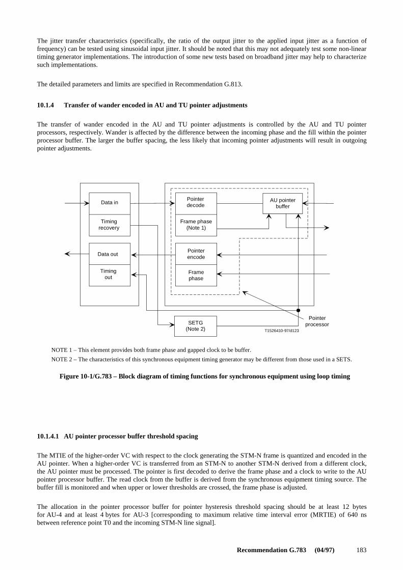
Recommendation G.783 (04/97) 183
The jitter transfer characteristics (specifically, the ratio of the output jitter to the applied input jitter as a function offrequency) can be tested using sinusoidal input jitter. It should be noted that this may not adequately test some non-lineartiming generator implementations. The introduction of some new tests based on broadband jitter may help to characterizesuch implementations.
The detailed parameters and limits are specified in Recommendation G.813.
10.1.4 Transfer of wander encoded in AU and TU pointer adjustments
The transfer of wander encoded in the AU and TU pointer adjustments is controlled by the AU and TU pointerprocessors, respectively. Wander is affected by the difference between the incoming phase and the fill within the pointerprocessor buffer. The larger the buffer spacing, the less likely that incoming pointer adjustments will result in outgoingpointer adjustments.
T1526410-97/d123
NOTE 1 – This element provides both frame phase and gapped clock to be buffer.
NOTE 2 – The characteristics of this synchronous equipment timing generator may be different from those used in a SETS.
Timingout
Data out
Timingrecovery
Data inPointerdecode
Frame phase(Note 1)
Pointerencode
Framephase
SETG(Note 2)
AU pointerbuffer
Pointerprocessor
Figure 10-1/G.783 – Block diagram of timing functions for synchronous equipment using loop timing
FIGURE 10-1/G.783...[D123] = 3 CM
10.1.4.1 AU pointer processor buffer threshold spacing
The MTIE of the higher-order VC with respect to the clock generating the STM-N frame is quantized and encoded in theAU pointer. When a higher-order VC is transferred from an STM-N to another STM-N derived from a different clock,the AU pointer must be processed. The pointer is first decoded to derive the frame phase and a clock to write to the AUpointer processor buffer. The read clock from the buffer is derived from the synchronous equipment timing source. Thebuffer fill is monitored and when upper or lower thresholds are crossed, the frame phase is adjusted.
The allocation in the pointer processor buffer for pointer hysteresis threshold spacing should be at least 12 bytesfor AU-4 and at least 4 bytes for AU-3 [corresponding to maximum relative time interval error (MRTIE) of 640 nsbetween reference point T0 and the incoming STM-N line signal].

184 Recommendation G.783 (04/97)
10.1.4.2 TU pointer processor buffer threshold spacing
The MTIE of the lower-order VC with respect to the clock generating the higher-order VC is quantized and encoded inthe TU pointer. When a lower-order VC is transferred from one higher-order VC into another higher-order VC derivedfrom a different clock, the TU pointer must be processed. The pointer is first decoded to derive the frame phase and aclock to write to the TU pointer processor buffer. The read clock from the buffer is derived from the synchronousequipment timing source. The buffer fill is monitored and when upper or lower thresholds are crossed, the frame phase isadjusted.
The allocation in the pointer processor buffer for pointer hysteresis threshold spacing should be at least 4 bytes for TU-3sand at least 2 bytes for TU-1s and TU-2s.
10.2 PDH interfaces
10.2.1 Input jitter and wander tolerance
Input jitter and wander tolerance for 2048 kbit/s hierarchy based signals are specified in Recommendation G.823. Inputjitter and wander tolerance of 1544 kbit/s hierarchy based signals are specified in Recommendations G.824, G.743,and G.752. The PDH signal may be used to synchronize the Synchronous Equipment Timing Source (SETS). In this case,additional parameters and limits are specified in Recommendation G.813.
NOTE – It may be necessary to specify transmit and receive separately for multi-vendor systems.
10.2.2 Jitter and wander transfer
As a minimum requirement, the jitter transfer specifications in any corresponding plesiochronous equipmentRecommendations must be met.
NOTE 1 – Equipment jitter and wander transfer may be difficult to specify for multi-vendor systems. Desynchronizers jitter andwander transfer may be more amenable to specification.
NOTE 2 – The above-mentioned specifications are not sufficient to assure that SDH equipment provide adequate overall jitter andwander attenuation. Specifically, attenuation of the jitter and wander arising from decoded pointer adjustments places more stringentrequirements on the SDH desynchronizer transfer characteristic.
10.2.3 Jitter and wander generation
10.2.3.1 Jitter and wander from tributary mapping
Specifications for jitter arising from mapping G.703 (PDH) tributaries into containers, described in Recommen-dation G.707, should be specified in terms of peak-to-peak amplitude over a given frequency band over a givenmeasurement interval. Detailed specifications are for further study. The limits for each G.703 (PDH) tributary interfaceand the corresponding filter characteristics for mapping jitter are given in Table 10-1.
NOTE – Tributary mapping jitter is measured in the absence of pointer adjustments. The output jitter from a 2048 kbit/s synchronizer,in the absence of input jitter and pointer activity, shall not exceed 0.35 UI peak-to-peak when measured through a digital 10 Hzlow-pass filter (representing an ideal desynchronizer) followed by a measurement filter which has a high-pass corner frequency of20 Hz and a 20 dB/decade slope.
The output wander should be specified in terms of MTIE together with its first and second derivatives with respect totime. The need for and details of this specification are for further study.
10.2.3.2 Jitter and wander from pointer adjustments
The jitter and wander arising from decoded pointer adjustments must be sufficiently attenuated to ensure that existingplesiochronous network performance is not degraded. Detailed specifications are for further study.
10.2.3.3 Combined jitter and wander from tributary mapping and pointer adjustments
The combined jitter arising from tributary mapping and pointer adjustments should be specified in terms of peak-to-peakamplitude over a given frequency band, under application of representative specified pointer adjustment test sequences,for a given measurement interval. This interval is dependent on the test sequence duration and number of repetitions. Akey feature that must be considered in the specification of the effects of pointer adjustments on G.703 (PDH) interfaces

Recommendation G.783 (04/97) 185
is the demarcation between jitter and wander. Thus, a critical feature is the high-pass filter characteristics. The limits foreach G.703 (PDH) tributary interface and the corresponding filter characteristics for combined jitter are given inTable 10-2, based on the pointer test sequences shown in Figure 10-2.
In order to prime the pointer processor and to prepare the equipment for the test sequence, it is necessary to applyinitialization and cool-down sequences. In the case of single and burst sequences, the pointer processor must not absorbthe pointer movements and stop them affecting the jitter on the demultiplexed tributary signal. In the case of periodicsequences, the pointer processor must be in the steady-state condition that it would be in if continual pointer movementshad always been present. For single and burst test sequences, the initialization period should consist of pointeradjustments applied at a rate exceeding that of the test sequence, but less than 3 pointer adjustments per second, in thesame direction as the subsequent test sequence. The initialization period should last, at least, until a response is detectedin the jitter measured on the demultiplexed tributary signal. After the initialization period, it is recommended that a30-second cool-down period is allowed when no pointer activity is present in the test signal. For periodic test sequences(both continuous and gapped), it is recommended that a minimum 60-second initialization period be used. A 30-secondcool-down period is recommended during which the periodic sequence is applied so that a steady state condition ismaintained. If necessary, the period must be extended to include an integral number of complete sequences.
Two tests for wander may be necessary: one with a single pole HPF and another with a double pole high-pass filter inorder to differentiate between the first and second derivatives of MTIE. Detailed specifications are for further study.
The values in Tables 10-1 and 10-2 are only valid if all network elements providing the path are maintained in synchro-nization. The above requirements do not apply under network synchronization loss conditions.
Table 10-1/G.783 – Mapping jitter generation specification
Filter characteristics (Note 3)Maximum peak-to-peak jitter
G.703 Mapping
(PDH)interface f1
high passf3
high passf4
low pass f1-f4 f3-f4
1 544 kbit/s 10 Hz20 dB/dec
8 kHz 40 kHz–20 dB/dec
(Note 1) 0.1 UI
2 048 kbit/s 20 Hz20 dB/dec
18 kHz(700 Hz)20 dB/dec
100 kHz–20 dB/dec
(Note 1) 0.075 UI
6 312 kbit/s 10 Hz 3 kHz 60 kHz–20 dB/dec
(Note 1) 0.1 UI
34 368 kbit/s 100 Hz20 dB/dec
10 kHz20 dB/dec
800 kHz–20 dB/dec
(Note 1) 0.075 UI
44 736 kbit/s 10 Hz 30 kHz 400 kHz–20 dB/dec
0.40 UI(A0)
0.1 UI
139 264 kbit/s 200 Hz20 dB/dec
10 kHz20 dB/dec
3500 kHz–20 dB/dec
(Note 1) (Note 2)
NOTE 1 – These values are for further study.
NOTE 2 – For further study. A value of 0.075 UI has been proposed.
NOTE 3 – The frequency value shown in parenthesis only applies to certain national interfaces.

186 Recommendation G.783 (04/97)
Table 10-2/G.783 – Combined jitter generation specification
Filter characteristics (Note 5)Maximum peak-to-peak jitter
G.703 Combined
(PDH)interface f1
high passf3
high passf4
low pass f1-f4 f3-f4
1 544 kbit/s 10 Hz20 dB/dec
8 kHz 40 kHz–20 dB/dec
1.5 UI(Note 6)
(Note 1)(Note 6)
2 048 kbit/s 20 Hz20 dB/dec
18 kHz(700 Hz)20 dB/dec
100 kHz–20 dB/dec
0.4 UI(Note 2)
0.075 UI(Note 2)
6 312 kbit/s 10 Hz 3 kHz 60 kHz–20 dB/dec
1.5 UI(Note 6)
(Note 1)(Note 6)
34 368 kbit/s 100 Hz20 dB/dec
10 kHz20 dB/dec
800 kHz–20 dB/dec
0.4 UI0.75 UI(Note 3)
0.075 UI
(Note 3)
44 736 kbit/s 10 Hz 30 kHz 400 kHz–20 dB/dec
(Note 1)(Note 7)
(Note 1)(Note 7)
139 264 kbit/s 200 Hz20 dB/dec
10 kHz20 dB/dec
3500 kHz–20 dB/dec
(Note 4)(Note 8)
(Note 4)(Note 8)
NOTE 1 – These values are for further study.
NOTE 2 – The limit corresponds to pointer sequences in Figure 10-2 a), b), c). T2 ≥ 0.75 T3 = 2 ms.NOTE 3 – The 0.4 UI and 0.075 UI limits correspond to pointer sequences in Figure 10-2 a), b), c). The 0.75 UI limit correspondsto the pointer sequence in Figure 10-2 d). T2 and T3 values are for further study. It is assumed that pointer adjustments of oppositepolarities are well spread in time, i.e. the periods between adjustments are greater than the desynchronizer time constant.
NOTE 4 – For further study. Values according to Note 3 have been proposed.
NOTE 5 – The frequency value shown in parenthesis only applies to certain national interfaces.
NOTE 6 – The limit corresponds to pointer sequences in Figure 10-2 e), f), g), and h) when a VC-11 or VC-2 mapping is used.T4 = 2 ms, 1 s < T5 < 10 s.
NOTE 7 – The limit corresponds to pointer sequences in Figure 10-2 e), f), g), and h) when an AU-3 mapping is used.T4 = 0.5 ms, 34 ms ≤ T5 < 10 s.
NOTE 8 – The pointer sequence in Figure 10-2 g) applies at AU-3 and AU-4 levels only. Jitter and wander values are for furtherstudy.

Recommendation G.783 (04/97) 187
o
o
T1526420-97/d124
Single pointersof opposite polarity
Regular pointersplus one doublepointer
Regular pointerswith one missingpointer
Double pointersof oppositepolarity
T1 ≥ 10 Seconds
Figure 10-2/G.783 – Pointer test sequences
T1
T2 T3
T2
T3
T3
T1
a)
b)
c)
d)
FIGURE 10-2/G.783...[D124] = 3 CM

188 Recommendation G.783 (04/97)
T1526430-97/d125
Initialization Cool down Measurement period
Single pointeradjustment
Burst pointeradjustment
Initialization Cool down Measurement period
Figure 10-2/G.783 – Pointer test sequences (continued)
≥ 30 s
T4 T4 T4 T4
≥ 30 s
f)
e)
FIGURE 10-2/G.783.SUITE..[D125] = 3 CM
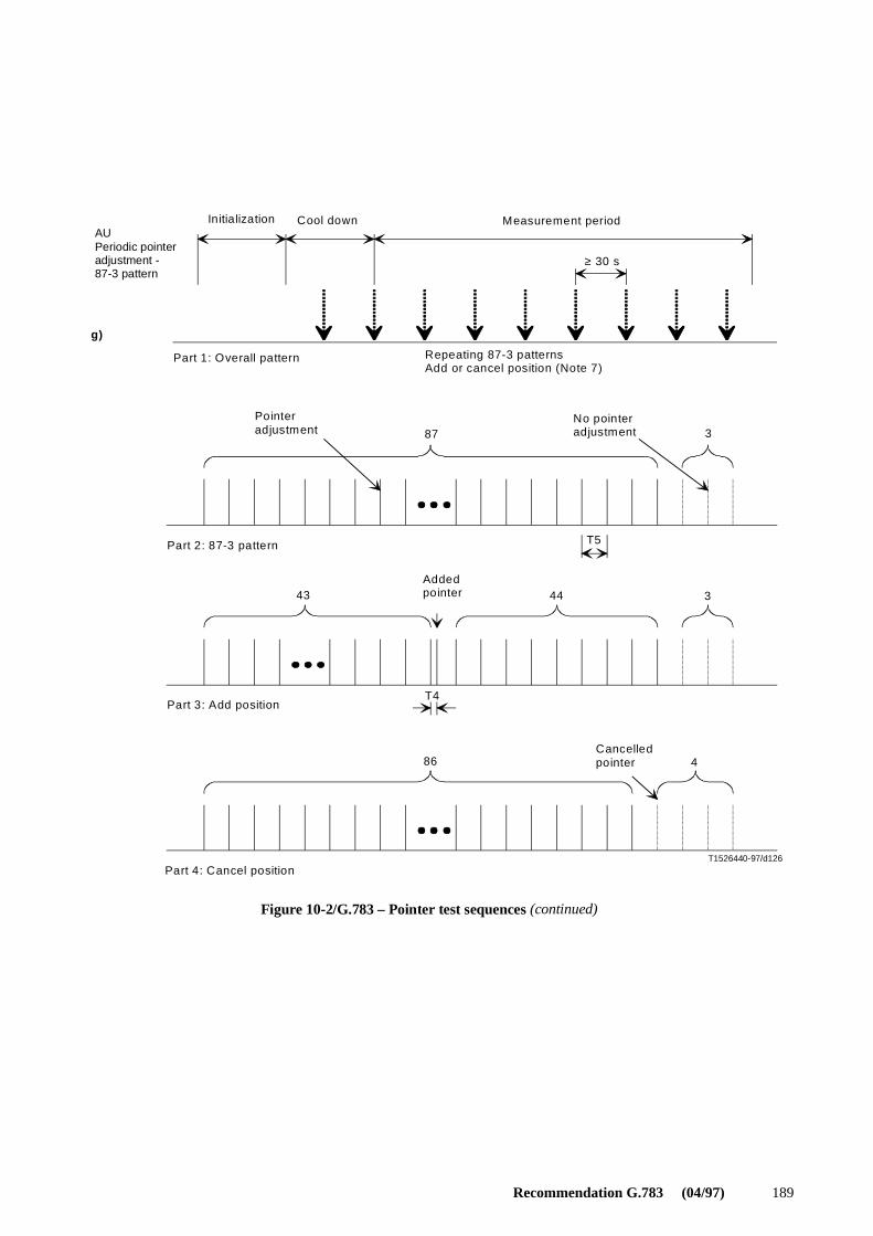
Recommendation G.783 (04/97) 189
T1526440-97/d126
Part 3: Add position
Part 4: Cancel position
Cancelledpointer
Part 1: Overall pattern
Part 2: 87-3 pattern
Repeating 87-3 patternsAdd or cancel position (Note 7)
Addedpointer
Pointeradjustment
No pointeradjustment
Initialization Cool down Measurement periodAUPeriodic pointeradjustment -87-3 pattern
Figure 10-2/G.783 – Pointer test sequences (continued)
≥ 30 s
g)
43 44
3
486
T5
87
3
T4
FIGURE 10-2/G.783..SUITE.[D126] = 3 CM

190 Recommendation G.783 (04/97)
T1526450-97/d127
Initialization Cool down Measurement period
Part 1 : Overa ll pattern
Periodic pointerad justment
Repeating continuous patternAdd or cancel position (Note 7)
Continuouspointers
Pointerad justment
Addedpointer
Cancelledpointer
Part 2 : Add/cancel position
NOTE 1 – The payload output jitter is defined as the maximum jitter over the entire measurement period.
NOTE 2 – For AU-3 level payloads, the adjustments shall be applied to the STM-N level pointers.For VC level payloads, the adjustments shall be applied to the TU level pointers.
NOTE 3 – Complete payload data integrity shall be maintained through the SDH network.
NOTE 4 – For both single and burst sequences, separate tests shall be run first with all positive pointer adjustments and then with all negative pointer adjustments.
NOTE 5 – For periodic sequences, T5 is constant for each measurement and determined by the amount of frequency offset between the VC and its carrier (higher order path for lower order VCs and STM-N for higher order VCs). T5 shallbe varied over the range given in Table 10-2, Notes 6 and 7.
NOTE 6 – All periodic tests must be done with positive frequency offsets and negative frequency offsets.
NOTE 7 – For periodic sequences, separate tests shall be run first with only added pointer adjustments and then with onlycancelled pointer adjustments.
Figure 10-2/G.783 – Pointer test sequences (concluded)
≥ 30 s
h)
T5 T 4
FIGURE 10-2/G.783.FIN..[D127] = 3 CM
11 Overhead Access Function (OHA)
In SDH equipment, it may be required to provide access in an integrated manner to transmission overhead functions. Thissubject is for further study in ITU-T. This Recommendation defines the U reference points across which information maybe exchanged with the other functional blocks.
A particular overhead access function which may be included in SDH NEs is the order-wire function which is used toprovide voice contact between SDH NEs for maintenance personnel.
The order-wire function of the OHA block shall be to accept E1 and E2 bytes from the U1 and U2 reference points andpresent them as data channels at one or more external interfaces as described in Table 11-1.

Recommendation G.783 (04/97) 191
The use of multiplexed order-wire interfaces for NEs terminating a number of order-wire channels is for further study.
Table 11-1/G.783 – Orderwire interface
Annex A
Multiplex Section Protection (MSP) protocol, commands and operation
A.1 MSP Protocol
The MSP functions, at the ends of a multiplex section, make requests for and give acknowledgments of switch action byusing the MSP bytes (K1 and K2 bytes in the MSOH of the protection section). The bit assignments for these bytes andthe bit-oriented protocol are defined as follows.
A.1.1 K1 byte
The K1 byte indicates a request of a channel for switch action.
Bits 1-4 indicate the type of request, as listed in Table A.1. A request can be:
1) a condition (SF and SD) associated with a section. A condition has high or low priority. The priority is set for eachcorresponding channel;
2) a state (wait to restore, do not revert, no request, reverse request) of the MSP function; or
3) an external request (lockout of protection, forced or manual switch, and exercise).
Bits 5-8 indicate the number of the channel for which the request is issued, as shown in Table A.2.
A.1.2 K1 byte generation rules
Local SF and SD conditions, wait to restore or do not revert state and the external request are evaluated by a prioritylogic, based on the descending order of request priorities in Table A.1. If local conditions (SF or SD) of the same levelare detected on different sections at the same time, the condition with the lowest channel number takes priority. Of theseevaluated requests, the one of the highest priority replaces the current local request, only if it is of higher priority.
Locally detected SF and SD conditions and externally initiated requests for working channels that have "lockout ofworking channel" control command (see A.2.2) applied to them are not evaluated during K1 byte generation.
Bit rate (kbit/s) Interface standard Synchronization Frame structure
64 Rec. G.703 Co-directional Bit 1 of E1/E2 bytes in STM-N framecorresponds to bit 1 in the 64 kbit/schannel

192 Recommendation G.783 (04/97)
A.1.2.1 In bidirectional operation
The priorities of the local request and the remote request on the received K1 byte are compared according to the des-cending order of priorities in Table A.1. Note that a received reverse request or a remote request for a working channelthat has a "lockout of working channel" applied to it are not considered in the comparison.Recommendation G.783 (04/97)
The sent K1 shall indicate:
a) a reverse request if the remote bridge request is for a channel that is not locked out, and
i) the remote request is of higher priority; or if
ii) the requests are of the same level (and are higher priority than a no request) and the sent K1 byte alreadyindicates reverse request; or if
iii) the requests are of the same level (and are higher priority than a no request) and the sent K1 byte does notindicate reverse request and the remote request indicates a lower channel number;
b) the local request in all other cases.
Table A.1/G.783 – Types of request
Table A.2/G.783 – K1 channel number
Bits1234 Condition, state or external request
Order(Note 1)
1111 Lockout of protection (Note 2) Highest1110 Forced switch |1101 Signal fail high priority |1100 Signal fail low priority |1011 Signal degrade high priority |1010 Signal degrade low priority |1001 Unused (Note 3) |1000 Manual switch |0111 Unused (Note 3) |0110 Wait to restore |0101 Unused (Note 3) |0100 Exercise |0011 Unused (Note 3) |0010 Reverse request |0001 Do not revert |0000 No request Lowest
NOTE 1 – An SF condition on the protection section is higher priority than any of the requests that would cause aworking channel to be selected from the protection section.
NOTE 2 – Only channel number 0 is allowed with a lockout of protection request.
NOTE 3 – Some network operators may use these codes for network specific purposes. The receiver shall becapable of ignoring these codes.
NOTE 4 – Requests are selected from the table depending on the protection switching arrangements; i.e. in anyparticular case, only a subset of the requests may be required.
Channel number Requesting switch action
0 Null channel (no working channel or extra traffic channel).Conditions and associated priority (fixed high) apply to theprotection section.
1-14 Working channel (1-14).Conditions and associated priority (high or low) apply to thecorresponding working sections.For 1 + 1 only working channel 1 is applicable, with fixed highpriority.
15 Extra traffic channel.Conditions are not applicable.Exists only when provisioned in a 1 : n architecture.

Recommendation G.783 (04/97) 193
A.1.2.2 In unidirectional operation
The sent K1 byte shall always indicate the local request. Therefore, reverse request is never indicated.
A.1.3 Revertive/non-revertive modes
In revertive mode of operation, when the protection is no longer requested, i.e. the failed working section is no longer inSD or SF condition (and assuming no other requesting channels), a local wait to restore state shall be activated. Since thisstate becomes the highest in priority, it is indicated on the sent K1 byte, and maintains the switch on that channel. Thisstate shall normally time out and become a no request null channel (or no request channel 15, if applicable). The wait torestore timer deactivates earlier if the sent K1 byte no longer indicates wait to restore, i.e. when any request of higherpriority pre-empts this state.
In non-revertive mode of operation, applicable only to 1 + 1 architecture, when the failed working section is no longer inSD or SF condition, the selection of that channel from protection is maintained by activating a do not revert state or await to restore state rather than a no request state.
Both wait to restore and do not revert requests in the sent K1 byte are normally acknowledged by a reverse request in thereceived K1 byte. However, no request is acknowledged by another no request received.
A.1.4 K2 byte
Bits 1-5 indicate the status of the bridge in the MSP switch (see Figure A.1). Bits 6 to 8 are reserved for future use toimplement drop and insert (nested) switching. Note that codes 111 and 110 will not be assigned for such use, since theyare used for MS-AIS detection and MS-RDI indication. Also note that in some regional implementations, when MS-RDIis not being generated, bits 6 to 8 are used to indicate the switching mode (i.e. unidirectional, using code 100, andbidirectional, using code 101).
Bits 1-4 indicate a channel number, as shown in Table A.3. Bit 5 indicates the type of the MSP architecture: set 1indicates 1 : n architecture and set 0 indicates 1 + 1 architecture.
T1526460-97/d128
Workingchannel 1
Protectionsection (0)
Selector
Workingsection 1
Workingsection 2Working
channel 2
Extratrafficchannel(15)
Nullchannel (0)
Bridge
Figure A.1/G.783 – MSP switch – 1 : n architecture(shown in released position)
0
1
2
15
15
0
1
2
FIGURE A.1/G.783...[D128]=3 CM
A.1.5 K2 byte generation rules
The sent K2 byte shall indicate in bits 1 to 4, for all architectures and operation modes:
a) null channel (0) if the received K1 byte indicates null channel;
b) the number of the channel which is bridged, in all other cases.

194 Recommendation G.783 (04/97)
Table A.3/G.783 – K2 channel number
The sent K2 byte shall indicate in bit 5:
a) 0 if 1 + 1 architecture;
b) 1 if 1 : n architecture.
Bit 5 of the sent and received K2 bytes may be compared; if a mismatch persists for 50 ms, a mismatch is indicated atreference point MSP_MP.
A.1.6 Control of the bridge
In 1 : n architecture, the channel number indicated on the received K1 byte controls the bridge. If, at the bridge end, theprotection section is in SF condition, the bridge is:
a) frozen (current bridge maintained), if the operation is unidirectional;
b) released, if the operation is bidirectional.
In 1 + 1 architecture, the working channel 1 is permanently bridged to protection.
A.1.7 Control of the selector
In 1 + 1 architecture in unidirectional operation, the selector is controlled by the highest priority local request. If theprotection section is in SF condition, the selector is released.
In 1 + 1 architecture in bidirectional operation, and in 1 : n architecture, the selector is controlled by comparing thechannel numbers indicated on received K2 and sent K1 bytes. If there is a match, then the indicated channel is selectedfrom the protection section. If there is a mismatch, the selector is released. Note that a match on 0000 also releases theselector. If the mismatch persists for 50 ms, a mismatch is indicated at reference point MSP_MP. If the protection sectionis in SF condition, the selector is released and the mismatch indication is disabled.
A.1.8 Transmission and acceptance of MSP bytes
Byte K1 and bits 1 to 5 of byte K2 shall be transmitted on the protection section. Although they may also be transmittedidentically on working sections, receivers should not assume so, and should have the capability to ignore this informationon the working sections.
MSP bytes shall be accepted as valid only when identical bytes are received in three consecutive frames.
Various conditions detected on the incoming K1 byte will cause an SF condition to be detected on the protection section.As noted in Table A.1, an SF condition on the protection section is higher priority than any of the requests that wouldcause a working channel to be selected from the protection section. Therefore, if the near end is signalling a request for aworking channel, it will replace that request with an SF request with a channel number of "0000", which in turn will causethe selector to be released. Conditions that will cause an NE to consider the protection section to be in an SF conditioninclude:
– In bidirectional operation, an inappropriate code that persists for 50 milliseconds in the received K1 bits 1-4.Appropriate codes are a higher priority request than the local request, an identical request to the local request, or areverse request for any local request except no request. Any other value that persists for 50 milliseconds isconsidered an inappropriate code.
– In bidirectional operation, an inappropriate or invalid channel number that persists for 50 milliseconds in thereceived K1 bits 5-8.
– An LOS, LOF, excessive errors, or MS-AIS detected on the protection multiplex section.
In addition, it should be noted that the detection of an invalid channel number in K2 bits 1-4 will be detected as amismatch of the sent K1 bits 5-8 and the received K2 bits 1-4, and will therefore cause the selector to be released.
Channel number Indication
0 Null channel.
1-14 Working channel (1-14).For 1 + 1, only working channel 1 is applicable.
15 Extra traffic channel.Exists only when provisioned in a 1 : n architecture.

Recommendation G.783 (04/97) 195
A.2 MSP commands
The MSP function receives MSP control parameters and switch requests from the synchronous equipment managementfunction at the MSP_MP reference point. A switch command issues an appropriate external request at the MSP function.Only one switch request can be issued at the MSP_MP. A control command sets or modifies MSP parameters or requeststhe MSP status.
Any external switch command not acknowledged by the far end within 2.5 seconds should be reported as failed, and thecommand and K byte request should be withdrawn.
A.2.1 Switch commands
A switch command issued at the MSP APS controller interface initiates one external bridge request for evaluation asdescribed in A.1.1. Switch commands are listed below in the descending order of priority and the functionality of each isdescribed.
1) Clear – Clears all switch commands listed below.
2) Lockout of protection – Denies all working channels (and the extra traffic channel, if applicable) access to theprotection section by issuing a "lockout of protection" request unless equal protection switch command is in effect.
3) Forced switch # – Switches working channel # to the protection section, unless an equal or higher priority switchcommand is in effect or SF condition exists on the protection section, by issuing a forced switch request for thatchannel.
NOTE 1 – For 1 + 1 systems, forced switch no working channel transfers the working channel from protection to the workingsection, unless an equal or higher priority request is in effect. Since forced switch has higher priority than SF or SD on theworking section, this command will be carried out regardless of the condition of the working section.
NOTE 2 – "Forced switch no working channel" has higher priority than "Forced switch-working channel 1" when bothcommands are detected at the same time.
4) Manual switch # – Switches working channel # to the protection section, unless a failure condition exists on othersections (including the protection section) or an equal or higher priority switch command is in effect, by issuing amanual switch request for that channel.
NOTE 3 – For 1 + 1 systems, manual switch no working channel transfers the working channel back from protection to theworking section, unless an equal or higher priority request is in effect. Since manual switch has lower priority than SF or SD ona working section, this command will be carried out only if the working section is not in SF or SD condition.
NOTE 4 – "Manual switch no working channel" has higher priority than "Manual switch-working channel 1" when bothcommands are detected at the same time.
5) Exercise # – Issues an exercise request for that channel and checks responses on MSP bytes, unless the protectionchannel is in use. The switch is not actually completed, i.e. the selector is released by an exercise request on eitherthe sent or the received and acknowledged K1 byte. The exercise functionality may not exist in all MSP functions.
Note that a functionality and a suitable command for freezing the current status of the MSP function is for further study.
A.2.2 Control commands
Control commands set and modify MSP protocol operation. The control commands that are currently defined apply onlyto 1 : n (unidirectional or bidirectional) switching.
Clear lockout working channel – Clears the lockout working channel command for the channel (or channels) specified.
Lockout working channel – Prevents the specified working channel (or channels) from switching to the protectionchannel.
These commands are not to be confused with the lockout of protection request, which prevents all working channels fromusing the protection section. The request to lock out an individual working channel or to clear the lockout of a

196 Recommendation G.783 (04/97)
working channel shall be received at reference point MSP_MP. Lockout of working can be activated or cleared for eachworking channel independently, and any number of working channels can be locked out at the same time. The locked outstatus of a working channel is not directly reflected in the K bytes.
The operation of lockout of working channel depends on the mode of operation at the MS protection sublayer at which itis applied. If the operation is bidirectional, then the lockout also operates bidirectionally. If a channel has a lockout ofworking channel command applied, then local bridge requests are not issued for the locked-out channel (i.e. localconditions and external requests for the channel are not considered in the K1 byte generation process), and remote bridgerequests for the channel are not acknowledged (i.e. remote requests for the channel are not considered in the K1 bytegeneration process and the requested bridge is not performed). Note that for bidirectional operation, the lockout ofworking channel command must be applied at both ends for proper operation.
If the operation is unidirectional, the lockout also operates unidirectionally. If a channel has a lockout of working channelcommand applied, then local bridge requests are not issued for the locked-out channel. However, remote bridge requestsfor that channel are acknowledged by performing the bridge and signalling that bridge in the K2 byte.
A.3 Switch operation
A.3.1 1 : n bidirectional switching
Table A.4 illustrates protection switching action between two multiplexer sites, denoted by A and C, of a 1 : n bidirec-tional protection switching system, shown in Figure 2-6/G.782.
When the protection section is not in use, null channel is indicated on both sent K1 and K2 bytes. Any working channelmay be bridged to the protection section at the head end. The tail end must not assume or require any specific channel. Inthe example in Table A.4, working channel (Wch) 3 is bridged at site C, and Wch 4 is bridged at site A.
When a fail condition is detected or a switch command is received at the tail end of a multiplex section, the protectionlogic compares the priority of this new condition with the request priority of the channel (if any) on the protection. Thecomparison includes the priority of any bridge order; i.e. of a request on received K1 byte. If the new request is of higherpriority, then the K1 byte is loaded with the request and the number of the channel requesting use of the protectionsection. In the example, SD is detected at C on working section 2, and this condition is sent on byte K1 as a bridge orderat A.
At the head end, when this new K1 byte has been verified (after being received identically for three successive frames)and evaluated (by the priority logic), byte K1 is set with a reverse request as a confirmation of the channel to use theprotection and order a bridge at the tail end for that channel. This initiates a bidirectional switch. Note that a reverserequest is returned for exerciser and all other requests of higher priority. This clearly identifies which end originated theswitch request. If the head end had also originated an identical request (not yet confirmed by a reverse request) for thesame channel, then both ends would continue transmitting the identical K1 byte and perform the requested switch action.
Also, at the head end, the indicated channel is bridged to protection. When the channel is bridged, byte K2 is set toindicate the number of the channel on protection.
At the tail end, when the channel number on received byte K2 matches the number of the channel requesting the switch,that channel is selected from protection. This completes the switch to protection for one direction. The tail end alsoperforms the bridge as ordered by byte K1 and indicates the bridged channel on byte K2.

Recommendation G.783 (04/97) 197
Table A.4/G.783 – 1 : n bidirectional protection switching example
Failure APS bytes
condition orcontroller state C → A A → C
Action
Byte K1 Byte K2 Byte K1 Byte K2 At C At A
No failures(protection sectionnot in use).
00000000 00001000 00000000 00001000 Wch 3 is bridged ontoprotection to provide a validsignal. Selector is released.
Wch 4 is bridged ontoprotection to provide a validsignal. Selector is released.
Working section 2degraded in directionA → C.
10100010 00001000 00000000 00001000 Failure detected. Order Wch 2bridge – SD.
10100010 00001000 00100010 00101000 Bridge Wch 2. Reverse orderWch 2 bridge.
10100010 00101000 00100010 00101000 Switch Wch 2. Bridge Wch 2.
10100010 00101000 00100010 00101000 Switch Wch 2. Bidirectionalswitch completed.
Working section 1failed in directionC → A.
10100010 00101000 11000001 00101000 Failure detected. OrderWch 1 bridge – SF. ReleaseWch 2 switch.
(This pre-empts theWch 2 switch.)
00100001 00011000 11000001 00101000 Bridge Wch 1. Reverse orderWch 1 bridge. Release Wch 2switch.
00100001 00011000 11000001 00011000 Switch Wch 1. Bridge Wch 1.
00100001 00011000 11000001 00011000 Switch Wch 1. Bidirectionalswitch completed.
Working section 1. 00100001 00011000 01100001 00011000 Wait to restore
Repaired (Workingsection 2 stilldegraded).
10100010 00011000 01100001 00011000 Order Wch 2 bridge. ReleaseWch 1 switch.
10100010 00011000 00100010 00101000 Bridge Wch 2. Reverse orderWch 2 bridge. Release Wch 1switch.
10100010 00101000 00100010 00101000 Bridge Wch 2. Switch Wch 2.
10100010 00101000 00100010 00101000 Switch Wch 2. Bidirectionalswitch completed.
Working section 2repaired.
01100010 00101000 00100010 00101000 Wait to restore Wch 2.

198 Recommendation G.783 (04/97)
Table A.4/G.783 – 1 : n bidirectional protection switching example (concluded)
The head end completes the bidirectional switch by selecting the channel from protection when it receives a matching K2byte.
If the switch is not completed because the requested/bridged channels did not match within 50 ms, the selectors wouldremain released and the failure of the protocol would be indicated. This may occur when one end is provisioned asunidirectional and the other as bidirectional. A mismatch may also occur when a locked-out channel at one end is notlocked out at the other. Note that a mismatch may also occur when a 1 + 1 architecture connects to a 1 : 1 architecture(which is not in a provisioned for 1 + 1 state), due to a mismatch of bit 5 on K2 bytes. This may be used to provisionthe 1 : 1 architecture to operate as 1 + 1.
The example further illustrates a priority switch, when an SF condition on working section 1 pre-empts the Wch 2 switch.Note that selectors are temporarily released before selecting Wch 1, due to temporary channel number mismatch on sentK1 and received K2 bytes. Further in the example, switching back Wch 2 after failed section 1 is repaired is illustrated.
When the switch is no longer required, e.g. the failed working section has recovered from failure and wait to restore hasexpired, the tail end indicates no request for null channel on byte K1 (00000000). This releases the selector due tochannel number mismatch.
The head end then releases the bridge and replies with the same indication on byte K1 and null channel indication on byteK2. The selector at the head end is also released due to mismatch.
Receiving null channel on K1 byte causes the tail end to release the bridge. Since the K2 bytes now indicate null channelwhich matches the null channel on the K1 bytes, the selectors remain released without any mismatch indicated, andrestoration is completed.
A.3.2 1 : n unidirectional switching
All actions are as described in A.3.1 except that the unidirectional switch is completed when the tail end selects fromprotection the channel for which it issued a request. This difference in operation is obtained by not considering remoterequests in the priority logic and therefore not issuing reverse requests.
A.3.3 1 + 1 unidirectional switching
For 1 + 1 unidirectional switching, the channel selection is based on the local conditions and requests. Therefore each endoperates independently of the other end, and bytes K1 and K2 are not needed to coordinate switch action. However, byteK1 is still used to inform the other end of the local action, and bit 5 of byte K2 is set to zero.
Failure APS bytes
condition orcontroller state C → A A → C
Action
Byte K1 Byte K2 Byte K1 Byte K2 At C At A
Wait to restoreexpired(no failures).
00000000 00101000 00100010 00101000 Drop Wch 2 bridge order.Release Wch 2 switch.
00000000 00101000 00000000 00001000 Drop Wch 2 bridge Drop.Drop Wch 2 bridge order.Release Wch 2 switch.
00000000 00001000 00000000 00001000 Drop Wch 2 bridge(Wch 3 is bridged).
(Wch 4 is bridged).

Recommendation G.783 (04/97) 199
A.3.4 1 + 1 bidirectional switching
The operation of 1 + 1 bidirectional switching can be optimized for a network in which 1 : n protection switching iswidely used and which is therefore based on compatibility with a 1 : n arrangement; alternatively it can be optimized for anetwork in which predominantly 1 + 1 bidirectional switching is used. This leads to two possible switching operationsdescribed below and in Annex B.
A.3.4.1 1 + 1 bidirectional switching compatible with 1 : n bidirectional switching
Bytes K1 and K2 are exchanged as described in A.3.1 to complete a switch. Since the bridge is permanent, i.e. workingchannel number 1 is always bridged, Wch 1 is indicated on byte K2, unless received K1 indicates null channel (0).Switching is completed when both ends select the channel, and may take less time because K2 indication does not dependon a bridging action.
For revertive switching, the restoration takes place as described in A.3.1. For non-revertive switching, Table A.5illustrates the operation of a 1 + 1 bidirectional protection switching system, shown in Figure 2-5/G.782.
For non-revertive operation, assuming the working channel is on protection, when the working section is repaired, or aswitch command is released, the tail end maintains the selection and indicates do not revert for Wch 1. The head end alsomaintains the selection and continues indicating reverse request. The do not revert is removed when pre-empted by afailure condition or an external request.
Table A.5/G.783 – Example of 1 + 1 bidirectional switchingcompatible with 1 : n bidirectional switching
Failure APS bytes
condition orcontroller state C → A A → C
Action
Byte K1 Byte K2 Byte K1 Byte K2 At C At A
No failures (assumeprotection section notin use).
00000000 00000000 00000000 00000000 Selector is released. Selector is released.
Working section 1failed in directionA → C.
11010001 00000000 00000000 00000000 Failure detected. OrderWch 1 bridge – SF.
11010001 00000000 00100001 00010000 Indicate Wch 1 bridged.Reverse order Wch 1 bridge.
11010001 00010000 00100001 00010000 Indicate Wch 1 bridged.Switch Wch 1.
11010001 00010000 00100001 00010000 Switch Wch 1. Bidirectionalswitch completed.
Working section 1repaired. Maintainswitch (non-revertive).
00010001 00010000 00100001 00010000 Send do not revert.
Protection sectiondegraded in directionA → C.
10110000 00010000 00100001 00010000 Failure detected. Order null chbridge – SD. Release Wch 1switch.

200 Recommendation G.783 (04/97)
Table A.5/G.783 – Example of 1 + 1 bidirectional switchingcompatible with 1 : n bidirectional switching (concluded)
Annex B
Multiplex section protection (MSP) 1 + 1 optimized protocol,commands and operation
B.1 1 + 1 bidirectional switching optimized for a network using predominantly 1 + 1 bidirectionalswitching
This algorithm uses working sections 1 and 2 in order to realize high speed 1 + 1 non-revertive protection switching. Inother words, revertive action is prevented by switching between working sections.
Bytes K1 and K2 (b1-b5) are exchanged to complete a switch. Since the bridge is permanent (see Figure B.1), the trafficis always bridged to the working section 1 and working section 2. Byte K2 indicates the number of the section whichcarries traffic when no switch is active. This will be referred to as the primary section. The other working section,referred to as the secondary section, provides protection for the primary section. Exchange of K1/K2 to control thisprotection occurs over the secondary section. The section number on byte K2 will be changed after a switch has cleared.Clearing of a switch is completed when both the receive end switches select the other working section as primary andreceive no request.
In 1 + 1 bidirectional optimized switching, both section 1 and 2 are equal to working sections. K1/K2 bytes are receivedon the secondary section. K1/K2 bytes need not always be received on the primary section, but in general, K1/K2 must besent on both sections to provide for successful clearing operations and to allow recovery of the primary channel mismatchcondition (see B.1.5).
In 1 + 1 bidirectional operation optimized for a network using predominately 1 + 1 bidirectional switching, the selector ison the primary section in the absence of a switch request. All switch requests are for a switch from the primary section tothe secondary section. Once a switch request clears normally, traffic is maintained on the section to which it was switchedby making that section the primary section.
B.1.1 Lockout
In 1 + 1 bidirectional optimized switching, lockout is considered as a local request which is not signalled across theK bytes. The effect of lockout is to freeze the selector position and transmitted K bytes until the lockout request iscleared. When a lockout request is cleared, the selector and transmitted K bytes will be set by applying any changedsection conditions and incoming K bytes to the previous state.
FailureAPS bytes
condition orcontroller state C → A A → C
Action
Byte K1 Byte K2 Byte K1 Byte K2 At C At A
Protection sectiondegraded in directionA → C.(cont.)
10110000 00010000 00100000 00000000 Reverse order null ch bridge.Drop Wch 1 bridge. ReleaseWch 1 switch.
10110000 00000000 00100000 00000000 Drop Wch 1 bridge.
Protection sectionrepaired.
00000000 00000000 00100000 00000000 Send no request.

Recommendation G.783 (04/97) 201
T1526470-97/d129
Workingchannel 1
Permanentbridge
Selector
Workingsection 1(primary)
Workingsection 2(secondary)
Figure B.1/G.783 – MSP switch – 1 + 1 bidirectional switching optimized (shown in released position with working section 1 as primary)
1
2
FIGURE B.1/G.783...[D129]=3 CM
B.1.2 Secondary section failure
The secondary section is considered failed whenever it is an SF or SD condition. As an option, the secondary section mayalso be considered failed whenever MS-RDI is being received for the secondary section.
No switch request will be issued or acknowledged when the secondary section has failed. When the secondary section hasfailed, the near end will always indicate no request on the K1 byte and the selector will choose service from the primarysection. In addition, if the secondary section fails while a switch request is active and not locked, the switch request willbe abandoned. That is, the selector will be returned to the primary section and no request will be sent on the K1 byte.
B.1.3 K1/K2 byte coding
The K1 byte indicates a request for switch action.
Bits 1-4 indicate the type of request, as listed in Table B.1. A request can be:
1) A condition (SF or SD) associated with the primary condition. Conditions are not indicated for the secondarysection.
2) A state (wait to restore, no request, reverse request) of the MSP function. Wait to restore and reverse request alwaysindicate the primary section. No request always indicates the null section.
3) An external request (forced switch) to switch from the primary to the secondary line.
Table B.1/G.783 – Types of request
Bits1234
Condition, state or external request Order
1111 Unused (Note 1) –1110 Forced switch Highest1101 Unused (Note 1) |1100 Signal fail |1011 Unused (Note 1) |1010 Signal degrade |1001 Unused (Note 1) |1000 Unused (Note 1) |0111 Unused (Note 1) |0110 Wait to restore |0101 Unused (Note 1) |0100 Unused (Note 1) |0011 Unused (Note 1) |0010 Reverse request |0001 Unused (Note 1) |0000 No request Lowest
NOTE 1 – When receiving an unused code, the equipment shall behave as though it is still receiving the mostrecently received used code.
NOTE 2 – In the case of Signal Degrade (SD) on both working sections, no protection switching should takeplace. Depending on the order in time of the individual SD, the selectors may be switched to section 1 or section2. In any case, no switching should take place.

202 Recommendation G.783 (04/97)
Bits 5-8 indicate the number of the section to be protected by the switch. This will be the null section for no request, andthe primary section for all other requests.
Table B.2/G.783 – K1 channel number
B.1.4 K2 byte coding
For 1 + 1 bidirectional switching optimized for a network using predominantly 1 + 1 bidirectional switching, the sentK2 byte shall indicate the selector position in bits 1-4:
a) Channel number 1 (0001) if section 1 is working.
b) Channel number 2 (0010) if section 2 is working.
Table B.3/G.783 – K2 channel number
B.1.5 Primary section mismatch
In the event that the near end and far end disagree about which section is primary (i.e. one end is indicating section 1 inbyte K2 and the other is indicating section 2), the side that believed section 2 was primary shall change so that section 1is primary and set its state according to local line conditions and the incoming K bytes.
B.2 Switch commands
Forced switch
Transfers service to the secondary section, unless a local lockout is in effect, an equal or higher priority request is ineffect, or the secondary section has failed. Since forced switch has higher priority than SF or SD, forced switch will beindicated as the reason for the switch to the secondary section even if the primary section is in an SF or SD condition.
Forced switch clear
If no lockout is in effect and a forced switch is active, the switch will be cleared by changing the primary line indicationto the currently active line and changing the request to no request. If no forced switch is active, the forced switch clearcommand is invalid.
B.3 Switch operation
Table B.4 illustrates the operation of a 1 + 1 bidirectional protection switching system for signal failure on the primarysection when section 1 is primary. Table B.5 illustrates the operation of a 1 + 1 bidirectional optimized protectionswitching system for a forced switch from the primary to the secondary section when section 2 is primary. Note that for aforced switch command, the wait to restore state is not necessary for clearing.
Channel number Requesting switch action
0 No working section (no request only).
1 Working section 1.Indicates a request to switch away from section number 1.
2 Working section 2.Indicates a request to switch away from section number 2.
Channel number Indication
1 Section 1 is primary.
2 Section 2 is primary.

Recommendation G.783 (04/97) 203
Table B.4/G.783 – Example of 1 + 1 bidirectional switching optimized for a network usingpredominantly 1 + 1 bidirectional switching – SF on working section 1
Table B.5/G.783 – Example of 1 + 1 bidirectional switching optimized for a network usingpredominantly 1 + 1 bidirectional switching – Forced switch from working section 2
Failure APS bytes
condition orcontroller state C → A A → C
Action
Byte K1 Byte K2 Byte K1 Byte K2 At C At A
No fault conditiontraffic on channel 1.
00000000 00010000 00000000 00010000
Signal fail onsection 1 at side C.
11000001 00010000 00000000 00010000 Detect local request.Update K1.
11000001 00010000 00100001 00010000 Detect remote request.Switch to channel 2.Issue reverse request.
11000001 00010000 00100001 00010000 Detect reverse request.Switch to channel 2.
Signal fail onsection 1 at side Ccleared andpersistence check.
01100001 00010000 00100001 00010000 Issue wait to restore request.
Wait to restoreexpires.
00000000 00100000 00100001 00010000 Send no request.Update K1, K2.
No fault condition.Traffic onsection 2.
00000000 00100000 00000000 00100000 Send no request.Update K1, K2.
Failure APS bytes
condition orcontroller state C → A A → C
Action
Byte K1 Byte K2 Byte K1 Byte K2 At C At A
No fault conditiontraffic on channel 2.
00000000 00100000 00000000 00100000
Forced switch fromSection 2 at side C.
11100010 00100000 00000000 00100000 Detect local request.Update K1.
11100010 00100000 00100010 00100000 Detect remote request.Switch to channel 2.Issue reverse request.
11100010 00100000 00100010 00100000 Detect reverse request.Switch to channel 2.
Clear forced switch atside C
00000000 00010000 00100010 00100000 Send no request.Update K1, K2.
No switch active.Traffic on section 1.
00000000 00010000 00000000 00010000 Send no request.Update K1, K2.

204 Recommendation G.783 (04/97)
Annex C
Algorithm for pointer detection
C.1 Pointer interpretation
The pointer processing algorithm can be modelled by a finite state machine. Within the pointer interpretation algorithmthree states are defined (as shown in Figure C.1):
– NORM_state;
– AIS_state;
– LOP_state.
The transitions between the states will be consecutive events (indications), e.g. three consecutive AIS indications to gofrom NORM_state to the AIS_state. The kind and number of consecutive indications activating a transition is chosensuch that the behaviour is stable and insensitive to bit errors.
The only transition on a single event is the one from the AIS_state to the NORMAL_state after receiving an NDF enabledwith a valid pointer value.
It should be noted that, since the algorithm only contains transitions based on consecutive indications, this implies thatnon-consecutively received invalid indications do not activate the transitions to the LOP_state.
The following events (indications) are defined:
– Norm_point: Normal NDF AND match of ss bits AND offset value in range.
– NDF_enable: NDF enabled AND match of ss bits AND offset value in range.
– AIS_ind: 11111111 11111111.
– Incr_ind: Normal NDF AND match of ss bits AND majority of I bits inverted AND no majority ofD bits inverted AND previous NDF_enable, incr_ind or decr_ind more than 3 times ago.
– Decr_ind: Normal NDF AND match of ss bits AND majority of D bits inverted AND no majority ofI bits inverted AND previous NDF_enable, incr_ind or decr_ind more than 3 times ago.
– Inv_point: Any other OR norm_point with offset value not equal to active offset.
NOTE 1 – Active offset is defined as the accepted current phase of the VC in the NORM_state and is undefined in the other states.
NOTE 2 – NDF enabled is equal to 1001, 0001, 1101, 1011, 1000.
NOTE 3 – Normal NDF is equal to 0110, 1110, 0010, 0100, 0111.
The transitions indicated in the state diagram are defined as follows:
– Inc_ind/dec_ind: Offset adjustment (increment or decrement indication).
– 3 × norm_point: Three consecutive equal norm_point indications.
– NDF_enable: Single NDF_enable indication.
– 3 × AIS_ind: Three consecutive AIS indications.
– N × inv_point: N consecutive inv_point (8 ≤ N ≤ 10).
– N × NDF_enable: N consecutive NDF_enable (8 ≤ N ≤ 10).
NOTE 4 – The transitions from NORM to NORM do not represent changes of state but imply offset changes.
NOTE 5 – 3 × norm_point takes precedence over N × inv_point.
NOTE 6 – In some applications interworking with North American countries may require that the ss bits in the AU-n pointer beignored.

Recommendation G.783 (04/97) 205
T1526480-97/d130
3 × AIS_ind
NDF_enable
3 × norm_point3 × norm_point
N × NDF_enable
N × inv_point
N × inv_point
3 × AIS_ind
Inc_Ind/dec_ind
norm_point
NDF_enable
3 ×
Figure C.1/G.783 – Pointer interpretation state diagram
NORM
AISLOP
FIGURE C.1/G.783...[D130]=3 CM
C.2 Concatenated payloads
In case of contiguous concatenations, the algorithm to verify the presence of a concatenation indicator instead of a normalpointer can be described conveniently in the same way as for a normal pointer. This is shown by the state diagram ofFigure C.2. Again, three states have been described:
– CONC_state;
– LOPC_state;
– AISC_state.
The following events (indications) are defined:
– Conc_ind: NDF enabled + dd 1111111111.
– AIS_ind: 11111111 11111111.
– Inv_point: Any other.
NOTE – dd bits are unspecified in Recommendation G.707 and therefore do not concern the algorithm.
The transitions indicated in the state diagram are defined as follows:
– 3 × AIS_ind: Three consecutive AIS indications.
– N × inv_point: N consecutive inv_point (8 ≤ N ≤ 10).
– 3 × conc_ind: Three consecutive conc_ind.
A defect in one or more of the AUs and TUs of a concatenated payload results in the detection of a defect in theconcatenated payload. Two types of defects can be reported:
– Loss of pointer;
– Path AIS.

206 Recommendation G.783 (04/97)
A loss of pointer defect is defined as a transition of the pointer interpreter from the NORM_state to the LOP_state or theAIS_state, or a transition from the CONC_state to the LOPC_state or AISC_state in any concatenated AU/TU. In caseboth the pointer interpreter is in the AIS_state and the concatenation indicators of all concatenated AU/TUs are in theAISC_state, an AU/TU-AIS defect will be reported.
T1526490-97/d131
3 × AIS_indN × inv_point
N × inv_point
3 × AIS_ind
3 × conc_ind 3 × conc_ind
Figure C.2/G.783 – Concatenation indicator state diagram
CONC
LOPC AISC
FIGURE C.2/G.783...[D131]=3 CM
C.3 Pointer processing flow chart
The mechanism of pointer processing is illustrated as a flow chart in Figure C.3.

Recommendation G.783 (04/97) 207
1
2
3
4
5
6
7
T1526500-97/d132
Receive AU Pointer
NDF: Enable?
Justification?
The Same 10-Bit Pointer
Value?
Send Justification?
DataNDF (T PTR [ ])SS (T PTR [ ]) SS (ES PTR [ ])*n
Payload DataNDF in AU Pointer SS Bits in AU Pointer Value TransmittedSS Bits in AU Pointer Value of an elastic store10-Bit PointerThe n-th Frame Preceding the Present One
Change PointerValue?
Transmit AU Pointer
C PTR [ ]R PTR [ ]T PTR [ ]ES PTR [ ]
I/D ( )
AU Pointer Value Inside EquipmentAU Pointer Value ReceivedAU Pointer Value TransmittedOutput AU Pointer Value of an elastic storeInvert I or D Bit of AU Pointer
T PTR (0), Data (0) = All Ones(AIS)
AU PointerInvalid Value?
(Note 1)
Elastic Store:Re-Numbering AU Pointer According toEquipment Frame
PointerInterpreter
Yes
No
Yes
Yes
Yes
Yes
No
No
No
No
PointerInterpreter
No
No
Yes
Yes
NOTE 1 – Concatenation Indication (CI) should be interpreted at this point. From the rules in Recommendation G.707, the first AU-4 of an AU-4-Xc shall be interpreted according to the flow chart; the pointers of the other AU-4s contain CI bits, and thepointer processor shall perform the same operation as performed on the first AU-4.
NOTE 2 – AU Pointer: NDF, SS, 10-bit pointer.
Figure C.3/G.783 – Pointer processing flow chart
C PTR * (0)= C PTR * (–1) + 1
C PTR (0)= R PTR (0)
C PTR (0)= C PTR (–1)
C PTR * (0)= R PTR * (0)
NDF (T PTR [0]) = 0110SS (T PTR [0]) = SS (ES PTR [0])T PTR* (0) = ES PTR* (0)
NDF (T PTR [0]) = 1001SS (T PTR [0]) = SS (ES PTR [0])T PTR* (0) = ES PTR* (0)
NDF (T PTR [0]) = 0110SS (T PTR [0]) = SS (ES PTR [0])T PTR* (0) = I/D (ES PTR)
AIS?
FIGURE C.3/G.783...[D132]=3 CM PAGE PLEINE

208 Recommendation G.783 (04/97)
Annex D
PDH physical section layers
The contents of this Annex are functional PDH specification that would not normally be part of an SDH functionalspecification. However, since the material does not exist elsewhere, it will be kept here in an annex until such PDHspecifications exist.
D.1 PDH physical section layer (Eq)
The PDH physical section layers are the 139 264, 44 736, 34 368, 6312, 2048 and 1554 kbit/s section layers.
T1526510-97/d133
Figure D.1/G.783 – Low order SDH path layer atomic functions
Eq
Eq/Pqx
Eq
P1qx_CP Pqx_CP
Eq_CP Eq_CP
Eq/Pqs
Pqs_CPPqs_CP
Eq
Eq_AP
Eq/Pqs Eq/Pqx
Eq_AP
FIGURE D.1/G.783...[D133]=3 CM
PDH physical section Eq layer characteristic information
The characteristic information Pq_CI has co-directional timing and is a digital, electrical signal of defined amplitude, bitrate, impedance and pulse shape specified by Recommendation G.703.
PDH physical section Eq layer adaptation information
The information passing across the Eq/Pqx AP is a 139 264, 44 736, 34 368, 6312, 2048 or 1554 kbit/s signal withco-directional bit timing.
The information passing across the Eq/Pqs AP is a 2048 or 1544 kbit/s signal with co-directional bit timing with a framestructure specified by Recommendation G.704.
Layer functions
Eq_C PDH physical section connection function.
Eq_TT PDH physical section termination function.
Eq/Pq_A PDH physical section adaptation functions.
Relationship to previous versions of Recommendation G.783
The 1994 version of Recommendation G.783 refers to the PPI basic functions. Table D.1 shows the relationship betweenthe basic functions and the atomic functions in the lower order path layers.

Recommendation G.783 (04/97) 209
Table D.1/G.783 – PDH physical section layer basic and atomic functions
D.1.1 Connection (N/A)
For further study.
D.1.2 Termination
The PDH physical section termination function provides the interface between the equipment and the physical mediumcarrying a signal which may have any of the physical characteristics of those described in Recommendation G.703.
The PDH physical section termination function comprises the atomic functions PDH physical section trail terminationsource [Eq_TT_So, q = (11, 12, 21, 31, 32 or 4)] and sink [Eq_TT_Sk, q = (11, 12, 21, 31, 32 or 4)] as illustrated inFigure D.2 and Tables D.2 and D.3.
T1526520-97/d134
Figure D.2/G.783 – PDH physical section termination function
Eq_APEq_AP
EqEq
Eq_CPEq_CP
Eq_TT_Sk_MP
FIGURE D.2/G.783...[D134]=3 CM
D.1.2.1 Source direction
Interfaces
Table D.2/G.783 – PDH physical section termination source input and output signals
Processes
The functions performed by the Eq_TT_So are encoding and adaptation to the physical medium as defined inRecommendation G.703. Eq_TT_So takes data at the Eq_AP to form the electrical signal at Eq_CP. The Eq_TT_Sopasses the data and timing information transparently.
Defects
None.
Basic function Atomic function
PPI Pq_TT_SoPq_TT_SkEq/Pqs_A_SoEq/Pqs_A_Sk
Input(s) Output(s)
Eq_AI_Data Eq_CI_Data

210 Recommendation G.783 (04/97)
Consequent actions
None.
Defect correlation
None.
Performance monitoring
None.
D.1.2.2 Sink direction
Interfaces
Table D.3/G.783 – PDH physical section termination sink input and output signals
Processes
The Eq_TT_Sk function recovers the electrical signals specified in Recommendation G.703.
The operation of Port mode is described in section 2.2.1.
Defects
The function shall detect for dLOS defects according to the specification in 2.2.
Consequent actions
The function shall perform the following consequent actions:
aTSF ← dLOS
Defect correlation
The function shall perform the following defect correlation to determine the most probable fault cause. This fault causeshall be reported to the SEMF.
cLOS ← dLOS and MON
Performance monitoring
None.
D.1.3 Adaptation functions Eq/Pqx_A and Eq/Pqs_A
The PDH physical section adaptation function comprises the atomic functions PDH physical section adaptation source[Eq/Pqx_A_So, q = (11, 12, 21, 31, 32 or 4) or Eq/Pqs_A_So, q = (11 or 12)] and sink [Eq/Pqx_A_Sk or Eq/Pqs_A_Sk,q = (11 or 12)] as illustrated in Figure D.3 and Tables D.4, D.5 and D.6.
Input(s) Output(s)
Eq_CI_Data Eq_AI_DataEq_AI_TSF
Eq_TT_Sk_MI_TPmode Eq_TT_Sk_MI_cLOS

Recommendation G.783 (04/97) 211
T1526530-97/d135
Figure D.3/G.783 – PDH physical section adaptation function
NOTE – In case of byte synchronous mappings, Pqx should be read as Pqs.
Pqx_CP Pqx_CP
Eq_APEq_AP
T0_TP
Eq/Pqx_A_So_MPEq/Pqx_A_Sk_MP Eq/Pqx Eq/Pqx
FIGURE D.3/G.783...[D135]=3 CM
D.1.3.1 Source direction
Interfaces
Table D.4/G.783 – PDH physical section adaptation source input and output signals
Processes
The Eq/Pqx_A_So function takes data and timing at the Pqx_CP or Pqs_CP and adds line code to form the transmitsignal at the Eq_AP.
Defects
None.
Consequent actions
None.
Defect correlation
None.
Performance monitoring
None.
D.1.3.2 Sink direction Eq/Pqx_A_Sk
Interfaces
Table D.5/G.783 – PDH physical section adaptation sink input and output signals
Input(s) Output(s)
Pqx_CI_Data Eq_AI_DataPqx_CI_ClockEq/Pqx_A_So_MI_Active
NOTE – In case of byte synchronous mappings, Pqx should be read as Pqs.
Input(s) Output(s)
Eq_AI_Data Pqx_CI_DataSm_AI_TSF Pqx_CI_ClockSm/Pqx_A_Sk_MI_Active Pqx_CI_SSF

212 Recommendation G.783 (04/97)
Processes
The Eq/Pqx_A_Sk function extracts timing from the received signal at the Eq_AP and regenerates the data. Afterdecoding, it passes the data and timing information to the Pqx_CP. The timing may also be provided at reference pointTP_T2 for possible use as a reference in the SETS.
Defects
None.
Consequent actions
The function shall perform the following consequent actions:
aAIS ← AI_SSF
aSSF ← AI_TSF
In the event of aAIS, an all-ONEs (AIS) data signal shall be applied at the Pqx_CP accompanied by a suitable referencetiming signal within 250 µs. Upon termination of aAIS, the all-ONEs signal shall be terminated within 250 µs.
NOTE – In the case of 45 Mbit/s interface, the AIS is defined in Recommendation M.20.
Defect correlation
None.
Performance monitoring
None.
D.1.3.3 Sink direction Eq/Pqs_A_Sk
Interfaces
Table D.6/G.783 – PDH physical section adaptation sink input and output signals
Processes
The Eq/Pqs_A_Sk function extracts timing from the received signal at the Eq_AP and regenerates the data. Afterdecoding, it recovers the FrameStart and MultiFrameStart and passes the data, timing and frame start information to thePqs_CP. The timing may also be provided at reference point TP_T2 for possible use as a reference in the SETS.
Defects
The function shall detect for dLOF and dAIS defects according to the specification in 2.2.
Consequent actions
The function shall perform the following consequent actions:
aAIS ← AI_TSF or dAIS or dLOF
aSSF ← AI_TSF or dAIS or dLOF
Input(s) Output(s)
Eq_AI_Data Pqs_CI_DataEq_AI_TSF Pqs_CI_Clock
Pqs_CI_FrameStartPqs_CI_MultiFrameStartPqs_CI_SSF
Eq/Pqs_A_Sk_MI_AIS_Reported Eq/Pqs_A_Sk_MI_cLOFEq/Pqs_A_Sk_MI_Active Eq/Pqs_A_Sk_MI_cAISEq/Pqs_A_Sk_MI_CRC4mode Eq/Pqs_A_Sk_MI_NCI

Recommendation G.783 (04/97) 213
In the event of aAIS, an all-ONEs (AIS) data signal shall be applied at the Pqs_CP accompanied by a suitable referencetiming signal within 250 µs. Upon termination of aAIS, the all-ONEs signal shall be terminated within 250 µs.
Defect correlation
cAIS ← dAIS and (not AI_TSF) and AIS_Reported
cLOF ← dLOF and (not dAIS) and (not AI_TSF)
Performance monitoring
None.
Appendix I
Example of F1 byte usage
Recommendation G.784 describes usage of DCCs for maintenance of the SDH network including regenerators. Tointroduce cost-effective regenerators, this Appendix shows an example of F1 byte usage to identify a failed section in achain of regenerator sections. When a regenerator detects a failure in its section, it inserts its regenerator number and thestatus of its failure into the F1 byte. Figure I.1 illustrates the procedure.
T1526540-97/d136
(Note 1) (Note 2) (Note 3) (Note 4)
Figure I.1/G.783 – Chain of regenerator sections
NOTE 1 – The terminal receives the regenerator’s alarms and reports them.
NOTE 2 – If the regenerator status is normal, it should transfer received F1 byte to the downstream without any change.
NOTE 3 – If Reg. 2 detects LOS, LOF, SD(B1) or ERR MON on the upstream side, then it sends the regenerator number and status information to the downstream side using the F1 byte. These alarms are defined as follows:
– LOF or LOS Loss of frame or loss of signal.
– SD(B1) Signal degrade calculated by B1 byte.
– ERR MON Error detection by monitoring B1 byte.
If the procedures SD(B1) and ERR MON are used, it is necessary that the RST function regarding B1 calculation be enhanced.
NOTE 4 – Normal is inserted into F1 byte by the terminal.
Term inal Term ina l
ID = 1Reg. 1
ID = 2Reg. 2
ID = 3Reg. 3
FIGURE I.1/G.783...[D136]=3 CM

214 Recommendation G.783 (04/97)
T1526550-97/d137
Status Regenerator identifier
00 Normal01 SD(B1)10 LOS or LOF11 ERR MON
Figure I.2/G.783 – Definition of F1 byte
b2 b3 b4 b5 b6 b7 b8b1
FIGURE I.2/G.783...[D137]=3 CM
Appendix II
CM configuration examples
The connection function as defined in 6.1.1 is highly flexible. To illustrate this, examples of a number of basic classes ofthe connection function are given below.
i) Connection matrix example for 1-port – The set of input and output ports is not divided into subsets, as shown inFigure II.1. This CM allows interconnectivity as given in Table II.1.
T1526560-97/d138
Figure II.1/G.783 – Connection matrix example for 1-port Sn_C
(Vi, Vj)
FIGURE II.1/G.783...[D138]=3 CM
Table II.1/G.783 – Connection matrix example for 1-port
ii) Connection matrix example for 2-port type I – The set of input and output ports is divided into two subsets, eachcontaining both input and output ports – Line (L) and Trib (T) as shown in Figure II.2. This CM allows inter-connectivity as given in Table II.2.
Vj
Vi X
X Indicates Vi-Vj connection possible for any i and j.

Recommendation G.783 (04/97) 215
T1526570-97/d139
Line
Tributary
Figure II.2/G.783 – Connection matrix example for 2-port Sn_C
(Vi, Vj)
L
T
FIGURE II.2/G.783...[D139]=3 CM
Table II.2/G.783 – Connection matrix example for 2-port type I
iii) Connection matrix example for 3-port type I – The set of input and output ports is divided into three subsets, eachcontaining both input and output ports – West (W), East (E), Drop (D) as shown in Figure II.3. This CM allowsinterconnectivity between any ports in the subsets, as given in Table II.3.
T1526580-97/d140
West East
Drop
Figure II.3/G.783 – Connection matrix example for 3-port Sn_C
(Vi, Vj)
D
W E
FIGURE II.3/G.783...[D140]=3 CM
Vi
L T
Vj L i = j X
T X i = j
X Indicates Vi-Vj connection possible for any i and j.
i = j Indicates Vi-Vj connections possible only in the case that i = j (e.g. loopback, no reconfiguration).

216 Recommendation G.783 (04/97)
Table II.3/G.783 – Connection matrix example for 3-port type I
iv) Connection matrix example for 3-port type II – The set of input and output ports is divided into three subsets, eachcontaining both input and output ports – West (W), East (E), Drop (D) as shown in Figure II.3. This CM allowsinterconnectivity between the D and W/E ports as shown in Table II.4.
Table II.4/G.783 – Connection matrix example for 3-port type II
v) Connection matrix example for 4-port type I – The set of input and output ports is divided into four subsets, eachcontaining both input and output ports – West (W), East (E), Drop East (DE), and Drop West (DW) as shown inFigure II.4. This CM allows interconnectivity between any ports in the subsets, as given in Table II.5.
T1526590-97/d141
West East
Drop west Drop east
Figure II.4/G.783 – Connection matrix example for 4-port Sn_C
(Vi, Vj)
DW
W E
DE
FIGURE II.4/G..783...[D141] = 3 CM
Vi
W E D
W i = j X X
Vj E X i = j X
D X X i = j
X Indicates Vi-Vj connection possible for any i and j.
i = j Indicates Vi-Vj connections possible only in the case that i = j (e.g. loopback, no reconfiguration).
Vi
W E D
W i = j i = j X
Vj E i = j i = j X
D X X i = j
X Indicates Vi-Vj connection possible for any i and j.
i = j Indicates Vi-Vj connections possible only in the case that i = j (e.g. loopback, no reconfiguration).

Recommendation G.783 (04/97) 217
Table II.5/G.783 – Connection matrix example for 4-port type I
vi) Connection matrix example for 4-port type II – The set of input and output ports is divided into four subsets, eachcontaining both input and output ports – West (W), East (E), Drop East (DE), and Drop West (DW) as shown inFigure II.4. This CM allows interconnectivity as given in Table II.6.
Table II.6/G.783 – Connection matrix example for 4-port type II
vii) Connection matrix example for degenerate – The Sn_C is a null function; i.e. a fixed connection pattern existsbetween input and output ports (see Figure II.5).
T1526600-97/d142
. . .
. . .
. . .
. . .
Figure II.5/G.783 – Connection matrix example for degenerate Sn_C
Sn_CP Sn_CP
FIGURE II.5/G..783...[D142] = 3 CM
Vi
W E DW DE
W i = j X X –
V j E X i = j – X
DW X – i = j –
DE – X – i = j
X Indicates Vi-V j connection possible for any i and j.
i = j Indicates Vi-V j connections possible only in the case that i = j (i.e. loopback, no reconfiguration).
– Indicates no connection possible.
V i
W E DW DE
W – i = j X –
V j E i = j – – X
DW X – – –
DE – X – –
X Indicates Vi-V j connection possible for any i and j.
i = j Indicates Vi-V j connections possible only in the case that i = j (i.e. loopback, no reconfiguration).
– Indicates no connection possible.

218 Recommendation G.783 (04/97)
Appendix III
Example of remote indication operation
In order to support single ended operation, the defect status and the number of detected error detection code violations ofthe characteristic information monitored at the trail termination sink shall be conveyed back to the far-end trailtermination source (via RDI and REI signals). Hence, in the case where the terminations lie in the domains of differentoperators, the Operations Systems (OSs) in both networks will have access to performance information from both trailends, without the need for OS-to-OS information exchange.
III.1 Remote Defect Indication (RDI)
RDI signals convey the defect status of the trail signal at the trail destination (i.e. at trail termination sink function) backto the trail origin (i.e. trail termination source function). This mechanism allows alignment of the near-end and far-endperformance monitoring processes.
Examples of RDI signals are the RDI bits in SDH signals, the A-bit in G.704 structured 2 Mbit/s signals and the alarmindication bit in other PDH multiplex signals.
Figure III.1 illustrates the RDI insertion and detection/processing for a multiplex section. Figure III.2 illustrates theprocess for a VC-4 path:
– at node A the near-end information represents the performance of the unidirectional section/path from B to A, whilethe far-end information represents the performance of the unidirectional section/path from A to B;
– at node B the near-end information represents the performance of the unidirectional section/path from A to B, whilethe far-end information represents the performance of the unidirectional section/path from B to A.
III.2 Remote Error Indication (REI)
REI signals contain either the exact or truncated4 number of error detection code violations detected in the trail signal atthe trail termination sink. This information is conveyed to the trail termination source. This mechanism allows alignmentof the near-end and far-end performance monitoring processes. Examples of REI signals are the REI bits in SDH signalsand the E-bit in G.704 structured 2 Mbit/s signals.
Figure III.3 illustrates the REI insertion and extraction/processing for a VC-4 bidirectional path:
– at node A the near-end information represents the performance of the unidirectional path from B to A, while the far-end information represents the performance of the unidirectional path from A to B;
– at node B the near-end information represents the performance of the unidirectional path from A to B, while the far-end information represents the performance of the unidirectional path from B to A.
_______________4 Refer to the specific atomic functions to determine between exact or truncated number of EDCV transport in the REI.

Recom
mendation G
.783 (04/97)219
T1526610-97/d143
Node A Node B
Part of MS_TT_So
K2 RDI-bits
Part of MS_TT_Sk
K2 RDI-bits
Part of MS_TT_So
Part of MS_TT_Sk
K2 RDI-bits
K2 RDI-bits
Figure III.1/G.783 – RDI insertion control example (multiplex section)
6 7 86 7 8
6 7 86 7 8
MS_RI_RDI
pNDS
dRDIpFDS
dAIS
dAISdRDIpFDS
pNDS
MS_RI_RDI
FIGU
RE
III.1/G.783...[D
143] = 3 CM
PAG
E PL
EIN
E A
L’IT
AL
IEN
NE

220R
ecomm
endation G.783 (04/97)
T1526620-97/d144
Node A Node B
Part of S4_TT_So
G1 RDI-bit
Part of S4_TT_Sk
G1 RDI-bit
Part of S4_TT_Sk
Part of S4_TT_So
G1 RDI-bit
G1 RDI-bit
OR
OR
Figure III.2/G.783 – RDI insertion control example (VC-4 path)
S4_RI_RDI
pNDS
dRDIpFDS
dUNEQdTIM
dUNEQdTIM
dRDIpFDS
CI_SSF
pNDS
S4_RI_RDI
CI_SSF
5 5
55
FIGU
RE
III.2/G.783...[D
144] = 3 CM
PAG
E PL
EIN
E A
L’IT
AL
IEN
NE

Recom
mendation G
.783 (04/97)221
T1526630-97/d145
Part of S4_TT_So
G1 REI-bits B3 BIP-8 bits
BIP-8calc.
Part of S4_TT_Sk
BIP-8read
BIP-8 violations
Part of S4_TT_Sk
Node A Node B
BIP-8calc.
G1 REI-bits B3 BIP-8 bits
BIP-8calc.
BIP-8read
BIP-8 violations
G1 REI-bits
G1 REI-bits
BIP-8calc.
B3 BIP-8 bits
B3 BIP-8 bits
Part of S4_TT_So
Figure III.3/G.783 – REI insertion control example (VC-4 path)
1 2 8
1 2 43
1 2 43
1 2 8
S4-RI_REI
pNEBCdDEG
pFEBC
1 2 8
1 2 43
1 2 43
1 2 8
pFEBC
pNEBCdDEG
S4_RI-REI
FIGU
RE
III.3/G.783...[D
145] = 3 CM
PAG
E PL
EIN
E A
L’IT
AL
IEN
NE

222 Recommendation G.783 (04/97)
Appendix IV
Alarm Indication Signal (AIS)
The AlS is an all-ONEs characteristic or adapted information signal. It is generated to replace the normal traffic signalwhen it contains a defect condition in order to prevent consequential downstream failures being declared and alarmsbeing raised.
All-ONEs (AIS) insertion in the sink direction is controlled as follows: every atomic function inserts all-ONEs on locally-detected defects only, with one of the defects being incoming AIS from upstream atomic functions.
Figure IV.1 illustrates this process. Due to a LOF defect (STM1dLOF) the OS1/RS1_A_Sk inserts the all-ONEs signal.This signal is propagated through the RS1 layer. The MS1_TT_Sk detects this all-ONEs signal by monitoring bits 6-8 ofK2. The MS1/S4_A_Sk detects the all-ONEs signal by monitoring the pointer bytes H1, H2. As a consequence bothfunctions insert all-ONEs at their outputs (i.e. they "refresh" the all-ONEs signal). This behaviour is continued in theother client layers.
T1526640-97/d146
Insert all-ONEs
Other adaptationfunctions Insert all-ONEs
Insert all-ONEs
Other adaptationfunctions
Figure IV.1/G.783 – All-ONEs (AIS) insertion and propagation in the sink direction in case of STM1dLOF
OS1
OS1/RS1
"1"
"1"
"1"
"1"
"1"
RS1
RS1/MS1
K2
H2H1
MS1dAIS
MS1/S4
MS1
STM1dLOF
AU4dAIS
FIGURE IV.1/G.783...[D146] = 3 CM
As soon as the direction through the layered structure reverts from the sink direction into the source direction, the all-ONEs (AIS) signal becomes one of the defined AIS patterns:
– MSn-AIS (n = 1, 4, 16) in case the RSn/MSn_A_Sk is connected to the RSn/MSn_A_So. This is the case in anSTM-n regenerator;
– AU4-AIS in case the MSn/S4_A_Sk is connected to the MSn/S4_A_So. This is the case in a VC-4 Add-DropMultiplexer and a VC-4 Digital Cross Connect (Figure IV.2);
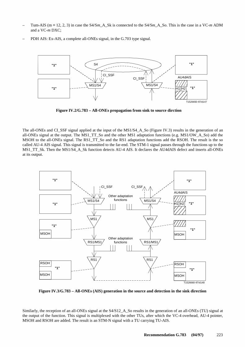
Recommendation G.783 (04/97) 223
– Tum-AIS (m = 12, 2, 3) in case the S4/Sm_A_Sk is connected to the S4/Sm_A_So. This is the case in a VC-m ADMand a VC-m DXC;
– PDH AIS: Ex-AIS, a complete all-ONEs signal, in the G.703 type signal.
T1526650-97/d147
Figure IV.2/G.783 – All-ONEs propagation from sink to source dirction
"1"
"1" "1"
"1"S4
MS1/S4MS1/S4
CI_SSFCI_SSF
AU4dAIS
H1 H2
FIGURE IV.2/G.783...[D147]=3 CM
The all-ONEs and CI_SSF signal applied at the input of the MS1/S4_A_So (Figure IV.3) results in the generation of anall-ONEs signal at the output. The MS1_TT_So and the other MS1 adaptation functions (e.g. MS1/OW_A_So) add theMSOH to the all-ONEs signal. The RS1_TT_So and the RS1 adaptation functions add the RSOH. The result is the socalled AU-4 AIS signal. This signal is transmitted to the far-end. The STM-1 signal passes through the functions up to theMS1_TT_Sk. Then the MS1/S4_A_Sk function detects AU-4 AIS. It declares the AU4dAIS defect and inserts all-ONEsat its output.
T1526660-97/d148
Other adaptationfunctions
Other adaptationfunctions
Figure IV.3/G.783 – All-ONEs (AIS) generation in the source and detection in the sink direction
"1"
"1"
"1""1"
"1"
"1"
"1" "1"
CI_SSF CI_SSF
MSOH
MSOH
MSOH
MSOH
RSOHRSOH
AU4dAIS
H1 H2MS1/S4 MS1/S4
MS1 MS1
RS1/MS1 RS1/MS1
RS1 RS1
FIGURE IV.3/G.783...[D148]=3 CM
Similarly, the reception of an all-ONEs signal at the S4/S12_A_So results in the generation of an all-ONEs (TU) signal atthe output of the function. This signal is multiplexed with the other TUs, after which the VC-4 overhead, AU-4 pointer,MSOH and RSOH are added. The result is an STM-N signal with a TU carrying TU-AIS.

224 Recommendation G.783 (04/97)
Appendix V
Signal Fail (SF) and Signal Degrade (SD)
V.1 Server Signal Fail (SSF) signal
The CI_SSF signal (generated by the adaptation sink function under control of aSSF) informs the next downstreamfunction of the "signal fail" condition of the associated data signal [which contains, due to that "signal fail" condition, theall-ONEs (AIS) pattern].
The CI_SSF signal, when connected to a connection function with protection functionality, represents the Signal Fail (SF)conditions.
V.2 Server Signal Degrade (aSSD) signal
The CI_SSD signal informs the next downstream function of the "signal degrade" condition of the associated data signal.
The CI_SSD signal is defined only in adaptation sink function in protection sublayers. The signal relays the AI_TSDsignal generated by the trail termination sink function towards the protection connection function in the protectionsublayer.
V.3 Trail Signal Fail (TSF) signal
The AI_TSF signal (generated by a trail termination sink function under control of aTSF) informs the next downstreamfunction(s) of the "signal fail" condition of the associated data signal [which contains, due to that "signal fail" condition,the all-ONEs (AIS) pattern].
The AI_TSF signal, when connected to a connection function with protection functionality, represents the SignalFail (SF) conditions.
V.4 Trail Signal Degrade (TSD) signal
The AI_TSD signal (generated by a trail termination sink function under control of aTSD) informs the next function(s) ofthe "signal degrade" condition of the associated data signal.
The AI_TSD signal is only connected to a connection function with protection functionality, and represents the SignalDegrade (SD) conditions.
Appendix VI
Data Communications Channel (DCC)
The use of the DCC is dependent on the network operator’s maintenance strategy and the specific situation. It may notalways be required as it is possible to carry out the required functions by other means.
There are two ways of using the DCC:
i) use of the D1 to D3 bytes located in the RSOH (DCCR) and accessible at regenerators and other network elements;
ii) use of the D4 to D12 bytes located in the MSOH (DCCM) and not accessible at regenerators. These bytes areprovided alternatively across either the P reference point (MCF function), or the U reference point (OHA function).The specific use of the D4 to D12 bytes is for further study.
These channels are message-based and provide communications between network elements. They can be used to supportcommunications between sites and the TMN. Two examples are given in Figures VI.1 and VI.2.

Recommendation G.783 (04/97) 225
T1526670-97/d149
RegeneratorTerminal Terminal
Q interface
Figure VI.1/G.783 – SDH linear system configuration
TMN
MCF
DCC
DCC DCC
SEMFSEMF
MCF
SS
MCF
SEMF
DCC
S
FIGURE VI.1/G.783...[D149] = 3 CM
T1526680-97/d150
Terminal Terminal Terminal
Terminal
Q interface
TMN
Figure VI.2/G.783 – SDH tree configuration
MCF
DCC
DCC
DCC
SEMF
SEMF
SEMF
MCF
MCF
SS
S
MCFDCC
SEMF
S
FIGURE VI.2/G.783...[D150] = 3 CM
Appendix VII
Atomic function modelling of basic functions from 1994 G.783
Figure VII.1 illustrates the correspondence between atomic transmission functions defined in this Recommendation andthe basic functions described in the 1994 issue of Recommendation G.783. Figure VII.2 illustrates the basic functions forsupport of the Message Communications Function (MCF) for the DCC. Figure VII.3 illustrates the basic function for useroverhead byte access. Figure VII.4 illustrates the basic functions for timing.

226 Recommendation G.783 (04/97)
T1526690-97/d151
Figure VII.1/G.783 – Atomic function modelling of basic functions for transmission
Sm/Pqx Sm/Pqs
LPA
SmP
SmP_C
Sm/SmP
LPP
SmLPT
Sn/SmHPA
SnP
SnP_C
Sn/SnP
HPP
SmD
SmD/SmLTCA
LTCT
LPC
SmC
SmDmLTCM
Sms
Smm Sms
LUG
LPOM
Sn
HPT
SnD
SnD/SnHTCA
HTCT
HPC
SnC
SnDmHTCM
Sns
Snm Sns
HUG
HPOM
TSF, TSD
TSF, TSD
Sn/User
FIGURE VII.1/G.783 (début)...[D151] = 3 CM PAGE PLEINE

Recommendation G.783 (04/97) 227
T1526700-97/d152
Figure VII.1/G.783 – Atomic function modelling of basic functions for transmission (concluded)
MSnP
MSnP_C
MSn/MSnP
MSP
MSn/SnMSA
D4-D12 E2
MSnC
MSn
MST MSn/DCC MSn/OW MSn/SD
S1
RSnC
RSn
RST RSn/DCC RSn/OW
F1D1-D3 E1
OSn
OSn/RSnSPI
RSn/MSn
OSnC
RSn/User
FIGURE VII.1/G.783 (fin)...[D152] = 3 CM
T1526710-97/d153
Figure VII.2/G.783 – Basic functions for MCF and DCC
A_MI
TT_MI
C_MI
SEMF MCF
Q-IF
F-IF
FIGURE VII.2/G.783...[D153] = 3 CM

228 Recommendation G.783 (04/97)
T1526720-97/d154
Figure VII.3/G.783 – Basic function for user overhead byte access
CHAU CHA-I
CHA-MI
FIGURE VII.3/G.783...[D154] = 3 CM
T1526730-97/d155
Externalsynchronization
Figure VII.4/G.783 – Basic functions for timing
T0_TI
T1_TI
Y SETS_MI SETPI_MI
SETS SETPI
FIGURE VII.4/G.783...[D155] = 3 CM

ITU-T RECOMMENDATIONS SERIES
Series A Organization of the work of the ITU-T
Series B Means of expression: definitions, symbols, classification
Series C General telecommunication statistics
Series D General tariff principles
Series E Overall network operation, telephone service, service operation and human factors
Series F Non-telephone telecommunication services
Series G Transmission systems and media, digital systems and networks
Series H Audiovisual and multimedia systems
Series I Integrated services digital network
Series J Transmission of television, sound programme and other multimedia signals
Series K Protection against interference
Series L Construction, installation and protection of cables and other elements of outsideplant
Series M TMN and network maintenance: international transmission systems, telephonecircuits, telegraphy, facsimile and leased circuits
Series N Maintenance: international sound programme and television transmission circuits
Series O Specifications of measuring equipment
Series P Telephone transmission quality, telephone installations, local line networks
Series Q Switching and signalling
Series R Telegraph transmission
Series S Telegraph services terminal equipment
Series T Terminals for telematic services
Series U Telegraph switching
Series V Data communication over the telephone network
Series X Data networks and open system communication
Series Z Programming languages
Related Documents