iSHELL Design Review Cryostat & Optics Bench Dan Kokubun 9/11/2013

ISHELL Design Review Cryostat & Optics Bench Dan Kokubun 9/11/2013.
Dec 24, 2015
Welcome message from author
This document is posted to help you gain knowledge. Please leave a comment to let me know what you think about it! Share it to your friends and learn new things together.
Transcript

iSHELL Design ReviewCryostat & Optics Bench
Dan Kokubun9/11/2013

Overview

Overview• Estimated Weight: 1040 lbs• CG: within 2” of optical axis
• Helium lines run eastward• Hall Effect box placement TBD

Overview
LN Can
Aladin
Cal Box
AladinController
Rotator Mechanism

Overview
X DisperserMechanism
IG Changer*upgrade
Cal Box
H2RGController H2RG
Order SortingMechanism

Cryostat - Housing• Welded Structure• Parts milled from billet• Inserts for Truss mounts
pressed in place
TensileYield
Notes
AL 5083-T0 21 kpsi No heat treat
AL 5056-T0 22 kpsi No heat treat
AL 6061-T6 40 kpsi Heat treat required post welding. Severe warping expected

Cryostat – Radiation Shield• Eight G-10 Mount tabs
(1.9W heat load)• Pre-polished panels• Access panels for wire
harness installation• Slots for truss clearance
during installation• Covers for access to truss
mount bolts

Optics BenchPhoton ShieldSpectrometer
Photon ShieldForeoptics
LN Can
Bench
Bus Bar

Optics Bench – Wire Routing
• All wires in covered channels• Motor power and heater wires
routed together• Hall effect sensors and
temperature sensors routed together
• Light tight bulkhead connectorsForeoptics
Spectrograph
IG Mech
Slit WheelDekker Mech
X Disperser Mech
OS Mech
Filter Wheel
Rotator
Filter Wheel
Rotator

Optics Bench – Connectors
Aladin
Temp Sens
Hall Effect Sens
• External access to wire harnesses• Hermetic connectors epoxied to a single plate• Radiation shield access panel

Optics Bench – Photon Shield• Welded Pan (3mm thk)• Machined Flange• Epoxied joint• Painted inside, polished outside• Qty 32 of #6 screws (4” spacing)

Thermal Design – Hybrid Overview
LN Cooled Bench
CCC First Stage Cooled Radiation Shielde
CCC Second Stage CooledAladin and H2RG

Thermal Design – LN Can• LN Can – milled from billet and welded• Cooling Bus Bar mouned with G-10 tabs• Bus Bar Feedthru epoxied to G-10 disk

Cold Stop Alignment Requirement
Requirement:To achieve an absolute flux calibration of 1%, the cold stop and telescope exit pupil need to remain co-aligned to within 1% of their diameters both while observing the object, and while performing the flux standard star observations. – Instrument Top Level Specification
Flow Down:• +/- 2.4 mm image movement at the
secondary• 1% of Secondary Diameter• Secondary Diameter is 243.84mm• Secondary vertex to Instrument
mounting face distance is 8632.84mm
• +/-0.016 deg max angular deflection (total budget)

FEA – Displacements
• Approximate Results– Three Truss: .015 deg– Four Truss: .005 deg• 4W thermal load
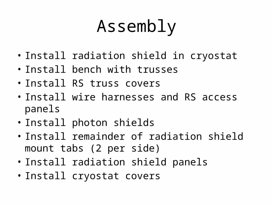
Assembly
• Install radiation shield in cryostat• Install bench with trusses• Install RS truss covers• Install wire harnesses and RS access panels• Install photon shields• Install remainder of radiation shield mount tabs (2
per side)• Install radiation shield panels• Install cryostat covers

Notes from Reviewers• WS: Use 1/32 tabs with G10 washers for the bus bar mounts• WS: Use Bellville washers under the cold strap screws• WS: Use t&g on the bus bar feed thru flanges• Weight Issue:
– SpeX is 1100 lbs– Cshell is 300 lbs– Consider weight reduction possibilities for iSHELL\
• WS: Reuse SpeX handling equipment if possible• RC: Find out if the cryostat vendor will do post weld stress relief• WS: Make sure the truss mounts are correctly positioned post welding• DW: The radiation shield has over constrained tabs.• ??: Add captive screws on the photon shields• JR: Add a key on the wiring slide (what is blue and what is red)• WS: Epoxy needs to be painted where light leaks are an issue• EW: Use separate holes in the radiation shield for the Aladdin and the other wiring• Multiple: provide more space for wire harness service loops under the connector plates. Suggest making a top hat out of the connector plate.• RC: Use #6-40 screws on the photon shield if larger screws cannot be used.• Don’t forget to include temperature sensors for engineering evaluation• Need to resolve epoxy vs. welding approach for the photon shields• JR: Need a getter on the cold finger• JR: Need to fine tune the A/L for the bus bars and flexible straps• AT: Review the FEA with Vern and Morgan• AT: Need to develop an assembly plan and handling equipment• Need to make the cryostat bigger. Allow for ½” clearance between the radiation shield and the cryostat/bench. DK: Will also consider making the photon shield
flanges wider to accommodate larger screws.• AT: have followup detailed design reviews in two parts
– 1. Discussion of assembly and optical alignment– 2. Final review at the 100% completion mark
• JR: Add the Slit viewer assembly in the applicable slides
Related Documents