Disclosure to Promote the Right To Information Whereas the Parliament of India has set out to provide a practical regime of right to information for citizens to secure access to information under the control of public authorities, in order to promote transparency and accountability in the working of every public authority, and whereas the attached publication of the Bureau of Indian Standards is of particular interest to the public, particularly disadvantaged communities and those engaged in the pursuit of education and knowledge, the attached public safety standard is made available to promote the timely dissemination of this information in an accurate manner to the public. इंटरनेट मानक “!ान $ एक न’ भारत का +नम-ण” Satyanarayan Gangaram Pitroda “Invent a New India Using Knowledge” “प0रा1 को छोड न’ 5 तरफ” Jawaharlal Nehru “Step Out From the Old to the New” “जान1 का अ+धकार, जी1 का अ+धकार” Mazdoor Kisan Shakti Sangathan “The Right to Information, The Right to Live” “!ान एक ऐसा खजाना > जो कभी च0राया नहB जा सकता ह ै” Bhartṛhari—Nītiśatakam “Knowledge is such a treasure which cannot be stolen” IS 15905 (2011): Hubless Centrifugally Cast (Spun) Iron Pipes, Fittings and Accessories - Spigot Series [MTD 6: Pig iron and Cast Iron]

Welcome message from author
This document is posted to help you gain knowledge. Please leave a comment to let me know what you think about it! Share it to your friends and learn new things together.
Transcript

Disclosure to Promote the Right To Information
Whereas the Parliament of India has set out to provide a practical regime of right to information for citizens to secure access to information under the control of public authorities, in order to promote transparency and accountability in the working of every public authority, and whereas the attached publication of the Bureau of Indian Standards is of particular interest to the public, particularly disadvantaged communities and those engaged in the pursuit of education and knowledge, the attached public safety standard is made available to promote the timely dissemination of this information in an accurate manner to the public.
इंटरनेट मानक
“!ान $ एक न' भारत का +नम-ण”Satyanarayan Gangaram Pitroda
“Invent a New India Using Knowledge”
“प0रा1 को छोड न' 5 तरफ”Jawaharlal Nehru
“Step Out From the Old to the New”
“जान1 का अ+धकार, जी1 का अ+धकार”Mazdoor Kisan Shakti Sangathan
“The Right to Information, The Right to Live”
“!ान एक ऐसा खजाना > जो कभी च0राया नहB जा सकता है”Bhartṛhari—Nītiśatakam
“Knowledge is such a treasure which cannot be stolen”
“Invent a New India Using Knowledge”
है”ह”ह
IS 15905 (2011): Hubless Centrifugally Cast (Spun) IronPipes, Fittings and Accessories - Spigot Series [MTD 6: Pigiron and Cast Iron]


© BIS 2011
B U R E A U O F I N D I A N S T A N D A R D SMANAK BHAVAN, 9 BAHADUR SHAH ZAFAR MARG
NEW DELHI 110002
March 2011 Price Group 8
IS 15905 : 2011
— —
Indian Standard
HUBLESS CENTRIFUGALLY CAST (SPUN) IRONPIPES, FITTINGS AND ACCESSORIES — SPIGOT
SERIES — SPECIFICATION
ICS 77.140.75; 91.140.80

Pig Iron and Cast Iron Sectional Committee, MTD 6
FOREWORD
This Indian Standard was adopted by the Bureau of Indian Standards, after the draft finalized by the Pig Iron andCast Iron Sectional Committee had been approved by the Metallurgical Engineering Division Council.
While formulating this standard in the light of the experience gained during these years, the Committee decidedto propose this standard to align with the present practices followed by the Indian construction industries and tobring it in line with the International and other overseas standard.
Hubless centrifugally cast (spun) iron pipe, fittings and accessories are widely used in drainage piping system.This standard has been formulated with a view to provide guidelines in the manufacture and use of hubless castiron pipe fittings and accessories for soil, waste, ventilation and rainwater building drainage system.
In the formulation of this standard due consideration has been given to the manufacturing and trade practicesfollowed in the country in this field and assistance has been derived from the following International Standards.
ISO 6594 : 2006 Cast iron drainage pipes and fittings — Spigot series
ISO 185 : 1988 Grey cast irons — Classifications
As per the current international practices, the requirements specified in this standard have been aligned withISO 6594. Besides these, as per the national practice, following new fittings other than those specified in ISO 6594have been incorporated in this standard:
88° Long radius bend See Table 6
88° Long tail bend See Table 7
Horn plain bend See Table 8
Double bend See Table 9
88° Double branch See Table 12
45° Double branch See Table 13
Offset See Table 15
Equal and unequal parallel branch See Table 16
P Trap See Table 17
H Ventilation pipe See Table 18
Y Ventilation Pipe See Table 19
88° T Y single branch See Table 20
Vent cowl See Table 21
For the purpose of deciding whether a particular requirement of this standard is complied with, the final value,observed or calculated, expressing the result of a test or analysis, shall be rounded off in accordance with IS 2 : 1960‘Rules for rounding off numerical values (revised)’. The number of significant places retained in the rounded offvalue should be the same as that of the specified value in this standard.
1
IS 15905 : 2011
Indian Standard
HUBLESS CENTRIFUGALLY CAST (SPUN) IRONPIPES, FITTINGS AND ACCESSORIES — SPIGOT
SERIES — SPECIFICATION
1 SCOPE
1.1 This standard covers the requirement for hublesscentrifugally cast (spun) iron soil, waste, ventilationand rain water pipes together with the details of thefittings and accessories including joints (coupling). Thepipe and fittings are intended for non-pressureapplication, normally as gravity drainage systems.
1.2 The fittings and accessories covered in this standardare normally manufactured by sand casting method.
1.3 Cast iron pipes, fittings and accessoriesmanufactured to this standard are of hubless (spigottype), without sockets.
1.4 The range of nominal sizes DN, of pipes and fittingsfollowed in this standard is as follows:
50, 75, 100, 150 and 200 mm.
1.5 The corresponding joints (couplings) are normallyfabricated or casted.
2 REFERENCES
The following standards contain provisions, whichthrough references in this text constitute provisions ofthis standard. At the time of publication, the editionsindicated were valid. All standards are subject torevision and parties to agreements based on thisstandard are encouraged to investigate the possibilityof applying the most recent editions of the standardsindicated below:
IS No. Title
210 : 1993 Grey iron castings — Specification(fourth revision)
1387 : 1993 General requirements for the supplyof metallurgical materials (secondrevision)
1500 : 2005/ Method for Brinell hardness test forISO 6506 : 1999 metallic materials(third revision)
1570 (Part 5) : Schedules for wrought steels:1985 Part 5 Stainless and heat resisting
steels (second revision)1865 : 1991 Iron castings with spheroidal or
nodular graphite (third revision)5382 : 1985 Specification for rubber ceiling rings
for gas mains, water mains andsewers (first revision)
5519 : 1979 Deviations for untoleranceddimensions and mass of grey ironcastings (first revision)
3 SUPPLY OF MATERIAL
General requirements relating to supply of materialshall be as laid down in IS 1387.
4 TERMINOLOGY
For the purpose of this standard, the followingdefinitions shall apply.
4.1 Drainage System for Buildings — System ofpipes, fittings, accessories and joints used to collectand discharge soil, waste water and rainwater from abuilding; it comprises discharge pipes, stack ventilationand rain water pipes, installed in order to connect thedischarge system of building to a sewer or a septictank.
4.2 Sewer — System of pipes designed to collect soil,waste water and rain water from buildings and toconvey them to the point of disposal or treatment.
4.3 Cast Iron — Alloy of iron and carbon in whichgraphite can be present in different forms.
4.4 Pipe — Casting of uniform bore, straight in axisnormally having plain ends.
4.5 Fitting — Cast iron casting, other than a pipe,which allows a deviation, a change of direction ordiameter, including flanged and access components.
4.6 Accessory — Any casting other than pipe or fittingused in a pipeline.
4.7 Joint — Connection between the ends of pipesand/or fittings, including the coupling or clampingcomponent, with sealing effected by EPDM rubbergasket(s).
4.8 Gasket — The EPDM rubber portion of thecoupling.
4.9 Clamp — That portion of the coupling excludingthe gasket and shield.
4.10 Shield — An external metallic protective devicedesigned to protect the sealing gasket.
4.11 Coupling — The complete assembly.
4.12 Nominal Size (DN) — An alphanumericdesignation of size for pipe, fitting and accessories,which is used for reference purposes. It comprises the

2
IS 15905 : 2011
letters DN followed by a dimensionless whole numberwhich is indirectly related to the physical size, inmillimetres, of the bore of the end connections.
4.13 Length — Effective length of a pipe or fitting.
NOTE — For hubless pipes and fittings, the effective length isequal to the overall length.
5 MANUFACTURE
5.1 Cast iron used for the manufacture of pipes, fittingsand accessories shall conform to FG 150 grade, asappropriate, specified in IS 210. Specific mass of castiron shall be taken as 7.15 kg/dm3 for the purpose ofcalculation.
5.2 The pipes, fittings and accessories shall be strippedwith all precautions necessary to avoid warping orshrinking defects. The pipes, fittings and accessoriesshall be sound, free from defects, other than anyunavoidable surface imperfections which result fromthe method of manufacture and which do not affectthe use of the casting shall not be rejected. Byagreement between the purchaser and the manufacturerminor defects may be rectified.
5.3 The pipes and fittings shall be capable of being cutwith the tools normally used for installation or assuggested in manufacturers catalogue. The hardnessof the external unmachined surface of the pipe andfittings should not exceed 230 HBS, when tested asper IS 1500.
5.4 In case the hardness is more than 230 HBW,fracture test shall be carried out and if fracture is grey(without showing any chilling effect) such pipes andfittings shall be accepted.
6 JOINTS
6.1 The pipes and fittings may be assembled usingvarious types of joints. The joints are intrinsiccomponents of the drainage systems, whosecharacteristics and tolerances shall be specified in themanufacturers catalogues.
6.2 Taking into account the different applications ofcast iron pipework systems, various joint designs arepermitted provided that they satisfy the requirementof this standard. The joints shall incorporate one ormore EPDM rubber gasket(s) to ensure leak tightnessand prevent direct contact between the ends of pipes,fittings and accessories.
6.3 In order to achieve satisfactory assembly, each endshall present a free length corresponding at least to thevalues of Table 1.
6.4 Materials for coupling or clamping componentsshall usually be made from:
a) Ductile iron of grade 500/7 as per IS 1865,or
b) Stainless steels in accordance with IS 1570(Part 5) in order to ensure resistance tocorrosion and a stabilization against theeffect of intergranular corrosion, only theaustentic stainless steel with at least 17percent chrome and 9 percent nickel orequivalent, or from material of comparableresistance. Some drawings alongwithdimensions of coupling are suggested inAnnex A for guidance only.
c) Ductile iron couplings or clampingcomponents shall be coated as given in 12.
d) All parts of the joints shall be free from defectslikely to compromise their suitability for use.
7 VISUAL INSPECTION AND HAMMER TEST
7.1 Each pipe, fitting, and accessories shall be visuallyinspected internally and externally using an appropriatelight source (for example against light) and tested forsoundness by striking with a light hand hammer whichshall emit a clear ringing sound.
8 CRUSH TESTS ON PIPE RINGS
Perform crush tests on three rings at lest 60 mm long,with parallel ends, and cut square to the axis fromuncoated pipes.
8.1 Crush the rings between parallel platens (withoutV-support) of a length greater than that of the ring.
8.2 Calculation
Crushing strength sp-=
where
F = load applied in N;
d = mean outside diameter or ring before testing,in mm;
c = mean thickness measured at the rupturelevel, in mm; and
b = mean length in mm.
The measured strength shall be at least 300 N/mm2 foran average of three sets.
9 HYDROSTATIC TEST
9.1 Each pipe and fitting shall be tested hydrostaticallyat a pressure of 0.07 MPa (N/mm2). This shall not showany sign of leakage, sweating or other defects of anykind.
9.2 The pressure shall be applied internally and shallbe steadily maintained for a period of 15 s.

3
IS 15905 : 2011
Table 1 Minimum Free Length(Clause 6.3)
9.3 Test shall be carried out after the application ofsurface coating on pipes, fittings and accessories.
10 TECHNICAL SPECIFICATION
10.1 External Diameters and Tolerances
The external diameters of pipes and fittings and thetolerance applicable are given in Table 2.
Table 2 External Diameters and Tolerances
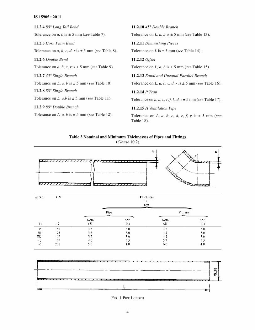
10.2 Thickness and Tolerances
Table 3 gives the minimum and nominal thickness ofpipes and fittings. Maximum thickness are notspecified.
10.3 Length and Tolerances
The normal manufacturing lengths of the pipes andfittings, and their tolerances, are given in 11.
10.4 Tolerance on the angles of the fittings are fixed at± 2° through out.
10.5 Masses and Tolerances
The negative tolerance with respect to the mass, ifindicated in the manufacturer’s Catalogue, shall be15 percent for pipes and fittings. No limit for positivetolerance is specified.
11 DIMENSIONS
11.1 Pipe
Tolerance on length of 3 000 mm ± 20 mm, for alldiameters (see Fig. 1).
11.2 Fittings
11.2.1 45° Bend
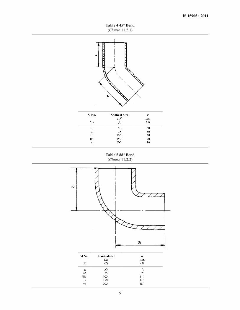
Tolerance on a is ± 5 mm (see Table 4).
11.2.2 88° Bend
Tolerance on a is ± 5 mm (see Table 5).
11.2.3 88° Long Radius Bend
Tolerance on a, r : is ± 5 mm (see Table 6).
4
IS 15905 : 2011
Table 3 Nominal and Minimum Thicknesses of Pipes and Fittings(Clause 10.2)
11.2.4 88° Long Tail Bend
Tolerance on a, b is ± 5 mm (see Table 7).
11.2.5 Horn Plain Bend
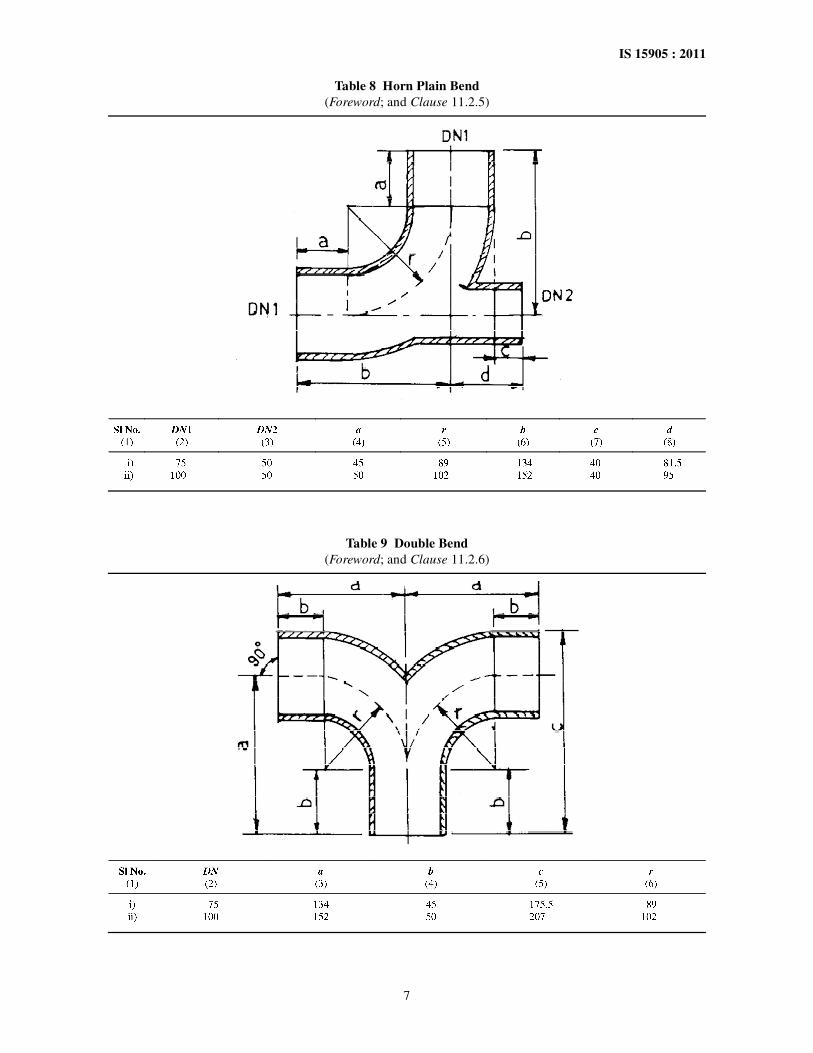
Tolerance on a, b, c, d, r is ± 5 mm (see Table 8).
11.2.6 Double Bend
Tolerance on a, b, c, r is ± 5 mm (see Table 9).
11.2.7 45° Single Branch
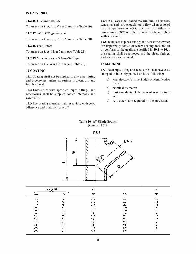
Tolerance on L, a, b is ± 5 mm (see Table 10).
11.2.8 88° Single Branch
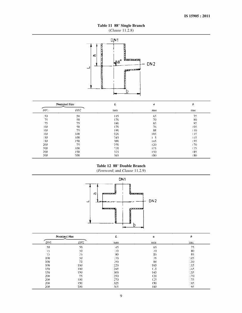
Tolerance on L, a,b is ± 5 mm (see Table 11).
11.2.9 88° Double Branch
Tolerance on L, a, b is ± 5 mm (see Table 12).
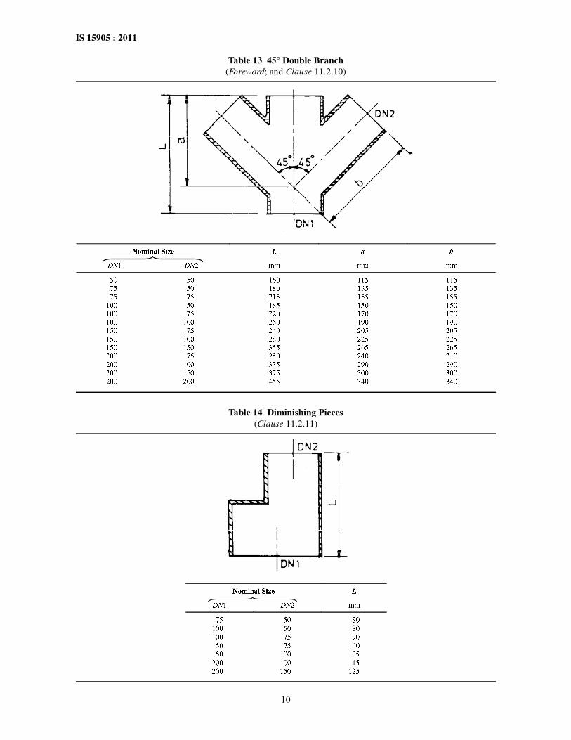
11.2.10 45° Double Branch
Tolerance on L, a, b is ± 5 mm (see Table 13).
11.2.11 Diminishing Pieces
Tolerance on L is ± 5 mm (see Table 14).
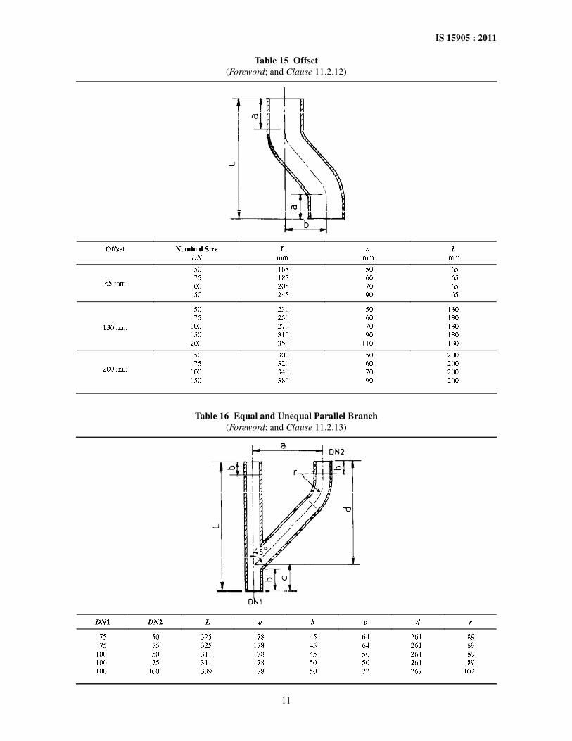
11.2.12 Offset
Tolerance on L, a, b is ± 5 mm (see Table 15).
11.2.13 Equal and Unequal Parallel Branch
Tolerance on L, a, b, c, d, r is ± 5 mm (see Table 16).
11.2.14 P Trap
Tolerance on a, b, c, r, j, k, d is ± 5 mm (see Table 17).
11.2.15 H Ventilation Pipe
Tolerance on L, a, b, c, d, e, f, g is ± 5 mm (seeTable 18).
FIG. 1 PIPE LENGTH
5
IS 15905 : 2011
Table 4 45° Bend(Clause 11.2.1)
Table 5 88° Bend
(Clause 11.2.2)

6
IS 15905 : 2011
Table 6 88° Long Radius Bend(Foreword; and Clause 11.2.3)
Table 7 88° Long Tail Bend
(Foreword; and Clause 11.2.4)
7
IS 15905 : 2011
Table 8 Horn Plain Bend(Foreword; and Clause 11.2.5)
Table 9 Double Bend(Foreword; and Clause 11.2.6)
8
IS 15905 : 2011
11.2.16 Y Ventilation Pipe
Tolerance on L, a, b, c, d is ± 5 mm (see Table 19).
11.2.17 88° T Y Single Branch
Tolerance on L, a, b, c, d is ± 5 mm (see Table 20).
11.2.18 Vent Cowel
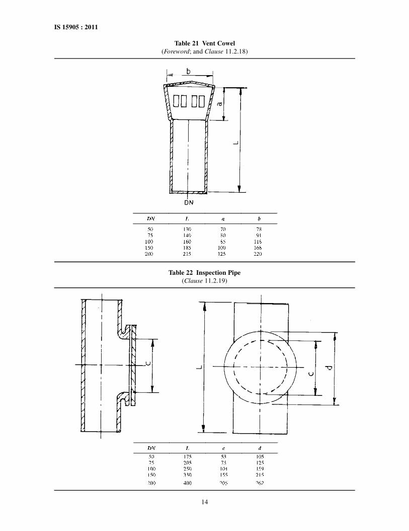
Tolerance on L, a, b is ± 5 mm (see Table 21).
11.2.19 Inspection Pipe (Clean-Out Pipe)
Tolerance on L, c, d is ± 5 mm (see Table 22).
12 COATING
12.1 Coating shall not be applied to any pipe, fittingand accessories, unless its surface is clean, dry andfree from rust.
12.2 Unless otherwise specified, pipes, fittings, andaccessories, shall be supplied coated internally andexternally.
12.3 The coating material shall set rapidly with goodadherence and shall not scale off.
12.4 In all cases the coating material shall be smooth,tenacious and hard enough not to flow when exposedto a temperature of 65°C but not so brittle at atemperature of 0°C as to chip off when scribbled lightlywith a penknife.
12.5 In the case of pipes, fittings and accessories, whichare imperfectly coated or where coating does not setor conform to the qualities specified in 10.1 to 10.4,the coating shall be removed and the pipes, fittings,and accessories recoated.
13 MARKING
13.1 Each pipe, fitting and accessories shall have cast,stamped or indelibly painted on it the following:
a) Manufacturer’s name, initials or identificationmark;
b) Nominal diameter;
c) Last two digits of the year of manufacture;and
d) Any other mark required by the purchaser.
Table 10 45° Single Branch(Clause 11.2.7)
9
IS 15905 : 2011
Table 11 88° Single Branch(Clause 11.2.8)
Table 12 88° Double Branch(Foreword; and Clause 11.2.9)
10
IS 15905 : 2011
Table 13 45° Double Branch(Foreword; and Clause 11.2.10)
Table 14 Diminishing Pieces
(Clause 11.2.11)
11
IS 15905 : 2011
Table 15 Offset(Foreword; and Clause 11.2.12)
Table 16 Equal and Unequal Parallel Branch(Foreword; and Clause 11.2.13)

12
IS 15905 : 2011
Table 17 P Trap(Foreword; and Clause 11.2.14)
Table 18 H Ventilation Pipe(Foreword;13
and Clause 11.2.15)

13
IS 15905 : 2011
Table 19 Y Ventilation Pipe(Foreword; and Clause 11.2.16)
Table 20 88° T Y Single Branch(Foreword; and Clause 11.2.17)
14
IS 15905 : 2011
Table 21 Vent Cowel(Foreword; and Clause 11.2.18)
Table 22 Inspection Pipe
(Clause 11.2.19)
15
IS 15905 : 2011
13.2 BIS Certification Marking
The pipes, fittings, and accessories may be marked withthe Standard Mark.
13.2.1 The use of the Standard Mark is governed bythe provisions of the Bureau of Indian Standards Act,
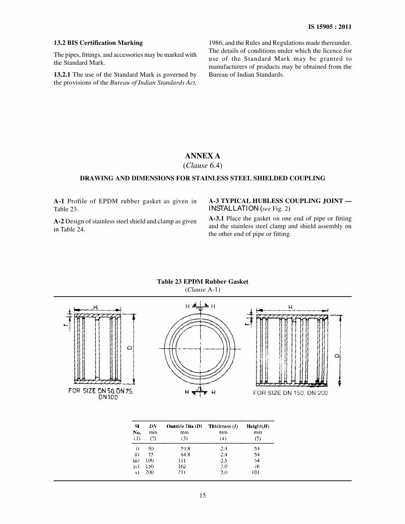
ANNEX A(Clause 6.4)
DRAWING AND DIMENSIONS FOR STAINLESS STEEL SHIELDED COUPLING
A-1 Profile of EPDM rubber gasket as given inTable 23.
A-2 Design of stainless steel shield and clamp as givenin Table 24.
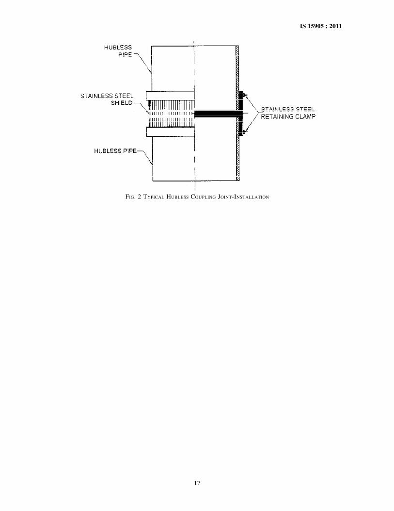
A-3 TYPICAL HUBLESS COUPLING JOINT —INSTALLATION (see Fig. 2)
A-3.1 Place the gasket on one end of pipe or fittingand the stainless steel clamp and shield assembly onthe other end of pipe or fitting.
Table 23 EPDM Rubber Gasket(Clause A-1)
1986, and the Rules and Regulations made thereunder.The details of conditions under which the licence foruse of the Standard Mark may be granted tomanufacturers of products may be obtained from theBureau of Indian Standards.

16
IS 15905 : 2011
Table 24 Stainless Steel Shield(Clause A-2)
A-3.2 Firmly seat the pipe or fitting ends against theintegrally moulded center stop inside the EPDM rubbergasket.
A-3.3 Slide the stainless steel shield and clampassembly over the EPDM rubber gasket and tightenthe bands. For larger diameters couplings which have
four bands, the inner bands should be tightened firstand then the outer bands.
A-3.4 In all the cases, when tightening bands theyshould be tightened alternately to insure that thecoupling shield is drawn up uniformly.
NOTE — Other types of joints can also be used at the discretion ofthe customer. The details given in this Annex is for guidance only.
17
IS 15905 : 2011
FIG. 2 TYPICAL HUBLESS COUPLING JOINT-INSTALLATION
Bureau of Indian Standards
BIS is a statutory institution established under the Bureau of Indian Standards Act, 1986 to promoteharmonious development of the activities of standardization, marking and quality certification of goodsand attending to connected matters in the country.
Copyright
BIS has the copyright of all its publications. No part of these publications may be reproduced in any formwithout the prior permission in writing of BIS. This does not preclude the free use, in the course ofimplementing the standard, of necessary details, such as symbols and sizes, type or grade designations.Enquiries relating to copyright be addressed to the Director (Publications), BIS.
Review of Indian Standards
Amendments are issued to standards as the need arises on the basis of comments. Standards are also reviewedperiodically; a standard along with amendments is reaffirmed when such review indicates that no changes areneeded; if the review indicates that changes are needed, it is taken up for revision. Users of Indian Standardsshould ascertain that they are in possession of the latest amendments or edition by referring to the latest issue of‘BIS Catalogue’ and ‘Standards : Monthly Additions’.
This Indian Standard has been developed from Doc No.: MTD 6 (4800).
Amendments Issued Since Publication
Amend No. Date of Issue Text Affected
BUREAU OF INDIAN STANDARDSHeadquarters:
Manak Bhavan, 9 Bahadur Shah Zafar Marg, New Delhi 110002Telephones : 2323 0131, 2323 3375, 2323 9402 Website: www.bis.org.in
Regional Offices: Telephones
Central : Manak Bhavan, 9 Bahadur Shah Zafar Marg 2323 7617NEW DELHI 110002 2323 3841
Eastern : 1/14 C.I.T. Scheme VII M, V. I. P. Road, Kankurgachi 2337 8499, 2337 8561KOLKATA 700054 2337 8626, 2337 9120
Northern : SCO 335-336, Sector 34-A, CHANDIGARH 160022 60 384360 9285
Southern : C.I.T. Campus, IV Cross Road, CHENNAI 600113 2254 1216, 2254 14422254 2519, 2254 2315
Western : Manakalaya, E9 MIDC, Marol, Andheri (East) 2832 9295, 2832 7858MUMBAI 400093 2832 7891, 2832 7892
Branches: AHMEDABAD. BANGALORE. BHOPAL. BHUBANESHWAR. COIMBATORE. DEHRADUN.FARIDABAD. GHAZIABAD. GUWAHATI. HYDERABAD. JAIPUR. KANPUR. LUCKNOW.NAGPUR. PARWANOO. PATNA. PUNE. RAJKOT. THIRUVANANTHAPURAM.VISAKHAPATNAM.
{
{{
{{
Published by BIS, New Delhi.
Related Documents