Iron pyrite thin films synthesized by spray pyrolysis technique Saad Farhan Oboudi 1 , Khudheir A.Mishjil 2 , Nadir Fadhil Habubi 2 *, Sami Salmann Chiad 2 1 Baghdad University, College of Science, Physics Department, Baghdad, (IRAQ) 2 Al_Mustansiriyah University, College of Education, Physics Department, Baghdad, (IRAQ) E-mail: [email protected] Full Paper Iron pyrite FeS 2 ; Optical constants; Spray pyrolysis technique. KEYWORDS ABSTRACT In this investigation, FeS 2 thin films were synthesized by spray pyrolysis technique on glass substrates. The films were annealed at 400 ”C and 450”C in air for a period of 1 hour. The optical characterizations of the as deposited and annealed films were carried out using UV VIS transmittance spectroscopy in the wavelength range 400900 nm. The results show that in the visible region the transmittance of the films decreases as the annealing temperature increases to 450”C. The reverse is the case with the reflectance as it was observed to be increased in the same region. The result also shows that the absorption coefficient, extinction coefficient, real and imaginary parts of dielectric constant are tending to increase with the increasing of annealing temperature. Further analysis shows that the films have high optical conductivity about 4.06-6.20 x 10 14 S -1 . The refractive index was found to be 4.38-5.14. The foregoing desirable properties make the FeS 2 to be a promising material for the fabrication of solar cells and optoelectronic devices. 2014 Trade Science Inc. - INDIA INTRODUCTION Iron pyrite FeS 2 has been widely investigated due to its potential photovoltaic and photoeletrochemical applications as a result of its proper band gap (E g 0.95eV) and large absorption coefficient (Æ >10 5 cm 1 for º < 103nm) [1,2] . In addition, iron pyrite which con- sists of nontoxic and widely available elements, is a suit- able semiconductor material for the environment. There- fore, it is attracting more attention because of its prom- ising potentials for applications as optoelectronic and photovoltaic material [3-9] . Formation of a particular phase depends on the nature of the starting material, its composition, deposi- tion method, and annealing temperatures. Many tech- niques were used to produce pyrite films such as sulfurization of electrodeposited [10,11] , metalorganic chemical vapour deposition [12] , ion beam magnetron sputtering [13] , spray pyrolysis [14] , electrodeposi- tion [15,16] , MOCVD [17] , solvothermal synthesis method [18] , magnetron sputtering [19] and Plasma-assisted sulfurization [20] . Each one of these methods has its own benefits which can be used to obtain films with specific characterizations. Many researches have been devoted to study the fabrication and characterization of FeS 2 thin films. In a review of literatures, it can be seen that the effect of annealing parameters on the film characteristics should be studied more sufficiently. In this study, the optical characteristics of FeS 2 films deposited by spray py- Materials Science MSAIJ, 11(5), 2014 [195-200] An Indian Journal Volume 11 Issue 5 Materials Science ISSN : 0974 - 7486

Welcome message from author
This document is posted to help you gain knowledge. Please leave a comment to let me know what you think about it! Share it to your friends and learn new things together.
Transcript
Iron pyrite thin films synthesized by spray pyrolysis technique
Saad Farhan Oboudi1, Khudheir A.Mishjil2, Nadir Fadhil Habubi2*, Sami Salmann Chiad2
1Baghdad University, College of Science, Physics Department, Baghdad, (IRAQ)2Al_Mustansiriyah University, College of Education, Physics Department, Baghdad, (IRAQ)
E-mail: [email protected]
Full Paper
Iron pyrite FeS2;
Optical constants;Spray pyrolysis technique.
KEYWORDSABSTRACT
In this investigation, FeS2 thin films were synthesized by spray pyrolysis
technique on glass substrates. The films were annealed at 400 ºC and 450ºC
in air for a period of 1 hour. The optical characterizations of the as depositedand annealed films were carried out using UV�VIS transmittance
spectroscopy in the wavelength range 400�900 nm. The results show that in
the visible region the transmittance of the films decreases as the annealingtemperature increases to 450ºC. The reverse is the case with the reflectance
as it was observed to be increased in the same region. The result also showsthat the absorption coefficient, extinction coefficient, real and imaginaryparts of dielectric constant are tending to increase with the increasing ofannealing temperature. Further analysis shows that the films have high opticalconductivity about 4.06-6.20 x 10¹⁴S-1. The refractive index was found to be4.38-5.14. The foregoing desirable properties make the FeS
2 to be a promising
material for the fabrication of solar cells and optoelectronic devices. 2014 Trade Science Inc. - INDIA
INTRODUCTION
Iron pyrite FeS2 has been widely investigated due
to its potential photovoltaic and photoeletrochemicalapplications as a result of its proper band gap (E
g
0.95eV) and large absorption coefficient (á >105cm�1
for ë < 103nm)[1,2]. In addition, iron pyrite which con-sists of nontoxic and widely available elements, is a suit-able semiconductor material for the environment. There-fore, it is attracting more attention because of its prom-ising potentials for applications as optoelectronic andphotovoltaic material[3-9].
Formation of a particular phase depends on thenature of the starting material, its composition, deposi-tion method, and annealing temperatures. Many tech-
niques were used to produce pyrite films such assulfurization of electrodeposited[10,11], metalorganicchemical vapour deposition[12], ion beam magnetronsputtering[13], spray pyrolysis[14], electrodeposi-tion[15,16], MOCVD[17], solvothermal synthesismethod[18], magnetron sputtering[19] and Plasma-assistedsulfurization[20]. Each one of these methods has its ownbenefits which can be used to obtain films with specificcharacterizations.
Many researches have been devoted to study thefabrication and characterization of FeS
2 thin films. In a
review of literatures, it can be seen that the effect ofannealing parameters on the film characteristics shouldbe studied more sufficiently. In this study, the opticalcharacteristics of FeS
2 films deposited by spray py-
Materials ScienceMSAIJ, 11(5), 2014 [195-200]
An Indian Journal
Volume 11 Issue 5
Materials ScienceISSN : 0974 - 7486
id3540578 pdfMachine by Broadgun Software - a great PDF writer! - a great PDF creator! - http://www.pdfmachine.com http://www.broadgun.com
.196 Iron pyrite thin films synthesized by spray pyrolysis technique
Full PaperMSAIJ, 11(5) 2014
An Indian JournalMaterials ScienceMaterials Science
rolysis technique on glass substrates are reported. Theoptical constants of the films were examined and theeffect of annealing temperature upon the optical prop-erties of the films was investigated.
EXPERIMENTAL DETAILS
Iron pyrite FeS2 thin films were deposited by the
spray pyrolysis technique[21], using iron chloride FeCl2
(purity: 99.99%) from Sigma-Aldrich UK and thioureaCS(NH
2)
2 (purity: 99.98%) from Merck Germany. The
molarity of the prepared solution is 0.1 M. The FeCl2
was dissolved in a mixture of methanol and redistilledwater in the ratio of 1:1, while the thiourea was dis-solved in deionized water. To enhance the solubility ofFeCl
2, a few drops of HCl were also added. The pre-
pared solutions of iron chloride and thiourea were ap-propriately mixed to obtain an Fe:S proportion of 1:2.The solutions obtained were pulverized on glass sub-strates with compressed air that maintained at a pres-sure of 105 Nm-2 at a flow rate of 5 ml/min and deposi-tion time 5 sec followed by 2 minutes wait to avoidexcessive cooling. The substrate temperature was main-tained at 400 oC. The distance from the spray nozzle tothe heater was kept at approximately at 29 cm. Underthese deposit conditions, good films are obtained. Theyare uniform and very adherent to the substrates.
The samples were weighed before and after spray-ing to determine the mass of the films[22]. Knowing thedimensions of the substrates used, the thicknesses canbe determined using the following equation[23]:
lLm
dm
(1)
Where m is the difference between the mass after andbefore spraying, ñ
m is the density, l the width and L the
length. Where m is the difference between the massafter and before spraying, ñ is the density, l the width
and L the length. Optical transmittance and absorbancewere recorded in the wavelength range (300-900 nm)using UV-VIS spectrophotometer (Shimadzu CompanyJapan). The effect of annealing temperatures on the op-tical properties was investigated.
RESULTS AND DISCUSSIONS
The spectral dependence of transmittance of the as
deposited FeS2 films and the films after annealing to
400 ºC and 450 ºC are shown in Figure 1. The results
indicate that T increases with the increasing of the inci-dent photons wavelength ë, and decreases with the in-creasing of annealing temperature. Also the figure an-nounces that the percentage of transmission of the asdeposited film is approximately 45% in the visible re-gion, decreased to 25% and 20% by increasing theannealing temperature to 400 ºC and 450 ºC respec-
tively. This could be attributed to the effect of pointdetects and film discontinuities from sulfuration at highertemperature. More vacancies should be created in thefilms annealed at 450oC because a lower energy ofvacancy formation was calculated at the temperature.These point defects forming donor or accepter statesin forbidden zones cause the reduction of band gapwidth[24]. Moreover, more film discontinuities or inho-mogeneities, such as pinholes, peelings and irregular filmmorphology can be formed at 450ºC. They tend to in-
crease the transparency or decrease the film absorbency.As a result, it is possible to make the optical absorptionedge move to low photon energies. This is in close agree-ment with the reports of Kassim et al[25] and Meng etal[26].
Figure 1 : Transmittance versus wavelength for as depositedand annealed FeS
2 thin films
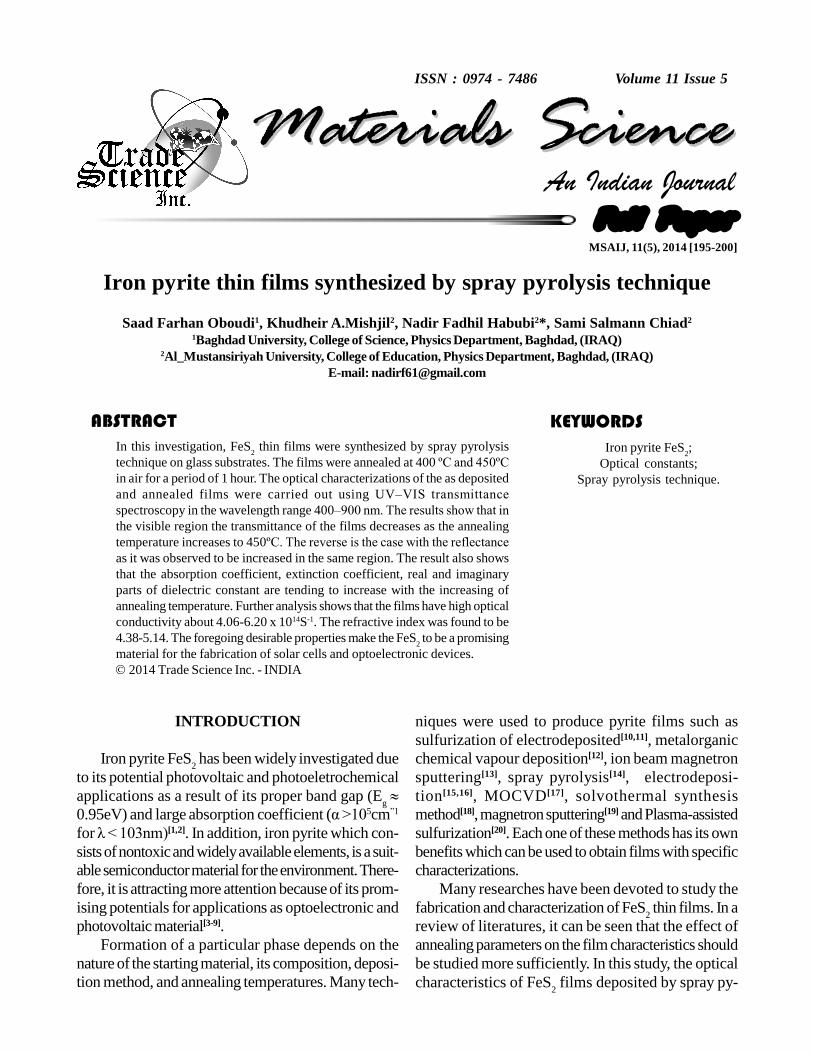
Figure 2 shows that in the visible region, the reflec-tance average value of the as deposited films was about0.38%, while the reflectance for the films after annealedto 400 ºC and 450ºC increased with the increasing of
wavelength and have the average value of 0.45%. Itcan be seen that the reflectance in the visible region islimited only by the surface reflectance.
The optical properties of FeS2 films by means of
Nadir Fadhil Habubi et al. 197
Full PaperMSAIJ, 11(5) 2014
An Indian JournalMaterials ScienceMaterials Science
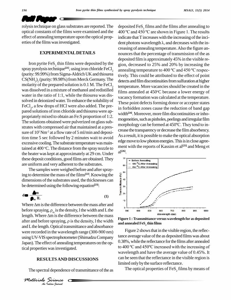
optical absorption in the visible region of (400�900)
nm have been investigated. The absorption coefficient(á) could be calculated using the following relation[27]:
t
A303.2 (2)
Where (A) is the absorption and (t) is the film thick-ness. Figure 3 show the dependence of the absorptioncoefficient (á) of the as deposited and annealed FeS
2
films. It can be seen that with increasing annealing tem-perature the absorption edge shifts to a higher wave-length direction in the visible region. This result provesthat the films are sensitive to visible light. The blue shiftin the absorption band edge has been claimed as a con-sequence of exciton confinement with decrease par-ticle size (the so-called quantum-size effect) in FeS
2 films.
Also, it might be due to the change of the energy gap ofthe disorder crystal in the films.
The refractive index of the films is an important pa-rameter for the optoelectronic device design. In order
to calculate the optical constant refractive index (n) andthe extinction coefficient (k) of the films at differentwavelengths, we can use the following relations[28,29]:n = [1 +R/1 � R] + [4R / (1-R)2 � k2 ]1/2 (3)
k = áë/4ð (4)
Where (á) is the absorption coefficient and ë is thewavelength. The refractive index of the films was cal-culated by using Eq. (2) and the variation of refractiveindex with wavelength for the films is shown in Figure4. After annealing to 400 ºC and 450ºC both films
showed similar behavior in refractive index spectrawhich is a gradually increases with increasing wave-length. This increase may be attributed to the higherpacking density and change in crystalline structure.Many researchers have reported that annealing treat-ment caused the refractive index to increase due to theenhancement of crystallization. Refractive index valuesof the samples have varied between (4.9-5.0) at longwavelengths.
Figure 2 : Reflectance versus wavelength for as deposited andannealed FeS
2 thin films
Figure 3 : Absorption coefficient versus wavelength for FeS2
thin films
Figure 4 : Refractive index versus wavelength for as depos-ited and annealed FeS
2 thin film
Figure 5 : Extension coefficient versus wavelength for as de-posited and annealed FeS
2 thin films
.198 Iron pyrite thin films synthesized by spray pyrolysis technique
Full PaperMSAIJ, 11(5) 2014
An Indian JournalMaterials ScienceMaterials Science
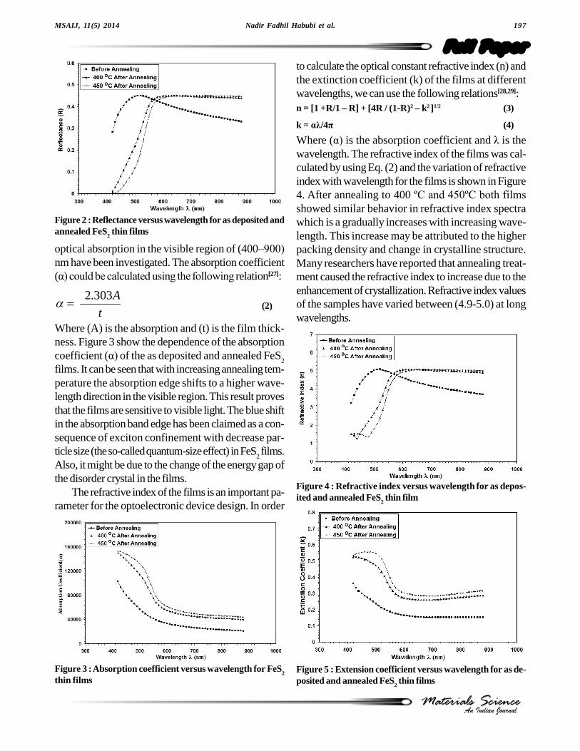
The calculated values of extinction coefficient kversus ë for FeS
2 films are illustrated in Figure 5. It
could be noticed that k values increases with increasingthe wavelength and also increased as the films annealedto 400 ºC and 450ºC.
The obtained values of n and k were used to calcu-late both å
1 and imaginary å
2 parts of the dielectric con-
stant and they were obtained using the formulas[30]:
1 = n2 � k2 (5)
2 = 2nk (6)
Where å1 determines the maximum energy that can be
stored in the material, å2 also is called the relative loss
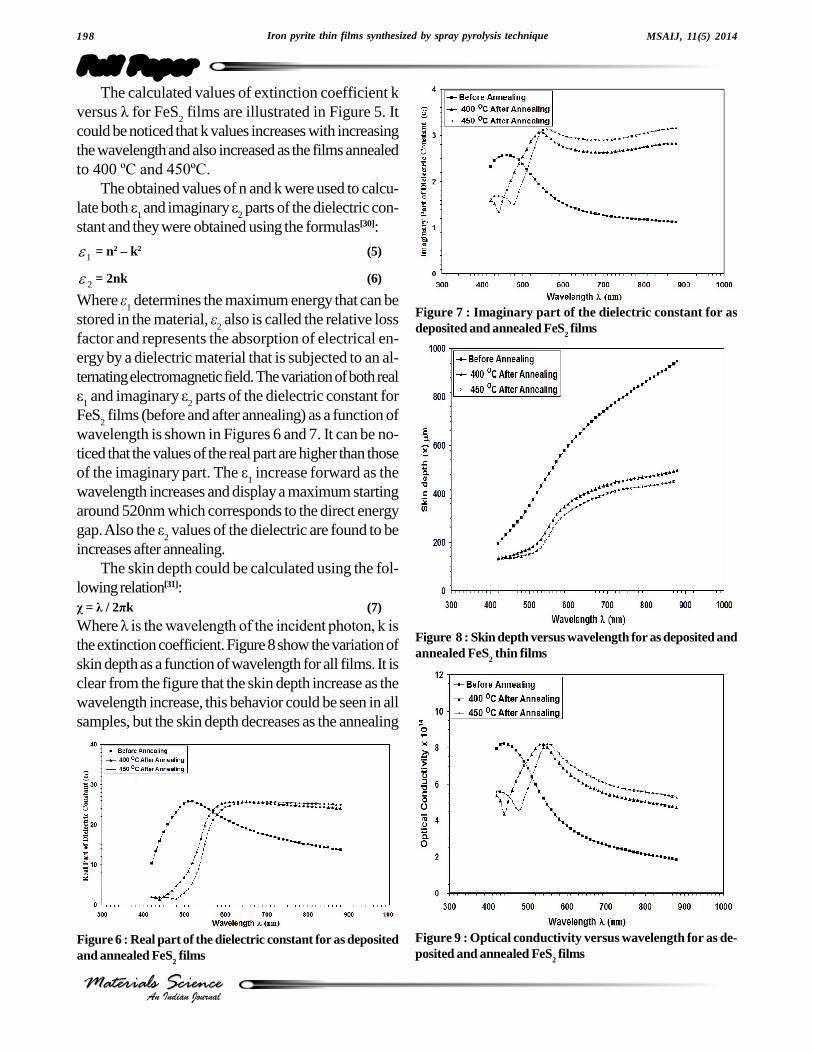
factor and represents the absorption of electrical en-ergy by a dielectric material that is subjected to an al-ternating electromagnetic field. The variation of both realå
1 and imaginary å
2 parts of the dielectric constant for
FeS2 films (before and after annealing) as a function of
wavelength is shown in Figures 6 and 7. It can be no-ticed that the values of the real part are higher than thoseof the imaginary part. The å
1 increase forward as the
wavelength increases and display a maximum startingaround 520nm which corresponds to the direct energygap. Also the å
2 values of the dielectric are found to be
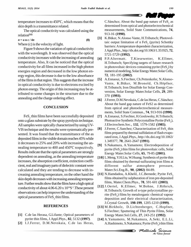
increases after annealing.The skin depth could be calculated using the fol-
lowing relation[31]:÷ = ë / 2ðk (7)
Where ë is the wavelength of the incident photon, k is
the extinction coefficient. Figure 8 show the variation ofskin depth as a function of wavelength for all films. It isclear from the figure that the skin depth increase as thewavelength increase, this behavior could be seen in allsamples, but the skin depth decreases as the annealing
Figure 6 : Real part of the dielectric constant for as depositedand annealed FeS
2 films
Figure 7 : Imaginary part of the dielectric constant for asdeposited and annealed FeS
2 films
Figure 8 : Skin depth versus wavelength for as deposited andannealed FeS
2 thin films
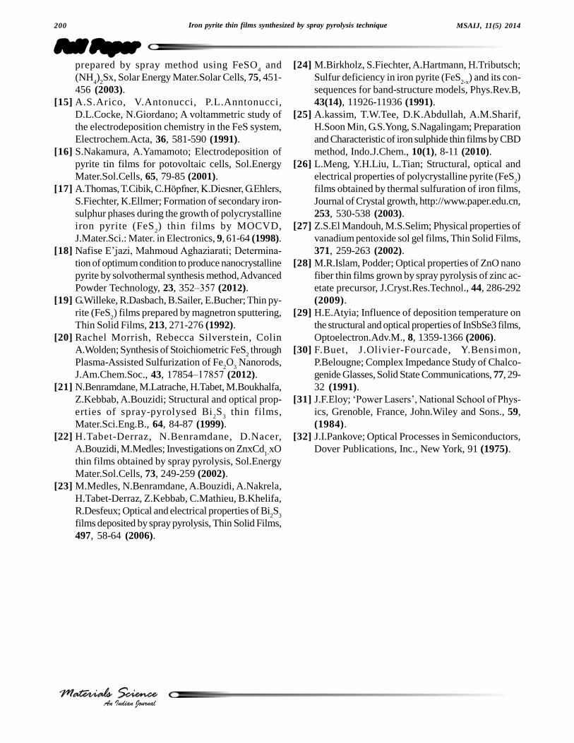
Figure 9 : Optical conductivity versus wavelength for as de-posited and annealed FeS
2 films
Nadir Fadhil Habubi et al. 199
Full PaperMSAIJ, 11(5) 2014
An Indian JournalMaterials ScienceMaterials Science
temperature increases to 450ºC, which means that the
skin depth is a transmittance related.The optical conductivity was calculated using the
relation[32]:
ó = á n c / 4ð (8)
Where (c) is the velocity of light.Figure 9 shows the variation of optical conductivity
with the wavelength. It was observed that the opticalconductivity increases with the increasing of annealingtemperature. Also, It can be noticed that the opticalconductivity for all films increased in the high photonenergies region and decreased in the low photon en-ergy region, this decrease is due to the low absorbanceof the films in that region. This suggests that the increasein optical conductivity is due to electrons excited byphoton energy. The origin of this increasing may be at-tributed to some changes in the structure due to theannealing and the charge ordering effect.
CONCLUSION
FeS2 thin films have been successfully deposited
onto a glass substrate by the spray pyrolysis technique.All samples were optically characterized by using UV-VIS technique and the results were systematically pre-sented. It was found that the transmittance of the asdeposited films in the visible domain reaches 45% whileit decreases to 25% and 20% with increasing the an-nealing temperature to 400 and 450ºC respectively.
Results indicate that the optical parameters are stronglydependent on annealing, as the annealing temperatureincreases, the absorption coefficient, extinction coeffi-cient, real and imaginary parts of dielectric constant werecalculated and they are tending to decrease with in-creasing annealing temperature, on the other hand theskin depth decreases with increasing annealing tempera-ture. Further results show that the films have a high opticalconductivity of about 4.06-6.20 x 10¹⁴S-1.These presentobservations can help improve the understanding of theoptical parameters of FeS
2 thin films.
REFERENCES
[1] C.de las Herasa, G.Lifante; Optical parameters ofpyrite thin films, J.Appl.Phys., 82, 5132 (1997).
[2] I.J.Ferrer, D.M.Nevskaia, C.de las Heras,
C.Sánchez; About the band gap nature of FeS2 as
determined from optical and photoelectrochemicalmeasurements, Solid State Communications, 74,913-16 (1990).
[3] K.Büker, N.Alonso Vante, H.Tributsch; Photovol-taic output limitation of n FeS
2 (pyrite) Schottky
barriers: A temperature dependent characterization,J.Appl.Phys., http://dx.doi.org/10.1063/1.351925, 72,5721-5729 (1992).
[4] P.P.Altermatt. T.Kiesewetter, K.Ellmer,H.Tributsch; Specifying targets of future researchin photovoltaic devices containing pyrite (FeS
2) by
numerical modeling, Solar Energy Mater.Solar Cells,72, 181-195 (2002).
[5] A.Ennaoui, S.Fiechter, Ch.Pettenkofer, N.Alonso-Vante, K.Büker, M.Bronold, Ch.Höpfner,
H.Tributsch; Iron Disulfide for Solar Energy Con-version, Solar Energy Mater.Solar Cells, 29, 289-370 (1993).
[6] J.Ferrer, D.M.Nevskaia, C.de las Heras, C.Sánchez;
About the band gap nature of FeS2 as determinedfrom optical and photoelectrochemical measure-ments, Solid State Commun., 74, 913-916 (1990).
[7] A.Ennaoui, S.Fiechter, H.Goslowsky, H.Tributsch;Photoactive Synthetic Polycrystalline Pyrite (FeS
2),
J.Electrochem.Soc., 132, 1579-1582 (1985).[8] J.Ferrer, C.Sanchez; Characterization of FeS
2 thin
films prepared by thermal sulfidation of flash evapo-rated iron, J.Appl.Phys., http://dx.doi.org/10.1063/1.349377, 70, 2641-2647 (1991).
[9] S.Nakamura, A.Yamamoto; Electrodeposition ofpyrite (FeS
2) thin films for photovoltaic cells, Solar
Energy Mater.Solar Cells, 65, 79-85 (2001).[10] L.Meng, Y.H.Liu, W.Huang; Synthesis of pyrite thin
films obtained by thermal-sulfurating iron films atdifferent sulfur atmosphere pressure,Mater.Sci.Eng.B., 90, (2002) 84-89.
[11] N.Hamdadou, A.Khelil, J.C.Bernede; Pyrite FeS2
films obtained by sulphuration of iron pre-depositedfilms, Mater.Chem.Phys., 78, 591-601 (2003).
[12] J.Oertel, K.Ellmer, W.Bohne, J.Röhrich,
H.Tributsch; Growth of n-type polycrystalline py-rite (FeS
2) films by metalorganic chemical vapour
deposition and their electrical characterization,J.Crystal Growth, 198-199, 1205-1210 (1999).
[13] M.Birkholz, D.Lichtenberger, C.Hopfner,S.Fiechter; Sputtering of Thin Pyrite Films, SolarEnergy Mater.Sol.Cells, 27, 243-251 (1992).
[14] A.Yamamoto, M.Nakamura, A.Seki, E.L.Li,A.Hashimoto, S.Nakamura; Pyrite (FeS
2) thin films
.200 Iron pyrite thin films synthesized by spray pyrolysis technique
Full PaperMSAIJ, 11(5) 2014
An Indian JournalMaterials ScienceMaterials Science
prepared by spray method using FeSO4 and
(NH4)
2Sx, Solar Energy Mater.Solar Cells, 75, 451-
456 (2003).[15] A.S.Arico, V.Antonucci, P.L.Anntonucci,
D.L.Cocke, N.Giordano; A voltammetric study ofthe electrodeposition chemistry in the FeS system,Electrochem.Acta, 36, 581-590 (1991).
[16] S.Nakamura, A.Yamamoto; Electrodeposition ofpyrite tin films for potovoltaic cells, Sol.EnergyMater.Sol.Cells, 65, 79-85 (2001).
[17] A.Thomas, T.Cibik, C.Höpfner, K.Diesner, G.Ehlers,
S.Fiechter, K.Ellmer; Formation of secondary iron-sulphur phases during the growth of polycrystallineiron pyrite (FeS
2) thin films by MOCVD,
J.Mater.Sci.: Mater. in Electronics, 9, 61-64 (1998).[18] Nafise E�jazi, Mahmoud Aghaziarati; Determina-
tion of optimum condition to produce nanocrystallinepyrite by solvothermal synthesis method, AdvancedPowder Technology, 23, 352�357 (2012).
[19] G.Willeke, R.Dasbach, B.Sailer, E.Bucher; Thin py-rite (FeS
2) films prepared by magnetron sputtering,
Thin Solid Films, 213, 271-276 (1992).[20] Rachel Morrish, Rebecca Silverstein, Colin
A.Wolden; Synthesis of Stoichiometric FeS2 through
Plasma-Assisted Sulfurization of Fe2O
3 Nanorods,
J.Am.Chem.Soc., 43, 17854�17857 (2012).[21] N.Benramdane, M.Latrache, H.Tabet, M.Boukhalfa,
Z.Kebbab, A.Bouzidi; Structural and optical prop-erties of spray-pyrolysed Bi
2S
3 thin films,
Mater.Sci.Eng.B., 64, 84-87 (1999).[22] H.Tabet-Derraz, N.Benramdane, D.Nacer,
A.Bouzidi, M.Medles; Investigations on ZnxCd1-xO
thin films obtained by spray pyrolysis, Sol.EnergyMater.Sol.Cells, 73, 249-259 (2002).
[23] M.Medles, N.Benramdane, A.Bouzidi, A.Nakrela,H.Tabet-Derraz, Z.Kebbab, C.Mathieu, B.Khelifa,R.Desfeux; Optical and electrical properties of Bi
2S
3
films deposited by spray pyrolysis, Thin Solid Films,497, 58-64 (2006).
[24] M.Birkholz, S.Fiechter, A.Hartmann, H.Tributsch;Sulfur deficiency in iron pyrite (FeS
2-x) and its con-
sequences for band-structure models, Phys.Rev.B,43(14), 11926-11936 (1991).
[25] A.kassim, T.W.Tee, D.K.Abdullah, A.M.Sharif,H.Soon Min, G.S.Yong, S.Nagalingam; Preparationand Characteristic of iron sulphide thin films by CBDmethod, Indo.J.Chem., 10(1), 8-11 (2010).
[26] L.Meng, Y.H.Liu, L.Tian; Structural, optical andelectrical properties of polycrystalline pyrite (FeS
2)
films obtained by thermal sulfuration of iron films,Journal of Crystal growth, http://www.paper.edu.cn,253, 530-538 (2003).
[27] Z.S.El Mandouh, M.S.Selim; Physical properties ofvanadium pentoxide sol gel films, Thin Solid Films,371, 259-263 (2002).
[28] M.R.Islam, Podder; Optical properties of ZnO nanofiber thin films grown by spray pyrolysis of zinc ac-etate precursor, J.Cryst.Res.Technol., 44, 286-292(2009).
[29] H.E.Atyia; Influence of deposition temperature onthe structural and optical properties of InSbSe3 films,Optoelectron.Adv.M., 8, 1359-1366 (2006).
[30] F.Buet, J.Olivier-Fourcade, Y.Bensimon,P.Belougne; Complex Impedance Study of Chalco-genide Glasses, Solid State Communications, 77, 29-32 (1991).
[31] J.F.Eloy; �Power Lasers�, National School of Phys-
ics, Grenoble, France, John.Wiley and Sons., 59,(1984).
[32] J.I.Pankove; Optical Processes in Semiconductors,Dover Publications, Inc., New York, 91 (1975).
Related Documents