City of Gallup, New Mexico Purchasing Division P.O. Box 1270 Gallup, New Mexico 87305-1270 Office: (505) 863-1232 Fax: (505) 722-5133 gallupnm.gov/purchasing INVITATION TO BID FORMAL BID NO NO. 1806 Hasler Valley Road Solid Waste Facility ISSUE DATE: March 5, 2018 BID OPENING DATE: April 3, 2018 BID OPENING TIME: 2:00 p.m. Local Time 6501 Americas Parkway NE, Suite 830 Albuquerque, NM 87110-8154 P 505.883.8114; F 505.883.5022

Welcome message from author
This document is posted to help you gain knowledge. Please leave a comment to let me know what you think about it! Share it to your friends and learn new things together.
Transcript
City of Gallup, New Mexico Purchasing Division P.O. Box 1270 Gallup, New Mexico 87305-1270 Office: (505) 863-1232 Fax: (505) 722-5133
gallupnm.gov/purchasing
INVITATION TO BID FORMAL BID NO NO. 1806
Hasler Valley Road Solid Waste Facility
ISSUE DATE: March 5, 2018 BID OPENING DATE: April 3, 2018 BID OPENING TIME: 2:00 p.m. Local Time
6501 Americas Parkway NE, Suite 830 Albuquerque, NM 87110-8154 P 505.883.8114; F 505.883.5022

Huitt-Zollars, Inc. Hasler Valley Road Solid Waste Facility HZ Project No. R305538.05
This page left intentionally blank
PROJECT MANUAL
PROJECT: HASLER VALLEY ROAD SOLID WASTE FACILITY OWNER: CITY OF GALLUP PUBLIC WORKS DEPARTMENT 110 WEST AZTEC AVENUE GALLUP, NM 87301 Contact: Mr. Dennis Romero, Utilities Director “The technical material and data contained in the specifications were prepared under the supervision and direction of the undersigned, whose seal as a Registered Architect, licensed to practice in the State of New Mexico, is affixed below.” “All questions about the meaning or intent of these documents shall be submitted only to the Architect of Record, stated above, in writing. Refer to Paragraph 3.2 of the Instructions to Bidders as to interpretations.”
ARCHITECT OF RECORD: Huitt-Zollars, Inc. 6501 Americas Parkway NE Suite 30 Albuquerque, NM 87110-8154 Contact: Jose M/ Zelaya, AIA, NCARB (505) 883-8114 ph (505) 883-5022 fax
11/22/17

Huitt-Zollars, Inc. Hasler Valley Road Solid Waste Facility HZ Project No. R305538.05
This page left intentionally blank

Huitt-Zollars, Inc. Hasler Valley Road Solid Waste Facility HZ Project No. R305538.05
Table of Contents 00-0110-1
TABLE OF CONTENTS
Section Title DIVISION 00 - Procurement and Contracting Requirements
General Conditions Notice to Bidders Labor Enforcement Fund Insurance Conditions of the Contract Bidders Qualification Statement Subcontractor Listing Proposal Form for Contract Bid Proposal Form Unit Prices Form Bid Bond Contract Payment Bond Performance Bond Notice of Award Notice to Proceed State of New Mexico Wage Decision
TECHNICAL SPECIFICATIONS
DIVISION 01 – General Requirements
01 1000 Summary 01 2200 Unit Prices 01 2300 Alternates 01 2500 Substitution Procedures 01 2600 Contract Modification Procedures 01 2900 Payment Procedures 01 3100 Project Management and Coordination 01 3200 Construction Progress Documentation 01 3300 Submittal Procedures 01 4000 Quality Requirements 01 5000 Temporary Facilities and Controls 01 5030 Construction Survey and Staking 01 6000 Product Requirements 01 6301 Prior Approval Substitution Request Form 01 7300 Execution 01 7700 Closeout Procedures 01 7823 Operation and Maintenance Data 01 7839 Project Record Documents 01 7900 Demonstration and Training

Huitt-Zollars, Inc. Hasler Valley Road Solid Waste Facility HZ Project No. R305538.05
This page left intentionally blank
Huitt-Zollars, Inc. Hasler Valley Road Solid Waste Facility HZ Project No. R305538.05
Table of Contents 00-0110-2
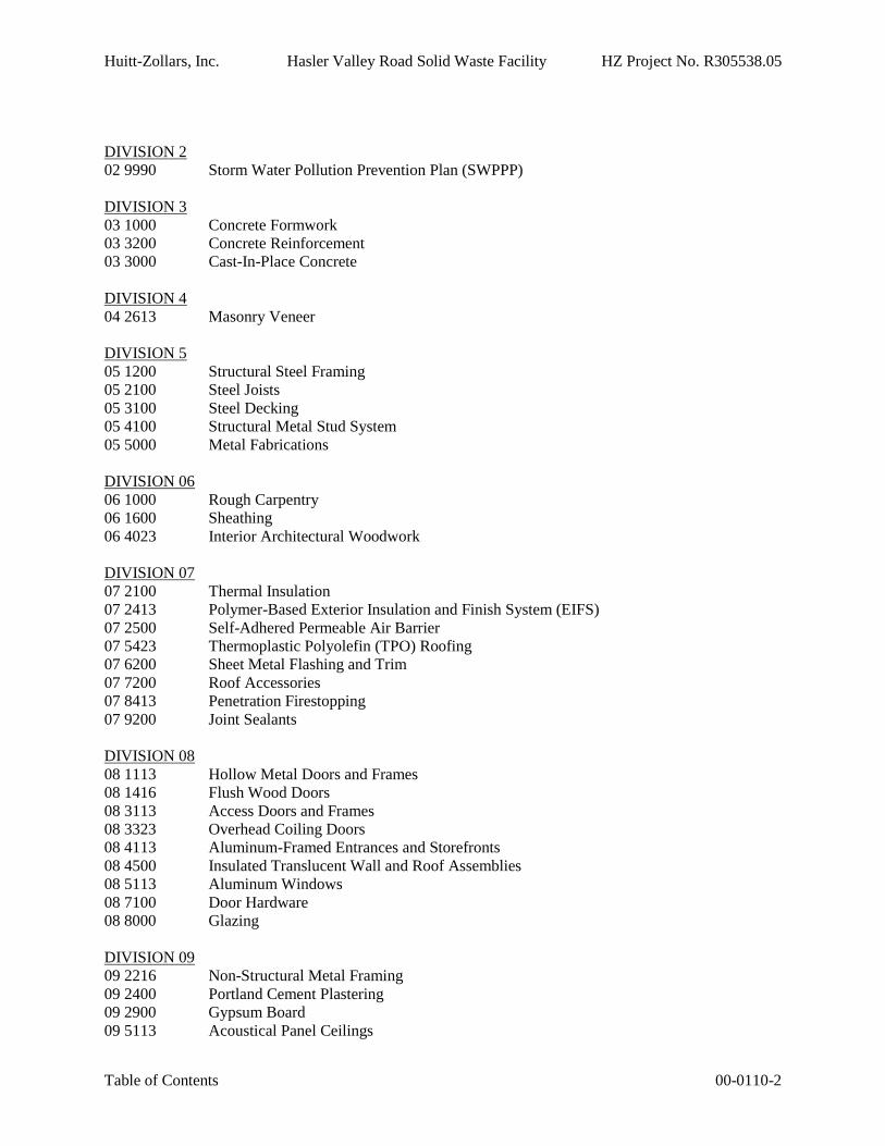
DIVISION 202 9990 Storm Water Pollution Prevention Plan (SWPPP)
DIVISION 303 1000 Concrete Formwork03 3200 Concrete Reinforcement03 3000 Cast-In-Place Concrete
DIVISION 404 2613 Masonry Veneer
DIVISION 505 1200 Structural Steel Framing05 2100 Steel Joists05 3100 Steel Decking05 4100 Structural Metal Stud System05 5000 Metal Fabrications
DIVISION 0606 1000 Rough Carpentry06 1600 Sheathing06 4023 Interior Architectural Woodwork
DIVISION 0707 2100 Thermal Insulation07 2413 Polymer-Based Exterior Insulation and Finish System (EIFS)07 2500 Self-Adhered Permeable Air Barrier07 5423 Thermoplastic Polyolefin (TPO) Roofing07 6200 Sheet Metal Flashing and Trim07 7200 Roof Accessories07 8413 Penetration Firestopping07 9200 Joint Sealants
DIVISION 0808 1113 Hollow Metal Doors and Frames08 1416 Flush Wood Doors08 3113 Access Doors and Frames08 3323 Overhead Coiling Doors08 4113 Aluminum-Framed Entrances and Storefronts08 4500 Insulated Translucent Wall and Roof Assemblies08 5113 Aluminum Windows08 7100 Door Hardware08 8000 Glazing
DIVISION 0909 2216 Non-Structural Metal Framing09 2400 Portland Cement Plastering09 2900 Gypsum Board09 5113 Acoustical Panel Ceilings

Huitt-Zollars, Inc. Hasler Valley Road Solid Waste Facility HZ Project No. R305538.05
This page left intentionally blank

Huitt-Zollars, Inc. Hasler Valley Road Solid Waste Facility HZ Project No. R305538.05
Table of Contents 00-0110-3
09 5133 Acoustical Metal Ceilings09 6513 Resilient Base and Accessories09 6723 Resinous Flooring09 6813 Tile Carpeting09 9600 High-Performance Coatings
DIVISION 1010 1100 Visual Display Surfaces10 1400 Signage10 2600 Wall and Door Protection10 2800 Toilet, Bath, and Laundry Accessories10 4413 Fire Extinguisher Cabinets10 4416 Fire Extinguisher10 7500 Flagpole
DIVISION 11NOT USED
DIVISION 1212 2413 Roller Window Shades
DIVISION 13-20NOT USED
DIVISION 21NOT USED
DIVISION 2222 0523 General-Duty Valves for Plumbing Piping22 0529 Hangers and Supports for Plumbing Piping and Equipment22 0553 Identification for Plumbing Piping and Equipment22 0700 Plumbing Insulation22 1116 Domestic Water Piping22 1316 Sanitary Waste and Vent Piping22 4000 Plumbing Fixtures
DIVISION 23230593 Testing, Adjusting, and Balancing for HVAC230700 HVAC Insulation231126 Facility Liquefied Petroleum Gas Piping233113 Metal Ducts233300 Air Duct Accessories233423 HVAC Power Ventilators233713 Diffusers, Registers, and Grilles237413 Packaged, Outdoor, Central-Station, Air-Handling Units
DIVISION 2626 0010 General Provisions26 0519 Low Voltage Conductors26 0526 Grounding

Huitt-Zollars, Inc. Hasler Valley Road Solid Waste Facility HZ Project No. R305538.05
This page left intentionally blank

Huitt-Zollars, Inc. Hasler Valley Road Solid Waste Facility HZ Project No. R305538.05
Table of Contents 00-0110-4
26 0533 Raceways, Boxes, and Fittings26 2416 Panelboards26 2726 Wiring Devices and Plates26 5113 Lighting Equipment
DIVISION 27NOT USED
DIVISION 2828 3100 Fire Detection and Alarm
DIVISION 3131 0000 Earthwork
DIVISION 3232 0000 Gravel (Landscape)
END OF TABLE OF CONTENTS

Huitt-Zollars, Inc. Hasler Valley Road Solid Waste Facility HZ Project No. R305538.05
This page left intentionally blank

GENERAL CONDITIONSFORMAL BID NO. 1806
SEALED BIDS: ALL BIDS MUST BE SUBMITTED IN A SEALED ENVELOPE AND SHALL NOT BE OPENED AND
CONSIDERED IF THEY ARE NOT RECEIVED BY THE PURCHASING DEPARTMENT PRIOR TO THE TIME
SPECIFIED FOR THE BID OPENING. ALL SEALED BIDS MUST BE SUBMITTED ON THE BID DOCUMENT
ORIGINALS OF FORMS, OR REASONABLE FACSIMILE, FURNISHED BY THE CITY OF GALLUP. ALL
PROPOSALS MUST BE SIGNED BY A RESPONSIBLE AND AUTHORIZED PERSON FOR THE BIDDING FIRM.
EACH BIDDER MUST ALSO FILL-IN AREAS FOR DELIVERY DATE, PAYMENT TERMS, AND F.O.B. POINT IF
REQUESTED; FAILURE TO DO SO MAY RESULT IN DISQUALIFICATION OF THEIR RESPECTIVE BID. NOTE
THAT FAX OR ELECTRONICALLY TRANSMITTED BIDS ARE NOT ACCEPTED ON THE CITY OF GALLUP
FORMAL BIDS. BIDS SUBMITTED AFTER THE BID OPENING DATE AND TIME WILL NOT BE CONSIDERED
AND WILL BE RETURNED UNOPENED. BIDS WILL BE OPENED IN THE PURCHASING DEPARTMENT
CONFERENCE ROOM.
BIDS WILL BE ACCEPTED UNTIL 2:00 P.M. LOCAL TIME ON APRIL 3, 2018 AT THE CITY OF GALLUP
PURCHASING OFFICE; 110 WEST AZTEC (87301); P.O. BOX 1270; GALLUP, NEW MEXICO 87305.
PRE-BID CONFERENCE: A MANDATORY PRE-BID CONFERENCE WILL BE HELD ON MARCH 20, 2018, AT
10:00AM AT THE CITY OF GALLUP, UTILITIES DEPARTMENT CONFERENCE ROOM; 230 S. SECOND
STREET, GALLUP, NM 87301; PHONE (505) 726-1278. A SITE VISIT WILL IMMEDIATELY FOLLOW THE PRE-
BID CONFERENCE.
MAILING: BIDDER SHALL UTILIZE THE FORMAL BID NUMBER ON THEIR RETURN MAILING ENVELOPE OR
PACKAGE. IF SENT BY MAIL OR OVERNIGHT METHOD (FED-EXPRESS, UPS NEXT DAY AIR ETC.), OR HAND
DELIVERED PLEASE Note Bid Number on CARRIER’S RECEIPT. FAILURE TO DO SO WILL NOT CONSTITUTE
A LIABILITY ON THE CITY IF THE BID IS MISPLACED OR LOST.
COPIES OF PLANS, SPECIFICATIONS AND BIDDING DOCUMENTS: PLANS, SPECIFICATIONS, AND BIDDING
DOCUMENTS MAY BE EXAMINED AT THE OFFICE OF THE PURCHASING DIRECTOR, 110 WEST AZTEC;
GALLUP, NM 87301, PHONE 505-863-1334. ADDITIONAL INFORMATION REGARDING THIS BID MAY ALSO BE
VIEWED AT gallupnm.gov/bids. PLANS, SPECIFICATIONS AND BIDDING DOCUMENTS MAY BE OBTAINED
FROM: Albuquerque Reprographics, 4716 McLeod NE, Albuquerque, NM 87109; [email protected]; Phone 505-884-
0862; Fax: 505-883-6452. THERE IS A $150 REFUNDABLE DEPOSIT FOR THE PLANS. COMPLETE SETS OF
PLANS MUST BE RETURNED WITH TEN (10) DAYS OF BID AWARD AND BE IN GOOD CONDITION.
INFORMATION: IF CLARIFICATION IS NEEDED ON ANY PART OF THE GENERAL CONDITIONS, CONTACT
FRANCES RODRIGUEZ; PURCHASING DIRECTOR; P.O. BOX 1270; GALLUP, NM 87305; 505-863-1334 OR 505-722-
5133 (FAX); [email protected] (EMAIL). QUESTIONS REGARDING THE SPECIFICATIONS AND
SCOPE OF WORK SHOULD BE DIRECTED TO THE ARCHITECT: Huitt-Zollars, Jose Zelaya, AIA, NCARB,
[email protected]; (505) 883-8114. QUESTIONS SUBMITTED LESS THAN 4 DAYS PRIOR TO BID

Huitt-Zollars, Inc. Hasler Valley Road Solid Waste Facility HZ Project No. R305538.05
This page left intentionally blank
OPENING, OR AFTER MARCH 27, 2018, MAY NOT BE ADDRESSED.
SPECIFICATIONS: SPECIFICATIONS, AS INCLUDED IN THIS BID AND THE PLANS, ARE INTENDED TO
INDICATE THE REQUIREMENTS OF THE CITY OF GALLUP AND GIVE AN ACCURATE DESCRIPTION OF
MINIMUM STANDARDS ACCEPTABLE. ALL ITEMS EQUAL OR EQUIVALENT TO THESE REQUIREMENTS AND
STANDARDS WILL BE CONSIDERED, EXCEPT WHERE OTHERWISE NOTED. ALL MATERIALS USED AND
INCORPORATED INTO THIS PROJECT SHALL BE NEW UNLESS OTHERWISE AGREED UPON.
SPECIFICATIONS AND DOCUMENTS: THE BID DOCUMENTS, SPECIFICATIONS, CONTRACT DOCUMENTS
AND ALL AMENDMENTS OR ADDENDA TO THE BID DOCUMENTS, SPECIFICATIONS AND CONTRACT
DOCUMENTS, IF ANY, ARE ESSENTIAL PARTS OF THE CONTRACT, AND A REQUIREMENT OCCURRING IN
ONE IS JUST AS BINDING AS THOUGH OCCURRING IN ALL. THE CONTRACTOR SHALL NOT TAKE
ADVANTAGE OF ANY APPARENT ERROR OR OMISSION IN THESE DOCUMENTS. IF THE CONTRACTOR
DISCOVERS AN APPARENT ERROR OR DISCREPANCY, HE SHALL IMMEDIATELY CONTACT THE OWNER FOR
ITS INTERPRETATION AND DECISION, AND SUCH DECISION SHALL BE FINAL.
BRAND NAMES: THE CITY HAS NO PREFERENCE FOR ANY BRAND OF EQUIPMENT, KIND OF MATERIAL OR
TYPE OF PROCESS AND WILL CONSIDER ALL BIDS FOR USE OF OTHER MATERIALS OR EQUIPMENT, IF
THEY ARE, IN FACT, EQUAL TO THAT SPECIFIED. THE CITY WILL BE THE SOLE JUDGE AS TO WHETHER
MATERIALS, EQUIPMENT, OR PROCESS OFFERED IS, IN FACT, EQUAL TO THAT SPECIFIED.
EXAMINATION OF PROPOSED WORK: BIDDERS MUST SATISFY THEMSELVES, BY PERSONAL
INVESTIGATION OR BY ANY MEANS THEY DEEM NECESSARY OR DESIRABLE, AS TO LOCATION OF AND
CONDITIONS AFFECTING PROPOSED WORK AND RESULTING COSTS THEREOF.
PROJECT ERRORS: BIDDERS WILL PROMPTLY NOTIFY THE CITY OF GALLUP OF ANY AMBIGUITY,
INCONSISTENCY OR ERROR THEY MAY DISCOVER UPON EXAMINATION OF THE PROJECT DOCUMENTS OR
THE SITE AND LOCAL CONDITIONS.
COMMENCEMENT AND COMPLETION: THE BIDDER MUST AGREE TO COMMENCE WORK ON A DATE TO
BE SPECIFIED IN A WRITTEN “NOTICE TO PROCEED” ISSUED BY CITY AND TO FULLY COMPLETE PROJECT
WITHIN 330 CALENDAR DAYS THEREAFTER, INCLUDING WEATHER DELAYS.
BIDDERS QUALIFICATIONS: BIDS WILL BE CONSIDERED ONLY FROM FIRMS WHO CAN PROVIDE
EVIDENCE THAT THEY HAVE ESTABLISHED A SATISFACTORY RECORD OF PERFORMANCE AND INTEGRITY
TO INSURE THEY CAN EXECUTE THE REQUIREMENTS AS STATED HEREIN. THE CITY MAY MAKE SUCH
INVESTIGATION IT DEEMS NECESSARY TO DETERMINE THE ABILITY OF THE BIDDER TO PERFORM THE
WORK. ANY DETERMINATION AS TO COMPETENCY SHALL BE MADE BY APPROPRIATE CITY STAFF.

Huitt-Zollars, Inc. Hasler Valley Road Solid Waste Facility HZ Project No. R305538.05
This page left intentionally blank

ANY PROPOSAL WHICH IS INCOMPLETE, IRREGULAR, OR ACCOMPANIED BY AN INSUFFICIENT OR BOND
MAY BE REJECTED. THE CITY OF GALLUP ALSO RESERVES THE RIGHT TO REJECT THE PROPOSAL OF A
BIDDER WHO HAS PREVIOUSLY FAILED TO PERFORM PROPERLY, INCLUDING INFERIOR MATERIALS,
WORKMANSHIP, OR ATTEMPTS TO USE SUBSTANDARD EQUIPMENT, EXCESSIVE INSPECTION CAUSED TO
THE PROJECT TO INSURE GOOD WORKMANSHIP, OR POOR CONSTRUCTION METHODS, OR FAILURE TO
COMPLETE ON TIME A CONTRACT OF SIMILAR NATURE, OR THE PROPOSAL OF A BIDDER WHO IS NOT IN A
POSITION TO PERFORM THE WORK GOVERNED BY THE CONTRACT.
BID SECURITY: SHALL BE SUBMITTED WITH THE BID AND MADE PAYABLE TO THE OWNER IN THE
AMOUNT OF FIVE PERCENT (5%) OF THE BID SUM. SECURITY SHALL BE BY CERTIFIED OR CASHIERS
CHECK, OR A BID BOND PREPARED ON A FORM ACCEPTABLE TO THE OWNER (PERSONAL OR CORPORATE
CHECKS ARE NOT ACCEPTABLE), ISSUED BY A SURETY LICENSED TO DO BUSINESS IN THE STATE WHERE
THE PROJECT IS LOCATED. PERSONAL OR CORPORATE CHECKS ARE NOT ACCEPTABLE. THE OWNER WILL
RETAIN THESE SECURITIES UNTIL A CONTRACT HAS BEEN ENTERED INTO. SHOULD THE LOW BIDDER
REFUSE TO ENTER INTO A CONTRACT, THE OWNER WILL RETAIN HIS SECURITY AS LIQUIDATED
DAMAGES, NOT AS A PENALTY. IF THE LOWEST BIDDER FAILS TO ENTER INTO A CONTRACT, THEN THE
NEXT LOWEST BIDDER WILL BE CONSIDERED AS THE LOWEST BIDDER.
PERFORMANCE AND PAYMENT BOND: THE SUCCESSFUL BIDDER SHALL EXECUTE A PERFORMANCE
BOND AND PAYMENT BOND, EACH IN THE SUM OF 100% OF THE TOTAL BID PRICE WITH A CORPORATE
SURETY AUTHORIZED TO DO BUSINESS IN THE STATE OF NEW MEXICO AND SAID SURETY TO BE
APPROVED IN FEDERAL CIRCULAR 570 AS PUBLISHED BY THE U.S. TREASURY DEPARTMENT WITHIN
FIFTEEN (15) DAYS OF RECEIPT OF NOTICE OF AWARD.
ADDITIONAL BONDS AND INSURANCE: PRIOR TO DELIVERY OF THE EXECUTED AGREEMENT BY OWNER
TO CONTRACTOR, OWNER MAY REQUIRE CONTRACTOR TO FURNISH SUCH OTHER BONDS AND SUCH
ADDITIONAL INSURANCE, IN SUCH FORM AND WITH SUCH SURETIES OR INSURERS, AS OWNER MAY
REQUIRE. IF SUCH OTHER BONDS OR SUCH OTHER INSURANCE ARE SPECIFIED BY WRITTEN
INSTRUCTIONS GIVEN PRIOR TO OPENING OF BIDS, THE PREMIUMS SHALL BE PAID BY CONTRACTOR; IF
SUBSEQUENT THERETO, THEY SHALL BE PAID BY OWNER.
PUBLIC WORKS: THIS SOLICITATION IS FOR A CITY OF GALLUP PROJECT AND SUBJECT TO THE PUBLIC
WORKS STATUTES OF THE STATE OF NEW MEXICO (13-4-1 TO 13-4-43 NMSA 1978); CONSTRUCTION
INDUSTRIES LICENSING ACT (60-13-1 et seq. NMSA 1978); CID RULES AND REGULATIONS; APPLICABLE
FEDERAL, STATE AND LOCAL STATUES AND LAWS; AND THE CITY OF GALLUP ORDINANCES.
WARRANTY: ALL LABOR AND WORK DONE BY THE CONTRACTOR SHALL BE WARRANTED FOR A PERIOD
OF ONE YEAR FROM DATE OF FINAL ACCEPTANCE

Huitt-Zollars, Inc. Hasler Valley Road Solid Waste Facility HZ Project No. R305538.05
This page left intentionally blank

BUSINESS LICENSE: BIDDER'S ARE ADVISED THAT THEY MUST HAVE OR OBTAIN A CURRENT CITY OF
GALLUP BUSINESS LICENSE FOR THE TYPE OF MATERIAL OR SERVICES REQUIRED UNDER THIS CONTRACT
BEFORE WORK COMMENCES OR A PURCHASE ORDER ISSUED.
FORMS COMPLETION: ALL FORMS SUBMITTED MUST BE TYPEWRITTEN OR WRITTEN IN INK. ANY
ALTERATIONS TO THE BID AMOUNTS BY ERASURES OR BY INTERLINEATIONS SHALL BE INITIALED BY
THE SIGNER OF THE BID FORM.
SUBCONTRACTORS: CONTRACTOR SHALL NOT EMPLOY ANY SUBCONTRACTOR OR OTHER PERSON OR
ORGANIZATION (INCLUDING THOSE WHO ARE TO FURNISH THE PRINCIPAL ITEMS OF MATERIALS OR
EQUIPMENT), WHETHER INITIALLY OR AS A SUBSTITUTE, AGAINST WHOM OWNER MAY HAVE A
REASONABLE OBJECTION. A SUBCONTRACTOR OR OTHER PERSON OR ORGANIZATION IDENTIFIED IN
WRITING TO OWNER BY CONTRACTOR PRIOR TO THE NOTICE OF AWARD AND NOT OBJECTED TO IN
WRITING BY OWNER PRIOR TO THE NOTICE OF AWARD WILL BE DEEMED ACCEPTABLE TO OWNER.
ACCEPTANCE OF ANY SUBCONTRACTOR, OTHER PERSON, OR ORGANIZATION BY OWNER SHALL NOT
CONSTITUTE A WAIVER OF ANY RIGHT OF OWNER TO REJECT DEFECTIVE WORK OR WORK NOT IN
CONFORMANCE WITH THE CONTRACT DOCUMENTS. IF OWNER, AFTER DUE INVESTIGATION, HAS
REASONABLE OBJECTION TO ANY SUBCONTRACTOR, OTHER PERSON, OR ORGANIZATION PROPOSED BY
CONTRACTOR AFTER THE NOTICE OF AWARD, CONTRACTOR SHALL SUBMIT AN ACCEPTABLE
SUBSTITUTE AND THE CONTRACT PRICE SHALL BE INCREASED OR DECREASED BY THE DIFFERENCE IN
COST OCCASIONED BY SUCH SUBSTITUTION AND AN APPROPRIATE CHANGE ORDER SHALL BE ISSUED.
CONTRACTOR SHALL NOT BE REQUIRED TO EMPLOY ANY SUBCONTRACTOR, OTHER PERSON, OR
ORGANIZATION AGAINST WHOM HE HAS REASONABLE OBJECTION. CONTRACTOR SHALL NOT WITHOUT
THE CONSENT OF OWNER MAKE ANY SUBSTITUTION FOR ANY SUBCONTRACTOR, OTHER PERSON, OR
ORGANIZATION WHO HAS BEEN ACCEPTED BY OWNER.
LIST OF SUBCONTRACTORS: THE BIDDER SHALL LIST THE SUBCONTRACTORS HE/SHE PROPOSES TO USE
FOR ALL TRADES OR ITEMS. IF AWARDED CONTRACT, THE BIDDER SHALL USE THE FIRM LISTED.
CHANGES OR SUBSTITUTIONS TO THIS LIST MUST BE APPROVED BY THE CITY. A LIST OF
SUBCONTRACTORS FOR THIS PROJECT MUST ACCOMPANY THE BID PROPOSAL SUBMITTAL.
THE LISTING THRESHOLD FOR SUBCONTRACTORS FOR THIS PROJECT IS $5,000 AND SHALL BE SUBMITTED
IN COMPLIANCE WITH 13-4-32 THRU 13-4-43 NMSA 1978. THERE SHALL BE ONLY ONE SUBCONTRACTOR
LISTED FOR EACH CLASSIFICATION. THE GENERAL CONTRACTOR SHALL NOT LIST THEMSELVES AS THE
SUBCONTRACTOR UNLESS HE REPRESENTS THAT HE/SHE IS LICENSED AND CAN PERFORM SUCH WORK
SATISFACTORILY. IF SUBCONTRACTORS CHANGE ACCORDING TO BID OPTIONS/ADDITIVE
ALTERNATES ACCEPTED, THEN LIST THE SUBCONTRACTORS AND THE BID ALTERNATES WHERE
THEY ARE TO BE USED.

Huitt-Zollars, Inc. Hasler Valley Road Solid Waste Facility HZ Project No. R305538.05
This page left intentionally blank
THE OWNER RESERVES THE RIGHT TO DISQUALIFY SUBCONTRACTORS AND SUPPLIERS IN ACCORDANCE
WITH THE CONDITIONS OF THE BID AND CONTRACT. THE CONTRACTOR AGREES THAT HE/SHE IS FULLY
RESPONSIBLE TO THE OWNER FOR THE ACTS AND OMISSIONS OF HIS SUBCONTRACTORS AND OR
PERSONS EITHER DIRECTLY OR INDIRECTLY EMPLOYED BY THEM, AS HE IS FOR THE ACTS AND
OMISSIONS OF PERSONS DIRECTLY EMPLOYED BY HIM. NOTHING CONTAINED IN THE CONTRACT
DOCUMENTS SHALL CREATE ANY CONTRACTUAL RELATION BETWEEN ANY SUBCONTRACTOR AND THE
OWNER.
THE BIDDER MAY BE REQUIRED TO ESTABLISH THE RELIABILITY AND RESPONSIBILITY OF THE PROPOSED
SUBCONTRACTORS OR OF ANY MANUFACTURER TO FURNISH AND PERFORM THE WORK IN ACCORDANCE
WITH THE CONTRACT DOCUMENTS AND COMPLETION SCHEDULE, AND MAY ALSO BE REQUIRED TO
REQUIRE PERFORMANCE AND PAYMENT BONDS OF SOME OR ALL SUBCONTRACTORS IN CONFORMANCE
WITH SEC. 13-4-37 NMSA 1978.
MINIMUM WAGE RATES: THERE SHALL BE NO DISCRIMINATION BECAUSE OF RACE, CREED, COLOR, SEX,
NATIONAL ORIGIN OR POLITICAL AFFILIATION IN THE EMPLOYMENT OF PERSONS QUALIFIED BY
TRAINING AND EXPERIENCE FOR WORK CARRIED OUT UNDER THIS CONTRACT.
WAGES WILL BE PAID IN ACCORDANCE WITH THE STATE OF NEW MEXICO PUBLIC WORKS STATUTES
REGARDING WAGE RATES. A WAGE RATE SCHEDULE IS ENCLOSED WITH THIS BID AND IS MADE PART OF
CONTRACT DOCUMENTS. COMPLIANCE WITH MINIMUM WAGE RATES SHALL APPLY EQUALLY TO ALL
CONTRACTORS AND SUBCONTRACTORS ENGAGED ON PROJECT. THE CONTRACTOR SHALL POST AT
APPROPRIATE PLACES ON THE JOB SITE.
IT SHALL BE THE RESPONSIBILITY OF THE CONTRACTOR TO FURNISH COPIES OF PAYROLLS TO THE
ENGINEER/ARCHITECT AND PURCHASING DIRECTOR (BIWEEKLY) AND THE NEW MEXICO DEPARTMENT
OF WORK FORCE SOLUTIONS WHEN REQUESTED, OR ANY OTHER INTERESTED PARTY SUCH AS
CONTRACTORS, CONTRACTING AGENCIES, LABOR ORGANIZATIONS, AND CONTRACTOR ASSOCIATIONS
TO ENSURE COMPLIANCE WITH THE NEW MEXICO PUBLIC WORKS MINIMUM WAGE ACT.
DEPARTMENT OF LABOR REGISTRATION: BIDDERS ARE ADVISED THAT ALL TIERS OF CONTRACTORS
(INCLUDING SUBCONTRACTORS) BIDDING MORE THAN $60,000 ON A PUBLIC WORKS CONTRACT MUST BE
REGISTERED WITH THE LABOR & INDUSTRIAL DIVISION OF THE STATE OF NEW MEXICO PRIOR TO
SUBMITTING A BID IN COMPLIANCE WITH 13-4-13.1 NMSA 1978. A LABOR ENFORCEMENT FUND FORM IS
AVAILABLE AT HTTP://WWW.DWS.STATE.NM.US/NEW/LABOR_RELATIONS/PUBLICWORKS.HTML
SEQUENCE OF WORK: IF APPLICABLE, CONTRACTOR SHALL PREPARE THE PROJECT SCHEDULE; PROVIDE
ALL SUBMITTALS, APPROVED TRAFFIC CONTROL PLANS, WORK PERMITS, CONTACT ALL OTHER UTILITY

Huitt-Zollars, Inc. Hasler Valley Road Solid Waste Facility HZ Project No. R305538.05
This page left intentionally blank

COMPANIES (811) AND COORDINATE WITH BOTH THE CITY OF GALLUP RESIDENTS AND BUSINESSES.
UTILITY LOCATES AND TIE-INS TO VERIFY LOCATIONS AND DEPTHS OF UTILITIES SHALL BE COMPLETED
AT THE BEGINNING OF PROJECT TO FACILITATE PRODUCT PARTS LEAD TIMES. SEWER SERVICE FOR ALL
RESIDENTS AND BUSINESSES SHALL BE MAINTAINED AT ALL TIMES.
LICENSES, LEGAL RESTRICTIONS, PERMITS AND REGULATIONS: THE CONTRACTOR SHALL HAVE A
LICENSE ISSUED BY THE CONSTRUCTION INDUSTRIES DIVISION (CID) OF THE NEW MEXICO REGULATION
AND LICENSING DEPARTMENT. THE LICENSES SHALL BE PROPERLY CLASSIFIED FOR THE WORK TO BE
PERFORMED UNDER THIS CONTRACT AND BE IN ACTIVE STATUS AT THE TIME OF BID OPENING. ALL
SUBCONTRACTORS SHALL ALSO MEET THESE CRITERIA.
ADDITIONAL, THE CONTRACTOR SHALL AT THEIR OWN EXPENSE, PROCURE ALL NECESSARY LICENSES
AND PERMITS OF A TEMPORARY NATURE AND SHALL GIVE DUE AND ADEQUATE NOTICES TO THOSE IN
CONTROL OF ALL PROPERTIES WHICH MAY BE AFFECTED BY THIS OPERATION. PERMITS, LICENSES AND
EASEMENTS FOR PERMANENT STRUCTURES OR PERMANENT CHANGES IN EXISTING FACILITIES, SHALL BE
PROVIDED BY THE OWNER UNLESS OTHERWISE SPECIFIED. THE CONTRACTOR SHALL GIVE ALL NOTICES
AND COMPLY WITH LAWS, ORDINANCES, RULES AND REGULATIONS BEARING ON THE CONDUCT OF THE
WORK AS DRAWN OR SPECIFIED.
TAXES: THE PROPOSAL TOTAL SHALL EXCLUDE ALL APPLICABLE TAXES. THE CITY WILL PAY ANY TAXES
DUE ON THE CONTRACT BASED UPON BILLING SUBMITTED BY THE CONTRACTOR, AT THE APPLICABLE
TAX RATE. TAXES SHALL BE SHOWN AS A SEPARATE AMOUNT ON ANY BILLING OR REQUEST FOR
PAYMENT.
COLLUSION: COLLUSION AMONG BIDDERS OR AN INTEREST IN MORE THAN ONE BID UNDER A
DIFFERENT NAME OR FIRM SHALL BE CAUSE FOR REJECTION OF BID(S).
PRICE TERMS: BIDDER AGREES THAT THE PRICES BID SHALL REMAIN IN EFFECT FOR 45 DAYS FROM THE
DATE OF THE BID OPENING AND SUBJECT TO ACCEPTANCE BY THE CITY OF GALLUP WITHIN THAT
PERIOD. TIME FOR ACCEPTANCE MAY BE EXTENDED WITH THE MUTUAL CONCURRENCE OF THE
CONTRACTOR.
UNIT PRICES: TYPOGRAPHICAL ERRORS, ERRORS IN EXTENDING UNIT PRICES, ARITHMETIC ERRORS OR
ERRORS CLEARLY EVIDENT ON THE FACE OF THE BID DOCUMENT MAY BE CORRECTED IN ACCORDANCE
WITH THE PROCUREMENT ORDINANCE AND PROCUREMENT REGULATIONS. DISCREPANCIES INVOLVING
THE INCORRECT EXTENSION OF UNIT PRICES SHALL BE RESOLVED IN FAVOR OF UNIT PRICES AS UNIT
PRICES CANNOT BE CORRECTED.

Huitt-Zollars, Inc. Hasler Valley Road Solid Waste Facility HZ Project No. R305538.05
This page left intentionally blank
ADDENDA/AMENDMENTS: IF ANY QUESTIONS OR RESPONSES REQUIRE REVISION TO THE SOLICITATION
AS ORIGINALLY PUBLISHED, SUCH REVISIONS WILL BE BY FORMAL AMENDMENT ONLY TO KNOWN PLAN
HOLDERS OF RECORD. IF THE SOLICITATION INCLUDES A CONTACT PERSON FOR TECHNICAL
INFORMATION, BIDDERS ARE CAUTIONED THAT ANY ORAL OR WRITTEN REPRESENTATIONS MADE BY
THIS OR ANY PERSON THAT APPEAR TO CHANGE MATERIALLY ANY PORTION OF THE SOLICITATION
SHALL NOT BE RELIED UPON UNLESS SUBSEQUENTLY RATIFIED BY A WRITTEN AMENDMENT TO THIS
SOLICITATION ISSUED BY THE PURCHASING OFFICE OR DESIGNEE. FOR A DETERMINATION AS TO
WHETHER ANY REPRESENTATION MADE REQUIRES THAT AN AMENDMENT BE ISSUED, CONTACT THE
BUYER LISTED UNDER THE PARAGRAPH ENTITLED “INFORMATION”.
MODIFICATIONS: THE CITY RESERVES THE RIGHT TO WAIVE MINOR INFORMALITIES, IRREGULARITIES
OR TECHNICALITIES IN THE BID. THE CITY WILL BE THE SOLE ENTITY TO DETERMINE THE ACCEPTANCE
OR NON-ACCEPTANCE OF ANY MODIFICATIONS OR DEVIATIONS.
AWARD: THE AWARD, IF MADE, SHALL BE MADE TO THE LOWEST RESPONSIBLE BIDDER SUBMITTING A
RESPONSIVE BID THAT IS MOST ADVANTAGEOUS TO THE PUBLIC. EXCEPT THAT IF SUFFICIENT FUNDS
ARE AVAILABLE TO FUND OPTION/ADDITIVE ALTERNATE BIDS, THE OWNER MAY AWARD THE
CONTRACT TO THE RESPONSIBLE BIDDER SUBMITTING THE LOW COMBINED BID WITHIN THE FUNDS
AVAILABLE (BASE BID PLUS OR MINUS OPTION/ADDITIVE ALTERNATES). BIDDER MUST SUBMIT BIDS
FOR ALL ITEMS - BASE BID PLUS ALL OPTION/ADDITIVE ALTERNATES-OR THEIR BID WILL BE FOUND
NON RESPONSIVE.
THE CITY RESERVES THE RIGHT TO REJECT ANY OR ALL BIDS, TO WAIVE MINOR TECHNICALITIES OR
IRREGULARITIES AND TO ACCEPT THE PROPOSAL IT DEEMS TO BE IN THE BEST INTERESTS OF THE CITY.
BIDS MAY BE REJECTED FOR, AMONG OTHER REASONS:
BIDS CONTAINING ANY IRREGULARITIES.
UNBALANCED VALUE OF ANY ITEMS.
REASON FOR BELIEVING COLLUSION EXISTS AMONG THE BIDDERS.
THE BIDDER BEING INTERESTED IN ANY LITIGATION AGAINST THE CITY.
THE BIDDER BEING IN ARREARS ON ANY EXISTING CONTRACT OR HAVING DEFAULTED ON A
PREVIOUS CONTRACT; OR WITHIN THE PAST THREE YEARS BEEN FORMALLY DEBARRED IN THE
STATE OF NEW MEXICO OR ANY OTHER JURISDICTION; OR WHOSE LICENSE HAS BEEN SUSPENDED
OR REVOKED BY THE APPROPRIATE LICENSING AUTHORITY
LACK OF RESPONSIBILITY AS MAY BE REVEALED BY A FINANCIAL STATEMENT, EXPERIENCE AND
EQUIPMENT, QUESTIONNAIRES, ETC.
UNCOMPLETED WORK WHICH IN THE JUDGMENT OF THE CITY WILL PREVENT OR HINDER THE
PROMPT COMPLETION OF ADDITIONAL WORK IF AWARDED.

Huitt-Zollars, Inc. Hasler Valley Road Solid Waste Facility HZ Project No. R305538.05
This page left intentionally blank
PROTESTS: ANY BIDDER OR OFFEROR WHO IS AGGRIEVED IN CONNECTION WITH ANY PHASE OF A
SOLICITATION, OR AWARD OF A CONTRACT MAY PROTEST TO THE CENTRAL PURCHASING OFFICE. THE
PROTEST MUST BE SUBMITTED IN WRITING WITHIN SEVEN (7) CALENDAR DAYS AFTER KNOWLEDGE OF
THE FACTS OR OCCURRENCES GIVING RISE THERETO STATE THE GROUNDS FOR THE PROTEST AND
INCLUDE ANY SUPPORTING DOCUMENTATION, AND THE RELIEF REQUESTED.
PROCUREMENT CODE VIOLATIONS: THE PROCUREMENT CODE IMPOSES CIVIL AND CRIMINAL
PENALTIES FOR ITS VIOLATION. IN ADDITION, THE NEW MEXICO CRIMINAL STATUTES IMPOSE FELONY
PENALTIES FOR ILLEGAL BRIBES, GRATUITIES, AND KICK-BACKS.
GOVERNING LAW: THIS AGREEMENT SHALL BE CONSTRUED IN ACCORDANCE WITH THE LAWS OF THE
STATE OF NEW MEXICO AS THEY PERTAIN TO AGREEMENTS EXECUTED AND FULLY TO BE PERFORMED
WITH NEW MEXICO, OR FEDERAL LAW WHERE APPLICABLE, BUT IN EITHER CASE EXCLUDING THAT BODY
OF LAW RELATING TO CHOICE OF LAW.
CODE COMPLIANCE: COMPLETE INSTALLATION MUST MEET FEDERAL, STATE, AND LOCAL LAWS, CODES
AND REGULATIONS.
PREFERENCES: THE STATE OF NEW MEXICO STATUTES SHALL APPLY. NEW MEXICO GRANTS A
PREFERENCE TO THOSE CONTRACTORS WHO HAVE BEEN CERTIFIED BY THE STATE OF NEW MEXICO
DEPARTMENT OF TAXATION AND REVENUE AS A RESIDENT CONTRACTOR OR A RESIDENT VETERANS
CONTRACTOR AT THE TIME BIDS ARE OPENED, PURSUANT TO 13-1-22 & 13-4-2 (NMSA 1978). THE NEW
MEXICO RESIDENT CONTRACTOR’S PREFERENCE OR RESIDENT VETERANS CONTRACTOR SHALL BE THE
ONLY PREFERENCE THAT APPLIES. CONTRACTORS MUST SUBMIT A COPY OF THEIR NEW MEXICO
RESIDENT CONTRACTOR’S CERTIFICATE OR NEW MEXICO RESIDENT VETERAN CONTRACTORS
CERTIFICATE WITH THEIR BID IN ORDER TO BE CONSIDERED FOR THE PREFERENCE AS PER 13-1-22
(A) NMSA 1978.
APPLICABLE STATE OF NEW MEXICO RESIDENT CONTRACTOR’S OR RESIDENT VETERAN CONTRACTOR’S
PREFERENCE WILL BE FACTORED INTO BID PRICES WHERE APPLICABLE. HOWEVER, THE PREFERENCES
ARE NOT CUMULATIVE AND BIDDERS WILL ONLY BE ENTITLED TO RECEIVE ONE PREFERENCE.
FOR INFORMATION ON NEW MEXICO RESIDENT CONTRACTOR CERTIFICATION PLEASE CALL 505-827-0951
OR TO DOWNLOAD APPLICATIONS, GO TO: WWW.TAX.NEWMEXICO.GOV , SELECT “BUSINESSES” AND
CLICK ON “IN-STATE PREFERENCE CERTIFICATION” UNDER “POPULAR INFORMATION” CAPTION

Huitt-Zollars, Inc. Hasler Valley Road Solid Waste Facility HZ Project No. R305538.05
This page left intentionally blank

NOTICE TO BIDDERS
As of October 5, 2011 applications for Resident New Mexico in-state contractors will no longer be processed through the State Purchasing Division. All resident business and contractors will have to obtain a new preference number with the New Mexico Department of Taxation and Revenue as of January 1, 2012.
As of July 1, 2012 a New Mexico Resident Veteran Contractors preference number may be obtained from the New Mexico Department Taxation and Revenue Department.
It will be the sole responsibility of Bidders requesting consideration for the New Mexico Resident Contractors Preference or the New Mexico Resident Veteran Contractors Preference to obtain approval and a certification from the New Mexico Department of Taxation & Revenue prior to the bid opening date. You must submit a copy of the Resident Contractors Certificate or Resident Veteran Contractor’s Certificate with your bid in order to be considered for the in-state preference as per Section 13-1-22, and 13-4-2 NMSA 1978.
For additional information please call 505-827-0951, or to download applications log on at:WWW.TAX.NEWMEXICO.GOV , select “Business” in top left hand corner, click on “In-State Preference Certification”under “Popular Information” caption.

Huitt-Zollars, Inc. Hasler Valley Road Solid Waste Facility HZ Project No. R305538.05
This page left intentionally blank
LABOR ENFORCEMENT FUND
(STRICTLY ENFORCED)
13-4-13.1 Public works contracts; registration of contractors and subcontractors.
A. Except as otherwise provided in this subsection, in order to submit a bid valued at more thansixty thousand dollars ($60,000) in order to respond to a request for proposals or to be considered for award of any portion of a public works project greater than sixty thousand dollars ($60,000) for a public works project that is subject to the Public Works Minimum Wage Act [13-4-10 NMSA1978], the contractor, serving as a prime contractor or not, shall be registered with the labor andindustrial division of the labor department. Bidding documents issued or released by a state agency orpolitical subdivision of the state shall include a clear notification that each contractor, primecontractor or subcontractor is required to be registered pursuant to this subsection. The provisions of this section do not apply to vocational classes in public schools or public postsecondary educationalinstitutions.
B. The state or any political subdivision of the state shall not accept a bid on a public works projectsubject to the Public Works Minimum Wage Act from a prime contractor that does not provide proof or required registration for itself.
C. Contractors and subcontractors may register with the division on a form provided by the division and in accordance with labor department rules. The division shall charge an annual registration fee oftwo hundred dollars ($200). The division shall issue to the applicant a certificate of registrationwithin fifteen days after receiving from the applicant the completed registration form and theregistration fee.
D. Registration fees collected by the division shall be deposited in the labor enforcement fund.
13-4-14.1 Labor enforcement fund; creation; use.
The "labor enforcement fund" is created in the state treasury. The fund shall consist of contractor andsubcontractor registration fees collected by the labor and industrial division of the labor department and all investment and interest income from the fund. The fund shall be administered by the division and money in the fund is appropriated to the division for administration and enforcement of the Public Works Minimum Wage Act [13-4-10 NMSA 1978]. Money in the fund shall not revert to the general fund at the endof a fiscal year.
13-4-14.2 Registration cancellation, revocation, suspension; injunctive relief.
The director of the labor and industrial division of the labor department may:A. cancel, revoke or suspend with conditions, including probation, the registration of any party required to be
registered pursuant to the Public Works Minimum Wage Act [13-4-10 NMSA 1978] for fai lure to comply with the registrat ion provisions or for good cause, subject to appeal pursuant to Section 13-4-15 NMSA 1978; and
B. seeks injunctive relief in district court for failure to comply with the registration provisions of the Public Works Minimum Wage Act.

Huitt-Zollars, Inc. Hasler Valley Road Solid Waste Facility HZ Project No. R305538.05
This page left intentionally blank

INSURANCE
INSURANCE: BIDDER SHALL PROVIDE A CERTIFICATE OF INSURANCE IN COMPLIANCE WITH THE TERMS
OF THIS BID AND THE STATE OF NEW MEXICO CONSTRUCTION INDUSTRIES DIVISION RULES AND
REGULATIONS, INCLUDING WORKMEN’S COMPENSATION IF REQUIRED BY LAW. CERTIFICATE SHALL BE
FURNISHED UPON REQUEST OF THE CITY OF GALLUP. THE CONTRACTOR OR HIS SUBCONTRACTORS
SHALL NOT COMMENCE WORK UNDER THIS CONTRACT UNTIL HE OR HIS SUBCONTRACTORS HAVE
OBTAINED INSURANCE REQUIRED UNDER THIS PARAGRAPH, AND IF ANY PORTION OF THE WORK IS
SUBLET THE SUBCONTRACTOR SHALL CARRY SIMILAR COVERAGE FOR ALL ITS EMPLOYEES ENGAGED IN
THE PROJECT. FOR PURPOSES OF THIS PARAGRAPH THE FOLLOWING INSURANCE REQUIREMENTS SHALL
APPLY:
THE CONTRACTOR AND HIS SUBCONTRACTORS SHALL OBTAIN AND MAINTAIN IN EFFECT DURING THE
LIFE OF THE CONTRACT COMPREHENSIVE GENERAL LIABILITY INSURANCE INCLUDING
PREMISE/OPERATIONS; PRODUCTS/COMPLETED OPERATIONS; BROAD FORM CONTRACTUAL
INDEPENDENT CONTRACTORS; BROAD FORM PROPERTY DAMAGE AND PERSONAL INJURY LIABILITIES:
COMPREHENSIVE GENERAL LIABILITY
BODILY INJURY $1,000,000 EACH OCCURRENCE$1,000,000 ANNUAL AGGREGATE
PERSONAL INJURY $1,000,000 ANNUAL AGGREGATE
PROPERTY DAMAGE $1,000,000 EACH OCCURRENCE$1,000,000 ANNUAL AGGREGATE
AUTOMOTIVE LIABILITY (OWNED, NON-OWNED, HIRED)
BODILY INJURY $1,000,000 EACH PERSON$1,000,000 EACH ACCIDENT
PROPERTY DAMAGE $1,000,000 EACH OCCURRENCE
PRODUCTS AND COMPLETED OPERATIONS SAME LIMITS AS ABOVE
INDEPENDENT CONTRACTORS SAME LIMITS AS ABOVE
WORKMAN’S COMPENSATION STATUTORYEMPLOYERS LIABILITY $1,000,000
ALL CERTIFICATES OF INSURANCE SHALL NAME THE CITY OF GALLUP AS OWNER AND ADDITIONAL INSURED, AND STATE THAT 30 DAYS WRITTEN NOTICE WILL BE GIVEN TO THE OWNER BEFORE THE POLICY IS CANCELLED OR CHANGED

Huitt-Zollars, Inc. Hasler Valley Road Solid Waste Facility HZ Project No. R305538.05
This page left intentionally blank

CONDITIONS OF THE CONTRACT
CONTRACTOR'S PRE-START REPRESENTATIONS - CONTRACTOR REPRESENTS THAT HE HAS
FAMILIARIZED HIMSELF WITH AND ASSUMES FULL RESPONSIBILITY FOR HAVING FAMILIARIZED HIMSELF
WITH THE NATURE AND EXTENT OF THE CONTRACT DOCUMENTS, WORK, LOCALITY, AND WITH ALL
LOCAL CONDITIONS INCLUDING WEATHER CONDITIONS, AND FEDERAL, STATE, AND LOCAL LAWS,
ORDINANCES, RULES AND REGULATIONS THAT MAY IN ANY MANNER AFFECT PERFORMANCE OF THE
WORK AND REPRESENTS THAT HE HAS CORRELATED HIS STUDY AND OBSERVATIONS WITH THE
REQUIREMENTS OF THE CONTRACT DOCUMENTS. CONTRACTOR ALSO REPRESENTS THAT HE HAS
STUDIED ALL SURVEYS AND INVESTIGATION REPORTS OF SUBSURFACE LATENT PHYSICAL CONDITIONS
REFERRED TO IN THE SPECIFICATIONS AND MADE SUCH ADDITIONAL SURVEYS AND INVESTIGATIONS AS
HE DEEMS NECESSARY FOR THE PERFORMANCE OF THE WORK AT THE CONTRACT PRICE IN ACCORDANCE
WITH THE REQUIREMENTS OF THE CONTRACT DOCUMENTS AND THAT HE HAS CORRELATED THE
RESULTS OF ALL SUCH DATA WITH THE REQUIREMENTS OF THE CONTRACT DOCUMENTS.
INDEMNIFICATION OF OWNER: THE CONTRACTOR EXPRESSLY BINDS HIMSELF TO DEFEND, INDEMNIFY,
AND SAVE HARMLESS THE OWNER, HIS AGENTS AND EMPLOYEES, FROM ALL SUITS AND ACTIONS OF
EVERY NATURE AND DESCRIPTION BROUGHT AGAINST THEM ON ACCOUNT OF THE CONSTRUCTION OF
THIS WORK OR BY REASON OF ANY ACT, OMISSIONS, MALFEASANCE OF THE CONTRACTOR, HIS
EMPLOYEES OR AGENTS, OR ANY SUBCONTRACTOR OR HIS AGENTS OR EMPLOYEES. THIS APPLIES
EQUALLY TO INJURIES TO THE CONTRACTOR’S EMPLOYEES. THE CONTRACTOR IS RESPONSIBLE FOR
PROTECTION OF LIFE, PROPERTY AND PREMISES FROM HARM, DAMAGE AND INJURY.
SECURITY: THE CITY DOES NOT ASSUME ANY RESPONSIBILITY, AT ANY TIME, FOR THE PROTECTION OF
OR LOSS OF MATERIALS FROM THE TIME THAT CONTRACT OPERATIONS HAVE COMMENCED UNTIL THE
FINAL ACCEPTANCE OF THE WORK BY THE OWNER.
CLEANING: THE CONTRACTOR SHALL KEEP THE PREMISES CLEAN OF ALL RUBBISH AND DEBRIS
GENERATED BY THE WORK INVOLVED. ALL SURPLUS MATERIAL, RUBBISH, DEBRIS SHALL BE DISPOSED
OF BY THE CONTRACTOR AT THE CONTRACTOR’S EXPENSE. THE CITY WILL NOT BE RESPONSIBLE FOR
THEFT OR DAMAGE TO THE CONTRACTORS PROPERTY. IT SHALL BE THE CONTRACTORS RESPONSIBILITY
TO AT ALL TIMES MAINTAIN A SAFE WORKING ENVIRONMENT. ALL POSSIBLE SAFETY HAZARDS TO
WORKERS OR THE PUBLIC SHALL BE CORRECTED IMMEDIATELY AND THE PREMISES LEFT IN A SAFE
CONDITION AT THE END OF EACH WORK DAY.
PRIOR TO PREPARATION OF FINAL PAY ESTIMATE, THE CONTRACTOR SHALL REMOVE FROM THE SITE OF
THE WORK ALL RUBBISH, DEBRIS, UNUSED MATERIAL, TEMPORARY BUILDINGS, EXCESS EARTH OR
PAVEMENT RUBBLE AND SHALL LEAVE THE PREMISES IN GOOD ORDER AND CONDITION, SUBJECT TO
APPROVAL OF THE OWNER.

Huitt-Zollars, Inc. Hasler Valley Road Solid Waste Facility HZ Project No. R305538.05
This page left intentionally blank

PROTECTION OF MATERIAL AND WORK: THE CONTRACTOR SHALL AT ALL TIMES CAREFULLY AND
PROPERLY PROTECT ALL MATERIALS, EQUIPMENT AND FACILITIES BOTH BEFORE, DURING AND AFTER
USE ON THE JOB, AND ALL WORK PERFORMED BY HIM AND PROVIDE ANY SPECIAL PROTECTION AS
NECESSARY FROM WEATHER, THEFT, AND/OR VANDALISM WITHOUT ADDITIONAL COSTS TO THE CITY.
WATER, GAS AND ELECTRICITY: ALL WATER, GAS, ELECTRICITY OR OTHER UTILITIES REQUIRED TO
COMPLETE THE PROJECT SHALL BE PROVIDED BY THE CONTRACTOR AT HIS EXPENSE, UNLESS
SPECIFICALLY MODIFIED IN OTHER PORTIONS OF THE CONTRACT DOCUMENTS.
PROTECTION AND/OR RESTORATION OF PUBLIC OR PRIVATE PROPERTY: THE CONTRACTOR SHALL
TAKE EVERY REASONABLE PRECAUTION TO INSURE THAT ALL PUBLIC AND PRIVATE PROPERTY IS
PROTECTED FROM DAMAGE DURING THE EXECUTION OF THE WORK. THE CONTRACTOR SHALL RESTORE
AT HIS OWN EXPENSE, ANY DAMAGES, EXCEPT AS OTHERWISE PROVIDED FOR IN THIS CONTRACT, FOR
WHICH HE IS DIRECTLY OR INDIRECTLY RESPONSIBLE, TO A CONDITION EQUAL TO THAT EXISTING
BEFORE THE DAMAGE. IF HE FAILS OR REFUSES TO DO SO UPON NOTICE, THE CITY MAY CAUSE SUCH
RESTORATION AND DEDUCT THE EXPENSE THEREFORE FROM THE MONIES DUE, OR WHICH MAY BECOME
DUE, TO THE CONTRACTOR.
EQUIPMENT AND MATERIALS SHIPPED TO MANUFACTURER OR TESTING FACILITY ARE TO BE EXCLUDED
FROM THIS PROVISION, IF ITEM(S) IS DECLARED BY SUCH AUTHORITY TO NOT BE ABLE TO BE REPAIRED
TO MANUFACTURER’S SPECIFICATIONS, NOR CERTIFIABLE. CONTRACTOR SHALL PROVIDE
DOCUMENTATION FROM MANUFACTURER OR TESTING FACILITY AND PROVIDE TO THE CITY.
SALVAGEABLE MATERIAL: ALL MATERIAL DEEMED SALVAGEABLE FROM EXISTING OWNER FACILITIES
WHICH ARE TO BE ABANDONED SHALL REMAIN THE PROPERTY OF THE OWNER. MATERIAL DEEMED NOT
SALVAGEABLE SHALL BE THE CONTRACTOR’S PROPERTY AND SHALL BE DISPOSED OF IN ACCORDANCE
WITH LOCAL, STATE AND FEDERAL RULES, REGULATIONS AND LAWS.
CHANGED WORK: THE OWNER MAY FROM TIME TO TIME ORDER ADDITIONS, DELETIONS OR REVISIONS
IN THE WORK; THESE WILL BE AUTHORIZED BY WRITTEN CHANGE ORDER PREPARED BY THE ENGINEER
AND SIGNED BY THE OWNER. ALL SUCH WORK WILL BE EXECUTED UNDER THE APPLICABLE CONDITIONS
OF THE CONTRACT DOCUMENTS.
ADDITIONAL WORK PERFORMED WITHOUT AUTHORIZATION OF A WRITTEN AND EXECUTED CHANGE
ORDER WILL NOT ENTITLE CONTRACTOR TO AN INCREASE OF CONTRACT PRICE OR AN EXTENSION OF
CONTRACT TIME.

Huitt-Zollars, Inc. Hasler Valley Road Solid Waste Facility HZ Project No. R305538.05
This page left intentionally blank
IF NOTICE OF A CHANGE AFFECTING THE GENERAL SCOPE OF WORK OR CHANGE IN CONTRACT PRICE IS
REQUIRED BY THE PROVISIONS OF ANY BOND TO BE GIVEN TO THE SURETY, IT WILL BE CONTRACTOR’S
RESPONSIBILITY TO SO NOTIFY THE SURETY, AND THE AMOUNT OF EACH APPLICABLE BOND SHALL BE
ADJUSTED ACCORDINGLY. CONTRACTOR SHALL FURNISH PROOF TO THE OWNER.
CHANGE IN CONTRACT PRICE: ANY CLAIM FOR AN INCREASE IN CONTRACT PRICE SHALL BE BASED ON
WRITTEN NOTICE DELIVERED TO OWNER OR OWNER’S REPRESENTATIVE WITHIN FIFTEEN (15) DAYS OF
THE OCCURRENCE OF THE EVENT GIVING RISE TO THE CLAIM BUT BEFORE THE CONTRACTOR HAS
INCURRED ADDITIONAL EXPENSE. NOTICE OF THE AMOUNT OF THE CLAIM WITH WRITTEN SUPPORTING
DATA AND EXPLANATION OF THE BASIS OF THE CLAIM SHALL BE DELIVERED WITHIN SEVEN (7) DAYS OF
THE OCCURRENCE UNLESS ENGINEER ALLOWS EXTRA TIME TO ASCERTAIN ACCURATE COST DATA. ANY
CHANGE IN CONTRACT PRICE SHALL BE BY CHANGE ORDER. ENGINEER MAY GRANT CONTRACTOR AN
EXTENSION OF TIME FOR RESOLVING A CLAIM FOR ADJUSTMENT BUT IN NO CASE SHALL CONTRACTOR
BE ENTITLED TO DAMAGES FOR DELAY.
THE VALUE OF ANY WORK COVERED BY A CHANGE ORDER OR FOR ANY CLAIM OF INCREASE OR
DECREASE IN CONTRACT PRICE SHALL BE DETERMINED IN ONE OF THE FOLLOWING WAYS:
1. BY UNIT PRICES CONTAINED IN THE CONTRACT DOCUMENTS; OR
2. MUTUAL ACCEPTANCE OF LUMP SUM OR UNIT PRICES
3. THE ACTUAL COST OF: (1) LABOR, INCLUDING FOREMEN (2) MATERIALS ENTERING
PERMANENTLY INTO THE WORK (3) THE OWNERSHIP OR RENTAL COST OF CONSTRUCTION
PLANT AND EQUIPMENT DURING THE TIME OF USE ON THE EXTRA WORK (4) POWER AND
CONSUMABLE SUPPLIES FOR THE OPERATION OF POWER EQUIPMENT
TO THE COST UNDER (3) THERE SHALL BE ADDED A FIXED FEE TO BE AGREED UPON BUT NOT TO EXCEED
TEN PERCENT (10%) UNLESS STATED OTHERWISE IN THE BID PROPOSAL, OF THE ACTUAL COST OF THE
WORK. THE FEE SHALL BE COMPENSATION TO COVER THE COST OF SUPERVISION, OVERHEAD, BOND,
PROFIT AND ANY OTHER GENERAL EXPENSES. TO THE CHARGE FOR EXTRA WORK UNDER (3) THE
CONTRACTOR MAY ADD APPLICABLE LOCAL AND STATE GROSS RECEIPTS TAXES.
CHANGE IN CONTRACT TIME: THE CONTRACTOR EXPRESSLY COVENANTS AND AGREES THAT IN
UNDERTAKING TO COMPLETE THE WORK AND HAVING MADE ALLOWANCES FOR ALL OF THE ORDINARY
DELAYS AND HINDRANCES INCIDENT TO SUCH WORK WHETHER GROWING OUT OF DELAYS IN SECURING
MATERIALS, WORKMEN OR OTHERWISE. SHOULD THE CONTRACTOR, HOWEVER, BE DELAYED IN THE
PROSECUTION AND COMPLETION OF THE WORK BY REASON OF DELAYED SHIPMENT ORDERS, OR BY ANY
CHANGES, ADDITIONS OR OMISSIONS THEREIN ORDERED IN WRITING BY THE OWNER OR BY THE
ABANDONMENT OF THE WORK BY MEN ENGAGED HEREON THROUGH NO FAULT OF THE CONTRACTOR,
OR BY EMBARGOES, ETC. WHICH WOULD EFFECT THE FABRICATION OR DELIVERY OF MATERIALS

Huitt-Zollars, Inc. Hasler Valley Road Solid Waste Facility HZ Project No. R305538.05
This page left intentionally blank

AND/OR EQUIPMENT TO THE WORK, OR BY DELAYS CAUSED BY COURT PROCEEDINGS, OR WEATHER,
THE CONTRACTOR SHALL HAVE NO CLAIMS FOR DAMAGES FOR ANY CAUSE OR DELAY, BUT HE SHALL IN
SUCH CASES, BE ENTITLED TO SUCH EXTENSION OF THE TIME SPECIFIED FOR THE COMPLETION OF THE
WORK AS THE OWNER SHALL AWARD IN WRITING ON ACCOUNT OF SUCH DELAYS, PROVIDED HOWEVER,
THAT CLAIM FOR SUCH EXTENSION OF TIME IS MADE BY THE CONTRACTOR TO THE OWNER IN WRITING
WITHIN ONE WEEK FROM THE TIME WHEN ANY SUCH ALLEGED CAUSE FOR DELAY SHALL OCCUR.
LIQUIDATED DAMAGES: IT IS MUTUALLY UNDERSTOOD, AGREED BY AND BETWEEN PARTIES, OF THIS
CONTRACT THAT TIME IS OF THE ESSENCE OF THE CONTRACT. IN THE EVENT THAT THE CONTRACTOR
SHALL FAIL TO COMPLETE THE WORK TO BE PERFORMED UNDER THIS CONTRACT BY AND AT THE
COMPLETION TIME STATED IN THE PROPOSAL, THE CONTRACTOR SHALL PAY UNTO THE OWNER AS AND
FOR THE LIQUIDATED DAMAGES, AND NOT AS A PENALTY, THE SUM OF $500.00 FOR EACH CALENDAR
DAY THEREAFTER AS PROVIDED IN THE GENERAL CONDITIONS TIME AND COMPLETION THAT THE
CONTRACTOR IS IN DEFAULT. EXTENSIONS OF TIME GRANTED BY THE OWNER IN ACCORDANCE WITH
THE PROVISIONS THE DELAYS AND EXTENSIONS OF TIME PROVISIONS PARAGRAPH AND SHALL NOT
OPERATE TO THE CONTRARY, UNLESS SUCH EXTENSIONS GRANTED BY THE OWNER SPECIFICALLY
PROVIDE FOR THE WAIVING OF LIQUIDATED DAMAGES DURING AND OVER SUCH PERIOD OF TIME
EXTENSION.
LIQUIDATED DAMAGES WILL BE WAIVED FOR AND DURING THE EXTENT OF ANY DELAY CAUSED BY THE
INABILITY OF THE CONTRACTOR TO OBTAIN MATERIALS OR EQUIPMENT BY REASON OF FEDERAL
EMBARGOES, PRIORITY ORDER OR OTHER RESTRICTIONS IMPOSED BY THE UNITED STATES
GOVERNMENT, PROVIDED THAT ADEQUATE EVIDENCE IS PRESENTED BY THE CONTRACTOR TO PROVE
SUCH DELAY AND TO ENABLE THE OWNER TO DETERMINE WITH EXACTNESS THE EXTENT AND
DURATION OF SUCH DELAY FOR EACH ITEMS OF MATERIAL AND EQUIPMENT INVOLVED.
THE OWNER SHALL HAVE THE RIGHT TO DEDUCT SAID LIQUIDATED DAMAGES FROM ANY MONIES IN
HIS/HER HANDS, OTHERWISE DUE, OR TO BECOME DUE TO SAID CONTRACTORS, OR TO CLAIM FOR AND
RECOVER COMPENSATION FOR DAMAGES FOR NON-PERFORMANCE OF THIS CONTRACT AT THE TIME
STIPULATED HEREIN AND PROVIDED FOR.
DELAYS AND EXTENSIONS OF TIME: THE CONTRACTOR EXPRESSLY COVENANTS AND AGREES THAT IN
UNDERTAKING TO COMPLETE TH WORK AND HAVING MADE ALLOWANCES FOR ALL OF THE ORDINARY
DELAYS AND HINDRANCES INCIDENT TO SUCH WORK WHETHER GROWING OUT OF DELAYS IN SECURING
MATERIALS, WORKMEN OR OTHERWISE. SHOULD THE CONTRACTOR , HOWEVER, BE DELAYED IN THE
PROSECUTION AND COMPLETION OF THE WORK BY REASON OR DELAYED SHIPMENT ORDERS, OR BY ANY
CHANGES, ADDITIONS, OR OMISSIONS THEREIN ORDERED IN WRITING BY THE OWNER OR BY THE
ABANDONMENT OF TH WORK BY MEN ENGAGED HEREON THROUGH NO FAULT OF THE CONTRACTOR, OR

Huitt-Zollars, Inc. Hasler Valley Road Solid Waste Facility HZ Project No. R305538.05
This page left intentionally blank
BY EMBARGOES, ETC., WHICH WOULD AFFECT THE FABRICATION OR DELIVERY OF MATERIALS AND/OR
EQUIPMENT TO THE WORK, OR BY DELAYS CAUSED BY COURT PROCEEDINGS, THE CONTRACTOR SHALL
HAVE NO CLAIMS FOR DAMAGES FOR ANY CAUSE OR DELAY, BUT HE/SHE SHALL IN SUCH CASES, BE
ENTITLED TO SUCH EXTENSION OF THE TIME SPECIFIED FOR THE COMPLETION OF THE WORK AS THE
OWNER SHALL AWARD IN WRITING ON ACCOUNT OF SUCH DELAYS, PROVIDED HOWEVER, THAT CLAIM
FOR SUCH EXTENSION OF TIME IS MADE BY THE CONTRACTOR TO THE OWNER IN WRITING WITHIN ONE
WEEK FROM THE TIME WHEN ANY SUCH ALLEGED CAUSE FOR DELAY SHALL OCCUR.
SUSPENSION OF WORK: THE OWNER MAY AT ANY TIME SUSPEND THE WORK OR ANY PART THEREOF
FOR A PERIOD NOT TO EXCEED NINETY (90) DAYS BY NOTICE TO THE CONTRACTOR IN WRITING. THE
WORK SHALL BE RESUMED BY THE CONTRACTOR WITHIN TEN (10) DAYS AFTER THE DATE FIXED IN THE
WRITTEN NOTICE FROM THE OWNER TO THE CONTRACTOR TO DO SO.
BUT IF THE WORK, OR ANY PART THEREOF, SHALL BE STOPPED BY THE NOTICE IN WRITING AFORESAID,
AND IF THE OWNER DOES NOT GIVE NOTICE IN WRITING TO THE CONTRACTOR TO RESUME WORK AT A
DATE WITHIN NINETY (90) DAYS OF THE DATE FIXED IN THE WRITTEN NOTICE TO SUSPEND, THEN THE
CONTRACTOR MAY ABANDON THAT PORTION OF THE WORK SO SUSPENDED, AND HE WILL BE ENTITLED
TO THE ESTIMATE AND PAYMENTS FOR ALL WORK DONE ON THE PORTIONS SO ABANDONED.
OWNER'S RIGHT TO DO WORK: IF THE CONTRACTOR SHOULD NEGLECT TO PERFORM THE WORK
PROPERLY OR FAIL TO PERFORM ANY PROVISION OF THIS CONTRACT, THE OWNER MAY, WITHOUT
PREJUDICE TO ANY OTHER REMEDY, MAKE GOOD SUCH DEFICIENCIES AND DEDUCT THE COST THEREOF
FROM THE PAYMENT THEN OR THEREAFTER DUE THE CONTRACTOR.
FINAL EXAMINATION AND ACCEPTANCES: AFTER CONTRACTOR HAS COMPLETED ALL WORK TO THE
SATISFACTION OF OWNER AND DELIVERED ALL MAINTENANCE AND OPERATING INSTRUCTION,
SCHEDULES, GUARANTEES, BONDS, CERTIFICATES OF INSPECTION, AS-BUILT PLANS AND OTHER
DOCUMENTS HE MAY MAKE APPLICATION FOR FINAL PAYMENT FOLLOWING THE PROCEDURE FOR
PROGRESS PAYMENTS. THE FINAL APPLICATION FOR PAYMENT SHALL BE ACCOMPANIED BY SUCH DATA
AND SCHEDULES AS OWNER MAY REASONABLY REQUIRE, TOGETHER WITH COMPLETE AND LEGALLY
EFFECTIVE RELEASES OR WAIVERS (SATISFACTORY TO OWNER) OF ALL LIENS ARISING OUT OF THE
CONTRACT DOCUMENTS AND THE LABOR AND SERVICES PERFORMED AND THE MATERIAL AND
EQUIPMENT FURNISHED. CONTRACTOR MUST ALSO FURNISH THE AFFIDAVIT OF WAGES PAID FOR
HIMSELF AND ALL SUBCONTRACTORS TO THE CITY OF GALLUP (OWNER) PRIOR TO FINAL PAYMENT
BEING RELEASED. ALTERNATELY, AND AS APPROVED BY OWNER, CONTRACTOR MAY FURNISH RECEIPTS
OR RELEASES IN FULL; AN AFFIDAVIT OF CONTRACTOR THAT THE RELEASES AND RECEIPTS INCLUDE ALL
LABOR, SERVICES, MATERIAL, AND EQUIPMENT FOR WHICH A LIEN COULD BE FILED, AND THAT ALL
PAYROLLS, MATERIAL, AND EQUIPMENT BILLS, AND OTHER INDEBTEDNESS CONNECTED WITH THE

Huitt-Zollars, Inc. Hasler Valley Road Solid Waste Facility HZ Project No. R305538.05
This page left intentionally blank

WORK FOR WHICH OWNER OR HIS PROPERTY MIGHT IN ANY WAY BE RESPONSIBLE, HAVE BEEN PAID OR
OTHERWISE SATISFIED. IF ANY SUBCONTRACTOR, MATERIALMAN, FABRICATOR, OR SUPPLIER FAILS TO
FURNISH A RELEASE OR RECEIPT IN FULL, CONTRACTOR MAY FURNISH A BOND OR OTHER COLLATERAL
SATISFACTORY TO OWNER TO INDEMNIFY HIM AGAINST ANY LIEN. ACCEPTANCE OF FINAL PAYMENT BY
THE CONTRACTOR SHALL CONSTITUTE A WAIVE OF ALL CLAIMS BY CONTRACTOR AGAINST OWNER
OTHER THAN THOSE PREVIOUSLY MADE IN WRITING AND STILL UNSETTLED.
PAYMENTS: ON OR ABOUT THE FIRST DAY OF EACH MONTH, THE CONTRACTOR WILL MAKE AN
APPROXIMATE ESTIMATE OF THE VALUE OF WORK DONE AND UNUSED MATERIALS DELIVERED AND
STORED ON THE SITE OF THE WORK DURING THE PREVIOUS CALENDAR MONTH.
AFTER EACH SUCH ESTIMATE HAS BEEN APPROVED BY THE OWNER, THE OWNER SHALL PAY TO THE
CONTRACTOR ONE HUNDRED (100%) PERCENT OF THE AMOUNT OF THE WORK COMPLETED LESS
PREVIOUS PARTIAL PAYMENTS. PAYMENTS TO THE CONTRACTOR WILL BE MADE WITHIN 21 DAYS OF
RECEIPT OF UNDISPUTED AMOUNT OF ANY PAY REQUEST BASED ON WORK COMPLETED.
PAYMENT WITHHELD FROM CONTRACTOR: THE OWNER MAY WITHHOLD OR NULLIFY THE WHOLE OR
A PART OF ANY CERTIFICATE, ON ACCOUNT OF SUBSEQUENTLY DISCOVERED EVIDENCE, TO SUCH
EXTENT ANY MAY BE NECESSARY TO PROTECT HIMSELF FROM LOSS ON ACCOUNT OF:
A. DEFECTIVE WORK NOT REMEDIED.
B. CLAIMS FILED OR REASONABLE EVIDENCE INDICATING PROBABLE FILING OF CLAIMS.
C. FAILURE OF THE CONTRACTOR TO MAKE PAYMENTS PROPERLY TO SUBCONTRACTORS OR FOR
MATERIAL OR LABOR.
D. A REASONABLE DOUBT THAT THE CONTRACT CAN BE COMPLETED FOR THE UNPAID PORTION
OF THE CONTRACT AMOUNT.
E. DAMAGE TO ANOTHER CONTRACTOR.
F. ANY OTHER VIOLATION OF OR FAILURE TO COMPLY WITH THE PROVISIONS OF THIS CONTRACT.
WHEN THE ABOVE GROUNDS ARE REMOVED, PAYMENT SHALL BE MADE FOR AMOUNTS WITHHELD
BECAUSE OF THEM.

Huitt-Zollars, Inc. Hasler Valley Road Solid Waste Facility HZ Project No. R305538.05
This page left intentionally blank
CHARGES FOR ADDITIONAL INSPECTIONS: SHOULD COMPLETION OF THE WORK EXTEND BEYOND THE
TIME ALLOWED BY THE CONTRACT DOCUMENTS OR SUPPLEMENTS THERETO, IT IS EXPRESSLY
UNDERSTOOD THAT IN ADDITION TO ANY OTHER PENALTY OR DAMAGE SUFFERED BY THE OWNER, THE
INSPECTION COSTS CAUSED BY VIRTUE OF THE DELAY WILL BE CHARGED TO THE CONTRACTOR AND BE
DEDUCTED FROM MONIES DUE TO THE CONTRACTOR AS INCLUDED IN LIQUIDATED DAMAGES SPECIFIED
IN THE CONTRACT AND BID DOCUMENTS.
OWNER'S RIGHT TO TERMINATE CONTRACT: IN THE EVENT THAT ANY OF THE PROVISIONS OF THIS
CONTRACT ARE VIOLATED BY THE CONTRACTOR, OR BY ANY OF HIS SUBCONTRACTORS, THE OWNER
MAY SERVE WRITTEN NOTICE UPON THE CONTRACTOR AND THE SURETY OF HIS INTENTION TO
TERMINATE THE CONTRACT. SUCH NOTICES ARE TO CONTAIN THE REASONS FOR INTENTION TO
TERMINATE THE CONTRACT AND UNLESS WITHIN THE TIME SPECIFIED IN THE SERVING OF SUCH NOTICE
UPON THE CONTRACTOR, SUCH VIOLATION OR DELAY SHALL CEASE AND SATISFACTORY ARRANGEMENT
OF CORRECTION BE MADE, THE CONTRACT SHALL, UPON THE EXPIRATION OF SAID TIME PERIOD, CEASE
AND TERMINATE. THE OWNER MAY TAKE OVER THE WORK AND PROSECUTE THE SAME TO COMPLETION
BY CONTRACT OR BY FORCE ACCOUNT FOR THE ACCOUNT AND AT THE EXPENSE OF THE CONTRACTOR.
THE CONTRACTOR AND HIS SURETY SHALL BE LIABLE TO THE OWNER FOR ANY EXCESS COST
OCCASIONED THE OWNER THEREBY, AND IN SUCH EVENT THE OWNER MAY TAKE POSSESSION OF AND
UTILIZE IN COMPLETING THE WORK SUCH MATERIALS, APPLIANCES AND PLANT AS MAY BE ON THE SITE
OF THE WORK AND NECESSARY THEREFORE.
TERMINATION FOR CONVENIENCE: OWNER MAY, FOR CONVENIENCE AND WITHOUT CAUSE AND
WITHOUT PREJUDICE TO ANY OTHER RIGHT OR REMEDY, ELECT TO TERMINATE THE CONTRACT FOR
CONVENIENCE IN THE TIME SPECIFIED IN THE WRITTEN NOTICE. UPON RECEIPT OF WRITTEN NOTICE,
CONTRACTOR SHALL INCUR NO FURTHER OBLIGATIONS IN CONNECTION WITH THE TERMINATED WORK
AND, ON THE DATE SET IN THE NOTICE OF TERMINATION; CONTRACTOR SHALL STOP WORK TO THE
EXTENT SPECIFIED. CONTRACTOR ALSO SHALL TERMINATE OUTSTANDING ORDERS AND SUBCONTRACTS
AS THEY RELATE TO THE TERMINATED WORK. ALL FINISHED OR UNFINISHED DOCUMENTS, DATA,
STUDIES, RESEARCH, SURVEYS, DRAWINGS, MAPS, MODELS, PHOTOGRAPHS, AND REPORTS OR OTHER
MATERIALS PREPARED BY CONTRACTOR UNDER THIS CONTRACT SHALL, AT THE OPTION OF THE CITY, BE
DELIVERED BY CONTRACTOR TO THE CITY AND SHALL BECOME THE CITY’S PROPERTY.IN SUCH CASE,
CONTRACTOR SHALL BE PAID FOR ALL WORK EXECUTED AND ANY REASONABLE EXPENSE SUSTAINED.
EXERCISE BY THE CITY OF THIS TERMINATION FOR CONVENIENCE PROVISION SHALL NOT BE DEEMED A
BREACH OF CONTRACT BY THE CITY.

Huitt-Zollars, Inc. Hasler Valley Road Solid Waste Facility HZ Project No. R305538.05
This page left intentionally blank
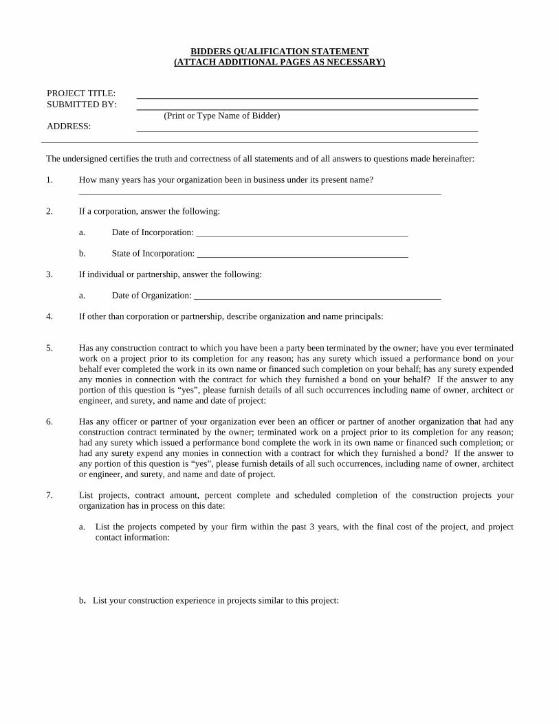
BIDDERS QUALIFICATION STATEMENT(ATTACH ADDITIONAL PAGES AS NECESSARY)
PROJECT TITLE: SUBMITTED BY:
(Print or Type Name of Bidder)ADDRESS:
The undersigned certifies the truth and correctness of all statements and of all answers to questions made hereinafter:
1. How many years has your organization been in business under its present name?
2. If a corporation, answer the following:
a. Date of Incorporation:
b. State of Incorporation:
3. If individual or partnership, answer the following:
a. Date of Organization:
4. If other than corporation or partnership, describe organization and name principals:
5. Has any construction contract to which you have been a party been terminated by the owner; have you ever terminated work on a project prior to its completion for any reason; has any surety which issued a performance bond on your behalf ever completed the work in its own name or financed such completion on your behalf; has any surety expended any monies in connection with the contract for which they furnished a bond on your behalf? If the answer to any portion of this question is “yes”, please furnish details of all such occurrences including name of owner, architect or engineer, and surety, and name and date of project:
6. Has any officer or partner of your organization ever been an officer or partner of another organization that had any construction contract terminated by the owner; terminated work on a project prior to its completion for any reason; had any surety which issued a performance bond complete the work in its own name or financed such completion; or had any surety expend any monies in connection with a contract for which they furnished a bond? If the answer to any portion of this question is “yes”, please furnish details of all such occurrences, including name of owner, architect or engineer, and surety, and name and date of project.
7. List projects, contract amount, percent complete and scheduled completion of the construction projects your organization has in process on this date:
a. List the projects competed by your firm within the past 3 years, with the final cost of the project, and project contact information:
b. List your construction experience in projects similar to this project:

Huitt-Zollars, Inc. Hasler Valley Road Solid Waste Facility HZ Project No. R305538.05
This page left intentionally blank
8. List name and construction experience of the principals in your organization, including officers:
9. List the states and categories of construction in which you organization is legally qualified to do business:
10. List name, address, and telephone number of an individual who represents each of the following and who may be contacted for a financial reference:
a. A surety:
b. A bank:
CREDIT AVAILABLE: $_______________
c. A major material supplier:
Dated this day of 20
Bidder: (Print or Type Name of Bidder)
By:
Title: Seal of Corporation

Huitt-Zollars, Inc. Hasler Valley Road Solid Waste Facility HZ Project No. R305538.05
This page left intentionally blank

CITY OF GALLUPSUBCONTRACTOR LISTING
Formal Bid No. 1806
The Subcontractor Listing Threshold For This Project Is $5,000, And Attached To The Bid In Compliance With 13-4-32 Thru 13-4-43 NMSA 1978, Together With The City Or County Location Of Their Place Of Business Listed. The Following Subcontractors Will Work On The Construction Of The Project If My Proposal Is Accepted. List only one Entry for each category of work as defined by Contractor.Bidder Represents That He Is Licensed And Qualified To Perform 100% Of The Category Of Work For Which NoSubcontractor Is Listed. D.W.S. Registration Number Required If Amount Of Work Exceeds $60,000.
Company Name: ____________________________ Company Name: ____________________________ Address: _______________________________ Address: _______________________________City/County: ____________________ State: ____ City/County: ____________________ State: ___________Work to be performed: ________________________ Work to be performed: ________________________Amount ($): _____________________ Amount ($): _____________________ License No.: _______________________ License No.:_________________________DWS Registration No. ________________ DWS Registration No. ________________
Company Name: ____________________________ Company Name: ____________________________ Address: _______________________________ Address: _______________________________City/County: ____________________ State: ____ City/County: ____________________ State: ___________Work to be Performed: ________________________ Work to be Performed: ________________________Amount ($): _____________________ Amount ($): _____________________ License No.: _______________________ License No.:_________________________DWS Registration No. ________________ DWS Registration No. ________________
Company Name: ____________________________ Company Name: ____________________________ Address: _______________________________ Address: _______________________________City/County: ____________________ State: ____ City/County: ____________________ State: ___________Work to be Performed: ________________________ Work to be Performed: ________________________Amount ($): _____________________ Amount ($): _____________________ License No.: _______________________ License No.:_________________________DWS Registration No. ________________ DWS Registration No. ________________
Company Name: ____________________________ Company Name: ____________________________ Address: _______________________________ Address: _______________________________City/County: ____________________ State: _____ City/County: ____________________ State: ___________Work to be Performed: ________________________ Work to be Performed: ________________________Amount ($): _____________________ Amount ($): _____________________ License No.: _______________________ License No.:_________________________DWS Registration No. ________________ DWS Registration No. ________________
No Contractor whose Proposal is accepted shall permit any subcontract to be voluntarily assigned or transferred or allow it to be performed byanyone other than the original subcontractor listed in the original Proposal without the consent of the using agency.
No Contractor whose Proposal is accepted, other than in the performance of change orders causing changes or deviations from the originalcontract, shall sublet or subcontract any portion of the work in excess of the listing threshold as to which his original Proposal did not designatea Subcontractor unless:
(1) the Contractor fails to receive a Proposal from a category of work. Under such circumstances, the contractor may subcontract. TheContractor shall designate on the listing form that no Proposal was received or;
(2) the Contractor fails to receive more than one Proposal for a category of work. Under such circumstances, the Contractor maysubcontract. The Contractor shall state on the listing form that only one Subcontractor’s Proposal was received, together with the name of the Subcontractor. This designation shall not occur more than one time on the Subcontractor list.
ADDITIONAL COPIES MAY BE MADE IF NECESSARY

Huitt-Zollars, Inc. Hasler Valley Road Solid Waste Facility HZ Project No. R305538.05
This page left intentionally blank
CITY OF GALLUP
PROPOSAL FORM FOR CONTRACTFormal Bid No. 1806
Project: Hasler Valley Road Solid Waste Facility
Proposal of _________________________________________(hereinafter called the bidder), a corporation, organized and existing under the laws of the State of New Mexico, a partnership or an individual doing business as ___________________________________________________________
to the City of Gallup (hereinafter called the Owner).
Gentlemen: The bidder in compliance with your invitation for bids for the above-named project, has examined bidding documents and the site of the proposed work, and being familiar with all of the existing building and conditions surrounding the construction of the proposed project, including the availability of materials and supplies and to construct the project in accordance with the contract documents within the time set forth and at the prices stated below. These prices are to cover all expenses incurred in performing the work required under the contract documents, of which this proposal is a part, including any applicable building permit or other fees.
Bid Security: Shall be submitted with the bid and made payable to the owner in the amount of five percent (5%) of the bid sum. Security shall be by cash, certified or cashiers’ check or a bid bond prepared on a form acceptable to the owner, issued by a surety licensed to do business in the state where the project is located. The Owner will retain these securities for 45 days or until a contract has been entered into, whichever is shorter. Should the low bidder refuse to enter into a contract, the owner will retain his security as liquidated damages, not as a penalty. If the lowest bidder fails to enter into a contract, then the next lowest bidder will be considered as the lowest bidder.
Performance and Payment Bond: In addition the successful bidder shall execute a performance bond and a payment bond each with a corporate surety authorized to do business in the State of New Mexico and said surety to be approved in Federal Circular 570 as published by the U.S. Treasury Department, each in the sum of 100% of the total bid price, within Fifteen (15) days of Notice of Award.
Liquidated Damages: Liquidated damages in the amount of $500.00 per day shall be assessed for every calendar day past the stated completion date.
Taxes: The proposal total shall exclude all applicable taxes. The City will pay any taxes due on the contract based upon billing submitted by the contractor, at the applicable tax rate. Taxes shall be shown as a separate amount on any billing or request for payment.
Bidder hereby agrees to commence work under this contract on the date specified in the Notice to Proceed. Bidder shall provide a certificate of insurance in compliance with the State of New Mexico Construction Industries Division rules and regulation and the terms of this bid. If required by law, bidder shall provide evidence of Workmen’s Compensation Insurance
Wages will be paid in accordance with the State of New Mexico wage rates as required by statute.

Huitt-Zollars, Inc. Hasler Valley Road Solid Waste Facility HZ Project No. R305538.05
This page left intentionally blank

ADDENDA: BIDDER ACKNOWLEDGES RECEIPT OF THE FOLLOWING AMENDMENTS:
InitialsAMENDMENT No. 1: ____ Date ________________
AMENDMENT No. 2:____ Date ________________
AMENDMENT No. 3:____ Date ________________
AMENDMENT No. 4:____ Date ________________
AMENDMENT No. 5:____ Date ________________
AMENDMENT No. 6:____ Date ________________
FAILURE TO ACKNOWLEDGE RECEIPT AS PROVIDED ABOVE MAY BE SUFFICIENT GROUNDS FOR DISQUALIFICATION OF THE BIDDER AND REJECTION OF HIS PROPOSAL. IT SHALL BE THE CONTRACTOR’SRESPONSIBILITY TO BECOME FULLY ADVISED OF ALL ADDENDA PRIOR TO SUBMITTING A BID.
Bidder’s Checklist of Required Documents
Bidder’s Qualification Statement, Pages _________________
Subcontractor’s Listing (1 Page, attach additional pages if needed), Page _
Proposal Form for Contract (2 Pages), Pages __________
Price Proposal Forms, Pages, _________
Bid Bond (5%) (2 Pages), _______
Bidders must include a Copy of New Mexico Resident Contractors Certificate or New Mexico Resident
Veteran Contractors Certificate (if applicable, to qualify for application of State Preference to the bid)
Acknowledge Receipts of Amendments (if any), This Page _____

Huitt-Zollars, Inc. Hasler Valley Road Solid Waste Facility HZ Project No. R305538.05
This page left intentionally blank
BID PROPOSAL FORM FORMAL BID NO. 1806
(FOR LUMP SUM CONTRACT ONLY)
THE BIDDER AGREES TO PERFORM ALL THE WORK AS DESCRIBED IN THE GENERAL CONDITIONS AND
PLANS TO PROVIDE___________________________________________ FOR THE FOLLOWING LUMP SUM:
BASE BID (EXCLUDING TAXES):
______________________________________________ $________________
(SHOW AMOUNTS IN FIGURES AND WORDS)
PLUS NEW MEXICO GROSS RECEIPTS TAX (@ 8.3125%)
_________________________________________________________ $________________
(SHOW AMOUNTS IN FIGURES AND WORDS)
ALTERNATE NO. 01 (EXCLUDING TAXES):
______________________________________________ $________________
(SHOW AMOUNTS IN FIGURES AND WORDS)
PLUS NEW MEXICO GROSS RECEIPTS TAX (@ 8.3125%)
____________________________________________________ $________________
(SHOW AMOUNTS IN FIGURES AND WORDS)
ALTERNATE NO. 02 (EXCLUDING TAXES):
______________________________________________ $________________
(SHOW AMOUNTS IN FIGURES AND WORDS)
PLUS NEW MEXICO GROSS RECEIPTS TAX (@ 8.3125%)
____________________________________________________ $________________
(SHOW AMOUNTS IN FIGURES AND WORDS)
ALTERNATE NO. 03 (EXCLUDING TAXES):
______________________________________________ $________________
(SHOW AMOUNTS IN FIGURES AND WORDS)
PLUS NEW MEXICO GROSS RECEIPTS TAX (@ 8.3125%)
____________________________________________________ $________________
(SHOW AMOUNTS IN FIGURES AND WORDS)

Huitt-Zollars, Inc. Hasler Valley Road Solid Waste Facility HZ Project No. R305538.05
This page left intentionally blank

TOTAL BID (INCLUDING TAXES)
____________________________________________________ $________________
(SHOW AMOUNTS IN FIGURES AND WORDS)
IN THE CASE OF A DISCREPANCY, THE AMOUNTS SHOWN IN WORDS SHALL GOVERN. SUBMITTED BY: Business Name ______________________________________ SIGNED By: ______________________________ ____________________________________
Authorized Signature Name Printed or Typed
____________________________ _________________________________
Title Date
____________________________ ____________________________________ Address Phone & Fax Number
_____________________________ ____________________________________ Email Address _____________________________
City, State, Zip
_____________________________ __________________________________
D.W.S. Registration No. N.M. Contractor's License No.

Huitt-Zollars, Inc. Hasler Valley Road Solid Waste Facility HZ Project No. R305538.05
This page left intentionally blank

Huitt-Zollars, Inc. Hasler Valley Road Solid Waste Facility HZ Project No. R305538.05
UNIT PRICES FORM 1
DOCUMENT 004322 - UNIT PRICES FORM
1.1 BID INFORMATION
A. Bidder: ____________________________________________________.
B. Project Name: Hasler Valley Road Solid Waste Facility.
C. Project Location: 1480 Hasler Valley Road, Gallup, NM .
D. Owner: City of Gallup.
E. Owner Project Number: 1806.
F. Architect: Huitt-Zollars, Inc.
G. Architect Project Number: R305538.05.
1.2 BID FORM SUPPLEMENT
A. This form is required to be attached to the Bid Form.
B. The undersigned Bidder proposes the amounts below be added to or deducted from the Contract Sum on performance and measurement of the individual items of Work and for adjustment of the quantity given in the Unit-Price Allowance for the actual measurement of individual items of the Work.
C. If the unit price does not affect the Work of this Contract, the Bidder shall indicate "NOT APPLICABLE."
1.3 UNIT PRICES
A. Unit-Price No. 1: Linear Grading
1. _______________________________________ Dollars ($_____________) per unit.
B. Unit-Price No. 2: Twelve-inch Subgrade Preparation
1. _______________________________________ Dollars ($_____________) per unit.
C. Unit-Price No. 3: Six-inch Base Course
1. _______________________________________ Dollars ($_____________) per unit.
D. Unit-Price No. 4: Three-inch HMA SP-IV
1. _______________________________________ Dollars ($_____________) per unit.

Huitt-Zollars, Inc. Hasler Valley Road Solid Waste Facility HZ Project No. R305538.05
This page left intentionally blank

Huitt-Zollars, Inc. Hasler Valley Road Solid Waste Facility HZ Project No. R305538.05
UNIT PRICES FORM 2
E. Unit-Price No. 5: Six-inch by Twelve-inch Concrete Header Curb
1. _______________________________________ Dollars ($_____________) per unit.
1.4 SUBMISSION OF BID SUPPLEMENT
A. Respectfully submitted this ____ day of ____________, 2018.
B. Submitted By:___________________________________(Insert name of bidding firm or corporation).
C. Authorized Signature:___________________________________(Handwritten signature).
D. Signed By:______________________________________________(Type or print name).
E. Title:___________________________________(Owner/Partner/President/Vice President).
END OF DOCUMENT 004322

Huitt-Zollars, Inc. Hasler Valley Road Solid Waste Facility HZ Project No. R305538.05
This page left intentionally blank

BID BOND
BIDDER (Name and Address):
SURETY (Name and Address of Principal Place of Business):
OWNER (Name and Address):City of Gallup110 West Aztec Ave., PO Box 1270Gallup, NM
BIDBID DUE DATE:PROJECT (Brief Description Including Location):
BONDBOND NUMBER: DATE (Not later than Bid due date): PENAL SUM (Words) (Figures)
IN WITNESS WHEREOF, Surety and Bidder, intending to be legally bound hereby, subject to the terms printed on the reserve side hereof, do each cause this Bid Bond to be duly executed on its behalf by its authorized officer, agent, or representative.
BIDDER SURETY
(Seal) (Seal)Bidder’s Name and Corporate Seal Surety’s Name and Corporate Seal
By: ________________________________ By:____________________________________ Signature and Title Signature and Title
(Attach Power of Attorney
Attest: ______________________________ Attest: _________________________________ Signature and Title Signature and Title
Note: (1) Above addresses are to be used for giving required notice.(2) Any singular reference to Bidder, Surety, OWNER or other party shall be considered plural where
applicable.1. Bidder and Surety, jointly and severally, bind themselves, their heirs, executors, administrators, successors and
assigns to pay to OWNER upon default of Bidder the penal sum set forth on the face of this Bond.
2. Default of Bidder shall occur upon the failure of Bidder to deliver within the time required by the bidding Documents (or any extension thereof agreed to in writing by OWNER) the executed Agreement required by the Bidding Documents and any performance and payment Bonds required by the Bidding Documents.

Huitt-Zollars, Inc. Hasler Valley Road Solid Waste Facility HZ Project No. R305538.05
This page left intentionally blank

3. This obligation shall be null and void if:
3.1 OWNER accepts Bidder’s Bid and Bidder delivers within the time required by the Bidding Documents (or any extension thereof agreed to in writing by OWNER) the executed Agreement required by the Bidding Documents and any performance and payment Bonds required by the Bidding Documents, or
3.2 All Bids are rejected by OWNER, or3.3 OWNER fails to issue a Notice of Award to Bidder within the time specified in the Bidding Documents (or
any extension thereof agreed to in writing by Bidder and, if applicable, consented to by Surety when required by paragraph 5 hereof).
4. Payment under this Bond will be due and payable upon default by Bidder and within 30 calendar days after receipt by Bidder and Surety of written notice of default from OWNER, which notice will be given with reasonable promptness, identifying this Bond and the Project and including a statement of the amount due.
5. Surety waives notice of any and all defenses based on or arising out of any time extension to issue Notice of Award agreed to in writing by OWNER and Bidder, provided that the total time for issuing Notice of Award including extensions shall not in the aggregate exceed 120 days from Bid due date without Surety’s written consent.
6. No suit or action shall be commenced under this Bond prior to 30 calendar days after the notice of default required in paragraph 4 above is received by Bidder and Surety and in no case later than one year after Bid due date.
7. Any suit or action under this Bond shall be commenced only in a court of competent jurisdiction located in the state in which the Project is located.
8. Notices required hereunder shall be in writing and sent to Bidder and Surety at their respective addresses shown on the face of this Bond. Such notices may be sent by personal delivery, commercial courier or by United States Registered or Certified Mail, return receipt requested, postage pre-paid, and shall be deemed to be effective upon receipt by the party concerned.
9. Surety shall cause to be attached to this Bond a current and effective Power of Attorney evidencing the authority of the officer, agent or representative who executed this Bond on behalf of Surety to execute, seal and deliver such Bond and bind the Surety thereby.
10. This Bond is intended to conform to all applicable statutory requirements. Any applicable requirements of any applicable statute that has been omitted from this Bond shall be deemed to be included herein as if set forth at length. If any provision of this Bond conflicts with any applicable statute, then the provision of said statute shall govern and the remainder of this Bond that is not in conflict therewith shall continue in full force and effect.
11. The term “Bid” as used herein includes a Bid, offer or proposal as applicable.

Huitt-Zollars, Inc. Hasler Valley Road Solid Waste Facility HZ Project No. R305538.05
This page left intentionally blank
CONTRACT
THIS AGREEMENT, made this day of __________________, 20__, by and between ______________________________________________, hereinafter called the "OWNER" and ______________________________________________, hereinafter called the "CONTRACTOR".
WITNESSETH: That for and in consideration of the payment and agreements hereinafter mentioned, to be made and performed by the OWNER, the CONTRACTOR hereby agrees with the OWNER to commence and complete the construction described as follows:_________________________________________________________________________________hereinafter called the project, for the sum of:________________________________________________________________________________Dollars ($____________________) and all work in connection therewith, under the terms as stated in the Terms, Conditions and Plans of the bid and this Contract; and at his (its or their) own proper cost and expense to furnish all the materials, supplies, machinery, equipment, tools, labor, insurance and other accessories and services necessary to complete the said project in accordance with the conditions and prices stated in the Proposal, the Terms and Conditions of the bid and the Contract, the plans, specifications and contract documents herefore as prepared by _________________________________ and the City of Gallup, all of which are made a part hereof and collectively constitute the Contract.
The Contractor hereby agrees to commence work under this Contract on or before a date to be specified in a written "Notice to Proceed" of the OWNER and to fully complete the project within ___________________________________ ( ) consecutive calendar days thereafter. The CONTRACTOR further agrees to pay, as liquidated damages, the sum of ______________________Dollars ($________________) for each consecutive calendar day thereafter as hereinafter provided in the Special and General Conditions.

Huitt-Zollars, Inc. Hasler Valley Road Solid Waste Facility HZ Project No. R305538.05
This page left intentionally blank
IN WITNESS WHEREOF, the parties to these presents have executed this Contract in four (4)
counterparts, each of which shall be deemed an original, in the year and day first above mentioned.
_____________________________________(SEAL) OWNERATTEST: ___________________________
BY:_____________________________________
SIGNATURE
_____________________________________NAME TYPED OR PRINTED
_____________________________________TITLE
(CORPORATE SEAL) _____________________________________CONTRACTOR
BY:_____________________________________
SIGNATURE
____________________________________NAME TYPED OR PRINTED
_____________________________________TITLE

Huitt-Zollars, Inc. Hasler Valley Road Solid Waste Facility HZ Project No. R305538.05
This page left intentionally blank
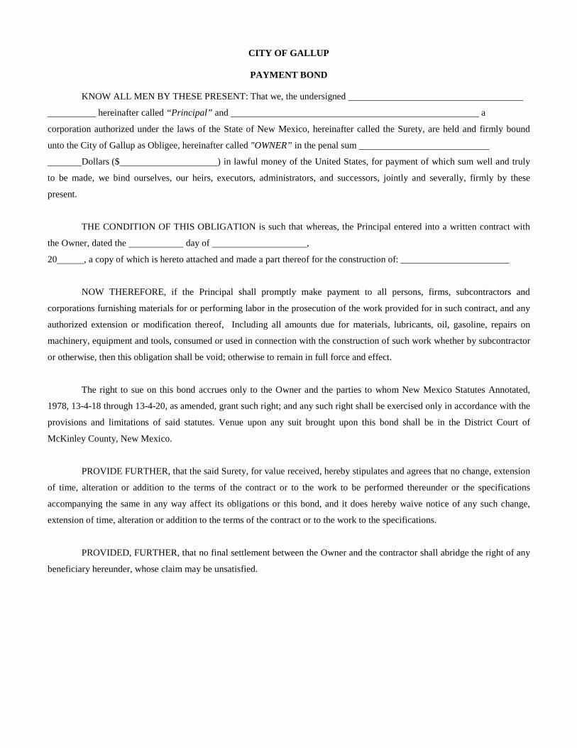
CITY OF GALLUP
PAYMENT BOND
KNOW ALL MEN BY THESE PRESENT: That we, the undersigned
hereinafter called “Principal” and a
corporation authorized under the laws of the State of New Mexico, hereinafter called the Surety, are held and firmly bound
unto the City of Gallup as Obligee, hereinafter called "OWNER” in the penal sum
Dollars ($ ) in lawful money of the United States, for payment of which sum well and truly
to be made, we bind ourselves, our heirs, executors, administrators, and successors, jointly and severally, firmly by these
present.
THE CONDITION OF THIS OBLIGATION is such that whereas, the Principal entered into a written contract with
the Owner, dated the day of ,
20 , a copy of which is hereto attached and made a part thereof for the construction of: _______________________
NOW THEREFORE, if the Principal shall promptly make payment to all persons, firms, subcontractors and
corporations furnishing materials for or performing labor in the prosecution of the work provided for in such contract, and any
authorized extension or modification thereof, Including all amounts due for materials, lubricants, oil, gasoline, repairs on
machinery, equipment and tools, consumed or used in connection with the construction of such work whether by subcontractor
or otherwise, then this obligation shall be void; otherwise to remain in full force and effect.
The right to sue on this bond accrues only to the Owner and the parties to whom New Mexico Statutes Annotated,
1978, 13-4-18 through 13-4-20, as amended, grant such right; and any such right shall be exercised only in accordance with the
provisions and limitations of said statutes. Venue upon any suit brought upon this bond shall be in the District Court of
McKinley County, New Mexico.
PROVIDE FURTHER, that the said Surety, for value received, hereby stipulates and agrees that no change, extension
of time, alteration or addition to the terms of the contract or to the work to be performed thereunder or the specifications
accompanying the same in any way affect its obligations or this bond, and it does hereby waive notice of any such change,
extension of time, alteration or addition to the terms of the contract or to the work to the specifications.
PROVIDED, FURTHER, that no final settlement between the Owner and the contractor shall abridge the right of any
beneficiary hereunder, whose claim may be unsatisfied.

Huitt-Zollars, Inc. Hasler Valley Road Solid Waste Facility HZ Project No. R305538.05
This page left intentionally blank

IN WITNESS WHEREOF, this instrument is executing in four (4) counterparts, each one of which shall be deemed an original,
this day of , 20 .
ATTEST:
________________________________ ___________________________________(Principal) Secretary Principal
By:
Address: _____________________________
____________________________________
____________________________________ City State Zip
SEAL
_______________________________Witness as to Principal
_______________________________Address
_______________________________City State Zip
ATTEST:
_______________________________ ___________________________________ (Surety) Secretary Surety
By: Attorney-in-Fact
____________________________________Address
____________________________________ City State Zip
SEAL
________________________________Witness as to Surety
________________________________Address
________________________________City State Zip

Huitt-Zollars, Inc. Hasler Valley Road Solid Waste Facility HZ Project No. R305538.05
This page left intentionally blank
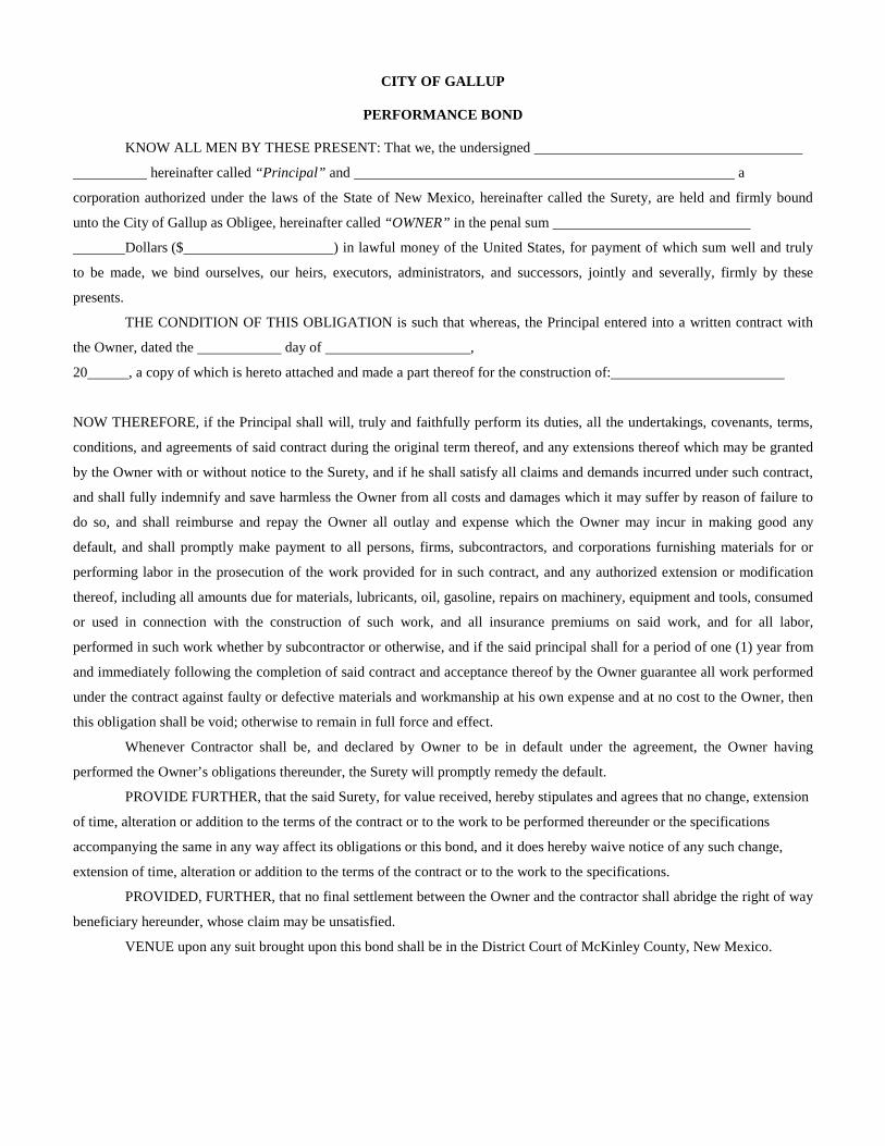
CITY OF GALLUP
PERFORMANCE BOND
KNOW ALL MEN BY THESE PRESENT: That we, the undersigned
hereinafter called “Principal” and a
corporation authorized under the laws of the State of New Mexico, hereinafter called the Surety, are held and firmly bound
unto the City of Gallup as Obligee, hereinafter called “OWNER” in the penal sum
Dollars ($ ) in lawful money of the United States, for payment of which sum well and truly
to be made, we bind ourselves, our heirs, executors, administrators, and successors, jointly and severally, firmly by these
presents.
THE CONDITION OF THIS OBLIGATION is such that whereas, the Principal entered into a written contract with
the Owner, dated the day of ,
20 , a copy of which is hereto attached and made a part thereof for the construction of:
NOW THEREFORE, if the Principal shall will, truly and faithfully perform its duties, all the undertakings, covenants, terms,
conditions, and agreements of said contract during the original term thereof, and any extensions thereof which may be granted
by the Owner with or without notice to the Surety, and if he shall satisfy all claims and demands incurred under such contract,
and shall fully indemnify and save harmless the Owner from all costs and damages which it may suffer by reason of failure to
do so, and shall reimburse and repay the Owner all outlay and expense which the Owner may incur in making good any
default, and shall promptly make payment to all persons, firms, subcontractors, and corporations furnishing materials for or
performing labor in the prosecution of the work provided for in such contract, and any authorized extension or modification
thereof, including all amounts due for materials, lubricants, oil, gasoline, repairs on machinery, equipment and tools, consumed
or used in connection with the construction of such work, and all insurance premiums on said work, and for all labor,
performed in such work whether by subcontractor or otherwise, and if the said principal shall for a period of one (1) year from
and immediately following the completion of said contract and acceptance thereof by the Owner guarantee all work performed
under the contract against faulty or defective materials and workmanship at his own expense and at no cost to the Owner, then
this obligation shall be void; otherwise to remain in full force and effect.
Whenever Contractor shall be, and declared by Owner to be in default under the agreement, the Owner having
performed the Owner’s obligations thereunder, the Surety will promptly remedy the default.
PROVIDE FURTHER, that the said Surety, for value received, hereby stipulates and agrees that no change, extension
of time, alteration or addition to the terms of the contract or to the work to be performed thereunder or the specifications
accompanying the same in any way affect its obligations or this bond, and it does hereby waive notice of any such change,
extension of time, alteration or addition to the terms of the contract or to the work to the specifications.
PROVIDED, FURTHER, that no final settlement between the Owner and the contractor shall abridge the right of way
beneficiary hereunder, whose claim may be unsatisfied.
VENUE upon any suit brought upon this bond shall be in the District Court of McKinley County, New Mexico.

Huitt-Zollars, Inc. Hasler Valley Road Solid Waste Facility HZ Project No. R305538.05
This page left intentionally blank

IN WITNESS WHEREOF, this instrument is executing in four (4) counterparts, each one of which shall be deemed an
original, this the day of , 20 .
ATTEST:
________________________________ ___________________________________(Principal) Secretary Principal
By:
Address: _____________________________
____________________________________
____________________________________ City State Zip
SEAL
_______________________________Witness as to Principal
_______________________________Address
_______________________________City State Zip
ATTEST:
_______________________________ ___________________________________ (Surety) Secretary Surety
By: Attorney-in-Fact
____________________________________Address
____________________________________ City State Zip
SEAL
________________________________Witness as to Surety
________________________________Address
________________________________City State Zip

Huitt-Zollars, Inc. Hasler Valley Road Solid Waste Facility HZ Project No. R305538.05
This page left intentionally blank
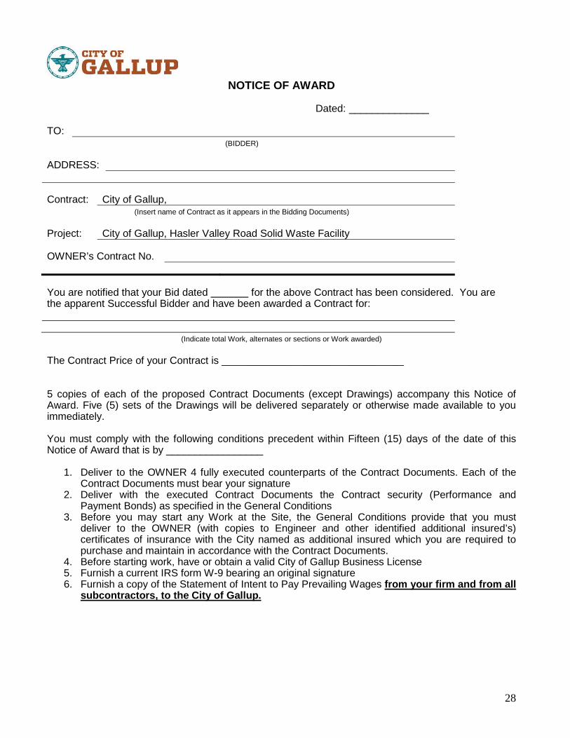
28
NOTICE OF AWARD
Dated: ______________
TO:(BIDDER)
ADDRESS:
Contract: City of Gallup, (Insert name of Contract as it appears in the Bidding Documents)
Project: City of Gallup, Hasler Valley Road Solid Waste Facility
OWNER’s Contract No.
You are notified that your Bid dated for the above Contract has been considered. You are the apparent Successful Bidder and have been awarded a Contract for:
(Indicate total Work, alternates or sections or Work awarded)
The Contract Price of your Contract is ________________________________
5 copies of each of the proposed Contract Documents (except Drawings) accompany this Notice of Award. Five (5) sets of the Drawings will be delivered separately or otherwise made available to you immediately.
You must comply with the following conditions precedent within Fifteen (15) days of the date of this Notice of Award that is by _________________
1. Deliver to the OWNER 4 fully executed counterparts of the Contract Documents. Each of the Contract Documents must bear your signature
2. Deliver with the executed Contract Documents the Contract security (Performance and Payment Bonds) as specified in the General Conditions
3. Before you may start any Work at the Site, the General Conditions provide that you must deliver to the OWNER (with copies to Engineer and other identified additional insured’s) certificates of insurance with the City named as additional insured which you are required to purchase and maintain in accordance with the Contract Documents.
4. Before starting work, have or obtain a valid City of Gallup Business License5. Furnish a current IRS form W-9 bearing an original signature 6. Furnish a copy of the Statement of Intent to Pay Prevailing Wages from your firm and from all
subcontractors, to the City of Gallup.

Huitt-Zollars, Inc. Hasler Valley Road Solid Waste Facility HZ Project No. R305538.05
This page left intentionally blank
29
Failure to comply with these conditions within the time specified will entitle OWNER to consider your Bid in default, to annul this Notice of Award and to declare your Bid security forfeited.
Within ten days after you comply with the above conditions, OWNER will return to you one fully executed counterpart of the Contract Documents.
City of Gallup(OWNER)
By: (AUTHORIZED SIGNATURE)
(TITLE)

Huitt-Zollars, Inc. Hasler Valley Road Solid Waste Facility HZ Project No. R305538.05
This page left intentionally blank

30
NOTICE TO PROCEED
Dated:
TO:(CONTRACTOR)
ADDRESS1:
Contract:(Insert name of Contract as it appears in the Bidding Documents)
Project:
OWNER’s Contract No.
You are notified that the Contract Times under the above contract will commence to run on _______________________. By that date, you are to start performing your obligations under the Contract Documents.
Also, before you may start any Work at the Site, you must(add other requirements)
(OWNER)
By: (AUTHORIZED SIGNATURE)
(TITLE)

Huitt-Zollars, Inc. Hasler Valley Road Solid Waste Facility HZ Project No. R305538.05
State of New Mexico Wage DecisionMC-18-0329-B

STATE OF NEW MEXICO NEW MEXICO DEPARTMENT OF WORKFORCE SOLUTIONS Labor Relations Division 121 Tijeras Ave NE, Suite 3000 Albuquerque, NM 87102 www.dws.state.nm.us
An Equal Opportunity Employer Page 1 of 2
PUBLIC WORKS PROJECT REQUIREMENTS
As a participant in a Public Works project valued at more than $60,000 in the State of New Mexico, the following list addresses many of the responsibilities that are defined by statute or regulation to each project stakeholder. Contracting Agency
Ensure that all Contractors wishing to bid on a Public Works project when the project is $60,000 or more are actively registered with the Public Works and Apprenticeship Application (PWAA) website: http://www.dws.state.nm.us/pwaa (Contractor Registration) prior to bidding. Please submit Notice of Award (NOA) and Subcontractor List(s) to the PWAA website promptly after the project is awarded. Please update the Subcontractor List(s) on the PWAA website whenever changes occur. All Sub-Contractors and tiers (excluding professional services) regardless of contract amount must be listed on the Subcontractor List and must adhere to the Public Works Minimum Wage Act. Ninety days after project completion please go into the PWAA system and close the project. Only Contracting Agencies are allowed to close the project. Agents or Contractors are not allowed to close projects.
General Contractor
Provide a complete Subcontractor List and Statements of Intent (SOI) to Pay Prevailing Wages for all Contractors, regardless of amount of work, to the Contracting Agency within 3 (three) days of award. Ensure that all Subcontractors wishing to bid on a Public Works project have an active Contractor Registration with the Public Works and Apprenticeship Application (PWAA) website: http://www.dws.state.nm.us/pwaa prior to bidding when their bid will exceed $60,000. Submit weekly certified payroll bi-weekly to the Contracting Agency. Make certain the Public Works Apprentice and Training Act contributions are paid either to an approved Apprenticeship Program or to the Public Works Apprentice and Training Fund. Confirm the Wage Rate poster, provided in PWAA, is displayed at the job site in an easily accessible place. Make sure, when a project has been completed, the Affidavits of Wages Paid (AWP) are sent to the Contracting Agency.

Huitt-Zollars, Inc. Hasler Valley Road Solid Waste Facility HZ Project No. R305538.05
This page left intentionally blank

STATE OF NEW MEXICO NEW MEXICO DEPARTMENT OF WORKFORCE SOLUTIONS Labor Relations Division 121 Tijeras Ave NE, Suite 3000 Albuquerque, NM 87102 www.dws.state.nm.us
An Equal Opportunity Employer Page 2 of 2
All Subcontractors and tiers (excluding professional services) regardless of contract amount must be listed on the Subcontractor List and must adhere to the Public Works Minimum Wage Act.
Subcontractor
Ensure that all Subcontractors wishing to bid on a Public Works project have an active Contractor Registration with the Public Works and Apprenticeship Application (PWAA) website: http://www.dws.state.nm.us/pwaa prior to bidding when their bid will exceed $60,000. Submit weekly certified payroll bi-weekly to the General Contractor(s). Make certain the Public Works Apprentice and Training Act contributions are paid either to an approved Apprenticeship Program or to the Public Works Apprentice and Training Fund. All Subcontractors and tiers (excluding professional services) regardless of contract amount must be listed on the Subcontractor List and must adhere to the Public Works Minimum Wage Act.
Additional Information Reference material and forms may be found at New Mexico Department of Workforce Solutions Public Works web pages at: https://www.dws.state.nm.us/Labor-Relations/Labor-Information/Public-Works. CONTACT INFORMATION Contact the Labor Relations Division for any questions relating to Public Works projects by email at [email protected] or call (505) 841-4400.

Huitt-Zollars, Inc. Hasler Valley Road Solid Waste Facility HZ Project No. R305538.05
This page left intentionally blank

Wage Decision Approval Summary
1) Project Title: Hasler Valley Road Solid Waste FacilityRequested Date: 02/27/2018Approved Date: 03/01/2018Approved Wage Decision Number: MC-18-0329-B
Wage Decision Expiration Date for Bids: 06/29/2018
2) Physical Location of Jobsite for Project:Job Site Address: 1480 Hasler Valley RoadJob Site City: GallupJob Site County: McKinley
3) Contracting Agency Name (Department or Bureau): City of GallupContracting Agency Contact's Name: Frances RodriguezContracting Agency Contact's Phone: (505) 863-1334 Ext.
4) Estimated Contract Award Date: 04/17/2018
5) Estimated total project cost: $3,100,000.00a. Are any federal funds involved?: Nob. Does this project involve a building?: Yes - The future administration building and storage yard for theSolid Waste Department for the City of Gallupc. Is this part of a larger plan for construction on or appurtenant to the property that is subject to thisproject?: Nod. Are there any other Public Works Wage Decisions related to this project?: Noe. What is the ultimate purpose or functional use of the construction once it is completed?: The futureadministration building and storage yard for the Solid Waste Department for the City of Gallup
6) Classifications of Construction:Classification Type
and Cost Total Description
General Building (B)Cost: $3,100,000.00
Development of approximately 4 acre site for the relocation of thecity of Gallup Solid Waste Facility. The project includes threestructures: 4,782 sf Administration Building; 1,879 sf Shop Buildingand Storage Building and Canopy shelter for up to eighteen (18)solid waste vehicles. Site improvements include: Improvements toaccess road, parking for staff and visitors and parking for fleetpickup trucks and maneuvering yard for the solid waste vehicles.
STATE OF NEW MEXICONEW MEXICO DEPARTMENT OFWORKFORCE SOLUTIONSLabor Relations Division,121 Tijeras Ave NE, Suite 3000Albuquerque, NM 87102www.dws.state.nm.us
An Equal Opportunity Employer Page 1 of 1.

Huitt-Zollars, Inc. Hasler Valley Road Solid Waste Facility HZ Project No. R305538.05
This page left intentionally blank

Base Rate Fringe Rate ApprenticeshipAsbestos Worker - Heat & Frost Insulator 31.76 11.11 0.67Boilermaker 32.06 27.35 0.67Bricklayer/Blocklayer/Stonemason 23.52 8.10 0.67Carpenter/Lather 24.00 9.47 0.67Cement Mason 20.37 9.78 0.67Electricians-Outside Classifications
Groundman 22.36 11.34 0.67Equipment Operator 32.08 13.77 0.67
Lineman/Tech 37.75 15.19 0.67Cable Splicer 41.53 16.14 0.67
Inside Classifications Wireman/Technician 30.40 10.36 0.67
Cable Splicer 33.44 10.45 0.67Sound Classifications Installer 23.39 8.31 0.67
Technician 28.95 7.52 0.67 Soundman 27.01 8.31 0.67
Elevator Constructor 41.10 32.40 0.67Elevator Constructor Helper 28.77 32.40 0.67Glazier 20.25 4.55 0.67Ironworker 26.50 14.66 0.67Painter (Brush/Roller/Spray) 16.75 5.88 0.67Paper Hanger 16.75 5.88 0.67Drywall Finisher/Taper 24.00 9.47 0.67Plasterer 22.07 8.16 0.67Plumber/Pipefitter 28.95 11.38 0.67Roofer 23.78 7.60 0.67Sheetmetal Worker 29.28 17.16 0.67Soft Floor Layer 24.00 9.47 0.67Sprinkler Fitter 29.90 19.67 0.67Tile Setter 23.52 8.10 0.67Tile Setter Helper/Finisher 15.59 8.10 0.67Laborers Group I 16.09 5.68 0.67 Group II 17.00 5.68 0.67 Group III 18.00 5.68 0.67 Group IV 20.25 5.68 0.67Operators Group I 20.32 6.47 0.67 Group II 22.38 6.47 0.67 Group III 22.82 6.47 0.67 Group IV 23.24 6.47 0.67 Group V 23.41 6.47 0.67 Group VI 23.62 6.47 0.67 Group VII 23.73 6.47 0.67 Group VIII 26.61 6.47 0.67 Group IX 28.89 6.47 0.67 Group X 32.13 6.47 0.67Truck Drivers Group I 14.76 6.25 0.67 Group II 15.00 6.25 0.67 Group III 15.50 6.25 0.67 Group IV 15.51 6.25 0.67 Group V 15.60 6.25 0.67 Group VI 15.75 6.25 0.67 Group VII 15.90 6.25 0.67 Group VIII 16.11 6.25 0.67 Group IX 16.32 6.25 0.67NOTE: All Contractors are required to pay SUBSISTENCE, ZONE AND INCENTIVE PAY according to the particular trade. Details are located in a PDF attachment at WWW.DWS.STATE.NM.US. Search
Type "B" - GENERAL BUILDING Effective January 1, 2018
Labor Relations/Labor Information/Public Works/Prevailing Wage Rates.

Huitt-Zollars, Inc. Hasler Valley Road Solid Waste Facility HZ Project No. R305538.05
This page left intentionally blank

Huitt-Zollars, Inc. Hasler Valley Road Solid Waste Facility HZ Project No. R305538.05
SUMMARY 011000 - 1
SECTION 011000 - SUMMARY
PART 1 - GENERAL
1.1 RELATED DOCUMENTS
A. Drawings and general provisions of the Contract, including General and Supplementary Conditions and other Division 01 Specification Sections, apply to this Section.
1.2 SUMMARY
A. Section includes:
1. Project information.2. Work covered by Contract Documents.3. Access to site.4. Work restrictions.5. Specification and drawing conventions.
B. Related Section:
1. Division 01 Section "Temporary Facilities and Controls" for limitations and procedures governing temporary use of Owner's facilities.
1.3 PROJECT INFORMATION
A. Project Identification: Hasler Valley Road Solid Waste Facility
1. Project Location: Gallup, New Mexico
B. Owner: City of Gallup
1. Owner's Representative: Mr. Adrian Marrufo, Superintendent, Solid Waste Department,1580 Hasler Valley Road, Gallup, New Mexico 87301, (505) 863-1212; fax (505) 863-9124
C. Architect: 1. Huitt-Zollars, Inc., 6501 Americas Parkway Ave, NE Ste. 550, Albuquerque, NM 87110.
Project Manager: Mr. José Zelaya, AIA, NCARB; (505) 883-8114; fax (505) [email protected]
1.4 ACCESS TO SITE
A. General: Contractor shall have full use of Project site for construction operations during construction period. Contractor's use of Project site is limited only by Owner's right to perform work or to retain other contractors on portions of Project.
Huitt-Zollars, Inc. Hasler Valley Road Solid Waste Facility HZ Project No. R305538.05
SUMMARY 011000 - 2
B. Use of Site: Limit use of Project site to work in areas indicated. Do not disturb portions of Project site beyond areas in which the Work is indicated.
C. Contractor shall provide keys to Owner and Architect for all locks placed on the existing chain link fence surrounding the project site.
1.5 WORK RESTRICTIONS
A. Work Restrictions, General: Comply with restrictions on construction operations.
1. Comply with limitations on use of public streets and other requirements of authorities having jurisdiction.
B. On-Site Work Hours: Contractor shall submit schedule of workdays and hours to Owner or Architect in written form for approval.
C. Existing Utility Interruptions: Do not interrupt utilities serving facilities occupied by Owner or others.
D. Noise, Vibration, and Odors: Coordinate operations that may result in high levels of noise and vibration, odors, or other disruption to Owner occupancy with Owner.
1. Notify Architect and Owner not less than two days in advance of proposed disruptive operations.
2. Obtain Architect's and Owner's written permission before proceeding with disruptive operations.
E. Nonsmoking Project: Smoking is not permitted on the project site.
F. Controlled Substances: Use of tobacco products and other controlled substances on the Project site is not permitted.
1.6 SPECIFICATION AND DRAWING CONVENTIONS
A. Specification Content: The Specifications use certain conventions for the style of language and the intended meaning of certain terms, words, and phrases when used in particular situations. These conventions are as follows:
1. Imperative mood and streamlined language are generally used in the Specifications. The words "shall," "shall be," or "shall comply with," depending on the context, are implied where a colon (:) is used within a sentence or phrase.
2. Specification requirements are to be performed by Contractor unless specifically stated otherwise.
B. Division 01 General Requirements: Requirements of Sections in Division 01 apply to the Work of all Sections in the Specifications.
C. Drawing Coordination: Requirements for materials and products identified on the Drawings are described in detail in the Specifications. One or more of the following are used on the Drawings to identify materials and products:
Huitt-Zollars, Inc. Hasler Valley Road Solid Waste Facility HZ Project No. R305538.05
SUMMARY 011000 - 3
1. Terminology: Materials and products are identified by the typical generic terms used in the individual Specifications Sections.
2. Abbreviations: Materials and products are identified by abbreviations scheduled on Drawings.
3. Keynoting: Materials and products are identified by reference keynotes referencing Specification Section numbers found in this Project Manual.
PART 2 - PRODUCTS (Not Used)
PART 3 - EXECUTION (Not Used)
END OF SECTION 011000

Huitt-Zollars, Inc. Hasler Valley Road Solid Waste Facility HZ Project No. R305538.05
This page left intentionally blank

Huitt-Zollars, Inc. Hasler Valley Road Solid Waste Facility HZ Project No. R305538.05
UNIT PRICES 012200 - 1
SECTION 012200 - UNIT PRICES
PART 1 - GENERAL
1.1 RELATED DOCUMENTS
A. Drawings and general provisions of the Contract, including General and Supplementary Conditions and other Division 01 Specification Sections, apply to this Section.
1.2 SUMMARY
A. Section includes administrative and procedural requirements for unit prices.
B. Related Requirements:
1. Section 012600 "Contract Modification Procedures" for procedures for submitting and handling Change Orders.
2. Section 014000 "Quality Requirements" for general testing and inspecting requirements.
1.3 DEFINITIONS
A. Unit price is an amount incorporated in the Agreement, applicable during the duration of the Work as a price per unit of measurement for materials, equipment, or services, or a portion of the Work, added to or deducted from the Contract Sum by appropriate modification, if the scope of Work or estimated quantities of Work required by the Contract Documents are increased or decreased.
1.4 PROCEDURES
A. Unit prices include all necessary material, plus cost for delivery, installation, insurance, applicable taxes, overhead, and profit.
B. Measurement and Payment: See individual Specification Sections for work that requires establishment of unit prices. Methods of measurement and payment for unit prices are specified in those Sections.
C. Owner reserves the right to reject Contractor's measurement of work-in-place that involves use of established unit prices and to have this work measured, at Owner's expense, by an independent surveyor acceptable to Contractor.
D. List of Unit Prices: A schedule of unit prices is included in Part 3. Specification Sections referenced in the schedule contain requirements for materials described under each unit price.
Huitt-Zollars, Inc. Hasler Valley Road Solid Waste Facility HZ Project No. R305538.05
UNIT PRICES 012200 - 2
PART 2 - PRODUCTS (Not Used)
PART 3 - EXECUTION
3.1 SCHEDULE OF UNIT PRICES
A. Unit Price 1: Linear Grading 1. Description: Linear grading per the most current edition of the Per NM Standard
Specification for Public Work Construction 2. Unit of Measurement: Square yard.
B. Unit Price No. 2: Twelve-inch (12”) Subgrade Preparation 1. Description: Per the most current edition of the Per NM Standard Specification for Public
Work Construction 2. Unit of Measurement: Square yard.
C. Unit Price No. 3: Six-inch (6”) Base Course 1. Description: Per the most current edition of the Per NM Standard Specification for Public
Work Construction 2. Unit of Measurement: Square yard.
D. Unit Price No. 4: Three-inch (3”) HMA SP-IV 1. Description: Per the most current edition of the Per NM Standard Specification for Public
Work Construction 2. Unit of Measurement: Square yard.
E. Unit Price No. 5: Six-inch by Twelve-inch (6” x 12”) Concrete Header Curb 1. Description: Per the most current edition of the Per NM Standard Specification for Public
Work Construction 2. Unit of Measurement: Linear feet.
END OF SECTION 012200

Huitt-Zollars, Inc. Hasler Valley Road Solid Waste Facility HZ Project No. R305538.05
ALTERNATES 012300 - 1
SECTION 012300 - ALTERNATES
PART 1 - GENERAL
1.1 RELATED DOCUMENTS
A. Drawings and general provisions of the Contract, including General and Supplementary Conditions and other Division 01 Specification Sections, apply to this Section.
1.2 SUMMARY
A. Section includes administrative and procedural requirements for alternates.
1.3 DEFINITIONS
A. Alternate: An amount proposed by bidders and stated on the Bid Form for certain work defined in the bidding requirements that may be added to or deducted from the base bid amount if Owner decides to accept a corresponding change either in the amount of construction to be completed or in the products, materials, equipment, systems, or installation methods described in the Contract Documents.
1. Alternates described in this Section are part of the Work only if enumerated in the Agreement.
2. The cost or credit for each alternate is the net addition to or deduction from the Contract Sum to incorporate alternate into the Work. No other adjustments are made to the Contract Sum.
1.4 PROCEDURES
A. Coordination: Revise or adjust affected adjacent work as necessary to completely integrate work of the alternate into Project.
1. Include as part of each alternate, miscellaneous devices, accessory objects, and similar items incidental to or required for a complete installation whether or not indicated as part of alternate.
B. Notification: Immediately following award of the Contract, notify each party involved, in writing, of the status of each alternate. Indicate if alternates have been accepted, rejected, or deferred for later consideration. Include a complete description of negotiated revisions to alternates.
C. Execute accepted alternates under the same conditions as other work of the Contract.
D. Schedule: A schedule of alternates is included at the end of this Section. Specification Sections referenced in schedule contain requirements for materials necessary to achieve the work described under each alternate.

Huitt-Zollars, Inc. Hasler Valley Road Solid Waste Facility HZ Project No. R305538.05
ALTERNATES 012300 - 2
PART 2 - PRODUCTS (Not Used)
PART 3 - EXECUTION
3.1 SCHEDULE OF ALTERNATESA. Construction of the City of Gallup Solid Waste Facility buildings and site development. The
project consists of the partial development of approximately 4.09 acres owned by the City of Gallup. The complex includes a 4,782 SF administration building for supervisors, staff and drivers, and a 7,950 SF canopy to shelter 18 garbage trucks. Site improvements include utilities, landscape, retention pond, access driveway, truck yard, and parking for staff and visitors.BASE BID INCLUDES: Grading, compact and prep and stabilize the ground of the area indicated as Bid Alternate No.2. Use polymer soil stabilizer similar or equal to Soilworks / Soiltac.Base Bid also includes the installation of utilities and services to the shop building up to the boundary indicated in Sheet G002 as Bid Alternate #1. (see Add Alternate No.1).If Add Alternate No.1 is not accepted; utilities for the Shop Building will be installed, terminated, capped and labeled at the boundary indicated as Bid Alternate #1.
B. Alternate No. 1: Construct Shop Building1. Construct a 1,880 SF shop and maintenance building with 2 maintenance bays and 1
outdoor wash bay. Add alternate includes utilities and services to and from this building from the limits of the boundary.Include concrete sidewalk and ramp, adjacent landscape, curb and gutter and concrete wash slab.For this work; reference drawings include but not limited to:
a. Cover Sheetb. G002, G004, G005, G006c. LS-101d. C-101, C-301, C-302e. S-001, S-002, S-003, S-111, S-112,S-211, S-301, S-302, S-401, S-402f. AS-101, A-111, A-211, A-311, A-501, A-502, A-503, A-601, A-602g. P-111, P-501, M-111, M-501h. E-001, ES-101, E-111, E-501
C. Alternate No. 2: Truck Yard Paving1. Construct approximately 1,127 square yard of paving in lieu of stabilized soil in the area
indicated in Sheet G002 as Additive Alternate No 2. Include paint stripping of walkway.2. For this work; reference drawings include but not limited to:
a. G002b. LS-101c. C-101, C-102, C-103, C-301, C-302
C. Alternate No. 3: Road Extension1. Construct road extension of access driveway from the north property limit to connect to
Hasler Valley Road approximately 320’ in length. Include road intersection.a. Provide unit prices only based on road section of access driveway.
END OF SECTION 012300

Huitt-Zollars, Inc. Hasler Valley Road Solid Waste Facility HZ Project No. R305538.05
SUBSTITUTION PROCEDURES 012500 - 1
SECTION 012500 - SUBSTITUTION PROCEDURES
PART 1 - GENERAL
1.1 RELATED DOCUMENTS
A. Drawings and general provisions of the Contract, including General and SupplementaryConditions and other Division 01 Specification Sections, apply to this Section.
1.2 SUMMARY
A. Section includes administrative and procedural requirements for substitutions.
B. Related Sections:
1. Division 01 Section "Allowances" for products selected under an allowance.2. Division 01 Section "Alternates" for products selected under an alternate.3. Division 01 Section "Product Requirements" for requirements for submitting comparable
product submittals for products by listed manufacturers.4. Divisions 01 through 33 Sections for specific requirements and limitations for
substitutions.
1.3 DEFINITIONS
A. Substitutions: Changes in products, materials, equipment, and methods of construction from those required by the Contract Documents and proposed by Contractor.
1. Substitutions for Cause: Changes proposed by Contractor that are required due to changed Project conditions, such as unavailability of product, regulatory changes, or unavailability of required warranty terms.
2. Substitutions for Convenience: Changes proposed by Contractor or Owner that are not required in order to meet other Project requirements but may offer advantage to Contractor or Owner.
1.4 SUBMITTALS
A. Substitution Requests: Submit three copies of each request for consideration. Identify product or fabrication or installation method to be replaced. Include Specification Section number andtitle and Drawing numbers and titles.
1. Substitution Request Form: Use facsimile of form provided at the end of this Section.2. Documentation: Show compliance with requirements for substitutions and the following,
as applicable:
a. Statement indicating why specified product or fabrication or installation cannot be provided, if applicable.
Huitt-Zollars, Inc. Hasler Valley Road Solid Waste Facility HZ Project No. R305538.05
SUBSTITUTION PROCEDURES 012500 - 2
b. Coordination information, including a list of changes or modifications needed to other parts of the Work and to construction performed by Owner and separate contractors, that will be necessary to accommodate proposed substitution.
c. Detailed comparison of significant qualities of proposed substitution with those of the Work specified. Include annotated copy of applicable specification section. Significant qualities may include attributes such as performance, weight, size, durability, visual effect, sustainable design characteristics, warranties, and specific features and requirements indicated. Indicate deviations, if any, from the Work specified.
d. Product Data, including drawings and descriptions of products and fabrication and installation procedures.
e. Samples, where applicable or requested.f. Certificates and qualification data, where applicable or requested.g. List of similar installations for completed projects with project names and
addresses and names and addresses of architects and owners.h. Material test reports from a qualified testing agency indicating and interpreting test
results for compliance with requirements indicated.i. Research reports evidencing compliance with building code in effect for Project,
from ICC-ES.j. Detailed comparison of Contractor's construction schedule using proposed
substitution with products specified for the Work, including effect on the overall Contract Time. If specified product or method of construction cannot be provided within the Contract Time, include letter from manufacturer, on manufacturer's letterhead, stating date of receipt of purchase order, lack of availability, or delays in delivery.
k. Cost information, including a proposal of change, if any, in the Contract Sum.l. Contractor's certification that proposed substitution complies with requirements in
the Contract Documents except as indicated in substitution request, is compatible with related materials, and is appropriate for applications indicated.
m. Contractor's waiver of rights to additional payment or time that may subsequently become necessary because of failure of proposed substitution to produce indicated results.
3. Architect's Action: If necessary, Architect will request additional information or documentation for evaluation within seven days of receipt of a request for substitution. Architect will notify Contractor of acceptance or rejection of proposed substitution within 15 days of receipt of request, or seven days of receipt of additional information or documentation, whichever is later.
a. Forms of Acceptance: Change Order, Construction Change Directive, or Architect's Supplemental Instructions for minor changes in the Work.
b. Use product specified if Architect does not issue a decision on use of a proposed substitution within time allocated.
1.5 QUALITY ASSURANCE
A. Compatibility of Substitutions: Investigate and document compatibility of proposed substitution with related products and materials. Engage qualified testing agency to perform compatibility tests recommended by manufacturers.
Huitt-Zollars, Inc. Hasler Valley Road Solid Waste Facility HZ Project No. R305538.05
SUBSTITUTION PROCEDURES 012500 - 3
1.6 PROCEDURES
A. Coordination: Modify or adjust affected work as necessary to integrate work of the approved substitutions.
PART 2 - PRODUCTS
2.1 SUBSTITUTIONS
A. Substitutions for Cause: Submit requests for substitution immediately upon discovery of need for change, but not later than 15 days prior to time required for preparation and review of related submittals.
1. Conditions: Architect will consider Contractor's request for substitution when the following conditions are satisfied. If the following conditions are not satisfied, Architect will return requests without action, except to record noncompliance with these requirements:
a. Requested substitution is consistent with the Contract Documents and will produce indicated results.
b. Substitution request is fully documented and properly submitted.c. Requested substitution will not adversely affect Contractor's construction schedule.d. Requested substitution has received necessary approvals of authorities having
jurisdiction.e. Requested substitution is compatible with other portions of the Work.f. Requested substitution has been coordinated with other portions of the Work.g. Requested substitution provides specified warranty.h. If requested substitution involves more than one contractor, requested substitution
has been coordinated with other portions of the Work, is uniform and consistent, is compatible with other products, and is acceptable to all contractors involved.
B. Substitutions for Convenience: Not allowed.
PART 3 - EXECUTION (Not Used)
END OF SECTION 012500

Huitt-Zollars, Inc. Hasler Valley Road Solid Waste Facility HZ Project No. R305538.05
This page left intentionally blank
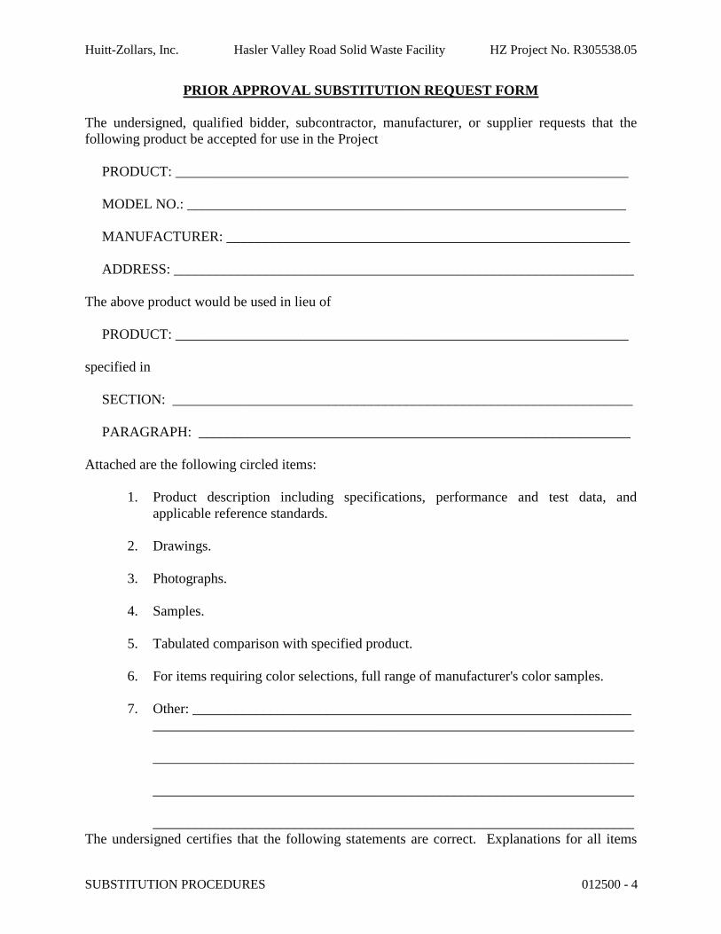
Huitt-Zollars, Inc. Hasler Valley Road Solid Waste Facility HZ Project No. R305538.05
SUBSTITUTION PROCEDURES 012500 - 4
PRIOR APPROVAL SUBSTITUTION REQUEST FORM
The undersigned, qualified bidder, subcontractor, manufacturer, or supplier requests that the following product be accepted for use in the Project
PRODUCT: ________________________________________________________________
MODEL NO.: ______________________________________________________________
MANUFACTURER: _________________________________________________________
ADDRESS: _________________________________________________________________
The above product would be used in lieu of
PRODUCT: ________________________________________________________________
specified in
SECTION: _________________________________________________________________
PARAGRAPH: _____________________________________________________________
Attached are the following circled items:
1. Product description including specifications, performance and test data, and applicable reference standards.
2. Drawings.
3. Photographs.
4. Samples.
5. Tabulated comparison with specified product.
6. For items requiring color selections, full range of manufacturer's color samples.
7. Other: ______________________________________________________________ ____________________________________________________________________
____________________________________________________________________
____________________________________________________________________
____________________________________________________________________The undersigned certifies that the following statements are correct. Explanations for all items

Huitt-Zollars, Inc. Hasler Valley Road Solid Waste Facility HZ Project No. R305538.05
This page left intentionally blank
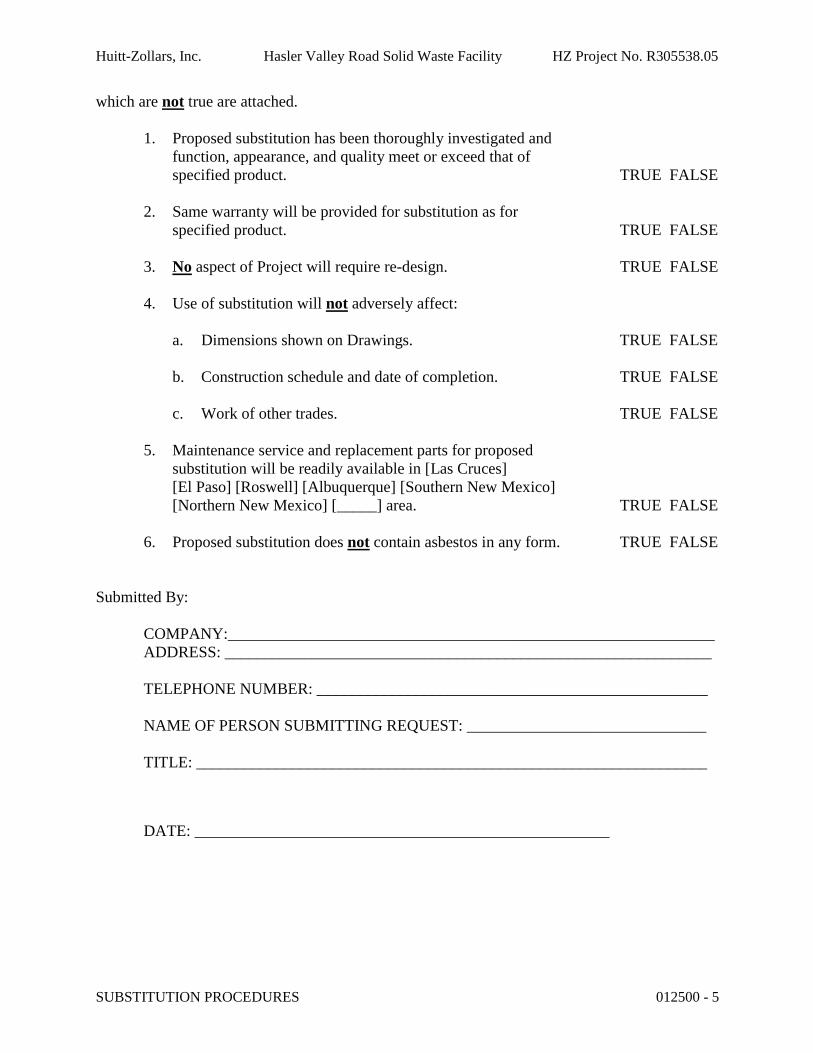
Huitt-Zollars, Inc. Hasler Valley Road Solid Waste Facility HZ Project No. R305538.05
SUBSTITUTION PROCEDURES 012500 - 5
which are not true are attached.
1. Proposed substitution has been thoroughly investigated and function, appearance, and quality meet or exceed that of specified product. TRUE FALSE
2. Same warranty will be provided for substitution as for specified product. TRUE FALSE
3. No aspect of Project will require re-design. TRUE FALSE
4. Use of substitution will not adversely affect:
a. Dimensions shown on Drawings. TRUE FALSE
b. Construction schedule and date of completion. TRUE FALSE
c. Work of other trades. TRUE FALSE
5. Maintenance service and replacement parts for proposed substitution will be readily available in [Las Cruces][El Paso] [Roswell] [Albuquerque] [Southern New Mexico] [Northern New Mexico] [_____] area. TRUE FALSE
6. Proposed substitution does not contain asbestos in any form. TRUE FALSE
Submitted By:
COMPANY:_____________________________________________________________ADDRESS: _____________________________________________________________
TELEPHONE NUMBER: _________________________________________________
NAME OF PERSON SUBMITTING REQUEST: ______________________________
TITLE: ________________________________________________________________
DATE: ____________________________________________________

Huitt-Zollars, Inc. Hasler Valley Road Solid Waste Facility HZ Project No. R305538.05
This page left intentionally blank

Huitt-Zollars, Inc. Hasler Valley Road Solid Waste Facility HZ Project No. R305538.05
CONTRACT MODIFICATION PROCEDURES 012600 - 1
SECTION 012600 - CONTRACT MODIFICATION PROCEDURES
PART 1 - GENERAL
1.1 RELATED DOCUMENTS
A. Drawings and general provisions of the Contract, including General and Supplementary Conditions and other Division 01 Specification Sections, apply to this Section.
1.2 SUMMARY
A. Section includes administrative and procedural requirements for handling and processing Contract modifications.
B. Related Sections:
1. Division 01 Section "Product Requirements" for administrative procedures for handling requests for substitutions made after Contract award.
1.3 MINOR CHANGES IN THE WORK
A. Architect will issue supplemental instructions authorizing minor changes in the Work, not involving adjustment to the Contract Sum or the Contract Time, on AIA Document G710, "Architect's Supplemental Instructions.”.
1.4 PROPOSAL REQUESTS
A. Owner-Initiated Proposal Requests: Architect will issue a detailed description of proposed changes in the Work that may require adjustment to the Contract Sum or the Contract Time. If necessary, the description will include supplemental or revised Drawings and Specifications.
1. Proposal Requests issued by Architect are not instructions either to stop work in progress or to execute the proposed change.
2. Within 10 days, when not otherwise specified, after receipt of Proposal Request, submit a quotation estimating cost adjustments to the Contract Sum and the Contract Time necessary to execute the change.
a. Include a list of quantities of products required or eliminated and unit costs, with total amount of purchases and credits to be made. If requested, furnish survey data to substantiate quantities.
b. Indicate applicable taxes, delivery charges, equipment rental, and amounts of trade discounts.
c. Include costs of labor and supervision directly attributable to the change.d. Include an updated Contractor's construction schedule that indicates the effect of
the change, including, but not limited to, changes in activity duration, start and

Huitt-Zollars, Inc. Hasler Valley Road Solid Waste Facility HZ Project No. R305538.05
CONTRACT MODIFICATION PROCEDURES 012600 - 2
finish times, and activity relationship. Use available total float before requesting an extension of the Contract Time.
e. Quotation Form: Use forms acceptable to Architect.
B. Contractor-Initiated Proposals: If latent or changed conditions require modifications to the Contract, Contractor may initiate a claim by submitting a request for a change to Architect.
1. Include a statement outlining reasons for the change and the effect of the change on the Work. Provide a complete description of the proposed change. Indicate the effect of the proposed change on the Contract Sum and the Contract Time.
2. Include a list of quantities of products required or eliminated and unit costs, with total amount of purchases and credits to be made. If requested, furnish survey data to substantiate quantities.
3. Indicate applicable taxes, delivery charges, equipment rental, and amounts of tradediscounts.
4. Include costs of labor and supervision directly attributable to the change.5. Include an updated Contractor's construction schedule that indicates the effect of the
change, including, but not limited to, changes in activity duration, start and finish times, and activity relationship. Use available total float before requesting an extension of the Contract Time.
6. Comply with requirements in Division 01 Section "Substitution Procedures" if the proposed change requires substitution of one product or system for product or system specified.
7. Proposal Request Form: Use form acceptable to Architect.
1.5 ADMINISTRATIVE CHANGE ORDERS
A. Allowance Adjustment: Refer to Division 01 Section "Allowances" for administrative procedures for preparation of Change Order Proposal for adjusting the Contract Sum to reflect actual costs of allowances.
B. Unit Price Adjustment: Refer to Division 01 Section "Unit Prices" for administrative procedures for preparation of Change Order Proposal for adjusting the Contract Sum to reflectmeasured scope of unit price work.
1.6 CHANGE ORDER PROCEDURES
A. On Owner's approval of a Proposal Request, Architect will issue a Change Order for signatures of Owner and Contractor on AIA Document G701.
1.7 CONSTRUCTION CHANGE DIRECTIVE
A. Construction Change Directive: Architect may issue a Construction Change Directive on AIA Document G714. Construction Change Directive instructs Contractor to proceed with a change in the Work, for subsequent inclusion in a Change Order.
Huitt-Zollars, Inc. Hasler Valley Road Solid Waste Facility HZ Project No. R305538.05
CONTRACT MODIFICATION PROCEDURES 012600 - 3
1. Construction Change Directive contains a complete description of change in the Work. It also designates method to be followed to determine change in the Contract Sum or the Contract Time.
B. Documentation: Maintain detailed records on a time and material basis of work required by the Construction Change Directive.
1. After completion of change, submit an itemized account and supporting data necessary to substantiate cost and time adjustments to the Contract.
PART 2 - PRODUCTS (Not Used)
PART 3 - EXECUTION (Not Used)
END OF SECTION 012600

Huitt-Zollars, Inc. Hasler Valley Road Solid Waste Facility HZ Project No. R305538.05
This page left intentionally blank
Huitt-Zollars, Inc. Hasler Valley Road Solid Waste Facility HZ Project No. R305538.05
PAYMENT PROCEDURES 012900 - 1
SECTION 012900 - PAYMENT PROCEDURES
PART 1 - GENERAL
1.1 RELATED DOCUMENTS
A. Drawings and general provisions of the Contract, including General and Supplementary Conditions and other Division 01 Specification Sections, apply to this Section.
1.2 SUMMARY
A. This Section specifies administrative and procedural requirements necessary to prepare and process Applications for Payment.
B. Related Sections:1. Division 01 Section "Contract and Procedures" for administrative procedures for
handling changes to the Contract.2. Division 01 Section "Construction Progress Documentation" for administrative
requirements governing the preparation and submittal of the Contractor's construction schedule.
3. Division 01 Section "Submittal Procedures" for administrative requirements governing the preparation and submittal of the submittal schedule.
1.3 DEFINITIONS
A. Schedule of Values: A statement furnished by Contractor allocating portions of the Contract Sum to various portions of the Work and used as the basis for reviewing Contractor's Applications for Payment.
1.4 SCHEDULE OF VALUES
A. Coordination: Coordinate preparation of the schedule of values with preparation of Contractor's construction schedule.
1. Correlate line items in the schedule of values with other required administrative forms and schedules, including the following:
a. Application for Payment forms with continuation sheets.b. Submittal schedule.c. Items required to be indicated as separate activities in Contractor's construction
schedule.
2. Submit the schedule of values to Architect at earliest possible date but no later than sevendays before the date scheduled for submittal of initial Applications for Payment.
Huitt-Zollars, Inc. Hasler Valley Road Solid Waste Facility HZ Project No. R305538.05
PAYMENT PROCEDURES 012900 - 2
B. Format and Content: Use the Project Manual table of contents as a guide to establish line items for the schedule of values. Provide at least one line item for each Specification Section.
1. Identification: Include the following Project identification on the schedule of values:
a. Project name and location.b. Name of Architect.c. Architect's project number.d. Contractor's name and address.e. Date of submittal.
2. Arrange schedule of values consistent with format of AIA Document G703.3. Arrange the schedule of values in tabular form with separate columns to indicate the
following for each item listed:
a. Related Specification Section or Division.b. Description of the Work.c. Name of subcontractor.d. Name of manufacturer or fabricator.e. Name of supplier.f. Change Orders (numbers) that affect value.g. Dollar value of the following, as a percentage of the Contract Sum to nearest one-
hundredth percent, adjusted to total 100 percent.
1) Labor.2) Materials.3) Equipment.
4. Round amounts to nearest whole dollar; total shall equal the Contract Sum.5. Provide a separate line item in the schedule of values for each part of the Work where
Applications for Payment may include materials or equipment purchased or fabricated and stored, but not yet installed.
a. Differentiate between items stored on-site and items stored off-site. If required, include evidence of insurance.
6. Provide separate line items in the schedule of values for initial cost of materials, for each subsequent stage of completion, and for total installed value of that part of the Work.
7. Each item in the schedule of values and Applications for Payment shall be complete. Include total cost and proportionate share of general overhead and profit for each item.
a. Temporary facilities and other major cost items that are not direct cost of actual work-in-place may be shown either as separate line items in the schedule of values or distributed as general overhead expense, at Contractor's option.
8. Schedule Updating: Update and resubmit the schedule of values before the next Applications for Payment when Change Orders or Construction Change Directives result in a change in the Contract Sum.
Huitt-Zollars, Inc. Hasler Valley Road Solid Waste Facility HZ Project No. R305538.05
PAYMENT PROCEDURES 012900 - 3
1.5 APPLICATIONS FOR PAYMENT
A. Each Application for Payment shall be consistent with previous applications and payments as certified by Architect and paid for by Owner.
1. Initial Application for Payment, Application for Payment at time of Substantial Completion, and final Application for Payment involve additional requirements.
B. Payment Application Times: The date for each progress payment is indicated in the Agreement between Owner and Contractor. The period of construction work covered by each Application for Payment is the period indicated in the Agreement.
1. Submit draft copy of Application for Payment seven days prior to due date for review by Architect.
C. Application for Payment Forms: Use AIA Document G702 and AIA Document G703 as form for Applications for Payment.
D. Application for Payment Forms: Use forms acceptable to Architect and Owner for Applications for Payment. Submit forms for approval with initial submittal of schedule of values.
E. Application Preparation: Complete every entry on form. Notarize and execute by a person authorized to sign legal documents on behalf of Contractor. Architect will return incomplete applications without action.
1. Entries shall match data on the schedule of values and Contractor's construction schedule. Use updated schedules if revisions were made.
2. Include amounts for work completed following previous Application for Payment, whether or not payment has been received. Include only amounts for work completed at time of Application for Payment.
3. Include amounts of Change Orders and Construction Change Directives issued before last day of construction period covered by application.
4. Indicate separate amounts for work being carried out under Owner-requested project acceleration.
F. Stored Materials: Include in Application for Payment amounts applied for materials or equipment purchased or fabricated and stored, but not yet installed. Differentiate between items stored on-site and items stored off-site.
1. Provide certificate of insurance, evidence of transfer of title to Owner, and consent of surety to payment, for stored materials.
2. Provide supporting documentation that verifies amount requested, such as paid invoices. Match amount requested with amounts indicated on documentation; do not include overhead and profit on stored materials.
3. Provide summary documentation for stored materials indicating the following:
a. Materials previously stored and included in previous Applications for Payment.b. Work completed for this Application utilizing previously stored materials.c. Additional materials stored with this Application.d. Total materials remaining stored, including materials with this Application.

Huitt-Zollars, Inc. Hasler Valley Road Solid Waste Facility HZ Project No. R305538.05
PAYMENT PROCEDURES 012900 - 4
G. Transmittal: Submit three signed and notarized original copies of each Application for Payment to Architect by a method ensuring receipt within 24 hours. One copy shall include waivers of lien and similar attachments if required.
1. Transmit each copy with a transmittal form listing attachments and recording appropriate information about application.
H. Waivers of Mechanic's Lien: With each Application for Payment, submit waivers of mechanic's lien from entities lawfully entitled to file a mechanic's lien arising out of the Contract and related to the Work covered by the payment.
1. Submit partial waivers on each item for amount requested in previous application, after deduction for retainage, on each item.
2. When an application shows completion of an item, submit conditional final or full waivers.
3. Owner reserves the right to designate which entities involved in the Work must submit waivers.
4. Waiver Forms: Submit waivers of lien on forms, executed in a manner acceptable to Owner.
I. Initial Application for Payment: Administrative actions and submittals that must precede or coincide with submittal of first Application for Payment include the following:
1. List of subcontractors.2. Schedule of values.3. Contractor's construction schedule (preliminary if not final).4. Products list (preliminary if not final).5. Submittal schedule (preliminary if not final).6. List of Contractor's staff assignments.7. List of Contractor's principal consultants.8. Copies of building permits.9. Copies of authorizations and licenses from authorities having jurisdiction for
performance of the Work.10. Initial progress report.11. Report of preconstruction conference.12. Certificates of insurance and insurance policies.13. Performance and payment bonds.14. Data needed to acquire Owner's insurance.
J. Application for Payment at Substantial Completion: After issuing the Certificate of Substantial Completion, submit an Application for Payment showing 100 percent completion for portion of the Work claimed as substantially complete.
1. Include documentation supporting claim that the Work is substantially complete and a statement showing an accounting of changes to the Contract Sum.
2. This application shall reflect Certificates of Partial Substantial Completion issued previously for Owner occupancy of designated portions of the Work.
K. Final Payment Application: Submit final Application for Payment with releases and supporting documentation not previously submitted and accepted, including, but not limited, to the following:

Huitt-Zollars, Inc. Hasler Valley Road Solid Waste Facility HZ Project No. R305538.05
PAYMENT PROCEDURES 012900 - 5
1. Evidence of completion of Project closeout requirements.2. Insurance certificates for products and completed operations where required and proof
that taxes, fees, and similar obligations were paid.3. Updated final statement, accounting for final changes to the Contract Sum.4. AIA Document G706, "Contractor's Affidavit of Payment of Debts and Claims."5. AIA Document G706A, "Contractor's Affidavit of Release of Liens."6. AIA Document G707, "Consent of Surety to Final Payment."7. Evidence that claims have been settled.8. Final meter readings for utilities, a measured record of stored fuel, and similar data as of
date of Substantial Completion or when Owner took possession of and assumed responsibility for corresponding elements of the Work.
9. Final liquidated damages settlement statement.
PART 2 - PRODUCTS (Not Used)
PART 3 - EXECUTION (Not Used)
END OF SECTION 012900
Huitt-Zollars, Inc. Hasler Valley Road Solid Waste Facility HZ Project No. R305538.05
This page left intentionally blank

Huitt-Zollars, Inc. Hasler Valley Road Solid Waste Facility HZ Project No. R305538.05
PROJECT MANAGEMENT AND COORDINATION 013100 - 1
SECTION 013100 - PROJECT MANAGEMENT AND COORDINATION
PART 1 - GENERAL
1.1 RELATED DOCUMENTS
A. Drawings and general provisions of the Contract, including General and Supplementary Conditions and other Division 01 Specification Sections, apply to this Section.
1.2 SUMMARY
A. Section includes administrative provisions for coordinating construction operations on Project including, but not limited to, the following:
1. General project coordination procedures.2. Administrative and supervisory personnel.3. Coordination drawings.4. Requests for Information (RFIs).5. Project meetings.
B. Each contractor shall participate in coordination requirements. Certain areas of responsibility are assigned to a specific contractor.
C. Related Sections:1. Division 01 Section "Construction Progress Documentation" for preparing and
submitting Contractor's construction schedule.2. Division 01 Section "Execution" for procedures for coordinating general installation and
field-engineering services, including establishment of benchmarks and control points.3. Division 01 Section "Closeout Procedures" for coordinating closeout of the Contract.
1.3 DEFINITIONS
A. RFI: Request from Owner, Architect, or Contractor seeking information from each other during construction.
1.4 COORDINATION
A. Coordination: Coordinate construction operations included in different Sections of the Specifications to ensure efficient and orderly installation of each part of the Work. Coordinate construction operations, included in different Sections that depend on each other for proper installation, connection, and operation.
1. Schedule construction operations in sequence required to obtain the best results where installation of one part of the Work depends on installation of other components, before or after its own installation.

Huitt-Zollars, Inc. Hasler Valley Road Solid Waste Facility HZ Project No. R305538.05
PROJECT MANAGEMENT AND COORDINATION 013100 - 2
2. Coordinate installation of different components to ensure maximum performance and accessibility for required maintenance, service, and repair.
3. Make adequate provisions to accommodate items scheduled for later installation.
B. Coordination: Each contractor shall coordinate its construction operations with those of other contractors and entities to ensure efficient and orderly installation of each part of the Work. Each contractor shall coordinate its operations with operations, included in different Sections that depend on each other for proper installation, connection, and operation.
1. Schedule construction operations in sequence required to obtain the best results where installation of one part of the Work depends on installation of other components, before or after its own installation.
2. Coordinate installation of different components with other contractors to ensure maximum performance and accessibility for required maintenance, service, and repair.
3. Make adequate provisions to accommodate items scheduled for later installation.
C. Prepare memoranda for distribution to each party involved, outlining special procedures required for coordination. Include such items as required notices, reports, and list of attendees at meetings.
1. Prepare similar memoranda for Owner and separate contractors if coordination of their Work is required.
D. Administrative Procedures: Coordinate scheduling and timing of required administrative procedures with other construction activities to avoid conflicts and to ensure orderly progress of the Work. Such administrative activities include, but are not limited to, the following:
1. Preparation of Contractor's construction schedule.2. Preparation of the schedule of values.3. Installation and removal of temporary facilities and controls.4. Delivery and processing of submittals.5. Progress meetings.6. Preinstallation conferences.7. Project closeout activities.8. Startup and adjustment of systems.9. Project closeout activities.
E. Conservation: Coordinate construction activities to ensure that operations are carried out with consideration given to conservation of energy, water, and materials. Coordinate use of temporary utilities to minimize waste.
1. Salvage materials and equipment involved in performance of, but not actually incorporated into, the Work. Refer to other Sections for disposition of salvaged materials that are designated as Owner's property.
1.5 COORDINATION DRAWINGS
A. Coordination Drawings, General: Prepare coordination drawings in accordance with requirements in individual Sections, where installation is not completely shown on Shop Drawings, where limited space availability necessitates coordination, or if coordination is

Huitt-Zollars, Inc. Hasler Valley Road Solid Waste Facility HZ Project No. R305538.05
PROJECT MANAGEMENT AND COORDINATION 013100 - 3
required to facilitate integration of products and materials fabricated or installed by more than one entity.
1. Content: Project-specific information, drawn accurately to a scale large enough to indicate and resolve conflicts. Do not base coordination drawings on standard printed data. Include the following information, as applicable:
a. Use applicable Drawings as a basis for preparation of coordination drawings. Prepare sections, elevations, and details as needed to describe relationship of various systems and components.
b. Coordinate the addition of trade-specific information to the coordination drawings by multiple contractors in a sequence that best provides for coordination of the information and resolution of conflicts between installed components before submitting for review.
c. Indicate functional and spatial relationships of components of architectural, structural, civil, mechanical, and electrical systems.
d. Indicate space requirements for routine maintenance and for anticipated replacement of components during the life of the installation.
e. Show location and size of access doors required for access to concealed dampers, valves, and other controls.
f. Indicate required installation sequences.g. Indicate dimensions shown on the Drawings. Specifically note dimensions that
appear to be in conflict with submitted equipment and minimum clearance requirements. Provide alternate sketches to Architect indicating proposed resolution of such conflicts. Minor dimension changes and difficult installations will not be considered changes to the Contract.
B. Coordination Drawing Organization: Organize coordination drawings as follows:
1. Floor Plans and Reflected Ceiling Plans: Show architectural and structural elements, and mechanical, plumbing, fire protection, fire alarm, and electrical Work. Show locations of visible ceiling-mounted devices relative to acoustical ceiling grid. Supplement plan drawings with section drawings where required to adequately represent the Work.
2. Plenum Space: Indicate subframing for support of ceiling and wall systems, mechanical and electrical equipment, and related Work. Locate components within ceiling plenum to accommodate layout of light fixtures indicated on Drawings. Indicate areas of conflict between light fixtures and other components.
3. Mechanical Rooms: Provide coordination drawings for mechanical rooms showing plans and elevations of mechanical, plumbing, fire protection, fire alarm, and electrical equipment.
4. Structural Penetrations: Indicate penetrations and openings required for all disciplines.5. Slab Edge and Embedded Items: Indicate slab edge locations and sizes and locations of
embedded items for metal fabrications, sleeves, anchor bolts, bearing plates, angles, door floor closers, slab depressions for floor finishes, curbs and housekeeping pads, and similar items.
6. Mechanical and Plumbing Work: Show the following:
a. Sizes and bottom elevations of ductwork, piping, and conduit runs, including insulation, bracing, flanges, and support systems.
b. Dimensions of major components, such as dampers, valves, diffusers, access doors, cleanouts and electrical distribution equipment.
Huitt-Zollars, Inc. Hasler Valley Road Solid Waste Facility HZ Project No. R305538.05
PROJECT MANAGEMENT AND COORDINATION 013100 - 4
c. Fire-rated enclosures around ductwork.
7. Electrical Work: Show the following:
a. Runs of vertical and horizontal conduit 1-1/4 inch diameter and larger.b. Light fixture, exit light, emergency battery pack, smoke detector, and other fire
alarm locations.c. Panel board, switch board, switchgear, transformer, busway, generator, and motor
control center locations.d. Location of pull boxes and junction boxes, dimensioned from column center lines.
8. Review: Architect will review coordination drawings to confirm that the Work is being coordinated, but not for the details of the coordination, which are the Contractor's responsibility. If the Architect determines that the coordination drawings are not being prepared in sufficient scope or detail, or are otherwise deficient, the Architect will so inform the Contractor, who shall make changes as directed and resubmit.
9. Coordination Drawing Prints: Prepare coordination drawing prints in accordance with requirements of Division 01 Section "Submittal Procedures."
1.6 KEY PERSONNEL
A. Key Personnel Names: Within 15 days of starting construction operations, submit a list of key personnel assignments, including superintendent and other personnel in attendance at Project site. Identify individuals and their duties and responsibilities; list addresses and telephone numbers, including home, office, and cellular telephone numbers and email addresses. Provide names, addresses, and telephone numbers of individuals assigned as standbys in the absence of individuals assigned to Project.
1. Post copies of list in project meeting room, in temporary field office, and by each temporary telephone. Keep list current at all times.
1.7 REQUESTS FOR INFORMATION (RFIs)
A. General: Immediately on discovery of the need for additional information or interpretation of the Contract Documents, Contractor shall prepare and submit an RFI in the form specified.
1. Architect will return RFIs submitted to Architect by other entities controlled by Contractor with no response.
2. Coordinate and submit RFIs in a prompt manner so as to avoid delays in Contractor's work or work of subcontractors.
B. RFI Forms: AIA Document G716 or another comparable RFI form approved by Architect.
C. Architect's Action: Architect will review each RFI, determine action required, and respond. Allow seven working days for Architect's response for each RFI. RFIs received by Architectafter 1:00 p.m. will be considered as received the following working day.
1. The following RFIs will be returned without action:

Huitt-Zollars, Inc. Hasler Valley Road Solid Waste Facility HZ Project No. R305538.05
PROJECT MANAGEMENT AND COORDINATION 013100 - 5
a. Requests for approval of submittals.b. Requests for approval of substitutions.c. Requests for coordination information already indicated in the Contract
Documents.d. Requests for adjustments in the Contract Time or the Contract Sum.e. Requests for interpretation of Architect's actions on submittals.f. Incomplete RFIs or inaccurately prepared RFIs.
2. Architect's action may include a request for additional information, in which case Architect's time for response will date from time of receipt of additional information.
3. Architect's action on RFIs that may result in a change to the Contract Time or the Contract Sum may be eligible for Contractor to submit Change Proposal according to Division 01 Section "Contract Modification Procedures."
a. If Contractor believes the RFI response warrants change in the Contract Time or the Contract Sum, notify Architect in writing within 10 days of receipt of the RFI response.
D. On receipt of Architect's action, update the RFI log and immediately distribute the RFI response to affected parties. Review response and notify Architect within seven days if Contractor disagrees with response.
E. RFI Log: Prepare, maintain, and submit a tabular log of RFIs organized by the RFI number. Submit log weekly. Include the following:
1. Project name.2. Name and address of Contractor.3. Name and address of Architect.4. RFI number including RFIs that were dropped and not submitted.5. RFI description.6. Date the RFI was submitted.7. Date Architect's response was received.8. Identification of related Minor Change in the Work, Construction Change Directive, and
Proposal Request, as appropriate.9. Identification of related Field Order, Work Change Directive, and Proposal Request, as
appropriate.
1.8 PROJECT MEETINGS
A. General: Schedule and conduct and conferences at Project site, unless otherwise indicated.
1. Attendees: Inform participants and others involved, and individuals whose presence is required, of date and time of each meeting. Notify Owner and Architect of scheduled meeting dates and times.
2. Agenda: Prepare the meeting agenda. Distribute the agenda to all invited attendees.3. Minutes: Entity responsible for conducting meeting will record significant discussions
and agreements achieved. Distribute the meeting minutes to everyone concerned, including Owner and Architect, within three days of the meeting.
Huitt-Zollars, Inc. Hasler Valley Road Solid Waste Facility HZ Project No. R305538.05
PROJECT MANAGEMENT AND COORDINATION 013100 - 6
B. Preconstruction Conference: Architect will schedule and conduct a preconstruction conference before starting construction, at a time convenient to Owner and Architect, but no later than 15 days after execution of the Agreement.
1. Conduct the conference to review responsibilities and personnel assignments.2. Attendees: Authorized representatives of Owner, Architect, and their consultants;
Contractor and its superintendent; major subcontractors; suppliers; and other concerned parties shall attend the conference. Participants at the conference shall be familiar with Project and authorized to conclude matters relating to the Work.
3. Agenda: Discuss items of significance that could affect progress, including the following:
a. Tentative construction schedule.b. Phasing.c. Critical work sequencing and long-lead items.d. Designation of key personnel and their duties.e. Lines of communications.f. Procedures for processing field decisions and Change Orders.g. Procedures for RFIs.h. Procedures for testing and inspecting.i. Procedures for processing Applications for Payment.j. Distribution of the Contract Documents.k. Submittal procedures.l. Preparation of record documents.m. Use of the premises.n. Work restrictions.o. Working hours.p. Owner's occupancy requirements.q. Responsibility for temporary facilities and controls.r. Procedures for moisture and mold control.s. Procedures for disruptions and shutdowns.t. Construction waste management and recycling.u. Parking availability.v. Office, work, and storage areas.w. Equipment deliveries and priorities.x. First aid.y. Security.z. Progress cleaning.
4. Minutes: Entity responsible for conducting meeting will record and distribute meeting minutes.
C. Preinstallation Conferences: Conduct a preinstallation conference at Project site before each construction activity that requires coordination with other construction.
1. Attendees: Installer and representatives of manufacturers and fabricators involved in or affected by the installation and its coordination or integration with other materials and installations that have preceded or will follow, shall attend the meeting. Advise Architect of scheduled meeting dates.
2. Agenda: Review progress of other construction activities and preparations for the particular activity under consideration, including requirements for the following:

Huitt-Zollars, Inc. Hasler Valley Road Solid Waste Facility HZ Project No. R305538.05
PROJECT MANAGEMENT AND COORDINATION 013100 - 7
a. Contract Documents.b. Options.c. Related RFIs.d. Related Change Orders.e. Purchases.f. Deliveries.g. Submittals.h. Review of mockups.i. Possible conflicts.j. Compatibility problems.k. Time schedules.l. Weather limitations.m. Manufacturer's written recommendations.n. Warranty requirements.o. Compatibility of materials.p. Acceptability of substrates.q. Temporary facilities and controls.r. Space and access limitations.s. Regulations of authorities having jurisdiction.t. Testing and inspecting requirements.u. Installation procedures.v. Coordination with other work.w. Required performance results.x. Protection of adjacent work.y. Protection of construction and personnel.
3. Record significant conference discussions, agreements, and disagreements, including required corrective measures and actions.
4. Reporting: Distribute minutes of the meeting to each party present and to other parties requiring information.
5. Do not proceed with installation if the conference cannot be successfully concluded. Initiate whatever actions are necessary to resolve impediments to performance of the Work and reconvene the conference at earliest feasible date.
D. Project Closeout Conference: Schedule and conduct a Project closeout conference, at a time convenient to Owner and Architect, but no later than 90 days prior to the scheduled date of Substantial Completion.
1. Conduct the conference to review requirements and responsibilities related to Project closeout.
2. Attendees: Authorized representatives of Owner, Architect, and their consultants; Contractor and its superintendent; major subcontractors; suppliers; and other concerned parties shall attend the meeting. Participants at the meeting shall be familiar with Project and authorized to conclude matters relating to the Work.
3. Agenda: Discuss items of significance that could affect or delay Project closeout, including the following:
a. Preparation of record documents.b. Procedures required prior to inspection for Substantial Completion and for final
inspection for acceptance.c. Submittal of written warranties.
Huitt-Zollars, Inc. Hasler Valley Road Solid Waste Facility HZ Project No. R305538.05
PROJECT MANAGEMENT AND COORDINATION 013100 - 8
d. Requirements for preparing sustainable design documentation.e. Requirements for preparing operations and maintenance data.f. Requirements for demonstration and training.g. Preparation of Contractor's punch list.h. Procedures for processing Applications for Payment at Substantial Completion and
for final payment.i. Submittal procedures.j. Coordination of separate contracts.k. Owner's partial occupancy requirements.l. Installation of Owner's furniture, fixtures, and equipment.m. Responsibility for removing temporary facilities and controls.
4. Minutes: Entity conducting meeting will record and distribute meeting minutes.
E. Progress Meetings: Conduct progress meetings at monthly intervals.
1. Coordinate dates of meetings with preparation of payment requests.2. Attendees: In addition to representatives of Owner and Architect, each contractor,
subcontractor, supplier, and other entity concerned with current progress or involved in planning, coordination, or performance of future activities shall be represented at these meetings. All participants at the meeting shall be familiar with Project and authorized to conclude matters relating to the Work.
3. Agenda: Review and correct or approve minutes of previous progress meeting. Review other items of significance that could affect progress. Include topics for discussion as appropriate to status of Project.
a. Contractor's Construction Schedule: Review progress since the last meeting. Determine whether each activity is on time, ahead of schedule, or behind schedule, in relation to Contractor's construction schedule. Determine how construction behind schedule will be expedited; secure commitments from parties involved todo so. Discuss whether schedule revisions are required to ensure that current and subsequent activities will be completed within the Contract Time.
1) Review schedule for next period.
b. Review present and future needs of each entity present, including the following:
1) Interface requirements.2) Sequence of operations.3) Status of submittals.4) Deliveries.5) Off-site fabrication.6) Access.7) Site utilization.8) Temporary facilities and controls.9) Progress cleaning.10) Quality and work standards.11) Status of correction of deficient items.12) Field observations.13) Status of RFIs.14) Status of proposal requests.
Huitt-Zollars, Inc. Hasler Valley Road Solid Waste Facility HZ Project No. R305538.05
PROJECT MANAGEMENT AND COORDINATION 013100 - 9
15) Pending changes.16) Status of Change Orders.17) Pending claims and disputes.18) Documentation of information for payment requests.
4. Minutes: Entity responsible for conducting the meeting will record and distribute the meeting minutes to each party present and to parties requiring information.
a. Schedule Updating: Revise Contractor's construction schedule after each progress meeting where revisions to the schedule have been made or recognized. Issue revised schedule concurrently with the report of each meeting.
PART 2 - PRODUCTS (Not Used)
PART 3 - EXECUTION (Not Used)
END OF SECTION 013100

Huitt-Zollars, Inc. Hasler Valley Road Solid Waste Facility HZ Project No. R305538.05
This page left intentionally blank

Huitt-Zollars, Inc. Hasler Valley Road Solid Waste Facility HZ Project No. R305538.05
CONSTRUCTION PROGRESS DOCUMENTATION 013200 - 1
SECTION 013200 - CONSTRUCTION PROGRESS DOCUMENTATION
PART 1 - GENERAL
1.1 RELATED DOCUMENTS
A. Drawings and general provisions of the Contract, including General and Supplementary Conditions and other Division 01 Specification Sections, apply to this Section.
1.2 SUMMARY
A. Section includes administrative and procedural requirements for documenting the progress of construction during performance of the Work, including the following:
1. Start-up construction schedule.2. Contractor's construction schedule.3. Daily construction reports.4. Material location reports.5. Field condition reports.6. Special reports.
B. Related Sections:1. Division 01 Section "Submittal Procedures" for submitting schedules and reports.2. Division 01 Section "Quality Requirements" for submitting a schedule of tests and
inspections.
1.3 DEFINITIONS
A. Activity: A discrete part of a project that can be identified for planning, scheduling, monitoring, and controlling the construction project. Activities included in a construction schedule consume time and resources.
1. Critical Activity: An activity on the critical path that must start and finish on the planned early start and finish times.
2. Predecessor Activity: An activity that precedes another activity in the network.3. Successor Activity: An activity that follows another activity in the network.
B. Cost Loading: The allocation of the schedule of values for the completion of an activity as scheduled. The sum of costs for all activities must equal the total Contract Sum, unless otherwise approved by Architect.
C. CPM: Critical path method, which is a method of planning and scheduling a construction project where activities are arranged based on activity relationships. Network calculations determine when activities can be performed and the critical path of the Project.
D. Critical Path: The longest connected chain of interdependent activities through the network schedule that establishes the minimum overall Project duration and contains no float.
Huitt-Zollars, Inc. Hasler Valley Road Solid Waste Facility HZ Project No. R305538.05
CONSTRUCTION PROGRESS DOCUMENTATION 013200 - 2
E. Event: The starting or ending point of an activity.
F. Float: The measure of leeway in starting and completing an activity.
1. Float time is not for the exclusive use or benefit of either Owner or Contractor, but is a jointly owned, expiring Project resource available to both parties as needed to meet schedule milestones and Contract completion date.
2. Free float is the amount of time an activity can be delayed without adversely affecting the early start of the successor activity.
3. Total float is the measure of leeway in starting or completing an activity without adversely affecting the planned Project completion date.
G. Resource Loading: The allocation of manpower and equipment necessary for the completion of an activity as scheduled.
1.4 INFORMATIONAL SUBMITTALS
A. Format for Submittals: Submit required submittals in the following format:1. Two paper copies.
B. Start-up construction schedule.
1. Approval of cost-loaded start-up construction schedule will not constitute approval of schedule of values for cost-loaded activities.
C. Contractor's Construction Schedule: Initial schedule, of size required to display entire schedule for entire construction period.
1. Submit a working electronic copy of schedule, using software indicated, and labeled to comply with requirements for submittals. Include type of schedule (initial or updated) and date on label.
D. CPM Reports: Concurrent with CPM schedule, submit each of the following reports. Format for each activity in reports shall contain activity number, activity description, cost and resource loading, original duration, remaining duration, early start date, early finish date, late start date, late finish date, and total float in calendar days.
1. Activity Report: List of all activities sorted by activity number and then early start date, or actual start date if known.
2. Logic Report: List of preceding and succeeding activities for all activities, sorted in ascending order by activity number and then early start date, or actual start date if known.
3. Total Float Report: List of all activities sorted in ascending order of total float.4. Earnings Report: Compilation of Contractor's total earnings from the Notice to Proceed
until most recent Application for Payment.
E. Daily Construction Reports: Submit at monthly intervals.
F. Material Location Reports: Submit at monthly intervals.
G. Field Condition Reports: Submit at time of discovery of differing conditions.
Huitt-Zollars, Inc. Hasler Valley Road Solid Waste Facility HZ Project No. R305538.05
CONSTRUCTION PROGRESS DOCUMENTATION 013200 - 3
H. Special Reports: Submit at time of unusual event.
I. Qualification Data: For scheduling consultant.
1.5 COORDINATION
A. Coordinate Contractor's construction schedule with the schedule of values, submittal schedule, progress reports, payment requests, and other required schedules and reports.
1. Secure time commitments for performing critical elements of the Work from entities involved.
2. Coordinate each construction activity in the network with other activities and schedule them in proper sequence.
PART 2 - PRODUCTS
2.1 CONTRACTOR'S CONSTRUCTION SCHEDULE, GENERAL
A. Time Frame: Extend schedule from date established for the Notice of Award to date of final completion.
1. Contract completion date shall not be changed by submission of a schedule that shows an early completion date, unless specifically authorized by Change Order.
B. Activities: Treat each story or separate area as a separate numbered activity for each principal element of the Work. Comply with the following:
1. Activity Duration: Define activities so no activity is longer than 20 days, unless specifically allowed by Architect.
2. Procurement Activities: Include procurement process activities for the following long lead items and major items, requiring a cycle of more than 60 days, as separate activities in schedule. Procurement cycle activities include, but are not limited to, submittals, approvals, purchasing, fabrication, and delivery.
3. Submittal Review Time: Include review and resubmittal times indicated in Division 01 Section "Submittal Procedures" in schedule. Coordinate submittal review times in Contractor's construction schedule with submittal schedule.
4. Startup and Testing Time: Include not less than 15 days for startup and testing.5. Substantial Completion: Indicate completion in advance of date established for
Substantial Completion, and allow time for Architect's administrative procedures necessary for certification of Substantial Completion.
6. Punch List and Final Completion: Include not more than 30 days for punch list and final completion.
C. Constraints: Include constraints and work restrictions indicated in the Contract Documents and as follows in schedule, and show how the sequence of the Work is affected.
1. Phasing: Arrange list of activities on schedule by phase.2. Work under More Than One Contract: Include a separate activity for each contract.

Huitt-Zollars, Inc. Hasler Valley Road Solid Waste Facility HZ Project No. R305538.05
CONSTRUCTION PROGRESS DOCUMENTATION 013200 - 4
3. Work by Owner: Include a separate activity for each portion of the Work performed by Owner.
4. Products Ordered in Advance: Include a separate activity for each product. Include delivery date indicated in Division 01 Section "Summary." Delivery dates indicated stipulate the earliest possible delivery date.
5. Owner-Furnished Products: Include a separate activity for each product. Include delivery date indicated in Division 01 Section "Summary." Delivery dates indicated stipulate the earliest possible delivery date.
6. Work Restrictions: Show the effect of the following items on the schedule:
a. Coordination with existing construction.b. Limitations of continued occupancies.c. Uninterruptible services.d. Partial occupancy before Substantial Completion.e. Use of premises restrictions.f. Provisions for future construction.g. Seasonal variations.h. Environmental control.
7. Work Stages: Indicate important stages of construction for each major portion of the Work, including, but not limited to, the following:
a. Subcontract awards.b. Submittals.c. Purchases.d. Mockups.e. Fabrication.f. Sample testing.g. Deliveries.h. Installation.i. Tests and inspections.j. Adjusting.k. Curing.l. Startup and placement into final use and operation.
8. Construction Areas: Identify each major area of construction for each major portion of the Work. Indicate where each construction activity within a major area must be sequenced or integrated with other construction activities to provide for the following:
a. Structural completion.b. Permanent space enclosure.c. Completion of mechanical installation.d. Completion of electrical installation.e. Substantial Completion.
D. Milestones: Include milestones indicated in the Contract Documents in schedule, including, but not limited to, the Notice to Proceed, Substantial Completion, and final completion.
E. Cost Correlation: At the head of schedule, provide a cost correlation line, indicating planned and actual costs. On the line, show dollar volume of the Work performed as of dates used for preparation of payment requests.

Huitt-Zollars, Inc. Hasler Valley Road Solid Waste Facility HZ Project No. R305538.05
CONSTRUCTION PROGRESS DOCUMENTATION 013200 - 5
1. Refer to Division 01 Section "Payment Procedures" for cost reporting and payment procedures.
F. Upcoming Work Summary: Prepare summary report indicating activities scheduled to occur or commence prior to submittal of next schedule update. Summarize the following issues:
1. Unresolved issues.2. Unanswered RFIs.3. Rejected or unreturned submittals.4. Notations on returned submittals.
G. Recovery Schedule: When periodic update indicates the Work is 14 or more calendar days behind the current approved schedule, submit a separate recovery schedule indicating means by which Contractor intends to regain compliance with the schedule. Indicate changes to working hours, working days, crew sizes, and equipment required to achieve compliance, and date by which recovery will be accomplished.
2.2 START-UP CONSTRUCTION SCHEDULE
A. Bar-Chart Schedule: Submit start-up horizontal bar-chart-type construction schedule withinseven days of date established for the Notice of Award.
B. Preparation: Indicate each significant construction activity separately. Identify first workday of each week with a continuous vertical line. Outline significant construction activities for first 90days of construction. Include skeleton diagram for the remainder of the Work and a cash requirement prediction based on indicated activities.
2.3 CONTRACTOR'S CONSTRUCTION SCHEDULE (GANTT CHART)
A. Gantt-Chart Schedule: Submit a comprehensive, fully developed, horizontal Gantt-chart-type, Contractor's construction schedule within 30 days of date established for Notice of Award. Base schedule on the start-up construction schedule and additional information received sincethe start of Project.
B. Preparation: Indicate each significant construction activity separately. Identify first workday of each week with a continuous vertical line.
1. For construction activities that require three months or longer to complete, indicate an estimated completion percentage in 10 percent increments within time bar.
2.4 REPORTS
A. Daily Construction Reports: Prepare a daily construction report recording the following information concerning events at Project site:
1. List of subcontractors at Project site.2. List of separate contractors at Project site.3. Approximate count of personnel at Project site.4. Equipment at Project site.
Huitt-Zollars, Inc. Hasler Valley Road Solid Waste Facility HZ Project No. R305538.05
CONSTRUCTION PROGRESS DOCUMENTATION 013200 - 6
5. Material deliveries.6. High and low temperatures and general weather conditions, including presence of rain or
snow.7. Accidents.8. Meetings and significant decisions.9. Unusual events (refer to special reports).10. Stoppages, delays, shortages, and losses.11. Meter readings and similar recordings.12. Emergency procedures.13. Orders and requests of authorities having jurisdiction.14. Change Orders received and implemented.15. Construction Change Directives received and implemented.16. Services connected and disconnected.17. Equipment or system tests and startups.18. Partial completions and occupancies.19. Substantial Completions authorized.
B. Material Location Reports: At monthly intervals, prepare and submit a comprehensive list of materials delivered to and stored at Project site. List shall be cumulative, showing materials previously reported plus items recently delivered. Include with list a statement of progress on and delivery dates for materials or items of equipment fabricated or stored away from Project site.
C. Field Condition Reports: Immediately on discovery of a difference between field conditions and the Contract Documents, prepare and submit a detailed report. Submit with a Request for Information. Include a detailed description of the differing conditions, together with recommendations for changing the Contract Documents.
2.5 SPECIAL REPORTS
A. General: Submit special reports directly to Owner within one day of an occurrence. Distribute copies of report to parties affected by the occurrence.
B. Reporting Unusual Events: When an event of an unusual and significant nature occurs at Project site, whether or not related directly to the Work, prepare and submit a special report. List chain of events, persons participating, response by Contractor's personnel, evaluation of results or effects, and similar pertinent information. Advise Owner in advance when these events are known or predictable.
PART 3 - EXECUTION
3.1 CONTRACTOR'S CONSTRUCTION SCHEDULE
A. Scheduling Consultant: Engage a consultant to provide planning, evaluation, and reporting using CPM scheduling.
Huitt-Zollars, Inc. Hasler Valley Road Solid Waste Facility HZ Project No. R305538.05
CONSTRUCTION PROGRESS DOCUMENTATION 013200 - 7
1. In-House Option: Owner may waive the requirement to retain a consultant if Contractor employs skilled personnel with experience in CPM scheduling and reporting techniques. Submit qualifications.
2. Meetings: Scheduling consultant shall attend all meetings related to Project progress, alleged delays, and time impact.
B. Contractor's Construction Schedule Updating: At monthly intervals, update schedule to reflect actual construction progress and activities. Issue schedule one week before each regularly scheduled progress meeting.
1. Revise schedule immediately after each meeting or other activity where revisions have been recognized or made. Issue updated schedule concurrently with the report of each such meeting.
2. Include a report with updated schedule that indicates every change, including, but not limited to, changes in logic, durations, actual starts and finishes, and activity durations.
3. As the Work progresses, indicate final completion percentage for each activity.
C. Distribution: Distribute copies of approved schedule to Architect, Owner, separate contractors, testing and inspecting agencies, and other parties identified by Contractor with a need-to-know schedule responsibility.
1. Post copies in Project meeting rooms and temporary field offices.2. When revisions are made, distribute updated schedules to the same parties and post in the
same locations. Delete parties from distribution when they have completed their assigned portion of the Work and are no longer involved in performance of construction activities.
END OF SECTION 013200

Huitt-Zollars, Inc. Hasler Valley Road Solid Waste Facility HZ Project No. R305538.05
This page left intentionally blank

Huitt-Zollars, Inc. Hasler Valley Road Solid Waste Facility HZ Project No. R305538.05
SUBMITTAL PROCEDURES 013300 - 1
SECTION 013300 - SUBMITTAL PROCEDURES
PART 1 - GENERAL
1.1 RELATED DOCUMENTS
A. Drawings and general provisions of the Contract, including General and Supplementary Conditions and other Division 01 Specification Sections, apply to this Section.
1.2 SUMMARY
A. Section includes requirements for the submittal schedule and administrative and procedural requirements for submitting Shop Drawings, Product Data, Samples, and other submittals.
B. Related Sections:
1. Division 01 Section "Payment Procedures" for submitting Applications for Payment and the schedule of values.
2. Division 01 Section "Construction Progress Documentation" for submitting schedules and reports, including Contractor's construction schedule.
3. Division 01 Section "Operation and Maintenance Data" for submitting operation and maintenance manuals.
4. Division 01 Section "Project Record Documents" for submitting record Drawings, record Specifications, and record Product Data.
5. Division 01 Section "Demonstration and Training" for submitting video recordings of demonstration of equipment and training of Owner's personnel.
1.3 DEFINITIONS
A. Action Submittals: Written and graphic information and physical samples that require Architect's responsive action. Action submittals are those submittals indicated in individual Specification Sections as action submittals.
B. Informational Submittals: Written and graphic information and physical samples that do not require Architect's responsive action. Submittals may be rejected for not complying with requirements. Informational submittals are those submittals indicated in individual Specification Sections as informational submittals.
C. File Transfer Protocol (FTP): Communications protocol that enables transfer of files to and from another computer over a network and that serves as the basis for standard Internet protocols. An FTP site is a portion of a network located outside of network firewalls within which internal and external users are able to access files.
D. Portable Document Format (PDF): An open standard file format licensed by Adobe Systems used for representing documents in a device-independent and display resolution-independent fixed-layout document format.

Huitt-Zollars, Inc. Hasler Valley Road Solid Waste Facility HZ Project No. R305538.05
SUBMITTAL PROCEDURES 013300 - 2
1.4 ACTION SUBMITTALS
A. Submittal Schedule: Submit a schedule of submittals, arranged in chronological order by dates required by construction schedule. Include time required for review, ordering, manufacturing, fabrication, and delivery when establishing dates. Include additional time required for making corrections or modifications to submittals noted by the Architect and additional time for handling and reviewing submittals required by those corrections.
1. Coordinate submittal schedule with list of subcontracts, the schedule of values, and Contractor's construction schedule.
2. Initial Submittal: Submit concurrently with start-up construction schedule. Include submittals required during the first 60 days of construction. List those submittals required to maintain orderly progress of the Work and those required early because of long lead time for manufacture or fabrication.
3. Final Submittal: Submit concurrently with the first complete submittal of Contractor's construction schedule.
a. Submit revised submittal schedule to reflect changes in current status and timing for submittals.
4. Format: Arrange the following information in a tabular format:
a. Scheduled date for first submittal.b. Specification Section number and title.c. Submittal category: Action, informational.d. Name of subcontractor.e. Description of the Work covered.f. Scheduled date for Architect's final release or approval.g. Scheduled dates for purchasing.h. Scheduled dates for installation.i. Activity or event number.
1.5 SUBMITTAL ADMINISTRATIVE REQUIREMENTS
A. Coordination: Coordinate preparation and processing of submittals with performance of construction activities.
1. Coordinate each submittal with fabrication, purchasing, testing, delivery, other submittals, and related activities that require sequential activity.
2. Submit all submittal items required for each Specification Section concurrently unless partial submittals for portions of the Work are indicated on approved submittal schedule.
3. Submit action submittals and informational submittals required by the same Specification Section as separate packages under separate transmittals.
4. Coordinate transmittal of different types of submittals for related parts of the Work so processing will not be delayed because of need to review submittals concurrently for coordination.
a. Architect reserves the right to withhold action on a submittal requiring coordination with other submittals until related submittals are received.

Huitt-Zollars, Inc. Hasler Valley Road Solid Waste Facility HZ Project No. R305538.05
SUBMITTAL PROCEDURES 013300 - 3
B. Processing Time: Allow time for submittal review, including time for resubmittals, as follows. Time for review shall commence on Architect's receipt of submittal. No extension of the Contract Time will be authorized because of failure to transmit submittals enough in advance of the Work to permit processing, including resubmittals.
1. Initial Review: Allow 15 days for initial review of each submittal. Allow additional time if coordination with subsequent submittals is required. Architect will advise Contractor when a submittal being processed must be delayed for coordination.
2. Intermediate Review: If intermediate submittal is necessary, process it in same manner as initial submittal.
3. Resubmittal Review: Allow 15 days for review of each resubmittal.4. Sequential Review: Where sequential review of submittals by Architect's consultants,
Owner, or other parties is indicated, allow 21 days for initial review of each submittal.
5. Concurrent Consultant Review: Where the Contract Documents indicate that submittals may be transmitted simultaneously to Architect and to Architect's consultants, allow 15 days for review of each submittal. Submittal will be returned to Architect before being returned to Contractor.
C. Identification and Information: Place a permanent label or title block on each paper copy submittal item for identification.
1. Indicate name of firm or entity that prepared each submittal on label or title block.2. Provide a space approximately 6 by 8 inches (150 by 200 mm) on label or beside title
block to record Contractor's review and approval markings and action taken by Architect.3. Include the following information for processing and recording action taken:
a. Project name.b. Date.c. Name of Architect.d. Name of Construction Manager.e. Name of Contractor.f. Name of subcontractor.g. Name of supplier.h. Name of manufacturer.i. Submittal number or other unique identifier, including revision identifier.
1) Submittal number shall use Specification Section number followed by a decimal point and then a sequential number (e.g., 061000.01). Resubmittals shall include an alphabetic suffix after another decimal point (e.g., 061000.01.A).
j. Number and title of appropriate Specification Section.k. Drawing number and detail references, as appropriate.l. Location(s) where product is to be installed, as appropriate.m. Other necessary identification.
D. Options: Identify options requiring selection by the Architect.
E. Deviations: Identify deviations from the Contract Documents on submittals.
Huitt-Zollars, Inc. Hasler Valley Road Solid Waste Facility HZ Project No. R305538.05
SUBMITTAL PROCEDURES 013300 - 4
F. Additional Paper Copies: Unless additional copies are required for final submittal, and unless Architect observes noncompliance with provisions in the Contract Documents, initial submittal may serve as final submittal.
1. Submit one copy of submittal to concurrent reviewer in addition to specified number of copies to Architect.
G. Transmittal: Assemble each submittal individually and appropriately for transmittal and handling. Transmit each submittal using a transmittal form. Architect will discard submittals received from sources other than Contractor.1. Transmittal Form: Provide locations on form for the following information:
a. Project name.b. Date.c. Destination (To:).d. Source (From:).e. Names of subcontractor, manufacturer, and supplier.f. Category and type of submittal.g. Submittal purpose and description.h. Specification Section number and title.i. Indication of full or partial submittal.j. Drawing number and detail references, as appropriate.k. Transmittal number, numbered consecutively.l. Submittal and transmittal distribution record.m. Remarks.n. Signature of transmitter.
2. On an attached separate sheet, prepared on Contractor's letterhead, record relevant information, requests for data, revisions other than those requested by Architect on previous submittals, and deviations from requirements in the Contract Documents, including minor variations and limitations. Include same identification information asrelated submittal.
H. Resubmittals: Make resubmittals in same form and number of copies as initial submittal.
1. Note date and content of previous submittal.2. Note date and content of revision in label or title block and clearly indicate extent of
revision.3. Resubmit submittals until they are marked with approval notation from Architect's action
stamp.
I. Distribution: Furnish copies of final submittals to manufacturers, subcontractors, suppliers, fabricators, installers, authorities having jurisdiction, and others as necessary for performance of construction activities. Show distribution on transmittal forms.
J. Use for Construction: Use only final submittals that are marked with approval notation from Architect's action stamp.

Huitt-Zollars, Inc. Hasler Valley Road Solid Waste Facility HZ Project No. R305538.05
SUBMITTAL PROCEDURES 013300 - 5
PART 2 - PRODUCTS
2.1 SUBMITTAL PROCEDURES
A. General Submittal Procedure Requirements: Prepare and submit submittals required by individual Specification Sections. Types of submittals are indicated in individual Specification Sections.
1. Action Submittals: Submit three paper copies of each submittal, unless otherwise indicated. Architect will return two copies.
2. Informational Submittals: Submit two paper copies of each submittal, unless otherwise indicated. Architect will not return copies.
3. Closeout Submittals and Maintenance Material Submittals: Comply with requirements specified in Division 01 Section "Closeout Procedures."
4. Certificates and Certifications Submittals: Provide a statement that includes signature of entity responsible for preparing certification. Certificates and certifications shall be signed by an officer or other individual authorized to sign documents on behalf of that entity.
a. Provide a digital signature with digital certificate on electronically-submitted certificates and certifications where indicated.
b. Provide a notarized statement on original paper copy certificates and certifications where indicated.
5. Test and Inspection Reports Submittals: Comply with requirements specified inDivision 01 Section "Quality Requirements."
B. Product Data: Collect information into a single submittal for each element of construction and type of product or equipment.
1. If information must be specially prepared for submittal because standard published data are not suitable for use, submit as Shop Drawings, not as Product Data.
2. Mark each copy of each submittal to show which products and options are applicable.3. Include the following information, as applicable:
a. Manufacturer's catalog cuts.b. Manufacturer's product specifications.c. Standard color charts.d. Statement of compliance with specified referenced standards.e. Testing by recognized testing agency.f. Application of testing agency labels and seals.g. Notation of coordination requirements.h. Availability and delivery time information.
4. For equipment, include the following in addition to the above, as applicable:
a. Wiring diagrams showing factory-installed wiring.b. Printed performance curves.c. Operational range diagrams.
Huitt-Zollars, Inc. Hasler Valley Road Solid Waste Facility HZ Project No. R305538.05
SUBMITTAL PROCEDURES 013300 - 6
d. Clearances required to other construction, if not indicated on accompanying Shop Drawings.
5. Submit Product Data before or concurrent with Samples.6. Submit Product Data in the following format:
a. Three paper copies of Product Data, unless otherwise indicated. Architect will return two copies.
C. Shop Drawings: Prepare Project-specific information, drawn accurately to scale. Do not base Shop Drawings on reproductions of the Contract Documents or standard printed data.
1. Preparation: Fully illustrate requirements in the Contract Documents. Include the following information, as applicable:
a. Identification of products.b. Schedules.c. Compliance with specified standards.d. Notation of coordination requirements.e. Notation of dimensions established by field measurement.f. Relationship and attachment to adjoining construction clearly indicated.g. Seal and signature of professional engineer if specified.
2. Sheet Size: Except for templates, patterns, and similar full-size drawings, submit Shop Drawings on sheets at least 8-1/2 by 11 inches (215 by 280 mm) but no larger than 30 by 42 inches (750 by 1067 mm).
3. Submit Shop Drawings in the following format:a. Two opaque (bond) copies of each submittal. Architect, through Construction
Manager, will return one copy.
D. Samples: Submit Samples for review of kind, color, pattern, and texture for a check of these characteristics with other elements and for a comparison of these characteristics between submittal and actual component as delivered and installed.
1. Transmit Samples that contain multiple, related components such as accessories together in one submittal package.
2. Identification: Attach label on unexposed side of Samples that includes the following:
a. Generic description of Sample.b. Product name and name of manufacturer.c. Sample source.d. Number and title of applicable Specification Section.
3. Disposition: Maintain sets of approved Samples at Project site, available for quality-control comparisons throughout the course of construction activity. Sample sets may be used to determine final acceptance of construction associated with each set.
a. Samples that may be incorporated into the Work are indicated in individual Specification Sections. Such Samples must be in an undamaged condition at time of use.

Huitt-Zollars, Inc. Hasler Valley Road Solid Waste Facility HZ Project No. R305538.05
SUBMITTAL PROCEDURES 013300 - 7
b. Samples not incorporated into the Work, or otherwise designated as Owner's property, are the property of Contractor.
4. Samples for Verification: Submit full-size units or Samples of size indicated, prepared from same material to be used for the Work, cured and finished in manner specified, and physically identical with material or product proposed for use, and that show full range of color and texture variations expected. Samples include, but are not limited to, the following: partial sections of manufactured or fabricated components; small cuts or containers of materials; complete units of repetitively used materials; swatches showing color, texture, and pattern; color range sets; and components used for independent testing and inspection.
a. Number of Samples: Submit three sets of Samples. Architect will retain one Sample set; remainder will be returned. Mark up and retain one returned Sample set as a Project record sample.
1) Submit a single Sample where assembly details, workmanship, fabrication techniques, connections, operation, and other similar characteristics are to be demonstrated.
2) If variation in color, pattern, texture, or other characteristic is inherent in material or product represented by a Sample, submit at least three sets of paired units that show approximate limits of variations.
E. Product Schedule: As required in individual Specification Sections, prepare a written summary indicating types of products required for the Work and their intended location. Include the following information in tabular form:
1. Type of product. Include unique identifier for each product.2. Manufacturer and product name, and model number if applicable.3. Number and name of room or space.4. Location within room or space.5. Submit product schedule in the following format:
a. Three paper copies of product schedule or list, unless otherwise indicated. Architect will return two copies.
F. Contractor's Construction Schedule: Comply with requirements specified in Division 01Section "Construction Progress Documentation."
G. Application for Payment: Comply with requirements specified in Division 01 Section "Payment Procedures."
H. Schedule of Values: Comply with requirements specified in Division 01 Section "Payment Procedures."
I. Subcontract List: Prepare a written summary identifying individuals or firms proposed for each portion of the Work, including those who are to furnish products or equipment fabricated to a special design. Include the following information in tabular form:
1. Name, address, and telephone number of entity performing subcontract or supplying products.
2. Number and title of related Specification Section(s) covered by subcontract.

Huitt-Zollars, Inc. Hasler Valley Road Solid Waste Facility HZ Project No. R305538.05
SUBMITTAL PROCEDURES 013300 - 8
3. Drawing number and detail references, as appropriate, covered by subcontract.4. Submit subcontract list in the following format:
a. Number of Copies: Three paper copies of subcontractor list, unless otherwise indicated. Architect will return two copies.
J. Coordination Drawings: Comply with requirements specified in Division 01 Section "Project Management and Coordination."
K. Qualification Data: Prepare written information that demonstrates capabilities and experience of firm or person. Include lists of completed projects with project names and addresses, contact information of architects and owners, and other information specified.
L. Welding Certificates: Prepare written certification that welding procedures and personnel comply with requirements in the Contract Documents. Submit record of Welding Procedure Specification and Procedure Qualification Record on American Welding Society (AWS) forms. Include names of firms and personnel certified.
M. Installer Certificates: Submit written statements on manufacturer's letterhead certifying that Installer complies with requirements in the Contract Documents and, where required, is authorized by manufacturer for this specific Project.
N. Manufacturer Certificates: Submit written statements on manufacturer's letterhead certifying that manufacturer complies with requirements in the Contract Documents. Include evidence of manufacturing experience where required.
O. Product Certificates: Submit written statements on manufacturer's letterhead certifying that product complies with requirements in the Contract Documents.
P. Material Certificates: Submit written statements on manufacturer's letterhead certifying that material complies with requirements in the Contract Documents.
Q. Material Test Reports: Submit reports written by a qualified testing agency, on testing agency's standard form, indicating and interpreting test results of material for compliance with requirements in the Contract Documents.
R. Product Test Reports: Submit written reports indicating current product produced by manufacturer complies with requirements in the Contract Documents. Base reports on evaluation of tests performed by manufacturer and witnessed by a qualified testing agency, or on comprehensive tests performed by a qualified testing agency.
S. Research Reports: Submit written evidence, from a model code organization acceptable to authorities having jurisdiction, that product complies with building code in effect for Project. Include the following information:
1. Name of evaluation organization.2. Date of evaluation.3. Time period when report is in effect.4. Product and manufacturers' names.5. Description of product.6. Test procedures and results.7. Limitations of use.

Huitt-Zollars, Inc. Hasler Valley Road Solid Waste Facility HZ Project No. R305538.05
SUBMITTAL PROCEDURES 013300 - 9
T. Schedule of Tests and Inspections: Comply with requirements specified in Division 01 Section "Quality Requirements."
U. Preconstruction Test Reports: Submit reports written by a qualified testing agency, on testing agency's standard form, indicating and interpreting results of tests performed before installation of product, for compliance with performance requirements in the Contract Documents.
V. Compatibility Test Reports: Submit reports written by a qualified testing agency, on testing agency's standard form, indicating and interpreting results of compatibility tests performed before installation of product. Include written recommendations for primers and substrate preparation needed for adhesion.
W. Field Test Reports: Submit reports indicating and interpreting results of field tests performed either during installation of product or after product is installed in its final location, for compliance with requirements in the Contract Documents.
X. Maintenance Data: Comply with requirements specified in Division 01 Section "Operation and Maintenance Data."
Y. Design Data: Prepare and submit written and graphic information, including, but not limited to, performance and design criteria, list of applicable codes and regulations, and calculations. Include list of assumptions and other performance and design criteria and a summary of loads. Include load diagrams if applicable. Provide name and version of software, if any, used for calculations. Include page numbers.
2.2 DELEGATED-DESIGN SERVICES
A. Performance and Design Criteria: Where professional design services or certifications by a design professional are specifically required of Contractor by the Contract Documents, provide products and systems complying with specific performance and design criteria indicated.
1. If criteria indicated are not sufficient to perform services or certification required, submit a written request for additional information to Architect.
PART 3 - EXECUTION
3.1 CONTRACTOR'S REVIEW
A. Action and Informational Submittals: Review each submittal and check for coordination with other Work of the Contract and for compliance with the Contract Documents. Note corrections and field dimensions. Mark with approval stamp before submitting to Architect.
B. Project Closeout and Maintenance/Material Submittals: Refer to requirements in Division 01 Section "Closeout Procedures."
C. Approval Stamp: Stamp each submittal with a uniform, approval stamp. Include Project name and location, submittal number, Specification Section title and number, name of reviewer, date
Huitt-Zollars, Inc. Hasler Valley Road Solid Waste Facility HZ Project No. R305538.05
SUBMITTAL PROCEDURES 013300 - 10
of Contractor's approval, and statement certifying that submittal has been reviewed, checked, and approved for compliance with the Contract Documents.
3.2 ARCHITECT'S ACTION
A. General: Architect will not review submittals that do not bear Contractor's approval stamp and will return them without action.
B. Action Submittals: Architect will review each submittal, make marks to indicate corrections or modifications required, and return it. Architect will stamp each submittal with an action stamp and will mark stamp appropriately to indicate action.
C. Informational Submittals: Architect will review each submittal and will not return it, or will return it if it does not comply with requirements. Architect will forward each submittal to appropriate party.
D. Partial submittals prepared for a portion of the Work will be reviewed when use of partial submittals has received prior approval from Architect].
E. Incomplete submittals are not acceptable, will be considered nonresponsive, and will be returned without review.
F. Submittals not required by the Contract Documents may not be reviewed and may be discarded.
END OF SECTION 013300

Huitt-Zollars, Inc. Hasler Valley Road Solid Waste Facility HZ Project No. R305538.05
QUALITY REQUIREMENTS 014000 - 1
SECTION 014000 - QUALITY REQUIREMENTS
PART 1 - GENERAL
1.1 RELATED DOCUMENTS
A. Drawings and general provisions of the Contract, including General and Supplementary Conditions and other Division 01 Specification Sections, apply to this Section.
1.2 SUMMARY
A. Section includes administrative and procedural requirements for quality assurance and quality control.
B. Testing and inspecting services are required to verify compliance with requirements specified or indicated. These services do not relieve Contractor of responsibility for compliance with the Contract Document requirements.
1. Specific quality-assurance and -control requirements for individual construction activities are specified in the Sections that specify those activities. Requirements in those Sections may also cover production of standard products.
2. Specified tests, inspections, and related actions do not limit Contractor's other quality-assurance and -control procedures that facilitate compliance with the Contract Document requirements.
3. Requirements for Contractor to provide quality-assurance and -control services required by Architect, Owner, or authorities having jurisdiction are not limited by provisions of this Section.
C. Related Sections:
1. Division 01 Section "Allowances" for testing and inspecting allowances.2. Division 01 Section "Construction Progress Documentation" for developing a schedule of
required tests and inspections.3. Divisions 01 through 33 Sections for specific test and inspection requirements.
1.3 DEFINITIONS
A. Quality-Assurance Services: Activities, actions, and procedures performed before and during execution of the Work to guard against defects and deficiencies and substantiate that proposed construction will comply with requirements.
B. Quality-Control Services: Tests, inspections, procedures, and related actions during and after execution of the Work to evaluate that actual products incorporated into the Work and completed construction comply with requirements. Services do not include contract enforcement activities performed by Architect.
Huitt-Zollars, Inc. Hasler Valley Road Solid Waste Facility HZ Project No. R305538.05
QUALITY REQUIREMENTS 014000 - 2
C. Preconstruction Testing: Tests and inspections performed specifically for the Project before products and materials are incorporated into the Work to verify performance or compliance with specified criteria.
D. Product Testing: Tests and inspections that are performed by an NRTL, an NVLAP, or a testing agency qualified to conduct product testing and acceptable to authorities having jurisdiction, to establish product performance and compliance with specified requirements.
E. Source Quality-Control Testing: Tests and inspections that are performed at the source, i.e., plant, mill, factory, or shop.
F. Field Quality-Control Testing: Tests and inspections that are performed on-site for installation of the Work and for completed Work.
G. Testing Agency: An entity engaged to perform specific tests, inspections, or both. Testing laboratory shall mean the same as testing agency.
H. Installer/Applicator/Erector: Contractor or another entity engaged by Contractor as an employee, Subcontractor, or Sub-subcontractor, to perform a particular construction operation, including installation, erection, application, and similar operations.
1. Use of trade-specific terminology in referring to a trade or entity does not require that certain construction activities be performed by accredited or unionized individuals, or that requirements specified apply exclusively to specific trade or trades.
1.4 CONFLICTING REQUIREMENTS
A. Referenced Standards: If compliance with two or more standards is specified and the standards establish different or conflicting requirements for minimum quantities or quality levels, comply with the most stringent requirement. Refer conflicting requirements that are different, but apparently equal, to Architect for a decision before proceeding.
B. Minimum Quantity or Quality Levels: The quantity or quality level shown or specified shall be the minimum provided or performed. The actual installation may comply exactly with the minimum quantity or quality specified, or it may exceed the minimum within reasonable limits. To comply with these requirements, indicated numeric values are minimum or maximum, as appropriate, for the context of requirements. Refer uncertainties to Architect for a decision before proceeding.
1.5 INFORMATIONAL SUBMITTALS
A. Contractor's Quality-Control Plan: For quality-assurance and quality-control activities and responsibilities.
B. Contractor's Quality-Control Manager Qualifications: For supervisory personnel.
C. Contractor's Statement of Responsibility: When required by authorities having jurisdiction, submit copy of written statement of responsibility sent to authorities having jurisdiction before starting work on the following systems.

Huitt-Zollars, Inc. Hasler Valley Road Solid Waste Facility HZ Project No. R305538.05
QUALITY REQUIREMENTS 014000 - 3
1. Seismic-force resisting system, designated seismic system, or component listed in the designated seismic system quality assurance plan prepared by the Architect.
2. Main wind-force resisting system or a wind-resisting component listed in the wind-force-resisting system quality assurance plan prepared by the Architect.
D. Testing Agency Qualifications: For testing agencies specified in "Quality Assurance" Article to demonstrate their capabilities and experience. Include proof of qualifications in the form of a recent report on the inspection of the testing agency by a recognized authority.
E. Schedule of Tests and Inspections: Prepare in tabular form and include the following:
1. Specification Section number and title.2. Entity responsible for performing tests and inspections.3. Description of test and inspection.4. Identification of applicable standards.5. Identification of test and inspection methods.6. Number of tests and inspections required.7. Time schedule or time span for tests and inspections.8. Requirements for obtaining samples.9. Unique characteristics of each quality-control service.
1.6 CONTRACTOR'S QUALITY-CONTROL PLAN
A. Quality-Control Plan, General: Submit quality-control plan within 10 days of Notice to Proceed, and not less than five days prior to preconstruction conference. Submit in format acceptable to Architect. Identify personnel, procedures, controls, instructions, tests, records, and forms to be used to carry out Contractor's quality-assurance and quality-control responsibilities. Coordinate with Contractor's construction schedule.
B. Submittal Procedure: Describe procedures for ensuring compliance with requirements through review and management of submittal process. Indicate qualifications of personnel responsible for submittal review.
C. Testing and Inspection: Include in quality-control plan a comprehensive schedule of Work requiring testing or inspection, including the following:
1. Contractor-performed tests and inspections including subcontractor-performed tests and inspections. Include required tests and inspections and Contractor-elected tests and inspections.
2. Special inspections required by authorities having jurisdiction and indicated on the "Statement of Special Inspections."
3. Owner-performed tests and inspections indicated in the Contract Documents, including tests and inspections indicated to be performed by the Commissioning Authority.
D. Continuous Inspection of Workmanship: Describe process for continuous inspection during construction to identify and correct deficiencies in workmanship in addition to testing and inspection specified. Indicate types of corrective actions to be required to bring work into compliance with standards of workmanship established by Contract requirements and approved mockups.
Huitt-Zollars, Inc. Hasler Valley Road Solid Waste Facility HZ Project No. R305538.05
QUALITY REQUIREMENTS 014000 - 4
E. Monitoring and Documentation: Maintain testing and inspection reports including log of approved and rejected results. Include work Architect has indicated as nonconforming or defective. Indicate corrective actions taken to bring nonconforming work into compliance with requirements. Comply with requirements of authorities having jurisdiction.
1.7 REPORTS AND DOCUMENTS
A. Test and Inspection Reports: Prepare and submit certified written reports specified in other Sections. Include the following:
1. Date of issue.2. Project title and number.3. Name, address, and telephone number of testing agency.4. Dates and locations of samples and tests or inspections.5. Names of individuals making tests and inspections.6. Description of the Work and test and inspection method.7. Identification of product and Specification Section.8. Complete test or inspection data.9. Test and inspection results and an interpretation of test results.10. Record of temperature and weather conditions at time of sample taking and testing and
inspecting.11. Comments or professional opinion on whether tested or inspected Work complies with
the Contract Document requirements.12. Name and signature of laboratory inspector.13. Recommendations on retesting and reinspecting.
B. Manufacturer's Technical Representative's Field Reports: Prepare written information documenting manufacturer's technical representative's tests and inspections specified in other Sections. Include the following:
1. Name, address, and telephone number of technical representative making report.2. Statement on condition of substrates and their acceptability for installation of product.3. Statement that products at Project site comply with requirements.4. Summary of installation procedures being followed, whether they comply with
requirements and, if not, what corrective action was taken.5. Results of operational and other tests and a statement of whether observed performance
complies with requirements.6. Statement whether conditions, products, and installation will affect warranty.7. Other required items indicated in individual Specification Sections.
C. Factory-Authorized Service Representative's Reports: Prepare written information documenting manufacturer's factory-authorized service representative's tests and inspections specified in other Sections. Include the following:
1. Name, address, and telephone number of factory-authorized service representative making report.
2. Statement that equipment complies with requirements.3. Results of operational and other tests and a statement of whether observed performance
complies with requirements.4. Statement whether conditions, products, and installation will affect warranty.
Huitt-Zollars, Inc. Hasler Valley Road Solid Waste Facility HZ Project No. R305538.05
QUALITY REQUIREMENTS 014000 - 5
5. Other required items indicated in individual Specification Sections.
D. Permits, Licenses, and Certificates: For Owner's records, submit copies of permits, licenses, certifications, inspection reports, releases, jurisdictional settlements, notices, receipts for fee payments, judgments, correspondence, records, and similar documents, established for compliance with standards and regulations bearing on performance of the Work.
1.8 QUALITY ASSURANCE
A. General: Qualifications paragraphs in this article establish the minimum qualification levels required; individual Specification Sections specify additional requirements.
B. Manufacturer Qualifications: A firm experienced in manufacturing products or systems similar to those indicated for this Project and with a record of successful in-service performance, as well as sufficient production capacity to produce required units.
C. Fabricator Qualifications: A firm experienced in producing products similar to those indicated for this Project and with a record of successful in-service performance, as well as sufficient production capacity to produce required units.
D. Installer Qualifications: A firm or individual experienced in installing, erecting, or assembling work similar in material, design, and extent to that indicated for this Project, whose work has resulted in construction with a record of successful in-service performance.
E. Professional Engineer Qualifications: A professional engineer who is legally qualified to practice in jurisdiction where Project is located and who is experienced in providing engineering services of the kind indicated. Engineering services are defined as those performed for installations of the system, assembly, or product that are similar to those indicated for this Project in material, design, and extent.
F. Specialists: Certain Specification Sections require that specific construction activities shall be performed by entities who are recognized experts in those operations. Specialists shall satisfy qualification requirements indicated and shall be engaged for the activities indicated.
1. Requirements of authorities having jurisdiction shall supersede requirements for specialists.
G. Testing Agency Qualifications: An NRTL, an NVLAP, or an independent agency with the experience and capability to conduct testing and inspecting indicated, as documented according to ASTM E 329; and with additional qualifications specified in individual Sections; and where required by authorities having jurisdiction, that is acceptable to authorities.
1. NRTL: A nationally recognized testing laboratory according to 29 CFR 1910.7.2. NVLAP: A testing agency accredited according to NIST's National Voluntary
Laboratory Accreditation Program.
H. Manufacturer's Technical Representative Qualifications: An authorized representative of manufacturer who is trained and approved by manufacturer to observe and inspect installation of manufacturer's products that are similar in material, design, and extent to those indicated for this Project.

Huitt-Zollars, Inc. Hasler Valley Road Solid Waste Facility HZ Project No. R305538.05
QUALITY REQUIREMENTS 014000 - 6
I. Factory-Authorized Service Representative Qualifications: An authorized representative of manufacturer who is trained and approved by manufacturer to inspect installation of manufacturer's products that are similar in material, design, and extent to those indicated for this Project.
J. Preconstruction Testing: Where testing agency is indicated to perform preconstruction testing for compliance with specified requirements for performance and test methods, comply with the following:
1. Contractor responsibilities include the following:
a. Provide test specimens representative of proposed products and construction.b. Submit specimens in a timely manner with sufficient time for testing and analyzing
results to prevent delaying the Work.c. Provide sizes and configurations of test assemblies, mockups, and laboratory
mockups to adequately demonstrate capability of products to comply with performance requirements.
d. Build site-assembled test assemblies and mockups using installers who will perform same tasks for Project.
e. Build laboratory mockups at testing facility using personnel, products, and methods of construction indicated for the completed Work.
2. Testing Agency Responsibilities: Submit a certified written report of each test, inspection, and similar quality-assurance service to Architect, with copy to Contractor.Interpret tests and inspections and state in each report whether tested and inspected work complies with or deviates from the Contract Documents.
1.9 QUALITY CONTROL
A. Owner Responsibilities: Where quality-control services are indicated as Owner's responsibility, Owner will engage a qualified testing agency to perform these services.
1. Owner will furnish Contractor with names, addresses, and telephone numbers of testing agencies engaged and a description of types of testing and inspecting they are engaged to perform.
2. Payment for these services will be made from testing and inspecting allowances, as authorized by Change Orders.
3. Costs for retesting and reinspecting construction that replaces or is necessitated by work that failed to comply with the Contract Documents will be charged to Contractor, and the Contract Sum will be adjusted by Change Order.
B. Contractor Responsibilities: Tests and inspections not explicitly assigned to Owner are Contractor's responsibility. Perform additional quality-control activities required to verify that the Work complies with requirements, whether specified or not.
1. Unless otherwise indicated, provide quality-control services specified and those required by authorities having jurisdiction. Perform quality-control services required of Contractor by authorities having jurisdiction, whether specified or not.
2. Where services are indicated as Contractor's responsibility, engage a qualified testing agency to perform these quality-control services.
Huitt-Zollars, Inc. Hasler Valley Road Solid Waste Facility HZ Project No. R305538.05
QUALITY REQUIREMENTS 014000 - 7
a. Contractor shall not employ same entity engaged by Owner, unless agreed to in writing by Owner.
3. Notify testing agencies at least 24 hours in advance of time when Work that requires testing or inspecting will be performed.
4. Where quality-control services are indicated as Contractor's responsibility, submit acertified written report, in duplicate, of each quality-control service.
5. Testing and inspecting requested by Contractor and not required by the Contract Documents are Contractor's responsibility.
6. Submit additional copies of each written report directly to authorities having jurisdiction, when they so direct.
C. Manufacturer's Field Services: Where indicated, engage a factory-authorized service representative to inspect field-assembled components and equipment installation, including service connections. Report results in writing as specified in Division 01 Section "Submittal Procedures."
D. Manufacturer's Technical Services: Where indicated, engage a manufacturer's technical representative to observe and inspect the Work. Manufacturer's technical representative's services include participation in preinstallation conferences, examination of substrates and conditions, verification of materials, observation of Installer activities, inspection of completed portions of the Work, and submittal of written reports.
E. Retesting/Reinspecting: Regardless of whether original tests or inspections were Contractor's responsibility, provide quality-control services, including retesting and reinspecting, for construction that replaced Work that failed to comply with the Contract Documents.
F. Testing Agency Responsibilities: Cooperate with Architect and Contractor in performance of duties. Provide qualified personnel to perform required tests and inspections.
1. Notify Architect and Contractor promptly of irregularities or deficiencies observed in the Work during performance of its services.
2. Determine the location from which test samples will be taken and in which in-situ tests are conducted.
3. Conduct and interpret tests and inspections and state in each report whether tested and inspected work complies with or deviates from requirements.
4. Submit a certified written report, in duplicate, of each test, inspection, and similar quality-control service through Contractor.
5. Do not release, revoke, alter, or increase the Contract Document requirements or approve or accept any portion of the Work.
6. Do not perform any duties of Contractor.
G. Associated Services: Cooperate with agencies performing required tests, inspections, and similar quality-control services, and provide reasonable auxiliary services as requested. Notify agency sufficiently in advance of operations to permit assignment of personnel. Provide the following:
1. Access to the Work.2. Incidental labor and facilities necessary to facilitate tests and inspections.3. Adequate quantities of representative samples of materials that require testing and
inspecting. Assist agency in obtaining samples.
Huitt-Zollars, Inc. Hasler Valley Road Solid Waste Facility HZ Project No. R305538.05
QUALITY REQUIREMENTS 014000 - 8
4. Facilities for storage and field curing of test samples.5. Delivery of samples to testing agencies.6. Preliminary design mix proposed for use for material mixes that require control by testing
agency.7. Security and protection for samples and for testing and inspecting equipment at Project
site.
H. Coordination: Coordinate sequence of activities to accommodate required quality-assurance and -control services with a minimum of delay and to avoid necessity of removing and replacing construction to accommodate testing and inspecting.
1. Schedule times for tests, inspections, obtaining samples, and similar activities.
I. Schedule of Tests and Inspections: Prepare a schedule of tests, inspections, and similar quality-control services required by the Contract Documents as a component of the Contractor's quality-control plan. Coordinate and submit concurrently with Contractor's construction schedule. Update as the Work progresses. .
1. Distribution: Distribute schedule to Owner, Architect, testing agencies, and each party involved in performance of portions of the Work where tests and inspections are required.
1.10 SPECIAL TESTS AND INSPECTIONS
A. Special Tests and Inspections: Engage a qualified testing agency to conduct special tests and inspections required by authorities having jurisdiction as the responsibility of Owner and as follows:
B. Special Tests and Inspections: Conducted by a qualified testing agency as required by authorities having jurisdiction, as indicated in individual Specification Sections and as follows:
1. Verifying that manufacturer maintains detailed fabrication and quality-control procedures and reviewing the completeness and adequacy of those procedures to perform the Work.
2. Notifying Architect and Contractor promptly of irregularities and deficiencies observed in the Work during performance of its services.
3. Submitting a certified written report of each test, inspection, and similar quality-control service to Architect with copy to Contractor and to authorities having jurisdiction.
4. Submitting a final report of special tests and inspections at Substantial Completion, which includes a list of unresolved deficiencies.
5. Interpreting tests and inspections and stating in each report whether tested and inspected work complies with or deviates from the Contract Documents.
6. Retesting and reinspecting corrected work.
Huitt-Zollars, Inc. Hasler Valley Road Solid Waste Facility HZ Project No. R305538.05
QUALITY REQUIREMENTS 014000 - 9
PART 2 - PRODUCTS (Not Used)
PART 3 - EXECUTION
3.1 TEST AND INSPECTION LOG
A. Prepare a record of tests and inspections. Include the following:
1. Date test or inspection was conducted.2. Description of the Work tested or inspected.3. Date test or inspection results were transmitted to Architect.4. Identification of testing agency or special inspector conducting test or inspection.
B. Maintain log at Project site. Post changes and modifications as they occur. Provide access to test and inspection log for Architect's reference during normal working hours.
3.2 REPAIR AND PROTECTION
A. General: On completion of testing, inspecting, sample taking, and similar services, repair damaged construction and restore substrates and finishes.
1. Provide materials and comply with installation requirements specified in other Specification Sections or matching existing substrates and finishes. Restore patched areas and extend restoration into adjoining areas with durable seams that are as invisible as possible. Comply with the Contract Document requirements for cutting and patching in Division 01 Section "Execution."
B. Protect construction exposed by or for quality-control service activities.
C. Repair and protection are Contractor's responsibility, regardless of the assignment of responsibility for quality-control services.
END OF SECTION 014000

Huitt-Zollars, Inc. Hasler Valley Road Solid Waste Facility HZ Project No. R305538.05
This page left intentionally blank
Huitt-Zollars, Inc. Hasler Valley Road Solid Waste Facility HZ Project No. R305538.05
TEMPORARY FACILITIES AND CONTROLS 015000 - 1
SECTION 015000 - TEMPORARY FACILITIES AND CONTROLS
PART 1 - GENERAL
1.1 RELATED DOCUMENTS
A. Drawings and general provisions of the Contract, including General and Supplementary Conditions and other Division 01 Specification Sections, apply to this Section.
1.2 SUMMARY
A. Section includes requirements for temporary utilities, support facilities, and security and protection facilities.
B. Related Sections:
1. Division 01 Section "Summary" for work restrictions and limitations on utility interruptions.
1.3 USE CHARGES
A. General: Installation and removal of and use charges for temporary facilities shall be included in the Contract Sum unless otherwise indicated. Allow other entities to use temporary services and facilities without cost, including, but not limited to, Owner's construction forces,Architect, testing agencies, and authorities having jurisdiction.
B. Water Service: Pay water service use charges for water used by all entities for construction operations.
C. Electric Power Service: Pay electric power service use charges for electricity used by all entities for construction operations.
1.4 INFORMATIONAL SUBMITTALS
A. Site Plan: Show temporary facilities, utility hookups, staging areas, and parking areas for construction personnel.
B. Erosion- and Sedimentation-Control Plan: Show compliance with requirements of the City of Gallup.
C. Moisture-Protection Plan: Describe procedures and controls for protecting materials and construction from water absorption and damage, including delivery, handling, and storage provisions for materials subject to water absorption or water damage, discarding water-damaged materials, protocols for mitigating water intrusion into completed Work, and replacing water damaged Work.

Huitt-Zollars, Inc. Hasler Valley Road Solid Waste Facility HZ Project No. R305538.05
TEMPORARY FACILITIES AND CONTROLS 015000 - 2
1. Indicate sequencing of work that requires water, such as, plastering, and describe plans for dealing with water from these operations. Show procedures for verifying that wet construction has dried sufficiently to permit installation of finish materials.
D. Dust-Control and HVAC-Control Plan: Submit coordination drawing and narrative that indicates the dust-control and HVAC-control measures proposed for use, proposed locations, and proposed time frame for their operation. Identify further options if proposed measures are later determined to be inadequate. Include the following:
1. Locations of dust-control partitions at each phase of the work.2. HVAC system isolation schematic drawing.3. Location of proposed air filtration system discharge.4. Other dust-control measures.5. Waste management plan.
1.5 QUALITY ASSURANCE
A. Electric Service: Comply with NECA, NEMA, and UL standards and regulations for temporary electric service. Install service to comply with NFPA 70.
B. Tests and Inspections: Arrange for authorities having jurisdiction to test and inspect each temporary utility before use. Obtain required certifications and permits.
C. Accessible Temporary Egress: Comply with applicable provisions in the U.S. Architectural & Transportation Barriers Compliance Board's ADA-ABA Accessibility Guidelines andICC/ANSI A117.1.
1.6 PROJECT CONDITIONS
A. Temporary Use of Permanent Facilities: Engage installer of each permanent service to assume responsibility for operation, maintenance, and protection of each permanent service during its use as a construction facility before Owner's acceptance, regardless of previously assigned responsibilities.
PART 2 - PRODUCTS
2.1 MATERIALS
A. Portable Chain-Link Fencing: Minimum 2-inch (50-mm), 0.148-inch- (3.8-mm-) thick, galvanized steel, chain-link fabric fencing; minimum 6 feet (1.8 m) high with galvanized steel pipe posts; minimum 2-3/8-inch- (60-mm-) OD line posts and 2-7/8-inch- (73-mm-) OD corner and pull posts, with 1-5/8-inch- (42-mm-) OD top and bottom rails. Provide galvanized steelbases for supporting posts.
B. Project Sign: Banner: Basis of Design-ARI Graphix1. To be printed on Duratex Grand Format Mesh with Latex ink.2. Caliper to be 18.5 mil with air floating rate of 2:8. Flame resistance NFPA701.
Huitt-Zollars, Inc. Hasler Valley Road Solid Waste Facility HZ Project No. R305538.05
TEMPORARY FACILITIES AND CONTROLS 015000 - 3
3. Finished with 1” welded seam and Clear BravTabs and nickel grommets placed every 18” OC.
4. Art work to be provided by Owner/Architect.5. Attace to temporary fencing on south side of project site. Sign to be visible from
Interstate 40.
2.2 TEMPORARY FACILITIES
A. Field Offices, General: Prefabricated or mobile units with serviceable finishes, temperature controls, and foundations adequate for normal loading.
B. Storage and Fabrication Sheds: Provide sheds sized, furnished, and equipped to accommodate materials and equipment for construction operations.
1. Store combustible materials apart from building.
2.3 EQUIPMENT
A. Fire Extinguishers: Portable, UL rated; with class and extinguishing agent as required by locations and classes of fire exposures.
B. HVAC Equipment: Unless Owner authorizes use of permanent HVAC system, provide vented, self-contained, liquid-propane-gas or fuel-oil heaters with individual space thermostatic control.
1. Use of gasoline-burning space heaters, open-flame heaters, or salamander-type heating units is prohibited.
C. Air Filtration Units: HEPA primary and secondary filter-equipped portable units with four-stage filtration. Provide single switch for emergency shutoff. Configure to run continuously.
PART 3 - EXECUTION
3.1 INSTALLATION, GENERAL
A. Locate facilities where they will serve Project adequately and result in minimum interference with performance of the Work. Relocate and modify facilities as required by progress of the Work.
1. Locate facilities to limit site disturbance as specified in Division 01 Section "Summary."
B. Provide each facility ready for use when needed to avoid delay. Do not remove until facilities are no longer needed or are replaced by authorized use of completed permanent facilities.
3.2 TEMPORARY UTILITY INSTALLATION
A. General: Install temporary service or connect to existing service.
Huitt-Zollars, Inc. Hasler Valley Road Solid Waste Facility HZ Project No. R305538.05
TEMPORARY FACILITIES AND CONTROLS 015000 - 4
1. Arrange with utility company, Owner, and existing users for time when service can be interrupted, if necessary, to make connections for temporary services.
B. Sewers and Drainage: Provide temporary utilities to remove effluent lawfully.
1. Connect temporary sewers to municipal system as directed by authorities having jurisdiction.
C. Water Service: Connect to Owner's existing water service facilities. Clean and maintain water service facilities in a condition acceptable to Owner. At Substantial Completion, restore these facilities to condition existing before initial use.
D. Sanitary Facilities: Provide temporary toilets, wash facilities, and drinking water for use of construction personnel. Comply with requirements of authorities having jurisdiction for type, number, location, operation, and maintenance of fixtures and facilities.
E. Heating and Cooling: Provide temporary heating and cooling required by construction activities for curing or drying of completed installations or for protecting installed construction from adverse effects of low temperatures or high humidity. Select equipment that will not have a harmful effect on completed installations or elements being installed.
F. Ventilation and Humidity Control: Provide temporary ventilation required by constructionactivities for curing or drying of completed installations or for protecting installed construction from adverse effects of high humidity. Select equipment that will not have a harmful effect on completed installations or elements being installed. Coordinate ventilation requirements to produce ambient condition required and minimize energy consumption.
1. Provide dehumidification systems when required to reduce substrate moisture levels to level required to allow installation or application of finishes.
G. Electric Power Service: Provide electric power service and distribution system of sufficient size, capacity, and power characteristics required for construction operations.
1. Install electric power service overhead, unless otherwise indicated.2. Connect temporary service to Owner's existing power source, as directed by Owner.
H. Lighting: Provide temporary lighting with local switching that provides adequate illumination for construction operations, observations, inspections, and traffic conditions.
1. Install and operate temporary lighting that fulfills security and protection requirements without operating entire system.
2. Install lighting for Project identification sign.
I. Telephone Service: Provide temporary telephone service in common-use facilities for use by all construction personnel. Install one telephone line(s) for each field office.
1. Provide additional telephone lines for the following:
a. Provide a dedicated telephone line for each facsimile machine in each field office.
Huitt-Zollars, Inc. Hasler Valley Road Solid Waste Facility HZ Project No. R305538.05
TEMPORARY FACILITIES AND CONTROLS 015000 - 5
2. At each telephone, post a list of important telephone numbers.
a. Police and fire departments.b. Ambulance service.c. Contractor's home office.d. Architect's office.e. Engineers' offices.f. Owner's office.g. Principal subcontractors' field and home offices.
3. Provide superintendent with cellular telephone or portable two-way radio for use when away from field office.
3.3 SUPPORT FACILITIES INSTALLATION
A. General: Comply with the following:
1. Provide construction for temporary offices, shops, and sheds located within construction area or within 30 feet (9 m) of building lines that is noncombustible according to ASTM E 136. Comply with NFPA 241.
2. Maintain support facilities until Architect schedules Substantial Completion inspection. Remove before Substantial Completion. Personnel remaining after Substantial Completion will be permitted to use permanent facilities, under conditions acceptable to Owner.
B. Temporary Roads and Paved Areas: Construct and maintain temporary roads and paved areas adequate for construction operations. Locate temporary roads and paved areas within construction limits indicated on Drawings.
1. Provide dust-control treatment that is nonpolluting and nontracking. Reapply treatment as required to minimize dust.
C. Temporary Use of Permanent Roads and Paved Areas: Locate temporary roads and paved areas in same location as permanent roads and paved areas. Construct and maintain temporary roads and paved areas adequate for construction operations. Extend temporary roads and paved areas, within construction limits indicated, as necessary for construction operations.
1. Coordinate elevations of temporary roads and paved areas with permanent roads and paved areas.
2. Prepare subgrade and install subbase and base for temporary roads and paved areas according to Division 31 Section "Earth Moving."
3. Recondition base after temporary use, including removing contaminated material, regrading, proofrolling, compacting, and testing.
4. Delay installation of final course of permanent hot-mix asphalt pavement until immediately before Substantial Completion. Repair hot-mix asphalt base-course pavement before installation of final course according to Division 32 Section "Asphalt Paving."
D. Traffic Controls: Comply with requirements of authorities having jurisdiction.
Huitt-Zollars, Inc. Hasler Valley Road Solid Waste Facility HZ Project No. R305538.05
TEMPORARY FACILITIES AND CONTROLS 015000 - 6
1. Protect existing site improvements to remain including curbs, pavement, and utilities.2. Maintain access for fire-fighting equipment and access to fire hydrants.
E. Parking: Provide temporary parking areas for construction personnel.
F. Waste Disposal Facilities: Comply with requirements specified in Division 01 Section "Construction Waste Management and Disposal."
G. Waste Disposal Facilities: Provide waste-collection containers in sizes adequate to handle waste from construction operations. Comply with requirements of authorities having jurisdiction. Comply with Division 01 Section "Execution" for progress cleaning requirements.
H. Lifts and Hoists: Provide facilities necessary for hoisting materials and personnel.
1. Truck cranes and similar devices used for hoisting materials are considered "tools and equipment" and not temporary facilities.
3.4 SECURITY AND PROTECTION FACILITIES INSTALLATION
A. Environmental Protection: Provide protection, operate temporary facilities, and conduct construction as required to comply with environmental regulations and that minimize possible air, waterway, and subsoil contamination or pollution or other undesirable effects.
1. Comply with work restrictions specified in Division 01 Section "Summary."
B. Temporary Erosion and Sedimentation Control: Comply with requirements of 2003 EPA Construction General Permit or authorities having jurisdiction, whichever is more stringent and requirements specified in Division 31 Section "Site Clearing."
C. Stormwater Control: Comply with requirements of authorities having jurisdiction. Provide barriers in and around excavations and subgrade construction to prevent flooding by runoff of stormwater from heavy rains.
D. Pest Control: Engage pest-control service to recommend practices to minimize attraction and harboring of rodents, roaches, and other pests and to perform extermination and control procedures at regular intervals so Project will be free of pests and their residues at Substantial Completion. Obtain extended warranty for Owner. Perform control operations lawfully, using environmentally safe materials.
E. Security Enclosure and Lockup: Install temporary enclosure around partially completed areas of construction. Provide lockable entrances to prevent unauthorized entrance, vandalism, theft, and similar violations of security. Lock entrances at end of each work day.
F. Barricades, Warning Signs, and Lights: Comply with requirements of authorities having jurisdiction for erecting structurally adequate barricades, including warning signs and lighting.
G. Temporary Egress: Maintain temporary egress from existing occupied facilities as indicatedand as required by authorities having jurisdiction.

Huitt-Zollars, Inc. Hasler Valley Road Solid Waste Facility HZ Project No. R305538.05
TEMPORARY FACILITIES AND CONTROLS 015000 - 7
3.5 MOISTURE AND MOLD CONTROL
A. Contractor's Moisture-Protection Plan: Avoid trapping water in finished work. Document visible signs of mold that may appear during construction.
B. Exposed Construction Phase: Before installation of weather barriers, when materials are subject to wetting and exposure and to airborne mold spores, protect as follows:
1. Protect porous materials from water damage.2. Protect stored and installed material from flowing or standing water.3. Keep porous and organic materials from coming into prolonged contact with concrete.4. Remove standing water from decks.5. Keep deck openings covered or dammed.
C. Partially Enclosed Construction Phase: After installation of weather barriers but before full enclosure and conditioning of building, when installed materials are still subject to infiltration of moisture and ambient mold spores, protect as follows:
1. Do not load or install drywall or other porous materials or components, or items with high organic content, into partially enclosed building.
2. Keep interior spaces reasonably clean and protected from water damage.3. Periodically collect and remove waste containing cellulose or other organic matter.4. Discard or replace water-damaged material.5. Do not install material that is wet.6. Discard, replace or clean stored or installed material that begins to grow mold.7. Perform work in a sequence that allows any wet materials adequate time to dry before
enclosing the material in drywall or other interior finishes.
3.6 OPERATION, TERMINATION, AND REMOVAL
A. Supervision: Enforce strict discipline in use of temporary facilities. To minimize waste and abuse, limit availability of temporary facilities to essential and intended uses.
B. Maintenance: Maintain facilities in good operating condition until removal.
1. Maintain operation of temporary enclosures, heating, cooling, humidity control, ventilation, and similar facilities on a 24-hour basis where required to achieve indicated results and to avoid possibility of damage.
C. Temporary Facility Changeover: Do not change over from using temporary security and protection facilities to permanent facilities until Substantial Completion.
D. Termination and Removal: Remove each temporary facility when need for its service has ended, when it has been replaced by authorized use of a permanent facility, or no later than Substantial Completion. Complete or, if necessary, restore permanent construction that may have been delayed because of interference with temporary facility. Repair damaged Work, clean exposed surfaces, and replace construction that cannot be satisfactorily repaired.
1. Materials and facilities that constitute temporary facilities are property of Contractor. Owner reserves right to take possession of Project identification signs.
Huitt-Zollars, Inc. Hasler Valley Road Solid Waste Facility HZ Project No. R305538.05
TEMPORARY FACILITIES AND CONTROLS 015000 - 8
Remove temporary roads and paved areas not intended for or acceptable for integrationinto permanent construction. Where area is intended for landscape development, removesoil and aggregate fill that do not comply with requirements for fill or subsoil. Removematerials contaminated with road oil, asphalt and other petrochemical compounds, andother substances that might impair growth of plant materials or lawns. Repair or replacestreet paving, curbs, and sidewalks at temporary entrances, as required by authoritieshaving jurisdiction.At Substantial Completion, repair, renovate, and clean permanent facilities used duringconstruction period. Comply with final cleaning requirements specified in Division 01Section "Closeout Procedures."

Huitt-Zollars, Inc. Hasler Valley Road Solid Waste Facility HZ Project No. R305538.05
CONSTRUCTION SURVEY AND STAKING 015000 - 1
SECTION 015030 – CONSTRUCTION SURVEY AND STAKING
PART 1 – GENERAL
1.1 DESCRIPTION OF WORK
A. The work under this section includes furnishing the necessary labor and material to supplement existing horizontal and vertical control and to layout and locate the facil-ities in accordance with the drawings. Also, any boundary or property surveys as re-quired due to destruction of existing monuments shall meet the “Minimum Standards for Land Surveying in New Mexico” as adopted by the New Mexico State Board of Registration for Professional Engineers and Surveyors and as required hereinafter. The definitions, conditions, and requirements of Supplementary Condition (SC) 4.4 shall also be followed as if contained herein. In case of discrepancy, the require-ments of the Supplementary Conditions shall be followed.
PART 2 – PRODUCTS/MATERIALS
No products or materials are described in this section.
PART 3 – EXECUTION
3.1 LAYOUT
A. The Contractor will be responsible for all surveys, and layout of the construction de-scribed herein. Layout includes location of the centerlines of construction, limits of work, reference points, all structural elements, and project features.
B. Horizontal and vertical control monuments will be provided for construction layout and Contractor should survey on elevation datum provided. The layout survey shall establish positions in accordance with the drawings. Any series of observations and measurements made for the purpose of restoring any real property boundary, includ-ing easements, rights-of-way, and work limits shall be performed by a Professional Surveyor registered in New Mexico in accordance with the New Mexico Engineer-ing and Surveying Practice Act.
C. The drawings include horizontal and vertical “control monuments” which shall be used in the layout of the project. The successful bidder (the Contractor) will be pro-vided with electronic data in AutoCAD format that provides control data and line lo-cations as shown. The Contractor is cautioned that the use of single horizontal or vertical “control monument” may not be accurate due to disturbance of said monu-ments or misidentification.
D. All vertical surveys and layouts by the Contractor, or his agents, shall be considered invalid unless at least two vertical “control monuments” are utilized in a closed level circuit. No horizontal or vertical “control monuments” shall be utilized until the

Huitt-Zollars, Inc. Hasler Valley Road Solid Waste Facility HZ Project No. R305538.05
CONSTRUCTION SURVEY AND STAKING 015000 - 2
Contractor, or his agents, has satisfied himself/themselves that the stated data for the monuments is consistent with the horizontal and vertical datum for the project. The Contractor, or his agents, may establish additional “control monuments” for his/their use, provided that accuracy of these monuments is in accordance with minimum ac-curacy standards for land surveys in New Mexico.
3.2 QUALIFICATION OF SURVEY AND LAYOUT PERSONNEL AND PROCEDURES
A. Prior to commencement of any boundary or right-of-way survey, the Contractor shall notify the Owner and Engineer of names and qualifications of the personnel who will perform all layout and survey work. The notification shall include the follow-ing:1. Name and New Mexico registration number of the Professional Surveyor who
will be in responsible charge of the work.2. Name and experience of field personnel.3. Types of equipment and accuracy of equipment to be used in the horizontal and
vertical layout and surveys.4. Schedule of time and manpower requirements to be utilized for layout and sur-
veys.5. Certification that work will be accomplished in accordance with the “Minimum
Standards for Surveying in New Mexico”.
END OF SECTION 015030

Huitt-Zollars, Inc. Hasler Valley Road Solid Waste Facility HZ Project No. R305538.05
PRODUCT REQUIREMENTS 016000 - 1
SECTION 016000 - PRODUCT REQUIREMENTS
PART 1 - GENERAL
1.1 RELATED DOCUMENTS
A. Drawings and general provisions of the Contract, including General and Supplementary Conditions and other Division 01 Specification Sections, apply to this Section.
1.2 SUMMARY
A. Section includes administrative and procedural requirements for selection of products for use in Project; product delivery, storage, and handling; manufacturers' standard warranties on products; special warranties; and comparable products.
B. Related Sections:1. Division 01 Section "Substitution Procedures" for requests for substitutions.
1.3 DEFINITIONS
A. Products: Items obtained for incorporating into the Work, whether purchased for Project or taken from previously purchased stock. The term "product" includes the terms "material," "equipment," "system," and terms of similar intent.
1. Named Products: Items identified by manufacturer's product name, including make or model number or other designation shown or listed in manufacturer's published product literature, that is current as of date of the Contract Documents.
2. New Products: Items that have not previously been incorporated into another project or facility. Products salvaged or recycled from other projects are not considered new products.
3. Comparable Product: Product that is demonstrated and approved through submittal process to have the indicated qualities related to type, function, dimension, in-service performance, physical properties, appearance, and other characteristics that equal or exceed those of specified product.
B. Basis-of-Design Product Specification: A specification in which a specific manufacturer's product is named and accompanied by the words "basis-of-design product," including make or model number or other designation, to establish the significant qualities related to type, function, dimension, in-service performance, physical properties, appearance, and other characteristics for purposes of evaluating comparable products of additional manufacturers named in the specification.

Huitt-Zollars, Inc. Hasler Valley Road Solid Waste Facility HZ Project No. R305538.05
PRODUCT REQUIREMENTS 016000 - 2
1.4 ACTION SUBMITTALS
A. Comparable Product Requests: Submit request for consideration of each comparable product. Identify product or fabrication or installation method to be replaced. Include Specification Section number and title and Drawing numbers and titles.
1. Include data to indicate compliance with the requirements specified in "Comparable Products" Article.
2. Architect's Action: If necessary, Architect will request additional information or documentation for evaluation within one week of receipt of a comparable product request. Architect will notify Contractor of approval or rejection of proposed comparable product request within 15 days of receipt of request, or seven days of receipt of additional information or documentation, whichever is later.
a. Form of Approval: As specified in Division 01 Section "Submittal Procedures."b. Use product specified if Architect does not issue a decision on use of a comparable
product request within time allocated.
B. Basis-of-Design Product Specification Submittal: Comply with requirements in Division 01Section "Submittal Procedures." Show compliance with requirements.
1.5 QUALITY ASSURANCE
A. Compatibility of Options: If Contractor is given option of selecting between two or more products for use on Project, select product compatible with products previously selected, even if previously selected products were also options.
1. Each contractor is responsible for providing products and construction methods compatible with products and construction methods of other contractors.
2. If a dispute arises between contractors over concurrently selectable but incompatible products, Architect will determine which products shall be used.
1.6 PRODUCT DELIVERY, STORAGE, AND HANDLING
A. Deliver, store, and handle products using means and methods that will prevent damage, deterioration, and loss, including theft and vandalism. Comply with manufacturer's written instructions.
B. Delivery and Handling:
1. Schedule delivery to minimize long-term storage at Project site and to prevent overcrowding of construction spaces.
2. Coordinate delivery with installation time to ensure minimum holding time for items that are flammable, hazardous, easily damaged, or sensitive to deterioration, theft, and other losses.
3. Deliver products to Project site in an undamaged condition in manufacturer's original sealed container or other packaging system, complete with labels and instructions for handling, storing, unpacking, protecting, and installing.
Huitt-Zollars, Inc. Hasler Valley Road Solid Waste Facility HZ Project No. R305538.05
PRODUCT REQUIREMENTS 016000 - 3
4. Inspect products on delivery to determine compliance with the Contract Documents and to determine that products are undamaged and properly protected.
C. Storage:
1. Store products to allow for inspection and measurement of quantity or counting of units.2. Store materials in a manner that will not endanger Project structure.3. Store products that are subject to damage by the elements, under cover in a weathertight
enclosure above ground, with ventilation adequate to prevent condensation.4. Store foam plastic from exposure to sunlight, except to extent necessary for period of
installation and concealment.5. Comply with product manufacturer's written instructions for temperature, humidity,
ventilation, and weather-protection requirements for storage.6. Protect stored products from damage and liquids from freezing.7. Provide a secure location and enclosure at Project site for storage of materials and
equipment by Owner's construction forces. Coordinate location with Owner.
1.7 PRODUCT WARRANTIES
A. Warranties specified in other Sections shall be in addition to, and run concurrent with, other warranties required by the Contract Documents. Manufacturer's disclaimers and limitations on product warranties do not relieve Contractor of obligations under requirements of the Contract Documents.
1. Manufacturer's Warranty: Written warranty furnished by individual manufacturer for a particular product and specifically endorsed by manufacturer to Owner.
2. Special Warranty: Written warranty required by the Contract Documents to provide specific rights for Owner.
B. Special Warranties: Prepare a written document that contains appropriate terms and identification, ready for execution.
1. Manufacturer's Standard Form: Modified to include Project-specific information and properly executed.
2. Specified Form: When specified forms are included with the Specifications, prepare a written document using indicated form properly executed.
3. Refer to Divisions 02 through 49. Sections for specific content requirements and particular requirements for submitting special warranties.
C. Submittal Time: Comply with requirements in Division 01 Section "Closeout Procedures."
PART 2 - PRODUCTS
2.1 PRODUCT SELECTION PROCEDURES
A. General Product Requirements: Provide products that comply with the Contract Documents, are undamaged and, unless otherwise indicated, are new at time of installation.

Huitt-Zollars, Inc. Hasler Valley Road Solid Waste Facility HZ Project No. R305538.05
PRODUCT REQUIREMENTS 016000 - 4
1. Provide products complete with accessories, trim, finish, fasteners, and other items needed for a complete installation and indicated use and effect.
2. Standard Products: If available, and unless custom products or nonstandard options are specified, provide standard products of types that have been produced and used successfully in similar situations on other projects.
3. Owner reserves the right to limit selection to products with warranties not in conflict with requirements of the Contract Documents.
4. Where products are accompanied by the term "as selected," Architect will make selection.
5. Descriptive, performance, and reference standard requirements in the Specifications establish salient characteristics of products.
6. Or Equal: For products specified by name and accompanied by the term "or equal," or "or approved equal," or "or approved," comply with requirements in "Comparable Products" Article to obtain approval for use of an unnamed product.
B. Product Selection Procedures:
1. Product: Where Specifications name a single manufacturer and product, provide the named product that complies with requirements. Comparable products or substitutions for Contractor's convenience will not be considered.
2. Manufacturer/Source: Where Specifications name a single manufacturer or source, provide a product by the named manufacturer or source that complies with requirements. Comparable products or substitutions for Contractor's convenience will not be considered.
3. Products:
a. Restricted List: Where Specifications include a list of names of both manufacturers and products, provide one of the products listed that complies with requirements. Comparable products or substitutions for Contractor's convenience will not be considered.
b. Nonrestricted List: Where Specifications include a list of names of both available manufacturers and products, provide one of the products listed, or an unnamed product, that complies with requirements. Comply with requirements in "Comparable Products" Article for consideration of an unnamed product.
4. Manufacturers:
a. Restricted List: Where Specifications include a list of manufacturers' names, provide a product by one of the manufacturers listed that complies with requirements. Comparable products or substitutions for Contractor's convenience will not be considered.
b. Nonrestricted List: Where Specifications include a list of available manufacturers, provide a product by one of the manufacturers listed, or a product by an unnamed manufacturer, that complies with requirements. Comply with requirements in "Comparable Products" Article for consideration of an unnamed manufacturer's product.
5. Basis-of-Design Product: Where Specifications name a product, or refer to a product indicated on Drawings, and include a list of manufacturers, provide the specified or indicated product or a comparable product by one of the other named manufacturers. Drawings and Specifications indicate sizes, profiles, dimensions, and other characteristics

Huitt-Zollars, Inc. Hasler Valley Road Solid Waste Facility HZ Project No. R305538.05
PRODUCT REQUIREMENTS 016000 - 5
that are based on the product named. Comply with requirements in "Comparable Products" Article for consideration of an unnamed product by one of the other named manufacturers.
C. Visual Matching Specification: Where Specifications require "match Architect's sample", provide a product that complies with requirements and matches Architect's sample. Architect's decision will be final on whether a proposed product matches.
1. If no product available within specified category matches and complies with other specified requirements, comply with requirements in Division 01 Section "Substitution Procedures" for proposal of product.
D. Visual Selection Specification: Where Specifications include the phrase "as selected by Architect from manufacturer's full range" or similar phrase, select a product that complies with requirements. Architect will select color, gloss, pattern, density, or texture from manufacturer's product line that includes both standard and premium items.
2.2 COMPARABLE PRODUCTS
A. Conditions for Consideration: Architect will consider Contractor's request for comparable product when the following conditions are satisfied. If the following conditions are not satisfied, Architect may return requests without action, except to record noncompliance with these requirements:
1. Evidence that the proposed product does not require revisions to the Contract Documents, that it is consistent with the Contract Documents and will produce the indicated results, and that it is compatible with other portions of the Work.
2. Detailed comparison of significant qualities of proposed product with those named in the Specifications. Significant qualities include attributes such as performance, weight, size, durability, visual effect, and specific features and requirements indicated.
3. Evidence that proposed product provides specified warranty.4. List of similar installations for completed projects with project names and addresses and
names and addresses of architects and owners, if requested.5. Samples, if requested.
PART 3 - EXECUTION (Not Used)
END OF SECTION 016000

Huitt-Zollars, Inc. Hasler Valley Road Solid Waste Facility HZ Project No. R305538.05
This page left intentionally blank
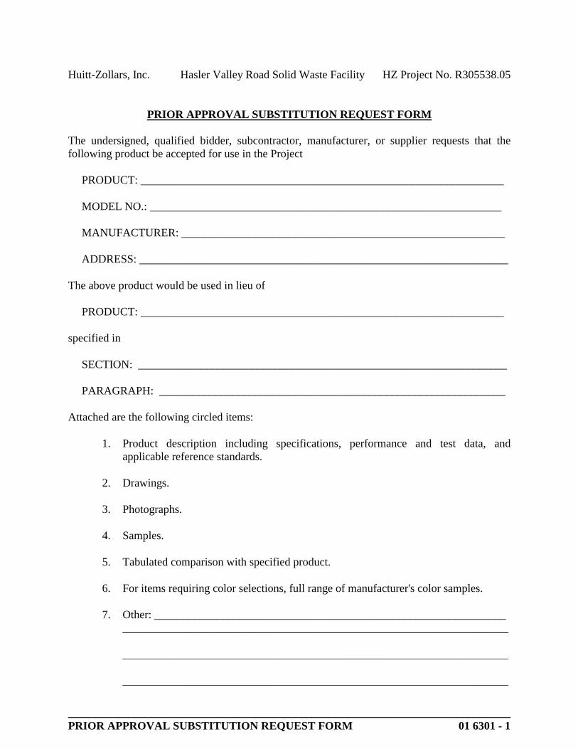
Huitt-Zollars, Inc. Hasler Valley Road Solid Waste Facility HZ Project No. R305538.05
______________________________________________________________________________PRIOR APPROVAL SUBSTITUTION REQUEST FORM 01 6301 - 1
PRIOR APPROVAL SUBSTITUTION REQUEST FORM
The undersigned, qualified bidder, subcontractor, manufacturer, or supplier requests that the following product be accepted for use in the Project
PRODUCT: ________________________________________________________________
MODEL NO.: ______________________________________________________________
MANUFACTURER: _________________________________________________________
ADDRESS: _________________________________________________________________
The above product would be used in lieu of
PRODUCT: ________________________________________________________________
specified in
SECTION: _________________________________________________________________
PARAGRAPH: _____________________________________________________________
Attached are the following circled items:
1. Product description including specifications, performance and test data, and applicable reference standards.
2. Drawings.
3. Photographs.
4. Samples.
5. Tabulated comparison with specified product.
6. For items requiring color selections, full range of manufacturer's color samples.
7. Other: ______________________________________________________________ ____________________________________________________________________
____________________________________________________________________
____________________________________________________________________

Huitt-Zollars, Inc. Hasler Valley Road Solid Waste Facility HZ Project No. R305538.05
This page left intentionally blank
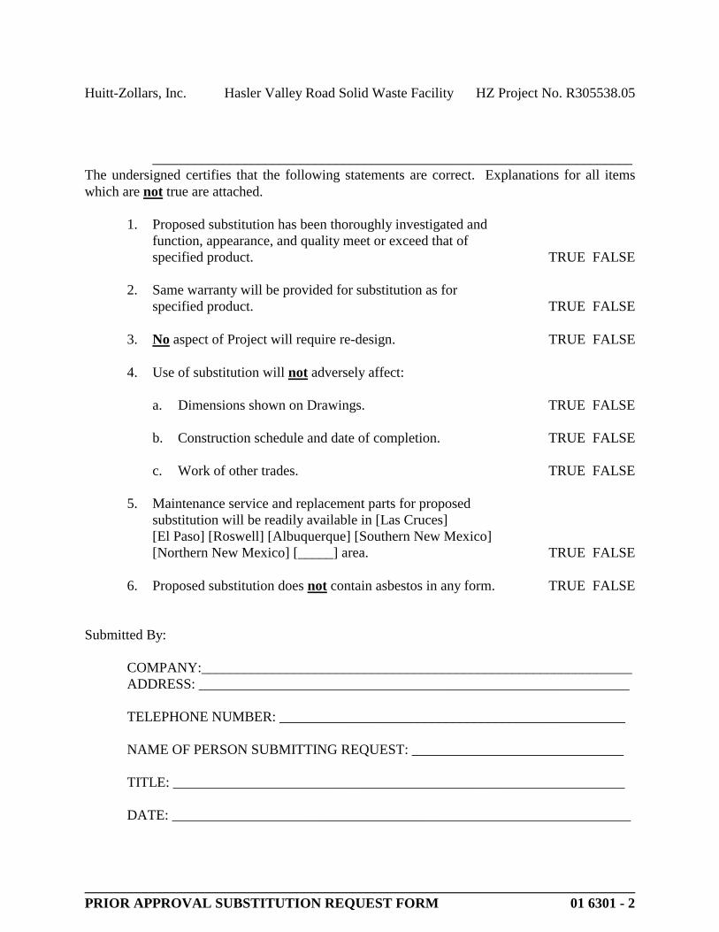
Huitt-Zollars, Inc. Hasler Valley Road Solid Waste Facility HZ Project No. R305538.05
______________________________________________________________________________PRIOR APPROVAL SUBSTITUTION REQUEST FORM 01 6301 - 2
____________________________________________________________________The undersigned certifies that the following statements are correct. Explanations for all items which are not true are attached.
1. Proposed substitution has been thoroughly investigated and function, appearance, and quality meet or exceed that of specified product. TRUE FALSE
2. Same warranty will be provided for substitution as for specified product. TRUE FALSE
3. No aspect of Project will require re-design. TRUE FALSE
4. Use of substitution will not adversely affect:
a. Dimensions shown on Drawings. TRUE FALSE
b. Construction schedule and date of completion. TRUE FALSE
c. Work of other trades. TRUE FALSE
5. Maintenance service and replacement parts for proposed substitution will be readily available in [Las Cruces][El Paso] [Roswell] [Albuquerque] [Southern New Mexico] [Northern New Mexico] [_____] area. TRUE FALSE
6. Proposed substitution does not contain asbestos in any form. TRUE FALSE
Submitted By:
COMPANY:_____________________________________________________________ADDRESS: _____________________________________________________________
TELEPHONE NUMBER: _________________________________________________
NAME OF PERSON SUBMITTING REQUEST: ______________________________
TITLE: ________________________________________________________________
DATE: _________________________________________________________________

Huitt-Zollars, Inc. Hasler Valley Road Solid Waste Facility HZ Project No. R305538.05
This page left intentionally blank
Huitt-Zollars, Inc. Hasler Valley Road Solid Waste Facility HZ Project No. R305538.05
EXECUTION 017300 - 1
SECTION 017300 - EXECUTION
PART 1 - GENERAL
1.1 RELATED DOCUMENTS
A. Drawings and general provisions of the Contract, including General and Supplementary Conditions and other Division 01 Specification Sections, apply to this Section.
1.2 SUMMARY
A. Section includes general administrative and procedural requirements governing execution of the Work including, but not limited to, the following:
1. Construction layout.2. Field engineering and surveying.3. Installation of the Work.4. Cutting and patching.5. Coordination of Owner-installed products.6. Progress cleaning.7. Starting and adjusting.8. Protection of installed construction.9. Correction of the Work.
B. Related Sections:
1. Division 01 Section "Submittal Procedures" for submitting surveys.2. Division 01 Section "Closeout Procedures" for submitting final property survey with
Project Record Documents, recording of Owner-accepted deviations from indicated lines and levels, and final cleaning.
1.3 DEFINITIONS
A. Cutting: Removal of in-place construction necessary to permit installation or performance of other work.
B. Patching: Fitting and repair work required to restore construction to original conditions after installation of other work.
1.4 INFORMATIONAL SUBMITTALS
A. Qualification Data: For land surveyor and/or professional engineer.
B. Certificates: Submit certificate signed by land surveyor and/or professional engineer certifying that location and elevation of improvements comply with requirements.
Huitt-Zollars, Inc. Hasler Valley Road Solid Waste Facility HZ Project No. R305538.05
EXECUTION 017300 - 2
C. Cutting and Patching Plan: Submit plan describing procedures at least 10 days prior to the time cutting and patching will be performed. Include the following information:
1. Extent: Describe reason for and extent of each occurrence of cutting and patching.2. Changes to In-Place Construction: Describe anticipated results. Include changes to
structural elements and operating components as well as changes in building appearance and other significant visual elements.
3. Products: List products to be used for patching and firms or entities that will perform patching work.
4. Dates: Indicate when cutting and patching will be performed.5. Utilities and Mechanical and Electrical Systems: List services and systems that cutting
and patching procedures will disturb or affect. List services and systems that will be relocated and those that will be temporarily out of service. Indicate how long services and systems will be disrupted.
D. Landfill Receipts: Submit copy of receipts issued by a landfill facility, licensed to accept hazardous materials, for hazardous waste disposal.
E. Certified Surveys: Submit two copies signed by land surveyor and/or professional engineer.
F. Final Property Survey: Submit 10 copies showing the Work performed and record survey data.
1.5 QUALITY ASSURANCE
A. Land Surveyor Qualifications: A professional land surveyor who is legally qualified to practice in jurisdiction where Project is located and who is experienced in providing land-surveying services of the kind indicated.
B. Cutting and Patching: Comply with requirements for and limitations on cutting and patching of construction elements.
1. Structural Elements: When cutting and patching structural elements, notify Architect of locations and details of cutting and await directions from the Architect before proceeding. Shore, brace, and support structural element during cutting and patching. Do not cut and patch structural elements in a manner that could change their load-carrying capacity or increase deflection
2. Operational Elements: Do not cut and patch operating elements and related components in a manner that results in reducing their capacity to perform as intended or that results in increased maintenance or decreased operational life or safety. Operational elements include the following:
a. Primary operational systems and equipment.b. Mechanical systems piping and ducts.c. Control systems.d. Communication systems.e. Electrical wiring systems.f. Operating systems of special construction.
Huitt-Zollars, Inc. Hasler Valley Road Solid Waste Facility HZ Project No. R305538.05
EXECUTION 017300 - 3
3. Other Construction Elements: Do not cut and patch other construction elements or components in a manner that could change their load-carrying capacity, that results in reducing their capacity to perform as intended, or that results in increased maintenance or decreased operational life or safety. Other construction elements include but are not limited to the following:
a. Water, moisture, or vapor barriers.b. Membranes and flashings.c. Exterior curtain-wall construction.d. Equipment supports.e. Piping, ductwork, vessels, and equipment.f. Noise- and vibration-control elements and systems.
4. Visual Elements: Do not cut and patch construction in a manner that results in visual evidence of cutting and patching. Do not cut and patch exposed construction in a manner that would, in Architect's opinion, reduce the building's aesthetic qualities. Remove and replace construction that has been cut and patched in a visually unsatisfactory manner.
C. Cutting and Patching Conference: Before proceeding, meet at Project site with parties involved in cutting and patching, including mechanical and electrical trades. Review areas of potential interference and conflict. Coordinate procedures and resolve potential conflicts before proceeding.
D. Manufacturer's Installation Instructions: Obtain and maintain on-site manufacturer's written recommendations and instructions for installation of products and equipment.
1.6 WARRANTY
A. Existing Warranties: Remove, replace, patch, and repair materials and surfaces cut or damaged during installation or cutting and patching operations, by methods and with materials so as not to void existing warranties.
PART 2 - PRODUCTS
2.1 MATERIALS
A. General: Comply with requirements specified in other Sections.
1. For projects requiring compliance with sustainable design and construction practices and procedures, utilize products for patching that comply with requirements of Division 01Section "Sustainable Design Requirements."
B. In-Place Materials: Use materials for patching identical to in-place materials. For exposed surfaces, use materials that visually match in-place adjacent surfaces to the fullest extent possible.

Huitt-Zollars, Inc. Hasler Valley Road Solid Waste Facility HZ Project No. R305538.05
EXECUTION 017300 - 4
1. If identical materials are unavailable or cannot be used, use materials that, when installed, will provide a match acceptable to the Architect for the visual and functional performance of in-place materials.
PART 3 - EXECUTION
3.1 EXAMINATION
A. Existing Conditions: The existence and location of underground and other utilities and construction indicated as existing are not guaranteed. Before beginning sitework, investigate and verify the existence and location of underground utilities, mechanical and electrical systems, and other construction affecting the Work.
1. Before construction, verify the location and invert elevation at points of connection of sanitary sewer, storm sewer, and water-service piping; underground electrical services, and other utilities.
2. Furnish location data for work related to Project that must be performed by public utilities serving Project site.
B. Examination and Acceptance of Conditions: Before proceeding with each component of the Work, examine substrates, areas, and conditions, with Installer or Applicator present where indicated, for compliance with requirements for installation tolerances and other conditions affecting performance. Record observations.
1. Written Report: Where a written report listing conditions detrimental to performance of the Work is required by other Sections, include the following:
a. Description of the Work.b. List of detrimental conditions, including substrates.c. List of unacceptable installation tolerances.d. Recommended corrections.
2. Verify compatibility with and suitability of substrates, including compatibility with existing finishes or primers.
3. Examine roughing-in for mechanical and electrical systems to verify actual locations of connections before equipment and fixture installation.
4. Examine walls, floors, and roofs for suitable conditions where products and systems are to be installed.
5. Proceed with installation only after unsatisfactory conditions have been corrected. Proceeding with the Work indicates acceptance of surfaces and conditions.
3.2 PREPARATION
A. Existing Utility Information: Furnish information to Owner that is necessary to adjust, move, or relocate existing utility structures, utility poles, lines, services, or other utility appurtenances located in or affected by construction. Coordinate with authorities having jurisdiction.
Huitt-Zollars, Inc. Hasler Valley Road Solid Waste Facility HZ Project No. R305538.05
EXECUTION 017300 - 5
B. Field Measurements: Take field measurements as required to fit the Work properly. Recheck measurements before installing each product. Where portions of the Work are indicated to fit to other construction, verify dimensions of other construction by field measurements before fabrication. Coordinate fabrication schedule with construction progress to avoid delaying the Work.
C. Space Requirements: Verify space requirements and dimensions of items shown diagrammatically on Drawings.
D. Review of Contract Documents and Field Conditions: Immediately on discovery of the need for clarification of the Contract Documents caused by differing field conditions outside the control of the Contractor, submit a request for information to Architect according to requirements in Division 01 Section "Project Management and Coordination."
3.3 CONSTRUCTION LAYOUT
A. Verification: Before proceeding to lay out the Work, verify layout information shown on Drawings, in relation to the property survey and existing benchmarks. If discrepancies are discovered, notify Architect promptly.
B. General: Engage a land surveyor and/or professional engineer to lay out the Work using accepted surveying practices.
1. Establish benchmarks and control points to set lines and levels at each story of construction and elsewhere as needed to locate each element of Project.
2. Establish dimensions within tolerances indicated. Do not scale Drawings to obtain required dimensions.
3. Inform installers of lines and levels to which they must comply.4. Check the location, level and plumb, of every major element as the Work progresses.5. Notify Architect when deviations from required lines and levels exceed allowable
tolerances.6. Close site surveys with an error of closure equal to or less than the standard established
by authorities having jurisdiction.
C. Site Improvements: Locate and lay out site improvements, including pavements, grading, fill and topsoil placement, utility slopes, and rim and invert elevations.
D. Building Lines and Levels: Locate and lay out control lines and levels for structures, building foundations, column grids, and floor levels, including those required for mechanical and electrical work. Transfer survey markings and elevations for use with control lines and levels. Level foundations and piers from two or more locations.
E. Record Log: Maintain a log of layout control work. Record deviations from required lines and levels. Include beginning and ending dates and times of surveys, weather conditions, name and duty of each survey party member, and types of instruments and tapes used. Make the log available for reference by Architect.
Huitt-Zollars, Inc. Hasler Valley Road Solid Waste Facility HZ Project No. R305538.05
EXECUTION 017300 - 6
3.4 FIELD ENGINEERING
A. Identification: Owner will identify existing benchmarks, control points, and property corners.
B. Reference Points: Locate existing permanent benchmarks, control points, and similar reference points before beginning the Work. Preserve and protect permanent benchmarks and control points during construction operations.
1. Do not change or relocate existing benchmarks or control points without prior written approval of Architect. Report lost or destroyed permanent benchmarks or control points promptly. Report the need to relocate permanent benchmarks or control points to Architect before proceeding.
2. Replace lost or destroyed permanent benchmarks and control points promptly. Base replacements on the original survey control points.
C. Benchmarks: Establish and maintain a minimum of two permanent benchmarks on Project site, referenced to data established by survey control points. Comply with authorities having jurisdiction for type and size of benchmark.
1. Record benchmark locations, with horizontal and vertical data, on Project Record Documents.
2. Where the actual location or elevation of layout points cannot be marked, provide temporary reference points sufficient to locate the Work.
3. Remove temporary reference points when no longer needed. Restore marked construction to its original condition.
D. Certified Survey: On completion of foundation walls, major site improvements, and other work requiring field-engineering services, prepare a certified survey showing dimensions, locations, angles, and elevations of construction and sitework.
E. Final Property Survey: Engage a land surveyor and/or professional engineer to prepare a final property survey showing significant features (real property) for Project. Include on the survey a certification, signed by land surveyor and/or professional engineer, that principal metes, bounds, lines, and levels of Project are accurately positioned as shown on the survey.
1. Show boundary lines, monuments, streets, site improvements and utilities, existing improvements and significant vegetation, adjoining properties, acreage, grade contours, and the distance and bearing from a site corner to a legal point.
2. Recording: At Substantial Completion, have the final property survey recorded by or with authorities having jurisdiction as the official "property survey."
3.5 INSTALLATION
A. General: Locate the Work and components of the Work accurately, in correct alignment and elevation, as indicated.
1. Make vertical work plumb and make horizontal work level.2. Where space is limited, install components to maximize space available for maintenance
and ease of removal for replacement.3. Conceal pipes, ducts, and wiring in finished areas, unless otherwise indicated.
Huitt-Zollars, Inc. Hasler Valley Road Solid Waste Facility HZ Project No. R305538.05
EXECUTION 017300 - 7
B. Comply with manufacturer's written instructions and recommendations for installing products in applications indicated.
C. Install products at the time and under conditions that will ensure the best possible results. Maintain conditions required for product performance until Substantial Completion.
D. Conduct construction operations so no part of the Work is subjected to damaging operations or loading in excess of that expected during normal conditions of occupancy.
E. Tools and Equipment: Do not use tools or equipment that produce harmful noise levels.
F. Templates: Obtain and distribute to the parties involved templates for work specified to be factory prepared and field installed. Check Shop Drawings of other work to confirm that adequate provisions are made for locating and installing products to comply with indicated requirements.
G. Attachment: Provide blocking and attachment plates and anchors and fasteners of adequate size and number to securely anchor each component in place, accurately located and aligned with other portions of the Work. Where size and type of attachments are not indicated, verify size and type required for load conditions.
1. Mounting Heights: Where mounting heights are not indicated, mount components at heights directed by Architect.
2. Allow for building movement, including thermal expansion and contraction.3. Coordinate installation of anchorages. Furnish setting drawings, templates, and
directions for installing anchorages, including sleeves, concrete inserts, anchor bolts, and items with integral anchors, that are to be embedded in concrete or masonry. Deliver such items to Project site in time for installation.
H. Joints: Make joints of uniform width. Where joint locations in exposed work are not indicated, arrange joints for the best visual effect. Fit exposed connections together to form hairline joints.
I. Hazardous Materials: Use products, cleaners, and installation materials that are not considered hazardous.
3.6 CUTTING AND PATCHING
A. Cutting and Patching, General: Employ skilled workers to perform cutting and patching. Proceed with cutting and patching at the earliest feasible time, and complete without delay.
1. Cut in-place construction to provide for installation of other components or performance of other construction, and subsequently patch as required to restore surfaces to their original condition.
B. Temporary Support: Provide temporary support of work to be cut.
C. Protection: Protect in-place construction during cutting and patching to prevent damage. Provide protection from adverse weather conditions for portions of Project that might be exposed during cutting and patching operations.

Huitt-Zollars, Inc. Hasler Valley Road Solid Waste Facility HZ Project No. R305538.05
EXECUTION 017300 - 8
D. Adjacent Occupied Areas: Where interference with use of adjoining areas or interruption of free passage to adjoining areas is unavoidable, coordinate cutting and patching in accordance with requirements of Division 01 Section "Summary."
E. Existing Utility Services and Mechanical/Electrical Systems: Where existing services/systems are required to be removed, relocated, or abandoned, bypass such services/systems before cutting to prevent interruption to occupied areas.
F. Cutting: Cut in-place construction by sawing, drilling, breaking, chipping, grinding, and similar operations, including excavation, using methods least likely to damage elements retained or adjoining construction. If possible, review proposed procedures with original Installer; comply with original Installer's written recommendations.
1. In general, use hand or small power tools designed for sawing and grinding, not hammering and chopping. Cut holes and slots neatly to minimum size required, and with minimum disturbance of adjacent surfaces. Temporarily cover openings when not in use.
2. Finished Surfaces: Cut or drill from the exposed or finished side into concealed surfaces.3. Concrete and Masonry: Cut using a cutting machine, such as an abrasive saw or a
diamond-core drill.4. Excavating and Backfilling: Comply with requirements in applicable Division 31
Sections where required by cutting and patching operations.5. Mechanical and Electrical Services: Cut off pipe or conduit in walls or partitions to be
removed. Cap, valve, or plug and seal remaining portion of pipe or conduit to prevent entrance of moisture or other foreign matter after cutting.
6. Proceed with patching after construction operations requiring cutting are complete.
G. Patching: Patch construction by filling, repairing, refinishing, closing up, and similar operations following performance of other work. Patch with durable seams that are as invisible as practicable. Provide materials and comply with installation requirements specified in other Sections, where applicable.
1. Inspection: Where feasible, test and inspect patched areas after completion to demonstrate physical integrity of installation.
2. Exposed Finishes: Restore exposed finishes of patched areas and extend finish restoration into retained adjoining construction in a manner that will minimize evidence of patching and refinishing.
a. Clean piping, conduit, and similar features before applying paint or other finishing materials.
b. Restore damaged pipe covering to its original condition.
3. Floors and Walls: Where walls or partitions that are removed extend one finished area into another, patch and repair floor and wall surfaces in the new space. Provide an even surface of uniform finish, color, texture, and appearance. Remove in-place floor and wall coverings and replace with new materials, if necessary, to achieve uniform color and appearance.
a. Where patching occurs in a painted surface, prepare substrate and apply primer and intermediate paint coats appropriate for substrate over the patch, and apply final paint coat over entire unbroken surface containing the patch. Provide additional coats until patch blends with adjacent surfaces.

Huitt-Zollars, Inc. Hasler Valley Road Solid Waste Facility HZ Project No. R305538.05
EXECUTION 017300 - 9
4. Ceilings: Patch, repair, or rehang in-place ceilings as necessary to provide an even-plane surface of uniform appearance.
5. Exterior Building Enclosure: Patch components in a manner that restores enclosure to a weathertight condition.
H. Cleaning: Clean areas and spaces where cutting and patching are performed. Remove paint, mortar, oils, putty, and similar materials from adjacent finished surfaces.
3.7 PROGRESS CLEANING
A. General: Clean Project site and work areas daily, including common areas. Enforce requirements strictly. Dispose of materials lawfully.
1. Comply with requirements in NFPA 241 for removal of combustible waste materials and debris.
2. Do not hold waste materials more than seven days during normal weather or three days if the temperature is expected to rise above 80 deg F (27 deg C).
3. Containerize hazardous and unsanitary waste materials separately from other waste. Mark containers appropriately and dispose of legally, according to regulations.
a. Utilize containers intended for holding waste materials of type to be stored.
4. Coordinate progress cleaning for joint-use areas where more than one installer has worked.
B. Site: Maintain Project site free of waste materials and debris.
C. Work Areas: Clean areas where work is in progress to the level of cleanliness necessary for proper execution of the Work.
1. Remove liquid spills promptly.2. Where dust would impair proper execution of the Work, broom-clean or vacuum the
entire work area, as appropriate.
D. Installed Work: Keep installed work clean. Clean installed surfaces according to written instructions of manufacturer or fabricator of product installed, using only cleaning materials specifically recommended. If specific cleaning materials are not recommended, use cleaning materials that are not hazardous to health or property and that will not damage exposed surfaces.
E. Concealed Spaces: Remove debris from concealed spaces before enclosing the space.
F. Exposed Surfaces in Finished Areas: Clean exposed surfaces and protect as necessary to ensure freedom from damage and deterioration at time of Substantial Completion.
G. Waste Disposal: Do not bury or burn waste materials on-site. Do not wash waste materials down sewers or into waterways. Comply with waste disposal requirements in Division 01Section "Temporary Facilities and Controls." And/or Division 01 Section "Construction Waste Management and Disposal."

Huitt-Zollars, Inc. Hasler Valley Road Solid Waste Facility HZ Project No. R305538.05
EXECUTION 017300 - 10
H. During handling and installation, clean and protect construction in progress and adjoining materials already in place. Apply protective covering where required to ensure protection from damage or deterioration at Substantial Completion.
I. Clean and provide maintenance on completed construction as frequently as necessary through the remainder of the construction period. Adjust and lubricate operable components to ensure operability without damaging effects.
J. Limiting Exposures: Supervise construction operations to assure that no part of the construction, completed or in progress, is subject to harmful, dangerous, damaging, or otherwise deleterious exposure during the construction period.
3.8 STARTING AND ADJUSTING
A. Coordinate startup and adjusting of equipment and operating components with requirements in Division 01 Section "General Commissioning Requirements."
B. Start equipment and operating components to confirm proper operation. Remove malfunctioning units, replace with new units, and retest.
C. Adjust equipment for proper operation. Adjust operating components for proper operation without binding.
D. Test each piece of equipment to verify proper operation. Test and adjust controls and safeties. Replace damaged and malfunctioning controls and equipment.
E. Manufacturer's Field Service: Comply with qualification requirements in Division 01 Section "Quality Requirements."
3.9 PROTECTION OF INSTALLED CONSTRUCTION
A. Provide final protection and maintain conditions that ensure installed Work is without damage or deterioration at time of Substantial Completion.
B. Comply with manufacturer's written instructions for temperature and relative humidity.
3.10 CORRECTION OF THE WORK
A. Repair or remove and replace defective construction. Restore damaged substrates and finishes.
1. Repairing includes replacing defective parts, refinishing damaged surfaces, touching up with matching materials, and properly adjusting operating equipment.
B. Restore permanent facilities used during construction to their specified condition.
C. Remove and replace damaged surfaces that are exposed to view if surfaces cannot be repaired without visible evidence of repair.

Huitt-Zollars, Inc. Hasler Valley Road Solid Waste Facility HZ Project No. R305538.05
EXECUTION 017300 - 11
D. Repair components that do not operate properly. Remove and replace operating components that cannot be repaired.
E. Remove and replace chipped, scratched, and broken glass or reflective surfaces.
END OF SECTION 017300

Huitt-Zollars, Inc. Hasler Valley Road Solid Waste Facility HZ Project No. R305538.05
This page left intentionally blank

Huitt-Zollars, Inc. Hasler Valley Road Solid Waste Facility HZ Project No. R305538.05
CLOSEOUT PROCEDURES 017700 - 1
SECTION 017700 - CLOSEOUT PROCEDURES
PART 1 - GENERAL
1.1 RELATED DOCUMENTS
A. Drawings and general provisions of the Contract, including General and Supplementary Conditions and other Division 01 Specification Sections, apply to this Section.
1.2 SUMMARY
A. Section includes administrative and procedural requirements for contract closeout, including, but not limited to, the following:
1. Substantial Completion procedures.2. Final completion procedures.3. Warranties.4. Final cleaning.
B. Related Sections:1. Division 01 Section "Execution" for progress cleaning of Project site.2. Division 01 Section "Operation and Maintenance Data" for operation and maintenance
manual requirements.3. Division 01 Section "Project Record Documents" for submitting Record Drawings,
Record Specifications, and Record Product Data.4. Division 01 Section "Demonstration and Training" for requirements for instructing
Owner's personnel.5. Divisions 01 through 33 Sections for specific closeout and special cleaning requirements
for the Work in those Sections.
1.3 SUBSTANTIAL COMPLETION
A. Preliminary Procedures: Before requesting inspection for determining date of Substantial Completion, complete the following. List items below that are incomplete with request.
1. Prepare a list of items to be completed and corrected (punch list), the value of items on the list, and reasons why the Work is not complete.
2. Advise Owner of pending insurance changeover requirements.3. Submit specific warranties, workmanship bonds, maintenance service agreements, final
certifications, and similar documents.4. Obtain and submit releases permitting Owner unrestricted use of the Work and access to
services and utilities. Include occupancy permits, operating certificates, and similar releases.
5. Prepare and submit Project Record Documents, operation and maintenance manuals, final completion construction photographic documentation, damage or settlement surveys, property surveys, and similar final record information.
Huitt-Zollars, Inc. Hasler Valley Road Solid Waste Facility HZ Project No. R305538.05
CLOSEOUT PROCEDURES 017700 - 2
6. Deliver tools, spare parts, extra materials, and similar items to location designated by Owner. Label with manufacturer's name and model number where applicable.
7. Make final changeover of permanent locks and deliver keys to Owner. Advise Owner's personnel of changeover in security provisions.
8. Complete startup testing of systems.9. Submit test/adjust/balance records.10. Terminate and remove temporary facilities from Project site, along with mockups,
construction tools, and similar elements.11. Advise Owner of changeover in heat and other utilities.12. Submit changeover information related to Owner's occupancy, use, operation, and
maintenance.13. Complete final cleaning requirements, including touchup painting.14. Touch up and otherwise repair and restore marred exposed finishes to eliminate visual
defects.
B. Inspection: Submit a written request for inspection for Substantial Completion. On receipt of request, Architect will either proceed with inspection or notify Contractor of unfulfilled requirements. Architect will prepare the Certificate of Substantial Completion after inspection or will notify Contractor of items, either on Contractor's list or additional items identified by Architect, that must be completed or corrected before certificate will be issued.
1. Reinspection: Request reinspection when the Work identified in previous inspections as incomplete is completed or corrected.
2. Results of completed inspection will form the basis of requirements for final completion.
1.4 FINAL COMPLETION
A. Preliminary Procedures: Before requesting final inspection for determining final completion, complete the following:
1. Submit a final Application for Payment according to Division 01 Section "Payment Procedures."
2. Submit certified copy of Architect's Substantial Completion inspection list of items to be completed or corrected (punch list), endorsed and dated by Architect. The certified copy of the list shall state that each item has been completed or otherwise resolved for acceptance.
3. Submit evidence of final, continuing insurance coverage complying with insurance requirements.
4. Submit pest-control final inspection report and warranty.5. Instruct Owner's personnel in operation, adjustment, and maintenance of products,
equipment, and systems.
B. Inspection: Submit a written request for final inspection for acceptance. On receipt of request, Architect will either proceed with inspection or notify Contractor of unfulfilled requirements. Architect will prepare a final Certificate for Payment after inspection or will notify Contractor of construction that must be completed or corrected before certificate will be issued.
1. Reinspection: Request reinspection when the Work identified in previous inspections as incomplete is completed or corrected.
Huitt-Zollars, Inc. Hasler Valley Road Solid Waste Facility HZ Project No. R305538.05
CLOSEOUT PROCEDURES 017700 - 3
1.5 LIST OF INCOMPLETE ITEMS (PUNCH LIST)
A. Organization of List: Include name and identification of each space and area affected by construction operations for incomplete items and items needing correction including, if necessary, areas disturbed by Contractor that are outside the limits of construction.
1. Organize list of spaces in sequential order, starting with exterior areas first.2. Organize items applying to each space by major element, including categories for ceiling,
individual walls, floors, equipment, and building systems.3. Include the following information at the top of each page:
a. Project name.b. Date.c. Name of Architect.d. Name of Contractor.e. Page number.
4. Submit list of incomplete items in the following format:
a. PDF electronic file.b. Three paper copies of product schedule or list, unless otherwise indicated.
Architect will return copies.
1.6 WARRANTIES
A. Submittal Time: Submit written warranties on request of Architect for designated portions of the Work where commencement of warranties other than date of Substantial Completion is indicated.
B. Partial Occupancy: Submit properly executed warranties within 15 days of completion of designated portions of the Work that are completed and occupied or used by Owner during construction period by separate agreement with Contractor.
C. Organize warranty documents into an orderly sequence based on the table of contents of the Project Manual.
1. Bind warranties and bonds in heavy-duty, three-ring, vinyl-covered, loose-leaf binders, thickness as necessary to accommodate contents, and sized to receive 8-1/2-by-11-inch(215-by-280-mm) paper.
2. Provide heavy paper dividers with plastic-covered tabs for each separate warranty. Mark tab to identify the product or installation. Provide a typed description of the product or installation, including the name of the product and the name, address, and telephone number of Installer.
3. Identify each binder on the front and spine with the typed or printed title "WARRANTIES," Project name, and name of Contractor.
4. Scan warranties and bonds and assemble complete warranty and bond submittal package into a single indexed electronic PDF file with links enabling navigation to each item. Provide table of contents at beginning of document.
D. Provide additional copies of each warranty to include in operation and maintenance manuals.

Huitt-Zollars, Inc. Hasler Valley Road Solid Waste Facility HZ Project No. R305538.05
CLOSEOUT PROCEDURES 017700 - 4
PART 2 - PRODUCTS
2.1 MATERIALS
A. Cleaning Agents: Use cleaning materials and agents recommended by manufacturer or fabricator of the surface to be cleaned. Do not use cleaning agents that are potentially hazardous to health or property or that might damage finished surfaces.
1. Use cleaning products that meet Green Seal GS-37, or if GS-37 is not applicable, use products that comply with the California Code of Regulations maximum allowable VOC levels.
PART 3 - EXECUTION
3.1 FINAL CLEANING
A. General: Perform final cleaning. Conduct cleaning and waste-removal operations to comply with local laws and ordinances and Federal and local environmental and antipollution regulations.
B. Cleaning: Employ experienced workers or professional cleaners for final cleaning. Clean each surface or unit to condition expected in an average commercial building cleaning and maintenance program. Comply with manufacturer's written instructions.
1. Complete the following cleaning operations before requesting inspection for certification of Substantial Completion for entire Project or for a portion of Project:
a. Clean Project site, yard, and grounds, in areas disturbed by construction activities, including landscape development areas, of rubbish, waste material, litter, and other foreign substances.
b. Sweep paved areas broom clean. Remove petrochemical spills, stains, and other foreign deposits.
c. Rake grounds that are neither planted nor paved to a smooth, even-textured surface.
d. Remove tools, construction equipment, machinery, and surplus material from Project site.
e. Remove snow and ice to provide safe access to building.f. Clean exposed exterior and interior hard-surfaced finishes to a dirt-free condition,
free of stains, films, and similar foreign substances. Avoid disturbing natural weathering of exterior surfaces. Restore reflective surfaces to their original condition.
g. Remove debris and surface dust from limited access spaces, including roofs, plenums, shafts, trenches, equipment vaults, manholes, attics, and similar spaces.
h. Sweep concrete floors broom clean in unoccupied spaces.i. Vacuum carpet and similar soft surfaces, removing debris and excess nap;
shampoo if visible soil or stains remain.j. Clean transparent materials, including mirrors and glass in doors and windows.
Remove glazing compounds and other noticeable, vision-obscuring materials.
Huitt-Zollars, Inc. Hasler Valley Road Solid Waste Facility HZ Project No. R305538.05
CLOSEOUT PROCEDURES 017700 - 5
Replace chipped or broken glass and other damaged transparent materials. Polish mirrors and glass, taking care not to scratch surfaces.
k. Remove labels that are not permanent.l. Touch up and otherwise repair and restore marred, exposed finishes and surfaces.
Replace finishes and surfaces that cannot be satisfactorily repaired or restored or that already show evidence of repair or restoration.
1) Do not paint over "UL" and other required labels and identification, including mechanical and electrical nameplates.
m. Wipe surfaces of mechanical and electrical equipment, and similar equipment. Remove excess lubrication, paint and mortar droppings, and other foreign substances.
n. Replace parts subject to operating conditions during construction that may impede operation or reduce longevity.
o. Clean plumbing fixtures to a sanitary condition, free of stains, including stains resulting from water exposure.
p. Replace disposable air filters and clean permanent air filters. Clean exposed surfaces of diffusers, registers, and grills.
q. Clean ducts, blowers, and coils if units were operated without filters during construction or that display contamination with particulate matter upon inspection.
1) Clean HVAC system in compliance with NADCA Standard 1992-01.Provide written report upon completion of cleaning.
r. Clean light fixtures, lamps, globes, and reflectors to function with full efficiency. Replace burned-out bulbs, and those noticeably dimmed by hours of use, and defective and noisy starters in fluorescent and mercury vapor fixtures to comply with requirements for new fixtures.
s. Leave Project clean and ready for occupancy.
C. Pest Control: Engage an experienced, licensed exterminator to make a final inspection and rid Project of rodents, insects, and other pests. Prepare a report.
D. Construction Waste Disposal: Comply with waste disposal requirements in Division 01 Section "Temporary Facilities and Controls." Or Division 01 Section "Construction Waste Management and Disposal."
END OF SECTION 017700

Huitt-Zollars, Inc. Hasler Valley Road Solid Waste Facility HZ Project No. R305538.05
This page left intentionally blank

Huitt-Zollars, Inc. Hasler Valley Road Solid Waste Facility HZ Project No. R305538.05
OPERATION AND MAINTENANCE DATA 017823 - 1
SECTION 017823 - OPERATION AND MAINTENANCE DATA
PART 1 - GENERAL
1.1 RELATED DOCUMENTS
A. Drawings and general provisions of the Contract, including General and Supplementary Conditions and other Division 01 Specification Sections, apply to this Section.
1.2 SUMMARY
A. Section includes administrative and procedural requirements for preparing operation and maintenance manuals, including the following:
1. Operation and maintenance documentation directory.2. Emergency manuals.3. Operation manuals for systems, subsystems, and equipment.4. Product maintenance manuals.5. Systems and equipment maintenance manuals.
B. Related Sections:1. Division 01 Section "Submittal Procedures" for submitting copies of submittals for
operation and maintenance manuals.2. Divisions 01 through 33 Sections for specific operation and maintenance manual
requirements for the Work in those Sections.
1.3 DEFINITIONS
A. System: An organized collection of parts, equipment, or subsystems united by regular interaction.
B. Subsystem: A portion of a system with characteristics similar to a system.
1.4 CLOSEOUT SUBMITTALS
A. Manual Content: Operations and maintenance manual content is specified in individual specification sections to be reviewed at the time of Section submittals. Submit reviewed manual content formatted and organized as required by this Section.
1. Where applicable, clarify and update reviewed manual content to correspond to modifications and field conditions.
B. Format: Submit operations and maintenance manuals in the following format:
1. PDF electronic file. Assemble each manual into a composite electronically-indexed file. Submit on digital media acceptable to Architect.

Huitt-Zollars, Inc. Hasler Valley Road Solid Waste Facility HZ Project No. R305538.05
OPERATION AND MAINTENANCE DATA 017823 - 2
a. Name each indexed document file in composite electronic index with applicable item name. Include a complete electronically-linked operation and maintenance directory.
b. Enable inserted reviewer comments on draft submittals.
2. Three paper copies. Include a complete operation and maintenance directory. Enclose title pages and directories in clear plastic sleeves. Architect will return two copies.
C. Final Manual Submittal: Submit each manual in final form prior to requesting inspection for Substantial Completion and at least 15 days before commencing demonstration and training. Architect will return copy with comments.
1. Correct or modify each manual to comply with Architect's comments. Submit copies ofeach corrected manual within 15 days of receipt of Architect's comments and prior to commencing demonstration and training.
PART 2 - PRODUCTS
2.1 OPERATION AND MAINTENANCE DOCUMENTATION DIRECTORY
A. Organization: Include a section in the directory for each of the following:
1. List of documents.2. List of systems.3. List of equipment.4. Table of contents.
B. List of Systems and Subsystems: List systems alphabetically. Include references to operation and maintenance manuals that contain information about each system.
C. List of Equipment: List equipment for each system, organized alphabetically by system. For pieces of equipment not part of system, list alphabetically in separate list.
D. Tables of Contents: Include a table of contents for each emergency, operation, and maintenance manual.
E. Identification: In the documentation directory and in each operation and maintenance manual, identify each system, subsystem, and piece of equipment with same designation used in the Contract Documents. If no designation exists, assign a designation according to ASHRAE Guideline 4, "Preparation of Operating and Maintenance Documentation for Building Systems."
2.2 REQUIREMENTS FOR EMERGENCY, OPERATION, AND MAINTENANCE MANUALS
A. Organization: Unless otherwise indicated, organize each manual into a separate section for each system and subsystem, and a separate section for each piece of equipment not part of a system. Each manual shall contain the following materials, in the order listed:
1. Title page.

Huitt-Zollars, Inc. Hasler Valley Road Solid Waste Facility HZ Project No. R305538.05
OPERATION AND MAINTENANCE DATA 017823 - 3
2. Table of contents.3. Manual contents.
B. Title Page: Include the following information:
1. Subject matter included in manual.2. Name and address of Project.3. Name and address of Owner.4. Date of submittal.5. Name and contact information for Contractor.6. Name and contact information for Construction Manager.7. Name and contact information for Architect.8. Name and contact information for Commissioning Agent.9. Names and contact information for major consultants to the Architect that designed the
systems contained in the manuals.10. Cross-reference to related systems in other operation and maintenance manuals.
C. Table of Contents: List each product included in manual, identified by product name, indexed to the content of the volume, and cross-referenced to Specification Section number in Project Manual.
1. If operation or maintenance documentation requires more than one volume to accommodate data, include comprehensive table of contents for all volumes in each volume of the set.
D. Manual Contents: Organize into sets of manageable size. Arrange contents alphabetically bysystem, subsystem, and equipment. If possible, assemble instructions for subsystems, equipment, and components of one system into a single binder.
E. Manuals, Electronic Files: Submit manuals in the form of a multiple file composite electronic PDF file for each manual type required.
1. Electronic Files: Use electronic files prepared by manufacturer where available. Where scanning of paper documents is required, configure scanned file for minimum readable file size.
2. File Names and Bookmarks: Enable bookmarking of individual documents based upon file names. Name document files to correspond to system, subsystem, and equipment names used in manual directory and table of contents. Group documents for each system and subsystem into individual composite bookmarked files, then create composite manual, so that resulting bookmarks reflect the system, subsystem, and equipment names in a readily navigated file tree. Configure electronic manual to display bookmark panel upon opening file.
F. Manuals, Paper Copy: Submit manuals in the form of hard copy, bound and labeled volumes.
1. Binders: Heavy-duty, three-ring, vinyl-covered, loose-leaf binders, in thickness necessary to accommodate contents, sized to hold 8-1/2-by-11-inch (215-by-280-mm)paper; with clear plastic sleeve on spine to hold label describing contents and with pockets inside covers to hold folded oversize sheets.

Huitt-Zollars, Inc. Hasler Valley Road Solid Waste Facility HZ Project No. R305538.05
OPERATION AND MAINTENANCE DATA 017823 - 4
a. If two or more binders are necessary to accommodate data of a system, organize data in each binder into groupings by subsystem and related components. Cross-reference other binders if necessary to provide essential information for proper operation or maintenance of equipment or system.
b. Identify each binder on front and spine, with printed title "OPERATION AND MAINTENANCE MANUAL," Project title or name, and subject matter of contents, and indicate Specification Section number on bottom of spine. Indicate volume number for multiple-volume sets.
2. Dividers: Heavy-paper dividers with plastic-covered tabs for each section of the manual. Mark each tab to indicate contents. Include typed list of products and major components of equipment included in the section on each divider, cross-referenced to Specification Section number and title of Project Manual.
3. Protective Plastic Sleeves: Transparent plastic sleeves designed to enclose diagnostic software storage media for computerized electronic equipment.
4. Supplementary Text: Prepared on 8-1/2-by-11-inch (215-by-280-mm) white bond paper.5. Drawings: Attach reinforced, punched binder tabs on drawings and bind with text.
a. If oversize drawings are necessary, fold drawings to same size as text pages and use as foldouts.
b. If drawings are too large to be used as foldouts, fold and place drawings in labeled envelopes and bind envelopes in rear of manual. At appropriate locations in manual, insert typewritten pages indicating drawing titles, descriptions of contents, and drawing locations.
2.3 EMERGENCY MANUALS
A. Content: Organize manual into a separate section for each of the following:
1. Type of emergency.2. Emergency instructions.3. Emergency procedures.
B. Type of Emergency: Where applicable for each type of emergency indicated below, include instructions and procedures for each system, subsystem, piece of equipment, and component:
1. Fire.2. Flood.3. Gas leak.4. Water leak.5. Power failure.6. Water outage.7. System, subsystem, or equipment failure.8. Chemical release or spill.
C. Emergency Instructions: Describe and explain warnings, trouble indications, error messages, and similar codes and signals. Include responsibilities of Owner's operating personnel for notification of Installer, supplier, and manufacturer to maintain warranties.
D. Emergency Procedures: Include the following, as applicable:

Huitt-Zollars, Inc. Hasler Valley Road Solid Waste Facility HZ Project No. R305538.05
OPERATION AND MAINTENANCE DATA 017823 - 5
1. Instructions on stopping.2. Shutdown instructions for each type of emergency.3. Operating instructions for conditions outside normal operating limits.4. Required sequences for electric or electronic systems.5. Special operating instructions and procedures.
2.4 OPERATION MANUALS
A. Content: In addition to requirements in this Section, include operation data required in individual Specification Sections and the following information:
1. System, subsystem, and equipment descriptions. Use designations for systems andequipment indicated on Contract Documents.
2. Performance and design criteria if Contractor is delegated design responsibility.3. Operating standards.4. Operating procedures.5. Operating logs.6. Wiring diagrams.7. Control diagrams.8. Piped system diagrams.9. Precautions against improper use.10. License requirements including inspection and renewal dates.
B. Descriptions: Include the following:
1. Product name and model number. Use designations for products indicated on Contract Documents.
2. Manufacturer's name.3. Equipment identification with serial number of each component.4. Equipment function.5. Operating characteristics.6. Limiting conditions.7. Performance curves.8. Engineering data and tests.9. Complete nomenclature and number of replacement parts.
C. Operating Procedures: Include the following, as applicable:
1. Startup procedures.2. Equipment or system break-in procedures.3. Routine and normal operating instructions.4. Regulation and control procedures.5. Instructions on stopping.6. Normal shutdown instructions.7. Seasonal and weekend operating instructions.8. Required sequences for electric or electronic systems.9. Special operating instructions and procedures.
D. Systems and Equipment Controls: Describe the sequence of operation, and diagram controls as installed.
Huitt-Zollars, Inc. Hasler Valley Road Solid Waste Facility HZ Project No. R305538.05
OPERATION AND MAINTENANCE DATA 017823 - 6
E. Piped Systems: Diagram piping as installed, and identify color-coding where required for identification.
2.5 PRODUCT MAINTENANCE MANUALS
A. Content: Organize manual into a separate section for each product, material, and finish. Include source information, product information, maintenance procedures, repair materials and sources, and warranties and bonds, as described below.
B. Source Information: List each product included in manual, identified by product name and arranged to match manual's table of contents. For each product, list name, address, and telephone number of Installer or supplier and maintenance service agent, and cross-reference Specification Section number and title in Project Manual and drawing or schedule designation or identifier where applicable.
C. Product Information: Include the following, as applicable:
1. Product name and model number.2. Manufacturer's name.3. Color, pattern, and texture.4. Material and chemical composition.5. Reordering information for specially manufactured products.
D. Maintenance Procedures: Include manufacturer's written recommendations and the following:
1. Inspection procedures.2. Types of cleaning agents to be used and methods of cleaning.3. List of cleaning agents and methods of cleaning detrimental to product.4. Schedule for routine cleaning and maintenance.5. Repair instructions.
E. Repair Materials and Sources: Include lists of materials and local sources of materials and related services.
F. Warranties and Bonds: Include copies of warranties and bonds and lists of circumstances and conditions that would affect validity of warranties or bonds.
1. Include procedures to follow and required notifications for warranty claims.
2.6 SYSTEMS AND EQUIPMENT MAINTENANCE MANUALS
A. Content: For each system, subsystem, and piece of equipment not part of a system, include source information, manufacturers' maintenance documentation, maintenance procedures, maintenance and service schedules, spare parts list and source information, maintenance service contracts, and warranty and bond information, as described below.
B. Source Information: List each system, subsystem, and piece of equipment included in manual, identified by product name and arranged to match manual's table of contents. For each product, list name, address, and telephone number of Installer or supplier and maintenance service agent,
Huitt-Zollars, Inc. Hasler Valley Road Solid Waste Facility HZ Project No. R305538.05
OPERATION AND MAINTENANCE DATA 017823 - 7
and cross-reference Specification Section number and title in Project Manual and drawing or schedule designation or identifier where applicable.
C. Manufacturers' Maintenance Documentation: Manufacturers' maintenance documentation including the following information for each component part or piece of equipment:
1. Standard maintenance instructions and bulletins.2. Drawings, diagrams, and instructions required for maintenance, including disassembly
and component removal, replacement, and assembly.3. Identification and nomenclature of parts and components.4. List of items recommended to be stocked as spare parts.
D. Maintenance Procedures: Include the following information and items that detail essential maintenance procedures:
1. Test and inspection instructions.2. Troubleshooting guide.3. Precautions against improper maintenance.4. Disassembly; component removal, repair, and replacement; and reassembly instructions.5. Aligning, adjusting, and checking instructions.6. Demonstration and training video recording, if available.
E. Maintenance and Service Schedules: Include service and lubrication requirements, list of required lubricants for equipment, and separate schedules for preventive and routine maintenance and service with standard time allotment.
1. Scheduled Maintenance and Service: Tabulate actions for daily, weekly, monthly, quarterly, semiannual, and annual frequencies.
2. Maintenance and Service Record: Include manufacturers' forms for recording maintenance.
F. Spare Parts List and Source Information: Include lists of replacement and repair parts, with parts identified and cross-referenced to manufacturers' maintenance documentation and local sources of maintenance materials and related services.
G. Maintenance Service Contracts: Include copies of maintenance agreements with name and telephone number of service agent.
H. Warranties and Bonds: Include copies of warranties and bonds and lists of circumstances and conditions that would affect validity of warranties or bonds.
1. Include procedures to follow and required notifications for warranty claims.
PART 3 - EXECUTION
3.1 MANUAL PREPARATION
A. Operation and Maintenance Documentation Directory: Prepare a separate manual that provides an organized reference to emergency, operation, and maintenance manuals.
Huitt-Zollars, Inc. Hasler Valley Road Solid Waste Facility HZ Project No. R305538.05
OPERATION AND MAINTENANCE DATA 017823 - 8
B. Emergency Manual: Assemble a complete set of emergency information indicating procedures for use by emergency personnel and by Owner's operating personnel for types of emergencies indicated.
C. Product Maintenance Manual: Assemble a complete set of maintenance data indicating care and maintenance of each product, material, and finish incorporated into the Work.
D. Operation and Maintenance Manuals: Assemble a complete set of operation and maintenance data indicating operation and maintenance of each system, subsystem, and piece of equipment not part of a system.
1. Engage a factory-authorized service representative to assemble and prepare information for each system, subsystem, and piece of equipment not part of a system.
2. Prepare a separate manual for each system and subsystem, in the form of an instructional manual for use by Owner's operating personnel.
E. Manufacturers' Data: Where manuals contain manufacturers' standard printed data, include only sheets pertinent to product or component installed. Mark each sheet to identify each product or component incorporated into the Work. If data include more than one item in a tabular format, identify each item using appropriate references from the Contract Documents. Identify data applicable to the Work and delete references to information not applicable.
1. Prepare supplementary text if manufacturers' standard printed data are not available and where the information is necessary for proper operation and maintenance of equipment or systems.
F. Drawings: Prepare drawings supplementing manufacturers' printed data to illustrate the relationship of component parts of equipment and systems and to illustrate control sequence and flow diagrams. Coordinate these drawings with information contained in record Drawings to ensure correct illustration of completed installation.
1. Do not use original project record documents as part of operation and maintenance manuals.
2. Comply with requirements of newly prepared record Drawings in Division 01 Section "Project Record Documents."
G. Comply with Division 01 Section "Closeout Procedures" for schedule for submitting operation and maintenance documentation.
END OF SECTION 017823
Huitt-Zollars, Inc. Hasler Valley Road Solid Waste Facility HZ Project No. R305538.05
PROJECT RECORD DOCUMENTS 017839 - 1
SECTION 017839 - PROJECT RECORD DOCUMENTS
PART 1 - GENERAL
1.1 RELATED DOCUMENTS
A. Drawings and general provisions of the Contract, including General and Supplementary Conditions and other Division 01 Specification Sections, apply to this Section.
1.2 SUMMARY
A. Section includes administrative and procedural requirements for project record documents, including the following:
1. Record Drawings.2. Record Specifications.3. Record Product Data.4. Miscellaneous record submittals.
B. Related Sections:1. Division 01 Section "Execution" for final property survey.2. Division 01 Section "Closeout Procedures" for general closeout procedures.3. Division 01 Section "Operation and Maintenance Data" for operation and maintenance
manual requirements.4. Divisions 01 through 33 Sections for specific requirements for project record documents
of the Work in those Sections.
1.3 CLOSEOUT SUBMITTALS
A. Record Drawings: Comply with the following:
1. Number of Copies: Submit one set of marked-up record prints.
B. Record Specifications: Submit one paper copy of Project's Specifications, including addenda and contract modifications.
C. Record Product Data: Submit one paper copy of each submittal.
1. Where record Product Data are required as part of operation and maintenance manuals, submit duplicate marked-up Product Data as a component of manual.
D. Miscellaneous Record Submittals: Refer to other Specification Sections for miscellaneous record-keeping requirements and submittals in connection with various construction activities. Submit one paper copy each submittal.

Huitt-Zollars, Inc. Hasler Valley Road Solid Waste Facility HZ Project No. R305538.05
PROJECT RECORD DOCUMENTS 017839 - 2
E. Reports: Submit written report weekly indicating items incorporated in Project record documents concurrent with progress of the Work, including modifications, concealed conditions, field changes, product selections, and other notations incorporated.
PART 2 - PRODUCTS
2.1 RECORD DRAWINGS
A. Record Prints: Maintain one set of marked-up paper copies of the Contract Drawings and Shop Drawings.
1. Preparation: Mark record prints to show the actual installation where installation varies from that shown originally. Require individual or entity who obtained record data, whether individual or entity is Installer, subcontractor, or similar entity, to provide information for preparation of corresponding marked-up record prints.
a. Give particular attention to information on concealed elements that would be difficult to identify or measure and record later.
b. Accurately record information in an acceptable drawing technique.c. Record data as soon as possible after obtaining it.d. Record and check the markup before enclosing concealed installations.e. Cross-reference record prints to corresponding archive photographic
documentation.
2. Content: Types of items requiring marking include, but are not limited to, the following:
a. Dimensional changes to Drawings.b. Revisions to details shown on Drawings.c. Depths of foundations below first floor.d. Locations and depths of underground utilities.e. Revisions to routing of piping and conduits.f. Revisions to electrical circuitry.g. Actual equipment locations.h. Duct size and routing.i. Locations of concealed internal utilities.j. Changes made by Change Order or Construction Change Directive.k. Changes made following Architect's written orders.l. Details not on the original Contract Drawings.m. Field records for variable and concealed conditions.n. Record information on the Work that is shown only schematically.
3. Mark the Contract Drawings and Shop Drawings completely and accurately. Utilize personnel proficient at recording graphic information in production of marked-up record prints.
4. Mark record sets with erasable, red-colored pencil. Use other colors to distinguish between changes for different categories of the Work at same location.
5. Mark important additional information that was either shown schematically or omitted from original Drawings.

Huitt-Zollars, Inc. Hasler Valley Road Solid Waste Facility HZ Project No. R305538.05
PROJECT RECORD DOCUMENTS 017839 - 3
6. Note Construction Change Directive numbers, alternate numbers, Change Order numbers, and similar identification, where applicable.
2.2 RECORD SPECIFICATIONS
A. Preparation: Mark Specifications to indicate the actual product installation where installation varies from that indicated in Specifications, addenda, and contract modifications.
1. Give particular attention to information on concealed products and installations that cannot be readily identified and recorded later.
2. Mark copy with the proprietary name and model number of products, materials, and equipment furnished, including substitutions and product options selected.
3. Record the name of manufacturer, supplier, Installer, and other information necessary to provide a record of selections made.
4. For each principal product, indicate whether record Product Data has been submitted in operation and maintenance manuals instead of submitted as record Product Data.
5. Note related Change Orders, record Product Data, and record Drawings where applicable.
B. Format: Submit record Specifications as paper copy.
2.3 RECORD PRODUCT DATA
A. Preparation: Mark Product Data to indicate the actual product installation where installation varies substantially from that indicated in Product Data submittal.
1. Give particular attention to information on concealed products and installations that cannot be readily identified and recorded later.
2. Include significant changes in the product delivered to Project site and changes in manufacturer's written instructions for installation.
3. Note related Change Orders, record Specifications, and record Drawings where applicable.
B. Format: Submit record Product Data as paper copy.
1. Include record Product Data directory organized by specification section number and title, electronically linked to each item of record Product Data.
2.4 MISCELLANEOUS RECORD SUBMITTALS
A. Assemble miscellaneous records required by other Specification Sections for miscellaneous record keeping and submittal in connection with actual performance of the Work. Bind or file miscellaneous records and identify each, ready for continued use and reference.
B. Format: Submit miscellaneous record submittals as paper copy.
1. Include miscellaneous record submittals directory organized by specification section number and title, electronically linked to each item of miscellaneous record submittals.
Huitt-Zollars, Inc. Hasler Valley Road Solid Waste Facility HZ Project No. R305538.05
PROJECT RECORD DOCUMENTS 017839 - 4
PART 3 - EXECUTION
3.1 RECORDING AND MAINTENANCE
A. Recording: Maintain one copy of each submittal during the construction period for project record document purposes. Post changes and modifications to project record documents as they occur; do not wait until the end of Project.
B. Maintenance of Record Documents and Samples: Store record documents and Samples in the field office apart from the Contract Documents used for construction. Do not use project record documents for construction purposes. Maintain record documents in good order and in a clean, dry, legible condition, protected from deterioration and loss. Provide access to project record documents for Architect's reference during normal working hours.
END OF SECTION 017839

Huitt-Zollars, Inc. Hasler Valley Road Solid Waste Facility HZ Project No. R305538.05
DEMONSTRATION AND TRAINING 017900 - 1
SECTION 017900 - DEMONSTRATION AND TRAINING
PART 1 - GENERAL
1.1 RELATED DOCUMENTS
A. Drawings and general provisions of the Contract, including General and Supplementary Conditions and other Division 01 Specification Sections, apply to this Section.
1.2 SUMMARY
A. Section includes administrative and procedural requirements for instructing Owner's personnel, including the following:
1. Demonstration of operation of systems, subsystems, and equipment.
B. Related Sections:
1. Divisions 01 through 33 Sections for specific requirements for demonstration and training for products in those Sections.
1.3 INFORMATIONAL SUBMITTALS
A. Instruction Program: Submit outline of instructional program for demonstration and training, including a list of training modules and a schedule of proposed dates, times, length of instruction time, and instructors' names for each training module. Include learning objective and outline for each training module.
1. Indicate proposed training modules utilizing manufacturer-produced demonstration and training video recordings for systems, equipment, and products in lieu of video recording of live instructional module.
1.4 CLOSEOUT SUBMITTALS
A. Demonstration and Training Manual and Documentation: Submit one copy within seven days of end of each training module.1. At completion of training, submit complete training manual(s) for Owner's use.
1.5 QUALITY ASSURANCE
A. Preinstruction Conference: Conduct conference at Project site to comply with requirements in Division 01 Section "Project Management and Coordination." Review methods and procedures related to demonstration and training including, but not limited to, the following:
1. Inspect and discuss locations required for instruction.
Huitt-Zollars, Inc. Hasler Valley Road Solid Waste Facility HZ Project No. R305538.05
DEMONSTRATION AND TRAINING 017900 - 2
2. Review and finalize instruction schedule and verify availability of educational materials, instructors' personnel, audiovisual equipment, and facilities needed to avoid delays.
3. Review required content of instruction.4. For instruction that must occur outside, review weather and forecasted weather conditions
and procedures to follow if conditions are unfavorable.
1.6 COORDINATION
A. Coordinate instruction schedule with Owner's operations. Adjust schedule as required to minimize disrupting Owner's operations.
B. Coordinate content of training modules with content of approved emergency, operation, and maintenance manuals. Do not submit instruction program until operation and maintenance data has been reviewed and approved by Architect.
PART 2 - PRODUCTS
2.1 INSTRUCTION PROGRAM
A. Program Structure: Develop an instruction program that includes individual training modules for each system and for equipment not part of a system, as required by individual Specification Sections.
B. Training Modules: Develop a learning objective and teaching outline for each module. Include a description of specific skills and knowledge that participant is expected to master. For each module, include instruction for the following as applicable to the system, equipment, or component:
1. Basis of System Design, Operational Requirements, and Criteria: Include the following:
a. System, subsystem, and equipment descriptions.b. Performance and design criteria if Contractor is delegated design responsibility.c. Operating standards.d. Regulatory requirements.e. Equipment function.f. Operating characteristics.g. Limiting conditions.h. Performance curves.
2. Documentation: Review the following items in detail:
a. Emergency manuals.b. Operations manuals.c. Maintenance manuals.d. Project record documents.e. Identification systems.f. Warranties and bonds.g. Maintenance service agreements and similar continuing commitments.

Huitt-Zollars, Inc. Hasler Valley Road Solid Waste Facility HZ Project No. R305538.05
DEMONSTRATION AND TRAINING 017900 - 3
3. Emergencies: Include the following, as applicable:
a. Instructions on meaning of warnings, trouble indications, and error messages.b. Instructions on stopping.c. Shutdown instructions for each type of emergency.d. Operating instructions for conditions outside of normal operating limits.e. Sequences for electric or electronic systems.f. Special operating instructions and procedures.
4. Operations: Include the following, as applicable:
a. Startup procedures.b. Equipment or system break-in procedures.c. Routine and normal operating instructions.d. Regulation and control procedures.e. Control sequences.f. Safety procedures.g. Instructions on stopping.h. Normal shutdown instructions.i. Operating procedures for emergencies.j. Operating procedures for system, subsystem, or equipment failure.k. Seasonal and weekend operating instructions.l. Required sequences for electric or electronic systems.m. Special operating instructions and procedures.
5. Adjustments: Include the following:
a. Alignments.b. Checking adjustments.c. Noise and vibration adjustments.d. Economy and efficiency adjustments.
6. Troubleshooting: Include the following:
a. Diagnostic instructions.b. Test and inspection procedures.
7. Maintenance: Include the following:
a. Inspection procedures.b. Types of cleaning agents to be used and methods of cleaning.c. List of cleaning agents and methods of cleaning detrimental to product.d. Procedures for routine cleaninge. Procedures for preventive maintenance.f. Procedures for routine maintenance.g. Instruction on use of special tools.
8. Repairs: Include the following:
a. Diagnosis instructions.b. Repair instructions.
Huitt-Zollars, Inc. Hasler Valley Road Solid Waste Facility HZ Project No. R305538.05
DEMONSTRATION AND TRAINING 017900 - 4
c. Disassembly; component removal, repair, and replacement; and reassembly instructions.
d. Instructions for identifying parts and components.e. Review of spare parts needed for operation and maintenance.
PART 3 - EXECUTION
3.1 PREPARATION
A. Assemble educational materials necessary for instruction, including documentation and training module. Assemble training modules into a training manual organized in coordination with requirements in Division 01 Section "Operations and Maintenance Data."
B. Set up instructional equipment at instruction location.
3.2 INSTRUCTION
A. Engage qualified instructors to instruct Owner's personnel to adjust, operate, and maintain systems, subsystems, and equipment not part of a system.1. Owner will furnish Contractor with names and positions of participants.
B. Scheduling: Provide instruction at mutually agreed on times. For equipment that requires seasonal operation, provide similar instruction at start of each season.
1. Schedule training with Owner, with at least days' advance notice.
C. Cleanup: Collect used and leftover educational materials and give to Owner. Remove instructional equipment. Restore systems and equipment to condition existing before initial training use.
END OF SECTION 017900

Huitt-Zollars, Inc. Hasler Valley Road Solid Waste Facility HZ Project No. R305538.05
SWPPP PREPARATION AND MAINTENANCE 015000 - 1
SECTION 02999 - STORM WATER POLLUTION PREVENTION PLAN (SWPPP)PREPARTION AND MAINTENANCE
PART 1 – GENERAL
1.1 SECTION INCLUDES
A. Storm Water Pollution Prevention Plan Preparation for Construction Activities
1. SWPPP is a document that contains an information sheet and the following forms; Inspection, NOI, Storm Water Program, Storm Water Management, NPDES General Construction Storm Water Permit Checklist, and Contractor Certification for NPDES General Permit for Storm Water Discharges from Construction Sites. The information sheet encompasses site description and NOI inputs and general notes; this sheet is included in the construction plan. In accordance with the provisions of the National Pollutant Discharge Elimination System (NPDES) General Permit, issued by the Environmental Protection Agency (EPA), construction projects with one acre or more of earth disturbance will require an SWPPP and submittal of Notice of Intent (NOI).
2. Temporary Erosion and Sediment Control Plan (TESCP). The TESCP is a set of sheets that depict location, type, and length of temporary erosion control measures. The TESCP shall define all erosion and sediment control measures to be constructed by the Contractor and in place until Physical Completion of the project. The Contractor will prepare and maintain a TESCP based on his or her construction phasing and schedule. The Contractor’s TESCP shall define all erosion and sediment control measures to be constructed, their locations, and their dates of placement and removal, by phase or major construction activity. This TESCP shall be kept current to reflect field modifications of control measures. The TESCP shall be considered part of the project SWPPP. The bid form includes an allowance for the contractor to prepare or hire an Engineer to prepare the TESCP and SWPPP.
B. Maintenance of Temporary Erosion and Sediment Control Plan
1.2 SUBMITTALS
A. SWPPP
B. Maintenance Reports

Huitt-Zollars, Inc. Hasler Valley Road Solid Waste Facility HZ Project No. R305538.05
SWPPP PREPARATION AND MAINTENANCE 015000 - 2
PART 2 – PRODUCTS
NOT USED
PART 3 - EXECUTION
3.1 SWPPP
A. The Contractor shall submit to the Project Manager, prior to initial soil disturbance, an SWPPP based on the planned phasing and schedules of construction. Amendments to the SWPPP shall be made as work progresses or as the Contractor proposes phasing/scheduling changes. The SWPPP shall specifically define all required control measures for each construction phase, shall comply with the provisions of the NPDES General Permit, and shall include but not be limited to the following items or activities:
TESCP;
The dates and locations of planned and actual clearing and grubbing activities, earthwork activities, and construction of permanent erosion control features;
A description of permanent best management practices, when, where, and why;
A description of control practices used to divert flows from exposed soils, when, where, and why;
A description of construction waste materials stored on site and controls used to minimize pollution from these materials; and
Preparation of a spill prevention and response plan.
B. The SWPPP shall also include proposed methods to minimize or eliminate pollution of streams, lakes, reservoirs, canals, and other impoundments, from the discharge of storm water associated with construction activities. Information required to develop the SWPPP is provided in the construction plans or may be obtained from the Project Manager within five working days of the request. No earth-disturbing activities shall commence until the Project Manager has accepted the SWPPP in writing.
C. The SWPPP shall be developed using a combination of structural, non-structural, and vegetative Best Management Practices (BMPs) to adequately control erosion and sedimentation and manage storm water. The SWPPP shall be modified as needed to address changes in the field that develop during construction.

Huitt-Zollars, Inc. Hasler Valley Road Solid Waste Facility HZ Project No. R305538.05
SWPPP PREPARATION AND MAINTENANCE 015000 - 3
D. The Contractor shall be responsible for maintaining the SWPPP in compliance with the NPDES General Permit until the Physical Completion of the project.
3.2 RETENTION OF RECORDS
A. The SWPPP is a dynamic document. The Contractor shall retain and maintain all changes made to the SWPPP as required by the NPDES General Permit. This will be the official record. The Contractor shall retain and place in the SWPPP a copy of the permit language and all inspection and maintenance reports. Inspection and maintenance reports shall be prepared by the Contractor from the commencement of earthwork disturbance activities to the Physical Completion of the project. The Contractor shall submit the official SWPPP to the Project Manager at the completion of the project. These records shall be available to the public at all times.
3.3 NOTICE OF INTENT (NOI).
A. The NOI shall meet the National Pollutant Discharge Elimination System (NPDES) General Permit requirements for the discharge of storm water associated with construction activities.
B. The Notices of Intent shall be submitted to the Environmental Protection Agency (EPA), designating the status of owner/operator. The NOI shall be accepted by the EPA and a permit tracking number issued prior to the start of any earth-disturbing construction activities on the project. A copy of the Contractor’s NOI shall be submitted to the Project Manager.
3.4 NOTICE OF TERMINATION (NOT).
A. The Contractor shall prepare and submit to the EPA an NOT within 30 days after the Physical Completion of the project, to indicate that the Contractor is no longer the operator of the project. A copy of the submittal shall be provided to the Project Manager.
3.5 OFF-SITE POLLUTION PREVENTION PLAN
A The Contractor shall prepare and submit an SWPPP and NOI, if required, to the appropriate agencies for all related work to take place outside the project right-of-way. The Contractor shall be responsible for filing the NOT for the off-site locations. A copy of each submittal shall be provided to the Project Manager. The Contractor shall be responsible for complying with all NPDES requirements for off-site locations.
END OF SECTION 02990

Huitt-Zollars, Inc. Hasler Valley Road Solid Waste Facility HZ Project No. R305538.05
This page left intentionally blank

Huitt-Zollars, Inc. Hasler Valley Road Solid Waste Facility HZ Project No. R305538.05
CONCRETE REINFORCEMENT 032000-1
SECTION 032000 - CONCRETE REINFORCEMENT
PART 1 - GENERAL
1.1 RELATED WORK SPECIFIED ELSEWHERE:
A. Submittals: SECTION 013300.
B. Quality Control: SECTION 014000.
C. Concrete Formwork: SECTION 031000.
D. Cast-in-Place Concrete: SECTION 033000.
1.2 QUALITY ASSURANCE:
A. Codes and Standards: Comply with the following codes and standards including current editions, revisions and supplements. 1. ACI 315, Manual of Standard Practice for Detailing Reinforced Concrete. 2. ACI 318, Building Code Requirements for Reinforced Concrete. 3. Concrete Reinforcing Steel Institute, Manual of Standard Practice.
1.3 SUBMITTALS:
A. Reinforcement: In advance of fabrication, complete Shop Drawings necessary for the fabrication of each component part of the concrete reinforcing including, but not necessarily limited to, the following:
1. Bar schedules. 2. Stirrup spacing. 3. Diagrams of bent bars. 4. Arrangements and assemblies required for the fabrications and placement of concrete
reinforcement and embedded rough hardware. 5. Special reinforcement at openings through concrete structures.
PART 2 - PRODUCTS
2.1 MATERIALS:
A. Reinforcement:
1. Deformed Steel Reinforcing Bars: ASTM A 615, Grade 60. Ties and stirrups may be Grade 40. The surface of reinforcement and accessories shall be clean and free of any oil, grease, grit, dust or other surface contaminants at time of coating.

Huitt-Zollars, Inc. Hasler Valley Road Solid Waste Facility HZ Project No. R305538.05
CONCRETE REINFORCEMENT 032000-2
2. Supports for Reinforcing Bars and Welded Wire Fabric: CRSI MSP-1, hot-dipped galvanized. Supports shall include bolsters, chairs, spacers and all other devices necessary for proper spacing, supporting, and fastening reinforcing bars and wire fabric in place. Precast blocks with integral tie wire may be used for supporting reinforcing in bottom of mat of footings.
3. Tie Wires: ASTM A 82, annealed steel, 16 gage steel minimum.
PART 3 - EXECUTION
3.1 FABRICATION:
A. General: Shop fabricate reinforcing bars to conform to required shapes and dimensions, with fabrication tolerances complying with ACI 315. In case of fabricating errors, do not re-bend or straighten reinforcement in a manner that will injure or weaken the material.
B. Unacceptable Materials: Reinforcement with the following defects will not be permitted in the Work:
1. Bar lengths, depths and bends exceeding specified fabrication tolerances, unless approved by Engineer.
2. Bends or kinks not indicated on Drawings or final Shop Drawings. 3. Bars with reduced cross-section due to excessive rusting or other cause.
3.2 CONCRETE COVER: Install reinforcement to achieve the following minimum coverage of concrete, unless noted otherwise on the Drawings:
Minimum Cover, Inches
A. Concrete cast against and permanently exposed to earth: 3
B. Concrete exposed to earth or weather:
1. No. 6 through No. 18 bar: 2 2. No. 5 bar, W31 or D31 wire, and smaller: 1-1/2
C. Concrete not exposed to weather or in contact with ground:
1. Slabs, walls, joists: a. No. 11 bar and smaller 3/4
2. Beams, columns:
a. Primary reinforcement, ties, stirrups, spirals: 1-1/2
3.3 INSTALLATION:
A. General:

Huitt-Zollars, Inc. Hasler Valley Road Solid Waste Facility HZ Project No. R305538.05
CONCRETE REINFORCEMENT 032000-3
1. Comply with the specified codes and standards and Concrete Reinforcing Steel Institute recommended practice for “Placing Reinforcing Bars”, for details and methods of reinforcement placement and supports, and as herein specified.
2. Clean reinforcement to remove loose rust and mill scale, earth, ice, and other materials which reduce or destroy bond with concrete.
B. Reinforcement:
1. Position, support and secure reinforcement against displacement by formwork, construction or concrete placement operations. Locate and support reinforcing by metal chairs, runners, bolsters, spacers and hangers, as required. a. Hold reinforcement steel in slabs above substrate using metal chair spacers of
quality required to hold steel at proper height and alignment. b. Hold welded wire fabric in slabs using plastic or metal chairs with sand plates
designed for use with welded wire fabric to hold at proper height and alignment. Pulling in place welded wire fabric with a hooked-bar shall not be used and is not an acceptable means of properly setting fabric in place, and shall be reason for rejection and removal of slab.
c. Dowels shall be installed and secured prior to pour. Wet setting of dowels is unacceptable and reason for rejection.
2. Place reinforcement to obtain the minimum coverage for concrete protection. Arrange, space, and securely tie bars and bar supports together with 16 gage wire to hold reinforcement accurately in position during concrete placement operations. Set wire ties so that ends are directed away from exposed concrete surfaces.
3. Provide sufficient numbers of supports and of strength to carry reinforcement. Do not place reinforcing bars more than two (2) inches beyond last leg of any continuous bar support. Do not use supports as bases for runways for concrete conveying equipment and similar construction loads.
4. Splices: Provide standard reinforcement splices by lapping ends, placing bars in contact and tightly wire tying lap splices 36 bar diameters for #6 and smaller, 48 bar diameters for #7 and larger or 24 inches minimum, unless greater splice length is shown on Drawings. Comply with requirements of ACI 318 for minimum lap of spliced bars.
END OF SECTION 032000

Huitt-Zollars, Inc. Hasler Valley Road Solid Waste Facility HZ Project No. R305538.05
This page left intentionally blank
Huitt-Zollars, Inc. Hasler Valley Road Solid Waste Facility HZ Project No. R305538.05
CONCRETE FORMWORK 031000 - 1
SECTION 031000 - CONCRETE FORMWORK
PART 1 - GENERAL
1.1 RELATED WORK SPECIFIED ELSEWHERE:
A. Submittals: SECTION 013300.
B. Quality Control: SECTION 014000.
C. Earthwork: SECTION 310000.
D. Concrete Reinforcement: SECTION 032000.
E. Cast-in-Place Concrete: SECTION 033000.
1.2 QUALITY ASSURANCE:
A. Codes and Standards: Comply with the following codes and standards including current editions, revisions, and supplements.
1. International Code Council – International Building Code. 2. ACI 347, Recommended Practices for Concrete Formwork. 3. PS 1 Construction and Industrial Plywood. 4. PS 20 American Softwood Lumber Standard. 5. ACI 301, Specifications for Structural Concrete for Buildings.
B. Inspection: Forms and Formwork are subject to inspection by Architect. Notify Architect prior to placing concrete. Damaged or improperly installed formwork will be rejected.
C. Coordination: Coordinate with other trades, installing all inserts, conduits, sleeves, anchors, etc., properly prior to placement of concrete.
PART 2 - PRODUCTS
2.1 FORM MATERIALS:
A. Forms for Exposed Finish Concrete:
1. General: Construct all formwork for cast-in-place concrete with plywood, metal, metal-framed plywood-faced or other acceptable panel-type materials to provide continuous, straight, smooth, exposed surfaces. Provide form material in the largest, practical sizes to the minimize number of joints.
2. Plywood: Use B-B plyform, sanded, Class 1, EXTDFPA grade trademarked of the American Plywood Association, PS 1-66.

Huitt-Zollars, Inc. Hasler Valley Road Solid Waste Facility HZ Project No. R305538.05
CONCRETE FORMWORK 031000 - 2
3. Lumber: For forming studs and whalers, use 2” nominal thickness, construction grade Douglas Fir. For concealed concrete surfaces, use construction grade Douglas Fir, shiplap or tongue and groove, nominal 1” thickness.
4. Concrete Column Forms: Sonotube Finish Free Concrete Forms with Duraglas Coating.
B. Forms for Architectural Finish Cast-in-Place Concrete: Forms for architectural finish shall produce the finish and texture indicated on the Drawings and approved by the Architect.
C. Forms for Unexposed Finish Concrete: Use plywood, lumber, metal or other acceptable material. Provide lumber dressed on at least 2 edges and one side for tight fit.
D. Form Coatings: Form coating compounds shall be first quality of their respective kinds and shall be non-staining, non-grain raising, free of mineral oils and other non-drying ingredients, and leaving no bond-inhibiting residues on concrete. The following products are acceptable form coatings and require no further approval.
E. Chamfer Strips: ¾” by ¾” wood, PVC, or rubber.
F. Expansion Joint Material: Asphalt saturated fiberboard, ½” thick, meeting the requirements of ASTM D 1751.
G. Felt: Asphalt-saturated organic felt, weighing 30 pounds per 100 square feet, meeting the requirements of ASTM D 226.
2.2 TIES AND SPREADERS:
A. Form ties and spreaders shall be prefabricated, rod, architectural snap types, flat band or threaded internal disconnecting type, of sufficient strength to resist all imposed loads of fresh concrete and with external holding devices of adequate bearing area. Ties shall permit tightening and spreading of forms and leave no metal closer than one (1) inch from surfaces. All form ties shall be a type which does not leave an open hole through the concrete and which permits neat and solid patching at every hole.
B. Wire ties and wood spreaders shall not be used.
2.3 ROUGH HARDWARE:
A. Accessories: Furnish and install all bolts, anchors, expansion joints and bolts, strap anchors, etc., required for all embedded work.
PART 3 - EXECUTION
3.1 FORM TYPES:

Huitt-Zollars, Inc. Hasler Valley Road Solid Waste Facility HZ Project No. R305538.05
CONCRETE FORMWORK 031000 - 3
A. Concealed Surfaces: For footings, foundation walls, grade beams and surfaces indicated to be covered by other materials, use boards, plywood, reinforced plastic, sonotubes or metal forms as specified in paragraph 2.1 above.
B. Exposed Surfaces: Use plywood or metal forms as specified in paragraph 2.1 above.
3.2 INSTALLATION:
A. General:
1. Install in accordance with ACI 301, Chapter 4. 2. Construct forms to exact shapes, sizes, lines and dimensions as required to obtain
accurate alignment, location and grades, and level and plumb work in finished structure. Provide for openings, offsets, recesses, moldings, blocking, bulkheads, anchorages and other required features. Make forms easily removable without hammering or prying against concrete. Use metal spreaders to provide accurate spreading of forms. Construct forms so that no sagging, leakage or displacement occurs during and after pouring of concrete.
3. Install form liner at retaining wall in full conformance with manufacturer’s recommendations and established procedures. If form liner becomes displaced during concrete placement, resulting in poor aesthetic quality of retaining wall surface, retaining wall shall be removed and reinstalled at Contractor’s expense.
3.3 EMBEDDED ITEMS AND ROUGH HARDWARE:
A. Conduits, electrical under floor ducts or Pipes shall be located to avoid reducing the strength of the construction, and in no case shall pipes other than conduits be placed in a slab 4-1/2” or less in thickness. Conduit buried in concrete slabs shall not have an outside diameter greater than 1/4 of the thickness of the slab nor be placed over top reinforcing steel.
B. Pipe Sleeves may pass through slabs or walls, provided they are not exposed to rusting or other deterioration and are of uncoated or galvanized iron or steel. Sleeves shall be large enough to pass any hub or coupling on the pipe line. Coordinate with DIVISION 15 – MECHANICAL, for special sleeves.
C. Conduits may be embedded in walls provided they are not larger in outside diameter than 1/3 the thickness of the wall, are not spaced closer than three diameters on center, and do not impair the strength of the structure.
END OF SECTION 031000

Huitt-Zollars, Inc. Hasler Valley Road Solid Waste Facility HZ Project No. R305538.05
This page left intentionally blank
Huitt-Zollars, Inc. Hasler Valley Road Solid Waste Facility HZ Project No. R305538.05
CAST-IN-PLACE CONCRETE 033000-1
SECTION 033000 - CAST-IN-PLACE CONCRETE
PART 1 - GENERAL
1.1 RELATED WORK SPECIFIED ELSEWHERE:
A. Submittals: SECTION 013300.
B. Quality Control: SECTION 014000.
C. Concrete Formwork: SECTION 031000.
D. Concrete Reinforcement: SECTION 032000.
E. Tilt-Up Concrete: SECTION 034713.
F. Structural Steel: SECTION 051200.
1.2 QUALITY ASSURANCE:
A. Qualification of Manufacturer: Manufacturer of ready mix concrete shall show experience of producing concrete for similar size projects for a minimum of 5 years and shall conform to ASTM C 94.
B. Codes and Standards: Comply with the following codes and standards including current editions, revisions and supplements.
1. ACI 301, Specifications for Structural Concrete for Buildings. 2. ACI 306.1, Standard Specification for Cold Weather Concreting. 3. ACI 315, Manual of Standard Practice for Detailing Reinforced Concrete
Structures.4. ACI 318, Building Code Requirements for Reinforced Concrete. 5. International Code Council – International Building Code.
C. Quality Control: Testing Laboratory, test costs, and test reports in accordance with SECTION 014000 QUALITY CONTROL.
1.3 SUBMITTALS:
A. Manufacturer’s Literature: Description and recommended installation/application instructions for admixtures, curing compounds, sealers/hardeners, coatings, patching compounds, grouts, filler strips, leveling compounds, etc.
B. Test Reports: Reports of concrete compression, yield, air content, and slump tests.

Huitt-Zollars, Inc. Hasler Valley Road Solid Waste Facility HZ Project No. R305538.05
CAST-IN-PLACE CONCRETE 033000-2
Testing Laboratory shall submit two copies of the report to Architect and one copy to the Contractor.
C. Design Mix: Mix design shall conform to the requirements of ACI 301, Section 4. Submit design mix prior to placing any concrete, with the following information:
1. Material content per cubic yard of each class of concrete furnished. 2. Results of laboratory tests performed within past six months indicating that
aggregate from the proposed source meet requirements of ASTM C 33. 3. Dry weights of cement, saturated surface-dried weights of fine and coarse
aggregate, quantities, type and name of admixtures, weight of water, ready-mix delivery tickets, ASTM C 94, design mix certification that mix designs conform to specification by Testing Laboratory.
4. All flyash shall conform to Class F.
D. Exterior Concrete: All exterior concrete shall contain between six (6) and eight (8) percent entrained air.
E. Shop Drawings: Submit shop drawings indicating dimensions drawn to a minimum scale of 1/8” = 1’-0” with reinforcing requirements shown. Contractor shall be responsible for verifying dimensions. Photocopy of structural plan will not be acceptable.
PART 2 - PRODUCTS
2.1 MATERIALS:
A. Portland Cement: ASTM C 150, Types I or II, low alkali. Use only one brand and supplier throughout the Project. Do not change brand without prior approval.
B. Aggregates: ASTM C 33. Furnish clean, crushed rock or washed gravel coarse
aggregate.
C. Water Reducing Admixtures: ASTM C 494, Type A.
D. Air-Entraining Admixtures: ASTM C 260, CRD C 13, AASHTO M 154.
E. Water Reducing and Retarding Admixture: ASTM C 494, Type D.
F. High Range Water Reducing Admixture: ASTM C 494, Type F.
G. Water: Potable.
H. Concrete Patching Compound:
1. Description: Fast setting, non-shrink patching material used for repairing/patching honeycomb, spalls, cracks, holes left by tie wires or

Huitt-Zollars, Inc. Hasler Valley Road Solid Waste Facility HZ Project No. R305538.05
CAST-IN-PLACE CONCRETE 033000-3
spreaders and construction faults in concrete.
I. Non-Shrink Grout: Corps of Engineers CRD-C 588.
J. Curing Sheet: ASTM C 171, polyethylene, non-staining white types.
K. Floor Filling/Leveling Materials: Cement based, self leveling.
L. Filler Strips: Provide widths and depths as indicated on the Drawings.
1. Bituminous Type: ASTM D 1751, non-extruding, resilient type, for exterior use as required.
2. Non-Bituminous Type: ASTM D 1752, Type I or II, non-extruding, resilient type, for interior use where expansion material is required.
M. Curing-Sealing-Hardener Compound: ASTM C 309, FS TT-C-00800A.
N. Curing Compound: ASTM C 309 and ASTM C 156, clear, non-staining and non-discoloring, non-residual cure for concrete to receive toppings or adhered-type floor covering.
2.2 PROPORTIONING AND DESIGN OF MIXES:
A. Prepare design mixes for each type on concrete. Admixtures shall not be used for cement replacement to reduce minimum cement content.
B. Concrete:
1. See General Structural Notes on the Contract Drawings for 28 day compressive strength requirements.
C. Basis of Mix Designs:
1. Control concrete mixes in accordance with Section 4, Specification for Reinforced Concrete for Buildings (ACI-301).
D. Slump Limits: Proportion and design mixes to result in concrete slump at point of placement without high range water reducer (superplasticizer) as follows:
1. Concrete containing high-range water-reducing admixture (superplasticizer): Not more than nine (9) inches after adding admixture to site-verified 3-to-4 inch slump.
2. Other Concrete: Not more than four (4) inches.
PART 3 - EXECUTION
3.1 PREPARATION FOR CONCRETE PLACEMENT:

Huitt-Zollars, Inc. Hasler Valley Road Solid Waste Facility HZ Project No. R305538.05
CAST-IN-PLACE CONCRETE 033000-4
A. Formwork: Comply with requirements of ACI 301, Section 2, and the completed cast-in-place shall conform to the tolerances specified in that referenced standard specification.
B. General: Before placing concrete, inspect and verify that formwork, reinforcing steel and items to be embedded or cast-in-place have been installed. Notify other trades to complete the installation of embedded items, coordinate trades in setting such work, as required. Do not use frozen materials or materials containing ice or snow. Do not place concrete on frozen substructure or substructure containing frozen materials. Remove excess water from forms before concrete is deposited. Remove hard concrete, debris, and foreign materials and ice from interior of forms and from inner surfaces of mixing and conveying equipment. Do not add water at job site without permission and approval by Architect or Contractor’s superintendent. Report on batch ticket the amount of water added at the job site.
C. Wetting: Wet wood forms sufficiently to tighten up cracks. Wet other materials sufficiently to reduce suction and maintain concrete workability.
D. Earth Subgrade: Lightly dampen 24 hours in advance of concrete placing, but do not muddy. Re-roll where necessary for smoothness and remove loose material.
E. Removing Forms:
1. General: Formwork not supporting weight of concrete, such as sides of beams, walls, columns, and similar parts of the work, may be removed after cumulatively curing at not less than 50 degrees F for 24 hours after placing concrete, provided concrete is sufficiently hard to not be damaged by form removal operations, and provided curing and protection operations are maintained.
2. Formwork Supporting Weight of Concrete: Such as beam soffits, joists, slabs, and other structural elements may not be removed in less than 14 days or unless concrete has attained at least 75 percent of design minimum compressive strength at 28 days. Determine potential compressive strength of in-place concrete by testing field-cured specimen representative of concrete locations or members.
3. Form-Facing Materials: May be removed 4 days after placement only if shores and other vertical supports have been arranged to permit removal of form-facing materials without loosening or disturbing shores and supports.
3.2 HOT AND COLD WEATHER OPERATIONS:
A. Hot Weather Concreting Operations:
1. When concrete is placed under conditions of hot weather concreting, provide extra protection of concrete, as specified within ACI 305. Hot weather is defined as air temperatures which exceed 80 degrees F.
2. During curing operation, cover concrete with wet burlap or cotton mats. Keep mats constantly wet for seven (7) days minimum. Keep mats covered with sheet polyethylene. Leave mats in place for three (3) days after discontinuing wetting process.
Huitt-Zollars, Inc. Hasler Valley Road Solid Waste Facility HZ Project No. R305538.05
CAST-IN-PLACE CONCRETE 033000-5
B. Cold Weather Concreting Operations:
1. When concrete is placed under conditions of cold weather concreting (defined as a period when the mean daily temperature drops below 40 degrees F. for more than three (3) successive days), take additional precautions as specified herein and in “Specifications for Cold Weather Concreting” by American Concrete Institute (ACI 306) when placing, curing, monitoring and protecting fresh concrete.
2. During the curing operation, maintain the temperature of the placed concrete as constant as possible, and protect from rapid atmospheric temperature changes.
3. Maintain the concrete in a continually moist condition during the curing process by leaving the forms in place as long as possible and by use of steam and/or moisture retaining covers on unformed surfaces.
4. Following the curing operation, avoid rapid changes in concrete temperature. Do not allow the internal temperature of the concrete to change at a rate which exceeds 50 degrees F. in any 24-hour period or 5 degrees F. in any one hour.
3.3 CONCRETE PLACING
A. Joints in Concrete:
1. Locate joints in concrete where indicated on the Drawings or at points of low stress.
2. Keep hardened concrete wet for at least 24 hours before placing new concrete.
B. Conveying and Placing:
1. Do not place concrete until reinforcing steel and forms have been approved by Architect and other authorities having jurisdiction.
2. Do not drop concrete from its point of release at mixer, hoppers, tremies, or conveyances more than six (6) feet for concealed concrete and three (3) feet for exposed concrete and otherwise prevent segregation of aggregate.
3. Deposit concrete so that the surface is kept level throughout, a minimum being permitted to flow from one portion to another.
4. Place concrete into forms immediately after mixing in a manner that will prevent separation of ingredients and in horizontal layers not over 18 inches thick.
C. Consolidating: Consolidate each layer of concrete with mechanical vibrating equipment. Transmit vibration directly to concrete, in no case through forms. Supplement vibration by forking or spading by hand adjacent to forms. Consolidate concrete into corners and angles of forms and around reinforcement and embedded fixtures.
D. Operation of Vibrators: Employ skilled and experienced workmen to operate vibrators. Do not transport concrete in forms with vibrators nor allow vibrator to contact forms or reinforcing. In vibrating freshly placed concrete, push the

Huitt-Zollars, Inc. Hasler Valley Road Solid Waste Facility HZ Project No. R305538.05
CAST-IN-PLACE CONCRETE 033000-6
vibrator down vertically into preceding layers that are still completely plastic and slowly withdraw, producing maximum obtainable density in concrete without creating voids or segregation. Under no circumstance should concrete be disturbed that has stiffened or partially set. Vibrate at intervals not exceeding 2/3 the effective visible vibration diameter of the submerged vibrator. Avoid excessive vibration that causes concrete segregation.
E. Correction of Segregation: Before placing next lift, and at top of last placement for vertical elements, remove concrete containing excess water or fine aggregate, or showing deficiency of coarse aggregate and fill the space with compacted concrete of correct proportions.
F. Slabs: Compact and tamp interior concrete slabs to bring 1/8” to 1/4” of mortar so surface, and wood float to straightedges and screeds. Do not use tampers on exterior slabs. Do not use steel or plastic floats of any kind for initial floating operations. Do not apply finish until surface water disappears and surface is sufficiently hardened. Remove bleed water and laitance as it appears.
1. Slab-on-Grade Areas: Slabs shall be placed in long panels as indicated on the Drawings. There shall be a minimum of one (1) day elapsed time between the placement of adjoining slabs.
2. Expansion Joints: Install in sidewalk joints and curbs and at perimeter of exterior slabs. Install expansion joint material at 20’-0” intervals and dummy joints at 5’-0” intervals.
3. Isolation Joints:
a. Joints shall be provided at points of contact between slabs on ground and vertical surfaces, such as column pedestals, foundation walls, grade beams, and elsewhere as indicated.
b. Expansion joints shall be filled with premolded joint filler strips 1/2 inch thick, extending full slab depth unless otherwise indicated. Filler strips shall be installed at proper level below finish floor elevation with slightly tapered, dress-and-oiled wood strip temporarily secured to top of filler strip to form groove not less than 3/4 inch in depth. Where joint will be sealed with sealing compound and not less than 1/4 inch in depth, joint sealing is not required. Wood strip shall be removed after concrete has set. Clean groove of foreign matter and loose particles after surface has dried.
c. Joints where indicated on the Drawings shall be isolated with the use of 30 pounds per square roofing felt complying with F.S. HH-R-590, Type II, Class A.
4. Construction and Shrinkage Control Joints: Joints shall be provided to form panels as indicated on the Drawings.
5. Sealing of Joints: Isolation and construction joints which will not be covered with finish flooring material shall be sealed with joint sealing compound after concrete curing period. Groove shall be slightly underfilled with joint sealing compound to prevent extrusion of compound. Excess material shall be removed as soon after sealing as possible.

Huitt-Zollars, Inc. Hasler Valley Road Solid Waste Facility HZ Project No. R305538.05
CAST-IN-PLACE CONCRETE 033000-7
3.4 CURING FORMED CONCRETE:
A. Maintain forms containing concrete in a thoroughly wet condition until forms are removed. Maintain concrete continuously moist for not less than seven (7) consecutive days after pouring. Keep concrete moist with fine fog spray until protected by curing materials. Use curing sheet material, or liquid membrane-forming curing compound.
3.5 RUBBED CONCRETE FINISH:
A. Preparation: Remove form marks, offsets, high spots and other defects and in uniform planes, in good condition to receive concrete coating. Fill honeycombed areas 3/8” or more in depth with concrete patching compound specified above. Surface of concrete to be coated shall be clean, free of laitance, dirt, dust, grease, form oil, efflorescence, paint and foreign materials which may be detrimental to adhesion of concrete coating.
B. Application: Mix concrete coating materials with clean water and bonding agent following manufacturer’s recommendations. Apply a light trowel coat of concrete coating compound over entire surface to be treated, making sure the material is firmly pressed into voids and leveled. Allow this coat to cure thoroughly before applying the final trowel application. When surface is set to point where the coating will not roll or lift, float uniformly using a sponge to achieve desired texture.
3.6 SLAB FINISHING:
A. Finish surfaces level or sloped as indicated with maximum deviation of 1/8 inch from a ten (10) foot straightedge on trowelled surfaces. Keep surface moist with fine fog spray of water as necessary. Dusting with cement or sand during finishing operation is not permitted. Finish exposed edge of slabs and slab joints with edging tool.
1. Steel Float Finish:
a. Location: Exposed interior concrete and where floor coverings are indicated to be installed.
b. Finish: After surface water disappears and floated surface in sufficiently hardened, steel trowel and retrowel to smooth surface. After concrete has set enough to ring trowel, retrowel to smooth uniform finish free of trowel marks or other blemishes. Avoid excessive troweling that may produce burnished areas.
2. Broom Finish:
a. Location: Exposed exterior concrete walks, curbs, drive pad curb and where indicated on the Drawings (non-exposed aggregate).
b. Finish: Prepare same as steel float finish, then apply uniform
Huitt-Zollars, Inc. Hasler Valley Road Solid Waste Facility HZ Project No. R305538.05
CAST-IN-PLACE CONCRETE 033000-8
approved coarse texture by sliding broom in one direction along straightedge guide placed at right angles to direction of vehicular traffic.
3. Non-Slip Broom Finish:
a. Apply heavy non-slip broom finish to exterior concrete handicapped ramps where indicated on Drawings. Immediately after trowel finishing, roughen concrete surface by heavy brooming with fiber bristle broom perpendicular to main pedestrian traffic route. Coordinate required final finish with Architect before application.
3.7 SLAB CURING AND SEALING:
A. Apply curing after finishing operations and in any case on same day. Apply liquid compounds in accordance with manufacturer’s recommendations at an application rate to achieve ASTM C 309.
1. Freshly placed concrete shall be protected from premature drying and cold or hot temperature and shall be maintained without drying at relatively constant temperature for a period of time necessary for hydration of cement and proper hardening of concrete.
2. Initial curing shall start as soon as free water has disappeared from surface of concrete after placing and finishing. Concrete shall be kept moist for minimum 72 hours.
3. Final curing shall immediately follow initial curing and before concrete has dried. Final curing shall continue until cumulative number of hours or fraction thereof (not necessarily consecutive) during which temperature of air in contact with concrete is above 50 degrees F. has totaled 168 hours. Rapid drying at end of final curing period shall be prevented.
B. Curing Materials: Apply curing after finishing operations and in any case on same day.
1. Curing Sheet: Cover concrete surfaces with moisture-retaining cover, place material in widest practical width with sides and ends lapped at least three (3) inches and sealed with waterproof adhesive tape compatible with curing sheet membrane. Immediately repair any holes or tears during curing sheet membrane. Immediately repair any holes or tears during curing period using additional layer(s) of curing sheet and waterproof adhesive tape.
2. Restriction: Do not use liquid membrane-forming curing compound on concrete to receive subsequent concrete or mortar, or on surfaces to receive subsequent applied materials unless such use and compound used are approved by manufacturer of materials to be applied; verify with related trades.
3. Curing-Sealer-Hardener: Apply at a rate to achieve ASTM C 309. Where dustproof finish is required for either exposed concrete finish or where additional floor finish material such as resilient flooring, carpeting, etc. is specified to be installed, apply two (2) coats of specified curing-sealer-

Huitt-Zollars, Inc. Hasler Valley Road Solid Waste Facility HZ Project No. R305538.05
CAST-IN-PLACE CONCRETE 033000-9
hardener in accordance with the manufacturer’s recommendations; first coat applied immediately after finishing; second coat applied after clean-up prior to completion of concrete work.
3.8 EQUIPMENT PADS:
A. Cast-in-place equipment pads for mechanical and electrical apparatus as indicated and/or as detailed on the Drawings. Verify exact sizes and location prior to forming concrete.
3.9 GROUTING:
A. Mixing: Mix approved non-shrink grout with sufficient water to cause it to flow under its own weight for grout. Field produced grout mix where non-shrink grout is required shall conform to ASTM C 270 and be proportioned by volume as follows:
1. One (1) part Portland cement. 2. 1/2 parts Type “S” hydrated lime or lime putty. 3. 4-1/2 parts sand.
B. Placing and Curing: Place fluid grout from one side and puddle for complete filling of voids; do not remove dams or forms until grout attains initial set. Finish exposed surfaces smooth and cure with damp burlap at least three (3) days.
3.10 INSPECTION AND TESTING OF CONCRETE:
A. General:
1. The Contractor shall engage at his expense, an independent testing laboratory approved by Architect, to conduct and interpret tests and reports and retests and reports. Testing Laboratory will perform tests as specified herein and as directed by Architect. Retesting due to non-compliance shall be at Contractor’s expense.
2. Concrete will be sampled and tested for quality control during the placement of the concrete as follows:
a. Sampling fresh concrete ASTM C 172 except modified for slump
1) As required for each test.
b. Slump test per ASTM C 94 ASTM C 143
1) One (1) for each concrete sample at point of discharge and one (1) for each set of compressive strength tests.
c. Air content by ASTM C 138, C 173, or C 231

Huitt-Zollars, Inc. Hasler Valley Road Solid Waste Facility HZ Project No. R305538.05
CAST-IN-PLACE CONCRETE 033000-10
1) One (1) for each set of method compressive strength tests.
d. Compression test specimens per ASTM C 31
1) One (1) set of four (4) standard specimen cylinders for each compressive strength test.
2) Quantity of testing:
i. One (1) set for each 25 cubic yards or fraction thereof of each concrete class placed in any one day nor less than one set for each 5000 SF of surface area for slabs-on-grade placed in any one day.
ii. Concrete temperature hourly when air temperature is 40 degrees F. or below and 80 degrees F. or above; each time a set of compression test specimens is made.
e. Compression testing per ASTM C 39
1) Specimens shall be tested at following rates and intervals:
i. One (1) specimen at seven (7) days. Two (2) specimens at twenty-eight (28) days. One (1) specimen held for fifty-six (56) days.
B. Batch Plant Tickets: Submit certification of ready mixed concrete. If concrete is altered by addition of water, admixtures, etc. on site, these alterations must be recorded on the batch ticket and a copy sent directly to the Architect. Other batch plant tickets shall be retained on site for review by Architect.
C. Defective Work: Acceptance or rejection of concrete shall be based on ACI 318-05 Building Code Requirements for Reinforced Concrete.
1. Concrete proven to be defective for any reason, may be ordered to be removed and replaced at discretion of Architect. If drilled core tests are required by Architect to determine exact strength of concrete in question, costs of drilling and testing will be at Contractor’s expense. Indications of strength below requirements shall make it mandatory that cement or water ratio be changed immediately to improve strength at Contractor’s expense.
2. When there is evidence that strength of concrete structure in place does not meet Specification requirements, cores drilled from hardened concrete for compressive strength determination shall be made in accordance with ASTM C 42, and as follows:
a. At least three (3) representative cores shall be taken from each member or area of concrete-in-place that is considered potentially deficient. Location of cores will be determined by Architect.
b. Cores shall be tested after moisture conditioning in accordance with ASTM C 42 if concrete they represent will be more than superficially wet under service.
3.11 PATCHING
Huitt-Zollars, Inc. Hasler Valley Road Solid Waste Facility HZ Project No. R305538.05
CAST-IN-PLACE CONCRETE 033000-11
A. Honeycombed Areas and Aggregate Pockets: Remove concrete down to sound concrete. Edges shall be perpendicular to surface and at least 3/8” deep.Sandblast surfaces to receive repair. Cast sandblasted surface with epoxy bonding compound. Place mortar in layers having a compacted thickness of 3/8”. Scratch surface of each layer to promote bonding with next layer. Match finish on adjacent concrete and cure as specified.
B. Spalled and Pitted Areas: Chip back to sound concrete sufficiently to obtain good mechanical bond, and filled with lean mortar.
C. Rough Areas and High Spots: Rub or grind to match plane of adjacent surface and to an acceptable smoothness, unless otherwise approved by Architect.
END OF SECTION 033000

Huitt-Zollars, Inc. Hasler Valley Road Solid Waste Facility HZ Project No. R305538.05
This page left intentionally blank

Huitt-Zollars, Inc. Hasler Valley Road Solid Waste Facility HZ Project No. R305538.05
MASONRY VENEER 042613 - 1
SECTION 042613 - MASONRY VENEER
PART 1 - GENERAL
1.1 RELATED DOCUMENTS
A. Drawings and general provisions of the Contract, including General and Supplementary Conditions and Division 01 Specification Sections, apply to this Section.
1.2 SUMMARY
A. Section Includes:
1. Concrete masonry units. 2. Mortar.3. Ties and anchors. 4. Embedded flashing. 5. Miscellaneous masonry accessories.
B. Products Installed but not Furnished under This Section:
1. Steel lintels in masonry veneer. 2. Steel shelf angles for supporting masonry veneer.
C. Related Requirements:
1. Section 054100 "Structural Metal Stud System" for installing adjustable masonry anchors to structural metal studs.
2. Section 076200 "Sheet Metal Flashing and Trim" for exposed sheet metal flashing and for furnishing manufactured reglets installed in masonry joints.
1.3 ACTION SUBMITTALS
A. Product Data: For each type of product.
B. Shop Drawings: For the following:
1. Masonry Units: Show sizes, profiles, coursing, and locations of special shapes.
C. Samples for Initial Selection:
1. Solid concrete masony units. 2. Weep holes/vents.
1.4 INFORMATIONAL SUBMITTALS
A. List of Materials Used in Constructing Mockups: List generic product names together with manufacturers, manufacturers' product names, model numbers, lot numbers, batch

Huitt-Zollars, Inc. Hasler Valley Road Solid Waste Facility HZ Project No. R305538.05
MASONRY VENEER 042613 - 2
numbers, source of supply, and other information as required to identify materials used. Include mix proportions for mortar and grout and source of aggregates.
1. Submittal is for information only. Receipt of list does not constitute approval of deviations from the Contract Documents unless such deviations are specifically brought to the attention of Architect and approved in writing.
B. Material Certificates: For each type and size of the following:
1. Masonry units.
a. Include data on material properties material test reports substantiating compliance with requirements.
2. Cementitious materials. Include name of manufacturer, brand name, and type. 3. Mortar admixtures. 4. Preblended, dry mortar mixes. Include description of type and proportions of ingredients. 5. Anchors, ties, and metal accessories.
C. Mix Designs: For each type of mortar. Include description of type and proportions of ingredients.
1. Include test reports for mortar mixes required to comply with property specification. Test according to ASTM C 109/C 109M for compressive strength, ASTM C 1506 for water retention, and ASTM C 91/C 91M for air content.
D. Cold-Weather and Hot-Weather Procedures: Detailed description of methods, materials, and equipment to be used to comply with requirements.
1.5 QUALITY ASSURANCE
A. Mockups: Build mockups to verify selections made under Sample submittals, to demonstrate aesthetic effects, and to set quality standards for materials and execution.
1. Clean one-half of exposed faces of mockups with masonry cleaner as indicated. 2. Protect accepted mockups from the elements with weather-resistant membrane. 3. Approval of mockups is for color, texture, and blending of masonry units; relationship of
mortar and sealant colors to masonry unit colors; tooling of joints; and aesthetic qualities of workmanship.
a. Approval of mockups is also for other material and construction qualities specifically approved by Architect in writing.
Huitt-Zollars, Inc. Hasler Valley Road Solid Waste Facility HZ Project No. R305538.05
MASONRY VENEER 042613 - 3
b. Approval of mockups does not constitute approval of deviations from the Contract Documents contained in mockups unless Architect specifically approves such deviations in writing.
4. Subject to compliance with requirements, approved mockups may become part of the completed Work if undisturbed at time of Substantial Completion.
1.6 DELIVERY, STORAGE, AND HANDLING
A. Store units on elevated platforms in a dry location. If units are not stored in an enclosed location, cover tops and sides of stacks with waterproof sheeting, securely tied. If units become wet, do not install until they are dry.
B. Store cementitious materials on elevated platforms, under cover, and in a dry location. Do not use cementitious materials that have become damp.
C. Store aggregates where grading and other required characteristics can be maintained and contamination avoided.
D. Deliver preblended, dry mortar mix in moisture-resistant containers. Store preblended, dry mortar mix in delivery containers on elevated platforms in a dry location or in covered weatherproof dispensing silos.
E. Store masonry accessories, including metal items, to prevent corrosion and accumulation of dirt and oil.
1.7 FIELD CONDITIONS
A. Protection of Masonry: During construction, cover tops of veneer, projections, and sills with waterproof sheeting at end of each day's work. Cover partially completed masonry when construction is not in progress.
1. Extend cover a minimum of 24 inches (600 mm) down face of veneer, and hold cover securely in place.
B. Stain Prevention: Prevent grout, mortar, and soil from staining the face of masonry. Immediately remove grout, mortar, and soil that contacts with masonry.
C. Cold-Weather Requirements: Do not use frozen materials or materials mixed or coated with ice or frost. Do not build on frozen substrates. Remove and replace masonry units

Huitt-Zollars, Inc. Hasler Valley Road Solid Waste Facility HZ Project No. R305538.05
MASONRY VENEER 042613 - 4
damaged by frost or by freezing conditions. Comply with cold-weather construction requirements contained in TMS 602/ACI 530.1/ASCE 6.
1. Cold-Weather Cleaning: Use liquid cleaning methods only when air temperature is 40 deg F (4 deg C) and higher and will remain so until masonry has dried, but not less than seven days after completing cleaning.
D. Hot-Weather Requirements: Comply with hot-weather construction requirements contained in TMS 602/ACI 530.1/ASCE 6.
PART 2 - PRODUCTS
2.1 MASONRY UNITS
A. ASTM C 90, Type I.
1. Minimum Compressive Strength: 1500 psi avg. gross area, 1900 psi avg. net area. 2. Drying Shrinkage: 0.035 percent or less with moisture not to exceed 25 percent. 3. Medium Weight Block; Aggregates: Scoria.
A. Sizes: 4 x 8 x 16 4. Color and Textures: Selected by Architect.
2.2 MORTAR MATERIALS
A. Portland Cement: ASTM C 150/C 150M, Type I or II, except Type III may be used for cold-weather construction. Provide natural color or white cement as required to produce mortar color indicated.
1. Alkali content shall not be more than 0.1 percent when tested according to ASTM C 114.
B. Hydrated Lime: ASTM C 207, Type S.
C. Portland Cement-Lime Mix: Packaged blend of portland cement and hydrated lime containing no other ingredients.
D. Masonry Cement: ASTM C 91/C 91M.
E. Mortar Cement: ASTM C 1329/C 1329M
F. Mortar Pigments: Natural and synthetic iron oxides and chromium oxides, compounded for use in mortar mixes and complying with ASTM C 979/C 979M. Use only pigments with a record of satisfactory performance in masonry mortar.
G. Aggregate for Mortar: ASTM C 144.
Huitt-Zollars, Inc. Hasler Valley Road Solid Waste Facility HZ Project No. R305538.05
MASONRY VENEER 042613 - 5
H. Cold-Weather Admixture: Nonchloride, noncorrosive, accelerating admixture complying with ASTM C 494/C 494M, Type C, and recommended by manufacturer for use in masonry mortar of composition indicated.
I. Water: Potable.
2.3 TIES AND ANCHORS
A. General: Ties and anchors shall extend at least 1-1/2 inches into veneer but with at least a 5/8-inch cover on outside face.
B. Materials: Provide ties and anchors specified in this article that are made from materials that comply with the following unless otherwise indicated:
1. Mill-Galvanized, Carbon-Steel Wire: ASTM A 82/A 82M, with ASTM A 641/A 641M, Class 1 coating.
2. Hot-Dip Galvanized, Carbon-Steel Wire: ASTM A 82/A 82M, with ASTM A 153/A 153M, Class B-2 coating.
3. Stainless-Steel Wire: ASTM A 580/A 580M. 4. Galvanized-Steel Sheet: ASTM A 653/A 653M, Commercial Steel, G60 zinc coating. 5. Steel Sheet, Galvanized after Fabrication: ASTM A 1008/A 1008M, Commercial Steel,
with ASTM A 153/A 153M, Class B coating. 6. Stainless-Steel Sheet: ASTM A 240/A 240M or ASTM A 666.
C. Corrugated-Metal Ties: Metal strips not less than 7/8 inch wide with corrugations having a wavelength of 0.3 to 0.5 inch and an amplitude of 0.06 to 0.10 inch made from 0.030-inch- thick, steel sheet, galvanized after fabrication.
1. Corrugated-Metal Ties: Metal strips not less than 7/8 inch wide with corrugations having a wavelength of 0.3 to 0.5 inch and an amplitude of 0.06 to 0.10 inch made from 0.060 inch thick steel sheet, galvanized after fabrication with dovetail tabs for inserting into dovetail slots in concrete.
2. Screw-Attached, Masonry-Veneer Anchors: Wire tie and a sheet metal anchor section, 1-1/4 inches wide by 6 inches long, with screw holes top and bottom and with raised rib-stiffened strap, 5/8 inch wide by 3-5/8 inches long, stamped into center to provide a slot between strap and base for inserting wire tie.
2.4 EMBEDDED FLASHING MATERIALS
A. Metal Flashing: Provide metal flashing complying with SMACNA's "Architectural Sheet Metal Manual" and Section 076200 "Sheet Metal Flashing and Trim" and as follows:
Huitt-Zollars, Inc. Hasler Valley Road Solid Waste Facility HZ Project No. R305538.05
MASONRY VENEER 042613 - 6
1. Fabricate through-wall flashing with drip edge unless otherwise indicated. Fabricate by extending flashing 1/2 inch (13 mm) out from wall, with outer edge bent down 30 degrees and hemmed.
2. Fabricate metal expansion-joint strips from stainless steel to shapes indicated. 3. Solder metal items at corners.
B. Application: Unless otherwise indicated, use the following:
1. Where flashing is indicated to receive counterflashing, use metal flashing. 2. Where flashing is indicated to be turned down at or beyond the wall face, use metal
flashing.3. Where flashing is partly exposed and is indicated to terminate at the wall face, use metal
flashing with a drip edge. 4. Where flashing is fully concealed, use metal flashing.
C. Solder and Sealants for Sheet Metal Flashings:
1. Solder for Stainless Steel: ASTM B 32, Grade Sn96, with acid flux of type recommended by stainless-steel sheet manufacturer.
2. Elastomeric Sealant: ASTM C 920, chemically curing urethane or polysulfide or silicone sealant; of type, grade, class, and use classifications required to seal joints in sheet metal flashing and remain watertight.
D. Adhesives, Primers, and Seam Tapes for Flashings: Flashing manufacturer's standard products or products recommended by flashing manufacturer for bonding flashing sheets to each other and to substrates.
2.5 MISCELLANEOUS MASONRY ACCESSORIES
A. Compressible Filler: Premolded filler strips complying with ASTM D 1056, Grade 2A1; compressible up to 35 percent; of width and thickness indicated; formulated from neoprene or PVC.
B. Weep/Vent Products: Use the following unless otherwise indicated:
1. Mesh Weep/Vent: Free-draining mesh; made from polyethylene strands, full height and width of head joint and depth 1/8 inch (3 mm) less than depth of outer wythe; in color selected from manufacturer's standard.
2. Vinyl Weep Hole/Vent: Units made from flexible PVC, designed to fit into a head joint and consisting of a louvered vertical leg, flexible wings to seal against ends of masonry units, and a top flap to keep mortar out of the head joint; in color selected by Architect.
Huitt-Zollars, Inc. Hasler Valley Road Solid Waste Facility HZ Project No. R305538.05
MASONRY VENEER 042613 - 7
C. Cavity Drainage Material: Free-draining mesh, made from polymer strands that will not degrade within the wall cavity.
1. Configuration: Provide one of the following:
a. Strips, not less than 1-inch thick and 11 inches high, with dimpled surface designed to catch mortar droppings and prevent weep holes from clogging with mortar.
b. Sheets or strips not less than 1 inch thick and installed to full height of cavity with additional strips 4 inches high at weep holes and thick enough to fill entire depth of cavity and prevent weep holes from clogging with mortar.
2.6 MASONRY CLEANERS
A. Proprietary Acidic Cleaner: Manufacturer's standard-strength cleaner designed for removing mortar/grout stains, efflorescence, and other new construction stains from new masonry without discoloring or damaging masonry surfaces. Use product expressly approved for intended use by cleaner manufacturer and manufacturer of masonry units being cleaned.
2.7 MORTAR MIXES
A. General: Do not use admixtures, including pigments, air-entraining agents, accelerators, retarders, water-repellent agents, antifreeze compounds, or other admixtures unless otherwise indicated.
1. Do not use calcium chloride in mortar or grout.
2. Add cold-weather admixture (if used) at same rate for all mortar that will be exposed to view, regardless of weather conditions, to ensure that mortar color is consistent.
B. Preblended, Dry Mortar Mix: Furnish dry mortar ingredients in form of a preblended mix. Measure quantities by weight to ensure accurate proportions, and thoroughly blend ingredients before delivering to Project site.
C. Mortar for Unit Masonry: Comply with ASTM C 270, Specification. Use Type S unless another type is indicated.

Huitt-Zollars, Inc. Hasler Valley Road Solid Waste Facility HZ Project No. R305538.05
MASONRY VENEER 042613 - 8
PART 3 - EXECUTION
3.1 EXAMINATION
A. Examine conditions, with Installer present, for compliance with requirements for installation tolerances and other conditions affecting performance of the Work.
1. For the record, prepare written report, endorsed by Installer, listing conditions detrimental to performance of the Work.
B. Proceed with installation only after unsatisfactory conditions have been corrected.
3.2 TOLERANCES
A. Dimensions and Locations of Elements:
1. For dimensions in cross section or elevation, do not vary by more than plus 1/2 inch (12 mm) or minus 1/4 inch (6 mm).
2. For location of elements in plan, do not vary from that indicated by more than plus or minus 1/2 inch (12 mm).
3. For location of elements in elevation, do not vary from that indicated by more than plus or minus 1/4 inch (6 mm) in a story height or 1/2 inch (12 mm) total.
B. Lines and Levels:
1. For bed joints and top surfaces of bearing walls, do not vary from level by more than 1/4 inch in 10 feet (6 mm in 3 m), or 1/2 inch (12 mm) maximum.
2. For conspicuous horizontal lines, such as lintels, sills, parapets, and reveals, do not vary from level by more than 1/8 inch in 10 feet (3 mm in 3 m), 1/4 inch in 20 feet (6 mm in 6 m), or 1/2 inch (12 mm) maximum.
3. For vertical lines and surfaces, do not vary from plumb by more than 1/4 inch in 10 feet (6 mm in 3 m), 3/8 inch in 20 feet (9 mm in 6 m), or 1/2 inch (12 mm) maximum.
4. For conspicuous vertical lines, such as external corners, door jambs, reveals, and expansion and control joints, do not vary from plumb by more than 1/8 inch in 10 feet (3 mm in 3 m), 1/4 inch in 20 feet (6 mm in 6 m), or 1/2 inch (12 mm) maximum.
5. For lines and surfaces, do not vary from straight by more than 1/4 inch in 10 feet (6 mm in 3 m), 3/8 inch in 20 feet (9 mm in 6 m), or 1/2 inch (12 mm) maximum.
6. For vertical alignment of exposed head joints, do not vary from plumb by more than 1/4 inch in 10 feet (6 mm in 3 m), or 1/2 inch (12 mm) maximum.
7. For faces of adjacent exposed masonry units, do not vary from flush alignment by more than 1/16 inch (1.5 mm) except due to warpage of masonry units within tolerances specified for warpage of units.

Huitt-Zollars, Inc. Hasler Valley Road Solid Waste Facility HZ Project No. R305538.05
MASONRY VENEER 042613 - 9
C. Joints:
1. For exposed bed joints, do not vary from bed-joint thickness of adjacent courses by more than 1/8 inch (3 mm).
2. For exposed head joints, do not vary from thickness indicated by more than plus or minus 1/8 inch (3 mm). Do not vary from adjacent bed-joint and head-joint thicknesses by more than 1/8 inch (3 mm).
3.3 LAYING MASONRY WALLS
A. Lay out veneer in advance for accurate spacing of surface bond patterns with uniform joint thicknesses and for accurate location of openings, movement-type joints, returns, and offsets. Avoid using less-than-half-size units, particularly at corners, jambs, and, where possible, at other locations.
B. Lay units in bond pattern indicated on Drawings; do not use units with less-than-nominal 4-inch horizontal face dimensions at corners or jambs.
C. Stopping and Resuming Work: Stop work by stepping back units in each course from those in course below; do not tooth. When resuming work, clean masonry surfaces that are to receive mortar, remove loose units and mortar, and wet masonry units if required before laying fresh masonry.
D. Built-in Work: As construction progresses, build in items specified in this and other Sections. Fill in solidly with masonry around built-in items.
E. Fill space between veneer and foundation walls below grade solidly with grout.
3.4 MORTAR BEDDING AND JOINTING
A. Lay solid masonry units with completely filled bed and head joints; butter ends with sufficient mortar to fill head joints and shove into place. Do not deeply furrow bed joints or slush head joints.
B. Tool exposed joints slightly concave when thumbprint hard, using a jointer larger than joint thickness unless otherwise indicated.
3.5 ANCHORED MASONRY VENEERS
A. Anchor masonry veneers to wall framing, masonry-veneer anchors to comply with the following requirements:

Huitt-Zollars, Inc. Hasler Valley Road Solid Waste Facility HZ Project No. R305538.05
MASONRY VENEER 042613 - 10
1. Fasten anchors with metal fasteners of type indicated. Use two fasteners unless anchor design only uses one fastener.
2. Embed tie sections in masonry joints. 3. Locate anchor sections to allow maximum vertical differential movement of ties up and
down.4. Space anchors as indicated, but not more than 16 inches o.c. vertically and 16 inches o.c.
horizontally, with not less than one anchor for each 2 sq. ft. of wall area. Install additional anchors within 12 inches of openings and at intervals, not exceeding 8 inches, around perimeter.
B. Provide not less than 1 inch of airspace between back of masonry veneer and face of insulation.
1. Keep airspace clean of mortar droppings and other materials during construction. Bevel beds away from airspace, to minimize mortar protrusions into airspace. Do not attempt to trowel or remove mortar fins protruding into airspace.
2. Grout air space below grade.
3.6 EXPANSION JOINTS
A. General: Install expansion-joint materials in unit masonry as masonry progresses. Do not allow materials to span expansion joints without provision to allow for in-plane wall or partition movement.
B. Form expansion joints as follows:
1. Build flanges of metal expansion strips into masonry. Lap each joint 4 inches (100 mm) in direction of water flow. Seal joints below grade and at junctures with horizontal expansion joints if any.
2. Build flanges of factory-fabricated, expansion-joint units into masonry. 3. Build in compressible joint fillers where indicated. 4. Form open joint full depth of masonry wythe and of width indicated, but not less than 3/8
inch for installation of sealant and backer rod specified in Section 079200 "Joint Sealants."
C. Provide horizontal, pressure-relieving joints by either leaving an airspace or inserting a compressible filler of width required for installing sealant and backer rod specified in Section 079200 "Joint Sealants," but not less than 3/8 inch.
1. Locate horizontal, pressure-relieving joints beneath shelf angles supporting masonry.

Huitt-Zollars, Inc. Hasler Valley Road Solid Waste Facility HZ Project No. R305538.05
MASONRY VENEER 042613 - 11
3.7 LINTELS
A. Install steel lintels where indicated.
B. Provide minimum bearing of 8 inches (200 mm) at each jamb unless otherwise indicated.
3.8 FLASHING, WEEP HOLES, AND VENTS
A. General: Install embedded flashing and weep holes in masonry at shelf angles, lintels, ledges, other obstructions to downward flow of water in wall, and where indicated. Installvents at shelf angles, ledges, and other obstructions to upward flow of air in cavities, and where indicated.
B. Install flashing as follows unless otherwise indicated:
1. Prepare masonry surfaces so they are smooth and free from projections that could puncture flashing. Where flashing is within mortar joint, place through-wall flashing on sloping bed of mortar and cover with mortar. Before covering with mortar, seal penetrations in flashing with adhesive, sealant, or tape as recommended by flashing manufacturer.
2. Extend flashing through veneer, across airspace behind veneer, and up face of sheathing at least 8 inches (200 mm); with upper edge tucked under air barrier, lapping at least 4 inches (100 mm).
3. At lintels and shelf angles, extend flashing a minimum of 6 inches (150 mm) into masonry at each end. At heads and sills, extend flashing 6 inches (150 mm) at ends and turn up not less than 2 inches (50 mm) to form end dams.
4. Interlock end joints of ribbed sheet metal flashing by overlapping ribs not less than 1-1/2 inches (38 mm) or as recommended by flashing manufacturer, and seal lap with elastomeric sealant complying with requirements in Section 079200 "Joint Sealants" for application indicated.
5. Install metal drip edges with ribbed sheet metal flashing by interlocking hemmed edges to form hooked seam. Seal seam with elastomeric sealant complying with requirements in Section 079200 "Joint Sealants" for application indicated.
6. Install metal drip edges beneath flexible flashing at exterior face of wall. Stop flexible flashing 1/2 inch (13 mm) back from outside face of wall, and adhere flexible flashing to top of metal drip edge.
C. Install reglets and nailers for flashing and other related construction where they are shown to be built into masonry.
D. Install weep holes in veneers in head joints of first course of masonry immediately above embedded flashing.

Huitt-Zollars, Inc. Hasler Valley Road Solid Waste Facility HZ Project No. R305538.05
MASONRY VENEER 042613 - 12
1. Use specified weep/vent products to form weep holes. 2. Use wicking material to form weep holes above flashing under masonry sills. Turn
wicking down at lip of sill to be as inconspicuous as possible. 3. Space weep holes 32 inches (600 mm) o.c. unless otherwise indicated. 4. Cover cavity side of weep holes with plastic insect screening at cavities insulated with
loose-fill insulation.
E. Place cavity drainage material in airspace behind veneers to comply with configuration requirements for cavity drainage material in "Miscellaneous Masonry Accessories" Article.
F. Install vents in head joints in exterior wythes at spacing indicated. Use specified weep/vent products to form vents.
1. Close cavities off vertically and horizontally with blocking in manner indicated. Install through-wall flashing and weep holes above horizontal blocking.
3.9 FIELD QUALITY CONTROL
A. Testing Prior to Construction: One set of tests. B. Clay Masonry Unit Test: For each type of unit provided, according to ASTM C 67 for
compressive strength.
C. Mortar Aggregate Ratio Test (Proportion Specification): For each mix provided, according to ASTM C 780.
D. Mortar Test (Property Specification): For each mix provided, according to ASTM C 780. Test mortar for mortar air content and compressive strength.
3.10 REPAIRING, POINTING, AND CLEANING
A. Remove and replace units that are loose, chipped, broken, stained, or otherwise damaged or that do not match adjoining units. Install new units to match adjoining units; install in fresh mortar, pointed to eliminate evidence of replacement.
B. Pointing: During the tooling of joints, enlarge voids and holes, except weep holes, and completely fill with mortar. Point up joints, including corners, openings, and adjacent construction, to provide a neat, uniform appearance. Prepare joints for sealant application, where indicated.
C. In-Progress Cleaning: Clean veneer as work progresses by dry brushing to remove mortar fins and smears before tooling joints.
D. Final Cleaning: After mortar is thoroughly set and cured, clean veneer as follows:

Huitt-Zollars, Inc. Hasler Valley Road Solid Waste Facility HZ Project No. R305538.05
MASONRY VENEER 042613 - 13
1. Remove large mortar particles by hand with wooden paddles and nonmetallic scrape hoes or chisels.
2. Test cleaning methods on sample wall panel; leave one-half of panel uncleaned for comparison purposes. Obtain Architect's approval of sample cleaning before proceeding with cleaning of veneer.
3. Protect adjacent concrete surfaces from contact with cleaner by covering them with polyethylene film and waterproof masking tape.
4. Wet wall surfaces with water before applying cleaners; remove cleaners promptly by rinsing surfaces thoroughly with clear water.
5. Clean veneer by bucket-and-brush hand-cleaning method described in BIA Technical Notes 20.
6. Clean veneere with a proprietary acidic cleaner applied according to manufacturer's written instructions.
3.11 MASONRY WASTE DISPOSAL
A. Salvageable Materials: Unless otherwise indicated, excess masonry units are Contractor's property. At completion of masonry work, remove from Project site.
END OF SECTION 042613

Huitt-Zollars, Inc. Hasler Valley Road Solid Waste Facility HZ Project No. R305538.05
This page left intentionally blank

Huitt-Zollars, Inc. Hasler Valley Road Solid Waste Facility HZ Project No. R305538.05
STRUCTURAL STEEL FRAMING 051200-1
SECTION 051200 - STRUCTURAL STEEL FRAMING
PART 1 - GENERAL
1.1 RELATED WORK SPECIFIED ELSEWHERE:
A. Submittals: SECTION 013300.
B. Quality Control: SECTION 014000.
C. Cast-in-Place Concrete: SECTION 033000.
D. Steel Joists: SECTION 052100.
E. Steel Decking: SECTION 053100.
F. Structural Metal Studs: SECTION 054100.
G. Metal Fabrications: SECTION 055000.
1.2 QUALITY ASSURANCE:
A. Codes and Standards: Comply with the following codes and standards including current editions, revision and supplements.
1. International Code Council – International Building Code. 2. A.I.S.C. Specifications for Structural Steel Buildings allowable stress design and
including the Commentary of the A.I.S.C. Specification, 13th Edition. 3. A.I.S.C. Code of Standard Practice for Steel Buildings and Bridges. 4. A.I.S.C. Specifications for Structural Joints using ASTM A 325 or A 490 Bolts approved
by the Research Council on Riveted and Bolted Structural Joints of the Engineering Foundation.
5. Structural Welding Code
a. AWS – D1.1 – Steel. b. AWS – D1.3 – Sheet Steel.
B. Qualifications of Contractor: Steel fabricator and steel erector shall have a minimum of ten (10) years experience in structural steel fabrications and in structural steel erection respectively on similar sized projects.
C. Welded Construction: Welding shall be performed in accordance with AWS Structural Welding Code. Welders, welding operators, and tackers, to be employed under this Specification, shall have been qualified by test as prescribed in AWS Code, within the last twelve (12) months, except that shop personnel continuously employed as welders may be accepted on basis of satisfactory reports dated not more than two (2) years prior to job.

Huitt-Zollars, Inc. Hasler Valley Road Solid Waste Facility HZ Project No. R305538.05
STRUCTURAL STEEL FRAMING 051200-2
Evidence of welding procedure qualification by Contractor shall be submitted for approval prior to fabrication as requested by Architect.
1.3 SUBMITTALS:
A. Shop Drawings: Complete indicating shop and erection details, including cuts, copes, connections, holes, threaded fasteners, and welds. Welds, both shop and field, shall be indicated by AWS “Welding Symbol”.
B. Manufacturer’s Literature: Indicating specifications and installation requirements for the materials specified, i.e., grout, etc.
1.4 JOB CONDITIONS: Take field measurements as required. Report any discrepancy between Drawings and field dimensions to Architect before fabrication of work.
PART 2 - PRODUCTS
2.1 MATERIALS:
A. Structural steel wide flange shapes shall meet ASTM A992; Fy = 50 ksi.
B. Channels, angles, plates, etc., shall be A36; Fy = 36 ksi.
C. Structural steel tubing shall be A501; Fy = 46 ksi.
D. High Strength Bolts:
1. Description: ASTM A325 or ASTM A490 High Strength Tension Set (TS) bolts for structural joints including mating nuts and washers.
E. Anchor Bolts: ASTM A 307, Grade A.
F. Non-Metallic Non-Shrink Grout:
1. Description: Corps of Engineers CRD-C621, premixed factory-packaged grouting compound.
G. Steel Prime Paint: Fabricators standard red oxide primer, 1.0 mil dry film thickness.
2.2 FABRICATION REQUIREMENTS:
A. General:
1. Fabricate structural steel in accordance with AISC Specification for Structural Steel Buildings and AISC Code of Standard Practice.
2. Rolled material before being laid out and after being worked shall be straight within tolerance allowed by ASTM Specification A6. If straightening is necessary, it may be
Huitt-Zollars, Inc. Hasler Valley Road Solid Waste Facility HZ Project No. R305538.05
STRUCTURAL STEEL FRAMING 051200-3
done by mechanical means or by application of limited amount of localized heat. Temperature of heated areas shall not exceed 1200 F. for material specified herein.
B. Finishing of member shall be in accordance with the following:
1. Column Base Plates: Rolled base plates may be used without milling provided satisfactory bearing contact surface is obtained. Bottom surfaces of column base plates which are grouted on foundations need not be planed.
2. Column Splices: Columns which are shown to be spliced shall have finished bearing surfaces with a maximum ANSI roughness height value of 500. Any fabricating technique which produces such a finish may be used.
3. Beams: Flame cut ends shall, wherever practical, be done by a mechanically guided torch. Flame cut edges which are subject to stresses shall be free from gouges. Occasional gouges greater than 3/16” that remain from cutting shall be removed by grinding or repaired by welding. Flame cut edges which are to have weld metal deposit on them shall be in accordance with AWS Code.
2.3 CONNECTIONS:
A. Shop Connections: Friction or bearing type connections shall be high strength bolted or welded, as indicated on the Structural Drawings or specifically approved on the connection detail Shop Drawings.
B. High-Strength Bolted Construction Assembly:
1. Shall be in accordance with AISC Specifications for structural joints. Bolted parts shall fit solidly together when assembled and shall not be separated by gaskets or other interposed compressible material. Joint surfaces shall be free of burrs and other foreign materials.
2. Hot-dip galvanized contact surfaces shall be scored by wire brush or blasted prior to assembly.
3. If thickness of material is not greater than normal diameter of bolt plus 1/8”, holes may be punched. If thickness of material is greater than normal diameter of bolt plus 1/8”, it shall be drilled full size or sub-punched 1/16” smaller than bolt diameter and reamed to full size.
4. Holes shall be provided for other work to be secured to structural steel framing, and for passage of other work through steel framing members, as shown on the approved Shop Drawings. Threaded nuts welded to framing, and other specialty items to receive other work, shall be provided as shown. Bolt holes shall be normal diameter unless specified on Structural Drawings. Slotted or oversize bolt holes, if required, shall be as specified in AISC.
5. Tension Set Bolts:
a. Tension set bolts shall be installed from one (1) side, are of one (1) piece construction which incorporates spline drive at threaded end with breakneck groove adjacent to spline.
b. Tension set bolt shall be installed through members to be connected with mating washer and nut engaged on threaded end of bolt.
c. A special mating installation tool engages spline end of bolt to prevent it from rotating and mates with nut and turns nut to preload bolt.

Huitt-Zollars, Inc. Hasler Valley Road Solid Waste Facility HZ Project No. R305538.05
STRUCTURAL STEEL FRAMING 051200-4
d. When assembly has been fully installed, spline drive end shears at breakneck groove resulting in an installed, torqued fastener at connection.
e. Tension set bolts are installed by means of electric, pneumatic or manual tools as described in Paragraph 3.1 of this Specification.
2.4 WELDING:
A. Welding Process: Welding process shall be limited to one of the following:
1. Shielded metal arc welding. 2. Flux-cored metal arc welding. 3. Submerged-arc welding.
B. Preparation: Clean surfaces to be welded of paint, grease, scale, and foreign matter. Clean welds each time electrodes are changed. Chip entire area of hand-guided and controlled flame cut edges before welds are deposited thereon. In general, surfaces made by automatic or mechanically guided controlled equipment need not be ground or chipped before welded thereto.
1. Joint surface shall be free from fins and tears caused by shearing. 2. Welding equipment shall be in good working condition, capable of adjustment in full
range of current settings; welding cables shall be of adequate size for currents involved, grounding methods shall be such as to assure proper machine performance. Sequence of joint welding shall be outlined and submitted to Architect for approval to control shrinkage and member alignment; this outline shall be rigidly adhered to.
C. Procedures: Do not weld in wind until adequate protective screening has been set up. Cut out defective welds or parts of welds with a chisel or air arc and replace.
1. Cover bead or finish pass on all welds shall show smooth and uniform surface with reinforcement of 1/16” to 1/8”. (Drawings indicate areas that require weld reinforcement to be ground flush.)
2. To insure soundness, ends of butt welds that carry stress approaching maximum allowable working stress shall be extended past edges of parts joined by means of short extension bars providing similar joint preparation and having width of not less than thickness of thicker part joined. Where material is not more than ¾” thick, extension bars may be omitted and side welds applied to fill out ends of same reinforcement as faces of welds. If extension bars are required to be removed due to fireproofing or some other matter, ends of welds shall be left smooth and flush with edges of abutting parts.
3. No welding shall begin until joint elements are clamped on or bolted in intimate contact and adjusted to dimensions shown on Drawings. Heavy sections and those having a high degree of restraint shall be welded with low hydrogen type electrodes as directed by Architect. No members shall be spliced unless noted on drawings or without prior approval of Architect.
4. No welding shall be done when temperature of base metal is below 32 F. At temperatures between 32 F. and 40 F. surface of all areas within three (3) inches of point where weld is to be started shall be heated to temperature at least warm to hand before welding is started. When welds are made in parts thicker than 1-1/2” temperature of base material adjacent to weld shall be at least 80 F.
Huitt-Zollars, Inc. Hasler Valley Road Solid Waste Facility HZ Project No. R305538.05
STRUCTURAL STEEL FRAMING 051200-5
5. Requirements for workmanship and techniques shall be as specified in AWS Code, including preheat and interpass temperatures, in accordance with process being used.
6. No combination of bolts and welds shall be used for stress transmission in same faying surface of any connection.
7. Groove welds made in shop fabrication shall be terminated at ends of joint by use of extension bars of run-off plates. These extensions shall be removed flush with base material edge.
8. Full penetration groove welds shall be made with use of steel backing bars. Backing bar shall be continuous for full length of weld. These bars shall be removed by grinding after completion of welding.
9. Fillet welds terminating at ends or sides shall be returned continuously for a distance at least twice the normal size of weld (end returns).
10. Welds not specified shall be continuous fillet welds, using minimum fillets as specified.
D. Characteristics of Welds: After being deposited, welds shall be brushed with wire brushes and shall exhibit uniform section, smoothness of welded metal, feather edges without undercuts or overlays, and freedom from porosity and clinkers. Visual inspection at edges and ends of fillet welds shall indicate good fusion and penetration into base metal.
PART 3 - EXECUTION
3.1 ERECTION OF STRUCTURAL STEEL:
A. General: Erect structural steel with qualified personnel carefully planned and laid out to require minimum of cutting. Erect work plumb, square, and true to line and level and in precise positions. Provided temporary bracing and guys to counteract loads and stresses to which structure may be subjected, including those due to erection equipment and its operation. Do not encumber premises with material or equipment.
B. Damaged Members: During erection, straighten or replace members which are bent, twisted, or damaged, as directed. If heating is required in straightening, perform heating by methods which ensure uniform temperature throughout entire member. When directed, remove members which are damaged to an extent, impairing their appearance, strength, or serviceability and replace with new members at Contractor’s expense.
C. Anchor Bolts: Furnish and deliver with setting drawings and instructions. Verify positions of bolts prior to delivery of steel; report errors or deviation for adjustment.
D. Column Base Plates:
1. Columns with base plates attached and similar structural members shall be set level to their proper alignment and elevation using leveling nuts.
2. Loose column bases are to be set level to their proper alignment and elevation by use of leveling nuts or as indicated on Structural Drawings. After members have been positioned and plumbed the anchor bolts are to be tightened.
3. Grout shall be packed solidly between bearing surfaces ensuring that no voids remain. Exposed surfaces of grout shall be finished, installed materials protected, and grout allowed to cure in strict compliance with manufacturer’s instructions or otherwise
Huitt-Zollars, Inc. Hasler Valley Road Solid Waste Facility HZ Project No. R305538.05
STRUCTURAL STEEL FRAMING 051200-6
directed by Architect.
E. Connections:
1. As erection progresses, securely bolt up members to maintain steel in position during field welding and final bolting and to take care of dead loads, wind, and erection stresses.
2. Do not weld or final bolt until members have been aligned and plumbed. 3. Install tension set bolt sizes specified of proper length through members to be
connected with mating washer and nut engaged on threaded end of bolt. Run nut and washer up by hand to touch steel and tighten snugly. At connections required to be slip-critical (SC) by general structural notes or as indicated on Drawings, use mating tool to engage spline end of bolt and nut fully. Drive assembly until spline drive shears at breakneck groove, making fastener assembly complete.
4. Multi-bolt slip-critical connections shall be tightened in stages without breaking spline off to prevent slackening of installed bolts. Final tightening shall be accomplished by working progressively away from fixed or most rigid point of connection to free edge. Proper bolt tension varies with bolt sizes and shall conform to manufacturer’s specifications for ASTM A325 of ASTM A490 bolts.
5. Inspection shall insure that spline drives are sheared off to assure specific bolt tension has been attained.
6. Steel shall be free of paint along bearing surfaces of slip-critical connections.
F. Erection Tolerances: Erect, plumb, level and align each individual member within tolerances defined in the AISC Code of Standard Practice, and Commentary allowing for weld shrinkage during erection for assurance that end product is within specified tolerance. As erection progresses, ensure accuracy of column line off-set, maintain and reference the building line required to verify plumbness of structural steel framing.
G. Field Erection:
1. Erect members according to most economical method and sequence available consistent with plans and specifications.
2. As erection progresses, provide temporary guy lines to properly align steel framing. Align various members accurately to lines and elevation indicated within specified erection tolerances. Make adjustments to various members prior to making permanent connections. Introduce and maintain temporary guying or bracing wherever necessary support all loads to which structure may be subjected throughout the erection process.
3. Permanently connect members as required by Structural Drawing or final Shop Drawings. Splice members only where shown or specified.
4. On exposed welded connections, remove erection bolts, fill holes with plug welds and grind smooth at exposed surfaces.
5. Comply with AISC Specifications for bearing, adequacy of temporary connections, alignment and removal of paint on surfaces adjacent to field welds.
6. Do not enlarge unfair holes in members by burning or use of drift pins. Ream holes that must be enlarged to admit bolts. Do not use gas-cutting torches in field for correcting fabrication errors in structural framing. Cutting will be permitted only on secondary members that are not under stress, as acceptable to Architect/Engineer. Finish gas-cut sections equal to sheared appearance when permitted.

Huitt-Zollars, Inc. Hasler Valley Road Solid Waste Facility HZ Project No. R305538.05
STRUCTURAL STEEL FRAMING 051200-7
3.2 CLEAN UP:
A. Upon completion of the Work, remove surplus materials, rubbish and debris resulting from operations, including disused equipment and implements of service and leave entire structure and site, insofar as Work of this Section is concerned, in a neat, clean and acceptable condition.
3.3 SHOP AND FIELD QUALITY CONTROL:
A. Refer to SECTION 014000 regarding tests, inspections, and reports.
3.4 INSPECTION AND TESTING OF STRUCTURAL STEEL:
A. Fabrication and erection of structural steel may be subject to inspection during shop and field work by a qualified independent testing and inspection laboratory selected by the Architect to check conformance with the specified codes and standards, if Architect deems non-compliance with codes and standards are apparent.
END OF SECTION 051200

Huitt-Zollars, Inc. Hasler Valley Road Solid Waste Facility HZ Project No. R305538.05
This page left intentionally blank
Huitt-Zollars, Inc. Hasler Valley Road Solid Waste Facility HZ Project No. R305538.05
STEEL JOISTS 052100-1
SECTION 052100 - STEEL JOISTS
PART 1 - GENERAL
1.1 RELATED WORK SPECIFIED ELSEWHERE:
A. Submittals: SECTION 013300.
B. Quality Control: SECTION 014000.
C. Structural Steel: SECTION 051200.
D. Steel Decking: SECTION 053100.
E. Structural Metal Stud System SECTION 054100
F. Metal Fabrications: SECTION 055000.
1.2 QUALITY ASSURANCE:
A. Codes and Standards: Comply with the following codes and standards including current editions, revisions and supplements.
1. International Code Council – International Building Code. 2. A.I.S.C. Specifications for Structural Steel Buildings and including the
Commentary of the A.I.S.C. Specifications, 13th Edition. 3. A.I.S.C. Code of Standard Practice for Steel Buildings and Bridges. 4. Structural Welding Code – AWS – D1.1 5. Steel Joist Institute (SJI) standard specifications, load tables and weight tables
for steel joists and joist girders.
B. Qualifications of Fabricator: Joist and Joist Girder Fabricator shall be in compliance with requirements of the Steel Joist Institute (SJI), and shall submit evidence of such if requested by Engineer.
C. Shop Welded Construction: Perform welding in accordance with SJI standard specifications. Welders, welding operators, and tackers, to be employed under this Specification, shall have been qualified by testing as prescribed by the fabricator's quality program.
D. Field Welded Construction: Perform welding in accordance with AWS Structural Welding Code. Welders shall have been qualified to perform welds within the last twelve (12) months.
1.3 SUBMITTALS:
Huitt-Zollars, Inc. Hasler Valley Road Solid Waste Facility HZ Project No. R305538.05
STEEL JOISTS 052100-2
A. Product Data: Manufacturer’s Specifications and installation instructions for each type of joist and accessories. Include manufacturer’s certification that joists comply with SJI “Specifications”.
B. Shop Drawings: Detailed drawings showing layout of joist units, special connections, jointing and accessories.
1. Include mark, number, type, location and spacing joists and bridging. 2. Independently produce Shop Drawings, do not reproduce Contract Documents
to create submittal Drawings.
1.4 JOB CONDITIONS: Contractor shall take field measurements as required. Report discrepancies between Drawings and field dimensions to Architect before fabrication of Work.
PART 2 - PRODUCTS
2.1 MATERIALS:
A. Steel: Comply with AISC and Steel Joist Institute (SJI) standards and requirements and as follows:
1. ASTM A36, Structural Steel. 2. ASTM A441, High-Strength Low-Alloy Structural Manganese Vanadium
Steel.3. ASTM A242, High-Strength Low-Alloy Structural Steel. 4. ASTM A245, Flat Rolled Carbon Steel Strip of Structural Quality. 5. ASTM A303, Hot-Rolled Carbon Steel Strip of Structural Quality.
B. Joists: Type, series, location as indicated on the Drawings.
C. Steel Prime Paint: Fabricators standard red or gray shop paint.
2.2 FABRICATION:
A. General: Fabricate steel joists in accordance with SJI “Specifications” and with top chord fabricated to radius as shown on Drawings where required.
B. Holes in Chord Members: Provide holes in chord members where shown for securing other work to steel joists; however, deduct area of holes from the area of chord when calculating strength of member.
C. Extended Ends: Provide extended ends on joists where shown, complying with manufacturer’s standards and requirements of applicable SJI “Specifications” and load tables. See loading diagrams for special requirements of eaves of high roofs.
D. Bridging: Provide horizontal or diagonal type bridging for “open web” joists, complying with SJI “Specifications”.
E. End Anchorage:

Huitt-Zollars, Inc. Hasler Valley Road Solid Waste Facility HZ Project No. R305538.05
STEEL JOISTS 052100-3
1. Provide bridging anchors for ends of bridging lines terminating at walls or beams.
2. Provide end anchorages to secure joists to adjacent construction, complying with SJI “Specifications”, unless otherwise indicated.
F. Shop Painting:
1. Remove loose scale, heavy rust and other foreign shop paint. 2. Apply one (1) shop coat of primer paint to steel joists and accessories, by
spray, dipping or other method to provide a continuous dry paint film thickness of not less than 0.50 mil.
PART 3 - EXECUTION
3.1 INSPECTION: Prior to Work, inspect installed work of other trades and verify that work is complete to the point where this installation may properly commence. Commencement of work shall indicate acceptance of substrate by Contractor. Errors which may occur from acceptance of substrate shall be repaired or replaced at Contractor’s expense in a manner acceptable to Architect.
3.2 ERECTION OF STEEL JOISTS:
A. General: Exercise care at all times to avoid damage through careless handling during unloading, storing and erecting. Dropping of joists shall not be permitted. Bridging shall be completely installed and joists permanently fastened into place before application of loads except weight of erectors.
1. Provide means for adequate distribution of concentrated loads so that carrying capacity of any joist is not exceeded.
2. Field welding shall not damage joist. Total length of weld at any one point on cold-formed members whose yield point has been attained by cold working and whose “as-formed” strength is used in design shall not exceed fifty percent (50%) of over-all developed width of cold-formed section.
B. Erection:
1. End Supports: Ends of joists shall extend not less than 2-1/2 inches over steel supports except where opposite joists butt over narrow steel support and positive attachment to support is made by welding or bolting. In such cases shorter end bearing length may be used when approved by Architect.
2. Bridging: Bridging and bridging anchors shall be completely installed before construction loads are placed on joists. Bridging shall support top chords against lateral movement during construction period and shall hold steel joists in approximate position as shown on the Drawings. Ends of bridging lines terminating at walls or beams shall be anchored thereto at top and bottom chords.
3. Fastening Joist: Field weld joists to supporting steel framework in accordance with SJI “Specifications” and installation recommendations. At columns, bolt joist to supports with ½” diameter A307 bolts as require by

Huitt-Zollars, Inc. Hasler Valley Road Solid Waste Facility HZ Project No. R305538.05
STEEL JOISTS 052100-4
SJI.
C. Touch-Up Painting: After joist installation, paint field bolt heads and nuts and welded areas, abraded or rusty surfaces on joists and steel supporting members. Wire brush surfaces and clean with solvent before painting. Use same type of paint as used for shop painting.
D. Cleaning: Upon completion of the Work, remove surplus materials, rubbish and debris resulting from the operations, including disused equipment and implements of service and leave the entire structure and site, insofar as the Work of this Section is concerned, in a neat, clean and acceptable condition.
END OF SECTION 052100

Huitt-Zollars, Inc. Hasler Valley Road Solid Waste Facility HZ Project No. R305538.05
STEEL DECKING 053100-1
SECTION 053100 - STEEL DECKING
PART 1 - GENERAL
1.1 RELATED WORK SPECIFIED ELSEWHERE:
A. Submittals: SECTION 013300.
B. Quality Control: SECTION 014000.
C. Structural Steel: SECTION 051200.
D. Steel Joists: SECTION 052100.
E. Structural Metal Stud System SECTION 054100
F. Metal Fabrications: SECTION 055000.
1.2 QUALITY ASSURANCE:
A. Codes and Standards: Comply with the following codes and standards including current editions, revisions and supplements.
1. ASTM A611, Specification for Steel, Sheet, Carbon, Cold Rolled Structural Quality.
2. ASTM A446, Specification for Steel Sheet, Zinc-Coated (Galvanized) by the Hot-Dip Process, Structural (Physical) Quality.
3. International Code Council – International Building Code.
1.3 SUBMITTALS:
A. Submit detailed shop drawings showing layout of metal decking panels, anchorage details and every condition requiring closure panels, supplementary framing, special jointing or other accessories.
1.4 DELIVERY, STORAGE AND HANDLING:
A. Do not bent or mar decking; store off ground with one end elevated for drainage and securely cover decking with waterproof material.
PART 2 - PRODUCTS
2.1 METAL DECKING:
A. Type B, 1½" deep metal roof decking:

Huitt-Zollars, Inc. Hasler Valley Road Solid Waste Facility HZ Project No. R305538.05
STEEL DECKING 053100-2
1. Type B metal decking shall be formed from cold rolled steel with a minimum yield strength of 33 ksi.
2. Roof decking sheets shall be prime painted and heat cured.
a. Base steel shall conform to ASTM A611, Grade C.
B. MBCI “Type R” roof deck, 1 ¼” deep metal roof decking. 1. Type R metal decking shall be formed from cold rolled steel with a minimum
yield strength of 33 ksi. 2. Roof decking sheets shall be painted with color selection by Architect.
a. Base steel shall conform to ASTM A611, Grade C.
2.2 FABRICATION:
A. General: Form Type B deck units in length to span three (3) or more supports, with butted, telescoped, or nested two (2) inch end laps and nestable side laps. Provide Type R deck units in lengths to span three (3) or more supports with minimum two (2”) laps over supports and nestable sidelaps.
B. Cant Strips: Fabricate from painted sheet steel of same quality as deck units. Use 20-gage as minimum thickness. Bend cants to form 40 degree slope not less than five (5) inches wide, with top and bottom flanges not less than three (3) inches wide.
C. Accessories: Furnish necessary decking accessories, including welding washers, anchor washers with ear clips, closures and filler strips, as required for complete installations. Contractor shall provide closure plates, and other attachments as required at openings through decking for ducts, shafts, and other penetrations. Where decking changes directions, and perimeter closures shall be of 12 gage steel unless otherwise indicated. Where Type R panels are used to resist weather, fasten with self drilling fasteners with neoprene washers.
PART 3 - EXECUTION
3.1 GENERAL:
A. Install metal decking units and accessories in accordance with the manufacturer’s recommendations, erection drawings, shop drawings and as specified herein.
3.2 INSTALLATION OF METAL DECKING:
A. General: Position decking units on supporting steel framework and adjust to final position with ends bearing on supporting members and accurately aligned end to end before being permanently fastened. Lap ends not less than two (2) inches. Place deck units flat and square, and secure to adjacent framing with warp or deflection.
B. Fastening: Fastening requirements shall be as indicated on the Drawings. Do not leave placed sheets unattached at the end of a working day under any condition. .

Huitt-Zollars, Inc. Hasler Valley Road Solid Waste Facility HZ Project No. R305538.05
STEEL DECKING 053100-3
C. Cant Strips: Attach cant strips to top surface of roof decking at twelve (12) inches on center. Lap end joints not less than three (3) inches.
3.3 CUTTING AND FITTING:
A. Decking units shall be cut to fit around projections through roof and as shown on structural drawings. Provide neat, square and trim cuts to true dimensions using metal saws, drills, or cutting torches. Do not use cutting torches if neat appearance is required.
3.4 TOUCH-UP PAINTING AND CLEAN-UP:
A. Wire brush, clean and paint scarred areas, welds, and rust spots on top and bottom surfaces of decking units and supporting steel members.
B. Touch-up surfaces with paint compatible with specific decking. Apply paint in accordance with manufacturer’s instructions.
C. Remove surplus materials and debris. Metal decking shall be left clean and free from extraneous materials and in a condition ready to receive concrete fills and insulation assemblies.
3.5 PROTECTION:
A. Do not use deck units for storage or working platforms until permanently secured in position.
B. Ensure that construction loads do not exceed carrying capacity of deck.
END OF SECTION 053100

Huitt-Zollars, Inc. Hasler Valley Road Solid Waste Facility HZ Project No. R305538.05
This page left intentionally blank
Huitt-Zollars, Inc. Hasler Valley Road Solid Waste Facility HZ Project No. R305538.05
STRUCTURAL METAL STUD SYSTEM 054100-1
SECTION 054100 - STRUCTURAL METAL STUD SYSTEM
PART 1 - GENERAL
1.1 RELATED WORK SPECIFIED ELSEWHWERE:
A. Submittals: SECTION 013300.
B. Quality Control: SECTION 014000.
C. Cast-In-Place Concrete: SECTION 033000.
D. Structural Steel: SECTION 051200.
E. Metal Fabrications: SECTION 055000.
1.2 QUALITY ASSURANCE:
A. Codes and Standards: Comply with the following codes and standards including current editions, revisions and supplements.
1. ASTM A446, A570 OR A611, Steel, Cold-Rolled Sheet, Carbon Structural. 2. A.I.S.I., Specifications for the Design of Cold Formed Steel Structural
Members.
B. Tolerance: Maximum deviation from a true plane shall be 1/8” in 10’ horizontally and 1/16” in 10’ vertically on any location, interior or exterior surface of studs.
1.3 SUBMITTALS:
A. Submit manufacturer’s literature indicating all components being furnished, structural properties, loading tables and diagrams.
1.4 DELIVERY, STORAGE AND HANDLING:
A. Deliver material to job site in a timely manner to ensure uninterrupted progress. Store material off of ground and protect from the elements.
PART 2 - PRODUCTS
2.1 MATERIALS:
A. Material: Loadbearing studs and track shall be fabricated from cold-rolled steel

Huitt-Zollars, Inc. Hasler Valley Road Solid Waste Facility HZ Project No. R305538.05
STRUCTURAL METAL STUD SYSTEM 054100-2
conforming to ASTM A 446, Grade A, with minimum yield strength of 33,000 psi for members 18 gage and thinner, 50,000 psi for members 16 gage and thicker. See Drawings for sizes.
B. Accessories:
1. Bridging: 16 gage, weld-attached using bridge clips. Provide bridging as follows:
a. Up to 10’-0” height: two (2) rows of bridging, equally spaced. b. Over 10’-0” height: bridging rows spaced 3’-4” o.c. maximum.
2. Slide Clips: 12 gage. 3. Attachment Angle: Size as detailed. 4. Continuous Angles and Clips: Size as detailed. 5. Deep Leg Track: 16 gage, 2-1/2” minimum leg, welded to bottom flanges of
beams where indicated and where beams receive fireproofing, otherwise use 1-5/16” minimum legged tracks.
C. Shop Painting: Studs, tracks and accessories, which are not galvanized, shall be primed with rust-inhibitive paint meeting the performance requirements of Federal Specification TT-P-636 C, except those tracks and studs scheduled to receive sprayed fireproofing material which shall not be primed.
2.2 FABRICATION:
A. Workmanship: Use materials of size, thickness and type specified or indicated on Drawings or, if not indicated, of the required size, thickness and type to produce adequate strength and durability for the intended use. Work to the dimension shown or accepted on approved Shop Drawings, using proven details of fabrication and support.
B. Pre-assembly: Framing components may be pre-assembled into panels prior to erecting. Pre-fabricated panels shall be square with components attached in a manner to prevent racking.
1. Framing components shall be cut squarely for attachment to perpendicular members, or as required for an angular fit against abutting members. Members shall be held positively in place until properly fastened.
2. Studs shall be installed in a manner which will assure that ends of the studs are positioned against the inside track web, prior to stud and track attachment.
PART 3 - EXECUTION
3.1 INSPECTION:
A. Prior to erection and installation, inspect the installed work of other trades and verify that such work is complete to the point where this work may properly commence.

Huitt-Zollars, Inc. Hasler Valley Road Solid Waste Facility HZ Project No. R305538.05
STRUCTURAL METAL STUD SYSTEM 054100-3
Immediately notify Architect of any discrepancies. Do not proceed in areas of discrepancy until such discrepancies have been fully resolved.
3.2 ERECTION:
A. General Requirements:
1. Prevent damage or distortion to any member during handling and lifting. 2. Securely anchor tracks to supporting structure as shown on the Drawings.
Provide complete uniform and level bearing support for bottom track. 3. Securely anchor abutting pieces of track to a common structural element or
butt-weld the pieces together. 4. Space studs at 16 inches o.c., or less as indicated on the Drawings, and plumb,
align and securely attach to the flanges or webs of both upper and lower tracks.
5. Install double studs back to back at openings and door jambs. Install jack studs or cripples below window sills, above window and door heads where detailed, at parapets where detailed, and elsewhere to furnish support and securely attach to supporting members.
6. Attach wall stud bridging in a manner to prevent stud rotation. Space rows of bridging as specified above.
7. Install vertical slide clips to allow vertical movement between non-loadbearing studs and structural loadbearing elements where shown on the Drawings. Do not splice axially or laterally loaded studs.
8. Provide strap braces on stud walls at locations indicated on the Drawings for frame stability and lateral load resistance. Provide additional studs to resist vertical force components due to braces.
3.3 FASTENING:
A. Wire tying of framing components shall not be permitted.
B. Welded (Fusion-Weld):
1. Use direct-current (DC) welder of 200 or more ampere capacity. Welders of less ampere capacity shall be approved by Architect.
2. Use a heat of 60 to 110 amperes as required, depending on gage of metal. 3. Welding Rods: 3/32 inches or 1/8 inches AWS Type 6013 or 7014 rods. 4. Use ASTM electrode classification E60, welds shall be fillet, plug, butt or
seam types or as noted and approved otherwise.
END OF SECTION 054100

Huitt-Zollars, Inc. Hasler Valley Road Solid Waste Facility HZ Project No. R305538.05
This page left intentionally blank

Huitt-Zollars, Inc. Hasler Valley Road Solid Waste Facility HZ Project No. R305538.05
METAL FABRICATIONS 055000-1
SECTION 055000 - METAL FABRICATIONS
PART 1 - GENERAL
1.1 RELATED WORK SPECIFIED ELSEWHERE:
A. Submittals: SECTION 013300.
B. Quality Control: SECTION 014000.
C. Cast-In-Place Concrete: SECTION 033000.
D. Structural Steel: SECTION 051200.
E. Steel Decking: SECTION 053100.
F. Loadbearing Metal Stud System: SECTION 054100.
1.2 QUALITY ASSURANCE:
A. Codes and Standards: Comply with the following codes and standards including current editions, revisions and supplements.
1. A.I.S.C. “Specifications for the Design, Fabrication and Erection of Structural Steel for Buildings” and including the “Commentary of the A.I.S.C. Specifications”, 13th
Edition.2. AWS D1.1, “Structural Welding Code”. 3. National Association of Architectural Metal Manufacturers (NAAMM).
B. Welded Construction:
1. Welding shall be performed in accordance with AWS Structural Welding Code. 2. Welders, welding operators, and tackers, to be employed under this specification, shall
have been qualified by test as prescribed in AWS Code, within the last twelve months, except that shop personnel continuously employed as welders may be accepted on basis of satisfactory reports dated not more than two (2) years prior to job.
3. Evidence of welding procedure qualification by Contractor shall be submitted for approval prior to fabrication as requested by Architect.
C. Field Measurements: Take field measurements prior to preparation of shop drawings and fabrication, where possible, to ensure proper fitting of the work. Allow for trimming and fitting wherever the taking of field measurements before fabrication might delay Work.
D. Coordination: Provide strict coordination between the components and products of this Section and that of other trades and Sections of these Specifications. The components and products, when erected and installed, shall act as a complete integral unit.
E. Shop Assembly: Preassemble items in the shop to the greatest extent possible, to minimize field splicing and assembly of units at the project site. Disassemble units only to the extent necessary for shipping and handling limitations. Clearly mark units for reassembly, coordinating installation.

Huitt-Zollars, Inc. Hasler Valley Road Solid Waste Facility HZ Project No. R305538.05
METAL FABRICATIONS 055000-2
1.3 SUBMITTALS:
A. Manufacturer’s Data: Copies of manufacturer’s specifications, load tables, dimensions diagrams, anchor details and installation instructions for products to be used in the fabrication of miscellaneous metal work and metal pan stairs.
B. Shop Drawings:
1. For shop fabricated and manufactured items showing details of installation, accessories, fastenings, welding and weld finishing.
2. Furnish/Submit minor connections and fastenings not indicated or specified to meet required conditions.
C. Welding Procedure: Written description if requested by Architect to illustrate each welding procedure to be performed. Contractor shall submit descriptive data for field welding equipment, including type, voltage and amperage.
PART 2 - PRODUCTS
2.1 MATERIALS:
A. General: For the fabrication of miscellaneous embedded metal work which will be exposed to view, use only materials which are smooth and free of surface blemishes including pitting, seam marks, roller marks, and roughness. Remove such blemished by grinding, or by welding and grinding.
B. Types:
1. Steel Shapes: Wide Flange Beams ASTM A992, Fy = 50 ksi Channels and Angles ASTM A36, Fy = 36 ksi
2. Steel Plates: ASTM A283, A 570, or A 611, Fy = 36 ksi 3. Steel Tubing: ASTM A501, Fy = 46 ksi 4. Steel Pipe: ASTM A53, Fy = 35 ksi 5. Steel Bars: ASTM A108, Fy = 36 ksi 6. Anchor Bolts: ASTM A36, A307, F1554
C. Anchoring and Fastening Hardware:
1. Wedge anchors, drop-in sleeve anchors, expansion shields, capsule anchors, spring toggle bolts, hollow wall fasteners, etc.
D. Miscellaneous Hardware:
1. Beam Clamps, Flange Clamps, Conduit Hangers, Strut Clips, Trapeze, Bar Hangers, etc.
E. Steel Pipe Railings: ASTM A53, with smooth, flush fittings and connector sleeves, mechanically fastened, included embedded sleeves.
F. Nosings for Exterior Stair: Cast abrasive cross hatched for use in poured concrete stair. Nosing shall be 3 inches wide with concrete stud anchor.

Huitt-Zollars, Inc. Hasler Valley Road Solid Waste Facility HZ Project No. R305538.05
METAL FABRICATIONS 055000-3
2.2 SHOP PAINT:
A. Shop paint miscellaneous metal work, except those members or portions of members to be embedded in concrete or masonry or coated with sprayed fireproofing material and galvanized surfaces, surfaces and edges to be field welded unless otherwise indicated.
B. Remove scale, rust and other deleterious materials before the shop coat of paint is applied. Clean off heavy rust and loose mill scale in accordance with SSPC SP-2 “Hand Tool Cleaning”, or SSPC SP-3 “Power Tool Cleaning”, or SP-7 “Brush-Off Blast Cleaning”. Remove oil, grease and similar contaminants in accordance with SSPC SP-1 “Solvent Cleaning”.
C. Apply one shop coat of red oxide metal primer paint to fabricated metal items, except apply two coats of paint to surfaces which are inaccessible after assembly or erection. Change color of second coat to a grey prime to distinguish it from the first.
D. Immediately after surface preparation, brush or spray on metal primer paint, applied in accordance with manufacturer’s instructions and at a rate to provide a uniform dry film thickness (DFT) of 2.0 mils for each coat. Use painting methods which will result in full coverage of joints, corner, edges and exposed surfaces with no sags or runs.
2.3 FABRICATION:
A. Use material of the size and thickness shown or, if not shown, of the required size and thickness to produce adequate strength and durability in the finished product for the intended use. Work to the dimensions shown or accepted on shop drawings, using proven details of fabrication and support. Use the type of materials shown or specified for the various components of work.
B. Form exposed work true to line and level with accurate angles and surfaces and straight sharp edges. Ease exposed edges to a radius of approximately 1/32” unless otherwise shown. Form bent-metal corners to the smallest radius possible without causing grain separation or otherwise impairing the work.
C. Weld corners and seams continuously and in accordance with the recommendations of AWS. Grind exposed welds smooth and flush to match and blend with adjoining surfaces.
D. Form exposed connections with hairline joints which are flush and smooth, using concealed fasteners wherever possible. Use exposed fasteners of the type shown or, if not shown, use Phillips flathead (countersunk) screws or bolts. Steel railings may be plug welded.
E. Provide for anchorage of the type shown, coordinated with the supporting structure and the progress schedule. Fabricate and space anchoring devices as shown and as required to provide adequate support for the intended use of the work.
F. Cut, reinforce, drill and tap miscellaneous metal work as may be required to receive hardware and similar items or work.
G. Use hot-rolled steel bars for work fabricated from bar stock, unless work is indicated to be fabricated from cold-finished or cold-rolled stock.

Huitt-Zollars, Inc. Hasler Valley Road Solid Waste Facility HZ Project No. R305538.05
METAL FABRICATIONS 055000-4
2.4 MISCELLANEOUS METAL ITEMS:
A. Fabricate miscellaneous units to the sizes, shapes and profiles shown. Except as otherwise shown, fabricate from structural steel shapes and plates and steel bars, of all welded construction using mitered corners welded brackets and splice plates and a minimum number of joints for field connection. Cut, drill, and tap units to receive hardware and similar items to be anchored to the work.
B. Provide miscellaneous steel trim shapes and sizes as required for the profiles shown. Except as otherwise noted, fabricate units from structural steel shapes and plates and steel bars, with continuously welded joints and smooth exposed edges. Use concealed field splices wherever possible. Provide cutouts, fittings, and anchorages as required for coordination of assembly and installation with other work.
PART 3 - EXECUTION
3.1 INSTALLATION:
A. Fastening to In-Place Construction: Provide anchorage devices and fasteners where necessary for securing miscellaneous metal fabrications to in-place construction, including threaded fasteners for concrete and masonry inserts (provided by others), and other connectors as required.
B. Cutting, Fitting, and Placement: Perform cutting, drilling and fitting required for the installation of the miscellaneous metal items. Set the work accurately in location, alignment and elevation, plumb, level, true and free from rack, measured from established lines and levels. Provide temporary bracing or anchors for items which are to be built into concrete, masonry or similar construction.
C. Fit exposed connections accurately together to form tight hairline joints. Weld connections which are not to be left as exposed joints but cannot be shop welded because of shipping size limitations. Grind joints smooth and shop paint with two (2) coats of primer as specified.
3.2 WELDING;
A. Welded construction shall be performed in accordance with AWS Structural Welding Code.Only welded joints deemed as being Pre-Qualified in accordance with AWS Code will be approved for use. Pre-Qualified joint welding procedures to be used shall be prepared by the Contractor as written procedures specifications and shall be made available to Architect.
B. Welding Process: Welding process shall be limited to one of the following: Shielded metal arc welding, flux-cored metal arc welding, or submerged-arc welding.
C. Preparation: Clean surfaces to be welded of paint, grease, scale, and foreign matter. Clean welds each time electrodes are changed. Chip entire area of handguided and controlled flame cut edges before welds are deposited thereon. In general, surfaces made by automatic or mechanically guided controlled equipment need not be ground or chipped before welded thereto.
1. Joint surface shall be free from fins and tears caused by shearing. 2. Welding equipment shall be in good working condition, capable of adjustment in full
range of current setting; welding cables shall be of adequate size for currents
Huitt-Zollars, Inc. Hasler Valley Road Solid Waste Facility HZ Project No. R305538.05
METAL FABRICATIONS 055000-5
involved, grounding methods shall be such as to assure proper machine performance. Sequence of joint welding shall be outlined and submitted to Architect for approval to control shrinkage and member alignment; this outline shall be rigidly adhered to.
D. Procedures: Do not weld in wind until adequate protective screening has been set up. Cut out defective welds or parts of welds with a chisel or air arc and replace.
1. Cover bead or finish pass on all welds shall show a smooth and uniform surface with reinforcement of 1/16” to 1/8”. (Drawings indicate areas that require weld reinforcement to be ground flush.)
2. To insure soundness, ends of butt welds that carry stress approaching maximum allowable working stress shall be extended past edges of parts joined by means of short extension bars providing a similar joint preparation and having a width of not less than the thickness of thicker part joined. Where material is not more than ¾” thick, extension bars may be omitted and side welds applied to fill out ends of same reinforcement as faces of welds. If extension bars are required to be removed due to fireproofing or some other matter, ends of welds shall be left smooth and flush with edges of abutting parts.
3. No welding shall begin until joint elements are clamped on or bolted in intimate contact and adjusted to dimensions shown on Drawings. Heavy sections and those having a high degree of restraint shall be welded with low hydrogen type electrodes as directed by Architect. Do not splice members without prior approval of Architect.
4. Align and plumb columns before welding on field connections begin. 5. No welding shall be done when temperature of base metal is below 32 F. At
temperatures between 32 F. and 40 F. surface of all areas within three (3) inches of point where weld is to be started shall be heated to temperature at least warm to the hand before welding is started. When welds are made in parts thicker than 1-1/2” temperature of base material adjacent to weld shall be at least 80 F.
6. Ensure that workmanship and techniques conform to the AWS Code, including preheat and interpass temperatures, in accordance with process being used.
7. No combination of bolts and welds shall be used for stress transmission in the same faying surface of any connection.
8. Groove welds made in shop fabrication shall be terminated at the ends of a joint by the use of extension bars of run-off plates. These extensions shall be removed flush with base material edge.
9. Full penetration groove welds shall be made with the use of steel backing bars. The backing bar shall be continuous for full length of weld. These bars shall be removed by grinding after completion of welding.
10. Fillet welds terminating at ends or sides shall be returned continuously for a distance at least twice the normal size of weld (end returns).
11. Welds not specified shall be continuous fillet welds, using minimum fillets as specified.
E. Characteristics of Welds: After being deposited, welds shall be brushed with wire brushes and shall exhibit uniform section, smoothness of welded metal, feather edges without undercuts or overlays, and freedom from porosity and clinkers. Visual inspection at edges and ends of fillet welds shall indicate good fusion and penetration into base metal.
END OF SECTION 055000

Huitt-Zollars, Inc. Hasler Valley Road Solid Waste Facility HZ Project No. R305538.05
This page left intentionally blank
Huitt-Zollars, Inc. Hasler Valley Road Solid Waste Facility HZ Project No. R305538.05
ROUGH CARPENTRY 061000 - 1
SECTION 061000 - ROUGH CARPENTRY
PART 1 - GENERAL
1.1 RELATED DOCUMENTS
A. Drawings and general provisions of the Contract, including General and Supplementary Conditions and Division 01 Specification Sections, apply to this Section.
1.2 SUMMARY
A. This Section includes the following:
1. Rooftop equipment bases and support curbs.2. Wood blocking and nailers.3. Wood sleepers.4. Plywood backing panels.
B. Related Sections include the following:
1. Division 06 Section "Sheathing."
1.3 SUBMITTALS
A. Product Data: For each type of process and factory-fabricated product. Indicate component materials and dimensions and include construction and application details.
1. Include data for wood-preservative treatment from chemical treatment manufacturer and certification by treating plant that treated materials comply with requirements. Indicate type of preservative used and net amount of preservative retained.
2. For products receiving a waterborne treatment, include statement that moisture content of treated materials was reduced to levels specified before shipment to Project site.
B. Research/Evaluation Reports: For the following, showing compliance with building code in effect for Project:
1. Wood-preservative-treated wood.2. Power-driven fasteners.3. Expansion anchors.4. Metal framing anchors.
1.4 DELIVERY, STORAGE, AND HANDLING
A. Stack lumber flat with spacers between each bundle to provide air circulation. Provide for air circulation around stacks and under coverings.

Huitt-Zollars, Inc. Hasler Valley Road Solid Waste Facility HZ Project No. R305538.05
ROUGH CARPENTRY 061000 - 2
PART 2 - PRODUCTS
2.1 WOOD PRODUCTS, GENERAL
A. Lumber: DOC PS 20 and applicable rules of grading agencies indicated. If no grading agency is indicated, provide lumber that complies with the applicable rules of any rules-writing agency certified by the ALSC Board of Review. Provide lumber graded by an agency certified by the ALSC Board of Review to inspect and grade lumber under the rules indicated.
1. Factory mark each piece of lumber with grade stamp of grading agency.
2.2 MISCELLANEOUS LUMBER
A. General: Provide miscellaneous lumber indicated and lumber for support or attachment of other construction, including the following:
1. Blocking.2. Nailers.
B. For blocking and nailers used for attachment of other construction, select and cut lumber to eliminate knots and other defects that will interfere with attachment of other work.
C. For furring strips for installing plywood or hardboard paneling, select boards with no knots capable of producing bent-over nails and damage to paneling.
2.3 PLYWOOD BACKING PANELS
A. Telephone and Electrical Equipment Backing Panels: DOC PS 1, Exterior, AC, fire-retardant treated, in thickness indicated or, if not indicated, not less than 3/4-inch (19-mm) nominal thickness.
2.4 FASTENERS
A. General: Provide fasteners of size and type indicated that comply with requirements specified in this Article for material and manufacture.
1. Where rough carpentry is exposed to weather, in ground contact, pressure-preservative treated, or in area of high relative humidity, provide fasteners with hot-dip zinc coating complying with ASTM A 153/A 153M.
PART 3 - EXECUTION
3.1 INSTALLATION, GENERAL
A. Set rough carpentry to required levels and lines, with members plumb, true to line, cut, and fitted. Fit rough carpentry to other construction; scribe and cope as needed for accurate fit.

Huitt-Zollars, Inc. Hasler Valley Road Solid Waste Facility HZ Project No. R305538.05
ROUGH CARPENTRY 061000 - 3
Locate nailers, blocking, and similar supports to comply with requirements for attaching other construction.
B. Framing Standard: Comply with AF&PA's "Details for Conventional Wood Frame Construction," unless otherwise indicated.
C. Sort and select lumber so that natural characteristics will not interfere with installation or with fastening other materials to lumber. Do not use materials with defects that interfere with function of member or pieces that are too small to use with minimum number of joints or optimum joint arrangement.
D. Comply with AWPA M4 for applying field treatment to cut surfaces of preservative-treated lumber.
1. Use inorganic boron for items that are continuously protected from liquid water.2. Use copper naphthenate for items not continuously protected from liquid water.
3.2 WOOD BLOCKING, AND NAILER INSTALLATION
A. Install where indicated and where required for attaching other work. Form to shapes indicated and cut as required for true line and level of attached work. Coordinate locations with other work involved.
B. Attach items to substrates to support applied loading. Recess bolts and nuts flush with surfaces, unless otherwise indicated.
C. Where wood-preservative-treated lumber is installed adjacent to metal decking, install continuous flexible flashing separator between wood and metal decking.
END OF SECTION 061000

Huitt-Zollars, Inc. Hasler Valley Road Solid Waste Facility HZ Project No. R305538.05
This page left intentionally blank
Huitt-Zollars, Inc. Hasler Valley Road Solid Waste Facility HZ Project No. R305538.05
SHEATHING 061600 - 1
SECTION 061600 - SHEATHING
PART 1 - GENERAL
1.1 RELATED DOCUMENTS
A. Drawings and general provisions of the Contract, including General and Supplementary Conditions and Division 01 Specification Sections, apply to this Section.
1.2 SUMMARY
A. This Section includes the following:
1. Wall, parapet and exterior soffit sheathing.2. Roof sheathing.
B. Related Sections include the following:
1. Division 06 Section "Rough Carpentry” for plywood backing panels.
2. Division 07 Section “Self-Adhered Permeable Air Barriers” for building wrap and flexible flashing.
1.3 SUBMITTALS
A. Product Data: For each type of process and factory-fabricated product. Indicate component materials and dimensions and include construction and application details.
1. For building wrap, include data on air-/moisture-infiltration protection based on testing according to referenced standards.
B. Research/Evaluation Reports: For the following, showing compliance with building code in effect for Project:
1. Fire-retardant-treated plywood.2. Building wrap.
1.4 QUALITY ASSURANCE
A. Fire-Test-Response Characteristics: For assemblies with fire-resistance ratings, provide materials and construction identical to those of assemblies tested for fire resistance per ASTM E 119 by a testing and inspecting agency acceptable to authorities having jurisdiction.
1. Fire-Resistance Ratings: Indicated by design designations from UL's "Fire Resistance Directory."

Huitt-Zollars, Inc. Hasler Valley Road Solid Waste Facility HZ Project No. R305538.05
SHEATHING 061600 - 2
1.5 DELIVERY, STORAGE, AND HANDLING
A. Stack plywood and other panels flat with spacers between each bundle to provide air circulation. Provide for air circulation around stacks and under coverings.
PART 2 - PRODUCTS
2.1 WALL, PARAPET AND SOFFIT SHEATHING
A. Glass-Mat Gypsum Sheathing: ASTM C 1177/1177M.
1. Available Manufacturers: Subject to compliance with requirements, manufacturers offering products that may be incorporated into the Work include, but are not limited to, the following:a. G-P Gypsum Corporation.b. Or approved equal.
2. Basis of Design: DensDeck®
a. Type and Thickness: Regular, 1/2 inch thick.b. Edge and End Configuration: Square.c. Size: 48 by 96 inches.
2.2 ROOF SHEATHING
A. Glass-Mat Gypsum Sheathing: ASTM C 1177/1177M.
1. Available Manufacturers: Subject to compliance with requirements, manufacturers offering products that may be incorporated into the Work include, but are not limited to,the following:a. G-P Gypsum Corporation.b. Or approved equal.
2. Basis of Design: DensDeck® Roof Board and DensDeck® Prime Roof Boarda. Type and Thickness: Regular, 1/4 inch thick.b. Edge and End Configuration: Square.c. Size: 48 by 96 inches.
2.3 FIRE RETARDANT-TREATED PLYWOOD
A. General: Comply with performance requirements in AWPA C27.
1. Use treatment that does not promote corrosion of metal fasteners.2. Use Interior Type A, unless otherwise indicated.
B. Kiln-dry material after treatment to a maximum moisture content of 15 percent. Do not use material that is warped or does not comply with requirements for untreated material.

Huitt-Zollars, Inc. Hasler Valley Road Solid Waste Facility HZ Project No. R305538.05
SHEATHING 061600 - 3
C. Identify fire-retardant-treated plywood with appropriate classification marking of UL, U.S. Testing, Timber Products Inspection, or another testing and inspecting agency acceptable to authorities having jurisdiction.
D. Application:
1. Telephone Terminal Backboard.
2.4 FASTENERS
A. General: Provide fasteners of size and type indicated that comply with requirements specified in this Article for material and manufacture.
1. For roof and wall sheathing, provide fasteners with hot-dip zinc coating complying with ASTM A 153/A 153M.
B. Nails, Brads, and Staples: ASTM F 1667.
C. Power-Driven Fasteners: NES NER-272.
D. Screws for Fastening Gypsum Sheathing to Cold-Formed Metal Framing: Steel drill screws, in length recommended by sheathing manufacturer for thickness of sheathing to be attached.
1. For steel framing less than 0.0329 inch thick, use screws that comply with ASTM C 1002.
2. For steel framing from 0.033 to 0.112 inch thick, use screws that comply with ASTM C 954.
PART 3 - EXECUTION
3.1 INSTALLATION, GENERAL
A. Do not use materials with defects that impair quality of sheathing or pieces that are too small to use with minimum number of joints or optimum joint arrangement.
B. Cut panels at penetrations, edges, and other obstructions of work; fit tightly against abutting construction, unless otherwise indicated.
C. Securely attach to substrate by fastening as indicated, complying with the following:
1. NES NER-272 for power-driven fasteners.2. Table 2304.9.1, "Fastening Schedule," in ICC's "International Building Code."
D. Coordinate wall and roof sheathing installation with flashing and joint-sealant installation so these materials are installed in sequence and manner that prevent exterior moisture from passing through completed assembly.
E. Do not bridge building expansion joints; cut and space edges of panels to match spacing of structural support elements.

Huitt-Zollars, Inc. Hasler Valley Road Solid Waste Facility HZ Project No. R305538.05
SHEATHING 061600 - 4
F. Coordinate sheathing installation with installation of materials installed over sheathing so sheathing is not exposed to precipitation or left exposed at end of the workday when rain isforecast.
3.2 GYPSUM SHEATHING INSTALLATION
A. Comply with GA-253 and with manufacturer's written instructions.1. Fasten gypsum sheathing to cold-formed metal framing with screws.2. Install boards with a 3/8-inch gap where non-load-bearing construction abuts structural
elements.3. Install boards with a 1/4-inch gap where they abut masonry or similar materials that
might retain moisture, to prevent wicking.
B. Apply fasteners so heads bear tightly against face of sheathing boards but do not cut into facing.
END OF SECTION 061600

Huitt-Zollars, Inc. Hasler Valley Road Solid Waste Facility HZ Project No. R305538.05
INTERIOR ARCHITECTURAL WOODWORK 064023 - 1
SECTION 064023 - INTERIOR ARCHITECTURAL WOODWORK
PART 1 - GENERAL
1.1 RELATED DOCUMENTS
A. Drawings and general provisions of the Contract, including General and Supplementary Conditions and Division 01 Specification Sections, apply to this Section.
1.2 SUMMARY
A. This Section includes the following:1. Plastic-laminate cabinets.2. Plastic-laminate countertops.
B. Related Sections include the following:
1. Division 06 Section "Rough Carpentry" for wood furring, blocking, shims, and hanging strips required for installing woodwork and concealed within other construction before woodwork installation.
1.3 DEFINITIONS
A. Interior architectural woodwork includes wood furring, blocking, shims, and hanging strips for installing woodwork items unless concealed within other construction before woodwork installation.
1.4 SUBMITTALS
A. Product Data: For each type of product indicated, including cabinet hardware and accessoriesand finishing materials and processes.
B. Shop Drawings: Show location of each item, dimensioned plans and elevations, large-scale details, attachment devices, and other components.
C. Samples for Verification:1. Plastic laminates, standard manufacturer’s sample, for each type, color, pattern, and
surface finish.
D. Product Certificates: For each type of product, signed by product manufacturer.
E. Woodwork Quality Standard Compliance Certificates: AWI Quality Certification Program certificates
F. Qualification Data: For Installer and fabricator.
Huitt-Zollars, Inc. Hasler Valley Road Solid Waste Facility HZ Project No. R305538.05
INTERIOR ARCHITECTURAL WOODWORK 064023 - 2
1.5 QUALITY ASSURANCE
A. Manufacturer Qualifications: Company specializing in manufacturing the products specified in this section with minimum five years of documented experience.
1. Member in good standing of the Architectural Woodwork Institute (AWI) and familiar with the AWI/AWMAC QSI.
B. Installer Qualifications: Fabricator of products.
1.6 DELIVERY, STORAGE, AND HANDLING
A. Do not deliver woodwork until painting and similar operations that could damage woodwork have been completed in installation areas. If woodwork must be stored in other than installation areas, store only in areas where environmental conditions comply with requirements specified in "Project Conditions" Article.
1.7 PROJECT CONDITIONS
A. Environmental Limitations: Do not deliver or install woodwork until building is enclosed, wet work is complete, and HVAC system is operating and maintaining temperature and relative humidity at occupancy levels during the remainder of the construction period.
B. Field Measurements: Where woodwork is indicated to fit to other construction, verify dimensions of other construction by field measurements before fabrication, and indicate measurements on Shop Drawings. Coordinate fabrication schedule with construction progress to avoid delaying the Work.
1. Locate concealed framing, blocking, and reinforcements that support woodwork by field measurements before being enclosed, and indicate measurements on Shop Drawings.
1.8 COORDINATION
A. Coordinate sizes and locations of framing, blocking, furring, reinforcements, and other related units of Work specified in other Sections to ensure that interior architectural woodwork can be supported and installed as indicated.
PART 2 - PRODUCTS
2.1 WOODWORK FABRICATORS
A. Available Fabricators: Subject to compliance with requirements, fabricators offering interior architectural woodwork that may be incorporated into the Work include, but are not limited to, the following:
1. Plastic-Laminate-Faced Manufactured Casework:

Huitt-Zollars, Inc. Hasler Valley Road Solid Waste Facility HZ Project No. R305538.05
INTERIOR ARCHITECTURAL WOODWORK 064023 - 3
a. Architectural Cabinet Systems; a division of Windham Millwork, Inc.b. CampbellRhea; a Sagas International company.c. CIF Furniture Ltd.d. Fisher Hamilton L.L.C.e. TMI Systems Design Corporation.f. Or approved equal.
2.2 MATERIALS
A. Low-Emitting Materials: Provide manufactured wood casework, including countertops, made with adhesives and composite wood products containing no urea formaldehyde.
B. Maximum Moisture Content for Lumber: 7 percent for hardwood and 12 percent for softwood.
C. Hardwood Plywood: HPVA HP-1, either veneer core or particleboard core unless otherwise indicated.
D. Softwood Plywood: DOC PS 1.
E. Particleboard: ANSI A208.1, Grade M-2.
F. MDF: ANSI A208.2, Grade 130.
G. Hardboard: AHA A135.4, Class 1 Tempered.
H. Plastic Laminate: High-pressure decorative laminate complying with NEMA LD 3.
1. Manufacturers: Subject to compliance with requirements, available manufacturers offering products that may be incorporated into the Work include, but are not limited to, the following:a. Formica Corporation.b. Nevamar Company, LLC; Decorative Products Div.c. Wilsonart International; Div. of Premark International, Inc.d. Or approved equal.
I. Thermoset Decorative Panels: Particleboard or MDF finished with thermally fused, melamine-impregnated decorative paper complying with LMA SAT-1.
J. Edgebanding for Plastic Laminate: Plastic laminate matching adjacent surfaces.
2.3 CABINET HARDWARE AND ACCESSORIES
A. General: Provide cabinet hardware and accessory materials associated with architectural cabinets, except for items specified in Division 08 Section "Door Hardware (Scheduled by Describing Products)."
B. Frameless Concealed Hinges (European Type): BHMA A156.9, B01602, 135 degrees of opening.
C. Back-Mounted Pulls: BHMA A156.9, B02011.

Huitt-Zollars, Inc. Hasler Valley Road Solid Waste Facility HZ Project No. R305538.05
INTERIOR ARCHITECTURAL WOODWORK 064023 - 4
D. Wire Pulls: Back mounted, solid metal, 4 inches (100 mm) long, 5/16 inch (8 mm) in diameter.
E. Catches: Magnetic catches, BHMA A156.9, B03141.
F. Adjustable Shelf Standards and Supports: BHMA A156.9, B04071; with shelf rests, B04081.1. Knape & Vogt – 255-AL, recessed installation.2. Or approved equal.
G. Shelf Rests: BHMA A156.9, B04013; metal.1. Knape & Vogt – 256 AL NAT.2. Or approved equal.
H. Drawer Slides: BHMA A156.9, B05091.
1. Standard Duty (Grade 1, Grade 2, and Grade 3): Side mounted and extending under bottom edge of drawer; full-extension type; zinc-plated steel with polymer rollers.
2. Pencil Drawer Slides: Grade 2; for drawers not more than 3 inches (75 mm) high and 24inches (600 mm) wide.
3. Keyboard Slides: Grade 1; for computer keyboard shelves.
I. Grommets for Cable Passage through Countertops: 2-inch (51-mm) OD, black, molded-plastic grommets and matching plastic caps with slot for wire passage.
J. Exposed Hardware Finishes: For exposed hardware, provide finish that complies with BHMA A156.18 for BHMA finish number indicated.
1. Satin Chromium Plated: BHMA 626 for bronze base; BHMA 640 for steel base; US26D.
K. For concealed hardware, provide manufacturer's standard finish that complies with product class requirements in BHMA A156.9.
2.4 PLASTIC-LAMINATE CABINETS
A. Grade: Custom.
B. AWI Type of Cabinet Construction: Flush overlay.
C. Laminate Cladding for Exposed Surfaces: High-pressure decorative laminate complying with the following requirements:
1. Horizontal Surfaces Other Than Tops: Grade HGS.2. Postformed Surfaces: Grade HGP.3. Vertical Surfaces: Grade VGS.4. Edges: Grade VGS5. Drawer Sides and Backs: Solid-hardwood lumber.6. Drawer Bottoms: Hardwood plywood.
D. Concealed Backs of Panels with Exposed Plastic Laminate Surfaces: High-pressure decorative laminate, Grade BKL.
Huitt-Zollars, Inc. Hasler Valley Road Solid Waste Facility HZ Project No. R305538.05
INTERIOR ARCHITECTURAL WOODWORK 064023 - 5
E. Colors, Patterns, and Finishes: Provide materials and products that result in colors and textures of exposed laminate surfaces complying with the following requirements:1. As selected by Architect from laminate manufacturer's full range in the following
categories:
a. Solid colors, gross and matte finish.b. Wood grains, gross and matte finish.c. Patterns, gloss and matte finish.
2.5 PLASTIC-LAMINATE COUNTERTOPS
A. Grade: Custom.
B. High-Pressure Decorative Laminate Grade: HGS.
C. Colors, Patterns, and Finishes: Provide materials and products that result in colors and textures of exposed laminate surfaces complying with the following requirements:1. As selected by Architect from manufacturer's full range in the following categories:
a. Solid colors, gloss and matte finish.b. Patterns, gloss and matte finish.
D. Grain Direction: Parallel to cabinet fronts.
E. Edge Treatment: Same as laminate cladding on horizontal surfaces.
F. Core Material: Particleboard or medium-density fiberboard.
G. Core Material at Sinks: Medium-density fiberboard made with exterior glue or exterior-grade plywood.
H. Backer Sheet: Provide plastic-laminate backer sheet, Grade BKL, on underside of countertop substrate.
I. Paper Backing: Provide paper backing on underside of countertop substrate.
2.6 MISCELLANEOUS MATERIALS AND ACCESSORIES
A. Furring, Blocking, Shims, and Hanging Strips: Softwood or hardwood lumber, kiln dried to less than 15 percent moisture content.
B. Anchors: Select material, type, size, and finish required for each substrate for secure anchorage. Provide nonferrous-metal or hot-dip galvanized anchors and inserts on inside face of exterior walls and elsewhere as required for corrosion resistance. Provide toothed-steel or lead expansion sleeves for drilled-in-place anchors.
C. Adhesives, General: Do not use adhesives that contain urea formaldehyde.

Huitt-Zollars, Inc. Hasler Valley Road Solid Waste Facility HZ Project No. R305538.05
INTERIOR ARCHITECTURAL WOODWORK 064023 - 6
D. VOC Limits for Installation Adhesives and Glues: Use installation adhesives that comply with the following limits for VOC content when calculated according to 40 CFR 59, Subpart D (EPA Method 24):
1. Wood Glues: 30 g/L.2. Contact Adhesive: 250 g/L.
E. Adhesive for Bonding Plastic Laminate: Unpigmented contact cement.
1. Adhesive for Bonding Edges: Hot-melt adhesive or adhesive specified above for faces.
2.7 FABRICATION, GENERAL
A. Fabricate woodwork to dimensions, profiles, and details indicated. Ease edges to radius indicated for the following:
1. Corners of Cabinets and Edges of Solid-Wood (Lumber) Members 3/4 Inch (19 mm)Thick or Less: 1/16 inch (1.5 mm).
2. Edges of Rails and Similar Members More Than 3/4 Inch (19 mm) Thick: 1/8 inch (3 mm).
3. Corners of Cabinets and Edges of Solid-Wood (Lumber) Members and Rails: 1/16 inch(1.5 mm).
B. Complete fabrication, including assembly and hardware application, to maximum extent possible before shipment to Project site. Disassemble components only as necessary for shipment and installation. Where necessary for fitting at site, provide ample allowance for scribing, trimming, and fitting.
1. Notify Architect seven days in advance of the dates and times woodwork fabrication will be complete.
2. Trial fit assemblies at fabrication shop that cannot be shipped completely assembled. Install dowels, screws, bolted connectors, and other fastening devices that can be removed after trial fitting. Verify that various parts fit as intended and check measurements of assemblies against field measurements indicated on Shop Drawings before disassembling for shipment.
C. Shop-cut openings to maximum extent possible to receive hardware, appliances, plumbing fixtures, electrical work, and similar items. Locate openings accurately and use templates or roughing-in diagrams to produce accurately sized and shaped openings. Sand edges of cutouts to remove splinters and burrs.
1. Seal edges of openings in countertops with a coat of varnish.
PART 3 - EXECUTION
3.1 PREPARATION
A. Before installation, condition woodwork to average prevailing humidity conditions in installation areas.

Huitt-Zollars, Inc. Hasler Valley Road Solid Waste Facility HZ Project No. R305538.05
INTERIOR ARCHITECTURAL WOODWORK 064023 - 7
B. Before installing architectural woodwork, examine shop-fabricated work for completion and complete work as required, including removal of packing and backpriming.
3.2 INSTALLATION
A. Grade: Install woodwork to comply with requirements for the same grade specified in Part 2 for fabrication of type of woodwork involved.
B. Assemble woodwork and complete fabrication at Project site to comply with requirements for fabrication in Part 2, to extent that it was not completed in the shop.
C. Install woodwork level, plumb, true, and straight. Shim as required with concealed shims. Install level and plumb (including tops) to a tolerance of 1/8 inch in 96 inches (3 mm in 2400 mm).
D. Scribe and cut woodwork to fit adjoining work, refinish cut surfaces, and repair damaged finish at cuts.
E. Anchor woodwork to anchors or blocking built in or directly attached to substrates. Secure with countersunk, concealed fasteners and blind nailing as required for complete installation. Use fine finishing nails or finishing screws for exposed fastening, countersunk and filled flush with woodwork and matching final finish if transparent finish is indicated.
F. Cabinets: Install without distortion so doors and drawers fit openings properly and are accurately aligned. Adjust hardware to center doors and drawers in openings and to provide unencumbered operation. Complete installation of hardware and accessory items as indicated.
1. Install cabinets with no more than 1/8 inch in 96-inch (3 mm in 2400-mm) sag, bow, or other variation from a straight line.
2. Fasten wall cabinets through back, near top and bottom, at ends and not more than 16inches (400 mm) o.c. with No. 10 wafer-head screws sized for 1-inch (25-mm)penetration into wood framing, blocking, or hanging strips or No. 10 wafer-head sheet metal screws through metal backing or metal framing behind wall finish.
G. Countertops: Anchor securely by screwing through corner blocks of base cabinets or other supports into underside of countertop.
1. Align adjacent solid-surfacing-material countertops and form seams to comply with manufacturer's written recommendations using adhesive in color to match countertop. Carefully dress joints smooth, remove surface scratches, and clean entire surface.
2. Install countertops with no more than 1/8 inch in 96-inch (3 mm in 2400-mm) sag, bow, or other variation from a straight line.
3. Secure backsplashes [to tops with concealed metal brackets at 16 inches (400 mm) o.c.and to walls with adhesive.
4. Calk space between backsplash and wall with sealant specified in Division 07 Section "Joint Sealants."
H. Shelf Standards: Recess shelf standards into cabinets and casework. Standards to be flush with laminate finish.

Huitt-Zollars, Inc. Hasler Valley Road Solid Waste Facility HZ Project No. R305538.05
INTERIOR ARCHITECTURAL WOODWORK 064023 - 8
I. Touch up finishing work specified in this Section after installation of woodwork. Fill nail holes with matching filler where exposed.
3.3 ADJUSTING AND CLEANING
A. Repair damaged and defective woodwork, where possible, to eliminate functional and visual defects; where not possible to repair, replace woodwork. Adjust joinery for uniform appearance.
B. Clean, lubricate, and adjust hardware.
C. Clean woodwork on exposed and semi-exposed surfaces. Touch up shop-applied finishes to restore damaged or soiled areas.
END OF SECTION 064023

Huitt-Zollars, Inc. Hasler Valley Road Solid Waste Facility HZ Project No. R305538.05
THERMAL INSULATION 072100 - 1
SECTION 072100 - THERMAL INSULATION
PART 1 - GENERAL
1.1 RELATED DOCUMENTS
A. Drawings and general provisions of the Contract, including General and Supplementary Conditions and Division 01 Specification Sections, apply to this Section.
1.2 SUMMARY
A. Section Includes:
1. Foam-plastic board insulation.2. Glass-fiber blanket insulation.
B. Related Sections:1. Division 06 Section "Sheathing" for foam-plastic board sheathing over steel framing.2. Division 07 Sections "Thermoplastic Polyolefin (TPO) Roofing for insulation specified
as part of roofing construction and “Self-Adhered Permeable Air Barriers” for building wrap and drainage material.
3. Division 09 Section(s) "Gypsum Board” for installation in metal-framed assemblies of insulation specified by referencing this Section.
1.3 SUBMITTALS
A. Product Data: For each type of product indicated.
B. Product Test Reports: Based on evaluation of comprehensive tests performed by a qualified testing agency, for each product.
C. Research/Evaluation Reports: For foam-plastic insulation, from ICC-ES.
1.4 QUALITY ASSURANCE
A. Surface-Burning Characteristics: As determined by testing identical products according to ASTM E 84 by a qualified testing agency. Identify products with appropriate markings of applicable testing agency.
1.5 DELIVERY, STORAGE, AND HANDLING
A. Protect insulation materials from physical damage and from deterioration due to moisture, soiling, and other sources. Store inside and in a dry location. Comply with manufacturer's written instructions for handling, storing, and protecting during installation.
Huitt-Zollars, Inc. Hasler Valley Road Solid Waste Facility HZ Project No. R305538.05
THERMAL INSULATION 072100 - 2
B. Protect foam-plastic board insulation as follows:
1. Do not expose to sunlight except to necessary extent for period of installation and concealment.
2. Protect against ignition at all times. Do not deliver foam-plastic board materials to Project site before installation time.
3. Quickly complete installation and concealment of foam-plastic board insulation in each area of construction.
PART 2 - PRODUCTS
2.1 FOAM-PLASTIC BOARD INSULATION
A. Extruded-Polystyrene Board Insulation: ASTM C 578, of type and minimum compressive strength indicated below, with maximum flame-spread and smoke-developed indexes of 75 and 450, respectively, per ASTM E 84.
1. Manufacturers: Subject to compliance with requirements, available manufacturers offering products that may be incorporated into the Work include, but are not limited to, the following:a. Dow Chemical Company (The).b. Owens Corning.c. Or approved equal.
B. Basis of Design: Owens Corning FOAMULAR® 250, XPS Insulation.a. Thermal Value: R-7.5b. Thickness: 1.0 inches.c. Width: 24 inches.d. Type: IVe. Minimum Comprehensive Strength: 25 psif. Edge type; Square.
C. Adhesive for Bonding Insulation: Product with demonstrated capability to bond insulation securely to substrates without damaging insulation and substrates.
2.2 GLASS-FIBER BLANKET INSULATION
A. Manufacturers: Subject to compliance with requirements, available manufacturers offering products that may be incorporated into the Work include, but are not limited to, the following:
1. CertainTeed Corporation.2. Johns Manville.3. Owens Corning.4. Or approved equal.
B. Basis of Design: Owens Corning EcoTouch® FIBERGLAS™ Insulation.1. Wall Insulation Value: R-19.
a. Thickness: 6.25 inches.

Huitt-Zollars, Inc. Hasler Valley Road Solid Waste Facility HZ Project No. R305538.05
THERMAL INSULATION 072100 - 3
b. Width: 16 inches.
2. Roof Insulation Value: R-38.a. Thickness: 12 inches.b. Width: 24 inches.
C. Glass-Fiber Blanket, Unfaced: ASTM C 665, Type I; with maximum flame-spread and smoke-developed indexes of 25 and 50, respectively, per ASTM E 84; passing ASTM E 136 for combustion characteristics.
PART 3 - EXECUTION
3.1 PREPARATION
A. Clean substrates of substances that are harmful to insulation or vapor retarders, including removing projections capable of puncturing vapor retarders, or that interfere with insulation attachment.
3.2 INSTALLATION, GENERAL
A. Comply with insulation manufacturer's written instructions applicable to products and applications indicated.
B. Install insulation that is undamaged, dry, and unsoiled and that has not been left exposed to ice, rain, or snow at any time.
C. Extend insulation to envelop entire area to be insulated. Cut and fit tightly around obstructions and fill voids with insulation. Remove projections that interfere with placement.
D. Provide sizes to fit applications indicated and selected from manufacturer's standard thicknesses, widths, and lengths. Apply single layer of insulation units to produce thickness indicated unless multiple layers are otherwise shown or required to make up total thickness.
3.3 INSTALLATION OF BELOW-GRADE INSULATION
A. On vertical footing and foundation wall surfaces, set insulation units using manufacturer's recommended adhesive according to manufacturer's written instructions.
1. If not otherwise indicated, extend insulation a minimum of 24 inches below exterior grade line.
B. On horizontal surfaces under slabs, loosely lay insulation units according to manufacturer's written instructions. Stagger end joints and tightly abut insulation units.
1. If not otherwise indicated, extend insulation a minimum of 24 inches in from exterior walls.

Huitt-Zollars, Inc. Hasler Valley Road Solid Waste Facility HZ Project No. R305538.05
THERMAL INSULATION 072100 - 4
3.4 INSTALLATION OF INSULATION IN FRAMED CONSTRUCTION
A. Blanket Insulation: Install in cavities formed by framing members according to the following requirements:
1. Use insulation widths and lengths that fill the cavities formed by framing members. If more than one length is required to fill the cavities, provide lengths that will produce a snug fit between ends.
2. Place insulation in cavities formed by framing members to produce a friction fit between edges of insulation and adjoining framing members.
3. Maintain 3-inch clearance of insulation around recessed lighting fixtures not rated for or protected from contact with insulation.
4. For metal-framed wall cavities where cavity heights exceed 96 inches, support unfaced blankets mechanically and support faced blankets by taping flanges of insulation to flanges of metal studs.
B. Miscellaneous Voids: Install insulation in miscellaneous voids and cavity spaces where required to prevent gaps in insulation using the following materials:
1. Glass-Fiber Insulation: Compact to approximately 40 percent of normal maximum volume equaling a density of approximately 2.5 lb/cu. ft.
3.5 INSTALLATION OF INSULATION FOR FRAMED CONSTRUCTION
A. Apply insulation units to substrates by method indicated, complying with manufacturer's written instructions. If no specific method is indicated, bond units to substrate with adhesive or use mechanical anchorage to provide permanent placement and support of units.
B. Foam-Plastic Board Insulation: Seal joints between units by applying adhesive, mastic, or sealant to edges of each unit to form a tight seal as units are shoved into place. Fill voids in completed installation with adhesive, mastic, or sealant as recommended by insulation manufacturer.
3.6 INSTALLATION OF INSULATION IN CEILINGS FOR SOUND ATTENUATION
A. Where glass-fiber blankets are indicated for sound attenuation above ceilings, install blanket insulation over entire ceiling area in thicknesses indicated. Extend insulation 48 inches (1219 mm) up either side of partitions.
3.7 PROTECTION
A. Protect installed insulation and vapor retarders from damage due to harmful weather exposures, physical abuse, and other causes. Provide temporary coverings or enclosures where insulation is subject to abuse and cannot be concealed and protected by permanent construction immediately after installation.
END OF SECTION 072100

Huitt-Zollars, Inc. Hasler Valley Road Solid Waste Facility HZ Project No. R305538.05
POLYMER-BASED EXTERIOR INSULATION AND FINISH SYSTEM (EIFS) 072413 - 1
SECTION 072413 - POLYMER-BASED EXTERIOR INSULATION AND FINISH SYSTEM (EIFS)
PART 1 - GENERAL
1.1 RELATED DOCUMENTS
A. Drawings and general provisions of the Contract, including General and Supplementary Conditions and Division 01 Specification Sections, apply to this Section.
1.2 SUMMARY
A. Section Includes:
1. EIFS-clad air and moisture barrier-wall assemblies that are field applied over substrate.
B. Related Requirements:1. Section 079200 "Joint Sealants" for sealing joints in EIFS with elastomeric joint sealants and for
perimeter joints between EIFS and other materials.
1.3 DEFINITIONS
A. Definitions in ASTM E 2110 apply to Work of this Section.
B. EIFS: Exterior insulation and finish system(s).
C. IBC: International Building Code.
D. Polymer-Based Exterior Insulation and Finish System: Class PB EIFS, as defined in ASTM E 2568.
1.4 ACTION SUBMITTALS
A. Product Data: For each EIFS component, trim, and accessory.
B. Samples: For each exposed product and for each color and texture specified, 8 inches square in size.
C. Samples for Initial Selection: For each type of finish-coat color and texture indicated.
1. Include similar Samples of exposed accessories involving color selection.
1.5 INFORMATIONAL SUBMITTALS
A. Qualification Data: For Installer.
B. Manufacturer Certificates: Signed by EIFS manufacturer certifying the following:
1. EIFS substrate is acceptable to EIFS manufacturer.
Huitt-Zollars, Inc. Hasler Valley Road Solid Waste Facility HZ Project No. R305538.05
POLYMER-BASED EXTERIOR INSULATION AND FINISH SYSTEM (EIFS) 072413 - 2
2. Accessory products installed with EIFS, including joint sealants, flashing, water-resistant barriers,trim, whether or not furnished by EIFS manufacturer and whether or not specified in this Section, are acceptable to EIFS manufacturer.
C. Product Certificates: For cementitious materials and aggregates and for insulation.
D. Product Test Reports: For each EIFS assembly and component, for tests performed by a qualified testing agency.
E. Field quality-control reports.
F. Evaluation Reports: For EIFS, including insulation fasteners, flexible membrane flashing, from ICC-ES.
G. Sample Warranty: For manufacturer's special warranty.
1.6 CLOSEOUT SUBMITTALS
A. Maintenance Data: For EIFS to include in maintenance manuals.
1.7 QUALITY ASSURANCE
A. Installer Qualifications: An installer certified in writing by EIFS manufacturer as qualified to install manufacturer's system using trained workers
B. Fabricator/Erector Qualifications: Certified in writing by EIFS manufacturer as qualified to fabricate and erect manufacturer's prefabricated panel system using skilled and trained workers.
C. Mockups: Build mockups to verify selections made under Sample submittals, to demonstrate aesthetic effects, to set quality standards for materials and execution, and to set quality standards for fabrication and installation.
1. Subject to compliance with requirements, approved mockups may become part of the completed Work if undisturbed at time of Substantial Completion.
1.8 DELIVERY, STORAGE, AND HANDLING
A. Deliver materials in original, unopened packages with manufacturers' labels intact and clearly identifying products.
B. Store materials inside and under cover; keep them dry and protected from weather, direct sunlight, surface contamination, aging, corrosion, damaging temperatures, construction traffic, and other causes.
1. Stack insulation board flat and off the ground.2. Protect plastic insulation against ignition at all times. Do not deliver plastic insulating materials to
Project site before installation time.3. Complete installation and concealment of plastic materials as rapidly as possible in each area of
construction.

Huitt-Zollars, Inc. Hasler Valley Road Solid Waste Facility HZ Project No. R305538.05
POLYMER-BASED EXTERIOR INSULATION AND FINISH SYSTEM (EIFS) 072413 - 3
1.9 FIELD CONDITIONS
A. Weather Limitations: Maintain ambient temperatures above 40 deg F for a minimum of 24 hours before, during, and after adhesives or coatings are applied. Do not apply EIFS adhesives or coatings during rainfall. Proceed with installation only when existing and forecasted weather conditions and ambient outdoor air, humidity, and substrate temperatures permit EIFS to be applied, dried, and cured according to manufacturers' written instructions and warranty requirements.
1.10 WARRANTY
A. Manufacturer's Special Warranty: Manufacturer agrees to repair or replace EIFS that fail in materials or workmanship within specified warranty period.
1. Failures include, but are not limited to, the following:
a. Bond integrity and weathertightness.b. Deterioration of EIFS finishes and other EIFS materials beyond normal weathering.
2. Warranty coverage includes the following EIFS components:
a. EIFS finish, including base and finish coats and reinforcing mesh.b. Insulation installed as part of EIFS.c. Insulation adhesive.d. EIFS accessories, including trim components and flashing.
3. Warranty Period: Ten years from date of Substantial Completion.
PART 2 - PRODUCTS
2.1 MANUFACTURERS
A. Manufacturers1. StoTherm® ci XPS Essence; Sto Corp2. Standard WaterMaster EIFS; Parex USA, Inc.3. Or approved equal.
B. Source Limitations: Obtain EIFS from single source from single EIFS manufacturer and from sources approved by EIFS manufacturer as tested and compatible with EIFS components.
2.2 PERFORMANCE REQUIREMENTS
A. EIFS Performance: Comply with ASTM E 2568 and with the following:
1. Weathertightness: Resistant to water penetration from exterior.2. Structural Performance: EIFS assembly and components shall comply with ICC-ES AC219 when
tested according to ASTM E 2568.a. Wind Loads: Uniform pressure as indicated on Drawings.
3. Impact Performance: ASTM E 2568, Standard impact resistance.4. Bond Integrity: Free from bond failure within EIFS components or between EIFS and substrates,
resulting from exposure to fire, wind loads, weather, or other in-service conditions.
Huitt-Zollars, Inc. Hasler Valley Road Solid Waste Facility HZ Project No. R305538.05
POLYMER-BASED EXTERIOR INSULATION AND FINISH SYSTEM (EIFS) 072413 - 4
5. Abrasion Resistance of Finish Coat: Sample consisting of 1-inch- thick EIFS mounted on 1/2-inch- thick gypsum board; cured for a minimum of 28 days and shows no cracking, checking, or loss of film integrity after exposure to 528 quarts of sand when tested according to ASTM D 968, Method A.
2.3 EIFS MATERIALS
A. Primer/Sealer: EIFS manufacturer's standard substrate conditioner designed to protect substrates from moisture penetration and to improve the bond between substrate and insulation adhesive; with VOC content of 250 g/L or less.
B. Flexible-Membrane Flashing: Cold-applied, self-adhering, self-healing, rubberized-asphalt and polyethylene-film composite sheet or tape and primer; EIFS manufacturer's standard or product recommended in writing by EIFS manufacturer.
C. Insulation Adhesive: EIFS manufacturer's standard formulation designed for indicated use; compatible with substrate; with VOC content of 50 g/L or less and complying with one of the following:1. Factory-blended dry formulation of portland cement, dry polymer admixture, and fillers specified
for base coat.2. Factory-mixed noncementitious formulation designed for adhesive attachment of insulation to
substrates of type indicated, as recommended by EIFS manufacturer.
D. Molded, (Expanded) Rigid Cellular Polystyrene Board Insulation (EPS): Comply with ASTM C 578, Type I; and with EIFS manufacturer's requirements for most stringent requirements for material performance and qualities of insulation, including dimensions and permissible variations, and the following:
1. Aging: Before cutting and shipping, age insulation in block form by air drying for not less than six weeks.
2. Flame-Spread and Smoke-Developed Indexes: 25 and 450 or less, respectively, according to ASTM E 84.
3. Dimensions: Provide insulation boards of not more than 24 by 48 inches and in thickness indicatedon Drawings.
E. Reinforcing Mesh: Balanced, alkali-resistant, open-weave, glass-fiber mesh treated for compatibility with other EIFS materials, made from continuous multiend strands with retained mesh tensile strength of not less than 120 lbf/in. according to ASTM E 2098 and the following:
1. Reinforcing Mesh for EIFS, General: Not less than weight required to meet impact-performance level specified in "Performance Requirements" Article.
2. Strip Reinforcing Mesh: As recommended by EIFS manufacturer.3. Detail Reinforcing Mesh: As recommended by EIFS manufacturer.4. Corner Reinforcing Mesh: As recommended by EIFS manufacturer.
F. Waterproof Adhesive/Base-Coat Materials: EIFS manufacturer's standard waterproof formulation; with VOC content of 50 g/L or less and complying with one of the following:
1. Job-mixed formulation of portland cement complying with ASTM C 150/C 150M, Type I, white or natural color; and manufacturer's standard polymer-emulsion adhesive designed for use with portland cement.
2. Job-combined formulation of manufacturer's standard polymer-emulsion adhesive and manufacturer's standard dry mix containing portland cement.

Huitt-Zollars, Inc. Hasler Valley Road Solid Waste Facility HZ Project No. R305538.05
POLYMER-BASED EXTERIOR INSULATION AND FINISH SYSTEM (EIFS) 072413 - 5
G. Primer: EIFS manufacturer's standard factory-mixed, elastomeric-polymer primer for preparing base-coat surface for application of finish coat.
H. Finish-Coat Materials: EIFS manufacturer's standard acrylic-based coating complying with the following:1. Factory-mixed formulation of polymer-emulsion binder, colorfast mineral pigments, sound stone
particles, and fillers.2. Colors: As selected by Architect from manufacturer's full range.3. Textures: As selected by Architect from manufacturer's full range.
I. Sealer: Manufacturer's waterproof, clear acrylic-based sealer for protecting finish coat.
J. Water: Potable.
K. Trim Accessories: Type as designated or required to suit conditions indicated and to comply with EIFS manufacturer's written instructions; manufactured from UV-stabilized PVC; and complying with ASTM D 1784 and ASTM C 1063.
1. Casing Bead: Prefabricated, one-piece type for attachment behind insulation, of depth required to suit thickness of coating and insulation, with face leg perforated for bonding to coating and back leg.
2. Drip Screed/Track: Prefabricated, one-piece type for attachment behind insulation with face leg extended to form a drip, of depth required to suit thickness of coating and insulation, with face leg perforated for bonding to coating and back leg.
3. Expansion Joint: Prefabricated, one-piece V profile; designed to relieve stress of movement.4. Windowsill Flashing: Prefabricated type for both flashing and sloping sill over framing beneath
windows; with end and back dams; designed to direct water to exterior.5. Parapet Cap Flashing: Type for both flashing and covering parapet top with design complying
with ASTM C 1397.
2.4 MIXING
A. Comply with EIFS manufacturer's requirements for combining and mixing materials. Do not introduce admixtures, water, or other materials except as recommended by EIFS manufacturer. Mix materials in clean containers. Use materials within time period specified by EIFS manufacturer or discard.
PART 3 - EXECUTION
3.1 EXAMINATION
A. Examine substrates, areas, and conditions, with Installer present, for compliance with requirements for installation tolerances and other conditions affecting performance of the Work.
B. Examine roof edges, wall framing, flashings, openings, substrates, and junctures at other construction for suitable conditions where EIFS will be installed.
C. Proceed with installation only after unsatisfactory conditions have been corrected.
1. Begin coating application only after surfaces are dry.2. Application of coating indicates acceptance of surfaces and conditions.

Huitt-Zollars, Inc. Hasler Valley Road Solid Waste Facility HZ Project No. R305538.05
POLYMER-BASED EXTERIOR INSULATION AND FINISH SYSTEM (EIFS) 072413 - 6
3.2 PREPARATION
A. Protect contiguous work from moisture deterioration and soiling caused by application of EIFS. Provide temporary covering and other protection needed to prevent spattering of exterior finish coats on other work.
B. Protect EIFS, substrates, and wall construction behind them from inclement weather during installation. Prevent penetration of moisture behind EIFS and deterioration of substrates.
C. Prepare and clean substrates to comply with EIFS manufacturer's written instructions to obtain optimum bond between substrate and adhesive for insulation.
1. Concrete and Concrete Masonry Units Substrates: Provide clean, dry, neutral-pH substrate for insulation installation. Verify suitability of substrate by performing bond and moisture tests recommended by EIFS manufacturer.
3.3 EIFS INSTALLATION, GENERAL
A. Comply with ASTM C 1397, ASTM E 2511, and EIFS manufacturer's written instructions for installation of EIFS as applicable to each type of substrate.
3.4 SUBSTRATE PROTECTION APPLICATION
A. Primer/Sealer: Apply over gypsum sheathing substrates and where required by EIFS manufacturer for improving adhesion of insulation to substrate.
B. Flexible-Membrane Flashing: Apply and lap to shed water; seal at openings, penetrations, terminations, and where required by EIFS manufacturer. Prime substrates and install flashing to comply with EIFS manufacturer's written instructions and details.
3.5 TRIM INSTALLATION
A. Trim: Apply trim accessories at perimeter of EIFS, at expansion joints, at windowsills, and elsewhere as indicated. Coordinate with installation of insulation.
1. Drip Screed/Track: Use at bottom edges of EIFS unless otherwise indicated.2. Windowsill Flashing: Use at windows unless otherwise indicated.3. Expansion Joint: Use where indicated on Drawings.4. Casing Bead: Use at other locations.5. Parapet Cap Flashing: Use where indicated on Drawings.
3.6 INSULATION INSTALLATION
A. Board Insulation: Adhesively attach insulation to substrate in compliance with ASTM C 1397 and the following:
1. Sheathing: Apply adhesive to insulation by notched-trowel method in a manner that results in coating the entire surface of sheathing with adhesive once insulation is adhered to substrate. Apply adhesive to a thickness of not less than 1/4 inch for factory mixed and not less than 3/8 inch for field mixed, measured from surface of insulation before placement.
2. Concrete or Masonry: Apply adhesive by ribbon-and-dab method.
Huitt-Zollars, Inc. Hasler Valley Road Solid Waste Facility HZ Project No. R305538.05
POLYMER-BASED EXTERIOR INSULATION AND FINISH SYSTEM (EIFS) 072413 - 7
3. Press and slide insulation into place. Apply pressure over the entire surface of insulation to accomplish uniform contact, high initial grab, and overall level surface.
4. Allow adhered insulation to remain undisturbed for not less than 24 hours, before installing mechanical fasteners, beginning rasping and sanding insulation or before applying base coat and reinforcing mesh.
a. Steel Framing: 5/16 inch.b. Wood Framing: 1 inch.c. Concrete and Masonry: 1 inch.
5. Apply insulation over dry substrates in courses with long edges of boards oriented horizontally.6. Begin first course of insulation from a level base line and work upward.7. Begin first course of insulation from screed/track and work upward. Work from perimeter casing
beads toward interior of panels if possible.8. Stagger vertical joints of insulation boards in successive courses to produce running bond pattern.
Locate joints so no piece of insulation is less than 12 inches wide or 6 inches high. Offset joints not less than 6 inches from corners of window and door openings and not less than 4 inches from aesthetic reveals.
a. Adhesive Attachment: Offset joints of insulation not less than 6 inches from horizontal and 4 inches from vertical joints in sheathing.
b. Mechanical Attachment: Offset joints of insulation from horizontal joints in sheathing.
9. Interlock ends at internal and external corners.10. Abut insulation tightly at joints within and between each course to produce flush, continuously
even surfaces without gaps or raised edges between boards. If gaps greater than 1/16 inch occur, fill with insulation cut to fit gaps exactly; insert insulation without using adhesive or other material.
11. Cut insulation to fit openings, corners, and projections precisely and to produce edges and shapes complying with details indicated.
12. Rasp or sand flush entire surface of insulation to remove irregularities projecting more than 1/16 inch from surface of insulation and to remove yellowed areas due to sun exposure; do not create depressions deeper than 1/16 inch. Prevent airborne dispersal and immediately collect insulation raspings or sandings.
13. Cut aesthetic reveals in outside face of insulation with high-speed router and bit configured to produce grooves, rabbets, and other features that comply with profiles and locations indicated. Do not reduce insulation thickness at aesthetic reveals to less than 3/4 inch.
14. Interrupt insulation for expansion joints where indicated.15. Form joints for sealant application by leaving gaps between adjoining insulation edges and
between insulation edges and dissimilar adjoining surfaces. Make gaps wide enough to produce joint widths indicated after encapsulating joint substrates with base coat and reinforcing mesh.
16. Form joints for sealant application with back-to-back casing beads for joints within EIFS and with perimeter casing beads at dissimilar adjoining surfaces. Make gaps between casing beads and between perimeter casing beads and adjoining surfaces of width indicated.
17. Fully wrap board edges with strip reinforcing mesh.18. Treat exposed edges of insulation as follows:
a. Except for edges forming substrates of sealant joints, encapsulate with base coat, reinforcing mesh, and finish coat.
b. Encapsulate edges forming substrates of sealant joints within EIFS or between EIFS and other work with base coat and reinforcing mesh.
c. At edges trimmed by accessories, extend base coat, reinforcing mesh, and finish coat over face leg of accessories.
19. Coordinate installation of flashing and insulation to produce wall assembly that does not allow water to penetrate behind flashing and EIFS lamina.

Huitt-Zollars, Inc. Hasler Valley Road Solid Waste Facility HZ Project No. R305538.05
POLYMER-BASED EXTERIOR INSULATION AND FINISH SYSTEM (EIFS) 072413 - 8
B. Expansion Joints: Install where required by EIFS manufacturer.
3.7 BASE-COAT INSTALLATION
A. Waterproof Adhesive/Base Coat: To all exposed surfaces of insulation, apply in minimum thickness recommended in writing by EIFS manufacturer.
B. Reinforcing Mesh: Embed reinforcing mesh in wet base coat to produce wrinkle-free installation with mesh continuous at corners, overlapped not less than 2-1/2 inches or otherwise treated at joints to comply with ASTM C 1397 and EIFS manufacturer's written instructions. Do not lap reinforcing mesh within 8inches of corners. Completely embed mesh, applying additional base-coat material if necessary, so reinforcing-mesh color and pattern are invisible.
C. Double-Layer Reinforcing-Mesh Application: Where indicated or required, apply second base coat and second layer of reinforcing mesh, overlapped not less than 2-1/2 inches or otherwise treated at joints to comply with ASTM C 1397 and EIFS manufacturer's written instructions in same manner as first application. Do not apply until first base coat has cured.
D. Additional Reinforcing Mesh: Apply strip reinforcing mesh around openings, extending 4 inches beyond perimeter. Apply additional 9-by-12-inch strip reinforcing mesh diagonally at corners of openings (re-entrant corners). Apply 8-inch- wide, strip reinforcing mesh at both inside and outside corners unless base layer of mesh is lapped not less than 4 inches on each side of corners.
1. At aesthetic reveals, apply strip reinforcing mesh not less than 8 inches wide.2. Embed strip reinforcing mesh in base coat before applying first layer of reinforcing mesh.
E. Double Base-Coat Application: Where indicated, apply second base coat in same manner and thickness as first application, except without reinforcing mesh. Do not apply until first base coat has cured.
3.8 FINISH-COAT INSTALLATION
A. Primer: Apply over dry base coat according to EIFS manufacturer's written instructions.
B. Finish Coat: Apply over dry primed base coat, maintaining a wet edge at all times for uniform appearance, in thickness required by EIFS manufacturer to produce a uniform finish of color and texture matching approved sample and free of cold joints, shadow lines, and texture variations.
1. Embed aggregate in finish coat according to EIFS manufacturer's written instructions to produce a uniform applied-aggregate finish of color and texture matching approved sample.
C. Sealer Coat: Apply over dry finish coat, in number of coats and thickness required by EIFS manufacturer.
3.9 FIELD QUALITY CONTROL
A. EIFS Tests and Inspections: According to ASTM E 2568.
B. EIFS will be considered defective if it does not pass tests and inspections.
C. Prepare test and inspection reports.
Huitt-Zollars, Inc. Hasler Valley Road Solid Waste Facility HZ Project No. R305538.05
POLYMER-BASED EXTERIOR INSULATION AND FINISH SYSTEM (EIFS) 072413 - 9
3.10 CLEANING AND PROTECTION
A. Remove temporary covering and protection of other work. Promptly remove coating materials from window and door frames and other surfaces outside areas indicated to receive EIFS coatings.
END OF SECTION 072413

Huitt-Zollars, Inc. Hasler Valley Road Solid Waste Facility HZ Project No. R305538.05
This page left intentionally blank
Huitt-Zollars, Inc. Hasler Valley Road Solid Waste Facility HZ Project No. R305538.05
SELF-ADHERED PERMEABLE AIR BARRIER 072727 - 1
SECTION 072500 – SELF-ADHERED PERMEABLE AIR BARRIERS
PART 1 - GENERAL
1.1 RELATED DOCUMENTS
A. Drawings and general provisions of the Contract, including General and Supplementary Conditions and Division 01 Specification Sections, apply to this Section.
1.2 SUMMARY
A. Section Includes:1. Building wrap.2. Flexible flashing.3. Drainage material.
B. Related Sections:1. Division 06 Section "Sheathing" for foam-plastic board sheathing over steel framing.2. Division 07 Section "Thermoplastic Polyolefin (TPO) Roofing for insulation specified as
part of roofing construction.3. Division 08 Sections “Aluminum-Framed Entrances and Storefronts and “Aluminum
Windows” for flashing.
1.3 ACTION SUBMITTALS
A. Product Data: For each type of product.
1. For building wrap, include data on air and water-vapor permeance based on testing according to referenced standards.
B. Shop Drawings: Show details of building wrap at terminations, openings, and penetrations. Show details of flexible flashing applications.
1.4 INFORMATIONAL SUBMITTALS
A. Evaluation Reports: For water-resistive barrier and flexible flashing, from ICC-ES.
PART 2 - PRODUCTS
2.1 SELF-ADHERED WATER-RESISTIVE VAPOR PERMEABLE AIR BARRIERMEMBRANE
A. Available Products: Subject to compliance with requirements, products that may be incorporated into the Work include, but are not limited to, the following:
Huitt-Zollars, Inc. Hasler Valley Road Solid Waste Facility HZ Project No. R305538.05
SELF-ADHERED PERMEABLE AIR BARRIER 072727 - 2
B. Products: Subject to compliance with requirements, provide one of the following:1. VaproShield.2. Or approved equal.
C. Building Wrap: Primary self-adhered air barrier sheet membrane shall be WrapShield SA® Self-Adhered Water-Resistive Vapor Permeable Air Barrier Sheet by VaproShield, a zero VOC self-adhered vapor permeable air barrier sheet membrane consisting of multiple layers of UV stabilized spun-bonded polypropylene having the following properties:
a. Water-Vapor Permeance: 50 perms (2875ng/Pa.s.m2) per ASTM E 96/E Method B.b. Air Leakage: <0.01 cfm/ft. sq. when tested in accordance with ASTM E 2357 and
< 0.0000263 cfm/sq. ft. @ 75 Pa (0.000134 L/s/m sq @ 75 Pa) when tested in accordance with ASTM E 2178
c. Allowable UV Exposure Time: Up to 180 days.d. Flame Propagation Test: Materials and construction shall be as tested according to
NFPA 285.e. Water Resistance tested to AATCC 127, 550 mm hydrostatic head for 5 hours: No
leakagef. Tensile Strength tested to ASTM D 882: 44.8 lbf/inch (78 N/mm), machine
direction; 25 lbf/inch (43.8 N/mm), cross-machine directiong. Application Temperature: Ambient temperature must be above 20 degrees F h. Surface Burning Characteristics tested to ASTM E 84: Class A, Flame-spread
index of less than 10, Smoke-development index of less than 15 i. Physical Dimensions: 0.026 inches (0.65 mm) thick and 59 inches (1.5 m) wide
and 8.26 oz per sq. yd.
D. WATER-RESISTIVE VAPOR PERMEABLE TRANSITION AND FLASHING MEMBRANE 1. Self-adhered air barrier transition and flashing membrane shall be VaproFlashing
SA™ by VaproShield, a zero VOC self-adhered water-resistive vapor permeable membrane having the following properties:a. VaproFlashing SA™ Orange: 11-3/4 inches or 19 2/3 inches wide x 164 feet long b. Air Leakage: < 0.0000263 cfm/sq. ft. @ 75 Pa (0.000134 L/s/m sq @ 75 Pa) when tested in accordance with ASTM E 2178c. Water Vapor Permeance tested to ASTM E 96 Method B: 50 perms (2875ng/Pa.s.m2)d. Water Resistance tested to AATCC 127, 550 mm hydrostatic head for 5
hours: No leakage
C. VAPROLIQUI-FLASH™ VAPOR PERMEABLE WATER RESISTIVE FLASHING FOR ROUGH OPENINGS
1. Window and door flashing shall be VaproLiqui-Flash by VaproShield, a liquid-applied vapor permeable air barrier flashing material with vapor permeance and resistance to air leakage properties compatible with the primary air barrier membrane.
PART 3 - EXECUTION
3.1 GENERALA. Verify that surfaces and conditions are ready to accept the Work of this section. Notify
Architect in writing of any discrepancies. Commencement of the Work or any parts thereof shall mean acceptance of the prepared substrates.

Huitt-Zollars, Inc. Hasler Valley Road Solid Waste Facility HZ Project No. R305538.05
SELF-ADHERED PERMEABLE AIR BARRIER 072727 - 3
B. All surfaces must be dry, sound, clean and free of oil, grease, dirt, excess mortar or other contaminants detrimental to the adhesion of the water resistive air barrier membrane and flashings. Fill voids and gaps in substrate greater than ¼ inch in width to provide an even surface. Strike masonry joints full-flush
C. Minimum application temperature self-adhered membrane and flashings to be above 20 degrees F (minus 6.0 degrees C).
D. Ensure all preparatory Work is complete prior to applying primary self-adhered vaporpermeable air barrier sheet membrane.
E. Mechanical fasteners used to secure sheathing boards or penetrate sheathing boards shall be set flush with sheathing and fastened into solid backing.
3.2 COORDINATION OF SELF-ADHERED VAPOR PERMEABLE AIR BARRIER MEMBRANE INSTALLATION
A. Self-adhered vapor permeable air barrier sheets may be installed vertically or horizontally over the outside face of exterior sheathing board or substrate.
B. Complete detail Work around corners, wall openings, building transitions and penetrations prior to field applications.
C. Install self-adhered vapor permeable air barrier sheet over the outside face of exterior sheathing board or substrate, measure and pre-cut into manageable sized sheets to suit the application conditions.
D. Install self-adhered vapor permeable air barrier sheet complete and continuous to substrate in a sequential overlapping weatherboard method starting at bottom or base of wall and working up.
E. Stagger all end lap seams.F. Roll installed membrane with roller to ensure positive contact and adhesion with
substrate.
3.3 BUILDING TRANSITION CONDITIONSA. Tie-in to structural beams, columns, floor slabs and intermittent floors, parapet curbs,
foundation walls, roofing systems and at the interface of dissimilar materials with self-adhering air barrier transition and flashing membrane.
B. Align and position self-adhered air barrier transition and flashing membrane, remove protective film and press firmly into place. Provide minimum 3 inch lap on to substrates.
C. Ensure minimum 3 inch overlap at side and end laps of membrane.D. Roll membrane and lap seams with roller to ensure positive contact and adhesion.
3.4 WINDOW, DOOR AND OTHER WALL OPENINGSA. To avoid waste, predetermine best method and sequence to the install self-adhered air
barrier transition and flashing membrane around window or wall openings subject to the opening size and installation of window, door or louver type.
B. Wrap self-adhered air barrier transition and flashing membrane into wall openings to cover sill, jambs and head. It is not required to install continuous sheets through corners.
C. Remove release film, align flashing membrane and apply pressure to ensure positive contact. Roll Lap seams to ensure adhesion. Provide lap seams to shed water.
D. Install preformed self-adhered corner flashing membrane into corners over flashing membrane.
E. Subject to window installation requirements, install preformed sill pan system and seal to installed self-adhered air barrier window flashing membrane with sealant.
F. Install windows in accordance with window manufacturer’s details and cover nail flange with flashing tape. Install flashing tape along jamb and across head flanges of window
Huitt-Zollars, Inc. Hasler Valley Road Solid Waste Facility HZ Project No. R305538.05
SELF-ADHERED PERMEABLE AIR BARRIER 072727 - 4
and seal to installed self-adhered air barrier transition membrane. Roll tape to ensure positive contact to substrate. Seal exposed leading edge of tape.
G. For windows without nail flange, install specified aluminized tape around perimeter of opening to accommodate placement of backer rod and sealant between window frame and self-adhered vapor permeable air barrier membrane.
3.5 MECHANICAL EQUIPMENT PENETRATIONSA. Mechanical pipe, electrical conduit and/or duct work must be secured solid into position
prior to installation of self-adhered vapor permeable air barrier membrane. B. Electrical services penetrating the wall assembly and self-adhered vapor permeable air
barrier membrane must be placed in appropriate conduit and secured solid into position. C. Install manufactured flanged penetration sleeves as recommended by sleeve
manufacturer. D. For straight sided penetrations, cut and fit self-adhered vapor permeable air barrier to
accommodate sleeve, install specified single sided flashing tape to seal the air barrier membrane to ductwork or preformed flange sleeve.
E. For pipe penetrations, refer to manufacturer’s standard details.
3.6 VERTICAL APPLICATIONS A. For vertical applications, align sheets with an ‘inside’ or ‘outside’ corner to avoid
wrinkles and miss-alignment of subsequent applications. B. Measure and pre-cut into manageable sized self-adhered sheets to suit the application
conditions.C. Hang self-adhered sheets over wall and extend down to lowest point of wall. Allow for
excess material at bottom of wall to accommodate tie-ins and connections to adjacent surfaces.
D. Align and position self-adhered membrane, remove release film and press firmly into place. Provide minimum 3 inch overlap at side and end laps of membrane. Roll membrane and lap seams with roller to ensure contact and adhesion.
E. Continue to remove release film and apply pressure to ensure positive contact onto wall substrate.
F. Install subsequent sheets of self-adhered vapor permeable air barrier sheets in overlapping weatherboard format. Ensure sheets lay smooth and flat to surfaces. Roll membrane and lap seams with roller to ensure contact and adhesion.
3.7 HORIZONTAL APPLICATIONSA. For horizontal applications, align sheets and begin installation of water-resistive weather
barrier at bottom or lowest point of wall.B. To avoid wrinkles and miss-alignment of subsequent applications it is recommended to
pre-mark or "Snap" a level line to work from. Measure and pre-cut into manageable sized sheets to suit the application conditions.
C. Allow for excess material at bottom of wall to accommodate tie-ins and connections to adjacent surfaces.
D. Align and position self-adhered membrane, remove release film and press firmly into place. Provide minimum 3 inch overlap at all side and end laps of membrane. Roll membrane and lap seams with roller to ensure contact and adhesion.
E. Continue to remove release film and apply pressure to ensure positive contact onto wall substrate.
F. Install subsequent sheets of self-adhered vapor permeable air barrier sheets in overlapping weatherboard format. Ensure sheets lay smooth and flat to surfaces. Roll membrane and lap seams with roller to ensure contact and adhesion.

Huitt-Zollars, Inc. Hasler Valley Road Solid Waste Facility HZ Project No. R305538.05
SELF-ADHERED PERMEABLE AIR BARRIER 072727 - 5
3.8 BATTENS AND VENTILATION STRIPS FOR RAIN SCREEN CLADDING SYSTEMSA. Provide and install specified battens and ventilation strips under cladding systems.B. Install horizontal starter strip or vent strip at base of wall, vertical battens and top
vent strip, secure into solid backing ready for installation of cladding system.C. Coordinate spacing of battens and vent strips to accommodate cladding system.
3.9 FASTENING CLIPS AND MASONRY TIESA. Install clips and masonry ties over primary self-adhered vapor permeable air barrier
membrane.B. Secure clips and masonry ties with corrosion-resistant, or stainless steel screws with
gasketed fasteners.C. Consult manufacturer for recommendations on appropriate masonry tie types and
methods to seal penetrations.
3.10 FIELD QUALITY CONTROLA. Make notification when sections of work are complete to allow review prior to covering
self-adhered water-resistive vapor permeable air barrier system.B. Owner to engage independent consultant to observe substrate and membrane installation
prior to placement of cladding systems and provide written documentation of observations.
3.11 PROTECTION A. Protect wall areas covered with self-adhered water-resistive vapor permeable air barrier
from damage due to construction activities, high wind conditions, and extended exposure to inclement weather.
B. Review condition of self-adhered water-resistive vapor permeable air barrier prior to installation of cladding. Repair, or remove and replace damaged sections with new membrane.
C. Recommend to cap and protect exposed back-up walls against wet weather conditions during and after application of membrane, including wall openings and construction activity above completed self-adhered water-resistive vapor permeable air barrier installations.
D. Remove and replace water-resistive weather barrier membrane affected by chemical spills or surfactants.
END OF SECTION 072727

Huitt-Zollars, Inc. Hasler Valley Road Solid Waste Facility HZ Project No. R305538.05
This page left intentionally blank

Huitt-Zollars, Inc. Hasler Valley Road Solid Waste Facility HZ Project No. R305538.05
FORMED METAL WALL PANELS 074213.13 - 1
SECTION 074213.13 - FORMED METAL WALL PANELS
PART 1 - GENERAL
1.1 RELATED DOCUMENTS
A. Drawings and general provisions of the Contract, including General and Supplementary Conditions and Division 01 Specification Sections, apply to this Section.
1.2 SUMMARY
A. Section Includes:1. Concealed-fastener, lap-seam metal wall panels.
B. Related Sections:1. Section 074213.53 "Metal Soffit Panels" for metal panels used in horizontal soffit
applications.
1.3 PREINSTALLATION MEETINGS
A. Preinstallation Conference: Conduct conference at Project site.
1. Meet with Owner, Architect, Owner's insurer if applicable, metal panel Installer, metal panel manufacturer's representative, structural-support Installer, and installers whose work interfaces with or affects metal panels, including installers of doors, windows, and louvers.
2. Review and finalize construction schedule and verify availability of materials, Installer's personnel, equipment, and facilities needed to make progress and avoid delays.
3. Review methods and procedures related to metal panel installation, including manufacturer's written instructions.
4. Examine support conditions for compliance with requirements, including alignment between and attachment to structural members.
5. Review flashings, special siding details, wall penetrations, openings, and condition of other construction that affect metal panels.
6. Review temporary protection requirements for metal panel assembly during and after installation.
7. Review of procedures for repair of metal panels damaged after installation.8. Document proceedings, including corrective measures and actions required, and furnish
copy of record to each participant.
1.4 ACTION SUBMITTALS
A. Product Data: For each type of product.
1. Include construction details, material descriptions, dimensions of individual components and profiles, and finishes for each type of panel and accessory.

Huitt-Zollars, Inc. Hasler Valley Road Solid Waste Facility HZ Project No. R305538.05
FORMED METAL WALL PANELS 074213.13 - 2
B. Shop Drawings:
1. Include fabrication and installation layouts of metal panels; details of edge conditions, joints, panel profiles, corners, anchorages, attachment system, trim, flashings, closures, and accessories; and special details.
2. Accessories: Include details of the flashing, trim, and anchorage systems, at a scale of not less than 1-1/2 inches per 12 inches.
C. Samples for Initial Selection: For each type of metal panel indicated with factory-applied finishes.
1. Include Samples of trim and accessories involving color selection.
D. Samples for Verification: For each type of exposed finish, prepared on Samples of size indicated below:
1. Metal Panels: 12 inches long by actual panel width. Include fasteners, closures, and other metal panel accessories.
1.5 INFORMATIONAL SUBMITTALS
A. Qualification Data: For Installer.
B. Product Test Reports: For each product, for tests performed by a qualified testing agency.
C. Field quality-control reports.
D. Sample Warranties: For special warranties.
1.6 CLOSEOUT SUBMITTALS
A. Maintenance Data: For metal panels to include in maintenance manuals.
1.7 QUALITY ASSURANCE
A. Installer Qualifications: An entity that employs installers and supervisors who are trained and approved by manufacturer.
B. UL-Certified, Portable Roll-Forming Equipment: UL-certified, portable roll-forming equipment capable of producing metal panels warranted by manufacturer to be the same as factory-formed products. Maintain UL certification of portable roll-forming equipment for duration of work.
C. Mockups: Build mockups to verify selections made under Sample submittals and to demonstrate aesthetic effects and set quality standards for fabrication and installation.
1. Build mockup of typical metal panel assembly, including corner, soffits, supports, attachments, and accessories.
Huitt-Zollars, Inc. Hasler Valley Road Solid Waste Facility HZ Project No. R305538.05
FORMED METAL WALL PANELS 074213.13 - 3
2. Approval of mockups does not constitute approval of deviations from the Contract Documents contained in mockups unless Architect specifically approves such deviations in writing.
3. Subject to compliance with requirements, approved mockups may become part of the completed Work if undisturbed at time of Substantial Completion.
1.8 DELIVERY, STORAGE, AND HANDLING
A. Deliver components, metal panels, and other manufactured items so as not to be damaged or deformed. Package metal panels for protection during transportation and handling.
B. Unload, store, and erect metal panels in a manner to prevent bending, warping, twisting, and surface damage.
C. Stack metal panels horizontally on platforms or pallets, covered with suitable weathertight and ventilated covering. Store metal panels to ensure dryness, with positive slope for drainage of water. Do not store metal panels in contact with other materials that might cause staining, denting, or other surface damage.
D. Retain strippable protective covering on metal panels during installation.
1.9 FIELD CONDITIONS
A. Weather Limitations: Proceed with installation only when existing and forecasted weather conditions permit assembly of metal panels to be performed according to manufacturers' written instructions and warranty requirements.
1.10 COORDINATION
A. Coordinate metal panel installation with rain drainage work, flashing, trim, construction of soffits, and other adjoining work to provide a leakproof, secure, and noncorrosive installation.
1.11 WARRANTY
A. Special Warranty: Manufacturer's standard form in which manufacturer agrees to repair or replace components of metal panel systems that fail in materials or workmanship within specified warranty period.
1. Failures include, but are not limited to, the following:
a. Structural failures including rupturing, cracking, or puncturing.b. Deterioration of metals and other materials beyond normal weathering.
2. Warranty Period: Two years from date of Substantial Completion.
B. Special Warranty on Panel Finishes: Manufacturer's standard form in which manufacturer agrees to repair finish or replace metal panels that show evidence of deterioration of factory-applied finishes within specified warranty period.

Huitt-Zollars, Inc. Hasler Valley Road Solid Waste Facility HZ Project No. R305538.05
FORMED METAL WALL PANELS 074213.13 - 4
1. Exposed Panel Finish: Deterioration includes, but is not limited to, the following:
a. Color fading more than 5 Hunter units when tested according to ASTM D 2244.b. Chalking in excess of a No. 8 rating when tested according to ASTM D 4214.c. Cracking, checking, peeling, or failure of paint to adhere to bare metal.
2. Finish Warranty Period: 20 years from date of Substantial Completion.
PART 2 - PRODUCTS
2.1 PERFORMANCE REQUIREMENTS
A. Structural Performance: Provide metal panel systems capable of withstanding the effects of the following loads, based on testing according to ASTM E 1592:
1. Wind Loads: As indicated on Drawings.2. Deflection Limits: For wind loads, no greater than 1/180 of the span.
2.2 CONCEALED-FASTENER, LAP-SEAM METAL WALL PANELS
A. General: Provide factory-formed metal panels designed to be field assembled by lapping and interconnecting side edges of adjacent panels and mechanically attaching through panel to supports using concealed fasteners and factory-applied sealant in side laps. Include accessories required for weathertight installation.
B. Wide-Reveal-Joint, Concealed-Fastener Metal Wall Panels (HORIZONTAL DIRECTION):Formed with vertical panel edges and a stepped profile between panel edges, resulting in a wide reveal joint between panels.1. Basis of Design: Delta Series CFP-16F; Firestone Building Products or Approved Equal.2. Metallic-Coated Steel Sheet: Zinc-coated (galvanized) steel sheet complying with
ASTM A 653, G90 coating designation, or aluminum-zinc alloy-coated steel sheet complying with ASTM A 79 coating designation; structural quality. Prepainted by the coil-coating process to comply with ASTM A 755/A 755M.
a. Nominal Thickness: 24 gauge.b. Exterior Finish: Two-coat fluoropolymer.c. Color: As selected by Architect from manufacturer's full range.
3. Panel Coverage: 12 inches.4. Panel Height: 7/8-inch.
2.3 MISCELLANEOUS MATERIALS
A. Miscellaneous Metal Subframing and Furring: ASTM C 645, cold-formed, metallic-coated steel sheet, ASTM A 653/A 653M, G90 (Z275 hot-dip galvanized) coating designation or ASTM A 792/A 792M, Class AZ50 (Class AZM150) aluminum-zinc-alloy coating designation unless otherwise indicated. Provide manufacturer's standard sections as required for support and alignment of metal panel system.
Huitt-Zollars, Inc. Hasler Valley Road Solid Waste Facility HZ Project No. R305538.05
FORMED METAL WALL PANELS 074213.13 - 5
B. Panel Accessories: Provide components required for a complete, weathertight panel system including trim, copings, fasciae, mullions, sills, corner units, clips, flashings, sealants, gaskets, fillers, closure strips, and similar items. Match material and finish of metal panels unless otherwise indicated.
1. Closures: Provide closures at eaves and rakes, fabricated of same metal as metal panels.2. Backing Plates: Provide metal backing plates at panel end splices, fabricated from
material recommended by manufacturer.3. Closure Strips: Closed-cell, expanded, cellular, rubber or crosslinked, polyolefin-foam or
closed-cell laminated polyethylene; minimum 1-inch-thick, flexible closure strips; cut or premolded to match metal panel profile. Provide closure strips where indicated or necessary to ensure weathertight construction.
C. Flashing and Trim: Provide flashing and trim formed from same material as metal panels as required to seal against weather and to provide finished appearance. Locations include, but are not limited to, bases, drips, sills, jambs, corners, endwalls, framed openings, rakes, fasciae, parapet caps, soffits, reveals, and fillers. Finish flashing and trim with same finish system as adjacent metal panels.
D. Panel Fasteners: Self-tapping screws designed to withstand design loads. Provide exposed fasteners with heads matching color of metal panels by means of plastic caps or factory-applied coating. Provide EPDM or PVC sealing washers for exposed fasteners.
E. Panel Sealants: Provide sealant type recommended by manufacturer that are compatible with panel materials, are nonstaining, and do not damage panel finish.
1. Sealant Tape: Pressure-sensitive, 100 percent solids, gray polyisobutylene compound sealant tape with release-paper backing. Provide permanently elastic, nonsag, nontoxic, nonstaining tape 1/2 inch wide and 1/8 inch thick.
2. Joint Sealant: ASTM C 920; elastomeric polyurethane or silicone sealant; of type, grade, class, and use classifications required to seal joints in metal panels and remain weathertight; and as recommended in writing by metal panel manufacturer.
3. Butyl-Rubber-Based, Solvent-Release Sealant: ASTM C 1311.
2.4 FABRICATION
A. General: Fabricate and finish metal panels and accessories at the factory, by manufacturer's standard procedures and processes, as necessary to fulfill indicated performance requirementsdemonstrated by laboratory testing. Comply with indicated profiles and with dimensional and structural requirements.
B. On-Site Fabrication: Subject to compliance with requirements of this Section, metal panels may be fabricated on-site using UL-certified, portable roll-forming equipment if panels are of same profile and warranted by manufacturer to be equal to factory-formed panels. Fabricate according to equipment manufacturer's written instructions and to comply with details shown.
C. Provide panel profile, including major ribs and intermediate stiffening ribs, if any, for full length of panel.
Huitt-Zollars, Inc. Hasler Valley Road Solid Waste Facility HZ Project No. R305538.05
FORMED METAL WALL PANELS 074213.13 - 6
D. Fabricate metal panel joints with factory-installed captive gaskets or separator strips that provide a weathertight seal and prevent metal-to-metal contact, and that minimize noise from movements.
E. Sheet Metal Flashing and Trim: Fabricate flashing and trim to comply with manufacturer's recommendations and recommendations in SMACNA's "Architectural Sheet Metal Manual" that apply to design, dimensions, metal, and other characteristics of item indicated.
1. Form exposed sheet metal accessories that are without excessive oil canning, buckling, and tool marks and that are true to line and levels indicated, with exposed edges folded back to form hems.
2. Seams for Aluminum: Fabricate nonmoving seams with flat-lock seams. Form seams and seal with epoxy seam sealer. Rivet joints for additional strength.
3. Seams for Other Than Aluminum: Fabricate nonmoving seams in accessories with flat-lock seams. Tin edges to be seamed, form seams, and solder.
4. Sealed Joints: Form nonexpansion, but movable, joints in metal to accommodate sealant and to comply with SMACNA standards.
5. Conceal fasteners and expansion provisions where possible. Exposed fasteners are not allowed on faces of accessories exposed to view.
6. Fabricate cleats and attachment devices from same material as accessory being anchored or from compatible, noncorrosive metal recommended in writing by metal panel manufacturer.
a. Size: As recommended by SMACNA's "Architectural Sheet Metal Manual" or metal wall panel manufacturer for application but not less than thickness of metal being secured.
2.5 FINISHES
A. Protect mechanical and painted finishes on exposed surfaces from damage by applying a strippable, temporary protective covering before shipping.
B. Appearance of Finished Work: Variations in appearance of abutting or adjacent pieces are acceptable if they are within one-half of the range of approved Samples. Noticeable variations in same piece are not acceptable. Variations in appearance of other components are acceptable if they are within the range of approved Samples and are assembled or installed to minimize contrast.
C. Steel Panels and Accessories:
1. Two-Coat Fluoropolymer: AAMA 621. Fluoropolymer finish containing not less than 70 percent PVDF resin by weight in color coat. Prepare, pretreat, and apply coating to exposed metal surfaces to comply with coating and resin manufacturers' written instructions.
Huitt-Zollars, Inc. Hasler Valley Road Solid Waste Facility HZ Project No. R305538.05
FORMED METAL WALL PANELS 074213.13 - 7
PART 3 - EXECUTION
3.1 EXAMINATION
A. Examine substrates, areas, and conditions, with Installer present, for compliance with requirements for installation tolerances, metal panel supports, and other conditions affecting performance of the Work.
1. Examine wall framing to verify that girts, angles, channels, studs, and other structural panel support members and anchorage have been installed within alignment tolerances required by metal wall panel manufacturer.
B. Examine roughing-in for components and systems penetrating metal panels to verify actual locations of penetrations relative to seam locations of metal panels before installation.
C. Proceed with installation only after unsatisfactory conditions have been corrected.
3.2 PREPARATION
A. Miscellaneous Supports: Install subframing, furring, and other miscellaneous panel support members and anchorages according to ASTM C 754 and metal panel manufacturer's written recommendations.
3.3 METAL PANEL INSTALLATION
A. General: Install metal panels according to manufacturer's written instructions in orientation, sizes, and locations indicated. Install panels perpendicular to supports unless otherwise indicated. Anchor metal panels and other components of the Work securely in place, with provisions for thermal and structural movement.
1. Shim or otherwise plumb substrates receiving metal panels.2. Flash and seal metal panels at perimeter of all openings. Fasten with self-tapping screws.
Do not begin installation until air- or water-resistive barriers and flashings that will be concealed by metal panels are installed.
3. Install screw fasteners in predrilled holes.4. Locate and space fastenings in uniform vertical and horizontal alignment.5. Install flashing and trim as metal panel work proceeds.6. Locate panel splices over, but not attached to, structural supports. Stagger panel splices
and end laps to avoid a four-panel lap splice condition.7. Align bottoms of metal panels and fasten with blind rivets, bolts, or self-tapping screws.
Fasten flashings and trim around openings and similar elements with self-tapping screws.8. Provide weathertight escutcheons for pipe- and conduit-penetrating panels.
B. Fasteners:
1. Steel Panels: Use stainless-steel fasteners for surfaces exposed to the exterior; use galvanized-steel fasteners for surfaces exposed to the interior.

Huitt-Zollars, Inc. Hasler Valley Road Solid Waste Facility HZ Project No. R305538.05
FORMED METAL WALL PANELS 074213.13 - 8
C. Metal Protection: Where dissimilar metals contact each other or corrosive substrates, protect against galvanic action as recommended in writing by metal panel manufacturer.
D. Lap-Seam Metal Panels: Fasten metal panels to supports with fasteners at each lapped joint at location and spacing recommended by manufacturer.
1. Lap ribbed or fluted sheets one full rib. Apply panels and associated items true to line for neat and weathertight enclosure.
2. Provide metal-backed washers under heads of exposed fasteners bearing on weather side of metal panels.
3. Locate and space exposed fasteners in uniform vertical and horizontal alignment. Use proper tools to obtain controlled uniform compression for positive seal without rupture of washer.
4. Install screw fasteners with power tools having controlled torque adjusted to compress washer tightly without damage to washer, screw threads, or panels. Install screws in predrilled holes.
5. Flash and seal panels with weather closures at perimeter of all openings.
E. Accessory Installation: Install accessories with positive anchorage to building and weathertight mounting, and provide for thermal expansion. Coordinate installation with flashings and other components.
1. Install components required for a complete metal panel system including trim, copings, corners, seam covers, flashings, sealants, gaskets, fillers, closure strips, and similar items. Provide types indicated by metal wall panel manufacturer; or, if not indicated, provide types recommended by metal panel manufacturer.
F. Flashing and Trim: Comply with performance requirements, manufacturer's written installation instructions, and SMACNA's "Architectural Sheet Metal Manual." Provide concealed fasteners where possible, and set units true to line and level as indicated. Install work with laps, joints, and seams that are permanently watertight.
1. Install exposed flashing and trim that is without buckling and tool marks, and that is true to line and levels indicated, with exposed edges folded back to form hems. Install sheet metal flashing and trim to fit substrates and achieve waterproof performance.
2. Expansion Provisions: Provide for thermal expansion of exposed flashing and trim. Space movement joints at a maximum of 10 feet with no joints allowed within 24 inches of corner or intersection. Where lapped expansion provisions cannot be used or would not be sufficiently waterproof, form expansion joints of intermeshing hooked flanges, not less than 1 inch deep, filled with mastic sealant (concealed within joints).
3.4 FIELD QUALITY CONTROL
A. Manufacturer's Field Service: Engage a factory-authorized service representative to test and inspect completed metal wall panel installation, including accessories.
B. Remove and replace metal wall panels where tests and inspections indicate that they do not comply with specified requirements.

Huitt-Zollars, Inc. Hasler Valley Road Solid Waste Facility HZ Project No. R305538.05
FORMED METAL WALL PANELS 074213.13 - 9
C. Additional tests and inspections, at Contractor's expense, are performed to determine compliance of replaced or additional work with specified requirements.
D. Prepare test and inspection reports.
3.5 CLEANING AND PROTECTION
A. Remove temporary protective coverings and strippable films, if any, as metal panels are installed, unless otherwise indicated in manufacturer's written installation instructions. On completion of metal panel installation, clean finished surfaces as recommended by metal panel manufacturer. Maintain in a clean condition during construction.
B. After metal panel installation, clear weep holes and drainage channels of obstructions, dirt, and sealant.
C. Replace metal panels that have been damaged or have deteriorated beyond successful repair by finish touchup or similar minor repair procedures.
END OF SECTION 074213.13

Huitt-Zollars, Inc. Hasler Valley Road Solid Waste Facility HZ Project No. R305538.05
This page left intentionally blank

Huitt-Zollars, Inc. Hasler Valley Road Solid Waste Facility HZ Project No. R305538.05
METAL SOFFIT PANELS 074213.53 - 1
SECTION 074213.53 - METAL SOFFIT PANELS
PART 1 - GENERAL
1.1 RELATED DOCUMENTS
A. Drawings and general provisions of the Contract, including General and Supplementary Conditions and Division 01 Specification Sections, apply to this Section.
1.2 SUMMARY
A. Section includes metal soffit panels.
1.3 ACTION SUBMITTALS
A. Product Data: For each type of product.
1. Include construction details, material descriptions, dimensions of individual components and profiles, and finishes for each type of panel and accessory.
B. Shop Drawings:
1. Include fabrication and installation layouts of metal panels; details of edge conditions, joints, panel profiles, corners, anchorages, attachment system, trim, flashings, closures, and accessories; and special details.
2. Accessories: Include details of flashing, trim, and anchorage systems, at a scale of not less than 1-1/2 inches per 12 inches.
C. Samples for Initial Selection: For each type of metal panel indicated with factory-applied color finishes.
1. Include similar Samples of trim and accessories involving color selection.
D. Samples for Verification: For each type of exposed finish required, prepared on Samples of size indicated below:
1. Metal Panels: 12 inches long by actual panel width. Include fasteners, closures, and other metal panel accessories.
1.4 INFORMATIONAL SUBMITTALS
A. Qualification Data: For Installer.
B. Product Test Reports: For each product, tests performed by a qualified testing agency.
C. Sample Warranties: For special warranties.
Huitt-Zollars, Inc. Hasler Valley Road Solid Waste Facility HZ Project No. R305538.05
METAL SOFFIT PANELS 074213.53 - 2
1.5 CLOSEOUT SUBMITTALS
A. Maintenance Data: For metal panels to include in maintenance manuals.
1.6 QUALITY ASSURANCE
A. Installer Qualifications: An entity that employs installers and supervisors who are trained and approved by manufacturer.
B. UL-Certified, Portable Roll-Forming Equipment: UL-certified, portable roll-forming equipment capable of producing metal panels warranted by manufacturer to be the same as factory-formed products. Maintain UL certification of portable roll-forming equipment for duration of work.
1.7 DELIVERY, STORAGE, AND HANDLING
A. Deliver components, metal panels, and other manufactured items so as not to be damaged or deformed. Package metal panels for protection during transportation and handling.
B. Unload, store, and erect metal panels in a manner to prevent bending, warping, twisting, and surface damage.
C. Stack metal panels horizontally on platforms or pallets, covered with suitable weathertight and ventilated covering. Store metal panels to ensure dryness, with positive slope for drainage of water. Do not store metal panels in contact with other materials that might cause staining, denting, or other surface damage.
D. Retain strippable protective covering on metal panels during installation.
1.8 FIELD CONDITIONS
A. Weather Limitations: Proceed with installation only when existing and forecasted weather conditions permit assembly of metal panels to be performed according to manufacturers' written instructions and warranty requirements.
1.9 COORDINATION
A. Coordinate metal panel installation with rain drainage work, flashing, trim, construction of walls, and other adjoining work to provide a leakproof, secure, and noncorrosive installation.
1.10 WARRANTY
A. Special Warranty: Manufacturer's standard form in which manufacturer agrees to repair or replace components of metal panel systems that fail in materials or workmanship within specified warranty period.
1. Failures include, but are not limited to, the following:
Huitt-Zollars, Inc. Hasler Valley Road Solid Waste Facility HZ Project No. R305538.05
METAL SOFFIT PANELS 074213.53 - 3
a. Structural failures including rupturing, cracking, or puncturing.b. Deterioration of metals and other materials beyond normal weathering.
2. Warranty Period: Two years from date of Substantial Completion.
B. Special Warranty on Panel Finishes: Manufacturer's standard form in which manufacturer agrees to repair finish or replace metal panels that show evidence of deterioration of factory-applied finishes within specified warranty period.
1. Exposed Panel Finish: Deterioration includes, but is not limited to, the following:
a. Color fading more than 5 Hunter units when tested according to ASTM D 2244.b. Chalking in excess of a No. 8 rating when tested according to ASTM D 4214.c. Cracking, checking, peeling, or failure of paint to adhere to bare metal.
2. Finish Warranty Period: 20 years from date of Substantial Completion.
PART 2 - PRODUCTS
2.1 PERFORMANCE REQUIREMENTS
A. Structural Performance: Provide metal panel systems capable of withstanding the effects of the following loads, based on testing according to ASTM E 1592:
1. Wind Loads: As indicated on Drawings.2. Deflection Limits: For wind loads, no greater than 1/240 of the span.
B. Air Infiltration: Air leakage of not more than 0.06 cfm/sq. ft. when tested according to ASTM E 283 at the following test-pressure difference:
1. Test-Pressure Difference: 1.57 lbf/sq. ft.
C. Water Penetration under Static Pressure: No water penetration when tested according to ASTM E 331 at the following test-pressure difference:
1. Test-Pressure Difference: 2.86 lbf/sq. ft.
D. Thermal Movements: Allow for thermal movements from ambient and surface temperature changes by preventing buckling, opening of joints, overstressing of components, failure of joint sealants, failure of connections, and other detrimental effects. Base calculations on surface temperatures of materials due to both solar heat gain and nighttime-sky heat loss.
1. Temperature Change (Range): 120 deg F, ambient; 180 deg F, material surfaces.
2.2 METAL SOFFIT PANELS
A. General: Provide metal soffit panels designed to be installed by lapping and interconnecting side edges of adjacent panels and mechanically attaching through panel to supports using concealed fasteners in side laps. Include accessories required for weathertight installation.
Huitt-Zollars, Inc. Hasler Valley Road Solid Waste Facility HZ Project No. R305538.05
METAL SOFFIT PANELS 074213.53 - 4
B. Metal Soffit Panels:
1. Finish: Match finish and color of metal wall panels.2. Sealant: Factory applied within interlocking joint.
C. Flush-Profile Metal Soffit Panels: Solid panels formed with vertical panel edges, interlocking legs (male/female interlocking joint design, and a flat pan between panel edges; with flush joint between panels.
1. Firestone Building Products – UC-500 or approved equal.2. Metallic-Coated Steel Sheet: Zinc-coated (galvanized) steel sheet complying with
ASTM A 653/A 653M, G90 coating designation, or aluminum-zinc alloy-coated steel sheet complying with ASTM A 792/A 792M, Class AZ50 coating designation; structural quality. Prepainted by the coil-coating process to comply with ASTM A 755/A 755M.
a. Nominal Thickness: 22 guage.b. Exterior Finish: Metallic fluoropolymer.c. Color: As selected by Architect from manufacturer's full range.
3. Panel Coverage: 12 inches.4. Panel Height: 1.0 inch.
2.3 MISCELLANEOUS MATERIALS
A. Miscellaneous Metal Subframing and Furring: ASTM C 645, cold-formed, metallic-coated steel sheet, ASTM A 653/A 653M, G90 coating designation or ASTM A 792/A 792M, Class AZ50aluminum-zinc-alloy coating designation unless otherwise indicated. Provide manufacturer'sstandard sections as required for support and alignment of metal panel system.
B. Panel Accessories: Provide components required for a complete, weathertight panel system including trim, clips, flashings, sealants, gaskets, fillers, closure strips, and similar items. Match material and finish of metal panels unless otherwise indicated.
C. Flashing and Trim: Provide flashing and trim formed from same material as metal panels as required to seal against weather and to provide finished appearance. Finish flashing and trim with same finish system as adjacent metal panels.
D. Panel Fasteners: All fasteners shall be non-corrosive type, as recommended by the panel manufacturer. Self-tapping screws at mounting flange and side lap joints designed to withstand design loads.
E. Panel Sealants: Provide sealant types recommended by manufacturer that are compatible with panel materials, are nonstaining, and do not damage panel finish.
1. Sealant Tape: Pressure-sensitive, 100 percent solids, gray polyisobutylene compound sealant tape with release-paper backing. Provide permanently elastic, nonsag, nontoxic, nonstaining tape 1/2 inch wide and 1/8 inch thick.
2. Joint Sealant: ASTM C 920; elastomeric polyurethane or silicone sealant; of type, grade, class, and use classifications required to seal joints in metal panels and remain weathertight; and as recommended in writing by metal panel manufacturer.

Huitt-Zollars, Inc. Hasler Valley Road Solid Waste Facility HZ Project No. R305538.05
METAL SOFFIT PANELS 074213.53 - 5
3. Butyl-Rubber-Based, Solvent-Release Sealant: ASTM C 1311.
2.4 FABRICATION
A. General: Fabricate and finish metal panels and accessories at the factory, by manufacturer's standard procedures and processes, as necessary to fulfill indicated performance requirements demonstrated by laboratory testing. Comply with indicated profiles and with dimensional and structural requirements.
B. Provide panel profile, including major ribs and intermediate stiffening ribs, if any, for full length of panel.
C. Sheet Metal Flashing and Trim: Fabricate flashing and trim to comply with manufacturer's recommendations and recommendations in SMACNA's "Architectural Sheet Metal Manual" that apply to design, dimensions, metal, and other characteristics of item indicated.
1. Form exposed sheet metal accessories that are without excessive oil canning, buckling, and tool marks and that are true to line and levels indicated, with exposed edges folded back to form hems.
2. Sealed Joints: Form nonexpansion, but movable, joints in metal to accommodate sealant and to comply with SMACNA standards.
3. Conceal fasteners and expansion provisions where possible. Exposed fasteners are not allowed on faces of accessories exposed to view.
4. Fabricate cleats and attachment devices from same material as accessory being anchored or from compatible, noncorrosive metal recommended in writing by metal panel manufacturer.
a. Size: As recommended by SMACNA's "Architectural Sheet Metal Manual" or metal soffit panel manufacturer for application but not less than thickness of metal being secured.
2.5 FINISHES
A. Protect mechanical and painted finishes on exposed surfaces from damage by applying a strippable, temporary protective covering before shipping.
B. Appearance of Finished Work: Variations in appearance of abutting or adjacent pieces are acceptable if they are within one-half of the range of approved Samples. Noticeable variations in same piece are not acceptable. Variations in appearance of other components are acceptable if they are within the range of approved Samples and are assembled or installed to minimize contrast.
C. Steel Panels and Accessories:1. Metallic Fluoropolymer: AAMA 621. Three-coat fluoropolymer finish with suspended
metallic flakes containing not less than 70 percent PVDF resin by weight in both color coat and clear topcoat. Prepare, pretreat, and apply coating to exposed metal surfaces to comply with coating and resin manufacturers' written instructions.

Huitt-Zollars, Inc. Hasler Valley Road Solid Waste Facility HZ Project No. R305538.05
METAL SOFFIT PANELS 074213.53 - 6
PART 3 - EXECUTION
3.1 EXAMINATION
A. Examine substrates, areas, and conditions, with Installer present, for compliance with requirements for installation tolerances, metal panel supports, and other conditions affecting performance of the Work.
1. Examine framing to verify that girts, angles, channels, studs, and other structural panel support members and anchorage have been installed within alignment tolerances required by metal panel manufacturer.
2. Examine sheathing to verify that sheathing joints are supported by framing or blocking and that installation is within flatness tolerances required by metal panel manufacturer.
a. Verify that air- or water-resistive barriers been installed over sheathing or backing substrate to prevent air infiltration or water penetration.
B. Examine roughing-in for components and systems penetrating metal panels to verify actual locations of penetrations relative to seam locations of metal panels before installation.
C. Proceed with installation only after unsatisfactory conditions have been corrected.
3.2 PREPARATION
A. Miscellaneous Supports: Install subframing, furring, and other miscellaneous panel support members and anchorages according to ASTM C 754 and metal panel manufacturer's written recommendations.
1. Soffit Framing: Wire tie or clip furring channels to supports, as required to comply with requirements for assemblies indicated.
3.3 METAL PANEL INSTALLATION
A. General: Install metal panels according to manufacturer's written instructions in orientation, sizes, and locations indicated. Install panels perpendicular to supports unless otherwise indicated. Anchor metal panels and other components of the Work securely in place, with provisions for thermal and structural movement.
1. Shim or otherwise plumb substrates receiving metal panels.2. Flash and seal metal panels at perimeter of all openings. Fasten with self-tapping screws.
Do not begin installation until air- or water-resistive barriers and flashings that will be concealed by metal panels are installed.
3. Install screw fasteners in predrilled holes.4. Locate and space fastenings in uniform vertical and horizontal alignment.5. Install flashing and trim as metal panel work proceeds.6. Locate panel splices over, but not attached to, structural supports. Stagger panel splices
and end laps to avoid a four-panel lap splice condition.7. Provide weathertight escutcheons for pipe- and conduit-penetrating panels.
Huitt-Zollars, Inc. Hasler Valley Road Solid Waste Facility HZ Project No. R305538.05
METAL SOFFIT PANELS 074213.53 - 7
B. Fasteners:1. Aluminum Panels: Use aluminum or stainless-steel fasteners for surfaces exposed to the
exterior; use aluminum or galvanized-steel fasteners for surfaces exposed to the interior.
C. Metal Protection: Where dissimilar metals contact each other or corrosive substrates, protect against galvanic action as recommended in writing by metal panel manufacturer.
D. Lap-Seam Metal Panels: Fasten metal panels to supports with fasteners at each lapped joint at location and spacing recommended by manufacturer.
1. Apply panels and associated items true to line for neat and weathertight enclosure.2. Provide metal-backed washers under heads of exposed fasteners bearing on weather side
of metal panels.3. Locate and space exposed fasteners in uniform vertical and horizontal alignment. Use
proper tools to obtain controlled uniform compression for positive seal without rupture of washer.
4. Install screw fasteners with power tools having controlled torque adjusted to compress washer tightly without damage to washer, screw threads, or panels. Install screws in predrilled holes.
E. Watertight Installation:
1. Apply a continuous ribbon of sealant or tape to seal lapped joints of metal panels, using sealant or tape as recommend by manufacturer on side laps of nesting-type panels and elsewhere as needed to make panels watertight.
2. Provide sealant or tape between panels and protruding equipment, vents, and accessories.3. At panel splices, nest panels with minimum 6-inch end lap, sealed with sealant and
fastened together by interlocking clamping plates.
F. Accessory Installation: Install accessories with positive anchorage to building and weathertight mounting, and provide for thermal expansion. Coordinate installation with flashings and other components.
1. Install components required for a complete metal panel system including trim, corners, seam covers, flashings, sealants, gaskets, fillers, closure strips, and similar items. Provide types indicated by metal panel manufacturer; or, if not indicated, provide types recommended by metal panel manufacturer.
G. Flashing and Trim: Comply with performance requirements, manufacturer's written installation instructions, and SMACNA's "Architectural Sheet Metal Manual." Provide concealed fasteners where possible, and set units true to line and level as indicated. Install work with laps, joints, and seams that are permanently watertight.
1. Install exposed flashing and trim that is without buckling, and tool marks, and that is true to line and levels indicated, with exposed edges folded back to form hems. Install sheet metal flashing and trim to fit substrates and to achieve waterproof performance.
2. Expansion Provisions: Provide for thermal expansion of exposed flashing and trim. Space movement joints at a maximum of 10 feet with no joints allowed within 24 inches of corner or intersection. Where lapped expansion provisions cannot be used or would not be waterproof, form expansion joints of intermeshing hooked flanges, not less than 1 inchdeep, filled with mastic sealant (concealed within joints).
Huitt-Zollars, Inc. Hasler Valley Road Solid Waste Facility HZ Project No. R305538.05
METAL SOFFIT PANELS 074213.53 - 8
3.4 CLEANING AND PROTECTION
A. Remove temporary protective coverings and strippable films, if any, as metal panels are installed unless otherwise indicated in manufacturer's written installation instructions. On completion of metal panel installation, clean finished surfaces as recommended by metal panel manufacturer. Maintain in a clean condition during construction.
B. After metal panel installation, clear weep holes and drainage channels of obstructions, dirt, and sealant.
C. Replace metal panels that have been damaged or have deteriorated beyond successful repair by finish touchup or similar minor repair procedures.
END OF SECTION 074213.53

Huitt-Zollars, Inc. Hasler Valley Road Solid Waste Facility HZ Project No. R305538.05
THERMOPLASTIC POLYOLEFIN (TPO) ROOFING 07 5423.02 - 1
SECTION 07 5423.02 – THERMOPLASTIC POLYOLEFIN (TPO) ROOFING
PART 1 – GENERAL
1.1 RELATED DOCUMENTS
A. Drawings and general provisions of Contract, including General and Supplementary Conditions, general project requirements and Division 01 Specification Sections, apply to this Section.
1.2 SCOPE OF WORK
A. Furnish and install a weather and watertight adhered TPO single-ply roof complete, in-place, per the Contract Documents.
B. Major new system components include the following:
1. Roof Insulation (loose laid)2. Cover board (mechanically attached) 3. Single-ply TPO flashings, fully adhered
C. The latest Manufacturer specifications and installation techniques are to be followed. When the Contract Documents and Manufacturer’s requirements are in variance with each other, the most stringent requirements of the two shall typically apply at noadditional cost to Owner or resulting change in Contract.
1.3 CODE COMPLIANCE
A. The completed roof system shall meet the following requirements:
1. Building Code: International Building Code, 2015 Edition2. Energy Code: New Mexico Energy Conservation Code, 2009 Edition3. External Fire Rating: UL Class C external fire rating.
B. The completed roof system shall meet the following design wind load pressures calculated in accordance with the applicable building code:
1. Field: 75 psf 2. Perimeters: 90 psf 3. Corners: 105 psf
C. Perimeter and corner areas shall be calculated based upon the applicable building code requirements.

Huitt-Zollars, Inc. Hasler Valley Road Solid Waste Facility HZ Project No. R305538.05
THERMOPLASTIC POLYOLEFIN (TPO) ROOFING 07 5423.02 - 2
1.4 QUALIFICATIONS
A. Manufacturer Qualifications 1. The Manufacturer of the roofing system shall have not less than five (5) years of
experience in the production of the specified system.
B. Installer Qualifications
1. The installer of the roofing shall have been engaged in the business of installing the specified roofing system for not less than five (5) years and shall be certified by the roofing system Manufacturer in the layout and application of this system. The installer shall have successfully installed the specified system as follows:
a. At least twenty (20) times, and; b. At least five (5) years prior to Bid on this Project.
2. The crew shall be composed of experienced and skilled workers in this work.
1.5 QUALITY ASSURANCE
A. Standards: Comply with latest edition of standards specified in this section and as referenced below:
1. The NRCA Roofing and Waterproofing Manual – National Roofing Contractors Association.
2. Membrane Manufacturer’s current published specifications, application instructions, and technical bulletins.
3. Annual Book of ASTM Standards, Latest Revision – ASTM International.
B. Qualifications of Installers: Use adequate number of skilled workers who are thoroughly trained and experienced in the necessary crafts, and who are completely familiar with the specified requirements and methods needed for proper performance of the work in this section. In acceptance or rejection of the work, the Owner will make no allowance for lack of skill on the part of the workers.
C. Roofing Inspections: Make all required notifications and secure all required inspections by the Manufacturer of the approved materials to facilitate issuance of the specified roof warranty.
D. Roofing Consultant and Observer: The Owner shall provide the services of a Roofing Consultant Roofing Observer for the purposes of quality assurance in the design and installation of the roofing system. See Subparagraph 1.1-B and other portions of this section for related Contractor’s requirements.
E. U.L. Listing: Provide materials bearing Underwriters Laboratories (U.L.) marking on bundle, package, or container, indicating that materials have been produced under U.L.’sclassification and follow-up service.
F. The Roofing Contractor shall not subcontract the installation of the roof system covered under this specification to an individual or a firm that is not a full-time employee of the Roofing Contractor’s company. Included shall be the following components:
Huitt-Zollars, Inc. Hasler Valley Road Solid Waste Facility HZ Project No. R305538.05
THERMOPLASTIC POLYOLEFIN (TPO) ROOFING 07 5423.02 - 3
1. Insulation 2. Roof Membrane 3. Membrane Flashings
1.6 REFERENCES
A. References: Materials used in this section shall be listed in the latest edition of the following:
1. Roofing Materials and Systems Directory and Fire Resistance Directory –Underwriters Laboratories Inc.
1.7 SUBMITTALS
A. General: Comply with the provisions of the General Conditions of the Contract and Division 01 specification sections. Submittal schedule shall allow ample time for processing and approval prior to Pre-Roofing Coordination Meeting and start of roof system installation work.
B. Product Data:
1. Provide manufacturer’s notice of approval for warranty, or other manufacturer’s signed document which verifies that:
a. The roof system proposed for the project qualifies for their 20 year N.D.L. warranty and the roof system composition should be listed.
b. The installed roof system will meet Class C fire rating.c. The roof system installed will meet the specific performance requirements. A
listing of the fastening patterns and attachments meets the specifications listed wind load, fastening requirements for the field, perimeter and corner areas for the project roof decks should be incuded.
2. Complete material list of all items proposed to be furnished and installed under this section.
3. Letter from Manufacturer stating that the roofing contractor is approved for installation of the specified roofing system.
4. Manufacturer’s recommended methods of installation.
a. When approved by the Design Professional, the Manufacturer’s recommended methods of installation, unless superseded by more stringent requirements in the Contract Documents, will become the basis forinspecting, and acceptance or rejection of the actual installation procedures used in this Work.
b. Where roof is tied into existing roof system provide acceptance of proposed tie-in by that manufacturer.
C. Drawings showing the proposed temporary water cutoff detail.
D. Fire Resistance Information: Provide documentation that roofing system, insulation, and component materials that have been tested for application and slopes indicated and are listed by Underwriters Laboratories, Inc. (UL) for Class C external fire exposure over
Huitt-Zollars, Inc. Hasler Valley Road Solid Waste Facility HZ Project No. R305538.05
THERMOPLASTIC POLYOLEFIN (TPO) ROOFING 07 5423.02 - 4
deck specified herein.
E. Wind Uplift Information: Provide documentation that rigid insulation, adhered roofing system, and component materials suitable for the structural deck, and that have been tested as a complete system for application and slopes indicated. Provide information on fastening for uplift resistance to meet the applicable Building Code.
F. Insulation fastening patterns for field, perimeter and corner areas and a roof plan clearly showing the perimeter and corner areas to receive increased fastener frequency. Provide the manufacturer tested fastener layout for all three (3) wind zones.
G. Manufacturer’s tapered insulation fabrication drawings.
H. Sheet metal and flashing shop drawings as required by Section 07 6200.
1.8 QUALITY ASSURANCE BY ROOF SYSTEM MANUFACTURER
A. Membrane Manufacturer’s technical representative, who shall be a full time employee of the membrane Manufacturer’s technical service, shall provide on-site training and quality assurance in conjunction with beginning of membrane installation.
B. During each visit, the Manufacturer’s technical representative shall check all work installed since the last visit, mark all defects for repair, and provide a written site visitation report listing any deficient work requiring correction by the Contractor.
C. The Manufacturer’s technical representative shall coordinate all site visits with the Contractor, Owner’s Roofing Consultant and Design Professional a minimum of three (3) business days in-advance.
D. After the roof installation is Substantially Complete, the Manufacturer shall inspect the work and inform (by written report) the Design Professional, Contractor, Owner’s Roofing Consultant and the Installer of defective/incomplete work to be remedied. Those areas indicated shall be corrected to the full satisfaction of the Design Professional, Owner, and Manufacturer. The Manufacturer shall submit written acceptance of theproject to the Design Professional prior to Final Completion for issuance of the weather tightness warranty.
1.9 DELIVERY, STORAGE AND HANDLING
A. Deliver materials to job site in their original unopened containers. Package labels shall indicate material name, production date, and/or product code. Slit Manufacturer-supplied plastic and cover with weatherproof tarps that are securely anchored so as to resist blow off.
B. Store materials in dry, raised, protected areas in an upright position. Control temperature of storage areas in accordance with Manufacturer’s instructions. Protect materials from exposed to the elements. Do not exceed allowable live load of storage area. Store all goods on end.
C. Use all necessary means to protect the materials in this section before, during, and after installation, and to protect the work and materials of all other trades.

Huitt-Zollars, Inc. Hasler Valley Road Solid Waste Facility HZ Project No. R305538.05
THERMOPLASTIC POLYOLEFIN (TPO) ROOFING 07 5423.02 - 5
D. In the event of damage to roofing and related work or building components, immediately make all necessary repairs and replacements subject to the approval of and at no additional cost to the Owner.
E. Wet, damaged, or defective materials which are intended for incorporation into the new roofing system shall be marked to indicate rejection, and removed from the site the same day as discovered.
F. Securely store and protect materials designated for removal and re-installation as part of the re-roofing work.
1.10 SCHEDULING
A. Work is to be performed on a daily basis with each section completed before progressing to the next day’s work, unless specifically directed otherwise by the Design Professional.
B. Substantial Completion of roofing work will be defined as the contractually required and weathertight installation of all specified roof preparation, insulation, field membrane, flashings, counterflashings, sheet metal, fasteners and caulking.
C. All flashings shall be installed concurrently with the roofing membrane as the job progresses. No temporary flashings shall be allowed without the prior written approval of the Design Professional. If any water is allowed to enter under the newly completed roofing due to incomplete flashings, seams and or night seals, the affected area shall be removed and replaced at the Contractor’s expense.
D. Once roofing is started, the roofing application must be Substantially Complete within the time period required by the Contract. All punch list items must be complete prior to Final Completion.
1.11 WARRANTY
A. The Roofing Contractor shall warrant all materials and workmanship for a period of two years from the date of acceptance of the completed work by the Owner. The Roofing Contractor shall make good any defects in materials or workmanship that may develop during the two-year period by repairing or replacing such defects at his own expense without cost to the Owner. Roofing Contractor shall use the form entitled “Roofing Contractor’s Warranty” provided in this section.
B. The Contractor shall make all necessary notices for warranty purpose to the primary roofing Manufacturer, to secure timely inspections and issuance of the warranty.
C. Upon Final Completion and prior to final payment, Contractor shall pay all required fees, secure all required inspections, and complete all items necessary to secure and deliver to the Design Professional the following items: 1. Copies of all Manufacturer’s punch lists and documentation of completion.2. Primary Roofing Manufacturer’s Total System 20-year no dollar limit (NDL)
labor and material, total systems warranty on the form provided in this section. The total system warranty shall include the following:
Huitt-Zollars, Inc. Hasler Valley Road Solid Waste Facility HZ Project No. R305538.05
THERMOPLASTIC POLYOLEFIN (TPO) ROOFING 07 5423.02 - 6
a. Roof membrane b. Roof membrane adhesion and attachment c. Roof membrane flashings d. Roof insulation e. Roof insulation attachment f. Roof system fasteners, termination bars, and other miscellaneous
accessories supplied by the roofing Manufacturer
D. Primary Roofing Manufacturer’s Warranty shall cover building code required design wind speed.
E. Primary Roofing Manufacturer’s warranty shall cover defects in materials and workmanship and shall become effective at the completion of the work. This warranty shall not include any buy-out clauses and shall not be prorated.
F. All warranties shall contain written provision(s) stating that they will be fully transferable at any time during the specified warranty period.
G. Submit all items to the Design Professional within ten days of receipt from the Manufacturer or within ten days of the final inspection.
1.12 ROOFING DATA FORMS
A. Roofing data forms shall be submitted at Project Closeout by Contractor. See Sections 01 7800 and 01 7801 for requirements.
PART 2 – PRODUCTS
2.1 GENERAL
A. All materials used on this project shall be compatible with the existing conditions and with each other.
B. No product shall contain any asbestos or asbestos-related products.
2.2 ACCEPTABLE MANUFACTURERS
A. Products manufactured or accepted by:
1. Carlisle Syntec2. Firestone Building Products 3. Or approved equal.
2.3 ROOF INSULATION PRODUCTS
A. Polyisocyanurate Foam Roof Insulation
1. Insulation shall be a closed-cell, polyisocyanurate foam core with factory fiberglass mat facers conforming to ASTM specification C 1289-01, Type II, Class 1. Foam core shall have a rated flame spread of 75 or less according to ASTM E 84. Insulation shall have minimum compressive strength of 20 psi

Huitt-Zollars, Inc. Hasler Valley Road Solid Waste Facility HZ Project No. R305538.05
THERMOPLASTIC POLYOLEFIN (TPO) ROOFING 07 5423.02 - 7
(Grade 2) according to ASTM C 1289-01. Insulation shall be supplied in 4’ x 8’ boards and fabricated to achieve slopes shown on Drawings. Achieve initial R-value of 37.1 and a Long-Term Thermal Resistance R-value of 35.0.
B. Tapered Polyisocyanurate Foam Roof Insulation
1. Insulation shall be a closed-cell, polyisocyanurate foam core with factory-fiberglass mat facers conforming to ASTM specification 1289-01, Type II, Class 1. Foam core shall have a rated flame spread of 75 or less according to ASTM E 84. Insulation shall have minimum compressive strength of 20 psi (Grade 2) according to ASTM 1289-01. Insulation shall be supplied in 4’ x 4’ boards.
C. Cover Board
1. ½” Densdeck Prime for fully adhered system or equal.
2.4 INSULATION FASTENERS
A. Nailable Deck
1. Corrosion-resistant, self-tapping, self-drilling #12 screw with #3 phillips head. ¼” hexhead fasteners are not approved. Fastener shall be carbon steel with fluorocarbon, corrosion-resistant coating. Fastener and plate shall meet FM 4470 requirements.
2. Corrosion-resistant, factory-made metal plate. 3. Steel Deck: Fasteners shall be the shortest length to penetrate the top flange
of the deck by ¾”.4. Fasteners at exposed deck shall not penetrate further than the bottom of the
metal deck flutes. Roofing Contractor will be responsible to correct any fasteners that penetrate past the bottom of the metal deck flutes.
2.5 INSULATION / COVER BOARD ADHESIVE
A. Dual component polyurethane adhesive and primer (where applicable), used to attach roof insulation board to roof decks and substrates.
2.6 ROOF SYSTEM
A. Roofing Membrane - Adhered System 1. Adhered roof membrane to be Energy Star rated grey color, nominal 80-mil,
reinforced, thermoplastic polyolefin (TPO) sheet membrane complying with ASTM D 6878.
B. Flashing Membrane
1. Flashings are to be of 60-mil roof membrane. 2. Unreinforced membrane shall not be used except where shown in details.
C. Membrane Adhesive - Solvent based contact adhesive as supplied by membrane Manufacturer. Adhesives shall not be used in field seams.

Huitt-Zollars, Inc. Hasler Valley Road Solid Waste Facility HZ Project No. R305538.05
THERMOPLASTIC POLYOLEFIN (TPO) ROOFING 07 5423.02 - 8
D. Cleaner/Primer/Seam Sealant - As supplied by membrane Manufacturer.
E. Water Cutoff Sealant - As supplied by membrane Manufacturer.
F. System Fasteners - Steel
1. Corrosion-resistant, self-tapping, self-drilling screw with low profile head. 2. Corrosion-resistant, factory-made barbed plate. 3. Fastener and plate to be supplied by roofing membrane Manufacturer.
G. Walkways - Walkway roll as supplied by membrane Manufacturer.
H. Membrane-Coated Sheet Metal - As supplied by membrane Manufacturer.
I. System Fastening Bar - 16 gauge, G-90 galvanized steel, 1" wide bar with pre-punched holes at 6”-8” o.c. as supplied by membrane Manufacturer.
2.7 OTHER MATERIALS
A. All other materials not specifically described but required for a complete and proper installation of the work in this section shall be as selected by the Contractor, approved by the Manufacturer, and subject to the approval of the Owner.
B. Wood Nailer – Division 06
PART 3 - EXECUTION
3.1 INSPECTION
A. The Contractor shall be responsible for verifying existence of suitable substrate to accept the roofing system.
B. Installer of roofing system shall examine substrate and conditions under which roofing work is to be performed and shall notify the Design Professional and Owner’s Representative immediately of unsatisfactory conditions. Do not proceed with roofing work until unsatisfactory conditions have been corrected in a manner acceptable toDesign Professional, installer and Manufacturer.
C. Pre-roofing coordination meeting: Before roofing work may begin, the Design Professional shall conduct a pre-roofing coordination meeting with mandatory attendance required for the Owner’s Representative, Owner’s Roofing Consultant, primary roofing Manufacturer’s technical representative, General Contractor, the Roofing Contractor, roofing foreman, and all other subcontractors who have any components of their work on or penetrating the roof. The participants shall:
1. As much as is possible by visual inspection and by the cutting of core samples, inspect surfaces and site conditions required to be ready to receive work. Contractor shall verify acceptability of substrate for application of new roofing system before commencement of installation.
2. Examine roof openings, curbs, pipes, sleeves, ducts, and vents through roof, cant
Huitt-Zollars, Inc. Hasler Valley Road Solid Waste Facility HZ Project No. R305538.05
THERMOPLASTIC POLYOLEFIN (TPO) ROOFING 07 5423.02 - 9
strips, wood nailing strips and reglets in place. Observe if curbs and penetrations have been laid out and installed with adequate vertical and horizontal clearance as required by the Manufacturer to provide the specified warranty.
3. Observe if the condition of surface to receive roof insulation is firm, clean, smooth, and dry.
4. Review the Contractor’s schedule for roofing work so that all parties can coordinate essential tasks within the time restraints and as required by the roofing production rates of the contract.
5. Review the responsibilities of all parties in regard to communication and coordination during the roofing portion of the Work, especially in that which pertains to the involvement of the Owner’s Roofing Consultant and Observer. See Section 00 7200 - General Conditions of the Contact and Division 01.
6. Review status of all submittals necessary to be approved prior to the start of the roofing work.
7. Review plans for roofing equipment and materials staging and roofing schedule in coordination with school schedule and traffic patterns.
3.2 DESCRIPTION
A. Preparation and Surface Conditions
1. Before roof application is started, remove trash, debris, grease, oil, water, moisture, and contaminants that may affect bond to substrate.
2. Prepare all surfaces according to applicable specification sections. 3. Protect adjacent areas from damage with tarps or other durable materials. 4. Surfaces scheduled to receive roofing are to be free of any standing water, frost,
snow, or loose debris. 5. Substrate is to be smooth, properly sloped, free of sharp projections, and free of
obvious depressions.6. All roof openings, curbs, pipes, sleeves, ducts, and vents through roof shall be solidly
set, and cant strips, wood nailing strips and reglets in place before roofing work begins. Verify that all nailers, curbs and penetrations have been laid out and securely installed with adequate vertical and horizontal clearance as required by the Manufacturer to provide the specified warranty.
7. Do not start roof application until defects have been corrected.
B. Installation – General
1. Perform all related work specified elsewhere necessary for the installation of the specified membrane system.
2. Ensure that fasteners do not penetrate conduit or other miscellaneous items located on the underside of the roof deck.
3. Do not apply roofing materials when water in any form (i.e. rain, dew, ice, frost, snow, etc.) is present.
4. Do not apply roofing membrane during inclement weather or when ambient conditions will not allow proper application. Consult Manufacturer’s technical

Huitt-Zollars, Inc. Hasler Valley Road Solid Waste Facility HZ Project No. R305538.05
THERMOPLASTIC POLYOLEFIN (TPO) ROOFING 07 5423.02 - 10
specifications on cold weather application. 5. Phased roofing system installation shall not be permitted.
3.3 PHASED CONSTRUCTION AND COMPLETION REQUIREMENTSA. Phased construction will not be permitted on this project.B. Once roofing operations are started, the roofing application, including all associated
work, must be continuous and finalized with all punch lists completed in the number of work days calculated as follows:1. 4,000 SF/40 hr Work Week Completion Rate2. Total Project SF/Completion Rate = Number of 40-hour Working Weeks to
complete the total roof installation. The Contractor will be responsible for additional fees for associated inspection time resulting from the contractor not completing the roofing installation in the allotted time period. The additional inspection is $750.00/day.
3.4 WOOD NAILER INSTALLATION
A. Nailers are to be installed as per detail drawings.
B. Discard units of material with defects that might impair quality of work and units that are too small to use in fabricating work with minimum joints or optimum joint arrangement.
C. Set nailers to required levels and lines with members plumb and true.
D. Top of perimeter nailers shall be uniformly flush with the top of insulation.
E. Inside edge of nailers on parapets to be beveled at 45 degrees and to be wrapped with TPO
F. Nailers shall be installed with 1/4" gap between ends of adjoining pieces.
G. Nailers shall be fastened in accordance with the following schedule:
1. Fasteners in 6” or wider (nominal) lumber shall be installed in two (2) rows, staggered one-third of nailer width. Listed spacing’s indicate distance between fasteners in adjacent rows.
2. Two (2) fasteners shall be installed within 3” of each nailer end. 3. Provide double fasteners at all corner areas. Corner fastener spacing shall extend
8’ maximum from all outside building corners. 4. Where two or more nailers are installed, each nailer shall be fastened
independently. 5. Over all deck types, the bottom nailer shall be fastened using the specified
fasteners and 5/8” diameter washers. Countersink washers and fasteners level with top of wood using spade bit or similar method. Fasten subsequent nailers, where specified, using the specified screws without washers.
6. Nailer Attachment Schedule (unless noted otherwise on the drawings)
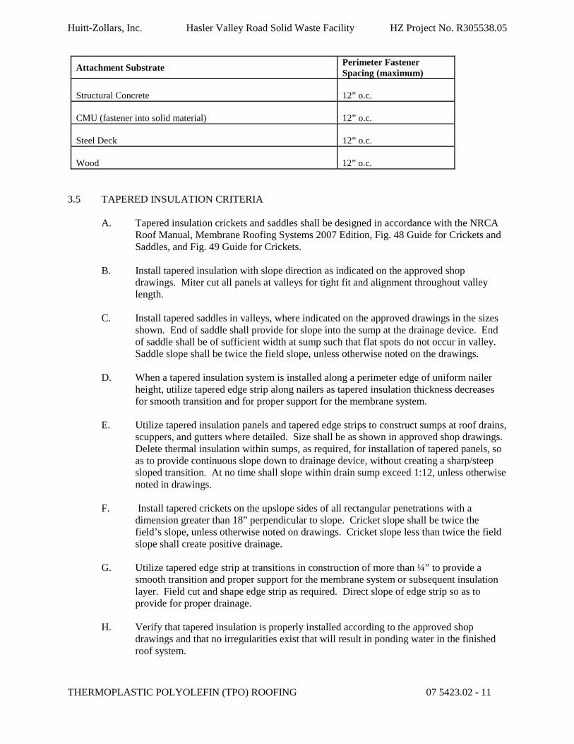
Huitt-Zollars, Inc. Hasler Valley Road Solid Waste Facility HZ Project No. R305538.05
THERMOPLASTIC POLYOLEFIN (TPO) ROOFING 07 5423.02 - 11
Attachment Substrate Perimeter Fastener Spacing (maximum)
Structural Concrete 12” o.c.
CMU (fastener into solid material) 12” o.c.
Steel Deck 12” o.c.
Wood 12” o.c.
3.5 TAPERED INSULATION CRITERIA
A. Tapered insulation crickets and saddles shall be designed in accordance with the NRCA Roof Manual, Membrane Roofing Systems 2007 Edition, Fig. 48 Guide for Crickets and Saddles, and Fig. 49 Guide for Crickets.
B. Install tapered insulation with slope direction as indicated on the approved shop drawings. Miter cut all panels at valleys for tight fit and alignment throughout valley length.
C. Install tapered saddles in valleys, where indicated on the approved drawings in the sizes shown. End of saddle shall provide for slope into the sump at the drainage device. End of saddle shall be of sufficient width at sump such that flat spots do not occur in valley. Saddle slope shall be twice the field slope, unless otherwise noted on the drawings.
D. When a tapered insulation system is installed along a perimeter edge of uniform nailer height, utilize tapered edge strip along nailers as tapered insulation thickness decreases for smooth transition and for proper support for the membrane system.
E. Utilize tapered insulation panels and tapered edge strips to construct sumps at roof drains, scuppers, and gutters where detailed. Size shall be as shown in approved shop drawings. Delete thermal insulation within sumps, as required, for installation of tapered panels, so as to provide continuous slope down to drainage device, without creating a sharp/steep sloped transition. At no time shall slope within drain sump exceed 1:12, unless otherwise noted in drawings.
F. Install tapered crickets on the upslope sides of all rectangular penetrations with a dimension greater than 18” perpendicular to slope. Cricket slope shall be twice the field’s slope, unless otherwise noted on drawings. Cricket slope less than twice the field slope shall create positive drainage.
G. Utilize tapered edge strip at transitions in construction of more than ¼” to provide a smooth transition and proper support for the membrane system or subsequent insulation layer. Field cut and shape edge strip as required. Direct slope of edge strip so as to provide for proper drainage.
H. Verify that tapered insulation is properly installed according to the approved shop drawings and that no irregularities exist that will result in ponding water in the finished roof system.

Huitt-Zollars, Inc. Hasler Valley Road Solid Waste Facility HZ Project No. R305538.05
THERMOPLASTIC POLYOLEFIN (TPO) ROOFING 07 5423.02 - 12
3.6 INSULATION AND TAPERED INSULATION INSTALLATION
A. Install only as much insulation as can be covered with roofing membrane and completed before the end of the day's work or before the onset of inclement weather.
B. Neatly fit insulation to all penetrations, projections, and nailers. Insulation should be loosely fitted, with gaps greater than 1/4" being filled with acceptable insulation. Under no circumstances should the membrane be left unsupported over a space greater than 1/4".
C. Where overall insulation thickness is 2 inches or greater, install required thickness in two layers with joints of second layer staggered from joints of first layer a minimum of 12 inches each direction.
D. Areas of damage or broken corners shall be cut out and replaced with pieces 12” x 12” minimum.
3.7 COVER BOARD INSTALLATION – MECHANICALLY ATTACHED
A. Increase attachments at perimeter and corners as required to meet uplift requirements and manufacturer’s requirements.
B. Areas of damage or broken corners shall be cut out and replaced with pieces 12” x 12” minimum, secured in hot asphalt. Attach with a minimum of two (2) fasteners.
C. Fastener spacings shall be required to meet the design wind up-lift resistance, but not less than two fasteners per each piece of insulation.
D. Fasten the top layer of insulation boards with screw and plate type fasteners. Minimum spacing shall be as required to achieve the specified wind up-lift resistance.
E. Any whole or partial insulation board that falls within the perimeter or corner areas shall have the increased fastening applied over the entire board.
3.8 ROOF MEMBRANE INSTALLATION
A. Install membrane materials in accordance with Manufacturer's current published application instructions for mechanically fastened single-ply.
1. Provide for tie in to existing roof system per approved methods and details acceptable to both new and existing roof manufacturers for warranty requirements.
B. Design Professional may take a seam sample of approximately 8” x 8” twice daily. Contractor shall be responsible for making watertight each sample area immediately after sample is cut.
C. Apply contact adhesive over the entire surface in a uniform fashion over a properly installed substrate using an approved ¾" nap solvent-resistant paint roller. The adhesive shall be applied in an even coat without holidays, puddles, or other irregularities. Coverage rate shall be as recommended by the Manufacturer depending upon substrate
Huitt-Zollars, Inc. Hasler Valley Road Solid Waste Facility HZ Project No. R305538.05
THERMOPLASTIC POLYOLEFIN (TPO) ROOFING 07 5423.02 - 13
finish. The adhesive shall be allowed to dry completely before installing the membrane. Unroll and position roofing membrane, without stretching, over the approved substrate, allowing sheets to overlap a minimum of 3”.
Once in place, one-half of the sheet’s length shall be turned back and the underside shall be coated with adhesive at a rate as recommended by the Manufacturer. When the membrane adhesive has dried slightly to produce strings when touched with a dry finger, the coated membrane shall be rolled onto the previously coated substrate being careful to avoid wrinkles or air pockets. Do not allow adhesive on the underside of the membrane to dry completely. The amount of membrane that can be coated with adhesive before rolling into substrate will be determined by ambient temperature, humidity and crew. The bonded sheet shall be pressed firmly in-place with a water-filled, foam-covered lawn roller by frequent rolling in two directions. The remaining un-bonded half of the sheet shall be folded back and the procedure repeated.
D. Laps in the membrane sheets shall be installed in a shingled manner in the direction of drainage as not to restrict the flow of water.
E. Seaming area is to be clean and free of dust, dirt, and debris. When cleaning is required, follow the Manufacturer’s procedures for cleaning.
F. Laps are to be hot air welded using a robot welder. Laps shall be welded daily. All T-laps shall be patched, using heat welded membrane.
G. All seams are to be fully welded a minimum of 1-1/2”, with robot welder and 2” minimum with hand welder, from the edge of the lap with an uninterrupted flow of black material from the edge of the completed seam.
H. Allow laps to cool and then check for fishmouths and other voids. Repairs are to be made daily by hot air welding.
I. After installation of the field membrane and before installation of flashings, the field membrane shall be secured per manufacturer’s recommendations.
3.9 FLASHINGS
A. Flashings shall be constructed and terminated as per the detail drawings. The specified water cutoff sealant shall be applied behind the top edges of the flashings. The top edges of flashings shall be fastened 6”-8” o.c., unless superseded by the detail drawings.
B. All flashings are to be totally bonded. Unadhered flashings will not be approved.
C. Flashings are to extend a minimum of 6" onto the roof membrane. The splice must be sealed at least 3" beyond the fastener.
D. Pitch pans are not allowed.
3.11 TEMPORARY WATER CUTOFFS
A. Temporary water cutoffs are to be constructed at the end of each working day to protect the insulation, roofing, building, and building interior from damage due to wind, snow,
Huitt-Zollars, Inc. Hasler Valley Road Solid Waste Facility HZ Project No. R305538.05
THERMOPLASTIC POLYOLEFIN (TPO) ROOFING 07 5423.02 - 14
and rain.
B. Temporary water cutoffs are to be constructed using hot asphalt unless otherwise specifically approved by the Design Professional.
C. Construction of temporary water cutoffs is to be detailed by the Contractor and approved by the Manufacturer and the Design Professional.
D. Temporary water cutoffs and asphalt-contaminated membrane shall be neatly trimmed and removed at the start of the next workday.
3.12 PROTECTION
A. Protect building surfaces, rooftop mounted equipment, piping, conduit, etc., against damage from roofing work. Where traffic must continue over finished roof membrane, protect surfaces.
3.13 CLEANUP
A. Remove bituminous markings from finished surfaces.
B. In areas where finished surfaces are soiled by work of this Section, consult Manufacturer of surfaces for cleaning advice and conform to their instructions.
C. Remove excess materials, trash, debris, equipment, and parts from the work.
D. Repair or replace defaced or disfigured finishes caused by work of this section.

Huitt-Zollars, Inc. Hasler Valley Road Solid Waste Facility HZ Project No. R305538.05
THERMOPLASTIC POLYOLEFIN (TPO) ROOFING 07 5423.02 - 15
ROOFING CONTRACTOR'S WARRANTY
1. Contractor warrants to Owner that the roofing system identified above have been installed in accordance with the specifications of the contract referenced above, and the specifications of the Manufacturers of all materials used in performance of the work.
2. Contractor warrants to Owner that Contractor for a period of two (2) years commencing with the date of Owner’s acceptance of the installation, will make good any deficiencies that develop as a direct result of workmanship defects, by repairing or replacing such defects. All corrective work shall utilize materials and installation procedures in strict accordance with the specifications. The Contractor will respond within 24 hours and repair within 5 business days, any leaks or defects in the roofingassembly.
3. Contractor warrants to Owner that Contractor for a period of two (2) years commencing with the date of Owner’s acceptance of the installation, will maintain all sheet metal flashing in a watertight condition without cost to the Owner.
4. Contractor's liability hereunder shall be limited to the repair or necessary replacement of any defective component of the work without cost to Owner and shall not include incidental or consequential damages.
CONTRACTOR By: (Officer) Title:
Company:
Date Executed:
Trade:
Manufacturer and System Installed:
Contractor:
Contract Number and Date:
Project and Location:
Area of Roof Installation:
Date of Acceptance (Effective Warranty Date):

Huitt-Zollars, Inc. Hasler Valley Road Solid Waste Facility HZ Project No. R305538.05
This page left intentionally blank

Huitt-Zollars, Inc. Hasler Valley Road Solid Waste Facility HZ Project No. R305538.05
THERMOPLASTIC POLYOLEFIN (TPO) ROOFING 07 5423.02 - 16
Total Roofing System Manufacturer’s 20 Year Warranty Manufacturer’s Warranty Number: Effective Date: Expiration Date:
Manufacturer Name: School District: Telephone #: Fax #: School: E-Mail: Project: Address: Project Address:
Total Warranty - Square Footage: Designer of Record: Roof Specification-System Name: Telephone #: Fax#: Insulation Type(s): E-Mail: Roofing Contractor: Address: Address:
Telephone No.: Fax #: Other Information:
WARRANTY
1 The Manufacturer warrants to the School District named above, that, subject to the provisions of this document, the Manufacturer will, within 3 business days, at its own expense, make or cause to be made all repairs necessary to maintain the roofing system in a watertight condition during the warranty period stated above which commences on the date of Substantial Completion. System warranty includes: A. Roof membrane B. Roof membrane adhesion C. Roof membrane flashings (except metal or components not furnished by the Manufacturer as part
of its advertised system) D. Roof insulation E. Roof insulation attachment / adhesion F. Roof system fasteners, termination bars, and other miscellaneous accessories supplied by the
roofing Manufacturer G. Roof related sheet metal (edge metal, copings, counterflashing) supplied by the Manufacturer. H. Metal component strip-in-plies. I. Roof system attachment / adhesion to the building code defined design wind speed.
2 OWNER'S RESPONSIBILITY: The Owner will notify the Manufacturer if repairs covered by the Warranty are required. The notice will be by, Telephone, Fax, E-mail, or Mail, to the Manufacturer's office listed above within 30 days of discovery of leaks or other defects in the roofing system. The Owner will provide the Manufacturer free access to the building during regular business hours over the life of the Warranty. The Owner acknowledges that the Manufacturer has provided its Roofing Maintenance Manual, including instructions necessary for the Owner to inspect and maintain the roofing system during the warranty period.
3 EXCLUSIONS: The following are excluded from this Warranty: A. Roof maintenance for corrections of conditions other than leaks. B. Damage to any part of the building (other than the roofing system) or to its contents
(consequential damages). C. Damage resulting from repairs made to the roofing system without the Manufacturer's prior

Huitt-Zollars, Inc. Hasler Valley Road Solid Waste Facility HZ Project No. R305538.05
This page left intentionally blank
Huitt-Zollars, Inc. Hasler Valley Road Solid Waste Facility HZ Project No. R305538.05
THERMOPLASTIC POLYOLEFIN (TPO) ROOFING 07 5423.02 - 17
authorization. D. Damage resulting from any one of the following:
1. Settlement, expansion, contraction, cracking, warping, deflection or movement of roof deck, walls, coping structural members or building foundation.
2. Natural disasters (i.e., windstorm (in excess of wind speed defined in 1. I. above), hail, flood, hurricane, cyclone, lighting, tornado or earthquake).
3. Changes in building usage; new installations on, through or adjacent to the roofing system made after the effective date of this Warranty, unless the Manufacturer has given prior written approval of such changes in building usage or new installations.
4. Accidents, vandalism or other uncontrollable events. 5. Lack of positive drainage (standing water) for asphalt built-up systems. 6. Chemical attacks on the membrane from sources unknown or not present at time of roofing
installation. 7. Falling objects, misuse or abuse of the roofing system, traffic, recreational activities or
storage of material on the roofing system. 8. Infiltration or condensation of moisture in, through or around walls, copings, building
structure or underlying or surrounding areas. 9. Movement or deterioration of metal components adjacent to the roof (except where such
components are a part of the Manufacturer's advertised roofing system). 10. Failure of materials supplied by others (except where such materials are a part of the specified
roofing system certified by the Manufacturer prior to bidding the roofing work). 11. Tests or test cuts not authorized by the Manufacturer. 12. Failure of the Owner to provide maintenance in accord with the Roofing Maintenance
Manual. 13. Failure of the Owner to notify the Manufacturer of leaks or other defects within 30 days of
discovery.
4. The Parties agree that any controversy or claims relating to this Warranty shall be first submitted to mediation under the Construction Industry Arbitration and Mediation Rules of the American Arbitration Association (Regular Track Procedures) or to such other mediation arrangement as the parties mutually agree. Participation in mediation as set forth above shall be a condition precedent to institution of any legal, equitable or arbitration proceedings regarding a controversy or claim relation to this warranty.
5. This is the sole roof system Manufacturer’s 20-year warranty, any implied warranty of merchantability and fitness for a particular purpose are excluded.
In Witness Whereof: Manufacturer and Owner have caused this Warranty to be duly executed on the dates below.
MANUFACTURER: OWNER: a State of Corporation with principle office at:
BY: ______________________________________ BY: ______________________________
TITLE: ____________________________________ TITLE: _____________________________
DATE: ____________________________________ DATE: _____________________________
END OF SECTION 07 5423.02

Huitt-Zollars, Inc. Hasler Valley Road Solid Waste Facility HZ Project No. R305538.05
This page left intentionally blank

Huitt-Zollars, Inc. Hasler Valley Road Solid Waste Facility HZ Project No. R305538.05
SHEET METAL FLASHING AND TRIM 076200 - 1
SECTION 07 6200 – SHEET METAL FLASHING AND TRIM
PART 1 - GENERAL
1.1 RELATED DOCUMENTS
A. Drawings and general provisions of Contract, including General and Supplementary Conditions,general project requirements and Division 01 Specification Sections, apply to this Section.
B. Documents specifically related to this section include:1. Division 06 Section Rough Carpentry for wood nailers, curbs, and blocking.2. Division 07 Section "Thermoplastic Polyolefin (TPO) Roofing” for installing sheet
metal flashing and trim integral with membrane roofing.3. Division 07 Section "Roof Accessories" for set-on-type curbs, equipment supports, roof
hatches, vents, and other manufactured roof accessory units.
1.2 SCOPE OF WORK
A. Furnish and install roof related sheet metal work per the drawings and specifications, include all clips, sealant, fasteners, and joining to make weather and watertight.1. Manufactured reglets.2. Formed roof-drainage sheet metal fabrications.3. Formed low-slope roof sheet metal fabrications.4. Formed wall sheet metal fabrications.5. Formed equipment support flashing.
1.3 CODE COMPLIANCE
A. The installed copings and edge metal shall comply with ANSI/SPRI ES-1 Standards and shall meet the following design wind pressures:1. Horizontal: 75 psf2. Vertical 90 psf
1.4 QUALIFICATIONS
A. Installer Qualifications1. The installer of the roofing shall have been engaged in the business of installing the
specified roofing system for not less than five (5) years and shall be certified by theroofing system Manufacturer in the layout and application of this system. The installer shall have successfully installed the specified system as follows:a. At least once, and;b. At least five (5) years prior to Bid on this Project.
2. The crew shall be composed of experienced and skilled workers in this work.
1.5 QUALITY ASSURANCE
Huitt-Zollars, Inc. Hasler Valley Road Solid Waste Facility HZ Project No. R305538.05
SHEET METAL FLASHING AND TRIM 076200 - 2
A. Standards: Comply with latest edition of standards specified in this section and as referenced below:1. ANSI/SPRI ES-1.2. Architectural Sheet Metal Manual, Sheet Metal and Air Conditioning Contractors National
Association, Fifth edition, 1993, as published by SMACNA.3. The NRCA Roofing and Waterproofing Manual – National Roofing Contractors Association.4. Published installation instructions from Manufacturers of selected products.5. Annual Book of ASTM Standards, Latest Revision – ASTM International.
B. Qualifications of Installers: Use adequate number of skilled workers who are thoroughly trained and experienced in the necessary crafts, and who are completely familiar with the specified requirements and methods needed for proper performance of the work in this section.
C. In acceptance or rejection of the work of this section, the Owner will make no allowance for lack of skill on the part of the workers.
1.6 SUBMITTALS
A. General: Comply with the provisions of the General Conditions of the Contract and Division01 specification sections. Submittal schedule shall allow ample time for processing andapproval prior to Pre-Roofing Coordination Meeting and start of roof system installationwork.
B. Drawings of all shop and pre-Manufacturered components to show type and gauge ofmetal used. Gauges of sheet metal specified in this section are minimums.
C. Submit product information or material list noting fasteners, sealants, sealant primers,sealant tapes, and other required accessories.
D. Submit color chart or physical samples for selection of prefinished metal color by the Design Professional.
E. Submit color chart or physical samples for selection of sealant color by the Design Professional.
F. Submit copies of all required warranties.
G. Provide verification that coping and edge metal material, configuration and installation will meet ES-1 requirements.
1.7 DELIVERY, STORAGE AND HANDLING
A. Use all means to protect the materials of this section before, during, and after installation and to protect the work and materials of all other trades. Roof surfaces shall be protectedfrom damage at all times.
B. Deliver only new materials to the job site. Materials to be stored in such a manner as to be protected from rain, snow, or inclement weather. When storing materials on the roof, do not
Huitt-Zollars, Inc. Hasler Valley Road Solid Waste Facility HZ Project No. R305538.05
SHEET METAL FLASHING AND TRIM 076200 - 3
overstress the deck.
C. In the event of damage, immediately make all repairs and replacements to the approval of the Owner and at no additional cost to the Owner.
D. Follow the Manufacturer’s recommendations for storage of temperature sensitive materials.
1.8 SCHEDULING
A. Work is to be performed on a daily basis with each section completed before progressing to the next day’s work, unless specifically directed otherwise by the Design Professional.
B. Substantial Completion of sheet metal flashing and trim work will be defined as thecontractually required and weathertight installation of all specified roof preparation, insulation, field membrane, flashings, counterflashings, sheet metal, fasteners and caulking.
C. All new sheet metal work shall be closely coordinated with the installation of the new roofing membrane.
D. Sheet metal shall be installed directly after roofing work such that roofingterminations shall not be left unprotected by metal.
E. Once roofing is started, the roofing application must be Substantially Complete within thetime period required by the Contract. All punch list items must be complete prior to Final Completion.
1.9 WARRANTY
A. The Roofing Contractor shall warrant all materials and workmanship for a period of two years from the date of acceptance of the completed work by the Owner. The RoofingContractor shall make good any defects in materials or workmanship that may developduring the two-year period by repairing or replacing such defects at his own expensewithout cost to the Owner. RoofingContractor shall use the form entitled “Sheet Metal Contractor’s Warranty” provided in this section.
B. 20-year warranty for Kynar 500/Hylar 5000 metal finish.
C. 25-year standard warranty from copper Manufacturer covering defects in materials and pre-patinated finish.
PART 2 – PRODUCTS
2.1 GENERAL
A. All materials used on this project shall be compatible with the existing conditions and with

Huitt-Zollars, Inc. Hasler Valley Road Solid Waste Facility HZ Project No. R305538.05
SHEET METAL FLASHING AND TRIM 076200 - 4
each other.B. No product shall contain any asbestos or asbestos-related products.
2.2 MATERIALS
A. Sheet metal components, metal types, finishes, gauges/thicknesses, joint types, and ANSI/SPRI ES-1 compliance data are specified in the detail drawings.
B. Where sheet metal is required and no material or gauge is indicated on the drawings, provide the highest quality and gauge commensurate with the referenced standards.
C. Contractor shall use gauges or thicknesses listed in the schedule or as prescribed in the referenced standards for specific girths, whichever is greater.
D. Continuous clip shall be fabricated with material one gauge heavier than connecting component.
2.3 MATERIAL SPECIFICATIONS
A. Aluminum1. The aluminum alloy and temper for sheet metal work shall be 3003-H14.2. Specification References
a. Fed. Spec. QQ-A-250d, Aluminum and Aluminum Alloy, Plate and Sheet.
b. ASTM B209 Specification for Aluminum Alloy, Sheet and Plate.c. ASTM B221 Specification for Aluminum Extrusions.
B. Galvanized Steel1. Galvanized steel shall be G-90 material.2. Specifications References
a. Fed. Spec. AA-S-775d.b. ASTM A653/A653M – Standard Specification for Steel Sheet, Zinc-
coated (Galvanized) or Zinc-Iron Alloy – Coated (Galvannealed) by theHot Dip Process.
C. Stainless Steel
1. Specification Referencesa. Fed. Spec. QQ-S-766C, Steel Plates, Sheets, and Strip, Corrosion
Resisting.b. ASTM - A167 Specification for Stainless and Heat Resisting
Chromium-Nickel Steel Plate, Sheet and Strip.2. Finish shall be selected by the Design Professional.
D. Kynar Prefinished Steel1. Approved Products
Huitt-Zollars, Inc. Hasler Valley Road Solid Waste Facility HZ Project No. R305538.05
SHEET METAL FLASHING AND TRIM 076200 - 5
a. PAC-CLAD by Peterson Aluminum Corporationb. TUFFCLAD by Clad-Tex Metalsc. Color Klad by Vincent Metalsd. UNA-CLAD by Firestone Building Productse. Approved equal
2. Color shall be selected by the Design Professional from theManufacturer’s standard colors.
2.4 ROOF DRAINAGE SHEET METAL FABRICATIONS
A. Downspouts: Fabricate plain rectangular downspouts complete with mitered elbows as required. Furnish with metal hangers, from same material as downspouts, and anchors.
1. Manufactured Hanger Style: SMACNA figure designation 1-34A, 1-34B, 1-34C, 1-34D or 1-34E.
2. Fabricate from the following materials:a. Heavy 22 gage Kynar 500® Aluminum.b. Size: 4” x 5”
B. Conductor Heads: Fabricate conductor heads with flanged back and stiffened top edge and of dimensions and shape indicated complete with outlet tubes, exterior flange trim, and built-in overflows. Fabricate from the following materials:
1. Kynar 500® Aluminum: 22 gage thick.
2.5 CARBON STEEL FASTENERS
A. All fasteners shall be carbon steel with corrosion-resistant coating, unless otherwisenoted. Fasteners shall show no more than 15% red rust corrosion after 30 cycles of Kesternich testing.
B. Masonry / Concrete Fasteners1. Fasteners shall be threaded or expansion type as required by site conditions.2. Threaded fasteners shall be corrosion-resistant with hex washer head.3. Expansion fasteners shall be zinc-alloy jacketed with stainless steel drive pin and
mushroom head (nylon or plastic anchors are not approved).4. Corrosion-resistant, watertight, EPDM sealing washer shall be supplied for either
threaded or expansion type fasteners.5. Fasteners shall be approved by FM Global.6. Approved Products
a. Tapcon Hex Washer Head with Blue Climaseal or WhiteUltraShield Coating by ITW Buildex
b. Tapper with Perma-Seal Coating by Powers Fasteners, Inc.c. Metal Hit Anchor by Hiltid. Zamac Hammer-Screw with Carbon Steel Drive Screw by
Powers Fasteners, Inc.

Huitt-Zollars, Inc. Hasler Valley Road Solid Waste Facility HZ Project No. R305538.05
SHEET METAL FLASHING AND TRIM 076200 - 6
e. Masonry Anchor by OMGf. Approved equal
7. Fasteners to be nominal ¼” thickness minimum and of sufficient length to penetrate the masonry/concrete 1".
C. Steel / Wood Fasteners1. Corrosion-resistant, self-drilling, self-tapping screw with hex washer head for
exposed fastening.2. Corrosion-resistant, watertight, EPDM sealing washer for exposed fastening.3. Approved Products – Steel Fasteners
a. Tek Screw with Climaseal Coating by ITW Buildexb. Dekfast Zac Anchor with Sentri XP Coating by SFS intec, Inc.c. Owner approved equal
4. Approved Products – Wood Fastenersa. TruGrip GT with Climaseal Coating by ITW Buildexb. Dekfast Zac Anchor with Sentri XP Coating by SFS intec, Inc.c. Owner approved equal
5. Fasteners to be nominal ¼” thickness minimum and of sufficient length to penetrate the steel ½” or into wood minimum 1".
6. 1¼” x 11-gauge, galvanized, ring shank roofing nails shall be used for concealed fastening into wood.
2.6 STAINLESS STEEL FASTENERS
A. All fasteners shall be Type 304 or Series 400 stainless steel, or zinc alloy incomposition.
B. Masonry / Concrete Fasteners1. Fasteners shall be threaded or expansion type as required by site conditions.2. Threaded fasteners shall be corrosion-resistant with hex washer head.3. Expansion fasteners shall be zinc alloy with stainless steel nail and mushroom
head (nylon or plastic anchors are not approved).4. Stainless steel, watertight, EPDM sealing washer shall be supplied for either
threaded or expansion type fasteners.5. Fasteners shall be approved by FM Global.6. Fasteners to be nominal ¼” thickness minimum and of sufficient length to penetrate
the masonry/concrete 1".7. Approved Products
a. Scots Tapcon Hex Washer Head with Silver Climaseal Coating by ITW Buildex
b. Metal Hit Anchor by Hiltic. Zamac Hammer Screw with Stainless Steel Drive Screw by
Powers Fasteners, Inc.d. Masonry Anchor by OMGe. Owner approved equal

Huitt-Zollars, Inc. Hasler Valley Road Solid Waste Facility HZ Project No. R305538.05
SHEET METAL FLASHING AND TRIM 076200 - 7
C. Steel / Wood Fasteners1. Corrosion-resistant, stainless steel, self-drilling, self-tapping screw with hex
washer head for exposed fastening.2. Stainless steel, watertight, EPDM sealing washer for exposed fastening.3. Approved Products – Steel Fasteners
a. 12 - 14 Scots Tek Screw with Climaseal Coating by ITW Buildexb. Owner approved equal
4. Approved Products – Wood Fastenersa. 17 - 14 Scots Tek Screw with Climaseal Coating by ITW Buildexb. Owner approved equal
5. Fasteners to be of sufficient length to penetrate the steel ½” or into wood minimum 1".
6. 1¼” x 11-gauge, stainless steel, ring shank, roofing nails shall be used forconcealed fastening into wood.
2.7 OTHER MATERIALS
A. Membrane Closure / Cover1. Sheet waterproofing underlayment at parapets, expansion joints, etc., shall be 36-
mil (minimum) single-ply material and associated seaming materials. Sheet waterproofing material shall be compatible and approved by the primary roofing membrane Manufacturer.
B. Sealants and Related Accessories1. General: Except as specifically otherwise directed by the Owner’s Representative,
use only the type of sealants described in this section.1. Silyl-Termination Polyether (Hybrid) Sealant
a. Approved Productsa. Sonolastic 150 VLM by BASF Building Systemsb. Approved Equal
2. Cleaner1. Industrial solvent recommended by the sealant Manufacturer, such as
Isopropyl Alcohol, Naphtha, Mineral Spirits, Xylol, Toluene, MEK, orManufacturer-supplied cleaner.
3. Primer1. General: Use only those primers that are specifically recommended for
this installation by the caulking Manufacturer.2. Primer shall be one of the following:
a. Primer 733 BASF Building Systemsb. Approved Equal
4. Backer Rod1. General: Use only those backup materials that are specifically
recommended for this installation by the sealant Manufacturer and that arenon-absorbent, non-staining, and non-gassing when punctured. Backupmaterials must be 1½ times the width of the joint.
2. Backer rod shall be one of the following:a. Soft Backer-Rod by BASF Building Systems
Huitt-Zollars, Inc. Hasler Valley Road Solid Waste Facility HZ Project No. R305538.05
SHEET METAL FLASHING AND TRIM 076200 - 8
b. Approved Equal5. High Temperature Resistant Sealant
1. Trade Mate® Hi-Temp Silicone Sealant by Dow CorningCorporation
2. Approved equal
C. Sealant Tape1. Permanently elastic isobutylene tripolymer tape or isobutylene isoprene copolymer
tape that will bond to galvanized steel; aluminum; siliconized polyester, and polyvinyl flouride painted metals; as well as wood, concrete, etc., 1/8” x 1” nominal cross section, meeting Federal Specification TT-C 1796A, Type II, Class B, with minimum 20 psi adhesive tensile strength according to ASTM C 907, with a servicetemperature range of -60 F to 212 F.1. Approved Products
a. Sika Lastomer – 95 Gray by Sika Corp.b. Sika Lastomer – 93 Black by Sika Corp.c. Sika Lastomer – 65 White by Sika Corp.d. Or approved equal.
D. Downspout Straps1. 1/8” x 1” downspout straps shall be provided.2. Fabricate shop primed and painted stainless steel brackets and straps shall be used
(color to match gutters and downspouts).
E. Solder1. ASTM B 32, flux type and alloy composition as required for use with metals to
be soldered.
F. Rivets1. Use copper, copper alloy, bronze, brass, or stainless steel for copper and
stainless steel for stainless steel and aluminum alloy, galvanized steel or stainless steel for galvanized steel.
2. Not less than 1/8” diameter.3. Water tight rivets shall be used wherever water penetrating through the rivet can enter
into the building.
PART 3 – EXECUTION
3.1 INSPECTION
A. Examine the areas and conditions under which work of this section will be installed.Correct conditions detrimental to the proper and timely completion of the work. Do not proceed until unsatisfactory conditions have been corrected.
3.2 FABRICATION

Huitt-Zollars, Inc. Hasler Valley Road Solid Waste Facility HZ Project No. R305538.05
SHEET METAL FLASHING AND TRIM 076200 - 9
A. Sheet metal shall be formed accurately to sheet shapes as indicated on the drawingsand in conformance with details on the approved shop drawings. Contractor shall beresponsible for all dimensions.
B. Two-piece counterflashing shall be furnished where indicated on drawings. Form flashingsections not less than 8’0” in length, unless otherwise approved prior to fabrication and installation.
1. Surface Mount2. Masonry
C. All metal roof counterflashings are to be 2-piece (reglet/receiver with flashing insert.) Counterflashings attached to metal and where slip metal is needed at mechanical curbs, one (1) piece may be used unless Drawings indicate otherwise.
D. Masonry and saw cut reglets: Insert masonry reglets to form tight fit. Secure saw cut reglets in place with appropriate wedges installed. Seal joints with approved sealant.
E. Surface mounted flashing receiver: Set receiver into non-skinning butyl caulk and fasten reglet to wall 12” O.C. through butyl/caulk. Seal top of receiver with one part polyurethane caulking.
F. All metal flashing and reglet corners are to be mitered, folded, caulked and pop riveted in a watertight manner. The reglet/receiver mitered corners are to be fabricated with legs no longer than 18 inches.
G. When masonry reglets are to be installed by other trades, insure that they are fully informed on installation requirements. Wall air/vapor barrier to extend over reglet flange against wall and across top of reglet.
H. Coping caps and edge metal shall be furnished where indicated on drawings. Formcoping and edge metal in sections not less than 8’0” in length, unless otherwise approved prior to fabrication and installation.
1. Coping will be fabricated from 22 gage iron sheet metal.2. Cover and splice plates will be installed.3. Coping Tee joints are to be fabricated with a 5 foot top of the Tee and a 30 inch
leg inserted under the top of the Tee, sealed and pop-riveted. Pop rivets are to penetrate through sealant.
4. Where coping abuts a high wall, a splice plate with edge flanged up and out will be installed against wall in sealant. A wall abutment flashing trimmed to fit tight around the splice plate will then be installed in sealant insuring the two corners at the splice plate are completely sealed with the sealant; fastened to the wall; and sealed around the edges.
5. Coping butt joints are to have both a 6 inch wide splice plate and a 6 inch wide cover plate at each joint. Separation between coping joints shall be ¼ inch. On each side of the splice plate there is to be two full rows of approved sealant. Under

Huitt-Zollars, Inc. Hasler Valley Road Solid Waste Facility HZ Project No. R305538.05
SHEET METAL FLASHING AND TRIM 076200 - 10
each side of the cover plate there is to be one row of approved sealant.
I. Where loose lock lap joints are specified on the drawings, adjacent sections of metal shalloverlap a minimum of 3”.
J. Where joint covers are specified on the drawings, they shall be slightly larger than theprimary component to ensure a proper fit. Edges of joint covers shall be tipped towardprimary component to form a compression seal.
K. Miter all inside and outside corner joints in coping caps, edge metal, and expansion joints.Joints adjacent to inside and outside corners shall be placed exactly 24” each directionfrom the corner, unless otherwise approved prior to fabrication and installation.
L. Break counterflashing, coping cap, or edge metal sections where they cross building expansion joints, if applicable.
M. Horizontal flanges of edge metal, soil pipe leads, pitch pans, lower flanges, pipe jacks,etc., shall be 4” minimum with rounded corners.
N. All exposed edges of cut sheet metal shall be folded back on concealed surfaces.
O. Form, fabricate, and install all sheet metal so as to adequately provide for expansion and contraction in the finished work.
P. Where a continuous clip is specified on the drawings, the primary component shall be continuously crimped along the bottom edge of the clip.
Q. Fabricate radial coping/edge metal in uniform length sections using radialcomponents with finished edges.
3.3 DISSIMILAR METALS
A. Dissimilar materials in contact, which are subject to electrolysis, shall be protected against such action prior to installation. Protective materials shall not be visible after installation.Protect metals using coatings recommended by Manufacturer, or separated using felt or EPDM membrane.
3.4 ROOF DRAINAGE SYSTEM INSTALLATION
A. General: Install sheet metal roof drainage items to produce complete roof drainage system according to SMACNA recommendations and as indicated. Coordinate installation of roof perimeter flashing with installation of roof drainage system.
B. Downspouts: Join sections with 1-1/2-inch (38-mm) telescoping joints.
C. Provide hangers with fasteners designed to hold downspouts securely to walls. Locate hangers at top and bottom and at approximately 60 inches (1500 mm) o.c. in between.
Huitt-Zollars, Inc. Hasler Valley Road Solid Waste Facility HZ Project No. R305538.05
SHEET METAL FLASHING AND TRIM 076200 - 11
D. Provide elbows at base of downspout to direct water away from building.
E. Conductor Heads: Anchor securely to wall with elevation of conductor head rim 1 inch (25 mm) below scupper discharge.
3.5 WEATHERPROOFING
A. Finish all sheet metal watertight and weathertight where so required.
B. Where lap seams do not have a joint cover, lap 3” minimum according to pitch.
C. Make all lap seams in the direction of the water flow.
D. Where roof membrane is not already carried over top of parapet wall, expansion joint blocking, etc., the top of each is to be covered with sheet waterproofing membrane (or theflashing membrane material if the roof system is a single-ply). Unless otherwise shown on the drawings, the membrane is to be fastened only on sides as required to hold it in placeand make the wall or curb watertight until sheet metal cover can be installed over it. Alllaps in the membrane material shall be seamed watertight per the Manufacturer’s published installation instructions.
3.6 JOINTS
A. Join parts with rivets or sheet metal screws where necessary for strength or stiffness.
B. Provide suitable watertight expansion joints for all sheet metal as required for proper installation in accordance with the schedule of roof related sheet metal and detail drawings.
C. Sealant application shall be neatly and thoroughly performed for a watertight seal. Sealantshall be installed within all loose lock joints under joint cover plates, and in other locations shown on the drawings. All exposed caulking joints shall be dry tooled to the profile shown on the detail drawings. If required, Contractor shall build custom tools on job site to provide the specified profile(s).
D. Surfaces to receive sealant shall be thoroughly cleaned as recommended by the sealant Manufacturer. All bitumen coating materials, roof cement, adhesive residue, rust, oldcaulking and/or other contaminants shall be removed down to the substrate to which sealant bonding is intended.
E. All surfaces to receive sealant shall be primed initially with the sealantManufacturer’s recommended primer.
F. Provide solder/weld joints where noted on the drawings.
3.7 FASTENING
Huitt-Zollars, Inc. Hasler Valley Road Solid Waste Facility HZ Project No. R305538.05
SHEET METAL FLASHING AND TRIM 076200 - 12
A. Only stainless steel fasteners shall be used to fasten aluminum components, where specified.
B. Only stainless steel fasteners shall be used to fasten copper components, where specified.
C. Secure metal as per detail drawings. Do not in any case install exposed fasteners on ahorizontal plane, unless specifically shown on a particular detail drawing.
D. All clips and cleats are to be fastened 6” o.c., unless otherwise noted on the drawings.
E. On the roof facing side, copings are to be fastened 12" o.c. with EPDM washered fasteners, unless noted otherwise on the drawings.
F. Do not fasten adjacent coping, counterflashing, or edge metal sections together at laps or at joint covers, so as to limit expansion/contraction ability. Fasten through center of jointcover through butt joint gap between primary component sections.
G. Embedded metal flanges are to be fastened 3” o.c., staggered.
H. The specified spacings for all fasteners in perimeter metal work shall be reduced by a factor of two in the corner zones of each roof section. Corner zones shall be as calculated basedupon the applicable version of ASCE-7.
I. For concealed fastening into wood, use annular ring shank roofing nails.
J. For fastening into concrete, use masonry/concrete anchors with EPDM washers. Use only metal anchors. Plastic anchors shall not be used.
K. For exposed fastening into wood, use screws with EPDM washers. Deformed shank nailsshall not be used.
L. Ensure that fasteners are not overdriven such that EPDM washer damage results.Remove and replace all such damaged fasteners, using oversized fasteners.
3.8 PROTECTION
A. Roof surfaces and flashing shall be adequately protected to prevent damage during the installation of metal work. The Contractor shall repair, at no cost to the Owner, any materials damaged.
3.9 CLEANUP
A. Debris from sheet metal work shall be frequently removed from building site as it accumulates.
B. Leave job site absolutely clean at completion of work, and properly dispose of all

Huitt-Zollars, Inc. Hasler Valley Road Solid Waste Facility HZ Project No. R305538.05
SHEET METAL FLASHING AND TRIM 076200 - 13
construction debris such as metal trimmings, fasteners, rivet nails, caulk tube ends, etc.
ROOFING CONTRACTOR'S WARRANTY
1. Contractor warrants to Owner that the roofing system identified above have been installed in accordance with the specifications of the contract referenced above, and the specifications of the Manufacturers of all materials used in performance of the work.
2. Contractor warrants to Owner that Contractor for a period of two (2) years commencing with the date of Owner’s acceptance of the installation, will make good any deficiencies that develop as a direct result of workmanship defects, by repairing or replacing such defects. All corrective work shall utilize materials and installation procedures in strict accordance with the specifications. The Contractor will respond within 24 hours and repair within 5 business days, any leaks or defects in the roofing assembly.
3. Contractor warrants to Owner that Contractor for a period of two (2) years commencing with the date of Owner’s acceptance of the installation, will maintain all sheet metal flashing in a watertight condition without cost to the Owner.
4. Contractor's liability hereunder shall be limited to the repair or necessary replacement of any defective component of the work without cost to Owner and shall not include incidental or consequential damages.
CONTRACTOR By: ______________ (Officer) Title: _____________
Trade:
Manufacturer and System Installed:
Contractor:
Contract Number and Date:
Project and Location:
Area of Roof Installation:
Date of Acceptance (Effective Warranty Date):

Huitt-Zollars, Inc. Hasler Valley Road Solid Waste Facility HZ Project No. R305538.05
This page left intentionally blank
Huitt-Zollars, Inc. Hasler Valley Road Solid Waste Facility HZ Project No. R305538.05
SHEET METAL FLASHING AND TRIM 076200 - 14
Company: _____________
Date Executed: ____________
END OF SECTION 07 6200

Huitt-Zollars, Inc. Hasler Valley Road Solid Waste Facility HZ Project No. R305538.05
This page left intentionally blank

Huitt-Zollars, Inc. Hasler Valley Road Solid Waste Facility HZ Project No. R305538.05
ROOF ACCESSORIES 077200 - 1
SECTION 077200 - ROOF ACCESSORIES
PART 1 - GENERAL
1.1 RELATED DOCUMENTS
A. Drawings and general provisions of the Contract, including General and Supplementary Conditions and Division 01 Specification Sections, apply to this Section.
1.2 SUMMARY
A. Section Includes:
1. Roof curbs.
2. Roof hatch.
B. Related Sections:
1. Division 05 Section "Metal Fabrications" for metal vertical ladders, ships' ladders, and stairs for access to roof hatches.
2. Division 07 Section "Sheet Metal Roofing" for shop- and field-formed roof curbs and snow guards for sheet metal roofing.
3. Division 07 Section "Sheet Metal Flashing and Trim" for shop- and field-formed metal flashing, roof-drainage systems, roof expansion-joint covers, and miscellaneous sheet metal trim and accessories.
1.3 PERFORMANCE REQUIREMENTS
A. General Performance: Roof accessories shall withstand exposure to weather and resist thermally induced movement without failure, rattling, leaking, or fastener disengagement due to defective manufacture, fabrication, installation, or other defects in construction.
1.4 SUBMITTALS
A. Product Data: For each type of roof accessory indicated. Include construction details, material descriptions, dimensions of individual components and profiles, and finishes.
B. Operation and Maintenance Data: For roof accessories to include in operation and maintenance manuals.

Huitt-Zollars, Inc. Hasler Valley Road Solid Waste Facility HZ Project No. R305538.05
ROOF ACCESSORIES 077200 - 2
1.5 COORDINATION
A. Coordinate layout and installation of roof accessories with roofing membrane and base flashing and interfacing and adjoining construction to provide a leakproof, weathertight, secure, and noncorrosive installation.
B. Coordinate dimensions with rough-in information or Shop Drawings of equipment to be supported.
PART 2 - PRODUCTS
2.1 MISCELLANEOUS MATERIALS
A. General: Provide materials and types of fasteners, protective coatings, sealants, and other miscellaneous items required by manufacturer for a complete installation.
B. Cellulosic-Fiber Board Insulation: ASTM C 208, Type II, Grade 1, thickness as indicated.
C. Glass-Fiber Board Insulation: ASTM C 726, thickness as indicated.
D. Wood Nailers: Softwood lumber, pressure treated with waterborne preservatives for aboveground use, acceptable to authorities having jurisdiction, containing no arsenic or chromium, and complying with AWPA C2; not less than 1-1/2 inches (38 mm) thick.
E. Bituminous Coating: Cold-applied asphalt emulsion complying with ASTM D 1187.
F. Fasteners: Roof accessory manufacturer's recommended fasteners suitable for application and metals being fastened. Match finish of exposed fasteners with finish of material being fastened. Provide nonremovable fastener heads to exterior exposed fasteners. Furnish the following unless otherwise indicated:
1. Fasteners for Zinc-Coated or Aluminum-Zinc Alloy-Coated Steel: Series 300 stainless steel or hot-dip zinc-coated steel according to ASTM A 153/A 153M or ASTM F 2329.
2. Fasteners for Aluminum Sheet: Aluminum or Series 300 stainless steel.
G. Gaskets: Manufacturer's standard tubular or fingered design of neoprene, EPDM, PVC, or silicone or a flat design of foam rubber, sponge neoprene, or cork.
H. Elastomeric Sealant: ASTM C 920, elastomeric polyurethane polymer sealant as recommended by roof accessory manufacturer for installation indicated; low modulus; of type, grade, class, and use classifications required to seal joints and remain watertight.
I. Butyl Sealant: ASTM C 1311, single-component, solvent-release butyl rubber sealant; polyisobutylene plasticized; heavy bodied for expansion joints with limited movement.
2.2 ROOF CURBS
A. Roof Curbs: Internally reinforced roof-curb units capable of supporting superimposed live and dead loads, including equipment loads and other construction indicated on Drawings; with

Huitt-Zollars, Inc. Hasler Valley Road Solid Waste Facility HZ Project No. R305538.05
ROOF ACCESSORIES 077200 - 3
welded or mechanically fastened and sealed corner joints and integrally formed deck-mounting flange at perimeter bottom.
1. Manufacturers: Subject to compliance with requirements, available manufacturers offering products that may be incorporated into the Work include, but are not limited to, the following:
a. AES Industries, Inc.b. Curbs Plus, Inc.c. Greenheck Fan Corporation.d. LM Curbs.e. Metallic Products Corp.f. Milcor Inc.; Commercial Products Group of Hart & Cooley, Inc.g. Or approved equal.
B. Size: Coordinate dimensions with roughing-in information or Shop Drawings of equipment to be supported.
C. Material: Zinc-coated (galvanized) steel sheet, [0.052 inch (1.32 mm)] [0.079 inch (2.01 mm) >thick.
1. Finish: Mill phosphatized
D. Construction:
1. Insulation: Factory insulated with 1-1/2-inch- (38-mm-) thick cellulosic or glass-fiber board insulation.
2. Liner: Same material as curb, of manufacturer's standard thickness and finish.3. Fabricate curbs to minimum height of 12 inches (300 mm) above finished roof surface
unless otherwise indicated.4. Top Surface: Level around perimeter with roof slope accommodated by sloping the
deck-mounting flange.
2.3 ROOF HATCH
A. Roof Hatches: Metal roof-hatch units with lids and insulated double-walled curbs, welded or mechanically fastened and sealed corner joints, continuous lid-to-curb counterflashing and weathertight perimeter gasketing, with an integral clip built into the hatch counterflashing that clamps onto the roofing membrane and raised to the thickness of roof insulation, and integrally formed deck-mounting flange at perimeter bottom.
1. Manufacturers: Subject to compliance with requirements, available manufacturers offering products that may be incorporated into the Work include, but are not limited to, the following:a. Nystrom.b. Or approved equal.
2. Basis of Design: Nystrom RHSB36x30-S1T
B. Type and Size: Single-leaf lid, 36 by 30 inches.

Huitt-Zollars, Inc. Hasler Valley Road Solid Waste Facility HZ Project No. R305538.05
ROOF ACCESSORIES 077200 - 4
C. Loads: Minimum 40-lbf/sq. ft. external live load and 20-lbf/sq. ft. internal uplift load.
D. Hatch Material: Aluminum-zinc alloy-coated steel sheet, 1/4 inch thick.
1. Finish: Baked enamel or powder coat.2. Color: As selected by Architect from manufacturer's full range.
E. Construction:
1. Insulation: 1” Polystyrene (R4) in cover and 1” fiberboard (R2.8) in curb.2. Hatch Lid: Opaque, insulated, and double walled, with manufacturer's standard metal
liner of same material and finish as outer metal lid.3. Curb Liner: Manufacturer's standard, of same material and finish as metal curb.4. Fabricate curbs to minimum height of 12 inches unless otherwise indicated.
F. Hardware: Galvanized-steel spring latch with turn handles, butt- or pintle-type hinge system, and padlock hasps inside and outside.
G. Safety Railing System: Roof-hatch manufacturer's standard system including rails, clamps, fasteners, safety barrier at railing opening, and accessories required for a complete installation; attached to roof hatch and complying with 29 CFR 1910.23 requirements and authorities having jurisdiction.
1. Height: 42 inches above finished roof deck.2. Posts and Rails: Galvanized-steel pipe, 1-1/4 inches in diameter or galvanized-steel tube,
1-5/8 inches in diameter.3. Flat Bar: Galvanized steel, 2 inches high by 3/8 inch thick.4. Maximum Opening Size: System constructed to prevent passage of a sphere 21 inches in
diameter.5. Chain Passway Barrier: Galvanized proof coil chain with quick link on fixed end.6. Self-Latching Gate: Fabricated of same materials and rail spacing as safety railing
system. Provide manufacturer's standard hinges and self-latching mechanism.7. Post and Rail Tops and Ends: Weather resistant, closed or plugged with prefabricated
end fittings.8. Provide weep holes or another means to drain entrapped water in hollow sections of
handrail and railing members.9. Fabricate joints exposed to weather to be watertight.10. Fasteners: Manufacturer's standard, finished to match railing system.11. Finish: Manufacturer's standard.
a. Color: As selected by Architect from manufacturer's full range.
H. Ladder-Assist Post: Roof-hatch manufacturer's standard device for attachment to roof-access ladder.
1. Operation: Post locks in place on full extension; release mechanism returns post to closed position.
2. Height: 42 inches above finished roof deck.3. Material: Steel tube.4. Post: 1-5/8-inch- diameter pipe.5. Finish: Manufacturer's standard baked enamel or powder coat.
Huitt-Zollars, Inc. Hasler Valley Road Solid Waste Facility HZ Project No. R305538.05
ROOF ACCESSORIES 077200 - 5
a. Color: As selected by Architect from manufacturer's full range.
PART 3 - EXECUTION
3.1 EXAMINATION
A. Examine substrates, areas, and conditions, with Installer present, to verify actual locations, dimensions, and other conditions affecting performance of the Work.
B. Verify that substrate is sound, dry, smooth, clean, sloped for drainage, and securely anchored.
C. Verify dimensions of roof openings for roof accessories.
D. Proceed with installation only after unsatisfactory conditions have been corrected.
3.2 INSTALLATION
A. General: Install roof accessories according to manufacturer's written instructions.
1. Install roof accessories level, plumb, true to line and elevation, and without warping, jogs in alignment, excessive oil canning, buckling, or tool marks.
2. Anchor roof accessories securely in place so they are capable of resisting indicated loads.3. Use fasteners, separators, sealants, and other miscellaneous items as required to complete
installation of roof accessories and fit them to substrates.4. Install roof accessories to resist exposure to weather without failing, rattling, leaking, or
loosening of fasteners and seals.
B. Metal Protection: Protect metals against galvanic action by separating dissimilar metals from contact with each other or with corrosive substrates by painting contact surfaces with bituminous coating or by other permanent separation as recommended by manufacturer.
1. Coat concealed side of any uncoated aluminum roof accessories with bituminous coating where in contact with wood, ferrous metal, or cementitious construction.
2. Underlayment: Where installing roof accessories directly on cementitious or wood substrates, install a course of felt underlayment and cover with a slip sheet, or install a course of polyethylene sheet.
3. Bed flanges in thick coat of asphalt roofing cement where required by manufacturers of roof accessories for waterproof performance.
C. Roof Curb Installation: Install each roof curb so top surface is level.
D. Seal joints with elastomeric or butyl sealant as required by roof accessory manufacturer.
3.3 REPAIR AND CLEANING
A. Galvanized Surfaces: Clean field welds, bolted connections, and abraded areas and repair galvanizing according to ASTM A 780.
Huitt-Zollars, Inc. Hasler Valley Road Solid Waste Facility HZ Project No. R305538.05
ROOF ACCESSORIES 077200 - 6
B. Touch up factory-primed surfaces with compatible primer ready for field painting according to Division 09 painting Sections.
C. Clean exposed surfaces according to manufacturer's written instructions.
D. Clean off excess sealants.
E. Replace roof accessories that have been damaged or that cannot be successfully repaired by finish touchup or similar minor repair procedures.
END OF SECTION 077200
Huitt-Zollars, Inc. Hasler Valley Road Solid Waste Facility HZ Project No. R305538.05
JOINT SEALANTS 079200 - 1
SECTION 079200 - JOINT SEALANTS
PART 1 - GENERAL
1.1 RELATED DOCUMENTS
A. Drawings and general provisions of the Contract, including General and Supplementary Conditions and Division 01 Specification Sections, apply to this Section.
1.2 SUMMARY
A. Section Includes:
1. Silicone joint sealants.2. Latex joint sealants.
B. Related Sections:
1. Division 04 Section "Masonry Veneer" for masonry control and expansion joint fillers and gaskets.
2. Division 08 Section "Glazing" for glazing sealants.3. Division 09 Section "Gypsum Board" for sealing perimeter joints.4. Division 09 Section "Tiling" for sealing tile joints.
1.3 SUBMITTALS
A. Product Data: For each joint-sealant product indicated.
B. Samples for Verification: For each kind and color of joint sealant required, provide Samples with joint sealants in 1/2-inch- (13-mm-) wide joints formed between two 6-inch- (150-mm-)long strips of material matching the appearance of exposed surfaces adjacent to joint sealants.
C. Product Certificates: For each kind of joint sealant and accessory, from manufacturer.
D. Product Test Reports: Based on evaluation of comprehensive tests performed by a qualified testing agency, indicating that sealants comply with requirements.
1.4 QUALITY ASSURANCE
A. Installer Qualifications: Manufacturer's authorized representative who is trained and approved for installation of units required for this Project.
B. Source Limitations: Obtain each kind of joint sealant from single source from single manufacturer.

Huitt-Zollars, Inc. Hasler Valley Road Solid Waste Facility HZ Project No. R305538.05
JOINT SEALANTS 079200 - 2
1.5 PROJECT CONDITIONS
A. Do not proceed with installation of joint sealants under the following conditions:
1. When ambient and substrate temperature conditions are outside limits permitted by joint-sealant manufacturer.
2. When joint substrates are wet.3. Where joint widths are less than those allowed by joint-sealant manufacturer for
applications indicated.4. Where contaminants capable of interfering with adhesion have not yet been removed
from joint substrates.
PART 2 - PRODUCTS
2.1 MATERIALS, GENERAL
A. Compatibility: Provide joint sealants, backings, and other related materials that are compatible with one another and with joint substrates under conditions of service and application, as demonstrated by joint-sealant manufacturer, based on testing and field experience.
B. Liquid-Applied Joint Sealants: Comply with ASTM C 920 and other requirements indicated for each liquid-applied joint sealant specified, including those referencing ASTM C 920 classifications for type, grade, class, and uses related to exposure and joint substrates.
C. Colors of Exposed Joint Sealants: As selected by Architect from manufacturer's full range.
2.2 SILICONE JOINT SEALANTS
A. Single-Component, Nonsag, Neutral-Curing Silicone Joint Sealant: ASTM C 920, Type S, Grade NS, Class 100/50, for Use NT.
1. Products: Subject to compliance with requirements, available products that may be incorporated into the Work include, but are not limited to, the following:
a. Dow Corning Corporation; 790 or NS Parking Structure Sealant.b. GE Advanced Materials - Silicones; SilPruf LM SCS2700.c. Sika Corporation, Construction Products Division; SikaSil-C990.d. Tremco Incorporated; Spectrem 1 or Spectrem 800.e. Or approved equal.
B. Single-Component, Nonsag, Traffic-Grade, Neutral-Curing Silicone Joint Sealant: ASTM C 920, Type S, Grade NS, Class 100/50, for Use T.
1. Products: Subject to compliance with requirements, available products that may be incorporated into the Work include, but are not limited to, the following:
a. Dow Corning Corporation; 790.b. May National Associates, Inc.; Bondaflex Sil 728 NS.c. Pecora Corporation; 301 NS or 311 NS.

Huitt-Zollars, Inc. Hasler Valley Road Solid Waste Facility HZ Project No. R305538.05
JOINT SEALANTS 079200 - 3
d. Tremco Incorporated; Spectrem 800.e. Or approved equal.
C. Mildew-Resistant, Single-Component, Nonsag, Neutral-Curing Silicone Joint Sealant: ASTM C 920, Type S, Grade NS, Class 25, for Use NT.
1. Products: Subject to compliance with requirements, available products that may be incorporated into the Work include, but are not limited to, the following:
a. Pecora Corporation; 898.b. Or approved equal.
2.3 LATEX JOINT SEALANTS
A. Latex Joint Sealant: Acrylic latex or siliconized acrylic latex, ASTM C 834, Type OP, Grade NF.
1. Products: Subject to compliance with requirements, available products that may be incorporated into the Work include, but are not limited to, the following:
a. BASF Building Systems; Sonolac.b. Bostik, Inc.; Chem-Calk 600.c. Tremco Incorporated; Tremflex 834.d. Or approved equal
2.4 JOINT SEALANT BACKING
A. General: Provide sealant backings of material that are nonstaining; are compatible with joint substrates, sealants, primers, and other joint fillers; and are approved for applications indicated by sealant manufacturer based on field experience and laboratory testing.
B. Cylindrical Sealant Backings: ASTM C 1330, Type C (closed-cell material with a surface skin) and of size and density to control sealant depth and otherwise contribute to producing optimum sealant performance.
2.5 MISCELLANEOUS MATERIALS
A. Primer: Material recommended by joint-sealant manufacturer where required for adhesion of sealant to joint substrates indicated, as determined from preconstruction joint-sealant-substrate tests and field tests.
B. Cleaners for Nonporous Surfaces: Chemical cleaners acceptable to manufacturers of sealants and sealant backing materials, free of oily residues or other substances capable of staining or harming joint substrates and adjacent nonporous surfaces in any way, and formulated to promote optimum adhesion of sealants to joint substrates.
C. Masking Tape: Nonstaining, nonabsorbent material compatible with joint sealants and surfaces adjacent to joints.
Huitt-Zollars, Inc. Hasler Valley Road Solid Waste Facility HZ Project No. R305538.05
JOINT SEALANTS 079200 - 4
PART 3 - EXECUTION
3.1 EXAMINATION
A. Examine joints indicated to receive joint sealants, with Installer present, for compliance with requirements for joint configuration, installation tolerances, and other conditions affecting joint-sealant performance.
B. Proceed with installation only after unsatisfactory conditions have been corrected.
3.2 PREPARATION
A. Surface Cleaning of Joints: Clean out joints immediately before installing joint sealants to comply with joint-sealant manufacturer's written instructions and the following requirements:
1. Remove all foreign material from joint substrates that could interfere with adhesion of joint sealant, including dust, paints (except for permanent, protective coatings tested and approved for sealant adhesion and compatibility by sealant manufacturer), old joint sealants, oil, grease, waterproofing, water repellents, water, surface dirt, and frost.
2. Clean porous joint substrate surfaces by brushing, grinding, mechanical abrading, or a combination of these methods to produce a clean, sound substrate capable of developing optimum bond with joint sealants. Remove loose particles remaining after cleaning operations above by vacuuming or blowing out joints with oil-free compressed air. Porous joint substrates include the following:
a. Concrete.b. Masonry.
3. Remove laitance and form-release agents from concrete.4. Clean nonporous joint substrate surfaces with chemical cleaners or other means that do
not stain, harm substrates, or leave residues capable of interfering with adhesion of joint sealants. Nonporous joint substrates include the following:
a. Metal.b. Glass.c. Glazed surfaces of ceramic tile.
B. Joint Priming: Prime joint substrates where recommended by joint-sealant manufacturer or as indicated by preconstruction joint-sealant-substrate tests or prior experience. Apply primer to comply with joint-sealant manufacturer's written instructions. Confine primers to areas of joint-sealant bond; do not allow spillage or migration onto adjoining surfaces.
C. Masking Tape: Use masking tape where required to prevent contact of sealant or primer with adjoining surfaces that otherwise would be permanently stained or damaged by such contact or by cleaning methods required to remove sealant smears. Remove tape immediately after tooling without disturbing joint seal.
Huitt-Zollars, Inc. Hasler Valley Road Solid Waste Facility HZ Project No. R305538.05
JOINT SEALANTS 079200 - 5
3.3 INSTALLATION OF JOINT SEALANTS
A. General: Comply with joint-sealant manufacturer's written installation instructions for products and applications indicated, unless more stringent requirements apply.
B. Sealant Installation Standard: Comply with recommendations in ASTM C 1193 for use of joint sealants as applicable to materials, applications, and conditions indicated.
C. Install sealant backings of kind indicated to support sealants during application and at position required to produce cross-sectional shapes and depths of installed sealants relative to joint widths that allow optimum sealant movement capability.
1. Do not leave gaps between ends of sealant backings.2. Do not stretch, twist, puncture, or tear sealant backings.3. Remove absorbent sealant backings that have become wet before sealant application and
replace them with dry materials.
D. Install sealants using proven techniques that comply with the following and at the same time backings are installed:
1. Place sealants so they directly contact and fully wet joint substrates.2. Completely fill recesses in each joint configuration.3. Produce uniform, cross-sectional shapes and depths relative to joint widths that allow
optimum sealant movement capability.
E. Tooling of Nonsag Sealants: Immediately after sealant application and before skinning or curing begins, tool sealants according to requirements specified in subparagraphs below to form smooth, uniform beads of configuration indicated; to eliminate air pockets; and to ensure contact and adhesion of sealant with sides of joint.
1. Remove excess sealant from surfaces adjacent to joints.2. Use tooling agents that are approved in writing by sealant manufacturer and that do not
discolor sealants or adjacent surfaces.3. Provide concave joint profile per Figure 8A in ASTM C 1193, unless otherwise
indicated.
3.4 CLEANING
A. Clean off excess sealant or sealant smears adjacent to joints as the Work progresses by methods and with cleaning materials approved in writing by manufacturers of joint sealants and of products in which joints occur.
3.5 PROTECTION
A. Protect joint sealants during and after curing period from contact with contaminating substances and from damage resulting from construction operations or other causes so sealants are without deterioration or damage at time of Substantial Completion. If, despite such protection, damage or deterioration occurs, cut out and remove damaged or deteriorated joint sealants immediately so installations with repaired areas are indistinguishable from original work.
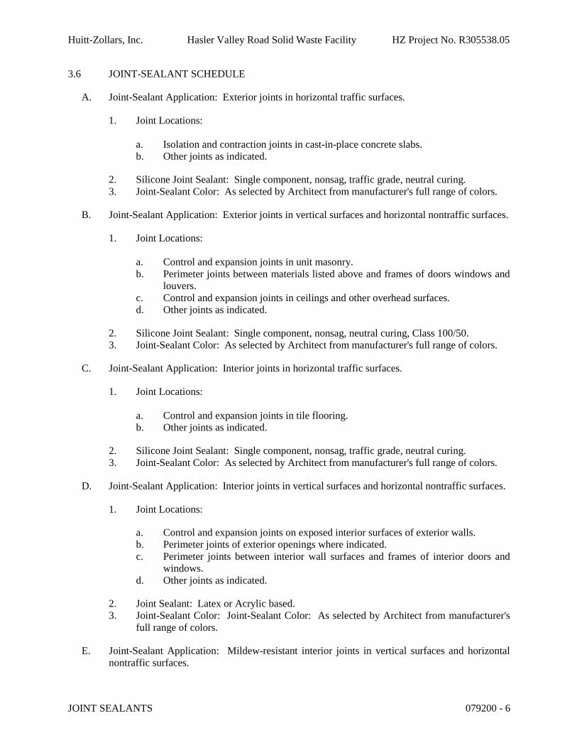
Huitt-Zollars, Inc. Hasler Valley Road Solid Waste Facility HZ Project No. R305538.05
JOINT SEALANTS 079200 - 6
3.6 JOINT-SEALANT SCHEDULE
A. Joint-Sealant Application: Exterior joints in horizontal traffic surfaces.
1. Joint Locations:
a. Isolation and contraction joints in cast-in-place concrete slabs.b. Other joints as indicated.
2. Silicone Joint Sealant: Single component, nonsag, traffic grade, neutral curing.3. Joint-Sealant Color: As selected by Architect from manufacturer's full range of colors.
B. Joint-Sealant Application: Exterior joints in vertical surfaces and horizontal nontraffic surfaces.
1. Joint Locations:
a. Control and expansion joints in unit masonry.b. Perimeter joints between materials listed above and frames of doors windows and
louvers.c. Control and expansion joints in ceilings and other overhead surfaces.d. Other joints as indicated.
2. Silicone Joint Sealant: Single component, nonsag, neutral curing, Class 100/50.3. Joint-Sealant Color: As selected by Architect from manufacturer's full range of colors.
C. Joint-Sealant Application: Interior joints in horizontal traffic surfaces.
1. Joint Locations:
a. Control and expansion joints in tile flooring.b. Other joints as indicated.
2. Silicone Joint Sealant: Single component, nonsag, traffic grade, neutral curing.3. Joint-Sealant Color: As selected by Architect from manufacturer's full range of colors.
D. Joint-Sealant Application: Interior joints in vertical surfaces and horizontal nontraffic surfaces.
1. Joint Locations:
a. Control and expansion joints on exposed interior surfaces of exterior walls.b. Perimeter joints of exterior openings where indicated.c. Perimeter joints between interior wall surfaces and frames of interior doors and
windows.d. Other joints as indicated.
2. Joint Sealant: Latex or Acrylic based.3. Joint-Sealant Color: Joint-Sealant Color: As selected by Architect from manufacturer's
full range of colors.
E. Joint-Sealant Application: Mildew-resistant interior joints in vertical surfaces and horizontal nontraffic surfaces.

Huitt-Zollars, Inc. Hasler Valley Road Solid Waste Facility HZ Project No. R305538.05
JOINT SEALANTS 079200 - 7
1. Joint Sealant Location:
a. Joints between plumbing fixtures and adjoining walls, floors, and counters.b. Tile control and expansion joints where indicated.c. Other joints as indicated.
2. Joint Sealant: Mildew resistant, single component, nonsag, neutral curing, Silicone.3. Joint-Sealant Color: As selected by Architect from manufacturer's full range of colors.
END OF SECTION 079200

Huitt-Zollars, Inc. Hasler Valley Road Solid Waste Facility HZ Project No. R305538.05
This page left intentionally blank
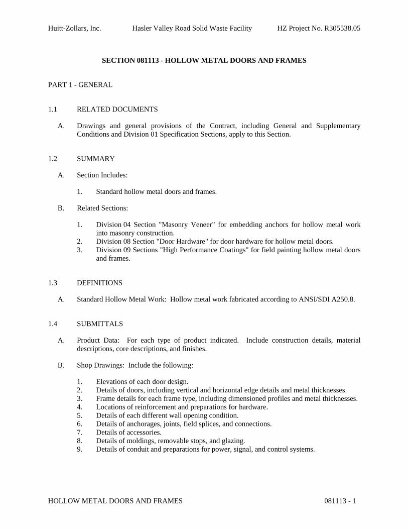
Huitt-Zollars, Inc. Hasler Valley Road Solid Waste Facility HZ Project No. R305538.05
HOLLOW METAL DOORS AND FRAMES 081113 - 1
SECTION 081113 - HOLLOW METAL DOORS AND FRAMES
PART 1 - GENERAL
1.1 RELATED DOCUMENTS
A. Drawings and general provisions of the Contract, including General and Supplementary Conditions and Division 01 Specification Sections, apply to this Section.
1.2 SUMMARY
A. Section Includes:
1. Standard hollow metal doors and frames.
B. Related Sections:
1. Division 04 Section "Masonry Veneer" for embedding anchors for hollow metal work into masonry construction.
2. Division 08 Section "Door Hardware" for door hardware for hollow metal doors.3. Division 09 Sections "High Performance Coatings" for field painting hollow metal doors
and frames.
1.3 DEFINITIONS
A. Standard Hollow Metal Work: Hollow metal work fabricated according to ANSI/SDI A250.8.
1.4 SUBMITTALS
A. Product Data: For each type of product indicated. Include construction details, material descriptions, core descriptions, and finishes.
B. Shop Drawings: Include the following:
1. Elevations of each door design.2. Details of doors, including vertical and horizontal edge details and metal thicknesses.3. Frame details for each frame type, including dimensioned profiles and metal thicknesses.4. Locations of reinforcement and preparations for hardware.5. Details of each different wall opening condition.6. Details of anchorages, joints, field splices, and connections.7. Details of accessories.8. Details of moldings, removable stops, and glazing.9. Details of conduit and preparations for power, signal, and control systems.
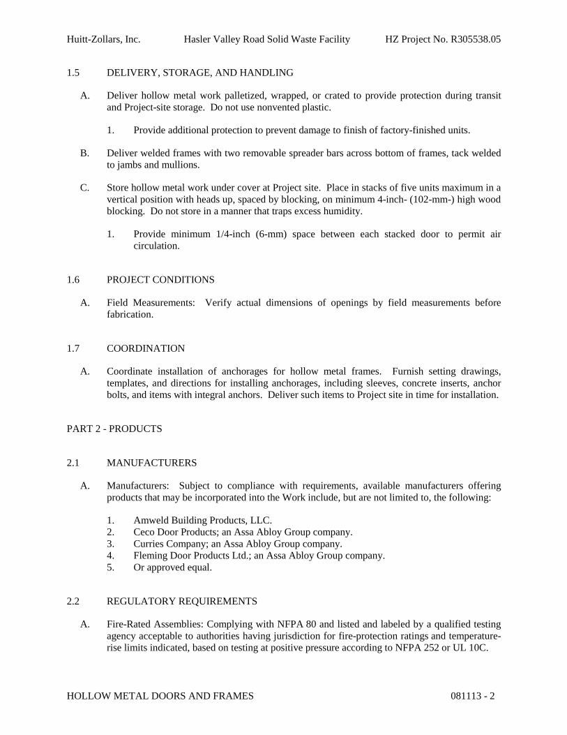
Huitt-Zollars, Inc. Hasler Valley Road Solid Waste Facility HZ Project No. R305538.05
HOLLOW METAL DOORS AND FRAMES 081113 - 2
1.5 DELIVERY, STORAGE, AND HANDLING
A. Deliver hollow metal work palletized, wrapped, or crated to provide protection during transit and Project-site storage. Do not use nonvented plastic.
1. Provide additional protection to prevent damage to finish of factory-finished units.
B. Deliver welded frames with two removable spreader bars across bottom of frames, tack welded to jambs and mullions.
C. Store hollow metal work under cover at Project site. Place in stacks of five units maximum in a vertical position with heads up, spaced by blocking, on minimum 4-inch- (102-mm-) high wood blocking. Do not store in a manner that traps excess humidity.
1. Provide minimum 1/4-inch (6-mm) space between each stacked door to permit air circulation.
1.6 PROJECT CONDITIONS
A. Field Measurements: Verify actual dimensions of openings by field measurements before fabrication.
1.7 COORDINATION
A. Coordinate installation of anchorages for hollow metal frames. Furnish setting drawings, templates, and directions for installing anchorages, including sleeves, concrete inserts, anchor bolts, and items with integral anchors. Deliver such items to Project site in time for installation.
PART 2 - PRODUCTS
2.1 MANUFACTURERS
A. Manufacturers: Subject to compliance with requirements, available manufacturers offering products that may be incorporated into the Work include, but are not limited to, the following:
1. Amweld Building Products, LLC.2. Ceco Door Products; an Assa Abloy Group company.3. Curries Company; an Assa Abloy Group company.4. Fleming Door Products Ltd.; an Assa Abloy Group company.5. Or approved equal.
2.2 REGULATORY REQUIREMENTS
A. Fire-Rated Assemblies: Complying with NFPA 80 and listed and labeled by a qualified testing agency acceptable to authorities having jurisdiction for fire-protection ratings and temperature-rise limits indicated, based on testing at positive pressure according to NFPA 252 or UL 10C.

Huitt-Zollars, Inc. Hasler Valley Road Solid Waste Facility HZ Project No. R305538.05
HOLLOW METAL DOORS AND FRAMES 081113 - 3
1. Smoke- and Draft-Control Assemblies: Provide an assembly with gaskets listed and labeled for smoke and draft control by a qualified testing agency acceptable to authorities having jurisdiction, based on testing according to UL 1784 and installed in compliance with NFPA 105.
2.3 INTERIOR DOORS AND FRAMES
A. Construct interior doors and frames to comply with the standards indicated for materials, fabrication, hardware locations, hardware reinforcement, tolerances, and clearances, and as specified.
B. Standard-Duty Doors and Frames: SDI A250.8, Level 1. At locations indicated in the Drawings.
1. Physical Performance: Level C according to SDI A250.4.2. Doors:
a. Type: As indicated in the Drawings.b. Thickness: 1-3/4 inches.c. Face: Uncoated, cold-rolled steel sheet, minimum thickness of 0.032 inch.d. Edge Construction: Model 1, Full Flush.e. Core: Manufacturer's standard kraft-paper honeycomb, polystyrene, polyurethane,
polyisocyanurate, mineral-board, or vertical steel-stiffener core at manufacturer's discretion.
3. Frames:
a. Materials: Uncoated, cold-rolled steel sheet, minimum thickness of 0.042 inch.b. Sidelite and Transom Frames: Fabricated from same thickness material as adjacent
door frame.c. Construction: Face welded corners.
4. Exposed Finish: Prime.
C. Hardware Reinforcement: Fabricate according to ANSI/SDI A250.6 with reinforcement plates from same material as frames.
2.4 EXTERIOR HOLLOW-METAL DOORS AND FRAMES
A. Construct exterior doors and frames to comply with the standards indicated for materials, fabrication, hardware locations, hardware reinforcement, tolerances, and clearances, and as specified.
B. Heavy-Duty Doors and Frames: SDI A250.8, Level 2. At locations indicated in the Drawings.
1. Physical Performance: Level B according to SDI A250.4.2. Doors:
a. Type: As indicated in the Door and Frame Schedule.b. Thickness: 1-3/4 inches.
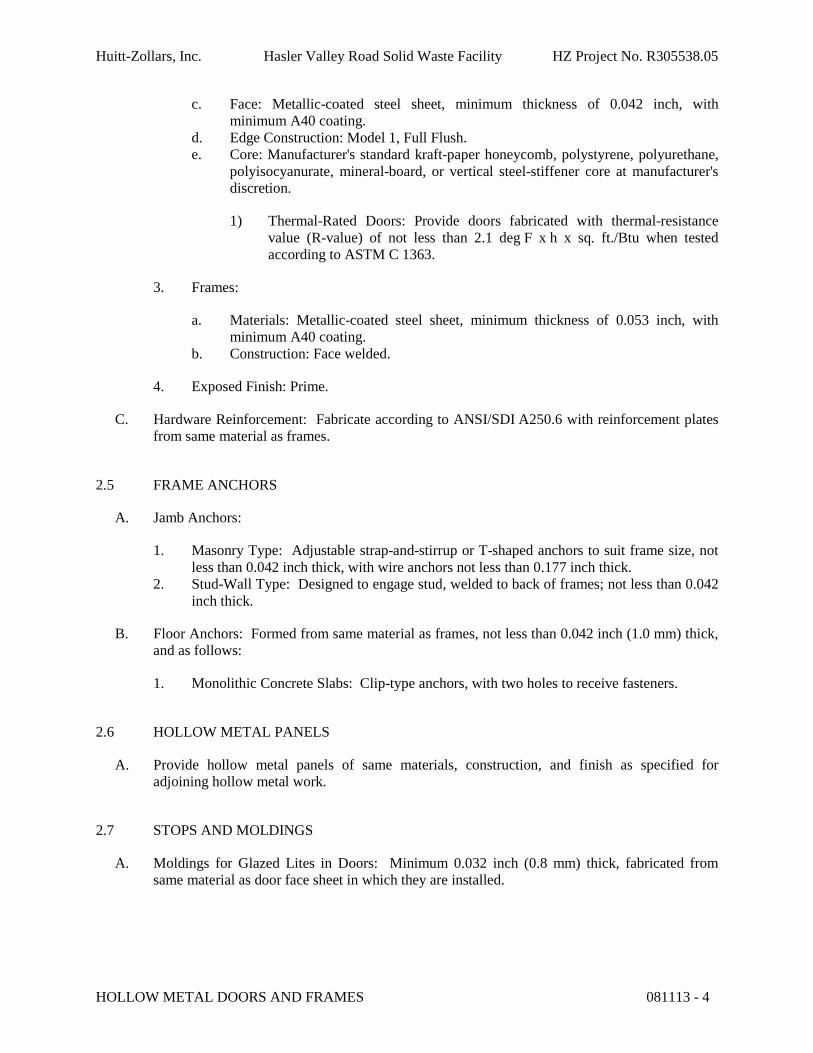
Huitt-Zollars, Inc. Hasler Valley Road Solid Waste Facility HZ Project No. R305538.05
HOLLOW METAL DOORS AND FRAMES 081113 - 4
c. Face: Metallic-coated steel sheet, minimum thickness of 0.042 inch, with minimum A40 coating.
d. Edge Construction: Model 1, Full Flush.e. Core: Manufacturer's standard kraft-paper honeycomb, polystyrene, polyurethane,
polyisocyanurate, mineral-board, or vertical steel-stiffener core at manufacturer's discretion.
1) Thermal-Rated Doors: Provide doors fabricated with thermal-resistance value (R-value) of not less than 2.1 deg F x h x sq. ft./Btu when tested according to ASTM C 1363.
3. Frames:
a. Materials: Metallic-coated steel sheet, minimum thickness of 0.053 inch, with minimum A40 coating.
b. Construction: Face welded.
4. Exposed Finish: Prime.
C. Hardware Reinforcement: Fabricate according to ANSI/SDI A250.6 with reinforcement plates from same material as frames.
2.5 FRAME ANCHORS
A. Jamb Anchors:
1. Masonry Type: Adjustable strap-and-stirrup or T-shaped anchors to suit frame size, not less than 0.042 inch thick, with wire anchors not less than 0.177 inch thick.
2. Stud-Wall Type: Designed to engage stud, welded to back of frames; not less than 0.042 inch thick.
B. Floor Anchors: Formed from same material as frames, not less than 0.042 inch (1.0 mm) thick, and as follows:
1. Monolithic Concrete Slabs: Clip-type anchors, with two holes to receive fasteners.
2.6 HOLLOW METAL PANELS
A. Provide hollow metal panels of same materials, construction, and finish as specified for adjoining hollow metal work.
2.7 STOPS AND MOLDINGS
A. Moldings for Glazed Lites in Doors: Minimum 0.032 inch (0.8 mm) thick, fabricated from same material as door face sheet in which they are installed.
Huitt-Zollars, Inc. Hasler Valley Road Solid Waste Facility HZ Project No. R305538.05
HOLLOW METAL DOORS AND FRAMES 081113 - 5
2.8 ACCESSORIES
A. Ceiling Struts: Minimum 1/4-inch-thick by 1-inch- (6.4-mm-thick by 25.4-mm-) wide steel.
B. Grout Guards: Formed from same material as frames, not less than 0.016 inch (0.4 mm) thick.
2.9 FABRICATION
A. Fabricate hollow metal work to be rigid and free of defects, warp, or buckle. Accurately form metal to required sizes and profiles, with minimum radius for thickness of metal. Where practical, fit and assemble units in manufacturer's plant. To ensure proper assembly at Project site, clearly identify work that cannot be permanently factory assembled before shipment.
B. Tolerances: Fabricate hollow metal work to tolerances indicated in SDI 117.
C. Hollow Metal Doors:
1. Exterior Doors: Provide weep-hole openings in bottom of exterior doors to permit moisture to escape. Seal joints in top edges of doors against water penetration.
D. Hollow Metal Frames: Where frames are fabricated in sections due to shipping or handling limitations, provide alignment plates or angles at each joint, fabricated of same thickness metal as frames.
1. Welded Frames: Weld flush face joints continuously; grind, fill, dress, and make smooth, flush, and invisible.
2. Provide countersunk, flat- or oval-head exposed screws and bolts for exposed fasteners unless otherwise indicated.
3. Grout Guards: Weld guards to frame at back of hardware mortises in frames to begrouted.
4. Floor Anchors: Weld anchors to bottom of jambs and mullions with at least four spot welds per anchor.
5. Jamb Anchors: Provide number and spacing of anchors as follows:
a. Masonry Type: Locate anchors not more than 18 inches from top and bottom of frame. Space anchors not more than 32 inches o.c. and as follows:1) Three anchors per jamb from 60 to 90 inches high.
b. Stud-Wall Type: Locate anchors not more than 18 inches from top and bottom of frame. Space anchors not more than 32 inches o.c. and as follows:
1) Three anchors per jamb up to 60 inches high.
6. Door Silencers: Except on weather-stripped doors, drill stops to receive door silencers as follows. Keep holes clear during construction.
a. Single-Door Frames: Drill stop in strike jamb to receive three door silencers.b. Double-Door Frames: Drill stop in head jamb to receive two door silencers.
E. Fabricate concealed stiffeners, edge channels, and hardware reinforcement from either cold- or hot-rolled steel sheet.
Huitt-Zollars, Inc. Hasler Valley Road Solid Waste Facility HZ Project No. R305538.05
HOLLOW METAL DOORS AND FRAMES 081113 - 6
F. Hardware Preparation: Factory prepare hollow metal work to receive templated mortised hardware; include cutouts, reinforcement, mortising, drilling, and tapping according to the Door Hardware Schedule and templates furnished as specified in Division 08 Section "Door Hardware."
1. Locate hardware as indicated, or if not indicated, according to ANSI/SDI A250.8.2. Reinforce doors and frames to receive non-templated, mortised and surface-mounted
door hardware.3. Comply with applicable requirements in ANSI/SDI A250.6 and ANSI/DHI A115 Series
specifications for preparation of hollow metal work for hardware.4. Coordinate locations of conduit and wiring boxes for electrical connections with
Division 26 Sections.
G. Stops and Moldings: Provide stops and moldings around glazed lites where indicated. Form corners of stops and moldings with butted or mitered hairline joints.
1. Single Glazed Lites: Provide fixed stops and moldings welded on secure side of hollow metal work.
2. Provide loose stops and moldings on inside of hollow metal work.3. Coordinate rabbet width between fixed and removable stops with type of glazing and
type of installation indicated.
2.10 STEEL FINISHES
A. Prime Finish: Apply manufacturer's standard primer immediately after cleaning and pretreating.
1. Shop Primer: Manufacturer's standard, fast-curing, lead- and chromate-free primer complying with ANSI/SDI A250.10 acceptance criteria; recommended by primer manufacturer for substrate; compatible with substrate and field-applied coatings despite prolonged exposure.
PART 3 - EXECUTION
3.1 EXAMINATION
A. Examine substrates, areas, and conditions, with Installer present, for compliance with requirements for installation tolerances and other conditions affecting performance of the Work.
B. Examine roughing-in for embedded and built-in anchors to verify actual locations before frame installation.
C. Proceed with installation only after unsatisfactory conditions have been corrected.
3.2 PREPARATION
A. Remove welded-in shipping spreaders installed at factory. Restore exposed finish by grinding, filling, and dressing, as required to make repaired area smooth, flush, and invisible on exposed faces.
Huitt-Zollars, Inc. Hasler Valley Road Solid Waste Facility HZ Project No. R305538.05
HOLLOW METAL DOORS AND FRAMES 081113 - 7
B. Prior to installation, adjust and securely brace welded hollow metal frames for squareness, alignment, twist, and plumbness to the following tolerances:
1. Squareness: Plus or minus 1/16 inch, measured at door rabbet on a line 90 degrees from jamb perpendicular to frame head.
2. Alignment: Plus or minus 1/16 inch, measured at jambs on a horizontal line parallel to plane of wall.
3. Twist: Plus or minus 1/16 inch, measured at opposite face corners of jambs on parallel lines, and perpendicular to plane of wall.
4. Plumbness: Plus or minus 1/16 inch, measured at jambs on a perpendicular line from head to floor.
C. Drill and tap doors and frames to receive non-templated, mortised, and surface-mounted door hardware.
3.3 INSTALLATION
A. General: Install hollow metal work plumb, rigid, properly aligned, and securely fastened in place; comply with Drawings and manufacturer's written instructions.
B. Hollow Metal Frames: Install hollow metal frames of size and profile indicated. Comply with ANSI/SDI A250.11.
1. Set frames accurately in position, plumbed, aligned, and braced securely until permanent anchors are set. After wall construction is complete, remove temporary braces, leaving surfaces smooth and undamaged.a. Where frames are fabricated in sections because of shipping or handling
limitations, field splice at approved locations by welding face joint continuously; grind, fill, dress, and make splice smooth, flush, and invisible on exposed faces.
b. Install frames with removable glazing stops located on secure side of opening.c. Install door silencers in frames before grouting.d. Remove temporary braces necessary for installation only after frames have been
properly set and secured.e. Check plumbness, squareness, and twist of frames as walls are constructed. Shim
as necessary to comply with installation tolerances.
2. Floor Anchors: Provide floor anchors for each jamb and mullion that extends to floor, and secure with postinstalled expansion anchors.
3. Metal-Stud Partitions: Solidly pack mineral-fiber insulation behind frames.4. Masonry Walls: Coordinate installation of frames to allow for solidly filling space
between frames and masonry with grout.5. Ceiling Struts: Extend struts vertically from top of frame at each jamb to overhead
structural supports or substrates above frame unless frame is anchored to masonry or to other structural support at each jamb. Bend top of struts to provide flush contact for securing to supporting construction. Provide adjustable wedged or bolted anchorage to frame jamb members.
6. Installation Tolerances: Adjust hollow metal door frames for squareness, alignment, twist, and plumb to the following tolerances:
Huitt-Zollars, Inc. Hasler Valley Road Solid Waste Facility HZ Project No. R305538.05
HOLLOW METAL DOORS AND FRAMES 081113 - 8
a. Squareness: Plus or minus 1/16 inch (1.6 mm), measured at door rabbet on a line 90 degrees from jamb perpendicular to frame head.
b. Alignment: Plus or minus 1/16 inch (1.6 mm), measured at jambs on a horizontal line parallel to plane of wall.
c. Twist: Plus or minus 1/16 inch (1.6 mm), measured at opposite face corners of jambs on parallel lines, and perpendicular to plane of wall.
d. Plumbness: Plus or minus 1/16 inch (1.6 mm), measured at jambs at floor.
C. Hollow Metal Doors: Fit hollow metal doors accurately in frames, within clearances specified below. Shim as necessary.
1. Non-Fire-Rated Standard Steel Doors:
a. Jambs and Head: 1/8 inch (3 mm) plus or minus 1/16 inch (1.6 mm).b. Between Edges of Pairs of Doors: 1/8 inch (3 mm) plus or minus 1/16 inch (1.6
mm).c. Between Bottom of Door and Top of Threshold: Maximum 3/8 inch (9.5 mm).d. Between Bottom of Door and Top of Finish Floor (No Threshold): Maximum 3/4
inch (19 mm).
D. Glazing: Comply with installation requirements in Division 08 Section "Glazing" and with hollow metal manufacturer's written instructions.
1. Secure stops with countersunk flat- or oval-head machine screws spaced uniformly notmore than 9 inches (230 mm) o.c. and not more than 2 inches (50 mm) o.c. from each corner.
3.4 ADJUSTING AND CLEANING
A. Final Adjustments: Check and readjust operating hardware items immediately before final inspection. Leave work in complete and proper operating condition. Remove and replace defective work, including hollow metal work that is warped, bowed, or otherwise unacceptable.
B. Remove grout and other bonding material from hollow metal work immediately after installation.
C. Prime-Coat Touchup: Immediately after erection, sand smooth rusted or damaged areas of prime coat and apply touchup of compatible air-drying, rust-inhibitive primer.
END OF SECTION 081113
Huitt-Zollars, Inc. Hasler Valley Road Solid Waste Facility HZ Project No. R305538.05
FLUSH WOOD DOORS 081416 - 1
SECTION 081416 - FLUSH WOOD DOORS
PART 1 - GENERAL
1.1 RELATED DOCUMENTS
A. Drawings and general provisions of the Contract, including General and Supplementary Conditions and Division 01 Specification Sections, apply to this Section.
1.2 SUMMARY
A. Section Includes:
1. Solid-core doors with wood-veneer faces.2. Factory finishing flush wood doors.
1.3 SUBMITTALS
A. Product Data: For each type of door indicated. Include details of core and edge construction,and trim for openings. Include factory-finishing specifications.
B. Shop Drawings: Indicate location, size, and hand of each door; elevation of each kind of door; construction details not covered in Product Data; location and extent of hardware blocking; and other pertinent data.
1. Indicate dimensions and locations of mortises and holes for hardware.2. Indicate dimensions and locations of cutouts.3. Indicate requirements for veneer matching.4. Indicate doors to be factory finished and finish requirements.5. Indicate fire-protection ratings for fire-rated doors.
C. Samples for Verification:
1. Factory finishes applied to actual door face materials, approximately 8 by 10 inches (200 by 250 mm), for each material and finish. For each wood species and transparent finish, provide set of three samples showing typical range of color and grain to be expected in the finished work.
a. Provide samples for each species of veneer and solid lumber required.b. Finish veneer-faced door samples with same materials proposed for factory-
finished doors.
D. Warranty: Sample of special warranty.

Huitt-Zollars, Inc. Hasler Valley Road Solid Waste Facility HZ Project No. R305538.05
FLUSH WOOD DOORS 081416 - 2
1.4 QUALITY ASSURANCE
A. Source Limitations: Obtain flush wood doors from single manufacturer.
B. Quality Standard: In addition to requirements specified, comply with AWI's "Architectural Woodwork Quality Standards Illustrated."
1. Provide AWI Quality Certification Labels or an AWI letter of licensing for Project indicating that doors comply with requirements of grades specified.
1.5 DELIVERY, STORAGE, AND HANDLING
A. Comply with requirements of referenced standard and manufacturer's written instructions.
B. Package doors individually in plastic bags or cardboard cartons.
C. Mark each door on top and bottom rail with opening number used on Shop Drawings.
1.6 PROJECT CONDITIONS
A. Environmental Limitations: Do not deliver or install doors until spaces are enclosed and weathertight, wet work in spaces is complete and dry, and HVAC system is operating and maintaining ambient temperature and humidity conditions at occupancy levels during the remainder of the construction period.
1.7 WARRANTY
A. Special Warranty: Manufacturer's standard form in which manufacturer agrees to repair or replace doors that fail in materials or workmanship within specified warranty period.
1. Failures include, but are not limited to, the following:
a. Warping (bow, cup, or twist) more than 1/4 inch (6.4 mm) in a 42-by-84-inch(1067-by-2134-mm) section.
b. Telegraphing of core construction in face veneers exceeding 0.01 inch in a 3-inch(0.25 mm in a 76.2-mm) span.
2. Warranty Period for Solid-Core Exterior Doors: Two years from date of Substantial Completion.
3. Warranty Period for Solid-Core Interior Doors: Life of installation.
PART 2 - PRODUCTS
2.1 MANUFACTURERS
A. Manufacturers: Subject to compliance with requirements, available manufacturers offering products that may be incorporated into the Work include, but are not limited to, the following:1. Ampco, Inc.

Huitt-Zollars, Inc. Hasler Valley Road Solid Waste Facility HZ Project No. R305538.05
FLUSH WOOD DOORS 081416 - 3
2. Eagle Plywood & Door Manufacturing, Inc.3. Marlite.4. Marshfield Door Systems, Inc.5. Or approved equal..
2.2 DOOR CONSTRUCTION, GENERAL
A. WDMA I.S.1-A Performance Grade: Standard Duty.
B. Interior Solid-Core Doors
1. Grade: Premium, with Grade AA faces.2. Species: Select white ash or select white birch or select white maple.3. Cut: Rotary cut.4. Match between Veneer Leaves: Book match.5. Assembly of Veneer Leaves on Door Faces: Balance match.6. Room Match: Provide door faces of compatible color and grain within each separate
room or area of building.7. Exposed Vertical Edges: Same species as faces.8. Core: Particleboard.9. Construction: Five or seven plies. Stiles and rails are bonded to core, then entire unit
abrasive planed before veneering. Faces are bonded to core using a hot press.10. WDMA I.S.1-A Performance Grade: Standard Duty.
2.3 FABRICATION
A. Factory machine doors for hardware that is not surface applied. Locate hardware to comply with DHI-WDHS-3. Comply with final hardware schedules, door frame Shop Drawings, DHI A115-W series standards, and hardware templates.
1. Coordinate with hardware mortises in metal frames to verify dimensions and alignment before factory machining.
B. Openings: Cut and trim openings through doors in factory.
1. Light Openings: Trim openings with moldings of material and profile indicated.
2.4 FACTORY FINISHING
A. General: Comply with referenced quality standard for factory finishing. Complete fabrication, including fitting doors for openings and machining for hardware that is not surface applied, before finishing.
1. Finish faces, all four edges, edges of cutouts, and mortises.
B. Finish doors at factory.
C. Transparent Finish:
Huitt-Zollars, Inc. Hasler Valley Road Solid Waste Facility HZ Project No. R305538.05
FLUSH WOOD DOORS 081416 - 4
1. Grade: Premium.2. Staining: As selected by Architect from manufacturer's full range.3. Sheen: Satin.
PART 3 - EXECUTION
3.1 EXAMINATION
A. Examine doors and installed door frames before hanging doors.
1. Verify that frames comply with indicated requirements for type, size, location, and swing characteristics and have been installed with level heads and plumb jambs.
2. Reject doors with defects.
B. Proceed with installation only after unsatisfactory conditions have been corrected.
3.2 INSTALLATION
A. Hardware: For installation, see Division 08 Section "Door Hardware."
B. Installation Instructions: Install doors to comply with manufacturer's written instructions and the referenced quality standard, and as indicated.
C. Job-Fitted Doors: Align and fit doors in frames with uniform clearances and bevels as indicated below; do not trim stiles and rails in excess of limits set by manufacturer or permitted for fire-rated doors. Machine doors for hardware. Seal edges of doors, edges of cutouts, and mortises after fitting and machining.
1. Clearances: Provide 1/8 inch (3.2 mm) at heads, jambs, and between pairs of doors. Provide 1/8 inch (3.2 mm) from bottom of door to top of decorative floor finish or covering unless otherwise indicated. Where threshold is shown or scheduled, provide 1/4 inch (6.4 mm) from bottom of door to top of threshold unless otherwise indicated.
2. Bevel non-fire-rated doors 1/8 inch in 2 inches (3-1/2 degrees) at lock and hinge edges.
D. Factory-Finished Doors: Restore finish before installation if fitting or machining is required at Project site.
3.3 ADJUSTING
A. Operation: Rehang or replace doors that do not swing or operate freely.
B. Finished Doors: Replace doors that are damaged or that do not comply with requirements. Doors may be repaired or refinished if work complies with requirements and shows no evidence of repair or refinishing.
END OF SECTION 081416
Huitt-Zollars, Inc. Hasler Valley Road Solid Waste Facility HZ Project No. R305538.05
ACCESS DOORS AND FRAMES 083113 - 1
SECTION 083113 - ACCESS DOORS AND FRAMES
PART 1 - GENERAL
1.1 RELATED DOCUMENTS
A. Drawings and general provisions of the Contract, including General and Supplementary Conditions and Division 01 Specification Sections, apply to this Section.
1.2 SUMMARY
A. This Section includes the following:
1. Access doors and frames for walls and ceilings.
B. Related Sections include the following:1. Division 08 Section "Door Hardware" for mortise or rim cylinder locks and master
keying.
1.3 SUBMITTALS
A. Product Data: For each type of access door and frame indicated. Include construction details,materials, individual components and profiles, and finishes.
B. Shop Drawings: Show fabrication and installation details of access doors and frames for each type of substrate. Include plans, elevations, sections, details, and attachments to other work.
C. Access Door and Frame Schedule: Provide complete access door and frame schedule, including types, locations, sizes, latching or locking provisions, and other data pertinent to installation.
1.4 QUALITY ASSURANCE
A. Source Limitations: Obtain access door(s) and frame(s) through one source from a single manufacturer.
1.5 COORDINATION
A. Verification: Determine specific locations and sizes for access doors needed to gain access to concealed plumbing, mechanical, or other concealed work, and indicate in the schedule specified in "Submittals" Article.

Huitt-Zollars, Inc. Hasler Valley Road Solid Waste Facility HZ Project No. R305538.05
ACCESS DOORS AND FRAMES 083113 - 2
PART 2 - PRODUCTS
2.1 STEEL MATERIALS
A. Steel Plates, Shapes, and Bars: ASTM A 36/A 36M.
1. ASTM A 123/A 123M, for galvanizing steel and iron products.2. ASTM A 153/A 153M, for galvanizing steel and iron hardware.
B. Steel Sheet: Uncoated or electrolytic zinc-coated, ASTM A 591/A 591M with cold-rolled steel sheet substrate complying with ASTM A 1008/A 1008M, Commercial Steel (CS), exposed.1. Baked-Enamel Finish: Immediately after cleaning and pretreating, apply manufacturer's
standard two-coat, baked-enamel finish consisting of prime coat and thermosetting topcoat. Comply with paint manufacturer's written instructions for applying and baking to achieve a minimum dry film thickness of 2 mils (0.05 mm).
C. Drywall Beads: Edge trim formed from 0.0299-inch (0.76-mm) zinc-coated steel sheet formed to receive joint compound and in size to suit thickness of gypsum board.
D. Plaster Beads: Casing bead formed from 0.0299-inch (0.76-mm) zinc-coated steel sheet with flange formed out of expanded metal lath and in size to suit thickness of plaster.
2.2 ACCESS DOORS AND FRAMES FOR WALLS AND CEILINGS
A. Available Manufacturers: Subject to compliance with requirements, manufacturers offering products that may be incorporated into the Work include, but are not limited to, the following:
1. Acudor Products, Inc.2. Babcock-Davis; A Cierra Products Co.3. Jensen Industries.4. J. L. Industries, Inc.5. Larsen's Manufacturing Company.6. Nystrom, Inc.7. Or approved equal.
B. Flush Access Doors and Frames with Exposed Trim: Fabricated from steel sheet.1. Locations: Wall and ceiling surfaces.
a. Wall Sizes: As shown in Drawingsb. Ceiling Sizes: As specified in Mechanical Sections.
2. Door: Minimum 0.060-inch- (1.5-mm-) thick sheet metal, set flush with exposed face flange of frame.
3. Frame: Minimum 0.060-inch- (1.5-mm-) thick sheet metal with 1-inch- (25-mm-) wide, surface-mounted trim.
4. Hinges: Spring-loaded, concealed-pin type.5. Latch: Cam latch operated by screwdriver with interior release.
Huitt-Zollars, Inc. Hasler Valley Road Solid Waste Facility HZ Project No. R305538.05
ACCESS DOORS AND FRAMES 083113 - 3
2.3 FABRICATION
A. General: Provide access door and frame assemblies manufactured as integral units ready for installation.
B. Metal Surfaces: For metal surfaces exposed to view in the completed Work, provide materials with smooth, flat surfaces without blemishes. Do not use materials with exposed pitting, seam marks, roller marks, rolled trade names, or roughness.
C. Doors and Frames: Grind exposed welds smooth and flush with adjacent surfaces. Furnish attachment devices and fasteners of type required to secure access panels to types of supports indicated.
1. Exposed Flanges: As indicated.2. Provide mounting holes in frames for attachment of units to metal framing.
D. Latching Mechanisms: Furnish number required to hold doors in flush, smooth plane when closed.
1. For cylinder lock, furnish two keys per lock and key all locks alike.2. For recessed panel doors, provide access sleeves for each locking device. Furnish plastic
grommets and install in holes cut through finish.
PART 3 - EXECUTION
3.1 INSTALLATION
A. Comply with manufacturer's written instructions for installing access doors and frames.
B. Install doors flush with adjacent finish surfaces or recessed to receive finish material.
3.2 ADJUSTING AND CLEANING
A. Adjust doors and hardware after installation for proper operation.
B. Remove and replace doors and frames that are warped, bowed, or otherwise damaged.
END OF SECTION 083113

Huitt-Zollars, Inc. Hasler Valley Road Solid Waste Facility HZ Project No. R305538.05
This page left intentionally blank
Huitt-Zollars, Inc. Hasler Valley Road Solid Waste Facility HZ Project No. R305538.05
OVERHEAD COILING DOORS 083323 - 1
SECTION 083323 - OVERHEAD COILING DOORS
PART 1 - GENERAL
1.1 RELATED DOCUMENTS
A. Drawings and general provisions of the Contract, including General and SupplementaryConditions and Division 01 Specification Sections, apply to this Section.
1.2 SUMMARY
A. Section Includes:1. Insulated service doors.
B. Related Sections:
1. Division 05 Section "Metal Fabrications" for miscellaneous steel supports.2. Division 09 Section "Exterior Painting" and "Interior Painting" for finish painting of
factory-primed doors.3. Division 26 Sections for electrical service and connections for powered operators and
accessories.
1.3 PERFORMANCE REQUIREMENTS
A. Delegated Design: Design overhead coiling doors, including comprehensive engineering analysis by a qualified professional engineer, using performance requirements and design criteria indicated.
B. Structural Performance, Exterior Doors: Exterior overhead coiling doors shall withstand the wind loads, the effects of gravity loads, and loads and stresses within limits and under conditions indicated according to SEI/ASCE 7.
1. Wind Loads:
a. Basic Wind Speed: 115 mph.b. Wind Pressure: 17 psfc. Exposure Category: B
2. Deflection Limits: Design overhead coiling doors to withstand design wind load without evidencing permanent deformation or disengagement of door components.
C. Seismic Performance: Overhead coiling doors shall withstand the effects of earthquake motions determined according to SEI/ASCE 7.
1. The term "withstand" means "the unit will remain in place without separation of any parts from the device when subjected to the seismic forces specified.
2. Seismic Component Importance Factor: 1.0.

Huitt-Zollars, Inc. Hasler Valley Road Solid Waste Facility HZ Project No. R305538.05
OVERHEAD COILING DOORS 083323 - 2
D. Operation Cycles: Provide overhead coiling door components and operators capable of operating for not less than number of cycles indicated for each door. One operation cycle is complete when a door is opened from the closed position to the fully open position and returned to the closed position.
1.4 SUBMITTALS
A. Product Data: For each type and size of overhead coiling door and accessory. Include the following:
1. Construction details, material descriptions, dimensions of individual components, profiles for slats, and finishes.
2. Rated capacities, operating characteristics, electrical characteristics, and furnished accessories.
3. For fire-rated doors, description of fire-release system including testing and resetting instructions.
B. Shop Drawings: For each installation and for special components not dimensioned or detailed in manufacturer's product data. Include plans, elevations, sections, details, and attachments to other work.
1. Detail equipment assemblies and indicate dimensions, weights, loads, required clearances, method of field assembly, components, and location and size of each field connection.
2. Show locations of replaceable fusible links.3. Wiring Diagrams: For power, signal, and control wiring.
C. Samples for Initial Selection: Manufacturer's finish charts showing full range of colors and textures available for units with factory-applied finishes.
1. Include similar Samples of accessories involving color selection.
D. Delegated-Design Submittal: For overhead coiling doors indicated to comply with performance requirements and design criteria, including analysis data signed and sealed by the qualified professional engineer responsible for their preparation.
1. Detail fabrication and assembly of seismic restraints.2. Summary of forces and loads on walls and jambs.
E. Qualification Data: For qualified Installer.
F. Seismic Qualification Certificates: For overhead coiling doors, accessories, and components, from manufacturer.
G. Oversize Construction Certification: For door assemblies required to be fire-rated and that exceed size limitations of labeled assemblies.
H. Maintenance Data: For overhead coiling doors to include in maintenance manuals.
Huitt-Zollars, Inc. Hasler Valley Road Solid Waste Facility HZ Project No. R305538.05
OVERHEAD COILING DOORS 083323 - 3
1.5 QUALITY ASSURANCE
A. Installer Qualifications: Manufacturer's authorized representative who is trained and approved for both installation and maintenance of units required for this Project.
B. Source Limitations: Obtain overhead coiling doors from single source from single manufacturer.
1. Obtain operators and controls from overhead coiling door manufacturer.
C. Electrical Components, Devices, and Accessories: Listed and labeled as defined in NFPA 70, by a qualified testing agency, and marked for intended location and application.
D. Regulatory Requirements: Comply with applicable provisions in the U.S. Architectural & Transportation Barriers Compliance Board's ADA-ABA Accessibility Guidelines andICC/ANSI A117.1.
PART 2 - PRODUCTS
2.1 DOOR CURTAIN MATERIALS AND CONSTRUCTION
A. Door Curtains: Fabricate overhead coiling-door curtain of interlocking metal slats, designed to withstand wind loading indicated, in a continuous length for width of door without splices. Unless otherwise indicated, provide slats of thickness and mechanical properties recommended by door manufacturer for performance, size, and type of door indicated, and as follows:
1. Steel Door Curtain Slats: Zinc-coated (galvanized), cold-rolled structural steel sheet; complying with ASTM A 653/A 653M, with G90 (Z275) zinc coating; nominal sheet thickness (coated) of 0.028 inch and as required to meet requirements.
2. Insulation: Fill slats for insulated doors with manufacturer's standard thermal insulation complying with maximum flame-spread and smoke-developed indexes of 75 and 450, respectively, according to ASTM E 84. Enclose insulation completely within slat faces.
3. Gasket Seal: Provide insulated slats with manufacturer's standard interior-to-exterior thermal break or with continuous gaskets between slats.
B. Endlocks and Windlocks for Service Doors: Malleable-iron casings galvanized after fabrication, secured to curtain slats with galvanized rivets or high-strength nylon. Provide locks on not less than alternate curtain slats for curtain alignment and resistance against lateral movement.
C. Bottom Bar for Service Doors: Consisting of two angles, each not less than 1-1/2 by 1-1/2 by 1/8 inch thick; fabricated from manufacturer's standard hot-dip galvanized steel, stainless steel, or aluminum extrusions to match curtain slats and finish.
D. Curtain Jamb Guides: Manufacturer's standard angles or channels and angles of same material and finish as curtain slats unless otherwise indicated, with sufficient depth and strength to retain curtain, to allow curtain to operate smoothly, and to withstand loading. Slot bolt holes for guide adjustment. Provide removable stops on guides to prevent overtravel of curtain, and a continuous bar for holding windlocks.
Huitt-Zollars, Inc. Hasler Valley Road Solid Waste Facility HZ Project No. R305538.05
OVERHEAD COILING DOORS 083323 - 4
1. Thresholds: Equip pass doors with integral thresholds that comply with egress and accessibility requirements of authorities having jurisdiction.
2.2 HOOD
A. General: Form sheet metal hood to entirely enclose coiled curtain and operating mechanism at opening head. Contour to fit end brackets to which hood is attached. Roll and reinforce top and bottom edges for stiffness. Form closed ends for surface-mounted hoods and fascia for any portion of between-jamb mounting that projects beyond wall face. Equip hood with intermediate support brackets as required to prevent sagging.
1. Galvanized Steel: Nominal 0.028-inch- thick, hot-dip galvanized steel sheet with G90(Z275) zinc coating, complying with ASTM A 653/A 653M.
2.3 LOCKING DEVICES
A. Slide Bolt: Fabricate with side-locking bolts to engage through slots in tracks for locking by padlock, located on both left and right jamb sides, operable from coil side.
B. Locking Device Assembly: Fabricate with cylinder lock, spring-loaded dead bolt, operating handle, cam plate, and adjustable locking bars to engage through slots in tracks.
1. Lock Cylinders: Provide cylinders standard with manufacturer and keyed to building keying system.
2. Keys: Provide three (3) for each cylinder.
C. Chain Lock Keeper: Suitable for padlock.
D. Safety Interlock Switch: Equip power-operated doors with safety interlock switch to disengage power supply when door is locked.
2.4 CURTAIN ACCESSORIES
A. Weatherseals: Equip each exterior door with weather-stripping gaskets fitted to entire perimeter of door for a weathertight installation, unless otherwise indicated.
1. At door head, use 1/8-inch- thick, replaceable, continuous sheet secured to inside of hood.
2. At door jambs, use replaceable, adjustable, continuous, flexible, 1/8-inch- thick seals of flexible vinyl, rubber, or neoprene.
B. Push/Pull Handles: Equip each push-up-operated or emergency-operated door with lifting handles on each side of door, finished to match door.
1. Provide pull-down straps or pole hooks for doors more than 84 inches high.

Huitt-Zollars, Inc. Hasler Valley Road Solid Waste Facility HZ Project No. R305538.05
OVERHEAD COILING DOORS 083323 - 5
2.5 COUNTERBALANCING MECHANISM
A. General: Counterbalance doors by means of manufacturer's standard mechanism with an adjustable-tension, steel helical torsion spring mounted around a steel shaft and contained in a spring barrel connected to top of curtain with barrel rings. Use grease-sealed bearings or self-lubricating graphite bearings for rotating members.
B. Counterbalance Barrel: Fabricate spring barrel of manufacturer's standard hot-formed, structural-quality, welded or seamless carbon-steel pipe, of sufficient diameter and wall thickness to support rolled-up curtain without distortion of slats and to limit barrel deflection to not more than 0.03 in./ft. of span under full load.
C. Spring Balance: One or more oil-tempered, heat-treated steel helical torsion springs. Size springs to counterbalance weight of curtain, with uniform adjustment accessible from outside barrel. Secure ends of springs to barrel and shaft with cast-steel barrel plugs.
D. Torsion Rod for Counterbalance Shaft: Fabricate of manufacturer's standard cold-rolled steel, sized to hold fixed spring ends and carry torsional load.
E. Brackets: Manufacturer's standard mounting brackets of either cast iron or cold-rolled steel plate.
2.6 ELECTRIC DOOR OPERATORS
A. General: Electric door operator assembly of size and capacity recommended and provided by door manufacturer for door and operation-cycles requirement specified, with electric motor and factory-prewired motor controls, starter, gear-reduction unit, solenoid-operated brake, clutch, remote-control stations, control devices, integral gearing for locking door, and accessories required for proper operation.
1. Comply with NFPA 70.2. Provide control equipment complying with NEMA ICS 1, NEMA ICS 2, and
NEMA ICS 6, with NFPA 70 Class 2 control circuit, maximum 24 V, ac or dc.
B. Usage Classification: Electric operator and components capable of operating for not less than number of cycles per hour indicated for each door.
C. Door Operator Location(s): Operator location indicated for each door.1. Front-of-Hood Mounted: Operator is mounted to the right or left door head plate with the
operator on coil side of the door-hood assembly and connected to the door drive shaft with drive chain and sprockets. Front clearance is required for this type of mounting.
D. Electric Motors: Comply with NEMA designation, temperature rating, service factor, enclosure type, and efficiency requirements specified in Division 11 Section "Common Motor Requirements for Equipment" unless otherwise indicated.
1. Electrical Characteristics:
a. Phase: Polyphase.b. Volts: 208 V.

Huitt-Zollars, Inc. Hasler Valley Road Solid Waste Facility HZ Project No. R305538.05
OVERHEAD COILING DOORS 083323 - 6
c. Hertz: 60.
2. Motor Type and Controller: Reversible motor and controller (disconnect switch) for motor exposure indicated.
3. Motor Size: Minimum size as indicated. If not indicated, large enough to start, accelerate, and operate door in either direction from any position, at a speed not less than 8 in./sec. and not more than 12 in./sec., without exceeding nameplate ratings or service factor.
4. Operating Controls, Controllers (Disconnect Switches), Wiring Devices, and Wiring: Manufacturer's standard unless otherwise indicated.
5. Coordinate wiring requirements and electrical characteristics of motors and other electrical devices with building electrical system and each location where installed.
E. Limit Switches: Equip each motorized door with adjustable switches interlocked with motor controls and set to automatically stop door at fully opened and fully closed positions.
F. Obstruction Detection Device: Equip motorized door with indicated external automatic safety sensor capable of protecting full width of door opening. For non-fire-rated doors, activation of device immediately stops and reverses downward door travel.
1. Photoelectric Sensor: Manufacturer's standard system designed to detect an obstruction in door opening without contact between door and obstruction.
2. Sensor Edge: Automatic safety sensor edge, located within astragal or weather stripping mounted to bottom bar. Contact with sensor activates device. Connect to control circuit using manufacturer's standard take-up reel or self-coiling cable.
G. Remote-Control Station: Momentary-contact, three-button control station with push-button controls labeled "Open," "Close," and "Stop."
1. Interior units, full-guarded, surface-mounted, heavy-duty type, with general-purpose NEMA ICS 6, Type 1 enclosure.
2. Exterior units, full-guarded, standard-duty, surface-mounted, weatherproof type, NEMA ICS 6, Type 4 enclosure, key operated.
H. Emergency Manual Operation: Equip each electrically powered door with capability for emergency manual operation. Design manual mechanism so required force for door operation does not exceed 25 lbf.
I. Emergency Operation Disconnect Device: Equip operator with hand-operated disconnect mechanism for automatically engaging manual operator and releasing brake for emergency manual operation while disconnecting motor without affecting timing of limit switch. Mount mechanism so it is accessible from floor level. Include interlock device to automatically prevent motor from operating when emergency operator is engaged.
J. Motor Removal: Design operator so motor may be removed without disturbing limit-switch adjustment and without affecting emergency manual operation.

Huitt-Zollars, Inc. Hasler Valley Road Solid Waste Facility HZ Project No. R305538.05
OVERHEAD COILING DOORS 083323 - 7
2.7 DOOR ASSEMBLY
A. Insulated Service Door: Overhead coiling door formed with curtain of interlocking metal slats.
1. Manufacturers: Subject to compliance with requirements, available manufacturers offering products that may be incorporated into the Work include, but are not limited to, the following:a. Cookson Company. Temp-Pro Insulated Rolling Doorb. Or approved equal
B. Operation Cycles: Not less than 20,000.
1. Include tamperproof cycle counter.
C. Curtain R-Value: 5.0 deg F x h x sq. ft./Btu
D. Door Curtain Material: Galvanized steel
E. Door Curtain Slats: Flat profile slats of 1-7/8-inch center-to-center height.1. Insulated-Slat Interior Facing: Metal.
F. Curtain Jamb Guides: Galvanized steel with exposed finish matching curtain slats. Provide continuous integral wear strips to prevent metal-to-metal contact and to minimize operational noise.
G. Hood: Match curtain material and finish.
1. Shape: Round2. Mounting: Face of wall mounting.
H. Locking Devices: Equip door with locking device assembly and chain lock keeper.
1. Locking Device Assembly: Single-jamb side locking bars, operable from inside with cylinders.
I. Electric Door Operator:
1. Usage Classification: Medium duty, up to 15 cycles per hour.2. Operator Location: Top of hood or Front of hood or Wall.3. Motor Exposure: Interior.4. Emergency Manual Operation: Chain type.5. Obstruction-Detection Device: Automatic photoelectric sensor
a. Sensor Edge Bulb Color: Black
J. Door Finish:1. Baked-Enamel or Powder-Coated Finish: Color as selected by Architect from
manufacturer's full range.2. Factory Prime Finish: Manufacturer's standard color.3. Interior Curtain-Slat Facing: Match finish of exterior curtain-slat face.

Huitt-Zollars, Inc. Hasler Valley Road Solid Waste Facility HZ Project No. R305538.05
OVERHEAD COILING DOORS 083323 - 8
2.8 GENERAL FINISH REQUIREMENTS
A. Comply with NAAMM's "Metal Finishes Manual for Architectural and Metal Products" for recommendations for applying and designating finishes.
B. Appearance of Finished Work: Noticeable variations in same piece are not acceptable. Variations in appearance of adjoining components are acceptable if they are within the range of approved Samples and are assembled or installed to minimize contrast.
2.9 STEEL AND GALVANIZED-STEEL FINISHES
A. Factory Prime Finish: Manufacturer's standard primer, compatible with field-applied finish. Comply with coating manufacturer's written instructions for cleaning, pretreatment, application, and minimum dry film thickness.
B. Baked-Enamel or Powder-Coat Finish: Manufacturer's standard baked-on finish consisting of prime coat and thermosetting topcoat. Comply with coating manufacturer's written instructions for cleaning, pretreatment, application, and minimum dry film thickness.
PART 3 - EXECUTION
3.1 EXAMINATION
A. Examine substrates areas and conditions, with Installer present, for compliance with requirements for substrate construction and other conditions affecting performance of the Work.
B. Examine locations of electrical connections.
C. Proceed with installation only after unsatisfactory conditions have been corrected.
3.2 INSTALLATION
A. Install overhead coiling doors and operating equipment complete with necessary hardware, anchors, inserts, hangers, and equipment supports; according to manufacturer's written instructions and as specified.
B. Install overhead coiling doors, hoods, and operators at the mounting locations indicated for each door.
C. Accessibility: Install overhead coiling doors, switches, and controls along accessible routes in compliance with regulatory requirements for accessibility.
3.3 STARTUP SERVICE
A. Engage a factory-authorized service representative to perform startup service.
1. Perform installation and startup checks according to manufacturer's written instructions.
Huitt-Zollars, Inc. Hasler Valley Road Solid Waste Facility HZ Project No. R305538.05
OVERHEAD COILING DOORS 083323 - 9
2. Test and adjust controls and safeties. Replace damaged and malfunctioning controls and equipment.
3. Test door closing when activated by detector or alarm-connected fire-release system. Reset door-closing mechanism after successful test.
3.4 ADJUSTING
A. Adjust hardware and moving parts to function smoothly so that doors operate easily, free of warp, twist, or distortion.
B. Lubricate bearings and sliding parts as recommended by manufacturer.
C. Adjust seals to provide weathertight fit around entire perimeter.
3.5 DEMONSTRATION
A. Engage a factory-authorized service representative to train Owner's maintenance personnel to adjust, operate, and maintain overhead coiling doors.
END OF SECTION 083323

Huitt-Zollars, Inc. Hasler Valley Road Solid Waste Facility HZ Project No. R305538.05
This page left intentionally blank
Huitt-Zollars, Inc. Hasler Valley Road Solid Waste Facility HZ Project No. R305538.05
ALUMINUM-FRAMED ENTRANCES AND STOREFRONTS 084113 - 1
SECTION 084113 - ALUMINUM-FRAMED ENTRANCES AND STOREFRONTS
PART 1 - GENERAL
1.1 RELATED DOCUMENTS
A. Drawings and general provisions of the Contract, including General and Supplementary Conditions and Division 01 Specification Sections, apply to this Section.
1.2 SUMMARY
A. Section Includes:
1. Exterior storefront framing.
1.3 DEFINITIONS
A. ADA/ABA Accessibility Guidelines: U.S. Architectural & Transportation Barriers Compliance Board's "Americans with Disability Act (ADA) and Architectural Barriers Act (ABA) Accessibility Guidelines for Buildings and Facilities."
1.4 PERFORMANCE REQUIREMENTS
A. General Performance: Aluminum-framed systems shall withstand the effects of the following performance requirements without exceeding performance criteria or failure due to defective manufacture, fabrication, installation, or other defects in construction:
1. Movements of supporting structure indicated on Drawings including, but not limited to, story drift and deflection from uniformly distributed and concentrated live loads.
2. Dimensional tolerances of building frame and other adjacent construction.3. Failure includes the following:
a. Deflection exceeding specified limits.b. Thermal stresses transferring to building structure.c. Framing members transferring stresses, including those caused by thermal and
structural movements to glazing.d. Noise or vibration created by wind and by thermal and structural movements.e. Loosening or weakening of fasteners, attachments, and other components.f. Sealant failure.g. Failure of operating units.
B. Structural Loads:
1. Wind Loads: As indicated on Drawings.
2. Seismic Loads: As indicated on Drawings
Huitt-Zollars, Inc. Hasler Valley Road Solid Waste Facility HZ Project No. R305538.05
ALUMINUM-FRAMED ENTRANCES AND STOREFRONTS 084113 - 2
C. Deflection of Framing Members:
1. Deflection Normal to Wall Plane: Limited to edge of glass in a direction perpendicular to glass plane shall not exceed L/175 of the glass edge length for each individual glazing liteor an amount that restricts edge deflection of individual glazing lites to 3/4 inch (19 mm),whichever is less.
2. Deflection Parallel to Glazing Plane: Limited to L/360 of clear span or 1/8 inch (3.2 mm), whichever is smaller.
D. Structural-Test Performance: Provide aluminum-framed systems tested according to ASTM E 330 as follows:
1. When tested at positive and negative wind-load design pressures, systems do not evidence deflection exceeding specified limits.
2. When tested at 150 percent of positive and negative wind-load design pressures, systems, including anchorage, do not evidence material failures, structural distress, and permanent deformation of main framing members exceeding 0.2 percent of span.
3. Test Durations: As required by design wind velocity, but not fewer than 10 seconds.
E. Air Infiltration: Provide aluminum-framed systems with maximum air leakage through fixed glazing and framing areas of 0.06 cfm/sq. ft. (0.03 L/s per sq. m) of fixed wall area when tested according to ASTM E 283 at a minimum static-air-pressure difference of 1.57 lbf/sq. ft. (75 Pa)][6.24 lbf/sq. ft. (300 Pa).
F. Water Penetration under Static Pressure: No evidence of water penetration through fixed glazing and framing areas when tested according to ASTM E 331 at a minimum static-air-pressure differential of 20 percent of positive wind-load design pressure, but not less than 6.24 lbf/sq. ft. (300 Pa).
1.5 SUBMITTALS
A. Product Data: For each type of product indicated. Include construction details, material descriptions, dimensions of individual components and profiles, and finishes for aluminum-framed systems.
B. Shop Drawings: For aluminum-framed systems. Include plans, elevations, sections, details, and attachments to other work.1. For entrance doors, include hardware schedule and indicate operating hardware types,
functions, quantities, and locations.
C. Maintenance Data: For aluminum-framed systems to include in maintenance manuals.
D. Warranties: Sample of warranties.
1.6 QUALITY ASSURANCE
A. Installer Qualifications: Manufacturer's authorized representative who is trained and approved for installation of units required for this Project.
Huitt-Zollars, Inc. Hasler Valley Road Solid Waste Facility HZ Project No. R305538.05
ALUMINUM-FRAMED ENTRANCES AND STOREFRONTS 084113 - 3
B. Engineering Responsibility: Prepare data for aluminum-framed systems, including Shop Drawings, based on testing and engineering analysis of manufacturer's standard units in systems similar to those indicated for this Project.
C. Accessible Entrances: Comply with applicable provisions in the U.S. Architectural & Transportation Barriers Compliance Board's ADA-ABA Accessibility Guidelines andICC/ANSI A117.1.
D. Source Limitations for Aluminum-Framed Systems: Obtain from single source from single manufacturer.
1.7 PROJECT CONDITIONS
A. Field Measurements: Verify actual locations of structural supports for aluminum-framed systems by field measurements before fabrication and indicate measurements on Shop Drawings.
1.8 WARRANTY
A. Special Warranty: Manufacturer's standard form in which manufacturer agrees to repair or replace components of aluminum-framed systems that do not comply with requirements or that fail in materials or workmanship within specified warranty period.
1. Failures include, but are not limited to, the following:
a. Structural failures including, but not limited to, excessive deflection.b. Noise or vibration caused by thermal movements.c. Deterioration of metals and other materials beyond normal d. Water leakage through fixed glazing and framing areas.e. Failure of operating components.
2. Warranty Period: Two years from date of Substantial Completion.
PART 2 - PRODUCTS
2.1 MANUFACTURERS
A. Manufacturers: Subject to compliance with requirements, manufacturers offering products that may be incorporated into the Work include, but are not limited to, the following:1. Kawneer North America; an Alcoa company.2. Tubelite.3. Vistawall Architectural Products; The Vistawall Group; a Bluescope Steel company.4. Or approved equal.

Huitt-Zollars, Inc. Hasler Valley Road Solid Waste Facility HZ Project No. R305538.05
ALUMINUM-FRAMED ENTRANCES AND STOREFRONTS 084113 - 4
2.2 MATERIALS
A. Aluminum: Alloy and temper recommended by manufacturer for type of use and finish indicated.
1. Sheet and Plate: ASTM B 209 (ASTM B 209M).2. Extruded Bars, Rods, Profiles, and Tubes: ASTM B 221 (ASTM B 221M).3. Extruded Structural Pipe and Tubes: ASTM B 429.4. Structural Profiles: ASTM B 308/B 308M.5. Welding Rods and Bare Electrodes: AWS A5.10/A5.10M.
B. Steel Reinforcement: Manufacturer's standard zinc-rich, corrosion-resistant primer, complying with SSPC-PS Guide No. 12.00; applied immediately after surface preparation and pretreatment. Select surface preparation methods according to recommendations in SSPC-SP COM and prepare surfaces according to applicable SSPC standard.
1. Structural Shapes, Plates, and Bars: ASTM A 36/A 36M.2. Cold-Rolled Sheet and Strip: ASTM A 1008/A 1008M.3. Hot-Rolled Sheet and Strip: ASTM A 1011/A 1011M.
2.3 FRAMING SYSTEMS
A. Framing Members: Manufacturer's standard extruded-aluminum framing members of thickness required and reinforced as required to support imposed loads.
1. Construction: Thermally broken.2. Glazing System: Retained mechanically with gaskets on four sides.3. Glazing Plane: As indicated in the Drawings.
B. Brackets and Reinforcements: Manufacturer's standard high-strength aluminum with nonstaining, nonferrous shims for aligning system components.
C. Fasteners and Accessories: Manufacturer's standard corrosion-resistant, nonstaining, nonbleeding fasteners and accessories compatible with adjacent materials.
1. Use self-locking devices where fasteners are subject to loosening or turning out from thermal and structural movements, wind loads, or vibration.
2. Reinforce members as required to receive fastener threads.
D. Concealed Flashing: Manufacturer's standard corrosion-resistant, nonstaining, nonbleeding flashing compatible with adjacent materials.
E. Framing System Gaskets and Sealants: Manufacturer's standard, recommended by manufacturer for joint type.
2.4 GLAZING SYSTEMS
A. Glazing: As specified in Division 08 Section "Glazing."
Huitt-Zollars, Inc. Hasler Valley Road Solid Waste Facility HZ Project No. R305538.05
ALUMINUM-FRAMED ENTRANCES AND STOREFRONTS 084113 - 5
B. Glazing Gaskets: Manufacturer's standard compression types; replaceable, molded or extruded, of profile and hardness required to maintain watertight seal.
C. Spacers and Setting Blocks: Manufacturer's standard elastomeric type.
1. Weatherseal Sealant: ASTM C 920 for Type S, Grade NS, Class 25, Uses NT, G, A, and O; single-component neutral-curing formulation that is compatible with structural sealant and other system components with which it comes in contact; recommended by structural-sealant, weatherseal-sealant, and aluminum-framed-system manufacturers for this use.a. Color: As selected by Architect from manufacturer’s standard color selections.
2.5 ENTRANCE DOOR SYSTEMS
A. Entrance Doors: Manufacturer's standard glazed entrance doors for manual-swing operation.
1. Door Construction: 1-3/4-inch (44.5-mm) overall thickness, with minimum 0.125-inch-(3.2-mm-) thick, extruded-aluminum tubular rail and stile members. Mechanically fasten corners with reinforcing brackets that are deeply penetrated and fillet welded or that incorporate concealed tie rods.
2. Door Design: Medium stile; 3-1/2-inch (88.9-mm) nominal width.
a. Accessible Doors: Smooth surfaced for width of door in area within 12inches (255 mm) above floor or ground plane.
3. Glazing Stops and Gaskets: Beveled, snap-on, extruded-aluminum stops and preformed gaskets.
B. Entrance Door Hardware: As specified in Division 08 Section "Door Hardware."
2.6 ACCESSORY MATERIALS
A. Joint Sealants: For installation at perimeter of aluminum-framed systems, as specified in Division 07 Section "Joint Sealants."
B. Bituminous Paint: Cold-applied, asphalt-mastic paint complying with SSPC-Paint 12requirements except containing no asbestos; formulated for 30-mil (0.762-mm) thickness per coat.
2.7 FABRICATION
A. Form or extrude aluminum shapes before finishing.
B. Framing Members, General: Fabricate components that, when assembled, have the following characteristics:
1. Profiles that are sharp, straight, and free of defects or deformations.2. Accurately fitted joints with ends coped or mitered.
Huitt-Zollars, Inc. Hasler Valley Road Solid Waste Facility HZ Project No. R305538.05
ALUMINUM-FRAMED ENTRANCES AND STOREFRONTS 084113 - 6
3. Means to drain water passing joints, condensation within framing members, and moisture migrating within the system to exterior.
4. Physical and thermal isolation of glazing from framing members.5. Accommodations for thermal and mechanical movements of glazing and framing to
maintain required glazing edge clearances.6. Provisions for field replacement of glazing from exterior.7. Fasteners, anchors, and connection devices that are concealed from view to greatest
extent possible.
C. Mechanically Glazed Framing Members: Fabricate for flush glazing without projecting stops.
D. Entrance Door Frames: Reinforce as required to support loads imposed by door operation and for installing entrance door hardware.
1. At exterior doors, provide compression weather stripping at fixed stops.2. At interior doors, provide silencers at stops to prevent metal-to-metal contact. Install
three silencers on strike jamb of single-door frames and two silencers on head of frames for pairs of doors.
E. Entrance Doors: Reinforce doors as required for installing entrance door hardware.1. At exterior doors, provide weather sweeps applied to door bottoms.
F. Entrance Door Hardware Installation: Factory install entrance door hardware to the greatest extent possible. Cut, drill, and tap for factory-installed entrance door hardware before applying finishes.
G. After fabrication, clearly mark components to identify their locations in Project according to Shop Drawings.
2.8 ALUMINUM FINISHES
A. Clear Anodic Finish: AAMA 611, AA-M12C22A41, Class I, 0.018 mm or thicker.
PART 3 - EXECUTION
3.1 EXAMINATION
A. Examine areas and conditions, with Installer present, for compliance with requirements for installation tolerances and other conditions affecting performance of the Work.
B. Proceed with installation only after unsatisfactory conditions have been corrected.
3.2 INSTALLATION
A. General:
1. Comply with manufacturer's written instructions.2. Do not install damaged components.

Huitt-Zollars, Inc. Hasler Valley Road Solid Waste Facility HZ Project No. R305538.05
ALUMINUM-FRAMED ENTRANCES AND STOREFRONTS 084113 - 7
3. Fit joints to produce hairline joints free of burrs and distortion.4. Rigidly secure nonmovement joints.5. Install anchors with separators and isolators to prevent metal corrosion and electrolytic
deterioration.6. Seal joints watertight unless otherwise indicated.
B. Metal Protection:
1. Where aluminum will contact dissimilar metals, protect against galvanic action by painting contact surfaces with primer or applying sealant or tape, or by installing nonconductive spacers as recommended by manufacturer for this purpose.
2. Where aluminum will contact concrete or masonry, protect against corrosion by painting contact surfaces with bituminous paint.
C. Install components to drain water passing joints, condensation occurring within framing members, and moisture migrating within the system to exterior.
D. Set continuous sill members and flashing in full sealant bed as specified in Division 07 Section "Joint Sealants" to produce weathertight installation.
E. Install components plumb and true in alignment with established lines and grades, and without warp or rack.
F. Install glazing as specified in Division 08 Section "Glazing."
G. Entrance Doors: Install doors to produce smooth operation and tight fit at contact points.
1. Exterior Doors: Install to produce weathertight enclosure and tight fit at weather stripping.
2. Field-Installed Entrance Door Hardware: Install surface-mounted entrance door hardware according to entrance door hardware manufacturers' written instructions using concealed fasteners to greatest extent possible.
H. Install perimeter joint sealants as specified in Division 07 Section "Joint Sealants" to produce weathertight installation.
3.3 ERECTION TOLERANCES
A. Install aluminum-framed systems to comply with the following maximum erection tolerances:
1. Location and Plane: Limit variation from true location and plane to 1/8 inch in 12 feet (3 mm in 3.7 m); 1/4 inch (6 mm) over total length.
2. Alignment:
a. Where surfaces abut in line, limit offset from true alignment to 1/16 inch (1.5 mm).b. Where surfaces meet at corners, limit offset from true alignment to 1/32 inch (0.8
mm).
B. Diagonal Measurements: Limit difference between diagonal measurements to 1/8 inch (3 mm).

Huitt-Zollars, Inc. Hasler Valley Road Solid Waste Facility HZ Project No. R305538.05
ALUMINUM-FRAMED ENTRANCES AND STOREFRONTS 084113 - 8
3.4 ADJUSTING
A. Adjust operating entrance door hardware to function smoothly as recommended by manufacturer.
1. For entrance doors accessible to people with disabilities, adjust closers to provide a 3-second closer sweep period for doors to move from a 70-degree open position to 3 inches(75 mm) from the latch, measured to the leading door edge.
END OF SECTION 084113
Huitt-Zollars, Inc. Hasler Valley Road Solid Waste Facility HZ Project No. R305538.05
TRANSLUCENT WALL AND ROOF ASSEMBLIES 084500 - 1
SECTION 084500 - TRANSLUCENT WALL AND ROOF ASSEMBLIES
PART 1 - GENERAL
1.1 DESCRIPTION
A. All requirements of the contract documents form an integral part of the work specified herein; in particular, refer to the conditions (general or otherwise) and Division 1 of the specifications, including all subdivisions thereof.
B. Insulated skylights shall consist of 2-3/4” thick flat factory prefabricated sandwich panels and systems.
C. Requests for substitutions must be approved by addendum prior tobid due dates in keeping with Division 1 (Substitutions) of the specifications.
D. Work included: Supply all material and labor required to provide and install the insulated skylight system. The following major items included are:
1. Prefabricated insulated translucent sandwich panels
2. Aluminum installation system
3. Aluminum flashing
E. Related work specified elsewhere:
1. Structural Steel: Section 05120
2. Flashing and Sheet Metal: Section 07600
3. Sealants: Section 07900
1.2 QUALITY ASSURANCE
A. Manufacturer's and Erector's Qualifications.
1. Skylight system must be listed by the International Conference of Building Officials, which requires quality control inspections and, fire, structural and water infiltration testing of sandwich panel systems by an approved agency; and the National Evaluation Service of the International Building Code.
2. Quality control inspections and required testing shall be conducted at least once each year and shall include manufacturing facilities, sandwich panel components and production sandwich panels for conformance with “Acceptance Criteria for Sandwich Panels” as regulated by the ICBO-ES.
3. Material and products shall be manufactured by a company continuously and regularly employed in the manufacture of specified materials for a period of at least ten (10) consecutive years and which can show evidence of those materials being satisfactorily used on at least six (6) projects of similar size, scope and location
Huitt-Zollars, Inc. Hasler Valley Road Solid Waste Facility HZ Project No. R305538.05
TRANSLUCENT WALL AND ROOF ASSEMBLIES 084500 - 2
within such a period. At least three (3) of the projects shall have been in successful use for ten (10) years or longer.
4. Erection shall be by an installer, which has been in the business of erecting specified materials for at least five (5) consecutive years and can show evidence of satisfactory completion of projects of similar size, scope and type.
B. Performance Requirements: The manufacturer shall be responsible for the configuration and fabrication of the complete skylight panel system.
1.3 SUBMITTALS
A. Submit shop drawings and color samples in accordance with Division 1, Submittals.
B. Test reports to be furnished by skylight system manufacturer in accordance with Division l, Submittals. The manufacturer shall submit certified test reports made by an independent testing organization for each type and class of panel system. Reports shall verify that the material will meet all performance requirements of this specification. Previously completed test reports will be acceptable if for current manufacturer and indicative of products used on this project. Test reports required are:
1. Flame Spread and Smoke Developed (UL 723) – Submit UL Card
2. Burn Extent (ASTM D-635)
3. Color Difference (ASTM-2244)
4. Erosion Resistance (ASTM D-4060)
5. Impact Strength (UL 972)
6. Tensile Bond Strength (ASTM C-297 after aging by ASTM D-1037)
7. Shear Bond Strength (ASTM D-1002 after five (5) separate conditions)
8. Beam Bending Strength (ASTM E-72)
9. Insulation “U” Factor (by NFRC-100)
10. NFRC Certification (Optional)
11. Condensation Resistance Factor (AAMA 1503.1) (Optional)
12. Class A Roof Covering Burning Brand (ASTM E-lO8)
13. UL Listed Class A Roof System (UL 790) (Optional) – Submit UL Card
14. Minimum STC Rating of 31 (ASTM E-90)
C. Proof of regular, independent quality control monitoring under a nationally recognized building code review and listing program shall be submitted.

Huitt-Zollars, Inc. Hasler Valley Road Solid Waste Facility HZ Project No. R305538.05
TRANSLUCENT WALL AND ROOF ASSEMBLIES 084500 - 3
1.4 PRODUCT HANDLING
Store skylight panels on the long edge, several inches above the ground, blocked and under cover to prevent warping in accordance with manufacturer's storage and handling instructions.
1.5 WARRANTY
Submit manufacturer’s standard one-year material and workmanship warranty.
PART 2 - PRODUCTS
2.1 MANUFACTURER
A. Kalwall CorporationB. Or approved equal
2.2 TRANSLUCENT FACING
A. Translucent faces shall be manufactured from glass fiber reinforced thermoset resins specifically for architectural use. Thermoplastic (e.g. polycarbonate, acrylic) faces are not acceptable.
B. Flammability - The interior face sheet shall be U.L. listed and have a flamespread rating no greater than 50 and smoke developed no greater than 250 when tested in accordance with UL 790. Burn extent by ASTM D-635 shall be no greater than 1”. Faces shall not deform, deflect or drip when subjected to fire or flame or delaminate when exposed to 200°F for 30 minutes per NBC and IBC (300°F for 25 minutes per UBC and SBC).
C. Weatherability -
1. The full thickness of the exterior face shall not change color more than 3.0 CIE Units DELTA E by ASTM D-2244 after 5 years outdoor South Florida weathering at 5 degrees facing South, determined by the average of at least three (3) white samples with and without a protective film or coating to ensure long-term color stability. Color stability shall be unaffected by abrasion or scratching.
2. The exterior face shall have a permanent glass erosion barrier embedded beneath the surface to provide long-term resistance to reinforcing fiber exposure. Sacrificial surface films or coatings are not acceptable erosion barriers. Exterior face surface loss shall not exceed .7 mils and 40 mgs when tested in accordance with ASTM D-4060-90 employing CS17 abrasive wheels at a head load of 500 grams for 1000 cycles.
D. Appearance - Exterior face sheets shall be smooth, .070” thick and Crystal in color. Interior face sheets shall be .045” thick and Crystal in color. Faces shall not vary more than + 10% in thickness and be uniform in color.
E. Strength - The exterior face sheet shall be uniform in strength, impenetrable by hand held pencil and repel an impact equal to 70 ft. lbs. without fracture or tear when impacted by a 3-1/4” diameter, 5 lb. free-falling ball per UL 972.

Huitt-Zollars, Inc. Hasler Valley Road Solid Waste Facility HZ Project No. R305538.05
TRANSLUCENT WALL AND ROOF ASSEMBLIES 084500 - 4
2.3 GRID CORE
A. Panels shall incorporate thermally broken structural rib grid core of 6063-T6 or 6005-T5 with provisions for mechanical interlocking of muntin-mullion and perimeter. Width of I- beam shall be no less than 7/16”. The grid shall be machined to tolerances of not greater than + .002
B. Panels shall withstand 1200°F fire for minimum one (1) hour without collapse or exterior flaming.
C. Thermally broken panels shall have minimum Condensation Resistance Factor of 80 by AAMA 1503.1 measured on the grid frame line and minimum CRF of 90 for center of grid cell.
2.4 ADHESIVE
A. The laminate adhesive shall be heat and pressure resin-type engineered for structural sandwich panel use, with minimum 25-years field use. Adhesive shall pass testing requirements specified by the International Conference of Building Officials “Acceptance Criteria for Sandwich Panel Adhesives” latest edition.
B. Minimum tensile strength shall be 750 PSI when the panel assembly is tested by ASTM C-297 after two (2) exposures to six (6) cycles each of the aging conditions prescribed by ASTM D-1037.
C. Minimum shear strength of the panel adhesive by ASTM D-1002 after exposure to five (5) separate conditions:
1. 50% Relative Humidity at 73° F: 540 PSI
2. 182° F: 100 PSI
3. Accelerated Aging by ASTM D-1037 at room temperature: 800 PSI
4. Accelerated Aging by ASTM D-1037 at 182° F: 250 PSI
5. 500-Hour Oxygen Bomb by ASTM D-572: 1400 PSI
2.5 PANEL CONSTRUCTION
A. Skylight panels shall have a thickness of 2-3/4” with a “U” factor by NFRC certified laboratory of .10, thermally broken, light transmission of 10 % and solar heat gain coefficient of 0.13.
B. Skylight panels shall be a true sandwich panel of flat fiberglass sheet bonded to a grid core of mechanically interlocking thermally broken aluminum ribs. Panels shall be resin laminated under a controlled process of heat and pressure, and deflect no more than 1.9” at 30 psf in 10’ span without a supporting frame by ASTM E-72.
C. Grid pattern shall be nominal 12” x 24” shoji.

Huitt-Zollars, Inc. Hasler Valley Road Solid Waste Facility HZ Project No. R305538.05
TRANSLUCENT WALL AND ROOF ASSEMBLIES 084500 - 5
The adhesive bonding line shall be straight, cover the entire width of the I-beam and have a neat, sharp edge.
D. Skylight panels and aluminum perimeter frame shall be pre-assembled where practical and sealed at the factory. Panels shall be shipped to the job site in rugged shipping units and shall be ready for erection.
E. Skylight system shall pass Class A Roof Burning Brand Test by ASTM E-108.
F. Skylight System shall meet the fall through requirements of OSHA 1910.23 as demonstrated by testing in accordance with ASTM E 661, thereby not requiring supplemental screens or railings.
G. STC Performance:
1. 2-3/4” Panels must be tested by an independent agency per ASTM E-90 Standards and must achieve a minimum rating of STC 31.
2.6 BATTENS AND PERIMETER CLOSURE SYSTEMS
A. Closure system shall be extruded 6063-T6 and 6063-T5 aluminum clamp-tight screw type.
B. Aluminum closures to be supplied with 300 series stainless steel screws (excluding final fasteners to the building) and shall be factory sealed to the panels. Aluminum battens and cap plates shall be field installed.
C. Finish of all exposed aluminum shall be manufacturer’s standard which meets the performance requirements of AAMA 2604. Color to be selected from manufacturer's standards.
2.7 FLEXIBLE SEALING TAPE
Sealing tape shall be manufacturer's standard pre-applied to closure system at the factory under controlled conditions.
PART 3 - EXECUTION
3.1 PREPARATION
The general contractor shall prepare openings including isolating dissimilar materials from aluminum, which may cause damage by electrolysis, and shall provide temporary enclosures if required.
3.2 ERECTION
A. The erector shall erect translucent skylight system in strict accordance with approved shop drawings as supplied by manufacturer. Fastening and sealing shall be in strict accordance with manufacturer's shop drawings and installation instructions. All surfaces shall be cleaned before sealants are applied.
B. Protect the skylight system from damage until final acceptance by the owner. After other trades have completed work on adjacent material, carefully inspect translucent panel
Huitt-Zollars, Inc. Hasler Valley Road Solid Waste Facility HZ Project No. R305538.05
TRANSLUCENT WALL AND ROOF ASSEMBLIES 084500 - 6
installation and make adjustments necessary to ensure proper installation and weather-tight conditions.
C. All staging, required for the complete insulated skylight installation, including staging, etc., necessary for field measuring, shall be provided by, set up, and maintained by the general contractor.
END OF SECTION 084500
Huitt-Zollars, Inc. Hasler Valley Road Solid Waste Facility HZ Project No. R305538.05
ALUMINUM WINDOWS 085113 - 1
SECTION 085113 - ALUMINUM WINDOWS
PART 1 - GENERAL
1.1 RELATED DOCUMENTS
A. Drawings and general provisions of the Contract, including General and Supplementary Conditions and Division 01 Specification Sections, apply to this Section.
1.2 SUMMARY
A. This Section includes fixed and operable aluminum-framed windows for exterior locations.
B. Related Sections include the following:
1. Division 08 Section "Aluminum-Framed Entrances and Storefronts" for coordinating finish among aluminum fenestration units.
1.3 DEFINITIONS
A. Performance class designations according to AAMA/WDMA 101/I.S.2/NAFS:1. C: Commercial.
B. Performance grade number according to AAMA/WDMA 101/I.S.2/NAFS:
1. Design pressure number in pounds force per square foot (pascals) used to determine the structural test pressure and water test pressure.
C. Structural Test Pressure: For uniform load structural test, is equivalent to 150 percent of the design pressure.
D. Minimum Test Size: Smallest size permitted for performance class (gateway test size). Products must be tested at minimum test size or at a size larger than minimum test size to comply with requirements for performance class.
1.4 PERFORMANCE REQUIREMENTS
A. General: Provide aluminum windows capable of complying with performance requirements indicated, based on testing manufacturer's windows that are representative of those specified, and that are of minimum test size indicated below:
1. Size required by AAMA/WDMA 101/I.S.2/NAFS for gateway performance for both gateway performance and optional performance grade.
2. Deflection: Design glass framing system to limit lateral deflections of glass edges to less than 1/175 of glass-edge length or 3/4 inch (19 mm), whichever is less, at design pressure
Huitt-Zollars, Inc. Hasler Valley Road Solid Waste Facility HZ Project No. R305538.05
ALUMINUM WINDOWS 085113 - 2
based on testing performed according to AAMA/WDMA 101/I.S.2/NAFS, Uniform Load Deflection Test or structural computations.
B. Thermal Movements: Provide aluminum windows, including anchorage, that allow for thermal movements resulting from the following maximum change (range) in ambient and surface temperatures by preventing buckling, opening of joints, overstressing of components, failure of joint sealants, failure of connections, and other detrimental effects. Base engineering calculation on surface temperatures of materials due to both solar heat gain and nighttime-sky heat loss.
1. Temperature Change (Range): 120 deg F (67 deg C), ambient; 180 deg F (100 deg C)material surfaces.
1.5 SUBMITTALS
A. Product Data: Include construction details, material descriptions, fabrication methods, dimensions of individual components and profiles, hardware, finishes, and operatinginstructions for each type of aluminum window indicated.
B. Shop Drawings: Include plans, elevations, sections, details, hardware, attachments to other work, operational clearances, installation details, and the following:
1. Mullion details, including reinforcement and stiffeners.2. Joinery details.3. Flashing and drainage details.4. Weather-stripping details.5. Thermal-break details.6. Glazing details.
C. Product Schedule: For aluminum windows. Use same designations indicated on Drawings.
D. Maintenance Data: For operating hardware, weather stripping, window system operators and finishes to include in maintenance manuals.
E. Warranty: Special warranty specified in this Section.
1.6 QUALITY ASSURANCE
A. Installer Qualifications: An installer acceptable to aluminum window manufacturer for installation of units required for this Project.
B. Manufacturer Qualifications: A manufacturer capable of fabricating aluminum windows that meet or exceed performance requirements indicated and of documenting this performance by inclusion in lists and by labels, test reports, and calculations.
C. Source Limitations: Obtain aluminum windows through one source from a single manufacturer.
D. Product Options: Information on Drawings and in Specifications establishes requirements for aluminum windows' aesthetic effects and performance characteristics. Aesthetic effects are indicated by dimensions, arrangements, alignment, and profiles of components and assemblies
Huitt-Zollars, Inc. Hasler Valley Road Solid Waste Facility HZ Project No. R305538.05
ALUMINUM WINDOWS 085113 - 3
as they relate to sightlines, to one another, and to adjoining construction. Performance characteristics are indicated by criteria subject to verification by one or more methods including preconstruction testing, field testing, and in-service performance.
1. Do not modify intended aesthetic effects, as judged solely by Architect, except with Architect's approval. If modifications are proposed, submit comprehensive explanatory data to Architect for review.
E. Fenestration Standard: Comply with AAMA/WDMA 101/I.S.2/NAFS, "North American Fenestration Standard Voluntary Performance Specification for Windows, Skylights and Glass Doors," for definitions and minimum standards of performance, materials, components, accessories, and fabrication. Comply with more stringent requirements if indicated.
1. Provide AAMA or WDMA-certified aluminum windows with an attached label.
F. Glazing Publications: Comply with published recommendations of glass manufacturers and with GANA's "Glazing Manual" unless more stringent requirements are indicated.
1.7 PROJECT CONDITIONS
A. Field Measurements: Verify aluminum window openings by field measurements before fabrication and indicate measurements on Shop Drawings.
1.8 WARRANTY
A. Special Warranty: Manufacturer's standard form in which manufacturer agrees to repair or replace aluminum windows that fail in materials or workmanship within specified warranty period.
1. Failures include, but are not limited to, the following:
a. Failure to meet performance requirements.b. Structural failures including excessive deflection, water leakage, air infiltration, or
condensation.c. Faulty operation of movable sash and hardware.d. Deterioration of metals, other materials, and metal finishes beyond normal
weathering.e. Failure of insulating glass.
2. Warranty Period:
a. Window: Two years from date of Substantial Completion.b. Glazing: Five years from date of Substantial Completion.c. Metal Finish: Five years from date of Substantial Completion.

Huitt-Zollars, Inc. Hasler Valley Road Solid Waste Facility HZ Project No. R305538.05
ALUMINUM WINDOWS 085113 - 4
PART 2 - PRODUCTS
2.1 MANUFACTURERS
A. Available Manufacturers: Subject to compliance with requirements, manufacturers offering products that may be incorporated into the Work include, but are not limited to, the following:1. Kawneer; an Alcoa Company.2. Or approved equal.
2.2 MATERIALS
A. Aluminum Extrusions: Alloy and temper recommended by aluminum window manufacturer for strength, corrosion resistance, and application of required finish, but not less than 22,000-psi(150-MPa) ultimate tensile strength, not less than 16,000-psi (110-MPa) minimum yield strength, and not less than 0.062-inch (1.6-mm) thickness at any location for the main frame and sash members.
B. Fasteners: Aluminum, nonmagnetic stainless steel, epoxy adhesive, or other materials warranted by manufacturer to be noncorrosive and compatible with aluminum window members, trim, hardware, anchors, and other components.
1. Reinforcement: Where fasteners screw anchor into aluminum less than 0.125 inch (3.2 mm) thick, reinforce interior with aluminum or nonmagnetic stainless steel to receivescrew threads, or provide standard, noncorrosive, pressed-in, splined grommet nuts.
C. Anchors, Clips, and Accessories: Aluminum, nonmagnetic stainless steel, or zinc-coated steel or iron complying with ASTM B 633 for SC 3 severe service conditions; provide sufficient strength to withstand design pressure indicated.
D. Reinforcing Members: Aluminum, nonmagnetic stainless steel, or nickel/chrome-plated steel complying with ASTM B 456 for Type SC 3 severe service conditions, or zinc-coated steel or iron complying with ASTM B 633 for SC 3 severe service conditions; provide sufficient strength to withstand design pressure indicated.
E. Compression-Type Weather Stripping: Provide compressible weather stripping designed for permanently resilient sealing under bumper or wiper action and for complete concealment when aluminum window is closed.
1. Weather-Stripping Material: Elastomeric cellular preformed gaskets complying with ASTM C 509.
F. Replaceable Weather Seals: Comply with AAMA 701/702.
G. Sealant: For sealants required within fabricated windows, provide window manufacturer's standard, permanently elastic, nonshrinking, and nonmigrating type recommended by sealant manufacturer for joint size and movement.

Huitt-Zollars, Inc. Hasler Valley Road Solid Waste Facility HZ Project No. R305538.05
ALUMINUM WINDOWS 085113 - 5
2.3 WINDOW
A. Window Type: As indicated in Drawings.
B. AAMA/WDMA Performance Requirements: Provide aluminum windows of performance indicated that comply with AAMA/WDMA 101/I.S.2/NAFS.1. Performance Class and Grade: C30.
C. Operating Force and Auxiliary (Durability) Tests: Comply with AAMA/WDMA 101/I.S.2/NAFS for operating window types indicated.
2.4 GLAZING
A. Glass and Glazing Materials: Refer to Division 08 Section "Glazing" for glass units and glazing requirements applicable to glazed aluminum window units.
2.5 HARDWARE
A. General: Provide manufacturer's standard hardware fabricated from aluminum, stainless steel, carbon steel complying with AAMA 907, or other corrosion-resistant material compatible with aluminum; designed to smoothly operate, tightly close, and securely lock aluminum windows, and sized to accommodate sash or ventilator weight and dimensions. Do not use aluminum in frictional contact with other metals. Where exposed, provide extruded, cast, or wrought aluminum.
B. Sill Cap/Track: Extruded-aluminum track with natural anodized finish, of thickness, dimensions, and profile indicated; designed to comply with performance requirements indicated and to drain to the exterior.
2.6 FABRICATION
A. Fabricate aluminum windows in sizes indicated. Include a complete system for assembling components and anchoring windows.
B. Fabricate aluminum windows that are reglazable without dismantling sash or ventilator framing.
C. Thermally Improved Construction: Fabricate aluminum windows with an integral, concealed, low-conductance thermal barrier; located between exterior materials and window members exposed on interior side; in a manner that eliminates direct metal-to-metal contact.
1. Provide thermal-break construction that has been in use for not less than three years and has been tested to demonstrate resistance to thermal conductance and condensation and to show adequate strength and security of glass retention.
2. Provide thermal barriers tested according to AAMA 505; determine the allowable design shear flow per the appendix in AAMA 505.
3. Provide hardware with low conductivity or nonmetallic material for hardware bridging thermal breaks at frame or vent sash.

Huitt-Zollars, Inc. Hasler Valley Road Solid Waste Facility HZ Project No. R305538.05
ALUMINUM WINDOWS 085113 - 6
D. Weather Stripping: Provide full-perimeter weather stripping for each operable sash and ventilator.
E. Weep Holes: Provide weep holes and internal passages to conduct infiltrating water to exterior.
F. Glazing Stops: Provide snap-on glazing stops coordinated with Division 08 Section "Glazing" and glazing system indicated. Provide glazing stops to match sash and ventilator frames.
2.7 FINISHES, GENERAL
A. Comply with NAAMM's "Metal Finishes Manual for Architectural and Metal Products" for recommendations for applying and designating finishes.
B. Protect mechanical finishes on exposed surfaces from damage by applying a strippable, temporary protective covering before shipping.
C. Appearance of Finished Work: Variations in appearance of abutting or adjacent pieces are acceptable if they are within one-half of the range of approved Samples. Noticeable variations in the same piece are not acceptable. Variations in appearance of other components are acceptable if they are within the range of approved Samples and are assembled or installed to minimize contrast.
2.8 ALUMINUM FINISHES
A. Finish designations prefixed by AA comply with the system established by the AluminumAssociation for designating aluminum finishes.
B. Class I, Clear Anodic Finish: AA-M12C22A41 (Mechanical Finish: nonspecular as fabricated; Chemical Finish: etched, medium matte; Anodic Coating: Architectural Class I, clear coating 0.018 mm or thicker) complying with AAMA 611.
PART 3 - EXECUTION
3.1 EXAMINATION
A. Examine openings, substrates, structural support, anchorage, and conditions, with Installer present, for compliance with requirements for installation tolerances and other conditions affecting performance of work. Verify rough opening dimensions, levelness of sill plate, and operational clearances. Examine wall flashings, vapor retarders, water and weather barriers, and other built-in components to ensure a coordinated, weathertight window installation.1. Proceed with installation only after unsatisfactory conditions have been corrected.
3.2 INSTALLATION
A. Comply with Drawings, Shop Drawings, and manufacturer's written instructions for installing windows, hardware, accessories, and other components.

Huitt-Zollars, Inc. Hasler Valley Road Solid Waste Facility HZ Project No. R305538.05
ALUMINUM WINDOWS 085113 - 7
B. Install windows level, plumb, square, true to line, without distortion or impeding thermal movement, anchored securely in place to structural support, and in proper relation to wall flashing and other adjacent construction.
C. Set sill members in bed of sealant or with gaskets, as indicated, for weathertight construction.
D. Install windows and components to drain condensation, water penetrating joints, and moisture migrating within windows to the exterior.
E. Separate aluminum and other corrodible surfaces from sources of corrosion or electrolytic action at points of contact with other materials.
3.3 ADJUSTING, CLEANING, AND PROTECTION
A. Adjust operating sashes and ventilators, screens, hardware, and accessories for a tight fit at contact points and weather stripping for smooth operation and weathertight closure. Lubricate hardware and moving parts.
B. Clean aluminum surfaces immediately after installing windows. Avoid damaging protective coatings and finishes. Remove excess sealants, glazing materials, dirt, and other substances.
C. Clean factory-glazed glass immediately after installing windows. Comply with manufacturer's written recommendations for final cleaning and maintenance. Remove nonpermanent labels, and clean surfaces.
D. Remove and replace glass that has been broken, chipped, cracked, abraded, or damaged during construction period.
E. Protect window surfaces from contact with contaminating substances resulting from construction operations. In addition, monitor window surfaces adjacent to and below exterior concrete and masonry surfaces during construction for presence of dirt, scum, alkaline deposits, stains, or other contaminants. If contaminating substances do contact window surfaces, remove contaminants immediately according to manufacturer's written recommendations.
END OF SECTION 085113

Huitt-Zollars, Inc. Hasler Valley Road Solid Waste Facility HZ Project No. R305538.05
This page left intentionally blank

Huitt-Zollars, Inc. Hasler Valley Road Solid Waste Facility HZ Project No. R305538.05
DOOR HARDWARE 087000 - 1
SECTION 08 7100 - DOOR HARDWARE
PART 1 - GENERAL
1.1 SUMMARY:
A. Section Includes: Finish Hardware for door openings, except as otherwise specified herein.
1. Door hardware for steel (hollow metal) doors.2. Door hardware for aluminum doors.3. Door hardware for wood doors.4. Door hardware for other doors indicated.5. Keyed cylinders as indicated.
B. Related Sections:
1. Division 6: Rough Carpentry.2. Division 8: Aluminum Doors and Frames3. Division 8: Hollow Metal Doors and Frames.4. Division 8: Wood Doors.5. Division 26 Electrical6. Division 28: Electronic Security
C. References: Comply with applicable requirements of the following standards. Where these standards conflict with other specific requirements, the most restrictive shall govern.
1. Builders Hardware Manufacturing Association (BHMA)2. NFPA 101 Life Safety Code3. NFPA 80 -Fire Doors and Windows4. ANSI-A156.xx- Various Performance Standards for Finish Hardware5. UL10C – Positive Pressure Fire Test of Door Assemblies6. ANSI-A117.1 – Accessible and Usable Buildings and Facilities7. DHI /ANSI A115.IG – Installation Guide for Doors and Hardware8. ICC – International Building Code
D. Intent of Hardware Groups
1. Should items of hardware not definitely specified be required for completion of the Work, furnish such items of type and quality comparable to adjacent hardware and appropriate for service required.
2. Where items of hardware aren’t definitely or correctly specified, are required for completion of the Work, a written statement of such omission, error, or other discrepancy to be submitted to Architect, prior to date specified for receipt of bids for clarification by addendum; or, furnish such items in the type and quality established by this specification, and appropriate to the service intended.
1.2 SUBSTITUTIONS:
A. Comply with Division 1.

Huitt-Zollars, Inc. Hasler Valley Road Solid Waste Facility HZ Project No. R305538.05
DOOR HARDWARE 087000 - 2
1.3 SUBMITTALS:
A. Comply with Division 1.
B. Special Submittal Requirements: Combine submittals of this Section with Sections listed below to ensure the "design intent" of the system/assembly is understood and can be reviewed together.
C. Product Data: Manufacturer's specifications and technical data including the following:
1. Detailed specification of construction and fabrication.2. Manufacturer's installation instructions.3. Wiring diagrams for each electric product specified. Coordinate voltage with electrical
before submitting.4. Submit 6 copies of catalog cuts with hardware schedule. 5. Provide 9001-Quality Management and 14001-Environmental Management for products
listed in Materials Section 2.2
D. Shop Drawings - Hardware Schedule: Submit 6 complete reproducible copy of detailed hardware schedule in a vertical format.
1. List groups and suffixes in proper sequence.2. Completely describe door and list architectural door number.3. Manufacturer, product name, and catalog number.4. Function, type, and style.5. Size and finish of each item.6. Mounting heights.7. Explanation of abbreviations and symbols used within schedule.8. Detailed wiring diagrams, specially developed for each opening, indicating all electric
hardware, security equipment and access control equipment, and door and frame rough-ins required for specific opening.
E. Templates: Submit templates and "reviewed Hardware Schedule" to door and frame supplier and others as applicable to enable proper and accurate sizing and locations of cutouts and reinforcing.
1. Templates, wiring diagrams and "reviewed Hardware Schedule" of electrical terms to electrical for coordination and verification of voltages and locations.
F. Samples: (If requested by the Architect)
1. 1 sample of Lever and Rose/Escutcheon design, (pair).2. 3 samples of metal finishes
G. Contract Closeout Submittals: Comply with Division 1 including specific requirements indicated.
1. Operating and maintenance manuals: Submit 3 sets containing the following.
a. Complete information in care, maintenance, and adjustment, and data on repair and replacement parts, and information on preservation of finishes.
Huitt-Zollars, Inc. Hasler Valley Road Solid Waste Facility HZ Project No. R305538.05
DOOR HARDWARE 087000 - 3
b. Catalog pages for each product.c. Name, address, and phone number of local representative for each manufacturer.d. Parts list for each product.
2. Copy of final hardware schedule, edited to reflect, "As installed".3. Copy of final keying schedule4. As installed “Wiring Diagrams” for each piece of hardware connected to power, both low
voltage and 110 volts.5. One set of special tools required for maintenance and adjustment of hardware, including
changing of cylinders.
1.4 QUALITY ASSURANCE
A. Comply with Division 1.
1. Statement of qualification for distributor and installers.2. Statement of compliance with regulatory requirements and single source responsibility.3. Distributor's Qualifications: Firm with 3 years experience in the distribution of
commercial hardware.
a. Distributor to employ full time Architectural Hardware Consultants (AHC) for the purpose of scheduling and coordinating hardware and establishing keying schedule.
b. Hardware Schedule shall be prepared and signed by an AHC.
4. Installer's Qualifications: Firm with 3 years experienced in installation of similar hardware to that required for this Project, including specific requirements indicated.
5. Regulatory Label Requirements: Provide testing agency label or stamp on hardware for labeled openings.
a. Provide UL listed hardware for labeled and 20 minute openings in conformance with requirements for class of opening scheduled.
b. Underwriters Laboratories requirements have precedence over this specification where conflict exists.
6. Single Source Responsibility: Except where specified in hardware schedule, furnish products of only one manufacturer for each type of hardware.
B. Review Project for extent of finish hardware required to complete the Work. Where there is a conflict between these Specifications and the existing hardware, notify the Architect in writing and furnish hardware in compliance with the Specification unless otherwise directed in writing by the Architect.
1.5 DELIVERY, STORAGE, AND HANDLING
A. Packing and Shipping: Comply with Division 1.
1. Deliver products in original unopened packaging with legible manufacturer's identification.
2. Package hardware to prevent damage during transit and storage.3. Mark hardware to correspond with "reviewed hardware schedule".
Huitt-Zollars, Inc. Hasler Valley Road Solid Waste Facility HZ Project No. R305538.05
DOOR HARDWARE 087000 - 4
4. Deliver hardware to door and frame manufacturer upon request.
B. Storage and Protection: Comply with manufacturer's recommendations.
1.6 PROJECT CONDITIONS:
A. Coordinate hardware with other work. Furnish hardware items of proper design for use on doors and frames of the thickness, profile, swing, security and similar requirements indicated, as necessary for the proper installation and function, regardless of omissions or conflicts in the information on the Contract Documents.
B. Review Shop Drawings for doors and entrances to confirm that adequate provisions will be made for the proper installation of hardware.
1.7 WARRANTY:
A. Refer to Conditions of the Contract
B. Manufacturer’s Warranty:
1. Closers: Ten years2. Exit Devices: Five Years3. Locksets & Cylinders: Three years4. All other Hardware: Two years.
1.8 OWNER’S INSTRUCTION:
A. Instruct Owner’s personnel in operation and maintenance of hardware units.
1.9 MAINTENANCE:
A. Extra Service Materials: Deliver to Owner extra materials from same production run as products installed. Package products with protective covering and identify with descriptive labels. Comply with Division 1 Closeout Submittals Section.
1. Special Tools: Provide special wrenches and tools applicable to each different or special hardware component.
2. Maintenance Tools: Provide maintenance tools and accessories supplied by hardware component manufacturer.
3. Delivery, Storage and Protection: Comply with Owner’s requirements for delivery, storage and protection of extra service materials.
B. Maintenance Service: Submit for Owner’s consideration maintenance service agreement for electronic products installed.
PART 2 - PRODUCTS
2.1 MANUFACTURERS:
A. The following manufacturers are approved subject to compliance with requirements of the Contract Documents. Approval of manufacturers other than those listed shall be in accordance with Division 1.
Huitt-Zollars, Inc. Hasler Valley Road Solid Waste Facility HZ Project No. R305538.05
DOOR HARDWARE 087000 - 5
Item: Manufacturer: Approved:Hinges Stanley Bommer, McKinneyContinuous Hinges Stanley Select, ABHLocksets Best SchlageCylinders Best SchlageExit Devices Precision Von Duprin, DormaClosers Stanley LCN 4040XP, Norton 7500Access Control System By Owner Security VendorAutomatic Operators Dorma LCN 4640, Norton Push/Pull Plates Trimco Don-Jo, Hager Push/Pull Bars Trimco Don-Jo, HagerProtection Plates Trimco Don-Jo, HagerOverhead Stops ABH Rixson, Glynn JohnsonDoor Stops Trimco Don-Jo, HagerFlush Bolts Trimco Don-Jo, HagerCoordinator & Brackets Trimco Don-Jo, HagerThreshold & Gasketing National Guard Reese, Pemko
2.2 MATERIALS:
A. Hinges: Shall be Five Knuckle Ball bearing hinges
1. Template screw hole locations2. Bearings are to be fully hardened. 3. Bearing shell is to be consistent shape with barrel. 4. Minimum of 2 permanently lubricated non-detachable bearings on standard weight hinge
and 4 permanently lubricated bearing on heavy weight hinges.5. Equip with easily seated, non-rising pins. 6. Non Removable Pin screws shall be slotted stainless steel screws.7. Hinges shall be full polished, front, back and barrel.8. Hinge pin is to be fully plated.9. Bearing assembly is to be installed after plating. 10. Sufficient size to allow 180-degree swing of door11. Furnish five knuckles with flush ball bearings12. Provide hinge type as listed in schedule.13. Furnish 3 hinges per leaf to 7 foot 6 inch height. Add one for each additional 30 inches in
height or fraction thereof.14. Tested and approved by BHMA for all applicable ANSI Standards for type, size, function
and finish15. UL10C listed for Fire rated doors.
B. Geared Continuous Hinges:
1. Tested and approved by BHMA for ANSI A156.26-1996 Grade 12. Anti-spinning through fastener3. UL10C listed for 3 hour Fire rating4. Non-handed5. Lifetime warranty6. Provide Fire Pins for 3-hour fire ratings7. Sufficient size to permit door to swing 180 degrees
Huitt-Zollars, Inc. Hasler Valley Road Solid Waste Facility HZ Project No. R305538.05
DOOR HARDWARE 087000 - 6
C. Cylindrical Type Locks and Latchsets:
1. Tested and approved by BHMA for ANSI A156.2, Series 4000, Operational Grade 1, Extra-Heavy Duty, and be UL10C listed.
2. Provide 9001-Quality Management and 14001-Environmental Management.3. Fit modified ANSI A115.2 door preparation.4. Locksets and cores to be of the same manufacturer to maintain complete lockset warranty5. Locksets to have anti-rotational studs that are thru-bolted6. Keyed lever shall not have exposed “keeper” hole7. Each lever to have independent spring mechanism controlling it8. 2-3/4 inch (70 mm) backset9. 9/16 inch (14 mm) throw latchbolt10. Provide sufficient curved strike lip to protect door trim11. Outside lever sleeve to be seamless, of one-piece construction made of a hardened steel
alloy12. Keyed lever to be removable only after core is removed, by authorized control key13. Provide locksets with 7-pin removable and interchangeable core cylinders14. Hub, side plate, shrouded rose, locking pin to be a one-piece casting with a shrouded
locking lug.15. Locksets outside locked lever must withstand minimum 1400 inch pounds of torque. In
excess of that, a replaceable part will shear. Key from outside and inside lever will still operate lockset.
16. Core face must be the same finish as the lockset.17. Functions and design as indicated in the hardware groups.
D. Exit Devices:
1. Exit devices to meet or exceed BHMA for ANSI 156.3, Grade 1. 2. Exit devices to be tested and certified by UL or by a recognized independent laboratory
for mechanical operational testing to 10 million cycles minimum with inspection confirming Grade 1 Loaded Forces have been maintained.
3. Exit devices chassis to be investment cast steel, zinc dichromate.4. Exit devices to have stainless steel deadlocking ¾” through latch bolt.5. Exit devices to be equipped with sound dampening on touchbar. 6. Non-fire rated exit devices to have cylinder dogging.7. Non-fire rated exit devices to have ¼” minimum turn hex key dogging.8. Touchpad to be “T” style constructed of architectural metal with matching metal end
caps.9. Touchbar assembly on wide style exit devices to have a ¼” clearance to allow for vision
frames. 10. All exposed exit device components to be of architectural metals and “true” architectural
finishes.11. Provide strikes as required by application.12. Fire exit hardware to conform to UL10C and UBC 7-2. UL tested for Accident Hazard.13. The strike is to be black powder coated finish.14. Exit devices to have field reversible handing.15. Provide heavy duty vandal resistant lever trim with heavy duty investment cast stainless
steel components and extra strength shock absorbing overload springs. Lever shall not require resetting. Lever design to match locksets and latchsets.
16. Provide 9001-Quality Management and 14001-Environmental Management.17. Vertical Latch Assemblies to have gravity operation, no springs.
Huitt-Zollars, Inc. Hasler Valley Road Solid Waste Facility HZ Project No. R305538.05
DOOR HARDWARE 087000 - 7
18. Approved Manufacturersa. The following manufacturers will be approved contingent on meeting or exceeding
the above performance criteria:1) Precision Manufactured by Stanley Security Solutions
E. Cylinders:
1. Provide the necessary cylinder housings, collars, rings & springs as recommended by the manufacturer for proper installation.
2. Provide the proper cylinder cams or tail piece as required to operate all locksets and other keyed hardware items listed in the hardware sets.
3. Coordinate and provide as required for related sections.
F. Door Closers shall:
1. Tested and approved by BHMA for ANSI 156.4, Grade 12. UL10C certified3. Provide 9001-Quality Management and 14001-Environmental Management. 4. Closer shall have extra-duty arms and knuckles5. Conform to ANSI 117.16. Maximum 2 7/16 inch case projection with non-ferrous cover7. Separate adjusting valves for closing and latching speed, and backcheck8. Provide adapter plates, shim spacers and blade stop spacers as required by frame and
door conditions9. Full rack and pinion type closer with 1½“ minimum bore10. Mount closers on non-public side of door, unless otherwise noted in specification11. Closers shall be non-handed, non-sized and multi-sized.
G. Automatic Operators shall:
1. Be listed under UL10C and UL325.2. Be capable of functioning on doors weighing up to 350 lb.3. Conform to ANSI A156.10 and A156.19 and be suitable for use in both full energy and
low energy applications.4. Be non-handed.5. Incorporate the following adjustment capabilities: opening force, closing force, open
speed, close speed, and open check speed.6. Incorporate a non-ferrous cover not exceeding 6 inches square in section.7. Incorporate a separate On-Off-Hold Open switch.8. Be microprocessor controlled and incorporate a position encoder.9. Readily function with standard activation and safety sensors, provide activation devices
as required.10. Function as a manual door closer without power applied, and shall power open/ spring
close with power applied.11. Function with 115 VAC electrical service for operator and standard low voltage
connections for activation.12. Automatic operators by Stanley “Magic-Force” series13. Units must be FURNISHED and INSTALLED

Huitt-Zollars, Inc. Hasler Valley Road Solid Waste Facility HZ Project No. R305538.05
DOOR HARDWARE 087000 - 8
H. Low Energy Operators shall:
1. Conform to ANSI/BHMA A156.19 as a low energy power opening device.2. Be listed under UL228, UL325, UL10B, UL10C, UBC 7.2 and FCC listed.3. Shall be non-handed.4. Be rated for door panels weighing up to 350 lbs (160 kg).5. The manual door closer within the Low Energy Operator shall be adjusted to meet
Americans with Disabilities Act (ADA) 5 lbs opening force [Push-Side applications only]6. Operator shall be isolated from mounting plate with rubber mounts to mitigate the
transmission of forces between the door and the operator.7. Shall have a position encoder to communicate with microprocessor.8. Incorporate a resetable powered operation counter that tracts both powered and non-
powered cycling of the Operator.9. Incorporate the following adjustable settings:
a. Hold Open Timer, to 28 secondsb. Open Speedc. Backcheck Speedd. Vestibule Sequence Timer
10. Include DIP switch controls for:a. On board diagnosticsb. Power closec. Push and Go operationd. Time delay logic for electrified hardware components
11. Include terminals for auxiliary controls including:a. Activation devices; provide two discrete inputsb. Vestibule sequencing
12. Control switches including:a. Day/Night open (illuminated)b. Power On-Off
13. Includes adhesive Low Energy Operator mounting templates.14. R-14 Aluminum Allow Materials15. For non-powered operation, the unit shall function as a standard door closer with
adjustable spring force size 1 thru 6.
I. Door Stops: Provide a dome floor or wall stop for every opening as listed in the hardware sets.
1. Wall stop and floor stop shall be wrought bronze, brass or stainless steel.2. Provide fastener suitable for wall construction.3. Coordinate reinforcement of walls where wall stop is specified. 4. Provide dome stops where wall stops are not practical. Provide spacers or carpet riser for
floor conditions encountered
J. Over Head Stops: Provide a Surface mounted or concealed overhead when a floor or wall stop cannot be used or when listed in the hardware set.
1. Concealed overhead stops shall be heavy duty bronze or stainless steel.2. Surface overhead stops shall be heavy duty bronze or stainless steel.
K. Push Plates: Provide with four beveled edges ANSI J301, .050 thickness, size as indicated in hardware set. Furnish oval-head countersunk screws to match finish.

Huitt-Zollars, Inc. Hasler Valley Road Solid Waste Facility HZ Project No. R305538.05
DOOR HARDWARE 087000 - 9
L. Pulls with plates: Provide with four beveled edges ANSI J301, .050 thickness Plate s with ANSI J401 Pull as listed in hardware set. Provide proper fasteners for door construction.
M. Push Pull Bars: Provide ANSI J504, .1” Dia. Pull and push bar model and series as listed in hardware set. Provide proper fasteners for door construction.
N. Kickplates: Provide with four beveled edges ANSI J102, 10 inches high by width less 2 incheson single doors and 1 inch on pairs of doors. Furnish oval-head countersunk screws to match finish.
O. Mop plates: Provide with four beveled edges ANSI J103, 4 inches high by width less 1 inch on single doors and 1 inch on pairs of doors. Furnish oval-head countersunk screws to match finish.
P. Door Bolts: Flush bolts for wood or metal doors.
1. Provide a set of Automatic bolts, Certified ANSI/BHMA 156.3 Type 25 for hollow metal label doors.
2. Provide a set of Automatic bolts, Certified ANSI/BHMA 156.3 Type 27 at wood label doors.
3. Manual flush bolts, Certified ANSI/BHMA 156.16 at openings where allowed local authority.
4. Provide Dust Proof Strike, Certified ANSI/BHMA 156.16 at doors with flush bolts without thresholds.
Q. Coordinator and Brackets: Provide a surface mounted coordinator when automatic bolts are used in the hardware set.
1. Coordinator, Certified ANSI/BHMA A1156.3 Type 21A for full width of the opening.2. Provide mounting brackets for soffit applied hardware.3. Provide hardware preparation (cutouts) for latches as necessary.
R. Seals: All seals shall be finished to match adjacent frame color. Seals shall be furnished as listed in schedule. Material shall be UL listed for labeled openings.
S. Weatherstripping: Provide at head and jambs only those units where resilient or flexible seal strip is easily replaceable. Where bar-type weatherstrip is used with parallel arm mounted closers install weatherstrip first.
1. Weatherstrip shall be resilient seal of (Neoprene, Polyurethane, Vinyl, Pile, Nylon Brush, Silicone)
2. UL10C Positive Pressure rated seal set when required.
T. Door Bottoms/Sweeps: Surface mounted or concealed door bottom where listed in the hardware sets.
1. Door seal shall be resilient seal of (Neoprene, Polyurethane, Nylon Brush, Silicone) 2. UL10C Positive Pressure rated seal set when required.
Huitt-Zollars, Inc. Hasler Valley Road Solid Waste Facility HZ Project No. R305538.05
DOOR HARDWARE 087000 - 10
U. Thresholds: Thresholds shall be aluminum beveled type with maximum height of ½” for conformance with ADA requirements. Furnish as specified and per details. Provide fasteners and screws suitable for floor conditions.
2.3 FINISH:
A. Designations used in Schedule of Finish Hardware - 3.05, and elsewhere to indicate hardware finishes are those listed in ANSI/BHMA A156.18 including coordination with traditional U.S. finishes shown by certain manufacturers for their products
B. Powder coat door closers to match other hardware, unless otherwise noted.
C. Aluminum items shall be finished to match predominant adjacent material. Seals to coordinate with frame color.
2.4 KEYS AND KEYING:
A. Provide keyed brass construction cores and keys during the construction period. Construction control and operating keys and core shall not be part of the Owner's permanent keying system or furnished in the same keyway (or key section) as the Owner's permanent keying system. Permanent cores and keys (prepared according to the accepted keying schedule) will be furnished to the Owner.
B. Cylinders, removable and interchangeable core system: Best CORMAX™ Patented 7-pin.
C. Permanent keys and cores: Stamped with the applicable key mark for identification. These visual key control marks or codes will not include the actual key cuts. Permanent keys will also be stamped "Do Not Duplicate."
D. Transmit Grand Masterkeys, Masterkeys and other Security keys to Owner by Registered Mail, return receipt requested.
E. Furnish keys in the following quantities:
1. 1 each Grand Masterkeys2. 4 each Masterkeys3. 2 each Change keys each keyed core4. 15 each Construction masterkeys5. 1 each Control keys
F. The Owner, or the Owner's agent, will install permanent cores and return the construction cores to the Hardware Supplier. Construction cores and keys remain the property of the Hardware Supplier.
G. Keying Schedule: Arrange for a keying meeting, and programming meeting with Architect Owner and hardware supplier, and other involved parties to ensure locksets and locking hardware, are functionally correct and keying and programming complies with project requirements. Furnish 3 typed copies of keying and programming schedule to Architect.

Huitt-Zollars, Inc. Hasler Valley Road Solid Waste Facility HZ Project No. R305538.05
DOOR HARDWARE 087000 - 11
PART 3 - EXECUTION
3.1 EXAMINATION
A. Verification of conditions: Examine doors, frames, related items and conditions under which Work is to be performed and identify conditions detrimental to proper and or timely completion.
1. Do not proceed until unsatisfactory conditions have been corrected.
3.2 HARDWARE LOCATIONS:
A. Mount hardware units at heights indicated in the following publications except as specifically indicated or required to comply with the governing regulations.
1. Recommended Locations for Builder’s Hardware for Standard Steel Doors and Frames, by the Door and Hardware Institute (DHI).
2. Recommended locations for Architectural Hardware for flush wood doors (DHI).
3. WDMA Industry Standard I.S.-1A-04, Industry Standard for Architectural wood flush doors.
3.3 INSTALLATION:
A. Install each hardware item per manufacturer's instructions and recommendations. Do not install surface mounted items until finishes have been completed on the substrate. Set units level, plumb and true to line and location. Adjust and reinforce the attachment substrate as necessary for proper installation and operation.
B. Conform to local governing agency security ordinance.
C. Install Conforming to ICC/ANSI A117.1 Accessible and Usable Building and Facilities.
1. Adjust door closer sweep periods so that from the open position of 70 degrees, the door will take at least 3 seconds to move to a point 3 inches from the latch, measured to the landing side of the door.
D. Installed hardware using the manufacturers fasteners provided. Drill and tap all screw holes located in metallic materials. Do not use “Riv-Nuts” or similar products.
3.4 FIELD QUALITY CONTROL AND FINAL ADJUSTMENT
A. Contractor/Installers, Field Services: After installation is complete, contractor shall inspect the completed door openings on site to verify installation of hardware is complete and properly adjusted, in accordance with both the Contract Documents and final shop drawings.
1. Check and adjust closers to ensure proper operation.
2. Check latchset, lockset, and exit devices are properly installed and adjusted to ensure proper operation.
a. Verify levers are free from binding.
Huitt-Zollars, Inc. Hasler Valley Road Solid Waste Facility HZ Project No. R305538.05
DOOR HARDWARE 087000 - 12
b. Ensure latchbolts and dead bolts are engaged into strike and hardware is functioning.
3. Report findings, in writing, to architect indicating that all hardware is installed and functioning properly. Include recommendations outlining corrective actions for improperly functioning hardware if required.
3.5 SCHEDULE OF FINISH HARDWARE:
Manufacturer List
Code NameAB ABH Manufacturing Inc.BE Best Access SystemsBY By OthersCK K.N. CrowderDM Dorma Door ControlsLC LCNNA National GuardRC RCIST StanleyTR TrimcoVD Von Duprin
Finish List
Code DescriptionAL Aluminum32D Satin Stainless Steel626 Satin Chromium Plated630 Satin Stainless Steel689 Aluminum PaintedBLACK BlackUS26D Chromium Plated, DullUS32D Stainless Steel, Dull
Option List
Code DescriptionM5 Galvanized Steel ChainB4E Beveled 4 EdgesCSK Counter Sunk Screw Holes

Huitt-Zollars, Inc. Hasler Valley Road Solid Waste Facility HZ Project No. R305538.05
DOOR HARDWARE 087000 - 13
HARDWARE SETS
SET #1Door: 101
1 Continuous Hinge 661HD UL AL ST1 Exit Device 33L x 360L 626 VD1 Rim Cylinder 12E-72 PATD 626 BE1 Electric Strike 0161 32D RC1 Auto Operator ED900 689 DM1 Power Supply 10-1 RC1 Wireless Wall Actuator Plate WS/RFT 1 433 SQ4 630 DM1 Card Reader by Owners Security Vendor BY1 Integral Seals by Door/Frame Mfg. BY1 ADA Compliant Threshold 513A AL NA
NOTE: Pressing either actuator plate releases electric strike and allows operator to open door. Relocks upon closing. After hours access will require use of authorized credentials. Auto operator to be placed in night mode after business hours to disable exterior actuator plate. Free egress allowed at all times without use of credentials, key or special knowledge.
SET #2Doors: 103A, 103B, 125D
3 Hinges FBB179 4 1/2 X 4 1/2 NRP US26D ST1 Exit Device 99L 626 VD1 Rim Cylinder 12E-72 PATD 626 BE1 Electric Strike 0161 32D RC1 Door Closer 4041XP CUSH 689 LC1 Kick Plate K0050 10" x 2" LDW B4E CSK 630 TR1 Power Supply 10-1 RC1 Card Reader by Owners Security Vendor BY1 Weatherstrip 160SA Head & Jambs NA1 Door Sweep 200NA NA1 ADA Compliant Threshold 513A AL NA
NOTE: Presenting authorized credentials releases electric strike allowing access. Door relocks upon closing. Free egress allowed at all times without use of credentials, key or special knowledge.
SET #3Door: 122
8 Hinges FBB168 4 1/2 X 4 1/2 NRP US26D ST1 Set Auto Flush Bolts 3810 X 3810 626 TR1 Lockset 9K3-7D15D PATD 626 BE1 Coordinator 3094C4 BLACK TR2 Door Closer 4041XP CUSH 689 LC1 Kick Plate K0050 10" x 1" LDW B4E CSK 630 TR2 Mounting Bracket 3095 BLACK TR1 Weatherstrip 160SA Head & Jambs NA

Huitt-Zollars, Inc. Hasler Valley Road Solid Waste Facility HZ Project No. R305538.05
DOOR HARDWARE 087000 - 14
1 Astragal 158NA NA2 Door Sweep 200NA NA1 ADA Compliant Threshold 513A AL NA
SET #4Door: 125C
3 Hinges FBB179 4 1/2 X 4 1/2 NRP US26D ST1 Lockset 9K3-7D15D PATD 626 BE1 Door Closer 4041XP CUSH 689 LC1 Kick Plate K0050 10" x 2" LDW B4E CSK 630 TR1 Weatherstrip 160SA Head & Jambs NA1 Door Sweep 200NA NA1 ADA Compliant Threshold 513A AL NA
SET #5Door: 102
3 Hinges FBB179 4 1/2 X 4 1/2 NRP US26D ST1 Lockset 9K3-7D15D PATD 626 BE1 Electric Strike 4114 32D RC1 Door Closer 4041XP Rw/PA 689 LC1 Kick Plate K0050 10" x 2" LDW B4E CSK 630 TR1 Mop Plate KM050 4" X 1" LDW B4E CSK 630 TR1 Wall Bumper 1270CVSV 626 TR1 Power Supply 10-1 RC1 Desk Switch PD15-2 DM1 Gasketing 5050B Head & Jambs NA
Note: Access to be controlled by remote switch located per Architects direction. Pressing desk switch button will release electric strike allowing access. Door relocks upon closing. Free egress is allowed at all times without use of key or special knowledge.
SET #6Doors: 108, 109, 110, 111, 113, 114
3 Hinges FBB179 4 1/2 X 4 1/2 US26D ST1 Lockset 9K3-7AB15D PATD 626 BE2 Mop Plates KM050 4" X 1" LDW B4E CSK 630 TR1 Wall Bumper 1270CVSV 626 TR1 Gasketing 5050B Head & Jambs NA
SET #7Doors: 106, 107, 120, 121, 124
3 Hinges FBB179 4 1/2 X 4 1/2 US26D ST1 Lockset 9K3-7D15D PATD 626 BE1 Kick Plate K0050 10" x 2" LDW B4E CSK 630 TR1 Mop Plate KM050 4" X 1" LDW B4E CSK 630 TR1 Wall Bumper 1270CVSV 626 TR1 Gasketing 5050B Head & Jambs NA
Huitt-Zollars, Inc. Hasler Valley Road Solid Waste Facility HZ Project No. R305538.05
DOOR HARDWARE 087000 - 15
SET #8Doors: 116A, 117A
3 Hinges FBB179 4 1/2 X 4 1/2 US26D ST1 Pull Plate 1017-3B 630 TR1 Push Plate 1001-9 630 TR1 Door Closer 4041 Rw/PA 689 LC1 Kick Plate K0050 10" x 2" LDW B4E CSK 630 TR1 Mop Plate KM050 4" X 1" LDW B4E CSK 630 TR1 Wall Bumper 1270CVSV 626 TR1 Gasketing 5050B Head & Jambs NA
SET #9Doors: 115, 119
3 Hinges FBB179 4 1/2 X 4 1/2 US26D ST1 Lockset 9K3-7D15D PATD 626 BE1 Kick Plate K0050 10" x 2" LDW B4E CSK 630 TR1 Mop Plate KM050 4" X 1" LDW B4E CSK 630 TR1 Wall Bumper 1270CVSV 626 TR1 Gasketing 5050B Head & Jambs NA
SET #10Door: 123
3 Hinges FBB179 4 1/2 X 4 1/2 US26D ST1 Privacy Set 9K3-0L15D 626 BE1 Mop Plate KM050 4" X 1" LDW B4E CSK 630 TR1 Wall Bumper 1270CVSV 626 TR1 Gasketing 5050B Head & Jambs NA
SET #11Doors: 104A, 105
3 Hinges FBB179 4 1/2 X 4 1/2 US26D ST1 Lockset 9K3-7AB15D PATD 626 BE1 Door Closer 4041XP Rw/PA 689 LC2 Mop Plates KM050 4" X 1" LDW B4E CSK 630 TR1 Wall Bumper 1270CVSV 626 TR1 Gasketing 5050B Head & Jambs NA
SET #12Doors: 117B, 117C
3 Hinges FBB179 4 1/2 X 4 1/2 US26D ST1 Lockset 9K3-7D15D PATD 626 BE1 Overhead Stop 4420 Series US32D AB2 Mop Plates KM050 4" X 1" LDW B4E CSK 630 TR1 Gasketing 5050B Head & Jambs NA
Huitt-Zollars, Inc. Hasler Valley Road Solid Waste Facility HZ Project No. R305538.05
DOOR HARDWARE 087000 - 16
SET #13Door: 104B
4 Flush Pull 1111C x BTB Mounting 630 TR1 Barn Door Kit CRT-101-SS x 2 Door CK
SET #14Doors: 125A, 125B
1 Padlock 41B-722L PATD M5 626 BE
END OF SECTION 08 7000

Huitt-Zollars, Inc. Hasler Valley Road Solid Waste Facility HZ Project No. R305538.05
AUTOMATIC DOOR OPERATORS 087113 - 1
SECTION 087113 - AUTOMATIC DOOR OPERATORS
PART 1 - GENERAL
1.1 RELATED DOCUMENTS
A. Drawings and general provisions of the Contract, including General and SupplementaryConditions and Division 01 Specification Sections, apply to this Section.
1.2 SUMMARY
A. Section Includes:1. Power-assist door operators for swinging doors.
1.3 DEFINITIONS
A. AAADM: American Association of Automatic Door Manufacturers.
B. Activation Device: A control that, when actuated, sends an electrical signal to the door operator to open the door.
C. Double-Egress (Doors): A pair of doors that simultaneously swing with the two doors moving in opposite directions with no mullion between them.
D. Double-Swing (Doors): A pair of doors that swing with the two doors moving in opposite directions with a mullion between them; each door functioning as a single-swing door.
E. Safety Device: A control that, to avoid injury, prevents a door from opening or closing.
F. For automatic door terminology, see BHMA A156.19 for definitions of terms.
1.4 COORDINATION
A. Coordinate sizes and locations of recesses in concrete floors for recessed control mats that control automatic door operators. Concrete, reinforcement, and formwork requirements are specified elsewhere.
B. Templates: Distribute for doors, frames, and other work specified to be factory prepared and reinforced for installing automatic door operators.
C. Coordinate hardware for doors with operators to ensure proper size, thickness, hand, function, and finish.
D. Electrical System Roughing-in: Coordinate layout and installation of automatic door operators

Huitt-Zollars, Inc. Hasler Valley Road Solid Waste Facility HZ Project No. R305538.05
AUTOMATIC DOOR OPERATORS 087113 - 2
1.5 ACTION SUBMITTALS
A. Product Data: For each type of product.
1. Include construction details, material descriptions, dimensions of individual components and profiles, and finishes for automatic door operators.
2. Include rated capacities, operating characteristics, electrical characteristics, and furnished specialties and accessories.
B. Shop Drawings: For automatic door operators.
1. Include plans, elevations, sections, hardware mounting heights, and attachment details.2. Indicate dimensions, weights, loads, required clearances, method of field assembly,
components, and location and size of each field connection.3. Indicate locations of activation and safety devices.4. Include diagrams for power, signal, and control wiring.5. Include plans, elevations, sections, and attachment details for guide rails.
1.6 INFORMATIONAL SUBMITTALS
A. Qualification Data: For Installer.
B. Product Certificates: For each type of automatic door operator.
C. Sample Warranties: For manufacturer's special warranties.
1.7 CLOSEOUT SUBMITTALS
A. Maintenance Data: For automatic door operators, safety devices, and control systems, to include in maintenance manuals.
1.8 QUALITY ASSURANCE
A. Installer Qualifications: An authorized representative who is trained and approved by manufacturer for installation and maintenance of units required for this Project.
1.9 WARRANTY
A. Special Warranty: Manufacturer agrees to repair or replace components of automatic door operators that fail in materials or workmanship within specified warranty period.
1. Failures include, but are not limited to, the following:
a. Faulty or sporadic operation of automatic door operator, including controls.b. Deterioration of metals, metal finishes, and other materials beyond normal
weathering or use.
2. Warranty Period: Two years from date of Substantial Completion.
Huitt-Zollars, Inc. Hasler Valley Road Solid Waste Facility HZ Project No. R305538.05
AUTOMATIC DOOR OPERATORS 087113 - 3
PART 2 - PRODUCTS
2.1 MANUFACTURERS
A. Source Limitations: Obtain automatic door operators, including activation and safety devices, from same manufacturer as for hardware in Section 087100 "Door Hardware.
2.2 AUTOMATIC DOOR OPERATORS, GENERAL
A. General: Provide operators of size recommended by manufacturer for door size, weight, and movement; for condition of exposure; and for long-term, maintenance-free operation under normal traffic load for occupancy type indicated; and according to UL 325. Coordinate operator mechanisms with door operation, hinges, and activation and safety devices.1. Wind Load: Provide door operators on exterior doors that will open and close doors and
maintain them in fully closed position when subjected to wind load of 90 mph.
B. Hinges: See Section 087100 "Door Hardware” for hinge type for each door that door operator shall accommodate.
C. Cover for Surface-Mounted Operators: Fabricated from 0.125-inch- (3.2-mm-) thick, extruded or formed aluminum; manufacturer's standard width with enclosed end caps, provision formaintenance access, and fasteners concealed when door is in closed position.
D. Brackets and Reinforcements: Fabricated from aluminum with nonstaining, nonferrous shims for aligning system components.
E. Electrical Components, Devices, and Accessories: Listed and labeled as defined in NFPA 70, by a qualified testing agency, and marked for intended location and application.
2.3 POWER-ASSIST DOOR OPERATORS
A. Standard: BHMA A156.19.
B. Performance Requirements:
1. Opening Force:
a. Opening Force if Power Fails: Not more than 15 lbf (67 N) required to release latch if provided, not more than 30 lbf (133 N) required to manually set door in motion, and not more than 15 lbf (67 N) required to fully open door.
b. Accessible Interior Doors: Not more than 5 lbf (22 N) to push or pull door to fully open position.
2. Entrapment-Prevention Force: Not more than 15 lbf (67 N) required to prevent stopped door from closing or opening.
C. Configuration: Operator to control single swinging door.
1. Traffic Pattern: One way.

Huitt-Zollars, Inc. Hasler Valley Road Solid Waste Facility HZ Project No. R305538.05
AUTOMATIC DOOR OPERATORS 087113 - 4
2. Operator Mounting: Surface.
D. Configuration: Operator to control pair of swinging doors.
1. Traffic Pattern: One way.2. Mounting: Surface.
E. Operation: Power-assisted opening that reduces the force to open door and power-assistedspring closing. Pushing or pulling on door activates operator. Provide time delay for door to remain open before initiating closing cycle as required by BHMA A156.19. When not in automatic mode, door operator shall function as manual door closer, with or without electrical power.
F. Operating System: Electromechanical.
G. Microprocessor Control Unit: Solid-state controller.
H. Features:
1. Adjustable opening and closing speed.2. Adjustable opening and closing force.3. Adjustable backcheck.4. Adjustable hold-open time from zero to 30 seconds.5. Adjustable time delay.6. Adjustable acceleration.7. Obstruction recycle.8. On-off/hold-open switch to control electric power to operator; key operated.
I. Exposed Finish: Finish matching door and frame.
2.4 MATERIALS
A. Aluminum: Alloy and temper recommended by manufacturer for type of use and finish indicated.
1. Extrusions: ASTM B 221 (ASTM B 221M).2. Sheet: ASTM B 209 (ASTM B 209M).
B. Fasteners and Accessories: Corrosion-resistant, nonstaining, nonbleeding fasteners and accessories compatible with adjacent materials.
2.5 FABRICATION
A. Factory fabricate automatic door operators to comply with indicated standards.
B. Form aluminum shapes before finishing.
C. Fabricate exterior components to drain condensation and water passing joints within operator enclosure to the exterior.

Huitt-Zollars, Inc. Hasler Valley Road Solid Waste Facility HZ Project No. R305538.05
AUTOMATIC DOOR OPERATORS 087113 - 5
D. Use concealed fasteners to greatest extent possible. Where exposed fasteners are required, use countersunk Phillips flat-head machine screws, finished to match operator.
E. Provide metal cladding, completely covering visible surfaces before shipment to Project site.Fabricate cladding with concealed fasteners and connection devices, with accurately fitted joints with ends coped or mitered to produce hairline joints free of burrs and distortion, and with allowance for thermal expansion at exterior doors.
2.6 ACCESSORIES
A. Signage: As required by cited BHMA standard for type of door and its operation.
1. Application Process: Operator manufacturer's standard process.2. Provide sign materials with instructions for field application when operators are installed.
2.7 GENERAL FINISH REQUIREMENTS
A. Protect mechanical finishes on exposed surfaces from damage by applying strippable, temporary protective covering before shipping.
B. Apply organic and anodic finishes to formed metal after fabrication unless otherwise indicated.
C. Appearance of Finished Work: Noticeable variations in same piece are not acceptable.Variations in appearance of adjoining components are acceptable if they are within range of approved Samples and are assembled or installed to minimize contrast.
PART 3 - EXECUTION
3.1 EXAMINATION
A. Examine conditions, with Installer present, for compliance with requirements for installation tolerances, door and frame preparation and reinforcements, and other conditions affecting performance of automatic door operators.
B. Examine roughing-in for electrical systems to verify actual locations of power connections before automatic door operator installation.
C. Examine roughing-in for compressed-air piping systems to verify actual locations of piping connections before automatic door operator installation.
D. Verify that full-height finger guards are installed at each door with pivot hinges where door has a clearance at hinge side greater than 1/4 inch (6 mm) and less than 3/4 inch (19 mm) with door in any position.
E. Proceed with installation only after unsatisfactory conditions have been corrected.

Huitt-Zollars, Inc. Hasler Valley Road Solid Waste Facility HZ Project No. R305538.05
AUTOMATIC DOOR OPERATORS 087113 - 6
3.2 INSTALLATION
A. General: Install automatic door operators according to manufacturer's written instructions and cited BHMA standard for type of door operation and direction of pedestrian travel, including signage, controls, wiring, remote power units if any, and connection to building's power supply.
1. Do not install damaged components. Fit joints to produce hairline joints free of burrs and distortion.
2. Install operators true in alignment with established lines and door geometry without warp or rack. Anchor securely in place.
B. Signage: Apply on both sides of each door as required by cited BHMA standard for type of door operator and direction of pedestrian travel.
3.3 FIELD QUALITY CONTROL
A. Perform the following tests and inspections:
1. Test and inspect each automatic door operator installation, using AAADM inspection forms, to determine compliance of installed systems with applicable BHMA standards.
B. Automatic door operators will be considered defective if they do not pass tests and inspections.
C. Prepare test and inspection reports.
3.4 ADJUSTING
A. Adjust automatic door operators to function smoothly, and lubricate as recommended by manufacturer; comply with requirements of applicable BHMA standards.
1. Adjust operators on exterior doors for weathertight closure.
B. After completing installation of automatic door operators, inspect exposed finishes on doors and operators. Repair damaged finish to match original finish.
C. Readjust automatic door operators and controls after repeated operation of completedinstallation equivalent to three days' use by normal traffic (100 to 300 cycles).
END OF SECTION 087113

Huitt-Zollars, Inc. Hasler Valley Road Solid Waste Facility HZ Project No. R305538.05
GLAZING 088000 - 1
SECTION 088000 - GLAZING
PART 1 - GENERAL
1.1 RELATED DOCUMENTS
A. Drawings and general provisions of the Contract, including General and Supplementary Conditions and Division 01 Specification Sections, apply to this Section.
1.2 SUMMARY
A. Section includes glazing for the following products and applications, including those specified in other Sections where glazing requirements are specified by reference to this Section:
1. Windows.2. Doors.
B. Related Sections:
1. Division 08 Section "All-Glass Entrances and Storefronts."
1.3 DEFINITIONS
A. Glass Manufacturers: Firms that produce primary glass, fabricated glass, or both, as defined in referenced glazing publications.
B. Glass Thicknesses: Indicated by thickness designations in millimeters according to ASTM C 1036.
C. Interspace: Space between lites of an insulating-glass unit.
1.4 PERFORMANCE REQUIREMENTS
A. General: Installed glazing systems shall withstand normal thermal movement and wind and impact loads (where applicable) without failure, including loss or glass breakage attributable to the following: defective manufacture, fabrication, or installation; failure of sealants or gaskets to remain watertight and airtight; deterioration of glazing materials; or other defects in construction.
1. Design Snow Loads: As indicated on Drawings.
B. Thermal Movements: Allow for thermal movements from ambient and surface temperature changes acting on glass framing members and glazing components.
1. Temperature Change: 120 deg F (67 deg C), ambient; 180 deg F (100 deg C), material surfaces.

Huitt-Zollars, Inc. Hasler Valley Road Solid Waste Facility HZ Project No. R305538.05
GLAZING 088000 - 2
1.5 SUBMITTALS
A. Product Data: For each glass product and glazing material indicated.
B. Glass Samples: For each type of the following products; 12 inches (300 mm) square.1. Insulating glass.
C. Product Certificates: For glass and glazing products, from manufacturer.
D. Warranties: Sample of special warranties.
1.6 QUALITY ASSURANCE
A. Manufacturer Qualifications for Insulating-Glass Units with Sputter-Coated, Low-E Coatings: A qualified insulating-glass manufacturer who is approved and certified by coated-glass manufacturer.
B. Source Limitations for Glass: Obtain insulating glass from single source from single manufacturer for each glass type.
C. Source Limitations for Glazing Accessories: Obtain from single source from single manufacturer for each product and installation method.
D. Insulating-Glass Certification Program: Permanently marked either on spacers or on at least one component lite of units with appropriate certification label of IGCC.
1.7 DELIVERY, STORAGE, AND HANDLING
A. Protect glazing materials according to manufacturer's written instructions. Prevent damage to glass and glazing materials from condensation, temperature changes, direct exposure to sun, or other causes.
B. Comply with insulating-glass manufacturer's written recommendations for venting and sealing units to avoid hermetic seal ruptures due to altitude change.
1.8 PROJECT CONDITIONS
A. Environmental Limitations: Do not proceed with glazing when ambient and substrate temperature conditions are outside limits permitted by glazing material manufacturers and when glazing channel substrates are wet from rain, frost, condensation, or other causes.
1. Do not install glazing sealants when ambient and substrate temperature conditions are outside limits permitted by sealant manufacturer or below 40 deg F (4.4 deg C).
1.9 WARRANTY
A. Manufacturer's Special Warranty on Insulating Glass: Manufacturer's standard form in which insulating-glass manufacturer agrees to replace insulating-glass units that deteriorate within
Huitt-Zollars, Inc. Hasler Valley Road Solid Waste Facility HZ Project No. R305538.05
GLAZING 088000 - 3
specified warranty period. Deterioration of insulating glass is defined as failure of hermetic seal under normal use that is not attributed to glass breakage or to maintaining and cleaning insulating glass contrary to manufacturer's written instructions. Evidence of failure is the obstruction of vision by dust, moisture, or film on interior surfaces of glass.
1. Warranty Period: 10 years from date of Substantial Completion.
PART 2 - PRODUCTS
2.1 GLASS PRODUCTS, GENERAL
A. Thickness: Where glass thickness is indicated, it is a minimum. Provide glass lites in thicknesses as needed to comply with requirements indicated.
1. Minimum Glass Thickness for Exterior Lites: Not less than 6.0 mm.
B. Strength: Where float glass is indicated, provide annealed float glass, Kind HS heat-treated float glass, or Kind FT heat-treated float glass. Where fully tempered glass is indicated, provide Kind FT heat-treated float glass.
C. Thermal and Optical Performance Properties: Provide glass with performance properties specified, as indicated in manufacturer's published test data, based on procedures indicated below:1. For insulating-glass units, properties are based on units of thickness indicated for overall
unit and for each lite.2. U-Factors: Center-of-glazing values, according to NFRC 100 and based on LBL's
WINDOW 5.2 computer program, expressed as Btu/sq. ft. x h x deg F (W/sq. m x K).3. Solar Heat-Gain Coefficient and Visible Transmittance: Center-of-glazing values,
according to NFRC 200 and based on LBL's WINDOW 5.2 computer program.4. Visible Reflectance: Center-of-glazing values, according to NFRC 300.
2.2 INSULATING GLASS
A. Manufacturers: Subject to compliance with requirements, provide products by one of the following available manufacturers offering products that may be incorporated into the Work include, but are not limited to, the following:1. PPG Industries, Inc.; Solarban 60 Starphire.2. Or approved equal
B. Insulating-Glass Units: Factory-assembled units consisting of sealed lites of glass separated by a dehydrated interspace, qualified according to ASTM E 2190, and complying with other requirements specified.
1. Sealing System: Dual seal, with manufacturer's standard primary and secondary.2. Spacer: Manufacturer's standard spacer material and construction.3. Desiccant: Molecular sieve or silica gel, or blend of both.

Huitt-Zollars, Inc. Hasler Valley Road Solid Waste Facility HZ Project No. R305538.05
GLAZING 088000 - 4
C. Glass: Comply with applicable requirements in "Glass Products" Article as indicated by designations in "Insulating-Glass Types" Article.
2.3 GLAZING GASKETS
A. Dense Compression Gaskets: Molded or extruded gaskets of profile and hardness required to maintain watertight seal, made from one of the following:
1. Neoprene complying with ASTM C 864.2. EPDM complying with ASTM C 864.3. Silicone complying with ASTM C 1115.4. Thermoplastic polyolefin rubber complying with ASTM C 1115.
B. Soft Compression Gaskets: Extruded or molded, closed-cell, integral-skinned neoprene,EPDM, silicone or thermoplastic polyolefin rubber gaskets complying with ASTM C 509,Type II, black; of profile and hardness required to maintain watertight seal.
1. Application: Use where soft compression gaskets will be compressed by inserting dense compression gaskets on opposite side of glazing or pressure applied by means of pressure-glazing stops on opposite side of glazing.
C. Lock-Strip Gaskets: Neoprene extrusions in size and shape indicated, fabricated into frames with molded corner units and zipper lock-strips, complying with ASTM C 542, black.
2.4 MISCELLANEOUS GLAZING MATERIALS
A. General: Provide products of material, size, and shape complying with referenced glazing standard, requirements of manufacturers of glass and other glazing materials for application indicated, and with a proven record of compatibility with surfaces contacted in installation.
B. Cleaners, Primers, and Sealers: Types recommended by sealant or gasket manufacturer.
C. Setting Blocks: Elastomeric material with a Shore, Type A durometer hardness of 85, plus or minus 5.
D. Spacers: Elastomeric blocks or continuous extrusions of hardness required by glass manufacturer to maintain glass lites in place for installation indicated.
E. Edge Blocks: Elastomeric material of hardness needed to limit glass lateral movement (side walking).
F. Perimeter Insulation for Fire-Resistive Glazing: Product that is approved by testing agency that listed and labeled fire-resistant glazing product with which it is used for application and fire-protection rating indicated.
2.5 FABRICATION OF GLAZING UNITS
A. Fabricate glazing units in sizes required to fit openings indicated for Project, with edge and face clearances, edge and surface conditions, and bite complying with written instructions of product

Huitt-Zollars, Inc. Hasler Valley Road Solid Waste Facility HZ Project No. R305538.05
GLAZING 088000 - 5
manufacturer and referenced glazing publications, to comply with system performancerequirements.
2.6 INSULATING-GLASS TYPE
A. Glass Type : Low-e-coated, clear insulating glass.
1. Overall Unit Thickness: 1 inch (25 mm).2. Thickness of Each Glass Lite: 6.0 mm.3. Outdoor Lite: Ultraclear fully tempered float glass.4. Interspace Content: Air.5. Indoor Lite: Fully tempered float glass.6. Low-E Coating: Sputtered on second surface.7. Visible Light Transmission: 63%8. U-Value Winter: 0.299. U-Value Summer: 0.2710. SHGC: 0.2711. Shading Coefficient: 0.3112. Outdoor Visible Light Reflectance: 11%
PART 3 - EXECUTION
3.1 EXAMINATION
A. Examine framing, glazing channels, and stops, with Installer present, for compliance with the following:
1. Manufacturing and installation tolerances, including those for size, squareness, and offsets at corners.
2. Presence and functioning of weep systems.3. Minimum required face and edge clearances.4. Effective sealing between joints of glass-framing members.
B. Proceed with installation only after unsatisfactory conditions have been corrected.
3.2 PREPARATION
A. Clean glazing channels and other framing members receiving glass immediately before glazing. Remove coatings not firmly bonded to substrates.
B. Examine glazing units to locate exterior and interior surfaces. Label or mark units as needed so that exterior and interior surfaces are readily identifiable. Do not use materials that will leave visible marks in the completed work.
Huitt-Zollars, Inc. Hasler Valley Road Solid Waste Facility HZ Project No. R305538.05
GLAZING 088000 - 6
3.3 GLAZING, GENERAL
A. Comply with combined written instructions of manufacturers of glass, sealants, gaskets, and other glazing materials, unless more stringent requirements are indicated, including those in referenced glazing publications.
B. Adjust glazing channel dimensions as required by Project conditions during installation to provide necessary bite on glass, minimum edge and face clearances, and adequate sealant thicknesses, with reasonable tolerances.
C. Protect glass edges from damage during handling and installation. Remove damaged glass from Project site and legally dispose of off Project site. Damaged glass is glass with edge damage or other imperfections that, when installed, could weaken glass and impair performance and appearance.
D. Apply primers to joint surfaces where required for adhesion of sealants, as determined by preconstruction testing.
E. Install setting blocks in sill rabbets, sized and located to comply with referenced glazing publications, unless otherwise required by glass manufacturer. Set blocks in thin course of compatible sealant suitable for heel bead.
F. Do not exceed edge pressures stipulated by glass manufacturers for installing glass lites.
G. Provide spacers for glass lites where length plus width is larger than 50 inches (1270 mm).
1. Locate spacers directly opposite each other on both inside and outside faces of glass. Install correct size and spacing to preserve required face clearances, unless gaskets and glazing tapes are used that have demonstrated ability to maintain required face clearances and to comply with system performance requirements.
2. Provide 1/8-inch (3-mm) minimum bite of spacers on glass and use thickness equal to sealant width. With glazing tape, use thickness slightly less than final compressed thickness of tape.
H. Provide edge blocking where indicated or needed to prevent glass lites from moving sideways in glazing channel, as recommended in writing by glass manufacturer and according to requirements in referenced glazing publications.
I. Set glass lites in each series with uniform pattern, draw, bow, and similar characteristics.
J. Set glass lites with proper orientation so that coatings face exterior or interior as specified.
K. Where wedge-shaped gaskets are driven into one side of channel to pressurize sealant or gasket on opposite side, provide adequate anchorage so gasket cannot walk out when installation is subjected to movement.
L. Square cut wedge-shaped gaskets at corners and install gaskets in a manner recommended by gasket manufacturer to prevent corners from pulling away; seal corner joints and butt joints with sealant recommended by gasket manufacturer.
Huitt-Zollars, Inc. Hasler Valley Road Solid Waste Facility HZ Project No. R305538.05
GLAZING 088000 - 7
3.4 GASKET GLAZING (DRY)
A. Cut compression gaskets to lengths recommended by gasket manufacturer to fit openings exactly, with allowance for stretch during installation.
B. Insert soft compression gasket between glass and frame or fixed stop so it is securely in place with joints miter cut and bonded together at corners.
C. Installation with Drive-in Wedge Gaskets: Center glass lites in openings on setting blocks and press firmly against soft compression gasket by inserting dense compression gaskets formed and installed to lock in place against faces of removable stops. Start gasket applications at corners and work toward centers of openings. Compress gaskets to produce a weathertight seal without developing bending stresses in glass. Seal gasket joints with sealant recommended by gasket manufacturer.
D. Installation with Pressure-Glazing Stops: Center glass lites in openings on setting blocks and press firmly against soft compression gasket. Install dense compression gaskets and pressure-glazing stops, applying pressure uniformly to compression gaskets. Compress gaskets to produce a weathertight seal without developing bending stresses in glass. Seal gasket joints with sealant recommended by gasket manufacturer.
E. Install gaskets so they protrude past face of glazing stops.
3.5 CLEANING AND PROTECTION
A. Protect exterior glass from damage immediately after installation by attaching crossed streamers to framing held away from glass. Do not apply markers to glass surface. Remove nonpermanent labels and clean surfaces.
B. Protect glass from contact with contaminating substances resulting from construction operations. If, despite such protection, contaminating substances do come into contact with glass, remove substances immediately as recommended in writing by glass manufacturer.
C. Examine glass surfaces adjacent to or below exterior concrete and other masonry surfaces at frequent intervals during construction, but not less than once a month, for buildup of dirt, scum, alkaline deposits, or stains; remove as recommended in writing by glass manufacturer.
D. Remove and replace glass that is broken, chipped, cracked, or abraded or that is damaged fromnatural causes, accidents, and vandalism, during construction period.
E. Wash glass on both exposed surfaces in each area of Project not more than four days before date scheduled for inspections that establish date of Substantial Completion. Wash glass as recommended in writing by glass manufacturer.
END OF SECTION 088000

Huitt-Zollars, Inc. Hasler Valley Road Solid Waste Facility HZ Project No. R305538.05
This page left intentionally blank

Huitt-Zollars, Inc. Hasler Valley Road Solid Waste Facility HZ Project No. R305538.05
NON-STRUCTURAL METAL FRAMING 092216 - 1
SECTION 092216 - NON-STRUCTURAL METAL FRAMING
PART 1 - GENERAL
1.1 RELATED DOCUMENTS
A. Drawings and general provisions of the Contract, including General and Supplementary Conditions and Division 01 Specification Sections, apply to this Section.
1.2 SUMMARY
A. This Section includes non-load-bearing steel framing members for the following applications:
1. Interior framing systems (e.g., supports for partition walls, framed soffits, furring, etc.).2. Interior suspension systems (e.g., supports for ceilings, suspended soffits, etc.).
B. Related Sections include the following:
1. Division 05 Section "Cold-Formed Metal Framing" for exterior and interior load-bearing and exterior non-load-bearing wall studs; floor joists; roof rafters and ceiling joists; and roof trusses.
2. Division 09 Section "Portland Cement Plastering" for metal lath supported by non-load-bearing steel framing.
1.3 SUBMITTALS
A. Product Data: For each type of product indicated.
PART 2 - PRODUCTS
2.1 NON-LOAD-BEARING STEEL FRAMING, GENERAL
A. Framing Members, General: Comply with ASTM C 754 for conditions indicated.
1. Steel Sheet Components: Comply with ASTM C 645 requirements for metal, unless otherwise indicated.
2.2 SUSPENSION SYSTEM COMPONENTS
A. Tie Wire: ASTM A 641/A 641M, Class 1 zinc coating, soft temper, 0.0625-inch- (1.59-mm-)diameter wire, or double strand of 0.0475-inch- (1.21-mm-) diameter wire.
B. Wire Hangers: ASTM A 641/A 641M, Class 1 zinc coating, soft temper, 0.162-inch (4.12-mm)diameter.

Huitt-Zollars, Inc. Hasler Valley Road Solid Waste Facility HZ Project No. R305538.05
NON-STRUCTURAL METAL FRAMING 092216 - 2
C. Carrying Channels: Cold-rolled, commercial-steel sheet with a base-metal thickness of 0.0538 inch (1.37 mm) and minimum 1/2-inch- (12.7-mm-) wide flanges.
1. Depth: 1-1/2 inches (38 mm).
D. Grid Suspension System for Ceilings: ASTM C 645, direct-hung system composed of main beams and cross-furring members that interlock.
1. Available Products: Subject to compliance with requirements, products that may be incorporated into the Work include, but are not limited to, the following:
2. Products: Subject to compliance with requirements, provide one of the following:
a. Armstrong World Industries, Inc.; Drywall Grid Systems.b. USG Corporation; Drywall Suspension System.c. Or approved equal.
2.3 STEEL FRAMING FOR FRAMED ASSEMBLIES
A. Steel Studs and Runners: ASTM C 645.
1. Minimum Base-Metal Thickness: 0.0312 inch (0.79 mm).2. Depth: As indicated on Drawings.
B. Flat Strap and Backing Plate: Steel sheet for blocking and bracing in length and width indicated.
1. Minimum Base-Metal Thickness: 0.0312 inch (0.79 mm).
C. Cold-Rolled Channel Bridging: 0.0538-inch (1.37-mm) bare-steel thickness, with minimum 1/2-inch- (12.7-mm-) wide flanges.
1. Depth: 1-1/2 inches (38.1 mm).2. Clip Angle: Not less than 1-1/2 by 1-1/2 inches (38.1 by 38.1 mm), 0.068-inch- (1.73-
mm-) thick, galvanized steel.
D. Hat-Shaped, Rigid Furring Channels: ASTM C 645.
1. Minimum Base Metal Thickness: 0.0312 inch (0.79 mm).2. Depth: 7/8 inch (22.2 mm).
E. Cold-Rolled Furring Channels: 0.0538-inch (1.37-mm) bare-steel thickness, with minimum 1/2-inch- (12.7-mm-) wide flanges.
1. Depth: 3/4 inch (19.1 mm).2. Furring Brackets: Adjustable, corrugated-edge type of steel sheet with minimum bare-
steel thickness of 0.0312 inch (0.79 mm).3. Tie Wire: ASTM A 641/A 641M, Class 1 zinc coating, soft temper, 0.0625-inch- (1.59-
mm-) diameter wire, or double strand of 0.0475-inch- (1.21-mm-) diameter wire.
Huitt-Zollars, Inc. Hasler Valley Road Solid Waste Facility HZ Project No. R305538.05
NON-STRUCTURAL METAL FRAMING 092216 - 3
2.4 AUXILIARY MATERIALS
A. General: Provide auxiliary materials that comply with referenced installation standards.
1. Fasteners for Metal Framing: Of type, material, size, corrosion resistance, holding powerand other properties required to fasten steel members to substrates.
B. Isolation Strip at Exterior Walls: Provide one of the following:
1. Asphalt-Saturated Organic Felt: ASTM D 226, Type I (No. 15 asphalt felt), nonperforated.
2. Foam Gasket: Adhesive-backed, closed-cell vinyl foam strips that allow fastener penetration without foam displacement, 1/8 inch (3.2 mm) thick, in width to suit steel stud size.
PART 3 - EXECUTION
3.1 EXAMINATION
A. Examine areas and substrates, with Installer present, and including welded hollow-metal frames, cast-in anchors, and structural framing, for compliance with requirements and other conditions affecting performance.
1. Proceed with installation only after unsatisfactory conditions have been corrected.
3.2 INSTALLATION, GENERAL
A. Installation Standard: ASTM C 754, except comply with framing sizes and spacing indicated.1. Portland Cement Plaster Assemblies: Also comply with requirements in ASTM C 1063
that apply to framing installation.2. Gypsum Board Assemblies: Also comply with requirements in ASTM C 840 that apply
to framing installation.
B. Install supplementary framing, and blocking to support fixtures, equipment services, heavy trim, grab bars, toilet accessories, furnishings, or similar construction.
C. Install bracing at terminations in assemblies.
D. Do not bridge building control and expansion joints with non-load-bearing steel framing members. Frame both sides of joints independently.
3.3 INSTALLING SUSPENSION SYSTEMS
A. Install suspension system components in sizes and spacings indicated on Drawings, but not less than those required by referenced installation standards for assembly types and other assembly components indicated.

Huitt-Zollars, Inc. Hasler Valley Road Solid Waste Facility HZ Project No. R305538.05
NON-STRUCTURAL METAL FRAMING 092216 - 4
B. Isolate suspension systems from building structure where they abut or are penetrated by building structure to prevent transfer of loading imposed by structural movement.
C. Suspend hangers from building structure as follows:
1. Install hangers plumb and free from contact with insulation or other objects within ceiling plenum that are not part of supporting structural or suspension system.
a. Splay hangers only where required to miss obstructions and offset resulting horizontal forces by bracing, countersplaying, or other equally effective means.
2. Where width of ducts and other construction within ceiling plenum produces hanger spacings that interfere with locations of hangers required to support standard suspension system members, install supplemental suspension members and hangers in the form of trapezes or equivalent devices.
a. Size supplemental suspension members and hangers to support ceiling loads within performance limits established by referenced installation standards.
3. Wire Hangers: Secure by looping and wire tying, either directly to structures or to inserts, eye screws, or other devices and fasteners that are secure and appropriate for substrate, and in a manner that will not cause hangers to deteriorate or otherwise fail.
4. Flat Hangers: Secure to structure, including intermediate framing members, by attaching to inserts, eye screws, or other devices and fasteners that are secure and appropriate for structure and hanger, and in a manner that will not cause hangers to deteriorate or otherwise fail.
5. Do not attach hangers to steel roof deck.6. Do not attach hangers to permanent metal forms. Furnish cast-in-place hanger inserts
that extend through forms.7. Do not attach hangers to rolled-in hanger tabs of composite steel floor deck.8. Do not connect or suspend steel framing from ducts, pipes, or conduit.
D. Seismic Bracing: Sway-brace suspension systems with hangers used for support.
E. Grid Suspension Systems: Attach perimeter wall track or angle where grid suspension systems meet vertical surfaces. Mechanically join main beam and cross-furring members to each other and butt-cut to fit into wall track.
F. Installation Tolerances: Install suspension systems that are level to within 1/8 inch in 12 feet (3 mm in 3.6 m) measured lengthwise on each member that will receive finishes and transversely between parallel members that will receive finishes.
3.4 INSTALLING FRAMED ASSEMBLIES
A. Where studs are installed directly against exterior masonry walls or dissimilar metals at exterior walls, install isolation strip between studs and exterior wall.
B. Install studs so flanges within framing system point in same direction.

Huitt-Zollars, Inc. Hasler Valley Road Solid Waste Facility HZ Project No. R305538.05
NON-STRUCTURAL METAL FRAMING 092216 - 5
C. Install tracks (runners) at floors and overhead supports. Extend framing full height to structural supports or substrates above suspended ceilings, except where partitions are indicated to terminate at suspended ceilings. Continue framing around ducts penetrating partitions above ceiling.
1. Door Openings: Screw vertical studs at jambs to jamb anchor clips on door frames; install runner track section (for cripple studs) at head and secure to jamb studs.
a. Install two studs at each jamb, unless otherwise indicated.b. Extend jamb studs through suspended ceilings and attach to underside of overhead
structure.
D. Installation Tolerance: Install each framing member so fastening surfaces vary not more than 1/8 inch (3 mm) from the plane formed by faces of adjacent framing.
END OF SECTION 092216

Huitt-Zollars, Inc. Hasler Valley Road Solid Waste Facility HZ Project No. R305538.05
This page left intentionally blank
Huitt-Zollars, Inc. Hasler Valley Road Solid Waste Facility HZ Project No. R305538.05
GYPSUM BOARD 092900 - 1
SECTION 092900 - GYPSUM BOARD
PART 1 - GENERAL
1.1 RELATED DOCUMENTS
A. Drawings and general provisions of the Contract, including General and Supplementary Conditions and Division 01 Specification Sections, apply to this Section.
1.2 SUMMARY
A. This Section includes the following:
1. Interior gypsum board.2. Exterior gypsum board for ceilings and soffits.
B. Related Sections include the following:
1. Division 05 Section "Cold-Formed Metal Framing" for load-bearing steel framing that supports gypsum board.
2. Division 06 Section "Sheathing" for gypsum sheathing.3. Division 07 Section "Thermal Insulation" for insulation and vapor retarders installed in
assemblies that incorporate gypsum board.4. Division 09 Section "Non-Structural Metal Framing" for non-structural framing and
suspension systems that support gypsum board.5. Division 09 painting Sections for primers applied to gypsum board surfaces.
1.3 SUBMITTALS
A. Product Data: For each type of product indicated.
1.4 STORAGE AND HANDLING
A. Store materials inside under cover and keep them dry and protected against damage from weather, condensation, direct sunlight, construction traffic, and other causes. Stack panels flat to prevent sagging.
1.5 PROJECT CONDITIONS
A. Environmental Limitations: Comply with ASTM C 840 requirements or gypsum board manufacturer's written recommendations, whichever are more stringent.
B. Do not install interior products until installation areas are enclosed and conditioned.

Huitt-Zollars, Inc. Hasler Valley Road Solid Waste Facility HZ Project No. R305538.05
GYPSUM BOARD 092900 - 2
C. Do not install panels that are wet, those that are moisture damaged, and those that are mold damaged.
1. Indications that panels are wet or moisture damaged include, but are not limited to, discoloration, sagging, or irregular shape.
2. Indications that panels are mold damaged include, but are not limited to, fuzzy or splotchy surface contamination and discoloration.
PART 2 - PRODUCTS
2.1 PANELS, GENERAL
A. Size: Provide in maximum lengths and widths available that will minimize joints in each area and that correspond with support system indicated.
2.2 INTERIOR GYPSUM BOARD
A. General: Complying with ASTM C 1396,/ASTM C473, ASTM C 840, ASTM D 3273, ASTM G 21, GA-216, GA 214 as applicable to type of gypsum board indicated and whichever is more stringent.
1. Available Manufacturers: Subject to compliance with requirements, manufacturers offering products that may be incorporated into the Work include, but are not limited to, the following:a. G-P Gypsum.b. National Gypsum Company.c. USG Corporation.d. Or approved equal.
B. Gypsum Board, Type X: ASTM C 1396/C 1396M1. Thickness: 5/8 inch.2. Long Edges: Tapered.
C. Ceiling Type: Manufactured to have more sag resistance than regular-type gypsum board.
1. Thickness: 1/2 inch.2. Long Edges: Tapered.
D. Moisture- and Mold-Resistant Type: With moisture- and mold-resistant core and surfaces.
1. Core: 5/8 inch, Type X.2. Long Edges: Tapered.
2.3 TRIM ACCESSORIES
A. Interior Trim: ASTM C 1047.
1. Material: Galvanized or aluminum-coated steel sheet or rolled zinc.

Huitt-Zollars, Inc. Hasler Valley Road Solid Waste Facility HZ Project No. R305538.05
GYPSUM BOARD 092900 - 3
2. Shapes:
a. Cornerbead.b. LC-Bead: J-shaped; exposed long flange receives joint compound.c. L-Bead: L-shaped; exposed long flange receives joint compound.d. U-Bead: J-shaped; exposed short flange does not receive joint compound.
B. Exterior Trim: ASTM C 1047.
1. Material: Hot-dip galvanized steel sheet, plastic, or rolled zinc.2. Shapes:
a. Cornerbead.b. LC-Bead: J-shaped; exposed long flange receives joint compound.c. Expansion (Control) Joint: One-piece, rolled zinc with V-shaped slot and
removable strip covering slot opening.
2.4 JOINT TREATMENT MATERIALS
A. General: Comply with ASTM C 475/C 475M.
B. Joint Tape:
1. Interior Gypsum Wallboard: Paper.2. Glass-Mat Gypsum Sheathing Board: 10-by-10 glass mesh.3. Tile Backing Panels: As recommended by panel manufacturer.
C. Joint Compound for Interior Gypsum Wallboard: For each coat use formulation that is compatible with other compounds applied on previous or for successive coats.
1. Prefilling: At open joints, rounded or beveled panel edges, and damaged surface areas, use setting-type taping compound.
2. Embedding and First Coat: For embedding tape and first coat on joints, fasteners, and trim flanges, use setting-type taping or drying-type, all-purpose compound.
a. Use setting-type compound for installing paper-faced metal trim accessories.
3. Fill Coat: For second coat, use setting-type, sandable topping or drying-type, all-purpose compound.
4. Finish Coat: For third coat, use setting-type, sandable topping or drying-type, all-purpose compound.
5. Skim Coat: For final coat of Level 5 finish, use setting-type, sandable topping or drying-type, all-purpose compound.
D. Joint Compound for Exterior Applications:
1. Exterior Gypsum Soffit Board: Use setting-type taping compound and setting-type, sandable topping compound.
Huitt-Zollars, Inc. Hasler Valley Road Solid Waste Facility HZ Project No. R305538.05
GYPSUM BOARD 092900 - 4
E. Joint Compound for Tile Backing Panels:1. Cementitious Backer Units: As recommended by backer unit manufacturer.
2.5 AUXILIARY MATERIALS
A. General: Provide auxiliary materials that comply with referenced installation standards and manufacturer's written recommendations.
B. Steel Drill Screws: ASTM C 1002, unless otherwise indicated.
1. Use screws complying with ASTM C 954 for fastening panels to steel members from 0.033 to 0.112 inch (0.84 to 2.84 mm) thick.
2. For fastening cementitious backer units, use screws of type and size recommended by panel manufacturer.
2.6 TEXTURE FINISHES
A. Primer: As recommended by textured finish manufacturer.
B. Aggregate Finish: Water-based, job-mixed, aggregated, drying-type texture finish for spray application.
1. Texture: Orange peel.
PART 3 - EXECUTION
3.1 EXAMINATION
A. Examine areas and substrates, with Installer present, and including welded hollow-metal frames and framing, for compliance with requirements and other conditions affecting performance.
B. Examine panels before installation. Reject panels that are wet, moisture damaged, and mold damaged.
C. Proceed with installation only after unsatisfactory conditions have been corrected.
3.2 APPLYING AND FINISHING PANELS, GENERAL
A. Comply with ASTM C 840.
B. Install ceiling panels across framing to minimize the number of abutting end joints and to avoid abutting end joints in central area of each ceiling. Stagger abutting end joints of adjacent panels not less than one framing member.
C. Install panels with face side out. Butt panels together for a light contact at edges and ends with not more than 1/16 inch (1.5 mm) of open space between panels. Do not force into place.

Huitt-Zollars, Inc. Hasler Valley Road Solid Waste Facility HZ Project No. R305538.05
GYPSUM BOARD 092900 - 5
D. Locate edge and end joints over supports, except in ceiling applications where intermediate supports or gypsum board back-blocking is provided behind end joints. Do not place tapered edges against cut edges or ends. Stagger vertical joints on opposite sides of partitions. Do not make joints other than control joints at corners of framed openings.
E. Form control and expansion joints with space between edges of adjoining gypsum panels.
F. Attachment to Steel Framing: Attach panels so leading edge or end of each panel is attached to open (unsupported) edges of stud flanges first.
G. Install sound attenuation blankets before installing gypsum panels, unless blankets are readily installed after panels have been installed on one side.
3.3 APPLYING INTERIOR GYPSUM BOARD
A. Install interior gypsum board in the following locations:
1. Type X: Vertical surfaces, unless otherwise indicated.2. Ceiling Type: Ceiling surfaces.3. Moisture- and Mold-Resistant Type: As indicated on Drawings.
B. Single-Layer Application:
1. On ceilings, apply gypsum panels before wall/partition board application to greatest extent possible and at right angles to framing, unless otherwise indicated.
2. On partitions/walls, apply gypsum panels horizontally (perpendicular to framing), unless otherwise indicated or required by fire-resistance-rated assembly, and minimize end joints.a. Stagger abutting end joints not less than one framing member in alternate courses
of panels.3. Fastening Methods: Apply gypsum panels to supports with steel drill screws.
3.4 INSTALLING TRIM ACCESSORIES
A. General: For trim with back flanges intended for fasteners, attach to framing with same fasteners used for panels. Otherwise, attach trim according to manufacturer's written instructions.
B. Control Joints: Install control joints according to ASTM C 840 and in specific locations approved by Architect for visual effect.
C. Interior Trim: Install in the following locations:
1. Cornerbead: Use at outside corners, unless otherwise indicated.2. LC-Bead: Use at exposed panel edges.
D. Exterior Trim: Install in the following locations:1. Cornerbead: Use at outside corners, unless otherwise indicated.2. LC-Bead: Use at exposed panel edges.
Huitt-Zollars, Inc. Hasler Valley Road Solid Waste Facility HZ Project No. R305538.05
GYPSUM BOARD 092900 - 6
3.5 FINISHING GYPSUM BOARD
A. General: Treat gypsum board joints, interior angles, edge trim, control joints, penetrations, fastener heads, surface defects, and elsewhere as required to prepare gypsum board surfaces for decoration. Promptly remove residual joint compound from adjacent surfaces.
B. Prefill open joints, rounded or beveled edges, and damaged surface areas.
C. Apply joint tape over gypsum board joints, except those with trim having flanges not intended for tape.
D. Gypsum Board Finish Levels: Finish panels to levels indicated below and according to ASTM C 840:
1. Level 4: At panel surfaces that will be exposed to view, unless otherwise indicated.
a. Primer and its application to surfaces are specified in other Division 09 Sections.
E. Cementitious Backer Units: Finish according to manufacturer's written instructions.
3.6 APPLYING TEXTURE FINISHES
A. Surface Preparation and Primer: Prepare and apply primer to gypsum panels and other surfaces receiving texture finishes. Apply primer to surfaces that are clean, dry, and smooth.
B. Texture Finish Application: Mix and apply finish using powered spray equipment, to produce a uniform texture free of starved spots or other evidence of thin application or of application patterns.
C. Prevent texture finishes from coming into contact with surfaces not indicated to receive texture finish by covering them with masking agents, polyethylene film, or other means. If, despite these precautions, texture finishes contact these surfaces, immediately remove droppings and overspray to prevent damage according to texture-finish manufacturer's written recommendations.
3.7 PROTECTION
A. Protect installed products from damage from weather, condensation, direct sunlight, construction, and other causes during remainder of the construction period.
B. Remove and replace panels that are wet, moisture damaged, and mold damaged.
1. Indications that panels are wet or moisture damaged include, but are not limited to, discoloration, sagging, or irregular shape.
2. Indications that panels are mold damaged include, but are not limited to, fuzzy or splotchy surface contamination and discoloration.
END OF SECTION 092900
Huitt-Zollars, Inc. Hasler Valley Road Solid Waste Facility HZ Project No. R305538.05
ACOUSTICAL TILE CEILINGS 095113 - 1
SECTION 095113 - ACOUSTICAL TILE CEILINGS
PART 1 - GENERAL
1.1 RELATED DOCUMENTS
A. Drawings and general provisions of the Contract, including General and Supplementary Conditions and Division 01 Specification Sections, apply to this Section.
1.2 SUMMARY
A. This Section includes acoustical panels and exposed suspension systems for ceilings.
1.3 DEFINITIONS
A. CAC: Ceiling Attenuation Class.
B. LR: Light Reflectance coefficient.
C. NRC: Noise Reduction Coefficient.
1.4 SUBMITTALS
A. Product Data: For each type of product indicated.
B. Samples for Verification: For each component indicated and for each exposed finish required, prepared on Samples of size indicated below.
1. Acoustical Panel: Set of 6-inch- (150-mm-) square Samples of each type, color, pattern, and texture.
2. Exposed Suspension System Members, Moldings, and Trim: Set of 12-inch- (300-mm-)long Samples of each type, finish, and color.
C. Qualification Data: For testing agency.
D. Product Test Reports: Based on evaluation of comprehensive tests performed by a qualified testing agency, for each acoustical panel ceiling.
E. Research/Evaluation Reports: For each acoustical panel ceiling and components and anchor and fastener type.
F. Maintenance Data: For finishes to include in maintenance manuals.
Huitt-Zollars, Inc. Hasler Valley Road Solid Waste Facility HZ Project No. R305538.05
ACOUSTICAL TILE CEILINGS 095113 - 2
1.5 QUALITY ASSURANCE
A. Source Limitations: Obtain each type of acoustical ceiling panel and supporting suspension system through one source from a single manufacturer.
1. Surface-Burning Characteristics: Provide acoustical panels with the following surface-burning characteristics complying with ASTM E 1264 for Class A materials as determined by testing identical products per ASTM E 84:
a. Smoke-Developed Index: 450 or less.
B. Seismic Standard: Provide acoustical panel ceilings designed and installed to withstand the effects of earthquake motions according to the following:
1. Standard for Ceiling Suspension Systems Requiring Seismic Restraint: Comply with ASTM E 580.
2. CISCA's Recommendations for Acoustical Ceilings: Comply with CISCA's "Recommendations for Direct-Hung Acoustical Tile and Lay-in Panel Ceilings--Seismic Zones 0-2."
3. CISCA's Guidelines for Systems Requiring Seismic Restraint: Comply with CISCA's "Guidelines for Seismic Restraint of Direct-Hung Suspended Ceiling Assemblies--Seismic Zones 3 & 4."
4. UBC Standard 25-2, "Metal Suspension Systems for Acoustical Tile and for Lay-in Panel Ceilings."
5. ASCE 7, "Minimum Design Loads for Buildings and Other Structures": Section 9, "Earthquake Loads."
1.6 DELIVERY, STORAGE, AND HANDLING
A. Deliver acoustical panels, suspension system components, and accessories to Project site in original, unopened packages and store them in a fully enclosed, conditioned space where they will be protected against damage from moisture, humidity, temperature extremes, direct sunlight, surface contamination, and other causes.
B. Before installing acoustical panels, permit them to reach room temperature and a stabilized moisture content.
C. Handle acoustical panels carefully to avoid chipping edges or damaging units in any way.
1.7 PROJECT CONDITIONS
A. Environmental Limitations: Do not install acoustical panel ceilings until spaces are enclosed and weatherproof, wet work in spaces is complete and dry, work above ceilings is complete, and ambient temperature and humidity conditions are maintained at the levels indicated for Project when occupied for its intended use.

Huitt-Zollars, Inc. Hasler Valley Road Solid Waste Facility HZ Project No. R305538.05
ACOUSTICAL TILE CEILINGS 095113 - 3
1.8 COORDINATION
A. Coordinate layout and installation of acoustical panels and suspension system with other construction that penetrates ceilings or is supported by them, including light fixtures, HVAC equipment, fire-suppression system, and partition assemblies.
1.9 EXTRA MATERIALS
A. Furnish extra materials described below that match products installed and that are packaged with protective covering for storage and identified with labels describing contents.
1. Acoustical Ceiling Panels: Full-size panels equal to 2.0 percent of quantity installed.
PART 2 - PRODUCTS
2.1 ACOUSTICAL PANELS, GENERAL
A. Acoustical Panel Standard: Provide manufacturer's standard panels of configuration indicated that comply with ASTM E 1264 classifications as designated by types, patterns, acoustical ratings, and light reflectances, unless otherwise indicated.
1. Mounting Method for Measuring NRC: Type E-400; plenum mounting in which face of test specimen is 15-3/4 inches (400 mm) away from test surface per ASTM E 795.
B. Acoustical Panel Colors and Patterns: Match appearance characteristics indicated for each product type.
2.2 ACOUSTICAL PANELS FOR ACOUSTICAL TILE CEILING
A. Available Products: Subject to compliance with requirements, products that may be incorporated into the Work include, but are not limited to, the following:1. USG Interiors, Inc.; 2. Or approved equal.
B. Basis of Design: USG, Radar ClimaPlus™ High-NRC/High CAC Panels.1. Characteristics::2. Type and Form: Type III, Form 2.3. Pattern: CDE (perforated small holes and fissured).4. Fire Class: A5. Mold/mildew protection6. Color: White.7. LR: Not less than 0.84.8. NRC: Not less than 0.70.9. CAC: Not less than 40.10. Flame Spread: 2511. Smoke Developed: 1012. Edge/Joint Detail: Square.
Huitt-Zollars, Inc. Hasler Valley Road Solid Waste Facility HZ Project No. R305538.05
ACOUSTICAL TILE CEILINGS 095113 - 4
13. Thickness: 3/4 inch.14. Modular Size: 24 by 48 inches (610 by 1220 mm).
2.3 METAL SUSPENSION SYSTEMS, GENERAL
A. Metal Suspension System Standard: Provide manufacturer's standard direct-hung metal suspension systems of types, structural classifications, and finishes indicated that comply with applicable requirements in ASTM C 635.
B. Finishes and Colors, General: Comply with NAAMM's "Metal Finishes Manual for Architectural and Metal Products" for recommendations for applying and designating finishes. Provide manufacturer's standard factory-applied finish for type of system indicated.
C. Attachment Devices: Size for five times the design load indicated in ASTM C 635, Table 1, "Direct Hung," unless otherwise indicated. Comply with seismic design requirements.
D. Wire Hangers, Braces, and Ties: Provide wires complying with the following requirements:
1. Zinc-Coated, Carbon-Steel Wire: ASTM A 641/A 641M, Class 1 zinc coating, soft temper.
2. Size: Select wire diameter so its stress at 3 times hanger design load (ASTM C 635, Table 1, "Direct Hung") will be less than yield stress of wire, but provide not less than 0.106-inch- (2.69-mm-) diameter wire.
E. Seismic Struts: Manufacturer's standard compression struts designed to accommodate seismic forces.
F. Hold-Down Clips: Where indicated, provide manufacturer's standard hold-down clips spaced 24 inches (610 mm) o.c. on all cross tees.
2.4 METAL SUSPENSION SYSTEM FOR ACOUSTICAL TILE CEILING
A. Available Products: Subject to compliance with requirements, products that may be incorporated into the Work include, but are not limited to, the following:
1. Armstrong World Industries, Inc.;2. BPB USA;3. Chicago Metallic Corporation;4. USG Interiors, Inc.;5. Or approved equal.
B. Wide-Face, Capped, Double-Web, Hot-Dip Galvanized, G60 (Z180), Steel Suspension System: Main and cross runners roll formed from cold-rolled steel sheet, hot-dip galvanized according to ASTM A 653/A 653M, G60 (Z180) coating designation, with prefinished, cold-rolled, 15/16-inch- (24-mm-) wide, aluminum caps on flanges.
1. Structural Classification: Intermediate-duty system.2. Face Design: Flat, flush.3. Face Finish: Painted white.
Huitt-Zollars, Inc. Hasler Valley Road Solid Waste Facility HZ Project No. R305538.05
ACOUSTICAL TILE CEILINGS 095113 - 5
2.5 METAL EDGE MOLDINGS AND TRIM
A. Available Products: Subject to compliance with requirements, products that may be incorporated into the Work include, but are not limited to, the following:
1. Armstrong World Industries, Inc.;2. BPB USA;3. Chicago Metallic Corporation;4. Fry Reglet Corporation;5. Gordon, Inc.;6. USG Interiors, Inc.;7. Or approved equal.
B. Roll-Formed, Sheet-Metal Edge Moldings and Trim: Type and profile indicated or, if not indicated, manufacturer's standard moldings for edges and penetrations that comply with seismic design requirements; formed from sheet metal of same material, finish, and color as that used for exposed flanges of suspension system runners.
1. Provide manufacturer's standard edge moldings that fit acoustical panel edge details and suspension systems indicated and that match width and configuration of exposed runners, unless otherwise indicated.
PART 3 - EXECUTION
3.1 EXAMINATION
A. Examine substrates, areas, and conditions, including structural framing to which acoustical panel ceilings attach or abut, with Installer present, for compliance with requirements specified in this and other Sections that affect ceiling installation and anchorage and with requirements for installation tolerances and other conditions affecting performance of acoustical panel ceilings.
1. Proceed with installation only after unsatisfactory conditions have been corrected.
3.2 PREPARATION
A. Measure each ceiling area and establish layout of acoustical panels to balance border widths at opposite edges of each ceiling. Avoid using less-than-half-width panels at borders, and comply with layout shown on reflected ceiling plans.
3.3 INSTALLATION
A. General: Install acoustical panel ceilings to comply with ASTM C 636 and seismic design requirements indicated, per manufacturer's written instructions and CISCA's "Ceiling Systems Handbook."
B. Suspend ceiling hangers from building's structural members and as follows:

Huitt-Zollars, Inc. Hasler Valley Road Solid Waste Facility HZ Project No. R305538.05
ACOUSTICAL TILE CEILINGS 095113 - 6
1. Install hangers plumb and free from contact with insulation or other objects within ceiling plenum that are not part of supporting structure or of ceiling suspension system.
2. Splay hangers only where required to miss obstructions; offset resulting horizontal forces by bracing, countersplaying, or other equally effective means.
3. Where width of ducts and other construction within ceiling plenum produces hanger spacings that interfere with location of hangers at spacings required to support standard suspension system members, install supplemental suspension members and hangers in form of trapezes or equivalent devices.
4. Secure wire hangers to ceiling suspension members and to supports above with a minimum of three tight turns. Connect hangers directly either to structures or to inserts, eye screws, or other devices that are secure and appropriate for substrate and that will not deteriorate or otherwise fail due to age, corrosion, or elevated temperatures.
5. Do not support ceilings directly from permanent metal forms or floor deck.6. When steel framing does not permit installation of hanger wires at spacing required,
install carrying channels or other supplemental support for attachment of hanger wires.7. Do not attach hangers to steel deck tabs.8. Do not attach hangers to steel roof deck. Attach hangers to structural members.9. Space hangers not more than 48 inches (1200 mm) o.c. along each member supported
directly from hangers, unless otherwise indicated; provide hangers not more than 8 inches(200 mm) from ends of each member.
10. Size supplemental suspension members and hangers to support ceiling loads within performance limits established by referenced standards and publications.
C. Install edge moldings and trim of type indicated at perimeter of acoustical ceiling area and where necessary to conceal edges of acoustical panels.1. Do not use exposed fasteners, including pop rivets, on moldings and trim.
D. Install suspension system runners so they are square and securely interlocked with one another. Remove and replace dented, bent, or kinked members.
E. Install acoustical panels with undamaged edges and fit accurately into suspension system runners and edge moldings. Scribe and cut panels at borders and penetrations to provide a neat, precise fit.
1. For square-edged panels, install panels with edges fully hidden from view by flanges of suspension system runners and moldings.
2. Install hold-down clips in areas indicated, in areas required by authorities having jurisdiction, and space as recommended by panel manufacturer's written instructions, unless otherwise indicated.
3.4 CLEANING
A. Clean exposed surfaces of acoustical panel ceilings, including trim, edge moldings, and suspension system members. Comply with manufacturer's written instructions for cleaning and touchup of minor finish damage. Remove and replace ceiling components that cannot be successfully cleaned and repaired to permanently eliminate evidence of damage.
END OF SECTION 095113

Huitt-Zollars, Inc. Hasler Valley Road Solid Waste Facility HZ Project No. R305538.05
RESILIENT BASE AND ACCESSORIES 096513 - 1
SECTION 096513 - RESILIENT BASE AND ACCESSORIES
PART 1 - GENERAL
1.1 RELATED DOCUMENTS
A. Drawings and general provisions of the Contract, including General and Supplementary Conditions and Division 01 Specification Sections, apply to this Section.
1.2 SUMMARY
A. Section Includes:
1. Resilient base.2. Resilient molding accessories.
1.3 SUBMITTALS
A. Product Data: For each type of product indicated.
B. Samples for Verification: For each type of product indicated, in manufacturer's standard-size Samples but not less than 12 inches (300 mm) long, of each resilient product color, texture, and pattern required.
C. Product Schedule: For resilient products.
1.4 DELIVERY, STORAGE, AND HANDLING
A. Store resilient products and installation materials in dry spaces protected from the weather, with ambient temperatures maintained within range recommended by manufacturer, but not less than 50 deg F (10 deg C) or more than 90 deg F (32 deg C).
1.5 PROJECT CONDITIONS
A. Maintain ambient temperatures within range recommended by manufacturer, but not less than 70 deg F (21 deg C) or more than 95 deg F (35 deg C), in spaces to receive resilient products during the following time periods:
1. 48 hours before installation.2. During installation.3. 48 hours after installation.
B. Until Substantial Completion, maintain ambient temperatures within range recommended by manufacturer, but not less than 55 deg F (13 deg C) or more than 95 deg F (35 deg C).
Huitt-Zollars, Inc. Hasler Valley Road Solid Waste Facility HZ Project No. R305538.05
RESILIENT BASE AND ACCESSORIES 096513 - 2
C. Install resilient products after other finishing operations, including painting, have been completed.
1.6 EXTRA MATERIALS
A. Furnish extra materials that match products installed and that are packaged with protective covering for storage and identified with labels describing contents.
1. Furnish not less than 10 linear feet (3 linear m) for every or fraction thereof, of each type, color, pattern, and size of resilient product installed.
PART 2 - PRODUCTS
2.1 RESILIENT BASE
A. Resilient Base:
1. Manufacturers: Subject to compliance with requirements, available manufacturers offering products that may be incorporated into the Work include, but are not limited to, the following:a. Armstrong World Industries, Inc.b. Johnsonite.c. Roppe Corporation, USA.d. Or approved equal.
B. Resilient Base Standard: ASTM F 1861.
1. Material Requirement: Type TS (rubber, vulcanized thermoset).2. Manufacturing Method: Group I (solid, homogeneous).3. Style: Cove (base with toe).
C. Minimum Thickness: 0.125 inch (3.2 mm).
D. Height: 4 inches (102 mm).
E. Lengths: Coils in manufacturer's standard length.
F. Outside Corners: Preformed.
G. Inside Corners: Preformed.
H. Finish: As selected by Architect from manufacturer's full range.
I. Colors and Patterns: As selected by Architect from full range of industry colors.
2.2 RESILIENT MOLDING ACCESSORY
A. Resilient Molding Accessory:

Huitt-Zollars, Inc. Hasler Valley Road Solid Waste Facility HZ Project No. R305538.05
RESILIENT BASE AND ACCESSORIES 096513 - 3
1. Manufacturers: Subject to compliance with requirements, available manufacturers offering products that may be incorporated into the Work include, but are not limited to, the following:a. Johnsonite.b. Roppe Corporation, USA.c. Or approved equal.
B. Description: Reducer strip for resilient floor covering and transition strips.
C. Material: Rubber.
D. Colors and Patterns: As selected by Architect from full range of industry colors.
2.3 INSTALLATION MATERIALS
A. Adhesives: Water-resistant type recommended by manufacturer to suit resilient products and substrate conditions indicated.
PART 3 - EXECUTION
3.1 EXAMINATION
A. Examine substrates, with Installer present, for compliance with requirements for maximum moisture content and other conditions affecting performance of the Work.
B. Verify that finishes of substrates comply with tolerances and other requirements specified in other Sections and that substrates are free of cracks, ridges, depressions, scale, and foreign deposits that might interfere with adhesion of resilient products.
C. Proceed with installation only after unsatisfactory conditions have been corrected.
3.2 PREPARATION
A. Prepare substrates according to manufacturer's written instructions to ensure adhesion of resilient products.
B. Fill cracks, holes, and depressions in substrates with trowelable leveling and patching compound and remove bumps and ridges to produce a uniform and smooth substrate.
C. Do not install resilient products until they are same temperature as the space where they are to be installed.
1. Move resilient products and installation materials into spaces where they will be installed at least 48 hours in advance of installation.
D. Sweep and vacuum clean substrates to be covered by resilient products immediately before installation.

Huitt-Zollars, Inc. Hasler Valley Road Solid Waste Facility HZ Project No. R305538.05
RESILIENT BASE AND ACCESSORIES 096513 - 4
3.3 RESILIENT BASE INSTALLATION
A. Comply with manufacturer's written instructions for installing resilient base.
B. Apply resilient base to walls, columns, pilasters, casework and cabinets in toe spaces, and other permanent fixtures in rooms and areas where base is required.
C. Install resilient base in lengths as long as practicable without gaps at seams and with tops of adjacent pieces aligned.
D. Tightly adhere resilient base to substrate throughout length of each piece, with base in continuous contact with horizontal and vertical substrates.
E. Do not stretch resilient base during installation.
F. Job-Formed Corners:
1. Outside Corners: Use straight pieces of maximum lengths possible. Form without producing discoloration (whitening) at bends.
2. Inside Corners: Use straight pieces of maximum lengths possible.
3.4 RESILIENT ACCESSORY INSTALLATION
A. Comply with manufacturer's written instructions for installing resilient accessories.
B. Resilient Molding Accessories: Butt to adjacent materials and tightly adhere to substrates throughout length of each piece. Install reducer strips at edges of carpet and resilient floor covering that would otherwise be exposed.
3.5 CLEANING AND PROTECTION
A. Comply with manufacturer's written instructions for cleaning and protection of resilient products.
B. Perform the following operations immediately after completing resilient product installation:
1. Remove adhesive and other blemishes from exposed surfaces.2. Damp-mop surfaces to remove marks and soil.
C. Protect resilient products from mars, marks, indentations, and other damage from construction operations and placement of equipment and fixtures during remainder of construction period.
D. Cover resilient products until Substantial Completion.
END OF SECTION 096513
Huitt-Zollars, Inc. Hasler Valley Road Solid Waste Facility HZ Project No. R305538.05
RESILIENT TILE FLOORING 096519 - 1
SECTION 096519 - RESILIENT TILE FLOORING
PART 1 - GENERAL
1.1 RELATED DOCUMENTS
A. Drawings and general provisions of the Contract, including General and SupplementaryConditions and Division 01 Specification Sections, apply to this Section.
1.2 SUMMARY
A. Section Includes:
1. Luxury vinyl floor tile.
1.3 ACTION SUBMITTALS
A. Product Data: For each type of product.
B. Shop Drawings: For each type of floor tile. Include floor tile layouts, edges, columns, doorways, enclosing partitions, built-in furniture, cabinets, and cutouts.
1. Show details of special patterns.
C. Samples for Initial Selection: For each type of floor tile indicated.
D. Product Schedule: For floor tile. Use same designations indicated on Drawings.
1.4 INFORMATIONAL SUBMITTALS
A. Qualification Data: For Installer.
1.5 CLOSEOUT SUBMITTALS
A. Maintenance Data: For each type of floor tile to include in maintenance manuals.
1.6 MAINTENANCE MATERIAL SUBMITTALS
A. Furnish extra materials that match products installed and that are packaged with protective covering for storage and identified with labels describing contents.
1. Floor Tile: Furnish one box for every 50 boxes or fraction thereof, of each type, color, and pattern of floor tile installed.

Huitt-Zollars, Inc. Hasler Valley Road Solid Waste Facility HZ Project No. R305538.05
RESILIENT TILE FLOORING 096519 - 2
1.7 QUALITY ASSURANCE
A. Installer Qualifications: A qualified installer who employs workers for this Project who are competent in techniques required by manufacturer for floor tile installation and seaming method indicated.
1. Engage an installer who employs workers for this Project who are trained or certified by floor tile manufacturer for installation techniques required.
B. Mockups: Build mockups to verify selections made under Sample submittals and to demonstrate aesthetic effects and set quality standards for materials and execution.
1. Build mockups for floor tile including resilient base and accessories.
a. Size: Minimum 100 sq. ft. (9.3 sq. m) for each type, color, and pattern in locations directed by Architect.
2. Approval of mockups does not constitute approval of deviations from the Contract Documents contained in mockups unless Architect specifically approves such deviations in writing.
3. Subject to compliance with requirements, approved mockups may become part of the completed Work if undisturbed at time of Substantial Completion.
1.8 DELIVERY, STORAGE, AND HANDLING
A. Store floor tile and installation materials in dry spaces protected from the weather, with ambient temperatures maintained within range recommended by manufacturer, but not less than 50deg F (10 deg C) or more than 90 deg F (32 deg C). Store floor tiles on flat surfaces.
1.9 FIELD CONDITIONS
A. Maintain ambient temperatures within range recommended by manufacturer, but not less than 70 deg F (21 deg C) or more than 95 deg F (35 deg C), in spaces to receive floor tile during the following time periods:
1. 48 hours before installation.2. During installation.3. 48 hours after installation.
B. After installation and until Substantial Completion, maintain ambient temperatures within range recommended by manufacturer, but not less than 55 deg F (13 deg C) or more than 95 deg F (35 deg C).
C. Close spaces to traffic during floor tile installation.
D. Close spaces to traffic for 48 hours after floor tile installation.
E. Install floor tile after other finishing operations, including painting, have been completed.
Huitt-Zollars, Inc. Hasler Valley Road Solid Waste Facility HZ Project No. R305538.05
RESILIENT TILE FLOORING 096519 - 3
PART 2 - PRODUCTS
2.1 MANUFACTURERS
A. Basis-of-Design Product: Subject to compliance with requirements, provide Luxury Vinyl Tile: Global Entry – Morikato from Mohawk Group or comparable product by one of the following:
a. Armstrong World Industriesb. Or approved equal
2.2 LUXURY VINYL FLOOR TILE
A. Tile Standard: ASTM F 1700.
1. Class: Class III, printed film vinyl tile.2. Type: A, smooth surface.
B. Thickness: 0.100 inch (2.5 mm).
C. Size: 12 by 24 inches (305 by 610 mm).
D. Colors and Patterns: As shown on Drawings.
2.3 INSTALLATION MATERIALS
A. Trowelable Leveling and Patching Compounds: Latex-modified, portland cement based or blended hydraulic-cement-based formulation provided or approved by floor tile manufacturer for applications indicated.
B. Adhesives: Water-resistant type recommended by floor tile and adhesive manufacturers to suit floor tile and substrate conditions indicated.
1. Adhesives shall comply with the following limits for VOC content:
a. Luxury Vinyl Tile Adhesives: 50 g/L or less.
PART 3 - EXECUTION
3.1 EXAMINATION
A. Examine substrates, with Installer present, for compliance with requirements for maximum moisture content and other conditions affecting performance of the Work.
1. Verify that finishes of substrates comply with tolerances and other requirements specifiedin other Sections and that substrates are free of cracks, ridges, depressions, scale, and foreign deposits that might interfere with adhesion of floor tile.

Huitt-Zollars, Inc. Hasler Valley Road Solid Waste Facility HZ Project No. R305538.05
RESILIENT TILE FLOORING 096519 - 4
B. Proceed with installation only after unsatisfactory conditions have been corrected.
3.2 PREPARATION
A. Prepare substrates according to floor tile manufacturer's written instructions to ensure adhesion of resilient products.
B. Concrete Substrates: Prepare according to ASTM F 710.
1. Verify that substrates are dry and free of curing compounds, sealers, and hardeners.2. Remove substrate coatings and other substances that are incompatible with adhesives and
that contain soap, wax, oil, or silicone, using mechanical methods recommended by floor tile manufacturer. Do not use solvents.
3. Alkalinity and Adhesion Testing: Perform tests recommended by floor tile manufacturer.Proceed with installation only after substrate alkalinity falls within range on pH scale recommended by manufacturer in writing, but not less than 8 or more than 10 pH.
4. Moisture Testing: Proceed with installation only after substrates pass testing according to floor tile manufacturer's written recommendations, but not less stringent than the following:
a. Perform anhydrous calcium chloride test according to ASTM F 1869. Proceed with installation only after substrates have maximum moisture-vapor-emission rate of 5lb of water/1000 sq. ft./24 hours in 24 hours.
b. Perform relative humidity test using in situ probes according to ASTM F 2170.Proceed with installation only after substrates have a maximum 85 percent relative humidity level for M700 adhesive, 90% for M950 adhesive and 93% for MS160 Spray Adhesive or per manufacturer’s recommendations.
C. Fill cracks, holes, and depressions in substrates with trowelable leveling and patching compound; remove bumps and ridges to produce a uniform and smooth substrate.
D. Do not install floor tiles until they are the same temperature as the space where they are to be installed.
1. At least 48 hours in advance of installation, move resilient floor tile and installationmaterials into spaces where they will be installed.
E. Immediately before installation, sweep and vacuum clean substrates to be covered by resilient floor tile.
3.3 FLOOR TILE INSTALLATION
A. Comply with manufacturer's written instructions for installing floor tile.
B. Lay out floor tiles from center marks established with principal walls, discounting minor offsets, so tiles at opposite edges of room are of equal width. Adjust as necessary to avoid using cut widths that equal less than one-half tile at perimeter.
1. Lay tiles exactly as shown on Drawings.

Huitt-Zollars, Inc. Hasler Valley Road Solid Waste Facility HZ Project No. R305538.05
RESILIENT TILE FLOORING 096519 - 5
C. Match floor tiles for color and pattern by selecting tiles from cartons in the same sequence as manufactured and packaged, if so numbered. Discard broken, cracked, chipped, or deformed tiles.
1. Lay tiles in pattern of colors and sizes indicated.
D. Scribe, cut, and fit floor tiles to butt neatly and tightly to vertical surfaces and permanent fixtures including built-in furniture, cabinets, pipes, outlets, and door frames.
E. Extend floor tiles into toe spaces, door reveals, closets, and similar openings. Extend floor tiles to center of door openings.
F. Maintain reference markers, holes, and openings that are in place or marked for future cutting by repeating on floor tiles as marked on substrates. Use chalk or other nonpermanent marking device.
G. Install floor tiles on covers for telephone and electrical ducts, building expansion-joint covers, and similar items in finished floor areas. Maintain overall continuity of color and pattern between pieces of tile installed on covers and adjoining tiles. Tightly adhere tile edges to substrates that abut covers and to cover perimeters.
H. Adhere floor tiles to flooring substrates using a full spread of adhesive applied to substrate to produce a completed installation without open cracks, voids, raising and puckering at joints, telegraphing of adhesive spreader marks, and other surface imperfections.
3.4 CLEANING AND PROTECTION
A. Comply with manufacturer's written instructions for cleaning and protecting floor tile.
B. Perform the following operations immediately after completing floor tile installation:
1. Remove adhesive and other blemishes from exposed surfaces.2. Sweep and vacuum surfaces thoroughly.3. Damp-mop surfaces to remove marks and soil.
C. Protect floor tile from mars, marks, indentations, and other damage from construction operations and placement of equipment and fixtures during remainder of construction period.
D. Cover floor tile until Substantial Completion.
END OF SECTION 096519

Huitt-Zollars, Inc. Hasler Valley Road Solid Waste Facility HZ Project No. R305538.05
This page left intentionally blank

Huitt-Zollars, Inc. Hasler Valley Road Solid Waste Facility HZ Project No. R305538.05
HIGH-PERFORMANCE COATINGS 09 9600 - 1
SECTION 09 9600 - HIGH-PERFORMANCE COATINGS
PART 1 - GENERAL
1.1 RELATED DOCUMENTS
A. Drawings and general provisions of the Contract, including General and Supplementary Conditions and Division 01 Specification Sections, apply to this Section.
1.2 SUMMARY
A. This Section includes surface preparation and application of high-performance coating systems on the following substrates:
1. Exterior Substrates:
a. Concrete, horizontal surfaces.b. Steel.
2. Interior Substrates:
a. Concrete, horizontal surfaces.b. Concrete masonry units (CMU).c. Steel.d. Gypsum board.
B. Related Sections include the following:
1. Division 05 Sections for shop priming of metal substrates with primers specified in this Section.
1.3 SUBMITTALS
A. Product Data: For each type of product indicated.
B. Samples for Verification: For each type of coating system and in each color and gloss of finish coat indicated.
1. Submit Samples on rigid backing, 8 inches (200 mm) square.2. Label each coat of each Sample.
C. Product List: For each product indicated. Cross-reference products to coating system and locations of application areas. Use same designations indicated on Drawings and in schedules.
Huitt-Zollars, Inc. Hasler Valley Road Solid Waste Facility HZ Project No. R305538.05
HIGH-PERFORMANCE COATINGS 09 9600 - 2
1.4 QUALITY ASSURANCE
A. Master Painters Institute (MPI) Standards:
1. Products: Complying with MPI standards indicated and listed in "MPI Approved Products List."
B. Mockups: Apply benchmark samples of each coating system indicated to verify preliminary selections made under sample submittals and to demonstrate aesthetic effects and set quality standards for materials and execution.
1. Architect will select one surface to represent surfaces and conditions for application of each type of coating and substrate.
a. Wall and Ceiling Surfaces: Provide samples of at least 100 sq. ft. (9 sq. m).b. Other Items: Stained concrete floor. Provide samples of at least 100 sq. ft. (9 sq.
m.).
2. Apply benchmark samples after permanent lighting and other environmental services have been activated.
3. Final approval of color selections will be based on benchmark samples.
a. If preliminary color selections are not approved, apply additional benchmark samples of additional colors selected by Architect at no added cost to Owner.
1.5 DELIVERY, STORAGE, AND HANDLING
A. Store materials not in use in tightly covered containers in well-ventilated areas with ambient temperatures continuously maintained at not less than 45 deg F (7 deg C).
1. Maintain containers in clean condition, free of foreign materials and residue.2. Remove rags and waste from storage areas daily.
1.6 PROJECT CONDITIONS
A. Apply coatings only when temperature of surfaces to be coated and surrounding air temperatures are between 50 and 95 deg F (10 and 35 deg C).
B. Do not apply coatings in snow, rain, fog, or mist; when relative humidity exceeds 85 percent; at temperatures less than 5 deg F (3 deg C) above the dew point; or to damp or wet surfaces.
1.7 EXTRA MATERIALS
A. Furnish extra materials described below that are from same production run (batch mix) as materials applied and that are packaged for storage and identified with labels describing contents.
1. Quantity: Furnish an additional 5 percent, but not less than 1 gal. (3.8 L) of each material and color applied.

Huitt-Zollars, Inc. Hasler Valley Road Solid Waste Facility HZ Project No. R305538.05
HIGH-PERFORMANCE COATINGS 09 9600 - 3
PART 2 - PRODUCTS
2.1 HIGH-PERFORMANCE COATINGS, GENERAL
A. Material Compatibility:1. Provide products of same manufacturer for each coat in a coating system.
B. Colors: As selected by Architect from manufacturer's full range.
2.2 BLOCK FILLERS
A. Interior/Exterior Latex Block Filler: MPI#4.
1. Available Products: Subject to compliance with requirements, products that may be incorporated into the Work include, but are not limited to, the following:
a. Benjamin Moore & Co.; Moorcraft, Super Craft Latex Block Filler, 285-01.b. Columbia Paint & Coatings; High Performance, Int/Ext Acrylic Latex Block Filler,
05-055-PP.c. Kelly-Moore Paints; Fill and Prime Acrylic Block Filler, 521.d. Kwal-Howells Paint; Accuguard High Performance, 5940.e. PPG Architectural Finishes, Inc.; Speedhide Int./Ext. Acrylic Masonry Block
Filler, 6-15.f. Sherwin-Williams Company (The); PrepRite, Int/Ext Block Filler, B25W25.g. Or approved equal.
2. VOC Content: Minimum E Range of E3.
2.3 CONCRETE FLOOR SEALER
A. Sealer, Solvent based for Concrete Floors: MPI#104.
1. Available Products: Subject to compliance with requirements, products that may be incorporated into the Work include, but are not limited to, the following:
a. Benjamin Moore & Co.; Concrete and Stone, Stain and Sealer, 075.b. Columbia Paint & Coatings; Industrial, Acry-Seal 20% Clear Concrete Sealer, 11-
067-XX.c. Kwal Paint; Coronado, Final Finish Concrete Stain, 21 Line.d. Or approved equal.
2. VOC Content: Minimum E Range of E1.
2.4 INTERIOR PRIMERS/SEALERS
A. Interior Latex Primer/Sealer: MPI #50.

Huitt-Zollars, Inc. Hasler Valley Road Solid Waste Facility HZ Project No. R305538.05
HIGH-PERFORMANCE COATINGS 09 9600 - 4
1. Available Products: Subject to compliance with requirements, products that may be incorporated into the Work include, but are not limited to, the following:
a. Benjamin Moore & Co.; Eco Spec, Interior Latex Primer Sealer, 231.b. Kwal-Howells Paint; Accu-Pro, Interior Latex Flat Drywall Primer, 0890.c. Sherwin-Williams Company (The); ProGreen 200, Low VOC Onterior Latex
Primer, B28W00600d. Or approved equal.
2. Environmental Characteristics:
a. VOC Content:
1) Minimum E Range of E3.
b. Environmental Performance Rating (EPR): Minimum EPR 2.
2.5 METAL PRIMERS
A. Rust-Inhibitive Primer (Water Based): MPI #107.
1. Available Products: Subject to compliance with requirements, products that may be incorporated into the Work include, but are not limited to, the following:
a. Benjamin Moore & Co.; Super Spec High Performance, Acrylic Metal Primer, P04/KP04.
b. ICI Paints; Devoe Coatings, Devflex TDM Flat Int/Ext W.B. Primer, 4020.c. PPG Architectural Finishes, Inc.; Pitt-Tech Plus, Int/Ext DTM Industrial Primer
White, 90-912.d. Or approved equal.
2. Environmental Characteristics:
a. VOC Content:
1) Minimum E Range of E3.
b. Environmental Performance Rating (EPR): Minimum EPR 3.
2.6 EPOXY COATINGS
A. Water-Based Epoxy (Interior and Exterior): MPI #115.
1. Available Products: Subject to compliance with requirements, products that may be incorporated into the Work include, but are not limited to, the following:
a. Benjamin Moore & Co.; Industrial Maintenance, Waterborne Polyamide Epoxy Gloss Coating. M42/M42-84.
b. Cloverdale Paint; EcoLogic Water-Borne Epoxy, 70503A/70503B .c. Or approved equal.
Huitt-Zollars, Inc. Hasler Valley Road Solid Waste Facility HZ Project No. R305538.05
HIGH-PERFORMANCE COATINGS 09 9600 - 5
2.7 INTERIOR HIGH-PERFORMANCE ARCHITECTURAL LATEX COATINGS
A. High-Performance Architectural Latex, Velvet Finish: MPI #138, Gloss Level 2.
1. Available Products: Subject to compliance with requirements, products that may be incorporated into the Work include, but are not limited to, the following:a. Dunn-Edwards; Suprema, Interior Ltex Low Sheen Paint, W 411V.b. Sherwin-Williams Company (The); Duration Home, Interior Latex satin,
A97W00151/A97WQ8151.c. Or approved equal.
2. Environmental Characteristics:
a. VOC Content:
1) Minimum E Range of E3.
b. Environmental Performance Rating (EPR): Minimum EPR 4.
PART 3 - EXECUTION
3.1 EXAMINATION
A. Examine substrates and conditions, with Applicator present, for compliance with requirements for maximum moisture content and other conditions affecting performance of work.
1. Maximum Moisture Content of Substrates: When measured with an electronic moisture meter as follows:
a. Concrete: 12 percent.b. Masonry (CMU): 12 percent.c. Gypsum Board: 12 percent.
2. Verify compatibility with and suitability of substrates, including compatibility with existing finishes or primers.
3. Begin coating application only after unsatisfactory conditions have been corrected and surfaces are dry.
4. Coating application indicates acceptance of surfaces and conditions.
3.2 PREPARATION
A. Comply with manufacturer's written instructions and recommendations in "MPI Architectural Painting Specification Manual" applicable to substrates indicated.
B. Remove plates, machined surfaces, mounted marker boards, chalk boards, nails, tacks, tape, etc.and similar items already in place that are not to be coated. If removal is impractical or impossible because of size or weight of item, provide surface-applied protection before surface preparation and coating.

Huitt-Zollars, Inc. Hasler Valley Road Solid Waste Facility HZ Project No. R305538.05
HIGH-PERFORMANCE COATINGS 09 9600 - 6
1. After completing coating operations, reinstall items that were removed; use workers skilled in the trades involved.
C. Clean substrates of substances that could impair bond of coatings, including dirt, oil, grease, and incompatible paints and encapsulants.
1. Remove incompatible primers and reprime substrate with compatible primers as required to produce coating systems indicated.
D. Concrete Substrates: Remove release agents, curing compounds, efflorescence, and chalk. Do not coat surfaces if moisture content or alkalinity of surfaces to be coated exceeds that permitted in manufacturer's written instructions.
1. Clean surfaces with pressurized water. Use pressure range of 1500 to 4000 psi (10 350 to 27 580 kPa) at 6 to 12 inches (150 to 300 mm).
E. CMU Substrates: Remove efflorescence and chalk. Do not coat surfaces if moisture content or alkalinity of surfaces to be coated exceeds that permitted in manufacturer's written instructions.
F. Galvanized-Metal Substrates: Remove grease and oil residue from galvanized sheet metal fabricated from coil stock by mechanical methods to produce clean, lightly etched surfaces that promote adhesion of subsequently applied coatings.
3.3 APPLICATION
A. Apply high-performance coatings according to manufacturer's written instructions.
1. Use applicators and techniques suited for coating and substrate indicated.2. Coat surfaces behind movable equipment and furniture same as similar exposed surfaces.
Before final installation, coat surfaces behind permanently fixed equipment or furniture with prime coat only.
3. Coat back sides of access panels, removable or hinged covers, and similar hinged items to match exposed surfaces.
4. Back roll all primer, intermediate and top coats of paint.
B. If undercoats or other conditions show through final coat, apply additional coats until cured film has a uniform coating finish, color, and appearance.
C. Apply coatings to produce surface films without cloudiness, spotting, holidays, laps, brush marks, runs, sags, ropiness, or other surface imperfections. Produce sharp glass lines and color breaks.
D. At end of each workday, remove rubbish, empty cans, rags, and other discarded materials from Project site.
E. After completing coating application, clean spattered surfaces. Remove spattered coatings by washing, scraping, or other methods. Do not scratch or damage adjacent finished surfaces.
Huitt-Zollars, Inc. Hasler Valley Road Solid Waste Facility HZ Project No. R305538.05
HIGH-PERFORMANCE COATINGS 09 9600 - 7
F. Protect work of other trades against damage from coating operation. Correct damage by cleaning, repairing, replacing, and recoating, as approved by Architect, and leave in an undamaged condition.
G. At completion of construction activities of other trades, touch up and restore damaged or defaced coated surfaces.
3.4 EXTERIOR HIGH-PERFORMANCE COATING SCHEDULE
A. CMU Substrates:
1. Water-Based, Light-Industrial Coating System:
a. Prime Coat: Interior/exterior latex block filler, MPI #4. Back roll.b. Intermediate Coat: Not required.
c. Topcoat: Water-based, light-industrial coating, MPI #110-G 3, eggshell. Back roll.
B. Steel Substrates:
1. Water-Based Epoxy Coating System:
a. Prime Coat: Rust-inhibitive primer, (water based), MPI #107.b. Intermediate Coat: Water-based epoxy (interior and exterior), MPI #115.c. Topcoat: Water-based epoxy (interior and exterior), MPI #115.
3.5 INTERIOR HIGH-PERFORMANCE COATING SCHEDULE
A. Concrete Substrates, Horizontal Surfaces.
1. Silicone/Acrylic Blended System:
a. Prime Coat: Silicone/Acrylic blended, low sheen, MPI #104. Back roll.
b. Topcoat: Silicone/Acrylic blended, low sheen, MPI #104. Back roll.
B. CMU Substrates:
1. High-Performance Architectural Latex Coating System:
a. Prime Coat: Interior/exterior latex block filler, MPI #4. Back roll.
b. Intermediate Coat: High-performance architectural latex matching topcoat. Back roll.
c. Topcoat: High-performance architectural latex, velvet finish, MPI #138, Gloss Level 2. Back roll.
C. Steel Substrates:

Huitt-Zollars, Inc. Hasler Valley Road Solid Waste Facility HZ Project No. R305538.05
HIGH-PERFORMANCE COATINGS 09 9600 - 8
1. Water-Based Epoxy Coating System:
a. Prime Coat: Rust-inhibitive primer (water based), MPI #107. Back roll.
b. Intermediate Coat: Water-based epoxy (interior and exterior), MPI #115. Back roll.
c. Topcoat: Water-based epoxy (interior and exterior), MPI #115. Back roll.
D. Gypsum Board Substrates:
1. High-Performance Architectural Latex Coating System:
a. Prime Coat: Interior latex primer/sealer, MPI #50. Back roll.
b. Intermediate Coat: High-performance architectural latex matching topcoat. Back roll.
c. Topcoat: High-performance architectural latex, velvet finish, MPI #138, Gloss Level 2. Back roll.
2. Water-Based Epoxy Coating System:
a. Prime Coat: Interior latex primer/sealer, MPI #50. Back roll.
b. Intermediate Coat: Water-based epoxy (interior and exterior), MPI #115. Back roll.
c. Topcoat: Water-based epoxy (interior and exterior), MPI #115. Back roll.
END OF SECTION 09 9600
Huitt-Zollars, Inc. Hasler Valley Road Solid Waste Facility HZ Project No. R305538.05
SIGNAGE 101400 - 1
SECTION 101400 - SIGNAGE
PART 1 - GENERAL
1.1 RELATED DOCUMENTS
A. Drawings and general provisions of the Contract, including General and Supplementary Conditions and Division 01 Specification Sections, apply to this Section.
1.2 SUMMARY
A. This Section includes the following:1. Dimensional characters.2. Panel signs3. Room-identification signs.
1.3 DEFINITIONS
A. ADA-ABA Accessibility Guidelines: U.S. Architectural & Transportation Barriers Compliance Board's "Americans with Disabilities Act (ADA) Accessibility Guidelines for Buildings and Facilities; Architectural Barriers Act (ABA) Accessibility Guidelines."
1.4 SUBMITTALS
A. Product Data: For each type of product indicated.
B. Maintenance Data: For signs to include in maintenance manuals.
1.5 QUALITY ASSURANCE
A. Fabricator Qualifications: Shop that employs skilled workers who custom-fabricate products similar to those required for this Project and whose products have a record of successful in-service performance.
B. Source Limitations for Signs: Obtain each sign type indicated from one source from a singlemanufacturer.
C. Regulatory Requirements: Comply with applicable provisions in ADA-ABA Accessibility Guidelines and ICC/ANSI A117.1.
Huitt-Zollars, Inc. Hasler Valley Road Solid Waste Facility HZ Project No. R305538.05
SIGNAGE 101400 - 2
1.6 PROJECT CONDITIONS
A. Weather Limitations: Proceed with installation only when existing and forecasted weather conditions permit installation of signs in exterior locations to be performed according to manufacturers' written instructions and warranty requirements.
1.7 COORDINATION
A. Coordinate placement of anchorage devices with templates for installing signs.
1.8 WARRANTY
A. Special Warranty: Manufacturer's standard form in which manufacturer agrees to repair or replace components of signs that fail in materials or workmanship within specified warranty period.
1. Failures include, but are not limited to, the following:
a. Deterioration of metal and/or polymer finishes beyond normal weathering.
2. Warranty Period: Five years from date of Substantial Completion.
PART 2 - PRODUCTS
2.1 MATERIALS
A. Aluminum Extrusions: ASTM B 221 (ASTM B 221M), alloy and temper recommended by aluminum producer and finisher for type of use and finish indicated, and with at least the strength and durability properties of Alloy 6063-T5.
B. Brass Castings: ASTM B 584, Alloy UNS No. C85200 (high-copper yellow brass).
2.2 DIMENSIONAL CHARACTERS
A. Available Manufacturers: Subject to compliance with requirements, manufacturers offering products that may be incorporated into the Work include, but are not limited to, the following:
B. Manufacturers: Subject to compliance with requirements, provide products by one of the following:
C. Basis-of-Design Product: Subject to compliance with requirements, provide a comparable product by one of the following:1. Gemini Incorporated.2. Metallic Arts.3. Or approved equal.
D. Aluminum Extrusions: Comply with the following requirements:
Huitt-Zollars, Inc. Hasler Valley Road Solid Waste Facility HZ Project No. R305538.05
SIGNAGE 101400 - 3
1. Finish: Anodized.2. Thickness: 1”.3. Mounting: Concealed studs, noncorroding for substrates encountered.
2.3 SIGNS
A. Available Manufacturers: Subject to compliance with requirements, manufacturers offering products that may be incorporated into the Work include, but are not limited to, the following:1. Best Sign Systems Inc.2. Or approved equal.
B. Interior Panel Signs: Provide smooth sign panel surfaces constructed to remain flat under installed conditions within a tolerance of plus or minus 1/16 inch measured diagonally from corner to corner, complying with the following requirements:1. Laminated, Etched Photopolymer: Raised graphics with Braille 1/32 inch above surface
with contrasting colors as selected by Architect from manufacturer's full range and laminated to acrylic back.
2. Edge Condition: Square cut3. Corner Condition: Square.4. Mounting: Unframed
a. Wall mounted with concealed anchors.b. Manufacturer's standard anchors for substrates encountered.
5. Color: As selected by Architect from manufacturer's full range.6. Tactile Characters: Characters and Grade 2 Braille raised 1/32 inch above surface with
contrasting colors.7. Text and Typeface: Typeface as indicated by manufacturer's designation.
C. Room-Identification Sign: Sign with smooth, uniform surfaces; with message and characters having uniform faces, sharp corners, and precisely formed lines and profiles; and as follows:1. Laminated-Sheet Sign: Photopolymer face sheet with raised graphics laminated to
phenolic backing sheet to produce composite sheet.
a. Composite-Sheet Thickness: Manufacturer's standard for size of sign.b. Surface-Applied Graphics: Applied vinyl film.c. Color(s): As selected by Architect from manufacturer's full range.
2. Sign-Panel Perimeter: Finish edges smooth.
a. Edge Condition: Square cut.b. Corner Condition in Elevation: Square.
3. Mounting: Manufacturer's standard method for substrates indicated. Provide blanks for all signs scheduled to be mounted on glazing.
4. Text and Typeface: Typeface as indicated by manufacturer's designation.
2.4 ACCESSORIES
A. Anchors and Inserts: Provide nonferrous-metal or hot-dip galvanized anchors and inserts for exterior installations and elsewhere as required for corrosion resistance. Use toothed steel or

Huitt-Zollars, Inc. Hasler Valley Road Solid Waste Facility HZ Project No. R305538.05
SIGNAGE 101400 - 4
lead expansion-bolt devices for drilled-in-place anchors. Furnish inserts, as required, to be set into concrete or masonry work.
2.5 FABRICATION
A. General: Provide manufacturer's standard signs of configurations indicated.
1. Welded Connections: Comply with AWS standards for recommended practices in shop welding. Provide welds behind finished surfaces without distortion or discoloration of exposed side. Clean exposed welded surfaces of welding flux and dress exposed and contact surfaces.
2. Conceal fasteners if possible; otherwise, locate fasteners where they will be inconspicuous.
2.6 FINISHES, GENERAL
A. Comply with NAAMM's "Metal Finishes Manual for Architectural and Metal Products" forrecommendations for applying and designating finishes.
B. Protect mechanical finishes on exposed surfaces from damage by applying a strippable, temporary protective covering before shipping.
C. Appearance of Finished Work: Variations in appearance of abutting or adjacent pieces are acceptable if they are within one-half of the range of approved Samples. Noticeable variations in the same piece are not acceptable. Variations in appearance of other components are acceptable if they are within the range of approved Samples and are assembled or installed to minimize contrast.
2.7 ALUMINUM FINISHES
A. Clear Anodic Finish: Manufacturer's standard Class 1 clear anodic coating, 0.018 mm or thicker, over a satin (directionally textured) mechanical finish, complying with AAMA 611.
PART 3 - EXECUTION
3.1 EXAMINATION
A. Examine substrates, areas, and conditions, with Installer present, for compliance with requirements for installation tolerances and other conditions affecting performance of work.
B. Verify that items, including anchor inserts, are sized and located to accommodate signs.
C. Proceed with installation only after unsatisfactory conditions have been corrected.

Huitt-Zollars, Inc. Hasler Valley Road Solid Waste Facility HZ Project No. R305538.05
SIGNAGE 101400 - 5
3.2 INSTALLATION
A. Locate signs and accessories where indicated, using mounting methods of types described and complying with manufacturer's written instructions.
1. Install signs level, plumb, and at heights indicated, with sign surfaces free of distortion and other defects in appearance.
2. Interior Wall Signs: Install signs on walls adjacent to latch side of door where applicable. Where not indicated or possible, such as double doors, install signs on nearest adjacent walls. Locate to allow approach within 3 inches (75 mm) of sign without encountering protruding objects or standing within swing of door.
B. Wall-Mounted Signs: Comply with sign manufacturer's written instructions except where more stringent requirements apply.1. Mechanical Fasteners: Use nonremovable mechanical fasteners placed through predrilled
holes. Attach signs with fasteners and anchors suitable for secure attachment to substrate as recommended in writing by sign manufacturer.
3.3 CLEANING AND PROTECTION
A. After installation, clean soiled sign surfaces according to manufacturer's written instructions. Protect signs from damage until acceptance by Owner.
END OF SECTION 10 1400

Huitt-Zollars, Inc. Hasler Valley Road Solid Waste Facility HZ Project No. R305538.05
This page left intentionally blank
Huitt-Zollars, Inc. Hasler Valley Road Solid Waste Facility HZ Project No. R305538.05
TOILET COMPARTMENTS 10 2113 - 1
SECTION 10 2113 - TOILET COMPARTMENTS
PART 1 - GENERAL
1.1 RELATED DOCUMENTS
A. Drawings and general provisions of the Contract, including General and Supplementary Conditions and Division 01 Specification Sections, apply to this Section.
1.2 SUMMARY
A. Section Includes:1. Phenolic-core toilet compartments configured as toilet enclosures and urinal screens.
B. Related Sections:
1. Division 05 Section "Metal Fabrications" for supports that attach floor-and-ceiling-anchored compartments to overhead structural system.
2. Division 10 Section "Toilet, Bath, and Laundry Accessories" for toilet tissue dispensers, grab bars, purse shelves, and similar accessories.
1.3 SUBMITTALS
A. Product Data: For each type of product indicated. Include construction details, material descriptions, dimensions of individual components and profiles, and finishes.
B. Shop Drawings: For toilet compartments. Include plans, elevations, sections, details, and attachments to other work.
1. Show locations of cutouts for compartment-mounted toilet accessories.2. Show locations of centerlines of toilet fixtures.3. Show ceiling grid and overhead support or bracing locations.
C. Samples for Verification: For the following products, in manufacturer's standard sizes unless otherwise indicated:
1. Each type of material, color, and finish required for units, prepared on 6-inch-squareSamples of same thickness and material indicated for Work.
2. Each type of hardware and accessory.
D. Product Certificates: For each type of toilet compartment, from manufacturer.
E. Maintenance Data: For toilet compartments to include in maintenance manuals.
Huitt-Zollars, Inc. Hasler Valley Road Solid Waste Facility HZ Project No. R305538.05
TOILET COMPARTMENTS 10 2113 - 2
1.4 QUALITY ASSURANCE
A. Comply with requirements in GSA's CID-A-A-60003, "Partitions, Toilets, Complete."
B. Surface-Burning Characteristics: As determined by testing identical products according to ASTM E 84, or another standard acceptable to authorities having jurisdiction, by a qualified testing agency. Identify products with appropriate markings of applicable testing agency.
1. Flame-Spread Index: 25 or less.2. Smoke-Developed Index: 450 or less.
C. Regulatory Requirements: Comply with applicable provisions in the U.S. Architectural & Transportation Barriers Compliance Board's "Americans with Disabilities Act (ADA) and Architectural Barriers Act (ABA) Accessibility Guidelines for Buildings and Facilities" andICC/ANSI A117.1 for toilet compartments designated as accessible.
1.5 PROJECT CONDITIONS
A. Field Measurements: Verify actual locations of toilet fixtures, walls, columns, ceilings, and other construction contiguous with toilet compartments by field measurements before fabrication.
PART 2 - PRODUCTS
2.1 MATERIALS
A. Stainless-Steel Sheet: ASTM A 666, Type 304, stretcher-leveled standard of flatness.
B. Stainless-Steel Castings: ASTM A 743/A 743M.
2.2 PHENOLIC-CORE UNITS
A. Manufacturers: Subject to compliance with requirements, provide products by one of the following] :
1. Accurate Partitions Corporation.2. American Sanitary Partition Corporation.3. Bobrick Washroom Equipment, Inc.4. Bradley Corporation; Mills Partitions.5. Metpar Corp.6. Or approved equal.
B. Toilet-Enclosure Style: Floor and ceiling anchored.
C. Urinal-Screen Style: Post to ceiling anchored.
D. Door, Panel, Screen, and Pilaster Construction: Solid phenolic-core panel material with melamine facing on both sides fused to substrate during panel manufacture (not separately

Huitt-Zollars, Inc. Hasler Valley Road Solid Waste Facility HZ Project No. R305538.05
TOILET COMPARTMENTS 10 2113 - 3
laminated), and with eased and polished edges. Provide minimum 3/4-inch- thick doors and pilasters and minimum 1/2-inch- thick panels.
E. Pilaster Shoes and Sleeves (Caps): Fabricated from stainless-steel sheet, not less than 0.031-inch (0.79-mm) nominal thickness and 3 inches (76 mm) high, finished to match hardware.
F. Urinal-Screen Post: Manufacturer's standard post design of 1-3/4-inch- square, aluminum tube with satin finish; with shoe and sleeve (cap) matching that on the pilaster.
G. Brackets (Fittings):
1. Stirrup Type: Ear or U-brackets, stainless steel.2. Full-Height (Continuous) Type: Manufacturer's standard design; stainless steel.
H. Phenolic-Panel Finish:
1. Facing Sheet Finish: One color and pattern in each room.2. Color and Pattern: As selected by Architect from manufacturer's full range, with
manufacturer's standard through-color core matching face sheet.
2.3 ACCESSORIES
A. Hardware and Accessories: Manufacturer's standard design, heavy-duty operating hardware and accessories.
1. Material: Stainless steel.2. Hinges: Manufacturer's standard continuous, cam type that swings to a closed or
partially open position.3. Latch and Keeper: Manufacturer's standard surface-mounted latch unit designed for
emergency access and with combination rubber-faced door strike and keeper. Provide units that comply with regulatory requirements for accessibility at compartments designated as accessible.
4. Coat Hook: Manufacturer's standard combination hook and rubber-tipped bumper, sized to prevent in-swinging door from hitting compartment-mounted accessories.
5. Door Bumper: Manufacturer's standard rubber-tipped bumper at out-swinging doors.6. Door Pull: Manufacturer's standard unit at out-swinging doors that complies with
regulatory requirements for accessibility. Provide units on both sides of doors at compartments designated as accessible.
B. Overhead Bracing: Manufacturer's standard continuous, extruded-aluminum head rail with antigrip profile and in manufacturer's standard finish.
C. Anchorages and Fasteners: Manufacturer's standard exposed fasteners of stainless steel or chrome-plated steel or brass, finished to match the items they are securing, with theft-resistant-type heads. Provide sex-type bolts for through-bolt applications. For concealed anchors, use stainless steel, hot-dip galvanized steel, or other rust-resistant, protective-coated steel.
Huitt-Zollars, Inc. Hasler Valley Road Solid Waste Facility HZ Project No. R305538.05
TOILET COMPARTMENTS 10 2113 - 4
2.4 FABRICATION
A. Floor-and-Ceiling-Anchored Units: Provide manufacturer's standard corrosion-resistant anchoring assemblies with leveling adjustment at tops and bottoms of pilasters. Provide shoes and sleeves (caps) at pilasters to conceal anchorage.
B. Urinal-Screen Posts: Provide manufacturer's standard corrosion-resistant anchoring assemblies with leveling adjustment at bottoms of posts. Provide shoes and sleeves (caps) at posts to conceal anchorage.
C. Door Size and Swings: Unless otherwise indicated, provide 24-inch- wide, in-swinging doors for standard toilet compartments and 36-inch- wide, out-swinging doors with a minimum 32-inch- wide, clear opening for compartments designated as accessible.
PART 3 - EXECUTION
3.1 INSTALLATION
A. General: Comply with manufacturer's written installation instructions. Install units rigid, straight, level, and plumb. Secure units in position with manufacturer's recommended anchoring devices.
1. Maximum Clearances:
a. Pilasters and Panels: 1/2 inch.b. Panels and Walls: 1 inch.
2. Stirrup Brackets: Secure panels to walls and to pilasters with no fewer than three brackets attached at midpoint and near top and bottom of panel.
a. Locate wall brackets so holes for wall anchors occur in masonry or tile joints.b. Align brackets at pilasters with brackets at walls.
B. Floor-and-Ceiling-Anchored Units: Secure pilasters to supporting construction and level, plumb, and tighten. Hang doors and adjust so doors are level and aligned with panels when doors are in closed position.
C. Urinal Screens: Attach with anchoring devices to suit supporting structure. Set units level and plumb, rigid, and secured to resist lateral impact.
3.2 ADJUSTING
A. Hardware Adjustment: Adjust and lubricate hardware according to hardware manufacturer's written instructions for proper operation. Set hinges on in-swinging doors to hold doors open approximately 30 degrees from closed position when unlatched. Set hinges on out-swinging doors and doors to return doors to fully closed position.
END OF SECTION 10 2113

Huitt-Zollars, Inc. Hasler Valley Road Solid Waste Facility HZ Project No. R305538.05
WALL AND DOOR PROTECTION 10 2600 - 1
SECTION 10 2600 - WALL AND DOOR PROTECTION
PART 1 - GENERAL
1.1 RELATED DOCUMENTS
A. Drawings and general provisions of the Contract, including General and Supplementary Conditions and Division 01 Specification Sections, apply to this Section.
1.2 SUMMARY
A. Section Includes:1. Corner guards.
1.3 SUBMITTALS
A. Product Data: Include construction details, material descriptions, impact strength, dimensions of individual components and profiles, and finishes for each impact-resistant wall protection unit.
B. Shop Drawings: For each impact-resistant wall protection unit showing locations and extent. Include sections, details, and attachments to other work.
1. For installed products indicated to comply with design loads, include structural analysis data signed and sealed by the qualified professional engineer responsible for their preparation.
C. Material Certificates: For each impact-resistant plastic material, from manufacturer.
D. Material Test Reports: For each impact-resistant plastic material.
E. Maintenance Data: For each impact-resistant wall protection unit to include in maintenance manuals.
1. Include recommended methods and frequency of maintenance for maintaining optimum condition of plastic covers under anticipated traffic and use conditions. Include precautions against using cleaning materials and methods that may be detrimental to plastic finishes and performance.
F. Warranty: Sample of special warranty.
1.4 QUALITY ASSURANCE
A. Installer Qualifications: An employer of workers trained and approved by manufacturer.
Huitt-Zollars, Inc. Hasler Valley Road Solid Waste Facility HZ Project No. R305538.05
WALL AND DOOR PROTECTION 10 2600 - 2
B. Source Limitations: Obtain impact-resistant wall protection units from single source from single manufacturer.
C. Product Options: Drawings indicate size, profiles, and dimensional requirements of impact-resistant wall protection units and are based on the specific system indicated. Refer to Division 01 Section "Quality Requirements."
1. Do not modify intended aesthetic effects, as judged solely by Architect, except with Architect's approval. If modifications are proposed, submit comprehensive explanatory data to Architect for review.
D. Surface-Burning Characteristics: Provide impact-resistant, plastic wall protection units with surface-burning characteristics as determined by testing identical products per ASTM E 84, NFPA 255, or UL 723 by UL or another qualified testing agency.
E. Regulatory Requirements: Comply with applicable provisions in the U.S. Architectural & Transportation Barriers Compliance Board's ADA-ABA Accessibility Guidelines andICC/ANSI A117.1.
1.5 DELIVERY, STORAGE, AND HANDLING
A. Store impact-resistant wall protection units in original undamaged packages and containers inside well-ventilated area protected from weather, moisture, soiling, extreme temperatures, and humidity.1. Store corner-guard covers in a vertical position.
1.6 PROJECT CONDITIONS
A. Environmental Limitations: Do not deliver or install impact-resistant wall protection units until building is enclosed and weatherproof, wet work is complete and dry, and HVAC system is operating and maintaining temperature at 70 deg F for not less than 72 hours before beginning installation and for the remainder of the construction period.
1.7 WARRANTY
A. Special Warranty: Manufacturer's standard form in which manufacturer agrees to repair or replace components of impact-resistant wall protection units that fail in materials or workmanship within specified warranty period.
1. Failures include, but are not limited to, the following:
a. Structural failures.b. Deterioration of plastic and other materials beyond normal use.
2. Warranty Period: Five years from date of Substantial Completion.

Huitt-Zollars, Inc. Hasler Valley Road Solid Waste Facility HZ Project No. R305538.05
WALL AND DOOR PROTECTION 10 2600 - 3
1.8 EXTRA MATERIALS
A. Furnish extra materials that match products installed and that are packaged with protective covering for storage and identified with labels describing contents.1. Corner-Guard Covers: Full-size plastic covers of maximum length equal to 2 percent of
each type, color, and texture of units installed, but no fewer than two, 4-foot long units.
B. Include mounting and accessory components. Replacement materials shall be from same production run as installed units.
PART 2 - PRODUCTS
2.1 MATERIALS
A. Stainless-Steel Sheet: ASTM A 240/A 240M.
B. Adhesive: As recommended by impact-resistant plastic wall protection manufacturer and with a VOC content of 70 g/L or less when calculated according to 40 CFR 59, Subpart D (EPA Method 24).
2.2 CORNER GUARDS
A. Surface-Mounted, Metal Corner Guards: Fabricated from one-piece, formed or extruded metal with formed edges; with 90- or 135-degree turn to match wall condition.
1. Manufacturers: Subject to compliance with requirements, available manufacturers offering products that may be incorporated into the Work include, but are not limited to, the following:a. Korogard Wall Protection Systems; a division of RJF International Corporation.b. Or Approved Equal.
2. Material: Stainless steel, Type 304.
a. Thickness: Minimum 0.0625 inch.b. Finish: Directional satin, No. 4.
3. Wing Size: Nominal 3-1/2 by 3-1/2 inches.4. Corner Radius: 1/8 inch.5. Mounting: Adhesive.
2.3 FABRICATION
A. Fabricate impact-resistant wall protection units to comply with requirements indicated for design, dimensions, and member sizes, including thicknesses of components.
B. Assemble components in factory to greatest extent possible to minimize field assembly. Disassemble only as necessary for shipping and handling.

Huitt-Zollars, Inc. Hasler Valley Road Solid Waste Facility HZ Project No. R305538.05
WALL AND DOOR PROTECTION 10 2600 - 4
C. Fabricate components with tight seams and joints with exposed edges rolled. Provide surfaces free of wrinkles, chips, dents, uneven coloration, and other imperfections. Fabricate members and fittings to produce flush, smooth, and rigid hairline joints.
2.4 METAL FINISHES
A. Comply with NAAMM's "Metal Finishes Manual for Architectural and Metal Products" for recommendations for applying and designating finishes.
1. Remove tool and die marks and stretch lines, or blend into finish.2. Grind and polish surfaces to produce uniform finish, free of cross scratches.3. Run grain of directional finishes with long dimension of each piece.4. When polishing is completed, passivate and rinse surfaces. Remove embedded foreign
matter and leave surfaces chemically clean.
B. Protect finishes on exposed surfaces from damage by applying a strippable, temporary protective covering before shipping.
PART 3 - EXECUTION
3.1 EXAMINATION
A. Examine substrates and wall areas, with Installer present, for compliance with requirements for installation tolerances, and other conditions affecting performance of work.
B. Proceed with installation only after unsatisfactory conditions have been corrected.
3.2 PREPARATION
A. Complete finishing operations, including painting, before installing impact-resistant wall protection system components.
B. Before installation, clean substrate to remove dust, debris, and loose particles.
3.3 INSTALLATION
A. Installation Quality: Install wall and door protection according to manufacturer's written instructions, level, plumb, and true to line without distortions. Do not use materials with chips, cracks, voids, stains, or other defects that might be visible in the finished Work.
B. Mounting Heights: Install wall and door protection in locations and at mounting heights indicated on Drawings.
1. Corner Guards: Install above wall base or coved base.
C. Accessories: Provide splices, mounting hardware, anchors, trim, joint moldings, and other accessories required for a complete installation.

Huitt-Zollars, Inc. Hasler Valley Road Solid Waste Facility HZ Project No. R305538.05
WALL AND DOOR PROTECTION 10 2600 - 5
1. Provide anchoring devices and suitable locations to withstand imposed loads.
3.4 CLEANING
A. Immediately after completion of installation, clean plastic covers and accessories using a standard, ammonia-based, household cleaning agent.
B. Remove excess adhesive using methods and materials recommended in writing by manufacturer.
END OF SECTION 10 2600

Huitt-Zollars, Inc. Hasler Valley Road Solid Waste Facility HZ Project No. R305538.05
This page left intentionally blank

Huitt-Zollars, Inc. Hasler Valley Road Solid Waste Facility HZ Project No. R305538.05
TOILET, BATH, AND LAUNDRY ACCESSORIES 102800 - 1
SECTION 102800 - TOILET, BATH, AND LAUNDRY ACCESSORIES
PART 1 - GENERAL
1.1 RELATED DOCUMENTS
A. Drawings and general provisions of the Contract, including General and Supplementary Conditions and Division 01 Specification Sections, apply to this Section.
1.2 SUMMARY
A. Section Includes:
1. Public-use washroom accessories.2. Childcare accessories.3. Underlavatory guards.4. Custodial accessories.
1.3 SUBMITTALS
A. Product Data: For each type of product indicated. Include the following:
1. Construction details and dimensions.2. Anchoring and mounting requirements, including requirements for cutouts in other work
and substrate preparation.3. Material and finish descriptions.4. Features that will be included for Project.5. Manufacturer's warranty.
B. Maintenance Data: For toilet and bath accessories to include in maintenance manuals.
C. Warranty: Sample of special warranty.
1.4 QUALITY ASSURANCE
A. Source Limitations: For products listed together in the same Part 2 articles, obtain products from single source from single manufacturer.
1.5 COORDINATION
A. Coordinate accessory locations with other work to prevent interference with clearances required for access by people with disabilities, and for proper installation, adjustment, operation, cleaning, and servicing of accessories.
Huitt-Zollars, Inc. Hasler Valley Road Solid Waste Facility HZ Project No. R305538.05
TOILET, BATH, AND LAUNDRY ACCESSORIES 102800 - 2
B. Deliver inserts and anchoring devices set into concrete or masonry as required to prevent delaying the Work.
1.6 WARRANTY
1. Warranty Period: 1 year from date of Substantial Completion.
PART 2 - PRODUCTS
2.1 PUBLIC-USE WASHROOM ACCESSORIES
A. Manufacturers: Subject to compliance with requirements, available manufacturers offering products that may be incorporated into the Work include, but are not limited to, the following:1. American Specialties, Inc.2. Bobrick Washroom Equipment, Inc.3. Bradley Corporation.4. Or approved equal.
B. Surface Mounted Twin Hide-A-Roll Toilet Tissue (Roll) Dispenser
1. Basis-of-Design Product: American Specialties, Inc. Model No.: 0030 or Approved Equal
2. Description: Roll-in-reserve dispenser with hinged front secured with tumbler lockset.3. Operation: Noncontrol delivery with standard spindle. Capacity: Designed for 4-1/2- or
5-inch- (114- or 127-mm-) diameter tissue rolls.4. Material and Finish: Stainless steel, No. 4 finish (satin).
C. Warm-Air Dryer:1. Description: Standard-speed, warm-air hand dryer.2. Mounting: Surface mounted, with low-profile design.3. Operation: Electronic-sensor activated with timed power cut-off switch.
a. Operation Time: 30 to 40 seconds.
4. Cover Material and Finish: Stainless steel, No. 4 finish (satin).5. Electrical Requirements: See Electrical Drawings.
D. Liquid-Soap Dispenser:
1. Basis of Design: Bobrick 818615 Contura Series Heavy-Duty Surface-Mounted Soap Dispenser or Approved Equal.
2. Designed for dispensing antibacterial soap in liquid or lotion form.3. Mounting: Vertically oriented, surface mounted.4. Capacity: 40 fl-oz.5. Refill Indicator: Window type.
E. Grab Bar:
1. Basis-of-Design Product: Bradley or Approved Equal.
Huitt-Zollars, Inc. Hasler Valley Road Solid Waste Facility HZ Project No. R305538.05
TOILET, BATH, AND LAUNDRY ACCESSORIES 102800 - 3
2. Mounting: Flanges with exposed fasteners.3. Material: Stainless steel, 0.05 inch (1.3 mm) thick.
a. Finish: Smooth, No. 4 finish (satin) on ends and slip-resistant texture in grip area.
4. Outside Diameter: 1-1/2 inches (38 mm).5. Configuration and Length: As indicated on Drawings.
F. Sanitary-Napkin Disposal Unit:
1. Basis-of-Design Product: Bradley or Approved Equal.2. Mounting: Partition mounted, dual access and surface mounted.3. Door or Cover: Self-closing, disposal-opening cover and hinged face panel with tumbler
lockset.4. Receptacle: Removable.5. Material and Finish: Stainless steel, No. 4 finish (satin).
G. Mirror Unit:
1. Basis-of-Design Product: Bradley or Approved Equal.2. Frame: Stainless-steel angle, 0.05 inch (1.3 mm) thick.
a. Corners: Manufacturer's standard.
3. Size: As indicated on Drawings.
2.2 CHILDCARE ACCESSORIES
A. Manufacturers: Subject to compliance with requirements, available manufacturers offering products that may be incorporated into the Work include, but are not limited to, the following:1. Koala Kare Products; a division of Bobrick Washroom Equipment, Inc.2. Max-Ability, Inc.,3. Or approved equal.
B. Diaper-Changing Station:
1. Description: Horizontal unit that opens by folding down from stored position and with child-protection strap.
a. Engineered to support a minimum of 250-lb (113-kg) static load when opened.
2. Mounting: Surface mounted, with unit projecting not more than 4 inches (100 mm) from wall when closed
3. Operation: By pneumatic shock-absorbing mechanism.4. Material and Finish: HDPE in manufacturer's standard color.5. Liner Dispenser: Built in.

Huitt-Zollars, Inc. Hasler Valley Road Solid Waste Facility HZ Project No. R305538.05
TOILET, BATH, AND LAUNDRY ACCESSORIES 102800 - 4
2.3 UNDERLAVATORY GUARDS
A. Manufacturers: Subject to compliance with requirements, available manufacturers offering products that may be incorporated into the Work include, but are not limited to, the following:
1. Plumberex Specialty Products, Inc.2. Truebro by IPS Corporation.3. Or approved equal.
B. Underlavatory Guard:
1. Description: Insulating pipe covering for supply and drain piping assemblies that prevent direct contact with and burns from piping; allow service access without removing coverings.
2. Material and Finish: Antimicrobial, molded plastic, white.
2.4 CUSTODIAL ACCESSORIES
A. Manufacturers: Subject to compliance with requirements, available manufacturers offering products that may be incorporated into the Work include, but are not limited to, the following:1. American Specialties, Inc.2. Bobrick Washroom Equipment, Inc.3. Bradley Corporation.4. Or approved equal.
B. Utility Shelf :
1. Basis-of-Design Product: Bradley or Approved Equal.2. Description: With exposed edges turned down not less than 1/2 inch (13 mm) and
supported by two triangular brackets welded to shelf underside.3. Size: 16 inches (406 mm) long by 6 inches (152 mm) deep.4. Material and Finish: Not less than nominal 0.05-inch- (1.3-mm-) thick stainless steel,
No. 4 finish (satin).
C. Mop and Broom Holder:
1. Basis-of-Design Product: Bradley or Approved Equal.2. Description: Unit with shelf, hooks, holders, and rod suspended beneath shelf.3. Length: 36 inches (914 mm).4. Hooks: Three.5. Mop/Broom Holders: Four, spring-loaded, rubber hat, cam type.6. Material and Finish: Stainless steel, No. 4 finish (satin).
a. Shelf: Not less than nominal 0.05-inch- (1.3-mm-) thick stainless steel.b. Rod: Approximately 1/4-inch- (6-mm-) diameter stainless steel.

Huitt-Zollars, Inc. Hasler Valley Road Solid Waste Facility HZ Project No. R305538.05
TOILET, BATH, AND LAUNDRY ACCESSORIES 102800 - 5
2.5 FABRICATION
A. General: Fabricate units with tight seams and joints, and exposed edges rolled. Hang doors and access panels with full-length, continuous hinges. Equip units for concealed anchorage and with corrosion-resistant backing plates.
B. Keys: Provide universal keys for internal access to accessories for servicing and resupplying. Provide minimum of six keys to Owner's representative.
PART 3 - EXECUTION
3.1 INSTALLATION
A. Install accessories according to manufacturers' written instructions, using fasteners appropriate to substrate indicated and recommended by unit manufacturer. Install units level, plumb, and firmly anchored in locations and at heights indicated.
B. Grab Bars: Install to withstand a downward load of at least 250 lbf (1112 N), when tested according to ASTM F 446.
3.2 ADJUSTING AND CLEANING
A. Adjust accessories for unencumbered, smooth operation. Replace damaged or defective items.
B. Remove temporary labels and protective coatings.
C. Clean and polish exposed surfaces according to manufacturer's written recommendations.
END OF SECTION 102800

Huitt-Zollars, Inc. Hasler Valley Road Solid Waste Facility HZ Project No. R305538.05
This page left intentionally blank

Huitt-Zollars, Inc. Hasler Valley Road Solid Waste Facility HZ Project No. R305538.05
FIRE EXTINGUISHER CABINETS 104413 - 1
SECTION 104413 - FIRE EXTINGUISHER CABINETS
PART 1 - GENERAL
1.1 RELATED DOCUMENTS
A. Drawings and general provisions of the Contract, including General and Supplementary Conditions and Division 01 Specification Sections, apply to this Section.
1.2 SUMMARY
A. Section Includes:
1. Fire protection cabinets for the following:
a. Portable fire extinguishers.
B. Related Sections:
1. Division 10 Section "Fire Extinguishers."
1.3 SUBMITTALS
A. Product Data: For each type of product indicated. Include construction details, material descriptions, dimensions of individual components and profiles, and finishes for fire protection cabinets.
1. Fire Protection Cabinets: Include roughing-in dimensions, details showing mounting methods, relationships of box and trim to surrounding construction, door hardware, cabinet type, trim style, and panel style.
B. Shop Drawings: For fire protection cabinets. Include plans, elevations, sections, details, and attachments to other work.
C. Maintenance Data: For fire protection cabinets to include in maintenance manuals.
1.4 COORDINATION
A. Coordinate size of fire protection cabinets to ensure that type and capacity of fire extinguishers indicated are accommodated.
B. Coordinate sizes and locations of fire protection cabinets with wall depths.

Huitt-Zollars, Inc. Hasler Valley Road Solid Waste Facility HZ Project No. R305538.05
FIRE EXTINGUISHER CABINETS 104413 - 2
PART 2 - PRODUCTS
2.1 MATERIALS
A. Cold-Rolled Steel Sheet: ASTM A 1008/A 1008M, Commercial Steel (CS), Type B.
B. Tempered Break Glass: ASTM C 1048, Kind FT, Condition A, Type I, Quality q3, 1.5 mm thick.
2.2 FIRE PROTECTION CABINET
A. Cabinet Type: Suitable for fire extinguisher.
1. Products: Subject to compliance with requirements, available products that may be incorporated into the Work include, but are not limited to, the following:
a. Amerex Corporation.b. Ansul Incorporated; Tyco International Ltd.c. J. L. Industries, Inc.; a division of Activar Construction Products Group.d. Kidde Residential and Commercial Division; Subsidiary of Kidde plc.e. Larsen's Manufacturing Company.f. Potter Roemer LLC.g. Or approved equal.
B. Cabinet Construction: Nonrated.
C. Semi-recessed Cabinet: One-piece combination trim and perimeter door frame overlapping surrounding wall surface with exposed trim face and wall return at outer edge (backbend).
1. Square-Edge Trim: 1-1/4- to 1-1/2-inch backbend depth.2. .
D. Cabinet Trim Material: Steel sheet.
E. Door Material: Steel sheet.
F. Door Style: Fully glazed panel with frame.
G. Door Hardware: Manufacturer's standard door-operating hardware of proper type for cabinet type, trim style, and door material and style indicated.
1. Provide manufacturer's standard.2. Provide continuous hinge, of same material and finish as trim, permitting door to open
180 degrees.
H. Accessories:
1. Mounting Bracket: Manufacturer's standard steel, designed to secure fire extinguisher to fire protection cabinet, of sizes required for types and capacities of fire extinguishers indicated, with plated or baked-enamel finish.

Huitt-Zollars, Inc. Hasler Valley Road Solid Waste Facility HZ Project No. R305538.05
FIRE EXTINGUISHER CABINETS 104413 - 3
2. Identification: Lettering complying with authorities having jurisdiction for letter style, size, spacing, and location. Locate as indicated:
a. Identify fire extinguisher in fire protection cabinet with the words "FIRE EXTINGUISHER."
1) Location: Applied to cabinet glazing.2) Application Process: Decals or pressure-sensitive vinyl letters.3) Lettering Color: White.4) Orientation: Vertical
I. Finishes:
1. Manufacturer's standard baked-enamel paint for the following:
a. Exterior of cabinet door, and trim except for those surfaces indicated to receive another finish.
b. Interior of cabinet and door.2. Steel: Baked enamel or powder coat.
2.3 FABRICATION
A. Fire Protection Cabinets: Provide manufacturer's standard box (tub) with trim, frame, door, and hardware to suit cabinet type, trim style, and door style indicated.
1. Weld joints and grind smooth.2. Provide factory-drilled mounting holes.3. Prepare doors and frames to receive locks.4. Install door locks at factory.
B. Cabinet Doors: Fabricate doors according to manufacturer's standards, from materials indicated and coordinated with cabinet types and trim styles selected.
1. Fabricate door frames with tubular stiles and rails and hollow-metal design, minimum 1/2 inch (13 mm) thick.
2. Miter and weld perimeter door frames.
C. Cabinet Trim: Fabricate cabinet trim in one piece with corners mitered, welded, and ground smooth.
2.4 GENERAL FINISH REQUIREMENTS
A. Comply with NAAMM's "Metal Finishes Manual for Architectural and Metal Products" for recommendations for applying and designating finishes.
B. Protect mechanical finishes on exposed surfaces of fire protection cabinets from damage by applying a strippable, temporary protective covering before shipping.
C. Finish fire protection cabinets after assembly.

Huitt-Zollars, Inc. Hasler Valley Road Solid Waste Facility HZ Project No. R305538.05
FIRE EXTINGUISHER CABINETS 104413 - 4
D. Appearance of Finished Work: Noticeable variations in same piece are not acceptable. Variations in appearance of adjoining components are acceptable if they are within the range of approved Samples and are assembled or installed to minimize contrast.
2.5 STEEL FINISHES
A. Baked-Enamel or Powder-Coat Finish: Immediately after cleaning and pretreating, apply manufacturer's standard two-coat, baked-on finish consisting of prime coat and thermosetting topcoat. Comply with coating manufacturer's written instructions for applying and baking to achieve a minimum dry film thickness of 2 mils (0.05 mm).
1. Color and Gloss: As selected by Architect from manufacturer's full range.
PART 3 - EXECUTION
3.1 EXAMINATION
A. Examine walls and partitions for suitable framing depth and blocking where semi-recessedcabinets will be installed.
B. Proceed with installation only after unsatisfactory conditions have been corrected.
3.2 PREPARATION
A. Prepare recesses for recessed fire protection cabinets as required by type and size of cabinet and trim style.
3.3 INSTALLATION
A. General: Install fire protection cabinets in locations and at mounting heights indicated below:
1. Fire Protection Cabinets: 54 inches above finished floor to top of cabinet.
B. Fire Protection Cabinets: Fasten cabinets to structure, square and plumb.1. Fasten mounting brackets to inside surface of fire protection cabinets, square and plumb.
C. Identification: Apply decals or vinyl lettering at locations indicated.
3.4 ADJUSTING AND CLEANING
A. Remove temporary protective coverings and strippable films, if any, as fire protection cabinets are installed unless otherwise indicated in manufacturer's written installation instructions.
B. Adjust fire protection cabinet doors to operate easily without binding. Verify that integral locking devices operate properly.
Huitt-Zollars, Inc. Hasler Valley Road Solid Waste Facility HZ Project No. R305538.05
FIRE EXTINGUISHER CABINETS 104413 - 5
C. On completion of fire protection cabinet installation, clean interior and exterior surfaces as recommended by manufacturer.
D. Touch up marred finishes, or replace fire protection cabinets that cannot be restored to factory-finished appearance. Use only materials and procedures recommended or furnished by fire protection cabinet and mounting bracket manufacturers.
E. Replace fire protection cabinets that have been damaged or have deteriorated beyond successful repair by finish touchup or similar minor repair procedures.
END OF SECTION 104413

Huitt-Zollars, Inc. Hasler Valley Road Solid Waste Facility HZ Project No. R305538.05
This page left intentionally blank
Huitt-Zollars, Inc. Hasler Valley Road Solid Waste Facility HZ Project No. R305538.05
FIRE EXTINGUISHERS 104416 - 1
SECTION 104416 - FIRE EXTINGUISHERS
PART 1 - GENERAL
1.1 RELATED DOCUMENTS
A. Drawings and general provisions of the Contract, including General and Supplementary Conditions and Division 01 Specification Sections, apply to this Section.
1.2 SUMMARY
A. Section includes portable, hand-carried fire extinguishers and mounting brackets for fire extinguishers.
B. Related Sections:
1. Division 10 Section "Fire Extinguisher Cabinets."
1.3 SUBMITTALS
A. Product Data: For each type of product indicated. Include rating and classification, material descriptions, dimensions of individual components and profiles, and finishes for fire extinguisher and mounting brackets.
B. Operation and Maintenance Data: For fire extinguishers to include in maintenance manuals.
C. Warranty: Sample of special warranty.
1.4 QUALITY ASSURANCE
A. NFPA Compliance: Fabricate and label fire extinguishers to comply with NFPA 10, "Portable Fire Extinguishers."
B. Fire Extinguishers: Listed and labeled for type, rating, and classification by an independent testing agency acceptable to authorities having jurisdiction.
1. Provide fire extinguishers approved, listed, and labeled by FMG.
1.5 WARRANTY
A. Special Warranty: Manufacturer's standard form in which manufacturer agrees to repair or replace fire extinguishers that fail in materials or workmanship within specified warranty period.
1. Failures include, but are not limited to, the following:
Huitt-Zollars, Inc. Hasler Valley Road Solid Waste Facility HZ Project No. R305538.05
FIRE EXTINGUISHERS 104416 - 2
a. Failure of hydrostatic test according to NFPA 10.b. Faulty operation of valves or release levers.
2. Warranty Period: Six years from date of Substantial Completion.
PART 2 - PRODUCTS
2.1 PORTABLE, HAND-CARRIED FIRE EXTINGUISHERS
A. Fire Extinguishers: Type, size, and capacity for each fire protection cabinet and mounting bracket indicated.
1. Manufacturers: Subject to compliance with requirements, available manufacturers offering products that may be incorporated into the Work include, but are not limited to, the following:
a. Amerex Corporation.b. Ansul Incorporated; Tyco International Ltd.c. J. L. Industries, Inc.; a division of Activar Construction Products Group.d. Kidde Residential and Commercial Division; Subsidiary of Kidde plc.e. Larsen's Manufacturing Company.f. Potter Roemer LLC.g. Or approved equal.
2. Valves: Manufacturer's standard.3. Handles and Levers: Manufacturer's standard.4. Instruction Labels: Include pictorial marking system complying with NFPA 10,
Appendix B and bar coding for documenting fire extinguisher location, inspections, maintenance, and recharging.
B. Multipurpose Dry-Chemical Type in Steel Container: UL-rated 4-A:60-B:C, 10-lb (4.5-kg)nominal capacity, with mono ammonium phosphate-based dry chemical in enameled-steel container.
2.2 MOUNTING BRACKETS
A. Mounting Brackets: Manufacturer's standard steel, designed to secure fire extinguisher to wall or structure, of sizes required for types and capacities of fire extinguishers indicated, with plated or red baked-enamel finish.
1. Manufacturers: Subject to compliance with requirements, manufacturers offering products that may be incorporated into the Work include, but are not limited to, the following:
a. Amerex Corporation.b. Ansul Incorporated; Tyco International Ltd.c. J. L. Industries, Inc.; a division of Activar Construction Products Group.d. Larsen's Manufacturing Company.

Huitt-Zollars, Inc. Hasler Valley Road Solid Waste Facility HZ Project No. R305538.05
FIRE EXTINGUISHERS 104416 - 3
e. Potter Roemer LLC.f. Or approved equal.
B. Identification: Lettering complying with authorities having jurisdiction for letter style, size, spacing, and location. Locate as indicated by Architect.
1. Identify bracket-mounted fire extinguishers with the words "FIRE EXTINGUISHER" in red letter decals applied to mounting surface.
a. Orientation: Vertical.
PART 3 - EXECUTION
3.1 EXAMINATION
A. Examine fire extinguishers for proper charging and tagging.
1. Remove and replace damaged, defective, or undercharged fire extinguishers.
B. Proceed with installation only after unsatisfactory conditions have been corrected.
3.2 INSTALLATION
A. General: Install fire extinguishers and mounting brackets in locations indicated and in compliance with requirements of authorities having jurisdiction.
1. Mounting Brackets: 54 inches (1372 mm) above finished floor to top of fire extinguisher.
B. Mounting Brackets: Fasten mounting brackets to surfaces, square and plumb, at locations indicated.
END OF SECTION 104416

Huitt-Zollars, Inc. Hasler Valley Road Solid Waste Facility HZ Project No. R305538.05
This page left intentionally blank
Huitt-Zollars, Inc. Hasler Valley Road Solid Waste Facility HZ Project No. R305538.05
METAL LOCKERS 105113 - 1
SECTION 105113 - METAL LOCKERS
PART 1 - GENERAL
1.1 RELATED DOCUMENTS
A. Drawings and general provisions of the Contract, including General and Supplementary Conditions and Division 01 Specification Sections, apply to this Section.
1.2 SUMMARY
A. Section Includes:1. Welded corridor lockers.
1.3 ACTION SUBMITTALS
A. Product Data: For each type of metal locker.
1. Include construction details, material descriptions, dimensions of individual components and profiles, and finishes for each type of metal locker.
B. Samples: For each color specified, in manufacturer's standard size.
C. Samples for Initial Selection: Manufacturer's color charts showing the full range of colors available.
1.4 INFORMATIONAL SUBMITTALS
A. Qualification Data: For Installer.
B. Sample Warranty: For special warranty.
1.5 CLOSEOUT SUBMITTALS
A. Maintenance Data: For adjusting, repairing, and replacing locker doors and latching mechanisms to include in maintenance manuals.
1.6 DELIVERY, STORAGE, AND HANDLING
A. Do not deliver metal lockers until spaces to receive them are clean, dry, and ready for their installation.
Huitt-Zollars, Inc. Hasler Valley Road Solid Waste Facility HZ Project No. R305538.05
METAL LOCKERS 105113 - 2
1.7 FIELD CONDITIONS
A. Field Measurements: Verify actual dimensions of recessed openings by field measurements before fabrication.
1.8 COORDINATION
A. Coordinate sizes and locations of concrete bases for metal lockers.
B. Coordinate sizes and locations of framing, blocking, furring, reinforcements, and other related units of work specified in other Sections to ensure that metal lockers can be supported and installed as indicated.
1.9 WARRANTY
A. Special Warranty: Manufacturer agrees to repair or replace components of metal lockers that fail in materials or workmanship, excluding finish, within specified warranty period.
1. Failures include, but are not limited to, the following:
a. Structural failures.b. Faulty operation of latches and other door hardware.
2. Damage from deliberate destruction and vandalism is excluded.3. Warranty Period for Welded Metal Lockers: 10 years from date of Substantial
Completion.
PART 2 - PRODUCTS
2.1 MANUFACTURERS
A. Source Limitations: Obtain metal lockers and accessories from single source from single locker manufacturer.
1. Basis of Design: ‘Rebel” Lockers from DeBourgh.
2.2 PERFORMANCE REQUIREMENTS
A. Accessibility Requirements: For lockers indicated to be accessible, comply with applicable provisions in the U.S. Architectural & Transportation Barriers Compliance Board's ADA-ABA Accessibility Guidelines and ICC A117.1.
2.3 WELDED CORRIDOR LOCKERS
A. Doors: One piece; fabricated from 16 gage nominal-thickness steel sheet; formed into channel shape with double bend at vertical edges and with right-angle single bend at horizontal edges.
Huitt-Zollars, Inc. Hasler Valley Road Solid Waste Facility HZ Project No. R305538.05
METAL LOCKERS 105113 - 3
1. Reinforcement: Manufacturer's standard reinforcing angles, channels, or stiffeners for doors more than 15 inches wide; welded to inner face of doors.
2. Door Style: Vented panel as follows:a. Perforated Vents: Manufacturer's standard shape and configuration.
B. Body: Assembled by welding body components together. Fabricate from unperforated steel sheet with thicknesses as follows:
1. Tops, Bottoms, and Sides: 0.060-inch nominal thickness.2. Backs: 0.048-inch nominal thickness.3. Shelves: 0.060-inch nominal thickness, with double bend at front and single bend at sides
and back.
C. Frames: Channel formed; fabricated from 0.060-inch nominal-thickness steel sheet; lapped and factory welded at corners; with top and bottom main frames factory welded into vertical main frames. Form continuous, integral, full-height door strikes on vertical main frames.
1. Cross Frames between Tiers: Channel formed and fabricated from same material as main frames; welded to vertical main frames.
D. Hinges: Welded to door and attached to door frame with no fewer than two factory-installed rivets per hinge that are completely concealed and tamper resistant when door is closed; fabricated to swing 180 degrees.1. Continuous Hinges: Manufacturer's standard, steel, full height.
E. Recessed Door Handle and Latch: Stainless-steel cup with integral door pull, recessed so locking device does not protrude beyond door face; pry and vandal resistant.
1. Single-Point Latching: Nonmoving latch hook with steel padlock loop that projects through recessed cup and is finished to match metal locker body.
a. Latch Hook: Equip each door with one latch hook, fabricated from 0.120-inchnominal-thickness steel sheet; welded midway up full-height door strike; with resilient silencer.
F. Continuous Sloping Tops: Fabricated from 0.048-inch nominal-thickness steel sheet, with a pitch of approximately 20 degrees.
1. Closures: Vertical.
G. Filler Panels: Fabricated from 0.048-inch nominal-thickness steel sheet.
H. Boxed End Panels: Fabricated from 0.048-inch nominal-thickness steel sheet.
I. Materials:
1. Cold-Rolled Steel Sheet: ASTM A 1008/A 1008M, Commercial Steel (CS), Type B, suitable for exposed applications.
J. Finish: Baked enamel or powder coat.
1. Color: As selected by Architect from manufacturer's full range.
Huitt-Zollars, Inc. Hasler Valley Road Solid Waste Facility HZ Project No. R305538.05
METAL LOCKERS 105113 - 4
2.4 FABRICATION
A. Fabricate metal lockers square, rigid, without warp, and with metal faces flat and free of dents or distortion. Make exposed metal edges safe to touch and free of sharp edges and burrs.
1. Form body panels, doors, shelves, and accessories from one-piece steel sheet unless otherwise indicated.
2. Provide fasteners, filler plates, supports, clips, and closures as required for complete installation.
B. Fabricate each metal locker with an individual door and frame; individual top, bottom, and back; and common intermediate uprights separating compartments. Factory weld frame members of each metal locker together to form a rigid, one-piece assembly.
C. Welded Construction: Factory preassemble metal lockers by welding all joints, seams, and connections; with no bolts, nuts, screws, or rivets used in assembly of main locker groups.Factory weld main locker groups into one-piece structures. Grind exposed welds flush.
D. Continuous Sloping Tops: Fabricated in lengths as long as practical, without visible fasteners at splice locations; finished to match lockers.
1. Sloping-top corner fillers, mitered.
E. Filler Panels: Fabricated in an unequal leg angle shape; finished to match lockers. Provide slip-joint filler angle formed to receive filler panel.
F. Finished End Panels: Designed for concealing unused penetrations and fasteners, except for perimeter fasteners, at exposed ends of nonrecessed metal lockers; finished to match lockers.
G. Center Dividers: Full-depth, vertical partitions between bottom and shelf; finished to match lockers.
2.5 ACCESSORIES
A. Fasteners: Zinc- or nickel-plated steel, slotless-type, exposed bolt heads; with self-locking nuts or lock washers for nuts on moving parts.
B. Anchors: Material, type, and size required for secure anchorage to each substrate.
1. Provide nonferrous-metal or hot-dip galvanized anchors and inserts on inside face of exterior wall, and elsewhere as indicated, for corrosion resistance.
2. Provide toothed-steel or lead expansion sleeves for drilled-in-place anchors.
PART 3 - EXECUTION
3.1 EXAMINATION
A. Examine walls, floors, and support bases, with Installer present, for compliance with requirements for installation tolerances and other conditions affecting performance of the Work.
Huitt-Zollars, Inc. Hasler Valley Road Solid Waste Facility HZ Project No. R305538.05
METAL LOCKERS 105113 - 5
B. Prepare written report, endorsed by Installer, listing conditions detrimental to performance of the Work.
C. Proceed with installation only after unsatisfactory conditions have been corrected.
3.2 INSTALLATION
A. General: Install lockers level, plumb, and true; shim as required, using concealed shims.
1. Anchor locker runs at ends and at intervals recommended by manufacturer, but not more than 36 inches o.c. Using concealed fasteners, install anchors through backup reinforcing plates, channels, or blocking as required to prevent metal distortion.
B. Welded Lockers: Connect groups together with standard fasteners, with no exposed fasteners on face frames.
C. Trim: Fit exposed connections of trim, fillers, and closures accurately together to form tight, hairline joints, with concealed fasteners and splice plates.1. Attach filler panels with concealed fasteners. Locate filler panels where indicated on
Drawings.2. Attach sloping-top units to metal lockers, with closures at exposed ends.3. Attach finished end panels using fasteners only at perimeter to conceal exposed ends of
nonrecessed metal lockers.
3.3 ADJUSTING
A. Clean, lubricate, and adjust hardware. Adjust doors and latches to operate easily without binding.
3.4 PROTECTION
A. Protect metal lockers from damage, abuse, dust, dirt, stain, or paint. Do not permit use during construction.
B. Touch up marred finishes, or replace metal lockers that cannot be restored to factory-finished appearance. Use only materials and procedures recommended or furnished by locker manufacturer.
END OF SECTION 105113

Huitt-Zollars, Inc. Hasler Valley Road Solid Waste Facility HZ Project No. R305538.05
This page left intentionally blank

Huitt-Zollars, Inc. Hasler Valley Road Solid Waste Facility HZ Project No. R305538.05
FLAGPOLES 107500 - 1
SECTION 107500 - FLAGPOLE
PART 1 - GENERAL
1.1 RELATED DOCUMENTS
A. Drawings and general provisions of the Contract, including General and Supplementary Conditions and Division 01 Specification Sections, apply to this Section.
1.2 SUMMARY
A. Section includes ground-mounted flagpoles made from aluminum.
B. Owner-Furnished Material: Flag.
1.3 PERFORMANCE REQUIREMENTS
A. Structural Performance: Flagpole assemblies, including anchorages and supports, shall withstand the effects of gravity loads, and the following loads and stresses within limits and under conditions indicated according to the following design criteria:
1. Seismic Loads: Group 1.2. Wind Loads: 115 m.p.h. speed and Exposure C.3. Base flagpole design on polyester flags of maximum standard size suitable for use with
flagpole or flag size indicated, whichever is more stringent.
1.4 SUBMITTALS
A. Product Data: For each type of product indicated. Include construction details, material descriptions, dimensions of individual components and profiles, operating characteristics, fittings, accessories, and finishes for flagpoles.
B. Shop Drawings: For flagpoles. Include plans, elevations, details, and attachments to other work. Show general arrangement, jointing, fittings, accessories, grounding, anchoring, and support.
1. Include section, and details of foundation system for ground-mounted flagpoles.
C. Qualification Data: For qualified professional engineer.
D. Operation and Maintenance Data: For flagpoles to include in operation and maintenance manuals.
Huitt-Zollars, Inc. Hasler Valley Road Solid Waste Facility HZ Project No. R305538.05
FLAGPOLES 107500 - 2
1.5 QUALITY ASSURANCE
A. Source Limitations: Obtain flagpole as complete unit, including fittings, accessories, bases, and anchorage devices, from single source from single manufacturer.
1.6 DELIVERY, STORAGE, AND HANDLING
A. General: Spiral wrap flagpoles with heavy paper and enclose in a hard fiber tube or other protective container.
PART 2 - PRODUCTS
2.1 MANUFACTURERS
A. Manufacturers: Subject to compliance with requirements, available manufacturers offering products that may be incorporated into the Work include, but are not limited to, the following:
1. American Flagpole; a Kearney-National Inc. company.2. Concord Industries, Inc.3. Or approved equal.
2.2 FLAGPOLES
A. Flagpole Construction, General: Construct flagpoles in one piece if possible. If more than one piece is necessary, comply with the following:
1. Fabricate shop and field joints without using fasteners, screw collars, or lead calking.2. Provide flush hairline joints using self-aligning, snug-fitting, internal sleeves.
B. Exposed Height: 30 feet.
C. Aluminum Flagpoles: Provide cone-tapered flagpoles fabricated from seamless extruded tubing complying with ASTM B 241/B 241M, Alloy 6063, with a minimum wall thickness of 3/16 inch (4.8 mm).
D. Metal Foundation Tube: Manufacturer's standard corrugated-steel foundation tube, not less than 0.064-inch- (1.6-mm-) nominal wall thickness. Provide with 3/16-inch (4.8-mm) steel bottom plate and support plate; 3/4-inch- (19-mm-) diameter, steel ground spike; and steel centering wedges welded together. Galvanize steel after assembly. Provide loose hardwood wedges at top of foundation tube for plumbing pole.
1. Provide flashing collar of same material and finish as flagpole.
E. Sleeve for Aluminum Flagpole: Foundation sleeve, made to fit flagpole, for casting into concrete foundation.
1. Provide flashing collar of same material and finish as flagpole.

Huitt-Zollars, Inc. Hasler Valley Road Solid Waste Facility HZ Project No. R305538.05
FLAGPOLES 107500 - 3
F. Cast-Metal Shoe Base: For anchor-bolt mounting; provide with anchor bolts.
1. Provide units made from aluminum with same finish and color as flagpoles.2. Provide ground spike at grade-mounted flagpoles.
2.3 FITTINGS
A. Finial Eagle: Manufacturer's standard, sized as standard with manufacturer for flagpole size indicated.
1. Cast aluminum, with gold anodic finish.2. 20-oz. (0.70-mm) copper with 23-karat gold leaf finish.
B. External Halyard: Ball-bearing, nonfouling, revolving truck assembly of cast metal with continuous 5/16-inch- (8-mm-) diameter, braided polypropylene halyard and 9-inch (228-mm)cast-metal cleats with fasteners. Finish exposed metal surfaces to match flagpole.
1. Provide one halyard and one cleat at each flagpole.2. Provide cast-metal cleat covers, finished to match flagpole, secured with cylinder locks.3. Halyard Flag Snaps: Provide two stainless-steel swivel snap hooks per halyard.
a. Provide with neoprene or vinyl covers.
2.4 MISCELLANEOUS MATERIALS
A. Drainage Material: Crushed stone, or crushed or uncrushed gravel; coarse aggregate.
2.5 GENERAL FINISH REQUIREMENTS
A. Comply with NAAMM's "Metal Finishes Manual for Architectural and Metal Products" for recommendations for applying and designating finishes.
B. Appearance of Finished Work: Noticeable variations in same piece are not acceptable. Variations in appearance of adjoining components are acceptable if they are within the range of approved Samples and are assembled or installed to minimize contrast.
2.6 ALUMINUM FINISHES
A. Natural Satin Finish: AA-M32, fine, directional, medium satin polish; buff complying with AA-M20; seal aluminum surfaces with clear, hard-coat wax.
B. Clear Anodic Finish: AAMA 611, AA-M12C22A31, Class II, 0.010 mm or thicker.

Huitt-Zollars, Inc. Hasler Valley Road Solid Waste Facility HZ Project No. R305538.05
FLAGPOLES 107500 - 4
PART 3 - EXECUTION
3.1 EXAMINATION
A. Examine substrates, areas, and conditions, with Installer present, for compliance with requirements for installation tolerances, including foundation; accurate placement, pattern, orientation of anchor bolts, and other conditions affecting performance of the Work.
B. Proceed with installation only after unsatisfactory conditions have been corrected.
3.2 FLAGPOLE INSTALLATION
A. General: Install flagpoles where shown and according to Shop Drawings and manufacturer's written instructions.
B. Ground Set: Place sleeve, center, and brace to prevent displacement during concreting. Place concrete. Plumb and level sleeve and allow concrete to cure. Install flagpole, plumb, in sleeve.
1. Foundation Tube: Place tube seated on bottom plate between steel centering wedges and install hardwood wedges to secure flagpole in place. Place and compact sand in foundation tube and remove hardwood wedges. Seal top of foundation tube with a 2-inch(50-mm) layer of elastomeric joint sealant and cover with flashing collar.
C. Baseplate: Cast anchor bolts in concrete foundation. Install baseplate on washers placed over leveling nuts on anchor bolts and adjust until flagpole is plumb. After flagpole is plumb, tighten retaining nuts and fill space under baseplate solidly with nonshrink, nonmetallic grout. Finish exposed grout surfaces smooth and slope 45 degrees away from edges of baseplate.
D. Mounting Brackets and Bases: Anchor brackets and bases securely through to structural support with fasteners as indicated on Shop Drawings.
END OF SECTION 107500

Huitt-Zollars, Inc. Hasler Valley Road Solid Waste Facility HZ Project No. R305538.05
ROLLER WINDOW SHADES 122413 - 1
SECTION 122413 - ROLLER WINDOW SHADES
PART 1 - GENERAL
1.1 RELATED DOCUMENTS
A. Drawings and general provisions of the Contract, including General and Supplementary Conditions and Division 01 Specification Sections, apply to this Section.
1.2 SUMMARY
A. Section Includes:
1. Manually operated roller shades with single rollers.
B. Related Requirements:
1. Division 06 Section "Miscellaneous Rough Carpentry" for wood blocking and grounds for mounting roller shades and accessories.
2. Division 07 Section "Joint Sealants" for sealing the perimeters of installation accessories for light-blocking shades with a sealant.
1.3 ACTION SUBMITTALS
A. Product Data: For each type of product.
1. Include styles, material descriptions, construction details, dimensions of individual components and profiles, features, finishes, and operating instructions for roller shades.
B. Shop Drawings: Show fabrication and installation details for roller shades, including shadeband materials, their orientation to rollers, and their seam and batten locations.
C. Samples: For each exposed product and for each color and texture specified, 10 inches (250mm) long.
D. Samples for Initial Selection: For each type and color of shadeband material.
1. Include Samples of accessories involving color selection.
E. Samples for Verification: For each type of roller shade.
1. Shadeband Material: Not less than 3 inches (76 mm)] square. Mark inside face of material if applicable.
2. Installation Accessories: Full-size unit, not less than 10 inches (250 mm) long.
Huitt-Zollars, Inc. Hasler Valley Road Solid Waste Facility HZ Project No. R305538.05
ROLLER WINDOW SHADES 122413 - 2
1.4 INFORMATIONAL SUBMITTALS
A. Qualification Data: For Installer.
B. Product Certificates: For each type of shadeband material, signed by product manufacturer.
C. Product Test Reports: For each type of shadeband material, for tests performed by manufacturer and witnessed by a qualified testing agency.
1.5 CLOSEOUT SUBMITTALS
A. Maintenance Data: For roller shades to include in maintenance manuals.
1.6 MAINTENANCE MATERIAL SUBMITTALS
A. Furnish extra materials that match products installed and that are packaged with protective covering for storage and identified with labels describing contents.
1. Roller Shades: Full-size units equal to 5 percent of quantity installed for each size, color, and shadeband material indicated, but no fewer than two units.
1.7 QUALITY ASSURANCE
A. Installer Qualifications: Fabricator of products.
1.8 DELIVERY, STORAGE, AND HANDLING
A. Deliver roller shades in factory packages, marked with manufacturer, product name, and location of installation using same designations indicated on Drawings.
1.9 FIELD CONDITIONS
A. Environmental Limitations: Do not install roller shades until construction and finish work in spaces, including painting, is complete and dry and ambient temperature and humidity conditions are maintained at the levels indicated for Project when occupied for its intended use.
B. Field Measurements: Where roller shades are indicated to fit to other construction, verify dimensions of other construction by field measurements before fabrication and indicate measurements on Shop Drawings. Allow clearances for operating hardware of operable glazed units through entire operating range. Notify Architect of installation conditions that vary from Drawings. Coordinate fabrication schedule with construction progress to avoid delaying the Work.

Huitt-Zollars, Inc. Hasler Valley Road Solid Waste Facility HZ Project No. R305538.05
ROLLER WINDOW SHADES 122413 - 3
1.10 WARRANTY
A. Lifetime Limited Warranty: Fabrics warranted for 5 years. Specific product warranties available from manufacturer or its authorized agent.
PART 2 - PRODUCTS
2.1 MANUFACTURERS
1. Phifer, Inc.2. Or approved equal.
B. Source Limitations: Obtain roller shades from single source from single manufacturer.
2.2 MANUALLY OPERATED SHADES WITH SINGLE ROLLERS
A. Chain-and-Clutch Operating Mechanisms: With continuous-loop bead chain and clutch that stops shade movement when bead chain is released; permanently adjusted and lubricated.
1. Bead Chains: Adjustment free continuous qualified #10 stainless steel ball chain (90-lb test).
a. Loop Length: Full length of roller shade.b. Limit Stops: Provide upper and lower ball stops.c. Chain-Retainer Type: Clip, jamb mount.
2. Spring Lift-Assist Mechanisms: Manufacturer's standard for balancing roller-shade weight and lifting heavy roller shades.
a. Provide for shadebands that weigh more than 10 lb (4.5 kg) or for shades as recommended by manufacturer, whichever criteria are more stringent.
B. Rollers: Corrosion-resistant steel or extruded-aluminum tubes of diameters and wall thicknesses required to accommodate operating mechanisms and weights and widths of shadebands indicated without deflection. Provide with permanently lubricated drive-end assemblies and idle-end assemblies designed to facilitate removal of shadebands for service.
1. Roller Drive-End Location: Right side of inside face of shade.2. Direction of Shadeband Roll: Regular, from back of roller.3. Shadeband-to-Roller Attachment: Manufacturer's standard method.
C. Mounting Hardware: Brackets or endcaps, corrosion resistant and compatible with roller assembly, operating mechanism, installation accessories, and mounting location and conditions indicated.
D. Roller-Coupling Assemblies: Coordinated with operating mechanism and designed to join up to three inline rollers into a multiband shade that is operated by one roller drive-end assembly.

Huitt-Zollars, Inc. Hasler Valley Road Solid Waste Facility HZ Project No. R305538.05
ROLLER WINDOW SHADES 122413 - 4
E. Shadebands:
1. Shadeband Material: Light-filtering fabric, 5% openess.2. Shadeband Bottom (Hem) Bar: Steel or extruded aluminum.
a. Type: Enclosed in sealed pocket of shadeband material.b. Color and Finish: As selected by Architect from manufacturer's full range.
F. Installation Accessories:
1. Exposed Headbox: Minimum sizes, square or rectangular, extruded-aluminum enclosure including front fascia, top and back covers, endcaps, and removable bottom closure.
a. Height: Manufacturer's standard minimum height required to enclose roller and shadeband when shade is fully open, but not less than 3 inches (76 mm).
2. Endcap Covers: To cover exposed endcaps.3. Installation Accessories Color and Finish: As selected by Architect from manufacturer's
full range.
G. Rollers: Minimum size corrosion-resistant steel or extruded-aluminum tubes of diameters and wall thicknesses required to accommodate operating mechanisms and weights and widths of shadebands indicated without deflection. Provide with permanently lubricated drive-end assemblies and idle-end assemblies designed to facilitate removal of shades for service.
1. Shadeband-to-Roller Attachment: Manufacturer's standard method.
H. Mounting Hardware: Brackets or endcaps, corrosion resistant and compatible with roller mounting configuration, roller assemblies, operating mechanisms, installation accessories, and installation locations and conditions indicated.
I. Roller-Coupling Assemblies: Coordinated with operating mechanism and designed to join up to three inline rollers into a multiband shade that is operated by one roller drive-end assembly.
2.3 SHADEBAND MATERIALS
A. Shadeband Material Flame-Resistance Rating: Comply with NFPA 701. Testing by a qualified testing agency. Identify products with appropriate markings of applicable testing agency.
B. Light-Filtering Fabric: Light-filtering fabric, stain and fade resistant.
1. Source: Roller-shade manufacturer.2. Type: Fiberglass yarn with vinyl coating.3. Roll Width: Full width of window framing.4. Orientation on Shadeband: Up the bolt.5. Features: Washable, antistatic treatment.6. Color: As selected by Architect from manufacturer's full range.

Huitt-Zollars, Inc. Hasler Valley Road Solid Waste Facility HZ Project No. R305538.05
ROLLER WINDOW SHADES 122413 - 5
2.4 ROLLER-SHADE FABRICATION
A. Product Safety Standard: Fabricate roller shades to comply with WCMA A 100.1, including requirements for flexible, chain-loop devices; lead content of components; and warning labels.
B. Unit Sizes: Fabricate units in sizes to fill window and other openings as follows, measured at 74 deg F (23 deg C):1. Outside of Jamb Installation: Width and length as indicated, with terminations between
shades of end-to-end installations at centerlines of mullion or other defined vertical separations between openings.
C. Shadeband Fabrication: Fabricate shadebands without battens or seams to extent possible.
PART 3 - EXECUTION
3.1 EXAMINATION
A. Examine substrates, areas, and conditions, with Installer present, for compliance with requirements for installation tolerances, operational clearances, and other conditions affecting performance of the Work.
B. Proceed with installation only after unsatisfactory conditions have been corrected.
3.2 ROLLER-SHADE INSTALLATION
A. Install roller shades level, plumb, and aligned with adjacent units according to manufacturer's written instructions.
1. Shadebands: Located so shadeband is not closer than 2 inches (51 mm) to interior face of glass.
3.3 ADJUSTING
A. Adjust and balance roller shades to operate smoothly, easily, safely, and free from binding or malfunction throughout entire operational range.
3.4 CLEANING AND PROTECTION
A. Clean roller-shade surfaces after installation, according to manufacturer's written instructions.
B. Provide final protection and maintain conditions, in a manner acceptable to manufacturer and Installer. Ensure that roller shades are without damage or deterioration at time of Substantial Completion.
C. Replace damaged roller shades that cannot be repaired, in a manner approved by Architect, before time of Substantial Completion.
Huitt-Zollars, Inc. Hasler Valley Road Solid Waste Facility HZ Project No. R305538.05
ROLLER WINDOW SHADES 122413 - 6
3.5 DEMONSTRATION
A. Engage a factory-authorized service representative to train Owner's maintenance personnel to adjust, operate, and maintain roller shades.
END OF SECTION 122413
Huitt-Zollars, Inc. Hasler Valley Solid Waste Facility HZ Project No. R305538.05
GENERAL-DUTY VALVES FOR PLUMBING PIPING 220523 - 1
SECTION 220523 - GENERAL-DUTY VALVES FOR PLUMBING PIPING
PART 1 - GENERAL
1.1 RELATED DOCUMENTS
A. Drawings and general provisions of the Contract, including General and Supplementary Conditions and Division 01 Specification Sections, apply to this Section.
1.2 SUMMARY
A. Section Includes:
1. Bronze angle valves.2. Brass ball valves.3. Iron, single-flange butterfly valves.4. Iron, grooved-end butterfly valves.5. Bronze lift check valves.6. Bronze swing check valves.7. Bronze gate valves.8. Bronze globe valves.
B. Related Sections:
1. Division 22 plumbing piping Sections for specialty valves applicable to those Sections only.
2. Division 22 Section "Identification for Plumbing Piping and Equipment" for valve tags and schedules.
1.3 DEFINITIONS
A. CWP: Cold working pressure.
B. EPDM: Ethylene propylene copolymer rubber.
C. NBR: Acrylonitrile-butadiene, Buna-N, or nitrile rubber.
D. NRS: Nonrising stem.
E. OS&Y: Outside screw and yoke.
F. RS: Rising stem.

Huitt-Zollars, Inc. Hasler Valley Solid Waste Facility HZ Project No. R305538.05
GENERAL-DUTY VALVES FOR PLUMBING PIPING 220523 - 2
1.4 QUALITY ASSURANCE
A. Source Limitations for Valves: Obtain each type of valve from single source from single manufacturer.
B. ASME Compliance:
1. ASME B16.10 and ASME B16.34 for ferrous valve dimensions and design criteria.2. ASME B31.1 for power piping valves.3. ASME B31.9 for building services piping valves.
C. NSF Compliance: NSF 61 for valve materials for potable-water service.
1.5 DELIVERY, STORAGE, AND HANDLING
A. Prepare valves for shipping as follows:
1. Protect internal parts against rust and corrosion.2. Protect threads, flange faces, grooves, and weld ends.3. Set angle, gate, and globe valves closed to prevent rattling.4. Set ball and plug valves open to minimize exposure of functional surfaces.5. Set butterfly valves closed or slightly open.6. Block check valves in either closed or open position.
B. Use the following precautions during storage:
1. Maintain valve end protection.2. Store valves indoors and maintain at higher than ambient dew point temperature. If
outdoor storage is necessary, store valves off the ground in watertight enclosures.
C. Use sling to handle large valves; rig sling to avoid damage to exposed parts. Do not use handwheels or stems as lifting or rigging points.
PART 2 - PRODUCTS
2.1 GENERAL REQUIREMENTS FOR VALVES
A. Refer to valve schedule articles for applications of valves.
B. Valve Pressure and Temperature Ratings: Not less than indicated and as required for system pressures and temperatures.
C. Valve Sizes: Same as upstream piping unless otherwise indicated.
D. Valve Actuator Types:1. Handwheel: For valves other than quarter-turn types.2. Handlever: For quarter-turn valves NPS 6 and smaller.
E. Valves in Insulated Piping: With 2-inch stem extensions and the following features:
Huitt-Zollars, Inc. Hasler Valley Solid Waste Facility HZ Project No. R305538.05
GENERAL-DUTY VALVES FOR PLUMBING PIPING 220523 - 3
1. Gate Valves: With rising stem.2. Ball Valves: With extended operating handle of non-thermal-conductive material, and
protective sleeve that allows operation of valve without breaking the vapor seal or disturbing insulation.
3. Butterfly Valves: With extended neck.
F. Valve-End Connections:
1. Flanged: With flanges according to ASME B16.1 for iron valves.2. Grooved: With grooves according to AWWA C606.3. Solder Joint: With sockets according to ASME B16.18.4. Threaded: With threads according to ASME B1.20.1.
G. Valve Bypass and Drain Connections: MSS SP-45.
2.2 BRONZE ANGLE VALVES
A. Class 125, Bronze Angle Valves with Bronze Disc:
1. Manufacturers: Subject to compliance with requirements:
a. Hammond Valve.b. Milwaukee Valve Company.c.
2. Description:
a. Standard: MSS SP-80, Type 1.b. CWP Rating: 200 psig.c. Body Material: ASTM B 62, bronze with integral seat and screw-in bonnet.d. Ends: Threaded.e. Stem and Disc: Bronze.f. Packing: Asbestos free.g. Handwheel: Malleable iron.
B. Class 150, Bronze Angle Valves with Bronze Disc:
1. Manufacturers: Subject to compliance with requirements:
a. Crane Co.; Crane Valve Group; Stockham Division.b. Kitz Corporation.
2. Description:
a. Standard: MSS SP-80, Type 1.b. CWP Rating: 300 psig.c. Body Material: ASTM B 62, bronze with integral seat and union-ring bonnet.d. Ends: Threaded.e. Stem and Disc: Bronze.f. Packing: Asbestos free.

Huitt-Zollars, Inc. Hasler Valley Solid Waste Facility HZ Project No. R305538.05
GENERAL-DUTY VALVES FOR PLUMBING PIPING 220523 - 4
g. Handwheel: Malleable iron.
2.3 BRASS BALL VALVES
A. One-Piece, Reduced-Port, Brass Ball Valves with Brass Trim:
1. Manufacturers: Subject to compliance with requirements:
a. Kitz Corporation.
2. Description:
a. Standard: MSS SP-110.b. CWP Rating: 400 psig.c. Body Design: One piece.d. Body Material: Forged brass.e. Ends: Threaded.f. Seats: PTFE or TFE.g. Stem: Brass.h. Ball: Chrome-plated brass.i. Port: Reduced.
B. Two-Piece, Full-Port, Brass Ball Valves with Brass Trim:
1. Manufacturers: Subject to compliance with requirements:
a. Crane Co.; Crane Valve Group; Crane Valves.b. Crane Co.; Crane Valve Group; Jenkins Valves.c. DynaQuip Controls.d. Flow-Tek, Inc.; a subsidiary of Bray International, Inc.e. Hammond Valve.f. Jamesbury; a subsidiary of Metso Automation.g. Jomar International, LTD.h. Kitz Corporation.i. Legend Valve.j. Marwin Valve; a division of Richards Industries.k. Milwaukee Valve Company.l. NIBCO INC.m. Red-White Valve Corporation.n. RuB Inc.
2. Description:
a. Standard: MSS SP-110.b. SWP Rating: 150 psig.c. CWP Rating: 600 psig.d. Body Design: Two piece.e. Body Material: Forged brass.f. Ends: Threaded.g. Seats: PTFE or TFE.

Huitt-Zollars, Inc. Hasler Valley Solid Waste Facility HZ Project No. R305538.05
GENERAL-DUTY VALVES FOR PLUMBING PIPING 220523 - 5
h. Stem: Brass.i. Ball: Chrome-plated brass.j. Port: Full.k.
C. Two-Piece, Regular-Port, Brass Ball Valves with Brass Trim:
1. Manufacturers: Subject to compliance with requirements:
a. Hammond Valve.b. Jamesbury; a subsidiary of Metso Automation.c. Legend Valve.d. Marwin Valve; a division of Richards Industries.e. Milwaukee Valve Company.
2. Description:
a. Standard: MSS SP-110.b. SWP Rating: 150 psig.c. CWP Rating: 600 psig.d. Body Design: Two piece.e. Body Material: Forged brass.f. Ends: Threaded.g. Seats: PTFE or TFE.h. Stem: Brass.i. Ball: Chrome-plated brass.j. Port: Regular.k.
D. Three-Piece, Full-Port, Brass Ball Valves with Brass Trim:
1. Manufacturers: Subject to compliance with requirements:
a. Jomar International, LTD.b. Kitz Corporation.c. Red-White Valve Corporation.d. Watts Regulator Co.; a division of Watts Water Technologies, Inc.
2. Description:
a. Standard: MSS SP-110.b. SWP Rating: 150 psig.c. CWP Rating: 600 psig.d. Body Design: Three piece.e. Body Material: Forged brass.f. Ends: Threaded.g. Seats: PTFE or TFE.h. Stem: Brass.i. Ball: Chrome-plated brass.j. Port: Full.

Huitt-Zollars, Inc. Hasler Valley Solid Waste Facility HZ Project No. R305538.05
GENERAL-DUTY VALVES FOR PLUMBING PIPING 220523 - 6
2.4 IRON, SINGLE-FLANGE BUTTERFLY VALVES
A. 200 CWP, Iron, Single-Flange Butterfly Valves with EPDM Seat and Aluminum-Bronze Disc:
1. Manufacturers: Subject to compliance with requirements:
a. ABZ Valve and Controls; a division of ABZ Manufacturing, Inc.b. Conbraco Industries, Inc.; Apollo Valves.c. Cooper Cameron Valves; a division of Cooper Cameron Corporation.d. Crane Co.; Crane Valve Group; Jenkins Valves.e. Crane Co.; Crane Valve Group; Stockham Division.f. DeZurik Water Controls.g. Flo Fab Inc.h. Hammond Valve.i. Kitz Corporation.j. Legend Valve.k. Milwaukee Valve Company.l. NIBCO INC.m. Norriseal; a Dover Corporation company.n. Red-White Valve Corporation.o. Spence Strainers International; a division of CIRCOR International, Inc.p. Watts Regulator Co.; a division of Watts Water Technologies, Inc.
2. Description:
a. Standard: MSS SP-67, Type I.b. CWP Rating: 200 psig.c. Body Design: Lug type; suitable for bidirectional dead-end service at rated
pressure without use of downstream flange.d. Body Material: ASTM A 126, cast iron or ASTM A 536, ductile iron.e. Seat: EPDM.f. Stem: One- or two-piece stainless steel.g. Disc: Aluminum bronze.
B. 200 CWP, Iron, Single-Flange Butterfly Valves with NBR Seat and Aluminum-Bronze Disc:
1. Manufacturers: Subject to compliance with requirements:
a. ABZ Valve and Controls; a division of ABZ Manufacturing, Inc.b. Conbraco Industries, Inc.; Apollo Valves.c. Cooper Cameron Valves; a division of Cooper Cameron Corporation.d. Crane Co.; Crane Valve Group; Jenkins Valves.e. Crane Co.; Crane Valve Group; Stockham Division.f. DeZurik Water Controls.g. Flo Fab Inc.h. Hammond Valve.i. Kitz Corporation.j. Legend Valve.k. Milwaukee Valve Company.l. NIBCO INC.m. Norriseal; a Dover Corporation company.

Huitt-Zollars, Inc. Hasler Valley Solid Waste Facility HZ Project No. R305538.05
GENERAL-DUTY VALVES FOR PLUMBING PIPING 220523 - 7
n. Red-White Valve Corporation.o. Spence Strainers International; a division of CIRCOR International, Inc.p. Watts Regulator Co.; a division of Watts Water Technologies, Inc.
2. Description:
a. Standard: MSS SP-67, Type I.b. CWP Rating: 200 psig.c. Body Design: Lug type; suitable for bidirectional dead-end service at rated
pressure without use of downstream flange.d. Body Material: ASTM A 126, cast iron or ASTM A 536, ductile iron.e. Seat: NBR.f. Stem: One- or two-piece stainless steel.g. Disc: Aluminum bronze.
C. 200 CWP, Iron, Single-Flange Butterfly Valves with EPDM Seat and Ductile-Iron Disc:
1. Manufacturers: Subject to compliance with requirements:
a. ABZ Valve and Controls; a division of ABZ Manufacturing, Inc.b. American Valve, Inc.c. Conbraco Industries, Inc.; Apollo Valves.d. Cooper Cameron Valves; a division of Cooper Cameron Corporation.e. Crane Co.; Crane Valve Group; Center Line.f. Crane Co.; Crane Valve Group; Stockham Division.g. DeZurik Water Controls.h. Flo Fab Inc.i. Hammond Valve.j. Kitz Corporation.k. Legend Valve.l. Milwaukee Valve Company.m. Mueller Steam Specialty; a division of SPX Corporation.n. NIBCO INC.o. Norriseal; a Dover Corporation company.p. Spence Strainers International; a division of CIRCOR International, Inc.q. Sure Flow Equipment Inc.r. Watts Regulator Co.; a division of Watts Water Technologies, Inc.
2. Description:
a. Standard: MSS SP-67, Type I.b. CWP Rating: 200 psig.c. Body Design: Lug type; suitable for bidirectional dead-end service at rated
pressure without use of downstream flange.d. Body Material: ASTM A 126, cast iron or ASTM A 536, ductile iron.e. Seat: EPDM.f. Stem: One- or two-piece stainless steel.g. Disc: Nickel-plated ductile iron.
D. 200 CWP, Iron, Single-Flange Butterfly Valves with NBR Seat and Ductile-Iron Disc:
Huitt-Zollars, Inc. Hasler Valley Solid Waste Facility HZ Project No. R305538.05
GENERAL-DUTY VALVES FOR PLUMBING PIPING 220523 - 8
1. Manufacturers: Subject to compliance with requirements:
a. ABZ Valve and Controls; a division of ABZ Manufacturing, Inc.b. American Valve, Inc.c. Conbraco Industries, Inc.; Apollo Valves.d. Cooper Cameron Valves; a division of Cooper Cameron Corporation.e. Crane Co.; Crane Valve Group; Center Line.f. Crane Co.; Crane Valve Group; Stockham Division.g. DeZurik Water Controls.h. Flo Fab Inc.i. Hammond Valve.j. Kitz Corporation.k. Legend Valve.l. Milwaukee Valve Company.m. Mueller Steam Specialty; a division of SPX Corporation.n. NIBCO INC.o. Norriseal; a Dover Corporation company.p. Spence Strainers International; a division of CIRCOR International, Inc.q. Sure Flow Equipment Inc.r. Watts Regulator Co.; a division of Watts Water Technologies, Inc.
2. Description:
a. Standard: MSS SP-67, Type I.b. CWP Rating: 200 psig.c. Body Design: Lug type; suitable for bidirectional dead-end service at rated
pressure without use of downstream flange.d. Body Material: ASTM A 126, cast iron or ASTM A 536, ductile iron.e. Seat: NBR.f. Stem: One- or two-piece stainless steel.g. Disc: Nickel-plated[ or -coated] ductile iron.
E. 200 CWP, Iron, Single-Flange Butterfly Valves with EPDM Seat and Stainless-Steel Disc:
1. Manufacturers: Subject to compliance with requirements:
a. ABZ Valve and Controls; a division of ABZ Manufacturing, Inc.b. American Valve, Inc.c. Conbraco Industries, Inc.; Apollo Valves.d. Cooper Cameron Valves; a division of Cooper Cameron Corporation.e. Crane Co.; Crane Valve Group; Jenkins Valves.f. Crane Co.; Crane Valve Group; Stockham Division.g. DeZurik Water Controls.h. Flo Fab Inc.i. Hammond Valve.j. Kitz Corporation.k. Legend Valve.l. Milwaukee Valve Company.m. Mueller Steam Specialty; a division of SPX Corporation.n. NIBCO INC.o. Norriseal; a Dover Corporation company.
Huitt-Zollars, Inc. Hasler Valley Solid Waste Facility HZ Project No. R305538.05
GENERAL-DUTY VALVES FOR PLUMBING PIPING 220523 - 9
p. Red-White Valve Corporation.q. Spence Strainers International; a division of CIRCOR International, Inc.r. Sure Flow Equipment Inc.s. Watts Regulator Co.; a division of Watts Water Technologies, Inc.
2. Description:
a. Standard: MSS SP-67, Type I.b. CWP Rating: 200 psig.c. Body Design: Lug type; suitable for bidirectional dead-end service at rated
pressure without use of downstream flange.d. Body Material: ASTM A 126, cast iron or ASTM A 536, ductile iron.e. Seat: EPDM.f. Stem: One- or two-piece stainless steel.g. Disc: Stainless steel.
F. 200 CWP, Iron, Single-Flange Butterfly Valves with NBR Seat and Stainless-Steel Disc:
1. Manufacturers: Subject to compliance with requirements:
a. ABZ Valves and Controls; A div. of ABZ Manufacturing, Inc.b. American Valve, Inc.c. Conbraco Industries, Inc.; Apollo Valves.d. Cooper Cameron Valves; A div. of Cooper Cameron Corp.e. Crane Co.; Crane Valve Group; Jenkins Valves.f. Crane Co.; Crane Valve Group; Stockham Div.g. DeZurik Water Controls.h. Flo Fab Inc.i. Hammond Valve.j. Kitz Corporation.k. Legend Valve.l. Milwaukee Valve Company.m. Mueller Steam Specialty; a division of SPX Corporation.n. NIBCO INC.o. Norriseal; a Dover Corporation company.p. Red-White Valve Corporation.q. Spence Strainers International; a division of CIRCOR International, Inc.r. Sure Flow Equipment Inc.s. Watts Regulator Co.; a division of Watts Water Technologies, Inc.
2. Description:
a. Standard: MSS SP-67, Type I.b. CWP Rating: 200 psig.c. Body Design: Lug type; suitable for bidirectional dead-end service at rated
pressure without use of downstream flange.d. Body Material: ASTM A 126, cast iron or ASTM A 536, ductile iron.e. Seat: NBR.f. Stem: One- or two-piece stainless steel.g. Disc: Stainless steel.
Huitt-Zollars, Inc. Hasler Valley Solid Waste Facility HZ Project No. R305538.05
GENERAL-DUTY VALVES FOR PLUMBING PIPING 220523 - 10
2.5 IRON, GROOVED-END BUTTERFLY VALVES
A. 175 CWP, Iron, Grooved-End Butterfly Valves:
1. Manufacturers: Subject to compliance with requirements:
a. Kennedy Valve; a division of McWane, Inc.b. Shurjoint Piping Products.c. Tyco Fire Products LP; Grinnell Mechanical Products.d. Victaulic Company.
2. Description:
a. Standard: MSS SP-67, Type I.b. CWP Rating: 175 psig.c. Body Material: Coated, ductile iron.d. Stem: Two-piece stainless steel.e. Disc: Coated, ductile iron.f. Seal: EPDM.
B. 300 CWP, Iron, Grooved-End Butterfly Valves:
1. Manufacturers: Subject to compliance with requirements:
a. Anvil International, Inc.b. Kennedy Valve; a division of McWane, Inc.c. Mueller Steam Specialty; a division of SPX Corporation.d. NIBCO INC.e. Shurjoint Piping Products.f. Tyco Fire Products LP; Grinnell Mechanical Products.g. Victaulic Company.
2. Description:
a. Standard: MSS SP-67, Type I.b. NPS 8 and Smaller CWP Rating: 300 psig.c. NPS 10 and Larger CWP Rating: 200 psig.d. Body Material: Coated, ductile iron.e. Stem: Two-piece stainless steel.f. Disc: Coated, ductile iron.g. Seal: EPDM.
2.6 BRONZE LIFT CHECK VALVES
A. Class 125, Lift Check Valves with Bronze Disc:
1. Manufacturers: Subject to compliance with requirements:
a. Crane Co.; Crane Valve Group; Crane Valves.b. Crane Co.; Crane Valve Group; Jenkins Valves.

Huitt-Zollars, Inc. Hasler Valley Solid Waste Facility HZ Project No. R305538.05
GENERAL-DUTY VALVES FOR PLUMBING PIPING 220523 - 11
c. Crane Co.; Crane Valve Group; Stockham Division.
2. Description:
a. Standard: MSS SP-80, Type 1.b. CWP Rating: 200 psig.c. Body Design: Vertical flow.d. Body Material: ASTM B 61 or ASTM B 62, bronze.e. Ends: Threaded.f. Disc: Bronze.
B. Class 125, Lift Check Valves with Nonmetallic Disc:
1. Manufacturers: Subject to compliance with requirements:
a. Flo Fab Inc.b. Hammond Valve.c. Kitz Corporation.d. Milwaukee Valve Company.e. Mueller Steam Specialty; a division of SPX Corporation.f. NIBCO INC.g. Red-White Valve Corporation.h. Watts Regulator Co.; a division of Watts Water Technologies, Inc.
2. Description:
a. Standard: MSS SP-80, Type 2.b. CWP Rating: 200 psig.c. Body Design: Vertical flow.d. Body Material: ASTM B 61 or ASTM B 62, bronze.e. Ends: Threaded.f. Disc: NBR, PTFE, or TFE.
2.7 BRONZE SWING CHECK VALVES
A. Class 125, Bronze Swing Check Valves with Bronze Disc:
1. Manufacturers: Subject to compliance with requirements:
a. American Valve, Inc.b. Crane Co.; Crane Valve Group; Crane Valves.c. Crane Co.; Crane Valve Group; Jenkins Valves.d. Crane Co.; Crane Valve Group; Stockham Division.e. Hammond Valve.f. Kitz Corporation.g. Milwaukee Valve Company.h. NIBCO INC.i. Powell Valves.j. Red-White Valve Corporation.k. Watts Regulator Co.; a division of Watts Water Technologies, Inc.
Huitt-Zollars, Inc. Hasler Valley Solid Waste Facility HZ Project No. R305538.05
GENERAL-DUTY VALVES FOR PLUMBING PIPING 220523 - 12
l. Zy-Tech Global Industries, Inc.
2. Description:
a. Standard: MSS SP-80, Type 3.b. CWP Rating: 200 psig.c. Body Design: Horizontal flow.d. Body Material: ASTM B 62, bronze.e. Ends: Threaded.f. Disc: Bronze.
B. Class 125, Bronze Swing Check Valves with Nonmetallic Disc:
1. Manufacturers: Subject to compliance with requirements:
a. Crane Co.; Crane Valve Group; Crane Valves.b. Crane Co.; Crane Valve Group; Jenkins Valves.c. Crane Co.; Crane Valve Group; Stockham Division.d. Hammond Valve.e. Kitz Corporation.f. Milwaukee Valve Company.g. NIBCO INC.h. Red-White Valve Corporation.i. Watts Regulator Co.; a division of Watts Water Technologies, Inc.
2. Description:
a. Standard: MSS SP-80, Type 4.b. CWP Rating: 200 psig.c. Body Design: Horizontal flow.d. Body Material: ASTM B 62, bronze.e. Ends: Threaded.f. Disc: PTFE or TFE.
C. Class 150, Bronze Swing Check Valves with Bronze Disc:
1. Manufacturers: Subject to compliance with requirements:
a. American Valve, Inc.b. Crane Co.; Crane Valve Group; Crane Valves.c. Crane Co.; Crane Valve Group; Jenkins Valves.d. Crane Co.; Crane Valve Group; Stockham Division.e. Kitz Corporation.f. Milwaukee Valve Company.g. NIBCO INC.h. Red-White Valve Corporation.i. Zy-Tech Global Industries, Inc.
2. Description:
a. Standard: MSS SP-80, Type 3.

Huitt-Zollars, Inc. Hasler Valley Solid Waste Facility HZ Project No. R305538.05
GENERAL-DUTY VALVES FOR PLUMBING PIPING 220523 - 13
b. CWP Rating: 300 psig.c. Body Design: Horizontal flow.d. Body Material: ASTM B 62, bronze.e. Ends: Threaded.f. Disc: Bronze.
D. Class 150, Bronze Swing Check Valves with Nonmetallic Disc:
1. Manufacturers: Subject to compliance with requirements:
a. Crane Co.; Crane Valve Group; Crane Valves.b. Crane Co.; Crane Valve Group; Jenkins Valves.c. Hammond Valve.d. Milwaukee Valve Company.e. NIBCO INC.f. Watts Regulator Co.; a division of Watts Water Technologies, Inc.
2. Description:
a. Standard: MSS SP-80, Type 4.b. CWP Rating: 300 psig.c. Body Design: Horizontal flow.d. Body Material: ASTM B 62, bronze.e. Ends: Threaded.f. Disc: PTFE or TFE.
2.8 BRONZE GATE VALVES
A. Class 125, NRS Bronze Gate Valves:
1. Manufacturers: Subject to compliance with requirements:
a. American Valve, Inc.b. Crane Co.; Crane Valve Group; Crane Valves.c. Crane Co.; Crane Valve Group; Jenkins Valves.d. Crane Co.; Crane Valve Group; Stockham Division.e. Hammond Valve.f. Kitz Corporation.g. Milwaukee Valve Company.h. NIBCO INC.i. Powell Valves.j. Red-White Valve Corporation.k. Watts Regulator Co.; a division of Watts Water Technologies, Inc.l. Zy-Tech Global Industries, Inc.
2. Description:
a. Standard: MSS SP-80, Type 1.b. CWP Rating: 200 psig.c. Body Material: ASTM B 62, bronze with integral seat and screw-in bonnet.

Huitt-Zollars, Inc. Hasler Valley Solid Waste Facility HZ Project No. R305538.05
GENERAL-DUTY VALVES FOR PLUMBING PIPING 220523 - 14
d. Ends: Threaded or solder joint.e. Stem: Bronze.f. Disc: Solid wedge; bronze.g. Packing: Asbestos free.h. Handwheel: Malleable iron.
B. Class 125, RS Bronze Gate Valves:
1. Manufacturers: Subject to compliance with requirements:
a. American Valve, Inc.b. Crane Co.; Crane Valve Group; Crane Valves.c. Crane Co.; Crane Valve Group; Jenkins Valves.d. Crane Co.; Crane Valve Group; Stockham Division.e. Hammond Valve.f. Kitz Corporation.g. Milwaukee Valve Company.h. NIBCO INC.i. Powell Valves.j. Watts Regulator Co.; a division of Watts Water Technologies, Inc.k. Zy-Tech Global Industries, Inc.
2. Description:
a. Standard: MSS SP-80, Type 2.b. CWP Rating: 200 psig.c. Body Material: ASTM B 62, bronze with integral seat and screw-in bonnet.d. Ends: Threaded or solder joint.e. Stem: Bronze.f. Disc: Solid wedge; bronze.g. Packing: Asbestos free.h. Handwheel: Malleable iron.
C. Class 150, NRS Bronze Gate Valves:
1. Manufacturers: Subject to compliance with requirements:
a. Hammond Valve.b. Kitz Corporation.c. Milwaukee Valve Company.d. NIBCO INC.e. Powell Valves.f. Red-White Valve Corporation.g. Watts Regulator Co.; a division of Watts Water Technologies, Inc.
2. Description:
a. Standard: MSS SP-80, Type 1.b. CWP Rating: 300 psig.c. Body Material: ASTM B 62, bronze with integral seat and union-ring bonnet.d. Ends: Threaded.

Huitt-Zollars, Inc. Hasler Valley Solid Waste Facility HZ Project No. R305538.05
GENERAL-DUTY VALVES FOR PLUMBING PIPING 220523 - 15
e. Stem: Bronze.f. Disc: Solid wedge; bronze.g. Packing: Asbestos free.h. Handwheel: Malleable iron.
D. Class 150, RS Bronze Gate Valves:
1. Manufacturers: Subject to compliance with requirements:
a. Crane Co.; Crane Valve Group; Crane Valves.b. Crane Co.; Crane Valve Group; Stockham Division.c. Hammond Valve.d. Kitz Corporation.e. Milwaukee Valve Company.f. NIBCO INC.g. Powell Valves.h. Watts Regulator Co.; a division of Watts Water Technologies, Inc.i. Zy-Tech Global Industries, Inc.
2. Description:
a. Standard: MSS SP-80, Type 2.b. CWP Rating: 300 psig.c. Body Material: ASTM B 62, bronze with integral seat and union-ring bonnet.d. Ends: Threaded.e. Stem: Bronze.f. Disc: Solid wedge; bronze.g. Packing: Asbestos free.h. Handwheel: Malleable iron.
2.9 BRONZE GLOBE VALVES
A. Class 125, Bronze Globe Valves with Bronze Disc:
1. Manufacturers: Subject to compliance with requirements:
a. Crane Co.; Crane Valve Group; Crane Valves.b. Crane Co.; Crane Valve Group; Stockham Division.c. Hammond Valve.d. Kitz Corporation.e. Milwaukee Valve Company.f. NIBCO INC.g. Powell Valves.h. Red-White Valve Corporation.i. Watts Regulator Co.; a division of Watts Water Technologies, Inc.j. Zy-Tech Global Industries, Inc.
2. Description:
a. Standard: MSS SP-80, Type 1.

Huitt-Zollars, Inc. Hasler Valley Solid Waste Facility HZ Project No. R305538.05
GENERAL-DUTY VALVES FOR PLUMBING PIPING 220523 - 16
b. CWP Rating: 200 psig.c. Body Material: ASTM B 62, bronze with integral seat and screw-in bonnet.d. Ends: Threaded or solder joint.e. Stem and Disc: Bronze.f. Packing: Asbestos free.g. Handwheel: Malleable iron.
B. Class 125, Bronze Globe Valves with Nonmetallic Disc:
1. Manufacturers: Subject to compliance with requirements:
a. Crane Co.; Crane Valve Group; Crane Valves.b. Crane Co.; Crane Valve Group; Stockham Division.c. NIBCO INC.d. Red-White Valve Corporation.
2. Description:
a. Standard: MSS SP-80, Type 2.b. CWP Rating: 200 psig.c. Body Material: ASTM B 62, bronze with integral seat and screw-in bonnet.d. Ends: Threaded or solder joint.e. Stem: Bronze.f. Disc: PTFE or TFE.g. Packing: Asbestos free.h. Handwheel: Malleable iron.
C. Class 150, Bronze Globe Valves with Nonmetallic Disc:
1. Manufacturers: Subject to compliance with requirements:
a. Crane Co.; Crane Valve Group; Crane Valves.b. Hammond Valve.c. Kitz Corporation.d. Milwaukee Valve Company.e. NIBCO INC.f. Powell Valves.g. Red-White Valve Corporation.h. Watts Regulator Co.; a division of Watts Water Technologies, Inc.i. Zy-Tech Global Industries, Inc.
2. Description:
a. Standard: MSS SP-80, Type 2.b. CWP Rating: 300 psig.c. Body Material: ASTM B 62, bronze with integral seat and union-ring bonnet.d. Ends: Threaded.e. Stem: Bronze.f. Disc: PTFE or TFE.g. Packing: Asbestos free.h. Handwheel: Malleable iron.

Huitt-Zollars, Inc. Hasler Valley Solid Waste Facility HZ Project No. R305538.05
GENERAL-DUTY VALVES FOR PLUMBING PIPING 220523 - 17
PART 3 - EXECUTION
3.1 EXAMINATION
A. Examine valve interior for cleanliness, freedom from foreign matter, and corrosion. Remove special packing materials, such as blocks, used to prevent disc movement during shipping and handling.
B. Operate valves in positions from fully open to fully closed. Examine guides and seats made accessible by such operations.
C. Examine threads on valve and mating pipe for form and cleanliness.
D. Examine mating flange faces for conditions that might cause leakage. Check bolting for proper size, length, and material. Verify that gasket is of proper size, that its material composition is suitable for service, and that it is free from defects and damage.
E. Do not attempt to repair defective valves; replace with new valves.
3.2 VALVE INSTALLATION
A. Install valves with unions or flanges at each piece of equipment arranged to allow service, maintenance, and equipment removal without system shutdown.
B. Locate valves for easy access and provide separate support where necessary.
C. Install valves in horizontal piping with stem at or above center of pipe.
D. Install valves in position to allow full stem movement.
E. Install check valves for proper direction of flow and as follows:
1. Swing Check Valves: In horizontal position with hinge pin level.2. Center-Guided and Plate-Type Check Valves: In horizontal or vertical position, between
flanges.3. Lift Check Valves: With stem upright and plumb.
3.3 ADJUSTING
A. Adjust or replace valve packing after piping systems have been tested and put into service but before final adjusting and balancing. Replace valves if persistent leaking occurs.
3.4 GENERAL REQUIREMENTS FOR VALVE APPLICATIONS
A. If valve applications are not indicated, use the following:
1. Shutoff Service: Ball, butterfly or gate valves.2. Butterfly Valve Dead-End Service: Single-flange lug type.

Huitt-Zollars, Inc. Hasler Valley Solid Waste Facility HZ Project No. R305538.05
GENERAL-DUTY VALVES FOR PLUMBING PIPING 220523 - 18
3. Throttling Service: Globe, ball or butterfly valves.4. Pump-Discharge Check Valves:
a. NPS 2 and Smaller: Bronze swing check valves with bronze disc.
B. If valves with specified SWP classes or CWP ratings are not available, the same types of valves with higher SWP classes or CWP ratings may be substituted.
C. Select valves, except wafer types, with the following end connections:
1. For Copper Tubing, NPS 2 and Smaller: Threaded ends except where solder-joint valve-end option is indicated in valve schedules below.
2. For Steel Piping, NPS 2 and Smaller: Threaded ends.3. For Steel Piping, NPS 2-1/2 to NPS 4: Flanged ends except where threaded valve-end
option is indicated in valve schedules below.4. For Steel Piping, NPS 5 and Larger: Flanged ends.
3.5 DOMESTIC, HOT- AND COLD-WATER VALVE SCHEDULE
A. Pipe NPS 2 and Smaller:
1. Bronze and Brass Valves: May be provided with solder-joint ends instead of threaded ends.
2. Bronze Angle Valves: Class 150, bronze disc.3. Ball Valves: One piece, full port, brass with brass trim.4. Bronze Swing Check Valves: Class 150, bronze disc.5. Bronze Gate Valves: Class 150, NRS.6. Bronze Globe Valves: Class 150, bronze disc.
END OF SECTION 220523
Huitt-Zollars, Inc. Hasler Valley Solid Waste Facility HZ Project No. R305538.05
HANGERS AND SUPPORTS FOR PLUMBING PIPING AND EQUIPMENT 220529 - 1
SECTION 220529 - HANGERS AND SUPPORTS FOR PLUMBING PIPING AND EQUIPMENT
PART 1 - GENERAL
1.1 RELATED DOCUMENTS
A. Drawings and general provisions of the Contract, including General and Supplementary Conditions and Division 01 Specification Sections, apply to this Section.
1.2 SUMMARY
A. This Section includes the following hangers and supports for plumbing system piping and equipment:
1. Steel pipe hangers and supports.2. Trapeze pipe hangers.3. Thermal-hanger shield inserts.4. Fastener systems.5. Pipe stands.6. Pipe positioning systems.7. Equipment supports.
B. Related Sections include the following:
1. Division 05 Section "Metal Fabrications" for structural-steel shapes and plates for trapeze hangers for pipe and equipment supports.
2. Division 22 Section "Expansion Fittings and Loops for Plumbing Piping" for pipe guides and anchors.
1.3 DEFINITIONS
A. MSS: Manufacturers Standardization Society for The Valve and Fittings Industry Inc.
B. Terminology: As defined in MSS SP-90, "Guidelines on Terminology for Pipe Hangers and Supports."
1.4 PERFORMANCE REQUIREMENTS
A. Design supports for multiple pipes, including pipe stands, capable of supporting combined weight of supported systems, system contents, and test water.
B. Design equipment supports capable of supporting combined operating weight of supported equipment and connected systems and components.
Huitt-Zollars, Inc. Hasler Valley Solid Waste Facility HZ Project No. R305538.05
HANGERS AND SUPPORTS FOR PLUMBING PIPING AND EQUIPMENT 220529 - 2
1.5 SUBMITTALS
A. Product Data: For the following:
1. Steel pipe hangers and supports.2. Thermal-hanger shield inserts.
B. Welding certificates.
1.6 QUALITY ASSURANCE
A. Welding: Qualify procedures and personnel according to AWS D1.1, "Structural Welding Code--Steel".
B. Welding: Qualify procedures and personnel according to the following:
1. AWS D1.1, "Structural Welding Code--Steel."
PART 2 - PRODUCTS
2.1 MANUFACTURERS
A. In other Part 2 articles where titles below introduce lists, the following requirements apply to product selection:
1. Available Manufacturers: Subject to compliance with requirements, manufacturers offering products that may be incorporated into the Work include, but are not limited to, manufacturers specified.
2. Manufacturers: Subject to compliance with requirements, provide products by one of the manufacturers specified.
2.2 STEEL PIPE HANGERS AND SUPPORTS
A. Description: MSS SP-58, Types 1 through 58, factory-fabricated components. Refer to Part 3"Hanger and Support Applications" Article for where to use specific hanger and support types.
B. Manufacturers:
1. AAA Technology & Specialties Co., Inc.2. Bergen-Power Pipe Supports.3. B-Line Systems, Inc.; a division of Cooper Industries.4. Carpenter & Paterson, Inc.5. Empire Industries, Inc.6. ERICO/Michigan Hanger Co.7. Globe Pipe Hanger Products, Inc.8. Grinnell Corp.9. GS Metals Corp.10. National Pipe Hanger Corporation.
Huitt-Zollars, Inc. Hasler Valley Solid Waste Facility HZ Project No. R305538.05
HANGERS AND SUPPORTS FOR PLUMBING PIPING AND EQUIPMENT 220529 - 3
11. PHD Manufacturing, Inc.12. PHS Industries, Inc.13. Piping Technology & Products, Inc.14. Tolco Inc.
C. Galvanized, Metallic Coatings: Pregalvanized or hot dipped.
D. Nonmetallic Coatings: Plastic coating, jacket, or liner.
E. Padded Hangers: Hanger with fiberglass or other pipe insulation pad or cushion for support of bearing surface of piping.
2.3 TRAPEZE PIPE HANGERS
A. Description: MSS SP-69, Type 59, shop- or field-fabricated pipe-support assembly made from structural-steel shapes with MSS SP-58 hanger rods, nuts, saddles, and U-bolts.
2.4 THERMAL-HANGER SHIELD INSERTS
A. Description: 100-psig minimum, compressive-strength insulation insert encased in sheet metal shield.
B. Manufacturers:
1. Carpenter & Paterson, Inc.2. ERICO/Michigan Hanger Co.3. PHS Industries, Inc.4. Pipe Shields, Inc.5. Rilco Manufacturing Company, Inc.6. Value Engineered Products, Inc.
C. Insulation-Insert Material for Cold Piping: Water-repellent treated, ASTM C 533, Type Icalcium silicate with vapor barrier.
D. Insulation-Insert Material for Hot Piping: Water-repellent treated, ASTM C 533, Type Icalcium silicate.
E. For Trapeze or Clamped Systems: Insert and shield shall cover entire circumference of pipe.
F. For Clevis or Band Hangers: Insert and shield shall cover lower 180 degrees of pipe.
G. Insert Length: Extend 2 inches beyond sheet metal shield for piping operating below ambient air temperature.
2.5 FASTENER SYSTEMS
A. Powder-Actuated Fasteners: Threaded-steel stud, for use in hardened portland cement concrete with pull-out, tension, and shear capacities appropriate for supported loads and building materials where used.

Huitt-Zollars, Inc. Hasler Valley Solid Waste Facility HZ Project No. R305538.05
HANGERS AND SUPPORTS FOR PLUMBING PIPING AND EQUIPMENT 220529 - 4
1. Manufacturers:
a. Hilti, Inc.b. ITW Ramset/Red Head.c. Masterset Fastening Systems, Inc.d. MKT Fastening, LLC.e. Powers Fasteners.
B. Mechanical-Expansion Anchors: Insert-wedge-type zinc-coated steel, for use in hardened portland cement concrete with pull-out, tension, and shear capacities appropriate for supported loads and building materials where used.
1. Manufacturers:
a. B-Line Systems, Inc.; a division of Cooper Industries.b. Empire Industries, Inc.c. Hilti, Inc.d. ITW Ramset/Red Head.e. MKT Fastening, LLC.f. Powers Fasteners.
2.6 PIPE STAND FABRICATION
A. Pipe Stands, General: Shop or field-fabricated assemblies made of manufactured corrosion-resistant components to support roof-mounted piping.
B. Compact Pipe Stand: One-piece plastic unit with integral-rod-roller, pipe clamps, or V-shaped cradle to support pipe, for roof installation without membrane penetration.
1. Manufacturers:
a. ERICO/Michigan Hanger Co.b. MIRO Industries.
C. Low-Type, Single-Pipe Stand: One-piece plastic base unit with plastic roller, for roof installation without membrane penetration.
1. Manufacturers:
a. MIRO Industries.
D. High-Type, Single-Pipe Stand: Assembly of base, vertical and horizontal members, and pipe support, for roof installation without membrane penetration.
1. Manufacturers:
a. ERICO/Michigan Hanger Co.b. MIRO Industries.c. Portable Pipe Hangers.
2. Base: Plastic.

Huitt-Zollars, Inc. Hasler Valley Solid Waste Facility HZ Project No. R305538.05
HANGERS AND SUPPORTS FOR PLUMBING PIPING AND EQUIPMENT 220529 - 5
3. Vertical Members: Two or more cadmium-plated-steel or stainless-steel, continuous-thread rods.
4. Horizontal Member: Cadmium-plated-steel or stainless-steel rod with plastic or stainless-steel, roller-type pipe support.
E. High-Type, Multiple-Pipe Stand: Assembly of bases, vertical and horizontal members, and pipe supports, for roof installation without membrane penetration.
1. Manufacturers:
a. Portable Pipe Hangers.
2. Bases: One or more plastic.3. Vertical Members: Two or more protective-coated-steel channels.4. Horizontal Member: Protective-coated-steel channel.5. Pipe Supports: Galvanized-steel, clevis-type pipe hangers.
F. Curb-Mounting-Type Pipe Stands: Shop- or field-fabricated pipe support made from structural-steel shape, continuous-thread rods, and rollers for mounting on permanent stationary roof curb.
2.7 PIPE POSITIONING SYSTEMS
A. Description: IAPMO PS 42, system of metal brackets, clips, and straps for positioning piping in pipe spaces for plumbing fixtures for commercial applications.
B. Manufacturers:
1. C & S Mfg. Corp.2. HOLDRITE Corp.; Hubbard Enterprises.3. Samco Stamping, Inc.
2.8 EQUIPMENT SUPPORTS
A. Description: Welded, shop- or field-fabricated equipment support made from structural-steel shapes.
2.9 MISCELLANEOUS MATERIALS
A. Structural Steel: ASTM A 36/A 36M, steel plates, shapes, and bars; black and galvanized.
B. Grout: ASTM C 1107, factory-mixed and -packaged, dry, hydraulic-cement, nonshrink and nonmetallic grout; suitable for interior and exterior applications.
1. Properties: Non-staining, non-corrosive, and non-gaseous.2. Design Mix: 5000-psi, 28-day compressive strength.
Huitt-Zollars, Inc. Hasler Valley Solid Waste Facility HZ Project No. R305538.05
HANGERS AND SUPPORTS FOR PLUMBING PIPING AND EQUIPMENT 220529 - 6
PART 3 - EXECUTION
3.1 HANGER AND SUPPORT APPLICATIONS
A. Specific hanger and support requirements are specified in Sections specifying piping systems and equipment.
B. Comply with MSS SP-69 for pipe hanger selections and applications that are not specified in piping system Sections.
C. Use hangers and supports with galvanized, metallic coatings for piping and equipment that will not have field-applied finish.
D. Use nonmetallic coatings on attachments for electrolytic protection where attachments are in direct contact with copper tubing.
E. Use padded hangers for piping that is subject to scratching.
F. Horizontal-Piping Hangers and Supports: Unless otherwise indicated and except as specified in piping system Sections, install the following types:
1. Adjustable, Steel Clevis Hangers (MSS Type 1): For suspension of non-insulated or insulated stationary pipes, NPS 1/2 to NPS 30.
2. Carbon- or Alloy-Steel, Double-Bolt Pipe Clamps (MSS Type 3): For suspension of pipes, NPS 3/4 to NPS 24, requiring clamp flexibility and up to 4 inches of insulation.
3. Steel Pipe Clamps (MSS Type 4): For suspension of cold and hot pipes, NPS 1/2 to NPS 24, if little or no insulation is required.
4. Pipe Hangers (MSS Type 5): For suspension of pipes, NPS 1/2 to NPS 4, to allow off-center closure for hanger installation before pipe erection.
5. Adjustable, Swivel Split- or Solid-Ring Hangers (MSS Type 6): For suspension of non-insulated stationary pipes, NPS 3/4 to NPS 8.
6. Adjustable, Steel Band Hangers (MSS Type 7): For suspension of non-insulated stationary pipes, NPS 1/2 to NPS 8.
7. U-Bolts (MSS Type 24): For support of heavy pipes, NPS 1/2 to NPS 30.8. Clips (MSS Type 26): For support of insulated pipes not subject to expansion or
contraction.9. Pipe Saddle Supports (MSS Type 36): For support of pipes, NPS 4 to NPS 36, with steel
pipe base stanchion support and cast-iron floor flange.
G. Vertical-Piping Clamps: Unless otherwise indicated and except as specified in piping system Sections, install the following types:
1. Extension Pipe or Riser Clamps (MSS Type 8): For support of pipe risers, NPS 3/4 to NPS 20.
2. Carbon- or Alloy-Steel Riser Clamps (MSS Type 42): For support of pipe risers, NPS 3/4 to NPS 20, if longer ends are required for riser clamps.
H. Hanger-Rod Attachments: Unless otherwise indicated and except as specified in piping system Sections, install the following types:

Huitt-Zollars, Inc. Hasler Valley Solid Waste Facility HZ Project No. R305538.05
HANGERS AND SUPPORTS FOR PLUMBING PIPING AND EQUIPMENT 220529 - 7
1. Steel Turnbuckles (MSS Type 13): For adjustment up to 6 inches for heavy loads.2. Steel Clevises (MSS Type 14): For 120 to 450 deg F piping installations.3. Swivel Turnbuckles (MSS Type 15): For use with MSS Type 11, split pipe rings.4. Malleable-Iron Sockets (MSS Type 16): For attaching hanger rods to various types of
building attachments.
I. Building Attachments: Unless otherwise indicated and except as specified in piping system Sections, install the following types:
1. Steel or Malleable Concrete Inserts (MSS Type 18): For upper attachment to suspend pipe hangers from concrete ceiling.
2. Top-Beam C-Clamps (MSS Type 19): For use under roof installations with bar-joist construction to attach to top flange of structural shape.
3. Side-Beam or Channel Clamps (MSS Type 20): For attaching to bottom flange of beams, channels, or angles.
4. Center-Beam Clamps (MSS Type 21): For attaching to center of bottom flange of beams.5. C-Clamps (MSS Type 23): For structural shapes.6. Side-Beam Clamps (MSS Type 27): For bottom of steel I-beams.7. Steel-Beam Clamps with Eye Nuts (MSS Type 28): For attaching to bottom of steel I-
beams for heavy loads.8. Linked-Steel Clamps with Eye Nuts (MSS Type 29): For attaching to bottom of steel I-
beams for heavy loads, with link extensions.9. Malleable Beam Clamps with Extension Pieces (MSS Type 30): For attaching to
structural steel.
J. Saddles and Shields: Unless otherwise indicated and except as specified in piping system Sections, install the following types:
1. Steel Pipe-Covering Protection Saddles (MSS Type 39): To fill interior voids with insulation that matches adjoining insulation.
2. Protection Shields (MSS Type 40): Of length recommended in writing by manufacturer to prevent crushing insulation.
3. Thermal-Hanger Shield Inserts: For supporting insulated pipe.
3.2 HANGER AND SUPPORT INSTALLATION
A. Steel Pipe Hanger Installation: Comply with MSS SP-69 and MSS SP-89. Install hangers, supports, clamps, and attachments as required to properly support piping from building structure.
B. Trapeze Pipe Hanger Installation: Comply with MSS SP-69 and MSS SP-89. Arrange for grouping of parallel runs of horizontal piping and support together on field-fabricated trapeze pipe hangers.
1. Pipes of Various Sizes: Support together and space trapezes for smallest pipe size or install intermediate supports for smaller diameter pipes as specified above for individual pipe hangers.
2. Field fabricate from ASTM A 36/A 36M, steel shapes selected for loads being supported. Weld steel according to AWS D1.1.

Huitt-Zollars, Inc. Hasler Valley Solid Waste Facility HZ Project No. R305538.05
HANGERS AND SUPPORTS FOR PLUMBING PIPING AND EQUIPMENT 220529 - 8
C. Thermal-Hanger Shield Installation: Install in pipe hanger or shield for insulated piping.
D. Fastener System Installation:
1. Install powder-actuated fasteners for use in lightweight concrete or concrete slabs less than 4-inches thick in concrete after concrete is placed and completely cured. Use operators that are licensed by powder-actuated tool manufacturer. Install fasteners according to powder-actuated tool manufacturer's operating manual.
2. Install mechanical-expansion anchors in concrete after concrete is placed and completely cured. Install fasteners according to manufacturer's written instructions.
E. Pipe Stand Installation:
1. Pipe Stand Types except Curb-Mounting Type: Assemble components and mount on smooth roof surface. Do not penetrate roof membrane.
2. Curb-Mounting-Type Pipe Stands: Assemble components or fabricate pipe stand and mount on permanent, stationary roof curb. Refer to Division 07 Section "Roof Accessories" for curbs.
F. Pipe Positioning System Installation: Install support devices to make rigid supply and waste piping connections to each plumbing fixture. Refer to Division 22 Section "Plumbing Fixtures" for plumbing fixtures.
G. Install hangers and supports complete with necessary inserts, bolts, rods, nuts, washers, and other accessories.
H. Equipment Support Installation: Fabricate from welded-structural-steel shapes.
I. Install hangers and supports to allow controlled thermal and seismic movement of piping systems, to permit freedom of movement between pipe anchors, and to facilitate action of expansion joints, expansion loops, expansion bends, and similar units.
J. Install lateral bracing with pipe hangers and supports to prevent swaying.
K. Install building attachments within concrete slabs or attach to structural steel. Install additional attachments at concentrated loads, including valves, flanges, and strainers, NPS 2-1/2 and larger and at changes in direction of piping. Install concrete inserts before concrete is placed; fasten inserts to forms and install reinforcing bars through openings at top of inserts.
L. Load Distribution: Install hangers and supports so piping live and dead loads and stresses from movement will not be transmitted to connected equipment.
M. Pipe Slopes: Install hangers and supports to provide indicated pipe slopes and so maximum pipe deflections allowed by ASME B31.9 (for building services piping) are not exceeded.
N. Insulated Piping: Comply with the following:
1. Attach clamps and spacers to piping.
a. Piping Operating above Ambient Air Temperature: Clamp may project through insulation.

Huitt-Zollars, Inc. Hasler Valley Solid Waste Facility HZ Project No. R305538.05
HANGERS AND SUPPORTS FOR PLUMBING PIPING AND EQUIPMENT 220529 - 9
b. Piping Operating below Ambient Air Temperature: Use thermal-hanger shield insert with clamp sized to match OD of insert.
c. Do not exceed pipe stress limits according to ASME B31.9 for building services piping.
2. Install MSS SP-58, Type 39, protection saddles if insulation without vapor barrier is indicated. Fill interior voids with insulation that matches adjoining insulation.
a. Option: Thermal-hanger shield inserts may be used. Include steel weight-distribution plate for pipe NPS 4 and larger if pipe is installed on rollers.
3. Install MSS SP-58, Type 40, protective shields on cold piping with vapor barrier. Shields shall span an arc of 180 degrees.
a. Option: Thermal-hanger shield inserts may be used. Include steel weight-distribution plate for pipe NPS 4 and larger if pipe is installed on rollers.
4. Shield Dimensions for Pipe: Not less than the following:
a. NPS 1/4 to NPS 3-1/2: 12 inches long and 0.048 inch thick.b. NPS 4: 12 inches long and 0.06 inch thick.c. NPS 5 and NPS 6: 18 inches long and 0.06 inch hick.
5. Insert Material: Length at least as long as protective shield.6. Thermal-Hanger Shields: Install with insulation same thickness as piping insulation.
3.3 EQUIPMENT SUPPORTS
A. Fabricate structural-steel stands to suspend equipment from structure overhead or to support equipment above floor.
B. Grouting: Place grout under supports for equipment and make smooth bearing surface.
C. Provide lateral bracing, to prevent swaying, for equipment supports.
3.4 METAL FABRICATIONS
A. Cut, drill, and fit miscellaneous metal fabrications for trapeze pipe hangers.
B. Fit exposed connections together to form hairline joints. Field weld connections that cannot be shop welded because of shipping size limitations.
C. Field Welding: Comply with AWS D1.1 procedures for shielded metal arc welding, appearance and quality of welds, and methods used in correcting welding work, and with the following:
1. Use materials and methods that minimize distortion and develop strength and corrosion resistance of base metals.
2. Obtain fusion without undercut or overlap.3. Remove welding flux immediately.4. Finish welds at exposed connections so no roughness shows after finishing and contours
of welded surfaces match adjacent contours.

Huitt-Zollars, Inc. Hasler Valley Solid Waste Facility HZ Project No. R305538.05
HANGERS AND SUPPORTS FOR PLUMBING PIPING AND EQUIPMENT 220529 - 10
3.5 ADJUSTING
A. Hanger Adjustments: Adjust hangers to distribute loads equally on attachments and to achieve indicated slope of pipe.
B. Trim excess length of continuous-thread hanger and support rods to 1-1/2 inches.
3.6 PAINTING
A. Touch Up: Clean field welds and abraded areas of shop paint. Paint exposed areas immediately after erecting hangers and supports. Use same materials as used for shop painting. Comply with SSPC-PA 1 requirements for touching up field-painted surfaces.
1. Apply paint by brush or spray to provide minimum dry film thickness of 2.0 mils.
B. Touch Up: Cleaning and touchup painting of field welds, bolted connections, and abraded areas of shop paint on miscellaneous metal are specified in Division 09.
C. Galvanized Surfaces: Clean welds, bolted connections, and abraded areas and apply galvanizing-repair paint to comply with ASTM A 780.
END OF SECTION 220529

Huitt-Zollars, Inc. Hasler Valley Solid Waste Facility HZ Project No. R305538.05
IDENTIFICATION FOR PLUMBING PIPING AND EQUIPMENT 220553 - 1
SECTION 220553 - IDENTIFICATION FOR PLUMBING PIPING AND EQUIPMENT
PART 1 - GENERAL
1.1 RELATED DOCUMENTS
A. Drawings and general provisions of the Contract, including General and Supplementary Conditions and Division 01 Specification Sections, apply to this Section.
1.2 SUMMARY
A. Section Includes:
1. Equipment labels.2. Pipe labels.3. Stencils.4. Valve tags.
1.3 COORDINATION
A. Coordinate installation of identifying devices with completion of covering and painting of surfaces where devices are to be applied.
B. Coordinate installation of identifying devices with locations of access panels and doors.
C. Install identifying devices before installing acoustical ceilings and similar concealment.
PART 2 - PRODUCTS
2.1 EQUIPMENT LABELS
A. Metal Labels for Equipment:
1. Material and Thickness: Brass, 0.032-inch minimum thickness, and having predrilled or stamped holes for attachment hardware.
2. Minimum Label Size: Length and width vary for required label content, but not less than 2-1/2 by 3/4 inch.
3. Minimum Letter Size: 1/4 inch for name of units if viewing distance is less than 24 inches, 1/2 inch for viewing distances up to 72 inches, and proportionately larger lettering for greater viewing distances. Include secondary lettering two-thirds to three-fourths the size of principal lettering.
4. Fasteners: Stainless-steel rivets or self-tapping screws.
B. Label Content: Include equipment's Drawing designation or unique equipment number, Drawing numbers where equipment is indicated (plans, details, and schedules), plus the
Huitt-Zollars, Inc. Hasler Valley Solid Waste Facility HZ Project No. R305538.05
IDENTIFICATION FOR PLUMBING PIPING AND EQUIPMENT 220553 - 2
Capacity of equipment indicated relative units, ie; BTUH, GPM, HP, VOLTAGE, PHASE, MANUFACTURER, MODEL NUMBER.
2.2 PIPE LABELS
A. General Requirements for Manufactured Pipe Labels: Preprinted, color-coded, with lettering indicating service, and showing flow direction.
B. Self-Adhesive Pipe Labels: Printed plastic with contact-type, permanent-adhesive backing.
C. Pipe Label Contents: Include identification of piping service using same designations or abbreviations as used on Drawings, pipe size, and an arrow indicating flow direction.
1. Flow-Direction Arrows: Integral with piping system service lettering to accommodate both directions, or as separate unit on each pipe label to indicate flow direction.
2. Lettering Size: At least 1-1/2 inches high.
2.3 STENCILS
A. Stencils: Prepared with letter sizes according to ASME A13.1 for piping; and minimum letter height of 3/4 inch for access panel and door labels, equipment labels, and similar operational instructions.
1. Stencil Paint: Exterior, gloss, acrylic enamel black unless otherwise indicated. Paint may be in pressurized spray-can form.
2. Identification Paint: Exterior, alkyd enamel in colors according to ASME A13.1 unless otherwise indicated.
2.4 VALVE TAGS
A. Valve Tags: Stamped or engraved with 1/4-inch letters for piping system abbreviation and 1/2-inch numbers.
1. Tag Material: Brass, 0.032-inch minimum thickness, and having predrilled or stamped holes for attachment hardware.
2. Fasteners: Brass beaded chain or S-hook.
B. Valve Schedules: For each piping system, on 8-1/2-by-11-inch bond paper. Tabulate valve number, piping system, system abbreviation (as shown on valve tag), location of valve (room or space), normal-operating position (open, closed, or modulating), and variations for identification. Mark valves for emergency shutoff and similar special uses.
1. Valve-tag schedule shall be included in operation and maintenance data.
Huitt-Zollars, Inc. Hasler Valley Solid Waste Facility HZ Project No. R305538.05
IDENTIFICATION FOR PLUMBING PIPING AND EQUIPMENT 220553 - 3
PART 3 - EXECUTION
3.1 PREPARATION
A. Clean piping and equipment surfaces of substances that could impair bond of identification devices, including dirt, oil, grease, release agents, and incompatible primers, paints, and encapsulants.
3.2 EQUIPMENT LABEL INSTALLATION
A. Install or permanently fasten labels on each major item of mechanical equipment.
B. Locate equipment labels where accessible and visible.
3.3 PIPE LABEL INSTALLATION
A. Piping Color-Coding: Painting of piping is specified in Division 09 Section.
B. Locate pipe labels where piping is exposed or above accessible ceilings in finished spaces; machine rooms; accessible maintenance spaces such as shafts, tunnels, and plenums; and exterior exposed locations as follows:
1. Near each valve and control device.2. Near each branch connection, excluding short takeoffs for fixtures and terminal units.
Where flow pattern is not obvious, mark each pipe at branch.3. Near penetrations through walls, floors, ceilings, and inaccessible enclosures.4. At access doors, manholes, and similar access points that permit view of concealed
piping.5. Near major equipment items and other points of origination and termination.6. Spaced at maximum intervals of 20 feet along each run. Reduce intervals to 10 feet in
areas of congested piping and equipment.7. On piping above removable acoustical ceilings. Omit intermediately spaced labels.
C. Pipe Label Color Schedule:
1. Domestic Water Piping:
a. Background Color: White.b. Letter Color: Blue.
2. Storm Drainage Piping:
a. Background Color: White.b. Letter Color: Black.

Huitt-Zollars, Inc. Hasler Valley Solid Waste Facility HZ Project No. R305538.05
IDENTIFICATION FOR PLUMBING PIPING AND EQUIPMENT 220553 - 4
3.4 VALVE-TAG INSTALLATION
A. Install tags on valves and control devices in piping systems, except check valves; valves within factory-fabricated equipment units; shutoff valves; faucets; convenience and lawn-watering hose connections; and similar roughing-in connections of end-use fixtures and units. List tagged valves in a valve schedule.
B. Valve-Tag Application Schedule: Tag valves according to size, shape, and color scheme and with captions similar to those indicated in the following subparagraphs:
1. Valve-Tag Size and Shape:
a. Cold Water: 1-1/2 inches, round.b. Hot Water: 1-1/2 inches, round.
2. Valve-Tag Color:
a. Cold Water: Natural.b. Hot Water: Natural.
3. Letter Color:
a. Cold Water: Blue.b. Hot Water: Red.
END OF SECTION 220553
Huitt-Zollars, Inc. Hasler Valley Solid Waste Facility HZ Project No. R305538.05
PLUMBING INSULATION 220700 - 1
SECTION 220700 - PLUMBING INSULATION
PART 1 - GENERAL
1.1 RELATED DOCUMENTS
A. Drawings and general provisions of the Contract, including General and Supplementary Conditions and Division 01 Specification Sections, apply to this Section.
1.2 SUMMARY
A. Section Includes:
1. Insulation Materials:
a. Calcium silicate.b. Cellular glass.c. Flexible elastomeric.d. Mineral fiber.
2. Insulating cements.3. Adhesives.4. Mastics.5. Lagging adhesives.6. Sealants.7. Factory-applied jackets.8. Field-applied fabric-reinforcing mesh.9. Field-applied cloths.10. Field-applied jackets.11. Tapes.12. Securements.
1.3 SUBMITTALS
A. Product Data: For each type of product indicated. Include thermal conductivity, thickness, and jackets (both factory and field applied, if any).
1.4 QUALITY ASSURANCE
A. Installer Qualifications: Skilled mechanics who have successfully completed an apprenticeship program or another craft training program certified by the Department of Labor, Bureau of Apprenticeship and Training.

Huitt-Zollars, Inc. Hasler Valley Solid Waste Facility HZ Project No. R305538.05
PLUMBING INSULATION 220700 - 2
B. Fire-Test-Response Characteristics: Insulation and related materials shall have fire-test-response characteristics indicated, as determined by testing identical products per ASTM E 84, by a testing and inspecting agency acceptable to authorities having jurisdiction. Factory label insulation and jacket materials and adhesive, mastic, tapes, and cement material containers, with appropriate markings of applicable testing and inspecting agency.
1. Insulation Installed Indoors: Flame-spread index of 25 or less, and smoke-developed index of 50 or less.
2. Insulation Installed Outdoors: Flame-spread index of 75 or less, and smoke-developed index of 150 or less.
1.5 DELIVERY, STORAGE, AND HANDLING
A. Packaging: Insulation material containers shall be marked by manufacturer with appropriate ASTM standard designation, type and grade, and maximum use temperature.
1.6 COORDINATION
A. Coordinate size and location of supports, hangers, and insulation shields specified in Division 22 Section "Hangers and Supports for Plumbing Piping and Equipment."
B. Coordinate clearance requirements with piping Installer for piping insulation application and equipment Installer for equipment insulation application. Before preparing piping Shop Drawings, establish and maintain clearance requirements for installation of insulation and field-applied jackets and finishes and for space required for maintenance.
C. Coordinate installation and testing of heat tracing.
1.7 SCHEDULING
A. Schedule insulation application after pressure testing systems. Insulation application may begin on segments that have satisfactory test results.
B. Complete installation and concealment of plastic materials as rapidly as possible in each area of construction.
PART 2 - PRODUCTS
2.1 INSULATION MATERIALS
A. Comply with requirements in Part 3 schedule articles for where insulating materials shall be applied.
B. Products shall not contain asbestos, lead, mercury, or mercury compounds.
Huitt-Zollars, Inc. Hasler Valley Solid Waste Facility HZ Project No. R305538.05
PLUMBING INSULATION 220700 - 3
C. Products that come in contact with stainless steel shall have a leachable chloride content of less than 50 ppm when tested according to ASTM C 871.
D. Insulation materials for use on austenitic stainless steel shall be qualified as acceptable according to ASTM C 795.
E. Foam insulation materials shall not use CFC or HCFC blowing agents in the manufacturing process.
F. Calcium Silicate:
1. Products: Subject to compliance with requirements:
a. Industrial Insulation Group (The); Thermo-12 Gold.
2. Preformed Pipe Sections: Flat-, curved-, and grooved-block sections of noncombustible, inorganic, hydrous calcium silicate with a non-asbestos fibrous reinforcement. Comply with ASTM C 533, Type I.
3. Flat-, curved-, and grooved-block sections of noncombustible, inorganic, hydrous calcium silicate with a non-asbestos fibrous reinforcement. Comply with ASTM C 533, Type I.
4. Prefabricated Fitting Covers: Comply with ASTM C 450 and ASTM C 585 for dimensions used in pre-forming insulation to cover valves, elbows, tees, and flanges.
G. Cellular Glass: Inorganic, incombustible, foamed or cellulated glass with annealed, rigid, hermetically sealed cells. Factory-applied jacket requirements are specified in "Factory-Applied Jackets" Article.
1. Products: Subject to compliance with requirements:
a. Cell-U-Foam Corporation; Ultra-CUF.b. Pittsburgh Corning Corporation; Foamglas Super K.
2. Block Insulation: ASTM C 552, Type I.3. Special-Shaped Insulation: ASTM C 552, Type III.4. Board Insulation: ASTM C 552, Type IV.5. Preformed Pipe Insulation without Jacket: Comply with ASTM C 552, Type II, Class 1.6. Preformed Pipe Insulation with Factory-Applied [ASJ] [ASJ-SSL]: Comply with
ASTM C 552, Type II, Class 2.7. Factory fabricate shapes according to ASTM C 450 and ASTM C 585.
H. Flexible Elastomeric: Closed-cell, sponge- or expanded-rubber materials. Comply with ASTM C 534, Type I for tubular materials and Type II for sheet materials.
1. Products: Subject to compliance with requirements:
a. Aeroflex USA Inc.; Aerocel.b. Armacell LLC; AP Armaflex.c. RBX Corporation; Insul-Sheet 1800 and Insul-Tube 180.
Huitt-Zollars, Inc. Hasler Valley Solid Waste Facility HZ Project No. R305538.05
PLUMBING INSULATION 220700 - 4
I. Mineral-Fiber Blanket Insulation: Mineral or glass fibers bonded with a thermosetting resin. Comply with ASTM C 553, Type II and ASTM C 1290, Type I. Factory-applied jacket requirements are specified in "Factory-Applied Jackets" Article.
1. Products: Subject to compliance with requirements:a. Johns Manville; Microlite.b. Knauf Insulation; Duct Wrap.c. Manson Insulation Inc.; Alley Wrap.d. Owens Corning; All-Service Duct Wrap.
2.2 INSULATING CEMENTS
A. Mineral-Fiber Insulating Cement: Comply with ASTM C 195.
1. Products: Subject to compliance with requirements:
a. Insulco, Division of MFS, Inc.; Triple I.b. P. K. Insulation Mfg. Co., Inc.; Super-Stik.
B. Expanded or Exfoliated Vermiculite Insulating Cement: Comply with ASTM C 196.
1. Products: Subject to compliance with requirements:
a. P. K. Insulation Mfg. Co., Inc.; Thermal-V-Kote.
2.3 ADHESIVES
A. Materials shall be compatible with insulation materials, jackets, and substrates and for bonding insulation to itself and to surfaces to be insulated, unless otherwise indicated.
B. Calcium Silicate Adhesive: Fibrous, sodium-silicate-based adhesive with a service temperature range of 50 to 800 deg F.
1. Products: Subject to compliance with requirements:
a. Childers Products, Division of ITW; CP-97.b. Foster Products Corporation, H. B. Fuller Company; 81-27/81-93.c. Marathon Industries, Inc.; 290.d. Mon-Eco Industries, Inc.; 22-30.e. Vimasco Corporation; 760.
2. For indoor applications, use adhesive that has a VOC content of 80 g/L or less when calculated according to 40 CFR 59, Subpart D (EPA Method 24).
C. Cellular-Glass, Phenolic, Polyisocyanurate, and Polystyrene Adhesive: Solvent-based resin adhesive, with a service temperature range of minus 75 to plus 300 deg F.
1. Products: Subject to compliance with requirements:

Huitt-Zollars, Inc. Hasler Valley Solid Waste Facility HZ Project No. R305538.05
PLUMBING INSULATION 220700 - 5
a. Childers Products, Division of ITW; CP-96.b. Foster Products Corporation, H. B. Fuller Company; 81-33.
2. For indoor applications, use adhesive that has a VOC content of 50 g/L or less when calculated according to 40 CFR 59, Subpart D (EPA Method 24).
D. Flexible Elastomeric and Polyolefin Adhesive: Comply with MIL-A-24179A, Type II, Class I.
1. Products: Subject to compliance with requirements:
a. Aeroflex USA Inc.; Aeroseal.b. Armacell LCC; 520 Adhesive.c. Foster Products Corporation, H. B. Fuller Company; 85-75.d. RBX Corporation; Rubatex Contact Adhesive.
2. For indoor applications, use adhesive that has a VOC content of 50 g/L or less when calculated according to 40 CFR 59, Subpart D (EPA Method 24).
E. Mineral-Fiber Adhesive: Comply with MIL-A-3316C, Class 2, Grade A.
1. Products: Subject to compliance with requirements:
a. Childers Products, Division of ITW; CP-82.b. Foster Products Corporation, H. B. Fuller Company; 85-20.c. ITW TACC, Division of Illinois Tool Works; S-90/80.d. Marathon Industries, Inc.; 225.e. Mon-Eco Industries, Inc.; 22-25.
2. For indoor applications, use adhesive that has a VOC content of 80 g/L or less when calculated according to 40 CFR 59, Subpart D (EPA Method 24).
F. ASJ Adhesive, and FSK and PVDC Jacket Adhesive: Comply with MIL-A-3316C, Class 2,Grade A for bonding insulation jacket lap seams and joints.
1. Products: Subject to compliance with requirements:
a. Childers Products, Division of ITW; CP-82.b. Foster Products Corporation, H. B. Fuller Company; 85-20.c. ITW TACC, Division of Illinois Tool Works; S-90/80.d. Marathon Industries, Inc.; 225.e. Mon-Eco Industries, Inc.; 22-25.
2. For indoor applications, use adhesive that has a VOC content of 50 g/L or less when calculated according to 40 CFR 59, Subpart D (EPA Method 24).
2.4 MASTICS
A. Materials shall be compatible with insulation materials, jackets, and substrates; comply with MIL-C-19565C, Type II.
Huitt-Zollars, Inc. Hasler Valley Solid Waste Facility HZ Project No. R305538.05
PLUMBING INSULATION 220700 - 6
1. For indoor applications, use mastics that have a VOC content of 80 g/L or less when calculated according to 40 CFR 59, Subpart D (EPA Method 24).
B. Vapor-Barrier Mastic: Water based; suitable for indoor and outdoor use on below ambient services.
1. Products: Subject to compliance with requirements:
a. Childers Products, Division of ITW; CP-35.b. Foster Products Corporation, H. B. Fuller Company; 30-90.c. ITW TACC, Division of Illinois Tool Works; CB-50.d. Marathon Industries, Inc.; 590.e. Mon-Eco Industries, Inc.; 55-40.f. Vimasco Corporation; 749.
2. Water-Vapor Permeance: ASTM E 96, Procedure B, 0.013 perm at 43-mil dry film thickness.
3. Service Temperature Range: Minus 20 to plus 180 deg F.4. Solids Content: ASTM D 1644, 59 percent by volume and 71 percent by weight.5. Color: White.
C. Vapor-Barrier Mastic: Solvent based; suitable for indoor use on below ambient services.
1. Products: Subject to compliance with requirements:
a. Childers Products, Division of ITW; CP-30.b. Foster Products Corporation, H. B. Fuller Company; 30-35.c. ITW TACC, Division of Illinois Tool Works; CB-25.d. Marathon Industries, Inc.; 501.e. Mon-Eco Industries, Inc.; 55-10.
2. Water-Vapor Permeance: ASTM F 1249, 0.05 perm at 35-mil dry film thickness.3. Service Temperature Range: 0 to 180 deg F.4. Solids Content: ASTM D 1644, 44 percent by volume and 62 percent by weight.5. Color: White.
D. Vapor-Barrier Mastic: Solvent based; suitable for outdoor use on below ambient services.
1. Products: Subject to compliance with requirements:
a. Childers Products, Division of ITW; Encacel.b. Foster Products Corporation, H. B. Fuller Company; 60-95/60-96.c. Marathon Industries, Inc.; 570.d. Mon-Eco Industries, Inc.; 55-70.
2. Water-Vapor Permeance: ASTM F 1249, 0.05 perm at 30-mil dry film thickness.3. Service Temperature Range: Minus 50 to plus 220 deg F.4. Solids Content: ASTM D 1644, 33 percent by volume and 46 percent by weight.5. Color: White.
Huitt-Zollars, Inc. Hasler Valley Solid Waste Facility HZ Project No. R305538.05
PLUMBING INSULATION 220700 - 7
E. Breather Mastic: Water based; suitable for indoor and outdoor use on above ambient services.
1. Products: Subject to compliance with requirements:
a. Childers Products, Division of ITW; CP-10.b. Foster Products Corporation, H. B. Fuller Company; 35-00.c. ITW TACC, Division of Illinois Tool Works; CB-05/15.d. Marathon Industries, Inc.; 550.e. Mon-Eco Industries, Inc.; 55-50.f. Vimasco Corporation; WC-1/WC-5.
2. Water-Vapor Permeance: ASTM F 1249, 3 perms at 0.0625-inch dry film thickness.3. Service Temperature Range: Minus 20 to plus 200 deg F.4. Solids Content: 63 percent by volume and 73 percent by weight.5. Color: White.
2.5 LAGGING ADHESIVES
A. Description: Comply with MIL-A-3316C, Class I, Grade A, and shall be compatible with insulation materials, jackets, and substrates.
1. For indoor applications, use lagging adhesives that have a VOC content of 80 g/L or less when calculated according to 40 CFR 59, Subpart D (EPA Method 24).
2. Products: Subject to compliance with requirements:
a. Childers Products, Division of ITW; CP-52.b. Foster Products Corporation, H. B. Fuller Company; 81-42.c. Marathon Industries, Inc.; 130.d. Mon-Eco Industries, Inc.; 11-30.e. Vimasco Corporation; 136.
3. Fire-resistant, water-based lagging adhesive and coating for use indoors to adhere fire-resistant lagging cloths over equipment and pipe insulation.
4. Service Temperature Range: Minus 50 to plus 180 deg F.5. Color: White.
2.6 SEALANTS
A. Joint Sealants:
1. Joint Sealants for Cellular-Glass, Phenolic, and Polyisocyanurate Products: Subject to compliance with requirements:
a. Childers Products, Division of ITW; CP-76.b. Foster Products Corporation, H. B. Fuller Company; 30-45.c. Marathon Industries, Inc.; 405.d. Mon-Eco Industries, Inc.; 44-05.e. Pittsburgh Corning Corporation; Pittseal 444.

Huitt-Zollars, Inc. Hasler Valley Solid Waste Facility HZ Project No. R305538.05
PLUMBING INSULATION 220700 - 8
f. Vimasco Corporation; 750.
2. Joint Sealants for Polystyrene Products:
a. Childers Products, Division of ITW; CP-70.b. Foster Products Corporation, H. B. Fuller Company; 30-45/30-46.c. Marathon Industries, Inc.; 405.d. Mon-Eco Industries, Inc.; 44-05.e. Vimasco Corporation; 750.
3. Materials shall be compatible with insulation materials, jackets, and substrates.4. Permanently flexible, elastomeric sealant.5. Service Temperature Range: Minus 100 to plus 300 deg F.6. Color: White or gray.7. For indoor applications, use sealants that have a VOC content of 250 g/L or less when
calculated according to 40 CFR 59, Subpart D (EPA Method 24).
B. FSK and Metal Jacket Flashing Sealants:
1. Products: Subject to compliance with requirements:
a. Childers Products, Division of ITW; CP-76-8.b. Foster Products Corporation, H. B. Fuller Company; 95-44.c. Marathon Industries, Inc.; 405.d. Mon-Eco Industries, Inc.; 44-05.e. Vimasco Corporation; 750.
2. Materials shall be compatible with insulation materials, jackets, and substrates.3. Fire- and water-resistant, flexible, elastomeric sealant.4. Service Temperature Range: Minus 40 to plus 250 deg F.5. Color: Aluminum.6. For indoor applications, use sealants that have a VOC content of 250 g/L or less when
calculated according to 40 CFR 59, Subpart D (EPA Method 24).
2.7 FACTORY-APPLIED JACKETS
A. Insulation system schedules indicate factory-applied jackets on various applications. When factory-applied jackets are indicated, comply with the following:
1. ASJ: White, kraft-paper, fiberglass-reinforced scrim with aluminum-foil backing; complying with ASTM C 1136, Type I.
2. ASJ-SSL: ASJ with self-sealing, pressure-sensitive, acrylic-based adhesive covered by a removable protective strip; complying with ASTM C 1136, Type I.
3. FSK Jacket: Aluminum-foil, fiberglass-reinforced scrim with kraft-paper backing; complying with ASTM C 1136, Type II.
4. PVDC Jacket for Indoor Applications: 4-mil thick, white PVDC biaxially oriented barrier film with a permeance at 0.02 perms when tested according to ASTM E 96 and with a flame-spread index of 5 and a smoke-developed index of 20 when tested according to ASTM E 84.
Huitt-Zollars, Inc. Hasler Valley Solid Waste Facility HZ Project No. R305538.05
PLUMBING INSULATION 220700 - 9
a. Products: Subject to compliance with requirements:
1) Dow Chemical Company (The); Saran 540 Vapor Retarder Film and Saran 560 Vapor Retarder Film.
2.8 FIELD-APPLIED FABRIC-REINFORCING MESH
A. Woven Glass-Fiber Fabric for Pipe Insulation: Approximately 2 oz./sq. yd. with a thread count of 10 strands by 10 strands/sq. inch for covering pipe and pipe fittings.
1. Products: Subject to compliance with requirements:
a. Vimasco Corporation; Elastafab 894.
B. Woven Glass-Fiber Fabric for Equipment Insulation: Approximately 6 oz./sq. yd. with a thread count of 5 strands by 5 strands/sq. inch for covering equipment.
1. Products: Subject to compliance with requirements:
a. Childers Products, Division of ITW; Chil-Glas No. 5.
C. Woven Polyester Fabric: Approximately 1 oz./sq. yd. with a thread count of 10 strands by 10 strands/sq. inch, in a Leno weave, for equipment and pipe.
1. Products: Subject to compliance with requirements:
a. Foster Products Corporation, H. B. Fuller Company; Mast-A-Fab.b. Vimasco Corporation; Elastafab 894.
2.9 FIELD-APPLIED CLOTHS
A. Woven Glass-Fiber Fabric: Comply with MIL-C-20079H, Type I, plain weave, and presized a minimum of 8 oz./sq. yd..
1. Products: Subject to compliance with requirements:
a. Alpha Associates, Inc.; Alpha-Maritex 84215 and 84217/9485RW, Luben 59.
2.10 FIELD-APPLIED JACKETS
A. Field-applied jackets shall comply with ASTM C 921, Type I, unless otherwise indicated.
B. Metal Jacket:
1. Products: Subject to compliance with requirements:
a. Childers Products, Division of ITW; Metal Jacketing Systems.b. PABCO Metals Corporation; Surefit.

Huitt-Zollars, Inc. Hasler Valley Solid Waste Facility HZ Project No. R305538.05
PLUMBING INSULATION 220700 - 10
c. RPR Products, Inc.; Insul-Mate.
2. Aluminum Jacket: Comply with ASTM B 209, Alloy 3003, 3005, 3105 or 5005, Temper H-14.
a. Sheet and roll stock ready for shop or field sizing.b. Finish and thickness are indicated in field-applied jacket schedules.c. Moisture Barrier for Outdoor Applications: 3-mil thick, heat-bonded polyethylene
and kraft paper.d. Factory-Fabricated Fitting Covers:
1) Same material, finish, and thickness as jacket.2) Preformed 2-piece or gore, 45- and 90-degree, short- and long-radius
elbows.3) Tee covers.4) Flange and union covers.5) End caps.6) Beveled collars.7) Valve covers.8) Field fabricate fitting covers only if factory-fabricated fitting covers are not
available.
2.11 TAPES
A. ASJ Tape: White vapor-retarder tape matching factory-applied jacket with acrylic adhesive, complying with ASTM C 1136.
1. Products: Subject to compliance with requirements:
a. Avery Dennison Corporation, Specialty Tapes Division; Fasson 0835.b. Compac Corp.; 104 and 105.c. Ideal Tape Co., Inc., an American Biltrite Company; 428 AWF ASJ.d. Venture Tape; 1540 CW Plus, 1542 CW Plus, and 1542 CW Plus/SQ.
2. Width: 3 inches.3. Thickness: 11.5 mils.4. Adhesion: 90 ounces force/inch in width.5. Elongation: 2 percent.6. Tensile Strength: 40 lb/inch in width.7. ASJ Tape Disks and Squares: Precut disks or squares of ASJ tape.
2.12 SECUREMENTS
A. Bands:
1. Products: Subject to compliance with requirements:
a. Childers Products; Bands.

Huitt-Zollars, Inc. Hasler Valley Solid Waste Facility HZ Project No. R305538.05
PLUMBING INSULATION 220700 - 11
b. PABCO Metals Corporation; Bands.c. RPR Products, Inc.; Bands.
2. Aluminum: ASTM B 209, Alloy 3003, 3005, 3105, or 5005; Temper H-14, 0.020 inchthick, 3/4 inch wide with wing or closed seal.
3. Springs: Twin spring set constructed of stainless steel with ends flat and slotted to accept metal bands. Spring size determined by manufacturer for application.
B. Insulation Pins and Hangers:
1. Capacitor-Discharge-Weld Pins: Copper- or zinc-coated steel pin, fully annealed for capacitor-discharge welding, 0.106-inch diameter shank, length to suit depth of insulation indicated.
a. Products: Subject to compliance with requirements:
1) AGM Industries, Inc.; CWP-1.2) GEMCO; CD.3) Midwest Fasteners, Inc.; CD.4) Nelson Stud Welding; TPA, TPC, and TPS.
2. Cupped-Head, Capacitor-Discharge-Weld Pins: Copper- or zinc-coated steel pin, fully annealed for capacitor-discharge welding, 0.106-inch diameter shank, length to suit depth of insulation indicated with integral 1-1/2-inch galvanized carbon-steel washer.
a. Products: Subject to compliance with requirements:
1) AGM Industries, Inc.; CWP-1.2) GEMCO; Cupped Head Weld Pin.3) Midwest Fasteners, Inc.; Cupped Head.4) Nelson Stud Welding; CHP.
3. Self-Sticking-Base Insulation Hangers: Baseplate welded to projecting spindle that is capable of holding insulation, of thickness indicated, securely in position indicated when self-locking washer is in place. Comply with the following requirements:
a. Products: Subject to compliance with requirements:
1) AGM Industries, Inc.; Tactoo Insul-Hangers, Series TSA.2) GEMCO; Press and Peel.3) Midwest Fasteners, Inc.; Self Stick.
b. Baseplate: Galvanized carbon-steel sheet, 0.030 inch thick by 2 inches square.c. Spindle: Aluminum, fully annealed, 0.106-inch diameter shank, length to suit
depth of insulation indicated.d. Adhesive-backed base with a peel-off protective cover.
4. Insulation-Retaining Washers: Self-locking washers formed from 0.016-inch thick, aluminum sheet, with beveled edge sized as required to hold insulation securely in place but not less than 1-1/2 inches in diameter.
Huitt-Zollars, Inc. Hasler Valley Solid Waste Facility HZ Project No. R305538.05
PLUMBING INSULATION 220700 - 12
a. Products: Subject to compliance with requirements:
1) AGM Industries, Inc.; RC-150.2) GEMCO; R-150.3) Midwest Fasteners, Inc.; WA-150.4) Nelson Stud Welding; Speed Clips.
b. Protect ends with capped self-locking washers incorporating a spring steel insert to ensure permanent retention of cap in exposed locations.
PART 3 - EXECUTION
3.1 EXAMINATION
A. Examine substrates and conditions for compliance with requirements for installation and other conditions affecting performance of insulation application.
1. Verify that systems and equipment to be insulated have been tested and are free of defects.
2. Verify that surfaces to be insulated are clean and dry.3. Proceed with installation only after unsatisfactory conditions have been corrected.
3.2 PREPARATION
A. Surface Preparation: Clean and dry surfaces to receive insulation. Remove materials that will adversely affect insulation application.
B. Surface Preparation: Clean and prepare surfaces to be insulated. Before insulating, apply a corrosion coating to insulated surfaces as follows:
1. Stainless Steel: Coat 300 series stainless steel with an epoxy primer 5 mils thick and an epoxy finish 5 mils thick if operating in a temperature range between 140 and 300 deg F.Consult coating manufacturer for appropriate coating materials and application methods for operating temperature range.
2. Carbon Steel: Coat carbon steel operating at a service temperature between 32 and 300 deg F with an epoxy coating. Consult coating manufacturer for appropriate coating materials and application methods for operating temperature range.
C. Mix insulating cements with clean potable water; if insulating cements are to be in contact with stainless-steel surfaces, use demineralized water.
3.3 GENERAL INSTALLATION REQUIREMENTS
A. Install insulation materials, accessories, and finishes with smooth, straight, and even surfaces; free of voids throughout the length of equipment and piping including fittings, valves, and specialties.
Huitt-Zollars, Inc. Hasler Valley Solid Waste Facility HZ Project No. R305538.05
PLUMBING INSULATION 220700 - 13
B. Install insulation materials, forms, vapor barriers or retarders, jackets, and thicknesses required for each item of equipment and pipe system as specified in insulation system schedules.
C. Install accessories compatible with insulation materials and suitable for the service. Install accessories that do not corrode, soften, or otherwise attack insulation or jacket in either wet or dry state.
D. Install insulation with longitudinal seams at top and bottom of horizontal runs.
E. Install multiple layers of insulation with longitudinal and end seams staggered.
F. Do not weld brackets, clips, or other attachment devices to piping, fittings, and specialties.
G. Keep insulation materials dry during application and finishing.
H. Install insulation with tight longitudinal seams and end joints. Bond seams and joints with adhesive recommended by insulation material manufacturer.
I. Install insulation with least number of joints practical.
J. Where vapor barrier is indicated, seal joints, seams, and penetrations in insulation at hangers, supports, anchors, and other projections with vapor-barrier mastic.
1. Install insulation continuously through hangers and around anchor attachments.2. For insulation application where vapor barriers are indicated, extend insulation on anchor
legs from point of attachment to supported item to point of attachment to structure. Taper and seal ends at attachment to structure with vapor-barrier mastic.
3. Install insert materials and install insulation to tightly join the insert. Seal insulation to insulation inserts with adhesive or sealing compound recommended by insulation material manufacturer.
4. Cover inserts with jacket material matching adjacent pipe insulation. Install shields over jacket, arranged to protect jacket from tear or puncture by hanger, support, and shield.
K. Apply adhesives, mastics, and sealants at manufacturer's recommended coverage rate and wet and dry film thicknesses.
L. Install insulation with factory-applied jackets as follows:
1. Draw jacket tight and smooth.2. Cover circumferential joints with 3-inch wide strips, of same material as insulation
jacket. Secure strips with adhesive and outward clinching staples along both edges of strip, spaced 4-inches o.c.
3. Overlap jacket longitudinal seams at least 1-1/2 inches. Install insulation with longitudinal seams at bottom of pipe. Clean and dry surface to receive self-sealing lap. Staple laps with outward clinching staples along edge at 2-inches on center.
a. For below ambient services, apply vapor-barrier mastic over staples.
4. Cover joints and seams with tape as recommended by insulation material manufacturer to maintain vapor seal.
Huitt-Zollars, Inc. Hasler Valley Solid Waste Facility HZ Project No. R305538.05
PLUMBING INSULATION 220700 - 14
5. Where vapor barriers are indicated, apply vapor-barrier mastic on seams and joints and at ends adjacent to pipe flanges and fittings.
M. Cut insulation in a manner to avoid compressing insulation more than 75 percent of its nominal thickness.
N. Finish installation with systems at operating conditions. Repair joint separations and cracking due to thermal movement.
O. Repair damaged insulation facings by applying same facing material over damaged areas. Extend patches at least 4-inches beyond damaged areas. Adhere, staple, and seal patches similar to butt joints.
P. For above ambient services, do not install insulation to the following:
1. Vibration-control devices.2. Testing agency labels and stamps.3. Nameplates and data plates.4. Manholes.5. Handholes.6. Cleanouts.
3.4 PENETRATIONS
A. Insulation Installation at Roof Penetrations: Install insulation continuously through roof penetrations.
1. Seal penetrations with flashing sealant.2. For applications requiring only indoor insulation, terminate insulation above roof surface
and seal with joint sealant. For applications requiring indoor and outdoor insulation, install insulation for outdoor applications tightly joined to indoor insulation ends. Seal joint with joint sealant.
3. Extend jacket of outdoor insulation outside roof flashing at least 2-inches below top of roof flashing.
4. Seal jacket to roof flashing with flashing sealant.
B. Insulation Installation at Underground Exterior Wall Penetrations: Terminate insulation flush with sleeve seal. Seal terminations with flashing sealant.
C. Insulation Installation at Aboveground Exterior Wall Penetrations: Install insulation continuously through wall penetrations.
1. Seal penetrations with flashing sealant.2. For applications requiring only indoor insulation, terminate insulation inside wall surface
and seal with joint sealant. For applications requiring indoor and outdoor insulation, install insulation for outdoor applications tightly joined to indoor insulation ends. Seal joint with joint sealant.
3. Extend jacket of outdoor insulation outside wall flashing and overlap wall flashing at least 2-inches.
Huitt-Zollars, Inc. Hasler Valley Solid Waste Facility HZ Project No. R305538.05
PLUMBING INSULATION 220700 - 15
4. Seal jacket to wall flashing with flashing sealant.
D. Insulation Installation at Interior Wall and Partition Penetrations (That Are Not Fire Rated): Install insulation continuously through walls and partitions.
E. Insulation Installation at Fire-Rated Wall and Partition Penetrations: Install insulation continuously through penetrations of fire-rated walls and partitions.
1. Comply with requirements in Division 07 Section "Penetration Firestopping" firestopping and fire-resistive joint sealers.
F. Insulation Installation at Floor Penetrations:
1. Pipe: Install insulation continuously through floor penetrations.2. Seal penetrations through fire-rated assemblies. Comply with requirements in
Division 07 Section "Penetration Firestopping."
3.5 GENERAL PIPE INSULATION INSTALLATION
A. Requirements in this article generally apply to all insulation materials except where more specific requirements are specified in various pipe insulation material installation articles.
B. Insulation Installation on Fittings, Valves, Strainers, Flanges, and Unions:
1. Install insulation over fittings, valves, strainers, flanges, unions, and other specialties with continuous thermal and vapor-retarder integrity, unless otherwise indicated.
2. Insulate pipe elbows using preformed fitting insulation or mitered fittings made from same material and density as adjacent pipe insulation. Each piece shall be butted tightly against adjoining piece and bonded with adhesive. Fill joints, seams, voids, and irregular surfaces with insulating cement finished to a smooth, hard, and uniform contour that is uniform with adjoining pipe insulation.
3. Insulate tee fittings with preformed fitting insulation or sectional pipe insulation of same material and thickness as used for adjacent pipe. Cut sectional pipe insulation to fit. Butt each section closely to the next and hold in place with tie wire. Bond pieces with adhesive.
4. Insulate valves using preformed fitting insulation or sectional pipe insulation of same material, density, and thickness as used for adjacent pipe. Overlap adjoining pipe insulation by not less than two times the thickness of pipe insulation, or one pipe diameter, whichever is thicker. For valves, insulate up to and including the bonnets, valve stuffing-box studs, bolts, and nuts. Fill joints, seams, and irregular surfaces with insulating cement.
5. Insulate strainers using preformed fitting insulation or sectional pipe insulation of same material, density, and thickness as used for adjacent pipe. Overlap adjoining pipe insulation by not less than two times the thickness of pipe insulation, or one pipe diameter, whichever is thicker. Fill joints, seams, and irregular surfaces with insulating cement. Insulate strainers so strainer basket flange or plug can be easily removed and replaced without damaging the insulation and jacket. Provide a removable reusable insulation cover. For below ambient services, provide a design that maintains vapor barrier.
Huitt-Zollars, Inc. Hasler Valley Solid Waste Facility HZ Project No. R305538.05
PLUMBING INSULATION 220700 - 16
6. Insulate flanges and unions using a section of oversized preformed pipe insulation. Overlap adjoining pipe insulation by not less than two times the thickness of pipe insulation, or one pipe diameter, whichever is thicker.
7. Cover segmented insulated surfaces with a layer of finishing cement and coat with a mastic. Install vapor-barrier mastic for below ambient services and a breather mastic for above ambient services. Reinforce the mastic with fabric-reinforcing mesh. Trowel the mastic to a smooth and well-shaped contour.
8. For services not specified to receive a field-applied jacket except for flexible elastomeric and polyolefin, install fitted PVC cover over elbows, tees, strainers, valves, flanges, and unions. Terminate ends with PVC end caps. Tape PVC covers to adjoining insulation facing using PVC tape.
9. Stencil or label the outside insulation jacket of each union with the word "UNION." Match size and color of pipe labels.
C. Insulate instrument connections for thermometers, pressure gages, pressure temperature taps, test connections, flow meters, sensors, switches, and transmitters on insulated pipes, vessels, and equipment. Shape insulation at these connections by tapering it to and around the connection with insulating cement and finish with finishing cement, mastic, and flashing sealant.
D. Install removable insulation covers at locations indicated. Installation shall conform to the following:
1. Make removable flange and union insulation from sectional pipe insulation of same thickness as that on adjoining pipe. Install same insulation jacket as adjoining pipe insulation.
2. When flange and union covers are made from sectional pipe insulation, extend insulation from flanges or union long at least two times the insulation thickness over adjacent pipe insulation on each side of flange or union. Secure flange cover in place with stainless-steel or aluminum bands. Select band material compatible with insulation and jacket.
3. Construct removable valve insulation covers in same manner as for flanges except divide the two-part section on the vertical center line of valve body.
4. When covers are made from block insulation, make two halves, each consisting of mitered blocks wired to stainless-steel fabric. Secure this wire frame, with its attached insulation, to flanges with tie wire. Extend insulation at least 2-inches over adjacent pipe insulation on each side of valve. Fill space between flange or union cover and pipe insulation with insulating cement. Finish cover assembly with insulating cement applied in two coats. After first coat is dry, apply and trowel second coat to a smooth finish.
5. Finish exposed surfaces with a metal jacket.
3.6 CALCIUM SILICATE INSULATION INSTALLATION
A. Insulation Installation on Straight Pipes and Tubes:
1. Secure single-layer insulation with stainless-steel bands at 12-inch intervals and tighten bands without deforming insulation materials.
2. Install 2-layer insulation with joints tightly butted and staggered at least 3 inches. Secure inner layer with wire spaced at 12-inch intervals. Secure outer layer with stainless-steel bands at 12-inch intervals.

Huitt-Zollars, Inc. Hasler Valley Solid Waste Facility HZ Project No. R305538.05
PLUMBING INSULATION 220700 - 17
3. Apply a skim coat of mineral-fiber, hydraulic-setting cement to insulation surface. When cement is dry, apply flood coat of lagging adhesive and press on one layer of glass cloth or tape. Overlap edges at least 1- inch. Apply finish coat of lagging adhesive over glass cloth or tape. Thin finish coat to achieve smooth, uniform finish.
B. Insulation Installation on Pipe Flanges:
1. Install preformed pipe insulation to outer diameter of pipe flange.2. Make width of insulation section same as overall width of flange and bolts, plus twice the
thickness of pipe insulation.3. Fill voids between inner circumference of flange insulation and outer circumference of
adjacent straight pipe segments with cut sections of block insulation of same material and thickness as pipe insulation.
4. Finish flange insulation same as pipe insulation.
C. Insulation Installation on Pipe Fittings and Elbows:
1. Install preformed sections of same material as straight segments of pipe insulation when available. Secure according to manufacturer's written instructions.
2. When preformed insulation sections of insulation are not available, install mitered sections of calcium silicate insulation. Secure insulation materials with wire or bands.
3. Finish fittings insulation same as pipe insulation.
D. Insulation Installation on Valves and Pipe Specialties:
1. Install mitered segments of calcium silicate insulation to valve body. Arrange insulation to permit access to packing and to allow valve operation without disturbing insulation.
2. Install insulation to flanges as specified for flange insulation application.3. Finish valve and specialty insulation same as pipe insulation.
3.7 CELLULAR-GLASS INSULATION INSTALLATION
A. Insulation Installation on Straight Pipes and Tubes:
1. Secure each layer of insulation to pipe with wire or bands and tighten bands without deforming insulation materials.
2. Where vapor barriers are indicated, seal longitudinal seams, end joints, and protrusions with vapor-barrier mastic and joint sealant.
3. For insulation with factory-applied jackets on above ambient services, secure laps with outward clinched staples at 6-inches on center.
4. For insulation with factory-applied jackets on below ambient services, do not staple longitudinal tabs but secure tabs with additional adhesive as recommended by insulation material manufacturer and seal with vapor-barrier mastic and flashing sealant.
B. Insulation Installation on Pipe Flanges:
1. Install preformed pipe insulation to outer diameter of pipe flange.2. Make width of insulation section same as overall width of flange and bolts, plus twice the
thickness of pipe insulation.

Huitt-Zollars, Inc. Hasler Valley Solid Waste Facility HZ Project No. R305538.05
PLUMBING INSULATION 220700 - 18
3. Fill voids between inner circumference of flange insulation and outer circumference of adjacent straight pipe segments with cut sections of cellular-glass block insulation of same thickness as pipe insulation.
4. Install jacket material with manufacturer's recommended adhesive, overlap seams at least 1-inch, and seal joints with flashing sealant.
C. Insulation Installation on Pipe Fittings and Elbows:
1. Install preformed sections of same material as straight segments of pipe insulation when available. Secure according to manufacturer's written instructions.
2. When preformed sections of insulation are not available, install mitered sections of cellular-glass insulation. Secure insulation materials with wire or bands.
D. Insulation Installation on Valves and Pipe Specialties:
1. Install preformed sections of cellular-glass insulation to valve body.2. Arrange insulation to permit access to packing and to allow valve operation without
disturbing insulation.3. Install insulation to flanges as specified for flange insulation application.
3.8 FLEXIBLE ELASTOMERIC INSULATION INSTALLATION
A. Seal longitudinal seams and end joints with manufacturer's recommended adhesive to eliminate openings in insulation that allow passage of air to surface being insulated.
B. Insulation Installation on Pipe Flanges:
1. Install pipe insulation to outer diameter of pipe flange.2. Make width of insulation section same as overall width of flange and bolts, plus twice the
thickness of pipe insulation.3. Fill voids between inner circumference of flange insulation and outer circumference of
adjacent straight pipe segments with cut sections of sheet insulation of same thickness as pipe insulation.
4. Secure insulation to flanges and seal seams with manufacturer's recommended adhesive to eliminate openings in insulation that allow passage of air to surface being insulated.
C. Insulation Installation on Pipe Fittings and Elbows:
1. Install mitered sections of pipe insulation.2. Secure insulation materials and seal seams with manufacturer's recommended adhesive to
eliminate openings in insulation that allow passage of air to surface being insulated.
D. Insulation Installation on Valves and Pipe Specialties:
1. Install preformed valve covers manufactured of same material as pipe insulation when available.
2. When preformed valve covers are not available, install cut sections of pipe and sheet insulation to valve body. Arrange insulation to permit access to packing and to allow valve operation without disturbing insulation.

Huitt-Zollars, Inc. Hasler Valley Solid Waste Facility HZ Project No. R305538.05
PLUMBING INSULATION 220700 - 19
3. Install insulation to flanges as specified for flange insulation application.4. Secure insulation to valves and specialties and seal seams with manufacturer's
recommended adhesive to eliminate openings in insulation that allow passage of air to surface being insulated.
3.9 MINERAL-FIBER INSULATION INSTALLATION
A. Insulation Installation on Straight Pipes and Tubes:
1. Secure each layer of preformed pipe insulation to pipe with wire or bands and tighten bands without deforming insulation materials.
2. Where vapor barriers are indicated, seal longitudinal seams, end joints, and protrusions with vapor-barrier mastic and joint sealant.
3. For insulation with factory-applied jackets on above ambient surfaces, secure laps with outward clinched staples at 6-inches on center.
4. For insulation with factory-applied jackets on below ambient surfaces, do not staple longitudinal tabs but secure tabs with additional adhesive as recommended by insulation material manufacturer and seal with vapor-barrier mastic and flashing sealant.
B. Insulation Installation on Pipe Flanges:
1. Install preformed pipe insulation to outer diameter of pipe flange.2. Make width of insulation section same as overall width of flange and bolts, plus twice the
thickness of pipe insulation.3. Fill voids between inner circumference of flange insulation and outer circumference of
adjacent straight pipe segments with mineral-fiber blanket insulation.4. Install jacket material with manufacturer's recommended adhesive, overlap seams at least
1-inch, and seal joints with flashing sealant.
C. Insulation Installation on Pipe Fittings and Elbows:
1. Install preformed sections of same material as straight segments of pipe insulation when available.
2. When preformed insulation elbows and fittings are not available, install mitered sections of pipe insulation, to a thickness equal to adjoining pipe insulation. Secure insulation materials with wire or bands.
D. Insulation Installation on Valves and Pipe Specialties:
1. Install preformed sections of same material as straight segments of pipe insulation whenavailable.
2. When preformed sections are not available, install mitered sections of pipe insulation to valve body.
3. Arrange insulation to permit access to packing and to allow valve operation without disturbing insulation.
4. Install insulation to flanges as specified for flange insulation application.
Huitt-Zollars, Inc. Hasler Valley Solid Waste Facility HZ Project No. R305538.05
PLUMBING INSULATION 220700 - 20
3.10 FIELD-APPLIED JACKET INSTALLATION
A. Where glass-cloth jackets are indicated, install directly over bare insulation or insulation with factory-applied jackets.
1. Draw jacket smooth and tight to surface with 2-inch overlap at seams and joints.2. Embed glass cloth between two 0.062-inch thick coats of lagging adhesive.3. Completely encapsulate insulation with coating, leaving no exposed insulation.
B. Where FSK jackets are indicated, install as follows:
1. Draw jacket material smooth and tight.2. Install lap or joint strips with same material as jacket.3. Secure jacket to insulation with manufacturer's recommended adhesive.4. Install jacket with 1-1/2-inch laps at longitudinal seams and 3-inch wide joint strips at
end joints.5. Seal openings, punctures, and breaks in vapor-retarder jackets and exposed insulation
with vapor-barrier mastic.
C. Where metal jackets are indicated, install with 2-inch overlap at longitudinal seams and end joints. Overlap longitudinal seams arranged to shed water. Seal end joints with weatherproof sealant recommended by insulation manufacturer. Secure jacket with stainless-steel bands 12-inches on center and at end joints.
3.11 FINISHES
A. Equipment and Pipe Insulation with ASJ, Glass-Cloth, or Other Paintable Jacket Material: Paint jacket with paint system identified below and as specified in Division 09 painting Sections.
1. Flat Acrylic Finish: Two finish coats over a primer that is compatible with jacket material and finish coat paint. Add fungicidal agent to render fabric mildew proof.
a. Finish Coat Material: Interior, flat, latex-emulsion size.
B. Flexible Elastomeric Thermal Insulation: After adhesive has fully cured, apply two coats of insulation manufacturer's recommended protective coating.
C. Color: Final color as selected by Architect. Vary first and second coats to allow visual inspection of the completed Work.
D. Do not field paint aluminum or stainless-steel jackets.
3.12 PIPING INSULATION SCHEDULE, GENERAL
A. Acceptable preformed pipe and tubular insulation materials and thicknesses are identified for each piping system and pipe size range. If more than one material is listed for a piping system, selection from materials listed is Contractor's option.
Huitt-Zollars, Inc. Hasler Valley Solid Waste Facility HZ Project No. R305538.05
PLUMBING INSULATION 220700 - 21
B. Items Not Insulated: Unless otherwise indicated, do not install insulation on the following:
1. Drainage piping located in crawl spaces.2. Underground piping.3. Chrome-plated pipes and fittings unless there is a potential for personnel injury.
3.13 INDOOR PIPING INSULATION SCHEDULE
A. Domestic Cold Water:
1. NPS 2 and Smaller: Insulation shall be one of the following:
a. Cellular Glass: 1-1/2 inches thick.b. Flexible Elastomeric: 1 inch thick.c. Mineral-Fiber, Preformed Pipe Insulation, Type I: 1 inch thick.
2. NPS 2-1/2 and Larger: Insulation shall be one of the following:
a. Cellular Glass: 1-1/2 inches thick.b. Flexible Elastomeric: 1 inch thick.c. Mineral-Fiber, Preformed Pipe Insulation, Type I: 1 inch thick.
B. Domestic Hot and Recirculated Hot Water:
1. NPS 1-1/2 and Smaller: Insulation shall be one of the following:
a. Cellular Glass: 1-1/2 inches thick.b. Flexible Elastomeric: 1 inch thick.c. Mineral-Fiber, Preformed Pipe Insulation, Type I: 1 inch thick.
C. Stormwater and Overflow:
1. All Pipe Sizes: Insulation shall be one of the following:
a. Cellular Glass: 1-1/2 inches thick.b. Flexible Elastomeric: 1 inch thick.c. Mineral-Fiber, Preformed Pipe Insulation, Type I: 1 inch thick.
D. Roof Drain and Overflow Drain Bodies:
1. All Pipe Sizes: Insulation shall be one of the following:
a. Cellular Glass: 1-1/2 inches thick.b. Flexible Elastomeric: 1 inch thick.c. Mineral-Fiber, Preformed Pipe Insulation, Type I: 1 inch thick.
E. Exposed Sanitary Drains, Domestic Water, Domestic Hot Water, and Stops for Plumbing Fixtures for People with Disabilities:
Huitt-Zollars, Inc. Hasler Valley Solid Waste Facility HZ Project No. R305538.05
PLUMBING INSULATION 220700 - 22
1. All Pipe Sizes: Insulation shall be one of the following:
a. Flexible Elastomeric: 1 inch thick.b. Mineral-Fiber, Preformed Pipe Insulation, Type I: 1 inch thick.c. Polyolefin: 3/4 inch thick.
F. Condensate and Equipment Drain Water below 60 Deg F:
1. All Pipe Sizes: Insulation shall be one of the following:
a. Cellular Glass: 1-1/2 inches thick.b. Flexible Elastomeric: 1 inch thick.c. Mineral-Fiber, Preformed Pipe Insulation, Type I: 1 inch thick.
END OF SECTION 220700
Huitt-Zollars, Inc. Hasler Valley Solid Waste Facility HZ Project No. R305538.05
DOMESTIC WATER PIPING 221116 - 1
SECTION 221116 - DOMESTIC WATER PIPING
PART 1 - GENERAL
1.1 RELATED DOCUMENTS
A. Drawings and general provisions of the Contract, including General and Supplementary Conditions and Division 01 Specification Sections, apply to this Section.
1.2 SUMMARY
A. Section Includes:
1. Under-building slab and aboveground domestic water pipes, tubes, fittings, and specialties inside the building.
2. Encasement for piping.3. Specialty valves.4. Flexible connectors.5. Water meters furnished by utility company for installation by Contractor.6. Water meters.7. Escutcheons.8. Sleeves and sleeve seals.9. Wall penetration systems.
1.3 SUBMITTALS
A. Product Data: For the following products:
1. Reduced Pressure Backflow Preventers.
1.4 QUALITY ASSURANCE
A. Piping materials shall bear label, stamp, or other markings of specified testing agency.
B. Comply with NSF 61 for potable domestic water piping and components.
1.5 PROJECT CONDITIONS
A. Interruption of Existing Water Service: Do not interrupt water service to facilities occupied by Owner or others unless permitted under the following conditions and then only after arranging to provide temporary water service according to requirements indicated:
1. Notify Construction Manager and Owner no fewer than three working days in advance of proposed interruption of water service.
Huitt-Zollars, Inc. Hasler Valley Solid Waste Facility HZ Project No. R305538.05
DOMESTIC WATER PIPING 221116 - 2
1.6 COORDINATION
A. Coordinate sizes and locations of concrete bases with actual equipment provided.
PART 2 - PRODUCTS
2.1 PIPING MATERIALS
A. Comply with requirements in "Piping Schedule" Article for applications of pipe, tube, fitting materials, and joining methods for specific services, service locations, and pipe sizes.
2.2 COPPER TUBE AND FITTINGS
A. Hard Copper Tube: ASTM B 88, Type L and ASTM B 88, Type M water tube, drawn temper.
1. Cast-Copper Solder-Joint Fittings: ASME B16.18, pressure fittings.2. Wrought-Copper Solder-Joint Fittings: ASME B16.22, wrought-copper pressure fittings.3. Bronze Flanges: ASME B16.24, Class 150, with solder-joint ends.4. Copper Unions: MSS SP-123, cast-copper-alloy, hexagonal-stock body, with ball-and-
socket, metal-to-metal seating surfaces, and solder-joint or threaded ends.5. Copper Pressure-Seal-Joint Fittings:
a. Manufacturers: Subject to compliance with requirements:
1) Elkhart Products Corporation; Industrial Division.2) NIBCO INC.3) Viega; Plumbing and Heating Systems.
b. NPS 2 and Smaller: Wrought-copper fitting with EPDM-rubber O-ring seal in each end.
c. NPS 2-1/2 to NPS 4: Cast-bronze or wrought-copper fitting with EPDM-rubber O-ring seal in each end.
2.3 PIPING JOINING MATERIALS
A. Pipe-Flange Gasket Materials: AWWA C110, rubber, flat face, 1/8 inch thick or ASME B16.21, nonmetallic and asbestos free, unless otherwise indicated; full-face or ring type unless otherwise indicated.
B. Metal, Pipe-Flange Bolts and Nuts: ASME B18.2.1, carbon steel unless otherwise indicated.
C. Solder Filler Metals: ASTM B 32, lead-free alloys. Include water-flushable flux according to ASTM B 813.
D. Brazing Filler Metals: AWS A5.8/A5.8M, BCuP Series, copper-phosphorus alloys for general-duty brazing unless otherwise indicated.
Huitt-Zollars, Inc. Hasler Valley Solid Waste Facility HZ Project No. R305538.05
DOMESTIC WATER PIPING 221116 - 3
2.4 ENCASEMENT FOR PIPING
A. Standard: ASTM A 674 or AWWA C105.
B. Form: Sheet or Tube.
C. Material: LLDPE film of 0.008-inch minimum thickness or high-density, cross-laminated PE film of 0.004-inch minimum thickness.
D. Color: Natural.
2.5 SPECIALTY VALVES
A. Comply with requirements in Division 22 Section "General-Duty Valves for Plumbing Piping" for general-duty metal valves.
B. Comply with requirements in Division 22 Section "Domestic Water Piping Specialties" for balancing valves, drain valves, backflow preventers, and vacuum breakers.
2.6 TRANSITION FITTINGS
A. General Requirements:
1. Same size as pipes to be joined.2. Pressure rating at least equal to pipes to be joined.3. End connections compatible with pipes to be joined.
B. Fitting-Type Transition Couplings: Manufactured piping coupling or specified piping system fitting.
C. Sleeve-Type Transition Coupling: AWWA C219.
1. Manufacturers: Subject to compliance with requirements:
a. Cascade Waterworks Manufacturing.b. Dresser, Inc.; Dresser Piping Specialties.c. Ford Meter Box Company, Inc. (The).d. JCM Industries.e. Romac Industries, Inc.f. Smith-Blair, Inc; a Sensus company.g. Viking Johnson; c/o Mueller Co.
2.7 DIELECTRIC FITTINGS
A. General Requirements: Assembly of copper alloy and ferrous materials or ferrous material body with separating nonconductive insulating material suitable for system fluid, pressure, and temperature.
B. Dielectric Unions:

Huitt-Zollars, Inc. Hasler Valley Solid Waste Facility HZ Project No. R305538.05
DOMESTIC WATER PIPING 221116 - 4
1. Manufacturers: Subject to compliance with requirements:
a. Capitol Manufacturing Company.b. Central Plastics Company.c. EPCO Sales, Inc.d. Hart Industries International, Inc.e. Watts Regulator Co.; a division of Watts Water Technologies, Inc.f. Zurn Plumbing Products Group; Wilkins Water Control Products.
2. Description:
a. Pressure Rating: 250 psig at 180 deg F.b. End Connections: Solder-joint copper alloy and threaded ferrous.
C. Dielectric Nipples:
1. Manufacturers: Subject to compliance with requirements:
a. Perfection Corporation; a subsidiary of American Meter Company.b. Precision Plumbing Products, Inc.c. Victaulic Company.
2. Description:
a. Electroplated steel nipple complying with ASTM F 1545.b. Pressure Rating: 300 psig at 225 deg F.c. End Connections: Male threaded or grooved.d. Lining: Inert and noncorrosive, propylene.
2.8 FLEXIBLE CONNECTORS
A. Manufacturers: Subject to compliance with requirements:
1. Flex-Hose Co., Inc.2. Flexicraft Industries.3. Flex Pression, Ltd.4. Flex-Weld, Inc.5. Hyspan Precision Products, Inc.6. Mercer Rubber Co.7. Metraflex, Inc.8. Proco Products, Inc.9. Tozen Corporation.10. Unaflex, Inc.11. Universal Metal Hose; a Hyspan company
B. Bronze-Hose Flexible Connectors: Corrugated-bronze tubing with bronze wire-braid covering and ends brazed to inner tubing.
1. Working-Pressure Rating: Minimum 250 psig.2. End Connections NPS 2 and Smaller: Threaded copper pipe or plain-end copper tube.
Huitt-Zollars, Inc. Hasler Valley Solid Waste Facility HZ Project No. R305538.05
DOMESTIC WATER PIPING 221116 - 5
3. End Connections NPS 2-1/2 and Larger: Flanged copper alloy.
C. Stainless-Steel-Hose Flexible Connectors: Corrugated-stainless-steel tubing with stainless-steel wire-braid covering and ends welded to inner tubing.
1. Working-Pressure Rating: Minimum 250 psig.2. End Connections NPS 2 and Smaller: Threaded steel-pipe nipple.3. End Connections NPS 2-1/2 and Larger: Flanged steel nipple.
2.9 WATER METERS AS APPLICABLE:
A. Turbine-Type Water Meters:
1. Manufacturers: Subject to compliance with requirements:
a. AALIANT; a Venture Measurement Product Line.b. ABB.c. Badger Meter, Inc.d. Hays Fluid Controls.e. Master Meter, Inc.f. McCrometer.g. Mueller Company; Water Products Division.h. Schlumberger Limited; Water Division.i. SeaMetrics Inc.j. Sensus Metering Systems.
2. Description:
a. Standard: AWWA C701.b. Pressure Rating: 150-psig working pressure.c. Body Design: Turbine; totalization meter.d. Registration: In gallons or as required by utility company.e. Case: Bronze.f. End Connections for Meters NPS 2 and Smaller: Threaded.g. End Connections for Meters NPS 2-1/2 and Larger: Flanged.
2.10 ESCUTCHEONS
A. General: Manufactured ceiling, floor, and wall escutcheons and floor plates.
B. One Piece, Cast Brass: Polished, chrome-plated finish with setscrews.
C. One Piece, Deep Pattern: Deep-drawn, box-shaped brass with chrome-plated finish.
D. Split Casting, Cast Brass: Polished, chrome-plated finish with concealed hinge and setscrew.
E. Split Plate, Stamped Steel: Chrome-plated finish with concealed hinge, setscrew or spring clips.

Huitt-Zollars, Inc. Hasler Valley Solid Waste Facility HZ Project No. R305538.05
DOMESTIC WATER PIPING 221116 - 6
F. Split-Casting Floor Plates: Cast brass with concealed hinge.
2.11 SLEEVES
A. Cast-Iron Wall Pipes: Fabricated of cast iron, and equivalent to ductile-iron pressure pipe, with plain ends and integral water-stop unless otherwise indicated.
B. Galvanized-Steel-Sheet Sleeves: 0.0239-inch minimum thickness; round tube closed with welded longitudinal joint.
C. Molded-PE Sleeves: Reusable, PE, tapered-cup shaped, and smooth outer surface with nailing flange for attaching to wooden forms.
D. Galvanized-Steel-Pipe Sleeves: ASTM A 53/A 53M, Type E, Grade B, Schedule 40, zinc-coated, with plain ends.
E. Stack Sleeve Fittings: Manufactured, cast-iron sleeve with integral clamping flange. Include clamping ring and bolts and nuts for membrane flashing.
1. Underdeck Clamp: Clamping ring with setscrews.
2.12 SLEEVE SEALS
A. Manufacturers: Subject to compliance with requirements:
1. Advance Products & Systems, Inc.2. Calpico, Inc.3. Metraflex, Inc.4. Pipeline Seal and Insulator, Inc.
B. Description: Modular sealing element unit, designed for field assembly, used to fill annular space between pipe and sleeve.
1. Sealing Elements: EPDM-rubber interlocking links shaped to fit surface of pipe. Include type and number required for pipe material and size of pipe.
2. Pressure Plates: Carbon steel.3. Connecting Bolts and Nuts: Carbon steel, with corrosion-resistant coating, of length
required to secure pressure plates to sealing elements.
2.13 WALL PENETRATION SYSTEMS
A. Manufacturers: Subject to compliance with requirements:
1. SIGMA.
B. Description: Wall-sleeve assembly, consisting of housing and gland, gaskets, and pipe sleeve.
1. Carrier-Pipe Deflection: Up to 5 percent without leakage.

Huitt-Zollars, Inc. Hasler Valley Solid Waste Facility HZ Project No. R305538.05
DOMESTIC WATER PIPING 221116 - 7
2. Housing: Ductile-iron casting with hub, water-stop, anchor ring, and locking devices. Include gland, bolts, and nuts.
3. Housing-to-Sleeve Gasket: EPDM rubber.4. Housing-to-Carrier-Pipe Gasket: AWWA C111, EPDM rubber.5. Pipe Sleeve: AWWA C151, ductile-iron pipe.
2.14 GROUT
A. Standard: ASTM C 1107, Grade B, post-hardening and volume-adjusting, dry, hydraulic-cement grout.
B. Characteristics: Non-shrink; recommended for interior and exterior applications.
C. Design Mix: 5000-psi, 28-day compressive strength.
D. Packaging: Premixed and factory packaged.
PART 3 - EXECUTION
3.1 EARTHWORK
A. Comply with requirements in Division 31 Section "Earth Moving" for excavating, trenching, and backfilling.
3.2 PIPING INSTALLATION
A. Drawing plans, schematics, and diagrams indicate general location and arrangement of domestic water piping. Indicated locations and arrangements are used to size pipe and calculate friction loss, expansion, and other design considerations. Install piping as indicated unless deviations to layout are approved on Coordination Drawings.
B. Install copper tubing under building slab according to CDA's "Copper Tube Handbook."
C. Install underground copper tube in PE encasement according to ASTM A 674 or AWWA C105.
D. Install shutoff valve, hose-end drain valve, strainer, pressure gage, and test tee with valve, inside the building at each domestic water service entrance. Comply with requirements in Division 22 Section "Meters and Gages for Plumbing Piping" for pressure gages and Division 22 Section "Domestic Water Piping Specialties" for drain valves and strainers.
E. Install shutoff valve immediately upstream of each dielectric fitting.
F. Install water-pressure-reducing valves downstream from shutoff valves. Comply with requirements in Division 22 Section "Domestic Water Piping Specialties" for pressure-reducing valves.
G. Install domestic water piping level and plumb.
Huitt-Zollars, Inc. Hasler Valley Solid Waste Facility HZ Project No. R305538.05
DOMESTIC WATER PIPING 221116 - 8
H. Rough-in domestic water piping as required for water-meter installation according to utility company's requirements.
I. Install piping concealed from view and protected from physical contact by building occupants unless otherwise indicated and except in equipment rooms and service areas.
J. Install piping indicated to be exposed and piping in equipment rooms and service areas at right angles or parallel to building walls. Diagonal runs are prohibited unless specifically indicated otherwise.
K. Install piping above accessible ceilings to allow sufficient space for ceiling panel removal, and coordinate with other services occupying that space.
L. Install piping adjacent to equipment and specialties to allow service and maintenance.
M. Install piping to permit valve servicing.
N. Install nipples, unions, special fittings, and valves with pressure ratings the same as or higher than system pressure rating used in applications below unless otherwise indicated.
O. Install piping free of sags and bends.
P. Install fittings for changes in direction and branch connections.
Q. Install unions in copper tubing at final connection to each piece of equipment, machine, and specialty.
R. Install thermometers on outlet piping from each water heater. Comply with requirements in Division 22 Section "Meters and Gages for Plumbing Piping" for thermometers.
3.3 JOINT CONSTRUCTION
A. Ream ends of pipes and tubes and remove burrs. Bevel plain ends of steel pipe.
B. Remove scale, slag, dirt, and debris from inside and outside of pipes, tubes, and fittings before assembly.
C. Threaded Joints: Thread pipe with tapered pipe threads according to ASME B1.20.1. Cut threads full and clean using sharp dies. Ream threaded pipe ends to remove burrs and restore full ID. Join pipe fittings and valves as follows:
1. Apply appropriate tape or thread compound to external pipe threads.2. Damaged Threads: Do not use pipe or pipe fittings with threads that are corroded or
damaged.
D. Brazed Joints: Join copper tube and fittings according to CDA's "Copper Tube Handbook," "Brazed Joints" Chapter.
E. Soldered Joints: Apply ASTM B 813, water-flushable flux to end of tube. Join copper tube and fittings according to ASTM B 828 or CDA's "Copper Tube Handbook."
Huitt-Zollars, Inc. Hasler Valley Solid Waste Facility HZ Project No. R305538.05
DOMESTIC WATER PIPING 221116 - 9
F. Copper-Tubing, Push-on Joints: Clean end of tube. Measure insertion depth with manufacturer's depth gage. Join copper tube and push-on-joint fittings by inserting tube to measured depth.
G. Flanged Joints: Select appropriate asbestos-free, nonmetallic gasket material in size, type, and thickness suitable for domestic water service. Join flanges with gasket and bolts according to ASME B31.9.
H. Dissimilar-Material Piping Joints: Make joints using adapters compatible with materials of both piping systems.
3.4 VALVE INSTALLATION
A. General-Duty Valves: Comply with requirements in Division 22 Section "General-Duty Valves for Plumbing Piping" for valve installations.
B. Install shutoff valve close to water main on each branch and riser serving plumbing fixtures or equipment, on each water supply to equipment, and on each water supply to plumbing fixtures that do not have supply stops. Use ball or gate valves for piping NPS 2 and smaller. Use butterfly or gate valves for piping NPS 2-1/2 and larger.
C. Install drain valves for equipment at base of each water riser, at low points in horizontal piping, and where required to drain water piping. Drain valves are specified in Division 22 Section "Domestic Water Piping Specialties."
1. Hose-End Drain Valves: At low points in water mains, risers, and branches.2. Stop-and-Waste Drain Valves: Instead of hose-end drain valves where indicated.
D. Install balancing valve in each hot-water circulation return branch and discharge side of each pump and circulator. Set balancing valves partly open to restrict but not stop flow. Use ball valves for piping NPS 2 and smaller and butterfly valves for piping NPS 2-1/2 and larger. Comply with requirements in Division 22 Section "Domestic Water Piping Specialties" for balancing valves.
E. Install calibrated balancing valves in each hot-water circulation return branch and discharge side of each pump and circulator. Set calibrated balancing valves partly open to restrict but not stop flow. Comply with requirements in Division 22 Section "Domestic Water Piping Specialties" for calibrated balancing valves.
3.5 TRANSITION FITTING INSTALLATION
A. Install transition couplings at joints of dissimilar piping.
B. Transition Fittings in Underground Domestic Water Piping:
1. NPS 1-1/2 and Smaller: Fitting-type coupling.2. NPS 2 and Larger: Sleeve-type coupling.

Huitt-Zollars, Inc. Hasler Valley Solid Waste Facility HZ Project No. R305538.05
DOMESTIC WATER PIPING 221116 - 10
3.6 DIELECTRIC FITTING INSTALLATION
A. Install dielectric fittings in piping at connections of dissimilar metal piping and tubing.
B. Dielectric Fittings for NPS 2 and Smaller: Use dielectric unions.
C. Dielectric Fittings for NPS 2-1/2 to NPS 4: Use dielectric nipples.
3.7 FLEXIBLE CONNECTOR INSTALLATION
A. Install flexible connectors in suction and discharge piping connections to each domestic water heater.
3.8 WATER METER INSTALLATION
A. Install water meters according to AWWA M6, utility company's requirements, and the owners requirements:
B. Install turbine-type water meters with shutoff valve on water-meter inlet. Install valve on water-meter outlet and valved bypass around meter unless prohibited by authorities having jurisdiction.
3.9 HANGER AND SUPPORT INSTALLATION
A. Comply with requirements in Division 22 Section "Hangers and Supports for Plumbing Piping and Equipment" for pipe hanger and support products and installation.
1. Vertical Piping: MSS Type 8 or 42, clamps.2. Individual, Straight, Horizontal Piping Runs:
a. 100 Feet and Less: MSS Type 1, adjustable, steel clevis hangers.b. Longer Than 100 Feet: MSS Type 43, adjustable roller hangers.c. Longer Than 100 Feet If Indicated: MSS Type 49, spring cushion rolls.
3. Multiple, Straight, Horizontal Piping Runs 100 Feet or Longer: MSS Type 44, pipe rolls. Support pipe rolls on trapeze.
4. Base of Vertical Piping: MSS Type 52, spring hangers.
B. Support vertical piping and tubing at base and at each floor.
C. Rod diameter may be reduced one size for double-rod hangers, to a minimum of 3/8 inch.
D. Install hangers for copper tubing with the following maximum horizontal spacing and minimum rod diameters:
1. NPS 3/4 and Smaller: 60 inches with 3/8-inch rod.2. NPS 1 and NPS 1-1/4: 72 inches with 3/8-inch rod.3. NPS 1-1/2 and NPS 2: 96 inches with 3/8-inch rod.4. NPS 2-1/2: 108 inches with 1/2-inch rod.

Huitt-Zollars, Inc. Hasler Valley Solid Waste Facility HZ Project No. R305538.05
DOMESTIC WATER PIPING 221116 - 11
E. Install supports for vertical copper tubing every 6 feet.
3.10 CONNECTIONS
A. Drawings indicate general arrangement of piping, fittings, and specialties.
B. Install piping adjacent to equipment and machines to allow service and maintenance.
C. Connect domestic water piping to exterior water-service piping. Use transition fitting to join dissimilar piping materials.
D. Connect domestic water piping to water-service piping with shutoff valve; extend and connect to the following:1. Water Heaters: Cold-water inlet and hot-water outlet piping in sizes indicated, but not
smaller than sizes of water heater connections.2. Plumbing Fixtures: Cold- and hot-water supply piping in sizes indicated, but not smaller
than required by plumbing code. Comply with requirements in Division 22 plumbing fixture Sections for connection sizes.
3. Equipment: Cold- and hot-water supply piping as indicated, but not smaller than equipment connections. Provide shutoff valve and union for each connection. Use flanges instead of unions for NPS 2-1/2 and larger.
3.11 SLEEVE INSTALLATION
A. General Requirements: Install sleeves for pipes and tubes passing through penetrations in floors, partitions, roofs, and walls.
B. Sleeves are not required for core-drilled holes.
C. Permanent sleeves are not required for holes formed by removable PE sleeves.
D. Cut sleeves to length for mounting flush with both surfaces unless otherwise indicated.
E. Install sleeves in new partitions, slabs, and walls as they are built.
F. For interior wall penetrations, seal annular space between sleeve and pipe or pipe insulation using joint sealants appropriate for size, depth, and location of joint. Comply with requirements in Division 07 Section "Joint Sealants" for joint sealants.
G. For exterior wall penetrations above grade, seal annular space between sleeve and pipe using joint sealants appropriate for size, depth, and location of joint. Comply with requirements in Division 07 Section "Joint Sealants" for joint sealants.
H. For exterior wall penetrations below grade, seal annular space between sleeve and pipe.
I. Seal space outside of sleeves in concrete slabs and walls with grout.
J. Install sleeves that are large enough to provide 1/4-inch annular clear space between sleeve and pipe or pipe insulation unless otherwise indicated.

Huitt-Zollars, Inc. Hasler Valley Solid Waste Facility HZ Project No. R305538.05
DOMESTIC WATER PIPING 221116 - 12
1. Sleeves for Piping Passing through Gypsum-Board Partitions:
a. Steel pipe sleeves for pipes smaller than NPS 6.b. Exception: Sleeves are not required for water supply tubes and waste pipes for
individual plumbing fixtures if escutcheons will cover openings.
2. Sleeves for Piping Passing through Concrete Roof Slabs: Steel pipe.3. Sleeves for Piping Passing through Exterior Concrete Walls:
a. Steel pipe sleeves for pipes smaller than NPS 6.
4. Sleeves for Piping Passing through Interior Concrete Walls:
a. Steel pipe sleeves for pipes smaller than NPS 6.
K. Fire-Barrier Penetrations: Maintain indicated fire rating of walls, partitions, ceilings, and floors at pipe penetrations. Seal pipe penetrations with firestop materials. Comply with requirements in Division 07 Section "Penetration Firestopping" for firestop materials and installations.
3.12 SLEEVE SEAL INSTALLATION
A. Install sleeve seals in sleeves in exterior concrete walls at water-service piping entries into building.
B. Select type and number of sealing elements required for pipe material and size. Position pipe in center of sleeve. Assemble sleeve seal components and install in annular space between pipe and sleeve. Tighten bolts against pressure plates that cause sealing elements to expand and make watertight seal.
3.13 WALL PENETRATION SYSTEM INSTALLATION
A. Install wall penetration systems in new, exterior concrete walls.
B. Assemble wall penetration system components with sleeve pipe. Install so that end of sleeve pipe and face of housing are flush with wall. Adjust locking devices to secure sleeve pipe in housing.
3.14 IDENTIFICATION
A. Identify system components. Comply with requirements in Division 22 Section "Identification for Plumbing Piping and Equipment" for identification materials and installation.
B. Label pressure piping with system operating pressure.
3.15 FIELD QUALITY CONTROL
A. Perform tests and inspections.
Huitt-Zollars, Inc. Hasler Valley Solid Waste Facility HZ Project No. R305538.05
DOMESTIC WATER PIPING 221116 - 13
B. Piping Inspections:
1. Do not enclose, cover, or put piping into operation until it has been inspected and approved by authorities having jurisdiction.
2. During installation, notify authorities having jurisdiction at least one day before inspection must be made. Perform tests specified below in presence of authorities having jurisdiction:
a. Roughing-in Inspection: Arrange for inspection of piping before concealing or closing-in after roughing-in and before setting fixtures.
b. Final Inspection: Arrange final inspection for authorities having jurisdiction to observe tests specified below and to ensure compliance with requirements.
3. Reinspection: If authorities having jurisdiction find that piping will not pass tests or inspections, make required corrections and arrange for re-inspection.
4. Reports: Prepare inspection reports and have them signed by authorities having jurisdiction.
C. Piping Tests:
1. Fill domestic water piping. Check components to determine that they are not air bound and that piping is full of water.
2. Test for leaks and defects in new piping and parts of existing piping that have been altered, extended, or repaired. If testing is performed in segments, submit a separate report for each test, complete with diagram of portion of piping tested.
3. Leave new, altered, extended, or replaced domestic water piping uncovered and unconcealed until it has been tested and approved. Expose work that was covered or concealed before it was tested.
4. Cap and subject piping to static water pressure of 50 psig above operating pressure, without exceeding pressure rating of piping system materials. Isolate test source and allow to stand for four hours. Leaks and loss in test pressure constitute defects that must be repaired.
5. Repair leaks and defects with new materials and retest piping or portion thereof until satisfactory results are obtained.
6. Prepare reports for tests and for corrective action required.
D. Domestic water piping will be considered defective if it does not pass tests and inspections.
E. Prepare test and inspection reports.
3.16 ADJUSTING
A. Perform the following adjustments before operation:
1. Close drain valves, hydrants, and hose bibbs.2. Open shutoff valves to fully open position.3. Open throttling valves to proper setting.4. Adjust balancing valves in hot-water-circulation return piping to provide adequate flow.

Huitt-Zollars, Inc. Hasler Valley Solid Waste Facility HZ Project No. R305538.05
DOMESTIC WATER PIPING 221116 - 14
a. Manually adjust ball-type balancing valves in hot-water-circulation return piping to provide flow of hot water in each branch.
b. Adjust calibrated balancing valves to flows indicated.
5. Remove plugs used during testing of piping and for temporary sealing of piping during installation.
6. Remove and clean strainer screens. Close drain valves and replace drain plugs.7. Remove filter cartridges from housings and verify that cartridges are as specified for
application where used and are clean and ready for use.8. Check plumbing specialties and verify proper settings, adjustments, and operation.
3.17 CLEANING
A. Clean and disinfect potable domestic water piping as follows:
1. Purge new piping and parts of existing piping that have been altered, extended, or repaired before using.
2. Use purging and disinfecting procedures prescribed by authorities having jurisdiction; if methods are not prescribed, use procedures described in either AWWA C651 or AWWA C652 or follow procedures described below:
a. Flush piping system with clean, potable water until dirty water does not appear at outlets.
b. Fill and isolate system according to either of the following:
1) Fill system or part thereof with water/chlorine solution with at least 50 ppmof chlorine. Isolate with valves and allow to stand for 24 hours.
2) Fill system or part thereof with water/chlorine solution with at least 200 ppm of chlorine. Isolate and allow to stand for three hours.
c. Flush system with clean, potable water until no chlorine is in water coming from system after the standing time.
d. Submit water samples in sterile bottles to authorities having jurisdiction. Repeat procedures if biological examination shows contamination.
3.18 PIPING SCHEDULE
A. Transition and special fittings with pressure ratings at least equal to piping rating may be used in applications below unless otherwise indicated.
B. Flanges and unions may be used for aboveground piping joints unless otherwise indicated.
C. Fitting Option: Extruded-tee connections and brazed joints may be used on aboveground copper tubing.
D. Under-building-slab, domestic water, building service piping, NPS 3 and smaller, shall be the following:
1. Soft copper tube, ASTM B 88, Type K; wrought-copper solder-joint fittings; and brazed.

Huitt-Zollars, Inc. Hasler Valley Solid Waste Facility HZ Project No. R305538.05
DOMESTIC WATER PIPING 221116 - 15
E. Aboveground domestic water piping, NPS 2 and smaller, shall be the following:1. Hard copper tube, ASTM B 88, Type L; cast or wrought copper solder-joint fittings; and
soldered joints.
F. Aboveground domestic water piping, NPS 2-1/2 to NPS 4, shall be the following:
1. Hard copper tube, ASTM B 88, Type L; cast or wrought copper solder-joint fittings; and brazed joints.
3.19 VALVE SCHEDULE
A. Drawings indicate valve types to be used. Where specific valve types are not indicated, the following requirements apply:
1. Shutoff Duty: Use ball or gate valves for piping NPS 2 and smaller. Use butterfly, ball, or gate valves with flanged ends for piping NPS 2-1/2 and larger.
2. Throttling Duty: Use ball or globe valves for piping NPS 2 and smaller. Use butterfly or ball valves with flanged ends for piping NPS 2-1/2 and larger.
3. Hot-Water Circulation Piping, Balancing Duty: Memory-stop balancing valves.4. Drain Duty: Hose-end drain valves.
B. Use check valves to maintain correct direction of domestic water flow to and from equipment.
END OF SECTION 221116

Huitt-Zollars, Inc. Hasler Valley Road Solid Waste Facility HZ Project No. R305538.05
This page left intentionally blank

Huitt-Zollars, Inc. Hasler Valley Solid Waste Facility HZ Project No. R305538.05
SANITARY WASTE AND VENT PIPING 221316 - 1
SECTION 221316 - SANITARY WASTE AND VENT PIPING
PART 1 - GENERAL
1.1 RELATED DOCUMENTS
A. Drawings and general provisions of the Contract, including General and Supplementary Conditions and Division 01 Specification Sections, apply to this Section.
1.2 SUMMARY
A. This Section includes the following for soil, waste, and vent piping inside the building:
1. Pipe, tube, and fittings.
1.3 DEFINITIONS
A. ABS: Acrylonitrile-butadiene-styrene plastic.
B. EPDM: Ethylene-Propylenediene Terpolymer rubber.
C. LLDPE: Linear, low-density polyethylene plastic.
D. NBR: Acrylonitrile-butadiene rubber.
E. PE: Polyethylene plastic.
F. PVC: Polyvinyl chloride plastic.
G. TPE: Thermoplastic elastomer.
1.4 PERFORMANCE REQUIREMENTS
A. Components and installation shall be capable of withstanding the following minimum working pressure, unless otherwise indicated:
1. Soil, Waste, and Vent Piping: 10-foot head of water.
1.5 QUALITY ASSURANCE
A. Piping materials shall bear label, stamp, or other markings of specified testing agency.
B. Comply with NSF 14, "Plastics Piping Systems Components and Related Materials," for plastic piping components. Include marking with "NSF-dwv" for plastic drain, waste, and vent piping;
Huitt-Zollars, Inc. Hasler Valley Solid Waste Facility HZ Project No. R305538.05
SANITARY WASTE AND VENT PIPING 221316 - 2
"NSF-drain" for plastic drain piping; "NSF-tubular" for plastic continuous waste piping; and "NSF-sewer" for plastic sewer piping.
PART 2 - PRODUCTS
2.1 MANUFACTURERS
A. In other Part 2 articles where titles below introduce lists, the following requirements apply to product selection:
1. Available Manufacturers: Subject to compliance with requirements, manufacturers offering products that may be incorporated into the Work include, but are not limited to, manufacturers specified.
2. Manufacturers: Subject to compliance with requirements, provide products by one of the manufacturers specified.
2.2 PIPING MATERIALS
A. Refer to Part 3 "Piping Applications" Article for applications of pipe, tube, fitting, and joining materials.
2.3 HUB-AND-SPIGOT, CAST-IRON SOIL PIPE AND FITTINGS
A. Pipe and Fittings: ASTM A 74, Service class.
B. Gaskets: ASTM C 564, rubber.
C. Calking Materials: ASTM B 29, pure lead and oakum or hemp fiber.
2.4 ABS PIPE AND FITTINGS
A. Solid-Wall ABS Pipe: ASTM D 2661, Schedule 40.
B. Cellular-Core ABS Pipe: ASTM F 628, Schedule 40.
C. ABS Socket Fittings: ASTM D 2661, made to ASTM D 3311, drain, waste, and vent patterns.
D. Solvent Cement and Adhesive Primer:
1. Use ABS solvent cement that has a VOC content of 325 g/L or less when calculated according to 40 CFR 59, Subpart D (EPA Method 24).
2. Use adhesive primer that has a VOC content of 550 g/L or less when calculated according to 40 CFR 59, Subpart D (EPA Method 24).

Huitt-Zollars, Inc. Hasler Valley Solid Waste Facility HZ Project No. R305538.05
SANITARY WASTE AND VENT PIPING 221316 - 3
2.5 PVC PIPE AND FITTINGS
A. Solid-Wall PVC Pipe: ASTM D 2665, drain, waste, and vent.
1. PVC Socket Fittings: ASTM D 2665, socket type, made to ASTM D 3311, drain, waste, and vent patterns.
B. Cellular-Core PVC Pipe: ASTM F 891, Schedule 40.
1. PVC Socket Fittings: ASTM D 2665, made to ASTM D 3311, drain, waste, and vent patterns and to fit Schedule 40 pipe.
C. Cellular-Core, Sewer and Drain Series, PVC Pipe: ASTM F 891, Series PS 100.
1. PVC Socket Fittings: ASTM D 2665, made to ASTM D 3311, drain, waste, and vent patterns and to fit Series PS 100 sewer and drain pipe.
D. Solvent Cement and Adhesive Primer:
1. Use PVC solvent cement that has a VOC content of 510 g/L or less when calculated according to 40 CFR 59, Subpart D (EPA Method 24).
2. Use adhesive primer that has a VOC content of 550 g/L or less when calculated according to 40 CFR 59, Subpart D (EPA Method 24).
PART 3 - EXECUTION
3.1 EXCAVATION
A. Refer to Division 31 Section "Earth Moving" for excavating, trenching, and backfilling.
3.2 PIPING APPLICATIONS
A. Aboveground, soil and waste piping NPS 6 and smaller shall be the following:
1. Service class, cast-iron soil pipe and fittings; gaskets; and gasketed joints.
B. Aboveground, vent piping NPS 4 and smaller shall be the following:
1. Service class, cast-iron soil pipe and fittings; gaskets; and gasketed joints.
C. Underground, soil, waste, and vent piping NPS 6 and smaller shall be any of the following:
1. Service class, cast-iron soil piping; calking materials; and calked joints.2. Cellular-core or Solid wall ABS pipe, ABS socket fittings, and solvent-cemented joints.3. Cellular-core or Solid wall PVC pipe, PVC socket fittings, and solvent-cemented joints.4. Cellular-core, Sewer and Drain Series, PVC pipe; PVC socket fittings; and solvent-
cemented joints.

Huitt-Zollars, Inc. Hasler Valley Solid Waste Facility HZ Project No. R305538.05
SANITARY WASTE AND VENT PIPING 221316 - 4
3.3 PIPING INSTALLATION
A. Basic piping installation requirements are specified in Division 22 Section "Common Work Results for Plumbing."
B. Install cleanouts at grade and extend to where building sanitary drains connect to building sanitary sewers.
C. Install cast-iron sleeve with water stop and mechanical sleeve seal at each service pipe penetration through foundation wall. Select number of interlocking rubber links required tomake installation watertight. Sleeves and mechanical sleeve seals are specified in Division 22Section "Common Work Results for Plumbing."
D. Install wall-penetration fitting at each service pipe penetration through foundation wall. Make installation watertight.
E. Install cast-iron soil piping according to CISPI's "Cast Iron Soil Pipe and Fittings Handbook," Chapter IV, "Installation of Cast Iron Soil Pipe and Fittings."
F. Make changes in direction for soil and waste drainage and vent piping using appropriate branches, bends, and long-sweep bends. Sanitary tees and short-sweep 1/4 bends may be used on vertical stacks if change in direction of flow is from horizontal to vertical. Use long-turn, double Y-branch and 1/8-bend fittings if 2 fixtures are installed back to back or side by side with common drain pipe. Straight tees, elbows, and crosses may be used on vent lines. Do not change direction of flow more than 90 degrees. Use proper size of standard increasers and reducers if pipes of different sizes are connected. Reducing size of drainage piping in direction of flow is prohibited.
G. Lay buried building drainage piping beginning at low point of each system. Install true to grades and alignment indicated, with unbroken continuity of invert. Place hub ends of piping upstream. Install required gaskets according to manufacturer's written instructions for use of lubricants, cements, and other installation requirements. Maintain swab in piping and pull past each joint as completed.
H. Install soil and waste drainage and vent piping at the following minimum slopes, unless otherwise indicated:
1. Building Sanitary Drain: 2 percent downward in direction of flow for piping NPS 3 and smaller; 1 percent downward in direction of flow for piping NPS 4 and larger.
2. Horizontal Sanitary Drainage Piping: 2 percent downward in direction of flow.3. Vent Piping: 1 percent down toward vertical fixture vent or toward vent stack.
I. Install engineered soil and waste drainage and vent piping systems as follows:
1. Combination Waste and Vent: Comply with standards of authorities having jurisdiction.2. Solvent Drainage System: Comply with ASSE 1043 and solvent fitting manufacturer's
written installation instructions.3. Reduced-Size Venting: Comply with standards of authorities having jurisdiction.
J. Sleeves are not required for cast-iron soil piping passing through concrete slabs-on-grade if slab is without membrane waterproofing.

Huitt-Zollars, Inc. Hasler Valley Solid Waste Facility HZ Project No. R305538.05
SANITARY WASTE AND VENT PIPING 221316 - 5
K. Install ABS soil and waste drainage and vent piping according to ASTM D 2661.
L. Install PVC soil and waste drainage and vent piping according to ASTM D 2665.
M. Install underground ABS or PVC soil and waste drainage piping according to ASTM D 2321.
N. Do not enclose, cover, or put piping into operation until it is inspected and approved by authorities having jurisdiction.
3.4 JOINT CONSTRUCTION
A. Basic piping joint construction requirements are specified in Division 22 Section "Common Work Results for Plumbing."
B. Join hub-and-spigot, cast-iron soil piping with calked joints according to CISPI's "Cast Iron Soil Pipe and Fittings Handbook" for lead and oakum calked joints.
C. PVC Non-pressure Piping Joints: Join piping according to ASTM D 2665.
3.5 HANGER AND SUPPORT INSTALLATION
A. Pipe hangers and supports are specified in Division 22 Section "Hangers and Supports for Plumbing Piping and Equipment." Install the following:
1. Vertical Piping: MSS Type 8 or Type 42 clamps.2. Install individual, straight, horizontal piping runs according to the following:
a. 100 Feet and Less: MSS Type 1, adjustable, steel clevis hangers.b. Longer Than 100 Feet: MSS Type 43, adjustable roller hangers.c. Longer Than 100 Feet, if Indicated: MSS Type 49, spring cushion rolls.
3. Multiple, Straight, Horizontal Piping Runs 100 Feet or Longer: MSS Type 44, pipe rolls. Support pipe rolls on trapeze.
4. Base of Vertical Piping: MSS Type 52, spring hangers.
B. Install supports according to Division 22 Section "Hangers and Supports for Plumbing Piping and Equipment."
C. Support vertical piping and tubing at base and at each floor.
D. Rod diameter may be reduced 1 size for double-rod hangers, with 3/8-inch minimum rods.
E. Install hangers for cast-iron soil piping with the following maximum horizontal spacing and minimum rod diameters:
1. NPS 1-1/2 and NPS 2: 60 inches with 3/8-inch rod.2. NPS 3: 60 inches with 1/2-inch rod.3. NPS 4 and NPS 5: 60 inches with 5/8-inch rod.4. NPS 6: 60 inches with 3/4-inch rod.
Huitt-Zollars, Inc. Hasler Valley Solid Waste Facility HZ Project No. R305538.05
SANITARY WASTE AND VENT PIPING 221316 - 6
F. Install supports for vertical cast-iron soil piping every 15-feet.
G. Install hangers for steel piping with the following maximum horizontal spacing and minimum rod diameters:
1. NPS 1-1/4: 84 inches with 3/8-inch rod.2. NPS 1-1/2: 108 inches with 3/8-inch rod.3. NPS 2: 10 feet with 3/8-inch rod.4. NPS 2-1/2: 11 feet with 1/2-inch rod.5. NPS 3: 12 feet with 1/2-inch rod.6. NPS 4 and NPS 5: 12 feet with 5/8-inch rod.7. NPS 6: 12 feet with 3/4-inch rod.
3.6 CONNECTIONS
A. Drawings indicate general arrangement of piping, fittings, and specialties.
B. Connect soil and waste piping to exterior sanitary sewerage piping. Use transition fitting to join dissimilar piping materials.
C. Connect drainage and vent piping to the following:
1. Plumbing Fixtures: Connect drainage piping in sizes indicated, but not smaller than required by plumbing code.
2. Plumbing Fixtures and Equipment: Connect atmospheric vent piping in sizes indicated, but not smaller than required by authorities having jurisdiction.
3. Plumbing Specialties: Connect drainage and vent piping in sizes indicated, but not smaller than required by plumbing code.
3.7 FIELD QUALITY CONTROL
A. During installation, notify authorities having jurisdiction at least 24 hours before inspection must be made. Perform tests specified below in presence of authorities having jurisdiction.
1. Roughing-in Inspection: Arrange for inspection of piping before concealing or closing-in after roughing-in and before setting fixtures.
2. Final Inspection: Arrange for final inspection by authorities having jurisdiction to observe tests specified below and to ensure compliance with requirements.
B. Re-inspection: If authorities having jurisdiction find that piping will not pass test or inspection, make required corrections and arrange for re-inspection.
C. Reports: Prepare inspection reports and have them signed by authorities having jurisdiction.
D. Test sanitary drainage and vent piping according to procedures of authorities having jurisdiction or, in absence of published procedures, as follows:

Huitt-Zollars, Inc. Hasler Valley Solid Waste Facility HZ Project No. R305538.05
SANITARY WASTE AND VENT PIPING 221316 - 7
1. Test for leaks and defects in new piping and parts of existing piping that have been altered, extended, or repaired. If testing is performed in segments, submit separate report for each test, complete with diagram of portion of piping tested.
2. Leave uncovered and unconcealed new, altered, extended, or replaced drainage and vent piping until it has been tested and approved. Expose work that was covered or concealed before it was tested.
3. Roughing-in Plumbing Test Procedure: Test drainage and vent piping, except outside leaders, on completion of roughing-in. Close openings in piping system and fill with water to point of overflow, but not less than 10-foot head of water. From 15 minutes before inspection starts to completion of inspection, water level must not drop. Inspect joints for leaks.
4. Finished Plumbing Test Procedure: After plumbing fixtures have been set and traps filled with water, test connections and prove they are gastight and watertight. Plug vent-stack openings on roof and building drains where they leave building. Introduce air into piping system equal to pressure of 1-inch wg. Use U-tube or manometer inserted in trap of water closet to measure this pressure. Air pressure must remain constant without introducing additional air throughout period of inspection. Inspect plumbing fixture connections for gas and water leaks.
5. Repair leaks and defects with new materials and retest piping, or portion thereof, until satisfactory results are obtained.
6. Prepare reports for tests and required corrective action.
3.8 CLEANING
A. Clean interior of piping. Remove dirt and debris as work progresses.
B. Protect drains during remainder of construction period to avoid clogging with dirt and debris and to prevent damage from traffic and construction work.
C. Place plugs in ends of uncompleted piping at end of day and when work stops.
END OF SECTION 221316

Huitt-Zollars, Inc. Hasler Valley Road Solid Waste Facility HZ Project No. R305538.05
This page left intentionally blank

Huitt-Zollars, Inc. Hasler Valley Solid Waste Facility HZ Project No. R305538.05
PUMBING FIXTURES 224000 - 1
SECTION 224000 - PLUMBING FIXTURES
PART 1 - GENERAL
1.1 RELATED DOCUMENTS
A. Drawings and general provisions of the Contract, including General and Supplementary Conditions and Division 01 Specification Sections, apply to this Section.
1.2 SUMMARY
A. This Section includes the following conventional plumbing fixtures and related components:
1. Faucets for lavatories and sinks.2. Flushometers.3. Toilet seats.4. Protective shielding guards.5. Fixture supports.6. Dishwasher air-gap fittings.7. Disposers.8. Water closets.9. Urinals.10. Lavatories.11. Counter sinks.12. Service basins.
B. Related Sections include the following:
1. Division 22 Section "Domestic Water Piping Specialties" for backflow preventers, floor drains, and specialty fixtures not included in this Section.
2. Division 22 Section "Drinking Fountains and Water Coolers."
1.3 DEFINITIONS
A. ABS: Acrylonitrile-butadiene-styrene plastic.
B. Accessible Fixture: Plumbing fixture that can be approached, entered, and used by people with disabilities.
C. Cast Polymer: Cast-filled-polymer-plastic material. This material includes cultured-marble and solid-surface materials.
D. Cultured Marble: Cast-filled-polymer-plastic material with surface coating.
E. Fitting: Device that controls the flow of water into or out of the plumbing fixture. Fittings specified in this Section include supplies and stops, faucets and spouts, shower heads and tub

Huitt-Zollars, Inc. Hasler Valley Solid Waste Facility HZ Project No. R305538.05
PUMBING FIXTURES 224000 - 2
spouts, drains and tailpieces, and traps and waste pipes. Piping and general-duty valves are included where indicated.
F. FRP: Fiberglass-reinforced plastic.
G. PMMA: Polymethyl Methacrylate (acrylic) plastic.
H. PVC: Polyvinyl Chloride plastic.
I. Solid Surface: Non-porous, homogeneous, cast-polymer-plastic material with heat-, impact-,scratch, and stain-resistance qualities.
1.4 SUBMITTALS
A. Product Data: For each type of plumbing fixture indicated. Include selected fixture and trim, fittings, accessories, appliances, appurtenances, equipment, and supports. Indicate materials and finishes, dimensions, construction details, and flow-control rates.
B. Warranty: Special warranty specified in this Section.
1.5 QUALITY ASSURANCE
A. Source Limitations: Obtain plumbing fixtures, faucets, and other components of each category through one source from a single manufacturer.
1. Exception: If fixtures, faucets, or other components are not available from a single manufacturer, obtain similar products from other manufacturers specified for that category.
B. Electrical Components, Devices, and Accessories: Listed and labeled as defined in NFPA 70, Article 100, by a testing agency acceptable to authorities having jurisdiction, and marked for intended use.
C. Regulatory Requirements: Comply with requirements in ICC A117.1, "Accessible and Usable Buildings and Facilities" for plumbing fixtures for people with disabilities.
D. Regulatory Requirements: Comply with requirements in Public Law 102-486, "Energy Policy Act," about water flow and consumption rates for plumbing fixtures.
E. NSF Standard: Comply with NSF 61, "Drinking Water System Components--Health Effects," for fixture materials that will be in contact with potable water.
F. Select combinations of fixtures and trim, faucets, fittings, and other components that are compatible.
G. Comply with the following applicable standards and other requirements specified for plumbing fixtures:
1. Enameled, Cast-Iron Fixtures: ASME A112.19.1M.2. Stainless-Steel Commercial, Handwash Sinks: NSF 2 construction.

Huitt-Zollars, Inc. Hasler Valley Solid Waste Facility HZ Project No. R305538.05
PUMBING FIXTURES 224000 - 3
3. Stainless-Steel Residential Sinks: ASME A112.19.3.4. Vitreous-China Fixtures: ASME A112.19.2M.5. Water-Closet, Flush Valve, Tank Trim: ASME A112.19.5.6. Water-Closet, Flushometer Tank Trim: ASSE 1037.
H. Comply with the following applicable standards and other requirements specified for lavatory and sink faucets:
1. Backflow Protection Devices for Faucets with Side Spray: ASME A112.18.3M.2. Backflow Protection Devices for Faucets with Hose-Thread Outlet: ASME A112.18.3M.3. Diverter Valves for Faucets with Hose Spray: ASSE 1025.4. Faucets: ASME A112.18.1.5. Hose-Connection Vacuum Breakers: ASSE 1011.6. Hose-Coupling Threads: ASME B1.20.7.7. Integral, Atmospheric Vacuum Breakers: ASSE 1001.8. NSF Potable-Water Materials: NSF 61.9. Pipe Threads: ASME B1.20.1.10. Sensor-Actuated Faucets and Electrical Devices: UL 1951.11. Supply Fittings: ASME A112.18.1.12. Brass Waste Fittings: ASME A112.18.2.
I. Comply with the following applicable standards and other requirements specified for miscellaneous fittings:
1. Atmospheric Vacuum Breakers: ASSE 1001.2. Brass and Copper Supplies: ASME A112.18.1.3. Dishwasher Air-Gap Fittings: ASSE 1021.4. Manual-Operation Flushometers: ASSE 1037.5. Brass Waste Fittings: ASME A112.18.2.6. Sensor-Operation Flushometers: ASSE 1037 and UL 1951.
J. Comply with the following applicable standards and other requirements specified for miscellaneous components:
1. Disposers: ASSE 1008 and UL 430.2. Dishwasher Air-Gap Fittings: ASSE 1021.3. Flexible Water Connectors: ASME A112.18.6.4. Floor Drains: ASME A112.6.3.5. Hose-Coupling Threads: ASME B1.20.7.6. Off-Floor Fixture Supports: ASME A112.6.1M.7. Pipe Threads: ASME B1.20.1.8. Plastic Toilet Seats: ANSI Z124.5.9. Supply and Drain Protective Shielding Guards: ICC A117.1.
1.6 EXTRA MATERIALS
A. Furnish extra materials described below to facilities maintenance personnel, that match products installed and that are packaged with protective covering for storage and identified with labels describing contents.
Huitt-Zollars, Inc. Hasler Valley Solid Waste Facility HZ Project No. R305538.05
PUMBING FIXTURES 224000 - 4
1. Faucet Washers and O-Rings: Equal to 10 percent of amount of each type and size installed.
2. Faucet Cartridges and O-Rings: Equal to 5 percent of amount of each type and size installed.
PART 2 - PRODUCTS
2.1 LAVATORY FAUCETS
A. Lavatory Faucets:
1. Available Manufacturers: Subject to compliance with requirements, manufacturers offering products that may be incorporated into the Work include, but are not limited to, the following:
2. Manufacturers: Subject to compliance with requirements, provide products by one of the following:
3. Basis-of-Design Product: Subject to compliance with requirements, provide acomparable product by one of the following:
a. Chicago Faucets.b. Delta Faucet Company.c. Kohler Co.d. T & S Brass and Bronze Works, Inc.e. Zurn Plumbing Products Group; Commercial Brass Operation.
4. Description: Refer to plumbing drawings for scheduled fixtures, any associated accessories and any additional information. Include hot- and cold-water indicators; coordinate faucet inlets with supplies and fixture holes; coordinate outlet with spout and fixture receptor.
2.2 SINK FAUCETS
A. Sink Faucets:
1. Available Manufacturers: Subject to compliance with requirements, manufacturers offering products that may be incorporated into the Work include, but are not limited to, the following:
2. Manufacturers: Subject to compliance with requirements, provide products by one of the following:
3. Basis-of-Design Product: Subject to compliance with requirements, provide acomparable product by one of the following:
a. Chicago Faucets.b. Delta Faucet Company.c. Kohler Co.d. T & S Brass and Bronze Works, Inc.e. Zurn Plumbing Products Group; Commercial Brass Operation.
Huitt-Zollars, Inc. Hasler Valley Solid Waste Facility HZ Project No. R305538.05
PUMBING FIXTURES 224000 - 5
4. Description: Refer to plumbing drawings for scheduled fixtures, any associated accessories and any additional information. Include hot- and cold-water indicators; coordinate faucet inlets with supplies and fixture holes; coordinate outlet with spout and fixture receptor.
2.3 SHOWER FAUCETS
A. Shower Faucets:
1. Available Manufacturers: Subject to compliance with requirements, manufacturers offering products that may be incorporated into the Work include, but are not limited to, the following:
2. Manufacturers: Subject to compliance with requirements, provide products by one of the following:
3. Basis-of-Design Product: Subject to compliance with requirements, provide the product indicated on Drawings or a comparable product by one of the following:
a. Chicago Faucets.b. Delta Faucet Company.c. Kohler Co.d. Symmons Industries, Inc.e. T & S Brass and Bronze Works, Inc.f. Zurn Plumbing Products Group; Commercial Brass Operation.
4. Description: Single-handle thermostatic and pressure-balance valve. Include hot- and cold-water indicators; check stops; and shower head, arm, and flange. Coordinate faucet inlets with supplies and outlet with diverter valve.
2.4 FLUSHOMETERS
A. Flushometers:
1. Available Manufacturers: Subject to compliance with requirements, manufacturers offering products that may be incorporated into the Work include, but are not limited to, the following:
2. Manufacturers: Subject to compliance with requirements, provide products by one of the following:
3. Basis-of-Design Product: Subject to compliance with requirements, provide a comparable product by one of the following:
a. Sloan Valve Company.b. Zurn Plumbing Products Group; Commercial Brass Operation.
4. Description: Flushometer for urinal and water-closet-type fixture. Include brass body with corrosion-resistant internal components, control stop with check valve, vacuum breaker, copper or brass tubing, and polished chrome-plated finish on exposed parts.Refer to plumbing fixture schedule for additional information.
Huitt-Zollars, Inc. Hasler Valley Solid Waste Facility HZ Project No. R305538.05
PUMBING FIXTURES 224000 - 6
2.5 TOILET SEATS
A. Toilet Seats:
1. Available Manufacturers: Subject to compliance with requirements, manufacturers offering products that may be incorporated into the Work include, but are not limited to, the following:
2. Manufacturers: Subject to compliance with requirements, provide products by one of the following:
3. Basis-of-Design Product: Subject to compliance with requirements, provide a comparable product by one of the following:
a. American Standard Companies, Inc.b. Bemis Manufacturing Company.c. Centoco Manufacturing Corp.d. Church Seats.e. Eljer.f. Kohler Co.
4. Description: Toilet seat for water-closet-type fixture. Refer to plumbing fixture schedule for seat size coordination with actual water closet call-out and additional information.
2.6 PROTECTIVE SHIELDING GUARDS
A. Protective Shielding Pipe Covers:
1. Available Manufacturers: Subject to compliance with requirements, manufacturers offering products that may be incorporated into the Work include, but are not limited to, the following:
2. Manufacturers: Subject to compliance with requirements, provide products by one of the following:
a. TRUEBRO, Inc.
3. Description: Manufactured plastic wraps for covering plumbing fixture hot- and cold-water supplies and trap and drain piping. Comply with Americans with Disabilities Act (ADA) requirements.
B. Protective Shielding Piping Enclosures:
1. Available Manufacturers: Subject to compliance with requirements, manufacturers offering products that may be incorporated into the Work include, but are not limited to, the following:
2. Manufacturers: Subject to compliance with requirements, provide products by one of the following:
a. TRUEBRO, Inc.
3. Description: Manufactured plastic enclosure for covering plumbing fixture hot- and cold-water supplies and trap and drain piping. Comply with ADA requirements.

Huitt-Zollars, Inc. Hasler Valley Solid Waste Facility HZ Project No. R305538.05
PUMBING FIXTURES 224000 - 7
2.7 FIXTURE SUPPORTS
A. Available Manufacturers: Subject to compliance with requirements, manufacturers offering products that may be incorporated into the Work include, but are not limited to, the following:
B. Manufacturers: Subject to compliance with requirements, provide products by one of the following:
1. Smith, Jay R. Mfg. Co.2. Zurn Plumbing Products Group; Specification Drainage Operation.
C. Water-Closet Supports: (If Required)
1. Description: Combination carrier designed for either accessible or standard mounting height of wall-mounting, water-closet-type fixture. Include single or double, vertical or horizontal, hub-and-spigot or hubless waste fitting as required for piping arrangement; faceplates; couplings with gaskets; feet; and fixture bolts and hardware matching fixture. Include additional extension coupling, faceplate, and feet for installation in wide pipe space.
D. Urinal Supports:
1. Description: Type II, urinal carrier with hanger and bearing plates for wall-mounting, urinal-type fixture. Include steel uprights with feet.
2. Accessible-Fixture Support: Include rectangular steel uprights.
E. Lavatory Supports:
1. Description: Type II, lavatory carrier with concealed arms and tie rod for wall-mounting,lavatory-type fixture. Include steel uprights with feet.
2. Accessible-Fixture Support: Include rectangular steel uprights.
F. Sink Supports:
1. Description: Type II, sink carrier with hanger plate, bearing studs, and tie rod for sink-type fixture. Include steel uprights with feet.
2.8 DISHWASHER AIR-GAP FITTINGS
A. Dishwasher Air-Gap Fittings:
1. Available Manufacturers: Subject to compliance with requirements, manufacturers offering products that may be incorporated into the Work include, but are not limited to, the following:
2. Manufacturers: Subject to compliance with requirements, provide products by one of the following:
a. B & K Industries, Inc.b. Brass Craft Mfg. Co.; a Subsidiary of Masco Corporation.

Huitt-Zollars, Inc. Hasler Valley Solid Waste Facility HZ Project No. R305538.05
PUMBING FIXTURES 224000 - 8
c. Brasstech Inc.; Newport Brass Div.d. Dearborn Brass; a div. of Moen, Inc.e. Geberit Manufacturing, Inc.f. JB Products; a Federal Process Corporation Company.g. Sioux Chief Manufacturing Company, Inc.h. Watts Brass & Tubular; a division of Watts Regulator Co.
3. Description: Fitting suitable for use with domestic dishwashers and for deck mounting; with plastic body, chrome-plated brass cover; and capacity of at least 5 GPM; and inlet pressure of at least 5 psig at a temperature of at least 140 deg F. Include 5/8-inch- ID inlet and 7/8-inch- ID outlet hose connections.
4. Hoses: Rubber and suitable for temperature of at least 140 deg F.
a. Inlet Hose: 5/8-inch ID and length determined in field.b. Outlet Hose: 7/8-inch ID and length determined in field.
2.9 DISPOSERS
A. Disposers:
1. Available Manufacturers: Subject to compliance with requirements, manufacturers offering products that may be incorporated into the Work include, but are not limited to, the following:
2. Manufacturers: Subject to compliance with requirements, provide products by one of the following:
3. Basis-of-Design Product: Subject to compliance with requirements, provide a comparable product by one of the following:
a. American Standard Companies, Inc.b. In-Sink-Erator; a div. of Emerson Electric Co.c. KitchenAid.
4. Description: household, food-waste disposer. Include reset button; wall switch; corrosion-resistant chamber with jam-resistant, cutlery- or stainless-steel grinder or shredder; NPS 1-1/2 outlet; quick-mounting, stainless-steel sink flange; antisplash guard; and combination cover/stopper. Refer to plumbing equipment schedule for additional information.
2.10 WATER CLOSETS
A. Water Closets:
1. Available Manufacturers: Subject to compliance with requirements, manufacturers offering products that may be incorporated into the Work include, but are not limited to, the following:
2. Manufacturers: Subject to compliance with requirements, provide products by one of the following:
3. Basis-of-Design Product: Subject to compliance with requirements, provide a comparable product by one of the following:

Huitt-Zollars, Inc. Hasler Valley Solid Waste Facility HZ Project No. R305538.05
PUMBING FIXTURES 224000 - 9
a. American Standard Companies, Inc.b. Crane Plumbing, L.L.C./Fiat Products.c. Kohler Co.d. TOTO USA, Inc.e. American Standard Companies, Inc.
4. Description: Accessible, floor and Floor-mounting, floor-outlet, vitreous-china fixture designed for flushometer valve operation. Refer to plumbing fixture schedule for additional information.
2.11 URINALS
A. Urinals:
1. Available Manufacturers: Subject to compliance with requirements, manufacturers offering products that may be incorporated into the Work include, but are not limited to, the following:
2. Manufacturers: Subject to compliance with requirements, provide products by one of the following:
3. Basis-of-Design Product: Subject to compliance with requirements, provide a comparable product by one of the following:
a. American Standard Companies, Inc.b. Crane Plumbing, L.L.C./Fiat Products.c. Kohler Co.d. TOTO USA, Inc.
4. Description: Accessible, wall-mounting, back-outlet, vitreous-china fixture designed for flushometer valve operation. Refer to plumbing fixture schedule for additional information.
2.12 LAVATORIES
A. Lavatories:
1. Available Manufacturers: Subject to compliance with requirements, manufacturers offering products that may be incorporated into the Work include, but are not limited to, the following:
2. Manufacturers: Subject to compliance with requirements, provide products by one of the following:
3. Basis-of-Design Product: Subject to compliance with requirements, provide a comparable product by one of the following:
a. American Standard Companies, Inc.b. Kohler Co.c. Crane Plumbing, L.L.C./Fiat Products.
4. Description: Refer to plumbing drawings for scheduled fixtures, any associated accessories and any additional information.

Huitt-Zollars, Inc. Hasler Valley Solid Waste Facility HZ Project No. R305538.05
PUMBING FIXTURES 224000 - 10
2.13 COMMERCIAL SINKS
A. Commercial Sinks:
1. Available Manufacturers: Subject to compliance with requirements, manufacturers offering products that may be incorporated into the Work include, but are not limited to, the following:
2. Manufacturers: Subject to compliance with requirements, provide products by one of the following:
3. Basis-of-Design Product: Subject to compliance with requirements, provide a comparable product by one of the following:
a. Elkay Manufacturing Co.b. Just Manufacturing Company.
4. Description: One-compartment, freestanding, stainless-steel commercial sink with backsplash. Refer to plumbing fixture schedule for additional information.
a. Supports: Adjustable-length, steel legs.b. Faucet: With vacuum breaker.
1) Number Required: One.2) Mounting: In backsplash.
c. Supplies: NPS 1/2 chrome-plated copper with stops or shutoff valves.d. Drain Piping: NPS 2 chrome-plated, cast-brass P-trap; 0.045-inch thick tubular
brass waste to solids interceptor.
2.14 COUNTER SINKS
A. Counter Sinks:
1. Available Manufacturers: Subject to compliance with requirements, manufacturers offering products that may be incorporated into the Work include, but are not limited to, the following:
2. Manufacturers: Subject to compliance with requirements, provide products by one of the following:
3. Basis-of-Design Product: Subject to compliance with requirements, provide a comparable product by one of the following:
a. American Standard Companies, Inc.b. Dayton Products, Inc.c. Elkay Manufacturing Co.d. Just Manufacturing Company.e. Kohler Co.
4. Description: Refer to plumbing drawings for scheduled fixtures, any associated accessories and any additional information.
Huitt-Zollars, Inc. Hasler Valley Solid Waste Facility HZ Project No. R305538.05
PUMBING FIXTURES 224000 - 11
2.15 SERVICE BASINS
A. Service Basins:
1. Available Manufacturers: Subject to compliance with requirements, manufacturers offering products that may be incorporated into the Work include, but are not limited to, the following:
2. Manufacturers: Subject to compliance with requirements, provide products by one of the following:
3. Basis-of-Design Product: Subject to compliance with requirements, provide acomparable product by one of the following:
a. Acorn Engineering Company.b. Crane Plumbing, L.L.C./Fiat Products.c. Stern-Williams Co., Inc.d. Fiat Terrazzo Productse. Swan Corporation.f. Zurn Plumbing Products Group; Light Commercial Operation.
4. Description: Flush-to-wall, floor-mounting, precast terrazzo fixture with rim guard.Refer to plumbing fixture schedule for additional information.
PART 3 - EXECUTION
3.1 EXAMINATION
A. Examine roughing-in of water supply and sanitary drainage and vent piping systems to verify actual locations of piping connections before plumbing fixture installation.
B. Examine cabinets, counters, floors, and walls for suitable conditions where fixtures will be installed.
C. Proceed with installation only after unsatisfactory conditions have been corrected.
3.2 INSTALLATION
A. Assemble plumbing fixtures, trim, fittings, and other components according to manufacturers' written instructions.
B. Install off-floor supports, affixed to building substrate, for wall-mounting fixtures.
1. Use carrier supports with waste fitting and seal for back-outlet fixtures.2. Use carrier supports without waste fitting for fixtures with tubular waste piping.3. Use chair-type carrier supports with rectangular steel uprights for accessible fixtures.
C. Install back-outlet, wall-mounting fixtures onto waste fitting seals and attach to supports.

Huitt-Zollars, Inc. Hasler Valley Solid Waste Facility HZ Project No. R305538.05
PUMBING FIXTURES 224000 - 12
D. Install floor-mounting fixtures on closet flanges or other attachments to piping or building substrate.
E. Install wall-mounting fixtures with tubular waste piping attached to supports.
F. Install floor-mounting, back-outlet water closets attached to building floor substrate and wall bracket and onto waste fitting seals.
G. Install counter-mounting fixtures in and attached to casework.
H. Install fixtures level and plumb according to roughing-in drawings.
I. Install water-supply piping with stop on each supply to each fixture to be connected to water distribution piping. Attach supplies to supports or substrate within pipe spaces behind fixtures. Install stops in locations where they can be easily reached for operation.
1. Exception: Use ball, gate, or globe valves if supply stops are not specified with fixture. Valves are specified in Division 22 Section "General-Duty Valves for Plumbing Piping."
J. Install trap and tubular waste piping on drain outlet of each fixture to be directly connected to sanitary drainage system as called for in drawings.
K. Install tubular waste piping on drain outlet of each fixture to be indirectly connected to drainage system as called for in drawings.
L. Install flushometer valves for accessible water closets and urinals with handle mounted on wide side of compartment. Install other actuators in locations that are easy for people with disabilities to reach.
M. Install toilet seats on water closets.
N. Install faucet-spout fittings with specified flow rates and patterns in faucet spouts if faucets are not available with required rates and patterns. Include adapters if required.
O. Install water-supply flow-control fittings with specified flow rates in fixture supplies at stop valves.
P. Install faucet flow-control fittings with specified flow rates and patterns in faucet spouts if faucets are not available with required rates and patterns. Include adapters if required.
Q. Install traps on fixture outlets.
1. Exception: Omit trap on fixtures with integral traps.2. Exception: Omit trap on indirect wastes, unless otherwise indicated.
R. Install disposer in outlet of each sink indicated to have disposer. Install switch where indicated or in wall adjacent to sink if location is not indicated.
S. Install dishwasher air-gap fitting at each sink indicated to have air-gap fitting. Install in sink deck. Connect inlet hose to dishwasher and outlet hose to disposer.
Huitt-Zollars, Inc. Hasler Valley Solid Waste Facility HZ Project No. R305538.05
PUMBING FIXTURES 224000 - 13
T. Install escutcheons at piping wall ceiling penetrations in exposed, finished locations and within cabinets and millwork. Use deep-pattern escutcheons if required to conceal protruding fittings. Escutcheons are specified in Division 22 Section "Common Work Results for Plumbing."
U. Set service basins in leveling bed of cement grout. Grout is specified in Division 22 Section "Common Work Results for Plumbing."
V. Seal joints between fixtures and walls, floors, and countertops using sanitary-type, one-part, mildew-resistant silicone sealant. Match sealant color to fixture color. Sealants are specified in Division 07 Section "Joint Sealants."
3.3 CONNECTIONS
A. Piping installation requirements are specified in other Division 22 Sections. Drawings indicate general arrangement of piping, fittings, and specialties.
B. Connect fixtures with water supplies, stops, and risers, and with traps, soil, waste, and vent piping. Use size fittings required to match fixtures.
C. Ground equipment according to Division 26 Section "Grounding and Bonding for Electrical Systems."
D. Connect wiring according to Division 26 Section "Low-Voltage Electrical Power Conductors and Cables."
3.4 FIELD QUALITY CONTROL
A. Verify that installed plumbing fixtures are categories and types specified for locations where installed.
B. Check that plumbing fixtures are complete with trim, faucets, fittings, and other specified components.
C. Inspect installed plumbing fixtures for damage. Replace damaged fixtures and components.
D. Test installed fixtures after water systems are pressurized for proper operation. Replace malfunctioning fixtures and components, then retest. Repeat procedure until units operate properly.
E. Install fresh batteries in sensor-operated mechanisms.
3.5 ADJUSTING
A. Operate and adjust faucets and controls. Replace damaged and malfunctioning fixtures, fittings, and controls.
B. Operate and adjust disposers and controls. Replace damaged and malfunctioning units and controls.

Huitt-Zollars, Inc. Hasler Valley Solid Waste Facility HZ Project No. R305538.05
PUMBING FIXTURES 224000 - 14
C. Adjust water pressure at faucets and flushometer valves to produce proper flow and stream.
D. Replace washers and seals of leaking and dripping faucets and stops.
E. If applicable; Install fresh batteries in sensor-operated mechanisms.
3.6 CLEANING
A. Clean fixtures, faucets, and other fittings with manufacturers' recommended cleaning methods and materials. Do the following:
1. Remove faucet spouts and strainers, remove sediment and debris, and reinstall strainers and spouts.
2. Remove sediment and debris from drains.
B. After completing installation of exposed, factory-finished fixtures, faucets, and fittings, inspect exposed finishes and repair damaged finishes.
3.7 PROTECTION
A. Provide protective covering for installed fixtures and fittings.
B. Do not allow use of plumbing fixtures for temporary facilities unless approved in writing by Owner.
END OF SECTION 224000
Huitt-Zollars, Inc. Hasler Valley Solid Waste Facility HZ Project No. R305538.05
TESTING, ADJUSTING, AND BALANCING FOR HVAC 230593 - 1
SECTION 230593 - TESTING, ADJUSTING, AND BALANCING FOR HVAC
PART 1 - GENERAL
1.1 RELATED DOCUMENTS
A. Drawings and general provisions of the Contract, including General and Supplementary Conditions and Division 01 Specification Sections, apply to this Section.
1.2 SUMMARY
A. Section Includes:
1. Balancing Air Systems:
a. Constant-volume air systems.
1.3 DEFINITIONS
A. AABC: Associated Air Balance Council.
B. NEBB: National Environmental Balancing Bureau.
C. TAB: Testing, adjusting, and balancing.
D. TABB: Testing, Adjusting, and Balancing Bureau.
E. TAB Specialist: An entity engaged to perform TAB Work.
1.4 QUALITY ASSURANCE
A. TAB Contractor Qualifications: Engage a TAB entity certified by NEBB.
1. TAB Field Supervisor: Employee of the TAB contractor and certified by NEBB.2. TAB Technician: Employee of the TAB contractor and who is certified by NEBB as a
TAB technician.
B. Certify TAB field data reports and perform the following:
1. Review field data reports to validate accuracy of data and to prepare certified TAB reports.
2. Certify that the TAB team complied with the approved TAB plan and the procedures specified and referenced in this Specification.
C. TAB Report Forms: Use standard TAB contractor's forms approved by Architect and Owner.
Huitt-Zollars, Inc. Hasler Valley Solid Waste Facility HZ Project No. R305538.05
TESTING, ADJUSTING, AND BALANCING FOR HVAC 230593 - 2
D. Instrumentation Type, Quantity, Accuracy, and Calibration: As described in ASHRAE 111, Section 5, "Instrumentation."
1.5 PROJECT CONDITIONS
A. Partial Owner Occupancy: Owner may occupy completed areas of building before Substantial Completion. Cooperate with Owner during TAB operations to minimize conflicts with Owner's operations.
1.6 COORDINATION
A. Notice: Provide seven days' advance notice for each test. Include scheduled test dates and times.
B. Perform TAB after leakage and pressure tests on air distribution systems have been satisfactorily completed.
PART 2 - PRODUCTS (Not Applicable)
PART 3 - EXECUTION
3.1 TAB SPECIALISTS
A. Subject to compliance with requirements.
3.2 EXAMINATION AS PERTAINING TO PROJECT:
A. Examine the Contract Documents to become familiar with Project requirements and to discover conditions in systems' designs that may preclude proper TAB of systems and equipment.
B. Examine systems for installed balancing devices, such as test ports, gage cocks, thermometer wells, flow-control devices, balancing valves and fittings, and manual volume dampers. Verify that locations of these balancing devices are accessible.
C. Examine the approved submittals for HVAC systems and equipment.
D. Examine design data including HVAC system descriptions, statements of design assumptions for environmental conditions and systems' output, and statements of philosophies and assumptions about HVAC system and equipment controls.
E. Examine ceiling plenums and/or if any, underfloor air plenums used for supply, return, or relief air to verify that they meet the leakage class of connected ducts as specified in Division 23Section "Metal Ducts" and are properly separated from adjacent areas. Verify that penetrations in plenum walls are sealed and fire-stopped if required.
F. Examine equipment performance data including fan and pump curves.
Huitt-Zollars, Inc. Hasler Valley Solid Waste Facility HZ Project No. R305538.05
TESTING, ADJUSTING, AND BALANCING FOR HVAC 230593 - 3
1. Relate performance data to Project conditions and requirements, including system effects that can create undesired or unpredicted conditions that cause reduced capacities in all or part of a system.
2. Calculate system-effect factors to reduce performance ratings of HVAC equipment when installed under conditions different from the conditions used to rate equipment performance. To calculate system effects for air systems, use tables and charts found in AMCA 201, "Fans and Systems," or in SMACNA's "HVAC Systems - Duct Design." Compare results with the design data and installed conditions.
G. Examine system and equipment installations and verify that field quality-control testing, cleaning, and adjusting specified in individual Sections have been performed.
H. Examine test reports specified in individual system and equipment Sections.
I. Examine HVAC equipment and filters and verify that bearings are greased, belts are aligned and tight, and equipment with functioning controls is ready for operation.
J. Examine heat-transfer coils for correct piping connections and for clean and straight fins.
K. Examine operating safety interlocks and controls on HVAC equipment.
L. Report deficiencies discovered before and during performance of TAB procedures. Observe and record system reactions to changes in conditions. Record default set points if different from indicated values.
3.3 PREPARATION
A. Prepare a TAB plan that includes strategies and step-by-step procedures.
B. Complete system-readiness checks and prepare reports. Verify the following:
1. Permanent electrical-power wiring is complete.2. Automatic temperature-control systems are operational.3. Equipment and duct access doors are securely closed.4. Balance, smoke, and fire dampers are open.5. Ceilings are installed in critical areas where air-pattern adjustments are required and
access to balancing devices is provided.6. Windows and doors can be closed so indicated conditions for system operations can be
met.
3.4 GENERAL PROCEDURES FOR TESTING AND BALANCING
A. Perform testing and balancing procedures on each system according to the procedures contained in NEBB's "Procedural Standards for Testing, Adjusting, and Balancing of Environmental Systems" and in this Section.
1. Comply with requirements in ASHRAE 62.1-2004, Section 7.2.2, "Air Balancing."
Huitt-Zollars, Inc. Hasler Valley Solid Waste Facility HZ Project No. R305538.05
TESTING, ADJUSTING, AND BALANCING FOR HVAC 230593 - 4
B. Cut insulation, ducts, pipes, and equipment cabinets for installation of test probes to the minimum extent necessary for TAB procedures.
1. After testing and balancing, patch probe holes in ducts with same material and thickness as used to construct ducts.
2. After testing and balancing, install test ports and duct access doors that comply with requirements in Division 23 Section "Air Duct Accessories."
3. Install and join new insulation that matches removed materials. Restore insulation, coverings, vapor barrier, and finish according to Division 23 Section "HVAC Insulation."
C. Mark equipment and balancing devices, including damper-control positions, valve position indicators, fan-speed-control levers, and similar controls and devices, with paint or other suitable, permanent identification material to show final settings.
3.5 GENERAL PROCEDURES FOR BALANCING AIR SYSTEMS
A. Prepare test reports for both fans and outlets. Obtain manufacturer's outlet factors and recommended testing procedures. Crosscheck the summation of required outlet volumes with required fan volumes.
B. Determine the best locations in main and branch ducts for accurate duct-airflow measurements.
C. Locate start-stop and disconnect switches, electrical interlocks, and motor starters.
D. Verify that motor starters are equipped with properly sized thermal protection.
E. Check dampers for proper position to achieve desired airflow path.
F. Check for airflow blockages.
G. Check condensate drains for proper connections and functioning.
H. Check for proper sealing of air-handling-unit components.
I. Verify that air duct system is sealed as specified in Division 23 Section "Metal Ducts."
3.6 PROCEDURES FOR CONSTANT-VOLUME AIR SYSTEMS
A. Adjust fans to deliver total indicated airflows within the maximum allowable fan speed listed by fan manufacturer.
1. Measure total airflow.
a. Where sufficient space in ducts is unavailable for Pitot-tube traverse measurements, measure airflow at terminal outlets and inlets and calculate the total airflow.
2. Measure fan static pressures as follows to determine actual static pressure:
Huitt-Zollars, Inc. Hasler Valley Solid Waste Facility HZ Project No. R305538.05
TESTING, ADJUSTING, AND BALANCING FOR HVAC 230593 - 5
a. Measure outlet static pressure as far downstream from the fan as practical and upstream from restrictions in ducts such as elbows and transitions.
b. Measure static pressure directly at the fan outlet or through the flexible connection.c. Measure inlet static pressure of single-inlet fans in the inlet duct as near the fan as
possible, upstream from the flexible connection, and downstream from duct restrictions.
d. Measure inlet static pressure of double-inlet fans through the wall of the plenum that houses the fan.
3. Measure static pressure across each component that makes up an air-handling unit, rooftop unit, and other air-handling and -treating equipment.
a. Report the cleanliness status of filters and the time static pressures are measured.
4. Measure static pressures entering and leaving other devices, such as sound traps, heat-recovery equipment, and air washers, under final balanced conditions.
5. Review Record Documents to determine variations in design static pressures versus actual static pressures. Calculate actual system-effect factors. Recommend adjustments to accommodate actual conditions.
6. Obtain approval from Construction Manager for adjustment of fan speed higher or lower than indicated speed. Comply with requirements in Division 23 Sections for air-handling units for adjustment of fans, belts, and pulley sizes to achieve indicated air-handling-unit performance.
7. Do not make fan-speed adjustments that result in motor overload. Consult equipment manufacturers about fan-speed safety factors. Modulate dampers and measure fan-motor amperage to ensure that no overload will occur. Measure amperage in full-cooling, full-heating, economizer, and any other operating mode to determine the maximum required brake horsepower.
B. Adjust volume dampers for main duct, submain ducts, and major branch ducts to indicated airflows within specified tolerances.
1. Measure airflow of submain and branch ducts.
a. Where sufficient space in submain and branch ducts is unavailable for Pitot-tube traverse measurements, measure airflow at terminal outlets and inlets and calculate the total airflow for that zone.
2. Measure static pressure at a point downstream from the balancing damper, and adjust volume dampers until the proper static pressure is achieved.
3. Re-measure each submain and branch duct after all have been adjusted. Continue to adjust submain and branch ducts to indicated airflows within specified tolerances.
C. Measure air outlets and inlets without making adjustments.
1. Measure terminal outlets using a direct-reading hood or outlet manufacturer's written instructions and calculating factors.
D. Adjust air outlets and inlets for each space to indicated airflows within specified tolerances of indicated values. Make adjustments using branch volume dampers rather than extractors and the dampers at air terminals.

Huitt-Zollars, Inc. Hasler Valley Solid Waste Facility HZ Project No. R305538.05
TESTING, ADJUSTING, AND BALANCING FOR HVAC 230593 - 6
1. Adjust each outlet in same room or space to within specified tolerances of indicated quantities without generating noise levels above the limitations prescribed by the Contract Documents.
2. Adjust patterns of adjustable outlets for proper distribution without drafts.
3.7 PROCEDURES FOR MOTORS
A. Motors, 1/2 HP and Larger: Test at final balanced conditions and record the following data:
1. Manufacturer's name, model number, and serial number.2. Motor horsepower rating.3. Motor rpm.4. Efficiency rating.5. Nameplate and measured voltage, each phase.6. Nameplate and measured amperage, each phase.7. Starter thermal-protection-element rating.
B. Motors Driven by Variable-Frequency Controllers: Test for proper operation at speeds varying from minimum to maximum. Test the manual bypass of the controller to prove proper operation. Record observations including name of controller manufacturer, model number, serial number, and nameplate data.
3.8 PROCEDURES FOR CONDENSING UNITS
A. Verify proper rotation of fans.
B. Measure entering- and leaving-air temperatures.
C. Record compressor data.
3.9 TOLERANCES
A. Set HVAC system's air flow rates and water flow rates within the following tolerances:
1. Supply, Return, and Exhaust Fans and Equipment with Fans: Plus or minus 10 percent.2. Air Outlets and Inlets: Plus or minus 10 percent.
3.10 FINAL REPORT
A. General: Prepare a certified written report; tabulate and divide the report into separate sections for tested systems and balanced systems.
1. Include a certification sheet at the front of the report's binder, signed and sealed by the certified testing and balancing engineer.
2. Include a list of instruments used for procedures, along with proof of calibration.
B. Final Report Contents: In addition to certified field-report data, include the following:

Huitt-Zollars, Inc. Hasler Valley Solid Waste Facility HZ Project No. R305538.05
TESTING, ADJUSTING, AND BALANCING FOR HVAC 230593 - 7
1. Pump curves.2. Fan curves.3. Manufacturers' test data.4. Field test reports prepared by system and equipment installers.5. Other information relative to equipment performance; do not include Shop Drawings and
product data.
C. General Report Data: In addition to form titles and entries, include the following data:
1. Title page.2. Name and address of the TAB contractor.3. Project name.4. Project location.5. Architect's name and address.6. Engineer's name and address.7. Contractor's name and address.8. Report date.9. Signature of TAB supervisor who certifies the report.10. Table of Contents with the total number of pages defined for each section of the report.
Number each page in the report.11. Summary of contents including the following:
a. Indicated versus final performance.b. Notable characteristics of systems.c. Description of system operation sequence if it varies from the Contract
Documents.
12. Nomenclature sheets for each item of equipment.13. Data for terminal units, including manufacturer's name, type, size, and fittings.14. Notes to explain why certain final data in the body of reports vary from indicated values.15. Test conditions for fans and pump performance forms including the following:
a. Settings for outdoor-, return-, and exhaust-air dampers.b. Conditions of filters.c. Cooling coil, wet- and dry-bulb conditions.d. Face and bypass damper settings at coils.e. Fan drive settings including settings and percentage of maximum pitch diameter.f. Inlet vane settings for variable-air-volume systems.g. Settings for supply-air, static-pressure controller.h. Other system operating conditions that affect performance.
D. System Diagrams: Include schematic layouts of air and hydronic distribution systems. Present each system with single-line diagram and include the following:
1. Quantities of outdoor, supply, return, and exhaust airflows.2. Water and steam flow rates.3. Duct, outlet, and inlet sizes.4. Pipe and valve sizes and locations.5. Terminal units.6. Balancing stations.7. Position of balancing devices.

Huitt-Zollars, Inc. Hasler Valley Solid Waste Facility HZ Project No. R305538.05
TESTING, ADJUSTING, AND BALANCING FOR HVAC 230593 - 8
E. Air-Handling-Unit Test Reports: For air-handling units with coils, include the following:
1. Unit Data:
a. Unit identification.b. Location.c. Make and type.d. Model number and unit size.e. Manufacturer's serial number.f. Unit arrangement and class.g. Discharge arrangement.h. Sheave make, size in inches (mm), and bore.i. Center-to-center dimensions of sheave, and amount of adjustments in inches (mm).j. Number, make, and size of belts.k. Number, type, and size of filters.
2. Motor Data:
a. Motor make, and frame type and size.b. Horsepower and rpm.c. Volts, phase, and hertz.d. Full-load amperage and service factor.e. Sheave make, size in inches (mm), and bore.f. Center-to-center dimensions of sheave, and amount of adjustments in inches (mm).
3. Test Data (Indicated and Actual Values):
a. Total air flow rate in cfm (L/s).b. Total system static pressure in inches wg (Pa).c. Fan rpm.d. Discharge static pressure in inches wg (Pa).e. Filter static-pressure differential in inches wg (Pa).f. Preheat-coil static-pressure differential in inches wg (Pa).g. Cooling-coil static-pressure differential in inches wg (Pa).h. Heating-coil static-pressure differential in inches wg (Pa).i. Outdoor airflow in cfm (L/s).j. Return airflow in cfm (L/s).k. Outdoor-air damper position.l. Return-air damper position.m. Vortex damper position.
F. Apparatus-Coil Test Reports:
1. Coil Data:
a. System identification.b. Location.c. Coil type.d. Number of rows.e. Fin spacing in fins per inch (mm) o.c.f. Make and model number.

Huitt-Zollars, Inc. Hasler Valley Solid Waste Facility HZ Project No. R305538.05
TESTING, ADJUSTING, AND BALANCING FOR HVAC 230593 - 9
g. Face area in sq. ft. (sq. m).h. Tube size in NPS (DN).i. Tube and fin materials.j. Circuiting arrangement.
2. Test Data (Indicated and Actual Values):
a. Air flow rate in cfm (L/s).b. Average face velocity in fpm (m/s).c. Air pressure drop in inches wg (Pa).d. Outdoor-air, wet- and dry-bulb temperatures in deg F (deg C).e. Return-air, wet- and dry-bulb temperatures in deg F (deg C).f. Entering-air, wet- and dry-bulb temperatures in deg F (deg C).g. Leaving-air, wet- and dry-bulb temperatures in deg F (deg C).h. Water flow rate in gpm (L/s).i. Water pressure differential in feet of head or psig (kPa).j. Entering-water temperature in deg F (deg C).k. Leaving-water temperature in deg F (deg C).l. Refrigerant expansion valve and refrigerant types.m. Refrigerant suction pressure in psig (kPa).n. Refrigerant suction temperature in deg F (deg C).o. Inlet steam pressure in psig (kPa).
G. Gas- and Oil-Fired Heat Apparatus Test Reports: In addition to manufacturer's factory startup equipment reports, include the following:
1. Unit Data:
a. System identification.b. Location.c. Make and type.d. Model number and unit size.e. Manufacturer's serial number.f. Fuel type in input data.g. Output capacity in Btu/h (kW).h. Ignition type.i. Burner-control types.j. Motor horsepower and rpm.k. Motor volts, phase, and hertz.l. Motor full-load amperage and service factor.m. Sheave make, size in inches (mm), and bore.n. Center-to-center dimensions of sheave, and amount of adjustments in inches (mm).
2. Test Data (Indicated and Actual Values):
a. Total air flow rate in cfm (L/s).b. Entering-air temperature in deg F (deg C).c. Leaving-air temperature in deg F (deg C).d. Air temperature differential in deg F (deg C).e. Entering-air static pressure in inches wg (Pa).f. Leaving-air static pressure in inches wg (Pa).

Huitt-Zollars, Inc. Hasler Valley Solid Waste Facility HZ Project No. R305538.05
TESTING, ADJUSTING, AND BALANCING FOR HVAC 230593 - 10
g. Air static-pressure differential in inches wg (Pa).h. Low-fire fuel input in Btu/h (kW).i. High-fire fuel input in Btu/h (kW).j. Manifold pressure in psig (kPa).k. High-temperature-limit setting in deg F (deg C).l. Operating set point in Btu/h (kW).m. Motor voltage at each connection.n. Motor amperage for each phase.o. Heating value of fuel in Btu/h (kW).
H. Fan Test Reports: For supply, return, and exhaust fans, include the following:
1. Fan Data:
a. System identification.b. Location.c. Make and type.d. Model number and size.e. Manufacturer's serial number.f. Arrangement and class.g. Sheave make, size in inches (mm), and bore.h. Center-to-center dimensions of sheave, and amount of adjustments in inches (mm).
2. Motor Data:
a. Motor make, and frame type and size.b. Horsepower and rpm.c. Volts, phase, and hertz.d. Full-load amperage and service factor.e. Sheave make, size in inches (mm), and bore.f. Center-to-center dimensions of sheave, and amount of adjustments in inches (mm).g. Number, make, and size of belts.
3. Test Data (Indicated and Actual Values):
a. Total airflow rate in cfm (L/s).b. Total system static pressure in inches wg (Pa).c. Fan rpm.d. Discharge static pressure in inches wg (Pa).e. Suction static pressure in inches wg (Pa).
I. Round, Flat-Oval, and Rectangular Duct Traverse Reports: Include a diagram with a grid representing the duct cross-section and record the following:
1. Report Data:
a. System and air-handling-unit number.b. Location and zone.c. Traverse air temperature in deg F (deg C).d. Duct static pressure in inches wg (Pa).e. Duct size in inches (mm).
Huitt-Zollars, Inc. Hasler Valley Solid Waste Facility HZ Project No. R305538.05
TESTING, ADJUSTING, AND BALANCING FOR HVAC 230593 - 11
f. Duct area in sq. ft. (sq. m).g. Indicated air flow rate in cfm (L/s).h. Indicated velocity in fpm (m/s).i. Actual air flow rate in cfm (L/s).j. Actual average velocity in fpm (m/s).k. Barometric pressure in psig (Pa).
J. Air-Terminal-Device Reports:
1. Unit Data:
a. System and air-handling unit identification.b. Location and zone.c. Apparatus used for test.d. Area served.e. Make.f. Number from system diagram.g. Type and model number.h. Size.i. Effective area in sq. ft. (sq. m).
2. Test Data (Indicated and Actual Values):
a. Air flow rate in cfm (L/s).b. Air velocity in fpm (m/s).c. Preliminary air flow rate as needed in cfm (L/s).d. Preliminary velocity as needed in fpm (m/s).e. Final air flow rate in cfm (L/s).f. Final velocity in fpm (m/s).g. Space temperature in deg F (deg C).
K. Instrument Calibration Reports:
1. Report Data:
a. Instrument type and make.b. Serial number.c. Application.d. Dates of use.e. Dates of calibration.
3.11 INSPECTIONS
A. Initial Inspection:
1. After testing and balancing are complete, operate each system and randomly check measurements to verify that the system is operating according to the final test and balance readings documented in the final report.
2. Check the following for each system:
Huitt-Zollars, Inc. Hasler Valley Solid Waste Facility HZ Project No. R305538.05
TESTING, ADJUSTING, AND BALANCING FOR HVAC 230593 - 12
a. Measure airflow of at least 10 percent of air outlets.b. Measure room temperature at each thermostat/temperature sensor. Compare the
reading to the set point.c. Verify that balancing devices are marked with final balance position.d. Note deviations from the Contract Documents in the final report.
B. Final Inspection:
1. After initial inspection is complete and documentation by random checks verifies that testing and balancing are complete and accurately documented in the final report, and after review of final report a request may be made for a final inspection by Architect.
C. TAB Work will be considered defective if it does not pass final inspections. If TAB Work fails, proceed as follows:
1. Recheck all measurements and make adjustments. Revise the final report and balancing device settings to include all changes; resubmit the final report and request a second final inspection.
2. If the second final inspection also fails, Owner may contract the services of another TAB contractor to complete TAB Work according to the Contract Documents and deduct the cost of the services from the original TAB contractor's final payment.
D. Prepare test and inspection reports.
END OF SECTION 230593

Huitt-Zollars, Inc. Hasler Valley Solid Waste Facility HZ Project No. R305538.05
HVAC INSULATION 230700 - 1
SECTION 230700 - HVAC INSULATION
PART 1 - GENERAL
1.1 RELATED DOCUMENTS
A. Drawings and general provisions of the Contract, including General and Supplementary Conditions and Division 01 Specification Sections, apply to this Section.
1.2 SUMMARY
A. Section Includes:
1. Insulation Materials:
a. Calcium silicate.b. Cellular glass.c. Flexible elastomeric.d. Mineral fiber.
2. Fire-rated insulation systems.3. Insulating cements.4. Adhesives.5. Mastics.6. Lagging adhesives.7. Sealants.8. Factory-applied jackets.9. Field-applied fabric-reinforcing mesh.10. Field-applied cloths.11. Field-applied jackets.12. Tapes.13. Securements.14. Corner angles.
B. Related Sections:
1. Division 22 Section "Plumbing Insulation."2. Division 23 Section "Metal Ducts" for duct liners.
1.3 SUBMITTALS
A. Product Data: For each type of product indicated. Include thermal conductivity, thickness, and jackets (both factory and field applied, if any).
Huitt-Zollars, Inc. Hasler Valley Solid Waste Facility HZ Project No. R305538.05
HVAC INSULATION 230700 - 2
B. Qualification Data: For qualified Installer.
C. Material Test Reports: From a qualified testing agency acceptable to authorities havingjurisdiction indicating, interpreting, and certifying test results for compliance of insulation materials, sealers, attachments, cements, and jackets, with requirements indicated. Include dates of tests and test methods employed.
1.4 QUALITY ASSURANCE
A. Installer Qualifications: Skilled mechanics who have successfully completed an apprenticeship program or another craft training program certified by the Department of Labor, Bureau of Apprenticeship and Training.
B. Fire-Test-Response Characteristics: Insulation and related materials shall have fire-test-response characteristics indicated, as determined by testing identical products per ASTM E 84, by a testing and inspecting agency acceptable to authorities having jurisdiction. Factory label insulation and jacket materials and adhesive, mastic, tapes, and cement material containers, with appropriate markings of applicable testing and inspecting agency.
1. Insulation Installed Indoors: Flame-spread index of 25 or less, and smoke-developed index of 50 or less.
2. Insulation Installed Outdoors: Flame-spread index of 75 or less, and smoke-developed index of 150 or less.
1.5 DELIVERY, STORAGE, AND HANDLING
A. Packaging: Insulation material containers shall be marked by manufacturer with appropriate ASTM standard designation, type and grade, and maximum use temperature.
1.6 COORDINATION
A. Coordinate size and location of supports, hangers, and insulation shields specified in Division 23 Section "Hangers and Supports for HVAC Piping and Equipment."
B. Coordinate clearance requirements with duct Installer for duct insulation application, and equipment Installer for equipment insulation application. Before preparing ductwork Shop Drawings, establish and maintain clearance requirements for installation of insulation and field-applied jackets and finishes and for space required for maintenance.
1.7 SCHEDULING
A. Schedule insulation application after pressure testing systems. Insulation application may begin on segments that have satisfactory test results.
Huitt-Zollars, Inc. Hasler Valley Solid Waste Facility HZ Project No. R305538.05
HVAC INSULATION 230700 - 3
PART 2 - PRODUCTS
2.1 INSULATION MATERIALS
A. Comply with requirements in Part 3 schedule articles for where insulating materials shall be applied.
B. Products shall not contain asbestos, lead, mercury, or mercury compounds.
C. Products that come in contact with stainless steel shall have a leachable chloride content of less than 50 ppm when tested according to ASTM C 871.
D. Foam insulation materials shall not use CFC or HCFC blowing agents in the manufacturing process.
E. Calcium Silicate:
1. Products: Subject to compliance with requirements:
a. Industrial Insulation Group (The); Thermo-12 Gold.
2. Flat-block, curved-block, and grooved-block sections of noncombustible, inorganic, hydrous calcium silicate with a non-asbestos fibrous reinforcement. Comply with ASTM C 533, Type I.
3. Prefabricated Fitting Covers: Comply with ASTM C 450 and ASTM C 585 for dimensions used in pre-forming insulation to cover valves, elbows, tees, and flanges.
F. Cellular Glass: Inorganic, incombustible, foamed or cellulated glass with annealed, rigid, hermetically sealed cells. Factory-applied jacket requirements are specified in "Factory-Applied Jackets" Article.
1. Products: Subject to compliance with requirements:
a. Cell-U-Foam Corporation; Ultra-CUF.b. Pittsburgh Corning Corporation; Foamglas Super K.
2. Block Insulation: ASTM C 552, Type I.3. Special-Shaped Insulation: ASTM C 552, Type III.4. Board Insulation: ASTM C 552, Type IV.5. Factory fabricate shapes according to ASTM C 450 and ASTM C 585.
G. Flexible Elastomeric: Closed-cell, sponge- or expanded-rubber materials. Comply with ASTM C 534, Type I for tubular materials and Type II for sheet materials.
1. Products: Subject to compliance with requirements:
a. Aeroflex USA Inc.; Aerocel.b. Armacell LLC; AP Armaflex.c. RBX Corporation; Insul-Sheet 1800 and Insul-Tube 180.

Huitt-Zollars, Inc. Hasler Valley Solid Waste Facility HZ Project No. R305538.05
HVAC INSULATION 230700 - 4
H. Mineral-Fiber Blanket Insulation: Mineral or glass fibers bonded with a thermosetting resin. Comply with ASTM C 553, Type II and ASTM C 1290.
1. Products: Subject to compliance with requirements:
a. CertainTeed Corp.; Duct Wrap.b. Johns Manville; Microlite.c. Knauf Insulation; Duct Wrap.d. Manson Insulation Inc.; Alley Wrap.e. Owens Corning; All-Service Duct Wrap.
I. Mineral-Fiber Board Insulation: Mineral or glass fibers bonded with a thermosetting resin. Comply with ASTM C 612, Type IA or Type IB. For duct and plenum applications.
1. Products: Subject to compliance with requirements:
a. CertainTeed Corp.; Commercial Board.b. Fibrex Insulations Inc.; FBX.c. Johns Manville; 800 Series Spin-Glas.d. Knauf Insulation; Insulation Board.e. Manson Insulation Inc.; AK Board.f. Owens Corning; Fiberglas 700 Series.
2.2 ADHESIVES
A. Materials shall be compatible with insulation materials, jackets, and substrates and for bonding insulation to itself and to surfaces to be insulated, unless otherwise indicated.
B. Calcium Silicate Adhesive: Fibrous, sodium-silicate-based adhesive with a service temperature range of 50 to 800 deg F.
1. Products: Subject to compliance with requirements:
a. Childers Products, Division of ITW; CP-97.b. Foster Products Corporation, H. B. Fuller Company; 81-27/81-93.c. Marathon Industries, Inc.; 290.d. Mon-Eco Industries, Inc.; 22-30.e. Vimasco Corporation; 760.
2. For indoor applications, use adhesive that has a VOC content of 80 g/L or less when calculated according to 40 CFR 59, Subpart D (EPA Method 24).
C. Mineral-Fiber Adhesive: Comply with MIL-A-3316C, Class 2, Grade A.
1. Products: Subject to compliance with requirements:
a. Childers Products, Division of ITW; CP-82.b. Foster Products Corporation, H. B. Fuller Company; 85-20.c. ITW TACC, Division of Illinois Tool Works; S-90/80.

Huitt-Zollars, Inc. Hasler Valley Solid Waste Facility HZ Project No. R305538.05
HVAC INSULATION 230700 - 5
d. Marathon Industries, Inc.; 225.e. Mon-Eco Industries, Inc.; 22-25.
2. For indoor applications, use adhesive that has a VOC content of 80 g/L or less when calculated according to 40 CFR 59, Subpart D (EPA Method 24).
2.3 MASTICS
A. Materials shall be compatible with insulation materials, jackets, and substrates; comply with MIL-C-19565C, Type II.
1. For indoor applications, use mastics that have a VOC content of 80 g/L or less when calculated according to 40 CFR 59, Subpart D (EPA Method 24).
B. Breather Mastic: Water based; suitable for indoor and outdoor use on above ambient services.
1. Products: Subject to compliance with requirements:
a. Childers Products, Division of ITW; CP-10.b. Foster Products Corporation, H. B. Fuller Company; 35-00.c. ITW TACC, Division of Illinois Tool Works; CB-05/15.d. Marathon Industries, Inc.; 550.e. Mon-Eco Industries, Inc.; 55-50.f. Vimasco Corporation; WC-1/WC-5.
2.4 LAGGING ADHESIVES
A. Description: Comply with MIL-A-3316C Class I, Grade A and shall be compatible with insulation materials, jackets, and substrates.
1. For indoor applications, use lagging adhesives that have a VOC content of 80 g/L or less when calculated according to 40 CFR 59, Subpart D (EPA Method 24).
2. Products: Subject to compliance with requirements:
a. Childers Products, Division of ITW; CP-52.b. Foster Products Corporation, H. B. Fuller Company; 81-42.c. Marathon Industries, Inc.; 130.d. Mon-Eco Industries, Inc.; 11-30.e. Vimasco Corporation; 136.
3. Service Temperature Range: Minus 50 to plus 180 deg F.4. Color: White.
2.5 SEALANTS
A. Joint Sealants:

Huitt-Zollars, Inc. Hasler Valley Solid Waste Facility HZ Project No. R305538.05
HVAC INSULATION 230700 - 6
1. Joint Sealants for Cellular-Glass Products: Subject to compliance with requirements:
a. Childers Products, Division of ITW; CP-76.b. Foster Products Corporation, H. B. Fuller Company; 30-45.c. Marathon Industries, Inc.; 405.d. Mon-Eco Industries, Inc.; 44-05.e. Pittsburgh Corning Corporation; Pittseal 444.f. Vimasco Corporation; 750.
2. Materials shall be compatible with insulation materials, jackets, and substrates.3. Permanently flexible, elastomeric sealant.4. Service Temperature Range: Minus 100 to plus 300 deg F.5. Color: White or gray.6. For indoor applications, use sealants that have a VOC content of 250 g/L or less when
calculated according to 40 CFR 59, Subpart D (EPA Method 24).
2.6 FIELD-APPLIED FABRIC-REINFORCING MESH
A. Woven Glass-Fiber Fabric for Duct and Equipment Insulation: Approximately 6 oz/square yardwith a thread count of 5 strands by 5 strands/square inch for covering equipment.
1. Products: Subject to compliance with requirements:
a. Childers Products, Division of ITW; Chil-Glas No. 5.
2.7 FIELD-APPLIED CLOTHS
A. Woven Glass-Fiber Fabric: Comply with MIL-C-20079H, Type I, plain weave, and pre-sized a minimum of 8 oz/square yard.
1. Products: Subject to compliance with requirements:
a. Alpha Associates, Inc.; Alpha-Maritex 84215 and 84217/9485RW, Luben 59.
2.8 TAPES
A. ASJ Tape: White vapor-retarder tape matching factory-applied jacket with acrylic adhesive, complying with ASTM C 1136.
1. Products: Subject to compliance with requirements:
a. Avery Dennison Corporation, Specialty Tapes Division; Fasson 0835.b. Compac Corp.; 104 and 105.c. Ideal Tape Co., Inc., an American Biltrite Company; 428 AWF ASJ.d. Venture Tape; 1540 CW Plus, 1542 CW Plus, and 1542 CW Plus/SQ.
2. Width: 3 inches.
Huitt-Zollars, Inc. Hasler Valley Solid Waste Facility HZ Project No. R305538.05
HVAC INSULATION 230700 - 7
3. Thickness: 11.5 mils.4. Adhesion: 90 ounces force/inch in width.5. Elongation: 2 percent.6. Tensile Strength: 40 lb foot/inch in width.7. ASJ Tape Disks and Squares: Precut disks or squares of ASJ tape.
B. FSK Tape: Foil-face, vapor-retarder tape matching factory-applied jacket with acrylic adhesive; complying with ASTM C 1136.
1. Products: Subject to compliance with requirements:
a. Avery Dennison Corporation, Specialty Tapes Division; Fasson 0827.b. Compac Corp.; 110 and 111.c. Ideal Tape Co., Inc., an American Biltrite Company; 491 AWF FSK.d. Venture Tape; 1525 CW, 1528 CW, and 1528 CW/SQ.
2. Width: 3 inches.3. Thickness: 6.5 mils.4. Adhesion: 90 ounces force/inch in width.5. Elongation: 2 percent.6. Tensile Strength: 40 lb foot/inch in width.7. FSK Tape Disks and Squares: Precut disks or squares of FSK tape.
C. Aluminum-Foil Tape: Vapor-retarder tape with acrylic adhesive.
1. Products: Subject to compliance with requirements:
a. Avery Dennison Corporation, Specialty Tapes Division; Fasson 0800.b. Compac Corp.; 120.c. Ideal Tape Co., Inc., an American Biltrite Company; 488 AWF.d. Venture Tape; 3520 CW.
2. Width: 2 inches.3. Thickness: 3.7 mils.4. Adhesion: 100 ounces force/inch in width.5. Elongation: 5 percent.6. Tensile Strength: 34 lb foot/inch in width.
2.9 SECUREMENTS
A. Bands:
1. Products: Subject to compliance with requirements:
a. Childers Products; Bands.b. PABCO Metals Corporation; Bands.c. RPR Products, Inc.; Bands.

Huitt-Zollars, Inc. Hasler Valley Solid Waste Facility HZ Project No. R305538.05
HVAC INSULATION 230700 - 8
2. Stainless Steel: ASTM A 167 or ASTM A 240/A 240M, Type 304 or Type 316; 0.015 inch thick, 1/2 inch wide with wing or closed seal.
3. Aluminum: ASTM B 209, Alloy 3003, 3005, 3105, or 5005; Temper H-14, 0.020 inchthick, 1/2 inch wide with wing or closed seal.
4. Springs: Twin spring set constructed of stainless steel with ends flat and slotted to accept metal bands. Spring size determined by manufacturer for application.
B. Insulation Pins and Hangers:
1. Capacitor-Discharge-Weld Pins: Copper- or zinc-coated steel pin, fully annealed for capacitor-discharge welding, 0.135-inch diameter shank, length to suit depth of insulation indicated.
a. Products: Subject to compliance with requirements:
1) AGM Industries, Inc.; CWP-1.2) GEMCO; CD.3) Midwest Fasteners, Inc.; CD.4) Nelson Stud Welding; TPA, TPC, and TPS.
2. Cupped-Head, Capacitor-Discharge-Weld Pins: Copper- or zinc-coated steel pin, fully annealed for capacitor-discharge welding, 0.135-inch diameter shank, length to suit depth of insulation indicated with integral 1-1/2-inch galvanized carbon-steel washer.
a. Products: Subject to compliance with requirements:
1) AGM Industries, Inc.; CWP-1.2) GEMCO; Cupped Head Weld Pin.3) Midwest Fasteners, Inc.; Cupped Head.4) Nelson Stud Welding; CHP.
3. Metal, Adhesively Attached, Perforated-Base Insulation Hangers: Baseplate welded to projecting spindle that is capable of holding insulation, of thickness indicated, securely in position indicated when self-locking washer is in place. Comply with the following requirements:
a. Products: Subject to compliance with requirements:
1) AGM Industries, Inc.; Tactoo Insul-Hangers, Series T.2) GEMCO; Perforated Base.3) Midwest Fasteners, Inc.; Spindle.
b. Baseplate: Perforated, galvanized carbon-steel sheet, 0.030 inch thick by 2 inchessquare.
c. Spindle: Copper- or zinc-coated, low carbon steel, fully annealed, 0.106-inchdiameter shank, length to suit depth of insulation indicated.
d. Adhesive: Recommended by hanger manufacturer. Product with demonstrated capability to bond insulation hanger securely to substrates indicated without damaging insulation, hangers, and substrates.

Huitt-Zollars, Inc. Hasler Valley Solid Waste Facility HZ Project No. R305538.05
HVAC INSULATION 230700 - 9
4. Self-Sticking-Base Insulation Hangers: Baseplate welded to projecting spindle that is capable of holding insulation, of thickness indicated, securely in position indicated when self-locking washer is in place. Comply with the following requirements:
a. Products: Subject to compliance with requirements:
1) AGM Industries, Inc.; Tactoo Insul-Hangers, Series TSA.2) GEMCO; Press and Peel.3) Midwest Fasteners, Inc.; Self Stick.4)
b. Baseplate: Galvanized carbon-steel sheet, 0.030 inch thick by 2 inches square.c. Spindle: Copper- or zinc-coated, low carbon steel, fully annealed, 0.106-inch
diameter shank, length to suit depth of insulation indicated.d. Adhesive-backed base with a peel-off protective cover.
5. Insulation-Retaining Washers: Self-locking washers formed from 0.016-inch thick, galvanized-steel sheet, with beveled edge sized as required to hold insulation securely in place but not less than 1-1/2 inches in diameter.
a. Products: Subject to compliance with requirements:
1) AGM Industries, Inc.; RC-150.2) GEMCO; R-150.3) Midwest Fasteners, Inc.; WA-150.4) Nelson Stud Welding; Speed Clips.
b. Protect ends with capped self-locking washers incorporating a spring steel insert to ensure permanent retention of cap in exposed locations.
2.10 CORNER ANGLES
A. Aluminum Corner Angles: 0.040 inch thick, minimum 1 by 1 inch , aluminum according to ASTM B 209, Alloy 3003, 3005, 3105 or 5005; Temper H-14.
B. Stainless-Steel Corner Angles: 0.024 inch thick, minimum 1 by 1 inch, stainless steel according to ASTM A 167 or ASTM A 240/A 240M, Type 304 or 316.
PART 3 - EXECUTION
3.1 EXAMINATION
A. Examine substrates and conditions for compliance with requirements for installation and other conditions affecting performance of insulation application.
1. Verify that systems and equipment to be insulated have been tested and are free of defects.
Huitt-Zollars, Inc. Hasler Valley Solid Waste Facility HZ Project No. R305538.05
HVAC INSULATION 230700 - 10
2. Verify that surfaces to be insulated are clean and dry.3. Proceed with installation only after unsatisfactory conditions have been corrected.
3.2 PREPARATION
A. Surface Preparation: Clean and dry surfaces to receive insulation. Remove materials that will adversely affect insulation application.
B. Surface Preparation: Clean and prepare surfaces to be insulated.
C. Mix insulating cements with clean potable water; if insulating cements are to be in contact with stainless-steel surfaces, use demineralized water.
3.3 GENERAL INSTALLATION REQUIREMENTS
A. Install insulation materials, accessories, and finishes with smooth, straight, and even surfaces; free of voids throughout the length of equipment, ducts and fittings, and specialties.
B. Install insulation materials, forms, vapor barriers or retarders, jackets, and thicknesses required for each item of equipment and duct system as specified in insulation system schedules.
C. Install accessories compatible with insulation materials and suitable for the service. Install accessories that do not corrode, soften, or otherwise attack insulation or jacket in either wet or dry state.
D. Install insulation with longitudinal seams at top and bottom of horizontal runs.
E. Install multiple layers of insulation with longitudinal and end seams staggered.
F. Do not weld brackets, clips, or other attachment devices to piping, fittings, and specialties.
G. Keep insulation materials dry during application and finishing.
H. Install insulation with tight longitudinal seams and end joints. Bond seams and joints with adhesive recommended by insulation material manufacturer.
I. Install insulation with least number of joints practical.
J. Apply adhesives, mastics, and sealants at manufacturer's recommended coverage rate and wet and dry film thicknesses.
K. Install insulation with factory-applied jackets as follows:
1. Draw jacket tight and smooth.2. Cover circumferential joints with 3-inch wide strips, of same material as insulation
jacket. Secure strips with adhesive and outward clinching staples along both edges of strip, spaced 4 inches o.c.
Huitt-Zollars, Inc. Hasler Valley Solid Waste Facility HZ Project No. R305538.05
HVAC INSULATION 230700 - 11
3. Overlap jacket longitudinal seams at least 1-1/2 inches. Install insulation with longitudinal seams at bottom of pipe. Clean and dry surface to receive self-sealing lap. Staple laps with outward clinching staples along edge at 2 inches o.c.
a. For below ambient services, apply vapor-barrier mastic over staples.
4. Cover joints and seams with tape as recommended by insulation material manufacturer to maintain vapor seal.
5. Where vapor barriers are indicated, apply vapor-barrier mastic on seams and joints and at ends adjacent to duct and pipe flanges and fittings.
L. Cut insulation in a manner to avoid compressing insulation more than 75 percent of its nominal thickness.
M. Finish installation with systems at operating conditions. Repair joint separations and cracking due to thermal movement.
N. Repair damaged insulation facings by applying same facing material over damaged areas. Extend patches at least 4 inches beyond damaged areas. Adhere, staple, and seal patches similar to butt joints.
O. For above ambient services, do not install insulation to the following:
1. Vibration-control devices.2. Testing agency labels and stamps.3. Nameplates and data plates.
3.4 PENETRATIONS
A. Insulation Installation at Roof Penetrations: Install insulation continuously through roof penetrations.
1. Seal penetrations with flashing sealant.2. For applications requiring only indoor insulation, terminate insulation above roof surface
and seal with joint sealant. For applications requiring indoor and outdoor insulation, install insulation for outdoor applications tightly joined to indoor insulation ends. Seal joint with joint sealant.
3. Extend jacket of outdoor insulation outside roof flashing at least 2 inches below top of roof flashing.
4. Seal jacket to roof flashing with flashing sealant.
B. Insulation Installation at Interior Wall and Partition Penetrations (That Are Not Fire Rated): Install insulation continuously through walls and partitions.
C. Insulation Installation at Fire-Rated Wall and Partition Penetrations: Install insulation continuously through penetrations of fire-rated walls and partitions. Terminate insulation at fire damper sleeves for fire-rated wall and partition penetrations. Externally insulate damper sleeves to match adjacent insulation and overlap duct insulation at least 2 inches.

Huitt-Zollars, Inc. Hasler Valley Solid Waste Facility HZ Project No. R305538.05
HVAC INSULATION 230700 - 12
1. Comply with requirements in Division 07 Section "Penetration Firestopping" and firestopping and fire-resistive joint sealers.
3.5 CALCIUM SILICATE INSULATION INSTALLATION
A. Insulation Installation on and Ducts:
1. Secure single-layer insulation with stainless-steel bands at 12-inch intervals and tighten bands without deforming insulation material.
2. Install 2-layer insulation with joints tightly butted and staggered at least 3 inches. Secure inner layer with wire spaced at 12-inch intervals. Secure outer layer with stainless-steel bands at 12-inch intervals.
3. On exposed applications without metal jacket, finish insulation surface with a skim coat of mineral-fiber, hydraulic-setting cement. When cement is dry, apply flood coat of lagging adhesive and press on one layer of glass cloth. Overlap edges at least 1 inch.Apply finish coat of lagging adhesive over glass cloth. Thin finish coat to achieve smooth, uniform finish.
B. Blanket Insulation Installation on Ducts and Plenums: Secure with adhesive and insulation pins.
1. Apply adhesives according to manufacturer's recommended coverage rates per unit area, for 100 percent coverage of duct and plenum surfaces.
2. Apply adhesive to entire circumference of ducts and to all surfaces of fittings and transitions.
3. Install either capacitor-discharge-weld pins and speed washers or cupped-head, capacitor-discharge-weld pins on sides and bottom of horizontal ducts and sides of vertical ducts as follows:
a. On duct sides with dimensions 18 inches and smaller, place pins along longitudinal centerline of duct. Space 3 inches maximum from insulation end joints, and 16 inches on center.
b. On duct sides with dimensions larger than 18 inches, place pins 16 inches oncenter each way, and 3 inches maximum from insulation joints. Install additional pins to hold insulation tightly against surface at cross bracing.
c. Pins may be omitted from top surface of horizontal, rectangular ducts and plenums.d. Do not over-compress insulation during installation.e. Impale insulation over pins and attach speed washers.f. Cut excess portion of pins extending beyond speed washers or bend parallel with
insulation surface. Cover exposed pins and washers with tape matching insulation facing.
4. For ducts and plenums with surface temperatures below ambient, install a continuous unbroken vapor barrier. Create a facing lap for longitudinal seams and end joints with insulation by removing 2 inches from 1 edge and 1 end of insulation segment. Secure laps to adjacent insulation section with 1/2-inch outward-clinching staples, 1 inch oncenter. Install vapor barrier consisting of factory- or field-applied jacket, adhesive, vapor-barrier mastic, and sealant at joints, seams, and protrusions.
Huitt-Zollars, Inc. Hasler Valley Solid Waste Facility HZ Project No. R305538.05
HVAC INSULATION 230700 - 13
a. Repair punctures, tears, and penetrations with tape or mastic to maintain vapor-barrier seal.
b. Install vapor stops for ductwork and plenums operating below 50 deg F at 18-footintervals. Vapor stops shall consist of vapor-barrier mastic applied in a Z-shaped pattern over insulation face, along butt end of insulation, and over the surface. Cover insulation face and surface to be insulated a width equal to 2 times the insulation thickness but not less than 3 inches.
5. Overlap unfaced blankets a minimum of 2 inches on longitudinal seams and end joints. At end joints, secure with steel bands spaced a maximum of 18 inches on center.
6. Install insulation on rectangular duct elbows and transitions with a full insulation section for each surface. Install insulation on round and flat-oval duct elbows with individually mitered gores cut to fit the elbow.
7. Insulate duct stiffeners, hangers, and flanges that protrude beyond insulation surface with 6-inch wide strips of same material used to insulate duct. Secure on alternating sides of stiffener, hanger, and flange with pins spaced 6 inches on center.
C. Board Insulation Installation on Ducts and Plenums: Secure with adhesive and insulation pins.
1. Apply adhesives according to manufacturer's recommended coverage rates per unit area, for 100 percent coverage of duct and plenum surfaces.
2. Apply adhesive to entire circumference of ducts and to all surfaces of fittings and transitions.
3. Install either capacitor-discharge-weld pins and speed washers or cupped-head, capacitor-discharge-weld pins on sides and bottom of horizontal ducts and sides of vertical ducts as follows:
a. On duct sides with dimensions 18 inches and smaller, place pins along longitudinal centerline of duct. Space 3 inches maximum from insulation end joints, and 16 inches on center.
b. On duct sides with dimensions larger than 18 inches, space pins 16 inches oncenter each way, and 3 inches maximum from insulation joints. Install additional pins to hold insulation tightly against surface at cross bracing.
c. Pins may be omitted from top surface of horizontal, rectangular ducts and plenums.d. Do not over-compress insulation during installation.e. Cut excess portion of pins extending beyond speed washers or bend parallel with
insulation surface. Cover exposed pins and washers with tape matching insulation facing.
4. For ducts and plenums with surface temperatures below ambient, install a continuous unbroken vapor barrier. Create a facing lap for longitudinal seams and end joints with insulation by removing 2 inches from 1 edge and 1 end of insulation segment. Secure laps to adjacent insulation section with 1/2-inch outward-clinching staples, 1 inch oncenter. Install vapor barrier consisting of factory or field-applied jacket, adhesive, vapor-barrier mastic, and sealant at joints, seams, and protrusions.
a. Repair punctures, tears, and penetrations with tape or mastic to maintain vapor-barrier seal.
b. Install vapor stops for ductwork and plenums operating below 50 deg F at 18-footintervals. Vapor stops shall consist of vapor-barrier mastic applied in a Z-shaped
Huitt-Zollars, Inc. Hasler Valley Solid Waste Facility HZ Project No. R305538.05
HVAC INSULATION 230700 - 14
pattern over insulation face, along butt end of insulation, and over the surface. Cover insulation face and surface to be insulated a width equal to 2 times the insulation thickness but not less than 3 inches.
5. Install insulation on rectangular duct elbows and transitions with a full insulation section for each surface. Groove and score insulation to fit as closely as possible to outside and inside radius of elbows. Install insulation on round and flat-oval duct elbows with individually mitered gores cut to fit the elbow.
6. Insulate duct stiffeners, hangers, and flanges that protrude beyond insulation surface with 6-inch wide strips of same material used to insulate duct. Secure on alternating sides of stiffener, hanger, and flange with pins spaced 6-inches on center.
3.6 FIELD QUALITY CONTROL
A. Installation of insulation shall be observed during site visits buy Owner, Architect and/or Engineer. Defective work shall be replaced or repaired at no additional cost to project.
3.7 INDOOR PIPING INSULATION SCHEDULE
A. Condensate and Equipment Drain Water below 60 Deg F:
1. All Pipe Sizes: Insulation shall be one of the following:
a. Cellular Glass: 1-1/2 inches thick.b. Flexible Elastomeric: 1 inch thick.c. Mineral-Fiber, Preformed Pipe Insulation, Type I: 1 inch thick.
B. Refrigerant Suction and Hot-Gas Piping:
1. All Pipe Sizes: Insulation shall be one of the following:
a. Flexible Elastomeric: 1 inch thick.
END OF SECTION 230700

Huitt-Zollars, Inc. Hasler Valley Solid Waste Facility HZ Project No. R305538.05
FACILITY LIQUEFIED-PETROLEUM GAS PIPING 231126 - 1
SECTION 231126 - FACILITY LIQUEFIED-PETROLEUM GAS PIPING
PART 1 - GENERAL
1.1 RELATED DOCUMENTS
A. Drawings and general provisions of the Contract, including General and Supplementary Conditions and Division 01 Specification Sections, apply to this Section.
1.2 SUMMARY
A. Section Includes:
1. Pipes, tubes, and fittings.2. Piping specialties.3. Piping and tubing joining materials.4. Valves.5. Pressure regulators.6. Storage containers.7. Mechanical sleeve seals.8. Grout.9. Concrete bases.
1.3 DEFINITIONS
A. Finished Spaces: Spaces other than mechanical and electrical equipment rooms, furred spaces, pipe and duct shafts, unheated spaces immediately below roof, spaces above ceilings, unexcavated spaces, crawlspaces, and tunnels.
B. Exposed, Interior Installations: Exposed to view indoors. Examples include finished occupied spaces and mechanical equipment rooms.
C. Exposed, Exterior Installations: Exposed to view outdoors or subject to outdoor ambient temperatures and weather conditions. Examples include rooftop locations.
D. LPG: Liquefied-petroleum gas.
1.4 PERFORMANCE REQUIREMENTS
A. Minimum Operating-Pressure Ratings:
1. For Piping Containing Only Vapor:
a. Piping and Valves: 125 psig unless otherwise indicated.
Huitt-Zollars, Inc. Hasler Valley Solid Waste Facility HZ Project No. R305538.05
FACILITY LIQUEFIED-PETROLEUM GAS PIPING 231126 - 2
2. For Piping Containing Liquid:
a. Piping between Shutoff Valves: 350 psig unless otherwise indicated.b. Piping Other Than Above: 250 psig unless otherwise indicated.c. Valves and Fittings: 250 psig unless otherwise indicated.
B. LPG System Pressure within Buildings: One pressure range. 11 inches water column.
1.5 QUALITY ASSURANCE
A. Steel Support Welding Qualifications: Qualify procedures and personnel according to AWS D1.1/D1.1M, "Structural Welding Code - Steel."
B. Pipe Welding Qualifications: Qualify procedures and operators according to ASME Boiler and Pressure Vessel Code.
C. Electrical Components, Devices, and Accessories: Listed and labeled as defined in NFPA 70, by a qualified testing agency, and marked for intended location and application.
1.6 DELIVERY, STORAGE, AND HANDLING
A. Deliver pipes and tubes with factory-applied end caps. Maintain end caps through shipping, storage, and handling to prevent pipe end damage and to prevent entrance of dirt, debris, and moisture.
B. Store pipes and tubes with protective PE coating to avoid damaging coating and protect from direct sunlight.
1.7 PROJECT CONDITIONS
A. Perform site survey, research public utility records, and verify existing utility locations. Contact utility-locating service for area where Project is located.
B. Interruption of Existing LPG Service: Do not interrupt LPG service to facilities occupied by Owner or others unless permitted under the following conditions and then only after arranging to provide purging and startup of LPG supply according to requirements indicated:
1. Notify Architect and Owner no fewer than three days in advance of proposed interruption of LPG service.
2. Do not proceed with interruption of LPG service without Architect's or Owner's written permission.
1.8 COORDINATION
A. Coordinate sizes and locations of concrete bases with actual equipment provided.

Huitt-Zollars, Inc. Hasler Valley Solid Waste Facility HZ Project No. R305538.05
FACILITY LIQUEFIED-PETROLEUM GAS PIPING 231126 - 3
B. Coordinate requirements for access panels and doors for valves installed concealed behind finished surfaces. Comply with requirements in Division 08 Section "Access Doors and Frames."
PART 2 - PRODUCTS
2.1 PIPES, TUBES, AND FITTINGS
A. Steel Pipe: ASTM A 53/A 53M, black steel, Schedules 40 and 80, Type E or S, Grade B.
1. Malleable-Iron Threaded Fittings: ASME B16.3, Class 150, standard pattern.2. Wrought-Steel Welding Fittings: ASTM A 234/A 234M for butt welding and socket
welding.3. Unions: ASME B16.39, Class 150, malleable iron with brass-to-iron seat, ground joint,
and threaded ends.4. Forged-Steel Flanges and Flanged Fittings: ASME B16.5, minimum Class 150,
including bolts, nuts, and gaskets of the following material group, end connections, and facings:
a. Material Group: 1.1.b. End Connections: Threaded or butt welding to match pipe.c. Lapped Face: Not permitted underground.d. Gasket Materials: ASME B16.20, metallic, flat, asbestos free, aluminum o-rings,
and spiral-wound metal gaskets.e. Bolts and Nuts: ASME B18.2.1, carbon steel aboveground, and stainless steel
underground.
5. Protective Coating for Underground Piping: Factory-applied, three-layer coating of epoxy, adhesive, and PE.
a. Joint Cover Kits: Epoxy paint, adhesive, and heat-shrink PE sleeves.
6. Mechanical Couplings:
a. Manufacturers: Subject to compliance with requirements, provide products by one of the following:
1) Dresser Piping Specialties; Division of Dresser, Inc.2) Smith-Blair, Inc.3) Gastite-XR2 Fitting Solution; Titeflex Corp.
b. Stainless-steel flanges and tube with epoxy finish.c. Buna-nitrile seals.d. Stainless-steel bolts, washers, and nuts.e. Coupling shall be capable of joining PE pipe to PE pipe, steel pipe to PE pipe, or
steel pipe to steel pipe.f. Steel body couplings installed underground on plastic pipe shall be factory
equipped with anode.

Huitt-Zollars, Inc. Hasler Valley Solid Waste Facility HZ Project No. R305538.05
FACILITY LIQUEFIED-PETROLEUM GAS PIPING 231126 - 4
B. Corrugated, Stainless-Steel Tubing: Comply with ANSI/IAS LC 1.
1. Manufacturers: Subject to compliance with requirements, provide products by one of the following:
a. OmegaFlex, Inc.b. Parker Hannifin Corporation; Parflex Division.c. Titeflex.d. Tru-Flex Metal Hose Corp.
2. Tubing: ASTM A 240/A 240M, corrugated, Series 300 stainless steel.3. Coating: PE with flame retardant.
a. Surface-Burning Characteristics: As determined by testing identical products according to ASTM E 84 by a qualified testing agency. Identify products with appropriate markings of applicable testing agency.
1) Flame-Spread Index: 25 or less.2) Smoke-Developed Index: 50 or less.
4. Fittings: Copper-alloy mechanical fittings with ends made to fit and listed for use with corrugated stainless-steel tubing and capable of metal-to-metal seal without gaskets. Include brazing socket or threaded ends complying with ASME B1.20.1.
5. Striker Plates: Steel, designed to protect tubing from penetrations.6. Manifolds: Malleable iron or steel with factory-applied protective coating. Threaded
connections shall comply with ASME B1.20.1 for pipe inlet and corrugated tubing outlets.
7. Operating-Pressure Rating: 5 psig.
2.2 PIPING SPECIALTIES
A. Flexible Piping Joints:
1. Approved for LPG service.2. Stainless-steel bellows with woven, flexible, bronze, wire-reinforcing protective jacket.3. Minimum working pressure of 250 psig and 250 deg F operating temperature.4. Flanged- or threaded-end connections to match equipment connected and shall be capable
of minimum 3/4-inch misalignment.5. Maximum 36-inch length for liquid LPG lines.
B. Appliance Flexible Connectors:
1. Indoor, Fixed-Appliance Flexible Connectors: Comply with ANSI Z21.24.2. Indoor, Movable-Appliance Flexible Connectors: Comply with ANSI Z21.69.3. Outdoor, Appliance Flexible Connectors: Comply with ANSI Z21.75.4. Corrugated stainless-steel tubing with polymer coating.5. Operating-Pressure Rating: 0.5 psig.6. End Fittings: Zinc-coated steel.7. Threaded Ends: Comply with ASME B1.20.1.

Huitt-Zollars, Inc. Hasler Valley Solid Waste Facility HZ Project No. R305538.05
FACILITY LIQUEFIED-PETROLEUM GAS PIPING 231126 - 5
8. Maximum Length: 72 inches.
C. Quick-Disconnect Devices: Comply with ANSI Z21.41.
1. Copper-alloy convenience outlet and matching plug connector.2. Nitrile seals.3. Hand operated with automatic shut-off when disconnected.4. For indoor or outdoor applications.5. Adjustable, retractable restraining cable.
D. Y-Pattern Strainers:
1. Body: ASTM A 126, Class B, cast iron with bolted cover and bottom drain connection.2. End Connections: Threaded ends for NPS 2 and smaller; flanged ends for NPS 2-1/2 and
larger.3. Strainer Screen: 40-mesh startup strainer and perforated stainless-steel basket with 50
percent free area.4. CWP Rating: 125 psig.
E. Weatherproof Vent Cap: Cast- or malleable-iron increaser fitting with corrosion-resistant wire screen, with free area at least equal to cross-sectional area of connecting pipe and threaded-end connection.
2.3 JOINING MATERIALS
A. Joint Compound and Tape: Suitable for LPG.
B. Welding Filler Metals: Comply with AWS D10.12/D10.12M for welding materials appropriate for wall thickness and chemical analysis of steel pipe being welded.
C. Brazing Filler Metals: Alloy with melting point greater than 1000 deg F complying with AWS A5.8/A5.8M.
2.4 MANUAL GAS SHUTOFF VALVES
A. See "Underground Manual Gas Shutoff Valve Schedule" and "Aboveground Manual Gas Shutoff Valve Schedule" Articles for where each valve type is applied in various services.
B. Metallic Valves, NPS 2 and Smaller for Liquid Service: Comply with ASME B16.33 and UL 842.
1. CWP Rating: 250 psig.2. Threaded Ends: Comply with ASME B1.20.1.3. Socket ends for brazed joints.4. Tamperproof Feature: Locking feature for valves indicated in "Underground Manual Gas
Shutoff Valve Schedule" and "Aboveground Manual Gas Shutoff Valve Schedule" Articles.

Huitt-Zollars, Inc. Hasler Valley Solid Waste Facility HZ Project No. R305538.05
FACILITY LIQUEFIED-PETROLEUM GAS PIPING 231126 - 6
5. Listing by CSA or agency acceptable to authorities having jurisdiction for valves 1 inchand smaller.
6. Valves 1-1/4 inch and larger shall be suitable for LPG service, with "WOG" indicated on valve body.
C. General Requirements for Metallic Valves, NPS 2 and Smaller for Vapor Service: Comply with ASME B16.33.
1. CWP Rating: 125 psig.2. Threaded Ends: Comply with ASME B1.20.1.3. Dryseal Threads on Flare Ends: Comply with ASME B1.20.3.4. Tamperproof Feature: Locking feature for valves indicated in "Underground Manual Gas
Shutoff Valve Schedule" and "Aboveground Manual Gas Shutoff Valve Schedule" Articles.
5. Listing: Listed and labeled by an NRTL acceptable to authorities having jurisdiction for valves 1 inch and smaller.
6. Service Mark: Valves 1-1/4 inch to NPS 2 shall have initials "WOG" permanently marked on valve body.
D. General Requirements for Metallic Valves, NPS 2-1/2 and Larger: Comply with ASME B16.38.
1. CWP Rating: 125 psig.2. Flanged Ends: Comply with ASME B16.5 for steel flanges.3. Tamperproof Feature: Locking feature for valves indicated in "Underground Manual Gas
Shutoff Valve Schedule" and "Aboveground Manual Gas Shutoff Valve Schedule" Articles.
4. Service Mark: Initials "WOG" shall be permanently marked on valve body.
E. One-Piece, Bronze Ball Valve with Bronze Trim: MSS SP-110.
1. Manufacturers: Subject to compliance with requirements, provide products by one of the following:
a. BrassCraft Manufacturing Company; a Masco company.b. Conbraco Industries, Inc.; Apollo Div.c. Lyall, R. W. & Company, Inc.d. McDonald, A. Y. Mfg. Co.e. Perfection Corporation; a subsidiary of American Meter Company.
2. Body: Bronze, complying with ASTM B 584.3. Ball: Chrome-plated brass.4. Stem: Bronze; blowout proof.5. Seats: Reinforced TFE; blowout proof.6. Packing: Separate packnut with adjustable-stem packing threaded ends.7. Ends: Threaded, flared, or socket as indicated in "Underground Manual Gas Shutoff
Valve Schedule" and "Aboveground Manual Gas Shutoff Valve Schedule" Articles.8. CWP Rating: 600 psig.9. Listing: Valves NPS 1 and smaller shall be listed and labeled by an NRTL acceptable to
authorities having jurisdiction.
Huitt-Zollars, Inc. Hasler Valley Solid Waste Facility HZ Project No. R305538.05
FACILITY LIQUEFIED-PETROLEUM GAS PIPING 231126 - 7
10. Service: Suitable for LPG service with "WOG" indicated on valve body.
F. Two-Piece, Full-Port, Bronze Ball Valves with Bronze Trim: MSS SP-110.
1. Manufacturers: Subject to compliance with requirements, provide products by one of the following:
a. BrassCraft Manufacturing Company; a Masco company.b. Conbraco Industries, Inc.; Apollo Div.c. Lyall, R. W. & Company, Inc.d. McDonald, A. Y. Mfg. Co.e. Perfection Corporation; a subsidiary of American Meter Company.
2. Body: Bronze, complying with ASTM B 584.3. Ball: Chrome-plated bronze.4. Stem: Bronze; blowout proof.5. Seats: Reinforced TFE; blowout proof.6. Packing: Threaded-body packnut design with adjustable-stem packing.7. Ends: Threaded, flared, or socket as indicated in "Underground Manual Gas Shutoff
Valve Schedule" and "Aboveground Manual Gas Shutoff Valve Schedule" Articles.8. CWP Rating: 600 psig.9. Listing: Valves NPS 1 and smaller shall be listed and labeled by an NRTL acceptable to
authorities having jurisdiction.10. Service: Suitable for LPG service with "WOG" indicated on valve body.
G. Two-Piece, Regular-Port Bronze Ball Valves with Bronze Trim: MSS SP-110.
1. Manufacturers: Subject to compliance with requirements, provide products by one of the following:
a. BrassCraft Manufacturing Company; a Masco company.b. Conbraco Industries, Inc.; Apollo Div.c. Lyall, R. W. & Company, Inc.d. McDonald, A. Y. Mfg. Co.e. Perfection Corporation; a subsidiary of American Meter Company.
2. Body: Bronze, complying with ASTM B 584.3. Ball: Chrome-plated bronze4. Stem: Bronze; blowout proof.5. Seats: Reinforced TFE.6. Packing: Threaded-body packnut design with adjustable-stem packing.7. Ends: Threaded, flared, or socket as indicated in "Underground Manual Gas Shutoff
Valve Schedule" and "Aboveground Manual Gas Shutoff Valve Schedule" Articles.8. CWP Rating: 600 psig.9. Listing: Valves NPS 1 and smaller shall be listed and labeled by an NRTL acceptable to
authorities having jurisdiction.10. Service: Suitable for LPG service with "WOG" indicated on valve body.
H. Bronze Plug Valves: MSS SP-78.

Huitt-Zollars, Inc. Hasler Valley Solid Waste Facility HZ Project No. R305538.05
FACILITY LIQUEFIED-PETROLEUM GAS PIPING 231126 - 8
1. Manufacturers: Subject to compliance with requirements, provide products by one of the following:
a. Lee Brass Company.b. McDonald, A. Y. Mfg. Co.
2. Body: Bronze, complying with ASTM B 584.3. Plug: Bronze.4. Ends: Threaded, socket, or flanged as indicated in "Underground Manual Gas Shutoff
Valve Schedule" and "Aboveground Manual Gas Shutoff Valve Schedule" Articles.5. Operator: Square head or lug type with tamperproof feature where indicated.6. Pressure Class: 125 psig.7. Listing: Valves NPS 1 and smaller shall be listed and labeled by an NRTL acceptable to
authorities having jurisdiction.8. Service: Suitable for LPG service with "WOG" indicated on valve body.
I. Valve Boxes:
1. Cast-iron, two-section box.2. Top section with cover with "GAS" lettering.3. Bottom section with base to fit over valve and barrel a minimum of 5 inches in diameter.4. Adjustable cast-iron extensions of length required for depth of bury.5. Include tee-handle, steel operating wrench with socket end fitting valve nut or flat head
and with stem of length required to operate valve.
2.5 PRESSURE REGULATORS
A. General Requirements:
1. Single stage and suitable for LPG.2. Steel jacket and corrosion-resistant components.3. Elevation compensator.4. End Connections: Threaded for regulators NPS 2 and smaller; flanged for regulators
NPS 2-1/2 and larger.
B. Service Pressure Regulators: Comply with ANSI Z21.80.
1. Manufacturers: Subject to compliance with requirements, provide products by one of the following:
a. Actaris.b. American Meter Company.c. Fisher Control Valves and Regulators; Division of Emerson Process Management.d. Invensys.e. Richards Industries; Jordan Valve Div.f. Gastite-XR2 Fitting Solution; Titeflex Corp.
2. Body and Diaphragm Case: Cast iron or die-cast aluminum.3. Springs: Zinc-plated steel; interchangeable.
Huitt-Zollars, Inc. Hasler Valley Solid Waste Facility HZ Project No. R305538.05
FACILITY LIQUEFIED-PETROLEUM GAS PIPING 231126 - 9
4. Diaphragm Plate: Zinc-plated steel.5. Seat Disc: Nitrile rubber resistant to gas impurities, abrasion, and deformation at the
valve port.6. Orifice: Aluminum; interchangeable.7. Seal Plug: Ultraviolet-stabilized, mineral-filled nylon.8. Single-port, self-contained regulator with orifice no larger than required at maximum
pressure inlet and no pressure sensing piping external to the regulator.9. Pressure regulator shall maintain discharge pressure setting downstream and not exceed
150 percent of design discharge pressure at shutoff.10. Overpressure Protection Device: Factory mounted on pressure regulator.11. Atmospheric Vent: Factory- or field-installed, stainless-steel screen in opening if not
connected to vent piping.12. Maximum Inlet Pressure: 100 psig.
C. Line Pressure Regulators: Comply with ANSI Z21.80.
1. Manufacturers: Subject to compliance with requirements, provide products by one of the following:
a. Actaris.b. American Meter Company.c. Eclipse Combustion, Inc.d. Fisher Control Valves and Regulators; Division of Emerson Process Management.e. Invensys.f. Maxitrol Company.g. Richards Industries; Jordan Valve Div.h. Gastite-XR2 Fitting Solution; Titeflex Corp.
2. Body and Diaphragm Case: Cast iron or die-cast aluminum.3. Springs: Zinc-plated steel; interchangeable.4. Diaphragm Plate: Zinc-plated steel.5. Seat Disc: Nitrile rubber resistant to gas impurities, abrasion, and deformation at the
valve port.6. Orifice: Aluminum; interchangeable.7. Seal Plug: Ultraviolet-stabilized, mineral-filled nylon.8. Single-port, self-contained regulator with orifice no larger than required at maximum
pressure inlet and no pressure sensing piping external to the regulator.9. Pressure regulator shall maintain discharge pressure setting downstream and not exceed
150 percent of design discharge pressure at shutoff.10. Overpressure Protection Device: Factory mounted on pressure regulator.11. Atmospheric Vent: Factory- or field-installed, stainless-steel screen in opening if not
connected to vent piping.12. Maximum Inlet Pressure: 5 psig.
D. Appliance Pressure Regulators: Comply with ANSI Z21.18.
1. Manufacturers: Subject to compliance with requirements, provide products by one of the following:
a. Canadian Meter Company Inc.
Huitt-Zollars, Inc. Hasler Valley Solid Waste Facility HZ Project No. R305538.05
FACILITY LIQUEFIED-PETROLEUM GAS PIPING 231126 - 10
b. Eaton Corporation; Controls Div.c. Harper Wyman Co.d. Maxitrol Company.e. SCP, Inc.f. Gastite-XR2 Fitting Solution; Titeflex Corp.
2. Body and Diaphragm Case: Die-cast aluminum.3. Springs: Zinc-plated steel; interchangeable.4. Diaphragm Plate: Zinc-plated steel.5. Seat Disc: Nitrile rubber.6. Seal Plug: Ultraviolet-stabilized, mineral-filled nylon.7. Factory-Applied Finish: Minimum three-layer polyester and polyurethane paint finish.8. Regulator may include vent limiting device, instead of vent connection, if approved by
authorities having jurisdiction.9. Maximum Inlet Pressure: 2 psig.
2.6 DIELECTRIC FITTINGS
A. Dielectric Unions:
1. Manufacturers: Subject to compliance with requirements, provide products by one of the following:
a. Capitol Manufacturing Company.b. Central Plastics Company.c. Hart Industries International, Inc.d. McDonald, A. Y. Mfg. Co.e. Watts Regulator Co.; Division of Watts Water Technologies, Inc.f. Wilkins; Zurn Plumbing Products Group.
2. Minimum Operating-Pressure Rating: 150 psig.3. Combination fitting of copper alloy and ferrous materials.4. Insulating materials suitable for LPG.5. Combination fitting of copper alloy and ferrous materials with threaded, brazed-joint,
plain, or welded end connections that match piping system materials.
B. Dielectric Flanges:
1. Manufacturers: Subject to compliance with requirements, provide products by one of the following:
a. Capitol Manufacturing Company.b. Central Plastics Company.c. Watts Regulator Co.; Division of Watts Water Technologies, Inc.d. Wilkins; Zurn Plumbing Products Group.
2. Minimum Operating-Pressure Rating: 150 psig.3. Combination fitting of copper alloy and ferrous materials.4. Insulating materials suitable for LPG.
Huitt-Zollars, Inc. Hasler Valley Solid Waste Facility HZ Project No. R305538.05
FACILITY LIQUEFIED-PETROLEUM GAS PIPING 231126 - 11
5. Combination fitting of copper alloy and ferrous materials with threaded, brazed-joint, plain, or welded end connections that match piping system materials.
C. Dielectric-Flange Kits:
1. Manufacturers: Subject to compliance with requirements, provide products by one of the following:
a. Advance Products & Systems, Inc.b. Calpico Inc.c. Central Plastics Company.d. Pipeline Seal and Insulator, Inc.
2. Minimum Operating-Pressure Rating: 150 psig.3. Companion-flange assembly for field assembly.4. Include flanges, full-face- or ring-type neoprene or phenolic gasket, phenolic or PE bolt
sleeves, phenolic washers, and steel backing washers.5. Insulating materials suitable for LPG.6. Combination fitting of copper alloy and ferrous materials with threaded, brazed-joint,
plain, or welded end connections that match piping system materials.
2.7 STORAGE CONTAINERS
A. Description: Factory fabricated, complying with requirements in NFPA 58 and ASME Boiler and Pressure Vessel Code and bearing the ASME label. Tanks shall be rated for 250-psigminimum working pressure.
1. Manufacturers: Subject to compliance with requirements, provide products by one of the following:
a. American Welding & Tank.b. Hanson, Roy E. Jr. Mfg.c. Trinity Industries, Inc.d. United Industries Group, Inc.
e. Liquid outlet and vapor inlet and outlet connections shall have shutoff valves with excess-flow safety shutoff valves and bypass and back-pressure check valves with smaller than 0.039-inch drill-size hole to equalize pressure. Liquid-fill connection shall have backflow check valve.
f. Connections: Color-code and tag valves to indicate type.
1) Liquid fill and outlet, red.2) Vapor inlet and outlet, yellow.
2. Level gage shall indicate current level of liquid in the container. Gages shall also indicate storage container contents; e.g., "Butane," "50-50 LPG Mix," or "Propane."
Huitt-Zollars, Inc. Hasler Valley Solid Waste Facility HZ Project No. R305538.05
FACILITY LIQUEFIED-PETROLEUM GAS PIPING 231126 - 12
3. Pressure relief valves, type and number as required by NFPA 58, connected to vapor space and having discharge piping same size as relief-valve outlet and long enough to extend at least 84 inches directly overhead. Identify relief valves as follows:
a. Discharge pressure in psig.b. Rate of discharge for standard air in cfm.c. Manufacturer's name.d. Catalog or model number.
4. Container pressure gage.5. For outdoor installation, exposed metal surfaces mechanically cleaned, primed, and
painted for resistance to corrosion.6. Ladders for access to valves more than 72 inches aboveground.7. Stainless-Steel Nameplate: Attach to aboveground storage container or to adjacent
structure for underground storage container.
a. Name and address of supplier or trade name of container.b. Capacity in gallons.c. Design pressure in psig.d. Year of manufacture.e. Manufacturer's serial number.f. ASME Code label.
8. Felt support pads and two concrete or painted-steel saddles per storage container. Corrosion protection required at container-to-felt contact.
9. Tie straps for each saddle.10. Straps and anchors for tie-down slab.11. Asphalt-based coating for corrosion protection.12. Container connections and valves protected in manway at top of storage container.13. Manway equipped with ventilation louvers.
2.8 SLEEVES
A. Steel Pipe Sleeves: ASTM A 53/A 53M, Type E, Grade B, Schedule 40, galvanized steel, plain ends.
B. Cast-Iron Pipe Sleeves: Cast or fabricated "wall pipe," equivalent to ductile-iron pressure pipe, with plain ends and integral waterstop, unless otherwise indicated.
2.9 MECHANICAL SLEEVE SEALS
A. Description: Modular sealing element unit, designed for field assembly, to fill annular space between pipe and sleeve.
1. Manufacturers: Subject to compliance with requirements, provide products by one of the following:
a. Advance Products & Systems, Inc.
Huitt-Zollars, Inc. Hasler Valley Solid Waste Facility HZ Project No. R305538.05
FACILITY LIQUEFIED-PETROLEUM GAS PIPING 231126 - 13
b. Calpico Inc.c. Metraflex Company (The).d. Pipeline Seal and Insulator, Inc.
2. Sealing Elements: EPDM interlocking links shaped to fit surface of pipe. Include type and number required for pipe material and size of pipe and sleeve.
3. Pressure Plates: Plastic.4. Connecting Bolts and Nuts: Carbon steel with corrosion-resistant coating or Stainless
steel of length required to secure pressure plates to sealing elements. Include one nut and bolt for each sealing element.
2.10 ESCUTCHEONS
A. General Requirements for Escutcheons: Manufactured wall and ceiling escutcheons and floor plates, with ID to fit around pipe or tube, and OD that completely covers opening.
B. Split-Casting, Cast-Brass Escutcheons: With concealed hinge and set screw.
1. Finish: Polished chrome-plated.
C. Split-Plate, Stamped-Steel Escutcheons: With concealed hinge, set screw or spring clips, and chrome-plated finish.
D. Split-Casting, Floor-Plate Escutcheons: Cast brass with concealed hinge and set screw.
2.11 GROUT
A. Description: ASTM C 1107, Grade B, non-shrink and nonmetallic, dry hydraulic-cement grout.
1. Characteristics: Post-hardening, volume adjusting, non-staining, noncorrosive, nongaseous, and recommended for interior and exterior applications.
2. Design Mix: 5000-psi, 28-day compressive strength.3. Packaging: Premixed and factory packaged.
2.12 LABELING AND IDENTIFYING
A. Detectable Warning Tape: Acid- and alkali-resistant PE film warning tape manufactured for marking and identifying underground utilities, a minimum of 6 inches wide and 4 mils thick, continuously inscribed with a description of utility, with metallic core encased in a protective jacket for corrosion protection, detectable by metal detector when tape is buried up to 30 inchesdeep; colored yellow.

Huitt-Zollars, Inc. Hasler Valley Solid Waste Facility HZ Project No. R305538.05
FACILITY LIQUEFIED-PETROLEUM GAS PIPING 231126 - 14
PART 3 - EXECUTION
3.1 EXAMINATION
A. Examine roughing-in for LPG piping system to verify actual locations of piping connections before equipment installation.
B. Proceed with installation only after unsatisfactory conditions have been corrected.
3.2 EARTHWORK
A. Comply with requirements in Division 31 Section "Earth Moving" for excavating, trenching, and backfilling.
3.3 PREPARATION
A. Close equipment shutoff valves before turning off LPG to premises or piping section.
B. Inspect LPG piping according to NFPA 58 and the International Fuel Gas Code to determine that LPG utilization devices are turned off in piping section affected.
C. Comply with NFPA 58 and the International Fuel Gas Code requirements for prevention of accidental ignition.
3.4 OUTDOOR PIPING INSTALLATION
A. Comply with NFPA 58 and the International Fuel Gas Code requirements for installation and purging of LPG piping.
B. Install underground, LPG piping buried at least 36 inches below finished grade. Comply with requirements in Division 31 Section "Earth Moving" for excavating, trenching, and backfilling.
1. If LPG piping is installed less than 36 inches below finished grade, install it in containment conduit.
C. Steel Piping with Protective Coating:
1. Apply joint cover kits to pipe after joining to cover, seal, and protect joints.2. Repair damage to PE coating on pipe as recommended in writing by protective coating
manufacturer.3. Replace pipe having damaged PE coating with new pipe.
D. Install fittings for changes in direction and branch connections.
E. Joints for connection to inlets and outlets on vaporizers, air mixers, regulators, and valves may be flanged or threaded to match the equipment.
Huitt-Zollars, Inc. Hasler Valley Solid Waste Facility HZ Project No. R305538.05
FACILITY LIQUEFIED-PETROLEUM GAS PIPING 231126 - 15
F. Aboveground, Exterior-Wall Pipe Penetrations: Seal penetrations using sleeves and mechanical sleeve seals. Select sleeve size to allow for 1-inch annular clear space between pipe and sleeve for installing mechanical sleeve seals.
1. Install steel pipe for sleeves smaller than 6 inches in diameter.2. Install cast-iron "wall pipes" for sleeves 6 inches and larger in diameter.
G. Underground, Exterior-Wall Pipe Penetrations: Install cast-iron "wall pipes" for sleeves. Seal pipe penetrations using mechanical sleeve seals. Select sleeve size to allow for 1-inch annular clear space between pipe and sleeve for installing mechanical sleeve seals.
H. Mechanical Sleeve Seal Installation: Select type and number of sealing elements required for pipe material and size. Position pipe in center of sleeve. Assemble mechanical sleeve seals and install in annular space between pipe and sleeve. Tighten bolts against pressure plates that cause sealing elements to expand and make watertight seal.
I. Install pressure gage downstream from each service regulator. Pressure gages are specified in Division 23 Section "Meters and Gages for HVAC Piping."
3.5 INDOOR PIPING INSTALLATION
A. Comply with NFPA 54 and the International Fuel Gas Code for installation and purging of LPG piping.
B. Drawing plans, schematics, and diagrams indicate general location and arrangement of piping systems. Indicated locations and arrangements were used to size pipe and calculate friction loss, expansion, and other design considerations. Install piping as indicated unless deviations to layout are approved on Coordination Drawings.
C. Arrange for pipe spaces, chases, slots, sleeves, and openings in building structure during progress of construction, to allow for mechanical installations.
D. Install piping in concealed locations unless otherwise indicated and except in equipment rooms and service areas.
E. Install piping indicated to be exposed and piping in equipment rooms and service areas at right angles or parallel to building walls. Diagonal runs are prohibited unless specifically indicated otherwise.
F. Install piping above accessible ceilings to allow sufficient space for ceiling panel removal.
G. Locate valves for easy access.
H. Install LPG piping at uniform grade of 2 percent down toward drip and sediment traps.
I. Install piping free of sags and bends.
J. Install fittings for changes in direction and branch connections.
Huitt-Zollars, Inc. Hasler Valley Solid Waste Facility HZ Project No. R305538.05
FACILITY LIQUEFIED-PETROLEUM GAS PIPING 231126 - 16
K. Install escutcheons for penetrations of interior walls, ceilings, and floors.
L. Fire-Barrier Penetrations: Maintain indicated fire rating of walls, partitions, ceilings, and floors at pipe penetrations. Seal pipe penetrations with firestop materials. Comply with requirements in Division 07 Section "Penetration Firestopping" for materials.
M. Verify final equipment locations for roughing-in.
N. Comply with requirements in Sections specifying gas-fired appliances and equipment for roughing-in requirements.
O. Drips and Sediment Traps: Install drips at points where condensate may collect, including service-meter outlets. Locate where readily accessible to permit cleaning and emptying. Do not install where condensate is subject to freezing.
1. Construct drips and sediment traps using tee fitting with bottom outlet plugged or capped. Use nipple a minimum length of 3 pipe diameters, but not less than 3 inches long and same size as connected pipe. Install with space below bottom of drip to remove plug or cap.
P. Extend relief vent connections for service regulators, line regulators, and overpressure protection devices to outdoors and terminate with weatherproof vent cap.
Q. Conceal pipe installations in walls, pipe spaces, utility spaces, above ceilings, below grade or floors, and in floor channels unless indicated to be exposed to view.
R. Concealed Location Installations: Except as specified below, install concealed LPG piping and piping installed under the building in containment conduit constructed of steel pipe with welded joints as described in Part 2. Install a vent pipe from containment conduit to outdoors and terminate with weatherproof vent cap.
1. Above Accessible Ceilings: LPG piping, fittings, valves, and regulators may be installed in accessible spaces without containment conduit.
2. In Floors: Install LPG piping with welded or brazed joints and protective coating in cast-in-place concrete floors. Cover piping to be cast in concrete slabs with minimum of 1-1/2 inches of concrete. Piping may not be in physical contact with other metallic structures such as reinforcing rods or electrically neutral conductors. Do not embed piping inconcrete slabs containing quick-set additives or cinder aggregate.
3. In Floor Channels: Install LPG piping in floor channels. Channels must have cover and be open to space above cover for ventilation.
4. In Walls or Partitions: Protect tubing installed inside partitions or hollow walls from physical damage using steel striker barriers at rigid supports.
a. Exception: Tubing passing through partitions or walls does not require striker barriers.
5. Prohibited Locations:
Huitt-Zollars, Inc. Hasler Valley Solid Waste Facility HZ Project No. R305538.05
FACILITY LIQUEFIED-PETROLEUM GAS PIPING 231126 - 17
a. Do not install LPG piping in or through circulating air ducts, clothes or trash chutes, chimneys or gas vents (flues), ventilating ducts, or dumbwaiter or elevator shafts.
b. Do not install LPG piping in solid walls or partitions.
S. Use eccentric reducer fittings to make reductions in pipe sizes. Install fittings with level side down.
T. Connect branch piping from top or side of horizontal piping.
U. Install unions in pipes NPS 2 and smaller, adjacent to each valve, at final connection to each piece of equipment. Unions are not required at flanged connections.
V. Do not use LPG piping as grounding electrode.
W. Install strainer on inlet of each line-pressure regulator and automatic or electrically operated valve.
X. Install pressure gage downstream from each line regulator. Pressure gages are specified in Division 23 Section "Meters and Gages for HVAC Piping."
3.6 VALVE INSTALLATION
A. Install manual gas shutoff valve for each gas appliance ahead of corrugated stainless-steel tubing, aluminum, or copper connector.
B. Install underground valves with valve boxes.
C. Install regulators and overpressure protection devices with maintenance access space adequate for servicing and testing.
D. Install earthquake valves aboveground outside buildings according to listing.
E. Install anode for metallic valves in underground PE piping.
3.7 PIPING JOINT CONSTRUCTION
A. Ream ends of pipes and tubes and remove burrs.
B. Remove scale, slag, dirt, and debris from inside and outside of pipe and fittings before assembly.
C. Threaded Joints:
1. Thread pipe with tapered pipe threads complying with ASME B1.20.1.2. Cut threads full and clean using sharp dies.3. Ream threaded pipe ends to remove burrs and restore full ID of pipe.4. Apply appropriate tape or thread compound to external pipe threads unless dryseal
threading is specified.
Huitt-Zollars, Inc. Hasler Valley Solid Waste Facility HZ Project No. R305538.05
FACILITY LIQUEFIED-PETROLEUM GAS PIPING 231126 - 18
5. Damaged Threads: Do not use pipe or pipe fittings with threads that are corroded or damaged. Do not use pipe sections that have cracked or open welds.
D. Welded Joints:
1. Construct joints according to AWS D10.12/D10.12M, using qualified processes and welding operators.
2. Bevel plain ends of steel pipe.3. Patch factory-applied protective coating as recommended by manufacturer at field welds
and where damage to coating occurs during construction.
E. Flanged Joints: Install gasket material, size, type, and thickness appropriate for LPG service. Install gasket concentrically positioned.
3.8 HANGER AND SUPPORT INSTALLATION
A. Comply with requirements for pipe hangers and supports specified in Division 23 Section "Hangers and Supports for HVAC Piping and Equipment."
B. Install hangers for horizontal steel piping with the following maximum spacing and minimum rod sizes:
1. NPS 1 and Smaller: Maximum span, 96 inches; minimum rod size, 3/8 inch.2. NPS 1-1/4: Maximum span, 108 inches; minimum rod size, 3/8 inch.3. NPS 1-1/2 and NPS 2: Maximum span, 108 inches; minimum rod size, 3/8 inch.4. NPS 2-1/2 to NPS 3-1/2: Maximum span, 10 feet; minimum rod size, 1/2 inch.5. NPS 4 and Larger: Maximum span, 10 feet; minimum rod size, 5/8 inch.
C. Install hangers for horizontal, drawn-temper copper tubing with the following maximum spacing and minimum rod sizes:
1. NPS 3/8: Maximum span, 48 inches; minimum rod size, 3/8 inch.2. NPS 1/2 and NPS 5/8: Maximum span, 72 inches; minimum rod size, 3/8 inch.3. NPS 3/4 and NPS 7/8: Maximum span, 84 inches; minimum rod size, 3/8 inch.4. NPS 1: Maximum span, 96 inches; minimum rod size, 3/8 inch.
D. Install hangers for horizontal, corrugated stainless-steel tubing with the following maximum spacing and minimum rod sizes:
1. NPS 3/8: Maximum span, 48 inches; minimum rod size, 3/8 inch.2. NPS 1/2: Maximum span, 72 inches; minimum rod size, 3/8 inch.3. NPS 3/4 and Larger: Maximum span, 96 inches; minimum rod, 3/8 inch.
3.9 CONNECTIONS
A. Connect to utility's gas main according to utility's procedures and requirements.
Huitt-Zollars, Inc. Hasler Valley Solid Waste Facility HZ Project No. R305538.05
FACILITY LIQUEFIED-PETROLEUM GAS PIPING 231126 - 19
B. Install LPG piping electrically continuous, and bonded to gas appliance equipment grounding conductor of the circuit powering the appliance according to NFPA 70.
C. Install piping adjacent to appliances to allow service and maintenance of appliances.
D. Connect piping to appliances using manual gas shutoff valves and unions. Install valve within 72 inches of each gas-fired appliances and equipment. Install union between valve and appliances or equipment.
E. Sediment Traps: Install tee fitting with capped nipple in bottom to form drip, as close as practical to inlet of each appliance.
3.10 STORAGE CONTAINER INSTALLATION
A. Fill storage container to at least 80 percent capacity with propane.
B. Install piping connections with swing joints or flexible connectors to allow for storage container settlement and for thermal expansion and contraction.
C. Ground containers according to NFPA 780. Grounding is specified in Division 26 Section "Lightning Protection for Structures."
D. Set storage containers in felt pads on concrete or steel saddles. Install corrosion protection at container-to-felt contact.
E. Install tie-downs over storage containers on saddles with proper tension.
F. Set concrete saddles on dowels set in concrete base. Anchor steel saddles to concrete base.
G. Set storage container on concrete ballast base large enough to offset buoyancy of empty storage container immersed in water.
H. Install tie-down straps over container anchored in ballast base and repair damaged coating.
I. Backfill with a minimum coverage for underground or mounded storage containers according to NFPA 58.
J. Backfill with pea gravel as required in Division 31 Section "Earth Moving."
K. Install cathodic protection for storage container. Cathodic protection is specified in Division 26 Section "Cathodic Protection."
3.11 LABELING AND IDENTIFYING
A. Comply with requirements in Division 23 Section "Identification for HVAC Piping and Equipment" for piping and valve identification.
B. Install detectable warning tape directly above gas piping, 12 inches below finished grade, except 6 inches below sub-grade under pavements and slabs.
Huitt-Zollars, Inc. Hasler Valley Solid Waste Facility HZ Project No. R305538.05
FACILITY LIQUEFIED-PETROLEUM GAS PIPING 231126 - 20
3.12 PAINTING
A. Comply with requirements in Division 09 painting Sections for painting interior and exterior LPG piping.
B. Paint exposed, exterior metal piping, valves, service regulators, service meters and meter bars, earthquake valves, and piping specialties, except components with factory-applied paint or protective coating.
1. Alkyd System: MPI EXT 5.1D.
a. Prime Coat: Alkyd anticorrosive metal primer.b. Intermediate Coat: Exterior alkyd enamel matching topcoat.c. Topcoat: Exterior alkyd enamel flat.d. Color: Gray.
C. Paint exposed, interior metal piping, valves, service regulators, service meters and meter bars,and piping specialties, except components with factory-applied paint or protective coating.
1. Latex Over Alkyd Primer System: MPI INT 5.1Q.
a. Prime Coat: Quick-drying alkyd metal primer.b. Intermediate Coat: Interior latex matching topcoat.c. Topcoat: Interior latex flat.d. Color: Gray.
2. Alkyd System: MPI INT 5.1E.
a. Prime Coat: Quick-drying alkyd metal primer.b. Intermediate Coat: Interior alkyd matching topcoat.c. Topcoat: Interior alkyd flat.d. Color: Gray.
D. Damage and Touchup: Repair marred and damaged factory-applied finishes with materials and by procedures to match original factory finish.
3.13 CONCRETE BASES
A. Concrete Bases: Anchor equipment to concrete base.
1. Construct concrete bases of dimensions indicated, but not less than 4 inches larger in both directions than supported unit.
2. Install dowel rods to connect concrete base to concrete floor. Unless otherwise indicated, install dowel rods on 18-inch centers around the full perimeter of the base.
3. Install epoxy-coated anchor bolts for supported equipment that extend through concrete base, and anchor into structural concrete floor.
4. Place and secure anchorage devices. Use supported equipment manufacturer's setting drawings, templates, diagrams, instructions, and directions furnished with items to be embedded.

Huitt-Zollars, Inc. Hasler Valley Solid Waste Facility HZ Project No. R305538.05
FACILITY LIQUEFIED-PETROLEUM GAS PIPING 231126 - 21
5. Install anchor bolts to elevations required for proper attachment to supported equipment.6. Use 3000-psig, 28-day, compressive-strength concrete and reinforcement as specified in
Division 03 Section "Cast-in-Place Concrete." or Division 03 Section "Miscellaneous Cast-in-Place Concrete."
3.14 FIELD QUALITY CONTROL
A. Perform tests and inspections.
B. Tests and Inspections:
1. Test, inspect, and purge LPG according to NFPA 58 and the International Fuel Gas Code and requirements of authorities having jurisdiction.
C. LPG piping will be considered defective if it does not pass tests and inspections.
D. Prepare test and inspection reports.
E. Installation of LPG system shall conform to NFPA 58, the International Fuel Gas Code and per the Authority having Jurisdiction.
3.15 DEMONSTRATION
A. Engage a factory-authorized service representative to train Owner's maintenance personnel to adjust, operate, and maintain LPG equipment.
END OF SECTION 231126

Huitt-Zollars, Inc. Hasler Valley Road Solid Waste Facility HZ Project No. R305538.05
This page left intentionally blank

Huitt-Zollars, Inc. Hasler Valley Solid Waste Facility HZ Project No. R305538.05
METAL DUCTS 233113 - 1
SECTION 233113 - METAL DUCTS
PART 1 - GENERAL
1.1 RELATED DOCUMENTS
A. Drawings and general provisions of the Contract, including General and Supplementary Conditions and Division 01 Specification Sections, apply to this Section.
1.2 SUMMARY
A. Section Includes:
1. Single-wall rectangular ducts and fittings.2. Single-wall round ducts and fittings.3. Sheet metal materials.4. Duct liner.5. Sealants and gaskets.6. Hangers and supports.
B. Related Sections:
1. Division 23 Section "Testing, Adjusting, and Balancing for HVAC" for testing, adjusting, and balancing requirements for metal ducts.
2. Division 23 Section "Air Duct Accessories" for dampers, sound-control devices, duct-mounting access doors and panels, turning vanes, and flexible ducts.
1.3 PERFORMANCE REQUIREMENTS
A. Delegated Duct Design: Duct construction, including sheet metal thicknesses, seam and joint construction, reinforcements, and hangers and supports, shall comply with SMACNA's "HVAC Duct Construction Standards - Metal and Flexible" and performance requirements and design criteria indicated in "Duct Schedule" Article.
B. Structural Performance: Duct hangers and supports shall withstand the effects of gravity loads and stresses within limits and under conditions described in SMACNA's "HVAC Duct Construction Standards - Metal and Flexible".
C. Airstream Surfaces: Surfaces in contact with the airstream shall comply with requirements in ASHRAE 62.1-2004.
D. Coordination Drawings: Plans, drawn to scale, on which the following items are shown and coordinated with each other, using input from installers of the items involved:

Huitt-Zollars, Inc. Hasler Valley Solid Waste Facility HZ Project No. R305538.05
METAL DUCTS 233113 - 2
1. Duct installation in congested spaces, indicating coordination with general construction, building components, and other building services. Indicate proposed changes to duct layout.
2. Penetrations of smoke barriers and fire-rated construction.3. Items penetrating finished ceiling including the following:
a. Lighting fixtures.b. Air outlets and inlets.
1.4 QUALITY ASSURANCE
A. ASHRAE Compliance: Applicable requirements in ASHRAE 62.1-2004, Section 5 - "Systems and Equipment" and Section 7 - "Construction and System Start-Up."
B. ASHRAE/IESNA Compliance: Applicable requirements in ASHRAE/IESNA 90.1-2004,Section 6.4.4 - "HVAC System Construction and Insulation."
PART 2 - PRODUCTS
2.1 SINGLE-WALL RECTANGULAR DUCTS AND FITTINGS
A. General Fabrication Requirements: Comply with SMACNA's "HVAC Duct Construction Standards - Metal and Flexible" based on indicated static-pressure class unless otherwise indicated.
B. Transverse Joints: Select joint types and fabricate according to SMACNA's "HVAC Duct Construction Standards - Metal and Flexible," Figure 1-4, "Transverse (Girth) Joints," for static-pressure class, applicable sealing requirements, materials involved, duct-support intervals, and other provisions in SMACNA's "HVAC Duct Construction Standards - Metal and Flexible."
C. Longitudinal Seams: Select seam types and fabricate according to SMACNA's "HVAC Duct Construction Standards - Metal and Flexible," Figure 1-5, "Longitudinal Seams - Rectangular Ducts," for static-pressure class, applicable sealing requirements, materials involved, duct-support intervals, and other provisions in SMACNA's "HVAC Duct Construction Standards -Metal and Flexible."
D. Elbows, Transitions, Offsets, Branch Connections, and Other Duct Construction: Select types and fabricate according to SMACNA's "HVAC Duct Construction Standards - Metal and Flexible," Chapter 2, "Fittings and Other Construction," for static-pressure class, applicable sealing requirements, materials involved, duct-support intervals, and other provisions in SMACNA's "HVAC Duct Construction Standards - Metal and Flexible."

Huitt-Zollars, Inc. Hasler Valley Solid Waste Facility HZ Project No. R305538.05
METAL DUCTS 233113 - 3
2.2 SINGLE-WALL ROUND DUCTS AND FITTINGS
A. General Fabrication Requirements: Comply with SMACNA's "HVAC Duct Construction Standards - Metal and Flexible," Chapter 3, "Round, Oval, and Flexible Duct," based on indicated static-pressure class unless otherwise indicated.
1. Manufacturers: Subject to compliance with requirements:
a. Lindab Inc.b. McGill AirFlow LLC.c. SEMCO Incorporated.d. Sheet Metal Connectors, Inc.e. Spiral Manufacturing Co., Inc.
B. Transverse Joints: Select joint types and fabricate according to SMACNA's "HVAC Duct Construction Standards - Metal and Flexible," Figure 3-2, "Transverse Joints - Round Duct," for static-pressure class, applicable sealing requirements, materials involved, duct-support intervals, and other provisions in SMACNA's "HVAC Duct Construction Standards - Metal and Flexible."
1. Transverse Joints in Ducts Larger Than 60-inches in Diameter: Flanged.
C. Longitudinal Seams: Select seam types and fabricate according to SMACNA's "HVAC Duct Construction Standards - Metal and Flexible," Figure 3-1, "Seams - Round Duct and Fittings," for static-pressure class, applicable sealing requirements, materials involved, duct-support intervals, and other provisions in SMACNA's "HVAC Duct Construction Standards - Metal and Flexible."
1. Fabricate round ducts larger than 90-inches in diameter with butt-welded longitudinal seams.
D. Tees and Laterals: Select types and fabricate according to SMACNA's "HVAC Duct Construction Standards - Metal and Flexible," Figure 3-4, "90 Degree Tees and Laterals," and Figure 3-5, "Conical Tees," for static-pressure class, applicable sealing requirements, materials involved, duct-support intervals, and other provisions in SMACNA's "HVAC Duct Construction Standards - Metal and Flexible."
2.3 SHEET METAL MATERIALS
A. General Material Requirements: Comply with SMACNA's "HVAC Duct Construction Standards - Metal and Flexible" for acceptable materials, material thicknesses, and duct construction methods unless otherwise indicated. Sheet metal materials shall be free of pitting, seam marks, roller marks, stains, discolorations, and other imperfections.
B. Galvanized Sheet Steel: Comply with ASTM A 653/A 653M.
1. Galvanized Coating Designation: G60.2. Finishes for Surfaces Exposed to View: Mill phosphatized.
Huitt-Zollars, Inc. Hasler Valley Solid Waste Facility HZ Project No. R305538.05
METAL DUCTS 233113 - 4
2.4 DUCT LINER
A. Fibrous-Glass Duct Liner: Comply with ASTM C 1071, NFPA 90A, or NFPA 90B; and with NAIMA AH124, "Fibrous Glass Duct Liner Standard."
1. Antimicrobial Erosion-Resistant Coating: Apply to the surface of the liner that will form the interior surface of the duct to act as a moisture repellent and erosion-resistant coating. Antimicrobial compound shall be tested for efficacy by an NRTL and registered by the EPA for use in HVAC systems.
2. Water-Based Liner Adhesive: Comply with NFPA 90A or NFPA 90B and with ASTM C 916.
a. For indoor applications, use adhesive that has a VOC content of 80 g/L or less when calculated according to 40 CFR 59, Subpart D (EPA Method 24).
B. Natural-Fiber Duct Liner: 85 percent cotton, 10 percent borate, and 5 percent polybinding fibers, treated with a microbial growth inhibitor and complying with NFPA 90A or NFPA 90B.
1. Manufacturers: Subject to compliance with requirements:2. Basis-of-Design Product: Subject to compliance with requirements, provide comparable
product by one of the following:
a. Bonded Logic, Inc.b. Reflectix Inc.
3. Maximum Thermal Conductivity: 0.24 Btu x in./h x sq. ft. x deg F at 75 deg F mean temperature when tested according to ASTM C 518.
4. Surface-Burning Characteristics: Maximum flame-spread index of 25 and maximum smoke-developed index of 50 when tested according to ASTM E 84; certified by an NRTL.
5. Liner Adhesive: As recommended by insulation manufacturer and complying with NFPA 90A or NFPA 90B.
a. For indoor applications, use adhesive that has a VOC content of 50 g/L or less when calculated according to 40 CFR 59, Subpart D (EPA Method 24).
C. Insulation Pins and Washers:
1. Cupped-Head, Capacitor-Discharge-Weld Pins: Copper- or zinc-coated steel pin, fully annealed for capacitor-discharge welding, 0.135-inch diameter shank, length to suit depth of insulation indicated with integral 1-1/2-inch galvanized carbon-steel washer.
2. Insulation-Retaining Washers: Self-locking washers formed from 0.016-inch thick galvanized steel; with beveled edge sized as required to hold insulation securely in place but not less than 1-1/2 inches in diameter.
D. Shop Application of Duct Liner: Comply with SMACNA's "HVAC Duct Construction Standards - Metal and Flexible," Figure 2-19, "Flexible Duct Liner Installation."
Huitt-Zollars, Inc. Hasler Valley Solid Waste Facility HZ Project No. R305538.05
METAL DUCTS 233113 - 5
1. Adhere a single layer of indicated thickness of duct liner with at least 90 percent adhesive coverage at liner contact surface area. Attaining indicated thickness with multiple layers of duct liner is prohibited.
2. Apply adhesive to transverse edges of liner facing upstream that do not receive metal nosing.
3. Butt transverse joints without gaps, and coat joint with adhesive.4. Fold and compress liner in corners of rectangular ducts or cut and fit to ensure butted-
edge overlapping.5. Do not apply liner in rectangular ducts with longitudinal joints, except at corners of ducts,
unless duct size and dimensions of standard liner make longitudinal joints necessary.6. Apply adhesive coating on longitudinal seams in ducts with air velocity of 2500 fpm.7. Secure liner with mechanical fasteners 4-inches from corners and at intervals not
exceeding 12-inches transversely; at 3 inches from transverse joints and at intervals not exceeding 18-inches longitudinally.
8. Secure transversely oriented liner edges facing the airstream with metal nosings that have either channel or "Z" profiles or are integrally formed from duct wall. Fabricate edge facings at the following locations:
a. Fan discharges.b. Intervals of lined duct preceding unlined duct.c. Upstream edges of transverse joints in ducts where air velocities are higher than
2500 fpm or where indicated.
9. Secure insulation between perforated sheet metal inner duct of same thickness as specified for outer shell. Use mechanical fasteners that maintain inner duct at uniform distance from outer shell without compressing insulation.
a. Sheet Metal Inner Duct Perforations: 3/32-inch diameter, with an overall open area of 23 percent.
10. Terminate inner ducts with build-outs attached to fire-damper sleeves, dampers, turning vane assemblies, or other devices. Fabricated build-outs (metal hat sections) or other build-out means are optional; when used, secure build-outs to duct walls with bolts, screws, rivets, or welds.
2.5 SEALANT AND GASKETS
A. General Sealant and Gasket Requirements: Surface-burning characteristics for sealants and gaskets shall be a maximum flame-spread index of 25 and a maximum smoke-developed index of 50 when tested according to UL 723; certified by an NRTL.
B. Two-Part Tape Sealing System:
1. Tape: Woven cotton fiber impregnated with mineral gypsum and modified acrylic/silicone activator to react exothermically with tape to form hard, durable, airtight seal.
2. Tape Width: 4-inches.3. Sealant: Modified styrene acrylic.4. Water resistant.

Huitt-Zollars, Inc. Hasler Valley Solid Waste Facility HZ Project No. R305538.05
METAL DUCTS 233113 - 6
5. Mold and mildew resistant.6. Maximum Static-Pressure Class: 10-inch wg, positive and negative.7. Service: Indoor and outdoor.8. Service Temperature: Minus 40 deg F to plus 200 deg F.9. Substrate: Compatible with galvanized sheet steel (both PVC coated and bare), stainless
steel, or aluminum.10. For indoor applications, use sealant that has a VOC content of 250 g/L or less when
calculated according to 40 CFR 59, Subpart D (EPA Method 24).
C. Water-Based Joint and Seam Sealant:
1. Application Method: Brush on.2. Solids Content: Minimum 65 percent.3. Shore A Hardness: Minimum 20.4. Water resistant.5. Mold and mildew resistant.6. VOC: Maximum 75 g/L (less water).7. Maximum Static-Pressure Class: 10-inch wg, positive and negative.8. Service: Indoor or outdoor.9. Substrate: Compatible with galvanized sheet steel, stainless steel, or aluminum sheets.
D. Solvent-Based Joint and Seam Sealant:
1. Application Method: Brush on.2. Base: Synthetic rubber resin.3. Solvent: Toluene and heptane.4. Solids Content: Minimum 60 percent.5. Shore A Hardness: Minimum 60.6. Water resistant.7. Mold and mildew resistant.8. For indoor applications, use sealant that has a VOC content of 250 g/L or less when
calculated according to 40 CFR 59, Subpart D (EPA Method 24).9. VOC: Maximum 395 g/L.10. Maximum Static-Pressure Class: 10-inch wg, positive or negative.11. Service: Indoor or outdoor.12. Substrate: Compatible with galvanized sheet steel (both PVC coated and bare), stainless
steel, or aluminum sheets.
E. Flanged Joint Sealant: Comply with ASTM C 920.
1. General: Single-component, acid-curing, silicone, elastomeric.2. Type: S.3. Grade: NS.4. Class: 25.5. Use: O.6. For indoor applications, use sealant that has a VOC content of 250 g/L or less when
calculated according to 40 CFR 59, Subpart D (EPA Method 24).
F. Flange Gaskets: Butyl rubber, neoprene, or EPDM polymer with polyisobutylene plasticizer.

Huitt-Zollars, Inc. Hasler Valley Solid Waste Facility HZ Project No. R305538.05
METAL DUCTS 233113 - 7
G. Round Duct Joint O-Ring Seals:
1. Seal shall provide maximum leakage class of 3 cfm/100 sq. ft. at 1-inch wg and shall be rated for 10-inch wg static-pressure class, positive or negative.
2. EPDM O-ring to seal in concave bead in coupling or fitting spigot.3. Double-lipped, EPDM O-ring seal, mechanically fastened to factory-fabricated couplings
and fitting spigots.
2.6 HANGERS AND SUPPORTS
A. Hanger Rods for Noncorrosive Environments: Cadmium-plated steel rods and nuts.
B. Hanger Rods for Corrosive Environments: Electrogalvanized, all-thread rods or galvanized rods with threads painted with zinc-chromate primer after installation.
C. Strap and Rod Sizes: Comply with SMACNA's "HVAC Duct Construction Standards - Metal and Flexible," Table 4-1, "Rectangular Duct Hangers Minimum Size," and Table 4-2,"Minimum Hanger Sizes for Round Duct."
D. Steel Cables for Galvanized-Steel Ducts: Galvanized steel complying with ASTM A 603.
E. Steel Cables for Stainless-Steel Ducts: Stainless steel complying with ASTM A 492.
F. Steel Cable End Connections: Cadmium-plated steel assemblies with brackets, swivel, and bolts designed for duct hanger service; with an automatic-locking and clamping device.
G. Duct Attachments: Sheet metal screws, blind rivets, or self-tapping metal screws; compatible with duct materials.
H. Trapeze and Riser Supports:
1. Supports for Galvanized-Steel Ducts: Galvanized-steel shapes and plates.2. Supports for Stainless-Steel Ducts: Stainless-steel shapes and plates.3. Supports for Aluminum Ducts: Aluminum or galvanized steel coated with zinc
chromate.
PART 3 - EXECUTION
3.1 DUCT INSTALLATION
A. Drawing plans, schematics, and diagrams indicate general location and arrangement of duct system. Indicated duct locations, configurations, and arrangements were used to size ducts and calculate friction loss for air-handling equipment sizing and for other design considerations. Install duct systems as indicated unless deviations to layout are approved on Shop Drawings and Coordination Drawings.

Huitt-Zollars, Inc. Hasler Valley Solid Waste Facility HZ Project No. R305538.05
METAL DUCTS 233113 - 8
B. Install ducts according to SMACNA's "HVAC Duct Construction Standards - Metal and Flexible" unless otherwise indicated.
C. Install round ducts in maximum practical lengths.
D. Install ducts with fewest possible joints.
E. Install factory- or shop-fabricated fittings for changes in direction, size, and shape and for branch connections.
F. Unless otherwise indicated, install ducts vertically and horizontally, and parallel and perpendicular to building lines.
G. Install ducts close to walls, overhead construction, columns, and other structural and permanent enclosure elements of building.
H. Install ducts with a clearance of 1 inch, plus allowance for insulation thickness.
I. Route ducts to avoid passing through transformer vaults and electrical equipment rooms and enclosures.
J. Where ducts pass through non-fire-rated interior partitions and exterior walls and are exposed to view, cover the opening between the partition and duct or duct insulation with sheet metal flanges of same metal thickness as the duct. Overlap openings on four sides by at least 1-1/2 inches.
K. Where ducts pass through fire-rated interior partitions and exterior walls, install fire dampers. Comply with requirements in Division 23 Section "Air Duct Accessories" for fire and smoke dampers.
L. Protect duct interiors from moisture, construction debris and dust, and other foreign materials. Comply with SMACNA's "Duct Cleanliness for New Construction Guidelines."
3.2 INSTALLATION OF EXPOSED DUCTWORK
A. Protect ducts exposed in finished spaces from being dented, scratched, or damaged.
B. Trim duct sealants flush with metal. Create a smooth and uniform exposed bead. Do not use two-part tape sealing system.
C. Grind welds to provide smooth surface free of burrs, sharp edges, and weld splatter. When welding stainless steel with a No. 3 or 4 finish, grind the welds flush, polish the exposed welds, and treat the welds to remove discoloration caused by welding.
D. Maintain consistency, symmetry, and uniformity in the arrangement and fabrication of fittings, hangers and supports, duct accessories, and air outlets.
E. Repair or replace damaged sections and finished work that does not comply with these requirements.
Huitt-Zollars, Inc. Hasler Valley Solid Waste Facility HZ Project No. R305538.05
METAL DUCTS 233113 - 9
3.3 DUCT SEALING
A. Seal ducts for duct static-pressure, seal classes, and leakage classes specified in "Duct Schedule" Article according to SMACNA's "HVAC Duct Construction Standards - Metal and Flexible."
3.4 HANGER AND SUPPORT INSTALLATION
A. Comply with SMACNA's "HVAC Duct Construction Standards - Metal and Flexible," Chapter 4, "Hangers and Supports."
B. Hanger Spacing: Comply with SMACNA's "HVAC Duct Construction Standards - Metal and Flexible," Table 4-1, "Rectangular Duct Hangers Minimum Size," and Table 4-2, "Minimum Hanger Sizes for Round Duct," for maximum hanger spacing; install hangers and supports within 24-inches of each elbow and within 48-inches of each branch intersection.
C. Hangers Exposed to View: Threaded rod and angle or channel supports.
D. Support vertical ducts with steel angles or channel secured to the sides of the duct with welds, bolts, sheet metal screws, or blind rivets; support at each floor and at a maximum intervals of 16-feet.
E. Install upper attachments to structures. Select and size upper attachments with pull-out, tension, and shear capacities appropriate for supported loads and building materials where used.
3.5 CONNECTIONS
A. Make connections to equipment with flexible connectors complying with Division 23 Section "Air Duct Accessories."
B. Comply with SMACNA's "HVAC Duct Construction Standards - Metal and Flexible" for branch, outlet and inlet, and terminal unit connections.
3.6 FIELD QUALITY CONTROL
A. Perform tests and inspections.
B. Leakage Tests:
1. Comply with SMACNA's "HVAC Air Duct Leakage Test Manual".
2. Disassemble, reassemble, and seal segments of systems to accommodate leakage testing and for compliance with test requirements.
3. Test for leaks before applying external insulation.

Huitt-Zollars, Inc. Hasler Valley Solid Waste Facility HZ Project No. R305538.05
METAL DUCTS 233113 - 10
4. Conduct tests at static pressures equal to maximum design pressure of system or section being tested. If static-pressure classes are not indicated, test system at maximum system design pressure. Do not pressurize systems above maximum design operating pressure.
C. Duct System Cleanliness Tests:
1. Visually inspect duct system to ensure that no visible contaminants are present.2. Test sections of metal duct system, chosen randomly by Owner, for cleanliness according
to "Vacuum Test" in NADCA ACR, "Assessment, Cleaning and Restoration of HVAC Systems."
a. Acceptable Cleanliness Level: Net weight of debris collected on the filter media shall not exceed 0.75 mg/100 sq. cm.
3.7 DUCT CLEANING
A. Clean duct systems before and as required after, testing, adjusting, and balancing.
B. Clean the following components by removing surface contaminants and deposits:
1. Air outlets and inlets (registers, grilles, and diffusers).2. Supply, return, and exhaust fans including fan housings, plenums (except ceiling supply
and return plenums), scrolls, blades or vanes, shafts, baffles, dampers, and drive assemblies.
3. Air-handling unit internal surfaces and components including mixing box, coil section, air wash systems, spray eliminators, condensate drain pans, humidifiers and dehumidifiers, filters and filter sections, and condensate collectors and drains.
4. Coils and related components.5. Return-air ducts, dampers, actuators, and turning vanes except in ceiling plenums and
mechanical equipment rooms.6. Supply-air ducts, dampers, actuators, and turning vanes.7. Dedicated exhaust and ventilation components and makeup air systems.
3.8 START UP
A. Air Balance: Comply with requirements in Division 23 Section "Testing, Adjusting, and Balancing for HVAC."
3.9 DUCT SCHEDULE
A. Fabricate ducts with galvanized sheet steel.
B. Elbow Configuration:
1. Rectangular Duct: Comply with SMACNA's "HVAC Duct Construction Standards -Metal and Flexible," Figure 2-2, "Rectangular Elbows."
Huitt-Zollars, Inc. Hasler Valley Solid Waste Facility HZ Project No. R305538.05
METAL DUCTS 233113 - 11
2. Round Duct: Comply with SMACNA's "HVAC Duct Construction Standards - Metal and Flexible," Figure 3-3, "Round Duct Elbows."
C. Branch Configuration:
1. Rectangular Duct: Comply with SMACNA's "HVAC Duct Construction Standards -Metal and Flexible," Figure 2-6, "Branch Connections."
a. Rectangular Main to Rectangular Branch: 45-degree entry.b. Rectangular Main to Round Branch: Spin in.
END OF SECTION 233113

Huitt-Zollars, Inc. Hasler Valley Road Solid Waste Facility HZ Project No. R305538.05
This page left intentionally blank

Huitt-Zollars, Inc. Hasler Valley Solid Waste Facility HZ Project No. R305538.05
AIR DUCT ACCESSORIES 233300 - 1
SECTION 233300 - AIR DUCT ACCESSORIES
PART 1 - GENERAL
1.1 RELATED DOCUMENTS
A. Drawings and general provisions of the Contract, including General and Supplementary Conditions and Division 01 Specification Sections, apply to this Section.
1.2 SUMMARY
A. Section Includes:
1. Back-draft and pressure relief dampers.2. Barometric relief dampers.3. Manual volume dampers.4. Control dampers.5. Fire dampers.6. Combination fire and smoke dampers.7. Duct-mounted access doors.8. Flexible connectors.9. Flexible ducts.10. Duct accessory hardware.
B. Related Sections:
1. Division 28 Section "Fire Detection and Alarm" for duct-mounted fire and smoke detectors.
1.3 SUBMITTALS
A. Product Data: For each type of product indicated.
1.4 QUALITY ASSURANCE
A. Comply with NFPA 90A, "Installation of Air Conditioning and Ventilating Systems," and with NFPA 90B, "Installation of Warm Air Heating and Air Conditioning Systems."
B. Comply with AMCA 500-D testing for damper rating.

Huitt-Zollars, Inc. Hasler Valley Solid Waste Facility HZ Project No. R305538.05
AIR DUCT ACCESSORIES 233300 - 2
PART 2 - PRODUCTS
2.1 MATERIALS
A. Comply with SMACNA's "HVAC Duct Construction Standards - Metal and Flexible" for acceptable materials, material thicknesses, and duct construction methods unless otherwise indicated. Sheet metal materials shall be free of pitting, seam marks, roller marks, stains, discolorations, and other imperfections.
B. Galvanized Sheet Steel: Comply with ASTM A 653/A 653M.
2.2 BACKDRAFT AND PRESSURE RELIEF DAMPERS
A. Subject to compliance with requirements of equipment manufacturer.
2.3 BAROMETRIC RELIEF DAMPERS
A. Subject to compliance with requirements of equipment manufacturer.
2.4 MANUAL VOLUME DAMPERS
A. Standard, Steel, Manual Volume Dampers:
1. Manufacturers: Subject to compliance with requirements:a. METALAIRE, Inc.b. Nailor Industries Inc.c. Pottorff; a division of PCI Industries, Inc.d. Ruskin Company.
2. Standard leakage rating with linkage outside airstream.3. Suitable for horizontal or vertical applications.
B. Damper Hardware:
1. Zinc-plated, die-cast core with dial and handle made of 3/32-inch thick zinc-plated steel, and a 3/4-inch hexagon locking nut.
2. Include center hole to suit damper operating-rod size.3. Include elevated platform for insulated duct mounting.
2.5 FIRE DAMPERS
A. Manufacturers: Subject to compliance with requirements:
1. Greenheck Fan Corporation.2. METALAIRE, Inc.3. Nailor Industries Inc.

Huitt-Zollars, Inc. Hasler Valley Solid Waste Facility HZ Project No. R305538.05
AIR DUCT ACCESSORIES 233300 - 3
4. Pottorff; a division of PCI Industries, Inc.5. Ruskin Company.
B. Type: Static and dynamic; rated and labeled according to UL 555 by an NRTL.
C. Closing rating in ducts up to 4-inch wg static pressure class and minimum 4000-fpm velocity.
D. Fire Rating: 3 hours.
E. Frame: Curtain type with blades outside airstream; fabricated with roll-formed, 0.034-inch-thick galvanized steel; with mitered and interlocking corners.
F. Mounting Sleeve: Factory- or field-installed, galvanized sheet steel.
1. Minimum Thickness: 0.052 or 0.138 inch thick, as indicated, and of length to suit application.
2. Exception: Omit sleeve where damper-frame width permits direct attachment of perimeter mounting angles on each side of wall or floor; thickness of damper frame must comply with sleeve requirements.
G. Mounting Orientation: Vertical or horizontal as indicated.
H. Heat-Responsive Device: Replaceable, 165 deg F (212 deg F for mechanical room applications) rated, fusible links.
2.6 COMBINATION FIRE AND SMOKE DAMPERS
A. Manufacturers: Subject to compliance with requirements:
1. Greenheck Fan Corporation.2. Nailor Industries Inc.3. Ruskin Company.
B. Type: Static and dynamic; rated and labeled according to UL 555 and UL 555S by an NRTL.
C. Closing rating in ducts up to 4-inch wg static pressure class and minimum 4000-fpm velocity.
D. Fire Rating: 3 hours.
E. Frame: Multiple-blade type; fabricated with roll-formed, 0.034-inch thick galvanized steel; with mitered and interlocking corners.
F. Heat-Responsive Device: Replaceable, 165 deg F (212 deg F for mechanical room applications) rated, fusible links.
G. Heat-Responsive Device: Electric resettable link and switch package, factory installed, rated.
H. Smoke Detector: Integral, factory wired for single-point connection.

Huitt-Zollars, Inc. Hasler Valley Solid Waste Facility HZ Project No. R305538.05
AIR DUCT ACCESSORIES 233300 - 4
I. Frame: Multiple-blade type; fabricated with roll-formed, 0.034-inch thick galvanized steel; with mitered and interlocking corners.
J. Blades: Roll-formed, horizontal, interlocking, 0.034-inch thick, galvanized sheet steel. In place of interlocking blades, use full-length, 0.034-inch thick, galvanized-steel blade connectors.
K. Leakage: Class II.
L. Rated pressure and velocity to exceed design airflow conditions.
M. Mounting Sleeve: Factory-installed, 0.052-inch thick, galvanized sheet steel; length to suit wall application.
N. Master control panel for use in dynamic smoke-management systems.
O. Damper Motors: two-position action.
P. Comply with NEMA designation, temperature rating, service factor, enclosure type, and efficiency requirements for motors specified in Division 23 Section "Common Motor Requirements for HVAC Equipment."
1. Motor Sizes: Minimum size as indicated. If not indicated, large enough so driven load will not require motor to operate in service factor range above 1.0.
2. Controllers, Electrical Devices, and Wiring: Comply with requirements for electrical devices and connections specified in Division 26 Sections.
3. Permanent-Split-Capacitor or Shaded-Pole Motors: With oil-immersed and sealed gear trains.
4. Spring-Return Motors: Equip with an integral spiral-spring mechanism where indicated. Enclose entire spring mechanism in a removable housing designed for service or adjustments. Size for running torque rating of 150 in. x lb ft and breakaway torque rating of 150 in. x lb ft.
5. Electrical Connection: 115 V, single phase, 60 Hz.
2.7 DUCT-MOUNTED ACCESS DOORS
A. Manufacturers: Subject to compliance with requirements:
1. Ductmate Industries, Inc.2. Greenheck Fan Corporation.3. McGill AirFlow LLC.4. Nailor Industries Inc.5. Pottorff; a division of PCI Industries, Inc.
B. Duct-Mounted Access Doors: Fabricate access panels according to SMACNA's "HVAC Duct Construction Standards - Metal and Flexible"; Figures 2-10, "Duct Access Doors and Panels," and 2-11, "Access Panels - Round Duct."
1. Door:

Huitt-Zollars, Inc. Hasler Valley Solid Waste Facility HZ Project No. R305538.05
AIR DUCT ACCESSORIES 233300 - 5
a. Double wall, rectangular.b. Galvanized sheet metal with insulation fill and thickness as indicated for duct
pressure class.c. Vision panel.d. Hinges and Latches: 1-by-1-inch butt or piano hinge and cam latches.e. Fabricate doors airtight and suitable for duct pressure class.
2. Frame: Galvanized sheet steel, with bend-over tabs and foam gaskets.3. Number of Hinges and Locks:
a. Access Doors Less Than 12 Inches Square: No hinges and two sash locks.b. Access Doors up to 18 Inches Square: Two hinges and two sash locks.c. Access Doors up to 24 by 48 Inches: Three hinges and two compression
latches with outside.d. Access Doors Larger Than 24 by 48 Inches: Four hinges and two compression
latches with outside and inside handles.
2.8 DUCT ACCESS PANEL ASSEMBLIES
A. Manufacturers: Subject to compliance with requirements:
1. Ductmate Industries, Inc.2. Flame Gard, Inc.3. 3M.
B. Labeled according to UL 1978 by an NRTL.
2.9 FLEXIBLE CONNECTORS
A. Manufacturers: Subject to compliance with requirements:
1. Ductmate Industries, Inc.2. Duro Dyne Inc.3. Ventfabrics, Inc.
B. Materials: Flame-retardant or noncombustible fabrics.
C. Coatings and Adhesives: Comply with UL 181, Class 1.
2.10 FLEXIBLE DUCTS
A. Manufacturers: Subject to compliance with requirements:
1. Flexmaster U.S.A., Inc.2. McGill AirFlow LLC.3. Ward Industries, Inc.; a division of Hart & Cooley, Inc.

Huitt-Zollars, Inc. Hasler Valley Solid Waste Facility HZ Project No. R305538.05
AIR DUCT ACCESSORIES 233300 - 6
B. Insulated, Flexible Duct: UL 181, Class 1
C. Flexible Duct Connectors:
1. Clamps: Stainless-steel band with cadmium-plated hex screw to tighten band with a worm-gear action in sizes 3 through 18 inches, to suit duct size.
2.11 DUCT ACCESSORY HARDWARE
A. Instrument Test Holes: Cast iron or cast aluminum to suit duct material, including screw cap and gasket. Size to allow insertion of pitot tube and other testing instruments and of length to suit duct-insulation thickness.
B. Adhesives: High strength, quick setting, neoprene based, waterproof, and resistant to gasoline and grease.
PART 3 - EXECUTION
3.1 INSTALLATION
A. Install duct accessories according to applicable details in SMACNA's "HVAC Duct Construction Standards - Metal and Flexible" for metal ducts and in NAIMA AH116, "Fibrous Glass Duct Construction Standards," for fibrous-glass ducts.
B. Install duct accessories of materials suited to duct materials; use galvanized-steel accessories in galvanized-steel and fibrous-glass ducts, stainless-steel accessories in stainless-steel ducts, and aluminum accessories in aluminum ducts.
C. Install backdraft dampers at inlet of exhaust fans or exhaust ducts as close as possible to exhaust fan unless otherwise indicated.
D. Install volume dampers at points on supply, return, and exhaust systems where branches extend from larger ducts. Where dampers are installed in ducts having duct liner, install dampers with hat channels of same depth as liner, and terminate liner with nosing at hat channel.
1. Install steel volume dampers in steel ducts.2. Install aluminum volume dampers in aluminum ducts.
E. Set dampers to fully open position before testing, adjusting, and balancing.
F. Install test holes at fan inlets and outlets and elsewhere as indicated.
G. Install fire/smoke dampers according to UL listing.
H. Install duct access doors on sides of ducts to allow for inspecting, adjusting, and maintaining accessories and equipment:
I. Install flexible connectors to connect ducts to equipment.
Huitt-Zollars, Inc. Hasler Valley Solid Waste Facility HZ Project No. R305538.05
AIR DUCT ACCESSORIES 233300 - 7
3.2 FIELD QUALITY CONTROL
A. Tests and Inspections:
1. Operate dampers to verify full range of movement.2. Inspect locations of access doors and verify that purpose of access door can be
performed.3. Operate fire, smoke, and combination fire and smoke dampers to verify full range of
movement and verify that proper heat-response device is installed.4. Inspect turning vanes for proper and secure installation.
END OF SECTION 233300

Huitt-Zollars, Inc. Hasler Valley Road Solid Waste Facility HZ Project No. R305538.05
This page left intentionally blank
Huitt-Zollars, Inc. Hasler Valley Solid Waste Facility HZ Project No. R305538.05
HVAC POWER VENTILATORS 233423 - 1
SECTION 233423 - HVAC POWER VENTILATORS
PART 1 - GENERAL
1.1 RELATED DOCUMENTS
A. Drawings and general provisions of the Contract, including General and Supplementary Conditions and Division 01 Specification Sections, apply to this Section.
1.2 SUMMARY
A. This Section includes the following:
1. Centrifugal roof ventilators.2. Ceiling-mounting ventilators.
1.3 PERFORMANCE REQUIREMENTS
A. Project Altitude: Base fan-performance ratings on actual Project site elevations.
B. Operating Limits: Classify according to AMCA 99.
1.4 SUBMITTALS
A. Product Data: Include rated capacities, furnished specialties, and accessories for each type of product indicated.
B. Operation and Maintenance Data: For power ventilators to include in emergency, operation, and maintenance manuals.
1.5 QUALITY ASSURANCE
A. Electrical Components, Devices, and Accessories: Listed and labeled as defined in NFPA 70, Article 100, by a testing agency acceptable to authorities having jurisdiction, and marked for intended use.
B. AMCA Compliance: Products shall comply with performance requirements and shall be licensed to use the AMCA-Certified Ratings Seal.
C. NEMA Compliance: Motors and electrical accessories shall comply with NEMA standards.
D. UL Standard: Power ventilators shall comply with UL 705.

Huitt-Zollars, Inc. Hasler Valley Solid Waste Facility HZ Project No. R305538.05
HVAC POWER VENTILATORS 233423 - 2
1.6 DELIVERY, STORAGE, AND HANDLING
A. Deliver fans as factory-assembled unit, to the extent allowable by shipping limitations, with protective crating and covering.
B. Disassemble and reassemble units, as required for moving to final location, according to manufacturer's written instructions.
C. Lift and support units with manufacturer's designated lifting or supporting points.
1.7 COORDINATION
A. Coordinate size and location of structural-steel support members.
B. Coordinate installation of roof curbs, equipment supports, and roof penetrations. These items are specified in Division 07 Section "Roof Accessories."
1.8 EXTRA MATERIALS
A. Furnish extra materials described below that match products installed and that are packaged with protective covering for storage and identified with labels describing contents.
1. Belts: One set for each belt-driven unit.
PART 2 - PRODUCTS
2.1 CENTRIFUGAL ROOF VENTILATORS
A. Available Manufacturers: Subject to compliance with requirements, manufacturers offering products that may be incorporated into the Work include, but are not limited to, the following:
B. Manufacturers: Subject to compliance with requirements, provide products by one of the following:
C. Basis-of-Design Product: Subject to compliance with requirements, provide a comparable product by one of the following:
1. Carnes Company HVAC.2. Greenheck.3. Loren Cook Company.4. Penn Ventilation.
D. Description: Direct- or belt-driven centrifugal fans consisting of housing, wheel, fan shaft, bearings, motor and disconnect switch, drive assembly, curb base, and accessories.
E. Housing: Removable, spun-aluminum, dome top square, one-piece, aluminum base with venturi inlet cone.
Huitt-Zollars, Inc. Hasler Valley Solid Waste Facility HZ Project No. R305538.05
HVAC POWER VENTILATORS 233423 - 3
F. Fan Wheels: Aluminum hub and wheel with backward-inclined blades.
G. Belt-Driven Drive Assembly: Resiliently mounted to housing, with the following features:
1. Fan Shaft: Turned, ground, and polished steel; keyed to wheel hub.2. Shaft Bearings: Permanently lubricated, permanently sealed, self-aligning ball bearings.3. Pulleys: Cast-iron, adjustable-pitch motor pulley.4. Fan and motor isolated from exhaust airstream.
H. Accessories:
1. Disconnect Switch: Non-fusible type, with thermal-overload protection mounted inside fan housing, factory wired through an internal aluminum conduit.
2. Bird Screens: Removable, 1/2-inch mesh, aluminum or brass wire.3. Dampers: Counterbalanced, parallel-blade, backdraft dampers mounted in curb base;
factory set to close when fan stops.
I. Roof Curbs: As furnished by equipment manufacturer.
J. Capacities and Characteristics: As scheduled on drawings.
2.2 CEILING-MOUNTING VENTILATORS
A. Available Manufacturers: Subject to compliance with requirements, manufacturers offering products that may be incorporated into the Work include, but are not limited to, the following:
B. Manufacturers: Subject to compliance with requirements, provide products by one of the following:
C. Basis-of-Design Product: Subject to compliance with requirements, provide the product indicated on Drawings or a comparable product by one of the following:
1. Carnes Company HVAC.2. Greenheck.3. Loren Cook Company.4. Penn Ventilation.
D. Description: Centrifugal fans designed for installing in ceiling or wall or for concealed in-line applications.
E. Accessories: As indicated on mechanical equipment schedule.
PART 3 - EXECUTION
3.1 INSTALLATION
A. Install power ventilators level and plumb.
Huitt-Zollars, Inc. Hasler Valley Solid Waste Facility HZ Project No. R305538.05
HVAC POWER VENTILATORS 233423 - 4
B. Support units using as indicated on construction documents.
C. Secure roof-mounting fans to roof curbs with cadmium-plated hardware. Refer to Division 07 Section "Roof Accessories" for installation of roof curbs.
D. Ceiling Units: Suspend units from structure; use metal straps.
E. Install units with clearances for service and maintenance.
F. Label units according to requirements specified in Division 23 Section "Identification for HVAC Piping and Equipment."
3.2 FIELD QUALITY CONTROL
A. Perform the following field tests and inspections and prepare test reports:
1. Verify that shipping, blocking, and bracing are removed.2. Verify that unit is secure on mountings and supporting devices and that connections to
ducts and electrical components are complete. Verify that proper thermal-overload protection is installed in motors, starters, and disconnect switches.
3. Verify that cleaning and adjusting are complete.4. Disconnect fan drive from motor, verify proper motor rotation direction, and verify fan
wheel free rotation and smooth bearing operation. Reconnect fan drive system, align and adjust belts, and install belt guards.
5. Adjust belt tension.6. Adjust damper linkages for proper damper operation.7. Verify lubrication for bearings and other moving parts.8. Verify that manual and automatic volume control and fire and smoke dampers in
connected ductwork systems are in fully open position.9. Disable automatic temperature-control operators, energize motor and adjust fan to
indicated rpm, and measure and record motor voltage and amperage.10. Shut unit down and reconnect automatic temperature-control operators.11. Remove and replace malfunctioning units and retest as specified above.
B. Test and adjust controls and safeties. Replace damaged and malfunctioning controls and equipment.
3.3 ADJUSTING
A. Adjust damper linkages for proper damper operation.
B. Adjust belt tension.
C. Refer to Division 23 Section "Testing, Adjusting, and Balancing for HVAC" for testing, adjusting, and balancing procedures.
D. Replace fan and motor pulleys as required to achieve design airflow.
E. Lubricate bearings.END OF SECTION 233423

Huitt-Zollars, Inc. Hasler Valley Solid Waste Facility HZ Project No. R305538.05
DIFFUSERS, REGISTERS, AND GRILLES 233713 - 1
SECTION 233713 - DIFFUSERS, REGISTERS, AND GRILLES
PART 1 - GENERAL
1.1 RELATED DOCUMENTS
A. Drawings and general provisions of the Contract, including General and Supplementary Conditions and Division 01 Specification Sections, apply to this Section.
1.2 SUMMARY
A. Section Includes:
1. Rectangular and square ceiling diffusers.2. Louver face diffusers.3. Linear bar diffusers.4. Adjustable bar registers and grilles.5. Fixed face registers and grilles.
B. Related Sections:
1. Division 08 Section "Louvers and Vents" for fixed and adjustable louvers and wall vents, whether or not they are connected to ducts.
2. Division 23 Section "Air Duct Accessories" for fire and smoke dampers and volume-control dampers not integral to diffusers, registers, and grilles.
1.3 SUBMITTALS
A. Product Data: For each type of product indicated, include the following:
1. Data Sheet: Indicate materials of construction, finish, and mounting details; and performance data including throw and drop, static-pressure drop, and noise ratings.
2. Diffuser, Register, and Grille Schedule: Indicate drawing designation, room location, quantity, model number, size, and accessories furnished.
PART 2 - PRODUCTS
2.1 CEILING DIFFUSERS
A. Rectangular and Square Ceiling Diffusers:
1. Manufacturers: Subject to compliance with requirements, provide products by one of the following:

Huitt-Zollars, Inc. Hasler Valley Solid Waste Facility HZ Project No. R305538.05
DIFFUSERS, REGISTERS, AND GRILLES 233713 - 2
2. Basis-of-Design Product: Subject to compliance with requirements, provide product and accessories as indicated on Drawings or comparable product by one of the following:
a. Carnes.b. Krueger.c. METALAIRE, Inc.d. Nailor Industries Inc.e. Price Industries.f. Titus.g. Tuttle & Bailey.
B. Louver Face Diffuser:
1. Manufacturers: Subject to compliance with requirements provide products by one of the following:
2. Basis-of-Design Product: Subject to compliance with requirements, provide product and accessories as indicated on Drawings or comparable product by one of the following:
a. Carnes.b. Krueger.c. METALAIRE, Inc.d. Nailor Industries Inc.e. Price Industries.f. Titus.g. Tuttle & Bailey.
2.2 REGISTERS AND GRILLES
A. Adjustable Bar Registers and Grilles:
1. Manufacturers: Subject to compliance with requirements, provide products by one of the following:
2. Basis-of-Design Product: Subject to compliance with requirements, provide product and accessories as indicated on Drawings or comparable product by one of the following:
a. Carnes.b. Krueger.c. METALAIRE, Inc.d. Nailor Industries Inc.e. Price Industries.f. Titus.g. Tuttle & Bailey.
B. Fixed Face Registers and Grilles:

Huitt-Zollars, Inc. Hasler Valley Solid Waste Facility HZ Project No. R305538.05
DIFFUSERS, REGISTERS, AND GRILLES 233713 - 3
1. Manufacturers: Subject to compliance with requirements, provide products by one of the following:
2. Basis-of-Design Product: Subject to compliance with requirements, provide product and accessories as indicated on Drawings or comparable product by one of the following:
a. Carnes.b. Krueger.c. Nailor Industries Inc.d. Price Industries.e. Titus.f. Tuttle & Bailey.
2.3 SOURCE QUALITY CONTROL
A. Verification of Performance: Rate diffusers, registers, and grilles according to ASHRAE 70,"Method of Testing for Rating the Performance of Air Outlets and Inlets."
PART 3 - EXECUTION
3.1 EXAMINATION
A. Examine areas where diffusers, registers, and grilles are to be installed for compliance with requirements for installation tolerances and other conditions affecting performance of equipment.
B. Proceed with installation only after unsatisfactory conditions have been corrected.
3.2 INSTALLATION
A. Install diffusers, registers, and grilles level and plumb.
B. Ceiling-Mounted Outlets and Inlets: Drawings indicate general arrangement of ducts, fittings, and accessories. Air outlet and inlet locations have been indicated to achieve design requirements for air volume, noise criteria, airflow pattern, throw, and pressure drop. Make final locations where indicated, as much as practical. Where architectural features or other items conflict with installation, notify Architect for a determination of final location.
C. Install diffusers, registers, and grilles with airtight connections to ducts and to allow service and maintenance of dampers.

Huitt-Zollars, Inc. Hasler Valley Solid Waste Facility HZ Project No. R305538.05
DIFFUSERS, REGISTERS, AND GRILLES 233713 - 4
3.3 ADJUSTING
A. After installation, adjust diffusers, registers, and grilles to air patterns indicated, or as directed, before starting air balancing.
END OF SECTION 233713

Huitt-Zollars, Inc. Hasler Valley Solid Waste Facility HZ Project No. R305538.05
PACKAGED, OUTDOOR, CENTRAL-STATION AIR HANDLING UNITS 237413 - 1
SECTION 237413 - PACKAGED, OUTDOOR, CENTRAL-STATION AIR-HANDLING UNITS
PART 1 - GENERAL
1.1 RELATED DOCUMENTS
A. Drawings and general provisions of the Contract, including General and Supplementary Conditions and Division 01 Specification Sections, apply to this Section.
1.2 SUMMARY
A. This Section includes packaged, outdoor, central-station air-handling units (rooftop units) with the following components and accessories:
1. Direct-expansion cooling.2. Gas furnace.3. Economizer outdoor- and return-air damper section.4. Integral, space temperature controls.5. Roof curbs.
1.3 DEFINITIONS
A. DDC: Direct-digital controls.
B. ECM: Electrically commutated motor.
C. Outdoor-Air Refrigerant-Coil Fan: The outdoor-air refrigerant-coil fan in RTUs. "Outdoor air" is defined as the air outside the building or taken from outdoors and not previously circulated through the system.
D. RTU: Rooftop unit. As used in this Section, this abbreviation means packaged, outdoor, central-station air-handling units. This abbreviation is used regardless of whether the unit is mounted on the roof or on a concrete base on ground.
E. Supply-Air Fan: The fan providing supply air to conditioned space. "Supply air" is defined as the air entering a space from air-conditioning, heating, or ventilating apparatus.
1.4 SUBMITTALS
A. Product Data: Include manufacturer's technical data for each RTU, including rated capacities, dimensions, required clearances, characteristics, furnished specialties, and accessories.
B. Operation and Maintenance Data: For RTUs to include in emergency, operation, and maintenance manuals.
C. Warranty: Special warranty specified in this Section.

Huitt-Zollars, Inc. Hasler Valley Solid Waste Facility HZ Project No. R305538.05
PACKAGED, OUTDOOR, CENTRAL-STATION AIR HANDLING UNITS 237413 - 2
1.5 QUALITY ASSURANCE
A. ARI Compliance:
1. Comply with ARI 210/240 and ARI 340/360 for testing and rating energy efficiencies for RTUs.
2. Comply with ARI 270 for testing and rating sound performance for RTUs.
B. ASHRAE Compliance:
1. Comply with ASHRAE 15 for refrigeration system safety.2. Comply with ASHRAE 33 for methods of testing cooling and heating coils.3. Comply with applicable requirements in ASHRAE 62.1-2004, Section 5 - "Systems and
Equipment" and Section 7 - "Construction and Startup."
C. ASHRAE/IESNA 90.1-2004 Compliance: Applicable requirements in ASHRAE/IESNA 90.1-2004, Section 6 - "Heating, Ventilating, and Air-Conditioning."
D. NFPA Compliance: Comply with NFPA 90A and NFPA 90B.
E. UL Compliance: Comply with UL 1995.
F. Electrical Components, Devices, and Accessories: Listed and labeled as defined in NFPA 70, Article 100, by a testing agency acceptable to authorities having jurisdiction, and marked for intended use.
1.6 WARRANTY
A. Special Warranty: Manufacturer's standard form in which manufacturer agrees to replace components of RTUs that fail in materials or workmanship within specified warranty period.
1. Warranty Period for Compressors: Manufacturer's standard, but not less than five years from date of Substantial Completion.
2. Warranty Period for Gas Furnace Heat Exchangers: Manufacturer's standard, but not less than five years from date of Substantial Completion.
3. Warranty Period for Solid-State Ignition Modules: Manufacturer's standard, but not less than three years from date of Substantial Completion.
4. Warranty Period for Control Boards: Manufacturer's standard, but not less than threeyears from date of Substantial Completion.
1.7 EXTRA MATERIALS
A. Furnish extra materials described below that match products installed and that are packaged with protective covering for storage and identified with labels describing contents.
1. Fan Belts: One set for each belt-driven fan.2. Filters: Two sets of filters for each unit.

Huitt-Zollars, Inc. Hasler Valley Solid Waste Facility HZ Project No. R305538.05
PACKAGED, OUTDOOR, CENTRAL-STATION AIR HANDLING UNITS 237413 - 3
PART 2 - PRODUCTS
2.1 MANUFACTURERS
A. Available Manufacturers: Subject to compliance with requirements, manufacturers offering products that may be incorporated into the Work include, but are not limited to, the following:
B. Manufacturers: Subject to compliance with requirements, provide products by one of the following:
C. Basis-of-Design Product: Subject to compliance with requirements, provide product indicated on Drawings or a comparable product by one of the following:
1. AAON, Inc.2. Carrier Corporation.3. Lennox Industries Inc.4. McQuay International.5. Trane; American Standard Companies, Inc.6. YORK International Corporation.
2.2 CASING
A. General Fabrication Requirements for Casings: Formed and reinforced double-wall insulated panels, fabricated to allow removal for access to internal parts and components, with joints between sections sealed.
B. Exterior Casing Material: Galvanized steel with factory-painted finish, with pitched roof panels and knockouts with grommet seals for electrical and piping connections and lifting lugs.
C. Casing Insulation and Adhesive: Comply with NFPA 90A or NFPA 90B.
D. Condensate Drain Pans: Formed sections of stainless-steel sheet, a minimum of 2-inches and complying with ASHRAE 62.1-2004.
1. Double-Wall Construction: Fill space between walls with foam insulation and seal moisture tight.
2. Drain Connections: Threaded nipple.3. Pan-Top Surface Coating: Corrosion-resistant compound.
E. Airstream Surfaces: Surfaces in contact with the airstream shall comply with requirements in ASHRAE 62.1-2004.
2.3 FANS
A. Direct-Driven Supply-Air Fans: Double width, forward curved, centrifugal; with permanently lubricated, multispeed motor resiliently mounted in the fan inlet. Aluminum or painted-steel wheels, and galvanized- or painted-steel fan scrolls.

Huitt-Zollars, Inc. Hasler Valley Solid Waste Facility HZ Project No. R305538.05
PACKAGED, OUTDOOR, CENTRAL-STATION AIR HANDLING UNITS 237413 - 4
B. Belt-Driven Supply-Air Fans: Double width, forward curved, centrifugal; with permanently lubricated, single-speed motor installed on an adjustable fan base resiliently mounted in the casing. Aluminum or painted-steel wheels, and galvanized- or painted-steel fan scrolls.
C. Condenser-Coil Fan: Propeller, mounted on shaft of permanently lubricated motor.
D. Relief-Air Fan: Forward curved or backward inclined, shaft mounted on permanently lubricated motor.
E. Fan Motor: Comply with requirements in Division 23 Section "Common Motor Requirementsfor HVAC Equipment."
2.4 COILS
A. Supply-Air and Outdoor-Air Refrigerant Coil:
1. Aluminum-plate fin and seamless internally grooved copper tube in steel casing with equalizing-type vertical distributor.
2. Polymer strip shall prevent all copper coil from contacting steel coil frame or condensate pan.
3. Coil Split: Interlaced.
2.5 REFRIGERANT CIRCUIT COMPONENTS
A. Compressor: Hermetic, scroll, mounted on vibration isolators; with internal over-current and high-temperature protection, internal pressure relief and crankcase heater.
B. Refrigeration Specialties:
1. Refrigerant: Puron R-410A.2. Expansion valve with replaceable thermostatic element.3. Refrigerant filter/dryer.4. Manual-reset high-pressure safety switch.5. Automatic-reset low-pressure safety switch.6. Minimum off-time relay.7. Automatic-reset compressor motor thermal overload.8. Brass service valves installed in compressor suction and liquid lines.9. Low-ambient kit high-pressure sensor.
2.6 GAS FURNACE
A. Description: Factory assembled, piped, and wired; complying with ANSI Z21.47 and NFPA 54.
1. CSA Approval: Designed and certified by and bearing label of CSA.
B. Burners: Stainless steel.

Huitt-Zollars, Inc. Hasler Valley Solid Waste Facility HZ Project No. R305538.05
PACKAGED, OUTDOOR, CENTRAL-STATION AIR HANDLING UNITS 237413 - 5
1. Fuel: LPG.2. Ignition: Electronically controlled electric spark.3. High-Altitude Kit: For Project elevations more than 6,300 feet above sea level.
C. Power Vent: Integral, motorized centrifugal fan interlocked with gas valve.
D. Safety Controls:
1. Gas Control Valve: Two stage.2. Gas Train: Single-body, regulated, redundant, 24-V ac gas valve assembly containing
pilot solenoid valve, pilot filter, pressure regulator, pilot shutoff, and manual shutoff.
2.7 DAMPERS
A. Outdoor- and Return-Air Mixing Dampers: Parallel- or opposed-blade galvanized-steel dampers mechanically fastened to cadmium plated for galvanized-steel operating rod in reinforced cabinet. Connect operating rods with common linkage and interconnect linkages so dampers operate simultaneously.
1. Damper Motor: Modulating with adjustable minimum position.2. Relief-Air Damper: Gravity actuated or motorized, as required by ASHRAE/IESNA
90.1-2004, with bird screen and hood.
2.8 ELECTRICAL POWER CONNECTION
A. Provide for single connection of power to unit with unit-mounted disconnect switch accessible from outside unit and control-circuit transformer with built-in over-current protection.
2.9 CONTROLS
A. Basic Unit Controls:
1. Control-voltage transformer.2. Wall-mounted programmable thermostat with the following features:
a. Heat-cool-off switch.b. Fan on-auto switch.c. Automatic changeover.d. Adjustable deadband.e. Degree F indication.f. Unoccupied-period-override push button.
2.10 ACCESSORIES
A. Low-ambient kit for unit operation down to 0 deg F.
B. Hail guards of galvanized steel, painted to match casing to protect condenser coil.

Huitt-Zollars, Inc. Hasler Valley Solid Waste Facility HZ Project No. R305538.05
PACKAGED, OUTDOOR, CENTRAL-STATION AIR HANDLING UNITS 237413 - 6
2.11 ROOF CURBS
A. Materials: Galvanized steel with corrosion-protection coating, watertight gaskets, and factory-installed wood nailer; complying with NRCA standards.
1. Curb Insulation and Adhesive: Comply with NFPA 90A or NFPA 90B.
a. Materials: ASTM C 1071, Type I or II.b. Thickness: 1-1/2 inches.
2. Application: Factory applied with adhesive and mechanical fasteners to the internal surface of curb.
a. Liner Adhesive: Comply with ASTM C 916, Type I.b. Mechanical Fasteners: Galvanized steel, suitable for adhesive attachment,
mechanical attachment, or welding attachment to duct without damaging liner when applied as recommended by manufacturer and without causing leakage in cabinet.
c. Liner materials applied in this location shall have air-stream surface coated with a temperature-resistant coating or faced with a plain or coated fibrous mat or fabric depending on service air velocity.
d. Liner Adhesive: Comply with ASTM C 916, Type I.
B. Curb Height: 14-inches.
PART 3 - EXECUTION
3.1 EXAMINATION
A. Examine substrates, areas, and conditions, with Installer present, for compliance with requirements for installation tolerances and other conditions affecting performance of RTUs.
B. Examine roughing-in for RTUs to verify actual locations of piping and duct connections before equipment installation.
C. Examine roofs for suitable conditions where RTUs will be installed.
D. Proceed with installation only after unsatisfactory conditions have been corrected.
3.2 INSTALLATION
A. Roof Curb: Install on roof structure, level and secure, according to NRCA's "Low-Slope Membrane Roofing Construction Details Manual," Illustration "Raised Curb Detail for Rooftop Air Handling Units and Ducts" and per manufacturer's installation instructions. Install RTUs on curbs and coordinate roof penetrations and flashing with roof construction specified in Division 07 Section "Roof Accessories." Secure RTUs to upper curb rail, and secure curb base to roof framing or concrete base with anchor bolts.
Huitt-Zollars, Inc. Hasler Valley Solid Waste Facility HZ Project No. R305538.05
PACKAGED, OUTDOOR, CENTRAL-STATION AIR HANDLING UNITS 237413 - 7
B. Install condensate drain, minimum connection size, with trap and indirect connection to nearest roof drain or area drain or onto roof.
C. Install piping adjacent to RTUs to allow service and maintenance.
1. Gas Piping: Comply with applicable requirements in Division 23 Section "Facility LP-Gas Piping." Connect gas piping to burner, full size of gas train inlet, and connect with union and shutoff valve with sufficient clearance for burner removal and service.
D. Duct installation requirements are specified in other Division 23 Sections. Drawings indicate the general arrangement of ducts. The following are specific connection requirements:
1. Install ducts to termination at top of roof curb.2. Remove roof decking only as required for passage of ducts. Do not cut out decking
under entire roof curb.3. Connect supply ducts to RTUs with flexible duct connectors specified in Division 23
Section "Air Duct Accessories."4. Install return-air duct continuously through roof structure.
3.3 FIELD QUALITY CONTROL
A. Manufacturer's Field Service: Engage a factory-authorized service representative to inspect, test, and adjust components, assemblies, and equipment installations, including connections. Report results in writing to General Contractor and copy owner upon request.
B. Perform tests and inspections and prepare test reports.
1. Manufacturer's Field Service: Engage a factory-authorized service representative to inspect components, assemblies, and equipment installations, including connections, and to assist in testing. Report results in writing.
C. Tests and Inspections:
1. After installing RTUs and after electrical circuitry has been energized, test units for compliance with requirements.
2. Inspect for and remove shipping bolts, blocks, and tie-down straps.3. Operational Test: After electrical circuitry has been energized, start units to confirm
proper motor rotation and unit operation.4. Test and adjust controls and safeties. Replace damaged and malfunctioning controls and
equipment.
D. Remove and replace malfunctioning units and retest as specified above.
3.4 STARTUP SERVICE
A. Engage a factory-authorized service representative to perform startup service.
B. Complete installation and startup checks according to manufacturer's written instructions and do the following:

Huitt-Zollars, Inc. Hasler Valley Solid Waste Facility HZ Project No. R305538.05
PACKAGED, OUTDOOR, CENTRAL-STATION AIR HANDLING UNITS 237413 - 8
1. Inspect for visible damage to unit casing.2. Inspect for visible damage to furnace combustion chamber.3. Inspect for visible damage to compressor, coils, and fans.4. Inspect internal insulation.5. Verify that labels are clearly visible.6. Verify that clearances have been provided for servicing.7. Verify that controls are connected and operable.8. Verify that filters are installed.9. Clean condenser coil and inspect for construction debris.10. Clean furnace flue and inspect for construction debris.11. Connect and purge gas line.12. Remove packing from vibration isolators.13. Inspect operation of barometric relief dampers.14. Verify lubrication on fan and motor bearings.15. Inspect fan-wheel rotation for movement in correct direction without vibration and
binding.16. Adjust fan belts to proper alignment and tension.17. Start unit according to manufacturer's written instructions.
a. Start refrigeration system.b. Do not operate below recommended low-ambient temperature.c. Complete startup sheets and attach copy with Contractor's startup report.
18. Inspect and record performance of interlocks and protective devices; verify sequences.19. Operate unit for an initial period as recommended or required by manufacturer.20. Perform the following operations for both minimum and maximum firing. Adjust burner
for peak efficiency.
a. Measure gas pressure on manifold.b. Inspect operation of power vents.c. Measure combustion-air temperature at inlet to combustion chamber.d. Measure flue-gas temperature at furnace discharge.e. Perform flue-gas analysis. Measure and record flue-gas carbon dioxide and
oxygen concentration.f. Measure supply-air temperature and volume when burner is at maximum firing
rate and when burner is off. Calculate useful heat to supply air.
21. Calibrate thermostats.22. Adjust and inspect high-temperature limits.23. Inspect outdoor-air dampers for proper stroke and interlock with return-air dampers.24. Start refrigeration system and measure and record the following when ambient is a
minimum of 15 deg F above return-air temperature:
a. Coil leaving-air, dry- and wet-bulb temperatures.b. Coil entering-air, dry- and wet-bulb temperatures.c. Outdoor-air, dry-bulb temperature.d. Outdoor-air-coil, discharge-air, dry-bulb temperature.
25. Inspect controls for correct sequencing of heating, mixing dampers, refrigeration, and normal and emergency shutdown.
Huitt-Zollars, Inc. Hasler Valley Solid Waste Facility HZ Project No. R305538.05
PACKAGED, OUTDOOR, CENTRAL-STATION AIR HANDLING UNITS 237413 - 9
26. Measure and record the following minimum and maximum airflows. Plot fan volumes on fan curve.
a. Supply-air volume.b. Return-air volume.c. Relief-air volume.d. Outdoor-air intake volume.
27. Simulate maximum cooling demand and inspect the following:
a. Compressor refrigerant suction and hot-gas pressures.b. Short circuiting of air through condenser coil or from condenser fans to outdoor-air
intake.
28. If applicable verify operation of remote panel including pilot-light operation and failure modes. Inspect the following:
a. High-temperature limit on gas-fired heat exchanger.b. Low-temperature safety operation.c. Filter high-pressure differential alarm.d. Economizer to minimum outdoor-air changeover.e. Relief-air fan operation.f. Smoke and firestat alarms.
29. After startup and performance testing and prior to Substantial Completion, replace existing filters with new filters.
3.5 CLEANING AND ADJUSTING
A. Occupancy Adjustments: When requested within 12 months of date of Substantial Completion, provide on-site assistance in adjusting system to suit actual occupied conditions. Provide up to two visits to site during other-than-normal occupancy hours for this purpose.
B. After completing system installation and testing, adjusting, and balancing RTU and air-distribution systems, clean filter housings and install new filters.
3.6 DEMONSTRATION
A. Engage a factory-authorized service representative to train Owner's maintenance personnel to adjust, operate, and maintain RTUs. Refer to Division 01 Section "Demonstration and Training."
END OF SECTION 237413

Huitt-Zollars, Inc. Hasler Valley Road Solid Waste Facility HZ Project No. R305538.05
This page left intentionally blank
Huitt-Zollars, Inc. Hasler Valley Road Solid Waste Facility HZ Project No. R305538.05
GENERAL PROVISIONS 260010 - 1
SECTION 260010 - GENERAL PROVISIONS
PART 1 - GENERAL
1.1 SCOPE OF WORK
A. Conform with applicable provisions of the General Provisions.
1.2 REQUIREMENTS
A. Furnish all labor, materials, service, equipment and appliances required to complete the installation of the complete electrical system in accordance with the specifications and contract drawings.
1.3 REQUIREMENTS OF REGULATORY AGENCIES AND STANDARDS
A. Regulatory Agencies: Installation, materials, equipment and workmanship shall conform tothe applicable provisions of the 2008 National Electrical Code (NEC), New Mexico State 2008 Edition, the National Electrical Safety Code (NESC), and the terms and the conditions of the authorities having lawful jurisdiction pertaining to the work required. All modifications required by these codes, rules, regulations and authorities shall be made by the Contractor without additional charge to the Owner.
B. Underwriter's Laboratories (UL): All materials, appliances, equipment or devices shall conform to the applicable standards of Underwriter's Laboratories, Inc. The label of, or listing by, UL is required.
1.4 SUBMITTALS
A. Materials List: Within 15 days after award of contract, the Contractor shall submit to the Architect a minimum of 7 (seven) copies of all equipment to be furnished. Where such equipment will be furnished "as specified", a statement to that effect is sufficient. Where substitutions are proposed, the Contractor shall submit for prior approval. Written approval of the Architect must be obtained.
B. Samples: If required by the Architect, the Contractor shall submit for inspection samples of both specified and proposed substitute items.
C. Shop Drawings: Submit for approval a minimum of seven (7) copies of all shop drawings after the materials list has been approved and prior to ordering. Show complete outlines, dimensions, electrical services, control diagrams, electrical characteristics of special nature or critical to the installation and pertinent data required for installation. Indicate in the transmittal that submittal has been reviewed and accepted and all contract deviations identified.
Huitt-Zollars, Inc. Hasler Valley Road Solid Waste Facility HZ Project No. R305538.05
GENERAL PROVISIONS 260010 - 2
PART 2 – PRODUCTS
2.1 EQUIPMENT REQUIREMENTS
A. The electrical requirements for equipment specified or indicated on the drawings are based on information available at the time of design. If equipment furnished for installation has electrical requirements other than indicated on the electrical drawings, the Contractor shall make all adjustments to wire and conduit size, controls, over current protection and installation as required to accommodate the equipment supplied, without additional charge to the Owner. The complete responsibility and costs for such adjustments shall be assigned to the respective section of this specification under which the equipment is furnished.
2.2 MATERIALSA. All similar materials and equipment shall be the product of the same manufacturer.
B. Where no specific material, apparatus or appliance is mentioned, any first-class product made by a reputable manufacturer may be used, providing it conforms to the contract requirements and meets the approval of the Architect.
C. Material and equipment shall be the standard products of manufacturers regularly engaged in the productions of such material and shall be the manufacturer's current and standard design.
D. Altitude: Equipment affected by altitude shall perform satisfactorily for the function intended at an altitude of the project site.
PART 3 - EXECUTION
3.1 GENERAL
A. Fabrication, erection and installation of the complete electrical system shall be done in a first class workmanlike manner by qualified personnel experienced in such work and shall proceed in an orderly manner so as not to hold up progress of the project. The Electrical Contractorshall check all areas and surfaces where electrical equipment material is to be installed, removed or relocated and report any unsatisfactory conditions before starting work. Commencement of work signifies this Contractor's acceptance of existing conditions. In the acceptance or rejection of the finished installation, no allowance will be made for lack of skill on the part of workmen.
3.2 TEMPORARY POWER AND LIGHTING
A. Furnish and install all temporary electrical facilities required for construction and safety operations.
Huitt-Zollars, Inc. Hasler Valley Road Solid Waste Facility HZ Project No. R305538.05
GENERAL PROVISIONS 260010 - 3
3.3 PERFORMANCE TESTS
A. Thoroughly test all fixtures, services and all circuits for proper operating condition and freedom from grounds and short circuits before acceptance is requested. All equipment, appliances, and devices shall be operated under load conditions.
3.4 AS-BUILT DRAWINGS
A. During progress of the work, maintain an accurate record of the installation of the system, locating each circuit precisely by dimension. Upon completion of the installation, transfer all record data to blue line prints of the original drawings.
3.5 OPERATING INSTRUCTIONS AND MANUALS
A. Instructions: Without additional charge to the Owner, furnish competent instruction to the Owner in the care, adjustment and operation of all parts of the electrical equipment and systems.
B. Manuals: Upon completion of the work, prepare and deliver to the Owner three (3) sets of complete operating and maintenance manuals for the systems and major equipment installed. Include catalog data, shop drawings, wiring diagrams, performance curves and rating data, spare parts lists and manufacturer's operating and maintenance data.
C. Other: The above requirements are in addition to specific instructions and manuals specified for individual systems or equipment.
3.6 DRAWINGS
A. General: The electrical drawings show the general arrangement of all conduit, equipment, etc. and shall be followed as closely as actual building construction and the work of other trades will permit. Because of the small scale of the electrical drawings, it is not possible to indicate all offsets, fittings and accessories which may be required. The contractor shall investigate the structural and finish conditions affecting the work and shall arrange his work accordingly, providing such fittings, elbow, pullboxes, and accessories as may be required to meet such conditions.
B. Field Measurements: The Contractor shall verify the dimensions governing the electrical work at the building. No extra compensation shall be claimed or allowed on account of differences between actual dimensions and those indicated on the drawings.
3.7 LOCATION OF EQUIPMENT AND OUTLETS
A. The approximate locations of cabinets, panelboards, wiring, power outlets, etc., are indicated on the drawings; however, they are not intended to give complete and accurate information. Determine the exact location after thoroughly examining the general building plans and by actual measurements during construction, subject to the approval of the Architect.
Huitt-Zollars, Inc. Hasler Valley Road Solid Waste Facility HZ Project No. R305538.05
GENERAL PROVISIONS 260010 - 4
3.8 ELECTRICAL INSTALLATIONS
A. Sequence, coordinate, and integrate the various elements of electrical systems, materials, and equipment. Comply with the following requirements:
1. Coordinate electrical systems, equipment, and materials installation with other building components.
2. Verify all dimensions by field measurements.
3. Arrange for chases, slots, and openings in other building components during progress of construction, to allow for electrical installations.
4. Coordinate the installation of required supporting devices and sleeves to be set in poured-in-place concrete and other structural components, as they are constructed.
5. Sequence, coordinate, and integrate installations of electrical materials and equipment for efficient flow of the Work. Give particular attention to large equipment requiring positioning prior to closing in the building.
6. Where mounting heights are not detailed or dimensioned, install systems, materials, and equipment to provide the maximum headroom possible.
7. Coordinate connection of electrical systems with existing utilities and services. Comply with other governing regulations.
8. Install systems, materials, and equipment to conform with approved submittal data, including coordination drawings, to greatest extent possible. Conform to arrangements indicated by the Contract Documents, recognizing that portions of the Work are shown only in diagrammatic form. Where coordination requirements conflict with individual system requirements, refer conflict to the Architect.
9. Install systems, materials, and equipment level and plumb, parallel and perpendicular to other building systems and components, where installed exposed in finished spaces.
10. Install electrical equipment to facilitate servicing, maintenance, and repair or replacement of equipment components. As much as practical, connect equipment for ease of disconnecting, with minimum of interference with other installations.
11. Install access panel or doors where units are concealed behind finished surfaces. Access panels and doors are specified in other sections of these specifications.
12. Install systems, materials, and equipment giving right-of-way priority to systems required to be installed at a specified slope.

Huitt-Zollars, Inc. Hasler Valley Road Solid Waste Facility HZ Project No. R305538.05
GENERAL PROVISIONS 260010 - 5
3.9 WARRANTY
A. Deliver originals of all guarantees and warranties on this portion of the work to the Owner. Warrant all equipment, materials and workmanship for one year in accordance with the terms of this Contract.
END OF SECTION 260010
Huitt-Zollars, Inc. Hasler Valley Road Solid Waste Facility HZ Project No. R305538.05
This page left intentionally blank

Huitt-Zollars, Inc. Hasler Valley Road Solid Waste Facility HZ Project No. R305538.05
LOW VOLTAGE CONDUCTORS 260519 - 1
SECTION 260519 - LOW VOLTAGE CONDUCTORS
PART 1 - GENERAL
1.1 CONFORMANCE
A. Conform with applicable provisions of the General Conditions, Special Provisions, and General Requirements.
1.2 RELATED WORK IN OTHER SECTIONS
A. Section 260010, General Provisions; Section 260526, Grounding.
PART 2 - PRODUCTS
2.1 WIRES AND CABLES (600 VOLTS)
A. Type: Conform to the applicable UL and IPCEA Standards for the use intended. Copper conductors with 600 volts insulation unless otherwise specified or noted on the drawings. Stranded conductors for No. 8 or larger where elsewhere specified or noted on the drawings.
B. Use of aluminum conductors will not be permitted.
C. Insulation: Type THHN insulation, 75 degrees C, for all conductors otherwise specified or noted on the drawings. 90 degrees C minimum insulation within fixture wireways of fluorescent fixtures. All control conductors shall be THHN stranded or MTW.
D. Size: No. 14 minimum for controls and No. 12 minimum for lighting and convenience outlets, etc. unless otherwise specified or noted on the drawings. Not less than NEC requirements for the system to be installed. If the equipment to be installed required larger conductor and conduit sizes than indicated on the drawings, the required changes shall be made without additional charge to the Owner.
E. Color Coding: Phase, neutral, and ground conductors color-coded in accordance with NEC. Connect all conductors of the same color to the same phase conductor. Color coding shall be A-black, B-red, C-blue, N-white, for 120/208 volts and A-brown, B-orange, C-yellow, N-off white for 277/480 volts, with green for all ground conductors. Conductors No. 14, 12 and 10 shall be solid color compounded for entire length.
2.2 CONNECTORS AND LUGS
A. For Copper Conductors No. 6 and Smaller: 3M Scotch-Lok or T & B Sta-Kon compression or indent type connectors with integral or separate insulating caps.
Huitt-Zollars, Inc. Hasler Valley Road Solid Waste Facility HZ Project No. R305538.05
LOW VOLTAGE CONDUCTORS 260519 - 2
B. For Copper Conductors Larger than No. 6: Solderless, indent, hex screw or bolt type pressure conductors, properly taped or insulated.
2.3 TAPE
A. Plastic tape: 8.5 mils minimum thickness, 1,000,000 megohms minimum insulation resistance, oil resistant vinyl backing, oil resistant acrylic adhesive, incapable of supporting combustion per ASTM D-568 Test Method B.
PART 3 - EXECUTION
3.1 SPLICES
A. (480 Volts and Under): Conductor lengths shall be continuous from termination to termination without splices unless approved by the Owner.
3.2 PULL WIRES
A. In each empty conduit, except underground conduits, install a No. 14 galvanized steel pull wire or a plastic line having a tensile strength of not less than 200 pounds. In each empty underground conduit install a No. 10 AWG bare, hard drawn copper or copper clad pull wire or a plastic line having a tensile strength of no less than 200 pounds.
3.3 IN RACEWAYS
A. Install conductors in rigid conduit. EMT or flexible metallic conduit, unless otherwise specified or noted on the drawings.
3.4 CABLE BENDS
A. Radius of ends not less than 10 times the outer diameter of the cable.
3.5 BUNDLING
A. Conductors No. 10 and smaller shall be neatly and securely bundled and conductors larger than No. 10 shall be neatly and securely cabled in individual circuits, utilizing marlin twine, two ply lacing or nylon straps.
3.6 CONDUCTOR PULL
A. Conductors shall not be pulled into conduits until after all plastering or concrete work is completed and all conduits in which moisture has collected have been swabbed out.
3.7 CONNECTORS AND LUGS

Huitt-Zollars, Inc. Hasler Valley Road Solid Waste Facility HZ Project No. R305538.05
LOW VOLTAGE CONDUCTORS 260519 - 3
A. Install with manufacturer's recommended tools and with the type and quantity of deformations recommended by manufacturer.
3.8 LABELING
A. All conductors and neutrals shall be tagged in every junction box and cabinet with wrap around, stick-on labels or pre-marked nylon clip sleeves identifying panel and circuit number.
END OF SECTION 26 05 19

Huitt-Zollars, Inc. Hasler Valley Road Solid Waste Facility HZ Project No. R305538.05
This page left intentionally blank

Huitt-Zollars, Inc. Hasler Valley Road Solid Waste Facility HZ Project No. R305538.05
GROUNDING 260526 - 1
SECTION 26 0526 - GROUNDING
PART 1 - GENERAL
1.1 RELATED WORK IN OTHER SECTIONS
A. Section 26 0010, General Provisions; Section 26 0533, Raceways, Boxes and Fittings; Section 26 0519, Low Voltage Conductors; Section 26 2726, Wiring Devices and Plates; Section 26 2416, Panelboards.
PART 2 - PRODUCTS
2.1 GROUNDING SYSTEM
A. Materials, equipment and devices related to the grounding system are specified under other sections of these specifications.
PART 3 - EXECUTION
3.1 GENERAL
A. Install two separate grounding systems: a service grounding system and an equipment grounding system. The service equipment, conduit systems, supports, cabinets, equipment, and neutral conductor shall be grounded in accordance with the minimum code requirements and as further indicated on the drawings or specified. Connect the two grounding systems together only at the main service equipment and at the secondary terminals of transformers creating separately derived distribution systems such as dry-type transformers.
3.2 SERVICE GROUNDING SYSTEM
A. General: The service grounding system is provided for the AC service neutral ground. Current return conductors, such as neutrals of the service entrance, feeder circuits and branch circuits, shall not be used for equipment grounding. Care must be exercised to insure that neutral bars are not bonded to the enclosures of panelboards, etc., which are not part of the main service equipment. Except for separately derived systems, the neutral conductors shall be grounded only in the main service equipment.
B. Common Ground Point: Establish one common ground point in the main service equipment by interconnecting the insulated neutral bus (or bar), the uninsulated equipment ground bus (or bar), and service grounding electrode conductor.
C. Neutral Disconnecting Means: Install a neutral disconnecting means in the main service equipment for disconnecting and isolating the neutral bus from the common ground. The disconnecting means may be disconnecting links in the interconnection between the insulated neutral and uninsulated equipment ground.
Huitt-Zollars, Inc. Hasler Valley Road Solid Waste Facility HZ Project No. R305538.05
GROUNDING 260526 - 2
D. Neutral Bars: Provide an insulated neutral bar, separate from the uninsulated equipment ground bar, in all panelboards, transformers, starters, disconnect switches, cabinets, etc., which have neutral connections.
3.3 EQUIPMENT GROUNDING SYSTEM
A. General: Provide a complete equipment grounding system in accordance with the minimum code requirements and as further indicated on the drawings or specified. The equipment ground (green conductor) consists of metallic conditions to ground of non-current carrying metal parts of the wiring system or apparatus connected to the system. The primary purpose of equipment grounding is to provide greater safety by limiting the electrical potential between non-current carrying parts of the system to provide a low impedance path to ground for possible ground fault currents.
B. Common Ground Point: Establish one common ground point as specified elsewhere in this section of the specifications for interconnection of the equipment grounding system and the service grounding electrode conductor.
C. Service Equipment Enclosure: Bond the enclosure of the main service equipment to the uninsulated equipment ground bus (or bar) with a conductor or bar sized for 25% of the largest service overcurrent device.
D. Ground Bar: Provide an uninsulated equipment ground bar, separate from any insulated neutral bar, in all switchboards, panelboards, transformers, motor control centers, starters, disconnect switches, cabinets, etc., for grounding the enclosure and for connecting other equipment ground conductors. The ground bar shall be an integrally mounted and braced bus bar in switchboards or a separately mounted bar adequately braced or bolted at the enclosure of other types of equipment. The ground bar shall be adequately braced or bolted to the enclosure after thoroughly cleaning both surfaces to assure good contact. Provide solderless pressure connectors for all conductor terminations. Number and size of pressure connectors on equipment grounding bars as required for the termination of equipment grounding conductors. In addition to the active circuits, provide pressure connectors for all three-phase spares and spaces.
E. Conduits: Where metallic conduits terminate without mechanical connection to a metallic housing of electrical equipment by means of lock nut and bushings, provide ground bushing connected with a bare copper conductor to the ground bar in the electrical equipment. Metallic conduits containing ground wiring shall be bonded to the ground wire at both conduit entrance and exit. Install grounding conductor in each non metallic conduit or duct except those used for telephone, sound, or low-voltage signals and in all flexible conduit that does not have a built-in ground conductor. Bond the conductor at both ends to the equipment grounding system.
F. Feeders and Branch Circuits: Provide a separate green insulated equipment grounding conductor for each single or three-phase feeder and each branch circuit with a three-phase protective device. Provide a separate green insulated equipment grounding conductor for single phase branch
circuits where indicated on the drawings. Install the required grounding conductor in the

Huitt-Zollars, Inc. Hasler Valley Road Solid Waste Facility HZ Project No. R305538.05
GROUNDING 260526 - 3
common conduit or raceway with the related phase and/or neutral conductors and connect to the box or cabinet grounding terminal. Where there are parallel feeders installed in more than one raceway, each raceway shall have a green insulated equipment ground conductor.
G. Devices: Install a minimum No. 12 green insulated equipment bonding conductor from a grounding terminal in the respective outlet or junction box to the green ground terminal of all receptacles and through flexible conduit to all light fixture housings.
H. Motors: Install a separate green insulated equipment bonding conductor from the equipment ground bar in the motor control center of separate starter through the conduit and flexible conduit to the ground terminal in the connection box mounted on the motor. Install the grounding conductor in the common conduit or raceway with the related motor circuit conductors.
3.45 GROUNDING ELECTRODES
A. The service ground electrodes shall be utilized. One shall be the main cold water metallic water piping system and the other shall be a made electrode consisting of not less than twenty feet of bare copper conductor encased along the bottom of a concrete foundation footing which is in direct contact with the earth (NEC 250-83a). Make the connections to the cold water pipe inside the building at the point of entrance. The grounding electrode for separately derived systems shall be approved for this application.
3.5 GROUNDING CONDUCTORS
A. The grounding conductors for both service ground electrodes shall be insulated or bare copper, sized in accordance with NEC 250-94(a), including the conductor for the made electrode. The conductors shall be continuous without joint or splice and shall be installed in conduit with the conduit bonded to the conductor at each end. Install the conductor to permit the shortest and most direct path and terminate in the main service equipment on the common ground point. Equipment grounding conductors shall be green insulated conductors equivalent to the insulation on the associated phase conductor, but not less than Type TW. The equipment grounding conductor or straps shall be sized in accordance with NEC. Where one feeder serves a series of panelboards or transformers, the equipment grounding conductor shall be continuous without splices. Grounding conductors shall not be installed through metal-sheathed holes. All connections shall be available for inspection and maintenance.
3.6 GROUND CONNECTIONS
A. Clean surfaces thoroughly before applying ground lugs or clamps. If surface is coated the coating must be removed down to the bare metal. After the coating has been removed, apply a non-corrosive approved compound to cleaned surface and install lugs or clamps. Where galvanizing is removed from metal, it shall be painted or touched up with "Galvanox", or equal.

Huitt-Zollars, Inc. Hasler Valley Road Solid Waste Facility HZ Project No. R305538.05
GROUNDING 260526 - 4
3.7 TESTS
A. Test the completed grounding system with a meggar at the service ground bar and submit a written report to the Architect for approval. The service shall not be energized if the test shows more than 5 ohms, unless approved by the Engineer.
END OF SECTION 26 05 26
Huitt-Zollars, Inc. Hasler Valley Road Solid Waste Facility HZ Project No. R305538.05
RACEWAYS, BOXES & FITTINGS 260533 - 1
SECTION 260533 - RACEWAYS, BOXES, AND FITTINGS
PART 1 - GENERAL
1.1 CONFORMANCE
A. Conform with applicable provisions of the General Conditions, Special Provisions and General Requirements.
1.2 RELATED WORK IN OTHER SECTIONS
A. Section 26 00 10, General Provisions; Section 26 05 26, Grounding.
PART 2 - PRODUCTS
2.1 CONDUITS
A. Steel Conduit: Rigid, threaded, thick wall, zinc coated on the outside and either zinc coated or coated with an approved corrosion resistant coating on the inside.
B. Electrical Metallic Tubing (EMT): Mild steel, zinc coated on the outside and either zinc coated or coated with an approved corrosion resistant coating on the inside. Maximum, size 2 inch electrical trade size unless noted on the drawings or specifically approved.
C. Intermediate Metal Conduit (IMC): Rigid, threaded, lightweight steel, zinc-coated on the outside and either zinc-coated or coated with an approved corrosion resistant coating on the inside.
D. Flexible Conduit: Commercial greenfield, galvanized steel, with a separate grounding bond wire installed in the conduit in addition to other wires.
E. Liquid Tight Flexible Conduit: Flexible galvanized steel tubing with extruded liquid tight PVC outer jacket and a continuous copper bonding conductor wound spirally between the convolutions. Where a separate grounding conductor is installed in the conduit, bonding conductor in the
convolutions may be omitted.
F. Plastic coated rigid steel conduit shall be hot galvanized steel conduit with a coating of polyvinyl chloride, minimum 15 mills (0.015), on the exterior surfaces, shall have an approved corrosion resistant coat inside and shall be Pittsburgh, J & L, Republic or approved equal.
G. Rigid Non-Metallic Conduit: Schedule 40, high impact PVC with 7,000 psi tensile strength at 73.4 F., 11,000 psi flexural strength, 8,600 psi compression strength, approved for 90 C. conductors. Carlon, Triangle, or approved equal.
H. Aluminum Conduit: Rigid, threaded, thick wall type, approved for the application.
I. Conduit Size: Minimum conduit size 1/2 inch except where specifically approved for equipment
Huitt-Zollars, Inc. Hasler Valley Road Solid Waste Facility HZ Project No. R305538.05
RACEWAYS, BOXES & FITTINGS 260533 - 2
connections. Sizes not noted on drawings shall be as required by the NEC. All home runs to panel shall be 3/4 inch minimum. Conduits for #12 THHN wire shall be sized the same as for #12 TW wire.
2.2 CONDUIT FITTINGS
A. Connectors and Couplings: Compression type threadless fittings for rigid steel conduit or IMC not permitted. Set screw type fittings for rigid aluminum conduit not permitted. EMT couplings and connectors either steel or malleable iron only. "Concrete Tight" or "Rain Tight" and either the gland and ring compression type or the stainless steel multiple point locking type. Connectors to have insulated throats. EMT fittings using set screws or indentations as a means of attachment are not permitted.
B. Bushings: Insulated type, designed to prevent abrasion of wires without impairing the continuity of the conduit grounding system, for rigid steel conduit, IMC and rigid aluminum conduit larger than 1/2 inch size and connectors for EMT.
C. Rigid Steel Conduit, IMC and EMT Fittings: Iron or steel only.
D. Liquid Tight Flexible Conduit Fittings: With threaded grounding cone, a steel, nylon or equal plastic compression ring and a gland for tightening. Either steel or malleable iron only with insulated throats and male thread and locknut or male bushing with or without "O" ring seat. Each connector shall provide a low resistance ground connection between the flexible conduit and the outlet box, conduit or other equipment to which it is connected.
E. Rigid Aluminum Conduit Fittings: Malleable iron, steel or aluminum alloy. Ferrous fittings zinc coated or cadmium plated. Aluminum alloy fittings shall conform with the characteristics defined by UL for aluminum rigid metallic conduit and shall not contain more than 0.04 percent copper.
F. Flexible Conduit Fittings (Commercial Greenfield): Either steel or malleable iron only, with insulated throats.
G. Fittings for PVC Coated Rigid Steel Conduit: Ells and couplings used with PVC coated rigid steel conduit shall have a factory applied coating of polyvinyl chloride, minimum 15 mills (0.015) on exterior surfaces and shall have a PVC sleeve extruded a minimum of 2" from one end of the fitting.
2.3 OUTLET BOXES
A. Construction: Zinc coated or cadmium plated steel boxes of a class to satisfy the condition at each outlet except where unilet on condulet bodies are required. Knockout type with knockouts removed only where necessary to accommodate the conduit entering. Square cornered, straight sided gang boxes, 4 inch octagon concrete rings and 4 inch octagon hung ceiling boxes with bars may be folded type, one piece deep drawn type for all other boxes.
B. Size: To accommodate the required number and sizes of conduits, wires and splices in accordance with NEC requirements, but not smaller than size shown or specified. Standard concrete type
Huitt-Zollars, Inc. Hasler Valley Road Solid Waste Facility HZ Project No. R305538.05.
RACEWAYS, BOXES & FITTINGS 260533 - 3
boxes not to exceed 6 inches deep except where necessary to permit entrance of conduits into side of boxes without interference with reinforcing bars. Special purpose boxes shall be sized for the device or application indicated.
2.4 PULLBOXES
A. Minimum NEC requirements unless larger box is noted. As specified for outlet boxes with blank cover for pullboxes with internal volume not more that 150 cubic inches. As specified for cabinets for pullboxes with internal volume over 150 cubic inches, except covers to have same thickness as box with corrosion resistant screw or bolt attachment.
PART 3 - EXECUTION
3.1 CONDUIT INSTALLATIONS
A. Conduit Systems: Rigid Steel conduit, IMC, EMT, or Rigid Non-Metallic conduit unless noted. Install steel conduits for underground runs, runs in concrete feeder circuits and where required by the NEC for mechanical protection, etc. Use flexible conduit only for motor or equipment connections and then only to the extent of minimum lengths required for connections. Install flexible conduit connections at all resilient mounted equipment. Provide liquid tight flexible conduit in exterior, wet or damp locations and for connections to the pipe mechanical system. Aluminum conduit may be used only in dry locations above ground in sizes two inch or larger for power and communications systems. Conduit and tubing shall be kept at least 6 inches from paralleled runs or hot water or steam pipes.
B. Conduit Installation: Install concealed conduit and EMT in as direct lines as possible. Install exposed conduits and EMT parallel to or at right angles to the lines of the building. Right angle bends in exposed conduit and EMT runs shall be made with standard elbows, screw jointed conduit fittings or conduit bent to radius no less than those of standard elbows.
C. Concealed Conduits: Install conduit systems concealed where possible unless otherwise noted. Conduit systems may be exposed in unfinished utility areas, ceiling cavities and where specifically approved by the Architect.
D. Conduit in Concrete: Conduits shall not be installed in floor slabs poured on grade. Rigid steel conduit may be embedded in above grade concrete providing the outside diameter does not exceed 1/3 thickness of concrete slab, wall or beam, is located entirely within the center third of the member and lateral spacing of conduits is not less than 3 diameters. Aluminum conduit shall not be embedded in concrete or masonry.
E. Conduit in Ground: PVC plastic coated rigid steel conduit shall be installed for all underground feeders and in all locations where conduit is in contact with dirt, soil, fill or earth. All fittings, couplings, ells, etc., used with conduit shall have same factory applied PC coating.
1. At his option, Contractor may substitute Schedule 40 rigid non-metallic conduit for PVC plastic coated rigid steel conduit, where allowed by the Code enforcing Authority. Installations and use of rigid non-metallic conduit shall comply with the NEC. An equipment grounding conductor, in accordance with NEC, shall be installed in all non-metallic conduits. All conduit sizes, shown on the plans, shall be increased to accommodate
Huitt-Zollars, Inc. Hasler Valley Road Solid Waste Facility HZ Project No. R305538.05
RACEWAYS, BOXES & FITTINGS 260533 - 4
the installation of the equipment grounding conductor. All joints shall be made with solvent cement per manufacturer's recommendations and shall be watertight. Plastic conduit runs stubbing up to above grade junction boxes or conduit by installing a female adapter, 90 degree PVC coated rigid steel elbow and a PVC coated rigid steel nipple of length as required to stub conduit up. No plastic conduit shall be installed above grade. Plastic conduit shall be used for straight runs only. PVC coated rigid steel conduit shall be used for all bends, ells and offsets.
F. Conduit Bends: In any conduit or EMT run, the number of quarter bends or equivalent between terminations at cabinets or boxes shall not exceed four bends for conduits up to 1 1/4 inch, three bends for 1 1/2 to 2 1/2 inch conduits and two bends for 3 to 4 inch conduits. Conduit runs between cabinets or boxes shall not exceed 200 feet for straight runs nor 100 feet for runs with maximum number of bends. Bends in telephone feeder conduits shall be long radius.
G. Conduit Openings: Protect all vertical runs of conduits or EMT terminating in the bottoms of boxes or cabinets, etc., from the entrance of foreign material prior to installation of conductors.
H. Sleeves for Conduit: Install sleeves for conduit where shown or as required. Conduit sleeves not used shall be plugged with recessed type plugs. Sleeve all conduit passing through walls. Sleeves that are used shall be caulked tight with lead yarn.
3.2 CONDUIT SUPPORTS
A. Supports: Provide supports for horizontal conduits and EMT not more than 8 feet apart with not less than two supports for each 10 foot straight length and one support near each elbow or bend including runs above suspended ceilings and within 3 feet of all junction boxes, switches, fittings, etc.
B. Strap: Install one hole pipe straps on conduits 1 1/2 inch or smaller. Install individual pipe hangers for conduits larger that 1 1/2 inch. Spring steel fasteners with hanger rods may be used in dry locations in lieu of pipe straps.
C. Trapezes: Install multiple (trapeze) pipe hangers where two or more horizontal conduits or EMT run parallel and at the same elevation. Secure each conduit or EMT to the horizontal hanger member by a U-bolt, one hole strap or other specially designed and approved fastener.
D. Hanger Rods: Install 1/4 inch diameter or larger galvanized steel rods for trapezes, spring steel fasteners, clips or clamps. Wire or perforated strapping shall not be used for the support of
any conduit or EMT.
E. Fastening: Fasten pipe straps and hanger rods to concrete by means of inserts or expansion bolts to brickwork by means of expansion bolts and to hollow masonry by means of toggle bolts. Wooden plugs and shield shall not be used. Power driven fasteners may be used to attach pipe straps and hanger rods to concrete only where approved by the Architect.
F. All conduits not embedded in concrete shall be firmly secured by means of pipe clamps, hangers, etc., equal to Caddy fasteners of ERICO Prodicts, Inc. Wire wrapped around conduits and supporting members will not be accepted.
Huitt-Zollars, Inc. Hasler Valley Road Solid Waste Facility HZ Project No. R305538.05
RACEWAYS, BOXES & FITTINGS 260533 - 5
3.3 CONDUIT STUB-UPS
A. All conduits run under floor shall be stubbed up to a coupling set flush with floor. This includes conduits stubbed up in walls and feeder conduits. Install flush plug until after floor is finished, then complete connections to boxes or equipment.
3.4 OUTLET BOXES
A. Outlet boxes, covers and fittings, according to the particular use for which they are required, shall be provided in the locations marked on the drawings by symbols, and/or for use to facilitate the installation of the electrical systems. When necessary, outlets shall be relocated so that where fixtures of other fittings are installed they will be symmetrically located according to the room layout and will not interfere with other work or equipment required by the drawings and these specifications.
B. Installation: Unless otherwise specified or shown on the drawings, outlet boxes shall be flush mounted and the front edges of the boxes or plaster covers shall be flush with the finished wall or ceiling line or if installed in walls and ceilings of incombustible construction, not more than 1/4 inch back of same. Mount boxes with the long axes of devices vertical, unless otherwise specified. Boxes in plastered walls and ceilings shall be provided with plastic covers. A multiple of box
extensions and/or covers will not be permitted. Install in a rigid and satisfactory manner with suitable metal bar hangers, box cleats, adjustable box hangers, etc. Use wood screws on wood, expansion shields on masonry and machine screws on steel work.
3.5 PULLBOXES
A. Provide additional pullboxes wherever necessary to meet requirements for maximum length of conduit runs and maximum numbers of bends as specified under "Conduit and Fittings".
3.6 FLOOR BOXES
A. Install level with top covers adjusted flush with finished floor or floor tile.
3.7 FIXTURE CONNECTIONS
A. Recessed or surface light fixtures in lay-in or accessible ceilings shall be connected with minimum 1/2 inch flexible metallic conduit, 4 to 6 feet long with grounding provisions.
3.8 CLOSING OF OPENINGS
A. Wherever slots, sleeves, or other openings are provided in floors or walls for the passage of conduits or other forms of raceway, such openings, if unused, or the spaces left in such openings, shall be filled or closed in a manner approved by the Architect.
END OF SECTION 260533

Huitt-Zollars, Inc. Hasler Valley Road Solid Waste Facility HZ Project No. R305538.05
PANELBOARDS 262416 - 1
SECTION 262416 - PANELBOARDS
PART 1 - GENERAL
1.1 RELATED WORK IN OTHER SECTIONS
A. Section 26 00 10, General Electrical Requirements; Section 26 05 26, Grounding.
1.2 SUBMITTALS
A. Submit complete shop drawings with outline dimensions, descriptive literature and complete descriptions of the frame size, trip setting, class and interrupting rating of all overcurrent devices. Identify available space.
PART 2 - PRODUCTS
2.1 GENERAL
A. Dead front, safety type with voltage ratings as scheduled. Panelboards shall be of the type required for the short circuit and duty ratings indicated on the drawings or specified. All panelboards shall have a neutral bus and a ground bus. Panelboards shall be circuit breaker as scheduled, unless otherwise noted.
2.2 CABINETS
A. Each panelboard shall be enclosed in a single sheet metal cabinet with front doors, catches, locks, etc.
B. Door-In-Door: Both surface and flush panels shall be door-in-door. The door over the interior of the panel shall be provided with hinges and combined lock and latch. The outside door over the panel gutters shall have a hinge on one side and machine screws into threaded holes in the panelboard cabinet on the other three sides. In order to insure the rigidity of the outside door, surface type panels shall have a 1/2 inch deep lip bent over all around with the corners welded and ground; or, in the case of flush panels a steel angle frame equivalent in strength to the bent-over lip, shall be welded to the inside of the door. The outside door shall be of such size as to allow a minimum of 2 3/4 inches opening to all four sides of the wiring gutter. All locks shall be keyed alike.
2.3 BRANCH CIRCUIT PANELS
A. All branch circuit panels for lighting and single phase loads shall be "Quick-lag" circuit breakers with 10,000 amps interrupting capacity, main lugs or main breaker as indicated on the drawings, "Door-In-Door" cover. Circuit breakers providing motor short circuit protection shall have trip elements sized to meet NEC requirements or equipment manufacturer's recommendations,
Huitt-Zollars, Inc. Hasler Valley Road Solid Waste Facility HZ Project No. R305538.05
PANELBOARDS 262416 - 2
whichever are smaller.
B. Breakers: Molded case as scheduled or required. Provide quick make and quick break toggle mechanism, inverse time trip characteristics and trip free operation on overload or short circuit. Automatic tripping shall be indicated by a handle position between the manual OFF and ON position. Provide trip ratings as indicated in the panelboard schedules. Adjustable magnetic trip devices shall be set at the factory to the low trip setting. Provide breaker frame sizes as required for the continuous rating or the interrupting capacity, whichever is larger.
C. Bolted Type: Circuit breaker current carrying connections to the bus shall be of the bolted type, factory assembled. Stab in type not permitted. Provide bus bars for three phase panelboards of the sequence phased type connection and arranged for 3 phase, 4 wire mains, unless otherwise indicated on the drawings.
D. Space Only: Where "space only" is noted on the drawings, provide necessary connectors, mounting brackets, etc., for the future insertion of an overcurrent device. Spaces shall be sized for 100 amp straps minimum. The word "space" is intended to mean a space for a future branch circuit breaker, and will include connection straps rated at 100 amperes, minimum, holding brackets, and an identifying numbering unit, so that all that is necessary to convert it to an active circuit is installation of the circuit breaker.
E. Directories: Provide typewritten circuit descriptions referencing permanent room numbering assigned in lieu of the room numbering shown on the drawings.
F. Labels:
1. Labels for identifying the breaker shall be engraved laminated plastic strips attached by screws or phenolic buttons or small window frame type.
2. Labels for identifying the panel shall be engraved laminated plastic attached by screws. The nameplate shall identify the panel by name or designation, the voltage system, number of phases, number of wires, and the location of the overcurrent protective device (e.g. "PANEL 2A - 120/208V, 3PH, 4W FED FROM MDS-2". Lettering shall be minimum 2" high white letters on black background.
G. Skirts: Where noted on the drawings panelboards shall be skirted with complete metal enclosures and barriers separating the panel interior.
2.4 BUS BARS
A. All bus bars shall be copper. Use of aluminum bus bars will not be permitted.
2.5 SPARE CONDUITS
A. Provide a minimum of five (5) 1"C stubbed from each branch circuit lighting and appliance panel to the closest accessible lay-in ceiling area, for future branch circuit wiring. The total number of spare conduits shall be determined by one (1) 1"C for every three (3) spare 20A/1P circuit breaker

Huitt-Zollars, Inc. Hasler Valley Road Solid Waste Facility HZ Project No. R305538.05
PANELBOARDS 262416 - 3
in the panel. All spare conduits shall be stubbed, capped, and labeled as "spare conduit". Refer to the plans for additional spare conduits.
PART 3 - EXECUTION
3.1 CIRCUIT NUMBERING
A. Circuit numbering shown on the drawings is based on pole position in the panelboard and not consecutive numbering.
3.2 PHASE ROTATION
A. Phase A, left bus; phase B, center bus; phase C, right bus (front viewing).
3.3 CABLE TIE-WRAPPING AND TRAINING
A. All branch circuit conductors within the panelboard shall be neatly tie-wrapped and trained - no exceptions. Utilize nylon cable wraps and group branch circuit conductors towards the rear of the panel interior. Other means of tie-wrapping branch circuit conductors will not be accepted (wire, string, or conductors).
B. Label all branch circuits at the point of entry into the panelboard. Labels shall be nylon clip-on sleeve and shall identify the branch circuit conductor by the panelboard circuit number.
3.4 CLEANING
A. All panel interiors shall be cleaned of dirt and debris prior to energizing the panels.
B. Clean all exposed panel surfaces of dirt and paint. Touch-up all scratches with matching paint.
END OF SECTION 26 2416

Huitt-Zollars, Inc. Hasler Valley Road Solid Waste Facility HZ Project No. R305538.05
WIRING DEVICES & PLATES 262726 - 1
SECTION 262726 - WIRING DEVICES AND PLATES
PART 1 - GENERAL
1.1 RELATED WORK IN OTHER SECTIONS
A. Section 26 00 10 General Provisions; Section 26 05 26, Grounding.
PART 2 - PRODUCTS
2.1 SNAP SWITCHES
A. Unless otherwise specified, each snap switch (flush tumbler-toggle) shall be of the A.C. General use type for mounting in a single gang spacing, fully rated 20 amperes minimum at 120/277 volts, conforming to minimum requirements of the latest revision of the Underwriter's Laboratories, Inc., UL 20 Fifth Edition Standard Snap Switches and further requirements herein specified. Specification grade, heavy duty, single pole, 3-way or 4-way, of the maintained, momentary or lock type as indicated on the drawings. Ivory color handles unless otherwise indicated on the drawings. Silver or silver alloy contacts. A.C. 120/277 volt general use snap switches shall be capable of
withstanding tests as outlined in NEMA Publications and shall be as follows unless otherwise noted.
20A 120/277 AC HUBBELL P&S AH&H GE
1P 1221-1 20-AC-1-1 1991-1 5951-23-WAY 1223-1 20-AC-3-1 1993-1 5953-24-WAY 1224-1 20-AC-4-1 1994-1 5954-2
2.2 RECEPTACLES
A. General: Configuration and requirements for all connector or outlet receptacles shall be in accordance with NEMA Publications. Fire resistant, non-absorptive, hot welded, phenolic composition or equal bodies and bases with metal plaster ears (integral with the supporting member). Single or duplex as shown or noted on drawings. Ivory color unless otherwise noted on the drawings. Double grip contacts for each prong.
B. Grounding Type: All receptacles shall be grounding type with a green colored hexagonal equipment ground screw of adequate size to accommodate an insulated grounding jumper (based on Table 250-95 of the NEC with minimum size No. 14 AWG). Grounding terminals of all receptacles shall be internally connected to the receptacle mounting yoke.
C. Unless otherwise noted, receptacle shall be as follows:

Huitt-Zollars, Inc. Hasler Valley Road Solid Waste Facility HZ Project No. R305538.05
WIRING DEVICES & PLATES 262726 - 2
DEVICE HUBBELL P&S AH&H GE20A-125V AC 2P 3W 5362-1 6300-1 5739-1 4108-215A-125V AC 2P 3W 5262-1 5262-1 5262-1 4065-2
D. Special: Receptacles for special applications shall be as indicated on the drawings.
2.3 DEVICE PLATES
A. General: Provide plates for each switch, receptacle, signal and telephone outlet and special purpose outlet. Plates shall be stainless steel unless otherwise noted. Do not use sectional gang plates.
B. Exposed: Plates for exposed screw jointed fittings shall match the fittings with edges of platesflush with edges of fittings. Heavy cadmium plates, steel with gasket. Plates for cast type boxes at locations subject to set or rain conditions shall be of the cast, vapor tight type. Provides hinged covers for devices.
C. Communications: Plates for telephone and signal outlets shall each have a 3/8 inch bushed opening in the center. Wall plates for push button and buzzer outlets shall have openings to suit the push buttons and buzzers.
PART 3 - EXECUTION
3.1 DEVICE PLATES
A. Install with alignment tolerance of one-sixteenth inch and all edges in continuous contact with wall surfaces.
END OF SECTION 26 2726

Huitt-Zollars, Inc. Hasler Valley Road Solid Waste Facility HZ Project No. R305538.05
LIGHTING EQUIPMENT 265113 - 1
SECTION 265113 - LIGHTING EQUIPMENT
PART 1 - GENERAL
1.1 RELATED WORK IN OTHER SECTIONS
A. Section 26 00 10, General Electrical Requirements; Section 26 05 26, Grounding.
1.2 SUBMITTALS
A. Submit for approval complete shop drawings, catalog cuts, special installation instructions, photometric data and descriptive literature. When fixtures are proposed for substitution and prior approval has not been issued, the submittal for approval shall include catalog cuts of both the specified and proposed fixtures.
PART 2 - PRODUCTS
2.1 GENERAL
A. Furnish all lighting fixtures throughout the type indicated on the drawings, complete with LED drivers, wiring, fitters, hangers, plaster rings, canopies, etc., as required.
2.2 LED FIXTURES
A. All fixtures shall be LED as scheduled on the drawings complete with drivers and supports. Louvers, shields, reflectors and all sections of the channel structure shall be securely held in position.
2.3 FINISH
A. Bonderized or equal treatment on all steel parts prior to applying finish. Metal parts shall be aluminum, brass, copper, bronze, or steel, with baked white enamel finish unless otherwise noted on the drawings.
2.4 CEILING TRIM
A. Furnish proper ceiling frames for the ceiling material in which recessed fixtures are to be installed.
2.5 LENS
A. When acrylic lens or diffuser is specified, it shall be molded of 100% acrylic meeting American Society for Testing Materials specifications for Methacrylate Molding and Extrusion Compounds (ASTM D788-63). Plastic diffusing panels, luminous side panels and other luminous plastic members of fixtures shall be made of not less than .125 inch thick prismatic clear acrylic material. Plastic shall be non-flammable or shall have a flame spread rate of not more than 3.2 inches per minutes for a 1/2 inch width of the material. The plastic shall be non-electrostatic or the finished parts shall be treated with an anti-static wax.
Huitt-Zollars, Inc. Hasler Valley Road Solid Waste Facility HZ Project No. R305538.05
LIGHTING EQUIPMENT 265113 - 2
2.6 HOUSING
A. Not less than 20 gauge steel with baked white enamel finish applied over corrosion-resistant primer unless otherwise specifically approved.
2.7 EXIT LIGHTS
A. Exit lights shall be constructed of die cast high strength aluminum construction, with removable snapouts provided in the stencil fact casting to allow for right, left, or double directional arrows. Exit stencil letter shall beet UL 924 requirements for height, width, stroke and minimum spacing. Exit lights shall be white in color with brushed aluminum stencil face.
B. Exit lights shall be supplied with lamp panels which consume less than .5 watt per face, and shall meet or exceed UL 924 requirements for exit face illumination and contrast ratio. Lamps shall be compact fluorescent as indicated on the fixture schedule.
PART 3 - EXECUTION
3.1 SUPPORTS
A. Support ceiling fixtures by anchorage to the ceiling only where the ceiling is concrete or masonry units. For ceilings of other construction, anchor ceiling fixtures to metal supports provided for that purpose of suitable strength and stability, adequately attached to and supported by joists, trusses, or other structural members, unless other methods of support are specifically approved by the Architect. Lay-in fixtures shall be supported independently of the ceiling support system.
3.2 CEILING TRIM AND MEANS OF SUPPORT
A. The ceiling trim and means of support of recessed fixtures shall be coordinated with the type of the ceiling to be installed to insure proper installation.
3.3 SUSPENDED FIXTURES
A. Provide swivel hangers to insure a plumb installation. For single unit suspended fluorescent fixtures provide tubings or stems for wiring at one point and a tubing or rod suspension provided for each unit of chassis. Provide 3/16 inch diameter rods minimum.
3.4 BLOCKING
A. Protect housing of recessed lighting fixtures during installation by internal blocking or framing to

Huitt-Zollars, Inc. Hasler Valley Road Solid Waste Facility HZ Project No. R305538.05
LIGHTING EQUIPMENT 265113 - 3
prevent distortion of sides or dislocation of threaded lugs which upon completion must be in perfect alignment and match the corresponding holes in frames or rims so that holding screws can be installed freely without forcing and remain so they can be easily removed when servicing. Threads to receive holding screws shall be chased after plating and finishing to insure easy installation and removal of knurled headed screws by thumb pressure.
3.5 CLEAN-UP
A. At final inspection all fixtures and lighting equipment shall be in first class operating order, in perfect condition as to finish and free from defects, completely lamped, clean and free from dust, plaster or paint spots and complete with the required glassware, reflectors, side panels, louvers or other components necessary to complete the fixtures.
3.6 CEILING TRIM
A. Furnish proper ceiling frames for the ceiling material in which recessed fixtures are to be installed; verify prior to ordering. Rims of all fixtures that overlap ceiling shall be installed tight and snug against the ceiling surfaces so that no light leakage occurs around the rim. If unevenness of surface of fixture allows light to show, then this contractor shall provide soft sponge filler or gasket on all fixtures requiring this treatment.
3.7 FLUSH AND RECESSED FIXTURES
A. Special attention is directed to the special provisions for flush and recessed fixtures in the National Electrical Code. All recessed fixtures shall have top connections to the outlet boxes installed in accordance with the code. Connections to lay-in fixtures shall be made with flexible connections 4'-0" minimum length.
3.8 LAY-IN FIXTURES
A. All lay-in fixtures shall be adequately supported to structure and not to ceiling alone.
3.9 TOP PLATES
A. All surface mounted fixtures shall be furnished with top plated whenever applicable.
3.10 CEILING FIRE RATING
A. All fixtures to be installed in a fire-resistive ceiling which shall be of a type suitable for such installation to ensure the maintenance of the ceiling fire rating or the fixtures shall be tented per UBC.
END OF SECTION 26 5113

Huitt-Zollars, Inc. Hasler Valley Road Solid Waste Facility HZ Project No. R305538.05
This page left intentionally blank

Huitt-Zollars, Inc. Hasler Valley Road Solid Waste Facility HZ Project No. R305538.05
FIRE DETECTION AND ALARM 283100 - 1
SECTION 283100 - FIRE DETECTION AND ALARM
PART 1 - GENERAL
1.1 SCOPE
A. This specification outlines the requirements for an automatic fire detection and alarm system.
B. The work described in this specification consists of all labor, materials, equipment and services necessary and required to complete and test the automatic fire detection and alarm system. Any material not specifically mentioned in this specification or not shown on drawings but required for proper performance and operation shall be furnished and installed.
1.2 DESCRIPTION
A. This section of the specifications includes the furnishing, installation, and connection of the microprocessor controlled, intelligent reporting fire alarm equipment required to form a complete coordinated system ready for operation. It shall include, but not be limited to, alarm initiating devices, alarm notification appliances, control panels, auxiliary control devices, annunciators, power supplies, and wiring as shown on the drawings and specified herein.
B. The fire alarm system shall comply with requirements of NFPA Standard No. 72 for protected premises signaling systems except as modified and supplemented by this specification. The system shall be electrically supervised and monitor the integrity of all conductors.
1.3 SCOPE
A. A new fire detection system for the new classroom addition shall be installed in accordance with the specifications and drawings.
B. Basic Performance:
1. Initiation device circuits shall be wired Class A (NFPA Style D).
2. Alarm signals arriving at the main FACP shall not be lost following a power failure (or outage) until the alarm signal is processed and recorded.
C. Basic System Functional Operation
1. Alarm Detection: When an alarm condition is detected by one of the system initiating devices, the following functions shall immediately occur:
a. The System Alarm LED shall flash.
b. A local sounding device in the panel shall be activated.

Huitt-Zollars, Inc. Hasler Valley Road Solid Waste Facility HZ Project No. R305538.05
FIRE DETECTION AND ALARM 283100 - 2
c. The corresponding LED on the initiating zone(s) in alarm shall flash.
d. All automatic programs assigned to the alarm point shall be executed and the associated indicating devices and relays activated. As each indicating circuit or control relay is activated, its green LED shall be illuminated.
e. The Remote Signaling (NFPA 72C) connection shall be activated.
2. System Trouble Detection: When a trouble condition is detected by one of the system initiating or indicating circuits, the following functions shall immediately occur:
a. The System Trouble LED shall flash.
b. A local sounding device in the panel shall be activated. This sound shall be distinct from the alarm sound from this device.
c. The trouble LED for the corresponding initiating or indicating circuit shall flash on its respective module. If the trouble condition is caused by a CPU or power supply trouble, the corresponding LED on the CPU shall flash.
C. BASIC SYSTEM FUNCTIONAL OPERATION
When a fire alarm condition is detected and reported by one of the system initiating devices or appliances, the following functions shall immediately occur:
1. The System Alarm LED shall flash.
2. A local piezo-electric signal in the control panel shall sound.
3. The 80-character LCD display shall indicate all information associated with the Fire Alarm condition, including the type of alarm point and its location within the protected premises.
4. Printing and history storage equipment shall log the information associated each new Fire Alarm Control Panel condition, along with time and date of occurrence.
5. All system output programs assigned via control-by-event equations to be activated by the particular point in alarm shall be executed, and the associated System Outputs (alarm indicating appliances and/or relays) shall be activated.
1.4 SUBMITTALS
A. General:
1. Two copies of all submittals shall be submitted to the Architect for review.
2. All references to manufacturer's model numbers and other pertinent information herein is

Huitt-Zollars, Inc. Hasler Valley Road Solid Waste Facility HZ Project No. R305538.05
FIRE DETECTION AND ALARM 283100 - 3
intended to establish minimum standards of performance, function and quality. Equivalent equipment (compatible UL Listed) from other manufacturers may be substituted for the specified equipment as long as the minimum standards are met.
3. All substitute equipment proposed as equal to the equipment specified herein, shall meet or exceed the following standards. For equipment other than that specified, the contractor shall supply proof that such substitute equipment equals or exceeds the features, functions, performance, and quality of the specified equipment.
B. Shop Drawings:
1. Sufficient information, clearly presented, shall be included to determine compliance with drawings and specifications.
2. Include manufacturer's name(s), model numbers, ratings, power requirements, equipment layout, device arrangement, complete wiring point-to-point diagrams, and conduit layouts.
3. Show annunciator layout and main control panel module layout, configurations and terminations.
C. Manuals:
1. Submit simultaneously with the shop drawings, complete operating and maintenance manuals listing the manufacturer's name(s) including technical data sheets.
2. Wiring diagrams shall indicate internal wiring for each item of equipment and the interconnections between the items of equipment.
3. Provide a clear and concise description of operation that gives, in detail, the information required to properly operate the equipment and system.
4. Approvals will be based on complete submissions of manuals together with shop drawings.
D. Software Modifications
1. Provide the services of a factory trained and authorized technician to perform all system software modifications, upgrades or changes. Response time of the technician to the site shall not exceed 24 hours.
2. Provide all hardware, software, programming tools and documentation necessary to modify the fire alarm system on site. Modification includes addition and deletion of devices, circuits, zones and changes to system operation and custom label changes for devices or zones. The system structure and software shall place no limit on the type or extent of software modifications on-site. Modification of software shall not require power-down of the system or loss of system fire protection while modifications are being made.
Huitt-Zollars, Inc. Hasler Valley Road Solid Waste Facility HZ Project No. R305538.05
FIRE DETECTION AND ALARM 283100 - 4
E. Certifications:
1. Together with the shop drawing submittal, submit a certification from the major equipment manufacturer indicating that the proposed supervisor of installation and the proposed performer of contract maintenance is an authorized representative of the major equipment manufacturer. Include names and addresses in the certification.
1.5 APPLICABLE PUBLICATIONS
A. General: The publications listed below form a part of this specification. The publications are referenced in text by the basic designation only.
B. National Fire Protection Association (NFPA) - USA:
No. 70-90 National Electrical Code (NEC)No. 71-89 Central Station Signaling SystemsNo. 72-90 Protective Signaling SystemsNo. 72E-90 Automatic Fire DetectorsNo. 72G-89 Notification Appliances for Protective Signaling SystemsNo. 72H-88 Testing Procedures for Signaling Systems.No. 101-91 Life Safety Code
C. Underwriters Laboratories Inc. (UL) - USA:
No. 50 Cabinets and Boxes, May 16, 1987No. 268 Smoke Detectors for Fire Protective Signaling Systems, July 20, 1987No. 864 Control Units for Fire Protective Signaling Systems, May 26, 1987No. 268A Smoke Detectors for Duct Applications.No. 521 Heat Detectors for Fire Protective No. 228 Door Closers-Holders for Fire Protective Signaling Systems.No. 464 Audible Signaling Appliances.No. 38 Manually Actuated Signaling Boxes.No. 346 Waterflow Indicators for Fire Protective Signaling Systems.No. 1481 Power supplies for Fire Protective Signaling Systems.No. 1076 Control Units for Burglar Alarm Proprietary Protective Signaling Systems.No. 1971 Visual Indicating Appliances.
D. Local and State Building Codes
E. All requirements of the Authority Having Jurisdiction (AHJ).
1.6 APPROVALS
A. The system must have proper listing and/or approval from the following nationally recognized agencies:
Huitt-Zollars, Inc. Hasler Valley Road Solid Waste Facility HZ Project No. R305538.05
FIRE DETECTION AND ALARM 283100 - 5
UL Underwriters Laboratories, Inc.
FM Factory Mutual
B. Modular Labeling
The Fire Alarm Control Panel shall meet the Modular Listing requirements of Underwriters Laboratories Inc. To facilitate system changes and expansions, and to ensure that all subassemblies have the proper listing, each subassembly of the FACP shall carry the appropriate UL modular label. This includes all printed circuit board assemblies, power supplies, and enclosure parts. Systems which do not include modular labeling may require return to the factory for modifications, and are not acceptable.
PART 2 - PRODUCTS
2.1 EQUIPMENT AND MATERIAL, GENERAL
A. All equipment and components shall be new, and the manufacturer's current model. The materials, appliances, equipment and devices shall be tested and listed by a nationally recognized approvals agency for use as part of a protected premises protective signaling (fire alarm) system. The authorized representative of the manufacturer of the major equipment, such as control panels, shall be responsible for the satisfactory installation of the complete system.
B. All equipment and components shall be installed in strict compliance with manufacturers' recommendations. Consult the manufacturer's installation manuals for all wiring diagrams, schematics, physical equipment sizes, etc., before beginning system installation. Refer to the Riser/Connection diagram for all specific system installation/termination/wiring data.
C. All Equipment shall be attached to walls and ceiling/floor assemblies and shall be held firmly in place (e.g., detectors shall not be supported solely by suspended ceilings). Fasteners and supports shall be adequate to support the required load.
2.2 CONDUIT AND WIRE
A. Conduit:
1. Conduit shall be in accordance with The National Electrical Code (NEC), local and state requirements.
2. Where possible, all wiring shall be installed in conduit or raceway. Conduit fill shall not exceed 40 percent of interior cross sectional area where three or more cables are contained within a single conduit.
3. Cable must be separated from any open conductors of Power, or Class 1 circuits, and shall not be placed in any conduit, junction box or raceway containing these conductors, as per

Huitt-Zollars, Inc. Hasler Valley Road Solid Waste Facility HZ Project No. R305538.05
FIRE DETECTION AND ALARM 283100 - 6
NEC Article 760-29.
4. Wiring for 24 volt control, alarm notification, emergency communication and similar power-limited auxiliary functions may be run in the same conduit as initiating and signaling line circuits. All circuits shall be provided with transient suppression devices and the system shall be designed to permit simultaneous operation of all circuits without interference or loss of signals.
5. Conduit shall not enter the Fire Alarm Control Panel, or any other remotely mounted Control Panel equipment or backboxes, except where conduit entry is specified by the FACP manufacturer.
6. Conduit shall be 3/4 inch (19.1 mm) minimum.
B. Wire:
1. All fire alarm system wiring must be new.
2. Wiring shall be in accordance with local, state and national codes (e.g., NEC Article 760) and as recommended by the manufacturer of the fire alarm system. Number and size of conductors shall be as recommended by the fire alarm system manufacturer, but not less than 18 AWG (1.02 mm) for Initiating Device Circuits and Signaling Line Circuits, and 14 AWG (1.63 mm) for Indicating Appliance Circuits.
3. All wire and cable shall be listed and/or approved by a recognized testing agency for use with a protective signaling system.
4. All field wiring shall be completely supervised. In the event of a primary power failure, disconnected standby battery, removal of any internal modules, or any open circuits in the field wiring; a trouble signal will be activated until the system and its associated field wiring are restored to normal condition.
C. Terminal Boxes, Junction Boxes and Cabinets: All boxes and cabinets shall be UL listed for their use and purpose.
D. Initiating circuits shall be arranged to serve like categories (manual, smoke, water flow). Mixed category circuitry shall not be permitted except on signaling line circuits connected to intelligent reporting devices.
2.3 MAIN FIRE ALARM CONTROL PANEL
A. The main FACP shall be as manufactured by Silent Knight and shall contain a microprocessor based central processing unit (CPU). The CPU shall communicate with and control slavemicroprocessor controlled modules which provide the interface to initiating device circuits, indicating appliance circuits, telephone circuits, speaker circuits, and control relays.

Huitt-Zollars, Inc. Hasler Valley Road Solid Waste Facility HZ Project No. R305538.05
FIRE DETECTION AND ALARM 283100 - 7
B. System Capacity and General Operation
1. The control panel shall be capable of expansion to 15 optional modules, of any mix, each with up to 8 initiating or indicting circuits.
2. The CPU shall provide the following controls and indicators used by the system operator:
AC POWER (Green LED)SYSTEMS ALARM (Red LED)SUPERVISORY (Yellow LED)SYSTEM TROUBLE (Yellow LED)SIGNALS SILENCED (Yellow LED)ANNUNCIATOR/MODULE FAILURE (Yellow LED)POWER TROUBLE (Yellow LED)ACKNOWLEDGE (Momentary Switch)SIGNAL SILENCE (Momentary Switch)SYSTEM RESET (Momentary Switch)DISABLE/ENABLE (Momentary Switch)INDICATING CKT 1 ALARM (Green LED)INDICATING CKT 1 TROUBLE (Yellow LED)INDICATING CKT 1 ON/OFF (Momentary Switch)INDICATING CKT 2 ALARM (Green LED)INDICATING CKT 2 TROUBLE (Yellow LED)INDICATING CKT 2 ON/OFF (Momentary Switch)ALARM RELAY ON (Green LED)ALARM RELAY TRBL/DISABLE (Yellow LED)ALARM RELAY ON/OFF/DRILL (Momentary Switch)REMOTE SIG/CITY TIE ON (Green LED)REMOTE SIG/CITY TIE TRBL (Yellow LED)REMOTE SIG/CITY TIE ON-OFF (Momentary Switch)
3. The system shall be fully programmable, configurable, and expandable in the field without the need for special tools or PROM programmers and shall not require replacement of memory Ics.
4. All programming may be accomplished through the front control panel indicators and switches.
5. All programs shall be stored in non-volatile memory.
6. Entry into program mode shall require a special key and a special password entered into the front panel.
7. Any indicating circuit or control relay may be programmed to activate on alarm of a single initiating zone or any combination of initiating zones.
8. The following functions shall be programmable:
a. Signal Silence Inhibit Timer, 30 sec. to 5 minutes.b. Automatic Silence Select, 5 to 20 minutes.c. Presignal Delay Select, 1 to 3 minutes.d. Positive Alarm Sequence per NPFA 72.e. Alarm and Trouble reminder.

Huitt-Zollars, Inc. Hasler Valley Road Solid Waste Facility HZ Project No. R305538.05
FIRE DETECTION AND ALARM 283100 - 8
C. Central Processing Unit Module
1. The central processing unit (CPU) module shall communicate with, monitor, and control all other modules in the panel. Removal, disconnection, failure, or change of type of any control panel module shall be detected and reported by the CPU as a module failure. The CPU shall contain and execute all custom programs for specific action to be taken if a fire situation is detected in the system. Such programs shall be held in non-volatile programmable memory, and shall not be lost even if system primary and secondary power failure occurs.
D. Initiating Zone Module
1. The Initiating Zone Module shall provide 8 fully supervised style B (Class B)Initiating Device Circuits (IDC).
2. These circuits may power and monitor two-wire smoke detectors or may monitor any N.O. dry contact initiating device.
3. The Initiating Zone Module shall provide 1 red ALARM LED and 1 yellow TROUBLE LED for each of the Initiating Device Circuits on the module.
4. It shall also provide a momentary switch per zone that may be used to disable, test or program each circuit. Custom label inserts shall be provided that may be used to identify the circuits using only a standard typewriter.
5. The Initiating Zone Module shall be provided with removable wiring terminal blocks for ease of installation and service. The terminal blocks shall be UL listed for use with up to 12 AWG wiring.
6. Any initiating circuit may be programmed to perform Smoke Detector Alarm Verification.
7. Any Initiating Device Circuit may be programmed to operate as a Supervisory Circuit.
8. Any Initiating Circuit may be programmed to operate as a Waterflow Alarm Circuit.
9. Any initiating circuit may be programmed to operate as a lower priority (non-fire function).
10. Initiating circuits may be programmed to operate as system ACKNOWLEDGE, SILENCE, OR RESET remote controls.
11. Initiating circuits may be programmed to operate as remote control to command a telephone page over the speaker circuits, either on an ALL-CALL basis or on a selected speaker circuit basis.
12. It shall be possible to convert the initiating zone module to Style D initiating device circuits with the addition of a module specific to that purpose.

Huitt-Zollars, Inc. Hasler Valley Road Solid Waste Facility HZ Project No. R305538.05
FIRE DETECTION AND ALARM 283100 - 9
E. Indicating Circuit Module
1. The Indicating Circuit Module shall provide 4 fully supervised style Z or Y indicating circuits for use with visual strobe devices.
2. The indicating circuit capacity shall be 3.0 amperes maximum per circuit and 6.0 amperes maximum per module.
3. If a short-circuit trouble occurs on one of the circuits, that circuit will not activate on either manual or automatic command.
4. An expansion printed circuit board shall be available for this module to extend its capability to 8 indicating circuits, or to add 4 control relays.
5. The module shall provide 8 green ON/OFF LEDs and 8 yellow TROUBLE LEDs. These LEDs will indicate the status of the individual circuits, and will also be used as an indicator for the programming of the control panel.
6. The module shall also provide a momentary switch per circuit that may be used to manually turn the particular circuit ON/OFF, to disable the circuit, or to program the circuit operation.
7. Custom label inserts shall be provided that may be used to identify the circuits using only a standard typewriter.
8. The Indicating Zone Module shall be provided with removable wiring terminal blocks for ease of installation and service. The terminal strips shall be UL listed for use with up to 12 AWG wiring.
9. Each strobe circuit may be programmed to not deactive on press of the signal silence switch.
F. Control Relay Module
1. The Control Relay Module shall provide 4 sets of Form-C auxiliary relay circuits rated at 5 amperes, 28 VDC.
2. These relay circuits may be programmed to activate on alarm from any initiating zone or to operate from any combination of initiating zones.
3. An expansion board may be provided for this module to extend its capability to 8 auxiliary relay circuits.
4. The expansion module shall provide 8 green ON/OFF LEDs and 8 yellow LEDs (indicates disabled status of the relay).
5. The module shall also provide a momentary switch per relay circuit that may be used to manually turn the relay ON/OFF, to disable the relay, or to program automatic relay operation.
6. Custom label inserts shall be provided that may be used to identify the circuits using only a standard typewriter.
7. The Control Relay Module shall be provided with removable wiring terminal blocks for ease
Huitt-Zollars, Inc. Hasler Valley Road Solid Waste Facility HZ Project No. R305538.05
FIRE DETECTION AND ALARM 283100 - 10
of installation and service. The terminal blocks shall be UL listed for use with up to 12 AWG wiring.
G. Enclosures:
1. The control panel shall be housed in a UL-listed cabinet suitable for surface or semi-flush mounting. Cabinet and front shall be corrosion protected, given a rust-resistant prime coat, and manufacturer's standard finish.
2. The back box and door shall be constructed of .060 steel with provisions for electrical conduit connections into the sides and top.
3. The door shall provide a key lock and shall include a glass or other transparent opening for viewing of all indicators. For convenience, the door may be selected for either right or left hand hinging.
H. Power Supply:
1. The Main Power Supply for the Fire Alarm Control Panel shall provide all control panel and peripheral device power needs, as well as 3 amperes of 24 VDC power for Audio-Visual alarm indicating devices.
2. Provisions will be made to allow the Audio-Visual power to be increased as required by adding modular expansion Audio-Visual power supplies. All Power Supplies shall meet UL and NFPA requirements for power-limited operation on all indicating and initiating circuits.
3. Positive-temperature-coefficient thermistors, circuit breakers, or other over-current protection shall be provided on all power outputs. The power supply shall provide an integral battery charger for use with batteries up to 25 AH, or may be used with external battery and charger systems. Battery arrangement may be configured in the field.
4. The Main Power Supply shall continuously monitor all field wires for Earth Ground conditions, and shall have the following LED indications:
Negative Ground Fault LEDPositive Ground Fault LEDBattery Fail LEDAC Power Fail LED
I. Specific System Operations
1. Walk Test Operation
a. Walk Test mode shall test Initiating Device Circuits and Indicating Device Circuits from the field without returning to the panel to reset the system.
b. Upon activation of a first Initiating device in a zone, the selected outputs shalloperate for approximately four seconds. Subsequent activation of devices in the same zone shall activate outputs for approximately 1 second. In this way, the Walk Test can alert the installer to a device that is installed on the wrong zone.
c. Inducing a trouble into the initiating circuit shall activate the controlled outputs

Huitt-Zollars, Inc. Hasler Valley Road Solid Waste Facility HZ Project No. R305538.05
FIRE DETECTION AND ALARM 283100 - 11
and remain activated until the trouble is cleared.
d. Walk test shall be selectable on a per zone basis. Any circuits which are not selected for walk test shall continue to provide fire protection, and if an alarm is detected, will exit walk test and activate all programmed alarm functions.
e. A red LED for alarm and a yellow LED for trouble shall flash upon completion of each circuit test.
2. Alarm Verification Operation
When an Alarm condition is detected on an Initiating Device Circuit which has been programmed for Alarm Verification, the system will automatically enter the ALARM Verification Mode. If the alarm condition is still present after a pre-set time period of 13 seconds, then the system will automatically enter the Alarm Mode.
3. Supervisory Operation
All Initiating Device Circuits of the system shall be programmable to provide Supervisory operation. If an Initiating Device Circuit is programmed as a Supervisory circuit, then activation of that circuit will cause the associated LED to Illuminate, but will not cause the system to enter the Trouble Mode. Any system output circuit shall be capable of being "mapped" to any system Supervisory circuit.
4. Signal Silence Operation
All Indicating Appliance Circuits of the system shall be programmable to provide Manual Signal Silence capability.
5. Non-Alarm Input Operation
Any Initiating Device Circuit in the system may be used as a Non-Alarm input to monitor anyNormally-Open contact device. Non-alarm functions are a lower priority than fire alarm initiating devices.
6. History Mode Operation
The system shall be able to store (in non-volatile memory) and display the last 255 system events which have occurred. Systems which store history information in non-volatile memory are not acceptable.
2.4 SYSTEM COMPONENTS
A. Programmable Electronic Sounders:
1. Electronic sounders shall operate on 24 VDC nominal.
2. Electronic Sounders shall be field programmable without the use of special tools, to provide slow whoop, continuous, or interrupted tones with an output sound level of at least 90 DBA measured at 10 feet from the device.
Huitt-Zollars, Inc. Hasler Valley Road Solid Waste Facility HZ Project No. R305538.05
FIRE DETECTION AND ALARM 283100 - 12
3. Shall be flush or surface mounted as shown on plans.
B. Strobe Lights:
1. Shall operate on 24 VDC nominal.
2. Shall meet the requirements of the ADA as defined in UL standard 1971 and shall meet the following criteria:
a. Unless otherwise specified on the drawings, the intensity shall be a minimum of 117 candela.
b. The flash rate shall be a minimum of 1 flash per second at 24VDC.
c. The strobe shall be for vertical sidewall mounting only with the clear lens window at the lower part of the lens lettering properly reading vertically.
d. All strobe lights in all classrooms shall be provided with an electronic sounder with an output sound level of at least 50 DBA measured at 10 feet from the device.
C. Audible/Visual Combination Devices:
1. Shall meet the applicable requirements of Section A listed above for audibility.
2. Shall meet the requirements of Section B listed above for visibility.
3. Provide audible/visual combination devices in all classrooms.
D. Manual Stations (Addressable Type):
1. Manual Fire Alarm Stations shall use a key operated test-reset lock, and shall be designed so that after actual Emergency Operation, they cannot be restored to normal use except by the use of a key.
2. All operated stations shall have a positive, visual indication of operation that cannot be reset without the use of a key.
3. Manual Stations shall be constructed of painted die-cast metal, with clearly visible operating instructions provided on the cover. The work FIRE shall appear on the front of the stations in raised letters. Model RMS-1T-KL.
4. Stations shall be suitable for surface mounting, or semiflush mounting as shown on the plans, and shall be installed not less than 42 inches, nor more than 48 inches above the finished floor.
E. Smoke Detectors (Addressable Type):
Huitt-Zollars, Inc. Hasler Valley Road Solid Waste Facility HZ Project No. R305538.05
FIRE DETECTION AND ALARM 283100 - 13
1. The detectors shall use the dual-chamber ionization principal to measure products of combustion.
2. The detectors shall be ceiling-mount and shall include a twist-lock base.
3. The detectors shall provide a test means whereby they will simulate an alarm condition and report that condition to the control panel. Such a test may be initiated at the detector itself, by activating a magnetic switch.
4. The detectors shall provide dual alarm and power LEDs. Both LEDs shall flash under normal conditions. In certain applications, LED'S may be selected to be polled without flashing through system programming. Both LEDs may be placed into steady illumination by the control panel, indicating that an alarm condition has been detected. An output connection shall also be provided in the base to connect an external remote alarm LED.
F. Heat Detectors
1. The detectors shall use an electronic sensor to measure thermal conditions caused by a fire and shall, on command from the control panel, send data to the panel representing the analog level of such thermal measurements.
2. The detectors shall be ceiling-mount and shall include a twist-lock base.
3. The detectors shall provide a test means whereby they will simulate an alarm condition and report that condition to the control panel. Such a test may be initiated at the detector itself (by activating a magnetic switch).
4. The detectors shall provide dual alarm and power LEDs. Both LEDs shall flash under normal conditions. In certain applications, LEDs may be selected to be polled without flashing through system programming. Both LEDs may be placed into steady illumination by the control panel, indicating that an alarm condition has been detected.
G. Intelligent In-duct Smoke Detector Housing
1. When sufficient smoke is sensed, an alarm signal is initiated at the FACP, and appropriate action taken to change over air handling systems to help prevent the rapid distribution of isolation of toxic smoke and fire gases throughout the areas served by the duct system.
H. Water flow Switches:
1. Flow switches shall be integral, mechanical, non-coded, non-accumulative retard type.
2. Flow switches shall have an alarm transmission delay time that is conveniently adjustable from 0 to 60 seconds. Initial settings shall be 30 45 seconds.
3. Flow switches shall be located a minimum of one (1) foot from a fitting that changes the

Huitt-Zollars, Inc. Hasler Valley Road Solid Waste Facility HZ Project No. R305538.05
FIRE DETECTION AND ALARM 283100 - 14
direction of the flow and a minimum of three (3) feet from a valve.
I. Sprinkler and Standpipe Valve Supervisory Switches:
1. Each sprinkler system water supply control valve riser or zone control valve, and each standpipe system riser control valve shall be equipped with a supervisory switch. Standpipe hose valves, and test and drain valves shall not be equipped with supervisory switches.
2. Each Post Indicator Valve (PIV) or main gate valve shall be equipped with a supervisory switch.
3. Mount switch so as not to interfere with the normal operation of the valve and adjust to operate within two revolutions toward the closed position of the valve control, or when the stem has moved no more than one-fifth of the distance from its normal position.
4. The mechanism shall be contained in a weatherproof aluminum housing, that shall provide a 3/4 inch tapped conduit entrance and incorporate the necessary facilities for attachment to the valves.
5. Switch housing to be finished in red baked enamel.
6. The entire installed assembly shall be tamper proof and arranged to cause a switch operation if the housing cover is removed, or if the unit is removed from its mounting.
7. Valve supervisory switches shall be provided and connected under this section and installed by mechanical contractor.
J. Annunciator Panel:
1. The annunciator shall display all alarm and trouble conditions in the system.
2.5 BATTERIES AND EXTERNAL CHARGER
A. Battery (As required to be added to the existing FACP):
1. Shall be 12 volt, Gell-Cell type.
2. Battery shall have sufficient capacity to power the fire alarm system for not less than twenty-four hours plus 5 minutes of alarm upon a normal AC power failure.
3. The batteries are to be completely maintenance free. No liquids are required. Fluid level checks refilling, spills and leakage shall not be required.
B. External Battery Charger:

Huitt-Zollars, Inc. Hasler Valley Road Solid Waste Facility HZ Project No. R305538.05
FIRE DETECTION AND ALARM 283100 - 15
1. Shall be completely automatic, with constant potential charger maintaining the battery fully charged under all service conditions. Charger shall operate from a 120-volt 60 hertz source.
2. Shall be rated for fully charging a completely discharged battery within 48 hours while simultaneously supplying any loads connected to the battery.
3. Shall have protection to prevent discharge through the charger.
4. Shall have protection for overloads and short circuits on both AC and DC sides.
5. Provide charger in addition to power supply charger when amp hour capacity requirement exceeds 25 amp hour.
2.6 DIGITAL ALARM COMMUNICATOR TRANSMITTER
A. Provide a digital alarm communicator transmitter. The digital alarm communicator transmitter shall have three (3) monitoring channels (inputs) respectively for transmitting system status to an off-site monitoring facility for Central or Remote Station compliance. Programming shall be accomplished on-site with a hand-held programmer.
PART 3 - EXECUTION
3.1 INSTALLATION
A. Installation shall be in accordance with the NEC, NFPA 72, local and state codes, as shown on the drawings, and as recommended by the major equipment manufacturer.
B. All conduit, junction boxes, conduit supports and hangers shall be concealed in finished areas and may be exposed in unfinished areas. Smoke detectors shall not be installed prior to the system programming and test period. If construction is ongoing during this period, measures shall be taken to protect smoke detectors from contamination and physical damage.
C. All fire detection and alarm system devices, control panels and remote annunciators shall be flush mounted when located in finished areas and may be surface mounted when located in unfinished areas.
3.2 TYPICAL OPERATION
A. Actuation of any manual station, smoke detector heat detector or water flow switch shall cause the following operations to occur unless otherwise specified:
1. Activate all programmed indicating circuits until silenced.
2. Actuate all strobe units until the panel is reset.
3. Annunciate the active initiating devices and zones.

Huitt-Zollars, Inc. Hasler Valley Road Solid Waste Facility HZ Project No. R305538.05
FIRE DETECTION AND ALARM 283100 - 16
4. Release all magnetic door holders to doors to adjacent zones on the floor from that the alarm was initiated.
5. Duct type smoke detectors shall, in addition to the above functions shut down the ventilation system or close associated control dampers as appropriate.
6. Activation of any sprinkler system low pressure switch, or valve tamper switch shall cause a system supervisory alarm indication.
B. Auxiliary Control System Normal Operation:
1. "On/Auto/Off" switches and status indicators shall be provided for monitoring and manual control of magnetic door holder release on smoke doors, and fire/smoke dampers.
2. Manual "Off" indication shall be red. "On" indication shall be green. In all modes, the "on" and "off" indications shall continuously follow the device status. Manual selection of "on"
shall force the controlled relay to the "on" state until manually returned to "automatic" state. Manual selection of "off" shall force the controlled relay to the "off" state until manually returned to "automatic."
3. Positive feedback shall be employed to verify correct operation of the device being controlled. Systems that indicate on/off/auto by physical switch position only are not acceptable.
4. A single yellow trouble LED shall be provided with each switch to indicate a trouble in the monitor and control point(s) associated with that switch.
3.3 TEST
A. Provide the service of a competent, factory-trained engineer or technician authorized by the manufacturer of the fire alarm equipment to technically supervise and participate during all of the adjustments and tests for the system.
1. Before energizing the cables and wires, check for correct connections and test for short circuits, ground faults, continuity, and insulation.
2. Close each sprinkler system flow valve and verify proper supervisory alarm at the FACP.3. Verify activation of all flow switches.
4. Open initiating device circuits and verify that the trouble signal actuates.
5. Open signaling line circuits and verify that the trouble signal actuates.
6. Open and short indicating appliance circuits and verify that trouble signal actuates.

Huitt-Zollars, Inc. Hasler Valley Road Solid Waste Facility HZ Project No. R305538.05
FIRE DETECTION AND ALARM 283100 - 17
7. Ground initiating device circuits and verify response of trouble signals.
8. Ground signaling line circuits and verify response of trouble signals.
9. Ground indicating appliance circuits and verify response of trouble signals.
10. Check presence and audibility of tone at all alarm notification devices.
11. Check installation, supervision, and operation of all intelligent smoke detectors during a walk test.
12. Each of the alarm conditions that the system is required to detect should be introduced on the system. Verify the proper receipt and the proper processing of the signal at the FACP and the correct activation of the control points.
13. When the system is equipped with optional features, the manufacturer's manual should be consulted to determine the proper testing procedures. This is intended to address such items as verifying controls performed by individually addressed or grouped devices, sensitivity monitoring, verification functionality and similar.
3.4 FINAL INSPECTION
A. At the final inspection a factory trained representative of the manufacturer of the major equipment shall demonstrate that the systems function properly in every respect.
3.5 INSTRUCTION
A. Provide instruction as required for operating the system. "Hands-on" demonstrations of the operation of all system components and the entire system including program changes and functions shall be provided.
B. The Contractor and/or the Systems Manufacturer's representatives shall provide a typewritten "Sequence of Operation" to the Owner.
3.6 MAINTENANCE MANUALS
A. Provide the following in triplicate:
1. Catalog cuts, installation instructions and drawings, descriptive literature for each component in the system.
2. Complete wiring schematics of the entire system.3. Floor plan indicating location, wiring and numbering of detectors, and all components of the
system. Floor plans shall be prepared on a reproducible 30"x42" mylar.
3.7 TOOLS/SPARE PARTS

Huitt-Zollars, Inc. Hasler Valley Road Solid Waste Facility HZ Project No. R305538.05
FIRE DETECTION AND ALARM 283100 - 18
A. Special tools and spare parts necessary for the maintenance of the equipment shall be furnished. One spare set of fuses for each type and size shall be furnished. Ten spare lamps for each type shall be furnished. Furnish a list in triplicate of all other spare parts and accessories which the manufacturer recommends to be stocked for maintenance of the system.
3.8 GUARANTEE
A. The Contractor shall guarantee all equipment and wiring free from inherent mechanical and electrical detects for a period of one year from the date of installation. The manufacturer shall furnish gratis to the Owner a one-year contract effective from the date of installation for maintenance and inspection service of the manufacturer's equipment with a minimum of two inspections during the contract year.
END OF SECTION 283100 - FIRE DETECTION AND ALARM

Huitt-Zollars, Inc. Hasler Valley Road Solid Waste Facility HZ Project No. R305538.05
EARTHWORK 310000-1
SECTION 310000 – EARTHWORK
PART 1 - GENERAL
1.1 RELATED WORK SPECIFIED ELSEWHERE:
A. Submittals: SECTION 013300.
B. Quality Control: SECTION 014000.
C. Cast-in-Place Concrete: SECTION 033000.
D. Mechanical Utility Excavation: DIVISION 22
E. Electrical Utility Excavation: DIVISION 26
1.2 CODES AND STANDARDS:
A. Comply with the following codes and standards including current editions, revisions and supplements.
1. International Code Council – International Building Code. 2. ASTM D 1556, Test for Density of Soil in Place by the Sand-Cone Method. 3. ASTM D 1557, Test Method for Laboratory Compaction Characteristics
Modified Effort (56,000 ft-lbs/ft3 (2,700KN-m/m3)). 4. ASTM D 2922, Methods for Determining the Density of Soil and Soil
Aggregate in Place by Nuclear Methods (Shallow-Depth). 5. ASTM D 3017, Test for Moisture Content of Soil and Soil Aggregate in
Place by Nuclear Methods (Shallow-Depth). 6. ASTM D 4318, Standard Test Method for Liquid Limit, Plastic Limit and
Plasticity Index of Soils.
B. Field Quality Control: Testing of soils and submitting of test reports in accordance with paragraph 3.6.
1.3 SUBMITTALS:
A. Submit copies of each prescribed test as specified in paragraph 3.6 below.
1.4 PROTECTION:
A. Protect and guard against damage to life and property of every description at all times throughout life of contract.
B. Keep excavations free from water from any source at all times. Provide and operate pumps if necessary. Remove water from site in manner to avoid damage to adjoining
Huitt-Zollars, Inc. Hasler Valley Road Solid Waste Facility HZ Project No. R305538.05
EARTHWORK 310000-2
property.
C. Contractor shall take every precaution to protect adjoining property from damage during earthwork and excavation operations and shall be responsible for protection of same.
D. Pollution Controls: Use water sprinkling, temporary enclosures, and other suitable methods to limit amount of dust and dirt rising and scattering in the air to lowest practical level.
1. Comply with governing regulations pertaining to environmental protection. 2. Clean adjacent structures and improvements of dust, dirt, and debris caused by
earthwork operations, as directed by the Architect or governing authorities. Return adjacent areas to condition existing prior to the start of the Work.
PART 2 - PRODUCTS
2.1 MATERIALS:
A. Structural Fill Quality Requirements: Structural fill and backfill shall be free of vegetation, debris and other deleterious material and shall be approved by the Geotechnical Engineer.
1. Structural Fill Beneath Slabs, Foundations and Footings and Roadways:
a. Gradation: See General Foundation Notes on the Contract Drawings. b. Plasticity Index: See General Foundation Notes on the Contract
Drawings; test in accordance with ASTM D 4318.
B. Rocks larger than three (3) inches in diameter shall not be used in the upper two (2) feet of structural fill.
PART 3 - EXECUTION
3.1 GROUND SURFACE PREPARATION:
A. Vegetation, asphalt paving, concrete, gravel, debris, existing fill and soft or disturbed soil shall be stripped and removed throughout the site where new construction is planned or indicated. Included in Clearing shall be any structures or other appurtenances indicated on the Drawings to be removed. Cleared areas shall be inspected by the Geotechnical Engineer prior to placing and compacting engineered fill. Debris shall be cleared and removed from the site to a llocation determined by the Owner.
3.2 EXCAVATION:
Huitt-Zollars, Inc. Hasler Valley Road Solid Waste Facility HZ Project No. R305538.05
EARTHWORK 310000-3
A. General: 1. Excavated areas shall be scarified, wetted and compacted as specified in
paragraph 3.3 (areas to receive structural fill) after excavating as specified above.
2. Excavations which are greater than required by Drawings or Specifications and which is within bearing area of footings, shall be filled with concrete, controlled low strength material (CLSM) or structural fill.
3. If utility lines are encountered that are not indicated on Drawings, Contractor shall contact the Architect immediately.
B. Stockpiling Excavated Materials: 1. The top 6 inches of soil removed are not suitable for use as engineered fill or
backfill but may be stockpiled for later use in landscaped areas if approved by the Owner. Soils that have been excavated shall be removed and taken to an area as determined by the Owner.
3.3 STRUCTURAL FILL AND BACKFILL:
A. Preparation of Substrate: See General Foundation Notes on the Drawings.
B. Required Degree of Compaction:
1. Exposed Ground Surface: See General Foundation Notes on the Drawings 2. Fill Materials:
a. Fill materials: See General Foundation Notes on the Drawings b. Fill beneath asphaltic concrete paving: Upper one (1) foot 95 percent
of ASTM D 1557 maximum density, fill below upper one (1) foot 90 percent ASTM D 1557 maximum density.
c. A minimum of six (6) inches of compacted fill shall be placed under all exterior concrete slabs unless noted otherwise on the Drawings.
3. Backfill Materials:
a. Backfill beyond 5 feet of the perimeter footing edge of the building pad or paved areas: 90 percent ASTM D 1557 maximum density.
b. All backfill under platforms, ramps and walks: 95 percent ASTM D 1557 maximum density.
4. For purposes of acceptance, the in-place density of the fill and backfill shall be defined as that determined by nuclear methods ASTM D 2922 and D 3017, or by sand cone method ASTM D 1556.
5. Structural fill compaction requirements shall apply to all utility trench, footing, retaining wall, and other backfill in various areas of the project designated for site grading.
6. Compaction Methods and Equipment: Compaction of structural fill after original ground preparation shall be by whatever method the Contractor chooses. Where vibratory compaction equipment is used, it shall be the Contractor’s responsibility to insure that vibrations do not damage nearby buildings or other adjacent property.

Huitt-Zollars, Inc. Hasler Valley Road Solid Waste Facility HZ Project No. R305538.05
EARTHWORK 310000-4
C. Thickness of Lifts:
1. For structural fill and backfill, lifts shall have a thickness, of no more than eight (8) inches maximum loose depth unless otherwise authorized by the Geotechnical Engineer. Where the Contractor demonstrates the equipment being used effectively compacts lifts thicker than eight (8) inches, thicker lifts may be authorized by the Geotechnical Engineer with approval of the Architect.
2. In areas not accessible to heavy equipment, place material in four (4) inch thick loose layers and compact with approved hand-held equipment or equivalent.
D. Compaction Observation:
1. Observations of compacting processes shall be performed by the Geotechnical Engineer as required to provide a basis for an opinion on the degree of compaction being obtained. Where compaction of less than specified is indicated, additional efforts shall be made with adjustment of moisture content as necessary until specified compaction is obtained.
3.4 UTILITY TRENCHING:
A. General:
1. Perform all trenching required for installation of items where trenching is not specifically described in other Sections of these specifications.
2. Make all trench construction with sufficient width to provide free working space at both sides of trench and around installed item as required for proper execution of the work, slope sides as required.
3. Mechanical and Electrical Contractors shall perform their respective excavations to requirements specified herein.
4. Trenches within the building pad that has been previously tested shall be retested for compaction for 95% of modified proctor density at 25 feet on center per lift of backfill placed. Backfill shall be placed in lifts no greater than 8” of loose material and compacted.
B. Depth:
1. Trench as required to elevations as indicated or required by the Drawings. 2. Where elevations are not shown on the Drawings, trench to sufficient depth to
give a minimum of 24” of fill above top of pipe, conduit, etc., as measured from adjacent finished grade, except as required otherwise.
3. Trench bottoms shall have smooth, firm, and stable foundation, free of rock points, etc., throughout length of trench.
4. Backfill soils in utility trenches to minimum of 90% of modified proctor density except within 5 feet and below the building footprint or beneath roadways which requires a 95% of modified proctor density.
C. Correction of Faulty Grades: Where trench excavation is inadvertently carried below proper elevations, backfill with material approved by Soils Engineer and then compact

Huitt-Zollars, Inc. Hasler Valley Road Solid Waste Facility HZ Project No. R305538.05
EARTHWORK 310000-5
as specified in paragraph 3.3 above providing firm and unyielding substrate. Correction of faulty grades shall be at Contractor’s expense.
D. Backfilling: Backfill soils shall be placed and compacted as specified in paragraph 3.3 above.
3.5 SITE GRADING:
A. Grade site within limits shown on the Drawings, to conform to finished grades indicated and to accomplish drainage away from building and paved areas.
B. Grade areas under asphaltic concrete paving to proper level to receive asphalt concrete pavement.
3.6 FIELD QUALITY CONTROLS:
A. General:
1. The Owner shall employ the services of a registered, licensed Geotechnical Engineer in the State of New Mexico, approved by Architect, who shall provide continuous on-site inspection by experienced personnel during the execution of all earthwork operations which includes Structural Fill and backfill work. Where critical elements are to be supported on structural fill or densified native soils, continuous observations and tests of grading operations shall be made by the Geotechnical Engineer. Contractor shall notify Geotechnical Engineer at least two (2) working days in advance of any field operations on the earthwork, or of any resumption of operations after stoppages due to thawing of frozen substrates, or during unfavorable weather conditions. Tests of the fill materials and embankments will be made at the following approximate rates or as deemed necessary by the Geotechnical Engineer:
a. One field density test for each 300 square yards of subgrade prior to placing fill.
b. One field density test for each 100 cubic yards of fill placed, or each layer of fill for each work area, whichever is greater.
c. One moisture-density curve for each type material used, as indicated by sieve analysis and plasticity index.
d. Field density and moisture tests may be determined by current ASTM sand cone or nuclear methods.
e. One field density test for each 100 lineal feet of utility trench backfill. f. Not less than 30 density tests shall be taken.
B. Test Reports: Submit four (4) copies of density test reports. Deliver two (2) copies directly to Architect, one (1) copy to the Owner, and one (1) copy to the Contractor for each prescribed test in accordance with paragraph 1.3 above.
C. Costs of Testing and Inspection: Costs of all tests and inspections by Geotechnical Engineer specified herein, or required, shall be paid by the Owner. Retests and
Huitt-Zollars, Inc. Hasler Valley Road Solid Waste Facility HZ Project No. R305538.05
EARTHWORK 310000-6
reinspections shall be paid by the Contractor.
END OF SECTION 310000

Huitt-Zollars, Inc. Hasler Valley Road Solid Waste Facility HZ Project No. R305538.05
GRAVEL (LANDSCAPE) 32 0000 - 1
SECTION 32 0000
GRAVEL (LANDSCAPE)
PART 1 - GENERAL
1.1 SUMMARY
A. This work consists of installing landscape gravel in miscellaneous areas.
1.2 SUBMITTALS
A. Submit the following items for approval:
1. Product Data: A copy of the manufacturer's product sheet together with instructions for installation of filter fabric 5 days before installation.
PART 2 - PRODUCTS
2.1 MATERIAL
A. Filter Fabric: Filter fabric must be non-plastic and approved by engineer.
B. Staples: Staples must be 2 inches in width, 6 inches in length and 11-gauge wire.
C. Gravel: Gravel must consist of crushed rock and must comply with the following:
Grading RequirementsSieve Size Percent Passing
1-inch 1003/4-inch 90-100
No. 4 35-60No. 30 10-30
No. 200 2-9
The color of gravel will be specified by Architect.
PART 3 - EXECUTION
3.1 CONSTRUCTION
A. Earthwork: Earthwork must comply with “Earthwork” section of the Standard Specification and these special provisions. After clearing, excavate areas to receive gravel. Where gravel is to be placed adjacent to an existing curb, dike, pavement, sidewalk or soundwall excavate so that the finished gravel elevation adjacent to those items will maintain planned flow lines, slope gradient and contours of the project site. After excavation, grade areas to receive gravel to a smooth, uniform surface and compact to not less than 90 percent relative compaction.

Huitt-Zollars, Inc. Hasler Valley Road Solid Waste Facility HZ Project No. R305538.051
GRAVEL (LANDSCAPE) 32 0000 - 2
B. Filter Fabric: Surfaces to receive filter fabric, immediately prior to placing, shall be free to loose or extraneous material and sharp objects that may damage the filter fabric during installation. The fabric shall be aligned and placed in a wrinkle-free manner. Adjacent rolls of the fabric shall be overlapped from 12 inches to 18 inches. The preceding roll shall overlap the following roll in the direction the material is being spread. Fabric shall be held in place with staples or stakes that are flush with the fabric and prevent movement of fabric during or after placement of gravel. Should the fabric be damaged during placing, the torn or punctured section shall be either completely replaced or shall be repaired by placing a piece of fabric that is large enough to cover the damaged area and to meet the overlap requirement. Damage to the fabric resulting from the Contractor’s vehicles, equipment or operations shall be replaced or repaired by the Contractor at the Contractor’s expense.
C. Gravel Installation. Compact gravel to a relative compaction of not less than 90 percent. When work is complete; the surface must be smooth and uniform; maintaining original flow lines, slope gradient and contours of the project site.
3.2 MEASUREMENT AND PAYMENT
A. Gravel (Miscellaneous areas) will be measured by lump sum as determined from actual measurements made parallel to the ground slope. The contract unit price paid per lump sum for gravel (miscellaneous areas) includes full compensation for furnishing all labor, materials, tools, equipment, and incidentals, and for doing all the work involved in gravel (miscellaneous areas), complete in place, including site preparation, earthwork, soil treatment, aggregate base, landscape fabric, and edging, as shown on the plans, as specified in the Standard Specifications and these special provisions, and as directed by the Engineer
END OF SECTION 32 0000
Related Documents