j m a t e r r e s t e c h n o l . 2 0 1 9; 8(5) :4863–4893 www.jmrt.com.br Available online at www.sciencedirect.com Review Article Investigation the conductivity of carbon fiber composites focusing on measurement techniques under dynamic and static loads Ibrahim M. Alarifi ∗ Department of Mechanical and Industrial Engineering, College of Engineering, Majmaah University, Al-Majmaah 11952, Saudi Arabia a r t i c l e i n f o Article history: Received 2 August 2019 Accepted 13 August 2019 Available online 26 August 2019 Keywords: Dynamic and static loads Ionic conductivity Thermal conductivity Electric conductivity Conductive yarn fiber Electrochemical conductivity a b s t r a c t Carbon fibers (CFs) have been e polymeric xtensively investigated in several applications because Carbon fibers have unique characteristics in comparison to other materials. CFs have superior qualities for example as high mechanical strength, Young’s modulus, tenacity, and thermal conductivity when reinforced with other composites. Dynamic load measure- ments are highly conductive than static load measurements. Conductive carbon yarn fibers are much better than all other fiber structures in terms of conductivity. The conductivity of carbon fiber has proven that this is the best material for the aircraft industry because of its many advantages. This study project is systematic and provides the latest technology that uses the reformed conductivity of carbon fibers. The focus of the present study is a review of an assortment of studies related to conductive nanofibers. It has been established that a correlation exists among the factors that show a dynamic character in the uses adopted for these conductive nanofibers. This paper examines the morphology, structure and compo- sition, electrical conductivity, and mechanical, and electrochemical attributes that inform the use of these conductive nanofibers which have enabled these fibers to be used in various applications. © 2019 The Author. Published by Elsevier B.V. This is an open access article under the CC BY-NC-ND license (http://creativecommons.org/licenses/by-nc-nd/4.0/). 1. Introduction 1.1. General background Thermal conductivity is a fundamental thermal property for evaluating the heat-transfer characteristics of fine fibers such as carbon, metallic, and non-metallic. It’s difficult to measure the thermal conductivity of fine fibers due to its small diam- eter [1,2] and is usually estimated by measuring a composite specimen comprised of a bundle of fibers. The complicated ∗ Corresponding author. E-mail: i.alarifi@mu.edu.sa impact of glue material with a composite structure yields ther- mal conductivity values that are far from the value of a single fiber. The addition of carbon fiber fillers to thermoplastic resins enhance the composite’s the resistance and the electrical conductivity as well as viscosity. While, using technology, a single type of carbon fiber filler is supplementary to achieve the preferred conductivity, which allows the material to mold into a bipolar uniform plate. Different amounts of PAN-polyacrylonitrile-based carbon nanofibers (CFs) could be added to liquid crystal polymer to form SWNTs fiber compos- ites, which then can be tested for electrical/ionic conductivity and other properties [3]. https://doi.org/10.1016/j.jmrt.2019.08.019 2238-7854/© 2019 The Author. Published by Elsevier B.V. This is an open access article under the CC BY-NC-ND license (http:// creativecommons.org/licenses/by-nc-nd/4.0/).

Welcome message from author
This document is posted to help you gain knowledge. Please leave a comment to let me know what you think about it! Share it to your friends and learn new things together.
Transcript
R
Icu
I
D
a
A
R
A
A
K
D
I
T
E
C
E
1
1
Teates
h2c
j m a t e r r e s t e c h n o l . 2 0 1 9;8(5):4863–4893
www.jmrt .com.br
Available online at www.sciencedirect.com
eview Article
nvestigation the conductivity of carbon fiberomposites focusing on measurement techniquesnder dynamic and static loads
brahim M. Alarifi ∗
epartment of Mechanical and Industrial Engineering, College of Engineering, Majmaah University, Al-Majmaah 11952, Saudi Arabia
r t i c l e i n f o
rticle history:
eceived 2 August 2019
ccepted 13 August 2019
vailable online 26 August 2019
eywords:
ynamic and static loads
onic conductivity
hermal conductivity
lectric conductivity
onductive yarn fiber
lectrochemical conductivity
a b s t r a c t
Carbon fibers (CFs) have been e polymeric xtensively investigated in several applications
because Carbon fibers have unique characteristics in comparison to other materials. CFs
have superior qualities for example as high mechanical strength, Young’s modulus, tenacity,
and thermal conductivity when reinforced with other composites. Dynamic load measure-
ments are highly conductive than static load measurements. Conductive carbon yarn fibers
are much better than all other fiber structures in terms of conductivity. The conductivity of
carbon fiber has proven that this is the best material for the aircraft industry because of its
many advantages. This study project is systematic and provides the latest technology that
uses the reformed conductivity of carbon fibers. The focus of the present study is a review
of an assortment of studies related to conductive nanofibers. It has been established that a
correlation exists among the factors that show a dynamic character in the uses adopted for
these conductive nanofibers. This paper examines the morphology, structure and compo-
sition, electrical conductivity, and mechanical, and electrochemical attributes that inform
the use of these conductive nanofibers which have enabled these fibers to be used in various
ublis
NC-N
immafib
encosin
applications.
© 2019 The Author. P
BY-
. Introduction
.1. General background
hermal conductivity is a fundamental thermal property forvaluating the heat-transfer characteristics of fine fibers such
s carbon, metallic, and non-metallic. It’s difficult to measurehe thermal conductivity of fine fibers due to its small diam-ter [1,2] and is usually estimated by measuring a compositepecimen comprised of a bundle of fibers. The complicated∗ Corresponding author.E-mail: [email protected]
thmoPAaditean
ttps://doi.org/10.1016/j.jmrt.2019.08.019238-7854/© 2019 The Author. Published by Elsevier B.V. This is an oreativecommons.org/licenses/by-nc-nd/4.0/).
hed by Elsevier B.V. This is an open access article under the CC
D license (http://creativecommons.org/licenses/by-nc-nd/4.0/).
pact of glue material with a composite structure yields ther-l conductivity values that are far from the value of a single
er.The addition of carbon fiber fillers to thermoplastic resinshance the composite’s the resistance and the electricalnductivity as well as viscosity. While, using technology, agle type of carbon fiber filler is supplementary to achieve
e preferred conductivity, which allows the material told into a bipolar uniform plate. Different amounts of
N-polyacrylonitrile-based carbon nanofibers (CFs) could beded to liquid crystal polymer to form SWNTs fiber compos-s, which then can be tested for electrical/ionic conductivityd other properties [3].
pen access article under the CC BY-NC-ND license (http://
4864 j m a t e r r e s t e c h n o l . 2 0 1 9;8(5):4863–4893
Nomenclature
ABS acrylonitrile-butadiene-styreneACFC activated carbon fiber clothAFI amniotic fluid indexAgNO3 silver nitrateAl2O3 aluminum oxideAOT aerosol OT (surfactant)BMI bismaleimideBN boron nitrideBr bromineC20 n-eicosaneCAP cellulose acetate propionateCB carbon blackCCFs continuous carbon fibersCFs carbon fibersCFME carbon fibers microelectrodeCFRC carbon fibers-reinforced carbonCNTs carbon nanotubeCr chromium1D CNTs one-dimensional CNTsCNY carbon nanotube yarnCPC conducting polymerCPSA camphorsulfonic acidCRF carbon-reinforced fiberDBSA 4-dodecylbenzenesulfonic acidDEHS diethylhexylsebacateDMA dynamic mechanical analysisDMF dimethylformamideDMSO dimethyl sulfoxideEB emeraldine baseECA electrically conductive aggregatesEDC ethylene dichlorideEG ethylene glycolEMI ethyl-methylimidazoleEVA ethylene vinyl acetateFSa ferrous saponiteFeCl3 iron trichlorideGF graphene foamGNP graphene nanoplateletGPC gel permeation chromatographyHCl hydrochloride acidHDPE high-density polyethyleneIL-FCM ionic liquid-functionalized carbon materialLDPE low-density polyethyleneLiCF3SO3 lithium trifluoromethane sulfonateLiClO4 lithium perchlorateLiCoO2 lithium cobalt oxideLiFePO4 lithium iron phosphateLi2S lithium sulfideLTEG low-temperature expandableMEK methyl ethyl ketoneMg2C60 fullerene polymerMWCNT multi-walled carbon nanotubeNi-Cp nickeloceneODA octadecylamineP2S5 phosphorus pentasulfide
PA6 polyamide 6PAA poly(acrylic acid)PAM polyacrylamidePAN polyacrylonitrilePANI polyanilanePBMA poly(n-butyl methacrylate)PBO poly(p-phenlenebenzobisoxazole)PBX polymer-bonded explosivesPC propylene carbonatePCM phase change materialPDLLA poly(D,L-lactide)PDMS polydimethylsiloxanePEDOT poly(3,4-ethylenedioxy)PEKK polyetherketoneketonePEO polyethylene oxidePET polyethylene terephthalatePHA polyhydroxy amidePHB polyhydroxybutyratePLA poly-DL-lactidePMDETA pentamethyldiethylene triaminePMMA poly(methyl methacrylate)PP polypropylenePPP polyparaphenylenePPS polyphenylene sulfidePPTA phenylene terephthalamidePPy polypyrrolePS polystyrenePS-co-DVB poly(styrene-co- divinylbenzene)PSS poly(4-styrene sulfonic acid)PTFE polytetrafluoroethylenePTH polythiophenePU polyurethanePVA polyvinyl alcoholPVC polyvinyl chloridePVDF polyvinylidene fluoridePVDF-HFP polyvinylidene fluoride-
hexafluoropropylenePVP polyvinylpyrrolidoneSBS styrene-butadiene-styreneSCC self-compacting concreteSDBS dodecylbenzene sulfonateSEM scanning electron microscopySFG semiconductor fiber graphiteSHM structural health monitoringSiC silicon carbideSMA styrene-maleic anhydrideSPLE solid polymer electrolyteSWCNT single-walled carbon nanotubeTHF tetrahydrofuranUPR unsaturated polyester resinUV ultravioletVBTMA vinylbenzyltrimethyl ammoniumVDF vinylidene fluorideVDWF van der Waals forcesVGCFs vapor-grown carbon nanofiberZrO2 zirconium dioxide
j m a t e r r e s t e c h n o l . 2 0 1 9;8(5):4863–4893 4865
that
dtb/btoartc
1fi
Nmte1Mafdtf
tivltdiomlsp
groint
1.3fib
Nacain
strmeitsthnizongraallaremausgraanof
obCatemdeit’
an
sostrfroa
turanlate into the ultimate CFs [16]. Through the electrospinning
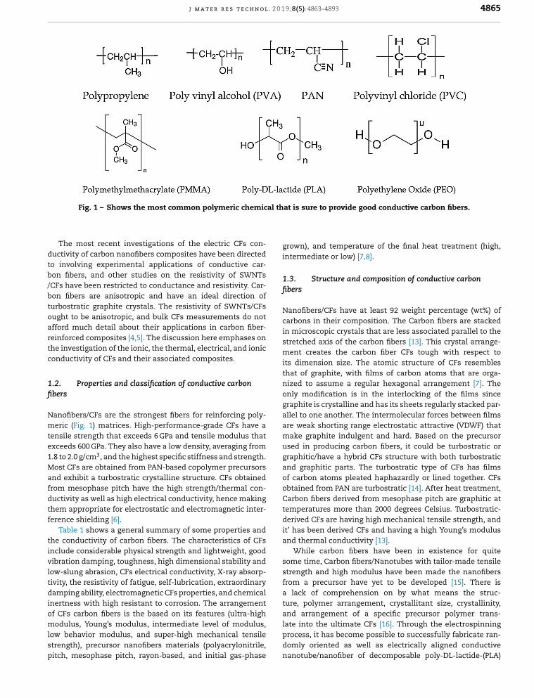
Fig. 1 – Shows the most common polymeric chemical
The most recent investigations of the electric CFs con-uctivity of carbon nanofibers composites have been directedo involving experimental applications of conductive car-on fibers, and other studies on the resistivity of SWNTsCFs have been restricted to conductance and resistivity. Car-on fibers are anisotropic and have an ideal direction ofurbostratic graphite crystals. The resistivity of SWNTs/CFsught to be anisotropic, and bulk CFs measurements do notfford much detail about their applications in carbon fiber-einforced composites [4,5]. The discussion here emphases onhe investigation of the ionic, the thermal, electrical, and ioniconductivity of CFs and their associated composites.
.2. Properties and classification of conductive carbonbers
anofibers/CFs are the strongest fibers for reinforcing poly-eric (Fig. 1) matrices. High-performance-grade CFs have a
ensile strength that exceeds 6 GPa and tensile modulus thatxceeds 600 GPa. They also have a low density, averaging from.8 to 2.0 g/cm3, and the highest specific stiffness and strength.ost CFs are obtained from PAN-based copolymer precursors
nd exhibit a turbostratic crystalline structure. CFs obtainedrom mesophase pitch have the high strength/thermal con-uctivity as well as high electrical conductivity, hence makinghem appropriate for electrostatic and electromagnetic inter-erence shielding [6].
Table 1 shows a general summary of some properties andhe conductivity of carbon fibers. The characteristics of CFsnclude considerable physical strength and lightweight, goodibration damping, toughness, high dimensional stability andow-slung abrasion, CFs electrical conductivity, X-ray absorp-ivity, the resistivity of fatigue, self-lubrication, extraordinaryamping ability, electromagnetic CFs properties, and chemical
nertness with high resistant to corrosion. The arrangementf CFs carbon fibers is the based on its features (ultra-highodulus, Young’s modulus, intermediate level of modulus,
ow behavior modulus, and super-high mechanical tensiletrength), precursor nanofibers materials (polyacrylonitrile,itch, mesophase pitch, rayon-based, and initial gas-phase
prodona
is sure to provide good conductive carbon fibers.
wn), and temperature of the final heat treatment (high,ermediate or low) [7,8].
. Structure and composition of conductive carboners
nofibers/CFs have at least 92 weight percentage (wt%) ofrbons in their composition. The Carbon fibers are stackedmicroscopic crystals that are less associated parallel to theetched axis of the carbon fibers [13]. This crystal arrange-nt creates the carbon fiber CFs tough with respect to
dimension size. The atomic structure of CFs resemblesat of graphite, with films of carbon atoms that are orga-ed to assume a regular hexagonal arrangement [7]. Thely modification is in the interlocking of the films sincephite is crystalline and has its sheets regularly stacked par-
el to one another. The intermolecular forces between films weak shorting range electrostatic attractive (VDWF) thatke graphite indulgent and hard. Based on the precursor
ed in producing carbon fibers, it could be turbostratic orphitic/have a hybrid CFs structure with both turbostratic
d graphitic parts. The turbostratic type of CFs has filmscarbon atoms pleated haphazardly or lined together. CFstained from PAN are turbostratic [14]. After heat treatment,rbon fibers derived from mesophase pitch are graphitic at
peratures more than 2000 degrees Celsius. Turbostratic-rived CFs are having high mechanical tensile strength, andhas been derived CFs and having a high Young’s modulusd thermal conductivity [13].While carbon fibers have been in existence for quite
me time, Carbon fibers/Nanotubes with tailor-made tensileength and high modulus have been made the nanofibersm a precursor have yet to be developed [15]. There islack of comprehension on by what means the struc-e, polymer arrangement, crystallitant size, crystallinity,d arrangement of a specific precursor polymer trans-
cess, it has become possible to successfully fabricate ran-mly oriented as well as electrically aligned conductivenotube/nanofiber of decomposable poly-DL-lactide-(PLA)
4866 j m a t e r r e s t e c h n o l . 2 0 1 9;8(5):4863–4893
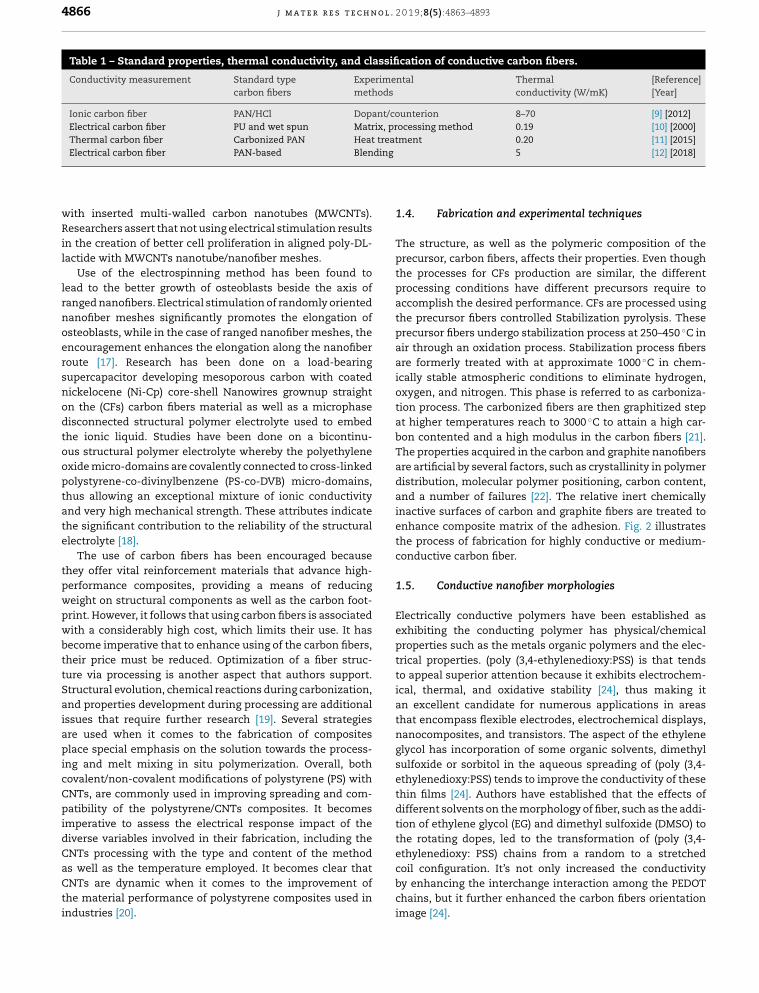
Table 1 – Standard properties, thermal conductivity, and classification of conductive carbon fibers.
Conductivity measurement Standard typecarbon fibers
Experimentalmethods
Thermalconductivity (W/mK)
[Reference][Year]
Ionic carbon fiber PAN/HCl Dopant/counterion 8–70 [9] [2012], proceatmng
wRil
lrnoersnodtooptate
tpwpwbttSaiapicCpidCaCti
1.4
Thprthpracthprairareicaoxtioat
boTharedisaninaenthco
1.5
Eleexprtrito
icaanthnaglysueththdiftiothethylenedioxy: PSS) chains from a random to a stretched
Electrical carbon fiber PU and wet spun MatrixThermal carbon fiber Carbonized PAN Heat trElectrical carbon fiber PAN-based Blendi
ith inserted multi-walled carbon nanotubes (MWCNTs).esearchers assert that not using electrical stimulation results
n the creation of better cell proliferation in aligned poly-DL-actide with MWCNTs nanotube/nanofiber meshes.
Use of the electrospinning method has been found toead to the better growth of osteoblasts beside the axis ofanged nanofibers. Electrical stimulation of randomly orientedanofiber meshes significantly promotes the elongation ofsteoblasts, while in the case of ranged nanofiber meshes, thencouragement enhances the elongation along the nanofiberoute [17]. Research has been done on a load-bearingupercapacitor developing mesoporous carbon with coatedickelocene (Ni-Cp) core-shell Nanowires grownup straightn the (CFs) carbon fibers material as well as a microphaseisconnected structural polymer electrolyte used to embedhe ionic liquid. Studies have been done on a bicontinu-us structural polymer electrolyte whereby the polyethylenexide micro-domains are covalently connected to cross-linkedolystyrene-co-divinylbenzene (PS-co-DVB) micro-domains,hus allowing an exceptional mixture of ionic conductivitynd very high mechanical strength. These attributes indicatehe significant contribution to the reliability of the structurallectrolyte [18].
The use of carbon fibers has been encouraged becausehey offer vital reinforcement materials that advance high-erformance composites, providing a means of reducingeight on structural components as well as the carbon foot-rint. However, it follows that using carbon fibers is associatedith a considerably high cost, which limits their use. It hasecome imperative that to enhance using of the carbon fibers,heir price must be reduced. Optimization of a fiber struc-ure via processing is another aspect that authors support.tructural evolution, chemical reactions during carbonization,nd properties development during processing are additionalssues that require further research [19]. Several strategiesre used when it comes to the fabrication of compositeslace special emphasis on the solution towards the process-
ng and melt mixing in situ polymerization. Overall, bothovalent/non-covalent modifications of polystyrene (PS) withNTs, are commonly used in improving spreading and com-atibility of the polystyrene/CNTs composites. It becomes
mperative to assess the electrical response impact of theiverse variables involved in their fabrication, including theNTs processing with the type and content of the methods well as the temperature employed. It becomes clear that
NTs are dynamic when it comes to the improvement ofhe material performance of polystyrene composites used inndustries [20].
cobychim
essing method 0.19 [10] [2000]ent 0.20 [11] [2015]
5 [12] [2018]
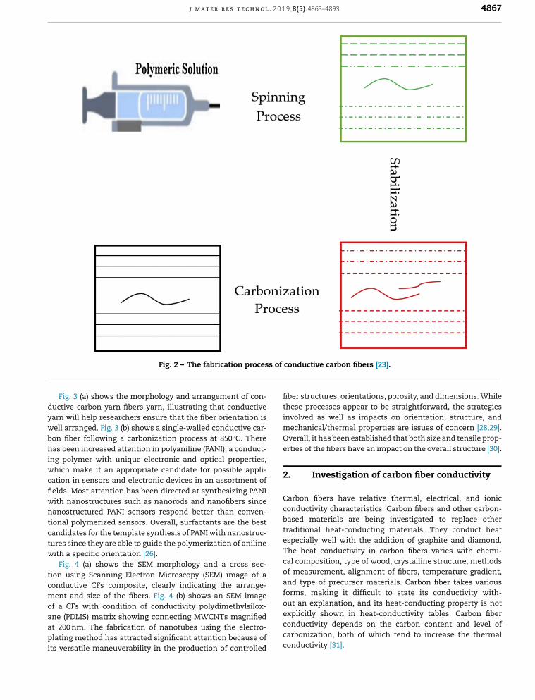
. Fabrication and experimental techniques
e structure, as well as the polymeric composition of theecursor, carbon fibers, affects their properties. Even thoughe processes for CFs production are similar, the differentocessing conditions have different precursors require tocomplish the desired performance. CFs are processed usinge precursor fibers controlled Stabilization pyrolysis. Theseecursor fibers undergo stabilization process at 250–450 ◦C in
through an oxidation process. Stabilization process fibers formerly treated with at approximate 1000 ◦C in chem-lly stable atmospheric conditions to eliminate hydrogen,ygen, and nitrogen. This phase is referred to as carboniza-n process. The carbonized fibers are then graphitized stephigher temperatures reach to 3000 ◦C to attain a high car-n contented and a high modulus in the carbon fibers [21].e properties acquired in the carbon and graphite nanofibers
artificial by several factors, such as crystallinity in polymertribution, molecular polymer positioning, carbon content,d a number of failures [22]. The relative inert chemicallyctive surfaces of carbon and graphite fibers are treated to
hance composite matrix of the adhesion. Fig. 2 illustratese process of fabrication for highly conductive or medium-nductive carbon fiber.
. Conductive nanofiber morphologies
ctrically conductive polymers have been established ashibiting the conducting polymer has physical/chemicaloperties such as the metals organic polymers and the elec-cal properties. (poly (3,4-ethylenedioxy:PSS) is that tendsappeal superior attention because it exhibits electrochem-l, thermal, and oxidative stability [24], thus making it
excellent candidate for numerous applications in areasat encompass flexible electrodes, electrochemical displays,nocomposites, and transistors. The aspect of the ethylenecol has incorporation of some organic solvents, dimethyl
lfoxide or sorbitol in the aqueous spreading of (poly (3,4-ylenedioxy:PSS) tends to improve the conductivity of these
in films [24]. Authors have established that the effects offerent solvents on the morphology of fiber, such as the addi-n of ethylene glycol (EG) and dimethyl sulfoxide (DMSO) toe rotating dopes, led to the transformation of (poly (3,4-
il configuration. It’s not only increased the conductivity enhancing the interchange interaction among the PEDOTains, but it further enhanced the carbon fibers orientationage [24].
j m a t e r r e s t e c h n o l . 2 0 1 9;8(5):4863–4893 4867
of co
dywbhiwcfiwntctw
tcmoaapi
fibthinvmeOvert
2.
CacobatraesThcaof
anforout an explanation, and its heat-conducting property is not
Fig. 2 – The fabrication process
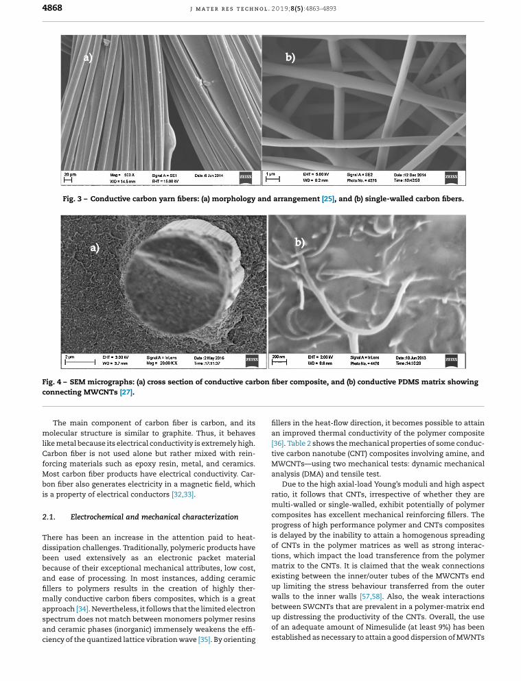
Fig. 3 (a) shows the morphology and arrangement of con-uctive carbon yarn fibers yarn, illustrating that conductivearn will help researchers ensure that the fiber orientation isell arranged. Fig. 3 (b) shows a single-walled conductive car-on fiber following a carbonization process at 850◦C. Thereas been increased attention in polyaniline (PANI), a conduct-
ng polymer with unique electronic and optical properties,hich make it an appropriate candidate for possible appli-
ation in sensors and electronic devices in an assortment ofelds. Most attention has been directed at synthesizing PANIith nanostructures such as nanorods and nanofibers sinceanostructured PANI sensors respond better than conven-
ional polymerized sensors. Overall, surfactants are the bestandidates for the template synthesis of PANI with nanostruc-ures since they are able to guide the polymerization of anilineith a specific orientation [26].
Fig. 4 (a) shows the SEM morphology and a cross sec-ion using Scanning Electron Microscopy (SEM) image of aonductive CFs composite, clearly indicating the arrange-ent and size of the fibers. Fig. 4 (b) shows an SEM image
f a CFs with condition of conductivity polydimethylsilox-
ne (PDMS) matrix showing connecting MWCNTs magnifiedt 200 nm. The fabrication of nanotubes using the electro-lating method has attracted significant attention because ofts versatile maneuverability in the production of controlled
excocaco
nductive carbon fibers [23].
er structures, orientations, porosity, and dimensions. Whileese processes appear to be straightforward, the strategiesolved as well as impacts on orientation, structure, andchanical/thermal properties are issues of concern [28,29].erall, it has been established that both size and tensile prop-ies of the fibers have an impact on the overall structure [30].
Investigation of carbon fiber conductivity
rbon fibers have relative thermal, electrical, and ionicnductivity characteristics. Carbon fibers and other carbon-sed materials are being investigated to replace otherditional heat-conducting materials. They conduct heat
pecially well with the addition of graphite and diamond.e heat conductivity in carbon fibers varies with chemi-l composition, type of wood, crystalline structure, methodsmeasurement, alignment of fibers, temperature gradient,d type of precursor materials. Carbon fiber takes variousms, making it difficult to state its conductivity with-
plicitly shown in heat-conductivity tables. Carbon fibernductivity depends on the carbon content and level ofrbonization, both of which tend to increase the thermalnductivity [31].
4868 j m a t e r r e s t e c h n o l . 2 0 1 9;8(5):4863–4893
Fig. 3 – Conductive carbon yarn fibers: (a) morphology and arrangement [25], and (b) single-walled carbon fibers.
F n fibc
mlCfMbi
2
Tdbbafimasac
fillan[36tivMWan
ratmucopris
of
tiomexup
ig. 4 – SEM micrographs: (a) cross section of conductive carboonnecting MWCNTs [27].
The main component of carbon fiber is carbon, and itsolecular structure is similar to graphite. Thus, it behaves
ike metal because its electrical conductivity is extremely high.arbon fiber is not used alone but rather mixed with rein-
orcing materials such as epoxy resin, metal, and ceramics.ost carbon fiber products have electrical conductivity. Car-
on fiber also generates electricity in a magnetic field, whichs a property of electrical conductors [32,33].
.1. Electrochemical and mechanical characterization
here has been an increase in the attention paid to heat-issipation challenges. Traditionally, polymeric products haveeen used extensively as an electronic packet materialecause of their exceptional mechanical attributes, low cost,nd ease of processing. In most instances, adding ceramicllers to polymers results in the creation of highly ther-
ally conductive carbon fibers composites, which is a greatpproach [34]. Nevertheless, it follows that the limited electronpectrum does not match between monomers polymer resinsnd ceramic phases (inorganic) immensely weakens the effi-iency of the quantized lattice vibration wave [35]. By orienting
wabeupof
es
er composite, and (b) conductive PDMS matrix showing
ers in the heat-flow direction, it becomes possible to attain improved thermal conductivity of the polymer composite]. Table 2 shows the mechanical properties of some conduc-e carbon nanotube (CNT) composites involving amine, and
CNTs—using two mechanical tests: dynamic mechanicalalysis (DMA) and tensile test.Due to the high axial-load Young’s moduli and high aspectio, it follows that CNTs, irrespective of whether they arelti-walled or single-walled, exhibit potentially of polymer
mposites has excellent mechanical reinforcing fillers. Theogress of high performance polymer and CNTs compositesdelayed by the inability to attain a homogenous spreadingCNTs in the polymer matrices as well as strong interac-ns, which impact the load transference from the polymer
atrix to the CNTs. It is claimed that the weak connectionsisting between the inner/outer tubes of the MWCNTs end
limiting the stress behaviour transferred from the outer
lls to the inner walls [57,58]. Also, the weak interactionstween SWCNTs that are prevalent in a polymer-matrix end distressing the productivity of the CNTs. Overall, the usean adequate amount of Nimesulide (at least 9%) has beentablished as necessary to attain a good dispersion of MWNTs
j m a t e r r e s t e c h n o l . 2 0 1 9;8(5):4863–4893 4869
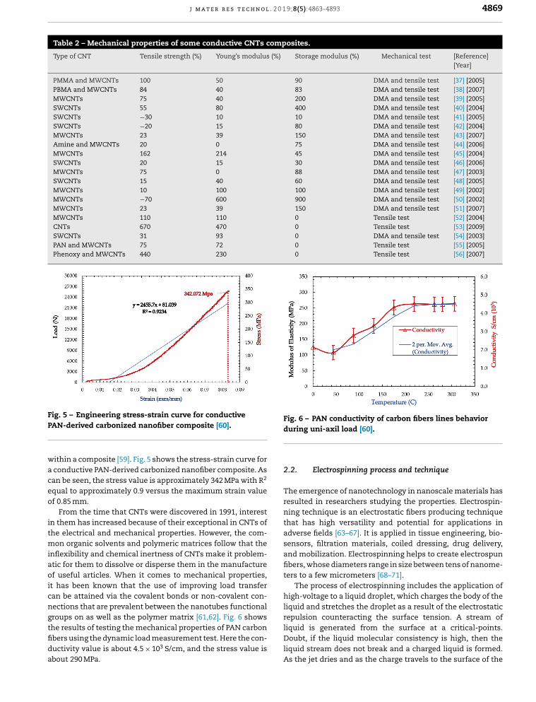
Table 2 – Mechanical properties of some conductive CNTs composites.
Type of CNT Tensile strength (%) Young’s modulus (%) Storage modulus (%) Mechanical test [Reference][Year]
PMMA and MWCNTs 100 50 90 DMA and tensile test [37] [2005]PBMA and MWCNTs 84 40 83 DMA and tensile test [38] [2007]MWCNTs 75 40 200 DMA and tensile test [39] [2005]SWCNTs 55 80 400 DMA and tensile test [40] [2004]SWCNTs −30 10 10 DMA and tensile test [41] [2005]SWCNTs −20 15 80 DMA and tensile test [42] [2004]MWCNTs 23 39 150 DMA and tensile test [43] [2007]Amine and MWCNTs 20 0 75 DMA and tensile test [44] [2006]MWCNTs 162 214 45 DMA and tensile test [45] [2004]SWCNTs 20 15 30 DMA and tensile test [46] [2006]MWCNTs 75 0 88 DMA and tensile test [47] [2003]SWCNTs 15 40 60 DMA and tensile test [48] [2005]MWCNTs 10 100 100 DMA and tensile test [49] [2002]MWCNTs −70 600 900 DMA and tensile test [50] [2002]MWCNTs 23 39 150 DMA and tensile test [51] [2007]MWCNTs 110 110 0 Tensile test [52] [2004]CNTs 670 470 0 Tensile test [53] [2009]SWCNTs 31 93 0 DMA and tensile test [54] [2003]PAN and MWCNTs 75 72 0 Tensile test [55] [2005]Phenoxy and MWCNTs 440 230 0 Tensile test [56] [2007]
FP
waceo
itmiaoicngtfida
Figdu
2.2
Thresninthadseanfibter
higliq
ig. 5 – Engineering stress-strain curve for conductiveAN-derived carbonized nanofiber composite [60].
ithin a composite [59]. Fig. 5 shows the stress-strain curve for conductive PAN-derived carbonized nanofiber composite. Asan be seen, the stress value is approximately 342 MPa with R2
qual to approximately 0.9 versus the maximum strain valuef 0.85 mm.
From the time that CNTs were discovered in 1991, interestn them has increased because of their exceptional in CNTs ofhe electrical and mechanical properties. However, the com-
on organic solvents and polymeric matrices follow that thenflexibility and chemical inertness of CNTs make it problem-tic for them to dissolve or disperse them in the manufacturef useful articles. When it comes to mechanical properties,
t has been known that the use of improving load transferan be attained via the covalent bonds or non-covalent con-ections that are prevalent between the nanotubes functional
roups on as well as the polymer matrix [61,62]. Fig. 6 showshe results of testing the mechanical properties of PAN carbonbers using the dynamic load measurement test. Here the con-uctivity value is about 4.5 × 10³ S/cm, and the stress value isbout 290 MPa.repliqDoliqAs
. 6 – PAN conductivity of carbon fibers lines behaviorring uni-axil load [60].
. Electrospinning process and technique
e emergence of nanotechnology in nanoscale materials hasulted in researchers studying the properties. Electrospin-g technique is an electrostatic fibers producing technique
at has high versatility and potential for applications inverse fields [63–67]. It is applied in tissue engineering, bio-nsors, filtration materials, coiled dressing, drug delivery,d mobilization. Electrospinning helps to create electrospuners, whose diameters range in size between tens of nanome-s to a few micrometers [68–71].The process of electrospinning includes the application ofh-voltage to a liquid droplet, which charges the body of the
uid and stretches the droplet as a result of the electrostaticulsion counteracting the surface tension. A stream of
uid is generated from the surface at a critical-points.ubt, if the liquid molecular consistency is high, then theuid stream does not break and a charged liquid is formed.
the jet dries and as the charge travels to the surface of the
4870 j m a t e r r e s t e c h n o l . 2 0 1 9;8(5):4863–4893
Fp
fieuttn
cficleci
lsoimmpptaahahe
2
TCdchcatapnm
Figco
wecoeledu
thhigamantuof
thratcolarfou
2.4
NaducoThcoclehapoelecestadu
eleairticanrei
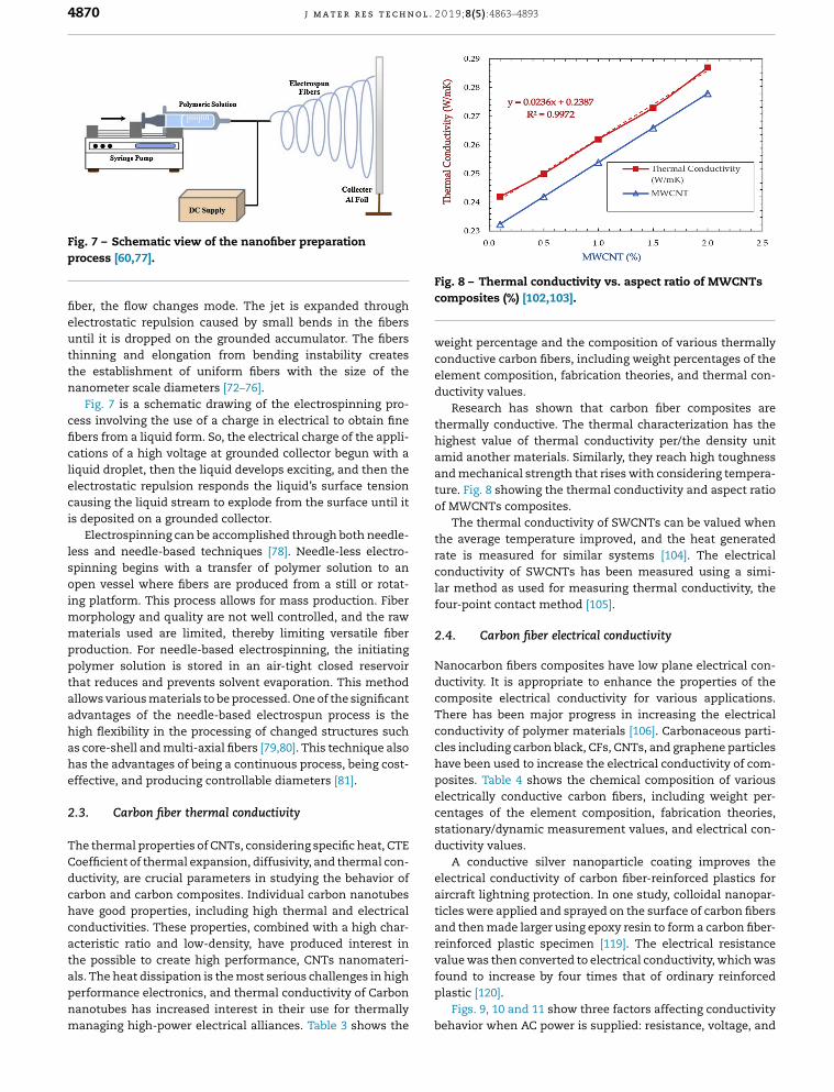
ig. 7 – Schematic view of the nanofiber preparationrocess [60,77].
ber, the flow changes mode. The jet is expanded throughlectrostatic repulsion caused by small bends in the fibersntil it is dropped on the grounded accumulator. The fibershinning and elongation from bending instability createshe establishment of uniform fibers with the size of theanometer scale diameters [72–76].
Fig. 7 is a schematic drawing of the electrospinning pro-ess involving the use of a charge in electrical to obtain finebers from a liquid form. So, the electrical charge of the appli-ations of a high voltage at grounded collector begun with aiquid droplet, then the liquid develops exciting, and then thelectrostatic repulsion responds the liquid’s surface tensionausing the liquid stream to explode from the surface until its deposited on a grounded collector.
Electrospinning can be accomplished through both needle-ess and needle-based techniques [78]. Needle-less electro-pinning begins with a transfer of polymer solution to anpen vessel where fibers are produced from a still or rotat-
ng platform. This process allows for mass production. Fiberorphology and quality are not well controlled, and the rawaterials used are limited, thereby limiting versatile fiber
roduction. For needle-based electrospinning, the initiatingolymer solution is stored in an air-tight closed reservoirhat reduces and prevents solvent evaporation. This methodllows various materials to be processed. One of the significantdvantages of the needle-based electrospun process is theigh flexibility in the processing of changed structures suchs core-shell and multi-axial fibers [79,80]. This technique alsoas the advantages of being a continuous process, being cost-ffective, and producing controllable diameters [81].
.3. Carbon fiber thermal conductivity
he thermal properties of CNTs, considering specific heat, CTEoefficient of thermal expansion, diffusivity, and thermal con-uctivity, are crucial parameters in studying the behavior ofarbon and carbon composites. Individual carbon nanotubesave good properties, including high thermal and electricalonductivities. These properties, combined with a high char-cteristic ratio and low-density, have produced interest in
he possible to create high performance, CNTs nanomateri-ls. The heat dissipation is the most serious challenges in higherformance electronics, and thermal conductivity of Carbonanotubes has increased interest in their use for thermallyanaging high-power electrical alliances. Table 3 shows thevafoupla
be
. 8 – Thermal conductivity vs. aspect ratio of MWCNTsmposites (%) [102,103].
ight percentage and the composition of various thermallynductive carbon fibers, including weight percentages of thement composition, fabrication theories, and thermal con-ctivity values.Research has shown that carbon fiber composites are
ermally conductive. The thermal characterization has thehest value of thermal conductivity per/the density unitid another materials. Similarly, they reach high toughness
d mechanical strength that rises with considering tempera-re. Fig. 8 showing the thermal conductivity and aspect ratioMWCNTs composites.The thermal conductivity of SWCNTs can be valued when
e average temperature improved, and the heat generatede is measured for similar systems [104]. The electricalnductivity of SWCNTs has been measured using a simi-
method as used for measuring thermal conductivity, ther-point contact method [105].
. Carbon fiber electrical conductivity
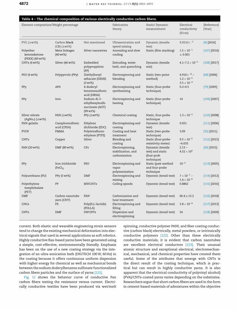
nocarbon fibers composites have low plane electrical con-ctivity. It is appropriate to enhance the properties of themposite electrical conductivity for various applications.ere has been major progress in increasing the electricalnductivity of polymer materials [106]. Carbonaceous parti-s including carbon black, CFs, CNTs, and graphene particlesve been used to increase the electrical conductivity of com-sites. Table 4 shows the chemical composition of variousctrically conductive carbon fibers, including weight per-
ntages of the element composition, fabrication theories,tionary/dynamic measurement values, and electrical con-ctivity values.A conductive silver nanoparticle coating improves thectrical conductivity of carbon fiber-reinforced plastics forcraft lightning protection. In one study, colloidal nanopar-les were applied and sprayed on the surface of carbon fibersd then made larger using epoxy resin to form a carbon fiber-nforced plastic specimen [119]. The electrical resistancelue was then converted to electrical conductivity, which was
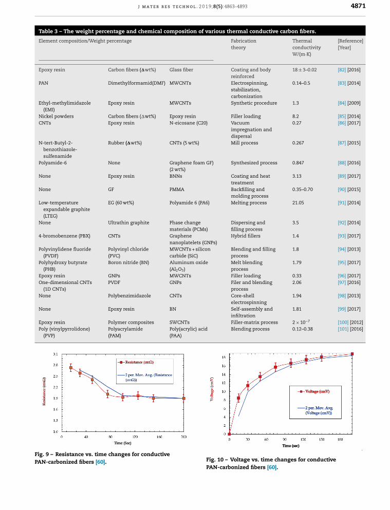
nd to increase by four times that of ordinary reinforcedstic [120].Figs. 9, 10 and 11 show three factors affecting conductivityhavior when AC power is supplied: resistance, voltage, and
j m a t e r r e s t e c h n o l . 2 0 1 9;8(5):4863–4893 4871
Table 3 – The weight percentage and chemical composition of various thermal conductive carbon fibers.
Element composition/Weight percentage Fabricationtheory
ThermalconductivityW/(m·K)
[Reference][Year]
Epoxy resin Carbon fibers (�wt%) Glass fiber Coating and bodyreinforced
18 ± 3–0.02 [82] [2016]
PAN Dimethylformamid(DMF) MWCNTs Electrospinning,stabilization,carbonization
0.14–0.5 [83] [2014]
Ethyl-methylimidazole(EMI)
Epoxy resin MWCNTs Synthetic procedure 1.3 [84] [2009]
Nickel powders Carbon fibers (�wt%) Epoxy resin Filler loading 8.2 [85] [2014]CNTs Epoxy resin N-eicosane (C20) Vacuum
impregnation anddispersal
0.27 [86] [2017]
N-tert-Butyl-2-benzothiazole-sulfenamide
Rubber (�wt%) CNTs (5 wt%) Mill process 0.267 [87] [2015]
Polyamide-6 None Graphene foam GF)(2 wt%)
Synthesized process 0.847 [88] [2016]
None Epoxy resin BNNs Coating and heattreatment
3.13 [89] [2017]
None GF PMMA Backfilling andmolding process
0.35–0.70 [90] [2015]
Low-temperatureexpandable graphite(LTEG)
EG (60 wt%) Polyamide 6 (PA6) Melting process 21.05 [91] [2014]
None Ultrathin graphite Phase changematerials (PCMs)
Dispersing andfilling process
3.5 [92] [2014]
4-bromobenzene (PBX) CNTs Graphenenanoplatelets (GNPs)
Hybrid fillers 1.4 [93] [2017]
Polyvinylidene fluoride(PVDF)
Polyvinyl chloride(PVC)
MWCNTs + siliconcarbide (SiC)
Blending and fillingprocess
1.8 [94] [2013]
Polyhydroxy butyrate(PHB)
Boron nitride (BN) Aluminum oxide(Al2O3)
Melt blendingprocess
1.79 [95] [2017]
Epoxy resin GNPs MWCNTs Filler loading 0.33 [96] [2017]One-dimensional CNTs
(1D CNTs)PVDF GNPs Filer and blending
process2.06 [97] [2016]
None Polybenzimidazole CNTs Core-shellelectrospinning
1.94 [98] [2013]
None Epoxy resin BN Self-assembly andinfiltration
1.81 [99] [2017]
Epoxy resin Polymer composites SWCNTs Filler-matrix process 2 × 10⁻⁷ [100] [2012]Poly (vinylpyrrolidone)
(PVP)Polyacrylamide(PAM)
Poly(acrylic) acid(PAA)
Blending process 0.12–0.38 [101] [2016]
FP
ig. 9 – Resistance vs. time changes for conductiveAN-carbonized fibers [60]. Fig. 10 – Voltage vs. time changes for conductivePAN-carbonized fibers [60].
4872 j m a t e r r e s t e c h n o l . 2 0 1 9;8(5):4863–4893
Table 4 – The chemical composition of various electrically conductive carbon fibers.
Element composition/Weight percentage Fabricationtheory
Static/ Dynamicmeasurement
Electricalconductivity(S/cm)
[Reference][Year]
PVC (�wt%) Carbon black(CB) (�wt%)
Not mentioned Ultrasonication andspeed mixing
Dynamic (tensiletest)
9.9210×−3 [4] [2016]
Polyetherketoneketone(PEKK) (60 wt%)
Meta linkages(40 wt%)
Silver nanowires Annealing and slowcooling
Static (film stacking) 1.5 × 10⁻¹
± 0.001[107] [2016]
CNTs (4 wt%) Silver (46 wt%) Embeddedpolypropylene(PP)
Extruding, waterbath, and quenching
Dynamic (tensiletest)
4.1–7.2 × 10⁻² [108] [2017]
PEO (4 wt%) Polypyrrole (PPy) Diethylhexylsebacate (DEHS)(3 wt%)
Electrospinning andblending
Static (two-pointmethod)
4.910×−8 –1.2 × 10⁻⁵
3.5 × 10⁻⁴
[68] [2006]
PPy APS 4-dodecylbenzenesulfonicacid (DBSA)
Electrospinning andsynthesizing
Static (four-probetechnique)
0.2–0.5 [79] [2005]
PPy Iron Sodium di-2-ethylhexylsulfosuccinate (AOT)(99 wt%)
Electrospinning andheating
Static (four-probetechnique)
14 [109] [2007]
Silver nitrate(AgNo3) (�wt%)
PAN (�wt%) PPy (�wt%) Chemical coating Static, four-probetechnique
1.3 × 10⁻³ [110] [2008]
PAN-gelatin Camphorsulfonicacid (CPSA)
Ethylenedichloride (EDC)
Electrospinning andcoating
Dynamic (tensiletest)
0.021 [111] [2006]
PVDF PMMA Polytetrafluoroethylene (PTFE)
Coating and heattreatment
Static (two-probetechnique)
3.09 [32] [2011]
CNTs Copper Silver Blending andcoating
Static (four-proberesistivity meter)
9.5 × 10⁻⁵
–6.633[112] [2015]
PAN (20 wt%) DMF (80 wt%) CFs Electrospinning,stabilization, andcarbonization
Dynamic (tensiletest) and static(four-probtechnique)
2.13 –4.52 × 10³
[60] [2015]
PPy Iron trichloride(FeCl3)
PEO Electrospinning andvaporpolymerization
Static (paw methodand four-probetechnique
10−3 [113] [2005]
Polyurethane (PU) PPy (5 wt%) DMF Electrospinning andmixing
Dyanmic (tensil test) 7 × 10⁻⁷ –1.4 × 10⁻⁶
[114] [2012]
Polyethyleneterephthalate(PET)
PP MWCNTs Coiling speeds Dyanmic (tensil test) 0.8862 [115] [2016]
DMF Carbon nanotubeyarn (CNY)
PAN Carbonization andheat treatment
Dyanmic (tensil test) 66.4 ± 13.2 [116] [2018]
rospin
rsionospin
cttHahgtwbc
cc
sptivcocoareatoicausthtic
CNCs PS Poly(D,L-lactide)(PDLLA)
Electfilling
CNTs DMF SWCNTs Dispeelectr
urrent. Both elastic and wearable engineering strain sensorsend to change the existing mechanical deformation into elec-rical signals that used in several applications as soft robotics.ighly conductive flax-based yarns have been generated using
simple, cost-effective, environmentally friendly. Emphasisas been on the use of a new coating strategy via the inte-ration of an ultra-sonication bath (DIGTECH 100 W, 60 Hz) inhe coating because it offers continuous uniform dispersionith higher energy for chemical as well as mechanical bondsetween the sodium dodecylbenzene sulfonate functionalized
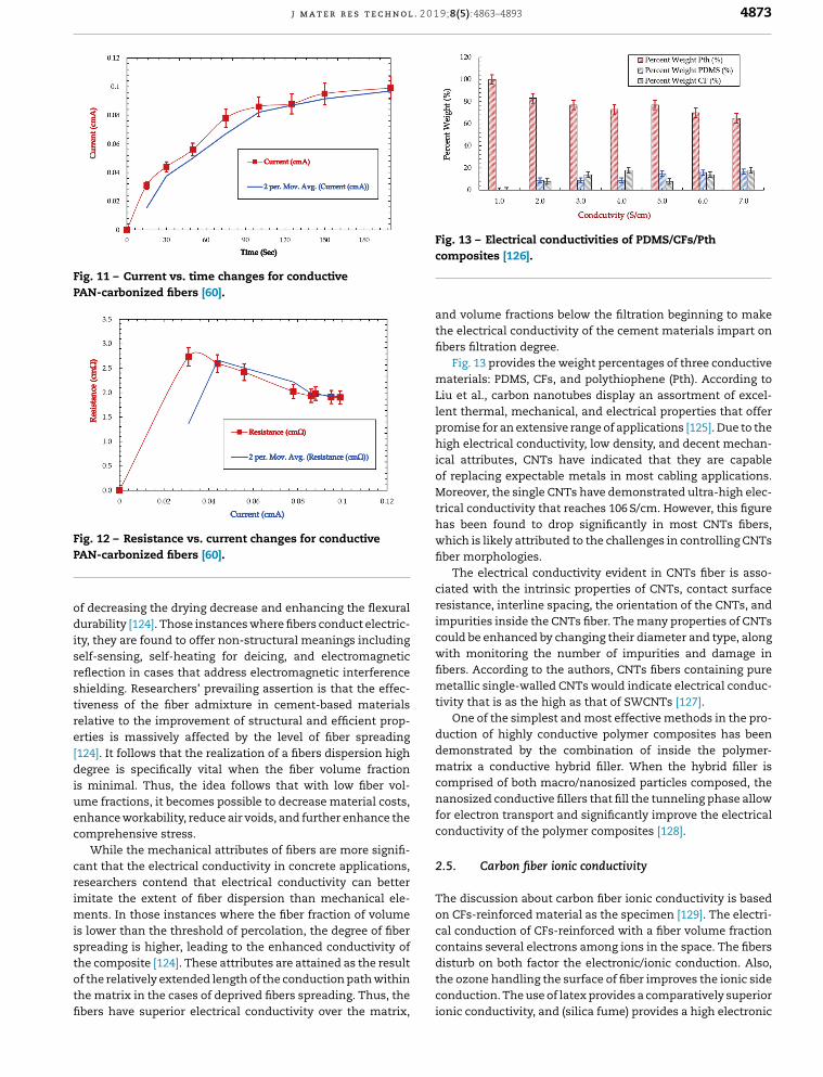
arbon fibers particles and the surface of yarns [121].Fig. 12 shows the behavior curve of conductive Panarbon fibers testing the resistance versus current. Electri-ally conductive textiles have been produced via wet/melt
ap(PVRein
ning and Dyanmic (tensil test) 5.8 × 10⁻⁴ [117] [2013]
andning
Dyanmic (tensil test) 54 [118] [2009]
inning, conductive polymer PANI, and fiber coating conduc-e (carbon black) electrically, metal powders, or intrinsicallynductive polymers [122]. Other than these electricallynductive materials, it is evident that carbon nanotubes
excellent electrical conductors [123]. Their unusualmic structure and exceptional electrical, electromechan-l, mechanical, and chemical properties have created themeful. Some of the attributes that emerge with CNTs ise direct result of the coating technique, which is prac-al but can result in highly conductive yarns. It is also
parent that the electrical conductivity of polyvinyl alcohol)A)/CNTs-coated yarns varies depending on the substrates.searchers argue that short carbon fibers are used in the formcement-based materials of admixtures within the objective
j m a t e r r e s t e c h n o l . 2 0 1 9;8(5):4863–4893 4873
Fig. 11 – Current vs. time changes for conductivePAN-carbonized fibers [60].
FP
odisrstre[diuec
crimistotfi
Figco
anthfib
maLiulenprohigicaof
Motrihawhfib
ciaresimcowifibmetiv
dudemaconaforco
2.5
Thoncaco
ig. 12 – Resistance vs. current changes for conductiveAN-carbonized fibers [60].
f decreasing the drying decrease and enhancing the flexuralurability [124]. Those instances where fibers conduct electric-
ty, they are found to offer non-structural meanings includingelf-sensing, self-heating for deicing, and electromagneticeflection in cases that address electromagnetic interferencehielding. Researchers’ prevailing assertion is that the effec-iveness of the fiber admixture in cement-based materialselative to the improvement of structural and efficient prop-rties is massively affected by the level of fiber spreading124]. It follows that the realization of a fibers dispersion highegree is specifically vital when the fiber volume fraction
s minimal. Thus, the idea follows that with low fiber vol-me fractions, it becomes possible to decrease material costs,nhance workability, reduce air voids, and further enhance theomprehensive stress.
While the mechanical attributes of fibers are more signifi-ant that the electrical conductivity in concrete applications,esearchers contend that electrical conductivity can bettermitate the extent of fiber dispersion than mechanical ele-
ents. In those instances where the fiber fraction of volumes lower than the threshold of percolation, the degree of fiberpreading is higher, leading to the enhanced conductivity of
he composite [124]. These attributes are attained as the resultf the relatively extended length of the conduction path withinhe matrix in the cases of deprived fibers spreading. Thus, thebers have superior electrical conductivity over the matrix,disthcoion
. 13 – Electrical conductivities of PDMS/CFs/Pthmposites [126].
d volume fractions below the filtration beginning to makee electrical conductivity of the cement materials impart oners filtration degree.Fig. 13 provides the weight percentages of three conductiveterials: PDMS, CFs, and polythiophene (Pth). According to
et al., carbon nanotubes display an assortment of excel-t thermal, mechanical, and electrical properties that offermise for an extensive range of applications [125]. Due to theh electrical conductivity, low density, and decent mechan-l attributes, CNTs have indicated that they are capablereplacing expectable metals in most cabling applications.reover, the single CNTs have demonstrated ultra-high elec-
cal conductivity that reaches 106 S/cm. However, this figures been found to drop significantly in most CNTs fibers,ich is likely attributed to the challenges in controlling CNTs
er morphologies.The electrical conductivity evident in CNTs fiber is asso-ted with the intrinsic properties of CNTs, contact surfaceistance, interline spacing, the orientation of the CNTs, andpurities inside the CNTs fiber. The many properties of CNTsuld be enhanced by changing their diameter and type, alongth monitoring the number of impurities and damage iners. According to the authors, CNTs fibers containing puretallic single-walled CNTs would indicate electrical conduc-
ity that is as the high as that of SWCNTs [127].One of the simplest and most effective methods in the pro-ction of highly conductive polymer composites has beenmonstrated by the combination of inside the polymer-trix a conductive hybrid filler. When the hybrid filler is
mprised of both macro/nanosized particles composed, thenosized conductive fillers that fill the tunneling phase allow
electron transport and significantly improve the electricalnductivity of the polymer composites [128].
. Carbon fiber ionic conductivity
e discussion about carbon fiber ionic conductivity is based CFs-reinforced material as the specimen [129]. The electri-l conduction of CFs-reinforced with a fiber volume fractionntains several electrons among ions in the space. The fibers
turb on both factor the electronic/ionic conduction. Also,e ozone handling the surface of fiber improves the ionic sidenduction. The use of latex provides a comparatively superioric conductivity, and (silica fume) provides a high electronic
4874 j m a t e r r e s t e c h n o l . 2 0 1 9;8(5):4863–4893
y In
coen
cp
�
WfitewTdattfpwt
itCtioi
ais
mtrianof
of
stuthwhththmextivco
2.6
SuprpepitbeCFonof
steacreshybechag
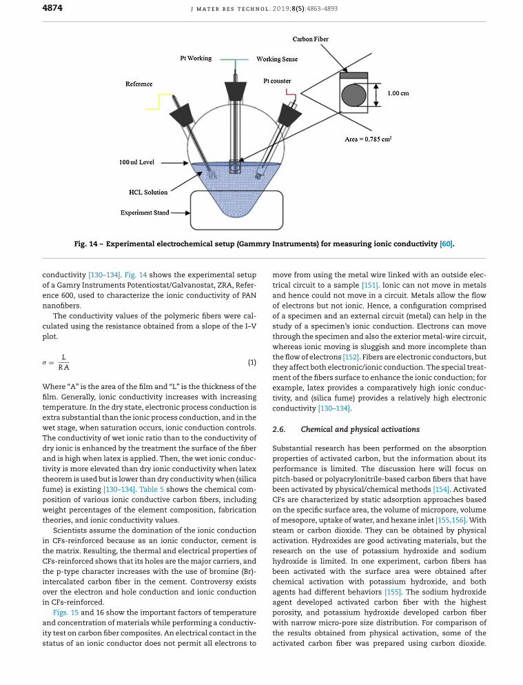
Fig. 14 – Experimental electrochemical setup (Gammr
onductivity [130–134]. Fig. 14 shows the experimental setupf a Gamry Instruments Potentiostat/Galvanostat, ZRA, Refer-nce 600, used to characterize the ionic conductivity of PANanofibers.
The conductivity values of the polymeric fibers were cal-ulated using the resistance obtained from a slope of the I–Vlot.
= L
R A(1)
here “A” is the area of the film and “L” is the thickness of thelm. Generally, ionic conductivity increases with increasingemperature. In the dry state, electronic process conduction isxtra substantial than the ionic process conduction, and in theet stage, when saturation occurs, ionic conduction controls.he conductivity of wet ionic ratio than to the conductivity ofry ionic is enhanced by the treatment the surface of the fibernd is high when latex is applied. Then, the wet ionic conduc-ivity is more elevated than dry ionic conductivity when latexheorem is used but is lower than dry conductivity when (silicaume) is existing [130–134]. Table 5 shows the chemical com-osition of various ionic conductive carbon fibers, includingeight percentages of the element composition, fabrication
heories, and ionic conductivity values.Scientists assume the domination of the ionic conduction
n CFs-reinforced because as an ionic conductor, cement ishe matrix. Resulting, the thermal and electrical properties ofFs-reinforced shows that its holes are the major carriers, and
he p-type character increases with the use of bromine (Br)-ntercalated carbon fiber in the cement. Controversy existsver the electron and hole conduction and ionic conduction
n CFs-reinforced.Figs. 15 and 16 show the important factors of temperaturend concentration of materials while performing a conductiv-ty test on carbon fiber composites. An electrical contact in thetatus of an ionic conductor does not permit all electrons to
agpowithac
struments) for measuring ionic conductivity [60].
ove from using the metal wire linked with an outside elec-cal circuit to a sample [151]. Ionic can not move in metalsd hence could not move in a circuit. Metals allow the flowelectrons but not ionic. Hence, a configuration compriseda specimen and an external circuit (metal) can help in thedy of a specimen’s ionic conduction. Electrons can move
rough the specimen and also the exterior metal-wire circuit,ereas ionic moving is sluggish and more incomplete than
e flow of electrons [152]. Fibers are electronic conductors, butey affect both electronic/ionic conduction. The special treat-ent of the fibers surface to enhance the ionic conduction; forample, latex provides a comparatively high ionic conduc-ity, and (silica fume) provides a relatively high electronicnductivity [130–134].
. Chemical and physical activations
bstantial research has been performed on the absorptionoperties of activated carbon, but the information about itsrformance is limited. The discussion here will focus onch-based or polyacrylonitrile-based carbon fibers that haveen activated by physical/chemical methods [154]. Activateds are characterized by static adsorption approaches based
the specific surface area, the volume of micropore, volumemesopore, uptake of water, and hexane inlet [155,156]. Witham or carbon dioxide. They can be obtained by physical
tivation. Hydroxides are good activating materials, but theearch on the use of potassium hydroxide and sodiumdroxide is limited. In one experiment, carbon fibers hasen activated with the surface area were obtained afteremical activation with potassium hydroxide, and bothents had different behaviors [155]. The sodium hydroxide
ent developed activated carbon fiber with the highestrosity, and potassium hydroxide developed carbon fiberth narrow micro-pore size distribution. For comparison ofe results obtained from physical activation, some of thetivated carbon fiber was prepared using carbon dioxide.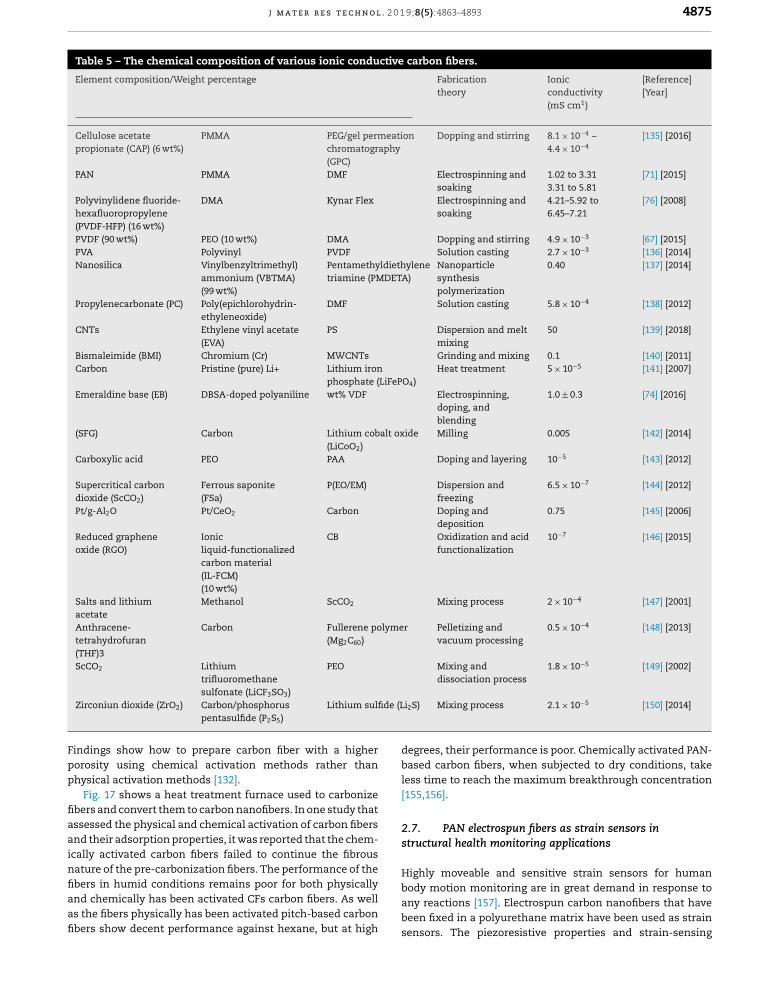
j m a t e r r e s t e c h n o l . 2 0 1 9;8(5):4863–4893 4875
Table 5 – The chemical composition of various ionic conductive carbon fibers.
Element composition/Weight percentage Fabricationtheory
Ionicconductivity(mS cm1)
[Reference][Year]
Cellulose acetatepropionate (CAP) (6 wt%)
PMMA PEG/gel permeationchromatography(GPC)
Dopping and stirring 8.1 × 10⁻⁴ –4.4 × 10⁻⁴
[135] [2016]
PAN PMMA DMF Electrospinning andsoaking
1.02 to 3.313.31 to 5.81
[71] [2015]
Polyvinylidene fluoride-hexafluoropropylene(PVDF-HFP) (16 wt%)
DMA Kynar Flex Electrospinning andsoaking
4.21–5.92 to6.45–7.21
[76] [2008]
PVDF (90 wt%) PEO (10 wt%) DMA Dopping and stirring 4.9 × 10⁻³ [67] [2015]PVA Polyvinyl PVDF Solution casting 2.7 × 10⁻³ [136] [2014]Nanosilica Vinylbenzyltrimethyl)
ammonium (VBTMA)(99 wt%)
Pentamethyldiethylenetriamine (PMDETA)
Nanoparticlesynthesispolymerization
0.40 [137] [2014]
Propylenecarbonate (PC) Poly(epichlorohydrin-ethyleneoxide)
DMF Solution casting 5.8 × 10⁻⁴ [138] [2012]
CNTs Ethylene vinyl acetate(EVA)
PS Dispersion and meltmixing
50 [139] [2018]
Bismaleimide (BMI) Chromium (Cr) MWCNTs Grinding and mixing 0.1 [140] [2011]Carbon Pristine (pure) Li+ Lithium iron
phosphate (LiFePO4)Heat treatment 5 × 10⁻⁵ [141] [2007]
Emeraldine base (EB) DBSA-doped polyaniline wt% VDF Electrospinning,doping, andblending
1.0 ± 0.3 [74] [2016]
(SFG) Carbon Lithium cobalt oxide(LiCoO2)
Milling 0.005 [142] [2014]
Carboxylic acid PEO PAA Doping and layering 10−5 [143] [2012]
Supercritical carbondioxide (ScCO2)
Ferrous saponite(FSa)
P(EO/EM) Dispersion andfreezing
6.5 × 10⁻⁷ [144] [2012]
Pt/g-Al2O Pt/CeO2 Carbon Doping anddeposition
0.75 [145] [2006]
Reduced grapheneoxide (RGO)
Ionicliquid-functionalizedcarbon material(IL-FCM)(10 wt%)
CB Oxidization and acidfunctionalization
10−7 [146] [2015]
Salts and lithiumacetate
Methanol ScCO2 Mixing process 2 × 10⁻⁴ [147] [2001]
Anthracene-tetrahydrofuran(THF)3
Carbon Fullerene polymer(Mg2C60)
Pelletizing andvacuum processing
0.5 × 10⁻⁴ [148] [2013]
ScCO2 Lithium PEO Mixing and 1.8 × 10⁻⁵ [149] [2002]
e (Li2S
Fpp
fiaainfiaafi
debales[15
2.7str
trifluoromethanesulfonate (LiCF3SO3)
Zirconiun dioxide (ZrO2) Carbon/phosphoruspentasulfide (P2S5)
Lithium sulfid
indings show how to prepare carbon fiber with a higherorosity using chemical activation methods rather thanhysical activation methods [132].
Fig. 17 shows a heat treatment furnace used to carbonizebers and convert them to carbon nanofibers. In one study thatssessed the physical and chemical activation of carbon fibersnd their adsorption properties, it was reported that the chem-cally activated carbon fibers failed to continue the fibrous
ature of the pre-carbonization fibers. The performance of thebers in humid conditions remains poor for both physicallynd chemically has been activated CFs carbon fibers. As wells the fibers physically has been activated pitch-based carbonbers show decent performance against hexane, but at highHiboanbese
dissociation process
) Mixing process 2.1 × 10⁻⁵ [150] [2014]
grees, their performance is poor. Chemically activated PAN-sed carbon fibers, when subjected to dry conditions, takes time to reach the maximum breakthrough concentration5,156].
. PAN electrospun fibers as strain sensors inuctural health monitoring applications
ghly moveable and sensitive strain sensors for humandy motion monitoring are in great demand in response toy reactions [157]. Electrospun carbon nanofibers that haveen fixed in a polyurethane matrix have been used as strainnsors. The piezoresistive properties and strain-sensing
4876 j m a t e r r e s t e c h n o l . 2 0
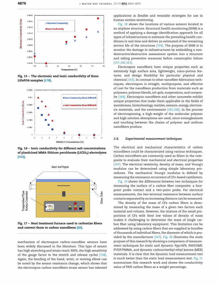
Fig. 15 – The electronic and ionic conductivity of threeLiFePO4 samples [178].
Fig. 16 – Ionic conductivity for different salt concentrationsof plasticized MMA-lithium perchlorate (LiClO4) electrolytes[153].
Fa
mbhoAbt
aphu
anmtypditsemdean[15
extuchniqof
poiteunmicsof
ananna
2.8
ThmCapo[16mcem
mpomco
mmpomboadof
vidpumPVDF/PMMA, and dynamic carbon/methyl ethyl ketone (MEK)
ig. 17 – Heat treatment furnace used to carbonize fibersnd convert them to carbon nanofibers [60].
echanism of electrospun carbon-nanofiber sensors haveeen widely discussed in the literature. This type of sensoras high stretching and strain reach 300%, the high sensitivity
f the gauge factor in the stretch and release cycles [158].gain, the bending of the hand, wrist, or moving elbow cane noted by the sensor resistance change, which shows thathe electrospun carbon nanofibers strain sensor has talentedmis
suva
1 9;8(5):4863–4893
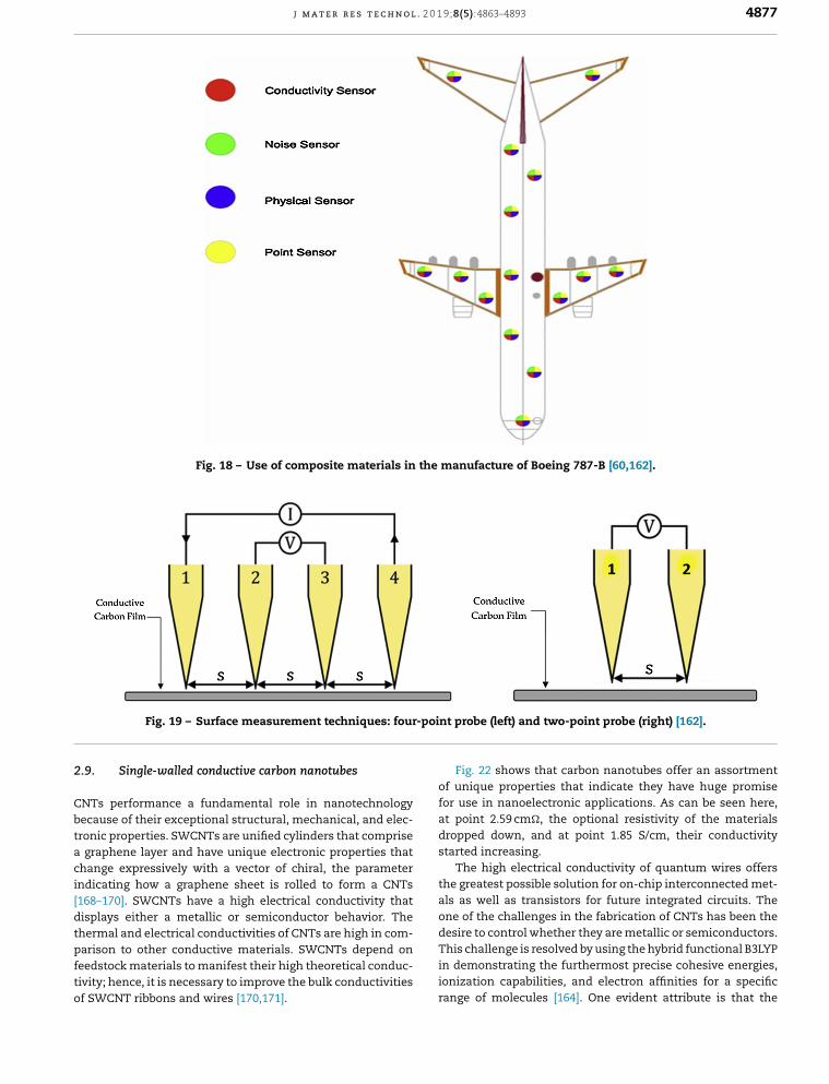
plications in flexible and wearable strategies for use inman motion monitoring.Fig. 18 shows the locations of various sensors located in
airplane structure. Structural health monitoring (SHM) is aethod of applying a damage identification approach for all
es of infrastructures to estimate the prevailing health con-ions in real time and deliver an estimated of the remainingrvice life of the structures [159]. The purpose of SHM is toonitor the damage in infrastructures by embedding a non-structive/destructive assessment system into a structured taking preventive measures before catastrophic failure7,160,161].Electrospun nanofibers have unique properties such as
tremely high surface area, lightweight, nano-porous fea-res, and design flexibility for particular physical andemical [163]. In contrast to other nanofiber fabrication tech-ues, electrospun is straight, multipurpose, and effective
cost for the nanofibers production from materials such aslymers, polymer blends, sol-gels, suspensions, and compos-
[164]. Electrospun nanofibers and other nanowebs exhibitique properties that make them applicable in the fields of
embranes, biotechnology, textiles, sensors, energy, electron- materials, and the environment [165,166]. In the processelectrospinning, a high-weight of the molecular polymerd high solution absorptions are used, since entanglementsd touching between the chains of polymer and uniformnofibers produce.
. Experimental measurement techniques
e electrical and mechanical characteristics of carbonicrofibers could be characterized using various techniques.rbon microfibers are commonly used as fillers in the com-site to evaluate their mechanical and electrical properties7]. The electrical resistivity, density of mass, and Young’s
odulus can be determined using simple laboratory pro-dures. The mechanical Young’s modulus is defined byeasuring the resonance occurrence of CFs-based cantilevers.Fig. 19 shows the differences between two techniques for
easuring the surface of a carbon fiber composite: a four-int probe contact and a two-point probe. For electricaleasurements, the two-terminal resistance between surfacentacts separated by an increasing distance can be measured.The density of the mass of CFs carbon fibers is deter-
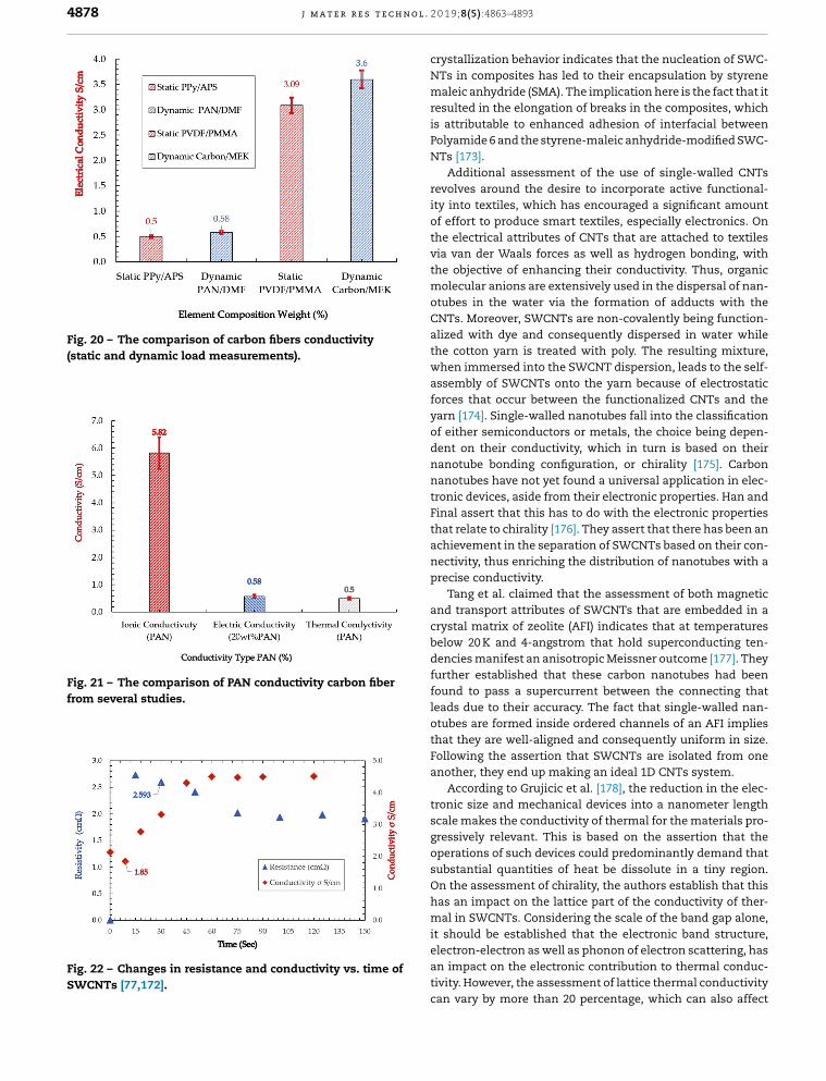
ined by measuring the mass of a given two factors suchaterial and volume. However, the mixture of the small pro-rtions of CFs with their low values of density of massakes it challenging to determine the mass of single car-n fiber using laboratory equipment. This limitation can bedressed by using carbon fibers that are supplied in bundlesthousands of individual fibers, the diameter of which is pro-ed by the manufacturer [167]. Fig. 20 illustrates the mainrpose of this research by showing a comparison of measure-ent techniques for static and dynamic Ppy/APS, PAN/DMF,
aterials. It is clear that the dynamic load measurement testmuch better than the static load measurement test. Fig. 21mmarizes this research work and shows the conductivitylue of PAN carbon fibers as a weight percentage.
j m a t e r r e s t e c h n o l . 2 0 1 9;8(5):4863–4893 4877
Fig. 18 – Use of composite materials in the manufacture of Boeing 787-B [60,162].
oint
2
Cbtaci[dtpfto
of
forat
drosta
thalsondesire to control whether they are metallic or semiconductors.
Fig. 19 – Surface measurement techniques: four-p
.9. Single-walled conductive carbon nanotubes
NTs performance a fundamental role in nanotechnologyecause of their exceptional structural, mechanical, and elec-ronic properties. SWCNTs are unified cylinders that comprise
graphene layer and have unique electronic properties thathange expressively with a vector of chiral, the parameterndicating how a graphene sheet is rolled to form a CNTs168–170]. SWCNTs have a high electrical conductivity thatisplays either a metallic or semiconductor behavior. Thehermal and electrical conductivities of CNTs are high in com-
arison to other conductive materials. SWCNTs depend oneedstock materials to manifest their high theoretical conduc-ivity; hence, it is necessary to improve the bulk conductivitiesf SWCNT ribbons and wires [170,171].Thin
ionran
probe (left) and two-point probe (right) [162].
Fig. 22 shows that carbon nanotubes offer an assortmentunique properties that indicate they have huge promise
use in nanoelectronic applications. As can be seen here,point 2.59 cm�, the optional resistivity of the materialspped down, and at point 1.85 S/cm, their conductivityrted increasing.The high electrical conductivity of quantum wires offers
e greatest possible solution for on-chip interconnected met- as well as transistors for future integrated circuits. Thee of the challenges in the fabrication of CNTs has been the
is challenge is resolved by using the hybrid functional B3LYPdemonstrating the furthermost precise cohesive energies,ization capabilities, and electron affinities for a specificge of molecules [164]. One evident attribute is that the
4878 j m a t e r r e s t e c h n o l . 2 0
Fig. 20 – The comparison of carbon fibers conductivity(static and dynamic load measurements).
Fig. 21 – The comparison of PAN conductivity carbon fiberfrom several studies.
Fig. 22 – Changes in resistance and conductivity vs. time ofSWCNTs [77,172].
cryNTmresis
PoNT
revityof
thviathmotuCNalithwhasforyaof
denanatroFinthacnepr
ancrybedefufouleaotuthFoan
troscgreopsuOnhamit
eleantivca
1 9;8(5):4863–4893
stallization behavior indicates that the nucleation of SWC-s in composites has led to their encapsulation by styrene
aleic anhydride (SMA). The implication here is the fact that itulted in the elongation of breaks in the composites, whichattributable to enhanced adhesion of interfacial betweenlyamide 6 and the styrene-maleic anhydride-modified SWC-s [173].Additional assessment of the use of single-walled CNTsolves around the desire to incorporate active functional-
into textiles, which has encouraged a significant amounteffort to produce smart textiles, especially electronics. One electrical attributes of CNTs that are attached to textiles
van der Waals forces as well as hydrogen bonding, withe objective of enhancing their conductivity. Thus, organicolecular anions are extensively used in the dispersal of nan-
bes in the water via the formation of adducts with theTs. Moreover, SWCNTs are non-covalently being function-
zed with dye and consequently dispersed in water whilee cotton yarn is treated with poly. The resulting mixture,en immersed into the SWCNT dispersion, leads to the self-
sembly of SWCNTs onto the yarn because of electrostaticces that occur between the functionalized CNTs and thern [174]. Single-walled nanotubes fall into the classificationeither semiconductors or metals, the choice being depen-nt on their conductivity, which in turn is based on theirnotube bonding configuration, or chirality [175]. Carbonnotubes have not yet found a universal application in elec-nic devices, aside from their electronic properties. Han andal assert that this has to do with the electronic properties
at relate to chirality [176]. They assert that there has been anhievement in the separation of SWCNTs based on their con-ctivity, thus enriching the distribution of nanotubes with aecise conductivity.Tang et al. claimed that the assessment of both magneticd transport attributes of SWCNTs that are embedded in astal matrix of zeolite (AFI) indicates that at temperatures
low 20 K and 4-angstrom that hold superconducting ten-ncies manifest an anisotropic Meissner outcome [177]. Theyrther established that these carbon nanotubes had been
nd to pass a supercurrent between the connecting thatds due to their accuracy. The fact that single-walled nan-bes are formed inside ordered channels of an AFI implies
at they are well-aligned and consequently uniform in size.llowing the assertion that SWCNTs are isolated from oneother, they end up making an ideal 1D CNTs system.According to Grujicic et al. [178], the reduction in the elec-nic size and mechanical devices into a nanometer length
ale makes the conductivity of thermal for the materials pro-ssively relevant. This is based on the assertion that the
erations of such devices could predominantly demand thatbstantial quantities of heat be dissolute in a tiny region.
the assessment of chirality, the authors establish that thiss an impact on the lattice part of the conductivity of ther-al in SWCNTs. Considering the scale of the band gap alone,
should be established that the electronic band structure,ctron-electron as well as phonon of electron scattering, hasimpact on the electronic contribution to thermal conduc-ity. However, the assessment of lattice thermal conductivityn vary by more than 20 percentage, which can also affect
0 1 9;
etv
2
Otiimcaabama
R
A
WopvssebimAsaiat
canofmdsiaccocmdca
coth
riacathdeenanthcrawhthatt
threlanattrelingthcathponumeblaingthrepcabypeThingrepsyingwi
agof
strentur[22ruapdaop[22whstrch
j m a t e r r e s t e c h n o l . 2
lectronic thermal conductivity [176]. Thus it follows that thehermal conductivity of specific SWCNTs in nanoprobes canary significantly from one to another.
.10. Carbon fiber electric resistivity
verall, the growing demand for effective heat dissipa-ion in electrical as well as electronic devices has made itmperative for engineering materials to be designed withmproved thermal conductivity. Also, concerning higher ther-
al conductivity, improved electrical resistivity could beonsidered necessary for those applications where materi-ls come into contact with electrical components as leadsnd wires [179–181]. It follows that ceramic fillers, includingoron nitride, aluminum oxide, silica, and aluminum nitride,re used to improve the conductivity of thermal for the poly-er matrices as well as maintain their electrical insulating
ttributes.
= RcxAo(2)
r = R − Ro
Ro(3)
here the contact resistance presented (Rc) is existing in theverlapping area measured Ao, so the amplitude resistanceresented (Ar) and R0 is the initial of measured resistivityalue. Further studies reveal that reinforced of cement withhort CFs carbon fibers has the capability of establishing itstrain owing to the impact of strain in the resistivity of thelectrical [182]. In this case, resistivity increased upon tensionecause of the slight fiber pull-out associated with the open-
ng of the crack and decreasing compression following theinimal fiber push-in related to the closing of the crack [183].dditionally, resistivity variations in directions that are oppo-ite the direction of the stress offer valuable insight into thisttribute that has an impact on the piezoresistive effect. Thus,t becomes imperative that scientific and technological issuesssess the resistivity in directions that are not associated withhe direction of stress [184].
Table 6 shows the effect of temperature on carbon fiberonductivity, which allows researchers to find appropri-te material for future research work. Overall, the carbonanotube-based polymer composite is comprised of materialsf multifunctional, which is adding to their function of basicor the physical and the mechanical attribute enhancement
ake it possible to sense through electrical methods. Con-uctive composites are mainly found automotive has beenignificant applications, also electronics, aircraft, and otherndustries [185]. Due to the electrical elements of CNTs, thespect ratio is high along with their propensity to create per-olated networks in matrices of viscous are extremely lowontent; they are very effective candidates for the modificationf thermosetting matrix components [186,187]. The electri-
al conductivity of CNTs is directly connected to the strain ofacroscopic functional to the material as well as the internalamage that accrues during service [185]. Changes in electri-al resistance owing to the applied strain on CNTs compositesre attributable to variations in the configurations of the CNTs
TheleThbema
8(5):4863–4893 4879
nductive network as well as the changes of dimensions fore nanotubes because of their deformation [185].Traditionally, concrete has been found to be a brittle mate-l characterized by low tensile strength and low strainpacity, which leads to low resistance to cracking. To improveese properties, concrete reinforced with fiber has beenveloped [219,220]. The use of fiber here is intended tohance the tensile strength, toughness, flexural strength,d impact strength, thus changing the failure mode throughe improvement of post-cracking ductility and controlledcking. These fibers can additionally exhibit a strong impacten it derives to the electrical properties of the composite in
ose cases where the added fibers have highly conductiveributes compared to the matrix [219,221–223].The assessment of interfacial attributes that exist between
e fiber and the matrix, as well as the investigation of theationship between tensile attributes of SWCNTs specimensd the resistance ratio of electrical, reveals some uniqueributes. This assessment indicates that, based on the linearationship, due to the transfer of stress from the reinforc-
matrix to the fiber, the SWCNTs ends up breaking first. Inis case, the stress delivery along the CFs predicts that therbon fibers tend to fracture along the tensile lines [224]. Inis research, it is evident that carbon black and fibers filledlymer composites of conductive have found applications inmerous high-technology applications comprised of a poly-r matrix and fine elements of conductive such as carbonck, aluminum fibers, and carbon fibers as the main reinforc-
materials [225,226]. The main challenge associated withe production of conductive polymer composites is in findingroducible conductivity because the conductivity of electri-
l along with attributes of mechanical are strongly impacted the mode of the additive of conductive, the mode of dis-rsion, and the state of the conductive fiber breakage [225].us, it becomes imperative to choose a standard process-
condition for the manufacture of these composites withroducible properties for a specific conductive filler-polymer
stem. In the case where the embedded fillers are conduct-, this leads to the production of materials whose behavior
ll be like that of conductive polymer composite [225].The aspect of sensing the strain as well as structure dam-
e is vital for load assessment, operation control, regulationthe structural vibration, and resulting evaluation of theuctural health [227]. Engineering Strain curve rather thangineering stress curve is a measure that impacts a struc-e, although strain is caused by the application of stress7]. Furthermore, stress and strain are linked in the elastic
le via the elasticity modulus. The maximum conventionalproaches for engineering strain and sensing encompass ofmage embedding or attaching a sensor as a sensor of fibertic, a piezoelectric sensor, along with an acoustic sensor7]. The less-conventional method is that of self-sensing,ich is reached by assessing the electrical resistivity of theuctural material, so long as the resistance continues isanging could be correlated with the strain or defect. Sensor.
e assessment of resistance encompasses the predominantctrical surface contacts uses along with a meter [225].e use of a carbon fiber polymer-matrix is recommendedcause the CFs are the middle in resistivity and the polymer-trix is completely not conductive, while the composite of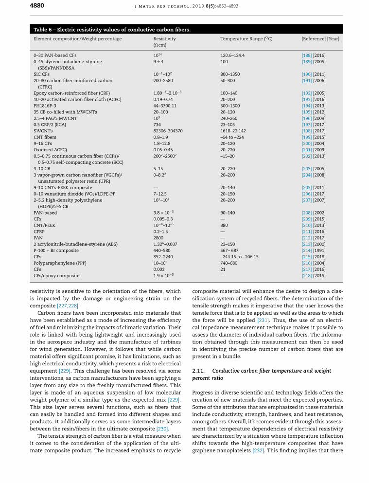
4880 j m a t e r r e s t e c h n o l . 2 0 1 9;8(5):4863–4893
Table 6 – Electric resistivity values of conductive carbon fibers.
Element composition/Weight percentage Resistivity(�cm)
Temperature Range (OC) [Reference] [Year]
0–30 PAN-based CFs 1014 120.6–124.4 [188] [2016]0–45 styrene-butadiene-styrene
(SBS)/PANI/DBSA9 ± 4 100 [189] [2005]
SiC CFs 10−1–102 800–1350 [190] [2011]20–80 carbon fiber-reinforced carbon
(CFRC)200–2580 50–300 [191] [2006]
Epoxy carbon-reinforced fiber (CRF) 1.80−3–2.10−3 100–140 [192] [2005]10–20 activated carbon fiber cloth (ACFC) 0.19–0.74 20–200 [193] [2016]PH1816P-3 44–3700.11 500–1300 [194] [2013]35 CB co-filled with MWCNTs 20–100 20–120 [195] [2012]2.5–4 PA6/5 MWCNT 103 240–260 [196] [2009]0.5 CRF/2 (ECA) 734 23–105 [197] [2017]SWCNTs 82306–304370 1618–22,142 [198] [2017]CNT fibers 0.8–1.9 –64 to –224 [199] [2015]9–16 CFs 1.8–12.8 20–120 [200] [2004]Oxidized ACFC) 0.05–0.45 20–220 [201] [2009]0.5–0.75 continuous carbon fiber (CCFs)/
0.5–0.75 self-compacting concrete (SCC)2002–25002 –15–20 [202] [2013]
3–10 CB 5–15 20–220 [203] [2005]3 vapor-grown carbon nanofiber (VGCFs)/
unsaturated polyester resin (UPR)0–8.22 20–200 [204] [2008]
9–10 CNTs-PEEK composite — 20–140 [205] [2011]0–10 vanadium dioxide (VO2)/LDPE-PP 7–12.5 20–150 [206] [2017]2–5.2 high-density polyethylene
(HDPE)/2–5 CB101–104 20–200 [207] [2007]
PAN-based 3.8 × 10⁻³ 90–140 [208] [2002]CFs 0.005–0.3 — [209] [2015]CNT/PEEK 10−4–10−5 380 [210] [2013]CFRP 0.2–1.5 — [211] [2016]PAN 2800 — [212] [2017]2 acrylonitrile-butadiene-styrene (ABS) 1.324–0.037 23–150 [213] [2000]P-100 + Br composite 440–580 567– 687 [214] [1991]
ric
horifmheillwTcpb
im
cosifitententhcaastioin
pr
2.1pe
ProcreSoincamong others. Overall, it becomes evident through this assess-
CFs 852–2240
Polyparaphenylene (PPP) 10–105
CFs 0.003
CFs/epoxy composite 1.9 × 10⁻³
esistivity is sensitive to the orientation of the fibers, whichs impacted by the damage or engineering strain on theomposite [227,228].
Carbon fibers have been incorporated into materials thatave been established as a mode of increasing the efficiencyf fuel and minimizing the impacts of climatic variation. Theirole is linked with being lightweight and increasingly usedn the aerospace industry and the manufacture of turbinesor wind generation. However, it follows that while carbon
aterial offers significant promise, it has limitations, such asigh electrical conductivity, which presents a risk to electricalquipment [229]. This challenge has been resolved via somenterventions, as carbon manufacturers have been applying aayer from any size to the freshly manufactured fibers. Thisayer is made of an aqueous suspension of low moleculareight polymer of a similar type as the expected mix [229].his size layer serves several functions, such as fibers thatan easily be handled and formed into different shapes androducts. It additionally serves as some intermediate layers
etween the resin/fibers in the ultimate composite [230].The tensile strength of carbon fiber is a vital measure whent comes to the consideration of the application of the ulti-
ate composite product. The increased emphasis to recycle
mareshgra
–244.15 to –206.15 [215] [2018]740–680 [216] [2004]21 [217] [2016]— [218] [2015]
mposite material will enhance the desire to design a clas-cation system of recycled fibers. The determination of thesile strength makes it imperative that the user knows thesile force that is to be applied as well as the areas to which
e force will be applied [231]. Thus, the use of an electri-l impedance measurement technique makes it possible tosess the diameter of individual carbon fibers. The informa-n obtained through this measurement can then be usedidentifying the precise number of carbon fibers that are
esent in a bundle.
1. Conductive carbon fiber temperature and weightrcent ratio
gress in diverse scientific and technology fields offers theation of new materials that meet the expected properties.
me of the attributes that are emphasized in these materialslude conductivity, strength, hardness, and heat resistance,
ent that temperature dependencies of electrical resistivity characterized by a situation where temperature inflection
ifts towards the high-temperature composites that havephene nanoplatelets [232]. This finding implies that there
0 1 9;
etecc
anpottmtrcrtpcwo
ttciufsfiacm
2
MgcsSuembMbwhgoooCoapm
eleviothasmeon
poitymacaasof
cloOvcaMWcosutiv
to
otucoamtemproesmothThopincpo
thMWcocothturprauyaetethth
proto
profillcapabe
j m a t e r r e s t e c h n o l . 2
xists greater impact of direct contact between the filler par-icles and that it does deviate from the model of effectivelectrical resistivity. Conversely, the contribution of tunnelonductivity is evidenced by the significant increase in theonductivity of electrical in the microwave range.
Most studies that are accessible in the area of char-cterization electrical of the CFs polymer matrix concernondestructive assessment as well as damage sensing in com-osites [233]. The overall objective has been in the assessmentf changes in electrical resistance as well as an electrical fieldhat emanates following the deviations in resistance of elec-rical and the consequent electrical field that is occasioned by
echanical damage [234,235]. When using electrical charac-erization tests, it becomes evident that electrical resistance iseduced following an increase in the magnitude of the electricurrent. It also becomes evident that electrical resistance iseduced following an increase in the plies number that are inhe composite laminate and that electrical resistance is a com-osite function layup [234]. Overall, temperatures in electrifiedomposites tend to increase in tandem with a magnitude asell as the period of the current of electric and the resistancef contact at the junction for the composite-electrode.
Traditional sensing strategies can be undertaken throughhe use of either an embedded or attaching sensor, which leadso an increase in the cost, or the reduction of durability andonsequent deterioration in the performance of the compos-te. This challenge can be resolved if the composite materialses an intrinsic sensor. A new technique for assessing inter-
acial attributes as well as curing elements and residualtresses involves the measurement of electrical resistivityor different conductive steel and carbon-reinforced compos-tes [236]. The emphasis here is on how conductive carbonnd steel fiber-reinforced composites respond to temperaturehanges and applied load. An increase in temperature and theodulus as well [237].
.12. Multi-walled conductive carbon nanotubes
ulti-walled carbon nanotubes have several rolled layers ofraphene. They are not well defined related to single-walledarbon nanotubes, due to their complexity and variety oftructural [238,239]. However, MWCNTs have advantages overWCNTs including mass production ease, lower the cost pernit, and enhanced stability of thermal and chemical. Thelectrical and mechanical properties of SWCNTs can transfor-ation due to defects of structural for the carbon-to-carbon
ond, resulting in breakage [240]. However, the properties ofWCNTs can be well preserved by modification of the surface
y exposing the outer wall to chemical modifiers [241]. Multi-alled carbon nanotubes are electrically conductive and alsoave high thermal conductivity [238,239]. The use of celluloserafting enhances the mechanical and electrical propertiesf MWCNTs and composite fibers [242]. The new biosensorf glucose amperometric is based on the conductor positionf platinum nanoparticles onto the surface of multi-walled
NTs polyaniline nanocomposites as well as glucose oxidasef the immobilizing using covalent interface, and here anbsorption effect has been developed. In this case, MWCNTs-olyaniline nanocomposites were synthesized in situ poly-erization and consequently characterized by microscopy ofadtancatioma
8(5):4863–4893 4881
ctron, Fourier transforms infrared spectroscopy, and ultra-let (UV) and visible UV absorption spectra. The process of
e electrode modification was investigated via SEM as well cyclic voltammetry along with optimization of the environ-ntal condition using a glucose biosensor assessment based
detailed chronoamperometry [243].The covalent modification of MWCNTs using low weightlyhydroxy of molecular is meant to improve the solubil-
and adhesion of interfacial for MWCNTs in the polymertrix. This method advances the strategies on how MWCTNs
n be employed in the fabrication of microscopic functional high-performance films or fibers. PHA allows the formationa thermally superior stable polymer via an additional ringsure in the polycondensation at elevated temperatures.erall, having demonstrated that increased conductivityn be attained in poly(p-phenlenebenzobisoxazole) (PBO)-
CNTs composite films as well as the inner core ofmposite films, although it becomes evident that the outerrface of the fibers does not indicate an increase in conduc-ity following the addition of MWCNTs.Kuan et al. have established some unique facts relativethe assessment of multi-walled thermal conductive nan-bes [244]. One of these attributes is that the insulator
nductor transmission occurs following the addition of smallounts of MWCNTs in polystyrene-MWCNTs composite sys-s [245]. Kara et al. also found that optical percolation
cesses for polymer-CNTs thin film composites can betablished by using optical transmission systems. Further-re, they established that the percolation of the electrical
reshold, the point of optical transparency, has disappeared.ese attributes imply that the loss in transparency of thetical indicates the start of electrical conductivity, whichreases and further saturates in completely opaque com-site films.Multi-walled carbon nanotube yarns have been produced
rough electrospinning from the sides of vertically alignedCNTs displays of 500 �m [246]. In the assessment of their
nductivity of electrical, it was confirmed that the electricalnductivity of MWCNTs tends to be decreased by increasingeir diameter [246]. This trend is associated with struc-al variations existing between small-large diameter yarns,
incipally regarding decreased CNTs migration lengths. Thethors further assert that a decrease in the twist angle of therns results in their reduced alignment with a larger diam-r. Investigations by Jakubinek et al. [246] have established
at the smaller-diameter yarn exhibits superior electrical andermal conductivity than the larger-diameter yarn.The past few decades have seen development in theduction of conducting polymer composites (CPCs) duetheir exceptional thermal, mechanical, and electricalperties. This type of composite is prepared via fixing
ers of conductive as carbon nanofibers, metal powder,rbon black, and carbon nanofibers into polymers. Com-red to traditional metal-conducting materials, CPCs haveen found to have corrosion resistance, lightweight, and
justable resistivity [247]. It follows that their capaci-ce, resistance, dialectic constant, and volume have thepability to change, depending on environmental condi-ns, which makes them excellent electromagnetic shieldingterials [248].
4 l . 2 0
owpllpey
ce[toiao
dctddtdt
fiaascrateoftea
2
Cvesmetbdaelt
t
statraGrththtecmmMWthcogracoto
podedivitipoimunhaduwhpa
boMaduviastrthThbybothforas
seof
prin
effotuCNtioemtrofroavtanIt
as
882 j m a t e r r e s t e c h n o
A greater number of turns in the preparation of carbon nan-tube yarns would lead to an increase in the radial grip, whichould make the yarn tighter, thus enhancing its properties ofhysical. Yao et al. established that the fibers of outer on a
arger-diameter yarn tend to be more lightly bound and thusess effective when it comes to contributing to the overall yarnroperties. Conduction and stress properties have thus beenstablished as being more uniform across smaller-diameterarns [249].
Yao et al. also established and functionalization that theovalent of CNTs permits groups of function to be differ-ntly attached to the tube caps as well as defective sidewalls249]. They found that the caps exhibit a semi-fullerene struc-ure, which is vital for the reaction of functionizalition toccur. Furthermore, the chemical reactivity of CNTs is strongly
mpacted by the occurrence of damages, including pentagonsnd vacancies, which result in a localized increase of reactivityf chemical for the graphic nanostructures.
Overall, the authors demonstrate that MWCNT’s can beirectly functionalized with octadecylamine to create super-onductive, superhydrophobic thin films. It becomes evidenthat the amination procedure does not demand the use ofestructive chemicals, which is in complete contrast to tra-itional routes for activating MWCNTs, such as oxidationreatment via the use of strong acids or mineral, which canisrupt the pi-stacking structure and consequently decreasehe electrical conductivity of MWCNTs.
Li et al. examined the conductivity of PEDOT/PSS thinlms doped with diverse MWCNTs, focusing on their roles a favorable enhancement in composite films [250]. Theyssert that the increased conductivity, in this case, is pos-ibly due to two effects, including �-� interactions and thehannel effect. The �-� interactions between the theophanyings of the poly(3,4-ethylenedioxy) backbone and MWCNTs,long with the electronic density transfer, take place fromhe poly(3,4-ethylenedioxy) to the MWCNTs in PSS/ poly(3,4-thylenedioxy), whereby the changes become more localizedn the PEDOT chains [250]. The latter is found to emanaterom the creation of some favorable MWCNTs channels inhe poly(3,4-ethylenedioxy)/PSS matrix. The two attributesxhibit the possibility of aiding the charge transport as wells enhancing the conductivity of the conductivity films.
.13. Conductive carbon nanotube yarns
arbon nanotubes have great potential in replacing con-entional metals because of their significant mechanical,lectrical, thermal, and non-oxidizing properties. Their den-ity and thermal conductivity are high in comparison toetals such as copper. Their properties have made them
ssential in the medical, electronics, and antenna applica-ions [251,252]. The use of carbon nanotubes in yarns haseen shown to exhibit frequency-independent resistive con-uct and benefits various applications such as ultra-widebandnd wireless body area networks [253,254]. The conductivity of
lectrical a carbon nanotube yarn depends on the properties,oading, and aspect ratio of the CNTs. Other factors include thewist angle and conductive network characteristics [255,256].A method of fabricating a superior conductive CNTs andhe graphene hybrid yarn has been established. The process
boof
th
CN
1 9;8(5):4863–4893
rts with displays of vertically aligned MWCNTs that arensformed into long MWCNTs sheets by sketch [253,254].aphene flakes are dropped on the MWCNTs sheets throughe electrospun process to form the structure of compositeat is changed into yarn nanofibers by using the twistinghnique. The materials setup are then characterized by
icroscopy of the electron, and electrical and mechanicaleasurements. The electrical conductivity of the composite
CNTs-graphene yarns is more than 9 S/m [255], which ise percentage within 400–1250 percentage higher than thenductivity of electrical for the natural MWCNTs yarns orphene sheet, correspondingly [253,254]. This increase in
nductivity is due to the increase in the state’s density closethe Fermi level and a decrease in hopping distance [257].In assessing the impact of solution conductivity onlystyrene fibers using DMF as the solvent, it becomes evi-nt that different results received from DMF solvent fromerse suppliers exhibit slightly different solution conductiv-
es. Additionally, polymer solutions prepared with the samelystyrene absorption exhibit different conductivities, whichpact the morphology of the polystyrene fibers obtainedder otherwise similar electroplating conditions. Overall, its been shown that solutions with higher conductivity pro-ced bead-free fibers from lower polymer concentrations,ich are an indication that solution conductivity plays a vital
rt in the production of uniform polystyrene fibers [258].The conductivity of thermal for polyacrylonitrile-based car-
n fibers occurs via phonons that travel through the medium.terial that has regular atomic structures displays high con-ctivity of thermal because of the fast-traveling photons
the regular coupling structure. Furthermore, the regularucture of atomic of the material as a polymer exhibits lowermal conductivity due to the complex structural attributes.e thermal conductivity in a unitary polymer change formed
covalent bonds as phonons travel fast through the covalentnds. Conversely, a thermal conductivity that exists betweene nondiverse con-covalent bond chains as van der Waalsces are significantly slow, due to phonon reflection as well
scattering phenomena between the chains [259,260].According to Jakubinek et al. [248], recent years have
en an increase in nanotube assemblies in a high densitypacking, as well as aligned configurations, offering the
omise of superior strength as well as transport attributesmicroscopic materials. Kim et al. sought to assess theects of thermal conductivity in free-standing carbon nan-be strands, CNTs yarn-like polymer composite fibers, andTs yarn-like fibers [261]. The conductivity of thermal valua-ns was made using T-type experimental configurations thatployed a Wollaston wire hot probe inside a scanning elec-n microscope. The conductivity of thermal was presumedm an analytical model that associated the drop in spatiallyeraged temperatures of the wire to thermal contact resis-ce as well as the thermal conductivity of the sample [248].
was established that the higher the thermal conductivitysociated with the increased stiffness, the lower CNTs-CNTs
undary struggle as well as CNTs alignment along the lengththe fiber, which occurred as the result of fiber pulling duringe manufacturing process.Bradford and Bogdanovich sought to demonstrate thatTs yarns could be utilized along with old-style carbon fibers
0 1 9;
tCfidcthtCi
eeteaytstenp
2
CtfieawfifdtcpiCeTbpeCaatieemelatt
motex
copofrotrocoproof
befibab[29potancasutriwicaof
torcoint
fibThgieusinttenityin
tioutihigstranae
meatteleweelebeto
eva p[30eleac
j m a t e r r e s t e c h n o l . 2
o produce three-dimensional (3D) braid performed [262]. TheNTs yarns tested during this study were extremely multi-
aceted systems of electrically conductive routes entrenchedn the epoxy, and that was resulting composite’s electrical con-uctivity had magnitudes greater than those of conventionalomposites created from the lower volume dispersals. Whilehe authors established that the electrical conductivity of theybrid 3D-braided CNTs composites was much higher thanhat of fiberglass, the integration of carbon nanotubes with theFs pulls resulted in creating an insignificant enhancement of
n-plane electrical conductivity.Abot et al. examined the variations in resistance of the
lectrical in DC mode, which was studied as a purpose ofngineering strain level in CNTs yarns [263]. They assertedhat negative piezo resistance is evident in CNTs yarns, whichxhibit a parabolic variation in the deformation phase. Thisssertion is supported by the fact that the subjection of CNTsarns to tension leads to nanotubes being transported nearerogether, thereby dropping the gap between them and con-equently the electrical resistance following the reduction ofhe artificial resistance. Overall, the reduction in resistance oflectrical by minimizing the interfacial contact resistance ofanotubes in the CNTs yarn acts as the dominant factor in theiezo resistance response of this yarn.
.14. Applications of conductive carbon fibers
arbon fibers are the strongest fibers, with extremely highhermal and electrical conductivity, thereby making themne applications in electrostatic and electromagnetic interfer-nce shielding [264–267]. They are also used for constructionntennas and microwave circuits by exchanging the metalith carbon fiber composites [268–270]. Conductive carbonber-graphite concrete material has been proposed recentlyor engineering floor heating. Carbon fiber finds such usesue to its high strength and the modulus, resistance to highemperature, resistance to acidic and alkali corrosion, goodonductivity, and flexibility [271–275]. Fiber-reinforced com-osites such as fiberglass have been used in the aircraft
ndustry due to their high modulus and less weight [276–281].Fs is also used for making sporting goods such as tennis rack-ts, golf clubs, hockey sticks, and archery arrows and bows.hey are also employed in the manufacture of wind turbinelades and the automotive industry [282–286]. In the contem-orary world, most applications of conductive carbon fiberlectrodes revolve around the sensors for neurotransmitters.arbon fiber microelectrodes (CFMEs) have an assortment ofdvantages, which have advanced their use. One of thesedvantages is that they are physically compatible and notoxic to cells. Another advantage is that their electrochem-stry has been effectively characterized, and they exhibit goodlectrochemical attributes [287–289]. Also, these carbon fibersmployed in electrodes are fewer than 20 mm in radius, whichakes them amenable for implantation and result in fewer
ngineering tissue damage defected and compared to otherarger predictable electrodes [290,291]. The conducting fibers,s well as yarns, have been seen as an essential component ofhe next-generation wearable electronics that have been seeno seamlessly incorporate electronic function into one of the
3.
Cain
str
8(5):4863–4893 4883
st versatile as well as widely used modes of manufacturingtiles [292–295].Further studies reveal that electrically conductive textile
atings, which represent a group of latest established com-sites, the studies have an applications assortment rangingm static charge dissipaters, sensors, and fillers to elec-magnetic interference shields [296,297]. One-dimensional
nducting polyvinyl alcohol has been established as amising non-metal that can be used the applicationsa biosensor in solution-processable microfluidic devices
cause of its hydrophilic attributes, which means that PVAers exhibit a good affinity for solutions and thus are desir-le materials for detecting the critical contained in solutions8,299]. Polypropylene is one of the major importance usedlymers, offering a balance among strength, chemical resis-ce, and modulus. PP has a low density, fiber forming
pability, low cost, and easy processability, thereby making ititable for use in the automobile, packing, and textile indus-es [300]. Its excellent strength-to-weight ratio associatedth the carbon fibers along with its exceptional mechani-l attributes has increased the use of PP in an assortmentapplications in the aerospace, transport, and sports sec-s. Also, the quantum wires described as the high electrical
nductivity of it’s the highest probable solution for on-chipersect metals for integrated circuits in future [301].From these studies, it is evident that conductive carboners have numerous applications in the contemporary world.eir physical properties, as well as manufacturing technolo-s, address both the technical and economic effects of their
e in protecting airplane structures [302]. Their incorporationo the cement matrix enhances the flexural strength andsile ductility, and their ability to adjust electrical conductiv-
makes them highly advantageous applications, especiallythe military [303]. According to Katunin [301], other applica-ns of carbon fibers involve formulations that are planned forlization in conductive material adhesives because of theirh mechanical strength attributes and in the composite ofuctural panels. The replacement of metal for weight savingsd corrosion resistance, making them ideal components forrospace, medical, and electronics applications [304,305].An additional application for carbon fibers is in solid poly-r electrolytes (SPLEs), which have been receiving majorention due to the role as conductors of ionic in diversectrochemical parts, such as flash memory, solar cellsre dye-sensitized, supercapacitors, and the devices ofctrochromic [306,307]. Furthermore, carbon nanotubes arelieved to act as one of the most hopeful materials owingtheir exceptional properties [308]. The inclusion of CNTs
en in tiny quantities has shown significant improvement inroduct’s mechanical, thermal, and electrical conductivity9–317]. They have a huge range of applications includingctromagnetic shielding, fuel emission, gas sensing, and
tuation [318].
Summary and conclusions
rbon fibers CFs is one of the most significant materialstoday’s world due to its superior characteristics of beingong, with high modulus, high tenacity, resistance to high
4 l . 2 0
tivmrocattaaaEmdecitmCtelcpcmdwmahc
A
TaatSMS
r
[1
[1
[1
[1
[1
[1
[1
[1
[1
[1
[2
[2
[2
884 j m a t e r r e s t e c h n o
emperatures, and high thermal and electrical conductiv-ty, when reinforced with other composites. CFs exists inarious classifications based on the strength of nanofibersaterials and final heat-treatment process temperature. The
esearchers could be fabricated using standard procedures tobtain the desired type of composite material with uniqueharacteristics in comparison to metals. The important char-cteristics of carbon fibers discussed in this paper are itshermal, electrical, and ionic conductivity, which have enabledhem to be applied to various electrical and thermal appli-nces. Because electrical devices are becoming slimmernd more integrated, the aspects of electrical conductivitynd have become central to the design of these devices.lectroplating methods have been found to offer versatileaneuverability in the production, orientation, porosity, and
imensions of controlled fiber structures. In applications, it isvident that low density offers a fiber-forming capability, theost is low, and the processability is much easy, thereby mak-ng CFs appropriate for use in the automobile, packing, andextile industries. While this study has highlighted an assort-
ent of issues and ways that inform the use of conductiveFs, it is evident that further studies are needed to enhance
he effectiveness of these applications. In this study, we havestablished that the increasing interest in conductive CFs hased to an enhancement in the ways that these componentsan be used. From this assessment of different studies androperties of conductive CFs, it can be concluded that signifi-ant issues related to their electrical and thermal conductivityake them unique. Some of their attributes have made it evi-
ent that the enhancements to conductive CFs are associatedith the densification as well as purification of the post treat-ents. It has also been established that the superior electrical
ttributes along with the flexibility of conductive carbon fibersave demonstrated a likely possibility that they will replaceonventional metal wires for use in future.
cknowledgments
he author would like to thank Deanship of Scientific Researcht Majmaah University for supporting this work. Also, theuthor appreciatively acknowledges the support and motiva-ion of the Dean of Engineering College at Majmaah University,audi Arabia, as well as inspiration from the Department ofechanical and Industrial Engineering at Majmaah University,
audi Arabia, during this present study.
e f e r e n c e s
[1] Nomura T, Tabuchi K, Zhu C, Sheng N, Wang S, Akiyama T.High thermal conductivity phase change composite withpercolating carbon fiber network. Appl Energy2015;154:678–85.
[2] Hou LG, Wu RZ, Wang XD, Zhang JH, Zhang ML, Dong AP,et al. Microstructure, mechanical properties and thermal
conductivity of the short carbon fiber reinforcedmagnesium matrix composites. J Alloys Compd2017;695:2820–6.[3] Gulgunje PV, Newcomb BA, Gupta K, Chae HG, Tsotsis TK,Kumar S. Low-density and high-modulus carbon fibers
[2
1 9;8(5):4863–4893
from polyacrylonitrile with honeycomb structure. Carbon2015;95:710–4.
[4] Islam I, Sultana S, Kumer Ray S, Parvin Nur H, Hossain MT,Md Ajmotgir W. Electrical and tensile properties of carbonblack reinforced polyvinyl chloride conductive composites.C 2018;4(1):15.
[5] Qu M, Nilsson F, Qin Y, Yang G, Pan Y, Liu X, Rodriguez GH,Chen J, Zhang C, Schubert DW. Electrical conductivity andmechanical properties of melt-spun ternary compositescomprising PMMA, carbon fibers and carbon black. ComposSci Technol 2017;150:24–31.
[6] Al-Saleh MH, Sundararaj U. Review of the mechanicalproperties of carbon nanofiber/polymer composites.Compos Part A Appl Sci Manuf 2011;42(12):2126–42.
[7] Coleman JN, Khan U, Blau WJ, Gun’ko YK. Small but strong:a review of the mechanical properties of carbonnanotube–polymer composites. Carbon 2006;44(9):1624–52.
[8] Sharma M, Gao S, Mäder E, Sharma H, Wei LY, Bijwe J.Carbon fiber surfaces and composite interphases. ComposSci Technol 2014;102:35–50.
[9] Pierson HO. Handbook of carbon, graphite, diamonds andfullerenes: processing, properties and applications. WilliamAndrew; 2012.
0] Nielsen LV, Ebert HP, Hemberger F, Fricke J, Biedermann A,Reichelt M, et al. Thermal conductivity of nonporouspolyurethane. High Temperatures High Pressures (UK)2000;32(6):701–7.
1] Lott P, Stollenwerk J, Wissenbach K. Laser-based productionof carbon fibers. J Laser Appl 2015;27(S2):S29106.
2] El-Hage Y, Hind S, Robitaille F. Thermal conductivity oftextile reinforcements for composites. J Text Fibrous Mater2018;1:1–12.
3] Newcomb BA. Processing, structure, and properties ofcarbon fibers. Compos Part A Appl Sci Manuf2016;91:262–82.
4] Wu S, Liu P, Zhang Y, Zhang H, Qin X. Flexible andconductive nanofiber-structured single yarn sensor forsmart wearable devices. Sens Actuators B Chem2017;252:697–705.
5] Hung CJ, Liu CH, Wang CH, Chen WH, Shen CW, Liang HC,et al. Effect of conductive carbon material content andstructure in carbon fiber paper made from carbon felt onthe performance of a proton exchange membrane fuel cell.Renew Energy 2015;78:364–73.
6] Frank E, Steudle LM, Ingildeev D, Spoerl JM, Buchmeiser MR.Carbon fibers: precursor systems, processing, structure, andproperties. Angew Chemie Int Ed 2014;53(21):5262–98.
7] Shao S, Zhou S, Li L, Li J, Luo C, Wang J, Li X, Weng J.Osteoblast function on electrically conductive electrospunPLA/MWCNTs nanofibers. Biomaterials 2011;32(11):2821–33.
8] Bae SH, Jeon C, Oh S, Kim CG, Seo M, Oh IK. Load-bearingsupercapacitor based on bicontinuous PEO-bP (S-co-DVB)structural electrolyte integrated with conductivenanowire-carbon fiber electrodes. Carbon 2018.
9] Liu Y, Kumar S. Recent progress in fabrication, structure,and properties of carbon fibers. Polym Rev2012;52(3):234–58.
0] Kaseem M, Hamad K, Ko YG. Fabrication and materialsproperties of polystyrene/carbon nanotube (PS/CNT)composites: a review. Eur Polym J 2016;79:36–62.
1] Huang X. Fabrication and properties of carbon fibers.Materials 2009;2(4):2369–403.
2] Al-Saleh MH, Sundararaj U. A review of vapor grown carbon
nanofiber/polymer conductive composites. Carbon2009;47(1):2–22.3] Alarifi IM, Khan WS, Rahman AS, Kostogorova-Beller Y,Asmatulu R. Synthesis, analysis and simulation ofcarbonized electrospun nanofibers infused carbon prepreg
0 1 9;
[4
[4
[4
[4
[4
[4
[4
[4
[5
[5
[5
[5
[5
[5
[5
[5
j m a t e r r e s t e c h n o l . 2
composites for improved mechanical and thermalproperties. Fibers Polym 2016;17(9):1449–55.
[24] Kara MOP, Frey MW. Effects of solvents on the morphologyand conductivity of poly (3, 4-ethylenedioxythiophene):poly (styrenesulfonate) nanofibers. J Appl Polym Sci2014;131(11).
[25] EREN S, Ulcay Y. Production of bi-component polyesterfibres for EMR (electromagnetic radiation) protection andexamining EMR shielding characteristics. J TextileApparel/Tekstil ve Konfeksiyon 2015;25(2).
[26] Xing S, Zhao C, Jing S, Wang Z. Morphology andconductivity of polyaniline nanofibers prepared by‘seeding’polymerization. Polymer 2006;47(7):2305–13.
[27] Caffrey PO, Gupta MC. Electrically conductingsuperhydrophobic microtextured carbon nanotubenanocomposite. Appl Surf Sci 2014;314:40–5.
[28] Itoh H, Li Y, Chan KHK, Kotaki M. Morphology andmechanical properties of PVA nanofibers spun by freesurface electrospinning. Polym Bull 2016;73(10):2761–77.
[29] Zheng Y, Li Y, Dai K, Wang Y, Zheng G, Liu C, et al. A highlystretchable and stable strain sensor based on hybrid carbonnanofillers/polydimethylsiloxane conductive compositesfor large human motions monitoring. Compos Sci Technol2018;156:276–86.
[30] Baji A, Mai YW, Wong SC, Abtahi M, Chen P. Electrospinningof polymer nanofibers: effects on oriented morphology,structures and tensile properties. Compos Sci Technol2010;70(5):703–18.
[31] Gagné M, Therriault D. Lightning strike protection ofcomposites. Prog Aerosp Sci 2014;64:1–16.
[32] Das A, Hayvaci HT, Tiwari MK, Bayer IS, Erricolo D,Megaridis CM. Superhydrophobic and conductive carbonnanofiber/PTFE composite coatings for EMI shielding. JColloid Interface Sci 2011;353(1):311–5.
[33] Payakaniti P, Pinitsoontorn S, Thongbai P,Amornkitbamrung V, Chindaprasirt P. Electricalconductivity and compressive strength of carbon fiberreinforced fly ash geopolymeric composites. Constr BuildMater 2017;135:164–76.
[34] Chae HG, Newcomb BA, Gulgunje PV, Liu Y, Gupta KK,Kamath MG, Lyons KM, Ghoshal S, Pramanik C, Giannuzzi L,S ahin K. High strength and high modulus carbon fibers.Carbon 2015;93:81–7.
[35] Kearns JC, Shambaugh RL. Polypropylene fibers reinforcedwith carbon nanotubes. J Appl Polym Sci 2002;86(8):2079–84.
[36] Hu J, Huang Y, Zeng X, Li Q, Ren L, Sun R, Xu JB, Wong CP.Polymer composite with enhanced thermal conductivityand mechanical strength through orientation manipulatingof BN. Compos Sci Technol 2018;160:127–37.
[37] Hong CY, You YZ, Wu D, Liu Y, Pan CY. Multiwalled carbonnanotubes grafted with hyperbranched polymer shell viaSCVP. Macromolecules 2005;38(7):2606–11.
[38] Shi JH, Yang BX, Pramoda KP, Goh SH. Enhancement of themechanical performance of poly (vinyl chloride) using poly(n-butyl methacrylate)-grafted multi-walled carbonnanotubes. Nanotechnology 2007;18(37):375704.
[39] Chae HG, Sreekumar TV, Uchida T, Kumar S. A comparisonof reinforcement efficiency of various types of carbonnanotubes in polyacrylonitrile fiber. Polymer2005;46(24):10925–35.
[40] Sreekumar TV, Liu T, Min BG, Guo H, Kumar S, Hauge RH,et al. Polyacrylonitrile single-walled carbon nanotube
composite fibers. Adv Mater 2004;16(1):58–61.[41] Bhattacharyya AR, Pötschke P, Häußler L, Fischer D.Reactive compatibilization of melt mixed PA6/SWNTcomposites: mechanical properties and morphology.Macromol Chem Phys 2005;206(20):2084–95.
[5
8(5):4863–4893 4885
2] Bhattacharyya AR, Pötschke P, Abdel-Goad M, Fischer D.Effect of encapsulated SWNT on the mechanical propertiesof melt mixed PA12/SWNT composites. Chem Phys Lett2004;392(1-3):28–33.
3] Liu T, Tong Y, Zhang WD. Preparation and characterizationof carbon nanotube/polyetherimide nanocomposite films.Compos Sci Technol 2007;67(3-4):406–12.
4] Xiong J, Zheng Z, Qin X, Li M, Li H, Wang X. The thermal andmechanical properties of a polyurethane/multi-walledcarbon nanotube composite. Carbon 2006;44(13):2701–7.
5] Liu T, Phang IY, Shen L, Chow SY, Zhang WD. Morphologyand mechanical properties of multiwalled carbonnanotubes reinforced nylon-6 composites. Macromolecules2004;37(19):7214–22.
6] Chae HG, Minus ML, Kumar S. Oriented and exfoliatedsingle wall carbon nanotubes in polyacrylonitrile. Polymer2006;47(10):3494–504.
7] Velasco-Santos C, Martínez-Hernández AL, Fisher FT, RuoffR, Castano VM. Improvement of thermal and mechanicalproperties of carbon nanotube composites throughchemical functionalization. Chem Mater 2003;15(23):4470–5.
8] Manchado ML, Valentini L, Biagiotti J, Kenny JM. Thermaland mechanical properties of single-walled carbonnanotubes–polypropylene composites prepared by meltprocessing. Carbon 2005;43(7):1499–505.
9] Andrews R, Jacques D, Minot M, Rantell T. Fabrication ofcarbon multiwall nanotube/polymer composites by shearmixing. Macromol Mater Eng 2002;287(6):395–403.
0] Dufresne A, Paillet M, Putaux JL, Canet R, Carmona F,Delhaes P, et al. Processing and characterization of carbonnanotube/poly (styrene-co-butyl acrylate) nanocomposites.J Mater Sci 2002;37(18):3915–23.
1] Mierczynska A, Mayne-L’Hermite M, Boiteux G, Jeszka JK.Electrical and mechanical properties of carbonnanotube/ultrahigh-molecular-weight polyethylenecomposites prepared by a filler prelocalization method. JAppl Polym Sci 2007;105(1):158–68.
2] Zhang WD, Phang IY, Shen L, Chow SY, Liu T. Polymernanocomposites using urchin-shaped carbonnanotube-silica hybrids as reinforcing fillers. MacromolRapid Commun 2004;25(21):1860–4.
3] Bokobza L. Mechanical, electrical and spectroscopicinvestigations of carbon nanotube-reinforced elastomers.Vib Spectrosc 2009;51(1):52–9.
4] Shofner ML, Rodriguez-Macias FJ, Vaidyanathan R, BarreraEV. Single wall nanotube and vapor grown carbon fiberreinforced polymers processed by extrusion freeformfabrication. Compos Part A Appl Sci Manuf2003;34(12):1207–17.
5] Hou H, Ge JJ, Zeng J, Li Q, Reneker DH, Greiner A, et al.Electrospun polyacrylonitrile nanofibers containing a highconcentration of well-aligned multiwall carbon nanotubes.Chem Mater 2005;17(5):967–73.
6] Yang BX, Shi JH, Pramoda KP, Goh SH. Enhancement ofstiffness, strength, ductility and toughness of poly(ethylene oxide) using phenoxy-grafted multiwalled carbonnanotubes. Nanotechnology 2007;18(12):125606.
7] Masoumi V, Mohammadi A, Amini M, Khoshayand MR,Dinarvand R. Electrochemical synthesis andcharacterization of solid-phase microextraction fibers usingconductive polymers: application in extraction ofbenzaldehyde from aqueous solution. J Solid StateElectrochem 2014;18(6):1763–71.
8] Guo J, Zhang Q, Gao L, Zhong W, Sui G, Yang X. Significantlyimproved electrical and interlaminar mechanicalproperties of carbon fiber laminated composites by usingspecial carbon nanotube pre-dispersion mixture. ComposPart A Appl Sci Manuf 2017;95:294–303.
4 l . 2 0
[7
[7
[7
[8
[8
[8
[8
[8
[8
[8
[8
[8
[8
[9
[9
886 j m a t e r r e s t e c h n o
[59] Goh HW, Goh SH, Xu GQ, Pramoda KP, Zhang WD. Dynamicmechanical behavior of in situ functionalized multi-walledcarbon nanotube/phenotype resin composite. Chem PhysLett 2003;373(3-4):277–83.
[60] Alarifi IM, Alharbi A, Khan WS, Swindle A, Asmatulu R.Thermal, electrical and surface hydrophobic properties ofelectrospun polyacrylonitrile nanofibers for structuralhealth monitoring. Materials 2015;8(10):7017–31.
[61] Zhou C, Wang S, Zhang Y, Zhuang Q, Han Z. In situpreparation and continuous fiber spinning of poly(p-phenylenebenzobisoxazole) composites witholigo-hydroxyamide-functionalized multi-walled carbonnanotubes. Polymer 2008;49(10):2520–30.
[62] Lionetto F, Mele C, Leo P, D’Ostuni S, Balle F, Maffezzoli A.Ultrasonic spot welding of carbon fiber reinforced epoxycomposites to aluminum: mechanical and electrochemicalcharacterization. Compos Part B Eng 2018;144:134–42.
[63] Hong KH, Kang TJ. Polyaniline–nylon 6 composite nanowiresprepared by emulsion polymerization and electrospinningprocess. J Appl Polym Sci 2006;99(3):1277–86.
[64] Celebioglu A, Uyar T. Electrospinning of nanofibers fromnon-polymeric systems: electrospun nanofibers fromnative cyclodextrins. J Colloid Interface Sci 2013;404:1–7.
[65] Laforgue A, Robitaille L. Fabrication ofpoly-3-hexylthiophene/polyethylene oxide nanofibersusing electrospinning. Synth Met 2008;158(14):577–84.
[66] Mousavi MR, Rafizadeh M, Sharif F. Effect of electrospinningon the ionic conductivity of polyacrylonitrile/polymethylmethacrylate nanofibrous membranes: optimization basedon the response surface method. Iran Polym J2016;25(6):525–37.
[67] Hakkak F, Rafizadeh M, Sarabi AA, Yousefi M. Optimizationof ionic conductivity of electrospun polyacrylonitrile/poly(vinylidene fluoride)(PAN/PVdF) electrolyte using theresponse surface method (RSM). Ionics 2015;21(7):1945–57.
[68] Chronakis IS, Grapenson S, Jakob A. Conductive polypyrrolenanofibers via electrospinning: electrical andmorphological properties. Polymer 2006;47(5):1597–603.
[69] Cetiner S, Kalaoglu F, Karakas H, Sarac AS. Electrospunnanofibers of polypyrrole-poly (acrylonitrile-co-vinylacetate). Text Res J 2010;80(17):1784–92.
[70] Choi J, Lee J, Choi J, Jung D, Shim SE. Electrospun PEDOT:PSS/PVP nanofibers as the chemiresistor in chemicalvapour sensing. Synth Met 2010;160(13-14):1415–21.
[71] Roghanizad F, Rafizadeh M. Ionic conductivity andinterfacial resistance of electrospun poly (acrylonitrile)/poly(methyl methacrylate) fibrous membrane-based polymerelectrolytes for lithium ion batteries. Ionics2015;21(10):2789–95.
[72] Zhao W, Yalcin B, Cakmak M. Dynamic assembly ofelectrically conductive PEDOT: PSS nanofibers inelectrospinning process studied by high speed video. SynthMet 2015;203:107–16.
[73] Cong Y, Liu S, Chen H. Fabrication of conductive polypyrrolenanofibers by electrospinning. J Nanomater 2013;2013:2.
[74] Merlini C, Pegoretti A, Araujo TM, Ramoa SD, Schreiner WH,de Oliveira Barra GM. Electrospinning of doped andundoped-polyaniline/poly (vinylidene fluoride) blends.Synth Met 2016;213:34–41.
[75] McKeon KD, Lewis A, Freeman JW. Electrospun poly (D,L-lactide) and polyaniline scaffold characterization. J ApplPolym Sci 2010;115(3):1566–72.
[76] Raghavan P, Zhao X, Kim JK, Manuel J, Chauhan GS, Ahn JH,
et al. Ionic conductivity and electrochemical properties ofnanocomposite polymer electrolytes based on electrospunpoly (vinylidene fluoride-co-hexafluoropropylene) withnano-sized ceramic fillers. Electrochim Acta2008;54(2):228–34.[9
1 9;8(5):4863–4893
7] Asadi A, Alarifi IM, Ali V, Nguyen HM. An experimentalinvestigation on the effects of ultrasonication time onstability and thermal conductivity of MWCNT-waternanofluid: finding the optimum ultrasonication time.Ultrason Sonochem 2019:104639.
8] Maitra T, Sharma S, Srivastava A, Cho YK, Madou M,Sharma A. Improved graphitization and electricalconductivity of suspended carbon nanofibers derived fromcarbon nanotube/polyacrylonitrile composites by directedelectrospinning. Carbon 2012;50(5):1753–61.
9] Kang TS, Lee SW, Joo J, Lee JY. Electrically conductingpolypyrrole fibers spun by electrospinning. Synth Met2005;153(1-3):61–4.
0] Spitalsky Z, Tasis D, Papagelis K, Galiotis C. Carbonnanotube–polymer composites: chemistry, processing,mechanical and electrical properties. Prog Polym Sci2010;35(3):357–401.
1] Prasanth R, Shubha N, Hng HH, Srinivasan M. Effect of poly(ethylene oxide) on ionic conductivity and electrochemicalproperties of poly (vinylidenefluoride) based polymer gelelectrolytes prepared by electrospinning for lithium ionbatteries. J Power Sources 2014;245:283–91.
2] Dong K, Liu K, Zhang Q, Gu B, Sun B. Experimental andnumerical analyses on the thermal conductive behaviors ofcarbon fiber/epoxy plain woven composites. Int J Heat MassTransf 2016;102:501–17.
3] Molnár K, Szebényi G, Szolnoki B, Marosi G, Vas LM, Toldy A.Enhanced conductivity composites for aircraft applications:carbon nanotube inclusion both in epoxy matrix and incarbonized electrospun nanofibers. Polym Adv Technol2014;25(9):981–8.
4] Yang K, Gu M, Guo Y, Pan X, Mu G. Effects of carbonnanotube functionalization on the mechanical and thermalproperties of epoxy composites. Carbon 2009;47(7):1723–37.
5] Uetani K, Ata S, Tomonoh S, Yamada T, Yumura M, Hata K.Elastomeric thermal interface materials with highthrough-plane thermal conductivity from carbon Fiberfillers vertically aligned by electrostatic flocking. Adv Mater2014;26(33):5857–62.
6] Karaipekli A, Bicer A, Sarı A, Tyagi VV. Thermalcharacteristics of expanded perlite/paraffin compositephase change material with enhanced thermalconductivity using carbon nanotubes. Energy ConversManage 2017;134:373–81.
7] Vizureanu P, Cimpoesu N, Radu V, Agop M. Investigationson thermal conductivity of carbon nanotubes reinforcedcomposites. Exp Heat Transf 2015;28(1):37–57.
8] Li X, Shao L, Song N, Shi L, Ding P. Enhancedthermal-conductive and anti-dripping properties ofpolyamide composites by 3D graphene structures at lowfiller content. Compos Part A Appl Sci Manuf2016;88:305–14.
9] Chen J, Huang X, Zhu Y, Jiang P. Cellulose nanofibersupported 3D interconnected BN nanosheets for epoxynanocomposites with ultrahigh thermal managementcapability. Adv Funct Mater 2017;27(5):1604754.
0] Fan Z, Gong F, Nguyen ST, Duong HM. Advancedmultifunctional graphene aerogel–poly (methylmethacrylate) composites: experiments and modeling.Carbon 2015;81:396–404.
1] Zhou S, Yu L, Song X, Chang J, Zou H, Liang M. Preparationof highly thermally conducting polyamide 6/graphitecomposites via low-temperature in situ expansion. J Appl
Polym Sci 2014;131(1).2] Ji H, Sellan DP, Pettes MT, Kong X, Ji J, Shi L, et al. Enhancedthermal conductivity of phase change materials withultrathin-graphite foams for thermal energy storage.Energy Environ Sci 2014;7(3):1185–92.
0 1 9;
[
[
[
[
[
[
[
[
[
[
[11
[11
[11
[11
[11
[11
[11
[11
[11
[11
[12
[12
[12
[12
[12
[12
[12
poly (dimethylsiloxane)/polythiophene composites:electrical, thermal and mechanical properties. Synth Met
j m a t e r r e s t e c h n o l . 2
[93] He G, Zhou X, Liu J, Zhang J, Pan L, Liu S. Synergeticenhancement of thermal conductivity for highlyexplosive-filled polymer composites through hybrid carbonnanomaterials. Polym Compos 2017.
[94] Cao JP, Zhao J, Zhao X, You F, Yu H, Hu GH, et al. Highthermal conductivity and high electrical resistivity of poly(vinylidene fluoride)/polystyrene blends by controlling thelocalization of hybrid fillers. Compos Sci Technol2013;89:142–8.
[95] Li Z, Ju D, Han L, Dong L. Formation of more efficientthermally conductive pathways due to the synergistic effectof boron nitride and alumina in poly (3-hydroxylbutyrate).Thermochim Acta 2017;652:9–16.
[96] Zakaria MR, Kudus MHA, Akil HM, Thirmizir MZM.Comparative study of graphene nanoparticle and multiwallcarbon nanotube filled epoxy nanocomposites based onmechanical, thermal and dielectric properties. Compos PartB Eng 2017;119:57–66.
[97] Cao Y, Liang M, Liu Z, Wu Y, Xiong X, Li C, Wang X, Jiang N,Yu J, Lin CT. Enhanced thermal conductivity for poly(vinylidene fluoride) composites with nano-carbon fillers.RSC Adv 2016;6(72):68357–62.
[98] Datsyuk V, Trotsenko S, Reich S. Carbon-nanotube–polymernanofibers with high thermal conductivity. Carbon2013;52:605–8.
[99] Hu J, Huang Y, Yao Y, Pan G, Sun J, Zeng X, Sun R, Xu JB,Song B, Wong CP. Polymer composite with improvedthermal conductivity by constructing a hierarchicallyordered three-dimensional interconnected network of BN.ACS Appl Mater Interfaces 2017;9(15):13544–53.
100] Li X, Fan X, Zhu Y, Li J, Adams JM, Shen S, et al.Computational modeling and evaluation of the thermalbehavior of randomly distributed single-walled carbonnanotube/polymer composites. Comput Mater Sci2012;63:207–13.
101] Xie X, Li D, Tsai TH, Liu J, Braun PV, Cahill DG. Thermalconductivity, heat capacity, and elastic constants ofwater-soluble polymers and polymer blends.Macromolecules 2016;49(3):972–8.
102] Hong J, Lee J, Hong CK, Shim SE. Effect of dispersion state ofcarbon nanotube on the thermal conductivity of poly(dimethyl siloxane) composites. Curr Appl Phys2010;10(1):359–63.
103] Park SJ. Carbon fibers. Springer Series in Materials Science;2015.
104] Salaway RN, Zhigilei LV. Molecular dynamics simulations ofthermal conductivity of carbon nanotubes: resolving theeffects of computational parameters. Int J Heat Mass Transf2014;70:954–64.
105] Alarifi IM, Khan WS, Rahman AS, Kostogorova-Beller Y,Asmatulu R. Synthesis, analysis and simulation ofcarbonized electrospun nanofibers infused carbon prepregcomposites for improved mechanical and thermalproperties. Fibers Polym 2016;17(9):1449–55.
106] Radzuan NAM, Sulong AB, Sahari J. A review of electricalconductivity models for conductive polymer composite. IntJ Hydrogen Energy 2017;42(14):9262–73.
107] Cortes LQ, Racagel S, Lonjon A, Dantras E, Lacabanne C.Electrically conductive carbon fiber/PEKK/silver nanowiresmultifunctional composites. Compos Sci Technol2016;137:159–66.
108] Lim TH, Lee SH, Yeo SY. Highly conductivepolymer/metal/carbon nanotube composite fiber prepared
by the melt-spinning process. Text Res J 2017;87(5):593–606.109] Han G, Shi G. Novel route to pure and composite fibers ofpolypyrrole. J Appl Polym Sci 2007;103(3):1490–4.
[12
8(5):4863–4893 4887
0] Chen R, Zhao S, Han G, Dong J. Fabrication of thesilver/polypyrrole/polyacrylonitrile composite nanofibrousmats. Mater Lett 2008;62(24):4031–4.
1] Li M, Guo Y, Wei Y, MacDiarmid AG, Lelkes PI.Electrospinning polyaniline-contained gelatin nanofibersfor tissue engineering applications. Biomaterials2006;27(13):2705–15.
2] Bui VP, Thitsartarn W, Liu EX, Chuan JYC, Chua EK. EMperformance of conductive composite laminate made ofnanostructured materials for aerospace application. IeeeTrans Electromagn Compat 2015;57(5):1139–48.
3] Nair S, Natarajan S, Kim SH. Fabrication of electricallyconducting polypyrrole-poly (ethylene oxide) compositenanofibers. Macromol Rapid Commun 2005;26(20):1599–603.
4] Yanilmaz M, Kalaoglu F, Karakas H, Sarac AS. Preparationand characterization of electrospunpolyurethane–polypyrrole nanofibers and films. J ApplPolym Sci 2012;125(5):4100–8.
5] Lin JH, Lin ZI, Pan YJ, Hsieh CT, Lee MC, Lou CW.Manufacturing techniques and property evaluations ofconductive composite yarns coated with polypropylene andmulti-walled carbon nanotubes. Compos Part A Appl SciManuf 2016;84:354–63.
6] Yan T, Wang Z, Wang YQ, Pan ZJ. Carbon/graphenecomposite nanofiber yarns for highly sensitive strainsensors. Mater Des 2018;143:214–23.
7] Chien HS, Wang C. Morphology, microstructure, andelectrical properties of poly (D, L-lactic acid)/carbonnanocapsule composite nanofibers. J Appl Polym Sci2013;128(2):958–69.
8] Mazinani S, Ajji A, Dubois C. Morphology, structure andproperties of conductive PS/CNT nanocompositeelectrospun mat. Polymer 2009;50(14):3329–42.
9] Ogasawara T, Hirano Y, Yoshimura A. Coupledthermal–electrical analysis for carbon fiber/epoxycomposites exposed to simulated lightning current.Compos Part A Appl Sci Manuf 2010;41(8):973–81.
0] Torrents JM, Mason TO, Peled A, Shah SP, Garboczi EJ.Analysis of the impedance spectra of short conductivefiber-reinforced composites. J Mater Sci 2001;36(16):4003–12.
1] Souri H, Bhattacharyya D. Wearable strain sensors based onelectrically conductive natural fiber yarns. Mater Des2018;154:217–27.
2] Zhang X, Zheng X, Ren D, Liu Z, Yang W, Yang M. Unusualpositive temperature coefficient effect of polyolefin/carbonfiber conductive composites. Mater Lett 2016;164:587–90.
3] Hoseini AHA, Arjmand M, Sundararaj U, Trifkovic M.Tunable electrical conductivity ofpolystyrene/polyamide-6/carbon nanotube blendnanocomposites via control of morphology and nanofillerlocalization. Eur Polym J 2017;95:418–29.
4] Chuang W, Geng-sheng J, Bing-liang L, Lei P, Ying F, Ni G,et al. Dispersion of carbon fibers and conductivity of carbonfiber-reinforced cement-based composites. Ceram Int2017;43(17):15122–32.
5] Liu P, Hu DC, Tran TQ, Jewell D, Duong HM. Electricalproperty enhancement of carbon nanotube fibers from posttreatments. Colloids Surf A Physicochem Eng Asp2016;509:384–9.
6] Sankır M, Kücükyavuz S, Kücükyavuz Z. Electrochemicalpreparation and characterization of carbon fiber reinforced
2002;128(3):247–51.7] Roch A, Greifzu M, Talens ER, Stepien L, Roch T, Hege J, Van
Nong N, Schmiel T, Dani I, Leyens C, Jost O. Ambient effects
4 l . 2 0
[
[
[
[
[
[
[
[
[
[
[
[
[
[
[
[
[
[
[14
[14
[14
[14
[15
[15
[15
[15
[15
[15
[15
[15
[15
[15
[16
[16
888 j m a t e r r e s t e c h n o
on the electrical conductivity of carbon nanotubes. Carbon2015;95:347–53.
128] Jin J, Lin Y, Song M, Gui C, Leesirisan S. Enhancing theelectrical conductivity of polymer composites. Eur Polym J2013;49(5):1066–72.
129] Wen S, Chung DDL. The role of electronic and ionicconduction in the electrical conductivity of carbon fiberreinforced cement. Carbon 2006;44(11):2130–8.
130] Deka BK, Hazarika A, Kim J, Park YB, Park HW.Multifunctional CuO nanowire embodied structuralsupercapacitor based on woven carbon fiber/ionicliquid–polyester resin. Compos Part A Appl Sci Manuf2016;87:256–62.
131] Karmakar A, Ghosh A. Structure and ionic conductivity ofionic liquid embedded c-LiCF3SO3 polymer electrolyte. AIPAdv 2014;4(8):087112.
132] Das S, Ghosh A. Ionic conductivity and dielectricpermittivity of PEO-LiClO4 solid polymer electrolyteplasticized with propylene carbonate. AIP Adv2015;5(2):027125.
133] Das S, Ghosh A. Effect of plasticizers on ionic conductivityand dielectric relaxation of PEO-LiClO4 polymer electrolyte.Electrochim Acta 2015;171:59–65.
134] Pal P, Ghosh A. Investigation of ionic conductivity andrelaxation in plasticized PMMA-LiClO 4 solid polymerelectrolytes. Solid State Ion 2018;319:117–24.
135] Sudhakar YN, Krishna Bhat D, Selvakumar M. Ionicconductivity and dielectric studies of acid doped celluloseacetate propionate solid electrolyte for supercapacitor.Polym Eng Sci 2016;56(2):196–203.
136] Tamilselvi P, Hema M. Conductivity studies of LiCF3SO3doped PVA: PVdF blend polymer electrolyte. Physica BCondens Matter 2014;437:53–7.
137] Wang P, Zhou YN, Luo JS, Luo ZH. Poly (ionic liquid) s-basednanocomposite polyelectrolytes with tunable ionicconductivity prepared via SI-ATRP. Polym Chem2014;5(3):882–91.
138] Nithya H, Selvasekarapandian S, Selvin PC, Kumar DA,Kawamura J. Effect of propylene carbonate anddimethylformamide on ionic conductivity of P (ECH-EO)based polymer electrolyte. Electrochim Acta 2012;66:110–20.
139] Soares BG, Calheiros LF, Silva AA, Indrusiak T, Barra GM, LiviS. Conducting melt blending of polystyrene and EVAcopolymer with carbon nanotube assisted byphosphonium-based ionic liquid. J Appl Polym Sci2018;135(24):45564.
140] Subramaniam K, Das A, Heinrich G. Development ofconducting polychloroprene rubber using imidazoliumbased ionic liquid modified multi-walled carbon nanotubes.Compos Sci Technol 2011;71(11):1441–9.
141] Wang C, Hong J. Ionic/electronic conducting characteristicsof Lifepo4 cathode materials the determining factors forhigh rate performance. Electrochem Solid-state Lett2007;10(3):A65–9.
142] Kwon NH, Yin H, Brodard P, Sugnaux C, Fromm KM. Impactof composite structure and morphology on electronic andionic conductivity of carbon contained LiCoO2 cathode.Electrochim Acta 2014;134:215–21.
143] Gu X, Knorr DB Jr, Wang G, Overney RM. Layered andinterfacially blended polyelectrolyte multi-walled carbonnanotube composites for enhanced ionic conductivity. ThinSolid Films 2012;520(6):1872–9.
144] Kitajima S, Tominaga Y. Improvement in dispersion and
ionic conductivity of polyether/freeze-dried claycomposites using supercritical carbon dioxide as treatmentmedium. Ionics 2012;18(9):845–51.145] Salazar M, Berry DA, Gardner TH, Shekhawat D, Floyd D.Catalytic partial oxidation of methane over Pt/ceria-doped
[16
1 9;8(5):4863–4893
catalysts: effect of ionic conductivity. Appl Catal A Gen2006;310:54–60.
6] Ye YS, Wang H, Bi SG, Xue Y, Xue ZG, Liao YG, Zhou XP, XieXL, Mai YW. Enhanced ion transport in polymer–ionic liquidelectrolytes containing ionic liquid-functionalizednanostructured carbon materials. Carbon 2015;86:86–97.
7] Jun J, Fedkiw PS. Ionic conductivity of alkali-metal salts insub-and supercritical carbon dioxide+ methanol mixtures. JElectroanal Chem 2001;515(1-2):113–22.
8] Pontiroli D, Aramini M, Gaboardi M, Mazzani M, Gorreri A,Ricco M, Margiolaki I, Sheptyakov D. Ionic conductivity inthe Mg intercalated fullerene polymer Mg2C60. Carbon2013;51:143–7.
9] Tominaga Y, Izumi Y, Kwak GH, Asai S, Sumita M.Improvement of the ionic conductivity for PEO–LiCF3SO3complex by supercritical CO2 treatment. Mater Lett2002;57(4):777–80.
0] Nagata H, Chikusa Y. Transformation of P2S5 into a solidelectrolyte with ionic conductivity at the positivecomposite electrode of all-solid-State Lithium–Sulfurbatteries. Energy Technol 2014;2(9-10):753–6.
1] Wang Z, Dai Q, Porter D, You Z. Investigation of microwavehealing performance of electrically conductive carbon fibermodified asphalt mixture beams. Constr Build Mater2016;126:1012–9.
2] Mansfeld U, Hoeppener S, Schubert US. Investigating themotion of diblock copolymer assemblies in ionic liquids byin situ Electron microscopy. Adv Mater 2013;25(5):761–5.
3] Qu M, Nilsson F, Schubert DW. Effect of filler orientation onthe electrical conductivity of carbon Fiber/PMMAcomposites. Fibers 2018;6(1):3.
4] Frank E, Hermanutz F, Buchmeiser MR. Carbon fibers:precursors, manufacturing, and properties. MacromolMater Eng 2012;297(6):493–501.
5] Ishikawa M, Morita M, Ihara M, Matsuda Y. ElectricDouble-Layer Capacitor Composed of Activated CarbonFiber Cloth Electrodes and Solid Polymer ElectrolytesContaining Alkylammonium Salts. J Electrochem Soc1994;141(7):1730–4.
6] Xu B, Wu F, Chen R, Cao G, Chen S, Yang Y. Mesoporousactivated carbon fiber as electrode material forhigh-performance electrochemical double layer capacitorswith ionic liquid electrolyte. J Power Sources2010;195(7):2118–24.
7] Alarifi IM, Alharbi A, Khan W, Asmatulu R. Carbonizedelectrospun polyacrylonitrile nanofibers as highly sensitivesensors in structural health monitoring of compositestructures. J Appl Polym Sci 2016;133(13).
8] Pham GT, Park YB, Liang Z, Zhang C, Wang B. Processingand modeling of conductive thermoplastic/carbonnanotube films for strain sensing. Compos Part B Eng2008;39(1):209–16.
9] Wang FS, Ji YY, Yu XS, Chen H, Yue ZF. Ablation damageassessment of aircraft carbon fiber/epoxy composite and itsprotection structures suffered from lightning strike.Compos Struct 2016;145:226–41.
0] Alexopoulos ND, Bartholome C, Poulin P, Marioli-Riga Z.Structural health monitoring of glass fiber reinforcedcomposites using embedded carbon nanotube (CNT) fibers.Compos Sci Technol 2010;70(2):260–71.
1] Yin JJ, Li SL, Yao XL, Chang F, Li LK, Zhang XH. Lightningstrike ablation damage characteristic analysis for carbon
Fiber/epoxy composite laminate with fastener. ApplCompos Mater 2016;23(4):821–37.2] Alarifi IM, Alharbi A, Khan WS, Asmatulu R. Electrospuncarbon nanofibers for improved electrical conductivity offiber reinforced composites. Electroactive polymer
0 1 9;
[
[
[
[
[
[
[
[
[
[
[
[
[
[
[
[
[17
[18
[18
[18
[18
[18
[18
[18
[18
[18
[18
[19
[19
[19
[19
[19
[19
j m a t e r r e s t e c h n o l . 2
actuators and devices (EAPAD) 2015, Vol. 9430. InternationalSociety for Optics and Photonics; 2015. p. 943032. April.
163] Riley EJ, Lenzing EH, Narayanan RM. Characterization ofcarbon fiber composite materials for RF applications. Radarsensor technology XVIII, Vol. 9077. International Society forOptics and Photonics; 2014. p. 907704. May.
164] Liu X, Krückel J, Zheng G, Schubert DW. Electricalconductivity behaviour of sheared poly (methylmethacrylate)/carbon black composites. Compos SciTechnol 2014;100:99–104.
165] Yanılmaz M, Sarac AS. A review: effect of conductivepolymers on the conductivities of electrospun mats. TextRes J 2014;84(12):1325–42.
166] Klongkan S, Pumchusak J. Effects of nano alumina andplasticizers on morphology, ionic conductivity, thermal andmechanical properties of PEO-LiCF3SO3 solid polymerelectrolyte. Electrochim Acta 2015;161:171–6.
167] Huang CL, Lou CW, Liu CF, Huang CH, Song XM, Lin JH.Polypropylene/graphene and polypropylene/carbon fiberconductive composites: mechanical, crystallization andelectromagnetic properties. Appl Sci 2015;5(4):1196–210.
168] Corral EL, Wang H, Garay J, Munir Z, Barrera EV. Effect ofsingle-walled carbon nanotubes on thermal and electricalproperties of silicon nitride processed using spark plasmasintering. J Eur Ceram Soc 2011;31(3):391–400.
169] Hajizadeh Ahmad, Shah Nehad Ali, Shah Syed Inayat Ali,Animasaun IL, Rahimi-Gorji Mohammad, Alarifi Ibrahim M.Free convection flow of nanofluids between two verticalplates with damped thermal flux. J Mol Liq 2019;289(1September):110964.
170] Lekawa-Raus A, Patmore J, Kurzepa L, Bulmer J, Koziol K.Electrical properties of carbon nanotube based fibers andtheir future use in electrical wiring. Adv Funct Mater2014;24(24):3661–82.
171] Meincke O, Kaempfer D, Weickmann H, Friedrich C,Vathauer M, Warth H. Mechanical properties and electricalconductivity of carbon-nanotube filled polyamide-6 and itsblends with acrylonitrile/butadiene/styrene. Polymer2004;45(3):739–48.
172] Bhattacharyya AR, Pötschke P. Mechanical properties andmorphology of melt-mixed PA6/SWNT composites: effect ofreactive coupling. Macromolecular symposia, Vol. 233.Weinheim: WILEY-VCH Verlag; 2006. p. 161–9. No. 1.February.
173] Zhang W, Tan YY, Wu C, Silva SRP. Self-assembly of singlewalled carbon nanotubes onto cotton to make conductiveyarn. Particuology 2012;10(4):517–21.
174] Harutyunyan AR, Chen G, Paronyan TM, Pigos EM,Kuznetsov OA, Hewaparakrama K, Kim SM, Zakharov D,Stach EA, Sumanasekera GU. Preferential growth ofsingle-walled carbon nanotubes with metallic conductivity.Science 2009;326(5949):116–20.
175] Han Z, Fina A. Thermal conductivity of carbon nanotubesand their polymer nanocomposites: a review. Prog PolymSci 2011;36(7):914–44.
176] Tang ZK, Zhang L, Wang N, Zhang XX, Wen GH, Li GD, WangJN, Chan CT, Sheng P. Superconductivity in 4 angstromsingle-walled carbon nanotubes. Science2001;292(5526):2462–5.
177] Grujicic M, Cao G, Gersten B. Atomic-scale computations ofthe lattice contribution to thermal conductivity ofsingle-walled carbon nanotubes. Mater Sci Eng B
2004;107(2):204–16.178] Ng HY, Lu X, Lau SK. Thermal conductivity, electricalresistivity, mechanical, and rheological properties ofthermoplastic composites filled with boron nitride andcarbon fiber. Polym Compos 2005;26(1):66–73.
[19
8(5):4863–4893 4889
9] Saleem A, Frormann L, Iqbal A. High performancethermoplastic composites: study on the mechanical,thermal, and electrical resistivity properties of carbonfiber-reinforced polyetheretherketone andpolyethersulphone. Polym Compos 2007;28(6):785–96.
0] Souayeh Basma, Ganesh Kumar K, Gnaneswara Reddy M,Rani Sudha, Hdhiri Najib, Alfannakh Huda, et al. Slip flowand radiative heat transfer behavior of Titanium alloy andferromagnetic nanoparticles along with suspension ofdusty fluid. J Mol Liq 2019;290(15 September), 111223.
1] Banthia N, Djeridane S, Pigeon M. Electrical resistivity ofcarbon and steel micro-fiber reinforced cements. CemConcr Res 1992;22(5):804–14.
2] Starkova O, Mannov E, Schulte K, Aniskevich A.Strain-dependent electrical resistance of epoxy/MWCNTcomposite after hydrothermal aging. Compos Sci Technol2015;117:107–13.
3] Wen S, Chung DDL. Uniaxial tension in carbon fiberreinforced cement, sensed by electrical resistivitymeasurement in longitudinal and transverse directions.Cem Concr Res 2000;30(8):1289–94.
4] Song J, Liu X, Zhang Y, Huang B, Yang W.Carbon-fiber-reinforced acrylonitrile–styrene–acrylatecomposites: mechanical and rheological properties andelectrical resistivity. J Appl Polym Sci 2016;133(13).
5] Yu H. Modeling and characterization of electrical resistivityof carbon composite laminates (Doctoral dissertation,University of Delaware); 2018.
6] Hart RJ. Electrical resistance based damage modeling ofmultifunctional carbon fiber reinforced polymer matrixcomposites. The University of Iowa; 2017.
7] Mei Z, Guerrero VH, Kowalik DP, Chung DDL. Mechanicaldamage and strain in carbon fiber thermoplastic-matrixcomposite, sensed by electrical resistivity measurement.Polym Compos 2002;23(3):425–32.
8] Souza FG Jr, Michel RC, Soares BG. A methodology forstudying the dependence of electrical resistivity withpressure in conducting composites. Polym Test2005;24(8):998–1004.
9] Hu TJ, Li XD, Li GY, Li YH, Wang H, Wang J. Axial gradedcarbon fiber and silicon carbide fiber with sinusoidalelectrical resistivity. J Am Ceram Soc 2011;94(9):2808–11.
0] Bing C, Keru W, Wu Y. Characteristics ofresistivity-temperature for carbon fiber reinforced concrete.J Wuhan Univ Technol Sci Ed 2006;21(1):121–4.
1] Park JM, Lee SI, Choi JH. Cure monitoring and residualstress sensing of single-carbon fiber reinforced epoxycomposites using electrical resistivity measurement.Compos Sci Technol 2005;65(3-4):571–80.
2] Johnsen DL, Zhang Z, Emamipour H, Yan Z, Rood MJ. Effectof isobutane adsorption on the electrical resistivity ofactivated carbon fiber cloth with select physical andchemical properties. Carbon 2014;76:435–45.
3] Böhrk H, Leschinski P, Reimer T. Electrical resistivitymeasurement of carbon-fiber-reinforced ceramic matrixcomposite under thermo-mechanical load. Compos SciTechnol 2013;76:1–7.
4] Fang Y, Zhao J, Zha JW, Wang DR, Dang ZM. Improvedstability of volume resistivity in carbonblack/ethylene-vinyl acetate copolymer composites byemploying multi-walled carbon nanotubes as second filler.Polymer 2012;53(21):4871–8.
5] Krause B, Pötschke P, Häußler L. Influence of small scale
melt mixing conditions on electrical resistivity of carbonnanotube-polyamide composites. Compos Sci Technol2009;69(10):1505–15.6] Chen B, Li B, Gao Y, Ling TC, Lu Z, Li Z. Investigation onelectrically conductive aggregates produced by
4 l . 2 0
[
[
[
[
[
[
[
[
[
[
[
[
[
[
[
[
[
[
[
[21
[21
[21
[21
[22
[22
[22
[22
[22
[22
[22
[22
[22
[22
[23
[23
[23
890 j m a t e r r e s t e c h n o
incorporating carbon fiber and carbon black. Constr BuildMater 2017;144:106–14.
197] Kedzierski K, Rytel K, Barszcz B, Gronostaj A, Majchrzycki Ł,Wrobel D. On the temperature dependent electricalresistivity of CNT layers in view of Variable Range Hoppingmodels. Org Electron 2017;43:253–61.
198] Lekawa-Raus A, Walczak K, Kozlowski G, Wozniak M,Hopkins SC, Koziol KK. Resistance–temperaturedependence in carbon nanotube fibres. Carbon2015;84:118–23.
199] Di W, Zhang G. Resistivity-temperature behavior of carbonfiber filled semicrystalline composites. J Appl Polym Sci2004;91(2):1222–8.
200] Hashisho Z, Rood MJ, Barot S, Bernhard J. Role of functionalgroups on the microwave attenuation and electricresistivity of activated carbon fiber cloth. Carbon2009;47(7):1814–23.
201] Chang C, Song G, Gao D, Mo YL. Temperature and mixingeffects on electrical resistivity of carbon fiber enhancedconcrete. Smart Mater Struct 2013;22(3):035021.
202] Zhang C, Ma CA, Wang P, Sumita M. Temperaturedependence of electrical resistivity for carbon black filledultra-high molecular weight polyethylene compositesprepared by hot compaction. Carbon 2005;43(12):2544–53.
203] Natsuki T, Ni QQ, Wu SH. Temperature dependence ofelectrical resistivity in carbon nanofiber/unsaturatedpolyester nanocomposites. Polym Eng Sci2008;48(7):1345–50.
204] Mohiuddin M, Hoa SV. Temperature dependent electricalconductivity of CNT–PEEK composites. Compos Sci Technol2011;72(1):21–7.
205] Hou YL, Zhang P, Xie MM. Thermally induceddouble-positive temperature coefficients of electricalresistivity in combined conductive filler-doped polymercomposites. J Appl Polym Sci 2017;134(23).
206] Traina M, Pegoretti A, Penati A. Time–temperaturedependence of the electrical resistivity of high-densitypolyethylene/carbon black composites. J Appl Polym Sci2007;106(3):2065–74.
207] Das NC, Chaki TK, Khastgir D. Effect of axial stretching onelectrical resistivity of short carbon fibre and carbon blackfilled conductive rubber composites. Polym Int2002;51(2):156–63.
208] Athanasopoulos N, Sikoutris D, Siakavellas NJ, KostopoulosV. Electrical resistivity prediction of dry carbon fiber mediaas a function of thickness and fiber volume fractioncombining empirical and analytical formulas. Compos PartB Eng 2015;81:26–34.
209] Mohiuddin M, Hoa SV. Estimation of contact resistance andits effect on electrical conductivity of CNT/PEEKcomposites. Compos Sci Technol 2013;79:42–8.
210] Gadomski J, Pyrzanowski P. Experimental investigation offatigue destruction of CFRP using the electrical resistancechange method. Measurement 2016;87:236–45.
211] Ma Z, Song H, Wang H, Xu P. Improving the performance ofmicrobial fuel cells by reducing the inherent resistivity ofcarbon fiber brush anodes. J Power Sources2017;348:193–200.
212] Liang X, Ling L, Lu C, Liu L. Resistivity of carbon fibers/ABSresin composites. Mater Lett 2000;43(3):144–7.
213] Gaier JR, Hambourger PD, Slabe ME. Resistivity of pristineand intercalated graphite fiber epoxy composites. Carbon1991;29(3):313–20.
214] Kempinski M. Resistivity switching in activated carbonfibers. Mater Lett 2018.
215] Nakazawa T, Oshida K, Ono N, Ohsawa K, Endo M, BonnamyS. Structure and electrical resistivity of nano-carbonmaterials. Thin Solid Films 2004;464:360–3.
[23
[23
1 9;8(5):4863–4893
6] Chu HY, Chen JK. The experimental study on thecorrelation of resistivity and damage for conductiveconcrete. Cem Concr Compos 2016;67:12–9.
7] McKenzie AB. Characterization of electrical conductivity ofcarbon fiber/epoxy composites with conductive AFM andscanning microwave impedance microscopy (Doctoraldissertation); 2015.
8] Vossoughi F. Electrical resistivity of carbon fiber reinforcedconcrete. University of California; 2004.
9] Li F, Liu Y, Qu CB, Xiao HM, Hua Y, Sui GX, et al. Enhancedmechanical properties of short carbon fiber reinforcedpolyethersulfone composites by graphene oxide coating.Polymer 2015;59:155–65.
0] Gory R. Damage detection in carbon fiber composites usingelectrical resistance measurements. The Florida StateUniversity; 2012.
1] Wen J, Xia Z, Choy F. Damage detection of carbon fiberreinforced polymer composites via electrical resistancemeasurement. Compos Part B Eng 2011;42(1):77–86.
2] Saha SC, Islam MS, Rahimi-Gorji M, Molla MM. Aerosolparticle transport and deposition in a CT-scan basedmouth-throat model. In: AIP Conference Proceedings 2121.2019.:040011, http://dx.doi.org/10.1063/1.5115882.
3] Kwon DJ, Wang ZJ, Choi JY, Shin PS, DeVries KL, Park JM.Interfacial evaluation of carbon fiber/epoxy compositesusing electrical resistance measurements at room and acryogenic temperature. Compos Part A Appl Sci Manuf2015;72:160–6.
4] Das NC, Chaki TK, Khastgir D. Effect of processingparameters, applied pressure and temperature on theelectrical resistivity of rubber-based conductivecomposites. Carbon 2002;40(6):807–16.
5] Safer OA, Bensaid S, Trichet D, Wasselynck G. Transverseelectrical resistivity evaluation of rod unidirectional carbonfiber-reinforced composite using eddy current method. IEEETrans Magn 2018;54(3):1–4.
6] Augustin T, Karsten J, Kötter B, Fiedler B. Health monitoringof scarfed CFRP joints under cyclic loading via electricalresistance measurements using carbon nanotube modifiedadhesive films. Compos Part A Appl Sci Manuf2018;105:150–5.
7] Wang D. Carbon fiber polymer-matrix structural compositesfor electrical-resistance-based sensing; 2013.
8] Beggs KM, Randall JD, Servinis L, Krajewski A, Denning R,Henderson LC. Increasing the resistivity and IFSS ofunsized carbon fibre by covalent surface modification.React Funct Polym 2018;129:123–8.
9] Jyoti J, Basu S, Singh BP, Dhakate SR. Superior mechanicaland electrical properties of multiwall carbon nanotubereinforced acrylonitrile butadiene styrene highperformance composites. Compos Part B Eng 2015;83:58–65.
0] Dandy LO, Oliveux G, Wood J, Jenkins MJ, Leeke GA.Counting carbon fibres by electrical resistancemeasurement. Compos Part A Appl Sci Manuf2015;68:276–81.
1] Perets Y, Matzui L, Vovchenko L, Ovsiienko I, Yakovenko O,Lazarenko O, Zhuravkov A, Brusylovets O. Influence ofultraviolet/ozonolysis treatment of nanocarbon filler on theelectrical resistivity of epoxy composites. Nanoscale ResLett 2016;11(1):370.
2] Wentzel D, Sevostianov I. Electrical conductivity ofunidirectional carbon fiber composites withepoxy-graphene matrix. Int J Eng Sci 2018;130:129–35.
3] Zantout AE, Zhupanska OI. On the electrical resistance ofcarbon fiber polymer matrix composites. Compos Part AAppl Sci Manuf 2010;41(11):1719–27.
4] Mathur RB, Bahl OP, Kannan A, Flandrois S, Marchand A,Gupta V. In situ electrical resistivity changes during
0 1 9;
[
[
[
[
[
[
[
[
[
[
[
[
[
[
[
[
[25
[25
[25
[25
[25
[25
[25
[25
[25
[26
[26
[26
[26
[26
[26
[26
[26
j m a t e r r e s t e c h n o l . 2
bromine intercalation in carbon fibers. Carbon1996;34(10):1215–20.
235] Park JM, Lee SI, DeVries KL. Nondestructive sensingevaluation of surface modified single-carbon fiberreinforced epoxy composites by electrical resistivitymeasurement. Compos Part B Eng 2006;37(7-8):612–26.
236] Almuhammadi K, Bera TK, Lubineau G. Electricalimpedance spectroscopy for measuring the impedanceresponse of carbon-fiber-reinforced polymer compositelaminates. Compos Struct 2017;168:510–21.
237] Yu J, Lu K, Sourty E, Grossiord N, Koning CE, Loos J.Characterization of conductive multiwall carbonnanotube/polystyrene composites prepared by latextechnology. Carbon 2007;45(15):2897–903.
238] Sarvi A, Sundararaj U. Electrical permittivity and electricalconductivity of multiwall carbon nanotube-polyaniline(mwcnt-pani) core-shell nanofibers andmwcnt-pani/polystyrene composites. Macromol Mater Eng2014;299(8):1013–20.
239] Ryu SH, Cho HB, Moon JW, Kwon YT, Eom NSA, Lee S,Hussain M, Choa YH. Highly conductive polymethly(methacrylate)/multi-wall carbon nanotube composites bymodeling a three-dimensional percolated microstructure.Compos Part A Appl Sci Manuf 2016;91:133–9.
240] Ruan S, Gao P, Yu TX. Ultra-strong gel-spun UHMWPE fibersreinforced using multiwalled carbon nanotubes. Polymer2006;47(5):1604–11.
241] Alamer FA. Structural and electrical properties ofconductive cotton fabrics coated with the compositepolyaniline/carbon black. Cellulose 2018;25(3):2075–82.
242] Zhong H, Yuan R, Chai Y, Li W, Zhong X, Zhang Y. In situchemo-synthesized multi-wall carbonnanotube-conductive polyaniline nanocomposites:characterization and application for a glucoseamperometric biosensor. Talanta 2011;85(1):104–11.
243] Kuan HC, Ma CCM, Chang WP, Yuen SM, Wu HH, Lee TM.Synthesis, thermal, mechanical and rheological propertiesof multiwall carbon nanotube/waterborne polyurethanenanocomposite. Compos Sci Technol2005;65(11-12):1703–10.
244] Kara S, Arda E, Dolastir F, Pekcan Ö. Electrical and opticalpercolations of polystyrene latex–multiwalled carbonnanotube composites. J Colloid Interface Sci2010;344(2):395–401.
245] Jakubinek MB, White MA, Li G, Jayasinghe C, Cho W, SchulzMJ, et al. Thermal and electrical conductivity of tall,vertically aligned carbon nanotube arrays. Carbon2010;48(13):3947–52.
246] Luo YL, Wei XP, Cao D, Bai RX, Xu F, Chen YS.Polystyrene-block-poly (tert-butyl methacrylate)/multiwallcarbon nanotube ternary conducting polymernanocomposites based on compatibilizers: preparation,characterization and vapor sensing applications. Mater Des2015;87:149–56.
247] Jakubinek MB, Johnson MB, White MA, Jayasinghe C, Li G,Cho W, Schulz MJ, Shanov V. Thermal and electricalconductivity of array-spun multi-walled carbon nanotubeyarns. Carbon 2012;50(1):244–8.
248] Yao H, Chu CC, Sue HJ, Nishimura R. Electrically conductivesuperhydrophobic octadecylamine-functionalizedmultiwall carbon nanotube films. Carbon 2013;53:366–73.
249] Li J, Liu JC, Gao CJ. On the mechanism of conductivity
enhancement in PEDOT/PSS film doped with multi-walledcarbon nanotubes. J Polym Res 2010;17(5):713–8.250] Ha MS, Kwon OY, Choi HS. Improved electrical conductivityof CFRP by conductive nano-particles coating for lightningstrike protection. Compos Res 2010;23(1):31–6.
[26
8(5):4863–4893 4891
1] Schwarz A, Kazani I, Cuny L, Hertleer C, Ghekiere F, DeClercq G, De Mey G, Van Langenhove L. Electro-conductiveand elastic hybrid yarns–the effects of stretching, cyclicstraining and washing on their electro-conductiveproperties. Mater Des 2011;32(8-9):4247–56.
2] Misak HE, Mall S. Electrical conductivity, strength andmicrostructure of carbon nanotube multi-yarns. Mater Des2015;75:76–84.
3] Tan HX, Xu XC. Conductive properties and mechanism ofvarious polymers doped with carbon nanotube/polyanilinehybrid nanoparticles. Compos Sci Technol 2016;128:155–60.
4] Golobostanfard MR, Abdizadeh H, Mohammadi S,Baghchesara MA. Carbon nanotube/indium tin oxide hybridtransparent conductive film: effect of nanotube diameter.Sol Energy Mater Sol Cells 2015;132:418–24.
5] Foroughi J, Spinks GM, Antiohos D, Mirabedini A, GambhirS, Wallace GG, Ghorbani SR, Peleckis G, Kozlov ME, LimaMD, Baughman RH. Highly conductive carbonnanotube-graphene hybrid yarn. Adv Funct Mater2014;24(37):5859–65.
6] Yang J, Xu T, Lu A, Zhang Q, Tan H, Fu Q. Preparation andproperties of poly (p-phenylene sulfide)/multiwall carbonnanotube composites obtained by melt compounding.Compos Sci Technol 2009;69(2):147–53.
7] Uyar T, Besenbacher F. Electrospinning of uniformpolystyrene fibers: the effect of solvent conductivity.Polymer 2008;49(24):5336–43.
8] Lee JW, Park SJ, Kim YH. Thermal characteristics of carbonfiber reinforced epoxy containing multi-walled carbonnanotubes. Results Phys 2018;9:1–5.
9] Li X, Hua T, Xu B. Electromechanical properties of a yarnstrain sensor with graphene-sheath/polyurethane-core.Carbon 2017;118:686–98.
0] Kim SH, Sim HJ, Shin MK, Choi AY, Kim YT, Lima MD,Baughman RH, Kim SJ. Conductive functional biscrolledpolymer and carbon nanotube yarns. RSC Adv2013;3(46):24028–33.
1] Bradford PD, Bogdanovich AE. Electrical conductivity studyof carbon nanotube yarns, 3-D hybrid braids and theircomposites. J Compos Mater 2008;42(15):1533–45.
2] Abot JL, Alosh T, Belay K. Strain dependence of electricalresistance in carbon nanotube yarns. Carbon2014;70:95–102.
3] Fan W, Li JL, Zheng YY, Liu TJ, Tian X, Sun RJ. Influence ofthermo-oxidative aging on the thermal conductivity ofcarbon fiber fabric reinforced epoxy composites. PolymDegrad Stab 2016;123:162–9.
4] Mehdipour A, Sebak AR, Trueman CW, Rosca ID, Hoa SV.Conductive carbon fiber composite materials for antennaand microwave applications. In: Radio science conference(NRSC), 2012 29th national. IEEE; 2012. p. 1–8. April.
5] Akermi Mehdi, Jaballah Nejmeddine, Alarifi Ibrahim M,Rahimi-Gorji Mohammad, Chaabane Rafik Ben, OuadaHafedh Ben, et al. Synthesis and characterization of a novelhydride polymer P-DSBT/ZnO nano-composite foroptoelectronic applications. J Mol Liq 2019;287:110963.
6] Ganesh Kumar K, Rahimi-Gorji Mohammad, GnaneswaraReddy M, Chamkha AliJ. Ibrahim M. Alarifi, Enhancement ofheat transfer in a convergent/divergent channel by usingcarbon nanotubes in the presence of a Darcy–Forchheimermedium. Microsyst Technol 2019,http://dx.doi.org/10.1007/s00542-019-04489-x.
7] Liang Y, Cheng S, Zhao J, Zhang C, Sun S, Zhou N, Qiu Y,
Zhang X. Heat treatment of electrospun Polyvinylidenefluoride fibrous membrane separators for rechargeablelithium-ion batteries. J Power Sources 2013;240:204–11.8] Raghavan P, Zhao X, Manuel J, Chauhan GS, Ahn JH, Ryu HS,Ahn HJ, Kim KW, Nah C. Electrochemical performance of
4 l . 2 0
[
[
[
[
[
[
[
[
[
[
[
[
[
[
[28
[28
[28
[28
[28
[28
[28
[29
[29
[29
[29
[29
[29
[29
[29
[29
892 j m a t e r r e s t e c h n o
electrospun poly (vinylidenefluoride-co-hexafluoropropylene)-based nanocompositepolymer electrolytes incorporating ceramic fillers and roomtemperature ionic liquid. Electrochim Acta2010;55(4):1347–54.
269] Adesanya Samuel O, Souayeh Basma, Rahimi-GorjiMohammad, Khan MN, Adeyemi OG. Heat irreversibiilityanalysis for a couple stress fluid flow in an inclined channelwith isothermal boundaries. J Taiwan Inst Chem Eng2019;101:251–8.
270] Zhang S, Zhang F, Pan Y, Jin L, Liu B, Mao Y, et al.Multiwall-carbon-nanotube/cellulose composite fibers withenhanced mechanical and electrical properties by cellulosegrafting. RSC Adv 2018;8(11):5678–84.
271] Su J, Zhang J. Improvement of electrical properties andthermal conductivity of ethylene propylene diene monomer(EPDM)/barium titanate (BaTiO 3) by carbon blacks andcarbon fibers. J Mater Sci Mater Electron 2017;28(7):5250–61.
272] Souayeh Basma, Gnaneswara Reddy M, Poornima T.Mohammad Rahimi- Gorji, Ibrahim M. Alarifi, Comparativeanalysis on non-linear radiative heat transfer on MHDCasson nanofluid past a thin needle. J Mol Liq2019;284:163–74.
273] Kahshan Muhammad, Lu Dianchen, Rahimi-GorjiMohammad. Hydrodynamical study of flow in a permeablechannel: application to flat plate dialyzer. Int J HydrogenEnergy 2019;44(31):17041–7.
274] Uddin S, Mohamad M, Rahimi-Gorji Mohammad, Roslan R,Alarifi Ibrahim M. Fractional electro-magneto transport ofblood modeled with magnetic particles in cylindrical tubewithout singular kernel. Microsyst Technol 2019,http://dx.doi.org/10.1007/s00542-019-04494-0.
275] Jang JU, Park HC, Lee HS, Khil MS, Kim SY. Electrically andthermally conductive carbon fibre fabric reinforced polymercomposites based on nanocarbons and an in-situpolymerizable cyclic oligoester. Sci Rep 2018;8(1):7659.
276] Wang Z, Wang Z, Tang S, He Y. Preparation and properties ofelectrically conductive aggregate made using magneticallyseparated fly ash. Constr Build Mater 2017;150:547–57.
277] Murali Krishna Ch, Viswanatha Reddy G, Souayeh Basma,Raju CSK, Rahimi-Gorji M, Suresh Kumar Raju S. Thermalconvection of MHD Blasius and Sakiadis flow with thermalconvective conditions and variable properties. MicrosystTechnol 2019, http://dx.doi.org/10.1007/s00542-019-04353-y.
278] Sureshkumar Raju S, Ganesh Kumar K, Rahimi-GorjiMohammad, Khan I. Darcy–Forchheimer flow and heattransfer augmentation of a viscoelastic fluid over anincessant moving needle in the presence of viscousdissipation. Microsyst Technol 2019,http://dx.doi.org/10.1007/s00542-019-04340-3.
279] Adesanya Samuel O, Onanaye AS, Adeyemi OG,Rahimi-Gorji Mohammad, Alarifi Ibrahim M. Evaluation ofheat irreversibility in couple stress falling liquid films alongheated inclined substrate. J Clean Prod 2019:117608.
280] Kasaragadda S, Alarifi Ibrahim M, Rahimi-GorjiMohammad, Asmatulu Ramazan. Investigating the effectsof surface superhydrophobicity on moisture ingression ofnanofiber-reinforced bio-composite structures. MicrosystTechnol 2019:1–13,http://dx.doi.org/10.1007/s00542-019-04507-y.
281] Zambrzycki M, Fraczek-Szczypta A. Conductive hybridpolymer composites based on recycled carbon fibres andcarbon nanofillers. J Mater Sci 2018;53(10):7403–16.
282] Sassani A, Ceylan H, Kim S, Arabzadeh A, Taylor PC,Gopalakrishnan K. Development of carbon fiber-modifiedelectrically conductive concrete for implementation in DesMoines International Airport. Case Stud Constr Mater2018;8:277–91.
[29
1 9;8(5):4863–4893
3] Ahmed Najma, Shah Nehad Ali, Ahmad Bakhtiar, ShahSyed Inayat Ali, Ulhaq Sam, Rahimi-Gorji Mohamad.Transient MHD convective flow of fractional nanofluidbetween vertical plates. J. Appl. Comput. Mech2019;5(4):592–602.
4] Dutta Abhijit, Chattopadhyay Himadri, Yasmin Humaira,Rahimi-Gorji Mohammad. Entropy generation in the humanlung due to effect of psychrometric condition and frictionin the respiratory tract. Comput Methods Programs Biomed2019:105010, http://dx.doi.org/10.1016/j.cmpb.2019.105010.
5] Seikh Asiful, Akinshilo Akinbowale, Taheri MH, GorjiMohammad Rahimi, Alharthi Nabeel H, Khan I, et al.Influence of the nanoparticles and uniform magnetic fieldon the slip blood flows in arterial vessels. Phys Scr 2019,online 25 July.
6] Zhao RH, Tuan CY, Xu A, Fan DB. Conductivity ofionically-conductive mortar under repetitive electricalheating. Constr Build Mater 2018;173:730–9.
7] Fang W, Liang F, Cao Z, Steinbach F, Feldhoff A. A mixedionic and electronic conducting dual-phase membranewith high oxygen permeability. Angew Chemie Int Ed2015;54(16):4847–50.
8] Hussanan Abid, Khan I, Gorji Mohammad Rahimi, KhanWaqar A. CNTS-water–Based nanofluid over a stretchingsheet. BioNanoScience 2019;9(1):21–9.
9] Slipher GA, Hairston WD, Bradford JC, Bain ED, Mrozek RA.Carbon nanofiber-filled conductive silicone elastomers assoft, dry bioelectronic interfaces. PLoS One2018;13(2):e0189415.
0] Pradère C, Batsale JC, Goyhénèche JM, Pailler R, Dilhaire S.Thermal properties of carbon fibers at very hightemperature. Carbon 2009;47(3):737–43.
1] Cai T, Wang H, Jin C, Sun Q, Nie Y. Fabrication ofnitrogen-doped porous electrically conductive carbonaerogel from waste cabbage for supercapacitors andoil/water separation. J Mater Sci Mater Electron2018;29(5):4334–44.
2] Rahman NA, Gizdavic-Nikolaidis M, Ray S, Easteal AJ,Travas-Sejdic J. Functional electrospun nanofibres of poly(lactic acid) blends with polyaniline or poly(aniline-co-benzoic acid). Synth Met2010;160(17-18):2015–22.
3] Alarifi Ibrahim M, Movva V, Rahimi-Gorji Mohammad,Asmatulu R. Performance analysis of impact-damagedlaminate composite structures for quality assurance. J BrazSoc Mech Sci Eng 2019;41:345.
4] Chinni Goutham, Alarifi Ibrahim M, Rahimi-GorjiMohammad, Asmatulu Ramazan. Investigating the effectsof process parameters on microalgae growth, lipidextraction, and stable nanoemulsion productions. J Mol Liq2019;291(1 October):111308.
5] Huffman ML, Venton BJ. Carbon-fiber microelectrodes forin vivo applications. Analyst 2009;134(1):18–24.
6] Lund A, van der Velden NM, Persson NK, Hamedi MM,Müller C. Electrically conducting fibres for e-textiles: anopen playground for conjugated polymers and carbonnanomaterials. Mater Sci Eng R Rep 2018;126:1–29.
7] Govaert F, Vanneste M. Preparation and application ofconductive textile coatings filled with honeycombstructured carbon nanotubes. J Nanomater 2014;2014:13.
8] Cho D, Hoepker N, Frey MW. Fabrication andcharacterization of conducting polyvinyl alcoholnanofibers. Mater Lett 2012;68:293–5.
9] Vargas AF, Orozco VH, Rault F, Giraud S, Devaux E, López BL.Influence of fiber-like nanofillers on the rheological,mechanical, thermal and fire properties of polypropylene:an application to multifilament yarn. Compos Part A ApplSci Manuf 2010;41(12):1797–806.
0 1 9;
[
[
[
[
[
[
[
[
[
[
[31
[31
[31
[31
[31
[31
[31
[31
polystyrene/multiwall carbon nanotube composite films.
j m a t e r r e s t e c h n o l . 2
300] Matsuda Y, Tahir-Kheli J, Goddard WA III. Definitive bandgaps for single-wall carbon nanotubes. J Phys Chem Lett2010;1(19):2946–50.
301] Katunin A. Lightning strike protection of aircraft compositestructures: analysis and comparative study. Fatigue AircrStruct 2016;2016(8):49–54.
302] Zhu JH, Wei L, Wang Z, Liang CK, Fang Y, Xing F. Applicationof carbon-fiber-reinforced polymer anode inelectrochemical chloride extraction of steel-reinforcedconcrete. Constr Build Mater 2016;120:275–83.
303] Tranchard P, Samyn F, Duquesne S, Thomas M, Estèbe B,Montès JL, et al. Fire behaviour of carbon fibre epoxycomposite for aircraft: novel test bench and experimentalstudy. J Fire Sci 2015;33(3):247–66.
304] Moloney PG. Low electrical resistivity carbon nanotube andpolyethylene nanocomposites for aerospace and energyexploration applications. Rice University; 2012.
305] Kong JH, Jang NS, Kim SH, Kim JM. Simple and rapidmicropatterning of conductive carbon composites and itsapplication to elastic strain sensors. Carbon2014;77:199–207.
306] Naeem S, Baheti V, Tunakova V, Militky J, Karthik D,Tomkova B. Development of porous and electricallyconductive activated carbon web for effective EMI shieldingapplications. Carbon 2017;111:439–47.
307] Li X, Du Z, Zhang C, Li H, Zou W. Preparation of polyanilinegrafted multiwalled carbon nanotubes and conductiveapplication in polyetherimide. Polym Adv Technol2013;24(2):151–6.
308] Ali TM, Padmanathan N, Selladurai S. Effect ofnanofillerCeO2 on structural, conductivity, and dielectricbehaviors of plasticized blend nanocomposite polymer
electrolyte. Ionics 2015;21(3):829–40.309] Yan L, Han D, Xiao M, Ren S, Li Y, Wang S, et al.Instantaneous carbonization of an acetylenic polymer intohighly conductive graphene-like carbon and its applicationin lithium–sulfur batteries. J Mater Chem A2017;5(15):7015–25.
[31
8(5):4863–4893 4893
0] Waqas M, Farooq M, Khan MI, Alsaedi A, Hayat T, YasmeenT. Magnetohydrodynamic (MHD) mixed convection flow ofmicropolar liquid due to nonlinear stretched sheet withconvective condition. Int J Heat Mass Transf2016;102:766–72.
1] Khan MI, Ullah S, Hayat T, Waqas M, Khan MI, Alsaedi A.Salient aspects of entropy generation optimization inmixed convection nanomaterial flow. Int J Heat Mass Transf2018;126(B):1337–46.
2] Khan MI, Kumar A, Hayat T, Waqas M, Singh R. Entropygeneration in flow of Carreaunanofluid. J Mol Liq2019;278:677–87.
3] Khan MI, Hayat T, Khan MI, Waqas M, Alsaedi A. Numericalsimulation of hydromagnetic mixed convective radiativeslip flow with variable fluid properties: a mathematicalmodel for entropy generation. J Phys Chem Solids2019;125:153–64.
4] Waqas M, Shehzad SA, Hayat T, Ijaz Khan M, Alsaedi A.Simulation of magnetohydrodynamics and radiative heattransport in convectively heated stratified flow of Jeffreynanofluid. J Phys Chem Solids 2019;133:45–51.
5] Ganesh Kumar K, Avinash BS, Rahimi-Gorji M, AlarifiIbrahim M. Optical and electrical properties of Ti1-XSnXO2nanoparticles. J Mol Liq 2019:111556.
6] Seikh AH, Adeyeye O, Omar Z, Raza J, Rahimi-Gorji M,Alharthi N, et al. Enactment of implicit two-stepObrechkoff-type block method on unsteady sedimentationanalysis of spherical particles in Newtonian fluid media. JMol Liq 2019:111416.
7] Bhatia R, Prasad V, Menon R. Characterization, electricalpercolation and magnetization studies of
Mater Sci Eng B 2010;175(3):189–94.8] Alarifi IM, Khan WS, Rahman MM, Asmatulu R. Mitigation
of lightning strikes on composite aircraft via micro andnanoscale materials. THE ROYAL SOCIETY. AdvanNanotechnol 2017;2:17.
Related Documents