Siemens DA 51.2 · 2007/2008 3/1 3 Inverter MICROMASTER 430 3/2 Description 3/4 Circuit diagrams 3/6 Technical data 3/9 Selection and ordering data 3/10 Options 3/19 Dimension drawings © Siemens AG 2007

Welcome message from author
This document is posted to help you gain knowledge. Please leave a comment to let me know what you think about it! Share it to your friends and learn new things together.
Transcript
Siemens DA 51.2 · 2007/2008 3/1
3
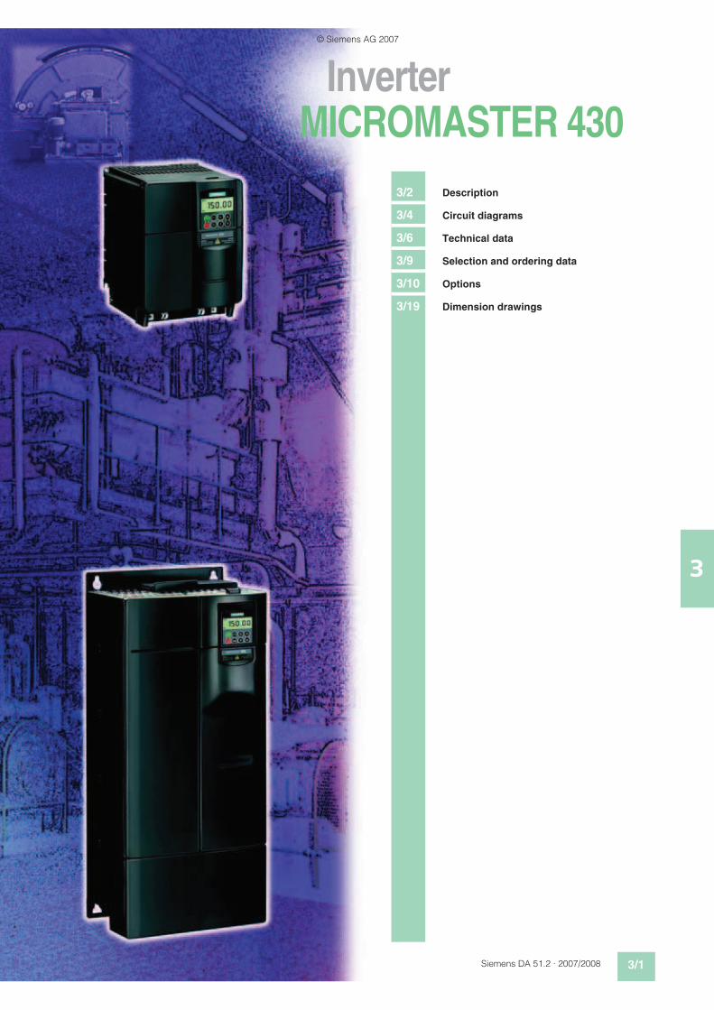
Inverter
MICROMASTER 430
3/2 Description
3/4 Circuit diagrams
3/6 Technical data
3/9 Selection and ordering data
3/10 Options
3/19 Dimension drawings
© Siemens AG 2007
3/2 Siemens DA 51.2 · 2007/2008
MICROMASTER 430
3
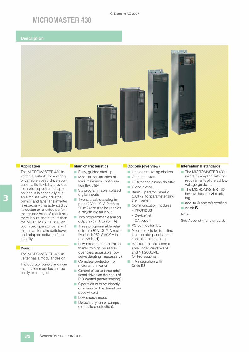
nApplication nMain characteristics nOptions (overview) n International standards
The MICROMASTER 430 in-verter is suitable for a variety of variable-speed drive appli-cations. Its flexibility provides for a wide spectrum of appli-cations. It is especially suit-able for use with industrial pumps and fans. The inverter is especially characterized by its customer-oriented perfor-mance and ease-of-use. It has more inputs and outputs than the MICROMASTER 420, an optimized operator panel with manual/automatic switchover and adapted software func-tionality.
nDesign
The MICROMASTER 430 in-verter has a modular design.
The operator panels and com-munication modules can be easily exchanged.
n Easy, guided start-up
n Modular construction al-lows maximum configura-tion flexibility
n Six programmable isolated digital inputs
n Two scaleable analog in-puts (0 V to 10 V, 0 mA to 20 mA) can also be used as a 7th/8th digital input
n Two programmable analog outputs (0 mA to 20 mA)
n Three programmable relay outputs (30 V DC/5 A resis-tive load; 250 V AC/2A in-ductive load)
n Low-noise motor operation thanks to high pulse fre-quencies, adjustable (ob-serve derating if necessary)
n Complete protection for motor and inverter
n Control of up to three addi-tional drives on the basis of PID control (motor staging)
n Operation of drive directly on mains (with external by-pass circuit)
n Low-energy mode
n Detects dry run of pumps (belt failure detection).
n Line commutating chokes
n Output chokes
n LC filter and sinusoidal filter
n Gland plates
n Basic Operator Panel 2 (BOP-2) for parameterizing the inverter
n Communication modules
– PROFIBUS
– DeviceNet
– CANopen
n PC connection kits
n Mounting kits for installing the operator panels in the control cabinet doors
n PC start-up tools execut-able under Windows 98 and NT/2000/ME/XP Professional.
n TIA integration with Drive ES
n The MICROMASTER 430 inverter complies with the requirements of the EU low-voltage guideline
n The MICROMASTER 430 inverter has the > mark-ing
n acc. to u and cu certified
n c-tick l4
Note:
See Appendix for standards.
Description
© Siemens AG 2007
Siemens DA 51.2 · 2007/2008 3/3
MICROMASTER 430
3
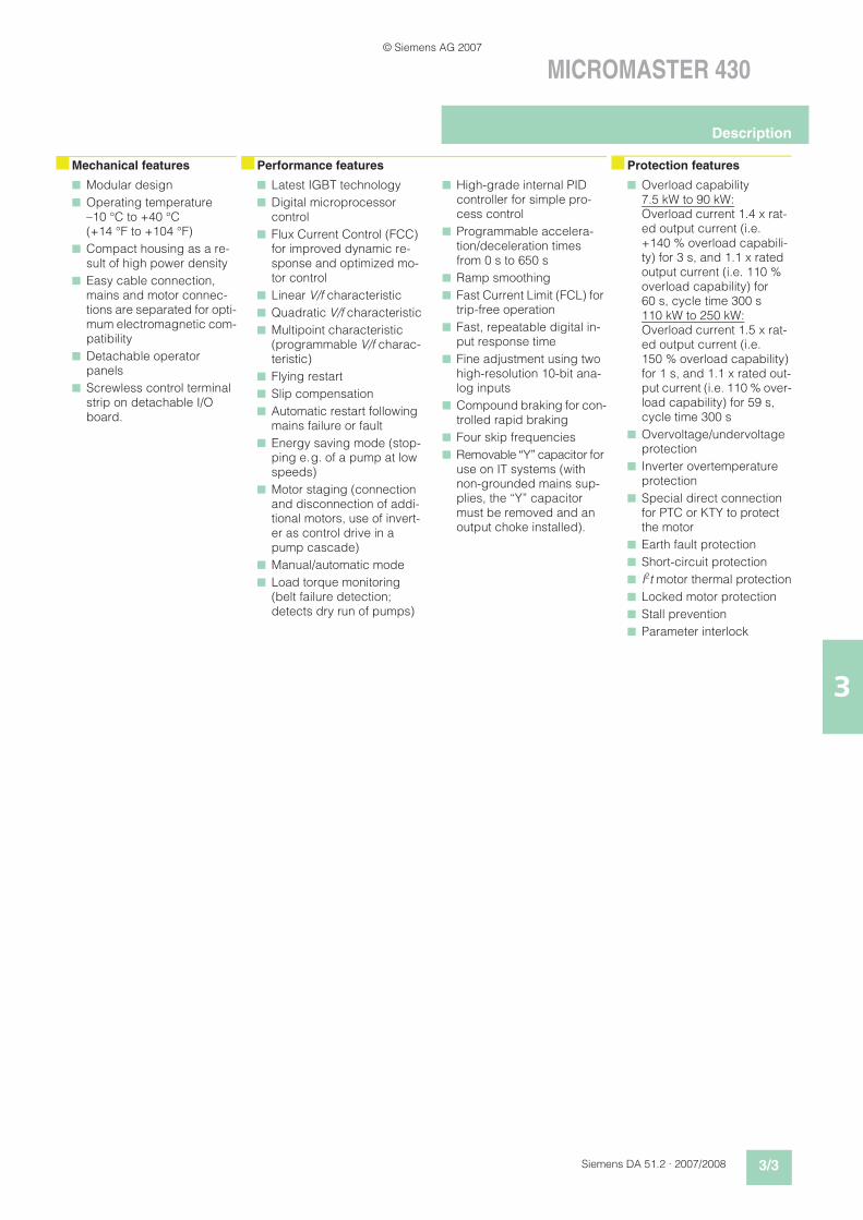
nMechanical features nPerformance features nProtection features
n Modular design
n Operating temperature–10 °C to +40 °C(+14 °F to +104 °F)
n Compact housing as a re-sult of high power density
n Easy cable connection, mains and motor connec-tions are separated for opti-mum electromagnetic com-patibility
n Detachable operator panels
n Screwless control terminal strip on detachable I/O board.
n Latest IGBT technology
n Digital microprocessor control
n Flux Current Control (FCC) for improved dynamic re-sponse and optimized mo-tor control
n Linear V/f characteristic
n Quadratic V/f characteristic
n Multipoint characteristic (programmable V/f charac-teristic)
n Flying restart
n Slip compensation
n Automatic restart following mains failure or fault
n Energy saving mode (stop-ping e.g. of a pump at low speeds)
n Motor staging (connection and disconnection of addi-tional motors, use of invert-er as control drive in a pump cascade)
n Manual/automatic mode
n Load torque monitoring (belt failure detection; detects dry run of pumps)
n High-grade internal PID controller for simple pro-cess control
n Programmable accelera-tion/deceleration times from 0 s to 650 s
n Ramp smoothing
n Fast Current Limit (FCL) for trip-free operation
n Fast, repeatable digital in-put response time
n Fine adjustment using two high-resolution 10-bit ana-log inputs
n Compound braking for con-trolled rapid braking
n Four skip frequencies
n Removable “Y” capacitor for use on IT systems (with non-grounded mains sup-plies, the “Y” capacitor must be removed and an output choke installed).
n Overload capability7.5 kW to 90 kW:Overload current 1.4 x rat-ed output current (i.e. +140 % overload capabili-ty) for 3 s, and 1.1 x rated output current (i.e. 110 % overload capability) for 60 s, cycle time 300 s110 kW to 250 kW:Overload current 1.5 x rat-ed output current (i.e. 150 % overload capability) for 1 s, and 1.1 x rated out-put current (i.e. 110 % over-load capability) for 59 s, cycle time 300 s
n Overvoltage/undervoltage protection
n Inverter overtemperature protection
n Special direct connection for PTC or KTY to protect the motor
n Earth fault protection
n Short-circuit protection
n I2t motor thermal protection
n Locked motor protection
n Stall prevention
n Parameter interlock
Description
© Siemens AG 2007
3/4 Siemens DA 51.2 · 2007/2008
MICROMASTER 430
3
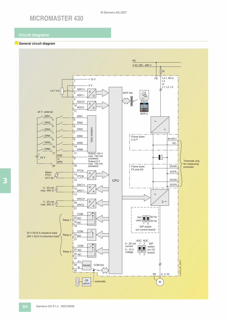
nGeneral circuit diagram
=
3 ~
A
D
A
D
PE
PE U, V, W
M
1 2
ADC ADC1 2
A/
D
A/
D
+ 10 V
0 V
NPN
PNP
DCNA
DCNS
DCPS
DCPA
B+/DC+
DC-
~
=
ADC1+
ADC2+
ADC2-
ADC1-
DIN1
DIN2
DIN3
DIN4
DIN5
DIN6
PTCA
PTCB
DAC1+
DAC2+
DAC2-
DAC1-
P+
N-
COM
COM
COM
NC
NO
NO
NO
NC
1
2
3
4
10
11
5
6
7
8
16
17
9
28
14
15
12
13
26
27
29
30
20
18
19
25
23
24
22
21
0 - 20 mAmax. 500
0 - 20 mAmax. 500
≥
0 - 20 mA
0 - 10 V
5
6
7
8
16
17
28
DIN1
DIN2
DIN3
DIN4
DIN5
DIN6
24 V
+
_
A
D
A
D
RS485
PE
SI
3 AC 380 - 480 V
1 2
60 Hz
50 Hz
Ω
A
D
150.00
BOP-2
RS232
~
=
CPU
L/L1, N/L2,
L3
L1, L2, L3
4,7 k
or
or
Motor
30 V DC/5 A (resistive load)
250 V AC/2 A (inductive load)
Frame sizes
C to F
Frame sizes
FX and GX
max. 100 mA(isolated)
Output +24 V
max. 100 mA(isolated)
Output 0 V
current
voltage
automatic
Terminals only
for measuring
purposes
Not
used
DIP switch
(on control board)
DIP
switch
(on I/O
board)
Opto isolation
G_DA51_EN _00012
COM link
BOP link
24 V external
Relay 3
Relay 2
Relay 1
CB
option
PTC/
KTY 84
Circuit diagrams
© Siemens AG 2007
Siemens DA 51.2 · 2007/2008 3/5
MICROMASTER 430
3
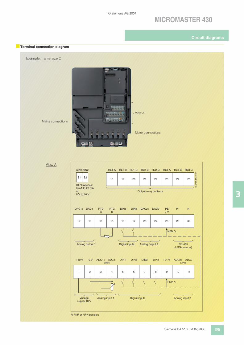
nTerminal connection diagram
22 24 252318 20 2119
27 29 302818 17 261612 14 1513
8 10 1196 751 3 42
RL1-A RL2-BRL1-B RL1-C RL2-C RL3-A RL3-B RL3-C
DAC1+ DAC1- P+ N-DIN5 DIN6 DAC2+ DAC2-PTCA
PTCB
PE0 V
+10 V 0 V ADC1+ ADC1- DIN1 DIN2 DIN3 DIN4 ADC2+ ADC2-+24 V
S2S1
(DIN7) (DIN8)
AIN1 AIN2
NPN *)
PNP *)
DIP Switches:0 mA to 20 mA or0 V to 10 V
Output relay contacts
Analog output 1 Digital inputs Analog output 2 RS-485(USS-protocol)
Voltagesupply 10 V
Digital inputsAnalog input 1 Analog input 2
*) PNP or NPN possible
G_D
A51_E
N_05107
View A
Example, frame size C
View A
Mains connections
Motor connections
Circuit diagrams
© Siemens AG 2007
3/6 Siemens DA 51.2 · 2007/2008
MICROMASTER 430
3
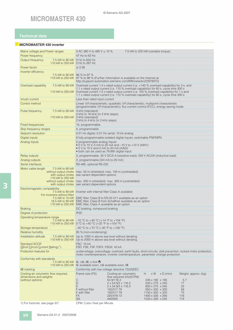
nMICROMASTER 430 inverter
Mains voltage and Power ranges 3 AC 380 V to 480 V ± 10 % 7.5 kW to 250 kW (variable torque)
Power frequency 47 Hz to 63 Hz
Output frequency 7.5 kW to 90 kW110 kW to 250 kW
0 Hz to 650 Hz0 Hz to 267 Hz
Power factor 0.95
Inverter efficiency7.5 kW to 90 kW
110 kW to 250 kW96 % to 97 %97 % to 98 % (Further information is available on the Internet at: http://support.automation.siemens.com/WW/view/en/22978972)
Overload capability 7.5 kW to 90 kW
110 kW to 250 kW
Overload current 1.4 x rated output current (i.e. +140 % overload capability) for 3 s, and 1.1 x rated output current (i.e. 110 % overload capability) for 60 s, cycle time 300 sOverload current 1.5 x rated output current (i.e. 150 % overload capability) for 1 s and1.1 x rated output current (i.e. 110 % overload capability) for 60 s, cycle time 300 s
Inrush current Less than rated input current
Control method Linear V/f characteristic; quadratic V/f characteristic; multipoint characteristic (programmable V/f characteristic); flux current control (FCC), energy saving mode
Pulse frequency 7.5 kW to 90 kW
110 kW to 250 kW
4 kHz (standard)2 kHz to 16 kHz (in 2 kHz steps)2 kHz (standard)2 kHz to 4 kHz (in 2 kHz steps)
Fixed frequencies 15, programmable
Skip frequency ranges 4, programmable
Setpoint resolution 0.01 Hz digital; 0.01 Hz serial; 10 bit analog
Digital inputs 6 fully programmable isolated digital inputs; switchable PNP/NPN
Analog inputs 2 programmable analog inputs• 0 V to 10 V, 0 mA to 20 mA and –10 V to +10 V (AIN1)• 0 V to 10 V and 0 mA to 20 mA (AIN2)• both can be used as 7th/8th digital input
Relay outputs 3, programmable, 30 V DC/5 A (resistive load); 250 V AC/2A (inductive load)
Analog outputs 2, programmable (0/4 mA to 20 mA)
Serial interfaces RS-485, optional RS-232
Motor cable length 7.5 kW to 90 kWwithout output choke
with output choke110 kW to 250 kW
without output chokewith output choke
max. 50 m (shielded); max. 100 m (unshielded)see variant dependent options
max. 200 m (shielded); max. 300 m (unshielded)see variant dependent options
Electromagnetic compatibility7.5 kW to 90 kW
For inverters without filter7.5 kW to 15 kW
18.5 kW to 90 kW110 kW to 250 kW
Inverter with internal filter Class A available
EMC filter, Class B to EN 55 011 available as an optionEMC filter, Class B from Schaffner available as an optionEMC filter, Class A available as an option
Braking DC braking, compound braking
Degree of protection IP20
Operating temperature range7.5 kW to 90 kW
110 kW to 250 kW–10 °C to +40 °C (+14 °F to +104 °F)0 °C to +40 °C (+32 °F to +104 °F)
Storage temperature –40 °C to +70 °C (–40 °F to +158 °F)
Relative humidity 95 % (non-condensing)
Installation altitude 7.5 kW to 90 kW110 kW to 250 kW
Up to 1000 m above sea level without deratingUp to 2000 m above sea level without derating
Standard SCCR (Short Circuit Current Rating) 1)
FSC: 10 kAFSD, FSE, FSF, FSFX, FSGX: 42 kA
Protection features for undervoltage, overvoltage, overload, earth faults, short-circuits, stall prevention, locked motor protection, motor overtemperature, inverter overtemperature, parameter change protection
Conformity with standards7.5 kW to 90 kW
110 kW to 250 kWu, cu, >, c-tick l4u available soon, cu available soon, >
> marking Conformity with low-voltage directive 73/23/EEC
Cooling-air volumetric flow required, dimensions and weights (without options)
Frame size (FS)
CDE F without filterF with filterFXGX
Cooling-air volumetric flow required (l/s)/(CFM) 54.9/116.32 x 54.9/2 x 116.32 x 54.9/2 x 116.3150/317.79150/317.79225/478.13440/935
H x W x D (mm)
245 x 185 x 195520 x 275 x 245650 x 275 x 245850 x 350 x 320
1150 x 350 x 3201400 x 326 x 3561533 x 326 x 545
Weight, approx. (kg)
5.717225675
116174
1) For footnote, see page 3/7. CFM: Cubic Feet per Minute
Technical data
© Siemens AG 2007
Siemens DA 51.2 · 2007/2008 3/7
MICROMASTER 430
3
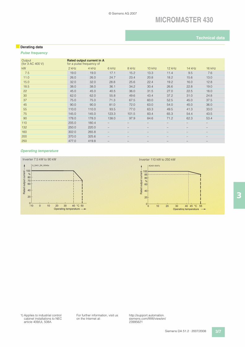
nDerating data
Pulse frequency
Operating temperature
Output(for 3 AC 400 V)
Rated output current in Afor a pulse frequency of
kW 2 kHz 4 kHz 6 kHz 8 kHz 10 kHz 12 kHz 14 kHz 16 kHz
7.5 19.0 19.0 17.1 15.2 13.3 11.4 9.5 7.6
11.0 26.0 26.0 24.7 23.4 20.8 18.2 15.6 13.0
15.0 32.0 32.0 28.8 25.6 22.4 19.2 16.0 12.8
18.5 38.0 38.0 36.1 34.2 30.4 26.6 22.8 19.0
22 45.0 45.0 40.5 36.0 31.5 27.0 22.5 18.0
30 62.0 62.0 55.8 49.6 43.4 37.2 31.0 24.8
37 75.0 75.0 71.3 67.5 60.0 52.5 45.0 37.5
45 90.0 90.0 81.0 72.0 63.0 54.0 45.0 36.0
55 110.0 110.0 93.5 77.0 63.3 49.5 41.3 33.0
75 145.0 145.0 123.3 101.5 83.4 65.3 54.4 43.5
90 178.0 178.0 138.0 97.9 84.6 71.2 62.3 53.4
110 205.0 180.4 – – – – – –
132 250.0 220.0 – – – – – –
160 302.0 265.8 – – – – – –
200 370.0 325.6 – – – – – –
250 477.0 419.8 – – – – – –
60
0
20
40
80
100
%
300 2010 5040 °C-10
70
Rated output current
Operating temperature
G_DA51_EN_05045a
4 0
6 0
00
2 0
4 0
8 0
D A 5 1 - 5 0 4 7 a
1 0 0
1 0
%
5 5° C
8 5
2 0 3 0 4 5
Rated output current
O p e r a t i n g t e m p e r a t u r e
A
Inverter 7.5 kW to 90 kW Inverter 110 kW to 250 kW
1) Applies to industrial control cabinet installations to NEC article 409/UL 508A.
For further information, visit us on the Internet at:
http://support.automation.siemens.com/WW/view/en/23995621
Technical data
© Siemens AG 2007
3/8 Siemens DA 51.2 · 2007/2008
MICROMASTER 430
3
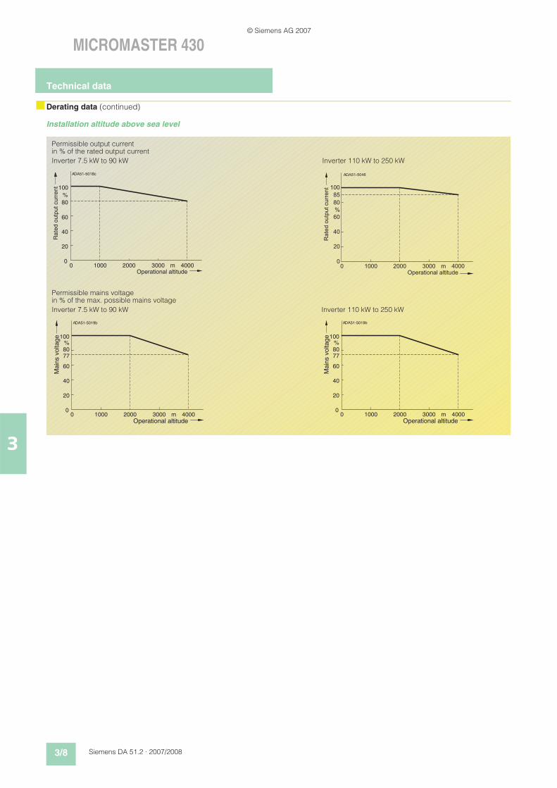
nDerating data (continued)
Installation altitude above sea level
2000
60
0 40000
20
40
80
DA51-5046
100
1000
%
3000 m
85
Rate
d o
utp
ut curr
ent
Operational altitude
A
2000
60
0 40000
20
40
80
DA51-5019b
100
1000
%
3000 m
77
Main
s v
oltage
Operational altitude
A
Permissible output current in % of the rated output current
Inverter 7.5 kW to 90 kW
2000
60
0 40000
20
40
80
DA51-5018c
100
1000
%
3000 m
Ra
ted o
utp
ut curr
en
t
Operational altitude
A
2000
60
0 40000
20
40
80
DA51-5019b
100
1000
%
3000 m
77
Main
s v
oltage
Operational altitude
A
Permissible mains voltage in % of the max. possible mains voltage
Inverter 7.5 kW to 90 kW
Inverter 110 kW to 250 kW
Inverter 110 kW to 250 kW
Technical data
© Siemens AG 2007
Siemens DA 51.2 · 2007/2008 3/9
MICROMASTER 430
3
nMICROMASTER 430 inverter
Output Rated input current
Rated output current
Frame size Order No.
kW hp A A (FS)
MICROMASTER 430 without filter 4)
MICROMASTER 430 with internal filter Class A 3)
Mains operating voltage 3 AC 380 V to 480 V
7.5 10 17.3 1) 19 C 6SE6430-2UD27-5CA0 6SE6430-2AD27-5CA0
11.0 15 23.1 1) 26 C 6SE6430-2UD31-1CA0 6SE6430-2AD31-1CA0
15.0 20 33.8 1) 32 C 6SE6430-2UD31-5CA0 6SE6430-2AD31-5CA0
18.5 25 37.0 1) 38 D 6SE6430-2UD31-8DA0 6SE6430-2AD31-8DA0
22 30 43.0 1) 45 D 6SE6430-2UD32-2DA0 6SE6430-2AD32-2DA0
30 40 59.0 1) 62 D 6SE6430-2UD33-0DA0 6SE6430-2AD33-0DA0
37 50 72.0 1) 75 E 6SE6430-2UD33-7EA0 6SE6430-2AD33-7EA0
45 60 87.0 1) 90 E 6SE6430-2UD34-5EA0 6SE6430-2AD34-5EA0
55 75 104.0 1) 110 F 6SE6430-2UD35-5FA0 6SE6430-2AD35-5FA0
75 100 139.0 1) 145 F 6SE6430-2UD37-5FA0 6SE6430-2AD37-5FA0
90 120 169.0 1) 178 F 6SE6430-2UD38-8FA0 6SE6430-2AD38-8FA0
110 150 200.0 2) 205 FX 6SE6430-2UD41-1FA0 –
132 200 245.0 2) 250 FX 6SE6430-2UD41-3FA0 –
160 250 297.0 2) 302 GX 6SE6430-2UD41-6GA0 –
200 300 354.0 2) 370 GX 6SE6430-2UD42-0GA0 –
250 350 442.0 2) 477 GX 6SE6430-2UD42-5GA0 –
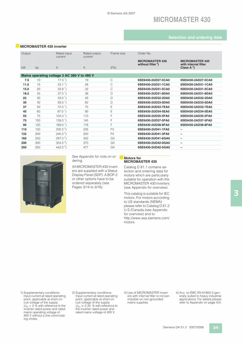
See Appendix for note on or-dering.
All MICROMASTER 430 invert-ers are supplied with a Status Display Panel (SDP). A BOP-2 or other options have to be ordered separately (see Pages 3/14 to 3/16).
nMotors for MICROMASTER 430
Catalog D 81.1 contains se-lection and ordering data for motors which are particularly suitable for operation with the MICROMASTER 430 inverters (see Appendix for overview).
This catalog is suitable for IEC motors. For motors according to US standards (NEMA) please refer to Catalog D 81.2 U.S./Canada (see Appendix for overview) and to: http://www.sea.siemens.com/motors
1) Supplementary conditions: Input current at rated operating point, applicable at short-cir-cuit voltage of the supply USC = 2 % with reference to the inverter rated power and rated mains operating voltage of 400 V without a line commutat-ing choke.
2) Supplementary conditions: Input current at rated operating point, applicable at short-cir-cuit voltage of the supply USC $ 2.33 % with reference to the inverter rated power and rated mains voltage of 400 V.
3) Use of MICROMASTER invert-ers with internal filter is not per-missible on non-grounded mains supplies.
4) Acc. to EMC EN 61800-3 gen-erally suited to heavy industrial applications. For details please refer to Appendix on page A/4.
Selection and ordering data
© Siemens AG 2007
3/10 Siemens DA 51.2 · 2007/2008
MICROMASTER 430
3nTechnical data
LC filter and sinusoidal filter
nOverview
EMC filter, Class A
All 7.5 kW to 90 kW inverters are supplied with an internal filter Class A. For inverters 110 kW to 250 kW, EMC filters Class A are available. In this perfor-mance range, the EMC filters are only permitted to be used in combination with a line commutating choke.
The requirements are fulfilled using shielded cables with a max. length of 25 m.
EMC filter, Class B
Available for inverters 7.5 kW to 15 kW with an internal Class A EMC filter.
The requirements are fulfilled using shielded cables with a max. length of 25 m.
For inverters 18.5 kW to 90 kW without filters, EMC filters of Class B from Schaffner can be used.
The requirements are fulfilled using shielded cables with a max. length of 25 m to 50 m (depending on the type, de-tails on request).
With this filter, the inverter complies with the emission standard EN 55 011, Class B for conducted interference emissions.
Leakage currents:
The leakage currents of the in-verters with/without filter (inter-nal/external) may exceed 30 mA. Typical values in prac-tice are between 10 mA and 50 mA. The exact values de-pend on the design, environ-ment and cable lengths. Inter-ference-free operation with residual current operated de-vices with a trigger value of 30 mA cannot be guaranteed.
However, operation with resid-ual current operated devices with a trigger value of 300 mA is possible. Please refer to the Instruction Manual for details.
LC filter and sinusoidal filter
The LC filter/sinusoidal filter limits the rate of rise of voltage and the capacitive charge/discharge currents which usu-ally occur with inverter opera-tion. This means that much longer shielded motor cables are possible when using LC filters/sinusoidal filters and the service life of the motor achieves values similar to those with direct mains opera-tion. Use of an output choke isn’t required with that.
Please note when using LC filters/sinusoidal filters:
• Only V/f, FCC control per-missible
• Please observe the derating of 15 % when selecting the appropriate inverter
• Operation only permissible with 4 kHz pulse frequencyNote: Please observe derat-ing for frame sizes FX and GX.
• The output frequency is lim-ited to 150 Hz
• Operation and commission-ing only with connected mo-tor as the LC filter/sinusoidal filter is not idling-proof!
The LC filters/sinusoidal filters can be used for all MICRO-MASTER 430 inverters of frame sizes C to GX.
• Frame sizes D to F: The LC filters, frame sizes D to F, are designed for mounting upright in the con-trol cabinet. Due to leakage flux lines caused by physical sources, a minimum dis-tance of 50 mm to adjacent modules and metal parts is recommended.
• Frame sizes FX and GX: The sinusoidal filters, frame sizes FX and GX, are de-signed for mounting upright in the control cabinet. Due to leakage flux lines caused by physical sources, a mini-mum distance of 100 mm to adjacent modules and metal parts is recommended.
Mains voltage 3 AC 380 V to 480 V
Current (at 40 °C/50 °C)For frame size C (7.5 to 15 kW)For frame size D (18.5 kW)For frame size D (22 kW)For frame size D (30 kW)For frame size E (37 kW)For frame size E (45 kW)For frame size F (55 kW)For frame size F (75 kW)For frame size F (90 kW)
32.6 A/ 26 A38.8 A/ 32 A45.9 A/ 38 A63.2 A/ 45 A76.5 A/ 62 A
112.2 A/ 90 A112.2 A/ 90 A147.9 A/110 A181.6 A/145 A
Current (at 40 °C/55 °C)For frame size FX (110 kW and 132 kW)For frame size GX (160 kW)For frame size GX (200 kW)For frame size GX (250 kW)
225 A/191 A276 A/235 A333 A/283 A408 A/347 A
Limiting of motor overvoltage 1078 V
dV/dt limiting 500 V/!s
Pulse frequency 4 kHz
Max. motor frequency 150 Hz
OptionsVariant dependent options
© Siemens AG 2007
Siemens DA 51.2 · 2007/2008 3/11
MICROMASTER 430
3
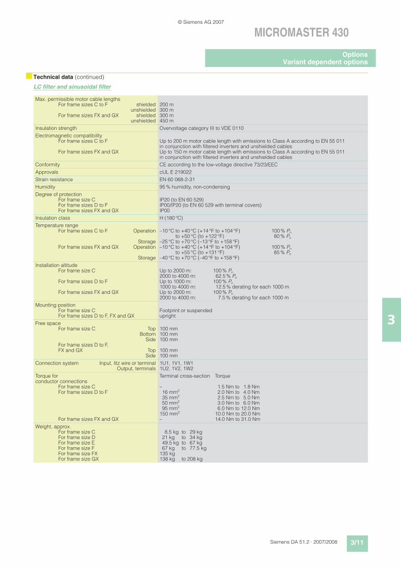
nTechnical data (continued)
LC filter and sinusoidal filter
Max. permissible motor cable lengthsFor frame sizes C to F shielded
unshieldedFor frame sizes FX and GX shielded
unshielded
200 m300 m300 m450 m
Insulation strength Overvoltage category III to VDE 0110
Electromagnetic compatibility For frame sizes C to F
For frame sizes FX and GX
Up to 200 m motor cable length with emissions to Class A according to EN 55 011 in conjunction with filtered inverters and unshielded cables Up to 150 m motor cable length with emissions to Class A according to EN 55 011 in conjunction with filtered inverters and unshielded cables
Conformity CE according to the low-voltage directive 73/23/EEC
Approvals cUL E 219022
Strain resistance EN 60 068-2-31
Humidity 95 % humidity, non-condensing
Degree of protectionFor frame size CFor frame sizes D to FFor frame sizes FX and GX
IP20 (to EN 60 529)IP00/IP20 (to EN 60 529 with terminal covers)IP00
Insulation class H (180 °C)
Temperature rangeFor frame sizes C to F Operation
StorageFor frame sizes FX and GX Operation
Storage
–10 °C to +40 °C (+14 °F to +104 °F) 100 % Pn
to +50 °C (to +122 °F) 80 % Pn
–25 °C to +70 °C (–13 °F to +158 °F)–10 °C to +40 °C (+14 °F to +104 °F) 100 % Pn
to +55 °C (to +131 °F) 85 % Pn
–40 °C to +70 °C (–40 °F to +158 °F)
Installation altitudeFor frame size C
For frame sizes D to F
For frame sizes FX and GX
Up to 2000 m: 100 % Pn
2000 to 4000 m: 62.5 % Pn
Up to 1000 m: 100 % Pn
1000 to 4000 m: 12.5 % derating for each 1000 mUp to 2000 m: 100 % Pn
2000 to 4000 m: 7.5 % derating for each 1000 m
Mounting position For frame size C For frame sizes D to F, FX and GX
Footprint or suspended upright
Free spaceFor frame size C Top
BottomSide
For frame sizes D to F, FX and GX Top
Side
100 mm100 mm100 mm
100 mm100 mm
Connection system Input, litz wire or terminalOutput, terminals
1U1, 1V1, 1W11U2, 1V2, 1W2
Torque for conductor connections
For frame size CFor frame sizes D to F
For frame sizes FX and GX
Terminal cross-section Torque
– 1.5 Nm to 1.8 Nm16 mm2 2.0 Nm to 4.0 Nm35 mm2 2.5 Nm to 5.0 Nm50 mm2 3.0 Nm to 6.0 Nm95 mm2 6.0 Nm to 12.0 Nm
150 mm2 10.0 Nm to 20.0 Nm– 14.0 Nm to 31.0 Nm
Weight, approx.For frame size CFor frame size DFor frame size EFor frame size FFor frame size FXFor frame size GX
8.5 kg to 29 kg21 kg to 34 kg49.5 kg to 67 kg67 kg to 77.5 kg
135 kg138 kg to 208 kg
OptionsVariant dependent options
© Siemens AG 2007
3/12 Siemens DA 51.2 · 2007/2008
MICROMASTER 430
3
nTechnical data
nOverview
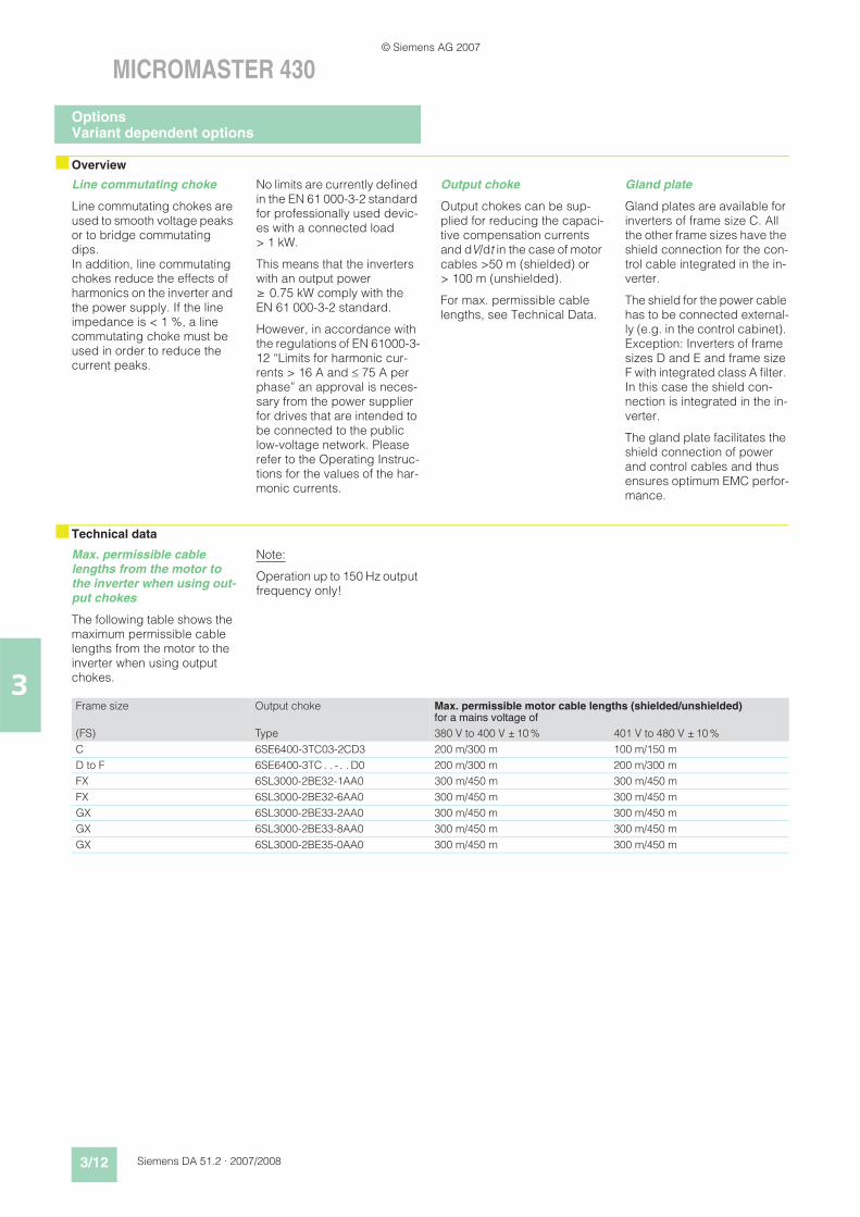
Line commutating choke
Line commutating chokes are used to smooth voltage peaks or to bridge commutating dips. In addition, line commutating chokes reduce the effects of harmonics on the inverter and the power supply. If the line impedance is < 1 %, a line commutating choke must be used in order to reduce the current peaks.
No limits are currently defined in the EN 61 000-3-2 standard for professionally used devic-es with a connected load > 1 kW.
This means that the inverters with an output power 0.75 kW comply with the EN 61 000-3-2 standard.
However, in accordance with the regulations of EN 61000-3-12 “Limits for harmonic cur-rents > 16 A and 75 A per phase” an approval is neces-sary from the power supplier for drives that are intended to be connected to the public low-voltage network. Please refer to the Operating Instruc-tions for the values of the har-monic currents.
Output choke
Output chokes can be sup-plied for reducing the capaci-tive compensation currents and dV/dt in the case of motor cables >50 m (shielded) or > 100 m (unshielded).
For max. permissible cable lengths, see Technical Data.
Gland plate
Gland plates are available for inverters of frame size C. All the other frame sizes have the shield connection for the con-trol cable integrated in the in-verter.
The shield for the power cable has to be connected external-ly (e.g. in the control cabinet). Exception: Inverters of frame sizes D and E and frame size F with integrated class A filter. In this case the shield con-nection is integrated in the in-verter.
The gland plate facilitates the shield connection of power and control cables and thus ensures optimum EMC perfor-mance.
Max. permissible cable lengths from the motor to the inverter when using out-put chokes
The following table shows the maximum permissible cable lengths from the motor to the inverter when using output chokes.
Note:
Operation up to 150 Hz output frequency only!
Frame size Output choke Max. permissible motor cable lengths (shielded/unshielded)for a mains voltage of
(FS) Type 380 V to 400 V ± 10 % 401 V to 480 V ± 10 %
C 6SE6400-3TC03-2CD3 200 m/300 m 100 m/150 m
D to F 6SE6400-3TC . . -. . D0 200 m/300 m 200 m/300 m
FX 6SL3000-2BE32-1AA0 300 m/450 m 300 m/450 m
FX 6SL3000-2BE32-6AA0 300 m/450 m 300 m/450 m
GX 6SL3000-2BE33-2AA0 300 m/450 m 300 m/450 m
GX 6SL3000-2BE33-8AA0 300 m/450 m 300 m/450 m
GX 6SL3000-2BE35-0AA0 300 m/450 m 300 m/450 m
OptionsVariant dependent options
© Siemens AG 2007
Siemens DA 51.2 · 2007/2008 3/13
MICROMASTER 430
3
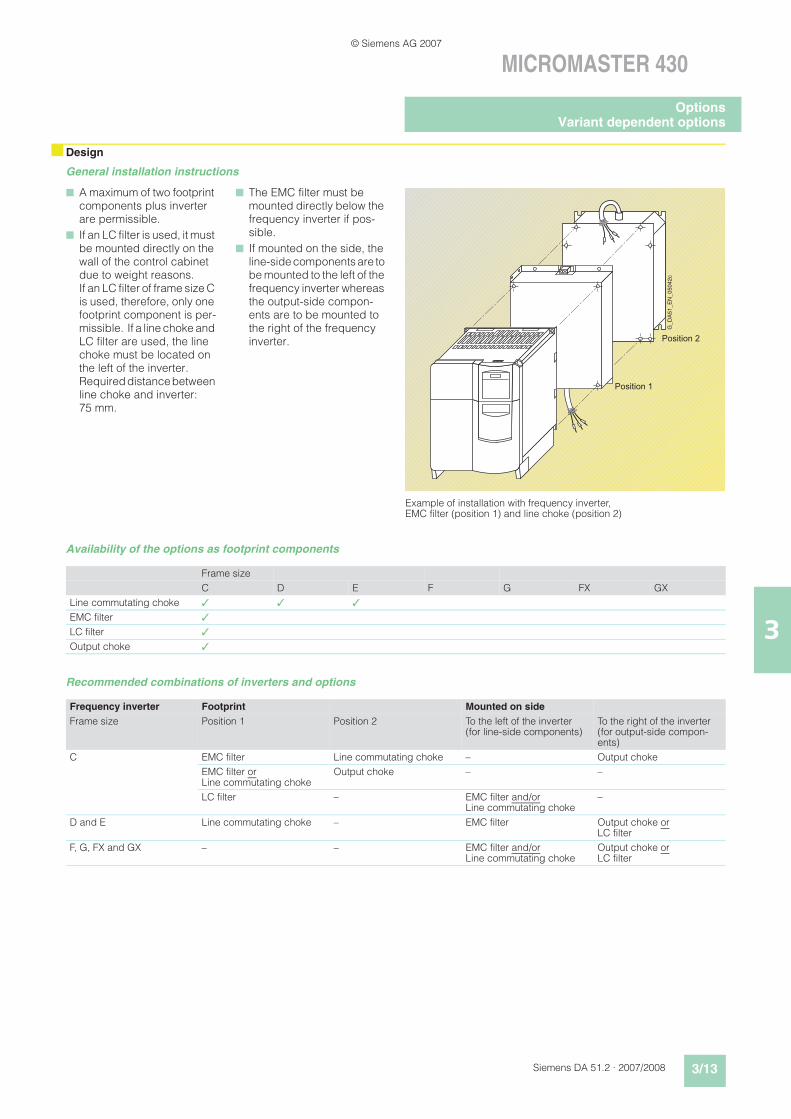
nDesign
General installation instructions
Availability of the options as footprint components
Recommended combinations of inverters and options
n A maximum of two footprint components plus inverter are permissible.
n If an LC filter is used, it must be mounted directly on the wall of the control cabinet due to weight reasons. If an LC filter of frame size C is used, therefore, only one footprint component is per-missible. If a line choke and LC filter are used, the line choke must be located on the left of the inverter. Required distance between line choke and inverter: 75 mm.
n The EMC filter must be mounted directly below the frequency inverter if pos-sible.
n If mounted on the side, the line-side components are to be mounted to the left of the frequency inverter whereas the output-side compon-ents are to be mounted to the right of the frequency inverter.
Frame size
C D E F G FX GX
Line commutating choke 3 3 3
EMC filter 3
LC filter 3
Output choke 3
Frequency inverter Footprint Mounted on side
Frame size Position 1 Position 2 To the left of the inverter (for line-side components)
To the right of the inverter (for output-side compon-ents)
C EMC filter Line commutating choke – Output choke
EMC filter orLine commutating choke
Output choke – –
LC filter – EMC filter and/orLine commutating choke
–
D and E Line commutating choke – EMC filter Output choke or LC filter
F, G, FX and GX – – EMC filter and/orLine commutating choke
Output choke or LC filter
Position 1
Position 2
G_
DA
51
_E
N_
05
04
2c
Example of installation with frequency inverter, EMC filter (position 1) and line choke (position 2)
OptionsVariant dependent options
© Siemens AG 2007
3/14 Siemens DA 51.2 · 2007/2008
MICROMASTER 430
3
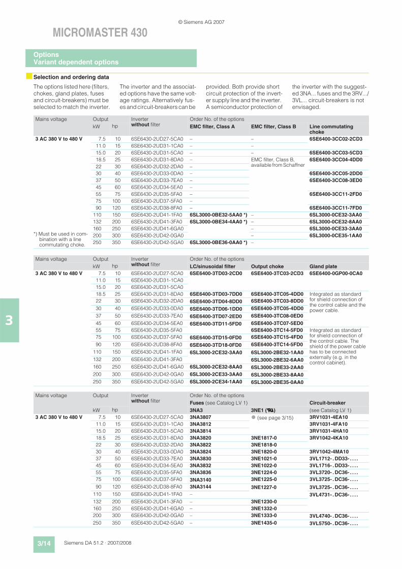
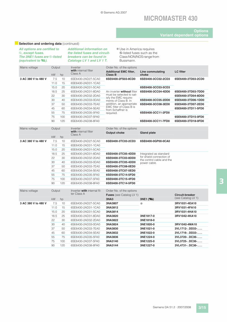
nSelection and ordering data
The options listed here (filters, chokes, gland plates, fuses and circuit-breakers) must be selected to match the inverter.
The inverter and the associat-ed options have the same volt-age ratings. Alternatively fus-es and circuit-breakers can be
provided. Both provide short circuit protection of the invert-er supply line and the inverter. A semiconductor protection of
the inverter with the suggest-ed 3NA... fuses and the 3RV.../3VL... circuit-breakers is not envisaged.
Mains voltage Output Inverterwithout filter
Order No. of the options
kW hp EMC filter, Class A EMC filter, Class B Line commutating choke
3 AC 380 V to 480 V
*) Must be used in com-bination with a line commutating choke.
7.5 10 6SE6430-2UD27-5CA0 – – 6SE6400-3CC02-2CD3
11.0 15 6SE6430-2UD31-1CA0 – –
15.0 20 6SE6430-2UD31-5CA0 – – 6SE6400-3CC03-5CD3
18.5 25 6SE6430-2UD31-8DA0 – EMC filter, Class B, available from Schaffner
6SE6400-3CC04-4DD0
22 30 6SE6430-2UD32-2DA0 –
30 40 6SE6430-2UD33-0DA0 – 6SE6400-3CC05-2DD0
37 50 6SE6430-2UD33-7EA0 – 6SE6400-3CC08-3ED0
45 60 6SE6430-2UD34-5EA0 –
55 75 6SE6430-2UD35-5FA0 – 6SE6400-3CC11-2FD0
75 100 6SE6430-2UD37-5FA0 –
90 120 6SE6430-2UD38-8FA0 – 6SE6400-3CC11-7FD0
110 150 6SE6430-2UD41-1FA0 6SL3000-0BE32-5AA0 *) – 6SL3000-0CE32-3AA0
132 200 6SE6430-2UD41-3FA0 6SL3000-0BE34-4AA0 *) – 6SL3000-0CE32-8AA0
160 250 6SE6430-2UD41-6GA0 – 6SL3000-0CE33-3AA0
200 300 6SE6430-2UD42-0GA0 – 6SL3000-0CE35-1AA0
250 350 6SE6430-2UD42-5GA0 6SL3000-0BE36-0AA0 *) –
Mains voltage Output Inverterwithout filter
Order No. of the options
kW hp LC/sinusoidal filter Output choke Gland plate
3 AC 380 V to 480 V 7.5 10 6SE6430-2UD27-5CA0 6SE6400-3TD03-2CD0 6SE6400-3TC03-2CD3 6SE6400-0GP00-0CA0
11.0 15 6SE6430-2UD31-1CA0
15.0 20 6SE6430-2UD31-5CA0
18.5 25 6SE6430-2UD31-8DA0 6SE6400-3TD03-7DD0 6SE6400-3TC05-4DD0 Integrated as standard for shield connection of the control cable and the power cable.
22 30 6SE6430-2UD32-2DA0 6SE6400-3TD04-8DD0 6SE6400-3TC03-8DD0
30 40 6SE6430-2UD33-0DA0 6SE6400-3TD06-1DD0 6SE6400-3TC05-4DD0
37 50 6SE6430-2UD33-7EA0 6SE6400-3TD07-2ED0 6SE6400-3TC08-0ED0
45 60 6SE6430-2UD34-5EA0 6SE6400-3TD11-5FD0 6SE6400-3TC07-5ED0
55 75 6SE6430-2UD35-5FA0 6SE6400-3TC14-5FD0 Integrated as standard for shield connection of the control cable. The shield of the power cable has to be connected externally (e.g. in the control cabinet).
75 100 6SE6430-2UD37-5FA0 6SE6400-3TD15-0FD0 6SE6400-3TC15-4FD0
90 120 6SE6430-2UD38-8FA0 6SE6400-3TD18-0FD0 6SE6400-3TC14-5FD0
110 150 6SE6430-2UD41-1FA0 6SL3000-2CE32-3AA0 6SL3000-2BE32-1AA0
132 200 6SE6430-2UD41-3FA0 6SL3000-2BE32-6AA0
160 250 6SE6430-2UD41-6GA0 6SL3000-2CE32-8AA0 6SL3000-2BE33-2AA0
200 300 6SE6430-2UD42-0GA0 6SL3000-2CE33-3AA0 6SL3000-2BE33-8AA0
250 350 6SE6430-2UD42-5GA0 6SL3000-2CE34-1AA0 6SL3000-2BE35-0AA0
Mains voltage Output Inverterwithout filter
Order No. of the options
Fuses (see Catalog LV 1) Circuit-breaker
kW hp 3NA3 3NE1 (U) (see Catalog LV 1)
3 AC 380 V to 480 V 7.5 10 6SE6430-2UD27-5CA0 3NA3807 (see page 3/15) 3RV1031-4EA10
11.0 15 6SE6430-2UD31-1CA0 3NA3812 3RV1031-4FA10
15.0 20 6SE6430-2UD31-5CA0 3NA3814 3RV1031-4HA10
18.5 25 6SE6430-2UD31-8DA0 3NA3820 3NE1817-0 3RV1042-4KA10
22 30 6SE6430-2UD32-2DA0 3NA3822 3NE1818-0
30 40 6SE6430-2UD33-0DA0 3NA3824 3NE1820-0 3RV1042-4MA10
37 50 6SE6430-2UD33-7EA0 3NA3830 3NE1021-0 3VL1712- . DD33- . . . .
45 60 6SE6430-2UD34-5EA0 3NA3832 3NE1022-0 3VL1716- . DD33- . . . .
55 75 6SE6430-2UD35-5FA0 3NA3836 3NE1224-0 3VL3720- . DC36- . . . .
75 100 6SE6430-2UD37-5FA0 3NA3140 3NE1225-0 3VL3725- . DC36- . . . .
90 120 6SE6430-2UD38-8FA0 3NA3144 3NE1227-0 3VL3725- . DC36- . . . .
110 150 6SE6430-2UD41-1FA0 – 3VL4731- . DC36- . . . .
132 200 6SE6430-2UD41-3FA0 – 3NE1230-0
160 250 6SE6430-2UD41-6GA0 – 3NE1332-0
200 300 6SE6430-2UD42-0GA0 – 3NE1333-0 3VL4740- . DC36- . . . .
250 350 6SE6430-2UD42-5GA0 – 3NE1435-0 3VL5750- . DC36- . . . .
OptionsVariant dependent options
© Siemens AG 2007
Siemens DA 51.2 · 2007/2008 3/15
MICROMASTER 430
3
nSelection and ordering data (continued)
All options are certified to u, except fuses. The 3NE1 fuses are u-listed (equivalent to U).
Additional information on the listed fuses and circuit-breakers can be found in Catalogs LV 1 and LV 1 T.
Use in America requires u-listed fuses such as the Class NON/NOS range from Bussmann.
Mains voltage Output Inverter with internal filter Class A
Order No. of the options
kW hpAdditional EMC filter, Class B
Line commutating choke
LC filter
3 AC 380 V to 480 V 7.5 10 6SE6430-2AD27-5CA0 6SE6400-2FS03-8CD0 6SE6400-3CC02-2CD3 6SE6400-3TD03-2CD0
11.0 15 6SE6430-2AD31-1CA0
15.0 20 6SE6430-2AD31-5CA0 6SE6400-3CC03-5CD3
18.5 25 6SE6430-2AD31-8DA0 An inverter without filter must be selected to sat-isfy the EMC require-ments of Class B. In addition, an appropriate EMC filter of Class B is from Schaffner is required.
6SE6400-3CC04-4DD0 6SE6400-3TD03-7DD0
22 30 6SE6430-2AD32-2DA0 6SE6400-3TD04-8DD0
30 40 6SE6430-2AD33-0DA0 6SE6400-3CC05-2DD0 6SE6400-3TD06-1DD0
37 50 6SE6430-2AD33-7EA0 6SE6400-3CC08-3ED0 6SE6400-3TD07-2ED0
45 60 6SE6430-2AD34-5EA0 6SE6400-3TD11-5FD0
55 75 6SE6430-2AD35-5FA0 6SE6400-3CC11-2FD0
75 100 6SE6430-2AD37-5FA0 6SE6400-3TD15-0FD0
90 120 6SE6430-2AD38-8FA0 6SE6400-3CC11-7FD0 6SE6400-3TD18-0FD0
Mains voltage Output Inverter with internal filter Class A
Order No. of the options
Output choke Gland plate
kW hp
3 AC 380 V to 480 V 7.5 10 6SE6430-2AD27-5CA0 6SE6400-3TC03-2CD3 6SE6400-0GP00-0CA0
11.0 15 6SE6430-2AD31-1CA0
15.0 20 6SE6430-2AD31-5CA0
18.5 25 6SE6430-2AD31-8DA0 6SE6400-3TC05-4DD0 Integrated as standard for shield connection of the control cable and the power cable.
22 30 6SE6430-2AD32-2DA0 6SE6400-3TC03-8DD0
30 40 6SE6430-2AD33-0DA0 6SE6400-3TC05-4DD0
37 50 6SE6430-2AD33-7EA0 6SE6400-3TC08-0ED0
45 60 6SE6430-2AD34-5EA0 6SE6400-3TC07-5ED0
55 75 6SE6430-2AD35-5FA0 6SE6400-3TC14-5FD0
75 100 6SE6430-2AD37-5FA0 6SE6400-3TC15-4FD0
90 120 6SE6430-2AD38-8FA0 6SE6400-3TC14-5FD0
Mains voltage Output Inverter with internal fil-ter Class A
Order No. of the options
Fuses (see Catalog LV 1) Circuit-breaker(see Catalog LV 1)kW hp 3NA3 3NE1 (U)
3 AC 380 V to 480 V 7.5 10 6SE6430-2AD27-5CA0 3NA3807 3RV1031-4EA10
11.0 15 6SE6430-2AD31-1CA0 3NA3812 3RV1031-4FA10
15.0 20 6SE6430-2AD31-5CA0 3NA3814 3RV1031-4HA10
18.5 25 6SE6430-2AD31-8DA0 3NA3820 3NE1817-0 3RV1042-4KA10
22 30 6SE6430-2AD32-2DA0 3NA3822 3NE1818-0
30 40 6SE6430-2AD33-0DA0 3NA3824 3NE1820-0 3RV1042-4MA10
37 50 6SE6430-2AD33-7EA0 3NA3830 3NE1021-0 3VL1712- . DD33- . . . .
45 60 6SE6430-2AD34-5EA0 3NA3832 3NE1022-0 3VL1716- . DD33- . . . .
55 75 6SE6430-2AD35-5FA0 3NA3836 3NE1224-0 3VL3720- . DC36- . . . .
75 100 6SE6430-2AD37-5FA0 3NA3140 3NE1225-0 3VL3725- . DC36- . . . .
90 120 6SE6430-2AD38-8FA0 3NA3144 3NE1227-0 3VL4731- . DC36- . . . .
OptionsVariant dependent options
© Siemens AG 2007
3/16 Siemens DA 51.2 · 2007/2008
MICROMASTER 430
3
nSelection and ordering data
n Overview
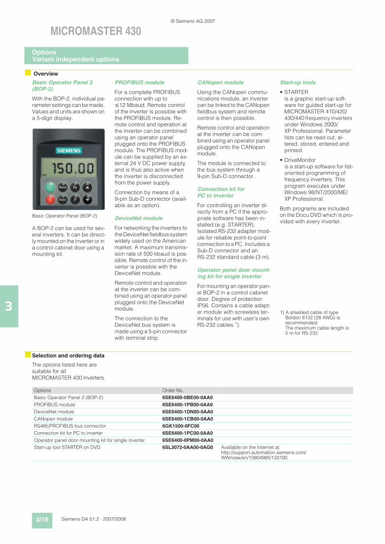
Basic Operator Panel 2 (BOP-2)
With the BOP-2, individual pa-rameter settings can be made. Values and units are shown on a 5-digit display.
Basic Operator Panel (BOP-2)
A BOP-2 can be used for sev-eral inverters. It can be direct-ly mounted on the inverter or in a control cabinet door using a mounting kit.
PROFIBUS module
For a complete PROFIBUS connection with up to 12 Mbaud. Remote control of the inverter is possible with the PROFIBUS module. Re-mote control and operation at the inverter can be combined using an operator panel plugged onto the PROFIBUS module. The PROFIBUS mod-ule can be supplied by an ex-ternal 24 V DC power supply and is thus also active when the inverter is disconnected from the power supply.
Connection by means of a 9-pin Sub-D connector (avail-able as an option).
DeviceNet module
For networking the inverters to the DeviceNet fieldbus system widely used on the American market. A maximum transmis-sion rate of 500 kbaud is pos-sible. Remote control of the in-verter is possible with the DeviceNet module.
Remote control and operation at the inverter can be com-bined using an operator panel plugged onto the DeviceNet module.
The connection to the DeviceNet bus system is made using a 5-pin connector with terminal strip.
CANopen module
Using the CANopen commu-nications module, an inverter can be linked to the CANopen fieldbus system and remote control is then possible.
Remote control and operation at the inverter can be com-bined using an operator panel plugged onto the CANopen module.
The module is connected to the bus system through a 9-pin Sub-D connector.
Connection kit forPC to inverter
For controlling an inverter di-rectly from a PC if the appro-priate software has been in-stalled (e.g. STARTER). Isolated RS-232 adapter mod-ule for reliable point-to-point connection to a PC. Includes a Sub-D connector and an RS-232 standard cable (3 m).
Operator panel door mount-ing kit for single inverter
For mounting an operator pan-el BOP-2 in a control cabinet door. Degree of protection IP56. Contains a cable adapt-er module with screwless ter-minals for use with user's own RS-232 cables 1).
Start-up tools
• STARTER is a graphic start-up soft-ware for guided start-up for MICROMASTER 410/420/430/440 frequency inverters under Windows 2000/XP Professional. Parameter lists can be read out, al-tered, stored, entered and printed.
• DriveMonitor is a start-up software for list-oriented programming of frequency inverters. This program executes under Windows 98/NT/2000/ME/XP Professional.
Both programs are included on the Docu DVD which is pro-vided with every inverter.
1) A shielded cable of type Belden 8132 (28 AWG) is recommended.The maximum cable length is 5 m for RS-232.
The options listed here are suitable for all MICROMASTER 430 inverters.
Options Order No.
Basic Operator Panel 2 (BOP-2) 6SE6400-0BE00-0AA0
PROFIBUS module 6SE6400-1PB00-0AA0
DeviceNet module 6SE6400-1DN00-0AA0
CANopen module 6SE6400-1CB00-0AA0
RS485/PROFIBUS bus connector 6GK1500-0FC00
Connection kit for PC to inverter 6SE6400-1PC00-0AA0
Operator panel door mounting kit for single inverter 6SE6400-0PM00-0AA0
Start-up tool STARTER on DVD 6SL3072-0AA00-0AG0 Available on the Internet at: http://support.automation.siemens.com/WW/view/en/10804985/133100
OptionsVariant independent options
© Siemens AG 2007
Siemens DA 51.2 · 2007/2008 3/17
MICROMASTER 430
3
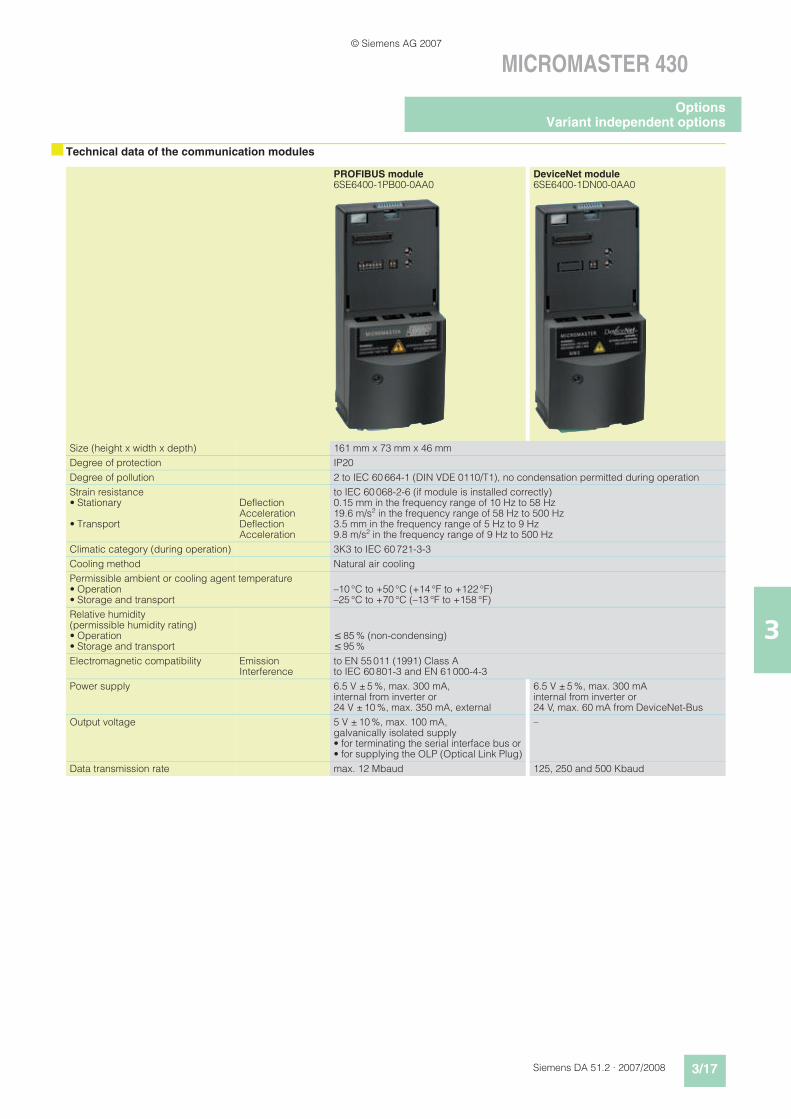
nTechnical data of the communication modules
PROFIBUS module6SE6400-1PB00-0AA0
DeviceNet module6SE6400-1DN00-0AA0
Size (height x width x depth) 161 mm x 73 mm x 46 mm
Degree of protection IP20
Degree of pollution 2 to IEC 60 664-1 (DIN VDE 0110/T1), no condensation permitted during operation
Strain resistance• Stationary
• Transport
DeflectionAccelerationDeflectionAcceleration
to IEC 60 068-2-6 (if module is installed correctly) 0.15 mm in the frequency range of 10 Hz to 58 Hz19.6 m/s2 in the frequency range of 58 Hz to 500 Hz3.5 mm in the frequency range of 5 Hz to 9 Hz9.8 m/s2 in the frequency range of 9 Hz to 500 Hz
Climatic category (during operation) 3K3 to IEC 60 721-3-3
Cooling method Natural air cooling
Permissible ambient or cooling agent temperature• Operation• Storage and transport
–10 °C to +50 °C (+14 °F to +122 °F)–25 °C to +70 °C (–13 °F to +158 °F)
Relative humidity(permissible humidity rating)• Operation• Storage and transport
85 % (non-condensing) 95 %
Electromagnetic compatibility EmissionInterference
to EN 55 011 (1991) Class Ato IEC 60 801-3 and EN 61 000-4-3
Power supply 6.5 V ± 5 %, max. 300 mA, internal from inverter or 24 V ± 10 %, max. 350 mA, external
6.5 V ± 5 %, max. 300 mA internal from inverter or 24 V, max. 60 mA from DeviceNet-Bus
Output voltage 5 V ± 10 %, max. 100 mA, galvanically isolated supply• for terminating the serial interface bus or• for supplying the OLP (Optical Link Plug)
–
Data transmission rate max. 12 Mbaud 125, 250 and 500 Kbaud
OptionsVariant independent options
© Siemens AG 2007
3/18 Siemens DA 51.2 · 2007/2008
MICROMASTER 430
3
nTechnical data of the communication modules (continued)
nSelection and ordering data
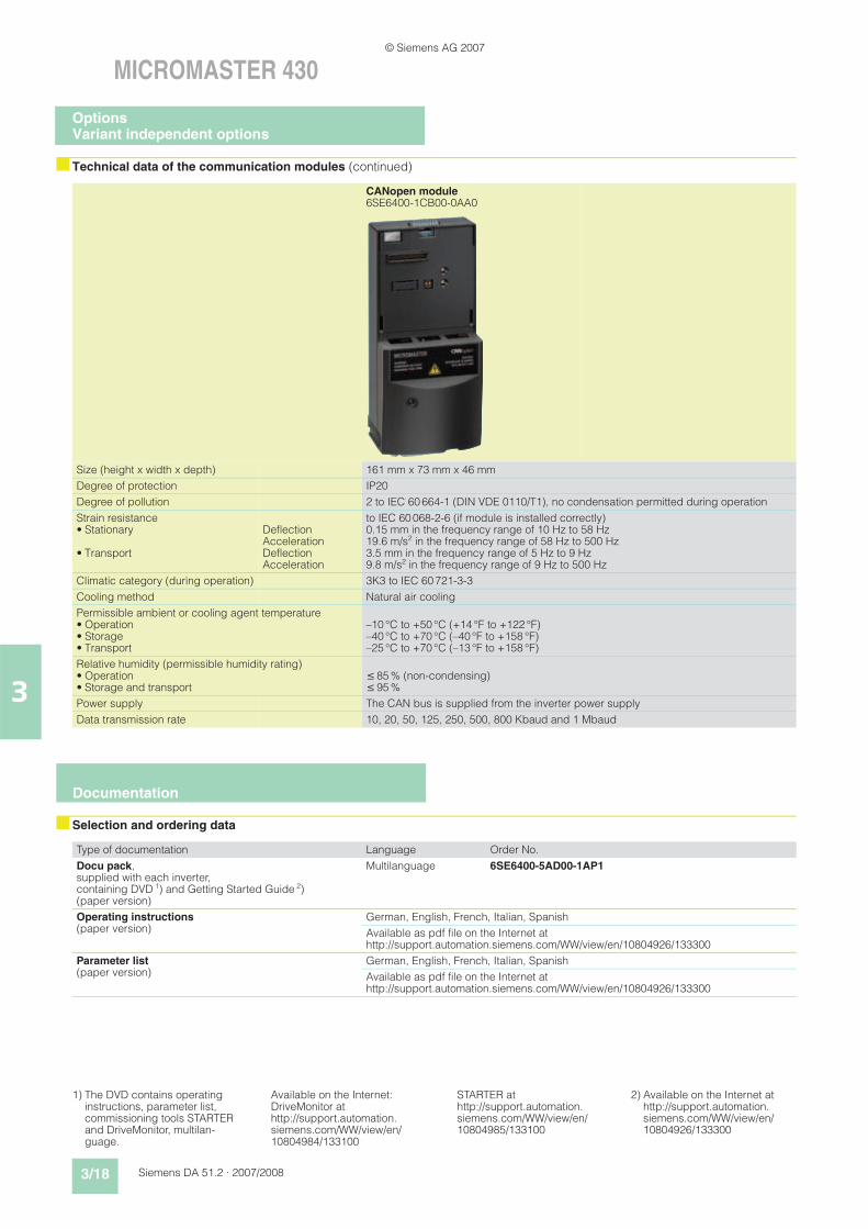
CANopen module6SE6400-1CB00-0AA0
Size (height x width x depth) 161 mm x 73 mm x 46 mm
Degree of protection IP20
Degree of pollution 2 to IEC 60 664-1 (DIN VDE 0110/T1), no condensation permitted during operation
Strain resistance• Stationary
• Transport
DeflectionAccelerationDeflectionAcceleration
to IEC 60 068-2-6 (if module is installed correctly) 0.15 mm in the frequency range of 10 Hz to 58 Hz19.6 m/s2 in the frequency range of 58 Hz to 500 Hz3.5 mm in the frequency range of 5 Hz to 9 Hz9.8 m/s2 in the frequency range of 9 Hz to 500 Hz
Climatic category (during operation) 3K3 to IEC 60 721-3-3
Cooling method Natural air cooling
Permissible ambient or cooling agent temperature• Operation• Storage• Transport
–10 °C to +50 °C (+14 °F to +122 °F)–40 °C to +70 °C (–40 °F to +158 °F)–25 °C to +70 °C (–13 °F to +158 °F)
Relative humidity (permissible humidity rating)• Operation• Storage and transport
85 % (non-condensing) 95 %
Power supply The CAN bus is supplied from the inverter power supply
Data transmission rate 10, 20, 50, 125, 250, 500, 800 Kbaud and 1 Mbaud
Type of documentation Language Order No.
Docu pack,supplied with each inverter, containing DVD 1) and Getting Started Guide 2) (paper version)
Multilanguage 6SE6400-5AD00-1AP1
Operating instructions(paper version)
German, English, French, Italian, Spanish
Available as pdf file on the Internet at http://support.automation.siemens.com/WW/view/en/10804926/133300
Parameter list
(paper version)German, English, French, Italian, Spanish
Available as pdf file on the Internet at http://support.automation.siemens.com/WW/view/en/10804926/133300
Documentation
1) The DVD contains operating instructions, parameter list, commissioning tools STARTER and DriveMonitor, multilan-guage.
Available on the Internet: DriveMonitor at http://support.automation.siemens.com/WW/view/en/10804984/133100
STARTER at http://support.automation.siemens.com/WW/view/en/10804985/133100
2) Available on the Internet at http://support.automation.siemens.com/WW/view/en/10804926/133300
OptionsVariant independent options
© Siemens AG 2007
Siemens DA 51.2 · 2007/2008 3/19
MICROMASTER 430
3
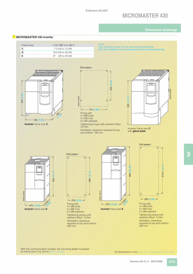
nMICROMASTER 430 inverter
With the communication module, the mounting depth increases for frame size C by 23 mm (0.91 inches).
Frame size 3 AC 380 V to 480 V
C 7.5 kW to 15 kW
D 18.5 kW to 30 kW
E 37 kW to 45 kW
Drill pattern
AD
A51-5
002d
185 (7.28)
245 (
9.6
5)
195
(7.6
8)
204 (
8.0
3)
174 (6.85)
Fixing with4 x M5 bolts4 x M5 nuts4 x M5 washers
Tightening torque with washers fitted: 3.0 Nm
Ventilation clearance required at top and bottom: 100 mm
Inverter frame size C
AD
A51-5
009b
309 (
12.1
6)
Inverter frame size C with gland plate
All dimensions in mm (values in brackets are in inches)
Inverter frame size D Inverter frame size E
520 (
20.4
7)
275 (10.82)
245
(9.6
5)
486 (
19.1
3)
Drill pattern
AD
A51-5
020b
235 (9.25)
Drill pattern
275 (10.82)
650 (
25.5
9)
245
(9.6
5)
AD
A51-5
021b
616.4
(24.2
7)
235 (9.25)
Fixing with4 x M8 bolts4 x M8 nuts4 x M8 washers
Tightening torque with washers fitted: 13 Nm
Ventilation clearance required at top and bottom: 300 mm
Fixing with4 x M8 bolts4 x M8 nuts4 x M8 washers
Tightening torque with washers fitted: 13 Nm
Ventilation clearance required at top and bottom: 300 mm
Note: The inverters must not be mounted horizontally. But the inverters can be mounted without lateral spacing.
Dimension drawings
© Siemens AG 2007
3/20 Siemens DA 51.2 · 2007/2008
MICROMASTER 430
3
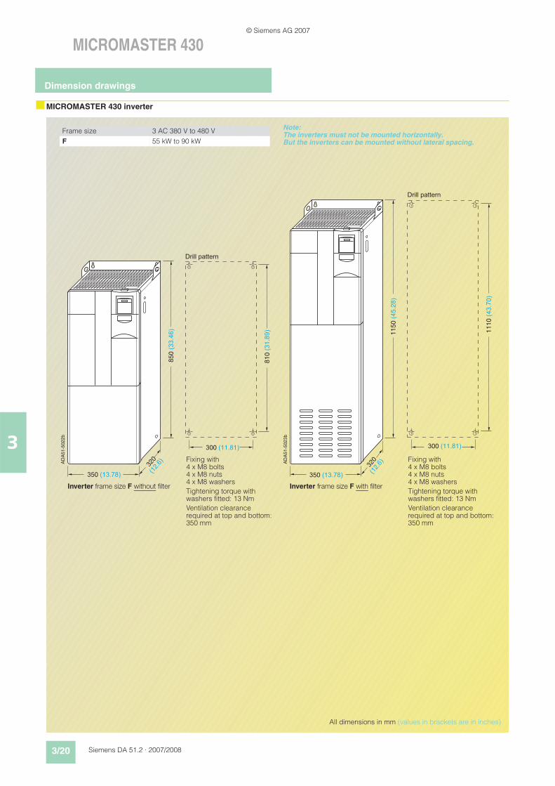
nMICROMASTER 430 inverter
All dimensions in mm (values in brackets are in inches)
Inverter frame size F without filter Inverter frame size F with filter
AD
A51-5
022b
850 (
33.4
6)
350 (13.78)
320
(12.
6)
810 (
31.8
9)
300 (11.81)
Drill pattern
AD
A51-5
023b
350 (13.78)
320
(12.
6)
300 (11.81)
Drill pattern
1150 (
45.2
8)
1110 (
43.7
0)
Fixing with4 x M8 bolts4 x M8 nuts4 x M8 washers
Tightening torque with washers fitted: 13 Nm
Ventilation clearance required at top and bottom: 350 mm
Fixing with4 x M8 bolts4 x M8 nuts4 x M8 washers
Tightening torque with washers fitted: 13 Nm
Ventilation clearance required at top and bottom: 350 mm
Frame size 3 AC 380 V to 480 V
F 55 kW to 90 kW
Note: The inverters must not be mounted horizontally. But the inverters can be mounted without lateral spacing.
Dimension drawings
© Siemens AG 2007
Siemens DA 51.2 · 2007/2008 3/21
MICROMASTER 430
3
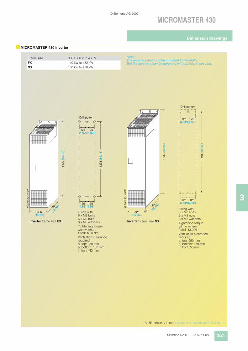
nMICROMASTER 430 inverter
G_D
A51_E
N_05074
Drill pattern
1400 (
55.1
2)
326(12.83)
356
(14.
06)
1375 (
54.1
3)
125(4.92)
125(4.92)
125(4.92)
125(4.92) G
_D
A51_E
N_05075
Drill pattern
1533 (
60.3
5)
326(12.83)
545
(21.
46)
1508 (
59.3
7)
125(4.92)
125(4.92)
125(4.92)
125(4.92)
Frame size 3 AC 380 V to 480 V
FX 110 kW to 132 kW
GX 160 kW to 250 kW
All dimensions in mm (values in brackets are in inches)
Inverter frame size FX Inverter frame size GX
Fixing with6 x M8 bolts6 x M8 nuts6 x M8 washers
Tightening torque with washers fitted: 13.0 Nm
Ventilation clearance required:at top: 250 mmat bottom: 150 mmin front: 40 mm
Fixing with6 x M8 bolts6 x M8 nuts6 x M8 washers
Tightening torque with washers fitted: 13.0 Nm
Ventilation clearance required:at top: 250 mmat bottom: 150 mmin front: 50 mm
Note: The inverters must not be mounted horizontally. But the inverters can be mounted without lateral spacing.
Dimension drawings
© Siemens AG 2007
3/22 Siemens DA 51.2 · 2007/2008
MICROMASTER 430
3
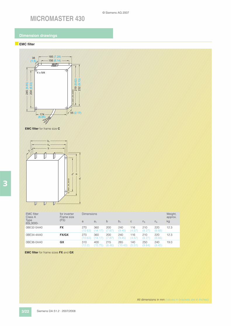
nEMC filter
G_DA51_EN_00063
185 (7.28)
156 (6.14)
55 (2.17)
245(9.65)
204(8.03)
232(9.13)
219(8.62)
4 x M4
174(6.85)
38(1.5)
EMC filter for frame size C
All dimensions in mm (values in brackets are in inches)
b1
n4
b
n3
a1
a
G_D
A51_X
X_05103
c
EMC filterClass AType 6SL3000-
for inverterFrame size (FS)
Dimensions Weight, approx.
a a1 b b1 c n3 n4 kg
0BE32-5AA0 FX 270(10.63)
360(14.17)
200(7.87)
240(9.45)
116(4.57)
210(8.27)
220(8.66)
12.3
0BE34-4AA0 FX/GX 270(10.63)
360(14.17)
200(7.87)
240(9.45)
116(4.57)
210(8.27)
220(8.66)
12.3
0BE36-0AA0 GX 310(12.2)
400(15.75)
215(8.46)
265(10.43)
140(5.51)
250(9.84)
240(9.45)
19.0
EMC filter for frame sizes FX and GX
Dimension drawings
© Siemens AG 2007
Siemens DA 51.2 · 2007/2008 3/23
MICROMASTER 430
3
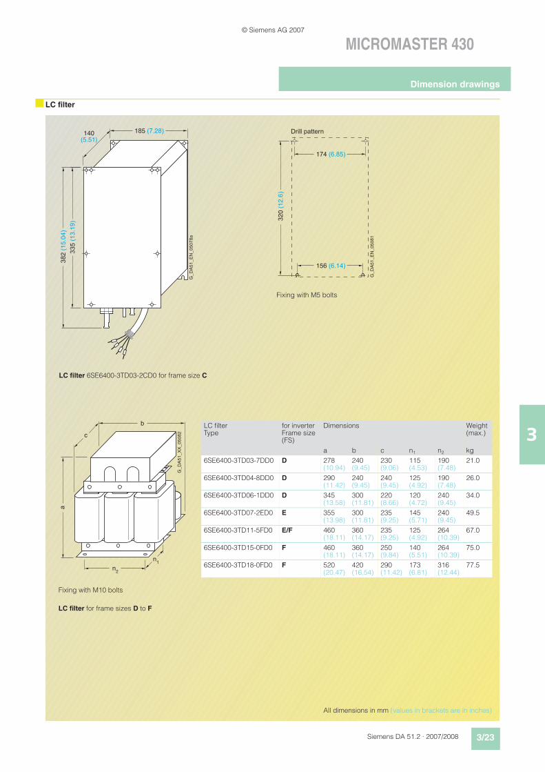
nLC filter
G_
DA
51
_E
N_
05
07
8a
185 (7.28)140(5.51)
382 (
15.0
4)
335 (
13.1
9)
Drill pattern
G_D
A51_E
N_05081
320 (
12.6
)
174 (6.85)
156 (6.14)
LC filter 6SE6400-3TD03-2CD0 for frame size C
Fixing with M5 bolts
Fixing with M10 bolts
LC filter for frame sizes D to F
b
c
a
n2
n1
G_D
A51_X
X_05082
LC filterType
for inverterFrame size (FS)
Dimensions Weight(max.)
a b c n1 n2 kg
6SE6400-3TD03-7DD0 D 278(10.94)
240(9.45)
230(9.06)
115(4.53)
190(7.48)
21.0
6SE6400-3TD04-8DD0 D 290(11.42)
240(9.45)
240(9.45)
125(4.92)
190(7.48)
26.0
6SE6400-3TD06-1DD0 D 345(13.58)
300(11.81)
220(8.66)
120(4.72)
240(9.45)
34.0
6SE6400-3TD07-2ED0 E 355(13.98)
300(11.81)
235(9.25)
145(5.71)
240(9.45)
49.5
6SE6400-3TD11-5FD0 E/F 460(18.11)
360(14.17)
235(9.25)
125(4.92)
264(10.39)
67.0
6SE6400-3TD15-0FD0 F 460(18.11)
360(14.17)
250(9.84)
140(5.51)
264(10.39)
75.0
6SE6400-3TD18-0FD0 F 520(20.47)
420(16.54)
290(11.42)
173(6.81)
316(12.44)
77.5
All dimensions in mm (values in brackets are in inches)
Dimension drawings
© Siemens AG 2007
3/24 Siemens DA 51.2 · 2007/2008
MICROMASTER 430
3
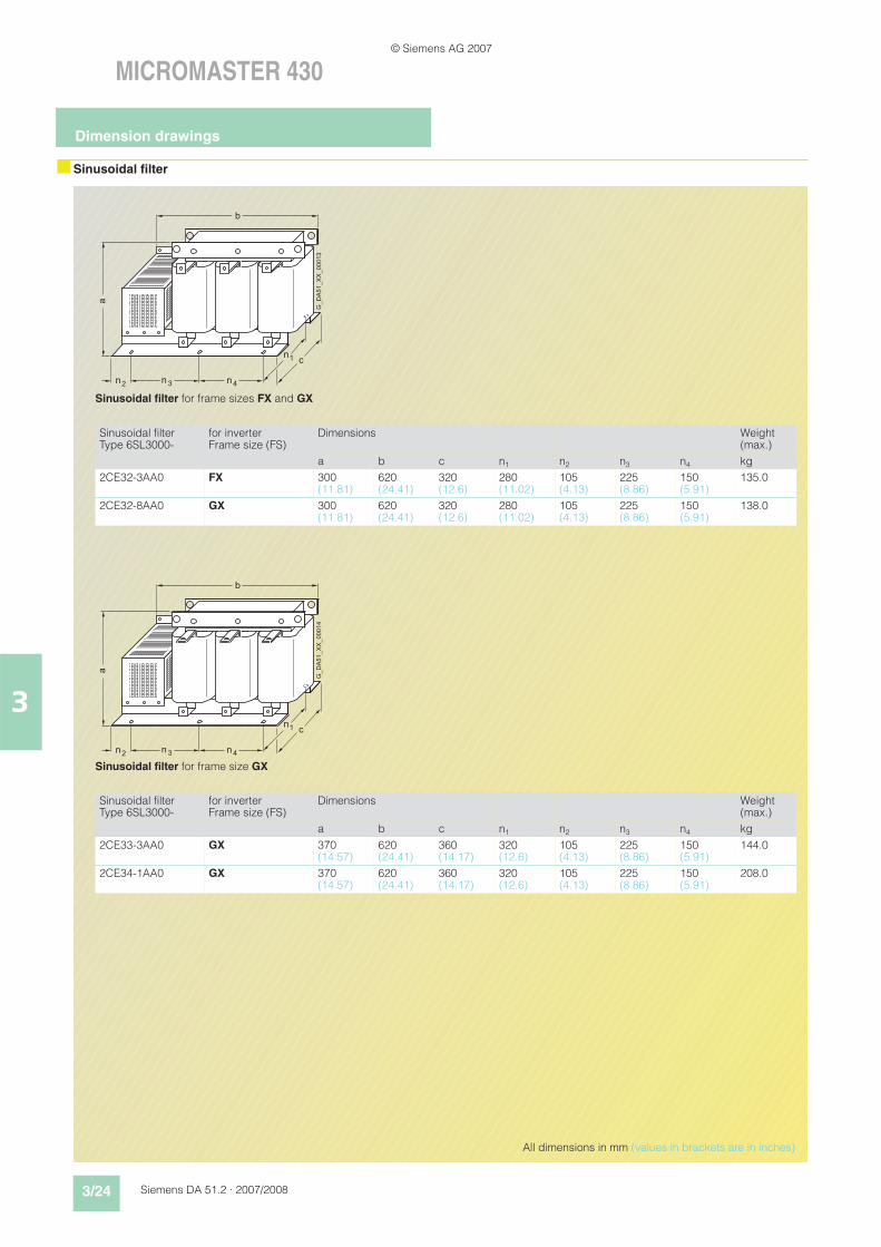
nSinusoidal filter
a
nn2 3 4
1
n
n
b
c
G_DA51_XX_00013
Sinusoidal filter for frame sizes FX and GX
Sinusoidal filter Type 6SL3000-
for inverter Frame size (FS)
Dimensions Weight (max.)
a b c n1 n2 n3 n4 kg
2CE32-3AA0 FX 300(11.81)
620(24.41)
320(12.6)
280(11.02)
105(4.13)
225(8.86)
150(5.91)
135.0
2CE32-8AA0 GX 300(11.81)
620(24.41)
320(12.6)
280(11.02)
105(4.13)
225(8.86)
150(5.91)
138.0
c
G_DA51_XX_00014
a
nn2 3 4
1
n
n
b
Sinusoidal filter for frame size GX
Sinusoidal filter Type 6SL3000-
for inverter Frame size (FS)
Dimensions Weight (max.)
a b c n1 n2 n3 n4 kg
2CE33-3AA0 GX 370(14.57)
620(24.41)
360(14.17)
320(12.6)
105(4.13)
225(8.86)
150(5.91)
144.0
2CE34-1AA0 GX 370(14.57)
620(24.41)
360(14.17)
320(12.6)
105(4.13)
225(8.86)
150(5.91)
208.0
All dimensions in mm (values in brackets are in inches)
Dimension drawings
© Siemens AG 2007
Siemens DA 51.2 · 2007/2008 3/25
MICROMASTER 430
3
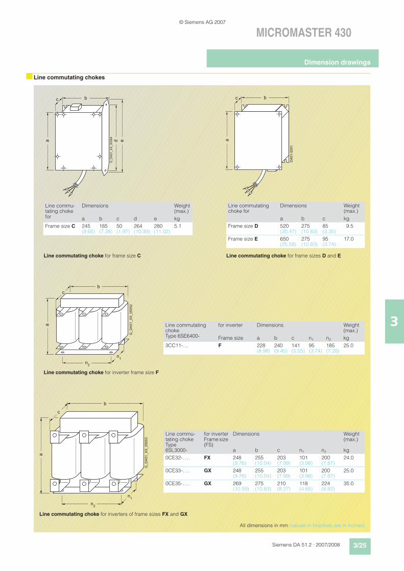
nLine commutating chokes
All dimensions in mm (values in brackets are in inches)
DA
51-5
051
b
a
c
Line commutating choke for frame sizes D and E
Line commutating choke for
Dimensions Weight (max.)
a b c kg
Frame size D 520(20.47)
275(10.83)
85(3.35)
9.5
Frame size E 650(25.59)
275(10.83)
95(3.74)
17.0
Line commutating choke for frame size C
G_DA51_XX_00064
b
a
c
d e
Line commu-tating choke for
Dimensions Weight (max.)
a b c d e kg
Frame size C 245(9.65)
185(7.28)
50(1.97)
264(10.39)
280(11.02)
5.1
b
c
a
n2
n1
G_D
A51_X
X_05052
Line commutating choke for inverter frame size F
Line commutating choke Type 6SE6400-
for inverter Dimensions Weight (max.)
Frame size a b c n1 n2 kg
3CC11-.... F 228(8.98)
240(9.45)
141(5.55)
95(3.74)
185(7.28)
25.0
b
c
a
n2
n1
G_D
A51_X
X_05053
Line commutating choke for inverters of frame sizes FX and GX
Line commu-tating choke Type 6SL3000-
for inverterFrame size (FS)
Dimensions Weight (max.)
a b c n1 n2 kg
0CE32-.... FX 248(9.76)
255(10.04)
203(7.99)
101(3.98)
200(7.87)
24.0
0CE33-.... GX 248(9.76)
255(10.04)
203(7.99)
101(3.98)
200(7.87)
25.0
0CE35-.... GX 269(10.59)
275(10.83)
210(8.27)
118(4.65)
224(8.82)
35.0
Dimension drawings
© Siemens AG 2007
3/26 Siemens DA 51.2 · 2007/2008
MICROMASTER 430
3
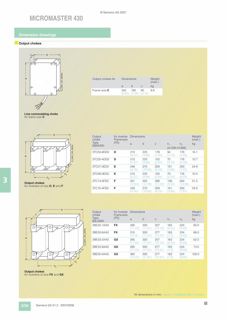
nOutput chokes
G_D
A51_X
X_05050a
b
a
c
Line commutating choke for frame size C
Output chokes for Dimensions Weight (max.)
a b c kg
Frame size C 245(9.65)
185(7.28)
80(3.15)
6.6
All dimensions in mm (values in brackets are in inches)
b
c
a
n2
n1
G_D
A51_X
X_05052
Output chokes for inverters of size D, E and F
Output choke Type 6SE6400-
for inverterFrame size (FS)
Dimensions Weight (max.)
a b c n1 n2 kg
(to DIN 41308)
3TC03-8DD0 D 210(8.27)
225(8.86)
179(7.05)
94(3.70)
176(6.93)
16.1
3TC05-4DD0 D 210(8.27)
225(8.86)
150(5.91)
70(2.76)
176(6.93)
10.7
3TC07-5ED0 E 248(9.76)
270(10.63)
209(8.23)
101(3.98)
200(7.87)
24.9
3TC08-0ED0 E 210(8.27)
225(8.86)
150(5.91)
70(2.76)
176(6.93)
10.4
3TC14-5FD0 F 321(12.64)
350(13.78)
288(11.34)
138(5.43)
264(10.39)
51.5
3TC15-4FD0 F 248(9.76)
270(10.63)
209(8.23)
101(3.98)
200(7.87)
24.0
b
c
a
n2
n1
G_D
A51_X
X_05053
Output chokes for inverters of size FX and GX
Output choke Type 6SL3000-
for inverterFrame size (FS)
Dimensions Weight (max.)
a b c n1 n2 kg
2BE32-1AA0 FX 285(11.22)
300(11.81)
257(10.12)
163(6.42)
224(8.82)
60.0
2BE32-6AA0 FX 315(12.4)
300(11.81)
277(10.91)
183(7.2)
224(8.82)
66.0
2BE33-2AA0 GX 285(11.22)
300(11.81)
257(10.12)
163(6.42)
224(8.82)
62.0
2BE33-8AA0 GX 285(11.22)
300(11.81)
277(10.91)
183(7.2)
224(8.82)
73.0
2BE35-0AA0 GX 365(14.37)
300(11.81)
277(10.91)
183(7.2)
224(8.82)
100.0
Dimension drawings
© Siemens AG 2007
Related Documents