Tutorials Introduction Autodesk MatchMover enables artists to track 3D camera data and motion from videos and film sequences, in order to more easily insert CG elements into a scene. MatchMover combines the ease of automatic tracking with the precise manual control of tracking points. The lessons in this tutorial describe how to use MatchMover to perform basic matchmoving, which includes loading images sequences, tracking a sequence, and then exporting the tracked rendered 3D data to file that can be used in 3D animation and compositing programs. You will also learn how to create a track manually using supervised tracking and set up survey points. This chapter includes the following lessons: ■ Lesson 1: Tracking an image sequence on page 6 Tutorials | 5

Welcome message from author
This document is posted to help you gain knowledge. Please leave a comment to let me know what you think about it! Share it to your friends and learn new things together.
Transcript
Tutorials
Introduction
Autodesk MatchMover enables artists to track 3D camera data and motionfrom videos and film sequences, in order to more easily insert CG elementsinto a scene. MatchMover combines the ease of automatic tracking with theprecise manual control of tracking points.
The lessons in this tutorial describe how to use MatchMover to perform basicmatchmoving, which includes loading images sequences, tracking a sequence,and then exporting the tracked rendered 3D data to file that can be used in3D animation and compositing programs. You will also learn how to createa track manually using supervised tracking and set up survey points.
This chapter includes the following lessons:
■ Lesson 1: Tracking an image sequence on page 6
Tutorials | 5
■ Lesson 2: Using supervised tracking on page 18
■ Lesson 3: Object-based tracking on page 35
■ Lesson 4: Motion capture on page 45
Lesson 1: Tracking an image sequence
Introduction
In this lesson you will learn how to track a sequence in 3D using MatchMover’sautomatic tracking engine, inspect the results, and export the result to one ofMatchMover’s supported file formats. The automatic tracking feature locatesgood tracking points in the image, and then tracks them through the sequence.
In this tutorial you will learn how to:
■ Load an image sequence.
■ Use the automatic tracker to compute the 3D camera path and the 3Dscene.
6 | Chapter 1 Getting Started
■ Navigate in the project with a 3D view to visualize and inspect the trackingresults.
■ Render a preview sequence.
■ Export the tracking results to a supported file format.
Lesson setupTo ensure the lesson works as described, do these steps before beginning:
1 Start MatchMover and ensure that it is set to Light mode.
To set MatchMover to Light mode, select Light from the MatchMovertoolbar.
Although this tutorial is designed for Light mode, it can be completedusing MatchMover Full mode.
2 If you have not already done so, copy the Tutorials folder from itsinstallation location to your a project directory.
The Tutorials folder can be found in the Help folder of MatchMover’sinstallation location: Help/Tutorials.
Loading the image sequenceThe first step in matchmoving is to load the image sequence you want totrack.
NOTE You can bypass this section of the lesson by openningBasic_Sequence.mmf.This file can be found in the Tutorials/Basic directory. You can then proceedto Running the automatic tracker on page 10.
To load an image sequence
1 Select File > Load Sequence or click the Load Sequence icon in thetoolbar.
The Load Sequence window appears.
Lesson 1: Tracking an image sequence | 7
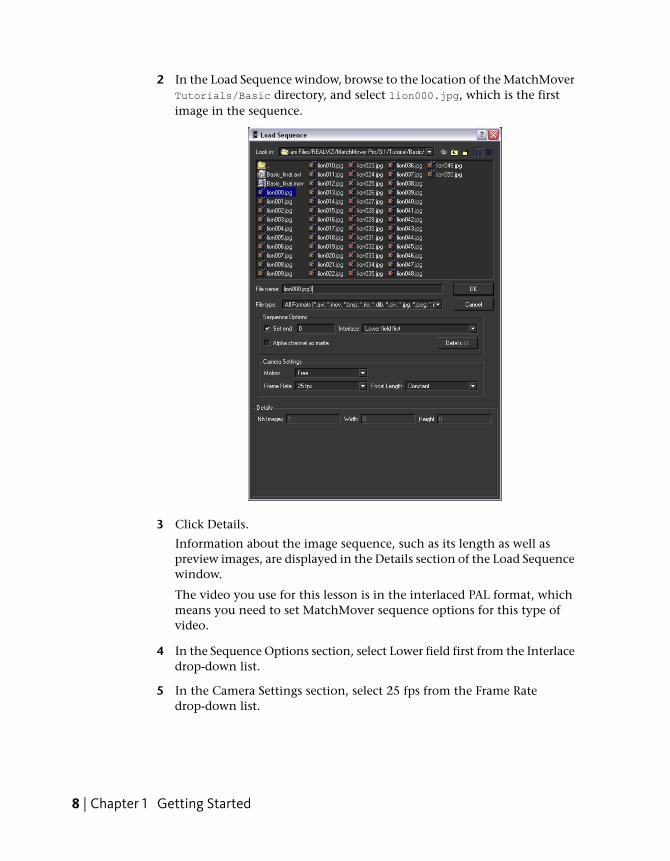
2 In the Load Sequence window, browse to the location of the MatchMoverTutorials/Basic directory, and select lion000.jpg, which is the firstimage in the sequence.
3 Click Details.
Information about the image sequence, such as its length as well aspreview images, are displayed in the Details section of the Load Sequencewindow.
The video you use for this lesson is in the interlaced PAL format, whichmeans you need to set MatchMover sequence options for this type ofvideo.
4 In the Sequence Options section, select Lower field first from the Interlacedrop-down list.
5 In the Camera Settings section, select 25 fps from the Frame Ratedrop-down list.
8 | Chapter 1 Getting Started
Leave Motion set to Free because in this example, the camera does notfollow any of the motion types specified in the list.
To play the image sequence
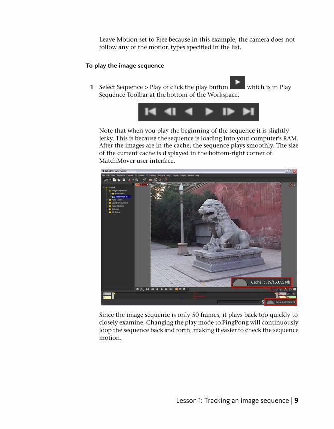
1 Select Sequence > Play or click the play button which is in PlaySequence Toolbar at the bottom of the Workspace.
Note that when you play the beginning of the sequence it is slightlyjerky. This is because the sequence is loading into your computer’s RAM.After the images are in the cache, the sequence plays smoothly. The sizeof the current cache is displayed in the bottom-right corner ofMatchMover user interface.
Since the image sequence is only 50 frames, it plays back too quickly toclosely examine. Changing the play mode to PingPong will continuouslyloop the sequence back and forth, making it easier to check the sequencemotion.
Lesson 1: Tracking an image sequence | 9
2 Select Sequence > Play Mode > PingPong or click the PingPong button
in the Play Sequence Toolbar.
3 To stop the playback, click the Stop button or press Esc.
TIP To play the scene manually, you can press Ctrl, click anywhere in theimage, and drag the pointer to the left or to the right.
4 To go back to the first frame, press Ctrl+Home (Windows) or
Command+Home (Mac) or press .
Running the automatic trackerYou can use the automatic tracking feature to have MatchMover select thebest location of place track points in the image sequence.
NOTE You can bypass this section of the lesson byopenningBasic_Calibrated.mmf. This file can be found in the Tutorials/Basicdirectory. You can then proceed to Checking the tracking results on page 12.
To run the automatic tracker
1 Select 2D Tracking > Automatic Tracking or click the Run the Automatic
Tracking icon .
The Automatic Tracking window appears listing the steps in the automaticmatchmoving process.
10 | Chapter 1 Getting Started
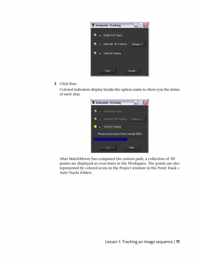
2 Click Run.
Colored indicators display beside the option name to show you the statusof each step.
After MatchMover has computed the camera path, a collection of 3Dpoints are displayed as cross-hairs in the Workspace. The points are alsorepresented by colored icons in the Project window in the Point Track >Auto Tracks folders.
Lesson 1: Tracking an image sequence | 11
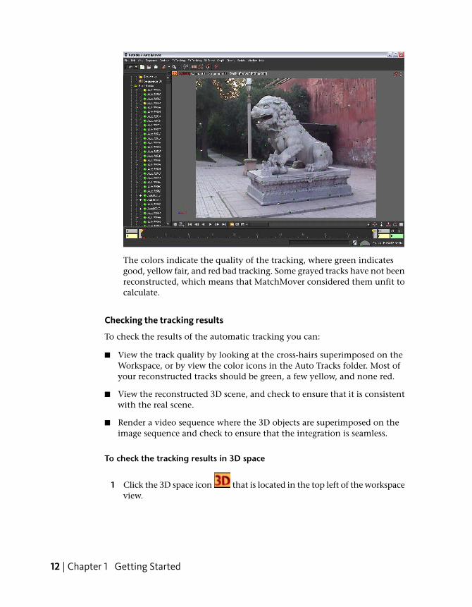
The colors indicate the quality of the tracking, where green indicatesgood, yellow fair, and red bad tracking. Some grayed tracks have not beenreconstructed, which means that MatchMover considered them unfit tocalculate.
Checking the tracking results
To check the results of the automatic tracking you can:
■ View the track quality by looking at the cross-hairs superimposed on theWorkspace, or by view the color icons in the Auto Tracks folder. Most ofyour reconstructed tracks should be green, a few yellow, and none red.
■ View the reconstructed 3D scene, and check to ensure that it is consistentwith the real scene.
■ Render a video sequence where the 3D objects are superimposed on theimage sequence and check to ensure that the integration is seamless.
To check the tracking results in 3D space
1 Click the 3D space icon that is located in the top left of the workspaceview.
12 | Chapter 1 Getting Started
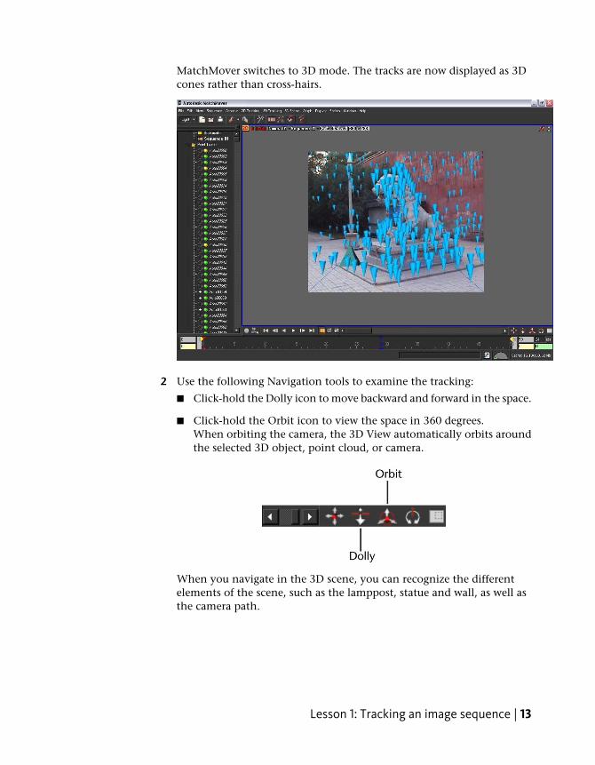
MatchMover switches to 3D mode. The tracks are now displayed as 3Dcones rather than cross-hairs.
2 Use the following Navigation tools to examine the tracking:
■ Click-hold the Dolly icon to move backward and forward in the space.
■ Click-hold the Orbit icon to view the space in 360 degrees.When orbiting the camera, the 3D View automatically orbits aroundthe selected 3D object, point cloud, or camera.
When you navigate in the 3D scene, you can recognize the differentelements of the scene, such as the lamppost, statue and wall, as well asthe camera path.
Lesson 1: Tracking an image sequence | 13
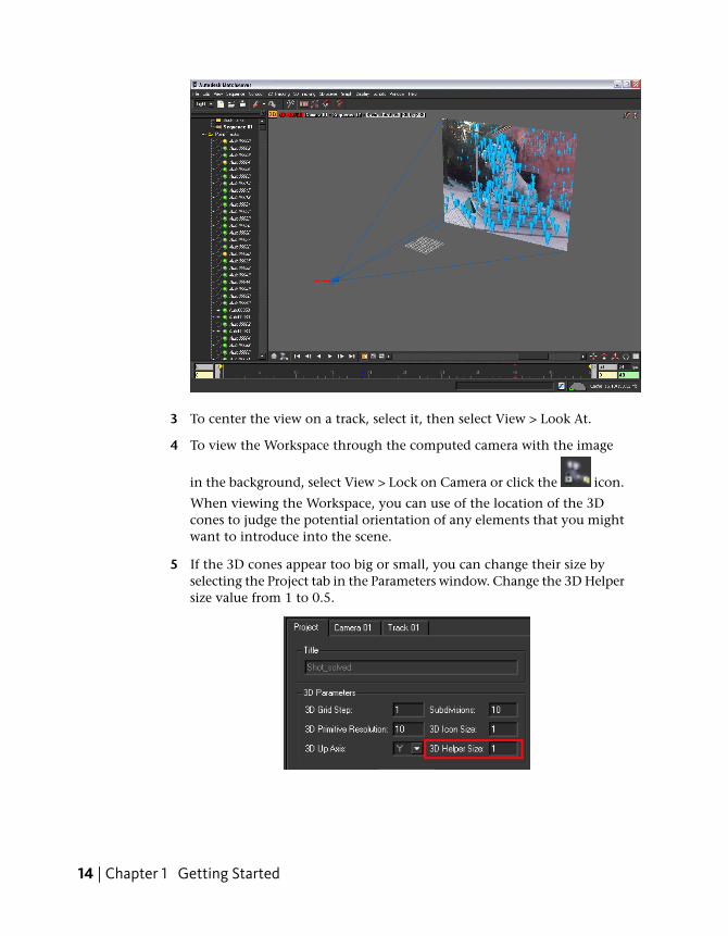
3 To center the view on a track, select it, then select View > Look At.
4 To view the Workspace through the computed camera with the image
in the background, select View > Lock on Camera or click the icon.
When viewing the Workspace, you can use of the location of the 3Dcones to judge the potential orientation of any elements that you mightwant to introduce into the scene.
5 If the 3D cones appear too big or small, you can change their size byselecting the Project tab in the Parameters window. Change the 3D Helpersize value from 1 to 0.5.
14 | Chapter 1 Getting Started
Rendering the tracked image sequenceAfter you have created and checked the quality of the 3D tracking in theWorkspace, you can render the scene in a video format to further check itsquality. You can also export the tracked sequence to a file format that youcan open in your favorite 3D animation or compositing program.
To render the tracked sequence
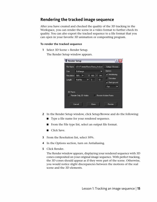
1 Select 3D Scene > Render Setup.
The Render Setup window appears.
2 In the Render Setup window, click Setup/Browse and do the following:
■ Type a file name for your rendered sequence.
■ From the File type list, select an output file format.
■ Click Save.
3 From the Resolution list, select 50%.
4 In the Options section, turn on Antialiasing.
5 Click Render.
The Render window appears, displaying your rendered sequence with 3Dcones composited on your original image sequence. With perfect tracking,the 3D cones should appear as if they were part of the scene. Otherwise,you would notice slight discrepancies between the motions of the realscene and the 3D elements.
Lesson 1: Tracking an image sequence | 15
Now that you have automatically tracked a PAL video sequence andverified it by rendering it, you can export the results to a file that can beopened in your favorite animation or compositing software.
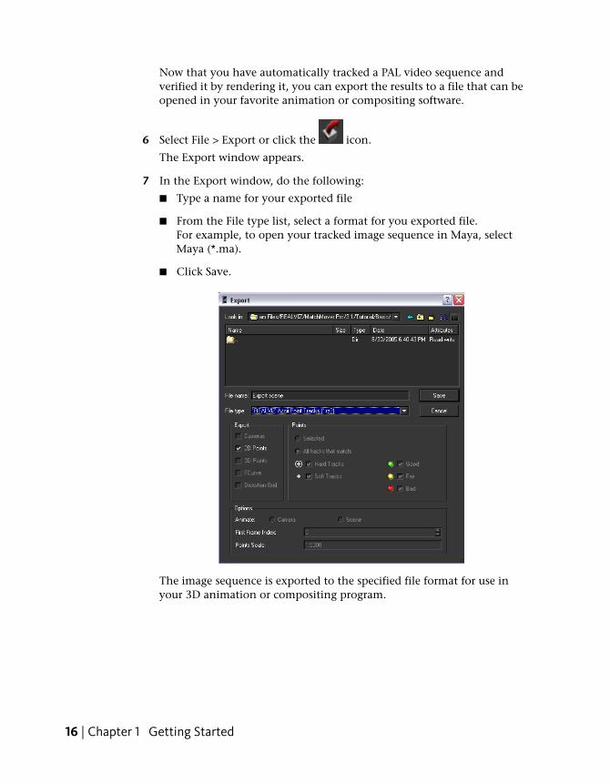
6 Select File > Export or click the icon.
The Export window appears.
7 In the Export window, do the following:
■ Type a name for your exported file
■ From the File type list, select a format for you exported file.For example, to open your tracked image sequence in Maya, selectMaya (*.ma).
■ Click Save.
The image sequence is exported to the specified file format for use inyour 3D animation or compositing program.
16 | Chapter 1 Getting Started
Beyond the lessonIn this tutorial you learned how to:
■ Load an image sequence.
■ Use the automatic tracker to compute the 3D camera path and the 3Dscene.
■ Navigate in the project with a 3D view to visualize and inspect the trackingresults.
■ Render a preview sequence
■ Export the tracking results to a file format that is supported by your favorite3D animation or compositing program.
For more information and related techniques about MatchMover, refer to theMatchMover Help.
Lesson 1: Tracking an image sequence | 17
Lesson 2: Using supervised tracking
Introduction
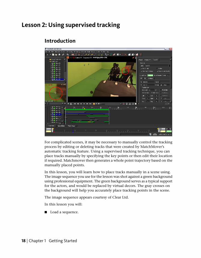
For complicated scenes, it may be necessary to manually control the trackingprocess by editing or deleting tracks that were created by MatchMover’sautomatic tracking feature. Using a supervised tracking technique, you canplace tracks manually by specifying the key points or then edit their locationif required. Matchmover then generates a whole point trajectory based on themanually placed points.
In this lesson, you will learn how to place tracks manually in a scene using.The image sequence you use for the lesson was shot against a green backgroundusing professional equipment. The green background serves as a typical supportfor the actors, and would be replaced by virtual decors. The gray crosses onthe background will help you accurately place tracking points in the scene.
The image sequence appears courtesy of Clear Ltd.
In this lesson you will:
■ Load a sequence.
18 | Chapter 1 Getting Started
■ Create and edit tracks manually.
■ Launch the solver.
■ Define a coordinate system.
■ Add a 3D object to verify the tracked sequence.
Lesson setupTo ensure the lesson works as described, do these steps before beginning:
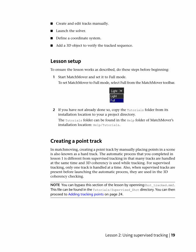
1 Start MatchMover and set it to Full mode.
To set MatchMover to Full mode, select Full from the MatchMover toolbar.
2 If you have not already done so, copy the Tutorials folder from itsinstallation location to your a project directory.
The Tutorials folder can be found in the Help folder of MatchMover’sinstallation location: Help/Tutorials.
Creating a point trackIn matchmoving, creating a point track by manually placing points in a sceneis also known as a hard track. The automatic process that you completed inlesson 1 is different from supervised tracking in that many tracks are handledat the same time and 3D coherency is used while tracking. For supervisedtracking, only one track is handled at a time. Also, when supervised tracks arepresent before launching the automatic process, they are used in the 3Dcoherency checking.
NOTE You can bypass this section of the lesson by openningShot_tracked.mmf.This file can be found in the Tutorials/Supervised_Shot directory. You can thenproceed to Adding tracking points on page 24.
Lesson 2: Using supervised tracking | 19
To load the image sequence
1 Select File > Load Sequence or click the Load Sequence icon.
The Load Sequence window appears.
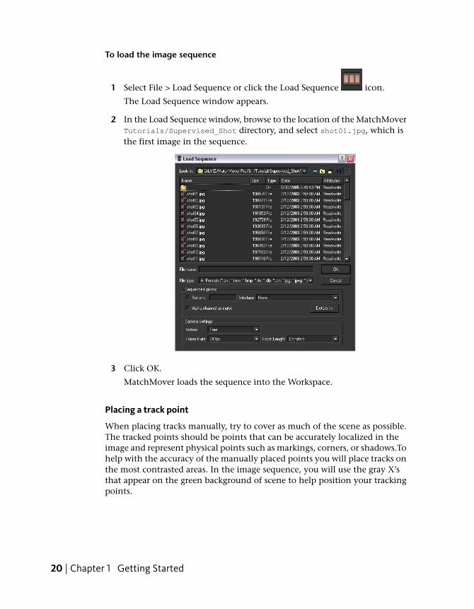
2 In the Load Sequence window, browse to the location of the MatchMoverTutorials/Supervised_Shot directory, and select shot01.jpg, which isthe first image in the sequence.
3 Click OK.
MatchMover loads the sequence into the Workspace.
Placing a track point
When placing tracks manually, try to cover as much of the scene as possible.The tracked points should be points that can be accurately localized in theimage and represent physical points such as markings, corners, or shadows.Tohelp with the accuracy of the manually placed points you will place tracks onthe most contrasted areas. In the image sequence, you will use the gray X’sthat appear on the green background of scene to help position your trackingpoints.
20 | Chapter 1 Getting Started

For more information about placing tracks, see Supervised 2D tracking onpage 132.
To place a track point in the scene
1 Go to the first frame of the sequence.
2 Select 2D Tracking > New Track or click the New Track icon.
When you drag the cursor over the Workspace, it changes to cross-hairs.
3 Position the cross-hairs near the one of the gray X’s that appear in thescene. Use the location shown in the image below as a guide.
Use the Magnifier window view below the Project window to help youprecisely position the location of the new point.
Lesson 2: Using supervised tracking | 21
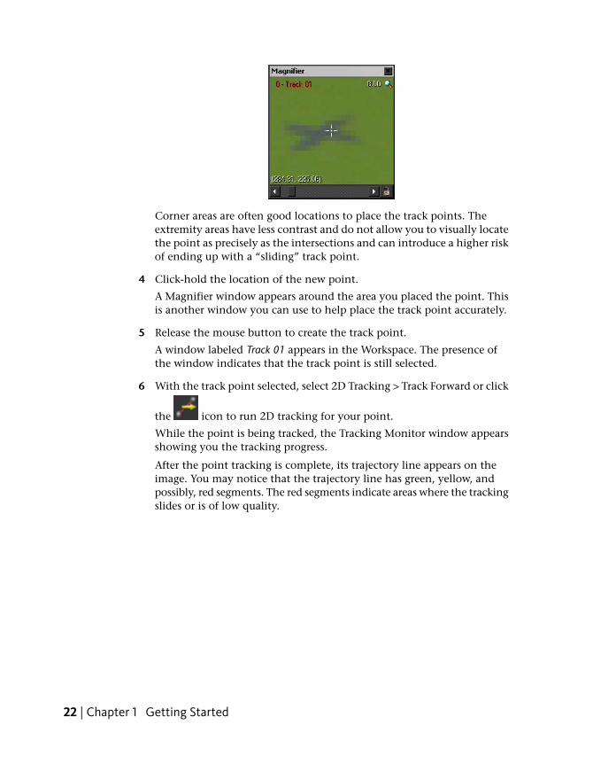
Corner areas are often good locations to place the track points. Theextremity areas have less contrast and do not allow you to visually locatethe point as precisely as the intersections and can introduce a higher riskof ending up with a “sliding” track point.
4 Click-hold the location of the new point.
A Magnifier window appears around the area you placed the point. Thisis another window you can use to help place the track point accurately.
5 Release the mouse button to create the track point.
A window labeled Track 01 appears in the Workspace. The presence ofthe window indicates that the track point is still selected.
6 With the track point selected, select 2D Tracking > Track Forward or click
the icon to run 2D tracking for your point.
While the point is being tracked, the Tracking Monitor window appearsshowing you the tracking progress.
After the point tracking is complete, its trajectory line appears on theimage. You may notice that the trajectory line has green, yellow, andpossibly, red segments. The red segments indicate areas where the trackingslides or is of low quality.
22 | Chapter 1 Getting Started

You can correct the sliding track by manually adjusting the point positionswhere the track has drifted significantly. In the next section of the lesson,you adjust the point positions to improve the tracking quality.
Editing a point trackTo improve the quality of your hard track, you can adjust the location of atracking point and re-run the tracking process.
To adjust tracking point positions
1 Using the time line controls, go to a frame where the track drifts.
This is indicated by the red sections.
2 In the Workspace, click-hold the tracking point and move it in thedirection that will improve the tracking such as closer to an inside cornerof the gray X’s.
Use the Magnifier window that appear around the point to help youadjust the point's position.
3 Release the mouse button.
Notice that when you release the mouse button, MatchMover clears theend of the trajectory. That is because the tracked data is no longercompatible with new position of the point. This means that you mustre-compute the trajectory based on the new point position.
4 With the track point selected, select 2D Tracking > Track Forward or pressF3, which is the Track Forward keyboard shortcut.
MatchMover calculates a new trajectory for the track.
Lesson 2: Using supervised tracking | 23
To make the track trajectory smoother, you can update the tracked databetween the initial point and the point's new location by usingbi-directional tracking.
5 Select 2D Tracking > Bidirectional or click the Run Track Full icon.
You can check the smoothness of your edited track by centering yourview on the current track.
6 Select View > Lock on Track or click the icon.
7 Play the image sequence in PingPong mode by clicking followed by
.
Notice that when the sequence plays back section of the sequence youhave tracked, the view is locked to the motion of the edited track.
8 Stop the sequence playback by clicking the icon.
9 To get a close-up view of the track, press Ctrl+Alt and drag the mouse upand down to zoom in and out of the Workspace view. If you are notsatisfied with the quality of the track, adjust the point and run thetracking again.
TIP If you notice a jump in the trajectory, you can adjust the point positionby pressing the arrow keys. Select Preferences > 2D Tracking to adjust thenudge step. Use shift to multiply the nudge step by 10. If needed, a key pointis inserted at the current edited frame.
Adding tracking pointsAdding more tracking points to your scene improves the overall quality ofthe tracking.
Open the file for the lesson
To ensure this lesson works as described, open the scene file namedShot_tracked.mmf. This file is in the Tutorials directory that you copied from
24 | Chapter 1 Getting Started
the MatchMover installation directory to a local directory:Tutorials\Supervised_Shot\Shot_tracked.mmf.
Supervised tracking
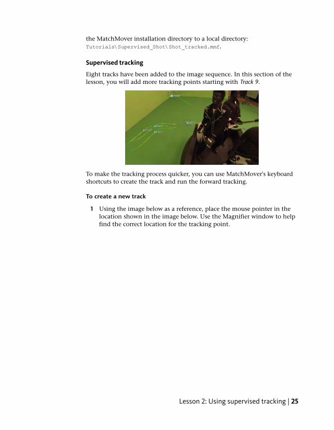
Eight tracks have been added to the image sequence. In this section of thelesson, you will add more tracking points starting with Track 9.
To make the tracking process quicker, you can use MatchMover's keyboardshortcuts to create the track and run the forward tracking.
To create a new track
1 Using the image below as a reference, place the mouse pointer in thelocation shown in the image below. Use the Magnifier window to helpfind the correct location for the tracking point.
Lesson 2: Using supervised tracking | 25

2 Create the tracking point by pressing Shift+right-click.
The tracking begins then stop around frame 15. Track 09 appears in theWorkspace and is also added to the track points in the Project window.
3 To run forward tracking press F3.
A window appears in the Workspace indicates that the tracking qualityis too low for MatchMover to continue the trajectory.
4 Click OK.
The reason the tracking quality is so low is that the actor’s body hidesthe area you want track in the sequence.
5 In the time line, double the last frame of the Track 9 trajectory.
26 | Chapter 1 Getting Started
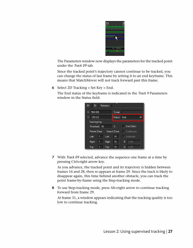
The Parameters window now displays the parameters for the tracked pointunder the Track 09 tab.
Since the tracked point’s trajectory cannot continue to be tracked, youcan change the status of last frame by setting it to an end keyframe. Thismeans that MatchMover will not track forward past this frame.
6 Select 2D Tracking > Set Key > End.
The End status of the keyframe is indicated in the Track 9 Parameterswindow in the Status field.
7 With Track 09 selected, advance the sequence one frame at a time bypressing Ctrl+right arrow key.
As you advance, the tracked point and its trajectory is hidden betweenframes 16 and 28, then re-appears at frame 29. Since the track is likely todisappear again, this time behind another obstacle, you can track thepoint frame-by-frame using the Step-tracking mode.
8 To use Step-tracking mode, press Alt+right arrow to continue trackingforward from frame 29.
At frame 31, a window appears indicating that the tracking quality is toolow to continue tracking.
Lesson 2: Using supervised tracking | 27
TIP Use the Magnifier window to get a better view of the obstacles that arehiding the Track 09 trajectory path.
9 At frame 31, change the status of the keyframe to End by selecting 2DTracking > Set Key > End.
10 Go to frame 44 and press F3 to run forward tracking.
Track 09 is now complete and set in the scene.
To check the quality of the track
1 Ensure that Track 9 is selected in the Workspace.
2 Click the padlock icon at the bottom right of the Magnifier window.
This makes the Magnifier window the only active view.
3 Select View > Skip Untracked or click the icon.
4 Play the image sequence in PingPong mode by clicking followed by
.
Notice that MatchMover only plays the sections of Track 09 that havebeen tracked. The frames that could not be tracked because of obstaclesin the scene are not played.
5 Click the lock icon to make the Workspace window active again.
6 Select View > Skip Untracked so that all frames play when the sequenceis played back.
Calibrating the cameraIn MatchMover, a camera is characterized by its internal parameters such asPrincipal Point, Focal Length, Pixel Aspect Ratio, and Distortion. In somecases, you may already have information about the camera. For example, youmay know that it is a 24 ×36 mm film back camera with a 35 mm lens. Youcan then input this information into MatchMover before launching the cameratracker. For this lesson, you will calibrate the camera using MatchMover'sdefault values. This process of calibrating a camera involves reconstructing
28 | Chapter 1 Getting Started
the 3D points corresponding to the 2D tracks and computing the camera pathfor all the sequences or frames and all the objects in one solve.
NOTE You can bypass this section of the lesson by openningShot_solved.mmf.This file can be found in the Tutorials/Supervised_Shot directory. You can thenproceed to Creating a coordinate system on page 29.
To calibrate the camera
1 Run the calibration by selecting 3D Tracking > Solve For Camera or by
clicking the Solve For Camera icon.
The camera is calibrated.
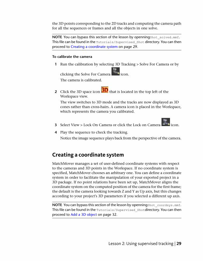
2 Click the 3D space icon that is located in the top left of theWorkspace view.
The view switches to 3D mode and the tracks are now displayed as 3Dcones rather than cross-hairs. A camera icon is placed in the Workspace,which represents the camera you calibrated.
3 Select View > Lock On Camera or click the Lock on Camera icon.
4 Play the sequence to check the tracking.
Notice the image sequence plays back from the perspective of the camera.
Creating a coordinate systemMatchMover manages a set of user-defined coordinate systems with respectto the cameras and 3D points in the Workspace. If no coordinate system isspecified, MatchMover chooses an arbitrary one. You can define a coordinatesystem in order to facilitate the manipulation of your exported project in a3D package. If no point relations have been set up, MatchMover aligns thecoordinate system on the computed position of the camera for the first frame;the default is the camera looking towards Z and Y as Up axis, but this changesaccording to your project's 3D parameters if you selected a different up axis.
NOTE You can bypass this section of the lesson by openningShot_coordsys.mmf.This file can be found in the Tutorials/Supervised_Shotdirectory. You can thenproceed to Add a 3D object on page 32.
Lesson 2: Using supervised tracking | 29
Open the file for the lesson
To ensure this lesson works as described, do the following:
1 Ensure that it is set to Full mode.
To set MatchMover to Full mode, select Full from the MatchMover toolbar.
2 Ensure that MatchMover is set to 3D mode.
To switch MatchMover to 3D mode, click the 3D space icon that is
located in the top left of the Workspace view. If a 2D space icon appears instead, then MatchMover is already in 3D mode.
3 If you have not already done so, copy the Tutorial folder from itsinstallation location to your a project directory.
4 Open the scene file named Shot_solved.mmf. This file is in the Tutorialsdirectory that you copied from the MatchMover installation directory toa local directory: Tutorials\Supervised_Shot\Shot_solved.mmf.
Setting up the coordinate system
To set up the coordinate system
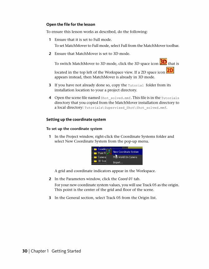
1 In the Project window, right-click the Coordinate Systems folder andselect New Coordinate System from the pop-up menu.
A grid and coordinate indicators appear in the Workspace.
2 In the Parameters window, click the Coord 01 tab.
For your new coordinate system values, you will use Track 05 as the origin.This point is the center of the grid and floor of the scene.
3 In the General section, select Track 05 from the Origin list.
30 | Chapter 1 Getting Started
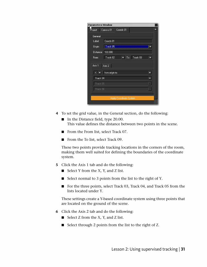
4 To set the grid value, in the General section, do the following:
■ In the Distance field, type 20.00.This value defines the distance between two points in the scene.
■ From the From list, select Track 07.
■ From the To list, select Track 09.
These two points provide tracking locations in the corners of the room,making them well suited for defining the boundaries of the coordinatesystem.
5 Click the Axis 1 tab and do the following:
■ Select Y from the X, Y, and Z list.
■ Select normal to 3 points from the list to the right of Y.
■ For the three points, select Track 03, Track 04, and Track 05 from thelists located under Y.
These settings create a Y-based coordinate system using three points thatare located on the ground of the scene.
6 Click the Axis 2 tab and do the following:
■ Select Z from the X, Y, and Z list.
■ Select through 2 points from the list to the right of Z.
Lesson 2: Using supervised tracking | 31
■ For the two points, select Track 01 and Track 02 from the lists locatedunder Z.
These settings create a Z-axis as the second axis which is based on thecrosses on the wall of the scene background.
7 Click Apply Coordinate System to validate your coordinate settings.
The defined coordinate system appears in the Workspace.
Add a 3D object
Now that you have defined a 3D coordinate system in MatchMover, you canimport an object into the Workspace and check its behavior in the scene.
NOTE You can bypass this section of the lesson by openningShot_object.mmf.This file can be found in the Tutorials/Supervised_Shotdirectory.
To add a 3D object
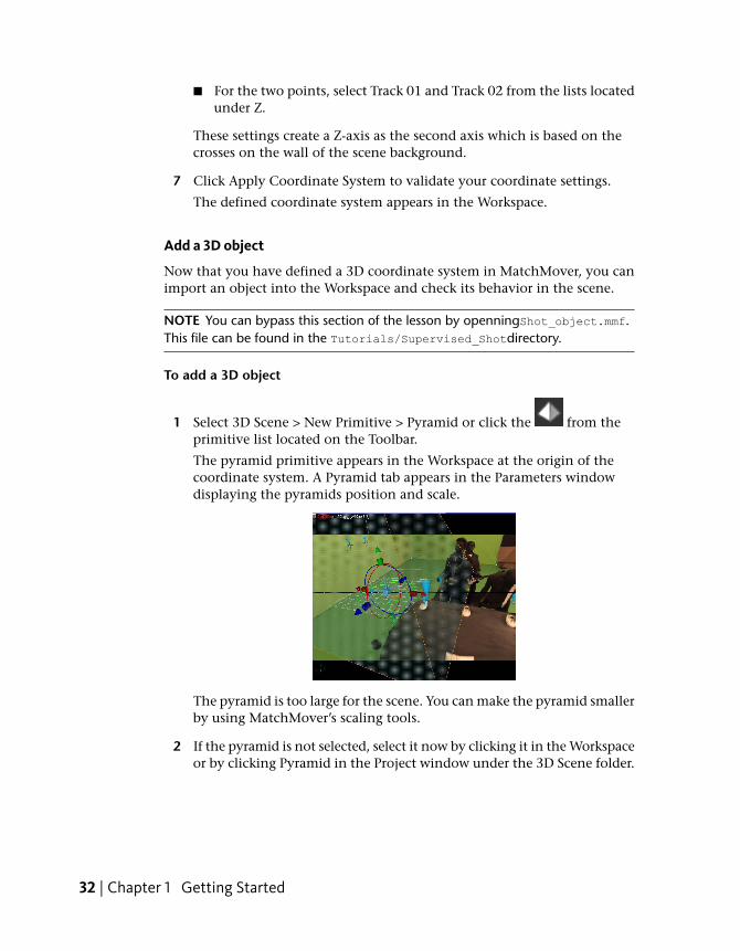
1 Select 3D Scene > New Primitive > Pyramid or click the from theprimitive list located on the Toolbar.
The pyramid primitive appears in the Workspace at the origin of thecoordinate system. A Pyramid tab appears in the Parameters windowdisplaying the pyramids position and scale.
The pyramid is too large for the scene. You can make the pyramid smallerby using MatchMover’s scaling tools.
2 If the pyramid is not selected, select it now by clicking it in the Workspaceor by clicking Pyramid in the Project window under the 3D Scene folder.
32 | Chapter 1 Getting Started
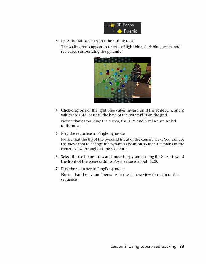
3 Press the Tab key to select the scaling tools.
The scaling tools appear as a series of light blue, dark blue, green, andred cubes surrounding the pyramid.
4 Click-drag one of the light blue cubes inward until the Scale X, Y, and Zvalues are 0.48, or until the base of the pyramid is on the grid.
Notice that as you drag the cursor, the X, Y, and Z values are scaleduniformly.
5 Play the sequence in PingPong mode.
Notice that the tip of the pyramid is out of the camera view. You can usethe move tool to change the pyramid’s position so that it remains in thecamera view throughout the sequence.
6 Select the dark blue arrow and move the pyramid along the Z-axis towardthe front of the scene until its Pos Z value is about -4.20.
7 Play the sequence in PingPong mode.
Notice that the pyramid remains in the camera view throughout thesequence.
Lesson 2: Using supervised tracking | 33
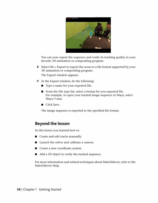
You can now export the sequence and verify its tracking quality in yourfavorite 3D animation or compositing program.
8 Select File > Export to export the scene to a file format supported by your3D animation or compositing program.
The Export window appears.
9 In the Export window, do the following:
■ Type a name for your exported file.
■ From the File type list, select a format for you exported file.For example, to open your tracked image sequence in Maya, selectMaya (*.ma).
■ Click Save.
The image sequence is exported to the specified file format.
Beyond the lessonIn this lesson you learned how to:
■ Create and edit tracks manually.
■ Launch the solver and calibrate a camera.
■ Create a new coordinate system.
■ Add a 3D object to verify the tracked sequence.
For more information and related techniques about MatchMover, refer to theMatchMover Help.
34 | Chapter 1 Getting Started
Lesson 3: Object-based tracking
Introduction
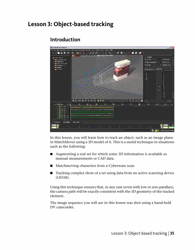
In this lesson, you will learn how to track an object, such as an image planein MatchMover using a 3D model of it. This is a useful technique in situationssuch as the following:
■ Augmenting a real set for which some 3D information is available asmanual measurements or CAD data.
■ Matchmoving characters from a Cyberware scan.
■ Tracking complex shots of a set using data from an active scanning device(LIDAR).
Using this technique ensures that, in any case (even with low or zero parallax),the camera path will be exactly consistent with the 3D geometry of the trackedelement.
The image sequence you will use in this lesson was shot using a hand-heldDV camcorder.
Lesson 3: Object-based tracking | 35
In this lesson you will learn how to:
■ Import a 3D mesh.
■ Create tracks and survey points attached to vertices of the mesh, using the“elastics” feature.
Lesson setupTo ensure the lesson works as described, do these steps before beginning:
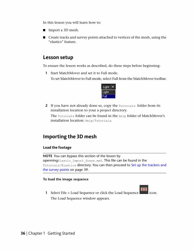
1 Start MatchMover and set it to Full mode.
To set MatchMover to Full mode, select Full from the MatchMover toolbar.
2 If you have not already done so, copy the Tutorials folder from itsinstallation location to your a project directory.
The Tutorials folder can be found in the Help folder of MatchMover’sinstallation location: Help/Tutorials.
Importing the 3D mesh
Load the footage
NOTE You can bypass this section of the lesson byopenningElastic_Import_Scene.mmf. This file can be found in theTutorials/Elastics directory. You can then proceed to Set up the trackers andthe survey points on page 39.
To load the image sequence
1 Select File > Load Sequence or click the Load Sequence icon.
The Load Sequence window appears.
36 | Chapter 1 Getting Started
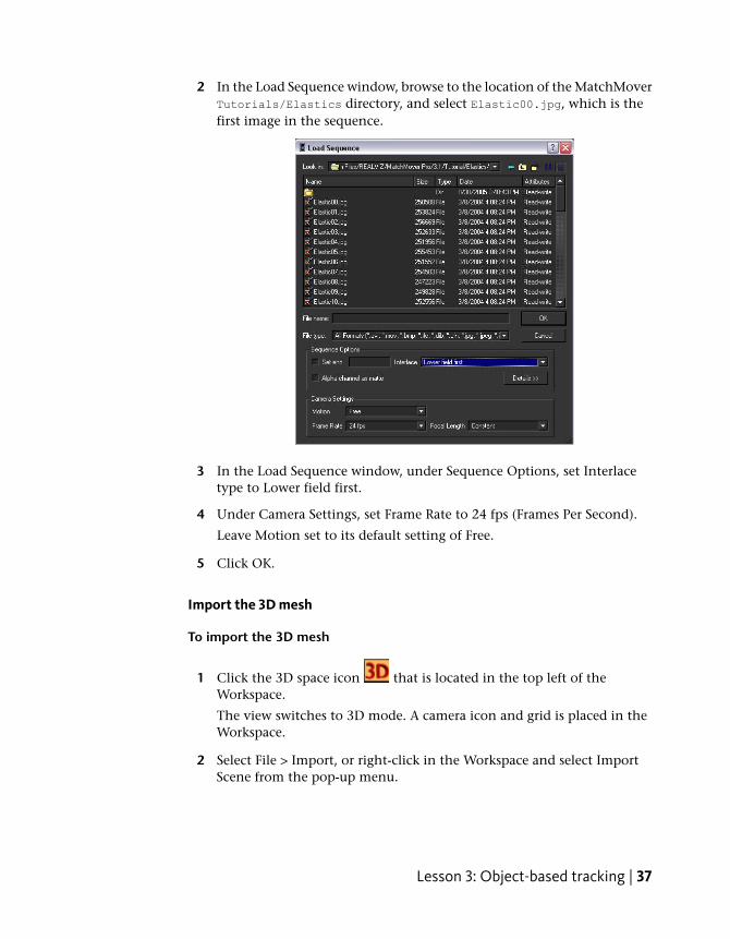
2 In the Load Sequence window, browse to the location of the MatchMoverTutorials/Elastics directory, and select Elastic00.jpg, which is thefirst image in the sequence.
3 In the Load Sequence window, under Sequence Options, set Interlacetype to Lower field first.
4 Under Camera Settings, set Frame Rate to 24 fps (Frames Per Second).
Leave Motion set to its default setting of Free.
5 Click OK.
Import the 3D mesh
To import the 3D mesh
1 Click the 3D space icon that is located in the top left of theWorkspace.
The view switches to 3D mode. A camera icon and grid is placed in theWorkspace.
2 Select File > Import, or right-click in the Workspace and select ImportScene from the pop-up menu.
Lesson 3: Object-based tracking | 37
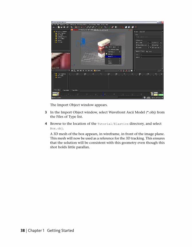
The Import Object window appears.
3 In the Import Object window, select Wavefront Ascii Model (*.obj) fromthe Files of Type list.
4 Browse to the location of the Tutorial/Elastics directory, and selectBox.obj.
A 3D mesh of the box appears, in wireframe, in front of the image plane.This mesh will now be used as a reference for the 3D tracking. This ensuresthat the solution will be consistent with this geometry even though thisshot holds little parallax.
38 | Chapter 1 Getting Started

Set up the trackers and the survey pointsYou can use survey points to analyze the results of 3D tracking and to isolatespecific frames or points where adjustment may be necessary.
NOTE You can bypass this section of the lesson by openingElastic_SetUp_Elastics.mmf. This file can be found in the Tutorials/Elasticsdirectory. You can then proceed to Solve and check the tracking results on page43.
1 Using the Pan and Dolly controls, make sure both the imported 3D object,which represents the shape of the box, and the image plane are clearlyvisible.
For example, set up your viewing position and angle similar to the imagebelow.
Lesson 3: Object-based tracking | 39
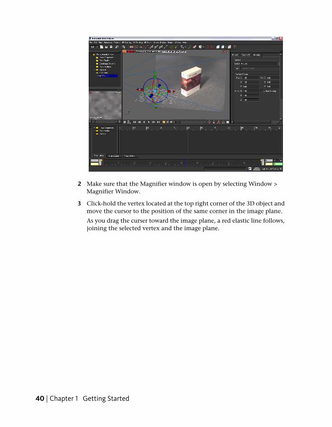
2 Make sure that the Magnifier window is open by selecting Window >Magnifier Window.
3 Click-hold the vertex located at the top right corner of the 3D object andmove the cursor to the position of the same corner in the image plane.
As you drag the curser toward the image plane, a red elastic line follows,joining the selected vertex and the image plane.
40 | Chapter 1 Getting Started
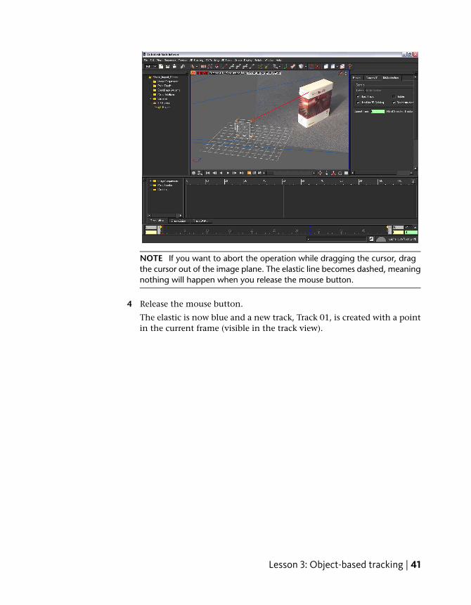
NOTE If you want to abort the operation while dragging the cursor, dragthe cursor out of the image plane. The elastic line becomes dashed, meaningnothing will happen when you release the mouse button.
4 Release the mouse button.
The elastic is now blue and a new track, Track 01, is created with a pointin the current frame (visible in the track view).
Lesson 3: Object-based tracking | 41
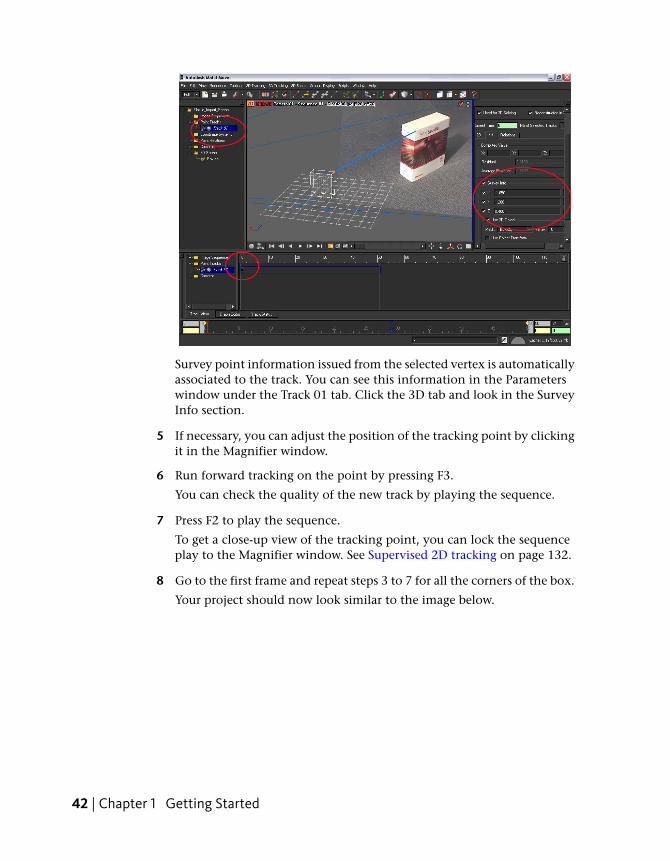
Survey point information issued from the selected vertex is automaticallyassociated to the track. You can see this information in the Parameterswindow under the Track 01 tab. Click the 3D tab and look in the SurveyInfo section.
5 If necessary, you can adjust the position of the tracking point by clickingit in the Magnifier window.
6 Run forward tracking on the point by pressing F3.
You can check the quality of the new track by playing the sequence.
7 Press F2 to play the sequence.
To get a close-up view of the tracking point, you can lock the sequenceplay to the Magnifier window. See Supervised 2D tracking on page 132.
8 Go to the first frame and repeat steps 3 to 7 for all the corners of the box.
Your project should now look similar to the image below.
42 | Chapter 1 Getting Started
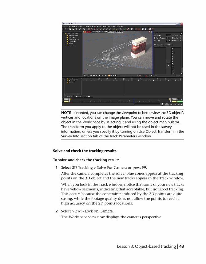
NOTE If needed, you can change the viewpoint to better view the 3D object’svertices and locations on the image plane. You can move and rotate theobject in the Workspace by selecting it and using the object manipulator.The transform you apply to the object will not be used in the surveyinformation, unless you specify it by turning on Use Object Transform in theSurvey Info section tab of the track Parameters window.
Solve and check the tracking results
To solve and check the tracking results
1 Select 3D Tracking > Solve For Camera or press F9.
After the camera completes the solve, blue cones appear at the trackingpoints on the 3D object and the new tracks appear in the Track window.
When you look in the Track window, notice that some of your new trackshave yellow segments, indicating that acceptable, but not good tracking.This occurs because the constraints induced by the 3D points are quitestrong, while the footage quality does not allow the points to reach ahigh accuracy on the 2D points locations.
2 Select View > Lock on Camera.
The Workspace view now displays the cameras perspective.
Lesson 3: Object-based tracking | 43
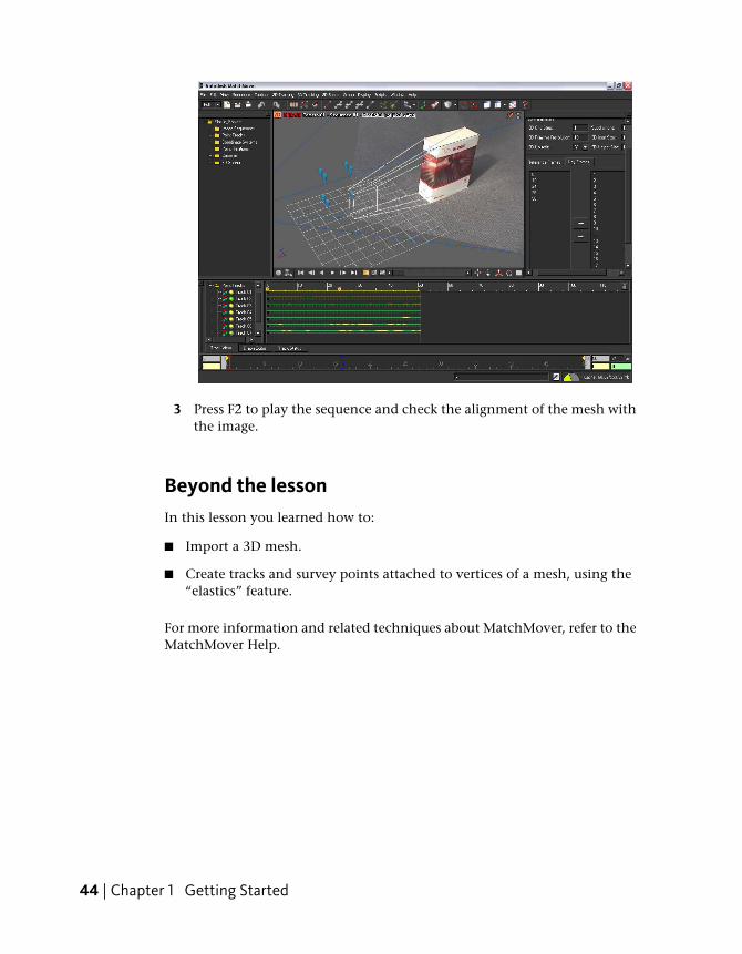
3 Press F2 to play the sequence and check the alignment of the mesh withthe image.
Beyond the lessonIn this lesson you learned how to:
■ Import a 3D mesh.
■ Create tracks and survey points attached to vertices of a mesh, using the“elastics” feature.
For more information and related techniques about MatchMover, refer to theMatchMover Help.
44 | Chapter 1 Getting Started
Lesson 4: Motion capture
Introduction
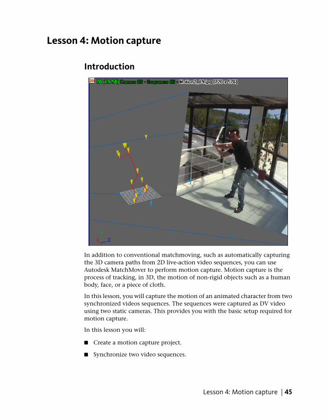
In addition to conventional matchmoving, such as automatically capturingthe 3D camera paths from 2D live-action video sequences, you can useAutodesk MatchMover to perform motion capture. Motion capture is theprocess of tracking, in 3D, the motion of non-rigid objects such as a humanbody, face, or a piece of cloth.
In this lesson, you will capture the motion of an animated character from twosynchronized videos sequences. The sequences were captured as DV videousing two static cameras. This provides you with the basic setup required formotion capture.
In this lesson you will:
■ Create a motion capture project.
■ Synchronize two video sequences.
Lesson 4: Motion capture | 45
■ Create motion tracks for two synchronized video sequences.
■ Calibrate the camera to obtain camera parameters.
■ Build a skeleton line representation of an actor’s motion.
Lesson setupTo ensure the lesson works as described, do these steps before beginning:
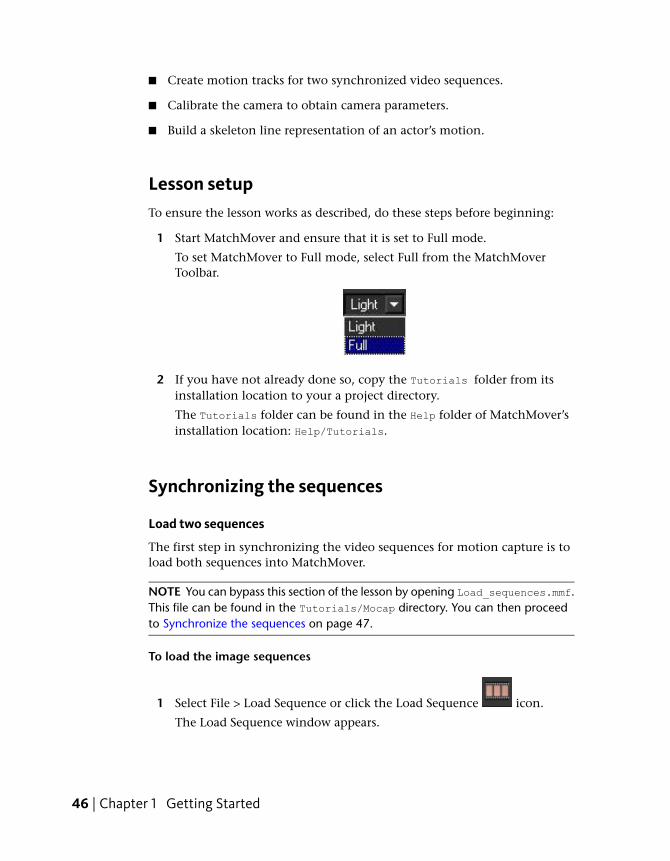
1 Start MatchMover and ensure that it is set to Full mode.
To set MatchMover to Full mode, select Full from the MatchMoverToolbar.
2 If you have not already done so, copy the Tutorials folder from itsinstallation location to your a project directory.
The Tutorials folder can be found in the Help folder of MatchMover’sinstallation location: Help/Tutorials.
Synchronizing the sequences
Load two sequences
The first step in synchronizing the video sequences for motion capture is toload both sequences into MatchMover.
NOTE You can bypass this section of the lesson by opening Load_sequences.mmf.This file can be found in the Tutorials/Mocap directory. You can then proceedto Synchronize the sequences on page 47.
To load the image sequences
1 Select File > Load Sequence or click the Load Sequence icon.
The Load Sequence window appears.
46 | Chapter 1 Getting Started
2 In the Load Sequence window, browse to the location of the MatchMoverTutorials/Mocap directory, and select Motion1_00.jpg, which is the firstimage in the first sequence.
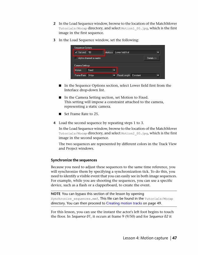
3 In the Load Sequence window, set the following:
■ In the Sequence Options section, select Lower field first from theInterlace drop-down list.
■ In the Camera Setting section, set Motion to Fixed.This setting will impose a constraint attached to the camera,representing a static camera.
■ Set Frame Rate to 25.
4 Load the second sequence by repeating steps 1 to 3.
In the Load Sequence window, browse to the location of the MatchMoverTutorials/Mocap directory, and select Motion2_00.jpg, which is the firstimage in the second sequence.
The two sequences are represented by different colors in the Track Viewand Project windows.
Synchronize the sequences
Because you need to adjust these sequences to the same time reference, youwill synchronize them by specifying a synchronization tick. To do this, youneed to identify a visible event that you can easily see in both image sequences.For example, while you are shooting the sequences, you can use a specificdevice, such as a flash or a clapperboard, to create the event.
NOTE You can bypass this section of the lesson by openingSynchronize_sequences.mmf. This file can be found in the Tutorials/Mocapdirectory. You can then proceed to Creating motion tracks on page 49.
For this lesson, you can use the instant the actor's left foot begins to touchthe floor. In Sequence 01, it occurs at frame 9 (9/50) and for Sequence 02 it
Lesson 4: Motion capture | 47
occurs at frame 58 (7/50). You can see this information displayed on thetop-left corner of the image viewport.
To synchronize the sequences
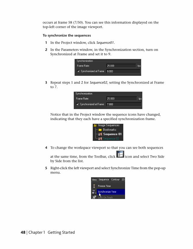
1 In the Project window, click Sequence01.
2 In the Parameters window, in the Synchronization section, turn onSynchronized at Frame and set it to 9.
3 Repeat steps 1 and 2 for Sequence02, setting the Synchronized at Frameto 7.
Notice that in the Project window the sequence icons have changed,indicating that they each have a specified synchronization frame.
4 To change the workspace viewport so that you can see both sequences
at the same time, from the Toolbar, click icon and select Two Sideby Side from the list.
5 Right-click the left viewport and select Synchronize Time from the pop-upmenu.
48 | Chapter 1 Getting Started
The information displayed in the top-left corner of this viewport is nowdisplayed in bright green, meaning it will update its own time using thesynchronization information specified.
6 Right-click the right viewport and select Synchronize Time from thepop-up menu.
7 With the right viewport still active, select any frame between 51 and 101in the Time line.
You can now play the sequence from this point in the Time Line to checkthat the sequences are synchronized.
Click the icon to play the sequence.
When you look at the start of Sequence 02 at frame 51 in the rightviewport, notice in the left viewport that Sequence 01 is at frame 2. It isthis difference that allows us to have a good synchronization betweenthe sequences.
Creating motion tracksIn this section of the lesson, you create a motion track of the actor’smovements.
NOTE You can bypass this section of the lesson by openingMotion_solved.mmf.mmf. This file can be found in the Tutorials/Mocap directory.You can then proceed to Finalizing your motion capture project on page 53.
The first step in this process is to create a new point track group that you willuse to place the actor's tracks.
To create a new point track group
1 In the Project window, right-click the Point Tracks folder and select NewGroup from the pop-up menu.
2 In the Parameters window, click the Group 01 tab.
3 In the Label field, select Group 01and type Actor.
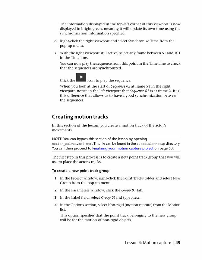
4 In the Options section, select Non-rigid (motion capture) from the Motionlist.
This option specifies that the point track belonging to the new groupwill be for the motion of non-rigid objects.
Lesson 4: Motion capture | 49
Creating point tracks
In this section of the lesson, you place track point on markers that are attachedto the actor. There are 18 markers attached to the actor, but for this sectionof the lesson, you use only six for your tracking points. When creating amotion track, you must place your track points on the same marker in bothsequences. For example, if you place Track 01 on the white marker located onthe right side of the actor’s head in Sequence01, you must also place Track 01on the same marker in Sequence02.
Be aware that some tracks may need manual adjustment as can be the casewhen using supervised tracking. For example, in a few of the frames,MatchMover confuses the motion of the actor's saber with the motion of themarkers on the actor's leg and includes the saber’s motion in the track.
The easiest markers to track in both sequences are located on the actor's headand on the legs. In all cases, try to choose the most visible markers in yoursequences.
For information about supervised tracking, see Lesson 2: Using supervisedtracking on page 18.
To create the track points
1 Go to frame 51 in the Time Line.
The left viewport now displays the first frame of Sequence 01and the rightviewport now displays the first frame of Sequence 02.
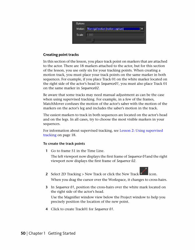
2 Select 2D Tracking > New Track or click the New Track icon.
When you drag the cursor over the Workspace, it changes to cross-hairs.
3 In Sequence 01, position the cross-hairs over the white mark located onthe right side of the actor's head.
Use the Magnifier window view below the Project window to help youprecisely position the location of the new point.
4 Click to create Track01 for Sequence 01.
50 | Chapter 1 Getting Started
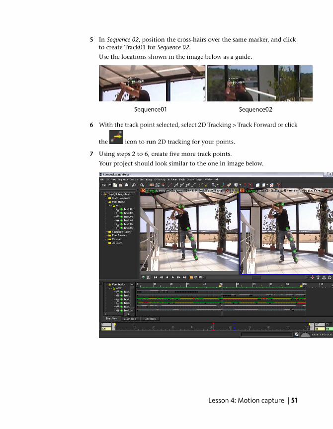
5 In Sequence 02, position the cross-hairs over the same marker, and clickto create Track01 for Sequence 02.
Use the locations shown in the image below as a guide.
6 With the track point selected, select 2D Tracking > Track Forward or click
the icon to run 2D tracking for your points.
7 Using steps 2 to 6, create five more track points.
Your project should look similar to the one in image below.
Lesson 4: Motion capture | 51
Performing an initial solve
Before you can perform the camera solve, you must remove the two-frameshift between the two sequences.
The first two frames (0-1 in the Time Line) only appear in Sequence 01, andthe last two frames (100-101 in the Time Line) only appear in sequenceSequence 02. Since no 3D information can be derived for these frames, youneed to specify that the frames are not solved.
To solve for the camera
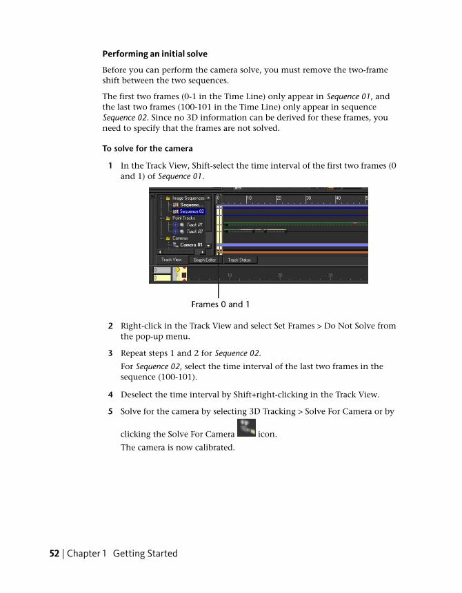
1 In the Track View, Shift-select the time interval of the first two frames (0and 1) of Sequence 01.
2 Right-click in the Track View and select Set Frames > Do Not Solve fromthe pop-up menu.
3 Repeat steps 1 and 2 for Sequence 02.
For Sequence 02, select the time interval of the last two frames in thesequence (100-101).
4 Deselect the time interval by Shift+right-clicking in the Track View.
5 Solve for the camera by selecting 3D Tracking > Solve For Camera or by
clicking the Solve For Camera icon.
The camera is now calibrated.
52 | Chapter 1 Getting Started
Finalizing your motion capture projectIn this section of the lesson, you will add three tracks that correspond to pointsin the scene’s static background. This is the minimum number of pointsrequired to define a coordinate system. Creating these tracks defines a 3Dcoordinates with respect to a world coordinate system attached to thebackground, which is very useful in motion capture. This step might not benecessary if all you need is to compute the 3D trajectories with respect to anunspecified coordinate system
In the last step of the lesson you will create skeleton lines which will betterdisplay the motion captured and of the tracked scene.
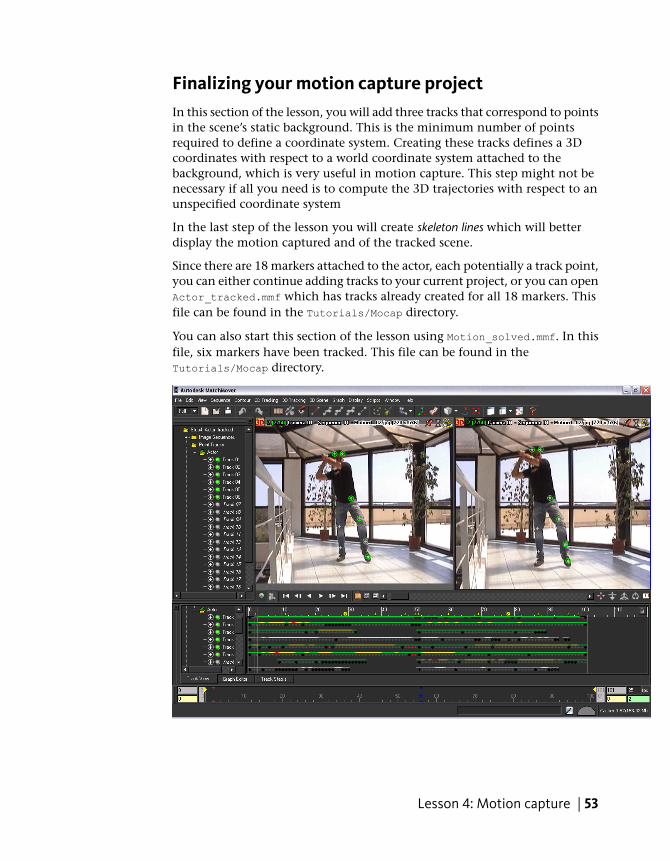
Since there are 18 markers attached to the actor, each potentially a track point,you can either continue adding tracks to your current project, or you can openActor_tracked.mmf which has tracks already created for all 18 markers. Thisfile can be found in the Tutorials/Mocap directory.
You can also start this section of the lesson using Motion_solved.mmf. In thisfile, six markers have been tracked. This file can be found in theTutorials/Mocap directory.
Lesson 4: Motion capture | 53
If you want to add the tracks yourself, do so before continuing the lesson.
To create point tracks in the background
1 In the Project window, select the Point Tracks folder.
Since the point tracks that you will create for the background are forstatic, rigid objects, selecting the Point Tracks folder ensures that yournew point tracks are not added to the Actor Point Tracks folder.
2 In the first frame of Sequence01, place a track point on the floor of thescene by selecting 2D Tracking > New Track or clicking the New Track
icon.
You can try to use the square patterns to locate easily recognizablelocations on the floor as you will need to place a track point in the samelocation in Sequence02.
NOTE You can try to use the square patterns to locate the points on thefloor. Once the first track is placed, you do not need to run the Track Forwardon it, because the sequence was shot with a fixed camera, and MatchMoverdetects this through the “fixed” motion constraint.
3 In the first frame of Sequence02, place the same track point in samelocation as you did in the first frame of Sequence01.
This point is reconstructed in space right away, based on the existingcamera calibration (solve). If the point is in the wrong location in one ofthe sequences, the cross-hairs will appear in red. This can often happenif your video sequences are low-resolution, compressed footage.
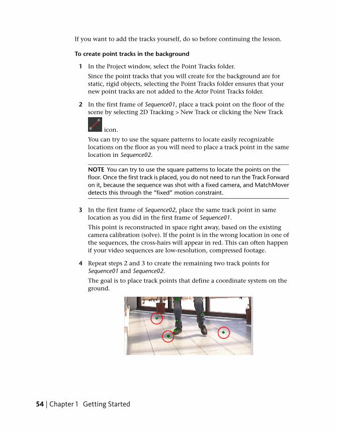
4 Repeat steps 2 and 3 to create the remaining two track points forSequence01 and Sequence02.
The goal is to place track points that define a coordinate system on theground.
54 | Chapter 1 Getting Started

5 Solve for the camera by selecting 3D Tracking > Solve For Camera or by
clicking the Solve For Camera icon.
The camera is calibrated with the a coordinate system on the scene’sbackground. You can now finalize you project by building some skeletonlines.
6 Click the 3D space icon that is located in the top left corner of bothviewports.
The view switches to 3D mode. A camera icon and grid is placed in theWorkspace.
You can also switch back to a single viewport by selecting Single ViewportSpace from the Toolbar.
7 In the viewport, select the yellow cone that appears at the right side ofthe actor’s head.
This cone represents Track01.
8 Shift-select the yellow cone that appears at the left side of the actor’shead.
This cone represents Track02.
9 With both cones still selected, select 3D Tracking > New Relation.
10 In the Parameters window, click the Relation 01 tab.
11 From the Type list, select Line.
Lesson 4: Motion capture | 55
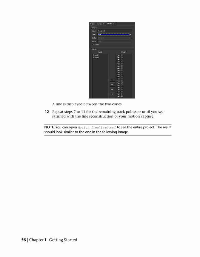
A line is displayed between the two cones.
12 Repeat steps 7 to 11 for the remaining track points or until you seesatisfied with the line reconstruction of your motion capture.
NOTE You can open Motion_finalized.mmf to see the entire project. The resultshould look similar to the one in the following image.
56 | Chapter 1 Getting Started
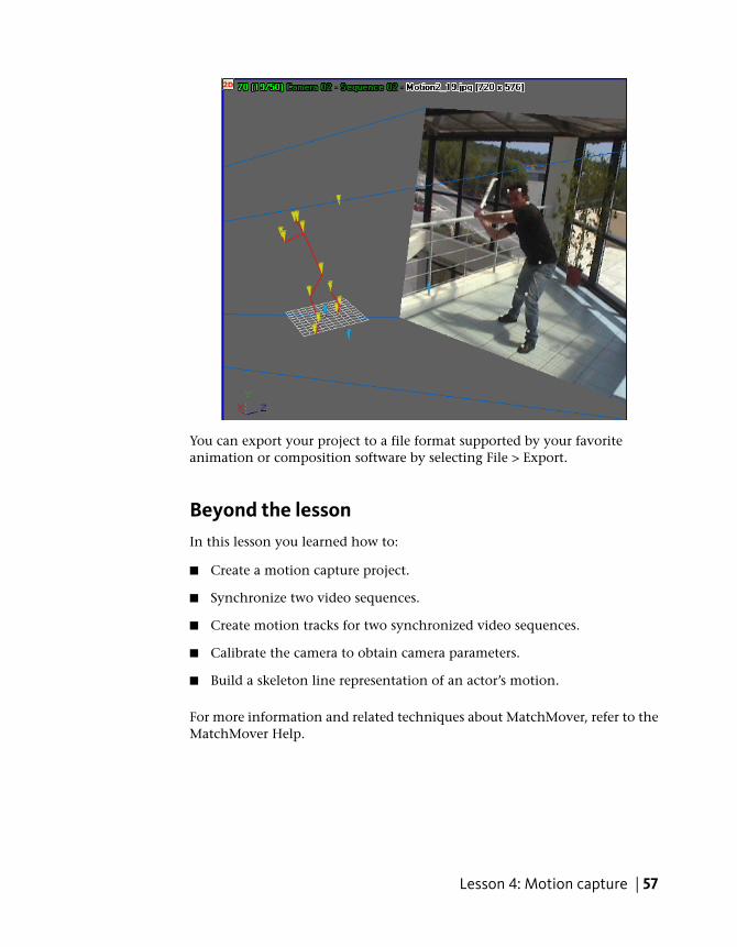
You can export your project to a file format supported by your favoriteanimation or composition software by selecting File > Export.
Beyond the lessonIn this lesson you learned how to:
■ Create a motion capture project.
■ Synchronize two video sequences.
■ Create motion tracks for two synchronized video sequences.
■ Calibrate the camera to obtain camera parameters.
■ Build a skeleton line representation of an actor’s motion.
For more information and related techniques about MatchMover, refer to theMatchMover Help.
Lesson 4: Motion capture | 57

58
Related Documents