1 08ICES-0222 International Space Station USOS Crew Quarters Development James Lee Broyan, Jr. NASA Lyndon B. Johnson Space Center Melissa Ann Borrego MEI Technologies, Inc. Juergen F. Bahr ERC Incorporated Copyright © 2008 SAE International ABSTRACT The International Space Station (ISS) United States Operational Segment (USOS) currently provides a Temporary Sleep Station (TeSS) as crew quarters for one crewmember in the Laboratory Module. The Russian Segment provides permanent crew quarters (Kayutas) for two crewmembers in the Service Module. The TeSS provides limited electrical, communication, and ventilation functionality. A new permanent rack sized USOS ISS Crew Quarters (CQ) is being developed. Up to four CQs can be installed into the Node 2 element to increase the ISS crewmember size to six. The new CQs will provide private crewmember space with enhanced acoustic noise mitigation, integrated radiation reduction material, controllable airflow, communication equipment, redundant electrical systems, and redundant caution and warning systems. The rack sized CQ is a system with multiple crewmember restraints, adjustable lighting, controllable ventilation, and interfaces that allow each crewmember to personalize their CQ workspace. Providing an acoustically quiet and visually isolated environment, while ensuring crewmember safety, is critical for obtaining crewmember rest and comfort to enable long term crewmember performance. The numerous human factor, engineering, and program considerations during the concept, design, and prototyping are outlined in the paper. INTRODUCTION As space flight has increased in duration from the several days of Gemini/Apollo, the few weeks of Skylab, to the extended months of Russian Mir and ISS, the needs for dedicated volumes for private crewmember space have become essential. The history of crew quarters (CQ) has been documented previously, (Dietz & Doerre, 1990) (Adams, 1998) but a few key milestones provide insight to the current development. Private volumes are required to provide a relatively quiet retreat from cabin equipment noise, allow for private medical consultations, conversations with family, and restful sleep. The requirements for acoustic, visual, and light isolation introduce additional design, habitability, and safety challenges because a private volume is by definition a confined space that introduces potential hazards. Design and development efforts of long-term crewmember accommodations began with the US Skylab crew quarters. Skylab featured visual private space for each crewmember but lacked acoustic and light isolation and had very limited ventilation control. The Skylab crew indicated these deficiencies and a lack of headroom for taller crewmembers reduced the effectiveness of the private volumes (Adams, 1998). The Russian crew quarters, or Kayutas, were introduced with Salyute 6 and the basic configuration was used in Mir’s base block and the ISS Service Module. The Kayutas provide an increased visually private volume with a 20-cm diameter window, but the window increases crewmember space radiation exposure. The Kayutas have air drawn from the cabin but are generally too warm and do not provide sufficient acoustic attenuation of the cabin noise (Adams, 1998). Valuable lessons were learned from participating in the Russian Mir program and were incorporated into CQ. Early Space Station Freedom (SSF) CQs were planned to be approximately one and a half equipment racks’ volume (3.2 m 3 ). This provided increased storage, thermal control, and office space compared to the ISS CQ volume under development (2.1 m 3 ). Four SSF CQs https://ntrs.nasa.gov/search.jsp?R=20080013462 2018-09-23T03:27:24+00:00Z

Welcome message from author
This document is posted to help you gain knowledge. Please leave a comment to let me know what you think about it! Share it to your friends and learn new things together.
Transcript
1
08ICES-0222
International Space Station USOS Crew Quarters Development
James Lee Broyan, Jr. NASA Lyndon B. Johnson Space Center
Melissa Ann Borrego MEI Technologies, Inc.
Juergen F. Bahr ERC Incorporated
Copyright © 2008 SAE International
ABSTRACT
The International Space Station (ISS) United States Operational Segment (USOS) currently provides a Temporary Sleep Station (TeSS) as crew quarters for one crewmember in the Laboratory Module. The Russian Segment provides permanent crew quarters (Kayutas) for two crewmembers in the Service Module. The TeSS provides limited electrical, communication, and ventilation functionality.
A new permanent rack sized USOS ISS Crew Quarters (CQ) is being developed. Up to four CQs can be installed into the Node 2 element to increase the ISS crewmember size to six. The new CQs will provide private crewmember space with enhanced acoustic noise mitigation, integrated radiation reduction material, controllable airflow, communication equipment, redundant electrical systems, and redundant caution and warning systems. The rack sized CQ is a system with multiple crewmember restraints, adjustable lighting, controllable ventilation, and interfaces that allow each crewmember to personalize their CQ workspace.
Providing an acoustically quiet and visually isolated environment, while ensuring crewmember safety, is critical for obtaining crewmember rest and comfort to enable long term crewmember performance. The numerous human factor, engineering, and program considerations during the concept, design, and prototyping are outlined in the paper.
INTRODUCTION
As space flight has increased in duration from the several days of Gemini/Apollo, the few weeks of Skylab, to the extended months of Russian Mir and ISS, the needs for dedicated volumes for private crewmember
space have become essential. The history of crew quarters (CQ) has been documented previously, (Dietz & Doerre, 1990) (Adams, 1998) but a few key milestones provide insight to the current development. Private volumes are required to provide a relatively quiet retreat from cabin equipment noise, allow for private medical consultations, conversations with family, and restful sleep. The requirements for acoustic, visual, and light isolation introduce additional design, habitability, and safety challenges because a private volume is by definition a confined space that introduces potential hazards.
Design and development efforts of long-term crewmember accommodations began with the US Skylab crew quarters. Skylab featured visual private space for each crewmember but lacked acoustic and light isolation and had very limited ventilation control. The Skylab crew indicated these deficiencies and a lack of headroom for taller crewmembers reduced the effectiveness of the private volumes (Adams, 1998). The Russian crew quarters, or Kayutas, were introduced with Salyute 6 and the basic configuration was used in Mir’s base block and the ISS Service Module. The Kayutas provide an increased visually private volume with a 20-cm diameter window, but the window increases crewmember space radiation exposure. The Kayutas have air drawn from the cabin but are generally too warm and do not provide sufficient acoustic attenuation of the cabin noise (Adams, 1998). Valuable lessons were learned from participating in the Russian Mir program and were incorporated into CQ.
Early Space Station Freedom (SSF) CQs were planned to be approximately one and a half equipment racks’ volume (3.2 m3). This provided increased storage, thermal control, and office space compared to the ISS CQ volume under development (2.1 m3). Four SSF CQs
https://ntrs.nasa.gov/search.jsp?R=20080013462 2018-09-23T03:27:24+00:00Z
2
were to be located in one end of the Habitation Module. The SSF CQs were not developed beyond the early preliminary design stage. However, the current ISS CQ requirements have maintained most of the functionality and basic anthropometric envelope but reduced the stowage, office utilities, and thermal adjustability of the SSF CQ concept.
In the late 1990s, concept development for what was termed Deployable Crew Quarters (DCQ) resulted in the rigid crew cabins providing personal space on ISS and the proposed TransHAB transit to Mars, (Kennedy, 1999). In 2001, a reduced functionality Temporary Sleep Station (TeSS) protoflight unit was developed rapidly over a nine month development period. TeSS was launched on 7A.1 and located in the US Laboratory Module (LAB), Destiny, to increase the ISS crewmember size from two to three.
TeSS was designed as a short term solution with limited functionality until the full functional CQs in the Habitation Module were delivered. Given the short development time, many of the habitability and maintainability requirements were waived or reduced to goals. The TeSS design (Keener, 2002) is briefly described here to compare and contrast with the current CQ. TeSS had limited functionality and provided a private volume consisting of a rack volume and a 30.5-cm bump-out into the aisle way, acoustic panels, and attachments for crewmember items. The TeSS has pass through openings for electrical cables and to allow external alarms to be heard. These openings limited the effectiveness of acoustic and light isolation. The TeSS did not incorporate independent ventilation but completely redirected one pair of LAB ventilation ducts into and out of the rack. The ventilation control of direction and flow rate was limited and some crewmembers have reported the inability to direct air as a source of discomfort. TeSS was a substantial improvement in crewmember on-orbit living and provided valuable lessons in acoustics, fabric liners, and crewmember preference over the last eight years.
The TeSS structure was launched folded flat on a Resupply Stowage Platform (RSP) to minimize launch loads and had to be assembled on orbit. Additionally, separate radiation blocks were launched and assembled inside the TeSS to reduce crewmember exposure to space radiation (Zapp, 2001). Both the initial installation and subsequent behind rack operations have resulted in substantial crewmember time to disassemble and reassemble. TeSS’ operational life was extended beyond the originally intended two years after the Habitation Module was removed from the station configuration in 2002. Subsequently, the ISS Node 2 element was outfitted with provisions for accommodating four CQs.
The current ISS sleeping provisions for three crewmembers (two Kayutas and one TeSS) will be augmented with the ISS CQs under development. The
CQs, with additional regenerative life support racks, will allow the ISS crewmember complement to be increased from three to six crewmembers to enable the ISS to reach its full science research potential. This paper describes the development of the USOS permanent CQ and how human factors and conventional engineering are combined for successful design. The detail requirements of the CQ were defined by the ISS program Interface Control Document SSP 50357 and Project Technical Requirements Specification SSP 50781.
MPLM LAUNCH AND INTEGRATION TO NODE 2 ELEMENT
Three of the CQs are scheduled for Space Shuttle launch in the Multi-Purpose Logistics Module (MPLM) on flight ULF2 in late 2008. Node 2 has the capability to accommodate four CQs and the individual CQ layout is based on the interaction of all four CQs. Although a custom designed assembly, each CQ will occupy a standard US rack volume and use the same structural attachment points. Once on orbit, each CQ will be removed from the MPLM and relocated to Node 2. Compared to TeSS, significantly less assembly work is required to obtain the final shape and outfit it with radiation reduction panels and electronics.
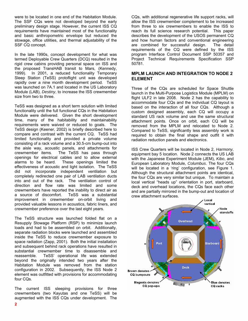
ISS Crew Quarters will be located in Node 2, Harmony, equipment bay 5 location. Node 2 connects the US LAB with the Japanese Experiment Module (JEM), Kibo, and European Laboratory Module, Columbus. The four CQs will be located in a ‘ring’ configuration, see Figure 1. Although the structural attachment points are identical, the four CQs are very similar but unique. To maintain a local vertical “heads up” orientation in port, starboard, deck and overhead locations, the CQs face each other and are partially mirrored in the bump-out and location of crew attachment surfaces.
3
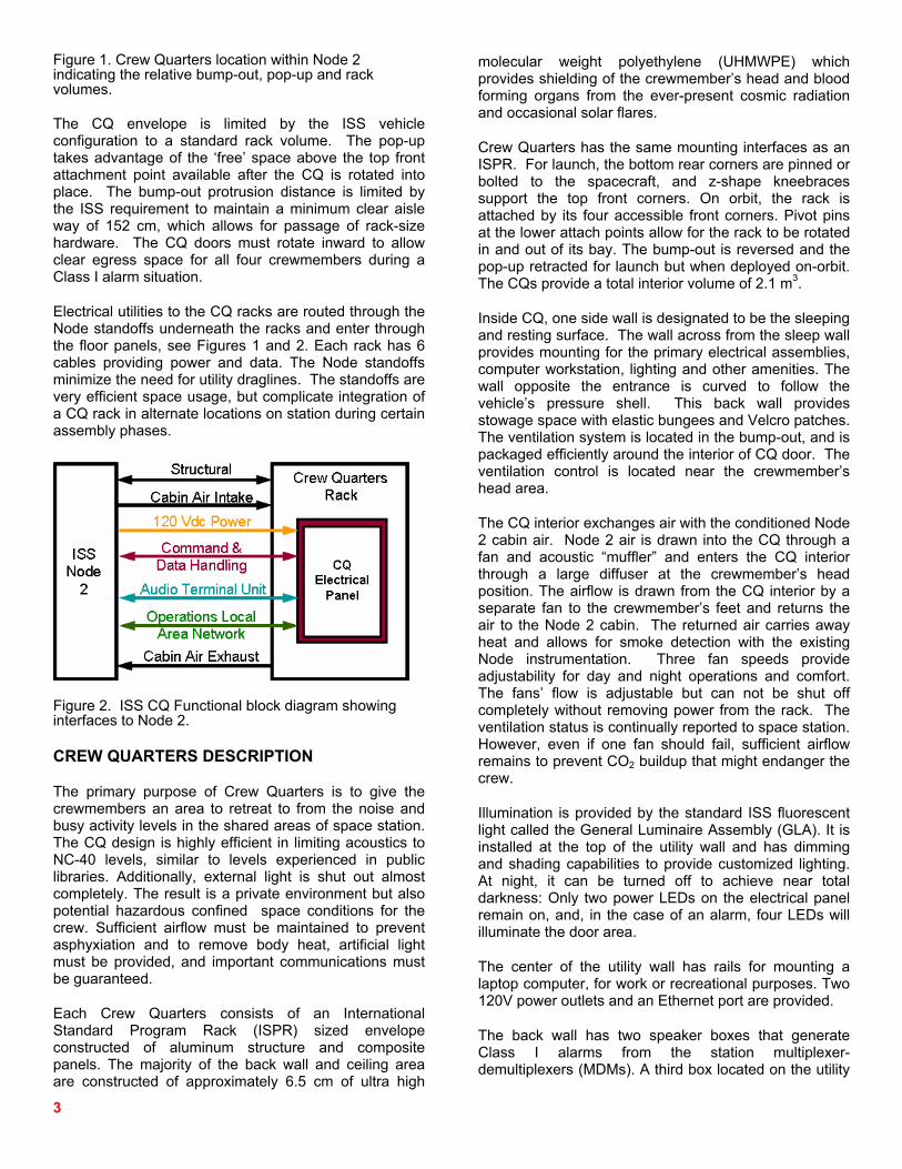
Figure 1. Crew Quarters location within Node 2 indicating the relative bump-out, pop-up and rack volumes.
The CQ envelope is limited by the ISS vehicle configuration to a standard rack volume. The pop-up takes advantage of the ‘free’ space above the top front attachment point available after the CQ is rotated into place. The bump-out protrusion distance is limited by the ISS requirement to maintain a minimum clear aisle way of 152 cm, which allows for passage of rack-size hardware. The CQ doors must rotate inward to allow clear egress space for all four crewmembers during a Class I alarm situation.
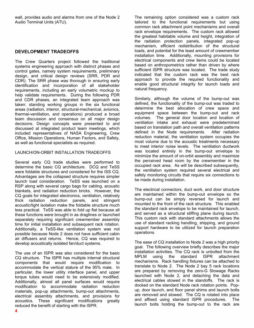
Electrical utilities to the CQ racks are routed through the Node standoffs underneath the racks and enter through the floor panels, see Figures 1 and 2. Each rack has 6 cables providing power and data. The Node standoffs minimize the need for utility draglines. The standoffs are very efficient space usage, but complicate integration of a CQ rack in alternate locations on station during certain assembly phases.
Figure 2. ISS CQ Functional block diagram showing interfaces to Node 2.
CREW QUARTERS DESCRIPTION
The primary purpose of Crew Quarters is to give the crewmembers an area to retreat to from the noise and busy activity levels in the shared areas of space station. The CQ design is highly efficient in limiting acoustics to NC-40 levels, similar to levels experienced in public libraries. Additionally, external light is shut out almost completely. The result is a private environment but also potential hazardous confined space conditions for the crew. Sufficient airflow must be maintained to prevent asphyxiation and to remove body heat, artificial light must be provided, and important communications must be guaranteed.
Each Crew Quarters consists of an International Standard Program Rack (ISPR) sized envelope constructed of aluminum structure and composite panels. The majority of the back wall and ceiling area are constructed of approximately 6.5 cm of ultra high
molecular weight polyethylene (UHMWPE) which provides shielding of the crewmember’s head and blood forming organs from the ever-present cosmic radiation and occasional solar flares.
Crew Quarters has the same mounting interfaces as an ISPR. For launch, the bottom rear corners are pinned or bolted to the spacecraft, and z-shape kneebraces support the top front corners. On orbit, the rack is attached by its four accessible front corners. Pivot pins at the lower attach points allow for the rack to be rotated in and out of its bay. The bump-out is reversed and the pop-up retracted for launch but when deployed on-orbit. The CQs provide a total interior volume of 2.1 m3.
Inside CQ, one side wall is designated to be the sleeping and resting surface. The wall across from the sleep wall provides mounting for the primary electrical assemblies, computer workstation, lighting and other amenities. The wall opposite the entrance is curved to follow the vehicle’s pressure shell. This back wall provides stowage space with elastic bungees and Velcro patches. The ventilation system is located in the bump-out, and is packaged efficiently around the interior of CQ door. The ventilation control is located near the crewmember’s head area.
The CQ interior exchanges air with the conditioned Node 2 cabin air. Node 2 air is drawn into the CQ through a fan and acoustic “muffler” and enters the CQ interior through a large diffuser at the crewmember’s head position. The airflow is drawn from the CQ interior by a separate fan to the crewmember’s feet and returns the air to the Node 2 cabin. The returned air carries away heat and allows for smoke detection with the existing Node instrumentation. Three fan speeds provide adjustability for day and night operations and comfort. The fans’ flow is adjustable but can not be shut off completely without removing power from the rack. The ventilation status is continually reported to space station. However, even if one fan should fail, sufficient airflow remains to prevent CO2 buildup that might endanger the crew.
Illumination is provided by the standard ISS fluorescent light called the General Luminaire Assembly (GLA). It is installed at the top of the utility wall and has dimming and shading capabilities to provide customized lighting. At night, it can be turned off to achieve near total darkness: Only two power LEDs on the electrical panel remain on, and, in the case of an alarm, four LEDs will illuminate the door area.
The center of the utility wall has rails for mounting a laptop computer, for work or recreational purposes. Two 120V power outlets and an Ethernet port are provided.
The back wall has two speaker boxes that generate Class I alarms from the station multiplexer-demultiplexers (MDMs). A third box located on the utility
4
wall, provides audio and alarms from one of the Node 2 Audio Terminal Units (ATU).
DEVELOPMENT TRADEOFFS
The Crew Quarters project followed the traditional systems engineering approach with distinct phases and control gates, namely system requirements, preliminary design, and critical design reviews (SRR, PDR and CDR). The SRR phase was thorough in ensuring early identification and incorporation of all stakeholder requirements, including an early volumetric mockup to help validate requirements. During the following PDR and CDR phases, an integrated team approach was taken: standing working groups in the six functional areas (radiation, interior, structural-mechanical, avionics, thermal-ventilation, and operations) produced a broad team discussion and consensus on all major design decisions. Design concepts were presented to and discussed at integrated product team meetings, which included representatives of NASA Engineering, Crew Office, Mission Operations, Human Factors, and Safety, as well as functional specialists as required.
LAUNCH/ON-ORBIT INSTALLATION TRADEOFFS
Several early CQ trade studies were performed to determine the basic CQ architecture. DCQ and TeSS were foldable structures and considered for the ISS CQ. Advantages are the collapsed structure requires simpler launch load consideration. TeSS was launched on a RSP along with several cargo bags for cabling, acoustic blankets, and radiation reduction bricks. However, the CQ goals for integrated electronics, ventilation, relatively thick radiation reduction panels, and stringent acoustic/light isolation make the foldable structure much less practical. TeSS was able to fold up flat because all these functions were brought in as draglines or launched separately requiring significant crewmember assembly time for initial installation and subsequent rack rotation. Additionally, a TeSS-like ventilation system was not possible because Node 2 does not have sufficient cabin air diffusers and returns. Hence, CQ was required to develop acoustically isolated fan/duct systems.
The use of an ISPR was also considered for the basic CQ structure. The ISPR has multiple internal structural components that would require modification to accommodate the vertical stature of the 95% male. In particular, the lower utility interface panel, and upper torque tubes would need to be extensively modified. Additionally, almost all panel surfaces would require modification to accommodate radiation reduction materials, pop-up attachments, bump-out attachments, electrical assembly attachments, and provisions for acoustics. These significant modifications greatly reduced the benefit of starting with the ISPR.
The remaining option considered was a custom rack tailored to the functional requirements but using common rack attachment point mechanisms and overall rack envelope requirements. The custom rack allowed the greatest habitable volume and height, integration of the radiation protection panels, integrated pop-up mechanism, efficient redistribution of the structural loads, and potential for the least amount of crewmember installation time. Additionally, mounting provisions for electrical components and crew items could be located based on anthropometrics rather than driven by where sufficient ISPR structure was located. The trade study indicated that the custom rack was the best rack approach to provide the required functionality and enable good structural integrity for launch loads and natural frequency.
Similarly, although the volume of the bump-out was defined, the functionality of the bump-out was traded to determine the best allocation of crew space and equipment space between the bump-out and rack volumes. The general door location and location of ventilation intake and exhaust were predetermined based on translation path and overall ventilation patterns defined in the Node requirements. After radiation reduction material, the ventilation system occupies the most volume due to the acoustic treatments necessary to meet interior noise levels. The ventilation ductwork was located entirely in the bump-out envelope to minimize the amount of on-orbit assembly and maximize the perceived head room by the crewmember in the occupied rack area. As will be described subsequently, the ventilation system required several electrical and safety monitoring circuits that require six connections to be made during installation.
The electrical connectors, duct work, and door structure are maintained within the bump-out envelope so the bump-out can be simply reversed for launch and mounted to the front of the rack structure. This enabled the standard rack envelope to be maintained for launch, and served as a structural stiffing plane during launch. This custom rack with standard attachments allows the use of standard racking handling, shipping, and ground support hardware to be utilized for launch preparation operations.
The ease of CQ installation to Node 2 was a high priority goal. The following overview briefly describes the major installation activities. The CQ rack is unbolted from the MPLM using the standard ISPR attachment mechanisms. Rack handling fixtures can be attached to translate to Node 2. The Node 2 bay 5 rack locations are prepared by removing the zero-G Stowage Racks launched with Node 2, and detaching the data and electrical cables stowed in the standoffs. The rack is docked on the standard Node rack rotation points. Pop-up, door launch, and floor panel shims and launch bolts are removed and stowed. The CQ is rotated into place and affixed using standard ISPR procedures. The launch bolts holding the bump-out to the rack are
5
The door halves are latched with a simple detent capture type latch at top and bottom. The door halves are overlapped, so only one side needs to be secured. This type of latch provides enough resistance to prevent the door from accidentally being pushed open by a passer-by, and low resistance (about 30 N) to allow easy egress by a 5
removed and stowed. The bump-out is removed, the door launch bolts removed, and temporarily stowed to allow removal of the launch bag containing the acoustic blankets, interior cables, speakers, and GLA. The CQ floor panel is removed and the Node 2 cables are loosely routed through the floor. The bump-out is then reattached with the protrusion outward using quick turn fasteners. The CQ doors are then reinstalled, the Node 2 electrical connectors are connected to provide fan power, the pop-up is deployed, the acoustic blankets are unfolded and attached, and the electrical cabling and GLA are mounted. The CQ then requests for application of power via a station laptop. The CQ is then ready for outfitting with crew items (sleeping bag, laptop, and personal items). The CQ acoustic isolation, ventilation, and comfort of the crewmember will immediately be noticeable and requires no instrumentation checkout or initialization period.
DOOR SYSTEM TRADEOFFS
Significant effort went into the design of the CQ doors, beginning with the term door itself: In the NASA system, some household words have connotations that automatically create a defined set of expectations. In the case of CQ doors, there is no need for latching; and they are different from standard hatches and area closures. Another design driver for the CQ doors is the need for a good seal of light/air passage at any hinge points and seams to achieve the challenging noise reduction to NC-40 levels. Several hard construction and soft construction design solutions were developed, all of them driven by the one-handed operation needed in space.
The close proximity of adjacent Crew Quarters made soft fabric panels/flap solutions with zippers or Velcro undesirable because of the sharp impulse noise created when opening and closing which could disturb neighboring crewmember’s sleep. Operationally, when opening the doors, the attached blankets must fold up and stay completely out of the way. Given the topology of the CQ entrance, this resulted in two independent door halves with slightly different widths. A bi-fold door would have required double-hinging to accommodate the bulk of the blankets folded up. One door rotates inward 90 degrees and the other door rotates inward 120 degrees. This provides an unobstructed door opening of 51 cm x 102 cm, which was based on the favorable feedback on the TeSS door.
th percentile female crewmember.
The door hinges were designed to allow easy and rapid removal if the door failed in the closed position. The door
can simply be lifted ‘up’ off the hinge pins when closed but not when open. Additionally, for several types of CQ maintenance (when power and thus light and ventilation, are shut down) it is preferred to remove the doors completely.
VENTILATION/ACOUSTIC SYSTEM TRADEOFFS
The CQ uses cabin air for ventilation, as opposed to ducted air for TeSS. This decision was a fundamental premise for the project, made to minimize the amount of hardware modifications for Node 2 and to add flexibility for the potential relocation of Crew Quarters to somewhere else on ISS.
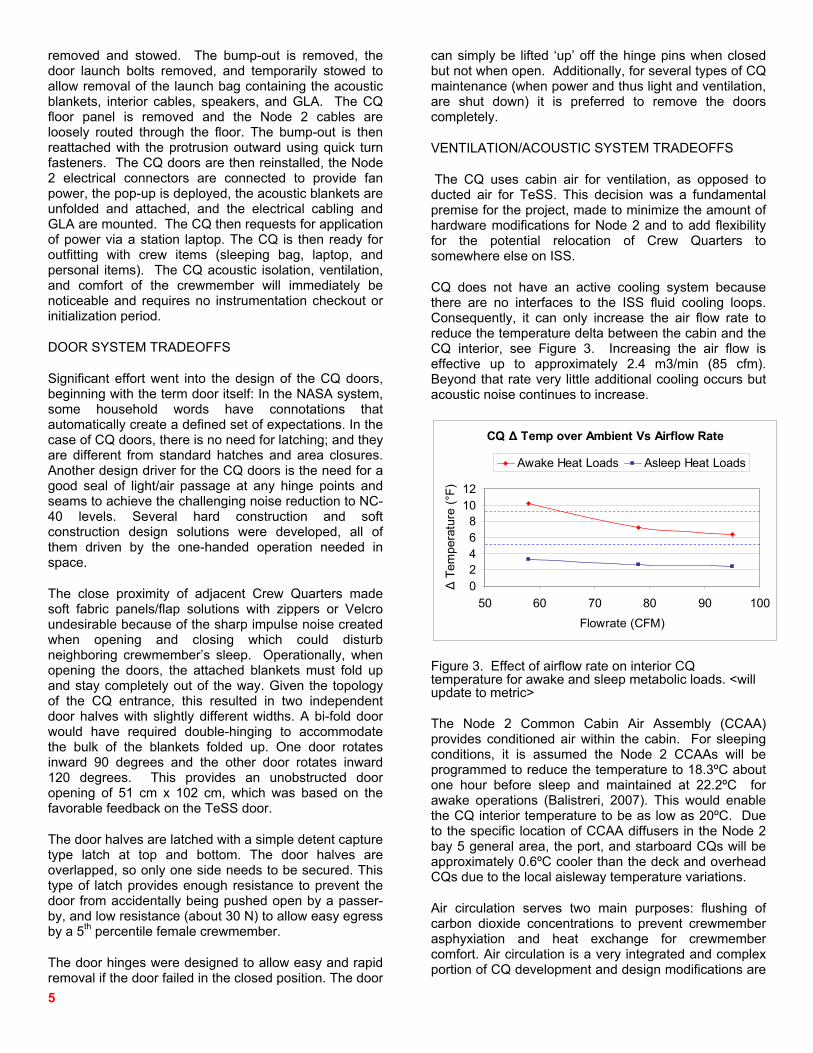
CQ does not have an active cooling system because there are no interfaces to the ISS fluid cooling loops. Consequently, it can only increase the air flow rate to reduce the temperature delta between the cabin and the CQ interior, see Figure 3. Increasing the air flow is effective up to approximately 2.4 m3/min (85 cfm). Beyond that rate very little additional cooling occurs but acoustic noise continues to increase.
CQ Δ Temp over Ambient Vs Airflow Rate
02468
1012
50 60 70 80 90 100Flowrate (CFM)
Δ Te
mpe
ratu
re (°
F)Awake Heat Loads Asleep Heat Loads
Figure 3. Effect of airflow rate on interior CQ temperature for awake and sleep metabolic loads. <will update to metric>
The Node 2 Common Cabin Air Assembly (CCAA) provides conditioned air within the cabin. For sleeping conditions, it is assumed the Node 2 CCAAs will be programmed to reduce the temperature to 18.3ºC about one hour before sleep and maintained at 22.2ºC for awake operations (Balistreri, 2007). This would enable the CQ interior temperature to be as low as 20ºC. Due to the specific location of CCAA diffusers in the Node 2 bay 5 general area, the port, and starboard CQs will be approximately 0.6ºC cooler than the deck and overhead CQs due to the local aisleway temperature variations.
Air circulation serves two main purposes: flushing of carbon dioxide concentrations to prevent crewmember asphyxiation and heat exchange for crewmember comfort. Air circulation is a very integrated and complex portion of CQ development and design modifications are

6
still being made with flight-like ventilation ductwork. Future publications will provide detailed information, so only a summary of ventilation follows.
The external configuration is straight-forward, due to the topology of the Node airflow. The CQ air intake is located on the front of each CQ, upstream of the door, where it receives the largest amount of fresh air delivered from Node 2. After passing through the inside of CQ, it is exhausted at the foot of each CQ, in the direction back toward the CCAA return. This prevents circulation back into itself or neighboring CQs. It also maintains safe operation should the doors be left open.
Internally, the design was driven by two factors: Circulation of fresh air from the astronaut’s head position to his/her feet and reduction of noise. Virtually all noise generated inside CQ is due to the ventilation system. Noise transmitted from the Node 2 exterior or from the CQ fans travels with the air towards the crewmember’s head and will be especially noticeable. This challenge was helped by implementing a push-pull fan system: One fan pulls air into CQ, another fan pushes air out the CQ exhaust. The exhaust fan noise is emitted to the Node, rather than the crewmember’s ear. The acoustic treatments and flow bends in the duct work result in pressure drop. The two fans provide more flow rate at reduced noise and size and enable more pressure drop allowance in the ducts which enables more acoustic treatments, See Figure 4.
Two EBM Papst 4184N/2XH in Series in CQ DuctingHead Vs Flow Rate
0.0
0.2
0.4
0.6
0.8
1.0
1.2
1.4
0 15 30 45 60 75 90 105 120 135 150
Flow Rate, SCFM
Hea
d, in
H2O
Low: 14 V (Interpolated) Mid: 20 V (Tested)High: 24 V (Tested) Ventilation Duct System Curve
Figure 4. Flow rate verses CQ ventilation duct pressure losses. <will convert to metric>
Implementing a two fan design was a safety requirement during the DCQ concept and is also applicable to ISS CQ. Preventing asphyxiation dictates that virtually all systems associated with ventilation and alarms are independent and redundant. The CQ design does not have redundant airflow paths but does provide redundant fans with redundant power supplies, redundant monitors and redundant alarms.
With the doors open, computational flow analysis shows that aisleway ventilation passing on the outside will provide sufficient turbulences to prevent hazardous CO2 build-up, however the CQ would be very uncomfortable due to heat buildup. No additional air circulation would be needed, were it not for the discomfort of heat build-up.
With the doors closed (evening and night time scenario), the fans must move at least 0.85 m3/min (30 cfm) to prevent asphyxiation hazards. The current design will meet this threshold with a margin, that allows for safe operation even with one fan failed. The fans are continually on and have a three-way switch to be set to low, medium and high speeds at the discretion of the crew. This accommodates various heat load scenarios and completely circulates air within the CQ volume, see Figure 5.
Figure 5. Illustrates air movement within the CQ interior at high fan speeds. <will convert to metric>
Heat load is an important factor in making the CQ a closed environment habitable. There are five major heat sources in CQ: crewmember metabolic loads, the fans, the GLA, laptop computer, and the CQ power supply. In the CQ, all heat generating elements were placed as far downstream in the airflow as possible. This means, cabin air taken in will only “see” the addition of the heat load of the intake fan. This incoming air stream will be directed at, or close to, the crew’s head, where cooling is most efficient, especially if a sleeping bag is used. Heat generated by light and electronics on the utility wall is directed past the crewmember and will not add to his discomfort. Body heat will be flowing down and reach its maximum at the feet. Heat from the power supplies and the exhaust fan is dissipated inside the exhaust duct and not the rack volume which keeps the interior ~0.6ºC cooler than if the power supply was inside the CQ interior. As shown in Figure 3, the reduction of CQ temperature by 0.6ºC, by moving the power supply into the exhaust duct, is equivalent to ~0.4 to 0.7 m3/min of airflow, depending on total CQ heat load. The airflow
7
reduction significantly decreases the fan noise that needs to be attenuated.
Industry employs push-pull configurations for fans to reduce noise. CQ avoided a parallel system for two additional reasons: (i) Doubling the heat in the intake duct, and (ii) the complexities associated with implementing redundancies. The fans could not be located in the exhaust system, because the possibility of an open door would have bypassed the crewmember’s head. Two fans in the intake are twice the noise and twice the heat. Parallel fans configuration create additional safety concerns. In a parallel fan configuration if one fan failures, the air from the surviving fan might circulate back through the failed one and not ventilate the CQ. With the push-pull system, the remaining healthy fan will push (or pull) sufficient air through the entire system, so it will not be necessary to awaken the crewmember if this problem occurs at night. Also by packaging one fan at the crew’s feet it gives more head room which is an important aspect of perceived habitability.
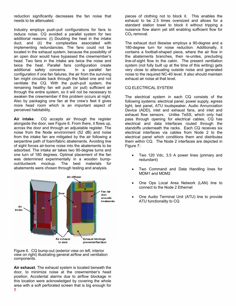
Air intake. CQ accepts air through the register alongside the door, see Figure 6. From there, it flows up, across the door and through an adjustable register. The noise from the Node environment (52 dB) and noise from the intake fan are mitigated by the air following a serpentine path of foam/fabric abatements. Avoiding line of sight forces air-borne noise into the abatements to be adsorbed. The intake air takes two 90-degree turns and one turn of 180 degrees. Optimal placement of the fan was determined experimentally in a wooden bump-out/ductwork mockup. The best materials for abatements were chosen through testing and analysis.
Figure 6. CQ bump-out (exterior view on left, interior view on right) illustrating general airflow and ventilation components.
Air exhaust. The exhaust system is located beneath the door, to minimize noise at the crewmember’s head position. Accidental alarms due to airflow blockage in this location were acknowledged by covering the whole area with a soft perforated screen that is big enough for
pieces of clothing not to block it. This enables the exhaust to be 2.5 times oversized and allows for a standard station towel to block it without tripping a nuisance flow alarm yet still enabling sufficient flow for CO2 removal.
The exhaust duct likewise employs a 90-degree and a 180-degree turn for noise reduction. Additionally, it contains a football-shaped piece, where the air flow in the abatements branches, then re-unites, precluding line-of-sight flow to the cabin. The present ventilation system (not fully built up at the time of this writing) gets very close to attenuating outside noise and generated noise to the required NC-40 level. It also should maintain exhaust air noise at that level.
CQ ELECTRICAL SYSTEM
The electrical system in each CQ consists of the following systems: electrical panel, power supply, egress light, test panel, ATU loudspeaker, Audio Annunciation Device (ADD), inlet and exhaust fans, and inlet and exhaust flow sensors. Unlike TeSS, which only had pass through opening for electrical cables, CQ has electrical and data interfaces routed through the standoffs underneath the racks. Each CQ receives six electrical interfaces via cables from Node 2 to the electrical panel which conditions them and distributes them within CQ. The Node 2 interfaces are depicted in Figure 7:
• Two 120 Vdc, 3.5 A power lines (primary and redundant)
• Two Command and Data Handling lines for MDM1 and MDM2
• One Ops Local Area Network (LAN) line to connect to the Node 2 Ethernet
• One Audio Terminal Unit (ATU) line to provide ATU functionality to CQ

8
Test Panel
GLA
Rack Power Switch
Egress Light
AAD Speaker
Fan Sensor 1
Power Supply
Egress Light
AAD Speaker
Fan Sensor 2
Inlet Fan
Outlet Fan
Mai
n C
QC
Q B
ump
Out
CQ Bump Out
CQ Electrical Panel
NO
DE
2C
rew
Qua
rter
ATU Loudspeaker
Laptop
Crew Interfaces
Test Panel
GLA
Rack Power Switch
Egress Light
AAD Speaker
Fan Sensor 1
Power Supply
Egress Light
AAD Speaker
Fan Sensor 2
Inlet Fan
Outlet Fan
Mai
n C
QC
Q B
ump
Out
CQ Bump Out
CQ Electrical Panel
NO
DE
2C
rew
Qua
rter
ATU Loudspeaker
Laptop
Crew Interfaces
Figure 7. CQ functional electrical schematic indicating power and signal distribution within CQ.
The CQ power supply converts the 120Vdc power to ±15 Vdc to power the fans and regulates the voltage to +5V to power the fan status circuits, audio circuits, and egress circuits. The 120 Vdc power is routed through the power supply to directly power the GLA, laptop, and an extra connection for crew preference items.
If a 120 Vdc power bus fails, redundant systems in the electrical panel and power supply allow the fans, egress lights, MDM logic, and the caution and warning alarm speakers to continue to run off of the operational 120Vdc input. However, when a power bus failure occurs, the non-critical laptop and GLA will need to be manually switched to the operational line via a 120Vdc select switch on the electrical panel.
The egress light will illuminate the door area inside the CQ whenever there is a loss of both primary and secondary power or annunciation of a Class 1 alarm occurs. Back-up battery power (via the 9V batteries located in the electrical panel) is supplied for the egress light and redundant audio in the event of loss of both primary and secondary power.
The test panel allows the crewmember to regularly test the health of the back-up battery system, the egress light LEDs, and the annunciation of Class 1 alarms.
CAUTION & WARNING SYSTEM TRADEOFFS
The internal acoustic requirements make the CQ too quiet for the crewmember to reliably hear the external alarms especially during sleep. Consequently, the CQ design provides a caution and warning (C&W) system
which includes two dedicated speakers (ADDs), that annunciate Class 1 alarms and uses the ATU loudspeaker as a third leg of redundancy. The ATU loudspeaker annunciates Class 2 and 3 alarms to only two of the fours CQs in Node 2 at a time.
When a Class 1 alarm situation occurs on ISS, the two MDMs in Node 2 send independent signals to CQ via the redundant C&DH data lines. The redundant speaker systems in CQ generates and annunciates a tone in CQ to alert the crewmembers to the emergency situation.
The signal from the ATU is a composite audio signal that consists of Class 1, 2, and 3 alarms and ATU audio. The CQ only re-annunciates these tones and does not regenerate them. The ATU loudspeaker is the only means by which the crewmember inside the CQ will receive Class 2 and 3 alarms. Because of this design limitation, the loudspeaker does not have volume control or an on/off switch. This feature was purposely incorporated into the design to avoid the situation where the crewmember inadvertently turns down/off the speaker and alarms are not communicated to them. The volume of all three speakers in CQ is permanently set to meet the C&W requirement of 20 dB above ambient noise.
A crewmember can also interface to the ATU loudspeaker via a headset for communication purposes. However, when the headset is plugged into the loudspeaker the crewmember will receive the alarms through the headset and through the speaker. A “speaker off” function was not implemented into the speaker design for when the headset was plugged in due to the concern that the crewmember may inadvertently leave the headset plugged in when not in use resulting in the alarms not being communicated to them. The headset also does not have a volume control. Audio volume is controlled at the Node 2 ATUs.
The Node only has two ATUs. Two of the four CQs manually patch into the Node 2 ATUs via a patch panel in Node 2. A disadvantage to relying on the ATUs for alarm notification is that not all alarms can be patched into all CQs at the same time. Operationally, this enables two ‘on-duty’ crewmembers to receive the Class 2 and 3 alarms and determine if the other crewmember need to be awoken using a ‘buddy system’. A possible improvement for future CQ development for other programs would be to provide independent data lines for each type of alarm to be annunciated. This would enable every CQ to received each type of alarm signal and have the ATU line volume be adjustable and muted with headset usage.
The risk of crewmember asphyxiation is a hazard for any confined spaced area and physiological considerations are well documented (Chang, 2002; Keener, 2002; James, 2007). Airflow monitoring devices were implemented into the CQ design to provide health status of the CQ ventilation system. Since the CQ ventilation
9
system is considered a criticality 1 system, monitoring the fan health controls the potential of a hazardous CO2 buildup environment due to no or low flow is a critical requirement.
There are a total of four airflow-monitoring devices in each CQ. Each fan has a tachometer and an independent flow sensor. The tachometer detects mechanical failure of the fans while the flow sensor detects any airflow failures. A failure from any one of the devices will notify the MDM with the appropriate failure indication resulting in an alarm that is broadcasted to the crewmember via the ATU loudspeaker.
Early CQ design included a smoke detector located in the exhaust duct. However, based on computational fluid dynamics (CFD) analysis and Safety concurrence, the smoke detector was removed from the design. The Node 2 smoke detectors are located in the CCAA inlet, approximately one and half bays away from the CQs in bay five. Analysis concluded that the worst-case CQ time of flight for smoke from the CQ fan inlet to the CCAA inlet with a minimum one-fan failed flow rate at 0.85 m3/min (30 cfm) would be approximately 85 seconds. Since there is no documented requirement for time of flight from smoke source to smoke detector, this was deemed an adequate time for detection.
Removal of the smoke detector from the CQ design allows more space in the exhaust duct for acoustic abatement material, reduces the overall CQ maintenance time on-orbit (cleaning), and potentially reduces the number of false smoke detector alarms caused by airborne particles (i.e. hair, skin, clothing, etc.)
LIGHTING TRADEOFFS
The CQ has three primary and specific lighting requirements. The first is for light isolation from the exterior for sleeping and privacy. The sleeping light isolation requirement, 54 Lux at head level (when the Node is illuminated), requires relatively tight sealing around the door frame, pop-up hinges, and through the ventilation ducts. The light isolation requirement limits the number of status LEDs on interior CQ equipment. Additionally, the low lighting level during sleep necessitates the need for egress indication (lighting), requirement of 0.5 Lux, to automatically illuminate if there is a Class I alarm or loss of electrical power. Although the CQ is a relatively small volume, it is possible for the crewmember to become disoriented during an alarm situation without visual cues. The redundant assemblies of LEDs are located on the top inner surface of the doorway so that the crewmember can operate the door quickly.
Finally, the CQ must provide general illumination during awake operations. The CQ lighting must provide 108 Lux in the general areas of CQ and 323 Lux on reading
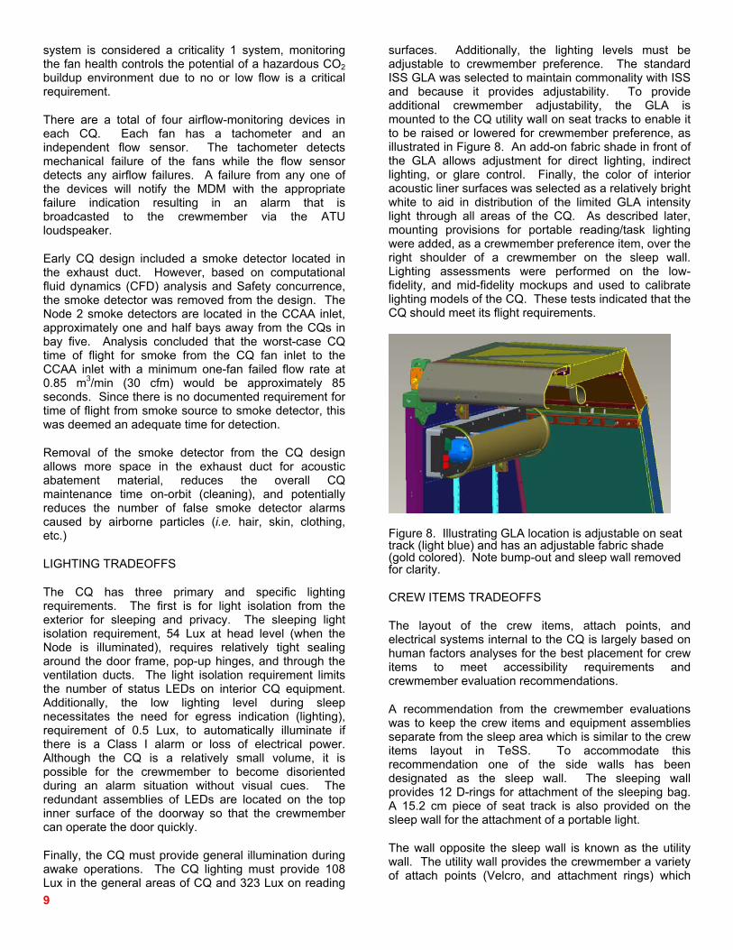
surfaces. Additionally, the lighting levels must be adjustable to crewmember preference. The standard ISS GLA was selected to maintain commonality with ISS and because it provides adjustability. To provide additional crewmember adjustability, the GLA is mounted to the CQ utility wall on seat tracks to enable it to be raised or lowered for crewmember preference, as illustrated in Figure 8. An add-on fabric shade in front of the GLA allows adjustment for direct lighting, indirect lighting, or glare control. Finally, the color of interior acoustic liner surfaces was selected as a relatively bright white to aid in distribution of the limited GLA intensity light through all areas of the CQ. As described later, mounting provisions for portable reading/task lighting were added, as a crewmember preference item, over the right shoulder of a crewmember on the sleep wall. Lighting assessments were performed on the low-fidelity, and mid-fidelity mockups and used to calibrate lighting models of the CQ. These tests indicated that the CQ should meet its flight requirements.
Figure 8. Illustrating GLA location is adjustable on seat track (light blue) and has an adjustable fabric shade (gold colored). Note bump-out and sleep wall removed for clarity.
CREW ITEMS TRADEOFFS
The layout of the crew items, attach points, and electrical systems internal to the CQ is largely based on human factors analyses for the best placement for crew items to meet accessibility requirements and crewmember evaluation recommendations.
A recommendation from the crewmember evaluations was to keep the crew items and equipment assemblies separate from the sleep area which is similar to the crew items layout in TeSS. To accommodate this recommendation one of the side walls has been designated as the sleep wall. The sleeping wall provides 12 D-rings for attachment of the sleeping bag. A 15.2 cm piece of seat track is also provided on the sleep wall for the attachment of a portable light.
The wall opposite the sleep wall is known as the utility wall. The utility wall provides the crewmember a variety of attach points (Velcro, and attachment rings) which
10
allow them to display any personal items. There are a total of 6 D-rings on the utility wall and 14 D-rings on the back wall for bungee attachment. Although highly desired by the crew, due to Velcro spacing constraints, CQ had to limit the number of Velcro patches that could be incorporated into the interior design layout. However this still enabled approximately 125 5.1 cm x 5.1 cm Velcro patches inside the CQ dedicated for crewmember usage. There are two pieces of seat track provided on the utility wall to attach a Bogen arm for the laptop desk and GLA. The test panel, electrical panel, and ATU loudspeaker are also located on the utility wall.
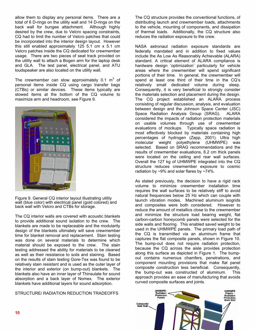
The crewmember can stow approximately 0.1 m3 of personal items inside CQ using cargo transfer bags (CTBs) or similar devices. These items typically are stowed items at the bottom of the CQ volume to maximize arm and headroom, see Figure 9.
Figure 9. General CQ interior layout illustrating utility wall (blue color) with electrical panel (gold colored) and back wall with Velcro and CTBs for storage.
The CQ interior walls are covered with acoustic blankets to provide additional sound isolation to the crew. The blankets are made to be replaceable and the modularity design of the blankets ultimately will save crewmember time for blanket removal and replacement. Stain testing was done on several materials to determine which material should be exposed to the crew. The stain testing addressed the ability for materials to be cleaned as well as their resistance to soils and staining. Based on the results of stain testing Gore-Tex was found to be relatively stain resistant and is used as the outer layer of the interior and exterior (on bump-out) blankets. The blankets also have an inner layer of Thinsulate for sound absorption and a back layer of Nomex. The exterior blankets have additional layers for sound adsorption.
STRUCTURE/ RADIATION REDUCTION TRADEOFFS
The CQ structure provides the conventional functions, of distributing launch and crewmember loads, attachments to the vehicle, mounting of components, and dissipation of thermal loads. Additionally, the CQ structure also reduces the radiation exposure to the crew.
NASA astronaut radiation exposure standards are federally mandated and in addition to fixed values include the As Low As Reasonably Achievable (ALARA) standard. A critical element of ALARA compliance is hardware design ‘optimization’ particularly for vehicle areas where the crewmember will spend significant portions of their time. In general, the crewmember will spend at least one third of their time in the CQ’s relatively small dedicated volume during sleep. Consequently, it is very beneficial to strongly consider the materials selection and placement during the design. The CQ project established an ALARA process consisting of regular discussion, analysis, and evaluation between design and the Johnson Space Center (JSC) Space Radiation Analysis Group (SRAG). ALARA considered the impacts of radiation protection materials on usable volumes through use of crewmember evaluations of mockups. Typically space radiation is most effectively blocked by materials containing high percentages of hydrogen (Zapp, 2001). Ultra high molecular weight polyethylene (UHMWPE) was selected. Based on SRAG recommendations and the results of crewmember evaluations, 6.2 cm thick panels were located on the ceiling and rear wall surfaces. Overall the 127 kg of UHMWPE integrated into the CQ structure reduces crewmember exposure to cosmic radiation by ~9% and solar flares by ~74%.
As stated previously, the decision to have a rigid rack volume to minimize crewmember installation time requires the wall surfaces to be relatively stiff to avoid natural frequencies below 25 Hz which can couple with launch vibration modes. Machined aluminum isogrids and composites were both considered. However to reduce the amount of metallics close to the crewmember and minimize the structure load bearing weight, flat carbon-carbon honeycomb panels were selected for the side walls and flooring. This enabled saved weight to be used in the UHMWPE panels. The primary load path of the CQ is transmitted via an aluminum frame that captures the flat composite panels, shown in Figure 10. The bump-out does not require radiation protection, because the CQ across the aisle provides protection along this surface as depicted in Figure 1. The bump-out contains numerous chamfers, penetrations, and component mounting provisions that make flat panel composite construction less beneficial. Consequently, the bump-out was constructed of aluminum. This approach provides an ease of manufacturing that avoids curved composite surfaces and joints.
11
Figure 10. CQ basic structural layout of aluminum exoskeleton, composite panels, and UHMWPE panels.
HABITABILITY EVALUATIONS
As part of each design phase for CQ, crewmembers were given the opportunity to evaluate a CQ mock-up that was representative of the current CQ design. Through coordination with the JSC Habitability and Human Factors Group, the CQ design went through three separate formal crewmember evaluations.
LOW-FIDELITY FOAM MOCK-UP EVALUATIONS
The first crewmember evaluation was conducted during the CQ SRR on a low-fidelity mock-up. The purpose of the evaluations was to evaluate the interior volume of the CQ and not the detailed placement or layout of crew items. The crewmember evaluated two CQ design concepts that focused on the amount of radiation protection that could be provided to meet the ALARA radiation requirement.
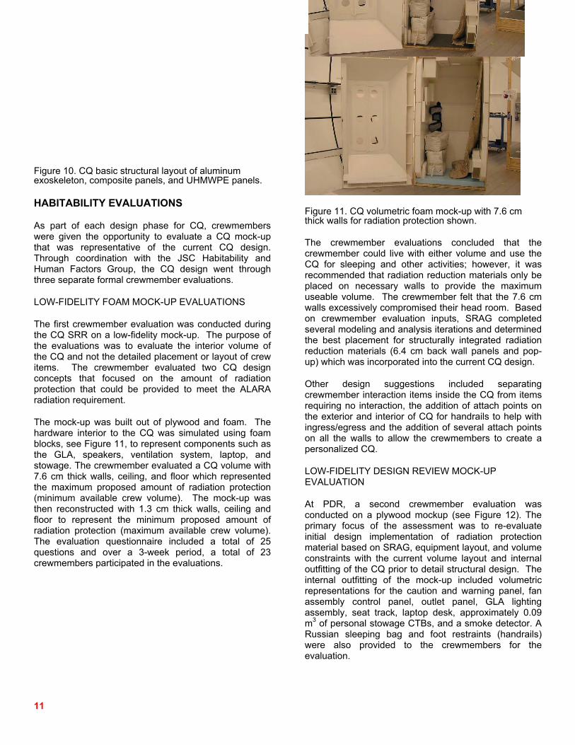
The mock-up was built out of plywood and foam. The hardware interior to the CQ was simulated using foam blocks, see Figure 11, to represent components such as the GLA, speakers, ventilation system, laptop, and stowage. The crewmember evaluated a CQ volume with 7.6 cm thick walls, ceiling, and floor which represented the maximum proposed amount of radiation protection (minimum available crew volume). The mock-up was then reconstructed with 1.3 cm thick walls, ceiling and floor to represent the minimum proposed amount of radiation protection (maximum available crew volume). The evaluation questionnaire included a total of 25 questions and over a 3-week period, a total of 23 crewmembers participated in the evaluations.
Figure 11. CQ volumetric foam mock-up with 7.6 cm thick walls for radiation protection shown.
The crewmember evaluations concluded that the crewmember could live with either volume and use the CQ for sleeping and other activities; however, it was recommended that radiation reduction materials only be placed on necessary walls to provide the maximum useable volume. The crewmember felt that the 7.6 cm walls excessively compromised their head room. Based on crewmember evaluation inputs, SRAG completed several modeling and analysis iterations and determined the best placement for structurally integrated radiation reduction materials (6.4 cm back wall panels and pop-up) which was incorporated into the current CQ design.
Other design suggestions included separating crewmember interaction items inside the CQ from items requiring no interaction, the addition of attach points on the exterior and interior of CQ for handrails to help with ingress/egress and the addition of several attach points on all the walls to allow the crewmembers to create a personalized CQ.
LOW-FIDELITY DESIGN REVIEW MOCK-UP EVALUATION
At PDR, a second crewmember evaluation was conducted on a plywood mockup (see Figure 12). The primary focus of the assessment was to re-evaluate initial design implementation of radiation protection material based on SRAG, equipment layout, and volume constraints with the current volume layout and internal outfitting of the CQ prior to detail structural design. The internal outfitting of the mock-up included volumetric representations for the caution and warning panel, fan assembly control panel, outlet panel, GLA lighting assembly, seat track, laptop desk, approximately 0.09 m3 of personal stowage CTBs, and a smoke detector. A Russian sleeping bag and foot restraints (handrails) were also provided to the crewmembers for the evaluation.

12
Figure 12. CQ low-fidelity wood mock-up with preliminary component layout.
A total of 23 crewmembers evaluated the mock-up. Each participant was asked to evaluate the CQ volume, accessibility and usability of items in the CQ as well as comments on any potential impacts with the proposed habitable volume and design. Ninety-one percent of the crewmember felt that volumetrically, the CQ was very spacious and that the volume was adequate to accommodate all personal items and most activities.
Concerns were expressed with incorporation of a removable/disposable liner, specifically with the impact on crewmember time to replace it on-orbit. Other recommendations included providing additional seat track length and quantity to allow more adjustability of the laptop desk, and using non-Velcro mechanisms for holding the door open and closed. There was overwhelming negative feedback on the GLA position with recommendations to move the GLA higher and incorporate a directable shade to customize the light levels.
Comments on the fan assembly (non-functional for mock-up) location were that it was too close to the crewmember’s head. The recommendation was to move the fan assembly further away from the head position as well as to conduct addition human factors analyses on placement of items inside the CQ (primarily the placement of the control panel and its design).
MID-FIDELITY MOCK-UP EVALUATIONS
At CDR, a final crewmember evaluation was conducted on a mid-fidelity CQ mock-up. The primary focus of this assessment was to evaluate potential volumetric impacts and solicit specific design suggestions regarding volume constraints, accessibility and location of items,
and basic usability of the components within the CQ volume. The mock-up was constructed of aluminum and composite materials and flight-like acoustic blankets lined the interior of the CQ as well as the exterior of the bump-out, depicted in Figure 13. The internal outfitting of the mock-up (see Figure 14) included a Russian sleeping bag attached to the CQ sleep wall, functional ventilation system (not representative of the flight design), GLA and shade, personal item restraints, volumetric ATU loudspeaker and Class 1 speakers, volumetric electrical panel and power supply, simulated Class 1, 2, and 3 alarms, seat track, handrails, laptop desk, and approximately 0.09 m3 of personal stowage. A total of 21 subjects evaluated the mock-up. Each participant was asked to evaluate the mock-up regarding habitable volume, habitability, accessibility, and internal outfitting. They were also asked to comment on the overall design and usability of items inside the CQ. 100% of the crewmember indicated that the volume was adequate for sleeping and other activities. Because the ventilation system was not flight-like, several negative comments were made on the high noise level and inadequate airflow provided by the system. The participants commented that the test panel and egress light design were adequate but felt that the systems were not necessary in the CQ design (but are required per requirements). Positive response was received on the incorporation of the GLA shade into the design; however, several recommendations were received on the GLA shade ease of use. Recommendations on additional bungee attachments and Velcro in the CQ design were made; however, the crewmember was pleased overall with the restraint layout and design. Due to the negative feedback on the noise level and inadequate airflow of the ventilation system, a follow-on evaluation is in work on a flight-like ventilation system. The system will be installed in the existing mock-up and will be evaluated for noise levels and airflow.

13
Figure 13. External of CQ mid-fidelity mockup on rack handling assembly.
Figure 14. CQ mid-fidelity mock-up (utility wall on left, sleep wall on right) outfitted with flight like acoustic blankets, lighting and crewmember items.
DESIGN IMPLEMENTATION
The previous trade studies and descriptions provide the rationale for the final CQ configuration. The result is a CQ with fully integrated radiation protection and crewmember provisions integrated into the structure. The ventilation system provides control independent of the Node CCAA registers (though it does depend on the Node 2 ambient temperature set point). The crewmember can vary the flow rate and direction of air. The acoustic controls are extensive on all interior surfaces and provide for long term use through material selection for stain resistance, cleanability, and replacement in sections. The ventilation acoustic abatements allow substantial acoustic attenuation from both the fans and exterior. The acoustic blankets and ventilation abatements are fully accessible, removable, and cleanable of dust and dander with a vacuum cleaner. The fully integrated, redundant electrical and
C&W systems ensure crewmember safety without interaction. The LAN, lighting adjustability, and flexibility in location and types of crew items that can be accommodated provide a place on ISS the crewmember can truly customize to maximize comfort. A follow-up paper will address the on-orbit experience and any operational issues.
CONCLUSION
The ISS CQ under development and fabrication will provide an acoustically quiet and visually isolated area for the crewmember to utilize for sleeping, relaxation, and a private retreat away from the busy environment onboard the ISS. These apparently simple functional requirements result in relatively complex and competing set of derived requirements for the hardware. Derived requirements to maintain crewmember safety, structural integrity, minimal installation/maintenance time, and reliability greatly increase the complexity of development and the necessity for close coordination across disciplines. Requirements such as radiation protection and crewmember volume and acoustic treatment and ventilation reduction from backpressure caused by the acoustic abatements are examples of how prioritizing the functionality of a system is important during early requirements development. Similarly, good system level design, coordination with habitability requirement stakeholders, and multiple crewmember evaluations are critical to ensuring a successful validation of crewmember use intensive hardware. The ISS CQ is a crucial crewmember item that will enable the ISS crewmember to expand to six crewmembers and assist them in maintaining long term productivity. The on-orbit assessment of CQ performance relative to the original development implementation will be described in a future paper.

14
REFERENCES
1. Dietz, L. P., Doerre, G. L., “Space Station Crew Quarters and Personal Hygiene Facility,” 901301, 20th Intersociety Conference on Environmental Systems, Williamsburg, VA, 1990.
2. Adams, C., “Four Legs in the Morning: Issues in Crew-Quarter Design for Long-Duration Space Facilities,” 981794, 28th International Conference on Environmental Systems, Danvers, MA, 1998.
3. Kennedy, K. J., “ISS TransHab: Architecture Description,” 1999-01-2143, International Conference on Environmental Systems, Denver, CO, 1999.
4. Keener, J. F., Paul, T., Eckhardt, B., “Analysis and Design of Crew Sleep Station for ISS,” 202-01-2303, International Conference on Environmental Systems, San Antonio, TX, 2002.
5. Zapp, N., Cucinotta, F. A., Atwell, B., “Strategies for Applying Retrofit Radiation Shielding to the ISS,” 2001-01-2369, 31st International Conference on Environmental Systems, Orlando, FL, 2001.
6. Balistreri, S. F., Son, C. H., Turner, E. H., “Analysis and Predicted Temperature Control of Crew Quarters added to Node 2 of the International Space Station,” 2007-01-3071, 37th International Conference on Environmental Systems, Chicago, IL 2007.
7. “Node 2 to Crew Quarters Interface Control Document,” SSP 50357 Rev A, July 12, 2007.
8. “Project Technical Requirements Specification for the ISS Crew Quarters,” SSP 50781 Rev A, July 25, 2007.
9. Zhang, Y. M., Keener, J. F., Smith, F. D., “Thermal Analysis of Compressible CO2 Flow for PFE TeSS Nozzle of Fire Detection System,” 2002-01-2347, San Antonio, TX 2002.
10. Chang, H. S., Zapata, J. L., Lin, C., “Investigation of Airflow and Accumulation of Carbon Dioxide in the Service Module Crew Quarters,” 2002-01-2341
11. James, J. T., “The Headache of Carbon Dioxide Exposures,” 2007-01-3218, 37th International Conference on Environmental Systems, Chicago, IL, 2007.
CONTACT
James Lee Broyan, Jr. can be contacted at [email protected].
Melissa Ann Borrego can be contacted at [email protected]
Jeff Bahr can be contacted at [email protected].
DEFINITIONS, ACRONYMS, ABBREVIATIONS
ALARA As Low As Reasonably Achievable ATU Audio Terminal Unit CCAA Common Cabin Air Assembly CCHA Crew Communication Headset Assembly CDR Critical Design Review C&DH Command and Data Handling CFD Computational Fluid Dynamics cfm cubic feet per minute CO2 Carbon Dioxide CQ Crew Quarters CTB Cargo Transfer Bag C&W Caution and Warning dB Decibel DCQ Deployable Crew Quarters ECLSS Environmental Controls and Life Support
Systems GLA General Luminaire Assembly ISPR International Standard Payload Rack ISS International Space Station JEM Japanese Experiment Module JSC Johnson Space Center LAB US Laboratory Module LAN Local Area Network LED Light Emitting Diode MDM Multiplexer-Demultiplexer MPLM Multipurpose Logistics Module MSFC Marshall Space Flight Center Mir Russian Space Station N2 Node 2 NASA National Aeronautics and Space Association NC Noise Curve PDR Preliminary Design Review RSP Resupply Stowage Platform SM Service Module SRAG Space Radiation Analysis Group SRR System Requirements Review SSF Space Station Freedom TeSS Temporary Sleep Station UHMWPE Ultra high molecular weight polyethylene US United States USOS US Operating Segment ACKNOWLEDGMENTS
This paper summarizes the hard work by the numerous JSC NASA and Engineering Support Contract project managers, design engineers, and analysts. Additional acknowledgement to the contributions of the JSC functional specialists, engineers, and crewmember whose frequent input was invaluable in ensuring as much anthropometric and habitability functionality as possible was incorporated. The CQ project is funded by the NASA JSC ISS Vehicle Office.
Related Documents