Reference number ISO/IEC 18004:2000(E) © ISO/IEC 2000 INTERNATIONAL STANDARD ISO/IEC 18004 First edition 2000-06-15 Information technology — Automatic identification and data capture techniques — Bar code symbology — QR Code Technologies de l'information — Techniques d'identification automatique et de capture de données — Symboles de codes à barres — Code QR Licensed to SCANBUY, INC./ASHISH MUNI ISO Store order #:762844/Downloaded:2006-08-01 Single user licence only, copying and networking prohibited

Welcome message from author
This document is posted to help you gain knowledge. Please leave a comment to let me know what you think about it! Share it to your friends and learn new things together.
Transcript

Reference numberISO/IEC 18004:2000(E)
© ISO/IEC 2000
INTERNATIONALSTANDARD
ISO/IEC18004
First edition2000-06-15
Information technology — Automaticidentification and data capturetechniques — Bar code symbology — QRCode
Technologies de l'information — Techniques d'identification automatique etde capture de données — Symboles de codes à barres — Code QR
Licensed to SCANBUY, INC./ASHISH MUNIISO Store order #:762844/Downloaded:2006-08-01Single user licence only, copying and networking prohibited

ISO/IEC 18004:2000(E)
PDF disclaimer
This PDF file may contain embedded typefaces. In accordance with Adobe's licensing policy, this file may be printed or viewed but shall notbe edited unless the typefaces which are embedded are licensed to and installed on the computer performing the editing. In downloading thisfile, parties accept therein the responsibility of not infringing Adobe's licensing policy. The ISO Central Secretariat accepts no liability in thisarea.
Adobe is a trademark of Adobe Systems Incorporated.
Details of the software products used to create this PDF file can be found in the General Info relative to the file; the PDF-creation parameterswere optimized for printing. Every care has been taken to ensure that the file is suitable for use by ISO member bodies. In the unlikely eventthat a problem relating to it is found, please inform the Central Secretariat at the address given below.
© ISO/IEC 2000
All rights reserved. Unless otherwise specified, no part of this publication may be reproduced or utilized in any form or by any means, electronicor mechanical, including photocopying and microfilm, without permission in writing from either ISO at the address below or ISO's member bodyin the country of the requester.
ISO copyright officeCase postale 56 � CH-1211 Geneva 20Tel. + 41 22 749 01 11Fax + 41 22 749 09 47E-mail [email protected] www.iso.ch
Printed in Switzerland
ii © ISO/IEC 2000 – All rights reserved
Licensed to SCANBUY, INC./ASHISH MUNIISO Store order #:762844/Downloaded:2006-08-01Single user licence only, copying and networking prohibited
ISO/IEC 18004:2000(E)
© ISO/IEC 2000 – All rights reserved iii
Contents Page
Foreword......................................................................................................................................................................v
Introduction ................................................................................................................................................................vi
1 Scope ..............................................................................................................................................................1
2 Conformance..................................................................................................................................................1
3 Normative references ....................................................................................................................................1
4 Terms and definitions ...................................................................................................................................2
5 Symbols (and abbreviated terms) ................................................................................................................3
6 Conventions ...................................................................................................................................................46.1 Module positions ...........................................................................................................................................46.2 Byte notation ..................................................................................................................................................46.3 Version references.........................................................................................................................................4
7 Symbol description .......................................................................................................................................47.1 Basic characteristics.....................................................................................................................................47.2 Summary of additional features...................................................................................................................57.3 Symbol structure ...........................................................................................................................................67.3.1 Symbol Versions and sizes ..........................................................................................................................67.3.2 Finder pattern...............................................................................................................................................137.3.3 Separators ....................................................................................................................................................137.3.4 Timing Pattern..............................................................................................................................................137.3.5 Alignment Patterns......................................................................................................................................137.3.6 Encoding region...........................................................................................................................................137.3.7 Quiet zone.....................................................................................................................................................13
8 Requirements...............................................................................................................................................148.1 Encode procedure overview.......................................................................................................................148.2 Data analysis ................................................................................................................................................158.3 Modes............................................................................................................................................................168.3.1 Extended Channel Interpretation (ECI) Mode ...........................................................................................168.3.2 Numeric Mode ..............................................................................................................................................168.3.3 Alphanumeric Mode ....................................................................................................................................168.3.4 8-bit Byte Mode ............................................................................................................................................168.3.5 Kanji Mode....................................................................................................................................................168.3.6 Mixing modes...............................................................................................................................................178.3.7 Structured Append Mode............................................................................................................................178.3.8 FNC1 Mode ...................................................................................................................................................178.4 Data encodation...........................................................................................................................................178.4.1 Extended Channel Interpretation (ECI) Mode ...........................................................................................188.4.2 Numeric Mode ..............................................................................................................................................198.4.3 Alphanumeric Mode ....................................................................................................................................218.4.4 8-bit Byte Mode ............................................................................................................................................228.4.5 Kanji Mode....................................................................................................................................................248.4.6 Mixing modes...............................................................................................................................................258.4.7 FNC1 Modes .................................................................................................................................................258.4.8 Terminator ....................................................................................................................................................278.4.9 Bit stream to codeword conversion...........................................................................................................278.5 Error correction............................................................................................................................................338.5.1 Error correction capacity ............................................................................................................................338.5.2 Generating the error correction codewords .............................................................................................458.6 Constructing the final message codeword sequence .............................................................................45
Licensed to SCANBUY, INC./ASHISH MUNIISO Store order #:762844/Downloaded:2006-08-01Single user licence only, copying and networking prohibited

ISO/IEC 18004:2000(E)
iv © ISO/IEC 2000 – All rights reserved
8.7 Codeword placement in matrix...................................................................................................................468.7.1 Symbol character representation...............................................................................................................468.7.2 Function pattern placement........................................................................................................................468.7.3 Symbol character placement......................................................................................................................468.8 Masking.........................................................................................................................................................508.8.1 Mask Patterns...............................................................................................................................................508.8.2 Evaluation of masking results....................................................................................................................528.9 Format Information ......................................................................................................................................538.10 Version Information .....................................................................................................................................54
9 Structured Append ......................................................................................................................................559.1 Basic principles ...........................................................................................................................................559.2 Symbol Sequence Indicator........................................................................................................................569.3 Parity Data ....................................................................................................................................................56
10 Symbol printing and marking .....................................................................................................................5710.1 Dimensions...................................................................................................................................................5710.2 Human-readable interpretation...................................................................................................................5710.3 Marking guidelines ......................................................................................................................................57
11 Symbol quality .............................................................................................................................................5711.1 Obtaining the test image .............................................................................................................................5711.2 Symbol quality parameters .........................................................................................................................5711.2.1 Decode ..........................................................................................................................................................5711.2.2 Symbol Contrast ..........................................................................................................................................5811.2.3 "Print" growth ..............................................................................................................................................5811.2.4 Axial Nonuniformity.....................................................................................................................................5811.2.5 Unused Error Correction.............................................................................................................................5811.3 Overall symbol grade ..................................................................................................................................5811.4 Process control measurements .................................................................................................................59
12 Decoding procedure overview ...................................................................................................................59
13 Reference decode algorithm for QR Code ................................................................................................60
14 Autodiscrimination capability.....................................................................................................................65
15 Transmitted data ..........................................................................................................................................6515.1 Symbology Identifier ...................................................................................................................................6515.2 Extended Channel Interpretations .............................................................................................................6515.3 FNC1..............................................................................................................................................................66
Annex A (normative) Error detection and correction generator polynomials ....................................................67
Annex B (normative) Error correction decoding steps .........................................................................................74
Annex C (normative) Format Information ...............................................................................................................76
Annex D (normative) Version Information ..............................................................................................................78
Annex E (normative) Position of Alignment Patterns............................................................................................81
Annex F (normative) Symbology Identifier.............................................................................................................83
Annex G (informative) Symbol encoding example.................................................................................................84
Annex H (informative) Optimisation of bit stream length......................................................................................86
Annex I (informative) User guidelines for printing and scanning of QR Code symbols....................................88
Annex J (informative) Autodiscrimination ..............................................................................................................90
Annex K (informative) Matrix code print quality guideline....................................................................................91
Annex L (informative) Process control techniques ...............................................................................................95
Annex M (informative) Characteristics of Model 1 QR Code symbols.................................................................97
Licensed to SCANBUY, INC./ASHISH MUNIISO Store order #:762844/Downloaded:2006-08-01Single user licence only, copying and networking prohibited

ISO/IEC 18004:2000(E)
© ISO/IEC 2000 – All rights reserved v
Foreword
ISO (the International Organization for Standardization) and IEC (the International Electrotechnical Commission)form the specialized system for worldwide standardization. National bodies that are members of ISO or IECparticipate in the development of International Standards through technical committees established by therespective organization to deal with particular fields of technical activity. ISO and IEC technical committeescollaborate in fields of mutual interest. Other international organizations, governmental and non-governmental, inliaison with ISO and IEC, also take part in the work.
International Standards are drafted in accordance with the rules given in the ISO/IEC Directives, Part 3.
In the field of information technology, ISO and IEC have established a joint technical committee, ISO/IEC JTC 1.Draft International Standards adopted by the joint technical committee are circulated to national bodies for voting.Publication as an International Standard requires approval by at least 75 % of the national bodies casting a vote.
Attention is drawn to the possibility that some of the elements of this International Standard may be the subject ofpatent rights. ISO and IEC shall not be held responsible for identifying any or all such patent rights.
International Standard ISO/IEC 18004 was prepared by Joint Technical Committee ISO/IEC JTC 1, Informationtechnology, Subcommittee SC 31, Automatic identification and data capture techniques, in collaboration with AIMInc.1).
Annexes A to F form a normative part of this International Standard. Annexes G to M are for information only.
1) AIM Inc., 634 Alpha Drive, Pittsburgh, PA 15238-2802, U.S.A.Licensed to SCANBUY, INC./ASHISH MUNIISO Store order #:762844/Downloaded:2006-08-01Single user licence only, copying and networking prohibited

ISO/IEC 18004:2000(E)
vi © ISO/IEC 2000 – All rights reserved
Introduction
QR Code is a matrix symbology consisting of an array of nominally square modules arranged in an overall squarepattern, including a unique finder pattern located at three corners of the symbol and intended to assist in easylocation of its position, size and inclination. A wide range of sizes of symbol is provided for together with four levelsof error correction. Module dimensions are user-specified to enable symbol production by a wide variety oftechniques. QR Code Model 1 is the original specification for QR Code; QR Code Model 2 is an enhanced form ofthe symbology with additional features and can be auto-discriminated from Model 1. Since Model 2 is therecommended model for new, open systems application of QR Code, this International Standard describes Model 2fully, and specifies the features in which Model 1 QR Code differs from Model 2 in an annex.
Licensed to SCANBUY, INC./ASHISH MUNIISO Store order #:762844/Downloaded:2006-08-01Single user licence only, copying and networking prohibited

INTERNATIONAL STANDARD ISO/IEC 18004:2000(E)
© ISO/IEC 2000 – All rights reserved 1
Information technology — Automatic identification and datacapture techniques — Bar code symbology — QR Code
1 Scope
This International Standard specifies the requirements for the symbology known as QR Code. It specifies the QRCode Model 2 symbology characteristics, data character encodation, symbol formats, dimensional characteristics,error correction rules, reference decoding algorithm, production quality requirements, and user-selectableapplication parameters, and defines in an annex the features of Model 1 symbols which differ from Model 2.
2 Conformance
QR Code symbols (and equipment designed to produce or read QR Code symbols) shall be considered as meetingthis specification if they meet the requirements defined for either QR Code Model 2 or Model 1. It should be noted,however, that Model 2 is the form of the symbology recommended for new and open systems applications.
3 Normative references
The following normative documents contain provisions which, through reference in this text, constitute provisions ofthis International Standard. For dated references, subsequent amendments to, or revisions of, any of thesepublications do not apply. However, parties to agreements based on this International Standard are encouraged toinvestigate the possibility of applying the most recent editions of the normative documents indicated below. Forundated references, the latest edition of the normative document referred to applies. Members of ISO and IECmaintain registers of currently valid International Standards.
ISO/IEC 15424, Information technology — Automatic identification and data capture techniques — Datacarrier/symbology identifiers.
ISO/IEC 15416, Information technology — Automatic identification and data capture techniques — Bar code printquality test specifications — Linear symbols.
EN 1556, Bar Coding — Terminology.
JIS X 0201, JIS 8-bit Character Set for Information Interchange.
JIS X 0208-1997, Japanese Graphic Character Set for Information Interchange.
ANSI X3.4, Coded Character Sets — 7-bit American National Standard Code for Information Interchange (7-bitASCII).
AIM International Technical Specification, Extended Channel Interpretations: Part 1: Identification scheme andprotocol (referred to as "AIM ECI specification").
Licensed to SCANBUY, INC./ASHISH MUNIISO Store order #:762844/Downloaded:2006-08-01Single user licence only, copying and networking prohibited

ISO/IEC 18004:2000(E)
2 © ISO/IEC 2000 – All rights reserved
4 Terms and definitions
For the purposes of this International Standard, the terms and definitions given in EN 1556 and the following apply.
4.1Alignment Patternfixed reference pattern in defined positions in a matrix symbology, which enables the decode software to re-synchronise the coordinate mapping of the image modules in the event of moderate amounts of distortion of theimage
4.2Character Count Indicatorbit sequence which defines the data string length in a mode
4.3ECI designatorsix-digit number identifying a specific ECI assignment
4.4encoding regionregion of the symbol not occupied by function patterns and available for encodation of data and error correctioncodewords
4.5Extended Channel Interpretation (ECI)protocol used in some symbologies that allows the output data stream to have interpretations different from that ofthe default character set
4.6Extension Patternin Model 1 symbols, a function pattern which does not encode data
4.7Format Informationfunction pattern containing information on the error correction level applied to the symbol and on the maskingpattern used, essential to enable the remainder of the encoding region to be decoded
4.8function patternoverhead component of the symbol required for location of the symbol or identification of its characteristics to assistin decoding
4.9Mask Pattern Referencethree-bit identifier of the masking patterns applied to the symbol
4.10maskingprocess of XORing the bit pattern in the encoding region with a masking pattern to provide a symbol with moreevenly balanced numbers of dark and light modules and reduced occurrence of patterns which would interfere withfast processing of the image
4.11modemethod of representing a defined character set as a bit string
Licensed to SCANBUY, INC./ASHISH MUNIISO Store order #:762844/Downloaded:2006-08-01Single user licence only, copying and networking prohibited

ISO/IEC 18004:2000(E)
© ISO/IEC 2000 – All rights reserved 3
4.12Mode Indicatorfour-bit identifier indicating in which mode the next data sequence is encoded
4.13Padding Bit0 bit, not representing data, used to fill empty positions of the final codeword after the Terminator in a data bit string
4.14Position Detection Patternone of three identical components of the Finder Pattern
4.15Remainder Bit0 bit, not representing data, used to fill empty positions of the symbol encoding region after the final symbolcharacter, where the encoding region does not divide exactly into eight-bit symbol characters
4.16Remainder CodewordPad Codeword used to fill empty codeword positions to complete the symbol if the total number of data and errorcorrection codewords does not exactly fill its nominal capacity
NOTE The Remainder codewords come after the error correction codewords.
4.17segmentsequence of data encoded according to the rules of one ECI or encodation mode
4.18Separatorfunction pattern of all light modules, one module wide, separating the Position Detection Patterns from the rest ofthe symbol
4.19Terminatorbit pattern 0000 used to end the bit string representing data
4.20Timing Patternalternating sequence of dark and light modules enabling module coordinates in the symbol to be determined
4.21Versionsize of the symbol represented in terms of its position in the sequence of permissible sizes from 21 � 21 modules(Version 1) to 177 � 177 (Version 40) modules
NOTE May also indicate the error correction level applied to the symbol.
4.22Version Informationin Model 2 symbols, a function pattern containing information on the symbol version together with error correctionbits for this data
5 Symbols (and abbreviated terms)
Mathematical symbols used in formulae and equations are defined after the formula or equation in which theyappear.
Licensed to SCANBUY, INC./ASHISH MUNIISO Store order #:762844/Downloaded:2006-08-01Single user licence only, copying and networking prohibited

ISO/IEC 18004:2000(E)
4 © ISO/IEC 2000 – All rights reserved
For the purposes of this specification, the mathematical operations which follow shall apply:
div is the integer division operator
mod is the integer remainder after division
XOR is the exclusive-or logic function whose output is one only when its two inputs are not equivalent. It isrepresented by the symbol �.
6 Conventions
6.1 Module positions
For ease of reference, module positions are defined by their row and column coordinates in the symbol, in the form(i, j) where i designates the row (counting from the top downwards) and j the column (counting from left to right) inwhich the module is located, with counting commencing at 0. Module (0, 0) is therefore located at the upper leftcorner of the symbol.
6.2 Byte notation
Byte contents are shown as hexadecimal values.
6.3 Version references
Symbol versions are referred to in the form Version V-E where V identifies the version number (1 - 40) and Eindicates the error correction level (L, M, Q, H).
7 Symbol description
The clauses and subclauses of this International Standard define the specifications applicable to Model 2 QR Codesymbols. Unless indicated otherwise in Annex M they also apply to Model 1 symbols.
7.1 Basic characteristics
QR Code is a matrix symbology with the following characteristics:
a) Encodable character set:
1) numeric data (digits 0 - 9);
2) alphanumeric data (digits 0 - 9; upper case letters A -Z; nine other characters: space, $ % * + - . / : );
3) 8-bit byte data (JIS 8-bit character set (Latin and Kana) in accordance with JIS X 0201);
4) Kanji characters (Shift JIS character set in accordance with JIS X 0208 Annex 1 Shift CodedRepresentation. Note that Kanji characters in QR Code can have values 8140HEX -9FFCHEX and E040HEX -EBBFHEX , which can be compacted into 13 bits.)
b) Representation of data:
A dark module is a binary one and a light module is a binary zero.
c) Symbol size (not including quiet zone):
21 � 21 modules to 177 � 177 modules (Versions 1 to 40, increasing in steps of 4 modules per side)Licensed to SCANBUY, INC./ASHISH MUNIISO Store order #:762844/Downloaded:2006-08-01Single user licence only, copying and networking prohibited

ISO/IEC 18004:2000(E)
© ISO/IEC 2000 – All rights reserved 5
d) Data characters per symbol (for maximum symbol size – Version 40-L):
1) numeric data: 7 089 characters
2) alphanumeric data: 4 296 characters
3) 8-bit byte data: 2 953 characters
4) Kanji data: 1 817 characters
e) Selectable error correction:
Four levels of error correction allowing recovery of:
L 7%
M 15%
Q 25%
H 30%
of the symbol codewords.
f) Code type:
Matrix
g) Orientation independence:
Yes
Figure 1 illustrates a Version 1 QR Code symbol.
Figure 1 — Example of QR Code symbol
7.2 Summary of additional features
The following additional features are either inherent or optional in QR Code:
a) Structured append (optional)
This allows files of data to be represented logically and continuously in up to 16 QR Code symbols. Thesemay be scanned in any sequence to enable the original data to be correctly reconstructed.
Licensed to SCANBUY, INC./ASHISH MUNIISO Store order #:762844/Downloaded:2006-08-01Single user licence only, copying and networking prohibited

ISO/IEC 18004:2000(E)
6 © ISO/IEC 2000 – All rights reserved
b) Masking (inherent)
This enables the ratio of dark to light modules in the symbol to be approximated to 1:1 whilst minimizing theoccurrence of arrangements of adjoining modules which would impede efficient decoding.
c) Extended Channel Interpretations (optional)
This mechanism enables data using character sets other than the default encodable set (e.g. Arabic, Cyrillic,Greek) and other data interpretations (e.g. compacted data using defined compression schemes) or otherindustry-specific requirements to be encoded.
7.3 Symbol structure
Each QR Code symbol shall be constructed of nominally square modules set out in a regular square array andshall consist of a encoding region and function patterns, namely finder, separator, timing patterns, and alignmentpatterns. Function patterns shall not be used for the encodation of data. The symbol shall be surrounded on allfour sides by a quiet zone border. Figure 2 illustrates the structure of a Version 7 QR Code symbol.
Quiet Zone
Position DetectionPatterns
Timing Patterns
Separators for PositionDetection Patterns
Alignment Patterns
Function
Patterns
Data and ErrorCorrection Codewords
Symbol
Format Information
Version Information Encoding
Region
Figure 2 — Structure of a QR Code symbol
7.3.1 Symbol Versions and sizes
There are forty sizes of QR Code symbol referred to as Version 1, Version 2 ... Version 40. Version 1 measures 21modules � 21 modules, Version 2 measures 25 modules � 25 modules and so on increasing in steps of 4 modulesper side up to Version 40 which measures 177 modules � 177 modules. Figures 3 to 8 illustrate the structure ofVersions 1, 2, 6, 7, 14, 21 and 40.
Licensed to SCANBUY, INC./ASHISH MUNIISO Store order #:762844/Downloaded:2006-08-01Single user licence only, copying and networking prohibited

ISO/IEC 18004:2000(E)
© ISO/IEC 2000 – All rights reserved 7
Version 1
5
21modules 5
21 modules
Version 2
25modules
25 modules9
9
Data and EC Codewords
Format Information and itsError Correction codes
Version Information and itsError Correction codes
Remainder Bits
Figure 3 — Version 1 and 2 symbols
Licensed to SCANBUY, INC./ASHISH MUNIISO Store order #:762844/Downloaded:2006-08-01Single user licence only, copying and networking prohibited

ISO/IEC 18004:2000(E)
8 © ISO/IEC 2000 – All rights reserved
Version 6
41 modules
41modules
25
25
Figure 4 — Version 6 symbol
Licensed to SCANBUY, INC./ASHISH MUNIISO Store order #:762844/Downloaded:2006-08-01Single user licence only, copying and networking prohibited

ISO/IEC 18004:2000(E)
© ISO/IEC 2000 – All rights reserved 9
Version 7
45 modules
45modules
29
29
Figure 5 — Version 7 symbol
Licensed to SCANBUY, INC./ASHISH MUNIISO Store order #:762844/Downloaded:2006-08-01Single user licence only, copying and networking prohibited

ISO/IEC 18004:2000(E)
10 © ISO/IEC 2000 – All rights reserved
Version 14
73 modules
73modules
57
57
Figure 6 — Version 14 symbol
Licensed to SCANBUY, INC./ASHISH MUNIISO Store order #:762844/Downloaded:2006-08-01Single user licence only, copying and networking prohibited

ISO/IEC 18004:2000(E)
© ISO/IEC 2000 – All rights reserved 11
Version 21
101 modules
101modules
85
85
Figure 7 — Version 21 symbol
Licensed to SCANBUY, INC./ASHISH MUNIISO Store order #:762844/Downloaded:2006-08-01Single user licence only, copying and networking prohibited

ISO/IEC 18004:2000(E)
12 © ISO/IEC 2000 – All rights reserved
Version 40
161
161
177 modules
177modules
Figure 8 — Version 40 symbol
Licensed to SCANBUY, INC./ASHISH MUNIISO Store order #:762844/Downloaded:2006-08-01Single user licence only, copying and networking prohibited

ISO/IEC 18004:2000(E)
© ISO/IEC 2000 – All rights reserved 13
7.3.2 Finder pattern
The finder pattern shall consist of three identical Position Detection Patterns located at the upper left, upper rightand lower left corners of the symbol respectively as illustrated in Figure 2. Each Position Detection Pattern may beviewed as three superimposed concentric squares and is constructed of dark 7 � 7 modules, light 5 � 5 modulesand dark 3 � 3 modules. The ratio of module widths in each Position Detection Pattern is 1:1:3:1:1 as illustrated inFigure 9. The symbol is preferentially encoded so that similar patterns have a low probability of being encounteredelsewhere in the symbol, enabling rapid identification of a possible QR Code symbol in the field of view.Identification of the three Position Detection Patterns comprising the finder pattern then unambiguously defines thelocation and orientation of the symbol in the field of view.
A: 3 modules
B: 5 modules
C: 7 modules
1 : 1 : 3 : 1 : 1
A B C
Figure 9 — Structure of Position Detection Pattern
7.3.3 Separators
A one-module wide Separator is placed between each Position Detection Pattern and Encoding Region, asillustrated in Figure 2, and is constructed of all light modules.
7.3.4 Timing Pattern
The horizontal and vertical Timing Patterns respectively consist of a one module wide row or column of alternatingdark and light modules, commencing and ending with a dark module. The horizontal Timing Pattern runs acrossrow 6 of the symbol between the separators for the upper Position Detection Patterns; the vertical Timing Patternsimilarly runs down column 6 of the symbol between the separators for the left-hand Position Detection Patterns.They enable the symbol density and version to be determined and provide datum positions for determining modulecoordinates.
7.3.5 Alignment Patterns
Each Alignment Pattern may be viewed as three superimposed concentric squares and is constructed of dark 5 � 5modules, light 3 � 3 modules and a single central dark module. The number of Alignment Patterns depends on thesymbol version and they shall be placed in all Model 2 symbols of Version 2 or larger in positions defined in AnnexE.
7.3.6 Encoding region
This region shall contain the symbol characters representing data, those representing error correction codewords,the Version Information and Format Information. Refer to 8.7.1 for details of the symbol characters. Refer to 8.9for details of the Format Information. Refer to 8.10 for details of the Version Information
7.3.7 Quiet zone
This is a region 4X wide which shall be free of all other markings, surrounding the symbol on all four sides. Itsnominal reflectance value shall be equal to that of the light modules.
Licensed to SCANBUY, INC./ASHISH MUNIISO Store order #:762844/Downloaded:2006-08-01Single user licence only, copying and networking prohibited

ISO/IEC 18004:2000(E)
14 © ISO/IEC 2000 – All rights reserved
8 Requirements
8.1 Encode procedure overview
This section provides an overview of the steps required to convert input data to a QR Code symbol.
Step 1 Data analysis
Analyze the input data stream to identify the variety of different characters to be encoded. QR Code supports theExtended Channel Interpretation feature, enabling data differing from the default character set to be encoded. QRCode includes several modes (see 8.3) to allow different sub-sets of characters to be converted into symbolcharacters in efficient ways. Switch between modes as necessary in order to achieve the most efficient conversionof data into a binary string. Select the required Error Detection and Correction Level. If the user has not specifiedthe symbol version to be used, select the smallest version that will accommodate the data. A complete list ofsymbol versions and capacities is shown in Table 1.
Step 2 Data encodation
Convert the data characters into a bit stream in accordance with the rules for the mode in force, as defined in 8.4.1to 8.4.5, inserting Mode Indicators as necessary to change modes at the beginning of each new mode segment,and a Terminator at the end of the data sequence. Split the resulting bit stream into 8-bit codewords. Add PadCharacters as necessary to fill the number of data codewords required for the version.
Step 3 Error correction coding
Divide the codeword sequence into the required number of blocks (as defined in Tables 13 to 22) to enable theerror correction algorithms to be processed. Generate the error correction codewords for each block, appendingthe error correction codewords to the end of the data codeword sequence.
Step 4 Structure final message
Interleave the data and error correction codewords from each block as described in 8.6 (step 3) and add remainderbits as necessary.
Step 5 Module placement in matrix
Place the codeword modules in the matrix together with the Finder Pattern, Separators, Timing Pattern, andAlignment Patterns.
Step 6 Masking
Apply the masking patterns in turn to the encoding region of the symbol. Evaluate the results and select thepattern which optimizes the dark/light module balance and minimizes the occurrence of undesirable patterns.
Step 7 Format and Version Information
Generate the Format and (where applicable) Version Information and complete the symbol.
Licensed to SCANBUY, INC./ASHISH MUNIISO Store order #:762844/Downloaded:2006-08-01Single user licence only, copying and networking prohibited

ISO/IEC 18004:2000(E)
© ISO/IEC 2000 – All rights reserved 15
Table 1 — Data capacity of all versions of QR Code
Version No. ofModules/side (A)
Functionpattern
modules (B)
Format andVersion
Informationmodules (C)
Datamodules
except (C)(D=A2-B-C)
Data capacity[codewords]a
(E)
Remainder
Bits
1 21 202 31 208 26 02 25 235 31 359 44 73 29 243 31 567 70 74 33 251 31 807 100 75 37 259 31 1 079 134 76 41 267 31 1 383 172 77 45 390 67 1 568 196 08 49 398 67 1 936 242 09 53 406 67 2 336 292 0
10 57 414 67 2 768 346 011 61 422 67 3 232 404 012 65 430 67 3 728 466 013 69 438 67 4 256 532 014 73 611 67 4 651 581 315 77 619 67 5 243 655 316 81 627 67 5 867 733 317 85 635 67 6 523 815 318 89 643 67 7 211 901 319 93 651 67 7 931 991 320 97 659 67 8 683 1 085 321 101 882 67 9 252 1 156 422 105 890 67 10 068 1 258 423 109 898 67 10 916 1 364 424 113 906 67 11 796 1 474 425 117 914 67 12 708 1 588 426 121 922 67 13 652 1 706 427 125 930 67 14 628 1 828 428 129 1 203 67 15 371 1 921 329 133 1 211 67 16 411 2 051 330 137 1 219 67 17 483 2 185 331 141 1 227 67 18 587 2 323 332 145 1 235 67 19 723 2 465 333 149 1 243 67 20 891 2 611 334 153 1 251 67 22 091 2 761 335 157 1 574 67 23 008 2 876 036 161 1 582 67 24 272 3 034 037 165 1 590 67 25 568 3 196 038 169 1 598 67 26 896 3 362 039 173 1 606 67 28 256 3 532 040 177 1 614 67 29 648 3 706 0
a All codewords shall be 8 bits in length.
8.2 Data analysis
Analyze the input data string to determine its content and select the default or other appropriate ECI and theappropriate mode to encode each sequence as described in 8.4. Each mode in sequence from Numeric mode to
Licensed to SCANBUY, INC./ASHISH MUNIISO Store order #:762844/Downloaded:2006-08-01Single user licence only, copying and networking prohibited

ISO/IEC 18004:2000(E)
16 © ISO/IEC 2000 – All rights reserved
Kanji mode progressively requires more bits per character. It is possible to switch from mode to mode within asymbol in order to minimize the bit stream length for data, parts of which can more efficiently be encoded in onemode than other parts, e.g. numeric sequences followed by alphanumeric sequences. It is in theory most efficientto encode data in the mode requiring the fewest bits per data character, but as there is some overhead in the formof Mode Indicator and Character Count Indicator associated with each mode change, it may not always result in theshortest overall bit stream to change modes for a small number of characters. Guidance on this is given in AnnexH. Also, because the capacity of symbols increases in discrete steps from one version to the next, it may notalways be necessary to achieve the maximum conversion efficiency in every case.
8.3 Modes
The modes defined below are based on the character values and assignments associated with the default ECI.When any other ECI is in force, the byte values rather than the specific character assignments shall be used toselect the optimum data compaction mode. For example, Numeric Mode would be appropriate if there is asequence of data byte values within the range 30HEX to 39HEX inclusive. In this case the compaction is carried outusing the default numeric or alphabetic equivalents of the byte values.
8.3.1 Extended Channel Interpretation (ECI) Mode
The Extended Channel Interpretation (ECI) protocol allows the output data stream to have interpretations differentfrom that of the default character set. The ECI protocol is defined consistently across a number of symbologies.Four broad types of interpretation are supported in QR Code:
a) international character sets (or code pages)
b) general purpose interpretations such as encryption or compaction
c) user-defined interpretations for closed systems.
d) control information for structured append in unbuffered mode
The ECI protocol is fully defined in the AIM ECI specification. The protocol provides a consistent method to specifyparticular interpretations of byte values before printing and after decoding.
The default interpretation for QR Code is ECI 000020 representing the JIS8 and Shift JIS character sets.
8.3.2 Numeric Mode
Numeric mode encodes data from the decimal digit set (0 - 9) (ASCII values 30HEX to 39HEX) at a normal density of3 data characters per 10 bits.
8.3.3 Alphanumeric Mode
Alphanumeric Mode encodes data from a set of 45 characters, i.e. 10 numeric digits (0 - 9) (ASCII values 30HEX to39HEX), 26 alphabetic characters (A - Z) (ASCII values 41HEX to 5AHEX) , and 9 symbols (SP, $, %, *, +, -, ., /, :)(ASCII values 20HEX, 24HEX, 25HEX, 2AHEX, 2BHEX, 2D to 2FHEX, 3AHEX respectively). Normally, two input charactersare represented by 11 bits.
8.3.4 8-bit Byte Mode
The 8-bit byte mode handles the 8-bit Latin/Kana character set in accordance with JIS X 0201 (character values00HEX to FFHEX). In this mode data is encoded at a density of 8 bits/character.
8.3.5 Kanji Mode
The Kanji mode handles Kanji characters in accordance with the Shift JIS system based on JIS X 0208. The ShiftJIS values are shifted from the JIS X 0208 values. Refer to JIS X 0208 Annex 1 Shift Coded Representation fordetail. Each two-byte character value is compacted to a 13 bit binary codeword.
Licensed to SCANBUY, INC./ASHISH MUNIISO Store order #:762844/Downloaded:2006-08-01Single user licence only, copying and networking prohibited

ISO/IEC 18004:2000(E)
© ISO/IEC 2000 – All rights reserved 17
8.3.6 Mixing modes
The QR Code symbol may contain sequences of data in a combination of any of the modes described in 8.3.1 to8.3.5
Refer to Annex H for guidance on selecting the most efficient way of representing a given input data string in MixingMode.
8.3.7 Structured Append Mode
Structured Append mode is used to split the encodation of the data from a message over a number of QR Codesymbols. All of the symbols require to be read and the data message can be reconstructed in the correctsequence. The Structured Append header is encoded in each symbol to identify the length of the sequence and thesymbol’s position in it, and verify that all the symbols read belong to the same message. Refer to 9 for details ofencodation in Structured Append mode.
8.3.8 FNC1 Mode
FNC1 mode is used for messages containing data formatted either in accordance with the UCC/EAN ApplicationIdentifiers standard or in accordance with a specific industry standard previously agreed with AIM International.
8.4 Data encodation
Input data is converted into a bit stream consisting of an ECI header if the initial ECI is other than the default ECI,followed by one or more segments each in a separate mode. In the default ECI, the bit stream commences withthe first Mode Indicator.
The ECI header (if present) shall comprise:
� ECI Mode Indicator (4 bits)
� ECI Designator (8, 16 or 24 bits)
The remainder of the bit stream is then made up of segments each comprising:
� Mode Indicator (4 bits)
� Character Count Indicator
� Data bit stream.
The ECI header shall begin with the first (most significant) bit of the ECI Mode Indicator and end with the final (leastsignificant) bit of the ECI Designator. Each Mode segment shall begin with the first (most significant) bit of theMode Indicator and end with the final (least significant) bit of the data bit stream. There shall be no explicitseparator between segments as their length is defined unambiguously by the rules for the mode in force and thenumber of input data characters.
To encode a sequence of input data in a given mode, the steps defined in sections 8.4.1 to 8.4.6 shall be followed.Table 2 defines the Mode Indicators for each mode. Table 3 defines the length of the Character Count Indicator,which varies according to the mode and the symbol version in use.
Licensed to SCANBUY, INC./ASHISH MUNIISO Store order #:762844/Downloaded:2006-08-01Single user licence only, copying and networking prohibited

ISO/IEC 18004:2000(E)
18 © ISO/IEC 2000 – All rights reserved
Table 2 — Mode indicators
Mode IndicatorECI 0111
Numeric 0001Alphanumeric 0010
8-bit Byte 0100Kanji 1000
Structured Append 0011FNC1 0101 (First position)
1001 (Second position)Terminator (End of Message) 0000
Table 3 — Number of bits in Character Count Indicator
Version NumericMode
AlphanumericMode
8-bit ByteMode
KanjiMode
1 to 9 10 9 8 810 to 26 12 11 16 1027 to 40 14 13 16 12
The end of the data in the complete symbol is indicated by a 4 bit terminator 0000, which is omitted or abbreviatedif the remaining symbol capacity after the data bit stream is less than 4 bits. The terminator is not a Mode Indicatoras such.
8.4.1 Extended Channel Interpretation (ECI) Mode
This mode, used for encoding data subject to alternative interpretations of byte values (e.g. alternative charactersets) in accordance with the AIM ECI specification which defines the pre-processing of this type of data, is invokedby the use of Mode Indicator 0111. There is no need to invoke the default Extended Channel Interpretation for QRCode (ECI 000020, corresponding to the JIS8/Shift JIS character sets) specifically at the beginning of any symbol.
The Extended Channel Interpretation can only be used with readers enabled to transmit the Symbology Identifier.Readers that cannot transmit the Symbology Identifier cannot transmit the data from any symbol containing an ECI.
Input ECI data shall be handled by the encoding system as a series of 8-bit byte values.
Data in an ECI sequence may be encoded in whatever mode or modes permit the most efficient encoding of thebyte values of the data, irrespective of their significance. For example, a sequence of bytes in the range 30HEX to39HEX could be encoded in Numeric Mode (see 8.4.2) as though it were a sequence of digits 0 – 9 even though itmight not actually represent numeric data. In order to determine the value of the Character Count Indicator, thenumber of bytes (or, in Kanji Mode, of byte pairs) shall be used.
8.4.1.1 ECI Designator
Each Extended Channel Interpretation is designated by a six-digit assignment number which is encoded in the QRCode symbol as the first one, two or three codewords following the ECI Mode Indicator. The encodation rules aredefined in Table 4. The ECI Designator appears in the data to be encoded as ASCII/JIS8 character 5CHEX (\ orbackslash in ISO 646 IRV, ¥ or yen sign in JIS8) followed by the six digit assignment number. Where ASCII/JIS8character 5CHEX appears as true data it shall have been doubled in the data string before encoding in symbols towhich the ECI protocol applies.
On decoding, the binary pattern of the first ECI Designator codeword (i.e. the codeword following the ModeIndicator in ECI Mode), determines the length of the ECI Designator sequence. The number of 1 bits before thefirst 0 bit defines the number of additional codewords after the first used to represent the ECI Assignment number.The bit sequence after the first 0 bit is the binary representation of the ECI Assignment number. The lowernumbered ECI assignments may be encoded in multiple ways, but the shortest way is preferred.
Licensed to SCANBUY, INC./ASHISH MUNIISO Store order #:762844/Downloaded:2006-08-01Single user licence only, copying and networking prohibited

ISO/IEC 18004:2000(E)
© ISO/IEC 2000 – All rights reserved 19
Table 4 — Encoding ECI Assignment Number
ECI Assignment Value No. ofCodewords
Codeword values
000000 to 000127 1 0bbbbbbb000000 to 016383 2 10bbbbbb bbbbbbbb000000 to 999999 3 110bbbbb bbbbbbbb bbbbbbbb
where b ... b is the binary value ofthe ECI Assignment number
Example
Assume data to be encoded is in Greek, using character set ISO 8859-7 (ECI 000009) in version 1-H symbol.
Data to be encoded: ����� (character values A1HEX, A2HEX, A3HEX, A4HEX, A5HEX)
Bit sequence in symbol:
ECI Mode Indicator 0111
ECI Assignment number (000009) 00001001
Mode indicator (8-bit byte) 0100
Character count indicator (5) 00000101
Data: 10100001 10100010 10100011 10100100 10100101
Final bit string: 0111 00001001 0100 00000101 10100001 10100010 1010001110100100 10100101
See 15.2 for example of transmission of this data following decoding.
8.4.1.2 Multiple ECIs
Refer to the AIM ECI specification for the rules defining the effect of a subsequent ECI Designator in an ECI datasegment. For example, data to which a character set ECI has been applied may also be subject to encryption orcompaction using a non-character set ECI which may co-exist with the initial ECI, or the second ECI may have theeffect of cancelling the first ECI and starting a new ECI segment. Where any ECI Designator appears in the data, itshall be encoded in the QR Code symbol in accordance with 8.4.1.1 and shall commence a new Mode segment.
8.4.1.3 ECIs and Structured Append
Any ECI(s) invoked shall apply subject to the rules defined above and in the AIM ECI specification until the end ofthe encoded data or a change of ECI (signaled by Mode Indicator 0111). If the encoded data in the ECI(s) extendsthrough two or more symbols in Structured Append Mode, it is necessary to provide an ECI header consisting ofECI Mode Indicator and ECI Designator number for each ECI in force, immediately following the Structured Appendheader, in subsequent symbols in which the ECI continues in force.
8.4.2 Numeric Mode
The input data string is divided into groups of three digits, and each group is converted to its 10 bit binaryequivalent. If the number of input digits is not an exact multiple of three, the final one or two digits are converted to4 or 7 bits respectively. The binary data is then concatenated and prefixed with the Mode Indicator and theCharacter Count Indicator. The Character Count Indicator in the Numeric Mode has 10, 12 or 14 bits as defined inTable 3. The number of input data characters is converted to its 10, 12 or 14 bit binary equivalent and added afterthe Mode Indicator and before the binary data sequence.
Example 1 (for Version 1-H symbol)Licensed to SCANBUY, INC./ASHISH MUNIISO Store order #:762844/Downloaded:2006-08-01Single user licence only, copying and networking prohibited

ISO/IEC 18004:2000(E)
20 © ISO/IEC 2000 – All rights reserved
Input data: 01234567
1. Divide into groups of three digits: 012 345 67
2. Convert each group to its binary equivalent: 012 ���� 0000001100
345 ���� 0101011001
67 ���� 1000011
3. Connect the binary data in sequence: 0000001100 0101011001 1000011
4. Convert Character Count Indicator to binary (10 bits for version 1-H):
No. of input data characters: 8 ���� 0000001000
5. Add Mode Indicator 0001 and Character Count Indicator to binary data:
0001 0000001000 0000001100 0101011001 1000011
Example 2 (for Version 1-H symbol)
Input data: 0123456789012345
1. Divide into groups of three digits: 012 345 678 901 234 5
2. Convert each group to its binary equivalent: 012 ���� 0000001100
345 ���� 0101011001
678 ���� 1010100110
901 ���� 1110000101
234 ���� 0011101010
5 ���� 0101
3. Connect the binary data in sequence:
0000001100 0101011001 1010100110 1110000101 0011101010 0101
4. Convert Character Count Indicator to binary (10 bits for version 1-H):
No. of input data characters: 16 ���� 0000010000
5. Add Mode Indicator 0001 and Character Count Indicator to binary data:
0001 0000010000 0000001100 0101011001 1010100110 1110000101 0011101010 0101
For any number of data characters the length of the bit stream in Numeric Mode is given by the following formula:
B = 4 + C + 10(D DIV 3) + R
where:
B = number of bits in bit stream
C = number of bits in Character Count Indicator ( from Table 3)Licensed to SCANBUY, INC./ASHISH MUNIISO Store order #:762844/Downloaded:2006-08-01Single user licence only, copying and networking prohibited

ISO/IEC 18004:2000(E)
© ISO/IEC 2000 – All rights reserved 21
D = number of input data characters
R = 0 if (D MOD 3) = 0
R = 4 if (D MOD 3) = 1
R = 7 if (D MOD 3) = 2
8.4.3 Alphanumeric Mode
Each input data character is assigned a character value V from 0 to 44 according to Table 5.
Table 5 — Encoding/decoding table for Alphanumeric Mode
Char. Value Char. Value Char. Value Char. Value Char. Value Char. Value Char. Value Char. Value
0 0 6 6 C 12 I 18 O 24 U 30 SP 36 . 421 1 7 7 D 13 J 19 P 25 V 31 $ 37 / 432 2 8 8 E 14 K 20 Q 26 W 32 % 38 : 443 3 9 9 F 15 L 21 R 27 X 33 * 394 4 A 10 G 16 M 22 S 28 Y 34 + 405 5 B 11 H 17 N 23 T 29 Z 35 - 41
Input data characters are divided into groups of two characters which are encoded to 11-bit binary codes. Thecharacter value of the first character is multiplied by 45 and the character value of the second digit is added to theproduct. The sum is then converted to an 11 bit binary number. If the number of input data characters is not amultiple of two, the character value of the final character is encoded to a 6-bit binary number. The binary data isthen concatenated and prefixed with the Mode Indicator and the Character Count Indicator. The Character CountIndicator in the Alphanumeric Mode has 9, 11 or 13 bits as defined in Table 3. The number of input data charactersis converted to its 9, 11 or 13 bit binary equivalent and added after the Mode Indicator and before the binary datasequence.
Example (for Version 1-H symbol)
Input data: AC-42
1. Determine character values according to Table 5. AC-42 ���� (10,12,41,4,2)
2. Divide the result into groups of two decimal values: (10,12) (41,4) (2)
3. Convert each group to its 11-bit binary equivalent: (10,12) 10*45+12 ���� 462 ���� 00111001110
(41,4) 41*45+4 ���� 1849 ���� 11100111001
(2) ���� 2 ���� 000010
4. Connect the binary data in sequence: 00111001110 11100111001 000010
5. Convert Character Count Indicator to binary (9 bits for version 1-H):
No. of input data characters: 5 ���� 000000101
6. Add Mode Indicator 0010 and Character Count Indicator to binary data:
0010 000000101 00111001110 11100111001 000010
For any number of data characters the length of the bit stream in Alphanumeric Mode is given by the followingformula:
Licensed to SCANBUY, INC./ASHISH MUNIISO Store order #:762844/Downloaded:2006-08-01Single user licence only, copying and networking prohibited

ISO/IEC 18004:2000(E)
22 © ISO/IEC 2000 – All rights reserved
B = 4 + C + 11(D DIV 2) + 6(D MOD 2)
where:
B = number of bits in bit stream
C = number of bits in Character Count Indicator ( from Table 3)
D = number of input data characters
8.4.4 8-bit Byte Mode
In this mode, one 8 bit codeword directly represents the JIS8 character value of the input data character as shownin Table 6, i.e. a density of 8 bits/character. In ECIs other than the default ECI, it represents an 8-bit byte valuedirectly.
Licensed to SCANBUY, INC./ASHISH MUNIISO Store order #:762844/Downloaded:2006-08-01Single user licence only, copying and networking prohibited

ISO/IEC 18004:2000(E)
© ISO/IEC 2000 – All rights reserved 23
Table 6 — Encoding/decoding table for JIS8 character set
Char. Hex Char. Hex Char. Hex Char. Hex Char. Hex Char. Hex Char. Hex Char. Hex
NUL 00 SP 20 @ 40 ` 60 80 A0 C0 E0
SOH 01 ! 21 A 41 a 61 81 A1 C1 E1
STX 02 " 22 B 42 b 62 82 A2 C2 E2
ETX 03 # 23 C 43 c 63 83 A3 C3 E3
EOT 04 $ 24 D 44 d 64 84 A4 C4 E4
ENQ 05 % 25 E 45 e 65 85 A5 C5 E5
ACK 06 & 26 F 46 f 66 86 A6 C6 E6
BEL 07 ' 27 G 47 g 67 87 A7 C7 E7
BS 08 ( 28 H 48 h 68 88 A8 C8 E8
HT 09 ) 29 I 49 I 69 89 A9 C9 E9
LF 0A * 2A J 4A j 6A 8A AA CA EA
VT 0B + 2B K 4B k 6B 8B AB CB EB
FF 0C , 2C L 4C l 6C 8C AC CC EC
CR 0D - 2D M 4D m 6D 8D AD CD ED
SO 0E . 2E N 4E n 6E 8E AE CE EE
SI 0F / 2F O 4F o 6F 8F AF CF EF
DLE 10 0 30 P 50 p 70 90 B0 D0 F0
DC1 11 1 31 Q 51 q 71 91 B1 D1 F1
DC2 12 2 32 R 52 r 72 92 B2 D2 F2
DC3 13 3 33 S 53 s 73 93 B3 D3 F3
DC4 14 4 34 T 54 t 74 94 B4 D4 F4
NAK 15 5 35 U 55 u 75 95 B5 D5 F5
SYN 16 6 36 V 56 v 76 96 B6 D6 F6
ETB 17 7 37 W 57 w 77 97 B7 D7 F7
CAN 18 8 38 X 58 x 78 98 B8 D8 F8
EM 19 9 39 Y 59 y 79 99 B9 D9 F9
SUB 1A : 3A Z 5A z 7A 9A BA DA FA
ESC 1B ; 3B [ 5B { 7B 9B BB DB FB
FS 1C < 3C ¥ 5C | 7C 9C BC DC FC
GS 1D = 3D ] 5D } 7D 9D BD DD FD
RS 1E > 3E ^ 5E ¯ 7E 9E BE DE FE
US 1F ? 3F _ 5F DEL 7F 9F BF DF FF
NOTE 1 In the JIS8 character set byte values 80HEX to 9FHEX and E0HEX to FFHEX are not assigned but are reservedvalues. Some of those values are used as the first byte in the Shift JIS character set and may be used to distinguishbetween the JIS8 and Shift JIS character sets. Refer to JIS X 0208 Annex 1 Shift Coded Representation for detail.
NOTE 2 Byte values 00HEX to 7FHEX in the JIS8 character set correspond to ISO 646 IRV, except values 5CHEX and7EHEX.
The binary data is then concatenated and prefixed with the Mode Indicator and the Character Count Indicator. TheCharacter Count Indicator in the 8-bit Byte Mode has 8 or 16 bits as defined in Table 3. The number of input datacharacters is converted to its 8 or 16 bit binary equivalent and added after the Mode Indicator and before the binarydata sequence.
Licensed to SCANBUY, INC./ASHISH MUNIISO Store order #:762844/Downloaded:2006-08-01Single user licence only, copying and networking prohibited

ISO/IEC 18004:2000(E)
24 © ISO/IEC 2000 – All rights reserved
For any number of data characters the length of the bit stream in 8-bit Byte Mode is given by the following formula:
B = 4 + C + 8D where:
B = number of bits in bit stream
C = number of bits in Character Count Indicator ( from Table 3)
D = number of input data characters
8.4.5 Kanji Mode
In the Shift JIS system, Kanji characters are represented by a two byte combination. These byte values are shiftedfrom the JIS X 0208 values. Refer to JIS X 0208 Annex 1 Shift Coded Representation for detail. Input datacharacters in Kanji Mode are compacted to 13 bit binary codewords as defined below. The binary data is thenconcatenated and prefixed with the Mode Indicator and the Character Count Indicator. The Character CountIndicator in the Kanji Mode has 8, 10 or 12 bits as defined in Table 3. The number of input data characters isconverted to its 8, 10 or 12 bit binary equivalent and added after the Mode Indicator and before the binary datasequence.
1. For characters with Shift JIS values from 8140HEX to 9FFCHEX:
a) Subtract 8140HEX from Shift JIS value;
b) Multiply most significant byte of result by C0HEX;
c) Add least significant byte to product from b);
d) Convert result to a 13 bit binary string.
2. For characters with Shift JIS values from E040HEX to EBBFHEX:
a) Subtract C140HEX from Shift JIS value;
b) Multiply most significant byte of result by C0HEX;
c) Add least significant byte to product from b);
d) Convert result to a 13 bit binary string;
Examples
Input character
(Shift JIS value): 935F E4AA
1. Subtract 8140 or C140 935F - 8140 = 121F E4AA - C140 = 236A
2. Multiply m.s.b. by C0 12 ���� C0 = D80 23 ���� C0 = 1A40
3. Add l.s.b. D80 + 1F = D9F 1A40 + 6A = 1AAA
4. Convert to 13 bit binary 0D9F ���� 0 1101 1001 1111 1AAA ����1 1010 1010 1010
Licensed to SCANBUY, INC./ASHISH MUNIISO Store order #:762844/Downloaded:2006-08-01Single user licence only, copying and networking prohibited

ISO/IEC 18004:2000(E)
© ISO/IEC 2000 – All rights reserved 25
3. For all characters:
e) Prefix binary sequence representing input data characters with Mode Indicator (1000) and Character CountIndicator binary equivalent ( 8, 10 or 12 bits);
For any number of data characters the length of the bit stream in Kanji Mode is given by the following formula:
B = 4 + C + 13D
where:
B = number of bits in bit stream
C = number of bits in Character Count Indicator ( from Table 3)
D = number of input data characters
8.4.6 Mixing modes
There is the option for a symbol to contain sequences of data in one mode and then to change modes if the datacontent requires it, or in order to increase the density of encodation. Refer to Annex H for guidance. Eachsegment of data is encoded in the appropriate mode as indicated in 8.4.1 to 8.4.5, with the basic structure ModeIndicator/Character Count Indicator/Data and followed immediately by the Mode Indicator commencing the nextsegment. Figure 10 illustrates the structure of data containing n segments.
Segment 1 Segment 2 …… Segment n
ModeIndicator
1
CharacterCount
IndicatorData
ModeIndicator
2
CharacterCount
IndicatorData ……
ModeIndicator
n
CharacterCount
IndicatorData
Figure 10 — Format of mixed mode data
8.4.7 FNC1 Modes
There are two Mode Indicators which are used cumulatively with those defined in 8.3.1 to 8.3.8 and 8.4.1 to 8.4.6to identify symbols encoding messages formatted according to specific predefined industry or applicationspecifications. These (together with any associated parameter data) precede the Mode Indicator(s) used to encodethe data efficiently. When these Mode Indicators are used, it is necessary for the decoder to transmit theSymbology Identifier as defined in 15.1 and Annex F.
8.4.7.1 FNC1 in first position
This Mode Indicator identifies symbols encoding data formatted according to the UCC/EAN Application Identifiersstandard. For this purpose, it is only used once in a symbol and shall always be placed immediately before the firstMode Indicator used for efficient data encoding (Numeric, Alphanumeric, 8-bit byte or Kanji), and after any ECI orStructured Append header. Where the UCC/EAN specifications call for the FNC1 character (in other symbologieswhich use this special character) to be used as a data field separator (i.e. at the end of a variable-length data field),QR Code symbols shall use the % character in Alphanumeric Mode or character GS (ASCII/JIS8 value 29) in 8-bitByte Mode to perform this function. If the % character occurs as part of the data it shall be encoded as %%.Decoders encountering % in these symbols shall transmit it as ASCII/JIS8 value 29, and if %% is encountered itshall be transmitted as a single % character.
Examples
Input data:
0104912345123459 (Application Identifier 01 = UCC/EAN article no., fixed length; data: 04912345123459)Licensed to SCANBUY, INC./ASHISH MUNIISO Store order #:762844/Downloaded:2006-08-01Single user licence only, copying and networking prohibited

ISO/IEC 18004:2000(E)
26 © ISO/IEC 2000 – All rights reserved
15970331 (Application Identifier 15 = "Best before" date YYMMDD, fixed length; data: 31 March 1997)
30128 (Application Identifier 30 = quantity, variable length; data: 128) (requires separator character)
10ABC123 (Application Identifier 10 = batch number, variable length; data: ABC123)
Data to be encoded:
01049123451234591597033130128%10ABC123
Bit sequence in symbol:
0101 (Mode indicator, FNC1 implied in 1st position)
0001 (Mode Indicator, Numeric Mode)
0000011101 (Character Count Indicator, 29)
<data bits for 01049123451234591597033130128>
0010 (Mode Indicator, Alphanumeric Mode)
000001001 (Character Count Indicator, 9)
<data bits for %10ABC123>
Transmitted data (see 15.1 and Annex F)
]Q301049123451234591597033130128<ASCII 29>10ABC123
Example of encoding/transmission of % character in data:
Input data: 123%
Encoded as: 123%%
Transmitted as: 123%
8.4.7.2 FNC1 in second position
This Mode Indicator identifies symbols formatted in accordance with specific industry or application specificationspreviously agreed with AIM International. It is immediately followed by a one-byte codeword the value of which isthat of the Application Indicator assigned to identify the specification concerned by AIM International. For thispurpose, it is only used once in a symbol and shall always be placed immediately before the first Mode Indicatorused for efficient data encoding (Numeric, Alphanumeric, 8-bit byte or Kanji), and after any ECI or structuredAppend header. An Application Indicator may take the form of any single Latin alphabetic character from the set {a- z, A - Z} (represented by the ASCII value of the character plus 100) or a two-digit number (represented by itsnumeric value directly) and shall be transmitted by the decoder as the first one or two characters immediatelypreceding the data.
Example:
(Application Indicator 37 has not been assigned at the time of publication to any organisation and the data contentof the example is purely arbitrary. )
Application Indicator: 37
Input data: AA1234BBB112text text text text<CR>
Licensed to SCANBUY, INC./ASHISH MUNIISO Store order #:762844/Downloaded:2006-08-01Single user licence only, copying and networking prohibited

ISO/IEC 18004:2000(E)
© ISO/IEC 2000 – All rights reserved 27
Bit sequence in symbol:
1001 (Mode Indicator, FNC1 implied in 2nd position)
00100101 (Application Indicator, 37)
0010 (Mode Indicator, Alphanumeric Mode)
000001100 (Character Count Indicator, 12)
<data bits for AA1234BBB112>
0100 (Mode Indicator, 8-bit Byte Mode)
00010100 (Character Count Indicator, 20)
<data bits for text text text text<CR> >
Transmitted data:
]Q537AA1234BBB112text text text text<CR>
8.4.8 Terminator
The end of data in the symbol is signalled by the Terminator sequence 0000, appended to the data bit streamfollowing the final mode segment. This may be omitted if the data bit stream completely fills the capacity of thesymbol, or abbreviated if the remaining capacity of the symbol is less than 4 bits.
8.4.9 Bit stream to codeword conversion
The bit streams corresponding to each mode segment shall be connected in order. The Terminator shall beappended to the complete bit stream, unless the data bit stream completely fills the capacity of the symbol. Theresulting message bit stream shall then be divided into codewords. All codewords are 8 bits in length. If the bitstream length is such that the final codeword is not exactly 8 bits in length, it shall be made 8 bits long by theaddition of padding bits with binary value 0. Padding bits shall be added after the final bit (least significant bit) ofthe data stream. The message bit stream shall then be extended to fill the data capacity of the symbolcorresponding to the Version and Error Correction Level, as defined in Tables 7 to 11, by the addition of the PadCodewords 11101100 and 00010001 alternately. The resulting series of codewords, the data codeword sequence,is then processed as described in 8.5 to add error correction codewords to the message. In certain versions ofsymbol, it may be necessary to add 3, 4 or 7 Remainder Bits (all zeros) to the end of the message in order exactlyto fill the symbol capacity (see Table 1).
Licensed to SCANBUY, INC./ASHISH MUNIISO Store order #:762844/Downloaded:2006-08-01Single user licence only, copying and networking prohibited

ISO/IEC 18004:2000(E)
28 © ISO/IEC 2000 – All rights reserved
Table 7 — Number of symbol characters and input data capacity for versions 1 to 8
Version Errorcorrection
level
Number ofdata
codewordsa
Number ofdatabitsb
Data capacity
Numeric Alphanumeric 8-bit Byte Kanji
1 LMQH
1916139
15212810472
41342717
25201610
1714117
10874
2 LMQH
34282216
272224176128
77634834
47382920
32262014
2016128
3 LMQH
55443426
440352272208
1271017758
77614735
53423224
32262015
4 LMQH
80644836
640512384288
18714911182
114906750
78624634
48382821
5 LMQH
108866246
864688496368
255202144106
1541228764
106846044
65523727
6 LMQH
1361087660
1 088864608480
322255178139
19515410884
1341067458
82654536
7 LMQH
1561248866
1 248992704528
370293207154
22417812593
1541228664
95755339
8 LMQH
19415411086
1 5521 232880688
461365259202
279221157122
19215210884
118936652
a All codewords shall be 8 bits in length.b The number of Data Bits includes bits for Mode Indicator and Character Count Indicator.
Licensed to SCANBUY, INC./ASHISH MUNIISO Store order #:762844/Downloaded:2006-08-01Single user licence only, copying and networking prohibited

ISO/IEC 18004:2000(E)
© ISO/IEC 2000 – All rights reserved 29
Table 8 — Number of symbol characters and input data capacity for versions 9 to 16
Version Errorcorrection
level
Number ofdata
codewordsa
Number ofdatabitsb
Data capacity
Numeric Alphanumeric 8-bit Byte Kanji
9 LMQH
232182132100
1 8561 4561 056800
552432312235
335262189143
23018013098
1411118060
10 LMQH
274216154122
2 1921 7281 232976
652513364288
395311221174
271213151119
1671319374
11
LMQH
324254180140
2 5922 0321 4401 120
772604427331
468366259200
321251177137
19815510985
12
LMQH
370290206158
2 9602 3201 6481 264
883691489374
535419296227
367287203155
22617712596
13
LMQH
428334244180
3 4242 6721 9521 440
1 022796580427
619483352259
425331241177
262204149109
14
LMQH
461365261197
3 6882 9202 0881 576
1 101871621468
667528376283
458362258194
282223159120
15
LMQH
523415295223
4 1843 3202 3601 784
1 250991703530
758600426321
520412292220
320254180136
16
LMQH
589453325253
4 7123 6242 6002 024
1 4081 082775602
854656470365
586450322250
361277198154
a All codewords shall be 8 bits in length.b The number of Data Bits includes bits for Mode Indicator and Character Count Indicator.
Licensed to SCANBUY, INC./ASHISH MUNIISO Store order #:762844/Downloaded:2006-08-01Single user licence only, copying and networking prohibited

ISO/IEC 18004:2000(E)
30 © ISO/IEC 2000 – All rights reserved
Table 9 — Number of symbol characters and input data capacity for versions 17 to 24
Version Errorcorrection
level
Number ofdata
codewordsa
Number ofdatabitsb
Data capacity
Numeric Alphanumeric 8-bit Byte Kanji
17
LMQH
647507367283
5 1764 0562 9362 264
1 5481 212876674
938734531408
644504364280
397310224173
18
LMQH
721563397313
5 7684 5043 1762 504
1 7251 346948746
1 046816574452
718560394310
442345243191
19
LMQH
795627445341
6 3605 0163 5602 728
1 9031 5001 063813
1 153909644493
792624442338
488384272208
20
LMQH
861669485385
6 8885 3523 8803 080
2 0611 6001 159919
1 249970702557
858666482382
528410297235
21
LMQH
932714512406
7 4565 7124 0963 248
2 2321 7081 224969
1 3521 035742587
929711509403
572438314248
22
LMQH
1 006782568442
8 0486 2564 5443 536
2 4091 8721 3581 056
1 4601 134823640
1 003779565439
618480348270
23
LMQH
1 094860614464
8 7526 8804 9123 712
2 6202 0591 4681 108
1 5881 248890672
1 091857611461
672528376284
24
LMQH
1 174914664514
9 3927 3125 3124 112
2 8122 1881 5881 228
1 7041 326963744
1 171911661511
721561407315
a All codewords shall be 8 bits in length.b The number of Data Bits includes bits for Mode Indicator and Character Count Indicator.
Licensed to SCANBUY, INC./ASHISH MUNIISO Store order #:762844/Downloaded:2006-08-01Single user licence only, copying and networking prohibited

ISO/IEC 18004:2000(E)
© ISO/IEC 2000 – All rights reserved 31
Table 10 — Number of symbol characters and input data capacity for versions 25 to 32
Version Errorcorrection
level
Number ofdata
codewordsa
Number ofdatabitsb
Data capacity
Numeric Alphanumeric 8-bit Byte Kanji
25
LMQH
1 2761 000718538
10 2088 0005 7444 304
3 0572 3951 7181 286
1 8531 4511 041779
1 273997715535
784614440330
26
LMQH
1 3701 062754596
10 9608 4966 0324 768
3 2832 5441 8041 425
1 9901 5421 094864
1 3671 059751593
842652462365
27
LMQH
1 4681 128808628
11 7449 0246 4645 024
3 5172 7011 9331 501
2 1321 6371 172910
1 4651 125805625
902692496385
28
LMQH
1 5311 193871661
12 2489 5446 9685 288
3 6692 8572 0851 581
2 2231 7321 263958
1 5281 190868658
940732534405
29
LMQH
1 6311 267911701
13 04810 1367 2885 608
3 9093 0352 1811 677
2 3691 8391 3221 016
1 6281 264908698
1 002778559430
30
LMQH
1 7351 373985745
13 88010 9847 8805 960
4 1583 2892 3581 782
2 5201 9941 4291 080
1 7321 370982742
1 066843604457
31
LMQH
1 8431 4551 033793
14 74411 6408 2646 344
4 4173 4862 4731 897
2 6772 1131 4991 150
1 8401 4521 030790
1 132894634486
32
LMQH
1 9551 5411 115845
15 64012 3288 9206 760
4 6863 6932 6702 022
2 8402 2381 6181 226
1 9521 5381 112842
1 201947684518
a All codewords shall be 8 bits in length.b The number of Data Bits includes bits for Mode Indicator and Character Count Indicator.
Licensed to SCANBUY, INC./ASHISH MUNIISO Store order #:762844/Downloaded:2006-08-01Single user licence only, copying and networking prohibited

ISO/IEC 18004:2000(E)
32 © ISO/IEC 2000 – All rights reserved
Table 11 — Number of symbol characters and input data capacity for versions 33 to 40
Version Errorcorrection
level
Number ofdata
codewordsa
Number ofdatabitsb
Data capacity
Numeric Alphanumeric 8-bit Byte Kanji
33
LMQH
2 0711 6311 171901
16 56813 0489 3687 208
4 9653 9092 8052 157
3 0092 3691 7001 307
2 0681 6281 168898
1 2731 002719553
34
LMQH
2 1911 7251 231961
17 52813 8009 8487 688
5 2534 1342 9492 301
3 1832 5061 7871 394
2 1881 7221 228958
1 3471 060756590
35
LMQH
2 3061 8121 286986
18 44814 49610 2887 888
5 5294 3433 0812 361
3 3512 6321 8671 431
2 3031 8091 283983
1 4171 113790605
36
LMQH
2 4341 9141 3541 054
19 47215 31210 8328 432
5 8364 5883 2442 524
3 5372 7801 9661 530
2 4311 9111 3511 051
1 4961 176832647
37
LMQH
2 5661 9921 4261 096
20 52815 93611 4088 768
6 1534 7753 4172 625
3 7292 8942 0711 591
2 5631 9891 4231 093
1 5771 224876673
38
LMQH
2 7022 1021 5021 142
21 61616 81612 0169 136
6 4795 0393 5992 735
3 9273 0542 1811 658
2 6992 0991 4991 139
1 6611 292923701
39
LMQH
2 8122 2161 5821 222
22 49617 72812 6569 776
6 7435 3133 7912 927
4 0873 2202 2981 774
2 8092 2131 5791 219
1 7291 362972750
40
LMQH
2 9562 3341 6661 276
23 64818 67213 32810 208
7 0895 5963 9933 057
4 2963 3912 4201 852
2 9532 3311 6631 273
1 8171 4351 024784
a All codewords shall be 8 bits in length.b The number of Data Bits includes bits for Mode Indicator and Character Count Indicator.
Licensed to SCANBUY, INC./ASHISH MUNIISO Store order #:762844/Downloaded:2006-08-01Single user licence only, copying and networking prohibited
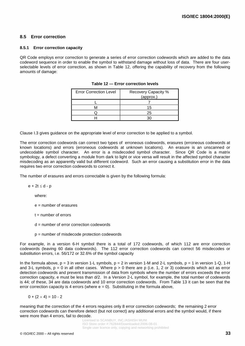
ISO/IEC 18004:2000(E)
© ISO/IEC 2000 – All rights reserved 33
8.5 Error correction
8.5.1 Error correction capacity
QR Code employs error correction to generate a series of error correction codewords which are added to the datacodeword sequence in order to enable the symbol to withstand damage without loss of data. There are four user-selectable levels of error correction, as shown in Table 12, offering the capability of recovery from the followingamounts of damage:
Table 12 — Error correction levels
Error Correction Level Recovery Capacity %(approx.)
L 7M 15Q 25H 30
Clause I.3 gives guidance on the appropriate level of error correction to be applied to a symbol.
The error correction codewords can correct two types of erroneous codewords, erasures (erroneous codewords atknown locations) and errors (erroneous codewords at unknown locations). An erasure is an unscanned orundecodable symbol character. An error is a misdecoded symbol character. Since QR Code is a matrixsymbology, a defect converting a module from dark to light or vice versa will result in the affected symbol charactermisdecoding as an apparently valid but different codeword. Such an error causing a substitution error in the datarequires two error correction codewords to correct it.
The number of erasures and errors correctable is given by the following formula:
e + 2t d - p
where:
e = number of erasures
t = number of errors
d = number of error correction codewords
p = number of misdecode protection codewords
For example, in a version 6-H symbol there is a total of 172 codewords, of which 112 are error correctioncodewords (leaving 60 data codewords). The 112 error correction codewords can correct 56 misdecodes orsubstitution errors, i.e. 56/172 or 32.6% of the symbol capacity
In the formula above, p = 3 in version 1-L symbols, p = 2 in version 1-M and 2-L symbols, p = 1 in version 1-Q, 1-Hand 3-L symbols, p = 0 in all other cases. Where p > 0 there are p (i.e. 1, 2 or 3) codewords which act as errordetection codewords and prevent transmission of data from symbols where the number of errors exceeds the errorcorrection capacity, e must be less than d/2. In a Version 2-L symbol, for example, the total number of codewordsis 44; of these, 34 are data codewords and 10 error correction codewords. From Table 13 it can be seen that theerror correction capacity is 4 errors (where e = 0). Substituting in the formula above,
0 + (2 � 4) = 10 - 2
meaning that the correction of the 4 errors requires only 8 error correction codewords; the remaining 2 errorcorrection codewords can therefore detect (but not correct) any additional errors and the symbol would, if therewere more than 4 errors, fail to decode.
Licensed to SCANBUY, INC./ASHISH MUNIISO Store order #:762844/Downloaded:2006-08-01Single user licence only, copying and networking prohibited

ISO/IEC 18004:2000(E)
34 © ISO/IEC 2000 – All rights reserved
Depending on the Version and Error Correction Level, the data codeword sequence shall be subdivided into one ormore blocks, to each of which the error correction algorithm shall be applied separately. Tables 13 to 22 list, foreach version and Error Correction Level, the total number of codewords, the total number of error correctioncodewords, and the structure and number of error correction blocks.
If Remainder Bits are required to fill remaining modules in the symbol capacity for certain symbol versions theyshall all be 0 bits.
Licensed to SCANBUY, INC./ASHISH MUNIISO Store order #:762844/Downloaded:2006-08-01Single user licence only, copying and networking prohibited

ISO/IEC 18004:2000(E)
© ISO/IEC 2000 – All rights reserved 35
Table 13 — Error correction characteristics for versions 1 to 6
Version Totalnumber ofcodewords
Errorcorrection
level
Number oferror
correctioncodewords
Number oferror correction
blocks
Error correctioncode per block a
1 26 L 7 1 (26,19,2) b
M 10 1 (26,16,4) b
Q 13 1 (26,13,6) b
H 17 1 (26,9,8) b
2 44 L 10 1 (44,34,4) b
M 16 1 (44,28,8)
Q 22 1 (44,22,11)
H 28 1 (44,16,14)
3 70 L 15 1 (70,55,7) b
M 26 1 (70,44,13)
Q 36 2 (35,17,9)
H 44 2 (35,13,11)
4 100 L 20 1 (100,80,10)
M 36 2 (50,32,9)
Q 52 2 (50,24,13)
H 64 4 (25,9,8)
5 134 L 26 1 (134,108,13)
M 48 2 (67,43,12)
Q 72 22
(33,15,9)(34,16,9)
H 88 22
(33,11,11)(34,12,11)
6 172 L 36 2 (86,68,9)
M 64 4 (43,27,8)
Q 96 4 (43,19,12)
H 112 4 (43,15,14)
a (c, k, r): c = total number of codewordsk = number of data codewordsr = number of error correction capacity
b Error correction capacity is less than half the number of error correction codewords to reduce theprobability of misdecodes.
Licensed to SCANBUY, INC./ASHISH MUNIISO Store order #:762844/Downloaded:2006-08-01Single user licence only, copying and networking prohibited

ISO/IEC 18004:2000(E)
36 © ISO/IEC 2000 – All rights reserved
Table 14 — Error correction characteristics for versions 7 to 10
Version Totalnumber ofcodewords
Errorcorrection
level
Number oferror
correctioncodewords
Number oferror correction
blocks
Error correctioncode per block a
7 196 L 40 2 (98,78,10)
M 72 4 (49,31,9)
Q 108 24
(32,14,9)(33,15,9)
H 130 41
(39,13,13)(40,14,13)
8 242 L 48 2 (121,97,12)
M 88 22
(60,38,11)(61,39,11)
Q 132 42
(40,18,11)(41,19,11)
H 156 42
(40,14,13)(41,15,13)
9 292 L 60 2 (146,116,15)
M 110 32
(58,36,11)(59,37,11)
Q 160 44
(36,16,10)(37,17,10)
H 192 44
(36,12,12)(37,13,12)
10 346 L 72 22
(86,68,9)(87,69,9)
M 130 41
(69,43,13)(70,44,13)
Q 192 62
(43,19,12)(44,20,12)
H 224 62
(43,15,14)(44,16,14)
a (c, k, r): c = total number of codewordsk = number of data codewordsr = number of error correction capacity
Licensed to SCANBUY, INC./ASHISH MUNIISO Store order #:762844/Downloaded:2006-08-01Single user licence only, copying and networking prohibited
ISO/IEC 18004:2000(E)
© ISO/IEC 2000 – All rights reserved 37
Table 15 — Error correction characteristics for Model 2, versions 11 to 14
Version Totalnumber ofcodewords
Errorcorrection
level
Number oferror
correctioncodewords
Number oferror correction
blocks
Error correctioncode per block a
11 404 L 80 4 (101,81,10)
M 150 14
(80,50,15)(81,51,15)
Q 224 44
(50,22,14)(51,23,14)
H 264 38
(36,12,12)(37,13,12)
12 466 L 96 22
(116,92,12)(117,93,12)
M 176 62
(58,36,11)(59,37,11)
Q 260 46
(46,20,13)(47,21,13)
H 308 74
(42,14,14)(43,15,14)
13 532 L 104 4 (133,107,13)
M 198 81
(59,37,11)(60,38,11)
Q 288 84
(44,20,12)(45,21,12)
H 352 124
(33,11,11)(34,12,11)
14 581 L 120 31
(145,115,15)(146,116,15)
M 216 45
(64,40,12)(65,41,12)
Q 320 115
(36,16,10)(37,17,10)
H 384 115
(36,12,12)(37,13,12)
a (c, k, r): c = total number of codewordsk = number of data codewordsr = number of error correction capacity
Licensed to SCANBUY, INC./ASHISH MUNIISO Store order #:762844/Downloaded:2006-08-01Single user licence only, copying and networking prohibited

ISO/IEC 18004:2000(E)
38 © ISO/IEC 2000 – All rights reserved
Table 16 — Error correction characteristics for versions 15 to 18
Version Totalnumber ofcodewords
Errorcorrection
level
Number oferror
correctioncodewords
Number oferror correction
blocks
Error correctioncode per block a
15 655 L 132 51
(109,87,11)(110,88,11)
M 240 55
(65,41,12)(66,42,12)
Q 360 57
(54,24,15)(55,25,15)
H 432 117
(36,12,12)(37,13,12)
16 733 L 144 51
(122,98,12)(123,99,12)
M 280 73
(73,45,14)(74,46,14)
Q 408 152
(43,19,12)(44,20,12)
H 480 313
(45,15,15)(46,16,15)
17 815 L 168 15
(135,107,14)(136,108,14)
M 308 101
(74,46,14)(75,47,14)
Q 448 115
(50,22,14)(51,23,14)
H 532 217
(42,14,14)(43,15,14)
18 901 L 180 51
(150,120,15)(151,121,15)
M 338 94
(69,43,13)(70,44,13)
Q 504 171
(50,22,14)(51,23,14)
H 588 219
(42,14,14)(43,15,14)
a (c, k, r): c = total number of codewordsk = number of data codewordsr = number of error correction capacity
Licensed to SCANBUY, INC./ASHISH MUNIISO Store order #:762844/Downloaded:2006-08-01Single user licence only, copying and networking prohibited

ISO/IEC 18004:2000(E)
© ISO/IEC 2000 – All rights reserved 39
Table 17 — Error correction characteristics for versions 19 to 22
Version Totalnumber ofcodewords
Errorcorrection
level
Number oferror
correctioncodewords
Number oferror correction
blocks
Error correctioncode per block a
19 991 L 196 34
(141,113,14)(142,114,14)
M 364 311
(70,44,13)(71,45,13)
Q 546 174
(47,21,13)(48,22,13)
H 650 916
(39,13,13)(40,14,13)
20 1 085 L 224 35
(135,107,14)(136,108,14)
M 416 313
(67,41,13)(68,42,13)
Q 600 155
(54,24,15)(55,25,15)
H 700 1510
(43,15,14)(44,16,14)
21 1 156 L 224 44
(144,116,14)(145,117,14)
M 442 17 (68,42,13)
Q 644 176
(50,22,14)(51,23,14)
H 750 196
(46,16,15)(47,17,15)
22 1 258 L 252 27
(139,111,14)(140,112,14)
M 476 17 (74,46,14)
Q 690 716
(54,24,15)(55,25,15)
H 816 34 (37,13,12)
a (c, k, r): c = total number of codewordsk = number of data codewordsr = number of error correction capacity
Licensed to SCANBUY, INC./ASHISH MUNIISO Store order #:762844/Downloaded:2006-08-01Single user licence only, copying and networking prohibited

ISO/IEC 18004:2000(E)
40 © ISO/IEC 2000 – All rights reserved
Table 18 — Error correction characteristics for versions 23 to 26
Version Totalnumber ofcodewords
Errorcorrection
level
Number oferror
correctioncodewords
Number oferror correction
blocks
Error correctioncode per block a
23 1 364 L 270 45
(151,121,15)(152,122,15)
M 504 414
(75,47,14)(76,48,14)
Q 750 1114
(54,24,15)(55,25,15)
H 900 1614
(45,15,15)(46,16,15)
24 1 474 L 300 64
(147,117,15)(148,118,15)
M 560 614
(73,45,14)(74,46,14)
Q 810 1116
(54,24,15)(55,25,15)
H 960 302
(46,16,15)(47,17,15)
25 1 588 L 312 84
(132,106,13)(133,107,13)
M 588 813
(75,47,14)(76,48,14)
Q 870 722
(54,24,15)(55,25,15)
H 1050 2213
(45,15,15)(46,16,15)
26 1 706 L 336 102
(142,114,14)(143,115,14)
M 644 194
(74,46,14)(75,47,14)
Q 952 286
(50,22,14)(51,23,14)
H 1110 334
(46,16,15)(47,17,15)
a (c, k, r): c = total number of codewordsk = number of data codewordsr = number of error correction capacity
Licensed to SCANBUY, INC./ASHISH MUNIISO Store order #:762844/Downloaded:2006-08-01Single user licence only, copying and networking prohibited

ISO/IEC 18004:2000(E)
© ISO/IEC 2000 – All rights reserved 41
Table 19 — Error correction characteristics for versions 27 to 30
Version Totalnumber ofcodewords
Errorcorrection
level
Number oferror
correctioncodewords
Number oferror correction
blocks
Error correctioncode per block a
27 1 828 L 360 84
(152,122,15)(153,123,15)
M 700 223
(73,45,14)(74,46,14)
Q 1 020 826
(53,23,15)(54,24,15)
H 1 200 1228
(45,15,15)(46,16,15)
28 1 921 L 390 310
(147,117,15)(148,118,15)
M 728 323
(73,45,14)(74,46,14)
Q 1 050 431
(54,24,15)(55,25,15)
H 1 260 1131
(45,15,15)(46,16,15)
29 2 051 L 420 77
(146,116,15)(147,117,15)
M 784 217
(73,45,14)(74,46,14)
Q 1 140 137
(53,23,15)(54,24,15)
H 1 350 1926
(45,15,15)(46,16,15)
30 2 185 L 450 510
(145,115,15)(146,116,15)
M 812 1910
(75,47,14)(76,48,14)
Q 1 200 1525
(54,24,15)(55,25,15)
H 1 440 2325
(45,15,15)(46,16,15)
a (c, k, r): c = total number of codewordsk = number of data codewordsr = number of error correction capacity
Licensed to SCANBUY, INC./ASHISH MUNIISO Store order #:762844/Downloaded:2006-08-01Single user licence only, copying and networking prohibited

ISO/IEC 18004:2000(E)
42 © ISO/IEC 2000 – All rights reserved
Table 20 — Error correction characteristics for versions 31 to 34
Version Totalnumber ofcodewords
Errorcorrection
level
Number oferror
correctioncodewords
Number oferror correction
blocks
Error correctioncode per block a
31 2 323 L 480 133
(145,115,15)(146,116,15)
M 868 229
(74,46,14)(75,47,14)
Q 1 290 421
(54,24,15)(55,25,15)
H 1 530 2328
(45,15,15)(46,16,15)
32 2 465 L 510 17 (145,115,15)
M 924 1023
(74,46,14)(75,47,14)
Q 1 350 1035
(54,24,15)(55,25,15)
H 1 620 1935
(45,15,15)(46,16,15)
33 2 611 L 540 171
(145,115,15)(146,116,15)
M 980 1421
(74,46,14)(75,47,14)
Q 1 440 2919
(54,24,15)(55,25,15)
H 1 710 1146
(45,15,15)(46,16,15)
34 2 761 L 570 136
(145,115,15)(146,116,15)
M 1 036 1423
(74,46,14)(75,47,14)
Q 1 530 447
(54,24,15)(55,25,15)
H 1 800 591
(46,16,15)(47,17,15)
a (c, k, r): c = total number of codewordsk = number of data codewordsr = number of error correction capacity
Licensed to SCANBUY, INC./ASHISH MUNIISO Store order #:762844/Downloaded:2006-08-01Single user licence only, copying and networking prohibited

ISO/IEC 18004:2000(E)
© ISO/IEC 2000 – All rights reserved 43
Table 21 — Error correction characteristics for versions 35 to 38
Version Totalnumber ofcodewords
Errorcorrection
level
Number oferror
correctioncodewords
Number oferror correction
blocks
Error correctioncode per block a
35 2 876 L 570 127
(151,121,15)(152,122,15)
M 1 064 1226
(75,47,14)(76,48,14)
Q 1 590 3914
(54,24,15)(55,25,15)
H 1 890 2241
(45,15,15)(46,16,15)
36 3 034 L 600 614
(151,121,15)(152,122,15)
M 1 120 634
(75,47,14)(76,48,14)
Q 1 680 4610
(54,24,15)(55,25,15)
H 1 980 264
(45,15,15)(46,16,15)
37 3 196 L 630 174
(152,122,15)(153,123,15)
M 1 204 2914
(74,46,14)(75,47,14)
Q 1 770 4910
(54,24,15)(55,25,15)
H 2 100 2446
(45,15,15)(46,16,15)
38 3 362 L 660 418
(152,122,15)(153,123,15)
M 1 260 1332
(74,46,14)(75,47,14)
Q 1 860 4814
(54,24,15)(55,25,15)
H 2 220 4232
(45,15,15)(46,16,15)
a (c, k, r): c = total number of codewordsk = number of data codewordsr = number of error correction capacity
Licensed to SCANBUY, INC./ASHISH MUNIISO Store order #:762844/Downloaded:2006-08-01Single user licence only, copying and networking prohibited

ISO/IEC 18004:2000(E)
44 © ISO/IEC 2000 – All rights reserved
Table 22 — Error correction characteristics for versions 39 to 40
Version Totalnumber ofcodewords
Errorcorrection
level
Number oferror
correctioncodewords
Number oferror correction
blocks
Error correctioncode per block a
39 3 532 L 720 204
(147,117,15)(148,118,15)
M 1 316 407
(75,47,14)(76,48,14)
Q 1 950 4322
(54,24,15)(55,25,15)
H 2 310 1067
(45,15,15)(46,16,15)
40 3 706 L 750 196
(148,118,15)(149,119,15)
M 1 372 1831
(75,47,14)(76,48,14)
Q 2 040 3434
(54,24,15)(55,25,15)
H 2 430 2061
(45,15,15)(46,16,15)
a (c, k, r): c = total number of codewordsk = number of data codewordsr = number of error correction capacity
Licensed to SCANBUY, INC./ASHISH MUNIISO Store order #:762844/Downloaded:2006-08-01Single user licence only, copying and networking prohibited

ISO/IEC 18004:2000(E)
© ISO/IEC 2000 – All rights reserved 45
8.5.2 Generating the error correction codewords
The data codewords including Pad codewords as necessary shall be divided into the number of blocks shown inTables 13 to 22. Error correction codewords shall be calculated for each block and appended to the datacodewords.
The polynomial arithmetic for QR Code shall be calculated using bit-wise modulo 2 arithmetic and byte-wisemodulo 100011101 arithmetic. This is a Galois field of 28 with 100011101 representing the field's prime moduluspolynomial x8 + x4 + x3 + x2 +1.
The data codewords are the coefficients of the terms of a polynomial with the coefficient of the highest term beingthe first data codeword and that of the lowest power term being the last data codeword before the first errorcorrection codeword.
The error correction codewords are the remainder after dividing the data codewords by a polynomial g(x) used forerror correction codes (see Annex A). The highest order coefficient of the remainder is the first error correctioncodeword and the zero power coefficient is the last error correction codeword and the last codeword in the block.
Thirty-one different generator polynomials are used for generating the error correction codewords. These are givenin Annex A.1.
This can be implemented by using the division circuit as shown in Figure 11. The registers b0 through bk-1 areinitialized as zeros. There are two phases to generate the encoding. In the first phase, with the switch in the downposition the data codewords are passed both to the output and the circuit. The first phase is complete after n clockpulses. In the second phase (n+1 ... n+k clock pulses), with the switch in the up position, the error correctioncodewords k-1 ... 0 are generated by flushing the registers in order while keeping the data input at 0.
bk-1b1b0
InputOutput
0
= GF(256) Addition
= GF(256) Multiplication
g0 g1 gk-1
Switch
Figure 11 — Error correction codeword encoding circuit
8.6 Constructing the final message codeword sequence
The total number of codewords in the message shall always be equal to the total number of codewords capable ofbeing represented in the symbol, as shown in Tables 7 to 12 and 13 to 22.
The following steps shall be followed to construct the final sequence of codewords (data plus error correctioncodewords plus Remainder Codewords if necessary):
1. Divide the data codeword sequence into n blocks as defined in Tables 13 to 22 according to the version anderror correction level.
2. For each data block, calculate a corresponding block of error correction codewords as defined in 8.5.2 andAnnex A.
Licensed to SCANBUY, INC./ASHISH MUNIISO Store order #:762844/Downloaded:2006-08-01Single user licence only, copying and networking prohibited

ISO/IEC 18004:2000(E)
46 © ISO/IEC 2000 – All rights reserved
3. Assemble the final sequence by taking data and error correction codewords from each block in turn: data block1, codeword 1; data block 2, codeword 1; data block 3, codeword 1; and similarly to data block n - 1, finalcodeword; data block n, final codeword; then error correction block 1, codeword 1, error correction block 2,codeword 1, ... and similarly to error correction block n - 1, final codeword; error correction block n, final codeword.QR Code symbols contain data and error correction blocks which always exactly fill the symbol codeword capacity.In certain versions, however, there may be a need for 3, 4 or 7 Remainder Bits to be appended to the finalmessage bit stream in order exactly to fill the number of modules in the encoding region.
The shortest data block (or blocks) shall be placed first in the sequence and all the data codewords shall be placedin the symbol before the first error correction codeword. For example, the Version 5-H symbol comprises four dataand four error correction blocks, the first two of each of which contain 11 data and 22 error correction codewordsrespectively, while the third and fourth pairs of blocks contain 12 data and 22 error correction codewordsrespectively. In this symbol, the character arrangement can be depicted as follows. Each row of the tablecorresponds to one block of data codewords (shown as Dn) followed by the associated block of error correctioncodewords (shown as En); the sequence of character placement in the symbol is obtained by reading down eachcolumn of the table in turn.
Data codewords Error correction codewords
Block 1 D1 D2 ..... D11 E1 E2 ..... E22
Block 2 D12 D13 ..... D22 E23 E24 ..... E44
Block 3 D23 D24 ..... D33 D34 E45 E46 ..... E66
Block 4 D35 D36 ..... D45 D46 E67 E68 ..... E88
The final message codeword sequence for the Version 5-H symbol is therefore:
D1, D12, D23, D35, D2, D13, D24, D36, ... D11, D22, D33, D45, D34, D46, E1, E23, E45, E67, E2, E24, E46, E68,... E22, E44, E66, E88. The symbol module capacity is filled by adding Remainder (0) bits as needed after the finalcodeword.
8.7 Codeword placement in matrix
8.7.1 Symbol character representation
There are two types of symbol character, regular and irregular, in the QR Code symbol. Their use depends on theirposition in the symbol, relative to other symbol characters and function patterns.
Most codewords shall be represented in a regular 2 x 4 module block in the symbol. There are two ways ofpositioning these blocks, in a vertical arrangement (2 modules wide and 4 modules high) and, if necessary whenplacement changes direction, in a horizontal arrangement (4 modules wide and 2 modules high). Irregular symbolcharacters are used when changing direction or in the vicinity of Alignment or other function Patterns.
8.7.2 Function pattern placement
A square blank matrix shall be constructed with the number of modules horizontally and vertically corresponding tothe Version in use. Positions corresponding to the Finder Pattern, Separator, Timing Pattern, and AlignmentPatterns shall be filled with either dark modules or light modules as appropriate. Module positions for the FormatInformation and Version Information shall be left temporarily blank. These positions are shown in Figures 15 and16 and are common to all Versions. Annex E defines the positioning of Alignment Patterns.
8.7.3 Symbol character placement
In the encoding region of the QR Code symbol, symbol characters are positioned in two-module wide columnscommencing at the lower right corner of the symbol and running alternately upwards and downwards from the right
Licensed to SCANBUY, INC./ASHISH MUNIISO Store order #:762844/Downloaded:2006-08-01Single user licence only, copying and networking prohibited
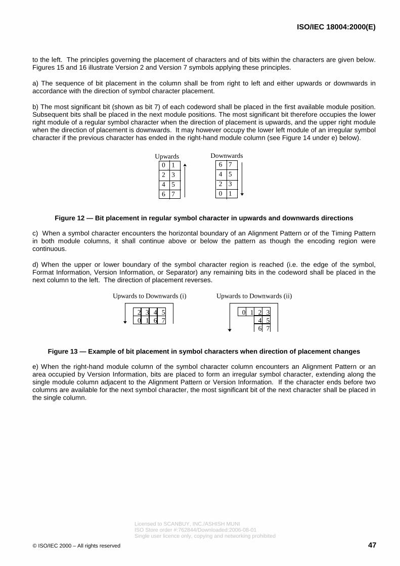
ISO/IEC 18004:2000(E)
© ISO/IEC 2000 – All rights reserved 47
to the left. The principles governing the placement of characters and of bits within the characters are given below.Figures 15 and 16 illustrate Version 2 and Version 7 symbols applying these principles.
a) The sequence of bit placement in the column shall be from right to left and either upwards or downwards inaccordance with the direction of symbol character placement.
b) The most significant bit (shown as bit 7) of each codeword shall be placed in the first available module position.Subsequent bits shall be placed in the next module positions. The most significant bit therefore occupies the lowerright module of a regular symbol character when the direction of placement is upwards, and the upper right modulewhen the direction of placement is downwards. It may however occupy the lower left module of an irregular symbolcharacter if the previous character has ended in the right-hand module column (see Figure 14 under e) below).
Upwards Downwards
10
2
4
6
3
5
7
76
4
2
0
5
3
1
Figure 12 — Bit placement in regular symbol character in upwards and downwards directions
c) When a symbol character encounters the horizontal boundary of an Alignment Pattern or of the Timing Patternin both module columns, it shall continue above or below the pattern as though the encoding region werecontinuous.
d) When the upper or lower boundary of the symbol character region is reached (i.e. the edge of the symbol,Format Information, Version Information, or Separator) any remaining bits in the codeword shall be placed in thenext column to the left. The direction of placement reverses.
Upwards to Downwards (ii)Upwards to Downwards (i)
4 5326 710
2 3104 5
76
Figure 13 — Example of bit placement in symbol characters when direction of placement changes
e) When the right-hand module column of the symbol character column encounters an Alignment Pattern or anarea occupied by Version Information, bits are placed to form an irregular symbol character, extending along thesingle module column adjacent to the Alignment Pattern or Version Information. If the character ends before twocolumns are available for the next symbol character, the most significant bit of the next character shall be placed inthe single column.
Licensed to SCANBUY, INC./ASHISH MUNIISO Store order #:762844/Downloaded:2006-08-01Single user licence only, copying and networking prohibited

ISO/IEC 18004:2000(E)
48 © ISO/IEC 2000 – All rights reserved
A
1st character
Upwards
(A represents modules occupiedby the Alignment Pattern)
2nd character 46
20
35
1
AA
07
1
A5
A34
2
76
Figure 14 — Example of bit placement adjacent to Alignment Pattern
An alternative method for placement in the symbol, which yields the same result, is to regard the interleavedcodeword sequence as a single bit stream, which is placed (starting with the most significant bit) in the two-modulewide columns alternately upwards and downwards from the right to left of the symbol. In each column the bits areplaced alternately in the right and left modules, moving upwards or downwards according to the direction ofplacement and skipping areas occupied by function patterns, changing direction at the top or bottom of the column.Each bit shall always be placed in the first available module position.
When the data capacity of the symbol is such that it does not divide exactly into a number of eight-bit symbolcharacters, the appropriate number of Remainder Bits (3, 4 or 7 as shown in Table 1) shall be used to fill thesymbol capacity. These Remainder Bits shall always have the value 0 before masking according to 8.8.
Data Codewords
EC Codewords
E9
D10
D7
D8
D13
D9D15
D12
D14
D11
D6D16
D17D22
D23
D21
D20D19
D3
D1
D2
D4D5
D18
E5
E6
E4
D24
D26D25
D23
E3
E1
E2
D28
D27
E15E16
E14E7
E10
E8
E12
E13
E11
Remainder Bits
Figure 15 — Symbol character arrangement in version 2-M symbol
Licensed to SCANBUY, INC./ASHISH MUNIISO Store order #:762844/Downloaded:2006-08-01Single user licence only, copying and networking prohibited

ISO/IEC 18004:2000(E)
© ISO/IEC 2000 – All rights reserved 49
D60
E48
D40
D1
D3
D53
D14
D15
D28
D27
D2
D7
D8
D5
D9
D6
D54
D4
D10
D55
D30
D42
D12
D16
D13
D17
D29
D19
D32
D57
D43
D31
D44
D41
D56
D18
D33
D45
D46D58
D21
D34D22
D20
D59
D47
D23D37
D24
D49
D25
D48
D38
D36
D50
D35
D63
D66
D62
D65
D52
D26 D64
D61
D51
E105
E1
E53
E79
E28
E54
E2
E106
D11
E27
E56 E4
E30
E108
E29
E55
E107
E3
D39
E81
E83
E57
E5
E109
E31
E84
E58
E6
E110
E32
E80
E85
E11
E33
E103
E77
E25
E129
E51
E82
E86
E60
E8
E34
E87
E61
E9
E113E35
E88
E62
E10
E36E112
E59
E89
E63E11
E115
E37
E90
E64
E12
E116
E38
E65
E13
E91
E39
E117
E66
E14
E118
E40
E92
E67
E15
E119
E41
E93
E68
E16
E120
E42
E94
E69
E17
E121
E43
E95
E70
E18
E122
E44
E96
E71
E19
E123
E45
E97
E98
E72
E20
E124
E46
E99
E73
E21
E125
E47
E100
E74
E22
E126
E101
E75
E23E127
E49
E102
E76
E128
E50
E104
E78
E26
E130
E52
E24
E7
E114
D1 - D13 Data Block 1
D14 - D26 Data Block 2
D27 - D39 Data Block 3
D40 - D52 Data Block 4
D53 - D66 Data Block 5
E1 - E26 EC Block 1
E27 - E52 EC Block 2
E53 - E78 EC Block 3
E79 - E104 EC Block 4
E105 - E130 EC Block 5
Figure 16 — Symbol character arrangement in version 7-H symbol
Licensed to SCANBUY, INC./ASHISH MUNIISO Store order #:762844/Downloaded:2006-08-01Single user licence only, copying and networking prohibited

ISO/IEC 18004:2000(E)
50 © ISO/IEC 2000 – All rights reserved
8.8 Masking
For reliable QR Code reading, it is preferable for dark and light modules to be arranged in a well-balanced mannerin the symbol. The bit pattern 1011101 particularly found in the Position Detection Pattern should be avoided inother areas of the symbol as much as possible. To meet the above conditions, masking should be appliedfollowing the steps described below:
1. Masking is not applied to function patterns.
2. Convert the given module pattern in the encoding region (excluding the Format Information and the VersionInformation) with multiple matrix patterns successively through the XOR operation. For the XOR operation, laythe module pattern over each of the masking matrix patterns in turn and reverse the modules (from light to darkor vice versa) which correspond to dark modules of the masking pattern.
3. Then evaluate all the resulting converted patterns by charging penalties for undesirable features on eachconversion result.
4. Select the pattern with the lowest penalty points score.
8.8.1 Mask Patterns
Table 23 shows the Mask Pattern Reference (binary reference for use in the Format Information) and the maskpattern generation condition. The mask pattern is generated by defining as dark any module in the encodingregion (excluding the area reserved for Format Information and the Version Information) for which the condition istrue; in the condition, i refers to the row position of the module in question and j to its column position, with (i, j) =(0, 0) for the top left module in the symbol.
Table 23 — Mask pattern generation conditions
Mask PatternReference
Condition
000 (i + j) mod 2 = 0001 i mod 2 = 0010 j mod 3 = 0011 (i + j) mod 3 = 0100 ((i div 2) + (j div 3)) mod 2 = 0101 (i j) mod 2 + (i j) mod 3 = 0110 ((i j) mod 2 + (i j) mod 3) mod 2 = 0111 ((i j) mod 3 + (i+j) mod 2) mod 2 = 0
Figure 17 shows all Mask Patterns, illustrated in a Version 1 symbol; Figure 18 simulates the effects of maskingusing Mask Pattern References 000 to 111.
Licensed to SCANBUY, INC./ASHISH MUNIISO Store order #:762844/Downloaded:2006-08-01Single user licence only, copying and networking prohibited

ISO/IEC 18004:2000(E)
© ISO/IEC 2000 – All rights reserved 51
000(i + j) mod 2 = 0
001i mod 2 = 0
010j mod 3 = 0
011(i + j) mod 3 = 0
100((i div 2) + (j div 3)) mod 2 = 0
101(i j) mod 2 + (i j) mod 3 = 0
110((i j) mod 2 + (i j) mod 3) mod 2 = 0
110((i j) mod 2 + (i j) mod 3) mod 2 = 0
Function modules
Masking shall not beapplied to these modules
i
j
NOTE 1 The three bits below each pattern represent the Mask Pattern Reference.
NOTE 2 The equation below the Mask Pattern Reference shows the mask pattern generation condition; modules which meetthe condition are shown dark.
Figure 17 — Mask patterns for version 1 symbol
Licensed to SCANBUY, INC./ASHISH MUNIISO Store order #:762844/Downloaded:2006-08-01Single user licence only, copying and networking prohibited
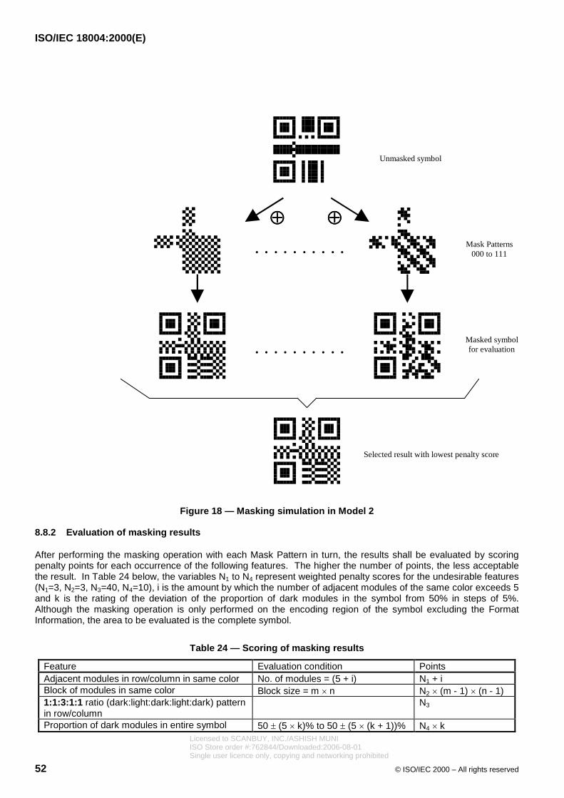
ISO/IEC 18004:2000(E)
52 © ISO/IEC 2000 – All rights reserved
Unmasked symbol
. . . . . . . . . .
. . . . . . . . . .
Mask Patterns000 to 111
���� ����
Masked symbolfor evaluation
Selected result with lowest penalty score
Figure 18 — Masking simulation in Model 2
8.8.2 Evaluation of masking results
After performing the masking operation with each Mask Pattern in turn, the results shall be evaluated by scoringpenalty points for each occurrence of the following features. The higher the number of points, the less acceptablethe result. In Table 24 below, the variables N1 to N4 represent weighted penalty scores for the undesirable features(N1=3, N2=3, N3=40, N4=10), i is the amount by which the number of adjacent modules of the same color exceeds 5and k is the rating of the deviation of the proportion of dark modules in the symbol from 50% in steps of 5%.Although the masking operation is only performed on the encoding region of the symbol excluding the FormatInformation, the area to be evaluated is the complete symbol.
Table 24 — Scoring of masking results
Feature Evaluation condition PointsAdjacent modules in row/column in same color No. of modules = (5 + i) N1 + iBlock of modules in same color Block size = m � n N2 � (m - 1) � (n - 1)1:1:3:1:1 ratio (dark:light:dark:light:dark) patternin row/column
N3
Proportion of dark modules in entire symbol 50 � (5 � k)% to 50 � (5 � (k + 1))% N4 � kLicensed to SCANBUY, INC./ASHISH MUNIISO Store order #:762844/Downloaded:2006-08-01Single user licence only, copying and networking prohibited

ISO/IEC 18004:2000(E)
© ISO/IEC 2000 – All rights reserved 53
The Mask Pattern which results in the lowest score shall be selected for the symbol.
8.9 Format Information
The Format Information is a 15 bit sequence containing 5 data bits, with 10 error correction bits calculated usingthe (15, 5) BCH code. For details of the error correction calculation for the Format Information, refer to Annex C.The first two data bits contain the Error Correction Level of the symbol, indicated as follows:
Table 25 — Error correction level indicators
Error CorrectionLevel
Binaryindicator
L 01M 00Q 11H 10
The third to fifth data bits of the Format Information contain the Mask Pattern Reference from Table 23 above forthe pattern selected according to 8.8.2.
The 10 error correction bits shall be calculated as described in Annex C and appended to the 5 data bits.
The 15 bit error corrected Format Information shall then be XORed with the Mask Pattern 101010000010010, inorder to ensure that no combination of Error Correction Level and Mask Pattern will result in an all-zero data string.
The resulting masked Format Information shall be mapped into the areas reserved for it in the symbol as shown inFigure 19. Note that the Format Information appears twice in the symbol in order to provide redundancy since itscorrect decoding is essential to the decoding of the complete symbol. The least significant bit of the FormatInformation is located in the modules numbered 0, and the most significant bit in the modules numbered 14 inFigure 19. The module in position (4V+ 9, 8) where V is the version number, shall always be dark and does notform part of the Format Information.
Example:
Assume Error Correction Level M: 00and Mask Pattern Reference: 101Data: 00101BCH bits: 0011011100Unmasked bit sequence: 001010011011100Mask pattern for XOR operation: 101010000010010Format Information module pattern: 100000011001110
Licensed to SCANBUY, INC./ASHISH MUNIISO Store order #:762844/Downloaded:2006-08-01Single user licence only, copying and networking prohibited

ISO/IEC 18004:2000(E)
54 © ISO/IEC 2000 – All rights reserved
14 911 7106
8
5
32
4
12
0
13
1
023 1467 5
8
1011
9
121314
Dark Module
Figure 19 — Format Information positioning
8.10 Version Information
The Version Information is an 18 bit sequence containing 6 data bits, with 12 error correction bits calculated usingthe (18, 6) BCH code. For details of the error correction calculation for the Version Information, refer to Annex D.The six data bits contain the Version of the symbol, most significant bit first.
The 12 error correction bits shall be calculated as described in Annex D and appended to the 6 data bits.
No Version Information will result in an all-zero data string since only Versions 7 to 40 symbols contain the VersionInformation. Masking is not therefore applied to the Version Information.
The resulting Version Information shall be mapped into the areas reserved for it in the symbol as shown in Figure20. Note that the Version Information appears twice in the symbol in order to provide redundancy since its correctdecoding is essential to the decoding of the complete symbol. The least significant bit of the Version Information islocated in the modules numbered 0, and the most significant bit in the modules numbered 17, in Figure 21.
Example:Version number: 7Data: 000111BCH bits: 110010010100Format Information module pattern: 000111110010010100
The Version Information areas are the 6 � 3 module block above the Timing Pattern and immediately to the left ofthe top right Position Detection Pattern Separator, and the 3 � 6 module block to the left of the Timing Pattern andimmediately above the lower left Position Detection Pattern separator.
Licensed to SCANBUY, INC./ASHISH MUNIISO Store order #:762844/Downloaded:2006-08-01Single user licence only, copying and networking prohibited

ISO/IEC 18004:2000(E)
© ISO/IEC 2000 – All rights reserved 55
Version Information
Figure 20 — Version Information positioning
Version Information in lower left Version Information in upper right
10
243
576
8109
111312
141615
17
10 243 576 8
109 111312 141615 17
Figure 21 — Module arrangement in Version Information
9 Structured Append
9.1 Basic principles
Up to 16 QR Code symbols may be appended in a structured format. If a symbol is part of a Structured Appendmessage, it is indicated by a header block in the first three symbol character positions.
The Structured Append Mode Indicator 0011 is placed in the four most significant bit positions in the first symbolcharacter.
This is immediately followed by two Structured Append codewords, spread over the four least significant bits of thefirst symbol character, the second symbol character and the four most significant bits of the third symbol character.The first codeword is the symbol sequence indicator. The second codeword is the parity data and is identical in allsymbols in the message, enabling it to be verified that all symbols read form part of the same Structured Appendmessage. This header is immediately followed by the data codewords for the symbol commencing with the firstMode Indicator. If one or more ECIs other than the default ECI is in force, an ECI header for each ECI, consistingof the ECI Mode Indicator and ECI Designator, shall follow the Structured Append header.
Licensed to SCANBUY, INC./ASHISH MUNIISO Store order #:762844/Downloaded:2006-08-01Single user licence only, copying and networking prohibited

ISO/IEC 18004:2000(E)
56 © ISO/IEC 2000 – All rights reserved
The lower part of Figure 22 shows an example of four Structured Append symbols, with the same data as that inthe upper symbol.
Figure 22 — Structured append
9.2 Symbol Sequence Indicator
This codeword indicates the position of the symbol within the set of (up to 16) QR Code symbols in the StructuredAppend format (in the form m of n symbols). The first 4 bits of this codeword identify the position of the particularsymbol. The last 4 bits identify the total number of symbols to be concatenated in the Structured Append format.The 4-bit patterns shall be the binary equivalents of (m - 1) and (n - 1) respectively.
Example:
To indicate the 3rd symbol of a set of 7, this shall be encoded thus:
3rd position: 0010
Total 7 symbols: 0110
Bit pattern: 00100110
9.3 Parity Data
The Parity Data shall be an 8 bit byte following the Symbol Sequence Indicator. The parity data is a value obtainedby XORing byte by byte the ASCII/JIS values of all the original input data before division into symbol blocks. ModeIndicators, Character Count Identifiers, padding bits, Terminator and Pad Characters shall be excluded from thecalculation. Input data is represented for this calculation by 2-byte Shift JIS values for Kanji (each byte beingtreated separately in the XOR calculation) and 8-bit JIS values as shown in Table 6 for other characters. In ECIMode the 8-bit byte values obtained after any encryption or compression of the data shall be used for thecalculation.
For example, "0123456789 " is divided into "0123", "4567" and "89 " as follows:
1st symbol block ("0123") - hex. values 30, 31, 32, 33Licensed to SCANBUY, INC./ASHISH MUNIISO Store order #:762844/Downloaded:2006-08-01Single user licence only, copying and networking prohibited

ISO/IEC 18004:2000(E)
© ISO/IEC 2000 – All rights reserved 57
2nd symbol block("4567") - hex. values 34, 35, 36, 37
3rd symbol block ("89 ") - hex. values 38, 39, 93FA, 967B
The parity data is calculated from "0123456789 " by XORing the data successively, byte by byte.
30 ���� 31 ���� 32 ���� 33 ���� 34 ���� 35 ���� 36 ���� 37 ���� 38 ���� 39 ���� 93 ���� FA ���� 96 ���� 7B = 85
Note that the calculation of the parity data may be performed either before the data is sent to the printer or in theprinter, based on the capabilities of the printer.
10 Symbol printing and marking
10.1 Dimensions
QR Code symbols shall conform to the following dimensions:
X dimension: the width of a module shall be specified by the application, taking into account the scanningtechnology to be used, and the technology to produce the symbol;
Y dimension: the height of a module shall be equal to the X dimension;
minimum quiet zone: equal to 4X on all four sides.
10.2 Human-readable interpretation
Because QR Code symbols are capable of encoding thousands of characters, a human readable interpretation ofthe data characters may not be practical. As an alternative, descriptive text rather than literal text may accompanythe symbol.
The character size and font are not specified, and the message may be printed anywhere in the area surroundingthe symbol. The human readable interpretation should not interfere with the symbol itself nor the quiet zones.
10.3 Marking guidelines
QR Code symbols can be printed or marked using a number of different techniques. Annex I provides userguidelines.
11 Symbol quality
QR Code symbols shall be assessed for quality using the 2D matrix bar code symbol print quality guidelinespresented in Annex K, as augmented and modified below.
11.1 Obtaining the test image
A grey-scale image of the symbol being tested shall be obtained with a precision video camera-based setup asdescribed in Annex K.1, but with an illumination color and direction specified by the application.
11.2 Symbol quality parameters
11.2.1 Decode
The reference decode algorithm set out in 13 shall be applied to the test image. If it results in a successful decodeof the entire data message, then Decode passes with a grade of 4 ("A"), otherwise it fails with a grade of 0 ("F").
Licensed to SCANBUY, INC./ASHISH MUNIISO Store order #:762844/Downloaded:2006-08-01Single user licence only, copying and networking prohibited

ISO/IEC 18004:2000(E)
58 © ISO/IEC 2000 – All rights reserved
11.2.2 Symbol Contrast
Symbol Contrast shall be graded using all of the grey-scale pixel values in the test image which fall within thesymbol's boundary, including the 4X wide quiet zones, as determined by the reference decode. The procedure isdefined in Annex K.2.2.
11.2.3 "Print" growth
The reference decode begins by creating a high resolution binary digitized image of the test symbol, and at a laterpoint establishes the position of the "alternating module centerlines" which bisect the Timing Patterns of thesymbol. "Print" Growth shall be assessed by checking that the "duty cycle" of the lines through the alternatingpatterns is around 50%.
Taking the two Timing Patterns independently (since horizontal and vertical growth can differ substantially),proceed from the inner side of the outer square of the Position Detection Pattern adjacent to each Timing Patternalong each Timing Pattern to the outer edge of the Separator adjacent to the other Position Detection Pattern andsum the number of light (NL) and dark (ND) pixels encountered. The resulting measure of print growth in eachdirection is D = ND / (NL + ND), which shall be graded against DNOM = 0.50 with DMIN = 0.35 and DMAX = 0.65 asprescribed in Annex K.2.3. The Print Growth grade shall be the lower of those achieved along the vertical andhorizontal Timing Patterns.
11.2.4 Axial Nonuniformity
The reference decode algorithm ultimately creates a grid of data module sampling points throughout the entire areaof the test image. The precise horizontal and vertical spacings of those sampling points are the basis for assessingaxial nonuniformity.
Working independently with the horizontal and vertical spacings between adjacent data modules, compute theiraverage values XAVG and YAVG over the whole symbol. The Axial Nonuniformity grade is then based on how closelythese two average spacings match each other, as computed by the procedure defined in Annex K.2.4.
11.2.5 Unused Error Correction
QR Code employs Reed-Solomon error control encoding. The smaller symbols contain a single error correctionfield while the larger symbols are subdivided into two or more error correction fields. In all cases, each errorcorrection field shall be graded independently as specified in Annex K.2.5, then the Unused Error Correction gradeshall be the lowest achieved by any of the fields. This calculation shall not apply, however, to the FormatInformation nor to the Version Information.
11.3 Overall symbol grade
The overall print quality grade for a QR Code symbol is the lowest of the five grades achieved above. Table 26summarizes the test criteria.
Table 26 — Symbol grading criteria
Grade Referencedecode
SymbolContrast
“Print” growth AxialNonuniformity
UnusedErrorCorrection
4,0 (A) Passes SC � 0,70 -0,50 D’ 0,50 AN < 0,06 UEC � 0,623,0 (B) SC � 0,55 -0,70 D’ 0,70 AN < 0,08 UEC � 0,502,0 (C) SC � 0,40 -0,85 D’ 0,85 AN < 0,10 UEC � 0,371,0 (D) SC � 0,20 -1,00 D’ 1,00 AN < 0,12 UEC � 0,250,0 (F) Fails SC < 0,20 D’ < -1,00 or D’ > 1,00 AN > 0,12 UEC < 0,25
Licensed to SCANBUY, INC./ASHISH MUNIISO Store order #:762844/Downloaded:2006-08-01Single user licence only, copying and networking prohibited

ISO/IEC 18004:2000(E)
© ISO/IEC 2000 – All rights reserved 59
11.4 Process control measurements
A variety of tools and methods is available which can perform useful measurements for monitoring and controllingthe process of creating QR Code symbols. These include:
1. Symbol contrast readings using a linear bar code verifier.
2. Horizontal (and vertical) print growth by measurement of the Position Detection Patterns in both axesusing a linear bar code verifier.
3. Determination of axial nonuniformity by physical measurement.
4. Visual inspection of the position detection and timing patterns for grid nonuniformities and defects.
Each of these tools and methods is described in Annex L.
12 Decoding procedure overview
The decoding steps from reading a QR Code symbol to outputting data characters are the reverse of the encodingprocedure. Figure 23 shows an outline of the process flow.
1. Locate and obtain an image of the Symbol. Recognize Dark and Light Modules as an array of “0” and “1” bits.
2. Read the Format Information. (Release the masking pattern and perform error correction on the FormatInformation modules as necessary; identify Error Correction Level and Mask Pattern Reference).
3. Read the Version Information (where applicable), then determine the Version of the symbol.
4. Release the Masking by XORing the encoding region bit pattern with the Mask Pattern the reference of whichhas been extracted from the Format Information.
5. Read the symbol characters according to the placement rules for the model and restore the data and errorcorrection codewords of the message.
6. Detect errors using the error correction codewords corresponding to the Level Information. If any error isdetected, correct it.
7. Divide the data codewords into segments according to the Mode Indicators and Character Count Indicators.
8. Finally, decode the Data Characters in accordance with the Mode(s) in use and output the result.
Licensed to SCANBUY, INC./ASHISH MUNIISO Store order #:762844/Downloaded:2006-08-01Single user licence only, copying and networking prohibited

ISO/IEC 18004:2000(E)
60 © ISO/IEC 2000 – All rights reserved
END
Decode Format Information
Release Masking
Recognize Black/White Modules
Error detectionusing Error Correction
codewords
Error Correction
Decode Data Codewords
Output
Error(s)
No error
START
Determine Version
Restore Data and RS Codewords
Figure 23 — QR Code decoding steps
13 Reference decode algorithm for QR Code
This reference decode algorithm finds the symbol in an image and decodes them. The decode algorithm refers todark and light states in the image.
1. Determine a Global Threshold by taking a reflectance value midway between the maximum reflectance andminimum reflectance in the image. Convert the image to a set of dark and light pixels using the GlobalThreshold.
2. Locate the Finder Pattern. The finder pattern in QR Code consists of three identical Position DetectionPatterns located at three of the four corners of the symbol. As described in 7.3.2, module width in eachPosition Detection Pattern is constructed of a dark-light-dark-light-dark sequence the relative widths of eachelement of which are in the ratios 1:1:3:1:1. For the purposes of this algorithm the tolerance for each of thesewidths is 0,5 (i.e. a range of 0,5 to 1,5 for the single module box and 2,5 to 3,5 for the three module squarebox).
a) When a candidate area is detected note the position of the first and last points A and B respectively atwhich a line of pixels in the image encounters the outer edges of the position detection pattern (see Figure29). Repeat this for adjacent pixel lines in the image until all lines crossing the central box of the positiondetection pattern in the x axis of the image have been identified.
Licensed to SCANBUY, INC./ASHISH MUNIISO Store order #:762844/Downloaded:2006-08-01Single user licence only, copying and networking prohibited

ISO/IEC 18004:2000(E)
© ISO/IEC 2000 – All rights reserved 61
A B
Figure 24 — Scan line in Position Detection Pattern
b) Repeat step a) for pixel columns crossing the central box of the position detection pattern in the y axis ofthe image.
c) Locate the center of the pattern. Construct a line through the midpoints between the points A and B onthe outermost pixel lines crossing the central box of the position detection pattern in the x axis. Constructa similar line through points A and B on the outermost pixel columns crossing the central box in the y axis.The center of the pattern is located at the intersection of these two lines.
d) Repeat steps a) to c) to locate the centers of the two other position detection patterns.
3. Determine the orientation of the symbol by analysing the position detection pattern center coordinates toidentify which pattern is the upper left pattern in the symbol and the angle of rotation of the symbol.
4. Determine a) the distance D crossing the full width of the symbol between the centers of the upper left positiondetector pattern and of the upper right position detection pattern and b) the width of the two patterns, WUL andWUR.
WUL WUR
D
Figure 25 — Upper Position Detection Patterns
5. Calculate the nominal X dimension of the symbol.
X = (WUL + WUR) / 14
6. Provisionally determine the version V of the symbol.
V = [(D/X) - 10] / 4
7. If the provisional symbol version is 6 or less, this is specified as the defined version. If the provisional symbolversion is 7 or more, the version information is decoded as follows.
a) Divide the width WUR of the upper right Position Detection Pattern by 7 to calculate the module size CPUR.
CPUR = WUR / 7
Licensed to SCANBUY, INC./ASHISH MUNIISO Store order #:762844/Downloaded:2006-08-01Single user licence only, copying and networking prohibited

ISO/IEC 18004:2000(E)
62 © ISO/IEC 2000 – All rights reserved
b) Find the guide lines AC and AB from A, B and C, which pass through the centers of the three PositionDetection Patterns, as shown in Figure 26 below. The sampling grid for each module center in theVersion Information 1 area is determined based on lines parallel to the guide lines, the central coordinatesof the Position Detection Patterns, and the module size CPUR. Binary values 0 and 1 are determined fromthe light or dark pattern on the sampling grid.
Figure 26 — Position Detection Patterns and Version Information
c) Determine the version by detecting and correcting errors, if any, based on the BCH error correctionapplied to the Version Information modules, defined in Annex D.
d) If errors exceeding the error correction capacity are detected, then calculate the pattern width WDL of thelower left Position Detection Pattern and follow a similar procedure to steps a), b) and c) above to decodeVersion Information 2.
8. Decoding of a Version 1 symbol with no Alignment Pattern continues in accordance with steps 7 and 8 of thealgorithm in Annex M.14, reverting to this algorithm at step 9. Decoding of version 2 and larger symbolsrequires the central coordinate of each Alignment Pattern to be determined from the coordinates defined in7.3.5 and Annex E to determine the sampling grids.
P3
P4
PURPUL P1
PDL
P2
P6
P5
Figure 27 — Position Detection Patterns and Alignment Patterns
Licensed to SCANBUY, INC./ASHISH MUNIISO Store order #:762844/Downloaded:2006-08-01Single user licence only, copying and networking prohibited

ISO/IEC 18004:2000(E)
© ISO/IEC 2000 – All rights reserved 63
a) Divide the pattern width WUL of the upper left Position Detection Pattern PUL by 7 to calculate the modulesize CPUL.
CPUL = WUL / 7
b) Determine the provisional central coordinates of the Alignment Patterns P1 and P2, based on thecoordinate of the center A of the upper left Position Detection Pattern PUL, lines parallel to the guide linesAB and AC obtained in 7c), and the module size CPUL.
c) Scan the outline of the white square in Alignment pattern P1 and P2 starting from the pixel of theprovisional central coordinate to find the actual central coordinates Xi and Yj (see Figure 28).
(Xi,Yj)
Figure 28 — Central coordinates of Alignment Pattern
d) Estimate the provisional central coordinate of the Alignment Pattern P3, based on the central coordinateof the upper left Position Detection Pattern PUL and the actual central coordinates of the AlignmentPatterns P1 and P2 obtained in c).
e) Find the actual central coordinate of the Alignment Pattern P3 by following the same procedure in c).
f) Find Lx, which is the center-to-center distance of the Alignment patterns P2 and P3, and Ly, which is thecenter-to-center distance of the Alignment Patterns P1 and P3. Divide Lx and Ly by the defined spacingof the Alignment Patterns to obtain the module pitches CPx in the lower side and CPy in the right side inthe upper left area of the symbol (see Figure 29).
CPx = Lx / AP
CPy = Ly / AP
where AP is the spacing in modules of the Alignment Pattern centers (see Table E.1).
In the same fashion, find Lx’, which is the horizontal distance between the central coordinates of the upperleft Position Detection Pattern PUL and the central coordinates of the Alignment Pattern P1, and Ly’, whichis the vertical distance between the central coordinates of the upper left Position Detection Pattern PUL
and the central coordinates of the Alignment Pattern P2. Divide Lx’ and Ly’ by the formula below to obtainthe module pitches CPx’ in the upper side and CPy’ in the left side in the upper left area of the symbol.
CPx’ = Lx’ / (Column coordinate of the central module of the Alignment Pattern P1
- Column coordinate of the central module of the upper left Position DetectionPattern PUL)
CPy’ = Ly’ / (Row coordinate of the central module of the Alignment Pattern P2
- Row coordinate of the central module of the upper left Position Detection PatternPUL)
Licensed to SCANBUY, INC./ASHISH MUNIISO Store order #:762844/Downloaded:2006-08-01Single user licence only, copying and networking prohibited

ISO/IEC 18004:2000(E)
64 © ISO/IEC 2000 – All rights reserved
LxP3
P1
PUL
P2
Lx’
Ly’ Ly
Figure 29 — Upper left area of symbol
g) Determine the sampling grid covering the upper left area of the symbol based on the module pitches CPx,CPx’, CPy and CPy’ representing each side in the upper left area of the symbol.
h) In the same fashion detemine the sampling grids for the upper right area (covered by the upper rightPosition Detection Pattern PUR, Alignment Patterns P1, P3 and P4) and lower left area (covered by theupper right Position Detection Pattern PUR, Alignment Patterns P2, P3 and P5) of the symbol.
i) For the Alignment Pattern P6 (see Figure 30), estimate its provisional central coordinate from the modulepitches CPx’ and CPy’, the values of which are obtained from the spacings of Alignment Patterns P3, P4and P5, guide lines passing through the centers of the Alignment Patterns P3 and P4, and P3 and P5respectively, and the central coordinates of these Patterns.
P3
Lx
P4
P6P5
LyLy’
Lx’
Figure 30 — Lower right area of symbol
j) Repeat steps e) to h) to determine the sampling grid for the lower right area of the symbol.
k) The same principles shall be applied to determine the sampling grids for any areas of the symbol notalready covered.
9. Sample the image pixel on each intersection of the grid lines and determine whether it is dark or light based onthe Global Threshold. Construct a bit matrix mapping the dark pixels as binary 1 and light pixels as binary 0.
10. Decode the Format Information adjacent to the upper left Position Detection Pattern to yield the ErrorCorrection Level and the Mask Pattern applied to the symbol. If errors exceeding the error correction capacityof the Format Information are detected, then follow the same procedure to decode the Format Informationadjacent to the upper right and lower left Position Detection Patterns.
11. XOR the Mask Pattern with the encoding region of the symbol to release the masking and restore the symbolcharacters representing data and error correction codewords. This reverses the effect of the masking processapplied during the encoding procedure.
Licensed to SCANBUY, INC./ASHISH MUNIISO Store order #:762844/Downloaded:2006-08-01Single user licence only, copying and networking prohibited

ISO/IEC 18004:2000(E)
© ISO/IEC 2000 – All rights reserved 65
12. Determine the symbol codewords in accordance with the placement rules in 8.7.3.
13. Rearrange the codeword sequence into blocks as required for the symbol Version and Error Correction Level,by reversing the interleaving process defined in 8.6. step 3 ).
14. Follow the error detection and correction decoding procedure in Annex B to correct errors and erasures up tothe maximum correction capacity for the symbol version and Error Correction Level.
15. Restore the original message bit stream by assembling the data blocks in sequence.
16. Subdivide the data bit stream into segments each commencing with a Mode Indicator and the length of whichis determined by the Character Count Indicator following the Mode Indicator.
17. Decode each segment according to the rules for the Mode in force.
14 Autodiscrimination capability
QR Code can be used in an autodiscrimination environment with a number of other symbologies. (See Annex J).In addition, Model 1 and Model 2 symbols can be autodiscriminated by analysis of the Format Information maskpattern. Equipment suppliers may offer the option of decoding of only Model 1 or only Model 2 or of both Models.
15 Transmitted data
All encoded data characters shall be included in the data transmission. The function patterns, format and versioninformation, error correction characters, Pad and Remainder characters shall not transmitted. The defaulttransmission mode for all data shall be as their 8-bit JIS8 values or 16-bit Shift JIS values. Because of thecharacter value assignments this gives unambiguous transmission of any sequence of numeric, Latin, Kana andKanji data. The Structured Append header block shall not be transmitted by decoders operating in buffered modewhich reconstructed the complete message before transmission. If the decoder is operating in unbuffered modethe Structured Append header shall be transmitted as the first 2 bytes of every symbol. More complexinterpretations including the transmission of data in an Extended Channel Interpretation, are addressed below.
15.1 Symbology Identifier
ISO/IEC 15424 provides a standard procedure for reporting the symbology which has been read, together withoptions set in the decoder and any special features encountered in the symbol.
Once the structure of the data (including the use of any ECI) has been identified, the appropriate SymbologyIdentifier should be added by the decoder as a preamble to the transmitted data; if ECIs are used the SymbologyIdentifier is required. See Annex F for the Symbology Identifier and option values which apply to QR Code.
15.2 Extended Channel Interpretations
In systems where the ECI protocol is supported the transmission of the Symbology Identifier is required with everytransmission. Whenever the ECI Mode Indicator is encountered, it shall be transmitted as the escape character5CHEX, which represents the character “¥” in the default encodation for QR code in accordance with JIS X 0201 (inthe AIM ECI specification and the ASCII character set this “¥” character value maps to the backslash character “\”).The codeword(s) representing the ECI Designator are converted into a 6 digit number by inverting the rules definedin Table 4. These 6 digits shall be transmitted as the corresponding 8-bit values in the range 30HEX to 39HEX,immediately following the escape character.
Application software recognizing \nnnnnn should interpret all subsequent characters as being from the ECI definedby the 6 digit designator. This interpretation remains in effect until:
a) the end of the encoded data
Licensed to SCANBUY, INC./ASHISH MUNIISO Store order #:762844/Downloaded:2006-08-01Single user licence only, copying and networking prohibited

ISO/IEC 18004:2000(E)
66 © ISO/IEC 2000 – All rights reserved
b) a change to a new ECI signaled by Mode Indicator 0111, subject to rules defined by the AIM ECI specification.
When reverting to the default interpretation the decoder shall output the appropriate escape sequence as prefix tothe data.
If the character “¥” needs to be used as encoded data, transmission shall be as follows: whenever character 5CHEX
occurs as data, two bytes of the value shall be transmitted, thus a single occurrence is always an escape characterand a double occurrence indicates true data.
Example 1
Encoded data: ABC¥1234
Transmitted data: ABC¥¥1234
Encoded data: ABC followed by <further data> encoded according to rules for ECI 123456.
Transmitted data: ABC¥123456<further data>
Example 2 (using data in 8.4.1.1)
The message contains ECI Mode Indicator/ECI Designator/Mode Indicator/Character count indicator/Data in theform of
0111 00001001 0100 00000101 10100001 10100010 10100011 10100100 10100101
Symbology Identifier ]Q2 (see Annex F) must be added to the data transmission.
Transmission (hex. values): 5D 51 32 5C 30 30 30 30 30 39 A1 A2 A3 A4 A5
Encoded data in ECI 000009: ��������������������
In Structured Append Mode, when the ECI Mode Indicator is encountered at the beginning of the symbol,subsequent data characters shall be interpreted as being from the ECI(s) in force at the end of the precedingsymbol.
Notes: The backslash character “\”, ASCII value 5CHEX, is equivalent to “¥” in JIS X 0201.
15.3 FNC1
In the modes with implied FNC1 in either first or second position, this implied character cannot be transmitteddirectly as there is no ASCII or JIS8 value corresponding to it. It is therefore necessary to indicate its presence inthe first or second position by the transmission of the relevant Symbology Identifier (]Q3, ]Q4, ]Q5 or ]Q6).Elsewhere in these symbols it may occur in accordance with the relevant application specification as a data fieldseparator, represented in Alphanumeric Mode by the character % and in 8-bit Byte Mode by the character GS(ASCII/JIS8 value 1DHEX). In both cases the decoder shall transmit ASCII/JIS8 value 1DHEX.
If the character % is used as part of the encoded data while in Alphanumeric Mode, it is represented in the symbolby %%. If this is encountered the decoder shall transmit a single % character.
Licensed to SCANBUY, INC./ASHISH MUNIISO Store order #:762844/Downloaded:2006-08-01Single user licence only, copying and networking prohibited

ISO/IEC 18004:2000(E)
© ISO/IEC 2000 – All rights reserved 67
Annex A(normative)
Error detection and correction generator polynomials
The check character generation polynomial is used to divide the data codeword polynomial, where each codewordis the coefficient of the dividend polynomial in descending power order. The coefficients of the remainder of thisdivision are the error correction codeword values.
Tables A.1 to A.7 show the generator polynomials for the error correction codes which are used for each Versionand Level. In the table, is the primitive element 2 under GF(28). Each generator polynomial is the product of thefirst degree polynomials: x-20, x-21, ..., x-2n-1; where n is the degree of the generator polynomial.
Table A.1 — Generator polynomials for 7 - 22 error correction codewords
Number oferror correction
codewords
Generator polynomials
7 x7+ 87x6+
229x5+ 146x4+ 149x3+ 238x2+ 102x+ 21
10 x10+ 251x9+
67x8+ 46x7+ 61x6+ 118x5+ 70x4+ 64x3
+ 94x2+ 32x+
45
13 x13+ 74x12+
152x11+ 176x10+ 100x9+ 86x8+ 100x7+ 106x6
+ 104x5+ 130x4+
218x3+ 206x2+ 140x+ 78
15 x15+ 8x14+
183x13+ 61x12+ 91x11+ 202x10+ 37x9+ 51x8
+ 58x7+ 58x6+
237x5+ 140x4+ 124x3+ 5x2+ 99x+ 105
16 x16+ 120x15+
104x14+ 107x13+ 109x12+ 102x11+ 161x10
+ 76x9+ 3x8+
91x7+ 191x6+ 147x5+ 169x4
182x3
+ 194x2+ 225x+
120
17 x17+ 43x16+
139x15+ 206x14+ 78x13+ 43x12+ 239x11
+ 123x10+ 206x9+
214x8+ 147x7+ 24x6+ 99x5+ 150x4
+ 39x3+ 243x2+
163x+ 136
18 x18+ 215x17+
234x16+ 158x15+ 94x14+ 184x13+ 97x12
+ 118x11+ 170x10+
79x9+ 187x8+ 152x7+ 148x6
+ 252x5+ 179x4+
5x3+ 98x2+ 96x+ 153
20 x20+ 17x19+� 60x18+
79x17+ 50x16+ 61x15+ 163x14+ 26x13
+ 187x12+ 202x11+
180x10+ 221x9+ 225x8+ 83x7
+ 239x6+ 156x5+
164x4+ 212x3+ 212x2+ 188x+ 190
22 x22+ 210x21+
171x20+ 247x19+ 242x18+ 93x17+ 230x16
+ 14x15+ 109x14+
221x13+ 53x12+ 200x11+ 74x10+ 8x9
+ 172x8+ 98x7+
80x6+ 219x5+ 134x4+ 160x3+ 105x2
+ 165x+ 231
Licensed to SCANBUY, INC./ASHISH MUNIISO Store order #:762844/Downloaded:2006-08-01Single user licence only, copying and networking prohibited

ISO/IEC 18004:2000(E)
68 © ISO/IEC 2000 – All rights reserved
Table A.2 — Generator polynomials for 24 - 36 error correction codewords
Number oferror correction
codewords
Generator polynomials
24 x24+ 229x23+
121x22+ 135x21+ 48x20+ 211x19+ 117x18
251x17+
126x16+ 159x15+ 180x14+ 169x13+ 152x12
+ 192x11+ 226x10+
228x9+ 218x8+ 111x7+x6+ 117x5
+ 232x4+ 87x3+
96x2+ 227x+ 21
26 x26+ 173x25+
125x24+ 158x23+ 2x22+
103x21+ 182x20
+ 118x19+ 17x18+
145x17+ 201x16+ 111x15+ 28x14
+ 165x13+ 53x12+
161x11+ 21x10+ 245x9+ 142x8
+ 13x7+ 102x6+
48x5+ 227x4+ 153x3+ 145x2+ 218x+ 70
28 x28+ 168x27+
223x26+ 200x25+ 104x24+ 224x23+ 234x22
+ 108x21+ 180x20+
110x19+ 190x18+ 195x17+ 147x16
+ 205x15+ 27x14+
232x13+ 201x12+ 21x11+ 43x10
+ 245x9+ 87x8+
42x7+ 195x6+ 212x5+ 119x4+ 242x3
+ 37x2+ 9x+
123
30 x30+ 41x29+
173x28+ 145x27+ 152x26+ 216x25+ 31x24
+ 179x23+ 182x22+
50x21+ 48x20+ 110x19+ 86x18
+ 239x17+ 96x16+
222x15+ 125x14+ 42x13+ 173x12
+ 226x11+ 193x10+
224x9+ 130x8+ 156x7+ 37x6
+� 251x5+ 216x4+
238x3+ 40x2+ 192x+ 180
32 x32
10x31+ 6x30+� 106x29+ 190x28+ 249x27+ 167x26
+ 4x25+ 67x24+
209x23+ 138x22+ 138x21+ 32x20
+ 242x19+ 123x18+
89x17+ 27x16+� 120x15+ 185x14
+� 80x13+� 156x12+� 38x11+� 69x10+� 171x9+� 60x8+� 28x7
+� 222x6+ 80x5+
52x4+ 254x3+ 185x2+ 220x+ 241
34 x34+ 111x33+
77x32+ 146x31+ 94x30+ 26x29+ 21x28
+ 108x27+ 19x26+
105x25+ 94x24+ 113x23+ 193x22
+ 86x21+ 140x20+
163x19+ 125x18+ 58x17+ 158x16
+ 229x15+ 239x14+
218x13+ 103x12+ 56x11+ 70x10
+ 114x9+ 61x8+
183x7+ 129x6+ 167x5+ 13x4+ 98x3
+ 62x2+ 129x+
51
36 x36+ 200x35+
183x34+ 98x33+ 16x32+ 172x31+ 31x30
+ 246x29+ 234x28+
60x27+ 152x26+ 115x25+x24
+ 167x23+ 152x22+
113x21+ 248x20+ 238x19+ 107x18
+ 18x17+ 63x16+
218x15+ 37x14+ 87x13+ 210x12
+ 105x11+ 177x10+
120x9+ 74x8+ 121x7+ 196x6
+ 117x5+ 251x4+
113x3+ 233x2+ 30x+ 120
Licensed to SCANBUY, INC./ASHISH MUNIISO Store order #:762844/Downloaded:2006-08-01Single user licence only, copying and networking prohibited

ISO/IEC 18004:2000(E)
© ISO/IEC 2000 – All rights reserved 69
Table A.3 — Generator polynomials for 40 - 46 error correction codewords
Number oferror correction
codewords
Generator polynomials
40 x40+ 59x39+
116x38+ 79x37+ 161x36+ 252x35+ 98x34
+ 128x33+ 205x32+
128x31+ 161x30+ 247x29+ 57x28
+ 163x27+ 56x26+
235x25+ 106x24+ 53x23+ 26x22
+ 187x21+ 174x20+
226x19+ 104x18+ 170x17+ 7x16
+ 175x15+ 35x14+
181x13+ 114x12+ 88x11+ 41x10
+ 47x9+ 163x8+
125x7+ 134x6+ 72x5+ 20x4+ 232x3
+ 53x2+ 35x+
15
42 x42+ 250x41+
103x40+ 221x39+ 230x38+ 25x37+ 18x36
+ 137x35+ 231x34+x33+ 3x32+ 58x31+ 242x30+ 221x29
+ 191x28+ 110x27+
84x26+ 230x25+ 8x24+ 188x23
+ 106x22+ 96x21+
147x20+ 15x19+ 131x18+ 139x17
+ 34x16+ 101x15+
223x14+ 39x13+ 101x12+ 213x11
+ 199x10+ 237x9+
254x8+ 201x7+ 123x6+ 171x5
+ 162x4+ 194x3+
117x2+ 50x+ 96
44 x44+ 190x43+
7x42+ 61x41+ 121x40+ 71x39+ 246x38
+ 69x37+ 55x36+
168x35+ 188x34+ 89x33+ 243x32
+ 191x31+ 25x30+
72x29+ 123x28+ 9x27+ 145x26
+ 14x25+ 247x24+ x23+ 238x22+ 44x21+ 78x20
+ 143x19+ 62x18+
224x17+ 126x16+ 118x15+ 114x14
+ 68x13+ 163x12+
52x11+ 194x10+ 217x9+ 147x8
+ 204x7+ 169x6+
37x5+ 130x4+ 113x3+ 102x2+ 73x+ 181
46 x46+ 112x45+
94x44+ 88x43+ 112x42+ 253x41+ 224x40
+ 202x39+ 115x38+
187x37+ 99x36+ 89x35+ 5x34
+ 54x33+ 113x32+
129x31+ 44x30+ 58x29+ 16x28
+ 135x27+ 216x26+
169x25+ 211x24+ 36x23+ x22
+ 4x21+ 96x20+
60x19+ 241x18+ 73x17+ 104x16
+ 234x15+ 8x14+
249x13+ 245x12+ 119x11+ 174x10
+ 52x9+ 25x8+
157x7+ 224x6+ 43x5+ 202x4+ 223x3
+ 19x2+ 82x+
15
Licensed to SCANBUY, INC./ASHISH MUNIISO Store order #:762844/Downloaded:2006-08-01Single user licence only, copying and networking prohibited

ISO/IEC 18004:2000(E)
70 © ISO/IEC 2000 – All rights reserved
Table A.4 — Generator polynomials for 48 - 54 error correction codewords
Number oferror correction
codewords
Generator polynomials
48 x48+ 228x47+
25x46+ 196x45+ 130x44+ 211x43+ 146x42
+ 60x41+ 24x40+
251x39+ 90x38+ 39x37+ 102x36
+ 240x35+ 61x34+
178x33+ 63x32+ 46x31+ 123x30
+ 115x29+ 18x28+
221x27+ 111x26+ 135x25+ 160x24
+ 182x23+ 205x22+
107x21+ 206x20+ 95x19+ 150x18
+ 120x17+ 184x16+
91x15+ 21x14+ 247x13+ 156x12
+ 140x11+ 238x10+
191x9+ 11x8+ 94x7+ 227x6
+ 84x5+ 50x4+
163x3+ 39x2+ 34x+ 108
50 x50+ 232x49+
125x48+ 157x47+ 161x46+ 164x45+ 9x44
+ 118x43+ 46x42+
209x41+ 99x40+ 203x39+ 193x38
+ 35x37+ 3x36+
209x35+ 111x34+ 195x33+ 242x32
+ 203x31+ 225x30+
46x29+ 13x28+ 32x27+ 160x26
+ 126x25+ 209x24+
130x23+ 160x22+ 242x21+ 215x20
+ 242x19+ 75x18+
77x17+ 42x16+ 189x15+ 32x14
+ 113x13+ 65x12+
124x11+ 69x10+ 228x9+ 114x8
+ 235x7+ 175x6+
124x5+ 170x4+ 215x3+ 232x2
+ 133x+ 205
52 x52+ 116x51+
50x50+ 86x49+ 186x48+ 50x47+ 220x46
+ 251x45+ 89x44+
192x43+ 46x42+ 86x41+ 127x40
+ 124x39+ 19x38+
184x37+ 233x36+ 151x35+ 215x34
+ 22x33+ 14x32+
59x31+ 145x30+ 37x29+ 242x28
+ 203x27+ 134x26+
254x25+ 89x24+ 190x23+ 94x22
+ 59x21+ 65x20+
124x19+ 113x18+ 100x17+ 233x16
+ 235x15+ 121x14+
22x13+ 76x12+ 86x11+ 97x10
+ 39x9+ 242x8+
200x7+ 220x6+ 101x5+ 33x4+ 239x3
+ 254x2+ 116x+
51
54 x54+ 183x53+
26x52+ 201x51+ 87x50+ 210x49+ 221x48
+ 113x47+ 21x46+
46x45+ 65x44+ 45x43+ 50x42
+ 238x41+ 184x40+
249x39+ 225x38+ 102x37+ 58x36
+ 209x35+ 218x34+
109x33+ 165x32+ 26x31+ 95x30
+ 184x29+ 192x28+
52x27+ 245x26+ 35x25+ 254x24
+ 238x23+ 175x22+
172x21+ 79x20+ 123x19+ 25x18
+ 122x17+ 43x16+
120x15+ 108x14+ 215x13+ 80x12
+ 128x11+ 201x10+
235x9+ 8x8+ 153x7+ 59x6+ 101x5
+ 31x4+ 198x3+
76x2+ 31x+ 156
Licensed to SCANBUY, INC./ASHISH MUNIISO Store order #:762844/Downloaded:2006-08-01Single user licence only, copying and networking prohibited

ISO/IEC 18004:2000(E)
© ISO/IEC 2000 – All rights reserved 71
Table A.5 — Generator polynomials for 56 - 60 error correction codewords
Number oferror correction
codewords
Generator polynomials
56 x56+ 106x55+
120x54+ 107x53+ 157x52+ 164x51+ 216x50
+ 112x49+ 116x48+
2x47+ 91x46+ 248x45+ 163x44
+ 36x43+ 201x42+
202x41+ 229x40+ 6x39+ 144x38
+ 254x37+ 155x36+
135x35+ 208x34+ 170x33+ 209x32
+ 12x31+ 139x30+
127x29+ 142x28+ 182x27+ 249x26
+ 177x25+ 174x24+
190x23+ 28x22+ 10x21+ 85x20
+ 239x19+ 184x18+
101x17+ 124x16+ 152x15+ 206x14
+ 96x13+ 23x12+
163x11+ 61x10+ 27x9+ 196x8
+ 247x7+ 151x6+
154x5+ 202x4+ 207x3+ 20x2+ 61x+ 10
58 x58+ 82x57+
116x56+ 26x55+ 247x54+ 66x53+ 27x52
+ 62x51+ 107x50+
252x49+ 182x48+ 200x47+ 185x46
+ 235x45+ 55x44+
251x43+ 242x42+ 210x41+ 144x40
+ 154x39+ 237x38+
176x37+ 141x36+ 192x35+ 248x34
+ 152x33+ 249x32+
206x31+ 85x30+ 253x29+ 142x28
+ 65x27+ 165x26+
125x25+ 23x24+ 24x23+ 30x22
+ 122x21+ 240x20+
214x19+ 6x18+ 129x17+ 218x16
+ 29x15+ 145x14+
127x13+ 134x12+ 206x11+ 245x10
+ 117x9+ 29x8+
41x7+ 63x6+ 159x5+ 142x4+ 233x3
+ 125x2+ 148x+
123
60 x60+ 107x59+
140x58+ 26x57+ 12x56+ 9x55+ 141x54
+ 243x53+ 197x52+
226x51+ 197x50+ 219x49+ 45x48
+ 211x47+ 101x46+
219x45+ 120x44+ 28x43+ 181x42
+ 127x41+ 6x40+
100x39+ 247x38+ 2x37+ 205x36
+ 198x35+ 57x34+
115x33+ 219x32+ 101x31+ 109x30
+ 160x29+ 82x28+
37x27+ 38x26+ 238x25+ 49x24
+ 160x23+ 209x22+
121x21+ 86x20+ 11x19+ 124x18
+ 30x17+ 181x16+
84x15+ 25x14+ 194x13+ 87x12
+ 65x11+ 102x10+
190x9+ 220x8+ 70x7+ 27x6+ 209x5
+ 16x4+ 89x3+
7x2+ 33x+ 240
Licensed to SCANBUY, INC./ASHISH MUNIISO Store order #:762844/Downloaded:2006-08-01Single user licence only, copying and networking prohibited

ISO/IEC 18004:2000(E)
72 © ISO/IEC 2000 – All rights reserved
Table A.6 — Generator polynomials for 62 - 66 error correction codewords
Number oferror correction
codewords
Generator polynomials
62 x62+ 65x61+
202x60+ 113x59+ 98x58+ 71x57+ 223x56
+ 248x55+ 118x54+
214x53+ 94x52+x51+ 122x50
+ 37x49+ 23x48+
2x47+ 228x46+ 58x45+ 121x44
+ 7x43+ 105x42+
135x41+ 78x40+ 243x39+ 118x38
+ 70x37+ 76x36+
223x35+ 89x34+ 72x33+ 50x32
+ 70x31+ 111x30+
194x29+ 17x28+ 212x27+ 126x26
+ 181x25+ 35x24+
221x23+ 117x22+ 235x21+ 11x20
+ 229x19+ 149x18+
147x17+ 123x16+ 213x15+ 40x14
+ 115x13+ 6x12+
200x11+ 100x10+ 26x9+ 246x8
+ 182x7+ 218x6+
127x5+ 215x4+ 36x3+ 186x2+ 110x+ 106
64 x64+ 45x63+
51x62+ 175x61+ 9x60+ 7x59+
158x58
+ 159x57+ 49x56+
68x55+ 119x54+ 92x53+ 123x52
+ 177x51+ 204x50+
187x49+ 254x48+ 200x47+ 78x46
+ 141x45+ 149x44+
119x43+ 26x42+ 127x41+ 53x40
+ 160x39+ 93x38+
199x37+ 212x36+ 29x35+ 24x34
+ 145x33+ 156x32+
208x31+ 150x30+ 218x29+ 209x28
+ 4x27+ 216x26+
91x25+ 47x24+ 184x23+ 146x22
+ 47x21+ 140x20+
195x19+ 195x18+ 125x17+ 242x16
+ 238x15+ 63x14+
99x13+ 108x12+ 140x11+ 230x10
+ 242x9+ 31x8+
204x7+ 11x6+ 178x5+ 243x4+ 217x3
+ 156x2+ 213x+
231
66 x66+ 5x65+
118x64+ 222x63+ 180x62+ 136x61+ 136x60
+ 162x59+ 51x58+
46x57+ 117x56+ 13x55+ 215x54
+ 81x53+ 17x52+
139x51+ 247x50+ 197x49+ 171x48
+ 95x47+ 173x46+
65x45+ 137x44+ 178x43+ 68x42
+ 111x41+ 95x40+
101x39+ 41x38+ 72x37+ 214x36
+ 169x35+ 197x34+
95x33+ 7x32+ 44x31+ 154x30
+ 77x29+ 111x28+
236x27+ 40x26+ 121x25+ 143x24
+ 63x23+ 87x22+
80x21+ 253x20+ 240x19+ 126x18
+ 217x17+ 77x16+
34x15+ 232x14+ 106x13+ 50x12
+ 168x11+ 82x10+
76x9+ 146x8+ 67x7+ 106x6
+ 171x5+ 25x4+
132x3+ 93x2+ 45x+ 105
Licensed to SCANBUY, INC./ASHISH MUNIISO Store order #:762844/Downloaded:2006-08-01Single user licence only, copying and networking prohibited

ISO/IEC 18004:2000(E)
© ISO/IEC 2000 – All rights reserved 73
Table A.7 — Generator polynomial for 68 error correction codewords
Number oferror correction
codewords
Generator polynomial
68 x68+ 247x67+
159x66+ 223x65+ 33x64+ 224x63+ 93x62
+ 77x61+ 70x60+
90x59+ 160x58+ 32x57+ 254x56
+ 43x55+ 150x54+
84x53+ 101x52+ 190x51+ 205x50
+ 133x49+ 52x48+
60x47+ 202x46+ 165x45+ 220x44
+ 203x43+ 151x42+
93x41+ 84x40+ 15x39+ 84x38
+ 253x37+ 173x36+
160x35+ 89x34+ 227x33+ 52x32
+ 199x31+ 97x30+
95x29+ 231x28+ 52x27+ 177x26
+ 41x25+ 125x24+
137x23+ 241x22+ 166x21+ 225x20
+ 118x19+ 2x18+
54x17+ 32x16+ 82x15+ 215x14
+ 175x13+ 198x12+
43x11+ 238x10+ 235x9+ 27x8
+ 101x7+ 184x6+
127x5+ 3x4+ 5x3+ 8x2+ 163x+ 238
Licensed to SCANBUY, INC./ASHISH MUNIISO Store order #:762844/Downloaded:2006-08-01Single user licence only, copying and networking prohibited
ISO/IEC 18004:2000(E)
74 © ISO/IEC 2000 – All rights reserved
Annex B(normative)
Error correction decoding steps
Take the Version 1-M symbol as an example. For the symbol, the (26, 16, 4) Reed-Solomon code under GF(28) isused for error correction. Provided that the code after releasing Masking from the symbol is:
R=(r0 , r1 , r2 , … , r25)
That is,
R(x)=r0 + r1x + r2x2 + … + r25x
25
ri(i=0-25) is an element of GF(28)
(i) Calculate the syndrome.
Find the syndrome Si(i=0-7).
S0 = R(1) = r0 + r1 + r2 + … + r25
S1 = R( ) = r0+r1 +r2 2 + … + r25
25
…
…
S7 = R( 7) = r0 + r1 7 + r2
14 + … + r25 175
where is a primitive element of GF(28)
(ii) Find the error position.
S0�4 - S1�3 + S2�2 - S3�1 + S4 = 0
S1�4 - S2�3 + S3�2 - S4�1 + S5 = 0
S2�4 - S3�3 + S4�2 - S5�1 + S6 = 0
S3�4 - S4�3 + S5�2 - S6�1 + S7 = 0
Find the variable �i(i=1-4) for each error position using the above formulas.Then, substitute the variable for the following polynomial and substitute elements of GF(28) one by one.
�(x) = �4 + �3x + �2x2 + �1x
3 + x4
Now, it is found that an error is on the jth digit (counting from the 0-th digit) for the element j which makes � ( )=0.
(iii) Find the error size.
Supposing that an error is on the j1, j2, j4 digits in (ii) above, then find the size of the error.
Y1 j1 + Y2 j2 + Y3 j3 + Y4 j4 = S0
Licensed to SCANBUY, INC./ASHISH MUNIISO Store order #:762844/Downloaded:2006-08-01Single user licence only, copying and networking prohibited

ISO/IEC 18004:2000(E)
© ISO/IEC 2000 – All rights reserved 75
Y1 2j1 + Y2
2j2 + Y3 2j3 + Y4
2j4 = S1
Y1 3j1 + Y2
3j2 + Y3 3j3 + Y4
3j4 = S2
Y1 4j1 + Y2
4j2 + Y3 4j3 + Y4
4j4 = S3
Solve the above equations to find the size of each error Yi(i=1-4).
(iv) Correct the error.
Correct the error by adding the complement of the error size value to each error position.
Licensed to SCANBUY, INC./ASHISH MUNIISO Store order #:762844/Downloaded:2006-08-01Single user licence only, copying and networking prohibited

ISO/IEC 18004:2000(E)
76 © ISO/IEC 2000 – All rights reserved
Annex C(normative)
Format Information
The Format Information consists of a 15 bit sequence comprising 5 data bits and 10 BCH error correction bits. ThisAnnex describes the calculation of the error correction bits and the error correction decoding process.
C.1 Error correction bit calculation
The Bose-Chaudhuri-Hocquenghem (15,5) code shall be used for error correction. The polynomial whosecoefficient is the data bit string shall be divided by the generator polynomial G(x) = x10 + x8 + x5 + x4 + x2 + x + 1.The coefficient string of the remainder polynomial shall be appended to the data bit string to form the (15,5) BCHcode string. Finally, masking shall be applied by XORing the bit string with 101010000010010 to ensure that theformat information bit pattern is not all zeroes for any combination of Mask Pattern and Error Correction Level andto enable Model 2 symbols to be autodiscriminated from Model 1 symbols.
.
Example:
Error Correction level M; Mask Pattern 101
Binary string: 00101
Polynomial: x2 + 1
Raise power to the (15 - 5) th: x12 + x10
Divide by G(x): = (x10 + x8 + x5 + x4 + x2 + x + 1)x2 + (x7 + x6 + x4 + x3 + x2)
Add coefficient string of above remainder polynomial to Format Information data string:
00101 + 0011011100 ���� 001010011011100
XOR with mask 101010000010010
Result: 100000011001110
Place these bits in the Format Information areas as described in 8.9.
C.2 Error correction decoding steps
Release the masking of the Format Information modules by XORing the bit sequence with the mask pattern101010000010010.
This will yield the following code:
R = (r0, r1, r2, ... , r14)
That is,
R(x) = r0 + r1x + r2x2 + ... + r14x
14
Licensed to SCANBUY, INC./ASHISH MUNIISO Store order #:762844/Downloaded:2006-08-01Single user licence only, copying and networking prohibited

ISO/IEC 18004:2000(E)
© ISO/IEC 2000 – All rights reserved 77
where ri (i = 0-14) is 0 or 1.
Calculate the syndrome.
Find the syndrome Si (I = 1, 3, 5).
S1 = R( ) = r0 + r1 + r2 2 + ... r14
14
S3 = R( 3) = r0 + r1 3 + r2
6 + ... r14 42
S5 = R( 5) = r0 + r1 5 + r2
10 + ... r14 70
where is a primitive element of GF(24).
Find the error position.
S1 + �1 = 0
S3 + S2�1 + S1�2 + �3 = 0
S5 + S4�1 + S3�2 + S2�3 = 0
where: S2 = S1 squared, S4 = S2 squared
Find the variable �i(i = 1-3) for each error position using the above formulas. Then substitute the variable for thefollowing polynomial and substitute elements of GF(24) one by one.
�(x) = x3 + �1x2 + �2x + �3
Now, it is found that an error is on the jth digit (counting from the 0-th digit) for the element j which makes�� j) = 0.
Correct the error by reversing the bit value of each error position.
Licensed to SCANBUY, INC./ASHISH MUNIISO Store order #:762844/Downloaded:2006-08-01Single user licence only, copying and networking prohibited

ISO/IEC 18004:2000(E)
78 © ISO/IEC 2000 – All rights reserved
Annex D(normative)
Version Information
The Version Information consists of an 18 bit sequence comprising 6 data bits and 12 BCH error correction bits.This Annex describes the calculation of the error correction bits and the error correction decoding process.
D.1 Error correction bit calculation
The Bose-Chaudhuri-Hocquenghem (18,6) code shall be used for error correction. The polynomial whosecoefficient is the data bit string shall be divided by the generator polynomial G(x) = x12 + x11 + x10 + x9 + x8 + x5 + x2
+ 1. The coefficient string of the remainder polynomial shall be appended to the data bit string to form the (18,6)BCH code string.
Example:
Version: 7
Binary string: 000111
Polynomial: x2 + x + 1
Raise power to the (18 - 6) th: x14 + x13 + x12
Divide by G(x): = (x12 + x11 + x10 + x9 + x8 + x5 + x2 + 1)x2 + (x11 + x10 + x7 + x4 + x2)
Add coefficient string of above remainder polynomial to Version Information data string:
000111 + 110010010100 ���� 000111110010010100
Place these bits in the Version Information areas as described in 8.10.
Table D.1 below shows the full Version Information bit stream for each version.
Licensed to SCANBUY, INC./ASHISH MUNIISO Store order #:762844/Downloaded:2006-08-01Single user licence only, copying and networking prohibited

ISO/IEC 18004:2000(E)
© ISO/IEC 2000 – All rights reserved 79
Table D.1 — Version information bit stream for each version
Version Version Information bit stream Hexadecimal equivalent
7 00 0111 1100 1001 0100 07C94
8 00 1000 0101 1011 1100 085BC
9 00 1001 1010 1001 1001 09A99
10 00 1010 0100 1101 0011 0A4D3
11 00 1011 1011 1111 0110 0BBF6
12 00 1100 0111 0110 0010 0C762
13 00 1101 1000 0100 0111 0D847
14 00 1110 0110 0000 1101 0E60D
15 00 1111 1001 0010 1000 0F928
16 01 0000 1011 0111 1000 10B78
17 01 0001 0100 0101 1101 1145D
18 01 0010 1010 0001 0111 12A17
19 01 0011 0101 0011 0010 13532
20 01 0100 1001 1010 0110 149A6
21 01 0101 0110 1000 0011 15683
22 01 0110 1000 1100 1001 168C9
23 01 0111 0111 1110 1100 177EC
24 01 1000 1110 1100 0100 18EC4
25 01 1001 0001 1110 0001 191E1
26 01 1010 1111 1010 1011 1AFAB
27 01 1011 0000 1000 1110 1B08E
28 01 1100 1100 0001 1010 1CC1A
29 01 1101 0011 0011 1111 1D33F
30 01 1110 1101 0111 0101 1ED75
31 01 1111 0010 0101 0000 1F250
32 10 0000 1001 1101 0101 209D5
33 10 0001 0110 1111 0000 216F0
34 10 0010 1000 1011 1010 228BA
35 10 0011 0111 1001 1111 2379F
36 10 0100 1011 0000 1011 24B0B
37 10 0101 0100 0010 1110 2542E
38 10 0110 1010 0110 0100 26A64
39 10 0111 0101 0100 0001 27541
40 10 1000 1100 0110 1001 28C69
Licensed to SCANBUY, INC./ASHISH MUNIISO Store order #:762844/Downloaded:2006-08-01Single user licence only, copying and networking prohibited

ISO/IEC 18004:2000(E)
80 © ISO/IEC 2000 – All rights reserved
D.2 Error correction decoding steps
Provided that the following code has been read from the Version Information area of the symbol:
R = (r0, r1, r2, ... , r17)
That is,
R(x) = r0 + r1x + r2x2 + ... + r17x
17
where ri (i = 0-17) is 0 or 1.
Calculate the syndrome.
Find the syndrome Si (I = 1, 3, 5).
S1 = R( ) = r0 + r1 + r2 2 + ... r17
17
S3 = R( 3) = r0 + r1 3 + r2
6 + ... r17 51
S5 = R( 5) = r0 + r1 5 + r2
10 + ... r14 85
where is a primitive element of GF(25).
Find the error position.
S1 + �1 = 0
S3 + S2�1 + S1�2 + �3 = 0
S5 + S4�1 + S3�2 + S2�3 = 0
where: S2 = (S1)2 and S4 = (S2)
2
Find the variable �i(i = 1-3) for each error position using the above formulas. Then substitute the variable for thefollowing polynomial and substitute elements of GF(25) one by one.
�(x) = x3 + �1x2 + �2x + �3
Now, it is found that an error is on the jth digit (counting from the 0-th digit) for the element j which makes�� j) = 0.
Correct the error by reversing the bit value of each error position.
Licensed to SCANBUY, INC./ASHISH MUNIISO Store order #:762844/Downloaded:2006-08-01Single user licence only, copying and networking prohibited

ISO/IEC 18004:2000(E)
© ISO/IEC 2000 – All rights reserved 81
Annex E(normative)
Position of Alignment Patterns
The Alignment Patterns are positioned symmetrically on either side of the diagonal running from the top left cornerof the symbol to the bottom right corner. They are spaced as evenly as possible between the Timing Pattern andthe opposite side of the symbol, any uneven spacing being accommodated between the Timing Pattern and thefirst Alignment Pattern in the symbol interior.
Table E.1 below shows, for each version, the number of Alignment Patterns and the row or column coordinates ofthe center module of each Alignment Pattern.
Licensed to SCANBUY, INC./ASHISH MUNIISO Store order #:762844/Downloaded:2006-08-01Single user licence only, copying and networking prohibited

ISO/IEC 18004:2000(E)
82 © ISO/IEC 2000 – All rights reserved
Table E.1 — Row/column coordinates of center module of Alignment Patterns
Version Number ofAlignmentPatterns
Row/Column coordinates of center module
1 0 -2 1 6 183 1 6 224 1 6 265 1 6 306 1 6 347 6 6 22 388 6 6 24 429 6 6 26 4610 6 6 28 5011 6 6 30 5412 6 6 32 5813 6 6 34 6214 13 6 26 46 6615 13 6 26 48 7016 13 6 26 50 7417 13 6 30 54 7818 13 6 30 56 8219 13 6 30 58 8620 13 6 34 62 9021 22 6 28 50 72 9422 22 6 26 50 74 9823 22 6 30 54 78 10224 22 6 28 54 80 10625 22 6 32 58 84 11026 22 6 30 58 86 11427 22 6 34 62 90 11828 33 6 26 50 74 98 12229 33 6 30 54 78 102 12630 33 6 26 52 78 104 13031 33 6 30 56 82 108 13432 33 6 34 60 86 112 13833 33 6 30 58 86 114 14234 33 6 34 62 90 118 14635 46 6 30 54 78 102 126 15036 46 6 24 50 76 102 128 15437 46 6 28 54 80 106 132 15838 46 6 32 58 84 110 136 16239 46 6 26 54 82 110 138 16640 46 6 30 58 86 114 142 170
For example, in a Version 7 symbol the table indicates values 6, 22 and 38. The Alignment Patterns, therefore, areto be centered on (row, column) positions (6,22), (22,6), (22,22), (22,38), (38,22), (38,38). Note that thecoordinates (6,6), (6,38), (38,6) are occupied by Position Detection Patterns and are not therefore used forAlignment Patterns.
Licensed to SCANBUY, INC./ASHISH MUNIISO Store order #:762844/Downloaded:2006-08-01Single user licence only, copying and networking prohibited

ISO/IEC 18004:2000(E)
© ISO/IEC 2000 – All rights reserved 83
Annex F(normative)
Symbology Identifier
The Symbology Identifier assigned to QR Code in ISO/IEC 15424, which should be added as a preamble to thedecoded data by a suitably programmed decoder is:
]Qm
where: ] is the Symbology Identifier flag (ASCII value 93)
Q is the code character for the QR Code symbology
m is the modifier character with one of the values defined in Table F.1
Table F.1 — Symbology Identifier options and modifier values
Modifiervalue
Option
0 Model 1 symbol1 Model 2 symbol, ECI protocol not implemented2 Model 2 symbol, ECI protocol implemented3 Model 2 symbol, ECI protocol not implemented, FNC1 implied in first
position4 Model 2 symbol, ECI protocol implemented, FNC1 implied in first position5 Model 2 symbol, ECI protocol not implemented, FNC1 implied in second
position6 Model 2 symbol, ECI protocol implemented, FNC1 implied in second
position
The permissible values of m are: 0, 1, 2, 3, 4, 5, 6
Licensed to SCANBUY, INC./ASHISH MUNIISO Store order #:762844/Downloaded:2006-08-01Single user licence only, copying and networking prohibited

ISO/IEC 18004:2000(E)
84 © ISO/IEC 2000 – All rights reserved
Annex G(informative)
Symbol encoding example
This Annex describes the encoding of the data string 01234567 into a version 1-M symbol, using the NumericMode in accordance with 8.4.2.
Step 1: Data Encodation
- Divide into groups of three digits and convert each group to its 10 or 7 bit binary equivalent:
012 ���� 0000001100
345 ���� 0101011001
67 ���� 1000011
- Convert Character Count Indicator to binary (10 bits for version 1-M)
Character count indicator (8) = 0000001000
- Connect Mode Indicator for Numeric Mode (0001), Character Count Indicator, binary data, and Terminator (0000)
0001 0000001000 0000001100 0101011001 1000011 0000
- Divide into 8-bit codewords, adding padding bits (shown underlined for illustration) as needed
00010000 00100000 00001100 01010110 01100001 10000000
- Add Pad codewords to fill data codeword capacity of symbol (for version 1-M, 16 data codewords, therefore 10Pad codewords required (shown underlined for illustration)), giving the result:
00010000 00100000 00001100 01010110 01100001 10000000 11101100 00010001 1110110000010001 11101100 00010001 11101100 00010001 11101100 00010001
Step 2: Error Correction Codeword generation
Using the Reed-Solomon algorithm to generate the required number of error correction codewords (for a Version 1-M symbol, 10 are needed), these (shown underlined for illustration) should be added to the bit stream, resulting in:
00010000 00100000 00001100 01010110 01100001 10000000 11101100 00010001 1110110000010001 11101100 00010001 11101100 00010001 11101100 00010001 10100101 0010010011010100 11000001 11101101 00110110 11000111 10000111 00101100 01010101
Step 3: Module placement in matrix.
As there is only a single error correction block in a version 1-M symbol, no interleaving is required in this instance.The Position Detection Patterns and Timing Patterns are placed in a blank 21 � 21 matrix and the modulepositions for the Format Information are left temporarily blank. The codewords from Step 2 are placed in the matrixin accordance with 8.7.3.
Licensed to SCANBUY, INC./ASHISH MUNIISO Store order #:762844/Downloaded:2006-08-01Single user licence only, copying and networking prohibited

ISO/IEC 18004:2000(E)
© ISO/IEC 2000 – All rights reserved 85
Figure G.1 — Data modules placed in symbol prior to masking
Step 4: Masking Pattern selection
Apply the masking patterns defined in 8.8.1 in turn and evaluate the results in accordance with 8.8.2. The MaskingPattern selected is referenced 011.
Step 5: Format Information
The error correction level is M and the masking pattern is 011. Therefore, the data bits of the Format Informationare 00 011.
The BCH error correction calculation gives 1101011001 as the bit sequence to be added to the data, giving:
000111101011001 as the unmasked Format Information.
XOR this bit stream with the mask 101010000010010:
000111101011001 (raw bit stream)
101010000010010 (mask)
101101101001011 (Format Information to be placed in symbol)
Step 6: Final symbol construction
Apply the selected masking pattern to the encoding region of the symbol as described in 8.8, and add FormatInformation modules in positions reserved in step 3.
Figure G.2 — Final version 1-M symbol encoding 01234567
Licensed to SCANBUY, INC./ASHISH MUNIISO Store order #:762844/Downloaded:2006-08-01Single user licence only, copying and networking prohibited

ISO/IEC 18004:2000(E)
86 © ISO/IEC 2000 – All rights reserved
Annex H(informative)
Optimisation of bit stream length
As described in this standard, QR Code offers various modes of encodation each of which differs in the number ofbits it requires to represent a given data string. Since there is an overlap between the character sets of each mode- for example, numeric data may be encoded in Numeric, Alphanumeric and 8-bit Byte modes, and Latinalphanumeric data may be encoded in Alphanumeric and 8-bit Byte modes - the symbol generation software mayneed to choose the most appropriate mode in which to encode data characters which appear in more than onemode.
This choice must be made initially and may also be possible part way through a data stream.
A number of alternative approaches may be adapted to minimize the bit stream length. The algorithm will need notonly to consider the immediate sequence of characters but also look ahead to the next sequence of data in view ofthe overhead required for switching modes.
The compaction efficiencies given in 8.4.2 to 8.4.5 need to be interpreted carefully. The best scheme for a given setof data may not be the one with the fewest bits per data character. If the highest degree of compaction is required,account has to be taken of the additional bits required to change modes (additional Mode Indicator and CharacterCount Indicator). It should also be noted that even if the number of codewords is minimized, the codeword streammay need to be expanded to fill a symbol. This fill process is done using pad characters.
The following guidelines may form the basis of one possible algorithm to determine the shortest bit stream for anygiven input data. Numbers of characters shown in square brackets e.g. [5,7,9] are applicable to versions 1 - 9, 10 -26, and 27 - 40 respectively. In the guidelines, the term “exclusive subset of” refers to the set of characters withinthe character set of a mode which are not shared with the more restricted character set of another mode, e.g. theexclusive subset of the 8-bit byte character set comprises JIS8 values 00HEX - FFHEX, but excludes hexadecimalvalues 20, 24, 25, 2A, 2B, 2D - 3A, and 41 - 5A; that of the Alphanumeric character set is the set {A - Z, space, $ %* + - . / :}.
1. Select initial mode:
a) If initial input data is in Kanji character set but in no other, select Kanji mode;
b) If initial input data is in the exclusive subset of the 8-bit byte character, select 8-bit byte mode;
c) If initial input data is in the exclusive subset of the Alphanumeric character set AND if there are less than[6,7,8] characters followed by data from the remainder of the 8-bit byte character set, THEN select the 8-bit byte mode ELSE select Alphanumeric mode;
d) If initial data is numeric, AND if there are less than [4,4,5] characters followed by data from the exclusivesubset of the 8-bit byte character set, THEN select 8-bit byte mode ELSE IF there are less than [6,7,8]characters followed by data from the exclusive subset of the Alphanumeric character set THEN selectAlphanumeric mode ELSE select Numeric mode;
2. While in 8-bit byte mode:
a) If one or more Kanji character occurs, switch to Kanji mode;
b) If a sequence of at least [6,8,9] Numeric characters occurs before more data from the exclusive subset ofthe 8-bit byte character set, switch to Numeric mode;
Licensed to SCANBUY, INC./ASHISH MUNIISO Store order #:762844/Downloaded:2006-08-01Single user licence only, copying and networking prohibited

ISO/IEC 18004:2000(E)
© ISO/IEC 2000 – All rights reserved 87
c) If a sequence of at least [11,15,16] character from the exclusive subset of the Alphanumeric character setoccurs before more data from the exclusive subset of the 8-bit byte character set, switch to Alphanumericmode;
3. While in Alphanumeric mode:
a) If one or more Kanji character occurs, switch to Kanji mode;
b) If one or more characters from the exclusive subset of the 8-bit byte character set occurs, switch to 8-bitbyte mode;
c) If a sequence of at least [13,15,17] Numeric characters occurs before more data from the exclusive subsetof the Alphanumeric character set, switch to Numeric mode;
4. While in Numeric mode:
a) If one or more Kanji character occurs, switch to Kanji mode;
b) If one or more characters from the exclusive subset of the 8-bit byte character set occurs, switch to 8-bitbyte mode;
c) If one or more characters from the exclusive subset of the Alphanumeric character set occurs, switch toAlphanumeric mode;
Licensed to SCANBUY, INC./ASHISH MUNIISO Store order #:762844/Downloaded:2006-08-01Single user licence only, copying and networking prohibited

ISO/IEC 18004:2000(E)
88 © ISO/IEC 2000 – All rights reserved
Annex I(informative)
User guidelines for printing and scanning of QR Code symbols
I.1 General
Any QR Code application must be viewed as a total system solution. All the symbology encoding/decodingcomponents (surface markers or printers, labels, readers) making up an installation need to operate together as asystem. A failure in any link of the chain, or a mismatch between them, could compromise the performance of theoverall system.
While compliance with the specifications is one key to assuring overall system success, other considerations comeinto play which may influence performance as well. The following guidelines suggest some factors to keep in mindwhen specifying or implementing bar or matrix code systems:
1. Select a print density which will yield tolerance values that can be achieved by the marking or printing technologybeing used. Ensure that the module dimension is an integer multiple of the print head pixel dimension (bothparallel to and perpendicular to the print direction). Ensure also that any adjustment for print gain (or loss) isperformed by changing an equal integer number of pixels from dark to light (or light to dark) on all dark-to-lightboundaries of individual or groups of adjoining dark modules in order to ensure that the module center spacingremains constant, although the apparent bit-map representation of the individual dark (or light) modules isadjusted in size to suit the direction of compensation.
2. Choose a reader with a resolution suitable for the symbol density and quality produced by the marking or printingtechnology.
3. Ensure that the optical properties of the printed symbol are compatible with the wavelength of the scanner lightsource or sensor.
4. Verify symbol compliance in the final label or package configuration. Overlays, show-through and curved orirregular surfaces can all affect symbol readability.
The effects of specular reflection from glossy symbol surfaces must be considered. Scanning systems must takeinto account the variations in diffuse reflection between dark and light features. At some scanning angles, thespecular component of the reflected light can greatly exceed the desired diffuse component, changing the scanningperformance. In cases where the surface of the material or part can be altered, matt, non-glossy surfaces mayhelp minimize specular effects. Where this option is not available, particular must be taken to ensure theillumination of the symbol to be read optimizes the desired contrast components.
I.2 User selection of Model
Model 2 symbols are recommended for all new and open systems applications, because the incorporation ofAlignment Patterns greatly assists the reading process in determining the module grid and maintaining its accuracy,and because the availability of symbols up to version 40 provides large data capacities. Model 2 symbols shouldalways be specified because their design is less susceptible to the effects of distortion. Model 1 symbols arelimited to use in existing applications.
I.3 User selection of error correction level
The users should define the appropriate level of error correction to suit the application requirements. As shown inTable 12, the four levels from L to H offer increasing capabilities of detecting and correcting errors, at the cost of
Licensed to SCANBUY, INC./ASHISH MUNIISO Store order #:762844/Downloaded:2006-08-01Single user licence only, copying and networking prohibited

ISO/IEC 18004:2000(E)
© ISO/IEC 2000 – All rights reserved 89
some increase in symbol size for a given message length. For example, a Version 20-Q symbol can contain a totalof 485 data codewords, but if a lower level of error correction was acceptable, the same data could also berepresented in a Version 15-L symbol (exact capacity 523 data codewords).
The error correction level should be determined in relation to:
- the expected level of symbol quality: the lower the expected quality grade, the higher the level to be applied;
- the importance of a high first read rate;
- the opportunity for re-scanning in the event of a read failure;
- the space constraints which might reduce the opportunity to use a higher error correction level.
Error correction level L is appropriate for high symbol quality and/or the need for the smallest possible symbol forgiven data. Level M is described as “Standard” level and offers a good compromise between small size andincreased reliability. Level Q is a “High reliability” level and suitable for more critical or poor print qualityapplications while level H offers the maximum achievable reliability.
Licensed to SCANBUY, INC./ASHISH MUNIISO Store order #:762844/Downloaded:2006-08-01Single user licence only, copying and networking prohibited

ISO/IEC 18004:2000(E)
90 © ISO/IEC 2000 – All rights reserved
Annex J(informative)
Autodiscrimination
QR Code may be read by suitably programmed decoders which have been designed to autodiscriminate it fromother symbologies. A properly programmed QR Code reader will not decode a symbol in another symbology as avalid QR Code symbol; however, representations of short linear symbols may be found in any matrix symbolincluding QR Code.
QR Code Model 1 and Model 2 symbols can also be autodiscriminated from each other by a suitable decoder.
The decoder’s valid set of symbologies should be limited to those needed by a given application in order tomaximize reading security.
Licensed to SCANBUY, INC./ASHISH MUNIISO Store order #:762844/Downloaded:2006-08-01Single user licence only, copying and networking prohibited

ISO/IEC 18004:2000(E)
© ISO/IEC 2000 – All rights reserved 91
Annex K(informative)
Matrix code print quality guideline
This Annex presents a framework for assessing the print quality of a 2D matrix bar code symbol, which can beadapted to any matrix symbology. Section 11 describes its application to QR Code. The method described hereparallels in many ways that of ISO/IEC15416 for assessing print quality of linear bar code symbols. It starts byobtaining a high resolution grey-scale image of the symbol under controlled illumination and viewing conditions.The stored image is then analyzed for the parameters of Decode, Symbol Contrast, “Print” Growth, AxialNonuniformity, and Unused Error Correction. The final symbol assessment is the lowest grade achieved for thesefive parameters and any others specified for a given symbology or application.
The procedures presented here must necessarily be augmented by the reference decode algorithm and othermeasurement details within any companion symbology specification, and they may also be altered or overridden asappropriate by governing symbology or application specifications.
K.1 Obtaining the test image
A test image of the symbol shall be obtained in a configuration that mimics the typical scanning situation for thatsymbol, but with substantially higher resolution, uniform illumination, and at best focus. Specialized applicationsclearly must dictate the color and angle of symbol illumination as well as the required imaging resolution, but thefollowing general test setup should work suitably for many open applications.
A standard monochrome video camera shall image the test symbol directly on axis with its center and normal to itsplane. The lens used shall be appropriate to frame the entire symbol (including any required quiet zones) in goodfocus, and with a sufficiently small field of view to minimize optical distortions. Light illumination shall uniformlyflood the symbol area from at least two sides with a 45 degree angle of incidence. Test images can be capturedwith 8-bit grey-scale digitization using standard frame capture equipment, and the grey-scale shall be calibratedusing targets of known diffuse reflectance.
Regardless of the exact optical setup, two principles should govern its selection. First, the test image’s grey-scaleshall be nominally linear and not be adjusted in any way to either enhance contrast or improve appearance.Second, the image resolution shall be adequate to produce consistent readings, which generally requires that themodule widths and heights span at least five image pixels.
K.2 Assessing symbol parameters
K.2.1 Decode
A symbology’s reference decoding algorithm shall be applied to the test image. If it achieves a valid decode, theDecode grade is “4”, otherwise it is “0”.
The Decode parameter tests on a Pass/Fail basis whether the symbol, when optimally imaged, has all its featuressufficiently correct to be readable. Beyond this; the initial reference decode performs three additional tasks neededfor subsequent measurement of the other symbol quality parameters. First, it locates and defines the area coveredby the test symbol in the image. Second, it adaptively creates a grid mapping of the data module centers so as tosample them. Third, it performs error correction, detecting if symbol damage has consumed any of the errorbudget. These images, image coordinates, and error decoding each facilitate one or more of the followingmeasurements.
Licensed to SCANBUY, INC./ASHISH MUNIISO Store order #:762844/Downloaded:2006-08-01Single user licence only, copying and networking prohibited

ISO/IEC 18004:2000(E)
92 © ISO/IEC 2000 – All rights reserved
K.2.2 Symbol Contrast
Within the grey-scale image, all of the image pixels which fall within the area of the test symbol, extending outwardto the limits of any required quiet zones, shall be sorted by their reflectance values to select the darkest 10% of thepixels and the lightest 10% of the pixels. Calculate the arithmetic mean of the reflectance of the darkest 10% andthe arithmetic mean of the reflectance of the lightest 10%. The difference of the two means is the Symbol Contrast,SC.
The Symbol Contrast grade is determined by
4,0 (A) if SC � 70%
3,0 (B) if SC � 55%
2,0 (C) if SC � 40%
1,0 (D) if SC � 20%
0,0 (F) if SC � 20%
Symbol Contrast tests that the two reflective states in the symbol, namely light and dark, are sufficiently andconsistently distinct throughout the symbol.
K.2.3 “Print” growth
Calculate a reflectance threshold halfway between the dark and light means from Annex K.2.2. Create asecondary binary image distinguishing dark and light regions using the threshold.
The print growth parameter, the extent to which dark or light markings appropriately fill their module boundaries, isan important indication of process quality which affects reading performance. The particular graphical structuresmost indicative of element growth or shrinkage from nominal dimensions will vary widely between symbologies, andshall be defined within their specifications, but will generally be either fixed structures or isolated elements whosedimension(s) D is/are determined by counting pixels in the binary digitized image. More than one dimension, forexample both horizontal and vertical growth, may be specified and checked independently. Each checkeddimension shall have specified both a nominal value DNOM and maximum DMAX and minimum DMIN allowed values.Each measured D shall be normalized to its corresponding nominal and limit values:
D’ = (D - DNOM) / (DMAX - DNOM) if D > DNOM
D’ = (D - DNOM) / (DNOM - DMIN) otherwise.
Print growth is then graded according to:
4,0 (A) if -0,50 D’ 0,50
3,0 (B) if -0,70 D’ 0,70
2,0 (C) if -0,85 D’ 0,85
1,0 (D) if -1,00 D’ 1,00
0,0 (F) if D’ < -1,00 or D’ > 1,00
Print Growth tests that the graphical features comprising the symbol have not grown or shrunk from nominal somuch as to hinder readability with less optimum imaging conditions than the test condition.
Licensed to SCANBUY, INC./ASHISH MUNIISO Store order #:762844/Downloaded:2006-08-01Single user licence only, copying and networking prohibited

ISO/IEC 18004:2000(E)
© ISO/IEC 2000 – All rights reserved 93
K.2.4 Axial Nonuniformity
2D matrix symbols include data fields of modules nominally lying in a regular polygonal grid, and any referencedecode algorithm must adaptively map the center positions of those modules to extract the data. AxialNonuniformity measures and grades the spacing of the mapping centers, i.e. the sampling points, in the direction ofeach of the grid’s major axes.
The spacings between adjacent sampling points are independently sorted for each polygonal axis, then theaverage spacing XAVG along each axis is computed. Axial Nonuniformity is a measure of how much the samplingpoint spacing differs from one axis to another, namely:
AN = abs(XAVG - YAVG) / ((XAVG + YAVG) / 2)
where abs() yields the absolute value. If a symbology has more than two major axes, then AN is computed forthose two average spacings which differ the most. Axial Nonuniformity is then graded as:
4,0 (A) if AN 0,06
3,0 (B) if AN 0,08
2,0 (C) if AN 0,10
1,0 (D) if AN 0,12
0,0 (F) if AN > 0,12
Axial Nonuniformity tests for uneven scaling of the symbol which would hinder readability at some non-normalviewing angles more than others.
K.2.5 Unused Error Correction
The correction capacity of Reed-Solomon decoding is expressed by the equation:
e + 2t d - p
where e is the number of erasures
t is the number of errors
d is the number of error correction codewords
p is the number of codewords reserved for error detection
Values for d and p are defined by the symbology specification (often depending on symbol size), while e and t aredetermined during the successful reference decode. The amount of Unused Error Correction is computed as UEC= 1,0 - (e+2t)/(d-p).
In symbols with more than one (e.g., interleaved) error correction block, UEC shall be calculated for each blockindependently, then the lowest value graded as:
4,0 (A) if UEC � 0,62
3,0 (B) if UEC � 0,50
2,0 (C) if UEC � 0,37
1,0 (D) if UEC � 0,25
0,0 (F) if UEC < 0,25Licensed to SCANBUY, INC./ASHISH MUNIISO Store order #:762844/Downloaded:2006-08-01Single user licence only, copying and networking prohibited

ISO/IEC 18004:2000(E)
94 © ISO/IEC 2000 – All rights reserved
The Unused Error Correction parameter tests the extent to which regional or spot damage in the symbol haseroded the reading safety margin that error correction provides.
K.3 Overall symbol grade
The overall symbol grade is the lowest of the parameter grades achieved above. Table K.1 summarizes the testparameters and grade levels.
Table K.1 — Test parameters and values
Grade Referencedecode
SymbolContrast
“Print” growth AxialNonuniformity
UnusedErrorCorrection
4,0 (A) Passes SC � 0,70 -0,50 D’ 0,50 AN < 0,06 UEC � 0,62
3,0(B) SC � 0,55 -0,70 D’ 0,70 AN < 0,08 UEC � 0,50
2,0 (C) SC � 0,40 -0,85 D’ 0,85 AN < 0,10 UEC � 0,37
1,0 (D) SC � 0,20 -1,00 D’ 1,00 AN < 0,12 UEC � 0,25
0,0 (F) Fails SC < 0,20 D’ < -1,00 or D’ > 1,00 AN > 0,12 UEC < 0,25
Quality grades are expressed either on a numeric scale ranging in descending order of quality from 4,0 to 0,0, toone decimal place, in accordance with ISO/IEC15416, or on an equivalent alphabetic scale from A to D, with afailing grade of F, as referred to in ANSI X3.182 (Bar Code Print Quality Guidelines)
Table K.2 maps the numeric and alphabetic grades to each other.
Table K.2 — Equivalence of numeric and alphabetic quality grades
4,0 �A � 3,5
3,5 �B �2,5
2,5 �C �1,5
1,5 �D �0,5
0,5 > F
Licensed to SCANBUY, INC./ASHISH MUNIISO Store order #:762844/Downloaded:2006-08-01Single user licence only, copying and networking prohibited

ISO/IEC 18004:2000(E)
© ISO/IEC 2000 – All rights reserved 95
Annex L(informative)
Process control techniques
This Annex describes tools and procedures useful for monitoring and controlling the process of creating scannableQR Code symbols. These techniques do not constitute a print quality check of the produced symbols - the methoddefined in 11 and Annex K is the required method for assessing symbol quality - but they individually andcollectively yield good indications of whether the symbol production process is creating workable symbols.
L.1 Symbol Contrast
Most verifiers for linear bar code symbols have either a reflectometer mode or a mode for plotting scan reflectanceprofiles and/or reporting Symbol Contrast, as defined in EN1635, from undecodable scans. Except with symbolsrequiring special illumination configurations, the symbol contrast readings that can be obtained using a 0,150 mmor 0,250 mm aperture at 660 nm wavelength - either the reported symbol contrast value, the maximum to minimumscan reflectance profile excursions, or the difference between maximum and minimum reflectometer readings - arefound to correlate well with an image-derived symbol contrast value. In particular these reading can be used tocheck that symbol contrast stays well above the minimum allowed for the intended symbol quality grade.
L.2 Assessing Axial Nonuniformity
For any symbol, measure the distance from the left edge of the upper left position detection pattern to the rightedge of the upper right position detection pattern, and the distance from the top edge of the upper left positiondetection pattern to the bottom edge of the lower left position detection pattern. Divide each of these by thenumber of modules in that dimension. E.g. a version 2 symbol would have 25 as a divisor. Substitute the resultsfor XAVG and YAVG in the formula in L.2.4 and grade the result for an assessment of Axial Nonuniformity.
L.3 Visual inspection for symbol distortion and defects
Ongoing visual inspection of the Position Detection and Timing Patterns in sample symbols can monitor animportant aspect of the production process.
Matrix code symbols are susceptible to errors caused by local distortions of the matrix grid. Any such distortionsmay show up visually as either crooked edges on the Position Detection Patterns or uneven spacings within thealternating Timing Patterns running between the Position Detection Patterns and aligned with the inner boundariesof these.
The Position Detection Patterns and the adjacent quiet zone areas should always be solidly dark and light.Failures in the print mechanism which may produce defects in the form of light or dark streaks through the symbolshould be visibly evident where they traverse the finder pattern or the quiet zone. Such systematic failures in theprint process should be corrected.
L.4 Assessing print growth
A linear bar code verifier capable of outputting direct measurements of bar and space patterns may be used for theassessment of print gain or loss in both horizontal and vertical axes, by measuring along two scan paths at rightangles, one passing through both upper Position Detection Patterns and crossing the center 3 x 3 block of modulesin each, and the other similarly passing through both left-hand Position Detection Patterns. Analysis of the output
Licensed to SCANBUY, INC./ASHISH MUNIISO Store order #:762844/Downloaded:2006-08-01Single user licence only, copying and networking prohibited

ISO/IEC 18004:2000(E)
96 © ISO/IEC 2000 – All rights reserved
should reveal an apparent bar/space/bar/space/bar pattern at each end of the scan path; the print gain (or loss)can be assessed by comparing the five measured element widths with the ideal 1:1:3:1:1 ratio of the widths.
Licensed to SCANBUY, INC./ASHISH MUNIISO Store order #:762844/Downloaded:2006-08-01Single user licence only, copying and networking prohibited

ISO/IEC 18004:2000(E)
© ISO/IEC 2000 – All rights reserved 97
Annex M(informative)
Characteristics of Model 1 QR Code symbols
Model 1 of QR Code is the form of the symbology used for a number of early or closed systems applications but isnot recommended for use in new or open systems applications, or those where data volumes are likely to be high.In most respects it follows the same specification as Model 2 but differs in a number of significant aspects whichare detailed in this Annex.
M.1 Model 1 overall characteristics
Model 1 symbols differ from Model 2 in the following ways:
1. Symbol size (not including quiet zone):
21 � 21 modules to 73 � 73 modules (Versions 1 to 14, increasing in steps of 4 modules per side)
2. Maximum data capacity (for maximum symbol size with lowest level of error correction, Version 14-L):
� numeric data: 1 167 characters
� alphanumeric data: 707 characters
� 8-bit byte data: 486 characters
� Kanji data: 299 characters
3. Symbol structure:
� Alignment Patterns: Model 1 symbols have no Alignment Patterns
� Extension patterns: Model 1 symbols have Extension Patterns on the right-hand and lower sides
� Version Information : Model 1 symbols contain no Version Information
� Symbol character placement : in consequence of the above, symbol character placement follows differentrules.
4. Error correction: the error detection and correction codewords are calculated identically with Model 2, butthe number and size of error correction blocks for any Version differs. Data and error correction codewordblocks are not subject to interleaving.
Figure M.1 below illustrates the structure of a Version 7 Model 1 QR Code symbol.
Licensed to SCANBUY, INC./ASHISH MUNIISO Store order #:762844/Downloaded:2006-08-01Single user licence only, copying and networking prohibited

ISO/IEC 18004:2000(E)
98 © ISO/IEC 2000 – All rights reserved
Quiet Zone
Position DetectionPatterns
Timing Patterns
Separators for PositionDetection Patterns
Extension Patterns
Function
Patterns
Data and ErrorCorrection Codewords
Symbol
Format Information
Encoding
Region
Figure M.1 — Structure of a QR Code Model 1 symbol
M.2 Symbol versions and sizes
There are only fourteen sizes of Model 1 symbol, from Version 1 to Version 14, the sizes of which are identical withthose of Model 2 symbols with the same Version numbers, as defined in 7.3.1. Version 1 symbols thereforemeasure 21 x 21 modules, and Version 14 symbols 73 x 73 modules. Figures M.2 and M.3 illustrate Model 1symbols in Version 1 and 2 and 13 and 14. Table M.1 shows the data capacity of all Model 1 symbols at thedifferent error correction levels.
Licensed to SCANBUY, INC./ASHISH MUNIISO Store order #:762844/Downloaded:2006-08-01Single user licence only, copying and networking prohibited

ISO/IEC 18004:2000(E)
© ISO/IEC 2000 – All rights reserved 99
Table M.1 — Data capacity of all versions of Model 1 QR Code
Version No. ofModules/side (A)
FunctionPatternsModules
(B)
FormatInformationModules (C)
Data Modules except(C)
(D=A2-B-C)
Data Capacity[codewords] a (E)
1 21 206 31 204 262 25 230 31 364 463 29 238 31 572 724 33 262 31 796 1005 37 270 31 1 068 1346 41 294 31 1 356 1707 45 302 31 1 692 2128 49 326 31 2 044 2569 53 334 31 2 444 30610 57 358 31 2 860 35811 61 366 31 3 324 41612 65 390 31 3 804 47613 69 398 31 4 332 54214 73 422 31 4 876 610
a The first codeword shall be 4 bits in length. All subsequent codewords shall be 8 bits in length. The first, 4bit, data codeword shall be prefixed with 0000 to make its length 8 bits for generating the error correctioncodewords.
Licensed to SCANBUY, INC./ASHISH MUNIISO Store order #:762844/Downloaded:2006-08-01Single user licence only, copying and networking prohibited

ISO/IEC 18004:2000(E)
100 © ISO/IEC 2000 – All rights reserved
Data and EC Codewords
Format Information and its ErrorCorrection codes
5
Version 1
5
21 modules
21modules
Version 2
9
25 modules
25modules
9
Figure M.2 — Model 1 symbols, versions 1 and 2
Licensed to SCANBUY, INC./ASHISH MUNIISO Store order #:762844/Downloaded:2006-08-01Single user licence only, copying and networking prohibited

ISO/IEC 18004:2000(E)
© ISO/IEC 2000 – All rights reserved 101
53
Version 13
53
69 modules
69modules
57
Version 14
57
73 modules
73modules
Figure M.3 — Model 1 symbols, versions 13 and 14
Licensed to SCANBUY, INC./ASHISH MUNIISO Store order #:762844/Downloaded:2006-08-01Single user licence only, copying and networking prohibited

ISO/IEC 18004:2000(E)
102 © ISO/IEC 2000 – All rights reserved
M.3 Symbol structure
M.3.1 Alignment patterns
Model 1 QR Code symbols have no alignment patterns. The encoding region covers the entire area shown shadedin Figure M.1 together with the Format Information.
M.3.2 Extension Patterns
These patterns were originally intended for future extension of QR Code functions and do not encode data.Extension Patterns shall consist of one four module square block located at the lower right corner of the symboltogether with a number of eight module blocks located along the outer right and bottom edges of the symbol. Thenumber of eight module blocks depends on the symbol version and may be calculated for version N from theformula
no. of eight module extension blocks = 2(N DIV 2).
This means that Version 1 symbols only have the four module Extension Pattern; Version 2 and 3 symbols have inaddition 2 eight module blocks, Version 4 and 5 symbols have 4, and so on. Figures M.2 and M.3 illustrate thepositioning of the Extension Patterns for Versions 1, 2, 13 and 14.
Figure M.4 below illustrates the dark and light module patterns for the Extension Patterns at the bottom rightcorner, right side and bottom of the symbol respectively.
For odd-numbered symbol versions, the first eight module blocks shall be positioned at the right hand end of rows17 to 20 or at the bottom of columns 17 to 20. Subsequent blocks shall be positioned at the end (bottom) of rows(columns) 25 to 28, 33 to 36 and so on, leaving an eight module block as part of the encoding region betweenExtension Patterns.
The same principles shall apply to even-numbered versions, commencing in rows (columns) 13 to 16, then 21 to24, 29 to 32 and so on.
<Extension Data at the base><Extension Data at the corner>
0 21
4 5 76
3
4
2
0
6
1
7
3
5
Dark Module
<Extension Data at the right side>
4 5
6 7
Figure M.4 — Extension patterns
NOTE Some early implementations of QR Code used Extension Patterns differing from those shown, with bits 0 and 3 (atthe base) and bits 0 and 6 (at the right side) dark, in addition to the bits colored dark in Figure M.4. Both patterns are valid andthe use of either pattern conveys no information in the symbol.
M.3.3 Version Information
There is no Version Information field in the encoding region of the symbol.
Licensed to SCANBUY, INC./ASHISH MUNIISO Store order #:762844/Downloaded:2006-08-01Single user licence only, copying and networking prohibited

ISO/IEC 18004:2000(E)
© ISO/IEC 2000 – All rights reserved 103
M.4 Encodation of Model 1 symbols
The encodation procedure is as defined in 8.1. The reference to Extended Channel Interpretations in Step 1 shallbe ignored. Step 5 shall be replaced by the following:
Group the blocks of data codewords and error correction codewords in sequence and add any remaindercodewords necessary to fill the symbol capacity.
In Step 6, replace ‘Alignment patterns’ by ‘Extension Patterns’.
M.4.1 Conversion of data to bit stream
Conversion of data to a bit stream in Model 1 follows the procedure defined for Model 2 as described in 8.4(excluding sub-clause 8.4.1 and its sub-clauses). However, in the data analysis stage of the process it should benoted that Model 1 symbols do not support the ECI protocol and the data must therefore be verified to ensure that itcontains only numeric, alphanumeric, 8-bit byte (JIS-8) data or Kanji data as specified in 8.3.2 to 8.3.5.
M.4.2 Bit stream to codeword conversion
In Model 1 symbols, the bit stream shall be divided into a sequence of codewords, commencing with one 4 bitcodeword, and the remaining codewords shall all be 8 bits in length. The final codeword shall if necessary bepadded to 8 bits in length by the adddition of pad bits with binary value 0 after the least significant data bit. Padcodewords 11101100 and 00010001 shall be added as described in 8.4.9 to fill the data codeword capacity of thesymbol as shown in Tables M.2 and M.3.
Licensed to SCANBUY, INC./ASHISH MUNIISO Store order #:762844/Downloaded:2006-08-01Single user licence only, copying and networking prohibited

ISO/IEC 18004:2000(E)
104 © ISO/IEC 2000 – All rights reserved
Table M.2 — Number of symbol characters and input data capacity for Model 1, versions 1 to 8
VersionError
correctionlevel
Number ofdata
codewordsa
Number ofdatabitsb
Data capacity
Numeric Alphanumeric 8-bit Byte Kanji
1
LMQH
1916139
14812410068
40332516
24201510
1714117
10864
2
LMQH
36302416
284236188124
81665233
49403120
34282214
2017138
3
LMQH
57443624
452348284188
1311008152
79604931
55423422
33252013
4
LMQH
80605034
636476396268
18613811476
113846946
78584832
48352919
5
LMQH
108826846
860652540364
253191157105
1541169563
106806644
65494027
6
LMQH
1361068658
1 084844684460
321249201133
19415112281
1341048456
82645134
7
LMQH
17013210872
1 3561 052860572
402311253167
244188154101
16813010670
103806543
8
LMQH
20816012887
1 6601 2761 020692
493378301203
299229183123
20615812685
126977752
a The first codeword shall be 4 bits in length. All subsequent codewords shall be 8 bits in length.b The number of Data Bits includes bits for Mode Indicator and character count Indicator.
Licensed to SCANBUY, INC./ASHISH MUNIISO Store order #:762844/Downloaded:2006-08-01Single user licence only, copying and networking prohibited

ISO/IEC 18004:2000(E)
© ISO/IEC 2000 – All rights reserved 105
Table M.3 — Number of symbol characters and input data capacity for Model 1, versions 9 to 14
VersionError
correctionLevel
Number ofdata
codewordsa
Number ofdatabitsb
Data capacity
Numeric Alphanumeric 8-bit Byte Kanji
9
LMQH
246186156102
1 9641 4841 244812
585441369239
354267223145
244184154100
1501139461
10
LMQH
290222183124
2 3161 7721 460988
690526433291
418319262176
287219180121
17713511174
11
LMQH
336256208145
2 6842 0441 6601 156
800608493342
485368299207
333253205142
20515612687
12
LMQH
384292244165
3 0682 3321 9481 316
915694579390
555421351236
381289241162
234178148100
13
LMQH
432332276192
3 4522 6522 2041 532
1 030790656454
624479398275
429329273189
264202168116
14
LMQH
489368310210
3 9082 9402 4761 676
1 167877738498
707531447302
486365307207
299225189127
a The first codeword shall be 4 bits in length. All subsequent codewords shall be 8 bits in length.b The number of Data Bits includes bits for Mode Indicator and character count Indicator.
M.5 Error correction coding
The error correction coding procedure and error correction levels are as defined in 8.5.
In Model 1, since the first data codeword consists of only 4 bits, it shall be prefixed with four zero bits and treatedas an 8 bit codeword for the error correction calculations. Tables M.4 and M.5 list, for each version and ErrorCorrection Level, the total number of codewords including the number of Remainder Codewords, the total numberof error correction codewords, and the structure and number of error correction blocks for Model 1 symbols.
A Remainder Codeword is a Pad codeword added after the end of the final block of error correction codewords tofill the capacity of the symbol. The Remainder Codewords serve no other purpose. For example, in a Version 14-H symbol, there are 6 blocks of 101 data and error correction codewords, totalling 606 codewords; since thesymbol contains 610 codewords, 4 Remainder Codewords are added at the end. The Pad Codewords 11101100and 00010001 shall be used alternately as Remainder Codewords.
Licensed to SCANBUY, INC./ASHISH MUNIISO Store order #:762844/Downloaded:2006-08-01Single user licence only, copying and networking prohibited

ISO/IEC 18004:2000(E)
106 © ISO/IEC 2000 – All rights reserved
Divide the codeword sequence into the required number of blocks (as defined in Tables M.4 and M.5 for Model 1)to enable the error correction algorithms to be processed. Generate the error correction codewords for each block.
Table M.4 — Error correction characteristics for Model 1, versions 1 to 7
Version Totalnumber ofcodewords
ErrorCorrection
Level
Number oferror
correctioncodewords
Number oferror
correctionblocks
Errorcorrectioncode perblock a
Number ofRemainderCodewords
1 26 L 7 1 (26,19,2) b 0
M 10 1 (26,16,4) b 0
Q 13 1 (26,13,6) b 0
H 17 1 (26,9,8) b 0
2 46 L 10 1 (46,36,4) b 0
M 16 1 (46,30,8) 0
Q 22 1 (46,24,11) 0
H 30 1 (46,16,15) 0
3 72 L 15 1 (72,57,7) b 0
M 28 1 (72,44,14) 0
Q 36 1 (72,36,18) 0
H 48 1 (72,24,24) 0
4 100 L 20 1 (100,80,10) 0
M 40 1 (100,60,20) 0
Q 50 1 (100,50,25) 0
H 66 1 (100,34,33) 0
5 134 L 26 1 (134,108,13) 0
M 52 1 (134,82,26) 0
Q 66 1 (134,68,33) 0
H 88 2 (67,23,22) 0
6 170 L 34 1 (170,136,17) 0
M 64 2 (85,53,16) 0
Q 84 2 (85,43,21) 0
H 112 2 (85,29,28) 0
7 212 L 42 1 (212,170,21) 0
M 80 2 (106,66,20) 0
Q 104 2 (106,54,26) 0
H 138 3 (70,24,23) 2
a (c,k,r): c = total number of codewordsk = number of data codewordsr = number of error correction capacity
b Error correction capacity is less than half number of error correction codewords to reduce probability ofmisdecodes.
Licensed to SCANBUY, INC./ASHISH MUNIISO Store order #:762844/Downloaded:2006-08-01Single user licence only, copying and networking prohibited

ISO/IEC 18004:2000(E)
© ISO/IEC 2000 – All rights reserved 107
Table M.5 — Error correction characteristics for Model 1, versions 8 to 14
Version Totalnumber ofcodewords
Errorcorrection
level
Number oferror
correctioncodewords
Number oferror
correctionblocks
Errorcorrectioncode perblock a
Number ofRemainderCodewords
8 256 L 48 2 (128,104,12) 0
M 96 2 (128,80,24) 0
Q 128 2 (128,64,32) 0
H 168 3 (85,29,28) 1
9 306 L 60 2 (153,123,15) 0
M 120 2 (153,93,30) 0
Q 150 3 (102,52,25) 0
H 204 3 (102,34,34) 0
10 358 L 68 2 (179,145,17) 0
M 136 2 (179,111,34) 0
Q 174 3 (119,61,29) 1
H 232 4 (89,31,29) 2
11 416 L 80 2 (208,168,20) 0
M 160 4 (104,64,20) 0
Q 208 4 (104,52,26) 0
H 270 5 (83,29,27) 1
12 476 L 92 2 (238,192,23) 0
M 184 4 (119,73,23) 0
Q 232 4 (119,61,29) 0
H 310 5 (95,33,31) 1
13 542 L 108 3 (180,144,18) 2
M 208 4 (135,83,26) 2
Q 264 4 (135,69,33) 2
H 348 6 (90,32,29) 2
14 610 L 120 3 (203,163,20) 1
M 240 4 (152,92,30) 2
Q 300 5 (122,62,30) 0
H 396 6 (101,35,33) 4
a (c,k,r): c = total number of codewordsk = number of data codewordsr = number of error correction capacity
Licensed to SCANBUY, INC./ASHISH MUNIISO Store order #:762844/Downloaded:2006-08-01Single user licence only, copying and networking prohibited

ISO/IEC 18004:2000(E)
108 © ISO/IEC 2000 – All rights reserved
M.6 Constructing the final message codeword sequence
The total number of codewords in the message shall always be equal to the total number of codewords capable ofbeing represented in the symbol, as shown in Tables M.4 and M.5.
For Model 1 symbols, assemble the final sequence of n blocks of data and n blocks of error-correction codewords,adding the number of Remainder codewords defined in Table M.4 or M.5:
Data block 1, data block 2, ... data block n, error correction block 1, error correction block 2, ... error correctionblock n, Remainder codewords.
Example: Model 1 Symbol Version 10-H
Total capacity: 358 codewords
Data codewords: 124 (4 blocks of 31)
Error correction codewords: 232 (58 per block)
Remainder codewords required: 2
Error correction codewords 1 to 58 are calculated for data codewords 1 to 31, error correction codewords 59 to 116for data codewords 32 to 62 and similarly for the remaining blocks, error correction codewords 117 to 174 arecalculated for data codewords 63 to 93, error correction codewords 175 to 232 are calculated for data codewords94 to 124.
The final message codeword sequence is therefore:
Data codeword 1, 2, ... 31, 32, ... 62, 63, ... 93, 94, ... 124, error correction codeword 1, 2, ... 58, 59, ... 116,117, ... 174, 175, ... 232, remainder codeword 1, 2.
M.7 Codeword placement in matrix
M.7.1 Symbol character representation
There are two types of symbol character in the Model 1 QR Code symbol. The first codeword, consisting of fourbits, shall be represented by a symbol character in the form of a 2 x 2 block of modules. All other codewords shallbe represented in a 2 x 4 module block in the symbol. There are two ways of positioning these blocks, in a verticalarrangement (2 modules wide and 4 modules high) and in a horizontal arrangement (4 modules wide and 2modules high). Figure M.5 below shows the arrangement of the modules in one symbol character for eacharrangement. In the figure, "0" corresponds to the least significant bit and "7" to the most significant bit. The leastsignificant bit shall always be positioned in the top left module of the symbol character and successive bits from leftto right and top to bottom, ending with the most significant bit in the lower right module. “0” bits shall berepresented by light modules and “1” bits by dark modules.
0 1
2 3
10 2 3
4 5 6 7
0 1
2 3
4 5
6 7
Figure M.5 — Module arrangement in one Model 1 symbol character
Licensed to SCANBUY, INC./ASHISH MUNIISO Store order #:762844/Downloaded:2006-08-01Single user licence only, copying and networking prohibited

ISO/IEC 18004:2000(E)
© ISO/IEC 2000 – All rights reserved 109
M.7.2 Function pattern placement
A square blank matrix shall be constructed with the number of modules horizontally and vertically corresponding tothe Version in use. Positions corresponding to the Finder Pattern, Separator, Timing Pattern and Extension Patternshall be filled with either dark modules or light modules as appropriate. Module positions for the FormatInformation shall be left temporarily blank. These positions are shown in Figure N.6 and N.7 and are common to allVersions.
M.7.3 Symbol character placement
In the encoding region of the Model 1 symbol, symbol characters are positioned from the bottom to the top and theright to the left starting from the right bottom corner of the symbol. The positions of symbol characters representingdata codewords (indicated by D1, D2 ...) and symbol characters representing error correction codewords (indicatedby E1, E2, ... ) in Version 2-M and 5-H symbols are shown as examples in Figures M.6 and M.7 respectively. Thefirst two columns of symbol characters, starting at the right, and the last four columns shall contain symbolcharacters in the vertical arrangement (with the exception of the first, 4 module, symbol character). All othersymbol characters shall be in the horizontal arrangement.
Data Codewords
EC Codewords
E16 D7 D3
D5 D2
D4D8
D9
D10
D15
D14
D30
D29
D28
D27
E8
E7
E6
E5
E4
E3
D18
D17
D16
E15 E9 D6D13
D12
E2
E1
E14 E12
E11E13
E10D22
D21
D20
D19
D26
D25
D24
D23
D11
D1
NOTE The first data codeword D1 consists of only 4 bits.
Figure M.6 — Symbol character arrangement in Model 1 version 2-M symbol
Licensed to SCANBUY, INC./ASHISH MUNIISO Store order #:762844/Downloaded:2006-08-01Single user licence only, copying and networking prohibited

ISO/IEC 18004:2000(E)
110 © ISO/IEC 2000 – All rights reserved
E88 D5
D7 D2
D6
D26
D25
D29
D28
D27
E87D24
D23
E83 E78
E82 E77
E73D39
D38
D37
D36
D43
D42
D41
D40
D16
D46
D45
D44
E9
E8
E86 D10
D4
D22
D21
E85 D9D20
D19
E81 E76
E80 E75
E71D35
D34
D33
D32
E7
E6
E5
E4
E84 D8D18
D17E79 E74
D31
D30
E3
E2
E72
E70
E69
E68
E67
E66
E50
E49
E48
E32 E15
E31 E14
E30 E13
E65
E64
E47
E46
E63
E62
E45
E44
E61
E60
E43
E42
E41
E40
E59
E58
E57 E39
E56 E38
E55 E37
E54 E36
E53 E35
E52 E34
E51 E33
E29 E12
E28 E11
E27 E10
E26
E25
E24
E23
E22
E21
E20
E19
E18
E17
E16
E1
D13
D15
D14
D12
D11
D3
D1
D1 - D23 Data Block 1
D24 - D46 Data Block 2
E1 - E44 EC Block 1
E45 - E88 EC Block 2
Figure M.7 — Symbol character arrangement in Model 1, version 5-H symbol
M.8 Masking
Masking shall be performed as defined in 8.8. Figures M.8 and M.9 show all Mask Patterns in a Model 1, Version 1symbol and its masking simulation respectively.
Licensed to SCANBUY, INC./ASHISH MUNIISO Store order #:762844/Downloaded:2006-08-01Single user licence only, copying and networking prohibited
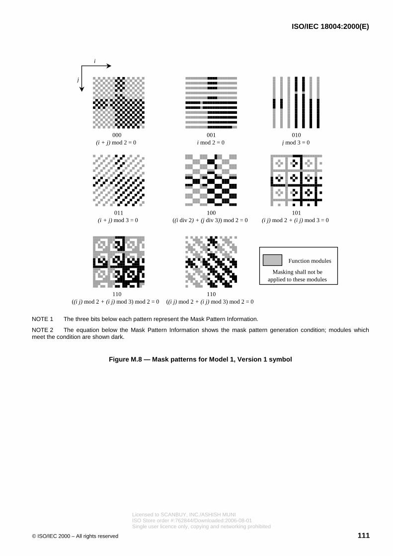
ISO/IEC 18004:2000(E)
© ISO/IEC 2000 – All rights reserved 111
000(i + j) mod 2 = 0
001i mod 2 = 0
010j mod 3 = 0
011(i + j) mod 3 = 0
100((i div 2) + (j div 3)) mod 2 = 0
101(i j) mod 2 + (i j) mod 3 = 0
110((i j) mod 2 + (i j) mod 3) mod 2 = 0
110((i j) mod 2 + (i j) mod 3) mod 2 = 0
Function modules
Masking shall not beapplied to these modules
i
j
NOTE 1 The three bits below each pattern represent the Mask Pattern Information.
NOTE 2 The equation below the Mask Pattern Information shows the mask pattern generation condition; modules whichmeet the condition are shown dark.
Figure M.8 — Mask patterns for Model 1, Version 1 symbol
Licensed to SCANBUY, INC./ASHISH MUNIISO Store order #:762844/Downloaded:2006-08-01Single user licence only, copying and networking prohibited

ISO/IEC 18004:2000(E)
112 © ISO/IEC 2000 – All rights reserved
Unmasked symbol
. . . . . . . . . .
. . . . . . . . . .
Mask Patterns000 to 111
���� ����
Masked symbolfor evaluation
Selected result with lowest penalty score
Figure M.9 — Masking simulation in Model 1
M.9 Format Information
The Format Information bits shall be calculated and, after masking, shall be mapped into the areas reserved forthem in the symbol, as defined in 8.9
The mask pattern for the Format information in Model 1 symbols is 010100000100101. The use of two differentmasking patterns ensures that the symbol Model may be autodiscriminated at the time of reading.
M.10 Structured Append
Structured Append for Model 1 follows precisely the same rules as for Model 2, as defined in 9. In Model 1symbols, the Structured Append Mode Indicator 0011 is placed in the first (four module) symbol character position.This is immediately followed by two structured append codewords. In Model 1 these two codewords occupy thesecond and third symbol characters.
Licensed to SCANBUY, INC./ASHISH MUNIISO Store order #:762844/Downloaded:2006-08-01Single user licence only, copying and networking prohibited

ISO/IEC 18004:2000(E)
© ISO/IEC 2000 – All rights reserved 113
M.11 Symbol printing and marking
Clause 10 applies in its entirety.
M.12 Symbol quality
Clause 11 applies in its entirety.
M.13 Decoding procedure overview
Clause 12 applies in its entirety.
M.14 Reference decode algorithm
The reference decode algorithm described in 13 shall be applied, substituting the following two steps for steps 7and 8 in the algorithm in 13:
7. Redefine X as the average spacing of the center points of the dark and light modules in the Timing Patterns.In a similar manner, calculate the Y dimension as the average spacing of the center points of the dark and lightmodules in the left side Timing Pattern.
8. Establish a sampling grid based on (a) the horizontal line through the upper Timing Pattern with lines parallelto it at the vertical spacing of Y, comprising six lines above the horizontal reference line and as many linesbelow it as are required for the version of the symbol and (b) the vertical line passing through the left sideTiming Pattern with lines parallel to it at the horizontal spacing of X, comprising six lines to the left of thevertical reference line and as many lines to the right of it as are required for the version of the symbol.
Additionally, step 12 shall be amended by substituting a reference to this Annex for the reference to 8.7.3.
Step 13 shall not be applied.
M.15 Autodiscrimination capability
Clause 14 applies in its entirety
M.16 Transmitted data
Clause 15 applies, with the exception of sub-clauses 15.2 and 15.3, ignoring other references to Extended ChannelInterpretations in the text.
M.17 Annexes
Annexes A, B, F, H, I, J, K, and L apply in their entirety.
Annexes D and E do not apply to Model 1 symbols.
Annex C applies, substituting the following for the final sentence in the first paragraph of C.1:
Finally, masking shall be applied by XORing the bit string with 010100000100101 to ensure that the formatinformation bit pattern is not all zeroes for any combination of Mask Pattern and Error Correction Level andto enable Model 1 symbols to be autodiscriminated from Model 2 symbols.
Licensed to SCANBUY, INC./ASHISH MUNIISO Store order #:762844/Downloaded:2006-08-01Single user licence only, copying and networking prohibited

ISO/IEC 18004:2000(E)
114 © ISO/IEC 2000 – All rights reserved
The last two lines of the example in Annex C.1 should be amended as follows, by substituting:
XOR with mask 010100000100101
Result: 011110011111001
Annex G applies, substituting the following step 3:
3. The Position Detection Patterns, Timing Patterns and Extension Pattern are placed in a blank 21 � 21matrix and the module positions for the Format Information are left temporarily blank. The codewords fromStep 2 are placed in the matrix in accordance with the placement rules in this Annex.
Licensed to SCANBUY, INC./ASHISH MUNIISO Store order #:762844/Downloaded:2006-08-01Single user licence only, copying and networking prohibited

Licensed to SCANBUY, INC./ASHISH MUNIISO Store order #:762844/Downloaded:2006-08-01Single user licence only, copying and networking prohibited

ISO/IEC 18004:2000(E)
ICS 01.080.50; 35.040Price based on 114 pages
© ISO/IEC 2000 – All rights reserved
Licensed to SCANBUY, INC./ASHISH MUNIISO Store order #:762844/Downloaded:2006-08-01Single user licence only, copying and networking prohibited
Related Documents