INTERNATIONAL STANDARD IEC 60938-1 QC 280000 Edition 2.1 2006-11 Fixed inductors for electromagnetic interference suppression – Part 1: Generic specification Reference number IEC 60938-1:1999+A1:2006(E) Edition 2:1999 consolidated with amendment 1:2006 Copyright International Electrotechnical Commission Provided by IHS under license with IEC No reproduction or networking permitted without license from IHS --`,,```,,,,````-`-`,,`,,`,`,,`---

Welcome message from author
This document is posted to help you gain knowledge. Please leave a comment to let me know what you think about it! Share it to your friends and learn new things together.
Transcript

INTERNATIONALSTANDARD
IEC60938-1
QC 280000
Edition 2.1
2006-11
Fixed inductors for electromagnetic interference suppression –
Part 1: Generic specification
Reference number IEC 60938-1:1999+A1:2006(E)
Edition 2:1999 consolidated with amendment 1:2006
Copyright International Electrotechnical Commission Provided by IHS under license with IEC
Not for ResaleNo reproduction or networking permitted without license from IHS
--`,,```,,,,````-`-`,,`,,`,`,,`---
Publication numbering
As from 1 January 1997 all IEC publications are issued with a designation in the 60000 series. For example, IEC 34-1 is now referred to as IEC 60034-1.
Consolidated editions
The IEC is now publishing consolidated versions of its publications. For example, edition numbers 1.0, 1.1 and 1.2 refer, respectively, to the base publication, the base publication incorporating amendment 1 and the base publication incorporating amendments 1 and 2.
Further information on IEC publications
The technical content of IEC publications is kept under constant review by the IEC, thus ensuring that the content reflects current technology. Information relating to this publication, including its validity, is available in the IEC Catalogue of publications (see below) in addition to new editions, amendments and corrigenda. Information on the subjects under consideration and work in progress undertaken by the technical committee which has prepared this publication, as well as the list of publications issued, is also available from the following:
• IEC Web Site (www.iec.ch)
• Catalogue of IEC publications
The on-line catalogue on the IEC web site (http://www.iec.ch/searchpub/cur_fut.htm) enables you to search by a variety of criteria including text searches, technical committees and date of publication. On-line information is also available on recently issued publications, withdrawn and replaced publications, as well as corrigenda.
• IEC Just Published
This summary of recently issued publications (http://www.iec.ch/online_news/ justpub/jp_entry.htm) is also available by email. Please contact the Customer Service Centre (see below) for further information.
• Customer Service Centre
If you have any questions regarding this publication or need further assistance, please contact the Customer Service Centre:
Email: [email protected] Tel: +41 22 919 02 11 Fax: +41 22 919 03 00
Copyright International Electrotechnical Commission Provided by IHS under license with IEC
Not for ResaleNo reproduction or networking permitted without license from IHS
--`,,```,,,,````-`-`,,`,,`,`,,`---

INTERNATIONAL STANDARD
IEC60938-1
QC 280000
Edition 2.1
2006-11
Fixed inductors for electromagnetic interference suppression –
Part 1: Generic specification
© IEC 2006 ⎯ Copyright - all rights reserved
No part of this publication may be reproduced or utilized in any form or by any means, electronic or mechanical, including photocopying and microfilm, without permission in writing from the publisher.
International Electrotechnical Commission, 3, rue de Varembé, PO Box 131, CH-1211 Geneva 20, SwitzerlandTelephone: +41 22 919 02 11 Telefax: +41 22 919 03 00 E-mail: [email protected] Web: www.iec.ch
CG
For price, see current catalogue
PRICE CODE
Commission Electrotechnique InternationaleInternational Electrotechnical CommissionМеждународная Электротехническая Комиссия
Edition 2:1999 consolidated with amendment 1:2006
Copyright International Electrotechnical Commission Provided by IHS under license with IEC
Not for ResaleNo reproduction or networking permitted without license from IHS
--`,,```,,,,````-`-`,,`,,`,`,,`---

– 2 – 60938-1 © IEC:1999+A1:2006(E)
CONTENTS FOREWORD...........................................................................................................................4 1 General ............................................................................................................................6
1.1 Scope......................................................................................................................6 1.2 Normative references ..............................................................................................6
2 Technical data ..................................................................................................................8 2.1 Units and symbols ...................................................................................................8 2.2 Definitions ...............................................................................................................8 2.3 Preferred values .................................................................................................... 11 2.4 Marking ................................................................................................................. 11
3 Quality assessment procedures ...................................................................................... 11 3.1 General ................................................................................................................. 11 3.2 Primary stage of manufacture ................................................................................ 11 3.3 Structurally similar inductors .................................................................................. 11 3.4 Qualification approval procedures .......................................................................... 11 3.5 Quality conformance inspection ............................................................................. 12 3.6 Alternative test methods ........................................................................................ 12 3.7 Unchecked parameters .......................................................................................... 13
4 Test and measurement procedure................................................................................... 13 4.1 General ................................................................................................................. 13 4.2 Standard atmospheric conditions ........................................................................... 13 4.3 Drying.................................................................................................................... 14 4.4 Visual examination and check of dimensions.......................................................... 14 4.5 Insulation resistance .............................................................................................. 16 4.6 Voltage proof ......................................................................................................... 18 4.7 Inductance............................................................................................................. 21 4.8 Insertion loss ......................................................................................................... 21 4.9 Robustness of terminations.................................................................................... 21 4.10 Resistance to soldering heat .................................................................................. 22 4.11 Solderability (applicable only for terminations intended to be soldered) ................... 23 4.12 Rapid change of temperature ................................................................................. 23 4.13 Vibration................................................................................................................ 24 4.14 Bump .................................................................................................................... 24 4.15 Shock .................................................................................................................... 24 4.16 Container sealing................................................................................................... 24 4.17 Climatic sequence ................................................................................................. 25 4.18 Damp heat, steady state ........................................................................................ 26 4.19 Temperature rise ................................................................................................... 26 4.20 Endurance ............................................................................................................. 27 4.21 Passive flammability .............................................................................................. 27 4.22 Active flammability................................................................................................. 28 4.23 Solvent resistance of marking ................................................................................ 28 4.24 Component solvent resistance ............................................................................... 28
Copyright International Electrotechnical Commission Provided by IHS under license with IEC
Not for ResaleNo reproduction or networking permitted without license from IHS
--`,,```,,,,````-`-`,,`,,`,`,,`---

60938-1 © IEC:1999+A1:2006(E) – 3 –
Annex A (normative) Interpretation of sampling plans and procedures as described in IEC 60410 for use within the IEC quality assessment system for electronic components (IECQ)..........................................................................................29 Annex B (normative) Rules for the preparation of detail specifications for capacitors and resistors for electronic equipment ...................................................................................30 Annex C (normative) Requirements for earth inductors ........................................................31 Figure 1 – Voltage proof test circuit .......................................................................................19 Table 1 – Reference test: standard atmospheric conditions ...................................................14 Table 2 – Creepage distances and clearances.......................................................................15 Table 3 – Measuring voltage .................................................................................................16 Table 4 – Measuring points ...................................................................................................17 Table 5 – Force.....................................................................................................................22 Table 6 – Torque...................................................................................................................22 Table 7 – Number of cycles ...................................................................................................26 Table 8 – Severities and requirements...................................................................................28 Table C.1 – Rated current related to minimum cross-sectional area of copper lead (mm2) of the earth inductor ..............................................................................................................31
Copyright International Electrotechnical Commission Provided by IHS under license with IEC
Not for ResaleNo reproduction or networking permitted without license from IHS
--`,,```,,,,````-`-`,,`,,`,`,,`---
– 4 – 60938-1 © IEC:1999+A1:2006(E)
INTERNATIONAL ELECTROTECHNICAL COMMISSION ____________
FIXED INDUCTORS FOR ELECTROMAGNETIC
INTERFERENCE SUPPRESSION –
Part 1: Generic specification
FOREWORD
1) The International Electrotechnical Commission (IEC) is a worldwide organization for standardization comprising all national electrotechnical committees (IEC National Committees). The object of IEC is to promote international co-operation on all questions concerning standardization in the electrical and electronic fields. To this end and in addition to other activities, IEC publishes International Standards, Technical Specifications, Technical Reports, Publicly Available Specifications (PAS) and Guides (hereafter referred to as “IEC Publication(s)”). Their preparation is entrusted to technical committees; any IEC National Committee interested in the subject dealt with may participate in this preparatory work. International, governmental and non-governmental organizations liaising with the IEC also participate in this preparation. IEC collaborates closely with the International Organization for Standardization (ISO) in accordance with conditions determined by agreement between the two organizations.
2) The formal decisions or agreements of IEC on technical matters express, as nearly as possible, an international consensus of opinion on the relevant subjects since each technical committee has representation from all interested IEC National Committees.
3) IEC Publications have the form of recommendations for international use and are accepted by IEC National Committees in that sense. While all reasonable efforts are made to ensure that the technical content of IEC Publications is accurate, IEC cannot be held responsible for the way in which they are used or for any misinterpretation by any end user.
4) In order to promote international uniformity, IEC National Committees undertake to apply IEC Publications transparently to the maximum extent possible in their national and regional publications. Any divergence between any IEC Publication and the corresponding national or regional publication shall be clearly indicated in the latter.
5) IEC provides no marking procedure to indicate its approval and cannot be rendered responsible for any equipment declared to be in conformity with an IEC Publication.
6) All users should ensure that they have the latest edition of this publication.
7) No liability shall attach to IEC or its directors, employees, servants or agents including individual experts and members of its technical committees and IEC National Committees for any personal injury, property damage or other damage of any nature whatsoever, whether direct or indirect, or for costs (including legal fees) and expenses arising out of the publication, use of, or reliance upon, this IEC Publication or any other IEC Publications.
8) Attention is drawn to the Normative references cited in this publication. Use of the referenced publications is indispensable for the correct application of this publication.
9) Attention is drawn to the possibility that some of the elements of this IEC Publication may be the subject of patent rights. IEC shall not be held responsible for identifying any or all such patent rights.
International Standard IEC 60938-1 has been prepared by IEC technical committee 40: Capacitors and resistors for electronic equipment.
This consolidated version of IEC 60938-1 consists of the second edition (1999) [documents 40/1110/FDIS and 40/1136/RVD] and its amendment 1 (2006) [documents 40/1602/CDV and 40/1699A/RVC].
The technical content is therefore identical to the base edition and its amendment and has been prepared for user convenience.
It bears the edition number 2.1.
A vertical line in the margin shows where the base publication has been modified by amendment 1.
The QC number that appears on the front cover of this publication is the specification number in the IEC Quality Assessment System for Electronic Components (IECQ).
Copyright International Electrotechnical Commission Provided by IHS under license with IEC
Not for ResaleNo reproduction or networking permitted without license from IHS
--`,,```,,,,````-`-`,,`,,`,`,,`---
60938-1 © IEC:1999+A1:2006(E) – 5 –
Annexes A, B and C form an integral part of this standard.
The committee has decided that the contents of the base publication and its amendments will remain unchanged until the maintenance result date indicated on the IEC web site under "http://webstore.iec.ch" in the data related to the specific publication. At this date, the publication will be
• reconfirmed, • withdrawn, • replaced by a revised edition, or • amended.
A bilingual version of this publication may be issued at a later date.
Copyright International Electrotechnical Commission Provided by IHS under license with IEC
Not for ResaleNo reproduction or networking permitted without license from IHS
--`,,```,,,,````-`-`,,`,,`,`,,`---

– 6 – 60938-1 © IEC:1999+A1:2006(E)
FIXED INDUCTORS FOR ELECTROMAGNETIC INTERFERENCE SUPPRESSION –
Part 1: Generic specification
1 General
1.1 Scope
This International Standard applies to inductors designed for electromagnetic interference suppression intended for use within, or associated with, electronic or electrical equipment and machines. It is restricted to inductors for which safety tests are appropriate.
The combination of two or more inductors within one enclosure is also included.
Inductors within the scope of this standard may also be used to protect apparatus and machines from electrical noise and voltage or current transients coming from either the supply or from other parts of the apparatus.
This standard does not necessarily apply in its entirety to inductors intended for use on motor vehicles, in aircraft or for marine applications.
1.2 Normative references
The following referenced documents are indispensable for the application of this document. For dated references, only the edition cited applies. For undated references, the latest edition of the referenced document (including any amendments) applies.
IEC 60027 (all parts), Letter symbols to be used in electrical technology
IEC 60050 (all parts), International Electrotechnical Vocabulary (IEV)
IEC 60062:1992, Marking codes for resistors and capacitors
IEC 60068-1:1988, Environmental testing – Part 1: General and guidance Amendment 1 (1992)
IEC 60068-2-1:1990, Environmental testing – Part 2: Tests – Tests A: Cold Amendment 1 (1993) Amendment 2 (1994)
IEC 60068-2-2:1974, Environmental testing – Part 2: Tests – Tests B: Dry Heat Amendment 1 (1993) Amendment 2 (1994)
IEC 60068-2-3:1969, Environmental testing – Part 2: Tests – Test Ca: Damp heat, steady state Amendment 1 (1984)
IEC 60068-2-6:1995, Environmental testing – Part 2: Tests – Test Fc: Vibration (sinusoidal)
IEC 60068-2-13:1983, Environmental testing – Part 2: Tests – Test M: Low air pressure
Copyright International Electrotechnical Commission Provided by IHS under license with IEC
Not for ResaleNo reproduction or networking permitted without license from IHS
--`,,```,,,,````-`-`,,`,,`,`,,`---
60938-1 © IEC:1999+A1:2006(E) – 7 –
IEC 60068-2-14:1984, Environmental testing – Part 2: Tests – Test N: Change of temperature Amendment 1 (1986)
IEC 60068-2-17:1994, Environmental testing – Part 2: Tests – Test Q: Sealing
IEC 60068-2-20:1979, Environmental testing – Part 2: Tests – Test T: Soldering Amendment 2 (1987)
IEC 60068-2-21:1983, Environmental testing – Part 2: Tests – Test U: Robustness of terminations and integral mounting devices Amendment 2 (1991) Amendment 3 (1992)
IEC 60068-2-27:1987, Environmental testing – Part 2: Tests – Test Ea and guidance: Shock
IEC 60068-2-29:1987, Environmental testing – Part 2: Tests – Test Eb and guidance: Bump
IEC 60068-2-30:1980, Environmental testing – Part 2: Tests – Test Db and guidance: Damp heat, cyclic (12 + 12 hour cycle) Amendment 1 (1985)
IEC 60068-2-45:1980, Environmental testing – Part 2: Tests – Test XA and guidance: Immersion in cleaning solvents Amendment 1 (1993)
IEC 60294:1969, Measurement of the dimensions of a cylindrical component having two axial terminations
IEC 60335-1:1991, Safety of household and similar electrical appliances – Part 1: General requirements
IEC 60410:1973, Sampling plans and procedures for inspection by attributes
IEC 60617 (all parts), Graphical symbols for diagrams
IEC 60695-2-2:1991, Fire hazard testing – Section 2: Needle-flame test Amendment 1 (1994)
CISPR 17:1981, Methods of measurement of the suppression characteristics of passive radio interference filters and suppression components
IEC QC 001002-3:1998, Rules of Procedure of the IEC Quality Assessment System for Electronic Components (IECQ) – Part 3: Approval procedures
ISO 1000:1992, SI units and recommendations for the use of their multiples and of certain other units
Copyright International Electrotechnical Commission Provided by IHS under license with IEC
Not for ResaleNo reproduction or networking permitted without license from IHS
--`,,```,,,,````-`-`,,`,,`,`,,`---

– 8 – 60938-1 © IEC:1999+A1:2006(E)
2 Technical data
2.1 Units and symbols
Units, graphical symbols, letter symbols and terminology shall, whenever possible, be taken from the following publications:
IEC 60027 IEC 60050 IEC 60617 ISO 1000
When further items are required they shall be derived in accordance with the principles of the documents listed above.
2.2 Definitions
For the purpose of this International Standard, the following definitions apply.
2.2.1 type a group of components having similar design features and the similarity of whose manufacturing techniques enables them to be grouped together either for qualification approval or for quality conformance inspection They are generally covered by a single detail specification. NOTE Components described in several detail specifications, may, in some cases, be considered as belonging to the same type.
2.2.2 style a sub-division of a type, generally based on dimensional factors. A style may include several variants, generally of a mechanical order
2.2.3 family (of electronic components) a group of electronic components which predominantly displays a particular physical attribute and/or fulfils a defined function
2.2.4 sub-family (of electronic components) a group of components within a family manufactured by similar technological methods
2.2.5 rated voltage (UR) rated voltage is either the maximum r.m.s. operating voltage of rated frequency or the maximum d.c. operating voltage which may be applied continuously to the terminations of the inductor at any temperature between the lower category temperature and the rated temperature NOTE For inductors with only one winding, the rated voltage should only be applied between one terminal and any conducting surface with which the case is liable to come into contact in normal use. For inductors having more than one winding, the rated voltage may be applied across two individual windings.
Copyright International Electrotechnical Commission Provided by IHS under license with IEC
Not for ResaleNo reproduction or networking permitted without license from IHS
--`,,```,,,,````-`-`,,`,,`,`,,`---
60938-1 © IEC:1999+A1:2006(E) – 9 –
2.2.6 category voltage (UC) maximum voltage which may be applied continuously to an inductor at its upper category temperature
2.2.7 lower category temperature minimum external surface temperature for which the inductor has been designed to operate continuously
2.2.8 upper category temperature maximum external surface temperature for which the inductor has been designed to operate continuously NOTE The external surface temperature can be affected by internal heating due to the lead-through current. The terminations are considered to be part of the external surface.
2.2.9 rated temperature maximum ambient temperature at which an inductor can carry its rated current
2.2.10 rated current maximum r.m.s. operating current at rated frequency or maximum d.c. operating current which allows continuous operation of the inductor at the rated temperature. It is assigned by the manufacturer for one or both of the following conditions: a) free air (IRO); b) with a specified heat sink (IRH).
2.2.11 rated inductance (LR) inductance value for which the inductor has been designed and which is usually indicated upon it
2.2.12 insertion loss ratio of the voltage before and after the insertion of the suppressor in the circuit as measured at the terminations NOTE 1 The insertion loss can be measured either with a symmetrical or an asymmetrical test circuit.
NOTE 2 When expressed in decibels the insertion loss is 20 times the logarithm of the ratio stated.
2.2.13 asymmetrical test circuit a test circuit in which the inductor under test is connected with a coaxial cable of which the outer conductor constitutes a return path for high-frequency current [CISPR 17:1981, 3.5 modified]
2.2.14 symmetrical test circuit a test circuit in which the inductor under test is connected with screened conductor pairs in which the asymmetrical voltage is small enough to be neglected [CISPR 17:1981, 3.6 modified]
Copyright International Electrotechnical Commission Provided by IHS under license with IEC
Not for ResaleNo reproduction or networking permitted without license from IHS
--`,,```,,,,````-`-`,,`,,`,`,,`---

– 10 – 60938-1 © IEC:1999+A1:2006(E)
2.2.15 insulated inductor an inductor in which all terminations connected to a section may be raised to a potential different (but not less than the rated voltage) from that of any conducting surface with which the case is liable to come into contact in normal use
2.2.16 uninsulated inductor an inductor in which at least one of the terminations connected to a section cannot be raised to a potential different (but not less than the rated voltage) from that of any conducting surface with which the case is liable to come into contact in normal use
2.2.17 electromagnetic interference suppression inductor an inductor which at mains frequency has a low impedance, but which at radio frequency has a high inductive impedance NOTE 1 It may be used for reducing the interference at frequencies caused by electrical equipment.
NOTE 2 These inductors are sometimes known as RF chokes.
2.2.18 current-compensated inductor an inductor having more than one winding on a single core arranged in such a way that the resultant magnetization caused by the current is near zero
2.2.19 earth inductor an inductor connected in the earth lead of an equipment. For requirements for earth inductors, see annex C
2.2.20 thyristor inductor an inductor used in thyristor controlled circuits
2.2.21 mains inductor an inductor intended for direct electrical connection to the supply mains NOTE This inductor may form part of an equipment.
2.2.22 TV choke an inductor designed to reduce interference mainly in the frequency range 30 MHz to 300 MHz NOTE Unencapsulated, non-current compensated TV chokes are not within the scope of this specification, but should be considered as part of the equipment wiring.
2.2.23 visible damage visible damage which reduces the usability of the inductor unit for intended purpose
Copyright International Electrotechnical Commission Provided by IHS under license with IEC
Not for ResaleNo reproduction or networking permitted without license from IHS
--`,,```,,,,````-`-`,,`,,`,`,,`---
60938-1 © IEC:1999+A1:2006(E) – 11 –
2.3 Preferred values
Each sectional specification shall prescribe the preferred values appropriate to the sub-family covered by that sectional specification.
2.4 Marking
2.4.1 General
The sectional specification shall indicate the identification criteria and other information to be shown on the inductors and the packing.
The order of priority for marking small inductors shall be specified.
2.4.2 Coding
When coding is used for tolerance or date of manufacture, the method shall be selected from those given in IEC 60062.
3 Quality assessment procedures
3.1 General
When these standards are used for the purpose of a full quality assessment system such as the IEC Quality Assessment System for Electronic Components (IECQ), compliance to 3.4 or 3.5 is required.
When these standards are used outside quality assessment systems for purposes such as design proving or type testing, the procedures and requirements of 3.4.1 and 3.4.3 may be used, but the tests and parts of tests shall be applied in the order given in the test schedules.
Before inductors can be qualified according to the procedures of this clause the manufacturer shall obtain the approval of his organization in accordance with the provisions of IEC QC 001002-3.
For certification by an independent test laboratory the procedure of 3.4.3 shall be sufficient, except that the test laboratory will produce the evidence of conformance.
3.2 Primary stage of manufacture
The primary stage of manufacture is the winding of the inductive element(s).
3.3 Structurally similar inductors
The grouping of structurally similar inductors for the purpose of qualification approval and quality conformance inspection shall be prescribed in the sectional specification.
3.4 Qualification approval procedures
3.4.1 Eligibility for qualification approval
The manufacturer shall comply with 3.1.1 of IEC QC 001002-3.
3.4.2 Application for qualification approval
The manufacturer shall comply with 3.1.3 of IEC QC 001002-3.
Copyright International Electrotechnical Commission Provided by IHS under license with IEC
Not for ResaleNo reproduction or networking permitted without license from IHS
--`,,```,,,,````-`-`,,`,,`,`,,`---

– 12 – 60938-1 © IEC:1999+A1:2006(E)
3.4.3 Test procedure for qualification approval
In addition to the requirements of 3.4.1 and 3.4.2, the manufacturer shall produce test evidence to show conformance to the specification requirements on the fixed sample size test schedule given in the sectional specification.
The specimens taken to form the sample shall be selected at random from current production or as agreed with the National Supervising Inspectorate (NSI).
3.4.4 Granting of qualification approval
Qualification approval shall be granted when the procedures in accordance with 3.1.4 of IEC QC 001002-3 have been completed satisfactorily.
3.4.5 Maintenance of qualification approval
Qualification approval obtained as part of a quality assessment system shall be maintained by regular demonstration of compliance with the requirements for quality conformance (see 3.5).
3.5 Quality conformance inspection
The blank detail specification(s) associated with the sectional specification shall prescribe the test schedule for quality conformance inspection. This schedule shall also specify the grouping, sampling and periodicity for the lot-by-lot and periodic inspection.
Operation of the switching rule for reduced inspection in group C is permitted in all sub-groups except endurance. Sampling plans and inspection levels shall be selected from those given in IEC 60410.
If required, more than one schedule may be specified.
3.5.1 Certified test records of released lots
When certified test records are requested by a purchaser, they shall be specified in the detail specification.
3.5.2 Delayed delivery
Inductors held for a period exceeding three years (unless otherwise specified in the detail specification) following the release of the lot shall, before delivery, be re-examined as specified in the sectional specification.
Once a lot has been satisfactorily re-inspected, its quality is re-assured for three years from the date of re-inspection.
3.5.3 Release for delivery before the completion of group B tests
When the conditions of IEC 60410 for changing to reduced inspection have been satisfied for all group B tests, the manufacturer is permitted to release components before the completion of such tests.
3.6 Alternative test methods
See 3.2.3.7 of IEC QC 001002-3 with the following details:
In case of dispute, for referee and reference purposes only the specified methods shall be used.
Copyright International Electrotechnical Commission Provided by IHS under license with IEC
Not for ResaleNo reproduction or networking permitted without license from IHS
--`,,```,,,,````-`-`,,`,,`,`,,`---
60938-1 © IEC:1999+A1:2006(E) – 13 –
3.7 Unchecked parameters
Only those parameters of a component which have been specified in a detail specification and which are subject to testing can be assumed to be within the specified limits.
It cannot be assumed that any unspecified parameter will remain unchanged from one component to another. Should it be necessary, for any reason, for further parameters to be controlled, then a new, more extensive specification should be used.
The additional test methods shall be fully described and appropriate limits, sampling plans and inspection levels specified.
4 Test and measurement procedure
4.1 General
The sectional and/or blank detail specification shall contain the tests to be made, which measurements are to be made before and after each test or sub-group of tests and the sequence in which they shall be carried out. The stages of each test shall be carried out in the order written. The measuring conditions shall be the same for initial and final measurements.
If national specifications within any quality assessment system include methods other than those specified in the above standards, they shall be fully described.
Limits given in all specifications are absolute limits. The principle to take measurement uncertainty into account shall be applied (see IEC QC 001002-3, annex C).
4.2 Standard atmospheric conditions
4.2.1 Standard atmospheric conditions for testing
Unless otherwise specified, all tests and measurements shall be made under standard atmospheric conditions for testing as given in 5.3 of IEC 60068-1:
– temperature: 15 °C to 35 °C; – relative humidity: 25 % to 75 %; – air pressure: 86 kPa to 106 kPa.
Before the measurements are made, the component shall be stored at the measuring temperature for a time sufficient to allow the entire component to reach this temperature. The period as prescribed for recovery at the end of a test is normally sufficient for this purpose.
When measurements are made at a temperature other than the specified temperature the results shall, where necessary, be corrected to the specified temperature. The ambient temperature during the measurements shall be stated in the test report. In the event of a dispute, the measurements shall be repeated, using one of the referee temperatures (as given in 4.2.3) and such other conditions as are prescribed in this specification.
When tests are conducted in a sequence, the final measurements of one test may be taken as the initial measurements for the succeeding test.
During measurements the component shall not be exposed to draughts, direct sunlight or other influences likely to cause errors.
Copyright International Electrotechnical Commission Provided by IHS under license with IEC
Not for ResaleNo reproduction or networking permitted without license from IHS
--`,,```,,,,````-`-`,,`,,`,`,,`---
– 14 – 60938-1 © IEC:1999+A1:2006(E)
4.2.2 Recovery conditions
Unless otherwise specified, recovery shall take place under the standard atmospheric conditions for testing (4.2.1).
If recovery under closely controlled conditions is necessary, the controlled recovery conditions of 5.4.1 of IEC 60068-1 shall be used.
Unless otherwise specified in the relevant specification, a duration of 1 h to 2 h shall be used.
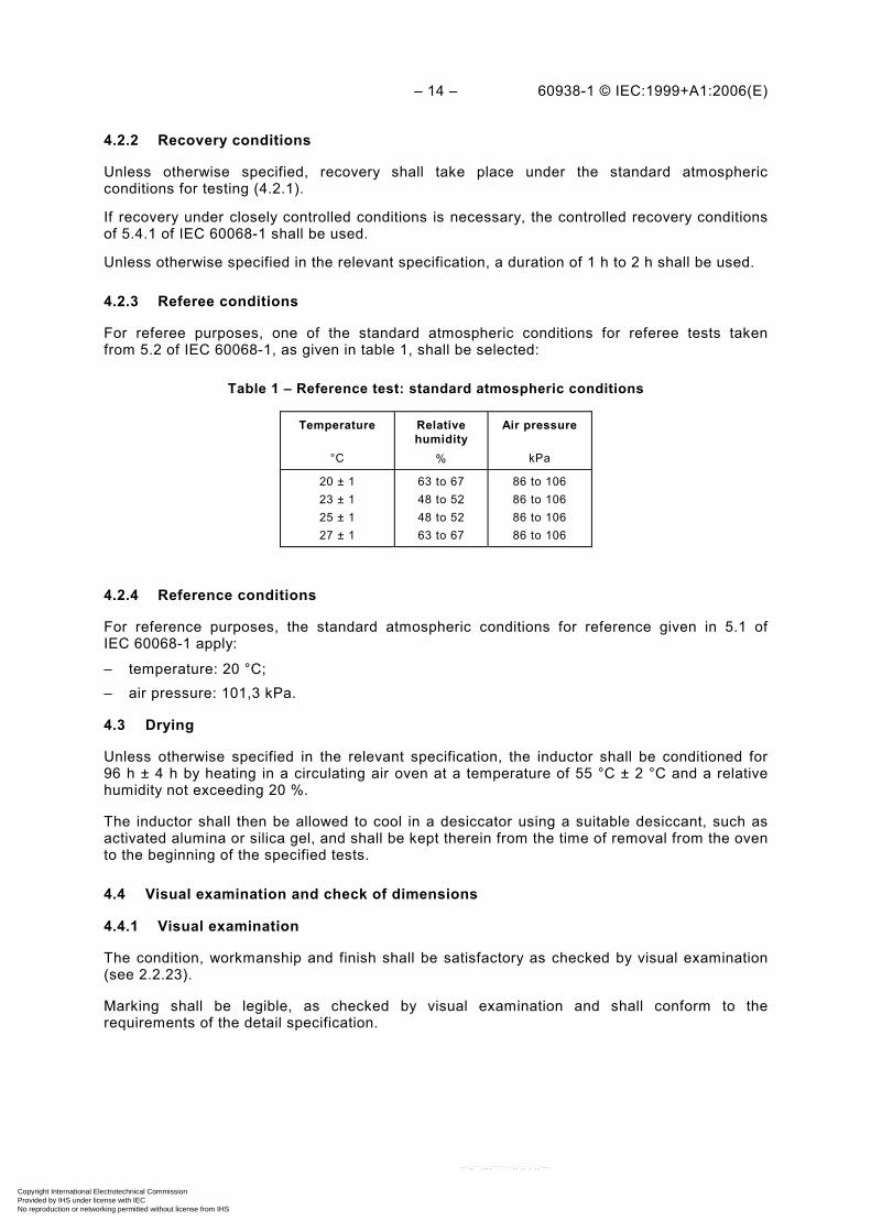
4.2.3 Referee conditions
For referee purposes, one of the standard atmospheric conditions for referee tests taken from 5.2 of IEC 60068-1, as given in table 1, shall be selected:
Table 1 – Reference test: standard atmospheric conditions
Temperature
°C
Relative humidity
%
Air pressure
kPa
20 ± 1 23 ± 1 25 ± 1 27 ± 1
63 to 67 48 to 52 48 to 52 63 to 67
86 to 106 86 to 106 86 to 106 86 to 106
4.2.4 Reference conditions
For reference purposes, the standard atmospheric conditions for reference given in 5.1 of IEC 60068-1 apply:
– temperature: 20 °C; – air pressure: 101,3 kPa.
4.3 Drying
Unless otherwise specified in the relevant specification, the inductor shall be conditioned for 96 h ± 4 h by heating in a circulating air oven at a temperature of 55 °C ± 2 °C and a relative humidity not exceeding 20 %.
The inductor shall then be allowed to cool in a desiccator using a suitable desiccant, such as activated alumina or silica gel, and shall be kept therein from the time of removal from the oven to the beginning of the specified tests.
4.4 Visual examination and check of dimensions
4.4.1 Visual examination
The condition, workmanship and finish shall be satisfactory as checked by visual examination (see 2.2.23).
Marking shall be legible, as checked by visual examination and shall conform to the requirements of the detail specification.
Copyright International Electrotechnical Commission Provided by IHS under license with IEC
Not for ResaleNo reproduction or networking permitted without license from IHS
--`,,```,,,,````-`-`,,`,,`,`,,`---
60938-1 © IEC:1999+A1:2006(E) – 15 –
4.4.2 Dimensions (gauging)
The dimensions indicated in the detail specification as being suitable for gauging shall be checked, and shall comply with the values prescribed in the detail specification.
When applicable, measurements shall be made in accordance with IEC 60294.
4.4.3 Dimensions (detail)
All dimensions prescribed in the detail specification shall be checked and shall comply with the values prescribed.
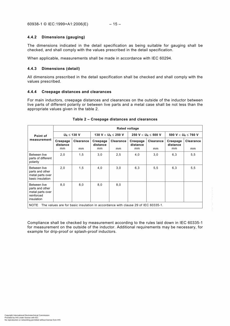
4.4.4 Creepage distances and clearances
For main inductors, creepage distances and clearances on the outside of the inductor between live parts of different polarity or between live parts and a metal case shall be not less than the appropriate values given in the table 2.
Table 2 – Creepage distances and clearances
Rated voltage
UR ≤ 130 V 130 V < UR ≤ 250 V 250 V < UR ≤ 500 V 500 V < UR ≤ 760 V
Point of measurement Creepage
distance mm
Clearance
mm
Creepage distance
mm
Clearance
mm
Creepage distance
mm
Clearance
mm
Creepage distance
mm
Clearance
mm
Between live parts of different polarity
2,0 1,5 3,0 2,5 4,0 3,0 6,3 5,5
Between live parts and other metal parts over basic insulation
2,0 1,5 4,0 3,0 6,3 5,5 6,3 5,5
Between live parts and other metal parts over reinforced insulation
8,0 8,0 8,0 8,0
NOTE The values are for basic insulation in accordance with clause 29 of IEC 60335-1.
Compliance shall be checked by measurement according to the rules laid down in IEC 60335-1 for measurement on the outside of the inductor. Additional requirements may be necessary, for example for drip-proof or splash-proof inductors.
Copyright International Electrotechnical Commission Provided by IHS under license with IEC
Not for ResaleNo reproduction or networking permitted without license from IHS
--`,,```,,,,````-`-`,,`,,`,`,,`---

– 16 – 60938-1 © IEC:1999+A1:2006(E)
4.5 Insulation resistance
4.5.1 Unless otherwise specified in the relevant specification, the insulation resistance shall be measured, at the d.c. voltage specified in table 3.
Table 3 – Measuring voltage
Voltage rating of inductor V
Measuring voltage V
UR or UC < 10
10 ≤ UR or UC < 100
100 ≤ UR or UC < 500
500 ≤ UR or UC
UC or UR ± 10 %
10 ± 1 *
100 ± 15
500 ± 50
* When it can be demonstrated that the voltage has no influence on the measuring result, or that a known relationship exists, measure-ment can be performed at voltages up to the rated or category voltage (10 V shall be used in case of dispute).
UR is the rated voltage for use in defining the measuring voltage to be used under standard atmospheric conditions for testing.
UC is the category voltage for use in defining the measuring voltage to be used at the upper category temperature.
4.5.2 The insulation resistance shall be measured between the measuring points defined in table 4, specified in the relevant specification.
Test A, between terminations, applies to all inductors, whether insulated or not.
Test B, internal insulation, applies to insulated inductors in uninsulated metal cases.
Test C, external insulation, applies to insulated inductors in non-metallic cases or in insulated metal cases. For this test, the measuring voltage shall be applied using one of the three following methods as specified in the relevant specification.
4.5.2.1 Foil method
A metal foil shall be closely wrapped around the body of the inductor. For inductors with axial terminations this foil shall extend beyond each end by not less than 5 mm, provided that a minimum distance of 1 mm can be maintained between the foil and the terminations. If this minimum distance cannot be maintained, the extension of the foil shall be reduced by as much as is necessary to establish the distance of 1 mm.
For inductors with unidirectional terminations a minimum distance of 1 mm shall be maintained between the edge of the foil and each termination.
4.5.2.2 Method for inductors with mounting devices
The inductor shall be mounted in its normal manner on a metal plate, which extends at least 13 mm in all directions beyond the mounting face of the inductor.
Copyright International Electrotechnical Commission Provided by IHS under license with IEC
Not for ResaleNo reproduction or networking permitted without license from IHS
--`,,```,,,,````-`-`,,`,,`,`,,`---
60938-1 © IEC:1999+A1:2006(E) – 17 –
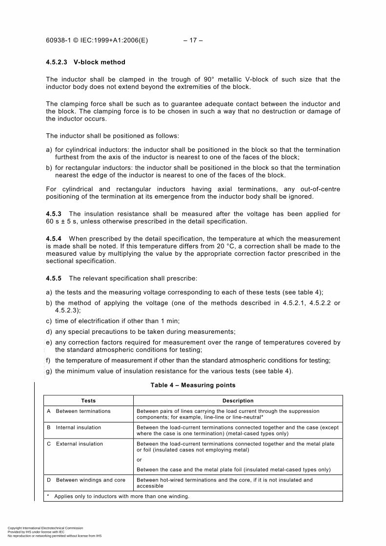
4.5.2.3 V-block method
The inductor shall be clamped in the trough of 90° metallic V-block of such size that the inductor body does not extend beyond the extremities of the block.
The clamping force shall be such as to guarantee adequate contact between the inductor and the block. The clamping force is to be chosen in such a way that no destruction or damage of the inductor occurs.
The inductor shall be positioned as follows:
a) for cylindrical inductors: the inductor shall be positioned in the block so that the termination furthest from the axis of the inductor is nearest to one of the faces of the block;
b) for rectangular inductors: the inductor shall be positioned in the block so that the termination nearest the edge of the inductor is nearest to one of the faces of the block.
For cylindrical and rectangular inductors having axial terminations, any out-of-centre positioning of the termination at its emergence from the inductor body shall be ignored.
4.5.3 The insulation resistance shall be measured after the voltage has been applied for 60 s ± 5 s, unless otherwise prescribed in the detail specification.
4.5.4 When prescribed by the detail specification, the temperature at which the measurement is made shall be noted. If this temperature differs from 20 °C, a correction shall be made to the measured value by multiplying the value by the appropriate correction factor prescribed in the sectional specification.
4.5.5 The relevant specification shall prescribe:
a) the tests and the measuring voltage corresponding to each of these tests (see table 4); b) the method of applying the voltage (one of the methods described in 4.5.2.1, 4.5.2.2 or
4.5.2.3); c) time of electrification if other than 1 min; d) any special precautions to be taken during measurements; e) any correction factors required for measurement over the range of temperatures covered by
the standard atmospheric conditions for testing; f) the temperature of measurement if other than the standard atmospheric conditions for testing; g) the minimum value of insulation resistance for the various tests (see table 4).
Table 4 – Measuring points
Tests Description
A Between terminations Between pairs of lines carrying the load current through the suppression components; for example, line-line or line-neutral*
B Internal insulation Between the load-current terminations connected together and the case (except where the case is one termination) (metal-cased types only)
C External insulation Between the load-current terminations connected together and the metal plate or foil (insulated cases not employing metal)
or
Between the case and the metal plate foil (insulated metal-cased types only)
D Between windings and core Between hot-wired terminations and the core, if it is not insulated and accessible
* Applies only to inductors with more than one winding.
Copyright International Electrotechnical Commission Provided by IHS under license with IEC
Not for ResaleNo reproduction or networking permitted without license from IHS
--`,,```,,,,````-`-`,,`,,`,`,,`---

– 18 – 60938-1 © IEC:1999+A1:2006(E)
EXAMPLE 1
Test A between 1 and
2 or 3 and 4. Test B between 1, 2, 3, 4 together and 5.
EXAMPLE 2
Test A between 1 and 2 or 3 and 4. Test C between 1, 2, 3, 4 together and the metal foil 5 wrapped around the case.
4.6 Voltage proof
The test prescribed below is a d.c. test. When the relevant specification prescribes an a.c. test, the test circuit shall be prescribed by that specification.
4.6.1 Test circuit (for the test between terminations)
The test circuit shall be such that the conditions relating to the charging and discharging currents and the time constant for charging, prescribed in the relevant specification, are complied with.
Figure 1 specifies the characteristics of a suitable test circuit.
1
2
3
4
5
Metal case
IEC 1469/99
1
2
3
4
5
Insulating case
IEC 1470/99
Copyright International Electrotechnical Commission Provided by IHS under license with IEC
Not for ResaleNo reproduction or networking permitted without license from IHS
--`,,```,,,,````-`-`,,`,,`,`,,`---

60938-1 © IEC:1999+A1:2006(E) – 19 –
R1
R2
V
12 3
CsInductorunder test
IEC 1471/99
Figure 1 – Voltage proof test circuit
The resistance of the voltmeter shall be not less than 10 000 Ω/V. The resistor R1 includes the internal resistance of the d.c. supply. The resistors R1 and R2 shall have a value sufficient to limit the charging and discharging current to the value prescribed in the relevant specification.
4.6.2 Test
Depending on the case, the test comprises one or more parts in accordance with table 4 and the requirements of the relevant specification.
4.6.2.1 Test A – Between terminations
Test A of table 4, in accordance with the requirements of the relevant specification.
Procedure
With the switch in position 2, connect the two terminals at the top of the diagram to a variable d.c. supply of sufficient power adjusted to the required test voltage.
Connect the inductor to be tested to the test circuit as indicated in the diagram.
Move the switch to position 1 to charge the stray capacitance CS.
The switch shall remain in this position for the time specified after the test voltage has been reached.
Discharge the stray capacitance CS through R2 by moving the switch to position 2. As soon as the voltmeter reading has fallen to zero, short-circuit the inductor by moving the switch to position 3 and disconnect the inductor.
Copyright International Electrotechnical Commission Provided by IHS under license with IEC
Not for ResaleNo reproduction or networking permitted without license from IHS
--`,,```,,,,````-`-`,,`,,`,`,,`---

– 20 – 60938-1 © IEC:1999+A1:2006(E)
4.6.2.2 Test B – Internal insulation
Test B of table 4, in accordance with the requirements of the relevant specification.
Procedure
The specified test voltage is applied instantaneously via the internal resistance of the power supply for the time specified in the relevant specification.
4.6.2.3 Test C – External insulation (applicable only to insulated inductors in non-metallic case or in insulated metal case)
Test C of table 4, using one of the three following methods for the application of the voltage in accordance with the requirements of the relevant specification.
Foil method
A metal foil shall be closely wrapped around the body of the inductor.
For inductors with axial terminations this foil shall extend beyond each end by not less than 5 mm, provided that a minimum distance of 1 mm/kV can be maintained between the foil and the terminations. If this minimum cannot be maintained, the extension of the foil shall be reduced by as much as is necessary to establish the distance of 1 mm/kV of test voltage.
For inductors with unidirectional terminations, a minimum distance of 1 mm/kV shall be maintained between the edge of the foil and each termination.
In no case shall the distance between the foil and the terminations be less than 1 mm.
Method for inductors with mounting devices
The inductor shall be mounted in its normal manner on a metal plate which extends by not less than 13 mm in all directions beyond the mounting face of the inductor.
V-block method
The inductor shall be clamped in the trough of a 90° metallic V-block of such size that the inductor body does not extend beyond the extremities of the block.
The clamping force shall be such as to guarantee adequate contact between the inductor and the block.
The inductor shall be positioned in accordance with the following:
a) for cylindrical inductors: the inductor shall be positioned in the block so that the termination furthest from the axis of the capacitor is nearest to one of the faces of the block;
b) for rectangular inductors: the inductor is positioned in the block so that the termination nearest the edge of the inductor is nearest to one of the faces of the block.
For cylindrical and rectangular inductors having axial terminations, any out-of-centre posi-tioning of the termination at its emergence from the inductor body shall be ignored.
Copyright International Electrotechnical Commission Provided by IHS under license with IEC
Not for ResaleNo reproduction or networking permitted without license from IHS
--`,,```,,,,````-`-`,,`,,`,`,,`---
60938-1 © IEC:1999+A1:2006(E) – 21 –
Procedure
The specified test voltage is applied instantaneously through the internal resistance of the power source for the time specified in the relevant specification.
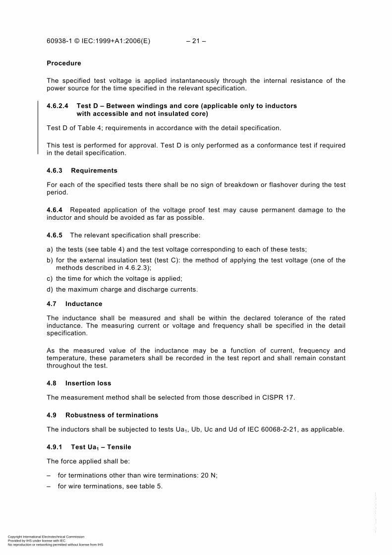
4.6.2.4 Test D – Between windings and core (applicable only to inductors with accessible and not insulated core)
Test D of Table 4; requirements in accordance with the detail specification.
This test is performed for approval. Test D is only performed as a conformance test if required in the detail specification.
4.6.3 Requirements
For each of the specified tests there shall be no sign of breakdown or flashover during the test period.
4.6.4 Repeated application of the voltage proof test may cause permanent damage to the inductor and should be avoided as far as possible.
4.6.5 The relevant specification shall prescribe:
a) the tests (see table 4) and the test voltage corresponding to each of these tests; b) for the external insulation test (test C): the method of applying the test voltage (one of the
methods described in 4.6.2.3); c) the time for which the voltage is applied; d) the maximum charge and discharge currents.
4.7 Inductance
The inductance shall be measured and shall be within the declared tolerance of the rated inductance. The measuring current or voltage and frequency shall be specified in the detail specification.
As the measured value of the inductance may be a function of current, frequency and temperature, these parameters shall be recorded in the test report and shall remain constant throughout the test.
4.8 Insertion loss
The measurement method shall be selected from those described in CISPR 17.
4.9 Robustness of terminations
The inductors shall be subjected to tests Ua1, Ub, Uc and Ud of IEC 60068-2-21, as applicable.
4.9.1 Test Ua1 – Tensile
The force applied shall be:
– for terminations other than wire terminations: 20 N; – for wire terminations, see table 5.
Copyright International Electrotechnical Commission Provided by IHS under license with IEC
Not for ResaleNo reproduction or networking permitted without license from IHS
--`,,```,,,,````-`-`,,`,,`,`,,`---

– 22 – 60938-1 © IEC:1999+A1:2006(E)
Table 5 – Force
Nominal cross-sectional area (S)
mm2
Corresponding diameter (d) of circular section wires
mm
Force with tolerance of ±10 %
N
S ≤ 0,05
0,05 < S ≤ 0,1
0,1 < S ≤ 0,2
0,2 < S ≤ 0,5
0,5 < S ≤ 1,2
1,2 < S
d ≤ 0,25
0,25 < d ≤ 0,35
0,35 < d ≤ 0,5
0,5 < d ≤ 0,8
0,8 < d ≤ 1,25
1,25 < d
1
2,5
5
10
20
40
4.9.2 Test Ub – Bending (first half of the sample)
Method 1: two consecutive bends shall be applied in each direction. This test shall not apply if, in the detail specification for the inductors, the terminations are described as rigid.
4.9.3 Test Uc – Torsion (second half of the sample)
Method A, severity 2 (two successive rotations of 180°) shall be used.
This test is not applicable if, in the detail specification, the terminations are described as rigid and connected to inductors with unidirectional terminations designed for printed board applications.
4.9.4 Test Ud – Torque (for terminations with threaded studs or screws and for integral mounting devices)
Table 6 – Torque
Nominal thread diameter
mm
2,6 3 3,5 4 5 6
Torque Severity 1 0,4 0,5 0,8 1,2 2,0 2,5
Nm Severity 2 0,2 0,25 0,4 0,6 1,0 1,25
4.9.5 Visual examination
After each of these tests the inductors shall be visually examined. There shall be no visible damage.
4.10 Resistance to soldering heat
4.10.1 Unless otherwise stated in the relevant specification, the inductors shall undergo one of the following tests, as prescribed by the relevant specification:
a) For all inductors except those of item b) below method 1A of test Tb of IEC 60068-2-20, with immersion time: 5 s or 10 s, as specified in the detail specification;
depth of immersion from the seating plane: 2 −00
,5 mm, using a thermal insulating screen of 1,5 mm ± 0,5 mm thickness; temperature of the solder bath: 260 °C ± 5 °C.
Copyright International Electrotechnical Commission Provided by IHS under license with IEC
Not for ResaleNo reproduction or networking permitted without license from IHS
--`,,```,,,,````-`-`,,`,,`,`,,`---

60938-1 © IEC:1999+A1:2006(E) – 23 –
b) Inductors not designed for use on printed boards as indicated in the detail specification, method 1B of test Tb of IEC 60068-2-20, with temperature of the solder bath: 350 °C ± 10 °C;
depth of immersion from the component body: 3,5 −00
,5 mm.
The period of recovery shall be not less than 1 h nor more than 2 h, unless otherwise specified by the detail specification.
4.10.2 When the test has been carried out the inductors shall be visually examined. There shall be no visible damage and the marking shall be legible.
The inductors shall then be measured as prescribed in the relevant specification.
4.11 Solderability (applicable only for terminations intended to be soldered)
4.11.1 Inductors shall be subjected to test Ta of IEC 60068-2-20 either using the solder bath method (method 1) or the soldering iron method (method 2) or the solder globule method (method 3) as prescribed by the detail specification.
4.11.2 When the solder bath method (method 1) is specified, the following requirements apply:
4.11.2.1 Bath temperature: 235 °C ± 5 °C.
Immersion time: 2,0 s ± 0,5 s.
a) All inductors except those of item b) below:
2 −00
,5 mm, using a thermal insulating screen of 1,5 mm ± 0,5 mm thickness.
b) Inductors indicated by the detail specification as being not designed for use on printed boards: 3,5 −0
0,5 mm.
4.11.2.2 The terminations shall be examined for good tinning as evidenced by free flowing of the solder with wetting of the terminations.
4.11.2.3 When the solder bath method is not applicable, the relevant specification shall define the method, test conditions and the requirements.
NOTE When the solder globule method is used, the requirement should include the soldering time.
4.12 Rapid change of temperature
4.12.1 The measurement prescribed in the relevant specification shall be made.
4.12.2 The inductors shall be subjected to test Na of IEC 60068-2-14 using the degree of severity as prescribed in the relevant specification.
4.12.3 After recovery the inductors shall be visually examined. There shall be no visible damage.
The measurements prescribed in the relevant specification shall then be made.
Copyright International Electrotechnical Commission Provided by IHS under license with IEC
Not for ResaleNo reproduction or networking permitted without license from IHS
--`,,```,,,,````-`-`,,`,,`,`,,`---
– 24 – 60938-1 © IEC:1999+A1:2006(E)
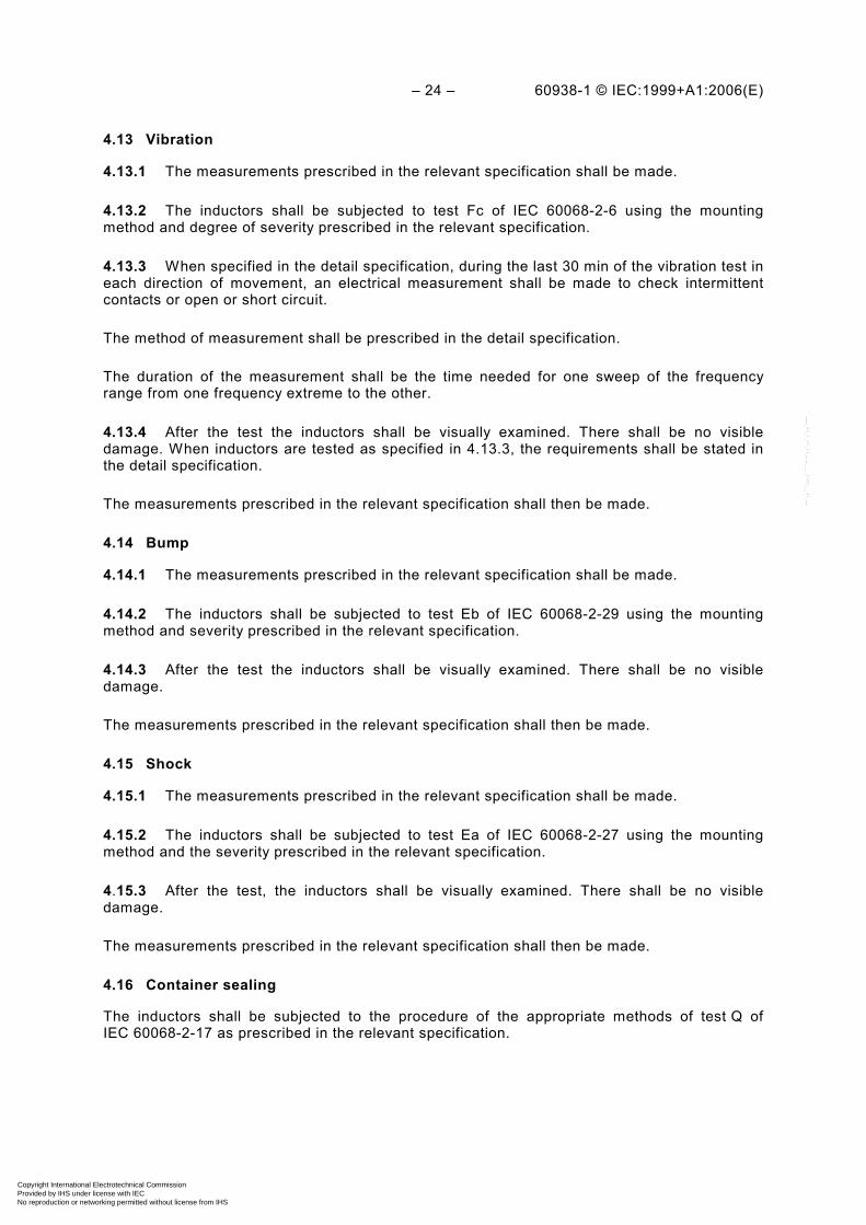
4.13 Vibration
4.13.1 The measurements prescribed in the relevant specification shall be made.
4.13.2 The inductors shall be subjected to test Fc of IEC 60068-2-6 using the mounting method and degree of severity prescribed in the relevant specification.
4.13.3 When specified in the detail specification, during the last 30 min of the vibration test in each direction of movement, an electrical measurement shall be made to check intermittent contacts or open or short circuit.
The method of measurement shall be prescribed in the detail specification.
The duration of the measurement shall be the time needed for one sweep of the frequency range from one frequency extreme to the other.
4.13.4 After the test the inductors shall be visually examined. There shall be no visible damage. When inductors are tested as specified in 4.13.3, the requirements shall be stated in the detail specification.
The measurements prescribed in the relevant specification shall then be made.
4.14 Bump
4.14.1 The measurements prescribed in the relevant specification shall be made.
4.14.2 The inductors shall be subjected to test Eb of IEC 60068-2-29 using the mounting method and severity prescribed in the relevant specification.
4.14.3 After the test the inductors shall be visually examined. There shall be no visible damage.
The measurements prescribed in the relevant specification shall then be made.
4.15 Shock
4.15.1 The measurements prescribed in the relevant specification shall be made.
4.15.2 The inductors shall be subjected to test Ea of IEC 60068-2-27 using the mounting method and the severity prescribed in the relevant specification.
4.15.3 After the test, the inductors shall be visually examined. There shall be no visible damage.
The measurements prescribed in the relevant specification shall then be made.
4.16 Container sealing
The inductors shall be subjected to the procedure of the appropriate methods of test Q of IEC 60068-2-17 as prescribed in the relevant specification.
Copyright International Electrotechnical Commission Provided by IHS under license with IEC
Not for ResaleNo reproduction or networking permitted without license from IHS
--`,,```,,,,````-`-`,,`,,`,`,,`---
60938-1 © IEC:1999+A1:2006(E) – 25 –
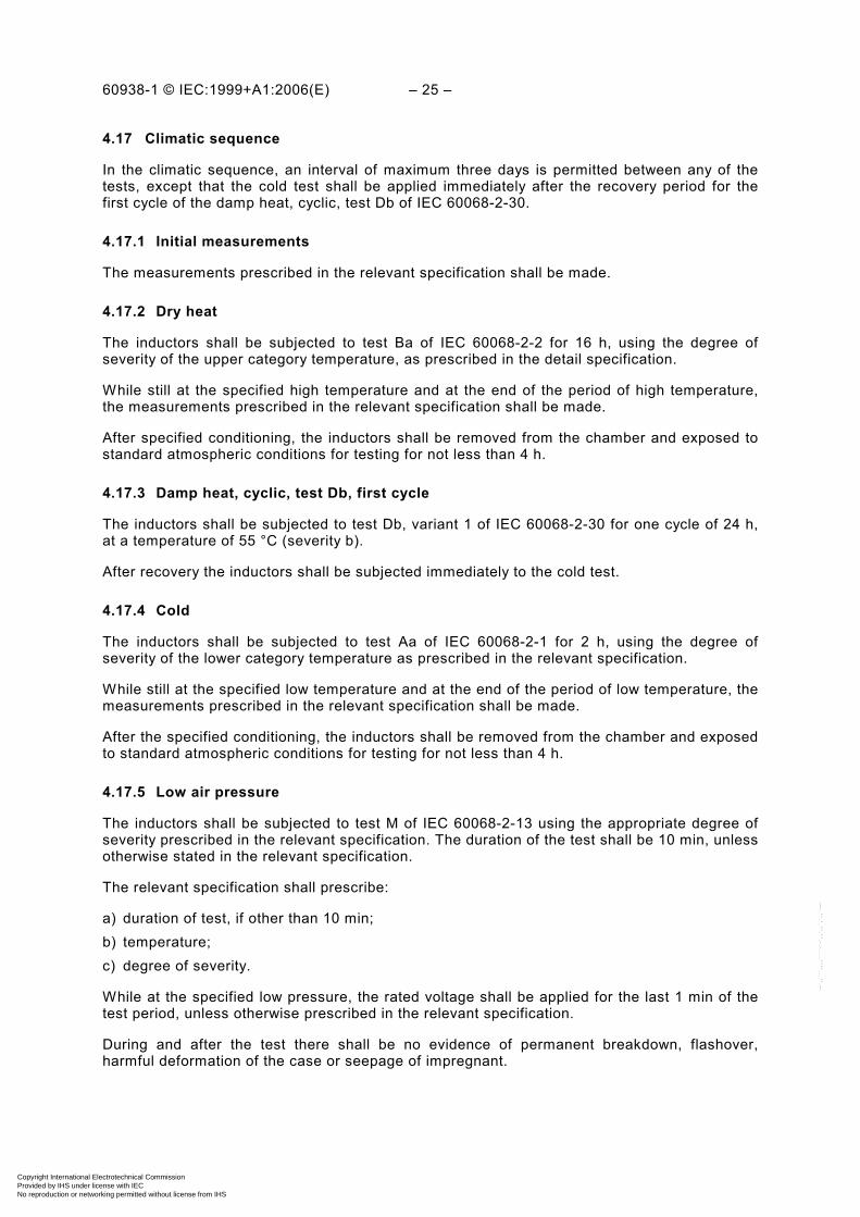
4.17 Climatic sequence
In the climatic sequence, an interval of maximum three days is permitted between any of the tests, except that the cold test shall be applied immediately after the recovery period for the first cycle of the damp heat, cyclic, test Db of IEC 60068-2-30.
4.17.1 Initial measurements
The measurements prescribed in the relevant specification shall be made.
4.17.2 Dry heat
The inductors shall be subjected to test Ba of IEC 60068-2-2 for 16 h, using the degree of severity of the upper category temperature, as prescribed in the detail specification.
While still at the specified high temperature and at the end of the period of high temperature, the measurements prescribed in the relevant specification shall be made.
After specified conditioning, the inductors shall be removed from the chamber and exposed to standard atmospheric conditions for testing for not less than 4 h.
4.17.3 Damp heat, cyclic, test Db, first cycle
The inductors shall be subjected to test Db, variant 1 of IEC 60068-2-30 for one cycle of 24 h, at a temperature of 55 °C (severity b).
After recovery the inductors shall be subjected immediately to the cold test.
4.17.4 Cold
The inductors shall be subjected to test Aa of IEC 60068-2-1 for 2 h, using the degree of severity of the lower category temperature as prescribed in the relevant specification.
While still at the specified low temperature and at the end of the period of low temperature, the measurements prescribed in the relevant specification shall be made.
After the specified conditioning, the inductors shall be removed from the chamber and exposed to standard atmospheric conditions for testing for not less than 4 h.
4.17.5 Low air pressure
The inductors shall be subjected to test M of IEC 60068-2-13 using the appropriate degree of severity prescribed in the relevant specification. The duration of the test shall be 10 min, unless otherwise stated in the relevant specification.
The relevant specification shall prescribe:
a) duration of test, if other than 10 min; b) temperature; c) degree of severity.
While at the specified low pressure, the rated voltage shall be applied for the last 1 min of the test period, unless otherwise prescribed in the relevant specification.
During and after the test there shall be no evidence of permanent breakdown, flashover, harmful deformation of the case or seepage of impregnant.
Copyright International Electrotechnical Commission Provided by IHS under license with IEC
Not for ResaleNo reproduction or networking permitted without license from IHS
--`,,```,,,,````-`-`,,`,,`,`,,`---

– 26 – 60938-1 © IEC:1999+A1:2006(E)
4.17.6 Damp heat, cyclic, test Db, remaining cycles
The inductors shall be subjected to test Db, variant 1 of IEC 60068-2-30 for the following number of cycles of 24 h as indicated in table 7, at a temperature of 55 °C (severity b).
Table 7 – Number of cycles
Categories Number of cycles
-/-/56
-/-/21
-/-/10
-/-/04
5
1
1
None
4.17.7 Final measurements
After the prescribed recovery, the measurements prescribed in the relevant specification shall be made.
4.18 Damp heat, steady state
4.18.1 The measurements prescribed in the relevant specification shall be made.
4.18.2 The inductors shall be subjected to the procedure of test Ca of IEC 60068-2-3 using the degree of severity corresponding to the climatic category of the inductor as indicated in the detail specification.
When specified in the blank detail specification, the detail specification may specify the application of a polarizing voltage during the whole period of damp heat conditioning. Within 15 min after removal from the test chamber the voltage proof test, tests A, B, and C, of 4.6 shall be carried out using 66 % of the voltage specified for the voltage proof test in the relevant specification.
4.18.3 After recovery the inductors shall be visually examined. There shall be no visible damage.
The measurements prescribed in the relevant specification shall then be made.
4.19 Temperature rise
4.19.1 The measurements prescribed in the relevant specification shall be made.
4.19.2 The inductors shall be submitted to a temperature rise test. The inductors shall be placed in the test chamber in such a manner that due to close spacing no extra heating of the inductors occurs. In cases of doubt the 25 mm spacing shall be used.
The inductors shall be mounted in the manner specified by the manufacturer. When the manufacturer specifies a rated current for both free air and heat sink conditions the test shall be carried out in the free air condition.
The specimens shall be introduced into a test chamber with a temperature equal to the rated temperature of the inductor and the rated current shall be applied. There shall be no air circulation other than that produced by natural convection caused by the heated inductor. The duration of the test shall be sufficient for the specimen to reach temperature stability.
After thermal equilibrium has been reached, the temperature of the inductor element(s) shall be measured, as prescribed in the relevant specification.
NOTE This test leads to an internal temperature rise of the inductor under rated conditions. This internal tempera-ture rise indicates whether the thermal conditions valid for the insulation materials used for the inductor are met.
Copyright International Electrotechnical Commission Provided by IHS under license with IEC
Not for ResaleNo reproduction or networking permitted without license from IHS
--`,,```,,,,````-`-`,,`,,`,`,,`---

60938-1 © IEC:1999+A1:2006(E) – 27 –
4.19.3 After recovery, the inductors shall be visually examined. There shall be no visible damage.
4.20 Endurance
4.20.1 The measurements prescribed in the relevant specification shall be made.
4.20.2 The inductors shall be submitted to an endurance test. The inductors shall be mounted in the manner specified by the manufacturer. When the manufacturer specifies a rated current for both free air and heat sink conditions the test shall be carried out in the free air condition.
The duration of this test, the value(s) of the applied voltage or current and the chamber temperature(s) at which it should be conducted, shall be prescribed in the relevant specification.
The inductors shall be placed in the test chamber in such a manner that due to close spacing no extra heating of the inductors occurs.
In cases of doubt:
a) for heat dissipating inductors no inductor is within 25 mm of any other inductor; b) for non-heat dissipating inductors no inductor is within 5 mm of any other inductor.
The inductors shall not be heated by direct radiation and the circulation of the air in the chamber shall be adequate to prevent the temperature from departing by more than 3 °C from the specified temperature of the test chamber, at any point where the components may be placed.
After the specified period, the inductors shall be allowed to recover under standard atmospheric conditions for testing.
4.20.3 The inductors shall then be visually examined. There shall be no visible damage.
The measurements prescribed in the relevant specification shall then be made.
4.21 Passive flammability
The inductors shall undergo the needle flame test of IEC 60695-2-2 with the following requirements.
4.21.1 Three specimens of each case size contained in the test sample shall be tested.
4.21.2 The inductor under test shall be held in the flame in the position which best promotes burning (if this position is not given in the detail specification it shall be evaluated by pre-testing). Each specimen shall only be exposed once to the flame.
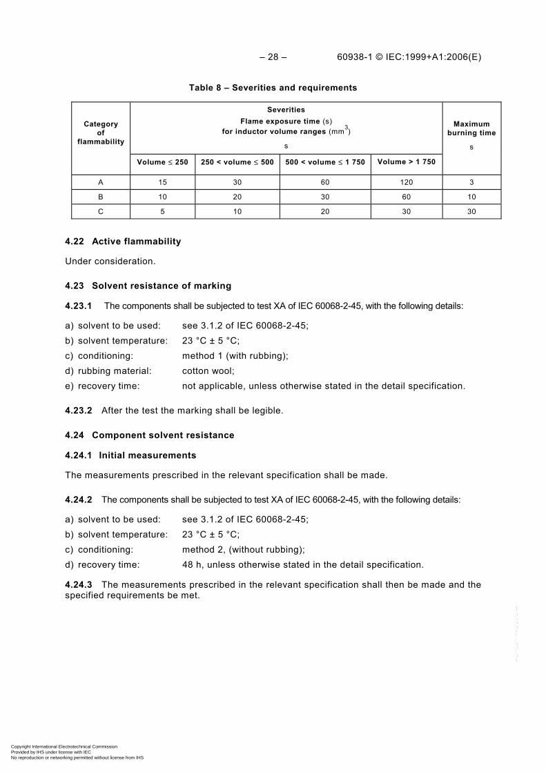
4.21.3 Time of exposure to flame and burning time: see table 8. If applicable, the detail specification shall specify the category of passive flammability.
4.21.4 Requirements
The burning time of any specimen shall not exceed the time specified in table 8.
Burning droplets or falling glowing parts shall not ignite the tissue paper.
Copyright International Electrotechnical Commission Provided by IHS under license with IEC
Not for ResaleNo reproduction or networking permitted without license from IHS
--`,,```,,,,````-`-`,,`,,`,`,,`---
– 28 – 60938-1 © IEC:1999+A1:2006(E)
Table 8 – Severities and requirements
Category of
flammability
Severities Flame exposure time (s)
for inductor volume ranges (mm3) s
Maximum burning time
s
Volume ≤ 250 250 < volume ≤ 500 500 < volume ≤ 1 750 Volume > 1 750
A 15 30 60 120 3
B 10 20 30 60 10
C 5 10 20 30 30
4.22 Active flammability
Under consideration.
4.23 Solvent resistance of marking
4.23.1 The components shall be subjected to test XA of IEC 60068-2-45, with the following details:
a) solvent to be used: see 3.1.2 of IEC 60068-2-45; b) solvent temperature: 23 °C ± 5 °C; c) conditioning: method 1 (with rubbing); d) rubbing material: cotton wool; e) recovery time: not applicable, unless otherwise stated in the detail specification.
4.23.2 After the test the marking shall be legible.
4.24 Component solvent resistance
4.24.1 Initial measurements
The measurements prescribed in the relevant specification shall be made.
4.24.2 The components shall be subjected to test XA of IEC 60068-2-45, with the following details:
a) solvent to be used: see 3.1.2 of IEC 60068-2-45; b) solvent temperature: 23 °C ± 5 °C; c) conditioning: method 2, (without rubbing); d) recovery time: 48 h, unless otherwise stated in the detail specification.
4.24.3 The measurements prescribed in the relevant specification shall then be made and the specified requirements be met.
Copyright International Electrotechnical Commission Provided by IHS under license with IEC
Not for ResaleNo reproduction or networking permitted without license from IHS
--`,,```,,,,````-`-`,,`,,`,`,,`---

60938-1 © IEC:1999+A1:2006(E) – 29 –
Annex A (normative)
Interpretation of sampling plans and procedures as described in
IEC 60410 for use within the IEC quality assessment system for electronic components (IECQ)
When using IEC 60410 for inspection by attributes the following interpretations of the clauses and subclauses of that standard as indicated below, apply for the purpose of this standard:
1 The responsible authority is the national authorized institution implementing the basic rules and rules of procedure.
1.5 The unit of product is the electronic component defined in a detail specification.
2 Only the following definitions from this clause are required:
– a “defect” is any non-conformance of the unit of product to specified requirements;
– a “defective” is a unit of product which contains one or more non-conformances.
3.1 The extent of non-conformance of a product shall be expressed in terms of per cent defective.
3.3 Not applicable.
4.5 The responsible authority is the IEC technical committee drafting the blank detail specification which forms part of the generic or sectional specification.
5.4 The responsible authority is the designated management representative (DMR), acting in accordance with the procedures prescribed in the document describing the inspection department of the approved manufacturer and approved by the national supervising inspectorate.
6.2 The responsible authority is the DMR.
6.3 Not applicable.
6.4 The responsible authority is the DMR.
8.1 Normal inspection shall always be used at the start of inspection.
8.3.3d) The responsible authority is the DMR.
8.4 The responsible authority is the national supervising inspectorate.
9.2 The responsible authority is the IEC technical committee drafting the blank detail specification which forms part of the generic or sectional specification.
9.4 (Fourth sentence only) Not applicable. (Fifth sentence only) The responsible authority is the DMR.
10.2 Not applicable.
Copyright International Electrotechnical Commission Provided by IHS under license with IEC
Not for ResaleNo reproduction or networking permitted without license from IHS
--`,,```,,,,````-`-`,,`,,`,`,,`---
– 30 – 60938-1 © IEC:1999+A1:2006(E)
Annex B (normative)
Rules for the preparation of detail specifications for capacitors
and resistors for electronic equipment
B.1 The drafting of a complete detail specification by IEC technical committee 40, if required, shall begin only when all the following conditions have been met:
a) the generic specification has been approved; b) the sectional specification, when appropriate, has been circulated for approval as an FDIS; c) the associated blank detail specification has been circulated for approval as an FDIS; d) there is evidence that at least three national committees have formally approved, as their
own national standard, specifications covering a component of closely similar performance.
When a national committee formally asserts that substantial or significant use is made within its country of a part described by some other national standard, this assertion may count towards the foregoing requirement.
B.2 Detail specifications prepared under the responsibility of technical committee 40 shall use the standard of preferred values, ratings and characteristics and severities for environmental tests, etc., which are given in the appropriate generic or sectional specifications.
An exception to this rule may only be granted for a specified detail specification, when agreed by technical committee 40.
B.3 The detail specification should not be circulated as an FDIS until the sectional and blank detail specifications have been approved for publication.
Copyright International Electrotechnical Commission Provided by IHS under license with IEC
Not for ResaleNo reproduction or networking permitted without license from IHS
--`,,```,,,,````-`-`,,`,,`,`,,`---
60938-1 © IEC:1999+A1:2006(E) – 31 –
Annex C (normative)
Requirements for earth inductors
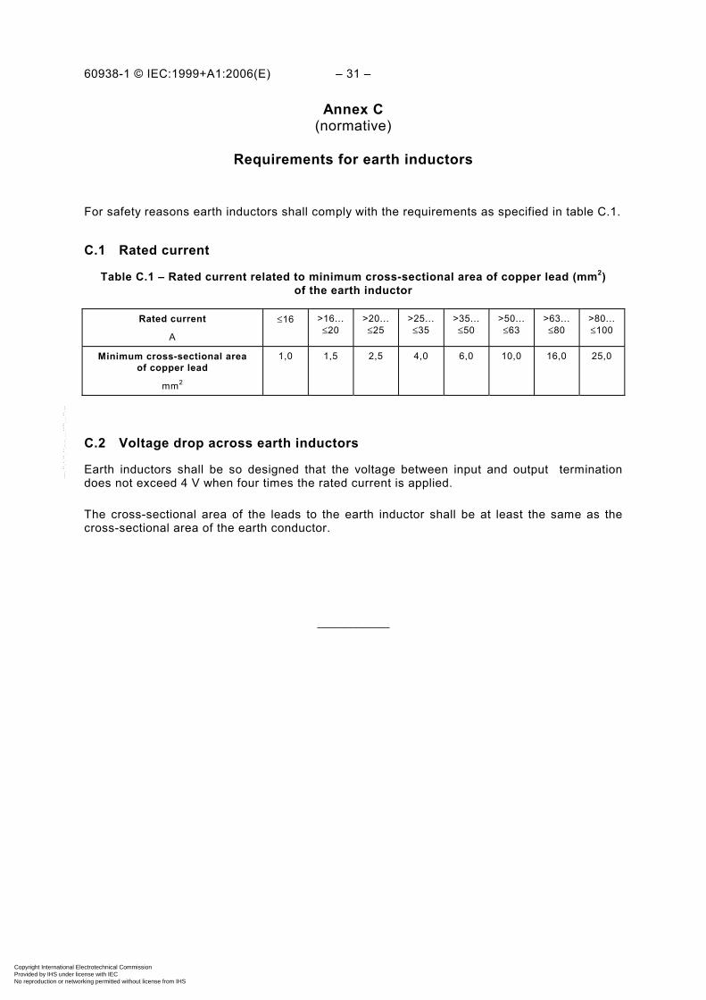
For safety reasons earth inductors shall comply with the requirements as specified in table C.1.
C.1 Rated current
Table C.1 – Rated current related to minimum cross-sectional area of copper lead (mm2) of the earth inductor
Rated current
A
≤16 >16...≤20
>20...≤25
>25...≤35
>35...≤50
>50... ≤63
>63... ≤80
>80...≤100
Minimum cross-sectional area of copper lead
mm2
1,0 1,5 2,5 4,0 6,0 10,0 16,0 25,0
C.2 Voltage drop across earth inductors
Earth inductors shall be so designed that the voltage between input and output termination does not exceed 4 V when four times the rated current is applied.
The cross-sectional area of the leads to the earth inductor shall be at least the same as the cross-sectional area of the earth conductor.
___________
Copyright International Electrotechnical Commission Provided by IHS under license with IEC
Not for ResaleNo reproduction or networking permitted without license from IHS
--`,,```,,,,````-`-`,,`,,`,`,,`---

ISBN 2-8318-8898-0
-:HSMINB=]]]^]^:ICS 29.100.10; 31.020
Typeset and printed by the IEC Central Office GENEVA, SWITZERLAND
Copyright International Electrotechnical Commission Provided by IHS under license with IEC
Not for ResaleNo reproduction or networking permitted without license from IHS
--`,,```,,,,````-`-`,,`,,`,`,,`---
Related Documents


![Elektor[nonlinear.ir] 1989-01.pdf](https://static.cupdf.com/doc/110x72/633c12717a3d41d8e607fbbf/elektornonlinearir-1989-01pdf.jpg)