Internal Combustion Engine Parts 1125 1. Introduction. 2. Principal Parts of an I. C. Engine. 3. Cylinder and Cylinder Liner. 4. Design of a Cylinder. 5. Piston. 6. Design Considerations for a Piston. 7. Material for Pistons. 8. Piston Head or Crown . 9. Piston Rings. 10. Piston Barrel. 11. Piston skirt. 12. Piston Pin. 13. Connecting Rod. 14. Forces Acting on the Connecting Rod. 15. Design of Connecting Rod. 16. Crankshaft. 17. Material and Manufacture of Crankshafts. 18. Bearing Pressures and Stresses in Crankshafts. 19. Design Procedure for Crankshaft. 20. Design for Centre Crankshaft. 21. Side or Overhung Crankshaft. 22. Valve Gear Mechanism. 23. Valves. 24. Rocker Arm. 32 C H A P T E R 32.1 Introduction As the name implies, the internal combustion engines (briefly written as I. C. engines) are those engines in which the combustion of fuel takes place inside the engine cylinder. The I.C. engines use either petrol or diesel as their fuel. In petrol engines (also called spark ignition engines or S.I engines), the correct proportion of air and petrol is mixed in the carburettor and fed to engine cylinder where it is ignited by means of a spark produced at the spark plug. In diesel engines (also called compression ignition engines or C.I engines), only air is supplied to the engine cylinder during suction stroke and it is compressed to a very high pressure, thereby raising its temperature from 600°C to 1000°C. The desired quantity of fuel (diesel) is now injected into the engine cylinder in the form of a very fine spray and gets ignited when comes in contact with the hot air. The operating cycle of an I.C. engine may be completed either by the two strokes or four strokes of the

Welcome message from author
This document is posted to help you gain knowledge. Please leave a comment to let me know what you think about it! Share it to your friends and learn new things together.
Transcript
Internal Combustion Engine Parts 1125
Internal CombustionEngine Parts
1125
1. Introduction.2. Principal Parts of an I. C.
Engine.3. Cylinder and Cylinder
Liner.4. Design of a Cylinder.5. Piston.6. Design Considerations for
a Piston.7. Material for Pistons.8. Piston Head or Crown .9. Piston Rings.
10. Piston Barrel.11. Piston skirt.12. Piston Pin.13. Connecting Rod.14. Forces Acting on the
Connecting Rod.15. Design of Connecting Rod.16. Crankshaft.17. Material and Manufacture
of Crankshafts.18. Bearing Pressures and
Stresses in Crankshafts.19. Design Procedure for
Crankshaft.20. Design for Centre
Crankshaft.21. Side or Overhung
Crankshaft.22. Valve Gear Mechanism.23. Valves.24. Rocker Arm.
32CHAPTER
32.1 IntroductionAs the name implies, the internal combustion engines
(briefly written as I. C. engines) are those engines in whichthe combustion of fuel takes place inside the engine cylinder.The I.C. engines use either petrol or diesel as their fuel. Inpetrol engines (also called spark ignition engines or S.Iengines), the correct proportion of air and petrol is mixedin the carburettor and fed to engine cylinder where it isignited by means of a spark produced at the spark plug. Indiesel engines (also called compression ignition enginesor C.I engines), only air is supplied to the engine cylinderduring suction stroke and it is compressed to a very highpressure, thereby raising its temperature from 600°C to1000°C. The desired quantity of fuel (diesel) is now injectedinto the engine cylinder in the form of a very fine spray andgets ignited when comes in contact with the hot air.
The operating cycle of an I.C. engine may becompleted either by the two strokes or four strokes of the
1126 A Textbook of Machine Design
piston. Thus, an engine which requires two strokes of the piston or one complete revolution of thecrankshaft to complete the cycle, is known as two stroke engine. An engine which requires fourstrokes of the piston or two complete revolutions of the crankshaft to complete the cycle, is known asfour stroke engine.
The two stroke petrol engines are generally employed in very light vehicles such as scooters,motor cycles and three wheelers. The two stroke diesel engines are generally employed in marinepropulsion.
The four stroke petrol engines are generally employed in light vehicles such as cars, jeeps andalso in aeroplanes. The four stroke diesel engines are generally employed in heavy duty vehicles suchas buses, trucks, tractors, diesel locomotive and in the earth moving machinery.
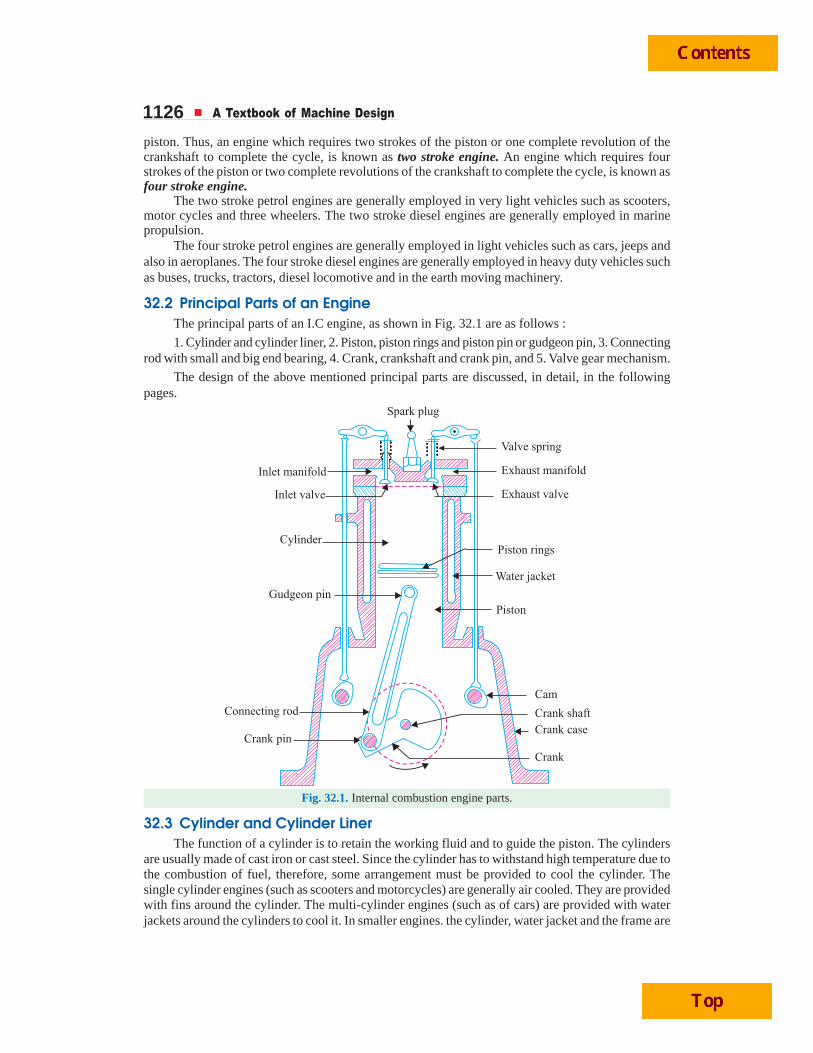
32.2 Principal Parts of an EngineThe principal parts of an I.C engine, as shown in Fig. 32.1 are as follows :
1. Cylinder and cylinder liner, 2. Piston, piston rings and piston pin or gudgeon pin, 3. Connectingrod with small and big end bearing, 4. Crank, crankshaft and crank pin, and 5. Valve gear mechanism.
The design of the above mentioned principal parts are discussed, in detail, in the followingpages.
Fig. 32.1. Internal combustion engine parts.
32.3 Cylinder and Cylinder LinerThe function of a cylinder is to retain the working fluid and to guide the piston. The cylinders
are usually made of cast iron or cast steel. Since the cylinder has to withstand high temperature due tothe combustion of fuel, therefore, some arrangement must be provided to cool the cylinder. Thesingle cylinder engines (such as scooters and motorcycles) are generally air cooled. They are providedwith fins around the cylinder. The multi-cylinder engines (such as of cars) are provided with waterjackets around the cylinders to cool it. In smaller engines. the cylinder, water jacket and the frame are
Internal Combustion Engine Parts 1127made as one piece, but for all the larger engines, these parts are manufactured separately. The cylindersare provided with cylinder liners so that in case of wear, they can be easily replaced. The cylinderliners are of the following two types :
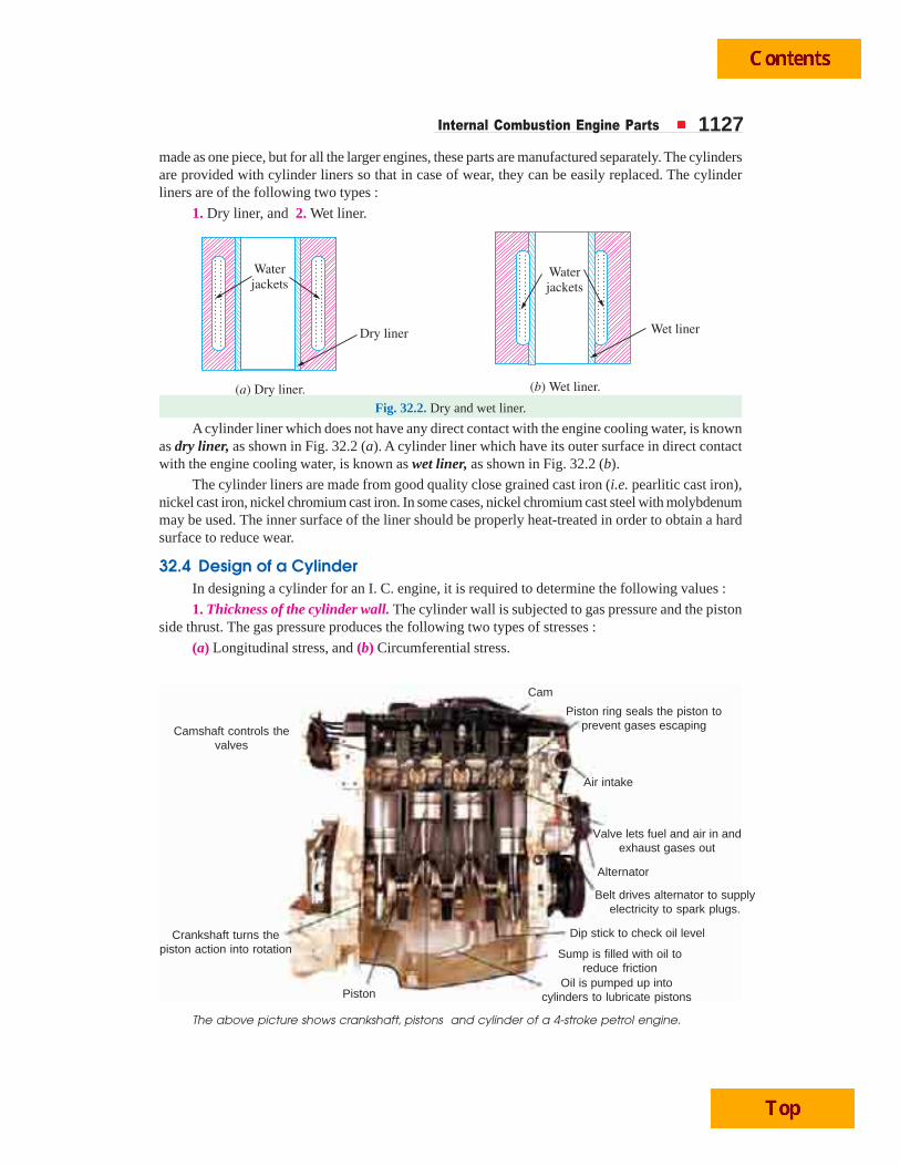
1. Dry liner, and 2. Wet liner.
Fig. 32.2. Dry and wet liner.
A cylinder liner which does not have any direct contact with the engine cooling water, is knownas dry liner, as shown in Fig. 32.2 (a). A cylinder liner which have its outer surface in direct contactwith the engine cooling water, is known as wet liner, as shown in Fig. 32.2 (b).
The cylinder liners are made from good quality close grained cast iron (i.e. pearlitic cast iron),nickel cast iron, nickel chromium cast iron. In some cases, nickel chromium cast steel with molybdenummay be used. The inner surface of the liner should be properly heat-treated in order to obtain a hardsurface to reduce wear.
32.4 Design of a CylinderIn designing a cylinder for an I. C. engine, it is required to determine the following values :
1. Thickness of the cylinder wall. The cylinder wall is subjected to gas pressure and the pistonside thrust. The gas pressure produces the following two types of stresses :
(a) Longitudinal stress, and (b) Circumferential stress.
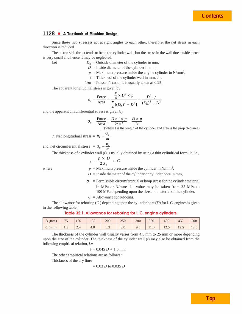
The above picture shows crankshaft, pistons and cylinder of a 4-stroke petrol engine.
Oil is pumped up intocylinders to lubricate pistons
Sump is filled with oil toreduce friction
Dip stick to check oil level
Belt drives alternator to supplyelectricity to spark plugs.
Alternator
Valve lets fuel and air in andexhaust gases out
Air intake
Piston ring seals the piston toprevent gases escaping
Cam
Camshaft controls thevalves
Crankshaft turns thepiston action into rotation
Piston
1128 A Textbook of Machine Design
Since these two stressess act at right angles to each other, therefore, the net stress in eachdirection is reduced.
The piston side thrust tends to bend the cylinder wall, but the stress in the wall due to side thrustis very small and hence it may be neglected.
Let D0 = Outside diameter of the cylinder in mm,D = Inside diameter of the cylinder in mm,p = Maximum pressure inside the engine cylinder in N/mm2,t = Thickness of the cylinder wall in mm, and
1/m = Poisson’s ratio. It is usually taken as 0.25.
The apparent longitudinal stress is given by
22
2 22 2 0
0
Force .4=Area ( )[( ) ]
4
l
D p D p
D DD D
π × ×σ = =
π −−
and the apparent circumferential stresss is given by
ForceArea 2 2c
D l p D pt l t
× × ×σ = = =×
... (where l is the length of the cylinder and area is the projected area)
∴ Net longitudinal stress = cl m
σσ −
and net circumferential stress = lc m
σσ −
The thickness of a cylinder wall (t) is usually obtained by using a thin cylindrical formula,i.e.,
t = 2 c
p DC
× +σ
where p = Maximum pressure inside the cylinder in N/mm2,
D = Inside diameter of the cylinder or cylinder bore in mm,
cσ = Permissible circumferential or hoop stress for the cylinder material
in MPa or N/mm2. Its value may be taken from 35 MPa to100 MPa depending upon the size and material of the cylinder.
C = Allowance for reboring.
The allowance for reboring (C ) depending upon the cylinder bore (D) for I. C. engines is givenin the following table :
Table 32.1. Allowance for reboring for I. C. engine cylinders.
D (mm) 75 100 150 200 250 300 350 400 450 500
C (mm) 1.5 2.4 4.0 6.3 8.0 9.5 11.0 12.5 12.5 12.5
The thickness of the cylinder wall usually varies from 4.5 mm to 25 mm or more dependingupon the size of the cylinder. The thickness of the cylinder wall (t) may also be obtained from thefollowing empirical relation, i.e.
t = 0.045 D + 1.6 mm
The other empirical relations are as follows :
Thickness of the dry liner
= 0.03 D to 0.035 D
Internal Combustion Engine Parts 1129Thickness of the water jacket wall
= 0.032 D + 1.6 mm or t / 3 m for bigger cylinders and 3t /4 forsmaller cylinders
Water space between the outer cylinder wall and inner jacket wall
= 10 mm for a 75 mm cylinder to 75 mm for a 750 mm cylinder
or 0.08 D + 6.5 mm
2. Bore and length of the cylinder. The bore (i.e. inner diameter) and length of the cylinder maybe determined as discussed below :
Let pm = Indicated mean effective pressure in N/mm2,
D = Cylinder bore in mm,
A = Cross-sectional area of the cylinder in mm2,
= π D2/4
l = Length of stroke in metres,
N = Speed of the engine in r.p.m., and
n = Number of working strokes per min
= N, for two stroke engine
= N/2, for four stroke engine.
We know that the power produced inside the engine cylinder, i.e. indicated power,
. . watts60
mp l A nI P
× × ×=
From this expression, the bore (D) and length of stroke (l) is determined. The length of stroke isgenerally taken as 1.25 D to 2D.
Since there is a clearance on both sides of the cylinder, therefore length of the cylinder is takenas 15 percent greater than the length of stroke. In other words,
Length of the cylinder, L = 1.15 × Length of stroke = 1.15 lNotes : (a) If the power developed at the crankshaft, i.e. brake power (B. P.) and the mechanical efficiency (ηm)of the engine is known, then
I.P. =. .
m
B Pη
(b) The maximum gas pressure ( p ) may be taken as 9 to 10 times the mean effective pressure ( pm).
3. Cylinder flange and studs. The cylinders are cast integral with the upper half of the crank-case or they are attached to the crankcase by means of a flange with studs or bolts and nuts. Thecylinder flange is integral with the cylinder and should be made thicker than the cylinder wall. Theflange thickness should be taken as 1.2 t to 1.4 t, where t is the thickness of cylinder wall.
The diameter of the studs or bolts may be obtained by equating the gas load due to the maximumpressure in the cylinder to the resisting force offered by all the studs or bolts. Mathematically,
2 .4
D pπ × = 2( )
4s c tn dπ× σ
where D = Cylinder bore in mm,
p = Maximum pressure in N/mm2,
ns = Number of studs. It may be taken as 0.01 D + 4 to 0.02 D + 4
dc = Core or minor diameter, i.e. diameter at the root of the thread inmm,
1130 A Textbook of Machine Design
tσ = Allowable tensile stress for the material of studs or bolts in MPa orN/mm2. It may be taken as 35 to 70 MPa.
The nominal or major diameter of the stud or bolt (d ) usually lies between 0.75 tf to tf, wheretf is the thickness of flange. In no case, a stud or bolt less than 16 mm diameter should be used.
The distance of the flange from the centre of the hole for the stud or bolt should not be less thand + 6 mm and not more than 1.5 d, where d is the nominal diameter of the stud or bolt.
In order to make a leak proof joint, the pitch of the studs or bolts should lie between 19 d to
28.5 ,d where d is in mm.
4. Cylinder head. Usually, a separate cylinder head or cover is provided with most of the engines.It is, usually, made of box type section of considerable depth to accommodate ports for air and gaspassages, inlet valve, exhaust valve and spark plug (in case of petrol engines) or atomiser at the centreof the cover (in case of diesel engines).
The cylinder head may be approximately taken as a flat circular plate whose thickness (th) maybe determined from the following relation :
th =.
c
C pD
σwhere D = Cylinder bore in mm,
p = Maximum pressure inside the cylinder in N/mm2,
cσ = Allowable circumferential stress in MPa or N/mm2. It may be takenas 30 to 50 MPa, and
C = Constant whose value is taken as 0.1.
The studs or bolts are screwed up tightly alongwith a metal gasket or asbestos packing to providea leak proof joint between the cylinder and cylinder head. The tightness of the joint also depends
upon the pitch of the bolts or studs, which should lie between 19 d to 28.5 .d The pitch circle
diameter (Dp) is usually taken as D + 3d. The studs or bolts are designed in the same way as discussedabove.
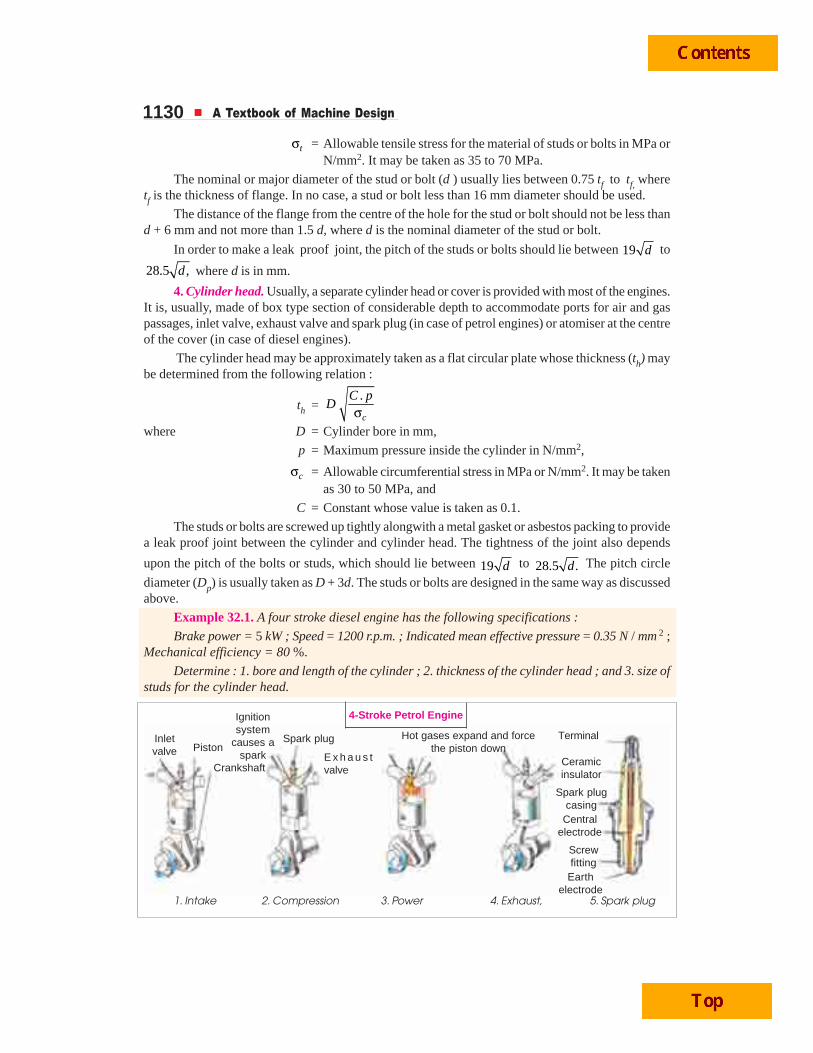
Example 32.1. A four stroke diesel engine has the following specifications :
Brake power = 5 kW ; Speed = 1200 r.p.m. ; Indicated mean effective pressure = 0.35 N / mm 2 ;Mechanical efficiency = 80 %.
Determine : 1. bore and length of the cylinder ; 2. thickness of the cylinder head ; and 3. size ofstuds for the cylinder head.
1. Intake 2. Compression 3. Power 4. Exhaust, 5. Spark plug
Inletvalve Piston
Crankshaft
Ignitionsystem
causes aspark
Spark plug
E x h a u s tvalve
Hot gases expand and forcethe piston down
Terminal
Ceramicinsulator
Spark plugcasing
Centralelectrode
Screwfitting
Earthelectrode
4-Stroke Petrol Engine
Internal Combustion Engine Parts 1131Solution. Given: B.P. = 5kW = 5000 W ; N = 1200 r.p.m. or n = N / 2 = 600 ;
pm = 0.35 N/mm2; ηm = 80% = 0.8
1. Bore and length of cylinderLet D = Bore of the cylinder in mm,
A = Cross-sectional area of the cylinder = 2 2mm4π × D
l = Length of the stroke in m.
= 1.5 D mm = 1.5 D / 1000 m ....(Assume)
We know that the indicated power,
I.P = B.P. / ηm = 5000 / 0.8 = 6250 W
We also know that the indicated power (I.P.),
6250 =2. . . 0.35 1.5 600
60 60 1000 4mp l A n D D× × π ×=
× × = 4.12 × 10⁻³ D3
...(Q For four stroke engine, n = N/2)
∴ D3 = 6250 / 4.12 × 10–3 = 1517 × 103 or D = 115 mm Ans.and l = 1.5 D = 1.5 × 115 = 172.5 mm
Taking a clearance on both sides of the cylinder equal to 15% of the stroke, therefore length ofthe cylinder,
L = 1.15 l = 1.15 × 172.5 = 198 say 200 mm Ans.2. Thickness of the cylinder head
Since the maximum pressure ( p) in the engine cylinder is taken as 9 to 10 times the meaneffective pressure ( pm), therefore let us take
p = 9 pm = 9 × 0.35 = 3.15 N/mm2
We know that thickness of the cyclinder head,
th =. 0.1 3.15
11542t
C pD
×=σ = 9.96 say 10 mm Ans.
...(Taking C = 0.1 and tσ = 42 MPa = 42 N/mm2)
3. Size of studs for the cylinder headLet d = Nominal diameter of the stud in mm,
dc = Core diameter of the stud in mm. It is usually taken as 0.84 d.
σt = Tensile stress for the material of the stud which is usually nickelsteel.
ns = Number of studs.
We know that the force acting on the cylinder head (or on the studs)
= 2 2(115) 3.15 32 702 N4 4
D pπ π× × = = ...(i)
The number of studs (ns ) are usually taken between 0.01 D + 4 (i.e. 0.01 × 115 + 4 = 5.15) and0.02 D + 4 (i.e. 0.02 × 115 + 4 = 6.3). Let us take ns = 6.
We know that resisting force offered by all the studs
= 2 2 2( ) 6 (0.84 ) 65 216 N4 4s c tn d d dπ π× σ = × = ...(ii)
...(Taking σt = 65 MPa = 65 N/mm2)From equations (i) and (ii),
d 2 = 32 702 / 216 = 151 or d = 12.3 say 14 mm
1132 A Textbook of Machine Design
The pitch circle diameter of the studs (Dp) is taken D + 3d.
∴ Dp = 115 + 3 × 14 = 157 mm
We know that pitch of the studs
=157
82.2 mm6
p
s
D
n
π × π ×= =
We know that for a leak-proof joint, the pitch of the studs should lie between 19 d to 28.5 ,dwhere d is the nominal diameter of the stud.
∴ Minimum pitch of the studs
= 19 d = 19 14 = 71.1 mmand maximum pitch of the studs
= 28.5 28.5 14 106.6mmd = =Since the pitch of the studs obtained above (i.e. 82.2 mm) lies within 71.1 mm and 106.6 mm,
therefore, size of the stud (d ) calculated above is satisfactory.
∴ d = 14 mm Ans.
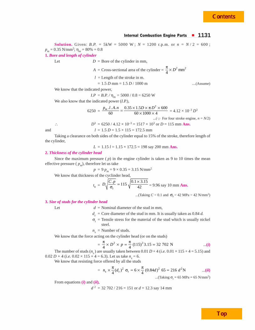
32.5 PistonThe piston is a disc which reciprocates within a cylinder. It is either moved by the fluid or it
moves the fluid which enters the cylinder. The main function of the piston of an internal combustionengine is to receive the impulse from the expanding gas and to transmit the energy to the crankshaftthrough the connecting rod. The piston must also disperse a large amount of heat from the combustionchamber to the cylinder walls.
Fig. 32.3. Piston for I.C. engines (Trunk type).
Internal Combustion Engine Parts 1133The piston of internal combustion engines are usually of trunk type as shown in Fig. 32.3. Such
pistons are open at one end and consists of the following parts :
1. Head or crown. The piston head or crown may be flat, convex or concave depending uponthe design of combustion chamber. It withstands the pressure of gas in the cylinder.
2. Piston rings. The piston rings are used to seal the cyliner in order to prevent leakage of thegas past the piston.
3. Skirt. The skirt acts as a bearing for the side thrust of the connecting rod on the walls ofcylinder.
4. Piston pin. It is also called gudgeon pin or wrist pin. It is used to connect the piston to theconnecting rod.
32.6 Design Considerations for a PistonIn designing a piston for I.C. engine, the following points should be taken into consideration :
1. It should have enormous strength to withstand the high gas pressure and inertia forces.
2. It should have minimum mass to minimise the inertia forces.
3. It should form an effective gas and oil sealing of the cylinder.
4. It should provide sufficient bearing area to prevent undue wear.
5. It should disprese the heat of combustion quickly to the cylinder walls.
6. It should have high speed reciprocation without noise.
7. It should be of sufficient rigid construction to withstand thermal and mechanical distortion.
8. It should have sufficient support for the piston pin.
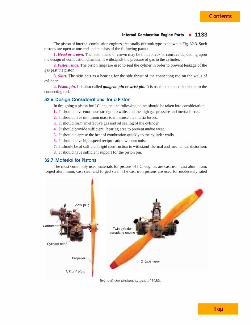
32.7 Material for PistonsThe most commonly used materials for pistons of I.C. engines are cast iron, cast aluminium,
forged aluminium, cast steel and forged steel. The cast iron pistons are used for moderately rated
Twin cylinder airplane engine of 1930s.
Spark plug
Carburettor
Cylinder head
Propeller
Twin-cylinderaeroplane engine
1. Front view
2. Side view
1134 A Textbook of Machine Design
engines with piston speeds below 6 m / s and aluminium alloy pistons are used for highly rated en-gines running at higher piston sppeds. It may be noted that
1. Since the *coefficient of thermal expansion for aluminium is about 2.5 times that of cast iron,therefore, a greater clearance must be provided between the piston and the cylinder wall (than withcast iron piston) in order to prevent siezing of the piston when engine runs continuously under heavyloads. But if excessive clearance is allowed, then the piston will develop ‘piston slap’ while it is coldand this tendency increases with wear. The less clearance between the piston and the cylinder wallwill lead to siezing of piston.
2. Since the aluminium alloys used for pistons have high **heat conductivity (nearly fourtimes that of cast iron), therefore, these pistons ensure high rate of heat transfer and thus keepsdown the maximum temperature difference between the centre and edges of the piston head orcrown.Notes: (a) For a cast iron piston, the temperature at the centre of the piston head (TC) is about 425°C to 450°Cunder full load conditions and the temperature at the edges of the piston head (TE) is about 200°C to 225°C.
(b) For aluminium alloy pistons, TC is about 260°C to 290°C and TE is about 185°C to 215°C.
3. Since the aluminium alloys are about ***three times lighter than cast iron, therfore, itsmechanical strength is good at low temperatures, but they lose their strength (about 50%) at temperaturesabove 325°C. Sometimes, the pistons of aluminium alloys are coated with aluminium oxide by anelectrical method.
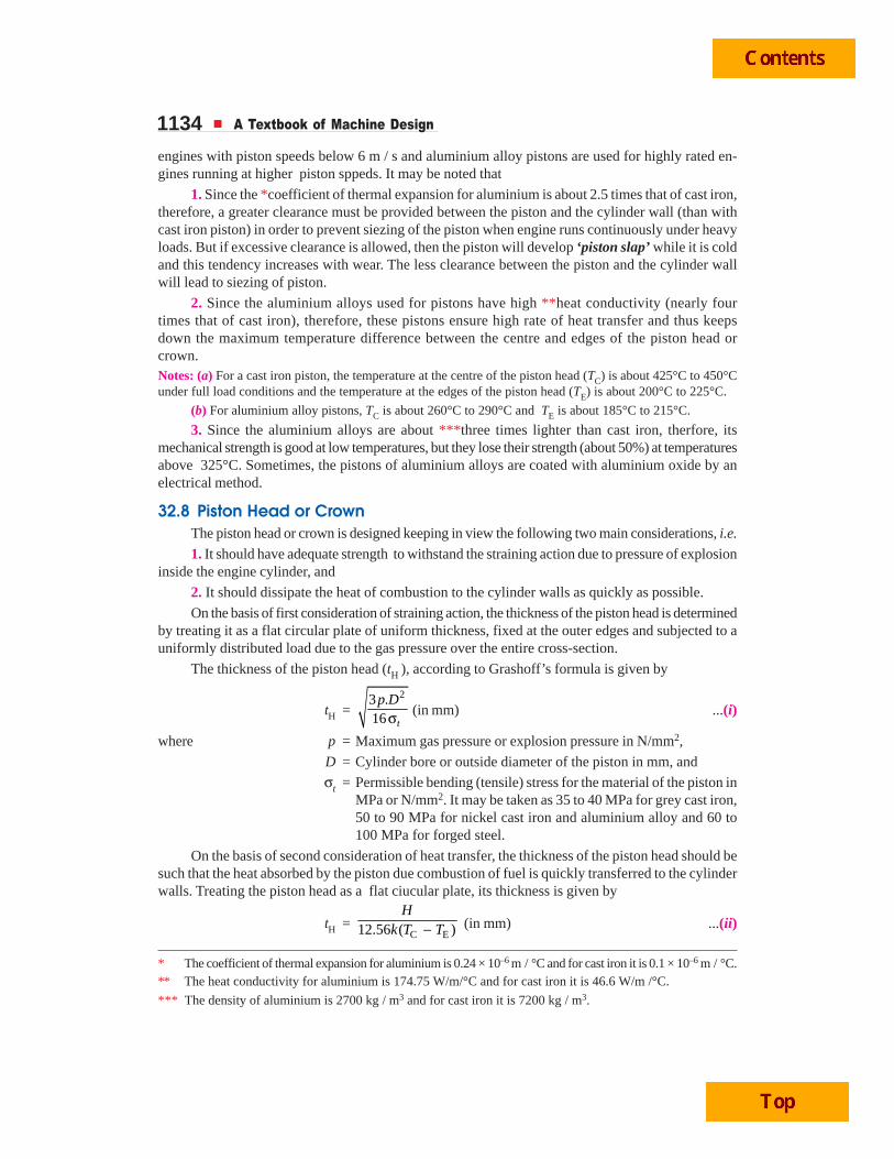
32.8 Piston Head or CrownThe piston head or crown is designed keeping in view the following two main considerations, i.e.
1. It should have adequate strength to withstand the straining action due to pressure of explosioninside the engine cylinder, and
2. It should dissipate the heat of combustion to the cylinder walls as quickly as possible.
On the basis of first consideration of straining action, the thickness of the piston head is determinedby treating it as a flat circular plate of uniform thickness, fixed at the outer edges and subjected to auniformly distributed load due to the gas pressure over the entire cross-section.
The thickness of the piston head (tH ), according to Grashoff’s formula is given by
tH =23 .
16 t
p Dσ (in mm) ...(i)
where p = Maximum gas pressure or explosion pressure in N/mm2,
D = Cylinder bore or outside diameter of the piston in mm, and
σt = Permissible bending (tensile) stress for the material of the piston inMPa or N/mm2. It may be taken as 35 to 40 MPa for grey cast iron,50 to 90 MPa for nickel cast iron and aluminium alloy and 60 to100 MPa for forged steel.
On the basis of second consideration of heat transfer, the thickness of the piston head should besuch that the heat absorbed by the piston due combustion of fuel is quickly transferred to the cylinderwalls. Treating the piston head as a flat ciucular plate, its thickness is given by
tH =C E12.56 ( )
Hk T T− (in mm) ...(ii)
* The coefficient of thermal expansion for aluminium is 0.24 × 10⁻⁶ m / °C and for cast iron it is 0.1 × 10⁻⁶ m / °C.** The heat conductivity for aluminium is 174.75 W/m/°C and for cast iron it is 46.6 W/m /°C.
*** The density of aluminium is 2700 kg / m3 and for cast iron it is 7200 kg / m3.
Internal Combustion Engine Parts 1135where H = Heat flowing through the piston head in kJ/s or watts,
k = Heat conductivity factor in W/m/°C. Its value is 46.6 W/m/°C forgrey cast iron, 51.25 W/m/°C for steel and 174.75 W/m/°C foraluminium alloys.
TC = Temperture at the centre of the piston head in °C, and
TE = Temperature at the edges of the piston head in °C.
The temperature difference (TC – TE) may be taken as 220°C for cast iron and 75°C for aluminium.
The heat flowing through the positon head (H) may be deternined by the following expression, i.e.,
H = C × HCV × m × B.P. (in kW)
where C = Constant representing that portion of the heat supplied to the enginewhich is absorbed by the piston. Its value is usually takenas 0.05.
HCV = Higher calorific value of the fuel in kJ/kg. It may be taken as45 × 103 kJ/kg for diesel and 47 × 103 kJ/ kg for petrol,
m = Mass of the fuel used in kg per brake power per second, and
B.P. = Brake power of the engine per cylinderNotes : 1. The thickness of the piston head (tH) is calculated by using equations (i) and (ii) and larger of the twovalues obtained should be adopted.
2. When tH is 6 mm or less, then no ribs are required to strengthen the piston head against gas loads. Butwhen tH is greater then 6 mm, then a suitable number of ribs at the centre line of the boss extending around theskirt should be provided to distribute the side thrust from the connecting rod and thus to prevent distortion of theskirt. The thickness of the ribs may be takes as tH / 3 to tH / 2.
3. For engines having length of stroke to cylinder bore (L / D) ratio upto 1.5, a cup is provided in the topof the piston head with a radius equal to 0.7 D. This is done to provide a space for combustion chamber.
32.9 Piston RingsThe piston rings are used to impart the necessary radial pressure to maintain the seal between
the piston and the cylinder bore. These are usually made of grey cast iron or alloy cast iron because oftheir good wearing properties and also they retain spring characteristics even at high temperatures.The piston rings are of the following two types :
1. Compression rings or pressure rings, and
2. Oil control rings or oil scraper.
The compression rings or pressure rings are inserted in the grooves at the top portion of thepiston and may be three to seven in number. These rings also transfer heat from the piston to thecylinder liner and absorb some part of the piston fluctuation due to the side thrust.
The oil control rings or oil scrapers are provided below the compression rings. These ringsprovide proper lubrication to the liner by allowing sufficient oil to move up during upward stroke andat the same time scraps the lubricating oil from the surface of the liner in order to minimise the flowof the oil to the combustion chamber.
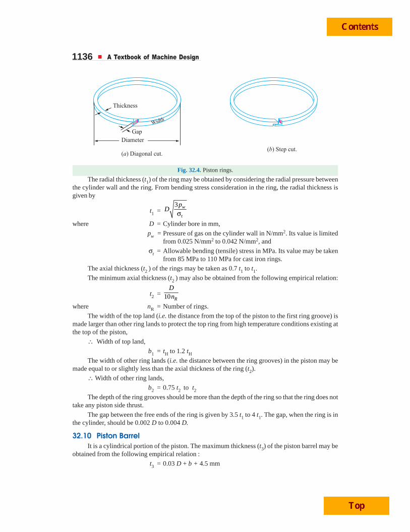
The compression rings are usually made of rectangular cross-section and the diameter of thering is slightly larger than the cylinder bore. A part of the ring is cut- off in order to permit it to go intothe cylinder against the liner wall. The diagonal cut or step cut ends, as shown in Fig. 32.4 (a) and (b)respectively, may be used. The gap between the ends should be sufficiently large when the ring is putcold so that even at the highest temperature, the ends do not touch each other when the ring expands,otherwise there might be buckling of the ring.
1136 A Textbook of Machine Design
Fig. 32.4. Piston rings.
The radial thickness (t1) of the ring may be obtained by considering the radial pressure betweenthe cylinder wall and the ring. From bending stress consideration in the ring, the radial thickness isgiven by
t1 =3 w
t
pD
σwhere D = Cylinder bore in mm,
pw = Pressure of gas on the cylinder wall in N/mm2. Its value is limitedfrom 0.025 N/mm2 to 0.042 N/mm2, and
σt = Allowable bending (tensile) stress in MPa. Its value may be takenfrom 85 MPa to 110 MPa for cast iron rings.
The axial thickness (t2 ) of the rings may be taken as 0.7 t1 to t1.
The minimum axial thickness (t2 ) may also be obtained from the following empirical relation:
t2 = 10 R
Dn
where nR = Number of rings.
The width of the top land (i.e. the distance from the top of the piston to the first ring groove) ismade larger than other ring lands to protect the top ring from high temperature conditions existing atthe top of the piston,
∴ Width of top land,
b1 = tH to 1.2 tHThe width of other ring lands (i.e. the distance between the ring grooves) in the piston may be
made equal to or slightly less than the axial thickness of the ring (t2).
∴ Width of other ring lands,
b2 = 0.75 t2 to t2The depth of the ring grooves should be more than the depth of the ring so that the ring does not
take any piston side thrust.
The gap between the free ends of the ring is given by 3.5 t1 to 4 t1. The gap, when the ring is inthe cylinder, should be 0.002 D to 0.004 D.
32.10 Piston BarrelIt is a cylindrical portion of the piston. The maximum thickness (t3) of the piston barrel may be
obtained from the following empirical relation :
t3 = 0.03 D + b + 4.5 mm
Internal Combustion Engine Parts 1137where b = Radial depth of piston ring groove which is taken as 0.4 mm larger
than the radial thickness of the piston ring (t1)
= t1 + 0.4 mm
Thus, the above relation may be written as
t3 = 0.03 D + t1 + 4.9 mm
The piston wall thickness (t4) towards the open end is decreased and should be taken as 0.25 t3to 0.35 t3.
32.11 Piston SkirtThe portion of the piston below the ring section is known as piston skirt. In acts as a bearing for
the side thrust of the connecting rod. The length of the piston skirt should be such that the bearingpressure on the piston barrel due to the side thrust does not exceed 0.25 N/mm2 of the projected areafor low speed engines and 0.5 N/mm2 for high speed engines. It may be noted that the maximumthrust will be during the expansion stroke. The side thrust (R) on the cylinder liner is usually taken as1/10 of the maximum gas load on the piston.
We know that maximum gas load on the piston,
P =2
4D
pπ×
∴ Maximum side thrust on the cylinder,
R = P/10 = 2
0.14D
pπ× ...(i)
where p = Maximum gas pressure in N/mm2, and
D = Cylinder bore in mm.
The side thrust (R) is also given by
R = Bearing pressure × Projected bearing area of the piston skirt
= pb × D × l
where l = Length of the piston skirt in mm. ...(ii)
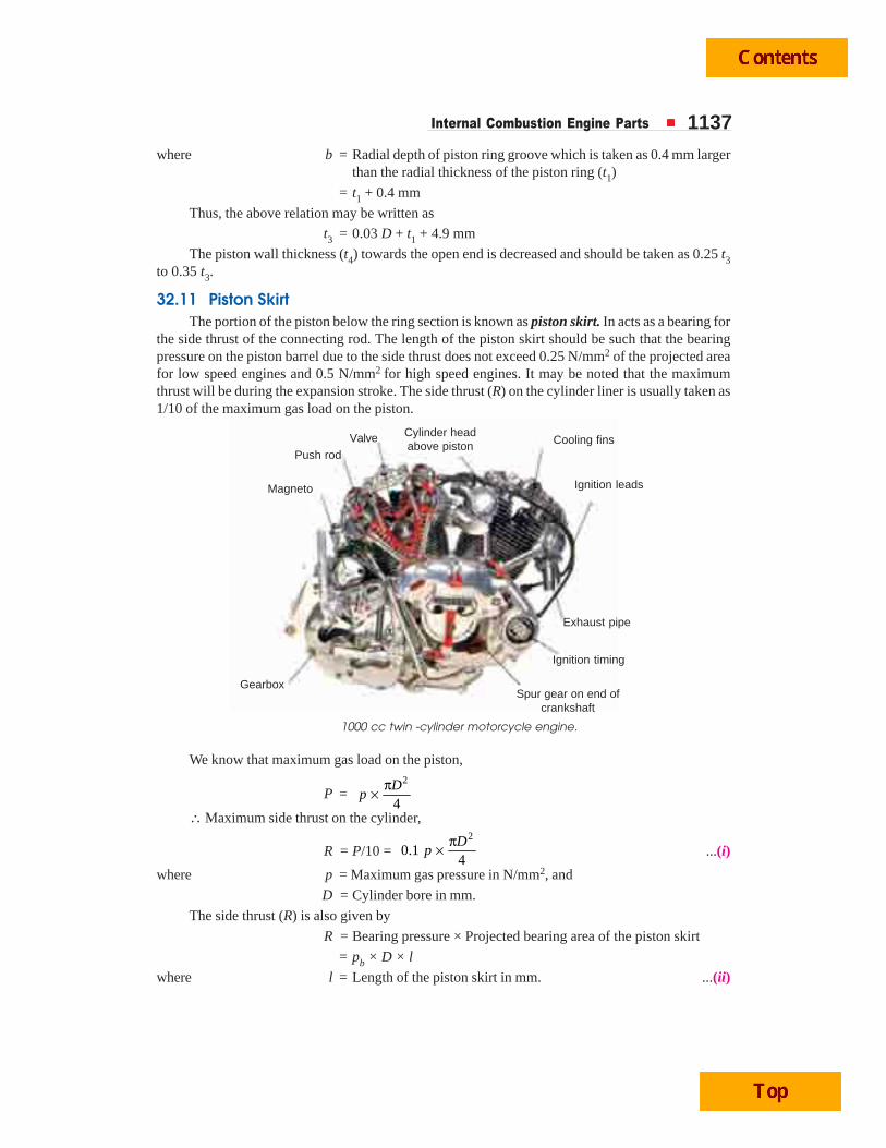
1000 cc twin -cylinder motorcycle engine.
Valve
Push rod
Magneto
Cylinder headabove piston Cooling fins
Ignition leads
Exhaust pipe
Ignition timing
Spur gear on end ofcrankshaft
Gearbox
1138 A Textbook of Machine Design
From equations (i) and (ii), the length of the piston skirt (l) is determined. In actual practice, thelength of the piston skirt is taken as 0.65 to 0.8 times the cylinder bore. Now the total length of thepiston (L) is given by
L = Length of skirt + Length of ring section + Top landThe length of the piston usually varies between D and 1.5 D. It may be noted that a longer piston
provides better bearing surface for quiet running of the engine, but it should not be made unnecessarilylong as it will increase its own mass and thus the inertiaforces.
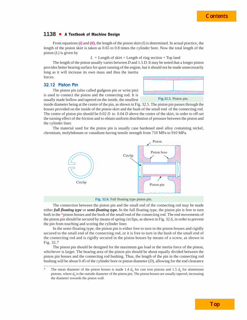
32.12 Piston PinThe piston pin (also called gudgeon pin or wrist pin)
is used to connect the piston and the connecting rod. It isusually made hollow and tapered on the inside, the smallestinside diameter being at the centre of the pin, as shown in Fig. 32.5. The piston pin passes through thebosses provided on the inside of the piston skirt and the bush of the small end of the connecting rod.The centre of piston pin should be 0.02 D to 0.04 D above the centre of the skirt, in order to off-setthe turning effect of the friction and to obtain uniform distribution of pressure between the piston andthe cylinder liner.
The material used for the piston pin is usually case hardened steel alloy containing nickel,chromium, molybdenum or vanadium having tensile strength from 710 MPa to 910 MPa.
Fig. 32.6. Full floating type piston pin.
The connection between the piston pin and the small end of the connecting rod may be madeeither full floating type or semi-floating type. In the full floating type, the piston pin is free to turnboth in the *piston bosses and the bush of the small end of the connecting rod. The end movements ofthe piston pin should be secured by means of spring circlips, as shown in Fig. 32.6, in order to preventthe pin from touching and scoring the cylinder liner.
In the semi-floating type, the piston pin is either free to turn in the piston bosses and rigidlysecured to the small end of the connecting rod, or it is free to turn in the bush of the small end ofthe connecting rod and is rigidly secured in the piston bosses by means of a screw, as shown inFig. 32.7
The piston pin should be designed for the maximum gas load or the inertia force of the piston,whichever is larger. The bearing area of the piston pin should be about equally divided between thepiston pin bosses and the connecting rod bushing. Thus, the length of the pin in the connecting rodbushing will be about 0.45 of the cylinder bore or piston diameter (D), allowing for the end clearance
Fig.32.5. Piston pin.
* The mean diameter of the piston bosses is made 1.4 d0 for cast iron pistons and 1.5 d0 for aluminiumpistons, where d0 is the outside diameter of the piston pin. The piston bosses are usually tapered, increasingthe diameter towards the piston wall.
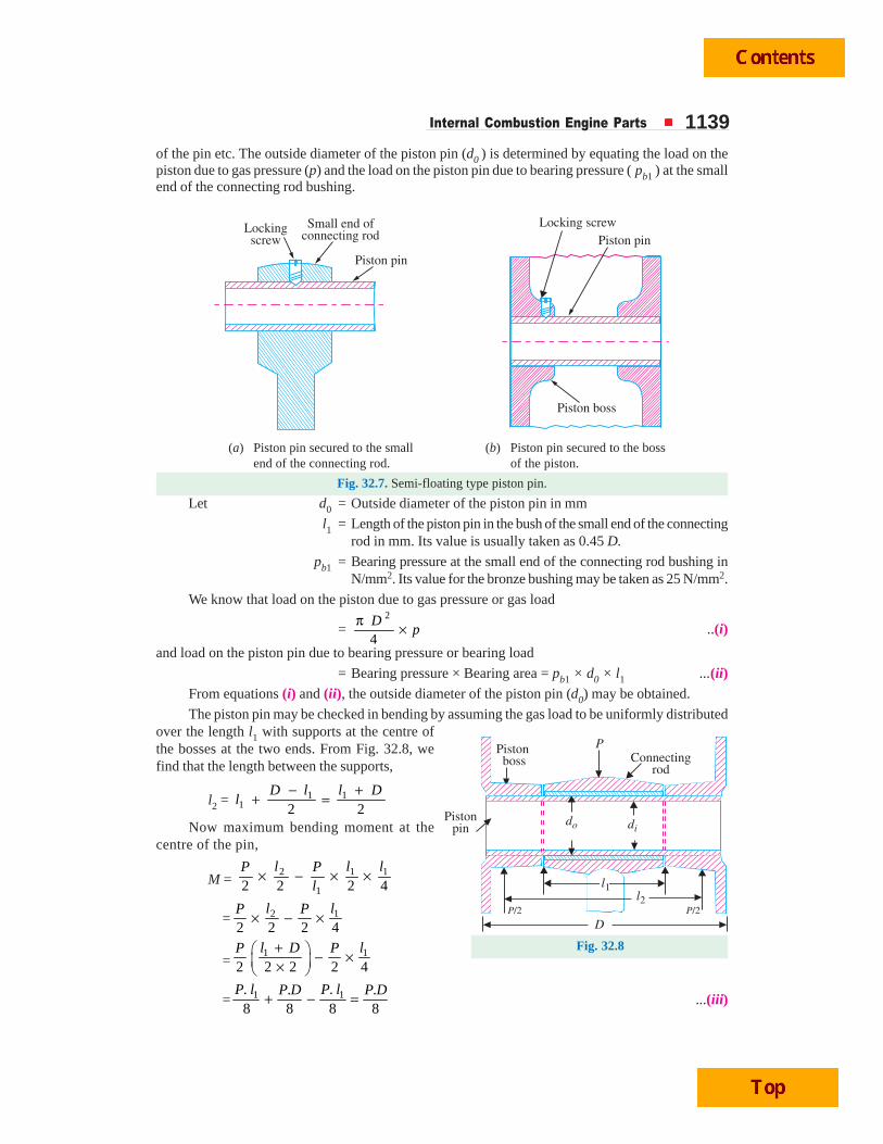
Internal Combustion Engine Parts 1139of the pin etc. The outside diameter of the piston pin (d0 ) is determined by equating the load on thepiston due to gas pressure (p) and the load on the piston pin due to bearing pressure ( pb1 ) at the smallend of the connecting rod bushing.
(a) Piston pin secured to the small (b) Piston pin secured to the bossend of the connecting rod. of the piston.
Fig. 32.7. Semi-floating type piston pin.
Let d0 = Outside diameter of the piston pin in mm
l1 = Length of the piston pin in the bush of the small end of the connectingrod in mm. Its value is usually taken as 0.45 D.
pb1 = Bearing pressure at the small end of the connecting rod bushing inN/mm2. Its value for the bronze bushing may be taken as 25 N/mm2.
We know that load on the piston due to gas pressure or gas load
=2
4D
pπ × ..(i)
and load on the piston pin due to bearing pressure or bearing load
= Bearing pressure × Bearing area = pb1 × d0 × l1 ...(ii)From equations (i) and (ii), the outside diameter of the piston pin (d0) may be obtained.
The piston pin may be checked in bending by assuming the gas load to be uniformly distributedover the length l1 with supports at the centre ofthe bosses at the two ends. From Fig. 32.8, wefind that the length between the supports,
l2 = 1 11 2 2
− ++ =
D l l Dl
Now maximum bending moment at thecentre of the pin,
M = 2 1 1
12 2 2 4× − × ×
l l lP Pl
= 2 1
2 2 2 4× − ×
l lP P
=1 1
2 2 2 2 4+⎛ ⎞ − ×⎜ ⎟×⎝ ⎠
l D lP P
= 1 1. .. .8 8 8 8
+ − =P l P lP D P D
...(iii)
Fig. 32.8
1140 A Textbook of Machine Design
We have already discussed that the piston pin is made hollow. Let d0 and di be the outside andinside diameters of the piston pin. We know that the section modulus,
Z =4 4
0
0
( ) ( )32
⎡ ⎤−π⎢ ⎥⎢ ⎥⎣ ⎦
id dd
We know that maximum bending moment,
M =4 4
0
0
( ) ( )32
⎡ ⎤−π× σ = σ⎢ ⎥⎢ ⎥⎣ ⎦
ib b
d dZ
d
where bσ = Allowable bending stress for the material of the piston pin. It is
usually taken as 84 MPa for case hardened carbon steel and140 MPa for heat treated alloy steel.
Assuming di = 0.6 d0, the induced bending stress in the piston pin may be checked.
Example 32.2. Design a cast iron piston for a single acting four stroke engine for the followingdata:
Cylinder bore = 100 mm ; Stroke = 125 mm ; Maximum gas pressure = 5 N/mm2 ; Indicatedmean effective pressure = 0.75 N/mm2 ; Mechanical efficiency = 80% ; Fuel consumption = 0.15 kgper brake power per hour ; Higher calorific value of fuel = 42 × 103 kJ/kg ; Speed = 2000 r.p.m.
Any other data required for the design may be assumed.
Solution. Given : D = 100 mm ; L = 125 mm = 0.125 m ; p = 5 N/mm2 ; pm = 0.75 N/mm2;
mη = 80% = 0.8 ; m = 0.15 kg / BP / h = 41.7 × 10⁻⁶ kg / BP / s; HCV = 42 × 103 kJ / kg ;
N = 2000 r.p.m.
The dimensions for various components of the piston are determined as follows :
1. Piston head or crownThe thickness of the piston head or crown is determined on the basis of strength as well as on the
basis of heat dissipation and the larger of the two values is adopted.
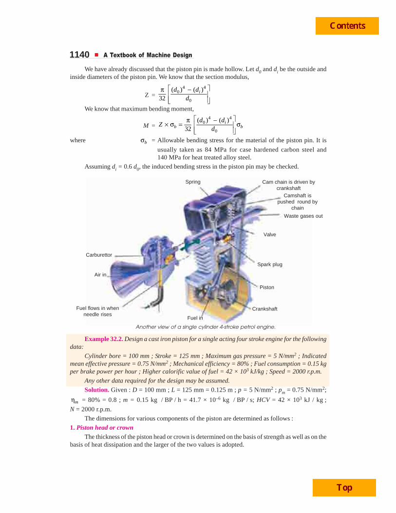
Another view of a single cylinder 4-stroke petrol engine.
Camshaft ispushed round by
chain
Cam chain is driven bycrankshaft
Waste gases out
Valve
Spark plug
Piston
CrankshaftFuel flows in whenneedle rises
Carburettor
Fuel in
Air in
Spring
Internal Combustion Engine Parts 1141We know that the thickness of piston head on the basis of strength,
tH = 2 23 . 3 5(100)
16 16 38t
p D ×=σ × = 15.7 say 16 mm
...(Taking tσ for cast iron = 38 MPa = 38 N/mm2)
Since the engine is a four stroke engine, therefore, the number of working strokes per minute,
n = N / 2 = 2000 / 2 = 1000
and cross-sectional area of the cylinder,
A =2 2
2(100)7855 mm
4 4Dπ π= =
We know that indicated power,
IP =. . . 0.75 0.125 7855 1000
12 270 W60 60
mp L A n × × ×= =
= 12.27 kW
∴ Brake power, BP = IP × mη = 12.27 × 0.8 = 9.8 kW ...(Q mη = BP / IP)
We know that the heat flowing through the piston head,
H = C × HCV × m × BP
= 0.05 × 42 × 103 × 41.7 × 10–6 × 9.8 = 0.86 kW = 860 W....(Taking C = 0.05)
∴Thickness of the piston head on the basis of heat dissipation,
tH =C E
8600.0067 m 6.7 mm
12.56 ( ) 12.56 46.6 220H
k T T= = =
− × ×...(Q For cast iron , k = 46.6 W/m/°C, and TC – TE = 220°C)
Taking the larger of the two values, we shall adopt
tH = 16 mm Ans.Since the ratio of L / D is 1.25, therefore a cup in the top of the piston head with a radius equal
to 0.7 D (i.e. 70 mm) is provided.
2. Radial ribsThe radial ribs may be four in number. The thickness of the ribs varies from tH / 3 to tH / 2.
∴ Thickness of the ribs, tR = 16 / 3 to 16 / 2 = 5.33 to 8 mm
Let us adopt tR = 7 mm Ans.3. Piston rings
Let us assume that there are total four rings (i.e. nr = 4) out of which three are compression ringsand one is an oil ring.
We know that the radial thickness of the piston rings,
t1 =3 3 0.035
100 3.490
w
t
pD
×= =σ
mm
...(Taking pw = 0.035 N/mm2, and tσ = 90 MPa)
and axial thickness of the piston rings
t2 = 0.7 t1 to t1 = 0.7 × 3.4 to 3.4 mm = 2.38 to 3.4 mm
Let us adopt t2 = 3 mm
1142 A Textbook of Machine Design
We also know that the minimum axial thickness of the pistion ring,
t2 =100
2.5 mm10 10 4
= =×r
Dn
Thus the axial thickness of the piston ring as already calculated (i.e. t2 = 3 mm)is satisfactory. Ans.The distance from the top of the piston to the first ring groove, i.e. the width of the top land,
b1 = tH to 1.2 tH = 16 to 1.2 × 16 mm = 16 to 19.2 mm
and width of other ring lands,
b2 = 0.75 t2 to t2 = 0.75 × 3 to 3 mm = 2.25 to 3 mm
Let us adopt b1 = 18 mm ; and b2 = 2.5 mm Ans.We know that the gap between the free ends of the ring,
G1 = 3.5 t1 to 4 t1 = 3.5 × 3.4 to 4 × 3.4 mm = 11.9 to 13.6 mm
and the gap when the ring is in the cylinder,
G2 = 0.002 D to 0.004 D = 0.002 × 100 to 0.004 × 100 mm
= 0.2 to 0.4 mm
Let us adopt G1 = 12.8 mm ; and G2 = 0.3 mm Ans.4. Piston barrel
Since the radial depth of the piston ring grooves (b) is about 0.4 mm more than the radialthickness of the piston rings (t1), therefore,
b = t1 + 0.4 = 3.4 + 0.4 = 3.8 mm
We know that the maximum thickness of barrel,
t3 = 0.03 D + b + 4.5 mm = 0.03 × 100 + 3.8 + 4.5 = 11.3 mm
and piston wall thickness towards the open end,
t4 = 0.25 t3 to 0.35 t3 = 0.25 × 11.3 to 0.35 × 11.3 = 2.8 to 3.9 mm
Let us adopt t4 = 3.4 mm
5. Piston skirtLet l = Length of the skirt in mm.
We know that the maximum side thrust on the cylinder due to gas pressure ( p ),
R =2 2(100)
0.1 5 3928 N4 4D
pπ πμ × × = × × =
...(Taking μ = 0.1)We also know that the side thrust due to bearing pressure on the piston barrel ( pb ),
R = pb × D × l = 0.45 × 100 × l = 45 l N...(Taking pb = 0.45 N/mm2)
From above, we find that45 l = 3928 or l = 3928 / 45 = 87.3 say 90 mm Ans.
∴ ∴ ∴ ∴ ∴ Total length of the piston ,L = Length of the skirt + Length of the ring section + Top land
= l + (4 t2 + 3b2) + b1
= 90 + (4 × 3 + 3 × 3) + 18 = 129 say 130 mm Ans.6. Piston pin
Let d0 = Outside diameter of the pin in mm,l1 = Length of pin in the bush of the small end of the connecting rod in
mm, and
Internal Combustion Engine Parts 1143pb1 = Bearing pressure at the small end of the connecting rod bushing in
N/mm2. It value for bronze bushing is taken as 25 N/mm2.We know that load on the pin due to bearing pressure
= Bearing pressure × Bearing area = pb1 × d0 × l1= 25 × d0 × 0.45 × 100 = 1125 d0 N ...(Taking l1 = 0.45 D)
We also know that maximum load on the piston due to gas pressure or maximum gas load2 2(100)
5 39 275 N4 4D
pπ π= × = × =
From above, we find that
1125 d0 = 39 275 or d0 = 39 275 / 1125 = 34.9 say 35 mm Ans.The inside diameter of the pin (di) is usually taken as 0.6 d0.
∴ di = 0.6 × 35 = 21 mm Ans.
Let the piston pin be made of heat treated alloy steel for which the bending stress ( bσ )may betaken as 140 MPa. Now let us check the induced bending stress in the pin.
We know that maximum bending moment at the centre of the pin,
M = 3. 39 275 100491 10
8 8P D ×= = × N-mm
We also know that maximum bending moment (M),
491 × 103 =4 4 4 4
0
0
( ) ( ) (35) (21)3664
32 32 35i
b b bd d
d
⎡ ⎤ ⎡ ⎤−π π −σ = σ = σ⎢ ⎥ ⎢ ⎥⎢ ⎥ ⎣ ⎦⎣ ⎦
∴ bσ = 491 × 103 / 3664 = 134 N/mm2 or MPa
Since the induced bending stress in the pin is less than the permissible value of 140 MPa (i.e.140 N/mm2), therefore, the dimensions for the pin as calculated above (i.e. d0 = 35 mm and di = 21 mm)are satisfactory.
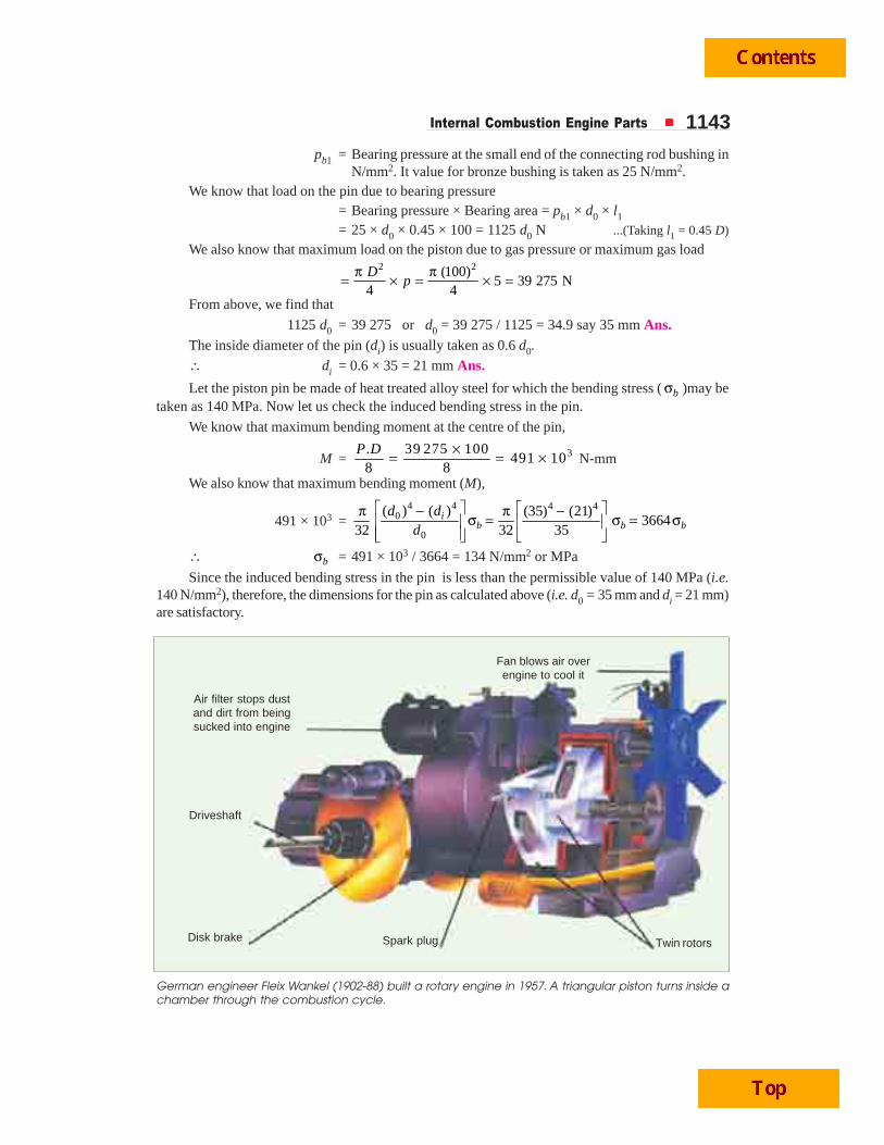
Air filter stops dustand dirt from beingsucked into engine
German engineer Fleix Wankel (1902-88) built a rotary engine in 1957. A triangular piston turns inside achamber through the combustion cycle.
Driveshaft
Disk brake Spark plug Twin rotors
Fan blows air overengine to cool it
Related Documents