EFFICIENCY OF A NEW INTERNAL COMBUSTION ENGINE CONCEPT WITH VARIABLE PISTON MOTION by Jovan . DORI] * and Ivan J. KLINAR Chair for Engines and Motor Vehicles, Faculty of Technical Sciences, University of Novi Sad, Novi Sad, Serbia Original scientific paper DOI: 10.2298/TSCI110923020D This paper presents simulation of working process in a new internal combustion en- gine concept. The main feature of this new internal combustion engine concept is the realization of variable movement of the piston. With this unconventional piston movement it is easy to provide variable compression ratio, variable displacement and combustion during constant volume. These advantages over standard piston mechanism are achieved through synthesis of the two pairs of non-circular gears. Presented mechanism is designed to obtain a specific motion law which provides better fuel consumption of internal combustion engines. For this paper Ricardo/WAVE software was used, which provides a fully integrated treatment of time-dependent fluid dynamics and thermodynamics by means of 1-D formulation. The results obtained herein include the efficiency characteristic of this new heat en- gine concept. The results show that combustion during constant volume, variable compression ratio and variable displacement have significant impact on improve- ment of fuel consumption. Key words: simulation, variable compression, variable displacement, constant volume combustion Introduction The internal combustion (IC) engine is the favoured propulsion system for passanger and freight traffic. A significant reduction of CO 2 emission in mobility sector is a major chal- lenge for the next years. Global concerns on the limitation of energy and reduction of the CO 2 emission force automotive engineers to develop more energy efficient and environmentally friendly alternative powertrain technologies. Considering the present development trends, trends for more efficient use of fuel resources and the well known problem of global warming and other environmental factors, development of IC engines will certainly move towards the re- duction of fuel consumption. In this paper one of the possible ways of reducing thermodynamic losses in the IC engine is shown. Relatively low efficiency of today`s internal combustion engine is the consequence of several factors. First, ordinary spark ignition (SI) IC engines during running at low loads have their thermal efficiency reduced due to the effect of the throttle valve that controls the engine load and by the fact that the compression starts at low pressure [1]. Under part load conditions, engines use some of the work to pump air across the partially closed throttle valve. One of the possible solutions for improving efficiency at part load is to reduce the stroke volume by selec- tively shutting of several cylinders of an engine at the part load conditions. As early as 1916, the Dori}, J. @., Klinar, I. J.: Efficiency of a New Internal Combustion Engine ... THERMAL SCIENCE: Year 2014, Vol. 18, No. 1, pp. 113-127 113 * Corresponding author; e-mail: [email protected]

Welcome message from author
This document is posted to help you gain knowledge. Please leave a comment to let me know what you think about it! Share it to your friends and learn new things together.
Transcript
EFFICIENCY OF A NEW INTERNAL COMBUSTION ENGINECONCEPT WITH VARIABLE PISTON MOTION
by
Jovan �. DORI] * and Ivan J. KLINAR
Chair for Engines and Motor Vehicles, Faculty of Technical Sciences,University of Novi Sad, Novi Sad, Serbia
Original scientific paperDOI: 10.2298/TSCI110923020D
This paper presents simulation of working process in a new internal combustion en-gine concept. The main feature of this new internal combustion engine concept isthe realization of variable movement of the piston. With this unconventional pistonmovement it is easy to provide variable compression ratio, variable displacementand combustion during constant volume. These advantages over standard pistonmechanism are achieved through synthesis of the two pairs of non-circular gears.Presented mechanism is designed to obtain a specific motion law which providesbetter fuel consumption of internal combustion engines. For this paperRicardo/WAVE software was used, which provides a fully integrated treatment oftime-dependent fluid dynamics and thermodynamics by means of 1-D formulation.The results obtained herein include the efficiency characteristic of this new heat en-gine concept. The results show that combustion during constant volume, variablecompression ratio and variable displacement have significant impact on improve-ment of fuel consumption.
Key words: simulation, variable compression, variable displacement,constant volume combustion
Introduction
The internal combustion (IC) engine is the favoured propulsion system for passanger
and freight traffic. A significant reduction of CO2 emission in mobility sector is a major chal-
lenge for the next years. Global concerns on the limitation of energy and reduction of the CO2
emission force automotive engineers to develop more energy efficient and environmentally
friendly alternative powertrain technologies. Considering the present development trends,
trends for more efficient use of fuel resources and the well known problem of global warming
and other environmental factors, development of IC engines will certainly move towards the re-
duction of fuel consumption. In this paper one of the possible ways of reducing thermodynamic
losses in the IC engine is shown.
Relatively low efficiency of today`s internal combustion engine is the consequence of
several factors. First, ordinary spark ignition (SI) IC engines during running at low loads have
their thermal efficiency reduced due to the effect of the throttle valve that controls the engine
load and by the fact that the compression starts at low pressure [1]. Under part load conditions,
engines use some of the work to pump air across the partially closed throttle valve. One of the
possible solutions for improving efficiency at part load is to reduce the stroke volume by selec-
tively shutting of several cylinders of an engine at the part load conditions. As early as 1916, the
Dori}, J. @., Klinar, I. J.: Efficiency of a New Internal Combustion Engine ...THERMAL SCIENCE: Year 2014, Vol. 18, No. 1, pp. 113-127 113
* Corresponding author; e-mail: [email protected]
potential of using a variable displacement engine to increase the fuel efficiency at part load con-
ditions was known and tested. This means that instead of reducing the air-fuel mixture charge by
the throttle valve at part load conditions, the stroke volume of the engine is reduced by disabling
some of the working cylinders [2]. Also, the compression ratio of the engine should be varied ac-
cording to the load and speed conditions in order to improve efficiency [3-5].
Conventional IC engines are based on a relatively simple solution to achieve a thermo-
dynamic cycle while providing mechanical power. While the performance, emissions, and reli-
ability of IC engines have been improved significantly, the fundamental principle of
crank-rod-piston slider mechanism still remains largely unaltered. In theory, the most efficient
thermodynamic cycle for IC engines is the Otto cycle [6], which consists of isentropic compres-
sion and expansion processes and constant volume heat addition and rejection processes [7, 8].
It is generally known that the most important parts of the cycle which determine the efficiency
are the constant volume heat addition at high compression ratios [9, 10]. This fact provides the
highest thermal potential of the various possible thermodynamic cycles which are suitable for
IC engines, and the subsequent expansion process, which converts the thermal potential into
work. In reality, neither conventional spark ignition nor compression ignition or even the mod-
ern developed homogeneous charge compression ignition or controlled auto ignition combus-
tion processes, can achieve the efficiency level suggested by the ideal thermodynamic cycles
[11]. Only the Otto cycle delivers theoretical maximum thermal efficiency. The traditional de-
sign of internal combustion engines using a simple slide-crank mechanism gives no time for a
constant volume combustion which significantly reduces the cycle efficiency [11].
Variable displacement and variable compression engines are gaining attention by sci-
entist and automobile manufactures because of their fuel consumption economy advantage. One
of the successfully constructed IC engine with variable compression ratio is certainly made by
SAAB [1]. In conventional IC engines the load regulation is balanced by throttling the intake
mixture [6]. Variable displacement concepts have been analyzed in many different scientific
publications. Siewart [12] reported a fuel economy approaching 20% for variable stroke engines
over fixed stroke engines. Also there is a several patents about mechanisms which provides vari-
able stroke, one of them are patented by Freudenstein and Maki [13]. Several authors [14-16]
have proposed different complex mechanisms to achieve variable displacement engine. In the
paper of Yamin and Dado [17] was investigated the effect of a variable stroke mechanism on the
engine performance, the conclusion showed that the engine performance was improved with
this novel design. Also Pouliot et al. [18], proposed, constructed and studied a five-cylinder,
four-bar linkage engine and Filipi and Assanis [19] theoretically, investigated the effect of vary-
ing the stroke length on a homogeneous charge engine's combustion, heat transfer and effi-
ciency using gasoline as fuel. Wong et al. [20] presented and analyzed a four cylinder engine
with Alvar cycle that utilizes secondary pistons and auxiliary chambers.
On the basis of these references a further step made in this paper is to make analysis of
a new engine concept which is able to make variable piston motion. Variable piston motion
(VPM) IC engine [21] is not only able to provide variable compression ratio and displacement
but also with this concept it is easy to achieve dwell angle at top dead center (TDC) and bottom
dead center (BDC). With piston dwell at bottom dead point more complete expansion can also
be achieved. In this paper was used Ricardo/WAVE software to obtaining the improvement be-
tween this new cycle and the standard Otto cycle. Also in this paper was presented basic descrip-
tion of the new engine that will be able to realize thermodynamic cycle with increased effi-
ciency.
Dori}, J. @., Klinar, I. J.: Efficiency of a New Internal Combustion Engine ...114 THERMAL SCIENCE: Year 2014, Vol. 18, No. 1, pp. 113-127
Variable piston motion IC engine
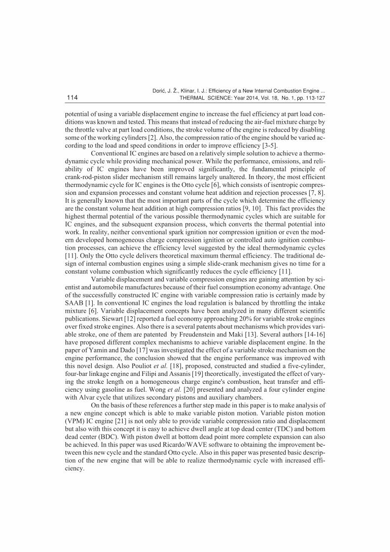
In the following section will be presented basic parts and shape of a new IC engine
concept. VPM IC engine is presented on the fig. 1. As can be seen from the described illustration
toroidal piston make a movement conditioned by the mechanism consisting of two pairs of
non-circular gears. In this article will not be presented detailed description of this concept, since
it is not the intention of the authors to propose a kinematic analysis of a new internal combustion
engine design but only thermodynamic features and advantages over ordinary spark ignition en-
gines.
VPM IC engine has a two pairs of non-circular gears (NCG). A NCG is a special gear
design with special characteristics and purpose. While a regular gear is optimized to transmit
torque to another engaged member with minimum noise and wear and with maximum effi-
ciency, a non-circular gear's main objective might be ratio variations, axle displacement oscilla-
tions and more. In fact this feature of NCG is very important for synthesis of mechanism where
is intermittent-motion required. This intermittent-motion mechanism combines circular gears
with non-circular gears in a planetary arrangement. With such planetary differential gear it is
possible to achieve very complex movement, where toroidal piston is able to provide motion
with variable displacement and variable compression, also because of the characteristics of
NCG, piston dwell at TDC and BDC is also feasible.
Dwell time or dwell angle is important fact during combustion process. In conven-
tional engine this dwell angle can be changed due to variations of ratio between connecting rod
and crank radius. Piston dwell at TDC and at BDC are often mentioned, it should be noted that
strictly, there is no dwell period in ordinary mechanism. The piston comes to rest at precisely the
crank angle that the crank and rod are in line (TDC and BDC), and is moving at all other crank
angles. At crank angles which are very close to the TDC and BDC angles, the piston is moving
slowly. It is this slow movement in the vicinity of TDC and BDC that give rise to the term piston
dwell. If the piston dwells longer near TDC and ignition is initiated properly, there will actually
be a longer period of time for the pressure created during combustion to press against the top of
the piston. This process occurs within the engine and its part of the thermodynamic cycle of the
Dori}, J. @., Klinar, I. J.: Efficiency of a New Internal Combustion Engine ...THERMAL SCIENCE: Year 2014, Vol. 18, No. 1, pp. 113-127 115
Figure 1. Basic parts of VPM ICengine [21]1 – engine block, 2 – engine head,3 – toroidal piston, 4 – intakemanifold, 5 – exhaust manifold, 6 –camshaft, 7 – valve, 8 – valvespring, 9 – housing, 10 – flywheel,11, 12, 13, 14 – non-circular gears,15, 16 – stepper motors, 17 –crankcase
device. In all IC engine useful work is generated from the hot, gaseous products of combustion
acting directly on moving surfaces of the engine, such as the top of a piston. This moving bound-
ary of combustion chamber is the focus of this paper. In generally moving of the piston is re-
sponsible for the volume changing during process of combustion. In this paper was presented IC
engine where this boundary, i. e. top of the piston, actually not moving in a large portion of heat
addition.
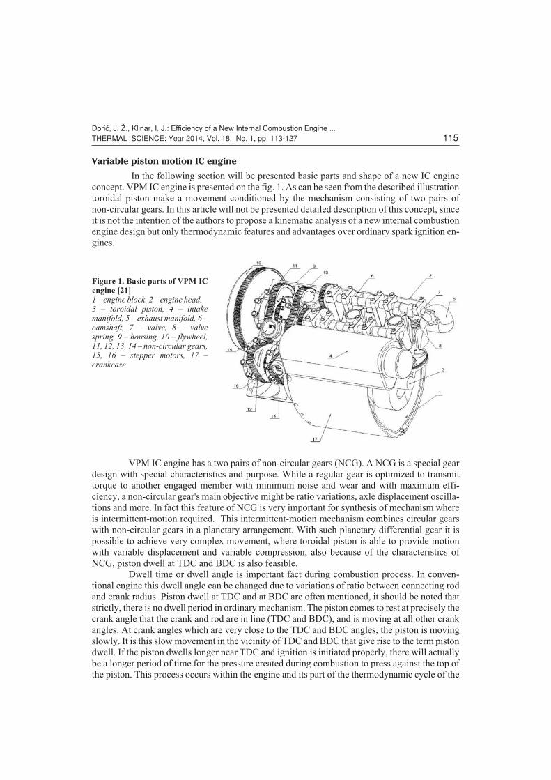
The four stroke spark SI engine pressure-volume diagram (p-V) contains two main
parts. They are the compression-combustion-expansion (high pressure loop) and the exhaust-in-
take (low pressure or gas exchange loop) parts. The main reason for efficiency decrease at part
load conditions for these types of engines is the flow restriction at the cross-sectional area of the
intake system by partially closing the throttle valve, which leads to increased pumping losses
and to increased low pressure loop area on the P-V diagram. Meanwhile, the poorer combustion
quality, i. e. lower combustion speed and cycle to cycle variations, additionally influence these
pressure loop areas, illustrated in detail on fig. 2.
Cylinder deactivation is initialized by cutting off the fuel supply to the selected cylin-
ders. There are also several systems that shut off the valves of the deactivated cylinders too. In
these systems, the reduction in pumping losses is more than that achieved by cutting off the fuel
supply only [22]. In this study, methods for increasing efficiency at part load conditions and
their potential for practical use are also investigated, in fact in this article was examined case
where classical approach of engine throttling was replaced with variable displacement piston
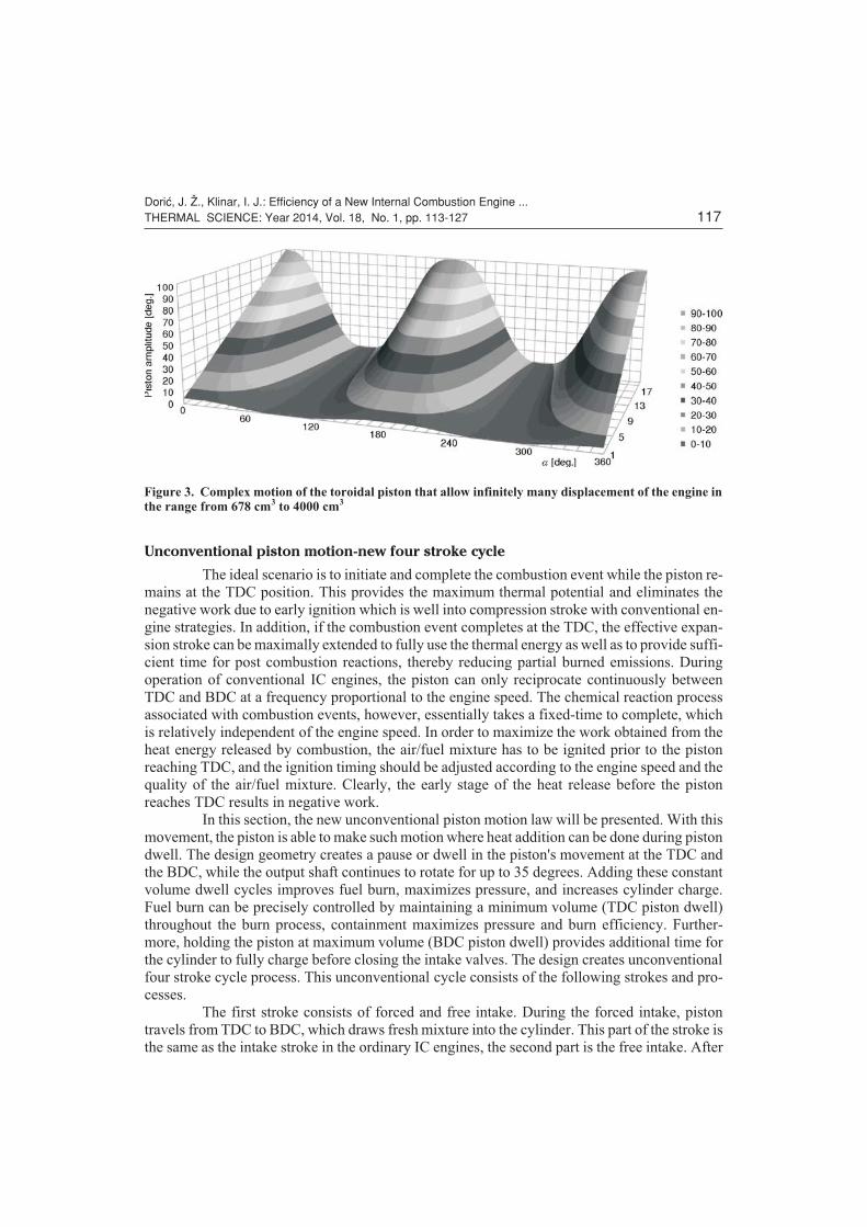
motion. In fig. 3 is presented piston motion law that was used for simulation of working pro-
cesses in variable piston motion IC engine.
Dori}, J. @., Klinar, I. J.: Efficiency of a New Internal Combustion Engine ...116 THERMAL SCIENCE: Year 2014, Vol. 18, No. 1, pp. 113-127
Figure 2. Schematic comparison of gross, pumping, net IMEP and their effect on indicated efficiency inhigh and low load conditions in SI engines [2]
Unconventional piston motion-new four stroke cycle
The ideal scenario is to initiate and complete the combustion event while the piston re-
mains at the TDC position. This provides the maximum thermal potential and eliminates the
negative work due to early ignition which is well into compression stroke with conventional en-
gine strategies. In addition, if the combustion event completes at the TDC, the effective expan-
sion stroke can be maximally extended to fully use the thermal energy as well as to provide suffi-
cient time for post combustion reactions, thereby reducing partial burned emissions. During
operation of conventional IC engines, the piston can only reciprocate continuously between
TDC and BDC at a frequency proportional to the engine speed. The chemical reaction process
associated with combustion events, however, essentially takes a fixed-time to complete, which
is relatively independent of the engine speed. In order to maximize the work obtained from the
heat energy released by combustion, the air/fuel mixture has to be ignited prior to the piston
reaching TDC, and the ignition timing should be adjusted according to the engine speed and the
quality of the air/fuel mixture. Clearly, the early stage of the heat release before the piston
reaches TDC results in negative work.
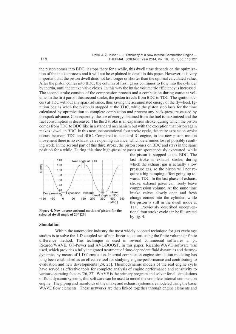
In this section, the new unconventional piston motion law will be presented. With this
movement, the piston is able to make such motion where heat addition can be done during piston
dwell. The design geometry creates a pause or dwell in the piston's movement at the TDC and
the BDC, while the output shaft continues to rotate for up to 35 degrees. Adding these constant
volume dwell cycles improves fuel burn, maximizes pressure, and increases cylinder charge.
Fuel burn can be precisely controlled by maintaining a minimum volume (TDC piston dwell)
throughout the burn process, containment maximizes pressure and burn efficiency. Further-
more, holding the piston at maximum volume (BDC piston dwell) provides additional time for
the cylinder to fully charge before closing the intake valves. The design creates unconventional
four stroke cycle process. This unconventional cycle consists of the following strokes and pro-
cesses.
The first stroke consists of forced and free intake. During the forced intake, piston
travels from TDC to BDC, which draws fresh mixture into the cylinder. This part of the stroke is
the same as the intake stroke in the ordinary IC engines, the second part is the free intake. After
Dori}, J. @., Klinar, I. J.: Efficiency of a New Internal Combustion Engine ...THERMAL SCIENCE: Year 2014, Vol. 18, No. 1, pp. 113-127 117
Figure 3. Complex motion of the toroidal piston that allow infinitely many displacement of the engine inthe range from 678 cm
3to 4000 cm
3
the piston comes into BDC, it stops there for a while, this dwell time depends on the optimiza-
tion of the intake process and it will not be explained in detail in this paper. However, it is very
important that the piston dwell does not last longer or shorter than the optimal calculated value.
After the piston comes into BDC, the column of fresh gases continues to flow into the cylinder
by inertia, until the intake valve closes. In this way the intake volumetric efficiency is increased.
The second stroke consists of the compression process and a combustion during constant vol-
ume. In the first part of this second stroke, the piston travels from BDC to TDC. The ignition oc-
curs at TDC without any spark advance, thus saving the accumulated energy of the flywheel. Ig-
nition begins when the piston is stopped at the TDC, while the piston stop lasts for the time
calculated by optimization to complete combustion and prevent any back-pressure caused by
the spark advance. Consequently, the use of energy obtained from the fuel is maximized and the
fuel consumption is decreased. The third stroke is an expansion stroke, during which the piston
comes from TDC to BDC like in a standard mechanism but with the exception that piston again
makes a dwell in BDC. In this new unconventional four stroke cycle, the entire expansion stroke
occurs between TDC and BDC. Compared to standard IC engine, in the new piston motion
movement there is no exhaust valve opening advance, which determines loss of possibly result-
ing work. In the second part of this third stroke, the piston comes on BDC and stays in the same
position for a while. During this time high-pressure gases are spontaneously evacuated, while
the piston is stopped at the BDC. The
last stroke is exhaust stroke, during
which the exhaust gas is actually a low
pressure gas, so the piston will not re-
quire a big pumping effort going up to-
wards TDC. In the last phase of exhaust
stroke, exhaust gases can freely leave
compression volume. At the same time
intake valves slowly open and fresh
charge comes into the cylinder, while
the piston is still in the dwell mode at
TDC. Previously described unconven-
tional four stroke cycle can be illustrated
by fig. 4.
Simulation
Within the automotive industry the most widely adopted technique for gas exchange
studies is to solve the 1-D coupled set of non-linear equations using the finite volume or finite
difference method. This technique is used in several commercial softwares e. g.,
Ricardo/WAVE, GT-Power and AVL/BOOST. In this paper, Ricardo/WAVE software was
used, which provides a fully integrated treatment of time-dependent fluid dynamics and thermo-
dynamics by means of 1-D formulation. Internal combustion engine simulation modeling has
long been established as an effective tool for studying engine performance and contributing to
evaluation and new developments [24, 25]. Thermodynamic models of the real engine cycle
have served as effective tools for complete analysis of engine performance and sensitivity to
various operating factors [26, 27]. WAVE is the primary program and solver for all simulations
of fluid dynamic systems, this software can be used to model the complete internal combustion
engine. The piping and manifolds of the intake and exhaust systems are modeled using the basic
WAVE flow elements. These networks are then linked together through engine elements and
Dori}, J. @., Klinar, I. J.: Efficiency of a New Internal Combustion Engine ...118 THERMAL SCIENCE: Year 2014, Vol. 18, No. 1, pp. 113-127
Figure 4. New unconventional motion of piston for theselected dwell angle of 20° [23]
sub-models, which have been calibrated to provide accurate driving inputs for the intake and ex-
haust pressure-wave dynamics.
The details of the flow (as calculated in the flow network) are obtained as a solution of
quasi-one dimensional compressible flow equations governing the conservation of mass, mo-
mentum and energy-eq. (1-3). The flow network of both conventional and unconventional pis-
ton movement is discretized into a series of small volumes and the governing equations are then
written in a finite difference form for each of these elementary volumes. A staggered mesh sys-
tem is used, with equations of mass and energy solved for each volume and the momentum equa-
tion solved for each boundary between volumes. The equations are written in an explicitly con-
servative form as:
– mass continuity equationd
dflux
m
tm
boundaries
� � (1)
– conservation of momentum equation
d m
t
PA m u
x
Cu xA
DC
boundaries
f( )
( )flux
flux
d
d
d
d
�� �
�
�42
2rP u A
x
1
22r
�
��
�
d(2)
– conservation of energy equation
d me
tP
V
tm H h A T T
boundaries
( )( )
d
d
dflux g gas wall� � � � � (3)
If the engine cylinder element has one zone, the entire cylinder is treated as one region.
In the latter, the cylinder is divided into two regions (unburned and burned), which share a com-
mon pressure. The two-zone model is used to capture the chemical processes taking place dur-
ing the combustion period in more detail. Combustion models may be used either with a single
or two-zone engine cylinders, but for this research two-zone models were used because of the
problem with knock combustion that was also examined. For the single zone model there is the
energy equation refer to (4) as below:
D D( )mu m h Q P Vi ii
nvalves� � � �
�1
(4)
During combustion, the only term of enthalpy flow is mihi due to propagation of the
flame front to the unburned zone. For the two-zone, refer to model (4), in the unburned zone we
have:
mu1uu1 – mu0uu0 + P(Vu1 – Vu0) + Qu – Dmuihui = 0 (5)
Using the equation of the state, it becomes:
mu1uu1 – mu0uu0 + mu1Ru1Tu1– PVu0 + Qu – Dmuihui = 0 (6)
Similarly, for the burned zone we have:
mb1ub1 – mb0ub0 + mb1Rb1Tb1 – PVb0+ Qb – Dmbihbi = 0 (7)
As a constraint, the volumes of the unburned and burned zones are summed up to the
total cylinder volume:
mu1Ru1Tu1 + mb1Rb1Tb1 – PVc = 0 (8)
The last three equations are a complete set and are solved by using the Newton itera-
tion method.
Dori}, J. @., Klinar, I. J.: Efficiency of a New Internal Combustion Engine ...THERMAL SCIENCE: Year 2014, Vol. 18, No. 1, pp. 113-127 119
Since this article investigates unconventional piston motion, classical approach for
solving problems of volume changes cannot be applied. When the piston position differs from
standard crank piston motion, the imposed piston motion sub-model can be used for modeling
the engine. The formulation to calculate the instantaneous cylinder volume is identical to the
one used in the standard WAVE model, with the exception that the piston position, is linearly in-
terpolated between points in the user-entered profile. Smooth piston motion depends on the fine
spacing of the crank angle array. In this case enough large arrays were used to enable one-degree
spacing. As far as the high-pressure part of the cycle is considered, the most important process is
the combustion. Without in-cylinder pressure measurements, the combustion model had to be
predicted based on typical forced induction Wiebe function parameters. WAVE allows for three
parameters in the Wiebe correlation to be input: 10-90% burn duration, 50% burn point, and the
Wiebe exponent, described by eq. (9). In this program, Ricardo Wave model of combustion can
be selected between several options, ranging from theoretical models with constant volume or
constant pressure heat release, over Wiebe-function based heat release models, to quasi-dimen-
sional two-zone model of turbulent flame propagation. The SI Wiebe function is widely used to
describe the rate of fuel mass burned in thermodynamic calculations [28]:
W � �� �
��
�
�
�
�
���
�
1 eAWI
BDUR
WEXP 1Dq
(9)
This relationship allows the independent
input of function shape parameters and of
burn duration. The experimentally ob-
served trends of premixed SI combustion
are represented quite well. In this paper the
Wiebe one stage model of heat release has
been chosen. The parameters of Wiebe
function were selected to achieve good
agreement between modeled and experi-
mentally recorded pressure. Selected pa-
rameters have been successfully applied in
the research [29-31]. Engine data that was
chosen for this research was presented in
tab. 1. It can be noticed that valves open du-
ration are constant values, but position of
maximum valve opening (EVMP and
IVMP) are in certain ranges. That is because
of variability of piston motion, mechanism
is constructed in that way that allow differ-
ent piston displacement and in the same
time adjustment of valvetrain open phase.
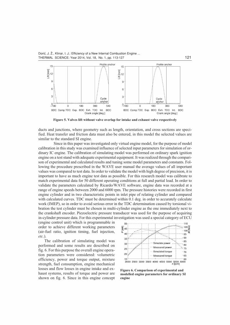
The valve train was modeled by setting up the appropriate number of valves per cylin-
der and entering details about valve size, lift, and flow, for this purpose was chosen values
which are different from the conventional valvetrain. Reason for that can be found in the fact
that piston dwell have impact on valves open duration. So, in this concept, because of the piston
dwell there is no need for valve overlap, this can be seen from fig. 5. Valve data for each cylinder
must be entered referencing a valve model. The lift valve model was used in this example, so
that the valve would follow a set profile. The intake and exhaust valves were modeled using
Dori}, J. @., Klinar, I. J.: Efficiency of a New Internal Combustion Engine ...120 THERMAL SCIENCE: Year 2014, Vol. 18, No. 1, pp. 113-127
Table 1. Main engine data
Engine type Spark ignition
Engine cycle Four-stroke
Number of cylinders 2
Number of valves per cylinder 4
Bore 120 mm
Stroke 30-177 mm
Intake valve diameter 44 mm
Exhaust valve diameter 40 mm
Valves path 15 mm
EVDUR 235 deg.
IVDUR 230 deg.
EVMP 253.3-245 deg.
IVMP 479.3-471 deg.
Octane number 98
Compression ratios 8-16
ducts and junctions, where geometry such as length, orientation, and cross sections are speci-
fied. Heat transfer and friction data must also be entered, in this model the selected values are
similar to the standard SI engine.
Since in this paper was investigated only virtual engine model, for the purpose of model
calibration in this study was examined influence of selected input parameters for simulation of or-
dinary IC engine. The calibration of simulating model was performed on ordinary spark ignition
engine on a test stand with adequate experimental equipment. It was realized through the compari-
son of experimental and calculated results and tuning some model parameters and constants. Fol-
lowing the procedure prescribed in the WAVE user manual the average values of all important
values was compared to test data. In order to validate the model with high degree of precision, it is
important to have as much engine test data as possible. For this research model was calibrate to
match experimental data for 50 different operating conditions at full and partial load. In order to
validate the parameters calculated by Ricardo/WAVE software, engine data was recorded at a
range of engine speeds between 2000 and 6000 rpm. The pressure histories were recorded in first
engine cylinder and in two characteristic points in inlet pipe of relating cylinder and compared
with calculated curves. TDC must be determined within 0.1 deg. in order to accurately calculate
work (IMEP), so in order to avoid serious error in the TDC determination caused by torsional vi-
bration the test cylinder must be chosen in multi-cylinder engine as the one immediately next to
the crankshaft encoder. Piezoelectric pressure transducer was used for the purpose of acquiring
in-cylinder pressure data. For this experimental investigation was used a special category of ECU
(engine control unit) which is programmable in
order to achieve different working parameters
(air-fuel ratio, ignition timing, fuel injection,
etc.).
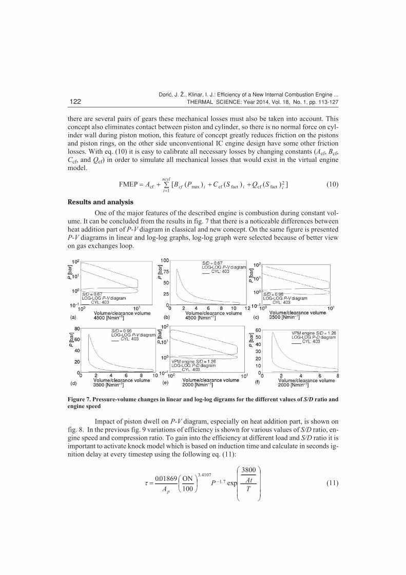
The calibration of simulating model was
performed and some results are described on
fig. 6. For this purpose the overall engine opera-
tion parameters were considered: volumetric
efficiency, power and torque output, mixture
strength, fuel consumption, engine mechanical
losses and flow losses in engine intake and ex-
haust systems, results of torque and power are
shown on fig. 6. Since in this engine concept
Dori}, J. @., Klinar, I. J.: Efficiency of a New Internal Combustion Engine ...THERMAL SCIENCE: Year 2014, Vol. 18, No. 1, pp. 113-127 121
Figure 5. Valves lift without valve overlap for intake and exhaust valve respectively
Figure 6. Comparison of experimental andmodelled engine parameters for ordinary SIengine
there are several pairs of gears these mechanical losses must also be taken into account. This
concept also eliminates contact between piston and cylinder, so there is no normal force on cyl-
inder wall during piston motion, this feature of concept greatly reduces friction on the pistons
and piston rings, on the other side unconventional IC engine design have some other friction
losses. With eq. (10) it is easy to calibrate all necessary losses by changing constants (Acf, Bcf,
Ccf, and Qcf) in order to simulate all mechanical losses that would exist in the virtual engine
model.
FMEP cf cf fact cf fact� � � � ��
A B P C S Q Scfi
ncyl
i i[ ( ) ( ) (max1
) ]i2 (10)
Results and analysis
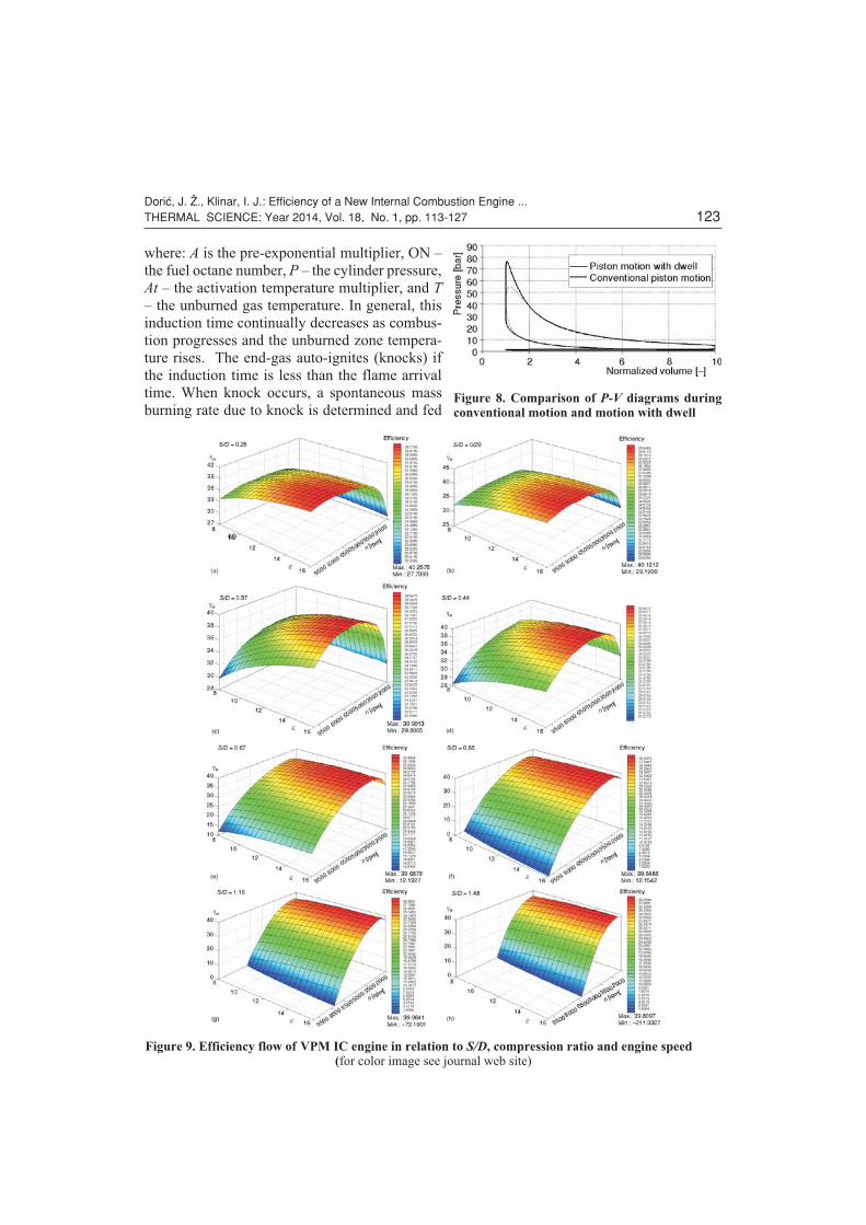
One of the major features of the described engine is combustion during constant vol-
ume. It can be concluded from the results in fig. 7 that there is a noticeable differences between
heat addition part of P-V diagram in classical and new concept. On the same figure is presented
P-V diagrams in linear and log-log graphs, log-log graph were selected because of better view
on gas exchanges loop.
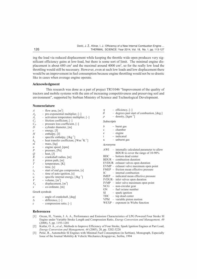
Impact of piston dwell on P-V diagram, especially on heat addition part, is shown on
fig. 8. In the previous fig. 9 variations of efficiency is shown for various values of S/D ratio, en-
gine speed and compression ratio. To gain into the efficiency at different load and S/D ratio it is
important to activate knock model which is based on induction time and calculate in seconds ig-
nition delay at every timestep using the following eq. (11):
t ��
��
�
�
�
����
�
�001869
100
38003 4107
1 7.
exp
.
.
AP At
Tp
ON
(11)
Dori}, J. @., Klinar, I. J.: Efficiency of a New Internal Combustion Engine ...122 THERMAL SCIENCE: Year 2014, Vol. 18, No. 1, pp. 113-127
Figure 7. Pressure-volume changes in linear and log-log digrams for the different values of S/D ratio andengine speed
where: A is the pre-exponential multiplier, ON –
the fuel octane number, P – the cylinder pressure,
At – the activation temperature multiplier, and T
– the unburned gas temperature. In general, this
induction time continually decreases as combus-
tion progresses and the unburned zone tempera-
ture rises. The end-gas auto-ignites (knocks) if
the induction time is less than the flame arrival
time. When knock occurs, a spontaneous mass
burning rate due to knock is determined and fed
Dori}, J. @., Klinar, I. J.: Efficiency of a New Internal Combustion Engine ...THERMAL SCIENCE: Year 2014, Vol. 18, No. 1, pp. 113-127 123
Figure 8. Comparison of P-V diagrams duringconventional motion and motion with dwell
Figure 9. Efficiency flow of VPM IC engine in relation to S/D, compression ratio and engine speed(for color image see journal web site)

back to the cylinder, leading to rapid rise in cylinder pressure and temperature. The in-cylinder
heat transfer coefficient is also increased during knock. The model assumes that auto-ignition
occurs when eq. (12) is satisfied:dt
tt
ti
�� 10
(12)
In the eq. (12) are mentioned following parameters: t0 – start of end-gas compression, ti
– the time of auto-ignition, and t – the induction time. After solving all necessary simulation
cases, efficiency curves for all examined S/D ratios can be drawn, such graph is presented on the
following fig. 10.
It is interesting to see the impact of variable displacement on efficiency in relation to
conventional throttling operation mode, such analysis was performed and results can be seen
from fig. 11.
Dori}, J. @., Klinar, I. J.: Efficiency of a New Internal Combustion Engine ...124 THERMAL SCIENCE: Year 2014, Vol. 18, No. 1, pp. 113-127
Figure 10. Efficiencycurves for differentS/D ratio in relation toengine speed incomparison withefficiency of ordinaryspark ignition engine
Figure 11. Comparisons of: (a) efficiency during conventional regulation of load and with VPM ICengine, (b) cylinder pressure diagrams for these two approaches (gas exchanges loop only)

In conventional engine during exploitation only two parameters can be changed, load
and speed. Unlike conventional engines in VPM engine there is one more parameter that can be
changed during operation-stroke. In fig. 12 are presented changes of in-cylinder pressure during
operation at constant speed and constant full load but with variable stroke (variable displace-
ment).
Conclusions
In this article was presented one approach for improvement of spark ignition engine
efficiency. Described concept has several advantages over ordinary SI engines. First of all, this
engine have variable compression ratio, than with this concept it is possible to avoid classical
approach for partial load operation via variable displacement. Finally presented concept is able
to provide heat addition during constant volume. All of these mentioned advantages show that
the potential to increase the efficiency of the SI engine conditions is not yet exhausted. As
shown in the research results above, variable displacement methods have the best potential to in-
crease the efficiency of the engine at part load conditions. To avoid engine operation below the
unthrottled load limit, facilitate smooth mode changes and further improve the vehicle fuel
economy. With the constant volume combustion cycle, the piston movement is significantly
slower around TDC and BDC, in fact piston actually stops for a while, this have significant im-
pact on volumetric efficiency and engine efficiency. Overall, the pressure integral of the con-
stant volume combustion cycle is about 11% higher than that of the conventional cycle at full
load, but with the feature of variable displacement this concept can reach almost 80% greater ef-
ficiency in relation to standard engine at part load. An advanced engine system design, combin-
ing variable displacement, variable compression and constant volume combustion has been ex-
plored with the aid of the physics-based computer simulation. The main objective was to
develop a system capable of operating unthrottled throughout the torque-speed range. Regulat-
Dori}, J. @., Klinar, I. J.: Efficiency of a New Internal Combustion Engine ...THERMAL SCIENCE: Year 2014, Vol. 18, No. 1, pp. 113-127 125
Figure 12. In-cylinder pressure changes in relation to crank angle and enginedisplacement at constant engine speed
ing the load via reduced displacement while keeping the throttle wide open produces very sig-
nificant efficiency gains at low-load, but there is some sort of limit. The minimal engine dis-
placement is about 680 cm3 and the maximal around 4000 cm3, so for the really low load the
throttling would still be necessary. However, even at such low loads and low displacement there
would be an improvement in fuel consumption because engine throttling would not be so drastic
like in cases when average engine operate.
Acknowledgment
This research was done as a part of project TR31046 “Improvement of the quality of
tractors and mobile systems with the aim of increasing competitiveness and preserving soil and
environment”, supported by Serbian Ministry of Science and Technological Development.
References
[1] Ozcan, H., Yamin, J. A. A., Performance and Emission Characteristics of LPG Powered Four Stroke SIEngine under Variable Stroke Length and Compression Ratio, Energy Conversion and Management, 49(2008), 5, pp. 1193-1201
[2] Kutlar, O. A., et al., Methods to Improve Efficiency of Four Stroke, Spark Ignition Engines at Part Load,Energy Conversion and Management, 46 (2005), 20, pp. 3202-3220
[3] Peši}, R., Automobile SI Engines with Minimal Fuel Consumption (in Serbian), Monograph, EspeciallyIssue of the Journal Mobility & Vehicle Mechanics,Kragujevac, Serbia, 1994
Dori}, J. @., Klinar, I. J.: Efficiency of a New Internal Combustion Engine ...126 THERMAL SCIENCE: Year 2014, Vol. 18, No. 1, pp. 113-127
Nomenclature
A – flow area, [m3]Ap – pre-exponential multiplier, [–]At – activation temperature multiplier, [–]Cf – friction coefficient, [–]CP – pressure loss coefficient, [–]D – cylinder diameter, [m]e – energy, [J]H – enthalpy, [J]h – specific enthalpy, [Jkg–1]hg – heat transfer coefficient, [Wm–2K–1]m – mass, [kg]n – engine speed, [rpm]P – pressure, [Pa]Q – heat, [J]R – crankshaft radius, [m]S – piston path, [m]T – temperature, [K]t – time, [s]t0 – start of end gas compression, [s]t1 – time of auto-ignition, [s]u – specific internal energy, [Jkg–1]V – volume, [m3]Vh – displacement, [m3]x – co-ordinate, [m]
Greek symbols
a – angle of crankshaft, [deg]D – difference, [–]e – compression ratio, [–]
h – efficiency, [–]q – degrees past start of combustion, [deg.]r – density, [kgm–3]
Subscripts
b – burnt gasc – chambere – enginei – indicatedu – unburnt gas
Acronyms
AWI – internally calculated parameter to allow– BDUR to cover the range of 10-90%
BDC – bottom dead centerBDUR – combustion durationEVDUR– exhaust valves open durationEVMP – exhaust valve maximum open pointFMEP – friction mean effective pressureIC – internal combustionIMEP – indicated mean effective pressureIVDUR– inlet valves open durationIVMP – inlet valve maximum open pointNCG – non-circular gearON – fuel octane numberSI – spark ignitionTDC – top dead centerVPM – variable piston motionWEXP – exponent in Wiebe function
[4] Wirbeleit, F. G., et al., Development of Piston with Variable Compression Height for Increasing Effi-ciency and Specific Power Output of Combustion Engines, SAE paper 900229, 1990
[5] Adams, W. H., et al., Analysis of the Combustion Process of a Spark Ignition Engine with a Variable Com-pression Ratio, SAE paper 870610, 1987
[6] Heywood, J. B., Internal Combustion Engines Fundamentals, McGraw-Hill Book Company, New York,USA, 1988
[7] Andresen, B., et al., Thermodynamics in Finite Time, Physics Today, 9 (1984), 37, pp. 62-70[8] Orlov, V. N., Berry, R. S., Power and Efficiency Limits for Internal-Combustion Ingines via Methods of
Finite-Time Thermodynamics, Journal of Applied Physics, 74 (1993), 10, pp. 4317-4322[9] Chen, L., et al., Effects of Heat Transfer, Friction and Variable Specific Heats of Working Fluid on Perfor-
mance of an Irreversible Dual Cycle, Energy Conversion Management, 47 (2006), 18/19, pp. 3224-3234[10] Klinar, I., Internal Combustion Engines, Faculty of Technical Sciences, Novi Sad, Serbia, 2008[11] Chen, R., et al., Quasi-Constant Volume (QCV) Spark Ignition Combustion, SAE technical paper
2009-01-0700, 2009[12] Siewert, R. M., Engine Combustion at Large Bore-to-Stroke Ratios, SAE Trans, 87 (1978), pp. 3637-51[13] Freudenstein, F., Maki, E. R., Variable Displacement Piston Engine, U. S. Patent #4,270,495, 1981[14] Pierce, J., Variable Stroke Mechanisms, U. S. Patent No. 1, 112, 832, 1914[15] Biermann, A. E., Variable Stroke Piston Engines, U.S. Patent No. 2, 909, 163, 1959[16] Welsh, H. W., Riley, C. T., The Variable Displacement Engine, An Advanced Concept Power Plant, SAE
paper 710830, 1971[17] Yamin, J. A., Dado, M. H., Performance Simulation of a Four-Stroke Engine with Variable Stroke-Length
and Compression Ratio, Applied Energy, 77 (2004), 4, pp. 447-463[18] Pouliot, H. N., et al., A Variable Displacement Spark Ignition Engine, SAE paper 770114, 1977[19] Filipi, Z. S., Assanis, D. N., The Effect of the Stroke-To-Bore Ratio on Combustion, Heat Transfer and Ef-
ficiency of a Homogeneous Charge Spark Ignition Engine of Given Displacement, International Journalof Engine Research, 2 (2000), 1, pp. 191-208
[20] Wong, V. W., et al., Increased Power Density via Variable Compression/Displacement and Turbocharg-ing Using the Alvar-Cycle Engine, SAE paper 981027, 1998
[21] Dori}, J., Variable Piston Motion Internal Combustion Engine, the Patent Application Material at the In-tellectual Property Office of the Republic of Serbia, Belgrade, 2011
[22] Waltner, A., Environmentally Friendly and Pioneering: Cylinder Cut-Out System Reduces Fuel Con-sumption, Mercedes Benz A. G, 1996
[23] Dori}, J., et al., Constant Volume Combustion Cycle for IC Engines, FME Transactions, 39 (2011), 3, pp.97-104
[24] Jovanovi}, Z., et al., The Effect of Bowl-in-Piston Geometry Layout on Fluid Flow Pattern, Thermal Sci-ence 15 (2011), 3, pp. 817-832
[25] Jovanovi}, Z., et al., The Effect of Combustion Chamber Geometry Layout on Combustion and Emission,Thermal Science, 12 (2008), 1, pp. 7-24
[26] Horlock, J. H., Winterbone, D. E., The Thermodynamics and Gas Dynamics of Internal Combustion En-gines, vol. II, Clarendon Press, Oxford, UK, 1986
[27] Moran, M. J., Shapiro, H. N., Fundamentals of Engineering Thermodynamics, John Wiley and Sons, NewYork, USA, 2000
[28] Tomi}, M., Petrovi}, S., Spark Ignition Engine Part Load Fuel Economy Improvement: Numerical Con-sideration, FME Transactions, 31 (2003), 1, pp. 21-26
[29] Schaerlaeckens, W., Deckers, R., The Application of WAVE in the Early Stages of Engine Design,NedCar Technology, Holland
[30] Golubev, P., et al., Application of the WAVE System at the Initial Stages of Engine Design, OJSC "ZMZ",Russia
[31] McCcollum, D., et al., Application of WAVE 1-D Engine Models with Vehicle Simulation Tools to Inves-tigate Efficiency, Performance, and Emission Impacts of Advanced Engine Operation, Ricardo Software9th Annual International Users Conference, Southfield, Mich., USA, 2004
[32] Dori}, J., Klinar, I., The Realisation and Analysis of a New Thermodynamic Cycle for Internal Combus-tion Engines, Thermal Science, 15 (2011), 4, pp. 961-974
Paper submitted: September 23, 2011Paper revised: December 9, 2011Paper accepted: January 7, 2012
Dori}, J. @., Klinar, I. J.: Efficiency of a New Internal Combustion Engine ...THERMAL SCIENCE: Year 2014, Vol. 18, No. 1, pp. 113-127 127
Related Documents