internal & single-stage implant systems maximum surface area for long-term stability

Welcome message from author
This document is posted to help you gain knowledge. Please leave a comment to let me know what you think about it! Share it to your friends and learn new things together.
Transcript

internal & single-stageimplant systems
maximum surface areafor long-term stability

B
SCIENCEBioHorizons uses science and innovation to create unique products with proven surgical and esthetic results.
productssold
in 85 markets
99.2%averageimplant
success rate1
global leader for
biologicbased
solutions
SERVICEBioHorizons understands the importance of providing excellent service. Our global network of professional representatives and our highly trained customer care support team are well-equipped to meet the needs of patients and clinicians.
INNOVATIONOur advanced implant technologies, biologic products and computer guided surgery software have made BioHorizons a leading dental implant company.
BioHorizons is dedicated to developing evidence-based and scientifically proven products. From the launch of the External implant system (Maestro) in 1997, to the Laser-Lok 3.0 implant in 2010, dental professionals as well as patients have confidence in our comprehensive portfolio of dental implants and biologics products.
Our commitment to science, innovation and service has aided us in becoming one of the fastest growing companies in the dental industry. BioHorizons has helped restore smiles in 85 markets throughout Asia, North America, South America, Africa, Australia and Europe.

1
Overview
Section 1: Product Catalog
Page
Table of Contents
Laser-Lok Technology Overview
Internal Implant Overview
Single-stage Implant Overview
6-7
8
9-11
12-13
14-15
16
17
18-19
20
21
22
23
24-25
26
27
28
29
30
31
32
33
2-3
4
5
Implants
VIP Software
Surgical Instruments
Ancillary Instruments
W&H Motors & Accessories
Instructions for Use
Surgical Protocols
Implant Spacing Considerations
Surgical Kit Layout & Drill Sequence
Surgical Drill Overview
Osteotomy Initialization
Osteotomy Modification
Final Bone Preparation & Drivers
Implant Pick-up
Abutment Level Placement (Internal Implant)
Implant Level Placement
Post-Operative Instructions
Internal Implant Healing Protocols
Single-stage Implant Healing Protocols
Icon Legend & References
Ordering & Warranty Information
Section 2: Surgical Manual

2shop online at www.biohorizons.com
Laser-Lok Technology
Unique surface characteristicsLaser-Lok microchannels is a series of cell-sized circumferential channels that are precisely created using laser ablation technology. This technology produces extremely consistent microchannels that are optimally sized to attach and organize both osteoblasts and fibroblasts.8,9 The Laser-Lok microstructure also includes a repeating nanostructure that maximizes surface area and enables cell pseudopodia and collagen microfibrils to interdigitate with the Laser-Lok surface.
Different than other surface treatmentsVirtually all dental implant surfaces on the market are grit-blasted and/or acid-etched. These manufacturing methods create random surfaces that vary from point to point on the implant and alter cell reaction depending on where each cell comes in contact with the surface.10 While random surfaces have shown higher osseointegration than machined surfaces,11 only the Laser-Lok surface has been shown using light microscopy, polarized light microscopy and scanning electron microscopy to also be effective for soft tissue attachment.2,12
SEM image at 30X showing the Laser-Lok zone on a BioHorizons implant.
The uniformity of the Laser-Lok microstructure and nanostructure is evident using extreme magnification.
Laser-Lok overviewLaser-Lok microchannels is a proprietary dental implant surface treatment developed from over 20 years of research initiated to create the optimal implant surface. Through this research, the unique Laser-Lok surface has been shown to elicit a biologic response that includes the inhibition of epithelial downgrowth and the attachment of connective tissue (unlike Sharpey fibers).2,3 This physical attachment produces a biologic seal around the implant that protects and maintains crestal bone health. The Laser-Lok phenomenon has been shown in post-market studies to be more effective than other implant designs in reducing bone loss.4,5,6,7
Colorized SEM of a dental implant harvested at 6 months post-op shows the connective tissue is physically attached and interdigitated with the Laser-Lok surface.
Human histology shows the apical extent of the junctional epithelium below which there is a supracrestal connective tissue attachment to the Laser-Lok surface.2
soft tissue Laser-Lokimplant
Polarized lights show the connective tissue is functionally oriented.2
bone
Laser-Lokimplant
3shop online at www.biohorizons.com
The clinical advantageThe Laser-Lok surface has been shown in several studies to offer a clinical advantage over other implant designs. In a prospective, controlled multi-center study, Laser-Lok implants, when placed alongside identical implants with a traditional surface, were shown at 37 months post-op to reduce bone loss by 70% (or 1.35mm).4 In a retrospective, private practice study, Laser-Lok implants placed in a variety of site conditions and followed up to 3 years minimized bone loss to 0.46mm.5 In a prospective, University-based overdenture study, Laser-Lok implants reduced bone loss by 63% versus NobelReplace™ Select.6
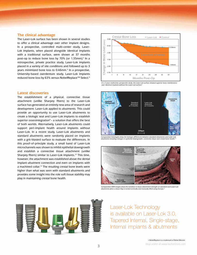
Latest discoveriesThe establishment of a physical, connective tissue attachment (unlike Sharpey fibers) to the Laser-Lok surface has generated an entirely new area of research and development: Laser-Lok applied to abutments. This could provide an opportunity to use Laser-Lok abutments to create a biologic seal and Laser-Lok implants to establish superior osseointegration9 – a solution that offers the best of both worlds. Alternatively, Laser-Lok abutments could support peri-implant health around implants without Laser-Lok. In a recent study, Laser-Lok abutments and standard abutments were randomly placed on implants with a grit-blasted surface to evaluate the differences. In this proof-of-principle study, a small band of Laser-Lok microchannels was shown to inhibit epithelial downgrowth and establish a connective tissue attachment (unlike Sharpey fibers) similar to Laser-Lok implants.12 This time, however, the attachment was established above the dental implant-abutment connection and even on implants with a machined collar.12 The resulting crestal bone levels were higher than what was seen with standard abutments and provides some insight into the role soft tissue stability may play in maintaining crestal bone health.
-2.50
-2.00
-1.50
-1.00
-0.50
0.00
1 5 9 13 17 21 25 29 33 37
0.59mm
1.94mm
Laser-Lok Control
Months Post-Op
Laser-Lok advantage
Cha
nge
in B
one
Leve
l (m
m)
Crestal Bone Loss
In a 3-year multicenter perspective study, the Laser-Lok surface showed superior bone maintenance over identical implants without the Laser-Lok surface.4
• NobelReplace is a trademark of Nobel Biocare.
Standard abutment
at 3 months
Laser-Lok abutmentat 3 months
New bone
Boneloss
Epithelialdowngrowth
Connective tissue
200µm
Comparative histologies show the biologic differences between standard abutments and Laser-Lok abutments including changes in epithelial downgrowth, connective tissue and crestal bone health.12
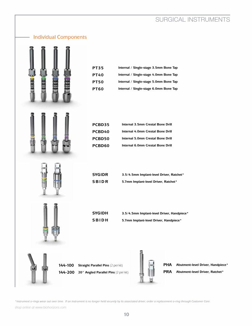
Comparative SEM images show the variation in tissue attachment strength on standard and Laser-Lok abutments when a tissue flap is incised vertically and manually lifted using forceps.12
Standard abutment
at 3 months
Laser-Lokabutmentat 3 months
Laser-Lokmicrochannels
Exposed implant collar
tissue flap
Laser-Lok Technologyis available on Laser-Lok 3.0, Tapered Internal, Single-stage, Internal implants & abutments

4
INTERNAL/SINGLE-STAGE OVERVIEW
internal
shop online at www.biohorizons.com
Supported by a comprehensive line of internally hexed prosthetics.
Internal dental implants provide maximum surface area through the use of a parallel-walled body and square thread design. It also is available with Laser-Lok microchannels to create a physical, connective tissue attachment (unlike Sharpey fibers) and long-term crestal bone maintenance.2
FEATURESProprietary biomechanical thread design maximizes implant surface area.13
Most widely used connection in implant dentistry.
2.0mm
5.5mm
6.5mm
apical diameterminimum ridge width
minimum mesial/distal space
2.1mm
6.5mm
7.5mm
2.5mm
7.7mm
8.7mm
3.5mm
8.0mm
8.7mm
connection
delivery options
body-type
placement
surface treatment
implant lengths
prosthetic platform
body diameter
3.5mm
3.5mm
4.5mm
4.0mm 5.0mm 6.0mm
5.7mm
mount-free3inOne abutment
internal hex
parallel-wall
bone level
RBT bodyoptional Laser-Lok collar
9.0mm10.5mm12.0mm15.0mm

5
Greater flexibility than other “soft tissue” implants.
INTERNAL/SINGLE-STAGE OVERVIEW
single-stage
shop online at www.biohorizons.com
Unlike similar “soft-tissue level” implant designs, the Single-stage dental implant features the BioHorizons power thread with maximum surface area to support the high occlusal forces often seen in the posterior. This gives dentists confidence that their placements will remain secure long-term even with limited ridge height and in softer bone.
FEATURESPower thread provides up to 154% greater surface area.13
Two body diameters for each platform.
2.0mm
5.5mm
6.5mm
apical diameterminimum ridge width
minimum mesial/distal space
2.1mm
6.5mm
7.5mm
2.5mm
7.7mm
8.7mm
3.5mm
8.0mm
8.7mm
prosthetic platform
body diameter
shoulder diameter
3.5mm
3.5mm
4.0mm
4.0mm
5.0mm
5.0mm
6.0mm
4.5mm 5.5mm 6.7mm
4.5mm 5.7mm
connection
delivery options
body-type
placement
surface treatment
implant lengths
mount-free
internal hex
parallel-wall
tissue level
RBT bodyoptional Laser-Lok collar
7.0mm9.0mm10.5mm12.0mm15.0mm

6
shop online at www.biohorizons.com
3.5mm Implants
4.0mm Implants
5.0mm Implants
Not all products are available in all markets.
3.5mm Cover Cap
4.5mm Cover Cap
5.7mm Cover Cap
PYCC
PGCC
PBCC
For use during submerged surgical healing. Hand-tighten with the .050” (1.25mm) Hex Driver. Titanium Alloy. A surgical cover cap is included with each implant but can also be ordered separately.
Surgical Cover Cap
Body Diameter x Length
3.5mm x 9mm
3.5mm x 10.5mm
3.5mm x 12mm
3.5mm x 15mm
4.0mm x 9mm
4.0mm x 10.5mm
4.0mm x 12mm
4.0mm x 15mm
6.0mm Implants
5.0mm x 9mm
5.0mm x 10.5mm
5.0mm x 12mm
5.0mm x 15mm
6.0mm x 9mm
6.0mm x 10.5mm
6.0mm x 12mm
6.0mm x 15mm
RBT Surfacew/Laser-Lok
LPGR4009
LPGR40105
LPGR4012
LPGR4015
LPYR3509
LPYR35105
LPYR3512
LPYR3515
LPBR6009
LPBR60105
LPBR6012
LPBR6015
LPBR5009
LPBR50105
LPBR5012
LPBR5015
RBT with Laser-Lok
RBT Surface
PGR4009
PGR40105
PGR4012
PGR4015
PYR3509
PYR35105
PYR3512
PYR3515
PBR6009
PBR60105
PBR6012
PBR6015
PBR5009
PBR50105
PBR5012
PBR5015
Resorbable Blast Texturing (RBT)
HA Surface
PGH4009*
PGH40105*
PGH4012*
PGH4015*
PYH3509*
PYH35105*
PYH3512*
PYH3515*
PBH6009*
PBH60105*
PBH6012*
PBH6015*
PBH5009*
PBH50105*
PBH5012*
PBH5015*
Hydroxylapatite(HA)*
INTERNAL IMPLANTS
Internal implants are available with a 3inOne abutment, surgical cover cap, and abutment screw.
PGLX4009
PGLX40105
PGLX4012
PGLX4015
PYLX3509
PYLX35105
PYLX3512
PYLX3515
PBLX6009
PBLX60105
PBLX6012
PBLX6015
PBLX5009
PBLX50105
PBLX5012
PBLX5015
RBT with Laser-Lok
Mount-freeMount-free implants are packaged without the 3inOne abutment
* Effective June 30, 2012, HA-coated implants will no longer be manufactured.

7
shop online at www.biohorizons.com
LSGR4007
LSGR4009
LSGR40105
LSGR4012
LSGR4015
SGR4007
SGR4009
SGR40105
SGR4012
Not available
LSYR4007
LSYR4009
LSYR40105
LSYR4012
LSYR4015
SYR4007
SYR4009
SYR40105
SYR4012
Not available
LSYR3507
LSYR3509
LSYR35105
LSYR3512
LSYR3515
SYR3507
SYR3509
SYR35105
SYR3512
Not available
LSGR5007
LSGR5009
LSGR50105
LSGR5012
LSGR5015
SGR5007*
SGR5009*
SGR50105*
SGR5012*
Not available
LSBR5007
LSBR5009
LSBR50105
LSBR5012
LSBR5015
SBR5007
SBR5009
SBR50105
SBR5012
Not available
LSBR6007
LSBR6009
LSBR60105
LSBR6012
LSBR6015
SBR6007*
SBR6009*
SBR60105*
SBR6012*
Not available
4.0mm x 7mm, 4.5mm platform
4.0mm x 9mm, 4.5mm platform
4.0mm x 10.5mm, 4.5mm platform
4.0mm x 12mm, 4.5mm platform
4.0mm x 15mm, 4.5mm platform
4.0mm x 7mm, 3.5mm platform
4.0mm x 9mm, 3.5mm platform
4.0mm x 10.5mm, 3.5mm platform
4.0mm x 12mm, 3.5mm platform
4.0mm x 15mm, 3.5mm platform
3.5mm x 7mm, 3.5mm platform
3.5mm x 9mm, 3.5mm platform
3.5mm x 10.5mm, 3.5mm platform
3.5mm x 12mm, 3.5mm platform
3.5mm x 15mm, 3.5mm platform
5.0mm x 7mm, 4.5mm platform
5.0mm x 9mm, 4.5mm platform
5.0mm x 10.5mm, 4.5mm platform
5.0mm x 12mm, 4.5mm platform
5.0mm x 15mm, 4.5mm platform
5.0mm x 7mm, 5.7mm platform
5.0mm x 9mm, 5.7mm platform
5.0mm x 10.5mm, 5.7mm platform
5.0mm x 12mm, 5.7mm platform
5.0mm x 15mm, 5.7mm platform
6.0mm x 7mm, 5.7mm platform
6.0mm x 9mm, 5.7mm platform
6.0mm x 10.5mm, 5.7mm platform
6.0mm x 12mm, 5.7mm platform
6.0mm x 15mm, 5.7mm platform
3.5mm Implant Body3.5mm Prosthetic Platform
Surface Treatment
Configuration:
RBT with Laser-Lok
RBT surface treatment
4.0mm Implant Body3.5mm Prosthetic Platform
4.0mm Implant Body4.5mm Prosthetic Platform
5.0mm Implant Body4.5mm Prosthetic Platform
5.0mm Implant Body5.7mm Prosthetic Platform
6.0mm Implant Body5.7mm Prosthetic Platform
*call for availability
SINGLE-STAGE IMPLANTS
All Single-stage implants come packaged with a 2mm healing abutment.
RBT only configurations available in limited
quantities. Please call for availability.

8
shop online at www.biohorizons.com
VIP SOFTWARE
Minimal System Requirements• Windows® XP• Pentium® III CPU, 500 MHz, 256 MB RAM• 1 GB of free hard disk space• Windows supported mouse• 15” computer monitor• Windows Internet Explorer® 6
If VIP installation CD does not start automatically, right-click on the CD-ROM drive, select Explore and doubleclick on the VIP setup icon.
VIP CD installation is only a demo and requires a user license for the full version of VIP.
© 2009 BioHorizons, Inc. All Rights Reserved.
VIP 2.1 software, Rev B
www.biohorizons.com
BioHorizons USA888.246.8338 or 205.967.7880
BioHorizons Canada866.468.8338 or 905.944.1700
BioHorizons Spain+34 91.713.10.84
BioHorizons UK+44 8700.620.550
BioHorizons Germany+49 7661.909989.0
BioHorizons Australia+61 2.8399.1520
BioHorizons Chile+56 2.361.9519
2300 Riverchase Center • Birmingham, Alabama • 35244
Virtual Implant Placement 2.1VIP
L0302 Rev B AUG 2009
VIP is not available in all countries
VIP2.1
Interactive 2D and 3D treatment planning software. Includes (2) software licenses.
VIP 2.1 Software
Virtual Implant Placement (VIP)
VIP Catalog & Surgical ManualL0303
VIP virtual surgical plan transfers
to Compu-Guide surgical template for implant position and
orientation
VIP was exclusively developed for clinicians who prefer an innovative and user-friendly treatment planning solution to help deliver a predictable surgical outcome. The integration of digital treatment planning for diagnosis and our Compu-Guide surgical templates for guided surgery gives you the confidence for a safe and effective procedure.
VIP BENEFITS• Interactive 2D and 3D treatment planning
• Open implant platform designed for cross implant compatibility
• DICOM converter for instant file conversion

9
shop online at www.biohorizons.com
122-800Internal / Single-stage Surgical KitIncludes all instruments shown on pages 9-11 except where indicated.
122-103
2.0mm Starter Drill
122-100
Drill Extender
SSTInternal / Single-stage Tray & Lid without instruments
Individual Components
Internal / Single-stage Surgical Kit
(adds 16mm to length of drill)
122-12507
122-12509
122-125105
122-12512
122-12515
122-225
2.5 x 7mm Depth Drill
2.5 x 9mm Depth Drill
2.5 x 10.5mm Depth Drill
2.5 x 12mm Depth Drill
2.5 x 15mm Depth Drill
2.5mm Depth Drill (without Depth Stop)
SURGICAL INSTRUMENTS
122-230
122-232
122-237
122-242
122-247
122-252
3.0mm Width Increasing Drill
3.4mm Width Increasing Drill
3.9mm Width Increasing Drill
4.4mm Width Increasing Drill
4.9mm Width Increasing Drill
5.4mm Width Increasing Drill
*instrument o-rings & c-rings wear out over time. If an instrument is no longer held securely by its associated driver, order a replacement ring through Customer Care.
10
shop online at www.biohorizons.com
Abutment-level Driver, Handpiece*
Abutment-level Driver, Ratchet*
PHA
PRA
3.5/4.5mm Implant-level Driver, Handpiece*
5.7mm Implant-level Driver, Handpiece*
SYGIDH
S B I D H
3.5/4.5mm Implant-level Driver, Ratchet*
5.7mm Implant-level Driver, Ratchet*
SYGIDR
S B I D R
SURGICAL INSTRUMENTS
Straight Parallel Pins (2 per kit)
20° Angled Parallel Pins (2 per kit)
144-100
144-200
Internal 3.5mm Crestal Bone Drill
Internal 4.0mm Crestal Bone Drill
Internal 5.0mm Crestal Bone Drill
Internal 6.0mm Crestal Bone Drill
Internal / Single-stage 3.5mm Bone Tap
Internal / Single-stage 4.0mm Bone Tap
Internal / Single-stage 5.0mm Bone Tap
Internal / Single-stage 6.0mm Bone Tap
PT35
PT40
PT50
PT60
PCBD35
PCBD40
PCBD50
PCBD60
Individual Components
*instrument o-rings wear out over time. If an instrument is no longer held securely by its associated driver, order a replacement o-ring through Customer Care.

11
shop online at www.biohorizons.com
135-351
.050” (1.25mm) Hex Driver
Hand Wrench*
300-400
Implant Spacer / Depth Probe
144-300Ratchet
130-000
Individual Components
Additional Kit Components
SURGICAL INSTRUMENTS
Single-stage 3.5mm Counter-sink Drill, 3.5mm platform
Single-stage 4.0mm Counter-sink Drill, 3.5mm platform
Single-stage 4.0mm Counter-sink Drill, 4.5mm platform
Single-stage 5.0mm Counter-sink Drill, 4.5mm platform
Single-stage 5.0mm Counter-sink Drill, 5.7mm platform
Single-stage 6.0mm Counter-sink Drill, 5.7mm platform
SYCD35
SYCD40
SGCD40
SGCD50
SBCD50
SBCD60
Simple Solutions 3.5mm Surgical Trial Abutment (2 per kit)
Simple Solutions 4.5mm Surgical Trial Abutment (2 per kit)
Simple Solutions 5.7mm Surgical Trial Abutment (2 per kit)
SYSTA
SGSTA
SBSTA
Sold separately; not included in the 122-800 surgical kit.
Sold separately; not included in the 122-800 surgical kit.
*instrument o-rings wear out over time. If an instrument is no longer held securely by its associated driver, order a replacement o-ring through Customer Care.
4mm Square Drive ExtenderReplaced 300-205 starting in June 2010.
Includes PEEK C-ring for durable retention in
Ratchet. Cannot be used with bone taps.
300-206
12
shop online at www.biohorizons.com
Extended Shank Drills have the same depth marks and cutting geometry as our standard drills, but add 8mm of length to the shank.
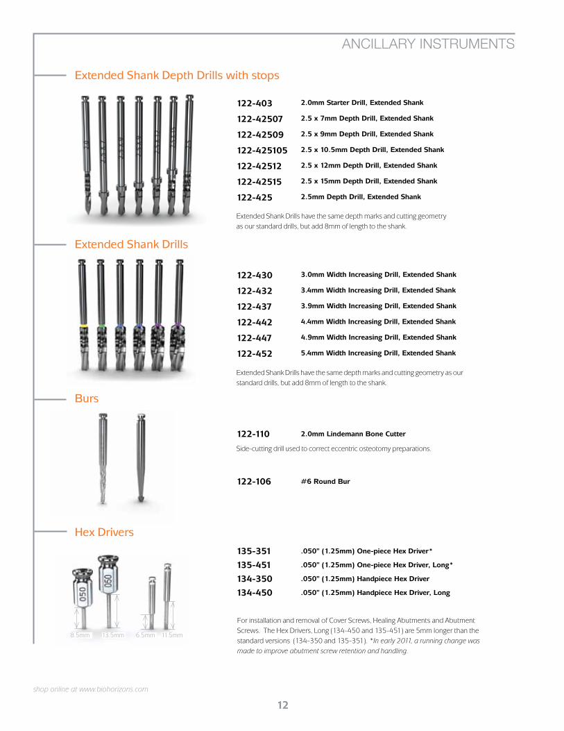
Extended Shank Drills
122-430
122-432
122-437
122-442
122-447
122-452
3.0mm Width Increasing Drill, Extended Shank
3.4mm Width Increasing Drill, Extended Shank
3.9mm Width Increasing Drill, Extended Shank
4.4mm Width Increasing Drill, Extended Shank
4.9mm Width Increasing Drill, Extended Shank
5.4mm Width Increasing Drill, Extended Shank
122-110 2.0mm Lindemann Bone Cutter
Side-cutting drill used to correct eccentric osteotomy preparations.
Extended Shank Depth Drills with stops
Extended Shank Drills have the same depth marks and cutting geometry as our standard drills, but add 8mm of length to the shank.
Burs
ANCILLARY INSTRUMENTS
122-403
122-42507
122-42509
122-425105
122-42512
122-42515
122-425
2.0mm Starter Drill, Extended Shank
2.5 x 7mm Depth Drill, Extended Shank
2.5 x 9mm Depth Drill, Extended Shank
2.5 x 10.5mm Depth Drill, Extended Shank
2.5 x 12mm Depth Drill, Extended Shank
2.5 x 15mm Depth Drill, Extended Shank
2.5mm Depth Drill, Extended Shank
122-106 #6 Round Bur
For installation and removal of Cover Screws, Healing Abutments and Abutment Screws. The Hex Drivers, Long (134-450 and 135-451) are 5mm longer than the standard versions (134-350 and 135-351). *In early 2011, a running change was made to improve abutment screw retention and handling.
135-351
135-451
134-350
134-450
.050” (1.25mm) One-piece Hex Driver*
.050” (1.25mm) One-piece Hex Driver, Long*
.050” (1.25mm) Handpiece Hex Driver
.050” (1.25mm) Handpiece Hex Driver, Long
Hex Drivers
11.5mm6.5mm13.5mm8.5mm

13
shop online at www.biohorizons.com
ANCILLARY INSTRUMENTS
3.5mm Tissue Punch
4.5mm Tissue Punch
5.7mm Tissue Punch
3.5mm Bone Profiling Bur & Guide
4.5mm Bone Profiling Bur & Guide
5.7mm Bone Profiling Bur & Guide
Tissue Punches are used in a latch-type handpiece to remove the soft tissue from the crest of the ridge prior to osteotomy preparation in a flapless surgical procedure. Available in 3 platform diameters.
Used at implant uncovery to contour crestal bone for abutments when the implant is subcrestal. For use in latch-type reduction handpieces. The Profiler’s internal geometry matches the geometry of the included Profiler Guide. The Guide is screwed into the implant and then aligns the Profiler for precise removal of tissue surrounding the platform. Comes in three sizes corresponding to the three internal prosthetic platforms.
PYBP
PGBP
PBBP
PYTP
PGTP
PBTP
Bone Profiling Burs
Tissue Punches
*instrument o-rings wear out over time. If an instrument is no longer held securely by its associated driver, order a replacement o-ring through Customer Care.
EL-C12374 Elos Adjustable Torque Wrench
Lightweight titanium design is easy to use as an adjustable torque wrench or a ratchet. Quickly disassembles for cleaning. No calibration required.
Adjustable Torque WrenchesATW ITL Precise Adjustable Torque Wrench
Place both implants and abutments with 9 distinct torque settings (15, 20, 25, 30, 35, 40, 45, 50 and 60 Ncm). A simple twist of the handle locks in precision-engineered torque values and guarantees accuracy and repeatability.
150-000Surgical Driver
Use to drive implants into the osteotomy, particularly in the anterior region. The driver holds the Abutment-level Driver, Ratchet which interfaces with the 3inOne Abutment. Also interfaces with the .050” (1.25mm) Hex Drivers as well as Bone Taps and the Implant-level Drivers, Ratchet.
Drivers
Abutment-level Driver, Hex-chuck Handpiece*Use with compatible W&H Hexagon Chucking System Handpieces to prevent deformation of the ISO shank latch connection in high-torque applications.
PADHH

14
shop online at www.biohorizons.com
WH-915L
WH-310L
WH-915
WH-310
ImplantMED 915 Starter Kit with LED
ElcoMED SA-310 Professional Kit with LED
ImplantMED SI-915 Starter Kit
ElcoMED SA-310 Professional Kit
Motor Kits include: console, motor with 1.8m attached cable, standard (ImplantMED) or premium (ElcoMED) foot pedal, (3) complete disposable irrigation tubes, USB documentation (ElcoMED), handpiece, bur testing gauge, spray cap and service oil (ships separately).
W&H Motor Kits
W&H ElcoMED SA-310 and ImplantMED SI-915 Re-Order items
W&H Motors
W&H MOTORS AND ACCESSORIES
Includes mono block LED handpiece (WH-10207560).
Includes LED handpiece (WH-10207530).
Includes mono block handpiece (WH-10207550).
Includes handpiece (WH-10207510).
WH-04363600
WH-06338400
WH-04757100
WH-10940011
WH-02038200
WH-04035100
WH-04013900
WH-06338500
WH-04035200
WH-04014000
WH-00929300
WH-04032600
WH-04019000
WH-00900103
WH-15933100
Disposable Irrigation Tubing, 2.2m (Implantmed and ElcoMED SA-310) (box of 6)
Irrigation Spike w/ Roller Clamp
Irrigation Spray Clip for External and Internal Irrigation (set of 3)
MD-400 Service-Oil F1
Oil Spray Cap for MD-400 Service-Oil F1
Pump Tube Complete (ElcoMED SA-200(C)
Pump Tube Complete (ImplantMED and ElcoMED SA-310)
Spare Irrigation Tube for Spike
Spare Pump Tubes (ElcoMED SA-200(C) (set of 3)
Spare Pump Tubes (ImplantMED and ElcoMED SA-310) (set of 3)
Spray Tubes (box of 10)
Sterilization Motor Protector
Tube Clamps (ImplantMED) (set of 5)
ImplantMED SI-915 (S-NU Foot Pedal) 1.8m Cable, Blue Console
ElcoMED SA-310 (with Documentation) 1.8m Cable
BioHorizons proudly distributes W&H implant motors, handpieces and accessories. Additional W&H products and re-order items are available. For more information, contact your BioHorizons representative or visit the online catalog (www.biohorizons.com).

15
shop online at www.biohorizons.com
Use to verify the condition of latch-type burs. Burs in proper condition will fit into larger diameter hole, but will not fit into the smaller hole (marked red). Burs that fail either of these tests are unfit for use, and may cause damage to the handpiece.
Cordless handpiece with precise torque control from 8-40 Ncm, 80:1 contra-angle handpiece with hexagon chucking system, charging station, rechargeable Li-ion battery, and power cable.
WH-02139800
WH-16934000
Bur Testing Gauge
IA-400 Prosthodontic Screwdriver
Surgical Handpieces
Bur Testing Gauge
Prosthodontic Screwdriver
W&H MOTORS AND ACCESSORIES
WI-75 E/KM LED G Surgical 20:1 Contra-Angle, Mono BlockLED, 20:1, hexagon chucking system, press-button chuck system, for surgical burs and cutters with a 2.35mm contra-angle shank, internal and external cooling system.
WI-75 E/KM Surgical 20:1 Contra-Angle, Mono Block20:1, hexagon chucking system, press-button chuck system, for surgical burs and cutters with a 2.35mm contra-angle shank, internal and external cooling system.
WS-75 E/KM LED G Surgical 20:1 Contra-Angle LED, 20:1, hexagon chucking system, press-button chuck system, for surgical burs and cutters with a 2.35mm contra-angle shank, internal and external cooling system. Dismantle for easy cleaning.
S-11 Surgical 1:1 Straight 1:1, straight, lever chuck system, for surgical burs and cutters 2.35mm >45mm shaft. Dismantle for easy cleaning.
WS-92 E/3 Surgical 1:2.7 Contra-Angle1:2.7, press-button chuck system with triple spray, for surgical burs and cutters with a 1.6mm friction grip shank. Dismantle for easy cleaning.
WH-00001100
WH-10209201
WH-10207530
WH-10207560
WH-10207550
S-12 Surgical 1:2 Angled1:2, angled, extra slim tip for increased vision, lever chuck system, for surgical burs and cutters 2.35mm >70mm extra long shaft. Dismantle for easy cleaning.
WH-10101200
WS-75 E/KM Surgical 20:1 Contra-Angle20:1, hexagon chucking system, press-button chuck system, for surgical burs and cutters with a 2.35mm contra-angle shank, internal and external cooling system. Dismantle for easy cleaning.
WH-10207510
16
This Surgical Manual serves as a reference for BioHorizons Internal and Single-stage implants and surgical instruments. It
is intended solely to provide instructions on the use of BioHorizons products. It is not intended to describe the methods
or procedures for diagnosis, treatment planning, or placement of implants, nor does it replace clinical training or a
clinician’s best judgment regarding the needs of each patient. BioHorizons strongly recommends appropriate training as
a prerequisite for the placement of implants and associated treatment.
The procedures illustrated and described within this manual reflect idealized patient presentations with adequate bone
and soft tissue to accommodate implant placement. No attempt has been made to cover the wide range of actual patient
conditions that may adversely affect surgical and prosthetic outcomes. Clinician judgment as related to any specific
case must always supersede any recommendations made in this or any BioHorizons literature.
Before beginning a surgical procedure with BioHorizons implants:
• Read and understand the Instructions for Use accompanying the products.
• Clean and sterilize the surgical tray and instruments per Instructions for Use.
• Become thoroughly familiar with all instruments and their uses.
• Study Surgical Kit layout and iconography.
• Design a surgical treatment plan to satisfy the prosthetic requirements of the case.
INSTRUCTIONS FOR USE
Virtual Implant Placement (VIP) treatment planning software is a user-friendly solution that reduces clinical challenges and enhances post-operative outcomes.
• Interactive 2D and 3D treatment planning
• Self processing DICOM converter
• Case viewer available for download from BioHorizons website
Small diameter implants with angled abutments are intended for the anterior region of the mouth and are not intended for the posterior region of the mouth due to possible failure of the implant.
Indications
VIP Treatment Planning
BioHorizons Internal & Single-stage implants are intended for use in the mandible or maxilla for use as
artificial root structures for single tooth replacement or for fixed bridgework and dental retention.
BioHorizons Internal & Single-stage implants may be restored immediately
1) with a temporary prosthesis that is not in functional occlusion or
2) when splinted together for multiple tooth replacement or when stabilized
with an overdenture supported by multiple implants.

17
Internal Implant with removable Healing Abutment in a single-
stage protocol.
Single-stage Implant with removable Healing
Abutment in a single-stage protocol.
Implant with Cover Cap in a two-stage protocol.
Internal implant restored with a non-functional provisional prosthesis.
Single-stage implants with a splinted prosthesis in immediate function.
SURGICAL PROTOCOLS
In a two-stage surgery, the implant is placed below the soft tissue and protected from occlusal function and other forces during osseointegration. A low-profile Cover Cap is placed on the implant to protect it from the ingress of soft tissue.
Following osseointegration, a second procedure exposes the implant and a transmucosal Healing Abutment is placed to allow for soft tissue healing and development of a sulcus. Prosthetic restoration begins after soft tissue healing.
Single-stage surgery may be accomplished by placing a healing abutment at the time of implant surgery. This eliminates the need for a second procedure. Although the implant is not in occlusal function, some forces can be transmitted to it through the exposed transmucosal element.
Prosthetic restoration begins following osseointegration of the implant and soft tissue healing.
Single-stage surgery with non-functional immediate provisionalization provides the patient a non-functioning provisional prosthesis early in the treatment plan. An abutment is placed on the implant at or shortly after surgery, and a provisional restoration is secured using temporary cement. The provisional can help shape the soft tissue profile during healing.
Single-stage surgery with immediate function is possible in good quality bone where multiple implants exhibiting excellent initial stability can be splinted together. Splinting implants together can offer a significant biomechanical advantage over individual, unsplinted prostheses.
Two-stage Protocol
Single-stage Protocol
Non-functional Immediate Restoration
Immediate Function Restoration

18
3.0mm
8.1mm
The osteotomy center-to-center measurement required to maintain a 3.0mm edge-to-edge spacing between Internal implants is derived using the following calculation: ½ [sum of 2 prosthetic platforms] + 3.0mm.The table below lists the permutations.
1.5mm
3.8mm
Osteotomy center 3.8mm from adjacent tooth
(4.5mm implant pictured)
1.5mm
Measurement is dependent on the two prosthetic platform diameters.
The osteotomy centerpoint required to maintain a 1.5mm implant-to-tooth spacing is derived using the following calculation: ½ [prosthetic platform diameter] + 1.5mmThe measurements for the 3 Internal prosthetic platforms are shown below.
During implant placement, clinicians must apply their best judgment as to the appropriate spacing for individual patient conditions.
IMPLANT SPACING CONSIDERATIONS
Implant Spacer / Depth Probe
Internal Implant Spacing
Purpose: Multi-function instrument for intraoral measurements.
The rectangular end of the tool provides intraoral
measurements.
Useful for marking center-to-center implant spacing
on the ridge.
The rectangular end against an existing crown places the osteotomy
~4.25mm from the contact.
~4.25mm
Probe tip measures osteotomy depth. Note: these markings are different
than the tapered drill markings
7mm
9mm
11mm
13mm
15mm
10mm
12mm
14mm
16mm
3.5mm
4.5mm
5.7mm
5.7mm4.5mm3.5mm
8.7mm8.1mm
7.5mm
6.5mm
7.6mm
7.0mm
bodydiameter
Implant center to center
3.5mm
4.5mm
5.7mm
3.3mm
4.4mm
3.8mm
bodydiameter
osteotomy center from adjacent tooth
• Five centimeter graduated ruler on shaft

19
IMPLANT SPACING CONSIDERATIONS
7.5mm
The osteotomy center-to-center measurement required to maintain a 3.0mm edge-to-edge spacing for Single-stage implants is derived using the following calculation: ½ [sum of 2 implant body diameters] + 3.0mm. The table below lists the different permutations.
2.0mm
4.0mm
The osteotomy centerpoint required to maintain a 2.0mm implant-to-tooth spacing for Single-stage implants is derived using the following calculation: ½ [implant body diameter] + 2.0mm. The figures below illustrate the measurements for the 4 implant body diameters.
Osteotomy center 4.0mm from adjacent tooth
(4.0mm implant pictured)
3.0mm
During implant placement, clinicians must apply their best judgment as to the appropriate spacing for individual patient conditions.
3.5mm
4.0mm
5.0mm
6.0mm
5.0mm 6.0mm4.0mm3.5mm
8.0mm
8.5mm 9.0mm
7.5mm
8.0mm
7.0mm
6.5mm
7.3mm
7.8mm
6.8mm
bodydiameter
Implant center to center
3.5mm
4.0mm
5.0mm
6.0mm
3.8mm
4.5mm
5.0mm
4.0mm
bodydiameter
osteotomy center from adjacent tooth
Measurement is dependent on the two implant body diameters. (3.5, 4.5 & 5.7mm implants pictured)
When placing the Internal implant in an uneven ridge, prepare the osteotomy and place the implant so that the bone/soft-tissue junction is within the Laser-Lok transition zone. If the discrepancy is more than the Laser-Lok transition zone, leveling the ridge can be considered.
Placement in Uneven Ridges
Single-stage Implant Placement

20
SURGICAL KIT LAYOUT & DRILL SEQUENCE
Surgical Kit Layout
Drill Sequence
The Internal / Single-stage Surgical Kit uses an intuitive layout to guide the surgeon through the instrument sequence. The sequence begins in the upper left hand corner and works left-to-right and then down. Color-coded lines, instruments and grommets are matched with each implant and further aid in instrument selection and identification.
Prior to use, clean and sterilize the surgical tray and instruments per appropriate Instructions for Use and study the Surgical Kit layout, color-coding and iconography. Surgical assistants should also be thoroughly familiar with all instruments and their uses.
Depth Drill Sequence
Crestal Bone & Countersink Drills
Bone Taps
Width IncreasingDrill Sequence
Implant-level and/or Abutment-level Drivers
Depth Gauges

21
SURGICAL DRILL OVERVIEW
The depth marks are consistent throughout the Starter Drill, Depth Drills, Width Increasing Drills and Bone Taps. The thick bands are each one millimeter wide. Thin lines are used to mark 7mm and 11mm.
14mm
10mm
12mm
15mm
11mm
13mm
7mm
9mm
• Peri-operative oral rinses with a 0.12% Chlorhexidine Digluconate solution have been shown to significantly lower the incidence of post-implantation infectious complications.15 A pre-operative 30-second rinse is recommended, followed by twice daily rinses for two weeks following surgery.
• Drilling must be done under a constant stream of sterile irrigation. A pumping motion should be employed to prevent over-heating the bone. Surgical drills and taps should be replaced when they are worn, dull, corroded or in any way compromised. BioHorizons recommends replacing drills after 12 to 20 osteotomies.16 A Drill-usage Tracking Chart is available at biohorizons.com to record this important information.
• There is a risk of injury to the mandibular nerve associated with surgical drilling in posterior mandibular regions. To minimize the risk of nerve injury, it is imperative that the clinician understands the drill depth markings as they relate to the implant length to produce the desired vertical placement of the implant.
All surgical drills included with this system are externally irrigated and designed to be used at drill speeds of 850-2500 rpm14 with steady sterile irrigation. Reduced drill speed may be indicated in softer bone or as drill diameter increases.
Note: The depth marks are consistent throughout the Starter Drills, Depth Drills and Width Increasing Drills
Important Considerations
Drill Markings

22
• Efficient cutting drill design collects bone for autografting
• Matte finish for increased visibility under operatory lights
Purpose: Set osteotomy depth.
• Chisel-tip design eliminates “skating” on osseous crest
• Prepares site for Paralleling Pins
• Matte finish for increased visibility under operatory lights
Purpose: Initiate osteotomy.
OSTEOTOMY INITIALIZATION
The 2.0mm and 2.5mm depth drills are designed to increase and/or set the depth of the osteotomy.
2.5mm Depth Drills with Stops
Purpose: Set osteotomy depth when access or visibility is poor.
• Fixed circular ring acts as a definitive drill stop
• One drill length for each implant length
• 1mm laser-etched line guides supracrestal implant placement
2.5mm Depth Drill2.0mm Starter Drill

23
OSTEOTOMY MODIFICATION
• Provided straight or with a 20° angle
• Use after 2.0mm Starter Drill and 2.5mm Depth Drill
• 9mm shank for radiographic evaluation of proximity to adjacent anatomy
• Hub diameter is 4.0mm
Purpose: Evaluate osteotomy position and angle.
• Represents either:
• Internal implant with 5.5mm high/1.8mm collar Abutment or
• Single-stage implant with 5.5mm high Abutment
• Used following 2.0mm Starter Drill
• Shank is 5.0mm long and 2.0mm in diameter
Purpose: Evaluation of osteotomy position for Simple Solutions restoration.
Trial Abutments are used to assess final abutment position, margin height and chimney height. They approximate the intra-oral position of either a 5.5mm high / 1.8mm collar Internal Simple Solutions Abutment on an Internal implant or 5.5mm high Single-stage Simple Solutions Abutment on a Single-stage implant. A minimum of 1.5mm clearance on the occlusal aspect of the Simple Solutions Abutments is recommended to allow adequate thickness for the framework and veneer of the laboratory fabricated restoration.
Paralleling Pins
Simple Solutions Trial Abutments
Width Increasing Drills
• Non-end cutting geometry for added safety
• Efficient cutting drill design collects bone for autografting
• Designed to not cut beyond depth set by Depth Drills
Purpose: Incrementally widens the osteotomy without creating excessive heat.
Extended shank versions are available which add 8mm of overall
length. Depth markings are identical to standard length drills.

24
• Use when dense cortical bone is present at crest
• Rounded non-end cutting hub centers drill in osteotomy
• Use following the final Width Increasing Drill for each implant
• Use when dense cortical bone is present at crest
• Rounded non-end cutting hub centers drill in osteotomy
• Use following the final Width Increasing Drill for each implant
Counter-sink Drills are available (sold separately) for each of the six Implant Body/Prosthetic Platform combinations available in the Single-stage system. They must ONLY be used if the flared transmucosal collar is to be placed below the osseous crest. To fully countersink the Single-stage implants, the osteotomies need to be overdrilled by 1.8mm.
Each of the Single-stage Counter-sink Drills has a unique double color-code band representing the Implant Body/Prosthetic Platform combination. Be certain the Counter-sink Drill matches the Implant Body/Prosthetic Platform combination being placed.
Implant
Body
Prosthetic
Platform
5.0mm
4.5mm
Implant level with osseous crest
Implant platform at tissue level
Purpose: Remove cortical bone at ridge crest for pressure-free seating of the implant collar.
Purpose: Remove cortical bone at ridge crest to countersink Single-stage implants.
Fully seat drill
Fully seat drill
FINAL BONE PREPARATION & DRIVERS
Crestal Bone Drills (for Internal implants)
Countersink Drills (for Single-stage implants)

2525
FINAL BONE PREPARATION & DRIVERS
• Site specific
• 30 rpm or less17
• Final instrument prior to implant placement
• Can be driven with a handpiece, Ratchet or Hand Wrench
Place into the osteotomy, apply firm apical pressure and rotate slowly in a clockwise direction. When the threads engage, allow the tap to feed without excessive pressure. To remove, rotate the Bone Tap in a counter-clockwise direction, allowing it to back out of the osteotomy. Do not pull on the Bone Tap to remove it from the site.
Purpose: Prepare dense cortical bone for implant threads.
Bone Taps
• Drivers interface with the internal square of the 3inOne Abutment
• PEEK plastic snap ring secures 3inOne Abutment
• 30 rpm or less17
Purpose: Engage the pre-mounted 3inOne Abutment on the Internal implant to drive into the osteotomy.
Abutment-Level Drivers (for Internal implants)
• May also be used following removal of the 3inOne Abutment
• Offers a narrower path of insertion than placing with a mount
• 30 rpm or less17
Purpose: Engage the implant’s internal hex to drive mount-free implants into the osteotomy.
Implant-level Drivers

26
IMPLANT PICK-UP
Mount-free Transfer3inOne Mount Transfer
Surgical mount
Implant
Implant
Cover Cap
Engage the 3inOne Abutment with the PEEK snap ring of the Abutment-level driver. The driver square has no retentive feature and does not need to be engaged. The driver square will automatically engage in the osteotomy when the driver is slowly rotated under apical pressure.
PEEK snap ring
Driver square
PEEK snap ring
Driver hex
Cover Cap
Cover Cap
Engage the implant with the PEEK snap ring of the Implant-level Driver. The hex of the driver has no retentive feature and does not need to be engaged. The driver hex will automatically engage in the osteotomy when the driver is slowly rotated under apical pressure.
The Cover Cap for a two-stage surgical protocol is mounted on a plastic base and packaged in the vial underneath the implant.
The Cover Cap for the Internal mount-free is mounted in the vial cap.
Excess pressure can deform the internal implant basket and should be avoided.

27
ABUTMENT LEVEL PLACEMENT (INTERNAL IMPLANT)
Implant Placement
Place the apex of the implant into the osteotomy, apply firm apical pressure and begin rotating slowly (30 rpm or less is recommended)17. When the threads engage, allow the implant to feed without excessive pressure. If the handpiece is unable to fully seat the implant, remove the 3inOne and complete placement using the implant-level driver, ratchet.
To avoid bone damage, the 3inOne abutment is designed to yield prior to the implant. This yield can occur at insertion torque levels above 120 Ncm. If an abutment yield occurs, placement can be completed at the implant level and a new 3inOne Abutment can be used for impression making.
Abutment Removal
Internal Hex Orientation
To remove the 3inOne Abutment, engage the Abutment Screw with the .050” (1.25mm) Hex Driver. Apply firm apical pressure to the Hex Driver and rotate counter-clockwise until the screw is completely disengaged from the implant body.
In soft bone, or when the implant lacks initial stability, an Abutment Clamp (IMPAH, sold separately) should be used to grasp the outside of the abutment to provide counter-torque during the loosening of the Abutment Screw.
The 3inOne Abutment and the Abutment Screw should be retained with the patient’s chart. They can later be used in the impression making procedure and as a temporary or final abutment for cement retention.
Difficulty removing the 3inOne Abutment may indicate that the yield point of the abutment has been exceeded. It is possible that this can create up to a 10º rotational impression error if the lab uses a substitute 3inOne Abutment when creating the stone model. If this occurs, a new impression with a new 3inOne Abutment must be made.
When seating the implant, use the corresponding dimples on the driver to orient one internal hex flat perpendicular to the implant angulation plane. Doing so verifies that an angled abutment will correct the angulation.
28
IMPLANT LEVEL PLACEMENT
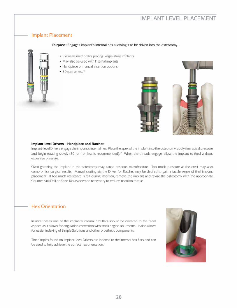
In most cases one of the implant’s internal hex flats should be oriented to the facial aspect, as it allows for angulation correction with stock angled abutments. It also allows for easier indexing of Simple Solutions and other prosthetic components.
The dimples found on Implant-level Drivers are indexed to the internal hex flats and can be used to help achieve the correct hex orientation.
Implant-level Drivers - Handpiece and RatchetImplant-level Drivers engage the implant’s internal hex. Place the apex of the implant into the osteotomy, apply firm apical pressure
and begin rotating slowly (30 rpm or less is recommended).17 When the threads engage, allow the implant to feed without excessive pressure.
Overtightening the implant in the osteotomy may cause osseous microfracture. Too much pressure at the crest may also compromise surgical results. Manual seating via the Driver for Ratchet may be desired to gain a tactile sense of final implant placement. If too much resistance is felt during insertion, remove the implant and revise the osteotomy with the appropriate Counter-sink Drill or Bone Tap as deemed necessary to reduce insertion torque.
• Exclusive method for placing Single-stage implants
• May also be used with Internal implants
• Handpiece or manual insertion options
• 30 rpm or less17
Purpose: Engages implant’s internal hex allowing it to be driven into the osteotomy.
Hex Orientation
Implant Placement

29
POST-OPERATIVE INSTRUCTIONS
All BioHorizons Surgical Kits are provided non-sterile and must be cleaned and sterilized prior to use. Always remove instruments from packaging prior to sterilization, and remove and discard packaging materials used to stabilize and secure kits during shipment. Double-check all surgical instruments to ensure their functionality prior to surgery. Backup sterile drills are also recommended.
Surgical Kit Cleaning
A period of unloaded healing time is often recommended to allow for integration between the bone and implant surface. This is dependent on individual patient healing rates and bone quality of the implant site. Each case must be independently evaluated.
The patient should be instructed to follow a post-surgical regimen including cold packs for 24 hours post-implantation. The patient’s diet should consist of soft foods and possibly dietary supplements. Pharmacological therapy should be considered as the patient’s condition dictates.
If a removable prosthesis is used during the initial healing phase, a soft liner material should be used to prevent pressure on the surgical site. Relieve the prosthesis over the implant site prior to the soft liner application. Periodically check the patient’s soft tissue and bone healing using clinical and radiographic evaluations.
Ongoing hygiene for the implant patient is vital. Hygiene recall appointments at three month intervals are suggested. Instruments designed for implant abutment scaling, such as Implacare® instruments from Hu-Friedy® should be utilized. The stainless steel handles may be fitted with assorted tip designs for hygiene on natural teeth. The Implacare® scalers contain no glass or graphite fillers that can scratch titanium implant abutments.
Post-Operative Instructions
Caution: The use of hydrogen peroxide or other oxidizing agents will cause damage to the surface of the instruments. Towel- or air-dry all instrumentation before sterilizing. After sterilization, use an adequate drying cycle to evaporate any moisture that can stain the instruments. Drills and taps should be replaced when wear is noticed, such as a decrease in cutting efficiency or when signs of discoloration appear. Drills should be replaced after approximately 12 to 20 osteotomy cycles, depending on the bone density.16
Drill usage charts can be downloaded from www.biohorizons.com.
Purpose: Remove and contour excess bone and soft tissue from the area of the prosthetic platform.
Bone Profilers
Do not use the Profiler without the Guide in place.
• Compatible with latch-type, speed-reducing handpieces
• 850-2,500 rpm drill speed with steady sterile irrigation14
• Profiler Guide protects implant platform
• Bone Profiler cuts away excess bone and soft tissue
• Color-coded by specific prosthetic platform
To use, remove the surgical Cover Cap from the implant and place the Profiler Guide [both use the .050” (1.25mm) Hex Driver]. Use the Profiler with copious amounts of sterile irrigation. Once the excess bone and soft tissue are removed, unscrew the Guide and seat the appropriate prosthetic component.

30
• Irrigate implant to remove blood and other debris
• Use an antibacterial paste to decrease the risk of bacterial growth
• Thread clockwise into implant body
• Hand-tighten (10-15 Ncm) utilizing .050” (1.25mm) Hex Driver
• Color-coded by prosthetic platform
Purpose: Protects prosthetic platform in two-stage
(submerged) surgical protocols.
INTERNAL IMPLANT HEALING PROTOCOLS
Cover cap for Two-stage Protocol
• Irrigate implant to remove blood and other debris
• Use an antibacterial paste to decrease the risk of bacterial growth
• Hand-tighten (10-15 Ncm) utilizing .050” (1.25mm) Hex Driver
• Color-coded by prosthetic platform
• Laser marked for easy intraoral identification, for example:
GR3 = Green (4.5mm) platform / Reg. Emerg. / 3mm High
Purpose: Transmucosal element for developing soft tissue
emergence with Narrow, Regular, Wide Emergence or
Simple Solutions Internal prosthetic components.
Healing Abutments for Single-stage Protocol
Immediate Provisional Restorative Options
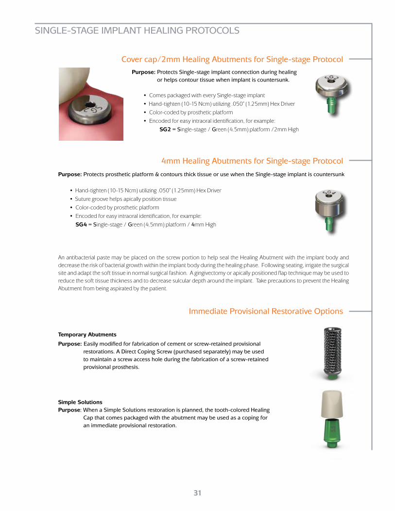
Temporary Abutments
Purpose: Easily modified for fabrication of cement or screw-retained provisional restorations. A Direct Coping Screw (purchased separately) may be used to maintain a screw access hole during the fabrication of a screw-retained provisional prosthesis.
Simple SolutionsPurpose: When a Simple Solutions restoration is planned, the tooth-colored Healing
Cap that comes packaged with the abutment may be used as a coping for an immediate provisional restoration.
31
4mm Healing Abutments for Single-stage Protocol
Cover cap/2mm Healing Abutments for Single-stage Protocol
Immediate Provisional Restorative Options
Temporary Abutments
Purpose: Easily modified for fabrication of cement or screw-retained provisional restorations. A Direct Coping Screw (purchased separately) may be used to maintain a screw access hole during the fabrication of a screw-retained provisional prosthesis.
Simple SolutionsPurpose: When a Simple Solutions restoration is planned, the tooth-colored Healing
Cap that comes packaged with the abutment may be used as a coping for an immediate provisional restoration.
• Comes packaged with every Single-stage implant
• Hand-tighten (10-15 Ncm) utilizing .050” (1.25mm) Hex Driver
• Color-coded by prosthetic platform
• Encoded for easy intraoral identification, for example:
SG2 = Single-stage / Green (4.5mm) platform /2mm High
Purpose: Protects Single-stage implant connection during healing or helps contour tissue when implant is countersunk.
SINGLE-STAGE IMPLANT HEALING PROTOCOLS
An antibacterial paste may be placed on the screw portion to help seal the Healing Abutment with the implant body and decrease the risk of bacterial growth within the implant body during the healing phase. Following seating, irrigate the surgical site and adapt the soft tissue in normal surgical fashion. A gingivectomy or apically positioned flap technique may be used to reduce the soft tissue thickness and to decrease sulcular depth around the implant. Take precautions to prevent the Healing Abutment from being aspirated by the patient.
• Hand-tighten (10-15 Ncm) utilizing .050” (1.25mm) Hex Driver
• Suture groove helps apically position tissue
• Color-coded by prosthetic platform
• Encoded for easy intraoral identification, for example:
SG4 = Single-stage / Green (4.5mm) platform / 4mm High
Purpose: Protects prosthetic platform & contours thick tissue or use when the Single-stage implant is countersunk

32
ICON LEGEND & REFERENCES
REF
LOT YYXXXXX
YYYY-MMexpires
do not re-use
0473
STERILE Rgamma irradiated
Rx Only
YYYY-MMmanufacture date
LPGR4012
RBT, Laser-Lok4.0 x 12mm, 4.5 Platform
LLPGR4012 Rev A
BioHorizons Internal
4.0 x 12mm, 4.5 PlatformREF LOT YYXXXXXLPGR4012
see instructions for use
BioHorizons Internal
40 x 12mm, 4.5 PlatformREF LOT YYXXXXXLPGR4012
4.0 x 12Internal Implant
Birmingham, AL 35244 USA 5.7
4.5
3.5
Prosthetic platform
3.5mm Prosthetic Platform
4.5mm Prosthetic Platform
5.7mm Prosthetic Platform
Symbol Descriptions for Product Labeling
BioHorizons products carry the CE mark and fulfill the require-ments of the Medical Devices Directive 93/42/EEC
0473
EU Authorised Representative Quality First InternationalLondon E7 0QY United KingdomTel. & Fax: +44-208-522-1937
Refer to Instructions for Use
Single use only
Lot/batch numberLOT
Reference/ar-ticle number
REF
Manufacture date (YYYY-MM)
Use before expiration date (YYYY-MM)
Caution: Federal (USA) law restricts these devices to the sale, distribution and use by, or on the order of, a dentist or physician.
Rx Only
Sterile by gamma irradiation
Non-sterileNON-STERILE
RSTERILE
Artwork label number
References1. Please see BioHorizons document #ML0130.2. Human Histologic Evidence of a Connective Tissue Attachment to a Dental
Implant. M Nevins, ML Nevins, M Camelo, JL Boyesen, DM Kim. International Journal of Periodontics & Restorative Dentistry. Vol. 28, No. 2, 2008.
3. The Effects of Laser Microtextured Collars Upon Crestal Bone Levels of Dental Implants. S Weiner, J Simon, DS Ehrenberg, B Zweig, JL Ricci.
Implant Dentistry, Volume 17, Number 2, 2008. p. 217-228.
4. Clinical Evaluation of Laser Microtexturing for Soft Tissue and Bone Attachment to Dental Implants. GE Pecora, R Ceccarelli, M Bonelli,
H Alexander, JL Ricci. Implant Dent. 2009 Feb;18(1):57-66.
5. Radiographic Analysis of Crestal Bone Levels on Laser-Lok® Collar Dental Implants. C Shapoff, B Lahey, P Wasserlauf, D Kim. Int J Periodontics Restorative Dent 2010;30:129-137.
6. The effects of laser microtexturing of the implant collar upon crestal bone levels and periimplant health. S Botos, H Yousef, B Zweig, R Flinton
and S Weiner. Int J Oral Maxillofac Implants 2011;26:492-498.
7. Marginal Tissue Response to Different Implant Neck Design. HEK Bae, MK Chung, IH Cha, DH Han. J Korean Acad Prosthodont. 2008, Vol. 46, No. 6.
8. Bone Response to Laser Microtextured Surfaces. JL Ricci, J Charvet, SR Frenkel, R Change, P Nadkarni, J Turner and H Alexander. Bone Engineering
(editor: JE Davies). Chapter 25. Published by Em2 Inc., Toronto, Canada. 2000.
9. Osseointegration on metallic implant surfaces: effects of microgeometry and growth factor treatment. SR Frankel, J Simon, H Alexander, M Dennis, JL Ricci.
J Biomed Mater Res. 2002;63(6): 706-13.
10. Surface Topography Modulates Osteoblast Morphology. BD Boyan, Z Schwartz. Bone Engineering (editor: JE Davies). Chapter 21. Published by Em2 Inc.,
Toronto, Canada. 2000.
11. Effects of titanium surface topography on bone integration: a systematic review. A Wennerberg, T Albrektsson. Clin Oral Implants Res. 2009 Sep;20 Suppl 4:172-84.
12. Histologic Evidence of a Connective Tissue Attachment to Laser Microgrooved Abutments: A Canine Study. M Nevins, DM Kim, SH Jun, K Guze, P Schupbach,
ML Nevins. International Journal of Periodontics & Restorative Dentistry. Vol. 30, No. 3, 2010.
13. Functional Surface Area: Thread-Form Parameter Optimization for Implant Body Design. J.Todd Strong, Carl E Misch, DDS, MDS, Martha W. Bidez, PhD, Prasad Naluri. Compendium / Special Issue. Vol 19, No. 3, 1998.
14. Density of Bone: Effect on Surgical Approach and Healing. CE Misch. Contemporary Implant Dentistry. Second Edition. Mosby: St. Louis, 1999. 371-384.
15. The influence of 0.12 percent chlorhexidine digluconate rinses on the incidence of infectious complications and implant success. Lambert PM, Morris HF, Ochi S.
J Oral Maxillofac Surg 1997;55(12 supplement 5):25-30.
16. Heat production by 3 implant drill systems after repeated drilling and sterilization. Chacon GE, Bower DL, Larsen PE, McGlumphy EA, Beck FM. J Oral Maxillofac Surg. 2006 Feb;64(2):265-9.
17. Root Form Surgery in the Edentulous Mandible: Stage I Implant Insertion. CE Misch. Contemporary Implant Dentistry Second Edition. Mosby: St. Louis, 1999. 347-369.

33
Product Support Specialist:
Cell phone:
Fax:
ORDERING & WARRANTY INFORMATION
BioHorizons Lifetime Warranty on Implants and Prosthetics: All BioHorizons implants and prosthetic components include a Lifetime Warranty. BioHorizons implant or prosthetic components will be replaced if removal of that product is due to failure (excluding normal wear to overdenture attachments).
Additional Warranties: BioHorizons warranties instruments, surgical drills, taps, torque wrenches and Virtual Implant Placement (VIP) treatment planning software.
(1) Surgical Drills and Taps: Surgical drills and taps include a warranty period of ninety (90) days from the date of initial invoice. Surgical instruments should be replaced when they become worn, dull, corroded or in any way compromised. Surgical drills should be replaced after 12 to 20 osteotomies.15
(2) Instruments: The BioHorizons manufactured instrument warranty extends for a period of one (1) year from the date of initial invoice. Instruments include drivers, sinus lift components, implant site dilators and BioHorizons tools used in the placement or restoration of BioHorizons implants.
(3) VIP treatment planning software: VIP treatment planning software warranty extends for a period of ninety (90) days from the date of initial invoice. The warranty requires that VIP be used according to the minimum system requirements.
(4) Compu-Guide surgical templates: Compu-Guide surgical templates are distributed without making any modifications to the submitted Compu-Guide Prescription Form and VIP treatment plan (“as is”). BioHorizons does not make any warranties expressed or implied as it relates to surgical templates.
Return Policy: Product returns require a Return Authorization Form, which can be acquired by contacting Customer Care. The completed Return Authorization Form should be included with the returned product. For more information, please see the reverse side of the invoice that was shipped with the product.
Disclaimer of Liability: BioHorizons products may only be used in conjunction with the associated original components and instruments according to the Instructions for Use (IFU). Use of any non-BioHorizons products in conjunction with BioHorizons products will void any warranty or any other obligation, expressed or implied.
Treatment planning and clinical application of BioHorizons products are the responsibility of each individual clinician. BioHorizons strongly recommends completion of postgraduate dental implant education and adherence to the IFU that accompany each product. BioHorizons is not responsible for inci-dental or consequential damages or liability relating to use of our products alone or in combination with other products other than replacement or repair under our warranties.
Compu-Guide surgical templates are ordered under the control of a Clinician. The Clinician recognizes responsibility for use. Therefore, regardless of the real or proven damages, the liability to BioHorizons is limited to the price of the product directly related to the reason for the claim.
Distributed Products: For information on the manufacturer’s warranty of distributed products, please refer to their product packaging. Distributed products are subject to price change without notice.
Validity: Upon its release, this literature supersedes all previously published versions.
Availability: Not all products shown or described in this literature are available in all countries. BioHorizons continually strives to improve its products and therefore reserves the right to improve, modify, change specifications or discontinue products at any time.
Any images depicted in this literature are not to scale, nor are all products depicted.

s h o p o n l i n e a t
w w w . b i o h o r i z o n s . c o m
Not all products shown or described in this literature are available in all countries. As applicable, BioHorizons products are cleared for sale in the European Union under the EU Medical Device Directive 93/42/EEC and the tissues and cells Directive 2004/23/EC. We are proud to be registered to ISO 13485:2003, the international quality
management system standard for medical devices, which supports and maintains our product licences with Health Canada and in other markets around the globe. Original language is English. © 2010 BioHorizons, Inc. All Rights Reserved.
*ML0115*ML0115
REV F OCT 2011
BioHorizons Spain+34 91 713 10 84
BioHorizons Germany+49 7661-909989-0
BioHorizons Canada866-468-8338
BioHorizons Chile+56 2 361 9519
Direct Offices
DistributorsFor contact information in our 85 markets, visit www.biohorizons.com
BioHorizons Australia +61 2 8399 1520
BioHorizons UK+44 (0)1344 752560
BioHorizons USA888-246-8338 or
205-967-7880
BioHorizons®, Laser-Lok®, MinerOss®, Autotac® and Mem-Lok® are registered trademarks of BioHorizons, Inc. Grafton® DBM and LADDEC® are registered trademarks of Osteotech, Inc. AlloDerm®, AlloDerm® GBR™ and LifeCell™ are registered trademarks of LifeCell Corporation.
Spiralock® is a registered trademark of Spiralock Corporation. Locator is a registered trademark of Zest Anchors, Inc. Delrin® is a registered trademark of E.I. du Pont de Nemours and Company. Pomalux® is a registered trademark of Westlake Plastics Co.
Mem-Lok® is manufactured by Collagen Matrix, Inc.
Related Documents