Architecture TUM.University Press Interaction Forms for Digital Design A Concept and Prototype for a Computer- Aided Design Platform for Urban Architectural Design Scenarios THESES Gerhard Schubert

Welcome message from author
This document is posted to help you gain knowledge. Please leave a comment to let me know what you think about it! Share it to your friends and learn new things together.
Transcript
Architecture
TUM.University Press
Interaction Forms for Digital DesignA Concept and Prototype for a Computer-Aided Design Platform for Urban Architectural Design Scenarios
THESES
Gerhard Schuber t
Interaction Forms for Digital DesignA Concept and Prototype for a Computer-Aided Design Platform for Urban Architectural Design Scenarios
Gerhard Schuber t
Imprint
1. Edition
Copyright © 2021 TUM.University Press Copyright © 2021 Gerhard Schubert All rights reserved
Translated and revised edition of the dissertation with the original title „Interaktionsformen für das digitale Entwerfen - Konzeption und Umsetzung einer rechnergestützten Entwurfsplattform für die städtebaulichen Phasen in der Architektur“ which was published by the Technical University of Munich in 2014.
Layout design and typesetting: Gerhard Schubert Cover design: Caroline Ennemoser Cover illustration: subject by Gerhard Schubert, photo by Nick Förster Translation: Michael Holohan Additional translation: Anja Müller
TUM.University Press Technical University of Munich Arcisstrasse 21 80333 Munich
DOI: 10.14459/2021md1610329
www.tum.de
The German National Library has registered this publication in the German National Bibliography. Detailed bibliographic data are available on the Internet at https://portal.dnb.de.
iii
Acknow
ledgments
Acknowledgments
This work was created during my work as a researcher at the Chair of Architecture Informatics (previously Professorship for CAAD) at the Technical University of Munich.
Many people have supported me in the implementation of this work, and for this I would like to thank you sincerely.
I would especially like to thank Prof. Richard Junge, Prof. Dr. Frank Petzold and Prof. Dr. Dieter Kranzlmüller for their many discussions with me, their professional and personal support and assistance, but also for the freedom they have given me and the great interest they have shown in my work.
I would also like to thank all my colleagues. They have always given me the time and support I needed to carry out this work, especially in its final stages.
Further thanks go to all the students who participated in the projects during their studies and thus made the implementation of the prototypes possible in the first place.
Special thanks to my family, who was always by my side with advice and words of motivation. They gave me support and assistance at all times, and I could always turn to them with all my questions and problems.
The English version of this work was only possible with the help of Michael Holohan and Anja Müller. Thank you for your great efforts in translating the paper. I would also like to thank the Dr. Marschall Foundation for their financial support.
Remarks
This work is the English translation of the 2014 dissertation with the original title “Interaktionsformen für das digitale Entwerfen - Konzeption und Umsetzung einer rechnergestützten Entwurfsplattform für die städtebaulichen Phasen in der Architektur” (http://nbn-resolving.de/urn/resolver.pl?urn:nbn:de:bvb:91-diss-20140703-1207655-0-3).
In the course of translation, individual passages were revised, and where possible sources were replaced with the original English version. If the source was not available in English, the quotation was translated from the original.
iv
Summ
ary
Summary
In the current day-to-day life of the architect, computers are used largely in the later, executive phases of planning – the early, creative phases remain mostly unaffected by this technology. The architect still designs using working models and hand-drawn sketches. However, digital calculations, analyses and simulations are increasingly used to check and verify architectural ideas. Yet these applications are completely detached from the activity of designing. Due to inadequate interfaces and inadequate software concepts, the workflow between physical models, analog sketches and digital tools is characterized by media disruptions.
The aim of this work is to bridge the current discrepancy between established working methods and digital design support tools.
This work is based on an analytical examination of the design process. On this basis, it is necessary to define the interaction methods necessary for designing and the basic requirements for design tools. Furthermore, the topic requires a consideration of the framework conditions of both actors: human and computer.
This work focuses on defining an application concept for a computer-aided design system. Based on the resulting requirements, a corresponding system structure and solution approach is described. In addition, a prototypical implementation of relevant sub-areas is carried out. The goal here is not to replace the architect’s established working methods with digital methods. Rather, both worlds must be connected in such a way that their strengths merge with each other. The core idea is therefore to create a seamless coupling of established tools and digital design support tools such as analyses and simulations. In this way, design decision support is made possible at an early stage of the design process. The computer assists the architect without disturbing or overwhelming them in their creative work.
v
Table of Contents
Table of Contents
1 Introduction 1
1.1 The Current Situation 1
1.2 Design Support Using the Computer 2
1.3 Critical Remarks 6
1.4 The goal of the work 6
1.5 Approach 7
1.6 Structure of the work 8
2 Architectural Design 10
2.1 Design 10
2.1.1 The design process 11
2.1.2 Design Methods 13
2.1.3 Summary 14
2.2 Brainstorming 15
2.2.1 The role of perception 16
2.2.2 Visual Thinking | A Creative Cycle 17
2.2.3 Summary 20
2.3 Design tools 20
2.3.1 Use of design tools 21
2.3.2 Established design tools 23
2.4 Definition of requirements 28
3 Human Processing 30
3.1 Information Reception [Perceptual Processor] 31
3.2 Information Processing [Cognitive Processor] 34
3.3 Reaction and Gesture [Motorized Processor] 36
3.4 Parameters of Human Processing 36
3.4.1 Multi-sensory perception 36
3.4.2 Locus of attention 37
3.4.3 Knowledge and mind 39
3.5 Definition of requirements 40
vi
Table of Contents
4 Human-Computer Interaction 41
4.1 Interaction as a dialog 42
4.2 Input & Output 45
4.2.1 Input 46
4.2.2 Output 49
4.2.3 Interplay between input and output 52
4.3 Interfaces 53
4.3.1 Command Devices 54
4.3.2 Pointing Devices 56
4.3.3 Tangible Devices 59
4.3.4 Comparison 63
4.4 Definition of Requirements 64
5 Discussion of Related Work 65
5.1 Pointing Devices 66
5.2 Virtual Environments 71
5.3 Tangible Interfaces 74
5.3.1 Constructive Assembly 75
5.3.2 Interactive Surfaces 77
5.4 Conclusion and Comparison 82
6 Deficit Analysis 85
6.1 Ease of Use 85
6.2 Flexible use 86
6.3 Direct Feedback 87
6.4 Visualization of Vague Thoughts 90
6.5 Stepwise Approach 90
6.6 Summary 92
vii
Table of Contents
7 A Digital Design System 93
7.1 Approach 93
7.1.1 The Computer as a Tool for Thinking 94
7.1.2 The computer as a support for design 95
7.1.3 Using the Computer to Solve Individual Tasks 97
7.1.4 Concept 98
7.2 Application Scenario 99
7.3 System Requirements 102
7.4 System component 1: Interface/Hardware 103
7.4.1 Subsystem 1: Plan view (Multi-touch table) 103
7.4.2 Subsystem 2: Info panel (vertical touchscreen) 108
7.4.3 Subsystem 3: Customizable hardware components 113
7.5 System Component 2: Software 116
7.5.1 Middleware/Host application 117
7.5.2 Plug-ins 120
8 Discussion & Outlook 123
Appendix
Appendix A: Prototypes 127
Appendix B: Glossary 148
Appendix C: List of abbreviations 151
Appendix D: List of figures 152
Appendix E: Bibliography 155
1
Introduction
1 Introduction
The core of the present work is the architectural design process and the question of the use of digital tools in the early creative phases of the architectural work process. It is motivated, above all, by the fact that the current potential of digital computer use can also be used to optimize these early design phases and thus ultimately also to sustainably improve architectural quality. Work in the field of architectural informatics follows an interdisciplinary approach and deals with topics from the fields of architecture, computer science and perceptual psychology. To better understand this, the situation as it is today will be discussed. Relevant questions and the goals of the work will be formulated on the basis of this discussion.
1.1 The Current Situation
The use of computers in many areas has become an integral part of the day-to-day work of architects. But even if, according to a study by Maisberger Whiteoaks and Nemetschek AG (2005, 17), the use of computers in architecture is certainly increasing, these computer systems are still only used in certain subfields despite their increasing performance capabilities. So while computers are used in many phases of the planning process, digital tools are rarely used in the early conceptual phases where designs are truly determined. Instead, established analog tools such as freehand sketches and working models are used – unconnected from any digital design support. The use of computers is rather focused on later planning phases like construction, visualization and they are also used for tender biddings to determine quantities and/or costs (Maisberger Whiteoaks/Nemetschek AG 2005). Thus computers are used to document the design rather than to support the designer. From a critical point of view, however, it can be said that established tools and workflows are, in most cases, only transferred to the computer one-to-one in the form of CAD. Thus the computer is usually used by the architect – with few exceptions – to document already thought-out ideas and less as an innovative design tool. More than 20 years ago, Ranulph Glanville (1992) described, not without good reason, how “CAD [is] Abusing Computing” as a tool instead of exploiting its full potential. The situation has not really changed much, as John Gero confirms: “They are all primarily focused on representing a design which has reached a level of finalisation in its development. They do not really support changing design perspectives” (Gero 2006, 1).
The root of this problem can to a large extent be seen in the inadequate human-computer interface of current computer systems. This concerns on the one hand the unergonomic tools themselves, but also the lack of interaction methods necessary for the design. If one considers established design tools such as freehand sketches and physical models in this context, it becomes clear how different this is from operating a computer. In addition, however, the use of computers in creative contexts is made more difficult by unsuitable concepts regarding how a computer can and should be used and by program functions that are too rigid, inflexible and inadequate.
2
Introduction
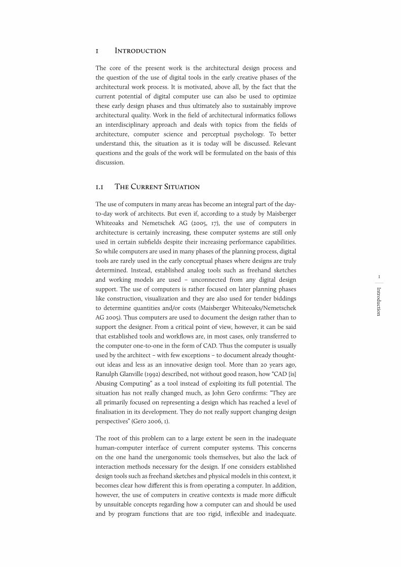
These absolutely contradictory worlds – the computer on the one hand and established design tools on the other – currently do not allow the tools to be linked with each other, providing no opportunity to integrate digital media into the design process. This problem leads to an operating scenario disturbed by media disruptions1. This results in an interrupted design process that consists of different, sequentially executed steps and the use of correspondingly different tools. Independent steps, which are carried out one at a time, inhibit creative work by constantly changing media and context and disrupting the design process enormously.
Fig. 1:
WORKING MODEL
SKETCHES
BIM / CAD
SIMULATIONS
3D-MODELSCALCULATIONS
REGULATIONS
Design media working together
In addition, however, unsuitable and inadequate usage concepts also make it difficult to use the computer in a creative context. For this reason, new approaches are required which can justify the use of the computer in creative design phases and also make it possible. Mihai Nadin (1997, 49) mentions this appropriately in the following context:
“The usage of computers for only cosmetic design, a task that can just as well be solved with conventional tools, is unproductive and unsatisfying. The computer must be integrated into the design process and must be incorporated creatively in new impending product designs.” (ibid.)2
1.2 Design Support Using the Computer
With the introduction of the computer in the 1960s and 1970s, various approaches to its use in the architectural field developed. The main application can be seen in the use of CAD or CAAD programs and thus
1 The term “media disruption” refers to a change of medium within a transmission chain in the
transmission of information. The resulting distortion of information and the slowing down
of information processing can be seen as problematic (Springer Gabler Verlag 2014, 2143).
2 Translated from the original: „Der Einsatz von Computern für ein nur kosmetisches Design,
eine Aufgabe, die mit herkömmlichen Werkzeugen ebenso gut gelöst werden kann, ist
unproduktiv und unbefriedigend. Der Computer muß in den Designprozeß, muß in neu zu
entwerfende Produkte kreativ eingebunden werden.“
wo quelle hin? vor oder nach den "."
3
Introduction
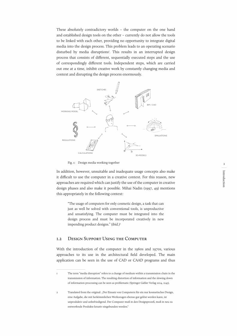
primarily in the use of the computer as a digital drawing board. Despite, or precisely because of, this dominance of the computer as a drawing or modelling tool for documenting ideas that have already been thought out, it is possible to discern different approaches to using the computer in architectural design contexts, particularly in the research sector. Based on this situation, I will discuss the use of computer support in the design process in more detail in what follows. Here, a distinction can be made between two contrasting conceptual approaches (Liebich 1994, 23-24):
• Active systems: design automation
• Passive systems: design assistant
Fig. 2:
Design machines Assistance systems
Limited complexity of the design problem
Unlimited competenceof designing
Limited competence of designing
Unlimited complexityof the design problem
A comparison of active and passive systems (according to Liebich 1994, 23). Translated from the original.
Active systems describe methods based on the automatic, generic generation of geometric structures. Passive systems, on the other hand, can be seen as systems that support the user and are dependent on a close cooperation between user and computer. (ibid.)
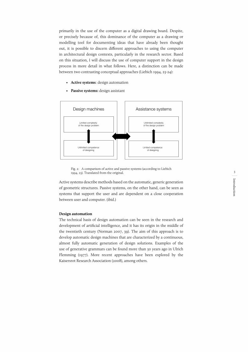
Design automationThe technical basis of design automation can be seen in the research and development of artificial intelligence, and it has its origin in the middle of the twentieth century (Norman 2007, 39). The aim of this approach is to develop automatic design machines that are characterized by a continuous, almost fully automatic generation of design solutions. Examples of the use of generative grammars can be found more than 30 years ago in Ulrich Flemming (1977). More recent approaches have been explored by the Kaisersrot Research Association (2008), among others.
B i l d u n t e r s c h r i f t ? ? ? Übersetzung erwähnen?
4
Introduction
Fig. 3: Kaisersrot's project: Urban planning solutions are generated automatically on the basis of adjustable parameters such as construction size, development, solar radiation (KCAP 2014).
Due to the complex problems of architectural tasks, generating structures is in many cases carried out using genetic algorithms. Based on genetics, a method is based on the following principle: Starting from parameters defined by the user, a number of different solution variants are formed by chance. These are then evaluated on the basis of previously defined criteria. New variants are created on the basis of the best-evaluated ones, and the process begins anew. The advantage of this method is that a corresponding result can be achieved, especially for complex tasks that do not have an unambiguously best solution. A genetic algorithm returns results after running through several evolutionary stages, and a large number of different solutions are available that nevertheless meet the criteria to a high degree. Thus, after passing through several stages of evolution, a genetic algorithm provides a variety of different solutions that nonetheless meet the criteria to a high degree. The general problem of this approach can therefore be seen, above all, in the way it dictates solutions to the architect. By automatically generating design proposals, the architect’s control is reduced to defining various parameters and selecting of one of the many proposed solutions. He or she cannot make any design decisions nor influence the process. Instead, he/she is presented with a fait accompli at the end of the process, which is not really an improvement of the creative process.
Design AssistantStarting from the problem of approaches based on artificial intelligence, Amplifying Intelligence developed as early as the 1960s as an alternative movement for solving complex problems with the help of computers (Ashby 1957, 271-272). In total contrast to artificial intelligence and the associated idea of digitally reproducing human thinking and intelligence, the basic ideas of Amplifying Intelligence, in the broadest sense, can be described as the extension of human intelligence by the computer: The computer assists the human being and thus enhances his or her intellectual potential (ibid.). In practice, this approach has become established, above all, in the idea of computer support being a decision support system. The computer helps the user and extends his discretion to the extent that the decisions the user takes are also based on sound and demonstrable knowledge. Quite the contrary to artificial intelligence, these systems enable the use of computers
5
Introduction
in a way that the decision-making power always remains with the human being. The advantages of using computers as a design decision support system in an architectural context lie, above all, in quantifying design-relevant parameters and criteria and helping the architect “[...] by shortening iteration times when evaluating alternatives” (Steinmann 1997, 36)3.
Herman Neukermans, Benjamin Geebelen and Stefan Boeykens (2005, 3) aptly point out that, while the computer can be seen as a tool for extending and augmenting the human brain, it should not be expected to be capable of making design decisions and selecting design options for the designer. Elsewhere they argue that the computer can only be used meaningfully if it supports the architect as an assistance system (decision support): “What the architect needs is a CAAD system that ‘looks over his/her shoulder’ while designing and that informs about the qualities of the design [...]” (Neuckermans, Geebelen und Boeykens 2005, 1).
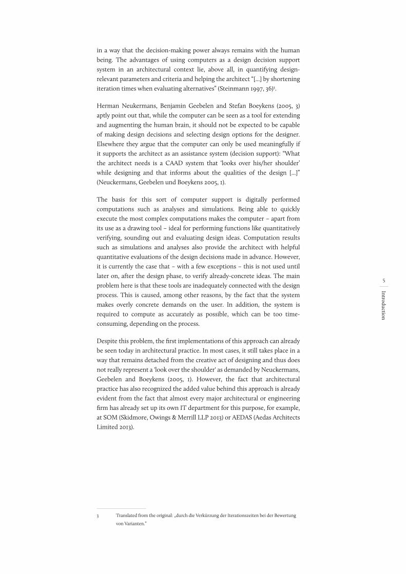
The basis for this sort of computer support is digitally performed computations such as analyses and simulations. Being able to quickly execute the most complex computations makes the computer – apart from its use as a drawing tool – ideal for performing functions like quantitatively verifying, sounding out and evaluating design ideas. Computation results such as simulations and analyses also provide the architect with helpful quantitative evaluations of the design decisions made in advance. However, it is currently the case that – with a few exceptions – this is not used until later on, after the design phase, to verify already-concrete ideas. The main problem here is that these tools are inadequately connected with the design process. This is caused, among other reasons, by the fact that the system makes overly concrete demands on the user. In addition, the system is required to compute as accurately as possible, which can be too time-consuming, depending on the process.
Despite this problem, the first implementations of this approach can already be seen today in architectural practice. In most cases, it still takes place in a way that remains detached from the creative act of designing and thus does not really represent a 'look over the shoulder' as demanded by Neuckermans, Geebelen and Boeykens (2005, 1). However, the fact that architectural practice has also recognized the added value behind this approach is already evident from the fact that almost every major architectural or engineering firm has already set up its own IT department for this purpose, for example, at SOM (Skidmore, Owings & Merrill LLP 2013) or AEDAS (Aedas Architects Limited 2013).
3 Translated from the original: „durch die Verkürzung der Iterationszeiten bei der Bewertung
von Varianten.”
erledigt
Gehört die Quelle hier überhaupt rein? Der Gedanke is ja von mir, nur das Zitat ned
6
Introduction
1.3 Critical Remarks
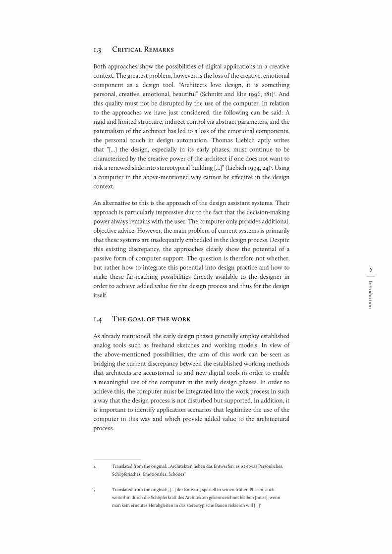
Both approaches show the possibilities of digital applications in a creative context. The greatest problem, however, is the loss of the creative, emotional component as a design tool. “Architects love design, it is something personal, creative, emotional, beautiful” (Schmitt and Elte 1996, 181)4. And this quality must not be disrupted by the use of the computer. In relation to the approaches we have just considered, the following can be said: A rigid and limited structure, indirect control via abstract parameters, and the paternalism of the architect has led to a loss of the emotional components, the personal touch in design automation. Thomas Liebich aptly writes that “[...] the design, especially in its early phases, must continue to be characterized by the creative power of the architect if one does not want to risk a renewed slide into stereotypical building [...]” (Liebich 1994, 24)5. Using a computer in the above-mentioned way cannot be effective in the design context.
An alternative to this is the approach of the design assistant systems. Their approach is particularly impressive due to the fact that the decision-making power always remains with the user. The computer only provides additional, objective advice. However, the main problem of current systems is primarily that these systems are inadequately embedded in the design process. Despite this existing discrepancy, the approaches clearly show the potential of a passive form of computer support. The question is therefore not whether, but rather how to integrate this potential into design practice and how to make these far-reaching possibilities directly available to the designer in order to achieve added value for the design process and thus for the design itself.
1.4 The goal of the work
As already mentioned, the early design phases generally employ established analog tools such as freehand sketches and working models. In view of the above-mentioned possibilities, the aim of this work can be seen as bridging the current discrepancy between the established working methods that architects are accustomed to and new digital tools in order to enable a meaningful use of the computer in the early design phases. In order to achieve this, the computer must be integrated into the work process in such a way that the design process is not disturbed but supported. In addition, it is important to identify application scenarios that legitimize the use of the computer in this way and which provide added value to the architectural process.
4 Translated from the original: „Architekten lieben das Entwerfen, es ist etwas Persönliches,
Schöpferisches, Emotionales, Schönes“
5 Translated from the original: „[...] der Entwurf, speziell in seinen frühen Phasen, auch
weiterhin durch die Schöpferkraft des Architekten gekennzeichnet bleiben [muss], wenn
man kein erneutes Herabgleiten in das stereotypische Bauen riskieren will [...]“
7
Introduction
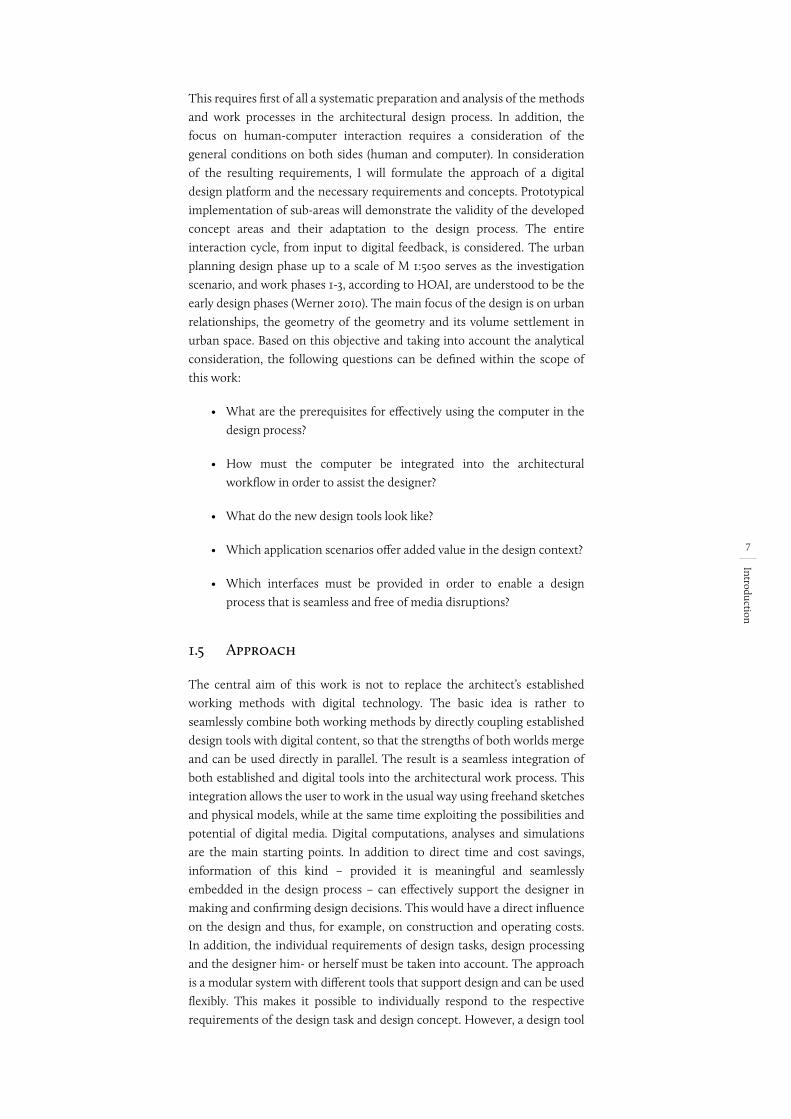
This requires first of all a systematic preparation and analysis of the methods and work processes in the architectural design process. In addition, the focus on human-computer interaction requires a consideration of the general conditions on both sides (human and computer). In consideration of the resulting requirements, I will formulate the approach of a digital design platform and the necessary requirements and concepts. Prototypical implementation of sub-areas will demonstrate the validity of the developed concept areas and their adaptation to the design process. The entire interaction cycle, from input to digital feedback, is considered. The urban planning design phase up to a scale of M 1:500 serves as the investigation scenario, and work phases 1-3, according to HOAI, are understood to be the early design phases (Werner 2010). The main focus of the design is on urban relationships, the geometry of the geometry and its volume settlement in urban space. Based on this objective and taking into account the analytical consideration, the following questions can be defined within the scope of this work:
• What are the prerequisites for effectively using the computer in the design process?
• How must the computer be integrated into the architectural workflow in order to assist the designer?
• What do the new design tools look like?
• Which application scenarios offer added value in the design context?
• Which interfaces must be provided in order to enable a design process that is seamless and free of media disruptions?
1.5 Approach
The central aim of this work is not to replace the architect’s established working methods with digital technology. The basic idea is rather to seamlessly combine both working methods by directly coupling established design tools with digital content, so that the strengths of both worlds merge and can be used directly in parallel. The result is a seamless integration of both established and digital tools into the architectural work process. This integration allows the user to work in the usual way using freehand sketches and physical models, while at the same time exploiting the possibilities and potential of digital media. Digital computations, analyses and simulations are the main starting points. In addition to direct time and cost savings, information of this kind – provided it is meaningful and seamlessly embedded in the design process – can effectively support the designer in making and confirming design decisions. This would have a direct influence on the design and thus, for example, on construction and operating costs. In addition, the individual requirements of design tasks, design processing and the designer him- or herself must be taken into account. The approach is a modular system with different tools that support design and can be used flexibly. This makes it possible to individually respond to the respective requirements of the design task and design concept. However, a design tool
8
Introduction
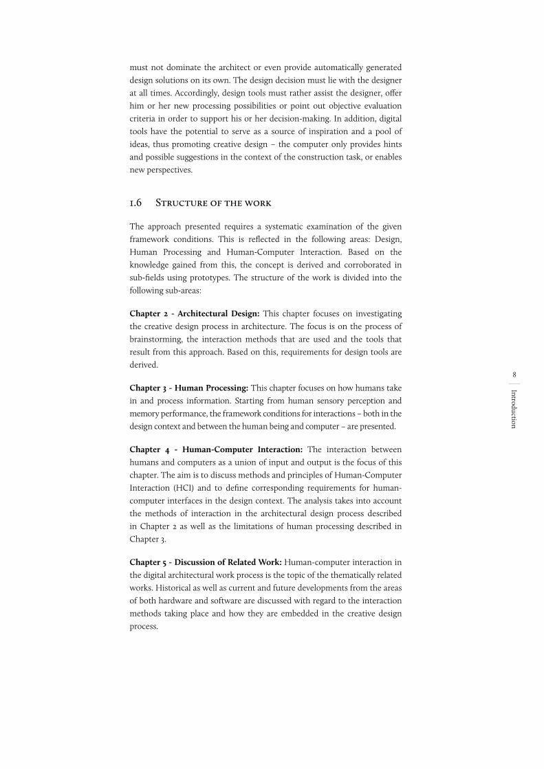
must not dominate the architect or even provide automatically generated design solutions on its own. The design decision must lie with the designer at all times. Accordingly, design tools must rather assist the designer, offer him or her new processing possibilities or point out objective evaluation criteria in order to support his or her decision-making. In addition, digital tools have the potential to serve as a source of inspiration and a pool of ideas, thus promoting creative design – the computer only provides hints and possible suggestions in the context of the construction task, or enables new perspectives.
1.6 Structure of the work
The approach presented requires a systematic examination of the given framework conditions. This is reflected in the following areas: Design, Human Processing and Human-Computer Interaction. Based on the knowledge gained from this, the concept is derived and corroborated in sub-fields using prototypes. The structure of the work is divided into the following sub-areas:
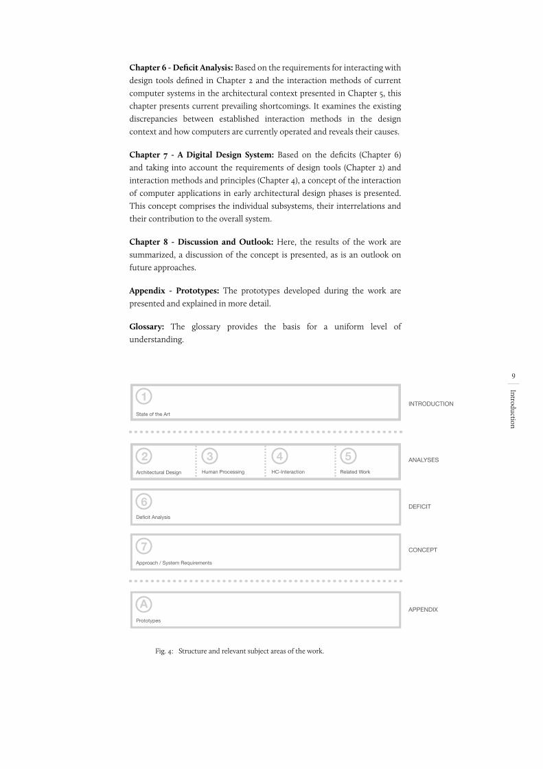
Chapter 2 - Architectural Design: This chapter focuses on investigating the creative design process in architecture. The focus is on the process of brainstorming, the interaction methods that are used and the tools that result from this approach. Based on this, requirements for design tools are derived.
Chapter 3 - Human Processing: This chapter focuses on how humans take in and process information. Starting from human sensory perception and memory performance, the framework conditions for interactions – both in the design context and between the human being and computer – are presented.
Chapter 4 - Human-Computer Interaction: The interaction between humans and computers as a union of input and output is the focus of this chapter. The aim is to discuss methods and principles of Human-Computer Interaction (HCI) and to define corresponding requirements for human-computer interfaces in the design context. The analysis takes into account the methods of interaction in the architectural design process described in Chapter 2 as well as the limitations of human processing described in Chapter 3.
Chapter 5 - Discussion of Related Work: Human-computer interaction in the digital architectural work process is the topic of the thematically related works. Historical as well as current and future developments from the areas of both hardware and software are discussed with regard to the interaction methods taking place and how they are embedded in the creative design process.
9
Introduction
Chapter 6 - Deficit Analysis: Based on the requirements for interacting with design tools defined in Chapter 2 and the interaction methods of current computer systems in the architectural context presented in Chapter 5, this chapter presents current prevailing shortcomings. It examines the existing discrepancies between established interaction methods in the design context and how computers are currently operated and reveals their causes.
Chapter 7 - A Digital Design System: Based on the deficits (Chapter 6) and taking into account the requirements of design tools (Chapter 2) and interaction methods and principles (Chapter 4), a concept of the interaction of computer applications in early architectural design phases is presented. This concept comprises the individual subsystems, their interrelations and their contribution to the overall system.
Chapter 8 - Discussion and Outlook: Here, the results of the work are summarized, a discussion of the concept is presented, as is an outlook on future approaches.
Appendix - Prototypes: The prototypes developed during the work are presented and explained in more detail.
Glossary: The glossary provides the basis for a uniform level of understanding.
Fig. 4:
Architectural Design Human Processing HC-Interaction Related Work
Deficit Analysis
State of the Art
Approach / System Requirements
ANALYSES
DEFICIT
CONCEPT
APPENDIX
INTRODUCTION1
2
6
7
Prototypes
A
3 4 5
Structure and relevant subject areas of the work.
10
Architectural D
esign
2 Architectural Design
This work is particularly interested in design as a fundamental activity of the architectural process. In the following sections, the fundamentals of the design process will therefore be examined and analyzed in greater detail. This investigation forms the thematic basis of the work and enables a uniform understanding of the architectural design process. The aim is to discuss the basic properties and procedures of design in order to define the necessary requirements for design support tools.
2.1 Design
Looking at the historical development of architecture, it can be seen that the function of the architect has not always been an independent area in the construction process. Until the middle of the 13th century, “a general idea of building type and dimension in the spirit of the master builder (opus in mente conceptum) served as the basis for the successive building construction” – there was no such thing as design as it is known today (Binding 2012, 70)6. It was not until the late Middle Ages, in the run-up to the industrial revolution, that the profession of architect and the concept of design – influenced by the spirit of the times, cultural changes and technical progress, among other things – became detached from the building process and established as a separate activity (Heskett 1980, 11). This change arose from the need to separate the act of brainstorming or planning from the act of building, which is understandable. In contrast to the artistic work of a painter or sculptor, the size and complexity of architectural tasks means that they can only be directly processed by an individual to a limited extent (Gänshirt 2007, 57). Increasingly larger, more complex and more elaborate construction tasks thus required new approaches – thinking ahead on a smaller scale had to take place. The advantages are obvious: “The whole point of having the process of design separated from the process of making is that proposals for new artefacts can be checked before they are put into production” (Cross 2008, 6). Thinking ahead was and still is necessary in order to anticipate developments, results and effects without having to actually carry them out (Fish and Scrivener 1990, 117). Therefore, the purpose of the design and designing can be narrowly defined:
“If making cannot start before designing is finished, then at least it is clear what the design process has to achieve. It has to provide a description of the artefact that is to be made. [...] When a client asks a designer for ‘a design’, that is what they want: the description. The focus of all design activities is that endpoint.“ (Cross 2008, 4)
The goals of designing thus lie in the concrete description of an initially unknown something, a future goal, proceeding from an abstract task to a concrete, three-dimensional model (Gänshirt 2007, 57). The architect may
6 Translated from the original: „Eine allgemeine Vorstellung von Bautyp und Dimension im
Geist des Baumeisters (opus in mente conceptum) diente als Grundlage für die sukzessive
Bauerstellung.“
keine englische Version
Quelle verschoben!
Finde ich nichtmehr
vielleicht 8 und 9 verwechselrt
früher stand hier 98. Macht aber keinen Sinn
11
Architectural D
esign
have a rough, vague idea of what the goal might look like right from the start. A concrete depiction of this, or the way in which the goal is to be achieved, only develops step by step. According to Brian Lawson (1994, 140),
Richard MacCormac describes this quite well:
“‘This is not a sensible way of earning a living, it’s completely insane, there has to be this big thing that you’re confident, you’re going to find, you don’t know what it is you’re looking for and you hang on.’“ (Lawson 1994, 140)
But even if this clearly defines the final purpose of design work, the question nevertheless arises: What is designing as such? If one first considers the basic conditions of architectural tasks in this context, it quickly becomes clear that architecture is a complex, multi-layered set of problems. The reason for this can be seen in the multitude of different framework conditions out of which the initially unknown object develops and is fleshed out. These can be very different and include, for example, the space plan, costs, function, construction, but also design parameters. Depending on the planning task, the individual problems have different priorities and are therefore more or less clearly defined. In addition, the different problems can change during the process, they fall away, or develop anew. However, these design-relevant parameters don’t exist independently. In many cases they are closely connected, influence each other and have to be weighed against each other according to different criteria. Architectural tasks are therefore complex, multi-layered problems based on different, mutually influencing framework conditions. The task of designing consists, above all, in taking account of these given framework conditions, as well as the problems that develop from them by solving the individual sub-problems without losing sight of the stated final goal. All these problems are supervised by the architect, who deals with them simultaneously. Therefore it is not surprising that, as Michael Wilford puts it, the architect sometimes seems like “[...] a ‘juggler who’s got six balls in the air […]’ ” (Lawson 1993, 8).
2.1.1 The design process
In the past, attempts have often been made to find a generally valid structure for the activity of problem solving. The first efforts to structure the process and to press it into a generally valid schema were made about 90 years ago with the “development process model”, used to develop a combat ship for the Royal Navy (Dubberly 2004, 7). Such efforts continue to this day: the more than 100 design theories collected and presented by Hugh Dubberly (2004) alone clearly show that design itself is difficult to explain and that it seems almost impossible to structurally grasp the processes involved or to compress them into a generally valid schema. Most design theories, however, limit themselves to dividing the design process into a logical sequence of actions that build on one another (Steinmann 1997, 44). These pragmatic models reflect the work phases well, but “[...] they disregard a consideration of the degree of detail as well as the complexity of actually occurring controls” and thus make no statements about the “[...] ‘how’ of the creative design [...]”
Die gezeigten pragmatischen Modelle geben
Leistungsphasen in einem assoziierten
Abstarktionsgrad/Unschärfe des
Entwurfsgegenstands gut wieder, sie lassen
eine Betrachtung des Detaillierungsgrades
sowie die Komplexität tatsächlich auftretender
Steuerungen jedoch außer acht. Sie eignen
sich zur Grobgliederung des Gesamtprozesses,
eine detaillierte Untersuchung des ‘Wie’ des
schöpferischen Entwurfs liefern sie nicht.
12
Architectural D
esign
(ibid.)7. Any form of generalization or attempt to determine strict procedural paths for the design process – exactly what these very forms of architectural theory represent – must be regarded as questionable and as providing no relevant statements about concrete design procedures.
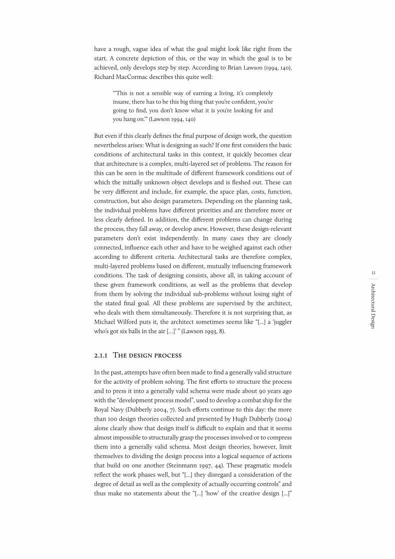
Even if the design cannot be made with the help of a general, generally valid formula8, in what follows, I will more closely examine the process’ analytical results and recurring patterns, detached from any rigid structure. Gottfried Vosgerau (2005, 3) describes problems in this context as a problem space, spanned by the various possible operations that can be carried out in a situation. Based on this, problem solving can be defined as the search for the shortest path through the space of this problem. In an analysis by Geoffrey Broadbent (1978, 256) (with reference to D.G. Christopherson and J.K. Page at the Conference of Design Methods) this is accomplished by means of three basic elements: analysis, synthesis, and evaluation (ibid.). These, however, do not represent a fixed order of the design process. Rather, the core activity must be seen as being a “[...] negotiation between problem and solution through the three activities of analysis, synthesis and evaluation” (Lawson 1997, 47).
Fig. 5: Designing as an iterative process of analysis, synthesis and evaluation (Lawson 1997, 47).
Contrary to the above-mentioned process-oriented theories, there are no fixed start and/or end points and no direction or predefined procedure path can be identified. Rather, the architect approaches the problem through a recurring analysis, synthesis and evaluation of an initially unknown solution. On the basis of this realization and the three relevant components of the process (analysis, synthesis, and evaluation) in mutual alternation, designing can be understood as “[...] a process of approaching concrete reality laboriously and gradually [...]” (Gänshirt 2007, 65). It is an individual process, dependent on the task, processor, design idea and many other factors, which is ultimately shaped by an iterative, recurring process:
7 Translated from the original: „[...] sie lassen eine Betrachtung des Detailierungsgrades sowie
die Komplexität tatsächlich auftretender Steuerungen jedoch außer acht“ und treffen somit
auch keine Aussagen über das „[...] ‘Wie’ des schöpferischen Entwurfes [...]“
8 Even if the design cannot be carried out according to a generally valid formula, each designer
nevertheless develops a personal, individual approach to problem solving in the course of his
or her work.
falsches Jahr - jetzt OK
falsches Jahr - jetzt OK
OK
13
Architectural D
esign
“In this kind of situation, it can be easy for the designer to become trapped in an iterative loop of decision-making, where improvements in one part of the design leads to adjustments in another part which lead to problems in yet another part. These problems may mean, that the earlier ‘improvement’ is not feasible. This iteration is a common feature of designing.“ (Cross 2008, 8)
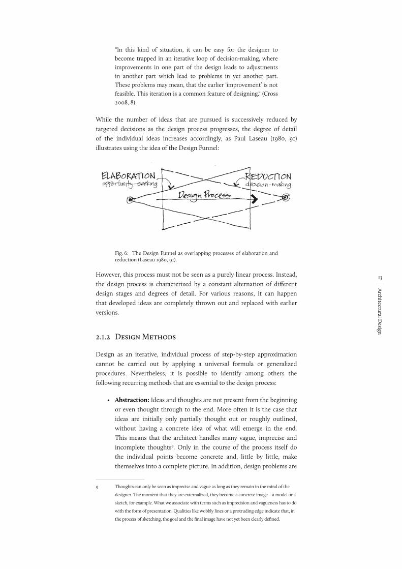
While the number of ideas that are pursued is successively reduced by targeted decisions as the design process progresses, the degree of detail of the individual ideas increases accordingly, as Paul Laseau (1980, 91) illustrates using the idea of the Design Funnel:
Fig. 6: The Design Funnel as overlapping processes of elaboration and reduction (Laseau 1980, 91).
However, this process must not be seen as a purely linear process. Instead, the design process is characterized by a constant alternation of different design stages and degrees of detail. For various reasons, it can happen that developed ideas are completely thrown out and replaced with earlier versions.
2.1.2 Design Methods
Design as an iterative, individual process of step-by-step approximation cannot be carried out by applying a universal formula or generalized procedures. Nevertheless, it is possible to identify among others the following recurring methods that are essential to the design process:
• Abstraction: Ideas and thoughts are not present from the beginning or even thought through to the end. More often it is the case that ideas are initially only partially thought out or roughly outlined, without having a concrete idea of what will emerge in the end. This means that the architect handles many vague, imprecise and incomplete thoughts9. Only in the course of the process itself do the individual points become concrete and, little by little, make themselves into a complete picture. In addition, design problems are
9 Thoughts can only be seen as imprecise and vague as long as they remain in the mind of the
designer. The moment that they are externalized, they become a concrete image – a model or a
sketch, for example. What we associate with terms such as imprecision and vagueness has to do
with the form of presentation. Qualities like wobbly lines or a protruding edge indicate that, in
the process of sketching, the goal and the final image have not yet been clearly defined.
von Fish & Skrive-ner S. 118wobbly
14
Architectural D
esign
usually complex tasks that cannot be understood in their entirety, but only partially. Abstraction, simplification and subdivision create smaller sub-areas that are more manageable and that can be processed more easily, thus enabling the architect to keep complex things in focus.
• Generating Alternatives: Architects regularly encounter situations that cannot be solved spontaneously. In these cases, they develop a wide variety of alternatives and suggested solutions (Rittel and Reuter 1992, 75-93). Based on both quantifiable and objective, as well as qualitative and subjective criteria, these suggested solutions are evaluated and weighed against each other. This includes design, technical, financial, legal and sociological considerations, among others. Due to the complex nature of the task and the often contradictory and interdependent requirements, it is rarely possible to carry out an evaluation unambiguously or automatically. Therefore, evaluating these individual alternatives and weighing them against each other becomes an important component in the design process.
“The exploration of design solution-and-problem is also often done through early sketching of tentative ideas. It is necessary because normally there is no way of directly generating an ‘optimum’ solution from the information provided in the design brief.“ (Cross 2008, 10)
In this way, one or more favorites can be identified, which then serve as the basis for further work. Depending on the situation and the problems that occur, it is conceivable that the current variant will be rejected later on, and that an earlier solution is used instead, and the work continues using this solution. And so the respective starting point and degree of detail change with every alteration.
2.1.3 Summary
As we can see, the design should be regarded as an individual process of problem solving which cannot be processed according to a generally valid formula. The aim of the process is to develop an idea or solution for an end product that, in many cases, does not yet exist, based on more or less clearly defined framework conditions and the problems that arise as a result. It is a means of problem solving that can be characterized by the following properties, among others:
• The aim of the design process is the formulation of an as yet unknown object.
• There are an inexhaustible number of different solutions.
• There is no optimal solution, but many different ones – the final solutions represent a compromise.
• Design problems are mainly of a creative, functional and technical nature.
15
Architectural D
esign
• Through abstraction and generating alternatives, an incremental approach to an initially unknown goal takes place.
• The design idea evolves from being vague, imprecise and incomplete into a concrete final solution.
• If there is no concrete problem or if the given problems are not complete, an essential part of the process lies in defining a problem.
2.2 Brainstorming
Architectural tasks are complex problems that cannot be solved using a general formula or general method. Instead, they involve a search for one of several optimal solutions in a solution space that covers the given task and the resulting problem areas. This search is characterized by creating solutions and evaluating them. The process of brainstorming is thus of particular importance in design work. A closer look at the process reveals two different areas: A logical side of thinking (“vertical”) and an intuitive side (“lateral”) (Bono 1972, 11). Other similar terms can be found in the literature: Otl Aicher (2015/1991, 54), for example, refers to “digital” and “analog thinking”, while Herbert Moelle (2006, 112) uses the terms “from the head” and “from the gut” to describe these two areas.
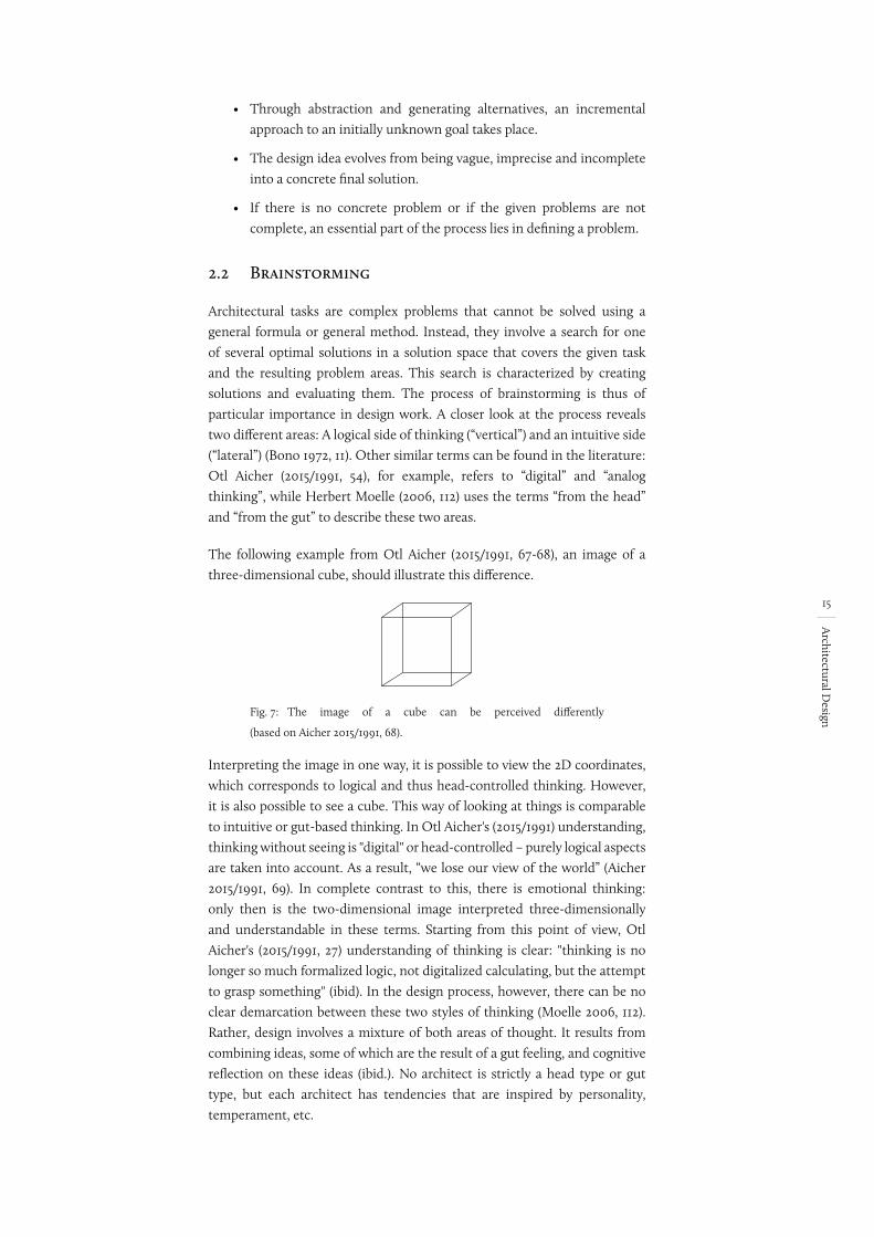
The following example from Otl Aicher (2015/1991, 67-68), an image of a three-dimensional cube, should illustrate this difference.
Fig. 7: The image of a cube can be perceived differently
(based on Aicher 2015/1991, 68).
Interpreting the image in one way, it is possible to view the 2D coordinates, which corresponds to logical and thus head-controlled thinking. However, it is also possible to see a cube. This way of looking at things is comparable to intuitive or gut-based thinking. In Otl Aicher's (2015/1991) understanding, thinking without seeing is "digital" or head-controlled – purely logical aspects are taken into account. As a result, “we lose our view of the world” (Aicher 2015/1991, 69). In complete contrast to this, there is emotional thinking: only then is the two-dimensional image interpreted three-dimensionally and understandable in these terms. Starting from this point of view, Otl Aicher's (2015/1991, 27) understanding of thinking is clear: "thinking is no longer so much formalized logic, not digitalized calculating, but the attempt to grasp something" (ibid). In the design process, however, there can be no clear demarcation between these two styles of thinking (Moelle 2006, 112). Rather, design involves a mixture of both areas of thought. It results from combining ideas, some of which are the result of a gut feeling, and cognitive reflection on these ideas (ibid.). No architect is strictly a head type or gut type, but each architect has tendencies that are inspired by personality, temperament, etc.
I found an English translation of Aicher’s book and have used the English from that source. I have changed the page numbers of the direct quotes to the corresponding page in the English translation. You might want include a footnote saying that the direct quotes of Aicher come from the English translation, and include the reference, which would be: Aicher, Otl (2015/1991). Analogous and Digital. Trans. Michael Robinson, Berlin: Ernst & Sohn.
16
Architectural D
esign
The question that arises here is: What happens in our brain during this time and how can this process be influenced? Looking at the literature on this subject, it is possible to define creativity generally as “making something new” (Vosgerau 2005, 1; Liu 2001, 24). And this “making something new” occurs when new connections arise in our brain – only the combination of conscious and unconscious information creates new ideas (Gänshirt 1999). Gottfried Vosgerau (2005, 7) mentions two different modules in this context (“associative” and “inhibitory” processes), which are necessary for a successful creative process. On the one hand, this requires “[...] a knowledge module that is organized as an associative network” (ibid.)10. This is the basis of information necessary for any kind of existing knowledge. These are memories and insights, which are kept in the memory over the course of one’s life as knowledge. But everything that is directly perceived can also be seen as information and thus as having a direct influence on our thinking and the creative act. The second process – in addition to the knowledge base – is “The successful search for cross-connections and parallels [...]”, which takes place by means of “[...] a targeted inhibition of associative processes [...]” (Vosgerau 2005, 3, Vosgerau 2005, 7)11. The decisive factor for this module is, in particular, that this inhibition is not simply random, but targeted, because “creativity can only arise if a meaningful selection of the links offered successfully takes place” (Vosgerau 2005, 7)12.
2.2.1 The role of perception
Ideas and thoughts arise through new linkages and cross-connections in the brain. The basis of all thought processes is thus human experience, knowledge and impressions, perceived in every form. But where does this knowledge come from? How does this experience come about? Human perception is the foundation of it all. Only through perception is it possible to record impressions as data, interpret them as information and store them as knowledge. Perception – be it the absorption of information in real time or as memory and knowledge that is already stored – forms the essential basis of any form of thinking, and thus “No thought processes seem to exist that cannot be found to operate, at least in principle, in perception” (Arnheim 1969, 14).
10 Translated from the original: „[...] ein Wissensmodul, das als assoziatives Netz organisiert ist“
11 Translated from the original: „Die erfolgreiche Suche nach Querverbindungen und Parallelen
[...]“ dar, was durch „[...] eine gezielte Hemmung der assoziativen Prozesse [...]“
12 Translated from the original: „Kreativität kann nur entstehen, wenn eine sinnvolle Auswahl
der angebotenen Verknüpfungen erfolgreich stattfindet“
T r a n s l a t e d
from the
original
kein EN verfügbar
Quelle im Verzeich-nis ändern: jetzt 1969:14
17
Architectural D
esign
From a purely anatomical or neurological point of view, the relationship between mind and sensory perception can be described as follows:
"Point stimuli are received by nerve fibers according to a ‘digital’ principle: Each individual stimulus is either picked up or rejected (‘I-O’). The stimuli received are processed electromagnetically and chemically in the central nervous system and result – in a way that is not fully understood – in the perception of the extended things." (Flusser 1994, 13)13
Through this direct coupling of the senses with the brain and its data processing, the activity of perception happens directly in the brain (Aicher 2015/1991, 41). If we look beyond this at the historical context, it becomes apparent how connected human thinking, perception and the sense organs are: starting in the 18th century, the epoch of language (which was starved of images), and going through thinking in images to modern times and the reduction of geometry to numerical values (Aicher 2015/1991, 37-38). Only through a rediscovery of images and their conscious communication is seeing not only considered to be essential to this process, but even imperative (ibid.). And so perception and thinking have always had a direct influence on each other. If one looks at the development of language and the cultural leap that resulted, this connection becomes clear, which Rudolf Wienands (2005, 211) confirms as follows in relation to Ulrich Wechsler:
“Only through language was a differentiation of thought possible, according to Ulrich Wechsler; only through language was it possible to lend subtle expression to the things one had thought and felt, seen and desired. Wechsler goes on to say: 'The development of the intellect is bound up with the development of language; a sense of fantasy emerges, the imaginative faculty, the power to develop abstract concepts, the ability to form inward images.'" (ibid.)
2.2.2 Visual Thinking | A Creative Cycle
The close connection between sensory perception and human thinking can be regarded as a fundamental component in the creative, design idea-finding process. One sees not with the eye, but with the brain: “Visual perception is visual thinking” (Arnheim 1969, 14). The gesture and the resulting sketch14 play a special role here in the design process. The gesture is the means by which a person makes his or her thoughts visible to the outside world and gives them shape. Without gesture, “[...] the appearance of the building floats
13 Translated from the original: „Punktförmige Reize werden von Nervenfasern empfangen,
und zwar nach einem <<digitalen>> Prinzip: Jeder einzelne Reiz wird entweder
aufgenommen oder abgewiesen (<<I-O>>). Die aufgenommenen Reize werden im
Zentralnervensystem elektromagnetisch und chemisch prozessiert und ergeben – auf nicht
völlig durchschaute Weise – die Wahrnehmung der ausgedehnten Dinge“
14 A sketch must not be understood as a hand-drawn sketch, as is generally the case. Instead, here
the term sketch describes a tangible, real image of aspects of human thoughts. This kind of
sketch can be of the most diverse form, e.g. text, image, drawing, working model or the like.
Es gibt eine englische Version:
Flusser, Vilém (2001): From Subject to Project: Becoming Human. English translation.London: Free Association Books, 2001
kann man aber nicht kaufen oder ausleihen
in uni checken
Kapitel 2: Ende 2. Absatz
erledigt
18
Architectural D
esign
in front of the soul of the architect” (Ostendorf 1918, 4)15. Vilém Flusser’s (1991, 47) words sound radical, yet understandable:
“There is no thinking that would not be articulated by a gesture. Thinking before articulation is only a virtuality; it is nothing. It is realized through the gesture. Strictly speaking, one cannot think before making gestures. [...] Unwritten thoughts actually mean you have nothing." (ibid.)16
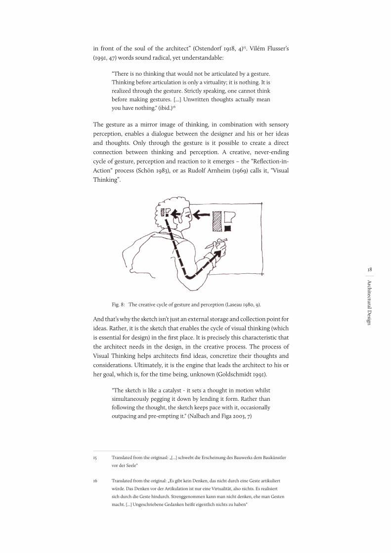
The gesture as a mirror image of thinking, in combination with sensory perception, enables a dialogue between the designer and his or her ideas and thoughts. Only through the gesture is it possible to create a direct connection between thinking and perception. A creative, never-ending cycle of gesture, perception and reaction to it emerges – the “Reflection-in-Action“ process (Schön 1983), or as Rudolf Arnheim (1969) calls it, “Visual Thinking”.
Fig. 8: The creative cycle of gesture and perception (Laseau 1980, 9).
And that’s why the sketch isn’t just an external storage and collection point for ideas. Rather, it is the sketch that enables the cycle of visual thinking (which is essential for design) in the first place. It is precisely this characteristic that the architect needs in the design, in the creative process. The process of Visual Thinking helps architects find ideas, concretize their thoughts and considerations. Ultimately, it is the engine that leads the architect to his or her goal, which is, for the time being, unknown (Goldschmidt 1991).
"The sketch is like a catalyst - it sets a thought in motion whilst simultaneously pegging it down by lending it form. Rather than following the thought, the sketch keeps pace with it, occasionally outpacing and pre-empting it." (Nalbach and Figa 2003, 7)
15 Translated from the originasl: „[...] schwebt die Erscheinung des Bauwerks dem Baukünstler
vor der Seele“
16 Translated from the original: „Es gibt kein Denken, das nicht durch eine Geste artikuliert
würde. Das Denken vor der Artikulation ist nur eine Virtualität, also nichts. Es realisiert
sich durch die Geste hindurch. Strenggenommen kann man nicht denken, ehe man Gesten
macht. [...] Ungeschriebene Gedanken heißt eigentlich nichts zu haben“
Ein Arnheim in Quellen muss raus. Hier war 1971 drin
war ohne Seitenzahl drin.
19
Architectural D
esign
The sketch thus guides the architect and enables an endless process until the moment when it is deliberately interrupted:
“The manner in which we do this is circular - conversational (in Pask’s sense): we act iteratively, until reaching self-reinforcing stability or misfit. We test, until we arrive at something satisfying our desires - for stability / recognizability / repeatability / etc.” (Glanville 1999, 89)
This close coupling of reflection, externalization and perception creates a particular effect: a direct feedback or a reciprocal interplay that directly supports and promotes the creativity of the designer. However, sketching does not reflect the complete thought. Thus the thought is reduced – almost automatically – to what is essential from the point of view of the designer (Nalbach and Figa 2003, 8). Gesture and sketch act like a filter and primarily embody the essential components of the thought – the by-products and secondary thoughts are sorted out, filtered. Sketches are therefore not definitive or final.
"Sketches represent drafts: something provisional, still to be completed - be it in architecture, the fine arts, music or literature. They invariably involve thoughts, ideas, notions that need to undergo further processing." (Nalbach and Figa 2003, 9)
This gives the architect a new, external and more objective view of his or her thoughts, which theoretically allows new and further possibilities to unfold (Laseau 1980, 9). It is the sketch itself that in turn stimulates the designer and guides him in new directions – new ideas and approaches to solutions emerge, often unconsciously and unintentionally (Glanville 1999, 88). The result is a creative dialogue between the architect and himself. It is not a dialogue in the form of words, but with the help of pencil, paper, the haptic model and the like – any tool that makes it possible to sketch and externalize one’s own thoughts by means of gestures (Glanville 1992, 214). However, working or thinking with the help of sketches not only makes it possible to enable this kind of creative dialogue. This way of working also has a direct impact on the creative process and thinking itself. So it is not surprising that in many cases “[...] sketching is a favourite means for changing consciously from the verbal-logical to the visual-spatial mode of thinking” (Gänshirt 2007, 122).
Because of this and the resulting possibilities, the process of Visual Thinking represents the essential component of creative thinking and thus of the design process. “The conceptual thinking process of the designer seems to be based on the development of ideas through their external expression in sketches” (Cross 2008, 20). The same idea can be found in Ranulph Glanville (1999, 88). For him, referencing Gordon Pask, the process of visual thinking is not only part of design, but rather represents design per se – or, as he puts it: “I characterize design as a conversation, usually held via a medium such a paper and pencil, with an other (either an ‘actual’ other or oneself acting as an other) as the conversational partner [33]” (Glanville 1999, 88).
Gänshirt beziehet sich auf Aalto, DeBono, Edwards
20
Architectural D
esign
2.2.3 Summary
Perception and gesture are two complementary media and thus, when closely coupled, make the process of visual thinking possible. This process in turn promotes creative thinking in a very particular way and it is also the process that makes it possible to find and develop new ideas in the first place. This leads Nigel Cross (2008, 9) to the following realization:
“This is often regarded as the mysterious, creative part of designing; [...] In reality, the process is less ‘magical’ than it appears. [...] This ability to design depends partly on being able to visualize something internally, in the ‘mind’s eye’, but perhaps it depends even more on being able to make external visualizations“. (ibid.)
So it is this visualization of one’s own thoughts, the direct reflection of these thoughts and the resulting cycle between action and reaction that represent the basic activity of design.
2.3 Design tools
As the embodiment of our thoughts, gesture in combination with perception forms the essential basis of the creative process. But the gesture itself is only an elusive, ever-fleeting action. It is only the sketch, which is an image of these thoughts, that can capture them and put them into a retrievable form and thus allow the designer to reflect on them. As a means of externalizing thought, design tools are a key element in the design process. It is these tools that make the process of visual thinking possible and offer the designer a platform to visualize his or her thoughts. Tools determine and influence each action and the form that each interaction takes. Looking at this fact in connection with the process of visual thinking, it becomes clear that it is ultimately the tools that influence and shape the way in which we think (Glanville 1992, 216). True to the motto “'The hammer forges the smith' [...] design tools do not just make their mark on what has been designed, but prior to this also [on the designer and] on the reflection about the design" (Gänshirt 2007, 95-96). The resulting interaction, “The interplay between thinking and making is of fundamental significance to design” (Gänshirt 2007, 96). Through direct feedback, tools change the way we work with them.
Tools can take different forms. There are tools that allow ideas to be represented in a very simple way (cf. the freehand sketch). In this case, thinking becomes faster – possibly also more chaotic. Furthermore, there are tools that make it possible to work in a rough, physical way (the haptic model), so that something can develop from rough, emotional working methods. Alternately, there are also tools that must be used carefully and with finesse, which can lead to a more careful and thoughtful design. All these specific characteristics have a direct impact on handling and the design process.
21
Architectural D
esign
The question of tools, their properties and possibilities in the design process is of central importance and will be examined in more detail below. The central question here is: How should a design tool be designed in order to enable the process of visual thinking as a tool for thinking, but at the same time not distract or disturb the designer in his or her creative work?
2.3.1 Use of design tools
“it is not a constraint but an extension of our own possibilities if every human being learns to handle pen and paper, acquires reading and writing skills” (Aicher 2015/1991, 30). As Otl Aicher (ibid.) aptly writes, the purpose of tools is thus, above all, to improve human abilities and to more easily or more quickly arrive at a better solution – or at a solution at all – that represents the design in the design context. Tools allow the designer to externalize the thoughts, ideas and visions that buzz around in his or her brain and to grasp them in a kind of static or tangible form and to reflect them. It can be said that the more complex the requirement, the more necessary this dynamic external memory becomes. As an example: mental visualization already reaches its limits with small geometric bodies such as a three-dimensional cube. It can be roughly understood by imagining it, but a detailed representation (e.g. of the corners) is only possible in parts. The visualization of the whole body including all the details is simply not possible. As this example illustrates, is difficult for humans to imagine even a simple geometric form – and it is all the more difficult when it comes to complete buildings. The human mind cannot grasp and understand all at once the complexity of architecture, the many different dimensions such as the geometric and abstract levels. The sketch, as a kind of external memory for thought, expands human potential. One step at a time, a thought externalizes itself on paper or in some other form of external memory. It is this externalization that creates the basis for subsequent design-relevant features. Using tools serves the designer most of all in the following ways:
• Tools for thinking ahead: Separating design and execution has developed decisively from the necessity or desire for thinking ahead. Tools, in turn, are what make this thinking ahead possible in the first place. Only through this process is it possible to recognize effects, problems, etc., without having to construct something at a 1:1 scale.
• Tools for evaluation: Generating alternatives is an important part of the design work (see section 2.1.2). But it is only by representing ideas pictorially (e.g. a text or graphic) that it is possible to generate alternatives and more easily and directly compare them (Buxton 2007, 105). In this context, however, Nigel Cross (2008, 8) points to the fact that drawings are not strictly needed to examine and compare certain factors since tables and graphs offer a better solution. Certainly, this only applies to factors that can be objectively compared, such as costs. Still, he has a point, since in these cases a comparison can also be done in a purely digital way.
QHabe ich erfunden
22
Architectural D
esign
• Tools for reduction to the essentials: Presenting an idea in the form of a set of sketches automatically reduces it to its essential components (Gänshirt 2007, 134-135). The sketch does not replicate the thought in its entirety since unimportant information is abstracted or completely omitted. It is the drawing itself that the draughtsman analyzes “and decides what factors his design work should relate to” (Gänshirt 2007, 134). Sketching thus helps the architect in two ways: in developing new ideas, as has already been mentioned, but also in assessing and clarifying existing ideas (Fish and Scrivener 1990, 117). It is precisely this reduction that makes it possible to master complexity.
• Mastering complexity: The design itself and the design process represent a very complex structure. Different factors from different disciplines – including, for example, compositional, technical, sociological, psychological and energetic aspects – have a direct influence on the design and thus also directly on the final result. It is the task of the architect to bring these influences into a functional and creative balance. As Christian Gänshirt (2007, 60-61) aptly points, it is our hand tools that help reduce complexity by reducing the possible number of movements. As a result, we are able to “reduc[e] a complex state of affairs to a few manageable aspects that can easily be manipulated” (Gänshirt 2007, 60). Elsewhere, however, he notes that by precisely executing these limited actions, you can produce an equal degree of complexity, which is important in the progress of the design process (Gänshirt 2007, 95).
In the early design phases, thoughts, ideas and possibilities are often only incomplete and vague. It is therefore all the more important that a thinking tool allows for and supports the representation of these abstract and imprecise thoughts. However, this is necessary not only because there is a lack of concrete knowledge of what is to be visualized or because it allows the designer to consciously concretize the design idea. It is also important in relation to feedback. Human beings are strongly limited in what they can absorb. The designer can be overtaxed when looking at sketches that are overly complex or too broadly conceived and not reduced to their essentials, which thus disturbs or stops his or her train of thought. The vague and imprecise character of the sketch and its incompleteness are precisely the factors that protect the architect from a flood of information and make it possible to see the essentials. Barbara Cutler and Joshua Nasman (2010, 20) refer to Alexander Koutamanis, who sees the reasons for this above all in Gestalt theory:
”Gestalt theory describes why our interpretation of an incomplete or ambiguous diagram tends toward simpler forms, avoiding complexity. The rich vocabulary of pen and paper sketching in architectural design draws on the gestalt principles of collinearity, parallelism, continuation, and completion [Koutamanis 1999].” (ibid.)
War irgendwie sehr komisch :-(
Nochmal final anschuaen
23
Architectural D
esign
The effects of representing vague and incomplete thoughts are more far-reaching than has been represented so far. In this context, the terms ambiguity and emergence17 must be mentioned, in particular. Images of vague and imprecise thoughts allow a wide range for interpretation, so that one and the same sketch can be viewed and interpreted in different, ambiguous ways. This effect is further reinforced by both phenomena: “If you want to get the most out of a sketch, you need to leave big enough holes” (Buxton 2007, 115). Thus, when looking at a sketch, completely new things can arise (even for the person who drew it), which had not been thought of before or which were not originally intended at all. The sketch acts as a catalyst, allowing new and different interpretations and thus the emergence of new ideas (ibid.).
Emotional criteria must also not be disregarded. With a sketch, the architect creates a connection with his/her emotional mood and with the situation in which she made the sketch, including the wine he/she may have drank. All this information, these emotions and thoughts, are an integral part of the sketch, hiding, so to speak, in its appearance and form. If one considers the fact that stored thoughts can often only be evoked via memory supports, it becomes clear that the more information that is coded as memory, the easier it is to retrieve it (Kandel 2007). The purpose of the sketch is not to satisfy design requirements. Storing information is not just about mental results. It’s more about the additional (e.g. emotional) information just mentioned. And so it is of crucial importance that a sketch looks the way it looks: Without embellishment and without straightening. Even if the paper is crumpled, then that’s just the way it is.
2.3.2 Established design tools
On the basis of these findings, I will discuss the established design tools (the freehand sketch and the model) in more detail. Looking at the historical development, the use of models and graphic representations for the presentation of architectural ideas can be traced back more than 2000 years (King 2001, 16; Oechslin 2011, 144). However, their use as a design tools for reviewing architectural ideas and decisions has only been proven as beginning in the 13th century (Binding 2012, 70). One of the most famous examples is certainly the Duomo in Florence (Santa Maria del Fiore – 1436). Models and plans were used to find a suitable design for the dome (King 2001, 16). Due to the complex and at first seemingly unsolvable task, it was only by using a model that it was possible to prove that the complex construction and the building process functioned as theoretically planned (ibid.).
To this day, both tools constitute the basic tools for working creatively. However, the tools themselves do not claim to purposes or to solve all problems. Rather, factors such as the approach, personal experience and the design idea, to name only a few, have a decisive influence on the choice of what tool is best for the respective situation. Each tool has individual characteristics,
17 The term emergence describes the effect of seeing something different or extra in an image,
beyond what was originally intended by the author (Gero 1996, 442).
wo geht Quelle los? Eigentlich da, wo sie steht.
ambiguity = Mehrdeutigkeit also kein Spezialbegriff
vor oder nach den Punkt?
24
Architectural D
esign
its own strengths and weaknesses. And “[...] since no medium has its meaning or existence alone, but only in constant interplay with other media”, the different tools directly interact with each other (McLuhan 1994, 26).
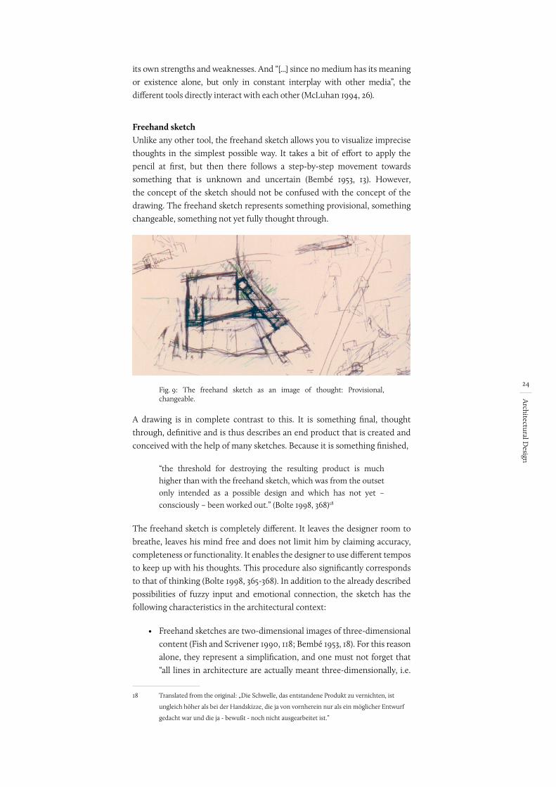
Freehand sketchUnlike any other tool, the freehand sketch allows you to visualize imprecise thoughts in the simplest possible way. It takes a bit of effort to apply the pencil at first, but then there follows a step-by-step movement towards something that is unknown and uncertain (Bembé 1953, 13). However, the concept of the sketch should not be confused with the concept of the drawing. The freehand sketch represents something provisional, something changeable, something not yet fully thought through.
Fig. 9: The freehand sketch as an image of thought: Provisional, changeable.
A drawing is in complete contrast to this. It is something final, thought through, definitive and is thus describes an end product that is created and conceived with the help of many sketches. Because it is something finished,
“the threshold for destroying the resulting product is much higher than with the freehand sketch, which was from the outset only intended as a possible design and which has not yet – consciously – been worked out.” (Bolte 1998, 368)18
The freehand sketch is completely different. It leaves the designer room to breathe, leaves his mind free and does not limit him by claiming accuracy, completeness or functionality. It enables the designer to use different tempos to keep up with his thoughts. This procedure also significantly corresponds to that of thinking (Bolte 1998, 365-368). In addition to the already described possibilities of fuzzy input and emotional connection, the sketch has the following characteristics in the architectural context:
• Freehand sketches are two-dimensional images of three-dimensional content (Fish and Scrivener 1990, 118; Bembé 1953, 18). For this reason alone, they represent a simplification, and one must not forget that “all lines in architecture are actually meant three-dimensionally, i.e.
18 Translated from the original: „Die Schwelle, das entstandene Produkt zu vernichten, ist
ungleich höher als bei der Handskizze, die ja von vornherein nur als ein möglicher Entwurf
gedacht war und die ja - bewußt - noch nicht ausgearbeitet ist.”
Quelle hinten anpassen. .pdf vorhanden
25
Architectural D
esign
‘spatially’” (Bembé 1953, 18)19. This applies both to representations of elevation (representing spatial depth by line thickness) and perspective. Thus the sketch represents a mixture of descriptive and pictorial images, which in turn enables two methods of visual representation to be translated (Fish and Scrivener 1990, 118).
• Sketches contain intentional, but also unintentional forms of indeterminacy. In this context, Jonathan Fish and Stephen Scrivener (1990, 120) mention, among other things, ten parameters of representation that can be the creative expression of such a sketch:
• Blank spaces where the drawing fades away
• Multiple alternative contour lines
• Missing contour lines
• Wobbly lines
• Dark shadows
• Suggestive scribbles and smudges
• Energetic cross-hatching
• Blots
• Accidental flow patterns of paint
• Scratch marks
• The incomparable flexibility of the freehand sketch allows for simple annotation and description in addition to pure geometric representation. The freehand sketch is thus an external memory for thoughts without fixed formalities or almost without restrictions in the form they are presented.
• Using sketch paper allows for overdrawing, making it possible to create alternatives by being able to draw directly over earlier versions. In addition, overdrawing images of any kind stimulates visual thinking and especially promotes the effect of emergence (Schneider and Petzold 2009, 210).
• The imprecision, superimposition and atmospheric compression present in a sketch, or when several sketches are superimposed, can lead in turn to a complexity that arises out of the process itself (Gänshirt 2007, 118). It is this complexity that leads to an increase in ambiguity, which in turn directly promotes the effect of emergence.
The freehand sketch is therefore the design tool par excellence. It allows for imprecision and flexible, simple thinking, but it cannot give an impression of how something works (Lawson 1997, 24-25). Since the interpretation of the 2D sketch in a 3D space depends purely on the viewer, this concerns sociological and psychological, but above all technical aspects. No matter
19 Translated from the original: „daß alle Linien in der Architektur eigentlich dreidimensional,
also ‘räumlich’ gemeint sind“
Das sind die englischen begriffe
ggf. in „Anfühurngszeichen“ setzen
Brauch ich da Anfüh-rungszeichen bei den 3 Worten, die ich über-nommen habe? Alles blaue auf Quelle checken
eigentlich ned. evtl. Kursiv
Falsches Jahr - jetzt OK
26
Architectural D
esign
how nice a detail may look, if it is misinterpreted (which can happen to both the creator and the viewer), it may lose one of its functions. This may be due to the missing informational content from the third dimension. In addition, the feedback of a gesture externalized by a sketch can almost entirely be attributed to the visual system. Certainly, certain stimuli such as the flow of a line or the properties of the paper are conveyed haptically. However, this is very abstract and does not convey any information about what has been sketched, which is of crucial importance especially in the context of visual thinking.
The physical model as working modelIn addition to the freehand sketch, the tangible, physical model must be seen as a further means of visualizing one’s own ideas. With reference to the model theory of Herbert Stachowiak (1973), however, the concept of the model must first be explained in more detail. This concept is broad and ranges from theoretical to digital to real models. He defines the three main characteristics of models as follows:
• “Models are always models of something, namely images, representations of natural or artificial originals, which themselves can also be models.“ (Stachowiak 1973, 131)20
• “In general, models do not capture all the attributes of the original, but only those that appear relevant to the respective model creators and/or model users.” (Stachowiak 1973, 132)21
• “Models are not unique to their originals per se. They function as a substitute a) for certain – recognizing and/or acting, model-using – subjects, b) within certain intervals of time and c) limited to certain mental or real operations.” (Stachowiak 1973, 132- 133) 22
Taking these characteristics into account, the term “model” is used in this work to describe the depiction or representation of architectural structures (both real and those that exist only as a design or purely as a thought) as physical objects, unless otherwise recognizable from the context. These models can exist in different scales up to a 1:1 full-size representation. In the context of the early design phases, special attention is paid to the working model as a physical, three-dimensional form of the sketch that supports the process of visual thinking. In contrast to presentation models, the purpose
20 Translated from the original: „Modelle sind stets Modelle von etwas, nämlich Abbildungen,
Repräsentationen natürlicher oder künstlicher Originale, die selbst wieder Modelle sein
können.“
21 Translated from the original: „Modelle erfassen im allgemeinen nicht alle Attribute des durch
sie repräsentierten Originals, sondern nur solche, die den jeweiligen Modellerschaffern und/
oder Modellbenutzern relevant erscheinen.“
22 Translated from the original: „Modell sind ihren Originalen nicht per se eindeutig
zugeordnet. Sie erfüllen ihre Ersetzungsfunktion a) für bestimmte – erkennende und/oder
handelnden, modellbenutzenden – Subjekte, b) innerhalb bestimmter Zeitintervalle und c)
unter Einschränkung auf bestimmte gedankliche oder tatsächliche Operationen.“
Gibt es nur auf Deutsch
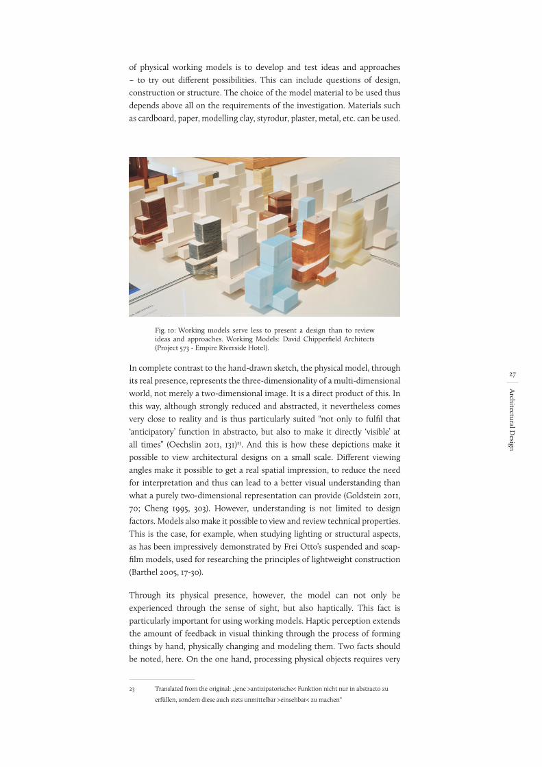
27
Architectural D
esign
of physical working models is to develop and test ideas and approaches – to try out different possibilities. This can include questions of design, construction or structure. The choice of the model material to be used thus depends above all on the requirements of the investigation. Materials such as cardboard, paper, modelling clay, styrodur, plaster, metal, etc. can be used.
Fig. 10: Working models serve less to present a design than to review ideas and approaches. Working Models: David Chipperfield Architects (Project 573 - Empire Riverside Hotel).
In complete contrast to the hand-drawn sketch, the physical model, through its real presence, represents the three-dimensionality of a multi-dimensional world, not merely a two-dimensional image. It is a direct product of this. In this way, although strongly reduced and abstracted, it nevertheless comes very close to reality and is thus particularly suited “not only to fulfil that ‘anticipatory’ function in abstracto, but also to make it directly ‘visible’ at all times” (Oechslin 2011, 131)23. And this is how these depictions make it possible to view architectural designs on a small scale. Different viewing angles make it possible to get a real spatial impression, to reduce the need for interpretation and thus can lead to a better visual understanding than what a purely two-dimensional representation can provide (Goldstein 2011, 70; Cheng 1995, 303). However, understanding is not limited to design factors. Models also make it possible to view and review technical properties. This is the case, for example, when studying lighting or structural aspects, as has been impressively demonstrated by Frei Otto’s suspended and soap-film models, used for researching the principles of lightweight construction (Barthel 2005, 17-30).
Through its physical presence, however, the model can not only be experienced through the sense of sight, but also haptically. This fact is particularly important for using working models. Haptic perception extends the amount of feedback in visual thinking through the process of forming things by hand, physically changing and modeling them. Two facts should be noted, here. On the one hand, processing physical objects requires very
23 Translated from the original: „jene >antizipatorische< Funktion nicht nur in abstracto zu
erfüllen, sondern diese auch stets unmittelbar >einsehbar< zu machen“
28
Architectural D
esign
little cognitive effort from the user (Sharlin et al. 2001, 1). In addition, using both hands increases performance at the cognitive level, especially when dealing with spatial issues (Shaer and Hornecker 2009, 69; Hinckley et al. 1997). Thus it is above all the physical presence and the support of several senses, that enable a very special form of processing in working models, which promotes the process of visual thinking in a particular way.
2.4 Definition of requirements
In general, the design process can be described as an idea-finding process with the aim of solving complex problems. Perception, as the basis of any form of idea finding, plays a special role. In tandem with gesture, visual thinking results and leads to a special problem solving process. This process is only made possible through the use of tools as an output for our thoughts, since pure imagination is not sufficient. Thus sketches serve not only to provide a visualization for others, but function above all for the designer him- or herself. Through the direct feedback of the gesture, design tools have a direct influence on thinking and acting and are an indispensable part of the idea-finding process. Design tools enable the creative cycle between input and output that is necessary to solve complex problems – they’re thinking tools.
However, there is no single tool for every kind of problem. Instead, it is necessary to have several different tools that can be used independent of time, space and scale (Mitchell and MacCullough 1995, 460). The choice of tool depends, among other things, on the design task, the design problem, the design idea, but also on the project status. If we take a closer look, we can see that the use of established design tools such as freehand sketches and physical models in the creative process leads to fundamental, recurring sequences of action. The main focus here is on the working method resulting from visual thinking, where the following interaction methods play a special role in the design process:
• Visualizing thoughts (representing): Creating sketches as an image of one’s own thoughts represents the initial step of visual thinking. Only then can the ideas that exist in the mind be fixed. They are given shape and, for the designer, become real as visible or tangible elements.
• Reflecting images (evaluating): At the moment of visualization, thoughts become present for the designer. This makes it possible to reflect on them from a distance. Irrespective of whether one uses a physical model or hand sketch, a creative cycle can only emerge by calling up the sketch (including existing sketches) and evaluating and differentiating it/them.
• Changing images (manipulating): By viewing and reflecting on the actual images, the designer’s train of thought is carried forward. The creative cycle leads to the images being changed. They are extended, altered or discarded and thus develop parallel to the thought as it progresses.
29
Architectural D
esign
This creation of images, their retrieval, evaluation and differentiation, as well as the constant manipulation of what is in front of the viewer’s eyes, represents the essential methods of interaction in the design context. Based on this and the analysis of the process, we can derive basic requirements for any design tools or design platform:
• Ease of Use: Intuitive, simple and quick operation is the basis for using models and hand sketches as thinking tools. Operating them must not distract from the design process. If the operation of a tool is too complex, the attention shifts to the tool and away from the design idea. In contrast to this, intuitive handling, based on familiar procedures, allows an operation without shifting focus, and without being subject to any rules or restrictions.
• Direct Feedback between Gesture with the Brain: Visual thinking requires a direct interplay between gesture and perception. Direct feedback on as many sensory channels as possible must be regarded as a decisive criterion here. In addition, the spatial dimensions supported by the tools are of decisive relevance for their use in the design process.
• Visualization of Vague Thoughts: The process of visual thinking requires the direct possibility of visualizing (illustrating) and viewing unfinished, vague and incomplete thoughts without having to specify them in advance. This is the only way to successively create, change and concretize within the sketch and thus also to enable the bilateral “Reflection-in-Action“ process (Schön 1983).
• Stepwise Approach: The step-by-step approach to a goal that is initially unknown is one of the core activities in the architectural work process. This procedure and the associated formation of different approaches to solutions requires that these variants be easy to generate, store, view and compare, and it must be supported by the tools used.
• Flexible Use and Free Operation: The different tasks as well as the changing design approaches and the individual approaches of different architects lead to different ways of working. In order to be able to react to all these changing requirements, the architect needs a selection of flexible design tools.
The interaction methods and the requirements for design tools that are derived from them represent the basic parameters for the conception of design-supporting tools and thus also for a digital design platform. If the first four points describe the basic properties of the tools themselves, the last point concerns, above all, how the individual tools connect to each other.
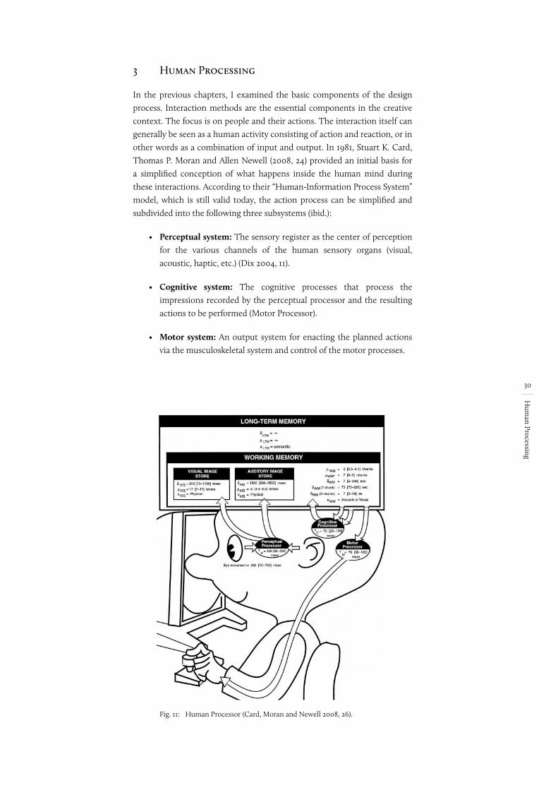
30
Hum
an Processing
3 Human Processing
In the previous chapters, I examined the basic components of the design process. Interaction methods are the essential components in the creative context. The focus is on people and their actions. The interaction itself can generally be seen as a human activity consisting of action and reaction, or in other words as a combination of input and output. In 1981, Stuart K. Card, Thomas P. Moran and Allen Newell (2008, 24) provided an initial basis for a simplified conception of what happens inside the human mind during these interactions. According to their “Human-Information Process System” model, which is still valid today, the action process can be simplified and subdivided into the following three subsystems (ibid.):
• Perceptual system: The sensory register as the center of perception for the various channels of the human sensory organs (visual, acoustic, haptic, etc.) (Dix 2004, 11).
• Cognitive system: The cognitive processes that process the impressions recorded by the perceptual processor and the resulting actions to be performed (Motor Processor).
• Motor system: An output system for enacting the planned actions via the musculoskeletal system and control of the motor processes.
Fig. 11: Human Processor (Card, Moran and Newell 2008, 26).
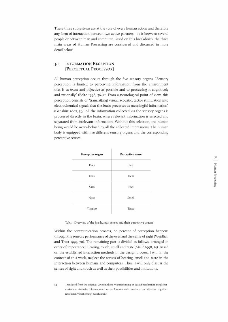
31
Hum
an Processing
These three subsystems are at the core of every human action and therefore any form of interaction between two active partners - be it between several people or between man and computer. Based on this breakdown, the three main areas of Human Processing are considered and discussed in more detail below.
3.1 Information Reception [Perceptual Processor]
All human perception occurs through the five sensory organs. “Sensory perception is limited to perceiving information from the environment that is as exact and objective as possible and to processing it cognitively and rationally” (Bolte 1998, 364)24. From a neurological point of view, this perception consists of “translat[ing] visual, acoustic, tactile stimulation into electrochemical signals that the brain processes as meaningful information” (Gänshirt 2007, 59). All the information collected via the sensory organs is processed directly in the brain, where relevant information is selected and separated from irrelevant information. Without this selection, the human being would be overwhelmed by all the collected impressions. The human body is equipped with five different sensory organs and the corresponding perceptive senses:
Perceptive organ Perceptive sense
Eyes See
Ears Hear
Skin Feel
Nose Smell
Tongue Taste
Tab. 1: Overview of the five human senses and their perceptive organs
Within the communication process, 80 percent of perception happens through the sensory performance of the eyes and the sense of sight (Weidlich and Trost 1995, 70). The remaining part is divided as follows, arranged in order of importance: Hearing, touch, smell and taste (Malić 1998, 14). Based on the established interaction methods in the design process, I will, in the context of this work, neglect the senses of hearing, smell and taste in the interaction between humans and computers. Thus, I will only discuss the senses of sight and touch as well as their possibilities and limitations.
24 Translated from the original: „Die sinnliche Wahrnehmung ist darauf beschränkt, möglichst
exakte und objektive Informationen aus der Umwelt wahrzunehmen und sie einer ‚kognitiv-
rationalen Verarbeitung‘ zuzuführen.“
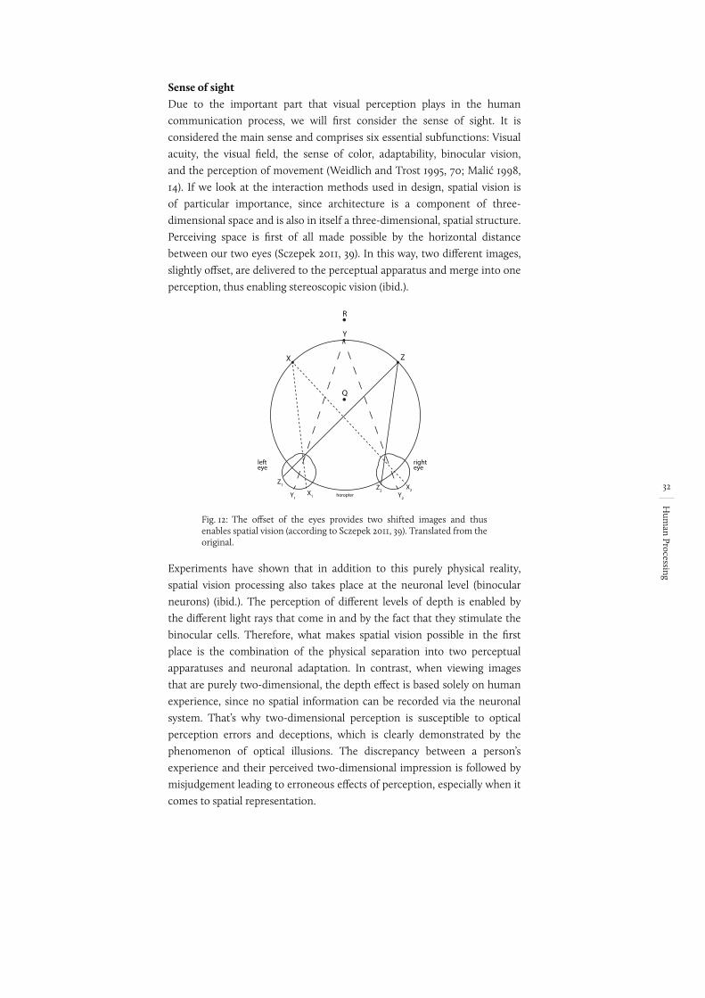
32
Hum
an Processing
Sense of sightDue to the important part that visual perception plays in the human communication process, we will first consider the sense of sight. It is considered the main sense and comprises six essential subfunctions: Visual acuity, the visual field, the sense of color, adaptability, binocular vision, and the perception of movement (Weidlich and Trost 1995, 70; Malić 1998, 14). If we look at the interaction methods used in design, spatial vision is of particular importance, since architecture is a component of three-dimensional space and is also in itself a three-dimensional, spatial structure. Perceiving space is first of all made possible by the horizontal distance between our two eyes (Sczepek 2011, 39). In this way, two different images, slightly offset, are delivered to the perceptual apparatus and merge into one perception, thus enabling stereoscopic vision (ibid.).
Fig. 12:
X
Y
Q
Z
R
lefteye
righteye
Z1
Y1X1
Z2Y2
X2horopter
The offset of the eyes provides two shifted images and thus enables spatial vision (according to Sczepek 2011, 39). Translated from the original.
Experiments have shown that in addition to this purely physical reality, spatial vision processing also takes place at the neuronal level (binocular neurons) (ibid.). The perception of different levels of depth is enabled by the different light rays that come in and by the fact that they stimulate the binocular cells. Therefore, what makes spatial vision possible in the first place is the combination of the physical separation into two perceptual apparatuses and neuronal adaptation. In contrast, when viewing images that are purely two-dimensional, the depth effect is based solely on human experience, since no spatial information can be recorded via the neuronal system. That’s why two-dimensional perception is susceptible to optical perception errors and deceptions, which is clearly demonstrated by the phenomenon of optical illusions. The discrepancy between a person’s experience and their perceived two-dimensional impression is followed by misjudgement leading to erroneous effects of perception, especially when it comes to spatial representation.
bild beschriftung
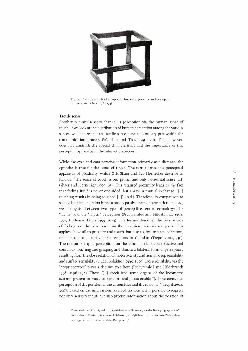
33
Hum
an Processing
Fig. 13: Classic example of an optical illusion. Experience and perception do not match (Ernst 1985, 173).
Tactile senseAnother relevant sensory channel is perception via the human sense of touch. If we look at the distribution of human perception among the various senses, we can see that the tactile sense plays a secondary part within the communication process (Weidlich and Trost 1995, 70). This, however, does not diminish the special characteristics and the importance of this perceptual apparatus in the interaction process.
While the eyes and ears perceive information primarily at a distance, the opposite is true for the sense of touch. The tactile sense is a perceptual apparatus of proximity, which Orit Shaer and Eva Hornecker describe as follows: “The sense of touch is our primal and only non-distal sense [...]” (Shaer and Hornecker 2009, 65). This required proximity leads to the fact that feeling itself is never one-sided, but always a mutual exchange: “[...] touching results in being touched [...]” (ibid.). Therefore, in comparison to seeing, haptic perception is not a purely passive form of perception. Instead, we distinguish between two types of perceptible sensor technology: The “tactile” and the “haptic” perception (Pschyrembel and Hildebrandt 1998, 1550; Dudenredaktion 1999, 1679). The former describes the passive side of feeling, i.e. the perception via the superficial sensory receptors. This applies above all to pressure and touch, but also to, for instance, vibration, temperature and pain via the receptors in the skin (Trepel 2004, 330). The notion of haptic perception, on the other hand, relates to active and conscious touching and grasping and thus to a bilateral form of perception, resulting from the close relation of motor activity and human deep sensibility and surface sensibility (Dudenredaktion 1999, 1679). Deep sensibility via the “proprioceptors” plays a decisive role here (Pschyrembel and Hildebrandt 1998, 1296-1297). These “[...] specialized sense organs of the locomotor system” present in muscles, tendons and joints enable “[...] the conscious perception of the position of the extremities and the torso [...]” (Trepel 2004, 332)25. Based on the impressions received via touch, it is possible to register not only sensory input, but also precise information about the position of
25 Translated from the original: „[...] spezialisierte[n] Sinnesorgane des Bewegungsapparates“
vorhanden in Muskeln, Sehnen und Gelenken, ermöglichen „[...] das bewusste Wahrnehmen
der Lage der Extremitäten und des Rumpfes [...]“
Zahlreiche spezialisierte Sinnesorgane
des Bewegungsapparates ermöglichen
uns das bewusste Wahrnehmen der Lage
der Extremitäten und des Rumpfes, den
reibungslosen Ablauf von Bewegungen und
einen Schutz vor Überlastung der Gelenke,
Bänder, Muskeln und Sehnen.
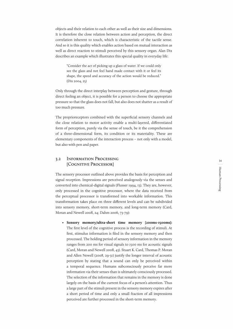
34
Hum
an Processing
objects and their relation to each other as well as their size and dimensions. It is therefore the close relation between action and perception, the direct correlation inherent to touch, which is characteristic of the tactile sense. And so it is this quality which enables action based on mutual interaction as well as direct reaction to stimuli perceived by this sensory organ. Alan Dix describes an example which illustrates this special quality in everyday life:
“Consider the act of picking up a glass of water. If we could only see the glass and not feel hand made contact with it or feel its shape, the speed and accuracy of the action would be reduced.” (Dix 2004, 25)
Only through the direct interplay between perception and gesture, through direct feeling an object, it is possible for a person to choose the appropriate pressure so that the glass does not fall, but also does not shatter as a result of too much pressure.
The proprioreceptors combined with the superficial sensory channels and the close relation to motor activity enable a multi-layered, differentiated form of perception, purely via the sense of touch, be it the comprehension of a three-dimensional form, its condition or its materiality. These are elementary components of the interaction process – not only with a model, but also with pen and paper.
3.2 Information Processing [Cognitive Processor]
The sensory processor outlined above provides the basis for perception and signal reception. Impressions are perceived analogously via the senses and converted into chemical-digital signals (Flusser 1994, 13). They are, however, only processed in the cognitive processor, where the data received from the perceptual processor is transformed into workable information. This transformation takes place on three different levels and can be subdivided into sensory memory, short-term memory, and long-term memory (Card, Moran and Newell 2008, 24; Dahm 2006, 73-79):
• Sensory memory/ultra-short time memory [200ms-1500ms]: The first level of the cognitive process is the recording of stimuli. At first, stimulus information is filed in the sensory memory and then processed. The holding period of sensory information in the memory ranges from 200 ms for visual signals to 1500 ms for acoustic signals (Card, Moran and Newell 2008, 43). Stuart K. Card, Thomas P. Moran and Allen Newell (2008, 29-31) justify the longer interval of acoustic perception by stating that a sound can only be perceived within a temporal sequence. Humans subconsciously perceive far more information via their senses than is ultimately consciously processed. The selection of the information that remains in the memory is done largely on the basis of the current focus of a person’s attention. Thus a large part of the stimuli present in the sensory memory expires after a short period of time and only a small fraction of all impressions perceived are further processed in the short-term memory.
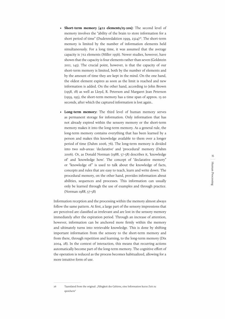
35
Hum
an Processing
• Short-term memory [4±2 elements/15-20s]: The second level of memory involves the “ability of the brain to store information for a short period of time” (Dudenredaktion 1999, 2324)26. The short-term memory is limited by the number of information elements held simultaneously. For a long time, it was assumed that the average capacity is 7±2 elements (Miller 1956). Newer studies, however, have shown that the capacity is four elements rather than seven (Goldstein 2011, 143). The crucial point, however, is that the capacity of our short-term memory is limited, both by the number of elements and by the amount of time they are kept in the mind. On the one hand, the oldest element expires as soon as the limit is reached and new information is added. On the other hand, according to John Brown (1958, 18) as well as Lloyd, R. Peterson and Margaret Jean Peterson (1959, 195), the short-term memory has a time span of approx. 15-20 seconds, after which the captured information is lost again..
• Long-term memory: The third level of human memory serves as permanent storage for information. Only information that has not already expired within the sensory memory or the short-term memory makes it into the long-term memory. As a general rule, the long-term memory contains everything that has been learned by a person and makes this knowledge available to them over a longer period of time (Dahm 2006, 76). The long-term memory is divided into two sub-areas: 'declarative' and 'procedural' memory (Dahm 2006). Or, as Donald Norman (1988, 57-58) describes it, 'knowledge of' and 'knowledge how'. The concept of “declarative memory” or “knowledge of” is used to talk about the knowledge of facts, concepts and rules that are easy to teach, learn and write down. The procedural memory, on the other hand, provides information about abilities, sequences and processes. This information can usually only be learned through the use of examples and through practice. (Norman 1988, 57-58)
Information reception and the processing within the memory almost always follow the same pattern. At first, a large part of the sensory impressions that are perceived are classified as irrelevant and are lost in the sensory memory immediately after the expiration period. Through an increase of attention, however, information can be anchored more firmly within the memory and ultimately turns into retrievable knowledge. This is done by shifting important information from the sensory to the short-term memory and from there, through repetition and learning, to the long-term memory (Dix 2004, 28). In the context of interaction, this means that recurring actions automatically become part of the long-term memory. The cognitive effort of the operation is reduced as the process becomes habitualized, allowing for a more intuitive form of use.
26 Taanslated from the original: „Fähigkeit des Gehirns, eine Information kurze Zeit zu
speichern“
Begriff in BIB checken: prozedurale vs. Produk-tionen.
Bzw. wo mache ich die Quelle hin: Haben beide alles gesagt oder wie ist das?
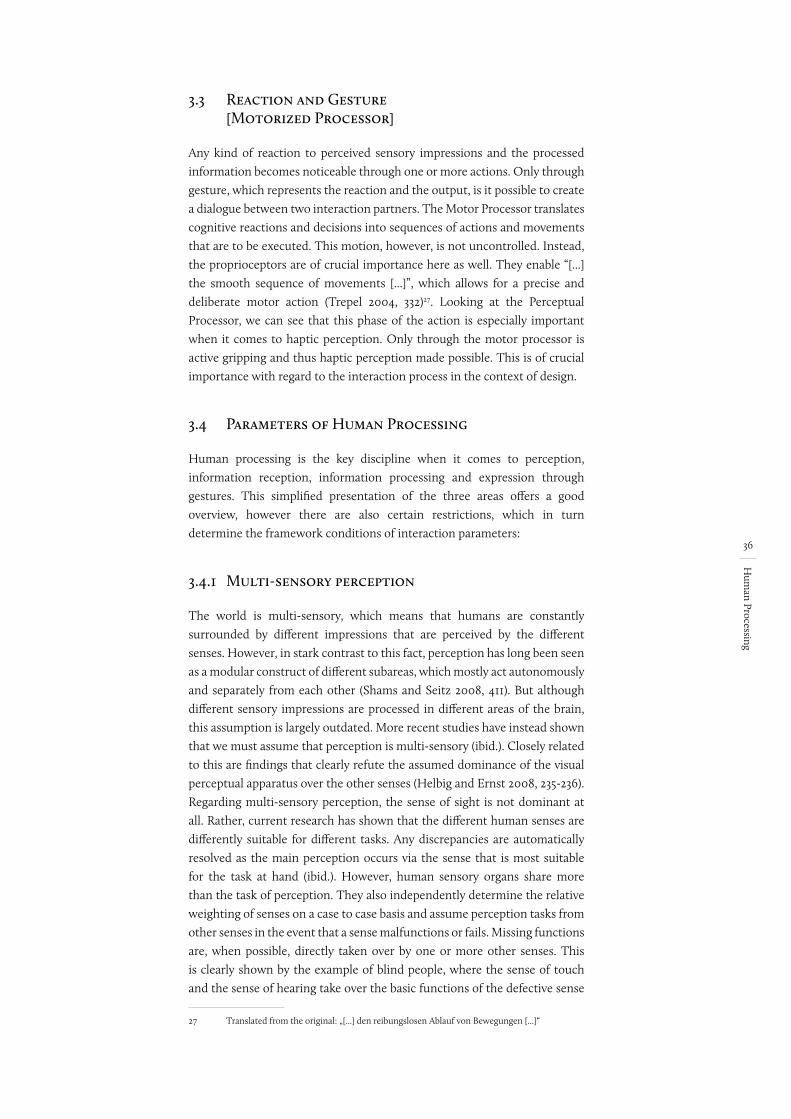
36
Hum
an Processing
3.3 Reaction and Gesture [Motorized Processor]
Any kind of reaction to perceived sensory impressions and the processed information becomes noticeable through one or more actions. Only through gesture, which represents the reaction and the output, is it possible to create a dialogue between two interaction partners. The Motor Processor translates cognitive reactions and decisions into sequences of actions and movements that are to be executed. This motion, however, is not uncontrolled. Instead, the proprioceptors are of crucial importance here as well. They enable “[...] the smooth sequence of movements [...]”, which allows for a precise and deliberate motor action (Trepel 2004, 332)27. Looking at the Perceptual Processor, we can see that this phase of the action is especially important when it comes to haptic perception. Only through the motor processor is active gripping and thus haptic perception made possible. This is of crucial importance with regard to the interaction process in the context of design.
3.4 Parameters of Human Processing
Human processing is the key discipline when it comes to perception, information reception, information processing and expression through gestures. This simplified presentation of the three areas offers a good overview, however there are also certain restrictions, which in turn determine the framework conditions of interaction parameters:
3.4.1 Multi-sensory perception
The world is multi-sensory, which means that humans are constantly surrounded by different impressions that are perceived by the different senses. However, in stark contrast to this fact, perception has long been seen as a modular construct of different subareas, which mostly act autonomously and separately from each other (Shams and Seitz 2008, 411). But although different sensory impressions are processed in different areas of the brain, this assumption is largely outdated. More recent studies have instead shown that we must assume that perception is multi-sensory (ibid.). Closely related to this are findings that clearly refute the assumed dominance of the visual perceptual apparatus over the other senses (Helbig and Ernst 2008, 235-236). Regarding multi-sensory perception, the sense of sight is not dominant at all. Rather, current research has shown that the different human senses are differently suitable for different tasks. Any discrepancies are automatically resolved as the main perception occurs via the sense that is most suitable for the task at hand (ibid.). However, human sensory organs share more than the task of perception. They also independently determine the relative weighting of senses on a case to case basis and assume perception tasks from other senses in the event that a sense malfunctions or fails. Missing functions are, when possible, directly taken over by one or more other senses. This is clearly shown by the example of blind people, where the sense of touch and the sense of hearing take over the basic functions of the defective sense
27 Translated from the original: „[...] den reibungslosen Ablauf von Bewegungen [...]“
Mike gefragt.ok
evtl. einen Satz weiter
37
Hum
an Processing
of sight, sometimes with a high degree of perfection. And so the human senses merge in combination, in harmony and in tandem to form a perfectly functioning perception machine. If we look at the sensory impressions from the natural environment in this context, this interaction is confirmed by the fact that information from the different sensory levels usually has the same origin and thus largely correlates in time and place (Mather 2011, 130). Based on these findings, we can assume that the human perceptual process is optimized for multi-sensory information reception over perception via only one sense (Shams and Seitz 2008, 417). Shams and Seitz even conclude that uniform perception does not fully exploit the performance potential of the human sensory apparatus. As a reason for this, they consider the artificially created perception situation via only one sense, which does not exist in the natural environment. (ibid.)
Based on the findings presented above, the advantages of multi-sensory perception become apparent on different levels. Perhaps most obvious is the fact that multi-dimensionally recorded sensory impressions lead to an increased density of information and thus to a better overall impression of the situation. The combination of different sensory perceptions helps to avoid or minimize mistakes and misperceptions. In combination with other senses (e.g. touch), information density increases and thus reduces the source of errors that leads to false perceptions. The automatic selection of the main sensory channel most suitable for the respective situation optimizes perception and makes the perceptual process more efficient. In addition, the optimal use of the sensory register in multi-sensory perception improves upon purely one-dimensional perception. If we apply this to the interaction process, we can assume that a greater involvement of the senses can directly lead to increased efficiency at the level of processing.
3.4.2 Locus of attention
Multisensory connections have shown that human perception can take place through several senses simultaneously. However, the anatomical conditions of the individual sensory organs do not make it possible to differentiate between different passive sensory impressions. At first, all of the incoming impressions are perceived by the senses. It is only in the sensory register itself that important information is distinguished from the unimportant. At the core of this is the locus of attention, which represents the conscious center of human attention. Counted among this can be either “[...] a feature or an object in the physical world or an idea about which you are intently and actively thinking” (Raskin 2007, 17). All environmental influences are automatically blanked out, so that all that a person focuses on is this one locus of attention. This ability, also called “selective attention” by psychologists, is, however, limited in its performance (Norman 1988, 164). If a person concentrates on one thing, the attention to all other things decreases, which, according to Donald Norman (1988, 164), results in a tunnel vision that allows all peripheral and secondary impressions to fade out. Since there is only a certain capacity of attention available to a person, several simultaneous activities, influences or thoughts bring about a phenomenon called “interference” (Baars 1995, 36). As a consequence, the
At the core of this is the ‘locus of attention’, which represents the conscious center of human attention that can be either “[...] a feature or an object in the physical world or an idea about which you are intently and actively thinking” (Raskin 2007, 17).
Titel EN: The human interface
Muss ich suchenerledigt
38
Hum
an Processing
available attention must be divided between the active tasks and thus the efficiency to solve the individual sub-tasks decreases accordingly (Baars 1995, 33–34). For greater concentration and performance, however, unwelcome disturbances can also be completely cut out of perception. This, however, “[...] is not necessarily an all-or-nothing response [...]” (Raskin 2007, 27). Rather, our brain enables a differentiated reaction to disturbances and can thus block them out “[...] proportional to the level of absorption and the degree of disturbance” (ibid.).
If a person focuses on a task, there is only one center of attention and all of their surroundings are blanked out. However, unexpected events and disruptions can attract the attention and, according to Jef Raskin, generate a “conscious attention” to precisely this disturbance (Raskin 2007, 24). To him, the difficulty here lies in the fact that there is no second locus of attention that is set up in addition to the already existing one (ibid.). Instead, the current train of thought or even the design idea is lost in its entirety (ibid.). In this context, it is important to point Allen Newell’s findings. His “Time Scale of Human Action” estimates 10 to 15 seconds is the required time for a “unit task” (an operation on a cognitive level to initialize an action and focus on a new locus of attention) (Newell 1994, 121-122). Therefore, based on the limitations of human processing described above, the number of distractions of any kind should be kept as low as possible, so that the locus of attention is not displaced but stays with the main activity – designing. To a certain extent, a remedy can be found in the form of making action sequences habitual. The more often certain action sequences or operating schemes are executed, the sooner they become habits. In this context, Jef Raskin (2007, 21) mentions that the automatisation of recurring actions is inevitable. This automatisation is part of human nature and can also affect entire sequences of individual actions (ibid.).
One of the main requirements for a tool or an interface is therefore to keep the change in context between the actual activity and the operation as low as possible. The user must be able to fully concentrate on their work and at the same time be in control of the system and its range of functions without losing focus:
“Interfaces should be designed as though the user will be absorbed in her task that she may not respond to your attempts to communicate with her. An interface must work, whatever the user’s state of absorption.” (Raskin 2007, 26)
Distractions in the work process are not only caused by unergonomic interfaces (also called operator interfaces in the following) that are complex to operate. Another cause of unwanted context change can be problematic and frequently occurring changes in media. The disturbances caused by media disruptions – whether from initialization or having to get used to tools that are too complex or because changing processes is too severe and occurs too often – lead to undesirable distractions. This repeatedly requires the locus of attention to be refocused. In particular the free and flexible selection and use of design tools can result in frequent changes in media, so that tools that are different from each other become a disruptive factor in the creative process.
39
Hum
an Processing
3.4.3 Knowledge and mind
However, the parameters of human processing cannot be reduced to the anatomical realm and the resulting performance limitations in information processing. In the following, I will therefore describe additional parameters that are relevant for human processing. Once a stimulus has been incorporated into our long-term memory, this experience can certainly be described as knowledge. Donald Norman (1988, 79) divides human knowledge into two different areas, knowledge in the world and knowledge in the head:
• Knowledge in the world: This can be understood as the area of knowledge which is made accessible through the universal rules, customs and use of things in the direct lived environment. Not all knowledge that is rooted in the world has to be learned explicitly. Actions based on collected experiences and the wealth of human experience can either be directly enacted by the user or easily understood and executed through transfer and adaptation. Once learned, knowledge in the world can be applied everywhere, so that in the context of an interaction, the user can presuppose this universal understanding and thus directly employ it as an interaction method. I can illustrate this by using the example of an ordinary screw cap: Due to the wealth of human experience, this mechanical closure is immediately understood and can therefore be used without thinking. Since knowledge in the world comes from human experience-based knowledge, its use must take into account the immediate environment of the end user.
• Knowledge in the head: This area of knowledge is the antithesis of knowledge in the world. It comprises everything that is consciously learned. According to Donald Norman (1988, 80), however, this knowledge must first be acquired:
“Knowledge in the world acts as its own reminder. Knowledge in the head is efficient: no search and interpretation of the environment is required. In Order to use knowledge in the head we have to get it there, which might require considerable amounts of learning. Knowledge in the world is easier to learn, but often more difficult to use. And it relies heavily upon the continued physical presence of the information; change the environment and the information is changed. Performance relies upon the physical presence of the task environment.” (ibid.)
However, once available, this form of knowledge can be applied in a quick and uncomplicated way, since it does not have to be searched for and adapted, and the situation does not have to be interpreted. This is primarily due to the fact that knowledge in the head is usually learned for a specific situation or area of application. Thus, operating modes that require special handling are harder to operate at the beginning. Once incorporated as knowledge in the head, however, they allow for an efficient and fast form of interaction.
QUELLENCHECKENDas sollten meine Gedanken sein
40
Hum
an Processing
When designing interfaces between humans and computers, it is important to be aware of these two areas. According to Donald Norman (1988, 79), knowledge in the world can be used as a basis for interaction methods between humans and computers. However, he identifies two problems here: On the one hand, the need to adapt can slow down the operation of interfaces that are based on this kind of knowledge. On the other hand, these approaches can result in unaesthetic and inelegant solutions, especially when too much information has to be gathered and processed at the same time. (ibid.) Despite these reservations, it certainly makes sense to align action sequences and operating steps to knowledge in the world wherever possible in order to facilitate access. However, this does not mean that they have to be adopted on a one-to-one basis. Instead, the operating methods must be adapted and modified in such a way that the form of adaptation can be understood by the user.
3.5 Definition of requirements
Human processing represents the essential human component of and contribution to the interaction process. Stimulation is recorded by the sensory organs and processed in the perceptual and cognitive processors. The reaction to this becomes visible again in action gestures occurring through the motor process.
If we consider the part that is played by the senses and by human processing in the process of visual thinking, it becomes clear that they are indispensable here. Only the combination of gesture and perception enables this process and thus provides the basis for the creative brainstorming process. The closer and the more unimpaired this feedback is and the more information is perceived, the more this process is promoted and supported. Here, multi-sensory perception plays a crucial role, resulting in a multi-layered information feedback as well as in performance improvements on the cognitive level. If we take a closer look at the human senses, taking into account visual thinking, we can see that haptic grasping is assigned a special position. In contrast to visual feedback, in haptic perception gesture and feedback happen simultaneously in both time and location. This is based on the fact that this form of perception – just like visual thinking itself – can only come about through the close connection of action and reaction. This enables a much more direct form of feedback than would be possible through seeing alone, and thus haptic perception supports visual thinking like no other sense.
Moreover, human processing defines the parameters of the interaction process on the human side. This concerns both the locus of attention and the realm of knowledge and mind. Based on this, a successful interface must first consider the active locus of attention. If this is not done and there are several points of attention, the efficiency of the individual sub-areas decreases. In the design process there is only one locus of attention, which must be focused on designing. On the other hand, however, conscious reactions to knowledge in the head and knowledge in the world make it easier to recognize and understand operating procedures. By repeating them, action sequences become habits or automatisms and can thus be carried out without a loss of attention paid to the design process.
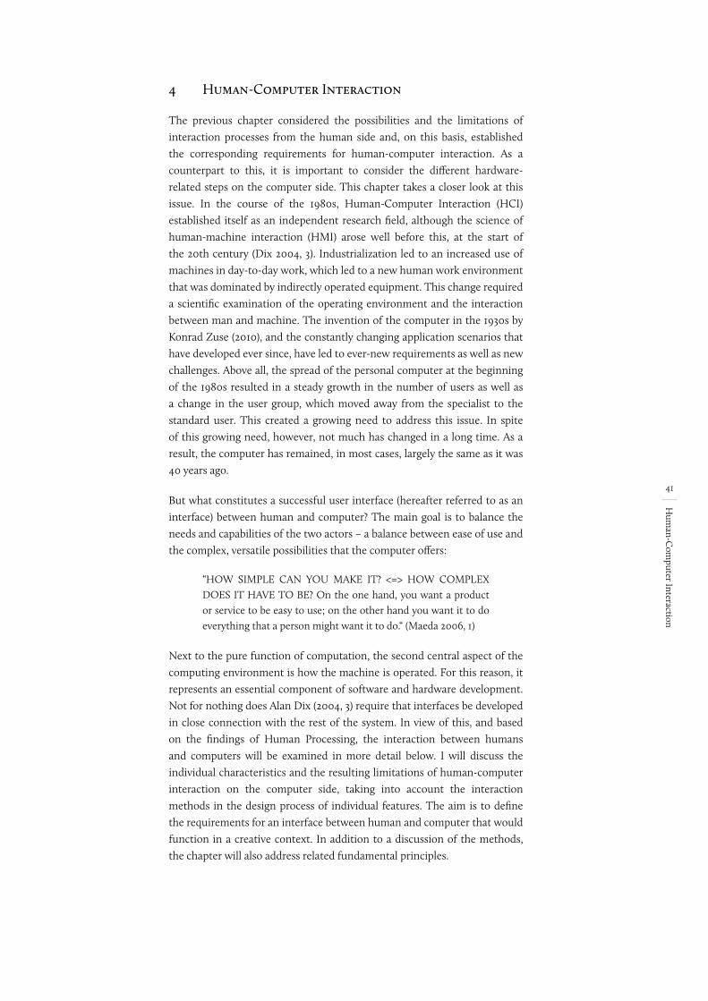
41
Hum
an-Com
puter Interaction
4 Human-Computer Interaction
The previous chapter considered the possibilities and the limitations of interaction processes from the human side and, on this basis, established the corresponding requirements for human-computer interaction. As a counterpart to this, it is important to consider the different hardware-related steps on the computer side. This chapter takes a closer look at this issue. In the course of the 1980s, Human-Computer Interaction (HCI) established itself as an independent research field, although the science of human-machine interaction (HMI) arose well before this, at the start of the 20th century (Dix 2004, 3). Industrialization led to an increased use of machines in day-to-day work, which led to a new human work environment that was dominated by indirectly operated equipment. This change required a scientific examination of the operating environment and the interaction between man and machine. The invention of the computer in the 1930s by Konrad Zuse (2010), and the constantly changing application scenarios that have developed ever since, have led to ever-new requirements as well as new challenges. Above all, the spread of the personal computer at the beginning of the 1980s resulted in a steady growth in the number of users as well as a change in the user group, which moved away from the specialist to the standard user. This created a growing need to address this issue. In spite of this growing need, however, not much has changed in a long time. As a result, the computer has remained, in most cases, largely the same as it was 40 years ago.
But what constitutes a successful user interface (hereafter referred to as an interface) between human and computer? The main goal is to balance the needs and capabilities of the two actors – a balance between ease of use and the complex, versatile possibilities that the computer offers:
“HOW SIMPLE CAN YOU MAKE IT? <=> HOW COMPLEX DOES IT HAVE TO BE? On the one hand, you want a product or service to be easy to use; on the other hand you want it to do everything that a person might want it to do.“ (Maeda 2006, 1)
Next to the pure function of computation, the second central aspect of the computing environment is how the machine is operated. For this reason, it represents an essential component of software and hardware development. Not for nothing does Alan Dix (2004, 3) require that interfaces be developed in close connection with the rest of the system. In view of this, and based on the findings of Human Processing, the interaction between humans and computers will be examined in more detail below. I will discuss the individual characteristics and the resulting limitations of human-computer interaction on the computer side, taking into account the interaction methods in the design process of individual features. The aim is to define the requirements for an interface between human and computer that would function in a creative context. In addition to a discussion of the methods, the chapter will also address related fundamental principles.
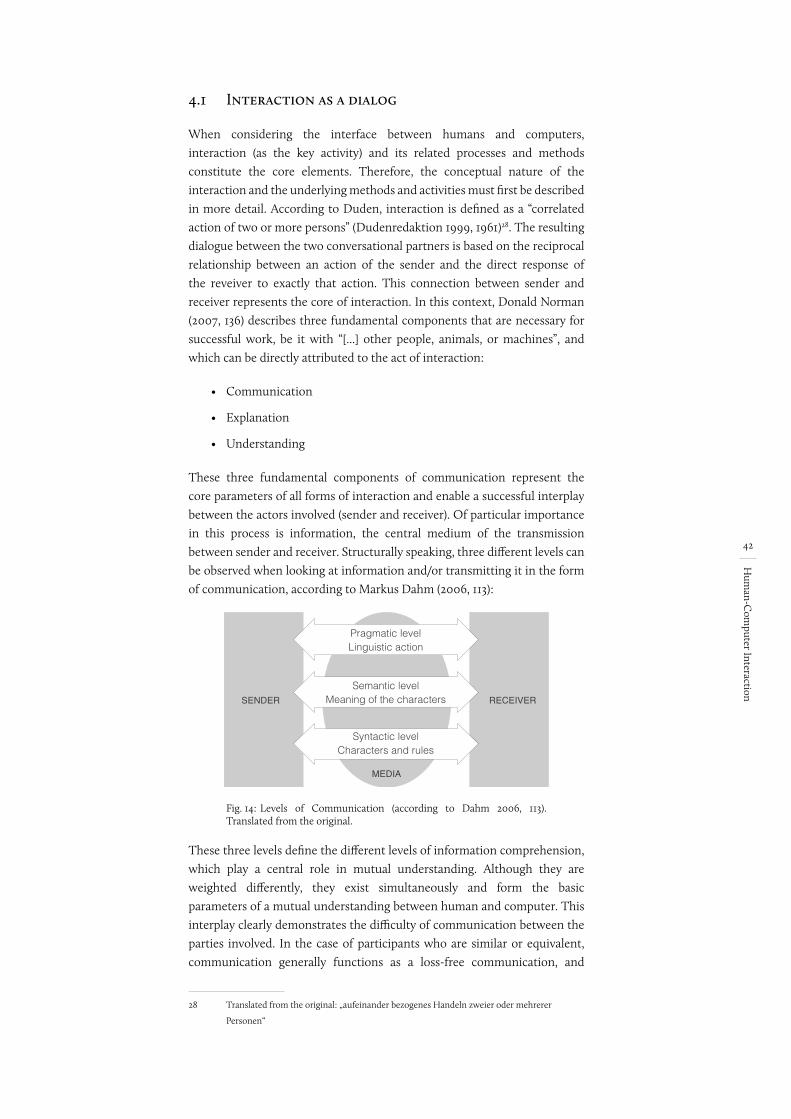
42
Hum
an-Com
puter Interaction
4.1 Interaction as a dialog
When considering the interface between humans and computers, interaction (as the key activity) and its related processes and methods constitute the core elements. Therefore, the conceptual nature of the interaction and the underlying methods and activities must first be described in more detail. According to Duden, interaction is defined as a “correlated action of two or more persons” (Dudenredaktion 1999, 1961)28. The resulting dialogue between the two conversational partners is based on the reciprocal relationship between an action of the sender and the direct response of the reveiver to exactly that action. This connection between sender and receiver represents the core of interaction. In this context, Donald Norman (2007, 136) describes three fundamental components that are necessary for successful work, be it with “[...] other people, animals, or machines”, and which can be directly attributed to the act of interaction:
• Communication
• Explanation
• Understanding
These three fundamental components of communication represent the core parameters of all forms of interaction and enable a successful interplay between the actors involved (sender and receiver). Of particular importance in this process is information, the central medium of the transmission between sender and receiver. Structurally speaking, three different levels can be observed when looking at information and/or transmitting it in the form of communication, according to Markus Dahm (2006, 113):
Fig. 14:
SENDER RECEIVER
Pragmatic levelLinguistic action
Semantic levelMeaning of the characters
Syntactic levelCharacters and rules
MEDIA
Levels of Communication (according to Dahm 2006, 113). Translated from the original.
These three levels define the different levels of information comprehension, which play a central role in mutual understanding. Although they are weighted differently, they exist simultaneously and form the basic parameters of a mutual understanding between human and computer. This interplay clearly demonstrates the difficulty of communication between the parties involved. In the case of participants who are similar or equivalent, communication generally functions as a loss-free communication, and
28 Translated from the original: „aufeinander bezogenes Handeln zweier oder mehrerer
Personen“
Begriffe stimmen. In ““?
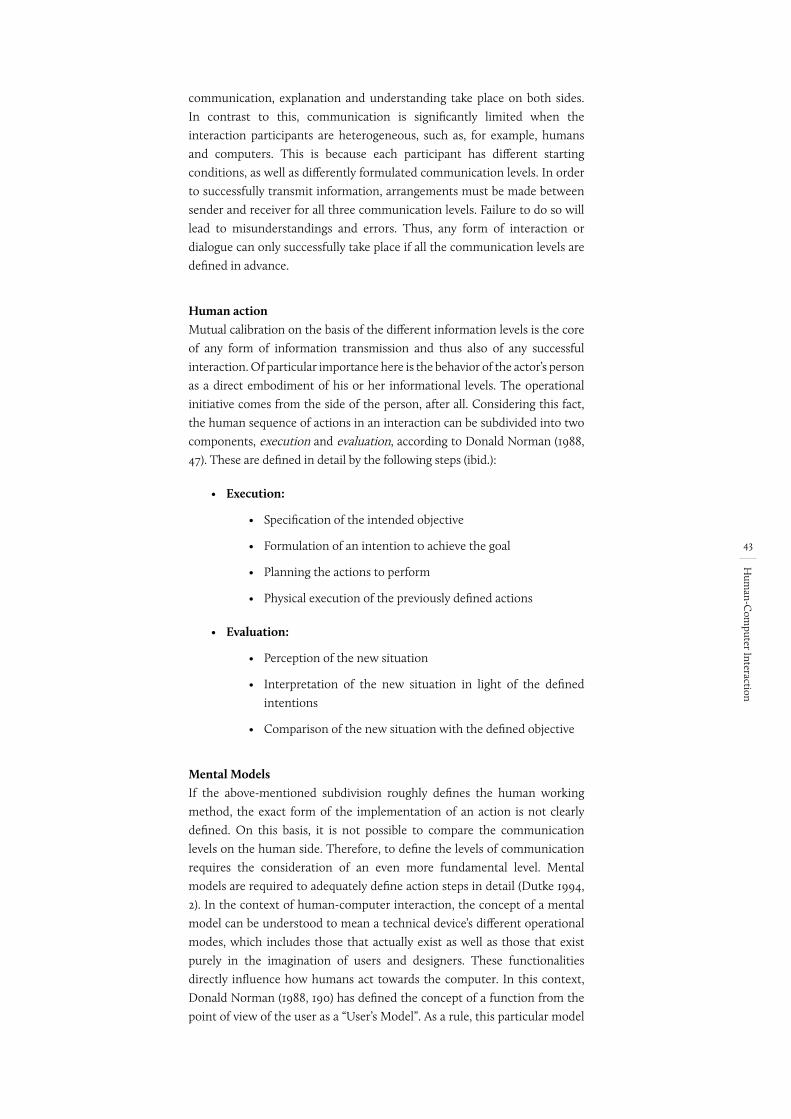
43
Hum
an-Com
puter Interaction
communication, explanation and understanding take place on both sides. In contrast to this, communication is significantly limited when the interaction participants are heterogeneous, such as, for example, humans and computers. This is because each participant has different starting conditions, as well as differently formulated communication levels. In order to successfully transmit information, arrangements must be made between sender and receiver for all three communication levels. Failure to do so will lead to misunderstandings and errors. Thus, any form of interaction or dialogue can only successfully take place if all the communication levels are defined in advance.
Human actionMutual calibration on the basis of the different information levels is the core of any form of information transmission and thus also of any successful interaction. Of particular importance here is the behavior of the actor’s person as a direct embodiment of his or her informational levels. The operational initiative comes from the side of the person, after all. Considering this fact, the human sequence of actions in an interaction can be subdivided into two components, execution and evaluation, according to Donald Norman (1988, 47). These are defined in detail by the following steps (ibid.):
• Execution:
• Specification of the intended objective
• Formulation of an intention to achieve the goal
• Planning the actions to perform
• Physical execution of the previously defined actions
• Evaluation:
• Perception of the new situation
• Interpretation of the new situation in light of the defined intentions
• Comparison of the new situation with the defined objective
Mental ModelsIf the above-mentioned subdivision roughly defines the human working method, the exact form of the implementation of an action is not clearly defined. On this basis, it is not possible to compare the communication levels on the human side. Therefore, to define the levels of communication requires the consideration of an even more fundamental level. Mental models are required to adequately define action steps in detail (Dutke 1994, 2). In the context of human-computer interaction, the concept of a mental model can be understood to mean a technical device’s different operational modes, which includes those that actually exist as well as those that exist purely in the imagination of users and designers. These functionalities directly influence how humans act towards the computer. In this context, Donald Norman (1988, 190) has defined the concept of a function from the point of view of the user as a “User’s Model”. As a rule, this particular model
Ausdrucken und che-cken
erledigt
44
Hum
an-Com
puter Interaction
concept is characterized by Knowledge in the World and Knowledge in the Head (see Chapter 3.4.3). In addition, Donald Norman (1988, 190) has also described two other models: the “System Image“ and the “Design Model“. The first describes the actual functionality of a product, and inspired by the IT world also called an “Implementation Model” (Cooper and Reimann 2003, 21). The second is the “Design Model”. This is the designer’s or the developer’s conceptual model – not his or her own, but rather what he or she imagines represents a function for the user (Cooper und Reimann 2003, 22).
Fig. 15: Three forms of mental models (Norman 1988, 190).
Both the User’s Model and the Design Model are based solely on the ideas and expectations of the user, and it is not really possible to clearly define the User’s Model because of the large number of different users. For this reason, the System Image is the only tangible component of this construct that can serve as the basis of a device’s function because the System Image is based on the actual physical or digital structures. Whereas the System Image and the User’s Model are close together in analogue devices (such as, for example, a record player), they are much farther apart in the digital world (Cooper and Reimann 2003, 22). This discrepancy is largely due to the fact that the computer is not designed for a single task or for executing exactly one predefined function. Martin Seel (1998, 256)29 describes this property with the concept of the “all-encompassing computer”. According to Seel, the computer, as a new medium, is a “convergent device”, a machine that is able to reproduce the functions of any other device, be it a CD player, a telephone or the control of a technical system (ibid.). The possibility of using different software to program and run the most diverse applications requires, in turn, versatile, flexible and generally usable interfaces. The purpose of an interface is precisely to bridge the discrepancy between the User’s Model and the System Image and to come to a consensus about the end product, which is also called “Representation Model”. The closer the User’s Model is to the Representation Model, the easier it is to understand how to use a device or software (Cooper and Reimann 2003, 22-23). Failure to do so will result in problems and errors in operation. Mihai Nadin explains the necessity of bridging the User’s Model and the System Image in the following statement:
29 Translated from the original: „umfassenden Computer“
nicht EN gefunden
45
Hum
an-Com
puter Interaction
“Digital technology should fit like a glove. And we should be able to use it without having to read a manual or needing an intensive introduction. Interface design is, of course, one of the most important aspects of computational design. And it must be equally self-evident that the best Interface Design – like all design – is invisible, which is to say integrated into the designed object or message. This is the objective and the responsibility that confronts design in the context of rapid technological innovation.” (Nadin 1997, 50)30
The production of mental models is facilitated with the help of Personas. Personas are different but precisely trained user models: “Personas are user models that are represented as specific, individual humans. They are not actual people, but are synthesized directly from observations of real people” (Cooper and Reimann 2003, 59). Yet personas should not be confused with stereotypes. They should rather be understood as archetypes with fictional details and characteristics (Constantine and Lockwood 2001). Like any other form of model, personas should be generated based on observations, impressions and experiences of the real world. Personas should be generated based on the following sources, among others (Cooper and Reimann 2003, 58):
• Interviews
• User information on the basis of expert observation
• Market studies
• Market segmentation
• Literature research, such as earlier studies
Out of this, personas produce a realistic image of the user group and thus help to generate the necessary mental models. The mental models, in turn, form the definitive basis for how the dialogue is executed. In concrete terms, this means, on the one hand, the form of the action carried out by humans, and on the other hand, what humans expect from their inhuman counterpart (the computer), namely feedback. When the action phase is primarily concerned with input, then the computer’s output is at the forefront of the activity during the evaluation phase.
4.2 Input & Output
Any form of interaction, regardless of whether it is between several people or between people and computers, is based on the principles outlined above, and it can only be successfully achieved by the mutual interplay of input
30 Translated from the original: „Die digitale Technik sollte uns passen wie ein Handschuh.
Und wir sollten in der Lage sein, uns ihrer zu bedienen, ohne daß wir Unmengen Gedrucktes
lesen müssen oder eine intensive Einweisung benötigen. Natürlich ist das Interface-
Design einer der wichtigsten Aspekte des computational Design. Aber eben so klar und
selbstverständlich müßte sein, daß das beste Interface-Design — wie überhaupt jedes Design
— eines ist, das unsichtbar, also in das entworfene Objekt bzw. die Botschaft integriert ist.
Damit sind die Ziele, die Aufgaben, die sich dem Design im Kontext der rapiden technischen
Erneuerung stellen, umschrieben.“
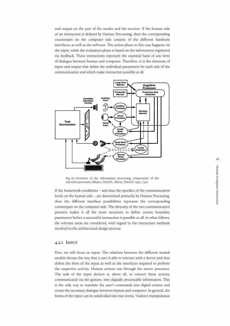
46
Hum
an-Com
puter Interaction
and output on the part of the sender and the receiver. If the human side of an interaction is defined by Human Processing, then the corresponding counterpart on the computer side consists of the different hardware interfaces, as well as the software. The action phase in this case happens via the input, while the evaluation phase is based on the information registered via feedback. These interactions represent the essential basis of any form of dialogue between human and computer. Therefore, it is the elements of input and output that define the individual parameters for each side of the communication and which make interaction possible at all.
Fig. 16: Overview of the information processing components of the executive processes. (Meyer, David E., Kieras, David E. 1997, 750).
If the framework conditions – and thus the specifics of the communication levels on the human side – are determined primarily by Human Processing, then the different interface possibilities represent the corresponding counterpart on the computer side. The diversity of the two communication partners makes it all the more necessary to define certain boundary parameters before a successful interaction is possible at all. In what follows, the relevant areas are considered, with regard to the interaction methods involved in the architectural design process.
4.2.1 Input
First, we will focus on input. The relations between the different mental models dictate the way that a user is able to interact with a device and thus define the form of the input as well as the interfaces required to perform the respective activity. Human actions run through the motor processor. The task of the input devices is, above all, to convert these actions, communicated via the gesture, into digitally processable information. This is the only way to translate the user’s commands into digital actions and create the necessary dialogue between human and computer. In general, the forms of the input can be subdivided into two terms, “indirect manipulation
47
Hum
an-Com
puter Interaction
interfaces” and “direct manipulation interfaces”, which were introduced by Ben Shneiderman (1983, 57). In particular, this division takes into account the manner in which orders are transmitted. An “indirect manipulation interface” is characterized in particular by a very passive form of input, which is usually done via indirect command transmission. Classic examples of this are command devices. In contrast, the properties of direct manipulation interfaces can be described as follows (ibid.):
• "rapid, reversible, incremental actions"
• "replacement of complex command language syntax by direct manipulation of the object of interest"
These definitions specify that the basic functions of a direct interface occur in the context of the communication between the user and the computer. In close relation to this, elementary principles of input can also be identified on the human side. In what follows, these principles will be examined in detail in the context of design, with particular regard to established interaction methods.
AffordanceIn 1976, James J. Gibson (1979, 127) defined the concept of “affordance” and used it to describe the character of the world as it is offered to a living being: “The affordances of the environment are what it offers the animal, what it provides or furnishes, either for good or ill“ (ibid.). When a human being sees a physical object, this awakens in him or her direct expectations of handling or use. It was Donald Norman who established this concept in the context of interaction and adapted the concept of physical affordances introduced by James J. Gibson to the human-computer interaction and added the concept of “perceived affordances” (Stapelkamp 2010, 59; Shaer And Hornecker 2009, 63). If the concept of perceived affordances refers purely to visually perceptible impressions, such as buttons or other graphical user interface (GUI) controls, the concept of physical affordances can be understood to mean any relationship with respect to real objects (such as, for example, switches or knobs). However, Bill Gaver explicitly points out that affordance cannot be understood “[...] as an expression of what you can do with an object [...]“ (Moggridge 2007, 579). Affordance is much more deeply concerned with perception. Therefore it is not a matter of the cultural and practical knowledge about what can be used and how. Rather, affordance is positioned at the place where the desire for an action is generated in the deep psychological sensation of human action – and which is mediated by the perception of the current situation. (ibid.) And thus affordance starts where mind, knowledge, and logic end.
Since affordances are based purely on perception, they are closely connected to human sensory channels. The more senses involved in an interaction process, the higher the degree of affordance. And so it is also understandable that, in general, real objects provide a far greater degree of affordance than purely digital, represented interfaces, and this is based purely on their physical nature and their multisensory presence: “[...] physical objects might
Seite kontrollieren. Wenn passt, dann (ibid.)
ALT: However, Bill Moggridge (2007, 579) explicitly points out that affordance cannot be understood as an expression of what one can do with a thing.
48
Hum
an-Com
puter Interaction
not just invite, but moreover seduce us to interact via ‘irresistibles’ that promise aesthetic interactions [176]” (Shaer and Hornecker 2009, 63)31. This relationship leads to the fact that an interaction with real objects happens almost automatically. In contrast, there is the fact that the deeper a user has to immerse him or herself in the digital world, the lower the degree of affordance and the more difficult the operation.
MappingAnother elementary input principles is mapping. This term describes the assignment of one or more control elements to an actually executable action – how closely are the two areas related and how well-aligned are they? Good mapping helps the user recognize the direct connections between the control element and the action and thus makes it possible to directly assess the potential of various actions. However, mapping does not involve just the optical interrelationship between a control element and an executable action, as Durrell Bishop emphasizes:
“You can see the potential of an action, for example, the potential of how far something might move, and it doesn’t actually matter what the object looks like, as long as you can remember it easily after seeing how it behaves.“ (Moggridge 2007, 547–548)
Thus, in addition to optical and functional interrelations, the main focus is on functional-logic adaptations, which is illustrated by Donald Norman (2007, 60) using the example of boiling water: the change in sound provides constant information about the current water temperature. Interestingly, you don’t need to be taught anything to understand this, and there is no need to learn any technique: “After listening to the sounds of boiling water a few times, you get it” (ibid.). Does the perceived information correspond to the related, actually occurring action, irrespective of whether it is input or output? This is what makes for good mapping. This is where knowledge in the world plays a decisive role. In this context, Donald Norman (1988, 79) aptly mentions that everything that is anchored in the world does not have to be learned explicitly. Instead, it is all understood through mapping. It is thus also understandable that actually existing objects naturally exhibit a greater degree of mapping compared to purely digital control elements. Interacting with physical objects thus not only makes for an easy entry, but above all, it makes it possible to act without changing the way one thinks or needing to interpret anything. In this way, an interaction can happen without need to be learned. With respect to the general conditions of human processing, this reduces the cognitive load necessary for the operation so that more resources are available for the actual action itself.
ChunkingThe human perceptual apparatus and short-term memory are limited, and these limitations decisively shape the human framework conditions on the input side. If the limit of the sensory register is a temporal one, the decisive
31 The term irresistibles is taken from the article “From Perception to Experience, from
Affordances to Irresistibles” (Overbeeke and Wensveen 2003)
49
Hum
an-Com
puter Interaction
factor for short-term memory is the number of information elements (see chapter 3.2). Because of this, Bill Buxton’s (1986, 8) claim that “any concept or transaction that can be described in a single word or phrase should be able to be articulated by a single gesture” can be fully understood in terms of interaction. However, it is not always possible to directly implement this principle because of technical limitations. In certain cases, several actions must be carried out successively in order to achieve the desired goal. This leads to an increased load on human short-term memory and thus directly increases the risk of unwanted context switches.
Chunking can provide a solution to this problem. Combining (chunking) several individual actions into a perceived single action, can directly reduce the cognitive load in the short-term memory. This leads to the fact that sequential interactions are perceived in parallel and as a chunk, which leads directly to an enhancement of cognitive performance. Looking more closely at the effect of chunking, it is possible to identify a close connection to the motor processor, especially in human-computer interaction. In this context, chunking especially facilitates modes of motor action. This effect occurs, for example, in a drag-and-drop action with the computer mouse. Contracting the muscles and constantly holding the mouse steady provides unconscious feedback about the temporary condition of the situation. Only letting go triggers a conscious signal that the action is finished. Although it is only the last of many steps, this temporary action makes the whole action chain perceivable to humans as a single action. (Buxton 1986, 4)
The findings of Ken Hinckely et al. (1994, 456) on this topic should be noted. Their research clearly shows that chunking is especially effective in the case of two-handed operation, and more information is communicated to the user automatically and unnoticeably. Experiments have not only shown that parallel execution can encompass several actions in a single gesture, but it can also lead to a more natural, intuitive form of interaction. (ibid.)
In the context of interaction, this effect can certainly be deliberately fostered or applied in order to compress and bundle more complex operations. In the light of these findings, motor sequences are of particular importance. Chunking helps to unconsciously reduce the cognitive load, thereby directly contributing to an improvement in brain performance. This direct relationship between human motor activity and brain performance makes it possible to reduce the cognitive load necessary for the operation and thus to facilitate the actual work.
4.2.2 Output
As a feedback medium, the output occurs in response to the action performed by the user, thus closing the cycle of interaction between the user and the computer. However, we should not understand output or feedback as a mere request from the system. Rather, it ought to be understood as any form of action coming from the digital interaction partner that is perceivable by a person. In this way, feedback is seen as a mode whereby the system communicates to the user. This idea is fundamental to successfully
hab ich eingefügt
Hier hatte ich auch mal eine Quelle nach dem 1. Satz drinnen
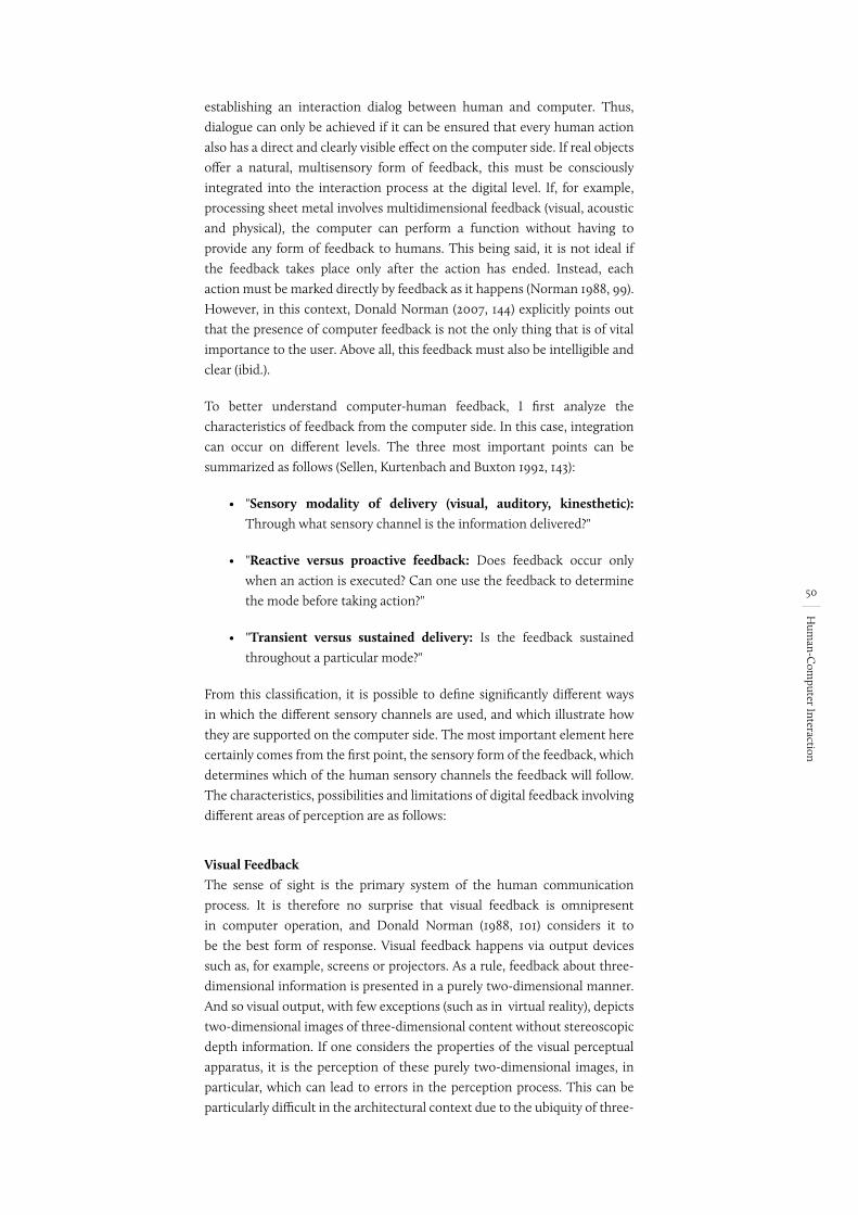
50
Hum
an-Com
puter Interaction
establishing an interaction dialog between human and computer. Thus, dialogue can only be achieved if it can be ensured that every human action also has a direct and clearly visible effect on the computer side. If real objects offer a natural, multisensory form of feedback, this must be consciously integrated into the interaction process at the digital level. If, for example, processing sheet metal involves multidimensional feedback (visual, acoustic and physical), the computer can perform a function without having to provide any form of feedback to humans. This being said, it is not ideal if the feedback takes place only after the action has ended. Instead, each action must be marked directly by feedback as it happens (Norman 1988, 99). However, in this context, Donald Norman (2007, 144) explicitly points out that the presence of computer feedback is not the only thing that is of vital importance to the user. Above all, this feedback must also be intelligible and clear (ibid.).
To better understand computer-human feedback, I first analyze the characteristics of feedback from the computer side. In this case, integration can occur on different levels. The three most important points can be summarized as follows (Sellen, Kurtenbach and Buxton 1992, 143):
• "Sensory modality of delivery (visual, auditory, kinesthetic): Through what sensory channel is the information delivered?"
• "Reactive versus proactive feedback: Does feedback occur only when an action is executed? Can one use the feedback to determine the mode before taking action?"
• "Transient versus sustained delivery: Is the feedback sustained throughout a particular mode?"
From this classification, it is possible to define significantly different ways in which the different sensory channels are used, and which illustrate how they are supported on the computer side. The most important element here certainly comes from the first point, the sensory form of the feedback, which determines which of the human sensory channels the feedback will follow. The characteristics, possibilities and limitations of digital feedback involving different areas of perception are as follows:
Visual FeedbackThe sense of sight is the primary system of the human communication process. It is therefore no surprise that visual feedback is omnipresent in computer operation, and Donald Norman (1988, 101) considers it to be the best form of response. Visual feedback happens via output devices such as, for example, screens or projectors. As a rule, feedback about three-dimensional information is presented in a purely two-dimensional manner. And so visual output, with few exceptions (such as in virtual reality), depicts two-dimensional images of three-dimensional content without stereoscopic depth information. If one considers the properties of the visual perceptual apparatus, it is the perception of these purely two-dimensional images, in particular, which can lead to errors in the perception process. This can be particularly difficult in the architectural context due to the ubiquity of three-
In ““?
vielleicht wie oben
51
Hum
an-Com
puter Interaction
dimensional information. Stereoscopic systems and displays offer potential alternatives. Using various methods (shutter glasses, parallax barriers, etc.), different images are created and shown to each eye, which mimics the natural process of perception. However, there are a number of identifiable problems when using binocular devices and 3D displays. In particular, “vergence-accommodation conflicts” can lead to user discomfort and fatigue (Shibata et al., 2011, 27). This term refers to disturbances caused by blurry and duplicated image information, which mainly involve the following problems (ibid.):
• Cybersickness: Use leads to discomfort and nausea.
• Eye tiredness: Use leads to eye fatigue more quickly than compared to visual perception in the actual environment.
In addition, Monika Pölönen (2010, 17) mentions further limitations when using virtual environments:
• Field of view: Restricted field of view caused by the display technology.
• Low contrast range: Limited contrast range due to technical factors, when compared to reality.
• Ergonomics: In addition to technical aspects, non-ergonomic hardware components, such as the wearability of eyeglasses, also pose problems.
At the moment, these problem areas lead to handling limitations and thus to a reduced user acceptance.
Tactile FeedbackIn addition to visual feedback, the second relevant feedback channel within this context is the haptic, perceptible form of output that is perceived by human skin receptors. This form of feedback is omnipresent when interacting with real, tangible objects. Examples are most commonly found in the field of (electro) mechanics, “For example, in some rotating tone controls you can feel a little ‘blip’ as you rotate it past the preferred, neutral position“ (Norman 2007, 65). As these examples clearly show, communication via the haptic sensory channel is a feedback option that is unmistakable but also inconspicuous and often subconsciously perceptible. It is, in particular, the bilateral property that makes it inevitable that this form of feedback will be used with humans. It also plays a special role in the context of interaction. Haptic feedback should therefore be understood not only as a one-sided action of the computer on humans. Rather, it is the direct interaction between gesture and feeling in the interaction process that enables the direct feedback of an action via the haptic sensory channel. The input and output devices merge into one. However, it is rather difficult to implement this in the field of human-computer interaction. In particular, the ubiquitous input tools such as the mouse, keyboard, and even the touch screen offer only a very indirect form of haptic feedback. To be sure, clicking
(LaViola Jr. 2000, 54)
erledigt
52
Hum
an-Com
puter Interaction
the mouse or touching a touchscreen also provides tactile feedback to the user. However, the abstract form does not convey anything about the state of the system. Thus these systems do not really support the sensitivity of tactile perception nor the characteristic of bipolarity. Tangible interfaces can help here. Examples from this field clearly demonstrate the potential of feedback that also engages with the sense of touch.
Computer feedback in any form can be regarded as an integral part of the interaction between human and computer. It is the only way to complete a human action through the evaluation phase. The human perception of computer feedback generally takes place via the sense organs. Starting from human sense perception, human processing, but also with regard to established design tools, multisensory feedback can be seen as an essential component of the interaction process, which is conducive to the design process. As the visualization of the two feedback channels (visual and tactile) clearly shows, tactile feedback is a very special form of feedback. In contrast to visual output, tactile feedback is mainly characterized by natural indicators in the interaction process. In this way, multi-layered information from the system can be transmitted to the user in a straightforward way that originates from “Knowledge in the World”. Moreover, a particularly close form of interaction is possible due to the bilateral communication via touching. Considering these specificities, it quickly becomes clear that real objects naturally have a clear and multisensory form of feedback, whereas purely digital interaction elements present a much higher communication barrier.
4.2.3 Interplay between input and output
In the previous chapters, input and output were initially viewed as separate from one another. However, the combination of the two is also particularly important. Only through mutual interplay can an interaction between the interaction partners occur. Above all, the spatial position of the two parts in relation to each other is of particular importance in the context of HCI. This is directly related to the form of the input, but above all the sensory form of the feedback. The relationship between the two areas, i.e. the degree of sensory or local correspondence and the spatial position of the input and output location, is described here by the term “level of embodiment” (Shaer and Hornecker 2009, 53). The level of embodiment indicates how close the connection between the input and output locations is. It is thus the measure of how much the digital feedback is a response to input from the real world, i.e. how it is embodied. A high level of embodiment also indicates a high degree of direct interaction. (ibid.) According to Orit Shaer and Eva Hornecker (ibid.), there are four different levels of embodiment. In descending order, they are:
• ”full where the output device is the input device,
• nearby where the output takes place near the input object,
• environment where the output is around the the user, and
• distand where the output is on another screen or even in another room.” (ibid.)
QUELLE
wörtlich oder ned??
Das ist nicht wörtlich, sondern umgeschrieben.
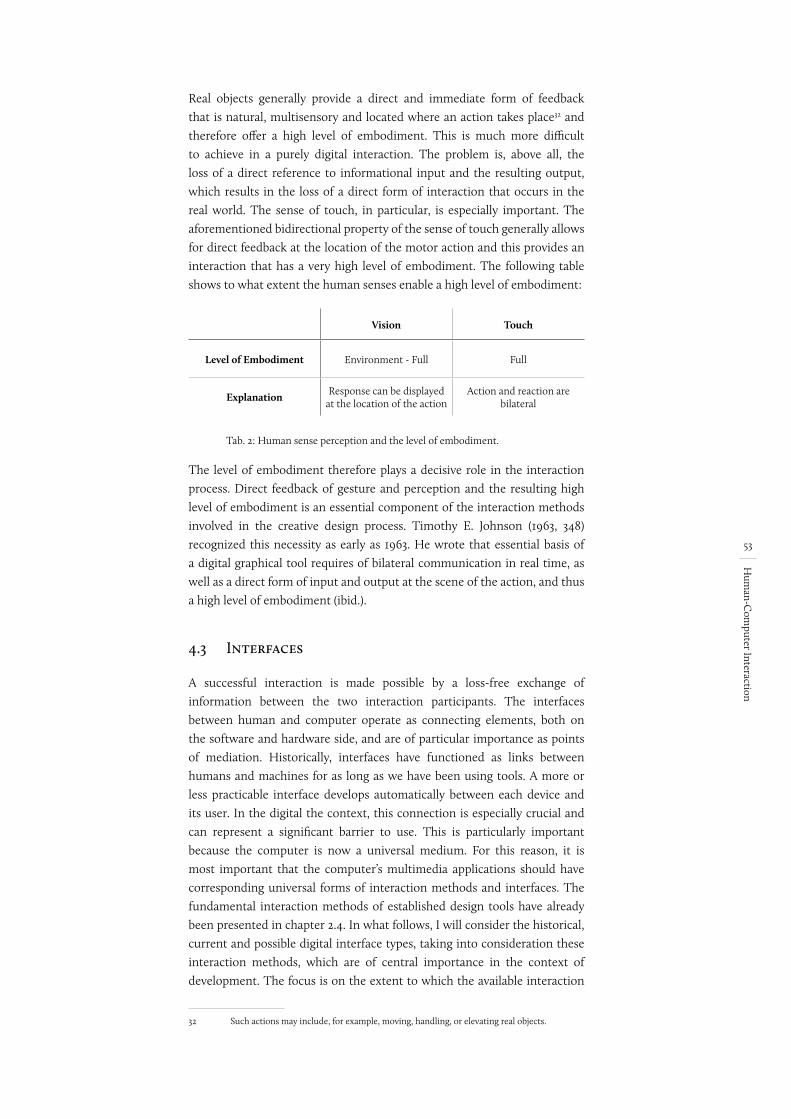
53
Hum
an-Com
puter Interaction
Real objects generally provide a direct and immediate form of feedback that is natural, multisensory and located where an action takes place32 and therefore offer a high level of embodiment. This is much more difficult to achieve in a purely digital interaction. The problem is, above all, the loss of a direct reference to informational input and the resulting output, which results in the loss of a direct form of interaction that occurs in the real world. The sense of touch, in particular, is especially important. The aforementioned bidirectional property of the sense of touch generally allows for direct feedback at the location of the motor action and this provides an interaction that has a very high level of embodiment. The following table shows to what extent the human senses enable a high level of embodiment:
Vision Touch
Level of Embodiment Environment - Full Full
Explanation Response can be displayed at the location of the action
Action and reaction are bilateral
Tab. 2: Human sense perception and the level of embodiment.
The level of embodiment therefore plays a decisive role in the interaction process. Direct feedback of gesture and perception and the resulting high level of embodiment is an essential component of the interaction methods involved in the creative design process. Timothy E. Johnson (1963, 348) recognized this necessity as early as 1963. He wrote that essential basis of a digital graphical tool requires of bilateral communication in real time, as well as a direct form of input and output at the scene of the action, and thus a high level of embodiment (ibid.).
4.3 Interfaces
A successful interaction is made possible by a loss-free exchange of information between the two interaction participants. The interfaces between human and computer operate as connecting elements, both on the software and hardware side, and are of particular importance as points of mediation. Historically, interfaces have functioned as links between humans and machines for as long as we have been using tools. A more or less practicable interface develops automatically between each device and its user. In the digital the context, this connection is especially crucial and can represent a significant barrier to use. This is particularly important because the computer is now a universal medium. For this reason, it is most important that the computer’s multimedia applications should have corresponding universal forms of interaction methods and interfaces. The fundamental interaction methods of established design tools have already been presented in chapter 2.4. In what follows, I will consider the historical, current and possible digital interface types, taking into consideration these interaction methods, which are of central importance in the context of development. The focus is on the extent to which the available interaction
32 Such actions may include, for example, moving, handling, or elevating real objects.
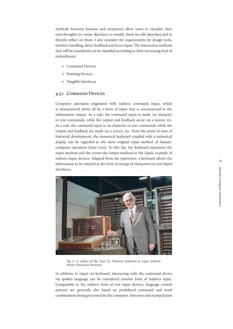
54
Hum
an-Com
puter Interaction
methods between humans and computers allow users to visualize their own thoughts (to create sketches), to modify them (to edit sketches) and to directly reflect on them. I also consider the requirements for design tools, intuitive handling, direct feedback and fuzzy input. The interaction methods that will be considered can be classified according to their increasing level of embodiment:
• Command Devices
• Pointing Devices
• Tangible Interfaces
4.3.1 Command Devices
Computer operation originated with indirect command input, which is characterized above all by a form of input that is unconnected to the information output. As a rule, the command input is made via character or text commands, while the output and feedback occur via a screen, etc. As a rule, the command input is via character or text commands, while the output and feedback are made via a screen, etc. From the point of view of historical development, the numerical keyboard coupled with a numerical display can be regarded as the most original input method of human-computer operation (Zuse 2010). To this day, the keyboard represents the input medium and the screen the output medium in the classic example of indirect input devices. Adapted from the typewriter, a keyboard allows the information to be entered in the form of strings of characters via text-based interfaces.
Fig. 17: A replica of the Zuse Z3. Numeric keyboard as input method. Photo: Deutsches Museum.
In addition to input via keyboard, interacting with the command device via spoken language can be considered another form of indirect input. Comparable to the indirect form of text input devices, language control systems are generally also based on predefined command and word combinations being processed by the computer. Selection and manipulation
55
Hum
an-Com
puter Interaction
of objects and elements is carried out by means of predefined text blocks via keyboard input or via voice commands.
This form of interaction allows individual instructions, such as information and text, to be input simply and quickly. In the architectural context, this applies to, for example, the input of text-based information such as additional attributes in the construction of semantic components. Speech input is of particular importance here. Contrary to text-input devices, voice-based systems offer considerable advantages, particularly when the hands are (already) occupied. Since the body is already occupied with carrying out physical actions, voice systems allow an interaction to happen in parallel with the manual operation. Imagine a scenario where someone is drawing while simultaneously using speech input to define component properties and attributes. It would be much more difficult to accomplish this in a purely graphical context. It is truly not possible to achieve a practical form of interaction in such a case. This is due not only to the fact that the input and output locations are separated, and thus possess a very low level of embodiment with no direct relationship between the two interaction participants (human and computer). It is due, moreover, to the fact that the method of input is indirect and occurs via abstract word metaphors, which leads to a very distant form of interaction and command input. A further difficulty has to do with the representation of vague, inaccurate and incomplete inputs, which is especially necessary to the creative act. This applies to both making objects and to manipulating them, for example, when moving an object. If the selection still occurs via identification numbers (IDs) or similar means, this raises the question of how command devices can implement inaccurate or vague input forms: “A bit more!” or “Stop, not so far!” are not interpretable on the computer side and thus are not usable as an input form.
In contrast to the keyboard, the peculiarities of speech input should be discussed. Here the recognition of spoken words represents a further problem. Thus, in addition to the use of predefined vocabulary, different pronunciations (such as dialects) make the automatic recognition of speech more difficult. But newer approaches, such as Siri from Apple (Apple Inc.), indicate the technical improvements that are possible, with systems like Siri offering the possibility of an almost natural form of verbal dialogue. However, there still remains the problem of the distance between input and output.
Despite the limitations that have been mentioned, keyboard input as well as speech input are useful and usable forms of interaction in certain application areas. However, the disadvantages of this indirect form of interaction are particularly evident in the creative context. Compared to established design tools, the most important issues are the low level of embodiment, the abstract form of input, manipulation via singular commands, as well as the impossibility of inputting fuzzy, vague, and incomplete information. This leads to the fact that it appears quite difficult to be able to apply this method in the graphical context and that it only makes sense in certain exceptional cases. And so it is also understandable that the application usually only supports other, more direct forms of interaction.
56
Hum
an-Com
puter Interaction
4.3.2 Pointing Devices
If the computer was first operated using a keyboard, new areas of computer application required a rethinking of established text-input operating modes. This resulted in applications for the creative and graphical fields such as architecture, design and engineering (see Sketchpad by Ivan Sutherland (Sutherland 1963)), all of which required the direct selection and manipulation of objects on the screen. “When you were interacting considerably with the screen, you needed some sort of device to select objects on the screen, to tell the computer that you wanted to do something with them” (Moggridge 2007, 17). The idea of a novel interface for the direct manipulation of digital objects with the aid of a so-called pointing device was developed as a “[...] a mechanism for communicating information, such as a particular location or choice of object on a display, to a system” (Raskin 2007, 34). In parallel with the innovations in hardware technology, new user interfaces were developed on the software side (Myers 1996). The idea for the graphical user interface (GUI) arose from the possibility of direct manipulation. Using the WIMP concept “W (windows) I (icons) M (menus) P (pointers)” in combination with a pointing device, it was possible to directly input commands and action sequences on the basis of graphical screen presentations (Shaer and Hornecker 2009, 3). Commands and actions are made easy and directly accessible to the user via a graphical user metaphor. Instead of making complicated commands via keyboard input, the GUI allows actions to be grouped into individual symbols and thus executed by a touch or a click using the digital pointer. However, this procedure leads to the following problem: activating the function via a symbol specifies a fixed operating path, meaning the correct command must be selected before the actual activity is executed. Thus, this input method requires the user to know which function he or she wants to execute and/or which geometry he or she wants to generat – knowledge that is only conditionally present in the early design phases due to the complex presentation of the problem and the ambiguously defined solution path.
If the development of pointing devices are examined more closely, the resulting approaches can be divided into two different areas. The biggest difference concerns the respective level of embodiment, and based on this we can divide things into indirect and direct pointing devices.
Indirect Pointing DeviceIndirect pointing devices are interfaces for controlling a pointer on the screen by means of an external input device independent of the screen. Examples include the light pen (the first of such devices invented) and the computer mouse (the most established method), as well as the joystick, the trackpad or the graphical tablet. The technological as well as spatial separation of input and output devices with indirect pointing devices allows for the direct modification of objects on a digital level. However, there is no direct relationship between human and object due to the external position of the control and output devices. The interplay of input and output can be described by the MVC model (model-view-control) (Ullmer, Brygg Anders 2002, 57).
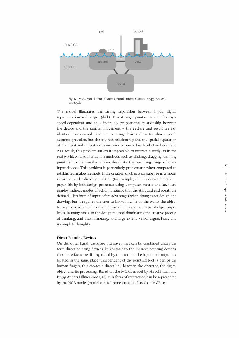
57
Hum
an-Com
puter Interaction
Fig. 18:
model
viewcontrol
input output
PHYSICAL
DIGITAL
MVC-Model (model-view-control) (from Ullmer, Brygg Anders 2002, 57).
The model illustrates the strong separation between input, digital representation and output (ibid.). This strong separation is amplified by a speed-dependent and thus indirectly proportional relationship between the device and the pointer movement – the gesture and result are not identical. For example, indirect pointing devices allow for almost pixel-accurate precision, but the indirect relationship and the spatial separation of the input and output locations leads to a very low level of embodiment. As a result, this problem makes it impossible to interact directly, as in the real world. And so interaction methods such as clicking, dragging, defining points and other similar actions dominate the operating range of these input devices. This problem is particularly problematic when compared to established analog methods. If the creation of objects on paper or in a model is carried out by direct interaction (for example, a line is drawn directly on paper, bit by bit), design processes using computer mouse and keyboard employ indirect modes of action, meaning that the start and end points are defined. This form of input offers advantages when doing exact design and drawing, but it requires the user to know how he or she wants the object to be produced, down to the millimeter. This indirect type of object input leads, in many cases, to the design method dominating the creative process of thinking, and thus inhibiting, to a large extent, verbal vague, fuzzy and incomplete thoughts.
Direct Pointing DevicesOn the other hand, there are interfaces that can be combined under the term direct pointing devices. In contrast to the indirect pointing devices, these interfaces are distinguished by the fact that the input and output are located in the same place. Independent of the pointing tool (a pen or the human finger), this creates a direct link between the operator, the digital object and its processing. Based on the MCRit model by Hiroshi Ishii and Brygg Anders Ullmer (2002, 58), this form of interaction can be represented by the MCR model (model-control-representation, based on MCRit):
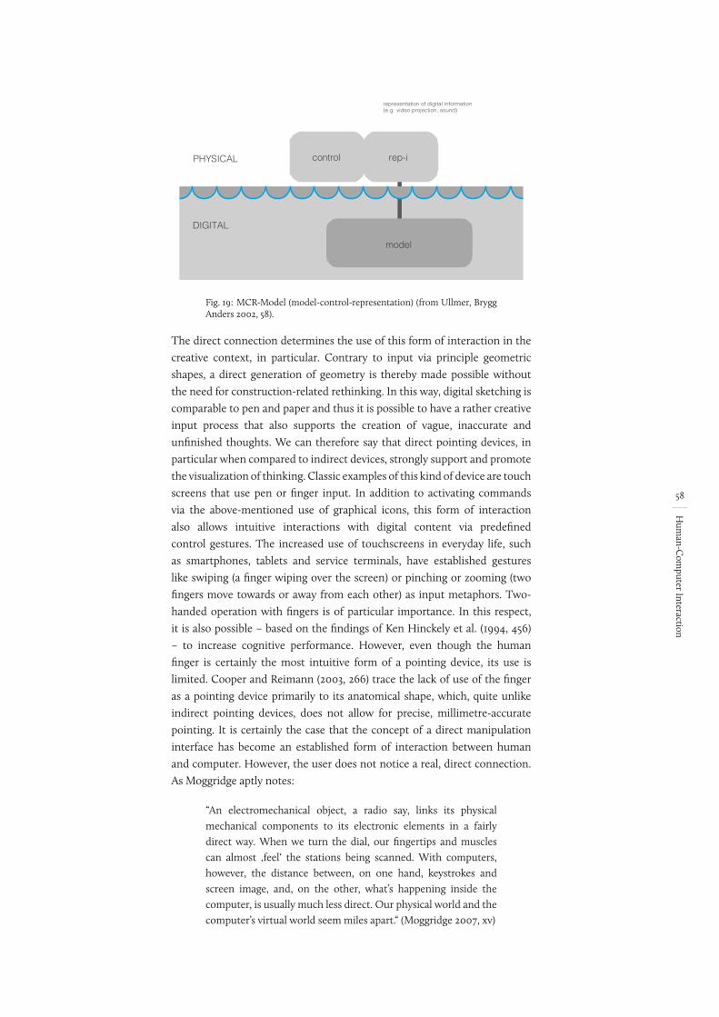
58
Hum
an-Com
puter Interaction
Fig. 19:
representation of digital information(e.g. video projection, sound)
PHYSICAL
DIGITAL
control rep-i
model
MCR-Model (model-control-representation) (from Ullmer, Brygg Anders 2002, 58).
The direct connection determines the use of this form of interaction in the creative context, in particular. Contrary to input via principle geometric shapes, a direct generation of geometry is thereby made possible without the need for construction-related rethinking. In this way, digital sketching is comparable to pen and paper and thus it is possible to have a rather creative input process that also supports the creation of vague, inaccurate and unfinished thoughts. We can therefore say that direct pointing devices, in particular when compared to indirect devices, strongly support and promote the visualization of thinking. Classic examples of this kind of device are touch screens that use pen or finger input. In addition to activating commands via the above-mentioned use of graphical icons, this form of interaction also allows intuitive interactions with digital content via predefined control gestures. The increased use of touchscreens in everyday life, such as smartphones, tablets and service terminals, have established gestures like swiping (a finger wiping over the screen) or pinching or zooming (two fingers move towards or away from each other) as input metaphors. Two-handed operation with fingers is of particular importance. In this respect, it is also possible – based on the findings of Ken Hinckely et al. (1994, 456) – to increase cognitive performance. However, even though the human finger is certainly the most intuitive form of a pointing device, its use is limited. Cooper and Reimann (2003, 266) trace the lack of use of the finger as a pointing device primarily to its anatomical shape, which, quite unlike indirect pointing devices, does not allow for precise, millimetre-accurate pointing. It is certainly the case that the concept of a direct manipulation interface has become an established form of interaction between human and computer. However, the user does not notice a real, direct connection. As Moggridge aptly notes:
“An electromechanical object, a radio say, links its physical mechanical components to its electronic elements in a fairly direct way. When we turn the dial, our fingertips and muscles can almost ‚feel‘ the stations being scanned. With computers, however, the distance between, on one hand, keystrokes and screen image, and, on the other, what’s happening inside the computer, is usually much less direct. Our physical world and the computer’s virtual world seem miles apart.“ (Moggridge 2007, xv)
Cooper and Reimann (2003, 266) suggest not using the finger as a pointing device mainly due to its anatomical form, which, in contrast to indirect pointing devices, does not allow for precise, millimeter-accurate pointing.
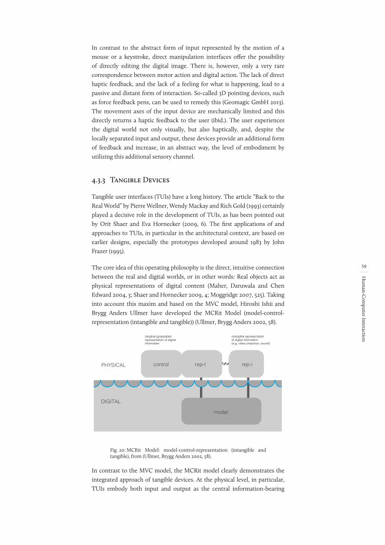
59
Hum
an-Com
puter Interaction
In contrast to the abstract form of input represented by the motion of a mouse or a keystroke, direct manipulation interfaces offer the possibility of directly editing the digital image. There is, however, only a very rare correspondence between motor action and digital action. The lack of direct haptic feedback, and the lack of a feeling for what is happening, lead to a passive and distant form of interaction. So-called 3D pointing devices, such as force feedback pens, can be used to remedy this (Geomagic GmbH 2013). The movement axes of the input device are mechanically limited and this directly returns a haptic feedback to the user (ibid.). The user experiences the digital world not only visually, but also haptically, and, despite the locally separated input and output, these devices provide an additional form of feedback and increase, in an abstract way, the level of embodiment by utilizing this additional sensory channel.
4.3.3 Tangible Devices
Tangible user interfaces (TUIs) have a long history. The article “Back to the Real World” by Pierre Wellner, Wendy Mackay and Rich Gold (1993) certainly played a decisive role in the development of TUIs, as has been pointed out by Orit Shaer and Eva Hornecker (2009, 6). The first applications of and approaches to TUIs, in particular in the architectural context, are based on earlier designs, especially the prototypes developed around 1983 by John Frazer (1995).
The core idea of this operating philosophy is the direct, intuitive connection between the real and digital worlds, or in other words: Real objects act as physical representations of digital content (Maher, Daruwala and Chen Edward 2004, 3; Shaer and Hornecker 2009, 4; Moggridge 2007, 525). Taking into account this maxim and based on the MVC model, Hiroshi Ishii and Brygg Anders Ullmer have developed the MCRit Model (model-control-representation (intangible and tangible)) (Ullmer, Brygg Anders 2002, 58).
Fig. 20:
intangible representationof digital information(e.g. video projection, sound)
PHYSICAL
DIGITAL
control rep-irep-t
model
tangible (graspable)representation of digitalinformation
MCRit Model: model-control-representation (intangible and tangible), from (Ullmer, Brygg Anders 2002, 58).
In contrast to the MVC model, the MCRit model clearly demonstrates the integrated approach of tangible devices. At the physical level, in particular, TUIs embody both input and output as the central information-bearing
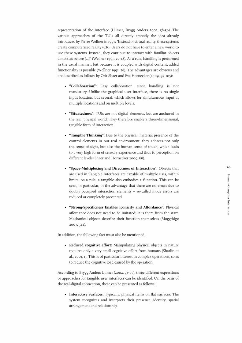
60
Hum
an-Com
puter Interaction
representation of the interface (Ullmer, Brygg Anders 2002, 58-59). The various approaches of the TUIs all directly embody the idea already introduced by Pierre Wellner in 1991: “Instead of virtual reality, these systems create computerized reality (CR). Users do not have to enter a new world to use these systems. Instead, they continue to interact with familiar objects almost as before [...]” (Wellner 1991, 27-28). As a rule, handling is performed in the usual manner, but because it is coupled with digital content, added functionality is possible (Wellner 1991, 28). The advantages are obvious and are described as follows by Orit Shaer and Eva Hornecker (2009, 97-105):
• “Collaboration”: Easy collaboration, since handling is not mandatory. Unlike the graphical user interface, there is no single input location, but several, which allows for simultaneous input at multiple locations and on multiple levels.
• “Situatedness”: TUIs are not digital elements, but are anchored in the real, physical world. They therefore enable a three-dimensional, tangible form of interaction.
• “Tangible Thinking”: Due to the physical, material presence of the control elements in our real environment, they address not only the sense of sight, but also the human sense of touch, which leads to a very high form of sensory experience and thus to perception on different levels (Shaer and Hornecker 2009, 68).
• “Space-Multiplexing and Directness of Interaction”: Objects that are used in Tangible Interfaces are capable of multiple uses, within limits. As a rule, a tangible also embodies a function. This can be seen, in particular, in the advantage that there are no errors due to doubly occupied interaction elements – so-called mode errors are reduced or completely prevented.
• “Strong-Specificness Enables Iconicity and Affordance”: Physical affordance does not need to be imitated; it is there from the start. Mechanical objects describe their function themselves (Moggridge 2007, 542).
In addition, the following fact must also be mentioned:
• Reduced cognitive effort: Manipulating physical objects in nature requires only a very small cognitive effort from humans (Sharlin et al., 2001, 1). This is of particular interest in complex operations, so as to reduce the cognitive load caused by the operation.
According to Brygg Anders Ullmer (2002, 73-97), three different expressions or approaches for tangible user interfaces can be identified. On the basis of the real-digital connection, these can be presented as follows:
• Interactive Surfaces: Typically, physical items on flat surfaces. The system recognizes and interprets their presence, identity, spatial arrangement and relationship.
ALLE CHECKEN AUF QUELLEN
• (Shaer and Hornecker 2009, 97-98)
• (Shaer and Hornecker 2009, 98)
• and 99-102
• (Shaer and Hornecker 2009, 102-103)
• (Shaer and Hornecker 2009, 103-105)
gelöscht: on the basis of these basic considerations
Vielelicht bild nach unten - habe ich gemacht
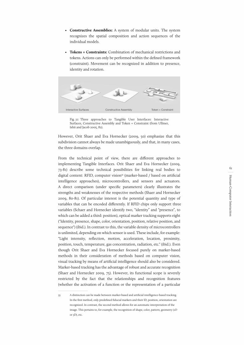
61
Hum
an-Com
puter Interaction
• Constructive Assemblies: A system of modular units. The system recognizes the spatial composition and action sequences of the individual models.
• Tokens + Constraints: Combination of mechanical restrictions and tokens. Actions can only be performed within the defined framework (constraint). Movement can be recognized in addition to presence, identity and rotation.
Fig. 21:
Interactive Surfaces Constructive Assembly Token + Constraint
Three approaches to Tangible User Interfaces: Interactive Surfaces, Constructive Assembly and Token + Constraint (from Ullmer, Ishii and Jacob 2005, 82).
However, Orit Shaer and Eva Hornecker (2009, 50) emphasize that this subdivision cannot always be made unambiguously, and that, in many cases, the three domains overlap.
From the technical point of view, there are different approaches to implementing Tangible Interfaces. Orit Shaer and Eva Hornecker (2009, 73-81) describe some technical possibilities for linking real bodies to digital content: RFID, computer vision33 (marker-based / based on artificial intelligence approaches), microcontrollers, and sensors and actuators. A direct comparison (under specific parameters) clearly illustrates the strengths and weaknesses of the respective methods (Shaer and Hornecker 2009, 80-81). Of particular interest is the potential quantity and type of variables that can be encoded differently. If RFID chips only support three variables (Schaer and Hornecker identify two, “identity” and “presence”, to which can be added a third: position), optical marker tracking supports eight ("Identity, presence, shape, color, orientation, position, relative position, and sequence") (ibid.). In contrast to this, the variable density of microcontrollers is unlimited, depending on which sensor is used. These include, for example: "Light intensity, reflection, motion, acceleration, location, proximity, position, touch, temperature, gas concentration, radiation, etc." (ibid.). Even though Orit Shaer and Eva Hornecker focused purely on marker-based methods in their consideration of methods based on computer vision, visual tracking by means of artificial intelligence should also be considered. Marker-based tracking has the advantage of robust and accurate recognition (Shaer and Hornecker 2009, 75). However, its functional scope is severely restricted by the fact that the relationships and recognition features (whether the activation of a function or the representation of a particular
33 A distinction can be made between marker-based and artificial intelligence-based tracking.
In the first method, only predefined fiducial markers and their ID, position, orientation are
recognized. In contrast, the second method allows for an automatic interpretation of the
image. This pertains to, for example, the recognition of shape, color, pattern, geometry (2D
or 3D), etc.
(Schaer and Hornecker identify two, identity and presence, to which can be added a third: position)
Nennen eigentlich nur 2
Danach sind es 8
wirklich in ““?????
62
Hum
an-Com
puter Interaction
object) must be defined in advance. In addition, the functional scope can only be expanded conditionally or separated from the actual work process. In contrast to this, when detection is detached from the marker, it is possible to recognize and track almost any visually recognizable shape, whether two-dimensional or three-dimensional. Moreover, the additional informational depth particularly distinguishes this method and allows for a very direct coupling between the real and the digital worlds, for example, when tracking a real form or recognizing certain properties (body anatomy, facial shape). A markerless coupling thus offers greatly increased flexibility and extensibility independently of predefined relationships. The interaction does not take place in an adapted way, but directly at the object, which also represents and embodies the interaction interface. This property is of crucial importance, especially in terms of the interaction methods of established tools used in the creative process to help map, modify and reflect our thoughts.
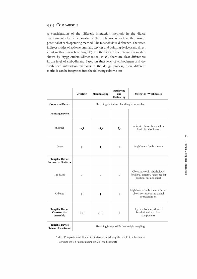
63
Hum
an-Com
puter Interaction
4.3.4 Comparison
A consideration of the different interaction methods in the digital environment clearly demonstrates the problems as well as the current potential of each operating method. The most obvious difference is between indirect modes of action (command devices and pointing devices) and direct input methods (touch or tangible). On the basis of the interaction models shown by Brygg Anders Ullmer (2002, 57-58), there are clear differences in the level of embodiment. Based on their level of embodiment and the established interaction methods in the design process, these different methods can be integrated into the following subdivision:
Creating ManipulatingRetrieving
and Evaluating
Strengths / Weaknesses
Command Device Sketching via indirect handling is impossible
Pointing Device
indirect -0 -0 0 Indirect relationship and low level of embodiment
direct + + + High level of embodiment
Tangible Device Interactive Surfaces
Tag-based - - -Objects are only placeholders
for digital content. Reference for position, but not object
AI-based + + +High level of embodiment: Input
object corresponds to digital representation
Tangible Device Constructive
Assembly+0 0+ +
High level of embodiment: Restriction due to fixed
components
Tangible Device Token + Constraint Sketching is impossible due to rigid coupling
Tab. 3: Comparison of different interfaces considering the level of embodiment.
- (low support) / 0 (medium support) / + (good support).
64
Hum
an-Com
puter Interaction
4.4 Definition of Requirements
Starting from the interaction methods and principles considered above, the following basic requirements for a human-computer interface in the architectural context can be defined with regard to the limitations of human processing and taking into account established interaction methods in the architectural design context:
• Level of Embodiment: The process of visual thinking is an integral part of the creative design process. It is very important that the tool provides the user with the most direct form of feedback possible. In this context, a high level of embodiment is a decisive requirement for human-computer interaction. The higher the level of embodiment, the more direct the feedback between the tool and the designer. The entire human perceptual apparatus is affected by this. The more senses involved in the interaction and the more directly the feedback, the more supportive it is to the design process.
• Intuitive Operation: This and the resulting low cognitive load can lead directly to a performance increase in the work process. The lower the short-term memory burden caused by the operation, the more cognitive resources remain for the actual work. Mental models are closely related to this. The better the user’s model fits the system image, the more intuitive the operation and the lower the cognitive load. In the context of the human-computer interaction and taking into account the design process, mental models must be formulated from established design tools. Thus it can be assumed that the more closely the system image is oriented towards established tools and/or actions, the greater the concordance between the different models and the easier it is for a successful form of interaction to take place. This is further supported by the control elements’ corresponding mapping and affordances.
• Reduction of cognitive load: In addition, the lowest possible stress on the short-term memory can generally be seen as a decisive criterion for a human-computer interface in the architectural context. The requirement is to keep as much of the memory as possible for designing, in order to provide the designer with sufficient reserve capacity. This is especially important in the case of short-term memory, since there is a limited amount of information that can be retained at the same time. This can be achieved, for example, by chunking, which can happen automatically, especially in the case of motor action. In addition, an increased cognitive load is mainly caused by unnecessary interactions and steps such as, for example, media disruptions caused by switching between different tools. Each change requires a refocusing of attention, which directly leads to an increased cognitive load.
65
Discussion of R
elated Work
5 Discussion of Related Work
While the previous chapter has focused on general approaches to human-computer interaction, the following section will take a closer look at the use of digital methods and media in the context of design. This review will include historical as well as current and emerging developments in hardware and software technology, with a particular emphasis on the available interfaces. The selection of works is based on their intended use. Since sketching is at the core of creative work, this section’s primary focus is on digital sketching tools, mostly oriented towards established tools such as freehand sketching and model building. Data input is often done by means of a touch screen, a pen or with physical models, in order to provide an analogy with reality. For better clarity, the programs that are reviewed are classified according to the interfaces they use. Pointing devices and tangible interfaces are of particular relevance.
The central question is: To what extent do the selected works support the previously illustrated interaction methods in the design context? The already defined requirements for design tools will serve as evaluation criteria. The following criteria for objective evaluation are based on the analysis of the design process and of established design tools:
EU – Ease of Use: To what degree does the operation require the user to be focused? Is it possible for the user to have a continuous creative thought process or is he or she instead disturbed and interrupted because using the tool is overly complex? Important factors include: Does the interaction occur on the basis of established behavior and/or knowledge in the world? Is the design environment familiar? Does the modeling happen intuitively or is it oriented towards the digital design process?
DF – Direct Feedback: Is the level of embodiment high enough to enable visual thinking? This concerns the number of sensory channels involved and the ratio of input to output. In addition, direct feedback also concerns the way in which digital models are generated and the extent to which direct visualization is possible. Are intermediate steps and abstract operations required, like the definition of a start and an end point?
VT – Visualization of Vague Thoughts: Does the software make it possible to visualize vague or unfinished ideas and thoughts and without knowing the final result? Does it require pixel-precise input using a mouse or abstract design methods such as point definitions? Or is the input simultaneous with the modeling gesture, enabling a gradual approach to creation?
SA – Stepwise Approach: Can intermediate results be captured and directly compared? Are there objective decision criteria to support the assessment of different versions? This applies to, for example, spatial observation in 3D or digitally calculated simulations and analyses.
66
Discussion of R
elated Work
Since the aspect of Flexible Use essentially refers to how the tools connect to each other, this requirement is disregarded in the context of the following consideration. Based on the analysis of the four criteria, the programs that are reviewed are evaluated with regard to how well they support the forms of interaction that are required for creative work and how well they can be used as tools for thinking::
• Visualizing thoughts: Is a simple visualization of ideas and externalization of thoughts possible?
• Reflecting images: Can the visualized thoughts be directly reflected? Is there support for evaluation?
• Changing images: Can the externalized thoughts be fleshed out, transformed or edited to generate a creative cycle?
The added value for the design process is also addressed here. On the basis of these aspects, the approaches that are reviewed are incorporated into the ongoing design process:
• Generation of ideas (sketching): The tool promotes the generation of ideas and the process of visual thinking.
• Fleshing out of ideas (drawing): Als Prozess der Ideen-konkretisierung. Die Inhalte, die dargestellt werden sollen sind weitgehend vorhanden.
• Elaboration of ideas (presentation): This refers to ideas that are currently available. It is primarily a matter of presenting them to other people.
5.1 Pointing Devices
To date, pointing devices represent the standard for computer control in almost all areas, whether via indirect interaction methods such as click-and-drag using a mouse and keyboard, or directly via drawing movements using a pen or touchscreen. The following section is a review and discussion of exemplary, subject-related approaches. Based on input via touchscreen and pen, the main focus of the programs is to make it easy to create objects (either 2D or 3D). However, as already stated in the paper “Is a pen-based system just another pen or more than a pen?” by Lim Chor-Kheng (2003), the question of the added value a pen-based computer system can offer in contrast to traditional freehand sketching on paper has to be looked at with a critical eye. Many examples in this context focus on a seamless transition from sketch to 3D model, which raises the question of whether this is in any way beneficial to the design process or even the brainstorming process. The interaction between the input device and the software application is therefore of critical importance. In the following, both current as well as historically significant approaches are reviewed:
check ch 1
67
Discussion of R
elated Work
Sketchpad (III)The first project to consider is Sketchpad by Ivan Sutherland (1963). Even though this work is technically not a sketching tool, its historical relevance is significant because the prototype, developed in 1963, can be considered the first graphic CAD application. This was revolutionary, especially considering the technical possibilities available at the time. The system demonstrates the potential of graphic interfaces in an architectural context, despite having a mere 64K memory and correspondingly long reaction times. Notwithstanding the problems represented by the technical state of the art at the time, it is worth emphasizing the form of interaction in the scope of work. By using a light pen as the input device, the project meets the requirements that had already been described by Timothy E. Johnson (1963, 348) and thus enables a direct relation between input and output (cf. chapter 4.2.3). On this basis, one would like to assume that the tool was ideal for use as a sketching tool. However, two elements are problematic here: Firstly, there are the ergonomic properties of the light pen. Secondly, the form of interaction supported by the software presents a problem in the creative context. While using a light pen supports the direct externalization of thoughts, it is nevertheless the case that this process remains unavoidably hindered by the interaction commands that are still used in the CA(A)D context (such as copying, inscribing shapes and defining a line by means of two points (Rubberline)). Based on Sutherland’s (1963) work, Timothy E. Johnson (1963) developed Sketchpad III. While its operation is similar to Sketchpad, Johnson extended the input by introducing a third dimension, thus making it possible to create three-dimensional volumes on a purely graphical basis.
• EU: Due to the software design, there is no intuitive form of operation. Thus, for each action, a mode of operation must first be selected in order to design a geometrical figure with it.
• DF: The feedback is purely visual in a two-dimensional way. Bilateral communication, such as between co-located points of input and output, lead to a high level of embodiment. However, the indirect form of object creation does not allow a direct relation between the gesture and the object that is represented.
• VT: Despite the input being made by pen, it is not possible for it to be imprecise. This is because the input is oriented towards precision design methods.
• SA: It is possible to save the geometric figures that have been created. However, it is only possible to view one saved version at a time. There is no support for decision making.
Based on the requirements that have been considered, it is possible to conclude that despite its pen input, Sketchpad (III) cannot be used as a creative design tool in the true sense. Instead, the project shows that only a combination of input device and software can result in a meaningful application of the computer as a thinking or sketching tool. Consequently, due to the given design methods and despite its pen input, Sketchpad (III) does not support the interaction methods that are required in the design context.
68
Discussion of R
elated Work
TeddyWhile Sketchpad is primarily intended for construction, Teddy is “[...] a sketching interface for quickly and easily designing freeform models such as stuffed animals and other rotund objects” and represents one of, if not the most well-known 3D sketching tools (Igarashi, Matsuoka and Tanaka 1999, 409). According to Takeo Igarashi, Satoshi Matsuoka and Hidehiko Tanaka (1999, 409), “[...] Teddy is designed for the rapid construction of approximate models, not for the careful editing of precise models” (ibid.). Based on various algorithms, Teddy allows for the modeling of round, three-dimensional shapes using only a few pen movements. However, due to its restriction to free-form objects, its use in an architectural context is limited. In addition to the creation of free-form, three-dimensional objects, Teddy makes it possible to sketch and draw directly onto the surfaces of the generated objects. In addition, actions such as deleting, cutting and extruding are supported by means of predefined control gestures, so that almost all interaction takes place via pen input and without the selection of icons. It is clear that the tool largely meets the requirements for thinking tools:
• EU: Simple and familiar operation thanks to established modes of operation via pen input. The possibility of direct sketching does not require any additional selection of functions.
• DF: The direct approach of sketching on a touchscreen means that the input and the output occure at the same place. The modeling also happens directly and without any abstract modeling metaphors.
• VT: The familiar method of sketching just like on paper enables a gradual approach in the sketching process. The existing blurriness of the freehand sketch is almost preserved, which promotes emergence and thus also reflection.
• SA: Saving and opening different versions happens directly in the application by using the corresponding buttons. However, version control or direct comparison of several versions is not supported.
Due to the direct feedback combined with the simple operation via pen, which is based on established modes of operation, Teddy fully meets the requirements for interaction methods in the design context. However, because it only supports strictly cubic shapes, it has limited use in an architectural context.
ILoveSketchA similar approach can be identified with ILoveSketch (Bae, Balakrishnan and Singh 2008). Like Teddy, ILoveSketch enables the easy creation of free-form, three-dimensional models and their editing by means of pen input and adapted software concepts. Moreover, various types of software-related user assistance are intended to support the designer. These include, for example, automatic alignment of layers and focal points, as well as support for symmetry and other design aids. However, this makes it necessary to think ahead and thus introduces a change in the familiar sketching process so that, depending on the use, the design method strongly dominates the brainstorming process:
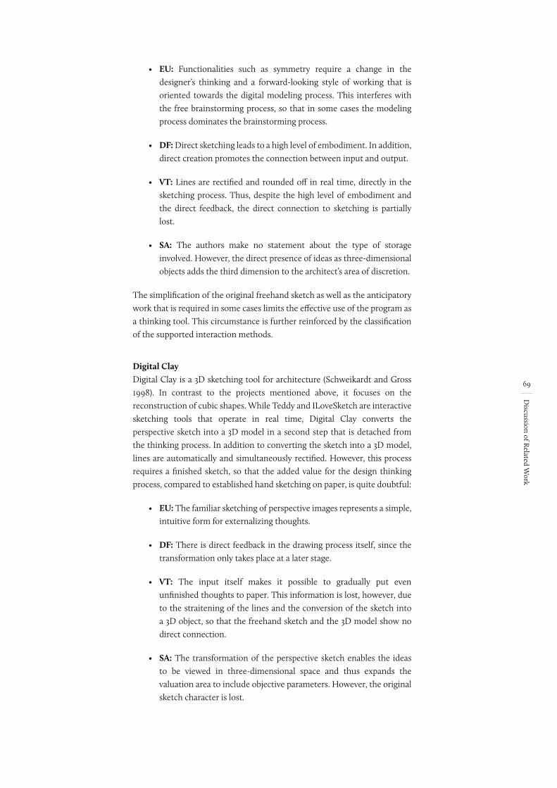
69
Discussion of R
elated Work
• EU: Functionalities such as symmetry require a change in the designer’s thinking and a forward-looking style of working that is oriented towards the digital modeling process. This interferes with the free brainstorming process, so that in some cases the modeling process dominates the brainstorming process.
• DF: Direct sketching leads to a high level of embodiment. In addition, direct creation promotes the connection between input and output.
• VT: Lines are rectified and rounded off in real time, directly in the sketching process. Thus, despite the high level of embodiment and the direct feedback, the direct connection to sketching is partially lost.
• SA: The authors make no statement about the type of storage involved. However, the direct presence of ideas as three-dimensional objects adds the third dimension to the architect’s area of discretion.
The simplification of the original freehand sketch as well as the anticipatory work that is required in some cases limits the effective use of the program as a thinking tool. This circumstance is further reinforced by the classification of the supported interaction methods.
Digital ClayDigital Clay is a 3D sketching tool for architecture (Schweikardt and Gross 1998). In contrast to the projects mentioned above, it focuses on the reconstruction of cubic shapes. While Teddy and ILoveSketch are interactive sketching tools that operate in real time, Digital Clay converts the perspective sketch into a 3D model in a second step that is detached from the thinking process. In addition to converting the sketch into a 3D model, lines are automatically and simultaneously rectified. However, this process requires a finished sketch, so that the added value for the design thinking process, compared to established hand sketching on paper, is quite doubtful:
• EU: The familiar sketching of perspective images represents a simple, intuitive form for externalizing thoughts.
• DF: There is direct feedback in the drawing process itself, since the transformation only takes place at a later stage.
• VT: The input itself makes it possible to gradually put even unfinished thoughts to paper. This information is lost, however, due to the straitening of the lines and the conversion of the sketch into a 3D object, so that the freehand sketch and the 3D model show no direct connection.
• SA: The transformation of the perspective sketch enables the ideas to be viewed in three-dimensional space and thus expands the valuation area to include objective parameters. However, the original sketch character is lost.
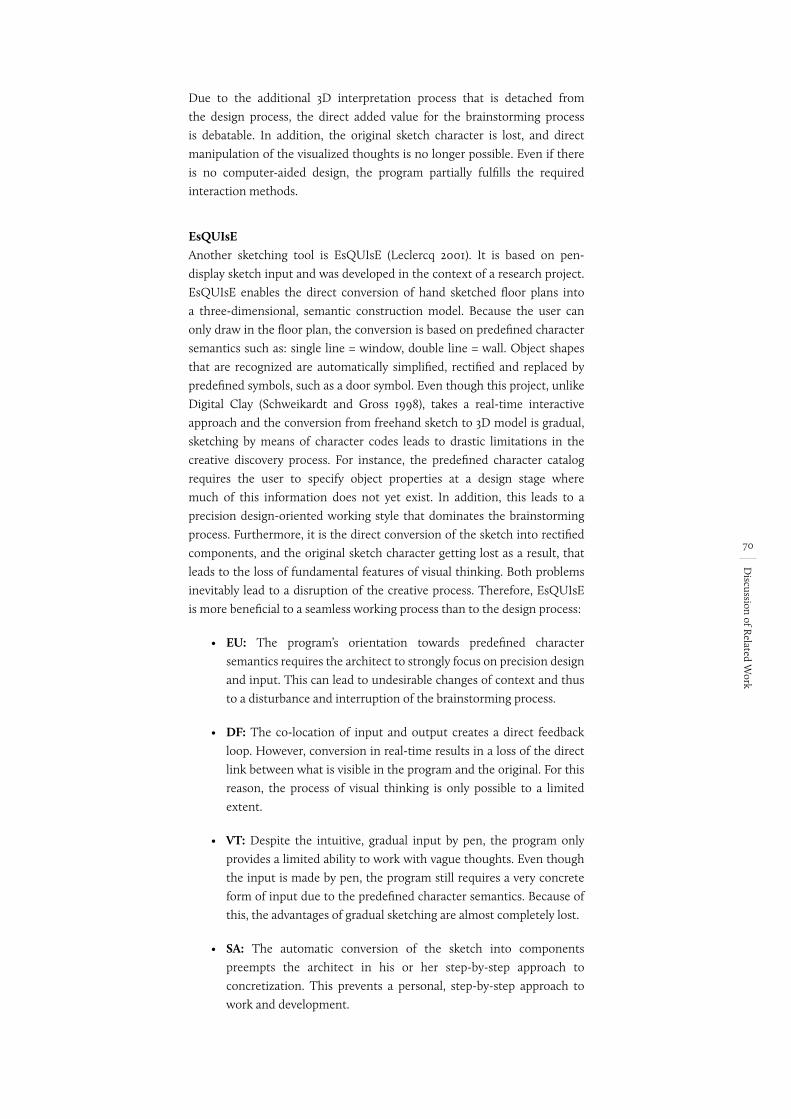
70
Discussion of R
elated Work
Due to the additional 3D interpretation process that is detached from the design process, the direct added value for the brainstorming process is debatable. In addition, the original sketch character is lost, and direct manipulation of the visualized thoughts is no longer possible. Even if there is no computer-aided design, the program partially fulfills the required interaction methods.
EsQUIsEAnother sketching tool is EsQUIsE (Leclercq 2001). It is based on pen-display sketch input and was developed in the context of a research project. EsQUIsE enables the direct conversion of hand sketched floor plans into a three-dimensional, semantic construction model. Because the user can only draw in the floor plan, the conversion is based on predefined character semantics such as: single line = window, double line = wall. Object shapes that are recognized are automatically simplified, rectified and replaced by predefined symbols, such as a door symbol. Even though this project, unlike Digital Clay (Schweikardt and Gross 1998), takes a real-time interactive approach and the conversion from freehand sketch to 3D model is gradual, sketching by means of character codes leads to drastic limitations in the creative discovery process. For instance, the predefined character catalog requires the user to specify object properties at a design stage where much of this information does not yet exist. In addition, this leads to a precision design-oriented working style that dominates the brainstorming process. Furthermore, it is the direct conversion of the sketch into rectified components, and the original sketch character getting lost as a result, that leads to the loss of fundamental features of visual thinking. Both problems inevitably lead to a disruption of the creative process. Therefore, EsQUIsE is more beneficial to a seamless working process than to the design process:
• EU: The program’s orientation towards predefined character semantics requires the architect to strongly focus on precision design and input. This can lead to undesirable changes of context and thus to a disturbance and interruption of the brainstorming process.
• DF: The co-location of input and output creates a direct feedback loop. However, conversion in real-time results in a loss of the direct link between what is visible in the program and the original. For this reason, the process of visual thinking is only possible to a limited extent.
• VT: Despite the intuitive, gradual input by pen, the program only provides a limited ability to work with vague thoughts. Even though the input is made by pen, the program still requires a very concrete form of input due to the predefined character semantics. Because of this, the advantages of gradual sketching are almost completely lost.
• SA: The automatic conversion of the sketch into components preempts the architect in his or her step-by-step approach to concretization. This prevents a personal, step-by-step approach to work and development.
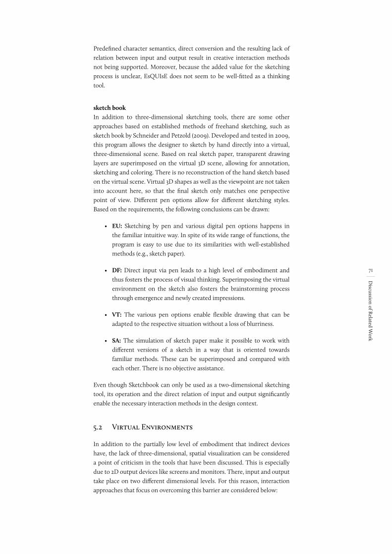
71
Discussion of R
elated Work
Predefined character semantics, direct conversion and the resulting lack of relation between input and output result in creative interaction methods not being supported. Moreover, because the added value for the sketching process is unclear, EsQUIsE does not seem to be well-fitted as a thinking tool.
sketch bookIn addition to three-dimensional sketching tools, there are some other approaches based on established methods of freehand sketching, such as sketch book by Schneider and Petzold (2009). Developed and tested in 2009, this program allows the designer to sketch by hand directly into a virtual, three-dimensional scene. Based on real sketch paper, transparent drawing layers are superimposed on the virtual 3D scene, allowing for annotation, sketching and coloring. There is no reconstruction of the hand sketch based on the virtual scene. Virtual 3D shapes as well as the viewpoint are not taken into account here, so that the final sketch only matches one perspective point of view. Different pen options allow for different sketching styles. Based on the requirements, the following conclusions can be drawn:
• EU: Sketching by pen and various digital pen options happens in the familiar intuitive way. In spite of its wide range of functions, the program is easy to use due to its similarities with well-established methods (e.g., sketch paper).
• DF: Direct input via pen leads to a high level of embodiment and thus fosters the process of visual thinking. Superimposing the virtual environment on the sketch also fosters the brainstorming process through emergence and newly created impressions.
• VT: The various pen options enable flexible drawing that can be adapted to the respective situation without a loss of blurriness.
• SA: The simulation of sketch paper make it possible to work with different versions of a sketch in a way that is oriented towards familiar methods. These can be superimposed and compared with each other. There is no objective assistance.
Even though Sketchbook can only be used as a two-dimensional sketching tool, its operation and the direct relation of input and output significantly enable the necessary interaction methods in the design context.
5.2 Virtual Environments
In addition to the partially low level of embodiment that indirect devices have, the lack of three-dimensional, spatial visualization can be considered a point of criticism in the tools that have been discussed. This is especially due to 2D output devices like screens and monitors. There, input and output take place on two different dimensional levels. For this reason, interaction approaches that focus on overcoming this barrier are considered below:
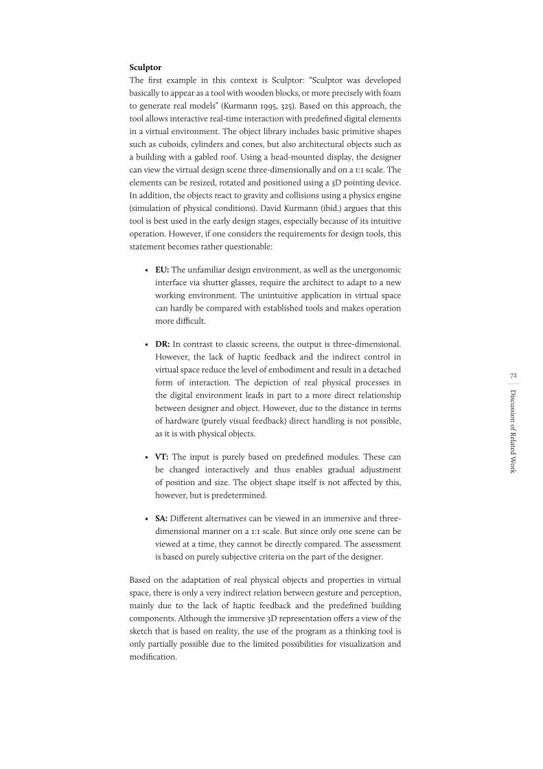
72
Discussion of R
elated Work
SculptorThe first example in this context is Sculptor: “Sculptor was developed basically to appear as a tool with wooden blocks, or more precisely with foam to generate real models” (Kurmann 1995, 325). Based on this approach, the tool allows interactive real-time interaction with predefined digital elements in a virtual environment. The object library includes basic primitive shapes such as cuboids, cylinders and cones, but also architectural objects such as a building with a gabled roof. Using a head-mounted display, the designer can view the virtual design scene three-dimensionally and on a 1:1 scale. The elements can be resized, rotated and positioned using a 3D pointing device. In addition, the objects react to gravity and collisions using a physics engine (simulation of physical conditions). David Kurmann (ibid.) argues that this tool is best used in the early design stages, especially because of its intuitive operation. However, if one considers the requirements for design tools, this statement becomes rather questionable:
• EU: The unfamiliar design environment, as well as the unergonomic interface via shutter glasses, require the architect to adapt to a new working environment. The unintuitive application in virtual space can hardly be compared with established tools and makes operation more difficult.
• DR: In contrast to classic screens, the output is three-dimensional. However, the lack of haptic feedback and the indirect control in virtual space reduce the level of embodiment and result in a detached form of interaction. The depiction of real physical processes in the digital environment leads in part to a more direct relationship between designer and object. However, due to the distance in terms of hardware (purely visual feedback) direct handling is not possible, as it is with physical objects.
• VT: The input is purely based on predefined modules. These can be changed interactively and thus enables gradual adjustment of position and size. The object shape itself is not affected by this, however, but is predetermined.
• SA: Different alternatives can be viewed in an immersive and three-dimensional manner on a 1:1 scale. But since only one scene can be viewed at a time, they cannot be directly compared. The assessment is based on purely subjective criteria on the part of the designer.
Based on the adaptation of real physical objects and properties in virtual space, there is only a very indirect relation between gesture and perception, mainly due to the lack of haptic feedback and the predefined building components. Although the immersive 3D representation offers a view of the sketch that is based on reality, the use of the program as a thinking tool is only partially possible due to the limited possibilities for visualization and modification.
73
Discussion of R
elated Work
The Augmented Round TableBringing the virtual world into reality is the approach of The Augmented Round Table (Broll, Stoerring and Mottram 2003). Using a head-mounted display, a virtual scene can be viewed and edited as a digital table model. Here, the virtual models are manipulated using a physical pointing stick and corresponding operating gestures. Additional features can be controlled via tangible interfaces using marker tracking. Moreover, a multi-user scenario allows multiple users to simultaneously view the same model from different angles. Thus, The Augmented Round Table makes it possible to view virtual models in a real environment in a roughly familiar way. Nevertheless, the program’s use in a design context can be regarded as difficult:
• EU: The necessary equipment and an unfamiliar work environment require increased concentration on the part of the user. Due to the interaction by means of gestures and tangible interfaces, easy input is likely to be difficult.
• DF: Despite the presence of an immersive, three-dimensional model, the lack of haptic feedback in the design context presents a difficulty, which is especially problematic when it comes to modeling: The lack of haptic feedback reduces the operation to pointer movements in the air, which in turn reduces the level of embodiment and thus the direct connection necessary for visual thinking.
• VT: There are no specifics on input and modeling functions.
• SA: There are no specifics on save functions or digital support.
The Augmented Round Table is another program where the lack of haptic feedback as well as the indirect and limited form of sketching are worth noting. Use in a creative context is therefore only possible to a limited extent, thus the focus is more on viewing than on creating ideas.
sketchand+Another approach in this direction is sketchand+ (Seichter 2003). However, in contrast to the aforementioned approaches, it is based on a real, physically existing model of the environment. Again, a head-mounted display is used for viewing. By means of a marker located in the real model at the design site, virtual design versions can directly augment34 the real scene and users can view things in three dimensions. The use of different markers makes it easy to compare several drafts. Furthermore, additional markers can be used to activate special features such as sharing, remote collaboration, etc. Even though Hartmut Seichter (2003, 216) explicitly states that the focus of the work does not lie in the conception of the sketching function, the possibilities are nevertheless briefly mentioned: Interactive modeling happens directly in the virtual view of the design with the help of a corresponding input pen. However, the input is reduced to extruding a 2D basic shape to a predefined height. The shape can be changed and adapted using certain key combinations.
34 Extension of the physical environment through digital content
74
Discussion of R
elated Work
• EU: The modes of action in the model, i.e. the positioning and relocating of the virtual models using markers, make operation familiar and simple. The features that can be activated by different markers also make it easy to run special applications.
• DF: Despite the fact that the real model is the design environment, design idea feedback is limited to the visual sensory channel and the marker as an abstract place holder. Therefore, the difference between physical and virtual structures requires the user to think in abstract ways.
• VT: The positioning of the markers that is based on physical models only allows for rough and imprecise work. The creation of digital models by extrusion of the footprint restricts creative work due to predefined parameters such as a fixed height.
• SA: Working with different markers enables a quick and direct comparison of different design versions in the model.
Being able to observe designs in the real physical model greatly enables the simple reflection of thoughts. However, the possibility of model input is limited. The approach to visualizing thoughts is thus deficient and limits the program’s application to that of presenting and discussing drafts. There is no direct possibility to change these drafts.
In comparison to 2D screens, these approaches offer an added value that is not to be underestimated, especially concerning three-dimensional visualization. However, having to wear 3D glasses is disruptive, and the lack of haptic relation between the observer and the model is equally problematic. The approaches make it possible to realistically observe model drafts based on predefined model scenarios. However, the modeling of the different versions takes place in advance, resulting in a separate processing step that is detached from the design process. This leads to an immediate loss of the direct relation between observing the models and editing them.
5.3 Tangible Interfaces
Approaches that work with the concept of tangible interfaces can be considered as alternatives to those characterized by the problematics of missing haptic feedback. In this context, it is the representation of digital functions by real, physically present objects in particular that leads to a very high level of embodiment. Physical presence also eliminates the dimensional difference between input and output. In terms of concrete implementations, the approaches can be divided into two different types:
• Constructive Assembly
• Interactive Surfaces
These projects are operated by means of tangible interaction elements. Depending on the type of implementation, these elements are abstract place
75
Discussion of R
elated Work
holders for digital content, and the digital image is either freely defined or a fixed module. In addition, there are approaches in which the physical objects embody the digital content directly and as a whole.
5.3.1 Constructive Assembly
Already at the beginning of the 1990s, there was research concerning human-computer interfaces in the architectural context, based on the idea of modular, connectable elements. The first attempts at using computers in the creative, architectural field were also made at this time.
Prototypes John FrazerOne of the pioneers from that time is John Frazer (1995). As early as 1980, he made a first attempt at conceiving a haptically tangible, digitally coupled design model and its technical implementation (ibid.). His book “An Evolutionary Architecture” contains a number of prototypes of then-novel 2D and 3D input devices (ibid.). Among the most important are Intelligent beermats, the Universal Constructor and the Segal Model. Frazer (1995, 37) emphasizes in all his projects that the solution to the mismatch between computer technology and architectural design tasks can only be found in a holistic approach through the simultaneous development of new human-computer interfaces and appropriate software. Based on this approach, his so-called “Machine-Readable Models” or “Intelligent Modeling Systems” represent their own application-oriented interfaces (Frazer 1995, 37). The combination of hardware and software enables physical operation through an additive assembly of the individual physical components and supports the designer through additional digital feedback (in terms of both the physical components and the virtual view). Through this combination, the approach already provided the “look[ing] over his/her shoulder” element later called for by Herman Neuckerman, Benjamin Geebelen and Stefan Boeykens (2005, 1). It also provides direct support for the designer and his or her design approaches. While the first prototype, beermats (Frazer 1995, 39), was still limited to two dimensions, the cube-shaped elements of the Universal Constructor (Frazer 1995, 44-48) enabled assembly in three dimensions. In the Segal Model (Frazer 1995, 41-43), the abstract level was abandoned, and the operating concept was transferred to wall, door and window elements. Frazer’s approaches and fundamental ideas are revolutionary, especially considering the technical possibilities of the time. His conceptual considerations, in particular, remain unparalleled today. However, the fact that the systems are based on a fixed modular system – as the name “intelligent model” suggests – is problematic. The intelligence is located in the component, so the user must depend on these predefined electronic elements. Despite this limitation, the approaches greatly fulfill the requirements for design tools:
• EU: The interaction on the basis of physically existing models enables a simple, intuitive application, which is reinforced by direct mapping as well as the high level of affordance.
ein satz wg quelle
76
Discussion of R
elated Work
• DF: Being able to work with components by hand, to arrange and stack them, leads to a direct, three-dimensional correlation between input and output. In this way, the process of visual thinking is promoted far beyond mere visual feedback.
• VT: Due to the grid, the resulting input and the forms are limited to cubic additions. This affects the flexibility and leads to limited individual shaping. Nevertheless, it is possible to work gradually, without precisely defining the input.
• SA: The physical presence of the models makes it easy to create and compare different versions. Provided that enough components are available, different concepts can be generated and tested in a flexible manner. Direct digitization and the digital simulations that are based on it also support decision-making.
Despite the module-based input, John Frazer’s integrated approaches enable a limited, yet direct visualization and reflection of thoughts. The additional objective parameters that support the designer expand the architect’s scope of discretion. Thus, these tools comply to a high degree with the required interaction methods for designing.
Projekt David AndersonThe project by David Anderson et al. (2000) can be considered a direct progression of John Frazer’s work. The modules here are much smaller than in John Frazer’s (1995, 44-48) Universal Constructor and thus allow for a much more differentiated approach. The disadvantages of the modular system that have already been discussed apply here as well. However, the true highlight is the subsequent interpretation phase of the digital model. This means that, for example, tiered model areas resulting from the modular system are transformed into pitched roofs. As a result, the approach in question can be classified as follows:
• EU: The operation by means of building blocks is simple and intuitive.
• DF: Working on the model enables direct feedback. However, due to the interpretation of the components and their transformation into a digital 3D model, there is no direct relation between the physical and the digital model.
• VT: The liberty of modeling is reduced to the grid. Even though the grid is smaller than John Frazer’s due to technical advances, it still hinders the flexibility of the input.
• SA: Again, comparing different versions is easy due to the physical presence of the models. The number of versions that can be generated depends on the number of components. In addition, every version must always be created from scratch. The interpretation of the digital data and its transformation into components does not add any value to the design process.
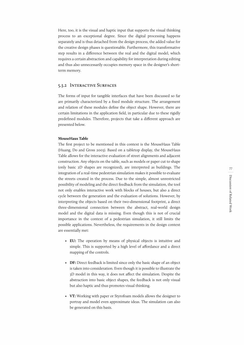
77
Discussion of R
elated Work
Here, too, it is the visual and haptic input that supports the visual thinking process to an exceptional degree. Since the digital processing happens separately and is thus detached from the design process, the added value for the creative design phases is questionable. Furthermore, this transformative step results in a difference between the real and the digital model, which requires a certain abstraction and capability for interpretation during editing and thus also unnecessarily occupies memory space in the designer’s short-term memory.
5.3.2 Interactive Surfaces
The forms of input for tangible interfaces that have been discussed so far are primarily characterized by a fixed module structure. The arrangement and relation of these modules define the object shape. However, there are certain limitations in the application field, in particular due to these rigidly predefined modules. Therefore, projects that take a different approach are presented below.
MouseHaus TableThe first project to be mentioned in this context is the MouseHaus Table (Huang, Do and Gross 2003). Based on a tabletop display, the MouseHaus Table allows for the interactive evaluation of street alignments and adjacent construction. Any objects on the table, such as models or paper cut to shape (only basic 2D shapes are recognized), are interpreted as buildings. The integration of a real-time pedestrian simulation makes it possible to evaluate the streets created in the process. Due to the simple, almost unrestricted possibility of modeling and the direct feedback from the simulation, the tool not only enables interactive work with blocks of houses, but also a direct cycle between the generation and the evaluation of solutions. However, by interpreting the objects based on their two-dimensional footprint, a direct three-dimensional connection between the abstract, real-world design model and the digital data is missing. Even though this is not of crucial importance in the context of a pedestrian simulation, it still limits the possible applications. Nevertheless, the requirements in the design context are essentially met:
• EU: The operation by means of physical objects is intuitive and simple. This is supported by a high level of affordance and a direct mapping of the controls.
• DF: Direct feedback is limited since only the basic shape of an object is taken into consideration. Even though it is possible to illustrate the 3D model in this way, it does not affect the simulation. Despite the abstraction into basic object shapes, the feedback is not only visual but also haptic and thus promotes visual thinking.
• VT: Working with paper or Styrofoam models allows the designer to portray and model even approximate ideas. The simulation can also be generated on this basis.
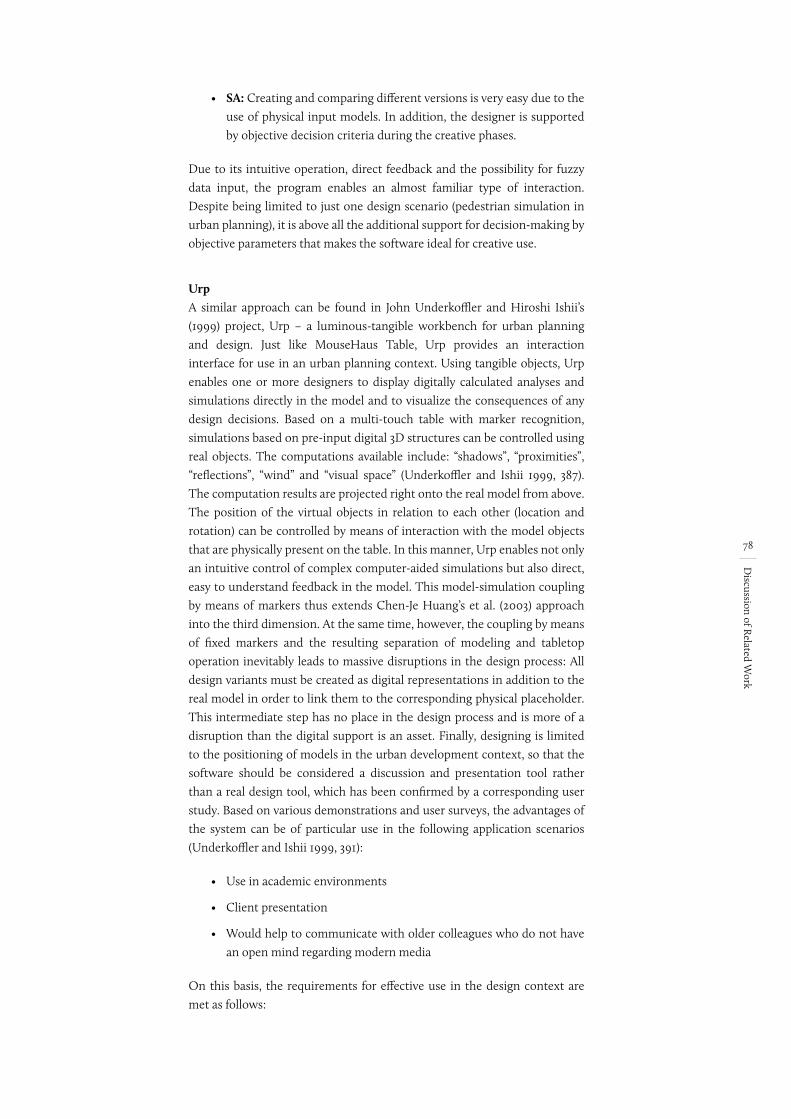
78
Discussion of R
elated Work
• SA: Creating and comparing different versions is very easy due to the use of physical input models. In addition, the designer is supported by objective decision criteria during the creative phases.
Due to its intuitive operation, direct feedback and the possibility for fuzzy data input, the program enables an almost familiar type of interaction. Despite being limited to just one design scenario (pedestrian simulation in urban planning), it is above all the additional support for decision-making by objective parameters that makes the software ideal for creative use.
UrpA similar approach can be found in John Underkoffler and Hiroshi Ishii’s (1999) project, Urp – a luminous-tangible workbench for urban planning and design. Just like MouseHaus Table, Urp provides an interaction interface for use in an urban planning context. Using tangible objects, Urp enables one or more designers to display digitally calculated analyses and simulations directly in the model and to visualize the consequences of any design decisions. Based on a multi-touch table with marker recognition, simulations based on pre-input digital 3D structures can be controlled using real objects. The computations available include: “shadows”, “proximities”, “reflections”, “wind” and “visual space” (Underkoffler and Ishii 1999, 387). The computation results are projected right onto the real model from above. The position of the virtual objects in relation to each other (location and rotation) can be controlled by means of interaction with the model objects that are physically present on the table. In this manner, Urp enables not only an intuitive control of complex computer-aided simulations but also direct, easy to understand feedback in the model. This model-simulation coupling by means of markers thus extends Chen-Je Huang’s et al. (2003) approach into the third dimension. At the same time, however, the coupling by means of fixed markers and the resulting separation of modeling and tabletop operation inevitably leads to massive disruptions in the design process: All design variants must be created as digital representations in addition to the real model in order to link them to the corresponding physical placeholder. This intermediate step has no place in the design process and is more of a disruption than the digital support is an asset. Finally, designing is limited to the positioning of models in the urban development context, so that the software should be considered a discussion and presentation tool rather than a real design tool, which has been confirmed by a corresponding user study. Based on various demonstrations and user surveys, the advantages of the system can be of particular use in the following application scenarios (Underkoffler and Ishii 1999, 391):
• Use in academic environments
• Client presentation
• Would help to communicate with older colleagues who do not have an open mind regarding modern media
On this basis, the requirements for effective use in the design context are met as follows:
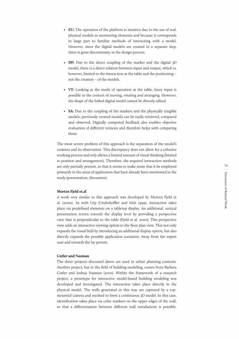
79
Discussion of R
elated Work
• EU: The operation of the platform is intuitive due to the use of real, physical models as monitoring elements and because it corresponds in large part to familiar methods of interacting with a model. However, since the digital models are created in a separate step, there is great discontinuity in the design process.
• DF: Due to the direct coupling of the marker and the digital 3D model, there is a direct relation between input and output, which is, however, limited to the interaction at the table and the positioning – not the creation – of the models.
• VT: Looking at the mode of operation at the table, fuzzy input is possible in the context of moving, rotating and arranging. However, the shape of the linked digital model cannot be directly edited.
• SA: Due to the coupling of the markers and the physically tangible models, previously created models can be easily retrieved, compared and observed. Digitally computed feedback also enables objective evaluation of different versions and therefore helps with comparing them.
The most severe problem of this approach is the separation of the model’s creation and its observation. This discrepancy does not allow for a cohesive working process and only allows a limited amount of visual thinking (limited to position and arrangement). Therefore, the required interaction methods are only partially present, so that it seems to make sense that it be employed primarily in the areas of application that have already been mentioned in the study (presentation, discussion).
Morten Fjeld et.alA work very similar to this approach was developed by Morten Fjeld et al. (2000). As with Urp (Underkoffler and Ishii 1999), interaction takes place via predefined elements on a tabletop display. An additional, vertical presentation screen extends the display level by providing a perspective view that is perpendicular to the table (Fjeld et al. 2000). This perspective view adds an interactive viewing option to the floor plan view. This not only expands the visual field by introducing an additional display option, but also directly expands the possible application scenarios: Away from the expert user and towards the lay person.
Cutler and NasmanThe three projects discussed above are used in urban planning contexts. Another project, but in the field of building modeling, comes from Barbara Cutler and Joshua Nasman (2010). Within the framework of a research project, a prototype for interactive model-based building modeling was developed and investigated. The interaction takes place directly in the physical model. The walls generated in this way are captured by a top-mounted camera and meshed to form a continuous 3D model. In this case, identification takes place via color markers on the upper edges of the wall, so that a differentiation between different wall installations is possible.
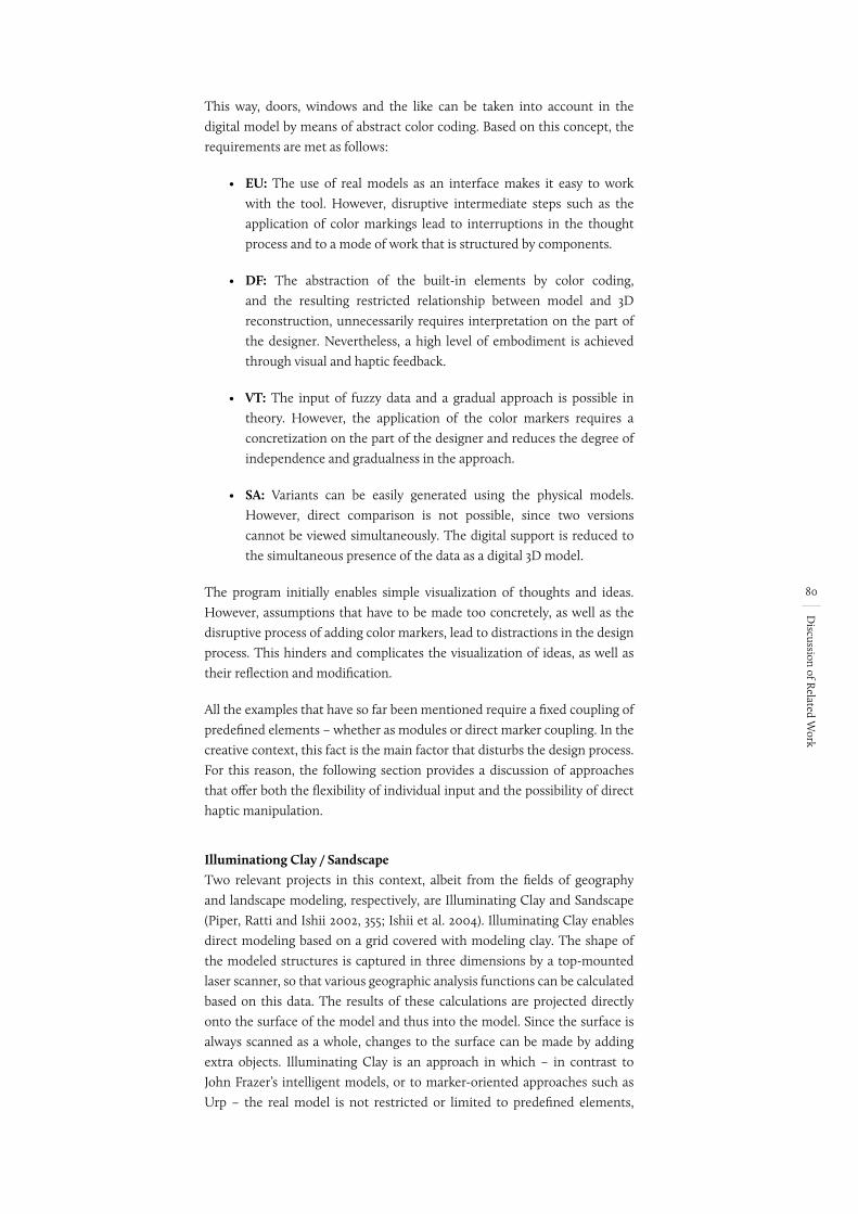
80
Discussion of R
elated Work
This way, doors, windows and the like can be taken into account in the digital model by means of abstract color coding. Based on this concept, the requirements are met as follows:
• EU: The use of real models as an interface makes it easy to work with the tool. However, disruptive intermediate steps such as the application of color markings lead to interruptions in the thought process and to a mode of work that is structured by components.
• DF: The abstraction of the built-in elements by color coding, and the resulting restricted relationship between model and 3D reconstruction, unnecessarily requires interpretation on the part of the designer. Nevertheless, a high level of embodiment is achieved through visual and haptic feedback.
• VT: The input of fuzzy data and a gradual approach is possible in theory. However, the application of the color markers requires a concretization on the part of the designer and reduces the degree of independence and gradualness in the approach.
• SA: Variants can be easily generated using the physical models. However, direct comparison is not possible, since two versions cannot be viewed simultaneously. The digital support is reduced to the simultaneous presence of the data as a digital 3D model.
The program initially enables simple visualization of thoughts and ideas. However, assumptions that have to be made too concretely, as well as the disruptive process of adding color markers, lead to distractions in the design process. This hinders and complicates the visualization of ideas, as well as their reflection and modification.
All the examples that have so far been mentioned require a fixed coupling of predefined elements – whether as modules or direct marker coupling. In the creative context, this fact is the main factor that disturbs the design process. For this reason, the following section provides a discussion of approaches that offer both the flexibility of individual input and the possibility of direct haptic manipulation.
Illuminationg Clay / SandscapeTwo relevant projects in this context, albeit from the fields of geography and landscape modeling, respectively, are Illuminating Clay and Sandscape (Piper, Ratti and Ishii 2002, 355; Ishii et al. 2004). Illuminating Clay enables direct modeling based on a grid covered with modeling clay. The shape of the modeled structures is captured in three dimensions by a top-mounted laser scanner, so that various geographic analysis functions can be calculated based on this data. The results of these calculations are projected directly onto the surface of the model and thus into the model. Since the surface is always scanned as a whole, changes to the surface can be made by adding extra objects. Illuminating Clay is an approach in which – in contrast to John Frazer’s intelligent models, or to marker-oriented approaches such as Urp – the real model is not restricted or limited to predefined elements,
81
Discussion of R
elated Work
nor is the physical object merely a placeholder for digital content. Due to the direct digitization of the surface, the model and the digital image are coupled in real time and as a whole. Scanning the surface in its entirety is certainly appropriate for geographical use, but in the architectural context it blurs the distinction between buildings and topography. Buildings are not depicted as individual objects, which results in a distorted digital image and therefore leads to incorrect analyses and calculations. The Sandscape project takes a very similar approach. However, in contrast to Illuminating Clay, it uses sand for modeling (Ishii et al. 2004). This allows for a simpler type of modeling. Also, it is possible to model directly in the design environment, which results in a much more direct relationship between the model and the digital world. The direct coupling in particular qualifies both approaches for creative design use:
• EU: Very simple and intuitive operation based on modeling clay or sand.
• DF: A very high level of embodiment is achieved through the ability to directly manipulate the form, digitization in real time and digital feedback at the point of input.
• VT: Working with sand or modeling clay is ideal for fuzzy input.
• SA: Both examples support the designer in his or her work by means of digitally calculated decision support. However, due to the direct editing of the interaction surface, it is not possible to file or save different draft versions or to compare different variants. However, ideas can always be developed further – but this also makes it difficult to return to an older version.
Even though both programs were primarily developed for the geographical context, they almost entirely meet the requirements for design tools (except for the limited possibility of step-by-step approximation). The direct feedback (visual and haptic) with objective decision support, the intuitive operation, as well as the possibility to enter fuzzy data allows for easy visualization, reflection and processing of ideas and thoughts.
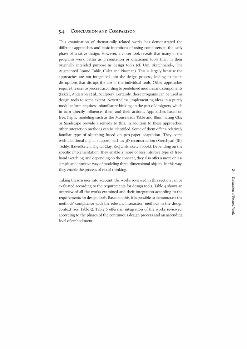
82
Discussion of R
elated Work
5.4 Conclusion and Comparison
This examination of thematically related works has demonstrated the different approaches and basic intentions of using computers in the early phase of creative design. However, a closer look reveals that many of the programs work better as presentation or discussion tools than in their originally intended purpose as design tools (cf. Urp, sketchhand+, The Augmented Round Table, Culer and Nasman). This is largely because the approaches are not integrated into the design process, leading to media disruptions that disrupt the use of the individual tools. Other approaches require the user to proceed according to predefined modules and components (Frazer, Anderson et al., Sculptor). Certainly, these programs can be used as design tools to some extent. Nevertheless, implementing ideas in a purely modular form requires unfamiliar rethinking on the part of designers, which in turn directly influences them and their actions. Approaches based on free, haptic modeling such as the MouseHaus Table and Illuminating Clay or Sandscape provide a remedy to this. In addition to these approaches, other interaction methods can be identified. Some of them offer a relatively familiar type of sketching based on pen-paper adaptation. They come with additional digital support, such as 3D reconstruction (Sketchpad (III), Teddy, ILoveSketch, Digital Clay, EsQUIsE, sketch book). Depending on the specific implementation, they enable a more or less intuitive type of free-hand sketching, and depending on the concept, they also offer a more or less simple and intuitive way of modeling three-dimensional objects. In this way, they enable the process of visual thinking.
Taking these issues into account, the works reviewed in this section can be evaluated according to the requirements for design tools. Table 4 shows an overview of all the works examined and their integration according to the requirements for design tools. Based on this, it is possible to demonstrate the methods’ compliance with the relevant interaction methods in the design context (see Table 5). Table 6 offers an integration of the works reviewed, according to the phases of the continuous design process and an ascending level of embodiment.
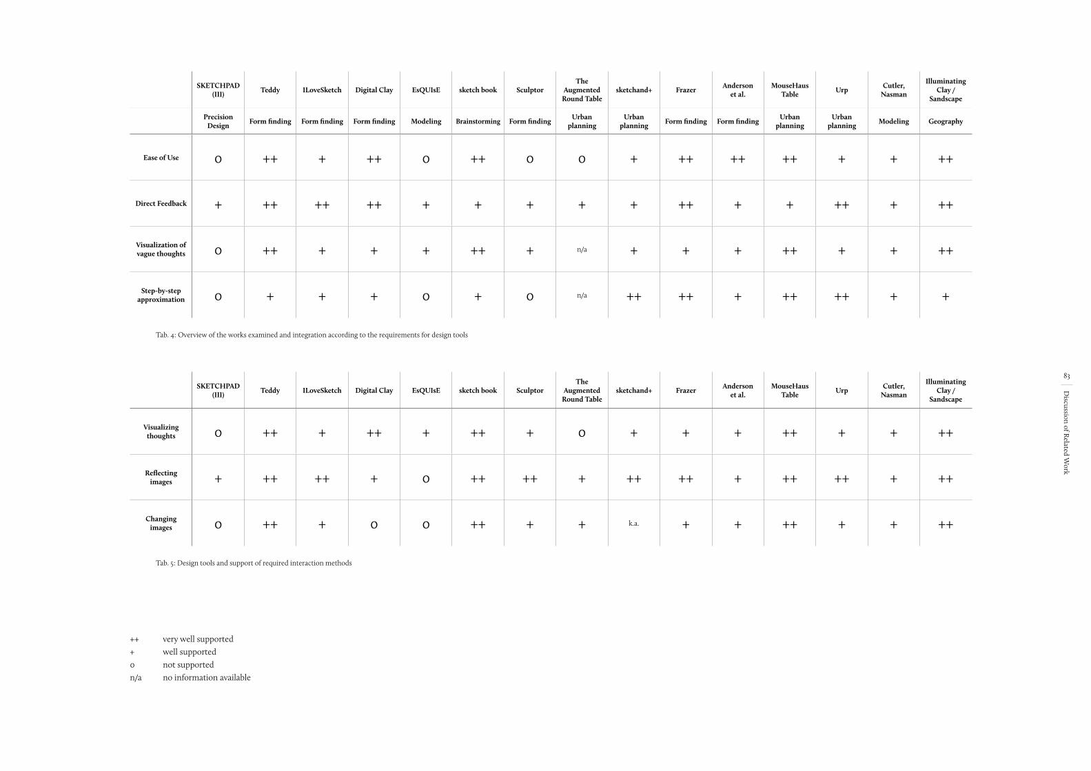
83
Discussion of R
elated Work
SKETCHPAD (III) Teddy ILoveSketch Digital Clay EsQUIsE sketch book Sculptor
The Augmented
Round Tablesketchand+ Frazer Anderson
et al.MouseHaus
Table Urp Cutler, Nasman
Illuminating Clay /
Sandscape
Precision Design Form finding Form finding Form finding Modeling Brainstorming Form finding Urban
planningUrban
planning Form finding Form finding Urban planning
Urban planning Modeling Geography
Ease of Use 0 ++ + ++ 0 ++ 0 0 + ++ ++ ++ + + ++
Direct Feedback + ++ ++ ++ + + + + + ++ + + ++ + ++
Visualization of vague thoughts 0 ++ + + + ++ + n/a + + + ++ + + ++
Step-by-step approximation 0 + + + 0 + 0 n/a ++ ++ + ++ ++ + +
Tab. 4: Overview of the works examined and integration according to the requirements for design tools
SKETCHPAD (III) Teddy ILoveSketch Digital Clay EsQUIsE sketch book Sculptor
The Augmented
Round Tablesketchand+ Frazer Anderson
et al.MouseHaus
Table Urp Cutler, Nasman
Illuminating Clay /
Sandscape
Visualizing thoughts 0 ++ + ++ + ++ + 0 + + + ++ + + ++
Reflecting images + ++ ++ + 0 ++ ++ + ++ ++ + ++ ++ + ++
Changing images 0 ++ + 0 0 ++ + + k.a. + + ++ + + ++
Tab. 5: Design tools and support of required interaction methods
++ very well supported+ well supported0 not supportedn/a no information available
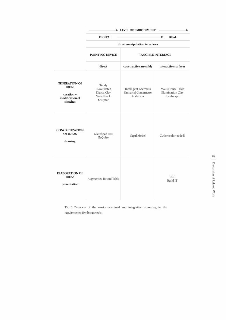
84
Discussion of R
elated Work
LEVEL OF EMBODIMENT
DIGITAL REAL
direct manipulation interfaces
POINTING DEVICE TANGIBLE INTERFACE
direct constructive assembly interactive surfaces
GENERATION OF IDEAS
creation +
modification of sketches
Teddy ILoveSketch Digital Clay Sketchbook
Sculptor
Intelligent Beermats Universal Constructor
Anderson
Maus House Table Illumination Clay
Sandscape
CONCRETIZATION OF IDEAS
drawing
Sketchpad (III) EsQuise
Segal Model Cutler (color-coded)
ELABORATION OF IDEAS
presentation
Augmented Round Table URP
Build IT
Tab. 6: Overview of the works examined and integration according to the
requirements for design tools
85
Deficit A
nalysis
6 Deficit Analysis
The previous chapters have explained in detail the contemporary uses of computers in the architectural context and have presented the requirements for design tools. These requirements can be summarized here as ease of use, direct feedback, visualization of vague thoughts, a stepwise approach and flexible use. Based on these requirements, I explain in more detail below the reasons why the computer cannot be used as a thinking tool and therefore cannot be meaningfully employed in the early phases of architectural design. Taking into account the way computers are currently used in the early design phases, the problem that Christian Gänshirt (2007, 91) identifies, with reference to Vilém Flusser, seems to be omnipresent:
“[...] tools are not instruments of freedom in every case. In the modern age, his analysis runs, tools no longer serve to solve problems, but start to become problematical in their own right.” (ibid.)
He believes the main reason for this to be the fact that tools are increasingly derived from scientific knowledge rather than from traditional precursors (ibid.). This is certainly often the case. However, in the area of computer applications, an overly literal adherence to traditional role models leads in most cases to the digitization of established tools without carefully questioning the origins of such tools. And so it happens that most digital tools in the architectural context are mere adaptions of established tools and thus do not really influence the design process. This would not be so problematic if the newly created digital tools could do the job at least as well as the old tools. However, this is by no means the case for the early phases of design, as has been demonstrated by the study of related works on this topic. It is not without reason that John Frazer speaks, in this context, of “Computer Obstructed Design” (Glanville 1992, 219). This is largely due to the fact that established design tools’ necessary characteristics – which are what make a creative act possible in the first place – are either inadequately supported or entirely unsupported by commonly available hardware and software solutions. In what follows, and taking into account the requirements and principles of human-computer interaction that have been defined and presented above, I will further consider the problems of doing creative work with the computer in the architectural context.
6.1 Ease of Use
Designing is a complex activity that requires the designer’s complete concentration. Established design tools, freehand sketching and architectural models, both support the design process perfectly by providing an execution that is simple, intuitive, direct and standard. These properties are sorely lacking in computers, however. The computer’s overly complex functions and overloaded interfaces require the full attention of the user and mean that a large part of the user’s memory is already occupied by the information on the screen, by having to locate icons and by simply having to operate the computer. This indirect type of interaction also leads to a mode of working that is dominated by rules and constraints and which requires
nochmal checken
86
Deficit A
nalysis
the user to adopt a mindset that is operation-oriented rather than design-oriented. This, however, affects not only the preliminary choices of a given function, but its direct execution as well. Thus, some if not all of the user’s attention shifts from design to operation, which is more or less a worst-case scenario. The user’s attention must be located in design and should not drift off into trivialities or ancillary activities. This becomes all the more relevant if we consider the temporal conditions of human memory’s absorptive capacity in this context: The time frame for mental intake of a new context is 10 seconds – the memory limit of human short-term memory is 4 ± 2 elements with a decay time of 15-20 seconds. We can conclude from this is that, in most cases, unintended changes of context inevitably lead to a loss of any data in the short-term memory or of the current idea or thought. Certainly, this is not always the case. The extent to which the location of the attention actually shifts results mainly from the user’s (in)experience with the tool, regardless of which tool is being used. The aim can only be to keep the operation and the handling of a tool as simple as possible in order to keep the resulting distraction as low as possible.
6.2 Flexible use
Performing architectural tasks can be compared to planning and creating a prototype or a one-off. Not only does each design task represent a unique project and therefore also an individual problem, the design concepts also differ from one another, as does the architect’s experience, all of which influences the approach to the individual project. The choice of the most suitable tool is also made based on this information. In this context, the choice is influenced primarily by manual considerations, i.e. which tool allows for the best and most suitable performance in a given situation, (such as the question: pen or haptic model?). An architect therefore does not need a specialized, single-function tool for designing. Rather, his or her hand-tool should be like a Swiss pocket knife that can be used expandably and changeably.
If one considers the possibilities of the computer in this context, it quickly becomes clear that the computer is a convergent device with a large spectrum of applications (Seel 1998, 256). However, this must not be equated with a flexible, individual application. Let us refer to Ranulph Glanville (Glanville, 1992, 216). He emphasizes that the computer as a tool fulfills the tasks it is set almost perfectly, but the problem is it can only do so for precisely predefined tasks (ibid.). Different software products certainly help to resolve this fundamental inflexibility, to a certain extent.
“Unlike pencils, brushes, knives, types of wood or metal, L-squares, etc. used by designers in the past, these programs already embody a condensed theory of the activity that they support or reinvent (as in the case of teleconferencing devices).“ (Nadin 1997, 45)35
35 Translated from the original: „Doch im Gegensatz zu Bleistift, Pinsel, Messer, Holz- oder
Metalltypen, Winkelhaken usw., die Designer in der Vergangenheit benutzten, verkörpern
diese Programme bereits eine komprimierte Theorie der Tätigkeit, die sie unterstützen oder
neu erfinden (wie im Fall der Telekonferenzeinrichtungen).“
87
Deficit A
nalysis
And Mihai Nadin (1997, 45) adds: “None of these theories describes all the aspects of design. But they describe and synthesize the activities of the designer, which are determined by our interests and our needs” (ibid.)36. It is thus the synthesis of the activities which leads to fixed working methods and which prevents complete flexibility not only in the selection of established tools, but also, and in particular, in their use and handling. The universality of the computer also leads to yet another problem. Different software products, for their part, require generically usable interfaces, interfaces that are universally applicable for any form of application. As a result, the interfaces are reduced to a generic form and do not support specialized forms of interaction. For this reason, the predominant form of operation is the mouse and keyboard – and in some cases, touch. This is completely contrary to the architect’s requirements. This procedure also requires the user to individually select interfaces that are adapted to the design – both software and hardware. Both need to be adapted to the respective design situation and so that they can react flexibly to the respective working method.
6.3 Direct Feedback
As has already been described, the process of visual thinking is at the core of any creative or artistic activity (see chapter 2.2.2). The concordance of gesture and perception and the resulting direct feedback of our thoughts as a process of visual thinking is absolutely crucial in the creative process and cannot be replaced. For many reasons, doing this process on a computer will always have limitations. The reduction of input to universally applicable input devices, such as a mouse and keyboard, leads to a very indirect formulation of gestures. It is indirect, in contrast to the direct physical connection provided by the physicality of electromechanical devices: “When we turn the dial, our fingertips and muscles can almost ‘feel’ the stations being scanned” (Moggridge 2007, xv). But when one uses a computer, the connection hand-mouse-screen only partly leads to a matching haptic feedback between motor action and the action on the screen (ibid.). In most cases, the purely optical adaptation of familiar operating elements leads to a familiar operating environment, but does not question whether there is a better solution to operating the computer from the point of view of the perfect application. And so it happens that in place of the actual action, the screen only displays an adaptation of the mouse’s movement, which is almost entirely (except for the key movement) based on visual feedback. On the contrary when using established tools, the thoughts that have been externalized by the gesture are perceived, experienced and understood by more than one sense. And this perception occurs simultaneously with the gesture, so that a cycle/loop is created in the process. On the computer, on the other hand, only the visual sense is included in the feedback in almost all cases. The step-by-step approach of using the computer – setting the starting point and the end point, and the abrupt form that emerges from
36 Translated from the original: „Keine dieser Theorien beschreibt sämtliche Aspekte des
Design. Aber sie beschreiben und synthetisieren Tätigkeiten des Designers, die durch unsere
Interessen und unseren Bedarf [...] bestimmt werden.“
vieelleicht ":" statt klammern
geändert
Mike hat keine ordentliche übersetzung geliefert
88
Deficit A
nalysis
this – leads only to an interplay between the two processes of ‘gesture’ and ‘perception’ and thus between the completed line and its observation: “An intuitive response to the lines one draws (stimulating ever bolder reactions through their perception) results in a different, freer process of thinking than with CAD drawing” (Wienands 2005, 211). And so, the low level of embodiment and the lack of feedback inevitably lead to a partial or total loss of direct reference to the design, a reference that is truly essential for the process of visual thinking:
“Digitalizing models and model-making loses the sensual experience of material and space, and with that the experience of the directness with which half-finished models can be
manipulated.“ (Gänshirt 2007, 158)
Inputs and Output Sites:As has been described, using the computer allows for only a limited amount direct feedback with the brain. One problem is the rather low level of embodiment that results from the spatial separation of haptic input when using the mouse and visual feedback on the screen. This inevitably leads to the question of where the attention is focused in this construct: Is it on moving the mouse or looking at the result on the screen? This screen-eye-hand-mouse coordination requires carefully trained motor skills because the hand movements only have an indirect effect on the screen that is amplified by effects such as pointer acceleration. The motor movements of the hand have only the remotest relation to the final result. And so the screen represents the gesture’s only realistic feedback. Only through this additional information channel can the result of a completed gesture be perceived at all. Only this way can users confirm whether the input actually corresponds to the idea they had in their mind. And so this problem presents a process-inhibiting barrier, especially for visual thinking. Certainly, touch screens with pen functionality are an alternative input method nowadays, but they don’t solve – or do so only partially – problems such as the lack of haptics due to the smooth surface or ergonomic aspects such as size and alignment.
2D vs. 3D:When using established tools, much of the feedback also takes place via the visual sensory channel. If one considers only the spatial dimensions, the digital output is the same as you would expect with established tools: A two-dimensional sketch is perceived as a two-dimensional image, and a real model can also be realized in all three dimensions. Things are quite different, however, when it comes to working with three-dimensional geometries on the computer. In general, three-dimensional contents can be generated, stored and edited on the computer. However, it is problematic that, as a rule, the input of three-dimensional geometries and bodies occurs purely by means of two-dimensional, planar movements of the input device. This fact remains an unsolved problem, even though input methods such as force feedback pens, offer the possibility of three-dimensional motion. However, due to the restricted workspace and the resulting indirect connection, as well as the separation of input and output, this is not comparable to the physical, two-handed manipulation of an object. The situation is
CHECK
89
Deficit A
nalysis
similar with regard to viewing the data. As has already been mentioned, it exists as three-dimensional, digital content, however, any type of screen reproduction represents – with a few exceptions – only a two-dimensional image of a three-dimensional object. With today’s technology it is possible to partly produce a nearly realistic, three-dimensional impression (see chapter 4.2.2), but its use is limited by the technical problems already mentioned. However, this form of representation represents a viable alternative for presentations and discussions. In this way, a realistic impression of complex, three-dimensional interrelations can be even made clear to laypeople. In the creative context, however, the abstract form of the input only partially provides the direct feedback required for visual thinking. Therefore it is questionable whether it can have any meaningful application.
Acting vs. Reacting:It is important here to emphasize the insights of Böhle et al. (1998), which have to do with the differences in viewing analogue and digital media. The difficulty in viewing digital content on a screen is due mainly to a lack of eye activity on the part of the viewer. Viewing the screen is independent of the content that is presented and leads “to a centering and narrowing of the perceptual field and a selective and sequential perception” on the part of the viewer (Böhle et al., 1998, 24)37. The reason for this, according to Böhle et al. (1998, 28), is not only because the presentation is cropped, but also because the monotonous distance between the observer and the screen, which always remains the same (in terms of distance and body posture). The problem of the viewer’s pure reactivity to content, without any active intervention, leads to “visual fixations” and thus directly to a inundation of the eye and thus also of sensory impressions (Köchling 1985, 43). This effect is intensified by the constant changes in the display, the perspective and the scale. This is quite easy to do on a computer, and thus it happens all the time. In contrast, working with established, analogue tools is very different: The eye is active; it searches for what to focus on and decides for itself which content is important and which is not. The problem with working only via a screen, according to Böhle et al. (1998, 24), is that the requirements for visual perception shift from a “qualitatively differentiated sensory perception” to a “physiological performance” (ibid.)38. But it is precisely this shift which, particularly in relation to the architectural design process, represents the loss of a basic element of the creative process, since differentiated sensory perception can be regarded as a fundamental component of visual thinking.
37 Translated from the original: „zu einer Zentrierung und Einengung des
Wahrnehmungsfeldes und einer punktuellen und sequentiellen Wahrnehmung“
38 Translated from the original: „qualitativ differenzierten sinnlichen Wahrnehmung“ hin zu
einer „physiologische[n] Leistungsfähigkeit“
Die Anforderungen an die visuelle Wahrnehmung
bei der Bildschirmarbeit richten sich primär auf
die physiologische Leistungsfähigkeit und nicht
auf die Fähigkeit zu einer qualitativ differenzierten
sinnlichen Wahrnehmung.
90
Deficit A
nalysis
6.4 Visualization of Vague Thoughts
The uncertainty of what is produced and the incrementalism of the design process, is due to the fact that the designer has no concrete idea in front of his or her mind’s eye, no clear idea of what he or she wants to do, nor what the result will be. And so the designer’s knowledge is limited to vague and fleeting thoughts, ideas, and information. However, communicating with the computer always requires the user to input precise information, usually pixel- or millimeter-exact details. There are endless examples of this, such as drawing a wall or even setting a point. Only by means of a millimeter-accurate specification and input via text or mouse click, can elements and components be placed precisely in the three-dimensional coordinate system – there is no way to input ‘roughly here’ in the computer. The situation becomes even more critical when, from the software point of view, object properties are required. The sheer endless number of input masks requires that of the exact object properties be defined – everything from the way it will look to physical conditions such as wall thickness, wall construction, height, number of floors, etc. The resulting problem can already be seen in the fact that the designer may not even know exactly whether the shape that has just come into being – let’s suppose it is a simple straight line – is meant to be a border, a wall, an opening, a floor or indicates only a change in surface. Or perhaps it is just a guide line. All this lies purely in the interpretation of the designer and is almost impossible to do on the computer, with its need for exact specifications. A sketch is something rough: many lines one above the other, sometimes containing several different ideas and sometimes several sketches of the same idea. They are all similar yet different. When working on the computer, on the other hand, everything is fine and precise – it creates the impression of something that is already definitive. How is the effect of emergence supposed to arise in a fine and precise drawing that always looks the same (even in multiple representations of the same idea)? For John Gero (2006, 1), it is precisely the multiplicity of the sketch that fosters a different interpretation and thus the effect of emergence. Conversely, this cognitive effect is inhibited not only by the purity of the computer construct, but also by the drawing itself - no matter how many times you draw it, it will always look the same. If, on the other hand, while three hand sketches might represent one and the same idea, it is very likely that each of these sketches will look different, whether in approach, point of view, focus or in its entirety.
6.5 Stepwise Approach
Since architectural tasks involve complex problems, it is not possible to proceed according to predefined methods and approaches to achieve a solution. Rather, one takes a step-by-step, iterative approach – from an initial starting point to a previously unknown goal – a process that characteristically generates variations and works, stepwise into detail, with and from what came before.
91
Deficit A
nalysis
Going into Detail: In this, one begins from this initial situation and takes a step-by-step approach, starting with something rough and abstract and which becomes more and more refined over time. This is quite contrary to the way work is done on the CAD program: Here one starts from details that are combined with other details and this builds up to form a collective whole. This approach used in the digital environment is made possible by corresponding software functions such as copying, mirroring, arraying, rotation, etc., which indirectly prescribe and even promote it (Bolte 1998, 366). The computer’s entire operation is designed in such a way that the user knows what he or she wants to do and already has a concrete goal in mind. The first step when working with the CAD program is to activate the correct function. CAD software provides a variety of different drawing functions for creating elements, and the function palette generally allows the user to generate everything from a simple point to complex geometric shapes (all of which are arranged as small symbols). When the user activates a particular drawing function (e.g., line, square, circle), only this exact function can be executed. And so the designer must be aware of what the element should look like before he or she can actually create it. In the sketching process, on the other hand, it is the sketching itself that leads to the final form. When a line is created, for example, the result is not yet defined – perhaps it will be a circle, or a square. This basic freedom, which is essential for the thought process, is completely suppressed by having to define the function ahead of time, which is necessary on the computer. It is just not possible, on a computer, to use the pen to ease your way into things and just let go.
Generating Variation: It is essential to the design process to be able to make, discard and compare different design variations on the way to the final goal, which remains unclear at the outset. While this happens almost incidentally in the established design process, when working on the computer, one can only work with design variations in a limited way. On the other hand, it is easy to see how simple established tools such as sketch paper or even models make the process simple. Variations can be intuitively and quickly generated, expanded, refined, can build on each other, be consolidated and evolve. Ideas can be discarded just as intuitively, since the designer can reject ideas simply by laying the sketches aside. There is also the act of crumpling the paper and throwing it away, which Annegret Bolte (1998, 367) considers to be an especially essential part of the process. This gets rid of not just the paper, but the wrong idea as well, while at the same time making noticeable space for new ideas. A behavior like this is impossible on the computer. As a rule, one puts aside different variations on the computer by storing the corresponding versions as individual files. In exceptional cases, there is also the possibility of versioning within a program, providing the possibility of a structured filing system via file names, keywords and tags. While this can make it easier to find individual versions, working with the different variants is quite problematic. With paper or a model, it is possible to compare two or more versions by simply putting them down and spreading them out in front of you. This is not possible on the computer. Screen size restrictions and ergonomic factors make it very difficult to directly compare different
Hier steht eigentlich “Detailierung“ im Deutschen. Übersetzung passt ned so ganz
Mike hatte: Precision and Detail
Vieleicht: going into detail?
92
Deficit A
nalysis
versions on the computer. A comparison can thus be made only by looking at preview images or by alternately opening the individual files. It is only possible to overlay different files by means of copy & paste or by a suitable layer structure. And so searching for and viewing design variants on the computer means, in many cases, having to open and close different files, zooming in on a specific aspect and then switching back and forth between windows.
6.6 Summary
The stated reasons and problems clearly show the current prevailing deficit between established design tools (pen and model) and conventional software. In the following, I will discuss the consequences this has for the architect’s thought process and the design process.
The direct consequences of the identified problems are particularly noticeable when it comes to thinking or creative work. The complexity of the systems on both the hardware and software side leads to unwanted context changes, and unnecessarily occupies human short-term memory. In turn, the designer is no longer focused primarily on the design, but rather on operating the system. A no less dramatic result is that the lack of feedback means that it is not possible to achieve a direct connection to what is being designed and that the process of visual thinking is hampered. This process represents the core activity of every creative work, and thus neither truly creative thinking nor the idea-finding process is possible on the computer in its current form. In addition, working with the computer as described above requires a complete rethinking of one’s modes of action. Certainly, many computer users have adapted themselves to this thinking, but working on a computer requires a different operating logic, which is contrary to creative thinking. At the moment, computers are not truly integrated into the design process, and thus their potential can only be utilized to a limited extent. The reasons for this are many and have already been explained. However, the computer is used in many situations, such as for calculations. But this is a separate use and leads to media disruptions and to a sequential design process. Due to this lack of integration, the evaluation of the design usually takes place in a separate, retroactive step and is thus not an actual part of the design process. Calculations are purely for verification and have no influence and provide no feedback on the design process.
In summary, the multiplicity of the reasons presented here justifies and substantiates the initial assertion that the use of the computer in the early phases of design would interfere with the process of designing more than it would support it. The core problem lies with the current systems’ inadequate human-computer communication. However, if one considers the potential of the computer more carefully, it is quite possible to find points of reference that could justify the use of digital tools in the early stages of urban development. In order to make this decisive step, however, we must first rethink hardware and software development. A concept can only be successful if it is developed out of the requirements of the design tools – only in this way can the digital become part of the creative phase and gain success and acceptance.
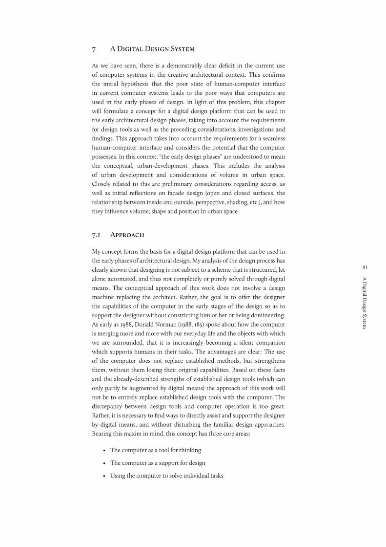
93
A D
igital Design System
7 A Digital Design System
As we have seen, there is a demonstrably clear deficit in the current use of computer systems in the creative architectural context. This confirms the initial hypothesis that the poor state of human-computer interface in current computer systems leads to the poor ways that computers are used in the early phases of design. In light of this problem, this chapter will formulate a concept for a digital design platform that can be used in the early architectural design phases, taking into account the requirements for design tools as well as the preceding considerations, investigations and findings. This approach takes into account the requirements for a seamless human-computer interface and considers the potential that the computer possesses. In this context, “the early design phases” are understood to mean the conceptual, urban-development phases. This includes the analysis of urban development and considerations of volume in urban space. Closely related to this are preliminary considerations regarding access, as well as initial reflections on facade design (open and closed surfaces, the relationship between inside and outside, perspective, shading, etc.), and how they influence volume, shape and position in urban space.
7.1 Approach
My concept forms the basis for a digital design platform that can be used in the early phases of architectural design. My analysis of the design process has clearly shown that designing is not subject to a scheme that is structured, let alone automated, and thus not completely or purely solved through digital means. The conceptual approach of this work does not involve a design machine replacing the architect. Rather, the goal is to offer the designer the capabilities of the computer in the early stages of the design so as to support the designer without constricting him or her or being domineering. As early as 1988, Donald Norman (1988, 185) spoke about how the computer is merging more and more with our everyday life and the objects with which we are surrounded, that it is increasingly becoming a silent companion which supports humans in their tasks. The advantages are clear: The use of the computer does not replace established methods, but strengthens them, without them losing their original capabilities. Based on these facts and the already-described strengths of established design tools (which can only partly be augmented by digital means) the approach of this work will not be to entirely replace established design tools with the computer. The discrepancy between design tools and computer operation is too great. Rather, it is necessary to find ways to directly assist and support the designer by digital means, and without disturbing the familiar design approaches. Bearing this maxim in mind, this concept has three core areas:
• The computer as a tool for thinking
• The computer as a support for design
• Using the computer to solve individual tasks
Tasks vs Problems
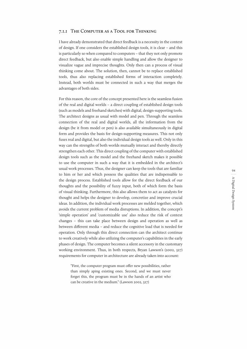
94
A D
igital Design System
7.1.1 The Computer as a Tool for Thinking
I have already demonstrated that direct feedback is a necessity in the context of design. If one considers the established design tools, it is clear – and this is particularly so when compared to computers – that they not only promote direct feedback, but also enable simple handling and allow the designer to visualize vague and imprecise thoughts. Only then can a process of visual thinking come about. The solution, then, cannot be to replace established tools, thus also replacing established forms of interaction completely. Instead, both worlds must be connected in such a way that merges the advantages of both sides.
For this reason, the core of the concept presented here is the seamless fusion of the real and digital worlds – a direct coupling of established design tools (such as models and freehand sketches) with digital, design-supporting tools. The architect designs as usual with model and pen. Through the seamless connection of the real and digital worlds, all the information from the design (be it from model or pen) is also available simultaneously in digital form and provides the basis for design-supporting measures. This not only fuses real and digital, but also the individual design tools as well. Only in this way can the strengths of both worlds mutually interact and thereby directly strengthen each other. This direct coupling of the computer with established design tools such as the model and the freehand sketch makes it possible to use the computer in such a way that it is embedded in the architect’s usual work processes. Thus, the designer can keep the tools that are familiar to him or her and which possess the qualities that are indispensable to the design process. Established tools allow for the direct feedback of our thoughts and the possibility of fuzzy input, both of which form the basis of visual thinking. Furthermore, this also allows them to act as catalysts for thought and helps the designer to develop, concretize and improve crucial ideas. In addition, the individual work processes are melded together, which avoids the current problem of media disruptions. In addition, the concept’s ‘simple operation’ and ‘customizable use’ also reduce the risk of context changes – this can take place between design and operation as well as between different media – and reduce the cognitive load that is needed for operation. Only through this direct connection can the architect continue to work creatively while also utilizing the computer’s capabilities in the early phases of design. The computer becomes a silent accessory in the customary working environment. Thus, in both respects, Bryan Lawson’s (2002, 327) requirements for computer in architecture are already taken into account:
“First, the computer program must offer new possibilities, rather than simply aping existing ones. Second, and we must never forget this, the program must be in the hands of an artist who can be creative in the medium.“ (Lawson 2002, 327)
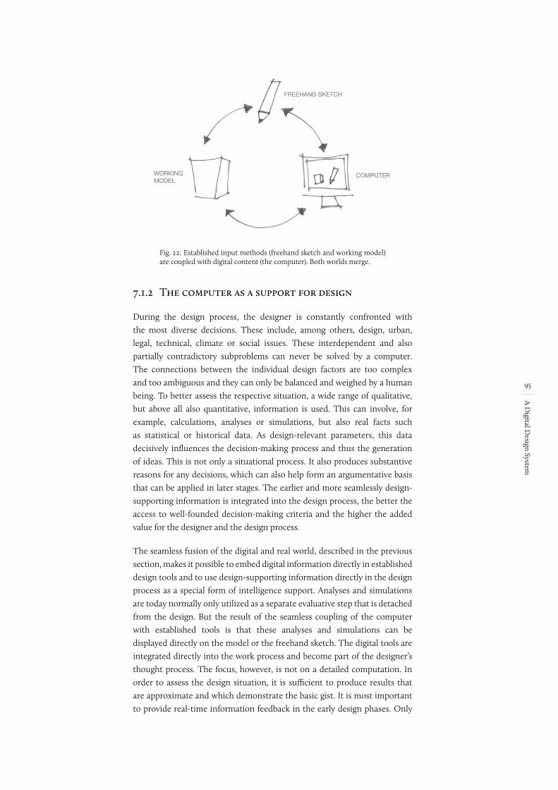
95
A D
igital Design System
Fig. 22:
FREEHAND SKETCH
WORKINGMODEL
COMPUTER
Established input methods (freehand sketch and working model) are coupled with digital content (the computer). Both worlds merge.
7.1.2 The computer as a support for design
During the design process, the designer is constantly confronted with the most diverse decisions. These include, among others, design, urban, legal, technical, climate or social issues. These interdependent and also partially contradictory subproblems can never be solved by a computer. The connections between the individual design factors are too complex and too ambiguous and they can only be balanced and weighed by a human being. To better assess the respective situation, a wide range of qualitative, but above all also quantitative, information is used. This can involve, for example, calculations, analyses or simulations, but also real facts such as statistical or historical data. As design-relevant parameters, this data decisively influences the decision-making process and thus the generation of ideas. This is not only a situational process. It also produces substantive reasons for any decisions, which can also help form an argumentative basis that can be applied in later stages. The earlier and more seamlessly design-supporting information is integrated into the design process, the better the access to well-founded decision-making criteria and the higher the added value for the designer and the design process.
The seamless fusion of the digital and real world, described in the previous section, makes it possible to embed digital information directly in established design tools and to use design-supporting information directly in the design process as a special form of intelligence support. Analyses and simulations are today normally only utilized as a separate evaluative step that is detached from the design. But the result of the seamless coupling of the computer with established tools is that these analyses and simulations can be displayed directly on the model or the freehand sketch. The digital tools are integrated directly into the work process and become part of the designer’s thought process. The focus, however, is not on a detailed computation. In order to assess the design situation, it is sufficient to produce results that are approximate and which demonstrate the basic gist. It is most important to provide real-time information feedback in the early design phases. Only
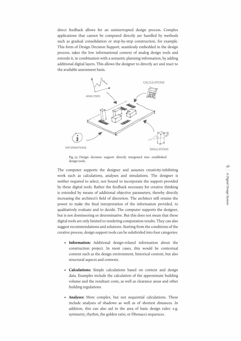
96
A D
igital Design System
direct feedback allows for an uninterrupted design process. Complex applications that cannot be computed directly are handled by methods such as gradual consolidation or step-by-step construction, for example. This form of Design Decision Support, seamlessly embedded in the design process, takes the low informational content of analog design tools and extends it, in combination with a semantic planning information, by adding additional digital layers. This allows the designer to directly act and react to the available assessment basis.
Fig. 23:
ANALYSES
CALCULATIONS
INFORMATIONS SIMULATIONS
Design decision support directly integrated into established design tools.
The computer supports the designer and assumes creativity-inhibiting work such as calculations, analyses and simulations. The designer is neither required to select, nor bound to incorporate the support provided by these digital tools. Rather the feedback necessary for creative thinking is extended by means of additional objective parameters, thereby directly increasing the architect’s field of discretion. The architect still retains the power to make the final interpretation of the information provided, to qualitatively evaluate and to decide. The computer supports the designer, but is not domineering or determinative. But this does not mean that these digital tools are only limited to rendering computation results. They can also suggest recommendations and solutions. Starting from the conditions of the creative process, design support tools can be subdivided into four categories:
• Information: Additional design-related information about the construction project. In most cases, this would be contextual content such as the design environment, historical content, but also structural aspects and contexts.
• Calculations: Simple calculations based on context and design data. Examples include the calculation of the approximate building volume and the resultant costs, as well as clearance areas and other building regulations.
• Analyses: More complex, but not sequential calculations. These include analyses of shadows as well as of shortest distances. In addition, this can also aid in the area of basic design rules: e.g. symmetry, rhythm, the golden ratio, or Fibonacci sequences.
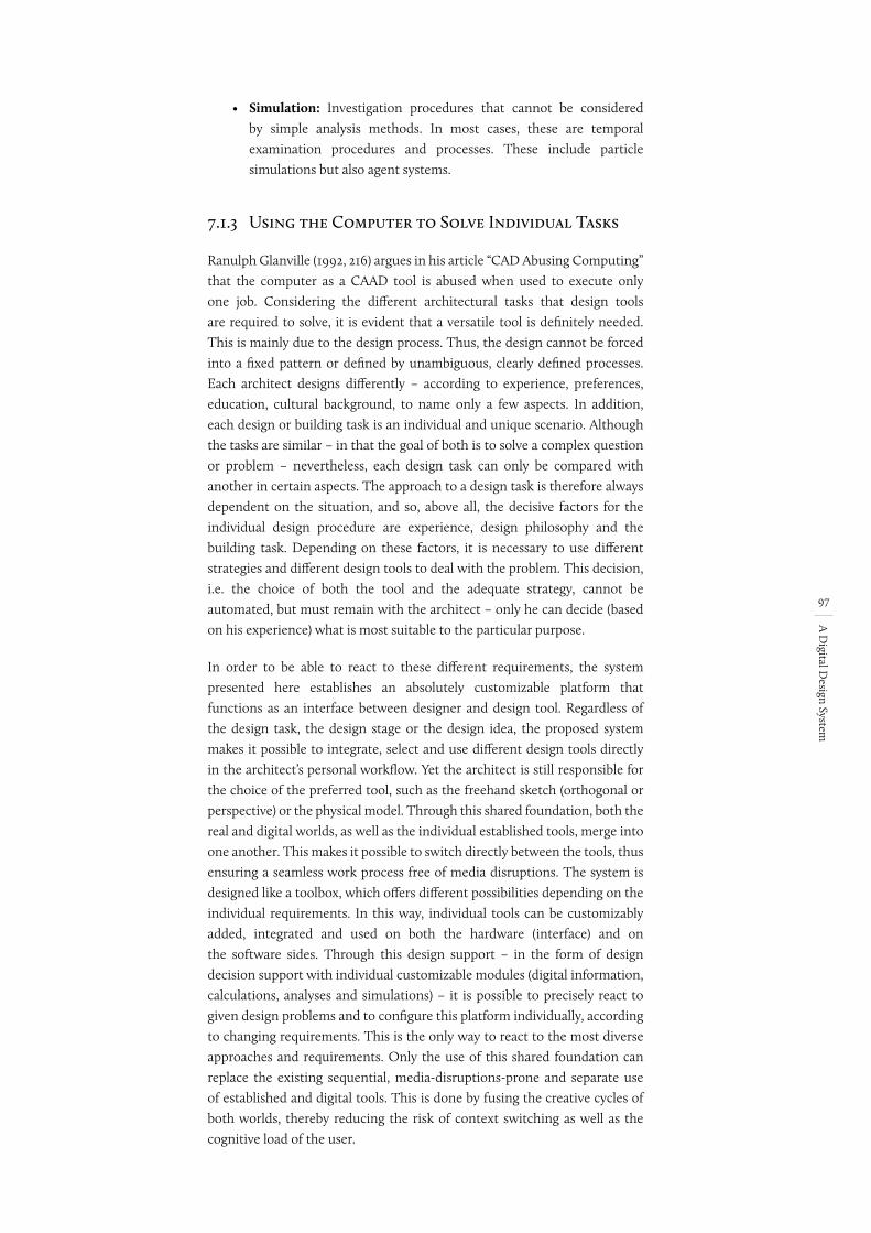
97
A D
igital Design System
• Simulation: Investigation procedures that cannot be considered by simple analysis methods. In most cases, these are temporal examination procedures and processes. These include particle simulations but also agent systems.
7.1.3 Using the Computer to Solve Individual Tasks
Ranulph Glanville (1992, 216) argues in his article “CAD Abusing Computing” that the computer as a CAAD tool is abused when used to execute only one job. Considering the different architectural tasks that design tools are required to solve, it is evident that a versatile tool is definitely needed. This is mainly due to the design process. Thus, the design cannot be forced into a fixed pattern or defined by unambiguous, clearly defined processes. Each architect designs differently – according to experience, preferences, education, cultural background, to name only a few aspects. In addition, each design or building task is an individual and unique scenario. Although the tasks are similar – in that the goal of both is to solve a complex question or problem – nevertheless, each design task can only be compared with another in certain aspects. The approach to a design task is therefore always dependent on the situation, and so, above all, the decisive factors for the individual design procedure are experience, design philosophy and the building task. Depending on these factors, it is necessary to use different strategies and different design tools to deal with the problem. This decision, i.e. the choice of both the tool and the adequate strategy, cannot be automated, but must remain with the architect – only he can decide (based on his experience) what is most suitable to the particular purpose.
In order to be able to react to these different requirements, the system presented here establishes an absolutely customizable platform that functions as an interface between designer and design tool. Regardless of the design task, the design stage or the design idea, the proposed system makes it possible to integrate, select and use different design tools directly in the architect’s personal workflow. Yet the architect is still responsible for the choice of the preferred tool, such as the freehand sketch (orthogonal or perspective) or the physical model. Through this shared foundation, both the real and digital worlds, as well as the individual established tools, merge into one another. This makes it possible to switch directly between the tools, thus ensuring a seamless work process free of media disruptions. The system is designed like a toolbox, which offers different possibilities depending on the individual requirements. In this way, individual tools can be customizably added, integrated and used on both the hardware (interface) and on the software sides. Through this design support – in the form of design decision support with individual customizable modules (digital information, calculations, analyses and simulations) – it is possible to precisely react to given design problems and to configure this platform individually, according to changing requirements. This is the only way to react to the most diverse approaches and requirements. Only the use of this shared foundation can replace the existing sequential, media-disruptions-prone and separate use of established and digital tools. This is done by fusing the creative cycles of both worlds, thereby reducing the risk of context switching as well as the cognitive load of the user.
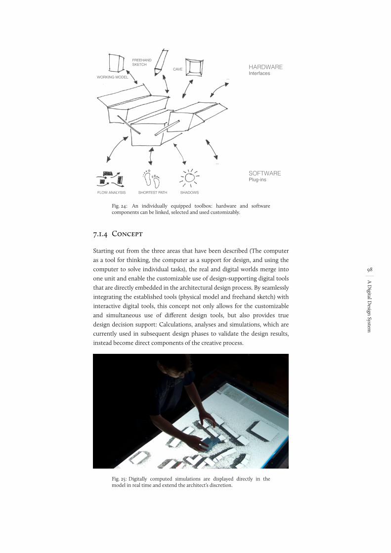
98
A D
igital Design System
Fig. 24:
HARDWAREInterfaces
SOFTWAREPlug-ins
FREEHANDSKETCH
WORKING MODEL
CAVE
...
...
FLOW ANALYSIS SHORTEST PATH SHADOWS
An individually equipped toolbox: hardware and software components can be linked, selected and used customizably.
7.1.4 Concept
Starting out from the three areas that have been described (The computer as a tool for thinking, the computer as a support for design, and using the computer to solve individual tasks), the real and digital worlds merge into one unit and enable the customizable use of design-supporting digital tools that are directly embedded in the architectural design process. By seamlessly integrating the established tools (physical model and freehand sketch) with interactive digital tools, this concept not only allows for the customizable and simultaneous use of different design tools, but also provides true design decision support: Calculations, analyses and simulations, which are currently used in subsequent design phases to validate the design results, instead become direct components of the creative process.
Fig. 25: Digitally computed simulations are displayed directly in the model in real time and extend the architect’s discretion.
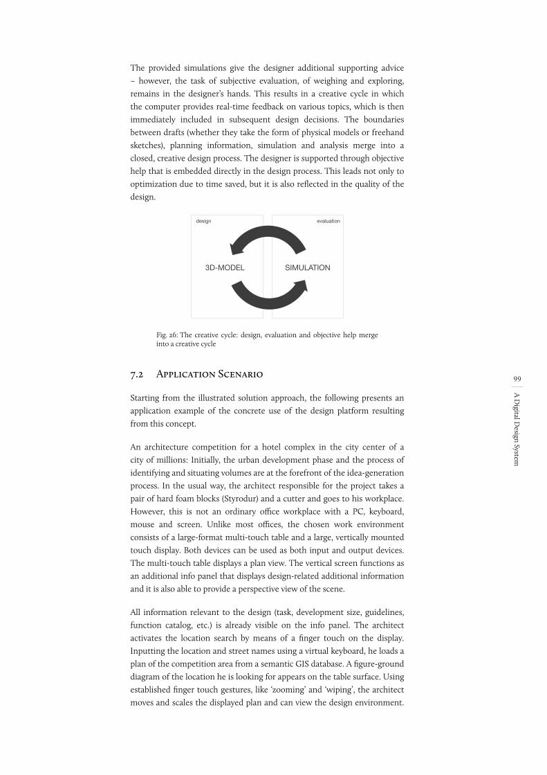
99
A D
igital Design System
The provided simulations give the designer additional supporting advice – however, the task of subjective evaluation, of weighing and exploring, remains in the designer’s hands. This results in a creative cycle in which the computer provides real-time feedback on various topics, which is then immediately included in subsequent design decisions. The boundaries between drafts (whether they take the form of physical models or freehand sketches), planning information, simulation and analysis merge into a closed, creative design process. The designer is supported through objective help that is embedded directly in the design process. This leads not only to optimization due to time saved, but it is also reflected in the quality of the design.
Fig. 26:
Entwurf
Ausarbeitung
Evaluierung
Simulation
Geometrie
3D-Modell
design
elaboration
evaluation
SIMULATION
GEOMETRY
3D-MODEL
The creative cycle: design, evaluation and objective help merge into a creative cycle
7.2 Application Scenario
Starting from the illustrated solution approach, the following presents an application example of the concrete use of the design platform resulting from this concept.
An architecture competition for a hotel complex in the city center of a city of millions: Initially, the urban development phase and the process of identifying and situating volumes are at the forefront of the idea-generation process. In the usual way, the architect responsible for the project takes a pair of hard foam blocks (Styrodur) and a cutter and goes to his workplace. However, this is not an ordinary office workplace with a PC, keyboard, mouse and screen. Unlike most offices, the chosen work environment consists of a large-format multi-touch table and a large, vertically mounted touch display. Both devices can be used as both input and output devices. The multi-touch table displays a plan view. The vertical screen functions as an additional info panel that displays design-related additional information and it is also able to provide a perspective view of the scene.
All information relevant to the design (task, development size, guidelines, function catalog, etc.) is already visible on the info panel. The architect activates the location search by means of a finger touch on the display. Inputting the location and street names using a virtual keyboard, he loads a plan of the competition area from a semantic GIS database. A figure-ground diagram of the location he is looking for appears on the table surface. Using established finger touch gestures, like ‘zooming’ and ‘wiping’, the architect moves and scales the displayed plan and can view the design environment.
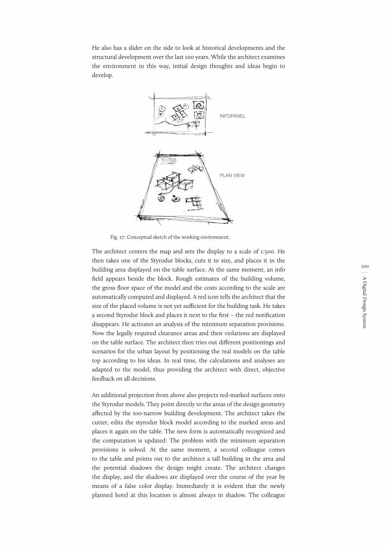
100
A D
igital Design System
He also has a slider on the side to look at historical developments and the structural development over the last 100 years. While the architect examines the environment in this way, initial design thoughts and ideas begin to develop.
Fig. 27: Conceptual sketch of the working environment.
INFOPANEL
PLAN VIEW
The architect centers the map and sets the display to a scale of 1:500. He then takes one of the Styrodur blocks, cuts it to size, and places it in the building area displayed on the table surface. At the same moment, an info field appears beside the block. Rough estimates of the building volume, the gross floor space of the model and the costs according to the scale are automatically computed and displayed. A red icon tells the architect that the size of the placed volume is not yet sufficient for the building task. He takes a second Styrodur block and places it next to the first – the red notification disappears. He activates an analysis of the minimum separation provisions. Now the legally required clearance areas and their violations are displayed on the table surface. The architect then tries out different positionings and scenarios for the urban layout by positioning the real models on the table top according to his ideas. In real time, the calculations and analyses are adapted to the model, thus providing the architect with direct, objective feedback on all decisions.
An additional projection from above also projects red-marked surfaces onto the Styrodur models. They point directly to the areas of the design geometry affected by the too-narrow building development. The architect takes the cutter, edits the styrodur block model according to the marked areas and places it again on the table. The new form is automatically recognized and the computation is updated: The problem with the minimum separation provisions is solved. At the same moment, a second colleague comes to the table and points out to the architect a tall building in the area and the potential shadows the design might create. The architect changes the display, and the shadows are displayed over the course of the year by means of a false color display. Immediately it is evident that the newly planned hotel at this location is almost always in shadow. The colleague
101
A D
igital Design System
then takes an input pencil and marks the relevant shadow areas in the plan view in order to clarify the problem with a freehand sketch. To check this change, and to better understand the design situation, one of the two architects places a SpaceMouse on the multi-touch table. At the same time, a perspective view of the entire design scene is shown on the vertical touch screen. Via the position and orientation of the SpaceMouse on the table, as well as mouse’s the tilt sensors, the architect adjusts the virtual camera of the perspective display so that the entire main facade of the design is in focus. Here, too, the 3D simulation shows which areas of the façade are most heavily in shadow. Taking into account this information, the two architects use the pen to sketch some ideas for the façade design and the position of the entrance position directly into the perspective drawing. The freehand sketch is automatically depicted as a texture conforming to the perspective on the building surfaces. In addition, the sketches of the facade appear in real time as a projection on the physically existing working models. They save the current draft via a simple user gesture.
One of the two architects makes a few more suggestions to improve the situation in regard to its urban planning aspects, taking some of the models in his hand and moving the blocks on the table according to his suggested changes. The perspective view adapts in real time. Through intelligent mapping, the recently sketched facade remains attached to the physical volume. Both move in the perspective view, but the change is also reflected in the projection analogous to the real model. Afterwards, the architect explains the improved urban-planning situation by means of hand-written annotations on the plan view and in the perspective view (arrows, text, shading, etc.). Taking a closer look at an overlaid view of the paths and distances to public transport, and of the sightlines, it becomes clear that certain facades in the required retail zones are difficult to see and thus would lead to lower profits. Suddenly his colleague has an idea. Intuitively, he reaches for the pen and sketches his new idea as a perspective freehand sketch onto the virtual scene. The sketched strokes, surfaces and bodies are interpreted three-dimensionally on the fly and are reconstructed as digital geometric objects. The volume generated in this way becomes a component of the virtual scene in real time and thus directly affects the ongoing simulations and analyses. It is clear that this new design is able to achieve much better access, visibility and shading.
Together, both colleagues continue to work and investigate wind conditions and evacuation scenarios. Starting from these objective supports, they work on the spatial structure and discuss further ideas for the façade design, the urban-planning aspects and the building shape. A comparison of the different saved versions clearly shows the advantages and disadvantages of the individual ideas.
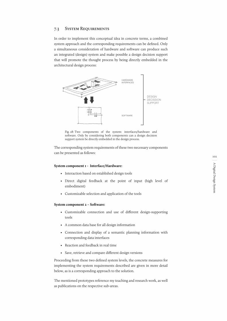
102
A D
igital Design System
7.3 System Requirements
In order to implement this conceptual idea in concrete terms, a combined system approach and the corresponding requirements can be defined. Only a simultaneous consideration of hardware and software can produce such an integrated (design) system and make possible a design decision support that will promote the thought process by being directly embedded in the architectural design process:
Fig. 28:
DESIGNDECISSIONSUPPORT
HARDWAREINTERFACES
SOFTWARE
Two components of the system: interfaces/hardware and software. Only by considering both components can a design decision support system be directly embedded in the design process.
The corresponding system requirements of these two necessary components can be presented as follows:
System component 1 - Interface/Hardware:
• Interaction based on established design tools
• Direct digital feedback at the point of input (high level of embodiment)
• Customizable selection and application of the tools
System component 2 – Software:
• Customizable connection and use of different design-supporting tools
• A common data base for all design information
• Connection and display of a semantic planning information with corresponding data interfaces
• Reaction and feedback in real time
• Save, retrieve and compare different design versions
Proceeding from these two defined system levels, the concrete measures for implementing the system requirements described are given in more detail below, as is a corresponding approach to the solution.
The mentioned prototypes reference my teaching and research work, as well as publications on the respective sub-areas.
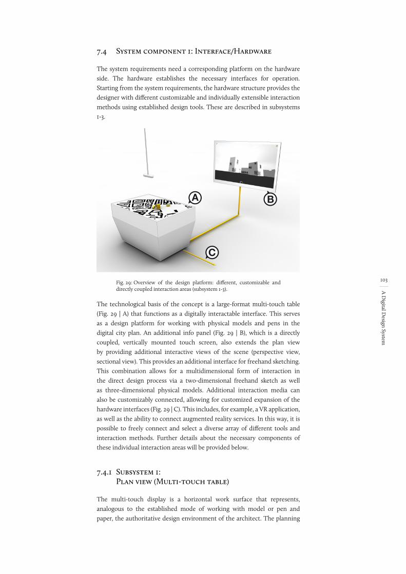
103
A D
igital Design System
7.4 System component 1: Interface/Hardware
The system requirements need a corresponding platform on the hardware side. The hardware establishes the necessary interfaces for operation. Starting from the system requirements, the hardware structure provides the designer with different customizable and individually extensible interaction methods using established design tools. These are described in subsystems 1-3.
Fig. 29:
A B
C
Overview of the design platform: different, customizable and directly coupled interaction areas (subsystem 1-3).
The technological basis of the concept is a large-format multi-touch table (Fig. 29 | A) that functions as a digitally interactable interface. This serves as a design platform for working with physical models and pens in the digital city plan. An additional info panel (Fig. 29 | B), which is a directly coupled, vertically mounted touch screen, also extends the plan view by providing additional interactive views of the scene (perspective view, sectional view). This provides an additional interface for freehand sketching. This combination allows for a multidimensional form of interaction in the direct design process via a two-dimensional freehand sketch as well as three-dimensional physical models. Additional interaction media can also be customizably connected, allowing for customized expansion of the hardware interfaces (Fig. 29 | C). This includes, for example, a VR application, as well as the ability to connect augmented reality services. In this way, it is possible to freely connect and select a diverse array of different tools and interaction methods. Further details about the necessary components of these individual interaction areas will be provided below.
7.4.1 Subsystem 1: Plan view (Multi-touch table)
The multi-touch display is a horizontal work surface that represents, analogous to the established mode of working with model or pen and paper, the authoritative design environment of the architect. The planning
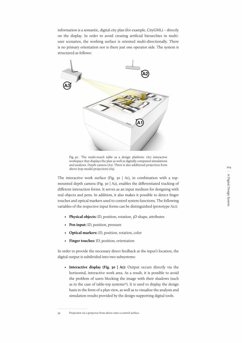
104
A D
igital Design System
information is a semantic, digital city plan (for example, CityGML) – directly on the display. In order to avoid creating artificial hierarchies in multi-user scenarios, the working surface is oriented multi-directionally. There is no primary orientation nor is there just one operator side. The system is structured as follows:
Fig. 30:
A1
A3
A2
The multi-touch table as a design platform: (A1) interactive workspace that displays the plan as well as digitally computed simulations and analyses. Depth camera (A2). There is also additional projection from above (top-model projection) (A3).
The interactive work surface (Fig. 30 | A1), in combination with a top-mounted depth camera (Fig. 30 | A2), enables the differentiated tracking of different interaction forms. It serves as an input medium for designing with real objects and pens. In addition, it also makes it possible to detect finger touches and optical markers used to control system functions. The following variables of the respective input forms can be distinguished (prototype A11):
• Physical objects: ID, position, rotation, 3D shape, attributes
• Pen input: ID, position, pressure
• Optical markers: ID, position, rotation, color
• Finger touches: ID, position, orientation
In order to provide the necessary direct feedback at the input’s location, the digital output is subdivided into two subsystems:
• Interactive display (Fig. 30 | A1): Output occurs directly via the horizontal, interactive work area. As a result, it is possible to avoid the problem of users blocking the image with their shadows (such as in the case of table-top systems39). It is used to display the design basis in the form of a plan view, as well as to visualize the analysis and simulation results provided by the design-supporting digital tools.
39 Projection via a projector from above onto a control surface.
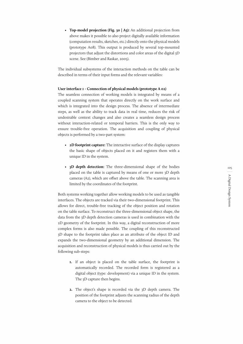
105
A D
igital Design System
• Top-model projection (Fig. 30 | A3): An additional projection from above makes it possible to also project digitally available information (computation results, sketches, etc.) directly onto the physical models (prototype A08). This output is produced by several top-mounted projectors that adjust the distortions and color areas of the digital 3D scene. See (Bimber and Raskar, 2005).
The individual subsystems of the interaction methods on the table can be described in terms of their input forms and the relevant variables:
User interface 1 - Connection of physical models (prototype A 02)The seamless connection of working models is integrated by means of a coupled scanning system that operates directly on the work surface and which is integrated into the design process. The absence of intermediate steps, as well as the ability to track data in real time, reduces the risk of undesirable context changes and also creates a seamless design process without interaction-related or temporal barriers. This is the only way to ensure trouble-free operation. The acquisition and coupling of physical objects is performed by a two-part system:
• 2D footprint capture: The interactive surface of the display captures the basic shape of objects placed on it and registers them with a unique ID in the system.
• 3D depth detection: The three-dimensional shape of the bodies placed on the table is captured by means of one or more 3D depth cameras (A2), which are offset above the table. The scanning area is limited by the coordinates of the footprint.
Both systems working together allow working models to be used as tangible interfaces. The objects are tracked via their two-dimensional footprint. This allows for direct, trouble-free tracking of the object position and rotation on the table surface. To reconstruct the three-dimensional object shape, the data from the 3D depth detection cameras is used in combination with the 2D geometry of the footprint. In this way, a digital reconstruction of more complex forms is also made possible. The coupling of this reconstructed 3D shape to the footprint takes place as an attribute of the object ID and expands the two-dimensional geometry by an additional dimension. The acquisition and reconstruction of physical models is thus carried out by the following sub-steps:
1. If an object is placed on the table surface, the footprint is automatically recorded. The recorded form is registered as a digital object (type: development) via a unique ID in the system. The 3D capture then begins.
2. The object’s shape is recorded via the 3D depth camera. The position of the footprint adjusts the scanning radius of the depth camera to the object to be detected.
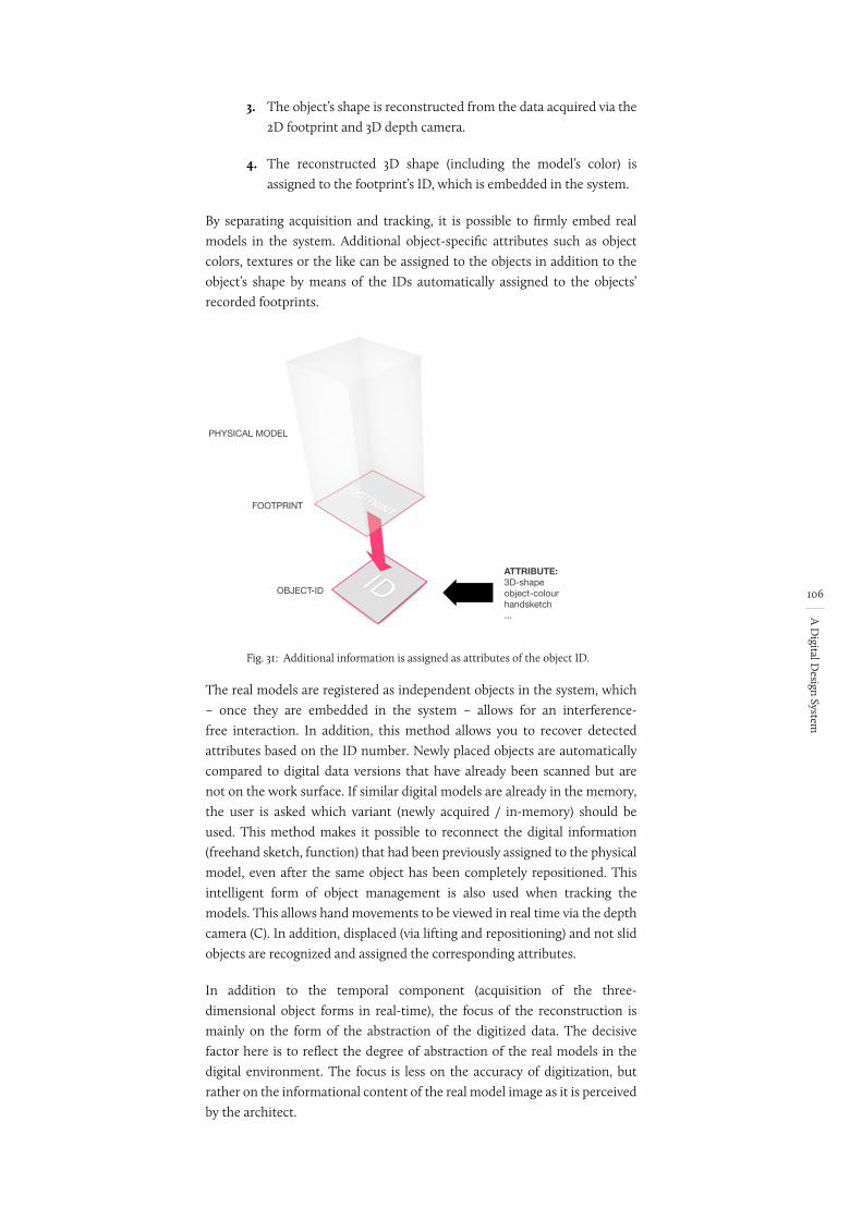
106
A D
igital Design System
3. The object’s shape is reconstructed from the data acquired via the 2D footprint and 3D depth camera.
4. The reconstructed 3D shape (including the model’s color) is assigned to the footprint’s ID, which is embedded in the system.
By separating acquisition and tracking, it is possible to firmly embed real models in the system. Additional object-specific attributes such as object colors, textures or the like can be assigned to the objects in addition to the object’s shape by means of the IDs automatically assigned to the objects’ recorded footprints.
Fig. 31:
FOOTPRINT
OBJECT-ID
PHYSICAL MODEL
ATTRIBUTE:3D-shapeobject-colourhandsketch...
Additional information is assigned as attributes of the object ID.
The real models are registered as independent objects in the system, which – once they are embedded in the system – allows for an interference-free interaction. In addition, this method allows you to recover detected attributes based on the ID number. Newly placed objects are automatically compared to digital data versions that have already been scanned but are not on the work surface. If similar digital models are already in the memory, the user is asked which variant (newly acquired / in-memory) should be used. This method makes it possible to reconnect the digital information (freehand sketch, function) that had been previously assigned to the physical model, even after the same object has been completely repositioned. This intelligent form of object management is also used when tracking the models. This allows hand movements to be viewed in real time via the depth camera (C). In addition, displaced (via lifting and repositioning) and not slid objects are recognized and assigned the corresponding attributes.
In addition to the temporal component (acquisition of the three-dimensional object forms in real-time), the focus of the reconstruction is mainly on the form of the abstraction of the digitized data. The decisive factor here is to reflect the degree of abstraction of the real models in the digital environment. The focus is less on the accuracy of digitization, but rather on the informational content of the real model image as it is perceived by the architect.
107
A D
igital Design System
User interface 2 – Freehand sketches (prototype A 03)The pencil is used to sketch directly onto the horizontal work surface and thus directly into the plan and at the location of the visual output. The sketching function is activated automatically when the pen is positioned. The character of the sketches (lines and inaccuracies) is preserved as is, in order to emphasise emergence and imprecision. The sketch is not interpreted and converted into geometric basic forms. Analogous to sketching on tracing paper, several drawing layers can be added, overlaid, and removed via gestures. The visibility of the individual sketching planes as well as their transparency can also be set individually. Various real pens (each pen has a dedicated ID) allow the digital formulation to be differentiated. Because the haptics at the tip of the pen can be adjusted and different degrees of pressure can be recognized, it is almost possible to reproduce the feeling of sketching with different tools. This allows to the architect to make a sketch as if it were with a hard pencil, a fiber pen or a marker.
User interface 3 - Markers (prototypes A 04/05)Using optical marker tracking, it is possible to couple fixed, recurring operating functions and predefined digital object forms to the system by means of a placeholder. Markers placed on the table are automatically recognized and their ID, position, orientation and color are registered. This allows previously defined marker-dependent functions to be operated intuitively and in a targeted manner via tangible interfaces. Examples include controlling the perspective camera (position and viewing direction), but also positioning a flow source (wind, water) as an analysis parameter. A combination of marker and object tracking is necessary to break up any rigid connection of the marker to a fixed digital form. Any footprint of an object located on the marker is assigned to the marker and thus is not interpreted as a building or other structure, but is applied as a special digital function. An example of this is the size (punctually) or shape (linear) of a noise source as an analysis parameter.
User interface 4 - Finger touch (prototype A 13)Finger-touch recognition is used to control the graphical user interface. Finger tracking supports the ID, position, and orientation of different fingers. In this way, the GUI (e.g., menu and card navigation) is operated intuitively with the hands and fingers. Meanwhile, established operating gestures such as ‘drag and drop’, ‘pinch’, ‘zoom’, etc. extend the functional possibilities. In accordance with the multidirectional orientation of the work surface, the graphical menu is in the shape of a pie menu40. This shape allows it to be oriented anywhere on the work surface. The menu orientation is always based on the orientation parameter of the touch gesture. In this way, the menu is always in reach and it is directly aligned with the user.
40 A pie menu is a round arrangement of menu points around a reference point.
Operator vs. Opersating
DE: Bedienschnittstelle
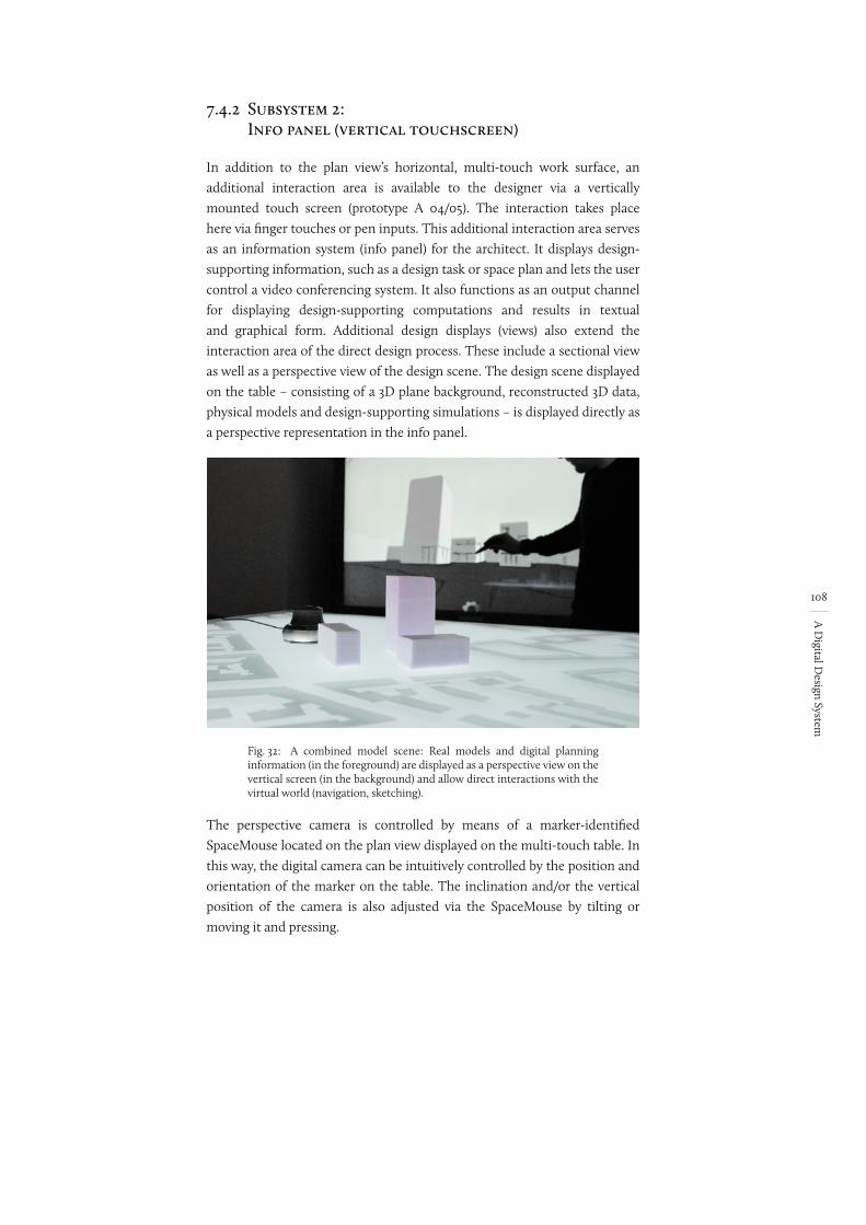
108
A D
igital Design System
7.4.2 Subsystem 2: Info panel (vertical touchscreen)
In addition to the plan view’s horizontal, multi-touch work surface, an additional interaction area is available to the designer via a vertically mounted touch screen (prototype A 04/05). The interaction takes place here via finger touches or pen inputs. This additional interaction area serves as an information system (info panel) for the architect. It displays design-supporting information, such as a design task or space plan and lets the user control a video conferencing system. It also functions as an output channel for displaying design-supporting computations and results in textual and graphical form. Additional design displays (views) also extend the interaction area of the direct design process. These include a sectional view as well as a perspective view of the design scene. The design scene displayed on the table – consisting of a 3D plane background, reconstructed 3D data, physical models and design-supporting simulations – is displayed directly as a perspective representation in the info panel.
Fig. 32: A combined model scene: Real models and digital planning information (in the foreground) are displayed as a perspective view on the vertical screen (in the background) and allow direct interactions with the virtual world (navigation, sketching).
The perspective camera is controlled by means of a marker-identified SpaceMouse located on the plan view displayed on the multi-touch table. In this way, the digital camera can be intuitively controlled by the position and orientation of the marker on the table. The inclination and/or the vertical position of the camera is also adjusted via the SpaceMouse by tilting or moving it and pressing.
planning information
checken ob richtiger begriff. Kommt oft vor
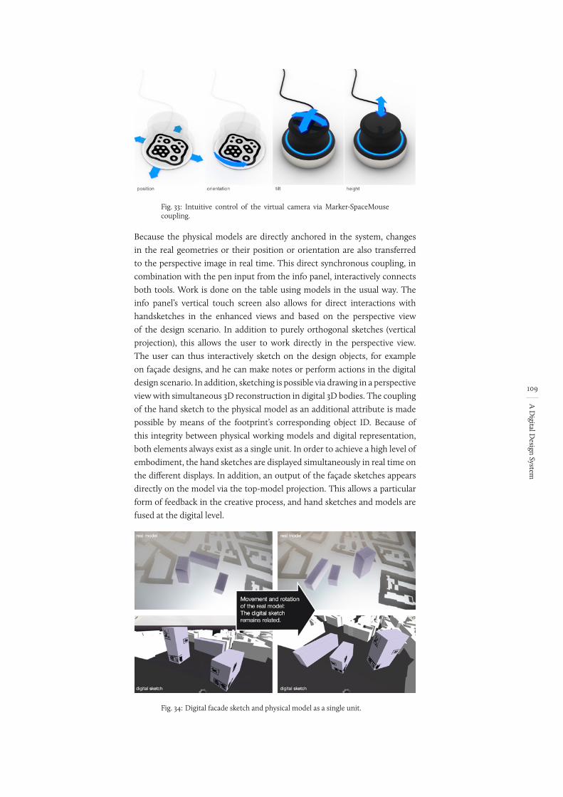
109
A D
igital Design System
Fig. 33: Intuitive control of the virtual camera via Marker-SpaceMouse coupling.
Because the physical models are directly anchored in the system, changes in the real geometries or their position or orientation are also transferred to the perspective image in real time. This direct synchronous coupling, in combination with the pen input from the info panel, interactively connects both tools. Work is done on the table using models in the usual way. The info panel’s vertical touch screen also allows for direct interactions with handsketches in the enhanced views and based on the perspective view of the design scenario. In addition to purely orthogonal sketches (vertical projection), this allows the user to work directly in the perspective view. The user can thus interactively sketch on the design objects, for example on façade designs, and he can make notes or perform actions in the digital design scenario. In addition, sketching is possible via drawing in a perspective view with simultaneous 3D reconstruction in digital 3D bodies. The coupling of the hand sketch to the physical model as an additional attribute is made possible by means of the footprint’s corresponding object ID. Because of this integrity between physical working models and digital representation, both elements always exist as a single unit. In order to achieve a high level of embodiment, the hand sketches are displayed simultaneously in real time on the different displays. In addition, an output of the façade sketches appears directly on the model via the top-model projection. This allows a particular form of feedback in the creative process, and hand sketches and models are fused at the digital level.
Fig. 34: Digital facade sketch and physical model as a single unit.
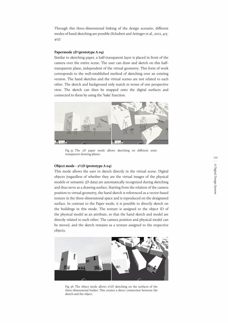
110
A D
igital Design System
Through this three-dimensional linking of the design scenario, different modes of hand sketching are possible (Schubert and Artinger et al., 2012, 413-415):
Papermode 2D (prototype A 04)Similar to sketching paper, a half-transparent layer is placed in front of the camera over the entire scene. The user can draw and sketch on this half-transparent plane, independent of the virtual geometry. This form of work corresponds to the well-established method of sketching over an existing version. The hand sketches and the virtual scenes are not related to each other. The sketch and background only match in terms of one perspective view. The sketch can then be mapped onto the digital surfaces and connected to them by using the ‘bake’ function.
Fig. 35: The 2D paper mode allows sketching on different semi-transparent drawing planes.
Object mode - 2½D (prototype A 04)This mode allows the user to sketch directly in the virtual scene. Digital objects (regardless of whether they are the virtual images of the physical models or semantic 3D data) are automatically recognized during sketching and thus serve as a drawing surface. Starting from the relation of the camera position to virtual geometry, the hand sketch is referenced as a vector-based texture in the three-dimensional space and is reproduced on the designated surface. In contrast to the Paper mode, it is possible to directly sketch on the buildings in this mode. The texture is assigned to the object ID of the physical model as an attribute, so that the hand sketch and model are directly related to each other. The camera position and physical model can be moved, and the sketch remains as a texture assigned to the respective objects.
Fig. 36: The object mode allows 2½D sketching on the surfaces of the three-dimensional bodies. This creates a direct connection between the sketch and the object.
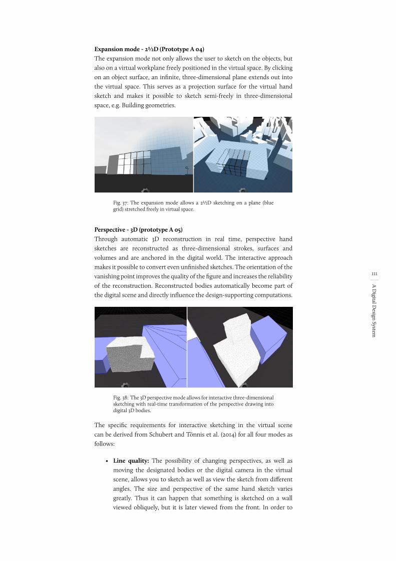
111
A D
igital Design System
Expansion mode - 2½D (Prototype A 04)The expansion mode not only allows the user to sketch on the objects, but also on a virtual workplane freely positioned in the virtual space. By clicking on an object surface, an infinite, three-dimensional plane extends out into the virtual space. This serves as a projection surface for the virtual hand sketch and makes it possible to sketch semi-freely in three-dimensional space, e.g. Building geometries.
Fig. 37: The expansion mode allows a 2½D sketching on a plane (blue grid) stretched freely in virtual space.
Perspective - 3D (prototype A 05)Through automatic 3D reconstruction in real time, perspective hand sketches are reconstructed as three-dimensional strokes, surfaces and volumes and are anchored in the digital world. The interactive approach makes it possible to convert even unfinished sketches. The orientation of the vanishing point improves the quality of the figure and increases the reliability of the reconstruction. Reconstructed bodies automatically become part of the digital scene and directly influence the design-supporting computations.
Fig. 38: The 3D perspective mode allows for interactive three-dimensional sketching with real-time transformation of the perspective drawing into digital 3D bodies.
The specific requirements for interactive sketching in the virtual scene can be derived from Schubert and Tönnis et al. (2014) for all four modes as follows:
• Line quality: The possibility of changing perspectives, as well as moving the designated bodies or the digital camera in the virtual scene, allows you to sketch as well as view the sketch from different angles. The size and perspective of the same hand sketch varies greatly. Thus it can happen that something is sketched on a wall viewed obliquely, but it is later viewed from the front. In order to
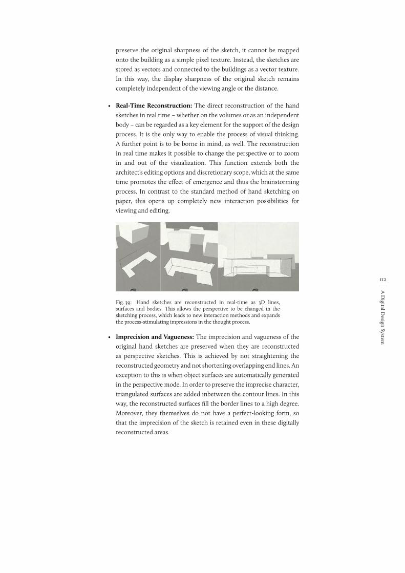
112
A D
igital Design System
preserve the original sharpness of the sketch, it cannot be mapped onto the building as a simple pixel texture. Instead, the sketches are stored as vectors and connected to the buildings as a vector texture. In this way, the display sharpness of the original sketch remains completely independent of the viewing angle or the distance.
• Real-Time Reconstruction: The direct reconstruction of the hand sketches in real time – whether on the volumes or as an independent body – can be regarded as a key element for the support of the design process. It is the only way to enable the process of visual thinking. A further point is to be borne in mind, as well. The reconstruction in real time makes it possible to change the perspective or to zoom in and out of the visualization. This function extends both the architect’s editing options and discretionary scope, which at the same time promotes the effect of emergence and thus the brainstorming process. In contrast to the standard method of hand sketching on paper, this opens up completely new interaction possibilities for viewing and editing.
Fig. 39: Hand sketches are reconstructed in real-time as 3D lines, surfaces and bodies. This allows the perspective to be changed in the sketching process, which leads to new interaction methods and expands the process-stimulating impressions in the thought process.
• Imprecision and Vagueness: The imprecision and vagueness of the original hand sketches are preserved when they are reconstructed as perspective sketches. This is achieved by not straightening the reconstructed geometry and not shortening overlapping end lines. An exception to this is when object surfaces are automatically generated in the perspective mode. In order to preserve the imprecise character, triangulated surfaces are added inbetween the contour lines. In this way, the reconstructed surfaces fill the border lines to a high degree. Moreover, they themselves do not have a perfect-looking form, so that the imprecision of the sketch is retained even in these digitally reconstructed areas.
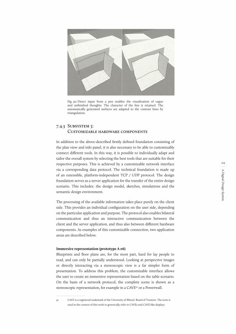
113
A D
igital Design System
Fig. 40: Direct input from a pen enables the visualization of vague and unfinished thoughts. The character of the line is retained. The automatically generated surfaces are adapted to the contour lines by triangulation.
7.4.3 Subsystem 3: Customizable hardware components
In addition to the above-described firmly defined foundation consisting of the plan view and info panel, it is also necessary to be able to customizably connect different tools. In this way, it is possible to individually adapt and tailor the overall system by selecting the best tools that are suitable for their respective purposes. This is achieved by a customizable network interface via a corresponding data protocol. The technical foundation is made up of an extensible, platform-independent TCP / UDP protocol. The design foundation serves as a server application for the transfer of the entire design scenario. This includes: the design model, sketches, simulations and the semantic design environment.
The processing of the available information takes place purely on the client side. This provides an individual configuration on the user side, depending on the particular application and purpose. The protocol also enables bilateral communication and thus an interactive communication between the client and the server application, and thus also between different hardware components. As examples of this customizable connection, two application areas are described below.
Immersive representation (prototype A 06)Blueprints and floor plans are, for the most part, hard for lay people to read, and can only be partially understood. Looking at perspective images or directly interacting via a stereoscopic view is a far simpler form of presentation. To address this problem, the customizable interface allows the user to create an immersive representation based on the table scenario. On the basis of a network protocol, the complete scene is shown as a stereoscopic representation, for example in a CAVE41 or a Powerwall.
41 CAVE is a registered trademark of the University of Illinois’ Board of Trustees. The term is
used in the context of this work to generically refer to CAVEs and CAVE-like displays.
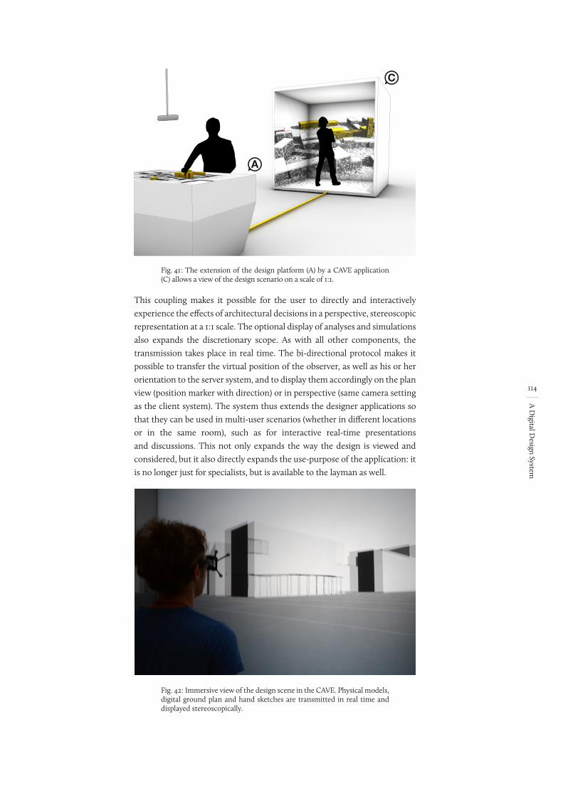
114
A D
igital Design System
Fig. 41:
A
C
The extension of the design platform (A) by a CAVE application (C) allows a view of the design scenario on a scale of 1:1.
This coupling makes it possible for the user to directly and interactively experience the effects of architectural decisions in a perspective, stereoscopic representation at a 1:1 scale. The optional display of analyses and simulations also expands the discretionary scope. As with all other components, the transmission takes place in real time. The bi-directional protocol makes it possible to transfer the virtual position of the observer, as well as his or her orientation to the server system, and to display them accordingly on the plan view (position marker with direction) or in perspective (same camera setting as the client system). The system thus extends the designer applications so that they can be used in multi-user scenarios (whether in different locations or in the same room), such as for interactive real-time presentations and discussions. This not only expands the way the design is viewed and considered, but it also directly expands the use-purpose of the application: it is no longer just for specialists, but is available to the layman as well.
Fig. 42: Immersive view of the design scene in the CAVE. Physical models, digital ground plan and hand sketches are transmitted in real time and displayed stereoscopically.
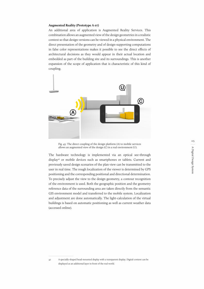
115
A D
igital Design System
Augmented Reality (Prototype A 07)An additional area of application is Augmented Reality Services. This combination allows an augmented view of the design geometries in a realistic context so that design versions can be viewed in a physical environment. The direct presentation of the geometry and of design-supporting computations in false color representations makes it possible to see the direct effects of architectural decisions as they would appear in their actual location and embedded as part of the building site and its surroundings. This is another expansion of the scope of application that is characteristic of this kind of coupling.
Fig. 43:
C
A
U
The direct coupling of the design platform (A) to mobile services allows an augmented view of the design (C) in a real environment (U).
The hardware technology is implemented via an optical see-through display42 or mobile devices such as smartphones or tablets. Current and previously saved design scenarios of the plan view can be transmitted to the user in real time. The rough localization of the viewer is determined by GPS positioning and the corresponding positional and directional determination. To precisely adjust the view to the design geometry, a contour recognition of the environment is used. Both the geographic position and the geometry reference data of the surrounding area are taken directly from the semantic GIS environment model and transferred to the mobile system. Localization and adjustment are done automatically. The light-calculation of the virtual buildings is based on automatic positioning as well as current weather data (accessed online).
42 A specially-shaped head-mounted display with a transparent display. Digital content can be
displayed as an additional layer in front of the real world.
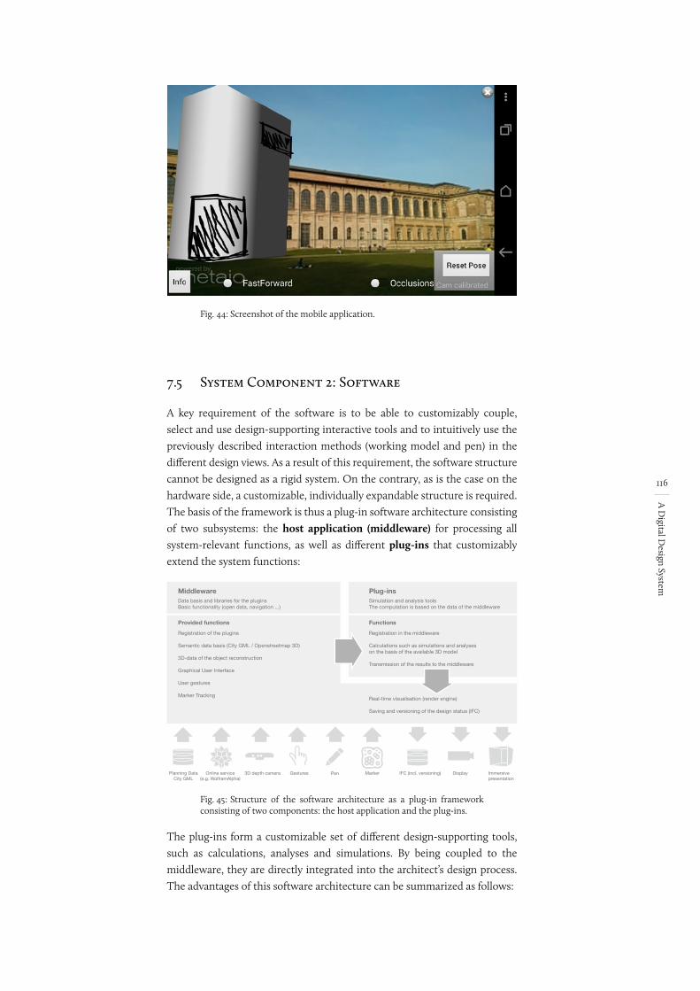
116
A D
igital Design System
Fig. 44: Screenshot of the mobile application.
7.5 System Component 2: Software
A key requirement of the software is to be able to customizably couple, select and use design-supporting interactive tools and to intuitively use the previously described interaction methods (working model and pen) in the different design views. As a result of this requirement, the software structure cannot be designed as a rigid system. On the contrary, as is the case on the hardware side, a customizable, individually expandable structure is required. The basis of the framework is thus a plug-in software architecture consisting of two subsystems: the host application (middleware) for processing all system-relevant functions, as well as different plug-ins that customizably extend the system functions:
Fig. 45:
Planning DataCity GML
3D depth cameraOnline service(e.g. WolframAlpha)
Gestures Marker IFC (incl. versioning) Display
Middleware
Registration of the plugins
Semantic data basis (City GML / Openstreetmap 3D)
3D-data of the object reconstruction
Graphical User Interface
User gestures
Marker TrackingReal-time visualisation (render engine)
Saving and versioning of the design status (IFC)
Registration in the middleware
Calculations such as simulations and analyses on the basis of the available 3D model
Transmission of the results to the middleware
Plug-ins
Immersivepresentation
Data basis and libraries for the pluginsBasic functionality (open data, navigation ...)
Simulation and analysis toolsThe computation is based on the data of the middleware
Provided functions Functions
Pen
Structure of the software architecture as a plug-in framework consisting of two components: the host application and the plug-ins.
The plug-ins form a customizable set of different design-supporting tools, such as calculations, analyses and simulations. By being coupled to the middleware, they are directly integrated into the architect’s design process. The advantages of this software architecture can be summarized as follows:
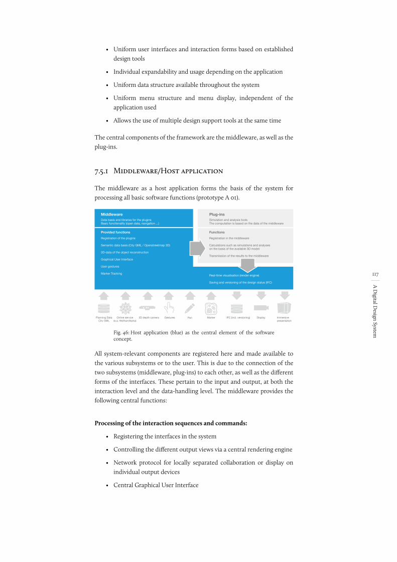
117
A D
igital Design System
• Uniform user interfaces and interaction forms based on established design tools
• Individual expandability and usage depending on the application
• Uniform data structure available throughout the system
• Uniform menu structure and menu display, independent of the application used
• Allows the use of multiple design support tools at the same time
The central components of the framework are the middleware, as well as the plug-ins.
7.5.1 Middleware/Host application
The middleware as a host application forms the basis of the system for processing all basic software functions (prototype A 01).
Fig. 46:
Planning DataCity GML
3D depth cameraOnline service(e.g. WolframAlpha)
Gestures Marker IFC (incl. versioning) Display
Middleware
Registration of the plugins
Semantic data basis (City GML / Openstreetmap 3D)
3D-data of the object reconstruction
Graphical User Interface
User gestures
Marker TrackingReal-time visualisation (render engine)
Saving and versioning of the design status (IFC)
Registration in the middleware
Calculations such as simulations and analyses on the basis of the available 3D model
Transmission of the results to the middleware
Plug-ins
Immersivepresentation
Data basis and libraries for the pluginsBasic functionality (open data, navigation ...)
Simulation and analysis toolsThe computation is based on the data of the middleware
Provided functions Functions
Pen
Host application (blue) as the central element of the software concept.
All system-relevant components are registered here and made available to the various subsystems or to the user. This is due to the connection of the two subsystems (middleware, plug-ins) to each other, as well as the different forms of the interfaces. These pertain to the input and output, at both the interaction level and the data-handling level. The middleware provides the following central functions:
Processing of the interaction sequences and commands:
• Registering the interfaces in the system
• Controlling the different output views via a central rendering engine
• Network protocol for locally separated collaboration or display on individual output devices
• Central Graphical User Interface
Bild Übersetzen
erledigt
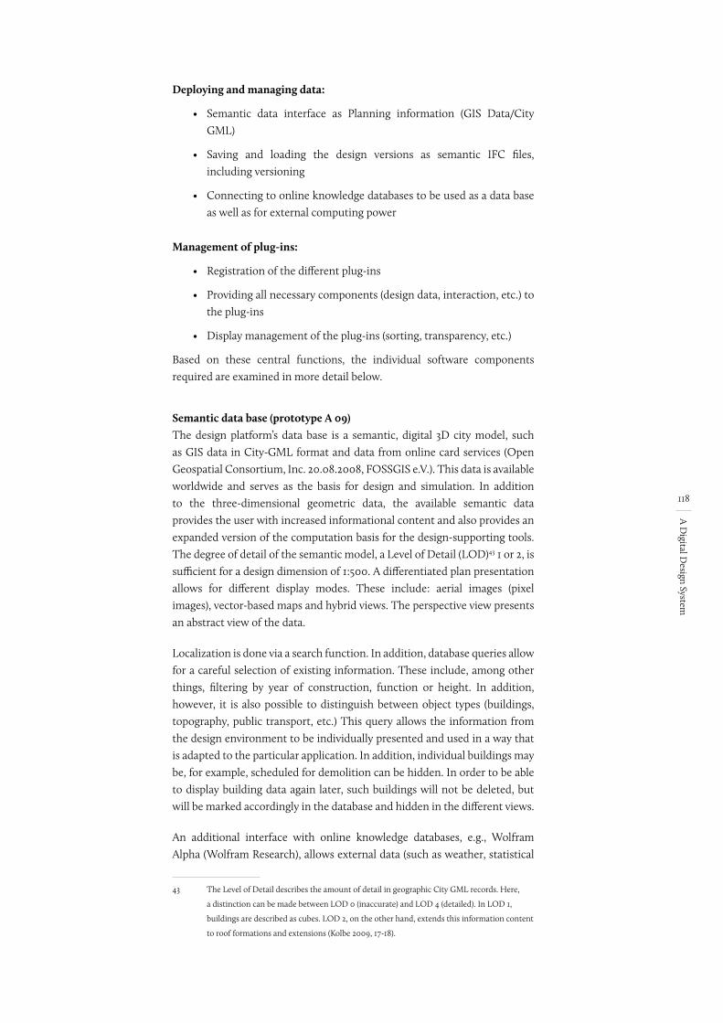
118
A D
igital Design System
Deploying and managing data:
• Semantic data interface as Planning information (GIS Data/City GML)
• Saving and loading the design versions as semantic IFC files, including versioning
• Connecting to online knowledge databases to be used as a data base as well as for external computing power
Management of plug-ins:
• Registration of the different plug-ins
• Providing all necessary components (design data, interaction, etc.) to the plug-ins
• Display management of the plug-ins (sorting, transparency, etc.)
Based on these central functions, the individual software components required are examined in more detail below.
Semantic data base (prototype A 09)The design platform’s data base is a semantic, digital 3D city model, such as GIS data in City-GML format and data from online card services (Open Geospatial Consortium, Inc. 20.08.2008, FOSSGIS e.V.). This data is available worldwide and serves as the basis for design and simulation. In addition to the three-dimensional geometric data, the available semantic data provides the user with increased informational content and also provides an expanded version of the computation basis for the design-supporting tools. The degree of detail of the semantic model, a Level of Detail (LOD)43 1 or 2, is sufficient for a design dimension of 1:500. A differentiated plan presentation allows for different display modes. These include: aerial images (pixel images), vector-based maps and hybrid views. The perspective view presents an abstract view of the data.
Localization is done via a search function. In addition, database queries allow for a careful selection of existing information. These include, among other things, filtering by year of construction, function or height. In addition, however, it is also possible to distinguish between object types (buildings, topography, public transport, etc.) This query allows the information from the design environment to be individually presented and used in a way that is adapted to the particular application. In addition, individual buildings may be, for example, scheduled for demolition can be hidden. In order to be able to display building data again later, such buildings will not be deleted, but will be marked accordingly in the database and hidden in the different views.
An additional interface with online knowledge databases, e.g., Wolfram Alpha (Wolfram Research), allows external data (such as weather, statistical
43 The Level of Detail describes the amount of detail in geographic City GML records. Here,
a distinction can be made between LOD 0 (inaccurate) and LOD 4 (detailed). In LOD 1,
buildings are described as cubes. LOD 2, on the other hand, extends this information content
to roof formations and extensions (Kolbe 2009, 17-18).
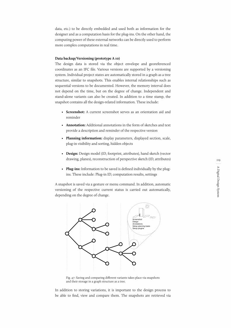
119
A D
igital Design System
data, etc.) to be directly embedded and used both as information for the designer and as a computation basis for the plug-ins. On the other hand, the computing power of these external networks can be directly used to perform more complex computations in real time.
Data backup/Versioning (prototype A 10)The design data is stored via the object envelope and georeferenced coordinates as an IFC file. Various versions are supported by a versioning system. Individual project states are automatically stored in a graph as a tree structure, similar to snapshots. This enables internal relationships such as sequential versions to be documented. However, the memory interval does not depend on the time, but on the degree of change. Independent and stand-alone variants can also be created. In addition to a time stamp, the snapshot contains all the design-related information. These include:
• Screenshot: A current screenshot serves as an orientation aid and reminder
• Annotation: Additional annotations in the form of sketches and text provide a description and reminder of the respective version
• Planning information: display parameters, displayed section, scale, plug-in visibility and sorting, hidden objects
• Design: Design model (ID, footprint, attributes), hand sketch (vector drawing, planes), reconstruction of perspective sketch (ID, attributes)
• Plug-ins: Information to be saved is defined individually by the plug-ins. These include: Plug-in ID, computation results, settings
A snapshot is saved via a gesture or menu command. In addition, automatic versioning of the respective current status is carried out automatically, depending on the degree of change.
Fig. 47:
ScreenshotDesignAnnotationsSetup planning basisSetup plugins
Saving and comparing different variants takes place via snapshots and their storage in a graph structure as a tree.
In addition to storing variations, it is important to the design process to be able to find, view and compare them. The snapshots are retrieved via
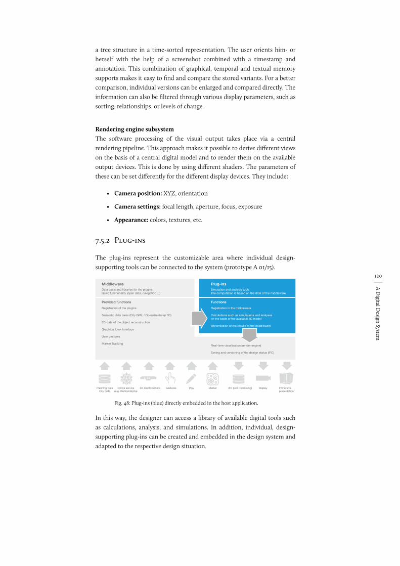
120
A D
igital Design System
a tree structure in a time-sorted representation. The user orients him- or herself with the help of a screenshot combined with a timestamp and annotation. This combination of graphical, temporal and textual memory supports makes it easy to find and compare the stored variants. For a better comparison, individual versions can be enlarged and compared directly. The information can also be filtered through various display parameters, such as sorting, relationships, or levels of change.
Rendering engine subsystemThe software processing of the visual output takes place via a central rendering pipeline. This approach makes it possible to derive different views on the basis of a central digital model and to render them on the available output devices. This is done by using different shaders. The parameters of these can be set differently for the different display devices. They include:
• Camera position: XYZ, orientation
• Camera settings: focal length, aperture, focus, exposure
• Appearance: colors, textures, etc.
7.5.2 Plug-ins
The plug-ins represent the customizable area where individual design-supporting tools can be connected to the system (prototype A 01/15).
Fig. 48:
Planning DataCity GML
3D depth cameraOnline service(e.g. WolframAlpha)
Gestures Marker IFC (incl. versioning) Display
Middleware
Registration of the plugins
Semantic data basis (City GML / Openstreetmap 3D)
3D-data of the object reconstruction
Graphical User Interface
User gestures
Marker TrackingReal-time visualisation (render engine)
Saving and versioning of the design status (IFC)
Registration in the middleware
Calculations such as simulations and analyses on the basis of the available 3D model
Transmission of the results to the middleware
Plug-ins
Immersivepresentation
Data basis and libraries for the pluginsBasic functionality (open data, navigation ...)
Simulation and analysis toolsThe computation is based on the data of the middleware
Provided functions Functions
Pen
Plug-ins (blue) directly embedded in the host application.
In this way, the designer can access a library of available digital tools such as calculations, analysis, and simulations. In addition, individual, design-supporting plug-ins can be created and embedded in the design system and adapted to the respective design situation.
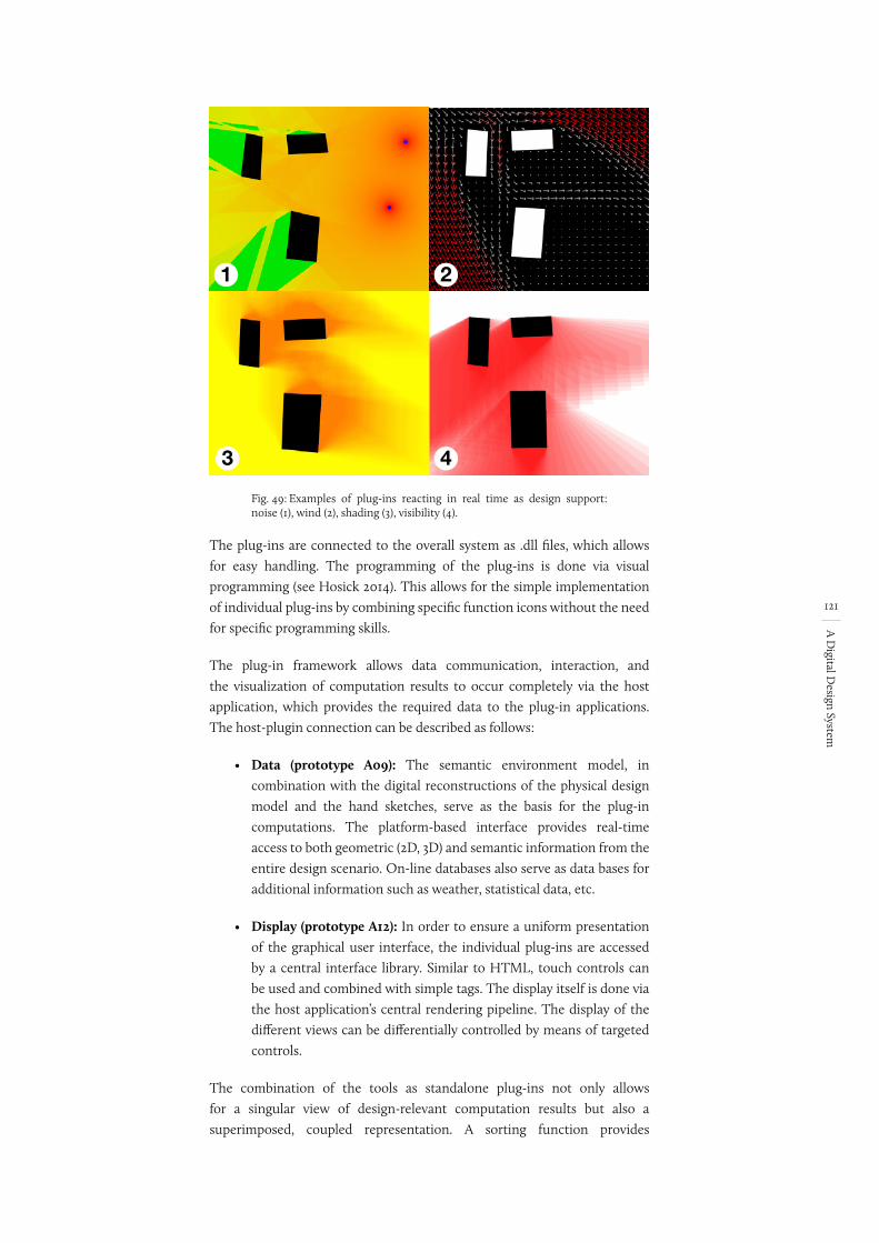
121
A D
igital Design System
Fig. 49: Examples of plug-ins reacting in real time as design support: noise (1), wind (2), shading (3), visibility (4).
The plug-ins are connected to the overall system as .dll files, which allows for easy handling. The programming of the plug-ins is done via visual programming (see Hosick 2014). This allows for the simple implementation of individual plug-ins by combining specific function icons without the need for specific programming skills.
The plug-in framework allows data communication, interaction, and the visualization of computation results to occur completely via the host application, which provides the required data to the plug-in applications. The host-plugin connection can be described as follows:
• Data (prototype A09): The semantic environment model, in combination with the digital reconstructions of the physical design model and the hand sketches, serve as the basis for the plug-in computations. The platform-based interface provides real-time access to both geometric (2D, 3D) and semantic information from the entire design scenario. On-line databases also serve as data bases for additional information such as weather, statistical data, etc.
• Display (prototype A12): In order to ensure a uniform presentation of the graphical user interface, the individual plug-ins are accessed by a central interface library. Similar to HTML, touch controls can be used and combined with simple tags. The display itself is done via the host application’s central rendering pipeline. The display of the different views can be differentially controlled by means of targeted controls.
The combination of the tools as standalone plug-ins not only allows for a singular view of design-relevant computation results but also a superimposed, coupled representation. A sorting function provides
1 2
43
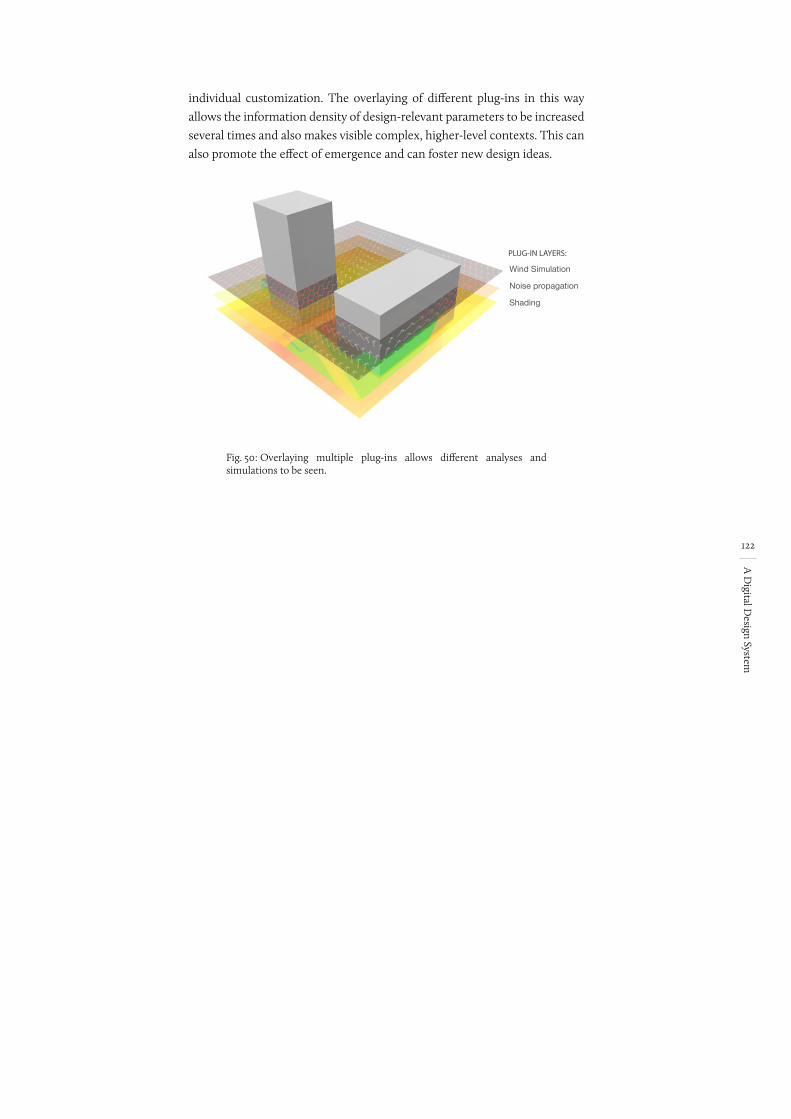
122
A D
igital Design System
individual customization. The overlaying of different plug-ins in this way allows the information density of design-relevant parameters to be increased several times and also makes visible complex, higher-level contexts. This can also promote the effect of emergence and can foster new design ideas.
Fig. 50:
Wind Simulation
Noise propagation
Shading
PLUG-IN LAYERS:
Overlaying multiple plug-ins allows different analyses and simulations to be seen.
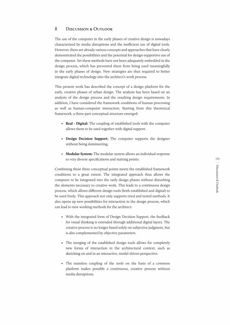
123
Discussion &
Outlook
8 Discussion & Outlook
The use of the computer in the early phases of creative design is nowadays characterized by media disruptions and the inefficient use of digital tools. However, there are already various concepts and approaches that have clearly demonstrated the possibilities and the potential for design-supportive use of the computer. Yet these methods have not been adequately embedded in the design process, which has prevented them from being used meaningfully in the early phases of design. New strategies are thus required to better integrate digital technology into the architect’s work process.
This present work has described the concept of a design platform for the early, creative phases of urban design. The analysis has been based on an analysis of the design process and the resulting design requirements. In addition, I have considered the framework conditions of human processing as well as human-computer interaction. Starting from this theoretical framework, a three-part conceptual structure emerged:
• Real - Digital: The coupling of established tools with the computer allows them to be used together with digital support.
• Design Decision Support: The computer supports the designer without being domineering.
• Modular System: The modular system allows an individual response to very diverse specifications and starting points.
Combining these three conceptual points meets the established framework conditions to a great extent. The integrated approach thus allows the computer to be integrated into the early design phases without disturbing the elements necessary to creative work. This leads to a continuous design process, which allows different design tools (both established and digital) to be used freely. This approach not only supports tried and tested methods. It also opens up new possibilities for interaction in the design process, which can lead to new working methods for the architect:
• With the integrated form of Design Decision Support, the feedback for visual thinking is extended through additional digital layers. The creative process is no longer based solely on subjective judgment, but is also complemented by objective parameters.
• The merging of the established design tools allows for completely new forms of interaction in the architectural context, such as sketching on and in an interactive, model-driven perspective.
• The seamless coupling of the tools on the basis of a common platform makes possible a continuous, creative process without media disruptions.
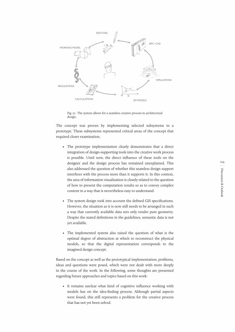
124
Discussion &
Outlook
Fig. 51:
WORKING MODEL
SKETCHES
BIM / CAD
SIMULATIONS
3D-MODELSCALCULATIONS
REGULATIONS
The system allows for a seamless creative process in architectural design.
The concept was proven by implementing selected subsystems in a prototype. These subsystems represented critical areas of the concept that required closer examination.
• The prototype implementation clearly demonstrates that a direct integration of design-supporting tools into the creative work process is possible. Until now, the direct influence of these tools on the designer and the design process has remained unexplained. This also addressed the question of whether this seamless design support interferes with the process more than it supports it. In this context, the area of information visualization is closely related to the question of how to present the computation results so as to convey complex content in a way that is nevertheless easy to understand.
• The system design took into account the defined GIS specifications. However, the situation as it is now still needs to be arranged in such a way that currently available data sets only render pure geometry. Despite the stated definitions in the guidelines, semantic data is not yet available.
• The implemented system also raised the question of what is the optimal degree of abstraction at which to reconstruct the physical models, so that the digital representation corresponds to the imagined design concept.
Based on the concept as well as the prototypical implementation, problems, ideas and questions were posed, which were not dealt with more deeply in the course of the work. In the following, some thoughts are presented regarding future approaches and topics based on this work:
• It remains unclear what kind of cognitive influence working with models has on the idea-finding process. Although partial aspects were found, this still represents a problem for the creative process that has not yet been solved.
Skizze tauschen EN
125
Discussion &
Outlook
• Current commercial touch-based hardware systems are designed exclusively as planar surfaces. For this reason, topographical information can only be conveyed visually. Current research approaches have already revealed solutions in this area (Follmer et al. 2013). However, they remain difficult to use due the too low resolution as well as the complex technical implementation that is required.
• The prototypes have also shown that representing the surrounding buildings and environment as a purely two-dimensional view, in combination with the physical working models, is not sufficient to achieve a spatial impression of the physical model. Here, techniques must be found (VR, physical 3D display, 3D printer) that will make the entire model scenario three-dimensionally tangible and physically accessible to the architect.
• A current research project at the Department of Architectural Informatics (Prof. Dr.-Ing. Frank Petzold), led by Christoph Langenhan and funded by the DFG, deals with the topic of reference searching using the spatial configuration (Langenhan et al. 2013). A direct interface of both projects (e.g., IFC data exchange) has made it possible to incorporate a reference search directly into the creative design process. There are two conceivable areas of application:
• Urban design: A similarity search in relation to the urban layout of several buildings. This applies to buildings, open spaces, access routes, etc.
• Spatial design: Searching for reference objects based on the object envelope, orientation and development. Such a connection would allow interior plans to be incorporated more strongly into the urban design process.
• Another focus is on a practical application scenario. In the future, therefore, different application scenarios will be investigated, which will prove that the system has uses outside of the research field, i.e. in practice.
• A number of design-supporting plug-ins have already been implemented. The focus here is on expanding this database, especially through interdisciplinary exchange with, for example, civil engineering. Sustainability is another focus.
126
Appendix
Appendix
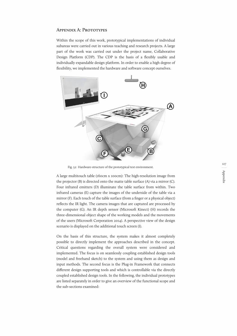
127
Appendix
Appendix A: Prototypes
Within the scope of this work, prototypical implementations of individual subareas were carried out in various teaching and research projects. A large part of the work was carried out under the project name, Collaborative Design Platform (CDP). The CDP is the basis of a flexibly usable and individually expandable design platform. In order to enable a high degree of flexibility, we implemented the hardware and software concept ourselves.
Fig. 52:
G
I
H
EF B
C
A
Hardware-structure of the prototypical test environment.
A large multitouch table (160cm x 100cm): The high-resolution image from the projector (B) is directed onto the matte table surface (A) via a mirror (C). Four infrared emitters (D) illuminate the table surface from within. Two infrared cameras (E) capture the images of the underside of the table via a mirror (F). Each touch of the table surface (from a finger or a physical object) reflects the IR light. The camera images that are captured are processed by the computer (G). An IR depth sensor (Microsoft Kinect) (H) records the three-dimensional object shape of the working models and the movements of the users (Microsoft Corporation 2014). A perspective view of the design scenario is displayed on the additional touch screen (I).
On the basis of this structure, the system makes it almost completely possible to directly implement the approaches described in the concept. Critical questions regarding the overall system were considered and implemented. The focus is on seamlessly coupling established design tools (model and freehand sketch) to the system and using them as design and input methods. The second focus is the Plug-in Framework that connects different design supporting tools and which is controllable via the directly coupled established design tools. In the following, the individual prototypes are listed separately in order to give an overview of the functional scope and the sub-sections examined:
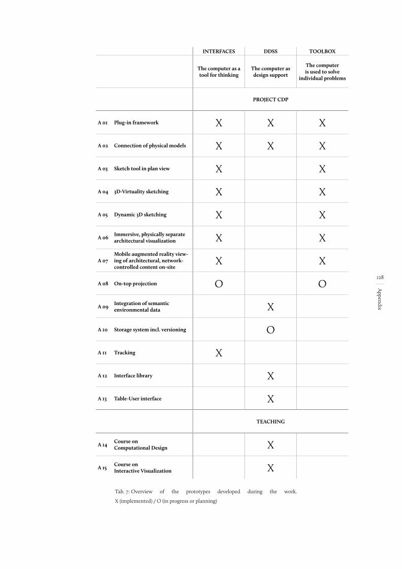
128
Appendix
INTERFACES DDSS TOOLBOX
The computer as a tool for thinking
The computer as design support
The computer is used to solve
individual problems
PROJECT CDP
A 01 Plug-in framework X X X
A 02 Connection of physical models X X X
A 03 Sketch tool in plan view X X
A 04 3D-Virtuality sketching X X
A 05 Dynamic 3D sketching X X
A 06 Immersive, physically separate architectural visualization X X
A 07Mobile augmented reality view-ing of architectural, network-controlled content on-site
X X
A 08 On-top projection O O
A 09 Integration of semantic environmental data X
A 10 Storage system incl. versioning O
A 11 Tracking X
A 12 Interface library X
A 13 Table-User interface X
TEACHING
A 14 Course on Computational Design X
A 15 Course on Interactive Visualization X
Tab. 7: Overview of the prototypes developed during the work.
X (implemented) / O (in progress or planning)
129
Appendix
A 01 Plug-in Framework
Research/IDP: as of Winter semester 2010/2011
Student: Violin Yanev (Yanev 2011); Benedikt Brück; Tobias Weigl (Weigl 2012)
Supervision: Dipl. Ing. Gerhard Schubert; Prof. Dr.-Ing. Frank Petzold
Publication: Tangible tools for architectural design: seamless integration into the architectural workflow (Schubert et al. 2011)
The integrated approach of the concept requires the possibility of a direct connection between interactive simulations and analyses and the design, taking the form of models and hand-drawn sketches. The plug-in framework forms the technical basis of the software, which is subdivided into two sub-areas:
• Middleware (C++): Management of all basic, central functionalities, such as tracking, data handling, 3D reconstruction, etc.
• Plug-ins: (C#): Design-supporting tools are integrated as .dll files and controlled using middleware interaction methods
Communication between the two sub-areas takes place via a corresponding wrapper component. By this, the geometry data and interaction commands are transmitted directly to the plug-ins and can be used in this way. The plug-ins are connected via compiled .dll files.
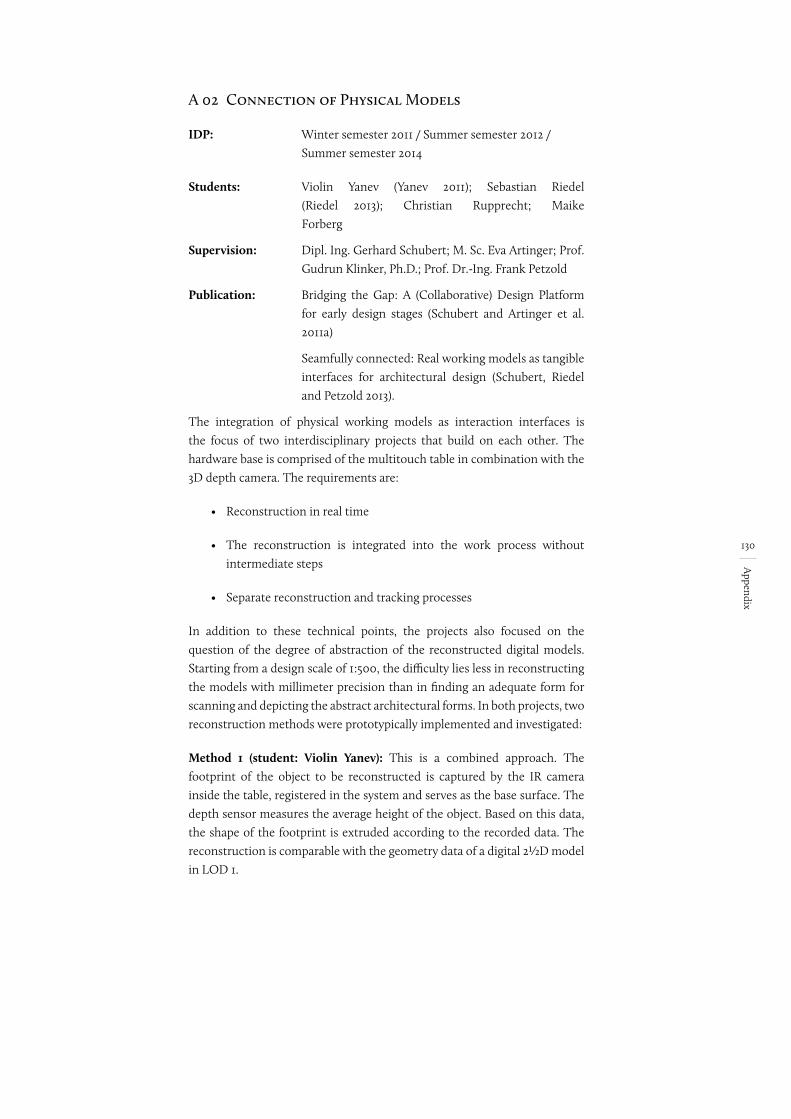
130
Appendix
A 02 Connection of Physical Models
IDP:
Students:
Supervision:
Publication:
Winter semester 2011 / Summer semester 2012 / Summer semester 2014
Violin Yanev (Yanev 2011); Sebastian Riedel (Riedel 2013); Christian Rupprecht; Maike Forberg
Dipl. Ing. Gerhard Schubert; M. Sc. Eva Artinger; Prof. Gudrun Klinker, Ph.D.; Prof. Dr.-Ing. Frank Petzold
Bridging the Gap: A (Collaborative) Design Platform for early design stages (Schubert and Artinger et al. 2011a)
Seamfully connected: Real working models as tangible interfaces for architectural design (Schubert, Riedel and Petzold 2013).
The integration of physical working models as interaction interfaces is the focus of two interdisciplinary projects that build on each other. The hardware base is comprised of the multitouch table in combination with the 3D depth camera. The requirements are:
• Reconstruction in real time
• The reconstruction is integrated into the work process withoutintermediate steps
• Separate reconstruction and tracking processes
In addition to these technical points, the projects also focused on the question of the degree of abstraction of the reconstructed digital models. Starting from a design scale of 1:500, the difficulty lies less in reconstructing the models with millimeter precision than in finding an adequate form for scanning and depicting the abstract architectural forms. In both projects, two reconstruction methods were prototypically implemented and investigated:
Method 1 (student: Violin Yanev): This is a combined approach. The footprint of the object to be reconstructed is captured by the IR camera inside the table, registered in the system and serves as the base surface. The depth sensor measures the average height of the object. Based on this data, the shape of the footprint is extruded according to the recorded data. The reconstruction is comparable with the geometry data of a digital 2½D model in LOD 1.
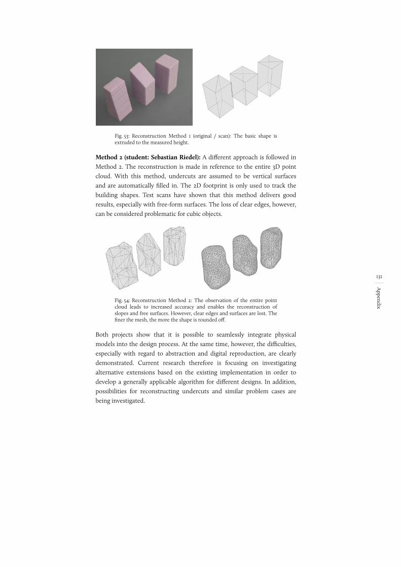
131
Appendix
Fig. 53: Reconstruction Method 1 (original / scan): The basic shape is extruded to the measured height.
Method 2 (student: Sebastian Riedel): A different approach is followed in Method 2. The reconstruction is made in reference to the entire 3D point cloud. With this method, undercuts are assumed to be vertical surfaces and are automatically filled in. The 2D footprint is only used to track the building shapes. Test scans have shown that this method delivers good results, especially with free-form surfaces. The loss of clear edges, however, can be considered problematic for cubic objects.
Fig. 54: Reconstruction Method 2: The observation of the entire point cloud leads to increased accuracy and enables the reconstruction of slopes and free surfaces. However, clear edges and surfaces are lost. The finer the mesh, the more the shape is rounded off.
Both projects show that it is possible to seamlessly integrate physical models into the design process. At the same time, however, the difficulties, especially with regard to abstraction and digital reproduction, are clearly demonstrated. Current research therefore is focusing on investigating alternative extensions based on the existing implementation in order to develop a generally applicable algorithm for different designs. In addition, possibilities for reconstructing undercuts and similar problem cases are being investigated.
132
Appendix
A 03 The Sketch Tool in the Plan View
IDP: Summer semester 2012
Student: Saburo Okita (Okita 2012)
Supervision: Dipl. Ing. Gerhard Schubert; Prof. Dr.-Ing. Frank Petzold
Within the framework of an interdisciplinary project, an interactive sketching environment for making manual annotations and sketches in the plan view was developed and implemented. It was based on the developed prototype from the collaborative design platform. In addition to the pure sketching function, the project also focused on developing a versioning system for managing the freehand sketches. The project is subdivided into the following sections:
• Sketching tool: Conception and implementation of an operating concept for a digital sketching environment. The goal was a seamless integration of the handsketch into the digital workflow.
• Versioning: Development and implementation of a versioning system to manage the freehand sketches on the basis of a two-dimensional graph structure.
The concept was implemented in the existing framework as a plug-in. The drawing pen is our own construction, consisting of a pen sleeve and an infrared LED at the tip of the pen. The frequency of the diode is controlled by a chip. A differentiation between finger touches and a pen sketch is made using the frequency of the LED diode. This would also make it possible to differentiate between different pen shapes.
The program itself allows for sketching and annotation in the plan view. Only one pen type was implemented during the work. The settings for brush size, brush shape and brush color can be adjusted via a corresponding menu.
On the software side, the versioning is done by means of GIT44. The drawings themselves are saved as pixel images. Alternatives are displayed using a temporally sorted tree structure, which is also used to select the project statuses. New versions are created automatically when new alternatives are created, starting from the edited node. If a previous version is selected and worked on, a new version branch is automatically created.
44 GIT is an open source version management system (GitHub).
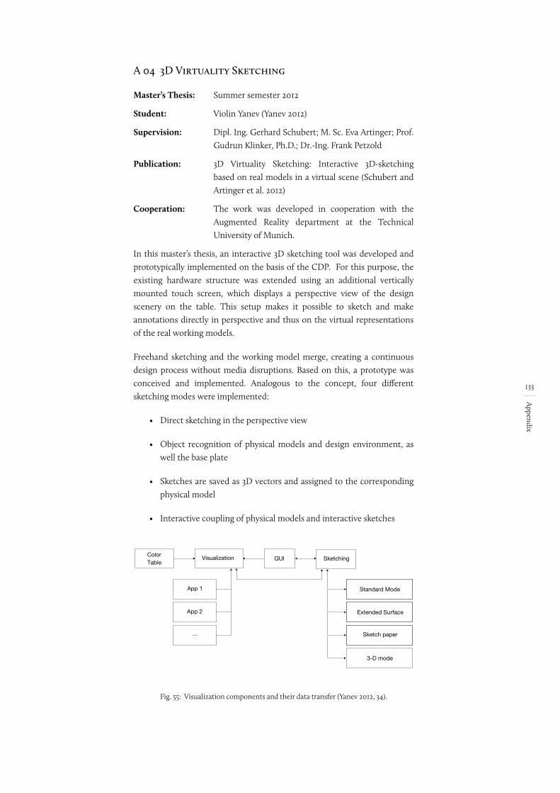
133
Appendix
A 04 3D Virtuality Sketching
Master’s Thesis: Summer semester 2012
Student: Violin Yanev (Yanev 2012)
Supervision: Dipl. Ing. Gerhard Schubert; M. Sc. Eva Artinger; Prof. Gudrun Klinker, Ph.D.; Dr.-Ing. Frank Petzold
Publication: 3D Virtuality Sketching: Interactive 3D-sketching based on real models in a virtual scene (Schubert and Artinger et al. 2012)
Cooperation: The work was developed in cooperation with the Augmented Reality department at the Technical University of Munich.
In this master’s thesis, an interactive 3D sketching tool was developed and prototypically implemented on the basis of the CDP. For this purpose, the existing hardware structure was extended using an additional vertically mounted touch screen, which displays a perspective view of the design scenery on the table. This setup makes it possible to sketch and make annotations directly in perspective and thus on the virtual representations of the real working models.
Freehand sketching and the working model merge, creating a continuous design process without media disruptions. Based on this, a prototype was conceived and implemented. Analogous to the concept, four different sketching modes were implemented:
• Direct sketching in the perspective view
• Object recognition of physical models and design environment, as well the base plate
• Sketches are saved as 3D vectors and assigned to the corresponding physical model
• Interactive coupling of physical models and interactive sketches
Fig. 55:
GUIColorTable
Visualization Sketching
App 1
App 2
…
Standard Mode
Extended Surface
Sketch paper
3-D mode
Visualization components and their data transfer (Yanev 2012, 34).
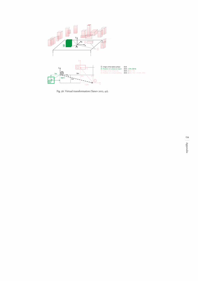
134
Appendix
Fig. 56:
B AD
Cx
z
y
A
D
B
C
Origin of the table surface
Origin of the virtual cityPosition of a physical object
Position of a virtual building
(0,0)(0,0) ~> (0,0) ~> (0,0) ~>
(1m, 0,8m)(5m, 1m)(5m, 1m) ~> (1,2m, -2m)
z
zxA
B
D
C
x
z
x
1m
0,8m
5m
1m
2m
1,2m
Virtual transformation (Yanev 2012, 42).
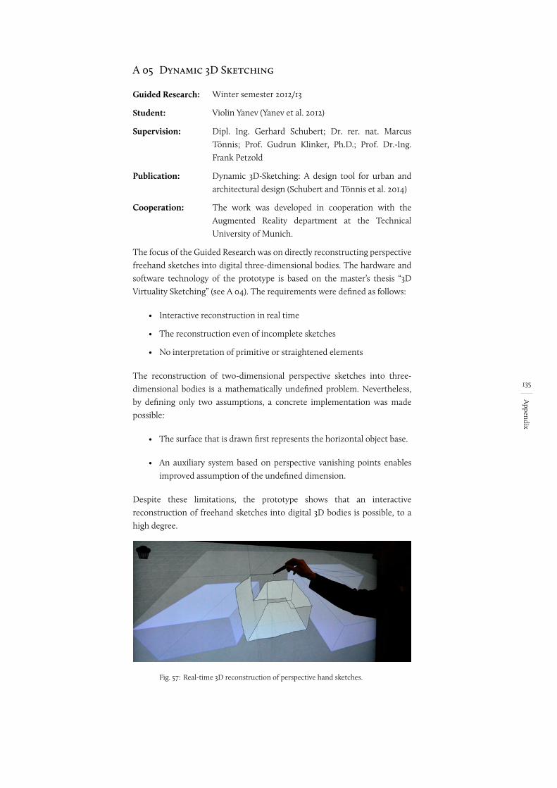
135
Appendix
A 05 Dynamic 3D Sketching
Guided Research:
Student:
Winter semester 2012/13
Violin Yanev (Yanev et al. 2012)
Supervision: Dipl. Ing. Gerhard Schubert; Dr. rer. nat. Marcus Tönnis; Prof. Gudrun Klinker, Ph.D.; Prof. Dr.-Ing. Frank Petzold
Publication: Dynamic 3D-Sketching: A design tool for urban and architectural design (Schubert and Tönnis et al. 2014)
Cooperation: The work was developed in cooperation with the Augmented Reality department at the Technical University of Munich.
The focus of the Guided Research was on directly reconstructing perspective freehand sketches into digital three-dimensional bodies. The hardware and software technology of the prototype is based on the master’s thesis “3D Virtuality Sketching” (see A 04). The requirements were defined as follows:
• Interactive reconstruction in real time
• The reconstruction even of incomplete sketches
• No interpretation of primitive or straightened elements
The reconstruction of two-dimensional perspective sketches into three-dimensional bodies is a mathematically undefined problem. Nevertheless, by defining only two assumptions, a concrete implementation was made possible:
• The surface that is drawn first represents the horizontal object base.
• An auxiliary system based on perspective vanishing points enablesimproved assumption of the undefined dimension.
Despite these limitations, the prototype shows that an interactive reconstruction of freehand sketches into digital 3D bodies is possible, to a high degree.
Fig. 57: Real-time 3D reconstruction of perspective hand sketches.
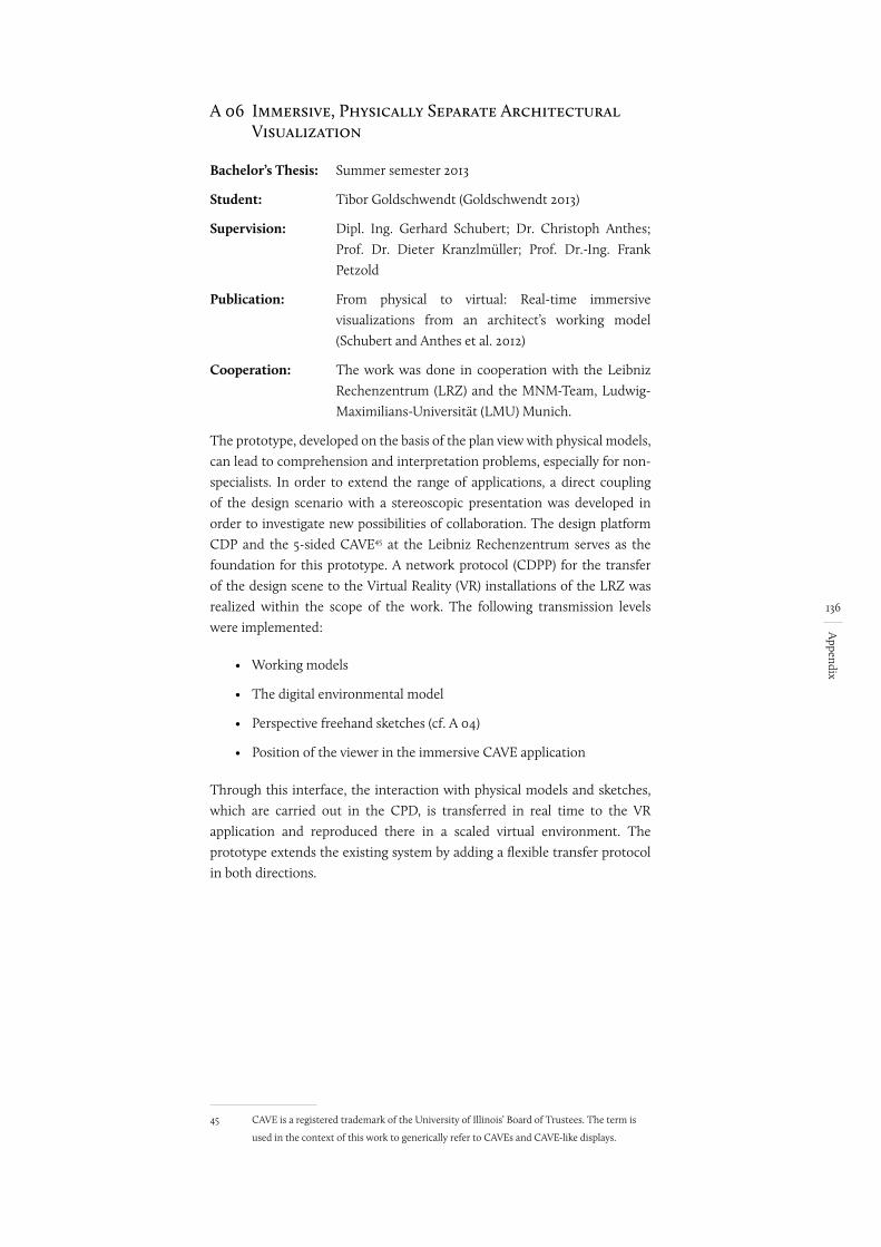
136
Appendix
A 06 Immersive, Physically Separate Architectural Visualization
Bachelor’s Thesis: Summer semester 2013
Student: Tibor Goldschwendt (Goldschwendt 2013)
Supervision: Dipl. Ing. Gerhard Schubert; Dr. Christoph Anthes; Prof. Dr. Dieter Kranzlmüller; Prof. Dr.-Ing. Frank Petzold
Publication: From physical to virtual: Real-time immersive visualizations from an architect’s working model (Schubert and Anthes et al. 2012)
Cooperation: The work was done in cooperation with the Leibniz Rechenzentrum (LRZ) and the MNM-Team, Ludwig-Maximilians-Universität (LMU) Munich.
The prototype, developed on the basis of the plan view with physical models, can lead to comprehension and interpretation problems, especially for non-specialists. In order to extend the range of applications, a direct coupling of the design scenario with a stereoscopic presentation was developed in order to investigate new possibilities of collaboration. The design platform CDP and the 5-sided CAVE45 at the Leibniz Rechenzentrum serves as the foundation for this prototype. A network protocol (CDPP) for the transfer of the design scene to the Virtual Reality (VR) installations of the LRZ was realized within the scope of the work. The following transmission levels were implemented:
• Working models
• The digital environmental model
• Perspective freehand sketches (cf. A 04)
• Position of the viewer in the immersive CAVE application
Through this interface, the interaction with physical models and sketches, which are carried out in the CPD, is transferred in real time to the VR application and reproduced there in a scaled virtual environment. The prototype extends the existing system by adding a flexible transfer protocol in both directions.
45 CAVE is a registered trademark of the University of Illinois’ Board of Trustees. The term is
used in the context of this work to generically refer to CAVEs and CAVE-like displays.
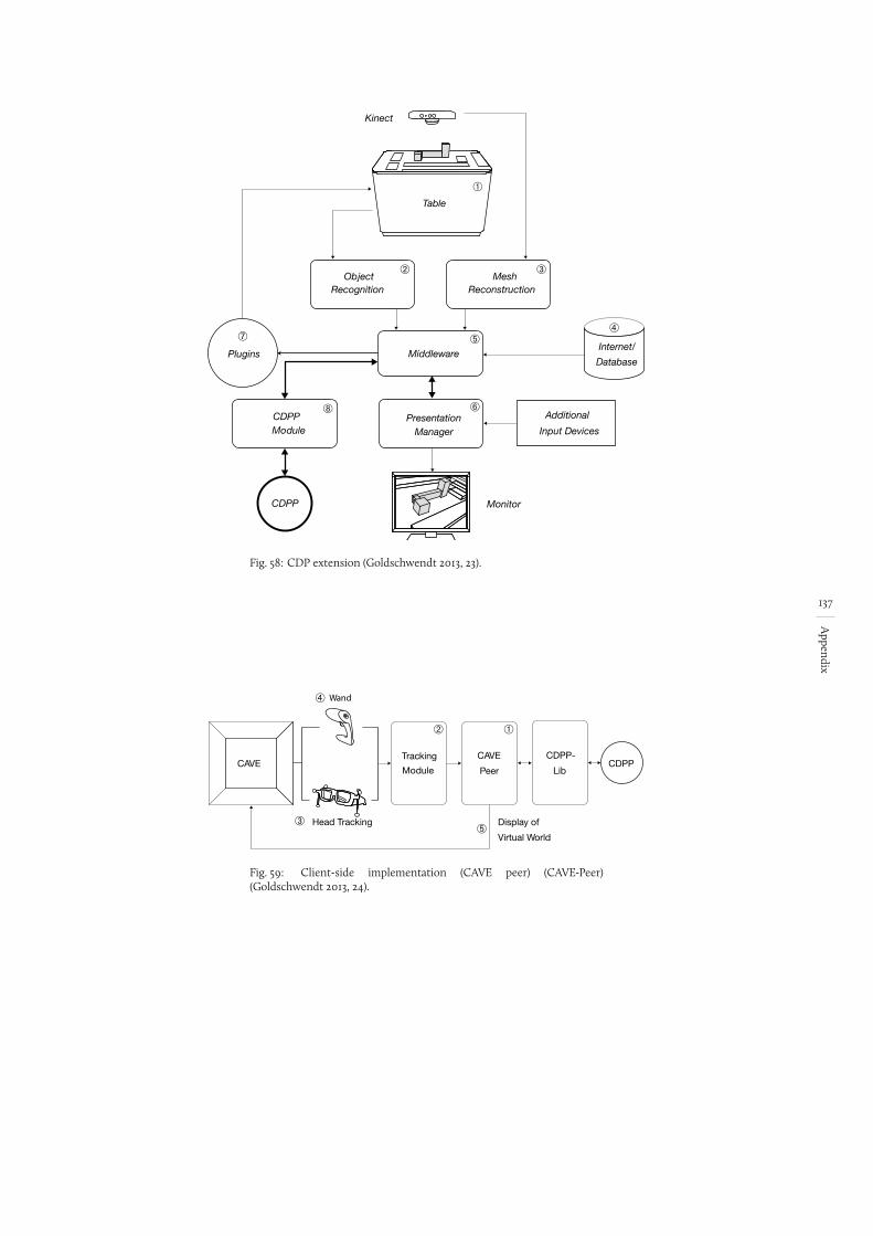
137
Appendix
Fig. 58:
Additional
Input Devices
Monitor
Kinect
Table
➀
MeshReconstruction
➂Object
Recognition
➁
Middleware➄
Internet/
Database
➃
PresentationManager
➅
Plugins
➆
CDPPModule
➇
CDPP
CDP extension (Goldschwendt 2013, 23).
Fig. 59:
Tracking
ModuleCDPP
CAVE
Peer
CDPP-
Lib
➂ Head Tracking
➃ Wand
CAVE
Display of
Virtual World
➀➁
➄
Client-side implementation (CAVE peer) (CAVE-Peer) (Goldschwendt 2013, 24).
138
Appendix
A 07 Mobile Augmented Reality Viewing of Architectural, Network-Controlled Content On-site [in progress]
Master’s Thesis: Summer semester 2014
Student: David Schattel
Supervision: Dipl. Ing. Gerhard Schubert; Dr. rer. nat. Marcus Tönnis; Prof. Gudrun Klinker, Ph.D.; Prof. Dr.-Ing. Frank Petzold
Cooperation: This work was developed in cooperation with the Department of Augmented Reality at the Technical University of Munich.
A further project is being developed as part of a current master’s thesis. Here, too, the focus is on extending the existing system through additional interaction methods. The focus of the thesis is connecting an augmented reality service based on the developed CDP protocol (see A 06). The aim is to directly couple a mobile device (tablet or smartphone) to the design platform. This makes it possible to view different designs and their effects in a real context. The requirements can be defined as follows:
• Representation of the digital model adapted to the real environment (position and size)
• Information exchange in real time
• Analysis of display options, such as the lighting control for the digital object, based on date and GPS data
• Investigation of different degrees of abstraction for representation
Based on this, a prototype was developed and implemented. The following assumptions were made to limit the work:
• The digital geometry data of the environment necessary for integration is assumed to be given
• The current scenario of the building is displayed on the table. The possibility of selecting different designs is not implemented.
The following extensions can be implemented in future projects:
• Selection of different design alternatives based on the saved versions
• Transfer of the computation results for the plug-ins
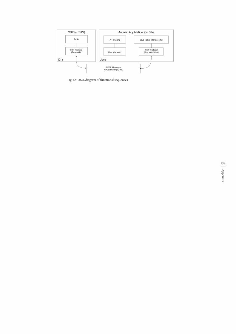
139
Appendix
Fig. 60:
CDP (at TUM) Android Application (On Site)
Table
C++ Java
CDP-Protocol(Table-side)
CDP-Protocol(App side / C++)
CDPP Messages(Virtual Buildings, etc.)
Java Native Interface (JNI)AR Tracking
User Interface
UML diagram of functional sequences.
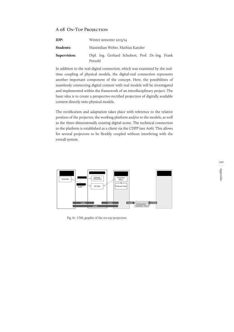
140
Appendix
A 08 On-Top Projection
IDP: Winter semester 2013/14
Students: Maximilian Weber, Mathias Kanzler
Supervision: Dipl. Ing. Gerhard Schubert; Prof. Dr.-Ing. Frank Petzold
In addition to the real-digital connection, which was examined by the real-time coupling of physical models, the digital-real connection represents another important component of the concept. Here, the possibilities of seamlessly connecting digital content with real models will be investigated and implemented within the framework of an interdisciplinary project. The basic idea is to create a perspective-rectified projection of digitally available content directly onto physical models.
The rectification and adaptation takes place with reference to the relative position of the projector, the working platform and/or to the models, as well as the three-dimensionally existing digital scene. The technical connection to the platform is established as a client via the CDPP (see A06). This allows for several projectors to be flexibly coupled without interfering with the overall system.
Fig. 61:
component: CDPPLibcomponent: CDP_Framework
initialization
manipulate scene
Configuration/Calibration Files
ProjectionMatrix
3D Data
Network Connection
component: on top projection
uses usesuses
Controller
Projection View
component: Calibration
writesreads
UML graphic of the on-top projection.
141
Appendix
A 09 Integration of Semantic Environmental Data
IDP: Summer semester 2014
Student: Jegan Sahayaraj John Brito (Brito 2013)
Supervision: Dipl. Ing. Gerhard Schubert; Prof. Dr.-Ing. Frank Petzold
The database for the prototype is a semantic environmental model. The integration of this data was implemented in selected parts within the framework of this IDP project. The prototype supports the integration of City-GML data based on an Oracle Spatial database, as well as the data stock from Open Streetmap. In the context of the project, the integration of the database was limited to loading the geometric data.
The display can be operated at different selectable scales. To demonstrate the differentiated representation on the basis of the semantic database, filtering by year of construction was implemented as an example.
The loaded data formed the information base of the overall system. On the one hand, they serve as the planning information (figure-ground diagram). On the other hand, the data is available as the computation base for the plug-ins.
.
142
Appendix
A 10 Storage system incl. versioning
IDP: Summer semester 2014
Student: Andreas Hubel
Betreuung: Dipl. Ing. Gerhard Schubert; Prof. Dr.-Ing. Frank Petzold
The creation, storage and comparison of alternatives represents a fundamental design process activity for the architect. Based on this requirement, the interdisciplinary project focuses on developing and implementing a versioning system based on the Collaborative Design Platform. The concept provides a flexibly extensible system that supports the storage of the following design elements:
• Physical buildings as .ifc files (component: shell)
• Settings and computation results of the plug-ins
• Section and geographical data of the design environment
• Screenshot of the plan view
• Timestamp
The different versions are displayed in a tree structure sorted by time. The individual version branches are created automatically when an existing variant is changed.
The technical basis of the version management is GIT. The design data is saved using .json and .ifc files. This enables the saved states to be used later on.
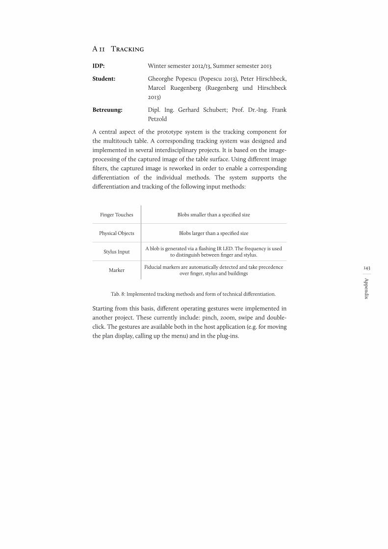
143
Appendix
A 11 Tracking
IDP: Winter semester 2012/13, Summer semester 2013
Student: Gheorghe Popescu (Popescu 2013), Peter Hirschbeck, Marcel Ruegenberg (Ruegenberg und Hirschbeck 2013)
Betreuung: Dipl. Ing. Gerhard Schubert; Prof. Dr.-Ing. Frank Petzold
A central aspect of the prototype system is the tracking component for the multitouch table. A corresponding tracking system was designed and implemented in several interdisciplinary projects. It is based on the image-processing of the captured image of the table surface. Using different image filters, the captured image is reworked in order to enable a corresponding differentiation of the individual methods. The system supports the differentiation and tracking of the following input methods:
Finger Touches Blobs smaller than a specified size
Physical Objects Blobs larger than a specified size
Stylus InputA blob is generated via a flashing IR LED. The frequency is used
to distinguish between finger and stylus.
MarkerFiducial markers are automatically detected and take precedence
over finger, stylus and buildings
Tab. 8: Implemented tracking methods and form of technical differentiation.
Starting from this basis, different operating gestures were implemented in another project. These currently include: pinch, zoom, swipe and double-click. The gestures are available both in the host application (e.g. for moving the plan display, calling up the menu) and in the plug-ins.
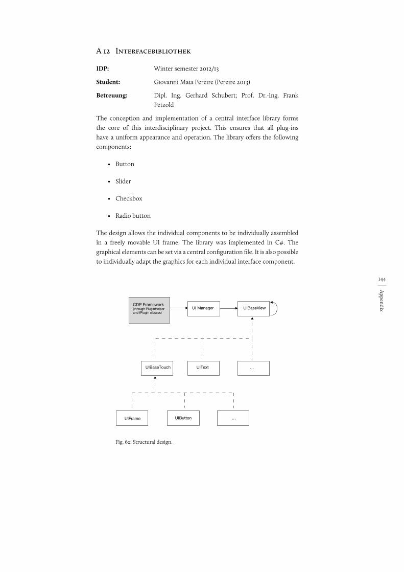
144
Appendix
A 12 Interfacebibliothek
IDP: Winter semester 2012/13
Student: Giovanni Maia Pereire (Pereire 2013)
Betreuung: Dipl. Ing. Gerhard Schubert; Prof. Dr.-Ing. Frank Petzold
The conception and implementation of a central interface library forms the core of this interdisciplinary project. This ensures that all plug-ins have a uniform appearance and operation. The library offers the following components:
• Button
• Slider
• Checkbox
• Radio button
The design allows the individual components to be individually assembled in a freely movable UI frame. The library was implemented in C#. The graphical elements can be set via a central configuration file. It is also possible to individually adapt the graphics for each individual interface component.
Fig. 62:
CDP Framework(through PluginHelper and IPlugin classes)
… UITextUIBaseTouch
UIBaseViewUI Manager
UIFrame UIButton
…
Structural design.
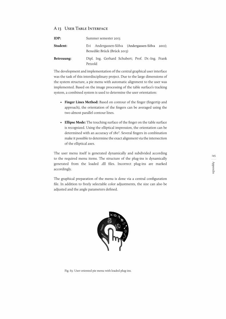
145
Appendix
A 13 User Table Interface
IDP: Summer semester 2013
Student: Evi Andergassen-Sölva (Andergassen-Sölva 2011); Benedikt Brück (Brück 2013)
Betreuung: Dipl. Ing. Gerhard Schubert; Prof. Dr.-Ing. Frank Petzold
The development and implementation of the central graphical user interface was the task of this interdisciplinary project. Due to the large dimensions of the system structure, a pie menu with automatic alignment to the user was implemented. Based on the image processing of the table surface’s tracking system, a combined system is used to determine the user orientation:
• Finger Lines Method: Based on contour of the finger (fingertip and approach), the orientation of the fingers can be averaged using the two almost parallel contour lines.
• Ellipse Mode: The touching surface of the finger on the table surface is recognized. Using the elliptical impression, the orientation can be determined with an accuracy of 180°. Several fingers in combination make it possible to determine the exact alignment via the intersection of the elliptical axes.
The user menu itself is generated dynamically and subdivided according to the required menu items. The structure of the plug-ins is dynamically generated from the loaded .dll files. Incorrect plug-ins are marked accordingly.
The graphical preparation of the menu is done via a central configuration file. In addition to freely selectable color adjustments, the size can also be adjusted and the angle parameters defined.
Fig. 63: User-oriented pie menu with loaded plug-ins.
146
Appendix
A 14 Course on Computational Design
Course: Computational Design: 2008-2014
Supervision: Dipl. Ing. Gerhard Schubert; Dipl.-Ing. Architekt Michael Drobnik; Prof. Dr.-Ing. Frank Petzold
At the core of the course, Computational Design (formerly Dynamic Architecture), is the question of the meaningful use of the computer in the architect’s early design phases. The focus is on the software side. The aim of the course is to design small helper tools for everyday architectural life and to implement them as prototypes.
The range of projects clearly shows that the use of design-supporting tools is possible and useful in almost all areas. The results range from analytical tools (e.g. tools for displaying drainage or determining the necessary areas for barrier-free construction) to systems that support design, such as installation space diagrams.
147
Appendix
A 15 Course on Interactive Visualization
Course: Interactive Visualization: WS 2013/14
Supervision: Dipl. Ing. Gerhard Schubert; Prof. Dr.-Ing. Frank Petzold
As part of an interdisciplinary course, various plug-ins for use with CDP were designed and implemented together with computer science students. On the basis of a one-day workshop, five subject areas were focused on and implemented alone or in teams:
• Shading
• The shortest way
• Sound propagation
• 2D wind simulation
• Visibility
The focus here was mainly on real-time computation and display, as well as analyzing the best possible form for visualizing information.
148
Appendix
Appendix B: Glossary
3D mouse: An input device for navigation in virtual 3D environments or for moving virtual objects (3Dconnexion GmbH).
Augmented Reality: Augmenting means adding to something (Dudenredaktion 1999, 362). In the digital context, this means enriching the real environment with digital content. This is usually done using semi-transparent, head-mounted displays that allow digital content to be superimposed on the user’s current field of vision.
CAD (Computer-aided Design): CAD allows for “computer-aided design and work planning” (Dudenredaktion 1999, 695).
CAAD (Computer Aided Architectural Design): This term is derived from the abbreviation CAD and describes computer-aided design in an architectural context.
CAVE: CAVE is a registered trademark of the University of Illinois’ Board of Trustees (Cruz-Neira et al., 1992). The term is generally used to refer to CAVEs or displays based on CAVEs.
CityGML: An “international standard for the mapping and exchange of semantic, three-dimensional city and landscape models” (Kolbe 2009, 16).
Computer vision: The goal of computer vision is to digitally process visually recorded information and reconstruct different image properties (Szeliski 2010, 3). These include, for example, recognizing color and brightness, but also recognizing form (ibid.). In the context of tangible interfaces, this method enables the recognition of shape, orientation, color, size, etc. in real time (Shaer and Hornecker 2009, 75).
Data, information, knowledge: All three terms are closely related and are to be understood as building on each other. “Data are syntactic units,” initially without meaning (Aamodt and Nygård 1995, 197-198). The term information describes “interpreted data” (ibid.), and knowledge is “learned information” (ibid.).
Drag-and-drop: A specific form of interaction, from the field of direct manipulation interfaces. Interaction chains are carried out by clicking on graphical elements, moving the mouse on the screen with the mouse button pressed down, and placing those elements elsewhere (Dudenredaktion 2007, 360).
Force feedback: A haptic input device for 3D modelling in a virtual environment. The computer-side feedback can be experienced not only via the visual sense, but also via the haptic sense. Haptic feedback is provided by mechanically controlled limitations of the input device. In this way, objects, obstacles and restrictions that exist virtually can also be physically felt by the user.
149
Appendix
Gesture: Generally, the term is usually equated with predefined action or movement sequences that are easy for the receiver to understand. This includes, for example, articulated hand movements such as waving. Regardless of the type of gesture, the receiver must be able to interpret the gesture correctly. In the context of Visual Thinking, this term must be expanded to cover any form of human expression.
GIS: The terms Geo-Information System and Geographical Information System describe digital systems for recording, processing and managing geographical data (Bill 2010, 1). This is a system consisting of hardware, software and data (Bill 2010, 8).
GUI: Graphical User Interface
Head-Mounted Display (HMD): A visual output device worn directly on the head to transmit digital information to the user. The technical implementation can be done either using small screens directly in front of the eyes or by projection onto the retina in the eye (Wikipedia 29.03.2014).
IFC (Industry Foundation Classes): The international standard for the mapping and exchange of semantic building data (ISO 2013-03-21).
Information: See Data
Interface: Interfaces between humans and computers on the hardware side that allow interaction between humans and computers.
Knowledge: See Data
Marker tracking: see Tracking
Media discontinuity: A media disruption is a change of medium within a transmission chain in the transmission of information. The resulting falsification of information and the slowing down of information processing can become problematic (Springer Gabler Verlag 2014, 2143).
Medium: Marshall McLuhan (1994) definitively coined the all-embracing concept of media. In his sense, “[...] every technology and every concept through which man relates to the world” is a medium (Krotz 2001, 66). This includes electric light as well as clothing or television, but also machines and tools: for McLuhan, media are extensions of the body.
Pie menu / cake menu: A graphical menu representation in the GUI. Menu items are not arranged linearly but circularly. A selection is made using a digital pointing device such as a computer mouse or finger.
Powerwall: A large-format, high-resolution, mostly stereoscopic projection screen. A projection from the rear allows it to be viewed and approached without casting shadows.
Was mach ma da?
Evtl. Doch media disruption
h t t p s : / / w w w .i t w i s s e n . i n f o /M e d i e n b r u c h -media-disruption.html
150
Appendix
RFID (Radio Frequency Identification): A system for contactless identification of a data carrier with the aid of a corresponding reader (Finkenzeller 2008, 1). In addition to stored data, the presence and position in the room can also be recorded.
SpaceMouse: see 3D mouse
Styrodur: A material (hard foam board), which is often used as a model material in the urban design process.
Tracking: In the context of human-computer-interaction, the term refers to the tracking of physical objects (optical markers, geometric properties, but also body parts) for use as a method of interaction.
TUI (Tangible User Interface): A tangible form of a user interface. Interaction with digital content is based on physical objects.
Usability: Refers to the degree of user-friendliness.
Working model / Physical model: A special form of model used to review ideas and approaches. In contrast to presentation models, which represent the final design, working models serve as tools for design development. A variety of materials are used that are best suited to this purpose. This can be cardboard, polystyrene, plasticine, clay, concrete, gypsum, etc.
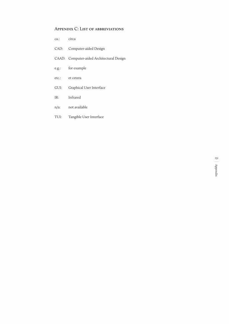
151
Appendix
Appendix C: List of abbreviations
ca.: circa
CAD: Computer-aided Design
CAAD: Computer-aided Architectural Design
e.g.: for example
etc.: et cetera
GUI: Graphical User Interface
IR: Infrared
n/a: not available
TUI: Tangible User Interface
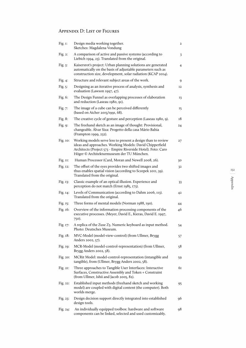
152
Appendix
Fig. 1: Design media working together. Sketches: Magdalena Vondung
2
Fig. 2: A comparison of active and passive systems (according to Liebich 1994, 23). Translated from the original.
3
Fig. 3: Kaisersrot's project: Urban planning solutions are generated automatically on the basis of adjustable parameters such as construction size, development, solar radiation (KCAP 2014).
4
Fig. 4: Structure and relevant subject areas of the work. 9
Fig. 5: Designing as an iterative process of analysis, synthesis and evaluation (Lawson 1997, 47).
12
Fig. 6: The Design Funnel as overlapping processes of elaboration and reduction (Laseau 1980, 91).
13
Fig. 7: The image of a cube can be perceived differently (based on Aicher 2015/1991, 68).
15
Fig. 8: The creative cycle of gesture and perception (Laseau 1980, 9). 18
Fig. 9: The freehand sketch as an image of thought: Provisional, changeable. Álvar Siza: Progetto della casa Mário Bahia (Frampton 1999, 232).
24
Fig. 10: Working models serve less to present a design than to review ideas and approaches. Working Models: David Chipperfield Architects (Project 573 - Empire Riverside Hotel). Foto: Caro Höger © Architekturmuseum der TU München.
27
Fig. 11: Human Processor (Card, Moran and Newell 2008, 26). 30
Fig. 12: The offset of the eyes provides two shifted images and thus enables spatial vision (according to Sczepek 2011, 39). Translated from the original.
32
Fig. 13: Classic example of an optical illusion. Experience and perception do not match (Ernst 1985, 173).
33
Fig. 14: Levels of Communication (according to Dahm 2006, 113). Translated from the original.
42
Fig. 15: Three forms of mental models (Norman 1988, 190). 44
Fig. 16: Overview of the information processing components of the executive processes. (Meyer, David E., Kieras, David E. 1997, 750).
46
Fig. 17: A replica of the Zuse Z3. Numeric keyboard as input method. Photo: Deutsches Museum.
54
Fig. 18: MVC-Model (model-view-control) (from Ullmer, Brygg Anders 2002, 57).
57
Fig. 19: MCR-Model (model-control-representation) (from Ullmer, Brygg Anders 2002, 58).
58
Fig. 20: MCRit Model: model-control-representation (intangible and tangible), from (Ullmer, Brygg Anders 2002, 58).
59
Fig. 21: Three approaches to Tangible User Interfaces: Interactive Surfaces, Constructive Assembly and Token + Constraint (from Ullmer, Ishii and Jacob 2005, 82).
61
Fig. 22: Established input methods (freehand sketch and working model) are coupled with digital content (the computer). Both worlds merge.
95
Fig. 23: Design decision support directly integrated into established design tools.
96
Fig. 24: An individually equipped toolbox: hardware and software components can be linked, selected and used customizably.
98
Appendix D: List of Figures
153
Appendix
Fig. 25: Digitally computed simulations are displayed directly in the model in real time and extend the architect’s discretion.
98
Fig. 26: The creative cycle: design, evaluation and objective help merge into a creative cycle
99
Fig. 27: Conceptual sketch of the working environment. 100
Fig. 28: Two components of the system: interfaces/hardware and software. Only by considering both components can a design decision support system be directly embedded in the design process.
102
Fig. 29: Overview of the design platform: different, customizable and directly coupled interaction areas (subsystem 1-3).
103
Fig. 30: The multi-touch table as a design platform: (A1) interactive workspace that displays the plan as well as digitally computed simulations and analyses. Depth camera (A2). There is also additional projection from above (top-model projection) (A3).
104
Fig. 31: Additional information is assigned as attributes of the object ID.
106
Fig. 32: A combined model scene: Real models and digital planning information (in the foreground) are displayed as a perspective view on the vertical screen (in the background) and allow direct interactions with the virtual world (navigation, sketching).
108
Fig. 33: Intuitive control of the virtual camera via Marker-SpaceMouse coupling.
109
Fig. 34: Digital facade sketch and physical model as a single unit. 109
Fig. 35: The 2D paper mode allows sketching on different semi-transparent drawing planes.
110
Fig. 36: The object mode allows 2½D sketching on the surfaces of the three-dimensional bodies. This creates a direct connection between the sketch and the object.
110
Fig. 37: The expansion mode allows a 2½D sketching on a plane (blue grid) stretched freely in virtual space.
111
Fig. 38: The 3D perspective mode allows for interactive three-dimensional sketching with real-time transformation of the perspective drawing into digital 3D bodies.
111
Fig. 39: Hand sketches are reconstructed in real-time as 3D lines, surfaces and bodies. This allows the perspective to be changed in the sketching process, which leads to new interaction methods and expands the process-stimulating impressions in the thought process.
112
Fig. 40: Direct input from a pen enables the visualization of vague and unfinished thoughts. The character of the line is retained. The automatically generated surfaces are adapted to the contour lines by triangulation.
113
Fig. 41: The extension of the design platform (A) by a CAVE application (C) allows a view of the design scenario on a scale of 1:1.
114
Fig. 42: Immersive view of the design scene in the CAVE. Physical models, digital ground plan and hand sketches are transmitted in real time and displayed stereoscopically.
114
Fig. 43: The direct coupling of the design platform (A) to mobile services allows an augmented view of the design (C) in a real environment (U).
115
Fig. 44: Screenshot of the mobile application. (David Schattel) 116
154
Appendix
Fig. 45: Structure of the software architecture as a plug-in framework consisting of two components: the host application and the plug-ins.
116
Fig. 46: Host application (blue) as the central element of the software concept.
117
Fig. 47: Saving and comparing different variants takes place via snapshots and their storage in a graph structure as a tree.
119
Fig. 48: Plug-ins (blue) directly embedded in the host application. 120
Fig. 49: Examples of plug-ins reacting in real time as design support: noise (1) (Vogginger), wind (2) (Rupprecht, Forberg), shading (3) (Koch, Dyrda, Herrero, Reindl), visibility (4) (Siglreithmaier).
121
Fig. 50: Overlaying multiple plug-ins allows different analyses and simulations to be seen.
122
Fig. 51: The system allows for a seamless creative process in architectural design. Sketches: Magdalena Vondung.
124
Fig. 52: Hardware-structure of the prototypical test environment. 127
Fig. 53: Reconstruction Method 1 (original / scan): The basic shape is extruded to the measured height.
131
Fig. 54: Reconstruction Method 2: The observation of the entire point cloud leads to increased accuracy and enables the reconstruction of slopes and free surfaces. However, clear edges and surfaces are lost. The finer the mesh, the more the shape is rounded off.
131
Fig. 55: Visualization components and their data transfer (Yanev 2012, 34).
133
Fig. 56: Virtual transformation (Yanev 2012, 42). 134
Fig. 57: Real-time 3D reconstruction of perspective hand sketches. 135
Fig. 58: CDP extension (Goldschwendt 2013, 23). 137
Fig. 59: Client-side implementation (CAVE peer) (CAVE-Peer) (Goldschwendt 2013, 24).
137
Fig. 60: UML diagram of functional sequences. (David Schattel) 139
Fig. 61: UML graphic of the on-top projection. (Maximilian Weber, Mathias Kanzler)
140
Fig. 62: Structural design. (Giovanni Maia) 144
Fig. 63: User-oriented pie menu with loaded plug-ins. 145
155
Appendix
Appendix E: Bibliography
3Dconnexion GmbH. “3Dconnexion : Was ist eine 3D-Maus?“. https://www.3dconnexion.de/products/what-is-a-3d-mouse.html (letzter Zugriff: 14. April 2014).
Aamodt, Agnar und Mads Nygård (1995). “Different roles and mutual dependencies of data, information, and knowledge: an AI perspective on their integration.“ Data and Knowledge Engineering 16: 191–222.
Abel G., Hrsg. Kreativität: Universitätsverlag der TU Berlin.
Adelson, Beth, Susan Dumais und Judith S. Olson, Hrsg. (1994). Proceedings of the SIGCHI conference on Human factors in computing systems celebrating interdependence. New York, NY: ACM.
Aedas Architects Limited (2013). “Research & Development | Aedas.“. http://www.aedas.com/Research (letzter Zugriff: 30. Dezember 2013).
Aicher, Otl (2015/1991). Analogous and Digital. Trans. Michael Robinson, Berlin: Ernst & Sohn.
Akeley, Kurt, Hrsg. (2000). SIGGRAPH 2000 conference proceedings. New York, NY: ACM Press [u.a.].
Andergassen-Sölva, Evi (2011). “Collaborative Design Platform. User Interface.“ IDP Dokumentation. Technische Universität München, München. Fachgebiet Augmented Reality; Lehrstuhl für Architekturinformatik.
Anderson, David, James L. Frankel, Joe Marks, Aseem Agarwala, Paul Beardsley, Jessica Hodgins, Darren Leigh, Kathy Ryall, Eddie Sullivan und Jonathan S. Yedidia (2000). “Tangible Interaction + Graphical Interpretation: A New Approach to 3D Modeling.“ in SIGGRAPH 2000 conference proceedings, hrsg. von Kurt Akeley. New York, NY: ACM Press [u.a.].
Apple Inc. “Apple – iOS 7 – Siri.“. https://www.apple.com/de/ios/siri/ (letzter Zugriff: 8. April 2014).
Arnheim, Rudolf (1969). Visual thinking. Berkeley and Los Angeles, California, Univ. of California Press, Ltd.
Ashby, W. Ross (1957). An Introduction to Cybernetics, 2. Aufl. London: Chapman & Hall Ltd.
Baars, Bernard J. (1995). A cognitive theory of consciousness, 1. Aufl. Cambridge [England], New York: Cambridge University Press.
Bae, Seok-Hyung, Ravin Balakrishnan und Karan Singh (2008). “ILoveSketch: As-Natural-As-Possible Sketching System for Creating 3D Curve Models.“ in Proceedings of the 21st Annual ACM Symposium on User Interface Software and Technology, hrsg. von Steve B. Cousins und Steve B. Beaudouin-Lafon, 151–160. New York, N.Y: Association for Computing Machinery.
Barthel, Rainer (2005). “Naturform - Architekturform.“ in Frei Otto - das Gesamtwerk: Leicht bauen, natürlich gestalten, hrsg. von Rainer Barthel, Winfried Nerdinger und Frei Otto, 17–32. Basel, Boston, Berlin: Birkhäuser.
Barthel, Rainer, Winfried Nerdinger und Frei Otto, Hrsg. (2005). Frei Otto - das Gesamtwerk: Leicht bauen, natürlich gestalten. Basel, Boston, Berlin: Birkhäuser.
Begole, James, John C. Thang und Rosco Hill, Hrsg. (2003). UIST’03: Proceedings of the 16th Annual ACM Symposium on User Interface Software and Technology. New York: Association for Computing Machinery.
Bembé, Carl August (1953). Von der Linie zum Raum. München: Callwey.
Bertin, Jacques (2011). Semiology of graphics: Diagrams networks maps. Redlands, Calif: ESRI Press.
Arnheim, Rudolf (1972). Anschauliches Denken: Zur Einheit von Bild und Begriff // Zur Einheit von Bild u. Begriff. DuMont Dokumente : Reihe Kunstgeschichte, Wissenschaft. Köln: DuMont Schauberg.
156
Appendix
Bill, Ralf (2010). Grundlagen der Geoinformationssysteme, 5., völlig neu bearb. Aufl. 2009. Berlin: Wichmann.
Bimber, Oliver und Ramesh Raskar (2005). Spatial augmented reality: Merging real and virtual worlds. Wellesley, Mass: A K Peters.
Binding, Günther (2012). “Der Architekt im Mittelalter.“ in Der Architekt: Geschichte und Gegenwart eines Berufsstandes, hrsg. von Winfried Nerdinger, 59–79. München: Prestel.
Böhle, Fritz, Sabine Weishaupt, Wolfgang Hätscher-Rosenbauer und Bernd Fritscher (1998). Tätigkeitsbezogene Sehschulung: Ein zukunftsweisender Ansatz zur Förderung der Gesundheit bei visueller Beanspruchung am Arbeitsplatz.
Bolte, Annegret (1998). “Beim CAD geht das Konstruieren langsamer als das Denken“: Zum Einfluß des Einsatzes von CAD-Systemen auf das Arbeitshandeln von Planern.“ Arbeit 7, Nr. 4: 362–379.
Bono, Edward de (1972). Laterales Denken für Führungskräfte. Reinbek bei Hamburg: Rowohlt.
Brito, Jegan Sahayaraj John (2013). “Collaborative Design Platform. Spatial Data Display.“ IDP Dokumentation. Technische Universität München, München. Lehrstuhl für Architekturinformatik.
Broadbent, Geoffrey (1978). Design in architecture: Architecture and the human sciences. Chichester (u.a.): Wiley.
Broll, Wolfgang, Moritz Stoerring und Chiron Mottram (2003). “The Augmented Round Table: a new Interface to Urban Planning and Architectural Design.“ in Human-Computer Interaction - Interact’03, hrsg. von Rauterberg et al., 1103–1104.
Brown, John (1958). “Some tests of the decay theory of immediate memory.“ Quarterly Journal of Experimental Psychology, Nr. 10: 12–21.
Brück, Benedikt (2013). “Table User Interface.“ IDP Dokumentation. Technische Universität München, München. Lehrstuhl für Architekturinformatik.
Bundesanstalt für Arbeitsschutz und Arbeitsmedizin, Hrsg. (1995). Sehen und Bildschirmarbeit. Schriftenreihe der Bundesanstalt für Arbeitsmedizin : Tagungsbericht 6. Bremerhaven: Wirtschaftsverlag NW Verlag für neue Wissenschaft GmbH.
Buxton, Bill (1986). “Chunking and phrasing and the design of human-computer dialogues.“ in Information processing 86: Proceedings of the IFIP 10. World Computer Congress, hrsg. von Hans-Jürgen Kugler, 475–480 10. Dublin: Ireland.
Buxton, Bill (2007). Sketching user experience: Getting the design right and the right design. San Francisco, Calif: M. Kaufmann.
Cabrinha, Mark Johnson Jason Kelly und Kyle Steinfeld, Hrsg. (2012). Proceedings of the 32nd Annual Conference of the Association for Computer Aided Design in Architecture (ACADIA): Synthetic Digital Technologies. San Francisco: The Printing House Inc, WI.
Callaos, N., Lesso W. und M. Palesi, Hrsg. (2005). The 9th world multi-conference on systemics cybernetics and informatics: International Institute of Informatics and Systemics.
Card, Stuart K., Thomas P. Moran und Allen Newell (2008). The psychology of human-computer interaction. Hillsdale, NJ: Erlbaum; L. Erlbaum Associates.
Ceccato, Cristiano, Lars Hesselgren, Mark Pauly, Helmut Pottmann und Johannes Wallner, Hrsg. (2010). Advances in Architectural Geometry 2010: Springer Vienna.
157
Appendix
Cheng, Nancy Yen-wen (1995). “Linking the Virtual to Reality: CAD & Physical Modeling.“ in The global design studio: Proceedings of the sixth International Conference on Computer-aided Architectural Design Futures,, hrsg. von Milton Tan und Robert Teh, 303–311. Singapore: Centre for Advanced Studies in Architecture, National University of Singapore.
Chor-Kheng, Lim (2003). “Is a pen-based system just another pen or more than a pen?“ in eCAADe // Digital design: Proceedings of the 21st Conference on Education in Computer Aided Architectural Design in Europe. Bd. 21, hrsg. von Wolfgang Dokonal und Urs Hirschberg, 615–622 21. Graz, Austria: Graz University of Technology.
Choutgrajank, Araya, Hrsg. (2003). CAADRIA 2003: Proceedings of the 8th International Conference on Computer-Aided Architectural Design Research in Asia. Thailand: Master of Science Program in Computer-Aided Architectural Design, Faculty of Architecture, Rangsit University.
Çolakoğlu, Birgül, Hrsg. (2009). Computation: The new realm of architectural design : proceedings of the 27th Conference on Education and Research in Computer Aided Architectural Design in Europe, 1st ed 27. Istanbul, Turkey: ITU/YTU.
Constantine, Larry L. und Lockwood, Lucy A. D. (2001). “forUse Newsletter #15.“. http://www.foruse.com/newsletter/foruse15.htm#3 (letzter Zugriff: 30. Dezember 2013).
Cooper, Alan und Robert Reimann (2003). About Face 2.0: The essentials of interaction design. Indianapolis, IN: Wiley.
Cousins, Steve B. und Steve B. Beaudouin-Lafon, Hrsg. (2008). Proceedings of the 21st Annual ACM Symposium on User Interface Software and Technology. New York, N.Y: Association for Computing Machinery.
Cross, Nigel (2008). Engineering design methods: Strategies for product design, 4. ed. (2008), reprinted. Chichester: John Wiley & Sons.
Cruz-Neira, Carolina, Daniel J. Sandin, Thomas A. DeFanti, Robert V. Kenyon und John C. Hart (1992). “The CAVE: Audio Visual Experience Automatic Virtual Environment.“ Commun. ACM 35, Nr. 6: 64–72.
Cutler, Barbara und Joshua Nasman (2010). “Interpreting Physical Sketches as Architectural Models.“ in Advances in Architectural Geometry 2010, hrsg. von Cristiano Ceccato et al., 15–35: Springer Vienna.
Dahm, Markus (2006). Grundlagen der Mensch-Computer-Interaktion. München [u.a.]: Pearson Studium.
Dix, Alan (2004). Human-computer interaction, 3. Aufl. Harlow, England [etc.]: Pearson Education.
Dokonal, Wolfgang und Urs Hirschberg, Hrsg. (2003). eCAADe // Digital design: Proceedings of the 21st Conference on Education in Computer Aided Architectural Design in Europe 21. Graz, Austria: Graz University of Technology.
Dubberly, Hugh (2004). “How do you design?“. http://www.dubberly.com/articles/how-do-you-design.html (letzter Zugriff: 1. April 2014).
Dudenredaktion, Hrsg. (1999). Duden: Das grosse Wörterbuch der deutschen Sprache : in zehn Bänden, 3., völlig neu bearb. und erweiterte Aufl. Mannheim, Leipzig, Wien [etc.]: Dudenverlag.
Dudenredaktion, Hrsg. (2007). Das grosse Fremdwörterbuch: Herkunft und Bedeutung der Fremdwörter. Unter Mitarbeit von Ursula Kraif, 4., aktualisierte Aufl. Mannheim [u.a.]: Dudenverlag.
Dutke, Stephan (1994). Mentale Modelle: Konstrukte des Wissens und Verstehens : kognitionspsychologische Grundlagen für die Software-Ergonomie. Arbeit und Technik Bd. 4. Göttingen: Verlag für Angewandte Psychologie.
158
Appendix
Edmonds, E. und R. Gibson, Hrsg. (2004). Proceedings of the Interaction Symposium: UTS Printing Services.
Ernst, Bruno (1985). Der Zauberspiegel des M.C. Escher, 3. Aufl. dtv 2879. München: Dt. Taschenbuch-Verl.
Escola Tecnica Superior D’arquitectura de Barcelona, Hrsg. (1992). CAAD Instruction: The New Teaching of an Architect? Proceedings of eCAADe 1992.
Finkenzeller, Klaus (2008). RFID-Handbuch: Grundlagen und praktische Anwendungen von Transpondern, kontaktlosen Chipkarten und NFC, 5., aktualis. u. erw. Aufl. München: Hanser, Carl.
Fish, Jonathan und Stephen Scrivener (1990). “Amplifying the Mind’s Eye: Sketching and Visual Cognition.“ Leonardo Electronic Almanac 23, Nr. 1: 117–126.
Fjeld, Morten, Fred Voorhorst, Martin Bichsel und helmut Krueger (2000). “Navigation Methods for an Augmented Reality System.“ in Proceedings of the SIGCHI conference on Human Factors in Computing Systems: In the video program / extended abstracts of CHI 2000, hrsg. von Thea Turner, 8–9. New York, NY: ACM.
Flemming, Ulrich (1977). Automatisierter Grundrissentwurf: Darstellung Erzeugung u. Dimensionierung von dicht gepackten rechtwinkligen Flächenanordnungen. Berlin:
Flusser, Vilém (1991). Gesten: Versuch einer Phänomenologie, 1. Aufl. Bollmann Bibliothek 5. Düsseldorf: Bollmann Verlag.
Flusser, Vilém (1994). Vom Subjekt zum Projekt. Menschwerdung, 1. Aufl. Schriften / Vilém Flusser 3. Bensheim, Düsseldorf: Bollmann.
Follmer, Sean, Daniel Leithinger, Alex Olwal, Akimitsu Hogge und Hiroshi Ishii (2013). “inFORM: Dynamic Physical Affordances and Constraints through Shape and Object Actuation.“ in Proceedings of the 26th annual ACM symposium on User interface software and technology, hrsg. von Shahram Izadi, 417–426. [S.l.]: ACM.
FOSSGIS e.V. “OpenStreetMap Deutschland: Die freie Wiki-Weltkarte.“. http://www.openstreetmap.de/ (letzter Zugriff: 7. April 2014).
Frampton, Kenneth (1999). álvaro siza: tutte le opere. Milano: Electa.
Frazer, John (1995). An evolutionary architecture. Themes / Architectural Association, London 7. London: Architectural Assoc.
Gänshirt, Christian (1999). “Sechs Werkzeuge des Entwerfens.“. http://www.tu-cottbus.de/theoriederarchitektur/Wolke/deu/Themen/991/Gaenshirt/gaenshirt.html (letzter Zugriff: 14. April 2014).
Gänshirt, Christian (2007). Tools for Ideas: An introduction to architectural design. Basel, Boston, Berlin: Birkhäuser.
Geomagic GmbH (2013). “Geomagic Phantom - Übersicht.“. http://geomagic.com/de/products/phantom-omni/overview (letzter Zugriff: 14. April 2014).
Gero, John S. “Emergence and its role in computer-aided architectural design.“.
Gibson, James J. (1979). The ecological approach to visual perception. Boston: Houghton Mifflin.
Glanville, Ranulph (1992). “cad abusing computing.“ in CAAD Instruction: The New Teaching of an Architect? Proceedings of eCAADe 1992, hrsg. von Escola Tecnica Superior D’arquitectura de Barcelona, 213–224.
Glanville, Ranulph (1999). “Researching Design and Designing Research.“ Design Issues 15, Nr. 2: 80–91.
Goldschmidt, G., William Porter und Mine Ozkar, Hrsg. (1999). Proceedings of the 4th International Design Thinking Research Symposium on Design Representation. London, New York: MIT; Springer.
159
Appendix
Goldschmidt, Gabriela (1991). “The Dialectics of Sketching.“ Creativity Research Journal 4, Nr. 2: 123–143.
Goldschwendt, Tibor (2013). “The Collaborative Design Platform Protocol: Design and Implementaton of a Protocol for Networked Virtual Environments and CAVE Peer Development.“ Bachelorarbeit, Ludwig-Maximilians-Universität München, 2013.
Goldstein, Eugen Bruce (2011). Cognitive psychology. Belmont, Calif. [u.a.]: Wadsworth Cengage Learning.
Grunwald, Martin, Hrsg. (2008). Human haptic perception: Basics and applications. Basel, Boston: Birkhäuser.
Helbig, Hannah B. und Marc O. Ernst (2008). “Haptic perception in interaction with other senses.“ in Human haptic perception: Basics and applications, hrsg. von Martin Grunwald, 235–249. Basel, Boston: Birkhäuser.
Herrmann, Wolfgang A., Hrsg. (2005). Fakultät für Architektur der Technischen Universität München. München: TUM.
Heskett, John (1980). Industrial design. New York: Oxford University Press.
Hinckley, Ken, Randy Pausch, John C. Goble und Neal Kassell (1994). “Passive Real-World Interface Props for Neurosurgical Visualization.“ in Proceedings of the SIGCHI conference on Human factors in computing systems celebrating interdependence, hrsg. von Beth Adelson, Susan Dumais und Judith S. Olson, 452–458. New York, NY: ACM.
Hinckley, Ken, Randy Pausch, Dennis Profitt, James Patten und Neal Kassell (1997). “Cooperative Bimanual Action.“ in Human factors in computing systems: Proceedings of the CHI 97 conference, hrsg. von Steven Pemberton und Rachel Bellamy, 27–34. New York: ACM; Association for Computing Machinery; Addison-Wesley.
Hosick, Eric (01.03.2014). “Interface Vision.“. http://blog.interfacevision.com/design/design-visual-progarmming-languages-snapshots/ (letzter Zugriff: 5. März 2014).
Huang, Chen-Je, Ellen Yi-Luen Do und Mark D. Gross (2003). “MouseHaus Table: a Physical Interface for Urban Design.“ in UIST’03: Proceedings of the 16th Annual ACM Symposium on User Interface Software and Technology, hrsg. von James Begole, John C. Thang und Rosco Hill, 41–42. New York: Association for Computing Machinery.
Igarashi, Takeo, Satoshi Matsuoka und Hidehiko Tanaka (1999). “Teddy: A Sketching Interface for 3D Freeform Design.“ in SIGGRAPH 1999 Conference Proceedings: Computer Graphics Annual Conference Series, hrsg. von Warren Waggenspack, 409–416 26. Los Angeles, CA: ACM; Addison Wesley Professional.
Ishii, Hiroshi, Carlo Ratti, Ben Piper, Yao Wang und Eran Ben-Joseph (2004). “Bringing clay and sand into digital design: continuous tangible user interfaces.“ BT Technology Journal 22, Nr. 4: 287–299.
ISO (2013-03-21). Industry Foundation Classes (IFC) for data sharing in the construction and facility management industries 25.040.40, 16739:2013.
Izadi, Shahram, Hrsg. (2013). Proceedings of the 26th annual ACM symposium on User interface software and technology. [S.l.]: ACM.
Johnson, E. Calvin, Hrsg. (1963). AFIPS ‘63 (Spring): Proceedings of the May 21-23, 1963, spring joint computer conference. Baltimore, Md.: Spartan Books inc.
Johnson, Timothy E. (1963). “Sketchpad III: a computer program for drawing in three dimensions.“ in AFIPS ‘63 (Spring): Proceedings of the May 21-23, 1963, spring joint computer conference, hrsg. von E. Calvin Johnson, 347–353. Baltimore, Md.: Spartan Books inc.
Kaisersrot (2008). “PROJECTS.“. http://www.kaisersrot.ch/kaisersrot-02/PROJECTS.html (letzter Zugriff: 24. März 2014).
160
Appendix
Kandel, Eric (2007). Auf der Suche nach dem Gedächtnis: Die Entstehung einer neuen Wissenschaft des Geistes. Köln: Filmform Köln mit Arte, ORF, WDR.
KCAP, Architects&Planners (10.04.2014). “Visuals - Kaisersrot - Projects - KCAP.“. http://www.kcap.eu/en/projects/v/kaisersrot/ (letzter Zugriff: 10. April 2014).
King, Ross (2001). Das Wunder von Florenz: Architektur und Intrige : wie die schönste Kuppel der Welt entstand. München: A. Knaus.
Köchling, Annegret (1985). Bildschirmarbeit: Gesundheitsregeln und Gesundheitsschutz. Wissenschaft im Arbeitnehmerinteresse 3. Köln: Bund-Verl.
Kolbe, Thomas H. (2009). “Representing and Exchanging 3D City Models with CityGML.“ in 3D geo-information sciences: [selected from the Third Workshop on 3D Geo-Information, 13 - 14 November, Seoul, Korea], hrsg. von Jiyeong Lee und Sisi Zlatanova, 15–31. Berlin [u.a.]: Springer.
Krämer, Sybille, Hrsg. (1998). Medien, Computer, Realität: Wirklichkeitsvorstellungen und Neue Medien, 1. Aufl. Frankfurt am Main: Suhrkamp Verlag.
Krotz, Friedrich (2001). “Marshall McLuhan Revisited: Der Theoretiker des Fernsehens und die Mediengesellschaft.“ M&K 49, Nr. 1: 62–81.
Kugler, Hans-Jürgen, Hrsg. (1986). Information processing 86: Proceedings of the IFIP 10. World Computer Congress 10. Amsterdam: North-Holland.
Kurmann, David (1995). “Sculptor - A Tool for Intuitive Architectural Design.“ in The global design studio: Proceedings of the sixth International Conference on Computer-aided Architectural Design Futures,, hrsg. von Milton Tan und Robert Teh, 323–330. Singapore: Centre for Advanced Studies in Architecture, National University of Singapore.
Langenhan, C., M. Weber, M. Liwicki, F. Petzold und A. Dengel (2013). “Graph-based retrieval of building information models for supporting the early design stages.“ Advanced Engineering Informatics 27, Nr. 4: 413–426.
Laseau, Paul (1980). Graphic thinking for architects and designers. New York, NY: Van Nostrand.
Lawson, Bryan (1993). “Parallel Lines of Thought.“ Languages of Design 1, Nr. 4: 357–366.
Lawson, Bryan (1994). Design in mind. Oxford [England], Boston: Butterworth Architecture.
Lawson, Bryan (1997). How designers think: The design process demystified, Completely rev. 3rd ed. Oxford [u.a.]: Architectural Press.
Lawson, Bryan (2002). “CAD and Creativity: Does the Computer Really Help?“ Leonardo Electronic Almanac 35, Nr. 3: 327–331.
Leclercq, Pierre P. (2001). “Programming and Assistent Sketching: Graphic and Parametric Integration in Architectural Design.“ in Computer Aided Architectural Design Futures 2001: Proceedings of the Ninth International Conference held at the Eindhoven University of Technology, hrsg. von Bauke de Vries, Jos van Leeuwen und Henri Achten, 15–31. Boston/London: Kluver Academic Publishers, Dornrecht.
Lee, Jiyeong und Sisi Zlatanova, Hrsg. (2009). 3D geo-information sciences: [selected from the Third Workshop on 3D Geo-Information, 13 - 14 November, Seoul, Korea]. Berlin [u.a.]: Springer.
Liebich, Thomas (1994). Wissensbasierter Architekturentwurf: Von den Modellen des Entwurfs zu einer intelligenten Computerunterstützung. Weimar: VDG, Verl. und Datenbank für Geisteswiss.
Liu, Yu-Tung (2001). Defining digital architecture: 2001 Far East International Architectural Design Award. Basel: Birkhäuser.
falsche quelle bei VR
Kammer, Dietrich, Georg Freitag, Mandy Keck und Markus Wacker (2010). “Taxonomy and Overview of Multi-touch Frameworks: Architecture, Scope and Features.“ in Proceedings of the 2nd ACM SIGCHI symposium on Engineering interactive computing systems: Workshop on Engineering Patterns for Multitouch Interfaces, hrsg. von Kris Luyten et al. New York, NY: ACM.
161
Appendix
Luyten, Kris, Davy Vanacken, Malte Weiss, Jan Borchers, Shahram Izadi, Shahram Wigdor und Noi Sukaviriya, Hrsg. (2010). Proceedings of the 2nd ACM SIGCHI symposium on Engineering interactive computing systems: Workshop on Engineering Patterns for Multitouch Interfaces. New York, NY: ACM.
Maeda, John (2006). The laws of simplicity: Design technology business life. Cambridge, Mass. [u.a.]: MIT Press.
Maher, Mary Lou, Yohann Daruwala und Chen Edward (2004). “A Design Workbench with Tangible Interfaces for 3D Design.“ in Proceedings of the Interaction Symposium, hrsg. von E. Edmonds und R. Gibson: UTS Printing Services.
Maisberger Whiteoaks/Nemetschek AG (2005). “Europaweite Studie: Neue Geschäftspotenziale für Architekten und Ingenieure, München.“.
Malić, Brankica (1998). Physiologische und technische Aspekte kartographischer Bildschirmvisualisierung. Schriftenreihe des Instituts für Kartographie und Topographie der Rheinischen Friedrich-Wilhelms-Universität Bonn 25. Bonn: Univ.
Mather, George (2011). Introduction to sensation and perception. New York: Routledge.
McLuhan, Marshall (1994). Understanding Media: The Extensions of Man. Cambridge, Massachusetts, The MIT Press”.
Meyer, David e., Kieras, David E. (1997). “A Computational Theory of Executive Cognitive Processes and Multiple-Task Performance: Part 2. Accounts of Psychologival Refractory-Period Phenomena.“ Psychological Review 104, Nr. 4: 749–791.
Microsoft Corporation (2014). “Kinect for Windows | Voice, Movement & Gesture Recognition Technology“. http://www.microsoft.com/en-us/kinectforwindows/ (letzter Zugriff: 16. April 2014).
Miller, George A. (1956). “The Magical Number Seven, Plus or Minus Two: Some Limits on Our Capacity for Processing Information.“ The Psychological Review,, Nr. 63: 81–97.
Mitchell, William J. und Malcolm MacCullough (1995). Digital design media. New York [u.a.]: Van Nostrand Reinhold.
Moelle, Herbert (2006). “Rechnergestützte Planungsprozesse der Entwurfsphasen des Architekten auf Basis semantischer Modelle.“ Dissertation, Technische Universität München, 2006.
Moggridge, Bill (2007). Designing interactions. Cambridge, Mass: MIT Press.
Myers, Brad A. (1998). “A Brief History of Human Computer Interaction Technology.“ ACM interactions 5, Nr. 2: 44–54. http://www.cs.cmu.edu/~amulet/papers/uihistory.tr.html.
Nadin, Mihai (1997). “Computational Design: Design im Zeitalter einer Wissensgesellschaft.“ formdiskurs I, Nr. 2: 40–60.
Nalbach, Gernot und Dimitra Figa (2003). Die erste Skizze: The first sketch. [Dortmund]: Förderkreis Dortmunder Modell Bauwesen, Lehrstuhl für Entwerfen und Innenraum.
Nerdinger, Winfried, Hrsg. (2012). Der Architekt: Geschichte und Gegenwart eines Berufsstandes. München: Prestel.
Neuckermans, Herman, Benjamin Geebelen und Stefan Boeykens (2005). “Virtual engineering in architectural design.“ in The 9th world multi-conference on systemics cybernetics and informatics, hrsg. von N. Callaos, Lesso W. und M. Palesi, 36–40: International Institute of Informatics and Systemics.
Newell, Allen (1994). Unified Theories of Cognition. William James Lectures: Harvard University Press.
OLD
McLuhan, Marshall (1968). Die magischen Kanäle. Düsseldorf, Wien: ECON-Verl.

162
Appendix
Norman, Donald A. (1988). The design of everyday things, 1. Aufl. New York: Basic Books.
Norman, Donald A. (2007). The design of future things. New York: Basic Books.
Oechslin, Werner (2011). “Architekturmodell: >>Idea materialis.“ in Die Medien der Architektur, hrsg. von Wolfgang Sonne, 131–155. München: Deutscher Kunstverlag.
Open Geospatial Consortium, Inc. (2008). OpenGIS City Geography Markup Language (CityGML) Encoding Standard, Version 1.0.0 OGC, 08-007r1 (letzter Zugriff: 7. April 2014).
Ostendorf, Friedrich (1918). Sechs Bücher vom Bauen: Enthaltend eine Theorie des architektonischen Entwerfens. Berlin: Ernst.
Pemberton, Steven und Rachel Bellamy, Hrsg. (1997). Human factors in computing systems: Proceedings of the CHI 97 conference. New York: ACM; Association for Computing Machinery; Addison-Wesley.
Pereire, Giovanni Maia Rodrigues (2013). “User Interface Elements for Plugin Development.“ IDP Dokumentation. Technische Universität München, München. Lehrstuhl für Architekturinformatik.
Peterson, Lloyd R. und Margaret Jean Peterson (1959). “Short-term retention of individual verbal items.“ Journal of Experimental Psychology 3, Nr. 58: 193–198.
Piper, Ben, Carlo Ratti und Hiroshi Ishii (2002). “Illuminating Clay: A 3-D Tangible Interface for Landscape Analysis.“ in CHI ‘02 Extended Abstracts on Human Factors in Computing Systems: Proceedings of CHI 2002, hrsg. von Loren Terveen, 355–362. New York, NY: ACM.
Popescu, George Alin (2013). “Fast object detection and tracking for the Collaborative Design Platform.“ IDP Dokumentation. Technische Universität München, München. Lehrstuhl für Architekturinformatik.
Pölönen, Monika (2010). “A head-mounted display as a personal viewing device: Dimensions of subjective experiences.“ Dissertation, University of Helsinki, Finland, 2010.
Pschyrembel, Willibald und Helmut Hildebrandt (1998). Pschyrembel Klinisches Wörterbuch, 258., neu bearb. Aufl. Berlin, New York: W. de Gruyter.
Raskin, Jef (2007). The Human Interface: New Directions for Designing Interactive Systems. Boston: Addison-Wesley.
Rauterberg et al., Hrsg. (2003). Human-Computer Interaction - Interact’03.
Rhyne, James R., Hrsg. (1991). UIST 1991: Proceedings of the 4th Annual ACM Symposium on User Interface Software and Technology. New York, Baltimore: ACM Press.
Riedel, Sebastian (2013). “Object Recognition & 3d Surface Reconstruction.“ IDP Dokumentation. Technische Universität München, München. Lehrstuhl für Architekturinformatik.
Rittel, Horst W. J. und Wolf D. Reuter (1992). Planen, Entwerfen, Design: Ausgewahlte Schriften zu Theorie und Methodik. Stuttgart: W. Kohlhammer.
Ruegenberg, Marcel; Hischbeck, Peter (2013). “Realization of enhanced interaction for a multitouch table.“ IDP Dokumentation. Technische Universität München, München. Lehrstuhl für Architekturinformatik.
Schmitt, Gerhard und Nathanea Elte (1996). Architektur mit dem Computer. Braunschweig: Vieweg.
163
Appendix
Schneider, Sven und Frank Petzold (2009). “A Virtual Design Platform: Bridging Barriers When Designing with Computers.“ in Computation: The new realm of architectural design : proceedings of the 27th Conference on Education and Research in Computer Aided Architectural Design in Europe, hrsg. von Birgül Çolakoğlu. 1st ed, 205–211 27. Istanbul, Turkey: ITU/YTU.
Schön, Donald A. (1983). The reflective practitioner: How professionals think in action. New York: Basic Books.
Schubert, Gerhard, Christoph Anthes, Dieter Kranzlmüller und Frank Petzold (2012). “From physical to virtual: Real-time immersive visualizations from an architect’s working model.“ in CONVR 2012: Proceedings of the 12th International Conference on Construction Applications of Virtual Reality ; November 1-2, 2012, Taipei Taiwan. Bd. 12, hrsg. von Lin Yu-Cheng und Jessy Kang Shih-Chung, 417–426. Taipei: Taiwan Univ. Press.
Schubert, Gerhard, Eva Artinger, Frank Petzold und Gudrun Klinker (2011). “Tangible tools for architectural design: seamless integration into the architectural workflow.“ in Integration through computation: Proceedings of the ACADIA 2011, hrsg. von Joshua M. Taron, 252–259 31. Stoughton, WI: Association for Computer Aided Design in Architecture.
Schubert, Gerhard; Eva Artinger; Frank Petzold und Gudrun Klinker (2011a). “Bridging the Gap: A (Collaborative) Design Platform for early design stages. in Respecting fragile places: Proceedings of the 29th Conference on Education in Computer Aided Architectural Design in Europe. Bd. 29, hrsg. von Tadeja Zupančič-Strojan, Matevž Juvančič, Špela Verovšek und Anja Jutraž, 187-193. Brussels, Ljubljana: eCAADe, Education and Research in Computer Aided Architectural Design in Europe; Faculty of Architecture.
Schubert, Gerhard, Eva Artinger, Violin Yanev, Frank Petzold und Gudrun Klinker (2012b). “3D Virtuality Sketching: Interactive 3D-sketching based on real models in a virtual scene.“ in Proceedings of the 32nd Annual Conference of the Association for Computer Aided Design in Architecture (ACADIA): Synthetic Digital Technologies. Bd. 32, hrsg. von Mark Johnson Jason Kelly Cabrinha und Kyle Steinfeld, 409–418. San Francisco: The Printing House Inc, WI.
Schubert, Gerhard, Sebastian Riedel und Frank Petzold (2013). “Seamfully connected: Real working models as tangible interfaces for architectural design.“ in Global Design and Local Materialization: Proceedings of the 15th International Conference, CAAD Futures 2013, hrsg. von Jianlong Zhang und Chengyu Sun, 210–221. Berlin, Heidelberg: Springer.
Schubert, Gerhard, Marcus Tönnis, Violin Yanev, Gudrun Klinker und Frank Petzold (2014). “Dynamic 3D-Sketching: A design tool for urban and architectural design.“ in Rethinking Comprehensive Design: Speculative Counterculture: Proceedings of the 19th International Conference of the Association of Computer-Aided Architectural Design Research in Asia, hrsg. von N. Gu Watanabe, H. Erhan und Hank Hauesler, M. Huang, W. Sosa, R.
Schweikardt, Eric und Mark D. Gross (1998). “Digital Clay: Derivering Digital Models from Freehand Sketches.“ in Digital design studios: Proceedings of ACADIA 1998, hrsg. von Thomas Seebohm und Skip van Wyk, 202–211. [S.l.]: Association for Computer-Aided Design in Architecture.
Sczepek, J. (2011). Visuelle Wahrnehmung: Eine Einführung in die Konzepte Bildentstehung, Helligkeit und Farbe, Raumtiefe, Größe, Kontrast und Schärfe: Books on Demand.
Seebohm, Thomas und Skip van Wyk, Hrsg. (1998). Digital design studios: Proceedings of ACADIA 1998. [S.l.]: Association for Computer-Aided Design in Architecture.
164
Appendix
Seel, Martin (1998). “Medien der Realität und Realität der Medien.“ in Medien, Computer, Realität: Wirklichkeitsvorstellungen und Neue Medien, hrsg. von Sybille Krämer. 1. Aufl, 244–268. Frankfurt am Main: Suhrkamp Verlag.
Seichter, Hartmut (2003). “Sketchand+ a Collaborative Augmented Reality Sketching Application.“ in CAADRIA 2003: Proceedings of the 8th International Conference on Computer-Aided Architectural Design Research in Asia, hrsg. von Araya Choutgrajank, 209–222. Thailand: Master of Science Program in Computer-Aided Architectural Design, Faculty of Architecture, Rangsit University.
Sellen, Abigail J., Gordon P. Kurtenbach und William A. S. Buxton (1992). “The prevention of mode errors through sensory feedback.“ Human-Computer Interaction 7, Nr. 2: 141–164.
Shaer, Orit und Eva Hornecker (2009). “Tangible User Interfaces: Past, Present, and Future Directions.“ Foundations and Trends in Human-Computer Interaction 3, 1-2: 1–137.
Shams, Ladan und Aaron R. Seitz (2008). “Benefits of multisensory learning.“ Trends in Cognitive Sciences 12, Nr. 11: 411–417.
Sharlin, Ehud, Benjamin Watson, Steve Sutphen, Robert Lederer, Pablo Figueroa und John Frazer (2001). “3D Computer Interaction Using Physical Objects:: Exploration of Tangible User Interfaces.“ Leonardo Electronic Almanac 9, Nr. 7.
Shibata, T., J. Kim, D. M. Hoffman und M. S. Banks (2011). “The zone of comfort: Predicting visual discomfort with stereo displays.“ Journal of Vision 11, Nr. 8: 11.
Shneiderman, Ben (1983). “Direct Manipulation: A Step Beyond Programming Languages.“ IEEE Computer 18, Nr. 8: 57–69.
Skidmore, Owings & Merrill LLP (2013). “Home page | SOM | Skidmore, Owings & Merrill LLP.“. https://www.som.com/ (letzter Zugriff: 30. Dezember 2013).
Sonne, Wolfgang, Hrsg. (2011). Die Medien der Architektur. München: Deutscher Kunstverlag.
Springer Gabler Verlag (2014). Gabler Wirtschafts-Lexikon. Unter Mitarbeit von Stefanie Brich. Wiesbaden: Springer Gabler.
Stachowiak, Herbert (1973). Allgemeine Modelltheorie. Wien [u.a.]: Springer.
Stapelkamp, Torsten (2010). Interaction- und Interfacedesign: Web-, Game-, Produkt- und Servicedesign Usability und Interface als Corporate Identity. Berlin, Heidelberg: Springer-Verlag.
Steinmann, Frank (1997). “Modellbildung und computergestütztes Modellieren in frühen Phasen des architektonischen Entwurfs.“ Dissertation, Bauhaus-Universität Weimar, 1997.
Sutherland, Ivan E. (1963). “Sketchpad: A Man-Machine Graphical Communication System.“ in AFIPS ‘63 (Spring): Proceedings of the May 21-23, 1963, spring joint computer conference, hrsg. von E. Calvin Johnson, 329–346. Baltimore, Md.: Spartan Books inc.
Szeliski, Richard (2010). Computer Vision: Algorithms and Applications. Texts in Computer Science: Springer.
Tan, Milton und Robert Teh, Hrsg. (1995). The global design studio: Proceedings of the sixth International Conference on Computer-aided Architectural Design Futures,. Singapore: Centre for Advanced Studies in Architecture, National University of Singapore.
Taron, Joshua M., Hrsg. (2011). Integration through computation: Proceedings of the ACADIA 2011 31. Stoughton, WI: Association for Computer Aided Design in Architecture.
165
Appendix
Terveen, Loren, Hrsg. (2002). CHI ‘02 Extended Abstracts on Human Factors in Computing Systems: Proceedings of CHI 2002. New York, NY: ACM.
Trepel, Martin (2004). Neuroanatomie: Struktur und Funktion : mit 27 Tabellen, 3., neu bearb. Aufl. München [u.a.]: Urban & Fischer.
Turner, Thea, Hrsg. (2000). Proceedings of the SIGCHI conference on Human Factors in Computing Systems: In the video program / extended abstracts of CHI 2000. New York, NY: ACM.
Ullmer, Brygg, Hiroshi Ishii und Robert J.K. Jacob (2005). “Token+constraint systems for tangible interaction with digital information.“ ACM Transactions on Computer-Human Interaction (TOCHI) 12, Nr. 1: 81–118.
Ullmer, Brygg Anders (2002). “Tangible Interfaces for Manipulating Aggregates of Digital Information.“ Dissertation, Massachusetts Institute of Technology, 2002.
Underkoffler, John und Hiroshi Ishii (1999). “Urp: A Luminous-Tangible Workbench for Urban Planning and Design.“ CHI 99: 386–393.
Vosgerau, Gottfried. “Kreativität als Zusammenspiel von Assoziation und Inhibition.“ in Kreativität, hrsg. von Abel G., 795–806: Universitätsverlag der TU Berlin.
Vries, Bauke de, Jos van Leeuwen und Henri Achten, Hrsg. (2001). Computer Aided Architectural Design Futures 2001: Proceedings of the Ninth International Conference held at the Eindhoven University of Technology. Boston/London: Kluver Academic Publishers, Dornrecht.
Waggenspack, Warren, Hrsg. (1999). SIGGRAPH 1999 Conference Proceedings: Computer Graphics Annual Conference Series 26. Los Angeles, CA: ACM; Addison Wesley Professional.
Watanabe, N. Gu, H. Erhan und Hank Hauesler, M. Huang, W. Sosa, R., Hrsg. (2014). Rethinking Comprehensive Design: Speculative Counterculture: Proceedings of the 19th International Conference of the Association of Computer-Aided Architectural Design Research in Asia.
Weidlich, R. und M. Trost (1995). “Sehen und Bildschirmarbeit aus augenärztlicher Sicht.“ in Sehen und Bildschirmarbeit, hrsg. von Bundesanstalt für Arbeitsschutz und Arbeitsmedizin, 70–75, Schriftenreihe der Bundesanstalt für Arbeitsmedizin : Tagungsbericht 6. Bremerhaven: Wirtschaftsverlag NW Verlag für neue Wissenschaft GmbH.
Weigl, Tobias (2012). “A middleware for the CDP Framework.“ IDP Dokumentation. Technische Universität München, München. Lehrstuhl für Architekturinformatik.
Wellner, Pierre (1991). “The DigitalDesk Calculator: Tangible Manipulation on a Desk Top Display.“ in UIST 1991: Proceedings of the 4th Annual ACM Symposium on User Interface Software and Technology. Bd. 4, hrsg. von James R. Rhyne, 27–33. New York, Baltimore: ACM Press.
Wellner, Pierre, Wendy Mackay und Rich Gold (1993). “Back to the real world.“ Communications of the ACM 36, Nr. 7: 24–27.
Werner, Ulrich (2010). VOB: Vergabe- und Vertragsordnung für Bauleistungen; Teil A und B. HOAI : Verordnung über Honorare für Leistungen der Architekten und der Ingenieure, Sonderausg., 28. Aufl. dtv 5596. München: Dt. Taschenbuch-Verl; Beck.
Wienands, Rudolf (2005). “Zeichnen ist Denken.“ in Fakultät für Architektur der Technischen Universität München, hrsg. von Wolfgang A. Herrmann, 206–211. München: TUM.
Wikipedia (29.03.2014). “Head-Mounted Display.“. http://de.wikipedia.org/w/index.php?oldid=128894549 (letzter Zugriff: 14. April 2014).
Wolfram Research. “About Wolfram|Alpha: Making the World’s Knowledge Computable.“. https://www.wolframalpha.com/about.html (letzter Zugriff: 4. April 2014).
166
Appendix
Yanev, Violin (2011). “Collaborative Design Platform: 3D object recognition.“ IDP Dokumentation. Technische Universität München, München. Lehrstuhl für Architekturinformatik; Fachgebiet Augmented Reality.
Yanev, Violin (2012). “3D virtuality sketching: a freehand sketch tool for conceptual urban design in architecture.“ Masterarbeit, Technische Universität München, 2012.
Yanev, Violin, Marcus Tönnis, Gerhard Schubert, Frank Petzold und Gudrun Klinker (2012). “3D Sketching in a Virtual Environment: Interdisciplinary project between the chair for Augmented Reality and the chair for Architecture Informatics at the TU Munich.“ Guided Research. Technische Universität München, München. Fachgebiet Augmented Reality; Lehrstuhl für Architekturinformatik.
Yu-Cheng, Lin und Jessy Kang Shih-Chung, Hrsg. (2012). CONVR 2012: Proceedings of the 12th International Conference on Construction Applications of Virtual Reality ; November 1-2, 2012, Taipei Taiwan. Taipei: Taiwan Univ. Press.
Zhang, Jianlong und Chengyu Sun, Hrsg. (2013). Global Design and Local Materialization: Proceedings of the 15th International Conference, CAAD Futures 2013. Berlin, Heidelberg: Springer.
Zupančič-Strojan, Tadeja, Matevž Juvančič, Špela Verovšek und Anja Jutraž, Hrsg. (2011). “Respecting fragile places. Proceedings of the 29th Conference on Education in Computer Aided Architectural Design in Europe, Ljubljana, Slovenia, September 21-24, 2011 29. 1 Brussels, Ljubljana: eCAADe, Education and Research in Computer Aided Architectural Design in Europe; Faculty of Architecture.
Zuse, Konrad (2010). Der Computer - Mein Lebenswerk (German Edition), 5th ed. Dordrecht: Springer.
Related Documents