Intelligent Power Distribution MICO INtellIgeNt Power DIstrIbutIoN MICo | 1.5.1 MICO Over current protection device for monitoring circuits with 24 V DC SELV (IEC 364-4-41) applications Type: 2 or 4 channels Input voltage: 24 V DC Supply voltage range: 18…31 V DC Output: Potential free alarm Bridging: One or two sides, with spring clamp terminals or bridge set Approvals: UL and CSA acc. to UL508, UL2367, C22.2 No. 14-05, GL, Gost from page 1.5.2 Intelligent power distribution General MICO ensures easy machine start-up and availability. With the MICO concept of current distribution and overload protection you can play it safe when securing 24 V DC circuits. Start-up and operation of systems have different requirements to the power distribution, which complicates the design of overload protection confirming to standards. If the power supply and circuit breakers are not exactly matched, over-currents of short-circuits will in many cases shut down the power supply without tripping the breaker. This can shut down the whole system and/or cause the risk of fire. MICO allows dividing incoming DC power into 4 independent branches. MICO controls the maximum load of each branch (the maximum load is easily adjustable by rotary switch), indicates when approaching the maximum load, and in case of over current immediately switches the affected channel off into a safe condition. Security is provided by Murrelektronik’s intelligent current management system. MICO indicates and saves errors and switches off affected branches. With MICO you don’t need to use multiple power supplies or separate power supplies for the HMI or the PLC. The compact design is suited for large wire diameters. Integrated alarm output to the PLC and the possibility of remote start by switches or the PLC enable specific diagnostics, reduce machine-downtime and avoid unnecessary service-work. Branches can also be turned off manually for service work. MICO – eliminate multiple power supplies, make wiring easier, faster trouble-shooting, reduced machine-downtime. MICO – the application areas: Plant construction Process automation Machine tools Packaging machines Advantages and customer benefits: Up to 30 % space saving Universal for all standard current ranges Low power-loss Maintenance-free with spring clamp terminals Status indication with LEDs that flash at 90 % of rated current No current limitation during operation in compliance with EN 61131-2 Group alarm output potential-free contact Proven bridge system allows daisy-chaining of multiple units Integrated labels make identification very easy Approvals

Welcome message from author
This document is posted to help you gain knowledge. Please leave a comment to let me know what you think about it! Share it to your friends and learn new things together.
Transcript

Inte
llige
nt P
ower
Dist
ribut
ion
MIC
O
INtellIgeNt Power DIstrIbutIoN MICo|
1.5.1
MICO
Over current protection device for monitoring circuits with 24 V DC SELV (IEC 364-4-41) applications
Type: 2 or 4 channels
Input voltage: 24 V DC
Supply voltage range: 18…31 V DC
Output: Potential free alarm
Bridging: One or two sides, with spring clamp terminals or bridge set
Approvals: UL and CSA acc. to UL508, UL2367, C22.2 No. 14-05,
GL, Gost from page 1.5.2
Intelligent power distribution
General
MICO ensures easy machine start-up and availability. With the MICO
concept of current distribution and overload protection you can play it safe
when securing 24 V DC circuits. Start-up and operation of systems have
different requirements to the power distribution, which complicates the
design of overload protection confirming to standards.
If the power supply and circuit breakers are not exactly matched,
over-currents of short-circuits will in many cases shut down the power
supply without tripping the breaker. This can shut down the whole system
and/or cause the risk of fire. MICO allows dividing incoming DC power into
4 independent branches. MICO controls the maximum load of each branch
(the maximum load is easily adjustable by rotary switch), indicates when
approaching the maximum load, and in case of over current immediately
switches the affected channel off into a safe condition.
Security is provided by Murrelektronik’s intelligent current management
system. MICO indicates and saves errors and switches off affected
branches. With MICO you don’t need to use multiple power supplies or
separate power supplies for the HMI or the PLC.
The compact design is suited for large wire diameters. Integrated alarm
output to the PLC and the possibility of remote start by switches or the PLC
enable specific diagnostics, reduce machine-downtime and avoid
unnecessary service-work. Branches can also be turned off manually for
service work. MICO – eliminate multiple power supplies, make wiring
easier, faster trouble-shooting, reduced machine-downtime.
MICO – the application areas:
Plant construction
Process automation
Machine tools
Packaging machines
Advantages and customer benefits:
Up to 30 % space saving
Universal for all standard current ranges
Low power-loss
Maintenance-free with spring clamp terminals
Status indication with LEDs that flash at 90 % of rated current
No current limitation during operation in compliance with EN 61131-2
Group alarm output potential-free contact
Proven bridge system allows daisy-chaining of multiple units
Integrated labels make identification very easy
Approvals
*
*
1-5-1_10_E_MICO.indd 3 31.03.2010 14:03:49 Uhr

Inte
llige
nt P
ower
Dist
ribut
ion
MIC
O
INtellIgeNt Power DIstrIbutIoN MICo|
MICO 4.4 MICO 2.4 4 channels 2 channels
Over current protection devicefor 24 V DC, 1…4 A
– SELV and PELV applications– fire protection (EN 60950-1)– supply voltage protection
(EN 61131-2)– operating condition capacity
(EN 61131-1)
Approvals:
Circuit diagram
Ordering data Art.-No. Art.-No.
Approval
German Lloyd 9000-41034-010 0400 9000-41042-010 0400
Technical data
Input voltage 24 V DC
Supply voltage range 18…30 V DC
Channel 4 channels 2 channels
Current adjustment 1 A, 2 A, 3 A, 4 A
Inrush capacity max. 20 mF
Operation by countersinked rotary switch, sealed
Alarm output potential-free alarm output 30 V AC/DC, 100 mA
Distance restart (ON) 10…30 V, min. impulse length 20 ms
General data
Mounting method spring clamp terminals
Input terminals 2 x 16 mm2 1 x 16 mm2
Output terminals per output 1 x 4 mm2
Alarm terminals 2.5 mm2
Bridging two sides, with spring clamp terminals or bridge set (max. 40 A) one side, with spring clamp terminals or bridge set (max. 40 A)
Temperature range 0…+55 °C
Mounting method DIN-rail mounting TH35 (EN 60715)
Weight 158 g 90 g
Dimension drawing
Accessories Art.-No.
Bridging set packaging unit 1 9000-41034-000 0002
packaging unit 10 9000-41034-000 0001
Shortened buttons 1 set (4 pcs.) 9000-41034-000 0003
Label plate 2 combs (10 pcs.) 996067
Notes
80
90
70
13 14
I > Imax.
+24 V DC 0 V ON
1 A2 A3 A4 A
1 A2 A3 A4 A
1 A2 A3 A4 A
1 A2 A3 A4 A
OUT1 OUT2 OUT3 OUT4
1.5.2
13 14
I > Imax.
+24 V DC 0 V ON
1 A2 A3 A4 A
1 A2 A3 A4 A
OUT1 OUT2
80
90
36
*
*
1-5-1_10_E_MICO.indd 4 31.03.2010 14:03:54 Uhr
INtellIgeNt Power DIstrIbutIoN MICo|
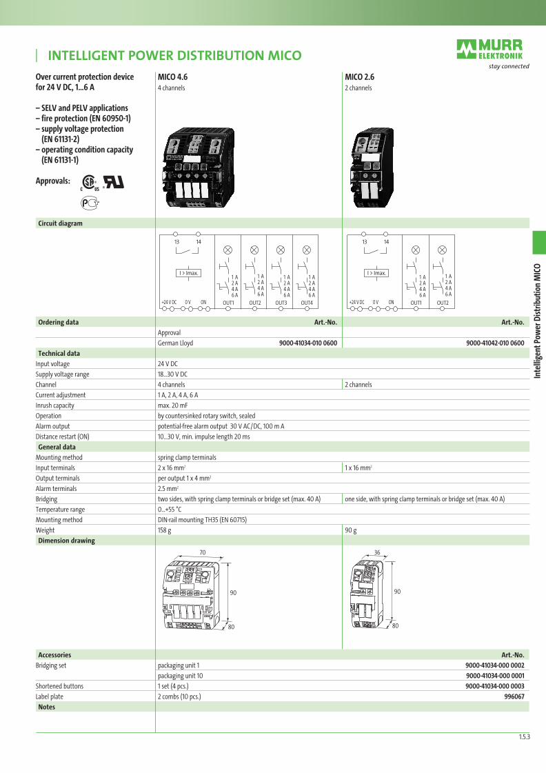
MICO 4.6 MICO 2.6 4 channels 2 channels
Over current protection device for 24 V DC, 1…6 A
– SELV and PELV applications– fire protection (EN 60950-1)– supply voltage protection
(EN 61131-2)– operating condition capacity
(EN 61131-1)
Approvals:
Circuit diagram
Ordering data Art.-No. Art.-No.
Approval
German Lloyd 9000-41034-010 0600 9000-41042-010 0600
Technical data
Input voltage 24 V DC
Supply voltage range 18…30 V DC
Channel 4 channels 2 channels
Current adjustment 1 A, 2 A, 4 A, 6 A
Inrush capacity max. 20 mF
Operation by countersinked rotary switch, sealed
Alarm output potential-free alarm output 30 V AC/DC, 100 m A
Distance restart (ON) 10…30 V, min. impulse length 20 ms
General data
Mounting method spring clamp terminals
Input terminals 2 x 16 mm2 1 x 16 mm2
Output terminals per output 1 x 4 mm2
Alarm terminals 2.5 mm2
Bridging two sides, with spring clamp terminals or bridge set (max. 40 A) one side, with spring clamp terminals or bridge set (max. 40 A)
Temperature range 0…+55 °C
Mounting method DIN-rail mounting TH35 (EN 60715)
Weight 158 g 90 g
Dimension drawing
13 14
I > Imax.
+24 V DC 0 V ON
1 A2 A4 A6 A
1 A2 A4 A6 A
1 A2 A4 A6 A
1 A2 A4 A6 A
OUT1 OUT2 OUT3 OUT4
Accessories Art.-No.
Bridging set packaging unit 1 9000-41034-000 0002
packaging unit 10 9000-41034-000 0001
Shortened buttons 1 set (4 pcs.) 9000-41034-000 0003
Label plate 2 combs (10 pcs.) 996067
Notes
1.5.3
Inte
llige
nt P
ower
Dist
ribut
ion
MIC
O
13 14
I > Imax.
+24 V DC 0 V ON
1 A2 A4 A6 A
1 A2 A4 A6 A
OUT1 OUT2
80
90
70
80
90
36
*
*
1-5-1_10_E_MICO.indd 5 31.03.2010 14:03:57 Uhr
Inte
llige
nt P
ower
Dist
ribut
ion
MIC
O
INtellIgeNt Power DIstrIbutIoN MICo|
1.5.4
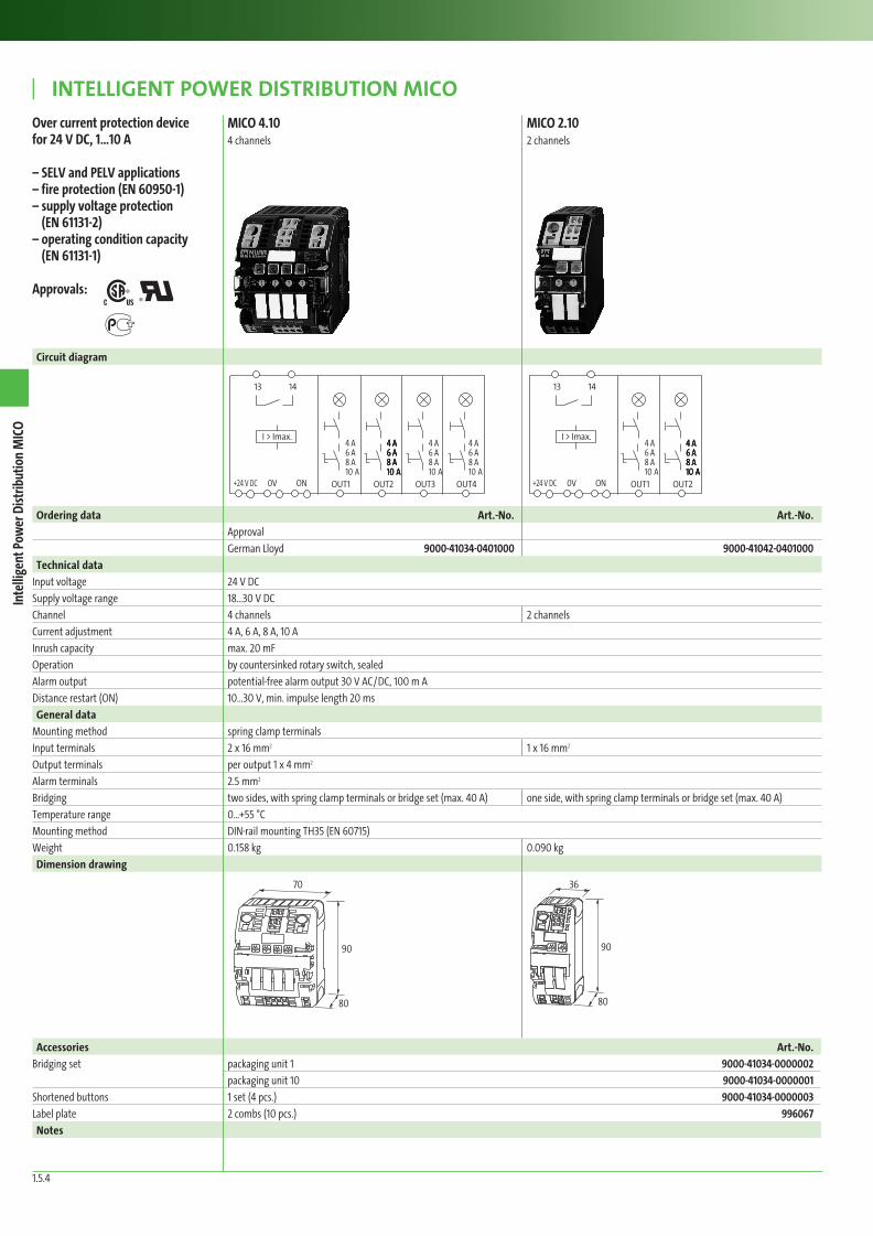
MICO 4.10 MICO 2.10 4 channels 2 channels
Over current protection device for 24 V DC, 1…10 A
– SELV and PELV applications– fire protection (EN 60950-1)– supply voltage protection
(EN 61131-2)– operating condition capacity
(EN 61131-1)
Approvals:
Circuit diagram
Ordering data Art.-No. Art.-No.
Approval
German Lloyd 9000-41034-0401000 9000-41042-0401000
Technical data
Input voltage 24 V DC
Supply voltage range 18…30 V DC
Channel 4 channels 2 channels
Current adjustment 4 A, 6 A, 8 A, 10 A
Inrush capacity max. 20 mF
Operation by countersinked rotary switch, sealed
Alarm output potential-free alarm output 30 V AC/DC, 100 m A
Distance restart (ON) 10…30 V, min. impulse length 20 ms
General data
Mounting method spring clamp terminals
Input terminals 2 x 16 mm2 1 x 16 mm2
Output terminals per output 1 x 4 mm2
Alarm terminals 2.5 mm2
Bridging two sides, with spring clamp terminals or bridge set (max. 40 A) one side, with spring clamp terminals or bridge set (max. 40 A)
Temperature range 0…+55 °C
Mounting method DIN-rail mounting TH35 (EN 60715)
Weight 0.158 kg 0.090 kg
Dimension drawing
13 14
I > Imax.
+24 V DC 0V ON
4 A 6 A 8 A 10 A
4 A 6 A 8 A 10 A
4 A 6 A 8 A 10 A
4 A 6 A 8 A 10 A
4 A 6 A 8 A 10 A
4 A 6 A 8 A 10 A
4 A 6 A 8 A 10 A
OUT1 OUT2 OUT3 OUT4
Accessories Art.-No.
Bridging set packaging unit 1 9000-41034-0000002
packaging unit 10 9000-41034-0000001
Shortened buttons 1 set (4 pcs.) 9000-41034-0000003
Label plate 2 combs (10 pcs.) 996067
Notes
13 14
I > Imax.
+24 V DC 0V ON
4 A 6 A 8 A 10 A
4 A 6 A 8 A 10 A
4 A 6 A 8 A 10 A
4 A 6 A 8 A 10 A
4 A 6 A 8 A 10 A
OUT1 OUT2
80
90
70
80
90
36
*
*
1-5-1_10_E_MICO.indd 6 31.03.2010 14:04:00 Uhr
Related Documents