ISSN 2395-695X (Print) ISSN 2395-695X (Online) International Journal of Advanced Research in Biology Engineering Science and Technology (IJARBEST) Vol. 2, Special Issue 10, March 2016 659 All Rights Reserved © 2016 IJARBEST INTELLIGENT FATIGUE DETECTION AND AUTOMATIC VEHICLE CONTROL SYSTEM Baby Shalini K 1 , Banupriya P 2 , Bhuvaneshwari S 3 , Eswari R 4 ,T.G.Dhaarani 5 1 and 2 and 3 and 4 B.E- Electronics And Communication Engineering, 5 ASSISTANT PROFESSOR/ECE Nandha Engineering College,Erode-52. 1 [email protected], 2 [email protected], 3 [email protected], 4 [email protected], [email protected]. I. INTRODUCTION INDIA is the second most populous Country in the World and is a fast growing economy. It is seeing terrible road congestion problems in its cities. Infrastructure growth is slow as compared to the growth in number of vehicles, due to space and cost constraints [1]. Also, Indian traffic is nonlane based and chaotic. It needs a traffic control solutions, which are different from the developed Countries. Intelligent management of traffic flows can reduce the negative impact of congestion. In recent years, wireless networks are widely used in the road transport as they provide more cost effective options [2]. Technologies like Wireless Remote, RFID and GSM can be used in traffic control to provide cost effective solutions. RFID is a wireless technology that uses radio frequency electromagnetic energy to carry information between the RFID tag and RFID reader. Some RFID systems will only work within the range inches or centimeters, while others may work for 100 meters (300 feet) or more. A GSM modem is a specialized type of modem, which accepts a SIM card and operates over a subscription to a mobile operator, just like a mobile phone. AT commands are used to control modems. These commands come from Hayes commands that were used by the Hayes smart modems. The Wireless Remote operates at low-power and can be used at all the levels of work configurations to perform predefined tasks. It operates in ISM bands (868 MHz in Europe, 915 MHz in USA and Australia, 2.4 GHz in rest of the world). Data transmission rates vary from 20 Kilobits/second in the 868 MHz frequency band to 250 Kilobits/second in the 2.4 GHz frequency band [3], [4]. The Wireless

Welcome message from author
This document is posted to help you gain knowledge. Please leave a comment to let me know what you think about it! Share it to your friends and learn new things together.
Transcript
ISSN 2395-695X (Print)
ISSN 2395-695X (Online)
International Journal of Advanced Research in Biology Engineering Science and Technology (IJARBEST)
Vol. 2, Special Issue 10, March 2016
659
All Rights Reserved © 2016 IJARBEST
INTELLIGENT FATIGUE DETECTION AND AUTOMATIC VEHICLE
CONTROL SYSTEM
Baby Shalini K1, Banupriya P
2, Bhuvaneshwari S
3,
Eswari R4,T.G.Dhaarani
5
1 and 2 and 3 and 4 B.E- Electronics And Communication Engineering,
5 ASSISTANT PROFESSOR/ECE
Nandha Engineering College,Erode-52. [email protected],
[email protected], [email protected],
I. INTRODUCTION
INDIA is the second most populous
Country in the World and is a fast growing
economy. It is seeing terrible road
congestion problems in its cities.
Infrastructure growth is slow as compared to
the growth in number of vehicles, due to
space and cost constraints [1]. Also, Indian
traffic is nonlane based and chaotic. It needs
a traffic control solutions, which are
different from the developed Countries.
Intelligent management of traffic flows can
reduce the negative impact of congestion. In
recent years, wireless networks are widely
used in the road transport as they provide
more cost effective options [2].
Technologies like Wireless Remote, RFID
and GSM can be used in traffic control to
provide cost effective solutions. RFID is a
wireless technology that uses radio
frequency electromagnetic energy to carry
information between the RFID tag and RFID
reader. Some RFID systems will only work
within the range inches or centimeters, while
others may work for 100 meters (300 feet)
or more. A GSM modem is a specialized
type of modem, which accepts a SIM card
and operates over a subscription to a mobile
operator, just like a mobile phone. AT
commands are used to control modems.
These commands come from Hayes
commands that were used by the Hayes
smart modems. The Wireless Remote
operates at low-power and can be used at all
the levels of work configurations to perform
predefined tasks. It operates in ISM bands
(868 MHz in Europe, 915 MHz in USA and
Australia, 2.4 GHz in rest of the world).
Data transmission rates vary from 20
Kilobits/second in the 868 MHz frequency
band to 250 Kilobits/second in the 2.4 GHz
frequency band [3], [4]. The Wireless
ISSN 2395-695X (Print)
ISSN 2395-695X (Online)
International Journal of Advanced Research in Biology Engineering Science and Technology (IJARBEST)
Vol. 2, Special Issue 10, March 2016
660
All Rights Reserved © 2016 IJARBEST
Remote uses 11 channels in case of 868/915
MHz radio frequency and 16 channelsin
case of 2.4 GHz radio frequency. It also uses
2 channel configurations, CSMA/CA and
slotted CSMA/CA [5].
II. LITERATURE SURVEY
Traffic congestion is a major problem
in cities of developing Countries like India.
Growth in urban population and the middle-
class segment contribute significantly to the
rising number of vehicles in the cities [6].
Congestion on roads eventually results in
slow moving traffic, which increases the
time of travel, thus stands-out as one of the
major issues in metropolitan cities. In [7],
green wave system was discussed, which
was used to provide clearance to any
emergency vehicle by turning all the red
lights to green on the path of the emergency
vehicle, hence providing a complete green
wave to the desired vehicle. A ‘green wave’
is the synchronization of the green phase of
traffic signals. With a ‘green wave’ setup, a
vehicle passing through a green signal will
continue to receive green signals as it travels
down the road. In addition to the green wave
path, the system will track a stolen vehicle
when it passes through a traffic light.
Advantage of the system is that GPS inside
the vehicle does not require additional
power. The biggest disadvantage of green
waves is that, when the wave is disturbed,
the disturbance can cause traffic problems
that can be exacerbated by the
synchronization.
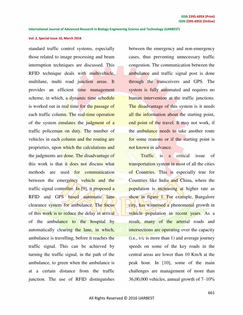
Fig. 1. Traffic in Bangalore city.
In such cases, the queue of vehicles in a
green wave grows in size until it becomes
too large and some of the vehicles cannot
reach the green lights in time and must stop.
This is called over-saturation.
In [8], the use of RFID traffic control to
avoid problems that usually arise with
ISSN 2395-695X (Print)
ISSN 2395-695X (Online)
International Journal of Advanced Research in Biology Engineering Science and Technology (IJARBEST)
Vol. 2, Special Issue 10, March 2016
661
All Rights Reserved © 2016 IJARBEST
standard traffic control systems, especially
those related to image processing and beam
interruption techniques are discussed. This
RFID technique deals with multivehicle,
multilane, multi road junction areas. It
provides an efficient time management
scheme, in which, a dynamic time schedule
is worked out in real time for the passage of
each traffic column. The real-time operation
of the system emulates the judgment of a
traffic policeman on duty. The number of
vehicles in each column and the routing are
proprieties, upon which the calculations and
the judgments are done. The disadvantage of
this work is that it does not discuss what
methods are used for communication
between the emergency vehicle and the
traffic signal controller. In [9], it proposed a
RFID and GPS based automatic lane
clearance system for ambulance. The focus
of this work is to reduce the delay in arrival
of the ambulance to the hospital by
automatically clearing the lane, in which,
ambulance is travelling, before it reaches the
traffic signal. This can be achieved by
turning the traffic signal, in the path of the
ambulance, to green when the ambulance is
at a certain distance from the traffic
junction. The use of RFID distinguishes
between the emergency and non-emergency
cases, thus preventing unnecessary traffic
congestion. The communication between the
ambulance and traffic signal post is done
through the transceivers and GPS. The
system is fully automated and requires no
human intervention at the traffic junctions.
The disadvantage of this system is it needs
all the information about the starting point,
end point of the travel. It may not work, if
the ambulance needs to take another route
for some reasons or if the starting point is
not known in advance.
Traffic is a critical issue of
transportation system in most of all the cities
of Countries. This is especially true for
Countries like India and China, where the
population is increasing at higher rate as
show in figure 1. For example, Bangalore
city, has witnessed a phenomenal growth in
vehicle population in recent years. As a
result, many of the arterial roads and
intersections are operating over the capacity
(i.e., v/c is more than 1) and average journey
speeds on some of the key roads in the
central areas are lower than 10 Km/h at the
peak hour. In [10], some of the main
challenges are management of more than
36,00,000 vehicles, annual growth of 7–10%
ISSN 2395-695X (Print)
ISSN 2395-695X (Online)
International Journal of Advanced Research in Biology Engineering Science and Technology (IJARBEST)
Vol. 2, Special Issue 10, March 2016
662
All Rights Reserved © 2016 IJARBEST
in traffic, roads operating at higher capacity
ranging from 1 to 4, travel speed less than
10 Km/h at some central areas in peak
hours, insufficient or no parking space for
vehicles, limited number of policemen. In
[11], currently a video traffic surveillance
and monitoring system commissioned in
Bangalore city. It involves a manual analysis
of data by the traffic management team to
determine the traffic light duration in each
of the junction. It will communicate the
same to the local police officers for the
necessary actions.
III. PROPOSED MODEL
From the current problem section, it
can be seen that, existing technologies are
insufficient to handle the problems of
congestion control, emergency vehicle
clearance, stolen vehicle detection, etc. To
solve these problems, we propose to
implement our Intelligent Traffic Control
System. It mainly consists of three parts.
First part contains automatic signal control
system. Here, each vehicle is equipped with
an RFID tag. When it comes in the range of
RFID reader, it will send the signal to the
RFID reader. The RFID reader will track
how many vehicles have passed through for
a specific period and determines the
congestion volume. Accordingly, it sets the
green light duration for that path. Second
part is for the emergency vehicle clearance.
Here, each emergency vehicle contains
Wireless Remote transmitter module and
the Wireless Remote receiver will be
implemented at the traffic junction. The
buzzer will be switched ON when the
vehicle is used for emergency purpose. This
will send the signal through the Wireless
Remote transmitter to the Wireless Remote
receiver. It will make the traffic light to
change to green. Once the ambulance passes
through, the receiver no longer receives the
Wireless Remote signal and the traffic light
is turned to red. The third part is responsible
for stolen vehicle detection. Here, when the
RFID reader reads the RFID tag, it compares
it to the list of stolen RFIDs. If a match is
found, it sends SMS to the police control
room and changes the traffic light to red, so
that the vehicle is made to stop in the traffic
junction and local police can take
appropriate action. List of components used
in the experiment are WIRELESS
REMOTERF module, Microchip
ARDUINO MEGA 2560, RFID Reader–
125KHz–TTL and SIM300 GSM module.
ISSN 2395-695X (Print)
ISSN 2395-695X (Online)
International Journal of Advanced Research in Biology Engineering Science and Technology (IJARBEST)
Vol. 2, Special Issue 10, March 2016
663
All Rights Reserved © 2016 IJARBEST
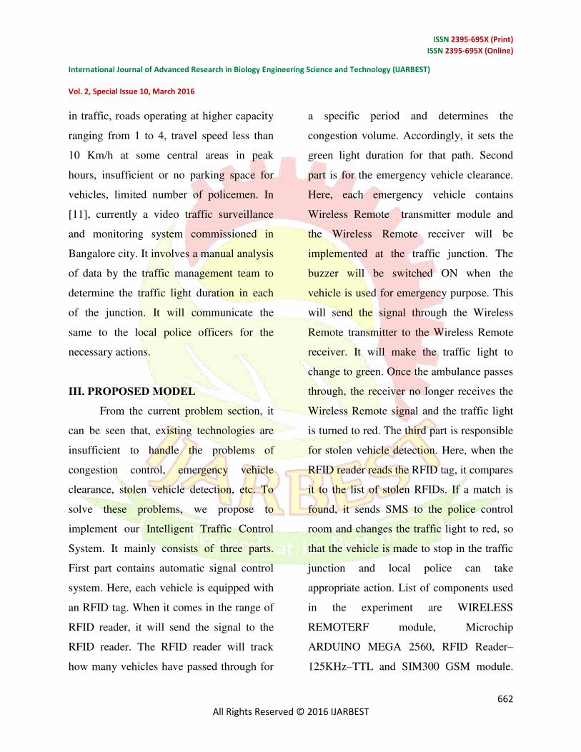
Figure 2 shows the pin diagrams (or
pictures) of components used.
Fig. 2. PIN diagrams of different
components used in our prototype. (a) Pin
diagram of Arduino MEGA 2560 (b) GSM
Module SIM300. (c) RFID reader–125 kHz–
TTL.
A. Wireless Remote Module
The is Wireless Remote a RF module
and has transreceiver, which provides an
easy way to use RF communication at 434
MHz. Every Wireless Remote is equipped
with the microcontroller which contains
Unique Identification Number (UIN). This
UIN is based on the registration number of
the vehicle. One of the most important
features isserial communication without any
extra hardware and no extra coding. Hence,
it is a transreceiver as it provides
communication in both directions, but only
one direction. The microcontroller and
Wireless Remote always communicate with
the microcontroller via serial
communication. Rx pin of is connected to
Tx (RC6) of microcontroller and Tx p
Wireless Remote in of CXC2500 is
connected to Rx pin of microcontroller
(RC7). Other two pins are used to energize
transreceiver. It is used to transmit and
receive the data at 9600 baud rate. Figure
4.1.a shows the image of transreceiver.
Here, we uses Wireless Remote module and
it has transmission range of 20 meters.
B. Microcontroller (ARDUINO MEGA
2560)
The Arduino Mega 2560 is a
microcontroller board based on the
ATmega2560 . It has 54 digital input/output
pins (of which 14 can be used as PWM
outputs), 16 analog inputs, 4 UARTs
(hardware serial ports), a 16 MHz crystal
oscillator, a USB connection, a power jack,
an ICSP header, and a reset button. It
ISSN 2395-695X (Print)
ISSN 2395-695X (Online)
International Journal of Advanced Research in Biology Engineering Science and Technology (IJARBEST)
Vol. 2, Special Issue 10, March 2016
664
All Rights Reserved © 2016 IJARBEST
contains everything needed to support the
microcontroller; simply connect it to a
computer with a USB cable or power it with
a AC-to-DC adapter or battery to get started.
The Mega is compatible with most shields
designed for the Arduino Duemilanove or
Diecimila.
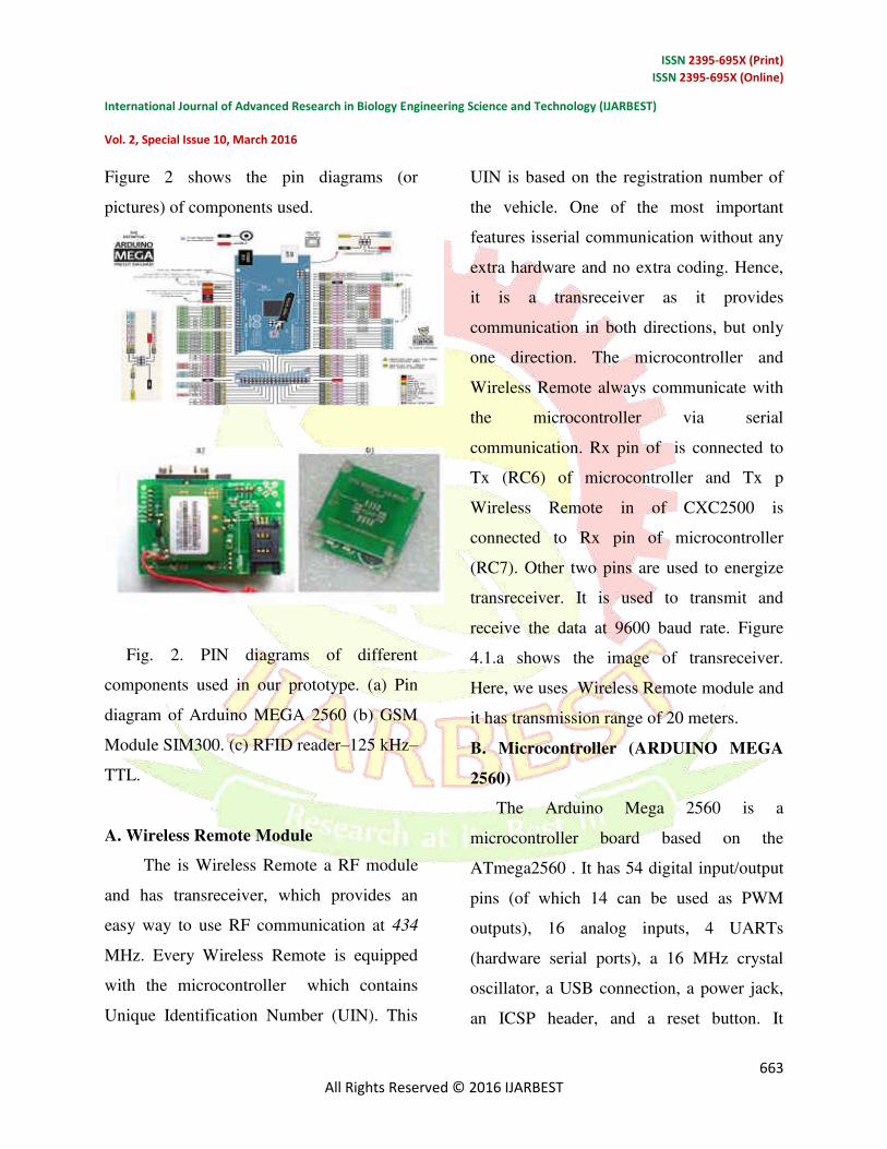
C. GSM Module SIM 300
Here, a GSM modem is connected with the
microcontroller. This allows the computer to
use the GSM modem to communicate over
the mobile network. These GSM modems
are most frequently used to provide mobile
Internet connectivity, many of them can also
be used for sending and receiving SMS and
MMS messages. GSM modem must support
an “extended AT command set” for
sending/receiving SMS messages. GSM
modems are a cost effective solution for
receiving SMS messages, because the sender
is paying for the message delivery. SIM 300
is designed for global market and it is a tri-
band GSM engine. It works on frequencies
EGSM 900 MHz, DCS 1800 MHz and PCS
1900 MHz. SIM300 features GPRS multi-
slot class 10/ class 8 (optional) and supports
the GPRS coding schemes. This GSM
modem is a highly flexible plug and play
quad band GSM modem, interface to
RS232, it supports features like voice, data,
SMS, GPRS and integrated TCP/IP stack. It
is controlled via AT commands (GSM
07.07,07.05 and enhanced AT commands).
It uses AC – DC power adaptor with
following ratings DC Voltage: 12V/1A.
D. RFID Reader–125 kHz–TTL
Radio Frequency Identification (RFID) is an
IT system that transmits signals without the
presence of physical gadgets in wireless
communication. It is categorized under
automatic identification technology, which
is well established protocol. The working of
an RFID system is very simple. The system
utilizes tags that are attached to various
components to be tracked. The tags store
data and information concerning the details
of the product of things to be traced. The
reader reads the radio frequency and
identifies the tags. The antenna provides the
means for the integrated circuit to transmit
its information to the reader. There are two
types of RFID categories, active and passive
tags. The tags that do not utilize power are
referred to as passive and they are driven by
an antenna that enables the tag to receive
electromagnetic waves from a reader. On the
contrary, active tags rely on power and they
ISSN 2395-695X (Print)
ISSN 2395-695X (Online)
International Journal of Advanced Research in Biology Engineering Science and Technology (IJARBEST)
Vol. 2, Special Issue 10, March 2016
665
All Rights Reserved © 2016 IJARBEST
have inbuilt power sources that enable it to
send and receive signals from RFID reader.
RFID range depends on transmit power,
receive sensitivity and efficiency, antenna,
frequency, tag orientations, surroundings.
Typically, the RFID range is from a few
centimeters to over hundred meters. RFID
reader uses frequency 125 KHz with a range
of 10 cm.
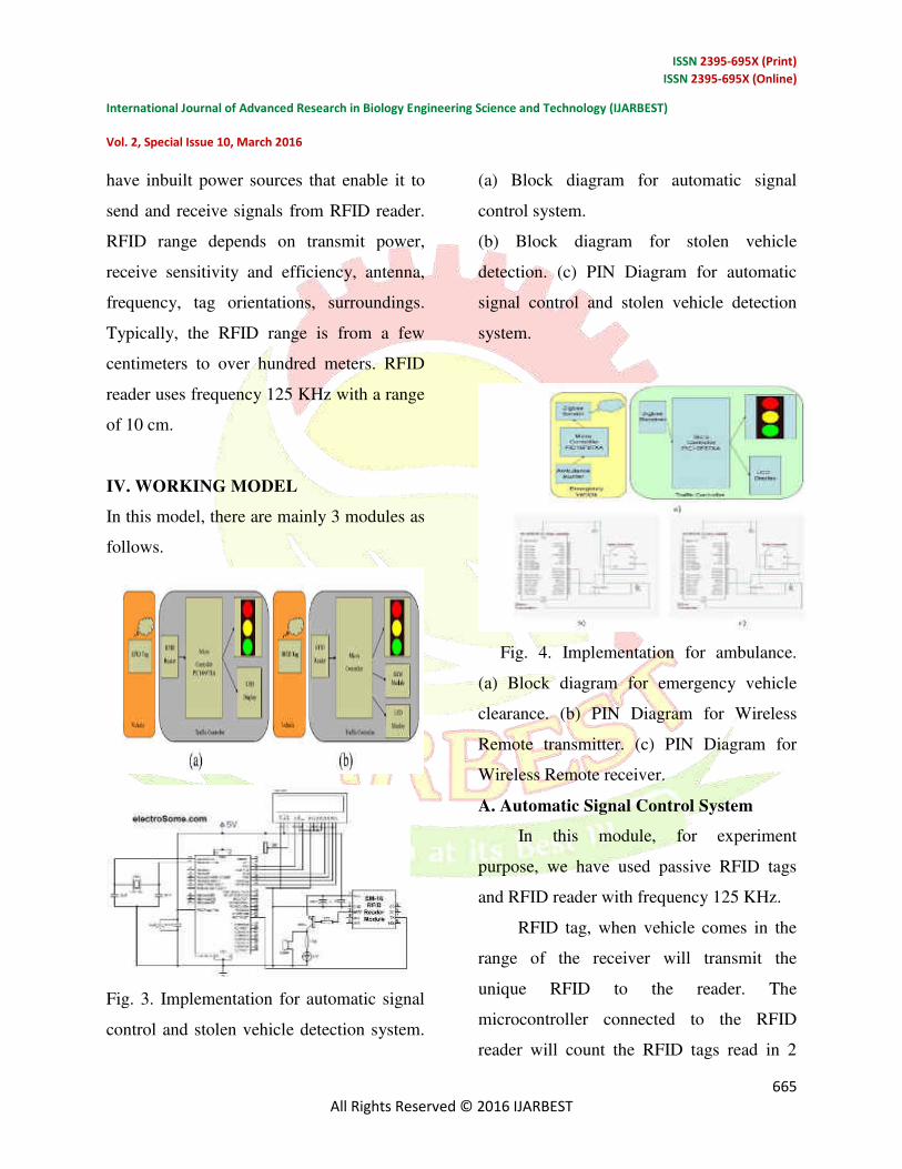
IV. WORKING MODEL
In this model, there are mainly 3 modules as
follows.
Fig. 3. Implementation for automatic signal
control and stolen vehicle detection system.
(a) Block diagram for automatic signal
control system.
(b) Block diagram for stolen vehicle
detection. (c) PIN Diagram for automatic
signal control and stolen vehicle detection
system.
Fig. 4. Implementation for ambulance.
(a) Block diagram for emergency vehicle
clearance. (b) PIN Diagram for Wireless
Remote transmitter. (c) PIN Diagram for
Wireless Remote receiver.
A. Automatic Signal Control System
In this module, for experiment
purpose, we have used passive RFID tags
and RFID reader with frequency 125 KHz.
RFID tag, when vehicle comes in the
range of the receiver will transmit the
unique RFID to the reader. The
microcontroller connected to the RFID
reader will count the RFID tags read in 2
ISSN 2395-695X (Print)
ISSN 2395-695X (Online)
International Journal of Advanced Research in Biology Engineering Science and Technology (IJARBEST)
Vol. 2, Special Issue 10, March 2016
666
All Rights Reserved © 2016 IJARBEST
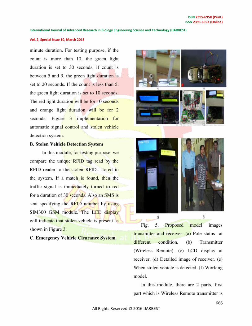
minute duration. For testing purpose, if the
count is more than 10, the green light
duration is set to 30 seconds, if count is
between 5 and 9, the green light duration is
set to 20 seconds. If the count is less than 5,
the green light duration is set to 10 seconds.
The red light duration will be for 10 seconds
and orange light duration will be for 2
seconds. Figure 3 implementation for
automatic signal control and stolen vehicle
detection system.
B. Stolen Vehicle Detection System
In this module, for testing purpose, we
compare the unique RFID tag read by the
RFID reader to the stolen RFIDs stored in
the system. If a match is found, then the
traffic signal is immediately turned to red
for a duration of 30 seconds. Also an SMS is
sent specifying the RFID number by using
SIM300 GSM module. The LCD display
will indicate that stolen vehicle is present as
shown in Figure 3.
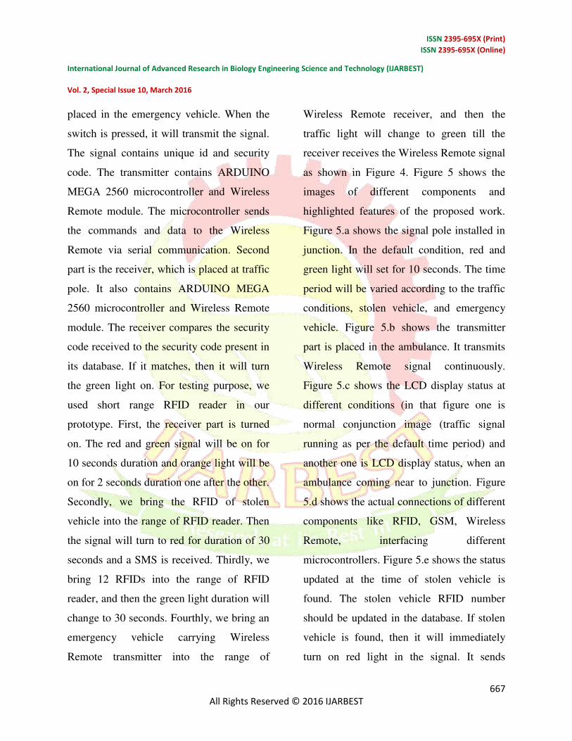
C. Emergency Vehicle Clearance System
Fig. 5. Proposed model images
transmitter and receiver. (a) Pole status at
different condition. (b) Transmitter
(Wireless Remote). (c) LCD display at
receiver. (d) Detailed image of receiver. (e)
When stolen vehicle is detected. (f) Working
model.
In this module, there are 2 parts, first
part which is Wireless Remote transmitter is
ISSN 2395-695X (Print)
ISSN 2395-695X (Online)
International Journal of Advanced Research in Biology Engineering Science and Technology (IJARBEST)
Vol. 2, Special Issue 10, March 2016
667
All Rights Reserved © 2016 IJARBEST
placed in the emergency vehicle. When the
switch is pressed, it will transmit the signal.
The signal contains unique id and security
code. The transmitter contains ARDUINO
MEGA 2560 microcontroller and Wireless
Remote module. The microcontroller sends
the commands and data to the Wireless
Remote via serial communication. Second
part is the receiver, which is placed at traffic
pole. It also contains ARDUINO MEGA
2560 microcontroller and Wireless Remote
module. The receiver compares the security
code received to the security code present in
its database. If it matches, then it will turn
the green light on. For testing purpose, we
used short range RFID reader in our
prototype. First, the receiver part is turned
on. The red and green signal will be on for
10 seconds duration and orange light will be
on for 2 seconds duration one after the other.
Secondly, we bring the RFID of stolen
vehicle into the range of RFID reader. Then
the signal will turn to red for duration of 30
seconds and a SMS is received. Thirdly, we
bring 12 RFIDs into the range of RFID
reader, and then the green light duration will
change to 30 seconds. Fourthly, we bring an
emergency vehicle carrying Wireless
Remote transmitter into the range of
Wireless Remote receiver, and then the
traffic light will change to green till the
receiver receives the Wireless Remote signal
as shown in Figure 4. Figure 5 shows the
images of different components and
highlighted features of the proposed work.
Figure 5.a shows the signal pole installed in
junction. In the default condition, red and
green light will set for 10 seconds. The time
period will be varied according to the traffic
conditions, stolen vehicle, and emergency
vehicle. Figure 5.b shows the transmitter
part is placed in the ambulance. It transmits
Wireless Remote signal continuously.
Figure 5.c shows the LCD display status at
different conditions (in that figure one is
normal conjunction image (traffic signal
running as per the default time period) and
another one is LCD display status, when an
ambulance coming near to junction. Figure
5.d shows the actual connections of different
components like RFID, GSM, Wireless
Remote, interfacing different
microcontrollers. Figure 5.e shows the status
updated at the time of stolen vehicle is
found. The stolen vehicle RFID number
should be updated in the database. If stolen
vehicle is found, then it will immediately
turn on red light in the signal. It sends
ISSN 2395-695X (Print)
ISSN 2395-695X (Online)
International Journal of Advanced Research in Biology Engineering Science and Technology (IJARBEST)
Vol. 2, Special Issue 10, March 2016
668
All Rights Reserved © 2016 IJARBEST
immediately a message to authorized person.
Figure 5.f shows the working model of the
proposed work.
V.CONCLUSION AND
ENHANCEMENTS
With automatic traffic signal control
based on the traffic density in the route, the
manual effort on the part of the traffic
policeman is saved. As the entire system is
automated, it requires very less human
intervention. With stolen vehicle detection,
the signal automatically turns to red, so that
the police officer can take appropriate
action, if he/she is present at the junction.
Also SMS will be sent so that they can
prepare to catch the stolen vehicle at the
next possible junctions. Emergency vehicles
like ambulance, fire trucks, need to reach
their destinations at the earliest. If they
spend a lot of time in traffic jams, precious
lives of many people may be in danger.
With emergency vehicle clearance, the
traffic signal turns to green as long as the
emergency vehicle is waiting in the traffic
junction. The signal turns to red, only after
the emergency vehicle passes through.
Further enhancements can be done to the
prototype by testing it with longer range
RFID readers. Also GPS can be placed into
the stolen vehicle detection module, so that
the exact location of stolen vehicle is
known. Currently, we have implemented
system by considering one road of the traffic
junction. It can be improved by extending to
all the roads in a multi-road junction.
Ultrasonic sensor is used to get accurate
result.
REFERENCES
[1] G. Varaprasad and R. S. D. Wahidabanu,
“Flexible routing algorithm
for vehicular area networks,” in Proc. IEEE
Conf. Intell. Transp. Syst.
Telecommun., Osaka, Japan, 2010, pp. 30–
38.
[2] B. P. Gokulan and D. Srinivasan,
“Distributed geometric fuzzy multiagent
urban traffic signal control,” IEEE Trans.
Intell. Transp. Syst.,vol. 11, no. 3, pp. 714–
727, Sep. 2010.
[3] K. Sridharamurthy, A. P. Govinda, J. D.
Gopal, and G. Varaprasad,
“Violation detection method for vehicular ad
hoc networking,”
Security Commun. Netw., to be published.
[Online]. Available:
ISSN 2395-695X (Print)
ISSN 2395-695X (Online)
International Journal of Advanced Research in Biology Engineering Science and Technology (IJARBEST)
Vol. 2, Special Issue 10, March 2016
669
All Rights Reserved © 2016 IJARBEST
http://onlinelibrary.wiley.com/doi/10.1002/s
ec.427/abstract
[4] M. Abdoos, N. Mozayani, and A. L. C.
Bazzan, “Traffic light control in non-
stationary environments based on multi
agent Q-learning,” in Proc.14th Int. IEEE
Conf. Intell. Transp. Syst., Oct. 2011, pp.
580–1585.
[5] Wireless Remote Specifications,
Wireless Remote Alliance IEEE Standard
802.15.4k2013,2014. [Online]. Available:
http://www.Wireless
Remote.org/Specifications.aspx
[6] Traffic Congestion in Bangalore—A
Rising Concern. [Online].
Available:http://www.commonfloor.com/gui
de/traffic-congestion-in-bangalore-arising-
concern-27238.html, accessed 2013.
[7] A. K. Mittal and D. Bhandari, “A novel
approach to implement green
wave system and detection of stolen
vehicles,” in Proc. IEEE 3rd Int.
Adv. Comput., Feb. 2013, pp. 1055–1059.
[8] S. Sharma, A. Pithora, G. Gupta, M.
Goel, and M. Sinha, “Traffic light priority
control for emergency vehicle using RFID,”
Int. J. Innov. Eng.Technol., vol. 2, no. 2, pp.
363–366, 2013.
[9] R. Hegde, R. R. Sali, and M. S. Indira,
“RFID and GPS based automatic lane
clearance system for ambulance,” Int. J.
Adv. Elect. Electron. Eng.,vol. 2, no. 3, pp.
102–107, 2013.
[10] P. Sood. Bangalore Traffic Police-
Preparing for the Future. [Online].Available:
http://www.intranse.in/its1/sites/default/files
/D1-S2-, accesse2011.
[11] Traffic Management Centre. [Online].
Available: http://www.
bangaloretrafficpolice.gov.in/index.php?
option=com_content&view=
article&id=87&btp=87, accessed 2014.
[12] G. Varaprasad, “High stable power
aware multicast algorithm for mobile ad hoc
networks,” IEEE Sensors J., vol. 13, no. 5,
pp. 1442–1446,May 2013.
[13] Traffic Solution. [Online]. Available:
http://phys.org/news/2013–05-physics-
green-city-traffic-smoothly.html, accessed
2013.
Related Documents