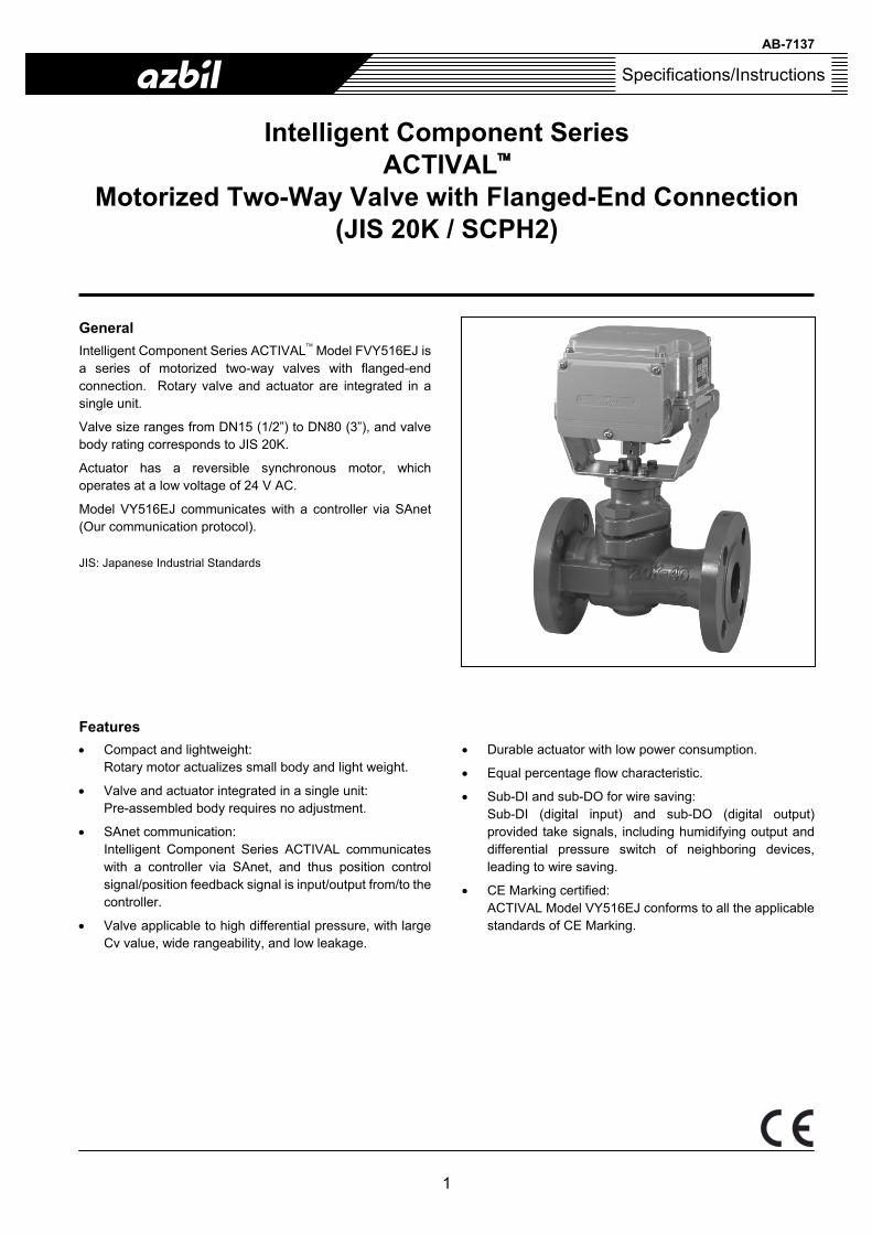
AB-7137 1 Specifications/Instructions Intelligent Component Series ACTIVAL™ Motorized Two-Way Valve with Flanged-End Connection (JIS 20K / SCPH2) General Intelligent Component Series ACTIVAL ™ Model FVY516EJ is a series of motorized two-way valves with flanged-end connection. Rotary valve and actuator are integrated in a single unit. Valve size ranges from DN15 (1/2”) to DN80 (3”), and valve body rating corresponds to JIS 20K. Actuator has a reversible synchronous motor, which operates at a low voltage of 24 V AC. Model VY516EJ communicates with a controller via SAnet (Our communication protocol). JIS: Japanese Industrial Standards Features • Compact and lightweight: Rotary motor actualizes small body and light weight. • Valve and actuator integrated in a single unit: Pre-assembled body requires no adjustment. • SAnet communication: Intelligent Component Series ACTIVAL communicates with a controller via SAnet, and thus position control signal/position feedback signal is input/output from/to the controller. • Valve applicable to high differential pressure, with large Cv value, wide rangeability, and low leakage. • Durable actuator with low power consumption. • Equal percentage flow characteristic. • Sub-DI and sub-DO for wire saving: Sub-DI (digital input) and sub-DO (digital output) provided take signals, including humidifying output and differential pressure switch of neighboring devices, leading to wire saving. • CE Marking certified: ACTIVAL Model VY516EJ conforms to all the applicable standards of CE Marking.

Welcome message from author
This document is posted to help you gain knowledge. Please leave a comment to let me know what you think about it! Share it to your friends and learn new things together.
Transcript
AB-7137
1
Specifications/Instructions
Intelligent Component Series ACTIVAL™
Motorized Two-Way Valve with Flanged-End Connection (JIS 20K / SCPH2)
General
Intelligent Component Series ACTIVAL™ Model FVY516EJ is a series of motorized two-way valves with flanged-end connection. Rotary valve and actuator are integrated in a single unit.
Valve size ranges from DN15 (1/2”) to DN80 (3”), and valve body rating corresponds to JIS 20K.
Actuator has a reversible synchronous motor, which operates at a low voltage of 24 V AC.
Model VY516EJ communicates with a controller via SAnet (Our communication protocol).
JIS: Japanese Industrial Standards
Features
• Compact and lightweight: Rotary motor actualizes small body and light weight.
• Valve and actuator integrated in a single unit: Pre-assembled body requires no adjustment.
• SAnet communication: Intelligent Component Series ACTIVAL communicates with a controller via SAnet, and thus position control signal/position feedback signal is input/output from/to the controller.
• Valve applicable to high differential pressure, with large Cv value, wide rangeability, and low leakage.
• Durable actuator with low power consumption.
• Equal percentage flow characteristic.
• Sub-DI and sub-DO for wire saving: Sub-DI (digital input) and sub-DO (digital output) provided take signals, including humidifying output and differential pressure switch of neighboring devices, leading to wire saving.
• CE Marking certified: ACTIVAL Model VY516EJ conforms to all the applicable standards of CE Marking.
AB-7137
2
Safety Instructions
Please read instructions carefully and use the product as specified in this manual. Be sure to keep this manual near by for ready reference.
Restrictions
This product is targeted for general air conditioning. Do not use this product in a situation where human life may be affected. If this product is used in a clean room or a place where reliability or control accuracy is particularly required, please contact oursales representative. Azbil Corporation will not bear any responsibility for the results produced by the operators.
Warnings and Cautions
WARNING Alerts users that improper handling may cause death or serious injury.
CAUTION Alerts users that improper handling may cause minor injury or material loss.
Signs
Alerts users possible hazardous conditions caused by erroneous operation or erroneous use. The symbol inside indicates the specific type of danger. (For example, the sign on the left warns of the risk of electric shock.)
Notifies users that specific actions are prohibited to prevent possible danger. The symbol inside graphically indicates the prohibited action. (For example, the sign on the left notifies that disassembly is prohibited.)
Instructs users to carry out a specific obligatory action to prevent possible danger. The symbol inside graphically indicates the actual action to be carried out. (For example, the sign on the left indicates general instructions.)
WARNING
Some of the product models weigh more than 18 kg. Carefully move the product with a vehicle or enough manpower in an appropriate manner. Careless lift or accidental drop of the product might cause injury or product damage.
Be sure to ground the product with ground resistance of less than 100 Ω. Improper grounding might cause electric shock or malfunction.
Detach the terminal cover only when wiring and setting the product and reattach the terminal cover after wiring and setting the product. Failure to do so might cause electric shock.
Before wiring or maintenance, be sure to turn off the power to the product. Failure to do so might cause electric shock or device failure.
CAUTION (1/2)
Install and use the product under the operating conditions requirement (temperature, humidity, power, vibration, shock, mounting direction, atmospheric condition, etc.) as listed in the specifications. Failure to do so might cause fire or device failure.
Do not allow the fluid to freeze. Doing so might damage the valve body and cause fluid leakage.
Use the product within its lifespan and avoid instrumentations that keep the product to operate excessively. Continued use beyond the lifespan might cause fire or device failure.
Do not install the product nearby a steam coil or a hot-water coil. High temperature radiation might cause malfunction of its actuator.
Install the product in the proper position as specified in this manual. Excessively tight connection to a pipe or improper installation position might damage the product.
Install the product with flange gasket so that the flange gasket will not go inside the pipe.
After installation, make sure no fluid leaks from the valve-pipe connections. Incorrect installation might cause fluid leakage.
AB-7137
3
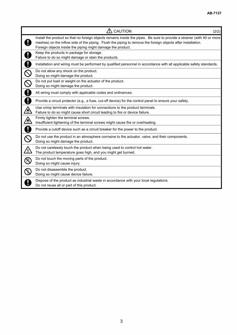
CAUTION (2/2)
Install the product so that no foreign objects remains inside the pipes. Be sure to provide a strainer (with 40 or more meshes) on the inflow side of the piping. Flush the piping to remove the foreign objects after installation. Foreign objects inside the piping might damage the product.
Keep the products in package for storage. Failure to do so might damage or stain the products.
Installation and wiring must be performed by qualified personnel in accordance with all applicable safety standards.
Do not allow any shock on the product. Doing so might damage the product.
Do not put load or weight on the actuator of the product. Doing so might damage the product.
All wiring must comply with applicable codes and ordinances.
Provide a circuit protector (e.g., a fuse, cut-off device) for the control panel to ensure your safety.
Use crimp terminals with insulation for connections to the product terminals. Failure to do so might cause short circuit leading to fire or device failure.
Firmly tighten the terminal screws. Insufficient tightening of the terminal screws might cause fire or overheating.
Provide a cutoff device such as a circuit breaker for the power to the product.
Do not use the product in an atmosphere corrosive to the actuator, valve, and their components. Doing so might damage the product.
Do not carelessly touch the product when being used to control hot water. The product temperature goes high, and you might get burned.
Do not touch the moving parts of the product. Doing so might cause injury.
Do not disassemble the product. Doing so might cause device failure.
Dispose of the product as industrial waste in accordance with your local regulations. Do not reuse all or part of this product.

AB-7137
4
System Configurations
Notes: *1 Up to two SAnet I/F (interface) module can be connected to one Infilex GC/Infilex GD. *2 For detailed specifications of SAnet, refer to Installation Manual of Intelligent Component Series for SAnet Communication
(AB-6713). *3 One ACTIVAL or damper actuator requires one SAnet address. One ACTIVAL PLUS requires two SAnet addresses.
Figure 1. System configuration example: SAnet connection in our BMS
BMS
Infilex™ GC Model WY5111
Infilex™ GD Model WY5110
Infilex™ AC Model WY5117C
Infilex™ FC Model WY5205
Infilex™ VC Model WY5206
NeopanelModel QY7205
(Digital user terminal)
Neoplate Model QY7290 (Analog user terminal)
NC-bus (Max. 500 m long but extendable up to 1 km using a repeater, Max. 25 remote units (controllers) connectable.)
SC-bus (Max. 1 km long, Max. 50 remote units (sub-controllers) connectable.)
SAnet I/F*1
Intelligent ComponentSeries
ACTIVAL™
Infilex™ ZM Model WY5122
SAnet*2 (Max. 15 addresses*3)
Intelligent Component Series
Damper actuator
Display Panel
Intelligent Component Series
ACTIVAL™ PLUS
Temperature sensor for pipe surface
For BMS (Building Management System) applicable to SAnet network, please ask our salesperson.
PARAMATRIX™ 4Model WY5130P
PARAMATRIX™ 4Model WY5130Q

AB-7137
5
Model Numbers
Model VY516EJ00XX is the model for the valve and actuator integrated into a single unit. The model number label is attached to the yoke.
Actuator/valve Actuator ValveBase model
number Control signal
Rating/ material
Type ⎯ Nominal size/Cv
⎯ Description
VY51 Motorized two-way valve with flanged-end connection
6 SAnet
E JIS 20K / SCPH2
J
IEC IP54 protected and standard torque type actuator with terminal block (Mountable valve sizes: DN15 to DN80)
00 Fixed
11 DN15 (1/2”) / 1.0 in Cv value 12 DN15 (1/2”) / 2.5 in Cv value 13 DN15 (1/2”) / 6.0 in Cv value 21 DN25 (1”) / 10 in Cv value 22 DN25 (1”) / 16 in Cv value 41 DN40 (11/2”) / 25 in Cv value 42 DN40 (11/2”) / 40 in Cv value 51 DN50 (2”) / 65 in Cv value 61 DN65 (21/2”) / 95 in Cv value 81 DN80 (3”) / 125 in Cv value
-B Fixed
AB-7137
6
Specifications
For weight, refer to the table shown in the section Dimensions.
Valve and actuator (as a single unit) specifications
Item Specification
Ambient temperature -20 °C to 50 °C (Applicable fluid temperature: 0 °C to 150 °C Do not allow the process fluid to freeze.)
Ambient humidity 5 %RH to 95 %RH
Rated operating conditions
Vibration 4.9 m/s2 (10 Hz to 150 Hz) Ambient temperature -20 °C to 70 °C Ambient humidity 5 %RH to 95 %RH
Environmental conditions
Transport/storage conditions (in package)
Vibration 19.6 m/s2 (10 Hz to 150 Hz) Installation locations Indoor / outdoor (Optional outdoor cover must be used, and salt air and corrosive gas must
be avoided.) Installation orientation Installable in any position ranging from upright to sideways (90° tilted.)
* Always install in upright position outdoors. Manual operation Available. Refer to the section Manually opening/closing the ACTIVAL. Position for shipment 100 % (fully open) preset at factory.
Valve specifications
Item Specification
Model Two-way valve with flanged-end connection Body pressure rating JIS 20K (Max. working pressure: 2.0 MPa) End connection JIS 20K flanged-end, raised flange
Model number Nominal size Cv Close-off ratingsVY516EJ0011 DN15 (1/2”) 1.0 1.0 MPa VY516EJ0012 DN15 (1/2”) 2.5 1.0 MPa VY516EJ0013 DN15 (1/2”) 6.0 1.0 MPa VY516EJ0021 DN25 (1”) 10 1.0 MPa VY516EJ0022 DN25 (1”) 16 1.0 MPa VY516EJ0041 DN40 (11/2”) 25 1.0 MPa VY516EJ0042 DN40 (11/2”) 40 1.0 MPa VY516EJ0051 DN50 (2”) 65 1.0 MPa VY516EJ0061 DN65 (21/2”) 95 1.0 MPa
Size, Cv, Close-off rating
VY516EJ0081 DN80 (3”) 125 0.7 MPa Applicable fluid Chilled/hot water, high temperature water, brine (ethylene glycol solutions, 50 % max.) Allowable fluid temperature 0 °C to 150 °C Flow characteristic Equal percentage Rangeability 100 : 1 Seat leakage 0.01 % of rated Cv value (0.0006 Cv or less for DN15 model) Materials Body Cast carbon steel (equivalent to JIS SCPH2) Plug, stem Stainless steel Seat ring, gland packing Heat-resistant PTFE Gasket Expandable graphite sheet Paint Gray (equivalent to M5B 4/1) Actuator to be combined Integrated with the valve

AB-7137
7
Actuator specifications
Item Specification
Power supply 24 V AC ± 15 %, 50 Hz/60 Hz Applicable valve type DN15 to DN80, standard torque Power consumption 10 VA Timing 63 ± 5 sec (50 Hz) / 53 ± 5 sec (60 Hz) Control signal SAnet
Input type Potential free (dry) contact input Sub-DI (contact input) Voltage, current 20 V DC, 5 mA
(* Unlike Models VY516XK, VY516XH, this product does not have forced shutoff DI.) Output type Potential free (dry) contact output Contact rating 200 V AC/24 V DC, Max. 0.5 A (2 A at startup)
Sub-DO (contact output)
Min. applicable load 24 V DC, 5 mA LED indication Description
Initializing Continuous ON → LED indication corresponding to the operating status (after initializing is complete.)
Normal Repetition of 1-second ON → 1-second OFF.
Major alarm Continuous ON. Minor alarm Repetition of
1-second ON → 0.25-second OFF → 0.25-second ON → 0.25-second OFF.
Communication error
(and minor alarm) Repetition of 0.25-second ON → 0.25-second OFF.
Manual operation Repetition of
0.25-second ON → 0.25-second OFF → 0.25-second ON → 1.25-second OFF.
Error during
manual operation Repetition of 0.25-second ON → 0.25-second OFF → 0.25-second ON → 0.25-second OFF → 0.25-second ON → 0.75-second OFF.
Transmission system Voltage transmission Transmission speed 1200 bps
Communication (SAnet)
Transmission distance Transmission distance varies depending on the number of devices and the type of devices to be connected to. For details regarding the transmission distance, refer to Installation Manual of Intelligent Component Series for SAnet Communication (AB-6713).
Materials Case Die cast aluminum Top cover, terminal cover Polycarbonate resin (Color: gray) Yoke Steel plate Surface finishing Case None Yoke Electro-galvanized (Bright chromate finish) Valve position indication Pointer located at the bottom of the actuator shows the position by pointing at the value of
the scale (0: close to 100: open) on front, rear, and bottom sides. Terminals connection M3.5 screw terminals Enclosure rating IEC IP54 (dust-proof and splash-proof) Insulation resistance Between terminal and case: 5 MΩ or higher at 500 V DC Dielectric strength Between terminal and case: 500 V AC/min with 5 mA or less leakage current
1s
1s
ON
OFF
1s
0.25s
0.25s
0.25s
ON
OFF
0.25s
0.25s
0.25s
0.25s 0.25s
0.25s
ON
OFF
0.25s
0.25s
0.25s 0.25s
1.25s
ON
OFF
0.25s
0.25s
0.25s
0.25s 0.25s
0.75s
ON
OFF

AB-7137
8
Function
Function Specification
Data monitoring Following items can be monitored/operated from our BMS and Infilex GC/ Infilex GD. Valve position setting, actual valve position, sub-DO, sub-DI
Note: Above function is available in combination with Infilex GC/Infilex GD and our BMS.
Wire Specifications
For details regarding specifications of SAnet communication line (24 V (∼), GND (⊥), SAnet), refer to the Installation Manual of SAnet for Intelligent Component Series (AB-6713).
Item Specification Length
Contact input (sub-DI) JIS CVV, JIS VCT, JIS IV, KPEV for low power 0.75 mm2, 0.9 mm2, 1.25 mm2, 2.0 mm2
30 m
Contact output (sub-DO) JIS CVV, JIS VCT, JIS IV, KPEV for low power 0.75 mm2, 0.9 mm2, 1.25 mm2, 2.0 mm2
30 m
KPEV: Wire standard provided by Furukawa Electric Co., Ltd.
Options
Separately order the following optional parts if needed.
Item Specification Note
Part No. 83104346-003 Applicable wire size: ø7 mm to ø9 mm Part No. 83104346-004 Applicable wire size: ø9 mm to ø11 mm
Seal connector
Part No. 83104346-005 Applicable wire size: ø11 mm to ø13 mm
Seal connector is necessary for IEC IP54 protection.
Part No. 83104346-012 Applicable wire size: ø6 mm to ø8 mm Part No. 83104346-013 Applicable wire size: ø7 mm to ø9 mm
Seal connector for cable gland with three ports Part No. 83104346-014 Applicable wire size: ø9 mm to ø11 mm
Seal connector for the cable gland with three ports is necessary for IEC IP54 protection.
Cable gland with three ports Part No. DY7000A1000
Do not use the cable gland with three ports outdoors.
For the specifications of the cable gland with three ports, refer to the Specifications (AS-923E). For the installation of the cable gland with three ports, refer to the Installation Manual of Intelligent Component Series for SAnet Communication (AB-6713).
Outdoor cover Part No. DY3001A1017 Required when the product is installed outdoors.
CE Marking Conformity
This product complies with the following Electromagnetic Compatibility (EMC).
EMC : EN61000-6-2, EN55011 Class A

AB-7137
9
Dimensions
Model number Valve size
(DN) H (mm) H1 (mm) L (mm) L1 (mm) t (mm)
øC (mm)
øD (mm)
øg (mm) øh (mm) NWeight
(kg)
VY516EJ001X 15 213 75 140 50 14 70 95 51 15 4 5.2 VY516EJ002X 25 228 90 165 60 16 90 125 67 19 4 7.4 VY516EJ004X 40 241 103 190 82.5 18 105 140 81 19 4 10.5 VY516EJ0051 50 245 107 216 115 18 120 155 96 19 8 12 VY516EJ0061 65 262 124 241 120.5 20 140 175 116 19 8 17 VY516EJ0081 80 263 125 283 123 22 160 200 132 23 8 22
Figure 2. Dimensions (mm)
Parts Identifications
Figure 3. Parts identification
Gland packing
Top cover
Terminal cover
Knockout
Terminal cover
Top cover
Pointer
Joint
Stem
Seat ring
Actuator
Yoke
Valve body
: Heat insulation
Plug
Bonnet
70 70
L1 L
t
H1
H
138
øC
øD
82 85
N × øh
øg
Min. 600
Min
. 300
Flow direction
Min. 300Min. 300
Min. 300
Note: Leave enough clearance for maintenance and wire connection after installation. 600 mm or more clearance is recommended. Install the product in a location where address setting inside the cover can visually be checked.
AB-7137
10
Installation
Precautions for installation
WARNING
Some of the product models weigh more than 18 kg. Carefully move the product with a vehicle or enough manpower in an appropriate manner. Careless lift or accidental drop of the product might cause injury or product damage.
CAUTION
Install the product in the proper position as specified in this manual. Excessively tight connection to a pipe or improper installation position might damage the product.
Install the product with flange gasket so that the flange gasket will not go inside the pipe.
After installation, make sure no fluid leaks from the valve-pipe connections. Incorrect installation might cause fluid leakage
Install the product so that no foreign objects remains inside the pipes. Be sure to provide a strainer (with 40 or more meshes) on the inflow side of the piping. Flush the piping to remove the foreign objects after installation. Foreign objects inside the piping might damage the product.
Keep the products in package for storage. Failure to do so might damage or stain the products.
Installation and wiring must be performed by qualified personnel in accordance with all applicable safety standards.
• ACTIVAL Model VY516EJ is the valve and actuator integrated into a single unit. Do not combine the valve with any other actuator, or do not combine the actuator with any other valve.
• To remove foreign objects inside the pipes, install a strainer with 40 or more meshes on the inflow side of each valve. If the strainers cannot be installed on the inflow side of each valve, install it on the pipe diverting sections (sections diverting from main piping system to sub piping system).
• Install the valve so that the flow direction of process fluid agrees with the arrow indicated on the valve body.
Installation location
CAUTION
Do not install the product nearby a steam coil or a hot-water coil. High temperature radiation might cause malfunction of its actuator.
Do not use the product in an atmosphere corrosive to the actuator, valve, and their components. Doing so might damage the product.
IMPORTANT:
• The top and the terminal covers might be corroded by chemicals and organic solvent or their vapor. Do not expose the product to such substances/vapor.
• Although the product can be used in high humidity environments (max. 95 %RH), do not immerse the actuator in water.
• Although the product can be used outdoors, be sure not to expose the actuator to direct sunlight.
• Install the product in a position allowing easy access for maintenance and inspection. Fig. 2 shows the minimum clearance for maintenance and inspection. When installing the product in a ceiling space, provide an access hole within the 50 cm radius of the product. And, place a drain pan under the valve.
• Do not mount the product on a pipe where water hammer occurs, or where solid objects including slug may accumulate.
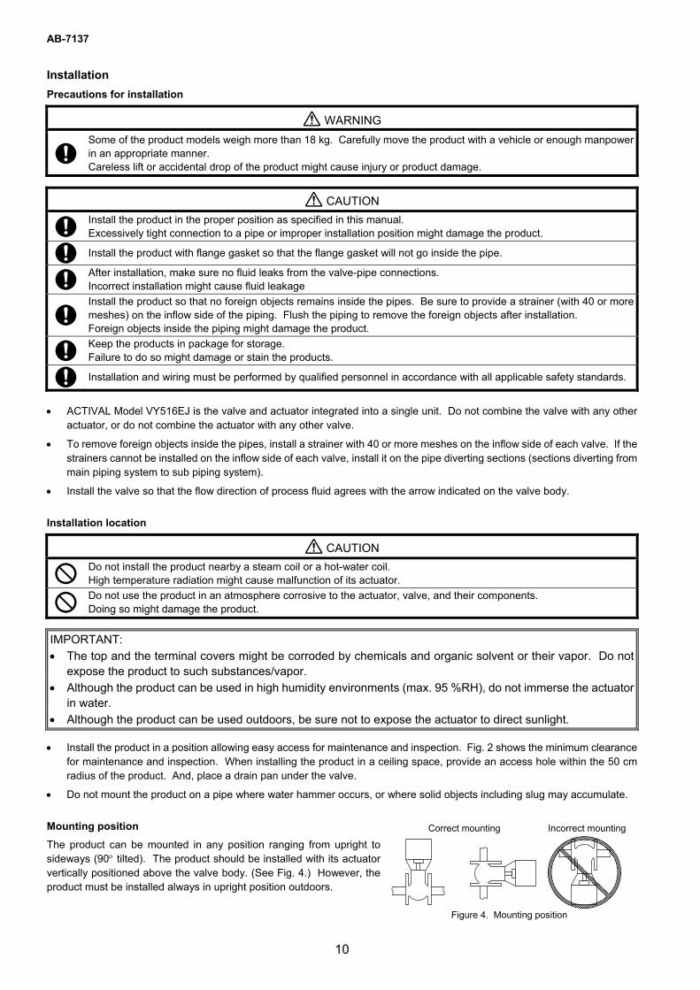
Mounting position
The product can be mounted in any position ranging from upright to sideways (90° tilted). The product should be installed with its actuator vertically positioned above the valve body. (See Fig. 4.) However, the product must be installed always in upright position outdoors.
Correct mounting Incorrect mounting
Figure 4. Mounting position
AB-7137
11
Piping
• Check that the model number of the product is what you ordered. The model number is shown on the label attached to the yoke.
• Install a bypass pipe and gate valves on the inflow, outflow, and bypass sides. Also, install a strainer with 40 or more meshes on the inflow side.
• When installing the product to the pipes, do not allow any object, such as chips, to get inside a pipe or valve. Valve cannot fully close, or the valve seat may get damaged causing fluid leakage, due to an object jammed inside the valve.
• When piping, do not apply too much sealing material, such as solidifying liquid and tape, to the pipe connection sections so that these materials flow into the valve. Valve cannot fully close, or the valve seat may get damaged causing fluid leakage, due to the sealing material jammed inside the valve.
• Before activating the product, fully open (in 100 % position) the valve and flush the pipes (with the product installed) at the maximum flow rate to remove all the foreign objects. (Factory preset position: 100 %)
Heat insulation
Do not apply heat insulation to the actuator or to the yoke, as shows in Fig. 3. If the yoke and the actuator are covered with insulation material, the pointer cannot be checked and may be distorted.
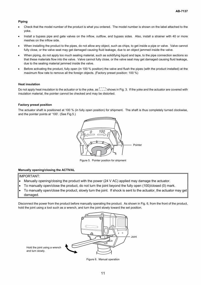
Factory preset position
The actuator shaft is positioned at 100 % (in fully open position) for shipment. The shaft is thus completely turned clockwise, and the pointer points at ‘100’. (See Fig.5.)
Figure 5. Pointer position for shipment
Manually opening/closing the ACTIVAL
IMPORTANT:
• Manually opening/closing the product with the power (24 V AC) applied may damage the actuator.
• To manually open/close the product, do not turn the joint beyond the fully open (100)/closed (0) mark.
• To manually open/close the product, slowly turn the joint. If shock is sent to the actuator, the actuator may get damaged.
Disconnect the power from the product before manually operating the product. As shown in Fig. 6, from the front of the product, hold the joint using a tool such as a wrench, and turn the joint slowly toward the set position.
Figure 6. Manual operation
Pointer
Joint
Hold the joint using a wrench and turn slowly.
AB-7137
12
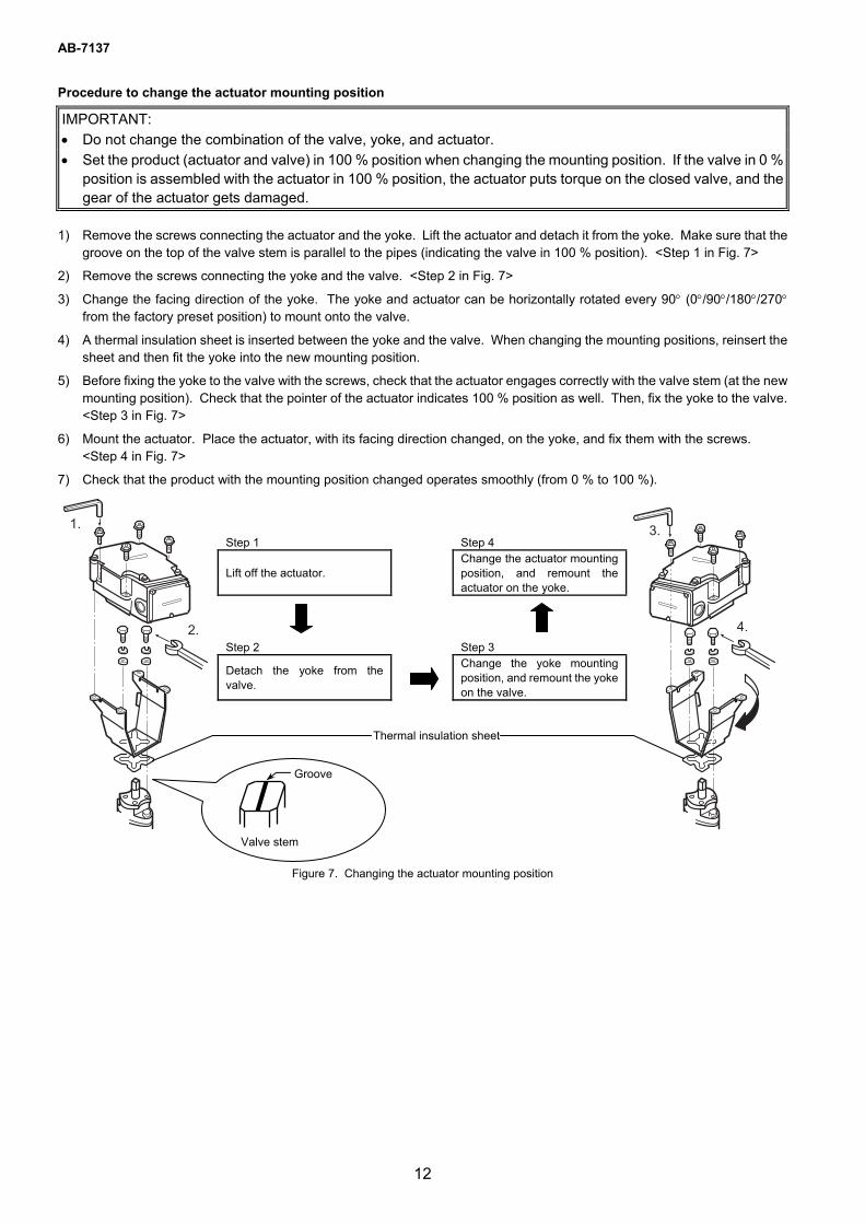
Procedure to change the actuator mounting position
IMPORTANT:
• Do not change the combination of the valve, yoke, and actuator.
• Set the product (actuator and valve) in 100 % position when changing the mounting position. If the valve in 0 % position is assembled with the actuator in 100 % position, the actuator puts torque on the closed valve, and the gear of the actuator gets damaged.
1) Remove the screws connecting the actuator and the yoke. Lift the actuator and detach it from the yoke. Make sure that the groove on the top of the valve stem is parallel to the pipes (indicating the valve in 100 % position). <Step 1 in Fig. 7>
2) Remove the screws connecting the yoke and the valve. <Step 2 in Fig. 7>
3) Change the facing direction of the yoke. The yoke and actuator can be horizontally rotated every 90° (0°/90°/180°/270° from the factory preset position) to mount onto the valve.
4) A thermal insulation sheet is inserted between the yoke and the valve. When changing the mounting positions, reinsert the sheet and then fit the yoke into the new mounting position.
5) Before fixing the yoke to the valve with the screws, check that the actuator engages correctly with the valve stem (at the new mounting position). Check that the pointer of the actuator indicates 100 % position as well. Then, fix the yoke to the valve. <Step 3 in Fig. 7>
6) Mount the actuator. Place the actuator, with its facing direction changed, on the yoke, and fix them with the screws. <Step 4 in Fig. 7>
7) Check that the product with the mounting position changed operates smoothly (from 0 % to 100 %).
Figure 7. Changing the actuator mounting position
Step 1 Step 4
Lift off the actuator. Change the actuator mounting position, and remount the actuator on the yoke.
Step 2 Step 3
Detach the yoke from the valve.
Change the yoke mounting position, and remount the yoke on the valve.
Thermal insulation sheet
Groove
Valve stem

AB-7137
13
Wiring
WARNING
Be sure to ground the product with ground resistance of less than 100 Ω. Improper grounding might cause electric shock or malfunction.
Detach the terminal cover only when wiring and setting the product and reattach the terminal cover after wiring and setting the product. Failure to do so might cause electric shock.
Before wiring or maintenance, be sure to turn off the power to the product. Failure to do so might cause electric shock or device failure.
CAUTION
Firmly tighten the terminal screws. Insufficient tightening of the terminal screws might cause fire or overheating.
IMPORTANT: • The product is designed for 24 V AC power supply voltage.
Do not apply any other power voltage (e.g., 100 V AC, 200 V AC) to the product.
• To prevent damage, cover the terminals except when connecting/disconnecting wires.
• Do not leave any refuse including metal chips after opening a knockout and after connecting the wires inside the actuator.
Wiring procedure
1) To lead the wires into the terminals, open a knockout for a wiring port. Two knockouts are provided on the bilateral sides of the actuator terminals. Select a knockout according to the conduit mounting direction, and open the hole by lightly knocking the knockout using a screwdriver.
Figure 8. Knockout for wiring port
2) Unscrew the 3 setscrews (M4 × 10) of the terminal cover and remove the terminal cover, as shown in Fig. 9.
Figure 9. Terminal cover removal
Knockout for wiring port
1. Unscrew the setscrews. 2. Remove terminal cover.
Terminal cover
Setscrews
Terminal block
Ground terminal

AB-7137
14
3-core2-core
Actuator of Model VY516EJ
SAnet
Filter alarm, etc.
5-core
∼
⊥
SAnet
DI
DO
Joint box
3) Correctly connect the wires to the terminals with M3.5 screw terminal lugs, referring to Fig. 10. To connect a device with over 100 V AC to the sub-DO (terminals 6 and 7), be sure to ground the actuator with 100 Ω or lower ground resistance. Refer to Fig. 10 for the location of each terminal.
Figure 10. Basic connection example
4) Separate sub-DO line from SAnet and sub-DI lines. Do not lead the sub-DO line through the wiring port (knockout) for SAnet and sub-DI lines to protect sub-DO line from noise.
Figure 11. Separation of sub-DO line from other lines
If sub-I/O is used, SAnet line cannot be daisy-chained since the number of the wiring ports is limited. In such a case, use the cable gland with three ports to daisy-chain the SAnet line, or branch the SAnet line ahead of connecting to the terminals.
Note: For wiring of SAnet line, refer to the Installation Manual of Intelligent Component Series for SAnet Communication (AB-6713).
To keep IP54 protection (dust-proof and splash-proof),
Use a water-proof connector for the product in a high-humidity environment or outdoor location. Through wiring port with the seal connector attached to, 1 cable can be lead in. Through wiring port with the cable gland (with three ports) and the seal connectors attached to, 3 cables can be lead in.
• Be sure to completely close the terminal cover and the top cover.
• Waterproof the wiring port. - For cable connection, use a water-proof connector. Following is the recommended parts we supply. Seal connector: Part Nos. 83104346-003, 83104346-004, 83104346-005 - To daisy-chain the SAnet line, use the cable gland with three ports and the seal connector we supply. Cable gland with three ports: Part No. DY7000A1000 Seal connector: Part Nos. 83104346-012, 83104346-013, 83104346-014 - For conduit connection, use a water-proof plica tube or the like.
1 2 3 4 5 6 7
∼ ⊥ SAnet
24 V AC
DI
SAnetHumidifier
∼
DO
Cable Thermostat, differential pressure switch, etc.
Actuator of Model VY516EJ
AB-7137
15
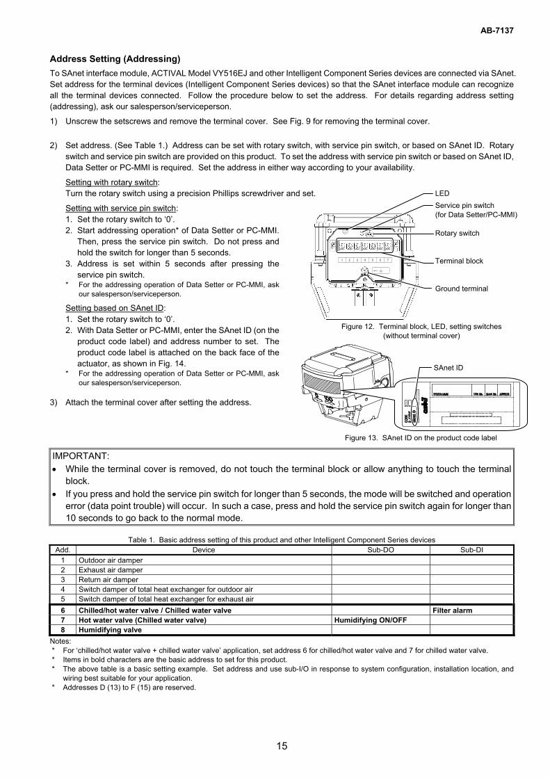
Address Setting (Addressing)
To SAnet interface module, ACTIVAL Model VY516EJ and other Intelligent Component Series devices are connected via SAnet. Set address for the terminal devices (Intelligent Component Series devices) so that the SAnet interface module can recognize all the terminal devices connected. Follow the procedure below to set the address. For details regarding address setting (addressing), ask our salesperson/serviceperson.
1) Unscrew the setscrews and remove the terminal cover. See Fig. 9 for removing the terminal cover.
2) Set address. (See Table 1.) Address can be set with rotary switch, with service pin switch, or based on SAnet ID. Rotary switch and service pin switch are provided on this product. To set the address with service pin switch or based on SAnet ID, Data Setter or PC-MMI is required. Set the address in either way according to your availability.
Setting with rotary switch: Turn the rotary switch using a precision Phillips screwdriver and set.
Setting with service pin switch: 1. Set the rotary switch to ‘0’. 2. Start addressing operation* of Data Setter or PC-MMI.
Then, press the service pin switch. Do not press and hold the switch for longer than 5 seconds.
3. Address is set within 5 seconds after pressing theservice pin switch.
* For the addressing operation of Data Setter or PC-MMI, ask our salesperson/serviceperson.
Setting based on SAnet ID: 1. Set the rotary switch to ‘0’. 2. With Data Setter or PC-MMI, enter the SAnet ID (on the
product code label) and address number to set. Theproduct code label is attached on the back face of the actuator, as shown in Fig. 14.
* For the addressing operation of Data Setter or PC-MMI, ask our salesperson/serviceperson.
3) Attach the terminal cover after setting the address.
IMPORTANT:
• While the terminal cover is removed, do not touch the terminal block or allow anything to touch the terminal block.
• If you press and hold the service pin switch for longer than 5 seconds, the mode will be switched and operation error (data point trouble) will occur. In such a case, press and hold the service pin switch again for longer than 10 seconds to go back to the normal mode.
Table 1. Basic address setting of this product and other Intelligent Component Series devices
Add. Device Sub-DO Sub-DI
1 Outdoor air damper 2 Exhaust air damper 3 Return air damper 4 Switch damper of total heat exchanger for outdoor air 5 Switch damper of total heat exchanger for exhaust air
6 Chilled/hot water valve / Chilled water valve Filter alarm 7 Hot water valve (Chilled water valve) Humidifying ON/OFF 8 Humidifying valve
Notes: * For ‘chilled/hot water valve + chilled water valve’ application, set address 6 for chilled/hot water valve and 7 for chilled water valve. * Items in bold characters are the basic address to set for this product. * The above table is a basic setting example. Set address and use sub-I/O in response to system configuration, installation location, and
wiring best suitable for your application. * Addresses D (13) to F (15) are reserved.
Figure 12. Terminal block, LED, setting switches (without terminal cover)
LED
Service pin switch (for Data Setter/PC-MMI) Rotary switch Terminal block Ground terminal
Figure 13. SAnet ID on the product code label
SAnet ID
AB-7137
16
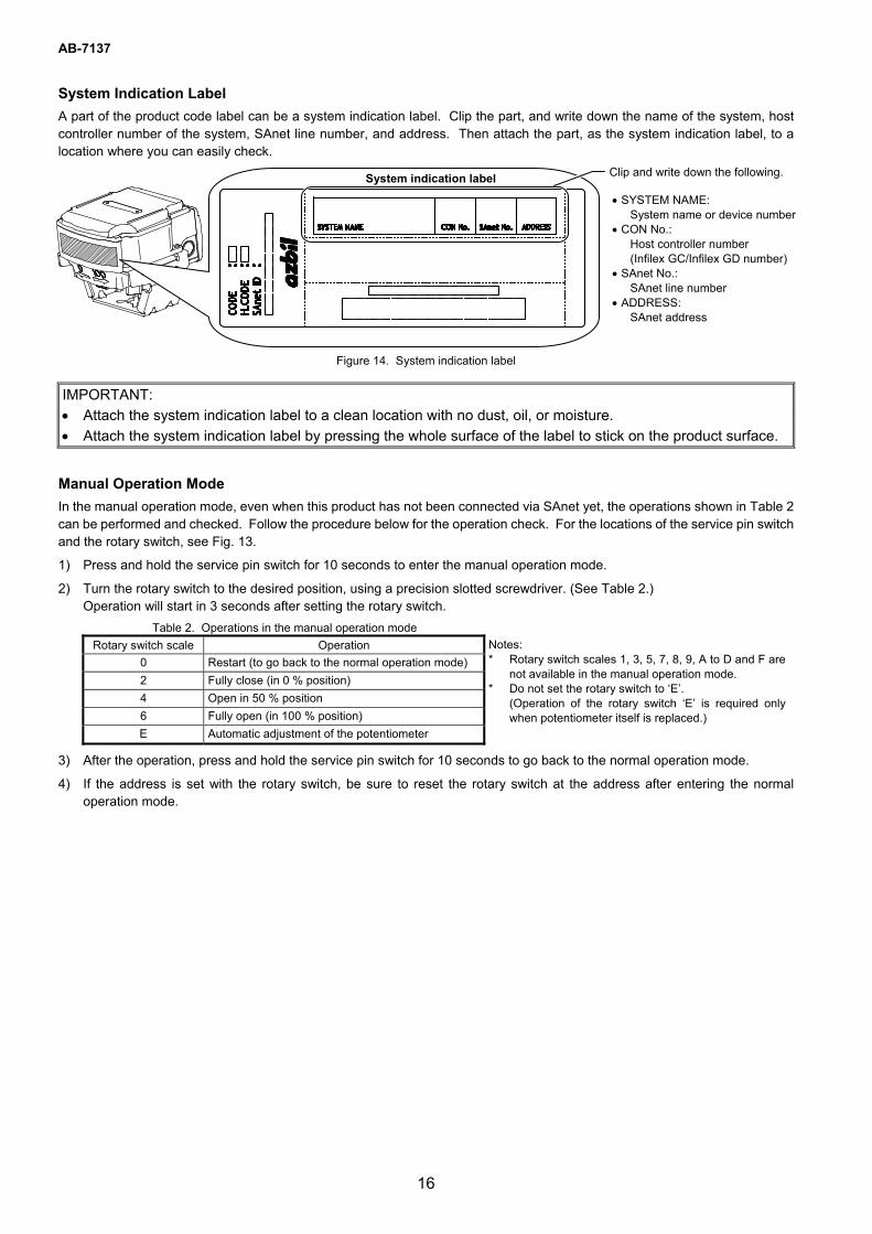
System Indication Label
A part of the product code label can be a system indication label. Clip the part, and write down the name of the system, host controller number of the system, SAnet line number, and address. Then attach the part, as the system indication label, to a location where you can easily check.
Figure 14. System indication label
IMPORTANT:
• Attach the system indication label to a clean location with no dust, oil, or moisture.
• Attach the system indication label by pressing the whole surface of the label to stick on the product surface.
Manual Operation Mode
In the manual operation mode, even when this product has not been connected via SAnet yet, the operations shown in Table 2 can be performed and checked. Follow the procedure below for the operation check. For the locations of the service pin switch and the rotary switch, see Fig. 13.
1) Press and hold the service pin switch for 10 seconds to enter the manual operation mode.
2) Turn the rotary switch to the desired position, using a precision slotted screwdriver. (See Table 2.) Operation will start in 3 seconds after setting the rotary switch.
Table 2. Operations in the manual operation mode
Rotary switch scale Operation
0 Restart (to go back to the normal operation mode)
2 Fully close (in 0 % position)
4 Open in 50 % position
6 Fully open (in 100 % position)
E Automatic adjustment of the potentiometer
Notes: * Rotary switch scales 1, 3, 5, 7, 8, 9, A to D and F are
not available in the manual operation mode. * Do not set the rotary switch to ‘E’.
(Operation of the rotary switch ‘E’ is required only when potentiometer itself is replaced.)
3) After the operation, press and hold the service pin switch for 10 seconds to go back to the normal operation mode.
4) If the address is set with the rotary switch, be sure to reset the rotary switch at the address after entering the normal operation mode.
Clip and write down the following. • SYSTEM NAME:
System name or device number • CON No.:
Host controller number (Infilex GC/Infilex GD number)
• SAnet No.: SAnet line number
• ADDRESS: SAnet address
System indication label
AB-7137
17
Inspection and Troubleshooting
WARNING
Detach the terminal cover only when wiring and setting the product and reattach the terminal cover after wiring and setting the product. Failure to do so might cause electric shock.
Before wiring or maintenance, be sure to turn off the power to the product. Failure to do so might cause electric shock or device failure.
CAUTION
Do not carelessly touch the product when being used to control hot water. The product temperature goes high, and you might get burned.
Do not touch the moving parts of the product. Doing so might cause injury.
• Inspect the product according to Table 3.
• Manually open/close the product at least once a month if it is left in inactive state for a long period.
• Visually inspect the fluid leakage of the valve and the actuator operations every six months. If any of the problems described in Table 4 are found, take corresponding actions shown in the table. If your problem is not solved by the corresponding action, please contact our sales/serviceperson.
Table 3. Inspection items and details
Inspection item Inspection interval Inspection detail
Visual inspection Semiannual • Fluid leakage from the gland and the flange face • Loosened bolts • Valve and actuator damages
Operating status Semiannual • Unstable open/close operation • Abnormal noise and vibration
Routine inspection Any time • Fluid leakage to the outside • Abnormal noise and vibration • Unstable open/close operation • Valve hunting
Table 4. Troubleshooting
Problem Part to check Action
Fluid leaks from the flange face. Loosened flange bolts Gasket on the flange face Misaligned piping
Tighten the flange bolts. Replace the gasket. Redo piping.
Fluid leaks from the gland. ⎯ Consult with our sales/serviceperson. Fluid leaks from the bonnet. Loosened bolts Tighten the bolts. Valve does not operate smoothly / valve stops halfway / valve does not operate at all.
Conditions of the power applied and of the input signal applied Loosened terminals Wiring condition / disconnected wires
Check the power supply and the controller connected to. Tighten the terminals. Check the wiring.
Fluid leaks to the outside of the valve when the product is in fully closed position.
Actuator pointer not pointing to fully closed position
Fully close the product.
The valve vibrates or produces an abnormal noise.
Primary pressure condition Differential pressure condition
Adjust the mounting position and change the installation location.
Valve hunting occurs. Secondary pressure condition Differential pressure condition Control stability
Adjust the mounting position and change the installation location. Correct the control parameter setting of controller.

AB-7137
18
Blank page added for editing purpose.

AB-7137
19
Blank page added for editing purpose.

AB-7137
ACTIVAL, Infilex, and PARAMATRIX are trademarks of Azbil Corporation in Japan or in other countries.
Specifications are subject to change without notice.
Building Systems Company 1-12-2 Kawana, Fujisawa, Kanagawa 251-8522 JAPAN
http://www.azbil.com/
Rev. 2.0 Dec. 2015 AB-7137
(J: AI-7137 Rev. 0.0)
20
Related Documents