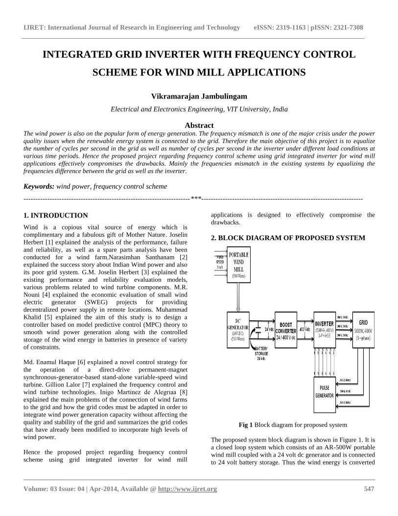
IJRET: International Journal of Research in Engineering and Technology eISSN: 2319-1163 | pISSN: 2321-7308 __________________________________________________________________________________________ Volume: 03 Issue: 04 | Apr-2014, Available @ http://www.ijret.org 547 INTEGRATED GRID INVERTER WITH FREQUENCY CONTROL SCHEME FOR WIND MILL APPLICATIONS Vikramarajan Jambulingam Electrical and Electronics Engineering, VIT University, India Abstract The wind power is also on the popular form of energy generation. The frequency mismatch is one of the major crisis under the power quality issues when the renewable energy system is connected to the grid. Therefore the main objective of this project is to equalize the number of cycles per second in the grid as well as number of cycles per second in the inverter under different load conditions at various time periods. Hence the proposed project regarding frequency control scheme using grid integrated inverter for wind mill applications effectively compromises the drawbacks. Mainly the frequencies mismatch in the existing systems by equalizing the frequencies difference between the grid as well as the inverter. Keywords: wind power, frequency control scheme ----------------------------------------------------------------------***-------------------------------------------------------------------- 1. INTRODUCTION Wind is a copious vital source of energy which is complimentary and a fabulous gift of Mother Nature. Joselin Herbert [1] explained the analysis of the performance, failure and reliability, as well as a spare parts analysis have been conducted for a wind farm.Narasimhan Santhanam [2] explained the success story about Indian Wind power and also its poor grid system. G.M. Joselin Herbert [3] explained the existing performance and reliability evaluation models, various problems related to wind turbine components. M.R. Nouni [4] explained the economic evaluation of small wind electric generator (SWEG) projects for providing decentralized power supply in remote locations. Muhammad Khalid [5] explained the aim of this study is to design a controller based on model predictive control (MPC) theory to smooth wind power generation along with the controlled storage of the wind energy in batteries in presence of variety of constraints. Md. Enamul Haque [6] explained a novel control strategy for the operation of a direct-drive permanent-magnet synchronous-generator-based stand-alone variable-speed wind turbine. Gillion Lalor [7] explained the frequency control and wind turbine technologies. Inigo Martinez de Alegrıaa [8] explained the main problems of the connection of wind farms to the grid and how the grid codes must be adapted in order to integrate wind power generation capacity without affecting the quality and stability of the grid and summarizes the grid codes that have already been modified to incorporate high levels of wind power. Hence the proposed project regarding frequency control scheme using grid integrated inverter for wind mill applications is designed to effectively compromise the drawbacks. 2. BLOCK DIAGRAM OF PROPOSED SYSTEM Fig 1 Block diagram for proposed system The proposed system block diagram is shown in Figure 1. It is a closed loop system which consists of an AR-500W portable wind mill coupled with a 24 volt dc generator and is connected to 24 volt battery storage. Thus the wind energy is converted

Integrated grid inverter with frequency control scheme for wind mill applications
May 26, 2015
IJRET : International Journal of Research in Engineering and Technology is an international peer reviewed, online journal published by eSAT Publishing House for the enhancement of research in various disciplines of Engineering and Technology. The aim and scope of the journal is to provide an academic medium and an important reference for the advancement and dissemination of research results that support high-level learning, teaching and research in the fields of Engineering and Technology. We bring together Scientists, Academician, Field Engineers, Scholars and Students of related fields of Engineering and Technology
Welcome message from author
This document is posted to help you gain knowledge. Please leave a comment to let me know what you think about it! Share it to your friends and learn new things together.
Transcript
IJRET: International Journal of Research in Engineering and Technology eISSN: 2319-1163 | pISSN: 2321-7308
__________________________________________________________________________________________
Volume: 03 Issue: 04 | Apr-2014, Available @ http://www.ijret.org 547
INTEGRATED GRID INVERTER WITH FREQUENCY CONTROL
SCHEME FOR WIND MILL APPLICATIONS
Vikramarajan Jambulingam
Electrical and Electronics Engineering, VIT University, India
Abstract The wind power is also on the popular form of energy generation. The frequency mismatch is one of the major crisis under the power
quality issues when the renewable energy system is connected to the grid. Therefore the main objective of this project is to equalize
the number of cycles per second in the grid as well as number of cycles per second in the inverter under different load conditions at
various time periods. Hence the proposed project regarding frequency control scheme using grid integrated inverter for wind mill
applications effectively compromises the drawbacks. Mainly the frequencies mismatch in the existing systems by equalizing the
frequencies difference between the grid as well as the inverter.
Keywords: wind power, frequency control scheme
----------------------------------------------------------------------***--------------------------------------------------------------------
1. INTRODUCTION
Wind is a copious vital source of energy which is
complimentary and a fabulous gift of Mother Nature. Joselin
Herbert [1] explained the analysis of the performance, failure
and reliability, as well as a spare parts analysis have been
conducted for a wind farm.Narasimhan Santhanam [2]
explained the success story about Indian Wind power and also
its poor grid system. G.M. Joselin Herbert [3] explained the
existing performance and reliability evaluation models,
various problems related to wind turbine components. M.R.
Nouni [4] explained the economic evaluation of small wind
electric generator (SWEG) projects for providing
decentralized power supply in remote locations. Muhammad
Khalid [5] explained the aim of this study is to design a
controller based on model predictive control (MPC) theory to
smooth wind power generation along with the controlled
storage of the wind energy in batteries in presence of variety
of constraints.
Md. Enamul Haque [6] explained a novel control strategy for
the operation of a direct-drive permanent-magnet
synchronous-generator-based stand-alone variable-speed wind
turbine. Gillion Lalor [7] explained the frequency control and
wind turbine technologies. Inigo Martinez de Alegrıaa [8]
explained the main problems of the connection of wind farms
to the grid and how the grid codes must be adapted in order to
integrate wind power generation capacity without affecting the
quality and stability of the grid and summarizes the grid codes
that have already been modified to incorporate high levels of
wind power.
Hence the proposed project regarding frequency control
scheme using grid integrated inverter for wind mill
applications is designed to effectively compromise the
drawbacks.
2. BLOCK DIAGRAM OF PROPOSED SYSTEM
Fig 1 Block diagram for proposed system
The proposed system block diagram is shown in Figure 1. It is
a closed loop system which consists of an AR-500W portable
wind mill coupled with a 24 volt dc generator and is connected
to 24 volt battery storage. Thus the wind energy is converted

IJRET: International Journal of Research in Engineering and Technology eISSN: 2319-1163 | pISSN: 2321-7308
__________________________________________________________________________________________
Volume: 03 Issue: 04 | Apr-2014, Available @ http://www.ijret.org 548
into electrical energy and this energy is collected in a battery
bank and stored. The 24 volt dc which is stored in the battery
and it is regulated to 400 volt dc via boost converter. This 400
volt dc output from the boost converter is fed as an input to the
three phase inverter module which converts fixed dc voltage
into three phase variable ac voltage as an output. The three
phase output ac voltage from the inverter is connected along
with the grid. A pulse generator gets the input voltage and
frequency from the grid and delivers six different pulses to the
six switches S1, S2, S3, S4, S5 and S6 of the inverter.
The grid side voltage as well as its frequency varies in
accordance to the different loads connected besides the grid.
So, whenever there is a change in voltage and frequency at the
grid side, then the pulse generator varies with the pulses
delivered to the inverter switches accordingly. This as a result
changes the inverter output voltage and frequency just as same
as the grid side voltage and frequency. Hence the inverter
output frequency is mapped with the grid side frequency and
thus the setback in the foregoing method is met through this
proposed system methodology.
2.1 DC Generator
A 24 volt dc generator of power 500 Watts with 300 rpm of
speed is used for this proposed renewable energy system. The
dc generator converts the input mechanical energy into an
electrical energy output.
Table.1 Design specification and circuit parameters
GENERATOR
TYPE DC Generator
VOLTAGE (V) 24 Volt DC
WATTS @ RATED
WIND SPEED 500 Watts
SPEED RPM (nominal) 300
With the help of MATLAB simulink environment, the
simulation of a dc generator is done for the given ratings as in
table 1. The simulink provides a dc machine block, in which
the parameters are set as per the requirements. A dc voltage
source is connected with the field winding provided in the
block. The dc machine is made to run at the speed of 300 rpm,
so that, the rated dc voltage (24 volts) is derived as an output
from the armature winding of the machine.
Fig 2 Simulation model of DC generator
2.2 Boost Converter
A boost converter (step-up converter) is a DC-to-DC power
converter with an output voltage greater than its input voltage.
A boost converter is designed with the help of MATLAB
simulink software which is shown in the figure 3. A 24 volt dc
source is given as an input to the converter circuit and a 400
volt dc output is regulated from the circuit. As discussed in the
above calculations, the inductance and the capacitance values
are calculated as per the project requirements. The 400 volt dc
output regulated from the boost converter is given as an input
to the three phase inverter circuit which will be discussed
later. The input and output dc voltage of the boost converter is
compared and measured by connecting a scope as shown in
figure 3. The simulation results are plotted in the figure 6.4.
Fig 3 Simulation model of boost converter
IJRET: International Journal of Research in Engineering and Technology eISSN: 2319-1163 | pISSN: 2321-7308
__________________________________________________________________________________________
Volume: 03 Issue: 04 | Apr-2014, Available @ http://www.ijret.org 549
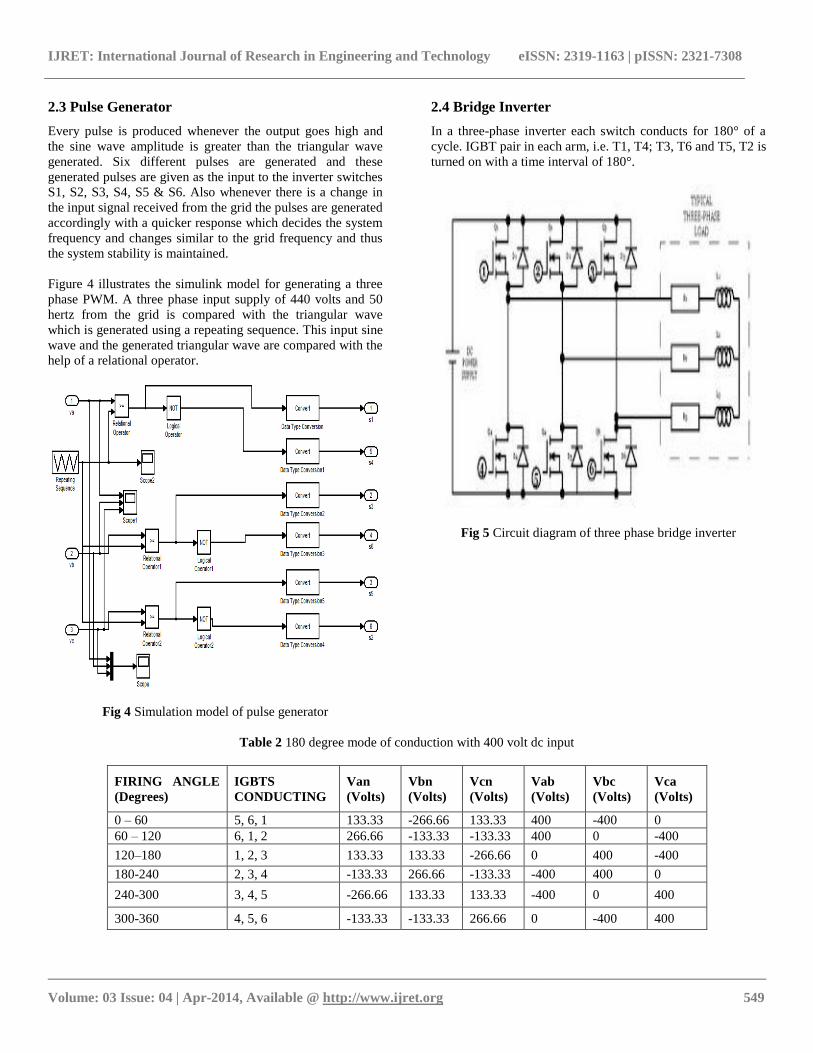
2.3 Pulse Generator
Every pulse is produced whenever the output goes high and
the sine wave amplitude is greater than the triangular wave
generated. Six different pulses are generated and these
generated pulses are given as the input to the inverter switches
S1, S2, S3, S4, S5 & S6. Also whenever there is a change in
the input signal received from the grid the pulses are generated
accordingly with a quicker response which decides the system
frequency and changes similar to the grid frequency and thus
the system stability is maintained.
Figure 4 illustrates the simulink model for generating a three
phase PWM. A three phase input supply of 440 volts and 50
hertz from the grid is compared with the triangular wave
which is generated using a repeating sequence. This input sine
wave and the generated triangular wave are compared with the
help of a relational operator.
Fig 4 Simulation model of pulse generator
2.4 Bridge Inverter
In a three-phase inverter each switch conducts for 180° of a
cycle. IGBT pair in each arm, i.e. T1, T4; T3, T6 and T5, T2 is
turned on with a time interval of 180°.
Fig 5 Circuit diagram of three phase bridge inverter
Table 2 180 degree mode of conduction with 400 volt dc input
FIRING ANGLE
(Degrees)
IGBTS
CONDUCTING
Van
(Volts)
Vbn
(Volts)
Vcn
(Volts)
Vab
(Volts)
Vbc
(Volts)
Vca
(Volts)
0 – 60 5, 6, 1 133.33 -266.66 133.33 400 -400 0
60 – 120 6, 1, 2 266.66 -133.33 -133.33 400 0 -400
120–180 1, 2, 3 133.33 133.33 -266.66 0 400 -400
180-240 2, 3, 4 -133.33 266.66 -133.33 -400 400 0
240-300 3, 4, 5 -266.66 133.33 133.33 -400 0 400
300-360 4, 5, 6 -133.33 -133.33 266.66 0 -400 400

IJRET: International Journal of Research in Engineering and Technology eISSN: 2319-1163 | pISSN: 2321-7308
__________________________________________________________________________________________
Volume: 03 Issue: 04 | Apr-2014, Available @ http://www.ijret.org 550
The table 2 is calculated for a supply voltage of Vs = 400 volt
(dc) which is given as an input dc supply and the output dc
voltages.Since the 180 degree mode of conduction has better
utilization of the switches, it is preferred for obtaining a three
phase output voltage according to the variations in the grid
side voltage.
The table 2 clearly explains how does the six step three phase
inverter operates at different modes and how the 400 vdc
output is attained at different time intervals.
3. INTEGRATED GRID INVERTER
A three phase grid integrated inverter) is intended with the
help of MATLAB graphical user interface software which is
shown in figure 6. The 400 volt dc source is given as an input
to the inverter model which is designed with six IGBT’s. Each
IGBT is triggered with six different pulses delivered from the
pulse generator.
The pulse generator receives three phase sine wave signals
from the grid. The received three phase sine wave signal is
compared with the triangular wave which is generated with the
help of a repeating sequence. The repeating sequence block is
available in the simulink option. The parameter values of the
repeating sequence is set in the parameters block according to
the project requirements.
v+ -
v+ -
v+ -
v+ -
v+ -
v+ -
A
B
C
a
b
c
A B C
Three-PhaseSeries RL Load
va
vb
vc
s1
s3
s5
s6
s4
s2
Subsystem
[A2][A4][A6][A5][A3][A1]
[A5]
[A2][A4]
[A6]
[A3][A1]
DC
g C
E
6
g C
E
5
g C
E
4
g C
E
3
g C
E
2
g CE
1
Fig.6. Simulation model of integrated grid inverter
The comparison of these two signals i.e. the sine wave signal
and the triangular wave signal, both together generates six
different square wave pulses which are given to the inverter
switches to operate at different frequencies according to the
change in the grid side frequency. So, whenever there is a
change in the grid side frequency the triggered pulse from the
pulse generator varies, which in order controls the inverter
output frequency and hence both the inverter as well as the
grid side frequencies shown clearly in the figure 10.
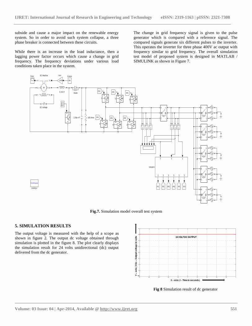
4. SIMULATION MODEL OF TEST SYSTEM
The three phase grid supply of 400 volts and 50 Hertz is
connected to the inverter output terminals with the help of a
three phase breaker as shown in the figure 7. If the breaker is
not connected in between the circuit, then the grid voltage
actually starts to supply voltage to the inverter. This makes the
inverter circuit to act like a rectifier circuit operation. The
mode of operation is reversed. This makes the entire system to
IJRET: International Journal of Research in Engineering and Technology eISSN: 2319-1163 | pISSN: 2321-7308
__________________________________________________________________________________________
Volume: 03 Issue: 04 | Apr-2014, Available @ http://www.ijret.org 551
subside and cause a major impact on the renewable energy
system. So in order to avoid such system collapse, a three
phase breaker is connected between these circuits.
While there is an increase in the load inductance, then a
lagging power factor occurs which cause a change in grid
frequency. The frequency deviations under various load
conditions taken place in the system.
The change in grid frequency signal is given to the pulse
generator which is compared with a reference signal. The
compared signals generate six different pulses to the inverter.
This operates the inverter for three phase 400V ac output with
frequency similar to grid frequency. The overall simulation
test model of proposed system is designed in MATLAB /
SIMULINK as shown in Figure 7.
Continuous
powergui
v+ -
v+ -
v+ -
v+ -
v+ -
v+ -
A
B
C
a
b
c
A
B
C
a
b
c
A
B
C
a
b
c
A
B
C
a
b
c
A
B
C
a
b
c
A
B
C
a
b
c
va
vb
vc
s1
s3
s5
s6
s4
s2
Subsystem
Scope
g CE
[A2][A4][A6][A5][A3][A1]
pi/30
Gain
[A5]
[A2][A4]
[A6]
[A3][A1]
Diode
DC Voltage
TLm
A+
F+
A-
F-
dc
DC Machine
300
Constant
g C
E
6
g C
E
5g C
E
4
g C
E
3
2.35e-4 F
g C
E
2
100 ohms
g CE
1
0.141 H
Fig.7. Simulation model overall test system
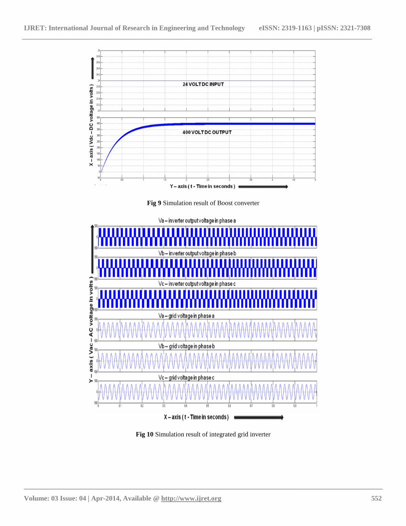
5. SIMULATION RESULTS
The output voltage is measured with the help of a scope as
shown in figure 2. The output dc voltage obtained through
simulation is plotted in the figure 8. The plot clearly displays
the simulation result for 24 volts unidirectional (dc) output
delivered from the dc generator.
Fig 8 Simulation result of dc generator
IJRET: International Journal of Research in Engineering and Technology eISSN: 2319-1163 | pISSN: 2321-7308
__________________________________________________________________________________________
Volume: 03 Issue: 04 | Apr-2014, Available @ http://www.ijret.org 552
Fig 9 Simulation result of Boost converter
Fig 10 Simulation result of integrated grid inverter

IJRET: International Journal of Research in Engineering and Technology eISSN: 2319-1163 | pISSN: 2321-7308
__________________________________________________________________________________________
Volume: 03 Issue: 04 | Apr-2014, Available @ http://www.ijret.org 553
Fig 11 Simulation results of Grid Voltage[VG] for Phase a,b,c [VaG, VbG, VcG] at T=1sec & Inverter Voltage[VI] for Phase a,b,c
[VaI,VbI,VcI] at T=1sec
Fig 12 Simulation results of Grid Voltage[VG] & Inverter Voltage[VI] for Phase a,b,c,[VaG& VaI, VbG & VbI, VcG & VcI] at T=1sec
IJRET: International Journal of Research in Engineering and Technology eISSN: 2319-1163 | pISSN: 2321-7308
__________________________________________________________________________________________
Volume: 03 Issue: 04 | Apr-2014, Available @ http://www.ijret.org 554
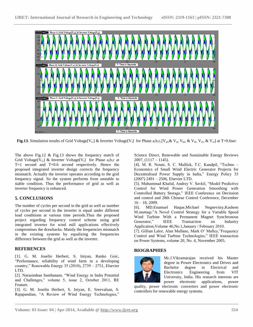
Fig.13. Simulation results of Grid Voltage[VG] & Inverter Voltage[VI] for Phase a,b,c,[VaG& VaI, VbG & VbI, VcG & VcI] at T=0.6sec
The above Fig.12 & Fig.13 shows the frequency match of
Grid Voltage[VG] & Inverter Voltage[VI] for Phase a,b,c at
T=1 second and T=0.6 second respectively. Hence the
proposed integrated inverter design corrects the frequency
mismatch. Actually the inverter operates according to the grid
frequency signal. So the system performs from unstable to
stable condition. Thus the performance of grid as well as
inverter frequency is enhanced.
5. CONCLUSIONS
The number of cycles per second in the grid as well as number
of cycles per second in the inverter is equal under different
load conditions at various time periods.Thus the proposed
project regarding frequency control scheme using grid
integrated inverter for wind mill applications effectively
compromises the drawbacks. Mainly the frequencies mismatch
in the existing systems by equalizing the frequencies
difference between the grid as well as the inverter.
REFERENCES
[1]. G. M. Joselin Herbert, S. Iniyan, Ranko Goic,
“Performance, reliability of wind farm in a developing
country,” Renewable Energy 35 (2010), 2739 – 2751, Elsevier
LTD.
[2]. Narasimhan Santhanam, “Wind Energy in India Potential
and Challenges,” volume 5, issue 2, October 2011, RE
Feature.
[3]. G. M. Joselin Herbert, S. Iniyan, E. Sreevalsan, S.
Rajapandian, “A Review of Wind Energy Technologies,”
Science Direct, Renewable and Sustainable Energy Reviews
2007, (1117 – 1145).
[4]. M. R. Nouni, S. C. Mullick, T.C. Kandpil, “Techno –
Economics of Small Wind Electric Generator Projects for
Decentralised Power Supply in India,” Energy Policy 35
(2007) 2491 – 2506, Elsevier LTD.
[5]. Muhammad Khalid, Andrey V. Savkil, “Model Predictive
Control for Wind Power Generation Smoothing with
Controlled Battery Storage,” IEEE Conference on Decission
and control and 28th Chinese Control Conference, December
16 – 18, 2009.
[6]. MD.Enamuel Haque,Michael Negnevisty,Kashem
M.muttaqi.”A Novel Control Strategy for a Variable Speed
Wind Turbine With a Permanent Magnet Synchronous
Generator,” IEEE Transaction on Industry
Application,Volume 46,No.1,January / February 2010.
[7]. Gillian Lalor, Alan Mullane, Mark O’ Malley,”Frequency
Control and Wind Turbine Technologies,” IEEE transaction
on Power Systems, volume 20, No. 4, November 2005.
BIOGRAPHIES
Mr.J.Vikramarajan received his Master
degree in Power Electronics and Drives and
Bachelor degree in Electrical and
Electronics Engineering from VIT
University, India. His research interests are
power electronic applications, power
quality, power electronic converters and power electronic
controllers for renewable energy systems.
Related Documents