INTEGRATED GREEN DESIGN for Urban & Rural Buildings in Hot-Dry Climate Zone

Welcome message from author
This document is posted to help you gain knowledge. Please leave a comment to let me know what you think about it! Share it to your friends and learn new things together.
Transcript
INTEGRATED GREEN DESIGNfor Urban & Rural Buildings
in Hot-Dry Climate Zone
INTEGRATED GREEN DESIGN
Central Public Works Department
for Urban & Rural Buildings in Hot-Dry Climate Zone

Integrated Green Design for Urban & Rural Buildings in Hot-Dry Climate Zone
C February 2013No part of the publication may be reproduced in any formwithout the weittrn permission of DG, CPWD------------------------------------------------------------------------------------------Published by:
Director of General
Central Public Works Department
101 A, Nirman Bhavan, New Delhi-110011Email: [email protected]
Prepared by:North Zone-III CPWD, JaipurEmail:[email protected]
Technical Advisory Team:CPWD - R.K.Singhal, spl. DG;Mukund Joshi, Chief Engineer;Rajiv Singhal, Suptd. Engineer ;Biswajit Bose, Seniour Architect;D.K. Ujjainia, Executive Engineer;
------------------------------------------------------------------------------------------ConsultantDeependra Prashad Architects & Planners (DPAP)S-335 (I fl r.), Panchsheel Park,New Delhi- 110017email: [email protected]
Printed by:Kshitiz EnterprisesD-57 south Estension Part-1, New [email protected]
IV Central Public Works Department
MessageIndia, a fast developing country, is required to balance the utilisation of resources with the simultaneous need for preserving the environment. To prevent rapid growth from irreversibly degrading the environment and a consequent decay in the quality of life, there is a need to explore options that are low on energy and water use, on pollution and on cost. The planning, construction and utilisation of buildings has to also take options into account.
While the work on sustainable buildings has begun in right earnest, there is scope to do more. While the government and private buildings are gradually adopting practices of energy and environmental effi ciency, for these to rapidly bring about visible change, the effort of the entire construction industry which is creating our infrastructure is needed. Since a large part of the built environment is dealing with buildings such as individual residences, schools, health centres, small commerical centres, amongst others, these also need to be included in the sustainable building movement. The cumulative effect of such buildings can make a signifi cant impact on the environmental footprint.
The creation of this manual brings the concept of integrated green design to the common person, wherein certain generic principles and easy to implement methodologies are made available.Architects and engineers who are important decision makers of this construction process will have a much needed ready reckoner with this publication.
I congratulate the Central Public Works Department in bringing out this guide and look forward to the widespread application of the principles.
Shri Kamal NathMinister of Urban DevelopmentGovernment of India

VI Central Public Works Department
Foreword The challenges of growth are many and complex. With development the aspirations of the people are rising. There are competing demands on natural resources such as water and land and on power. Over and above all this are the increasingly evident impacts of global warming induced climate change, wherein temperatures are rising.
India’s 2011 Census provides some interesting data that reveals development trends and offers planning opportunities. It shows that one in every third Indian now lives in an urban environment. While the number of million plus cities has shot up to 53 from 35 in 2001, the smaller cities are growing much faster than the larger ones that have a million plus population. The Census houses have increased from 25 crore to 33 crore, of which a third are in urban areas. The challenge then is to meet the necessary and basic needs of all, while maintaining levels of comfort, of using natural resources sustainably and with, minimum impact on the environment. This calls for making simple yet effective and locally relevant changes in the way we develop and construct in our urban and rural habitats, enabling us to reduce our resource consumption. The sheer numbers on widespread adoption will help provide the desired impact.
The publication and widespread dissemination of this simple yet effective user friendly guide on integrated green design for small structures in the hot- dry climate zones in the country by the Central Public Works Department, Ministry of Urban Development, marks another milestone in the journey of reducing our ecological footprints in the urban and rural living spaces, in a manner that will continue, if not enhance comfort levels. I look forward to the adoption of options offered.
Dr Sudhir KrishnaSecretaryMinistry of Urban DevelopmentGovernment of India

VIII Central Public Works Department
About the book
IXIntegrated Green Design (IGD) for Urban & Rural buildings in Hot-Dry climate
Contents
What is a Green Building? 1
Site Context & Environment 2
Hot - Dry Climate Zone Description 3
Integrated Green Design (IGD) Approach 5
Sustainable Site Planning 6
Landscaping for improving Occupant Comfort 12
Building Design 14
Materials 22
Building Energy Effi ciency 28
Water Effi ciency 30
Modifying Existing Buildings 32
Temporary Structures 33
Abbreviations & References 34
1Integrated Green Design (IGD) for Urban & Rural buildings,Hot-Dry Climate Zone
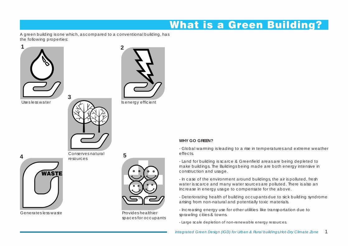
What is a Green Building?A green building is one which, as compared to a conventional building, has the following properties:
WHY GO GREEN?
- Global warming is leading to a rise in temperatures and extreme weather effects.
- Land for building is scarce & Greenfi eld areas are being depleted to make buildings. The Buildings being made are both energy intensive in construction and usage.
- In case of the environment around buildings, the air is polluted, fresh water is scarce and many water sources are polluted. There is also an Increase in energy usage to compensate for the above.
- Deteriorating health of building occupants due to sick building syndrome arising from non-natural and potentially toxic materials.
- Increasing energy use for other utilities like transportation due to sprawling cities & towns.
- Large scale depletion of non-renewable energy resources.
1 2
3
4 5
Uses less water Is energy effi cient
Generates less waste Provides healthier spaces for occupants
Conserves natural resources
2 Central Public Works Department
Site Context and Environment
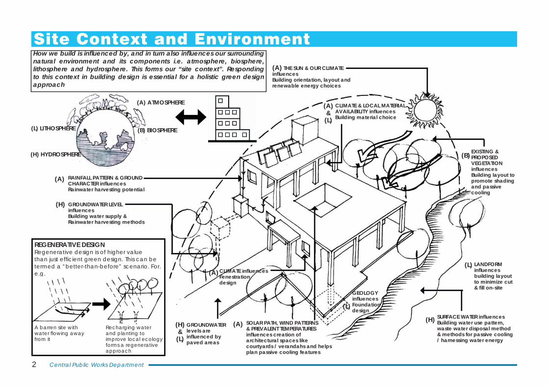
(A) THE SUN & OUR CLIMATE infl uences Building orientation, layout and renewable energy choices
GROUNDWATER LEVEL infl uences Building water supply & Rainwater harvesting methods
(H)
RAINFALL PATTERN & GROUND CHARACTER infl uences Rainwater harvesting potential
(A)
GROUNDWATERlevels are infl uenced by paved areas
(H) & (L)
SOLAR PATH, WIND PATTERNS & PREVALENT TEMPERATURES infl uences creation of architectural spaces like courtyards / verandahs and helps plan passive cooling features
(A)SURFACE WATER infl uences Building water use pattern, waste water disposal method & methods for passive cooling / harnessing water energy
(H)
CLIMATE & LOCAL MATERIAL AVAILABILITY infl uences Building material choice
(A)& (L)
EXISTING & PROPOSED VEGETATION infl uences Building layout to promote shading and passive cooling
(B)
CLIMATE infl uences Fenestration design
GEOLOGY infl uences Foundation design
(L)
(A)LANDFORM infl uences building layout to minimize cut & fi ll on-site
(L)
(A) ATMOSPHERE
(B) BIOSPHERE(L) LITHOSPHERE
(H) HYDROSPHERE
How we build is infl uenced by, and in turn also infl uences our surrounding natural environment and its components i.e. atmosphere, biosphere, lithosphere and hydrosphere. This forms our “site context”. Responding to this context in building design is essential for a holistic green design approach
REGENERATIVE DESIGNRegenerative design is of higher value than just effi cient green design. This can be termed a “better-than-before” scenario. For. e.g.
Recharging water and planting to improve local ecology forms a regenerative approach
A barren site with water fl owing away from it
3Integrated Green Design (IGD) for Urban & Rural buildings,Hot-Dry Climate Zone
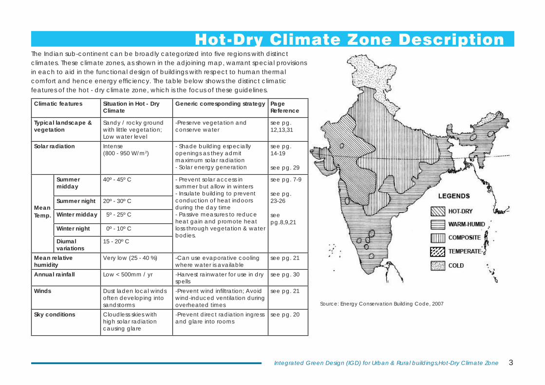
Hot-Dry Climate Zone DescriptionThe Indian sub-continent can be broadly categorized into fi ve regions with distinct climates. These climate zones, as shown in the adjoining map, warrant special provisions in each to aid in the functional design of buildings with respect to human thermal comfort and hence energy effi ciency. The table below shows the distinct climatic features of the hot - dry climate zone, which is the focus of these guidelines.
Climatic features Situation in Hot - Dry Climate
Generic corresponding strategy Page Reference
Typical landscape & vegetation
Sandy / rocky ground with little vegetation; Low water level
-Preserve vegetation and conserve water
see pg. 12,13,31
Solar radiation Intense (800 - 950 W/m2)
- Shade building especially openings as they admit maximum solar radiation- Solar energy generation
see pg. 14-19
see pg. 29
Mean Temp.
Summer midday
40º - 45º C - Prevent solar access in summer but allow in winters- Insulate building to prevent conduction of heat indoors during the day time- Passive measures to reduce heat gain and promote heat loss through vegetation & water bodies.
see pg. 7-9
see pg. 23-26
see pg.8,9,21
Summer night 20º - 30º C
Winter midday 5º - 25º C
Winter night 0º - 10º C
Diurnal variations
15 - 20º C
Mean relative humidity
Very low (25 - 40 %) -Can use evaporative cooling where water is available
see pg. 21
Annual rainfall Low < 500mm / yr -Harvest rainwater for use in dry spells
see pg. 30
Winds Dust laden local winds often developing into sandstorms
-Prevent wind infi ltration; Avoid wind-induced ventilation during overheated times
see pg. 21
Sky conditions Cloudless skies with high solar radiation causing glare
-Prevent direct radiation ingress and glare into rooms
see pg. 20
Source: Energy Conservation Building Code, 2007

5Integrated Green Design (IGD) for Urban & Rural buildings,Hot-Dry Climate Zone
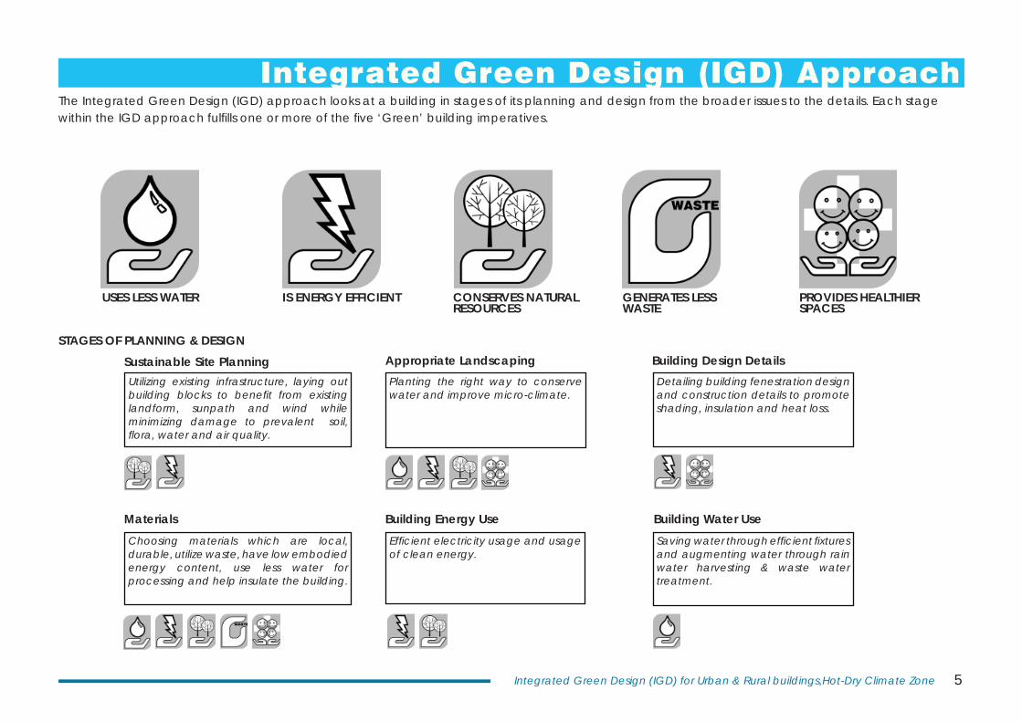
Integrated Green Design (IGD) ApproachThe Integrated Green Design (IGD) approach looks at a building in stages of its planning and design from the broader issues to the details. Each stage within the IGD approach fulfi lls one or more of the fi ve ‘Green’ building imperatives.
Utilizing existing infrastructure, laying out building blocks to benefi t from existing landform, sunpath and wind while minimizing damage to prevalent soil, fl ora, water and air quality.
Planting the right way to conserve water and improve micro-climate.
Detailing building fenestration design and construction details to promote shading, insulation and heat loss.
Choosing materials which are local, durable, utilize waste, have low embodied energy content, use less water for processing and help insulate the building.
Effi cient electricity usage and usage of clean energy.
Saving water through effi cient fi xtures and augmenting water through rain water harvesting & waste water treatment.
USES LESS WATER IS ENERGY EFFICIENT CONSERVES NATURAL RESOURCES
GENERATES LESS WASTE
PROVIDES HEALTHIER SPACES
Sustainable Site Planning Appropriate Landscaping Building Design Details
Materials Building Energy Use Building Water Use
STAGES OF PLANNING & DESIGN

6 Central Public Works Department
Sustainable Site PlanningSITE SELECTION
COMPACT ACCESS ROADS AND UTILITIES- Improve effi ciency of movement and feasibility of common maintenance on campuses- Reduce paved areas on site and consequently reduce heat gain- Connecting to adjacent structures for common services & access road would reduce servicing costs and improve walkability
AVOID NATURAL DRAINAGE LINES- Especially important in sloped sites. Obstructing natural drainage lines would involve energy use to drain out storm water or risk site fl ooding
READY ACCESS TO EXISTING INFRASTRUCTURE- Electricity supply- Water supply- Public transportHelps reduce need for new infrastructure
PROPOSED BUILDING
ACCESS TO OTHER FACILITIES
BANK
SCHOOL
SHOPS
The IGD approach starts not from the site layout but from site selection. While not possible in all cases, wherever possible efforts must be made to choose an appropriate site for the proposed use of the building. This would result in less damage of virgin land and less energy expenditure in ‘developing’ a site. For buildings within large campuses, selecting an appropriate plot within is equally important.
COMPACT CLUSTER PLANNINGCluster based planning of the building blocks within campuses results in more compact utilities network, reduces damage to existing environment and promotes walkability. Sharing spaces, services and creating a medium-rise, high density development complements this.
One block shades the other
Possibility of future expansion reduces need for encroaching on greenfi eld sites
Shaded spaces
7Integrated Green Design (IGD) for Urban & Rural buildings,Hot-Dry Climate Zone
Dec 21
June 21
June 21
Dec 21
N
S
E
W
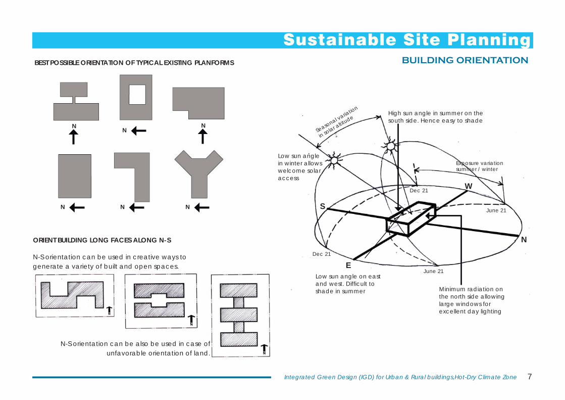
BUILDING ORIENTATION
Sustainable Site PlanningBEST POSSIBLE ORIENTATION OF TYPICAL EXISTING PLANFORMS
Minimum radiation on the north side allowing large windows for excellent day lighting
High sun angle in summer on the south side. Hence easy to shade
Low sun angle on east and west. Diffi cult to shade in summer
ORIENT BUILDING LONG FACES ALONG N-S
N-S orientation can be used in creative ways to generate a variety of built and open spaces.
Seasonal variation
in solar altitude
Exposure variation summer / winter
N
N N
N
N
N
N-S orientation can be also be used in case of unfavorable orientation of land.
Low sun angle in winter allows welcome solar access
8 Central Public Works Department
53 61 42
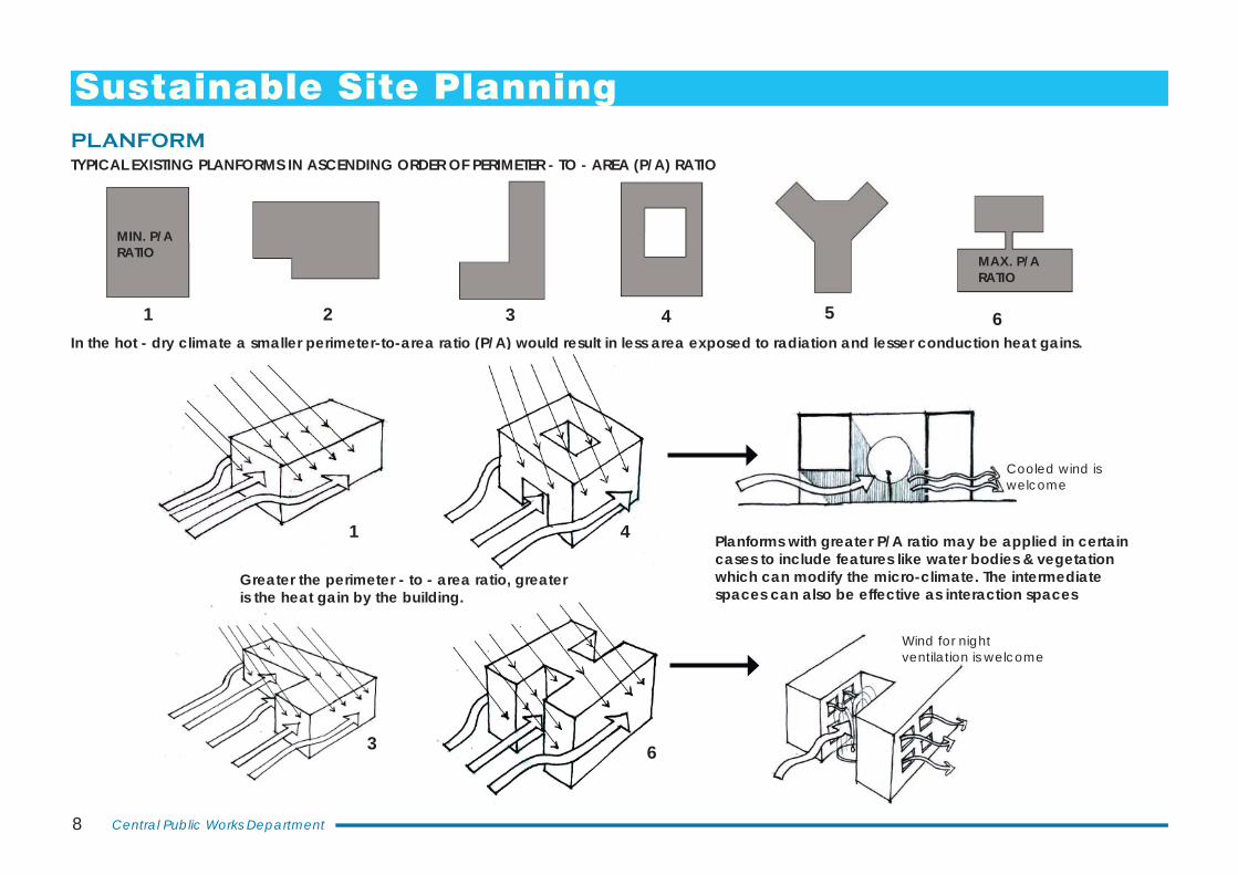
PLANFORM
In the hot - dry climate a smaller perimeter-to-area ratio (P/A) would result in less area exposed to radiation and lesser conduction heat gains.
Planforms with greater P/A ratio may be applied in certain cases to include features like water bodies & vegetation which can modify the micro-climate. The intermediate spaces can also be effective as interaction spaces
1
3
4
6
Greater the perimeter - to - area ratio, greater is the heat gain by the building.
MIN. P/A RATIO MAX. P/A
RATIO
TYPICAL EXISTING PLANFORMS IN ASCENDING ORDER OF PERIMETER - TO - AREA (P/A) RATIO
Cooled wind is welcome
Wind for night ventilation is welcome
Sustainable Site Planning

9Integrated Green Design (IGD) for Urban & Rural buildings,Hot-Dry Climate Zone
ACTIVITY ZONING FOR VARIOUS PLANFORMS
Most concepts in hot, dry climate focus on decreasing heat gain but adequate daylight is also important. Depending upon the building use, choosing an appropriate planform and proper activity zoning at the initial design stages can ensure heat gain reduction and optimum daylighting.
Service areas like kitchen/ toilet/ staircase
Habitable areas Service areas like kitchen / toilet / staircase
Possibility of being shaded A shaded and
vegetated courtyard can induce cool ventilation
Service areas
Habitable areas
Stage & seating
Habitable areas like green rooms
Backstage service areas
Service areas (public)
Lobby, etc.
FOR AUDITORIUMS
In comparing L-shapes..
H-SHAPED PLANFORM RECTANGULAR PLANFORM
L-SHAPED PLANFORM COURTYARD PLANFORM
Y-SHAPED PLANFORM
Habitable areas
Habitable areas
Habitable areas
This approach is useful in placing service spaces like toilets/ storage areas / staircase at locations where they can act as thermal barriers. The effect of an unfavorable plan orientation can also be reduced to some extent by zoning.
N
v/s
Sustainable Site Planning
10 Central Public Works Department
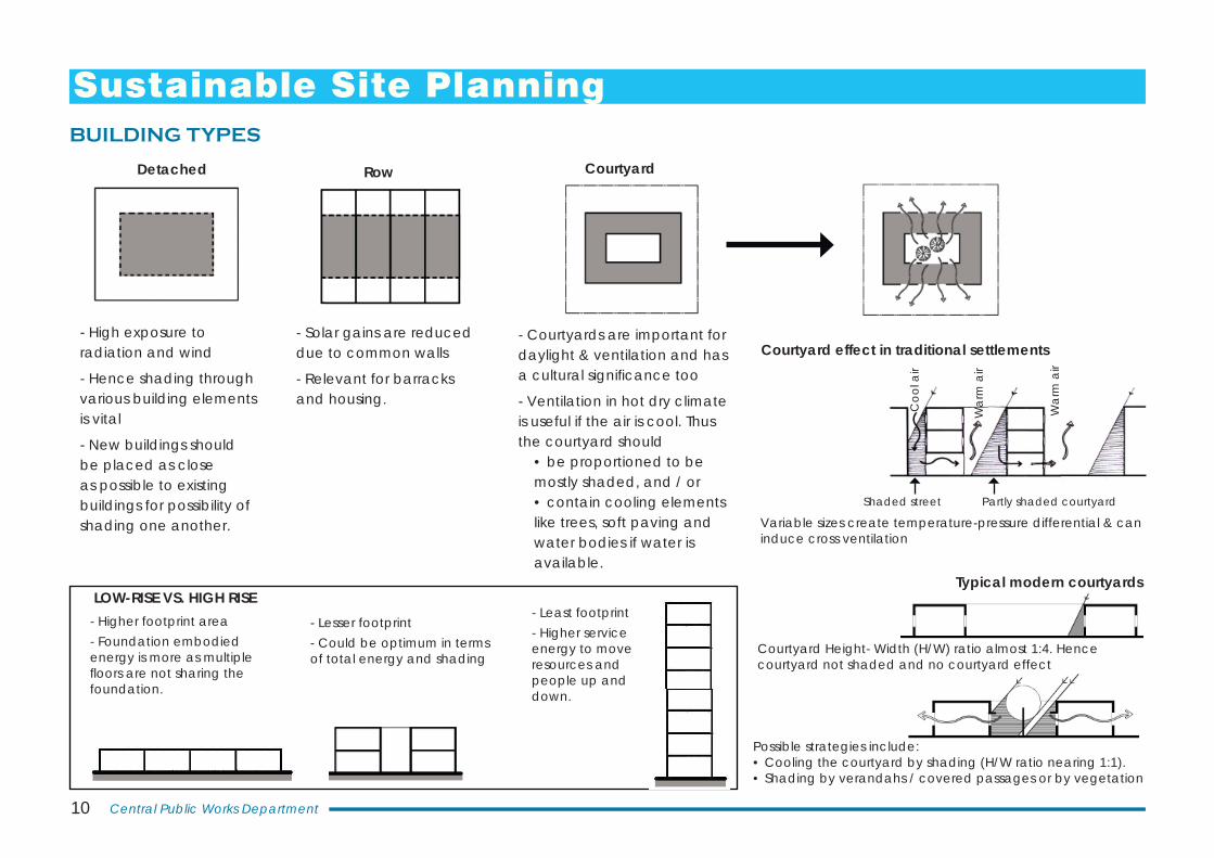
- High exposure to radiation and wind
- Hence shading through various building elements is vital
- New buildings should be placed as close as possible to existing buildings for possibility of shading one another.
- Courtyards are important for daylight & ventilation and has a cultural signifi cance too
- Ventilation in hot dry climate is useful if the air is cool. Thus the courtyard should
• be proportioned to be mostly shaded, and / or• contain cooling elements like trees, soft paving and water bodies if water is available.
- Solar gains are reduced due to common walls
- Relevant for barracks and housing.
- Higher footprint area- Foundation embodied energy is more as multiple fl oors are not sharing the foundation.
- Lesser footprint- Could be optimum in terms of total energy and shading
- Least footprint- Higher service energy to move resources and people up and down.
LOW-RISE VS. HIGH RISE
BUILDING TYPES
Detached Row Courtyard
Courtyard Height- Width (H/W) ratio almost 1:4. Hence courtyard not shaded and no courtyard effect
Possible strategies include:• Cooling the courtyard by shading (H/W ratio nearing 1:1). • Shading by verandahs / covered passages or by vegetation
Courtyard effect in traditional settlements
Shaded street
Coo
l air
War
m a
ir
Partly shaded courtyard
Typical modern courtyards
Variable sizes create temperature-pressure differential & can induce cross ventilation
War
m a
ir
Sustainable Site Planning
11Integrated Green Design (IGD) for Urban & Rural buildings,Hot-Dry Climate Zone
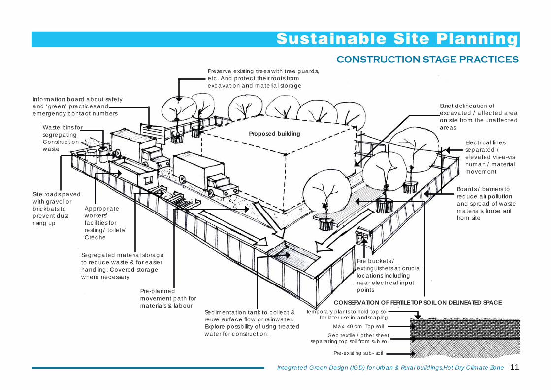
CONSTRUCTION STAGE PRACTICESPreserve existing trees with tree guards, etc. And protect their roots from excavation and material storage
Information board about safety and ‘green’ practices and emergency contact numbers
Waste bins for segregatingConstruction waste
Site roads paved with gravel or brickbats to prevent dust rising up
Appropriate workers’ facilities for resting/ toilets/ Crèche
Segregated material storage to reduce waste & for easier handling. Covered storage where necessary
Pre-planned movement path for materials & labour
Sedimentation tank to collect & reuse surface fl ow or rainwater. Explore possibility of using treated water for construction.
Fire buckets / extinguishers at crucial locations including near electrical input points
Proposed building
CONSERVATION OF FERTILE TOP SOIL ON DELINEATED SPACETemporary plants to hold top soil
for later use in landscaping
Max. 40 cm. Top soilGeo textile / other sheet
separating top soil from sub soil
Pre-existing sub- soil
Boards / barriers to reduce air pollution and spread of waste materials, loose soil from site
Electrical lines separated / elevated vis-a-vis human / material movement
Strict delineation of excavated / affected area on site from the unaffected areas
Sustainable Site Planning
12 Central Public Works Department
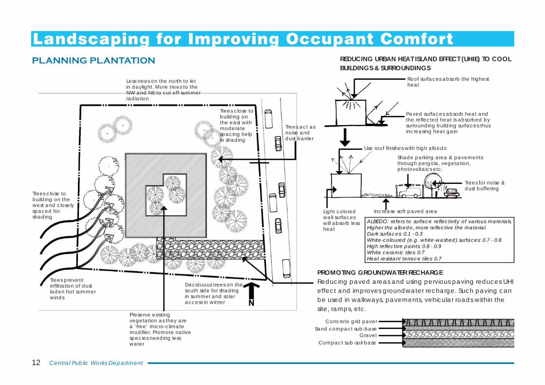
PROMOTING GROUNDWATER RECHARGE Reducing paved areas and using pervious paving reduces UHI effect and improves groundwater recharge. Such paving can be used in walkways, pavements, vehicular roads within the site, ramps, etc.
Trees close to building on the west and closely spaced for shading
Deciduous trees on the south side for shading in summer and solar access in winter
Less trees on the north to let in daylight. More trees to the NW and NE to cut off summer radiation
Trees close to building on the east with moderate spacing help in shading
Trees act as noise and dust barrier
Trees prevent infi ltration of dust laden hot summer winds
Concrete grid paverSand compact sub-base
GravelCompact sub-soil base
Preserve existing vegetation as they are a ‘free’ micro-climate modifi er. Promote native species needing less water
Landscaping for Improving Occupant ComfortPLANNING PLANTATION REDUCING URBAN HEAT ISLAND EFFECT (UHIE) TO COOL
BUILDINGS & SURROUNDINGS
Paved surfaces absorb heat and the refl ected heat is absorbed by surrounding building surfaces thus increasing heat gain
Roof surfaces absorb the highest heat
Increase soft paved area
Shade parking area & pavements through pergola, vegetation, photovoltaics etc.
Use roof fi nishes with high albedo
Light colored wall surfaces will absorb less heat
ALBEDO: refers to surface refl ectivity of various materials. Higher the albedo, more refl ective the material.Dark surfaces: 0.1 - 0.3White-coloured (e.g. white-washed) surfaces: 0.7 - 0.8High refl ective paints: 0.8 - 0.9White ceramic tiles: 0.7Heat resistant terrace tiles: 0.7
Trees for noise & dust buffering
13Integrated Green Design (IGD) for Urban & Rural buildings,Hot-Dry Climate Zone
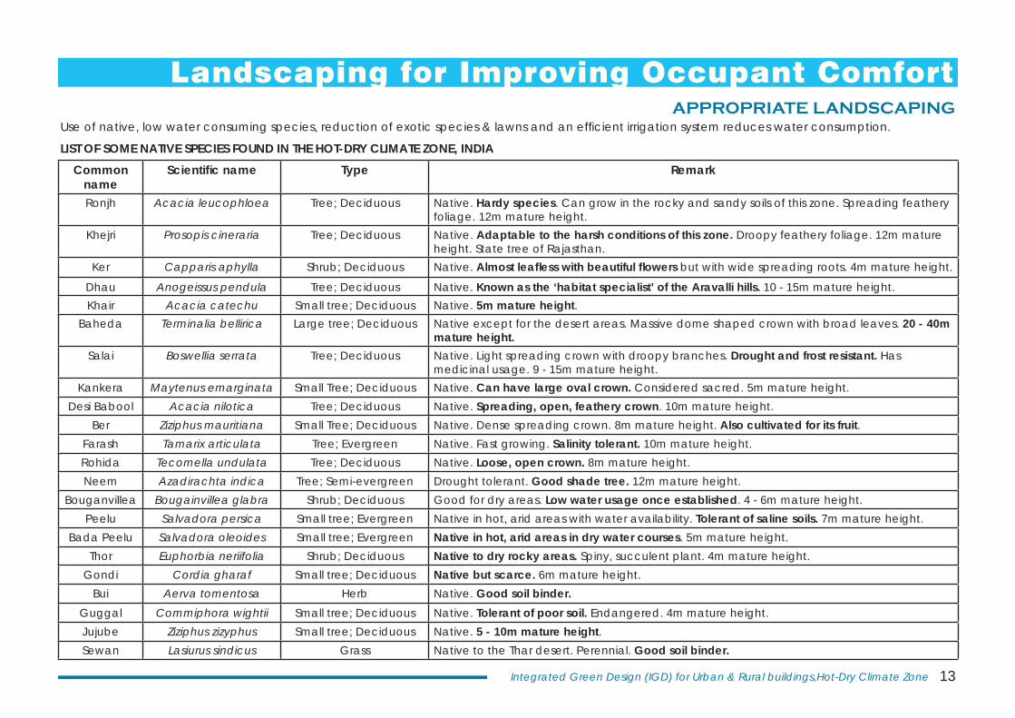
Common name
Scientifi c name Type Remark
Ronjh Acacia leucophloea Tree; Deciduous Native. Hardy species. Can grow in the rocky and sandy soils of this zone. Spreading feathery foliage. 12m mature height.
Khejri Prosopis cineraria Tree; Deciduous Native. Adaptable to the harsh conditions of this zone. Droopy feathery foliage. 12m mature height. State tree of Rajasthan.
Ker Capparis aphylla Shrub; Deciduous Native. Almost leafl ess with beautiful fl owers but with wide spreading roots. 4m mature height.
Dhau Anogeissus pendula Tree; Deciduous Native. Known as the ‘habitat specialist’ of the Aravalli hills. 10 - 15m mature height.Khair Acacia catechu Small tree; Deciduous Native. 5m mature height.
Baheda Terminalia bellirica Large tree; Deciduous Native except for the desert areas. Massive dome shaped crown with broad leaves. 20 - 40m mature height.
Salai Boswellia serrata Tree; Deciduous Native. Light spreading crown with droopy branches. Drought and frost resistant. Has medicinal usage. 9 - 15m mature height.
Kankera Maytenus emarginata Small Tree; Deciduous Native. Can have large oval crown. Considered sacred. 5m mature height.Desi Babool Acacia nilotica Tree; Deciduous Native. Spreading, open, feathery crown. 10m mature height.
Ber Ziziphus mauritiana Small Tree; Deciduous Native. Dense spreading crown. 8m mature height. Also cultivated for its fruit.Farash Tamarix articulata Tree; Evergreen Native. Fast growing. Salinity tolerant. 10m mature height.Rohida Tecomella undulata Tree; Deciduous Native. Loose, open crown. 8m mature height.Neem Azadirachta indica Tree; Semi-evergreen Drought tolerant. Good shade tree. 12m mature height.
Bouganvillea Bougainvillea glabra Shrub; Deciduous Good for dry areas. Low water usage once established. 4 - 6m mature height.Peelu Salvadora persica Small tree; Evergreen Native in hot, arid areas with water availability. Tolerant of saline soils. 7m mature height.
Bada Peelu Salvadora oleoides Small tree; Evergreen Native in hot, arid areas in dry water courses. 5m mature height.Thor Euphorbia neriifolia Shrub; Deciduous Native to dry rocky areas. Spiny, succulent plant. 4m mature height.
Gondi Cordia gharaf Small tree; Deciduous Native but scarce. 6m mature height.Bui Aerva tomentosa Herb Native. Good soil binder.
Guggal Commiphora wightii Small tree; Deciduous Native. Tolerant of poor soil. Endangered. 4m mature height.Jujube Ziziphus zizyphus Small tree; Deciduous Native. 5 - 10m mature height.Sewan Lasiurus sindicus Grass Native to the Thar desert. Perennial. Good soil binder.
Use of native, low water consuming species, reduction of exotic species & lawns and an effi cient irrigation system reduces water consumption.
LIST OF SOME NATIVE SPECIES FOUND IN THE HOT-DRY CLIMATE ZONE, INDIA
Landscaping for Improving Occupant ComfortAPPROPRIATE LANDSCAPING
14 Central Public Works Department
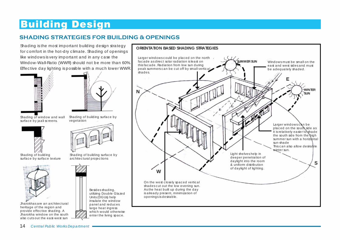
Shading of window and wall surface by jaali screens.
Shading of building surface by vegetation
Shading of building surface by architectural projections
Jharokhas are an architectural heritage of the region and provide effective shading. A Jharokha window on the south also cuts out the east-west sun
Building DesignSHADING STRATEGIES FOR BUILDING & OPENINGS
Shading of building surface by surface texture
N
SW
E
On the west closely spaced vertical shades cut out the low evening sun. As the heat built up during the day is already present, minimization of openings is desirable.
Larger windows could be placed on the north facade as direct solar radiation is least on this facade. Radiation from low sun during peak summers can be cut off by small vertical shades.
Larger windows can be placed on the south side as it is relatively easier to shade the south side from the high summer sun with a horizontal sun-shadeThis can also allow desirable winter sun.
Light shelves help in deeper penetration of daylight into the room & uniform distribution of daylight of lighting.
WINTER SUN
SUMMER SUN
ORIENTATION BASED SHADING STRATEGIESShading is the most important building design strategy for comfort in the hot-dry climate. Shading of openings like windows is very important and in any case the Window-Wall-Ratio (WWR) should not be more than 60%. Effective day lighting is possible with a much lower WWR.
Windows must be small on the east and west sides and must be adequately shaded.
Besides shading, utilizing Double Glazed Units (DGUs) help insulate the window panel and reduces large heat ingress which would otherwise enter the living space.
15Integrated Green Design (IGD) for Urban & Rural buildings,Hot-Dry Climate Zone
HSA
Altitude
VSA
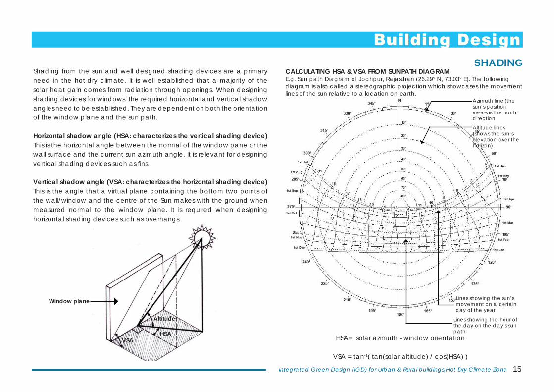
Shading from the sun and well designed shading devices are a primary need in the hot-dry climate. It is well established that a majority of the solar heat gain comes from radiation through openings. When designing shading devices for windows, the required horizontal and vertical shadow angles need to be established. They are dependent on both the orientation of the window plane and the sun path.
Horizontal shadow angle (HSA: characterizes the vertical shading device) This is the horizontal angle between the normal of the window pane or the wall surface and the current sun azimuth angle. It is relevant for designing vertical shading devices such as fi ns.
Vertical shadow angle (VSA: characterizes the horizontal shading device) This is the angle that a virtual plane containing the bottom two points of the wall/window and the centre of the Sun makes with the ground when measured normal to the window plane. It is required when designing horizontal shading devices such as overhangs.
HSA= solar azimuth - window orientation
VSA = tan-1( tan(solar altitude) / cos(HSA) )
CALCULATING HSA & VSA FROM SUNPATH DIAGRAME.g. Sun path Diagram of Jodhpur, Rajasthan (26.29° N, 73.03° E). The following diagram is also called a stereographic projection which showcases the movement lines of the sun relative to a location on earth.
Azimuth line (the sun’s position vis-a-vis the north direction
Altitude lines (shows the sun’s elevation over the horizon)
Lines showing the sun’s movement on a certain day of the year
Lines showing the hour of the day on the day’s sun path
SHADING
Window plane
Building Design
16 Central Public Works Department
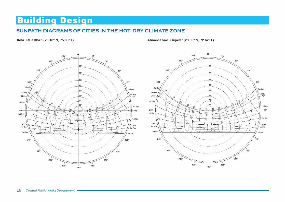
SUNPATH DIAGRAMS OF CITIES IN THE HOT- DRY CLIMATE ZONE
Kota, Rajasthan (25.18° N, 75.83° E) Ahmedabad, Gujarat (23.03° N, 72.62° E)
Building Design
17Integrated Green Design (IGD) for Urban & Rural buildings,Hot-Dry Climate Zone
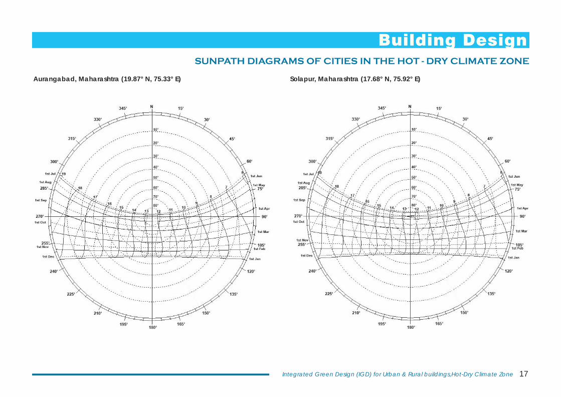
SUNPATH DIAGRAMS OF CITIES IN THE HOT - DRY CLIMATE ZONE
Aurangabad, Maharashtra (19.87° N, 75.33° E) Solapur, Maharashtra (17.68° N, 75.92° E)
Building Design
18 Central Public Works Department
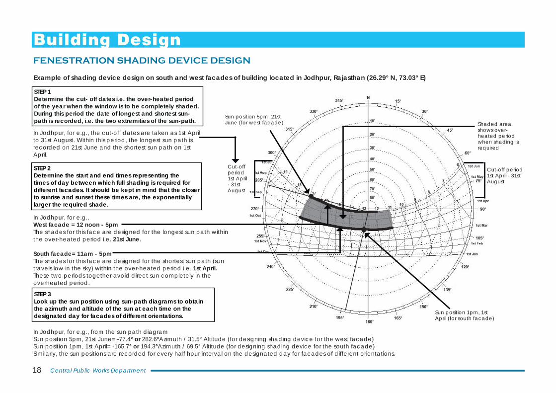
STEP 1Determine the cut- off dates i.e. the over-heated period of the year when the window is to be completely shaded. During this period the date of longest and shortest sun-path is recorded, i.e. the two extremities of the sun-path.
STEP 2Determine the start and end times representing the times of day between which full shading is required for different facades. It should be kept in mind that the closer to sunrise and sunset these times are, the exponentially larger the required shade.
STEP 3Look up the sun position using sun-path diagrams to obtain the azimuth and altitude of the sun at each time on the designated day for facades of different orientations.
FENESTRATION SHADING DEVICE DESIGN
Cut-off period1st April - 31st August
Cut-off period1st April - 31st August
In Jodhpur, for e.g., the cut-off dates are taken as 1st April to 31st August. Within this period, the longest sun path is recorded on 21st June and the shortest sun path on 1st April.
Example of shading device design on south and west facades of building located in Jodhpur, Rajasthan (26.29° N, 73.03° E)
In Jodhpur, for e.g., West facade = 12 noon - 5pmThe shades for this face are designed for the longest sun path within the over-heated period i.e. 21st June.
South facade= 11am - 5pmThe shades for this face are designed for the shortest sun path (sun travels low in the sky) within the over-heated period i.e. 1st April.These two periods together avoid direct sun completely in the overheated period.
Sun position 1pm, 1st April (for south facade)
In Jodhpur, for e.g., from the sun path diagramSun position 5pm, 21st June= -77.4° or 282.6°Azimuth / 31.5° Altitude (for designing shading device for the west facade) Sun position 1pm, 1st April= -165.7° or 194.3°Azimuth / 69.5° Altitude (for designing shading device for the south facade)Similarly, the sun positions are recorded for every half hour interval on the designated day for facades of different orientations.
Shaded area shows over-heated period when shading is required
Sun position 5pm, 21st June (for west facade)
Building Design
19Integrated Green Design (IGD) for Urban & Rural buildings,Hot-Dry Climate Zone
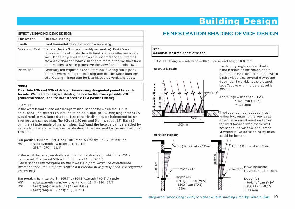
STEP 4Calculate HSA and VSA at different times during designated period for each facade. We need to design a shading device for the lowest possible VSA (horizontal shade) and the lowest possible HSA (vertical shade).
Step 5Calculate required depth of shade.
FENESTRATION SHADING DEVICE DESIGN
EXAMPLEIn the west facade, one can design vertical shades for which the HSA is calculated. The lowest HSA is found to be at 2:30pm (0.5°). Designing for this HSA would result in very large shades. Hence the shading device is designed for an intermediate sun position. The HSA at 1:30 pm and 5 pm is about 12°. But at 5 pm, the altitude angle of the sun is less (31.5°)and the facade can be shaded by vegetation. Hence, in this case the shades will be designed for the sun position at 1:30 pm.
Sun position 1:30 pm, 21st June= -101.3° or 258.7°Azimuth / 78.2° Altitude HSA = solar azimuth - window orientation = 258.7 - 270 = -11.3°
In the south facade, we shall design horizontal shades for which the VSA is calculated. The lowest VSA is found to be at 1pm (70.1°).(These shades are designed for the lowest sun path within the over-heated, summer period. The sun path is lower in winter but during this period solar ingress is preferable)
Sun position 1pm, 1st April= -165.7° or 194.3°Azimuth / 69.5° Altitude HSA = solar azimuth - window orientation= 194.3 - 180= 14.3VSA = tan-1( tan(solar altitude) / cos(HSA) ) = tan-1( tan(69.5) / cos(14.3) ) = 70.1.
EFFECTIVE SHADING DEVICE DESIGNOrientation Effective shadingSouth Fixed horizontal device or window recessing.West and East Vertical device/louvres (possibly moveable). East / West
faces are diffi cult to shade with fi xed shades as the sun is very low. Hence only small windows are recommended. External moveable shades / rollable blinds are more effective than fi xed shades. These also help preserve the view from the windows.
North side Generally not required except from low evening sun in peak summer when the sun path is long and hits the North from the side. Cutting this out can be is achieved by vertical shades.
EXAMPLE: Taking a window of width 1500mm and height 1800mm
For west facade
1500mm
250mm
HSA= 11.3°
Shading by single vertical shade is not feasible as the shade depth becomes prohibitive. Hence the width is subdivided and several louvres are designed. If 6 divisions are created, i.e. effective width to be shaded is 250mm
depth (d)= width / tan (HSA) =250 / tan (11.3°) = 1250mm
This depth can be reduced much further by designing the louvres at an angle. As mentioned earlier, on the west facade fi xed shades will not shade the window at all times. Movable louvers or shading by trees could be better .
d=
1250
mm
d=
275m
m
For south facade
Depth (d)= Height / tan (VSA)=1800 / tan (70.1)= 650mm
If two horizontal louvres are used then, Depth (d) = Height / tan (VSA)= 850 / tan (70.1°)= 300mm
VSA= 70.1° VSA= 70.1°
Depth (d) derived as 300mm
1800
mm 85
0mm
Depth (d) derived as 650mm
Building Design
20 Central Public Works Department
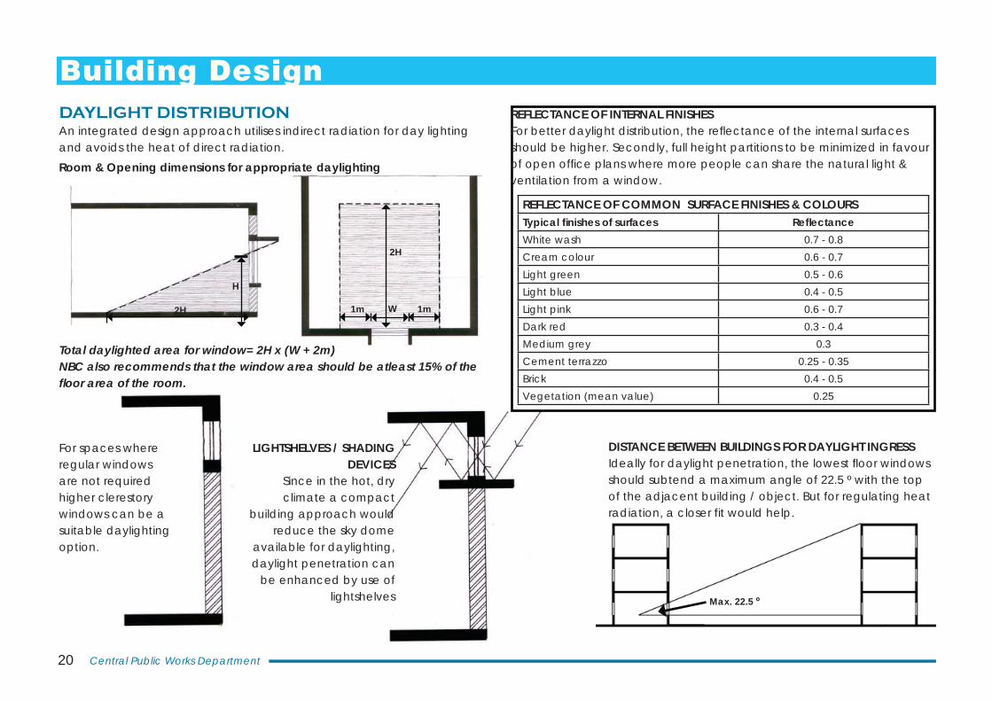
DAYLIGHT DISTRIBUTIONAn integrated design approach utilises indirect radiation for day lighting and avoids the heat of direct radiation.
REFLECTANCE OF INTERNAL FINISHESFor better daylight distribution, the refl ectance of the internal surfaces should be higher. Secondly, full height partitions to be minimized in favour of open offi ce plans where more people can share the natural light & ventilation from a window.
H
2H
2H
W1m 1m
Total daylighted area for window= 2H x (W + 2m)NBC also recommends that the window area should be atleast 15% of the fl oor area of the room.
For spaces where regular windows are not required higher clerestory windows can be a suitable daylighting option.
LIGHTSHELVES / SHADING DEVICES
Since in the hot, dry climate a compact
building approach would reduce the sky dome
available for daylighting, daylight penetration can
be enhanced by use of lightshelves Max. 22.5 º
DISTANCE BETWEEN BUILDINGS FOR DAYLIGHT INGRESSIdeally for daylight penetration, the lowest fl oor windows should subtend a maximum angle of 22.5 º with the top of the adjacent building / object. But for regulating heat radiation, a closer fit would help.
REFLECTANCE OF COMMON SURFACE FINISHES & COLOURSTypical fi nishes of surfaces Refl ectanceWhite wash 0.7 - 0.8Cream colour 0.6 - 0.7Light green 0.5 - 0.6Light blue 0.4 - 0.5Light pink 0.6 - 0.7Dark red 0.3 - 0.4Medium grey 0.3Cement terrazzo 0.25 - 0.35Brick 0.4 - 0.5Vegetation (mean value) 0.25
Room & Opening dimensions for appropriate daylighting
Building Design
21Integrated Green Design (IGD) for Urban & Rural buildings,Hot-Dry Climate Zone
PASSIVE COOLING STRATEGIES
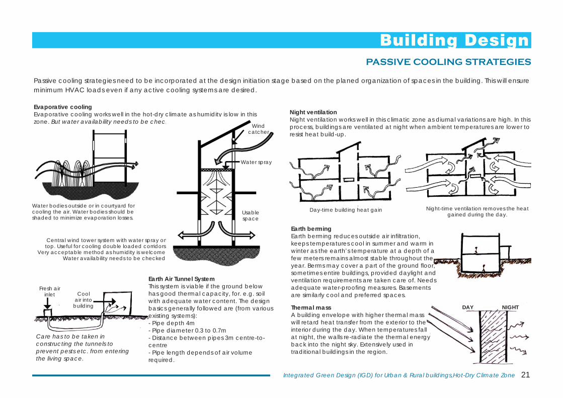
Passive cooling strategies need to be incorporated at the design initiation stage based on the planed organization of spaces in the building. This will ensure minimum HVAC loads even if any active cooling systems are desired.
Water bodies outside or in courtyard for cooling the air. Water bodies should be shaded to minimize evaporation losses.
Central wind tower system with water spray on top. Useful for cooling double loaded corridors.
Very acceptable method as humidity is welcome. Water availability needs to be checked.
Night ventilationNight ventilation works well in this climatic zone as diurnal variations are high. In this process, buildings are ventilated at night when ambient temperatures are lower to resist heat build-up.
Night-time ventilation removes the heat gained during the day.
Day-time building heat gain
DAY NIGHT
Evaporative coolingEvaporative cooling works well in the hot-dry climate as humidity is low in this zone. But water availability needs to be checked.
Wind catcher
Water spray
Usable space
Fresh air inlet Cool
air into building
Earth Air Tunnel SystemThis system is viable if the ground below has good thermal capacity, for. e.g. soil with adequate water content. The design basics generally followed are (from various existing systems):- Pipe depth 4m- Pipe diameter 0.3 to 0.7m - Distance between pipes 3m centre-to-centre- Pipe length depends of air volume required.
Care has to be taken in constructing the tunnels to prevent pests etc. from entering the living space.
Earth bermingEarth berming reduces outside air infi ltration, keeps temperatures cool in summer and warm in winter as the earth’s temperature at a depth of a few meters remains almost stable throughout the year. Berms may cover a part of the ground fl oor, sometimes entire buildings, provided daylight and ventilation requirements are taken care of. Needs adequate water-proofi ng measures. Basements are similarly cool and preferred spaces.
Thermal massA building envelope with higher thermal mass will retard heat transfer from the exterior to the interior during the day. When temperatures fall at night, the walls re-radiate the thermal energy back into the night sky. Extensively used in traditional buildings in the region.
Building Design
22 Central Public Works Department
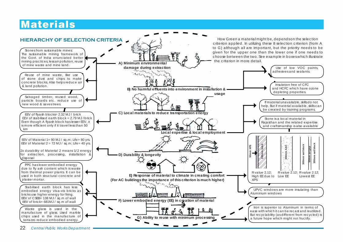
A) Minimum environmental damage during extraction
B) No harmful effl uents into environment in installation & usage
C) Local materials to reduce transportation energy
Local expertise & local employment
D) Durability & longevity
E) Response of material to climate in creating comfort(For AC buildings the importance of this criterion is much higher)
F) Lower embodied energy (EE) in creation of material
G) Ability to reuse with minimum processing
EEV of fl yash blocks= 2.32 MJ / brick EEV of stabilised earth block = 2.79 MJ /brickEven though A fl yash block has lesser EEV, it is more effi cient only if it travel less than 50
km
EEV of Material 1= 90 MJ / sq.m; Life= 80 yrs. EEV of Material 2 = 72 MJ / sq.m; Life= 40 yrs.
2x durability of Material 2 means 1/2 energy for extraction, processing, installation & disposal
PPC has lower embodied energy due to fl y ash content which is waste from thermal power plants. It can be used in both structural concrete and plaster mortar.
Stones from sustainable mines: The sustainable mining framework of the Govt. of India enunciated better mining practices, less air pollution, reuse of mine waste and mine land.
Reuse of mine waste, like use of stone dust and chips to make concrete blocks, Also helps reduce air & land pollution.
Use of low VOC paints, adhesives and sealants.
Insulation free of CFC and HCFC which have ozone depleting properties.
Stabilised earth block has less embodied energy vis-a-vis bricks as bricks use higher energy for fi ring.EEV of CSEB= 138 MJ / sq.m of wallEEV of brick= 681MJ / sq.m of wall
Iron is superior to Aluminum in terms of ease with which it can be recast and reutilized. But recyclability (as different from recycled) is a future hope which might not fructify.
Salvaged timber, reused wood, particle boards etc. reduce use of new wood & saves trees. If material unavailable, skills do not
help, But if material available, skills can be created by training programs.
Waste glass is used in the manufacture of glass. Used marble chips used in the manufacture of
terrazzo reduce embodied energy.
230m
m b
rick
50m
m X
PS
300m
m A
AC
R value 2.12; High EE due to XPS
R value 2.12; Low EE
R value 2.12; Lowest EE
300m
m s
oil b
lock
300m
m s
oil b
lock
50m
m a
ir ga
p
UPVC windows are more insulating than Aluminium windows
Stone is a local material in Rajasthan and the related expertise and craftsmanship is also available
Materials HIERARCHY OF SELECTION CRITERIA
How Green a material might be, depends on the selection criterion applied. In utilizing these 8 selection criterion (from A to G) although all are important, but the priority needs to be given for the upper one than the lower one if one needs to choose between the two. See example in boxes which illustrate the criterion in more detail.
23Integrated Green Design (IGD) for Urban & Rural buildings,Hot-Dry Climate Zone
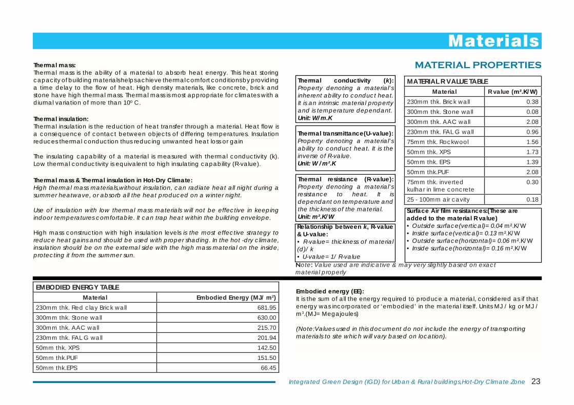
MATERIAL PROPERTIES
Embodied energy (EE): It is the sum of all the energy required to produce a material, considered as if that energy was incorporated or ‘embodied’ in the material itself. Units MJ / kg or MJ / m3.(MJ= Megajoules)
(Note:Values used in this document do not include the energy of transporting materials to site which will vary based on location).
Thermal conductivity (k): Property denoting a material’s inherent ability to conduct heat. It is an intrinsic material property and is temperature dependant. Unit: W/m.K
Thermal mass:Thermal mass is the ability of a material to absorb heat energy. This heat storing capacity of building materials helps achieve thermal comfort conditions by providing a time delay to the fl ow of heat. High density materials, like concrete, brick and stone have high thermal mass. Thermal mass is most appropriate for climates with a diurnal variation of more than 10º C.
Thermal insulation:Thermal insulation is the reduction of heat transfer through a material. Heat fl ow is a consequence of contact between objects of differing temperatures. Insulation reduces thermal conduction thus reducing unwanted heat loss or gain
The insulating capability of a material is measured with thermal conductivity (k). Low thermal conductivity is equivalent to high insulating capability (R-value).
Thermal mass & Thermal insulation in Hot-Dry Climate:High thermal mass materials,without insulation, can radiate heat all night during a summer heatwave, or absorb all the heat produced on a winter night.
Use of insulation with low thermal mass materials will not be effective in keeping indoor temperatures comfortable. It can trap heat within the building envelope.
High mass construction with high insulation levels is the most effective strategy to reduce heat gains and should be used with proper shading. In the hot -dry climate, insulation should be on the external side with the high mass material on the inside, protecting it from the summer sun.
MATERIAL R VALUE TABLEMaterial R value (m².K/W)
230mm thk. Brick wall 0.38300mm thk. Stone wall 0.08300mm thk. AAC wall 2.08230mm thk. FAL G wall 0.9675mm thk. Rockwool 1.5650mm thk. XPS 1.7350mm thk. EPS 1.3950mm thk.PUF 2.0875mm thk. inverted kulhar in lime concrete
0.30
25 - 100mm air cavity 0.18
EMBODIED ENERGY TABLEMaterial Embodied Energy (MJ/ m2)
230mm thk. Red clay Brick wall 681.95300mm thk. Stone wall 630.00300mm thk. AAC wall 215.70230mm thk. FAL G wall 201.9450mm thk. XPS 142.5050mm thk.PUF 151.5050mm thk.EPS 66.45
Relationship between k, R-value & U-value:• R-value= thickness of material (d)/ k• U-value= 1/ R-value
Thermal resistance (R-value): Property denoting a material’s resistance to heat. It is dependant on temperature and the thickness of the material. Unit: m².K/W
Surface Air fi lm resistances:(These are added to the material R value)• Outside surface(vertical)= 0.04 m².K/W• Inside surface(vertical)= 0.13 m².K/W• Outside surface(horizontal)= 0.06 m².K/W• Inside surface(horizontal)= 0.16 m².K/W
Materials
Thermal transmittance(U-value): Property denoting a material’s ability to conduct heat. It is the inverse of R-value.Unit: W /m².K
Note: Value used are indicative & may very slightly based on exact material properly
24 Central Public Works Department
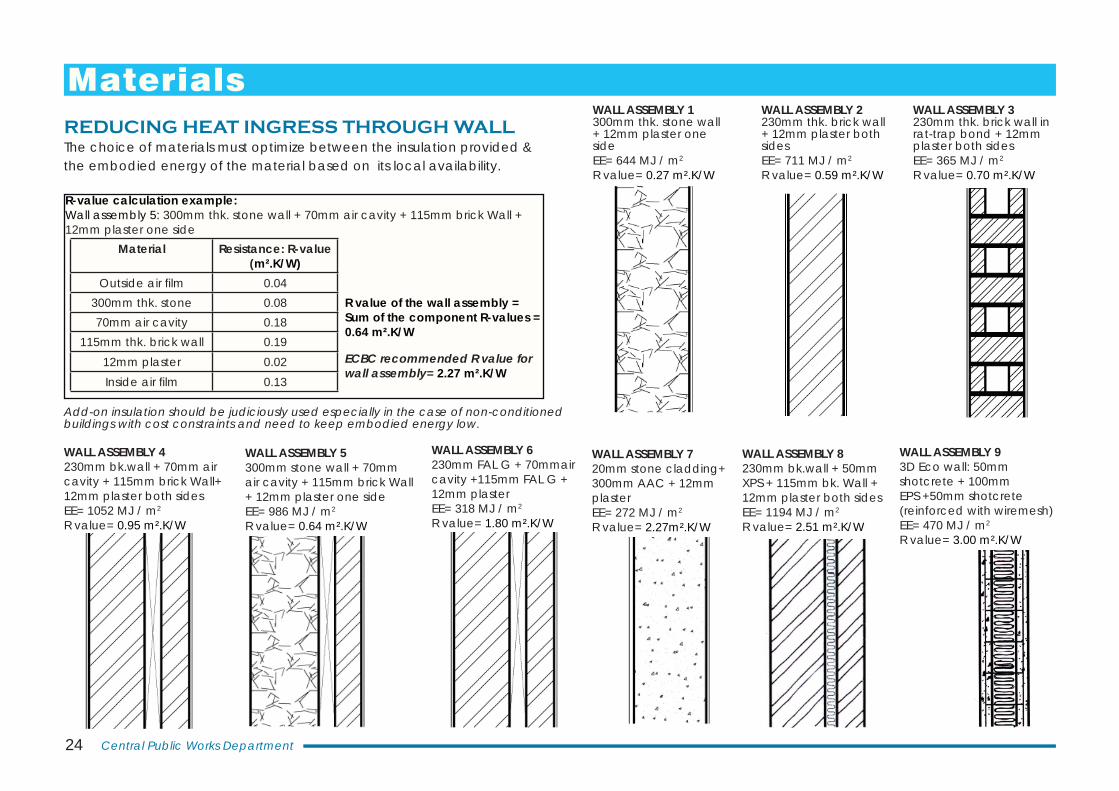
REDUCING HEAT INGRESS THROUGH WALLThe choice of materials must optimize between the insulation provided & the embodied energy of the material based on its local availability.
Add-on insulation should be judiciously used especially in the case of non-conditioned buildings with cost constraints and need to keep embodied energy low.
WALL ASSEMBLY 1300mm thk. stone wall + 12mm plaster one sideEE= 644 MJ / m2
R value= 0.27 m².K/W
WALL ASSEMBLY 2230mm thk. brick wall + 12mm plaster both sidesEE= 711 MJ / m2
R value= 0.59 m².K/W
WALL ASSEMBLY 4230mm bk.wall + 70mm air cavity + 115mm brick Wall+ 12mm plaster both sidesEE= 1052 MJ / m2
R value= 0.95 m².K/W
WALL ASSEMBLY 6230mm FAL G + 70mmair cavity +115mm FAL G + 12mm plasterEE= 318 MJ / m2
R value= 1.80 m².K/W
WALL ASSEMBLY 720mm stone cladding+ 300mm AAC + 12mm plasterEE= 272 MJ / m2
R value= 2.27m².K/W
WALL ASSEMBLY 8230mm bk.wall + 50mm XPS + 115mm bk. Wall + 12mm plaster both sidesEE= 1194 MJ / m2
R value= 2.51 m².K/W
WALL ASSEMBLY 93D Eco wall: 50mm shotcrete + 100mm EPS +50mm shotcrete (reinforced with wiremesh) EE= 470 MJ / m2
R value= 3.00 m².K/W
WALL ASSEMBLY 3230mm thk. brick wall in rat-trap bond + 12mm plaster both sidesEE= 365 MJ / m2
R value= 0.70 m².K/W
WALL ASSEMBLY 5300mm stone wall + 70mm air cavity + 115mm brick Wall + 12mm plaster one sideEE= 986 MJ / m2
R value= 0.64 m².K/W
R-value calculation example: Wall assembly 5: 300mm thk. stone wall + 70mm air cavity + 115mm brick Wall + 12mm plaster one side
R value of the wall assembly = Sum of the component R-values =0.64 m².K/W
ECBC recommended R value for wall assembly= 2.27 m².K/W
Material Resistance: R-value (m².K/W)
Outside air fi lm 0.04300mm thk. stone 0.0870mm air cavity 0.18
115mm thk. brick wall 0.1912mm plaster 0.02Inside air fi lm 0.13
Materials
25Integrated Green Design (IGD) for Urban & Rural buildings,Hot-Dry Climate Zone
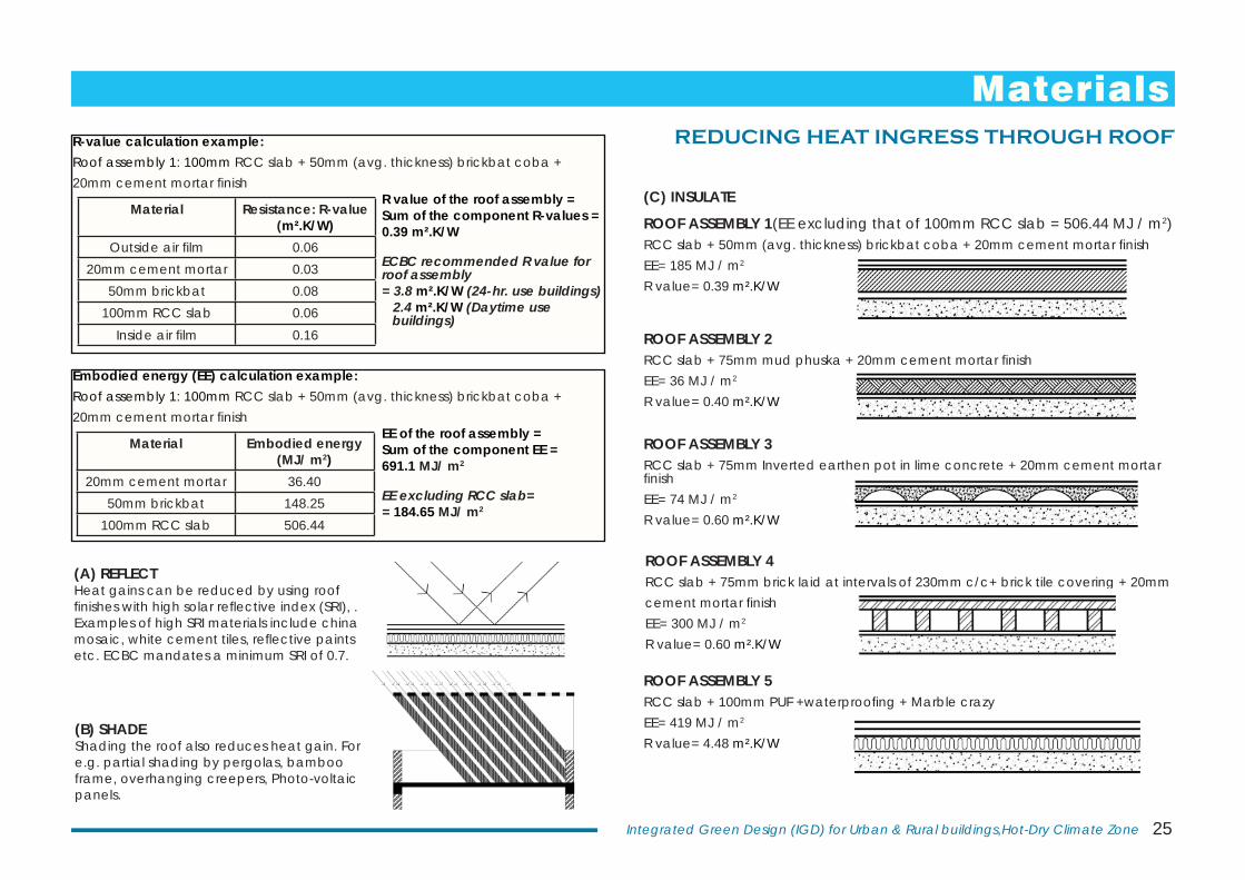
REDUCING HEAT INGRESS THROUGH ROOF
(A) REFLECTHeat gains can be reduced by using roof fi nishes with high solar refl ective index (SRI), . Examples of high SRI materials include china mosaic, white cement tiles, refl ective paints etc. ECBC mandates a minimum SRI of 0.7.
(B) SHADEShading the roof also reduces heat gain. For e.g. partial shading by pergolas, bamboo frame, overhanging creepers, Photo-voltaic panels.
ROOF ASSEMBLY 3RCC slab + 75mm Inverted earthen pot in lime concrete + 20mm cement mortar fi nishEE= 74 MJ / m2
R value= 0.60 m².K/W
ROOF ASSEMBLY 5 RCC slab + 100mm PUF +waterproofi ng + Marble crazyEE= 419 MJ / m2
R value= 4.48 m².K/W
ROOF ASSEMBLY 1(EE excluding that of 100mm RCC slab = 506.44 MJ / m2)RCC slab + 50mm (avg. thickness) brickbat coba + 20mm cement mortar fi nishEE= 185 MJ / m2
R value= 0.39 m².K/W
ROOF ASSEMBLY 2RCC slab + 75mm mud phuska + 20mm cement mortar fi nish EE= 36 MJ / m2
R value= 0.40 m².K/W
(C) INSULATE
ROOF ASSEMBLY 4 RCC slab + 75mm brick laid at intervals of 230mm c/c+ brick tile covering + 20mm cement mortar fi nishEE= 300 MJ / m2
R value= 0.60 m².K/W
R-value calculation example: Roof assembly 1: 100mm RCC slab + 50mm (avg. thickness) brickbat coba + 20mm cement mortar fi nish
R value of the roof assembly = Sum of the component R-values =0.39 m².K/W
ECBC recommended R value for roof assembly= 3.8 m².K/W (24-hr. use buildings) 2.4 m².K/W (Daytime use buildings)
Material Resistance: R-value (m².K/W)
Outside air fi lm 0.0620mm cement mortar 0.03
50mm brickbat 0.08100mm RCC slab 0.06
Inside air fi lm 0.16
Embodied energy (EE) calculation example: Roof assembly 1: 100mm RCC slab + 50mm (avg. thickness) brickbat coba + 20mm cement mortar fi nish
EE of the roof assembly = Sum of the component EE =691.1 MJ/ m2
EE excluding RCC slab== 184.65 MJ/ m2
Material Embodied energy (MJ/ m2)
20mm cement mortar 36.4050mm brickbat 148.25
100mm RCC slab 506.44
Materials
26 Central Public Works Department
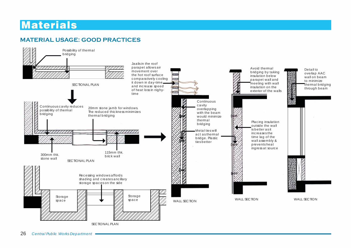
Possibility of thermal bridging
Continuous cavity reduces possibility of thermal bridging
20mm stone jamb for windows. The reduced thickness minimizes thermal bridging
300mm thk. stone wall
115mm thk. brick wall
SECTIONAL PLAN
WALL SECTION
Continuous cavity overlapping with the beam would minimize thermal bridging Placing insulation
outside the wall is better as it increases the time lag of the wall assembly & prevents heat ingress at source
SECTIONAL PLAN
SECTIONAL PLAN
WALL SECTION
Recessing windows affords shading and creates ancillary storage spaces on the side
Avoid thermal bridging by taking insulation below parapet wall and meeting with wall insulation on the exterior of the walls
Jaalis in the roof parapet allows air movement over the hot roof surface comparatively cooling it down in day-time and increase speed of heat loss in nighy-time
Metal ties will act as thermal bridge. Plastic ties better
Storage space
Detail to overlap AAC wall on beam to minimize thermal bridging through beam
WALL SECTION
MATERIAL USAGE: GOOD PRACTICES
Storage space
Materials
27Integrated Green Design (IGD) for Urban & Rural buildings,Hot-Dry Climate Zone
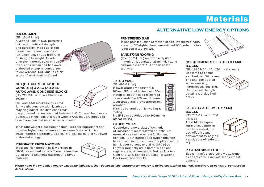
CLC (CELLULAR LIGHTWEIGHT CONCRETE) & AAC (AERATED AUTOCLAVED CONCRETE) BLOCKS (EE= 215 MJ / m2 for wall thickness 300mm) CLC and AAC blocks are air-cured lightweight concrete with fl y-ash as a major ingredient. The difference lies in the process of generation of air bubbles. In CLC the air bubbles are generated in the form of a foam while in AAC they are produced from a reaction that uses aluminum powder.
These light-weight blocks reduce structural steel requirement and provides higher thermal insulation. As it uses fl y-ash which is a waste material it leads to substantial material saving and has lower embodied energy.
CSEB (COMPRESSED STABILISED EARTH BLOCKS) (EE= 138.6 MJ / m2 for 230mm thk. wall ) Blocks made of mud stabilised with 5% cement lime and compacted in block-making machines without fi ring. Compressive strength equal to red clay fi red bricks.
FAL G (FLY ASH- LIME GYPSUM)BLOCKS (EE= 202 MJ / m2 for 230 thik wall)These blocks require less mortar, plastering can be avoided, are cost effective and environment-friendly as it avoids use of fertile top soil.
PRE-CAST STONE BLOCKSBlocks manufactured using waste stone pieces of various sizes with lean cement concrete.
3D ECO WALL(EE= 470 MJ / m2) This wall assembly consists of a 100mm EPS panel fi nished with 50mm shotcrete on both sides, reinforced by wiremesh. The 200mm thk. panel saves space and provides excellent insulation.This may be used both for walling & roofi ng.The EPS can be reduced to 100mm for interior walling.
SANDSTONE ROOFING (EE= 196 MJ / m2) An extensively used material, this consists of 25mm thick stone slabs on pre-cast RCC beams or iron sections.
GEOPOLYMERSGeopolymers are a class of synthetic aluminosilicate materials with potential use essentially as a replacement for Portland cement. Fly ash based geopolymer concrete has superior strength and mortar / plaster made from it does not require curing. GPC (Geo Polymer Cements) use a host of waste and virgin materials in feedstock. Besides Structural Concrete, GPC can be used also for Building Blocks and Paver Blocks.
Please note: The embodied energy values are indicative. They do not include transportation energy to deliver material on-site. Values will vary as per exact construction detail utilized.
PERFORATED BRICK MASONRYThese are high strength hollow bricks with 50-60 percent perforations. These perforations act as sound and heat insulators and saves materials.
PRE-STRESSED SLABThis helps in reduction of section of slab. Pre-stressed slabs are up to 25% lighter than conventional RCC slabs due to a reduction in section size.
FERROCEMENT(EE= 111 MJ / m2) A versatile form of RCC possessing unique properties of strength and durability. Made up of rich cement mortar and wire mesh reinforcement, it has a high ratio of strength to weight. A cost-effective material, it also enables faster construction and has lower embodied energy in comparison to conventional RCC due to its thin section & minimization of steel
ALTERNATIVE LOW ENERGY OPTIONS
Materials
28 Central Public Works Department
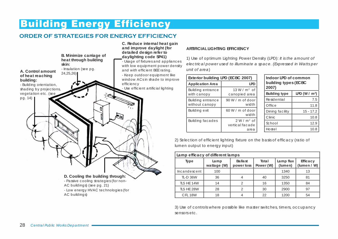
D. Cooling the building through: - Passive cooling strategies (for non-AC buildings) (see pg. 21)- Low energy HVAC technologies (for AC buildings)
A. Control amount of heat reaching building: - Building orientation, shading by projections, vegetation etc. (see pg. 14)
B. Minimize carriage of heat through building skin: - Insulation (see pg. 24,25,26)
C. Reduce internal heat gain and improve daylight (for detailed design refer to daylighting code SP41)- Usage of fi xtures and appliances with low equipment power density and with effi cient BEE rating. - Keep outdoor equipment like window ACs in shade to improve effi ciency- Use effi cient artifi cial lighting
Lamp effi cacy of different lampsType Lamp
wattage (W)Ballast
power lossTotal
Power (W)Lamp fl ux (lumen)
Effi cacy (lumen / W)
Incandescent 100 1340 13TL-D 36W 36 4 40 3250 81
TL5 HE 14W 14 2 16 1350 84TL5 HE 28W 28 2 30 2900 97
CFL 18W 18 4 22 1200 54
Indoor LPD of common building types (ECBC 2007)Building type LPD (W / m2)Residential 7.5Offi ce 11.8Dining facility 15 - 17.2Clinic 10.8School 12.9Hostel 10.8
ARTIFICIAL LIGHTING EFFICIENCY
1) Use of optimum Lighting Power Density (LPD): It is the amount of electrical power used to illuminate a space. (Expressed in Watts per unit of area)
Exterior building LPD (ECBC 2007)Application Area LPD Building entrance with canopy
13 W / m2 of canopied area
Building entrance without canopy
90 W / m of door width
Building exit 60 W / m of door width
Building facades 2 W / m2 of vertical facade
area
ORDER OF STRATEGIES FOR ENERGY EFFICIENCY
3) Use of controls where possible like master switches, timers, occupancy sensors etc.
2) Selection of effi cient lighting fi xture on the basis of effi cacy (ratio of lumen output to energy input)
Building Energy Efficiency
29Integrated Green Design (IGD) for Urban & Rural buildings,Hot-Dry Climate Zone
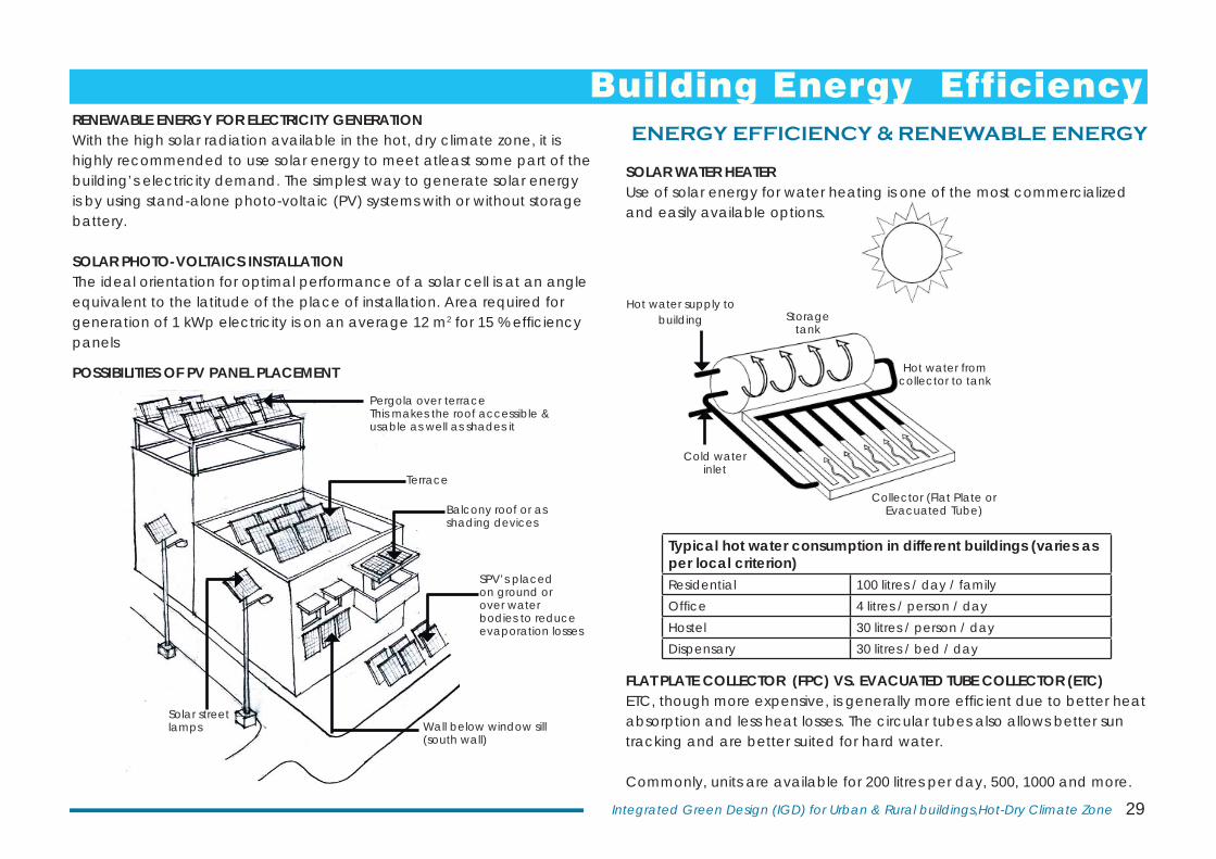
Cold water inlet
Hot water from collector to tank
Storage tank
Collector (Flat Plate or Evacuated Tube)
Hot water supply to building
Typical hot water consumption in different buildings (varies as per local criterion)Residential 100 litres / day / familyOffi ce 4 litres / person / dayHostel 30 litres / person / dayDispensary 30 litres / bed / day
RENEWABLE ENERGY FOR ELECTRICITY GENERATIONWith the high solar radiation available in the hot, dry climate zone, it is highly recommended to use solar energy to meet atleast some part of the building’s electricity demand. The simplest way to generate solar energy is by using stand-alone photo-voltaic (PV) systems with or without storage battery.
SOLAR PHOTO-VOLTAICS INSTALLATIONThe ideal orientation for optimal performance of a solar cell is at an angle equivalent to the latitude of the place of installation. Area required for generation of 1 kWp electricity is on an average 12 m2 for 15 % effi ciency panels
POSSIBILITIES OF PV PANEL PLACEMENT
SOLAR WATER HEATERUse of solar energy for water heating is one of the most commercialized and easily available options.
Terrace
Balcony roof or as shading devices
Wall below window sill (south wall)
Solar street lamps
Pergola over terraceThis makes the roof accessible & usable as well as shades it
SPV’s placed on ground or over water bodies to reduce evaporation losses
FLAT PLATE COLLECTOR (FPC) VS. EVACUATED TUBE COLLECTOR (ETC)ETC, though more expensive, is generally more effi cient due to better heat absorption and less heat losses. The circular tubes also allows better sun tracking and are better suited for hard water.
Commonly, units are available for 200 litres per day, 500, 1000 and more.
ENERGY EFFICIENCY & RENEWABLE ENERGY
Building Energy Efficiency
30 Central Public Works Department
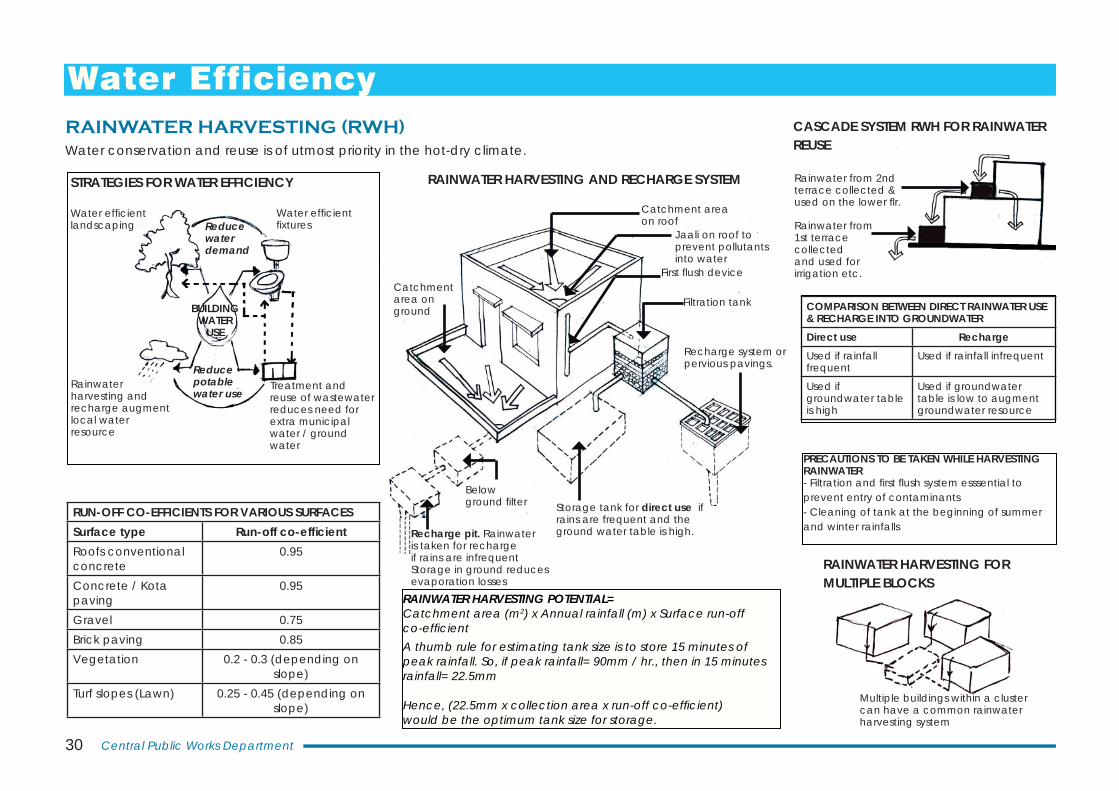
RAINWATER HARVESTING AND RECHARGE SYSTEM
RUN-OFF CO-EFFICIENTS FOR VARIOUS SURFACESSurface type Run-off co-effi cientRoofs conventional concrete
0.95
Concrete / Kota paving
0.95
Gravel 0.75Brick paving 0.85Vegetation 0.2 - 0.3 (depending on
slope)Turf slopes (Lawn) 0.25 - 0.45 (depending on
slope)
RAINWATER HARVESTING POTENTIAL= Catchment area (m2) x Annual rainfall (m) x Surface run-off co-effi cientA thumb rule for estimating tank size is to store 15 minutes of peak rainfall. So, if peak rainfall= 90mm / hr., then in 15 minutes rainfall= 22.5mm
Hence, (22.5mm x collection area x run-off co-effi cient)would be the optimum tank size for storage.
CASCADE SYSTEM RWH FOR RAINWATER REUSE
Storage tank for direct use if rains are frequent and the ground water table is high.
Filtration tank
Recharge system or pervious pavings.
Catchment area on roof
First fl ush deviceCatchment area on ground
Below ground fi lter
Recharge pit. Rainwater is taken for recharge if rains are infrequent Storage in ground reduces evaporation losses
Jaali on roof to prevent pollutants into water
COMPARISON BETWEEN DIRECT RAINWATER USE & RECHARGE INTO GROUNDWATERDirect use RechargeUsed if rainfall frequent
Used if rainfall infrequent
Used if groundwater table is high
Used if groundwater table is low to augment groundwater resource
PRECAUTIONS TO BE TAKEN WHILE HARVESTING RAINWATER- Filtration and fi rst fl ush system esssential to prevent entry of contaminants- Cleaning of tank at the beginning of summer and winter rainfalls
Reduce water demand
Reduce potable water use
Treatment and reuse of wastewater reduces need for extra municipal water / ground water
Rainwater harvesting and recharge augment local water resource
Water effi cient fi xtures
Water effi cient landscaping
BUILDING WATER
USE
STRATEGIES FOR WATER EFFICIENCY
Multiple buildings within a cluster can have a common rainwater harvesting system
RAINWATER HARVESTING FOR MULTIPLE BLOCKS
Rainwater from 1st terrace collected and used for irrigation etc.
Rainwater from 2nd terrace collected & used on the lower fl r.
Water conservation and reuse is of utmost priority in the hot-dry climate.RAINWATER HARVESTING (RWH)
Water Efficiency
31Integrated Green Design (IGD) for Urban & Rural buildings,Hot-Dry Climate Zone
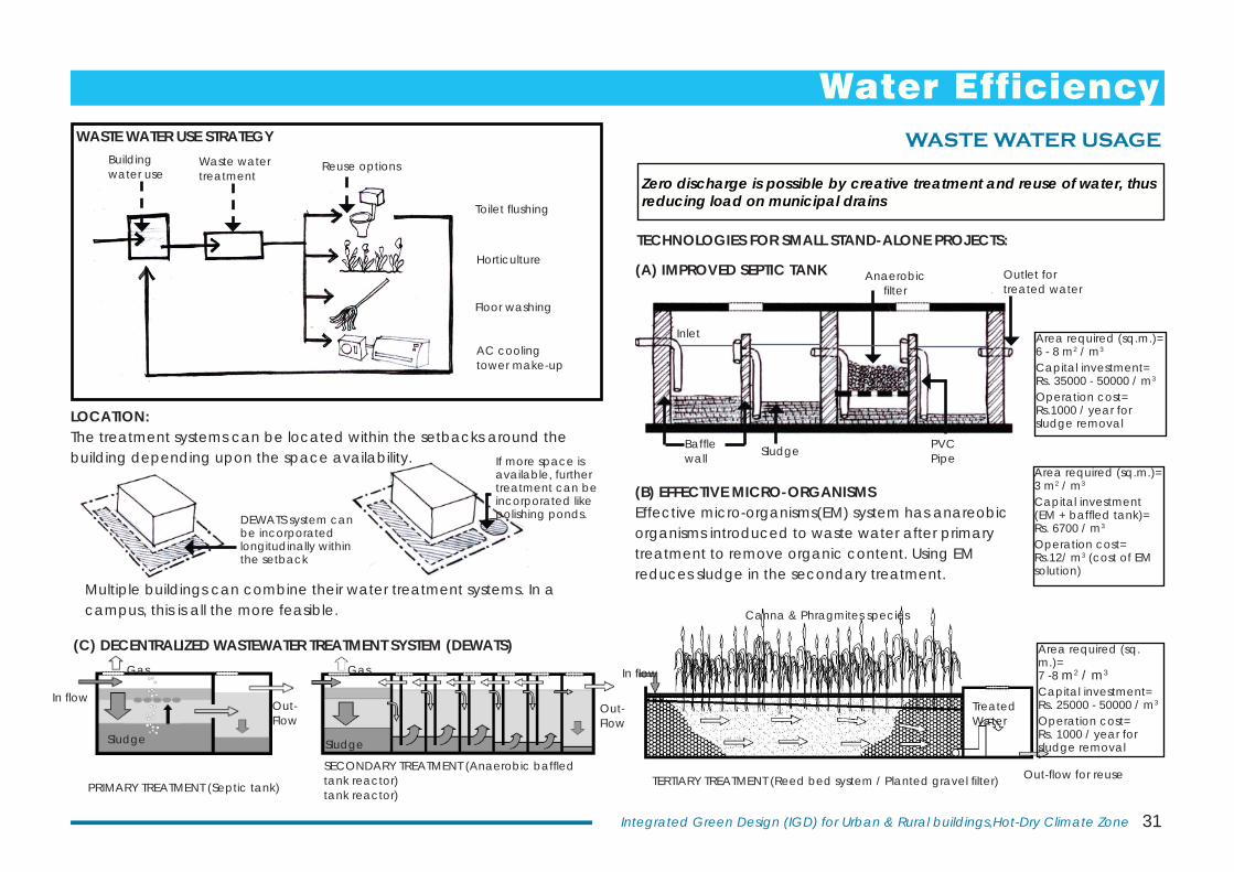
(A) IMPROVED SEPTIC TANK
(C) DECENTRALIZED WASTEWATER TREATMENT SYSTEM (DEWATS)
PRIMARY TREATMENT (Septic tank)
SECONDARY TREATMENT (Anaerobic baffl edtank reactor)tank reactor)
TERTIARY TREATMENT (Reed bed system / Planted gravel fi lter)
(B) EFFECTIVE MICRO-ORGANISMSEffective micro-organisms(EM) system has anareobic organisms introduced to waste water after primary treatment to remove organic content. Using EM reduces sludge in the secondary treatment.
Zero discharge is possible by creative treatment and reuse of water, thus reducing load on municipal drains
Area required (sq.m.)= 6 - 8 m2 / m3
Capital investment= Rs. 35000 - 50000 / m3
Operation cost= Rs.1000 / year for sludge removal
Area required (sq.m.)= 3 m2 / m3
Capital investment (EM + baffl ed tank)= Rs. 6700 / m3
Operation cost= Rs.12/ m3 (cost of EM solution)
Area required (sq.m.)= 7 -8 m2 / m3 Capital investment= Rs. 25000 - 50000 / m3
Operation cost= Rs. 1000 / year for sludge removal
LOCATION:The treatment systems can be located within the setbacks around the building depending upon the space availability.
DEWATS system can be incorporated longitudinally within the setback
If more space is available, further treatment can be incorporated like polishing ponds.
TECHNOLOGIES FOR SMALL STAND-ALONE PROJECTS:
Toilet fl ushing
Horticulture
Floor washing
AC cooling tower make-up
Waste water treatment
Building water use Reuse options
WASTE WATER USE STRATEGY
Multiple buildings can combine their water treatment systems. In a campus, this is all the more feasible.
WASTE WATER USAGE
Baffl e wall
Inlet
Anaerobic fi lter
Sludge PVC Pipe
Outlet for treated water
Water Efficiency
In fl ow
Treated Water
Canna & Phragmites species
Out-fl ow for reuse
Out-Flow
Gas
Sludge
In fl ow
Gas
Sludge
Out-Flow
32 Central Public Works Department
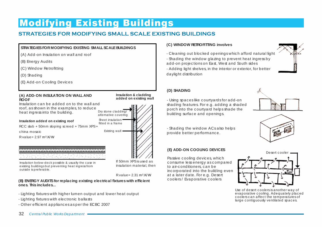
Desert cooler
Insulation added on existing roofRCC slab + 50mm sloping screed + 75mm XPS + china mosaicR value= 2.97 m².K/W
If 50mm XPS is used as insulation material, then
R value= 2.31 m².K/W
(A) ADD-ON INSULATION ON WALL AND ROOFInsulation can be added on to the wall and roof, as shown in the examples, to reduce heat ingress into the building.
(B) ENERGY AUDITS for replacing existing electrical fi xtures with effi cient ones. This includes...
- Lighting fi xtures with higher lumen output and lower heat output- Lighting fi xtures with electronic ballasts- Other effi cient appliances as per the ECBC 2007
(E) ADD-ON COOLING DEVICES
Passive cooling devices, which consume less energy as compared to air-conditioners, can be incorporated into the building even at a later date. For e.g. Desert coolers / Evaporative coolers
(C) WINDOW RETROFITTING involves
- Cleaning out blocked openings which afford natural light- Shading the window glazing to prevent heat ingress by add-on projections on East, West and South sides- Adding light shelves, in the interior or exterior, for better daylight distribution
STRATEGIES FOR MODIFYING EXISTING SMALL SCALE BUILDINGS
(A) Add-on Insulation on wall and roof
(B) Energy Audits
(C) Window Retrofi tting
(D) Shading
(E) Add-on Cooling Devices
Insulation below-deck possible & usually the case in existing buildings but preventing heat ingress from outside is preferable.
Insulation & cladding added on existing wall
Dry stone cladding/alternative coveringSheet insulation fi tted in a frame
Existing wall
(D) SHADING
- Using spaces like courtyards for add-on shading features. For e.g. adding a shaded porch into the courtyard helps shade the building surface and openings.
- Shading the window ACs also helps provide better performance.
Use of desert coolers is another way of evaporative cooling. Adequately placed coolers can affect the temperatures of large contiguously ventilated spaces.
STRATEGIES FOR MODIFYING SMALL SCALE EXISTING BUILDINGS
Modifying Existing Buildings
33Integrated Green Design (IGD) for Urban & Rural buildings,Hot-Dry Climate Zone
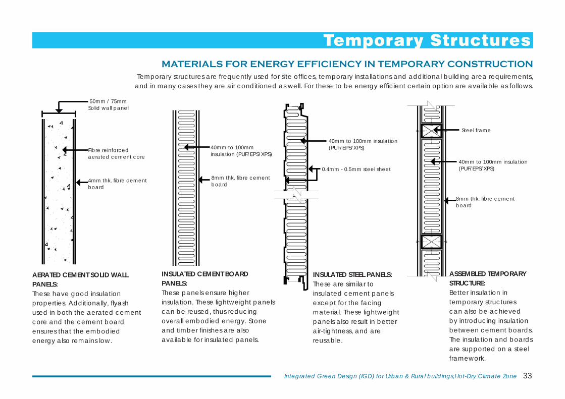
Temporary structures are frequently used for site offi ces, temporary installations and additional building area requirements, and in many cases they are air conditioned as well. For these to be energy effi cient certain option are available as follows.
INSULATED STEEL PANELS:These are similar to insulated cement panels except for the facing material. These lightweight panels also result in better air-tightness, and are reusable.
ASSEMBLED TEMPORARY STRUCTURE:Better insulation in temporary structures can also be achieved by introducing insulation between cement boards. The insulation and boards are supported on a steel framework.
AERATED CEMENT SOLID WALL PANELS:These have good insulation properties. Additionally, fl yash used in both the aerated cement core and the cement board ensures that the embodied energy also remains low.
50mm / 75mm Solid wall panel
Fibre reinforced aerated cement core
4mm thk. fi bre cement board
40mm to 100mm insulation (PUF/EPS/XPS)
0.4mm - 0.5mm steel sheet
INSULATED CEMENT BOARD PANELS:These panels ensure higher insulation. These lightweight panels can be reused, thus reducing overall embodied energy. Stone and timber fi nishes are also available for insulated panels.
40mm to 100mm insulation (PUF/EPS/XPS)
8mm thk. fi bre cement board
40mm to 100mm insulation (PUF/EPS/XPS)
Steel frame
8mm thk. fi bre cement board
MATERIALS FOR ENERGY EFFICIENCY IN TEMPORARY CONSTRUCTION
Temporary Structures

34 Central Public Works Department
35Integrated Green Design (IGD) for Urban & Rural buildings,Hot-Dry Climate Zone
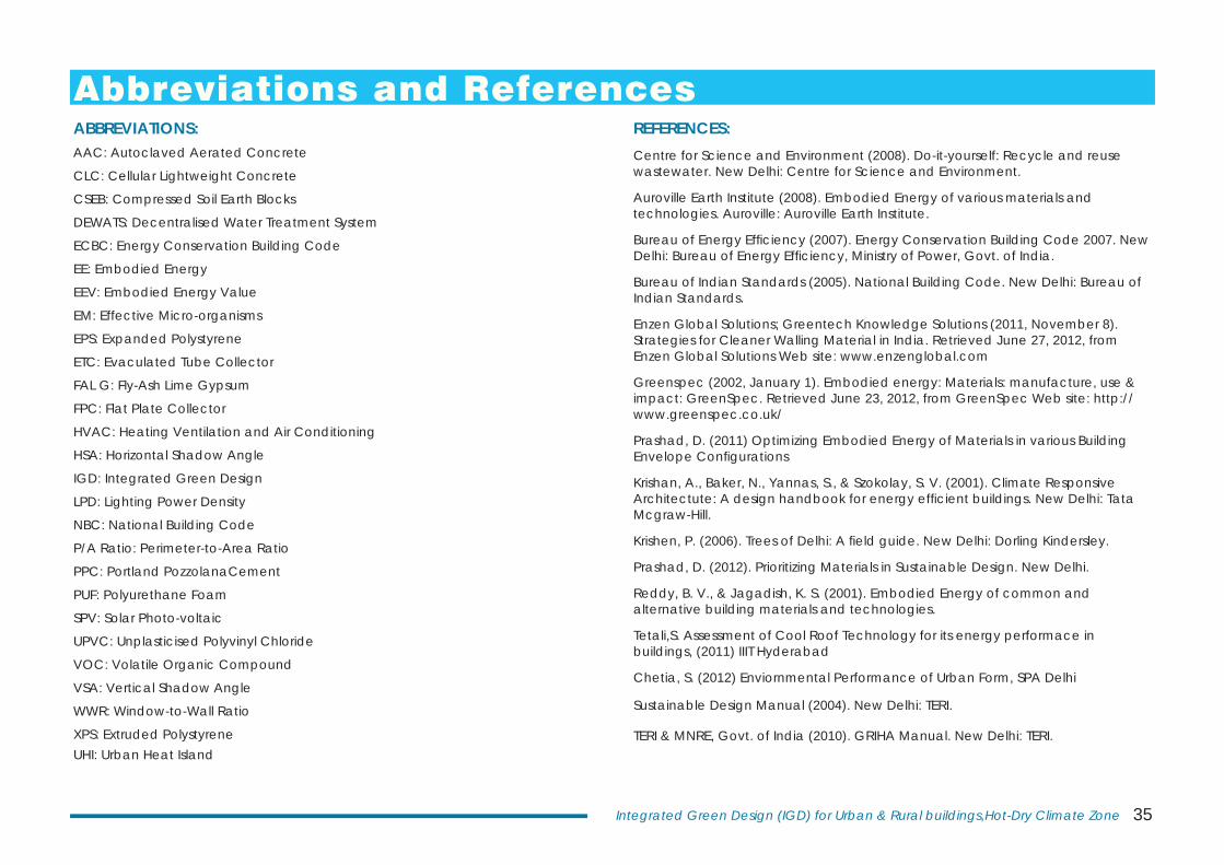
REFERENCES:Centre for Science and Environment (2008). Do-it-yourself: Recycle and reuse wastewater. New Delhi: Centre for Science and Environment.
Auroville Earth Institute (2008). Embodied Energy of various materials and technologies. Auroville: Auroville Earth Institute.
Bureau of Energy Effi ciency (2007). Energy Conservation Building Code 2007. New Delhi: Bureau of Energy Effi ciency, Ministry of Power, Govt. of India.
Bureau of Indian Standards (2005). National Building Code. New Delhi: Bureau of Indian Standards.
Enzen Global Solutions; Greentech Knowledge Solutions (2011, November 8). Strategies for Cleaner Walling Material in India. Retrieved June 27, 2012, from Enzen Global Solutions Web site: www.enzenglobal.com
Greenspec (2002, January 1). Embodied energy: Materials: manufacture, use & impact: GreenSpec. Retrieved June 23, 2012, from GreenSpec Web site: http://www.greenspec.co.uk/
Prashad, D. (2011) Optimizing Embodied Energy of Materials in various Building Envelope Confi gurations
Krishan, A., Baker, N., Yannas, S., & Szokolay, S. V. (2001). Climate Responsive Architectute: A design handbook for energy effi cient buildings. New Delhi: Tata Mcgraw-Hill.
Krishen, P. (2006). Trees of Delhi: A fi eld guide. New Delhi: Dorling Kindersley.
Prashad, D. (2012). Prioritizing Materials in Sustainable Design. New Delhi.
Reddy, B. V., & Jagadish, K. S. (2001). Embodied Energy of common and alternative building materials and technologies.
Tetali,S. Assessment of Cool Roof Technology for its energy performace in buildings, (2011) IIIT Hyderabad
Chetia, S. (2012) Enviornmental Performance of Urban Form, SPA Delhi
Sustainable Design Manual (2004). New Delhi: TERI.
TERI & MNRE, Govt. of India (2010). GRIHA Manual. New Delhi: TERI.
ABBREVIATIONS:AAC: Autoclaved Aerated Concrete
CLC: Cellular Lightweight Concrete
CSEB: Compressed Soil Earth Blocks
DEWATS: Decentralised Water Treatment System
ECBC: Energy Conservation Building Code
EE: Embodied Energy
EEV: Embodied Energy Value
EM: Effective Micro-organisms
EPS: Expanded Polystyrene
ETC: Evaculated Tube Collector
FAL G: Fly-Ash Lime Gypsum
FPC: Flat Plate Collector
HVAC: Heating Ventilation and Air Conditioning
HSA: Horizontal Shadow Angle
IGD: Integrated Green Design
LPD: Lighting Power Density
NBC: National Building Code
P/A Ratio: Perimeter-to-Area Ratio
PPC: Portland PozzolanaCement
PUF: Polyurethane Foam
SPV: Solar Photo-voltaic
UPVC: Unplasticised Polyvinyl Chloride
VOC: Volatile Organic Compound
VSA: Vertical Shadow Angle
WWR: Window-to-Wall Ratio
XPS: Extruded PolystyreneUHI: Urban Heat Island
Abbreviations and References
36 Central Public Works Department
Acknowledgements
Related Documents