6 F 2 S 0 8 5 0 INSTRUCTION MANUAL LINE DIFFERENTIAL RELAY GRL100 - 7∗∗B © TOSHIBA Corporation 2006 All Rights Reserved. ( Ver. 0.3 ) www . ElectricalPartManuals . com

Welcome message from author
This document is posted to help you gain knowledge. Please leave a comment to let me know what you think about it! Share it to your friends and learn new things together.
Transcript

6 F 2 S 0 8 5 0
INSTRUCTION MANUAL
LINE DIFFERENTIAL RELAY
GRL100 - 7∗∗B
© TOSHIBA Corporation 2006 All Rights Reserved.
( Ver. 0.3 ) www . El
ectric
alPar
tMan
uals
. com

1
6 F 2 S 0 8 5 0
Safety Precautions Before using this product, please read this chapter carefully.
This chapter describes the safety precautions recommended when using the GRL100. Before installing and using the equipment, this chapter must be thoroughly read and understood.
Explanation of symbols used Signal words such as DANGER, WARNING, and two kinds of CAUTION, will be followed by important safety information that must be carefully reviewed.
Indicates an imminently hazardous situation which will result in death or serious injury if you do not follow the instructions.
Indicates a potentially hazardous situation which could result in death or serious injury if you do not follow the instructions.
CAUTION Indicates a potentially hazardous situation which if not avoided, may result in minor injury or moderate injury.
CAUTION Indicates a potentially hazardous situation which if not avoided, may result in property damage.
DANGER
WARNING
www . El
ectric
alPar
tMan
uals
. com

2
6 F 2 S 0 8 5 0
• Current transformer circuit Never allow the current transformer (CT) secondary circuit connected to this equipment to be opened while the primary system is live. Opening the CT circuit will produce a dangerously high voltage.
• Exposed terminals Do not touch the terminals of this equipment while the power is on, as the high voltage generated is dangerous.
• Residual voltage Hazardous voltage can be present in the DC circuit just after switching off the DC power supply. It takes approximately 30 seconds for the voltage to discharge.
• Fiber optic Invisible laser radiation Do not view directly with optical instruments. Class 1M laser product (Transmission distance: 30km class)
- the maximum output of laser radiation: 0.2 mW
- the pulse duration: 79.2 ns
- the emitted wavelength(s): 1310 nm
CAUTION
• Earth The earthing terminal of the equipment must be securely earthed.
CAUTION
• Operating environment The equipment must only used within the range of ambient temperature, humidity and dust detailed in the specification and in an environment free of abnormal vibration.
• Ratings Before applying AC voltage and current or the DC power supply to the equipment, check that they conform to the equipment ratings.
• Printed circuit board Do not attach and remove printed circuit boards when the DC power to the equipment is on, as this may cause the equipment to malfunction.
• External circuit When connecting the output contacts of the equipment to an external circuit, carefully check the supply voltage used in order to prevent the connected circuit from overheating.
• Connection cable Carefully handle the connection cable without applying excessive force.
DANGER
WARNING
www . El
ectric
alPar
tMan
uals
. com

3
6 F 2 S 0 8 5 0
• Modification Do not modify this equipment, as this may cause the equipment to malfunction.
• Short-link Do not remove a short-link which is mounted at the terminal block on the rear of the relay before shipment, as this may cause the performance of this equipment such as withstand voltage, etc., to reduce.
• Disposal When disposing of this equipment, do so in a safe manner according to local regulations.
www . El
ectric
alPar
tMan
uals
. com

4
6 F 2 S 0 8 5 0
Contents Safety Precautions 1
1. Introduction 9
2. Application Notes 11 2.1 Protection Schemes 11 2.2 Current Differential Protection 12
2.2.1 Operation of Current Differential Protection 12 2.2.2 Segregated-phase Current Differential Protection 12 2.2.3 Zero-phase Current Differential Protection 13 2.2.4 Fail-safe Function 14 2.2.5 Remote Differential Trip 15 2.2.6 Transmission Data 17 2.2.7 Synchronized Sampling 17 2.2.8 Charging Current Compensation 24 2.2.9 Blind Zone Protection 25 2.2.10 Application to Three-terminal Lines 26 2.2.11 Dual Communication Mode 28 2.2.12 Application to One-and-a-half Breaker Busbar System 28 2.2.13 Communication System 29 2.2.14 Setting 35
2.3 Distance Protection 43 2.3.1 Time-Stepped Distance Protection 43 2.3.2 Command Protection 58 2.3.3 Power Swing Blocking 73
2.4 Directional Earth Fault Protection 76 2.4.1 Directional Earth Fault Command Protection 77 2.4.2 Directional Earth Fault Protection 81
2.5 Overcurrent Backup Protection 83 2.5.1 Inverse Time Overcurrent Protection 84 2.5.2 Definite Time Overcurrent Protection 86
2.6 Transfer Trip Function 87 2.7 Out-of-step Protection 88 2.8 Thermal Overload Protection 90 2.9 Overvoltage and Undervoltage Protection 93
2.9.1 Overvoltage Protection 93 2.9.2 Undervoltage Protection 97
2.10 Broken Conductor Protection 101 2.11 Breaker Failure Protection 104 2.12 Switch-Onto-Fault Protection 107 2.13 Stub Protection 109
2.13.1 STUB DIF Protection 109 2.13.2 STUB OC Protection 109 www . El
ectric
alPar
tMan
uals
. com

5
6 F 2 S 0 8 5 0
2.13.3 Setting 110 2.14 Tripping Output 111 2.15 Autoreclose 113
2.15.1 Application 113 2.15.2 Scheme Logic 115 2.15.3 Autoreclose Output Signals 131
2.16 Characteristics of Measuring Elements 132 2.16.1 Segregated-phase Current Differential Element DIF and DIFSV 132 2.16.2 Zero-phase Current Differential Element DIFG 133 2.16.3 Distance Measuring Elements Z1, Z2, Z3, Z4, ZR and PSB 134 2.16.4 Phase Selection Element UVC 142 2.16.5 Directional Earth Fault Elements DEFF and DEFR 143 2.16.6 Inverse Definite Minimum Time (IDMT) Overcurrent Element OCI and
EFI 144 2.16.7 Thermal Overload Element 145 2.16.8 Out-of-Step Element OST 145 2.16.9 Voltage and Synchronism Check Elements OVL, UVL, OVB, UVB and
SYN 146 2.16.10 Current change detection elements OCD, OCD1 and EFD 147 2.16.11 Level Detectors 147
2.17 Fault Locator 149 2.17.1 Application 149 2.17.2 Starting Calculation 149 2.17.3 Displaying Location 149 2.17.4 Distance to Fault Calculation 150 2.17.5 Setting 154
3. Technical Description 158 3.1 Hardware Description 158
3.1.1 Outline of Hardware Modules 158 3.1.2 Transformer Module 161 3.1.3 Signal Processing and Communication Module 162 3.1.4 Binary Input and Output Module 163 3.1.5 Human Machine Interface (HMI) Module 167
3.2 Input and Output Signals 169 3.2.1 Input Signals 169 3.2.2 Binary Output Signals 172 3.2.3 PLC (Programmable Logic Controller) Function 172
3.3 Automatic Supervision 173 3.3.1 Basic Concept of Supervision 173 3.3.2 Relay Monitoring 173 3.3.3 CT Circuit Current Monitoring 174 3.3.4 CT Circuit Failure Detection 175 3.3.5 Voltage Transformer Failure Supervision 175 3.3.6 Differential Current (Id) Monitoring 177 3.3.7 Telecommunication Channel Monitoring 178 www . El
ectric
alPar
tMan
uals
. com

6
6 F 2 S 0 8 5 0
3.3.8 GPS Signal Reception Monitoring (For GPS-mode only) 178 3.3.9 Relay Address Monitoring 178 3.3.10 Disconnector Monitoring 178 3.3.11 Failure Alarms 179 3.3.12 Trip Blocking 180 3.3.13 Setting 180
3.4 Recording Function 181 3.4.1 Fault Recording 181 3.4.2 Event Recording 182 3.4.3 Disturbance Recording 182
3.5 Metering Function 184
4. User Interface 185 4.1 Outline of User Interface 185
4.1.1 Front Panel 185 4.1.2 Communication Ports 187
4.2 Operation of the User Interface 189 4.2.1 LCD and LED Displays 189 4.2.2 Relay Menu 192 4.2.3 Displaying Records 194 4.2.4 Displaying the Status 198 4.2.5 Viewing the Settings 204 4.2.6 Changing the Settings 205 4.2.7 Testing 225
4.3 Personal Computer Interface 232 4.4 Relay Setting and Monitoring System 232 4.5 IEC 60870-5-103 Interface 233 4.6 Clock Function 233
5. Installation 234 5.1 Receipt of Relays 234 5.2 Relay Mounting 234 5.3 Electrostatic Discharge 234 5.4 Handling Precautions 234 5.5 External Connections 235
6. Commissioning and Maintenance 237 6.1 Outline of Commissioning Tests 237 6.2 Cautions 238
6.2.1 Safety Precautions 238 6.2.2 Cautions on Tests 238
6.3 Preparations 239 6.4 Hardware Tests 240
6.4.1 User Interfaces 240 6.4.2 Binary Input Circuit 241 6.4.3 Binary Output Circuit 242 6.4.4 AC Input Circuits 243 www . El
ectric
alPar
tMan
uals
. com

7
6 F 2 S 0 8 5 0
6.5 Function Test 244 6.5.1 Measuring Element 244 6.5.2 Timer 269 6.5.3 Protection Scheme 271 6.5.4 Metering and Recording 275 6.5.5 Fault Locator 275
6.6 Conjunctive Tests 277 6.6.1 On Load Test 277 6.6.2 Signaling Circuit Test 277 6.6.3 Tripping and Reclosing Circuit Test 279
6.7 Maintenance 281 6.7.1 Regular Testing 281 6.7.2 Failure Tracing and Repair 281 6.7.3 Replacing Failed Modules 283 6.7.4 Resumption of Service 285 6.7.5 Storage 285
7. Putting Relay into Service 286
www . El
ectric
alPar
tMan
uals
. com

8
6 F 2 S 0 8 5 0
Appendix A Block Diagram 287
Appendix B Signal List 289
Appendix C Variable Timer List 323
Appendix D Binary Output Default Setting List 325
Appendix E Details of Relay Menu and LCD & Button Operation 329
Appendix F Case Outline 339
Appendix G Typical External Connection 347
Appendix H Relay Setting Sheet 351
Appendix I Commissioning Test Sheet (sample) 381
Appendix J Return Repair Form 387
Appendix K Technical Data 393
Appendix L Symbols Used in Scheme Logic 409
Appendix M Multi-phase Autoreclose 413
Appendix N Data Transmission Format 417
Appendix O Example of Setting 423
Appendix P Programmable Reset Characteristics and Implementation of Thermal Model to IEC60255-8 435
Appendix Q IEC60870-5-103: interoperability 439
Appendix R Inverse Time Characteristics 453
Appendix S Failed Module Tracing and Replacement 457
Appendix S PLC Setting Sample 463
Appendix T Ordering 467
The data given in this manual are subject to change without notice. (Ver.0.3)
www . El
ectric
alPar
tMan
uals
. com

9
6 F 2 S 0 8 5 0
1. Introduction The GRL100 provides high-speed phase-segregated current differential protection for use with telecommunication systems, and ensures high reliability and security for diverse faults including single-phase and multi-phase faults and double-faults on double-circuit lines, evolving faults and high-impedance earth faults.
The GRL100 is used as a main protection for the following two- or three-terminal lines in EHV or HV networks:
• Overhead lines or underground cables • Lines with weak infeed or non-infeed terminals • Single or parallel lines • Lines with heavy load current • Short- or long-distance lines
The GRL100 actuates high-speed single-shot autoreclose or multi-shot autoreclose.
The GRL100 can be used for lines associated with one-and-a-half busbar arrangement as well as single or double busbar arrangement.
For telecommunications using the current differential protection, dedicated optical fibres or 64 kbits/s multiplexed communication links can be employed.
Furthermore, in addition to current differential protection, the GRL100 provides distance, directional earth fault, overcurrent backup, thermal overload, under- and over-voltage, out-of-step and breaker failure protection.
The GRL100 is a member of the G-series family of numerical relays which utilise common hardware modules with the common features:
The GRL100 provides the following metering and recording functions.
- Metering - Fault record - Event record - Fault location - Disturbance record
The GRL100 provides the following menu-driven human interfaces for relay setting or viewing of stored data.
- Relay front panel; 4 × 40 character LCD, LED display and keypad - Local PC - Remote PC
Password protection is provided to change settings. Eight active setting groups are provided. This allows the user to set one group for normal operating conditions while other groups may be set to cover alternative operating conditions.
GRL100 provides either two or three serial ports, and an IRIG-B port for an external clock connection. A local PC can be connected via the RS232C port on the front panel of the relay. Either one or two rear ports (RS485 or fibre optic) are provided for connection to a remote PC and for IEC60870-5-103 communication with a substation control and automation system.
Further, the GRL100 provides the following functions.
- Configurable binary inputs and outputs www . El
ectric
alPar
tMan
uals
. com

10
6 F 2 S 0 8 5 0
- Programmable logic for I/O configuration, alarms, indications, recording, etc. - Automatic supervision
The GRL100 has the following models:
Relay Type and Model
Relay Type: - Type GRL100; Numerical current differential relay Relay Model: - For two terminal line, With distance protection and autoreclose • Model 701; 25 binary inputs, 19 binary outputs, 6 binary outputs for tripping • Model 702; 28 binary inputs, 37 binary outputs, 6 binary outputs for tripping - For three terminal line, With distance protection and autoreclose • Model 711; 25 binary inputs, 19 binary outputs, 6 binary outputs for tripping • Model 712; 28 binary inputs, 37 binary outputs, 6 binary outputs for tripping
Table 1.1 GRL100 Models
Model 701B 702B 711B 712B
2- or 3-terminal line application 2-terminal 2-terminal 3-terminal 3-termnal
Segregated-phase current differential protection (DIF) x x x x
Zero-phase current differential protection (DIFG) x x x x
Charging current compensation (CCC) x x x x
Distance protection (DZ) x x x x
Power swing blocking (PSB) x x x x
Directional earth fault protection (DEF) x x x x
Switch-on-to-fault protection (SOTF) x x x x
Stub protection (STUB) x x x x
Phase overcurrent protection (OC) x x x x
Earth fault overcurrent protection (EF) x x x x
Thermal overload protection (THM) x x x x
Undervoltage protection (UV) x x x x
Overvoltage protection (OV) x x x x
Broken conductor detection (BCD) x x x x
Breaker failure protection (BF) x x x x
Out-of-step protection (OST) x x x x
Autoreclose (ARC) x x x x
Fault location (FL) x x x x
CT failure detection (CTF) x x x x
VT failure detection (VTF) x x x x
www . El
ectric
alPar
tMan
uals
. com

11
6 F 2 S 0 8 5 0
2. Application Notes 2.1 Protection Schemes
The GRL100 provides the following protection schemes (Appendix A shows block diagrams of the GRL100-700 series):
• Segregated-phase current differential protection
• Zero-phase current differential protection
• Three-stepped distance protection and command protection
• Directional earth fault protection
• SOTF and Stub protection
• Overcurrent backup protection
• Thermal overload protection
• Overvoltage and undervoltage protection
• Broken conductor detection
• Out-of-step protection
• Breaker failure protection
• Transfer trip protection
Zero-phase current differential protection enables sensitive protection for high-impedance earth faults.
Overcurrent backup protection provides both inverse time overcurrent and definite time overcurrent protection for phase faults and earth faults.
Out-of-step protection performs phase comparison of the local and remote voltages and operates only when the out-of-step loci cross the protected line.
Furthermore, the GRL100 incorporates autoreclose functions, charging current compensation for cable or long-distance lines and fault location. The autoreclose mode can be selected from single-phase, three-phase, single- and three-phase and multi-phase modes.
The current differential protection utilises with the microwave or fibre optic digital telecommunication systems to transmit instantaneous current values sampled synchronously at each terminal.
www . El
ectric
alPar
tMan
uals
. com

12
6 F 2 S 0 8 5 0
2.2 Current Differential Protection
GRL100 is applicable to telecommunication systems which employ dedicated optical fibre, 64 kbit/s multiplexed communication channels or microwave links.
2.2.1 Operation of Current Differential Protection
Current differential protection compares the currents flowing into and out of the protected line. The difference of the currents, that is, the differential current, is almost zero when a fault is external or there is no fault, and is equal to the fault current when the fault is internal. The differential protection operates when the difference of the currents exceeds a set value.
The GRL100 relay installed at each line terminal samples the local currents every 7.5 electrical degrees and transmits the current data to other terminals every four samples via the telecommunication system. The GRL100 performs master/master type current differential protection using the current data from all terminals.
As synchronized sampling of all terminals is performed in the GRL100, the current data are the instantaneous values sampled simultaneously at each terminal. Therefore, the differential current can be easily calculated by summing the local and remote current data with the identical sampling address. Thus, compensation of transmission delay time is not required.
The GRL100 utilises the individual three phase currents and residual current to perform segregated-phase and zero-phase current differential protection.
2.2.2 Segregated-phase Current Differential Protection
The segregated-phase differential protection transmits the three phase currents to the remote terminal, calculates the individual differential currents and detects both phase-to-phase and phase-to-earth faults on a per phase basis.
Figure 2.2.2.1 shows the scheme logic of the segregated-phase current differential protection. Output signals of differential elements DIF-A, -B and -C can perform instantaneous tripping of the breaker on a per phase basis and start the incorporated autoreclose function.
Note: For the symbols used in the scheme logic, see Appendix L.
DIF.FS-A_TP
DIF.FS-B_TP
DIF.FS-C_TP
DIF-A &
41
& 82: DIF-A_TRIP
&401
DIF-B &
42 & 83: DIF-B_TRIP
&DIF-C
&Communication failure, etc.
43 &
1 CRT_BLOCK1544
84: DIF-C_TRIP&
DIF-A_FS 1616
DIF-B_FS 1617
DIF-C_FS 1618
403
402
≥1 400
DIF.FS_TRIP
43C ON &TELEPROTECTION OFF (from IEC103 command)
DIFFS
1 DIF_BLOCK1585 DIF BLOCK
Figure 2.2.2.1 Scheme Logic of Segregated-phase Current Differential Protection www . El
ectric
alPar
tMan
uals
. com
13
6 F 2 S 0 8 5 0
Tripping output signals can be blocked by the PLC command DIF_BLOCK and CRT_BLOCK. The output signals of DIF-A, DIF-B and DIF-C are also blocked when a communication circuit failure is detected by the data error check, sampling synchronism check or interruption of the receive signals. For DIF-A_FS, DIF-B_FS and DIF-C_FS signals, see Section 2.2.4.
The differential elements DIF have a percentage restraining characteristic with weak restraint in the small current region and strong restraint in the large current region, to cope with CT saturation. (For details of the characteristic, see Section 2.16.)
Erroneous current data may be transmitted from the remote terminal when the remote relay is out-of-service for testing or other purposes. To prevent false operation in this case, the relay sets the receiving current data to zero in the differential current calculation upon detecting that the remote terminal is out-of-service.
If the relay is applied to a three-terminal line, the zero setting is performed only for the current data received from an out-of-service terminal.
Figure 2.2.2.2 shows the remote terminal out-of-service detection logic. The local terminal detects that the remote terminal is out-of-service by receiving a signal LOCAL TEST which is transmitted when the scheme switch [L. TEST] is set to "ON" at the terminal under test. As an alternative means, the local terminal can detect it by using the circuit breaker and disconnector status signal CBDS-A, B and C transmitted from the remote out-of-service terminal. The signal CBDS-A is "1" when both the circuit breaker and disconnector are closed. Thus, out-of-service is detected when either the circuit breaker or disconnector is open in all three phases.
Zero setting of the receive current data is also performed at the terminal under test. If the scheme switch [L. TEST] is set to "ON" or the signal R.DATA_ZERO is input by PLC, all the receive current data transmitted from the in-service terminal is set to zero and this facilitates the local testing. The zero setting of the receive current data is not performed by the alternative way as mentioned above.
The out-of-service detection logic can be blocked by the scheme switch [OTD].
REM1_IN_SRV: Remote 1 in-service
REM1_OFF_SRV: Remote 1 out-of-service
REM1_NON_USE: Remote 1 not used
1 ≥1 REM1_OFF_SRV
LOCAL_TEST1
CBDS-A
CBDS-B
CBDS-C
[OTD]
"ON" (+)
&
[Open1]
"ON" (+)
1
≥11 REM1_NON_USE
REM1_IN_SRV207
208
209
≥1
R.DATD_ZERO1623 ≥1
(∗) Out-of-service detection logic for the remote 2 is same as above.
Figure 2.2.2.2 Out-of-Service Detection Logic
Note: When a communication circuit is disconnected or communication circuit failure occurs, do not close the circuit breaker. When closing it, make sure that the DIF element is blocked. (Otherwise, it may cause malfunction.)
2.2.3 Zero-phase Current Differential Protection
The GRL100 provides sensitive protection for high-impedance earth faults by employing zero-phase current differential protection. For more sensitive protection, residual current is introduced through an auxiliary CT in the residual circuit instead of deriving the zero-phase current from the three phase currents.
The zero-phase current differential element has a percentage restraining characteristic with weak www . El
ectric
alPar
tMan
uals
. com

14
6 F 2 S 0 8 5 0
restraint. For details of the characteristic, see Section 2.16.
The scheme logic is shown in Figure 2.2.3.1. The output signal of the differential element DIFG performs time-delayed three-phase tripping of the circuit breaker with the tripping output signal DIFG.FS_TRIP. DIFG.FS_TRIP can start the incorporated autoreclose function when the scheme switch [ARC-DIFG] is set to "ON". The DIFG can trip instantaneously by PLC command DIFG_INST_TP.
Tripping output signal can be blocked by the PLC command DIFG_BLOCK and CRT_BLOCK. The output signal is also blocked when a communication circuit failure is detected by data error check, sampling synchronism check or interruption of the receive signals. For DIFG_FS signal, see Section 2.2.4.
Since the DIFG is used for high-impedance earth fault protection, the DIFG output signal is blocked when zero-phase current is large as shown in the following equation:
Σ I01 ≥ 2 pu or Σ I02 ≥ 2 pu
where,
Σ I01: Scalar summation of zero-phase current at local terminal relay
Σ I02: Scalar summation of zero-phase current at remote terminal relay
pu: per unit value
In GPS-mode setting and backup mode (refer to 2.2.7.2), DIFG is blocked.
DIFG
DIFG.FS_TRIP
"ON"
&
1 ΣI01≥2PU
ΣI02≥2PU≥1
Communication failure, etc.
1 DIFG_BLOCK 1586
85 44
DIFG_FS 1619
& 404
43C ON
86 DIFG_TRIP
DIFGFS
DIFG_INST_TP 1632
≥1&
+[DIFG]
t 0TDIFG
0.0-10.0s
&
Figure 2.2.3.1 Scheme Logic of Zero-phase Current Differential Protection
2.2.4 Fail-safe Function
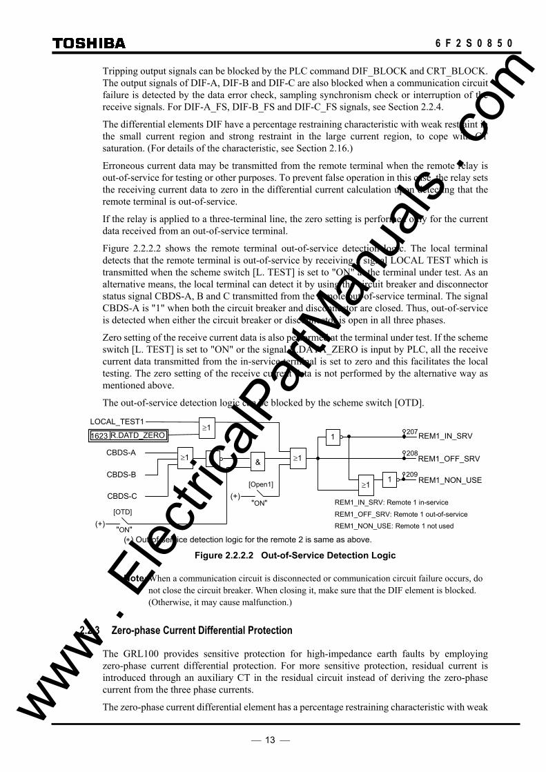
GRL100 provides OC1, OCD and EFD elements. These are used for fail-safe to prevent unnecessary operation caused by error data in communication failure. OC1 is phase overcurrent element and its sensitivity can be set. OCD is phase current change detection element, and EFD is zero-sequence current change detection element. Both of the OCD and EFD sensitivities are fixed. The scheme logic is shown in Figure 2.2.4.1.
The outputs of DIF.FS_OP and DIFG.FS_OP signals are connected to DIF-A_FS, DIF-B_FS, DIF-C_FS and DIFG_FS respectively by PLC function. These are connected at the default setting.
The fail-safe functions are disabled by [DIF-FS] and [DIFG-FS] switches. In the [DIF-FS], OC1 or OCD or both elements can be selected. If these switches are set to “OFF”, the signals of DIF.FS_OP and DIFG.FS_OP are “1” and the fail-safe is disabled. www .
Elec
tricalP
artM
anua
ls . c
om
15
6 F 2 S 0 8 5 0
DIF.FS-A_OP OC1-A
OC1-B
OC1-C
OCD-A
OCD-B
OCD-C
[DIF-FS]
"BOTH"
"OCD"
"OFF"
"OC" +
&
&
&
&
≥1
≥1
&
&
≥1
≥1
≥1
409
DIF.FS-B_OP 410
DIF.FS-C_OP 411
DIF.FS_OP 408
EFD & ≥1 DIFG.FS_OP
412
[DIFG-FS]
"ON" +
"OFF"
DIFG_FS (see Fig. 2.2.3.1.)
DIF-A_FS DIF-B_FS DIF-C_FS (see Fig. 2.2.2.1.)
≥1
Figure 2.2.4.1 Fail-safe Logic
2.2.5 Remote Differential Trip
Note: This function is available only when the three-terminal protection is applied by setting the scheme switch [TERM] to “3-TERM”. In the case of A-MODE setting, this function is not available.
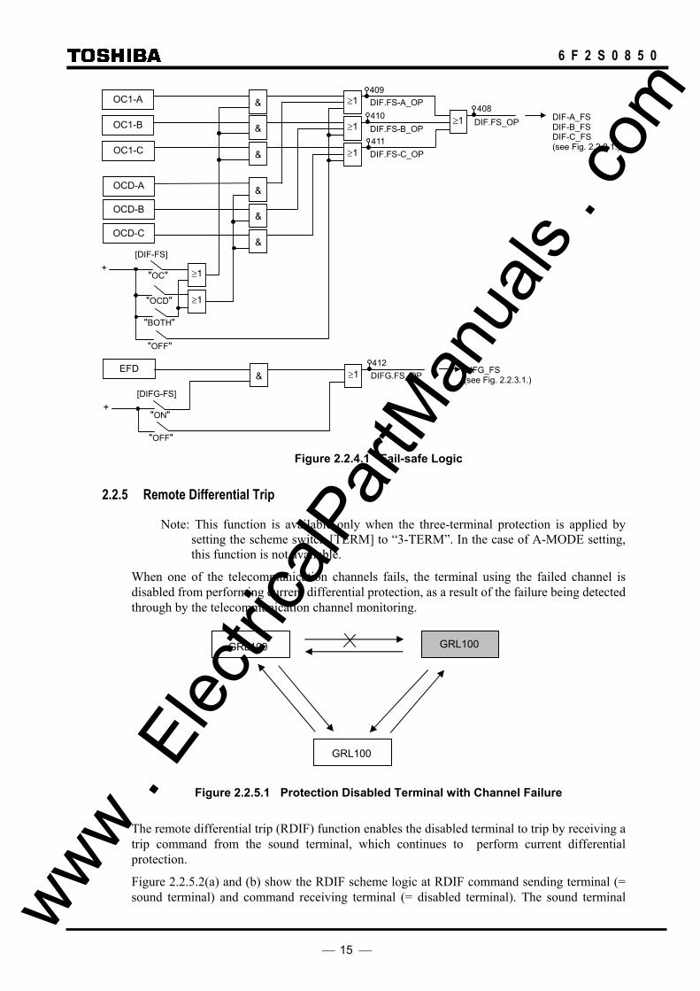
When one of the telecommunication channels fails, the terminal using the failed channel is disabled from performing current differential protection, as a result of the failure being detected through by the telecommunication channel monitoring.
Figure 2.2.5.1 Protection Disabled Terminal with Channel Failure
The remote differential trip (RDIF) function enables the disabled terminal to trip by receiving a trip command from the sound terminal, which continues to perform current differential protection.
Figure 2.2.5.2(a) and (b) show the RDIF scheme logic at RDIF command sending terminal (= sound terminal) and command receiving terminal (= disabled terminal). The sound terminal
GRL100
GRL100
GRL100
www . El
ectric
alPar
tMan
uals
. com

16
6 F 2 S 0 8 5 0
sends the command when the tripping signals RDIF-A-S, RDIF-B-S, RDIF-C-S or RDIF-S are output locally and the scheme switches [RDIF] and [TERM] are set to “ON” and “3-TERM” respectively. The RDIF command is sent to the remote terminal via the 64kb/s digital link together with other data and signals.
The receiving terminal outputs a local three-phase trip signal RDIF-TRIP under the conditions that when the command RDIF1 or RDIF2 is received from either of the remote terminals, local differential protection does not operate, the scheme switches [RDIF] and [TERM] are set to “ON” and “3-TERM” respectively and no communication channel failure exists in the channel which received the RDIF command.
When the RDIF function is applied, the command sending signals and receiving signals must be assigned by PLC function.
DIF-A_TRIP
[RDIF] +
“ON”
&
&
&
DIF-B_TRIP
DIF-C_TRIP
451≥1
≥1
≥1
452
DIF-G_TRIP &
453
RDIF-A-S
RDIF-B-S
RDIF-C-S
≥1 RDIF-S 454
(a) Sending terminal
RD.FS-A TP456
& 455
457
458
≥1
≥1
≥1
RDIF-A-R1 1684
RDIF-B-R1 1685
RDIF-C-R1 1686
≥1
1RDIF_BLOCK 1598
RDIF-R1 1687
&
&
&
&
&
&
RDIF_3PTP1649
≥1
≥1
≥1
RD.FS-B TP
RD.FS-C TP
RD.FS_TRIP
RD.FS-A_ TRIP Receiving signal from Remote Terminal 1
≥1
≥1
≥1
≥1
≥1
≥1
RDIF-A-R2 1716
RDIF-B-R2 1717
RDIF-C-R2 1718
RDIF-R2 1719
Receiving signal from Remote Terminal 2
43C ON
+ “ON”
[RDIF]
[TERM] + “3-TERM”
&
RD.FS-B_ TRIP
RD.FS-C_ TRIP
RDIF-A_FS1624
RDIF-B_FS1625
RDIF-C_FS1626
DIF elements not operated DIF.FS_OP
(b) Receiving Terminal
Figure 2.2.5.2 Remote Differential Trip
www . El
ectric
alPar
tMan
uals
. com

17
6 F 2 S 0 8 5 0
2.2.6 Transmission Data
The following data are transmitted to the remote terminal via the 64kb/s digital link. The data depends on the communication mode and whether a function is used or not. The details are shown in Appendix N.
A-phase current
B-phase current
C-phase current
Residual current
Positive sequence voltage
A-phase differential element output signal
B-phase differential element output signal
C-phase differential element output signal
A-phase breaker and disconnector status
B-phase breaker and disconnector status
C-phase breaker and disconnector status
Scheme switch [LOCAL TEST] status
Scheme switch [TFC] status
Reclose block command
Sampling synchronization control signal
Synchronized test trigger signal
User configurable data
Current and voltage data are instantaneous values which are sampled every 30 electrical degrees (12 times per cycle) and consist of eleven data bits and one sign bit. This data is transmitted every sample to the remote terminal.
Three differential element outputs and the transfer trip command are related to remote terminal tripping and are transmitted every sampling interval.
Other data is transmitted once every power cycle.
The data transmission format and user configurable data are also shown in Appendix N.
A synchronized test trigger signal is used to test the differential protection simultaneously at all terminals. For details, see Section 6.5.3.
In addition to the above data, cyclic redundancy check bits and fixed check bits are transmitted to monitor the communication channel. If a channel failure is detected at the local terminal, all the local and remote current and voltage data at that instant are set to zero and outputs of the differential protection and out-of-step protection are blocked, and these protections of remote terminal are also blocked because the channel failure is also detected at the remote terminal.
2.2.7 Synchronized Sampling
The GRL100 performs synchronized simultaneous sampling at all terminals of the protected line. Two methods are applied for the sampling synchronization; intra-system synchronization and GPS-based synchronization. The former is applied to communication modes A-MODE and www .
Elec
tricalP
artM
anua
ls . c
om
18
6 F 2 S 0 8 5 0
B-MODE, and the latter is applied to GPS-MODE.
The intra-system synchronization keeps the sampling timing error between the terminals within ±10µs or ±20µs and the GPS-based system keeps it within ±5µs or ±10µs for two- or three-terminal applications.
In both methods, the sampling synchronization is realized through timing synchronization control and sampling address synchronization control. These controls are performed once every two power cycles.
2.2.7.1 Intra-system Synchronized Sampling for A-MODE and B-MODE The synchronized sampling is realized using sampling synchronization control signals transmitted to other terminals together with the power system data. This synchronized sampling requires neither an external reference clock nor synchronization of the internal clocks of the relays at different terminals. The transmission delay of the channel is corrected automatically.
Timing synchronization One of the terminals is selected as the time reference terminal and set as the master terminal. The other terminal is set as the slave terminal. The scheme switch [SP.SYN] is used for the settings.
Note: The master and slave terminals are set only for the convenience of the sampling timing synchronization. The GRL100s at all terminals perform identical protection functions and operate simultaneously.
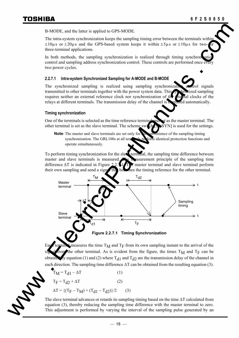
To perform timing synchronization for the slave terminal, the sampling time difference between master and slave terminals is measured. The measurement principle of the sampling time difference ∆T is indicated in Figure 2.2.7.1. The master terminal and slave terminal perform their own sampling and send a signal that becomes the timing reference for the other terminal.
t
t
Master terminal
TM
∆T
Slave terminal
Td2
Td1
Sampling timing
TF
Figure 2.2.7.1 Timing Synchronization
Each terminal measures the time TM and TF from its own sampling instant to the arrival of the signal from the other terminal. As is evident from the figure, the times TM and TF can be obtained by equation (1) and (2) where Td1 and Td2 are the transmission delay of the channel in each direction. The sampling time difference ∆T can be obtained from the resulting equation (3).
TM = Td1 − ∆T (1)
TF = Td2 + ∆T (2)
∆T = (TF − TM) + (Td1 − Td2)/2 (3)
The slave terminal advances or retards its sampling timing based on the time ∆T calculated from equation (3), thereby reducing the sampling time difference with the master terminal to zero. This adjustment is performed by varying the interval of the sampling pulse generated by an www .
Elec
tricalP
artM
anua
ls . c
om

19
6 F 2 S 0 8 5 0
oscillator in the slave terminal.
The difference of the transmission delay time Tdd (= Td1 − Td2) is set to zero when sending and receiving take the same route and exhibit equal delays. When the route is separate and the sending and receiving delays are different, Tdd must be set at each terminal to be equal to the sending delay time minus the receiving delay time. The maximum Tdd that can be set is 10ms. (For setting, see Section 4.2.6.7. The setting elements of transmission delay time difference are TCDT1 and TCDT2.)
The time TM measured at the master terminal is sent to the slave terminal together with the current data and is used to calculate the ∆T.
The permissible maximum transmission delay time of the channel is 10ms.
In case of the three-terminal line application, the communication ports of the GRL100 are interlinked with each other as shown in Figure 2.2.7.2, that is, port CH1 of one terminal and port CH2 of the other terminal are interlinked. For the setup of the communication system, see Section 2.2.13.3.
When terminal A is set as the master terminal by the scheme switch [SP.SYN], the synchronization control is performed between terminals A and B, and terminals B and C. The terminal B follows the terminal A and the terminal C follows the terminal B. The slave terminals perform the follow-up control at their communication port CH2.
When the master terminal is out-of-service in A-MODE, the slave terminal that is interlinked with port 1 of the master terminal takes the master terminal function. In the case shown in Figure 2.2.7.2, terminal B takes the master terminal function when the master terminal A is out-of-service. In B-MODE and GPS-MODE, even if the master terminal is out-of-service, the master terminal is not changed. If DC power supply of the out-of-service terminal is “OFF”, differential elements at all terminals are blocked. Therefore, the [TERM] setting change from “3TERM” to “2TERM” is required.
GRL100
Terminal B Terminal A
Terminal C
CH1
Communication port
GRL100
GRL100
Master Slave
Slave
CH2 CH1
CH2
CH1 CH2
Figure 2.2.7.2 Communication Link in Three-terminal Line
Sampling address synchronization The principle of sampling address synchronization control is indicated in Figure 2.2.7.3. After time synchronization has been established, the slave terminal measures the time from sending its own timing reference signal until it returns from the master terminal. The transmission delay time Td1 from slave to master terminal can be calculated from equation (4). www .
Elec
tricalP
artM
anua
ls . c
om

20
6 F 2 S 0 8 5 0
Td = (To − (T − TM)/2 + Tdd)/2 (4)
The calculated transmission delay time Td1 is divided by the sampling interval T. The mantissa is truncated and the quotient is expressed as an integer. If the integer is set to P, the reception at the slave terminal of the signal sent from the master terminal occurs at P sampling intervals from the transmission. Accordingly, by performing control so that the sampling address of the slave terminal equals integer P when the sampling address = 0 signal is received from the master terminal, the sampling address of the slave terminal can be made the same as the master terminal.
t
t
Master terminal
TM
Slave terminal
T
Td2Td1TO
TF
Figure 2.2.7.3 Sampling Address Synchronization
2.2.7.2 GPS-based Synchronized Sampling for GPS-MODE The relays at all terminals simultaneously receive the GPS clock signal once every second. Figure 2.2.7.4 shows the GPS-based synchronized sampling circuit at one terminal. The GPS clock signal is received by the GPS receiver HHGP1 and input to a time difference measurement circuit in the GRL100. The circuit measures the time difference ∆T between the GPS clock and the internal clock generated from the crystal oscillator. The oscillator is controlled to synchronize with the GPS clock using the measured ∆T and outputs 2,400 Hz (50Hz rating) sampling signals to the current sampling circuit (analog to digital converter).
Figure 2.2.7.4 GPS Clock-based Sampling
GPS
GPS receiver HHGP1
Time difference measurement
Crystal oscillator
Analog/digital converter
Synchronous control
ΔT Lead/lag control
GRL100
Line
www . El
ectric
alPar
tMan
uals
. com

21
6 F 2 S 0 8 5 0
Timing synchronization When the GPS signal is received normally at every line terminal, the GRL100 performs synchronized sampling based on the received clock signal. The GRL100 can provide a backup synchronization system if the GPS signal is interrupted at one or more terminals, and perform synchronized sampling without any external reference clock. The backup system becomes valid by setting the scheme switch [GPSBAK] to "ON".
In the backup modes, the percentage restraint in the small current region can be increased from the normal 16.7% ((1/6)Ir in Figure 2.16.1.1) in accordance with the PDTD setting which is the probable transmission delay time difference between send and receive channels.
Backup modes, Mode 1, 2A and 2B are initialised when the backup system is set valid.
If the GPS signal interruption occurs when the backup is set invalid, the sampling runs based on the local clock. When the arrival time of the remote signal measured from local sampling instant deviates from a nominal time, the protection is blocked.
Mode 0: When the GPS signal is received normally, the sampling is performed synchronizing with the received clock signal thus realizing synchronized sampling at all terminals. Difference of the transmission delay time for the channel in each direction and fluctuation of the delay time can be permitted.
The GRL100 performs the protection based on the nominal current differential characteristics.
When the GPS signal has interrupted for more than ten seconds at any of the terminals, the mode changes to Mode 1 at all terminals.
Mode 1: The terminal which loses its GPS signal first functions as the slave terminal. If all terminals lose their signals simultaneously, then the scheme switch [SP.SYN] setting determines which terminal functions as the slave or master. The slave terminal adjusts the local sampling timing to synchronize the sampling with other terminal which is receiving the GPS signal regularly or with the master terminal.
Note: When two terminals are receiving the GPS signal regularly, the slave terminal synchronizes with the terminal that is interlinked with port 2 of the slave terminal.
When the GPS signal has been restored, the mode shifts from Mode 1 back to Mode 0.
If, during Mode 1 operation, a failure occurs in the communication system, the sampling timing adjustment is disabled and each terminal runs free. If the free running continues over the time determined by the PDTD setting or the apparent phase difference exceeds the value determined by the PDTD setting, the mode shifts from Mode 1 to Mode 2A at all terminals.
Mode 2A: In this mode, the intra-system synchronization described in 2.2.7.1 is applied assuming that the transmission delay time for the channel in each direction is identical. Fluctuation of the delay time can be permitted.
The current differential protection is blocked in this mode.
When the GPS signal has been restored, the mode shifts from Mode 2A to Mode 0.
If the GPS signal interruption occurs a set period following energisation of the relay power supply or the mode returned to Mode 0 from Mode 1, 2A or 2B, then the transmission delay time measurement will not be completed in Mode 0, and the mode changes to Mode 2A.
When the apparent current phase difference has stayed within the value determined by the PDTD setting, the scheme switch [AUTO2B] for automatic mode change is set to "ON" and [TERM] is set to "2TERM", the mode changes from Mode 2A to Mode 2B at both terminals.
The mode can be changed to Mode 2B manually through a binary input signal "Mode 2B initiation" or user interface. Before this operation, it must be checked that the transmission delay www .
Elec
tricalP
artM
anua
ls . c
om

22
6 F 2 S 0 8 5 0
time difference between send and receive terminals is less than the PDTD setting and the SYNC ALARM LED is off. If these conditions are not satisfied, the operation may cause a false tripping.
Note: The mode change with the binary input signal is performed by either way: • If the binary input contact is such as to be open when the relay is in service, set
the BI to "Inv" (inverted). The mode changes when the contact is closed more than 2 seconds and then open.
• If the binary input contact is such as to be closed when the relay is in service, set the BI to "Norm" (normal). The mode changes when the contact is open more than 2 seconds and then closed.
For the BISW4, see Section 3.2.1.
In the three-terminal application, the mode change to Mode 2B is available even when one of the three communication routes is failed.
Mode 2B: The same intra-system synchronization as in Mode 2A is applied.
When the GPS signal has been restored, the mode shifts from Mode 2B to Mode 0.
If a failure occurs in the communication system, the sampling timing adjustment is disabled and each terminal runs free.
The mode shifts from Mode 2B to Mode 2A, when the apparent load current phase difference exceeds the value determined by the PDTD setting for pre-determined time.
Checking the current phase difference (For two-terminal application setting only) The current phase difference is checked using the following equations:
I1A ⋅ cos θ < 0 I1A ⋅ I1B sin θ < I1A ⋅ I1B sin θs
I1A > OCCHK
I1B > OCCHK
Where,
I1A = Positive sequence component of load current at local terminal I1B = Positive sequence component of load current at remote terminal θ = Phase difference of I1B from - I1A
θs = Critical phase difference = CHKθ‐HYSθ
CHKθ = PDTD(µs)
2 × 360°
20000(µs) + 8.5°
HYSθ = Margin of phase difference checking
OCCHK = Minimum current for phase difference check
If the magnitude of I1A and I1B exceed the setting and the conditions for both equations above are established, then the sampling is regarded to be synchronized.
If the current phase difference exceeds a set value, the "SYNC ALARM" LED on the front panel is lit.
Checking the current phase difference is enabled by setting the scheme switches [TERM] to "2TERM" and [SRCθ] to "I".
www . El
ectric
alPar
tMan
uals
. com

23
6 F 2 S 0 8 5 0
I1A I1B
-I1A θs
θ
Figure 2.2.7.5 Current Phase Difference Check
Sampling address synchronization The same method as described in section 2.2.7.1 is employed in Mode 0 and Mode 2A where the sampling synchronization must be established. It is not employed in Mode 1 and 2B because the sampling address synchronization has already been established in the previous mode.
2.2.7.3 Differential Current Calculation Synchronized sampling allows correct calculation of differential current even in the presence of a transmission time delay. This processing is indicated in Figure 2.2.7.4. As indicated in the figure, sampling synchronization is established between terminals A and B, and both the sampling timing and sampling address match. The instantaneous current data and sampling address are both sent to the other terminal. The GRL100 refers to the sampling address affixed to the received data and uses local data with the same sampling address to calculate the differential current. This allows both terminals to use data sampled at the same instant to perform the differential current calculation, no matter how large the transmission time delay is.
t
t
Terminal A
Terminal B
4 3210
iB(1)iA(0)
iB(0) iA(1)
4 3210Sampling address number iA(0)
Differential current calculation iB(0)
Figure 2.2.7.4 Calculation of Differential Current with Transmission Delay Time
Protection in anomalous power system operation Even when any of the terminals is out-of-service, the GRL100 in-service terminal can still provide the differential protection using the out-of-service detection logic. For details of the out-of-service detection logic, see Section 2.2.2.
When one terminal is out-of-service in a two-terminal line, the other terminal continues the current differential protection using the local current irrespective of whether it is a master terminal or a slave terminal.
When one terminal is out-of-service in a three-terminal line, synchronized sampling is established between the remaining two terminals as follows and the differential protection is maintained.
• If the master terminal is out-of-service, one of the slave terminals takes over the master terminal synchronized sampling function and enables current differential protection www .
Elec
tricalP
artM
anua
ls . c
om
24
6 F 2 S 0 8 5 0
between the remaining terminals to be performed.
• If the slave terminal is out-of-service, the master and another slave terminal maintain the differential protection.
When two terminals are out-of-service in a three-terminal line, the remaining terminal continues the current differential protection using the local current irrespective of whether it is a master terminal or a slave terminal.
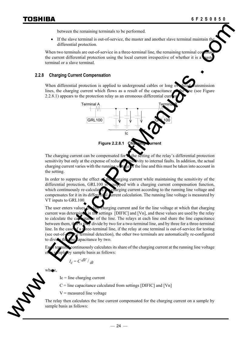
2.2.8 Charging Current Compensation
When differential protection is applied to underground cables or long overhead transmission lines, the charging current which flows as a result of the capacitance of the line (see Figure 2.2.8.1) appears to the protection relay as an erroneous differential current.
GRL100 GRL100
Terminal A Terminal B
Ic
Figure 2.2.8.1 Charging Current
The charging current can be compensated for in the setting of the relay’s differential protection sensitivity but only at the expense of reduced sensitivity to internal faults. In addition, the actual charging current varies with the running voltage of the line and this must be taken into account in the setting.
In order to suppress the effect of the charging current while maintaining the sensitivity of the differential protection, GRL100 is equipped with a charging current compensation function, which continuously re-calculates the charging current according to the running line voltage and compensates for it in its differential current calculation. The running line voltage is measured by VT inputs to GRL100.
The user enters values for line charging current and for the line voltage at which that charging current was determined in the settings [DIFIC] and [Vn], and these values are used by the relay to calculate the capacitance of the line. The relays at each line end share the line capacitance between them, that is they divide by two for a two-terminal line, and by three for a three-terminal line. In the case of a three-terminal line, if the relay at one terminal is out-of-service for testing (see out-of-service terminal detection), the other two terminals are automatically re-configured to divide the line capacitance by two.
Each terminal continuously calculates its share of the charging current at the running line voltage on a sample by sample basis as follows:
Ic = C dV / dt
where,
Ic = line charging current
C = line capacitance calculated from settings [DIFIC] and [Vn]
V = measured line voltage
The relay then calculates the line current compensated for the charging current on a sample by sample basis as follows: www .
Elec
tricalP
artM
anua
ls . c
om

25
6 F 2 S 0 8 5 0
I = I’ - Ic
where,
I = compensated current
I’ = actual measured current
Note that since GRL100 calculates both the charging current and compensated line current on a sample by sample basis, all necessary phase information is inherently taken into account.
2.2.9 Blind Zone Protection
The GRL100 relay has “Out-of-Service Detection Logic” as described in Section 2.2.2. This logic functions automatically to detect the remote CB or DS (line disconnecting switch) opened condition as shown in Figure 2.2.9.1. If the remote CB or DS is opened, the received remote current data is set to “zero” Ampere at the local terminal, and the local relay can be operated with only local current like a simple over current relay. Therefore, this logic function is used for blind zone protection.
The zone between CB and CT at the remote terminal is the blind zone in Figure 2.2.9.1. If a fault occurs within this zone, the busbar protection should operate first and trip the CB at the remote terminal, but the fault remains and the fault current (IF) is fed continuously from the local terminal. Since this phenomenon is an external fault for the current differential protection scheme, the blind zone fault cannot be cleared. The fault may be cleared by remote backup protection following a time delay, but there is a danger of damage being caused to power system plant. Fast tripping for this type of fault is highly desirable. The Out-of-Service Detection Logic is effective for a fault where a blind zone between CT and CB on the line exists as shown in Figure 2.2.9.1.
If the CB and DS condition are introduced at the remote terminal as shown in Figure 2.2.9.1, the GRL100 relay at the local terminal can operate with only local current and the fault can be cleared, because the remote current data is automatically cancelled as explained above.
Please note the “CB Close Command” signal must be connected to the GRL100 relay to prevent unwanted operation for a CB close operation (manual close and/or autoreclose). Unwanted operation may be caused if the close timing of the CB auxiliary contact is delayed relative to the CB main contact. Therefore, the CB close command signal resets forcibly the Out-of-Service Detection Logic before the CB main contact is closed.
CB and DS status signals are input by PLC. If the out-of-service detection is not used, its logic can be blocked by the scheme switch [OTD].
www . El
ectric
alPar
tMan
uals
. com

26
6 F 2 S 0 8 5 0
DS
IR (=IF) IL (=IF) LINE REMOTELOCAL
52A 52C 52B
89L1
IR (Current) IR (Current)
CBDS-C CBDS-B
(Remote terminal closed: “0” logic)
Differential Current (Id)
Remote terminal “OPEN” CBDS-A
Comm. Link CBDS-A,B,C CBDS-A,B,C
DIFF RELAY GRL100 (REMOTE)
DIFF RELAY GRL100 (LOCAL)
1
&
≧1
1
If DS or CB signals (CBDS-A, B, C) changes to “0”, remote current data (IR) is cancelled to zero (0). Therefore, differential current (Id) equals to local current (IL).
(Cancel circuit of remote terminal current IR)
Σ
BUSBAR PROT.
CB
FAULT
≧1
CB CLOSE COMMAND
IR
IL
Blind Zone
Figure 2.2.9.1 Blind Zone Protection
2.2.10 Application to Three-terminal Lines
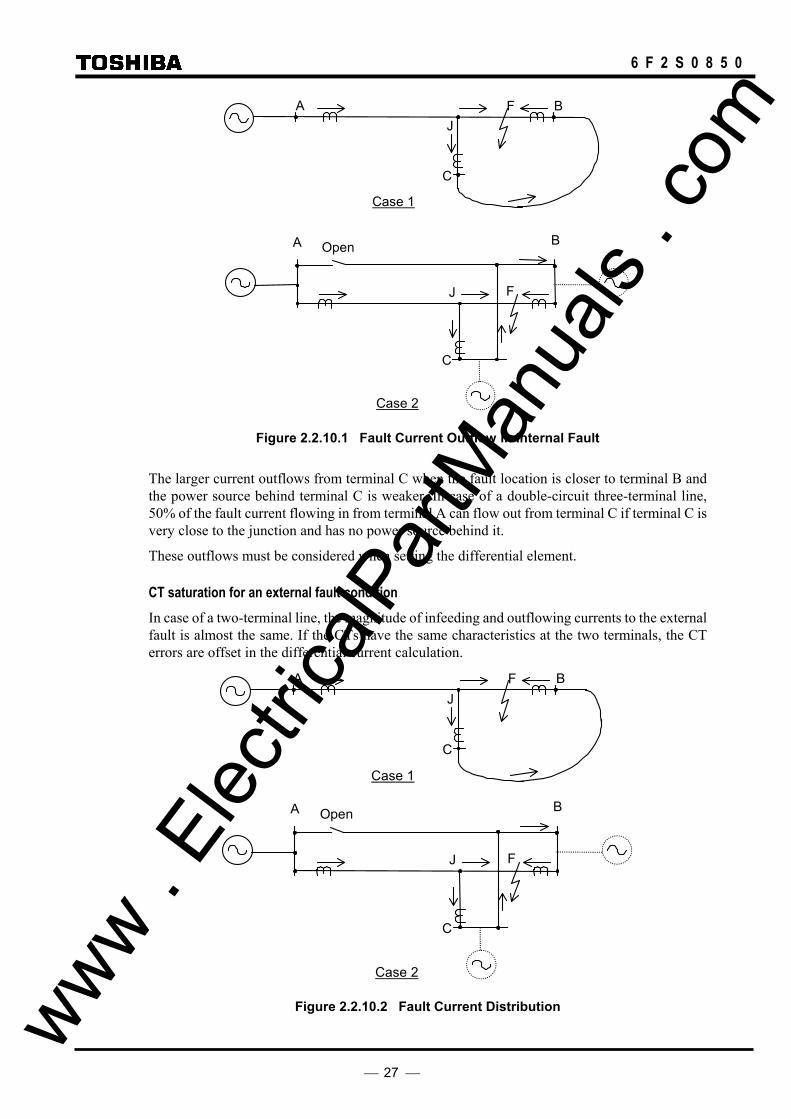
When current differential protection is applied to a three-terminal line, special attention must be paid to the fault current flowing out of the line in the case of an internal fault and CT saturation at the outflowing terminal in case of an external fault.
Fault current outflow in case of internal fault In case of a two-terminal line, fault current never flows out from the terminals for an internal fault. But in case of a three-terminal line with an outer loop circuit, a partial fault current can flow out of one terminal and flow into another terminal depending on the fault location and magnitude of the power source behind each terminal.
Case 1 in Figure 2.2.10.1 shows a fault current outflow in a single circuit three-terminal line with outer loop circuit. J and F in the figure indicate the junction point and fault point. A part of the fault current flowing in from terminal A flows out once from terminal C and flows in again from terminal B through the outer loop.
Case 2 shows the outflow in a double-circuit three-terminal line. The outer loop is generated when one terminal is open in the parallel line. A part of the fault current flowing in from terminal A flows out from the fault line to the parallel line at terminal C and flows in again at terminal B through the parallel line. www .
Elec
tricalP
artM
anua
ls . c
om
27
6 F 2 S 0 8 5 0
A B F
Case 1
J
C
Case 2
A
J
B
F
C
Open
Figure 2.2.10.1 Fault Current Outflow in Internal Fault
The larger current outflows from terminal C when the fault location is closer to terminal B and the power source behind terminal C is weaker. In case of a double-circuit three-terminal line, 50% of the fault current flowing in from terminal A can flow out from terminal C if terminal C is very close to the junction and has no power source behind it.
These outflows must be considered when setting the differential element.
CT saturation for an external fault condition In case of a two-terminal line, the magnitude of infeeding and outflowing currents to the external fault is almost the same. If the CTs have the same characteristics at the two terminals, the CT errors are offset in the differential current calculation.
A B F
Case 1
J
C
Case 2
A
J
B
F
C
Open
Figure 2.2.10.2 Fault Current Distribution www . El
ectric
alPar
tMan
uals
. com

28
6 F 2 S 0 8 5 0
But in case of a three-terminal line, the magnitude of the current varies between the terminals and the terminal closest to the external fault has the largest magnitude of outflowing fault current. Thus, the CT errors are not offset in the differential current calculation. Thus, it is necessary to check whether any fault causes CT saturation, particularly in the terminal with outflow, and the saturation must be accommodated utilising the DIFI2 setting of the DIF element.
2.2.11 Dual Communication Mode
Three-terminal application models have dual communication mode (GRL100-∗1∗). By connecting the remote terminal with dual communication routes, even if one of the routes fails, it is possible to continue sampling synchronization and protection by the current differential relay. To set dual communication mode, select "Dual" in the TERM setting. Other settings are the same as that of the two-terminal. In GPS-MODE setting, however, the dual communication mode cannot be applied.
GRL100 GRL100CH1
CH2
CH1
CH2
Figure 2.2.11.1 Dual Communication Mode
2.2.12 Application to One-and-a-half Breaker Busbar System
The GRL100-700 series can be used for lines connected via a one-and-a-half breaker busbar system, and have functions to protect against stub faults and through fault currents.
Stub fault If a fault occurs at F1 or F2 when line disconnector DS of terminal A is open as shown in Figure 2.2.12.1, the differential protection operates and trips the breakers at both terminals without any countermeasures.
Terminal A
F2 F1
DS
×× ×
Terminal B
× × ×
Figure 2.2.12.1 Stub Fault
GRL100 provides stub protection to avoid unnecessary tripping of the breakers in these cases. For the stub protection, see Section 2.13.
Fault current outflow in case of internal fault As shown in Figure 2.2.12.2, the fault current may outflow in case of an internal fault of double-circuit lines. The outflow at terminal A increases as the fault location F approaches terminal B. When the fault is close to terminal B, 50% of the fault current flows out to the parallel line, though it depends on the power source conditions at terminals A and B.
This outflow must be considered when setting the differential element. www . El
ectric
alPar
tMan
uals
. com
29
6 F 2 S 0 8 5 0
Figure 2.2.12.2 Fault Current Outflow in Internal Fault
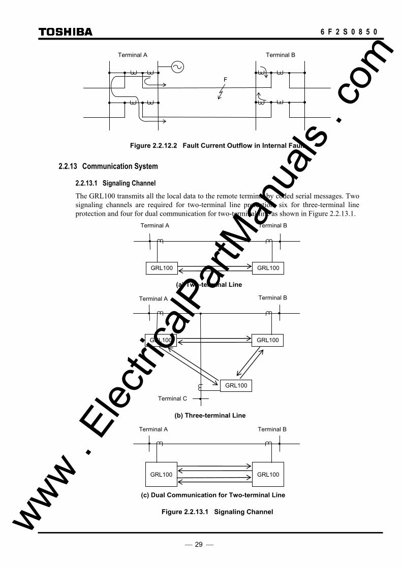
2.2.13 Communication System
2.2.13.1 Signaling Channel The GRL100 transmits all the local data to the remote terminal by coded serial messages. Two signaling channels are required for two-terminal line protection, six for three-terminal line protection and four for dual communication for two-terminal line as shown in Figure 2.2.13.1.
GRL100
Terminal B Terminal A
GRL100
(a) Two-terminal Line
GRL100
GRL100
Terminal B Terminal A
Terminal C
GRL100
(b) Three-terminal Line
Terminal B Terminal A
GRL100
GRL100
(c) Dual Communication for Two-terminal Line
Figure 2.2.13.1 Signaling Channel
F
Terminal B Terminal A
www . El
ectric
alPar
tMan
uals
. com

30
6 F 2 S 0 8 5 0
The variation of the channel delay time due to switching the route of the channel is automatically corrected in the relay and does not influence the synchronized sampling provided the sending and receiving channels take the same route. If the routes are separate, the transmission delay difference time must be set (see Section 2.2.7).
When the route is switched in A- or B-mode application, the synchronized sampling recovers within 4s in case of a two- terminal line and 6s in case of a three-terminal line after the switching. The differential element is blocked until the sampling synchronization is established.
In GPS-mode application (GPS-based synchronization), the sampling synchronization is not influenced by the route switch. The differential element is only blocked for the duration of the path switching.
2.2.13.2 Linking to Communication Circuit The GRL100 can be provided with one of the following interfaces by order type and linked to a dedicated optical fiber communication circuit or multiplexed communication circuit.
• Optical interface (1310nm, SM, 30km class)
• Optical interface (1550nm, DSF(Dispersion Shifted Fibre), 80km class) (*)
• Optical interface (820nm, GI, 2km class)
• Electrical interface in accordance with CCITT-G703-1.2.1
• Electrical interface in accordance with CCITT-G703-1.2.2 and 1.2.3
• Electrical interface in accordance with CCITT X.21
• Electrical interface in accordance with RS422, RS530
Note (*): When using the 80km class optical interface, it is necessary to ensure that the received optical power does not exceed −10dB, in order to avoid communication failure due to overloading of the receiver.
When testing in loop-back mode, for instance, the sending terminal should be connected to the receiving terminal via an optical attenuator with 10 dB or more attention. Even if the sending terminal is directly connected to the receiving terminal, the optical transceiver will not damaged, but communication failures may occur. - Fibre Coupled Power: −5 to 0dBm - Input Power Range: −34 to −10dBm - Optical Damage Input Level: 3dBm
Alternative links to the telecommunication circuit are shown in Figure 2.2.13.2 (a) to (c).
www . El
ectric
alPar
tMan
uals
. com

31
6 F 2 S 0 8 5 0
(a) Direct link
(b) Electrical link via multiplexer
(c) Optical link via multiplexer
Figure 2.2.13.2 Link to Communication Circuit
Direct link When connected to single-mode (SM) 10/125µm type of dedicated optical fiber communication circuits and using Duplex LC type connector for 30km class, the optical transmitter is an LD with output power of more than –13dBm and the optical receiver is a PIN diode with a sensitivity of less than –30dBm. For 80km class, the optical transmitter is an LD with output power of more than –5dBm and the optical receiver is a PIN diode with a sensitivity of less than –34dBm.
When connected to graded-index (GI) multi-mode 50/125µm type or 62.5/125µm type of dedicated optical fiber telecommunication circuit and using an ST type connector, the optical transmitter is an LED with output power of more than –19dBm or –16dBm and the optical receiver is a PIN diode with a sensitivity of less than –24dBm.
For details, refer to Appendix K.
Link via multiplexer The GRL100 can be linked to a multiplexed communication circuit with an electrical or optical interface. The electrical interface supports CCITT G703-1.2.1, G703-1.2.2 and 1.2.3, X.21(RS530) or RS422. Twisted pair cable with shield (<60m) is used for connecting the relay and multiplexer.
In the optical interface, optical fibers of graded-index multi-mode 50/125µm or 62.5/125µm type are used and an optical to electrical converter is provided at the end of the multiplexer. The electrical interface between the converter and the multiplexer supports CCITT G703-1.2.1, G703-1.2.2 and 1.2.3, X.21(RS530) or RS422.
A D-sub connector (DB-25) or an ST connector is used for electrical linking and optical linking, respectively.
O/E: Optical/Electrical converter MUX: Multiplexer
Optical interface
GRL100
Twisted pair cable with shield < 60m
MUX
Optical fibers
O/E
GRL100
Multiplexed circuit Twisted pair cable with shield < 60m MUX
Electrical interface
GRL100
Optical fiber circuit
Optical interface
www . El
ectric
alPar
tMan
uals
. com
32
6 F 2 S 0 8 5 0
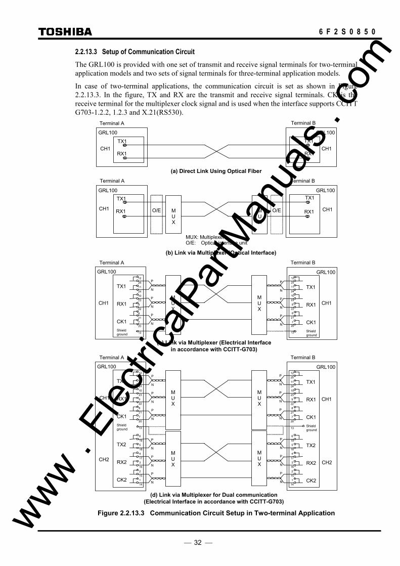
2.2.13.3 Setup of Communication Circuit The GRL100 is provided with one set of transmit and receive signal terminals for two-terminal application models and two sets of signal terminals for three-terminal application models.
In case of two-terminal applications, the communication circuit is set as shown in Figure 2.2.13.3. In the figure, TX and RX are the transmit and receive signal terminals. CK is the receive terminal for the multiplexer clock signal and is used when the interface supports CCITT G703-1.2.2, 1.2.3 and X.21(RS530).
Terminal B Terminal A
GRL100GRL100
TX1 TX1
RX1 RX1
(a) Direct Link Using Optical Fiber Terminal B Terminal A
MUX: Multiplexer O/E: Optical interface unit
GRL100GRL100
M U X
M U X
TX1 TX1
RX1 RX1
O/E
O/E
(b) Link via Multiplexer (Optical Interface)
CH1 CH1
CH1 CH1
Terminal B Terminal A
GRL100GRL100
M U X
M U X
TX1 RX1 CK1 Shield ground
12 25 11 24 10 23 9 22 8 21 7 20
13
TX1 RX1 CK1 Shield ground
(c) Link via Multiplexer (Electrical Interfacein accordance with CCITT-G703)
P
N
P
N
P
N
P
N
P
N
P
N
CH1 CH1
12 25 11 24 10 23 9
22 8
21 7
20
13
Terminal B Terminal A
GRL100GRL100
M U X
M U X
TX1 RX1 CK1 Shield ground
12 25 11 24 10 23 9 22 8 21 7 20
13
TX1 RX1 CK1 Shield ground
M U X
M U X
TX2 RX2 CK2
6 19 5 18 4 17 3 16 2 15 1 14
TX2 RX2 CK2
(d) Link via Multiplexer for Dual communication(Electrical Interface in accordance with CCITT-G703)
P
N
P
N
P
N
P
N
P
N
P
N
P
N
P
N
P
N
P
N
P
N
P
N
CH1 CH1
CH2 CH2
12 25 11 24 10 23 9
22 8
21 7
20
13
6 19 5
18 4
17 3
16 2
15 1
14
Figure 2.2.13.3 Communication Circuit Setup in Two-terminal Application www .
Elec
tricalP
artM
anua
ls . c
om

33
6 F 2 S 0 8 5 0
Terminal B Terminal A
GRL100GRL100
MUX
M U X
Signal ground
TX1 RX1 CK1 Shield
7 2 14 3 16 15 12
1
Signal ground TX1 RX1 CK1 Shield
(e) Link via Multiplexer (Electrical Interfacein accordance with X.21, RS530)
Terminal B Terminal A
GRL100GRL100
(f) Link via Multiplexer for Dual communication(Electrical Interface in accordance with X.21, RS530)
P
N
P
N
P
N
P
N
P
N
P
N
CH1 CH1
7 2
14 3
16
15
12
1
MUX
M U X
Signal ground
TX1 RX1 CK1 Shield
7 2 14 3 16 15 12
1
Signal ground TX1 RX1 CK1 Shield
P
N
P
N
P
N
P
N
P
N
P
N
CH1 CH1
7 2
14 3
16
15
12
1
MUX
M U X
Signal ground
TX2 RX2 CK2 Shield
7 2 14 3 16 15 12
1
Signal ground TX2 RX2 CK2 Shield
P
N
P
N
P
N
P
N
P
N
P
N
CH2 CH2
7 2
14 3
16
15
12
1
Figure 2.2.13.3 Communication Circuit Setup in Two-terminal Application (continued)
In case of three-terminal applications, signal terminals CH1-TX1, -RX1 and -CK1 which have the same function as CH2-TX2, -RX2 and -CK2 are added.
Figure 2.2.13.4 shows the communication circuit arrangement for three-terminal applications. Note that the CH1 signal terminals TX1, RX1 and CK1 of one terminal are interlinked with the CH2 signal terminals TX2, RX2 and CK2 of another terminal and that the scheme switch [TERM] is set to "3-TERM". If the same channel is interlinked between both terminals such as the CH1 signal terminals of one terminal are interlinked with the CH1 signal terminals of another terminal, the scheme switch setting [CH. CON] should be set to “Exchange”.
The three-terminal line application models can be applied to a two-terminal line. In this case, same channel’s TX, RX and CK of both terminals are interlinked and scheme switch [TERM] is set to "2-TERM".
The three-terminal models also have dual communication mode as shown in Figure 2.2.13.5.
www . El
ectric
alPar
tMan
uals
. com

34
6 F 2 S 0 8 5 0
Terminal B
GRL100
Terminal A
GRL100
TX1
RX1
CK1
TX2
RX2
CK2
Terminal C
GRL100
CH1
CH1
CH2
CH2
TX2
RX2
CK2
CH2
TX1
RX1
CK1
CH1
TX1
RX1
CK1
TX2
RX2
CK2
Figure 2.2.13.4 Communication Circuit Setup for Three-terminal Applications
Terminal B
GRL100
Terminal A
GRL100
TX1
RX1
CK1
TX1
RX1
CK1
CH1 CH1
TX2
RX2
CK2
CH2
TX2
RX2
CK2
CH2
Note: The corresponding channels are connected to each other. Figure 2.2.13.5 Dual Communication Mode
2.2.13.4 Telecommunication Channel Monitoring If a failure occurs or noise causes a disturbance in the telecommunication channel, this may interrupt the data transmission or generate erroneous data, thus causing the relay to operate incorrectly.
The GRL100 detects data failures by performing a cyclic redundancy check and a fixed bit check on the data. The checks are carried out for every sample.
If the failure lasts for ten seconds, a communication failure alarm is issued.
The output blocking ceases instantly when the failure recovers.
www . El
ectric
alPar
tMan
uals
. com

35
6 F 2 S 0 8 5 0
2.2.14 Setting
The following shows the setting elements necessary for the current differential protection and their setting ranges. The settings can be made on the LCD screen or PC screen.
Element Range Step Default Remarks Communication Mode A B GPS DIF Phase current
DIFI1 0.50 − 10.00A 0.01A 5.00A Small current region x x x (0.10 − 2.00A 0.01A 1.00A)(*1)
DIFI2 3.0 − 120.0A 0.1A 15.0A Large current region x x x (0.6 − 24.0A 0.1A 3.0A) DIFG Residual current
DIFGI 0.25 − 5.00A 0.01A 2.50A x x x (0.05 − 1.00A 0.01A 0.50A) DIFIC 0.00 − 5.00A 0.01A 0.00 A x x x (0.00 − 1.00A 0.01A 0.00 A)
Charging current compensation
Vn 100 - 120V 1V 110V Rated line voltage x x x TDIFG 0.00 − 10.00s 0.01s 0.50s Delayed tripping timer x x x DIFSV 0.25 − 10.00A 0.01A 0.50A x x x (0.05 − 2.00A 0.01A 0.10A)
Differential current (Id) monitoring
TIDSV 0 – 60s 1s 10s Timer for Id detection x x x OCCHK (*4) 0.5 − 5.0A 0.1A 0.5A -- -- x (0.10 − 1.00A 0.01A 0.10A)
Minimum current for phase difference check
HYSθ (*4) 1 − 5 deg 1 deg 1 deg Phase difference check margin -- -- x TDSV 100 - 16000 1µs 6000µs Transmission delay time threshold
setting for alarm (*7) x x x
TCDT1 −10000 − 10000 1µs 0µs Transmission delay time difference setting for channel 1 (*6)
x x x
TCDT2 −10000 − 10000 1µs 0µs Transmission delay time difference setting for channel 2 (*6)
x x x
PDTD 200 - 2000µs 1µs 1000µs Transmission delay time difference between send and receive channels (GPS synchronization only)
-- -- x
RYID 0-63 0 Local relay address -- x x
RYID1 0-63 0 Remote 1 relay address -- x x
RYID2 0-63 0 Remote 2 relay address -- x x
[DIFG] ON/OFF ON High impedance earth fault protection x x x [STUB] ON/OFF ON Measure for stub fault x x x [RDIF] ON/OFF ON Remote differential protection -- x x [OTD] ON/OFF OFF Open terminal detection x x x [DIF-FS] OFF/OC/OCD/Both OFF Fail-safe function x x x [DIFG-FS] ON/OFF OFF Fail-safe function x x x [COMMODE] A / B / GPS B Communication mode A B GPS [TERM] 2TERM/3TERM
/Dual (*2) 3TERM For three-terminal application models x x x www .
Elec
tricalP
artM
anua
ls . c
om
36
6 F 2 S 0 8 5 0
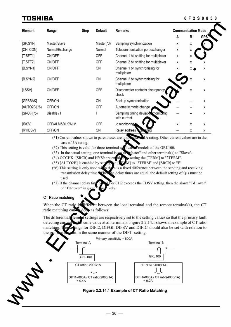
Element Range Step Default Remarks Communication Mode A B GPS [SP.SYN] Master/Slave Master(*3) Sampling synchronization x x x [CH. CON] Normal/Exchange Normal Telecommunication port exchanger x x x [T.SFT1] ON/OFF OFF Channel 1 bit shifting for multiplexer x x x [T.SFT2] ON/OFF OFF Channel 2 bit shifting for multiplexer x x x [B.SYN1] ON/OFF ON Channel 1 bit synchronising for
multiplexer x x x
[B.SYN2] ON/OFF ON Channel 2 bit synchronising for multiplexer
x x x
[LSSV] ON/OFF OFF Disconnector contacts discrepancy check
x x x
[GPSBAK] OFF/ON ON Backup synchronization -- -- x [AUTO2B](*6) OFF/ON OFF Automatic mode change -- -- x [SRCθ](*5) Disable / I I Sampling timing deviation monitoring
with current -- -- x
[IDSV] OFF/ALM&BLK/ALM OFF Id monitoring x x x [RYIDSV] OFF/ON ON Relay address monitoring -- x x
(*1) Current values shown in parentheses are in the case of 1A rating. Other current values are in the case of 5A rating.
(*2) This setting is valid for three-terminal application models of the GRL100. (*3) In the actual setting, one terminal is set to "Master" and other terminal(s) to "Slave". (*4) OCCHK, [SRCθ] and HYSθ are enabled by setting the [TERM] to "2TERM". (*5) [AUTO2B] is enabled by setting the [TERM] to "2TERM" and [SRCθ] to "I". (*6) This setting is only used when there is a fixed difference between the sending and receiving
transmission delay time. When the delay times are equal, the default setting of 0µs must be used.
(*7) If the channel delay time of CH1 or CH2 exceeds the TDSV setting, then the alarm "Td1 over" or "Td2 over" is given respectively.
CT Ratio matching When the CT ratio is different between the local terminal and the remote terminal(s), the CT ratio matching can be done as follows:
The differential element settings are respectively set to the setting values so that the primary fault detecting current is the same value at all terminals. Figure 2.2.14.1 shows an example of CT ratio matching. The settings for DIFI2, DIFGI, DIFSV and DIFIC should also be set with relation to the primary current in the same manner of the DIFI1 setting.
CT ratio : 2000/1A
Terminal-A Terminal-B
GRL100 GRL100
DIFI1=800A / CT ratio(2000/1A) = 0.4A
CT ratio : 4000/1A
DIFI1=800A / CT ratio(4000/1A) = 0.2A
Primary sensitivity = 800A
Figure 2.2.14.1 Example of CT Ratio Matching
www . El
ectric
alPar
tMan
uals
. com

37
6 F 2 S 0 8 5 0
If the CT secondary ratings at the local and remote terminals are different, relay model suitable for the CT secondary rating is used at each terminal and then CT ratio matching can be applied the same as above. The differential element settings are respectively set to the setting values so that the primary fault detecting current is the same value at all terminals. Figure 2.2.14.2 shows an example of CT ratio matching. The settings for DIFI2, DIFGI, DIFSV and DIFC should also be set with relation to the primary current in the same manner of the DIFI1 setting.
CT ratio : 2000/1A
Terminal-A Terminal-B
GRL100 1A rated model
DIFI1=800A / CT ratio(2000/1A) = 0.4A
CT ratio : 2000/5A
DIFI1=800A / CT ratio(2000/5A) = 2.0A
Primary sensitivity = 800A
GRL100 5A rated model
Figure 2.2.14.2 Example of CT Ratio Matching incase of Different CT secondary Rating
Setting of DIFI1 The setting of DIFI1 is determined from the minimum internal fault current to operate and the maximum erroneous differential current (mainly the internal charging current) during normal service condition not to operate.
DIFI1 should therefore be set to satisfy the following equation:
K⋅Ic < DIFI1 < If / K
where,
K: Setting margin (K = 1.2 to 1.5)
Ic: Internal charging current
If: Minimum internal fault current
For the GRL100 provided with the charging current compensation, the condition related to the charging current can be neglected.
The setting value of DIFI1 must be identical at all terminals. If the terminals have different CT ratios, then the settings for DIFI1 must be selected such that the primary settings are identical.
Setting of DIFI2 The setting of DIFI2 is determined from the following two factors:
• Maximum erroneous current generated by CT saturation in case of an external fault
• Maximum load current
• Maximum outflow current in case of an internal fault
In the first factor, the DIFI2 should be set as small as possible so that unwanted operation is not caused by the maximum erroneous current generated by CT saturation on the primary side by a through current at an external fault. It is recommended normally to set DIFI2 to 2×In (In: secondary rated current) for this factor.
In the second factor, the DIFI2 should be set large enough such that it does not encroach on load current.
The third factor must be considered only when the GRL100 is applied to three-terminal www . El
ectric
alPar
tMan
uals
. com
38
6 F 2 S 0 8 5 0
double-circuit lines, lines with outer loop circuit, or double-circuit lines with one-and-a-half busbar system. DIFI2 should be set larger than the possible largest value of outflow current in case of an internal fault.
As the occurrence of current outflow depends on the power system configuration or operation, it is necessary to check whether it is possible for the fault current to flow out of the line. If so, the factor must be taken into consideration when making the setting.
In other applications, only the first and second factors need be considered.
Setting of DIFGI The setting of DIFGI is determined from the high-impedance earth fault current.
The setting value of DIFGI must be identical at all terminals. If the terminals have different CT ratios, then the settings for DIFGI must be selected such that the primary settings are identical.
Setting of DIFSV When using the differential current monitoring function, the setting of DIFSV is determined from the maximum erroneous differential current during normal service condition.
K⋅Ierr < DIFSV < DIFI1 / (1.5 to 2)
Ierr: maximum erroneous differential current
For the GRL100 provided with the charging current compensation, the condition related to the charging current can be neglected.
The setting value of DIFSV must be identical at all terminals. If the terminals have different CT ratios, then the settings for DIFSV must be selected such that the primary settings are identical.
Setting of DIFIC The internal charging current under the rated power system voltage is set for DIFIC. The charging current is measured by energizing the protected line from one terminal and opening the other terminal.
If the measured power system voltage differs from the rated one, the measured charging current must be corrected.
The setting value of DIFIC must be identical at all terminals. If the terminals have different CT ratios, then the settings for DIFIC must be selected such that the primary settings are identical.
Setting of OCCHK This setting is available for [COMMODE]=‘GPS-MODE’ setting. The OCCHK must be set larger than any of the following three values, taking the errors due to charging current and measurement inaccuracy into consideration. If the differential current setting in the small current region DIFI1 differs between terminals due to different CT ratios, the larger DIFI1 is applied.
• 14 × charging current (A)
• 0.5 × DIFI1 setting (A)
• 0.5A (or 0.1A in case of 1A rating)
Setting of PDTD, [COMMODE], [GPSBAK], [AUTO2B], [TERM], [SRC θ] and [RYIDSV] The setting of these items must be identical at all terminals.
COMMODE: generally set to ‘B-MODE’ which is standard operating mode. Set to ‘A-MODE’ if the opposite terminal relay is an old version of GRL100, that is GRL100-∗∗∗A, -∗∗∗N or -∗∗∗Y. If the relay is applied to the GPS-based synchronization, set to www . El
ectric
alPar
tMan
uals
. com

39
6 F 2 S 0 8 5 0
‘GPS-MODE’. The ‘GPS-MODE’ is only available for the relay provided with a GPS interface.
PDTD, GPSBAK, AUTO2B, SRCθ : Available for [COMMODE]=‘GPS-MODE’ setting. See Section 2.2.7.
Note: Do not set [TERM] to “Dual” in GPS-mode.
Setting of TDSV, TCDT1 and TCDT2 The TDSV is a transmission delay time threshold setting. GRL100 gives an alarm if the transmission delay time exceeds TDSV. The alarm messages are ‘Td1 over’ for CH1 and ‘Td2 over’ for CH2.
The TCDT1 and TCDT2 are transmission time delay difference settings for CH1 and CH2 respectively. If there is a permanent and constant difference of more than 100µs between the send and receive channel delay times, then the TCDT setting is used to compensate for that difference. The setting is calculated as follows:
TCDT = (Sending delay time) − (Receiving delay time)
(Example)
RELAY A
RELAY B RELAY C
CH1
CH1
CH1
CH2
CH2 CH2
1000µs
1000µs
2000µs
1000µs
3000µs
5000µs
Setting of [SP.SYN] One of terminals must be set to MASTER and others SLAVE.
If not, the synchronized sampling fails under the intra-system synchronized sampling or backup modes of the GPS-based synchronized sampling.
Note: As the simultaneous setting change at all terminals is not practical, it is not recommended to change the settings when the relay is in service.
Setting of [CH.CON] In case of the two-terminal line application, the communication ports of the GRL100 are interlinked with port CH1 as shown in Figure 2.2.14.3(a) and (b). In case of three-terminal application, port CH1 of one terminal and port CH2 of the other terminal are linked as shown in Figure 2.2.14.3(c).
In these normal linkages, the communication port exchange switch [CH.CON] is set to "Normal".
Setting of [T.SFT1], [T.SFT2], [B.SYN1], and [B.SYN2] T.SFT1: is used to synchronise the relay with multiplexer by shifting the send signal by a half-bit
when the distance from the relay to the multiplexer is long. When electrical interface X.21, CCITT G.703-1.2.2 or -1.2.3 is applied and the distance (cable length from relay to multiplexer) is 300m or more, the setting is set to 'ON'. (for channel 1)
T.SFT2: same as above. (for channel 2)
CH1: TCDT1 = 2000 − 1000 = 1000µs
CH2: TCDT2 = 1000 − 1000 = 0µs
CH1: TCDT1 = 5000 − 3000 = 2000µs
CH2: TCDT2 = 1000 − 2000 = −1000µs
CH1: TCDT1 = 1000 − 1000 = 0µs
CH2: TCDT2 = 3000 − 5000 = −2000µs
www . El
ectric
alPar
tMan
uals
. com
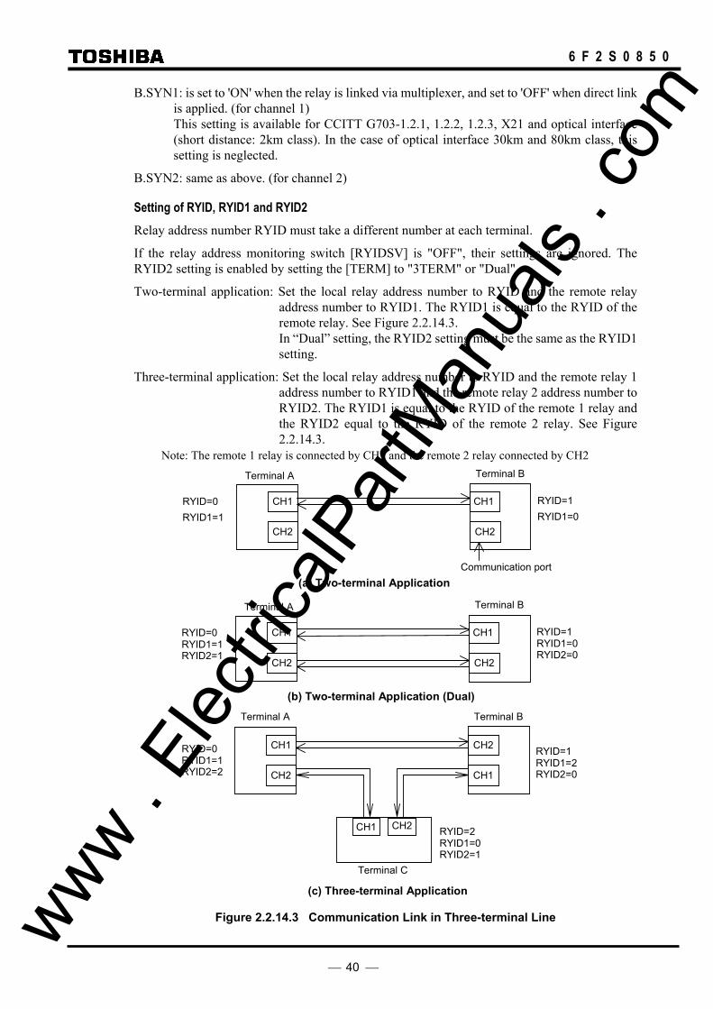
40
6 F 2 S 0 8 5 0
B.SYN1: is set to 'ON' when the relay is linked via multiplexer, and set to 'OFF' when direct link is applied. (for channel 1) This setting is available for CCITT G703-1.2.1, 1.2.2, 1.2.3, X21 and optical interface (short distance: 2km class). In the case of optical interface 30km and 80km class, this setting is neglected.
B.SYN2: same as above. (for channel 2)
Setting of RYID, RYID1 and RYID2 Relay address number RYID must take a different number at each terminal.
If the relay address monitoring switch [RYIDSV] is "OFF", their settings are ignored. The RYID2 setting is enabled by setting the [TERM] to "3TERM" or "Dual".
Two-terminal application: Set the local relay address number to RYID and the remote relay address number to RYID1. The RYID1 is equal to the RYID of the remote relay. See Figure 2.2.14.3.
In “Dual” setting, the RYID2 setting must be the same as the RYID1 setting.
Three-terminal application: Set the local relay address number to RYID and the remote relay 1 address number to RYID1 and the remote relay 2 address number to RYID2. The RYID1 is equal to the RYID of the remote 1 relay and the RYID2 equal to the RYID of the remote 2 relay. See Figure 2.2.14.3.
Note: The remote 1 relay is connected by CH1 and the remote 2 relay connected by CH2
Terminal B
CH1
CH2
Communication port
CH1
CH2
Terminal A
(a) Two-terminal Application
RYID=1 RYID1=0
RYID=0 RYID1=1
Terminal B
CH1
CH2
CH1
CH2
Terminal A
(b) Two-terminal Application (Dual)
RYID=1 RYID1=0 RYID2=0
RYID=0 RYID1=1 RYID2=1
Terminal B Terminal A
Terminal C
CH1
CH2
CH2
CH1
CH1 CH2 RYID=2
RYID1=0 RYID2=1
RYID=0 RYID1=1 RYID2=2
RYID=1 RYID1=2 RYID2=0
(c) Three-terminal Application
Figure 2.2.14.3 Communication Link in Three-terminal Line www . El
ectric
alPar
tMan
uals
. com

41
6 F 2 S 0 8 5 0
Setting depending on communication mode The setting depending on communication mode is shown in the following table.
Setting A-MODE B-MODE GPS-MODE Default setting Remarks
Communication mode
COMMODE Must select “A” of A/B/GPS
Must select “B” of A/B/GPS
Must select “GPS” of A/B/GPS
B
GPS backup mode
GPSBAK -- -- On/Off On
MODE2B shifted automatically
AUTO2B -- -- On/Off Off
Phase difference check
SRCθ -- -- Disable/I I Available for only 2TERM setting
Terminal application
TERM 2TERM/3TERM/ DUAL
2TERM/3TERM/ DUAL
2TERM/3TERM 2TERM For 3 terminal application model
Relay address monitoring
RYIDSV -- On/Off On/Off On
Multi-phase autoreclosing
Autoreclose mode
MPAR2/MPAR3 MPAR2/MPAR3 MPAR2/MPAR3 SPAR&TPAR RYIDSV=Off is required
Open terminal detection
OTD On/Off On/Off On/Off Off
Zero-phase current differential
DIFG On/Off On/Off On/Off On
Out-of-step tripping
OST Trip/BO/Off Trip/BO/Off Trip/BO/Off Off
Fault locator FL On/Off On/Off On/Off On
Remote differential trip
RDIF -- On/Off On/Off On Available for 3TERM application
--: don’t care.
Terminal application In A-MODE and B-MODE, anyone of 2TERM, 3TERM or DUAL can be selected. In GPS-MODE, however, DUAL cannot be selected.
Multi-phase autoreclosing To apply the multi-phase autoreclosing with MPAR2 or MPAR3, the relay address monitoring RYIDSV in B-MODE and GPS-MODE must be set to “OFF”. When the RYIDSV=OFF, CBLS (CBDS) condition is sent.
If shared with the relay address monitoring, the bits for CBLS condition can be assigned instead of the bits for DIFG or OST/FL by PLC function when DIFG or OST/FL is not used.
Automatic open terminal detection OTD In B-MODE and GPS-MODE, the RYIDSV=OFF setting for relay address monitoring is required to use the open terminal detection function (OTD=On).
If shared with the relay address monitoring, the following methods can be applied:
(1) Only one bit with open terminal condition instead of CBLS condition can be sent by sub-communication bit.
(2) If DIFG or OST/FL is not used, the bits for CBLS condition can be assigned instead of the bits for DIFG or OST/FL by PLC function.
The open terminal detection in B-MODE and GPS-MODE do not automatically change www . El
ectric
alPar
tMan
uals
. com

42
6 F 2 S 0 8 5 0
“Master” or Slave” in SP.SYN. If the master terminal becomes out-of-service, therefore, the synchronization control of slave terminal follows that of the master terminal by ON/OFF at the master terminal and the current differential protection is blocked.
When putting a terminal into out-of-service in three-terminal operation, the following setting change method is recommended:
(Example)
When putting Terminal C into out-of-service to two-terminal operation, the following four setting are changed.
SP.SYN:
If the terminal C has been “Master”, change the terminal A or B to “Master”. If the terminal A or C has been “Master”, do not change the setting.
TERM:
Change both the terminal A and B to “2TERM”.
CH.CON:
It is defined that CH1 of both terminal relays is connected each other in two-terminal application and CH1 of local relay is connected to CH2 of remote relay in three-terminal application as shown in Figure 2.2.14.3. Therefore, the communication cable connection must be changed from CH2 to CH1.
[CH.CON] is to change CH1 or CH2 signal with CH2 or CH1 signal in the relay inside. If the [CH.CON] is set to “Exchange”, CH2 data is dealt with as CH1 data or in reverse. In Figure 2.2.14.3, change the terminal B to “Exchange”. However, note that the display or output such as a communication failure, etc. is expressed as CH1 because CH2 data is dealt with as CH1 data at the terminal B.
RYID1:
The remote terminal 1 seen from terminal B changes from terminal C to terminal A. Therefore, change the remote terminal 1 relay address setting RYID1 from "2" to "0" at terminal B.
If the relay address monitoring switch [RYIDSV] is "OFF", the setting is invalid and setting change is not required.
Remote differential trip RDIF This function is not available for the A-MODE setting.
When this function is used, set [RDIF] and [TERM] are set to "ON" and "3-TERM" and the following must be configured by the PLC function.
Assign the remote DIF trip send signals RDIF-∗-S to user configurable data, and the receiving data from remote terminals to the trip command signals RDIF-∗-R1 and RDIF-∗-R2.
www . El
ectric
alPar
tMan
uals
. com

43
6 F 2 S 0 8 5 0
2.3 Distance Protection
2.3.1 Time-Stepped Distance Protection
2.3.1.1 Application Using reach and tripping time settings coordinated with adjacent lines, the GRL100 provides three steps of distance protection for forward faults and one backup protection for reverse faults. These are used as the main protection when telecommunications are not available, or as backup protection for the protected line and adjacent lines.
The GRL100 has four distance measuring zones for both phase and earth faults, three zones for forward faults and one zone for reverse faults respectively. The zones can be defined with either mho-based characteristic or quadrilateral characteristic. The characteristic is selected by setting the scheme switch [ZS-C] for phase fault and [ZG-C] for earth fault to "Mho" or "Quad".
Figure 2.3.1.1 shows the mho-based characteristics. Zone 1 (Z1) and Zone 2 (Z2) have a complex characteristic combining the reactance element, mho element and blinder element, while Zone 3 (Z3), reverse Zone R (ZR) and reverse Zone 4 (Z4) elements have a complex characteristic combining the mho element and blinder element.
The blinder element (BFR) can be provided for each forward zone. The setting of blinder element can be set independently or set common to forward zones by the scheme switch [BLZONE]. Figures 2.3.1.1 and 2.3.1.2 show the characteristics with an independent setting.
Since the Z4 is used for detection of reverse faults in command protection, the Z4 for phase faults has an offset characteristic with an offset mho element which assures detection of close-up phase faults. The operation of Z4 for phase faults in the event of internal faults is inhibited by the operations of Z2 and Z3.
Figure 2.3.1.2 shows the quadrilateral characteristics. These have a complex characteristic combining the reactance element, directional element and blinder element.
The Z4 for phase faults has an offset characteristic with an offset directional element which assures detection of close-up phase faults.
The operation is the same as the mho-based characteristics.
Z1S
Z2S
Z3S
Z4S
BFR1S
BRRS
Z1G
Z2G
Z3G
Z4G
BFR1G
BRRG
Z3Sθ
Z1Sθ175°
Z3Gθ
Z1Gθ1 75°
ZRS ZRG
BRLS
BFR2S
BFRS
BFR2G
BFRG
BRLG
(a) Phase fault element (b) Earth fault element
Figure 2.3.1.1 Mho-based Characteristics www . El
ectric
alPar
tMan
uals
. com
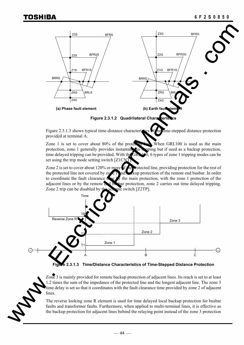
44
6 F 2 S 0 8 5 0
Z1G
Z2G
Z3G
Z4G
BFR1G
BRRG
Z1S
Z2S
Z3S
Z4S
BFR1S
BRRS
ZRS ZRG
BFR2S
BFRS
BRLS
BFR2G
BFRG
BRLG
(a) Phase fault element (b) Earth fault element
Figure 2.3.1.2 Quadrilateral Characteristics
Figure 2.3.1.3 shows typical time-distance characteristics of the time-stepped distance protection provided at terminal A.
Zone 1 is set to cover about 80% of the protected line. When GRL100 is used as the main protection, zone 1 generally provides instantaneous tripping but if used as a backup protection, time delayed tripping can be provided. With the GRL100, 6 types of zone 1 tripping modes can be set using the trip mode setting switch [Z1CNT].
Zone 2 is set to cover about 120% or more of the protected line, providing protection for the rest of the protected line not covered by zone 1 and backup protection of the remote end busbar. In order to coordinate the fault clearance time by the main protection, with the zone 1 protection of the adjacent lines or by the remote end busbar protection, zone 2 carries out time delayed tripping. Zone 2 trip can be disabled by the scheme switch [Z2TP].
Time
TR
T3
T2
T1
C BA
Reverse Zone R
Zone 2
Zone 1
Zone 3
∼ ∼
Figure 2.3.1.3 Time/Distance Characteristics of Time-Stepped Distance Protection
Zone 3 is mainly provided for remote backup protection of adjacent lines. Its reach is set to at least 1.2 times the sum of the impedance of the protected line and the longest adjacent line. The zone 3 time delay is set so that it coordinates with the fault clearance time provided by zone 2 of adjacent lines.
The reverse looking zone R element is used for time delayed local backup protection for busbar faults and transformer faults. Furthermore, when applied to multi-terminal lines, it is effective as the backup protection for adjacent lines behind the relaying point instead of the zone 3 protection www .
Elec
tricalP
artM
anua
ls . c
om

45
6 F 2 S 0 8 5 0
at the remote terminal. This is because it is difficult for zone 3 at terminals A and C to provide remote backup protection for the fault shown in Figure 2.3.1.4 due to fault infeed from the other terminal, whereas reverse looking zone R of terminal B is not affected by this. Zone R trip can be disabled by the scheme switch [ZRTP].
Zone 3
Zone R
A
C
B
Figure 2.3.1.4 Reverse Zone Protection
To maintain stable operation for close-up three-phase faults which cause the voltages of all phases to drop to 0 or close to 0, zone 1 for phase faults, once operated, changes its element to a reverse offset element. This continues until the fault is cleared, and thus it is effective for time delayed protection.
The reactance element characteristics of zone 1 and zone 2 are parallel lines to the R axis and provide sufficient coverage for high-resistance faults. The reactance element characteristics of zone 1 can be transformed to a broken line depending on the load flow direction in order to avoid overreaching by the influence of load current. The characteristic in the resistive direction is limited by the mho characteristic of zone 3. The reactive reach setting is independent for each zone. It is also possible to have independent settings for each individual phase fault and earth fault elements.
With a long-distance line or heavily loaded line, it is possible for the load impedance to encroach on the operation zone of the mho element. Blinders are provided to limit the operation of the mho element in the load impedance area. Zero-sequence current compensation is applied to zone 1 and zone 2 for earth fault protection. This compensates measuring errors caused by the earth return of zero-sequence current. This allows the faulted phase reactance element to precisely measure the positive-sequence impedance up to the fault point. Furthermore, in the case of double-circuit lines, zero-sequence current from the parallel line is introduced to compensate for influences from zero-sequence mutual coupling. Considering the case where the impedance angle of positive-sequence impedance and zero-sequence impedance differ which is the most common in cable circuits, GRL100 carries out vectorial zero-sequence current compensation.
The autoreclose schemes are utilised with instantaneous zone 1 tripping. When single-phase autoreclose or single- and three-phase autoreclose are selected, zone 1 executes single-phase tripping for a single-phase earth fault. In order to achieve reliable fault phase selection even for faults on heavily loaded long-distance lines or irrespective of variations in power source conditions behind the relaying point, an undervoltage element with current compensation is used as a phase selector. Other zones only execute three-phase tripping, and do not initiate autoreclose.
2.3.1.2 Scheme Logic Figure 2.3.1.5 shows the scheme logic for the time-stepped distance protection. For zone 1 tripping, as described later, it is possible to select instantaneous tripping or time delayed tripping using the scheme switch [Z1CNT] in the trip mode control logic. (Detail of the [Z1CNT] is described after.) Zone 2, zone 3 and zone R give time delayed tripping. However, these zones can trip instantaneously by PLC signals Z∗_INST_TP. Timers TZ2, TZ3 and TZR with time delayed tripping can be set for earth faults and phase faults separately. Zone 1, zone 2, zone 3 and zone R www .
Elec
tricalP
artM
anua
ls . c
om
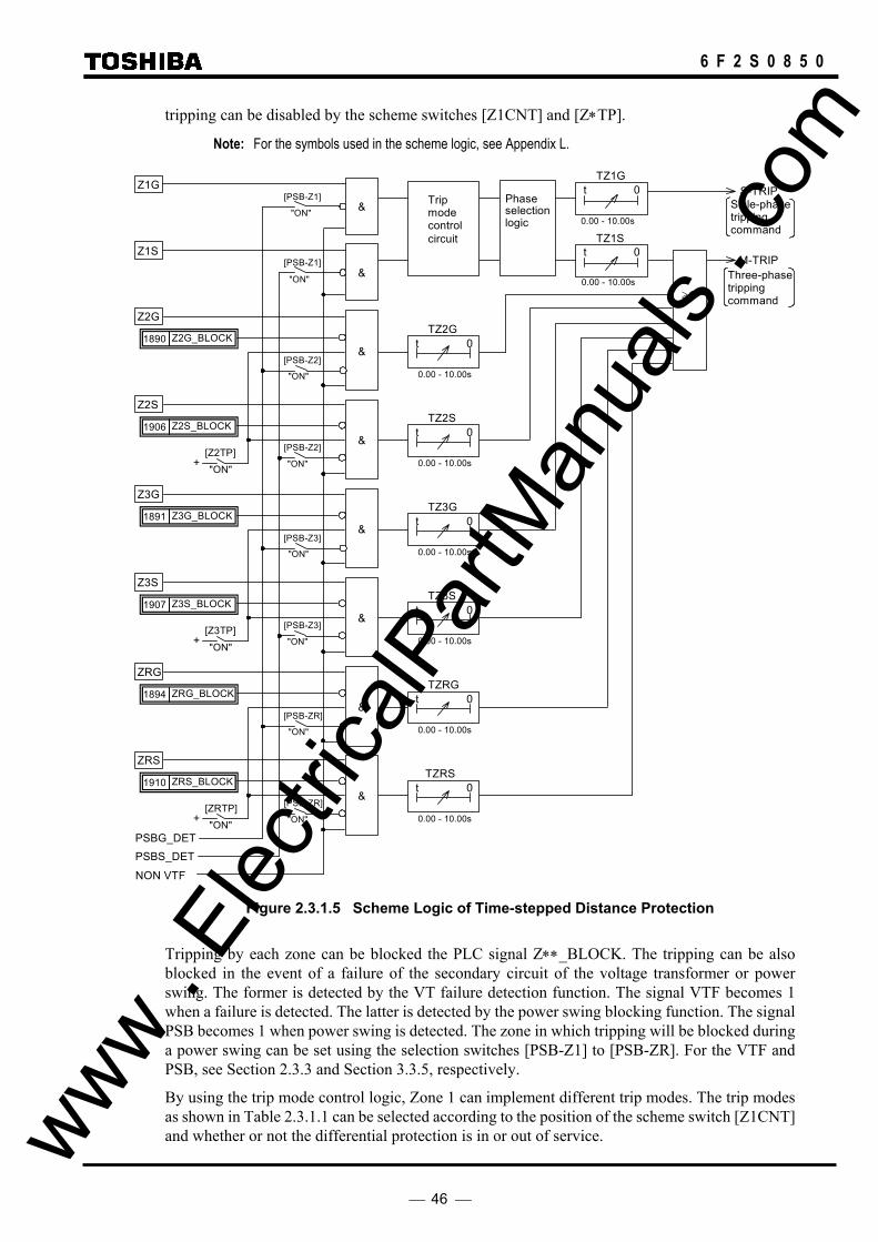
46
6 F 2 S 0 8 5 0
tripping can be disabled by the scheme switches [Z1CNT] and [Z∗TP].
Note: For the symbols used in the scheme logic, see Appendix L.
S-TRIP
& Tripmodecontrol
M-TRIP
TZ2Gt 0
&
Z1G
Z2G
Phaseselection logic
Sigle-phase tripping command
0.00 - 10.00s
[PSB-Z1]
PSBG_DET
+ [Z2TP]
[PSB-Z2]
NON VTF
Three-phase tripping command
TZ1G t 0
0.00 - 10.00s
&
Z1S
"ON"
[PSB-Z1]
TZ1S t 0
0.00 - 10.00s
Z2G_BLOCK 1890
TZ2St 0
&
0.00 - 10.00s
"ON"
"ON"
Z2S
[PSB-Z2]
Z2S_BLOCK 1906
"ON"
≥ 1
"ON"
TZ3Gt 0
&
Z3G
0.00 - 10.00s
+ [Z3TP]
[PSB-Z3]
Z3G_BLOCK 1891
TZ3St 0
&
0.00 - 10.00s
"ON"
Z3S
[PSB-Z3]
Z3S_BLOCK 1907
"ON" "ON"
TZRGt 0
&
ZRG
0.00 - 10.00s
+ [ZRTP]
[PSB-ZR]
ZRG_BLOCK 1894
TZRSt 0
&
0.00 - 10.00s
"ON"
ZRS
[PSB-ZR]
ZRS_BLOCK 1910
"ON" "ON"
PSBS_DET
circuit
Figure 2.3.1.5 Scheme Logic of Time-stepped Distance Protection
Tripping by each zone can be blocked the PLC signal Z∗∗_BLOCK. The tripping can be also blocked in the event of a failure of the secondary circuit of the voltage transformer or power swing. The former is detected by the VT failure detection function. The signal VTF becomes 1 when a failure is detected. The latter is detected by the power swing blocking function. The signal PSB becomes 1 when power swing is detected. The zone in which tripping will be blocked during a power swing can be set using the selection switches [PSB-Z1] to [PSB-ZR]. For the VTF and PSB, see Section 2.3.3 and Section 3.3.5, respectively.
By using the trip mode control logic, Zone 1 can implement different trip modes. The trip modes as shown in Table 2.3.1.1 can be selected according to the position of the scheme switch [Z1CNT] and whether or not the differential protection is in or out of service. www .
Elec
tricalP
artM
anua
ls . c
om

47
6 F 2 S 0 8 5 0
Table 2.3.1.1 Zone 1 Trip Mode Control
Z1CNT CURRENT DIFFERENTIAL PROTECTION USE OR NOT
Position USE NO USE (*)
1 SINGLE-PHASE TRIP & AUTO-REC SINGLE-PHASE INST. TRIP & AUTO-REC
2 THREE-PHASE TRIP SINGLE-PHASE INST. TRIP & AUTO-REC
3 THREE-PHASE TRIP THREE-PHASE INST. TRIP
4 SINGLE-PHASE TRIP & AUTO-REC
5 THREE-PHASE TRIP
6 Z1 TRIP BLOCK (*): during a communication failure or when the [DIF] setting is “No use”.
The zone 1 tripping mode at each position of the switch [Z1CNT] is as follows:
Position 1: When the current differential protection is in service, zone 1 executes time tripping with a time delay using timer TZ1 and starts autoreclose. Zone 1 performs single-phase tripping and reclosing or three-phase tripping and reclosing depending on the reclose mode of the autoreclose function and the type of faults (single-phase faults or multi-phase faults). If the autoreclose is out of service, zone 1 performs three-phase final tripping for all faults.
When the current differential protection is out of service, zone 1 executes performs instantaneous single-phase tripping and reclosing or three-phase tripping and reclosing depending on the reclose mode of the autoreclose function and the type of faults (single-phase faults or multi-phase faults). If the autoreclose is out of service, zone 1 performs instantaneous three-phase final tripping for all faults.
Position 2: When the current differential protection is in service, zone 1 performs three-phase tripping with a time delay using timer TZ1 and does not start autoreclose. The zone 1 performs instantaneous single-phase tripping and reclosing or three-phase tripping and reclosing depending on the reclose mode of the autoreclose function and the type of faults (single-phase faults or multi-phase faults), if the current differential protection is out of service. If the autoreclose is out of service, zone 1 performs three-phase final tripping for all faults.
Position 3: When the current differential protection is in service, zone 1 performs three-phase tripping with a time delay using timer TZ1 and does not start autoreclose. The zone 1 performs three-phase tripping instantaneously and does not start autoreclose if the current differential protection is out of service.
Position 4: Though the current differential protection is in service or out of service, zone 1 executes time tripping with a time delay using timer TZ1 and starts autoreclose. Zone 1 performs single-phase tripping and reclosing or three-phase tripping and reclosing depending on the reclose mode of the autoreclose function and the type of faults (single-phase faults or multi-phase faults). If the autoreclose is out of service, zone 1 performs three-phase final tripping for all faults.
Position 5: Though the current differential protection is in service or out of service, zone 1 performs three-phase tripping with a time delay using timer TZ1 and does not start autoreclose.
Position 6: Zone 1 tripping is blocked though the current differential protection is in service or out of service.
Zone 1 Trip Mode Control is performed using PLC default function as shown in Figure 2.3.1.6. By changing the PLC default setting, the Z1 trip can be controlled independently of the [Z1CNT] setting.
www . El
ectric
alPar
tMan
uals
. com
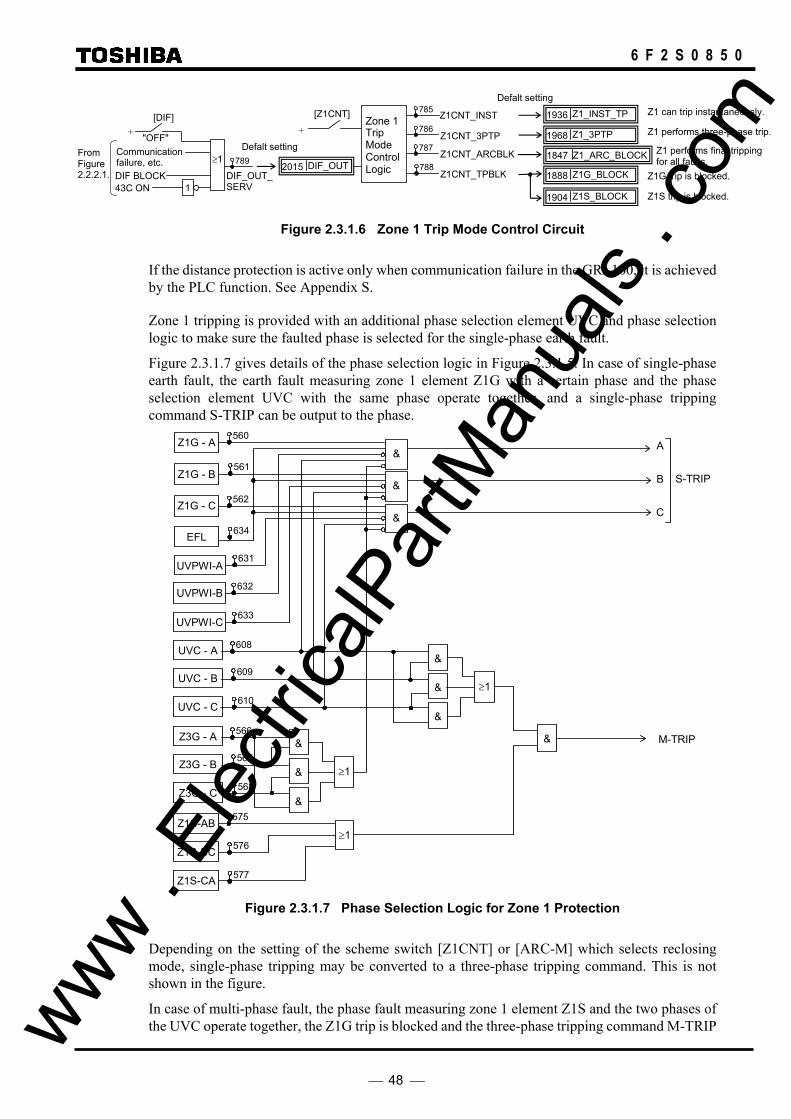
48
6 F 2 S 0 8 5 0
DIF_OUT_SERV
Z1CNT_INST +
43C ON
[Z1CNT] Z1_INST_TP 1936 785
786
787
788
Z1CNT_3PTP
Z1CNT_ARCBLK
Z1CNT_TPBLK
Z1_3PTP 1968
Z1_ARC_BLOCK 1847
Z1G_BLOCK 1888
Z1S_BLOCK 1904
Z1 can trip instantaneously.
Z1 performs three-phase trip.
Z1 performs final tripping for all faults.
Z1G trip is blocked.
Z1S trip is blocked.
Defalt setting
DIF_OUT2015
TripModeControlLogic
Zone 1
1
≥1 789
DIF BLOCK
Communication failure, etc.
+ [DIF]
"OFF" Defalt setting From
Figure 2.2.2.1.
Figure 2.3.1.6 Zone 1 Trip Mode Control Circuit
If the distance protection is active only when communication failure in the GRL100, it is achieved by the PLC function. See Appendix S.
Zone 1 tripping is provided with an additional phase selection element UVC and phase selection logic to make sure the faulted phase is selected for the single-phase earth fault.
Figure 2.3.1.7 gives details of the phase selection logic in Figure 2.3.1.5. In case of single-phase earth fault, the earth fault measuring zone 1 element Z1G with a certain phase and the phase selection element UVC with the same phase operate together, and a single-phase tripping command S-TRIP can be output to the phase.
&
UVC - C
UVC - B
UVC - A
Z1G - C
Z1G - B
Z1G - A
≥1Z1S-BC
Z1S-AB
C
B
A&
&
&
Z1S-CA
S-TRIP
M-TRIP
560
561
562
EFL
UVPWI-C
UVPWI-B
UVPWI-A 631
632
633
634
608
609
610
575
576
577
≥1
&
&
&
Z3G - C
Z3G - B
Z3G - A 566
567
568 ≥1
&
&
&
Figure 2.3.1.7 Phase Selection Logic for Zone 1 Protection
Depending on the setting of the scheme switch [Z1CNT] or [ARC-M] which selects reclosing mode, single-phase tripping may be converted to a three-phase tripping command. This is not shown in the figure.
In case of multi-phase fault, the phase fault measuring zone 1 element Z1S and the two phases of the UVC operate together, the Z1G trip is blocked and the three-phase tripping command M-TRIP www .
Elec
tricalP
artM
anua
ls . c
om

49
6 F 2 S 0 8 5 0
is always output. The condition for the UVC two-phase operation is to inhibit the Z1S from overreaching in the event of a single-phase earth fault.
The UVC element is applied to the zone 1 distance elements.
EFL is an earth fault detection element, and UVPWI is a phase undervoltage relay to provide countermeasures for overreaching of a leading-phase distance element at positive phase weak infeed condition. These elements are applied to all earth fault distance elements. (Refer to Appendix A.) The UVPWI can be disabled by the scheme switch [UVPWIEN].
2.3.1.3 Setting The following shows the necessary distance protection elements and their setting ranges.
Element Range Step Default Remarks Phase fault protection ZS-C Mho - Quad Mho Characteristic selection Z1S 0.01 - 50.00Ω 0.01Ω 1.60Ω Z1 reach (0.10 - 250.00Ω 0.01Ω 8.00Ω) (*1) Z1S θ1 0° - 45° 1° 0° Gradient of reactance element Z1S θ2 45° - 90° 1° 90° BFR1S 0.10 - 20.00Ω 0.01Ω 5.10Ω Forward right blinder reach for Z1 (0.5 - 100.0Ω 0.1Ω 25.5Ω) Z2S 0.01 - 50.00Ω 0.01Ω 3.00Ω Z2 reach (0.10 - 250.00Ω 0.01Ω 15.00Ω) BFR2S 0.10 - 20.00Ω 0.01Ω 5.10Ω Forward right blinder reach for Z2 (0.5 - 100.0Ω 0.1Ω 25.5Ω) Z3S 0.01 - 50.00Ω 0.01Ω 6.00Ω Z3 reach (0.1 – 250.0Ω 0.1Ω 30.0Ω) Z3S θ(*2) 45 - 90° 1° 85° Characteristic angle of mho element ZBS θ(*3) 0 - 45° 1° 5° Angle of directional element BFRS 0.10 - 20.00Ω 0.01Ω 5.10Ω Forward right blinder reach for Z3 (0.5 - 100.0Ω 0.1Ω 25.5Ω) BFLS θ 90° - 135° 1° 120° Forward left blinder angle ZRS 0.01 - 50.00Ω 0.01Ω 4.00Ω ZR reach (0.1 – 250.0Ω 0.1Ω 20.0Ω) Z4S 0.01 - 50.00Ω 0.01Ω 8.00Ω Z4 reach (0.1 – 250.0Ω 0.1Ω 40.0Ω) BRRS 0.10 - 20.00Ω 0.01Ω 5.10Ω Reverse right blinder reach (0.5 - 100.0Ω 0.1Ω 25.5Ω) TZ1S 0.00 - 10.00 s 0.01 s 0.00 s Zone 1 timer TZ2S 0.00 - 10.00 s 0.01 s 0.30 s Zone 2 timer TZ3S 0.00 - 10.00 s 0.01 s 0.40 s Zone 3 timer TZRS 0.00 - 10.00 s 0.01 s 0.60 s Zone R timer Earth fault protection ZG-C Mho - Quad Mho Characteristic selection Z1G 0.01 - 50.00Ω 0.01Ω 1.60Ω Z1 reach (0.10 - 250.00Ω 0.01Ω 8.00Ω) Z1G θ1 0° - 45° 1° 0° Gradient of reactance element Z1G θ2 45° - 90° 1° 90° BFR1G 0.10 - 20.00Ω 0.01Ω 5.10Ω Forward right blinder reach for Z1 (0.5 - 100.0Ω 0.1Ω 25.5Ω) www .
Elec
tricalP
artM
anua
ls . c
om
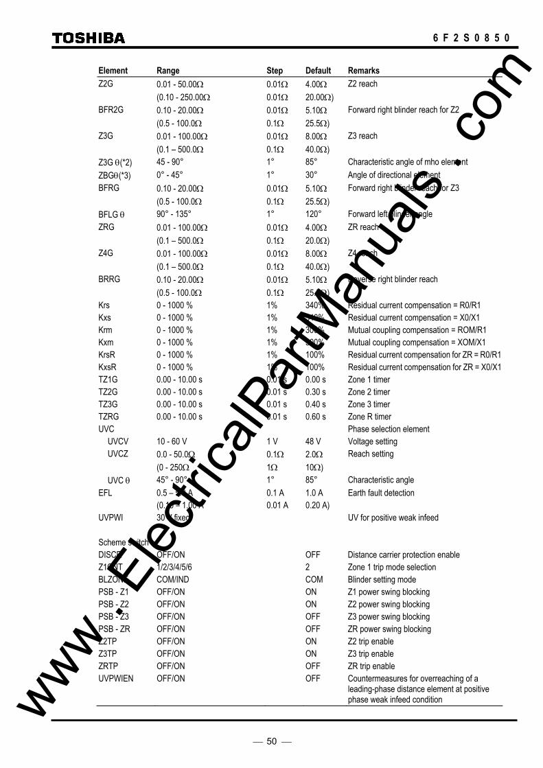
50
6 F 2 S 0 8 5 0
Element Range Step Default Remarks Z2G 0.01 - 50.00Ω 0.01Ω 4.00Ω Z2 reach (0.10 - 250.00Ω 0.01Ω 20.00Ω) BFR2G 0.10 - 20.00Ω 0.01Ω 5.10Ω Forward right blinder reach for Z2 (0.5 - 100.0Ω 0.1Ω 25.5Ω) Z3G 0.01 - 100.00Ω 0.01Ω 8.00Ω Z3 reach (0.1 – 500.0Ω 0.1Ω 40.0Ω) Z3G θ(*2) 45 - 90° 1° 85° Characteristic angle of mho element ZBGθ(*3) 0° - 45° 1° 30° Angle of directional element BFRG 0.10 - 20.00Ω 0.01Ω 5.10Ω Forward right blinder reach for Z3 (0.5 - 100.0Ω 0.1Ω 25.5Ω) BFLG θ 90° - 135° 1° 120° Forward left blinder angle ZRG 0.01 - 100.00Ω 0.01Ω 4.00Ω ZR reach (0.1 – 500.0Ω 0.1Ω 20.0Ω) Z4G 0.01 - 100.00Ω 0.01Ω 8.00Ω Z4 reach (0.1 – 500.0Ω 0.1Ω 40.0Ω) BRRG 0.10 - 20.00Ω 0.01Ω 5.10Ω Reverse right blinder reach (0.5 - 100.0Ω 0.1Ω 25.5Ω) Krs 0 - 1000 % 1% 340% Residual current compensation = R0/R1 Kxs 0 - 1000 % 1% 340% Residual current compensation = X0/X1 Krm 0 - 1000 % 1% 300% Mutual coupling compensation = ROM/R1 Kxm 0 - 1000 % 1% 300% Mutual coupling compensation = XOM/X1 KrsR 0 - 1000 % 1% 100% Residual current compensation for ZR = R0/R1 KxsR 0 - 1000 % 1% 100% Residual current compensation for ZR = X0/X1 TZ1G 0.00 - 10.00 s 0.01 s 0.00 s Zone 1 timer TZ2G 0.00 - 10.00 s 0.01 s 0.30 s Zone 2 timer TZ3G 0.00 - 10.00 s 0.01 s 0.40 s Zone 3 timer TZRG 0.00 - 10.00 s 0.01 s 0.60 s Zone R timer UVC Phase selection element UVCV 10 - 60 V 1 V 48 V Voltage setting UVCZ 0.0 - 50.0Ω 0.1Ω 2.0Ω Reach setting (0 - 250Ω 1Ω 10Ω) UVC θ 45° - 90° 1° 85° Characteristic angle EFL 0.5 – 5.0 A 0.1 A 1.0 A Earth fault detection (0.10 – 1.00 A 0.01 A 0.20 A) UVPWI 30 V fixed UV for positive weak infeed Scheme switch DISCR OFF/ON OFF Distance carrier protection enable Z1CNT 1/2/3/4/5/6 2 Zone 1 trip mode selection BLZONE COM/IND COM Blinder setting mode PSB - Z1 OFF/ON ON Z1 power swing blocking PSB - Z2 OFF/ON ON Z2 power swing blocking PSB - Z3 OFF/ON OFF Z3 power swing blocking PSB - ZR OFF/ON OFF ZR power swing blocking Z2TP OFF/ON ON Z2 trip enable Z3TP OFF/ON ON Z3 trip enable ZRTP OFF/ON OFF ZR trip enable UVPWIEN OFF/ON OFF Countermeasures for overreaching of a
leading-phase distance element at positive phase weak infeed condition www .
Elec
tricalP
artM
anua
ls . c
om
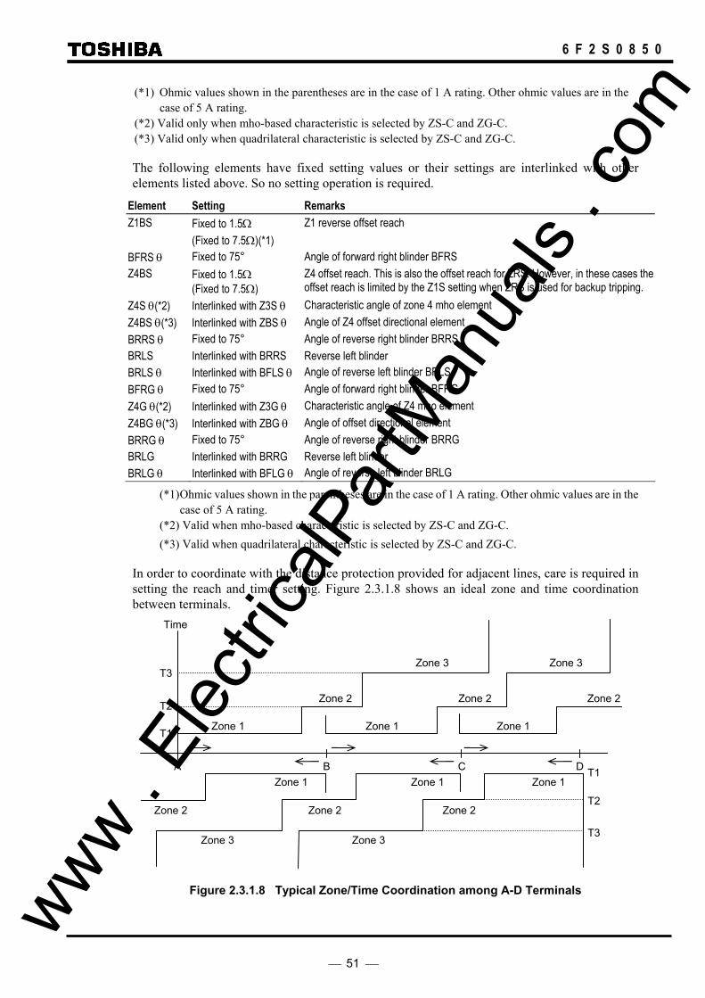
51
6 F 2 S 0 8 5 0
(*1) Ohmic values shown in the parentheses are in the case of 1 A rating. Other ohmic values are in the case of 5 A rating.
(*2) Valid only when mho-based characteristic is selected by ZS-C and ZG-C. (*3) Valid only when quadrilateral characteristic is selected by ZS-C and ZG-C.
The following elements have fixed setting values or their settings are interlinked with other elements listed above. So no setting operation is required.
Element Setting Remarks Z1BS Fixed to 1.5Ω Z1 reverse offset reach (Fixed to 7.5Ω)(*1) BFRS θ Fixed to 75° Angle of forward right blinder BFRS Z4BS Fixed to 1.5Ω
(Fixed to 7.5Ω) Z4 offset reach. This is also the offset reach for ZRS. However, in these cases the offset reach is limited by the Z1S setting when ZRS is used for backup tripping.
Z4S θ(*2) Interlinked with Z3S θ Characteristic angle of zone 4 mho element Z4BS θ(*3) Interlinked with ZBS θ Angle of Z4 offset directional element BRRS θ Fixed to 75° Angle of reverse right blinder BRRS BRLS Interlinked with BRRS Reverse left blinder BRLS θ Interlinked with BFLS θ Angle of reverse left blinder BRLS BFRG θ Fixed to 75° Angle of forward right blinder BFRG Z4G θ(*2) Interlinked with Z3G θ Characteristic angle of Z4 mho element Z4BG θ(*3) Interlinked with ZBG θ Angle of offset directional element BRRG θ Fixed to 75° Angle of reverse right blinder BRRG BRLG Interlinked with BRRG Reverse left blinder BRLG θ Interlinked with BFLG θ Angle of reverse left blinder BRLG
(*1) Ohmic values shown in the parentheses are in the case of 1 A rating. Other ohmic values are in the case of 5 A rating.
(*2) Valid when mho-based characteristic is selected by ZS-C and ZG-C. (*3) Valid when quadrilateral characteristic is selected by ZS-C and ZG-C.
In order to coordinate with the distance protection provided for adjacent lines, care is required in setting the reach and timer setting. Figure 2.3.1.8 shows an ideal zone and time coordination between terminals.
Figure 2.3.1.8 Typical Zone/Time Coordination among A-D Terminals
Time
Zone 1 Zone 1
Zone 3 Zone 3
Zone 3 Zone 3
Zone 2Zone 2
Zone 2Zone 2 Zone 2
Zone 2
Zone 1 Zone 1 Zone 1
Zone 1
D C B A
T1
T2
T3
T1
T2
T3
www . El
ectric
alPar
tMan
uals
. com
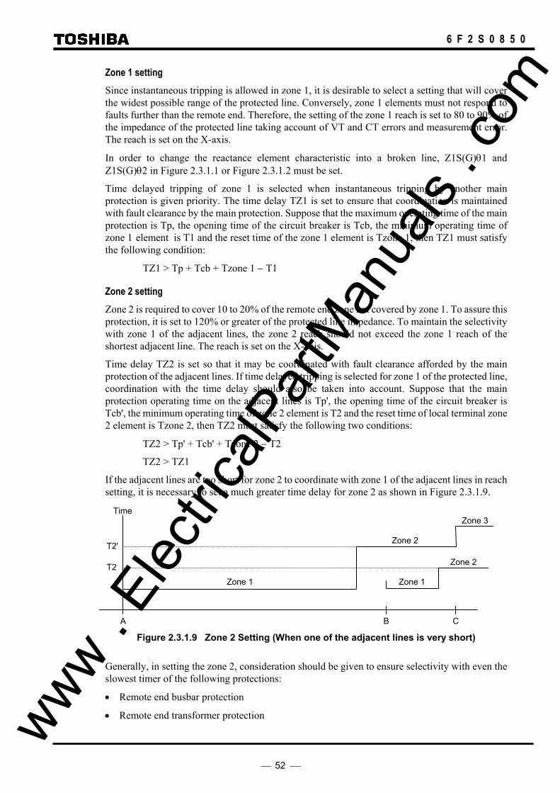
52
6 F 2 S 0 8 5 0
Zone 1 setting Since instantaneous tripping is allowed in zone 1, it is desirable to select a setting that will cover the widest possible range of the protected line. Conversely, zone 1 elements must not respond to faults further than the remote end. Therefore, the setting of the zone 1 reach is set to 80 to 90% of the impedance of the protected line taking account of VT and CT errors and measurement error. The reach is set on the X-axis.
In order to change the reactance element characteristic into a broken line, Z1S(G)θ1 and Z1S(G)θ2 in Figure 2.3.1.1 or Figure 2.3.1.2 must be set.
Time delayed tripping of zone 1 is selected when instantaneous tripping by another main protection is given priority. The time delay TZ1 is set to ensure that coordination is maintained with fault clearance by the main protection. Suppose that the maximum operating time of the main protection is Tp, the opening time of the circuit breaker is Tcb, the minimum operating time of zone 1 element is T1 and the reset time of the zone 1 element is Tzone 1, then TZ1 must satisfy the following condition:
TZ1 > Tp + Tcb + Tzone 1 − T1
Zone 2 setting Zone 2 is required to cover 10 to 20% of the remote end zone not covered by zone 1. To assure this protection, it is set to 120% or greater of the protected line impedance. To maintain the selectivity with zone 1 of the adjacent lines, the zone 2 reach should not exceed the zone 1 reach of the shortest adjacent line. The reach is set on the X-axis.
Time delay TZ2 is set so that it may be coordinated with fault clearance afforded by the main protection of the adjacent lines. If time delayed tripping is selected for zone 1 of the protected line, coordination with the time delay should also be taken into account. Suppose that the main protection operating time on the adjacent lines is Tp', the opening time of the circuit breaker is Tcb', the minimum operating time of zone 2 element is T2 and the reset time of local terminal zone 2 element is Tzone 2, then TZ2 must satisfy the following two conditions:
TZ2 > Tp' + Tcb' + Tzone 2 − T2
TZ2 > TZ1
If the adjacent lines are too short for zone 2 to coordinate with zone 1 of the adjacent lines in reach setting, it is necessary to set a much greater time delay for zone 2 as shown in Figure 2.3.1.9.
Figure 2.3.1.9 Zone 2 Setting (When one of the adjacent lines is very short)
Generally, in setting the zone 2, consideration should be given to ensure selectivity with even the slowest timer of the following protections:
• Remote end busbar protection
• Remote end transformer protection
Time
T2'
T2
Zone 3
Zone 2
Zone 2
Zone 1 Zone 1
C B A
www . El
ectric
alPar
tMan
uals
. com

53
6 F 2 S 0 8 5 0
• Line protection of adjacent lines
• Remote end breaker failure protection
Zone 3 setting Zone 3, in cooperation with zone 2, affords backup protection for faults that have occurred on adjacent lines. The reach should be set to exceed the remote end of the longest adjacent line whenever possible. It is also necessary to take into account the effect of fault infeed at the remote busbars. If an ideal reach setting as shown in Figure 2.3.1.8 is possible, the timer setting for zone 3 needs only to consider the coordination with the timer setting in zone 2 of the protected lines and adjacent lines.
However, as shown in Figure 2.3.1.10, if there are short-distance adjacent lines and it is impossible to establish coordination only by the reach setting, there may also be a case where the time delay for zone 3 will need to be set greater than that of the adjacent lines.
The zone 3 reach is set on the characteristic angle when the mho characteristic is selected or set on the X axis when the quadrilateral characteristic is selected.
Figure 2.3.1.10 Zone 3 Setting (When one of the adjacent lines is very short)
Zone R setting Zone R is used to provide local backup protection equivalent to that of zone 3 of the remote terminal. In such a case, the reach is set so as to exceed the remote end of the longest adjacent line behind the relaying point. The time delay is also set to be equivalent to that of the remote terminal.
the X axis when the quadrilateral characteristic is selected.
Z4 setting Zone 4 is the reverse fault detection for the command protection. The reach setting of zone 4 should be greater than that of zone 2 or zone 3 whichever is used as a forward overreaching element at the remote terminal.
The zone 4 reach is set on the characteristic angle when the mho characteristic is selected or set on the X axis when the quadrilateral characteristic is selected.
Blinder setting BFR and BRR reaches are set to the minimum load impedance with a margin. The minimum load impedance is calculated using the minimum operating voltage and the maximum load current.
The blinder element (BFR) can be provided for each forward zone. The setting of blinder element can be set independently or set common to forward zones by [BLZONE]=IND or [BLZONE]=COM setting. In the [BLZONE]=IND setting, the forward zone blinder setting should be set BFR1∗≤BFR2∗≤BFR∗. If BFR∗≤BFR1∗, for example, the reach of BFR1∗ is
Zone 2
T3'
T3
Zone 2
Zone 1 Zone 1
C B A
D
Zone 3
Zone 3
www . El
ectric
alPar
tMan
uals
. com

54
6 F 2 S 0 8 5 0
limited to the BFR∗ setting reach as shown in Figure 2.3.1.11(b).
X
R
BFR
Z3
Z2
BFR1
Z1
BFR2
X
R
BFR1
Z3
Z2
BFRBFR2
Z1
(a) (b)
Figure 2.3.1.11 BFR Reach
The BFL angle can be set to 90 to 135° and is set to 120° as a default. The BRL angle is linked with the BFL angle.
Figure 2.3.1.12 shows an example of the blinder setting when the minimum load impedance is ZLmin and Z’Lmin under the load transmitting and receiving conditions.
θ
θ
BFRX
30° 75°R
BFL
Load Area
ZLmin 75° Z’Lmin
BRL BRR
Figure 2.3.1.12 Blinder Setting
When Z4 is used for overreaching command protection ie. POP, UOP and BOP, it is necessary when setting BRR to take account of the setting of the remote end BFR to ensure coordination. That is, the BRR is set to a value greater than the set value of the remote end BFR (e.g., 120% of BFR). This ensures that a reverse fault that causes remote end zone 2 or zone 3 to operate is detected in local zone R and false tripping is blocked.
Setting of earth fault compensation factor (zero sequence compensation) In order to correctly measure the positive-sequence impedance to the fault point, the current input to the earth fault measuring elements is compensated by the residual current (3I0) of the protected line in the case of a single circuit line and by residual current (3I0) of the protected line and residual current (3I0’) of the parallel line in the case of a double circuit line.
Generally, the following equation is used to compensate the zero-sequence voltage drop in the case of phase “a”. www .
Elec
tricalP
artM
anua
ls . c
om

55
6 F 2 S 0 8 5 0
Va = (Ia − I0)Z1 + I0 × Z0 + Iom × Zom (1)
where,
Va: Phase “a” voltage
Ia: Phase “a” current
I0: Zero-sequence current of the protected line
I0m: Zero-sequence current of the parallel line
Z1: Positive-sequence impedance (Z1 = R1 + jX1)
Z0: Zero-sequence impedance (Z0 = R0 + jX0)
Z0m: Zero-sequence mutual impedance (Zom = Rom + jXom)
Equation (1) can be written as follows:
Va = (R1 + jX1)Ia + (R0 − R1) + j(X0 − X1)I0 + (Rom + jXom)Iom
= R1(Ia + R0 − R1
R1 I0 + Rom R1 Iom) + jX1(Ia +
X0 − X1X1 I0 +
Xom X1 Iom)
In the GRL100, the voltage is compensated independently for resistance and reactance components as shown in equation (2) in stead of general equation (1).
VaR + jVaX = R1( IaR +
Krs100 − 1
3 × 3I0R +
Krm100
3 × 3IomR )
− X1( IaX +
Kxs100 − 1
3 × 3I0X +
Kxm100
3 × 3IomX )
+ jR1( IaX +
Krs100 − 1
3 × 3I0X +
Krm100
3 × 3IomX )
+ X1( IaR +
Kxs100 − 1
3 × 3I0R +
Kxm100
3 × 3IomR ) (2)
where,
Kxs: compensation factor (Kxs = X0/X1 × 100)
Krs: compensation factor (Krs = R0/R1 × 100)
Kxm: compensation factor (Kxm = Xom/X1 × 100)
Krm: compensation factor (Krm = Rom/R1 × 100)
X: imaginary part of the measured impedance
R: real part of the measured impedance
VaX: imaginary part of phase “a” voltage
VaR: real part of phase “a” voltage
IaX: imaginary part of phase “a” current
IaR: real part of phase “a” current www . El
ectric
alPar
tMan
uals
. com

56
6 F 2 S 0 8 5 0
I0X: imaginary part of zero-sequence current of the protected line
I0R: real part of zero-sequence current of the protected line
IomX: imaginary part of zero-sequence current of the parallel line
IomR: real part of zero-sequence current of the parallel line
Figure 2.3.1.13 Earth Fault Compensation
The zero-sequence compensation factors are applied to the earth fault measuring elements as shown in the table below
Element Protected line Parallel line Z1G Krs, Kxs Krm, Kxm Z2G Krs, Kxs Krm, Kxm Z3G − − ZRG − − Z4G − −
−: Compensation is not provided.
The zero-sequence compensation of the parallel line is controlled by the ZPCC (Zero-sequence Current Compensation) element.
When an earth fault occurs on the protected line, the ZPCC operates and parallel line compensation is performed to prevent underreach caused by the mutual zero-sequence current of the parallel line.
When an earth fault on the parallel line occurs, the ZPCC does not operate and the compensation of parallel line is not performed to prevent overreach. The operating condition of the ZPCC is as follows:
3I0 / 3Iom ≥ 0.8
Charging current compensation When distance protection is applied to underground cables or long-distance overhead lines, the effect of charging current cannot be ignored. It appears as a distance measurement error in the fault.
To suppress the effect of the charging current and maintain the highly accurate distance measurement capability, the distance protection of GRL100 has a charging current compensation function.
The compensation is recommended if the minimum fault current can be less than three times the charging current.
The setting value of ZIC should be the charging current at the rated voltage Vn.
Element Range Step Default Remarks
I0’
I1, I2, Io
Z1, Z2, Zo
Zom P F
Va
www . El
ectric
alPar
tMan
uals
. com

57
6 F 2 S 0 8 5 0
ZIC 0.00 - 5.00 A 0.01 A 0.0 0 Charging current setting ( 0.00 - 1.00 A 0.01 A 0.00 A) (*) Vn 100 - 120 1 V 110 V Rated line voltage
(*) Current values shown in the parentheses are in the case of 1 A rating. Other current values are in the case of 5 A rating.
Setting of phase selection element Phase selection is required only for faults on the protected line. Therefore, impedance reach setting UVCZ is set to 120% of the positive-sequence impedance of the protected line. Impedance angle setting UVC θ is set the same as the protected line angle.
Undervoltage setting UVCV is set higher than the estimated maximum fault voltage at the fault point for a single-phase earth fault.
www . El
ectric
alPar
tMan
uals
. com

58
6 F 2 S 0 8 5 0
2.3.2 Command Protection
If operational information from the distance relays located at each end of the protected line is exchanged by means of telecommunication, it is possible to accurately determine whether or not the fault is internal or external to the protected line. Each terminal can provide high-speed protection for any fault along the whole length of the protected line. The GRL100 provides the following command (carrier) protection using the distance measuring elements.
• Permissive underreach protection (PUP)
• Permissive overreach protection (POP)
• Unblocking overreach protection (UOP)
• Blocking overreach protection (BOP)
Each command protection can initiate high-speed autoreclose. These protections perform single-phase or three-phase tripping depending on the setting of the reclosing mode and the fault type.
Each command protection includes the aforementioned time-stepped distance protection as backup protection.
2.3.2.1 Permissive Underreach Protection Application In permissive underreach protection (PUP), the underreaching zone 1 protection operates and trips the local circuit breakers and at the same time sends a trip permission signal to the remote terminal. The terminal which receives this signal executes instantaneous tripping on condition that the local overreaching element has operated. The overreaching element can be selected as either zone 2 or zone 3.
Since the trip permission signal is sent only when it is sure that the fault exists in the operating zone of zone 1, the PUP provides excellent security. On the other hand, the PUP does not provide sufficient dependability for faults on lines that contain open terminals or weak infeed terminals for which zone 1 cannot operate. Faults near open terminals or weak infeed terminals are removed by delayed tripping of zone 2 elements at remote terminals.
Since only the operating signal of the underreaching element is transmitted, it is not necessary to distinguish a transmit signal from a receive signal. That is, the telecommunication channel can be shared by the terminals and a simplex channel can be used.
Scheme Logic Figure 2.3.2.1 shows the scheme logic of the PUP. Once zone 1 starts to operate, it outputs a single-phase tripping signal S-TRIP or three-phase tripping signal M-TRIP to the local terminal instantaneously and at the same time sends a trip permission signal CS to the remote terminals. When the trip permission signal R1-CR or R2-CR or both is received from the remote terminals, PUP executes instantaneous tripping on condition that either zone 2 or zone 3 has operated. Whether or not zone 2 or zone 3 is used can be selected by the scheme switch [ZONESEL].
To select the faulted phases reliably, phase selection is performed using the phase selection element UVC. Phase selection logic in zone 1 tripping is shown in Figure 2.3.1.7 and its operation is described in Section 2.3.1. Phase selection logic in command tripping is shown in Figure 2.3.2.9. Refer to Section 2.3.2.7.
Off-delay timer TSBCT is provided for the following purpose:
In many cases, most of the overreaching elements at both ends operate almost simultaneously. However, there may be some cases where they cannot operate simultaneously due to unbalanced distribution of fault currents. Non-operation of the overreaching elements can occur at a terminal www .
Elec
tricalP
artM
anua
ls . c
om
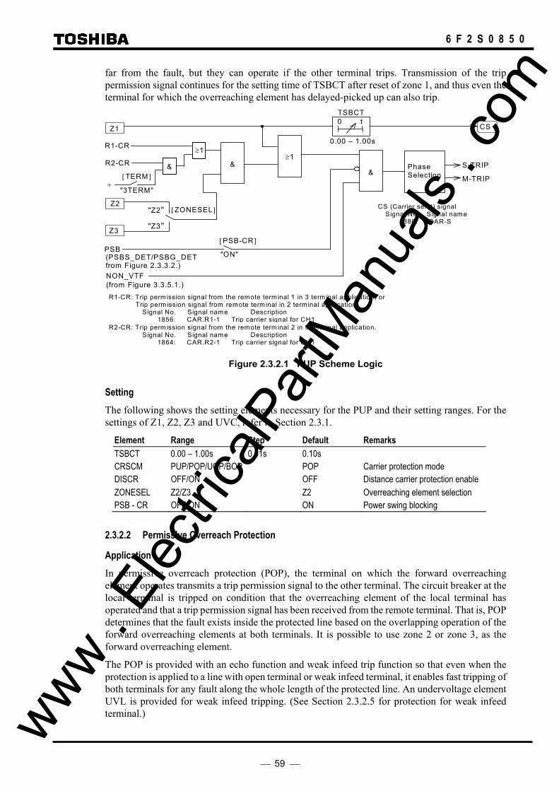
59
6 F 2 S 0 8 5 0
far from the fault, but they can operate if the other terminal trips. Transmission of the trip permission signal continues for the setting time of TSBCT after reset of zone 1, and thus even the terminal for which the overreaching element has delayed-picked up can also trip.
[ZONESEL]
NON_VTF
S-TRIP &
& ≥ 1
M-TRIP
Phase Selection
R1-CR
CS Z1
Z3
Z2
PSB " ON "
[PSB-CR]
"Z2"
"Z3"
R2-CR
≥1
[TERM]
"3TERM" +
&
R1-CR: Trip perm ission signal from the remote term inal 1 in 3 term inal application, or Trip perm ission signal from remote term inal in 2 term inal application.
Signal No. Signal name Description 1856: CAR.R1-1 Trip carrier signal for CH1
TSBCT
0.00 – 1.00s
0 t
CS (Carrier send) signal Signal No. Signal name
886: CAR-S
(PSBS_DET/PSBG_DET from Figure 2.3.3.2.)
(from Figure 3.3.5.1.)
R2-CR: Trip perm ission signal from the remote term inal 2 in 3 term inal application. Signal No. Signal name Description
1864: CAR.R2-1 Trip carrier signal for CH1
Figure 2.3.2.1 PUP Scheme Logic
Setting The following shows the setting elements necessary for the PUP and their setting ranges. For the settings of Z1, Z2, Z3 and UVC, refer to Section 2.3.1.
Element Range Step Default Remarks TSBCT 0.00 – 1.00s 0.01s 0.10s CRSCM PUP/POP/UOP/BOP POP Carrier protection mode DISCR OFF/ON OFF Distance carrier protection enable ZONESEL Z2/Z3 Z2 Overreaching element selection PSB - CR OFF/ON ON Power swing blocking
2.3.2.2 Permissive Overreach Protection
Application In permissive overreach protection (POP), the terminal on which the forward overreaching element operates transmits a trip permission signal to the other terminal. The circuit breaker at the local terminal is tripped on condition that the overreaching element of the local terminal has operated and that a trip permission signal has been received from the remote terminal. That is, POP determines that the fault exists inside the protected line based on the overlapping operation of the forward overreaching elements at both terminals. It is possible to use zone 2 or zone 3, as the forward overreaching element.
The POP is provided with an echo function and weak infeed trip function so that even when the protection is applied to a line with open terminal or weak infeed terminal, it enables fast tripping of both terminals for any fault along the whole length of the protected line. An undervoltage element UVL is provided for weak infeed tripping. (See Section 2.3.2.5 for protection for weak infeed terminal.) www .
Elec
tricalP
artM
anua
ls . c
om

60
6 F 2 S 0 8 5 0
When a sequential fault clearance occurs for a fault on a parallel line, the direction of the current on the healthy line is reversed. The status of the forward overreaching element changes from an operating to a reset state at the terminal where the current is reversed from an inward to an outward direction, and from a non-operating status to operating status at the other terminal. In this process, if the operating periods of the forward overreaching element of both terminals overlap, the healthy line may be tripped erroneously. To prevent this, current reversal logic (CRL) is provided. (See Section 2.3.2.6 for current reversal.)
Since the POP transmits a trip permission signal with the operation of the overreaching element, it requires multiplex signaling channels or one channel for each direction. This ensures that the transmitting terminal does not trip erroneously due to reception of its own transmit signal during an external fault in the overreaching zone.
Scheme Logic Figure 2.3.2.2 shows the scheme logic for the POP. The POP transmits a trip permission signal to the other terminal for any of the following conditions.
• The forward overreaching zone 2 or zone 3 selected by scheme switch [ZONESEL] operates and the current reversal logic (CRL) has not picked up.
• The circuit breaker is opened and a trip permission signal CR is received from the other terminal.
• The forward overreaching zone 2 or zone 3 and reverse looking Z4 have not operated and a trip permission signal is received from the other terminal.
The last two are implemented when an echo function (ECH) is selected. (Refer to Section 2.3.2.5 for echo function.)
Transmission of the trip permission signal continues for the TSBCT setting even after the local terminal is tripped by the delayed drop-off timer TSBCT. This is to ensure that command tripping is executed at the remote terminal.
The POP outputs single-phase tripping signal S-TRIP or three-phase tripping signal M-TRIP to the local terminal when the trip permission signal R1-CR and R2-CR are received from the remote terminals, the current reversal logic (CRL) is not picked up and one of the following conditions is established.
• The forward overreaching element operates.
• The undervoltage element UVL (UVLS or UVLG) operates and the forward overreaching and the reverse looking elements do not operate.
The latter is implemented when the weak infeed trip function is selected. (Refer to Section 2.3.2.5 for weak infeed trip function.)
To select the faulted phase reliably, phase selection is performed using the phase selection element UVC. Phase selection logic is described in Section 2.3.2.7.
www . El
ectric
alPar
tMan
uals
. com

61
6 F 2 S 0 8 5 0
≥ 1
&
≥ 1
≥ 1
&
&&
CB-OR
Z4
Z2
Z3
UVL
" ON"NON VTF
PSB
ECH
WIT
100ms
S-TRIPM-TRIP
20ms
CS
Phase Selection
t 0 0 t
&
CRL
[ZONESEL] "Z3"
"Z2"
[PSB-CR]
1
R1-CR
R2-CR
&
[TERM]
"2TERM" +
≥1
TREBK
≥ 1
&
≥ 1
TECCB
0.00 - 200.00s
t 0
TSBCT
0.00 – 1.00s
0 t
(∗) Note: Details of UVL Signal No. Signal name Description
622: UVLS-AB A-B phase623: UVLS-BC B-C phase624: UVLS-CA C-A phase628: UVLG-A A phase 629: UVLG-B B phase 630: UVLG-C C phase
(∗)
Figure 2.3.2.2 POP Scheme Logic
Setting The following shows the setting elements necessary for the POP and their setting ranges. For the settings of Z2, Z3 and UVC, refer to Section 2.3.1.
Element Range Step Default Remarks UVL Weak infeed trip element
UVLS 50 - 100 V 1V 77V Undervoltage detection (phase fault) UVLG 10 - 60 V 1V 45V Undervoltage detection (earth fault)
Z4S 0.01 - 50.00Ω 0.01Ω 8.00Ω Z4 reach (0.1 – 250.0Ω 0.1Ω 40.0Ω) (*) BRRS 0.10 - 20.00Ω 0.01Ω 5.10Ω Reverse right blinder reach (0.5 - 100.0Ω 0.1Ω 25.5Ω) Z4G 0.01 – 100.00Ω 0.01Ω 8.00Ω Z4 reach (0.1 – 500.0Ω 0.1Ω 40.0Ω) BRRG 0.10 - 20.00Ω 0.01Ω 5.10Ω Reverse right blinder reach (0.5 - 100.0Ω 0.1Ω 25.5Ω) TREBK 0.00 - 10.00s 0.01s 0.10s Current reversal block time TSBCT 0.00 – 1.00s 0.01s 0.10s CRSCM PUP/POP/UOP/BOP POP Carrier protection mode DISCR OFF/ON OFF Distance carrier protection enable ZONESEL Z2/Z3 Z2 Overreaching element selection PSB - CR OFF/ON ON Power swing blocking ECHO OFF/ON ON Echo function WKIT OFF/ON ON Weak infeed trip function
(*) Ohmic values shown in the parentheses are in the case of 1 A rating. Other ohmic values are in the case of 5 A rating. www .
Elec
tricalP
artM
anua
ls . c
om
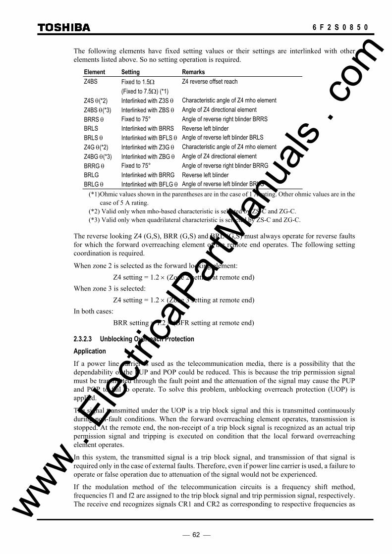
62
6 F 2 S 0 8 5 0
The following elements have fixed setting values or their settings are interlinked with other elements listed above. So no setting operation is required.
Element Setting Remarks Z4BS Fixed to 1.5Ω Z4 reverse offset reach (Fixed to 7.5Ω) (*1) Z4S θ(*2) Interlinked with Z3S θ Characteristic angle of Z4 mho element Z4BS θ(*3) Interlinked with ZBS θ Angle of Z4 directional element BRRS θ Fixed to 75° Angle of reverse right blinder BRRS BRLS Interlinked with BRRS Reverse left blinder BRLS θ Interlinked with BFLS θ Angle of reverse left blinder BRLS Z4G θ(*2) Interlinked with Z3G θ Characteristic angle of Z4 mho element Z4BG θ(*3) Interlinked with ZBG θ Angle of Z4 directional element BRRG θ Fixed to 75° Angle of reverse right blinder BRRG BRLG Interlinked with BRRG Reverse left blinder BRLG θ Interlinked with BFLG θ Angle of reverse left blinder BRLG
(*1) Ohmic values shown in the parentheses are in the case of 1 A rating. Other ohmic values are in the case of 5 A rating.
(*2) Valid only when mho-based characteristic is selected by ZS-C and ZG-C. (*3) Valid only when quadrilateral characteristic is selected by ZS-C and ZG-C.
The reverse looking Z4 (G,S), BRR (G,S) and BRL (G,S) must always operate for reverse faults for which the forward overreaching element of the remote end operates. The following setting coordination is required.
When zone 2 is selected as the forward looking element: Z4 setting = 1.2 × (Zone 2 setting at remote end) When zone 3 is selected: Z4 setting = 1.2 × (Zone 3 setting at remote end) In both cases: BRR setting = 1.2 × (BFR setting at remote end)
2.3.2.3 Unblocking Overreach Protection Application If a power line carrier is used as the telecommunication media, there is a possibility that the dependability of the PUP and POP could be reduced. This is because the trip permission signal must be transmitted through the fault point and the attenuation of the signal may cause the PUP and POP to fail to operate. To solve this problem, unblocking overreach protection (UOP) is applied.
The signal transmitted under the UOP is a trip block signal and this is transmitted continuously during non-fault conditions. When the forward overreaching element operates, transmission is stopped. At the remote end, the non-receipt of a trip block signal is recognized as an actual trip permission signal and tripping is executed on condition that the local forward overreaching element operates.
In this system, the transmitted signal is a trip block signal, and transmission of that signal is required only in the case of external faults. Therefore, even if power line carrier is used, a failure to operate or false operation due to attenuation of the signal would not be experienced.
If the modulation method of the telecommunication circuits is a frequency shift method, frequencies f1 and f2 are assigned to the trip block signal and trip permission signal, respectively. The receive end recognizes signals CR1 and CR2 as corresponding to respective frequencies as www .
Elec
tricalP
artM
anua
ls . c
om

63
6 F 2 S 0 8 5 0
the actual trip permission signals when either one of the following conditions is established and executes tripping on condition that the overreaching element should operate.
• CR1 is lost and only CR2 is received.
• Both CR1 and CR2 are lost.
The latter is also applicable if there is a telecommunication circuit failure in addition to attenuation of the signal at the fault point. Therefore, when the latter condition continues for a certain period or longer, the UOP is blocked and a telecommunication circuit failure alarm is output.
The UOP is provided with an echo function and weak infeed trip function and even when applied to a line with open terminals or weak infeed terminals, it allows fast tripping of both terminals for any fault along the whole length of the protected line. An undervoltage element UVL is provided for weak infeed tripping. (See Section 2.3.2.5 for protection for weak infeed terminal.)
When a sequential fault clearance occurs for a fault on a parallel line, the direction of the current on the healthy line is reversed. The status of the forward overreaching element changes from an operating to a reset state at the terminal where the current is reversed from an inward to an outward direction, and from a non-operating status to an operating status at the other terminal. In this process, if the operating periods of the forward overreaching element of both terminals overlap, the healthy line may be tripped erroneously. To prevent this, current reversal logic is provided. (See Section 2.3.2.6 for current reversal.)
For the communication channel, a single channel shared by different terminals or multiplex channels, one channel for each direction can be used.
Scheme Logic Figure 2.3.2.3 shows the scheme logic of the UOP. The logic level of transmit signal CS and receive signal R1-CR and R2-CR is "1" for a trip block signal and "0" for a trip permission signal.
The UOP changes its transmit signal CS from a trip block signal to trip permission signal under one of the following conditions. The logic level of CS changes from 1 to 0.
• The forward overreaching zone 2 or zone 3 selected by the scheme switch [ZONESEL] operates and the current reversal logic (CRL) is not picked up.
• The circuit breaker is open and the trip permission signal (R1-CR=0, R2-CR=0) is received from the other terminal.
• The forward overreaching zone 2 or zone 3 and reverse looking Z4 are not operating and a trip permission signal is received from the other terminal.
The last two are implemented when an echo function (ECH) is selected. (Refer to Section 2.3 2.5 for echo function.)
Transmission of a trip permission signal continues for the TSBCT setting even after the local terminal is tripped. This is to ensure that command tripping is executed at the remote terminal.
The UOP outputs single-phase tripping signal S-TRIP or three-phase tripping signal M-TRIP to the local terminal when the trip permission signal (R1-CR=0, R2-CR=0) is received from the remote terminal, the current reversal logic (CRL) is not picked up and one of the following conditions is established.
• The forward overreaching element operates.
• The undervoltage element UVL (UVLS or UVLG) operates and the forward overreaching and the reverse looking elements do not operate.
The latter is implemented when the weak infeed trip function is selected.
To select the faulted phase reliably, phase selection is performed using the phase selection element www . El
ectric
alPar
tMan
uals
. com
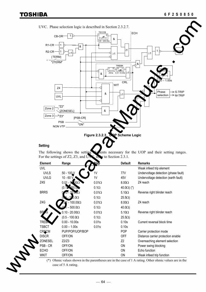
64
6 F 2 S 0 8 5 0
UVC. Phase selection logic is described in Section 2.3.2.7.
≥ 1
&
≥ 1
&
CB-OR
Z4
Zone 2
Zone 3
UVL
" ON " NON VTF
PSB
ECH
CRLWIT
0.01-10.00s
S-TRIPM-TRIP
20ms
CS
Phase selection
t 0 0 t
&
&
1
≥ 1
≥ 1 &
≥ 1
&
[PSB-CR]"Z3"
"Z2" [ZONESEL]
1
R1-CR
R2-CR
&
[TERM]
"2TERM"+
≥1 1
1
TREBK
TECCB
0.00 - 200.00s
t 0
TSBCT
0.00 – 1.00s
0 t
Figure 2.3.2.3 UOP Scheme Logic
Setting The following shows the setting elements necessary for the UOP and their setting ranges. For the settings of Z2, Z3, and UVC, refer to Section 2.3.1.
Element Range Step Default Remarks UVL Weak infeed trip element
UVLS 50 - 100 V 1V 77V Undervoltage detection (phase fault) UVLG 10 - 60 V 1V 45V Undervoltage detection (earth fault)
Z4S 0.01 - 50.00Ω 0.01Ω 8.00Ω Z4 reach (0.1 – 250.0Ω 0.1Ω 40.0Ω) (*) BRRS 0.10 - 20.00Ω 0.01Ω 5.10Ω Reverse right blinder reach (0.5 - 100.0Ω 0.1Ω 25.5Ω) Z4G 0.01 - 100.00Ω 0.01Ω 8.00Ω Z4 reach (0.1 – 500.0Ω 0.1Ω 40.0Ω) BRRG 0.10 - 20.00Ω 0.01Ω 5.10Ω Reverse right blinder reach (0.5 - 100.0Ω 0.1Ω 25.5Ω) TREBK 0.00 - 10.00s 0.01s 0.10s Current reversal block time TSBCT 0.00 – 1.00s 0.01s 0.10s CRSCM PUP/POP/UOP/BOP POP Carrier protection mode DISCR OFF/ON OFF Distance carrier protection enable ZONESEL Z2/Z3 Z2 Overreaching element selection PSB - CR OFF/ON ON Power swing blocking ECHO OFF/ON ON Echo function WKIT OFF/ON ON Weak infeed trip function
(*) Ohmic values shown in the parentheses are in the case of 1 A rating. Other ohmic values are in the case of 5 A rating. www .
Elec
tricalP
artM
anua
ls . c
om
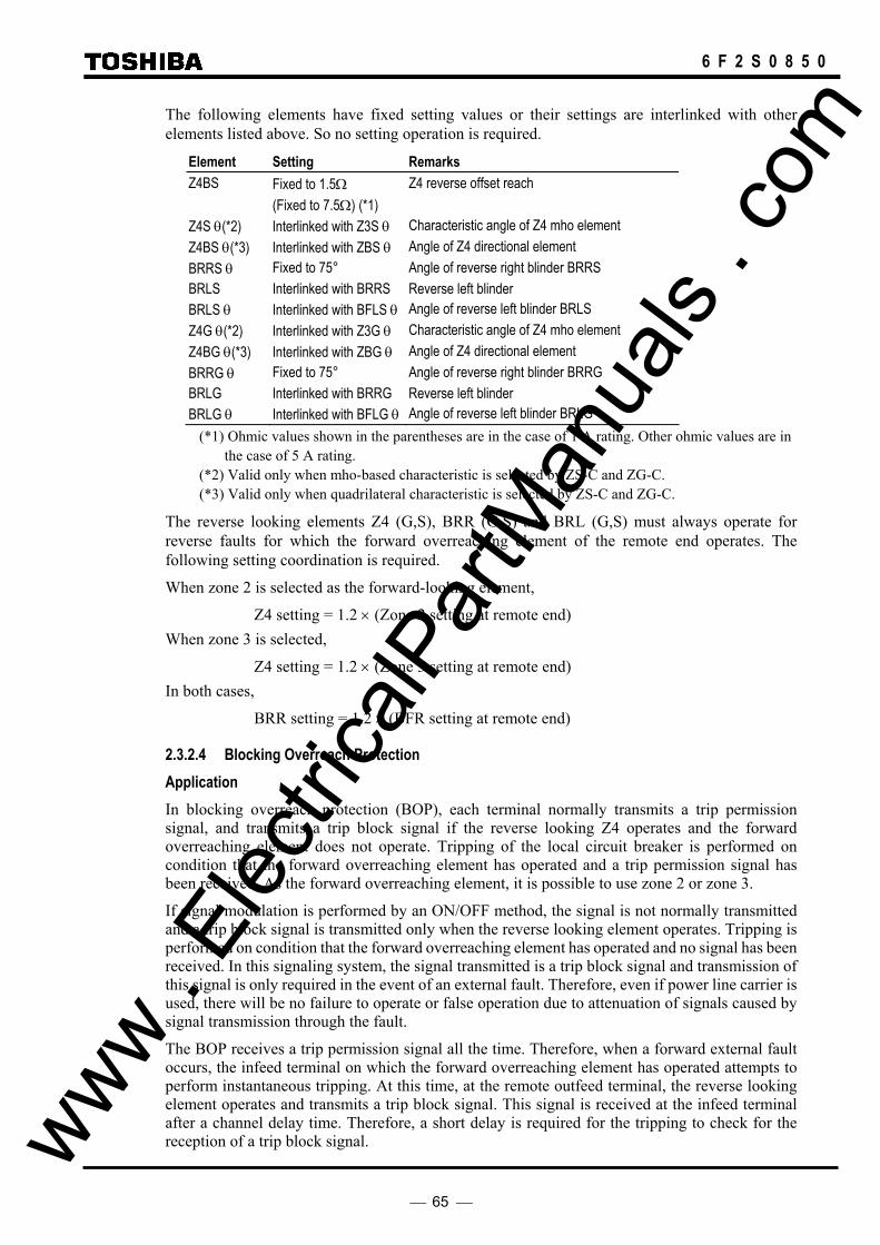
65
6 F 2 S 0 8 5 0
The following elements have fixed setting values or their settings are interlinked with other elements listed above. So no setting operation is required.
Element Setting Remarks Z4BS Fixed to 1.5Ω Z4 reverse offset reach (Fixed to 7.5Ω) (*1) Z4S θ(*2) Interlinked with Z3S θ Characteristic angle of Z4 mho element Z4BS θ(*3) Interlinked with ZBS θ Angle of Z4 directional element BRRS θ Fixed to 75° Angle of reverse right blinder BRRS BRLS Interlinked with BRRS Reverse left blinder BRLS θ Interlinked with BFLS θ Angle of reverse left blinder BRLS Z4G θ(*2) Interlinked with Z3G θ Characteristic angle of Z4 mho element Z4BG θ(*3) Interlinked with ZBG θ Angle of Z4 directional element BRRG θ Fixed to 75° Angle of reverse right blinder BRRG BRLG Interlinked with BRRG Reverse left blinder BRLG θ Interlinked with BFLG θ Angle of reverse left blinder BRLG
(*1) Ohmic values shown in the parentheses are in the case of 1 A rating. Other ohmic values are in the case of 5 A rating.
(*2) Valid only when mho-based characteristic is selected by ZS-C and ZG-C. (*3) Valid only when quadrilateral characteristic is selected by ZS-C and ZG-C.
The reverse looking elements Z4 (G,S), BRR (G,S) and BRL (G,S) must always operate for reverse faults for which the forward overreaching element of the remote end operates. The following setting coordination is required.
When zone 2 is selected as the forward-looking element,
Z4 setting = 1.2 × (Zone 2 setting at remote end) When zone 3 is selected,
Z4 setting = 1.2 × (Zone 3 setting at remote end) In both cases,
BRR setting = 1.2 × (BFR setting at remote end)
2.3.2.4 Blocking Overreach Protection Application In blocking overreach protection (BOP), each terminal normally transmits a trip permission signal, and transmits a trip block signal if the reverse looking Z4 operates and the forward overreaching element does not operate. Tripping of the local circuit breaker is performed on condition that the forward overreaching element has operated and a trip permission signal has been received. As the forward overreaching element, it is possible to use zone 2 or zone 3.
If signal modulation is performed by an ON/OFF method, the signal is not normally transmitted and a trip block signal is transmitted only when the reverse looking element operates. Tripping is performed on condition that the forward overreaching element has operated and no signal has been received. In this signaling system, the signal transmitted is a trip block signal and transmission of this signal is only required in the event of an external fault. Therefore, even if power line carrier is used, there will be no failure to operate or false operation due to attenuation of signals caused by signal transmission through the fault.
The BOP receives a trip permission signal all the time. Therefore, when a forward external fault occurs, the infeed terminal on which the forward overreaching element has operated attempts to perform instantaneous tripping. At this time, at the remote outfeed terminal, the reverse looking element operates and transmits a trip block signal. This signal is received at the infeed terminal after a channel delay time. Therefore, a short delay is required for the tripping to check for the reception of a trip block signal. www .
Elec
tricalP
artM
anua
ls . c
om
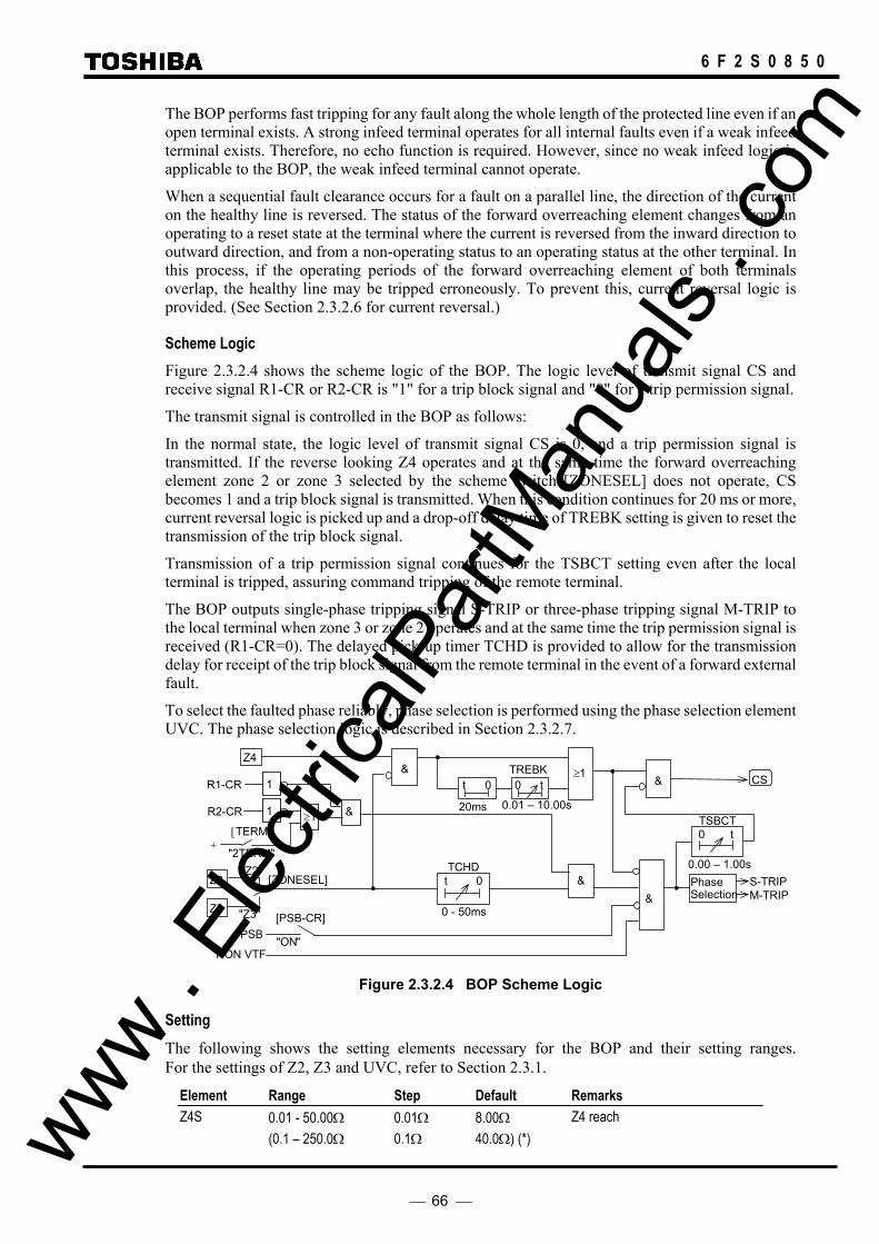
66
6 F 2 S 0 8 5 0
The BOP performs fast tripping for any fault along the whole length of the protected line even if an open terminal exists. A strong infeed terminal operates for all internal faults even if a weak infeed terminal exists. Therefore, no echo function is required. However, since no weak infeed logic is applicable to the BOP, the weak infeed terminal cannot operate.
When a sequential fault clearance occurs for a fault on a parallel line, the direction of the current on the healthy line is reversed. The status of the forward overreaching element changes from an operating to a reset state at the terminal where the current is reversed from the inward direction to outward direction, and from a non-operating status to an operating status at the other terminal. In this process, if the operating periods of the forward overreaching element of both terminals overlap, the healthy line may be tripped erroneously. To prevent this, current reversal logic is provided. (See Section 2.3.2.6 for current reversal.)
Scheme Logic Figure 2.3.2.4 shows the scheme logic of the BOP. The logic level of transmit signal CS and receive signal R1-CR or R2-CR is "1" for a trip block signal and "0" for a trip permission signal.
The transmit signal is controlled in the BOP as follows:
In the normal state, the logic level of transmit signal CS is 0, and a trip permission signal is transmitted. If the reverse looking Z4 operates and at the same time the forward overreaching element zone 2 or zone 3 selected by the scheme switch [ZONESEL] does not operate, CS becomes 1 and a trip block signal is transmitted. When this condition continues for 20 ms or more, current reversal logic is picked up and a drop-off delay time of TREBK setting is given to reset the transmission of the trip block signal.
Transmission of a trip permission signal continues for the TSBCT setting even after the local terminal is tripped, assuring command tripping of the remote terminal.
The BOP outputs single-phase tripping signal S-TRIP or three-phase tripping signal M-TRIP to the local terminal when zone 3 or zone 2 operates and at the same time the trip permission signal is received (R1-CR=0). The delayed pick-up timer TCHD is provided to allow for the transmission delay for receipt of the trip block signal from the remote terminal in the event of a forward external fault.
To select the faulted phase reliably, phase selection is performed using the phase selection element UVC. The phase selection logic is described in Section 2.3.2.7.
&
& ≥ 1 CS
Z4
20ms
t 0
0.01 – 10.00s
0 t
M-TRIPS-TRIPPhase
Selection&Z2
Z3
TCHD
0 - 50ms
t 0"Z2"
"Z3"
[ZONESEL]
[PSB-CR]
" ON " PSB
NON VTF
&R1-CR
R2-CR &
[TERM]
"2TERM" +
≥1 1
1 TREBK
TSBCT
0.00 – 1.00s
0 t
Figure 2.3.2.4 BOP Scheme Logic
Setting The following shows the setting elements necessary for the BOP and their setting ranges. For the settings of Z2, Z3 and UVC, refer to Section 2.3.1.
Element Range Step Default Remarks Z4S 0.01 - 50.00Ω 0.01Ω 8.00Ω Z4 reach (0.1 – 250.0Ω 0.1Ω 40.0Ω) (*) www .
Elec
tricalP
artM
anua
ls . c
om

67
6 F 2 S 0 8 5 0
BRRS 0.10 - 20.00Ω 0.01Ω 5.10Ω Reverse right blinder reach (0.5 - 100.0Ω 0.1Ω 25.5Ω) Z4G 0.01 - 100.00Ω 0.01Ω 8.00Ω Z4 reach (0.1 – 500.0Ω 0.1Ω 40.0Ω) BRRG 0.10 - 20.00Ω 0.01Ω 5.10Ω Reverse right blinder reach (0.5 - 100.0Ω 0.1Ω 25.5Ω) TCHD 0 - 50 ms 1 ms 12 ms Channel delay time TREBK 0.00 - 10.00s 0.01s 0.10s Current reversal block time TSBCT 0.00 – 1.00s 0.01s 0.10s CRSCM PUP/POP/UOP/BOP POP Carrier protection mode DISCR OFF/ON OFF Distance carrier protection enable ZONESEL Z2/Z3 Z2 Overreaching element selection PSB - CR OFF/ON ON Power swing blocking
(*) Ohmic values shown in the parentheses are in the case of 1 A rating. Other ohmic values are in the case of 5 A rating.
The following elements have fixed setting values or their settings are interlinked with other elements listed above. So no setting operation is required.
Element Setting Remarks Z4BS Fixed to 1.5Ω Z4 reverse offset reach (Fixed to 7.5Ω) (*1) Z4S θ(*2) Interlinked with Z3S θ Characteristic angle of Z4 mho element Z4BS θ(*3) Interlinked with ZBS θ Angle of Z4 directional element BRRS θ Fixed to 75° Angle of reverse right blinder BRRS BRLS Interlinked with BRRS Reverse left blinder BRLS θ Interlinked with BFLS θ Angle of reverse left blinder BRLS Z4G θ(*2) Interlinked with Z3G θ Characteristic angle of Z4 mho element Z4BG θ(*3) Interlinked with ZBG θ Angle of Z4 directional element BRRG θ Fixed to 75° Angle of reverse right blinder BRRG BRLG Interlinked with BRRG Reverse left blinder BRLG θ Interlinked with BFLG θ Angle of reverse left blinder BRLG
(*1)Ohmic values shown in the parentheses are in the case of 1 A rating. Other ohmic values are in the case of 5 A rating.
(*2) Valid only when mho-based characteristic is selected by ZS-C and ZG-C. (*3) Valid only when quadrilateral characteristic is selected by ZS-C and ZG-C.
The reverse looking elements Z4 (G,S), BRR (G,S) and BRL (G,S) must always operate for reverse faults for which the forward overreaching element of the remote end operates. The following setting coordination is required.
When zone 2 is selected as the forward-looking element, Z4 setting = 1.2 × (Zone 3 setting at remote end) or Z4 setting = α × (Zone 2 setting at remote end)
Note: α should be determined in consideration of the extension of zone 2 by zero-sequence compensation.
When zone 3 is selected, Z4 setting = 1.2 × (Zone 3 setting at remote end) In both cases, www .
Elec
tricalP
artM
anua
ls . c
om
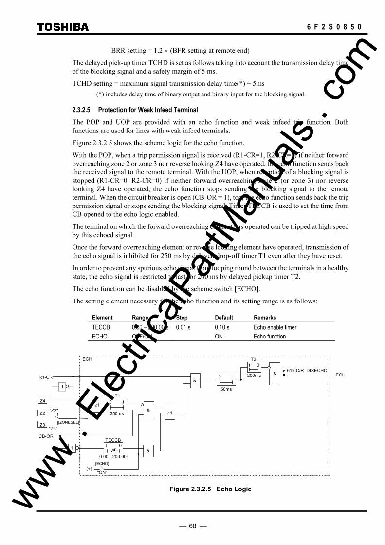
68
6 F 2 S 0 8 5 0
BRR setting = 1.2 × (BFR setting at remote end)
The delayed pick-up timer TCHD is set as follows taking into account the transmission delay time of the blocking signal and a safety margin of 5 ms.
TCHD setting = maximum signal transmission delay time(*) + 5ms (*) includes delay time of binary output and binary input for the blocking signal.
2.3.2.5 Protection for Weak Infeed Terminal The POP and UOP are provided with an echo function and weak infeed trip function. Both functions are used for lines with weak infeed terminals.
Figure 2.3.2.5 shows the scheme logic for the echo function.
With the POP, when a trip permission signal is received (R1-CR=1, R2-CR=1) if neither forward overreaching zone 2 or zone 3 nor reverse looking Z4 have operated, the echo function sends back the received signal to the remote terminal. With the UOP, when reception of a blocking signal is stopped (R1-CR=0, R2-CR=0) if neither forward overreaching zone 2 (or zone 3) nor reverse looking Z4 have operated, the echo function stops sending the blocking signal to the remote terminal. When the circuit breaker is open (CB-OR = 1), too, the echo function sends back the trip permission signal or stops sending the blocking signal. Timer TECCB is used to set the time from CB opened to the echo logic enabled.
The terminal on which the forward overreaching element has operated can be tripped at high speed by this echoed signal.
Once the forward overreaching element or reverse looking element have operated, transmission of the echo signal is inhibited for 250 ms by delayed drop-off timer T1 even after they have reset.
In order to prevent any spurious echo signal from looping round between the terminals in a healthy state, the echo signal is restricted to last for 200 ms by delayed pickup timer T2.
The echo function can be disabled by the scheme switch [ECHO].
The setting element necessary for the echo function and its setting range is as follows:
Element Range Step Default Remarks TECCB 0.00 – 200.00 s 0.01 s 0.10 s Echo enable timer ECHO OFF/ON ON Echo function
" ON "
&
&
& ≥ 1
200ms
50ms
(+)
t 0
Z3
Z2
Z4
T2
T1
250ms
0 t
0 t
ECH
[ZONESEL] "Z3"
"Z2"
ECH
[ECHO]
1
CB-OR
≥ 1
R1-CR
1 &
TECCB
0.00 - 200.00s
t 0
619:C/R_DISECHO
Figure 2.3.2.5 Echo Logic www . El
ectric
alPar
tMan
uals
. com

69
6 F 2 S 0 8 5 0
Figure 2.3.2.6 shows the scheme logic of the weak infeed trip function. Weak infeed tripping is executed on condition that a trip permission signal has been received (R1-CR=1, R2-CR=1) for the POP, and reception of a trip block signal has stopped (R1-CR=0, R2-CR=0) for the UOP, the undervoltage element UVL (UVLS or UVLG) operates and neither forward overreaching zone 2 or zone 3 nor reverse looking Z4 operates.
WIT &
WIT
[ZONESEL]
250ms
0 t
"Z3"
"Z2"
[WKIT]
"ON" (+)
Z4
Z3
Z2
UVL
R2-CR
1
[TERM]
"2TERM" (+)
≥1
R1-CR
1
≥ 1 &
CB-OR
876:DISWI_TRIP
Figure 2.3.2.6 Weak Infeed Trip Logic
The undervoltage element responds to three phase-to-phase voltages and three phase-to-ground voltages. The undervoltage element prevents false weak infeed tripping due to spurious operation of the channel.
Single-phase tripping or three-phase tripping is also applicable to weak infeed tripping according to the reclosing mode of the autoreclose function.
The weak infeed trip function can be disabled by the scheme switch [WKIT].
2.3.2.6 Measure for Current Reversal In response to faults on parallel lines, sequential opening of the circuit breaker may cause a fault current reversal on healthy lines. This phenomenon may cause false operation of the POP, UOP and BOP schemes in the worst case. To prevent this, the POP, UOP and BOP are provided with current reversal logic.
With the parallel line arrangement as shown in Figure 2.3.2.7 (a), suppose that a fault occurs at time t1 at point F of line L1, A1 trips at time t2 first and then B1 trips at time t3. The direction of the current that flows in healthy line L2 can be reversed at time t2. That is, the current flows from terminal B to terminal A as indicated by a solid line in the period from time t1 to t2, and from terminal A to terminal B as indicated by a broken line in the period from time t2 to t3. This current reversal phenomenon may occur with the presence of an external looped circuit if not for parallel lines.
Figure 2.3.2.7 (b) shows a sequence diagram of Z3 and Z4 and the current reversal logic CRL on healthy line L2 before and after the occurrence of a current reversal. When the current is reversed, Z3 operation and Z4 reset are seen at terminal A, while reset of Z3 and operation of Z4 are seen at terminal B. If at this time, Z3 of A2 operates before Z3 of B2 is reset, this may cause false operation of the POP, UOP and BOP on line L2. www .
Elec
tricalP
artM
anua
ls . c
om

70
6 F 2 S 0 8 5 0
Figure 2.3.2.7 Current Reversal Phenomenon
Figure 2.3.2.8 shows the current reversal logic. The current reversal logic is picked up on condition that reverse looking Z4 has operated and forward overreaching zone 2 or zone 3 have not operated, and the output CRL immediately controls the send signal to a trip block signal and at the same time blocks local tripping. If the condition above continues longer than 20ms, the output CRL will last for the TREBK setting even after the condition above ceases to exist.
≥1
TREBK
[ZONESEL]
CRL
Z2
Z3
Z4
&
0.01 – 10.00s
0 t
20ms
t 0
"Z3"
"Z2" 866:REV_BLK-A 867:REV_BLK-B 868:REV_BLK-C 869:REV_BLK-S 865:REV_BLK
Figure 2.3.2.8 Current Reversal Logic
The operation of the current reversal logic and its effect in the event of a fault shown in Figure 2.3.2.7 (a) are as follows. As shown in Figure 2.3.2.7 (b), the current reversal logic of terminal A2 operates (CRL = 1) immediately after the fault occurs. This operation lasts for TREBK setting even after the current is reversed and Z3 operates, continuously blocking the local tripping and transmitting a trip block signal to the terminal B2.
Even if overlap arises due to current reversal on the operation of Z3 at terminal A2 and terminal B2, it will disappear while the current reversal logic is operating, thus avoiding false tripping of the healthy line of parallel lines. When a current reversal occurs in the direction opposite to the above, the current reversal logic at terminal B2 will respond similarly.
Current reversal logic is not picked up for internal faults, thus not obstructing high-speed operation of any protection scheme.
A2 B2
B A
A1 B1F L1
L2
(a) Direction of fault current : Before A1 opened : After A1 opened
t1
CRL
Z4
Z3
A2
(b) Sequence diagram
t2 t3
TREBK setting
TREBK setting
CRL
Z4
Z3
B2
www . El
ectric
alPar
tMan
uals
. com
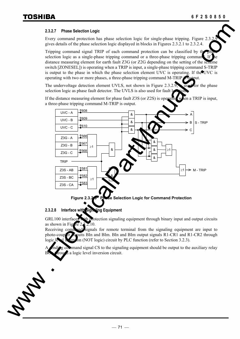
71
6 F 2 S 0 8 5 0
2.3.2.7 Phase Selection Logic Every command protection has phase selection logic for single-phase tripping. Figure 2.3.2.9 gives details of the phase selection logic displayed in blocks in Figures 2.3.2.1 to 2.3.2.4.
Tripping command signal TRIP of each command protection can be classified by the phase selection logic as a single-phase tripping command or a three-phase tripping command. If the distance measuring element for earth fault Z3G (or Z2G depending on the setting of the scheme switch [ZONESEL]) is operating when a TRIP is input, a single-phase tripping command S-TRIP is output to the phase in which the phase selection element UVC is operating. If the UVC is operating with two or more phases, a three-phase tripping command M-TRIP is output.
The undervoltage detection element UVLS, not shown in Figure 2.3.2.9, is used for the phase selection logic as phase fault detector. The UVLS is also used for fault location.
If the distance measuring element for phase fault Z3S (or Z2S) is operating when a TRIP is input, a three-phase tripping command M-TRIP is output.
≥1
& M - TRIP
≥1
Z3S - CA
Z3S - BC
Z3S - AB
≥1 &
S - TRIP
C
B
A
TRIP
≥1
Z3G - C
Z3G - B
Z3G - A
&
&
&
UVC - C
UVC - B
UVC - A &
&
&
608
609
610
566
567
568
581
582
583
Figure 2.3.2.9 Phase Selection Logic for Command Protection
2.3.2.8 Interface with Signaling Equipment
GRL100 interfaces with protection signaling equipment through binary input and output circuits as shown in Figure 2.3.2.10. Receiving command signals for remote terminal from the signaling equipment are input to photo-coupler circuits BIn and BIm. BIn and BIm output signals R1-CR1 and R1-CR2 through logic level inversion (NOT logic) circuit by PLC function (refer to Section 3.2.3).
A sending command signal CS to the signaling equipment should be output to the auxiliary relay BOn through a logic level inversion circuit.
www . El
ectric
alPar
tMan
uals
. com

72
6 F 2 S 0 8 5 0
Logic Level Inversion
Trip
Trip
BIn
BIm
(+)
(-)
R1-CR1
Logic Level Inversion
R1-CR2
Signal Receiving
Signaling Equipment
Signal Sending
BonLogic Level Inversion (*) CS Trip
BOnLogic Level Inversion (*) S-DEF Trip
(*): By PLC function.
Figure 2.3.2.10 Interface with Signaling Equipment
2.3.2.9 Signaling Channel When directional earth fault command protection (see Section 2.4.1) is used with POP, UOP or BOP scheme of distance protection and two channels are available, signal channel can be separated from distance protection by setting the scheme switch [CH-DEF] to “CH2”. In this case, signals CH1 and CH2 are used for distance protection and directional earth protection respectively. If the scheme switch [CH-DEF] is set to “CH1”, the signal CH1 is shared by the both protections.
When directional earth fault command protection is used with PUP scheme, signal channel is separated irrespective of [CH-DEF] setting.
Following table shows the scheme switch settings and usable signals:
Use of signal Scheme CH-DEF setting CH1 CH2
PUP CH1 PUP DEF CH2 PUP DEF POP CH1 POP and DEF (*) -- CH2 POP DEF UOP CH1 UOP and DEF (*) -- CH2 UOP DEF BOP CH1 BOP and DEF (*) -- CH2 BOP DEF
(*) CH1 is shared by the distance and directional earth fault command protections.
Setting Element Range Step Default Remarks CH-DEF CH1/CH2 CH1 Channel separation
www . El
ectric
alPar
tMan
uals
. com

73
6 F 2 S 0 8 5 0
2.3.3 Power Swing Blocking
When a power swing occurs on the power system, the impedance seen by the distance measuring element moves away from the load impedance area into the operating zone of the distance measuring element. The operation of the distance measuring element due to the power swing occurs in many points of interconnected power systems. Therefore, tripping due to the operation of the distance measuring element during a power swing is generally not allowed. The power swing blocking function (PSB) of the GRL100 detects the power swing and blocks tripping by the distance measuring element. The GRL100 provides PSBSZ and PSBGZ for phase fault measuring elements and earth fault measuring elements. Their functions and characteristics are same.
Once the PSB is in operation, tripping of zone 1 to zone 3 of the time-stepped distance protection, backup protection zone R for reverse faults and command protection using distance measuring elements can be blocked. These tripping blocks can be disabled by setting the scheme switches.
If a zero-phase current has been detected, the PSB is inhibited. This allows tripping in the event of an earth fault during a power swing or high resistance earth fault by which the resistance at the fault point changes gradually.
GRL100 can provide a high-speed protection for one- and two-phase faults which occur during a power swing by using negative sequence directional element and any of the command protection PUP, POP, UOP and BOP.
Three-phase faults during a power swing are eliminated by distance and overcurrent backup protection.
Scheme logic A power swing is detected by using two PSB elements PSBIN and PSBOUT. They are composed of blinder elements and reactance elements as shown in Figure 2.3.3.1. PSBOUT encloses PSBIN with a settable width of PSBZ.
Figure 2.3.3.2 shows the power swing detection logic. During a power swing, the impedance viewed from the PSB elements passes through the area between the PSBOUT and PSBIN in a certain time. In the event of a system fault, the impedance passes through this area instantaneously. Therefore, a power swing is detected in a time which commences on operation of the PSBOUT until PSBIN starts to operate, if longer than the set value of delayed pick-up timer TPSB. If the residual overcurrent element EFL operates, detection of the power swing is inhibited.
The trip block signal PSB generated as a result of the detection of a power swing is reset 500 ms after the PSBOUT is reset by delayed timer T2.
PSBZ
PSBZ PSBZ 0
PSBZ
PSBIN PSBOUT
R
X
Z3
Z4 ZR
Figure 2.3.3.1 Power Swing Blocking Element
www . El
ectric
alPar
tMan
uals
. com

74
6 F 2 S 0 8 5 0
PSBSZ and PSBGZ have same functions and characteristics as shown in Figures 2.3.3.1 and 2.3.3.2, and block tripping of phase and earth fault elements respectively.
& S Q F/F
R EFL
PSBSIN
PSBSOUT
PSBS_DET
TPSB
t 0
0.02 - 0.06s
&
T2
t 0
0.5s
596:PSBSIN-AB 597:PSBSIN-BC 598:PSBSIN-CA
593:PSBSOUT-AB 594:PSBSOUT-BC 595:PSBSOUT-CA
765
590:PSBGIN-A 591:PSBGIN-B 592:PSBGIN-C
587:PSBGOUT-A 588:PSBGOUT-B 589:PSNGOUT-C
& S Q F/F
R
PSBGIN
PSBGOUT
PSBG_DET
TPSB
t 0
0.02 - 0.06s
&
T2
t 0
0.5s
764
≥1 PSB_DET766
PSB_BLOCK 1877
PSB_F.RESET 1987
≥1
≥1
≥1
Figure 2.3.3.2 Power Swing Detection Logic
One- and two-phase faults can be protected with the command protection even during a power swing.
The PSB can be disabled or reset by the PLC signal PSB_BLOCK or PSB_F.RESET.
www . El
ectric
alPar
tMan
uals
. com

75
6 F 2 S 0 8 5 0
Setting The setting elements necessary for the PSB and their setting ranges are as shown in the table below.
Element Range Step Default Remarks PSBSZ 0.50 - 15.00Ω 0.01Ω 2.00Ω PSBS detection zone ( 2.5 - 75.0Ω 0.1Ω 10.0Ω) (*) PSBGZ 0.50 - 15.00Ω 0.01Ω 2.00Ω PSBG detection zone ( 2.5 - 75.0Ω 0.1Ω 10.0Ω) (*) EFL 0.5 - 5.0 A 0.1 A 1.0 A Residual overcurrent ( 0.10 - 1.00 A 0.01 A 0.20 A) TPSB 20 - 60 1 ms 40 ms Power swing timer PSB-Z1 OFF/ON ON Z1 blocked under power swing PSB-Z2 OFF/ON ON Z2 blocked under power swing PSB-Z3 OFF/ON OFF Z3 blocked under power swing PSB-CR OFF/ON ON Carrier trip blocked under power swing PSB-ZR OFF/ON OFF ZR blocked under power swing
(*) Values shown in the parentheses are in the case of 1A rating. Other values are in the case of 5A rating.
Residual overcurrent element EFL is used in common with the following functions.
• VT failure detection
• Earth fault distance protection
The PSBIN reach is set automatically to coordinate with the Z3 and Z4 settings.
Note: In the case of the quadrilateral characteristic, if the ZR reach is larger than the Z4, the PEB-IN reach depends on the ZR reach. Therefore, the ZR must be set less than the Z4 whether the ZR used or not.
The right side forward and reverse blinders for PSBIN are shared with the right side forward and reverse blinders of the distance protection characteristic, BFRS/BFRG and BRRS/BRRG respectively, ensuring that the PSB element coordinates properly with the protection, for both mho and quadrilateral characteristics.
The positive reactive reach setting is fixed so that the setting makes the reactance element tangential to the Z3 distance element when the Z3 is mho-based or takes the same value as the Z3 reactive reach setting when the Z3 is quadrilateral-based.
The negative resistive reach takes the same value as that of the positive reach. The negative reactive reach setting is fixed so that the setting makes the reactance element tangential to the Z4 distance element when the Z4 is mho-based or takes the same value as the Z4 reactive reach setting when the Z4 is quadrilateral-based.
PSBOUT encloses PSBIN and the margin between the two is determined by the user-settable power swing detection zone width, PSBSZ and PSBGZ, for phase and earth fault characteristics respectively.
www . El
ectric
alPar
tMan
uals
. com

76
6 F 2 S 0 8 5 0
2.4 Directional Earth Fault Protection
For a high-resistance earth fault for which the impedance measuring elements cannot operate, the GRL100 uses a directional earth fault element (DEF) to provide the following protections.
• Directional earth fault command protection
• Directional inverse or definite time earth fault backup protection
Figure 2.4.1 shows the scheme logic for the directional earth fault protection. The two kinds of protection above can be enabled or disabled by the scheme switches [DEFCR], [CRSCM], [DEFFEN] and [DEFREN]. The DEF command protection or DEF backup protection can be blocked by the binary input signal (PLC signal) DEF∗_BLOCK or DEFCRT_BLOCK.
NON VTF
CommandProtection
&CB-DISCR
& M-TRIP
DEFR
DEFF
&
& ≥1
[DEFFEN] TDEF t 0
0.00 - 10.00s"ON"
[SCHEME]
S-TRIP(from Figure 3.2.1.2.)
611
612 ≥1
[DEFREN] TDER t 0
0.00 - 10.00s"ON"
[DEFCR] "ON"
+
& DEFF_INST_TP 1945
& DEFR_INST_TP 1947
"
[EFIBT]
NOD "
" R "
F "
EFI &72
EFI_BLOCK 1592
&
&"
≥1
BU TRIP (M-TRIP)
810811 18
≥ 1
DEFF_TRIP
DEFR_TRIP
117EFI_TRIP
DEFF_BLOCK 1897
DEFR_BLOCK 1899
&
DEFCRT_BLOCK1875
Figure 2.4.1 Directional Earth Fault Protection
The directional earth fault command protection provides the POP, UOP and BOP schemes using forward looking DEFF and reverse looking DEFR elements. All schemes execute three-phase tripping and autoreclose.
The command protection is disabled during a single-phase autoreclosing period (CB-DISCR=1).
The directional earth fault protection as backup protection is described in Section 2.4.2.
The directional earth fault element DEF provides selective protection against a high-resistance earth fault. The direction of earth fault is determined by the lagging angle (θ) of the residual current (3l0) with respect to the residual voltage (−3V0). The residual voltage and residual current are derived from the vector summation of the three-phase voltages and three-phase currents inside the relay.
The phase angle θ in the event of an internal fault is equal to the angle of the zero-sequence impedance of the system and in the directly-earthed system this value ranges approximately from 50° to 90°. θ of the DEF can be set from 0° to 90°. The minimum voltage necessary to maintain directionality can be set from 1.7 to 21.0 V.
www . El
ectric
alPar
tMan
uals
. com

77
6 F 2 S 0 8 5 0
2.4.1 Directional Earth Fault Command Protection
High-speed directional earth fault command protection is provided using the forward looking directional earth fault element DEFF and reverse looking directional earth fault element DEFR. The signaling channel of DEF command protection can be shared with or separated from distance protection by the scheme switch [CH-DEF].
Figure 2.4.1.1 shows the scheme logic for the DEF command protection.
The DEF command protections are applied in combination with the distance command protection POP, UOP, BOP and PUP and enabled when the scheme switch [CRSCM] is set to "POP", "UOP", "BOP" or "PUP". These protections are called as the DEF POP, DEF UOP, DEF BOP and DEF PUP hereafter. The POP, UOP or BOP schemes can be selected as a common scheme. However, in the DEF PUP, distance protection takes the PUP scheme but DEF command protection takes the POP scheme and signaling channels of distance and DEF command protections are always separated (CH1: distance, CH2: DEF, see Section 2.3.2.9.).
The DEF command protection can select fast tripping or delayed tripping by a timer setting. Delayed tripping is used when it is desired to give priority to distance protection.
The DEF command protection is blocked during a single-phase autoreclose period by the distance protection (CB-DISCR=1). The signal CB-DISCR is generated with the binary input signals (PLC signals) of circuit breaker auxiliary contact (refer to Section 3.2.1).
The DEF command protection provides the phase selection logic for single-phase tripping. The details are shown in Figure 2.4.1.2. The current change detection element separated (OCD1) is used as the phase selection element. In addition, it is possible to input the output of external phase selection relay in PLC input DEF_PHSEL-A, DEF_PHSEL-B and DEF_PHSEL-C.
"POP""UOP""BOP""PUP"
DEFFCR
DEFR
DEFF
NON VTF
&
CB-DISCR
TDEFC t 0
0 – 300ms [CRSCM]
&
TDERC t 0
0 – 300ms
DEFRCR776
775
Phase selection Logic for DEF
DEFRY
Figure 2.4.1.1 DEF Command Protection
≥1
DEFFCR-A
OCD1 - C
OCD1 - B
OCD1 - A
DEFF
≥1
≥1
≥1
S R S R S R
1
1
&
&
& DEFFCR-B
DEFFCR-C
605
606
607
DEF_PHSEL-A 1988
DEF_PHSEL-B 1989
DEF_PHSEL-C 1990
≥1
≥1
≥1
Figure 2.4.1.2 Phase Selection Logic for DEFF www . El
ectric
alPar
tMan
uals
. com
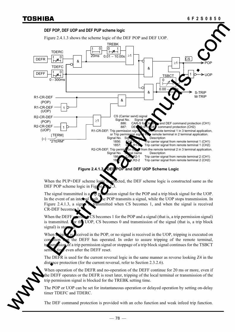
78
6 F 2 S 0 8 5 0
DEF POP, DEF UOP and DEF PUP scheme logic Figure 2.4.1.3 shows the scheme logic of the DEF POP and DEF UOP.
[TERM]
"2TERM" (+)
(UOP)
(POP) 1
R2-CR-DEF
R2-CR-DEF ≥1
(UOP)
&
≥120ms
t 0
UOP
POP
TDERC
0 - 300ms
S-TRIP M-TRIP
&
1
≥1 t 0
t 0
R1-CR-DEF
R1-CR-DEF
CS
DEFF
DEFR
1
TDEFC
(POP)
&
&
TREBK
0.01 – 10.00s
0 t
TSBCT
0.00 – 1.00s
0 t
R1-CR-DEF: Trip permission signal from the remote terminal 1 in 3 terminal application,or Trip permission signal from remote terminal in 2 terminal application.
Signal No. Signal name Description 1856: CAR.R1-1 Trip carrier signal from remote terminal 1 (CH1)1857: CAR.R1-2 Trip carrier signal from remote terminal 1 (CH2)
R2-CR-DEF: Trip permission signal from the remote terminal 2 in 3 terminal application. Signal No. Signal name Description
1864: CAR.R2-1 Trip carrier signal from remote terminal 2 (CH1)1865: CAR.R2-2 Trip carrier signal from remote terminal 2 (CH2)
CS (Carrier send) signal Signal No. Signal name
886: CAR-S for Distance and DEF command protection (CH1)887: DECAR-S for DEF command protection (CH2)
Figure 2.4.1.3 DEF POP and DEF UOP Scheme Logic
When the PUP+DEF scheme logic is selected, the DEF scheme logic is constructed same as the DEF POP scheme logic in Figure 2.4.1.3.
The signal transmitted is a trip permission signal for the POP and a trip block signal for the UOP. In the event of an internal fault, the POP transmits a signal, while the UOP stops transmission. In Figure 2.4.1.3, a signal is transmitted when CS becomes 1, and when the signal is received CR-DEF becomes 1.
When the DEFF operates, CS becomes 1 for the POP and a signal (that is, a trip permission signal) is transmitted. For the UOP, CS becomes 0 and transmission of the signal (that is, a trip block signal) is stopped.
When a signal is received in the POP, or no signal is received in the UOP, tripping is executed on condition that the DEFF has operated. In order to assure tripping of the remote terminal, transmission of a trip permission signal or stoppage of a trip block signal continues for the TSBCT setting time even after the DEFF reset.
The DEFR is used for the current reversal logic in the same manner as reverse looking Z4 in the distance protection (for the current reversal, refer to Section 2.3.2.6).
When operation of the DEFR and no-operation of the DEFF continue for 20 ms or more, even if the DEFF operates or the DEFR is reset later, tripping of the local terminal or transmission of the trip permission signal is blocked for the TREBK setting time.
The POP or UOP can be set for instantaneous operation or delayed operation by setting on-delay timer TDEFC and TDERC.
The DEF command protection is provided with an echo function and weak infeed trip function. www . El
ectric
alPar
tMan
uals
. com

79
6 F 2 S 0 8 5 0
Both functions are used for lines with weak infeed terminals.
The echo function allows fast tripping of the terminal on which the DEFF has operated when applied to a line with an open terminal or a weak infeed earth fault current terminal. The scheme logic is shown in Figure 2.4.1.4.
With the POP, when a trip permission signal is received (R1-CR-DEF = 1, R2-CR-DEF = 1) if neither the forward looking DEFF nor the reverse looking DEFR operates, the echo function sends back the received signal to the remote terminal. With the UOP, when reception of a blocking signal is stopped (R1-CR-DEF = 0, R2-CR-DEF = 0), if the DEFF and DEFR do not operate, the echo function stops transmission of the blocking signal likewise. When the circuit breaker is open, the echo function also sends back the trip permission signal or stops transmission of the blocking signal.
Once the DEFF or the DEFR operates, transmission of the echo signal is inhibited for 250 ms by delayed drop-off timer T1 even after they are reset.
In order to prevent any spurious echo signal from looping round between terminals in a healthy state, the echo signal is restricted to last 200 ms by delayed pick-up timer T2.
The echo function can be disabled by the scheme switch [ECHO].
When a signaling channel is shared by the distance protection and DEF protection, it is necessary to unite the scheme logic of both echo functions so that the echo function may not be picked up in the event of an external fault. The echo function at this time is blocked by Z2 (or Z3) and Z4 indicated by a dotted line in Figure 2.4.1.4.
"ON"
&
&
≥ 1
200ms
(+)
t 0T2
T1
250ms
0 t
50ms
0 t
[ECHO]
1CB-OR
≥ 1R1-CR-DEF
&
TECCB
0.00 - 200.00s
t 0
DEFFCR DEFRY
CS
CS (Carrier send) signal Signal No. Signal name
886: CAR-S for Distance and DEF command protection (CH1) 887: DECAR-S for DEF command protection (CH2)
&
&
ECHO1_DEF-1
≥ 1
&
&
200ms
t 0T2
50ms
0 t≥ 1R2-CR-DEF
&&
ECHO1_DEF-2
R1-CR-DEF: Trip permission signal from the remote terminal 1 in 3 terminal application,or Trip permission signal from remote terminal in 2 terminal application.
Signal No. Signal name Description 1856: CAR.R1-1 Trip carrier signal from remote terminal 1 (CH1) 1857: CAR.R1-2 Trip carrier signal from remote terminal 1 (CH2)
R2-CR-DEF: Trip permission signal from the remote terminal 2 in 3 terminal application. Signal No. Signal name Description
1864: CAR.R2-1 Trip carrier signal from remote terminal 2 (CH1) 1865: CAR.R2-2 Trip carrier signal from remote terminal 2 (CH2)
Z3
Z2
Z4
[ZONESEL] "Z3"
"Z2"
Figure 2.4.1.4 Echo Function in DEF Scheme Logic
Figure 2.4.1.5 shows the scheme logic of the weak infeed trip function. Weak infeed tripping is executed on condition that a trip permission signal has been received (ECHO1_DEF-1=1 or ECHO1_DEF-2=1), the undervoltage element UVL (UVLS or UVLG) operates.
The undervoltage element responds to three phase-to-phase voltages and three phase-to-ground voltages. The undervoltage element prevents false weak infeed tripping due to spurious operation of the channel.
Single-phase tripping or three-phase tripping is also applicable to weak infeed tripping according to the reclosing mode of the autoreclose function. www .
Elec
tricalP
artM
anua
ls . c
om
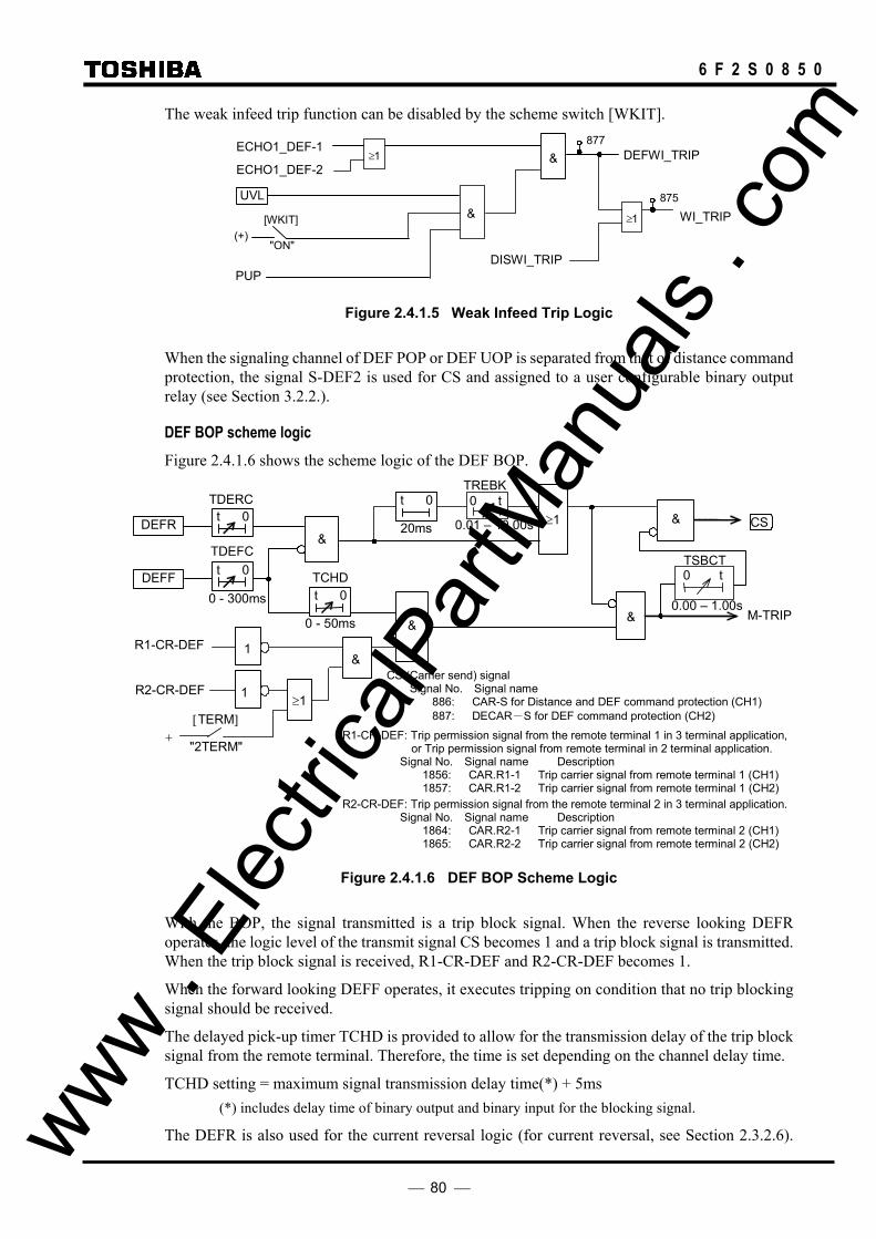
80
6 F 2 S 0 8 5 0
The weak infeed trip function can be disabled by the scheme switch [WKIT].
DEFWI_TRIP &
[WKIT]
"ON" (+)
UVL
ECHO1_DEF-1
&
PUP
877 ≥ 1
ECHO1_DEF-2
≥ 1
DISWI_TRIP
875
WI_TRIP
Figure 2.4.1.5 Weak Infeed Trip Logic
When the signaling channel of DEF POP or DEF UOP is separated from that of distance command protection, the signal S-DEF2 is used for CS and assigned to a user configurable binary output relay (see Section 3.2.2.).
DEF BOP scheme logic Figure 2.4.1.6 shows the scheme logic of the DEF BOP.
&
& ≥1
0 - 50ms
TDERC
TCHD 0 - 300ms
20ms
t 0
CS
DEFF
DEFR t 0
t 0
M-TRIP&
&
t 0
TDEFC
R1-CR-DEF
R2-CR-DEF
&
[TERM]
"2TERM" +
≥1 1
1
TSBCT
0.00 – 1.00s
0 t
0.01 – 10.00s
0 tTREBK
CS (Carrier send) signal Signal No. Signal name
886: CAR-S for Distance and DEF command protection (CH1) 887: DECAR-S for DEF command protection (CH2)
R1-CR-DEF: Trip permission signal from the remote terminal 1 in 3 terminal application,or Trip permission signal from remote terminal in 2 terminal application.
Signal No. Signal name Description 1856: CAR.R1-1 Trip carrier signal from remote terminal 1 (CH1) 1857: CAR.R1-2 Trip carrier signal from remote terminal 1 (CH2)
R2-CR-DEF: Trip permission signal from the remote terminal 2 in 3 terminal application. Signal No. Signal name Description
1864: CAR.R2-1 Trip carrier signal from remote terminal 2 (CH1) 1865: CAR.R2-2 Trip carrier signal from remote terminal 2 (CH2)
Figure 2.4.1.6 DEF BOP Scheme Logic
With the BOP, the signal transmitted is a trip block signal. When the reverse looking DEFR operates, the logic level of the transmit signal CS becomes 1 and a trip block signal is transmitted. When the trip block signal is received, R1-CR-DEF and R2-CR-DEF becomes 1.
When the forward looking DEFF operates, it executes tripping on condition that no trip blocking signal should be received.
The delayed pick-up timer TCHD is provided to allow for the transmission delay of the trip block signal from the remote terminal. Therefore, the time is set depending on the channel delay time.
TCHD setting = maximum signal transmission delay time(*) + 5ms (*) includes delay time of binary output and binary input for the blocking signal.
The DEFR is also used for the current reversal logic (for current reversal, see Section 2.3.2.6). www . El
ectric
alPar
tMan
uals
. com

81
6 F 2 S 0 8 5 0
When operation of the DEFR and non-operation of the DEFF last for 20 ms or more, even if the DEFF operates or the DEFR is reset later, tripping of the local terminal is blocked for the TREBK setting time and transmission of the trip block signal continues for the TSBCT setting time.
When the signaling channel of DEF BOP is separated from that of distance command protection, the signal S-DEFBOP2 is used for CS and assigned to a user configurable binary output relay (see Section 3.2.2.).
Setting The following setting is required for the DEF command protection:
Element Range Step Default Remarks DEFF Forward looking DEF
DEFFI 0.5 - 5.0 A 0.1 A 1.0 A Residual current (0.10 - 1.00 A 0.01 A 0.2 A) (*) DEFFV 1.7 – 21.0 V 0.1 V 2.0 V Residual voltage TDEFC 0.00 - 0.30 s 0.01 s 0.15 s DEF carrier trip delay timer
DEFR Reverse looking DEF DEFRI 0.5 - 5.0 A 0.1 A 1.0 A Residual current (0.10 - 1.00 A 0.01 A 0.20 A) DEFRV 1.7 – 21.0 V 0.1 V 2.0 V Residual voltage TDERC 0.00 - 0.30 s 0.01 s 0.15 s DEF carrier trip delay timer
DEF θ 0 - 90° 1° 85° Characteristic angle TCHD 0-50 ms 1 ms 12 ms Coordination timer TREBK 0.00 - 10.00s 0.01s 0.10s Current reversal blocking timer TSBCT 0.00 - 1.00s 0.01s 0.10s SBCNT timer TECCB 0.00 – 200.00s 0.01s 0.10 ECHO enable timer from CB opened CRSCM PUP/POP/UOP/ BOP POP Scheme selection DISCR OFF/ON OFF Distance carrier protection enable DEFCR OFF/ON OFF DEF carrier protection enable ZONESEL Z2/Z3 Z2 Carrier control element ECHO OFF/ON OFF ECHO carrier send WKIT OFF/ON OFF Weak infeed carrier trip CH-DEF CH1/CH2 CH1 DEF carrier channel setting
(*) Current values shown in the parentheses are in the case of 1 A rating. Other current values are in the case of 5 A rating.
When the DEFF at the remote end operates, the local DEFR must always operate for reverse faults. The setting levels of the residual current and residual voltage for the DEFR must be lower than that for the DEFF.
2.4.2 Directional Earth Fault Protection
The scheme logic is shown in Figure 2.4.1.
The directional inverse or definite time earth fault protection as backup protection executes three-phase final tripping. The forward looking DEFF or reverse looking DEFR can be selected. The directional inverse and definite time earth fault protections are available to trip instantaneously by binary input DEF∗_INST-TRIP except for [DEF∗EN]= “OFF” setting.
In order to give priority to the distance protection, the directional earth fault protection enables inverse time or definite time delayed tripping by the scheme switch [DEF∗EN].
www . El
ectric
alPar
tMan
uals
. com
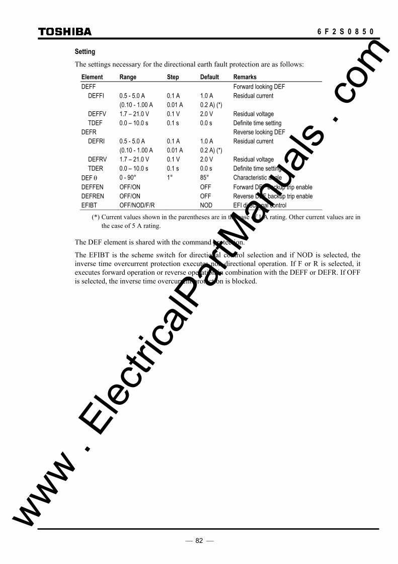
82
6 F 2 S 0 8 5 0
Setting The settings necessary for the directional earth fault protection are as follows:
Element Range Step Default Remarks DEFF Forward looking DEF
DEFFI 0.5 - 5.0 A 0.1 A 1.0 A Residual current (0.10 - 1.00 A 0.01 A 0.2 A) (*) DEFFV 1.7 – 21.0 V 0.1 V 2.0 V Residual voltage TDEF 0.0 – 10.0 s 0.1 s 0.0 s Definite time setting
DEFR Reverse looking DEF DEFRI 0.5 - 5.0 A 0.1 A 1.0 A Residual current (0.10 - 1.00 A 0.01 A 0.2 A) (*) DEFRV 1.7 – 21.0 V 0.1 V 2.0 V Residual voltage TDER 0.0 – 10.0 s 0.1 s 0.0 s Definite time setting
DEF θ 0 - 90° 1° 85° Characteristic angle DEFFEN OFF/ON OFF Forward DEF backup trip enable DEFREN OFF/ON OFF Reverse DEF backup trip enable EFIBT OFF/NOD/F/R NOD EFI directional control
(*) Current values shown in the parentheses are in the case of 1 A rating. Other current values are in the case of 5 A rating.
The DEF element is shared with the command protection.
The EFIBT is the scheme switch for directional control selection and if NOD is selected, the inverse time overcurrent protection executes non-directional operation. If F or R is selected, it executes forward operation or reverse operation in combination with the DEFF or DEFR. If OFF is selected, the inverse time overcurrent protection is blocked.
www . El
ectric
alPar
tMan
uals
. com
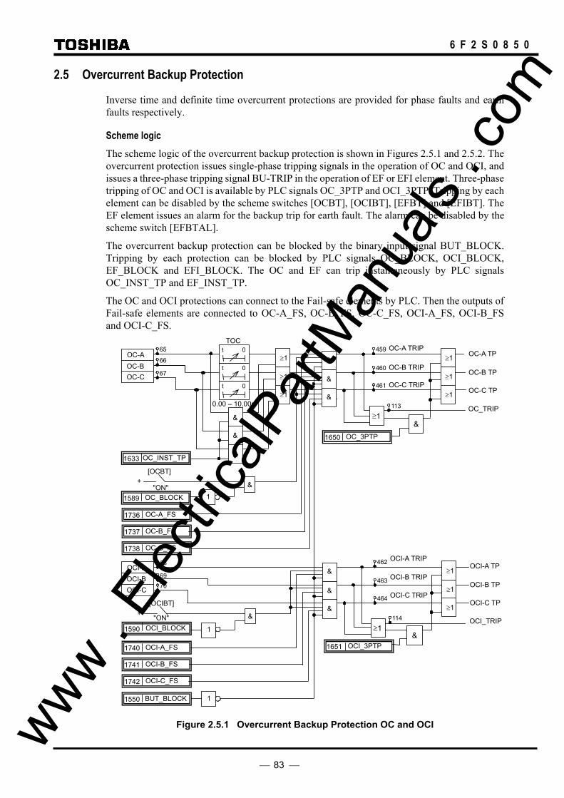
83
6 F 2 S 0 8 5 0
2.5 Overcurrent Backup Protection
Inverse time and definite time overcurrent protections are provided for phase faults and earth faults respectively.
Scheme logic The scheme logic of the overcurrent backup protection is shown in Figures 2.5.1 and 2.5.2. The overcurrent protection issues single-phase tripping signals in the operation of OC and OCI, and issues a three-phase tripping signal BU-TRIP in the operation of EF or EFI element. Three-phase tripping of OC and OCI is available by PLC signals OC_3PTP and OCI_3PTP. Tripping by each element can be disabled by the scheme switches [OCBT], [OCIBT], [EFBT] and [EFIBT]. The EF element issues an alarm for the backup trip for earth fault. The alarm can be disabled by the scheme switch [EFBTAL].
The overcurrent backup protection can be blocked by the binary input signal BUT_BLOCK. Tripping by each protection can be blocked by PLC signals OC_BLOCK, OCI_BLOCK, EF_BLOCK and EFI_BLOCK. The OC and EF can trip instantaneously by PLC signals OC_INST_TP and EF_INST_TP.
The OC and OCI protections can connect to the Fail-safe elements by PLC. Then the outputs of Fail-safe elements are connected to OC-A_FS, OC-B_FS, OC-C_FS, OCI-A_FS, OCI-B_FS and OCI-C_FS.
OC_INST_TP 1633
+
&
0.00 – 10.00s
TOC
OC-A
t 0
t 0
t 0
"ON"
[OCBT]
& 1 OC_BLOCK 1589
1 BUT_BLOCK 1550
65
66
67
&
&
&
≥ 1 113 OC_TRIP
OC-A TP
OC-B TP
OC-C TP
≥1
≥1
≥1
OC_3PTP 1650
461
460
459 OC-A TRIP
OC-B TRIP
OC-C TRIP
OC-B OC-C
[OCIBT]
&
"ON" + & OCI_BLOCK 1590 1
68
69 70
≥ 1 114 OCI_TRIP
OCI-A TP
OCI-B TP
OCI-C TP
1651 OCI_3PTP
464
463
462 OCI-A TRIP
OCI-B TRIP
OCI-C TRIP
OCI-A OCI-B OCI-C &
&
&
&
&
&
≥1
≥1
≥1
OCI-C_FS 1742
OCI-B_FS 1741
OCI-A_FS 1740
OC-C_FS 1738
OC-B_FS 1737
≥1
≥1
≥1
OC-A_FS 1736
Figure 2.5.1 Overcurrent Backup Protection OC and OCI www . El
ectric
alPar
tMan
uals
. com

84
6 F 2 S 0 8 5 0
"ON"
[EFBT] +
1 EF_BLOCK1591
& EFBT (Alarm) 116
"ON"
[EFBTAL] +
&
&
EFI_BLOCK1592 1
& "NOD", "F", "R"
[EFIBT] +
1 BUT_BLOCK1550
& EF TRIP 115
EFI 72 &
EFI TRIP 117
& EF_INST_TP1634
BU-TRIP 118 1 ≥ EF
TEF t 0
0.00 – 10.00s
71 1 ≥
Figure 2.5.2 Overcurrent Backup Protection EF and EFI
2.5.1 Inverse Time Overcurrent Protection
In a system in which the fault current is mostly determined by the fault location, without being greatly affected by changes in the power source impedance, it is advantageous to use the inverse definite minimum time (IDMT) overcurrent protection. Reasonably fast tripping should be obtained even at a terminal close to the power supply by using the inverse time characteristics. In the IDMT overcurrent protection function, one of the following three IEC-standard-compliant inverse time characteristics and one long time inverse characteristic is available.
• standard inverse IEC 60255-3 • very inverse IEC 60255-3 • extremely inverse IEC 60255-3
The IDMT element has a reset feature with definite time reset.
If the reset time is set to instantaneous, then no intentional delay is added. As soon as the energising current falls below the reset threshold, the element returns to its reset condition.
If the reset time is set to some value in seconds, then an intentional delay is added to the reset period. If the energising current exceeds the setting for a transient period without causing tripping, then resetting is delayed for a user-definable period. When the energising current falls below the reset threshold, the integral state (the point towards operation that it has travelled) of the timing function (IDMT) is held for that period.
This does not apply following a trip operation, in which case resetting is always instantaneous.
Setting The following table shows the setting elements necessary for the inverse time overcurrent protection and their setting ranges.
Element Range Step Default Remarks OCI 0.5 - 25.0 A 0.1 A 10.0 A ( 0.10 - 5.00 A 0.01 A 2.00 A) (*) TOCI 0.05 - 1.00 0.01 0.50 OCI time setting TOCIR 0.0 – 10.0 s 0.1 s 0.0 s OCI definite time reset delay [MOCI] Long/Std/Very/Ext Std OCI inverse characteristic selection [OCIBT] ON/OFF ON OCI backup protection www .
Elec
tricalP
artM
anua
ls . c
om

85
6 F 2 S 0 8 5 0
EFI 0.5 - 5.0 A 0.1 A 5.0 A Earth fault EFI setting ( 0.10 - 1.00 A 0.01 A 1.00 A) (*) TEFI 0.05 - 1.00 0.01 0.50 EFI time setting TEFIR 0.0 – 10.0 s 0.1 s 0.0 s EFI definite time reset delay [MEFI] Long/Std/Very/Ext Std EFI inverse characteristic selection [EFIBT] OFF/NOD/F/R NOD EFI backup protection
(*) Current values shown in the parentheses are in the case of 1 A rating. Other current values are in the case of 5 A rating.
The scheme switches [MOCI] and [MEFI] are used to select one of the four inverse time characteristics.
Current setting In Figure 2.5.1.1, the current setting at terminal A is set lower than the minimum fault current in the event of a fault at remote end F1. Furthermore, when considering also backup protection of a fault within the adjacent lines, it is set lower than the minimum fault current in the event of a fault at remote end F3. For grading of the current settings, the terminal furthest from the power source is set to the lowest value and the terminals closer to the power source are set to a higher value.
The minimum setting is restricted so as not to operate on false zero-sequence currents caused by an unbalance in the load current, errors in the current transformer circuits or zero-sequence mutual coupling of parallel lines.
Figure 2.5.1.1 Current Settings in Radial System
Time setting Time setting is performed to provide selectivity in relation with the relays on the adjacent lines. Suppose a minimum source impedance when the current flowing in the relay becomes the maximum. In Figure 2.5.1.1, in the event of a fault at near end F2 of the adjacent line, the operating time is set so that terminal A may operate by time grading Tc behind terminal B. The current flowing in the relays may sometimes be greater when the remote end of the adjacent line is open. At this time, time coordination must also be kept.
The reason why the operating time is set when the fault current reaches the maximum is that if time coordination is obtained for large fault current, then time coordination can also be obtained for small fault current as long as relays with the same operating characteristic are used for each terminal.
The grading margin Tc of terminal A and terminal B is given by the following expression for a fault at point F2 in Figure 2.5.1.1.
Tc = T1 + T2 + M where, T1: circuit breaker clearance time at B T2: relay reset time at A M: margin
When single-phase autoreclose is used, the minimum time of the earth fault overcurrent protection must be set longer than the time from fault occurrence to reclosing of the circuit breaker. This is to prevent three-phase final tripping from being executed by the overcurrent protection during a single-phase autoreclose cycle.
F3 F2 F1
C B A
www . El
ectric
alPar
tMan
uals
. com

86
6 F 2 S 0 8 5 0
2.5.2 Definite Time Overcurrent Protection
In a system in which fault current does not change greatly with the position of the fault, the advantages of the IDMT characteristics are not fully realised. In this case, the definite time overcurrent protection is applied. The operating time can be set irrespective of the magnitude of the fault current.
The definite time overcurrent protection consists of instantaneous overcurrent elements and on-delay timers started by them.
Identical current values can be set for terminals, but graded settings are better than identical settings in order to provide a margin for current sensitivity. The farther from the power source the terminal is located, the higher sensitivity (i.e. the lower setting) is required.
The operating time of the overcurrent element of each terminal is constant irrespective of the magnitude of the fault current and selective protection is implemented by graded settings of the on-delay timer. As a result, the circuit breaker of the terminal most remote from the power source is tripped in the shortest time.
When setting the on-delay timers, time grading margin Tc is obtained in the same way as explained in Section 2.5.1.
Setting The setting elements necessary for the definite time overcurrent protection and their setting ranges are shown below.
Element Range Step Default Remarks OC 0.5 - 100.0 A 0.1 A 10.0 A Phase overcurrent ( 0.1 - 20.0 A 0.1 A 2.0 A) (*) TOC 0.00 - 10.00 s 0.01 s 3.00 s OC delayed tripping OCBT ON/OFF ON OC backup protection EF 0.5 - 5.0 A 0.1 A 5.0 A Residual overcurrent ( 0.10 - 1.00 A 0.01 A 1.00 A) (*) TEF 0.00 - 10.00 s 0.01 s 3.00 s EF delayed tripping [EFBT] ON/OFF ON EF backup protection [EFBTAL] ON/OFF ON EF backup trip alarm
(*) Current values shown in the parentheses are in the case of 1 A rating. Other current values are in the case of 5 A rating.
www . El
ectric
alPar
tMan
uals
. com

87
6 F 2 S 0 8 5 0
2.6 Transfer Trip Function
The GRL100 provides the transfer trip function which receives a trip signal from the remote terminal and outputs a trip command. Two transfer trip commands are provided. The scheme logic is shown in Figure 2.6.1. When the scheme switch [TTSW∗] is set to “TRIP”, the binary output for tripping is driven. When set to “BO”, the binary output for tripping is not driven and only user-configurable binary output is driven.
The sending signal is configured by PLC function. If the sending signal is assigned on a per phase basis by PLC, a single-phase tripping is available.
TR1-A TP419
& 418
423
420
421
≥1
≥1
≥1
TR1-A-R1 1688
TR1-B-R1 1689
TR1-C-R1 1690
425
424
≥1
1 TR1_BLOCK 1595
TR1-A-R2 1720
TR1-B-R2 1721
TR1-C-R2 1722
&
&
&
"BO" [TTSW1]
+
"TRIP
&
&
&
TR1_3PTP 1660
422 ≥1
≥1
≥1
≥1
TR1-B TP
TR1-C TP
TR1 TRIP
INTER TRIP1-A
INTER TRIP1-B
INTER TRIP1-C
INTER TRIP1
From Remote Terminal 1
From Remote Terminal 2
Transfer Trip Command 1
TR2-A TP427
& 426
431
428
429
≥1
≥1
≥1
TR2-A-R1 1692
TR2-B-R1 1693
TR2-C-R1 1694
433
432
≥1
1 TR2_BLOCK 1596
TR2-A-R2 1724
TR2-B-R2 1725
TR2-C-R2 1726
&
&
&
"BO" [TTSW2]
+
"TRIP
&
&
&
TR2_3PTP 1661
430 ≥1
≥1
≥1
≥1
TR2-B TP
TR2-C TP
TR2 TRIP
INTER TRIP2-A
INTER TRIP2-B
INTER TRIP2-C
INTER TRIP2
From Remote Terminal 1
From Remote Terminal 2
Transfer Trip Command 2
Figure 2.6.1 Transfer Trip Scheme Logic
www . El
ectric
alPar
tMan
uals
. com

88
6 F 2 S 0 8 5 0
2.7 Out-of-step Protection
The GRL100 out-of-step protection (OST) operates only when the out-of-step loci cross the protected line and provides optimal power system separation in case of power system step out.
The OST compares the phase of the local and remote positive sequence voltages and detects the out-of-step when the difference in the phase angle exceeds 180°. The OST can detect any of the out-of-steps with slow or fast slip cycles.
Figure 2.7.1 show the loci of the voltage vectors measured at terminals A and B when an out-of-step occurs on the power system. P and Q are equivalent power source locations. Loci 1 and 2 are the cases when the locus crosses the protected line, and passes outside the protected line, respectively.
(a) Internal
×
X Q
B VB1
Locus 1
R A
P
VB3VB2
1θ3
2×VA2
VA1VA3
×
(b) External
×
X
B
Q
VB1'
Locus 2
R A
P
VB3'VB2'
1'
θ
3'2'×
VA2' VA1'VA3'
×
Figure 2.7.1 Out-of-step Loci
Voltage phase angle differs by θ between terminals A and B. In case of Locus 1, θ gets larger as the voltage locus approaches the protected line and becomes 180° when the locus crosses the line. In case of Locus 2, θ becomes 0° when the locus crosses the power system impedance outside the protected line. www .
Elec
tricalP
artM
anua
ls . c
om
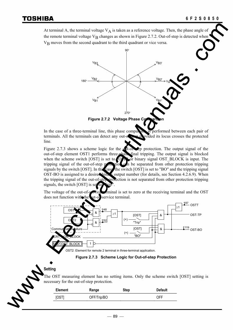
89
6 F 2 S 0 8 5 0
At terminal A, the terminal voltage VA is taken as a reference voltage. Then, the phase angle of the remote terminal voltage VB changes as shown in Figure 2.7.2. Out-of-step is detected when VB moves from the second quadrant to the third quadrant or vice versa.
90°
180°
270°
VB1'VB1
VA
VB3' VB3
VB2'VB2
Figure 2.7.2 Voltage Phase Comparison
In the case of a three-terminal line, this phase comparison is performed between each pair of terminals. All the terminals can detect any out-of-step provided its locus crosses the protected line.
Figure 2.7.3 shows a scheme logic for the out-of-step protection. The output signal of the out-of-step element OST1 performs three-phase final tripping. The output signal is blocked when the scheme switch [OST] is set to "OFF" or binary signal OST_BLOCK is input. The tripping signal of the out-of-step protection can be separated from other protection tripping signals by the switch [OST]. In this case, the switch [OST] is set to "BO" and the tripping signal OST-BO is assigned to a desired binary output number (for details, see Section 4.2.6.9). When the tripping signal of the out-of-step protection is not separated from other protection tripping signals, the switch [OST] is set to "Trip".
The voltage of the out-of-service terminal is set to zero at the receiving terminal and the OST does not function with the out-of-service terminal.
OST1
&OST-TP
[OST]
"BO"(+)
&
&
[OST]
"Trip"(+)
OST-BOCommunication failure
1 OST_BLOCK 1587
52 OST2 &
≥148
≥1 OSTT
87
119
OST2: Element for remote 2 terminal in three-terminal application.
CRT_NON_BLOCK
Figure 2.7.3 Scheme Logic for Out-of-step Protection
Setting The OST measuring element has no setting items. Only the scheme switch [OST] setting is necessary for the out-of-step protection.
Element Range Step Default
[OST] OFF/Trip/BO OFF www . El
ectric
alPar
tMan
uals
. com
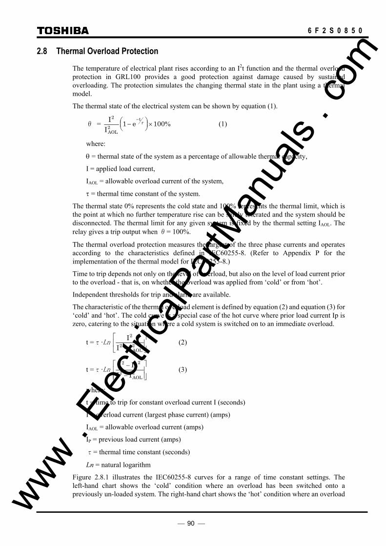
90
6 F 2 S 0 8 5 0
2.8 Thermal Overload Protection
The temperature of electrical plant rises according to an I2t function and the thermal overload protection in GRL100 provides a good protection against damage caused by sustained overloading. The protection simulates the changing thermal state in the plant using a thermal model.
The thermal state of the electrical system can be shown by equation (1).
θ = II
eAOL
t2
2 1 100−
×−
τ % (1)
where:
θ = thermal state of the system as a percentage of allowable thermal capacity,
I = applied load current,
IAOL = allowable overload current of the system,
τ = thermal time constant of the system.
The thermal state 0% represents the cold state and 100% represents the thermal limit, which is the point at which no further temperature rise can be safely tolerated and the system should be disconnected. The thermal limit for any given system is fixed by the thermal setting IAOL. The relay gives a trip output when θ= 100%.
The thermal overload protection measures the largest of the three phase currents and operates according to the characteristics defined in IEC60255-8. (Refer to Appendix P for the implementation of the thermal model for IEC60255-8.)
Time to trip depends not only on the level of overload, but also on the level of load current prior to the overload - that is, on whether the overload was applied from ‘cold’ or from ‘hot’.
Independent thresholds for trip and alarm are available.
The characteristic of the thermal overload element is defined by equation (2) and equation (3) for ‘cold’ and ‘hot’. The cold curve is a special case of the hot curve where prior load current Ip is zero, catering to the situation where a cold system is switched on to an immediate overload.
t =τ·Ln II IAOL
2
2 2−
(2)
t =τ·Ln I II I
P
AOL
2 2
2 2−
−
(3)
where:
t = time to trip for constant overload current I (seconds)
I = overload current (largest phase current) (amps)
IAOL = allowable overload current (amps)
IP = previous load current (amps)
τ= thermal time constant (seconds)
Ln = natural logarithm
Figure 2.8.1 illustrates the IEC60255-8 curves for a range of time constant settings. The left-hand chart shows the ‘cold’ condition where an overload has been switched onto a previously un-loaded system. The right-hand chart shows the ‘hot’ condition where an overload www .
Elec
tricalP
artM
anua
ls . c
om
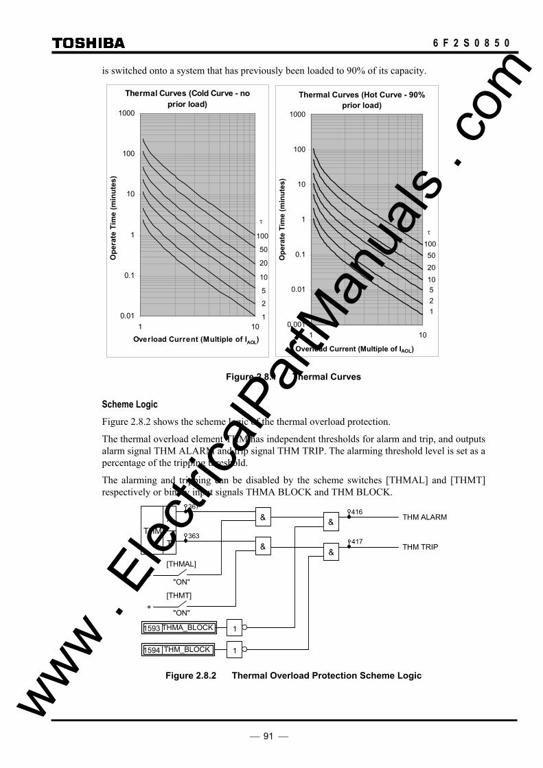
91
6 F 2 S 0 8 5 0
is switched onto a system that has previously been loaded to 90% of its capacity.
Thermal Curves (Cold Curve - noprior load)
0.01
0.1
1
10
100
1000
1 10
Overload Current (Multiple of IAOL)
Ope
rate
Tim
e (m
inut
es)
Thermal Curves (Hot Curve - 90%prior load)
0.001
0.01
0.1
1
10
100
1000
1 10
Overload Current (Multiple of IAOL)
Ope
rate
Tim
e (m
inut
es)
Figure 2.8.1 Thermal Curves
Scheme Logic Figure 2.8.2 shows the scheme logic of the thermal overload protection.
The thermal overload element THM has independent thresholds for alarm and trip, and outputs alarm signal THM ALARM and trip signal THM TRIP. The alarming threshold level is set as a percentage of the tripping threshold.
The alarming and tripping can be disabled by the scheme switches [THMAL] and [THMT] respectively or binary input signals THMA BLOCK and THM BLOCK.
T
A THM
& THM ALARM
+ "ON"
[THMAL]
+ "ON"
[THMT]
THM TRIP &
&
&
1THMA_BLOCK 1593
1THM_BLOCK 1594
367
363
416
417
Figure 2.8.2 Thermal Overload Protection Scheme Logic
τ
100
50
20
10
5
2
1
τ
100 50 20 10 5 2 1
www . El
ectric
alPar
tMan
uals
. com

92
6 F 2 S 0 8 5 0
Setting The table below shows the setting elements necessary for the thermal overload protection and their setting ranges.
Element Range Step Default Remarks
THM 2.0 – 10.0 A (0.40 – 2.00 A)(*)
0.1 A (0.01 A)
5.0 A (1.00 A)
Thermal overload setting. (THM = IAOL: allowable overload current)
THMIP 0.0 – 5.0 A (0.00 – 1.00 A)(*)
0.1 A (0.01 A)
0.0 A (0.00 A)
Previous load current
TTHM 0.5 - 300.0 min 0.1 min 10.0 min Thermal time constant
THMA 50 – 99 % 1 % 80 % Thermal alarm setting. (Percentage of THM setting.)
[THMT] Off / On Off Thermal OL enable
[THMAL] Off / On Off Thermal alarm enable (*) Current values shown in the parenthesis are in the case of a 1 A rating. Other current
values are in the case of a 5 A rating.
Note: THMIP sets a minimum level of previous load current to be used by the thermal element, and is typically used when testing the element. For the majority of applications, THMIP should be set to its default value of zero, in which case the previous load current, Ip, is calculated internally by the thermal model, providing memory of conditions occurring before an overload.
www . El
ectric
alPar
tMan
uals
. com

93
6 F 2 S 0 8 5 0
2.9 Overvoltage and Undervoltage Protection
2.9.1 Overvoltage Protection
GRL100 provides four independent undervoltage elements with programmable dropoff/pickup(DO/PU) ratio for phase-to-phase voltage input and phase voltage input. OVS1 and OVS2 are used for phase-to-phase voltage input, and OVG1 and OVG2 for phase voltage input. OVS1 and OVG1 are programmable for inverse time (IDMT) or definite time (DT) operation. OVS2 and OVG2 have definite time characteristic only.
OVS1 and OVG1 overvoltage protection elements have an IDMT characteristic defined by equation (1):
( )
−×=
1
1
VsV
TMSt (1)
where:
t = operating time for constant voltage V (seconds),
V = energising voltage (V),
Vs = overvoltage setting (V),
TMS = time multiplier setting.
The IDMT characteristic is illustrated in Figure 2.9.1.1.
The OVS2 and OVG2 elements are used for definite time overvoltage protection.
Definite time reset The definite time resetting characteristic is applied to the OVS1 and OVG1 elements when the inverse time delay is used.
If definite time resetting is selected, and the delay period is set to instantaneous, then no intentional delay is added. As soon as the energising voltage falls below the reset threshold, the element returns to its reset condition.
If the delay period is set to some value in seconds, then an intentional delay is added to the reset period. If the energising voltage exceeds the setting for a transient period without causing tripping, then resetting is delayed for a user-definable period. When the energising voltage falls below the reset threshold, the integral state (the point towards operation that it has travelled) of the timing function (IDMT) is held for that period.
This does not apply following a trip operation, in which case resetting is always instantaneous.
Overvoltage elements OVS1, OVS2, OVG1 and OVG2 have a programmable dropoff/pickup (DO/PU) ratio.
www . El
ectric
alPar
tMan
uals
. com
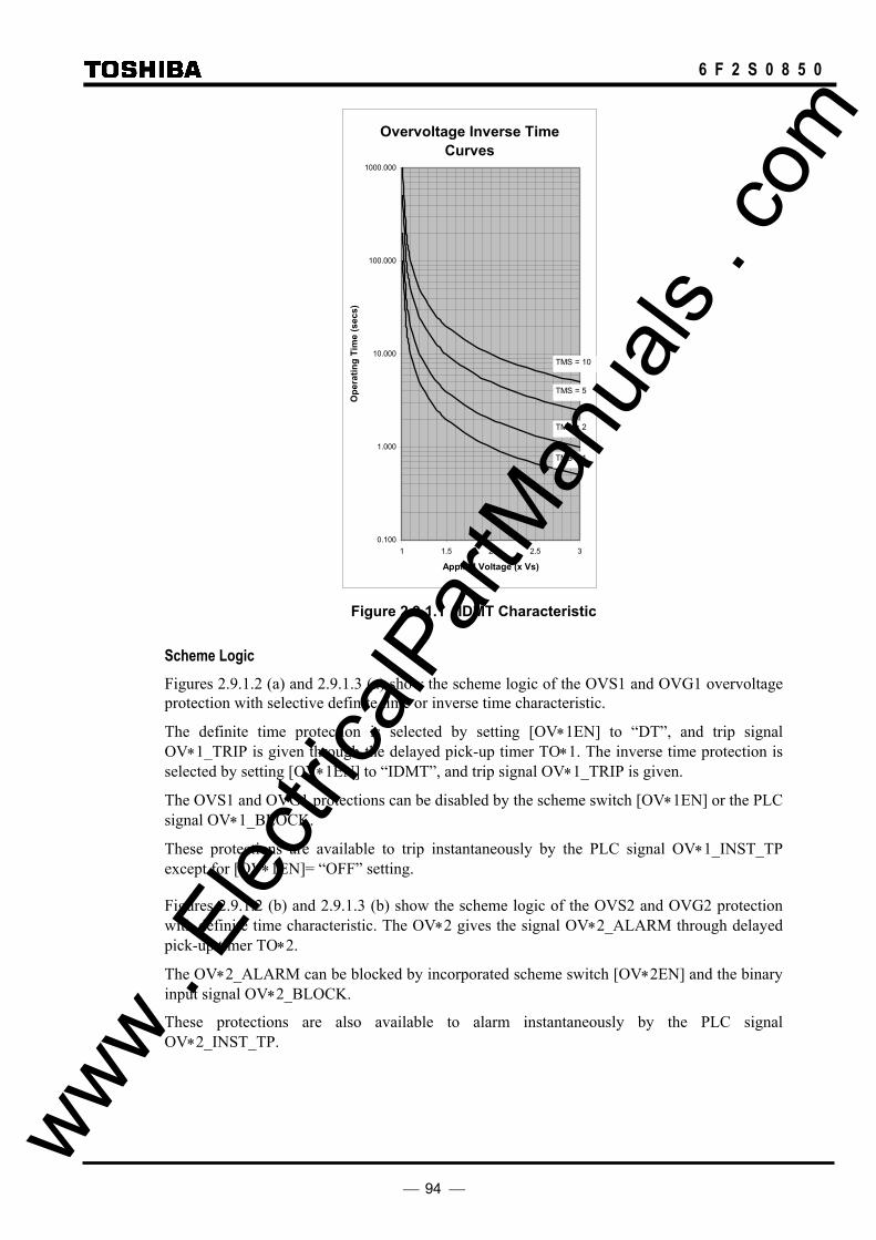
94
6 F 2 S 0 8 5 0
Overvoltage Inverse TimeCurves
0.100
1.000
10.000
100.000
1000.000
1 1.5 2 2.5 3
Applied Voltage (x Vs)
Ope
ratin
g Ti
me
(sec
s)
TMS = 1
TMS = 2
TMS = 5
TMS = 10
Figure 2.9.1.1 IDMT Characteristic
Scheme Logic Figures 2.9.1.2 (a) and 2.9.1.3 (a) show the scheme logic of the OVS1 and OVG1 overvoltage protection with selective definite time or inverse time characteristic.
The definite time protection is selected by setting [OV∗1EN] to “DT”, and trip signal OV∗1_TRIP is given through the delayed pick-up timer TO∗1. The inverse time protection is selected by setting [OV∗1EN] to “IDMT”, and trip signal OV∗1_TRIP is given.
The OVS1 and OVG1 protections can be disabled by the scheme switch [OV∗1EN] or the PLC signal OV∗1_BLOCK.
These protections are available to trip instantaneously by the PLC signal OV∗1_INST_TP except for [OV∗1EN]= “OFF” setting.
Figures 2.9.1.2 (b) and 2.9.1.3 (b) show the scheme logic of the OVS2 and OVG2 protection with definite time characteristic. The OV∗2 gives the signal OV∗2_ALARM through delayed pick-up timer TO∗2.
The OV∗2_ALARM can be blocked by incorporated scheme switch [OV∗2EN] and the binary input signal OV∗2_BLOCK.
These protections are also available to alarm instantaneously by the PLC signal OV∗2_INST_TP.
www . El
ectric
alPar
tMan
uals
. com
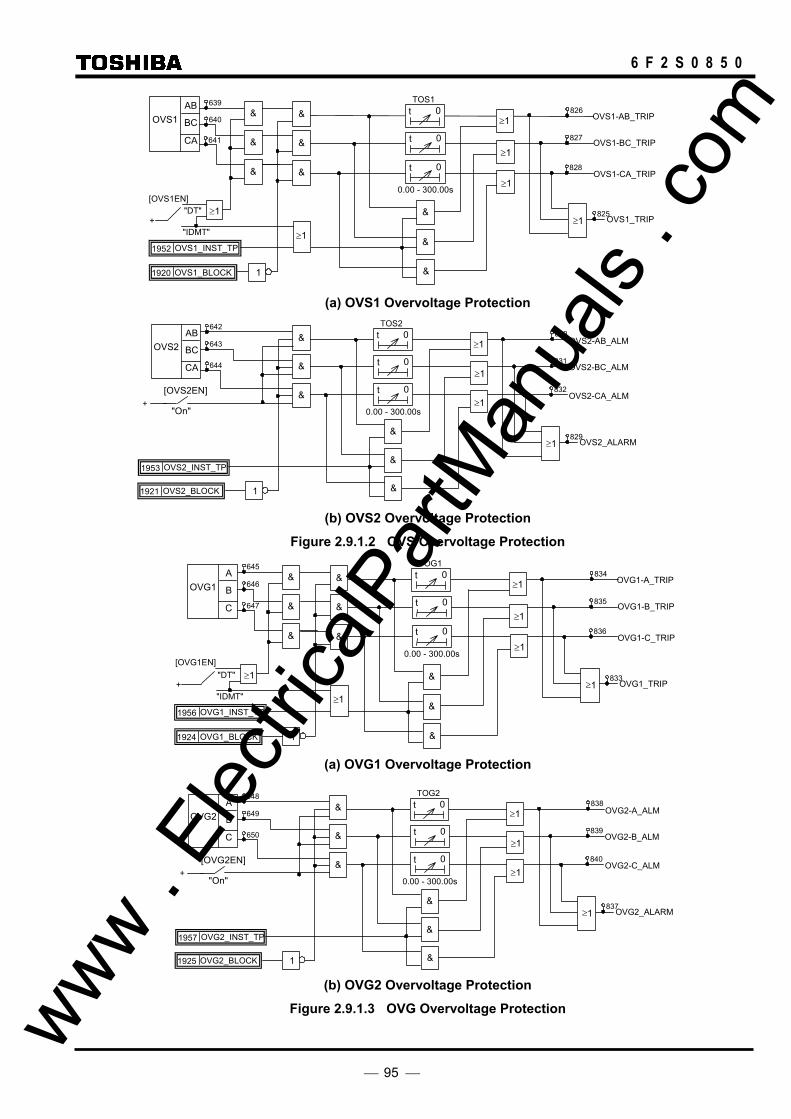
95
6 F 2 S 0 8 5 0
≥1
≥1
≥1
OVS1_TRIP≥ 1
0.00 - 300.00s
TOS1t 0
t 0
t 0
&
&
&
&
&
& AB
OVS1 BC
CA
OVS1-CA_TRIP
OVS1-AB_TRIP
OVS1-BC_TRIP&
&
&
1
≥1
OVS1_BLOCK 1920
OVS1_INST_TP 1952
639
640
641
825
826
827
828
"DT"
"IDMT"
[OVS1EN]
+ ≥1
(a) OVS1 Overvoltage Protection
≥1
≥1
≥1
OVS2_ALARM ≥ 1
0.00 - 300.00s
TOS2t 0
t 0
t 0
&
&
&
&
&
& AB OVS2 BC
CA
OVS2-CA_ALM
OVS2-AB_ALM
OVS2-BC_ALM
1 OVS2_BLOCK 1921
OVS2_INST_TP 1953
642
643
644
829
830
831
832
+ "On"
[OVS2EN]
(b) OVS2 Overvoltage Protection
Figure 2.9.1.2 OVS Overvoltage Protection
≥1
≥1
≥1
OVG1_TRIP≥ 1
0.00 - 300.00s
TOG1t 0
t 0
t 0
&
&
&
&
&
& A OVG1 B
C
OVG1-C_TRIP
OVG1-A_TRIP
OVG1-B_TRIP &
&
&
1
≥1
OVG1_BLOCK 1924
OVG1_INST_TP 1956
645
646
647
833
834
835
836
"DT"
"IDMT"
[OVG1EN]
+ ≥1
(a) OVG1 Overvoltage Protection
≥1
≥1
≥1
OVG2_ALARM ≥ 1
0.00 - 300.00s
TOG2t 0
t 0
t 0
&
&
&
&
&
& A OVG2 B
C
OVG2-C_ALM
OVG2-A_ALM
OVG2-B_ALM
1 OVG2_BLOCK 1925
OVG2_INST_TP 1957
648
649
650
837
838
839
840
+ "On"
[OVG2EN]
(b) OVG2 Overvoltage Protection
Figure 2.9.1.3 OVG Overvoltage Protection www . El
ectric
alPar
tMan
uals
. com

96
6 F 2 S 0 8 5 0
Setting The table shows the setting elements necessary for the overvoltage protection and their setting ranges.
Element Range Step Default Remarks
OVS1 5.0 – 150.0 V 0.1 V 120.0 V OVS1 threshold setting. TOS1I 0.05 – 100.00 0.01 10.00 OVS1 time multiplier setting. Required if [OVS1EN] = IDMT. TOS1 0.00 – 300.00 s 0.01 s 0.10 s OVS1 definite time setting. Required if [OVS1EN] = DT. TOS1R 0.0 – 300.0 s 0.1 s 0.0 s OVS1 definite time delayed reset. OS1DP 10 – 98 % 1 % 95 % OVS1 DO/PU ratio setting. OVS2 5.0 – 150.0 V 0.1 V 140.0 V OVS2 threshold setting. TOS2 0.00 – 300.00 s 0.01 s 0.10 s OVS2 definite time setting. OS2DP 10 - 98 % 1 % 95 % OVS2 DO/PU ratio setting. OVG1 5.0 – 150.0 V 0.1V 70.0 V OVG1 threshold setting. TOG1I 0.05 – 100.00 0.01 10.00 OVG1 time multiplier setting. Required if [OVG1EN]=IDMT. TOG1 0.00 – 300.00 s 0.01 s 0.10 s OVG1 definite time setting. Required if [ZOV1EN]=DT. TOG1R 0.0 – 300.0 s 0.1 s 0.0 s OVG1 definite time delayed reset. OG1DP 10 – 98 % 1 % 95 % OVG1 DO/PU ratio OVG2 5.0 – 150.0 V 0.1V 80.0 V OVG2 threshold setting TOG2 0.00 – 300.00 s 0.01 s 0.10 s OVG2 definite time setting OG2DP 10 – 98 % 1 % 95 % OVG2 DO/PU ratio [OVS1EN] Off / DT / IDMT Off OVS1 Enable [OVS2EN] Off / On Off OVS2 Enable [OVG1EN] Off / DT / IDMT Off OVG1 Enable [OVG2EN] Off / On Off OVG2 Enable
www . El
ectric
alPar
tMan
uals
. com

97
6 F 2 S 0 8 5 0
2.9.2 Undervoltage Protection
GRL100 provides four independent undervoltage elements for phase and earth fault protection. UVS1 and UVS2 are used for phase fault protection, and UVG1 and UVG2 for earth fault protection. UVS1 and UVG1 are programmable for inverse time (IDMT) or definite time (DT) operation. UVS2 and UVG2 have definite time characteristic only.
UVS1 and UVG1 undervoltage protection elements have an IDMT characteristic defined by equation (2):
( )
−×=
VsV
TMSt1
1 (2)
where:
t = operating time for constant voltage V (seconds),
V = energising voltage (V),
Vs = undervoltage setting (V),
TMS = time multiplier setting.
The IDMT characteristic is illustrated in Figure 2.9.2.1.
The UVS2 and UVG2 elements are used for definite time undervoltage protection.
Definite time reset The definite time resetting characteristic is applied to the UVS1 and UVG1 elements when the inverse time delay is used.
If definite time resetting is selected, and the delay period is set to instantaneous, then no intentional delay is added. As soon as the energising voltage rises above the reset threshold, the element returns to its reset condition.
If the delay period is set to some value in seconds, then an intentional delay is added to the reset period. If the energising voltage is below the undercurrent setting for a transient period without causing tripping, then resetting is delayed for a user-definable period. When the energising voltage rises above the reset threshold, the integral state (the point towards operation that it has travelled) of the timing function (IDMT) is held for that period.
This does not apply following a trip operation, in which case resetting is always instantaneous.
www . El
ectric
alPar
tMan
uals
. com
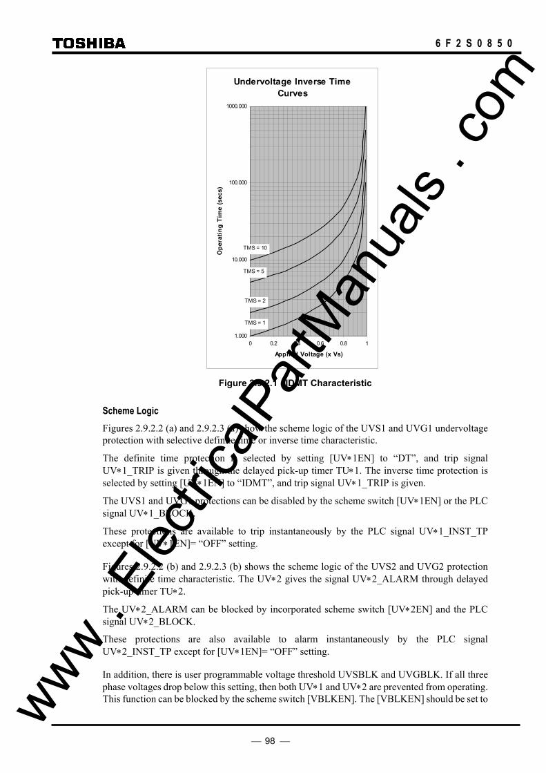
98
6 F 2 S 0 8 5 0
Undervoltage Inverse TimeCurves
1.000
10.000
100.000
1000.000
0 0.2 0.4 0.6 0.8 1
Applied Voltage (x Vs)
Ope
ratin
g Ti
me
(sec
s)
TMS = 10
TMS = 5
TMS = 2
TMS = 1
Figure 2.9.2.1 IDMT Characteristic
Scheme Logic Figures 2.9.2.2 (a) and 2.9.2.3 (a) show the scheme logic of the UVS1 and UVG1 undervoltage protection with selective definite time or inverse time characteristic.
The definite time protection is selected by setting [UV∗1EN] to “DT”, and trip signal UV∗1_TRIP is given through the delayed pick-up timer TU∗1. The inverse time protection is selected by setting [UV∗1EN] to “IDMT”, and trip signal UV∗1_TRIP is given.
The UVS1 and UVG1 protections can be disabled by the scheme switch [UV∗1EN] or the PLC signal UV∗1_BLOCK.
These protections are available to trip instantaneously by the PLC signal UV∗1_INST_TP except for [UV∗1EN]= “OFF” setting.
Figures 2.9.2.2 (b) and 2.9.2.3 (b) shows the scheme logic of the UVS2 and UVG2 protection with definite time characteristic. The UV∗2 gives the signal UV∗2_ALARM through delayed pick-up timer TU∗2.
The UV∗2_ALARM can be blocked by incorporated scheme switch [UV∗2EN] and the PLC signal UV∗2_BLOCK.
These protections are also available to alarm instantaneously by the PLC signal UV∗2_INST_TP except for [UV∗1EN]= “OFF” setting.
In addition, there is user programmable voltage threshold UVSBLK and UVGBLK. If all three phase voltages drop below this setting, then both UV∗1 and UV∗2 are prevented from operating. This function can be blocked by the scheme switch [VBLKEN]. The [VBLKEN] should be set to www .
Elec
tricalP
artM
anua
ls . c
om
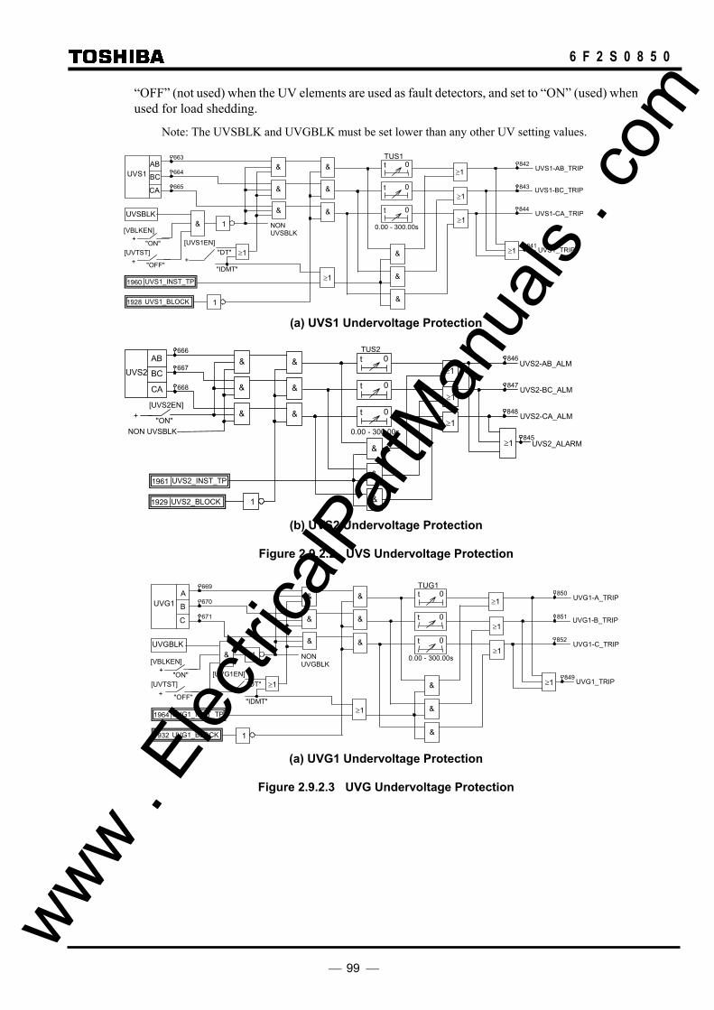
99
6 F 2 S 0 8 5 0
“OFF” (not used) when the UV elements are used as fault detectors, and set to “ON” (used) when used for load shedding.
Note: The UVSBLK and UVGBLK must be set lower than any other UV setting values.
≥1
≥1
≥1
UVS1_TRIP ≥ 1
1 0.00 - 300.00s
TUS1t 0
t 0
t 0
&
&
&
&
&
&
&
&
&
NON UVSBLK
&
"ON"
[VBLKEN] +
"OFF"
[UVTST] +
UVSBLK
1
UVS1-CA_TRIP
UVS1-BC_TRIP
UVS1-AB_TRIPAB UVS1 BC
CA
UVS1_BLOCK 1928
UVS1_INST_TP 1960
663
664
665
841
842
843
844
"DT"
"IDMT"
[UVS1EN]
+ ≥1
≥1
(a) UVS1 Undervoltage Protection
+ "ON"
[UVS2EN]
0.00 - 300.00s
&
&
&
TUS2t 0
t 0
t 0
AB
UVS2 BC
CA
UVS2_ALARM≥ 1
UVS2-CA_ALM
UVS2-AB_ALM
UVS2-BC_ALM
&
&
&
NON UVSBLK ≥1
≥1
≥1
&
&
&
1 UVS2_BLOCK1929
UVS2_INST_TP 1961
845
846
847
848
666
667
668
(b) UVS2 Undervoltage Protection
Figure 2.9.2.2 UVS Undervoltage Protection
≥1
≥1
≥1
UVG1_TRIP≥ 1
1 0.00 - 300.00s
TUG1t 0
t 0
t 0
&
&
&
&
&
&
&
&
&
NON UVGBLK
&
"ON"
[VBLKEN] +
"OFF"
[UVTST] +
UVGBLK
1
UVG1-C_TRIP
UVG1-B_TRIP
UVG1-A_TRIPA UVG1 B
C
UVG1_BLOCK1932
UVG1_INST_TP 1964
669
670
671
849
850
851
852
"DT"
"IDMT"
[UVG1EN]
+≥1
≥1
(a) UVG1 Undervoltage Protection
Figure 2.9.2.3 UVG Undervoltage Protection
www . El
ectric
alPar
tMan
uals
. com
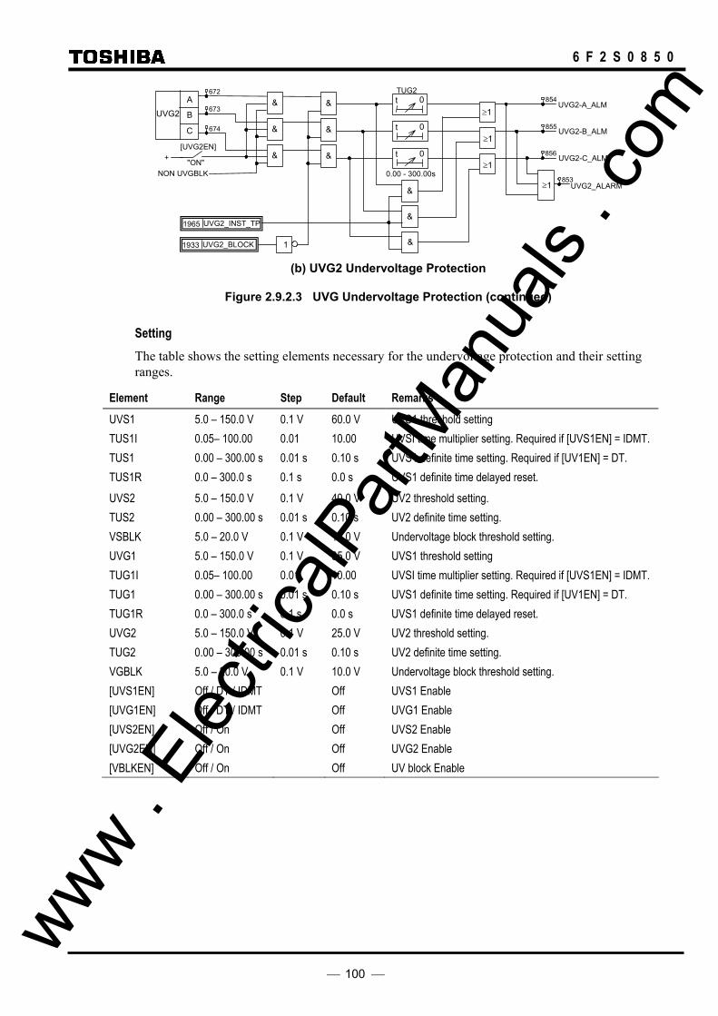
100
6 F 2 S 0 8 5 0
+ "ON"
[UVG2EN]
0.00 - 300.00s
&
&
&
TUG2t 0
t 0
t 0
A UVG2 B
C
UVG2_ALARM≥ 1
UVG2-C_ALM
UVG2-A_ALM
UVG2-B_ALM
&
&
&
NON UVGBLK ≥1
≥1
≥1
&
&
&
1 UVG2_BLOCK 1933
UVG2_INST_TP 1965
853
854
855
856
672
673
674
(b) UVG2 Undervoltage Protection
Figure 2.9.2.3 UVG Undervoltage Protection (continued)
Setting The table shows the setting elements necessary for the undervoltage protection and their setting ranges.
Element Range Step Default Remarks
UVS1 5.0 – 150.0 V 0.1 V 60.0 V UVS1 threshold setting TUS1I 0.05– 100.00 0.01 10.00 UVSI time multiplier setting. Required if [UVS1EN] = IDMT. TUS1 0.00 – 300.00 s 0.01 s 0.10 s UVS1 definite time setting. Required if [UV1EN] = DT. TUS1R 0.0 – 300.0 s 0.1 s 0.0 s UVS1 definite time delayed reset. UVS2 5.0 – 150.0 V 0.1 V 40.0 V UV2 threshold setting. TUS2 0.00 – 300.00 s 0.01 s 0.10 s UV2 definite time setting. VSBLK 5.0 – 20.0 V 0.1 V 10.0 V Undervoltage block threshold setting. UVG1 5.0 – 150.0 V 0.1 V 35.0 V UVS1 threshold setting TUG1I 0.05– 100.00 0.01 10.00 UVSI time multiplier setting. Required if [UVS1EN] = IDMT. TUG1 0.00 – 300.00 s 0.01 s 0.10 s UVS1 definite time setting. Required if [UV1EN] = DT. TUG1R 0.0 – 300.0 s 0.1 s 0.0 s UVS1 definite time delayed reset. UVG2 5.0 – 150.0 V 0.1 V 25.0 V UV2 threshold setting. TUG2 0.00 – 300.00 s 0.01 s 0.10 s UV2 definite time setting. VGBLK 5.0 – 20.0 V 0.1 V 10.0 V Undervoltage block threshold setting. [UVS1EN] Off / DT / IDMT Off UVS1 Enable [UVG1EN] Off / DT / IDMT Off UVG1 Enable [UVS2EN] Off / On Off UVS2 Enable [UVG2EN] Off / On Off UVG2 Enable [VBLKEN] Off / On Off UV block Enable
www . El
ectric
alPar
tMan
uals
. com

101
6 F 2 S 0 8 5 0
2.10 Broken Conductor Protection
Series faults or open circuit faults which do not accompany any earth faults or phase faults are caused by broken conductors, breaker contact failure, operation of fuses, or false operation of single-phase switchgear.
Figure 2.10.1 shows the sequence network connection diagram in the case of a single-phase series fault assuming that the positive, negative and zero sequence impedance of the left and right side system of the fault location is in the ratio of k1 to (1 – k1), k2 to (1 – k2) and k0 to (1 – k0).
Figure 2.10.1 Equivalent Circuit for a Single-phase Series Fault
Positive phase sequence
Single-phase series fault
Zero phase sequence
k2Z2 (1-k2)Z2
k0Z0 (1-k0)Z0
E1A E1B
I1FI1F
I2FI2F
I0F I0F
Negative phase sequence
(1-k1)Z1 k1Z1
E1B E1A
k1 1– k1
E1A E1B
I1FI1F (1-k1)Z1 k1Z1
k2Z2 (1-k2)Z2
K0Z0 (1-k0)Z0
E1A E1B
I1F
Z1 Z2
Z0
www . El
ectric
alPar
tMan
uals
. com
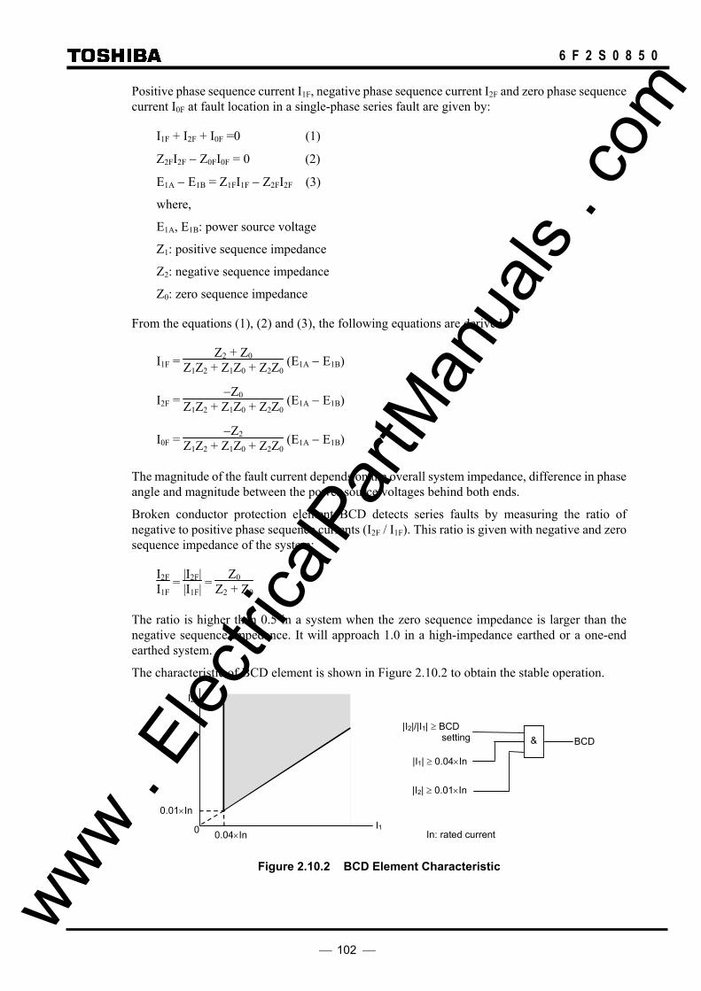
102
6 F 2 S 0 8 5 0
Positive phase sequence current I1F, negative phase sequence current I2F and zero phase sequence current I0F at fault location in a single-phase series fault are given by:
I1F + I2F + I0F =0 (1)
Z2FI2F − Z0FI0F = 0 (2)
E1A − E1B = Z1FI1F − Z2FI2F (3)
where,
E1A, E1B: power source voltage
Z1: positive sequence impedance
Z2: negative sequence impedance
Z0: zero sequence impedance
From the equations (1), (2) and (3), the following equations are derived.
I1F = Z2 + Z0
Z1Z2 + Z1Z0 + Z2Z0 (E1A − E1B)
I2F = −Z0
Z1Z2 + Z1Z0 + Z2Z0 (E1A − E1B)
I0F = −Z2
Z1Z2 + Z1Z0 + Z2Z0 (E1A − E1B)
The magnitude of the fault current depends on the overall system impedance, difference in phase angle and magnitude between the power source voltages behind both ends.
Broken conductor protection element BCD detects series faults by measuring the ratio of negative to positive phase sequence currents (I2F / I1F). This ratio is given with negative and zero sequence impedance of the system:
I2FI1F
= |I2F||I1F| =
Z0Z2 + Z0
The ratio is higher than 0.5 in a system when the zero sequence impedance is larger than the negative sequence impedance. It will approach 1.0 in a high-impedance earthed or a one-end earthed system.
The characteristic of BCD element is shown in Figure 2.10.2 to obtain the stable operation.
I1
I2
0
0.01×In
0.04×In
|I2|/|I1| ≥ BCD setting
|I1| ≥ 0.04×In
& BCD
|I2| ≥ 0.01×In
In: rated current
Figure 2.10.2 BCD Element Characteristic
www . El
ectric
alPar
tMan
uals
. com

103
6 F 2 S 0 8 5 0
Scheme Logic Figure 2.10.3 shows the scheme logic of the broken conductor protection. BCD element outputs trip signals BCD TRIP through a delayed pick-up timer TBCD.
The tripping can be disabled by the scheme switch [BCDEN] or binary input signal BCD BLOCK.
BCD BCD TRIP
0.00 - 300.00s
&
TBCDt 0
"ON"
[BCDEN] +
BCD BLOCK 1
859 635
Figure 2.10.3 Broken Conductor Protection Scheme Logic
Settings The table below shows the setting elements necessary for the broken conductor protection and their setting ranges.
Element Range Step Default Remarks
BCD 0.10 – 1.00 0.01 0.20 I2 / I1
TBCD 0.00 – 300.00s 0.01s 1.00 s BCD definite time setting
[BCDEN] Off / On Off BCD Enable
Minimum setting of the BC threshold is restricted by the negative phase sequence current normally present on the system. The ratio I2 / I1 of the system is measured in the relay continuously and displayed on the metering screen of the relay front panel, along with the maximum value of the last 15 minutes I21 max. It is recommended to check the display at the commissioning stage. The BCD setting should be 130 to 150% of I2 / I1 displayed.
Note: It must be noted that I2 / I1 is displayed only when the positive phase sequence current (or load current) in the secondary circuit is larger than 2 % of the rated secondary circuit current.
TBCD should be set to more than 1 cycle to prevent mal-operation caused by a transient operation such as CB closing.
www . El
ectric
alPar
tMan
uals
. com

104
6 F 2 S 0 8 5 0
2.11 Breaker Failure Protection
When a fault remains uncleared due to a breaker failure, the breaker failure protection (BFP) clears the fault by backtripping the adjacent breakers.
If the current continues to flow following the output of a trip command, the BFP judges it as a breaker failure. The existence of the current is detected by an overcurrent element provided for each phase. For high-speed operation of the BFP, a high-speed reset overcurrent element is used.
In order to prevent the BFP from starting by accident during maintenance work and testing and thus tripping the adjacent breakers, the BFP has the function of retripping the original breaker. To confirm that the breaker has failed, a trip command is issued to the original breaker again before tripping the adjacent breakers to prevent unnecessary tripping of the adjacent breakers in case of erroneous initiation of the BFP. It is possible to choose not to use retripping at all, or to use retripping with a backtrip command plus delayed pick-up timer, or retripping with a backtrip command plus overcurrent detection plus delayed pick-up timer.
Tripping by the BFP is three-phase final tripping and autoreclose is blocked.
An overcurrent element and on-delay timer are provided for each phase and they also operate correctly on the breaker failure in the event of an evolving fault.
Scheme logic The BFP is performed on an individual phase basis. Figure 2.11.1 shows the scheme logic for one phase. The BFP is initiated by a trip signal EXT_CBFIN from the external line protection or an internal trip signal TRIP. Starting with an external trip signal can be disabled by the scheme switch [BFEXT]. These trip signals must be present exist as long as the fault persists.
RETRIP-A
C B A
OCBF ≥ 1
&
50 – 500ms
TBF2
t 0
t 0
t 0
"ON"
[BF2] +
1 CBF_BLOCK 1588
&
&
54
55
56
CBF-TRIP 92
≥ 1 91
&
&
&
TRIP-A0
&
&
&
EXT_CBFIN-A 1556
EXT_CBFIN-B 1557
EXT_CBFIN-C 1558
"ON"
[BFEXT] +
≥1
≥1
≥1
TRIP-B0
TRIP-C0
&
&
&
&
TBF1
t 0
t 0
t 0 &
&
&
50 – 500ms
t 0
t 0
t 0 &
&
"T"
[BF1]
+
"TOC"
≥1
≥1
≥1
RETRIP-B
RETRIP-C
CBFDET
88
89
90
Figure 2.11.1 BFP Scheme Logic
The backtrip signal to the adjacent breakers CBF-TRIP is output if the overcurrent element OCBF operates continuously for the setting time of the delayed pick-up timer TBF2 after the www .
Elec
tricalP
artM
anua
ls . c
om

105
6 F 2 S 0 8 5 0
start-up. Tripping of the adjacent breakers can be blocked with the scheme switch [BF2].
There are two kinds of mode of the retrip signal to the original breaker RETRIP: the mode in which RETRIP is controlled by the overcurrent element OCBF, and the direct trip mode in which RETRIP is not controlled. The retrip mode together with the trip block can be selected with the scheme switch [BF1].
Figure 2.11.2 shows a sequence diagram of the BFP when a retrip and backtrip are used. If the breaker trips normally, the OCBF is reset before timer TBF1 or TBF2 is picked up and the BFP is reset.
If the OCBF continues operating, a retrip command is given to the original breaker after the setting time of TBF1. Unless the breaker fails, the OCBF is reset by the retrip. The TBF2 is not picked up and the BFP is reset. This may happen when the BFP is started by mistake and unnecessary tripping of the original breaker is unavoidable.
If the original breaker fails, retrip has no effect and the OCBF continues operating and the TBF2 is picked up finally. A trip command CBF-TRIP is issued to the adjacent breakers and the BFP is completed.
Fault
CBF - TRIP
TBF2
RETRIP
TBF1
OCBF
Original breaker
Adjacent breakers
TRIP
Retrip
TocToc
TcbT cb
TBF1
TBF2
Normal trip
Trip
Open Closed
Start BFP
OpenOpenClosed
Tcb: operating time of the original breaker Toc: reset time of the overcurrent element OCBF
Figure 2.11.2 Sequence Diagram
www . El
ectric
alPar
tMan
uals
. com

106
6 F 2 S 0 8 5 0
Setting The setting elements necessary for the breaker failure protection and its setting ranges are as follows:
Element Range Step Default Remarks
OCBF 0.5 − 10.0A 0.1A 4.0A Overcurrent setting
(0.1 − 2.0A 0.1A 0.8A) (*)
TBF1 50 − 500ms 1ms 150ms Retrip timer
TBF2 50 − 500ms 1ms 200ms Adjacent breaker trip timer
[BFEXT] ON/OFF OFF External start
[BF1] T/TOC/OFF OFF Retrip mode
[BF2] ON/OFF OFF Adjacent breaker trip
(*) Current values shown in parentheses are in the case of 1A rating. Other current values are in the case of 5A rating.
The overcurrent element OCBF checks that the breaker has opened and the current has disappeared. Therefore, since it is allowed to respond to the load current, it can be set from 10 to 200% of the rated current.
The settings of TBF1 and TBF2 are determined by the opening time of the original breaker (Tcb in Figure 2.11.2) and the reset time of the overcurrent element (Toc in Figure 2.11.2). The timer setting example when using retrip can be obtained as follows.
Setting of TBF1 = Breaker opening time + OCBF reset time + Margin
= 40ms + 10ms + 20ms
= 70ms
Setting of TBF2 = TBF1 + Output relay operating time + Breaker opening time + OCBF reset time + Margin
= 70ms + 10ms + 40ms + 10ms + 10ms
= 140ms
If retrip is not used, the setting of TBF2 can be the same as that of TBF1.
www . El
ectric
alPar
tMan
uals
. com
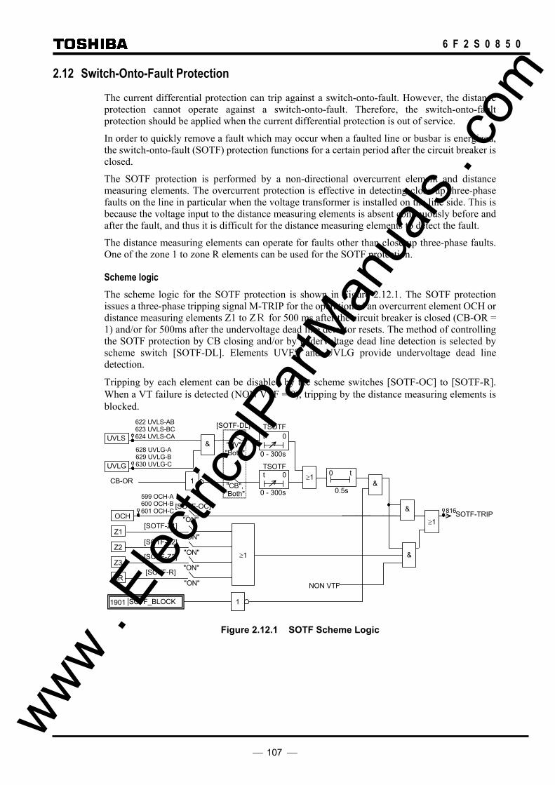
107
6 F 2 S 0 8 5 0
2.12 Switch-Onto-Fault Protection
The current differential protection can trip against a switch-onto-fault. However, the distance protection cannot operate against a switch-onto-fault. Therefore, the switch-onto-fault protection should be applied when the current differential protection is out of service.
In order to quickly remove a fault which may occur when a faulted line or busbar is energized, the switch-onto-fault (SOTF) protection functions for a certain period after the circuit breaker is closed.
The SOTF protection is performed by a non-directional overcurrent element and distance measuring elements. The overcurrent protection is effective in detecting close-up three-phase faults on the line in particular when the voltage transformer is installed on the line side. This is because the voltage input to the distance measuring elements is absent continuously before and after the fault, and thus it is difficult for the distance measuring elements to detect the fault.
The distance measuring elements can operate for faults other than close-up three-phase faults. One of the zone 1 to zone R elements can be used for the SOTF protection.
Scheme logic The scheme logic for the SOTF protection is shown in Figure 2.12.1. The SOTF protection issues a three-phase tripping signal M-TRIP for the operation of an overcurrent element OCH or distance measuring elements Z1 to ZR for 500 ms after the circuit breaker is closed (CB-OR = 1) and/or for 500ms after the undervoltage dead line detector resets. The method of controlling the SOTF protection by CB closing and/or by undervoltage dead line detection is selected by scheme switch [SOTF-DL]. Elements UVFS and UVLG provide undervoltage dead line detection.
Tripping by each element can be disabled by the scheme switches [SOTF-OC] to [SOTF-R]. When a VT failure is detected (NON VTF = 0), tripping by the distance measuring elements is blocked.
0.5s
0 t
≥1
1
SOTF-TRIP[SOTF-Z1]
[SOTF-OC]
NON VTF
CB-OR
OCH
Z1
"ON"
"ON" Z2
"ON" Z3
"ON"
UVLS
≥1
0 - 300s
t 0TSOTF
0 - 300s
t 0TSOTF
"UV", "Both"
"CB", "Both"
[SOTF-DL]
[SOTF-Z2]
[SOTF-Z3]
[SOTF-R] ZR
"ON"
&
599 OCH-A 600 OCH-B 601 OCH-C
UVLG
628 UVLG-A629 UVLG-B630 UVLG-C
622 UVLS-AB 623 UVLS-BC 624 UVLS-CA
&
SOTF_BLOCK 1901 1
≥1
&
&
816
Figure 2.12.1 SOTF Scheme Logic
www . El
ectric
alPar
tMan
uals
. com

108
6 F 2 S 0 8 5 0
Setting The setting elements necessary for the SOTF protection and their setting ranges are as follows:
Element Range Step Default Remarks OCH 2.0 - 15.0 A 0.1 A 6.0 A Overcurrent setting ( 0.4 - 3.0 A 0.1 A 1.2 A) (*) TSOTF 0 – 300 s 1 s 5 s SOTF check timer SOTF - OC OFF/ON ON Overcurrent tripping SOTF - Z1 OFF/ON OFF Zone 1 tripping SOTF - Z2 OFF/ON OFF Zone 2 tripping SOTF - Z3 OFF/ON OFF Zone 3 tripping SOTF - R OFF/ON OFF Zone R tripping SOTF-DL CB/UV/BOTH CB SOTF control
(*) Current values shown in the parentheses are in the case of 1 A rating. Other current values are in the case of 5 A rating.
The OCH element and its setting are common with the stub protection.
www . El
ectric
alPar
tMan
uals
. com

109
6 F 2 S 0 8 5 0
2.13 Stub Protection
In the case of a busbar with a one-and-a-half breaker arrangement as shown in Figure 2.13.1.1, the differential protection will operate and will trip the breakers at both terminals, and the distance protection will not operate.
Terminal A
F2F1
DS
×× ×
Terminal B
× × ×
Figure 2.13.1 Stub Fault
GRL100-700 series provides the following two schemes of stub protection for such cases:
- STUB DIF
- STUB OC
2.13.1 STUB DIF Protection
If a fault occurs at F1 or F2 when line disconnector DS of terminal A is open as shown in Figure 2.13.1, the differential protection operates and trips the breakers at both terminals.
Figure 2.13.1.1 shows the stub fault protection logic of STUB DIF using the current differential principle.
DS &[STUB]
STUB ON
"ON" (+)
1
Figure 2.13.1.1 STUB DIF Protection
If the switch is set to "DIF" and the disconnector is open (DS = 0), the signal STUB ON is generated and used to reset the receiving current data from terminal B to zero. Thus, terminal A does not need to operate unnecessarily in response to fault F2.
Terminal B detects that terminal A is out-of-service with the out-of-service detection logic and resets the receiving current data from terminal A to zero, and so does not operate in response to fault F1.
The signal STUB ON brings the local tripping into three-phase final tripping.
2.13.2 STUB OC Protection
In the case of a busbar with a one-and-a-half breaker arrangement, the VT is generally installed on the line side. If the line is separated from the busbar, the distance protection does not cover to the "stub" area between the two CTs and line isolator. This is because the line VT cannot supply a correct voltage for a fault in the "stub" area. For a fault in the stub area under such conditions, fast overcurrent protection is applied.
www . El
ectric
alPar
tMan
uals
. com

110
6 F 2 S 0 8 5 0
Scheme logic The scheme logic for the stub protection is shown in Figure 2.13.2.1. The stub protection performs three-phase tripping on the condition that the line disconnector is open (DS_N/O_CONT = 0) and the overcurrent element has operated (OCH = 1). CB condition (STUB_CB) can be added by using programmable BI function (PLC function). Tripping can be disabled by the scheme switch [STUB-OC].
[STUB-OC]
"ON" OCH
STUB-OC_TRIP (M-TRIP)
&
1
1
812DS_N/O_CONT 1542
STUB_CB 1985
STUBOC_BLOCK 1900
599 OCH-A 600 OCH-B 601 OCH-C
OCHTP_ON 1986
OCH_BLOCK 1902
& &
821 OCH_TRIP 822 OCH-A_TRIP 823 OCH-B_TRIP 824 OCH-C_TRIP
OCH_TRIP
Figure 2.13.2.1 Stub Protection Scheme Logic
2.13.3 Setting
The setting elements necessary for the stub protection and their setting ranges are as follows:
Element Range Step Default Remarks STUB OFF/ON OFF STUB DIF protection OCH 2.0 - 10.0 A 0.1 A 6.0 A Overcurrent setting for STUB OC (0.4 - 2.0 A 0.1 A 1.2 A) (*) STUB-OC OFF/ON OFF STUB OC protection
(*) Current values shown in the parentheses are in the case of 1 A rating. Other current values are in the case of 5 A rating.
The OCH element and its setting are common with the SOTF protection.
www . El
ectric
alPar
tMan
uals
. com
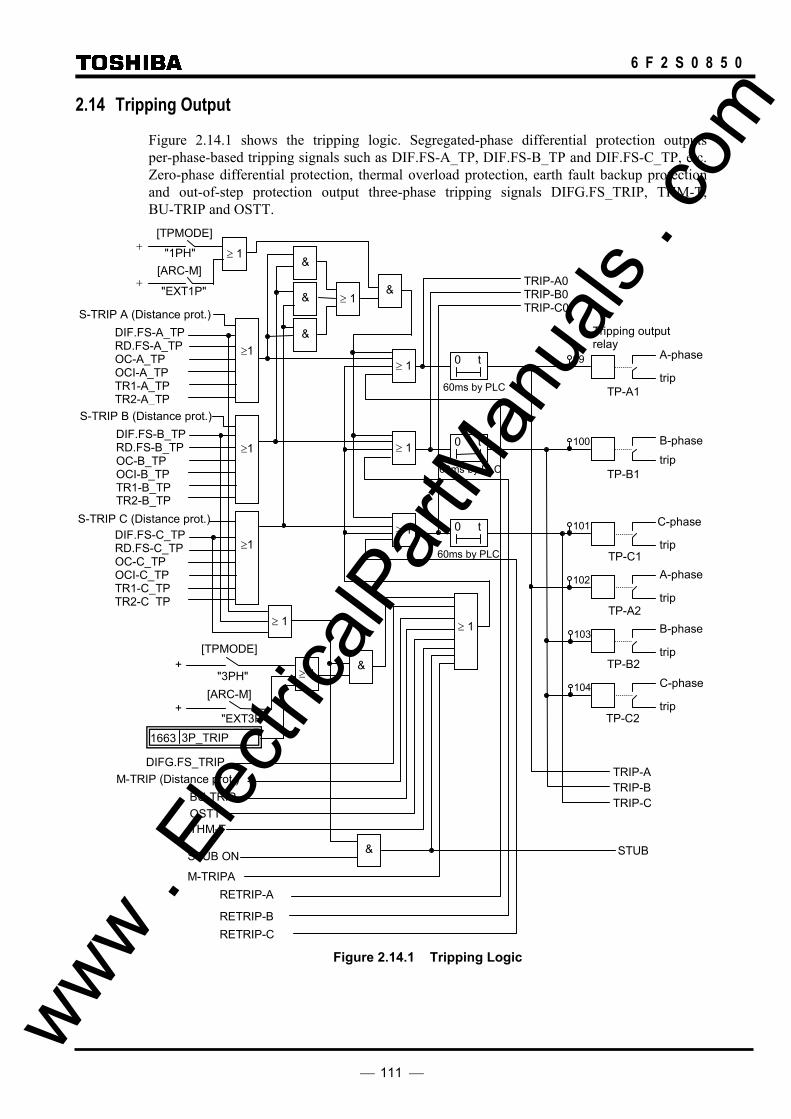
111
6 F 2 S 0 8 5 0
2.14 Tripping Output
Figure 2.14.1 shows the tripping logic. Segregated-phase differential protection outputs per-phase-based tripping signals such as DIF.FS-A_TP, DIF.FS-B_TP and DIF.FS-C_TP, etc. Zero-phase differential protection, thermal overload protection, earth fault backup protection and out-of-step protection output three-phase tripping signals DIFG.FS_TRIP, THM-T, BU-TRIP and OSTT.
BU-TRIP
≥ 1
≥ 1
≥ 1
60ms by PLCtrip
A-phase
Tripping output relay
DIF.FS-A_TP RD.FS-A_TP OC-A_TP OCI-A_TP TR1-A_TP TR2-A_TP
0 t
≥ 1
60ms by PLCtrip B-phase0 t
≥ 1
≥ 1
&
&
&
&
≥ 1
60ms by PLC trip
C-phase
OSTT
STUB ON
M-TRIPA
RETRIP-B
RETRIP-A
RETRIP-C
0 t
trip
A-phase
trip
B-phase
trip
TRIP-B TRIP-A
TRIP-C
STUB
C-phase
[TPMODE]
"3PH" +
[ARC-M]
"EXT3P" +
&
&
"EXT1P"
"1PH" +
+ [ARC-M]
[TPMODE]
≥ 1
THM-T
3P_TRIP 1663
TRIP-A0 TRIP-B0 TRIP-C0
≥1
≥1
≥1
101
100
99
102
103
104
DIF.FS-B_TP RD.FS-B_TP OC-B_TP OCI-B_TP TR1-B_TP TR2-B_TP
DIF.FS-C_TP RD.FS-C_TP OC-C_TP OCI-C_TP TR1-C_TP TR2-C_TP
TP-A1
TP-B1
TP-C1
TP-A2
TP-B2
TP-C2
S-TRIP A (Distance prot.)
S-TRIP B (Distance prot.)
S-TRIP C (Distance prot.)
DIFG.FS_TRIP M-TRIP (Distance prot.)
Figure 2.14.1 Tripping Logic
www . El
ectric
alPar
tMan
uals
. com
112
6 F 2 S 0 8 5 0
In the following cases, per-phase-based tripping is converted to three-phase tripping.
• When autoreclose is prohibited by a binary input signal (ARC−BLK = 1)
• When the autoreclose mode selection switch [ARC-M] is set to "EXT3P"
• When the measure for stub fault is enabled (STUB ON = 1) (This applies to the one-and-a-half busbar system.)
• PLC command “3P_TRIP” is established.
In the following cases, two-phase tripping is converted to three-phase tripping.
• When the switch [ARC-M] is set to "EXT1P"
For the following trips, the logic level of M-TRIPA becomes 1, and per-phase-based tripping is converted to three-phase tripping. M-TRIPA is a logic signal in the autoreclose circuit (see Figure 2.15.2.1).
• Tripping within the reclaim time
• Tripping when reclosing and the mode selection switch [ARC-M] is set to "Disable" or "TPAR"
Signals RETRIP-A, RETRIP-B and RETRIP-C are the retripping signals of the breaker failure protection.
Tripping signals drive the high-speed tripping output relays. Two sets of output relays are provided for each phase and each relay has one normally open contact.
The tripping output relays reset 60ms(*) after the tripping signal disappears by clearing the fault. The tripping circuit must be opened with the auxiliary contact of the breaker prior to reset of the tripping relay to prevent the tripping relay from directly interrupting the tripping current of the breaker.
(*) Reset time is adjustable by PLC function. Default setting is 60ms.
A tripping output relay is user configurable for the adjacent breakers tripping signal CBF-TRIP in the breaker failure protection. For the default setting, see Appendix D. The relay is assigned to the signal number 92 with signal name CBF-TRIP.
The signals TRIP-A, TRIP-B and TRIP-C are used to start the autoreclose.
The signal TRIP-A0, TRIP-B0 and TRIP-C0 are used to start the breaker failure protection.
If the signal No.1663 “3P_TRIP”assigned by PLC is activated, GRL100 outputs a three-phase tripping command without regard to faulted phase.
www . El
ectric
alPar
tMan
uals
. com

113
6 F 2 S 0 8 5 0
2.15 Autoreclose 2.15.1 Application
Most faults that occur on high-voltage or extra-high-voltage overhead lines are transient faults caused by lightning. If a transient fault occurs, the circuit breaker is tripped to isolate the fault, and then reclosed following a time delay to ensure that the hot gases caused by the fault arc have de-ionized. This makes it possible to recover power transmission.
The time between clearing the fault and reclosing the circuit breaker, that is, the dead time, should be made as short as possible to keep the power system stable. From the viewpoint of de-ionization of the fault arc, the fault arc is de-ionized more thoroughly as the period of this dead time is extended. The de-ionization commences when the circuit breakers for all terminals of the line are tripped. Therefore, the dead time can be set at its minimum level if all terminals of the line are tripped at the same time.
Autoreclose of the GRL100 is started by the current differential protection that ensures high-speed protection of all terminals.
The GRL100 provides two autoreclose systems, single-shot autoreclose and multi-shot autoreclose.
Single-shot autoreclose Four types of single-shot autoreclose mode are provided: single-phase autoreclose, three-phase autoreclose, single- and three-phase autoreclose, and multi-phase autoreclose. An optimal mode is selected by the autoreclose mode selection switch [ARC-M]. In any case, autoreclose is performed only once. If the fault state still continues after reclosing, three-phase final tripping is activated.
Single-phase autoreclose:
In this mode, only the faulty phase is tripped, and then reclosed if a single-phase earth fault occurs. In the case of a multi-phase fault, three phases are tripped, but reclosing is not made. Since power can be transmitted through healthy phases even during the dead time, this mode is convenient for maintaining power system stability. On the other hand, the capacitive coupling effect between the healthy phase and faulty phase may cause a longer de-ionization time when compared to a three-phase autoreclose. As a result, a longer dead time is required.
It is essential to correctly determine the faulty phase. The GRL100 provides phase-segregated current differential protection to correctly determine the faulty phase(s).
For single-phase autoreclose, each phase of the circuit breaker must be segregated.
This reclosing mode is simply expressed as "SPAR" in the following descriptions.
Three-phase autoreclose:
In this autoreclose mode, three phases are tripped, and then reclosed regardless of the fault mode, whether single-phase fault or multi-phase fault. A shorter dead time can be set in this mode when compared to the single-phase autoreclose. For the three-phase autoreclose, synchronism check and voltage check between the busbar and the line are required.
This reclosing mode is simply expressed as "TPAR" in the following descriptions.
Single- and three-phase autoreclose:
In this autoreclose mode, single-phase tripping and reclosing are performed if a single-phase fault occurs, while three-phase tripping and reclosing are performed if a multi-phase fault occurs. www .
Elec
tricalP
artM
anua
ls . c
om

114
6 F 2 S 0 8 5 0
This reclosing mode is simply expressed as "SPAR & TPAR" in the following descriptions.
Multi-phase autoreclose:
This autoreclose mode can be applied to double-circuit lines. In this mode, only the faulted phases are tripped and reclosed when the terminals of double-circuit lines are interconnected during the dead time through at least two or three different phases.
This mode realizes high-speed reclosing for multi-phase faults without synchronism and voltage check and minimizes the possibility of outages in the case of double faults on double-circuit lines.
If the interlinking condition is not satisfied, all the phases are tripped and reclosing is not started.
This reclosing mode is simply expressed as "MPAR2" for two-phase interconnection and "MPAR3" for three-phase interconnection in the following descriptions.
For the detailed performance of the multi-phase autoreclose, see Appendix M.
In B-mode and GPS-mode, the multi-phase autoreclose can be applied if the RYIDSV function is not applied.
Single-shot autoreclose can be applied to one-breaker reclosing and two-breaker reclosing in the one-and-a-half breaker busbar system.
Multi-shot autoreclose In the multi-shot autoreclose, any of two- to four-shot reclosing can be selected. In any case, the first shot is selected from four types of autoreclose mode as described in the above single-shot autoreclose. All successive shots (up to three times), which are applied if the first shot fails, are three-phase tripping and reclosing.
Multi-shot autoreclose cannot be applied to two-breaker reclosing in the one-and-a-half breaker busbar system.
The autoreclose can also be activated from an external line protection. At this time, all autoreclose modes described above are effective.
If a fault occurs under the following conditions, three-phase final tripping is performed and autoreclose is blocked:
• Reclosing block signal is received from an external unit locally or remotely.
• Throughout the reclaim time.
For evolving faults that occur during the dead time between single-phase tripping and reclosing, "SPAR & TPAR" functions are as follows.
For evolving faults that occur within the period of time set from the first fault, the reclosing mode enters the three-phase autoreclose mode. At this time, the total dead time becomes the dead time for three-phase autoreclose added to the dead time for single-phase autoreclose which has expired up to the point at which the evolving fault occurs.
For evolving faults that occurred after the set time, three-phase final tripping is performed, and reclosing is not performed.
If an evolving fault occurs when "SPAR" is selected, three-phase final tripping is performed, and reclosing is not performed.
If an evolving fault occurs when "MPAR2" or "MPAR3" is selected, the dead time is recounted provided the network conditions defined for linked circuits are satisfied. www .
Elec
tricalP
artM
anua
ls . c
om

115
6 F 2 S 0 8 5 0
2.15.2 Scheme Logic
2.15.2.1 One-breaker Autoreclose Figure 2.15.2.1 shows the simplified scheme logic for the single-shot autoreclose. Autoreclose for a further fault incident is available when the circuit breaker is closed and ready for autoreclose (CB-RDY=1), the reclosing mode selection switch [ARC-M] is set to "SPAR", "TPAR", "SPAR & TPAR", "MPAR2" or "MPAR3" and the on-delay timer TRDY1 is picked up. TRDY1 is used to determine the reclaim time.
If the autoreclose is ready, the internal tripping signal TRIP-A, B, C or external tripping signal EXT_TRIP-A, B, C for each phase of the breaker activates the autoreclose. Whether or not the external trip signals are used to activate the reclosing is selected by the scheme switch [ARC-EXT].
Once this autoreclose is activated, it is kept by the flip-flop circuit until one reclosing cycle is completed.
Autoreclose is not activated in the following conditions and all the phases are tripped (M-TRIPA=1).
• When tripping is performed by the high-impedance earth fault protection (DIFGT=1) and the autoreclose selection switch [ARC-DIFG] is set to "OFF".
• When tripping is performed by the backup protection (BU-TRIP=1) and the autoreclose selection switch [ARC-BU] is set to "OFF".
• When tripping is performed by the out-of-step protection (OSTT=1), breaker failure protection (RETRIP=1) or stub fault protection (STUB=1).
• When an autoreclose prohibiting binary input signal is applied at either the local or remote terminal (ARC_BLOCK=1).
• When tripping is performed by the DEF command protection and the autoreclose selection switch [ARC-DEFC] is set to "OFF".
If autoreclosing is not ready, a three-phase tripping command M-TRIPA is output for all tripping modes. At this time, autoreclose is not activated.
Autoreclose for single-phase fault If the switch [ARC-M] is set to "SPAR", "SPAR & TPAR" or "MPAR2", single-phase tripping is performed. If it is set to "MPAR3", single-phase tripping is performed only when the adjacent parallel line is healthy.
The dead time counter TSPR or TMPR for single-phase reclosing is started by any of the tripping signals TRIP-A to C. After the dead time has elapsed, reclosing command ARC is output. The voltage check condition can be configured by the PLC function, if the voltage check and others are required for the reclosing condition.
If [ARC-M] is set to "TPAR", three-phase tripping is performed and the dead time counter TTPR1 for three-phase reclosing is started. After the dead time has elapsed, reclosing command ARC is output based on the operating conditions of the voltage and synchronism check elements output signal SYN-OP. (The SYN-OP is assigned by the PLC as a default setting.)
If [ARC-M] is set to "Disable", three-phase tripping is performed and autoreclose is not started.
www . El
ectric
alPar
tMan
uals
. com

116
6 F 2 S 0 8 5 0
"SPAR", "TPAR", "SPAR & TPAR", "MPAR2", "MPAR3" &
+ [ARC-M]
5-300s
t 0
& 52A 52B 52C
CB1_READY 1571
TRIP-A
TRIP-B
TRIP-C
[ARC-EXT]
≥1
≥1
≥1
"ON"
"ON"
≥1
EXT_TRIP-A 1552
EXT_TRIP-B 1553
EXT_TRIP-C 1554
&
TP
F/F Single-phase trip
+[ARC-M]
"SPAR", "SPAR & TPAR"
& ≥1
No-Link & Single-phase trip
+[ARC-M]
"MPAR2", "MPAR3"
&
&0.01-10s
t 0 TRDY1 TSPR1
SPR.L-REQ 1824"Default =CONSTANT 1"
&
Multi-phase trip
+[ARC-M]
"TPAR", "SPAR & TPAR"
& ≥1
No-Link & Multi-phase trip
+[ARC-M]
"MPAR2", "MPAR3"
&
&0.01-100s
t 0 TTPR1
TPR.L-REQ 1825"Default =SYN-OP"
&
+[ARC-M]
&
"MPAR2", "MPAR3"
0.01-10s
t 0 TMPR1
MPR.L-REQ 1826"Default =CONSTANT 1"
& &
OSTT
RETRIPSTUB
DIFG.FS-TRIP[ARC-DIFG] &
"OFF"
BU-TRIP[ARC-BU] &
"OFF"
ARC_BLOCK1574
≥1&
LINK
Single-phase trip
0.01-10s
t 0TEVLV
Multi-phase trip
+[ARC-M]
"SPAR & TPAR"
&
≥1
0.01-100s
t 0TRR
≥1 0.1 - 10s
TW1
0.2s
ARC(*)
MSARC
ARC FAIL
(*)ARC
(For Leader CB)
(For Leader CB)
FT
(For Leader CB)
≥1
ARC (For Leader CB)
(For Leader CB)
(For Leader CB)
M-TRIPA
FT
≥10.1s
LINK condition for MPAR is not satisfied.
Trip when ARC1 READY not operated.
Multi phase trip in SPAR.
ARC1 READY
( To Figure 2.10.2.8. )
+[ARC-SUC]
&
"ON"
ARC_BLOCK11578≥1
Figure 2.15.2.1 Autoreclose Scheme
Autoreclose for multi-phase fault If [ARC-M] is set to "MPAR2" or "MPAR3", only the faulted phases are tripped and the dead time counter TMPR is started by any of the tripping signals TRIP-A to C. After the dead time has elapsed, reclosing command ARC is output, based on the status of the linked circuits check output signal LINK. The voltage check condition can be configured by the PLC function, if the voltage check and others are required for the reclosing condition.
In other reclosing modes, three-phase tripping is performed and all of TRIP-A to C are activated. If [ARC-M] is set to "TPAR" or "SPAR & TPAR", the dead time counter TTPR1 for three-phase reclosing is started. After the dead time has elapsed, reclosing command ARC is output based on the status of the voltage and synchronism check elements output signal SYN-OP. (The SYN-OP www .
Elec
tricalP
artM
anua
ls . c
om
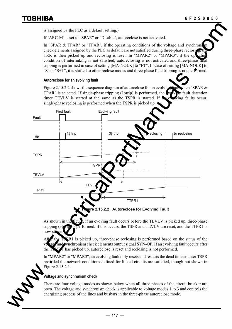
117
6 F 2 S 0 8 5 0
is assigned by the PLC as a default setting.)
If [ARC-M] is set to "SPAR" or "Disable", autoreclose is not activated.
In "SPAR & TPAR" or "TPAR", if the operating conditions of the voltage and synchronism check elements assigned by the PLC as default are not satisfied during three-phase reclosing, the TRR is then picked up and reclosing is reset. In "MPAR2" or "MPAR3", if the operating condition of interlinking is not satisfied, autoreclosing is not activated and three-phase final tripping is performed in case of setting [MA-NOLK] to “FT”. In case of setting [MA-NOLK] to "S" or "S+T", it is shifted to other reclose modes and three-phase final tripping is not performed.
Autoreclose for an evolving fault Figure 2.15.2.2 shows the sequence diagram of autoreclose for an evolving fault when "SPAR & TPAR" is selected. If single-phase tripping (1φtrip) is performed, the evolving fault detection timer TEVLV is started at the same as the TSPR is started. If no evolving faults occur, single-phase reclosing is performed when the TSPR is picked up.
Figure 2.15.2.2 Autoreclose for Evolving Fault
As shown in the figure, if an evoving fault occurs before the TEVLV is picked up, three-phase tripping (3φtrip) is performed. If this occurs, the TSPR and TEVLV are reset, and the TTPR1 is now started.
After the TTPR1 is picked up, three-phase reclosing is performed based on the status of the voltage and synchronism check elements output signal SYN-OP. If an evolving fault occurs after the TEVLV has picked up, autoreclose is reset and reclosing is not performed.
In "MPAR2" or "MPAR3", an evolving fault only resets and restarts the dead time counter TSPR provided the network conditions defined for linked circuits are satisfied, though not shown in Figure 2.15.2.1.
Voltage and synchronism check There are four voltage modes as shown below when all three phases of the circuit breaker are open. The voltage and synchronism check is applicable to voltage modes 1 to 3 and controls the energizing process of the lines and busbars in the three-phase autoreclose mode.
Evolving fault First fault
Fault
Trip 3φ reclosing 1φ reclosing 1φ trip 3φ trip
TSPR
TEVLV
TSPR
TTPR1 TEVLV
TTPR1
www . El
ectric
alPar
tMan
uals
. com

118
6 F 2 S 0 8 5 0
Voltage Mode 1 2 3 4 Busbar voltage (VB) live live dead dead
Line voltage (VL) live dead live dead
The synchronism check is performed for voltage mode 1 while the voltage check is performed for voltage modes 2 and 3.
&
SYN1
UVL1
OVL1
OVB
& UVB
+"OFF"
[VCHK]
"SY"
"DB"
"LB"
DBLL
LBDL
SYN-OP
TLBD1
0.01 – 10.00S
0.01 – 1.00STDBL1
0.01 – 1.00S
&
&
TSYN1
≥1
57
58
61
59
60
159
T3PLL
0.01 – 1.00S
4983PLL (Three phase live line)
OVL1 (3PH)
78
Figure 2.15.2.3 Energizing Control Scheme
Figure 2.15.2.3 shows the energizing control scheme. The voltage and synchronism check output signal SYN-OP is generated when the following conditions have been established:
• Synchronism check element SYN1 operates and on-delay timer TSYN1 is picked up.
• Busbar overvoltage detector OVB and line undervoltage detector UVL1 operate, and on-delay timer TLBD1 is picked up. (This detects the live bus and dead line condition.)
• Busbar undervoltage detector UVB and line overvoltage detector OVL1 operate, and on-delay timer TDBL1 is picked up. (This detects the dead bus and live line condition.)
Using the scheme switch [VCHK], the energizing direction can be selected.
Setting of [VCHK] Energizing control LB Reclosed under the "live bus and dead line" condition or with synchronism check. DB Reclosed under the "dead bus and live line" condition or with synchronism check. SYN Reclosed with synchronism check only. OFF Reclosed without voltage and synchronism check.
When [VCHK] is set to "LB", the line is energized in the direction from the busbar to line under the "live bus and dead line" condition. When [VCHK] is set to "DB", the lines are energized in the direction from the line to busbar under the "dead bus and live line" condition.
When the synchronism check output exists, autoreclose is executed regardless of the position of www . El
ectric
alPar
tMan
uals
. com
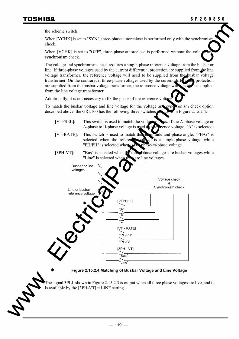
119
6 F 2 S 0 8 5 0
the scheme switch.
When [VCHK] is set to "SYN", three-phase autoreclose is performed only with the synchronism check.
When [VCHK] is set to "OFF", three-phase autoreclose is performed without the voltage and synchronism check.
The voltage and synchronism check requires a single-phase reference voltage from the busbar or line. If three-phase voltages used by the current differential protection are supplied from the line voltage transformer, the reference voltage will need to be supplied from the busbar voltage transformer. On the contrary, if three-phase voltages used by the current differential protection are supplied from the busbar voltage transformer, the reference voltage will need to be supplied from the line voltage transformer.
Additionally, it is not necessary to fix the phase of the reference voltage.
To match the busbar voltage and line voltage for the voltage and synchronism check option described above, the GRL100 has the following three switches as shown in Figure 2.15.2.4:
[VTPSEL]: This switch is used to match the voltage phases. If the A-phase voltage or A-phase to B-phase voltage is used as a reference voltage, "A" is selected.
[VT-RATE]: This switch is used to match the magnitude and phase angle. "PH/G" is selected when the reference voltage is a single-phase voltage while "PH/PH" is selected when it is a phase-to-phase voltage.
[3PH-VT]: "Bus" is selected when the three-phase voltages are busbar voltages while "Line" is selected when they are line voltages.
Vref
Vc
Vb
Va
[VTPSEL]
"C"
"B""A"
+
+
+
[VT - RATE]
"PH/G"
[3PH - VT]
"Line"
"Bus"
"PH/PH"
+
+
+
+
Busbar or line voltages
Line or busbar reference voltage
Voltage check &
Synchronism check
Figure 2.15.2.4 Matching of Busbar Voltage and Line Voltage
The signal 3PLL shown in Figure 2.15.2.3 is output when all three phase voltages are live, and it is available by the [3PH-VT] = LINE setting.
www . El
ectric
alPar
tMan
uals
. com
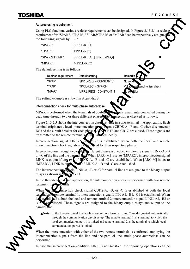
120
6 F 2 S 0 8 5 0
Autoreclosing requirement Using PLC function, various reclose requirements can be designed. In Figure 2.15.2.1, a reclose requirement for "SPAR", "TPAR", "SPAR&TPAR" or "MPAR" can be respectively assigned to the following signals by PLC:
"SPAR": [SPR.L-REQ]
"TPAR": [TPR.L-REQ]
"SPAR&TPAR": [SPR.L-REQ], [TPR.L-REQ]
"MPAR": [MPR.L-REQ]
The default setting is as follows:
Reclose requirement Default setting Remarks "SPAR" [SPR.L-REQ] = CONSTANT_1 No condition "TPAR" [TPR.L-REQ] = SYP-ON Voltage and synchronism check "MPAR" [MPR.L-REQ] = CONSTANT_1 No condition
The setting example is shown in Appendix S.
Interconnection check for multi-phase autoreclose MPAR is performed when the terminals of double-circuit lines remain interconnected during the dead time through two or three different phases. Interconnection is checked as follows.
Figure 2.15.2.5 shows the interconnection check scheme in a two-terminal line application. Each terminal originates a local interconnection check signals CBDS-A, -B and -C when disconnector DS and the circuit breaker for each phase CB1A, CB1B and CB1C are closed. These signals are transmitted to the remote terminals as well as used locally.
Interconnection signal LINK-A, -B or -C is established when both the local and remote interconnection check signals are established for their respective phases.
Interconnection through two or three different phases is checked employing signals LINK-A, -B or –C of the line and the parallel line. When [ARC-M] is set to "MPAR2", interconnection signal LINK is output if any two of LINK-A, -B and -C are established. When [ARC-M] is set to "MPAR3", LINK is output if all of LINK-A, -B and -C are established.
The interconnection signals LINK-A, -B or -C for parallel line are assigned to the binary output relays as shown in Appendix D.
In the three-terminal line application, the interconnection check is performed with two remote terminals independently.
When the interconnection check signal CBDS-A, -B, or -C is established at both the local terminal and remote terminal 1, interconnection signal LINK-A1, -B1, -C1 is established. When it is established at both the local and remote terminal 2, interconnection signal LINK-A2, -B2 or -C2 is established. Those signals are assigned to the binary output relays and output to the parallel line.
Note: In the three-terminal line application, remote terminal 1 and 2 are designated automatically through the communication circuit setup. The remote terminal 1 is a terminal to which the local communication port 1 is linked and remote terminal 2 is the terminal to which local communication port 2 is linked.
When the interconnection with either of the two remote terminals is confirmed employing the interconnection signals from the line and the parallel line, multi-phase autoreclose can be performed.
In case the interconnection condition LINK is not satisfied, the following operations can be www . El
ectric
alPar
tMan
uals
. com
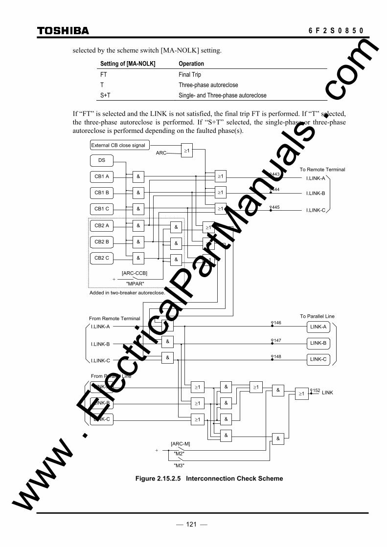
121
6 F 2 S 0 8 5 0
selected by the scheme switch [MA-NOLK] setting.
Setting of [MA-NOLK] Operation FT Final Trip T Three-phase autoreclose S+T Single- and Three-phase autoreclose
If “FT” is selected and the LINK is not satisfied, the final trip FT is performed. If “T” selected, the three-phase autoreclose is performed. If “S+T” selected, the single-phase or three-phase autoreclose is performed depending on the faulted phase(s).
"M3"
& CB1 A
DS
&
&
CB1 C
CB1 B
&
CB2 B
CB2 A
&
&
I.LINK-A
[ARC-CCB]
"MPAR" +
Added in two-breaker autoreclose.
From Remote Terminal
I.LINK-B
I.LINK-C
CB2 C
&
≥1 ≥1≥1
≥1
≥1
I.LINK-A
I.LINK-B
I.LINK-C
LINK-A
LINK-C
From Parallel Line
LINK-B
& &
&
&
&
&
LINK-A
LINK-C
To Remote Terminal
To Parallel Line
LINK
+ "M2"
[ARC-M]
LINK-B
≥1
≥1
≥1
&
&
&
≥1
≥1
≥1
&
&
External CB close signal ≥1ARC
443
444
445
146
147
148
152
Figure 2.15.2.5 Interconnection Check Scheme
www . El
ectric
alPar
tMan
uals
. com

122
6 F 2 S 0 8 5 0
Permanent fault When reclose-onto-a-fault is activated when a permanent fault exists, three-phase final tripping is performed. However, this operation is performed only in the single-shot autoreclose mode. In the multi-shot autoreclose mode, reclosing is retried as shown below, for multi-shot autoreclosing.
Multi-shot autoreclose In a multi-shot autoreclose, low-speed autoreclose is executed up to three times after high-speed autoreclose fails. The first shot is high-speed autoreclose that functions in the same manner as described for single-shot autoreclose. Figure 2.15.2.6 shows the simplified scheme logic for the low-speed autoreclose of the second to fourth shot.
F/F
F/F
F/F
F/F
&
≥ 1 SP2 SP1 FT
MSARC1
≥ 1
≥ 1
FT MSARC2
SP1
F/FFT
MSARC3 SP2
5 - 300s
FT ARC3 ARC2
SYN-OP
"S2", "S3", "S4" +
TP
ARC1
ARC1
t 0
STEP COUNTER
MSARC
SP3 SP2 SP1
MSARC1 TS2R
TS2
5 - 300s
t 0
&≥ 1
5 - 300s
t 05 - 300s
t 0
5 - 300s
t 05 - 300s
t 0
MSARC2
MSARC3 TS4R
FT FT2FT1
TS4
TS3R
TS3
&SP2
SP1
&SP3 FT3
&
≥ 1
&
≥ 1
≥ 1
&
&
&
CLR
CLOCK
1
0.1s
0 t
MSARC ≥1
FT
"S3"
"S4"
"S2"
[ARC-SM]
[ARC-SM]
0.5s
Figure 2.15.2.6 Scheme Logic for Multi-Shot Autoreclose
The multi-shot mode, two shots to four shots, is set with the scheme switch [ARC-SM].
In low-speed autoreclose, the dead time counter TS2 for the second shot is activated if high-speed autoreclose is performed (ARC = 1), but tripping occurs again (TP = 1). Second shot autoreclose is performed only when the voltage and synchronism check element operates (SYN-OP = 1) after the period of time set on TS2 has elapsed. At this time, outputs of the step counter are: SP1 = 1, SP2 = 0, and SP3 = 0.
Autoreclose is completed at this step if the two-shot mode is selected for the multi-shot mode. Therefore, the tripping following the "reclose-onto-a-fault" becomes the final tripping (FT = 1).
If the voltage and synchronism check element does not operate within the period of time set on the timer TS2R which is started at the same time as TS2 is started, the multi-shot autoreclose is cancelled (FT = 1). www .
Elec
tricalP
artM
anua
ls . c
om
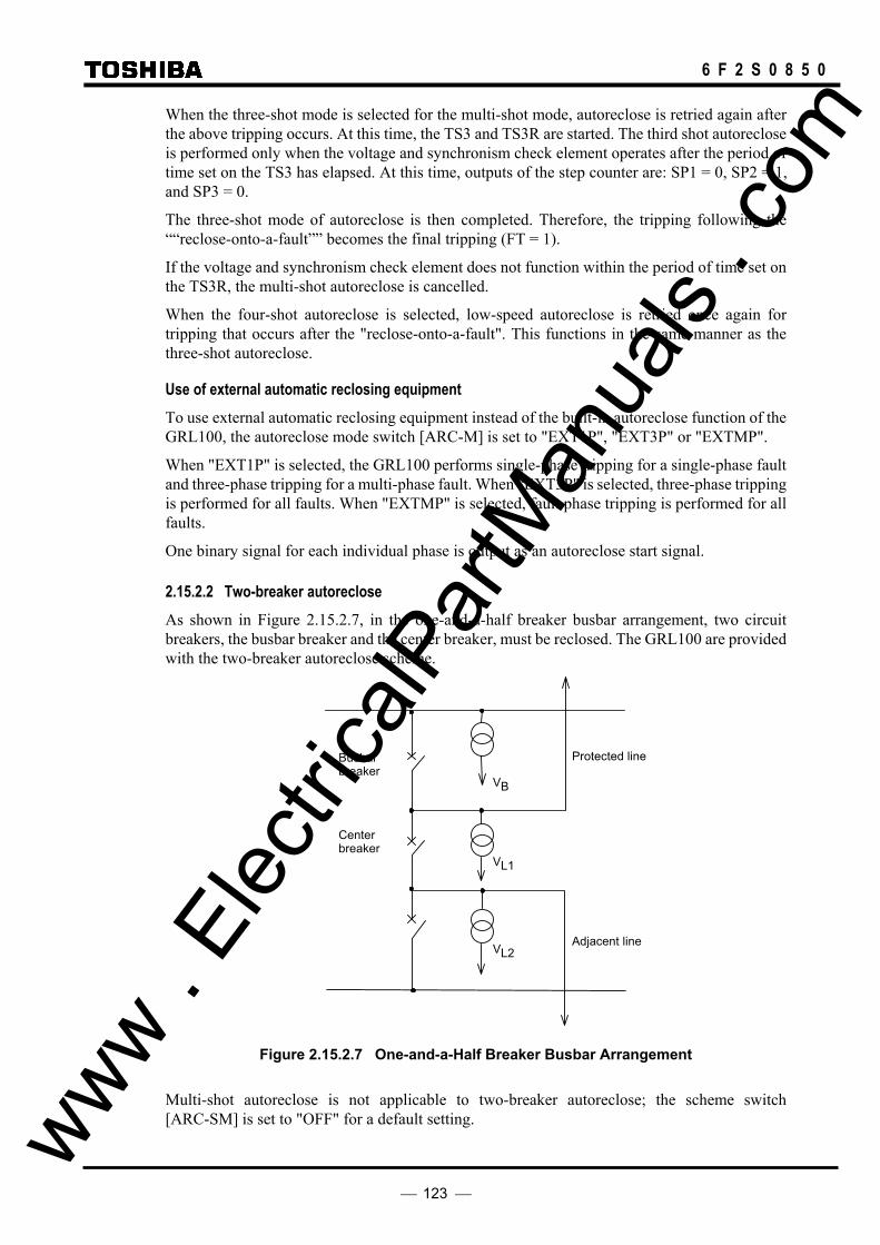
123
6 F 2 S 0 8 5 0
When the three-shot mode is selected for the multi-shot mode, autoreclose is retried again after the above tripping occurs. At this time, the TS3 and TS3R are started. The third shot autoreclose is performed only when the voltage and synchronism check element operates after the period of time set on the TS3 has elapsed. At this time, outputs of the step counter are: SP1 = 0, SP2 = 1, and SP3 = 0.
The three-shot mode of autoreclose is then completed. Therefore, the tripping following the ““reclose-onto-a-fault”” becomes the final tripping (FT = 1).
If the voltage and synchronism check element does not function within the period of time set on the TS3R, the multi-shot autoreclose is cancelled.
When the four-shot autoreclose is selected, low-speed autoreclose is retried once again for tripping that occurs after the "reclose-onto-a-fault". This functions in the same manner as the three-shot autoreclose.
Use of external automatic reclosing equipment To use external automatic reclosing equipment instead of the built-in autoreclose function of the GRL100, the autoreclose mode switch [ARC-M] is set to "EXT1P", "EXT3P" or "EXTMP".
When "EXT1P" is selected, the GRL100 performs single-phase tripping for a single-phase fault and three-phase tripping for a multi-phase fault. When "EXT3P" is selected, three-phase tripping is performed for all faults. When "EXTMP" is selected, fault phase tripping is performed for all faults.
One binary signal for each individual phase is output as an autoreclose start signal.
2.15.2.2 Two-breaker autoreclose As shown in Figure 2.15.2.7, in the one-and-a-half breaker busbar arrangement, two circuit breakers, the busbar breaker and the center breaker, must be reclosed. The GRL100 are provided with the two-breaker autoreclose scheme.
Center breaker
Busbar breaker
VL2
VL1
VB
Protected line
Adjacent line
Figure 2.15.2.7 One-and-a-Half Breaker Busbar Arrangement
Multi-shot autoreclose is not applicable to two-breaker autoreclose; the scheme switch [ARC-SM] is set to "OFF" for a default setting. www .
Elec
tricalP
artM
anua
ls . c
om

124
6 F 2 S 0 8 5 0
Autoreclose is not activated when an autoreclose prohibiting binary input signal is applied at the local or remote terminal.
• ARC_BLOCK signal common for leader and follower CB
• ARC_BLOCK1 signal for leader CB
• ARC_BLOCK2 signal for follower CB
The autoreclose scheme is different depending on the reclosing mode.
Single-phase autoreclose and single- and three-phase autoreclose The breaker(s) to be reclosed and the reclosing order can be set by the scheme switch [ARC-CB] as follows:
Setting of [ARC-CB] Autoreclose mode ONE (Set when applied to a one-breaker system) O1 Only the busbar breaker is reclosed and the center breaker is subjected to final tripping. O2 Only the center breaker is reclosed and the busbar breaker is subjected to final tripping. L1 Single-phase autoreclose: Both breakers are reclosed simultaneously. (∗1) Three-phase autoreclose: The busbar breaker is reclosed first. If successful, then the
center breaker is reclosed. L2 Single-phase autoreclose: Both breakers are reclosed simultaneously. (∗1) Three-phase autoreclose: The center breaker is reclosed first. If successful, then the
busbar breaker is reclosed. Note : "ONE" is set only when the relay is applied to a one-breaker system. Trip and reclose
commands are output only for CB1(bus CB). (∗1): Sequential autoreclose can be applied by changing of the dead timer setting or the PLC
setting. (∗2): When [ARC-M] – MPAR is selected, the autoreclose mode depends on the [ARC-CCB]
setting and the [ARC-CB] is not applied.
The autoreclose scheme logic for the two circuit breakers is independent of each other and are almost the same. The autoreclose scheme logic of the circuit breaker to be reclosed first (lead breaker) is the same as that shown in Figure 2.15.2.1. The scheme logic of the circuit breaker to be reclosed later (follower breaker) is shown in Figure 2.15.2.8.
The start of the dead time counter can be configured by the PLC. In the default setting, the single-phase autoreclose is started instantaneously after tripping, and the three-phase autoreclose is started after the ARC-SET condition is satisfied.
The “ARC-SET” is a scheme signal whose logical level becomes 1 when a leader breaker’s autoreclose command is output.
In default setting, therefore, the dead time of the follower breaker is as follows:
• Three-phase autoreclose: equal to the sum of the dead time setting of the two breakers. (TTPR1 + TTPR2)
• Single-phase autoreclose: TSPR2
However, the dead time can be set that of the leader breaker by the PLC setting “RF.ST-REQ”. The shortening of the dead time can be also applied when the leader breaker is final-tripped because it is no ready.
www . El
ectric
alPar
tMan
uals
. com

125
6 F 2 S 0 8 5 0
Autoreclose start requirement Using PLC function, various autoreclose start requirements can be designed. In Figure 2.15.2.8, a reclose start requirement for "SPAR", "TPAR", "SPAR&TPAR" or "MPAR" can be respectively assigned to the following signals by PLC:
"SPAR": [SPR.F-ST.REQ]
"TPAR": [TPR.F-ST.REQ]
"SPAR&TPAR": [SPR.F-ST.REQ], [TPR.F-ST.REQ]
"MPAR": [MPR.F-ST.REQ]
The default setting for the follower CB autoreclose start requirement is as follows:
Reclose start requirement
Default setting Remarks
"SPAR" [SPR.F-ST.REQ] = CONSTANT_1 No condition "TPAR" [TPR.F-ST.REQ] = ARC-SET or CCB-SET ARC-SET becomes “1” when the leader CB is
reclosed. CCB-SET becomes “1” when [ARC-M]=M2 or M3 and [ARC-CCB]=TPAR setting.
"MPAR" [MPR.F-ST.REQ] = CONSTANT_1 No condition
Autoreclose requirement The autoreclose requirement can be designed by assigning a reclose requirement to the signals [SPR.F-REQ], [TPR.F-REQ] and [MPR.F-REQ] same as above.
The default setting for the follower CB autoreclose requirement is as follows:
Reclose requirement Default setting Remarks "SPAR" [SPR.F-REQ] = CONSTANT_1 No condition "TPAR" [TPR.F-REQ] = SYP-ON Voltage and synchronism check "MPAR" [MPR.F-REQ] = CONSTANT_1 No condition
Others
If the autoreclose start requirement is designed such as starting the follower CB in no-ready condition of the leader CB, it is assigned to the signal [R.F-ST.REQ].
By assigning the autoreclose start requirement to the signal [R.F-ST.REQ], both the leader CB and the follower CB are set the same dead time. The reclose requirement is assigned to the signals [SPR.F2-ST.REQ], [TPR.F2-ST.REQ] and [MPR.F2-ST.REQ].
The default setting for the follower CB is as follows:
Requirement Default setting Reclose requirement [R.F-ST.REQ] = CONSTANT_0 (No used) Reclose start requirement "SPAR" [SPR.F2-ST.REQ] = CONSTANT_0 (No used) "TPAR" [TPR.F2-ST.REQ] = CONSTANT_0 (No used) "MPAR" [MPR.F2-ST.REQ] = CONSTANT_0 (No used)
www . El
ectric
alPar
tMan
uals
. com

126
6 F 2 S 0 8 5 0
"SPAR", "TPAR", "SPAR & TPAR", "MPAR2", "MPAR3" &
+ [ARC-M]
5-300s
t 0
& 52A 52B 52C
CB2_READY 1572 &
TP
Single-phase trip
+[ARC-M]
"SPAR", "SPAR & TPAR"
&
No-Link & Single-phase trip
+[ARC-M]
"MPAR2", "MPAR3"
&
0.01-10s
t 0 TRDY2 TSPR2
SPR.F2-ST.REQ 1837"Default =CONSTANT 0"
"Default =CONSTANT 0"
+[ARC-M]
&
"MPAR2", "MPAR3"
&
OSTT
RETRIPSTUB
DIFG.FS-TRIP[ARC-DIFG] &
+"OFF"
BU-TRIP[ARC-BU] &
"OFF"
ARC_BLOCK1574
≥1
&
LINK
Single-phase trip
0.01-10s
t 0TEVLV
Multi-phase trip
+[ARC-M]
"SPAR & TPAR"
&
≥1
0.01-100s
t 0TRR
0.1 - 10s
TW2
0.1s
0.2s
≥1
ARC(*)
(*)ARC
(For Follower CB)
(For Follower CB)
FT ≥1
ARC (For Follower CB)
(For Follower CB)
(For Follower CB)
M-TRIPA
FT
F/F
SPR.F-ST.REQ1830"Default =CONSTANT 1"
≥1
≥1 &
0.01-10s
t 0 TSPR1
&
& ≥1
Multi-phase trip
+[ARC-M]
"MPAR2", "MPAR3"
&
No-Link & Multi-phase trip
+[ARC-M]
"MPAR2", "MPAR3"
&
0.01-10s
t 0 TTPR2
TPR.F2-ST.REQ 1838TPR.F-ST.REQ1831
"Default ="ARC-SET" or "CCB-SET"
≥1
≥1 &
0.01-100s
t 0 TTPR1
&
&
LINK condition for MPAR is not satisfied.
Trip when ARC2 READY not operated.
Multi phase trip in SPAR.
+[ARC-CCB]
"TPAR"
+[ARC-M]
"MPAR2", "MPAR3"
&
0.01-10s
t 0 TMPR2
MPR.F2-ST.REQ 1839"Default =CONSTANT 0"
≥1
0.01-10s
t 0 TMPR1
&
&
MPR.F-ST.REQ1832"Default =CONSTANT 1"
R.F-ST.REQ 1836
"Default =CONSTANT 0"
ARC2 READY
( From Figure 2.10.2.1. )
&
SPR.F-REQ 1827"Default =CONSTANT 1"
&
&
TPR.F-REQ 1828"Default =CONSTANT 1"
&
&
MPR.F-REQ 1829"Default =CONSTANT 1"
&
ARC FAIL
(For Follower CB)
+[ARC-SUC]
&
"ON"
ARC_BLOCK21579≥1
Figure 2.15.2.8 Autoreclose Scheme for Follower Breaker
www . El
ectric
alPar
tMan
uals
. com

127
6 F 2 S 0 8 5 0
Figure 2.15.2.9 shows the energizing control scheme of the two circuit breakers in the three-phase autoreclose. OVB and UVB are the overvoltage and undervoltage detectors of busbar voltage VB in Figure 2.15.2.7. OVL1 and UVL1 are likewise the overvoltage and undervoltage detectors of line voltage VL1.
OVL2 and UVL2 are likewise the overvoltage and undervoltage detectors of line voltage VL2. VL2 in the center breaker is equivalent to the busbar voltage VB in the busbar breaker.
SYN1 and SYN2 are the synchronism check elements to check synchronization between the two sides of the busbar and center breakers, respectively. SYN-OP is a voltage and synchronism check output.
&
SYN2
UVL2
OVL2
UVL1
OVL1
SYN1
UVB
OVB
[VCHK]
"LB2"
"LB1"
"DB"
"SYN"
"OFF"
TLBD1
0.01 - 1sTDBL1
0.01 - 1s
0.01 - 10s
0.01 - 1s
0.01 - 1s
0.01 - 10s
≥1≥1
&
&
&
&
&&
&
1
&
&
TSYN1
≥1
≥1
"ONE"
"L1"
"L2"
"01"
"02"
[ARC-CB]
ARC-SET
+
+
≥1&
&
TLBD2
TDBL2
TSYN2
1
&
&
&
SYN-OP
57
58
60
61
59
159
62
63
64
T3PLL
0.01 - 1s
3PLL (Three phase live line)
498OVL1 (3PH)
78
Note : [ARC-CB] is set to "ONE" only when the relay is applied to one-breaker system. Trip and reclose
commands are output only for CB1(bus CB).
Figure 2.15.2.9 Energizing Control Scheme for Two Circuit Breakers
www . El
ectric
alPar
tMan
uals
. com

128
6 F 2 S 0 8 5 0
The voltage and synchronism check is performed as shown below according to the [ARC-CB] settings:
Setting of [ARC-CB] Voltage and synchronism check ONE or O1 A voltage and synchronism check is performed using voltages VB and VL1.
O2 A voltage and synchronism check is performed using voltages VL1 and VL2.
L1 Since the logical level of ARC-SET is 0, a voltage and synchronism check is performed for the busbar breaker using voltages VB and VL1. Then, the logical level of ARC-SET becomes 1 and a voltage and synchronism check is performed for the center breaker using voltages VL1 and VL2 and a reclosing command is output to the center breaker.
L2 A voltage and synchronism check is performed for the center breaker using voltages VL1 and VL2. Then, the logical level of ARC-SET becomes 1 and a voltage and synchronism check is performed for the busbar breaker using voltages VB and VL1.
Note : "ONE" is set only when the relay is applied to one-breaker system. Trip and reclose commands are output only for CB1(bus CB).
The energizing control for the two circuit breakers can be set by the scheme switch [VCHK] as follows:
Setting of [VCHK] Energizing control LB1 The lead breaker is reclosed under the "live bus and dead line" condition or with
synchronism check, and the follower breaker is reclosed with synchronism check only. LB2 The leader breaker is reclosed under the "live bus and dead line" condition or with
synchronism check, and the follower breaker is reclosed under the "dead bus and live line" condition or with synchronism check.
DB Both breakers are reclosed under the "dead bus and live line" condition or with synchronism check.
SYN Both breakers are reclosed with synchronism check only. OFF Both breakers are reclosed without voltage and synchronism check.
Multi-phase autoreclose The scheme switch [ARC-M] is set to "MPAR2" or "MPAR3", then the busbar breaker is always reclosed in the multi-phase autoreclose mode.
The center breaker can select three-phase autoreclose, multi-phase autoreclose or three-phase final tripping by setting the scheme switch [ARC-CCB] shown in Figure 2.15.2.5.
When [ARC-CCB] is set to "TPAR", the logic level of CCB-SET signal becomes 1 and the center breaker is reclosed in the three-phase autoreclose mode only after the busbar breaker is successfully reclosed. If the voltage check condition is configured by the PLC, the energizing control for the center breaker is dependent on the setting of the scheme switch [VCHK] as follows.
Setting of [VCHK] Energizing control LB Reclosed under the "live bus and dead line" condition or with synchronism check. DB Reclosed under the "dead bus and live line" condition or with synchronism check. SYN Reclosed with synchronism check only. OFF Reclosed without voltage and synchronism check. Note: As this three-phase autoreclose is applied only to the center breaker, the settings of the
[VCHK] is the same as that of one-breaker autoreclose. www . El
ectric
alPar
tMan
uals
. com

129
6 F 2 S 0 8 5 0
When [ARC-CCB] is set to "MPAR", the center breaker is also reclosed in the multi-phase autoreclose mode at the time of the TMPR2 setting.
When [ARC-CCB] is set to "OFF", autoreclose does not start for the center breaker.
The scheme switch [ARC-CCB] used in single-phase autoreclose and single- and three-phase autoreclose is invalid when multi-phase autoreclose is selected as a reclose mode.
The interlinking check scheme for two-breaker autoreclose is shown in Figure 2.15.2.5. Local interlink check signals CBDS-A, -B and –C are originated by ORing the busbar and center breaker conditions.
The scheme switch [ARC-SUC] is used to check the autoreclose succeeds. If all three phase CB contacts have been closed within TSUC time after ARC shot output, it is judged that the autoreclose has succeeded (AS). If not, it is judged that the autoreclose has failed (AF), and becomes the final tripping (FT).
The relay provides the user configurable switch [UARCSW] with three-positions (P1, P2, P3) to be programmed by using PLC function. Any position can be selected. If this switch is not used for the PLC setting, it is invalid. The setting example is shown in Appendix S.
2.15.2.3 Setting The setting elements necessary for the autoreclose and their setting ranges are shown in the table below.
Element Range Step Default Remarks VT 1 - 20000 1 2000 VT ratio for line differential protection VTs1 1 - 20000 1 2000 VT ratio for voltage and synchronism check TSPR1 0.01 – 10.00s 0.01s 0.80s Dead time for single-phase autoreclose and
multi-phase autoreclose TTPR1 0.01 – 100.00s 0.01s 0.60s Dead time for three-phase autoreclose TMPR1 0.01 – 100.00s 0.01s 0.80s Dead time for multi-phase autoreclose TRR 0.01 – 100.00s 0.01s 2.00s Autoreclose reset time TEVLV 0.01 – 10.00s 0.01s 0.30s Dead time reset for evolving fault TRDY1 5 – 300s 1s 60s Reclaim time SYN1 Synchronism check SY1 θ 5 – 75° 1° 30° SY1UV 10 – 150V 1V 83V SY1OV 10 – 150V 1V 51V OVB 10 – 150V 1V 51V Live bus check UVB 10 – 150V 1V 13 V Dead bus check OVL1 10 – 150V 1V 51V Live line check UVL1 10 – 150V 1V 13V Dead line check TSYN1 0.01 – 10.00s 0.01s 1.00s Synchronism check time TLBD1 0.01 – 1.00s 0.01s 0.05s Voltage check time TDBL1 0.01 – 1.00s 0.01s 0.05s Voltage check time T3PLL 0.01 – 1.00s 0.01s 0.05s Line three voltage check time TW1 0.1 – 10.0s 0.1s 0.2s Reclosing signal output time TS2 5.0 – 300.0s 0.1s 20.0s Second shot dead time TS3 5.0 – 300.0s 0.1s 20.0s Third shot dead time TS4 5.0 – 300.0s 0.1s 20.0s Fourth shot dead time www .
Elec
tricalP
artM
anua
ls . c
om

130
6 F 2 S 0 8 5 0
Element Range Step Default Remarks TS2R 5.0 – 300.0s 0.1s 30.0s Second shot reset time TS3R 5.0 – 300.0s 0.1s 30.0s Third shot reset time TS4R 5.0 – 300.0s 0.1s 30.0s Fourth shot reset time TSUC 0.1 – 10.0s 0.1s 3.0s Autoreclose success check time [ARC – M] Disabled/SPAR/TPAR/
SPAR & TPAR/MPAR2/MPAR3/ EXT1P/EXT3P/EXTMP
SPAR & TPAR Autoreclose mode
[ARCDIFG] OFF/ON OFF High-resistance fault autoreclose [ARC-BU] OFF/ON OFF Backup trip autoreclose [ARC-EXT] OFF/ON OFF External start [ARC – SM] OFF/S2/S3/S4 OFF Multi – shot autoreclose mode [ARC-SUC] OFF/ON OFF Autoreclose success checking [MA-NOLK] FT/T/S+T FT Control under NON-LINK in MPAR [VCHK] OFF/LB/DB/SYN LB Energizing direction [VTPHSEL] A/B/C A Phase of reference voltage [VT – RATE] PH/G / PH/PH PH/G VT rating [3PH – VT] BUS/LINE LINE Location of three – phase VTs [UARCSW] P1/P2/P3 (P1)(∗) User ARC switch for PLC
(∗) If this switch is not used for PLC setting, it is invalid.
“VT” is VT ratio setting of protection, and “VTs1” is VT ratio setting of a reference voltage input for voltage and synchronism check element as shown in Figure 2.16.9.1.
In a voltage setting, set “SY1UV”, “SY1OV”, “OVB”, “UVB”, “OVL1” and “UVL1” based on the VT rating for voltage and synchronism check. (When a voltage rating between line VT and busbar VT is different as shown in Figure 2.15.2.10, the voltage input from “VT” is matched to the rating of “VTs1” using the setting of “VT” and “VTs1”.)
CB
Line VT
Busbar VT
VT settingGRL100
Busbar
Line
VL
X
VTs1 setting
VBReference voltage for voltage and synchronism check
For line differentialprotection
Figure 2.15.2.10 VT and VTs1 Ratio Setting for Busbar or Line Voltage
To determine the dead time, it is essential to find an optimal value while taking into consideration the de-ionization time and power system stability factors, which normally contradict each other.
Normally, a longer de-ionization time is required for a higher line voltage or larger fault current. For three-phase autoreclose, the dead time is generally 15 to 30 cycles. In single-phase autoreclose, the secondary arc current induced from the healthy phases may affect the de-ionization time. Therefore, it is necessary to set a longer dead time for single-phase autoreclose compared to that for three-phase autoreclose. www .
Elec
tricalP
artM
anua
ls . c
om

131
6 F 2 S 0 8 5 0
In three-phase autoreclose, if the voltage and synchronism check does not operate within the period of time set on the on-delay timer TRR, which is started at the same time as the dead time counter TTPR1 is started, reclosing is not performed and three-phase autoreclose is reset to its initial state. Therefore, for example, the TRR is set to the time setting of the TTPR1 plus 100ms.
The TEVLV determines the possibility of three-phase reclosing for an evolving fault.
When the TEVLV is set to the same setting as the TSPR, three-phase reclosing is performed for all evolving faults. As the setting for the TEVLV is made shorter, the possibility of three-phase reclosing for an evolving fault becomes smaller and that of three-phase final tripping becomes larger.
For the two-breaker autoreclose, the following additional settings are required.
Element Range Step Default Remarks VTs2 1 - 20000 1 2000 VT ratio for voltage and synchronism checkSYN2 TSPR2 0.1 – 10.0s 0.1s 0.1s Dead time for single-phase autoreclode of follower
breaker TTPR2 0.1 – 10.0s 0.1s 0.1s Dead time for three-phase autoreclode of follower
breaker TMPR2 0.1 – 10.0s 0.1s 0.1s Dead time for multi-phase autoreclode of follower
breaker TRDY2 5 – 300s 1s 60s Reclaim time of follower breaker SYN2 Synchronism check SY2 θ 5 – 75° 1° 30° SY2UV 10 – 150V 1V 83V SY2OV 10 – 150V 1V 51V OVL2 10 – 150V 1V 51V Live line check UVL2 10 – 150V 1V 13V Dead line check TSYN2 0.01 – 10.00s 0.01s 1.00s Synchronism check time TLBD2 0.01 – 1.00s 0.01s 0.05s Voltage check time TDBL2 0.01 – 1.00s 0.01s 0.05s Voltage check time TW2 0.1 – 10.0s 0.1s 0.2s Reclosing signal output time [ARC-CB] ONE/O1/O2/L1/L2 L1 Two breaker autoreclose mode [ARC-CCB] TPAR/MPAR/OFF MPAR Center breaker autoreclose mode [VCHK] OFF/LB1/LB2/DB/SYN LB1 Energizing direction
Note : [ARC-CB] is set to "ONE" only when the relay is applied to one-breaker system. Trip and reclose commands are output only for CB1(bus CB).
2.15.3 Autoreclose Output Signals
The autoreclose scheme logic has two output reclosing signals: ARC1 and ARC2. ARC1 is a reclosing signal for single breaker autoreclose or a reclosing signal for the busbar breaker in a two-breaker autoreclose scheme.
ARC2 is the reclosing signal for the center breaker of the two-breaker autoreclose scheme.
The assignment of these reclosing signals to the output relays can be configured, which is done using the setting menu. For details, see Section 3.2.2. For the default setting, see Appendix D.
www . El
ectric
alPar
tMan
uals
. com

132
6 F 2 S 0 8 5 0
2.16 Characteristics of Measuring Elements
2.16.1 Segregated-phase Current Differential Element DIF and DIFSV
The segregated-phase current differential elements DIF have dual percentage restraint characteristics. Figure 2.16.1.1 shows the characteristics on the differential current (Id) and restraining current (Ir) plane. Id is a vector summation of the phase current of all terminals and Ir is a scalar summation of the phase current of all terminals. In these summations, charging current is eliminated from the phase currents by the charging current compensation function.
Figure 2.16.1.1 Segregated-phase Current Differential Element (Ir-Id Plane)
Characteristic A of the DIF element is expressed by the following equation:
Id ≥ (1/6)Ir + (5/6)DIFI1
where DIFI1 is a setting and defines the minimum internal fault current.
This characteristic has weaker restraint and ensures sensitivity to low-level faults.
Characteristic B is expressed by the following equation:
Id ≥ Ir - 2 × DIFI2
where DIFI2 is a setting and its physical meaning is described later.
This characteristic has stronger restraint and prevents the element from operating falsely in response to the erroneous differential current which is caused by saturation or transient errors of the CT during an external fault. If the CT saturation occurs at the external fault in a small current region of the characteristics and continues, the element may operate falsely caused by increasing the erroneous differential current. The DIF prevents the false operation by enhancing the restraining quantity for the DIF calculation, depending on the magnitude of restraining current in the large current region characteristic B.
The figure shows how the operation sensitivity varies depending on the restraining current.
The same characteristic can be represented on the outflowing current (Iout) and infeeding current (Iin) plane as shown in Figure 2.16.1.2.
Large current region Ir
B
Id
0
A 5/6 DIFI1
−2 × DIFI2
Small current region
Operating Zone
www . El
ectric
alPar
tMan
uals
. com

133
6 F 2 S 0 8 5 0
Figure 2.16.1.2 Segregated-phase Current Differential Element (Iin-Iout Plane)
Characteristic A is expressed by the following equation:
Iout ≤ (5/7)(Iin - DIFI1)
Characteristic B is expressed by the following equation:
Iout ≤ DIFI2
This figure shows the physical meaning of setting DIFI2, that is, DIFI2 defines the maximum outflowing current in case of an internal fault which can be detected by the relay. This outflowing current can be significant particularly in the case of a double-circuit three-terminal line or three-terminal line with outer loop circuit. Depending on the fault location, part of the fault current flows out from one terminal and flows in from another terminal. For details of the outflowing fault current, see Sections 2.2.10 and 2.2.12.
2.16.2 Zero-phase Current Differential Element DIFG
The DIF element is not too insensitive to detect a high-impedance earth fault, but to detect such faults under a heavy load current, the GRL100 is provided with a protection using a residual current.
Figure 2.16.2.1 represents the percentage restraining characteristic of the residual current differential element. Differential current (Id) is a vector summation of the residual currents of all terminals and restraining current (Ir) is a scalar summation of the residual currents of all terminals.
Id
Ir
5/6 DIFGI
Operating Zone
Figure 2.16.2.1 Zero-phase Current Differential Element (Ir-Id Plane)
The characteristic of the DIFG element is the same as that of the DIF element in the small current region and is expressed by the following equation:
Operating Zone
B
Iout = Iin
Iout
A
0 DIFI1 Iin
DIFI2
www . El
ectric
alPar
tMan
uals
. com

134
6 F 2 S 0 8 5 0
Id ≥ (1/6)Ir + (5/6)DIFGI
where DIFGI is a setting and defines the minimum residual fault current.
2.16.3 Distance Measuring Elements Z1, Z2, Z3, Z4, ZR and PSB
The GRL100 provides eight distance measuring zones with mho-based characteristics or quadrilateral characteristics.
As shown in Figure 2.16.3.1, mho-based zone characteristics are composed of mho element, offset mho element, impedance element, reactance element, and blinder element for phase fault protection and earth fault protection.
Z1 (zone 1) and Z2 (zone 2) are a combination of the reactance element, mho element and blinder element.
Z3 (zone 3), ZR (reverse zone R) and Z4 use the mho element and blinder element, but Z4 for phase faults uses the offset mho element instead of mho element. This makes it possible to detect a reverse close-up fault at high speed if Z4 for phase faults is used for the command protection.
The blinder element is normally used to restrict the resistive reach of the mho or offset mho element if their operating range encroaches upon the load impedance.
The blinder element (BFR) can be provided for each forward zone. The setting of blinder element can be set independently or set common to forward zones by the scheme switch [BLZONE].
Z1
Z2
Z3
Z4
BFR1,2,3
BRR
Z1
Z2
Z3
Z4
BFR1,2,3
BRR
Z3Sθ
Z1Sθ175°
Z3Gθ
Z1Gθ1 75°
ZR ZR
(a) Phase fault element (b) Earth fault element
Figure 2.16.3.1 Mho-based Characteristics
As shown in Figure 2.16.3.2, quadrilateral zone characteristics are composed of reactance element, directional element and blinder element. Z4 for phase faults uses the offset directional element to ensure a reverse close-up fault detection.
The forward offset reach of reverse zone ZR for both mho-based and quadrilateral characteristics is fixed as 7.5 ohms for 1A rating or 1.5 ohms for 5A rating. However, when they are used for back-up tripping ([ZRTP]= "ON"), the forward offset reach is limited to the zone 1 reach setting, as shown in Figure 2.16.3.3. Z4, on the other hand, is normally used to provide blocking in the command schemes, and its offset is not limited by the zone 1 reach setting. It is fixed at 7.5Ω (or 1.5Ω) in order to give reliable, fast blocking for a close-up reverse fault. www .
Elec
tricalP
artM
anua
ls . c
om

135
6 F 2 S 0 8 5 0
Z1
Z2
Z3
Z4
BFR1,2,3
BRR
Z1
Z2
Z3
Z4
BFR1,2,3
BRR
ZR ZR
(a) Phase fault element (b) Earth fault element
Figure 2.16.3.2 Quadrilateral Four Zone Characteristics
(a) Mho-based characteristic
R
X
ZRS
Z1S
(b) Quadrilateral characteristic
R
X
Z1S
ZRS
Figure 2.16.3.3 ZRS Characteristic Offset Reach for Backup Tripping
Zone 1 and zone 2 can trip on condition that zone 3 has operated, in both characteristics.
The power swing blocking elements (PSBS and PSBG) are a combination of the reactance element and blinder element as shown in Figure 2.16.3.4. The outer element PSBOUT encloses the inner element PSBIN with a settable width of PSBZ.
PSBZ
PSBZ PSBZ 0
PSBZ
PSBIN PSBOUT
R
X
Z3
Z4 ZR
Figure 2.16.3.4 Power Swing Blocking Element www .
Elec
tricalP
artM
anua
ls . c
om

136
6 F 2 S 0 8 5 0
Mho element The characteristic of the mho element is obtained by comparing the phases between signals S1 and S2. If the angle between these signals is 90° or more, it means that the fault is within the mho characteristic, and the mho element will operate.
S1 = V − IZs
S2 = Vp
where,
V = fault voltage
I = fault current
Zs = zone reach setting
Vp = polarizing voltage
Figure 2.16.3.5 is a voltage diagram, which shows that the mho characteristic is obtained by the phase comparison if V and Vp are in-phase.
The mho characteristic on the impedance plane is obtained by dividing the voltage in Figure 2.16.3.5 by current I.
Figure 2.16.3.5 Mho Element
Both the phase fault mho element and earth fault mho element of the GRL100 employ a dual polarization (self-polarization plus cross-polarization). Its polarizing voltage Vp is expressed by the following equations.
For B-to-C-phase phase fault element
Vpbc = 3 (Va − V0) ∠ − 90° + Vbc
For an A-phase earth fault element
Vpa = 3 (Va − V0) + Vbc ∠90°
where,
Va = A-phase voltage
V0 = zero-sequence voltage
Vbc = B-to-C-phase voltage
The dual-polarization improves the directional security when applied to heavily loaded lines or weak infeed terminals.
R
V
IZs
S2 = Vp S1 = V − IZs
X
www . El
ectric
alPar
tMan
uals
. com
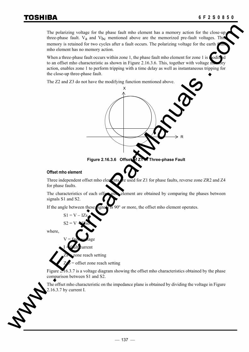
137
6 F 2 S 0 8 5 0
The polarizing voltage for the phase fault mho element has a memory action for the close-up three-phase fault. Va and Vbc mentioned above are the memorized pre-fault voltages. This memory is retained for two cycles after a fault occurs. The polarizing voltage for the earth fault mho element has no memory action.
When a three-phase fault occurs within zone 1, the phase fault mho element for zone 1 is modified to an offset mho characteristic as shown in Figure 2.16.3.6. This, together with voltage memory action, enables zone 1 to perform tripping with a time delay as well as instantaneous tripping for the close-up three-phase fault.
The Z2 and Z3 do not have the modifying function mentioned above.
Figure 2.16.3.6 Offset of Z1 in Three-phase Fault
Offset mho element Three independent offset mho elements are used for Z1 for phase faults, reverse zone ZR2 and Z4 for phase faults.
The characteristics of each offset mho element are obtained by comparing the phases between signals S1 and S2.
If the angle between these signals is 90° or more, the offset mho element operates.
S1 = V − IZs
S2 = V + IZso
where,
V = fault voltage
I = fault current
Zs = zone reach setting
Zso = offset zone reach setting
Figure 2.16.3.7 is a voltage diagram showing the offset mho characteristics obtained by the phase comparison between S1 and S2.
The offset mho characteristic on the impedance plane is obtained by dividing the voltage in Figure 2.16.3.7 by current I.
R
X
www . El
ectric
alPar
tMan
uals
. com

138
6 F 2 S 0 8 5 0
R
V
−IZso
IZs
S2 = V + IZso
S1 = V − IZs
X
Figure 2.16.3.7 Offset Mho Element
Reactance element The reactance element of Z1 has a composite characteristic with the two straight lines, one is parallel and the other is gradual descent toward the R-axis as shown in Figure 2.16.3.8.
The characteristic is defined by the reach setting Xs and the angle settings θ1 and θ2. This composite characteristic is obtained only when the load current is transmitted from local to remote terminal. When the load current flows from remote to local terminal or the load current does not flow or θ1 is set to 0°, the reactance element characteristic is a horizontal line which is parallel to the R-axis.
The characteristic is expressed by the following equations.
For horizontal characteristic
X ≤ Xs
For gradient characteristic
R ≤ Xs tan ( 90° − θ2 ) + ( Xs − X ) tan ( 90° − θ1 )
where,
R = resistance component of measured impedance
X = reactance component of measured impedance
Xs = reach setting
The reactance element characteristic of Z2 and ZR is given by a parallel line to the R axis.
R and X are calculated using an integration approximation algorithm. The reactance element provides high measurement accuracy even in the presence of power system frequency fluctuations and distorted transient waveforms containing low-frequency spectral components.
A decision to operate is made 6 times in each power frequency cycle using the above-mentioned equation. The reactance element operates when two consecutive measurements are made if the distance to a fault is within 90% of the reach setting. If the distance to a fault is more than 90%, the reactance element operates when four consecutive measurements are made. This decision method prevents transient overreaching occurring for faults close to the element boundary. www .
Elec
tricalP
artM
anua
ls . c
om

139
6 F 2 S 0 8 5 0
Figure 2.16.3.8 Reactance Element
The setting of θ1(Z1θ1) and θ2(Z1θ2) are set to the following:
Z1θ2 < tan-1( X / RF )
Where,
X = reactance component
RF = fault resistance
Z1θ1 < tan-1ILmax / (ILmax + IFmin )
ILmax = maximum load current
IFmin = minimum fault current
Blinder element The blinder element is commonly applicable to Z1, Z2, Z3, ZR and Z4. As shown in Figure 2.16.3.9, the blinder element provides the forward blinder and the reverse blinder. The operating area of the forward blinder is the zone enclosed by the lines BFR and BFL, and that of the reverse blinder is the zone enclosed by the lines BRR and BRL. The BFR has an angle θ of 75° to the R-axis and BFL 90° to 135°. The angle of BRL is linked with that of BFL.
(a) Forward blinder (b) Reverse blinder
BRL
R
X
-Rs
θ 75°
BRR
X
R
θ 75°
BFR BFL
RRs
X
Rs
Figure 2.16.3.9 Blinder element
The characteristic of the BFR is obtained by the following equation.
X ≥ (R − Rs) tan 75°
where,
(b) Z2 and ZF
X
R
90°
(a) Z1 and Z1X
θ2 R
θ1
X
www . El
ectric
alPar
tMan
uals
. com

140
6 F 2 S 0 8 5 0
R = resistance component of measured impedance
X = reactance component of measured impedance
Rs = reach setting
The characteristic BFL is obtained by the following equation. Polarizing voltage employed is the same as employed for mho element.
Vp I cos ( φ + θ − 90° ) > 0
where,
Vp = polarizing voltage
I = fault current
φ = lagging angle of I to Vp
θ = angle setting
A blinder applicable to the offset mho element for the power swing blocking also has the same characteristics as BFR.
The characteristics of BRR and BRL are expressed by the following equations.
For BRR
X ≤ (R + Rs) tan 75°
For BRL
X ≤ (R − Rs) tan (180° − θ)
where,
R = resistance component of measured impedance
X = reactance component of measured impedance
Rs = reach setting
The reach settings of BFR and BRR are made on the R-axis. The BRL setting is interlinked with the BRR setting.
If the minimum load impedance is known, then assuming a worst case load angle of 30° and a margin of 80%, then the following equation can be used to calculate the blinder element resistive settings:
Rset < 0.8 × ZLmin × (cos30 − sin30tan75 )
Directional element The directional element is used for the quadrilateral four zone characteristics.
Vp
θ I
lag
Figure 2.16.3.10 Directional Element www . El
ectric
alPar
tMan
uals
. com

141
6 F 2 S 0 8 5 0
The characteristic of the directional element is obtained by the following equation.
I・Vp cos ( θ − φ ) ≥ 0
where,
I = fault current
Vp = polarizing voltage
φ = lagging angle of I to Vp
θ = directional angle setting
The polarizing voltage Vp is the same one as employed in the mho element.
For B-to-C-phase phase fault element
Vpbc = 3 (Va − V0) ∠ − 90° + Vbc
For an A-phase earth fault element
Vpa = 3 (Va − V0) + Vbc ∠90°
where,
Va = A-phase voltage
V0 = zero-sequence voltage
Vbc = B-to-C-phase voltage
The polarizing voltage for the phase fault element has a memory action for the close-up three-phase fault. Va and Vbc mentioned above are the memorized pre-fault voltages. This memory is retained for two cycles after a fault occurs. The polarizing voltage for the earth fault element has no memory action.
When a three-phase fault occurs within zone 1, the phase fault element for zone 1 is modified to an offset characteristic as shown in Figure 2.16.3.11. This, together with voltage memory action, enables zone 1 to perform tripping with a time delay as well as instantaneous tripping for the close-up three-phase fault.
The Z2 and Z3 do not have the modifying function mentioned above.
X
R
Reactance
Blinder
Directional
Figure 2.16.3.11 Quadrilateral characteristic
Offset directional element The offset directional element is used only in Z4 for phase faults in the quadrilateral four zone characteristics. www .
Elec
tricalP
artM
anua
ls . c
om

142
6 F 2 S 0 8 5 0
Figure 2.16.3.12 Offset Directional Element
The characteristic of the offset directional element is obtained by the following equation.
X + R tanθ ≦ ZB
where,
X = reactance component of measured impedance
R = resistance component of measured impedance
θ = directional angle setting (interlinked with directional element angle setting)
ZB = offset reach setting (fixed to 1.5Ω in 5A rating and 7.5Ω in 1A rating)
2.16.4 Phase Selection Element UVC
The phase selection element has the undervoltage characteristic shown in Figure 2.16.4.1 and is used to select a faulty phase in case of a single-phase-to-earth fault.
I
V
Vs
IZs
θ
Figure 2.16.4.1 Phase Selection Element
The characteristic is obtained by a combination of the equations below. If equation (1) or equation (2), or both equations (3) and (4) are established, the UVC operates.
|V| ≤ Vs (1)
|V − IZs| ≤ Vs (2)
−Vs ≤ V sinθ ≤ Vs (3)
0 ≤ V cosθ ≤ |IZs| (4)
R
θ
X
ZB
www . El
ectric
alPar
tMan
uals
. com

143
6 F 2 S 0 8 5 0
where,
V = fault voltage
I = fault current
θ = angle difference between V and IZs
Zs = impedance setting
Vs = undervoltage setting
When the value and angle of Zs are set to those similar to the impedance of the protected line, the phase selection element will detect all single-phase earth faults that have occurred on the protected line even with a strong source and the voltage drop is small.
As a result of current compensation, the operating zone expands only in the direction leading the current by the line impedance angle. Therefore, the effect of current compensation is very small under load conditions where the current and voltage have almost the same phase angle.
2.16.5 Directional Earth Fault Elements DEFF and DEFR
There are two types of directional earth fault element, the forward looking element (DEFF) and reverse looking element (DEFR). Their characteristics are shown in Figure 2.16.5.1.
Both the DEFF and DEFR use a residual voltage as their polarizing voltage and determine the fault direction based on the phase relationship between the residual current and polarizing voltage.
−3V0 φ
θθ + 180°
DEFF
3I0Isf
Isr
DEFR
Figure 2.16.5.1 Directional Earth Fault Element
The operation decision is made using the following equation.
DEFF
3I0 ⋅ cos(φ − θ) ≥ Isf
3V0 ≥ Vsf
DEFR
3I0 cos(φ − θ − 180°) ≥ Isr
3V0 ≥ Vsr
where,
3I0 = residual current www . El
ectric
alPar
tMan
uals
. com

144
6 F 2 S 0 8 5 0
3V0 = residual voltage
−3V0 = polarizing voltage
φ = lagging angle of (3I0) to (−3V0)
θ = characteristic angle setting (lagging to polarizing voltage)
Isf, Isr = current setting
Vsf, Vsr = voltage setting
2.16.6 Inverse Definite Minimum Time (IDMT) Overcurrent Element OCI and EFI
As shown in Figure 2.16.6.1, the IDMT element has one long time inverse characteristic and three inverse time characteristics in conformity with IEC 60255-3. One of these characteristics can be selected.
1 0.1
0.5
1
5
10
50
TD=1
100
Standard Inverse
Very Inverse
Extremely Invease
5 10 20 30
200
0.2
2
20
Long-time Inverse
2
Current I (Multiple of setting)
(s)
Figure 2.16.6.1 IDMT Characteristics
These characteristics are expressed by the following equations.
Operating time t
www . El
ectric
alPar
tMan
uals
. com
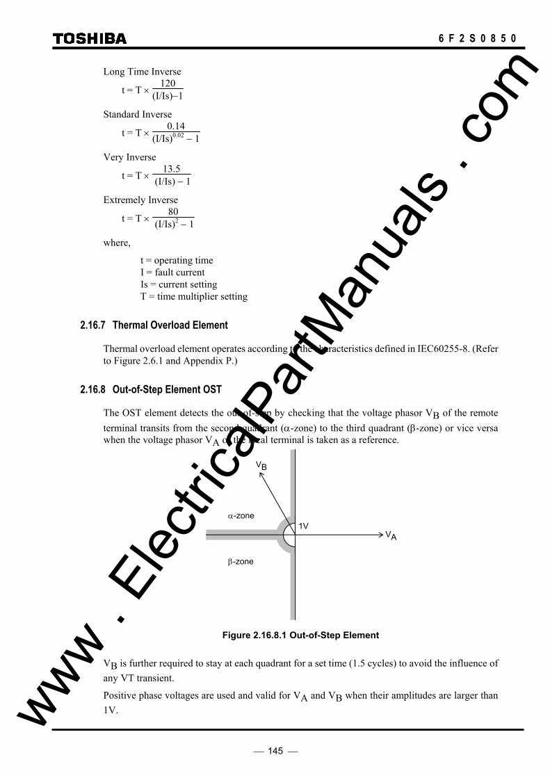
145
6 F 2 S 0 8 5 0
Long Time Inverse
t = T × 120
(I/Is)−1
Standard Inverse
t = T × 0.14
(I/Is)0.02 − 1
Very Inverse
t = T × 13.5
(I/Is) − 1
Extremely Inverse
t = T × 80
(I/Is)2 − 1
where,
t = operating time I = fault current Is = current setting T = time multiplier setting
2.16.7 Thermal Overload Element
Thermal overload element operates according to the characteristics defined in IEC60255-8. (Refer to Figure 2.6.1 and Appendix P.)
2.16.8 Out-of-Step Element OST
The OST element detects the out-of-step by checking that the voltage phasor VB of the remote terminal transits from the second quadrant (α-zone) to the third quadrant (β-zone) or vice versa when the voltage phasor VA of the local terminal is taken as a reference.
Figure 2.16.8.1 Out-of-Step Element
VB is further required to stay at each quadrant for a set time (1.5 cycles) to avoid the influence of any VT transient.
Positive phase voltages are used and valid for VA and VB when their amplitudes are larger than 1V.
α-zone
VB
β-zone
1VVA
www . El
ectric
alPar
tMan
uals
. com

146
6 F 2 S 0 8 5 0
SY1UV
SY1OV
VB
VL
θ SY1θ
2.16.9 Voltage and Synchronism Check Elements OVL, UVL, OVB, UVB and SYN
The voltage check and synchronism check elements are used for autoreclose.
The output of the voltage check element is used to check whether the line and busbar are dead or live. The voltage check element has undervoltage detectors UVL and UVB, and overvoltage detectors OVL and OVB for the line voltage and busbar voltage check. The undervoltage detector checks that the line or busbar is dead while the overvoltage detector checks that it is live.
Figure 2.16.9.1 shows the characteristics of the synchronism check element used for the autoreclose if the line and busbar are live.
The synchronism check element operates if both the voltage difference and phase angle difference are within their setting values.
Figure 2.16.9.1 Synchronism Check Element
The voltage difference is checked by the following equations:
SY1OV ≤ VB ≤ SY1UV
SY1OV ≤ VL ≤ SY1UV
where,
VB = busbar voltage
VL = line voltage
SY1OV = lower voltage setting
SY1UV = upper voltage setting
The phase difference is checked by the following equations:
VB ⋅ VL cos θ ≥ 0
VB ⋅ VL sin(SY1θ ) ≥ VB ⋅ VL sin θ
where,
θ = phase difference between VB and VL
SY1θ = phase difference setting
Note: When the phase difference setting and the synchronism check time setting are given, a www . El
ectric
alPar
tMan
uals
. com

147
6 F 2 S 0 8 5 0
detected maximum slip cycle is determined by the following equation:
where,
f = slip cycle
SY1θ = phase difference setting (degree)
TSYN1 = setting of synchronism check timer (second)
2.16.10 Current change detection elements OCD, OCD1 and EFD
As shown in Figure 2.16.10.1, the current change detection element operates if the vectorial difference between currents IM and IN observed one cycle apart is larger than the fixed setting. Therefore, the operating sensitivity of this element is not affected by the quiescent load current and can detect a fault current with high sensitivity.
The OCD element is used for the VT failure supervision circuit.
The OCD1 and EFD are used as a fail-safe for current differential protection.
Figure 2.16.10.1 Current Change Detection
The operation decision is made by the following equation. |IM − IN| > Is
where, IM = present current
IN = current one cycle before
Is = fixed setting
2.16.11 Level Detectors
In addition to those explained above, GRL100 has overcurrent, overvoltage, and undervoltage level detectors described below.
All level detectors except for undervoltage level detectors UVFS and UVFG, and overcurrent level detector OCBF which require high-speed operation, operate in a similar manner.
That is, the operation decision is made by comparing the current or voltage amplitude with the relevant setting.
Overcurrent detector OCH, OC and OC1 This detector measures A, B, and C phase currents and its sensitivity can be set. The detector OCH is commonly used for the SOTF and stub protection. The detector OC is commonly used for backup protection. The OC1 is used as a fail-safe for current differential protection.
f = 180°×TSYN1
SY1θ
Is
IM
IN
www . El
ectric
alPar
tMan
uals
. com

148
6 F 2 S 0 8 5 0
Residual overcurrent detector EF and EFL This detector measures a residual current and its sensitivity can be set. The EF is used for backup protection. The EFL is used for the earth fault detection of distance protection and VT failure supervision.
Overvoltage detector OVS1/OVS2/OVG1/OVG2 and undervoltage detector UVS1/UVS2/UVG1/UVG2 The OVS∗ and UVS∗ measure a phase-to-phase voltage while the OVG∗ and UVG∗ measure a phase-to-earth voltage. These detectors are used for overvoltage and undervoltage protection as described in Section 2.9.
Residual overvoltage detector OVG This detector measures a residual voltage and its sensitivity is fixed at 20V. This detector is used for supervision of VT failure.
Undervoltage detector UVLS and UVLG The UVLS measures a phase-to-phase voltage while the UVLG measures a phase-to-earth voltage. Their sensitivity can be set.
These detectors are used for weak infeed tripping.
The following two level detectors require high-speed operation or high-speed reset.
Undervoltage detector UVFS and UVFG The UVFS measures a phase-to-phase voltage while the UVFG measures a phase-to-earth voltage. Their sensitivity can be set.
These detectors are commonly used for the VT failure supervision and signal channel test.
Undervoltage detector UVPWI The UVPWI measures a phase-to-earth voltage and its sensitivity is 30V fixed. The UVPWI is used for countermeasures for overreaching of a leading-phase distance element at positive phase weak infeed condition.
Overcurrent detector OCBF This detector measures A, B, and C phase currents and its sensitivity can be set. This detector is used for breaker failure protection and resets when the current falls below 80% of the operating value.
www . El
ectric
alPar
tMan
uals
. com

149
6 F 2 S 0 8 5 0
2.17 Fault Locator
2.17.1 Application
GRL100 provides the following two type fault locators.
- Fault location using the local and remote end data (when current differential protection is applied.) (∗)
- Fault location using the only local end data (when current differential protection is not applied.)
Note (∗): The fault location using the local and remote end data is applied. In case of communication failure, however, the fault location using the only local end data is applied.
The measurement result is expressed as a percentage (%) of the line length and the distance (km) and is displayed on the LCD on the relay front panel. In three-terminal application, however, the measurement result is expressed as a fault section instead of a percentage. It is also output to a local PC or RSM (relay setting and monitoring) system.
To measure the distance to fault, the fault locator requires minimum 3 cycles as a fault duration time.
In distance to fault calculations, the change in the current before and after the fault has occurred is used as a reference current, alleviating influences of the load current and arc voltage. As a result, the location error in fault location using only local end data is a maximum of ±2.5 km for faults at a distance of up to 100 km, and a maximum of ±2.5% for faults at a distance between 100 km and 399.9 km. The location error in fault location using local and remote ends data is a maximum of ±2.0 km for faults at a distance of up to 100 km, and a maximum of ±2.0% for faults at a distance between 100 km and 399.9 km at the positive differential current more than In (rated current). If a fault current is more than 25×In, the location error is larger than above. (See Appendix K.)
Fault location is enabled or disabled by setting "Fault locator" to "ON" or "OFF" on the "Fault record" screen in the "Record" sub-menu.
2.17.2 Starting Calculation
Calculation of the fault location can be initiated by one of the following tripping signals.
• current differential protection trip • carrier protection (command protection) trip • zone 1 trip • zone 2 trip • zone 3 trip • external protection trip
2.17.3 Displaying Location
The measurement result is stored in the "Fault record" and displayed on the LCD of the relay front panel or on the local or remote PC. For displaying on the LCD, see Section 4.2.3.1.
In the two-terminal line, the location is displayed as a distance (km) and a percentage (%) of the line length.
In the three-terminal line, the location is displayed as a distance (km). To discriminate faults in the second and the third section, the fault section is supplemented. www .
Elec
tricalP
artM
anua
ls . c
om

150
6 F 2 S 0 8 5 0
“∗OB”, “∗OJ”, and “∗NC” and may display after the location result. These mean the followings: ∗OB: Fault point is over the boundary. ∗OJ: Fault point is over the junction in three-terminal line application. ∗NC: Fault calculation has not converged.
In case of a fault such as a fault duration time is too short, the fault location is not displayed and the "---" marked is displayed.
2.17.4 Distance to Fault Calculation
2.17.4.1 Fault location using the local and remote end data Calculation Principle In the case of a two-terminal line as shown in Figure 2.17.4.1, the relationship between the voltages at the local and remote terminals and the voltage at the fault point are expressed by Equations (1) and (2).
VA
IA VB
Z
IB
χ 1 − χ
Terminal A Terminal B Fault
Vf
Figure 2.17.4.1 Two-terminal Model
VA - χZ IA = Vf (1)
VB - (1 - χ)Z IB = Vf (2)
where,
VA = voltage at terminal A
IA = current at terminal A
VB = voltage at terminal B
IB = current at terminal B
χ = distance from terminal A to fault point as a ratio to line length Vf = voltage at fault point
Z = line impedance
The distance χ is given by Equation (3) by eliminating Vf,
χ = (VA - VB + ZIB) /Z(IA + IB) (3)
As (IA + IB ) is equal to differential current Id, χ is calculated with the differential current obtained as follows:
χ = (VA - VB + ZIB) /ZId (4)
The distance calculation principle mentioned above can be applied to three-terminal lines. But in www . El
ectric
alPar
tMan
uals
. com

151
6 F 2 S 0 8 5 0
case of three-terminal application, the distance measurement equation varies according to which zone the fault is in, this side or beyond the junction. Terminal A measures the distance using Equations (5), (6) or (7).
Figure 2.17.4.2 Three-terminal Model
χA = (VA − VB + ZA(IB + IC) + ZBIB ) / ZAId (5)
χJB = (VA − VB + ZBIB − ZAIA) / ZBId (6)
χJC = (VA − VC + ZCIC − ZAIA) / ZCId (7)
where,
Id = IA + IB + IC
VC = voltage at terminal C
IC = current at terminal C
χA = distance from terminal A to fault point as a ratio to line length from terminal A to junction
χJB , χJC = distance from junction to fault point as a ratio to line length from junction to terminal B or C
ZA ,ZB ,ZC = impedance from each terminal to junction
Firstly, χA is calculated using Equation (5) assuming that the fault is between terminal A and the
junction. If the result does not match the input line data, then χJB is calculated using Equation (6) assuming that the fault is between the junction and terminal B. If the result does not match the input line data, the calculation is repeated using Equation (7) assuming that the fault is between the junction and terminal C.
Calculation Method In the calculation, the sequence quantities of voltages and currents are employed instead of the phase quantities. Thus, equation (4) is combined with Equation (8) to give:
χ = V V Z I Z I Z I
Z Id Z Id Z Id A B B B B1 1 11 1 12 2 10 0
11 1 12 2 10 0
− + + + + +
( ) (8)
where,
VA1 = positive sequence voltage at terminal A
VB1 = positive sequence voltage at terminal B
Terminal A Terminal B
Terminal C
VA
Junction
IA VB
ZC
IC
ZA
VC, IC
ZB
www . El
ectric
alPar
tMan
uals
. com
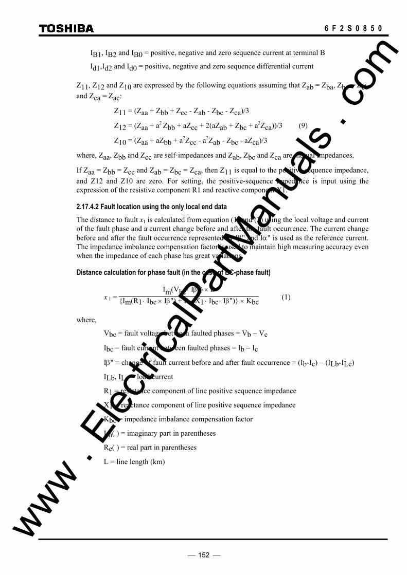
152
6 F 2 S 0 8 5 0
IB1, IB2 and IB0 = positive, negative and zero sequence current at terminal B
Id1,Id2 and Id0 = positive, negative and zero sequence differential current
Z11, Z12 and Z10 are expressed by the following equations assuming that Zab = Zba, Zbc = Zcb and Zca = Zac:
Z11 = (Zaa + Zbb + Zcc - Zab - Zbc - Zca)/3
Z12 = (Zaa + a2 Zbb + aZcc + 2(aZab + Zbc + a2Zca))/3 (9)
Z10 = (Zaa + aZbb + a2Zcc - a2Zab - Zbc - aZca)/3
where, Zaa, Zbb and Zcc are self-impedances and Zab, Zbc and Zca are mutual impedances.
If Zaa = Zbb = Zcc and Zab = Zbc = Zca, then Z11 is equal to the positive sequence impedance, and Z12 and Z10 are zero. For setting, the positive-sequence impedance is input using the expression of the resistive component R1 and reactive component X1.
2.17.4.2 Fault location using the only local end data The distance to fault x1 is calculated from equation (1) and (2) using the local voltage and current of the fault phase and a current change before and after the fault occurrence. The current change before and after the fault occurrence represented by Iβ" and Iα" is used as the reference current. The impedance imbalance compensation factor is used to maintain high measuring accuracy even when the impedance of each phase has great variations.
Distance calculation for phase fault (in the case of BC-phase fault)
x 1 = Im(Vbc ⋅ Iβ") × L
Im(R1 ⋅ Ibc × Iβ") + Re(X1 ⋅ Ibc ⋅ Iβ") × Kbc (1)
where,
Vbc = fault voltage between faulted phases = Vb − Vc
Ibc = fault current between faulted phases = Ib − Ic
Iβ" = change of fault current before and after fault occurrence = (Ib-Ic) − (ILb-ILc)
ILb, ILc = load current
R1 = resistance component of line positive sequence impedance
X1 = reactance component of line positive sequence impedance
Kbc = impedance imbalance compensation factor
Im( ) = imaginary part in parentheses
Re( ) = real part in parentheses
L = line length (km)
www . El
ectric
alPar
tMan
uals
. com
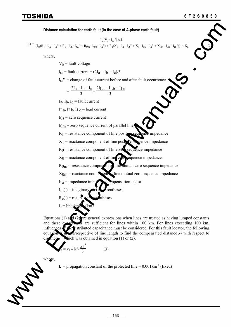
153
6 F 2 S 0 8 5 0
Distance calculation for earth fault (in the case of A-phase earth fault)
x1 = Im(Va ⋅ Iα") × L
Im(R1 ⋅ Iα ⋅ Iα" + R0 ⋅ I0S ⋅ Iα" + R0m ⋅ I0m ⋅ Iα") + Re(X1 ⋅ Iα ⋅ Iα" + X0 ⋅ I0S ⋅ Iα" + X0m ⋅ I0m ⋅ Iα") × Ka
where,
Va = fault voltage
Iα = fault current = (2Ia − Ib − Ic)/3
Iα" = change of fault current before and after fault occurrence
= 2Ia − Ib − Ic
3 − 2ILa − ILb − ILc
3
Ia, Ib, Ic = fault current
ILa, ILb, ILc = load current
I0s = zero sequence current
I0m = zero sequence current of parallel line
R1 = resistance component of line positive sequence impedance
X1 = reactance component of line positive sequence impedance
R0 = resistance component of line zero sequence impedance
X0 = reactance component of line zero sequence impedance
R0m = resistance component of line mutual zero sequence impedance
X0m = reactance component of line mutual zero sequence impedance
Ka = impedance imbalance compensation factor
Im( ) = imaginary part in parentheses
Re( ) = real part in parentheses
L = line length (km)
Equations (1) and (2) are general expressions when lines are treated as having lumped constants and these expressions are sufficient for lines within 100 km. For lines exceeding 100 km, influences of the distributed capacitance must be considered. For this fault locator, the following equation is used irrespective of line length to find the compensated distance x2 with respect to distance x1 which was obtained in equation (1) or (2).
x2 = x1 − k2 ⋅
x 13
3 (3)
where,
k = propagation constant of the protected line = 0.001km-1 (fixed)
(2)
www . El
ectric
alPar
tMan
uals
. com

154
6 F 2 S 0 8 5 0
2.17.5 Setting
Fault location using the local and remote end data The setting items necessary for the fault location and their setting ranges are shown in the table below.
When setting the line impedance, one of the following methods can be selected.
Inputting phase impedances: The self-impedances Zaa, Zbb and Zcc and mutual impedances Zab, Zbc and Zca are input individually using the expression of the resistive components R∗∗ and reactive components X∗∗.
Inputting positive-sequence impedances: This can be done provided that Zaa ≒ Zbb ≒ Zcc and Zab ≒ Zbc ≒ Zca. The positive-sequence impedance is input using the expression of the resistive component R1 and reactive component X1.
The resistive and reactive components are input with the secondary values for the line.
When setting the line impedance, the three-terminal line is divided into three sections. The first section is from the local terminal to the junction, the second is from the junction to remote terminal 1 and the third is from the junction to remote terminal 2. The line constants are input for each section in the same way as the two-terminal application.
Note that remote terminals 1 and 2 are automatically set according to the communication system setup. Remote terminal 1 is a terminal to which local communication port 1 is linked and remote terminal 2 is a terminal to which local communication port 2 is linked.
Item Range Step Default Remarks Fault locator ON/OFF OFF Line data Section 1
1R1 0.00 - 199.99 Ω (0.0 - 999.9 Ω
0.10 Ω 0.1 Ω
0.20 Ω 1.0 Ω) (*)
1X1 0.00 - 199.99 Ω (0.0 - 999.9 Ω
0.10 Ω 0.1 Ω
2.00 Ω 10.0 Ω) (*)
1Line 0.0 - 399.9 km 0.1 km 50.0 km Line length from local terminal to junction or
1Raa 0.00 - 199.99 Ω 0.10 Ω 0.21 Ω 1Xaa (0.0 - 999.9 Ω 0.1 Ω) (1.1 Ω) 1Rbb 1Xbb 0.01 Ω 1Rcc (0.1 Ω) 1Xcc 1Rab 2.10 Ω 1Xab (10.5 Ω) 1Rbc 1Xbc 0.10 Ω 1Rca (0.5 Ω) 1Xca 1Line 0.0 - 399.9 km 0.1 km 50.0 km Line length from local terminal to junction
www . El
ectric
alPar
tMan
uals
. com
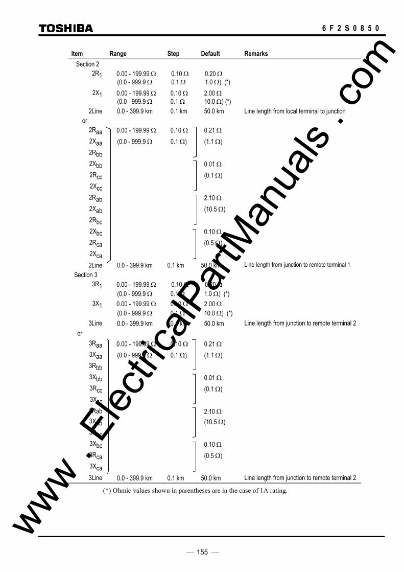
155
6 F 2 S 0 8 5 0
Item Range Step Default Remarks Section 2
2R1 0.00 - 199.99 Ω (0.0 - 999.9 Ω
0.10 Ω 0.1 Ω
0.20 Ω 1.0 Ω) (*)
2X1 0.00 - 199.99 Ω (0.0 - 999.9 Ω
0.10 Ω 0.1 Ω
2.00 Ω 10.0 Ω) (*)
2Line 0.0 - 399.9 km 0.1 km 50.0 km Line length from local terminal to junction or
2Raa 0.00 - 199.99 Ω 0.10 Ω 0.21 Ω 2Xaa (0.0 - 999.9 Ω 0.1 Ω) (1.1 Ω) 2Rbb 2Xbb 0.01 Ω 2Rcc (0.1 Ω) 2Xcc 2Rab 2.10 Ω 2Xab (10.5 Ω) 2Rbc 2Xbc 0.10 Ω 2Rca (0.5 Ω) 2Xca 2Line 0.0 - 399.9 km 0.1 km 50.0 km Line length from junction to remote terminal 1
Section 3 3R1 0.00 - 199.99 Ω
(0.0 - 999.9 Ω 0.10 Ω 0.1 Ω
0.20 Ω 1.0 Ω) (*)
3X1 0.00 - 199.99 Ω (0.0 - 999.9 Ω
0.10 Ω 0.1 Ω
2.00 Ω 10.0 Ω) (*)
3Line 0.0 - 399.9 km 0.1 km 50.0 km Line length from junction to remote terminal 2 or
3Raa 0.00 - 199.99 Ω 0.10 Ω 0.21 Ω 3Xaa (0.0 - 999.9 Ω 0.1 Ω) (1.1 Ω) 3Rbb 3Xbb 0.01 Ω 3Rcc (0.1 Ω) 3Xcc 3Rab 2.10 Ω 3Xab (10.5 Ω) 3Rbc 3Xbc 0.10 Ω 3Rca (0.5 Ω) 3Xca 3Line 0.0 - 399.9 km 0.1 km 50.0 km Line length from junction to remote terminal 2
(*) Ohmic values shown in parentheses are in the case of 1A rating.
www . El
ectric
alPar
tMan
uals
. com
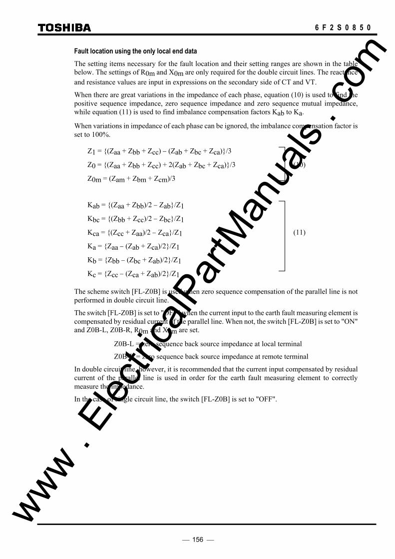
156
6 F 2 S 0 8 5 0
Fault location using the only local end data The setting items necessary for the fault location and their setting ranges are shown in the table below. The settings of R0m and X0m are only required for the double circuit lines. The reactance and resistance values are input in expressions on the secondary side of CT and VT.
When there are great variations in the impedance of each phase, equation (10) is used to find the positive sequence impedance, zero sequence impedance and zero sequence mutual impedance, while equation (11) is used to find imbalance compensation factors Kab to Ka.
When variations in impedance of each phase can be ignored, the imbalance compensation factor is set to 100%.
Z1 = (Zaa + Zbb + Zcc) − (Zab + Zbc + Zca)/3
Z0 = (Zaa + Zbb + Zcc) + 2(Zab + Zbc + Zca)/3 (10)
Z0m = (Zam + Zbm + Zcm)/3
Kab = (Zaa + Zbb)/2 − Zab/Z1
Kbc = (Zbb + Zcc)/2 − Zbc/Z1
Kca = (Zcc + Zaa)/2 − Zca/Z1 (11)
Ka = Zaa − (Zab + Zca)/2/Z1
Kb = Zbb − (Zbc + Zab)/2/Z1
Kc = Zcc − (Zca + Zab)/2/Z1
The scheme switch [FL-Z0B] is used when zero sequence compensation of the parallel line is not performed in double circuit line.
The switch [FL-Z0B] is set to "OFF" when the current input to the earth fault measuring element is compensated by residual current of the parallel line. When not, the switch [FL-Z0B] is set to "ON" and Z0B-L, Z0B-R, R0m and X0m are set.
Z0B-L = zero sequence back source impedance at local terminal
Z0B-R = zero sequence back source impedance at remote terminal
In double circuit line, however, it is recommended that the current input compensated by residual current of the parallel line is used in order for the earth fault measuring element to correctly measure the impedance.
In the case of single circuit line, the switch [FL-Z0B] is set to "OFF".
www . El
ectric
alPar
tMan
uals
. com

157
6 F 2 S 0 8 5 0
Item Range Step Default Remarks Section 1 R1 0.0 - 199.99 Ω 0.01 Ω 0.20Ω
(0.0 - 999.9 Ω 0.1 Ω 1.0Ω) (*) X1 0.0 - 199.99 Ω 0.01 Ω 2.00Ω
(0.0 - 999.9 Ω 0.1 Ω 10.0Ω) R0 0.0 - 999.99 Ω 0.01 Ω 0.70Ω
(0.0 - 999.9 Ω 0.1 Ω 3.5Ω) X0 0.0 - 199.99 Ω 0.01 Ω 6.80Ω
(0.0 - 999.9 Ω 0.1 Ω 34.0Ω) R0m 0.0 - 199.99 Ω 0.01 Ω 0.20Ω
(0.0 - 999.9 Ω 0.1 Ω 1.0Ω) X0m 0.0 - 199.99 Ω 0.01 Ω 2.00Ω
(0.0 - 999.9 Ω 0.1 Ω 10.0Ω) Kab 80 - 120% 1% 100% Kbc 80 - 120% 1% 100% Kca 80 - 120% 1% 100% Ka 80 - 120% 1% 100% Kb 80 - 120% 1% 100% Kc 80 - 120% 1% 100%
Line 0.0 - 399.9 km 0.1 km 50.0km Line length from local terminal to junction if three-terminal application
FL-Z0B OFF/ON OFF ZOB-L 0.0 - 199.99 Ω 0.01 Ω 2.00Ω (0.0 - 999.9 Ω 0.1 Ω 10.0Ω) ZOB-R 0.0 - 199.99 Ω 0.01 Ω 2.00Ω (0.0 - 999.9 Ω 0.1 Ω 10.0Ω) UVLS 50 – 100V 1V 77V Phase fault detection
(*) Ohmic values shown in the parentheses are in the case of 1 A rating. Other ohmic values are in the case of 5A rating.
www . El
ectric
alPar
tMan
uals
. com
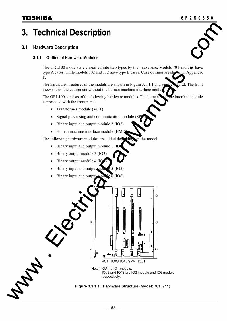
158
6 F 2 S 0 8 5 0
3. Technical Description 3.1 Hardware Description
3.1.1 Outline of Hardware Modules
The GRL100 models are classified into two types by their case size. Models 701 and 711 have type A cases, while models 702 and 712 have type B cases. Case outlines are shown in Appendix F.
The hardware structures of the models are shown in Figure 3.1.1.1 and Figure 3.1.1.2. The front view shows the equipment without the human machine interface module.
The GRL100 consists of the following hardware modules. The human machine interface module is provided with the front panel.
• Transformer module (VCT)
• Signal processing and communication module (SPM)
• Binary input and output module 2 (IO2)
• Human machine interface module (HMI)
The following hardware modules are added depending on the model:
• Binary input and output module 1 (IO1)
• Binary output module 3 (IO3)
• Binary output module 4 (IO4)
• Binary input and output module 5 (IO5)
• Binary input and output module 6 (IO6)
Figure 3.1.1.1 Hardware Structure (Model: 701, 711)
6
IO#1 IO#2 IO#3 VCT SPM
Note: IO#1 is IO1 module. IO#2 and IO#3 are IO2 module and IO6 module
respectively.
www . El
ectric
alPar
tMan
uals
. com

159
6 F 2 S 0 8 5 0
Figure 3.1.1.2 Hardware Structure (Model: 702, 712)
The correspondence between each model and module used is as follows:
Model
Module
701, 711 702, 712
VCT × ×
SPM × ×
IO1 × ×
IO2 × ×
IO3
IO4 ×
IO5 ×
IO6 ×
HMI × ×
Note: The VCT and SPM modules are not interchangeable among different models.
The hardware block diagrams of the GRL100 using these modules are shown in Figure 3.1.1.3.
IO5
IO4
IO5
IO4
IO#3 IO#4 SPM IO#2 VCT IO#1
Note: IO#1 is IO1 module. IO#2, IO#3 and IO#4 are IO2, IO5 and IO4 module
respectively.
www . El
ectric
alPar
tMan
uals
. com

160
6 F 2 S 0 8 5 0
Signal Processing and Communication Module
Analog filter
A/D Converter
O/E
E/O
S/P
P/S
(SPM)
Binary I/O Module (IO#4)
Binary output
(*2)
(*1)
(*1)
Transformer Module (VCT)
CT×4
IRIG-B port
V
I
AC input
External clock
DCsupply
Remote PC
Binary I/O Module (IO#1)(*3)
DC/DC Converter
Binary input ×15
Binary output (High speed)
×6
Binary I/O Module (IO#2)
Binary output ×14
RS485 Transceiver
Binary input ×3
Human Machine Interface(HMI)
Liquid crystal display 40characters×4lines
LEDs
Monitoring jacks
Operation keys
RS232C I/F Local PC
Tripcommand
(or VT×5) VT×4
Binary I/O Module (IO#3)
Binary input ×10
Binary I/O Module(IO#3)
Binary input 7
Binary output ×10
Binary output 6
Telecommunication system
MPU2
Auxiliary relay
Photocoupler
Auxiliary relay
Auxiliary relay
Auxiliary relay
Photocoupler
Photocoupler
Photocoupler
MPU1
Binary input 3
14 Auxiliary relay
Photocoupler
Remote PC
Fibre opt. I/F or Ethernet LAN I/F
O/E
GPS
(*1) : required for models 702, 712 (*2) : required for models 701, 711
Figure 3.1.1.3 Hardware Block Diagram
www .
Elec
tricalP
artM
anua
ls . c
om

161
6 F 2 S 0 8 5 0
3.1.2 Transformer Module
The transformer module (VCT module) provides isolation between the internal and external AC circuits through an auxiliary transformer and transforms the magnitude of AC input signals to suit the electronic circuits. The AC input signals are as follows:
• three-phase currents (Ia, Ib and Ic) • residual current (3Io) • residual current of parallel line (3Iom) • three-phase voltages (Va, Vb and Vc) • autoreclose reference voltage (Vref1) • autoreclose reference voltage (Vref2)
Figure 3.1.2.1 shows a block diagram of the transformer module. There are 5 auxiliary CTs mounted in the transformer module, and an additional 5 auxiliary VTs. (The reference between terminal numbers and AC input signals is given in Table 3.2.1.1.)
Vref1 and Vref2 are the busbar or line voltages necessary for the voltage and synchronism check for the autoreclose.
The transformer module is also provided with an IRIG-B port. This port collects the serial IRIG-B format data from the external clock for synchronization of the relay calendar clock. The IRIG-B port is insulated from the external circuit by a photo-coupler. A BNC connector is used as the input connector.
Transformer module
IRIG-B port
BNC connector
I a
I b
I c
3I o
V a
V b
V c
V ref1
V ref2
External clock
Signalprocessing module
3I om
Figure 3.1.2.1 Transformer Module
www . El
ectric
alPar
tMan
uals
. com
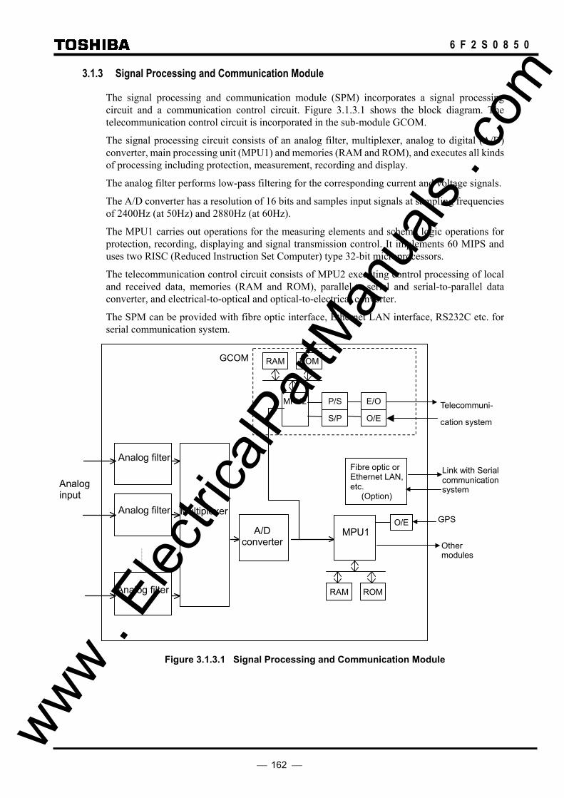
162
6 F 2 S 0 8 5 0
3.1.3 Signal Processing and Communication Module
The signal processing and communication module (SPM) incorporates a signal processing circuit and a communication control circuit. Figure 3.1.3.1 shows the block diagram. The telecommunication control circuit is incorporated in the sub-module GCOM.
The signal processing circuit consists of an analog filter, multiplexer, analog to digital (A/D) converter, main processing unit (MPU1) and memories (RAM and ROM), and executes all kinds of processing including protection, measurement, recording and display.
The analog filter performs low-pass filtering for the corresponding current and voltage signals.
The A/D converter has a resolution of 16 bits and samples input signals at sampling frequencies of 2400Hz (at 50Hz) and 2880Hz (at 60Hz).
The MPU1 carries out operations for the measuring elements and scheme logic operations for protection, recording, displaying and signal transmission control. It implements 60 MIPS and uses two RISC (Reduced Instruction Set Computer) type 32-bit microprocessors.
The telecommunication control circuit consists of MPU2 executing control processing of local and received data, memories (RAM and ROM), parallel-to-serial and serial-to-parallel data converter, and electrical-to-optical and optical-to-electrical converter.
The SPM can be provided with fibre optic interface, Ethernet LAN interface, RS232C etc. for serial communication system.
Telecommuni-
cation system
Analog filter
Other modules
A/D converter
MPU1
Analog filter
Analog filter
Multiplexer
Analog input
MPU2 P/S
S/P
RAM ROM
ROMRAM
E/O
O/E
GCOM
Fibre optic or Ethernet LAN, etc.
(Option)
Link with Serial communication system
O/E GPS
Figure 3.1.3.1 Signal Processing and Communication Module
www . El
ectric
alPar
tMan
uals
. com

163
6 F 2 S 0 8 5 0
3.1.4 Binary Input and Output Module
There are four types of binary input and output module (IO module): These modules are used depending on the model (see Section 3.1.1).
3.1.4.1 IO1 Module IO1 provides a DC/DC converter, binary inputs and binary outputs for tripping.
As shown in Figure 3.1.4.1, the IO1 module incorporates a DC/DC converter, 15 photo-coupler circuits (BI) for binary input signals and 6 auxiliary relays (TP-A1 to TP-C2) dedicated to the circuit breaker tripping command.
The input voltage rating of the DC/DC converter is 24V, 48V, 110V/125V or 220V/250V. The normal range of input voltage is −20% to +20%.
The six or three tripping command auxiliary relays are the high-speed operation type and have one normally open output contact.
Auxiliary relay(high speed)
-
DC/DCconverter
FG (−) (+)
BI Photo-coupler
Tripping command
Binary input signals
Line filterDC supply
TP-C2
TP-B2
TP-A2
TP-C1
TP-B1
TP-A1
BI
BI
BI
BI
(× 15)
Figure 3.1.4.1 IO1 Module
www . El
ectric
alPar
tMan
uals
. com
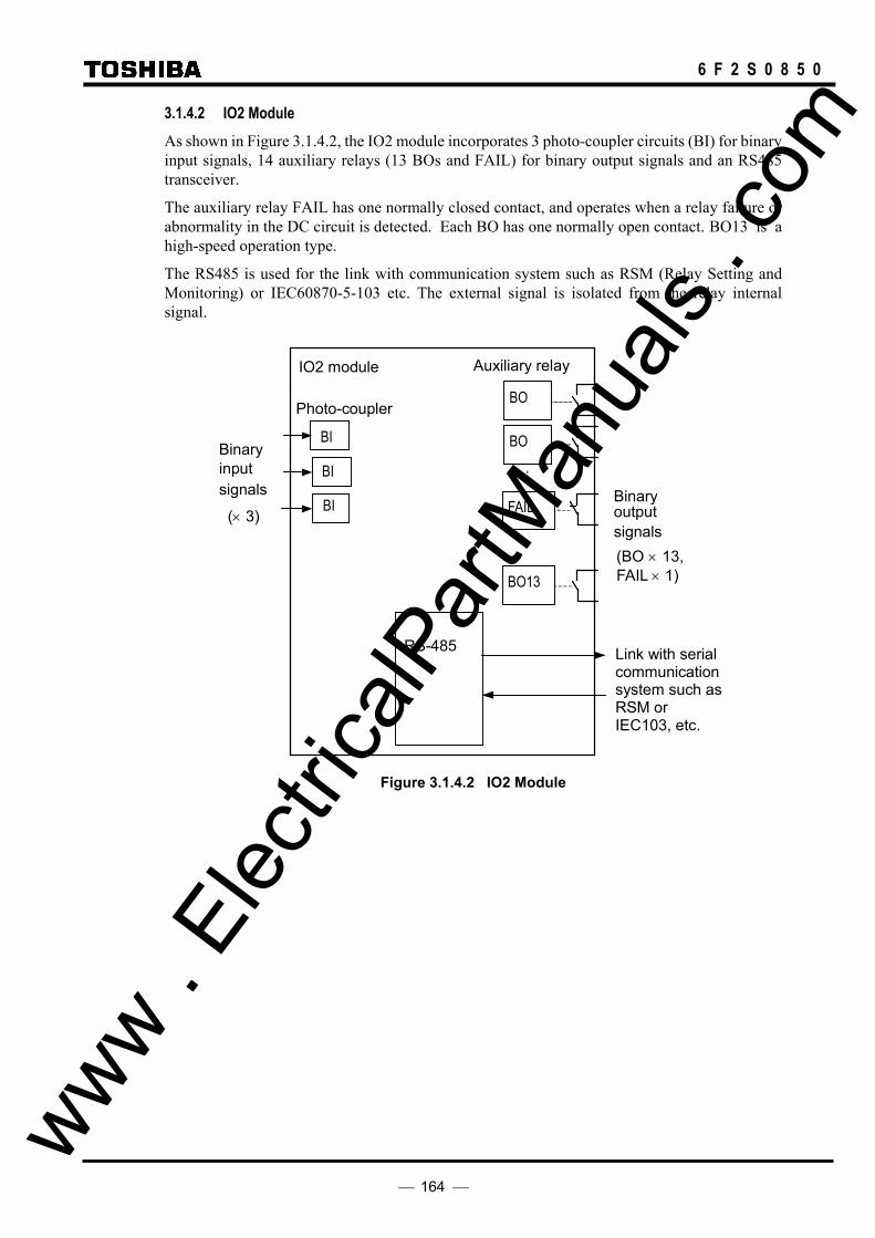
164
6 F 2 S 0 8 5 0
3.1.4.2 IO2 Module As shown in Figure 3.1.4.2, the IO2 module incorporates 3 photo-coupler circuits (BI) for binary input signals, 14 auxiliary relays (13 BOs and FAIL) for binary output signals and an RS485 transceiver.
The auxiliary relay FAIL has one normally closed contact, and operates when a relay failure or abnormality in the DC circuit is detected. Each BO has one normally open contact. BO13 is a high-speed operation type.
The RS485 is used for the link with communication system such as RSM (Relay Setting and Monitoring) or IEC60870-5-103 etc. The external signal is isolated from the relay internal signal.
Auxiliary relay
RS-485
IO2 module
BI
BI
BI Binary output signals
Binary input signals
Photo-coupler
BO
FAIL
BO13
BO
(× 3)
(BO × 13,FAIL × 1)
Link with serial communication system such as RSM or IEC103, etc.
Figure 3.1.4.2 IO2 Module
www . El
ectric
alPar
tMan
uals
. com

165
6 F 2 S 0 8 5 0
3.1.4.3 IO3 and IO4 Modules The IO3 and IO4 modules are used to increase the number of binary outputs.
The IO3 module incorporates 10 auxiliary relays (BO) for binary outputs. The IO4 module incorporates 14 auxiliary relays (BO) for binary outputs and 3 photo-coupler circuits (BI). All auxiliary relays each have one normally open contact.
Auxiliary relay
BO
BO
BO
BO
Binary output signals (× 10)
Figure 3.1.4.3 IO3 Module
Auxiliary relay
BO
BO
BO
BO
Binary output signals (× 14)
BI
BI
BI
Binary input signals (× 3)
Photo-coupler
Figure 3.1.4.4 IO4 Module
www . El
ectric
alPar
tMan
uals
. com

166
6 F 2 S 0 8 5 0
3.1.4.4 IO5 and IO6 Modules The IO5 and IO6 modules are used to increase the number of binary inputs and outputs.
The IO5 module incorporates 10 photo-coupler circuits (BI) for binary inputs and 10 auxiliary relays (BO) for binary outputs. The IO6 module incorporates 7 photo-coupler circuits (BI) for binary inputs and 6 auxiliary relays (BO) for binary outputs. All auxiliary relays each have one normally open contact.
Auxiliary relay
BO
BO
BO
BOPhoto-coupler
Binary output signals
BI
BI
BI
BI
Binary input signals (× 10)
(× 10)
Figure 3.1.4.5 IO5 Module
Auxiliary relay
BO
BO
BO
BOPhoto-coupler
Binary output signals
BI
BI
BI
BI
Binary input signals (× 7)
(× 6)
Figure 3.1.4.6 IO6 Module
www . El
ectric
alPar
tMan
uals
. com
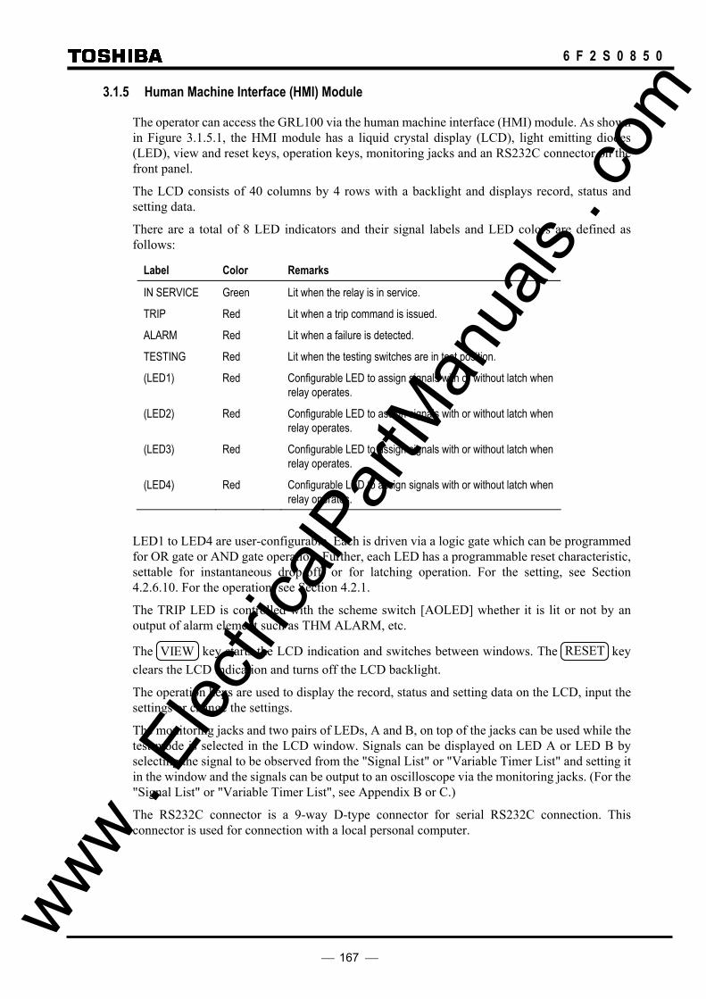
167
6 F 2 S 0 8 5 0
3.1.5 Human Machine Interface (HMI) Module
The operator can access the GRL100 via the human machine interface (HMI) module. As shown in Figure 3.1.5.1, the HMI module has a liquid crystal display (LCD), light emitting diodes (LED), view and reset keys, operation keys, monitoring jacks and an RS232C connector on the front panel.
The LCD consists of 40 columns by 4 rows with a backlight and displays record, status and setting data.
There are a total of 8 LED indicators and their signal labels and LED colors are defined as follows:
Label Color Remarks
IN SERVICE Green Lit when the relay is in service.
TRIP Red Lit when a trip command is issued.
ALARM Red Lit when a failure is detected.
TESTING Red Lit when the testing switches are in test position.
(LED1) Red Configurable LED to assign signals with or without latch when relay operates.
(LED2) Red Configurable LED to assign signals with or without latch when relay operates.
(LED3) Red Configurable LED to assign signals with or without latch when relay operates.
(LED4) Red Configurable LED to assign signals with or without latch when relay operates.
LED1 to LED4 are user-configurable. Each is driven via a logic gate which can be programmed for OR gate or AND gate operation. Further, each LED has a programmable reset characteristic, settable for instantaneous drop-off, or for latching operation. For the setting, see Section 4.2.6.10. For the operation, see Section 4.2.1.
The TRIP LED is controlled with the scheme switch [AOLED] whether it is lit or not by an output of alarm element such as THM ALARM, etc.
The VIEW key starts the LCD indication and switches between windows. The RESET key clears the LCD indication and turns off the LCD backlight.
The operation keys are used to display the record, status and setting data on the LCD, input the settings or change the settings.
The monitoring jacks and two pairs of LEDs, A and B, on top of the jacks can be used while the test mode is selected in the LCD window. Signals can be displayed on LED A or LED B by selecting the signal to be observed from the "Signal List" or "Variable Timer List" and setting it in the window and the signals can be output to an oscilloscope via the monitoring jacks. (For the "Signal List" or "Variable Timer List", see Appendix B or C.)
The RS232C connector is a 9-way D-type connector for serial RS232C connection. This connector is used for connection with a local personal computer.
www . El
ectric
alPar
tMan
uals
. com

168
6 F 2 S 0 8 5 0
LINE DIFFERENTIAL PROTECTION
•
GRL100
Operation keys
Light emitting diode
100/110/115/120V
Liquid crystal display
Monitoring jack
RS232C connector
701B-31-10
Figure 3.1.5.1 Front Panel
www . El
ectric
alPar
tMan
uals
. com

169
6 F 2 S 0 8 5 0
3.2 Input and Output Signals
3.2.1 Input Signals
AC input signals Table 3.2.1.1 shows the AC input signals necessary for the GRL100-700 series and their respective input terminal numbers. The AC input signals are input via terminal block TB1. See Appendix G for external connections.
The GRL100-700 series require 5 current inputs and 3 voltage inputs, and also required an additional voltage signal using voltage and synchronism checks for the autoreclose function. For single or double busbar applications, one voltage signal is required, while for one-and-a-half circuit breaker arrangements, two voltage signals are required. (For the busbar and line voltages, see Figure 2.15.2.7.)
Table 3.2.1.1 AC Input Signals
Terminal No. GRL100-701, 702, 711, 712
1-2 3-4 5-6 7-8
9-10 11-14 12-14 13-14 15-16 17-18
20
A-phase Current B-phase Current C-phase Current Residual Current Residual Current of parallel line A-phase Voltage B-phase Voltage C-phase Voltage Voltage for Autoreclose Voltage for Autoreclose (earth)
Binary input signals Table 3.2.1.2 shows the binary input signals necessary for the GRL100, their driving contact conditions and functions enabled.
Input signals are configurable and depend on the GRL100 models. See Appendix G for the default settings and external connections.
Note: For the three-phase binary input signals of Interlink A, B and C, interlink signals of the parallel line are applied.
The interlink signals are assigned to the binary output relays as LINK-A1, -B1 and -C1 in two-terminal line application and as LINK-A1, -B1 and -C1 and LINK-A2, -B2 and -C2 in the three-terminal line application. For the default setting, see Appendix D.
Two-terminal line application: Apply the LINK-A1, -B1 and -C1 contacts of the parallel line to the binary input signals of Interlink A, B and C (Terminal 1).
Three-terminal line application: Apply the LINK-A1, -B1 and -C1 contacts of the parallel line to Interlink A, B and C (Terminal 1) and LINK-A2, -B2 and -C2 contacts to Interlink A, B and C (Terminal 2) respectively.
The binary input circuit of the GRL100 is provided with a logic level inversion function as shown in Figure 3.2.1.1. Each input circuit has a binary switch BISW which can be used to select either normal or inverted operation. This allows the inputs to be driven either by normally open or normally closed contact.
If a signal is not input, the function concerned is disabled. www . El
ectric
alPar
tMan
uals
. com
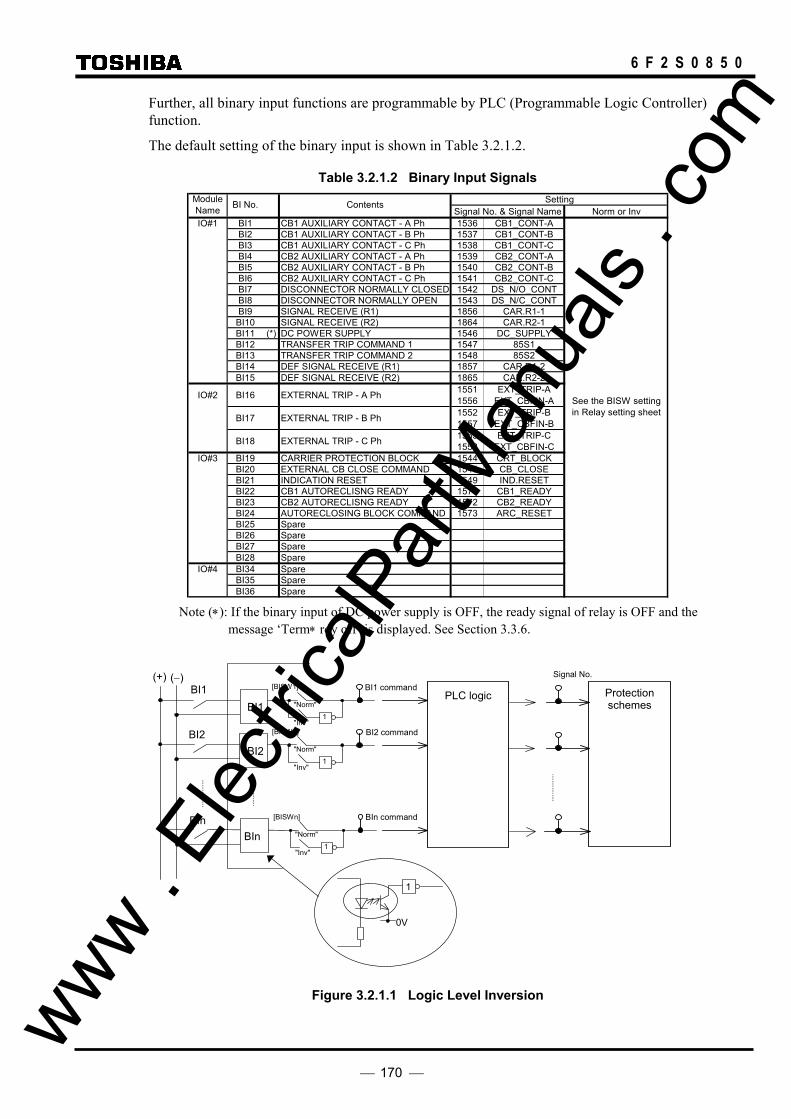
170
6 F 2 S 0 8 5 0
Further, all binary input functions are programmable by PLC (Programmable Logic Controller) function.
The default setting of the binary input is shown in Table 3.2.1.2.
Table 3.2.1.2 Binary Input Signals Setting
Signal No. & Signal Name Norm or InvIO#1 BI1 CB1 AUXILIARY CONTACT - A Ph 1536 CB1_CONT-A
BI2 CB1 AUXILIARY CONTACT - B Ph 1537 CB1_CONT-BBI3 CB1 AUXILIARY CONTACT - C Ph 1538 CB1_CONT-CBI4 CB2 AUXILIARY CONTACT - A Ph 1539 CB2_CONT-ABI5 CB2 AUXILIARY CONTACT - B Ph 1540 CB2_CONT-BBI6 CB2 AUXILIARY CONTACT - C Ph 1541 CB2_CONT-CBI7 DISCONNECTOR NORMALLY CLOSED 1542 DS_N/O_CONTBI8 DISCONNECTOR NORMALLY OPEN 1543 DS_N/C_CONTBI9 SIGNAL RECEIVE (R1) 1856 CAR.R1-1BI10 SIGNAL RECEIVE (R2) 1864 CAR.R2-1BI11 (*) DC POWER SUPPLY 1546 DC_SUPPLYBI12 TRANSFER TRIP COMMAND 1 1547 85S1BI13 TRANSFER TRIP COMMAND 2 1548 85S2BI14 DEF SIGNAL RECEIVE (R1) 1857 CAR.R1-2BI15 DEF SIGNAL RECEIVE (R2) 1865 CAR.R2-2
IO#2 BI16 EXTERNAL TRIP - A Ph 15511556
EXT_TRIP-AEXT_CBFIN-A
BI17 EXTERNAL TRIP - B Ph 15521557
EXT_TRIP-BEXT_CBFIN-B
BI18 EXTERNAL TRIP - C Ph 15531558
EXT_TRIP-CEXT_CBFIN-C
IO#3 BI19 CARRIER PROTECTION BLOCK 1544 CRT_BLOCKBI20 EXTERNAL CB CLOSE COMMAND 1545 CB_CLOSEBI21 INDICATION RESET 1549 IND.RESETBI22 CB1 AUTORECLISNG READY 1571 CB1_READYBI23 CB2 AUTORECLISNG READY 1572 CB2_READYBI24 AUTORECLOSING BLOCK COMMAND 1573 ARC_RESETBI25 SpareBI26 SpareBI27 SpareBI28 Spare
IO#4 BI34 SpareBI35 SpareBI36 Spare
ModuleName Contents
See the BISW settingin Relay setting sheet
BI No.
Note (∗): If the binary input of DC power supply is OFF, the ready signal of relay is OFF and the
message ‘Term∗ rdy off’ is displayed. See Section 3.3.6.
(−) (+)
BI1
BI2
BIn
0V
1
BI1
BI2
BIn
PLC logic BI1 command Protection
schemes
Signal No. [BISW1]
1 "Inv"
"Norm"
1 "Inv"
"Norm"
[BISW2]
1"Inv"
"Norm"
[BISWn]
BI2 command
BIn command
Figure 3.2.1.1 Logic Level Inversion
www . El
ectric
alPar
tMan
uals
. com

171
6 F 2 S 0 8 5 0
The binary input signals of circuit breaker auxiliary contact are transformed as shown in Figure 3.2.1.2 to use in the scheme logic.
&
&
≥1
CB-AND
&≥1
1 &
&
&
CB-OR
CB-DISCR
CB1_CONT-A1536
CB1_CONT-B1537
CB1_CONT-C1538
720
721
BI1_command
BI2_command
BI3_command
[Default setting]
Figure 3.2.1.2 Circuit Breaker Signals Transformation
www . El
ectric
alPar
tMan
uals
. com

172
6 F 2 S 0 8 5 0
3.2.2 Binary Output Signals
The number of binary output signals and their output terminals vary depending on the relay model. For all models, all outputs except the tripping command and relay failure signal can be configured.
The signals shown in the signal list in Appendix B can be assigned to the output relay individually or in arbitrary combinations. Signals can be combined using either an AND circuit or OR circuit with 6 gates each as shown in Figure 3.2.2.1. The output circuit can be configured according to the setting menu. Appendix D shows the factory default settings.
A 0.2s delayed drop-off timer can be attached to these assigned signals. The delayed drop-off time is disabled by the scheme switch [BOTD].
All the models are equipped with normally open trip contacts for each phase.
The relay failure contact closes the contact when a relay defect or abnormality in the DC power supply circuit is detected.
Figure 3.2.2.1 Configurable Output
3.2.3 PLC (Programmable Logic Controller) Function
GRL100 is provided with a PLC function allowing user-configurable sequence logics on binary signals. The sequence logics with timers, flip-flops, AND, OR, XOR, NOT logics, etc. can be produced by using the PC software “PLC tool” and linked to signals corresponding to relay elements or binary circuits.
Configurable binary inputs, binary outputs and LEDs, and the initiation trigger of disturbance record are programmed by the PLC function. Temporary signals are provided for complicated logics or for using a user-configured signal in many logic sequences.
PLC logic is assigned to protection signals by using the PLC tool. For PLC tool, refer to PLC tool instruction manual.
Figure 3.2.3.1 Sample Screen of PLC Tool
Signal List
Auxiliary relay Appendix B
0.2s
t 0
[BOTD] +
"ON"
6 GATES OR
6 GATES
&
≥1
&
≥1
www . El
ectric
alPar
tMan
uals
. com

173
6 F 2 S 0 8 5 0
3.3 Automatic Supervision
3.3.1 Basic Concept of Supervision
Though the protection system is in the non-operating state under normal conditions, it is waiting for a power system fault to occur at any time and must operate for faults without fail. Therefore, the automatic supervision function, which checks the health of the protection system during normal operation, plays an important role. A numerical relay based on microprocessor operations is suitable for implementing this automatic supervision function of the protection system. The GRL100 implements the automatic supervision function taking advantage of this feature based on the following concept:
• The supervising function should not affect protection performance.
• Perform supervision with no omissions whenever possible.
• When a failure occurs, it should be able to easily identify the location of the failure.
3.3.2 Relay Monitoring
The following items are supervised:
AC input imbalance monitoring The AC voltage and current inputs are monitored to check that the following equations are satisfied and the health of the AC input circuits is checked.
• Zero sequence voltage monitoring
|Va + Vb + Vc| / 3 ≤ 6.35(V)
• Negative sequence voltage monitoring
|Va + a2Vb + aVc| / 3 ≤ 6.35(V)
where,
a = Phase shifter of 120°
• Zero sequence current monitoring
|Ia + Ib + Ic − 3Io| / 3 ≤ 0.1 × Max(|Ia|, |Ib|, |Ic|) + k0
where,
3Io = Residual current
Max(|Ia|, |Ib|, |Ic|) = Maximum amplitude among Ia, Ib and Ic
k0 = 5% of rated current
These zero sequence monitoring and negative sequence monitoring allow high-sensitivity detection of failures that have occurred in the AC input circuits.
The negative sequence voltage monitoring allows high sensitivity detection of failures in the voltage input circuit, and it is effective for detection particularly when cables have been connected with the incorrect phase sequence.
The zero sequence current monitoring allows high-sensitivity detection of failures irrespective of the presence of the zero sequence current on the power system by introduction of the residual circuit current.
Only zero sequence monitoring is carried out for the current input circuit, because zero sequence www . El
ectric
alPar
tMan
uals
. com

174
6 F 2 S 0 8 5 0
monitoring with the introduction of the residual circuit current can be performed with higher sensitivity than negative sequence monitoring.
A/D accuracy checking An analog reference voltage is input to a prescribed channel in the analog-to-digital (A/D) converter, and the system checks that the data after A/D conversion is within the prescribed range and that the A/D conversion characteristics are correct.
Memory monitoring The memories are monitored as follows depending on the type of memory, and the health of the memory circuits is checked:
• Random access memory monitoring: Writes/reads prescribed data and checks the storage function.
• Program memory monitoring: Checks the checksum value of the written data.
• Setting value monitoring: Checks for discrepancies between the setting values stored in duplicate.
Watchdog Timer A hardware timer, which is cleared periodically by software, is provided and the system checks that the software is running normally.
DC Supply monitoring The secondary voltage level of the built-in DC/DC converter is monitored and the system checks that the DC voltage is within the prescribed range. If a failure is detected, the relay trip is blocked and the alarm is issued.
Furthermore, DC supply is monitored by using the binary input signal in the current differential protection. If the binary input signal is “OFF” (= DC supply “OFF” or “Failure”), the ready condition of the differential protection is “OFF” and both local and remote relays are blocked. (Refer to Table 3.2.1.2.) This monitoring is provided to surely block the unwanted operation of remote terminal relays caused by sending the remote terminals an uncertain data even for short time at DC supply off or failure, though the former monitoring is enough at DC supply off or failure in general.
3.3.3 CT Circuit Current Monitoring
The CT circuit is monitored to check that the following equation is satisfied and the health of the CT circuit is checked.
Max(|Ia|, |Ib|, |Ic|) − 4 × Min(|Ia|, |Ib|, |Ic|) ≥ k0
where,
Max(|Ia|, |Ib|, |Ic|) = Maximum amplitude among Ia, Ib and Ic Min(|Ia|, |Ib|, |Ic|) = Minimum amplitude among Ia, Ib and Ic k0 = 20% of rated current
The CT circuit current monitoring allows high sensitivity detection of failures that have occurred in the AC input circuit. This monitoring can be disabled by the scheme switch [CTSV].
www . El
ectric
alPar
tMan
uals
. com

175
6 F 2 S 0 8 5 0
3.3.4 CT Circuit Failure Detection
If a failure occurs in a CT circuit, the differential elements may operate incorrectly. GRL100 incorporates a CT failure detection function (CTF) against such incorrect operation. When the CTF detects a CT circuit failure, it can block the DIF trip.
The CTF is enabled or disabled by the scheme switch [CTFEN] as follows:
- “Off”: Disabled.
- “On”: Enabled. If once CTF is detected, the CTF function cannot be reset until ID is reset.
- “OPT-On”: Enabled. After CTF is detected, the CTF function is reset if CTFUV, CTFDV or CTFOVG operates.
The DIF trip is blocked or not by the scheme switch [CTFCNT].
- “NA”: No block the DIF trip
- “BLK”: Block the DIF trip
Detection logic Figure 3.3.4.1 shows the CTF detection logic.
&
CTFID
CTFUV
CTFUVD
CTFOVG
1
≥1
CTF detection
391:CTFOVG
392:CTFUVD-A 393:CTFUVD-B 394:CTFUVD-C
&
381:CTFID-A 382:CTFID-B 383:CTFID-C
388:CTFUV-A 389:CTFUV-B 390:CTFUV-C
1 CTF detection
CTFID (CFID): Differential current element for CTF CTFUVD (CFDV): Undervoltage change element for CTF CTFUV (CFUV): Undervoltage element for CTF CTFOVG (CFOVG): Zero-sequence overvoltage element for CTF
Figure 3.3.4.1 CTF Detection Logic
Setting The setting elements necessary for the CTF and their setting ranges are as follows:
Element Range Step Default Remarks CFID 0.25 - 5.00 A 0.1 A 0.25 A Id current level ( 0.05 - 1.00 A 0.01 A 0.05 A) (*) CFUV 20 - 60 V 1 V 20 V CFDV 1 - 10 % 1 % 7 % % of rated voltage CFOVG 0.1 - 10.0 V 0.1 V 1.0 V Zero-sequence voltage [CTFEN] Off/On/OPT-On Off CTF enabled or not [CTFCNT] NA / BLK NA Control by CTF detection
(*) Current values shown in the parentheses are in the case of 1 A rating. Other current values are in the case of 5 A rating.
3.3.5 Voltage Transformer Failure Supervision
When a fault occurs in the secondary circuit of the voltage transformer (VT), the voltage dependent measuring elements may operate incorrectly. GRL100 incorporates a VT failure www .
Elec
tricalP
artM
anua
ls . c
om
176
6 F 2 S 0 8 5 0
supervision function (VTFS) as a measure against such incorrect operation. When the VTFS detects a VT failure, it blocks the following voltage dependent protections instantaneously. In 10 seconds, it displays the VT failure and outputs an alarm.
• Zone 1-3 and R distance protection
• Directional earth fault protection
• Command protection
Resetting of the blocks above and resetting of the display and alarm are automatically performed when it is confirmed that all three phases are healthy.
A binary input signal to indicate a miniature circuit breaker trip in the VT circuits is also available for the VTFS.
Scheme logic Figure 3.3.5.1 shows the scheme logic for the VTFS. VT failures are detected under any one of the following conditions and then a trip block signal VTF is output.
VTF1: The phase-to-phase undervoltage element UVFS or phase-to-earth undervoltage element UVFG operates (UVFS = 1 or UVFG =1) when the three phases of the circuit breaker are closed (CB-AND = 1) and the phase current change detection element OCD1 does not operate (OCD1 = 0).
VTF2: The residual overcurrent element EFL does not operate (EFL = 0), the residual overvoltage element OVG operates (OVG = 1) and the phase current change detection element OCD1 does not operate (OCD1 = 0).
In order to prevent detection of false VT failures due to unequal pole closing of the circuit breaker, the VTFS is blocked for 200 ms after line energisation.
The trip block signal VTF is reset 100 milliseconds after the VT failure condition has reset. When the VTF continues for 10s or more, an alarm signal VTF-ALM is output.
Further, the VT failure is detected when the binary input signal (PLC signal) EXT_VTF is received. The binary input signal requires the time coordinated with Zone 1 operation and reset. If not, the time can be adjusted by the PLC function.
This function can be enabled or disabled by the scheme switch [VTF1EN] or [VTF2EN] and has a programmable reset characteristic. When set to “ON”, the latched operation for VTF1 is reset by reset of UVFS/UVFG element, and that for VTF2 is reset by reset of OVG element. Set to “OPT-ON” to reset the latched operation when OCD1 or EFL operates.
The VTFS can be disabled by the PLC signal VTF_BLOCK.
www . El
ectric
alPar
tMan
uals
. com
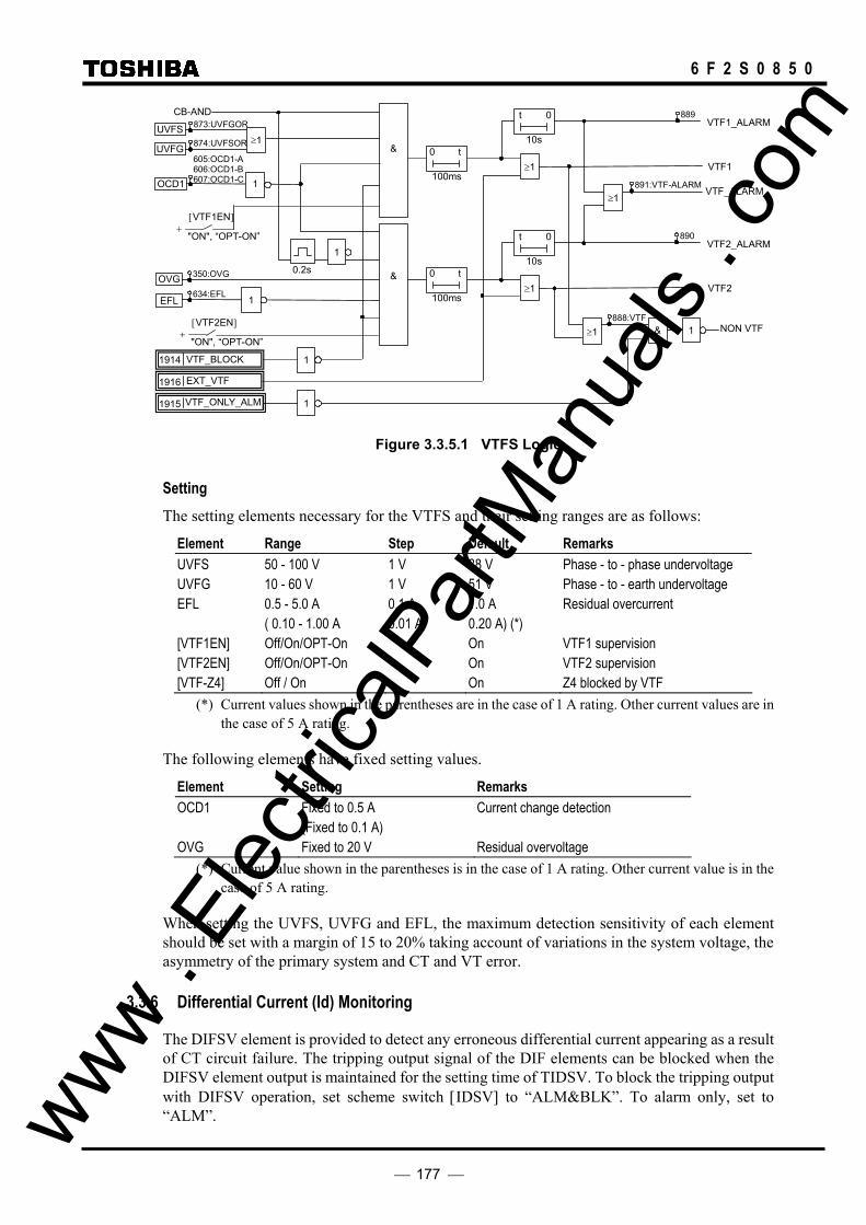
177
6 F 2 S 0 8 5 0
≥1&
&
0.2s
VTF2_ALARM
VTF2 1 100ms
0 t
CB-AND
UVFS
UVFG
OCD1
OVG
EFL
1
1 10s
t 0
≥1
[VTF1EN]
"ON", “OPT-ON” +
[VTF2EN]
"ON", “OPT-ON” +
≥1
VTF1_ALARM
VTF1 100ms
0 t10s
t 0
350:OVG
634:EFL
873:UVFGOR
874:UVFSOR
605:OCD1-A 606:OCD1-B 607:OCD1-C
VTF_BLOCK 1914 1
EXT_VTF 1916
≥1
VTF_ONLY_ALM1915
≥1 & 1
890
NON VTF
VTF_ALARM
889
1
891:VTF-ALARM
888:VTF
Figure 3.3.5.1 VTFS Logic
Setting The setting elements necessary for the VTFS and their setting ranges are as follows:
Element Range Step Default Remarks UVFS 50 - 100 V 1 V 88 V Phase - to - phase undervoltage UVFG 10 - 60 V 1 V 51 V Phase - to - earth undervoltage EFL 0.5 - 5.0 A 0.1 A 1.0 A Residual overcurrent ( 0.10 - 1.00 A 0.01 A 0.20 A) (*) [VTF1EN] Off/On/OPT-On On VTF1 supervision [VTF2EN] Off/On/OPT-On On VTF2 supervision [VTF-Z4] Off / On On Z4 blocked by VTF
(*) Current values shown in the parentheses are in the case of 1 A rating. Other current values are in the case of 5 A rating.
The following elements have fixed setting values.
Element Setting Remarks OCD1 Fixed to 0.5 A Current change detection (Fixed to 0.1 A) OVG Fixed to 20 V Residual overvoltage
(*) Current value shown in the parentheses is in the case of 1 A rating. Other current value is in the case of 5 A rating.
When setting the UVFS, UVFG and EFL, the maximum detection sensitivity of each element should be set with a margin of 15 to 20% taking account of variations in the system voltage, the asymmetry of the primary system and CT and VT error.
3.3.6 Differential Current (Id) Monitoring
The DIFSV element is provided to detect any erroneous differential current appearing as a result of CT circuit failure. The tripping output signal of the DIF elements can be blocked when the DIFSV element output is maintained for the setting time of TIDSV. To block the tripping output with DIFSV operation, set scheme switch [IDSV] to “ALM&BLK”. To alarm only, set to “ALM”. www .
Elec
tricalP
artM
anua
ls . c
om

178
6 F 2 S 0 8 5 0
3.3.7 Telecommunication Channel Monitoring
Signal channel monitoring for current differential protection The telecommunication channel is monitored at each terminal by employing a cyclic redundancy check and fixed bit check of the received data. The check is carried out for every sampling.
If a data failure occurs between the local terminal and remote terminal 1 and lasts for ten seconds, failure alarms "Com1 fail" and "Com1 fail-R" are issued at the local and remote terminals respectively. "Com1 fail" is a failure detected by the local terminal relay, and "Com1 fail-R" is a failure detected by the remote terminal relay. If the failure occurs between the local terminal and remote terminal 2, "Com2 fail" and "Com2 fail-R" are issued.
Note: The remote terminal 1 and 2 are those with which the local communication port 1 (CH1) and 2 (CH2) are linking with.
In the case that the GRL100 is linked directly to a dedicated optical fiber communication circuit, sending and receiving signal levels are monitored and error messages "TX1 level err" of CH1 or "TX2 level err" of CH2 for sending signal and "RX1 level err" of CH1 or "RX2 level err" of CH2 for receiving signal are output when the levels fall below the minimum allowed.
In the communication setup in which the GRL100 receives the clock signal from the multiplexer, an error message "CLK1 fail" of CH1 or "CLK2 fail" of CH2 is output when the signal is interrupted.
Note: Messages "Com2 fail", "RX2 level err", "TX2 level err" and "CLK2 fail" are valid in three-terminal applications.
If the ready signal of the remote terminal relay via CH1 or CH2 is OFF during ten seconds or more, the message ‘Term1 rdy off’ or ‘Term2 rdy off’ is displayed. (For the ready signal, see Appendix N.)
Signal channel monitoring for command protection In the PUP, POP or UOP schemes, when a trip permission signal is received consecutively for 10 seconds, this is considered to be an error of the signal channel and an alarm of "Ch-R1. fail" and/or "Ch-R2. fail" is issued.
3.3.8 GPS Signal Reception Monitoring (For GPS-mode only)
If the GPS signal receiving from the GPS receiver unit is interrupted, an alarm is issued.
3.3.9 Relay Address Monitoring
In applications where the telecommunication channel can be switched, it is possible that the data could be communicated to the wrong terminal. To avoid this, the relay address can be assigned and monitored at each terminal to check that the data is communicated to the correct terminal.
The different address must be assigned to a relay at each terminal.
The monitoring is enabled by setting the scheme switch [RYIDSV] to "ON".
3.3.10 Disconnector Monitoring
The disconnector is monitored because the disconnector contact signal is used for the out-of-service terminal detection and for the stub fault protection in the one-and-a-half busbar system.
To monitor the disconnector, one pair of normally open contacts 89A and normally closed contacts 89B are introduced. Disconnector failure is detected when both 89A and 89B are www .
Elec
tricalP
artM
anua
ls . c
om
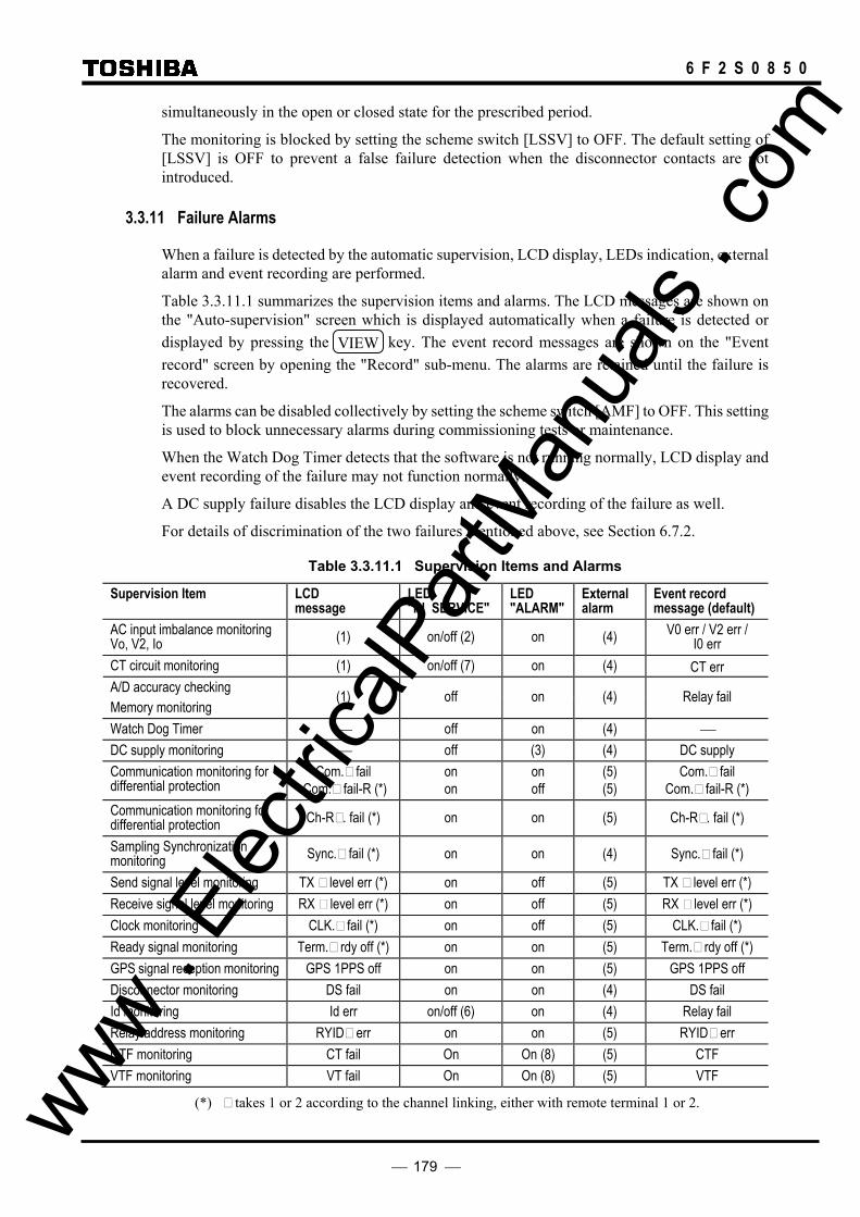
179
6 F 2 S 0 8 5 0
simultaneously in the open or closed state for the prescribed period.
The monitoring is blocked by setting the scheme switch [LSSV] to OFF. The default setting of [LSSV] is OFF to prevent a false failure detection when the disconnector contacts are not introduced.
3.3.11 Failure Alarms
When a failure is detected by the automatic supervision, LCD display, LEDs indication, external alarm and event recording are performed.
Table 3.3.11.1 summarizes the supervision items and alarms. The LCD messages are shown on the "Auto-supervision" screen which is displayed automatically when a failure is detected or displayed by pressing the VIEW key. The event record messages are shown on the "Event record" screen by opening the "Record" sub-menu. The alarms are retained until the failure is recovered.
The alarms can be disabled collectively by setting the scheme switch [AMF] to OFF. This setting is used to block unnecessary alarms during commissioning tests or maintenance.
When the Watch Dog Timer detects that the software is not running normally, LCD display and event recording of the failure may not function normally.
A DC supply failure disables the LCD display and event recording of the failure as well.
For details of discrimination of the two failures mentioned above, see Section 6.7.2.
Table 3.3.11.1 Supervision Items and Alarms
Supervision Item LCD message
LED "IN SERVICE"
LED "ALARM"
External alarm
Event record message (default)
AC input imbalance monitoring Vo, V2, Io (1) on/off (2) on (4) V0 err / V2 err /
I0 err CT circuit monitoring (1) on/off (7) on (4) CT err A/D accuracy checking Memory monitoring
(1) off on (4) Relay fail
Watch Dog Timer off on (4) DC supply monitoring off (3) (4) DC supply Communication monitoring for differential protection
Com. fail Com. fail-R (*)
on on
on off
(5) (5)
Com. fail Com. fail-R (*)
Communication monitoring for differential protection Ch-R . fail (*) on on (5) Ch-R . fail (*)
Sampling Synchronization monitoring Sync. fail (*) on on (4) Sync. fail (*)
Send signal level monitoring TX level err (*) on off (5) TX level err (*) Receive signal level monitoring RX level err (*) on off (5) RX level err (*) Clock monitoring CLK. fail (*) on off (5) CLK. fail (*) Ready signal monitoring Term. rdy off (*) on on (5) Term. rdy off (*) GPS signal reception monitoring GPS 1PPS off on on (5) GPS 1PPS off Disconnector monitoring DS fail on on (4) DS fail Id monitoring Id err on/off (6) on (4) Relay fail Relay address monitoring RYID err on on (5) RYID err CTF monitoring CT fail On On (8) (5) CTF VTF monitoring VT fail On On (8) (5) VTF
(*) takes 1 or 2 according to the channel linking, either with remote terminal 1 or 2. www . El
ectric
alPar
tMan
uals
. com

180
6 F 2 S 0 8 5 0
(1) There are various messages such as "⋅⋅⋅ err" and "⋅⋅⋅ fail" as shown in the table in Section 6.7.2. (2) The LED is on when the scheme switch [SVCNT] is set to "ALM", and off when "ALM &
BLK" (refer to Section 3.3.11). (3) Whether the LED is lit or not depends on the degree of voltage drop. (4) The binary output relay "FAIL" will operate. (5) User-configurable binary output relay will operate if the supervision function and signal
applied. (6) The LED is on when the scheme switch [IDSV] is set to "ALM", and off when "ALM & BLK". (7) The LED is on when the scheme switch [CTSV] is set to "ALM", and off when "ALM & BLK". (8) The LED is on if the signals is assigned and the scheme switch [CTFEN] / [VTFEN] is set to
"On" or "OPT-On".
3.3.12 Trip Blocking
When a failure is detected by the following supervision items, the trip function is blocked as long as the failure exists and is restored when the failure is removed:
• A/D accuracy checking • Memory monitoring • Watch Dog Timer • DC supply monitoring • Telecommunication channel monitoring
When a failure is detected by AC input imbalance monitoring, CT circuit current monitoring or differential current monitoring, the scheme switch [SVCNT], [CTSV] or [IDSV] setting can be used to determine if both tripping is blocked and an alarm is output, or, if only an alarm is output. The CT circuit current monitoring and the differential current monitoring can be disabled by the [CTSV] and [IDSV] respectively.
3.3.13 Setting
The setting elements necessary for the automatic supervision and their setting ranges are shown in the table below.
Element Range Step Default Remarks DIFSV 0.25 − 10.00A
(0.05 − 2.00A 0.01A 0.01A
0.50A 0.10A) (∗)
Differential current supervision
TIDSV 0 – 60s 1s 10s Detected time setting RYID 0-63 0 Local relay address RYID1 0-63 0 Remote 1 relay address RYID2 0-63 0 Remote 2 relay address [IDSV] OFF/ALM&BLK/ALM OFF Differential current supervision [RYIDSV] OFF/ON ON Relay address supervision [LSSV] ON/OFF OFF Disconnector monitoring [SVCNT] ALM&BLK/ALM ALM&BLK Alarming and/or blocking [CTSV] OFF/ALM&BLK/ALM OFF CT circuit monitoring
(∗) Current values shown in parentheses are in the case of 1A rating. Other current values are in the case of 5A rating.
For setting method, see Section 2.2.12. For the setting range of CT circuit failure detection, see section 3.3.4. www .
Elec
tricalP
artM
anua
ls . c
om
181
6 F 2 S 0 8 5 0
3.4 Recording Function
The GRL100 is provided with the following recording functions:
Fault recording
Event recording
Disturbance recording
These records are displayed on the LCD of the relay front panel or on the local or remote PC.
3.4.1 Fault Recording
Fault recording is started by a tripping command of the GRL100, a tripping command of the external main protection or PLC command by user-setting (max. 4) and the following items are recorded for one fault:
Date and time of fault occurrence Faulted phase Tripping phase Tripping mode Fault location Relevant events Power system quantities
Up to 8 most-recent faults are stored as fault records. If a new fault occurs when 8 faults have been stored, the record of the oldest fault is deleted and the record of the latest fault is then stored.
Date and time of fault occurrence The time resolution is 1 ms using the relay internal clock. To be precise, this is the time at which a tripping command has been output.
Fault phase The faulted phase is indicated by DIF, OC or OCI operating phase.
Tripping phase This is the phase to which a tripping command is output.
Tripping mode This shows the protection scheme that outputted the tripping command.
Fault location The distance to the fault point calculated by the fault locator is recorded. The distance is expressed in km and as a percentage (%) of the line length in two-terminal application. In case of three-terminal application, the distance in km and the section on the fault point are displayed.
For the fault locator, see Section 2.17.
Relevant events Such events as autoreclose, re-tripping following the reclose-on-to-a fault or autoreclose and tripping for evolving faults are recorded with time-tags.
Power system quantities The following power system quantities in pre-faults and post-faults are recorded. The power system quantities are not recorded for evolving faults. www .
Elec
tricalP
artM
anua
ls . c
om

182
6 F 2 S 0 8 5 0
- Magnitude and phase angle of phase voltage (Va, Vb, Vc) - Magnitude and phase angle of phase current at the local terminal (Ia, Ib, Ic) - Magnitude and phase angle of phase voltage for autoreclose (Vs1, Vs2) - Magnitude and phase angle of symmetrical component voltage (V1, V2, V0) - Magnitude and phase angle of symmetrical component current at the local terminal (I1, I2, I0) - Magnitude and phase angle of positive sequence voltage at the remote terminal 1 and 2 (V11, V12) - Magnitude and phase angle of phase current and residual current at the remote terminal 1
(Ia1, Ib1, Ic1, I01)
- Magnitude and phase angle of phase current and residual current at the remote terminal 2 (Ia2, Ib2, Ic2, I02)
- Magnitude of phase differential current (Ida, Idb, Idc)
- Magnitude of residual differential current (Id0)
- Telecommunication delay time 1 at the remote terminal 1 - Telecommunication delay time 2 at the remote terminal 2 - Magnitude of parallel line zero sequence current (I0m) - Resistive and reactive component of phase impedance (Ra, Rb, Rc, Xa, Xb, Xc) - Resistive and reactive component of phase-to-phase impedance (Rab, Rbc, Rca, Xab, Xbc, Xca)
Phase angles above are expressed taking that of positive sequence voltage or positive sequence current when the voltage is small or no voltage is input) as a reference phase angle.
3.4.2 Event Recording
The events shown are recorded with a 1 ms resolution time-tag when the status changes. The user can set the maximum 128 recording items and their status change mode. The event recording is initiated by a binary input signal. The event items can be assigned to a signal number in the signal list. The status change mode is set to “On” (only recording when On.) or “On/Off”(recording when both On and Off.) mode by setting. The items of “On/Off” mode are specified by “Bi-trigger events” setting. If the “Bi-trigger events” is set to “100”, No.1 to 100 events are “On/Off” mode and No.101 to 128 events are “On” mode.
The name of event can be set by RSM100. Maximum 22 characters can be set, but LCD displays up to 11 characters of them. Therefore, it is recommended the maximum characters are set. The set name can be viewed on the Setting(view) screen.
The elements necessary for event recording and their setting ranges are shown in the table below. The default setting of event record is shown in Appendix H.
Element Range Step Default Remarks BITRN 0 - 128 1 100 Number of bi-trigger(on/off) events EV1 – EV128 0 - 3071 Assign the signal number
Up to 480 records can be stored. If an additional event occurs when 480 records have been stored, the oldest event record is deleted and the latest event record is then stored.
3.4.3 Disturbance Recording
Disturbance recording is started when overcurrent or undervoltage starter elements operate or a tripping command is output, or PLC command by user-setting (max. 4: Signal No. 2632 to 2635) is outputted. The records include 19 analog signals (local terminal: Va, Vb, Vc, Ia, Ib, Ic, 3I0, www .
Elec
tricalP
artM
anua
ls . c
om
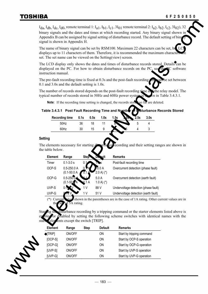
183
6 F 2 S 0 8 5 0
Ida, Idb, Idc, Id0, remote terminal 1: Ia1, Ib1, Ic1, 3I01 remote terminal 2: Ia2, Ib2, Ic2, 3I02), 32 binary signals and the dates and times at which recording started. Any binary signal shown in Appendix B can be assigned by signal setting of disturbance record. The default setting of binary signal is shown in Appendix H.
The name of binary signal can be set by RSM100. Maximum 22 characters can be set, but LCD displays up to 11 characters of them. Therefore, it is recommended the maximum characters are set. The set name can be viewed on the Setting(view) screen.
The LCD display only shows the dates and times of disturbance records stored. Details can be displayed on the PC. For how to obtain disturbance records on the PC, see the PC software instruction manual.
The pre-fault recording time is fixed at 0.3s and the post-fault recording time can be set between 0.1 and 3.0s and the default setting is 1.0s.
The number of records stored depends on the post-fault recording time and the relay model. The typical number of records stored in 50Hz and 60Hz power system is shown in Table 3.4.3.1.
Note: If the recording time setting is changed, the records stored so far are deleted.
Table 3.4.3.1 Post Fault Recording Time and Number of Disturbance Records Stored
Recording time 0.1s 0.5s 1.0s 1.5s 2.0s 2.5s 3.0s 50Hz 36 18 11 8 6 5 4 60Hz 30 15 9 6 5 4 3
Setting The elements necessary for starting disturbance recording and their setting ranges are shown in the table below.
Element Range Step Default Remarks Timer 0.1-3.0 s 0.1 s 1.0 s Post-fault recording time OCP-S 0.5-250.0 A
(0.1-50.0 A 0.1 A 0.1 A
10.0 A 2.0 A) (*)
Overcurrent detection (phase fault)
OCP-G 0.5-250.0 A (0.1-50.0 A
0.1 A 0.1 A
5.0 A 1.0 A) (*)
Overcurrent detection (earth fault)
UVP-S 0-132 V 1 V 88 V Undervoltage detection (phase fault) UVP-G 0-76 V 1 V 51 V Undervoltage detection (earth fault) (*) Current values shown in the parentheses are in the case of 1A rating. Other current values are in
the case of 5A rating.
Starting the disturbance recording by a tripping command or the starter elements listed above is enabled or disabled by setting the following scheme switches with identical names with the starter elements except the switch [TRIP].
Element Range Step Default Remarks [TRIP] ON/OFF ON Start by tripping command [OCP-S] ON/OFF ON Start by OCP-S operation [OCP-G] ON/OFF ON Start by OCP-G operation [UVP-S] ON/OFF ON Start by UVP-S operation [UVP-G] ON/OFF ON Start by UVP-G operation
www . El
ectric
alPar
tMan
uals
. com

184
6 F 2 S 0 8 5 0
3.5 Metering Function
The GRL100 performs continuous measurement of the analog input quantities. The measurement data shown below is updated every second and displayed on the LCD of the relay front panel or on the local or remote PC.
- Magnitude and phase angle of phase voltage (Va, Vb, Vc)
- Magnitude and phase angle of phase current at the local terminal (Ia, Ib, Ic)
- Magnitude and phase angle of phase voltage for autoreclose (Vs1, Vs2)
- Magnitude and phase angle of symmetrical component voltage (V1, V2, V0)
- Magnitude and phase angle of symmetrical component current at the local terminal (I1, I2, I0)
- Magnitude and phase angle of positive sequence voltage at the remote terminal 1 and 2 (V11, V12)
- Magnitude and phase angle of phase current and residual current at the remote terminal 1 (Ia1, Ib1, Ic1, I01)
- Magnitude and phase angle of phase current and residual current at the remote terminal 2 (Ia2, Ib2, Ic2, I02)
- Magnitude of phase differential current (Ida, Idb, Idc)
- Magnitude of residual differential current (Id0)
- Percentage of thermal capacity (THM%)
- Pickup current of segregated-phase current differential element (Ipua, Ipub, Ipuc)
- Restraining current of segregated-phase current differential element (Ira, Irb, Irc)
- Telecommunication delay time 1 at the remote terminal 1
- Telecommunication delay time 2 at the remote terminal 2
- Magnitude of parallel line zero sequence current (I0m)
- Resistive and reactive component of phase impedance (Ra, Rb, Rc, Xa, Xb, Xc)
- Resistive and reactive component of phase-to-phase impedance (Rab, Rbc, Rca, Xab, Xbc, Xca)
- Active power and reactive power
- Frequency
Phase angles above are expressed taking that of positive sequence voltage or positive sequence current at the local terminal when the voltage is small or no voltage is input) as a reference phase angle, where leading phase angles are expressed as positive, (+). When electrical quantities at the local terminal are "0", electrical quantities at the remote terminal are displayed as "−".
The above system quantities are displayed in values on the primary side or on the secondary side determined by the setting. To display accurate values, it is necessary to set the CT ratio and VT ratio as well. For the setting method, see "Setting the line parameters" in 4.2.6.7.
The signing of active and reactive power flow direction can be set positive for either power sending or power receiving. The signing of reactive power can be also set positive for either lagging phase or leading phase. For the setting method, see Section 4.2.6.6.
www . El
ectric
alPar
tMan
uals
. com

185
6 F 2 S 0 8 5 0
4. User Interface 4.1 Outline of User Interface
The user can access the relay from the front panel.
Local communication with the relay is also possible using a personal computer (PC) via an RS232C port. Furthermore, remote communication is also possible using RSM (Relay Setting and Monitoring) or IEC60870-5-103 communication, etc., via an RS485.
This section describes the front panel configuration and the basic configuration of the menu tree of the local human machine communication ports and HMI (Human Machine Interface).
4.1.1 Front Panel
As shown in Figure 3.1.5.1, the front panel is provided with a liquid crystal display (LCD), light emitting diode (LED), operation keys, VIEW and RESET keys, monitoring jack and RS232C connector.
LCD The LCD screen, provided with a 4-line, 40-character back-light, displays detailed information of the relay interior such as records, status and settings. The LCD screen is normally unlit, but pressing the VIEW key will display the digest screen and pressing any key other than VIEW and RESET will display the menu screen.
These screens are turned off by pressing the RESET key or END key. If any display is left for 5 minutes or longer without operation, the back-light will go off.
LED There are 8 LED displays. The signal labels and LED colors are defined as follows:
Label Color Remarks IN SERVICE Green Lit when the relay is in service. TRIP Red Lit when a trip command is issued. ALARM Red Lit when a failure is detected. TESTING Red Lit when the testing switches are in test
position. (LED1) Red Configurable LED to assign signals with or without latch
when relay operates. (LED2) Red Configurable LED to assign signals with or without latch
when relay operates. (LED3) Red Configurable LED to assign signals with or without latch
when relay operates. (LED4) Red Configurable LED to assign signals with or without latch
when relay operates.
The TRIP LED lights up once the relay is operating and remains lit even after the trip command goes off. For the operation, see Section 4.2.1.
www . El
ectric
alPar
tMan
uals
. com
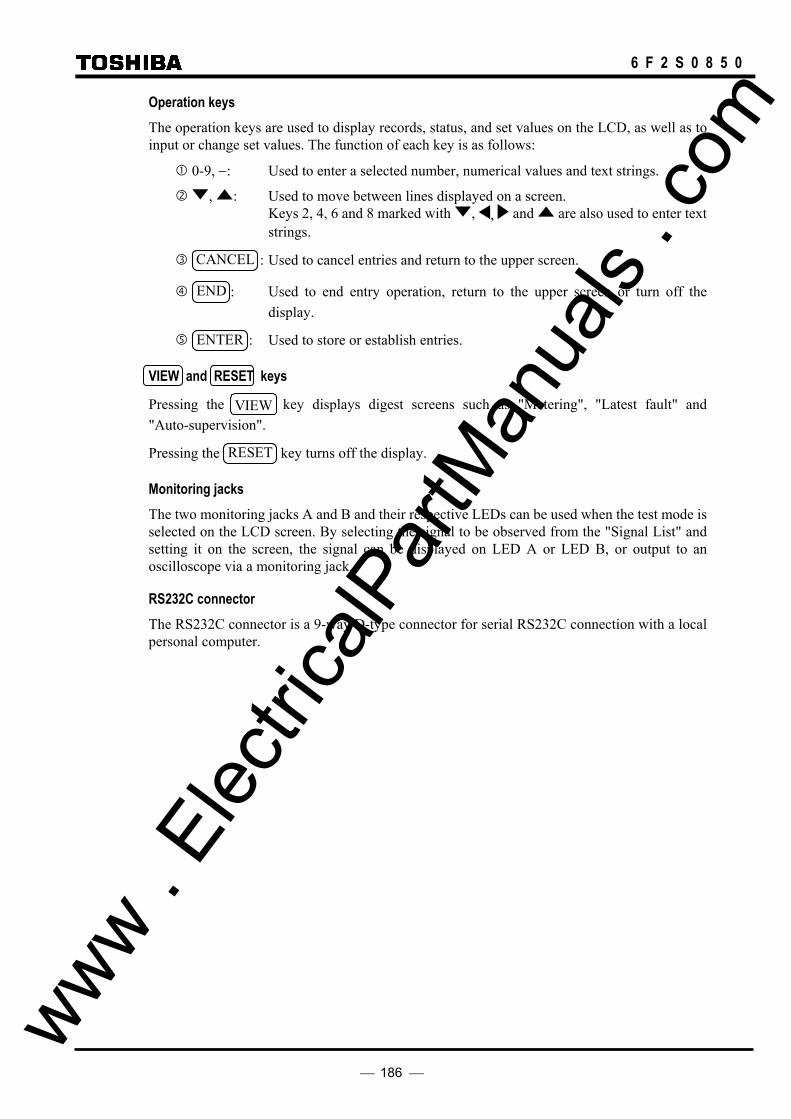
186
6 F 2 S 0 8 5 0
Operation keys The operation keys are used to display records, status, and set values on the LCD, as well as to input or change set values. The function of each key is as follows:
0-9, −: Used to enter a selected number, numerical values and text strings.
, : Used to move between lines displayed on a screen. Keys 2, 4, 6 and 8 marked with , , and are also used to enter text strings.
CANCEL : Used to cancel entries and return to the upper screen.
END : Used to end entry operation, return to the upper screen or turn off the display.
ENTER : Used to store or establish entries.
VIEW and RESET keys
Pressing the VIEW key displays digest screens such as "Metering", "Latest fault" and "Auto-supervision".
Pressing the RESET key turns off the display.
Monitoring jacks The two monitoring jacks A and B and their respective LEDs can be used when the test mode is selected on the LCD screen. By selecting the signal to be observed from the "Signal List" and setting it on the screen, the signal can be displayed on LED A or LED B, or output to an oscilloscope via a monitoring jack.
RS232C connector The RS232C connector is a 9-way D-type connector for serial RS232C connection with a local personal computer.
www . El
ectric
alPar
tMan
uals
. com

187
6 F 2 S 0 8 5 0
4.1.2 Communication Ports
The following interfaces are provided as communication ports:
• RS232C port
• RS485, Fibre optic or Ethernet LAN port for serial communication
• IRIG-B port
• Interface port for telecommunication link
RS232C port This connector is a standard 9-way D-type connector for serial port RS232C transmission and is mounted on the front panel. By connecting a personal computer to this connector, setting and display functions can be performed from the personal computer.
RS485, Fibre optic or Ethernet LAN port One or two serial communication ports can be provided. In the single-port type, it is connected to the RSM (Relay Setting and Monitoring system) via the protocol converter G1PR2 or IEC60870-5-103 communication via BCU/RTU (Bay Control Unit / Remote Terminal Unit) to connect between relays and to construct a network communication system. (See Figure 4.4.1 in Section 4.4.)
In the case of the two-port type, one port can be used for the relay setting and monitoring (RSM) system or IEC60870-5-103 communication, while the other port is used for IEC60870-5-103 communication only.
Screw terminal for RS485, ST connector for fibre optic or RJ45 connector for Ethernet LAN (10Base-T) is provided on the back of the relay as shown in Figure 4.1.2.1.
IRIG-B port The IRIG-B port is mounted on the transformer module, and collects serial IRIG-B format data from the external clock to synchronize the relay calendar clock. The IRIG-B port is isolated from the external circuit by a photo-coupler. A BNC connector is used as the input connector.
This port is on the back of the relay, as shown in Figure 4.1.2.1.
Interface port for telecommunication link The optical or electrical interface port for telecommunication link is provided on the back of the relay as shown in Figure 4.1.2.1. The connector using for the optical interface port is the ST type (for 2km class), SC type (for 30km class) or Duplex LC type (for 80km class) connector and the connector for the electrical interface port is the D-sub connector.
www . El
ectric
alPar
tMan
uals
. com
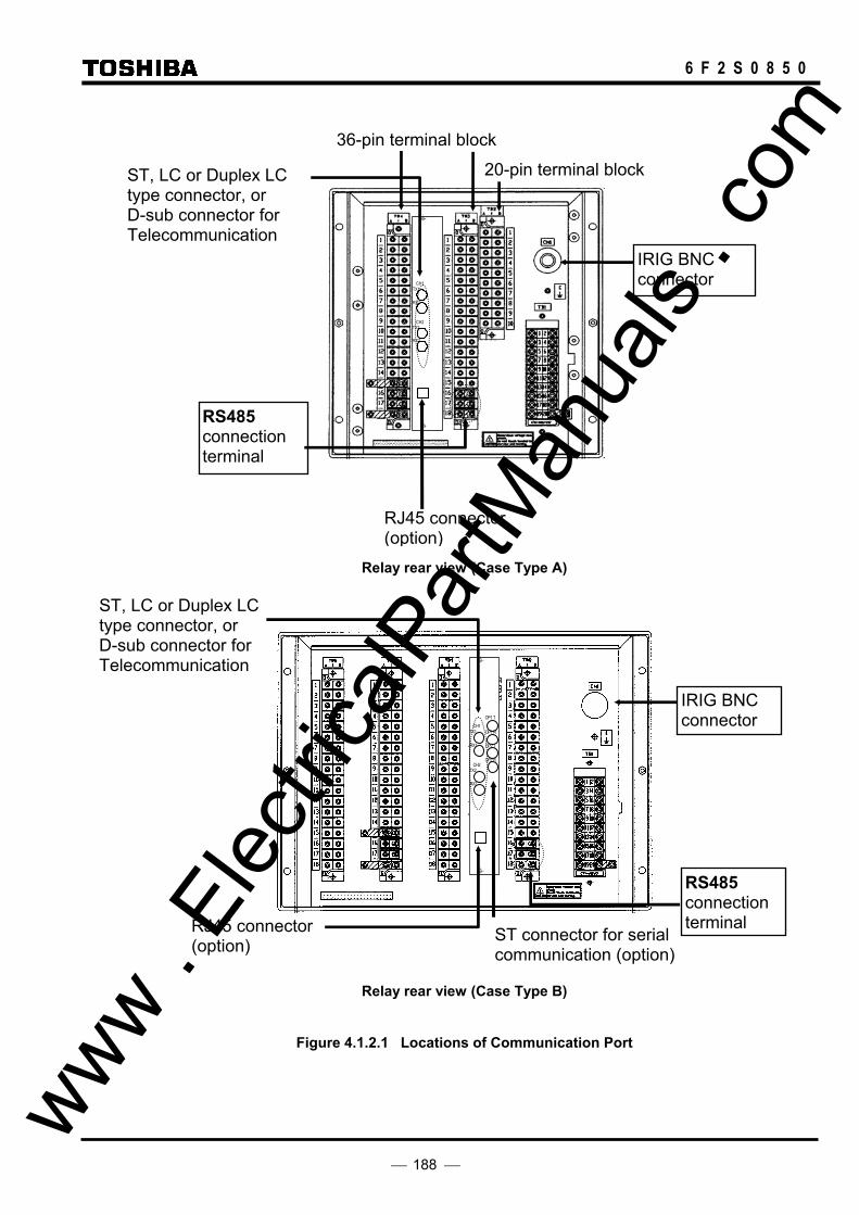
188
6 F 2 S 0 8 5 0
CH1 TX1
RX1
CH2 TX2
RX2
Relay rear view (Case Type A)
CH1 TX1
RX1
CH2 TX2
RX2
OP1 T
OP1 R
OP2 T
OP2 R
Relay rear view (Case Type B)
Figure 4.1.2.1 Locations of Communication Port
20-pin terminal block
36-pin terminal block
IRIG BNC connector
RS485 connection terminal
RS485 connection terminal
IRIG BNC connector
ST, LC or Duplex LC type connector, or D-sub connector for Telecommunication
RJ45 connector (option)
ST, LC or Duplex LC type connector, or D-sub connector for Telecommunication
RJ45 connector (option) ST connector for serial
communication (option)
www . El
ectric
alPar
tMan
uals
. com

189
6 F 2 S 0 8 5 0
4.2 Operation of the User Interface
The user can access such functions as recording, measurement, relay setting and testing with the LCD display and operation keys.
Note: LCD screens depend on the relay model and the scheme switch setting. Therefore, LCD screens described in this section are samples of typical model.
4.2.1 LCD and LED Displays
Displays during normal operation When the GRL100 is operating normally, the green "IN SERVICE" LED is lit and the LCD is off.
Press the VIEW key when the LCD is off to display the digest screens "Metering1", "Metering2", "Metering3", "Metering4", "Latest fault" and "Auto-supervision" in turn. The last two screens are displayed only when there is some data. The following are the digest screens and can be displayed without entering the menu screens.
M e t e r i n g 1 6 / O c t / 1 9 9 7 1 8 : 1 3
V a 1 2 7 . 0 k V I a 2 . 1 0 k
V b 1 2 7 . 0 k V I b 2 . 1 0 k
V c 1 2 7 . 0 k V I c 2 . 1 0 k
1
A
M e t e r i n g 1 6 / O c t / 1 9 9 7 1 8 : 1 3
V a 1 2 7 . 0 k V I a
V b 1 2 7 . 0 k V I b
V c 1 2 7 . 0 k V I c
1
A
A
A
M e t e r i n g 1 6 / O c t / 1 9 9 7 1 8 : 1 3
V a 1 * * . * k V I a * * . * * k
V b 1 * * . * k V I b * * . * * k
V c 1 * * . * k V I c * * . * * ka
1
A
M e t e r i n g 1 6 / O c t / 1 9 9 7 1 8 : 1 3
V a * . k V I a
V b * . k V I b
V c * . k V I c
c
b
b
c
a
1
A
A
A
M e t e r i n g 1 6 / O c t / 1 9 9 7 1 8 : 1 3
I d 0 . 0 0 k A I a 1 . 0 5 k
I d 0 . 0 0 k A I b 1 . 0 5 k
I d 0 . 0 0 k A I c 1 . 0 5 k
a
b
c
3
1
1
1
A
A
A
I a 1 . 0 5 k
I b 1 . 0 5 k
I c 1 . 0 5 k
2
2
2
A
A
A Note: I∗1 and I∗2 are phase currents of remote terminal 1 and remote terminal 2.
M e t e r i n g 1 6 / O c t / 1 9 9 7 1 8 : 1 34
− + 4 0 0 . 1 1 M W
2 5 . 5 1 M rav
6 0 . 1 H z Press the RESET key to turn off the LCD.
For any display, the back-light is automatically turned off after five minutes.
Displays in tripping L a t e s t f a u l t 1 6 / O c t / 1 9 9 7 1 8 : 1 3 : 4 5 . 1 6 0
P h a s e A B N T r i p A
D I F
4 7 . 3 k m ( 5 7 . 1 )%
B C
If a fault occurs and a tripping command is output when the LCD is off, the red "TRIP" LED and other configurable LED if signals assigned to trigger by tripping. www .
Elec
tricalP
artM
anua
ls . c
om
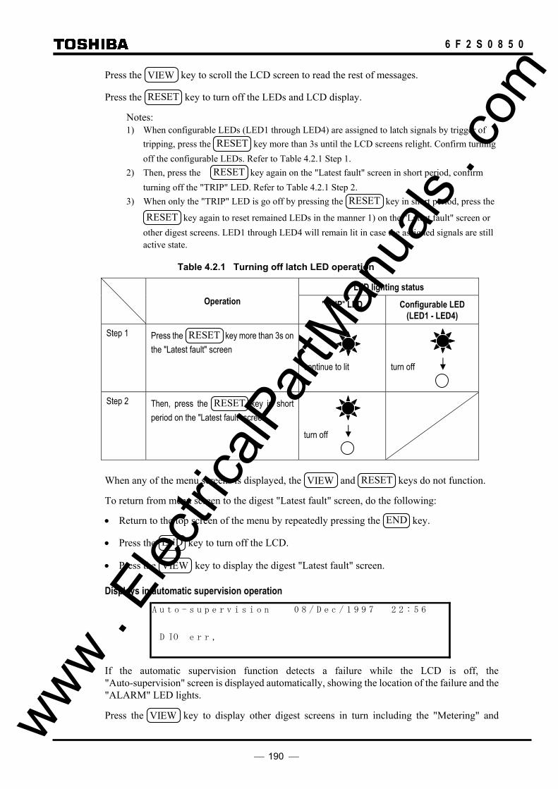
190
6 F 2 S 0 8 5 0
Press the VIEW key to scroll the LCD screen to read the rest of messages.
Press the RESET key to turn off the LEDs and LCD display.
Notes: 1) When configurable LEDs (LED1 through LED4) are assigned to latch signals by trigger of
tripping, press the RESET key more than 3s until the LCD screens relight. Confirm turning off the configurable LEDs. Refer to Table 4.2.1 Step 1.
2) Then, press the RESET key again on the "Latest fault" screen in short period, confirm turning off the "TRIP" LED. Refer to Table 4.2.1 Step 2.
3) When only the "TRIP" LED is go off by pressing the RESET key in short period, press the
RESET key again to reset remained LEDs in the manner 1) on the "Latest fault" screen or other digest screens. LED1 through LED4 will remain lit in case the assigned signals are still active state.
Table 4.2.1 Turning off latch LED operation
LED lighting status Operation "TRIP" LED Configurable LED
(LED1 - LED4)
Step 1
Press the RESET key more than 3s on the "Latest fault" screen
continue to lit
turn off
Step 2
Then, press the RESET key in short period on the "Latest fault" screen
turn off
When any of the menu screens is displayed, the VIEW and RESET keys do not function.
To return from menu screen to the digest "Latest fault" screen, do the following:
• Return to the top screen of the menu by repeatedly pressing the END key.
• Press the END key to turn off the LCD.
• Press the VIEW key to display the digest "Latest fault" screen.
Displays in automatic supervision operation
A u t o - s u p e r v i s i o n 0 8 / D e c / 1 9 9 7 2 2 : 5 6
D IO e r ,r
If the automatic supervision function detects a failure while the LCD is off, the "Auto-supervision" screen is displayed automatically, showing the location of the failure and the "ALARM" LED lights.
Press the VIEW key to display other digest screens in turn including the "Metering" and www . El
ectric
alPar
tMan
uals
. com
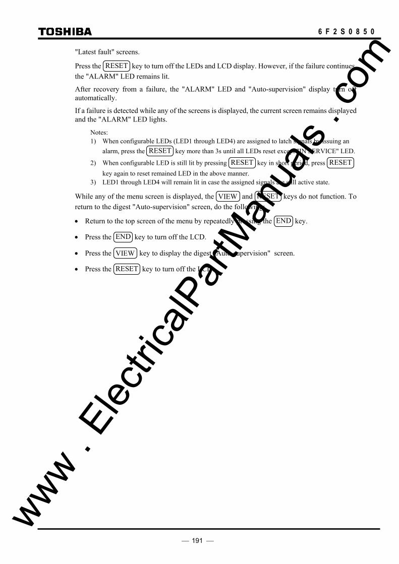
191
6 F 2 S 0 8 5 0
"Latest fault" screens.
Press the RESET key to turn off the LEDs and LCD display. However, if the failure continues, the "ALARM" LED remains lit.
After recovery from a failure, the "ALARM" LED and "Auto-supervision" display turn off automatically.
If a failure is detected while any of the screens is displayed, the current screen remains displayed and the "ALARM" LED lights.
Notes: 1) When configurable LEDs (LED1 through LED4) are assigned to latch signals by issuing an
alarm, press the RESET key more than 3s until all LEDs reset except "IN SERVICE" LED.
2) When configurable LED is still lit by pressing RESET key in short period, press RESET key again to reset remained LED in the above manner.
3) LED1 through LED4 will remain lit in case the assigned signals are still active state.
While any of the menu screen is displayed, the VIEW and RESET keys do not function. To return to the digest "Auto-supervision" screen, do the following:
• Return to the top screen of the menu by repeatedly pressing the END key.
• Press the END key to turn off the LCD.
• Press the VIEW key to display the digest "Auto-supervision" screen.
• Press the RESET key to turn off the LCD.
www . El
ectric
alPar
tMan
uals
. com

192
6 F 2 S 0 8 5 0
4.2.2 Relay Menu
Figure 4.2.2.1 shows the menu hierarchy in the GRL100. The menu has five sub-menus, "Record", "Status", "Setting (view)", "Setting (change)", and "Test". For details of the menu hierarchy, see Appendix E.
Record Fault record
Event record Disturbance record
Autoreclose count Status Metering
Binary I/O
Relay element Time sync source
Clock adjustment Terminal condition Direction Setting (view) Version
Description
Communication Record Status Protection
Binary input Binary output LED Setting (change) Password Description Communication Record Status Protection Binary input Binary output LED Test Switch Binary output Timer Logic circuit Sim. fault
Menu
Figure 4.2.2.1 Relay Menu
www . El
ectric
alPar
tMan
uals
. com

193
6 F 2 S 0 8 5 0
Record In the "Record" menu, the fault records, event records and disturbance records can be displayed or erased. Furthermore, autoreclose function can be displayed in counter form or reset.
Status The "Status" menu displays the power system quantities, binary input and output status, relay measuring element status, signal source for time synchronization (IRIG-B, RSM, IEC or GPS), terminal condition (In- or out-of-service) and adjusts the clock.
Setting (view) The "Setting (view)" menu displays the relay version, plant name and the current settings of relay address, IP address and RS232C baud rate in communication, record, status, protection, configurable binary inputs, configurable binary outputs and configurable LEDs.
Setting (change) The "Setting (change)" menu is used to set or change the settings of password, plant name, relay address, IP address and RS232C baud rate in communication, record, status, protection, configurable binary inputs, configurable binary outputs and configurable LEDs.
Since this is an important menu and is used to set or change settings related to relay tripping, it has password security protection.
Test The "Test" menu is used to set testing switches, to test the trip circuit, to forcibly operate binary output relays, to measure variable timer time, to observe the binary signals in the logic circuit, and to set the synchronized trigger signal for end-to-end dynamic test.
When the LCD is off, press any key other than the VIEW and RESET keys to display the top "MENU" screen and then proceed to the relay menus.
M E N U
1 = R e c o r d 2 = S t a t u s
3 = S e t t i n g ( v i e w ) 4 = S e t t i n g ( c h a n g e )
5 = T e s t
To display the "MENU" screen when the digest screen is displayed, press the RESET key to
turn off the LCD, then press any key other than the VIEW and RESET keys.
Press the END key when the top screen is displayed to turn off the LCD.
An example of the sub-menu screen is shown below. The top line shows the hierarchical layer of the screen, screen title and total number of lines of the screen. The last item is not displayed for all the screens. "/6" displayed on the far left means that the screen is in the sixth hierarchical layer, while "1/8" displayed on the far right means that the screen has eight lines excluding the top line and that the cursor is on the first line.
To move the cursor downward or upward for setting or viewing other lines not displayed on the window, use the and keys.
www . El
ectric
alPar
tMan
uals
. com

194
6 F 2 S 0 8 5 0
/ 6 S c h e m e s w i t c h 1 / 8 A R C - E X T 0 = O f f 1 = O n 1
A R C - S M 0 = O f f 1 = S 2 2 = S 3 3 = S 4 1 V T P H S E L 1 = A 2 = B 3 = C 1 V T - R A T E 1 = P H / G 2 = P H / P H 1
A R C - B U 0 = O f f 1 = O n 1 A R C D I F G 0 = O f f 1 = O n 1 V C H K 0 = O f f 1 = L B 2 = D B 3 = S Y 1
3 P H - V T 1 = B U S 2 = L i n e 1 To move to the lower screen or move from the left-side screen to the right-side screen in Appendix E, select the appropriate number on the screen. To return to the higher screen or move from the right-side screen to the left-side screen, press the END key.
The CANCEL key can also be used to return to the higher screen but it must be used carefully because it may cancel entries made so far.
To move between screens of the same hierarchical depth, first return to the higher screen and then move to the lower screen.
4.2.3 Displaying Records
The sub-menu of "Record" is used to display fault records, event records, disturbance records and autoreclose counts.
4.2.3.1 Displaying Fault Records To display fault records, do the following:
• Open the top "MENU" screen by pressing any keys other than the VIEW and RESET keys.
• Select 1 (=Record) to display the "Record" sub-menu.
R e c o
1 = r e c o r d
3 = D i s t u r b a n c e n 4 = A u t o r e c l o s e t c o u
/ 1 r
a u t F l 2 = E v e n t r e c o r d
r e c o r d
d
• Select 1 (=Fault record) to display the "Fault record" screen.
1 = a
/ 2 r e c o r
i s l D p 2 = C l e a r
a u t F l
y
d
• Select 1 (=Display) to display the dates and times of fault records stored in the relay from the
top in new-to-old sequence.
/ 3 F a u l t r e c o r d 1 / 8
# 1 1 6 / O c t / 1 9 9 7 1 8 : 1 3 : 5 7 . 0 3 1
# 2 2 0 / S e p / 1 9 9 7 1 5 : 2 9 : 2 2 . 4 6 3
# 3 0 4 / J u l / 1 9 9 7 1 1 : 5 4 : 5 3 . 9 7 7 • Move the cursor to the fault record line to be displayed using the and keys and press the
ENTER key to display the details of the fault record. www . El
ectric
alPar
tMan
uals
. com
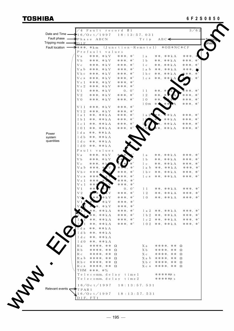
195
6 F 2 S 0 8 5 0
/4 Fault record #1 3/62
16/Oct/1997 18:13:57.031
Phase ABCN Trip ABC DIF
Vc ***.*kV ***.*° lc **.**kA ***.*°
Vb ***.*kV ***.*° lb **.**kA ***.*°
Va ***.*kV ***.*° la **.**kA ***.*°
Prefault values
Va ***.*kV ***.*° la **.**kA ***.*°
Vb ***.*kV ***.*° lb **.**kA ***.*°
Vc ***.*kV ***.*° lc **.**kA ***.*°
V s 1 ***.*kV ***.*°
V1 ***.*kV 0.0° l1 **.**kA ***.*°
V2 ***.*kV ***.*° l2 **.**kA ***.*°
V0 ***.*kV ***.*° l0 **.**kA ***.*°
Ia1 **.**kA ***.*° la2 **.**kA ***.*°
Ib1 **.**kA ***.*° lb2 **.**kA ***.*°
Ic1 **.**kA ***.*° lc2 **.**kA ***.*°
ld 0 **.**kA
ldc **.**kA
ldb **.**kA
lda **.**kA
I01 **.**kA ***.*° l02 **.**kA ***.*°
Telecomm. delay time2 ***** µ s Telecomm. delay time1 ***** µ s
Fault values
Vs1 ***.*kV ***.*°
V1 ***.*kV 0.0° l1 **.**kA ***.*°
V2 ***.*kV ***.*° l2 **.**kA ***.*°
V0 ***.*kV ***.*° l0 **.**kA ***.*°
16/Oct/1997 18:13:57.531
DIF,FT1
TPAR1 16/Oct/1997 18:13:57.531
V11 ***.*kV ***.*°
V12 ***.*kV ***.*°
V11 ***.*kV ***.*°
V12 ***.*kV ***.*°
Ia1 **.**kA ***.*° la2 **.**kA ***.*°
Ib1 **.**kA ***.*° lb2 **.**kA ***.*°
Ic1 **.**kA ***.*° lc2 **.**kA ***.*°
ld 0 **.**kA
ldc **.**kA
ldb **.**kA
lda **.**kA
I01 **.**kA ***.*° l02 **.**kA ***.*°
***.* km (Junction-Remote1) *OB*NC*CF
THM ***.*%
Va b ***.*kV ***.*° lab **.**kA ***.*°
Vb c ***.*kV ***.*° lbc **.**kA ***.*°
Vc a ***.*kV ***.*° lca **.**kA ***.*°
l0m **.**kA ***.*°
V s 2 ***.*kV ***.*°
V s 1 ***.*kV ***.*°
Va b ***.*kV ***.*° lab **.**kA ***.*°
Vb c ***.*kV ***.*° lbc **.**kA ***.*°
Vc a ***.*kV ***.*° lca **.**kA ***.*°
Ra ****.** Ω Xa ****.** Ω Rb ****.** Ω Xb ****.** Ω Rc ****.** Ω Xc ****.** Ω Ra b ****.** Ω Xab ****.** Ω Rb c ****.** Ω Xbc ****.** Ω Rc a ****.** Ω Xca ****.** Ω
Date and Time Fault phase
Tripping mode Fault location
Power system quantities
Relevant events
Tripping phase
www . El
ectric
alPar
tMan
uals
. com

196
6 F 2 S 0 8 5 0
Note: I∗1 and I∗2 are phase currents of remote terminal 1 and remote terminal 2. V11 and V12 are symmetrical component voltages of remote terminal 1 and remote terminal 2.
The lines which are not displayed in the window can be displayed by pressing the and keys.
To clear all the fault records, do the following:
• Open the "Record" sub-menu.
• Select 1 (=Fault record) to display the "Fault record" screen.
• Select 2 (=Clear) to display the following confirmation screen.
/ 2 F a u l t r e c o r d
C l e a r a l l f a u l t r e c o r d s ?
E N T E R = Y e s C A N C E L = N o
• Press the ENTER (=Yes) key to clear all the fault records stored in non-volatile memory.
If all fault records have been cleared, the "Latest fault" screen of the digest screens is not displayed.
4.2.3.2 Displaying Event Records To display event records, do the following:
• Open the top "MENU" screen by pressing any keys other than the VIEW and RESET keys.
• Select 1 (=Record) to display the "Record" sub-menu.
• Select 2 (=Event record) to display the "Event record" screen.
1 = y
/ 2 r e c o r
i s l D p 2 = C l e a r
v e t E n d
• Select 1 (=Display) to display the events with date and time from the top in new-to-old
sequence. / 3 E v e n t r e c o r d 3 / 2 1
2 3 / O c t / 1 9 9 7 1 8 : 1 8 : 5 8 . 2 5 5 D S
O
O n
2 3 / O c t / 1 9 9 7 1 8 : 1 3 : 5 8 . 0 2 8 D S f f
1 6 / A u g / 1 9 9 7 6 : 1 3 : 5 7 . 7 7 3 C o m . 1 f fOlia f The lines which are not displayed in the window can be displayed by pressing the and keys.
To clear all the event records, do the following:
• Open the "Record" sub-menu.
• Select 2 (=Event record) to display the "Event record" screen.
• Select 2 (=Clear) to display the following confirmation screen.
www . El
ectric
alPar
tMan
uals
. com

197
6 F 2 S 0 8 5 0
/ 2 E v e n t r e c o r d
C l e a r a l l e v e n t r e c o r d s ?
E N T E R = Y e s C A N C E L = N o
• Press the ENTER (=Yes) key to clear all the event records stored in non-volatile memory.
4.2.3.3 Displaying Disturbance Records Details of disturbance records can be displayed on the PC screen only (*); the LCD displays only the recorded date and time for all disturbances stored in the relay. To display them, do the following:
(*) For the display on the PC screen, refer to RSM100 manual.
• Open the top "MENU" screen by pressing any keys other than the VIEW and RESET keys.
• Select 1 (=Record) to display the "Record" sub-menu.
• Select 3 (=Disturbance record) to display the "Disturbance record" screen.
1 = y
/ 2 r e c o r
i s l D p 2 = C l e a r
i s u D t r b a n c e d
• Select 1 (=Display) to display the date and time of the disturbance records from the top in
new-to-old sequence.
/ 3 D i s t u r b a n c e r e c o r d 3 /12
# 1 1 6 / O c t / 1 9 9 7 1 8 : 1 3 : 5 7 . 0 3 1
# 2 2 0 / S e p / 1 9 9 7 1 5 : 2 9 : 2 2 . 4 6 3
# 3 0 4 / J u l / 1 9 9 7 1 1 : 5 4 : 5 3 . 9 7 7 The lines which are not displayed in the window can be displayed by pressing the and keys.
To clear all the disturbance records, do the following:
• Open the "Record" sub-menu.
• Select 3 (=Disturbance record) to display the "Disturbance record" screen.
• Select 2 (=Clear) to display the following confirmation screen.
/ 2 D i s t u r b a n c e r e c o r d
C l e a r a l l d i s t u r b a n c e r e c o r d s ?
E N T E R = Y e s C A N C E L = N o
• Press the ENTER (=Yes) key to clear all the disturbance records stored in non-volatile memory.
4.2.3.4 Displaying Autoreclose Counts The autoreclose output counts can be displayed or can be reset to zero as follows.
To display the autoreclose output counts on the LCD, do the following: www . El
ectric
alPar
tMan
uals
. com

198
6 F 2 S 0 8 5 0
• Select 1 (=Record) on the top "MENU" screen to display the "Record" sub-menu.
• Select 4 (=Autoreclose count) to display the "Autoreclose count" screen.
1 = y
/ 2 c o u n t
i s l D p 2 = R e s e t
u t r A o e c l o s e
• Select 1 (=Display) to display the autoreclose counts.
/ 3 A u t o r e c l o s e c o u n t
C B 1S P A R
C B 2
[ 4 6 ]T P A R M P A R
[ 2 2 ] [ 1 2 ][ 4 6 ] [ 2 2 ] [ 1 2 ]
In the case of two breaker autoreclose, CB1 and CB2 mean busbar breaker and center breaker, respectively. SPAR, TPAR and MPAR mean single-phase, three-phase and multi-phase autoreclose, respectively.
To reset the autoreclose output count, do the following: • Select 2 (=Reset) on the "Autoreclose count" screen to display the "Reset autoreclose count"
screen.
1 =
/ 3
B 1 C
2 = C B 2
c o u n tu t ra o e c l o s eR e s e t
• Select 1 (=CB1) or 2 (=CB2) to display the confirmation screen.
/ 3 c o u n tu t ra o e c l o s eR e s e t
R e s e t c o u n t s ?
E N T E R = Y e s C A N C E L = N o
• Press the ENTER key to reset the count to zero and return to the previous screen.
4.2.4 Displaying the Status
From the sub-menu of "Status", the following statuses can be displayed on the LCD:
Metering data of the protected line
Status of binary inputs and outputs
Status of measuring elements output
Status of time synchronization source
Status of remote terminal
The data are updated every second.
This sub-menu is also used to adjust the time of the internal clock.
4.2.4.1 Displaying Metering Data To display metering data on the LCD, do the following:
• Select 2 (=Status) on the top "MENU" screen to display the "Status" screen. www . El
ectric
alPar
tMan
uals
. com
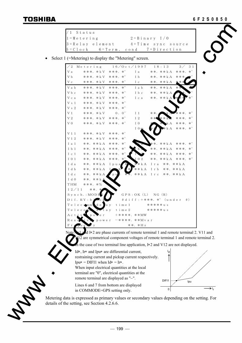
199
6 F 2 S 0 8 5 0
/ 1 S t a t u s
1 = M e t e r i n g 2 = B i n a r y I / O
3 = R e l a y e l e m e n t 4 = T i m e s y n c s o u r c e
5 = C l o c o n k d6 = T e r m . c o n 7 = D i r e c t i
• Select 1 (=Metering) to display the "Metering" screen.
/2 Metering 16/Oct/1997 18:13 3/ 31
Va ***.*kV ***.*° Ia **.**kA ***.*°
Vb ***.*kV ***.*° Ib **.**kA ***.*°
Vc ***.*kV ***.*° Ic **.**kA ***.*°
Vab ***.*kV ***.*° Iab **.**kA ***.*°
Vbc ***.*kV ***.*° Ibc **.**kA ***.*°
Vca ***.*kV ***.*° Ica **.**kA ***.*°
Vs1 ***.*kV ***.*°
Vs2 ***.*kV ***.*°
V1 ***.*kV 0.0° I1 **.**kA ***.*°
V2 ***.*kV ***.*° I2 **.**kA ***.*°
V0 ***.*kV ***.*° I0 **.**kA ***.*°
I0m **.**kA ***.*°
V11 ***.*kV ***.*°
V12 ***.*kV ***.*°
Ia1 **.**kA ***.*° Ia2 **.**kA ***.*°
Ib1 **.**kA ***.*° Ib2 **.**kA ***.*°
Ic1 **.**kA ***.*° Ic2 **.**kA ***.*°
I01 **.**kA ***.*° I02 **.**kA ***.*°
Ida **.**kA Ipua **.**kA Ira **.**kA
Idb **.**kA Ipub **.**kA Irb **.**kA
Idc **.**kA Ipuc **.**kA Irc **.**kA
Id0 **.**kA
THM ***.*%
I2/I1 **.**
Synch.:MODE2A GPS:OK(L) NG(R)
Dif.RY:blocked θdiff:+***.*°(under θ)
Telecomm delay time1 *****us
Telecomm delay time2 *****us
Active power +****.**MW
Reactive power -****.**Mvar
Frequency **.*Hz Note: I∗1 and I∗2 are phase currents of remote terminal 1 and remote terminal 2. V11 and
V12 are symmetrical component voltages of remote terminal 1 and remote terminal 2.
In the case of two terminal line application, I∗2 and V12 are not displayed.
Id∗, Ir∗ and Ipu∗ are differential current, restraining current and pickup current respectively.
Ipu∗ = DIFI1 when Id∗ = Ir∗. When input electrical quantities at the local
terminal are "0", electrical quantities at the remote terminal are displayed as "−".
Lines 6 and 7 from bottom are displayed in COMMODE=GPS setting only.
Metering data is expressed as primary values or secondary values depending on the setting. For details of the setting, see Section 4.2.6.6.
Id
Ir
DIFI1 Ipu
0
www . El
ectric
alPar
tMan
uals
. com

200
6 F 2 S 0 8 5 0
4.2.4.2 Displaying the Status of Binary Inputs and Outputs To display the binary input and output status, do the following:
• Select 2 (=Status) on the top "MENU" screen to display the "Status" screen.
• Select 2 (=Binary I/O) to display the binary input and output status. / 2 B i n a r y i n p u t & o u t p u t 3 / 8
I n p u t ( I O # 1 [ 0 0 0 0 0 0 0 0 0 0 0 0 0 0 0 ]
I n p u t ( I O # 2 [ 0 0 0 ]
O u t p u t ( I O 1 - t r i p ) [ 0 0 0 0 0 0 ]
O u t p u t ( I O# 3 [ 0 0 0 0 0 0 0 0 0 0 ]O u t p u t ( I O# 4 [ 0 0 0 0 0 0 0 0 0 0 0 0 0 0 ]
)
)
O u t p u t ( I O# 2 [ 0 0 0 0 0 0 0 0 0 0 0 0 0 0 ]
I n p u t ( I O # 3 [ 0 0 0 0 0 0 0 0 0 0 ])
)))
#I n p u t ( I O # 4 [ 0 0 0 ])
The display format of IO and FD modules is shown below.
[ ] Input (IO#1) BI1 BI2 BI3 BI4 BI5 BI6 BI7 BI8 BI9 BI10 BI11 BI12 BI13 BI14 BI15 Input (IO#2) BI16 BI17 BI18 — — — — — — — — — — — — Input (IO#3:IO5) BI19 BI20 BI21 BI22 BI23 BI24 BI25 BI26 BI27 BI28 — — — — — Input (IO#3:IO6) BI19 BI20 BI21 BI22 BI23 BI24 BI25 — — — — — — — — Input (IO#4:IO4) BI34 BI35 BI36 — — — — — — — — — — — — Output (IO#1-trip) TPA1 TPB1 TPC1 TPA2 TPB2 TPC2 — — — — — — — — — Output (IO#2) BO1 BO2 BO3 BO4 BO5 BO6 BO7 BO8 BO9 BO10 BO11 BO12 FAIL BO13 — Output (IO#3:IO3) BO1 BO2 BO3 BO4 BO5 BO6 BO7 BO8 BO9 BO10 — — — — — Output (IO#3:IO5) BO1 BO2 BO3 BO4 BO5 BO6 BO7 BO8 BO9 BO10 — — — — — Output (IO#3:IO6) BO1 BO2 BO3 BO4 BO5 BO6 — — — — — — — — — Output (IO#4:IO4) BO1 BO2 BO3 BO4 BO5 BO6 BO7 BO8 BO9 BO10 BO11 BO12 BO13 BO14 —
Lines 1 and 2 show the binary input status. BI1 to BI18 correspond to each binary input signal. For details of the binary input signals, see Appendix G. The status is expressed with logical level "1" or "0" at the photo-coupler output circuit. The module names of IO#1 to IO#4 in the table depend on the model. (Refer to Appendix G.)
Lines 5 to 12 show the binary output status. TPA1 to TPC2 of line 5 correspond to the tripping command outputs. Other outputs expressed with BO1 to BO14 are configurable. The status of these outputs is expressed with logical level "1" or "0" at the input circuit of the output relay driver. That is, the output relay is energized when the status is "1".
To display all the lines, press the and keys.
4.2.4.3 Displaying the Status of Measuring Elements To display the status of measuring elements on the LCD, do the following:
• Select 2 (=Status) on the top "MENU" screen to display the "Status" screen.
• Select 3 (=Relay element) to display the status of the relay elements.
www . El
ectric
alPar
tMan
uals
. com

201
6 F 2 S 0 8 5 0
/ 2 R e l a e y l e m e n t 3 / 9
D E
[ 0
0 0 0 0 0 0
D I F , D I F G [ 0 0 0 0 ]
Z G
0 0 0O S T [ 0 0 0 ]
0 0 0
C B F [ 0 0 0 ]
O C , E F [ 0 0 0 0 0 0 0 0 0
]
0 0
]
]
T H M [ 0 0
[ 0 0 0 0 0 0
] D B C
F
0 0 0 0 0 0 Z S 0 0 0 ] [ 0 0 0 0 0 00 0 0 0 0 0 B L ] [ 0 0 0 0 0 00 0 0 0 0 0 P S B ] [ 0 0 0 0 0 0
0 0O C , [ 0 0 0 ]
0 0 0O V 1 [ 0 0 0 ] 0 0 0O V 2 [ 0 0 0 ] 0 0 0U V 1 [ 0 0 0 ] 0 0 0 0 0 00 0 0U V 2 [ 0 0 0 ] 0 0 00 0 0U V 3 [ 0 0 0 ] 0 0 0
0 0 0C T F [ 0 0 0 ] 0
0 0 0V T F [ 0 0 0 ] 0
A u t o r e l o s ec 0 0 0[ 0 0 0 ] 0 0 0
1
The display format is as shown below.
[ ] A B C
DIF, DIFG DIF
α β OST α β OST OST
OST1 OST2 CBF A B C — — — — — — — — — — — —
A B C A B C A B C OC, EF
OC OCI OC1 THM THM-A THM-T — — — — — — — — — — — — — BCD BCD — — — — — — — — — — — — — —
A B C A B C A B C A B C A B C ZG
Z1G Z2G Z3G Z4G ZRG AB BC CA AB BC CA AB BC CA AB BC CA AB BC CA
ZS Z1S Z2S Z3S Z4S ZRS
AB BC CA AB BC CA A B C A B C BL
BFS BRS BFG BRG — — —
AB BC CA AB BC CA A B C A B C PSB
PSBSOUT PSBSIN PSBGOUT PSBGIN — — —
A B C OC, DEF
OCH DEFF DEFR — — — — — — — — — —
AB BC CA AB BC CA OV1
OVS1 OVS2 — — — — — — — — —
A B C A B C OV2
OVG1 OVG2 — — — — — — — — —
A B C AB BC CA A B C A B C UV1
UVC UVLS UVLG UVPWI — — —
DIFG — — — — — — — — — — —
— — — — — — — — —
EF EFI — — — —
www . El
ectric
alPar
tMan
uals
. com

202
6 F 2 S 0 8 5 0
AB BC CA AB BC CA AB BC CA UV2
UVS1 UVS2 UVSBLK — — — — — —
A B C A B C A B C UV3
UVG1 UVG2 UVGBLK — — — — — —
A B C A B C CTF
CTFID CTFUV CTF OVG — — — — — — — —
AB BC CA A B C VTF
UVFS UVFG OVG — — — — — — — —
Autoreclose OVB UVB SYN1 OVL1 UVL1 SYN2 OVL2 UVL2 OVL1(3PH)
— — — — — —
Line 1 shows the operation status of current differential elements for phase faults and earth faults, respectively.
Line 2 shows the status of the out-of-step protection. α and β is "1" when the remote terminal voltage is at α-zone and β-zone respectively. OST shows the operation status of out-of-step element. OST1 and OST2 correspond to the out-of-step detection with remote terminal 1 and 2 respectively.
Line 3 shows the status of the overcurrent element for breaker failure protection.
Line 4 shows the status of the overcurrent elements and fail-safe elements.
Line 5 shows the status of the thermal overload element.
Line 6 shows the status of the broken conductor detection element.
Lines 7 and 8 show the status of the distance measuring element for phase and earth faults.
Lines 9 and 10 show the status of the blinder element and power swing blocking element.
Line 11 shows the status of the overcurrent element and directional earth fault element.
Lines 12 to 16 show the status of the overvoltage elements and undervoltage elements.
Lines 17 and 18 show the status of elements used for CTF and VTF detection.
Line 19 shows the status of elements used for autoreclose.
The status of each element is expressed with logical level "1" or "0". Status "1" means the element is in operation.
To display all the lines on the LCD, press the and keys.
4.2.4.4 Displaying the Status of the Time Synchronization Source The internal clock of the GRL100 can be synchronized with external clocks such as the IRIG-B time standard signal clock or RSM (relay setting and monitoring system) clock or by an IEC60870-5-103 control system or GPS. To display on the LCD whether these clocks are active or inactive and which clock the relay is synchronized with, do the following:
• Select 2 (=Status) on the top "MENU" screen to display the "Status" screen.
• Select 4 (=Time sync source) to display the status of time synchronization sources.
/ 2 T i m e s y n c
* I R I G : A c t i v
h r o n i z a t o ni s o u r c e
e
R S M : a c t i v eI n
I E C : a c t i v eI n
3 / 4
G P S : a c t i v eI n www . El
ectric
alPar
tMan
uals
. com
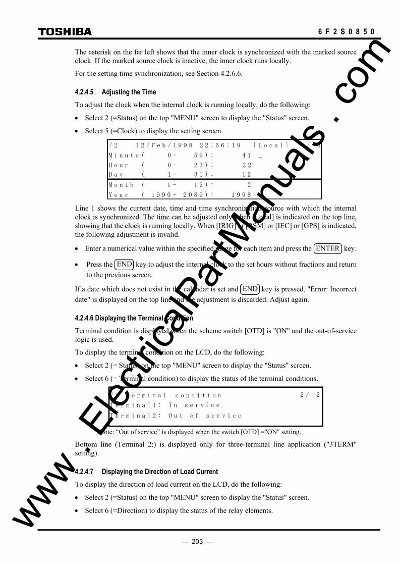
203
6 F 2 S 0 8 5 0
The asterisk on the far left shows that the inner clock is synchronized with the marked source clock. If the marked source clock is inactive, the inner clock runs locally.
For the setting time synchronization, see Section 4.2.6.6.
4.2.4.5 Adjusting the Time To adjust the clock when the internal clock is running locally, do the following:
• Select 2 (=Status) on the top "MENU" screen to display the "Status" screen.
• Select 5 (=Clock) to display the setting screen. / 2 1 2 / F e b / 1 9 9 8 2 2 : 5 6 : 1 9 [ L o c a l ] 1 / 5
M i n u t e ( 0 - 5 9 ) : 4 1
H o u r ( 0 - 2 3 ) : 2 2
D a y ( 1 - 3 1 ) : 1 2
M o n t h ( 1 - 1 2 ) : 2
Y e a r ( 1 9 9 0 - 2 0 8 9 ) : 1 9 9 8 Line 1 shows the current date, time and time synchronization source with which the internal clock is synchronized. The time can be adjusted only when [Local] is indicated on the top line, showing that the clock is running locally. When [IRIG] or [RSM] or [IEC] or [GPS] is indicated, the following adjustment is invalid.
• Enter a numerical value within the specified range for each item and press the ENTER key.
• Press the END key to adjust the internal clock to the set hours without fractions and return to the previous screen.
If a date which does not exist in the calendar is set and END key is pressed, "Error: Incorrect date" is displayed on the top line and the adjustment is discarded. Adjust again.
4.2.4.6 Displaying the Terminal Condition Terminal condition is displayed when the scheme switch [OTD] is "ON" and the out-of-service logic is used.
To display the terminal condition on the LCD, do the following:
• Select 2 (= Status) on the top "MENU" screen to display the "Status" screen.
• Select 6 (= Terminal condition) to display the status of the terminal conditions.
/ 2
u t o f s e r v i c e
T e r m i n a l 1 : I
T e r m i n a l c o n d i t i o n
n s e r v i c e
T e r m i n a l 2 : O
2 / 2
Note: “Out of service” is displayed when the switch [OTD] ="ON" setting.
Bottom line (Terminal 2:) is displayed only for three-terminal line application ("3TERM" setting).
4.2.4.7 Displaying the Direction of Load Current To display the direction of load current on the LCD, do the following:
• Select 2 (=Status) on the top "MENU" screen to display the "Status" screen.
• Select 6 (=Direction) to display the status of the relay elements. www . El
ectric
alPar
tMan
uals
. com

204
6 F 2 S 0 8 5 0
/2 Direction
Phase A: Forward
Phase B: Forward
Phase C: ______________ Note: If the load current is less than 0.04xIn, the direction is expressed as “----“. The BFL element is used to detect the direction of load current and shared with blinder. (See
Figure 2.3.1.12.)
4.2.5 Viewing the Settings
The sub-menu "Setting (view)" is used to view the relay version or the settings made using the sub-menu "Setting (change)".
The following items are displayed:
Relay version Description Communication (Relay address and baud rate in the RSM or IEC60870-5-103) Recording setting Status setting Protection setting Binary input setting Binary output setting LED setting
Enter a number on the LCD to display each item as described in the previous sections.
4.2.5.1 Relay version To view the relay version, do the following.
• Press 3 (=Setting (view)) on the main "MENU" screen to display the "Setting (view)" screen.
/ 1 S e t t i n g v i e w ) (
t i o n
t 9 = L E D
1 = V e r s i o n r2 = D e s c p t i o n 3 =i C o m m .
4 = R e c o r d 5 = S t a t u s 6 = P r o t e c
7 = B i n a r y i n p u t 8 = B i n a r y o u t p u • Press 1 (=Version) on the "Setting (view)" screen to display the "Relay version" screen.
/ 2 R e l a y nv e r s i o
S e r i a l N o . :
M a i n s o f t w a r e :
P L C d a t a :
R e l a y t y p e :
s o f t w a r e :C O M
63 /
I E C 1 0 3 d a t a :
4.2.5.2 Settings The "Description", " Comm.", "Record", "Status", "Protection", "Binary input", "Binary output" and "LED" screens display the current settings input using the "Setting (change)" sub-menu.
www . El
ectric
alPar
tMan
uals
. com

205
6 F 2 S 0 8 5 0
4.2.6 Changing the Settings
The "Setting (change)" sub-menu is used to make or change settings for the following items:
Password Description Communication Recording Status Protection Binary input Binary output LED
All of the above settings except the password can be seen using the "Setting (view)" sub-menu.
4.2.6.1 Setting Method There are three setting methods as follows:
- To enter a selected number - To enter numerical values
- To enter a text string
To enter a selected number If a screen as shown below is displayed, perform the setting as follows.
The number to the left of the cursor shows the current setting or default setting set at shipment. The cursor can be moved to upper or lower lines within the screen by pressing the and keys. If setting (change) is not required, skip the line with the and keys.
/ 6 S c h e m e s w i t c h 1 / 4
A R C - E X T 0 = O f f 1 = O n 1
A R C - S M 0 = O f f 1 = S 2 2 = S 3 3 = S 4 1
V T P H S E L 1 = A 2 = B 3 = C 1 V T - R A T E 1 = P H / G 2 = P H / P H 1
A R C - B U 0 = O f f 1 = O n 1 A R C D I F G 0 = O f f 1 = O n 0
3 P H - V T 1 = B U S 2 = L i n e 1
V C H K 0 = O f f 1 = L B 4 = S Y 1 1 2 = L B 2 3 = D B A R C D E F C 0 = O f f 1 = O n 1
1 A R C - C B 1 = O N E 2 = O 1 5 = L 2 1 3 = O 2 4 = L 1
B A R C - C C 0 = O f f 1 = T P R M 2 = A R P A 1 M A - N O L 0 = F T 1 = T K T 0 2 = S + A R C - S U C 0 = O f f 1 = O n 0
U A R C S W 1 = P 1 2 = P 2 1 3 = P B • Move the cursor to a setting line.
• Enter the selected number. (Numbers other than those displayed cannot be entered.)
• Press the ENTER key to confirm the entry and the cursor will move to the next line below. (On the lowest line, the entered number blinks.)
• After completing the setting on the screen, press the END key to return to the upper menu. www . El
ectric
alPar
tMan
uals
. com
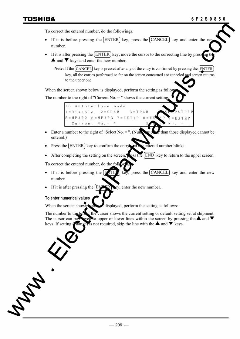
206
6 F 2 S 0 8 5 0
To correct the entered number, do the followings.
• If it is before pressing the ENTER key, press the CANCEL key and enter the new number.
• If it is after pressing the ENTER key, move the cursor to the correcting line by pressing the and keys and enter the new number.
Note: If the CANCEL key is pressed after any of the entry is confirmed by pressing the ENTER key, all the entries performed so far on the screen concerned are canceled and screen returns to the upper one.
When the screen shown below is displayed, perform the setting as follows.
The number to the right of "Current No. = " shows the current setting.
/ 6 A u t o r e c l o s e m o d e
1 = D i s a elb 2 = S P A R 3 = T P RA 4 =
5 = M P A R 2 7 = E X T 1 P
C u r r e n t N o . = 4 S e l e c t N o . =
S P A &R T P RA
6 = M P A R 3 8 = E X T 3 P 9 = E X T M P
• Enter a number to the right of "Select No. = ". (Numbers other than those displayed cannot be
entered.)
• Press the ENTER key to confirm the entry and the entered number blinks.
• After completing the setting on the screen, press the END key to return to the upper screen.
To correct the entered number, do the following.
• If it is before pressing the ENTER key, press the CANCEL key and enter the new number.
• If it is after pressing the ENTER key, enter the new number.
To enter numerical values When the screen shown below is displayed, perform the setting as follows:
The number to the left of the cursor shows the current setting or default setting set at shipment. The cursor can be moved to upper or lower lines within the screen by pressing the and keys. If setting (change) is not required, skip the line with the and keys.
www . El
ectric
alPar
tMan
uals
. com

207
6 F 2 S 0 8 5 0
/6 Protection element 1/ **
DIFI1( 0.50- 10.00): 1.00 _ A
DIFI2( 3.0- 120.0): 2.0 A
DIFGI( 0.25- 5.00): 0.50 A
DIFIC( 0.00- 5.00): 1.00 A
Vn ( 100- 120): 110 V
TDIFG( 0.00- 10.00): 0.10 s
DIFSV( 0.05- 1.00): 0.10 A
TIDSV( 0- 60): 10 s
OCBF ( 0.5- 10.0): 0.5 A
TBF1 ( 50- 500): 50 ms
TBF2 ( 50- 500): 50 ms
OC ( 0.5- 100.0): 0.5 A
TOC ( 0.00- 10.00): 1.00 s
OC1 ( 0.5- 100.0): 1.0 A
OCI ( 0.5- 25.0): 0.5 A
TOCI ( 0.05- 1.00): 1.00
TOCIR( 0.0- 10.0): 0.0 s
EF ( 0.5- 5.0): 0.5 A
TEF ( 0.00- 10.00): 1.00 s
EFI ( 0.5- 5.0): 0.5 A
TEFI ( 0.05- 1.00): 1.00
TEFIR( 0.0- 10.0): 0.0 s
THM ( 2.0- 10.0): 5.0 A
THMIP( 0.0- 5.0): 0.0 A
TTHM ( 0.5- 300.0): 10.0 min
THMA ( 50- 99): 80 %
OCCHK( 0.5- 5.0): 0.5 A
HYSθ ( 1- 5): 1 deg
: : :
: : :
TECCB( 0.00-200.00): 0.10 s
TSBCT( 0.00- 1.00): 0.10 s • Move the cursor to a setting line.
• Enter the numerical value.
• Press the ENTER key to confirm the entry and the cursor will move to the next line below. (If a numerical value outside the displayed range is entered, "Error: Out of range" appears on the top line and the cursor remains on the line. Press the CANCEL key to clear the entry.)
• After completing the setting on the screen, press the END key to return to the upper screen.
To correct the entered numerical value, do the followings.
• If it is before pressing the ENTER key, press the CANCEL key and enter the new numerical value.
• If it is after pressing the ENTER key, move the cursor to the correct line by pressing the and keys and enter the new numerical value.
Note: If the CANCEL key is pressed after any of the entry is confirmed by pressing the ENTER key, all the entries made so far on the screen concerned are canceled and the screen returns to the upper one.
To enter a text string Text strings are entered in the bracket under "Plant name" or "Description" screen.
To select a character, use keys 2, 4, 6 and 8 to move the blinking cursor down, left, up and right. "→" and "←" on each of lines 2 to 4 indicate a space and backspace, respectively. A maximum of 22 characters can be entered within the brackets.
www . El
ectric
alPar
tMan
uals
. com

208
6 F 2 S 0 8 5 0
/ 3 P l a n t n a m e ]_[
→←A B C D E F G H I J K L M N O P Q R S T U V W X Y Z ( ) [ ] @ _
a b c d e f g h i j k l m n o p q r s t u v w x y z * / + - < = >
0 1 2 3 4 5 6 7 8 9 ! ”# $ % & ’:;,. `
→←→←
• Set the cursor position in the bracket by selecting "→" or "←" and pressing the ENTER key.
• Move the blinking cursor to select a character.
• Press the ENTER to enter the blinking character at the cursor position in the brackets.
• Press the END key to confirm the entry and return to the upper screen.
To correct the entered character, do either of the following.
• Discard the character by selecting "←" and pressing the ENTER key and enter the new character.
• Discard the whole entry by pressing the CANCEL key and restart the entry from the first.
To complete the setting
Enter after making entries on each setting screen by pressing the ENTER key, the new settings are not yet used for operation, though stored in the memory. To validate the new settings, take the following steps.
• Press the END key to return to the upper screen. Repeat this until the confirmation screen shown below is displayed. The confirmation screen is displayed just before returning to the "Setting (change)" sub-menu.
/ 2 * * * * * * * * * * * * * *
C h a n g e s e t t i n g s ?
E N T E R = Y e s C A N C E L = N o
• When the screen is displayed, press the ENTER key to start operation using the new settings, or press the CANCEL key to correct or cancel entries. In the latter case, the screen turns back to the setting screen to enable reentries. Press the CANCEL key to cancel entries made so far and to turn to the "Setting (change)" sub-menu.
4.2.6.2 Password For the sake of security of changing the settings, password protection can be set as follows:
• Press 4 (=Setting (change)) on the main "MENU" screen to display the "Setting (change)" screen.
• Press 1 (=Password) to display the "Password" screen.
/ 2 P a s s w o r d
I n p u t n e w p a s s w o r d [ ]
R e t y p e n e w p a s s w o r d [ ]
• Enter a 4-digit number within the brackets after "Input new password" and press the
ENTER key. www . El
ectric
alPar
tMan
uals
. com

209
6 F 2 S 0 8 5 0
• For confirmation, enter the same 4-digit number in the brackets after "Retype new password" and press the ENTER key.
• Press the END key to display the confirmation screen. If the retyped number is different from that first entered, the following message is displayed on the bottom of the "Password" screen before returning to the upper screen.
"Mismatch-password unchanged"
Reentry is then requested.
Password trap After the password has been set, the password must be entered in order to enter the setting change screens.
If 4 (=Setting (change)) is entered on the top "MENU" screen, the password trap screen "Password" is displayed. If the password is not entered correctly, it is not possible to move to the "Setting (change)" sub-menu screens.
P a s s w o r d
I n p u t p a s s w o r d [ ]
Canceling or changing the password To cancel the password protection, enter "0000" in the two brackets on the "Password" screen. The "Setting (change)" screen is then displayed without having to enter a password.
The password can be changed by entering a new 4-digit number on the "Password" screen in the same way as the first password setting.
If you forget the password
Press CANCEL and RESET together for one second on the top "MENU" screen. The screen disappears, and the password protection of the GRL100 is canceled. Set the password again.
4.2.6.3 Description To enter the plant name and other data, do the following. These data are attached to records.
• Press 4 (=Setting (change)) on the main "MENU" screen to display the "Setting (change)" screen.
• Press 2 (=Description) to display the "Description" screen. / 2 D e s c r i p t i o n
1 = P l a n n at e = D e i2 s c r i tpm o n
• To enter the plant name, select 1 (=Plant name) on the "Description" screen.
/ 3 P l a n t n a m e ]_[
→←A B C D E F G H I J K L M N O P Q R S T U V W X Y Z ( ) [ ] @ _
a b c d e f g h i j k l m n o p q r s t u v w x y z * / + - < = >
0 1 2 3 4 5 6 7 8 9 ! ”# $ % & ’:;,. `
→←→←
To enter special items, select 2 (=Description) on the "Description" screen. www . El
ectric
alPar
tMan
uals
. com

210
6 F 2 S 0 8 5 0
/ 3 D e s c r p t i o ] _[
→ ← A B C D E F G H I J K L M N O P Q R S T U V W X Y Z ( ) [ ] @
a b c d e f g h i j k l m n o p q r s t u v w x y z * / + - < = >
0 1 2 3 4 5 6 7 8 9 ! ” # $ % & ’ :;,. `
→ ←
→ ←
i n
• Enter the text string.
The plant name and special items entered are viewed with the "Setting (view)" sub-menu and attached to disturbance records when they are displayed on a local or a remote PC.
4.2.6.4 Communication If the relay is linked with RSM (relay setting and monitoring system), IEC60870-5-103 or Ethernet LAN, the relay address must be set. Do this as follows:
• Press 4 (=Setting (change)) on the main "MENU" screen to display the "Setting (change)" screen.
• Press 3 (=Comm.) to display the "Communication" screen. / 2
e s s1 = A d d r
cC o m m u n i nta oi
c h2 = S w i t
/ P a r a m e t e r
• Press 1 (=Address/Parameter) to enter the relay address number.
/3 Address/Parameter 1/ 15
HDLC ( 1- 32): 1 _ IEC ( 0- 254): 2
SYADJ( -9999- 9999): 0 ms
IP1-1( 0- 254): 0
IP1-2( 0- 254): 0
IP1-3( 0- 254): 0
IP1-4( 0- 254): 0
SM1-1( 0- 254): 0
SM1-2( 0- 254): 0
SM1-3( 0- 254): 0
SM1-4( 0- 254): 0
GW1-1( 0- 254): 0
GW1-2( 0- 254): 0
GW1-3( 0- 254): 0
GW1-4( 0- 254): 0 • Enter the address number on "HDLC" column for RSM and/or "IEC" column for
IEC60870-5-103 and the compensation value on "SYADJ" column for adjustment of time synchronization of protocol used. (−: lags the time, +: leads the time) And enter IP address for IP1-1 to IP1-4, Subnet mask for SM1-1 to SM4, and Default gateway for GW1-1 to GW1-4.
IP address: ∗∗∗, ∗∗∗, ∗∗∗, ∗∗∗
IP1-1 IP1-2 IP1-3 IP1-4
Subnet mask SM1-1 to SM4 and Default gateway GW1-1 to GW1-4: same as above.
• Press the ENTER key.
CAUTION: Do not overlap the number in a network. www . El
ectric
alPar
tMan
uals
. com

211
6 F 2 S 0 8 5 0
• Press 2 (=Switch) on the "Communication" screen to select the protocol and the RS232C transmission speed (baud rate), etc., of the RSM or IEC60870-5-103.
/ 3 S w i t c h 1 /4
P R T C 1 = H D L C C2 = I E 01 31L 2
2 3 2 C 1 = 9 . 6 2 = 1 9 . 2 =3 3 8 . 4 4 = . 65 7 4
I E C B 1 = 9 . 6 2 = 1 9 . 2R 2
I E C B 1 = N o r a l 2 = B co k e dKL lm 1
• Select the number corresponding to the system and press the ENTER key.
<PRTCL1> PRTCL1 is used to select the protocol for channel 1 (COM1 or OP1) of the serial communication port RS485 or FO (fibre optic).
• When the remote RSM system applied, select 1 (=HDLC). When the IEC60870-5-103 applied, select 2 (=IEC103).
<232C> This line is to select the RS232C baud rate when the RSM system applied.
Note: The default setting of the 232C is 9.6kbps. The 57.6kbps setting, if possible, is recommended to serve user for comfortable operation. The setting of RSM100 is also set to the same baud rate.
<IECBR> This line is to select the baud rate when the IEC60870-5-103 system applied.
<IECBLK> Select 2 (=Blocked) to block the monitor direction in the IEC60870-5-103 communication.
4.2.6.5 Setting the Recording To set the recording function as described in Section 4.2.3, do the following:
• Press 4 (=Setting (change)) on the main "MENU" screen to display the "Setting (change)" screen.
• Press 4 (=Record) to display the "Record" screen.
R e c o
1 = r e c o r d
3 = D i s t u r b a n c e
/ 2 r
a u t F l 2 = E v e n t r e c o r d
r e c o r d
d
Setting the fault recording • Press 1 (=Fault record) to display the "Fault record" screen.
r e c o r d
r 1 _
1 1 / / 3
0 = O f f
a u t F l
1 = O nl o c a t oa u t F l
• Enter 1 (=On) to record the fault location.
Enter 0 (=Off) not to record the fault location.
• Press the ENTER key. www . El
ectric
alPar
tMan
uals
. com

212
6 F 2 S 0 8 5 0
Setting the event recording • Press 2 (=Event record) to display the "Event record" screen.
E V 4 ( 0 - 3 0 7 1 ) : 1
E V 3 ( 0 - 3 0 7 1 ) : 1
E V 2 ( 0 - 3 0 7 1 ) : 1
E V 1 ( 0 - 3 0 7 1 ) : 0
/ 3 E v e n t r e c o r d 1 / 1 2 9
B I T R N ( 0 - 1 2 8 ) : 1 2 8 _
E V 1 2 8 ( 0 - 3 0 7 1 ) : 3 0 7 1 <BITRN> • Enter the number of event to record the status change both to "On" and "Off". If enter 20,
both status change is recorded for EV1 to EV20 events and only the status change to "On" is recorded for EV21 to EV128 events.
<EV∗> • Enter the signal number to record as the event in Appendix B. It is recommended that this
setting can be performed by RSM100 because the signal name cannot be entered by LCD screen. (Refer to Section 3.4.2.)
Setting the disturbance recording • Press 3 (=Disturbance record) to display the "Disturbance record" screen.
/ 3 D i s t u r b a n
1 = R e c o r mt i e t&
e
s
2 = S c h e
c e r e c ro
m s w i t c
gis
h
d
n a
t a r e r
y 3 = B i n ra l • Press 1 (=Record time & starter) to display the "Record time & starter" screen.
U V P - G ( 0 - 7 6 ) : 5 7 V
U V P - S ( 0 - 1 3 2 ) : 1 0 0 V
O C P - G ( 0 . 5 - 2 5 0 . 0 ) : 1 0 . 0 A
O C P - S ( 0 . 5 - 2 5 0 . 0 ) : 1 0 . 0 A
/ 4 R e c o r d t i m e & s t a r t e r 1 / 5
T i m e ( 0 . 1 - 3 . 0 ) : 2 . 0 _ A
• Enter the recording time and starter element settings.
To set each starter to use or not to use, do the following:
• Press 2 (=Scheme switch) on the "Disturbance record" screen to display the "Scheme switch" screen.
/ 4 S c h e m e s w i t c 1 / 5
T R I P
G
0 = fO f 1 1
O C P - S
= O n
1 0 = O f f 1 = O n
O C P - 1 0 = O f f 1 = O n
U V P - 1 0 = O f f 1 = O n
U V P 1 0 = O f f 1 = O n
G
S -
h
• Enter 1 to use as a starter. www .
Elec
tricalP
artM
anua
ls . c
om

213
6 F 2 S 0 8 5 0
• Press 3 (=Binary signal) on the "Disturbance record" screen to display the "Binary signal" screen.
S I G 4 ( 0 - 3 0 7 1 ) : 4
S I G 3 ( 0 - 3 0 7 1 ) : 3
S I G 2 ( 0 - 3 0 7 1 ) : 2
/ 4 B i n a r y s i g n a l 1 / 3 2
S I G 1 ( 0 - 3 0 7 1 ) : 1 _
S I G 3 2 ( 0 - 3 0 7 1 ) : 0 • Enter the signal number to record binary signals in Appendix B. It is recommended that this
setting can be performed by RSM100 because the signal name cannot be entered by LCD screen. (Refer to Section 3.4.3.)
4.2.6.6 Status To set the status display described in Section 4.2.4, do the following:
• Press 5 (=Status) on the "Setting (change)" sub-menu to display the "Status" screen.
3 = T i m e z o n e
2 = T i m e s y n c h r o n i z a t i o n
/ 2 S t a t u s
1 = M e t e r i n g
Setting the metering • Press 1 (=Metering) to display the "Metering" screen.
/ 3 M e t e r i n g 3 / 3
D i s p l a y v a l u e 1 = P r i m a r y 2 = S e c o n r y d a
_
1
P o w e r (
C u r r e n t
P / Q ) 1 = S e n d
1 = L a g
2 = R e c e i v e
2 = L e a d
1
1
• Enter the selected number and press the ENTER key. Repeat this for all items.
Note: Power and Current setting Active Power Display
Power setting=1(Send) Power setting=2(Receive)
+
+
-
-
V
I
V
I
+
+ -
- Reactive Power Display
Current setting=1(Lag) Current setting=2(Lead)
+
-
+
-
V
I
V
I
+
- -
+
www . El
ectric
alPar
tMan
uals
. com

214
6 F 2 S 0 8 5 0
Setting the time synchronization The calendar clock can run locally or be synchronized with external IRIG-B time standard signal, RSM clock, IEC60870-5-103 or GPS. This is selected by setting as follows:
• Press 2 (=Time synchronization) to display the "Time synchronization" screen.
/ 3 T i m e s y n c h r o n i z a t i o n 1 / 1
S y n c 0 = O f f 1 = I R I G 2 = R S M 3 = I E C 4 = G P S 1
• Enter the selected number and press the ENTER key.
Note: When to select IRIG-B, RSM, IEC or GPS, check that they are active on the "Time synchronization source" screen in "Status" sub-menu. If it is set to an inactive IRIG-B, RSM, IEC or GPS, the calendar clock runs locally.
Setting the time zone When the calendar clock is synchronized with the IRIG-B time standard signal or GPS signal, it is possible to transfer GMT to the local time.
• Press 3 (=Time zone) to display the "Time zone" screen.
/ 3 T i m e z o n e 1 / 1
G M T ( - 1 2 - + 1 2 ) : + 9 _ h r s
• Enter the difference between GMT and local time and press the ENTER key.
4.2.6.7 Protection The GRL100 can have 8 setting groups for protection according to the change of power system operation, one of which is assigned to be active. To set protection, do the following:
• Press 6 (=Protection) on the "Setting (change)" screen to display the "Protection" screen.
/ 2 P r o t e c t i o n
1 = C h a n g e a c t i v e g r o u p
2 = C h a n g e s e t t i n g
3 = C o p y g r o u p
Changing the active group • Press 1 (=Change active group) to display the "Change active group" screen.
/ 3 C h a n g e a c t i v e g r o u p ( A c t i v e g r o u p = * )
1 = G r o u p 1 2 = G r o u p 2 3 = G r o u p 3 4 = G r o u p 4
5 = G r o u p 5 6 = G r o u p 6 7 = G r o u p 7 8 = G r o u p 8
C u r r e n t N o . = * S e l e c t N o . =
• Enter the selected number and press the ENTER key.
Changing the settings Almost all the setting items have default values that are set when the GRL100 was shipped. For the default values, see Appendix D and H. To change the settings, do the following: www .
Elec
tricalP
artM
anua
ls . c
om

215
6 F 2 S 0 8 5 0
• Press 2 (=Change setting) to display the "Change setting" screen.
/ 3 C h a n g e s e t t i n g ( A c t i v e g r o u p = * )
1 = G r o u p 1 2 = G r o u p 2 3 = G r o u p 3 4 = G r o u p 4
5 = G r o u p 5 6 = G r o u p 6 7 = G r o u p 7 8 = G r o u p 8
• Press the group number to change the settings and display the "Protection" screen.
/ 4 P r o t e c t i o n ( G r o u p * )
1 = L i n e p a r a m e t e r
2 = T e l e 3 = T r i pc o m m u n i c noita
4 = A u t o r e c l o s e
Setting the line parameters Enter the line name, VT&CT ratio and settings for the fault locator as follows:
• Press 1 (=Line parameter) on the "Protection" screen to display the "Line parameter" screen.
/ 5 L i n e p a r a m e t e r ( G r o u p * )
1 = L i n e n a m e
2 = V T & C T r a t i o
3 = F a u l t l o c a t o r • Press 1 (=Line name) to display the "Line name" screen.
• Enter the line name as a text string.
• Press the END key to return the display to the "Line parameter" screen.
• Press 2 (=VT&CT ratio) to display the "VT&CT ratio" screen.
V T s 1 ( 1 - 2 0 0 0 0 ) : 2 2 0 0
/ 6 V T & C T r a t i o 1 / 4
V T ( 1 - 2 0 0 0 0 ) : 2 2 0 0 _
C T ( 1 - 2 0 0 0 0 ) : 4 0 0
V T s 2 ( 1 - 2 0 0 0 0 ) : 2 2 0 0
• Enter the VT ratio for protection function and press the ENTER key.
• Enter the VTs1 ratio and/or VTs2 ratio for autoreclose function and press the ENTER key. VTs1 is used for the VT ratio setting for voltage and synchronism check of autoreclose function. VTs2 is used for the VT ratio setting for the other voltage and synchronism check at the time of two-breaker autoreclose.
• Enter the CT ratio and press the ENTER key.
• Press the END key to return the display to the "Line parameter" screen.
• Press 3 (= Fault locator) to display the "Fault locator" screen. / 6 F a u l t l o c a ( G r o u p * )
1 = S e t t g i m p e d a
2 = L i n e
m o d e
d a t a
t o r
i n n c e
• Press 1 (=Setting impedance mode) to display the "Setting impedance mode" screen.
www . El
ectric
alPar
tMan
uals
. com
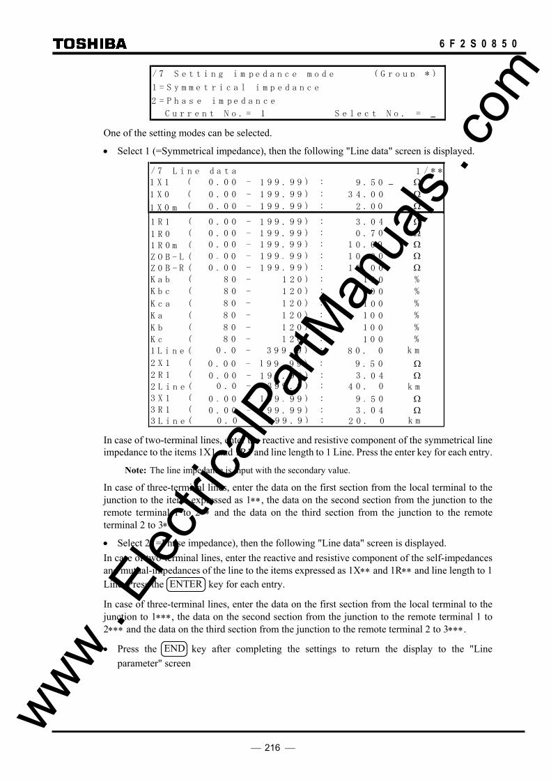
216
6 F 2 S 0 8 5 0
/ 7 S e t t i n g i m ( G r o u p * )
1 = S y m m e
p e d a n ec
p2 = P h a s e i m e d a ecn
m o ed
i m p e d a n ec
C u r r e n t N o . = 1 S e l e c t N o . =
t r i c a l
One of the setting modes can be selected.
• Select 1 (=Symmetrical impedance), then the following "Line data" screen is displayed. / 7 L i n e a at 1 / * *
1
L
( 0 . 9 9 . )99
( 0
9
( 0
( 0(
(
d
Z O B -BZ 0 (
0 0
. 0 0
. 0
- 1 : . Ω 5
9 9 . )99 4- 1 : . Ω 0
9 9 . )99 2- 0: .
3
Ω 0
0 . 9 9 . )99 4
03
0
0 0. 0 0
. 0
- 1 : . Ω 09 9 . )99 0- 1 : . Ω 7
9 9 . )99 0- 1: .0 Ω 00 . 00 0 - : . Ω 09 9 . )991
K ba ( 1 )028 0 0- : 1 % 0
(L i n e 0 3 9 9 )9. 0- 8: . m k 0
0
0
0
1 0
- R 1 0
K cb ( 1 )028 0 0- : 1 % 0
K ac ( 1 )028 0 0- : 1 % 0
K a ( 1 )028 0 0- : 1 % 0
K b ( 1 )028 0 0- : 1 % 0
K c ( 1 )028 0 0- : 1 % 0
11 R ( 00 . 0 9 9 . )99 0- 0: . Ω 00 1
2 X ( 0 . 9 9 . )99 090 0 - 1 : . Ω 51
2 R ( 0 . 9 9 . )99 430 0 - 1 : . Ω 01
(2 L i n 0 . 0 3 9 9 )9. 0- 4: . m k 0e
3 X ( 0 . 9 9 . )99 090 0 - 1 : . Ω 513 R ( 0 . 9 9 . )99 430 0 - 1 : . Ω 01
( 3 L i n 0 . 0 3 9 9 )9. 0- 2: . m k 0e
1
m
1 X 1
1 X 0
1 X 0
1 R 1
1 R 0m
0 .
In case of two-terminal lines, enter the reactive and resistive component of the symmetrical line impedance to the items 1X1 and 1R1 and line length to 1 Line. Press the enter key for each entry.
Note: The line impedance is input with the secondary value.
In case of three-terminal lines, enter the data on the first section from the local terminal to the junction to the items expressed as 1∗∗, the data on the second section from the junction to the remote terminal 1 to 2∗∗ and the data on the third section from the junction to the remote terminal 2 to 3∗∗.
• Select 2 (=Phase impedance), then the following "Line data" screen is displayed. In case of two-terminal lines, enter the reactive and resistive component of the self-impedances and mutual-impedances of the line to the items expressed as 1X∗∗ and 1R∗∗ and line length to 1 Line. Press the ENTER key for each entry.
In case of three-terminal lines, enter the data on the first section from the local terminal to the junction to 1∗∗∗, the data on the second section from the junction to the remote terminal 1 to 2∗∗∗ and the data on the third section from the junction to the remote terminal 2 to 3∗∗∗.
• Press the END key after completing the settings to return the display to the "Line parameter" screen
www . El
ectric
alPar
tMan
uals
. com

217
6 F 2 S 0 8 5 0
3Line ( 0.0 - 399.9) : 20.0 km
2Line ( 0.0 - 399.9) : 40.0 km
1Line ( 0.0 - 399.9) : 80.0 km
/ 7 L i n e aad t 1 */ *
1Xbb ( 0.00 - 199.99) : 10.00 Ω 1Xcc ( 0.00 - 199.99) : 10.00 Ω
1Xaa ( 0.00 - 199.99) : 10.00_ Ω
1Xbc ( 0.00 - 199.99) : 0.50 Ω 1Xca ( 0.00 - 199.99) : 0.50 Ω
1Xab ( 0.00 - 199.99) : 0.50 Ω
1Rbb ( 0.00 - 199.99) : 3.20 Ω 1Rcc ( 0.00 - 199.99) : 3.20 Ω
1Raa ( 0.00 - 199.99) : 3.20 Ω
1Rbc ( 0.00 - 199.99) : 0.16 Ω 1Rca ( 0.00 - 199.99) : 0.16 Ω
1Rab ( 0.00 - 199.99) : 0.16 Ω
Ω
1X0m ( 0.00 - 199.99) : 2.00 Ω
ZOB-L ( 0.00 - 199.99) : 10.00 Ω ZOB-R ( 0.00 - 199.99) : 10.00 Ω
1R0m ( 0.00 - 199.99) : 10.00 Ω
Ω Ω
Ω Ω
Ω
Ω Ω
Ω
Ω Ω
Ω
Ω Ω
Ω Ω
Ω
Ω Ω
Ω
Ω Ω
2Xbb ( 0.00 - 199.99) : 10.00 2Xcc ( 0.00 - 199.99) : 10.00
2Xaa ( 0.00 - 199.99) : 10.00
2Xbc ( 0.00 - 199.99) : 0.50 2Xca ( 0.00 - 199.99) : 0.50
2Xab ( 0.00 - 199.99) : 0.50
2Rbb ( 0.00 - 199.99) : 3.20
2Rcc ( 0.00 - 199.99) : 3.20
2Raa ( 0.00 - 199.99) : 3.20
2Rbc ( 0.00 - 199.99) : 0.16 2Rca ( 0.00 - 199.99) : 0.16
2Rab ( 0.00 - 199.99) : 0.16
3Xbb ( 0.00 - 199.99) : 10.00 3Xcc ( 0.00 - 199.99) : 10.00
3Xaa ( 0.00 - 199.99) : 10.00
3Xbc ( 0.00 - 199.99) : 0.50 3Xca ( 0.00 - 199.99) : 0.50
3Xab ( 0.00 - 199.99) : 0.50
3Rbb ( 0.00 - 199.99) : 3.20 3Rcc ( 0.00 - 199.99) : 3.20
3Raa ( 0.00 - 199.99) : 3.20
3Rbc ( 0.00 - 199.99) : 0.16 3Rca ( 0.00 - 199.99) : 0.16
3Rab ( 0.00 - 199.99) : 0.16
Ω
Ω
Setting the telecommunication • Press 2 (=Telecommunication) on the "Protection" screen to display the
"Telecommunication" screen.
/ 5 T e l e c o m m u n i c a t oi n ( G r o u p * )
1 = S c h e m e s w i t c h
2 = T e l e c o m m u n i c a t oi n e l e m e n t
• Press 1 (=Scheme switch) to display the "Scheme switch" screen. Set the communication www .
Elec
tricalP
artM
anua
ls . c
om

218
6 F 2 S 0 8 5 0
mode "A", "B" or "GPS", and the "Master" or "Slave", and "2 terminal line (=2TERM)" or "3 terminal line (=3TERM)" or "Dual communication for 2 terminal line (=Dual)". Refer to Section 2 and 2.2.2.
However "TERM", "CH.CON", "T.SFT2" and "B.SYN2" items are not displayed in the case of 2 terminal models.
For the "CH.CON" setting, refer to Section 2.2.14.
In "B.SYN∗", set to "On" when synchronizing the sending signal of GRL100 with the external clock signal or the receiving signal from multiplexer.
For "GPSBAK", "AUTO2B" and "SRCθ", refer to Section 2.2.7. / 6 S c h e m e 1 / 2
S P . S Y N 1 = M a s t re 2 = S l eva
s w i t c h
1
T E R M 1 = 2 T E R M 2 = 3 T MRE 1 .
3 = D u l a
C H . C O N 1 = N o r m la 2 = E x ahc 1 n g e
T . S F T 1 0 = O f f 1 = O n 1
T . S F T 2 0 = O f f 1 = O n 1
B . S Y N 1 0 = O f f 1 = O n 1
B . S Y N 2 0 = O f f 1 = O n 1
G P S A K 0 = O f f 1 = O n 1BA U T 2 B 0 = O f f 1 = O n 0OS R C 0 = D i s a lb 1 = I 1θ e
R Y I S V 0 = O f f 1 = O n 1D
C O M M O D 1 = A 2 B= 3 = G P S 2 E
1
Note: The setting of [COMMODE], [TERM], [GPSBAK], [AUTO2B], [SRC θ] and
[RYIDSV] must be identical at all terminals.
• Press 2 (=Telecommunication element) to display the "Telecommunication element" screen.
/ 6 1 / 7
P
I
TD ( 2 2 0 )00 1
R Y (
0
R Y (I 1D
0 0
0
- : 0 µ 0
)36- : 0
)36- : 0
T e l e c o m m u n i c a t oi n e l e m e n t
D
D
0
s
T SD ( 1 1 6 0 )00 6 00 0 - : 0 µ 0V s
R Y (I 2D )36- : 00
T C D T 1 1( - 0 0 0 0 - u s0)1 0 0 0 0
T C D T 2 1( - 0 0 0 0 - u s0)1 0 0 0 0 :
:
• Enter the time delay setting values and the relay identity numbers (address numbers) and
press the ENTER key for each setting.
PDTD: Setting for permissible difference of telecommunication delay time.
RYID, RYID1, RYID2: Setting for address numbers of the local (RYID) and remote (RYID1 and RYID2) relays. These items are only enabled when the switch [RYIDSV] is set to "ON". See Section 2.2.14.
TDSV: Setting for transmission delay time to be supervised.
TCDT1, TCDT2: Adjusting the transmission delay time for CH1 and CH2
• After settings, press the END key to return to the "Telecommunication" screen.
Setting the trip function To set the scheme switches and protection elements, do the following. Protection elements are measuring elements and timers. www .
Elec
tricalP
artM
anua
ls . c
om
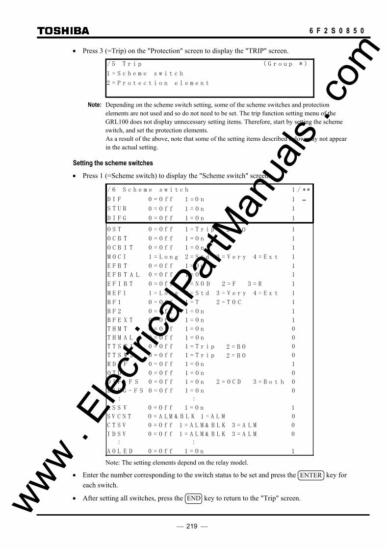
219
6 F 2 S 0 8 5 0
• Press 3 (=Trip) on the "Protection" screen to display the "TRIP" screen.
/ 5 T r i p ( G r o u p * )
1 =
2 = P r o t e c t i o n e l e m e n t
S c h e m e s w i t c h
Note: Depending on the scheme switch setting, some of the scheme switches and protection
elements are not used and so do not need to be set. The trip function setting menu of the GRL100 does not display unnecessary setting items. Therefore, start by setting the scheme switch, and set the protection elements.
As a result of the above, note that some of the setting items described below may not appear in the actual setting.
Setting the scheme switches • Press 1 (=Scheme switch) to display the "Scheme switch" screen.
S V C N T O = LA M 0 & 1 = A L MB L K
S T U B 1 0 = O f f 1 = O n
D I F G 1 0 = O f f 1 = O n
B F 2 1 0 = O f f 1 = O n
B F 1 1 0 = O f f 1 = T 2 = COT
M E F I 1 1 = L o n 2 = S tg d 3 = V e r y 4 = E x t
/ 6 S c h e m e s w i t c h 1 / ∗ ∗
O S T 1 0 = O f f 1 = T r i p 2 = B O
D I F 0 = fO f 1 1 = O n
T T S 0 0 = O f f 1 = T r i p 2 = B OW 1
D I F - 0 0 = O f f 1 = O n h 2 = O C D 3 = B o t F S
D I F - G 0 0 = O f f 1 = O nF S
I D S V 0 0 = O f f = A L M1 & LB K 3 = A ML
O C B 1 0 = O f f 1 = O nT
T O C B 1 0 = O f f 1 = O nI
M O C I 1 1 = L o n 2 = S tg d 3 = V e r y 4 = E x t
E F B 1 0 = O f f 1 = O nT
A L E F B 1 0 = O f f 1 = O nT
T B F E 1 0 = O f f 1 = O nX
T H M 0 0 = O f f 1 = O nT
L T H M 0 0 = O f f 1 = O nA
T T S 0 0 = O f f 1 = T r i p 2 = B OW 2
R D I 1 0 = O f f 1 = O nF
O T D 0 0 = O f f 1 = O n
L S S 1 0 = O f f 1 = O nV
C T S V 0 0 = O f f = A L M1 & LB K 3 = A ML
: :
D A O L 1 0 = O f f 1 = O nE
: :
T E F I 1 0 = O f f 1 = N OB D 2 = F 3 = R
Note: The setting elements depend on the relay model.
• Enter the number corresponding to the switch status to be set and press the ENTER key for each switch.
• After setting all switches, press the END key to return to the "Trip" screen. www . El
ectric
alPar
tMan
uals
. com
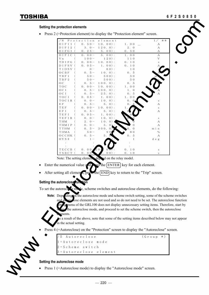
220
6 F 2 S 0 8 5 0
Setting the protection elements • Press 2 (=Protection element) to display the "Protection element" screen.
/6 Protection element 1/ **
DIFI1( 0.50- 10.00): 1.00 _ A
DIFI2( 3.0- 120.0): 2.0 A
DIFGI( 0.25- 5.00): 0.50 A
DIFIC( 0.00- 5.00): 1.00 A
Vn ( 100- 120): 110 V
TDIFG( 0.00- 10.00): 0.10 s
DIFSV( 0.05- 1.00): 0.10 A
TIDSV( 0- 60): 10 s
OCBF ( 0.5- 10.0): 0.5 A
TBF1 ( 50- 500): 50 ms
TBF2 ( 50- 500): 50 ms
OC ( 0.5- 100.0): 0.5 A
TOC ( 0.00- 10.00): 1.00 s
OC1 ( 0.5- 100.0): 1.0 A
OCI ( 0.5- 25.0): 0.5 A
TOCI ( 0.05- 1.00): 1.00
TOCIR( 0.0- 10.0): 0.0 s
EF ( 0.5- 5.0): 0.5 A
TEF ( 0.00- 10.00): 1.00 s
EFI ( 0.5- 5.0): 0.5 A
TEFI ( 0.05- 1.00): 1.00
TEFIR( 0.0- 10.0): 0.0 s
THM ( 2.0- 10.0): 5.0 A
THMIP( 0.0- 5.0): 0.0 A
TTHM ( 0.5- 300.0): 10.0 min
THMA ( 50- 99): 80 %
OCCHK( 0.5- 5.0): 0.5 A
HYSθ ( 1- 5): 1 deg
: : :
: : :
TECCB( 0.00-200.00): 0.10 s
TSBCT( 0.00- 1.00): 0.10 s Note: The setting elements depend on the relay model.
• Enter the numerical value and press the ENTER key for each element.
• After setting all elements, press the END key to return to the "Trip" screen.
Setting the autoreclose function To set the autoreclose mode, scheme switches and autoreclose elements, do the following:
Note: Depending on the autoreclose mode and scheme switch setting, some of the scheme switches and autoreclose elements are not used and so do not need to be set. The autoreclose function setting menu of the GRL100 does not display unnecessary setting items. Therefore, start by setting the autoreclose mode, and proceed to set the scheme switch, then the autoreclose elements.
As a result of the above, note that some of the setting items described below may not appear in the actual setting.
• Press 4 (=Autoreclose) on the "Protection" screen to display the "Autoreclose" screen.
/ 5 A u t o r e c l o s e ( G r o u p * )
1 = A u t o r e c l o s e m o d e
2 = S c h e m e s w i t c h
3 = A u t o r e c l o s e e l e m e n t
Setting the autoreclose mode • Press 1 (=Autoreclose mode) to display the "Autoreclose mode" screen. www .
Elec
tricalP
artM
anua
ls . c
om

221
6 F 2 S 0 8 5 0
/ 6 A u t o r e c l o s e m o d e
1 = D i s a e l b 2 = S P A R 3 = T P RA 4 =
5 = M P A R 2 7 = E X T 1 P
C u r r e n t N o . = 4 S e l e c t N o . =
S P A & R T P R A
6 = M P A R 3 8 = E X T 3 P 9 = E X T M P
_ Note: The setting elements on the screen depend on the relay model.
• Select the autoreclose mode to be used by entering the number corresponding to the autoreclose mode and press the ENTER key.
• Press the END key to return to the "Autoreclose" screen.
Setting the scheme switches • Press 2 (=Scheme switch) to display the "Scheme switch" screen.
/ 6 S c h e m e s w i t c h 1 / 4
A R C - E X T 0 = O f f 1 = O n 1
A R C - S M 0 = O f f 1 = S 2 2 = S 3 3 = S 4 1
V T P H S E L 1 = A 2 = B 3 = C 1 V T - R A T E 1 = P H / G 2 = P H / P H 1
A R C - B U 0 = O f f 1 = O n 1 A R C D I F G 0 = O f f 1 = O n 0
3 P H - V T 1 = B U S 2 = L i n e 1
V C H K 0 = O f f 1 = L B 4 = S Y 1 1 2 = L B 2 3 = D B A R C D E F C 0 = O f f 1 = O n 1
1 A R C - C B 1 = O N E 2 = O 1 5 = L 2 1 3 = O 2 4 = L 1
B A R C - C C 0 = O f f 1 = T P R M 2 = A R P A 1 M A - N O L 0 = F T 1 = T K T 0 2 = S + A R C - S U C 0 = O f f 1 = O n 0
U A R C S W 1 = P 1 2 = P 2 1 3 = P B
• Enter the number corresponding to the switch status to be set and press the ENTER key for each switch.
• After setting all switches, press the END key to return to the "Autoreclose" screen.
Setting the autoreclose elements • Press 3 (=Autoreclose element) to display the "Autoreclose element" screen.
/ 6 A u t o r e c o s e e l e m e n t ( G r o u p * )
1 = A u t o r e c l o s e t i m e r
2 = S y n c h r o c h e c k
l
Press 1 to display the "Autoreclose timer" screen or 2 to display the "Synchrocheck" screen for voltage check and synchronism check elements.
Set these elements in the same way as protection elements.
Setting group copy To copy the settings of one group and overwrite them to another group, do the following:
• Press 3 (=Copy group) on the "Protection" screen to display the "Copy group A to B" screen.
www . El
ectric
alPar
tMan
uals
. com
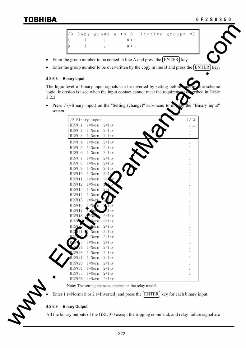
222
6 F 2 S 0 8 5 0
/ 3 C o p y g r o u p A t o B ( A c t i v e g r o u p = * )
A ( 1 - 8 ) :
B ( 1 - 8 ) :
• Enter the group number to be copied in line A and press the ENTER key.
• Enter the group number to be overwritten by the copy in line B and press the ENTER key.
4.2.6.8 Binary Input The logic level of binary input signals can be inverted by setting before entering the scheme logic. Inversion is used when the input contact cannot meet the requirement described in Table 3.2.2.
• Press 7 (=Binary input) on the "Setting (change)" sub-menu to display the "Binary input" screen.
/2 Binary input 1/ 31
BISW 3 1=Norm 2=Inv 1
BISW 2 1=Norm 2=Inv 1
BISW 1 1=Norm 2=Inv 1
BISW28 1=Norm 2=Inv 1
BISW27 1=Norm 2=Inv 1 BISW26 1=Norm 2=Inv 1
BISW24 1=Norm 2=Inv 1
BISW23 1=Norm 2=Inv 1
BISW22 1=Norm 2=Inv 1
BISW21 1=Norm 2=Inv 1
BISW20 1=Norm 2=Inv 1
BISW19 1=Norm 2=Inv 1
BISW18 1=Norm 2=Inv 1
BISW17 1=Norm 2=Inv 1
BISW16 1=Norm 2=Inv 1
BISW15 1=Norm 2=Inv 1
BISW14 1=Norm 2=Inv 1
BISW13 1=Norm 2=Inv 1
BISW12 1=Norm 2=Inv 1
BISW11 1=Norm 2=Inv 1
BISW10 1=Norm 2=Inv 1
BISW 9 1=Norm 2=Inv 1
BISW 8 1=Norm 2=Inv 1 BISW 7 1=Norm 2=Inv 1
BISW 6 1=Norm 2=Inv 1 BISW 5 1=Norm 2=Inv 1
BISW 4 1=Norm 2=Inv 1
BISW36 1=Norm 2=Inv 1
BISW35 1=Norm 2=Inv 1 BISW34 1=Norm 2=Inv 1
Note: The setting elements depend on the relay model.
• Enter 1 (=Normal) or 2 (=Inverted) and press the ENTER key for each binary input.
4.2.6.9 Binary Output All the binary outputs of the GRL100 except the tripping command, and relay failure signal are www .
Elec
tricalP
artM
anua
ls . c
om

223
6 F 2 S 0 8 5 0
user-configurable. It is possible to assign one signal or up to six ANDing or ORing signals to one output relay. Available signals are listed in Appendix B.
It is also possible to attach a drop-off delay time of 0.2 second to these signals. The drop-off delay time is disabled by the scheme switch [BOTD].
Appendix D shows the factory default settings.
To configure the binary output signals, do the following:
Selection of output module • Press 8 (=Binary output) on the "Setting (change)" screen to display the "Binary output"
screen. The available output module(s) will be shown. (This differs depending on the relay model.)
/ 2 B i n a r y o u t p u t
1 = I O # 2 = I O # 3 = I O #2 3 4
• Press the number corresponding to the selected output module to display the "Binary output"
screen.
/ 3 B i n a r y o u t p u t ( * * * * * )
S e l e c t B O ( 1 - * * )
S e l e c t N o . = Note: The setting is required for all the binary outputs. If any of the binary outputs are not to be
used, enter 0 for logic gates #1 to #6 when assigning signals.
Selecting the output relay
• Enter the output relay number and press the ENTER key to display the "Setting" screen.
/ 4 S e t t i n g ( B O * * o f * * * * * )
1 = L o g i c g a t e t y p e & d e l a y t i m e r
2 = I n p u t t o l o g i c g a t e
Setting the logic gate type and timer • Press 1 to display the "Logic gate type & delay timer" screen.
/ 5 L o g i c g a t e t y p e & d e l a y t i m e r 1 / 2
L o g i c 1 = O R 2 = A N D 1
B O T D 0 = O f f 1 = O n 1
• Enter 1 or 2 to use an OR gate or AND gate and press the ENTER key.
• Enter 0 or 1 to add 0.2s off-delay time to the output relay or not and press the ENTER key.
• Press the END key to return to the "Setting" screen.
Assigning signals • Press 2 on the "Setting" screen to display the "Input to logic gate" screen. www .
Elec
tricalP
artM
anua
ls . c
om

224
6 F 2 S 0 8 5 0
/ 5 I n p u t t o l o g i c g a t e 1 / 6
I n # 1 ( 0 - 0 7 1 ) : 2 13
I n # 2 ( 0 - ) : 40 7 13
I n # 3 ( 0 - ) : 6 70 7 13
I n # 4 ( 0 - ) : 00 7 13
I n # 5 ( 0 - ) : 00 7 13
I n # 6 ( 0 - ) : 00 7 13 • Assign signals to gates (In #1 to #6) by entering the number corresponding to each signal
referring to Appendix B.
Note: If signals are not assigned to all the gates #1 to #6, enter 0 for the unassigned gate(s).
Repeat this process for the outputs to be configured.
4.2.6.10 LEDs Four LEDs of the GRL100 are user-configurable. Each is driven via a logic gate which can be programmed for OR gate or AND gate operation. Further, each LED has a programmable reset characteristic, settable for instantaneous drop-off, or for latching operation. The signals listed in Appendix B can be assigned to each LED as follows.
Selection of LED • Press 9 (=LED) on the "Setting (change)" screen to display the "LED" screen.
/ 2 L E D
S e l e c t L E ( 1 -D 4 )
S e l e c t N o . =
• Enter the LED number and press the ENTER key to display the "Setting" screen.
/ 3 S e t t i n g ( L E D 1 )
1 = L o g i c g a t e t y p e & r e s e t
2 = I n p u t t o l o g i c g a t e
Setting the logic gate type and reset • Press 1 to display the "Logic gate type and reset" screen.
/ 4 L o g i c g a t e t y p e & r e s e t 1 / 2
L o g i c 1 = O R 2 = A N D 1
R e s e 0 = I n s t t1 = L a 1 t c h
• Enter 1 or 2 to use an OR gate or AND gate and press the ENTER key.
• Enter 0 or 1 to select “Instantaneous reset” or “Latch reset” and press the ENTER key.
• Press the END key to return to the "Setting" screen.
Note: To release the latch state, refer to Section 4.2.1.
Assigning signals • Press 2 on the "Setting" screen to display the "Input to logic gate" screen. www .
Elec
tricalP
artM
anua
ls . c
om

225
6 F 2 S 0 8 5 0
/ 4 I n p u t t o l o g i c g a t e 1 / 4
I n # 1 ( 0 - 0 7 1 ) : 2 1
I n # 2 ( 0 - 0 7 1 ) : 4
I n # 3 ( 0 - 0 7 1 ) : 6 7
I n # 4 ( 0 - 0 7 1 ) : 0
3
3
3
3 • Assign signals to gates (In #1- #4) by entering the number corresponding to each signal
referring to Appendix B.
Note: If signals are not assigned to all the gates #1-#4, enter 0 to the unassigned gate(s).
Repeat this process for other LEDs to be configured.
4.2.7 Testing
The sub-menu "Test" provides such functions as setting of testing switches, forced operation of binary outputs, time measurement of the variable setting timer, logic signal observation and synchronized end-to-end tests.
4.2.7.1 Testing switches • Press 5 (=Test) on the top "MENU" screen to display the "Test" screen.
/ 1 T e s t
1 = S w i t hc 2 = B i n a r y o u t p u t
3 = T i m e r 4 = L o g i c c i r c u i t
5 = S i m . f a u l t 6 = I n i t . 2 B • Press 1 (=Switch) to display the switch screen.
• Enter the number corresponding to the switch status to be set and press the ENTER key for each switch.
• Press the END key to return to the "Test" screen.
/ 2 S w i t c h 1 / ∗A . M . F . 0 = O f f 1 = O n 1L . t e s t 0 = O f f 1 = O n 0
0 = O f f 1 = O n 0 O p e n 1
T . t e s t 0 = O f f 1 = O n 0 O p e n 2
0 = O f f 1 = O n 0
D . t e s t 0 = O f f 1 = O n 0
I E C T S T 0 = O f f 1 = O n 0
T H M R S T 0 = O f f 1 = O n 0
C O M 4 0 = O f f 1 = O n 0
C O M 5 0 = O f f 1 = O n 0
S C O M 1 0 = O f f 1 = O n 0
S C O M 2 0 = O f f 1 = O n 0
S 2 C O M 1 0 = O f f 1 = O n 0
S 2 C O M 2 0 = O f f 1 = O n 0
2S 3 C O M 1 0 = O f f 1 = O n 0
∗
Z 1 S - 1 P 0 = O f f 1 = O n 0H
mZ B - C T R 0 = N o r 1 = O F 0L SS T n - F2 = N o T X A N G L E 0 = O f f 1 = O n 0U V T E S T 0 = O f f 1 = O n 0
www . El
ectric
alPar
tMan
uals
. com
226
6 F 2 S 0 8 5 0
The fourth line (Open2) is displayed only for three-terminal line application ("3TERM" setting).
The automatic monitor function (A.M.F.) can be disabled by setting the switch [A.M.F] to "OFF".
A.M.F. Disabling the A.M.F. prevents tripping from being blocked even in the event of a failure in the items being monitored by this function. It also prevents failures from being displayed on the "ALARM" LED and LCD described in Section 4.2.1. No events related to A.M.F. are recorded, either.
Disabling A.M.F. is useful for blocking the output of unnecessary alarms during testing.
Note: If the simulated fault inputs are applied under a failure condition and the A.M.F. is switched "OFF", the relay will issue a trip command but the operation of the relay cannot be displayed correctly.
L.TEST The switch [L. test] is used for local testing.
When the switch [L. test] is set to "1" (=On), the voltage and current data received from the remote terminal are set to zero. This switching is transmitted to the remote terminal and the remote terminal sets the voltage and current data received from the switching terminal to zero.
Thus in the three-terminal application, the out-of-service terminal can carry out a local relay testing without disturbing the in-service terminals.
Note: When [L. test] is set to "1" (=On) in the two-terminal application, the current differential element can operate at both terminals if the load current is larger than the setting of DIFI1.
Open1, Open2 The switch [Open 1] and [Open 2] are used to maintain two terminal operation in three-terminal line application, when one terminal is out-of-service (i.e., breaker and/or disconnector are opened) due to relay failures or communication failures and fault investigations.
When the remote terminal 1 or 2 is out-of-service, set the switch [Open 1] or [Open 2] to "1" (=On) at the in-service terminals to remove the out-of-service remote terminal from protection. The remote terminal 1 is a terminal to which the local communication port 1 is linked and the remote terminal 2 is a terminal to that the local communication port 2 is linked.
T.TEST The switch [T. test] is used for local testing of the current differential elements. When the [T. test] is set to "1" (=On), the local current data is looped into the receiving circuit interrupting the current data from the remote terminal as well as transmitted to the remote terminal.
Note: The switch [T. test] must be used only when all the terminals are out-of-service. If not, the local test current may cause a disturbance at the in-service remote terminal because this switching is not recognized at the remote terminal.
In case of electrical interface, the electrical cable must be removed to prevent signal interfering between sending and the receiving data. The remote terminal will detect the communication failure.
D.TEST The switch [D. test] is used to test the relay models with an optical interface (Short wavelength light, GI, 2km class) and with an electrical interface in accordance with CCITT-G703-1.2.1, 1.2.2 and 1.2.3. Setting the [D. test] to "1" (=On) enables loop-back tests as well as end-to-end tests of the relays under the direct connection of the communication circuit. For the loop-back test or end-to-end test setup, see Section 6.5.1.1. www .
Elec
tricalP
artM
anua
ls . c
om
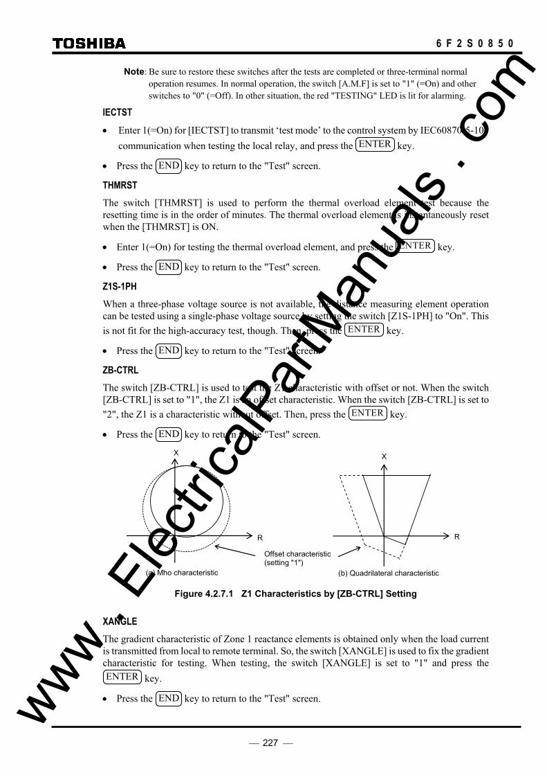
227
6 F 2 S 0 8 5 0
Note: Be sure to restore these switches after the tests are completed or three-terminal normal operation resumes. In normal operation, the switch [A.M.F] is set to "1" (=On) and other switches to "0" (=Off). In other situation, the red "TESTING" LED is lit for alarming.
IECTST • Enter 1(=On) for [IECTST] to transmit ‘test mode’ to the control system by IEC60870-5-103
communication when testing the local relay, and press the ENTER key.
• Press the END key to return to the "Test" screen.
THMRST The switch [THMRST] is used to perform the thermal overload element test because the resetting time is in the order of minutes. The thermal overload element is instantaneously reset when the [THMRST] is ON.
• Enter 1(=On) for testing the thermal overload element, and press the ENTER key.
• Press the END key to return to the "Test" screen.
Z1S-1PH When a three-phase voltage source is not available, the distance measuring element operation can be tested using a single-phase voltage source by setting the switch [Z1S-1PH] to "On". This is not fit for the high-accuracy test, though. Then, press the ENTER key.
• Press the END key to return to the "Test" screen.
ZB-CTRL The switch [ZB-CTRL] is used to test the Z1 characteristic with offset or not. When the switch [ZB-CTRL] is set to "1", the Z1 is an offset characteristic. When the switch [ZB-CTRL] is set to "2", the Z1 is a characteristic without offset. Then, press the ENTER key.
• Press the END key to return to the "Test" screen.
Offset characteristic (setting "1")
X
RR
X
(b) Quadrilateral characteristic (a) Mho characteristic
Figure 4.2.7.1 Z1 Characteristics by [ZB-CTRL] Setting
XANGLE The gradient characteristic of Zone 1 reactance elements is obtained only when the load current is transmitted from local to remote terminal. So, the switch [XANGLE] is used to fix the gradient characteristic for testing. When testing, the switch [XANGLE] is set to "1" and press the ENTER key.
• Press the END key to return to the "Test" screen. www . El
ectric
alPar
tMan
uals
. com

228
6 F 2 S 0 8 5 0
R
Z1Sθ1 or Z1Gθ1
X
Figure 4.2.7.2 Gradient Characteristic of Zone 1
UVTEST • Enter 0 (=Off) or 1 (=On) to set disable/enable the UV blocking (UVBLK) and press the
EN TER key.
• Press the END key to return to the "Test" screen.
COM∗ and S∗COM∗ It is possible to forcibly send communication data [COM4], [COM5], [SCOM1], [SCOM2], [S2COM1] to [S2COM12] and [S3COM1] to [S3COM12] for testing. If testing, a desired communication data is set to “ON” and press the ENTER key.
• Press the END key to return to the "Test" screen.
4.2.7.2 Binary Output Relay It is possible to forcibly operate all binary output relays for checking connections with the external devices. Forced operation can be performed on one or more binary outputs at a time for each module.
• Press 2 (=Binary output) on the "Test" screen to display the "Binary output" screen. / 2 B i n a r y o u t p u t
1 = I O # 2 = I O # 3 = I O #1 2 3
The LCD displays the output modules installed depending on the model. • Enter the selected number corresponding to each module to be operated. Then the LCD
displays the name of the module, the name of the output relay, the name of the terminal block and the terminal number to which the relay contact is connected.
/ 3 B O ( 0 = D i s a b l e 1 = E n a b l e ) 1 / 6
I O # T P - 1
I O # T P - 1
I O # T P - 1
I O # T P - 0
I O # T P - 0
I O # T P - 0
1A1
1
1
1
1
1
1B
1C
2A
2B
2C
www . El
ectric
alPar
tMan
uals
. com

229
6 F 2 S 0 8 5 0
/ 3 B O ( 0 = D i s a b l e 1 = E n a b l e ) 1 / 1 4
I O # B O 1 1
I O # B O 2 1
I O # B O 3 1
I O # B O 4 0
I O # B O 5 0
I O # B O 6 0
I O # B O 7 0
I O # B O 8 0
I O # B O 9 0
I O # B O 1 0 0
I O # B O 1 1 0
I O # B O 1 2 0
I O # F A I L 0
I O # 0B O 1 3
2
2
2
2
2
2
2
2
2
2
2
2
2
2
• Enter 1 and press the ENTER key to operate the output relays forcibly.
• After completing the entries, press the END key. Then the LCD displays the screen shown below.
/ 3 B O
K e e p p r e s s i n ot1g o p e r a t e .
P r e s s C A N C E L t o c a n c e l . • Keep pressing the 1 key to operate the assigned output relays.
• Release pressing the 1 key to reset the operation.
Caution: In case of relay models with fault detector, FD module BO also operates when IO#1 module BO is forcibly operated.
• Press the CANCEL key to return to the upper screen.
4.2.7.3 Timer The pick-up or drop-off delay time of the variable timer used in the scheme logic can be measured with monitoring jacks A and B. Monitoring jacks A and B are used to observe the input signal and output signal to the timer, respectively.
• Press 3(=Timer) on the "Test menu" screen to display the "Timer" screen. / 2 T i m e r 1 / 1
T i m e r ( 1 - 0 0 ) : 1 1
• Enter the number corresponding to the timer to be observed and press the ENTER key. The
timers and related numbers are listed in Appendix C.
• Press the END key to display the following screen.
www . El
ectric
alPar
tMan
uals
. com
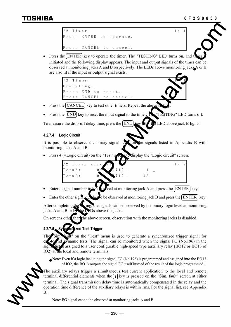
230
6 F 2 S 0 8 5 0
/ 2 T i m e r 1 / 1
P r e s s E N T E R t o o p e r a t e .
P r e s s C A N C E L t o c a n c e l . • Press the ENTER key to operate the timer. The "TESTING" LED turns on, and timer is
initiated and the following display appears. The input and output signals of the timer can be observed at monitoring jacks A and B respectively. The LEDs above monitoring jacks A or B are also lit if the input or output signal exists.
/ 2 T i m e r 1 / 1
O p e r a t i n g . . .
P r e s s E N D t o r e s e t .
P r e s s C A N C E L t o c a n c e l . • Press the CANCEL key to test other timers. Repeat the above testing.
• Press the END key to reset the input signal to the timer. The "TESTING" LED turns off.
To measure the drop-off delay time, press the END key after the LED above jack B lights.
4.2.7.4 Logic Circuit It is possible to observe the binary signal level on the signals listed in Appendix B with monitoring jacks A and B.
• Press 4 (=Logic circuit) on the "Test" screen to display the "Logic circuit" screen. / 2 L o g i c c i r c u i t 1 / 2
T e r m A ( 0 - 0 7 1 ) : 1 _
T e r m B ( 0 - 0 7 1 ) : 4 83
3
• Enter a signal number to be observed at monitoring jack A and press the ENTER key.
• Enter the other signal number to be observed at monitoring jack B and press the ENTER key.
After completing the setting, the signals can be observed by the binary logic level at monitoring jacks A and B or by the LEDs above the jacks.
On screens other than the above screen, observation with the monitoring jacks is disabled.
4.2.7.5 Synchronized Test Trigger The "Sim. fault" on the "Test" menu is used to generate a synchronized trigger signal for end-to-end dynamic tests. The signal can be monitored when the signal FG (No.196) in the signal list is assigned to a user configurable high-speed type auxiliary relay (BO12 or BO13 of IO2) at the local and remote terminals.
Note: Even if a logic including the signal FG (No.196) is programmed and assigned into the BO13 of IO2, the BO13 outputs the signal FG itself instead of the result of the logic programmed.
The auxiliary relays trigger a simultaneous test current application to the local and remote terminal differential elements when the 1 key is pressed on the "Sim. fault" screen at either terminal. The signal transmission delay time is automatically compensated in the relay and the operation time difference of the auxiliary relays is within 1ms. For the signal list, see Appendix B.
Note: FG signal cannot be observed at monitoring jacks A and B. www . El
ectric
alPar
tMan
uals
. com
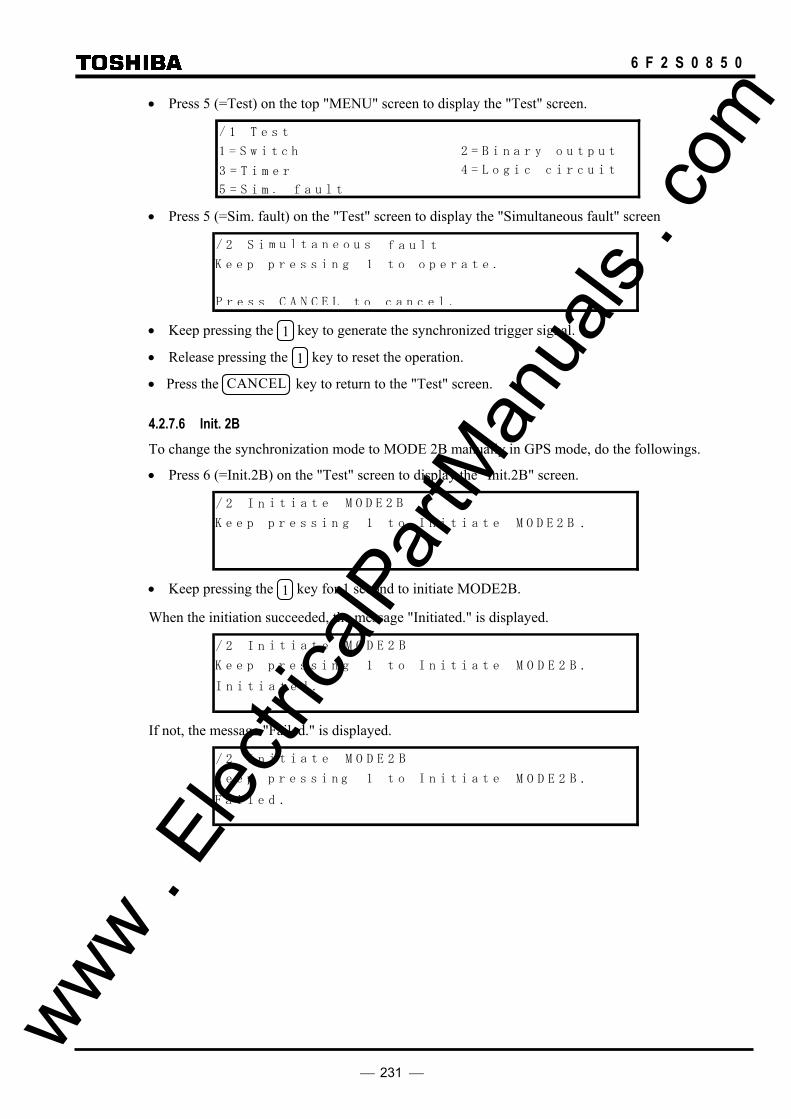
231
6 F 2 S 0 8 5 0
• Press 5 (=Test) on the top "MENU" screen to display the "Test" screen. / 1 T e s t
1 = S w i t hc 2 = B i n a r y o u t p u t
3 = T i m e r 4 = L o g i c c i r c u i t
5 = S i m . f a u l t • Press 5 (=Sim. fault) on the "Test" screen to display the "Simultaneous fault" screen
/ 2 S i
P r e s s C A N C E L t o c a n c e l .
m u l t a n e o u s f a u l t
K e e p p r e s s i n ot1g o p e r a t e .
• Keep pressing the 1 key to generate the synchronized trigger signal.
• Release pressing the 1 key to reset the operation.
• Press the CANCEL key to return to the "Test" screen.
4.2.7.6 Init. 2B To change the synchronization mode to MODE 2B manually in GPS mode, do the followings.
• Press 6 (=Init.2B) on the "Test" screen to display the "Init.2B" screen. / 2 I n i t i a t e BM O D E 2
K e e p p r e s s i n ot1g I n i t i a t e B M O D E 2 .
• Keep pressing the 1 key for 1 second to initiate MODE2B.
When the initiation succeeded, the message "Initiated." is displayed. / 2 I n
I n i t i a t e d .
i t i a t e BM O D E 2
K e e p p r e s s i n ot1g I n i t i a t e B M O D E 2 .
If not, the message "Failed." is displayed.
/ 2 I n
F a i l e d .
i t i a t e BM O D E 2
K e e p p r e s s i n ot1g I n i t i a t e B M O D E 2 .
www . El
ectric
alPar
tMan
uals
. com
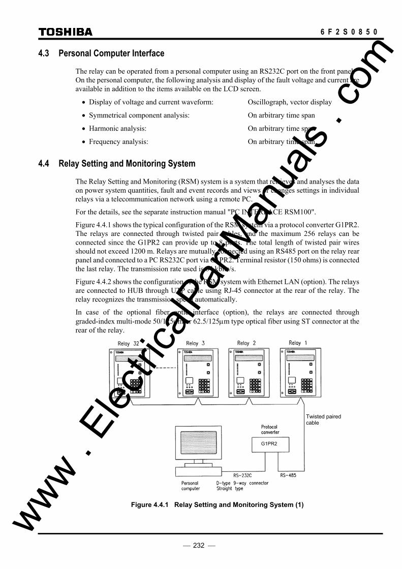
232
6 F 2 S 0 8 5 0
4.3 Personal Computer Interface
The relay can be operated from a personal computer using an RS232C port on the front panel. On the personal computer, the following analysis and display of the fault voltage and current are available in addition to the items available on the LCD screen.
• Display of voltage and current waveform: Oscillograph, vector display
• Symmetrical component analysis: On arbitrary time span
• Harmonic analysis: On arbitrary time span
• Frequency analysis: On arbitrary time span
4.4 Relay Setting and Monitoring System
The Relay Setting and Monitoring (RSM) system is a system that retrieves and analyses the data on power system quantities, fault and event records and views or changes settings in individual relays via a telecommunication network using a remote PC.
For the details, see the separate instruction manual "PC INTERFACE RSM100".
Figure 4.4.1 shows the typical configuration of the RSM system via a protocol converter G1PR2. The relays are connected through twisted pair cables, and the maximum 256 relays can be connected since the G1PR2 can provide up to 8 ports. The total length of twisted pair wires should not exceed 1200 m. Relays are mutually connected using an RS485 port on the relay rear panel and connected to a PC RS232C port via G1PR2. Terminal resistor (150 ohms) is connected the last relay. The transmission rate used is 64 kbits/s.
Figure 4.4.2 shows the configuration of the RSM system with Ethernet LAN (option). The relays are connected to HUB through UTP cable using RJ-45 connector at the rear of the relay. The relay recognizes the transmission speed automatically.
In case of the optional fiber optic interface (option), the relays are connected through graded-index multi-mode 50/125µm or 62.5/125µm type optical fiber using ST connector at the rear of the relay.
G1PR2
Figure 4.4.1 Relay Setting and Monitoring System (1)
Twisted paired cable
www . El
ectric
alPar
tMan
uals
. com

233
6 F 2 S 0 8 5 0
PC Relay HUB.
UTP cable (10Base-T)
100/110/115/120V
214B-13-10
Other relays
Figure 4.4.2 Relay Setting and Monitoring System (2)
4.5 IEC 60870-5-103 Interface
The GRL100 can support the IEC60870-5-103 communication protocol. This protocol is mainly used when the relay communicates with a control system and is used to transfer the following measurand, status data and general command from the relay to the control system.
• Measurand data: current, voltage, active power, reactive power, frequency • Status data: events, fault indications, etc.
The IEC60870-5-103 function in the relay can be customized with the original software “IEC103 configurator”. It runs on a personal computer (PC) connected to the relay, and can help setting of Time-tagged messages, General command, Metering, etc. For details of the setting method, refer to “IEC103 configurator” manual. For the default setting of IEC60870-5-103, see Appendix Q.
The protocol can be used through the RS485 port on the relay rear panel and can be also used through the optional fibre optical interface.
The relay supports two baud-rates 9.6kbps and 19.2kbps.
The data transfer from the relay can be blocked by the setting.
For the settings, see the Section 4.2.6.4.
4.6 Clock Function
The clock function (Calendar clock) is used for time-tagging for the following purposes:
• Event records • Disturbance records • Fault records • Metering • Automatic supervision • Display of the system quantities on the digest screen • Display of the fault records on the digest screen • Display of the automatic monitoring results on the digest screen
The calendar clock can run locally or be synchronized with the external IRIG-B time standard signal, RSM, IEC or GPS clock. This can be selected by setting.
If it is necessary to synchronize with the IRIG-B time standard signal or GPS signal, it is possible to transform GMT to the local time by setting.
When the relays are connected to the RSM system as shown in Figure 4.4.1, the calendar clock of each relay is synchronized with the RSM clock. If the RSM clock is synchronized with the external time standard (GPS clock etc.), then all the relay clocks are synchronized with the external time standard. www .
Elec
tricalP
artM
anua
ls . c
om
234
6 F 2 S 0 8 5 0
5. Installation 5.1 Receipt of Relays
When relays are received, carry out the acceptance inspection immediately. In particular, check for damage during transportation, and if any is found, contact the vendor.
Check that the following accessories are attached.
• 3 pins for the monitoring jack, packed in a plastic bag.
• An attachment kit required in rack-mounting, if ordered. (See Appendix F.)
1 large bracket with 5 round head screws, spring washers and washers (M4×10) 1 small bracket with 3 countersunk head screws (M4×6) 2 bars with 4 countersunk head screws (M3×8)
Always store the relays in a clean, dry environment.
5.2 Relay Mounting
Either a rack or flush mounting relay is delivered as designated by the customer. The GRL100 models are classified into two types by their case size, type A and type B. Appendix F shows the case outlines.
If the customer requires a rack-mounting relay, support metal fittings necessary to mount it in the 19-inch rack are also supplied with the relay.
When to mount the relay in the rack, detach the original brackets fixed on both sides of the relay and seals on the top and bottom of the relay. Attach the larger bracket and smaller bracket on the left and right side of the relay respectively and the two bars on the top and bottom of the relay.
How to mount the attachment kit, see Appendix F.
Dimensions of the attachment kits EP-101 and EP-102 is also shown in Appendix F.
5.3 Electrostatic Discharge
CAUTION
Do not take out any modules outside the relay case since electronic components on the modules are very sensitive to electrostatic discharge. If it is absolutely essential to take the modules out of the case, do not touch the electronic components and terminals with your bare hands. Additionally, always put the module in a conductive anti-static bag when storing it.
5.4 Handling Precautions
A person's normal movements can easily generate electrostatic potential of several thousand volts. Discharge of these voltages into semiconductor devices when handling electronic circuits can cause serious damage, which often may not be immediately apparent but the reliability of the circuit will have been reduced.
The electronic circuits are completely safe from electrostatic discharge when housed in the case. Do not expose them to risk of damage by withdrawing modules unnecessarily.
Each module incorporates the highest practicable protection for its semiconductor devices. However, if it becomes necessary to withdraw a module, precautions should be taken to preserve www .
Elec
tricalP
artM
anua
ls . c
om

235
6 F 2 S 0 8 5 0
the high reliability and long life for which the equipment has been designed and manufactured.
CAUTION
• Before removing a module, ensure that you are at the same electrostatic potential as the equipment by touching the case.
• Handle the module by its front plate, frame or edges of the printed circuit board. Avoid touching the electronic components, printed circuit board or connectors.
• Do not pass the module to another person without first ensuring you are both at the same electrostatic potential. Shaking hands achieves equipotential.
• Place the module on an anti-static surface, or on a conducting surface which is at the same potential as yourself.
• Do not place modules in polystyrene trays.
It is strongly recommended that detailed investigations on electronic circuitry should be carried out in a Special Handling Area such as described in the IEC 60747.
5.5 External Connections
External connections are shown in Appendix G.
Electrical interface for telecommunication The connector should be handled as follows:
• Insert the connector horizontally and tighten both upper and lower screws alternately.
• Do not touch the connector pin with your bare hand.
Connector
Screw
In electrical interface to multiplexed communication circuit for GRL100-∗∗∗∗-∗9-∗∗, the earthing wire of electrical cable is connected to the earth terminal (E) of the relay as shown in Figure 5.5.1, if required.
E
CH1
CH2
To Multiplexer
Earthing wire
Figure 5.5.1 Connection of communication cable
www . El
ectric
alPar
tMan
uals
. com

236
6 F 2 S 0 8 5 0
Optical interface for telecommunication The optical cables tend to come down, therefore, bending requires special attention.
Handling instructions of optical cable are as follows:
Instructions
1 Do not insert the connector obliquely.
2 Tighten the connector when connecting.
3 Do not pull the cable.
4 Do not bend the cable.
5 Do not bend the neck of the connector.
6 Do not twist the cable.
7 Do not kink in the cable.
8 Do not put and drop on the cable.
9 Do not bend the cable to (*)mm or less in radius.
(*)Length differs from characteristics of optical cable.
www . El
ectric
alPar
tMan
uals
. com

237
6 F 2 S 0 8 5 0
6. Commissioning and Maintenance 6.1 Outline of Commissioning Tests
The GRL100 is fully numerical and the hardware is continuously monitored.
Commissioning tests can be kept to a minimum and need only include hardware tests and conjunctive tests. The function tests are at the user’s discretion.
In these tests, user interfaces on the front panel of the relay or local PC can be fully applied.
Test personnel must be familiar with general relay testing practices and safety precautions to avoid personal injuries or equipment damage.
Hardware tests These tests are performed for the following hardware to ensure that there is no hardware defect. Defects of hardware circuits other than the following can be detected by monitoring which circuits functions when the DC power is supplied.
User interfaces Binary input circuits and output circuits AC input circuits
Function tests These tests are performed for the following functions that are fully software-based. Tests of the protection schemes and fault locator require a dynamic test set.
Measuring elements Timers Protection schemes Autoreclose Metering and recording Fault locator
Conjunctive tests The tests are performed after the relay is connected with the primary equipment, telecommunication equipment and other external equipment.
The following tests are included in these tests:
On load test: phase sequence check and polarity check Signaling circuit test Tripping and reclosing circuit test
www . El
ectric
alPar
tMan
uals
. com

238
6 F 2 S 0 8 5 0
6.2 Cautions
6.2.1 Safety Precautions
CAUTION
• The relay rack is provided with a grounding terminal. Before starting the work, always make sure the relay rack is grounded.
• When connecting the cable to the back of the relay, firmly fix it to the terminal block and attach the cover provided on top of it.
• Before checking the interior of the relay, be sure to turn off the power.
• Class 1M laser radiation when remove cap for models with <30km class optical interface. Do not view directly with optical instruments.
Failure to observe any of the precautions above may cause electric shock or malfunction.
6.2.2 Cautions on Tests
CAUTION
• While the power is on, do not connect/disconnect the flat cable on the front of the printed circuit board (PCB).
• While the power is on, do not mount/dismount the PCB. • Before turning on the power, check the following:
- Make sure the polarity and voltage of the power supply are correct. - Make sure the CT circuit is not open. - Make sure the VT circuit is not short-circuited.
• Be careful that the transformer module is not damaged due to an overcurrent or overvoltage. • If settings are changed for testing, remember to reset them to the original settings.
Failure to observe any of the precautions above may cause damage or malfunction of the relay.
Before mounting/dismounting the PCB, take antistatic measures such as wearing an earthed wristband.
www . El
ectric
alPar
tMan
uals
. com

239
6 F 2 S 0 8 5 0
6.3 Preparations
Test equipment The following test equipment is required for the commissioning tests.
1 Three-phase voltage source 2 Single-phase current sources 1 Dynamic three-phase test set (for protection scheme test) 1 DC power supply 3 DC voltmeters 3 AC voltmeters 3 Phase angle meters 2 AC ammeters 1 Time counter, precision timer 1 PC (not essential)
Relay settings Before starting the tests, it must be specified whether the tests will use the user’s settings or the default settings.
For the default settings, see the following appendixes:
Appendix D Binary Output Default Setting List Appendix H Relay Setting Sheet
Visual inspection After unpacking the product, check for any damage to the relay case. If there is any damage, the internal module might also have been affected. Contact the vendor.
Relay ratings Check that the items described on the nameplate on the front of the relay conform to the user’s specification. The items are: relay type and model, AC voltage, current and frequency ratings, and auxiliary DC supply voltage rating.
Local PC When using a local PC, connect it with the relay via the RS232C port on the front of the relay. RSM100 software is required to run the PC.
For the details, see the separate instruction manual "PC INTERFACE RSM100".
www . El
ectric
alPar
tMan
uals
. com

240
6 F 2 S 0 8 5 0
6.4 Hardware Tests
The tests can be performed without external wiring, but DC power supply and AC voltage and current source are required.
6.4.1 User Interfaces
This test ensures that the LCD, LEDs and keys function correctly.
LCD display • Apply the rated DC voltage and check that the LCD is off.
Note: If there is a failure, the LCD displays the "Auto-supervision" screen when the DC voltage is applied.
• Press the RESET key for 1 second when the LCD is off, and check that black dots appear on the whole screen.
LED display • Apply the rated DC voltage and check that the "IN SERVICE" LED is lit in green.
• Press the RESET key for 1 second when the LCD is off, and check that seven LEDs under the "IN SERVICE" LED and two LEDs for monitoring jacks A and B are lit in red.
VIEW and RESET keys
• Press the VIEW key when the LCD is off and check that the "Metering" screen is displayed on the LCD.
• Press the RESET key and check that the LCD turns off.
Keypad • Press any key on the keypad when the LCD is off and check that the LCD displays the
"MENU" screen. Press the END key to turn off the LCD.
• Repeat this for all keys.
www . El
ectric
alPar
tMan
uals
. com

241
6 F 2 S 0 8 5 0
6.4.2 Binary Input Circuit
The testing circuit is shown in Figure 6.4.2.1.
TB4
BI2
BI1
-B4
-A16
-A17
E
TB4
GRL100
DCpower supply
+
−
-A4
BI15
:
:
-A15
-B10
TB3 -A14
-B14
-A11
-B11
BI17
BI16
BI18
:
:
-B15
BI20
BI19
-B7
-A7
BI25
:
-A10 :
TB2
Figure 6.4.2.1 Testing Binary Input Circuit
• Display the "Binary input & output" screen from the "Status" sub-menu. / 2 B i n a r y i n p u t & o u t p u t 3 / 6
I n p u t ( I O # 1 [ 0 0 0 0 0 0 0 0 0 0 0 0 0 0 0 ] )
I n p u t ( I O # 2 [ 0 0 0 ] )
I n p u t ( I O # 3 [ 0 0 0 0 0 0 0 ] )
O u t p u t ( I O# 2 [ 0 0 0 0 0 0 0 0 0 0 0 0 0 0 ] )
O u t p u t ( I O# 3 [ 0 0 0 0 0 0 ] )
O u t p u t ( I O 1 - t r i p ) [ 0 0 0 0 0 0 ] #
• Apply the rated DC voltage to terminal A4, B4, ..., A11 of terminal block TB4, A14, B14 and
A15 of terminal block TB3 and A7, B7, ..., A10 of terminal block TB2, in case of the model 7∗1. Check that the status display corresponding to the input signal changes from 0 to 1. (For details of the binary input status display, see Section 4.2.4.2.)
Note: Different models have different terminal block and terminal number, so refer to Appendix G.
The user will be able to perform this test for one terminal to another or for all the terminals at once. www .
Elec
tricalP
artM
anua
ls . c
om

242
6 F 2 S 0 8 5 0
6.4.3 Binary Output Circuit
This test can be performed by using the "Test" sub-menu and forcibly operating the relay drivers and output relays. Operation of the output contacts is monitored at the output terminal. The output contact and corresponding terminal number are shown in Appendix G.
• Press 2 (= Binary output) on the "Test" screen to display the "Binary output" screen. The LCD displays the output modules mounted depending on the model.
• Enter the selected number corresponding to each module to be operated. Then the LCD displays the name of the module, the name of the output relay, the name of the terminal block and the terminal number to which the relay contact is connected.
• Enter 1 and press the ENTER key.
• After completing the entries, press the END key. Then the LCD displays the screen shown below. If 1 is entered for all the output relays, the following forcible operation can be performed collectively.
/ 3 B O
K e e p p r e s s i t o o p e r a t e .
C A N C E t o c a n c e l .LP r e s s
n g 1
• Keep pressing the 1 key to operate the output relays forcibly.
• Check that the output contacts operate at the terminal.
• Release pressing the 1 key to reset the operation.
www . El
ectric
alPar
tMan
uals
. com
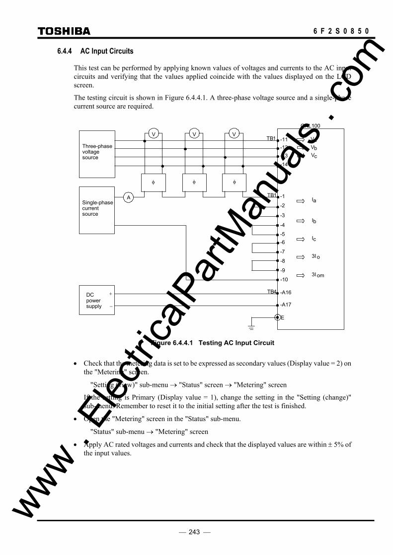
243
6 F 2 S 0 8 5 0
6.4.4 AC Input Circuits
This test can be performed by applying known values of voltages and currents to the AC input circuits and verifying that the values applied coincide with the values displayed on the LCD screen.
The testing circuit is shown in Figure 6.4.4.1. A three-phase voltage source and a single-phase current source are required.
Three-phase voltage source
A
φ
V TB1
- 12 -11 V a
V V
φ φ
Single-phase current source
DC power supply
+
−
- 13 - 14
TB1
- 2
-1
- 3
- 4
- 5 - 6
- 7
- 8
- A16
- A17
E
TB4
V c
V b
I a
I b
I c
3I o
GRL100
- 9
- 10 3I om
Figure 6.4.4.1 Testing AC Input Circuit
• Check that the metering data is set to be expressed as secondary values (Display value = 2) on the "Metering" screen.
"Setting (view)" sub-menu → "Status" screen → "Metering" screen
If the setting is Primary (Display value = 1), change the setting in the "Setting (change)" sub-menu. Remember to reset it to the initial setting after the test is finished.
• Open the "Metering" screen in the "Status" sub-menu.
"Status" sub-menu → "Metering" screen
• Apply AC rated voltages and currents and check that the displayed values are within ± 5% of the input values.
www . El
ectric
alPar
tMan
uals
. com

244
6 F 2 S 0 8 5 0
6.5 Function Test
CAUTION The function test may cause the output relays to operate including the tripping output relays. Therefore, the test must be performed with tripping circuits disconnected.
6.5.1 Measuring Element
Measuring element characteristics are realized by software, so it is possible to verify the overall characteristics by checking representative points.
Operation of the element under test is observed by the binary output signal at monitoring jacks A or B or by the LED indications above the jacks. In any case, the signal number corresponding to each element output must be set on the "Logic circuit" screen of the "Test" sub-menu.
/ 2 L o g 1 / 2
T e r m ( 0 - 0 7 1 ) : 1
T e r m ( 0 - 0 7 1 ) : 84
i c c i r c u i t
A
B
3
3
When a signal number is entered for the TermA line, the signal is observed at monitoring jack A and when entered for the TermB line, observed at monitoring jack B.
Note: The voltage level at the monitoring jacks is +15V ±3V for logic level "1" when measured by an instrument with 10kΩ input impedance, and less than 0.1V for logic level "0".
CAUTION • Use test equipment with more than 1kΩ of internal impedance when observing the output
signal at the monitoring jacks. • Do not apply an external voltage to the monitoring jacks.
In case of a three-phase element, it is enough to test a representative phase. A-phase is selected hereafter.
www . El
ectric
alPar
tMan
uals
. com

245
6 F 2 S 0 8 5 0
6.5.1.1 Phase current differential element DIF The phase current differential element is checked for the following items.
Operating current value
Charging current compensation
Percentage restraining characteristic
The top two items are tested locally or under an end-to-end setup of each terminal relay.
The last item is tested only under an end-to-end setup of each terminal relay.
Operating current value Figure 6.5.1.1 shows the circuit to test the A-phase element locally.
GRL100
Single-phase current source
A TB1 -1
-2RX1
TX1
Ia
Monitoring jack
A
0V
DC voltmeter
TB4 -A16
-A17
E
DC power supply
+
−
RX2
TX2
CH1
CH2
Figure 6.5.1.1 Testing Phase Current Differential Element
The output signal numbers of the DIF element are as follows.
Element Signal number
DIF-A 41
DIF-B 42
DIF-C 43
• Set the [L.test] to “1” (=On) on the “Switch” screen of the “Test” sub-menu.
• Check that the charging current compensation DIFIC is set to zero on the "Protection element" screen in the "Setting (view)" sub-menu. If not, set it to zero in the "Setting (change)" sub-menu.
• Press 4 (=Logic circuit) on the "Test" sub-menu screen to display the "Logic circuit" screen.
• Enter a signal number 41 for Term A line to observe the DIF-A operation at monitoring jack A and press the ENTER key. www .
Elec
tricalP
artM
anua
ls . c
om
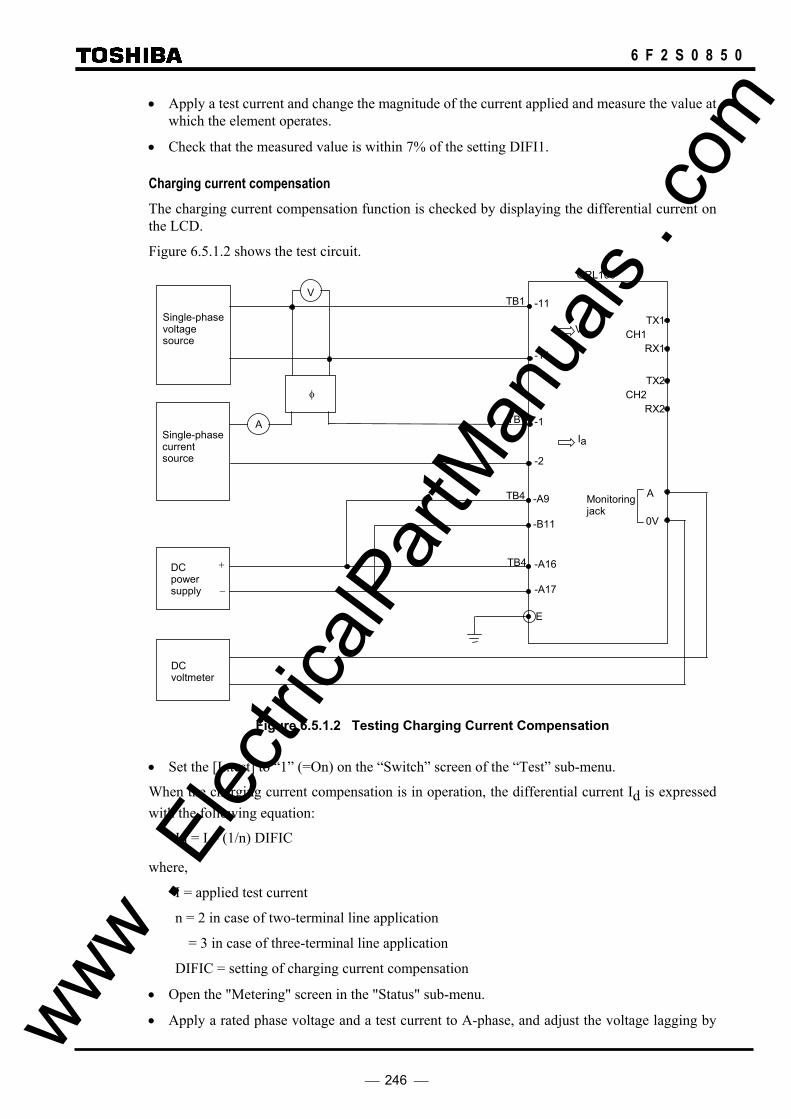
246
6 F 2 S 0 8 5 0
• Apply a test current and change the magnitude of the current applied and measure the value at which the element operates.
• Check that the measured value is within 7% of the setting DIFI1.
Charging current compensation The charging current compensation function is checked by displaying the differential current on the LCD.
Figure 6.5.1.2 shows the test circuit.
Single-phase voltage source
A
φ
V TB1 -11
V a
Single-phase current source
DC voltmeter
-14
TB1
-2
-1
-A16
-A17
E
TB4
I a
GRL100
DC power supply
+
−
RX1
TX1
Monitoring jack
A
0V
TB4 -A9
-B11
RX2
TX2
CH1
CH2
Figure 6.5.1.2 Testing Charging Current Compensation
• Set the [L.test] to “1” (=On) on the “Switch” screen of the “Test” sub-menu.
When the charging current compensation is in operation, the differential current Id is expressed with the following equation:
Id = I – (1/n) DIFIC
where,
I = applied test current
n = 2 in case of two-terminal line application
= 3 in case of three-terminal line application
DIFIC = setting of charging current compensation
• Open the "Metering" screen in the "Status" sub-menu.
• Apply a rated phase voltage and a test current to A-phase, and adjust the voltage lagging by www . El
ectric
alPar
tMan
uals
. com

247
6 F 2 S 0 8 5 0
90°.
• Check that the A-phase differential current Ida on the "Metering" screen coincides with the Id mentioned above with an error within ±7%.
End-to-end test setup When the percentage restraint characteristic is checked, an end-to-end setup using two relays is required.
<Testing at laboratory>
If the relays can be collected and tested at a laboratory, the end-to-end test is possible by directly connecting their communication ports. Figure 6.5.1.3 (a) shows the testing circuit of the laboratory end-to-end test.
In case of two-terminal applications, the signal terminals CH1-TX1 and -RX1 of one relay are directly connected to CH1-RX1 and -TX1 of another relay.
Note: When the relays have an electrical telecommunications interface in accordance with CCITT-G703-1.2.1 or an optical interface (Short wavelength light, GI, 2km class), the scheme switch [D. test] must be set to “1” (= On) to test them under the direct connection of the communication circuits.
www . El
ectric
alPar
tMan
uals
. com

248
6 F 2 S 0 8 5 0
Single-phase current source
TB1
TB4
-1
-2
-A16
-A17
E
Relay A: GRL100
Monitoring jack
φ
A
0V
Ia +
−
A
DC voltmeter
Single-phase current source
TB1
TB4
-1
-2
-A16
-A17
E
Relay B: GRL100
Monitoring jack
A
0V
0V
Ia
+
+
−
A
DC power supply
TB1
TB4
-1
-2
-A16
-A17
E
Relay C: GRL100
Monitoring jack
A
0V
Ia
TX1
RX1
TX1
RX1
TX2
RX2
TX1
RX1
TX2
RX2
TX2
RX2
(*)
(**)CH1
CH2
CH1
CH2
CH1
CH2
Note: In case of two-terminal applications (The relay C is not used.),
(*) Connect the dotted line. (**) Connect CH1-TX1 and CH1-RX1 of the relay A to CH1-RX1 and CH1-TX1 of the relay B.
Figure 6.5.1.3 (a) End-to-end Test Setup at Laboratory
www . El
ectric
alPar
tMan
uals
. com

249
6 F 2 S 0 8 5 0
<Testing on site>
If the relays are tested at each installation site, the end-to-end test is performed after the telecommunication circuit between terminals is setup. Figure 6.5.1.3 (b) shows the testing circuit of the on-site end-to-end test.
In the on-site test, it is necessary to set the phase relationship between the test currents of each terminal. The pulse signal PULSE generated from the synchronized sampling clock is used as a reference phase signal at each terminal because it is in-phase between the terminals.
www . El
ectric
alPar
tMan
uals
. com
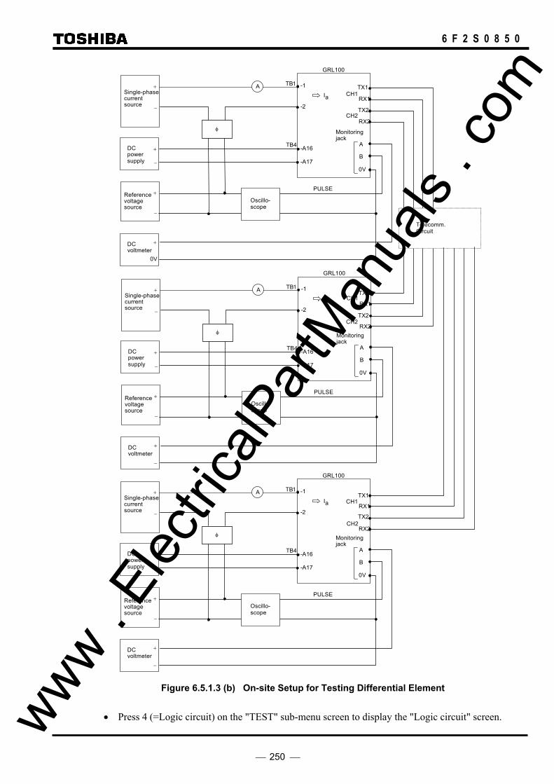
250
6 F 2 S 0 8 5 0
Single-phase current source
TB1
DC voltmeter
TB4
-1
-2
-A16
-A17
GRL100
PULSE
Monitoringjack
φ
A
0V
Ia
+
−
TX1
RX1
A
Reference voltage source
0V
+
+
−
DC power supply
B+
−
Oscillo- scope
Telecomm. Circuit
TX2
RX2
Single-phase current source
TB1
DC voltmeter
TB4
-1
-2
-A16
-A17
GRL100
PULSE
Monitoringjack
φ
A
0V
Ia
+
−
A
Reference voltage source
−
+
+
−
DC power supply
B+
−
Oscillo- scope
TX1
RX1
TX2
RX2
Single-phase current source
TB1
DC voltmeter
TB4
-1
-2
-A16
-A17
GRL100
PULSE
Monitoringjack
φ
A
0V
Ia
+
−
A
Reference voltage source
−
+
+
−
DC power supply
B+
−
Oscillo- scope
TX1
RX1
TX2
RX2
CH1
CH2
CH1
CH2
CH1
CH2
Figure 6.5.1.3 (b) On-site Setup for Testing Differential Element
• Press 4 (=Logic circuit) on the "TEST" sub-menu screen to display the "Logic circuit" screen. www . El
ectric
alPar
tMan
uals
. com

251
6 F 2 S 0 8 5 0
Iin
Iout Iin = Iout
DIFI2
DIFI1 + 7/5 DIFI2 DIFI1
B
A
DIFI1, DIFI2: Setting value
• Enter a signal number 270 for Term B to observe a signal PULSE at monitoring jack B, and then press the ENTER key.
The phase of the test current is adjusted as follows.
• Adjust the reference voltage to be in-phase with the pulse signal PULSE monitoring a CRT oscilloscope.
• Adjust the test current to be in-phase with the reference voltage to simulate an infeed current and counter-phase to simulate an outflow current.
Figure 6.5.1.4 Phase Adjustment
Percentage restraint characteristics The percentage restraint characteristic is tested on the outflow current (Iout) and infeed current (Iin) plane as shown in Figure 6.5.1.5 by applying an infeed current to one relay and an outflow current to another relay.
Figure 6.5.1.5 Percentage Restraining Characteristic on Iin-Iout Plane
Characteristic A is expressed by the following equation,
Iout ≤ (5/7) (Iin - DIFI1)
Characteristic B is expressed by the following equation,
One cycle (20ms or 16.7ms)
PULSE signal
Time Reference voltage
Testing current
www . El
ectric
alPar
tMan
uals
. com

252
6 F 2 S 0 8 5 0
Iout ≤ DIFI2
where, DIFI1 and DIFI2 are setting values.
• Set the charging current compensation DIFIC to zero.
• Press 4 (=Logic circuit) on the "Test" sub-menu screen to display the "Logic circuit" screen.
• Enter a signal number 41 to observe the DIF-A output at monitoring jack A and press the ENTER key.
• Apply a fixed infeed current to one relay. Apply an outflow current to another relay, change the magnitude of the current applied and measure the value at which the element operates.
• Repeat the above by changing the magnitude of the infeed current.
• Check that the measured value of the outflow current is within ±7% of the theoretical values obtained using the equations mentioned above. (The infeed current is more than 0.5×In).
6.5.1.2 Residual current differential element DIFG The residual current differential element is checked on the operating current and percentage restraining characteristic in the same way as described in Section 6.5.1.1.
Element Signal number
DIFG 44
The differences from the procedure described in Section 6.5.1.1 are as follows.
• Apply a test current to terminal 7 and 8 instead of 1 and 2.
• Enter a signal number 44 instead of 41 to observe the DIFG element operation at monitoring jack A.
• Use the settings DIFGI instead of DIFI1.
www . El
ectric
alPar
tMan
uals
. com

253
6 F 2 S 0 8 5 0
6.5.1.3 Distance Measuring Element Z1, Z2, Z3, Z4, ZR and PSB
Phase fault element reach test The test voltage and current input test circuit is shown in Figure 6.5.1.6.
Three-phase voltage source
A
φ
V TB1
-12-11
Va
V V
φ φ
Single-phase current source
DC voltmeter
-13
-14
TB1
-2
-1
-3
-4
-A16
-A17
E
TB4
Vc Vb
Ia
Ib
GRL100
DC power supply
+
−
Monitoring jack
A
0V
Figure 6.5.1.6 Testing Phase-Fault Element
Phase fault elements and their output signal numbers are listed below.
Measuring element Signal number
Z1S-AB 575
Z2S-AB 578
Z3S-AB 581
Z4S-AB 584
ZRS-AB 364
PSBSIN-AB 596
PSBSOUT-AB 593
• Press 5 (=Logic circuit) on the "Test" screen to display the "Logic circuit" screen.
• Enter a signal number to be observed at monitoring jack A and press the ENTER key.
• Apply three-phase rated voltage.
• Choose a test current IT by referring to the table below, the table shows the relationship between the reach setting, test current and measuring error.
www . El
ectric
alPar
tMan
uals
. com

254
6 F 2 S 0 8 5 0
Reach setting IT Error
0.01 - 0.05Ω (0.1 - 0.2Ω
25A 5A)(*)
±10%
0.06 - 0.09Ω (0.3 - 0.4Ω
20A 4A)
±7%
0.10 - 1.00Ω (0.5 - 5.0Ω
10A 2A)
±5%
1.01 - 10.00Ω (5.1 - 50.0Ω
5A 1A)
±5%
10.01 - 20.00Ω (50.1 – 100.0Ω
2.5A 0.5A)
±5%
20.01 - 50.00Ω (100.1 – 250.0Ω
1A 0.2A)
±7%
(*) Values shown in parentheses are in the case of 1A rating. Other values are in the case of 5A rating.
• Set the voltage and current phase relationship as shown below. That is, Va lags Vc by 90°, Vb = - Va and IT lags Va by θ or θ + 180°. θ is 90° when testing.
IT
θ
90° Vb
Vc
Va
Z1S, Z2S, Z3S and PSB
θ + 180°
IT
Vb Va
Vc
Z4S
• Adjust the magnitude of Va and Vb while retaining the conditions above and measure the voltage Va at which the element operates.
• The theoretical operating voltage is obtained by 2IT × ZS when the setting reach is ZS. Check that the measured voltage is within the above-mentioned error of the theoretical voltage value when it is expressed with 2Va (= Va − Vb).
Element reach setting (ZS) IT 2IT × ZS Measured voltage (2Va)
Z1S Z2S Z3S Z4S ZRS PSBSIN PSBSOUT www .
Elec
tricalP
artM
anua
ls . c
om

255
6 F 2 S 0 8 5 0
[Testing of Zone 1 bending characteristic] The test circuit and test method is same as above.
The operating voltage of Zone 1 bending characteristic can be calculated as follows:
X
R
(X1, R1)θ1
θ2
0
θ1: Z1Sθ1 setting angle
θ2: Z1Sθ2 setting angle
θθθ
θθ
θ sin1
tantan1
tantan1
sin1
1
2
11
⋅⋅
+
+
=⋅= IX
IXV p
where,
X1 is the Z1S setting reach.
θ is the angle difference between voltage and current.
Note: Toshiba recommend that a minimum of three values for θ be tested to check that the
correct relay settings have been applied. Care must be taken in choosing values of θ to ensure that the testing points come within the operating boundary defined by the Z1S θ2 setting and either the load blinder or mho settings, as appropriate
www . El
ectric
alPar
tMan
uals
. com

256
6 F 2 S 0 8 5 0
Earth fault element reach test The test circuit is shown in Figure 6.5.1.7.
Three-phase voltage source
A
φ
V TB1
-12-11
Va
Single-phase current source
DC voltmeter
-13
-14
TB1
-2
-1
-7
-8
-A16
-A17
E
TB4
Vc Vb
Ia
3Io
GRL100
DC power supply
+
−
Monitoring jack
A
0V
Figure 6.5.1.7 Testing Earth-Fault Element
Earth fault elements and their output signal number are listed below.
Measuring element Signal number
Z1G-A 560
Z2G-A 563
Z3G-A 566
Z4G-A 569
ZRG-A 572
PSBGIN-A 590
PSBGOUT-A 587
• Press 5 (=Logic circuit) on the Test screen to display the Logic circuit screen.
• Enter a signal number to be observed at monitoring jack A and press the ENTER key.
• Apply three-phase rated voltage.
• Choose a test current IT by referring to the table below, the table shows the relationship between the reach setting, test current and measuring error.
Reach setting IT Error
0.01 - 0.05Ω (0.1 - 0.2Ω
25A 5A)(*)
±10%
0.06 - 0.09Ω 20A ±7% www . El
ectric
alPar
tMan
uals
. com
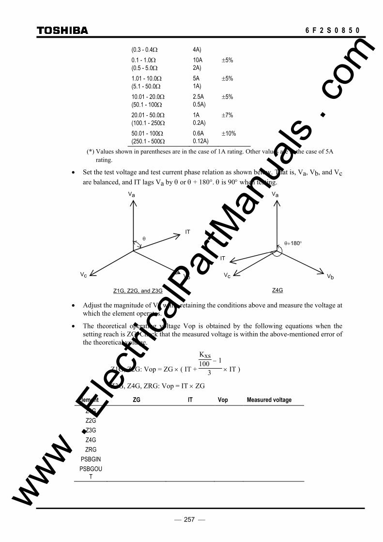
257
6 F 2 S 0 8 5 0
(0.3 - 0.4Ω 4A) 0.1 - 1.0Ω (0.5 - 5.0Ω
10A 2A)
±5%
1.01 - 10.0Ω (5.1 - 50.0Ω
5A 1A)
±5%
10.01 - 20.0Ω (50.1 - 100Ω
2.5A 0.5A)
±5%
20.01 - 50.0Ω (100.1 - 250Ω
1A 0.2A)
±7%
50.01 - 100Ω (250.1 - 500Ω
0.6A 0.12A)
±10%
(*) Values shown in parentheses are in the case of 1A rating. Other values are in the case of 5A rating.
• Set the test voltage and test current phase relation as shown below. That is, Va, Vb, and Vc are balanced, and IT lags Va by θ or θ + 180°. θ is 90° when testing.
θ+180°
Z4G
IT
VbVc
Va
Z1G, Z2G, and Z3G
IT θ
Vb Vc
Va
• Adjust the magnitude of Va while retaining the conditions above and measure the voltage at
which the element operates.
• The theoretical operating voltage Vop is obtained by the following equations when the setting reach is ZG. Check that the measured voltage is within the above-mentioned error of the theoretical voltage.
Z1G, Z2G: Vop = ZG × ( IT +
Kxs100 − 1
3 × IT )
Z3G, Z4G, ZRG: Vop = IT × ZG
Element ZG IT Vop Measured voltage Z1G Z2G Z3G Z4G ZRG
PSBGIN PSBGOU
T
www . El
ectric
alPar
tMan
uals
. com

258
6 F 2 S 0 8 5 0
[Testing of Zone 1 bending characteristic]
The test circuit and test method is same as above.
The operating voltage of Zone 1 bending characteristic can be calculated as follows:
X
R
(X1, R1)θ1
θ2
0
θ1: Z1Gθ1 setting angle
θ2: Z1Gθ2 setting angle
θθθ
θθ
θ sin1'
''
tantan
1
tantan1
sin1'
1
2
11
⋅⋅
⋅+
+
=⋅= x
r
xxp I
II
XIXV
where,
mxmxs
x Ik
Ik
II 00 100100100
' +−
+= , mrmrs
r Ik
Ik
II 00 100100100
' +−
+=
X1 is the Z1G setting reach.
θ is the angle difference between voltage and current.
Note: Toshiba recommend that a minimum of three values for θ be tested to check that the correct relay settings have been applied. Care must be taken in choosing values of θ to ensure that the testing points come within the operating boundary defined by the Z1G θ2 setting and either the load blinder or mho settings, as appropriate
6.5.1.4 Phase Selection Element UVC The testing circuit is shown in Figure 6.5.1.7.
UVC elements and their output signal numbers are listed below.
Measuring element Signal number
UVC-A 608
UVC-B 609
UVC-C 610
The following shows the case when testing UVC-A.
• Press 5 (=Logic circuit) on the Test screen to display the Logic circuit screen.
• Enter 608 as a signal number to be observed at monitoring jack A and press the ENTER key.
• Apply a three-phase rated voltage.
• Set the test current IT to zero ampere and adjust the voltage. Measure the voltage at which the element operates. Check that the voltage is within ±5% of the setting UVCV. (The www .
Elec
tricalP
artM
anua
ls . c
om

259
6 F 2 S 0 8 5 0
default setting of the UVCV is 48 V.)
• Choose a test current IT by referring to the table below, which shows the relation of setting reach UVCZ, test current IT and measuring error.
UVCZ IT Error
0.0- 2.0Ω (0 - 10Ω
10A 5A) (*)
±5%
2.1 – 10.0Ω (11 - 50Ω
5A 1A)
±5%
10.1 – 20.0Ω (51 - 100Ω
2.5A 0.5A)
±5%
20.1 – 50.0Ω (101 - 250Ω
1A 0.2A)
±7%
(*) Values shown in parentheses are in the case of 1A rating. Other values are in the case of 5A rating.
• Set the test voltage and test current phase relation as shown below. That is, Va, Vb, and Vc are balanced, and IT lags Va by UVC characteristic angle UVC θ.
(The default setting of UVC θ is 85°.)
• Adjust the magnitude of Va while retaining the conditions above and measure the voltage Va at which the element operates.
• The theoretical operating voltage is obtained by (IT × UVCZ + UVCV) when the setting reach is UVCZ. Check that the measured voltage is within the above-mentioned error of the theoretical voltage value. (The default setting of the UVCZ is 2.0 ohm for 5A rating and 10 ohm for 1A rating.)
Element UVCV UVCZ IT IT×UVCZ + UVCV Measured voltage
UVCZ
6.5.1.5 Directional Earth Fault Element DEF The testing circuit is shown in Figure 6.5.1.7.
DEF elements and their output signal number are listed below.
Measuring element Signal number
DEFF 611
DEFR 612
The following shows the case when testing DEFF.
IT θ
Vb Vc
Va
www . El
ectric
alPar
tMan
uals
. com

260
6 F 2 S 0 8 5 0
• Press 5 (=Logic circuit) on the Test screen to display the Logic circuit screen.
• Enter 59 as a signal number to be observed at monitoring jack A and press the ENTER key.
Residual current level detection is verified as follows:
• Apply three-phase rated voltage and single-phase test current IT (= 3Io). Set IT to lag Va by DEFF characteristic angle DEF θ. (The default setting of DEF θ is 85°.)
• Lower Va to 10 V to generate a residual voltage. Changing the magnitude of IT while retaining the phase angle with the voltages, and measure the current at which the element operates. Check that the measured current magnitude is within ± 5% of the current setting.
Residual voltage level detection is verified as follows:
• Set IT to rated current and the three-phase voltage to rated voltage. Lower the magnitude of Va while retaining the phase angle with the current and measure the voltage Va at which the element operates. Operating residual voltage is expressed by (VR-Va), where VR is the rated voltage. Check that the (VR-Va) is within 5% of the residual voltage setting.
6.5.1.6 Inverse Definite Minimum Time Overcurrent Element (IDMT) OCI, EFI The testing circuit is shown in Figure 6.5.1.8.
Single-phase current source
A TB1
-2
-1
-7
-8
Ia
3Io
GRL100
Monitoring jack
A
0V
Time counter
TB4 -A16
-A17
E
DC power supply
+
−
Start
Stop
OV
Figure 6.5.1.8 Testing IDMT
One of the four inverse time characteristics can be set, and the output signal numbers of the IDMT are as follows:
IT θ
3Vo
Vb Vc
Va
Va
www . El
ectric
alPar
tMan
uals
. com

261
6 F 2 S 0 8 5 0
Element Signal number
OCI-A 68
OCI-B 69
OCI-C 70
EFI 72
Fix the time characteristic to test by setting the scheme switch MEFI or MOCI on the "Scheme switch" screen.
"Setting (change)" sub-menu → "Protection" screen → "Trip" screen → "Scheme switch" screen
The test procedure is as follows:
• Press 5 (=Logic circuit) on the "Test" screen to display the "Logic circuit" screen.
• Enter a signal number to observe the OCI or EFI output at monitoring jack A and press the ENTER key.
• Apply a test current and measure the operating time. The magnitude of the test current should be between 1.2 × Is to 20 × Is, where Is is the current setting.
• Calculate the theoretical operating time using the characteristic equations shown in Section 2.16.6. Check that the measured operating time is within IEC 60255-3 class 5 for standard, very and long-time inverse or IEC 60255-3 class 7.5 for extremely inverse.
6.5.1.7 Thermal overload element THM-A and THM-T The testing circuit is same as the circuit shown in Figure 6.5.1.8.
The output signal of testing element is assigned to the monitoring jack A.
The output signal numbers of the elements are as follows:
Element Signal No.
THM-A 367 THM-T 363
To test easily the thermal overload element, the scheme switch [THMRST] in the "Switch" screen on the "Test" menu is used.
• Set the scheme switch [THMRST] to "ON".
• Enter the signal number to observe the operation at the monitoring jack A as shown in Section 6.5.1.
• Apply a test current and measure the operating time. The magnitude of the test current should be between 1.2 × Is to 10 × Is, where Is is the current setting.
CAUTION
After the setting of a test current, apply the test current after checking that the THM% has become 0 on the "Metering" screen.
• Calculate the theoretical operating time using the characteristic equations shown in Section 2.8. Check that the measured operating time is within 5%.
6.5.1.8 Broken conductor detection element BCD The testing circuit is shown in Figure 6.5.1.9. www .
Elec
tricalP
artM
anua
ls . c
om

262
6 F 2 S 0 8 5 0
Three-phase Current source
TB1
-2 -1
-3
-4
-6
-5
Ia
Ib
GRL100
-A16
-B17
E
TB4DC power supply
+
−
A
Ic
A
A
DC voltmeter
+
0V
Monitoring jack
A
0V
Figure 6.5.1.9 Testing BCD element
The output signal of testing element is assigned to the monitoring jack A.
The output signal numbers of the elements are as follows:
Element Signal No.
BCD 635
• Enter the signal number to observe the operation at the monitoring jack A as shown in Section 6.5.1.
• Apply the three-phase balance current at 10% of the rated current and interrupt a phase current.
Then, check the BCD element operates.
6.5.1.9 Overvoltage / undervoltage elements OVS1, OVS2, OVG1, OVG2, UVS1, UVS2, UVG1, UVG2
The testing circuit is shown in Figure 6.5.1.10.
TB4 -A16
-B17
E
GRL100
DC power supply
+
−
V TB1+
−
Variable-
Voltage source
-11
-12 or -14(*)
DC voltmeter
+
0V
Monitoring jack
A
0V
(∗) TB1-12 for OVS1, OVS2, UVS1 and UVS2, TB1-14 for OVG1, OVG2, UVG1 and UVG2. Figure 6.5.1.10 Operating Value Test Circuit
The output signal of testing element is assigned to the monitoring jack A. www . El
ectric
alPar
tMan
uals
. com

263
6 F 2 S 0 8 5 0
Overvoltage and undervoltage elements and their output signal number are listed below.
Element Signal No. OVS1-AB OVS2-AB OVG1-A OVG2-A UVS1-AB UVS2-AB UVG1-A UVG2-A
639 642 645 648 663 666 669 672
• Enter the signal number to observe the operation at the monitoring jack A as shown in Section 6.5.1.
Operating value test of OVS1, OVS2, OVG1, OVG2 • Apply a rated voltage as shown in Figure 6.5.1.10.
• Increase the voltage and measure the value at which the element operates. Check that the measured value is within ± 5% of the setting.
Operating value test of UVS1, UVS2, UVG1, UVG2 • Apply a rated voltage and frequency as shown Figure 6.5.1.10.
• Decrease the voltage and measure the value at which the element operates. Check that the measured value is within ± 5% of the setting.
Operating time check of OVS1, OVG1, UVS1, UVG1 IDMT curves • Apply a rated voltage at the IDMT time multiplier setting 10.0 of the relay.
• Change the voltage from the rated voltage to the test voltage quickly and measure the operating time. Test voltage: 1.5 × (setting voltage) or 0.5 × (setting voltage)
• Calculate the theoretical operating time using the characteristic equations shown in Section 2.9.1 and 2.9.2. Check the measured operating time within ±5%.
6.5.1.10 Out-of-step element OST The out-of-step element can be tested with an end-to-end setup using two relays.
Figure 6.5.1.11 (a) and (b) shows the testing circuits of the laboratory test and on-site test. For the test setup, refer to Section 6.5.1.1.
www . El
ectric
alPar
tMan
uals
. com
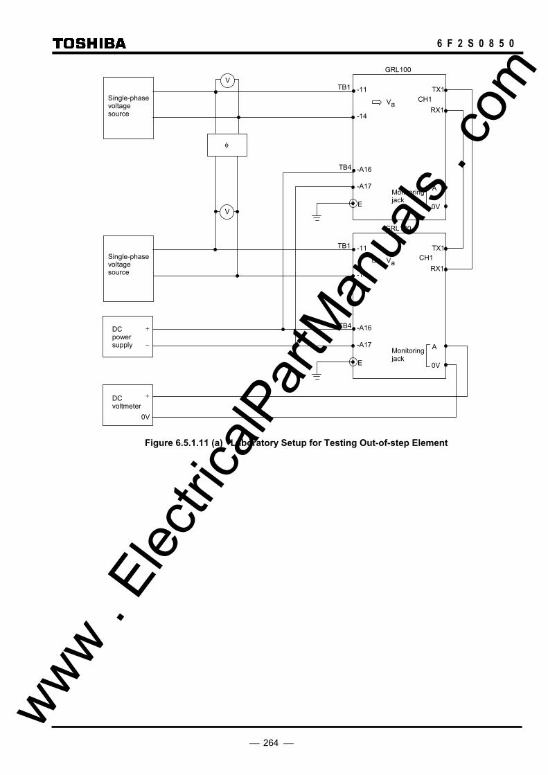
264
6 F 2 S 0 8 5 0
Single-phase voltage source
TB1
DC voltmeter
TB4
-11
-14
-A16
-A17
E
GRL100
Monitoring jack
A
0V
RX1
TX1
Va
V
Single-phase voltage source
TB1
TB4
-11
-14
-A16
-A17
E
GRL100
Monitoring jack
A
0V
0V
RX1
TX1
Va
−
+
+
V
DC power supply
φ
CH1
CH1
Figure 6.5.1.11 (a) Laboratory Setup for Testing Out-of-step Element
www . El
ectric
alPar
tMan
uals
. com
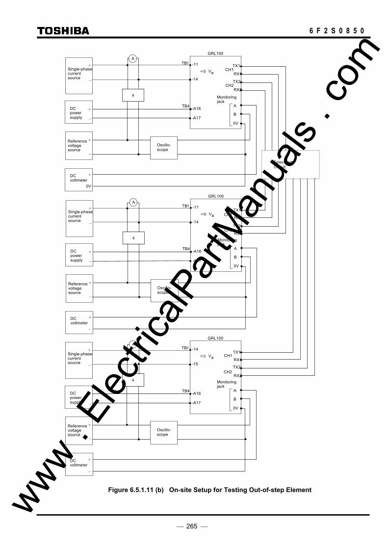
265
6 F 2 S 0 8 5 0
Single-phase current source
TB1
DC voltmeter
TB4
-11
-14
-A16
-A17
GRL100
Monitoringjack
φ
A
0V
Va
+
−
TX1
RX1
A
Reference voltage source
0V
+
+
−
DC power supply
B+
−
Oscillo- scope
Telecomm. Circuit
TX2
RX2
Single-phase current source
TB1
DC voltmeter
TB4
-11
-14
-A16
-A17
GRL100
Monitoringjack
φ
A
0V
Va
+
−
A
Reference voltage source
−
+
+
−
DC power supply
B+
−
Oscillo- scope
TX1
RX1
TX2
RX2
Single-phase current source
TB1
DC voltmeter
TB4
-14
-15
-A16
-A17
GRL100
Monitoringjack
φ
A
0V
Va
+
−
A
Reference voltage source
−
+
+
−
DC power supply
B+
−
Oscillo- scope
TX1
RX1
TX2
RX2
CH1
CH2
CH1
CH2
CH1
CH2
Figure 6.5.1.11 (b) On-site Setup for Testing Out-of-step Element www . El
ectric
alPar
tMan
uals
. com
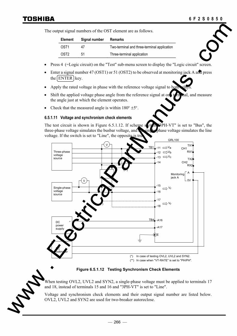
266
6 F 2 S 0 8 5 0
The output signal numbers of the OST element are as follows.
Element Signal number Remarks
OST1 47 Two-terminal and three-terminal application
OST2 51 Three-terminal application
• Press 4 (=Logic circuit) on the "Test" sub-menu screen to display the "Logic circuit" screen.
• Enter a signal number 47 (OST1) or 51 (OST2) to be observed at monitoring jack A and press the ENTER key.
• Apply the rated voltage in phase with the reference voltage signal to both relays.
• Shift the applied voltage phase angle from the reference signal at one terminal, and measure the angle just at which the element operates.
• Check that the measured angle is within 180° ±5°.
6.5.1.11 Voltage and synchronism check elements The test circuit is shown in Figure 6.5.1.12. If scheme switch "3PH-VT" is set to "Bus", the three-phase voltage simulates the busbar voltage, and the single-phase voltage simulates the line voltage. If the switch is set to "Line", the opposite is true.
Three-phasevoltage source
φ
V
(*)
(**)
TB1
-12-11 V a
Single-phase voltage source
DC voltmeter
-13
-14
-15
-18
-16
-17
-A16
-A17
E
TB4
V c
V b
V r
V r
GRL100
DC power supply
+
−
Monitoring jack A
A
0V V
RX1
TX1
RX2
TX2
CH1
CH2
(*) In case of testing OVL2, UVL2 and SYN2. (**) In case when "VT-RATE" is set to "PH/PH".
Figure 6.5.1.12 Testing Synchronism Check Elements
When testing OVL2, UVL2 and SYN2, a single-phase voltage must be applied to terminals 17 and 18, instead of terminals 15 and 16 and "3PH-VT" is set to "Line".
Voltage and synchronism check elements and their output signal number are listed below. OVL2, UVL2 and SYN2 are used for two-breaker autoreclose. www .
Elec
tricalP
artM
anua
ls . c
om

267
6 F 2 S 0 8 5 0
Element Signal number
OVB 57
UVB 58
OVL1 60
UVL1 61
OVL2 62
UVL2 63
SYN1 59
SYN2 64
OVL1(3PH) 78
Connect the phase angle meter to the three-phase voltages taking the scheme switch "VT-RATE" and VTPH-SEL settings into consideration. The phase angle meter connection shown in Figure 6.5.1.12 is the case for the default settings, ie., "VT-RATE" and "VTPH-SEL" are set to PH/G and A, respectively.
VT-RATE setting VTPH-SEL setting Meter connection phase
PH/G A A-N
B B-N
C C-N
PH/PH A A-B
B B-C
C C-A
Voltage check element OVB, UVB, OVL1, UVL1, OVL2, and UVL2 • Press 4 (=Logic circuit) on the "Test" screen to display the "Logic circuit" screen.
• Enter a signal number for the TermA line to be observed at monitoring jack A and press the ENTER key.
• Apply a three-phase rated voltage and a single-phase rated voltage as shown in Figure 6.5.1.12.
OVB and UVB:
• Change the magnitude of the three-phase voltage if the scheme switch "3PH-VT" is set to "Bus" or change the magnitude of the single-phase voltage if it is set to "Line". Measure the value at which the element operates and check that it is within ± 5% of the setting.
OVL1 and UVL1:
• Change the magnitude of the single-phase voltage if the scheme switch "3PH-VT" is set to "Bus" or change the magnitude of the three-phase voltage if it is set to "Line". Measure the value at which the element operates and check that it is within ± 5% of the setting.
OVL2 and UVL2:
• Change the magnitude of the single-phase voltage applied to terminal 17 and 18 and measure the value at which the element operates. Check that the measured value is within ± 5% of the setting. www .
Elec
tricalP
artM
anua
ls . c
om
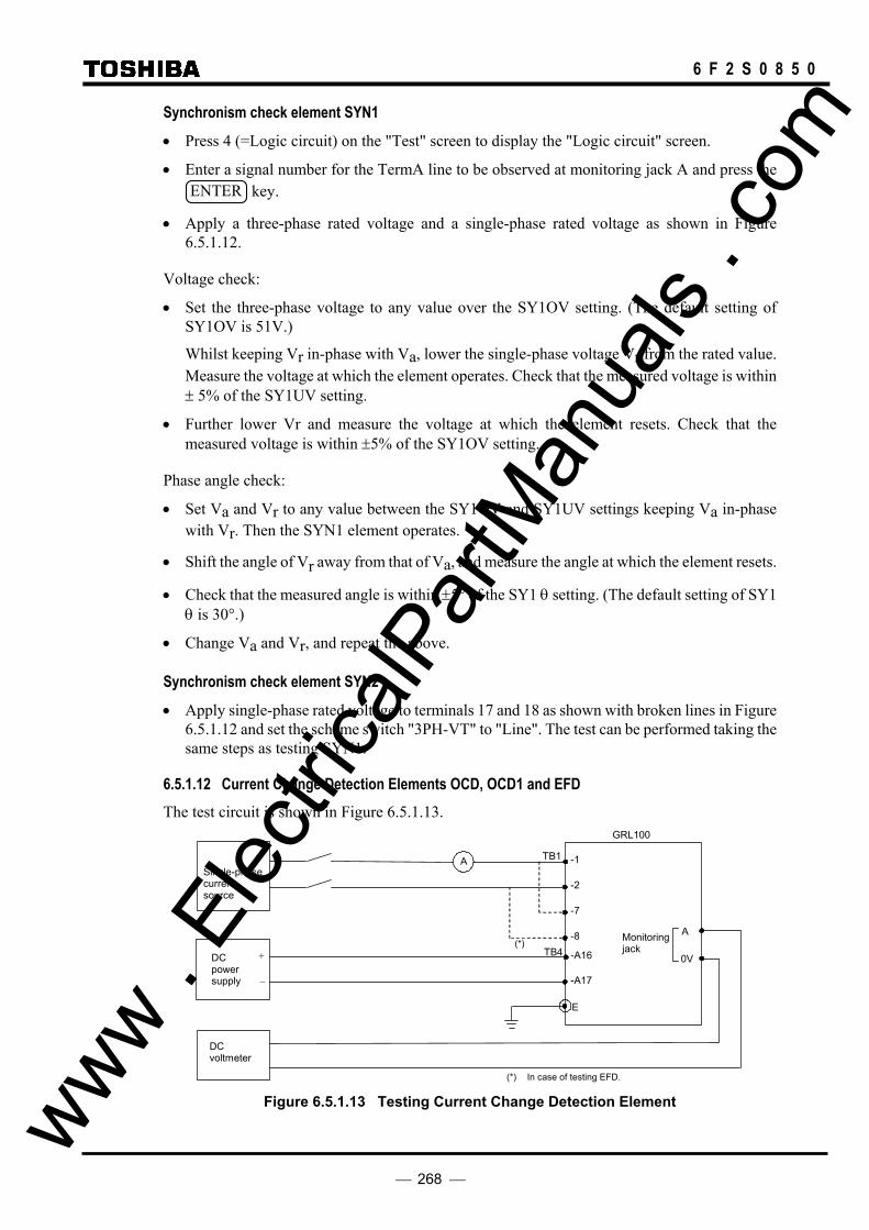
268
6 F 2 S 0 8 5 0
Synchronism check element SYN1 • Press 4 (=Logic circuit) on the "Test" screen to display the "Logic circuit" screen.
• Enter a signal number for the TermA line to be observed at monitoring jack A and press the ENTER key.
• Apply a three-phase rated voltage and a single-phase rated voltage as shown in Figure 6.5.1.12.
Voltage check:
• Set the three-phase voltage to any value over the SY1OV setting. (The default setting of SY1OV is 51V.)
Whilst keeping Vr in-phase with Va, lower the single-phase voltage Vr from the rated value. Measure the voltage at which the element operates. Check that the measured voltage is within ± 5% of the SY1UV setting.
• Further lower Vr and measure the voltage at which the element resets. Check that the measured voltage is within ±5% of the SY1OV setting.
Phase angle check:
• Set Va and Vr to any value between the SY1OV and SY1UV settings keeping Va in-phase with Vr. Then the SYN1 element operates.
• Shift the angle of Vr away from that of Va, and measure the angle at which the element resets.
• Check that the measured angle is within ±5° of the SY1 θ setting. (The default setting of SY1 θ is 30°.)
• Change Va and Vr, and repeat the above.
Synchronism check element SYN2 • Apply single-phase rated voltage to terminals 17 and 18 as shown with broken lines in Figure
6.5.1.12 and set the scheme switch "3PH-VT" to "Line". The test can be performed taking the same steps as testing SYN1.
6.5.1.12 Current Change Detection Elements OCD, OCD1 and EFD The test circuit is shown in Figure 6.5.1.13.
Single-phase current source
A TB1
DC voltmeter
TB4 -A16
-A17
E
GRL100
DC power supply
+
−
Monitoring jack
A
0V
-1
-2
-7
-8 (*)
(*) In case of testing EFD. Figure 6.5.1.13 Testing Current Change Detection Element www . El
ectric
alPar
tMan
uals
. com
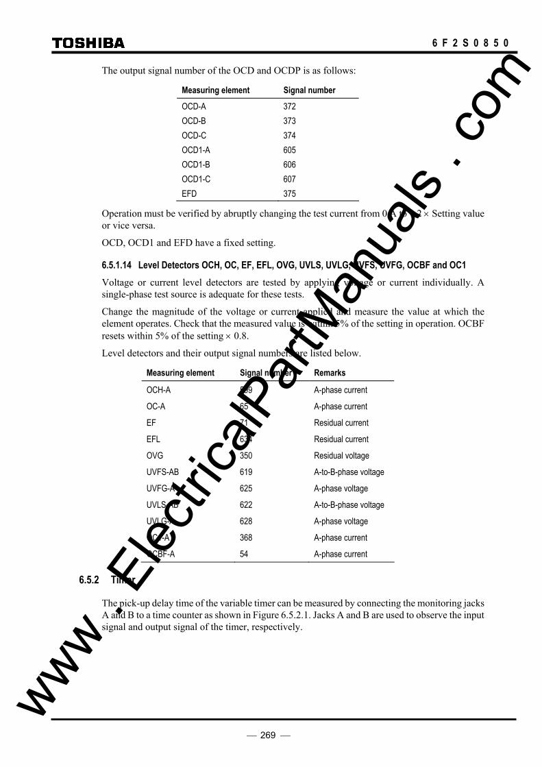
269
6 F 2 S 0 8 5 0
The output signal number of the OCD and OCDP is as follows:
Measuring element Signal number
OCD-A 372 OCD-B 373 OCD-C 374 OCD1-A 605 OCD1-B 606 OCD1-C 607 EFD 375
Operation must be verified by abruptly changing the test current from 0 A to 1.2 × Setting value or vice versa.
OCD, OCD1 and EFD have a fixed setting.
6.5.1.14 Level Detectors OCH, OC, EF, EFL, OVG, UVLS, UVLG, UVFS, UVFG, OCBF and OC1 Voltage or current level detectors are tested by applying voltage or current individually. A single-phase test source is adequate for these tests.
Change the magnitude of the voltage or current applied and measure the value at which the element operates. Check that the measured value is within 5% of the setting in operation. OCBF resets within 5% of the setting × 0.8.
Level detectors and their output signal numbers are listed below.
Measuring element Signal number Remarks
OCH-A 599 A-phase current
OC-A 65 A-phase current
EF 71 Residual current
EFL 634 Residual current
OVG 350 Residual voltage
UVFS-AB 619 A-to-B-phase voltage
UVFG-A 625 A-phase voltage
UVLS-AB 622 A-to-B-phase voltage
UVLG-A 628 A-phase voltage
OC1-A 368 A-phase current
OCBF-A 54 A-phase current
6.5.2 Timer
The pick-up delay time of the variable timer can be measured by connecting the monitoring jacks A and B to a time counter as shown in Figure 6.5.2.1. Jacks A and B are used to observe the input signal and output signal of the timer, respectively.
www . El
ectric
alPar
tMan
uals
. com

270
6 F 2 S 0 8 5 0
Time counter
TB4 -A16
-A17
E
GRL100
DC power supply
+
−
Monitoring jack
A
0V
Start
Stop
0V
B
TX1 RX1 TX2 RX2
CH1
CH2
Figure 6.5.2.1 Testing Variable Timer
• Press 3 (=Timer) on the "Test" screen to display the "Timer" screen.
• Enter the number corresponding to the timer to be observed. The timers and assigned numbers are listed in Appendix C.
• Press the END key to display the following screen.
/ 2
P r e s s E N T E R t o o p e r a t e .
C A N C E t o c a n c e l .LP r e s s
T i m e r
• Press the ENTER key to operate the timer. The "TESTING" LED turns on, and the timer is initiated and the following display appears. The input and output signals of the timer can be observed at monitoring jacks A and B respectively. The LEDs above monitoring jacks A or B are also lit if the input or output signal exists.
Check that the measured time is within 10 ms of the setting time.
/ 2
P r e s s E N D t o r e s e t .
C A N C E t o c a n c e l .LP r e s s
T i m e r
O p e r a t i n g . . . . . .
• Press the END key to reset the input signal to the timer. The "TESTING" LED turns off.
Press CANCEL key to test other timers. Repeat the above testing.
To measure the drop-off delay time, press the END key after the LED above jack B lights. The off-delay time is the time from a signal at the monitoring jack A resets till a signal at the monitoring jack B resets.
www . El
ectric
alPar
tMan
uals
. com
271
6 F 2 S 0 8 5 0
6.5.3 Protection Scheme
Protection schemes implemented in GRL100 are basically for unit protection. It is recommended that the protection schemes are tested under end-to-end mode. The setup of the end-to-end synchronized test is described in Section 6.5.1.
In the protection scheme tests, a dynamic test set with the three-phase voltage source and current source is required to simulate power system pre-fault, fault and post-fault conditions.
The "Sim.fault" on the LCD "Test" menu is available to test local and remote terminals synchronously. For use, see Section 4.2.7.5
The autoreclose function can be tested together with these tests. A permanent fault should be applied to test a reclose-onto-fault.
Tripping is observed with the tripping command output relays TP-A1 to -C1 and TP-A2 to -C2.
Reclosing is observed with the user configurable reclosing command output relays assigned to signals ARC1 and ARC2. For the default setting, see Appendix D.
Differential tripping When a phase current is applied, instantaneous per phase based tripping or three-phase tripping is performed depending on the fault types, setting of the scheme switches [ARC-M], and [STUB].
The tripping should be checked for the current which is two times or larger than the minimum operating current DIFI1 or DIFGI. Operating time is measured by the operating time of the tripping command output relay. It will typically be 1 cycle.
Check that the indications and recordings are correct.
When a residual current is applied, time-delayed three-phase tripping is performed. Operating time will be 1 cycle plus setting of timer TDIFG. The tripping or reclosing is blocked when the scheme switch [DIFG] or [ARC-DIFG] is set to "OFF".
Check that the indications and recordings are correct.
Zone 1 tripping This performs instantaneous or time-delayed, and single-phase or three-phase tripping depending on the fault types, setting of trip mode control switch [Z1CNT] and autoreclose mode switch [ARC-M].
Zone 1 tripping should be checked for the fault at 50% of the zone 1 reach setting. Operating time is measured on operation of the trip output relay. It will typically be 1 cycle in case of instantaneous tripping.
Check that the indications and recordings are correct.
Zone 2 tripping Check that three-phase time-delayed final tripping is performed for all kinds of faults. Faults should be set midway between zone 1 and zone 2.
Check that the operating time is 1-1.5 cycle plus zone 2 timer setting.
Check that the indications and recordings are correct.
Zone 3 tripping Check that three-phase time-delayed final tripping is performed for all kinds of faults. Faults should be set midway between zone 2 and zone 3. www .
Elec
tricalP
artM
anua
ls . c
om

272
6 F 2 S 0 8 5 0
Check that the operating time is 1-1.5 cycle plus zone 3 timer setting.
Check that the indications and recordings are correct.
Zone R tripping Set the scheme switches [ZRTP] to "On". (The [ZRTP] default setting is "Off".)
Check that three-phase time-delayed final tripping is performed for all kinds of faults. Faults should be set in the center of zone R.
Check that the operating time is 1-1.5 cycle plus zone R timer setting.
Check that the indications and recordings are correct.
Command Protection The scheme switch [DISCR] is set "On". The carrier send and receive signals are assigned to the binary output and input by PLC function.
PUP tripping Set the scheme switch [CRSCM] to "PUP".
Energize the binary input BIn (assigned to the receive Signal No. 1856 CAR.R1-1) to simulate a trip permission signal reception and apply a zone 2 fault.
Check that instantaneous single-phase or three-phase tripping is performed depending on the fault types and setting of autoreclose mode selection switch [ARC-M].
De-energize the binary input BIn and apply a zone 2 fault. Check that PUP tripping does not occur.
Apply a zone 1 fault, and check that binary output relay BO13 (assigned to the send signal No. 886 CAR-S as default) operates.
Check that the indications and recordings are correct.
POP tripping Set the scheme switch [CRSCM] to "POP", [WKIT] and [ECHO] to "off".
Energize the binary input BIn to simulate a trip permission signal reception and apply a zone 2 fault.
Check that instantaneous single-phase or three-phase tripping is performed depending on the fault types and setting of autoreclose mode selection switch [ARC-M].
Set [WKIT] and [ECHO] to "On" and apply a weak-infeed fault. Check that instantaneous tripping is performed.
De-energize the binary input BIn and apply a zone 2 fault. Check that POP tripping does not occur.
Apply a zone 2 fault, and check that binary output relay BO13 operates.
Set the scheme switch [ECHO] to "On". De-energize the binary inputs BI1, BI2 and BI3 to simulate the breaker being open. Check that binary output relay BO13 operates when the binary input BIn is energized.
Apply a zone 4 fault (reverse fault) while the binary inputs BI1, BI2 and BI3 are energized, and check that the binary output relay BO13 does not operate when the binary input BIn is energized.
Check that the indications and recordings are correct.
www . El
ectric
alPar
tMan
uals
. com
273
6 F 2 S 0 8 5 0
UOP tripping Set the scheme switch [CRSCM] to "UOP", [WKIT] and [ECHO] to "Off".
De-energize the binary input BIn to simulate interruption of a trip block signal reception and apply a zone 2 fault.
Check that instantaneous single-phase or three-phase tripping is performed depending on the fault types and setting of autoreclose mode selection switch [ARC-M].
Set [WKIT] and [ECHO] to "On" and apply a weak-infeed fault. Check that instantaneous tripping is performed.
Energize the binary input BIn to simulate trip block signal reception and apply a zone 2 fault. Check that UOP tripping does not occur.
Check that binary output relay BO13 operates in the normal condition. Apply a zone 2 fault, and check that the BO13 resets.
Set the scheme switch [ECHO] to "On". De-energize the binary inputs BI1, BI2 and BI3 to simulate the breaker being open. Check that binary output relay BO13 resets when the binary input BIn is de-energized.
Apply a zone 4 fault (reverse fault) while the binary inputs BI1, BI2 and BI3 are energized, and check that the binary output relay BO13 remains operated when the binary input BIn is de-energized.
Check that the indications and recordings are correct.
BOP tripping Set the scheme switch [CRSCM] to "BOP".
Check that the binary input BIn is de-energized and apply a zone 2 fault.
Check that instantaneous single-phase or three-phase tripping is performed depending on the fault types and setting of autoreclose mode selection switch [ARC-M].
Energize the binary input BIn to simulate trip block signal reception and apply a zone 2 fault. Check that BOP tripping does not occur.
Apply a zone 2 fault, and check that binary output relay BO13 does not operate. Apply a zone 4 fault (reverse fault), and check that BO13 operates.
Check that the indications and recordings are correct.
SOTF-OC and SOTF-Z tripping SOTF tripping is carried out by distance measuring element Z1 to ZR operation or overcurrent element OCH operation. Z1 to ZR can perform the SOTF tripping by setting.
The SOTF function is activated when the breaker has been open for timer TSOTF (0 – 300s) setting and active for an additional 500ms after the breaker is closed.
The SOTF function is checked as follows:
• Set the scheme switch [SOTF-OC] to "On" and [SOTF-Z∗] to "Off".
De-energize the binary input signals BI1 to BI3 (terminal number A4, B4 and A5 of terminal block TB4) for more than TSOTF (0 – 300s) setting.
• Energize the binary input signals and apply a zone 1 fault at the same time.
Check that the operating time is within 1-1.5 cycle.
• Set the scheme switch [SOTF-OC] to "Off" and [SOTF-Z∗] to "On" and repeat the above. www . El
ectric
alPar
tMan
uals
. com

274
6 F 2 S 0 8 5 0
Voltage transformer failure supervision A voltage transformer (VT) failure is detected when an undervoltage element or residual overvoltage element operates but a current change detection element or residual overcurrent element does not operate accordingly.
VT failure detection is checked as follows:
• Set the circuit breaker closed condition by applying a "1" signal to binary inputs BI1, BI2 and BI3.
• Press 5 (=Logic circuit) on the "Test" screen to display the "Logic circuit" screen.
• Enter signal number 891 for the TermA line to observe the VT failure alarm signal, and 888 for the TermB line to observe the VT failure detection signal at monitoring jack A and B. Press the ENTER key.
• Apply a three-phase rated voltage. Then, remove single-, two- or three-phase voltage. Check that the signals are instantly observed at jack B and observed at jack A after a 10s delay.
Blocking of the voltage-dependent protection is checked as follows:
• Apply a three-phase rated voltage. Then, remove single-, two- or three-phase voltage and at the same time apply a zone 1 fault. During this process, do not change the current.
Check that neither zone 1 tripping nor command tripping takes place.
• In the similar manner, apply a zone 1 extension, zone 2 or zone 3 fault and check that tripping does not take place.
Check that VT failure is recorded on the event record.
Power swing blocking A power swing is detected when the condition that the PSBSOUT element operates and PSBSIN element and residual overcurrent element EFL do not operate, for a period of TPSB setting or more.
Power swing detection is checked as follows:
• Press 5 (=Logic circuit) on the "Test" screen to display the "Logic circuit" screen.
• Enter signal number 765 for the TermA line to observe the power swing blocking signal at monitoring jack A and press the ENTER key.
• Apply a phase fault which is set to midway between PSBSIN and PSBSOUT. Check that the signal is generated with a delay of TPSB setting after the PSBSOUT operates. The PSBSOUT operating time will be 1-2 cycles.
• Reset the fault and check that the monitoring signal resets with a 500ms delay after PSBSOUT resets.
• Apply an earth fault which is set to midway between PSBSIN and PSBSOUT. Check that the signal is not generated.
Power swing blocking is checked as follows:
• Apply a zone 1 phase fault after generating the power swing blocking signal. The blocking signal is generated in the way as mentioned above. Check that zone 1 tripping takes place if scheme switch [PSB-Z1] is set to "Off" and does not take place if set to "On".
• In the similar manner, apply zone 2, zone 3 and zone R faults, and check that tripping takes place or does not take place depending on the "On" or "Off" setting of scheme switch www .
Elec
tricalP
artM
anua
ls . c
om

275
6 F 2 S 0 8 5 0
[PSB-Z2], [-Z3] and [-ZR].
Check that power swing blocking is recorded on the event record.
Out-of-step tripping Set the scheme switch [OST] to "Trip".
Shift the phase angle from the second quadrant to the third quadrant or vice versa taking the remote terminal voltage as a reference voltage.
Check that the tripping output relay operates in all phases and autoreclose does not start.
Check that the indications and recordings are correct.
Shift the phase angle from the first quadrant to the fourth quadrant or vice versa taking the remote terminal voltage as a reference voltage.
Check that any of the tripping output relays do not operate.
Circuit breaker failure tripping Set the scheme switch [BF1] to "T" or "TOC" and [BF2] to "ON".
Apply a fault and retain it. Check that the adjacent breaker tripping output relay operates after the time setting of the TBF2.
The adjacent breaker tripping output relay is user configurable and assigned to signal CBF-TRIP. For the setting, see Sections 4.2.6.9 and 4.2.7.2.
6.5.4 Metering and Recording
The metering function can be checked whilst testing the AC input circuit. See Section 6.4.4.
Fault recording can be checked whilst testing the protection schemes. Open the "Fault records" screen and check that the descriptions are correct for the applied fault.
The default setting of events is shown in Appendix H. Event recording on the external events such as CB1 ready, Ind.reset, etc., can be checked by changing the status of binary input signals. Change the status in the same way as the binary input circuit test (see Section 6.4.2) and check that the description displayed on the "Event Records" screen is correct.
Note: The choice of whether to record or not can be set for each event. Change the status of the binary input signal after confirming that the related event is set to record. (The default setting enables all the events to be recorded.)
Some of the internal events such as Trip, Com1.fail, etc., can be checked in the protection scheme tests.
Disturbance recording can be checked while testing the protection schemes. The LCD display only shows the date and time when a disturbance is recorded. Open the "Disturbance records" screen and check that the descriptions are correct.
Details can be displayed on the PC. Check that the descriptions on the PC are correct. For details on how to obtain disturbance records on the PC, see the RSM100 Manual.
6.5.5 Fault Locator
As the fault locator requires local and remote terminal currents, the fault locator can be tested under the end-to-end synchronized test setup.
In the tests, a dynamic test set with the three-phase voltage and current source is required for each terminal to simulate power system pre-fault, fault and post-fault conditions. www .
Elec
tricalP
artM
anua
ls . c
om

276
6 F 2 S 0 8 5 0
The fault locator starts measurement when the current differential protection operates. Therefore, it is preferable to test it whilst testing the protection schemes by applying a fault.
The line parameter settings must be changed to meet those of the test set.
The measurement result is expressed as a percentage of the line length and the distance, and is displayed on the "Fault Record" screen of the LCD.
www . El
ectric
alPar
tMan
uals
. com

277
6 F 2 S 0 8 5 0
6.6 Conjunctive Tests
6.6.1 On Load Test
With the relay connected to the line which is carrying load current, it is possible to check the polarity of the voltage and current transformers and the phase rotation with the metering displays on the LCD screen.
• Open the following "Metering" screen from the "Status" sub-menu. / 2 M e t e r i n g
V a 6 3 . 5 V 0
V b 6 3 . 4 V - 1 2 0 A
V c 6 3 . 5 V 1 2 0
2 . 1 0l
. 0 °
- 1 1 5 . 0 ° . 0 °
. 1 ° b
l a
l c
A2 . 1 0
A2 . 1 5
4 . 9 °
1 2 5 . 1 °
. . .
A c t i v e p o w e r + 4 0 0 . 1 1 M
R e a c t i e 2 5 . 5 1 M
. . .
W
v p o w e r - rav
F r e q u e c n y 6 0 . 1 H z
3 / 1 3 1 2 / F e b / 1 9 9 8 2 2 : 5 6
Note: The magnitude of voltage, current and power can be set in values on the primary side or on
the secondary side by the setting. (The default setting is the primary side.) Phase angles are expressed taking that of the positive sequence voltage as the reference angle. The sign of the phase angle can be set positive for either lagging phase or leading phase. (In the default setting, it is set positive when the phase is leading to the reference angle.) The sign of the power flow direction can be set positive for either power sending or power receiving. (The default setting is power sending.)
• Check that the phase rotation is correct.
• Verify the phase relationship between the voltage and current with a known load current direction.
6.6.2 Signaling Circuit Test
This test is performed when a command protection using a signaling channel is applied.
The test is to check whether the communication circuit is correctly connected between a
and a remote terminal.
Signal channel for current differential protection:
Input the voltage or current at a remote terminal relay. Check the voltage and current by the "Metering" screen from the "Status" sub-menu at a local relay.
Signal channel for command protection:
This test is performed when a command protection using a signaling channel is applied. The test is carried out after the signal receive and send contacts are connected to the telecommunication circuit.
The signal send circuit from the relay to the telecommunication equipment is checked by forcibly operating the signal send relay and monitoring the signal at the telecommunication equipment.
Signal sending is performed on the LCD using the "Test" sub-menu as follows. www . El
ectric
alPar
tMan
uals
. com
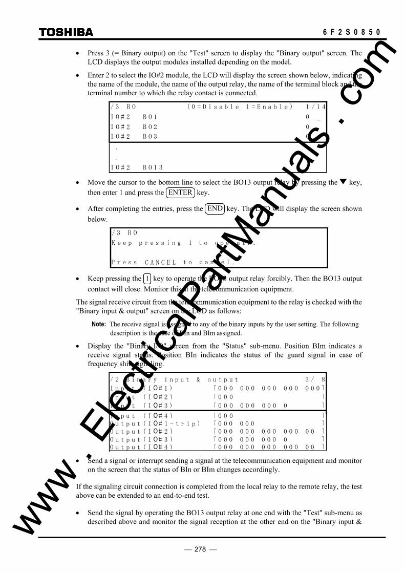
278
6 F 2 S 0 8 5 0
• Press 3 (= Binary output) on the "Test" screen to display the "Binary output" screen. The LCD displays the output modules installed depending on the model.
• Enter 2 to select the IO#2 module, the LCD will display the screen shown below, indicating the name of the module, the name of the output relay, the name of the terminal block and the terminal number to which the relay contact is connected.
/ 3 B O ( 0 = D i s a b l e 1 = E n a b l e ) 1 / 1 4
I O # B O 1 0
I O # B O 2 0
I O # B O 3 0
.
.
O B O 1 I # 1
2
2
2
2
3 • Move the cursor to the bottom line to select the BO13 output relay by pressing the key,
then enter 1 and press the ENTER key.
• After completing the entries, press the END key. The LCD will display the screen shown below.
/ 3 B O
K e e p i n g 1 t o o p e r a t e .
C A N C E t o c a n c e l .LP r e s s
p r e s s
• Keep pressing the 1 key to operate the BO13 output relay forcibly. Then the BO13 output contact will close. Monitor this at the telecommunication equipment.
The signal receive circuit from the telecommunication equipment to the relay is checked with the "Binary input & output" screen on the LCD as follows:
Note: The receive signal is assigned to any of the binary inputs by the user setting. The following description is the case of BIn and BIm assigned.
• Display the "Binary I/O" screen from the "Status" sub-menu. Position BIm indicates a receive signal status. Position BIn indicates the status of the guard signal in case of frequency shift signaling.
/ 2 B i n a r y i n p u t & o u t p u t 3 / 8
I n p u t ( I O # 1 [ 0 0 0 0 0 0 0 0 0 0 0 0 0 0 0 ]
I n p u t ( I O # 2 [ 0 0 0 ]
O u t p u t ( I O 1 - t r i p ) [ 0 0 0 0 0 0 ]
O u t p u t ( I O# 3 [ 0 0 0 0 0 0 0 0 0 0 ]O u t p u t ( I O# 4 [ 0 0 0 0 0 0 0 0 0 0 0 0 0 0 ]
)
)
O u t p u t ( I O# 2 [ 0 0 0 0 0 0 0 0 0 0 0 0 0 0 ]
I n p u t ( I O # 3 [ 0 0 0 0 0 0 0 0 0 0 ])
)))
#I n p u t ( I O # 4 [ 0 0 0 ])
• Send a signal or interrupt sending a signal at the telecommunication equipment and monitor
on the screen that the status of BIn or BIm changes accordingly.
If the signaling circuit connection is completed from the local relay to the remote relay, the test above can be extended to an end-to-end test.
• Send the signal by operating the BO13 output relay at one end with the "Test" sub-menu as described above and monitor the signal reception at the other end on the "Binary input & www .
Elec
tricalP
artM
anua
ls . c
om
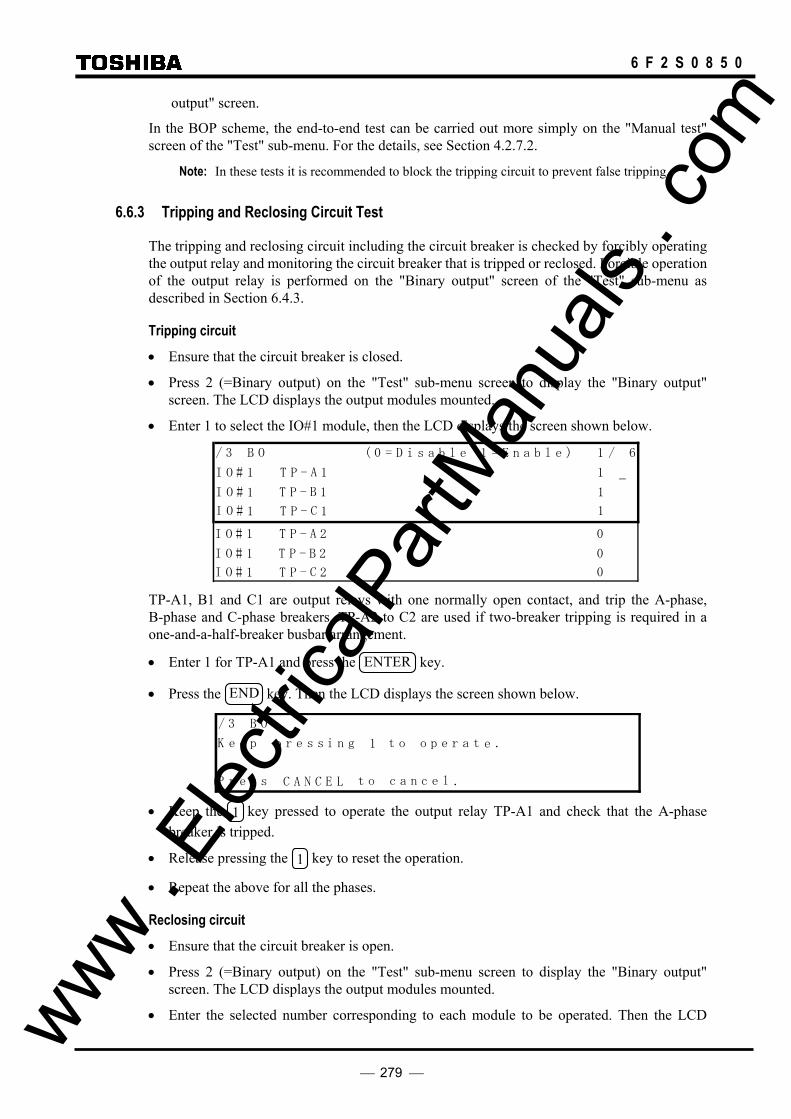
279
6 F 2 S 0 8 5 0
output" screen.
In the BOP scheme, the end-to-end test can be carried out more simply on the "Manual test" screen of the "Test" sub-menu. For the details, see Section 4.2.7.2.
Note: In these tests it is recommended to block the tripping circuit to prevent false tripping.
6.6.3 Tripping and Reclosing Circuit Test
The tripping and reclosing circuit including the circuit breaker is checked by forcibly operating the output relay and monitoring the circuit breaker that is tripped or reclosed. Forcible operation of the output relay is performed on the "Binary output" screen of the "Test" sub-menu as described in Section 6.4.3.
Tripping circuit • Ensure that the circuit breaker is closed.
• Press 2 (=Binary output) on the "Test" sub-menu screen to display the "Binary output" screen. The LCD displays the output modules mounted.
• Enter 1 to select the IO#1 module, then the LCD displays the screen shown below.
/ 3 B O ( 0 = D i s a b l e 1 = E n a b l e ) 1 / 6
I O #
T P -
1
I O # 1
I O # 1
B 1
T P - A 1
T P - C 1
I O #
T P -
0
I O # 0
I O # 0
B 2
T P - A 2
T P - C 2
1
1
1
1
1
1 TP-A1, B1 and C1 are output relays with one normally open contact, and trip the A-phase, B-phase and C-phase breakers. TP-A2 to C2 are used if two-breaker tripping is required in a one-and-a-half-breaker busbar arrangement.
• Enter 1 for TP-A1 and press the ENTER key.
• Press the END key. Then the LCD displays the screen shown below.
/ 3 B O
K e e p p r e s s t o o p e r a t e .
C A N C E t o c a n c e l .LP r e s s
i n g 1
• Keep the 1 key pressed to operate the output relay TP-A1 and check that the A-phase
breaker is tripped.
• Release pressing the 1 key to reset the operation.
• Repeat the above for all the phases.
Reclosing circuit • Ensure that the circuit breaker is open.
• Press 2 (=Binary output) on the "Test" sub-menu screen to display the "Binary output" screen. The LCD displays the output modules mounted.
• Enter the selected number corresponding to each module to be operated. Then the LCD www . El
ectric
alPar
tMan
uals
. com

280
6 F 2 S 0 8 5 0
displays the name of the module, the name of the output relay, the name of the terminal block and the terminal number to which the relay contact is connected.
Note: The autoreclose command is assigned to any of the output relays by the user setting. The following description is the case for the default setting. In the default setting, the autoreclose command is set to BO9 and BO10 of the IO2 module. (BO9 is used in the two-breaker autoreclose.)
• Enter 2 to select the IO#2 module, then the LCD displays the screen shown below.
/ 3 B O ( 0 = D i s a b l e 1 = E n a b l e ) 1 / 1 4
I O #
B O 2
0
I O # 0
I O # 0
B O 1
B O 3
B O 1 I O # 1
I O # 0
0
B O 1 1
. . .
I O # 0 B O 1 2
I O # 0 F A I L
I O # 0 B O 1 3
2
2
2
2
2
2
2
2
Move the cursor by pressing the key and select BO10. BO10 is an autoreclose command output relay with one normally open contact.
• Enter 1 and press the ENTER key.
• Press the END key. Then the LCD displays the screen shown below.
/ 3 B O
K e e p p r e s s i t o o p e r a t e .
C A N C E t o c a n c e l .LP r e s s
n g 1
• Keep pressing the 1 key to forcibly operate the output relay BO10 and check that the
breaker is closed.
• Release pressing the 1 key to reset the operation.
• In case of two-breaker autoreclose, repeat the forcible operation for BO9.
www . El
ectric
alPar
tMan
uals
. com

281
6 F 2 S 0 8 5 0
6.7 Maintenance
6.7.1 Regular Testing The relay is almost completely self-supervised. The circuits which cannot be supervised are binary input and output circuits and human interfaces.
Therefore regular testing can be minimized to checking the unsupervised circuits. The test procedures are the same as described in Sections 6.4.1, 6.4.2 and 6.4.3.
6.7.2 Failure Tracing and Repair
Failures will be detected by automatic supervision or regular testing.
When a failure is detected by supervision, a remote alarm is issued with the binary output signal of FAIL (*) and the failure is indicated on the front panel with LED indicators or LCD display. It is also recorded in the event record.
(*) Failure signals on the external circuits, namely the signaling channel and isolator circuit, can be allotted to any of the binary output relays by the user. Failure signals of the signaling channel are set to BO11 of the IO2 module as the default setting.
Failures detected by supervision are traced by checking the "Auto-supervision" screen on the LCD.
If any messages are shown on the LCD, the failed module or failed external circuits can be located by referring to Table 6.7.2.1.
This table shows the relationship between messages displayed on the LCD and estimated failure location. Locations marked with (1) have a higher probability than locations marked with (2).
As shown in the table, some of the messages cannot identify the fault location definitely but suggest plural possible failure locations. In these cases, the failure location is identified by replacing the suggested failed modules with spare modules one by one or investigating and restoring the monitored external circuits (the signaling channel and isolator circuit) until the "ALARM" LED is turned off.
The replacement or investigation should be performed first for the module or circuit with higher probability in the table.
If there is a failure and the LCD is not working such as a screen is frozen or not displayed, the failure location is either SPM or HMI module.
www . El
ectric
alPar
tMan
uals
. com

282
6 F 2 S 0 8 5 0
Table 6.7.2.1 LCD Message and Failure Location
Message Failure location
VCT SPM (GCOM)
IO1 IO2 IO3, IO5, IO6
IO4 HMI Channel Discon- nector
AC cable
Checksum err × ROM-RAM err × SRAM err × BU-RAM err × DPRAM err × EEPROM err × ROM data err × A/D err × V0 err × (2) × (1) × (2) V2 err × (2) × (1) × (2) I0 err × (2) × (1) × (2) Id err × (2) × (1) × (2) CT err × (2) × (2) × (1) Sampling err × DIO err × (2) × (1) × (1) × (1) × (1) RSM err × (2) × (1) COM_ ….err × FD: … err × (2) × (1) O/P circuit fail × (2) × (1) DS fail × (2) × (2) × (1) Com.1 fail, Com.2 fail × (2)* × (2)* × (2)* × (1)* Sync.1 fail, Sync.2 fail × (2)* × (2)* × (2)* × (1)* TX1 level err, TX2 level err
× (1)* × (2)* × (2)* × (1)*
RX1 level err, RX2 level err
× (2)* × (2)* × (2)* × (1)*
CLK 1 fail, CLK 2 fail × (2)* × (2)* × (2)* × (1)* Term1 rdy off, Term2 rdy off
× (2)* × (1)*
RYID1 err, RYID2 err × (2)* × (1)* CT fail × (2) × (2) × (1) No-working of LCD × (2) × (1)
Note: The location marked with (1) has a higher probability than the location marked with (2). The item of location marked with (*): also check the remote terminal relays and equipment.
www . El
ectric
alPar
tMan
uals
. com

283
6 F 2 S 0 8 5 0
If no message is shown on the LCD, it means that the failure location is either in the DC power supply circuit or in the microprocessors mounted on the SPM module. In this case, check the "ALARM" LED. If it is off, the failure is in the DC power supply circuit. If it is lit, open the relay front panel and check the LEDs mounted on the SPM module. If the LED is off, the failure is in the DC power supply circuit. If the LED is lit, the failure is in the microprocessors.
In the former case, check if the correct DC voltage is applied to the relay. If it is, replace the IO1 module mounting the DC/DC converter and confirm that the "ALARM" LED is turned off. In the latter case, replace the SPM module mounting the processors and confirm that the "ALARM" LED is turned off.
When a failure is detected during regular testing, it will not be difficult to identify the failed module to be replaced.
Note: When a failure or an abnormality is detected during the regular test, confirm the following first: - Test circuit connections are correct. - Modules are securely inserted in position. - Correct DC power voltage with correct polarity is applied and connected to the correct terminals. - Correct AC inputs are applied and connected to the correct terminals. - Test procedures comply with those stated in the manual.
6.7.3 Replacing Failed Modules
If the failure is identified to be in the relay module and the user has spare modules, the user can recover the protection by replacing the failed modules.
Repair at the site should be limited to module replacement. Maintenance at the component level is not recommended.
Check that the replacement module has an identical module name (VCT, SPM, IO1, IO2, etc.) and hardware type-form as the removed module. Furthermore, the SPM and FD modules should have the same software name.
The module name is indicated on the bottom front of the relay case. The hardware type-form is indicated on the module in the following format:
Module name Hardware type-form
VCT G1PC1 - ∗∗∗∗
SPM G1SP∗ - ∗∗∗∗
IO1 G1IO1 - ∗∗∗∗
IO2 G1IO2 - ∗∗∗∗
IO3 G1IO3 - ∗∗∗∗
IO4 G1IO2 - ∗∗∗∗
IO5 G1IO3 - ∗∗∗∗
IO6 G1IO3 - ∗∗∗∗
www . El
ectric
alPar
tMan
uals
. com
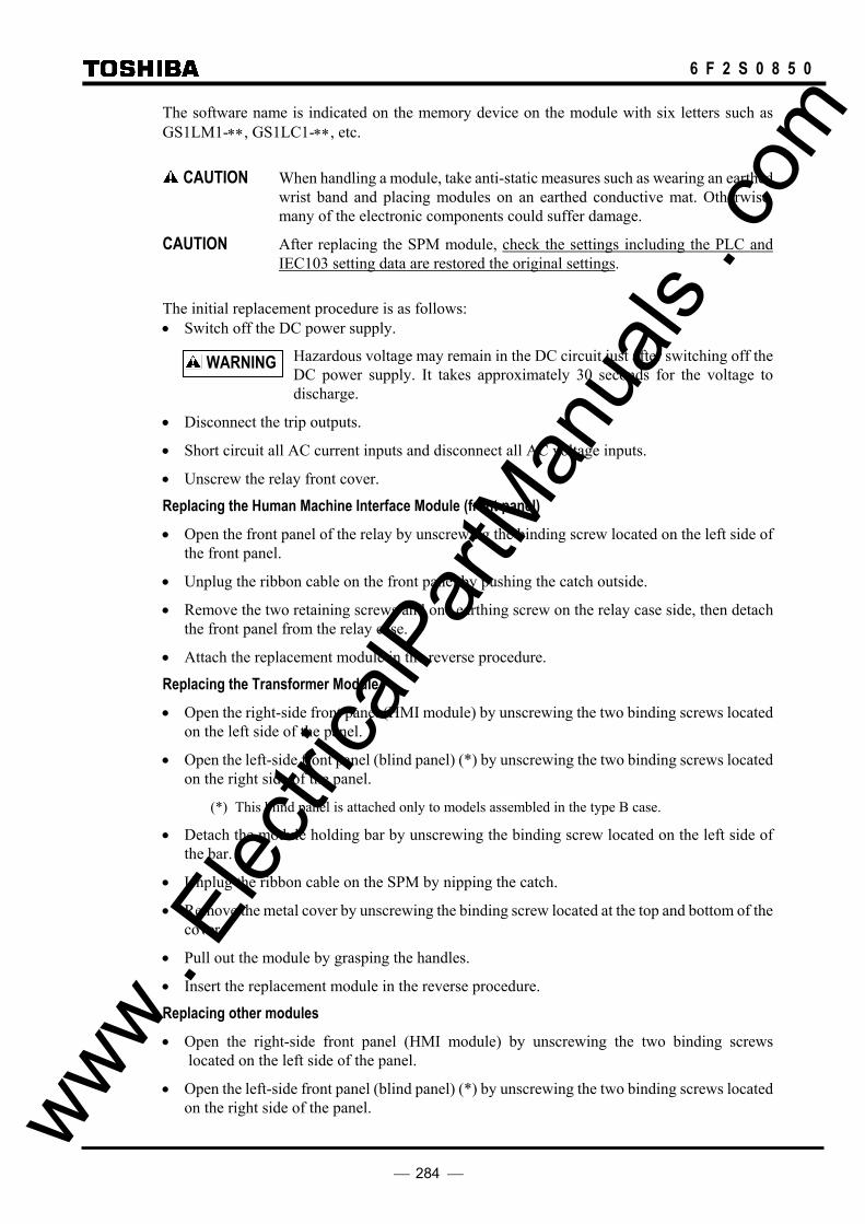
284
6 F 2 S 0 8 5 0
The software name is indicated on the memory device on the module with six letters such as GS1LM1-∗∗, GS1LC1-∗∗, etc.
CAUTION When handling a module, take anti-static measures such as wearing an earthed wrist band and placing modules on an earthed conductive mat. Otherwise, many of the electronic components could suffer damage.
CAUTION After replacing the SPM module, check the settings including the PLC and IEC103 setting data are restored the original settings.
The initial replacement procedure is as follows: • Switch off the DC power supply.
Hazardous voltage may remain in the DC circuit just after switching off the DC power supply. It takes approximately 30 seconds for the voltage to discharge.
• Disconnect the trip outputs.
• Short circuit all AC current inputs and disconnect all AC voltage inputs.
• Unscrew the relay front cover.
Replacing the Human Machine Interface Module (front panel) • Open the front panel of the relay by unscrewing the binding screw located on the left side of
the front panel.
• Unplug the ribbon cable on the front panel by pushing the catch outside.
• Remove the two retaining screws and one earthing screw on the relay case side, then detach the front panel from the relay case.
• Attach the replacement module in the reverse procedure.
Replacing the Transformer Module • Open the right-side front panel (HMI module) by unscrewing the two binding screws located
on the left side of the panel.
• Open the left-side front panel (blind panel) (*) by unscrewing the two binding screws located on the right side of the panel.
(*) This blind panel is attached only to models assembled in the type B case.
• Detach the module holding bar by unscrewing the binding screw located on the left side of the bar.
• Unplug the ribbon cable on the SPM by nipping the catch.
• Remove the metal cover by unscrewing the binding screw located at the top and bottom of the cover.
• Pull out the module by grasping the handles.
• Insert the replacement module in the reverse procedure.
Replacing other modules • Open the right-side front panel (HMI module) by unscrewing the two binding screws
located on the left side of the panel.
• Open the left-side front panel (blind panel) (*) by unscrewing the two binding screws located on the right side of the panel.
WARNING
www . El
ectric
alPar
tMan
uals
. com

285
6 F 2 S 0 8 5 0
(*) This panel is attached only to models assembled in the type B case.
• Detach the module holding bar by unscrewing the binding screw located on the left side of the bar.
• Unplug the ribbon cable running among the modules by nipping the catch (in case of black connector) and by pushing the catch outside (in case of gray connector) on the connector.
• Unplug the cable connector behind the case when replacing the SPM module.
• Pull out the module by pulling up or down on the top and bottom levers.
• Insert the replacement module in the reverse procedure.
6.7.4 Resumption of Service
After replacing the failed module or repairing failed external circuits, take the following procedures to restore the relay to service.
• Switch on the DC power supply and confirm that the "IN SERVICE" green LED is lit and the "ALARM" red LED is not lit.
Note: Supply DC power after checking that all the modules are in their original positions and the ribbon cables are plugged in.
• If the telecommunication circuit or trip circuit was repaired, check that the circuit is normal.
• Supply the AC inputs and reconnect the trip outputs.
6.7.5 Storage
The spare relay or module should be stored in a dry and clean room. Based on IEC Standard 60255-0 the storage temperature should be −25°C to +70°C, but the temperature of 0°C to +40°C is recommended for long-term storage.
www . El
ectric
alPar
tMan
uals
. com

286
6 F 2 S 0 8 5 0
7. Putting Relay into Service The following procedure must be adhered to when putting the relay into service after finishing commissioning or maintenance tests.
• Check that all external connections are correct.
• Check the settings of all measuring elements, timers, scheme switches, recordings and clock are correct.
In particular, when settings are changed temporarily for testing, be sure to restore them.
• Clear any unnecessary records on faults, events and disturbances which are recorded during the tests.
• Reset the counter figures of autoreclose, if necessary. For resetting the count, see Section 4.2.3.4.
• Press the VIEW key and check that no failure message is displayed on the "Auto-supervision" screen.
• Check that the green "IN SERVICE" LED is lit and no other LEDs are lit on the front panel.
Whilst the relay is put into service at one terminal by supplying DC power and not yet at the other terminal, a communication failure will be detected by the automatic monitoring at the in-service terminal and a red "ALARM" LED is lit. But it will be reset when the relays are put into service at all terminals.
www . El
ectric
alPar
tMan
uals
. com

287
6 F 2 S 0 8 5 0
Appendix A
Block Diagram
www . El
ectric
alPar
tMan
uals
. com

288
6 F 2 S 0 8 5 0
Block Diagram of Line Differential Relay GRL100-7∗∗
TZ1G
TZ2G
TZRG
TZ3G
OVS2
Bus CB Trip Command
Zone 1 Trip
Center CB Trip Command
Zone Back-up Trip ≧1
&
&
&
Phase
Selection
≧1
≧1 &
&
≧1
≧1
t 0t 0
t 0t 0
t 0t 0
t 0t 0 Z1G
Z2G
Z3G
ZRG
UVC
TZ1S
TZ2S
TZRS
TZ3S
Alarm
UVG2
≧1
t 0t 0
t 0t 0
t 0t 0
t 0t 0
Z1S
Z2S
Z3S
ZRS
Command protection scheme logic
- PUP
- POP
- UOP
- BOP
Command protection
Trip
SOTF Trip
Stub Trip
CBF Re-trip
CBF Related CB trip
Out of step trip
: Measuring element
: Binary input/output
TBF1
TBF2
CB Z1,Z2,Z3 or ZR
CB STUB-OC scheme
logic
Isolator
Trip
MCB trip
of VT
Phase
Selection
SOTF-OC & SOTF-Z
scheme logic
&
PSB scheme
logic
VTF scheme
logic
&
Signal Send
t 0t 0
t 0t 0
OVG1
≧1 ≧1
OST scheme
logic
OCH
OCBF
OVGF
UVF
OCD1
PSB
OST
UVL
DEF & EF
Back-up Trip
TEF 0
≧1
Signal receive
≧1
t 0t 0
DEFF
DEFR
EF
OCI
EFI
TOC t 0t 0 OC
≧1
&
Z3S
Z4S
THR THR Trip
Center CB Reclose Command
Autoreclose scheme logic
- SPAR
- TPAR
(with synchronism check)
- SPAR+TPAR
- Multi-pole ARC (BUS CB only)
- Multi-shot Autoreclose (4shots)
- 1.5CB busbar application
SYN
UV
OV
Bus CB Reclose Command
EFL
UVPWI
&
1
DIFG
DIF
TDIFG
t 0t 0
TBCD
TOG1
TOS1
t 0t 0
t 0t 0
t 0t 0
BCD
OVS1
TUS1
TOS2
TUG1
t 0t 0
t 0t 0
t 0t 0
OC Back-up
Trip
UVG1
TOG2
TUG2
TUS2
t 0t 0
t 0t 0
t 0t 0
OVG2
UVS2
Parallel line link condition C (Term.1)
Parallel line link condition A (Term.1) Parallel line link condition B (Term.1)
Parallel line link condition C (Term.2) Parallel line link condition B (Term.2) Parallel line link condition A (Term.2)
Backup protection block (43CH)
Transfer trip command2 (85S2) Transfer trip command1 (85S1)
Interlink
Condition
Circuit
between
Local and
Remote
terminal
Comm.
Channel
(for DIF)
(Sending)
External trip A External trip B External trip C
ARC block CB2 ARC ready CB1 ARC ready
CB1 contact A CB1 contact B CB1 contact C CB2 contact A CB2 contact B CB2 contact C
Disconnector N/O contact Disconnector N/C contact
CBF Related CB trip
TDEF t 0t 0t 0
TDER t 0t 0t
Related CB trip Command
UVS1
≧1
≧1
External CB close signal
Directional
control
0
www . El
ectric
alPar
tMan
uals
. com

289
6 F 2 S 0 8 5 0
Appendix B
Signal List
www . El
ectric
alPar
tMan
uals
. com

290
6 F 2 S 0 8 5 0
Signal list
Protection 0 CONSTANT 0 constant 0relay 1 CONSTANT 1 constant 1
output 23456789 43CX Diff.protection enable condition101112131415 43BUX Backup protection enable condition1617181920212223242526272829303132333435363738 ARC_COM.ON Autorecloser active (for IEC103)39 TELE.COM.ON Teleprotection active (for IEC103)40 PROT.COM.ON Protection active (for IEC103)41 DIF-A DIF-A element output42 DIF-B DIF-B element output43 DIF-C DIF-C element output44 DIFG DIFG element output45 OST1A OST1 A zone46 OST1B OST1 B zone47 OST1AB OST1 A+B zone48 OST1 OST1 element output (OST with terminal 1)49 OST2A OST2 A zone50 OST2B OST2 B zone51 OST2AB OST2 A+B zone52 OST2 OST2 element output (OST with terminal 2)53 RELAY_BLOCK DIF element block signal54 OCBF-A OCBF-A element output55 OCBF-B OCBF-B element output56 OCBF-C OCBF-C element output57 OVB OVB element output58 UVB UVB element output59 SYN1 SYN1 element output60 OVL1 OVL1 element output61 UVL1 UVL1 element output62 OVL2 OVL2 element output63 UVL2 UVL2 element output64 SYN2 SYN2 element output65 OC-A OC-A element output66 OC-B OC-B element output67 OC-C OC-C element output68 OCI-A OCI-A element output69 OCI-B OCI-B element output70 OCI-C OCI-C element output71 EF EF element output72 EFI EFI element output737475767778 OVL-ABC OVL element output (for 3phase line voltage)7980 52AND2 CB2 contact AND logic
No. Signal Name Contents
www . El
ectric
alPar
tMan
uals
. com

291
6 F 2 S 0 8 5 0
Signal list
81 52AND1 CB1 contact AND logic82 DIF-A TRIP DIF trip signal A83 DIF-B TRIP DIF trip signal B84 DIF-C_TRIP DIF trip signal C85 TDIFG TDIFG timer output86 DIFG TRIP DIFG trip signal87 OST_TRIP OST trip signal88 RETRIP-A BFP retrip signal A89 RETRIP-B BFP retrip signal B90 RETRIP-C BFP retrip signal C91 CBFDET BFP operation (88+89+90+92)92 CBF TRIP BFP adjacent breaker trip command93 TRIP-A Trip signal A94 TRIP-B Trip signal B95 TRIP-C Trip signal C96 TRIP-DETOR Trip signal (93+94+95)97 TRIP Trip signal single shot98 STUB Stub trip signal99 TRIP-A1 CB1 trip command A
100 TRIP-B1 CB1 trip command B101 TRIP-C1 CB1 trip command C102 TRIP-A2 CB2 trip command A103 TRIP-B2 CB2 trip command B104 TRIP-C2 CB2 trip command C105 FDX1 Fault detector output relay 1 driving signal106 FDX2 Fault detector output relay 2 driving signal107 M-OR Main trip OR logic108 M-AND Main trip AND logic109 FD Fault detector output OR logic110 FD-AND Fault detector output AND logic111 TOC TOC timer output112 TEF TEF timer output113 OC_TRIP OC trip signal114 OCI TRIP OCI trip signal115 EF_TRIP EF trip signal116 EFBT EF alarm signal117 EFI TRIP EFI trip signal118 BU_TRIP Backup trip signal119 OST-BO OST trip signal for BO output120121 REC_BLK12 Autoreclose block command from remote terminal122 TRDY1 Reclaim time count up signal of leader CB123 TSPR1 Dead time count up signal in leader CB SPAR124 TTPR1 Dead time count up signal in leader CB TPAR125 ARC-L Leader CB autoreclose signal126 TPARL-SET TPAR output set signal in leader CB autoreclose127 TRR1 Leader CB autoreclose reset signal128 TRDY2 Reclaim time count up signal of follower CB129 TSPR2 Dead time count up signal in follower CB SPAR130 TTPR2 Dead time count up signal in follower CB TPAR131 ARC-F Follower CB autoreclose signal132 TPAR-F TPAR output set signal in follower CB autoreclose133 TRR2 Follower CB autoreclose reset signal134 TS2 Second shot autoreclose signal135 TS3 Third shot autoreclose signal136 TS4 Fourth shot autoreclose signal137 TS2R Second shot autoreclose reset signal138 TS3R Third shot autoreclose reset signal139 TS4R Fourth shot autoreclose reset signal140 MULTI-ARC Multi-shot autoreclose signal (134+135+136)141 MAROK0 First shot autoreclose success signal142 MAROK1 Second shot autoreclose success signal143 MAROK2 Third shot autoreclose success signal144 MAROK3 Fourth shot autoreclose success signal145 MAR-FT Multi-shot autoreclose failure signal146 89CB-1AB Interlink A with terminal 1147 89CB-2AB Interlink B with terminal 1148 89CC-3AB Interlink C with terminal 1149 89CB-1AC Interlink A with terminal 2150 89CB-2AC Interlink B with terminal 2151 89CC-3AC Interlink C with terminal 2152 LINK Interlink signal153 LB.DL-1 Live bus and dead line status on CB1154 DB.LL-1 Dead bus and live line status on CB1155 LB.LL.SYN-1 Synchronism check output for CB1156 LB.DL-2 Live bus and dead line status on CB2157 DB.LL-2 Dead bus and live line status on CB2158 LB.LL.SYN-2 Synchronism check output for CB2159 SYN-OP Voltage and synchronism check output (153 +--+ 158)160 SYN-SEL SYN element selection signal
No. Signal Name Contents
www . El
ectric
alPar
tMan
uals
. com

292
6 F 2 S 0 8 5 0
Signal list
161 TDBL1 TDBL1 timer output162 TLBD1 TLBD1 timer output163 TSYN1 TSYN1 timer output164 TDBL2 TDBL2 timer output165 TLBD2 TLBD2 timer output166 TSYN2 TSYN2 timer output167 REC-READY1 ARC ready signal in leader CB autoreclose168 REC-READY2 ARC ready signal in follower CB autoreclose169 BRIDGE1 Bridge condition in leader CB autoreclose170 BRIDGE2 Bridge condition in follower CB autoreclose171 IN-PROG1 ARC in-progress in leader CB autoreclose 172 IN-PROG2 ARC in-progress in follower CB autoreclose 173 SPAR1 Single-phase autoreclose signal for leader CB174 SPAR2 Single-phase autoreclose signal for follower CB175 TPAR1 Three-phase autoreclose signal for leader CB176 TPAR2 Three-phase autoreclose signal for follower CB177 ARC1 Autoreclose command for CB1178 ARC2 Autoreclose command for CB2179 94TT1 Discrepancy trip signal in leader CB autoreclose180 94TT2 Discrepancy trip signal in follower CB ARC181 FT1 Final trip of leader CB182 FT2 Final trip of center CB183 MPAR1 Multi-phase auoteclosing signal in leader CB ARC184 TEVLV TEVLV timer output185 MPAR2 Multi-phase auoteclosing signal in follower CB ARC186 TP-MPH Multi-phase trip187 TP-1PH single phase trip188 TP-2PH two or more phase trip189 TSPR3 Dead time count up signal in follower CB MPAR190 TTPR3 Dead time count up signal in follower CB MPAR191 READY Local terminal ready192 REM1_READY Terminal 1 ready193 REM2_READY Terminal 2 ready194 MASTER Being set to master terminal195 SLAVE Being set to slave terminal196 FG Trigger signal for end-to-end synchronized test197 85R1.REM1 Transfer trip command 1 receiving from terminal 1198 85R2.REM1 Transfer trip command 2 receiving from terminal 1199 REC-BLK1 Autoreclose blocked at terminal 1200 TFC_ON1 TFC scheme ON setting between remote terminal 1201 LOCAL_TEST1 Terminal 1 "under local test"202 85R1.REM2 Transfer trip command 1 receiving from terminal 2203 85R2.REM2 Transfer trip command 2 receiving from terminal 2204 REC-BLK2 Autoreclose blocked at terminal 2205 TFC_ON2 TFC scheme ON setting between remote terminal 2206 LOCAL_TEST2 Terminal 2 "under local test"207 REM1_IN_SRV Terminal 1 "in-service"208 REM1_OFF_SRV Terminal 1 "out-of-service"209 REM1_NON_USE Terminal 1 "not used"210 REM2 IN SRV Terminal 2 "in-service"211 REM2_OFF_SRV Terminal 2 "out-of-service"212 REM2_NON_USE Terminal 2 "not used"213 UNREADY1 Terminal 1 communication not ready214 CFSV1 Terminal 1 CFSV215 SPSV1 Sampling synchronization with terminal 1 failure signal216 TX_LEVEL1 Terminal 1 drop of transmission signal level217 RX_LEVEL1 Terminal 1 drop of receiving signal level218 CLK1 Terminal 1 interrupt of clock signal219 UNREADY2 Terminal 2 communication not ready220 CFSV2 Terminal 2 CFSV221 SPSV2 Sampling synchronization with terminal 2 failure signal222 TX_LEVEL2 Terminal 2 drop of transmission signal level223 RX_LEVEL2 Terminal 2 drop of receiving signal level224 CLK2 Terminal 2 interrupt of clock signal225 COMM1_FAIL Communication with terminal 1 failure signal226 COMM2_FAIL Communication with terminal 2 failure signal227 TRANSFER Transfer trip receive228 RDIF-R1_OR RDIF1 (Remote differential trip received from remote-1)229 RDIF-R2_OR RDIF2 (Remote differential trip received from remote-2)230 CFSV1/2-L CFSV1/2-L (Communication fail (236+238))231 RLY_FAIL Relay failure232 RLY_OP_BLK Relay output block233 AMF_OFF A.M.F disabling signal234 O/P_CIR._SV False operation of tripping output circuit235 LSSV DS failure signal236 CFSV1-L CFSV1-L (Communication with term.1 fail detected by local relay)237 CFSV1-R CFSV1-R (Communication with term.1 fail detected by remote relay)238 CFSV2-L CFSV2-L (Communication with term.2 fail detected by local relay)239 CFSV2-R CFSV2-R (Communication with term.2 fail detected by remote relay)240
No. Signal Name Contents
www . El
ectric
alPar
tMan
uals
. com

293
6 F 2 S 0 8 5 0
Signal list
241242243244245246247248249250251 CHECKING During automatic checking252 CHK FAIL-Q Fail-to-operate of tripping output circuit253 CHK STEP1 Checking step1254 CHK_STEP2 Checking step2255 CHK_STEP3 Checking step3256 OC/OCI_TRIP OC/OCI trip257 EF/EFI_TRIP EF/EFI trip258 RYIDSV1 RYIDSV1 (Remote 1 relay address monitoring)259 RYIDSV2 RYIDSV2 (Remote 2 relay address monitoring)260261 TRIP-H Trip signal hold262263 DEG ALARM DEG ALARM output264 AMP ALARM AMP ALARM output265 DEG_OK DEG OK output266 CF1 Telecommunication failure detect signal for ch#1267 CF2 Telecommunication failure detect signal for ch#2268 TDSV1 Telecommunication delay time over of ch#1269 TDSV2 Telecommunication delay time over of ch#2270 50/60Hz Pulse signal for end-to-end test271 1PPS_OFF 1PPS signal check (instant)272 1PPS_SV-L 1PPS signal check for a certain time at local term.273 1PPS_SV-R 1PPS signal check for a certain time at remote term.274 1PPS_ERROR 1PPS signal interval error275276277278 ch2 used for sampling synchoronization279 DIF#1_ DIF#1 element block signal280 DIF#2 DIF#2 element block signal281 DIF-A#1 DIF-A#1 element output282 DIF-B#1 DIF-B#1 element output283 DIF-C#1 DIF-C#1 element output284 DIFG#1 DIFG#1 element output285 DIF-A#2 DIF-A#2 element output286 DIF-B#2 DIF-B#2 element output287 DIF-C#2 DIF-C#2 element output288 DIFG#2 DIFG#2 element output289 OVER_PH Phase difference (over)290 INVALID_PH Phase difference (invalid)291 UNDER_PH Phase difference (under)292293294295 MODE2A Synchronization in MODE2A296297298299300301 OCMF-L1 OCMF-L1 element output 302 OCMF-L2 OCMF-L2 element output303 OCMF-L3 OCMF-L3 element output 304 OCMF-L4 OCMF-L4 element output305 OCMF-L5 OCMF-L5 element output306 OCMF-L6 OCMF-L6 element output307 OCMF-L7 OCMF-L7 element output308 OCMF OCMF element output “OR” 309 OCDF-A OCDF-A element output 310 OCDF-B OCDF-B element output 311 OCDF-C OCDF-C element output 312 OVL-A OVL-A element output (for 3phase line voltage)313 OVL-B OVL-B element output (for 3phase line voltage)314 OVL-C OVL-C element output (for 3phase line voltage)315316 EFF EFF element output317 UVSF-AB UVSF-A element output318 UVSF-BC UVSF-B element output319 UVSF-CA UVSF-C element output320
No. Signal Name Contents
www . El
ectric
alPar
tMan
uals
. com

294
6 F 2 S 0 8 5 0
Signal list
321 UVGF-A UVGF-A element output322 UVGF-B UVGF-B element output323 UVGF-C UVGF-C element output324325 UVDF-A UVDF-A element output 326 UVDF-B UVDF-B element output327 UVDF-C UVDF-C element output328329330331332333 TMPR1 Dead time count up signal in leader CB MPAR334 TMPR2 Dead time count up signal in follower CB MPAR335 TMPR3 Dead time count up signal in follower CB MPAR336 CF1 Telecommunication failure detect signal for ch#1337 RXSA1_ERR RXSA synchronization error for ch#1338 CF2 Telecommunication failure detect signal for ch#2339 RXSA2_ERR RXSA synchronization error for ch#2340 1PPS SV-R2 1PPS signal check for a certain time at remote#2 term.341342343344345346347348349350 OVG EARTH OV RELAY351352353354355356357358359360361362363 THMT Thermal trip element output364 ZRS-AB PHASE FAULT RELAY ZRS365 ZRS-BC ditto366 ZRS-CA ditto367 THMA Thermal alarm element output368 OC1-A OC1-A element output369 OC1-B OC1-B element output370 OC1-C OC1-C element output371372 OCD-A OCD-A element output373 OCD-B OCD-B element output374 OCD-C OCD-C element output375 EFD EFD element output376377378379380381 CTFID-A Id element output382 CTFID-B ditto383 CTFID-C ditto384 DIFSV-A DIFSV-A element output385 DIFSV-B DIFSV-B element output386 DIFSV-C DIFSV-C element output387 CTFID Id element output388 CTFUV-A UV element for CTF function389 CTFUV-B ditto390 CTFUV-C ditto391 CTFOVG OVG element for CTF function392 CTFUVD-A UVD element for CTF function393 CTFUVD-B ditto394 CTFUVD-C ditto395 CTFUV UV element for CTF function396 CTFUVD UVD element for CTF function397398399400 DIF.FS TRIP DIF trip with FS
No. Signal Name Contents
www . El
ectric
alPar
tMan
uals
. com

295
6 F 2 S 0 8 5 0
Signal list
401 DIF.FS-A TRIP DIF-A trip with FS402 DIF.FS-B_TRIP DIF-B trip with FS403 DIF.FS-C_TRIP DIF-C trip with FS404 DIFG.FS_TRIP DIFG trip with FS405 DIF_TRIP DIF trip signal406407408 DIFFS_OP Fail safe for DIF trip409 DIFFS-A_OP ditto410 DIFFS-B_OP ditto411 DIFFS-C OP ditto412 DIFGFS_OP Fail safe for DIFG trip413414415416 THM_ALARM Thermal alarm signal417 THM_TRIP Thermal trip signal418 TR1_TRIP TRANSFER TRIP-1419 TR1-A_TRIP TRANSFER TRIP-1 (A ph.)420 TR1-B_TRIP TRANSFER TRIP-1 (B ph.)421 TR1-C TRIP TRANSFER TRIP-1 (C ph.)422 INTER_TRIP1 INTER TRIP-1423 INTER_TRIP1-A INTER TRIP-1 (A ph.)424 INTER_TRIP1-B INTER TRIP-1 (B ph.)425 INTER_TRIP1-C INTER TRIP-1 (C ph.)426 TR2_TRIP TRANSFER TRIP-2427 TR2-A_TRIP TRANSFER TRIP-2 (A ph.)428 TR2-B_TRIP TRANSFER TRIP-2 (B ph.)429 TR2-C_TRIP TRANSFER TRIP-2 (C ph.)430 INTER_TRIP2 INTER TRIP-2431 INTER_TRIP2-A INTER TRIP-2 (A ph.)432 INTER_TRIP2-B INTER TRIP-2 (B ph.)433 INTER_TRIP2-C INTER TRIP-2 (C ph.)434 LOCAL_TEST LOCAL TESTING SW ON435 TP-A Trip A-phase command without off-delay timer436 TP-B Trip B-phase command without off-delay timer437 TP-C Trip C-phase command without off-delay timer438 SHOT_NUM1 Trip/Auto-Reclosing shot number1 condition439 SHOT_NUM2 Trip/Auto-Reclosing shot number2 condition440 SHOT_NUM3 Trip/Auto-Reclosing shot number3 condition441 SHOT_NUM4 Trip/Auto-Reclosing shot number4 condition442 SHOT_NUM5 Trip/Auto-Reclosing shot number5 condition443 I.LINK-A Interilnk signal444 I.LINK-B ditto445 I.LINK-C ditto446 TRIP_ALARM Trip alarm447 READY1_ALARM Terminal 1 ready 448 READY2_ALARM Terminal 2 ready449 ARCMD_ALARM PLC Autoreclosing mode discrepancy alarm 450 TFC ON TFC scheme ON setting451 RDIF-A-S Remote DIF trip sending signal452 RDIF-B-S ditto453 RDIF-C-S ditto454 RDIF-S ditto455 RD.FS_TRIP RDIF trip with FS456 RD.FS-A_TRIP RDIF-A trip with FS457 RD.FS-B_TRIP RDIF-B trip with FS458 RD.FS-C_TRIP RDIF-C trip with FS459 OC-A_TRIP OC-A trip signal460 OC-B TRIP OC-B trip signal461 OC-C_TRIP OC-C trip signal462 OCI-A_TRIP OCI-A trip signal463 OCI-B_TRIP OCI-B trip signal464 OCI-C_TRIP OCI-C trip signal465 IDSV-A Id-A failure signal 466 IDSV-B Id-A failure signal 467 IDSV-C Id-A failure signal 468469470471472473474475476477 ARC-SET output set signal in leader CB autoreclose478 CCB-SET CCB output set signal in leader CB autoreclose479 CB_UNDRY.L_ST Starting signal for Final Trip with CB unready480 ARCMD_OFF Autoreclosing mode (Disable)
No. Signal Name Contents
www . El
ectric
alPar
tMan
uals
. com
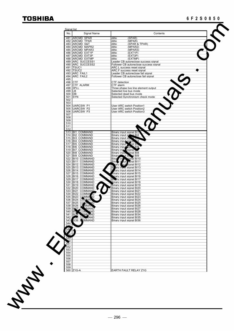
296
6 F 2 S 0 8 5 0
Signal list
481 ARCMD SPAR ditto (SPAR)482 ARCMD_TPAR ditto (MPAR)483 ARCMD S&T ditto (SPAR & TPAR)484 ARCMD_MAPR2 ditto (MPAR2)485 ARCMD MPAR3 ditto (MPAR3)486 ARCMD EXT1P ditto (EXT1P)487 ARCMD EXT3P ditto (EXT3P)488 ARCMD EXTMP ditto (EXTMP)489 ARC SUCCESS1 Leader CB autoreclose success signal490 ARC SUCCESS2 Follower CB autoreclose success signal491 TSUC1 ARC.L success reset signal492 TSUC2 ARC.F success reset signal493 ARC_FAIL1 Leader CB autoreclose fail signal494 ARC FAIL2 Follower CB autoreclose fail signal495496 CTF CTF detection497 CTF_ALARM CTF alarm498 3PLL Three phase live line element output499 LB Selected live bus mode500 DB Selected dead bus mode501 SYN Selected Synchronism check mode502503504 UARCSW P1 User ARC switch Position1505 UARCSW P2 User ARC switch Position2506 UARCSW_P3 User ARC switch Position3507508509510511512513 BI1 COMMAND Binary input signal BI1514 BI2_COMMAND Binary input signal BI2515 BI3 COMMAND Binary input signal BI3516 BI4 COMMAND Binary input signal BI4517 BI5 COMMAND Binary input signal BI5518 BI6 COMMAND Binary input signal BI6519 BI7_COMMAND Binary input signal BI7520 BI8 COMMAND Binary input signal BI8521 BI9_COMMAND Binary input signal BI9522 BI10 COMMAND Binary input signal BI10523 BI11_COMMAND Binary input signal BI11524 BI12 COMMAND Binary input signal BI12525 BI13_COMMAND Binary input signal BI13526 BI14 COMMAND Binary input signal BI14527 BI15_COMMAND Binary input signal BI15528 BI16 COMMAND Binary input signal BI16529 BI17 COMMAND Binary input signal BI17530 BI18 COMMAND Binary input signal BI18531 BI19 COMMAND Binary input signal BI19532 BI20 COMMAND Binary input signal BI20533 BI21 COMMAND Binary input signal BI21534 BI22_COMMAND Binary input signal BI22535 BI23 COMMAND Binary input signal BI23536 BI24_COMMAND Binary input signal BI24537 BI25 COMMAND Binary input signal BI25538 BI26_COMMAND Binary input signal BI26539 BI27 COMMAND Binary input signal BI27540 BI28_COMMAND Binary input signal BI28541 BI34 COMMAND Binary input signal BI34542 BI35_COMMAND Binary input signal BI35543 BI36 COMMAND Binary input signal BI36544545546547548549550551552553554555556557558559560 Z1G-A EARTH FAULT RELAY Z1G
No. Signal Name Contents
www . El
ectric
alPar
tMan
uals
. com

297
6 F 2 S 0 8 5 0
Signal list
561 Z1G-B ditto562 Z1G-C ditto563 Z2G-A EARTH FAULT RELAY Z2G564 Z2G-B ditto565 Z2G-C ditto566 Z3G-A EARTH FAULT RELAY Z3G567 Z3G-B ditto568 Z3G-C ditto569 Z4G-A EARTH FAULT RELAY Z4G570 Z4G-B ditto571 Z4G-C ditto572 ZRG-A EARTH FAULT RELAY ZRG573 ZRG-B ditto574 ZRG-C ditto575 Z1S-AB PHASE FAULT RELAY Z1S576 Z1S-BC ditto577 Z1S-CA ditto578 Z2S-AB PHASE FAULT RELAY Z2S579 Z2S-BC ditto580 Z2S-CA ditto581 Z3S-AB PHASE FAULT RELAY Z3S582 Z3S-BC ditto583 Z3S-CA ditto584 Z4S-AB PHASE FAULT RELAY Z4S585 Z4S-BC ditto586 Z4S-CA ditto587 PSBGOUT-A POWER SWING BLOCK for ZG OUTER ELEMENT588 PSBGOUT-B ditto589 PSBGOUT-C ditto590 PSBGIN-A POWER SWING BLOCK FOR ZG INNER ELEMENT591 PSBGIN-B ditto592 PSBGIN-C ditto593 PSBSOUT-AB POWER SWING BLOCK for ZS OUTER ELEMENT594 PSBSOUT-BC ditto595 PSBSOUT-CA ditto596 PSBSIN-AB POWER SWING BLOCK FOR ZS INNER ELEMENT597 PSBSIN-BC ditto598 PSBSIN-CA ditto599 OCH-A HIGH SET OC RELAY600 OCH-B ditto601 OCH-C ditto602 OCCR-A OC RELAY FOR LINE VT603 OCCR-B ditto604 OCCR-C ditto605 OCD1-A CURRENT CHANGE DETEC. RELAY606 OCD1-B ditto607 OCD1-C ditto608 UVC-A UV RELAY (PHASE SELECTOR)609 UVC-B ditto610 UVC-C ditto611 DEFF DIRECT. EF RLY (INTERNAL) 612 DEFR DIRECT. EF RLY (EXTERNAL) 613 DEFF INST DEFF relay element start614 DEFF_RST DEFF relay element delayed reset615 DEFF BU DEFF backup616 DEFR_INST DEFR relay element start617 DEFR RST DEFR relay element delayed reset618 DEFR_BU DEFR backup619 UVFS-AB UV RELAY (High set)620 UVFS-BC ditto621 UVFS-CA ditto622 UVLS-AB UV RELAY (Low set)623 UVLS-BC ditto624 UVLS-CA ditto625 UVFG-A UV RELAY (High set)626 UVFG-B ditto627 UVFG-C ditto628 UVLG-A UV RELAY (Low set)629 UVLG-B ditto630 UVLG-C ditto631 UVPWI-A UV RELAY632 UVPWI-B ditto633 UVPWI-C ditto634 EFL EARTH FAULT RELAY635 BCD BCD relay element output636 UVD-A UVD relay element637 UVD-B ditto638 UVD-C ditto639 OVS1-AB OVS1-AB relay element output640 OVS1-BC OVS1-BC relay element output
No. Signal Name Contents
www . El
ectric
alPar
tMan
uals
. com

298
6 F 2 S 0 8 5 0
Signal list
641 OVS1-CA OVS1-CA relay element output642 OVS2-AB OVS2-AB relay element output643 OVS2-BC OVS2-BC relay element output644 OVS2-CA OVS2-CA relay element output645 OVG1-A OVG1-A relay element output646 OVG1-B OVG1-B relay element output647 OVG1-C OVG1-C relay element output648 OVG2-A OVG2-A relay element output649 OVG2-B OVG2-B relay element output650 OVG2-C OVG2-C relay element output651 OVS1-AB_INST OVS1-AB relay element start652 OVS1-BC INST OVS1-BC relay element start653 OVS1-CA_INST OVS1-CA relay element start654 OVS1-AB RST OVS1-AB relay element delayed reset655 OVS1-BC_RST OVS1-BC relay element delayed reset656 OVS1-CA RST OVS1-CA relay element delayed reset657 OVG1-A_INST OVG1-A relay element start658 OVG1-B INST OVG1-B relay element start659 OVG1-C_INST OVG1-C relay element start660 OVG1-A RST OVG1-A relay element delayed reset661 OVG1-B RST OVG1-B relay element delayed reset662 OVG1-C RST OVG1-C relay element delayed reset663 UVS1-AB UVS1-AB relay element output664 UVS1-BC UVS1-BC relay element output665 UVS1-CA UVS1-CA relay element output666 UVS2-AB UVS2-AB relay element output667 UVS2-BC UVS2-BC relay element output668 UVS2-CA UVS2-CA relay element output669 UVG1-A UVG1-A relay element output670 UVG1-B UVG1-B relay element output671 UVG1-C UVG1-C relay element output672 UVG2-A UVG2-A relay element output673 UVG2-B UVG2-B relay element output674 UVG2-C UVG2-C relay element output675 UVS1-AB INST UVS1-AB relay element start676 UVS1-BC INST UVS1-BC relay element start677 UVS1-CA INST UVS1-CA relay element start678 UVS1-AB RST UVS1-AB relay element delayed reset679 UVS1-BC_RST UVS1-BC relay element delayed reset680 UVS1-CA RST UVS1-CA relay element delayed reset681 UVG1-A_INST UVG1-A relay element start682 UVG1-B INST UVG1-B relay element start683 UVG1-C_INST UVG1-C relay element start684 UVG1-A RST UVG1-A relay element delayed reset685 UVG1-B_RST UVG1-B relay element delayed reset686 UVG1-C RST UVG1-C relay element delayed reset687 UVSBLK-AB UVSBLK-AB relay element output688 UVSBLK-BC UVSBLK-BC relay element output689 UVSBLK-CA UVSBLK-CA relay element output690 UVGBLK-A UVGBLK-A relay element output691 UVGBLK-B UVGBLK-B relay element output692 UVGBLK-C UVGBLK-C relay element output693 BFS-AB BLINDER FOR ZS (FORWARD)694 BFS-BC ditto695 BFS-CA ditto696 BRS-AB BLINDER FOR ZS (REVERSE)697 BRS-BC ditto698 BRS-CA ditto699 BFG-A BLINDER FOR ZG (FORWARD)700 BFG-B ditto701 BFG-C ditto702 BRG-A BLINDER FOR ZG (REVERSE)703 BRG-B ditto704 BRG-C ditto705 UVD-OR UVD relay element706707708709710711712713714715716717718719720 CB-AND CB CONTACT (3PHASE AND)
No. Signal Name Contents
www . El
ectric
alPar
tMan
uals
. com
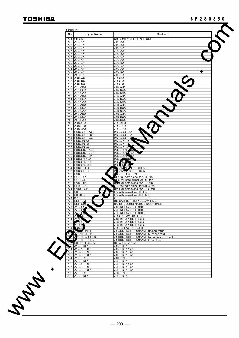
299
6 F 2 S 0 8 5 0
Signal list
721 CB-OR CB CONTACT (3PHASE OR)722 Z1G-AX Z1G-AX723 Z1G-BX Z1G-BX724 Z1G-CX Z1G-CX725 Z2G-AX Z2G-AX726 Z2G-BX Z2G-BX727 Z2G-CX Z2G-CX728 Z3G-AX Z3G-AX729 Z3G-BX Z3G-BX730 Z3G-CX Z3G-CX731 Z4G-AX Z4G-AX732 Z4G-BX Z4G-BX733 Z4G-CX Z4G-CX734 ZRG-AX ZRG-AX735 ZRG-BX ZRG-BX736 ZRG-CX ZRG-CX737 Z1S-ABX Z1S-ABX738 Z1S-BCX Z1S-BCX739 Z1S-CAX Z1S-CAX740 Z2S-ABX Z2S-ABX741 Z2S-BCX Z2S-BCX742 Z2S-CAX Z2S-CAX743 Z3S-ABX Z3S-ABX744 Z3S-BCX Z3S-BCX745 Z3S-CAX Z3S-CAX746 Z4S-ABX Z4S-ABX747 Z4S-BCX Z4S-BCX748 Z4S-CAX Z4S-CAX749 ZRS-ABX ZRS-ABX750 ZRS-BCX ZRS-BCX751 ZRS-CAX ZRS-CAX752 PSBGOUT-AX PSBGOUT-AX753 PSBGOUT-BX PSBGOUT-BX754 PSBGOUT-CX PSBGOUT-CX755 PSBGIN-AX PSBGIN-AX756 PSBGIN-BX PSBGIN-BX757 PSBGIN-CX PSBGIN-CX758 PSBSOUT-ABX PSBSOUT-ABX759 PSBSOUT-BCX PSBSOUT-BCX760 PSBSOUT-CAX PSBSOUT-CAX761 PSBSIN-ABX PSBSIN-ABX762 PSBSIN-BCX PSBSIN-BCX763 PSBSIN-CAX PSBSIN-CAX764 PSBG DET PSB for ZG DETECTION765 PSBS_DET PSB for ZS DETECTION766 PSB DET PSB DETECTION767 OC1_OP OC1 fail safe signal for DIF trip768 OCD OP OCD fail safe signal for DIF trip769 UVD OP UVD fail safe signal for DIF trip770 EFD OP EFD fail safe signal for DIFG trip771 UVDG OP UVD fail safe signal for DIFG trip772 DIFFS Fail safe signal for DIF trip773 DIFGFS Fail safe signal for DIFG trip774 2PH 2PH775 DEFFCR DG CARRIER TRIP DELAY TIMER776 DEFRCR CARR. COORDINATION DGO TIMER777 Z1GOR Z1G RELAY OR LOGIC778 Z2GOR Z2G RELAY OR LOGIC779 Z3GOR Z3G RELAY OR LOGIC780 ZRGOR ZRG RELAY OR LOGIC781 Z1SOR Z1S RELAY OR LOGIC782 Z2SOR Z2S RELAY OR LOGIC783 Z3SOR Z3S RELAY OR LOGIC784 ZRSOR ZRS RELAY OR LOGIC785 Z1CNT INST Z1 CONTROL COMMAND (Instantly trip)786 Z1CNT 3PTP Z1 CONTROL COMMAND (3-phase trip)787 Z1CNT_ARCBLK Z1 CONTROL COMMAND (Autoreclosing block)788 Z1CNT TPBLK Z1 CONTROL COMMAND (Trip block)789 DIF_OUT_SERV DIF out-of-service790 Z1G TRIP Z1G TRIP791 Z1G-A_TRIP Z1G TRIP A ph.792 Z1G-B TRIP Z1G TRIP B ph.793 Z1G-C_TRIP Z1G TRIP C ph.794 Z1S TRIP Z1S TRIP795 Z2G_TRIP Z2G TRIP796 Z2G-A TRIP Z2G TRIP A ph.797 Z2G-B TRIP Z2G TRIP B ph.798 Z2G-C TRIP Z2G TRIP C ph.799 Z2S TRIP Z2S TRIP800 Z3G TRIP Z3G TRIP
No. Signal Name Contents
www . El
ectric
alPar
tMan
uals
. com

300
6 F 2 S 0 8 5 0
Signal list
801 Z3G-A TRIP Z3G TRIP A ph.802 Z3G-B_TRIP Z3G TRIP B ph.803 Z3G-C TRIP Z3G TRIP C ph.804 Z3S_TRIP Z3S TRIP805 ZRG TRIP ZRG TRIP806 ZRG-A TRIP ZRG TRIP A ph.807 ZRG-B TRIP ZRG TRIP B ph.808 ZRG-C TRIP ZRG TRIP C ph.809 ZRS TRIP ZRS TRIP810 DEFF TRIP DEFF BACK-UP TRIP811 DEFR_TRIP DEFR BACK-UP TRIP812 STUBOC TRIP STUB-OC TRIP813 STUBOC-A_TP STUB-OC TRIP A ph.814 STUBOC-B TP STUB-OC TRIP B ph.815 STUBOC-C_TP STUB-OC TRIP C ph.816 SOTF TRIP SOTF TRIP817 SOTF-A_TRIP SOTF-OCH TRIP A ph.818 SOTF-B TRIP SOTF-OCH TRIP B ph.819 SOTF-C_TRIP SOTF-OCH TRIP C ph.820 SOTF-Z TRIP SOTF-Zistance TRIP821 OCH TRIP OCH TRIP822 OCH-A TRIP OCH TRIP A ph.823 OCH-B TRIP OCH TRIP B ph.824 OCH-C TRIP OCH TRIP C ph.825 OVS1 TRIP OVS1 TRIP826 OVS1-AB_TRIP OVS1-AB TRIP827 OVS1-BC TRIP OVS1-BC TRIP828 OVS1-CA_TRIP OVS1-CA TRIP829 OVS2 ALARM OVS2 ALARM830 OVS2-AB_ALM OVS2-AB ALARM831 OVS2-BC ALM OVS2-BC ALARM832 OVS2-CA_ALM OVS2-CA ALARM833 OVG1 TRIP OVS1 TRIP834 OVG1-A_TRIP OVS1-A TRIP835 OVG1-B TRIP OVS1-B TRIP836 OVG1-C TRIP OVS1-C TRIP837 OVG2 ALARM OVS2 ALARM838 OVG2-A ALM OVS2-A ALARM839 OVG2-B_ALM OVS2-B ALARM840 OVG2-C ALM OVS2-C ALARM841 UVS1_TRIP UVS1 TRIP842 UVS1-AB TRIP UVS1-AB TRIP843 UVS1-BC_TRIP UVS1-BC TRIP844 UVS1-CA TRIP UVS1-CA TRIP845 UVS2_ALARM UVS2 ALARM846 UVS2-AB ALM UVS2-AB ALARM847 UVS2-BC_ALM UVS2-BC ALARM848 UVS2-CA ALM UVS2-CA ALARM849 UVG1 TRIP UVS1 TRIP850 UVG1-A TRIP UVS1-A TRIP851 UVG1-B TRIP UVS1-B TRIP852 UVG1-C TRIP UVS1-C TRIP853 UVG2 ALARM UVS2 ALARM854 UVG2-A_ALM UVS2-A ALARM855 UVG2-B ALM UVS2-B ALARM856 UVG2-C_ALM UVS2-C ALARM857 UVSBLK UVS BLOCK858 UVGBLK UVG BLOCK859 BCD TRIP BCD TRIP860 ZGCX CARRIER CONTROL RELAY(Z2G/Z3G)861 ZGC-AX CARRIER CONTROL RELAY(Z2G/Z3G-A ph.)862 ZGC-BX CARRIER CONTROL RELAY(Z2G/Z3G-B ph.)863 ZGC-CX CARRIER CONTROL RELAY(Z2G/Z3G-C ph.)864 ZSCX CARRIER CONTROL RELAY(Z2S/Z3S)865 REV BLK CARRIER SEND FOR BLOCK866 REV BLK-A CARRIER SEND FOR BLOCK (ZG-A ph.)867 REV_BLK-B CARRIER SEND FOR BLOCK (ZG-B ph.)868 REV BLK-C CARRIER SEND FOR BLOCK (ZG-C ph.)869 REV_BLK-S CARRIER SEND FOR BLOCK (ZS)870 REV BLK-DEF DG.CARRIER SEND FOR BLOCK871 UVLGOR UVLGOR872 UVLSOR UVLSOR873 UVFGOR UVFGOR874 UVFSOR UVFSOR875 WI_TRIP WEAK INFEED TRIP876 DISWI TRIP WEEK INFEED LOCAL TRIP877 DEFWI TRIP-A DG CARRIER WEEK INFEED LOCAL TRIP878 DISCR TRIP DISTANCE CARRIER TRIP879 DISCR-A TRIP DISTANCE CARRIER TRIP (A ph.)880 DISCR-B TRIP DISTANCE CARRIER TRIP (B ph.)
No. Signal Name Contents
www . El
ectric
alPar
tMan
uals
. com
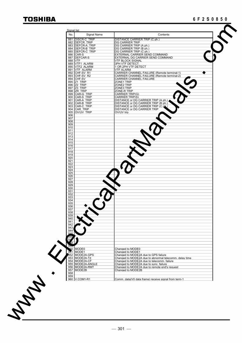
301
6 F 2 S 0 8 5 0
Signal list
881 DISCR-C TRIP DISTANCE CARRIER TRIP (C ph.)882 DEFCR_TRIP DG CARRIER TRIP883 DEFCR-A_TRIP DG CARRIER TRIP (A ph.)884 DEFCR-B_TRIP DG CARRIER TRIP (B ph.)885 DEFCR-C_TRIP DG CARRIER TRIP (C ph.)886 CAR-S EXTERNAL CARRIER SEND COMMAND887 DEFCAR-S EXTERNAL DG CARRIER SEND COMMAND888 VTF VTF BLOCK SIGNAL889 VTF1_ALARM 3PH VTF DETECT.890 VTF2_ALARM 1 OR 2PH VTF DETECT891 VTF ALARM VTF ALARM892 CHF-SV_R1 CARRIER CHANNEL FAILURE (Remote terminal-1)893 CHF-SV_R2 CARRIER CHANNEL FAILURE (Remote terminal-2)894 CHF-SV CARRIER CHANNEL FAILURE895 Z1_TRIP ZONE1 TRIP896 Z2_TRIP ZONE2 TRIP897 Z3_TRIP ZONE3 TRIP898 ZR_TRIP ZONE-R TRIP899 CAR-G_TRIP CARRIER TRIP(G)900 CAR-S_TRIP CARRIER TRIP(S)901 CAR-A TRIP DISTANCE or DG CARRIER TRIP (A ph.)902 CAR-B_TRIP DISTANCE or DG CARRIER TRIP (B ph.)903 CAR-C_TRIP DISTANCE or DG CARRIER TRIP (C ph.)904 CAR_TRIP DISTANCE or DG CARRIER TRIP905 OV/UV_TRIP OV/UV trip906907908909910911912913914915916917918919920921922923924925926927928929930931932933934935936937938939940941942943944945946947948949950 MODE0 Changed to MODE0951 MODE1 Changed to MODE1952 MODE2A-GPS Changed to MODE2A due to GPS failure953 MODE2A-Td Changed to MODE2A due to abnormal telecomm. delay time954 MODE2A-CF Changed to MODE2A due to telecomm. failure955 MODE2A-ANGLE Changed to MODE2A due to sync. failure956 MODE2A-RMT Changed to MODE2A due to remote end's request957 MODE2B Changed to MODE2B958959960 V.COM1-R1 Comm. data(V0 data frame) receive signal from term-1
No. Signal Name Contents
www . El
ectric
alPar
tMan
uals
. com

302
6 F 2 S 0 8 5 0
Signal list
961 V.COM2-R1 ditto962 V.COM3-R1 ditto963964 S.V.COM1-R1 Comm. data(V0 data frame) receive signal from term-1965 S.V.COM2-R1 ditto966 S.V.COM3-R1 ditto967 S.V.COM4-R1 ditto968 S.V.COM5-R1 ditto969 S.V.COM6-R1 ditto970 S.V.COM7-R1 ditto971 S.V.COM8-R1 ditto972 S.V.COM9-R1 ditto973 S.V.COM10-R1 ditto974 S.V.COM11-R1 ditto975 S.V.COM12-R1 ditto976 V.COM1-R2 Comm. data(V0 data frame) receive signal from term-2977 V.COM2-R2 ditto978 V.COM3-R2 ditto979980 S.V.COM1-R2 Comm. data(V0 data frame) receive signal from term-2981 S.V.COM2-R2 ditto982 S.V.COM3-R2 ditto983 S.V.COM4-R2 ditto984 S.V.COM5-R2 ditto985 S.V.COM6-R2 ditto986 S.V.COM7-R2 ditto987 S.V.COM8-R2 ditto988 S.V.COM9-R2 ditto989 S.V.COM10-R2 ditto990 S.V.COM11-R2 ditto991 S.V.COM12-R2 ditto992 I.COM1-R1 Comm. data(I0 data frame) receive signal from term-1993 I.COM2-R1 ditto994 I.COM3-R1 ditto995996 S.I.COM1-R1 Comm. data(I0 data frame) receive signal from term-1997 S.I.COM2-R1 ditto998 S.I.COM3-R1 ditto999 S.I.COM4-R1 ditto1000 S.I.COM5-R1 ditto1001 S.I.COM6-R1 ditto1002 S.I.COM7-R1 ditto1003 S.I.COM8-R1 ditto1004 S.I.COM9-R1 ditto1005 S.I.COM10-R1 ditto1006 S.I.COM11-R1 ditto1007 S.I.COM12-R1 ditto1008 I.COM1-R2 Comm. data(I0 data frame) receive signal from term-21009 I.COM2-R2 ditto1010 I.COM3-R2 ditto10111012 S.I.COM1-R2 Comm. data(I0 data frame) receive signal from term-21013 S.I.COM2-R2 ditto1014 S.I.COM3-R2 ditto1015 S.I.COM4-R2 ditto1016 S.I.COM5-R2 ditto1017 S.I.COM6-R2 ditto1018 S.I.COM7-R2 ditto1019 S.I.COM8-R2 ditto1020 S.I.COM9-R2 ditto1021 S.I.COM10-R2 ditto1022 S.I.COM11-R2 ditto1023 S.I.COM12-R2 ditto10241025102610271028102910301031103210331034103510361037103810391040 FAULT_PHA_A fault_phase_A
No. Signal Name Contents
www . El
ectric
alPar
tMan
uals
. com

303
6 F 2 S 0 8 5 0
Signal list
1041 FAULT PHA B fault phase B1042 FAULT_PHA_C fault_phase_C1043 FAULT_PHA_N fault_phase_N1044 FL_ERR fault location start up error1045 FL_OB_FWD fault location out of bounds(forward)1046 FL_OB_BACK fault location out of bounds(backward)1047 FL_NC fault location not converged1048 FL_COMPLETED fault location completed1049105010511052105310541055105610571058105910601061106210631064106510661067106810691070107110721073107410751076107710781079108010811082108310841085108610871088 COM1-R1 Comm. data receive signal from remote term-11089 COM2-R1 ditto1090 COM3-R1 ditto1091 COM4-R1 ditto1092 COM5-R1 ditto1093109410951096 COM1-R1_UF Comm. data receive signal from remote term-1 (unfiltered)1097 COM2-R1_UF ditto1098 COM3-R1_UF ditto1099 COM4-R1_UF ditto1100 COM5-R1 UF ditto1101110211031104 SUB_COM1-R1 Sub comm. data receive signal from term-11105 SUB_COM2-R1 ditto1106 SUB_COM3-R1 ditto1107 SUB_COM4-R1 ditto1108 SUB_COM5-R1 ditto1109111011111112 SUB2_COM1-R1 Sub comm. data2 receive signal from term-11113 SUB2_COM2-R1 ditto1114 SUB2_COM3-R1 ditto1115 SUB2_COM4-R1 ditto1116 SUB2_COM5-R1 ditto1117 SUB2_COM6-R1 ditto1118 SUB2_COM7-R1 ditto1119 SUB2_COM8-R1 ditto1120 SUB2_COM9-R1 ditto
No. Signal Name Contents
www . El
ectric
alPar
tMan
uals
. com

304
6 F 2 S 0 8 5 0
Signal list
1121 SUB2 COM10-R1 ditto1122 SUB2_COM11-R1 ditto1123 SUB2_COM12-R1 ditto11241125112611271128 COM1-R2 Comm. data receive signal from remote term-21129 COM2-R2 ditto1130 COM3-R2 ditto1131 COM4-R2 ditto1132 COM5-R2 ditto1133113411351136 COM1-R2_UF Comm. data receive signal from remote term-2 (unfiltered)1137 COM2-R2_UF ditto1138 COM3-R2_UF ditto1139 COM4-R2_UF ditto1140 COM5-R2_UF ditto1141114211431144 SUB_COM1-R2 Sub comm. data receive signal from term-21145 SUB_COM2-R2 ditto1146 SUB_COM3-R2 ditto1147 SUB_COM4-R2 ditto1148 SUB_COM5-R2 ditto1149115011511152 SUB2_COM1-R2 Sub comm. data2 receive signal from term-21153 SUB2_COM2-R2 ditto1154 SUB2_COM3-R2 ditto1155 SUB2_COM4-R2 ditto1156 SUB2_COM5-R2 ditto1157 SUB2_COM6-R2 ditto1158 SUB2_COM7-R2 ditto1159 SUB2_COM8-R2 ditto1160 SUB2_COM9-R2 ditto1161 SUB2_COM10-R2 ditto1162 SUB2_COM11-R2 ditto1163 SUB2_COM12-R2 ditto11641165116611671168 SUB3_COM1-R1 Sub comm. data3 receive signal from term-11169 SUB3_COM2-R1 ditto1170 SUB3 COM3-R1 ditto1171 SUB3_COM4-R1 ditto1172 SUB3_COM5-R1 ditto1173 SUB3_COM6-R1 ditto1174 SUB3_COM7-R1 ditto1175 SUB3_COM8-R1 ditto1176 SUB3_COM9-R1 ditto1177 SUB3_COM10-R1 ditto1178 SUB3_COM11-R1 ditto1179 SUB3_COM12-R1 ditto11801181118211831184 SUB3_COM1-R2 Sub comm. data3 receive signal from term-21185 SUB3_COM2-R2 ditto1186 SUB3_COM3-R2 ditto1187 SUB3_COM4-R2 ditto1188 SUB3_COM5-R2 ditto1189 SUB3_COM6-R2 ditto1190 SUB3 COM7-R2 ditto1191 SUB3_COM8-R2 ditto1192 SUB3_COM9-R2 ditto1193 SUB3_COM10-R2 ditto1194 SUB3_COM11-R2 ditto1195 SUB3_COM12-R2 ditto11961197119811991200
No. Signal Name Contents
www . El
ectric
alPar
tMan
uals
. com
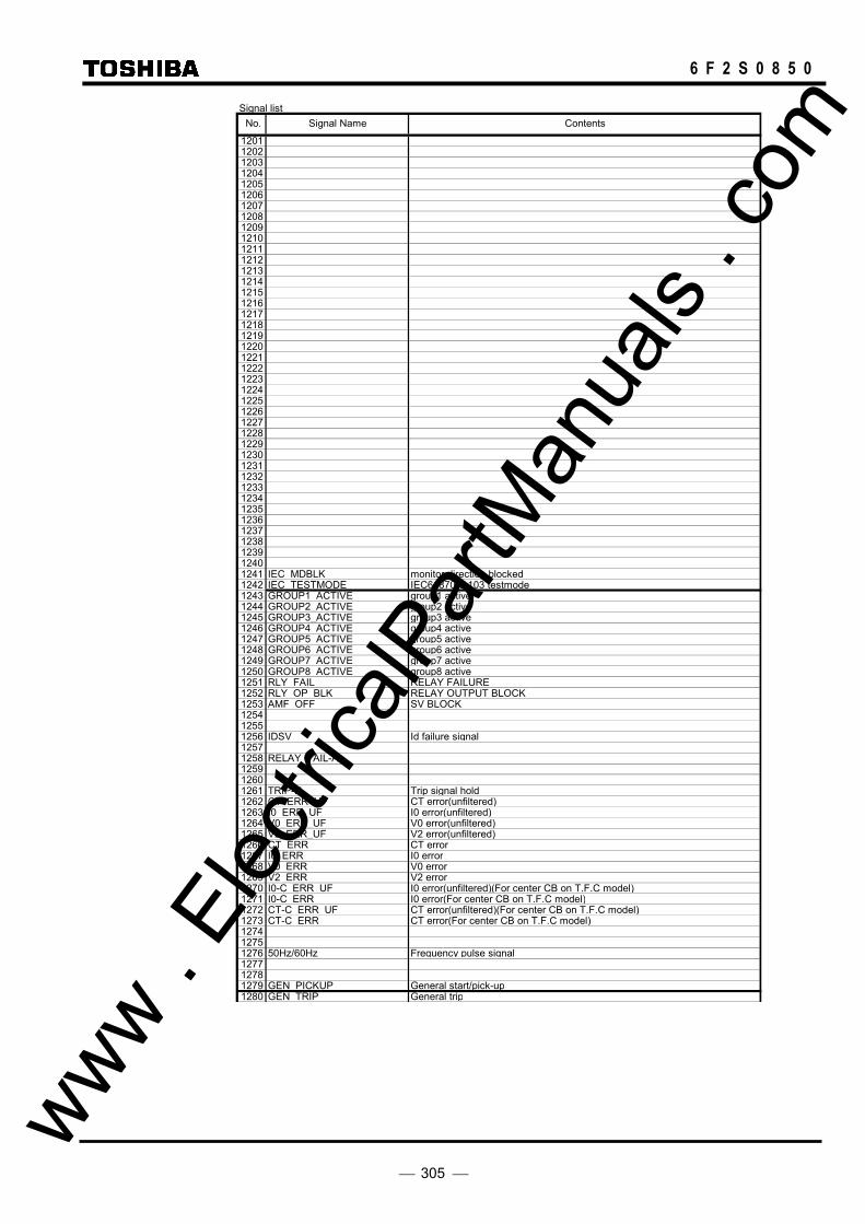
305
6 F 2 S 0 8 5 0
Signal list
12011202120312041205120612071208120912101211121212131214121512161217121812191220122112221223122412251226122712281229123012311232123312341235123612371238123912401241 IEC_MDBLK monitor direction blocked1242 IEC_TESTMODE IEC61870-5-103 testmode1243 GROUP1_ACTIVE group1 active1244 GROUP2_ACTIVE group2 active1245 GROUP3_ACTIVE group3 active1246 GROUP4_ACTIVE group4 active1247 GROUP5_ACTIVE group5 active1248 GROUP6_ACTIVE group6 active1249 GROUP7_ACTIVE group7 active1250 GROUP8 ACTIVE group8 active1251 RLY_FAIL_ RELAY FAILURE1252 RLY_OP_BLK_ RELAY OUTPUT BLOCK1253 AMF_OFF_ SV BLOCK125412551256 IDSV Id failure signal12571258 RELAY_FAIL-A125912601261 TRIP-H_ Trip signal hold1262 CT_ERR_UF CT error(unfiltered)1263 I0_ERR_UF I0 error(unfiltered)1264 V0_ERR_UF V0 error(unfiltered)1265 V2_ERR_UF V2 error(unfiltered)1266 CT_ERR CT error1267 I0_ERR I0 error1268 V0_ERR V0 error1269 V2_ERR V2 error1270 I0-C ERR UF I0 error(unfiltered)(For center CB on T.F.C model)1271 I0-C_ERR I0 error(For center CB on T.F.C model)1272 CT-C_ERR_UF CT error(unfiltered)(For center CB on T.F.C model)1273 CT-C_ERR CT error(For center CB on T.F.C model)127412751276 50Hz/60Hz Frequency pulse signal127712781279 GEN_PICKUP General start/pick-up1280 GEN_TRIP General trip
No. Signal Name Contents
www . El
ectric
alPar
tMan
uals
. com

306
6 F 2 S 0 8 5 0
Signal list
1281128212831284 BI1_COM_UF Binary input signal BI1 (unfiltered)1285 BI2_COM_UF Binary input signal BI2 (unfiltered)1286 BI3_COM_UF Binary input signal BI3 (unfiltered)1287 BI4_COM_UF Binary input signal BI4 (unfiltered)1288 BI5_COM_UF Binary input signal BI5 (unfiltered)1289 BI6_COM_UF Binary input signal BI6 (unfiltered)1290 BI7_COM_UF Binary input signal BI7 (unfiltered)1291 BI8 COM UF Binary input signal BI8 (unfiltered)1292 BI9_COM_UF Binary input signal BI9 (unfiltered)1293 BI10_COM_UF Binary input signal BI10 (unfiltered)1294 BI11_COM_UF Binary input signal BI11 (unfiltered)1295 BI12_COM_UF Binary input signal BI12 (unfiltered)1296 BI13_COM_UF Binary input signal BI13 (unfiltered)1297 BI14_COM_UF Binary input signal BI14 (unfiltered)1298 BI15_COM_UF Binary input signal BI15 (unfiltered)12991300130113021303130413051306130713081309131013111312131313141315131613171318131913201321132213231324132513261327132813291330133113321333133413351336133713381339134013411342134313441345134613471348134913501351135213531354135513561357135813591360
No. Signal Name Contents
www . El
ectric
alPar
tMan
uals
. com

307
6 F 2 S 0 8 5 0
Signal list
13611362136313641365136613671368136913701371137213731374137513761377137813791380138113821383138413851386138713881389139013911392139313941395139613971398139914001401 LOCAL_OP_ACT local operation active1402 REMOTE_OP_ACT remote operation active1403 NORM_LED_ON IN-SERVICE LED ON1404 ALM_LED_ON ALARM LED ON1405 TRIP_LED_ON TRIP LED ON1406 TEST_LED_ON TEST LED ON14071408 PRG_LED_RESET Latched progammable LED RESET1409 LED_RESET TRIP LED RESET14101411 ARC_COM_ON IEC103 communication command1412 TELE_COM_ON IEC103 communication command1413 PROT_COM_ON IEC103 communication command1414 PRG_LED1_ON PROGRAMMABLE LED1 ON1415 PRG_LED2_ON PROGRAMMABLE LED2 ON1416 PRG_LED3_ON PROGRAMMABLE LED3 ON1417 PRG_LED4_ON PROGRAMMABLE LED4 ON14181419142014211422142314241425142614271428142914301431143214331434 F.Record_DONE fault location completed1435 F.Record_CLR Fault record clear1436 E.Record_CLR Event record clear1437 D.Record_CLR Disturbance record clear143814391440
No. Signal Name Contents
www . El
ectric
alPar
tMan
uals
. com
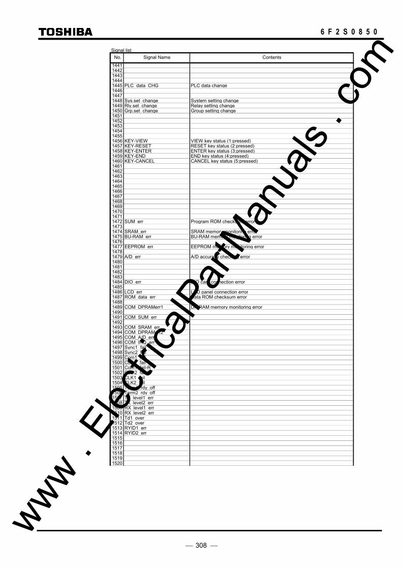
308
6 F 2 S 0 8 5 0
Signal list
14411442144314441445 PLC_data_CHG PLC data change144614471448 Sys.set_change System setting change1449 Rly.set_change Relay setting change1450 Grp.set_change Group setting change145114521453145414551456 KEY-VIEW VIEW key status (1:pressed)1457 KEY-RESET RESET key status (2:pressed)1458 KEY-ENTER ENTER key status (3:pressed)1459 KEY-END END key status (4:pressed)1460 KEY-CANCEL CANCEL key status (5:pressed)146114621463146414651466146714681469147014711472 SUM_err Program ROM checksum error14731474 SRAM_err SRAM memory monitoring error1475 BU-RAM_err BU-RAM memory monitoring error14761477 EEPROM_err EEPROM memory monitoring error14781479 A/D_err A/D accuracy checking error14801481148214831484 DIO_err DIO card connection error14851486 LCD_err LCD panel connection error1487 ROM_data_err Data ROM checksum error14881489 COM_DPRAMerr1 DP-RAM memory monitoring error14901491 COM_SUM_err14921493 COM_SRAM_err1494 COM_DPRAMerr21495 COM_A/D_err1496 COM_IRQ_err1497 Sync1_fail1498 Sync2_fail1499 Com1_fail1500 Com2 fail1501 Com1_fail-R1502 Com2_fail-R1503 CLK1_fail1504 CLK2_fail1505 Term1_rdy_off1506 Term2_rdy_off1507 TX_level1_err1508 TX_level2_err1509 RX_level1_err1510 RX level2 err1511 Td1_over1512 Td2_over1513 RYID1_err1514 RYID2_err151515161517151815191520
No. Signal Name Contents
www . El
ectric
alPar
tMan
uals
. com
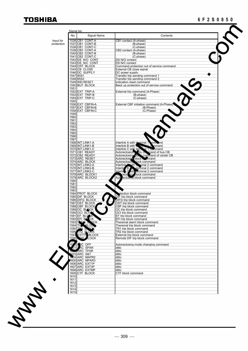
309
6 F 2 S 0 8 5 0
Signal list
Input for 1536 CB1 CONT-A CB1 contact (A-phase) protection 1537 CB1 CONT-B (B-phase)
1538 CB1 CONT-C (C-phase)1539 CB2 CONT-A CB2 contact (A-phase)1540 CB2 CONT-B (B-phase)1541 CB2 CONT-C (C-phase)1542 DS N/O CONT DS N/O contact1543 DS N/C CONT DS N/C contact1544 CRT BLOCK Command protection out of service command1545 CB CLOSE External CB close signal1546 DC SUPPLY DC power supply1547 85S1 Transfer trip sending command 11548 85S2 Transfer trip sending command 21549 IND.RESET Indication reset command1550 BUT BLOCK Back up protection out of service command15511552 EXT TRIP-A External trip command (A-Phase)1553 EXT TRIP-B (B-phase)1554 EXT TRIP-C (C-phase)15551556 EXT CBFIN-A External CBF initiation command (A-Phase)1557 EXT CBFIN-B (B-Phase)1558 EXT CBFIN-C (C-Phase)1559156015611562156315641565156615671568 INT.LINK1-A Interlink A with terminal 1 command1569 INT.LINK1-B Interlink B with terminal 1 command1570 INT.LINK1-C Interlink C with terminal 1 command1571 CB1 READY Autoreclosing ready command of bus CB1572 CB2 READY Autoreclosing ready command of center CB1573 ARC RESET Autoreclosing block command1574 ARC BLOCK Autoreclosing block command1575 INT.LINK2-A Interlink A with terminal 2 command1576 INT.LINK2-B Interlink B with terminal 2 command1577 INT.LINK2-C Interlink C with terminal 2 command1578 ARC BLOCK1 Autoreclosing block command1579 ARC BLOCK2 Autoreclosing block command15801581158215831584 PROT BLOCK Protection block command1585 DIF BLOCK DIF trip block command1586 DIFG BLOCK DIFG trip block command1587 OST BLOCK OST trip block command1588 CBF BLOCK CBF trip block command1589 OC BLOCK OC trip block command1590 OCI BLOCK OCI trip block command1591 EF BLOCK EF trip block command1592 EFI BLOCK EFI trip block command1593 THMA BLOCK Theremal alarm block command1594 THM BLOCK Theremal trip block command1595 TR1 BLOCK TR1 trip block command1596 TR2 BLOCK TR2 trip block command1597 EXTTP BLOCK External trip block command1598 RDIF BLOCK Remote DIF trip block command15991600 ARC OFF Autoreclosing mode changing command1601 ARC SPAR ditto1602 ARC TPAR ditto1603 ARC S&T ditto1604 ARC MAPR2 ditto1605 ARC MPAR3 ditto1606 ARC EXT1P ditto1607 ARC EXT3P ditto1608 ARC EXTMP ditto1609 CTF BLOCK CTF block command161016111612161316141615
No. Signal Name Contents
www . El
ectric
alPar
tMan
uals
. com
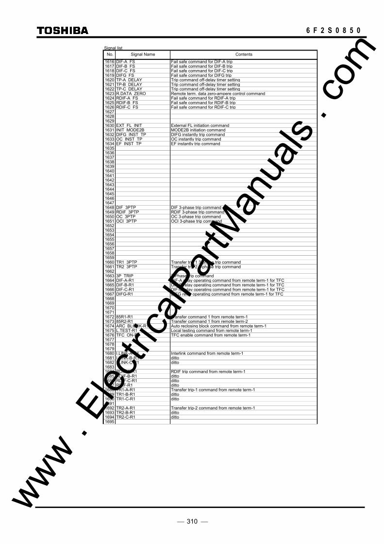
310
6 F 2 S 0 8 5 0
Signal list
1616 DIF-A_FS Fail safe command for DIF-A trip1617 DIF-B FS Fail safe command for DIF-B trip1618 DIF-C_FS Fail safe command for DIF-C trip1619 DIFG FS Fail safe command for DIFG trip1620 TP-A_DELAY Trip command off-delay timer setting1621 TP-B DELAY Trip command off-delay timer setting1622 TP-C_DELAY Trip command off-delay timer setting1623 R.DATA ZERO Remote term. data zero-ampere control command1624 RDIF-A_FS Fail safe command for RDIF-A trip1625 RDIF-B FS Fail safe command for RDIF-B trip1626 RDIF-C_FS Fail safe command for RDIF-C trip1627162816291630 EXT_FL_INIT External FL initiation command1631 INIT_MODE2B MODE2B initiation command1632 DIFG_INST_TP DIFG instantly trip command1633 OC_INST_TP OC instantly trip command1634 EF INST TP EF instantly trip command16351636163716381639164016411642164316441645164616471648 DIF 3PTP DIF 3-phase trip command1649 RDIF_3PTP RDIF 3-phase trip command1650 OC_3PTP OC 3-phase trip command1651 OCI_3PTP OCI 3-phase trip command165216531654165516561657165816591660 TR1_3PTP Transfer trip 1 3-phase trip command1661 TR2 3PTP Transfer trip 2 3-phase trip command16621663 3P TRIP 3-Phase trip command1664 DIF-A-R1 DIF-A relay operating command from remote term-1 for TFC1665 DIF-B-R1 DIF-B relay operating command from remote term-1 for TFC1666 DIF-C-R1 DIF-C relay operating command from remote term-1 for TFC1667 DIFG-R1 DIFG relay operating command from remote term-1 for TFC16681669167016711672 85R1-R1 Transfer command 1 from remote term-11673 85R2-R1 Transfer command 1 from remote term-21674 ARC BLOCK-R1 Auto reclosing block command from remote term-11675 L.TEST-R1 Local testing command from remote term-11676 TFC ON-R1 TFC enable command from remote term-11677167816791680 I.LINK-A-R1 Interlink command from remote term-11681 I.LINK-B-R1 ditto1682 I.LINK-C-R1 ditto16831684 RDIF-A-R1 RDIF trip command from remote term-11685 RDIF-B-R1 ditto1686 RDIF-C-R1 ditto1687 RDIF-R1 ditto1688 TR1-A-R1 Transfer trip-1 command from remote term-11689 TR1-B-R1 ditto1690 TR1-C-R1 ditto16911692 TR2-A-R1 Transfer trip-2 command from remote term-11693 TR2-B-R1 ditto1694 TR2-C-R1 ditto1695
No. Signal Name Contents
www . El
ectric
alPar
tMan
uals
. com
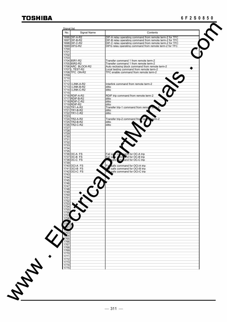
311
6 F 2 S 0 8 5 0
Signal list
1696 DIF-A-R2 DIF-A relay operating command from remote term-2 for TFC1697 DIF-B-R2 DIF-B relay operating command from remote term-2 for TFC1698 DIF-C-R2 DIF-C relay operating command from remote term-2 for TFC1699 DIFG-R2 DIFG relay operating command from remote term-2 for TFC17001701170217031704 85R1-R2 Transfer command 1 from remote term-21705 85R2-R2 Transfer command 1 from remote term-21706 ARC BLOCK-R2 Auto reclosing block command from remote term-21707 L.TEST-R2 Local testing command from remote term-21708 TFC ON-R2 TFC enable command from remote term-21709171017111712 I.LINK-A-R2 Interlink command from remote term-21713 I.LINK-B-R2 ditto1714 I.LINK-C-R2 ditto17151716 RDIF-A-R2 RDIF trip command from remote term-21717 RDIF-B-R2 ditto1718 RDIF-C-R2 ditto1719 RDIF-R2 ditto1720 TR1-A-R2 Transfer trip-1 command from remote term-21721 TR1-B-R2 ditto1722 TR1-C-R2 ditto17231724 TR2-A-R2 Transfer trip-2 command from remote term-21725 TR2-B-R2 ditto1726 TR2-C-R2 ditto1727172817291730173117321733173417351736 OC-A FS Fail safe command for OC-A trip1737 OC-B FS Fail safe command for OC-B trip1738 OC-C FS Fail safe command for OC-C trip17391740 OCI-A FS Fail safe command for OCI-A trip1741 OCI-B FS Fail safe command for OCI-B trip1742 OCI-C FS Fail safe command for OCI-C trip174317441745174617471748174917501751175217531754175517561757175817591760176117621763176417651766176717681769177017711772177317741775
No. Signal Name Contents
www . El
ectric
alPar
tMan
uals
. com

312
6 F 2 S 0 8 5 0
Signal list
17761777177817791780178117821783178417851786178717881789179017911792 IO#1-TP-A1 Binary output signal of TP-A11793 IO#1-TP-B1 TP-B11794 IO#1-TP-C1 TP-C11795 IO#1-TP-A2 Binary output signal of TP-A21796 IO#1-TP-B2 TP-B21797 IO#1-TP-C2 TP-C2179817991800180118021803180418051806180718081809181018111812181318141815181618171818181918201821182218231824 SPR.L-REQ Leader SPAR requirement1825 TPR.L-REQ Leader TPAR requirement1826 MPR.L-REQ Leader MPAR requirement1827 SPR.F-REQ Follower SPAR requirement1828 TPR.F-REQ Follower TPAR requirement1829 MPR.F-REQ Follower MPAR requirement1830 SPR.F-ST.REQ Follower SPAR starting requirement1831 TPR.F-ST.REQ Follower TPAR starting requirement1832 MPR.F-ST.REQ Follower MPAR starting requirement1833183418351836 R.F-ST.REQ Follower AR starting requirement1837 SPR.F2-ST.REQ Follower SPAR starting requirement1838 TPR.F2-ST.REQ Follower TPAR starting requirement1839 MPR.F2-ST.REQ Follower MPAR starting requirement1840 ARC.L TERM Leader terminal of Autoreclosing1841 ARC.F TERM Follower terminal of Autoreclosing184218431844184518461847 Z1_ARC_BLOCK Autoreclosing block by Z1 command18481849185018511852185318541855
No. Signal Name Contents
www . El
ectric
alPar
tMan
uals
. com
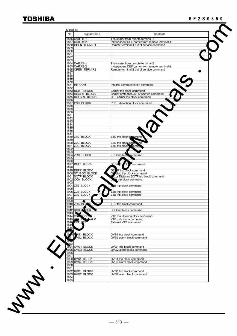
313
6 F 2 S 0 8 5 0
Signal list
1856 CAR.R1-1 Trip carrier from remote terminal-11857 CAR.R1-2 Independent DEF carrier from remote terminal-11858 OPEN TERM-R1 Remote terminal-1 out of service command185918601861186218631864 CAR.R2-1 Trip carrier from remote terminal-21865 CAR.R2-2 Independent DEF carrier from remote terminal-21866 OPEN TERM-R2 Remote terminal-2 out of service command18671868186918701871 INT.COM Integral communication command18721873 DCRT_BLOCK Carrier trip block command1874 DISCRT BLOCK Carrier protection out of service command1875 DEFCRT BLOCK DEF carrier trip block command18761877 PSB BLOCK PSB detection block command18781879188018811882188318841885188618871888 Z1G BLOCK Z1G trip block command18891890 Z2G BLOCK Z2G trip block command1891 Z3G_BLOCK Z3G trip block command189218931894 ZRG BLOCK ZRG trip block command189518961897 DEFF BLOCK DEF-F trip block command18981899 DEFR BLOCK DEF-R trip block command1900 STUBOC_BLOCK OC stub trip block command1901 SOTF BLOCK OC or Distance SOTF trip block command1902 OCH BLOCK OCH trip block command19031904 Z1S BLOCK Z1S trip block command19051906 Z2S BLOCK Z2S trip block command1907 Z3S_BLOCK Z3S trip block command190819091910 ZRS BLOCK ZRS trip block command19111912 BCD BLOCK BCD trip block command19131914 VTF BLOCK VTF monitoering block command1915 VTF ONLY ALM VTF only alarm command1916 EXT_VTF External VTF command1917191819191920 OVS1 BLOCK OVS1 trip block command1921 OVS2 BLOCK OVS2 alarm block command192219231924 OVG1 BLOCK OVG1 trip block command1925 OVG2_BLOCK OVG2 alarm block command192619271928 UVS1 BLOCK UVS1 trip block command1929 UVS2 BLOCK UVS2 alarm block command193019311932 UVG1 BLOCK UVG1 trip block command1933 UVG2 BLOCK UVG2 alarm block command19341935
No. Signal Name Contents
www . El
ectric
alPar
tMan
uals
. com

314
6 F 2 S 0 8 5 0
Signal list
1936 Z1 INST TP Z1 instantly trip command19371938 Z2 INST TP Z2 instantly trip command1939 Z3 INST TP Z3 instantly trip command194019411942194319441945 DEFF INST TP DEF-F instantly trip command19461947 DEFR INST TP DEF-R instantly trip command1948 ZR INST TP ZR instantly trip command1949195019511952 OVS1 INST TP OVS1 instantly trip command1953 OVS2_INST_TP OVS2 instantly alarm command195419551956 OVG1 INST TP OVG1 instantly trip command1957 OVG2 INST TP OVG2 instantly alarm command195819591960 UVS1_INST_TP UVS1 instantly trip command1961 UVS2 INST TP UVS2 instantly alarm command196219631964 UVG1 INST TP UVG1 instantly trip command1965 UVG2 INST TP UVG2 instantly alarm command196619671968 Z1 3PTP Z1 3-phase trip command19691970 Z2 3PTP Z2 3-phase trip command197119721973197419751976 DISCAR 3PTP Distance CAR 3-phase trip command1977 DEFCAR 3PTP DG.CAR 3-phase trip command19781979198019811982198319841985 STUB CB CB close command for stub protection1986 OCHTP ON OCH trip pemmisive command1987 PSB.F_RESET PSB forcibly reset command1988 DEF PHSEL-A Fault phase selection command for DEF1989 DEF_PHSEL-B ditto1990 DEF PHSEL-C ditto19911992 Z2G-A FS Z2G-A fail-safe command1993 Z2G-B FS Z2G-B fail-safe command1994 Z2G-C FS Z2G-C fail-safe command19951996199719981999200020012002200320042005200620072008 Z2G-A BLOCK Z2G-A block command2009 Z2G-B BLOCK ditto2010 Z2G-C BLOCK ditto20112012201320142015 DIF OUT DIF protection out-of-service condition for Z1 control
No. Signal Name Contents
www . El
ectric
alPar
tMan
uals
. com
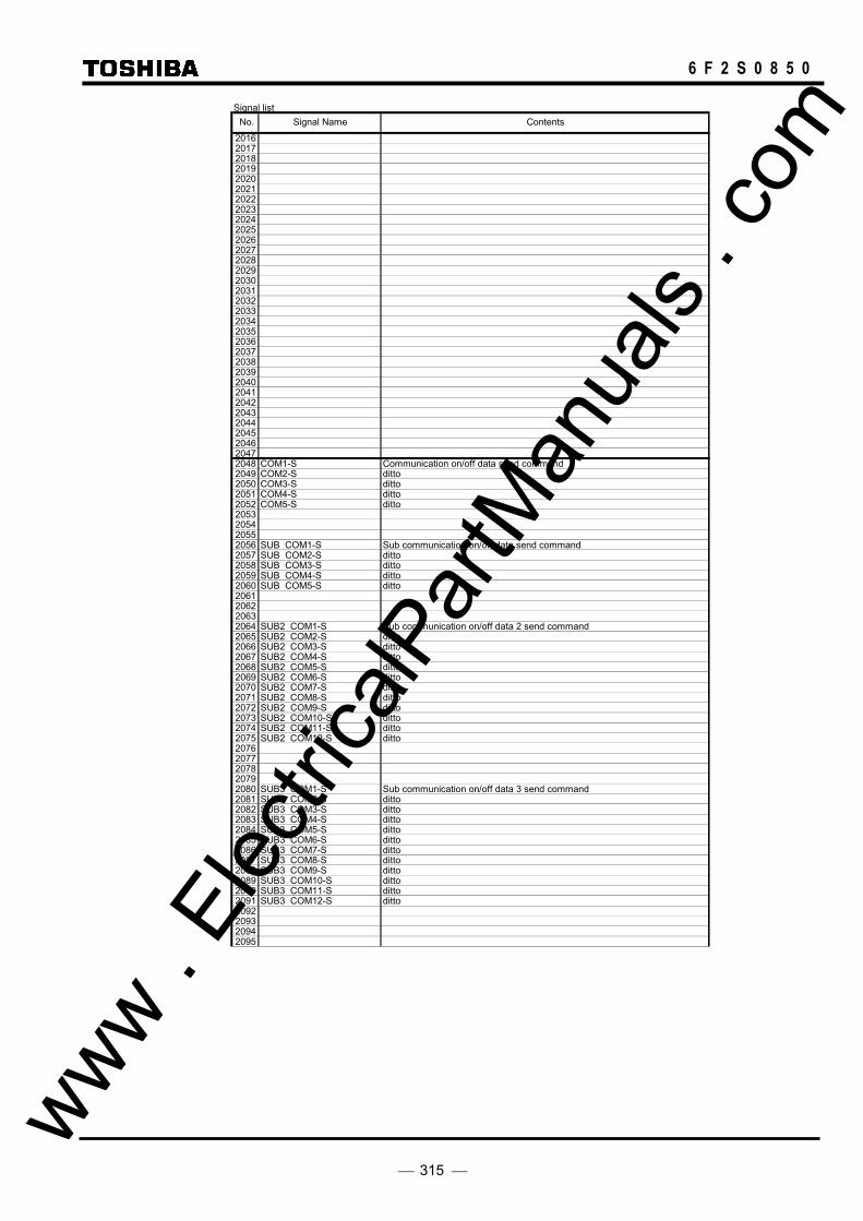
315
6 F 2 S 0 8 5 0
Signal list
201620172018201920202021202220232024202520262027202820292030203120322033203420352036203720382039204020412042204320442045204620472048 COM1-S Communication on/off data send command2049 COM2-S ditto2050 COM3-S ditto2051 COM4-S ditto2052 COM5-S ditto2053205420552056 SUB COM1-S Sub communication on/off data send command2057 SUB COM2-S ditto2058 SUB COM3-S ditto2059 SUB COM4-S ditto2060 SUB COM5-S ditto2061206220632064 SUB2 COM1-S Sub communication on/off data 2 send command2065 SUB2 COM2-S ditto2066 SUB2 COM3-S ditto2067 SUB2 COM4-S ditto2068 SUB2 COM5-S ditto2069 SUB2 COM6-S ditto2070 SUB2 COM7-S ditto2071 SUB2 COM8-S ditto2072 SUB2 COM9-S ditto2073 SUB2 COM10-S ditto2074 SUB2 COM11-S ditto2075 SUB2 COM12-S ditto20762077207820792080 SUB3 COM1-S Sub communication on/off data 3 send command2081 SUB3 COM2-S ditto2082 SUB3 COM3-S ditto2083 SUB3 COM4-S ditto2084 SUB3 COM5-S ditto2085 SUB3 COM6-S ditto2086 SUB3 COM7-S ditto2087 SUB3 COM8-S ditto2088 SUB3 COM9-S ditto2089 SUB3 COM10-S ditto2090 SUB3 COM11-S ditto2091 SUB3 COM12-S ditto2092209320942095
No. Signal Name Contents
www . El
ectric
alPar
tMan
uals
. com

316
6 F 2 S 0 8 5 0
Signal list
2096 V.COM1-S Communiation on/off data(V0 data frame) send command2097 V.COM2-S ditto2098 V.COM3-S ditto20992100 S.V.COM1-S Communiation on/off data(V0 data frame) send command2101 S.V.COM2-S ditto2102 S.V.COM3-S ditto2103 S.V.COM4-S ditto2104 S.V.COM5-S ditto2105 S.V.COM6-S ditto2106 S.V.COM7-S ditto2107 S.V.COM8-S ditto2108 S.V.COM9-S ditto2109 S.V.COM10-S ditto2110 S.V.COM11-S ditto2111 S.V.COM12-S ditto2112 I.COM1-S Communiation on/off data(I0 data frame) send command2113 I.COM2-S ditto2114 I.COM3-S ditto21152116 S.I.COM1-S Communiation on/off data(I0 data frame) send command2117 S.I.COM2-S ditto2118 S.I.COM3-S ditto2119 S.I.COM4-S ditto2120 S.I.COM5-S ditto2121 S.I.COM6-S ditto2122 S.I.COM7-S ditto2123 S.I.COM8-S ditto2124 S.I.COM9-S ditto2125 S.I.COM10-S ditto2126 S.I.COM11-S ditto2127 S.I.COM12-S ditto212821292130213121322133213421352136213721382139214021412142214321442145214621472148214921502151215221532154215521562157215821592160216121622163216421652166216721682169217021712172
::
2575
No. Signal Name Contents
www . El
ectric
alPar
tMan
uals
. com

317
6 F 2 S 0 8 5 0
Signal list
25762577257825792580258125822583258425852586258725882589259025912592259325942595259625972598259926002601260226032604260526062607260826092610 ALARM_LED_SET Alarm LED set26112612261326142615261626172618261926202621262226232624 F.RECORD1 Fault record stored command 12625 F.RECORD2 22626 F.RECORD3 32627 F.RECORD4 426282629263026312632 D.RECORD1 Disturbance record stored command 12633 D.RECORD2 22634 D.RECORD3 32635 D.RECORD4 426362637263826392640 SET.GROUP1 Active setting group changed commamd (Change to group1)2641 SET.GROUP2 22642 SET.GROUP3 32643 SET.GROUP4 42644 SET.GROUP5 52645 SET.GROUP6 62646 SET.GROUP7 72647 SET.GROUP8 826482649265026512652265326542655
No. Signal Name Contents
www . El
ectric
alPar
tMan
uals
. com

318
6 F 2 S 0 8 5 0
Signal list
2656 CON TPMD1 User configurable trip mode in fault record2657 CON TPMD2 ditto2658 CON_TPMD3 ditto2659 CON TPMD4 ditto2660 CON TPMD5 ditto2661 CON TPMD6 ditto2662 CON TPMD7 ditto2663 CON TPMD8 ditto266426652666266726682669267026712672267326742675267626772678267926802681268226832684 ARC_COM_RECV Auto-recloser inactivate command received 2685 TEL COM RECV Teleprotection inactivate command received 2686 PROT COM RECV protection inactivate command received 26872688 TPLED RST RCV TRIP LED RESET command received26892690269126922693269426952696269726982699270027012702270327042705270627072708270927102711271227132714271527162717271827192720272127222723272427252726272727282729273027312732
::
2815
No. Signal Name Contents
www . El
ectric
alPar
tMan
uals
. com
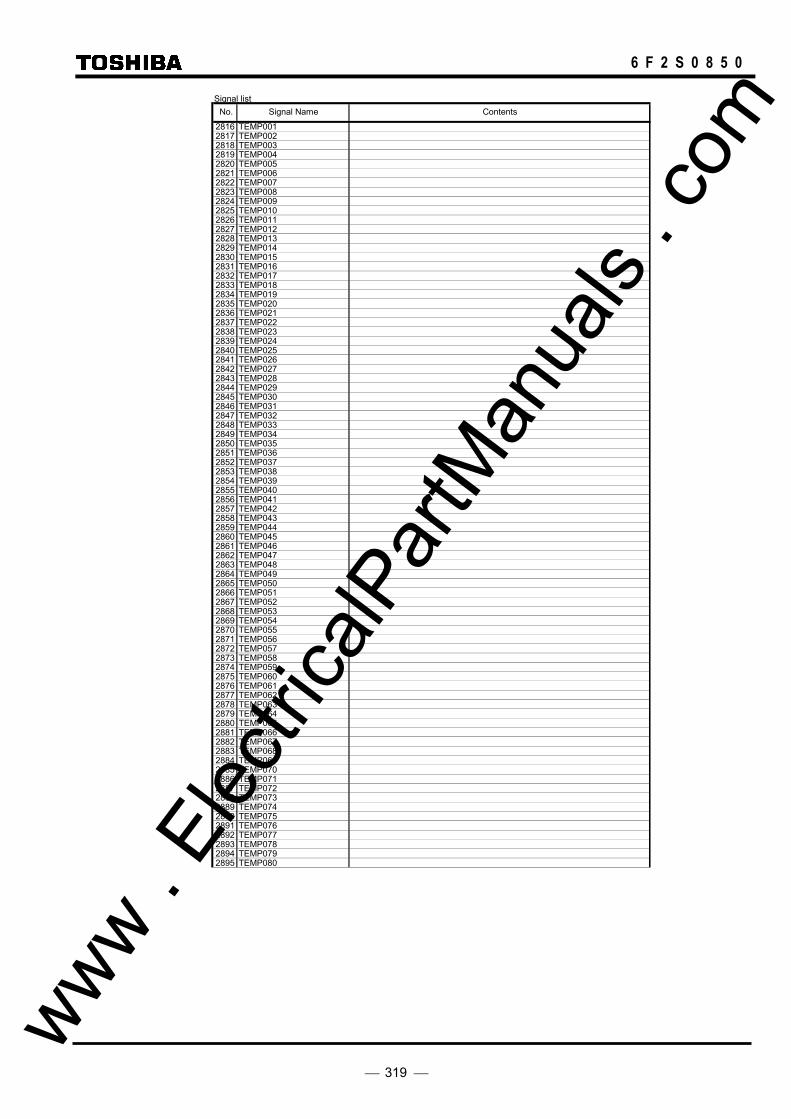
319
6 F 2 S 0 8 5 0
Signal list
2816 TEMP0012817 TEMP0022818 TEMP0032819 TEMP0042820 TEMP0052821 TEMP0062822 TEMP0072823 TEMP0082824 TEMP0092825 TEMP0102826 TEMP0112827 TEMP0122828 TEMP0132829 TEMP0142830 TEMP0152831 TEMP0162832 TEMP0172833 TEMP0182834 TEMP0192835 TEMP0202836 TEMP0212837 TEMP0222838 TEMP0232839 TEMP0242840 TEMP0252841 TEMP0262842 TEMP0272843 TEMP0282844 TEMP0292845 TEMP0302846 TEMP0312847 TEMP0322848 TEMP0332849 TEMP0342850 TEMP0352851 TEMP0362852 TEMP0372853 TEMP0382854 TEMP0392855 TEMP0402856 TEMP0412857 TEMP0422858 TEMP0432859 TEMP0442860 TEMP0452861 TEMP0462862 TEMP0472863 TEMP0482864 TEMP0492865 TEMP0502866 TEMP0512867 TEMP0522868 TEMP0532869 TEMP0542870 TEMP0552871 TEMP0562872 TEMP0572873 TEMP0582874 TEMP0592875 TEMP0602876 TEMP0612877 TEMP0622878 TEMP0632879 TEMP0642880 TEMP0652881 TEMP0662882 TEMP0672883 TEMP0682884 TEMP0692885 TEMP0702886 TEMP0712887 TEMP0722888 TEMP0732889 TEMP0742890 TEMP0752891 TEMP0762892 TEMP0772893 TEMP0782894 TEMP0792895 TEMP080
No. Signal Name Contents
www . El
ectric
alPar
tMan
uals
. com

320
6 F 2 S 0 8 5 0
Signal list
2896 TEMP0812897 TEMP0822898 TEMP0832899 TEMP0842900 TEMP0852901 TEMP0862902 TEMP0872903 TEMP0882904 TEMP0892905 TEMP0902906 TEMP0912907 TEMP0922908 TEMP0932909 TEMP0942910 TEMP0952911 TEMP0962912 TEMP0972913 TEMP0982914 TEMP0992915 TEMP1002916 TEMP1012917 TEMP1022918 TEMP1032919 TEMP1042920 TEMP1052921 TEMP1062922 TEMP1072923 TEMP1082924 TEMP1092925 TEMP1102926 TEMP1112927 TEMP1122928 TEMP1132929 TEMP1142930 TEMP1152931 TEMP1162932 TEMP1172933 TEMP1182934 TEMP1192935 TEMP1202936 TEMP1212937 TEMP1222938 TEMP1232939 TEMP1242940 TEMP1252941 TEMP1262942 TEMP1272943 TEMP1282944 TEMP1292945 TEMP1302946 TEMP1312947 TEMP1322948 TEMP1332949 TEMP1342950 TEMP1352951 TEMP1362952 TEMP1372953 TEMP1382954 TEMP1392955 TEMP1402956 TEMP1412957 TEMP1422958 TEMP1432959 TEMP1442960 TEMP1452961 TEMP1462962 TEMP1472963 TEMP1482964 TEMP1492965 TEMP1502966 TEMP1512967 TEMP1522968 TEMP1532969 TEMP1542970 TEMP1552971 TEMP1562972 TEMP1572973 TEMP1582974 TEMP1592975 TEMP160
No. Signal Name Contents
www . El
ectric
alPar
tMan
uals
. com

321
6 F 2 S 0 8 5 0
Signal list
2976 TEMP1612977 TEMP1622978 TEMP1632979 TEMP1642980 TEMP1652981 TEMP1662982 TEMP1672983 TEMP1682984 TEMP1692985 TEMP1702986 TEMP1712987 TEMP1722988 TEMP1732989 TEMP1742990 TEMP1752991 TEMP1762992 TEMP1772993 TEMP1782994 TEMP1792995 TEMP1802996 TEMP1812997 TEMP1822998 TEMP1832999 TEMP1843000 TEMP1853001 TEMP1863002 TEMP1873003 TEMP1883004 TEMP1893005 TEMP1903006 TEMP1913007 TEMP1923008 TEMP1933009 TEMP1943010 TEMP1953011 TEMP1963012 TEMP1973013 TEMP1983014 TEMP1993015 TEMP2003016 TEMP2013017 TEMP2023018 TEMP2033019 TEMP2043020 TEMP2053021 TEMP2063022 TEMP2073023 TEMP2083024 TEMP2093025 TEMP2103026 TEMP2113027 TEMP2123028 TEMP2133029 TEMP2143030 TEMP2153031 TEMP2163032 TEMP2173033 TEMP2183034 TEMP2193035 TEMP2203036 TEMP2213037 TEMP2223038 TEMP2233039 TEMP2243040 TEMP2253041 TEMP2263042 TEMP2273043 TEMP2283044 TEMP2293045 TEMP2303046 TEMP2313047 TEMP2323048 TEMP2333049 TEMP2343050 TEMP2353051 TEMP2363052 TEMP2373053 TEMP2383054 TEMP2393055 TEMP240
No. Signal Name Contents
www . El
ectric
alPar
tMan
uals
. com

322
6 F 2 S 0 8 5 0
Signal list
3056 TEMP2413057 TEMP2423058 TEMP2433059 TEMP2443060 TEMP2453061 TEMP2463062 TEMP2473063 TEMP2483064 TEMP2493065 TEMP2503066 TEMP2513067 TEMP2523068 TEMP2533069 TEMP2543070 TEMP2553071 TEMP256
No. Signal Name Contents
www . El
ectric
alPar
tMan
uals
. com

323
6 F 2 S 0 8 5 0
Appendix C
Variable Timer List
www . El
ectric
alPar
tMan
uals
. com
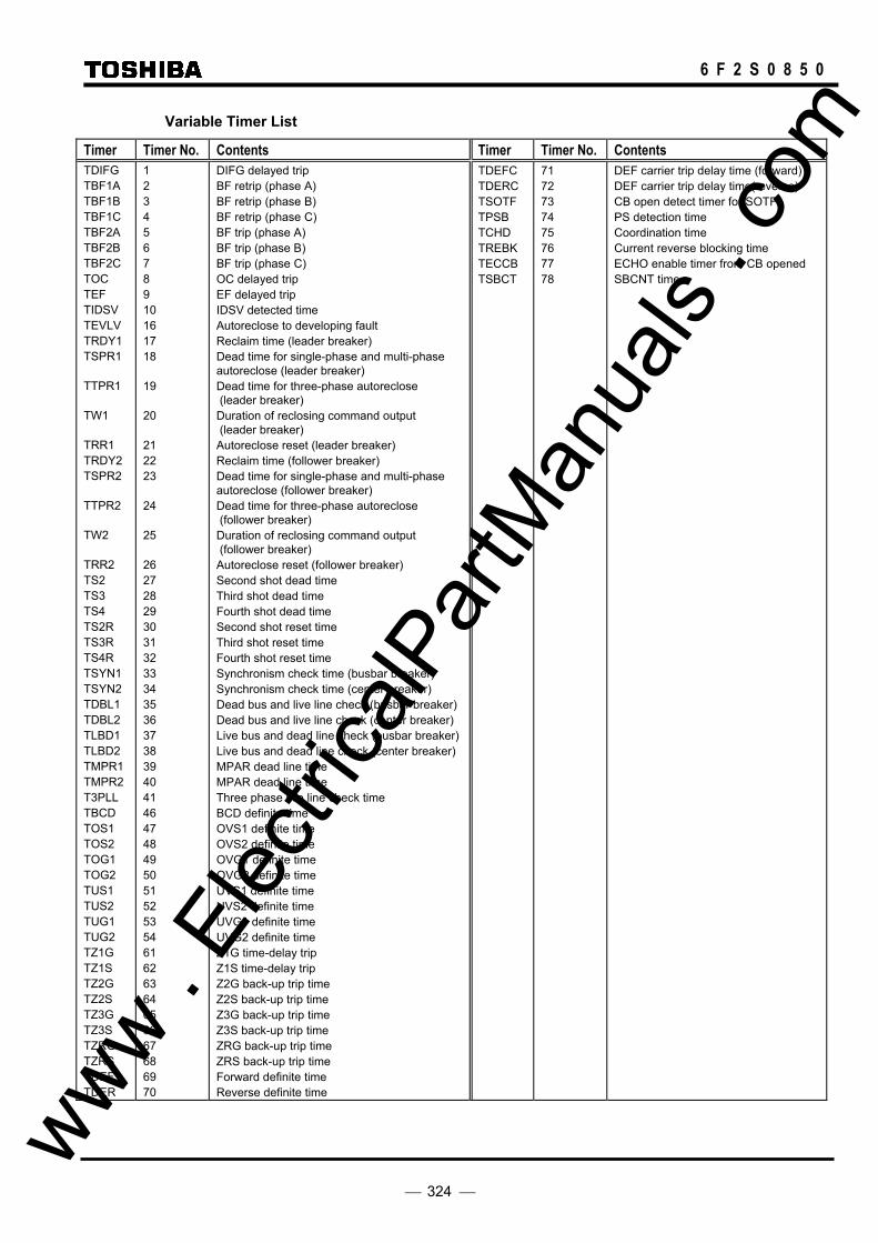
324
6 F 2 S 0 8 5 0
Variable Timer List
Timer Timer No. Contents Timer Timer No. Contents TDIFG TBF1A TBF1B TBF1C TBF2A TBF2B TBF2C TOC TEF TIDSV TEVLV TRDY1 TSPR1 TTPR1 TW1 TRR1 TRDY2 TSPR2 TTPR2 TW2 TRR2 TS2 TS3 TS4 TS2R TS3R TS4R TSYN1 TSYN2 TDBL1 TDBL2 TLBD1 TLBD2 TMPR1 TMPR2 T3PLL TBCD TOS1 TOS2 TOG1 TOG2 TUS1 TUS2 TUG1 TUG2 TZ1G TZ1S TZ2G TZ2S TZ3G TZ3S TZRG TZRS TDEF TDER
1 2 3 4 5 6 7 8 9 10 16 17 18 19 20 21 22 23 24 25 26 27 28 29 30 31 32 33 34 35 36 37 38 39 40 41 46 47 48 49 50 51 52 53 54 61 62 63 64 65 66 67 68 69 70
DIFG delayed trip BF retrip (phase A) BF retrip (phase B) BF retrip (phase C) BF trip (phase A) BF trip (phase B) BF trip (phase C) OC delayed trip EF delayed trip IDSV detected time Autoreclose to developing fault Reclaim time (leader breaker) Dead time for single-phase and multi-phase autoreclose (leader breaker) Dead time for three-phase autoreclose (leader breaker) Duration of reclosing command output (leader breaker) Autoreclose reset (leader breaker) Reclaim time (follower breaker) Dead time for single-phase and multi-phase autoreclose (follower breaker) Dead time for three-phase autoreclose (follower breaker) Duration of reclosing command output (follower breaker) Autoreclose reset (follower breaker) Second shot dead time Third shot dead time Fourth shot dead time Second shot reset time Third shot reset time Fourth shot reset time Synchronism check time (busbar breaker) Synchronism check time (center breaker) Dead bus and live line check (busbar breaker) Dead bus and live line check (center breaker) Live bus and dead line check (busbar breaker) Live bus and dead line check (center breaker) MPAR dead line time MPAR dead line time Three phase live line check time BCD definite time OVS1 definite time OVS2 definite time OVG1 definite time OVG2 definite time UVS1 definite time UVS2 definite time UVG1 definite time UVG2 definite time Z1G time-delay trip Z1S time-delay trip Z2G back-up trip time Z2S back-up trip time Z3G back-up trip time Z3S back-up trip time ZRG back-up trip time ZRS back-up trip time Forward definite time Reverse definite time
TDEFC TDERC TSOTF TPSB TCHD TREBK TECCB TSBCT
71 72 73 74 75 76 77 78
DEF carrier trip delay time (forward) DEF carrier trip delay time(reverse) CB open detect timer for SOTF PS detection time Coordination time Current reverse blocking time ECHO enable timer from CB opened SBCNT time
www . El
ectric
alPar
tMan
uals
. com

325
6 F 2 S 0 8 5 0
Appendix D
Binary Output Default Setting List
www . El
ectric
alPar
tMan
uals
. com

326
6 F 2 S 0 8 5 0
Binary Output Default Setting List (1)
Relay Model Module BO No. Terminal No. Signal Name Contents Setting Name Signal No.
LOGIC
(OR:1, AND:2) TIMER
(OFF:0, ON:1)
GRL100 -701
IO#2
BO1 BO2 BO3 BO4 BO5 BO6 BO7 BO8 BO9 BO10 BO11 BO12 BO13
TB3: A2-A1 A2-B1 A2-B2 A3-B3 A4-B4 A5-B5 A6-B6 A7-B7 A8-B8 A9-B9 A10-B10 A11-B11 A13-B13
TRIP-A1/A2 TRIP-B1/B2 TRIP-C1/C2 TRIP-A1/A2 TRIP-B1/B2 TRIP-C1/C2 TRIP-A∗,B∗,C∗ TRIP-A∗,B∗,C∗ ARC1 ARC2 COMM1_FAIL 85R1.REM1 CAR-S
Trip A phase Trip B phase Trip C phase Trip A phase Trip B phase Trip C phase Trip A, B or C phase Trip A, B or C phase Bus CB autoreclose Center CB autoreclose Communication failure Transfer trip 1 receive Carrier send command
99, 102
100, 103 101, 104 99, 102
100, 103 101, 104
99, 100, 101, 102, 103, 104 99, 100, 101, 102, 103, 104
177 178 225 197 886
1 1 1 1 1 1 1 1 1 1 1 1 1
1 1 1 1 1 1 1 1 0 0 1 1 0
(FAIL) A12-B12 RELAY FAILURE -- -- -- --
IO#3
BO1 BO2 BO3 BO4 BO5 BO6
TB2: A1-B1 A2-B2 A3-B3 A4-B4 A5-B5 A6-B6
89CB-1AB 89CB-2AB 89CB-3AB DIF-∗ /DIFG_TRIP CAR/Z1G/Z1S_TRIP CBFDET
Link A phase (A-B terminal)Link B phase (A-B terminal)Link C phase (A-B terminal)DIF, DIFG relay operating Carrier, Z1S, Z1G trip CBF detection
146 147 148
82, 83, 84, 86 904, 790, 794
91
1 1 1 1 1 1
0 0 0 1 1 1
GRL100 -702
IO#2
BO1 BO2 BO3 BO4 BO5 BO6 BO7 BO8 BO9 BO10 BO11 BO12 BO13
TB2: A2-A1 A2-B1 A2-B2 A3-B3 A4-B4 A5-B5 A6-B6 A7-B7 A8-B8 A9-B9 A10-B10 A11-B11 A13-B13
TRIP-A1/A2 TRIP-B1/B2 TRIP-C1/C2 TRIP-A1/A2 TRIP-B1/B2 TRIP-C1/C2 TRIP-A∗,B∗,C∗ TRIP-A∗,B∗,C∗ ARC1 ARC2 COMM1_FAIL 85R1.REM1 CAR-S
Trip A phase Trip B phase Trip C phase Trip A phase Trip B phase Trip C phase Trip A, B or C phase Trip A, B or C phase Bus CB autoreclose Center CB autoreclose Communication failure Transfer trip 1 receive Carrier send command
99, 102
100, 103 101, 104 99, 102
100, 103 101, 104
99, 100, 101, 102, 103, 104 99, 100, 101, 102, 103, 104
177 178 225 197 886
1 1 1 1 1 1 1 1 1 1 1 1 1
1 1 1 1 1 1 1 1 0 0 1 1 0
(FAIL) A12-B12 RELAY FAILURE -- -- -- --
IO#4
BO1 BO2 BO3 BO4 BO5 BO6 BO7 BO8 BO9 BO10 BO11 BO12 BO13 BO14
TB3: A2-A1 A2-B1 A2-B2 A3-B3 A4-B4 A5-B5 A6-B6 A7-B7 A8-B8 A9-B9 A10-B10 A11-B11 A12-B12 A13-B13
89CB-1AB 89CB-2AB 89CB-3AB TRIP-A1/A2 TRIP-B1/B2 TRIP-C1/C2 TRIP-A1/A2 TRIP-B1/B2 TRIP-C1/C2 TRIP-A1/A2 TRIP-B1/B2 TRIP-C1/C2 TRIP-A1/A2 TRIP-B1/B2
Link A phase (A-B terminal)Link B phase (A-B terminal)Link C phase (A-B terminal)Trip A phase Trip B phase Trip C phase Trip A phase Trip B phase Trip C phase Trip A phase Trip B phase Trip C phase Trip A phase Trip B phase
146 147 148
99, 102 100, 103 101, 104 99, 102
100, 103 101, 104 99, 102
100, 103 101, 104 99, 102
100, 103
1 1 1 1 1 1 1 1 1 1 1 1 1 1
0 0 0 1 1 1 1 1 1 1 1 1 1 1
IO#3
BO1 BO2 BO3 BO4 BO5 BO6 BO7 BO8 BO9 BO10
TB5: A1-B1 A2-B2 A3-B3 A4-B4 A5-B5 A6-B6 A7-B7 A8-B8 A9-B9 A10-B10
TRIP-C1/C2 DIF-A, -B, -C_TRIP DIFG_TRIP CAR_TRIP Z1G_TRIP/Z1S_TRIPCBFDET SPAR1 TPAR1 SPAR2 TPAR2
Trip C phase DIF relay operating DIFG relay operating Distance or DG carrier trip Z1G, Z1S trip CBF detection Bus CB single pole ARC Bus CB three pole ARC Center CB single pole ARC Center CB three pole ARC
101, 104 82, 83, 84
86 904
790, 794 91
173 175 174 176
1 1 1 1 1 1 1 1 1 1
1 1 1 1 1 1 1 1 1 1
www . El
ectric
alPar
tMan
uals
. com

327
6 F 2 S 0 8 5 0
Binary Output Default Setting List (2)
Relay Model Module BO No. Terminal No. Signal Name Contents Setting Name Signal No.
LOGIC
(OR:1, AND:2) TIMER
(OFF:0, ON:1)
GRL100 -711
IO#2
BO1 BO2 BO3 BO4 BO5 BO6 BO7 BO8 BO9 BO10 BO11 BO12 BO13
TB3: A2-A1 A2-B1 A2-B2 A3-B3 A4-B4 A5-B5 A6-B6 A7-B7 A8-B8 A9-B9 A10-B10 A11-B11 A13-B13
TRIP-A1/A2 TRIP-B1/B2 TRIP-C1/C2 TRIP-A1/A2 TRIP-B1/B2 TRIP-C1/C2 TRIP-A∗,B∗,C∗ TRIP-A∗,B∗,C∗ ARC1 ARC2 COMM1/2_FAIL 85R1.REM1/2 CAR-S
Trip A phase Trip B phase Trip C phase Trip A phase Trip B phase Trip C phase Trip A, B or C phase Trip A, B or C phase Bus CB autoreclose Center CB autoreclose Communication failure Transfer trip 1 receive Carrier send command
99, 102
100, 103 101, 104 99, 102
100, 103 101, 104
99, 100, 101, 102, 103, 104 99, 100, 101, 102, 103, 104
177 178
225, 226 197, 202
886
1 1 1 1 1 1 1 1 1 1 1 1 1
1 1 1 1 1 1 1 1 0 0 1 1 0
(FAIL) A12-B12 RELAY FAILURE -- -- -- --
IO#3
BO1 BO2 BO3 BO4 BO5 BO6
TB2: A1-B1 A2-B2 A3-B3 A4-B4 A5-B5 A6-B6
89CB-1AB 89CB-2AB 89CB-3AB 89CB-1AC 89CB-2AC 89CB-3AC
Link A phase (A-B terminal)Link B phase (A-B terminal)Link C phase (A-B terminal)Link A phase (A-C terminal)Link B phase (A-C terminal)Link C phase (A-C terminal)
146 147 148 149 150 151
1 1 1 1 1 1
0 0 0 0 0 0
GRL100 -712
IO#2
BO1 BO2 BO3 BO4 BO5 BO6 BO7 BO8 BO9 BO10 BO11 BO12 BO13
TB2: A2-A1 A2-B1 A2-B2 A3-B3 A4-B4 A5-B5 A6-B6 A7-B7 A8-B8 A9-B9 A10-B10 A11-B11 A13-B13
TRIP-A1/A2 TRIP-B1/B2 TRIP-C1/C2 TRIP-A1/A2 TRIP-B1/B2 TRIP-C1/C2 TRIP-A∗,B∗,C∗ TRIP-A∗,B∗,C∗ ARC1 ARC2 COMM1/2_FAIL 85R1.REM1/2 CAR-S
Trip A phase Trip B phase Trip C phase Trip A phase Trip B phase Trip C phase Trip A, B or C phase Trip A, B or C phase Bus CB autoreclose Center CB autoreclose Communication failure Transfer trip 1 receive Carrier send command
99, 102
100, 103 101, 104 99, 102
100, 103 101, 104
99, 100, 101, 102, 103, 104 99, 100, 101, 102, 103, 104
177 178
225, 226 197, 202
886
1 1 1 1 1 1 1 1 1 1 1 1 1
1 1 1 1 1 1 1 1 0 0 1 1 0
(FAIL) A12-B12 RELAY FAILURE -- -- -- --
IO#4
BO1 BO2 BO3 BO4 BO5 BO6 BO7 BO8 BO9 BO10 BO11 BO12 BO13 BO14
TB3: A2-A1 A2-B1 A2-B2 A3-B3 A4-B4 A5-B5 A6-B6 A7-B7 A8-B8 A9-B9 A10-B10 A11-B11 A12-B12 A13-B13
89CB-1AB 89CB-2AB 89CB-3AB 89CB-1AC 89CB-2AC 89CB-3AC TRIP-A1/A2 TRIP-B1/B2 TRIP-C1/C2 TRIP-A1/A2 TRIP-B1/B2 TRIP-C1/C2 TRIP-A1/A2 TRIP-B1/B2
Link A phase (A-B terminal)Link B phase (A-B terminal)Link C phase (A-B terminal)Link A phase (A-C terminal)Link B phase (A-C terminal)Link C phase (A-C terminal)Trip A phase Trip B phase Trip C phase Trip A phase Trip B phase Trip C phase Trip A phase Trip B phase
146 147 148 149 150 151
99, 102 100, 103 101, 104 99, 102
100, 103 101, 104 99, 102
100, 103
1 1 1 1 1 1 1 1 1 1 1 1 1 1
0 0 0 0 0 0 1 1 1 1 1 1 1 1
IO#3
BO1 BO2 BO3 BO4 BO5 BO6 BO7 BO8 BO9 BO10
TB5: A1-B1 A2-B2 A3-B3 A4-B4 A5-B5 A6-B6 A7-B7 A8-B8 A9-B9 A10-B10
TRIP-C1/C2 DIF-A, -B, -C_TRIP DIFG_TRIP CAR_TRIP Z1G_TRIP/Z1S_TRIPCBFDET SPAR1 TPAR1 SPAR2 TPAR2
Trip C phase DIF relay operating DIFG relay operating Distance or DG carrier trip Z1G, Z1S trip CBF detection Bus CB single pole ARC Bus CB three pole ARC Center CB single pole ARC Center CB three pole ARC
101, 104 82, 83, 84
86 904
790, 794 91
173 175 174 176
1 1 1 1 1 1 1 1 1 1
1 1 1 1 1 1 1 1 1 1
www . El
ectric
alPar
tMan
uals
. com

328
6 F 2 S 0 8 5 0 www .
Elec
tricalP
artM
anua
ls . c
om

329
6 F 2 S 0 8 5 0
Appendix E
Details of Relay Menu and LCD & Button Operation
www . El
ectric
alPar
tMan
uals
. com

330
6 F 2 S 0 8 5 0
MENU 1=Record 2=Status 3=Setting(view) 4=Setting(change) 5=Test
/1 Record 1=Fault record 2=Event record 3=Disturbance record 4= Autoreclose count
/2 Fault record 1=Display 2=Clear
/3 Fault record 2/8 #1 16/Oct/1998 23:18:03.913 #2 12/Feb/1998 03:51:37.622 #3 30/Jan/1997 15:06:11.835
/2 Fault record Clear all fault records ? ENTER=Yes CANCEL=No
/4 Fault record #2 3/33 16/Oct/1998 23:18:03.913 Phase BC Trip ABC DIF
/2 Event record Clear all event records ? ENTER=Yes CANCEL=No
/2 Disturbance record Clear all disturbance records ? ENTER=Yes CANCEL=No
/2 Event record 1=Display 2=Clear
/3 Event record 2/48 16/Oct/1998 23:18:04.294 Trip Off 16/Oct/1998 23:18:03.913 Trip On 12/Feb/1998 03:51:37.622 Rly.set change
/2 Disturbance record 1=Display 2=Clear
/3 Disturbance record 1/ 11 #1 16/Oct/1998 23:18:03.913 #2 12/Feb/1998 03:51:37.622 #3 30/Jan/1997 15:06:11.835
/2 Autoreclose count 1=Display 2=Reset
/3 Autoreclose count SPAR TPAR MPAR CB1 [ 46] [ 46] [ 12] CB2 [ 46] [ 46]
/3 Reset autoreclose count 1=CB1 2=CB2
/3 Reset autoreclose count Reset count ? ENTER=Yes CANCEL=No
/3 Reset autoreclose count Reset count ? ENTER=Yes CANCEL=No
a-1 www . El
ectric
alPar
tMan
uals
. com

331
6 F 2 S 0 8 5 0
/2 Description Plant name: ******************** Description: ********************
/1 Status 1=Metering 2=Binary I/O 3=Relay element 4=Time sync source 5=Clock adjustment 6=Terminal condition
/2 Metering 12/Feb/1998 22:56 3/13 Va ***.*kV ***.* Ia **.**kA ***.* Vb ***.*kV ***.* Ib **.**kA ***.* Vc ***.*kV ***.* Ic **.**kA ***.*
/2 Terminal condition Terminal 1: In service Terminal 2: Out of service
/2 12/Feb/1998 22:56:19 [local] 1/5 Minute ( 0 - 59) : 56 _ Hour ( 0 - 23) : 22 Day ( 1 - 31) : 12
/2 Relay version Relay type : ******************** Serial No. : ******************** Main software: ********************
/2 Binary input & output 3/ 5 Input (IO#1) [000 000 000 000 000] Input (IO#2) [000 ] Output(IO#1-trip)[000 000 ]
/2 Relay element 3/ 6 DIF, DIFG [000 0 ] OST [000 00 0 ] CBF [000 ]
/2 Time synchronization source 3/ 4 *IRIG: Active RSM: Inactive IEC: Inactive
/2 Communication 1=Address/Parameter 2=Switch
/3 Fault record 1/ 1 Fault locator 0=Off 1=On 1
/3 Event record 1=Signal no. 2=Event name
/1 Setting(view) 1=Version 2=Description 3=Comm 4=Record 5=Status 6=Protection 7=Binary input 8=Binary output 9=LED
/2 Record 1=Fault record 2=Event record 3=Disturbance record 4=Automatic test interval
/3 Disturbance record 1=Record time & starter 2=Scheme switch 3=Binary signal 4=Signal name
/4 Record time & starter 2/ 5 Time ( 3.0s ) OCP-S( 50.0A ) OCP-G ( 50.0A ) UVP-S( 0V ) UVP-G ( 0V )
/4 Scheme switch 1/ 5 Trip 0=Off 1=On 1 OCP-S 0=Off 1=On 1 OCP-G 0=Off 1=On 1
/3 Automatic test interval 1/ 1 Trip ( 7 days)
a-1
a-1 a-2
/3 Address/Parameter 2/ 8 HDLC ( 1 ) IEC ( 1 ) SYADJ ( 0 ms) IP1-1 ( 10 ) IP1-2 ( 245 ) IP1-3 ( 105 )
/3 Switch 3/ 4 PRTCL1 1=HDLC 2=IEC103 2 232C 1=9.6 2=19.2 3=38.4 4=57.6 4 IECBR 1=9.6 2=19.2 2
/4 Signal no. 3/ 65 BITRN ( 128 ) EV1 ( 3071 ) EV2 ( 0 ) EV3 ( 1 ) EV4 ( 2 ) EV4 ( 4 )
/4 Event name 3/128 Event name1 [ ] Event name2 [ ] Event name3 [ ]
/4 Binary signal 3/ 16 SIG1 ( 128 ) SIG2 ( 3071 ) SIG3 ( 0 ) SIG4 ( 1 ) SIG5 ( 2 ) SIG6 ( 4 )
/4 Signal name 3/32 Signal name1 [ ] Signal name2 [ ] Signal name3 [ ] www .
Elec
tricalP
artM
anua
ls . c
om

332
6 F 2 S 0 8 5 0
/2 Status 1=Metering 2=Time Synchronization 3=Time zone
/3 Time synchronization 1/ 1 Sync 0=Off 1=IRIG 2=RSM 3=IEC 4=GPS 1
/3 Time zone 1/ 1 GMT ( +9 hrs )
/3 Metering 3/ 3 Display value 1=Primary 2=Secondary 1 Power (P/Q) 1=Send 2=Receive 1 Current 1=Lag 2=Lead 1
/4 Line parameter (Group 1) 1=Line name 2=VT & CT ratio 3=Fault locator
/4 Telecommunication (Group 1) 1=Scheme switch 2=Telecommunication element
/6 Line data 3/ 5
1X1 ( 24.5Ω ) 1R1 ( 2.8Ω ) 1Line ( 80.0km) 2X1 ( 12.5Ω ) 2R1 ( 1.5Ω ) 2Line ( 41.3km)
/5 Scheme switch 2/ 12 COMMODE 1=A 2=B 3=GPS 2 SP.SYN. 1=Master 2=Slave 1 TERM. 1=2TERM 2=3TERM 3=Dual 1 _
/2 Protection (Active group= *) 1=Group1 2=Group2 3=Group3 4=Group4 5=Group5 6=Group6 7=Group7 8=Group8
/5 Line name 1/ 1 Line name ********************
/3 Protection (Group 1) 1=Line parameter 2=Telecommunication 3=Trip 4=Autoreclose
/5 VT & CT ratio 1/ 2 VT ( 2000 ) VTs1 ( 2000 ) VTs2 ( 2000 ) CT ( 120 )
/5 Scheme switch 3/16 TPMODE 1=3PH 2=1PH 3=MPH 1 STUB 0=Off 1=On 1 DIFG 0=Off 1=On 1
/5 Protection element 3/11 DIFI1 ( 1.00A ) DIFI2 ( 2.0A ) DIFG1 ( 0.50A ) DIFIC ( 1.00A ) Vn ( 110V ) TDIFG ( 0.10s )
/4 Autoreclose (Group 1) 1=Autoreclose mode 2=Scheme switch 3=Autoreclose element
/5 Scheme switch 3/ 8 ARC-CB 1=00 2=01 3=02 4=L1 5=L2 1 ARC-EXT 0=Off 1=On 0 ARCDIFG 0=Off 1=On 1
/5 Autoreclose element (Group 1) 1=Autoreclose timer 2=Synchrocheck
/6 Autoreclose timer 3/ 8 TEVLV( 0.30 s ) TRDY1( 60 s ) TSPR ( 0.80 s ) TTPR1( 0.60 s ) TRR ( 2.00 s ) TW1 ( 0.3 s )
/6 Synchrocheck 3/ 9 OVB ( 51 V ) UVB ( 13 V ) OVL1 ( 51 V ) UVL1 ( 13 V ) SY1UV( 83 V ) SY1OV( 51 V )
/5 Autoreclose mode 1=Disable 2=SPAR 3=TPAR 4=SPAR&TPAR 5=MPAR2 6=MPAR3 7=EXT1P 8=EXT3P 9=EXTMP Current No.= 4
/3 Protection (Group 8) 1=Line parameter 2=Telecommunication 3=Trip 4=Autoreclose
/3 Protection (Group 2) 1=Line parameter 2=Telecommunication 3=Trip 4=Autoreclose
a-1 a-2
a-1 a-2
/4 Trip (Group 1) 1=Scheme switch 2=Protection element
/5 Telecommunicatio element 1/ 7 PDTD ( 200 - 2000) : 1000 us RYID ( 0 - 63) : 0 RYID1 ( 0 - 63) : 0
/5 Fault locator (Group 1) 1=Setting impedance mode 2=Line data
/6 Setting impedance mode 1=Symmetrical impedance 2=Phase impedance Current No.= 1
www . El
ectric
alPar
tMan
uals
. com

333
6 F 2 S 0 8 5 0
a-1 a-2
/2 Password Input new password [ _ ] Retype new password [ ]
/2 Description 1=Plant name 2=Description
/2 Communication 1=Address/Parameter 2=Switch
/3 Fault record 1/ 1 Fault locator 0=Off 1=On 1 _
/3 Event record 1/129 BITRN ( 0- 128) : 128 _ EV1 ( 0- 3071) : 0 EV2 ( 0- 3071) : 1
/1 Setting(change) 1=Password 2=Description 3=Comm 4=Record 5=Status 6=Protection 7=Binary input 8=Binary output 9=LED
/2 Record 1=Fault record 2=Event record 3=Disturbance record
/3 Disturbance record 1=Record time & starter 2=Scheme switch 3=Binary signal
/4 Record time & starter 1/ 3 Time ( 0.1- 3.0): 2.0 _ s OCP-S( 0.5- 250.0): 10.0: A OCP-G( 0.5- 250.0): 10.0: A
/4 Scheme switch 1/ 5 Trip trigger 0=Off 1=On 1 _ OCP-S 0=Off 1=On 1 OCP-G 0=Off 1=On 1
/2 Binary output 1=IO#2 2=IO#3 3=IO#4
/2 Binary input 3/ 31 BISW 1 1=Norm 2=Inv 1 BISW 2 1=Norm 2=Inv 1 BISW 3 1=Norm 2=Inv 1
/3 Binary output (IO#2)3/12 BO1 ( 1, 2, 3, 4, 5, 6) AND,D BO2 ( 1, 2, 3, 4, 5, 6) OR, BO3 ( 1, 2, 3, 4, 5, 6) OR,D
/2 LED 3/ 4 LED1 ( 1, 309, 0, 0) AND, I LED2 ( 0, 0, 0, 0) OR, I LED3 ( 15, 16, 17, 0) OR, L
/3 Binary output (IO#4)3/12 BO1 ( 1, 2, 3, 4, 5, 6) AND,D BO2 ( 1, 2, 3, 4, 5, 6) OR, BO3 ( 1, 2, 3, 4, 5, 6) OR,D
: Confirmation trap
: Password trap Password Input password [_ ]
/2 ************* Change settings? ENTER=Yes CANCEL=No
/3 Plant name [ _ ]
ABCDEFGHIJKLMNOPQRSTUVWXYZ()[]@_← →
abcdefghijklmnopqrstuvwxyz*/+-<=>← →
0123456789!”#$%&’:;,.^ ← →
/3 Description [ _ ]
ABCDEFGHIJKLMNOPQRSTUVWXYZ()[]@_← →
abcdefghijklmnopqrstuvwxyz*/+-<=>← →
0123456789!”#$%&’:;,.^ ← →
a-1 a-2
/3 Address/Parameter 1/ 15 HDLC ( 1- 32) : 1 _ IEC ( 0- 254) : 2 SYADJ (-9999- 9999) : 0 ms
/3 Switch 1/ 4 PRTCL1 1=HDLC 2=IEC103 2 _ 232C 1=9.6 2=19.2 3=38.4 4=57.6 4 IECBR 1=9.6 2=19.2 2
/4 Binary signal 1/ 32 SIG1 ( 0- 3071) : 1 _ SIG2 ( 0- 3071) : 2 SIG3 ( 0- 3071) : 1 www .
Elec
tricalP
artM
anua
ls . c
om

334
6 F 2 S 0 8 5 0
/5 Line parameter (Group 1) 1=Line name 2=VT & CT ratio 3=Fault locator
/5 Trip (Group 1) 1=Scheme switch 2=Protection element
/5 Telecommunication (Group 1) 1=Scheme switch 2=Telecommunication
/7 Line data 1/ 9
1X1 ( 0.0 - 199.9): 24.5 _ Ω 1R1 ( 0.0 - 199.9): 2.8 Ω 1Line( 0.0 - 199.9): 80.0 km
/6 Protection element 1/17 DIFI1( 0.50 - 5.00): 1.00 _ A DIFI2( 3.0 - 120.0): 2.0 A DIFG1( 0.25 - 5.00): 0.50 A
/2 Protection 1=Change active group 2=Change setting 3=Copy group
/6 Line name [ _ ]
ABCDEFGHIJKLMNOPQRSTUVWXYZ()[]@_← →
abcdefghijklmnopqrstuvwxyz*/+-<=>← →
0123456789!”#$%&’:;,.^ ← →
/4 Protection (Group 1) 1=Line parameter 2=Telecommunication 3=Trip 4=Autoreclose
/6 VT & CT ratio 1/ 2 VT ( 1- 20000): 2000 _ VTs1 ( 1- 20000): 2000 CT ( 1- 20000): 120
/6 Scheme switch 1/ 12 COMMODE 1=A 2=B 3=GPS 2 _ SP.SYN. 1=Master 2=Slave 1 TERM. 1=2TERM 2=3TERM 3=Dual 1
/6 Scheme switch 1/16 TPMODE 1=3PH 2=1PH 3=MPH 1 _ STUB 0=Off 1=On 1 LSSV 0=Off 1=On 1
/2 Status 1=Metering 2=Time Synchronization 3=Time zone
/3 Time synchronization 1/ 1 Sync 0=Off 1=IRIG 2=RSM 3=IEC 4=GPS 1 _
/3 Time zone 1/ 1 GMT ( -12 - +12): +9 _ hrs
/3 Metering 1/ 3 Display value 1=Primary 2=Secondary 1_ Power (P/Q) 1=Send 2=Receive 1 Current 1=Lag 2=Lead 1
/3Change active group(Active group= *) 1=Group1 2=Group2 3=Group3 4=Group4 5=Group5 6=Group6 7=Group7 8=Group8 Current No.= * Select No.= _
/3 Change setting (Active group= *) 1=Group1 2=Group2 3=Group3 4=Group4 5=Group5 6=Group6 7=Group7 8=Group8
a-1 a-2 a-3 a-4 a-5
a-1 a-2
/6 Telecommunication 1/ 7 PDTD ( 200- 2000): 0 _ us RYID ( 0- 63): 0 RYID1 ( 0- 63): 0
/6 Fault locator (Group 1) 1=Setting impedance mode 2=Line data
/7 Setting impedance 1=Symmetrical impedance 2=Phase impedance Current No.= 1 Select No.= _
www . El
ectric
alPar
tMan
uals
. com

335
6 F 2 S 0 8 5 0
/7 Autoreclose timer 1/12 TEVLV( 0.01- 10.00): 0.30 _ s TRDY1( 5 - 300): 60 s TSPR ( 0.01- 10.00): 0.60 s
/7 Synchrocheck 1/18 OVB ( 10 - 100): 51 _ V UVB ( 10 - 100): 13 V OVL1 ( 10 - 100): 51 V
a-1
a-1 a-2 a-3 a-4 a-5
/3 Binary output (IO#2 ) Select BO ( 1- 12) Select No.= _
/2 Binary input 1/ 31 BISW 1 1=Norm 2=Inv 1 _ BISW 2 1=Norm 2=Inv 1 BISW 3 1=Norm 2=Inv 1
/5 Logic gate type & delay timer 1/ 2 Logic 1=OR 2=AND 1 _ BOTD 0=Off 1=On 1
/5 Input to logic gate 3/ 6 In #1 ( 0 - 3071): 21 In #2 ( 0 - 3071): 67 In #3 ( 0 - 3071): 12 _
/5 Autoreclose (Group 1) 1=Autoreclose mode 2=Scheme switch 3=Autoreclose element
/6 Scheme switch 1/ 8 ARC-CB 1=00 2=01 3=03 4=L1 5=L2 1 _ ARC-EXT 0=Off 1=On 0 ARCDIFG 0=Off 1=On 1
/6 Autoreclose element (Group 1) 1=Autoreclose timer 2=Synchrocheck
/6 Autoreclose mode 1=Disable 2=SPAR 3=TPAR 4=SPAR&TPAR 5=MPAR2 6=MPAR3 7=EXT1P 8=EXT3P Current No.= 4 Select No.= _
/3 Copy groupA to B (Active group= 1) A ( 1- 8): _ B ( 1- 8):
/4 Protection (Group 8) 1=Line parameters 2=Telecommunication 3=Trip 4=Autoreclose
/4 Protection (Group 2) 1=Line parameter 2=Telecommunication 3=Trip 4=Autoreclose
/2 Binary output 1=IO#2 2=IO#3 3=IO#4
/4 Setting (BO 1 of IO#2 ) 1=Logic gate type & delay timer 2=Input to logic gate
/4 Setting (BO 12 of IO#2 ) 1=Logic gate type & delay timer 2=Input to logic gate
/4 Binary output (IO#4 ) Select BO ( 1- 8) Select No.=_
/2 LED Select LED ( 1 - 4) Select No.=_
/4 Logic gate type & delay timer 1/ 2 Logic 1=OR 2=AND 1 _ Reset 0=Inst 1=Latch 1
/4 Input to logic gate 1/ 4 In #1 ( 0 - 3071): 274 _ In #2 ( 0 - 3071): 289 In #3 ( 0 - 3071): 295
/3 Setting (LED1) 1=Logic gate type & reset 2=Input to logic gate
/3 Setting (LED4) 1=Logic gate type & reset 2=Input to logic gate
www . El
ectric
alPar
tMan
uals
. com
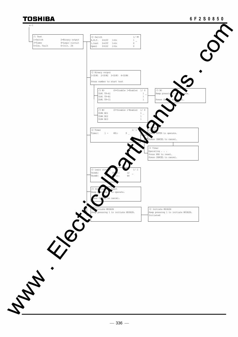
336
6 F 2 S 0 8 5 0
a-1
/1 Test 1=Switch 2=Binary output 3=Timer 4=Logic circuit 5=Sim. Fault 6=Init. 2B
/2 Switch 1/ ∗∗ A.M.F. 0=Off 1=On 1 _ L.test 0=Off 1=On 0 Open1 0=Off 1=On 0
/2 Timer 1/ 1 Timer( 1 - 48): 8 _
/2 Binary output 1=IO#1 2=IO#2 3=IO#3 4=IO#4 Press number to start test
/3 BO (0=Disable 1=Enable) 1/ 6 IO#1 TP-A1 1 _ IO#1 TP-B1 1 IO#1 TP-C1 1
/3 BO Keep pressing 1 to operate. Press CANCEL to cancel.
/2 Timer Press ENTER to operate. Press CANCEL to cancel.
/2 Timer Operating . . . Press END to reset. Press CANCEL to cancel.
/2 Logic circuit 1/ 2 TermA( 0 - 3071): 12 _ TermB( 0 - 3071): 48
/3 BO (0=Disable 1=Enable) 1/ 8 IO#4 BO1 1 _ IO#4 BO2 1 IO#4 BO3 1
/2 Simultaneous fault Keep pressing 1 to operate. Press CANCEL to cancel.
/2 Initiate MODE2B Keep pressing 1 to initiate MODE2B.
/2 Initiate MODE2B Keep pressing 1 to initiate MODE2B. Initiated
www . El
ectric
alPar
tMan
uals
. com
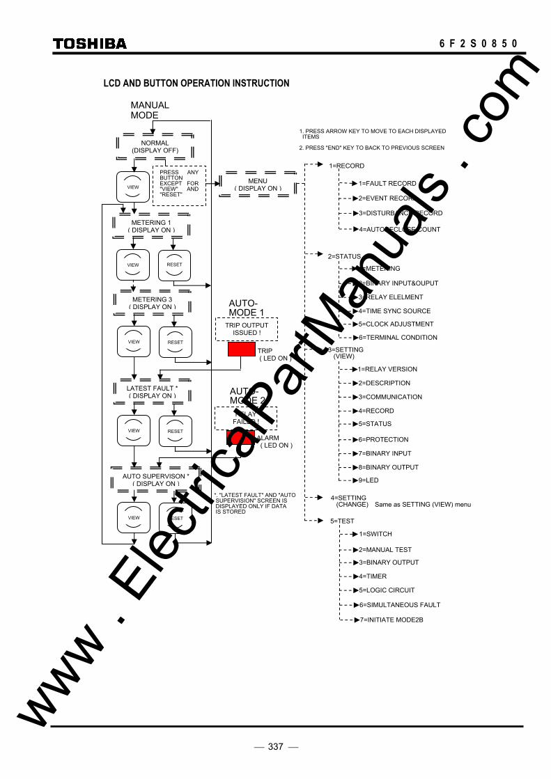
337
6 F 2 S 0 8 5 0
LCD AND BUTTON OPERATION INSTRUCTION
NORMAL (DISPLAY OFF)
VIEW
METERING 1 ( DISPLAY ON )
VIEW RESET
METERING 3 ( DISPLAY ON )
VIEW
LATEST FAULT * ( DISPLAY ON )
RESET
VIEW
AUTO SUPERVISON * ( DISPLAY ON )
RESET
VIEW RESET
TRIP OUTPUT ISSUED !
TRIP ( LED ON )
MANUALMODE
AUTO-MODE 1
RELAY FAILED !
ALARM ( LED ON )
AUTO-MODE 2
PRESS ANY BUTTON EXCEPT FOR "VIEW" AND "RESET"
MENU ( DISPLAY ON )
1=RECORD
1=FAULT RECORD
2=EVENT RECORD
2=STATUS
1=METERING
2=BINARY INPUT&OUPUT
3=RELAY ELELMENT
4=TIME SYNC SOURCE
5=CLOCK ADJUSTMENT
3=SETTING (VIEW)
1=RELAY VERSION
2=DESCRIPTION
3=COMMUNICATION
4=RECORD
5=STATUS
6=PROTECTION
7=BINARY INPUT
8=BINARY OUTPUT
9=LED
5=TEST
1=SWITCH
3=BINARY OUTPUT
4=TIMER
5=LOGIC CIRCUIT
1. PRESS ARROW KEY TO MOVE TO EACH DISPLAYED ITEMS 2. PRESS "END" KEY TO BACK TO PREVIOUS SCREEN
*. "LATEST FAULT" AND "AUTO SUPERVISION" SCREEN IS DISPLAYED ONLY IF DATA IS STORED
4=SETTING (CHANGE)
6=TERMINAL CONDITION
2=MANUAL TEST
3=DISTURBANCE RECORD
4=AUTORECLOSE COUNT
Same as SETTING (VIEW) menu
6=SIMULTANEOUS FAULT
7=INITIATE MODE2B
www . El
ectric
alPar
tMan
uals
. com

338
6 F 2 S 0 8 5 0 www .
Elec
tricalP
artM
anua
ls . c
om

339
6 F 2 S 0 8 5 0
Appendix F
Case Outline • Case Type-A: Flush Mount Type
• Case Type-B: Flush Mount Type
• Case Type-A, B: Rack Mount Type
www . El
ectric
alPar
tMan
uals
. com
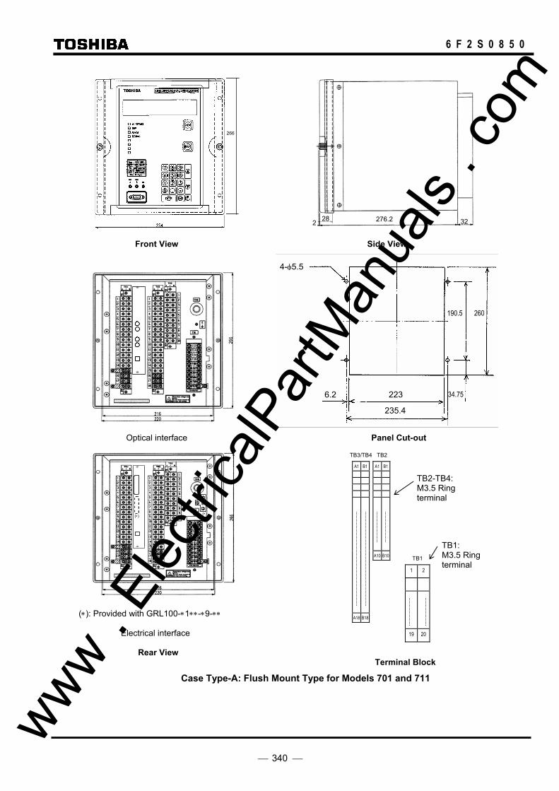
340
6 F 2 S 0 8 5 0
Front View Side View
Optical interface Panel Cut-out
(∗): Provided with GRL100-∗1∗∗-∗9-∗∗
Electrical interface Rear View
Terminal Block
Case Type-A: Flush Mount Type for Models 701 and 711
TB1
1 2
19 20
TB3/TB4 TB2
A1 B1 A1 B1
A10 B10
A18 B18
TB2-TB4: M3.5 Ring terminal
TB1: M3.5 Ring terminal
34.75
190.5 260
6.2
235.4
223
4-φ5.5
266
E
(∗) (∗)
276.2 2 3228
www . El
ectric
alPar
tMan
uals
. com
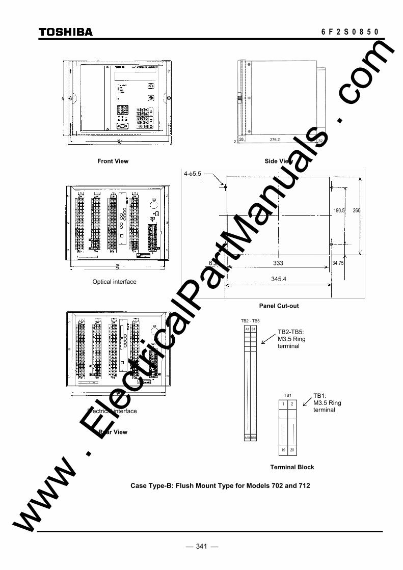
341
6 F 2 S 0 8 5 0
Front View Side View
Panel Cut-out
Electrical interface Rear View
Terminal Block
Case Type-B: Flush Mount Type for Models 702 and 712
TB2-TB5: M3.5 Ring terminal
TB1: M3.5 Ring terminal
TB1
1 2
19 20
TB2 - TB5
A1 B1
A18 B18
34.75
190.5 260
6.2
345.4
333
4-φ5.5
Optical interface
276.2 2 32 28
www . El
ectric
alPar
tMan
uals
. com
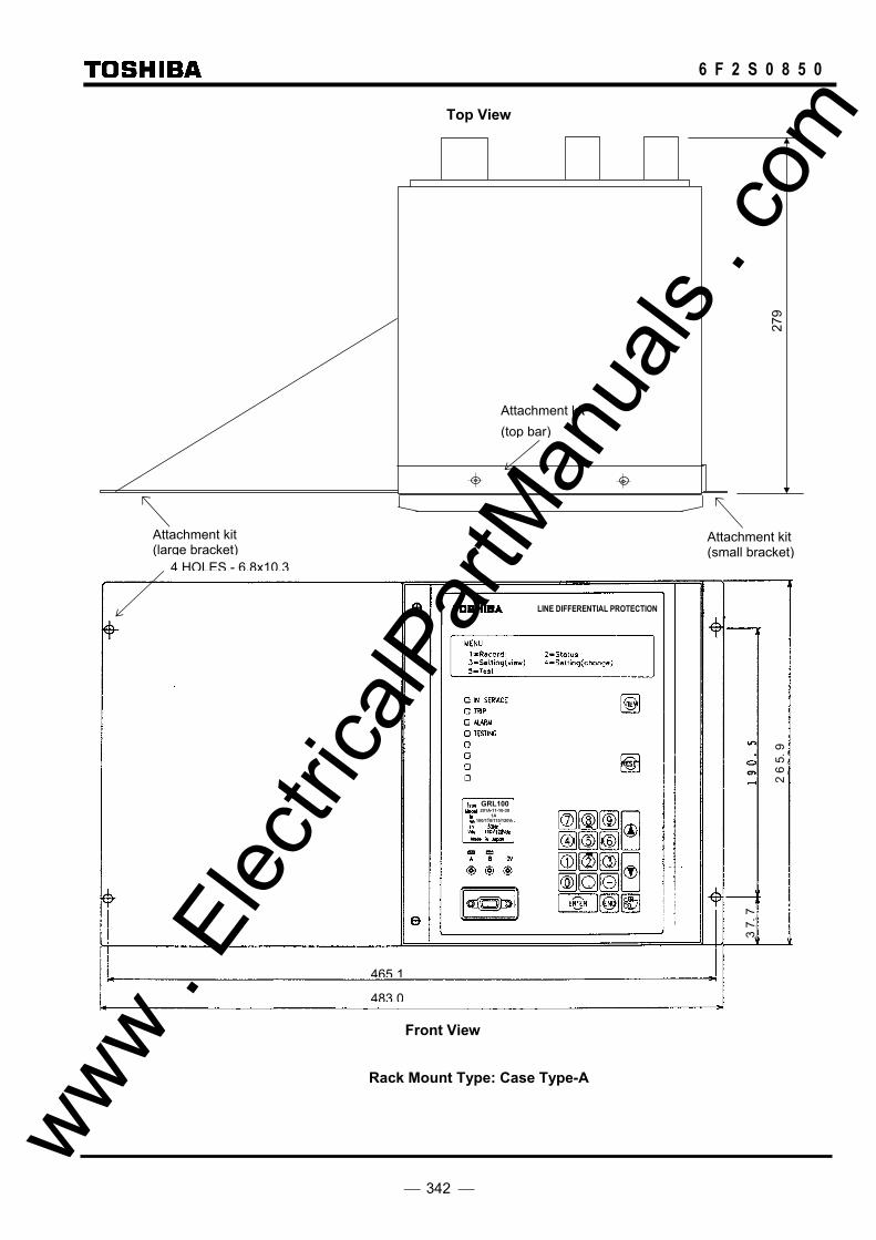
342
6 F 2 S 0 8 5 0
Top View
2 6
5. 9
3 7.
7
GRL100201A-11-10-30
1A100/110/115/120V
LINE DIFFERENTIAL PROTECTION
Front View
Rack Mount Type: Case Type-A
279
Attachment kit (large bracket)
Attachment kit (small bracket)
Attachment kit (top bar)
4 HOLES - 6.8x10.3
465.1
483.0
www . El
ectric
alPar
tMan
uals
. com
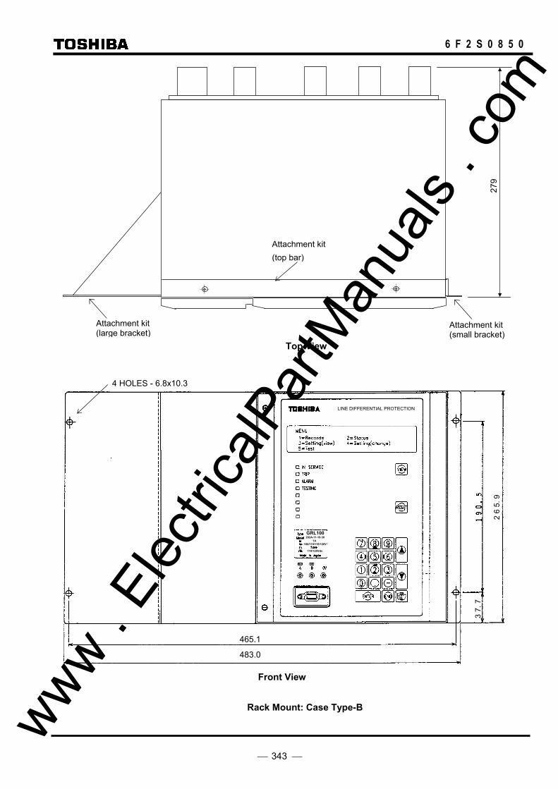
343
6 F 2 S 0 8 5 0
Top View
2 6
5. 9
3 7.
7
GRL100202A-11-10-30
1A 100/110/115/120V
110/125Vdc
Front View
Rack Mount: Case Type-B
483.0
4 HOLES - 6.8x10.3
465.1
LINE DIFFERENTIAL PROTECTION
279
Attachment kit (large bracket)
Attachment kit (small bracket)
Attachment kit (top bar)
www . El
ectric
alPar
tMan
uals
. com

344
6 F 2 S 0 8 5 0
Dimensions of Attachment Kit EP-101
136
265.
9
247.8
(a) Large Bracket
265.
9
19.4 18.8
(b) Small Bracket
216
18
(c) Bar for Top and Bottom of Relay
Parts
(a) 1 Large bracket, 5 Round head screws with spring washers and washers (M4x10)
(b) 1 Small bracket, 3 Countersunk head screws (M4x6)
(c) 2 Bars, 4 Countersunk head screws (M3x8)
www . El
ectric
alPar
tMan
uals
. com

345
6 F 2 S 0 8 5 0
(a) Large Bracket (b) Small Bracket
(c) Bar for Top and Bottom of Relay
Parts
(a) 1 Large bracket, 5 Round head screws with spring washers and washers (M4x10)
(b) 1 Small bracket, 3 Countersunk head screws (M4x6)
(c) 2 Bars, 4 Countersunk head screws (M3x8)
Dimensions of Attachment Kit EP-102
132
265.
9
137.8
265.
9
19.4 18.8
326
18
www . El
ectric
alPar
tMan
uals
. com
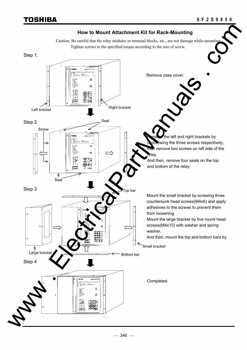
346
6 F 2 S 0 8 5 0
How to Mount Attachment Kit for Rack-Mounting Caution: Be careful that the relay modules or terminal blocks, etc., are not damage while mounting. Tighten screws to the specified torque according to the size of screw.
Step 1.
GPS ALARM SYNC. ALARM MODE 2A CF
Step 2.
GPS ALARM SYNC. ALARM MODE 2A CF
Step 3
GPS ALARM SYNC. ALARM MODE 2A CF
Step 4
GPS ALARM SYNC. ALARM MODE 2A CF
Remove case cover.
Remove the left and right brackets by unscrewing the three screws respectively, then remove two screws on left side of the relay. And then, remove four seals on the top and bottom of the relay.
Right bracket Left bracket
Top bar
Bottom bar
Mount the small bracket by screwing three countersunk head screws(M4x6) and apply adhesives to the screws to prevent them from loosening. Mount the large bracket by five round head screws(M4x10) with washer and spring washer. And then, mount the top and bottom bars by
Small bracket
Large bracket
Completed.
Seal
Seal
Screw
www . El
ectric
alPar
tMan
uals
. com

347
6 F 2 S 0 8 5 0
Appendix G
Typical External Connection
www . El
ectric
alPar
tMan
uals
. com

348
6 F 2 S 0 8 5 0
RS485 I/F
COM-B
COM-A
0V
TB3-A18
A17
B17
B18
A16
B16
IRIG-B
TP-A1
TP-B1
TP-C 1
TP-A2
TP-B2
TP-C 2
TRIP-B
TRIP-A
TRIP-C
BUS CB
(+)
TRIP-B
TRIP-A
TRIP-C
B14
A12
A13
B13
(+) TB4- A3
A1
B3
A2
B2
TB4-A14
(One RS485 port)
IO#3
A2
B2
A3
A4
B3
B4
A5
A6
B5
B6
TB2-A1
B1BO 1
BO 2
BO 3
BO 4
BO 5
BO 6
TB3- A2
A1
B1
B2
RELAY
FAILURE
BO 1
BO 2
BO 3
BO 4
BO 5
BO 6
BO 7
BO 8
BO 9
BO 10
BO 11
BO 12
A3
B3
A4
A5
B4
B5
A6
A7
B6
B7
A8
A9
B8
B9
A10
A11
B11
B10
A12
B12
B13
A13
(HIGH SPEED
RELAY)
FAIL
BO 1
BO 2
BO 3
BO 13
(HIGH SPEED
RELAY)
IO#1: IO1 module IO#2: IO2 module IO#3: IO6 module
Note GRL100-701: 2 terminal system, not provided with terminals marked with (*).
GRL100-711: 3 terminal system
TB2
B10
B1
IO#3
TB2
B10
B1
IO#3
Model GRL100-7*1
Terminal Block Arrangement (Rear view)
For electrical interface
For optical interface VCT
IO#2
TB1
TB3TB4
IO#1
CN1
(IRIG-B)
E
A18
A1
B18
B1
1 2
19 20
TX1
RX1
TX2
RX2 (*)
VCTIO#2
TB1
TB3TB4
IO#1
CN1
(IRIG-B)
E
A18
A1
B18
B1
1 2
19 20
CN2
COM2-B COM2-A TB3-A18 A17 A16 B18 B17 B16
COM2-0V COM1-B COM1-A COM1-0V
Two ports RS485 I/F (option)
or
TX1
CK1RX1
CN2
Communication
Links Optical
Interface
Electrical
InterfaceTX2
CK2RX2
TX1RX1
TX2
RX2
CH1
(*)CH2
CH1
(*) CH2
GPS Signal
(Optical Interface)
OP1
OP2
For RSM100 or IEC103
For IEC103
Transfer trip command 1
B14
B5
52C (C-ph.)
A5
BI3 52A (A-ph.)
BI4
B6
52B (A-ph.)
A6
BI5 52C (A-ph.)
BI6
B7
Disconnector N/O contact A7
BI7
Disconnector N/C contact
BI8
B8
Carrier from remote 1 A8
BI9
Carrier from remote 2
BI10
B9
DC power supply A9
BI11
BI12
DEF carrier from remote 2 A11
B11
BI15 (-)
TB3-A14
BI16
BI17 A15
B15
BI18 (-)
(-)
CB2 contacts (Closed when center CB main contact closed.)
(+)
B4
52A (A-ph.)
TB4-A4
BI1 CB1 contacts (Closed when bus CB main contact closed.)
52B (B-ph.)
BI2
A-ph
B-ph
C-ph
IO#1
IO#2 External trip signals
(Reclose & CBF Initiation)
B8
A8
BI21
BI22
B9
A9
BI23
BI24
CB1 ARC ready (Bus CB)
A10
B10 BI25
CB2 ARC ready (Center CB)
ARC block
B7 BI19
BI20
TB2-A7
IO#3
[Default Setting]
Dif. protection block (#43C)
External CB close
Indication reset
B10
Transfer trip command 2 A10
BI13
DEF carrier from remote 1
BI14
BUS
BUS
TB1 -1
4
3
2
7
6
5
8
12
11
13
15
14
16
BUS VT
CT
CT
CB
CB
VT
BUS VT
17
20
18
PARALLEL LINE VT
CB
+5Vdc
DD FAIL.
TB4 -A16
(-)
(+)
0V
B18
A18
E
B17
B16
A17
DC
SUPPLY
(CASE EARTH)
DC-DC
RELAY FAIL.
≧1
B15 A15
(∗1)
(∗1)These connections are connected by short-bars before shipment.
Io from adjacent Line CT
9 10
(∗1) (CASE EARTH)
www . El
ectric
alPar
tMan
uals
. com
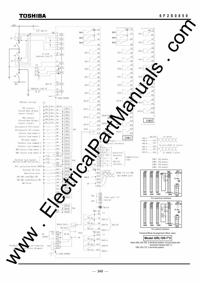
349
6 F 2 S 0 8 5 0
COM-B
COM-A
0V
RS485 I/F for RSM
TB2-A18
B18
A17
B17
A16
B16
IRIG-B
TP-A1
TP-B1
TP-C 1
TP-A2
TP-B2
TP-C 2
TRIP-B
TRIP-A
TRIP-C
BUS CB
(+)
TRIP-B
TRIP-A
TRIP-C
B14
A12
A13
B13
(+) TB4- A3
A1
B3
A2
B2
TB4-A14
IO#3
A2
B2
A3
A4
B3
B4
A5
A6
B5
B6
A7
A8
B7
B8
TB5-A1
B1 BO 1
BO 2
BO 3
BO 4
BO 5
BO 6
BO 7
BO 8
A9
A10
B9
B10
BO 9
BO 10
(One RS485 port)
IO#1: IO1 module
IO#2: IO2 module
IO#3: IO5 module
IO#4: IO4 module
TB2- A2
A1
B1
B2
RELAY
FAILURE
BO 1
BO 2
BO 3
BO 4
BO 5
BO 6
BO 7
BO 8
BO 9
BO 10
BO 11
BO 12
A3
B3
A4
A5
B4
B5
A6
A7
B6
B7
A8
A9
B8
B9
A10
A11
B11
B10
A12
B12
B13
A13
(HIGH SPEED
RELAY)
FAIL
BO 1
BO 2
BO 3
BO 13
(HIGH SPEED RELAY)
IO#4
TB3- A2
A1
B1
B2
BO 1
BO 2
BO 3
BO 4
BO 5
BO 6
BO 7
BO 8
BO 9
BO 10
BO 11
BO 12
A3
B3
A4
A5
B4
B5
A6
A7
B6
B7
A8
A9
B8
B9
A10
A11
B11
B10
A13
B12
A12
B13BO 14
BO 1
BO 2
BO 3
BO 13
For optical interface
IO#1
TB4 TB5
IO#3 B18
IO#2A18
TB2A1 B1
VCT
TB1 1 2
19 20IO#4
TB3 CN1(IRIG-B)
ETX1
RX1
TX2
RX2 (*)
IO#1
TB4 TB5
IO#3 B18
IO#2A18
TB2A1 B1
VCT
TB1 1 2
19 20IO#4
TB3 CN1(IRIG-B)
E
For electrical interface
CN2
Note GRL100-702: 2 terminal system, not provided with terminals marked with (*).
GRL100-712: 3 terminal system
Model GRL100-7*2
Terminal Block Arrangement (Rear view)
COM2-B COM2-A TB2-A18 A17 A16 B18 B17 B16
COM2-0V COM1-B COM1-A COM1-0V
Two ports RS485 I/F (option) TX1
CK1RX1
CN2
TX2
CK2RX2
TX1
RX1
TX2
RX2
Communication
Links Optical
Interface
Electrical
Interface
or
CH1
(*)CH2
CH1
(*) CH2
GPS Signal
(Optical Interface)
Fibre optic I/F
(option)
TROP1
TR
OP2
OP1
OP2
OP1
OP2
For RSM100 or IEC103
For IEC103
Dif. protection block (#43C)
External CB close
Indication reset
BUS
BUS
TB1 -1
4
3
2
7
6
5
8
12
11
13
15
14
16
BUS VT
CT
CT
CB
CB
VT
BUS VT
17
20
18
PARALLEL LINE VT
CB
Transfer trip command 1
B14
B5
52C (C-ph.) A5 BI3
BI4
B6
A6 BI5
BI6
B7
Disconnector N/O contact A7 BI7
Disconnector N/C contact BI8
B8
Carrier from remote 1 A8 BI9
Carrier from remote 2 BI10
B9
DC power supply A9 BI11
BI12
B10
Transfer trip command 2 A10BI13
DEF Carrier from remote 1 BI14
DEF carrier from remote 2 A11 B11 BI15 (-)
CB1 ARC ready(Bus CB)
TB2-A14 BI16
ARC block
BI17 A15 B15 BI18
(-)
(-)
(+)
B4
52A (A-ph.) TB4-A4BI1 CB1 contacts
(Closed when CB main
contact closed.)
52B (B-ph.)
BI2
B13
A13
BI21
BI22
B14
A14BI23
BI24
B15
A15
BI25
BI26 A16
B16BI27
A18BI28
B12
TB5-A12 BI19
BI20
External trip signals ( Reclose & CBF Initiation)
IO#1
IO#2
IO#3
A-ph
B-ph
C-ph
+5Vdc
DD FAIL.
TB4 -A16
(-)
(+)
0V
B18
A18
E
B17
B16
A17
DC
SUPPLY
(CASE EARTH)
DC-DC
RELAY FAIL.
≧1
B15
A15
(∗1) (∗1)These connections are connected by short-bars before shipment.
[Default setting]
52C (C-ph.)
CB2 contacts
(Closed when CB main
contact closed.)
52B (B-ph.)
CB2 ARC ready(Center CB)
52A (A-ph.)
B14
TB3-A14 BI34
BI35 A15 B15 BI36
IO#4
Io from adjacent Line CT
9 10
(∗1) (CASE EARTH)
www . El
ectric
alPar
tMan
uals
. com

350
6 F 2 S 0 8 5 0 www .
Elec
tricalP
artM
anua
ls . c
om

351
6 F 2 S 0 8 5 0
Appendix H
Relay Setting Sheet • Relay Identification
• Transmission line parameters
• Protection
• Autoreclose scheme
• Contacts setting
• Contacts setting (continued)
• Relay and Protection Scheme Setting Sheets
www . El
ectric
alPar
tMan
uals
. com

352
6 F 2 S 0 8 5 0
Relay Setting Sheets
1. Relay Identification Date:
Relay type Serial Number Frequency CT rating VT rating dc supply voltage Password Active setting group
2. Transmission line parameters
Line type Line length Line impedance Z1 = Z0 = Z0 (mutual) = Zm = VT ratio CT ratio Tripping mode 1 + 3 phase/3 phase
3. Protection
Master Slave 2 Term 3 Term
4. Autoreclose scheme
Not used SPAR SPAR + TPAR TPAR MPAR 2 (for two-phase interlinking) MPAR 3 (for three-phase interlinking) EX1P (external autoreclose SPAR + TPAR scheme) EX3P (external autoreclose TPAR scheme) 1CB or 2CB reclosing Multi-shot autoreclose 1 shot, 2 shots, 3 shots or 4 shots
www . El
ectric
alPar
tMan
uals
. com

353
6 F 2 S 0 8 5 0
5. Contacts setting
(1) IO#2 BO1 BO2 BO3 BO4 BO5 BO6 BO7 BO8 BO9 BO10 BO11 BO12 BO13 (2) IO#3 BO1 BO2 BO3 BO4 BO5 BO6 BO7 BO8 BO9 BO10 BO11 BO12 BO13 BO14 (3) IO#4 BO1 BO2 BO3 BO4 BO5 BO6 BO7 BO8 BO9 BO10 BO11 BO12 BO13 BO14
(Memo: For relay elements and scheme logic settings, the setting list as shown on the next page is made.)
www . El
ectric
alPar
tMan
uals
. com
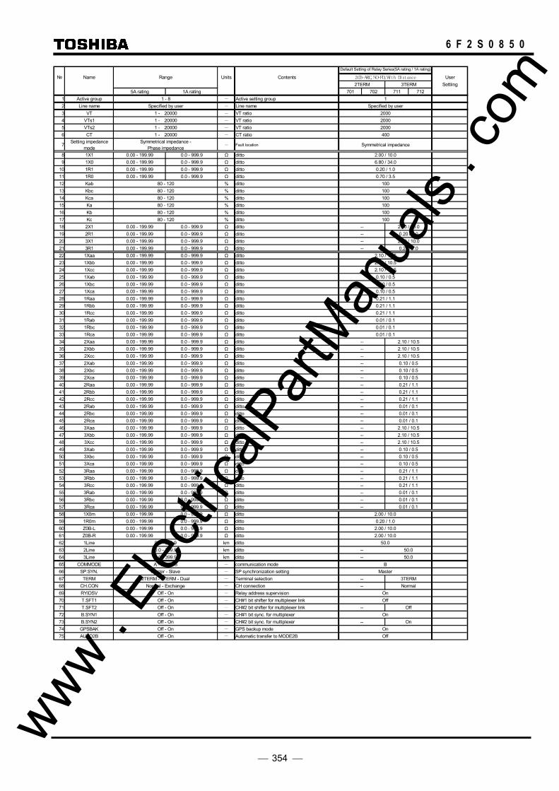
354
6 F 2 S 0 8 5 0
Name Range Units Contents 2CB-ARC, NO-FD, Wi th Di stance User2TERM 3TERM Settiing
5A rating 1A rating 701 702 711 7121 Active group 1 - 8 - Active setting group 12 Line name Specified by user - Line name Specified by user3 VT 1 - 20000 - VT ratio 20004 VTs1 1 - 20000 - VT ratio 20005 VTs2 1 - 20000 - VT ratio 20006 CT 1 - 20000 - CT ratio 400
7 Setting impedance mode
Symmetrical impedance - Phase impedance - Fault location Symmetrical impedance
8 1X1 0.00 - 199.99 0.0 - 999.9 Ω ditto 2.00 / 10.09 1X0 0.00 - 199.99 0.0 - 999.9 Ω ditto 6.80 / 34.0
10 1R1 0.00 - 199.99 0.0 - 999.9 Ω ditto 0.20 / 1.011 1R0 0.00 - 199.99 0.0 - 999.9 Ω ditto 0.70 / 3.512 Kab 80 - 120 % ditto 10013 Kbc 80 - 120 % ditto 10014 Kca 80 - 120 % ditto 10015 Ka 80 - 120 % ditto 10016 Kb 80 - 120 % ditto 10017 Kc 80 - 120 % ditto 10018 2X1 0.00 - 199.99 0.0 - 999.9 Ω ditto -- 2.00 / 10.019 2R1 0.00 - 199.99 0.0 - 999.9 Ω ditto -- 0.20 / 1.020 3X1 0.00 - 199.99 0.0 - 999.9 Ω ditto -- 2.00 / 10.021 3R1 0.00 - 199.99 0.0 - 999.9 Ω ditto -- 0.20 / 1.022 1Xaa 0.00 - 199.99 0.0 - 999.9 Ω ditto 2.10 / 10.523 1Xbb 0.00 - 199.99 0.0 - 999.9 Ω ditto 2.10 / 10.524 1Xcc 0.00 - 199.99 0.0 - 999.9 Ω ditto 2.10 / 10.525 1Xab 0.00 - 199.99 0.0 - 999.9 Ω ditto 0.10 / 0.526 1Xbc 0.00 - 199.99 0.0 - 999.9 Ω ditto 0.10 / 0.527 1Xca 0.00 - 199.99 0.0 - 999.9 Ω ditto 0.10 / 0.528 1Raa 0.00 - 199.99 0.0 - 999.9 Ω ditto 0.21 / 1.129 1Rbb 0.00 - 199.99 0.0 - 999.9 Ω ditto 0.21 / 1.130 1Rcc 0.00 - 199.99 0.0 - 999.9 Ω ditto 0.21 / 1.131 1Rab 0.00 - 199.99 0.0 - 999.9 Ω ditto 0.01 / 0.132 1Rbc 0.00 - 199.99 0.0 - 999.9 Ω ditto 0.01 / 0.133 1Rca 0.00 - 199.99 0.0 - 999.9 Ω ditto 0.01 / 0.134 2Xaa 0.00 - 199.99 0.0 - 999.9 Ω ditto -- 2.10 / 10.535 2Xbb 0.00 - 199.99 0.0 - 999.9 Ω ditto -- 2.10 / 10.536 2Xcc 0.00 - 199.99 0.0 - 999.9 Ω ditto -- 2.10 / 10.537 2Xab 0.00 - 199.99 0.0 - 999.9 Ω ditto -- 0.10 / 0.538 2Xbc 0.00 - 199.99 0.0 - 999.9 Ω ditto -- 0.10 / 0.539 2Xca 0.00 - 199.99 0.0 - 999.9 Ω ditto -- 0.10 / 0.540 2Raa 0.00 - 199.99 0.0 - 999.9 Ω ditto -- 0.21 / 1.141 2Rbb 0.00 - 199.99 0.0 - 999.9 Ω ditto -- 0.21 / 1.142 2Rcc 0.00 - 199.99 0.0 - 999.9 Ω ditto -- 0.21 / 1.143 2Rab 0.00 - 199.99 0.0 - 999.9 Ω ditto -- 0.01 / 0.144 2Rbc 0.00 - 199.99 0.0 - 999.9 Ω ditto -- 0.01 / 0.145 2Rca 0.00 - 199.99 0.0 - 999.9 Ω ditto -- 0.01 / 0.146 3Xaa 0.00 - 199.99 0.0 - 999.9 Ω ditto -- 2.10 / 10.547 3Xbb 0.00 - 199.99 0.0 - 999.9 Ω ditto -- 2.10 / 10.548 3Xcc 0.00 - 199.99 0.0 - 999.9 Ω ditto -- 2.10 / 10.549 3Xab 0.00 - 199.99 0.0 - 999.9 Ω ditto -- 0.10 / 0.550 3Xbc 0.00 - 199.99 0.0 - 999.9 Ω ditto -- 0.10 / 0.551 3Xca 0.00 - 199.99 0.0 - 999.9 Ω ditto -- 0.10 / 0.552 3Raa 0.00 - 199.99 0.0 - 999.9 Ω ditto -- 0.21 / 1.153 3Rbb 0.00 - 199.99 0.0 - 999.9 Ω ditto -- 0.21 / 1.154 3Rcc 0.00 - 199.99 0.0 - 999.9 Ω ditto -- 0.21 / 1.155 3Rab 0.00 - 199.99 0.0 - 999.9 Ω ditto -- 0.01 / 0.156 3Rbc 0.00 - 199.99 0.0 - 999.9 Ω ditto -- 0.01 / 0.157 3Rca 0.00 - 199.99 0.0 - 999.9 Ω ditto -- 0.01 / 0.158 1X0m 0.00 - 199.99 0.0 - 999.9 Ω ditto 2.00 / 10.059 1R0m 0.00 - 199.99 0.0 - 999.9 Ω ditto 0.20 / 1.060 Z0B-L 0.00 - 199.99 0.0 - 999.9 Ω ditto 2.00 / 10.061 Z0B-R 0.00 - 199.99 0.0 - 999.9 Ω ditto 2.00 / 10.062 1Line 0.0 - 399.9 km ditto 50.063 2Line 0.0 - 399.9 km ditto -- 50.064 3Line 0.0 - 399.9 km ditto -- 50.065 COMMODE A - B - GPS - communication mode B66 SP.SYN. Master - Slave - SP synchronization setting Master67 TERM 2TERM - 3TERM - Dual - Terminal selection -- 3TERM68 CH.CON Normal - Exchange - CH connection -- Normal69 RYIDSV Off - On - Relay address supervision On70 T.SFT1 Off - On - CH#1 bit shifter for multiplexer link Off71 T.SFT2 Off - On - CH#2 bit shifter for multiplexer link -- Off72 B.SYN1 Off - On - CH#1 bit sync. for multiplexer On73 B.SYN2 Off - On - CH#2 bit sync. for multiplexer -- On74 GPSBAK Off - On - GPS backup mode On75 AUTO2B Off - On - Automatic transfer to MODE2B Off
Default Setting of Relay Series(5A rating / 1A rating)
www . El
ectric
alPar
tMan
uals
. com
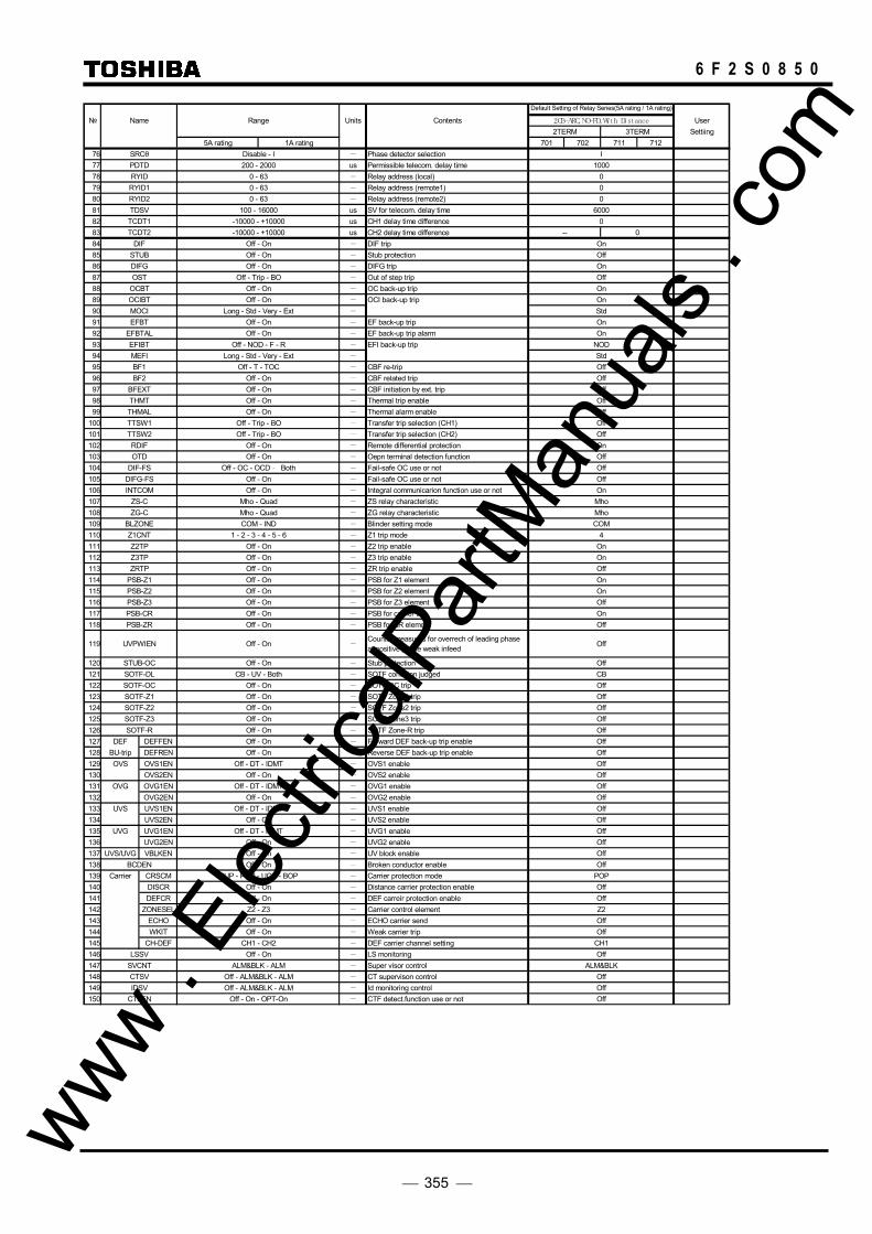
355
6 F 2 S 0 8 5 0
Name Range Units Contents 2CB-ARC, NO-FD, Wi th Di stance User2TERM 3TERM Settiing
5A rating 1A rating 701 702 711 71276 SRCθ Disable - I - Phase detector selection I77 PDTD 200 - 2000 us Permissible telecom. delay time 100078 RYID 0 - 63 - Relay address (local) 079 RYID1 0 - 63 - Relay address (remote1) 080 RYID2 0 - 63 - Relay address (remote2) 081 TDSV 100 - 16000 us SV for telecom. delay time 600082 TCDT1 -10000 - +10000 us CH1 delay time difference 083 TCDT2 -10000 - +10000 us CH2 delay time difference -- 084 DIF Off - On - DIF trip On85 STUB Off - On - Stub protection Off86 DIFG Off - On - DIFG trip On87 OST Off - Trip - BO - Out of step trip Off88 OCBT Off - On - OC back-up trip On89 OCIBT Off - On - OCI back-up trip On90 MOCI Long - Std - Very - Ext - Std91 EFBT Off - On - EF back-up trip On92 EFBTAL Off - On - EF back-up trip alarm On93 EFIBT Off - NOD - F - R - EFI back-up trip NOD94 MEFI Long - Std - Very - Ext - Std95 BF1 Off - T - TOC - CBF re-trip Off96 BF2 Off - On - CBF related trip Off97 BFEXT Off - On - CBF initiation by ext. trip Off98 THMT Off - On - Thermal trip enable Off99 THMAL Off - On - Thermal alarm enable Off
100 TTSW1 Off - Trip - BO - Transfer trip selection (CH1) Off101 TTSW2 Off - Trip - BO - Transfer trip selection (CH2) Off102 RDIF Off - On - Remote differential protection On103 OTD Off - On - Oepn terminal detection function Off104 DIF-FS Off - OC - OCD ‐ Both - Fail-safe OC use or not Off105 DIFG-FS Off - On - Fail-safe OC use or not Off106 INTCOM Off - On - Integral communicarion function use or not On107 ZS-C Mho - Quad - ZS relay characteristic Mho108 ZG-C Mho - Quad - ZG relay characteristic Mho109 BLZONE COM - IND - Blinder setting mode COM110 Z1CNT 1 - 2 - 3 - 4 - 5 - 6 - Z1 trip mode 4111 Z2TP Off - On - Z2 trip enable On112 Z3TP Off - On - Z3 trip enable On113 ZRTP Off - On - ZR trip enable Off114 PSB-Z1 Off - On - PSB for Z1 element On115 PSB-Z2 Off - On - PSB for Z2 element On116 PSB-Z3 Off - On - PSB for Z3 element Off117 PSB-CR Off - On - PSB for carrier trip On118 PSB-ZR Off - On - PSB for ZR element Off
119 UVPWIEN Off - On -Counter measures for overrech of leading phaseat positive phase weak infeed Off
120 STUB-OC Off - On - Stub protection Off121 SOTF-DL CB - UV - Both - SOTF condition judged CB122 SOTF-OC Off - On - SOTF OC trip Off123 SOTF-Z1 Off - On - SOTF Zone1 trip Off124 SOTF-Z2 Off - On - SOTF Zone2 trip Off125 SOTF-Z3 Off - On - SOTF Zone3 trip Off126 SOTF-R Off - On - SOTF Zone-R trip Off127 DEF DEFFEN Off - On - Forward DEF back-up trip enable Off128 BU-trip DEFREN Off - On - Reverse DEF back-up trip enable Off129 OVS OVS1EN Off - DT - IDMT - OVS1 enable Off130 OVS2EN Off - On - OVS2 enable Off131 OVG OVG1EN Off - DT - IDMT - OVG1 enable Off132 OVG2EN Off - On - OVG2 enable Off133 UVS UVS1EN Off - DT - IDMT - UVS1 enable Off134 UVS2EN Off - On - UVS2 enable Off135 UVG UVG1EN Off - DT - IDMT - UVG1 enable Off136 UVG2EN Off - On - UVG2 enable Off137 UVS/UVG VBLKEN Off - On - UV block enable Off138 BCDEN Off - On - Broken conductor enable Off139 Carrier CRSCM PUP - POP - UOP - BOP - Carrier protection mode POP140 DISCR Off - On - Distance carrier protection enable Off141 DEFCR Off - On - DEF carreir protection enable Off142 ZONESEL Z2 - Z3 - Carrier control element Z2143 ECHO Off - On - ECHO carrier send Off144 WKIT Off - On - Weak carrier trip Off145 CH-DEF CH1 - CH2 - DEF carrier channel setting CH1146 LSSV Off - On - LS monitoring Off147 SVCNT ALM&BLK - ALM - Super visor control ALM&BLK148 CTSV Off - ALM&BLK - ALM - CT supervison control Off149 IDSV Off - ALM&BLK - ALM - Id monitoring control Off150 CTFEN Off - On - OPT-On - CTF detect.function use or not Off
Default Setting of Relay Series(5A rating / 1A rating)
www . El
ectric
alPar
tMan
uals
. com
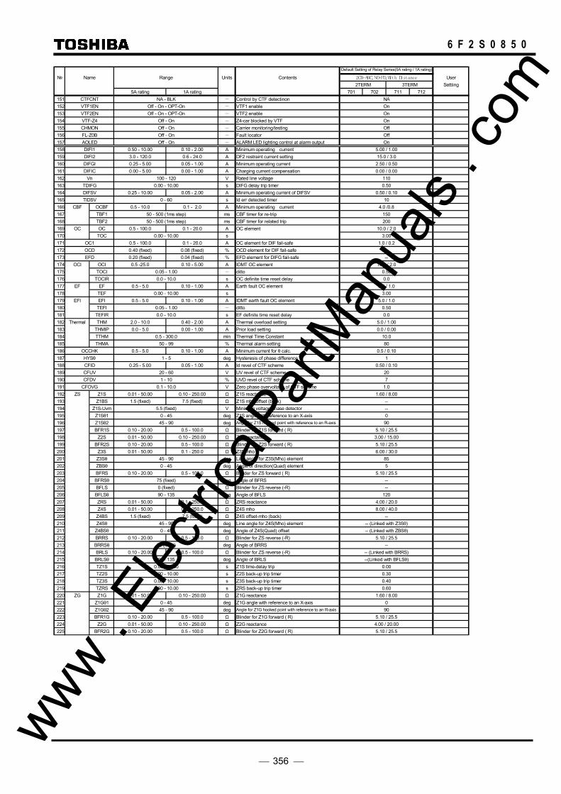
356
6 F 2 S 0 8 5 0
Name Range Units Contents 2CB-ARC, NO-FD, Wi th Di stance User2TERM 3TERM Settiing
5A rating 1A rating 701 702 711 712151 CTFCNT NA - BLK - Control by CTF detectinon NA152 VTF1EN Off - On - OPT-On - VTF1 enable On153 VTF2EN Off - On - OPT-On - VTF2 enable On154 VTF-Z4 Off - On - Z4-car blocked by VTF On155 CHMON Off - On - Carrier monitoring/testing Off156 FL-Z0B Off - On - Fault locator Off157 AOLED Off - On - ALARM LED lighting control at alarm output On158 DIFI1 0.50 - 10.00 0.10 - 2.00 A Minimum operating current 5.00 / 1.00159 DIFI2 3.0 - 120.0 0.6 - 24.0 A DF2 restraint current setting 15.0 / 3.0160 DIFGI 0.25 - 5.00 0.05 - 1.00 A Minimum operating current 2.50 / 0.50161 DIFIC 0.00 - 5.00 0.00 - 1.00 A Charging current compensation 0.00 / 0.00162 Vn 100 - 120 V Rated line voltage 110163 TDIFG 0.00 - 10.00 s DIFG delay trip timer 0.50164 DIFSV 0.25 - 10.00 0.05 - 2.00 A Minimum operating current of DIFSV 0.50 / 0.10165 TIDSV 0 - 60 s Id err detected timer 10166 CBF OCBF 0.5 - 10.0 0.1 - 2.0 A Minimum operating current 4.0 /0.8167 TBF1 50 - 500 (1ms step) ms CBF timer for re-trip 150168 TBF2 50 - 500 (1ms step) ms CBF timer for related trip 200169 OC OC 0.5 - 100.0 0.1 - 20.0 A OC element 10.0 / 2.0170 TOC 0.00 - 10.00 s 3.00171 OC1 0.5 - 100.0 0.1 - 20.0 A OC element for DIF fail-safe 1.0 / 0.2172 OCD 0.40 (fixed) 0.08 (fixed) % OCD element for DIF fail-safe --173 EFD 0.20 (fixed) 0.04 (fixed) % EFD element for DIFG fail-safe --174 OCI OCI 0.5 -25.0 0.10 - 5.00 A IDMT OC element 10.0 / 2.0175 TOCI 0.05 - 1.00 - ditto 0.50176 TOCIR 0.0 - 10.0 s OC definite time reset delay 0.0177 EF EF 0.5 - 5.0 0.10 - 1.00 A Earth fault OC element 5.0 / 1.0178 TEF 0.00 - 10.00 s 3.00179 EFI EFI 0.5 - 5.0 0.10 - 1.00 A IDMT earth fault OC element 5.0 / 1.0180 TEFI 0.05 - 1.00 - ditto 0.50181 TEFIR 0.0 - 10.0 s EF definite time reset delay 0.0182 Thermal THM 2.0 - 10.0 0.40 - 2.00 A Thermal overload setting 5.0 / 1.00183 THMIP 0.0 - 5.0 0.00 - 1.00 A Prior load setting 0.0 / 0.00184 TTHM 0.5 - 300.0 min Thermal Time Constant 10.0185 THMA 50 - 99 % Thermal alarm setting 80186 OCCHK 0.5 - 5.0 0.10 - 1.00 A Minimum current for θ calc. 0.5 / 0.10187 HYSθ 1 - 5 deg Hysteresis of phase difference 1188 CFID 0.25 - 5.00 0.05 - 1.00 A Id revel of CTF scheme 0.50 / 0.10189 CFUV 20 - 60 V UV revel of CTF scheme 20190 CFDV 1 - 10 % UVD revel of CTF scheme 7191 CFOVG 0.1 - 10.0 V Zero phase overvoltage of CTF scheme 1.0192 ZS Z1S 0.01 - 50.00 0.10 - 250.00 Ω Z1S reactance 1.60 / 8.00193 Z1BS 1.5 (fixed) 7.5 (fixed) Ω Z1S mho offset (back) --194 Z1S-Uvm 5.5 (fixed) V Minimum voltage phase detector --195 Z1Sθ1 0 - 45 deg Z1S angle with reference to an X-axis 0196 Z1Sθ2 45 - 90 deg Angle for Z1S hooked point with reference to an R-axis 90197 BFR1S 0.10 - 20.00 0.5 - 100.0 Ω Blinder for Z1S forward ( R) 5.10 / 25.5198 Z2S 0.01 - 50.00 0.10 - 250.00 Ω Z2S reactance 3.00 / 15.00199 BFR2S 0.10 - 20.00 0.5 - 100.0 Ω Blinder for Z2S forward ( R) 5.10 / 25.5200 Z3S 0.01 - 50.00 0.1 - 250.0 Ω Z3S mho 6.00 / 30.0201 Z3Sθ 45 - 90 deg Line angle for Z3S(Mho) element 85202 ZBSθ 0 - 45 deg Angle of direction(Quad) element 5203 BFRS 0.10 - 20.00 0.5 - 100.0 Ω Blinder for ZS forward ( R) 5.10 / 25.5204 BFRSθ 75 (fixed) deg Angle of BFRS --205 BFLS 0 (fixed) Ω Blinder for ZS reverse (-R) --206 BFLSθ 90 - 135 deg Angle of BFLS 120207 ZRS 0.01 - 50.00 0.1 - 250.0 Ω ZRS reactance 4.00 / 20.0208 Z4S 0.01 - 50.00 0.1 - 250.0 Ω Z4S mho 8.00 / 40.0209 Z4BS 1.5 (fixed) 7.5 (fixed) Ω Z4S offset-mho (back) --210 Z4Sθ 45 - 90 deg Line angle for Z4S(Mho) element -- (Linked with Z3Sθ)211 Z4BSθ 0 - 45 deg Angle of Z4S(Quad) offset -- (Linked with ZBSθ)212 BRRS 0.10 - 20.00 0.5 - 100.0 Ω Blinder for ZS reverse (-R) 5.10 / 25.5213 BRRSθ 75 (fixed) deg Angle of BRRS --214 BRLS 0.10 - 20.00 0.5 - 100.0 Ω Blinder for ZS reverse (-R) -- (Linked with BRRS)215 BRLSθ 90 - 135 deg Angle of BRLS --(Linked with BFLSθ)216 TZ1S 0.00 - 10.00 s Z1S time-delay trip 0.00217 TZ2S 0.00 - 10.00 s Z2S back-up trip timer 0.30218 TZ3S 0.00 - 10.00 s Z3S back-up trip timer 0.40219 TZRS 0.00 - 10.00 s ZRS back-up trip timer 0.60220 ZG Z1G 0.01 - 50.00 0.10 - 250.00 Ω Z1G reactance 1.60 / 8.00221 Z1Gθ1 0 - 45 deg Z1G angle with reference to an X-axis 0222 Z1Gθ2 45 - 90 deg Angle for Z1G hooked point with reference to an R-axis 90223 BFR1G 0.10 - 20.00 0.5 - 100.0 Ω Blinder for Z1G forward ( R) 5.10 / 25.5224 Z2G 0.01 - 50.00 0.10 - 250.00 Ω Z2G reactance 4.00 / 20.00225 BFR2G 0.10 - 20.00 0.5 - 100.0 Ω Blinder for Z2G forward ( R) 5.10 / 25.5
Default Setting of Relay Series(5A rating / 1A rating)
www . El
ectric
alPar
tMan
uals
. com

357
6 F 2 S 0 8 5 0
Name Range Units Contents 2CB-ARC, NO-FD, Wi th Di stance User2TERM 3TERM Settiing
5A rating 1A rating 701 702 711 712226 ZG Z3G 0.01 - 100.00 0.1 - 500.0 Ω Z3G mho 8.00 / 40.0227 Z3Gθ 45 - 90 deg Line angle for Z3S(Mho) element 85228 ZBGθ 0 - 45 deg Angle of direction(Quad) element 30229 BFRG 0.10 - 20.00 0.5 - 100.0 Ω Blinder for ZG forward ( R) 5.10 / 25.5230 BFRGθ 75 (fixed) deg Angle of BFRG --231 BFLG 0 (fixed) Ω Blinder for ZG forward (-R) --232 BFLGθ 90 - 135 deg Angle of BFLG 120233 ZRG 0.01 - 100.00 0.1 - 500.0 Ω ZRG reactance 4.00 / 20.0234 Z4G 0.01 - 100.00 0.1 - 500.0 Ω Z4G mho 8.00 / 40.0235 Z4Gθ 45 - 90 deg Line angle for Z4G(Mho) element -- (Linked with Z3Gθ)236 Z4BGθ 0 - 45 deg Angle of Z4G(Quad) offset -- (Linked with ZBGθ)237 BRRG 0.10 - 20.00 0.5 - 100.0 Ω Blinder for ZG reverse (-R) 5.10 / 25.5238 BRRGθ 75 (fixed) deg Angle of BRRG --239 BRLG 0.10 - 20.00 0.5 - 100.0 Ω Blinder for ZG reverse ( R) -- (Linked with BRRG)240 BRLGθ 90 - 135 deg Angle of BRLG -- (Linked with BFLGθ)
241 Krs 0 - 1000 % Zero phase current factor: Self line "R0/R1" 340
242 Kxs 0 - 1000 % Zero phase current factor: Self line "X0/X1" 340
243 Krm 0 - 1000 % Zero phase current factor: Adjacent line "Rom/R1" 300
244 Kxm 0 - 1000 % Zero phase current factor: Adjacent line "Xom/X1" 300
245 KrsR 0 - 1000 %Zero phase current factor for ZR element: Self line"R0/R1" 100
246 KxsR 0 - 1000 %Zero phase current factor for ZR element: Self line"X0/X1" 100
247 TZ1G 0.00 - 10.00 s Z1G time-delay trip 0.00248 TZ2G 0.00 - 10.00 s Z2G back-up trip timer 0.30249 TZ3G 0.00 - 10.00 s Z3G back-up trip timer 0.40250 TZRG 0.00 - 10.00 s ZRG back-up trip timer 0.60251 ZIC 0.00 - 5.00 0.00 - 1.00 A Charging current compensation 0.00252 ZPCC ZPCC 0.8 (Sensitivity ratio) - Zero phase current --253 OCG 0.2 (fixed) 0.04 (fixed) A compensation controller --254 PSB PSBSZ 0.50 - 15.00 2.5 - 75.0 Ω Power swing block for Ph-Ph 2.00 / 10.0255 PSBGZ 0.50 - 15.00 2.5 - 75.0 Ω Power swing block for Ph-G 2.00 / 10.0256 PSBRθ 75 (fixed) deg ditto --257 PSBLθ 105 (fixed) deg ditto --258 TPSB 20 - 60 ms PS detection timer 40259 OCH 2.0 - 15.0 0.4 - 3.0 A Overcurrent element 6.0 / 1.2260 TSOTF 0 - 300 s CB open detect timer for SOTF 5261 OCD1 0.5 (fixed) 0.1 (fixed) A Curr. change detector --262 OCCR 0.4 (fixed) 0.08 (fixed) A OC element --263 DEF DEFFI 0.5 - 5.0 0.10 - 1.00 A Directional earth fault element 1.0 / 0.20264 DEFFV 1.7 - 21.0 V ditto 2.0265 DEFRI 0.5 - 5.0 0.10 - 1.00 A ditto 1.0 / 0.20266 DEFRV 1.7 - 21.0 V ditto 2.0267 DEFθ 0 - 90 deg ditto 85268 DEF TDEF 0.00 - 10.00 s Forward definite timer 3.00269 BU-trip TDER 0.00 - 10.00 s Reverse definite timer 3.00270 EFL 0.5 - 5.0 0.10 - 1.00 A EF element for ZG fail safe 1.0 / 0.20271 UVC UVCV 10 - 60 V Undervoltage element with current compensation 48272 UVCZ 0.0 - 50.0 0.0 - 250.0 Ω ditto 2.0 / 10.0273 UVCθ 45 - 90 deg ditto 85274 UVCKrs 0 - 1000 % ditto -- (Linked with Krs of ZG)275 UVCKxs 0 - 1000 % ditto -- (Linked with Kxs of ZG)276 OVGF 20 (fixed) V OV element for VTF detect. function --277 UVFS 50 - 100 V UV ph-ph element 88278 UVLS 50 - 100 V UV ph-ph element "L" level 77279 UVFG 10 - 60 V UV ph-g element 51280 UVLG 10 - 60 V UV ph-g element "L" level 45281 UVPWI 30 (fixed) V UV for positive weak infeed --282 OVS OVS1 5.0 - 150.0 V OVS1 element 120.0283 TOS1I 0.05 - 100.00 - OVS1 IDMT timer 10.00284 TOS1 0.00 - 300.00 s OVS1 deninite timer 0.10285 TOS1R 0.0 - 300.0 s OVS1 deninite time reset delay 0.0286 OS1DP 10 - 98 % OVS1 DO/PU ratio 95287 OVS2 5.0 - 150.0 V OVS2 element 140.0288 TOS2 0.00 - 300.00 s OVS2 deninite timer 0.10289 OS2DP 10 - 98 % OVS2 DO/PU ratio 95290 OVG OVG1 5.0 - 150.0 V OVG1 element 70.0291 TOG1I 0.05 - 100.00 - OVG1 IDMT timer 10.00292 TOG1 0.00 - 300.00 s OVG1 deninite timer 0.10293 TOG1R 0.0 - 300.0 s OVG1 deninite time reset delay 0.0294 OG1DP 10 - 98 % OVG1 DO/PU ratio 95295 OVG2 5.0 - 150.0 V OVG2 element 80.0
Default Setting of Relay Series(5A rating / 1A rating)
www . El
ectric
alPar
tMan
uals
. com
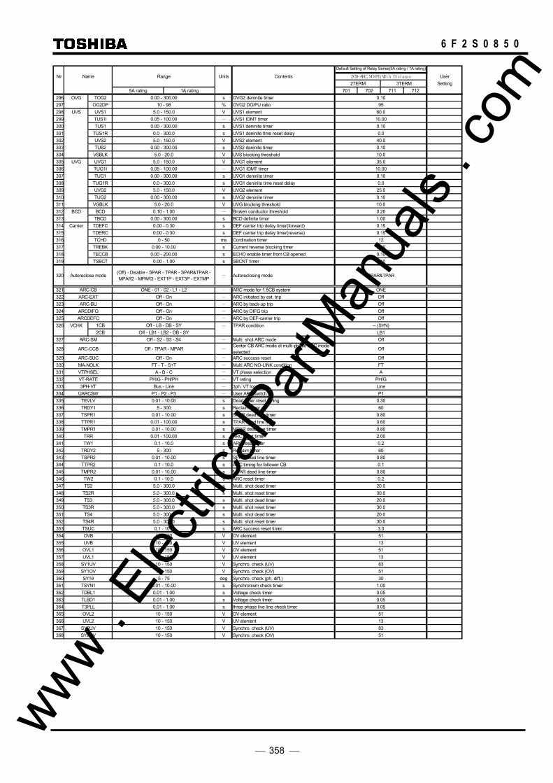
358
6 F 2 S 0 8 5 0
Name Range Units Contents 2CB-ARC, NO-FD, Wi th Di stance User2TERM 3TERM Settiing
5A rating 1A rating 701 702 711 712296 OVG TOG2 0.00 - 300.00 s OVG2 deninite timer 0.10297 OG2DP 10 - 98 % OVG2 DO/PU ratio 95298 UVS UVS1 5.0 - 150.0 V UVS1 element 60.0299 TUS1I 0.05 - 100.00 - UVS1 IDMT timer 10.00300 TUS1 0.00 - 300.00 s UVS1 deninite timer 0.10301 TUS1R 0.0 - 300.0 s UVS1 deninite time reset delay 0.0302 UVS2 5.0 - 150.0 V UVS2 element 40.0303 TUS2 0.00 - 300.00 s UVS2 deninite timer 0.10304 VSBLK 5.0 - 20.0 V UVS blocking threshold 10.0305 UVG UVG1 5.0 - 150.0 V UVG1 element 35.0306 TUG1I 0.05 - 100.00 - UVG1 IDMT timer 10.00307 TUG1 0.00 - 300.00 s UVG1 deninite timer 0.10308 TUG1R 0.0 - 300.0 s UVG1 deninite time reset delay 0.0309 UVG2 5.0 - 150.0 V UVG2 element 25.0310 TUG2 0.00 - 300.00 s UVG2 deninite timer 0.10311 VGBLK 5.0 - 20.0 V UVG blocking threshold 10.0312 BCD BCD 0.10 - 1.00 - Broken conductor threshold 0.20313 TBCD 0.00 - 300.00 s BCD definite timer 1.00314 Carrier TDEFC 0.00 - 0.30 s DEF carrier trip delay timer(forward) 0.15315 TDERC 0.00 - 0.30 s DEF carrier trip delay timer(reverse) 0.15316 TCHD 0 - 50 ms Cordination timer 12317 TREBK 0.00 - 10.00 s Current reverse blocking timer 0.10318 TECCB 0.00 - 200.00 s ECHO enable timer from CB opened 0.10319 TSBCT 0.00 - 1.00 s SBCNT timer 0.10
320 Autoreclose mode (Off) - Disable - SPAR - TPAR - SPAR&TPAR -MPAR2 - MPAR3 - EXT1P - EXT3P - EXTMP - Autoreclosing mode SPAR&TPAR
321 ARC-CB ONE - 01 - 02 - L1 - L2 - ARC mode for 1.5CB system ONE322 ARC-EXT Off - On - ARC initiated by ext. trip Off323 ARC-BU Off - On - ARC by back-up trip Off324 ARCDIFG Off - On - ARC by DIFG trip Off325 ARCDEFC Off - On - ARC by DEF-carrier trip Off326 VCHK 1CB Off - LB - DB - SY - TPAR condition -- (SYN)
2CB Off - LB1 - LB2 - DB - SY LB1327 ARC-SM Off - S2 - S3 - S4 - Multi. shot ARC mode Off
328 ARC-CCB Off - TPAR - MPAR -Center CB ARC mode at multi-phase ARC modeselected
Off
329 ARC-SUC Off - On - ARC success reset Off330 MA-NOLK FT - T - S+T - Multi ARC NO-LINK condition FT331 VTPHSEL A - B - C - VT phase selection A332 VT-RATE PH/G - PH/PH - VT rating PH/G333 3PH-VT Bus - Line - 3ph. VT location Line334 UARCSW P1 - P2 - P3 - User ARC switch P1335 TEVLV 0.01 - 10.00 s Dead timer reset timing 0.30336 TRDY1 5 - 300 s Reclaim timer 60337 TSPR1 0.01 - 10.00 s SPAR dead line timer 0.80338 TTPR1 0.01 - 100.00 s TPAR dead line timer 0.60339 TMPR1 0.01 - 10.00 s MPAR dead line timer 0.80340 TRR 0.01 - 100.00 s ARC reset timer 2.00341 TW1 0.1 - 10.0 s ARC reset timer 0.2342 TRDY2 5 - 300 s Reclaim timer 60343 TSPR2 0.01 - 10.00 s SPAR dead line timer 0.80344 TTPR2 0.1 - 10.0 s ARC timing for follower CB 0.1345 TMPR2 0.01 - 10.00 s MPAR dead line timer 0.80346 TW2 0.1 - 10.0 s ARC reset timer 0.2347 TS2 5.0 - 300.0 s Multi. shot dead timer 20.0348 TS2R 5.0 - 300.0 s Multi. shot reset timer 30.0349 TS3 5.0 - 300.0 s Multi. shot dead timer 20.0350 TS3R 5.0 - 300.0 s Multi. shot reset timer 30.0351 TS4 5.0 - 300.0 s Multi. shot dead timer 20.0352 TS4R 5.0 - 300.0 s Multi. shot reset timer 30.0353 TSUC 0.1 - 10.0 s ARC success reset timer 3.0354 OVB 10 - 150 V OV element 51355 UVB 10 - 150 V UV element 13356 OVL1 10 - 150 V OV element 51357 UVL1 10 - 150 V UV element 13358 SY1UV 10 - 150 V Synchro. check (UV) 83359 SY1OV 10 - 150 V Synchro. check (OV) 51360 SY1θ 5 - 75 deg Synchro. check (ph. diff.) 30361 TSYN1 0.01 - 10.00 s Synchronism check timer 1.00362 TDBL1 0.01 - 1.00 s Voltage check timer 0.05363 TLBD1 0.01 - 1.00 s Voltage check timer 0.05364 T3PLL 0.01 - 1.00 s three phase live line check timer 0.05365 OVL2 10 - 150 V OV element 51366 UVL2 10 - 150 V UV element 13367 SY2UV 10 - 150 V Synchro. check (UV) 83368 SY2OV 10 - 150 V Synchro. check (OV) 51
Default Setting of Relay Series(5A rating / 1A rating)
www . El
ectric
alPar
tMan
uals
. com

359
6 F 2 S 0 8 5 0
Name Range Units Contents 2CB-ARC, NO-FD, Wi th Di st ance User2TERM 3TERM Settiing
5A rating 1A rating 701 702 711 712369 SY2θ 5 - 75 deg Synchro. check (ph. diff.) 30370 TSYN2 0.01 - 10.00 s Synchronism check timer 1.00371 TDBL2 0.01 - 1.00 s Voltage check timer 0.05372 TLBD2 0.01 - 1.00 s Voltage check timer 0.05373 BISW1 Norm - Inv - Binary input Norm374 BISW2 Norm - Inv - ditto Norm375 BISW3 Norm - Inv - ditto Norm376 BISW4 Norm - Inv - ditto Norm377 BISW5 Norm - Inv - ditto Norm378 BISW6 Norm - Inv - ditto Norm379 BISW7 Norm - Inv - ditto Norm380 BISW8 Norm - Inv - ditto Norm381 BISW9 Norm - Inv - ditto Norm382 BISW10 Norm - Inv - ditto Norm383 BISW11 Norm - Inv - ditto Norm384 BISW12 Norm - Inv - ditto Norm385 BISW13 Norm - Inv - ditto Norm386 BISW14 Norm - Inv - ditto Norm387 BISW15 Norm - Inv - ditto Norm388 BISW16 Norm - Inv - ditto Norm389 BISW17 Norm - Inv - ditto Norm390 BISW18 Norm - Inv - ditto Norm391 BISW19 Norm - Inv - ditto Norm392 BISW20 Norm - Inv - ditto Norm393 BISW21 Norm - Inv - ditto Norm394 BISW22 Norm - Inv - ditto Norm395 BISW23 Norm - Inv - ditto Norm396 BISW24 Norm - Inv - ditto Norm397 BISW25 Norm - Inv - ditto Norm398 BISW26 Norm - Inv - ditto -- Norm -- Norm399 BISW27 Norm - Inv - ditto -- Norm -- Norm400 BISW28 Norm - Inv - ditto -- Norm -- Norm401 BISW34 Norm - Inv - ditto -- Norm -- Norm402 BISW35 Norm - Inv - ditto -- Norm -- Norm403 BISW36 Norm - Inv - ditto -- Norm -- Norm404 LED1 Logic OR / AND - LED* Logic Gate Type OR405 Reset Inst / Latch - LED* Reset operation Inst406 In #1 0 - 3071 - LED Functions 0407 In #2 0 - 3071 - ditto 0408 In #3 0 - 3071 - ditto 0409 In #4 0 - 3071 - ditto 0410 LED2 Logic OR / AND - LED* Logic Gate Type OR411 Reset Inst / Latch - LED* Reset operation Inst412 In #1 0 - 3071 - LED Functions 0413 In #2 0 - 3071 - ditto 0414 In #3 0 - 3071 - ditto 0415 In #4 0 - 3071 - ditto 0416 LED3 Logic OR / AND - LED* Logic Gate Type OR417 Reset Inst / Latch - LED* Reset operation Inst418 In #1 0 - 3071 - LED Functions 0419 In #2 0 - 3071 - ditto 0420 In #3 0 - 3071 - ditto 0421 In #4 0 - 3071 - ditto 0422 LED4 Logic OR / AND - LED* Logic Gate Type OR423 Reset Inst / Latch - LED* Reset operation Inst424 In #1 0 - 3071 - LED Functions 0425 In #2 0 - 3071 - ditto 0426 In #3 0 - 3071 - ditto 0427 In #4 0 - 3071 - ditto 0428 Plant name Specified by user - Plant name Specified by user429 Description ditto - Memorandum for user Specified by user430 HDLC 1 - 32 - Relay ID No. for RSM 1431 IEC 0 - 254 - Station address for IEC103 2432 SYADJ -9999 - 9999 ms Time sync. Compensation 0433 PRTCL1 HDLC - IEC103 - CH1 Communication protocol HDLC434 IP1-1 0 - 254 - CH1 IP address 192435 IP1-2 0 - 254 - CH1 IP address 168436 IP1-3 0 - 254 - CH1 IP address 19437 IP1-4 0 - 254 - CH1 IP address 172438 SM1-1 0 - 255 - CH1 Subnet mask 255439 SM1-2 0 - 255 - CH1 Subnet mask 255440 SM1-3 0 - 255 - CH1 Subnet mask 255441 SM1-4 0 - 255 - CH1 Subnet mask 0442 GW1-1 0 - 254 - CH1 Gateway 192443 GW1-2 0 - 254 - CH1 Gateway 168
Default Setting of Relay Series(5A rating / 1A rating)
www . El
ectric
alPar
tMan
uals
. com
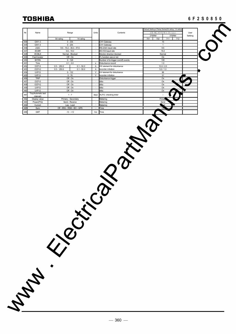
360
6 F 2 S 0 8 5 0
Name Range Units Contents 2CB-ARC, NO-FD, Wi th Di st ance User2TERM 3TERM Settiing
5A rating 1A rating 701 702 711 712444 GW1-3 0 - 254 - CH1 Gateway 19445 GW1-4 0 - 254 - CH1 Gateway 1446 232C 9.6 - 19.2 - 38.4 - 57.6 - RS-232C baud rate 9.6447 IECBR 9.6 - 19.2 - IEC103 baud rate 19.2448 IECBLK Normal - Blocked - Monitor direction blocked Normal449 Fault locator Off - On - FL function use or not On450 BITRN 0 - 128 - Number of bi-trigger (on/off) events 100451 Time 0.1 - 3.0 s Disturbance record 1.0452 OCP-S 0.5 - 250.0 0.1 - 50.0 A OC element for disturbance 10.0 / 2.0453 OCP-G 0.5 - 250.0 0.1 - 50.0 A recorder initiation 5.0 / 1.0454 UVP-S 0 - 132 V UV element for disturbance 88455 UVP-G 0 - 76 V recorder initiation 51456 TRIP Off - On - Disturbance trigger On457 OCP-S Off - On - ditto On458 OCP-G Off - On - ditto On459 UVP-S Off - On - ditto On460 UVP-G Off - On - ditto On
461Trip(Automatic test
interval)1 - 7 days AUTO. checking timer --
462 Display value Primary - Secondary - Metering Primary463 Power(P/Q) Send - Receive - Metering Send464 Current Lag - Lead - Metering Lead465 Sync Off - IRIG - RSM - IEC - GPS - Time Off
466 GMT -12 - +12 hrs Time 0
Default Setting of Relay Series(5A rating / 1A rating)
www . El
ectric
alPar
tMan
uals
. com

361
6 F 2 S 0 8 5 0
No. Name Range Unit Contents Signal No. Signal name Type1 EV1 0 - 3071 - Event record signal 1536 CB1 A On/Off2 EV2 0 - 3071 - ditto 1537 CB1 B On/Off3 EV3 0 - 3071 - ditto 1538 CB1 C On/Off4 EV4 0 - 3071 - ditto 1539 CB2 A On/Off5 EV5 0 - 3071 - ditto 1540 CB2 B On/Off6 EV6 0 - 3071 - ditto 1541 CB2 C On/Off7 EV7 0 - 3071 - ditto 1542 DS On/Off8 EV8 0 - 3071 - ditto 1544 Dif.block On/Off9 EV9 0 - 3071 - ditto 1550 BU block On/Off10 EV10 0 - 3071 - ditto 1545 Ext.close On/Off11 EV11 0 - 3071 - ditto 1546 DC supply On/Off12 EV12 0 - 3071 - ditto 1547 Trans.trip1 On/Off13 EV13 0 - 3071 - ditto 1548 Trans.trip2 On/Off14 EV14 0 - 3071 - ditto 1549 Ind. reset On/Off15 EV15 0 - 3071 - ditto 1552 Ext.trip A On/Off16 EV16 0 - 3071 - ditto 1553 Ext.trip B On/Off17 EV17 0 - 3071 - ditto 1554 Ext.trip C On/Off18 EV18 0 - 3071 - ditto 1571 CB1 ready On/Off19 EV19 0 - 3071 - ditto 1572 CB2 ready On/Off20 EV20 0 - 3071 - ditto 1573 ARC block On/Off21 EV21 0 - 3071 - ditto 446 Trip On/Off22 EV22 0 - 3071 - ditto 177 CB1 ARC On/Off23 EV23 0 - 3071 - ditto 178 CB2 ARC On/Off24 EV24 0 - 3071 - ditto 231 Relay fail On/Off25 EV25 0 - 3071 - ditto 1268 V0 err On/Off26 EV26 0 - 3071 - ditto 1269 V2 err On/Off27 EV27 0 - 3071 - ditto 1267 I0 err On/Off28 EV28 0 - 3071 - ditto 235 DS fail On/Off29 EV29 0 - 3071 - ditto 214 Com1 fail On/Off30 EV30 0 - 3071 - ditto 215 Sync1 fail On/Off31 EV31 0 - 3071 - ditto 220 Com2 fail On/Off32 EV32 0 - 3071 - ditto 221 Sync2 fail On/Off33 EV33 0 - 3071 - ditto 447 Term1 rdy On/Off34 EV34 0 - 3071 - ditto 448 Term2 rdy On/Off35 EV35 0 - 3071 - ditto 272 GPS 1PPS err On/Off36 EV36 0 - 3071 - ditto 289 Angle over On/Off37 EV37 0 - 3071 - ditto 1513 RYID1 err On/Off38 EV38 0 - 3071 - ditto 1514 RYID2 err On/Off39 EV39 0 - 3071 - ditto 1511 Td1 over On/Off40 EV40 0 - 3071 - ditto 1512 Td2 over On/Off41 EV41 0 - 3071 - ditto 1503 CLK1 fail On/Off42 EV42 0 - 3071 - ditto 1504 CLK2 fail On/Off43 EV43 0 - 3071 - ditto 1507 TX level1 err On/Off44 EV44 0 - 3071 - ditto 1508 TX level2 err On/Off45 EV45 0 - 3071 - ditto 1509 RX level1 err On/Off46 EV46 0 - 3071 - ditto 1510 RX level2 err On/Off47 EV47 0 - 3071 - ditto 1501 Com1 fail-R On/Off48 EV48 0 - 3071 - ditto 1502 Com2 fail-R On/Off49 EV49 0 - 3071 - ditto 489 AS1 On/Off50 EV50 0 - 3071 - ditto 490 AS2 On/Off51 EV51 0 - 3071 - ditto 228 RDIF1 On/Off52 EV52 0 - 3071 - ditto 229 RDIF2 On/Off53 EV53 0 - 3071 - ditto 1266 CT err On/Off54 EV54 0 - 3071 - ditto 1256 Id err On/Off55 EV55 0 - 3071 - ditto 496 CTF On/Off56 EV56 0 - 3071 - ditto 493 AF1 On/Off57 EV57 0 - 3071 - ditto 494 AF2 On/Off58 EV58 0 - 3071 - ditto 1271 I0-C err On/Off59 EV59 0 - 3071 - ditto 1273 CT-C err On/Off60 EV60 0 - 3071 - ditto 891 VTF On/Off61 EV61 0 - 3071 - ditto 766 PSB On/Off62 EV62 0 - 3071 - ditto 894 Ch.fail On/Off63 EV63 0 - 3071 - ditto 064 EV64 0 - 3071 - ditto 0
Event record
www . El
ectric
alPar
tMan
uals
. com
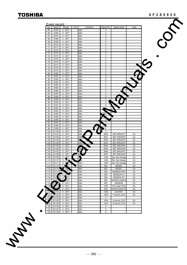
362
6 F 2 S 0 8 5 0
No. Name Range Unit Contents Signal No. Signal name Type65 EV65 0 - 3071 - ditto 066 EV66 0 - 3071 - ditto 067 EV67 0 - 3071 - ditto 068 EV68 0 - 3071 - ditto 069 EV69 0 - 3071 - ditto 070 EV70 0 - 3071 - ditto 071 EV71 0 - 3071 - ditto 072 EV72 0 - 3071 - ditto 073 EV73 0 - 3071 - ditto 074 EV74 0 - 3071 - ditto 075 EV75 0 - 3071 - ditto 076 EV76 0 - 3071 - ditto 077 EV77 0 - 3071 - ditto 078 EV78 0 - 3071 - ditto 079 EV79 0 - 3071 - ditto 080 EV80 0 - 3071 - ditto 081 EV81 0 - 3071 - ditto 082 EV82 0 - 3071 - ditto 083 EV83 0 - 3071 - ditto 084 EV84 0 - 3071 - ditto 085 EV85 0 - 3071 - ditto 086 EV86 0 - 3071 - ditto 087 EV87 0 - 3071 - ditto 088 EV88 0 - 3071 - ditto 089 EV89 0 - 3071 - ditto 090 EV90 0 - 3071 - ditto 091 EV91 0 - 3071 - ditto 092 EV92 0 - 3071 - ditto 093 EV93 0 - 3071 - ditto 094 EV94 0 - 3071 - ditto 095 EV95 0 - 3071 - ditto 096 EV96 0 - 3071 - ditto 097 EV97 0 - 3071 - ditto 098 EV98 0 - 3071 - ditto 099 EV99 0 - 3071 - ditto 0
100 EV100 0 - 3071 - ditto 0101 EV101 0 - 3071 - ditto 2640 SET.GROUP1 On102 EV102 0 - 3071 - ditto 2641 SET.GROUP2 On103 EV103 0 - 3071 - ditto 2642 SET.GROUP3 On104 EV104 0 - 3071 - ditto 2643 SET.GROUP4 On105 EV105 0 - 3071 - ditto 2644 SET.GROUP5 On106 EV106 0 - 3071 - ditto 2645 SET.GROUP6 On107 EV107 0 - 3071 - ditto 2646 SET.GROUP7 On108 EV108 0 - 3071 - ditto 2647 SET.GROUP8 On109 EV109 0 - 3071 - ditto 1448 Sys. Set change On110 EV110 0 - 3071 - ditto 1449 Rly. Set change On111 EV111 0 - 3071 - ditto 1450 Grp. Set change On112 EV112 0 - 3071 - ditto 950 MODE0 On113 EV113 0 - 3071 - ditto 951 MODE1 On114 EV114 0 - 3071 - ditto 952 MODE2A-GPS On115 EV115 0 - 3071 - ditto 953 MODE2A-Td On116 EV116 0 - 3071 - ditto 954 MODE2A-CF On117 EV117 0 - 3071 - ditto 955 MODE2A-ANGLE On118 EV118 0 - 3071 - ditto 957 MODE2B On119 EV119 0 - 3071 - ditto 1445 PLC data CHG On120 EV120 0 - 3071 - ditto 956 MODE2A-REMOTE On121 EV121 0 - 3071 - ditto 1409 LED RST On122 EV122 0 - 3071 - ditto 1435 F.record_CLR On123 EV123 0 - 3071 - ditto 0124 EV124 0 - 3071 - ditto 1436 E.record_CLR On125 EV125 0 - 3071 - ditto 1437 D.record_CLR On126 EV126 0 - 3071 - ditto 0127 EV127 0 - 3071 - ditto 0128 EV128 0 - 3071 - ditto 0
Event record
www . El
ectric
alPar
tMan
uals
. com
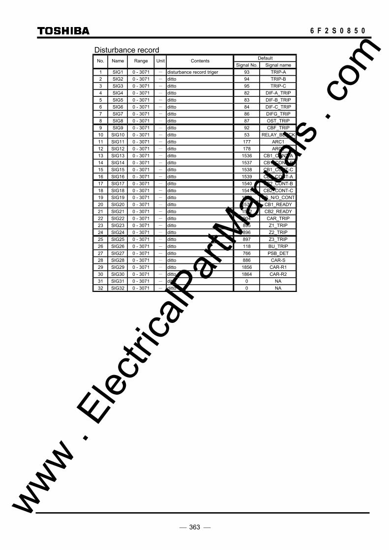
363
6 F 2 S 0 8 5 0
DefaultSignal No. Signal name
1 SIG1 0 - 3071 - disturbance record triger 93 TRIP-A2 SIG2 0 - 3071 - ditto 94 TRIP-B3 SIG3 0 - 3071 - ditto 95 TRIP-C4 SIG4 0 - 3071 - ditto 82 DIF-A_TRIP5 SIG5 0 - 3071 - ditto 83 DIF-B_TRIP6 SIG6 0 - 3071 - ditto 84 DIF-C_TRIP7 SIG7 0 - 3071 - ditto 86 DIFG_TRIP8 SIG8 0 - 3071 - ditto 87 OST_TRIP9 SIG9 0 - 3071 - ditto 92 CBF_TRIP
10 SIG10 0 - 3071 - ditto 53 RELAY_BLOCK11 SIG11 0 - 3071 - ditto 177 ARC112 SIG12 0 - 3071 - ditto 178 ARC213 SIG13 0 - 3071 - ditto 1536 CB1_CONT-A14 SIG14 0 - 3071 - ditto 1537 CB1_CONT-B15 SIG15 0 - 3071 - ditto 1538 CB1_CONT-C16 SIG16 0 - 3071 - ditto 1539 CB2_CONT-A17 SIG17 0 - 3071 - ditto 1540 CB2_CONT-B18 SIG18 0 - 3071 - ditto 1541 CB2_CONT-C19 SIG19 0 - 3071 - ditto 1542 DS_N/O_CONT20 SIG20 0 - 3071 - ditto 1571 CB1_READY21 SIG21 0 - 3071 - ditto 1572 CB2_READY22 SIG22 0 - 3071 - ditto 904 CAR_TRIP23 SIG23 0 - 3071 - ditto 895 Z1_TRIP24 SIG24 0 - 3071 - ditto 896 Z2_TRIP25 SIG25 0 - 3071 - ditto 897 Z3_TRIP26 SIG26 0 - 3071 - ditto 118 BU_TRIP27 SIG27 0 - 3071 - ditto 766 PSB_DET28 SIG28 0 - 3071 - ditto 886 CAR-S29 SIG29 0 - 3071 - ditto 1856 CAR-R130 SIG30 0 - 3071 - ditto 1864 CAR-R231 SIG31 0 - 3071 - ditto 0 NA32 SIG32 0 - 3071 - ditto 0 NA
Disturbance recordNo. Name Range Unit Contents
www . El
ectric
alPar
tMan
uals
. com

364
6 F 2 S 0 8 5 0
PLC Default SettingOutput Timing Logic expression Delay Time / Flip Flop
Cycle Flip Flop Timer
30 90 User Norm BackUp
ReleaseSignal
OffDelay
OnDelay
OneShot Time Value
1536 CB1_CONT-A X [513]BI1_COMMAND X1537 CB1_CONT-B X [514]BI2_COMMAND X1538 CB1_CONT-C X [515]BI3_COMMAND X1539 CB2_CONT-A X [516]BI4_COMMAND X1540 CB2_CONT-B X [517]BI5_COMMAND X1541 CB2_CONT-C X [518]BI6_COMMAND X1542 DS_N/O_CONT X [519]BI7_COMMAND X1543 DS_N/C_CONT X [520]BI8_COMMAND X1544 CRT_BLOCK X [531]BI19_COMMAND X1545 CB_CLOSE X [532]BI20_COMMAND X1546 DC_SUPPLY X [523]BI11_COMMAND X1547 85S1 X [1295]BI12_COM_UF X1548 85S2 X [1296]BI13_COM_UF X1549 IND.RESET X [533]BI21_COMMAND X1550 BUT_BLOCK15511552 EXT_TRIP-A X [528]BI16_COMMAND X1553 EXT_TRIP-B X [529]BI17_COMMAND X1554 EXT_TRIP-C X [530]BI18_COMMAND X15551556 EXT_CBFIN-A X [528]BI16_COMMAND X1557 EXT_CBFIN-B X [529]BI17_COMMAND X1558 EXT_CBFIN-C X [530]BI18_COMMAND X1559156015611562156315641565156615671568 INT.LINK1-A1569 INT.LINK1-B1570 INT.LINK1-C1571 CB1_READY X [534]BI22_COMMAND X1572 CB2_READY X [535]BI23_COMMAND X1573 ARC_RESET X [536]BI24_COMMAND X
1574 ARC_BLOCK X 2
[87]OST_TRIP + [91]CBFDET +[98]STUB + [417]THM_TRIP +
[418]TR1_TRIP + [426]TR2_TRIP +[859]BCD_TRIP + [905]OV/UV_TRIP
X
1575 INT.LINK2-A1576 INT.LINK2-B1577 INT.LINK2-C1578 ARC_BLOCK11579 ARC_BLOCK215801581158215831584 PROT_BLOCK1585 DIF_BLOCK1586 DIFG_BLOCK1587 OST_BLOCK1588 CBF_BLOCK1589 OC_BLOCK1590 OCI_BLOCK1591 EF_BLOCK1592 EFI_BLOCK1593 THMA_BLOCK1594 THM_BLOCK1595 TR1_BLOCK1596 TR2_BLOCK1597 EXTTP_BLOCK1598 RDIF_BLOCK1599
None Signal Turn Model 7xx
www . El
ectric
alPar
tMan
uals
. com

365
6 F 2 S 0 8 5 0
PLC Default Setting
Output Timing Logic expression Delay Time / Flip FlopCycle Flip Flop Timer
30 90 User Norm BackUp
ReleaseSignal
OffDelay
OnDelay
OneShot Time Value
1600 ARC_OFF1601 ARC_SPAR1602 ARC_TPAR1603 ARC_S&T1604 ARC_MAPR21605 ARC_MPAR31606 ARC_EXT1P1607 ARC_EXT3P1608 ARC_EXTMP1609 CTF_BLOCK1610161116121613161416151616 DIF-A_FS X [408]DIFFS_OP X1617 DIF-B_FS X [408]DIFFS_OP X1618 DIF-C_FS X [408]DIFFS_OP X1619 DIFG_FS X [412]DIFGFS_OP X1620 TP-A_DELAY X [435]TP-A X 60 ms1621 TP-B_DELAY X [436]TP-B X 60 ms1622 TP-C_DELAY X [437]TP-C X 60 ms1623 R.DATA_ZERO1624 RDIF-A_FS X [408]DIFFS_OP + [412]DIFGFS_OP X1625 RDIF-B_FS X [408]DIFFS_OP + [412]DIFGFS_OP X1626 RDIF-C_FS X [408]DIFFS_OP + [412]DIFGFS_OP X16271628162916301631 INIT_MODE2B1632 DIFG_INST_TP1633 OC_INST_TP1634 EF_INST_TP16351636163716381639164016411642164316441645164616471648 DIF_3PTP1649 RDIF_3PTP1650 OC_3PTP X 0 [1]CONSTANT_1 X1651 OCI_3PTP X 0 [1]CONSTANT_1 X165216531654165516561657165816591660 TR1_3PTP1661 TR2_3PTP16621663 3P_TRIP1664166516661667166816691670
None Signal Turn Model 7xx
www .
Elec
tricalP
artM
anua
ls . c
om

366
6 F 2 S 0 8 5 0
PLC Default SettingOutput Timing Logic ex pression Delay Time / Flip Flop
Cycle Flip Flop Timer
30 90 User NormBackUp
ReleaseSignal
OffDelay
OnDelay
OneShot
Time Value
16711672 85R1-R1 X [1091]COM4-R1 X1673 85R2-R1 X [1092]COM5-R1 X1674 ARC_BLOCK-R1 X [1104]SUB_COM1-R1 X1675 L.TEST-R1 X [1105]SUB_COM2-R1 X1676167716781679
1680 I.LINK-A-R1 X[1112]SUB2_COM1-R1 + [1115]SUB2_COM4-R1
+ [1118]SUB2_COM7-R1 +[1121]SUB2_COM10-R1
X
1681 I.LINK-B-R1 X[1113]SUB2_COM2-R1 + [1116]SUB2_COM5-R1
+ [1119]SUB2_COM8-R1 +[1122]SUB2_COM11-R1
X
1682 I.LINK-C-R1 X[1114]SUB2_COM3-R1 + [1117]SUB2_COM6-R1
+ [1120]SUB2_COM9-R1 +[1123]SUB2_COM12-R1
X
16831684 RDIF-A-R11685 RDIF-B-R11686 RDIF-C-R11687 RDIF-R11688 TR1-A-R11689 TR1-B-R11690 TR1-C-R116911692 TR2-A-R11693 TR2-B-R11694 TR2-C-R11695169616971698169917001701170217031704 85R1-R2 X [1131]COM4-R2 X1705 85R2-R2 X [1132]COM5-R2 X1706 ARC_BLOCK-R2 X [1144]SUB_COM1-R2 X1707 L.TEST-R2 X [1145]SUB_COM2-R2 X1708170917101711
1712 I.LINK-A-R2 X[1152]SUB2_COM1-R2 + [1155]SUB2_COM4-R2
+ [1158]SUB2_COM7-R2 +[1161]SUB2_COM10-R2
X
1713 I.LINK-B-R2 X[1153]SUB2_COM2-R2 + [1156]SUB2_COM5-R2
+ [1159]SUB2_COM8-R2 +[1162]SUB2_COM11-R2
X
1714 I.LINK-C-R2 X[1154]SUB2_COM3-R2 + [1157]SUB2_COM6-R2
+ [1160]SUB2_COM9-R2 +[1163]SUB2_COM12-R2
X
17151716 RDIF-A-R21717 RDIF-B-R21718 RDIF-C-R21719 RDIF-R21720 TR1-A-R21721 TR1-B-R21722 TR1-C-R217231724 TR2-A-R21725 TR2-B-R21726 TR2-C-R21727172817291730
None Signal Turn Model 7x x
www .
Elec
tricalP
artM
anua
ls . c
om
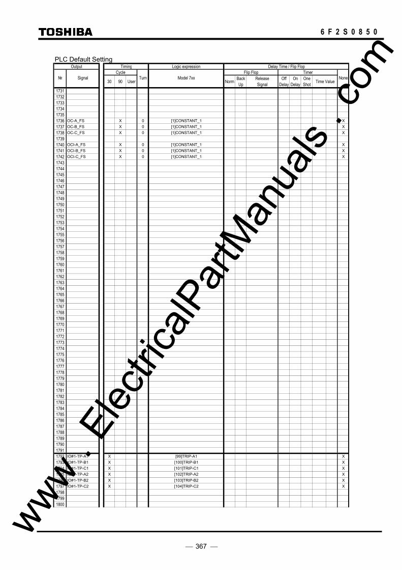
367
6 F 2 S 0 8 5 0
PLC Default Setting
Output Timing Logic expression Delay Time / Flip FlopCycle Flip Flop Timer
30 90 User Norm BackUp
ReleaseSignal
OffDelay
OnDelay
OneShot Time Value
173117321733173417351736 OC-A_FS X 0 [1]CONSTANT_1 X1737 OC-B_FS X 0 [1]CONSTANT_1 X1738 OC-C_FS X 0 [1]CONSTANT_1 X17391740 OCI-A_FS X 0 [1]CONSTANT_1 X1741 OCI-B_FS X 0 [1]CONSTANT_1 X1742 OCI-C_FS X 0 [1]CONSTANT_1 X17431744174517461747174817491750175117521753175417551756175717581759176017611762176317641765176617671768176917701771177217731774177517761777177817791780178117821783178417851786178717881789179017911792 IO#1-TP-A1 X [99]TRIP-A1 X1793 IO#1-TP-B1 X [100]TRIP-B1 X1794 IO#1-TP-C1 X [101]TRIP-C1 X1795 IO#1-TP-A2 X [102]TRIP-A2 X1796 IO#1-TP-B2 X [103]TRIP-B2 X1797 IO#1-TP-C2 X [104]TRIP-C2 X179817991800
None Signal Turn Model 7xx
www .
Elec
tricalP
artM
anua
ls . c
om

368
6 F 2 S 0 8 5 0
PLC Default SettingOutput Timing Logic expression Delay Time / Flip Flop
Cycle Flip Flop Timer
30 90 User Norm BackUp
ReleaseSignal
OffDelay
OnDelay
OneShot Time Value
180118021803180418051806180718081809181018111812181318141815181618171818181918201821182218231824 SPR.L-REQ X [1]CONSTANT_1 X1825 TPR.L-REQ X [159]SYN-OP X1826 MPR.L-REQ X [1]CONSTANT_1 X1827 SPR.F-REQ X [1]CONSTANT_1 X1828 TPR.F-REQ X [159]SYN-OP X1829 MPR.F-REQ X [1]CONSTANT_1 X1830 SPR.F-ST.REQ X [1]CONSTANT_1 X1831 TPR.F-ST.REQ X [477]ARC-SET + [478]CCB-SET X1832 MPR.F-ST.REQ X [1]CONSTANT_1 X1833183418351836 R.F-ST.REQ1837 SPR.F2-ST.REQ1838 TPR.F2-ST.REQ1839 MPR.F2-ST.REQ1840 ARC.L_TERM1841 ARC.F_TERM184218431844184518461847 Z1_ARC_BLOCK X 1 [787]Z1CNT_ARCBLK X184818491850185118521853185418551856 CAR.R1-1 X [1292]BI9_COM_UF X1857 CAR.R1-2 X [1297]BI14_COM_UF X1858 OPEN_TERM-R1185918601861186218631864 CAR.R2-1 X [1293]BI10_COM_UF X1865 CAR.R2-2 X [1298]BI15_COM_UF X1866 OPEN_TERM-R21867186818691870
None Signal Turn Model 7xx
www .
Elec
tricalP
artM
anua
ls . c
om

369
6 F 2 S 0 8 5 0
PLC Default SettingOutput Timing Logic expression Delay Time / Flip Flop
Cycle Flip Flop Timer
30 90 User Norm BackUp
ReleaseSignal
OffDelay
OnDelay
OneShot Time Value
1871 INT.COM18721873 DCRT_BLOCK1874 DISCRT_BLOCK1875 DEFCRT_BLOCK18761877 PSB_BLOCK18781879188018811882188318841885188618871888 Z1G_BLOCK X 1 [788]Z1CNT_TPBLK X18891890 Z2G_BLOCK1891 Z3G_BLOCK189218931894 ZRG_BLOCK189518961897 DEFF_BLOCK18981899 DEFR_BLOCK1900 STUBOC_BLOCK1901 SOTF_BLOCK1902 OCH_BLOCK19031904 Z1S_BLOCK X 1 [788]Z1CNT_TPBLK X19051906 Z2S_BLOCK1907 Z3S_BLOCK190819091910 ZRS_BLOCK19111912 BCD_BLOCK19131914 VTF_BLOCK1915 VTF_ONLY_ALM1916 EXT_VTF1917191819191920 OVS1_BLOCK1921 OVS2_BLOCK192219231924 OVG1_BLOCK1925 OVG2_BLOCK192619271928 UVS1_BLOCK1929 UVS2_BLOCK193019311932 UVG1_BLOCK1933 UVG2_BLOCK193419351936 Z1_INST_TP X 1 [785]Z1CNT_INST X19371938 Z2_INST_TP1939 Z3_INST_TP1940
None Signal Turn Model 7xx
www .
Elec
tricalP
artM
anua
ls . c
om
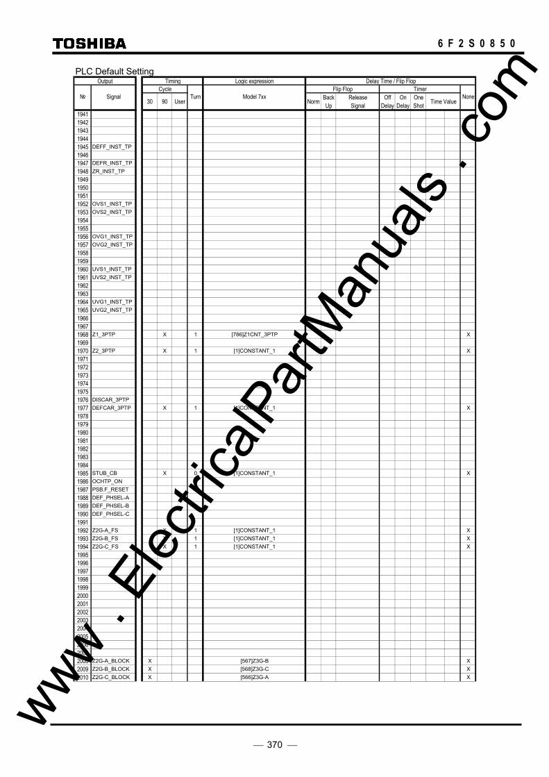
370
6 F 2 S 0 8 5 0
PLC Default SettingOutput Timing Logic expression Delay Time / Flip Flop
Cycle Flip Flop Timer
30 90 User Norm BackUp
ReleaseSignal
OffDelay
OnDelay
OneShot Time Value
19411942194319441945 DEFF_INST_TP19461947 DEFR_INST_TP1948 ZR_INST_TP1949195019511952 OVS1_INST_TP1953 OVS2_INST_TP195419551956 OVG1_INST_TP1957 OVG2_INST_TP195819591960 UVS1_INST_TP1961 UVS2_INST_TP196219631964 UVG1_INST_TP1965 UVG2_INST_TP196619671968 Z1_3PTP X 1 [786]Z1CNT_3PTP X19691970 Z2_3PTP X 1 [1]CONSTANT_1 X197119721973197419751976 DISCAR_3PTP1977 DEFCAR_3PTP X 1 [1]CONSTANT_1 X19781979198019811982198319841985 STUB_CB X 0 [1]CONSTANT_1 X1986 OCHTP_ON1987 PSB.F_RESET1988 DEF_PHSEL-A1989 DEF_PHSEL-B1990 DEF_PHSEL-C19911992 Z2G-A_FS X 1 [1]CONSTANT_1 X1993 Z2G-B_FS X 1 [1]CONSTANT_1 X1994 Z2G-C_FS X 1 [1]CONSTANT_1 X19951996199719981999200020012002200320042005200620072008 Z2G-A_BLOCK X [567]Z3G-B X2009 Z2G-B_BLOCK X [568]Z3G-C X2010 Z2G-C_BLOCK X [566]Z3G-A X
None Signal Turn Model 7xx
www .
Elec
tricalP
artM
anua
ls . c
om
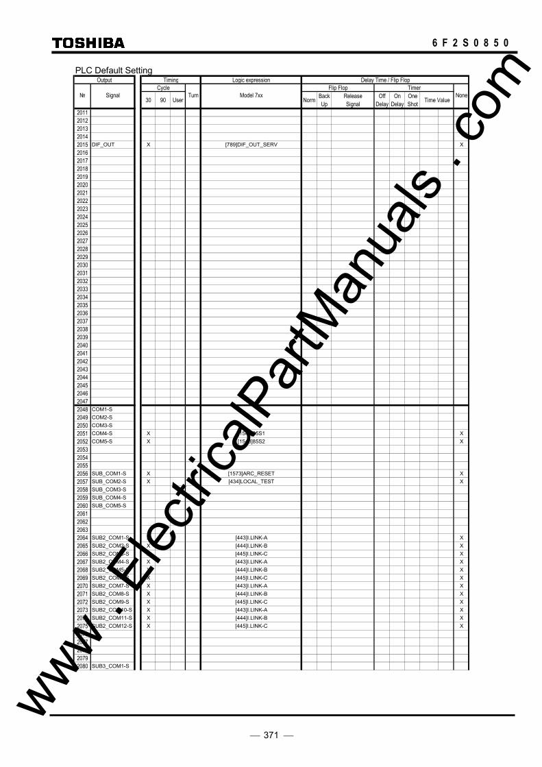
371
6 F 2 S 0 8 5 0
PLC Default SettingOutput Timing Logic expression Delay Time / Flip Flop
Cycle Flip Flop Timer
30 90 User Norm BackUp
ReleaseSignal
OffDelay
OnDelay
OneShot Time Value
20112012201320142015 DIF_OUT X [789]DIF_OUT_SERV X201620172018201920202021202220232024202520262027202820292030203120322033203420352036203720382039204020412042204320442045204620472048 COM1-S2049 COM2-S2050 COM3-S2051 COM4-S X [1547]85S1 X2052 COM5-S X [1548]85S2 X2053205420552056 SUB_COM1-S X [1573]ARC_RESET X2057 SUB_COM2-S X [434]LOCAL_TEST X2058 SUB_COM3-S2059 SUB_COM4-S2060 SUB_COM5-S2061206220632064 SUB2_COM1-S X [443]I.LINK-A X2065 SUB2_COM2-S X [444]I.LINK-B X2066 SUB2_COM3-S X [445]I.LINK-C X2067 SUB2_COM4-S X [443]I.LINK-A X2068 SUB2_COM5-S X [444]I.LINK-B X2069 SUB2_COM6-S X [445]I.LINK-C X2070 SUB2_COM7-S X [443]I.LINK-A X2071 SUB2_COM8-S X [444]I.LINK-B X2072 SUB2_COM9-S X [445]I.LINK-C X2073 SUB2_COM10-S X [443]I.LINK-A X2074 SUB2_COM11-S X [444]I.LINK-B X2075 SUB2_COM12-S X [445]I.LINK-C X20762077207820792080 SUB3_COM1-S
None Signal Turn Model 7xx
www .
Elec
tricalP
artM
anua
ls . c
om

372
6 F 2 S 0 8 5 0
PLC Default SettingOutput Timing Logic ex pression Delay Time / Flip Flop
Cycle Flip Flop Timer
30 90 User NormBackUp
ReleaseSignal
OffDelay
OnDelay
OneShot
Time Value
2081 SUB3_COM2-S2082 SUB3_COM3-S2083 SUB3_COM4-S2084 SUB3_COM5-S2085 SUB3_COM6-S2086 SUB3_COM7-S2087 SUB3_COM8-S2088 SUB3_COM9-S2089 SUB3_COM10-S2090 SUB3_COM11-S2091 SUB3_COM12-S20922093209420952096 V.COM1-S2097 V.COM2-S2098 V.COM3-S20992100 S.V.COM1-S2101 S.V.COM2-S2102 S.V.COM3-S2103 S.V.COM4-S2104 S.V.COM5-S2105 S.V.COM6-S2106 S.V.COM7-S2107 S.V.COM8-S2108 S.V.COM9-S2109 S.V.COM10-S2110 S.V.COM11-S2111 S.V.COM12-S2112 I.COM1-S2113 I.COM2-S2114 I.COM3-S21152116 S.I.COM1-S2117 S.I.COM2-S2118 S.I.COM3-S2119 S.I.COM4-S2120 S.I.COM5-S2121 S.I.COM6-S2122 S.I.COM7-S2123 S.I.COM8-S2124 S.I.COM9-S2125 S.I.COM10-S2126 S.I.COM11-S2127 S.I.COM12-S2128212921302131213221332134213521362137213821392140214121422143214421452146
:::
2600
None Signal Turn Model 7x x
www .
Elec
tricalP
artM
anua
ls . c
om
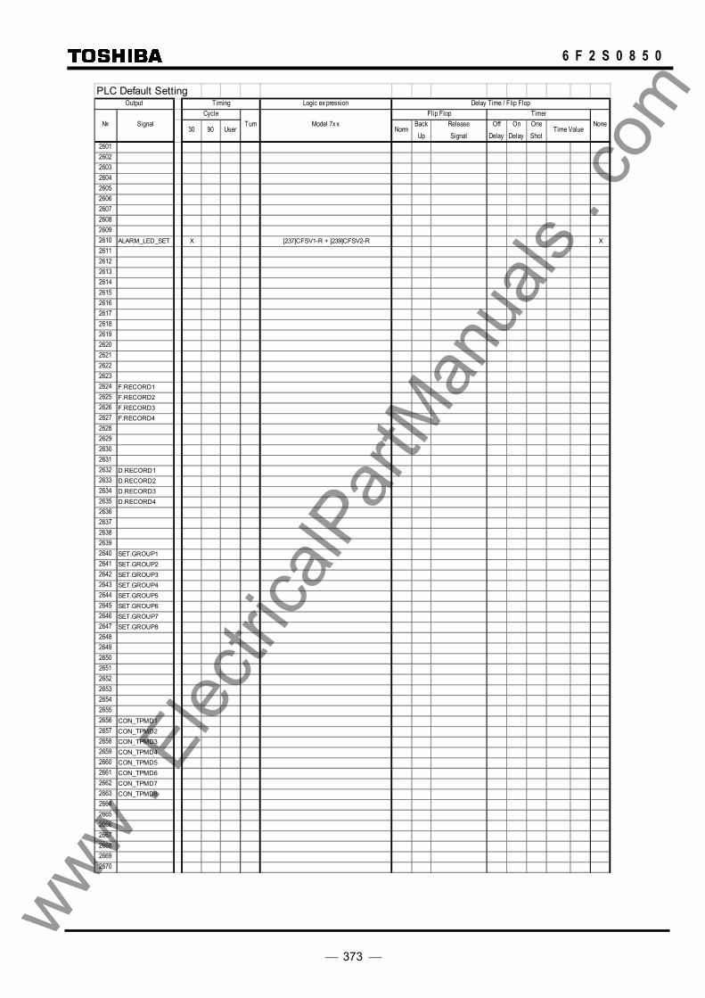
373
6 F 2 S 0 8 5 0
PLC Default SettingOutput Timing Logic ex pression Delay Time / Flip Flop
Cycle Flip Flop Timer
30 90 User NormBackUp
ReleaseSignal
OffDelay
OnDelay
OneShot
Time Value
2601260226032604260526062607260826092610 ALARM_LED_SET X [237]CFSV1-R + [239]CFSV2-R X26112612261326142615261626172618261926202621262226232624 F.RECORD12625 F.RECORD22626 F.RECORD32627 F.RECORD426282629263026312632 D.RECORD12633 D.RECORD22634 D.RECORD32635 D.RECORD426362637263826392640 SET.GROUP12641 SET.GROUP22642 SET.GROUP32643 SET.GROUP42644 SET.GROUP52645 SET.GROUP62646 SET.GROUP72647 SET.GROUP8264826492650265126522653265426552656 CON_TPMD12657 CON_TPMD22658 CON_TPMD32659 CON_TPMD42660 CON_TPMD52661 CON_TPMD62662 CON_TPMD72663 CON_TPMD82664266526662667266826692670
None Signal Turn Model 7x x
www .
Elec
tricalP
artM
anua
ls . c
om

374
6 F 2 S 0 8 5 0
PLC Default SettingOutput Timing Logic expression Delay Time / Flip Flop
Cycle Flip Flop Timer
30 90 User Norm Back Up
Release Signal
Off Delay
On Delay
One Shot Time Value
2671267226732674267526762677267826792680268126822683 ARC_COM_RECV
2684 TEL_COM_RECV2685 PROT_COM_RECV
26862687 TPLED_RST_RCV
26882689269026912692269326942695269626972698269927002701270227032704270527062707270827092710271127122713271427152716271727182719272027212722272327242725272627272728272927302731273227332734273527362737273827392740
None Signal Turn Model 7xx
www . El
ectric
alPar
tMan
uals
. com

375
6 F 2 S 0 8 5 0
PLC Default SettingOutput Timing Logic ex pression Delay Time / Flip Flop
Cycle Flip Flop Timer
30 90 User NormBackUp
ReleaseSignal
OffDelay
OnDelay
OneShot
Time Value
2741274227432744274527462747274827492750275127522753275427552756275727582759276027612762276327642765276627672768276927702771277227732774277527762777277827792780278127822783278427852786278727882789279027912792279327942795279627972798279928002801280228032804280528062807280828092810
None Signal Turn Model 7x x
www .
Elec
tricalP
artM
anua
ls . c
om

376
6 F 2 S 0 8 5 0
PLC Default SettingOutput Timing Logic ex pression Delay Time / Flip Flop
Cycle Flip Flop Timer
30 90 User NormBackUp
ReleaseSignal
OffDelay
OnDelay
OneShot
Time Value
281128122813281428152816 TEMP0012817 TEMP0022818 TEMP0032819 TEMP0042820 TEMP0052821 TEMP0062822 TEMP0072823 TEMP0082824 TEMP0092825 TEMP0102826 TEMP0112827 TEMP0122828 TEMP0132829 TEMP0142830 TEMP0152831 TEMP0162832 TEMP0172833 TEMP0182834 TEMP0192835 TEMP0202836 TEMP0212837 TEMP0222838 TEMP0232839 TEMP0242840 TEMP0252841 TEMP0262842 TEMP0272843 TEMP0282844 TEMP0292845 TEMP0302846 TEMP0312847 TEMP0322848 TEMP0332849 TEMP0342850 TEMP0352851 TEMP0362852 TEMP0372853 TEMP0382854 TEMP0392855 TEMP0402856 TEMP0412857 TEMP0422858 TEMP0432859 TEMP0442860 TEMP0452861 TEMP0462862 TEMP0472863 TEMP0482864 TEMP0492865 TEMP0502866 TEMP0512867 TEMP0522868 TEMP0532869 TEMP0542870 TEMP0552871 TEMP0562872 TEMP0572873 TEMP0582874 TEMP0592875 TEMP0602876 TEMP0612877 TEMP0622878 TEMP0632879 TEMP0642880 TEMP065
None Signal Turn Model 7x x
www . El
ectric
alPar
tMan
uals
. com

377
6 F 2 S 0 8 5 0
PLC Default SettingOutput Timing Logic ex pression Delay Time / Flip Flop
Cycle Flip Flop Timer
30 90 User NormBackUp
ReleaseSignal
OffDelay
OnDelay
OneShot
Time Value
2881 TEMP0662882 TEMP0672883 TEMP0682884 TEMP0692885 TEMP0702886 TEMP0712887 TEMP0722888 TEMP0732889 TEMP0742890 TEMP0752891 TEMP0762892 TEMP0772893 TEMP0782894 TEMP0792895 TEMP0802896 TEMP0812897 TEMP0822898 TEMP0832899 TEMP0842900 TEMP0852901 TEMP0862902 TEMP0872903 TEMP0882904 TEMP0892905 TEMP0902906 TEMP0912907 TEMP0922908 TEMP0932909 TEMP0942910 TEMP0952911 TEMP0962912 TEMP0972913 TEMP0982914 TEMP0992915 TEMP1002916 TEMP1012917 TEMP1022918 TEMP1032919 TEMP1042920 TEMP1052921 TEMP1062922 TEMP1072923 TEMP1082924 TEMP1092925 TEMP1102926 TEMP1112927 TEMP1122928 TEMP1132929 TEMP1142930 TEMP1152931 TEMP1162932 TEMP1172933 TEMP1182934 TEMP1192935 TEMP1202936 TEMP1212937 TEMP1222938 TEMP1232939 TEMP1242940 TEMP1252941 TEMP1262942 TEMP1272943 TEMP1282944 TEMP1292945 TEMP1302946 TEMP1312947 TEMP1322948 TEMP1332949 TEMP1342950 TEMP135
None Signal Turn Model 7x x
www .
Elec
tricalP
artM
anua
ls . c
om

378
6 F 2 S 0 8 5 0
PLC Default SettingOutput Timing Logic ex pression Delay Time / Flip Flop
Cycle Flip Flop Timer
30 90 User NormBackUp
ReleaseSignal
OffDelay
OnDelay
OneShot
Time Value
2951 TEMP1362952 TEMP1372953 TEMP1382954 TEMP1392955 TEMP1402956 TEMP1412957 TEMP1422958 TEMP1432959 TEMP1442960 TEMP1452961 TEMP1462962 TEMP1472963 TEMP1482964 TEMP1492965 TEMP1502966 TEMP1512967 TEMP1522968 TEMP1532969 TEMP1542970 TEMP1552971 TEMP1562972 TEMP1572973 TEMP1582974 TEMP1592975 TEMP1602976 TEMP1612977 TEMP1622978 TEMP1632979 TEMP1642980 TEMP1652981 TEMP1662982 TEMP1672983 TEMP1682984 TEMP1692985 TEMP1702986 TEMP1712987 TEMP1722988 TEMP1732989 TEMP1742990 TEMP1752991 TEMP1762992 TEMP1772993 TEMP1782994 TEMP1792995 TEMP1802996 TEMP1812997 TEMP1822998 TEMP1832999 TEMP1843000 TEMP1853001 TEMP1863002 TEMP1873003 TEMP1883004 TEMP1893005 TEMP1903006 TEMP1913007 TEMP1923008 TEMP1933009 TEMP1943010 TEMP1953011 TEMP1963012 TEMP1973013 TEMP1983014 TEMP1993015 TEMP2003016 TEMP2013017 TEMP2023018 TEMP2033019 TEMP2043020 TEMP205
None Signal Turn Model 7x x
www .
Elec
tricalP
artM
anua
ls . c
om

379
6 F 2 S 0 8 5 0
PLC Default SettingOutput Timing Logic expression Delay Time / Flip Flop
Cycle Flip Flop Timer
30 90 User Norm BackUp
ReleaseSignal
OffDelay
OnDelay
OneShot Time Value
3021 TEMP2063022 TEMP2073023 TEMP2083024 TEMP2093025 TEMP2103026 TEMP2113027 TEMP2123028 TEMP2133029 TEMP2143030 TEMP2153031 TEMP2163032 TEMP2173033 TEMP2183034 TEMP2193035 TEMP2203036 TEMP2213037 TEMP2223038 TEMP2233039 TEMP2243040 TEMP2253041 TEMP2263042 TEMP2273043 TEMP2283044 TEMP2293045 TEMP2303046 TEMP2313047 TEMP2323048 TEMP2333049 TEMP2343050 TEMP2353051 TEMP2363052 TEMP2373053 TEMP2383054 TEMP2393055 TEMP2403056 TEMP2413057 TEMP2423058 TEMP2433059 TEMP2443060 TEMP2453061 TEMP2463062 TEMP2473063 TEMP2483064 TEMP2493065 TEMP2503066 TEMP2513067 TEMP2523068 TEMP2533069 TEMP2543070 TEMP2553071 TEMP256
None Signal Turn Model 7xx
www . El
ectric
alPar
tMan
uals
. com

380
6 F 2 S 0 8 5 0 www .
Elec
tricalP
artM
anua
ls . c
om

381
6 F 2 S 0 8 5 0
Appendix I
Commissioning Test Sheet (sample)
1. Relay identification
2. Preliminary check
3. Hardware check
4. Function test
5. Protection scheme test
6. Metering and recording check
7. Conjunctive test
www . El
ectric
alPar
tMan
uals
. com

382
6 F 2 S 0 8 5 0
1. Relay identification
Type Serial number
Model System frequency
Station Date
Circuit Engineer
Protection scheme Witness
Active settings group number
2. Preliminary check
Ratings
CT shorting contacts
DC power supply
Power up
Wiring
Relay inoperative alarm contact
Calendar and clock
3. Hardware check
3.1 User interface check
3.2 Binary input/Binary output circuit check
Binary input circuit
Binary output circuit
3.3 AC input circuit 4. Function test 4.1 Phase current differential element DIF test (1) Minimum operating value test
Tap setting I Measured current
(2) Charging current compensation test
Tap setting Measured current
(3) Percentage restraining characteristic test www . El
ectric
alPar
tMan
uals
. com

383
6 F 2 S 0 8 5 0
Tap setting I Measured current (I2)
× Tap
× Tap
20 × Tap
4.2 Residual current differential element DIFG test (1) Minimum operating value test
Tap setting I1 Measured current (I2)
(2) Percentage restraining characteristic test
Tap setting I1 Measured current (I2)
5 × Tap
20 × Tap
4.3 Phase fault element ZS test
Element Reach setting (ZS) IT 2IT × ZS Measured voltage (2Va)
Z1S
Z2S
Z3S
Z4S
ZRS
PSBSIN
PSBSOUT
4.4 Earth fault element ZG test
Element Reach setting (ZG) IT 2IT × ZG Measured voltage (2Va)
Z1G
Z2G
Z3G
Z4G
ZRG
PSBGIN
PSBGOUT
4.5 Phase selection element UVC test
Element Reach setting (UVCZ) IT IT × UVCZ + UVCV Measured voltage
UVC 0 0
www . El
ectric
alPar
tMan
uals
. com

384
6 F 2 S 0 8 5 0
4.6 Directional earth fault element DEF test (1)
Element Current setting Measured current
DEFF
DEFR
(2) Element Voltage setting Measured voltage
DEFF DEFR
4.7 Inverse definite minimum time overcurrent element (IDMT) EFI and OCI test
Element Test current Measured operating time EFI 1.2 × Is
20 × Is
OCI 1.2 × Is
20 × Is
4.8 Thermal overload element test
Element Test current Measured operating time THM-A 1.2 × Is
THM-T 10 × Is
4.9 Current change detection element
Element Test current Result OCD 1.2 × Fixed setting
OCDP 1.2 × Setting value
www . El
ectric
alPar
tMan
uals
. com
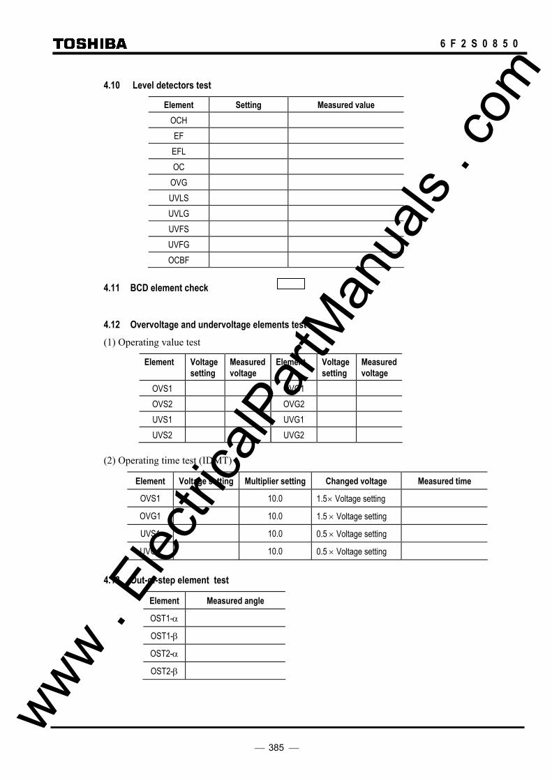
385
6 F 2 S 0 8 5 0
4.10 Level detectors test
Element Setting Measured value OCH EF EFL OC
OVG UVLS UVLG UVFS UVFG OCBF
4.11 BCD element check
4.12 Overvoltage and undervoltage elements test (1) Operating value test
Element Voltage setting
Measured voltage
Element Voltage setting
Measured voltage
OVS1 OVG1 OVS2 OVG2 UVS1 UVG1 UVS2 UVG2
(2) Operating time test (IDMT)
Element Voltage setting Multiplier setting Changed voltage Measured time
OVS1 10.0 1.5 × Voltage setting
OVG1 10.0 1.5 × Voltage setting
UVS1 10.0 0.5 × Voltage setting
UVG1 10.0 0.5 × Voltage setting
4.13 Out-of-step element test
Element Measured angle
OST1-α
OST1-β
OST2-α
OST2-β
www . El
ectric
alPar
tMan
uals
. com

386
6 F 2 S 0 8 5 0
4.14 Voltage and synchronism check elements test (1) Voltage check element
Element Setting Measured voltage Element Setting Measured voltage
OVB UVL1
UVB OVL2
OVL1 UVL2
(2) Synchronism check element
Voltage check
Element Setting Measured voltage Element Setting Measured voltage
SYN1(SY1UV) SYN2(SY2UV)
SYN1(SY1OV) SYN2(SY2OV)
Phase angle check
Element Setting Measured angle
SYN1(SY1θ)
SYN2(SY2θ)
5. Protection scheme test
6. Metering and recording check
7. Conjunctive test
Item Results
On load check Tripping circuit Reclosing circuit
www . El
ectric
alPar
tMan
uals
. com

387
6 F 2 S 0 8 5 0
Appendix J
Return Repair Form
www . El
ectric
alPar
tMan
uals
. com

388
6 F 2 S 0 8 5 0
RETURN / REPAIR FORM
Please fill in this form and return it to Toshiba Corporation with the GRL100 to be repaired.
TOSHIBA CORPORATION Fuchu Complex
1, Toshiba-cho, Fuchu-shi, Tokyo, Japan
For: Power Systems Protection & Control Department
Quality Assurance Section
Type: GRL100 Model: Sub No.
(Example: Type: GRL100 Model: 701B Sub No. 22-10)
Product No.:
Serial No. :
Date:
1. Why the relay is being returned ?
mal-operation
does not operate
increased error
investigation
others
2. Fault records, event records or disturbance records stored in the relay and relay settings are very helpful information to investigate the incident.
Please inform us of this information in respect to the incident on a Floppy Disk, or by completing the Fault Record sheet and Relay Setting sheet attached.
www . El
ectric
alPar
tMan
uals
. com

389
6 F 2 S 0 8 5 0
Fault Record Date/Month/Year Time / / / : : .
(Example: 04/ Nov./ 1997 15:09:58.442)
Faulty phase:
Fault Locator : km ( %)
Prefault values (CT ratio: kA/: A, VT ratio: kV/: V) Va: kV or V∠ ° Ia: kA or A∠ ° Vb: kV or V∠ ° Ib: kA or A∠ ° Vc: kV or V∠ ° Ic: kA or A∠ ° Vab kV or V∠ ° Iab kA or A∠ ° Vbc kV or V∠ ° Ibc kA or A∠ ° Vca kV or V∠ ° Ica kA or A∠ ° Vs1 kV or V∠ ° Vs2 kV or V∠ ° V1: kV or V∠ ° I1: kA or A∠ ° V2: kV or V∠ ° I2: kA or A∠ ° V0: kV or V∠ ° I0: kA or A∠ ° I0m kA or A∠ ° V11: kV or V∠ ° V12: kV or V∠ ° Ia1: kA or A∠ ° Ia2: kA or A∠ ° Ib1: kA or A∠ ° Ib2: kA or A∠ ° Ic1: kA or A∠ ° Ic2: kA or A∠ ° I01: kA or A∠ ° I02: kA or A∠ ° Ida: kA or A∠ ° Idb: kA or A∠ ° Idc: kA or A∠ ° Id0: kA or A∠ ° Fault values Prefault values (CT ratio: kA/: A, VT ratio: kV/: V) Va: kV or V∠ ° Ia: kA or A∠ ° Vb: kV or V∠ ° Ib: kA or A∠ ° Vc: kV or V∠ ° Ic: kA or A∠ ° Vab kV or V∠ ° Iab kA or A∠ ° Vbc kV or V∠ ° Ibc kA or A∠ ° Vca kV or V∠ ° Ica kA or A∠ ° Vs1 kV or V∠ ° Vs2 kV or V∠ ° V1: kV or V∠ ° I1: kA or A∠ ° V2: kV or V∠ ° I2: kA or A∠ ° V0: kV or V∠ ° I0: kA or A∠ ° I0m kA or A∠ ° V11: kV or V∠ ° V12: kV or V∠ ° Ia1: kA or A∠ ° Ia2: kA or A∠ ° Ib1: kA or A∠ ° Ib2: kA or A∠ ° Ic1: kA or A∠ ° Ic2: kA or A∠ ° I01: kA or A∠ ° I02: kA or A∠ ° Ida: kA or A∠ ° www .
Elec
tricalP
artM
anua
ls . c
om

390
6 F 2 S 0 8 5 0
Idb: kA or A∠ ° Idc: kA or A∠ ° Id0: kA or A∠ ° Ra: Ω Xa: Ω Rb: Ω Xb: Ω Rc: Ω Xc: Ω Rab Ω Xab Ω Rbc Ω Xbc Ω Rca Ω Xca Ω THM % Telecomm. delay time 1 µs Telecomm. delay time 2 µs
www . El
ectric
alPar
tMan
uals
. com

391
6 F 2 S 0 8 5 0
3. What was the message on the LCD display at the time of the incident.
4. Please write the detail of the incident.
5. Date of the incident occurred.
Day/ Month/ Year: / / /
(Example: 10/ July/ 2005)
6. Please write any comments on the GRL100, including the document.
www . El
ectric
alPar
tMan
uals
. com

392
6 F 2 S 0 8 5 0
Customer
Name:
Company Name:
Address:
Telephone No.:
Facsimile No.:
Signature:
www . El
ectric
alPar
tMan
uals
. com

393
6 F 2 S 0 8 5 0
Appendix K
Technical Data
www . El
ectric
alPar
tMan
uals
. com

394
6 F 2 S 0 8 5 0
TECHNICAL DATA
Ratings
AC current In: 1A or 5A AC voltage 100V, 110V, 115V, 120V Frequency: 50Hz or 60Hz DC power supply: 110Vdc/125Vdc (Operative range: 88 - 150Vdc)
220Vdc/250Vdc (Operative range: 176 - 300Vdc) 48Vdc/54Vdc/60Vdc (Operative range: 38.4 - 72Vdc) 24Vdc/30Vdc (Operative range: 19.2 – 36Vdc)
AC ripple on DC supply IEC60255-11 maximum 12% DC supply interruption IEC60255-11
Permissive duration of DC supply voltage interruption to maintain normal operation:
Restart time:
up to 50ms at 110V less than 10s
Binary input circuit DC voltage: 110/125Vdc 220/250Vdc 48/54/60Vdc 24/30Vdc
Overload Ratings AC current input AC voltage input
4 times rated continuous 100 times rated for 1s 2 times rated continuous
Burden AC current input 0.2VA per phase (at rated 5A)
0.4 VA at zero-sequence circuit (at rated 5A) 0.1VA per phase (at rated 1A) 0.3 VA at zero-sequence circuit (at rated 1A)
AC voltage input 0.1VA (at rated voltage) DC power supply: less than16W (quiescent)
less than 25W (operation) Binary input circuit: ≤ 0.5W per input at 110Vdc Phase-segregated Current Differential Protection DIFI1 (Small current region) 0.10 to 2.00A in 0.01A steps (1A relay)
0.50 to 10.00A in 0.01A steps (5A relay) DIFI2 (Large current region) 0.6 to 24.0A in 0.1A steps (1A relay)
3.0 to 120.0A in 0.1A steps (5A relay) Operating time less than 1 cycle at 300% of DIFI1 Resetting time less than 110ms (for tripping output)
less than 40ms (for signal output) Zero-sequence Current Differential Protection for high-resistance earth DIFGI 0.05 to 1.00A in 0.01A steps (1A relay)
0.25 to 5.00A in 0.01A steps (5A relay) Timer 0.00 to 10.00s in 0.01s steps Operating time less than 45ms Resetting time less than 100ms Charging Current Compensation DIFIC 0.00 to 1.00A in 0.01A steps (1A relay)
0.00 to 5.00A in 0.01A steps (5A relay) Differential Current Supervision DIFSV 0.05 to 2.00A in 0.01A steps (1A relay)
0.25 to 10.00A in 0.01A steps (5A relay) Timer 0 to 60s in 1s steps Out-of-step protection Out-of-step trip OFF / TRIP / BO(separated from other trip signals) www .
Elec
tricalP
artM
anua
ls . c
om
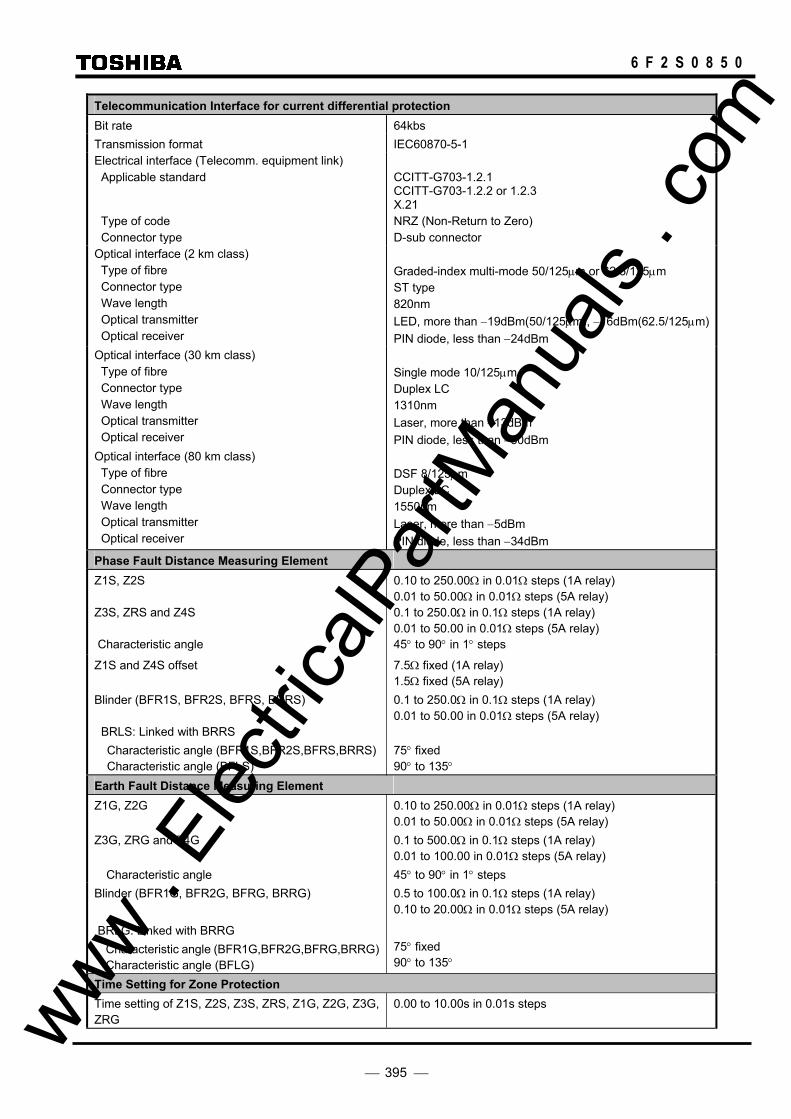
395
6 F 2 S 0 8 5 0
Telecommunication Interface for current differential protection Bit rate 64kbs Transmission format IEC60870-5-1 Electrical interface (Telecomm. equipment link) Applicable standard Type of code Connector type
CCITT-G703-1.2.1 CCITT-G703-1.2.2 or 1.2.3 X.21 NRZ (Non-Return to Zero) D-sub connector
Optical interface (2 km class) Type of fibre Connector type Wave length Optical transmitter Optical receiver
Graded-index multi-mode 50/125µm or 62.5/125µm ST type 820nm LED, more than −19dBm(50/125µm), −16dBm(62.5/125µm)PIN diode, less than −24dBm
Optical interface (30 km class) Type of fibre Connector type Wave length Optical transmitter Optical receiver
Single mode 10/125µm Duplex LC 1310nm Laser, more than −13dBm PIN diode, less than −30dBm
Optical interface (80 km class) Type of fibre Connector type Wave length Optical transmitter Optical receiver
DSF 8/125µm Duplex LC 1550nm Laser, more than −5dBm PIN diode, less than −34dBm
Phase Fault Distance Measuring Element Z1S, Z2S Z3S, ZRS and Z4S Characteristic angle
0.10 to 250.00Ω in 0.01Ω steps (1A relay) 0.01 to 50.00Ω in 0.01Ω steps (5A relay) 0.1 to 250.0Ω in 0.1Ω steps (1A relay) 0.01 to 50.00 in 0.01Ω steps (5A relay) 45° to 90° in 1° steps
Z1S and Z4S offset Blinder (BFR1S, BFR2S, BFRS, BRRS) BRLS: Linked with BRRS
Characteristic angle (BFR1S,BFR2S,BFRS,BRRS)Characteristic angle (BFLS)
7.5Ω fixed (1A relay) 1.5Ω fixed (5A relay) 0.1 to 250.0Ω in 0.1Ω steps (1A relay) 0.01 to 50.00 in 0.01Ω steps (5A relay) 75° fixed 90° to 135°
Earth Fault Distance Measuring Element Z1G, Z2G Z3G, ZRG and Z4G
Characteristic angle
0.10 to 250.00Ω in 0.01Ω steps (1A relay) 0.01 to 50.00Ω in 0.01Ω steps (5A relay) 0.1 to 500.0Ω in 0.1Ω steps (1A relay) 0.01 to 100.00 in 0.01Ω steps (5A relay) 45° to 90° in 1° steps
Blinder (BFR1G, BFR2G, BFRG, BRRG) BRLG: Linked with BRRG
Characteristic angle (BFR1G,BFR2G,BFRG,BRRG)Characteristic angle (BFLG)
0.5 to 100.0Ω in 0.1Ω steps (1A relay) 0.10 to 20.00Ω in 0.01Ω steps (5A relay) 75° fixed 90° to 135°
Time Setting for Zone Protection Time setting of Z1S, Z2S, Z3S, ZRS, Z1G, Z2G, Z3G, ZRG
0.00 to 10.00s in 0.01s steps www . El
ectric
alPar
tMan
uals
. com

396
6 F 2 S 0 8 5 0
Minimum Operating Current of Distance Protection Current 0.08A (1A relay), 0.4A (5A relay) Residual Current Compensation Residual current compensation for reactance element of Z1G, Z2G, ZRG Earth return compensation Mutual coupling compensation (ZRG excluded)
Adjustable as follows: 0 to 1000% in 1% steps 0 to 1000% in 1% steps
Command Protection Coordination time for BOP scheme 0 to 50ms in 1ms steps Operating and Resetting Time of Distance Measuring Element Typical operating time Resetting time
20ms Less than 30ms (for tripping output) Less than 40ms (for signal output)
Power Swing Blocking Detection zone (PSBZS, PSBZG) Detection time
2.5 to 75.0Ω in 0.1Ω steps (1A relay) 0.50 to 15.00 in 0.01Ω steps (5A relay) 20 to 60ms in 1ms steps
Phase Selection Element Undervoltage Impedance Characteristic angle Residual current compensation
10 to 60V in 1V steps 0.0 to 250.0Ω in 0.1Ω steps (1A relay) 0.0 to 50.0Ω in 0.1Ω steps (5A relay) 45° to 90° in 1° steps Automatically set according to residual current compensation setting of reactance element
Weak Infeed and Echo Protection Phase-to-phase undervoltage element Phase-to-earth undervoltage element
50 to 100V in 1V steps 10 to 60V in 1V steps
Directional Earth Fault Protection
Characteristic angle Polarising voltage (3V0) Zero-sequence current (3I0) Time for backup trip
0 to 90° in 1° steps (3I0 lags for −3V0) 1.7 to 21.0V in 0.1V steps 0.10 to 1.00A in 0.01A in 0.01A steps (1A relay) 0.5 to 5.0A in 0.1A steps (5A relay) 0.00 to 10.00s in 0.01s steps
Directional Earth Fault Command Protection Time for delayed trip Coordination time
0.00 to 0.30s in 0.01s steps 0 to 50ms in 1ms steps
Inverse Time Overcurrent Protection OCI (for phase fault protection) OCI time multiplier OCI characteristic Reset time delay
0.10 to 5.00A in 0.01A steps (1A relay) 0.5 to 25.0A in 0.1A steps (5A relay) 0.05 to 1.00 in 0.01 steps Standard / Very / Extremely / Long-time inverse 0.0 to 10.0s in 0.1s steps
EFI (for earth fault protection) EFI time multiplier EFI characteristic Reset time delay
0.10 to 1.00A in 0.01A steps (1A relay) 0.5 to 5.0A in 0.1A steps (5A relay) 0.05 to 1.00 in 0.01 steps Standard / Very / Extremely / Long-time inverse 0.0 to 10.0s in 0.1s steps
Definite Time Overcurrent Protection OC (for phase fault protection) OC time delay
0.1 to 20.0A in 0.1A steps (1A relay) 0.5 to 100.0A in 0.1A steps (5A relay) 0.00 to 10.00s in 0.01s steps
EF (for earth fault protection) EF time delay
0.10 to 1.00A in 0.01A steps (1A relay) 0.5 to 5.0A in 0.1A steps (5A relay) 0.00 to 10.00s in 0.01s steps www .
Elec
tricalP
artM
anua
ls . c
om

397
6 F 2 S 0 8 5 0
Overvoltage Protection Phase-to-phase element (OVS) 1st, 2nd Overvoltage thresholds: Delay type (1st threshold only): IDMTL Time Multiplier Setting TMS: DTL delay: Dropout / Pickup ratio:
OFF, 5.0 – 150.0V in 0.1V steps DTL, IDMTL 0.05 - 100.00 in 0.01 steps Inst, 0.01 - 300.00s in 0.01s steps 10 to 98% in 1% steps
Phase-to-earth element (OVG) 1st, 2nd Overvoltage thresholds: Delay type (1st threshold only): IDMTL Time Multiplier Setting TMS: DTL delay: Dropout / Pickup ratio:
OFF, 5.0 – 150.0V in 0.1V steps DTL, IDMTL 0.05 - 100.00 in 0.01 steps Inst, 0.01 - 300.00s in 0.01s steps 10 to 98% in 1% steps
Undervoltage Protection Phase-to-phase element (UVS) 1st, 2nd Undervoltage thresholds: Delay type (1st threshold only): IDMTL Time Multiplier Setting TMS: DTL delay: Undervoltage block threshold:
OFF, 5.0 – 150.0V in 0.1V steps DTL, IDMTL 0.05 - 100.00 in 0.01 steps Inst, 0.01 - 300.00s in 0.01s steps 5.0 to 20.0V in 1V steps
Phase-to-earth element (UVG) 1st, 2nd Undervoltage thresholds: Delay type (1st threshold only): IDMTL Time Multiplier Setting TMS: DTL delay: Undervoltage block threshold:
OFF, 5.0 – 150.0V in 0.1V steps DTL, IDMTL 0.05 - 100.00 in 0.01 steps Inst, 0.01 - 300.00s in 0.01s steps 5.0 to 20.0V in 1V steps
Thermal Overload Protection Thermal setting (THM = k.IFLC) Time constant (τ) Thermal alarm Pre-load current setting
OFF, 0.40 – 2.00A in 0.01A steps (1A rating) OFF, 2.0 – 10.0A in 0.1A steps (5A rating) 0.5 – 300.0mins in 0.1min steps OFF, 50% to 99% in 1% steps 0.00 – 1.00A in 0.01A steps (1A rating) 0.0 – 5.0A in 0.1A steps (5A rating)
Switch-on-to-fault and Stub Protection Overcurrent 0.4 to 3.0A in 0.1A steps (1A relay)
2.0 to 15.0A in 0.1A steps (5A relay) Broken Conductor Detection Broken conductor threshold (I2/I1): DTL delay:
OFF, 0.10 - 1.00 in 0.01 steps 0.00 to 300.00s in 0.01s steps
Breaker Failure (BF) Protection Overcurrent element Reset BF timer for retry-trip of failed circuit breaker BF timer for adjacent circuit breaker tripping Operating time of overcurrent element Resetting time of overcurrent element
0.1 to 2.0A in 0.1A steps (1A relay) 0.5 to 10.0A in 0.1A steps (5A relay) less than 80% of operating value 50 to 500ms in 1ms steps 50 to 500ms in 1ms steps less than 20ms at 50Hz or 17ms at 60Hz less than 15ms at 50Hz or 13ms at 60Hz
www . El
ectric
alPar
tMan
uals
. com

398
6 F 2 S 0 8 5 0
Accuracy Current differential protection: pick-up ±5% (±7% at I < 0.3×In) Distance measuring element Static accuracy Static angle accuracy Transient overreach
±5% under SIR < 30, ±10% under 30 < SIR < 50 ±5° +5%
Inverse time overcurrent characteristics ±5% or 30ms(1.5 to 30 times setting) Definite time overcurrent protection: pick-up ±5% Overcurrent element for BF: pick-up ±5% Autoreclose function Number of shots 1 to 4 shots Timer settings Dead time for single-phase autoreclose Dead time for three-phase autoreclose Multi-shot dead line time Multi-shot reset time Reclaim time Pulse width of reclosing signal output Autoreclose reset time Reset time for developing fault
0.01 to 10.00s in 0.01s steps 0.01 to 100.00s in 0.01s steps 5.0 to 300.0s in 0.1s steps 5.0 to 300.0s in 0.1s steps 5 to 300s in 1s steps 0.1 to 10.0s in 0.1s steps 0.01 to 100.00s in 0.01s steps 0.01 to 10.00s in 0.01s steps
One-and-a-half breaker system Follower breaker autoreclose delay time
0.1 to 10.0s in 0.1s steps
Voltage and synchronism check element Synchronism check angle UV element OV element Busbar or line dead check Busbar or line live check Synchronism check time Voltage check time
5° to 75° in 1° steps 60 to 150V in 1V steps 10 to 100V in 1V steps 10 to 100V in 1V steps 10 to 100V in 1V steps 0.01 to 10.00s in 0.01s steps 0.01 to 1.00s in 0.01s steps
Voltage Transformer Failure Supervision Undervoltage element (phase-to-phase) Undervoltage element (phase-to-earth) Current change detection element Residual voltage element Residual current element
50 to 100V in 1V steps 10 to 60V in 1V steps 0.1A fixed (1A relay) 0.5A fixed (5A relay) 20V fixed Common use with earth fault detection element
Fault Locator Line resistance and reactance settings 0.0 to 999.9Ω in 0.1Ω steps (1A relay)
0.00 to 199.99Ω in 0.01Ω steps (5A relay) Line length 0.0 to 399.9km in 0.1km steps Accuracy Two terminal Three terminal
±1km (up to 100km) or ±1% (up to 399.9km at DIFI=0.5In setting and Id=2In ±2km (up to 100km) or ±2% (up to 399.9km at DIFI=0.25In setting and Id=2In
Minimum measuring cycles 2 cycles Disturbance Record Initiation Overcurrent element 0.1 to 50.0A in 0.1A steps (1A relay)
0.5 to 250.0A in 0.1A steps (5A relay) Undervoltage element 0 to 132V in 1V steps (for phase fault)
0 to 76V in 1V steps (for earth fault) Pre-fault time 0.3s (fixed) Post-fault time 0.1 to 3.0 in 0.1s steps www .
Elec
tricalP
artM
anua
ls . c
om

399
6 F 2 S 0 8 5 0
Communication Port Front communication port (local PC) Connection Cable type Cable length Connector
Point to point Multi-core (straight) 15m (max.) RS232C 9-pin D-sub miniature connector female
Rear communication port (remote PC) RS485 I/F:
Transmission data rate for RSM system Connection Connector Cable and length Isolation
64kbps Multidrop mode (max. 32 relays) Screw terminals Twisted pair cable, max. 1200m 2kVac for 1min.
Fibre optic I/F:
ST connector, graded-index multi-mode 50/125µm or 62.5/125µm type optical fibres
Ethernet LAN I/F: 10BASE-T, RJ-45 connector IRIG-B Port Connection BNC connector Cable type 50 ohm coaxial cable Binary Inputs Operating voltage Typical 74Vdc(min.70Vdc) for 110V/125Vdc rating
Typical 138Vdc(min.125Vdc) for 220V/250Vdc rating Typical 31Vdc(min.28Vdc) for 48V/54V/60Vdc rating Typical 15Vdc(min.14Vdc) for 24Vdc rating
Contact Ratings Trip contacts Make and carry Break
5A continuously, 30A, 290Vdc for 0.5s (L/R=10ms) 0.15A, 290Vdc (L/R=40ms)
Auxiliary contacts Make and carry Break
4A continuously, 10A, 220Vdc for 0.5s (L/R≥5ms) 0.1A, 220Vdc (L/R=40ms)
Durability Make and carry Break
10,000 operations minimum 100,000 operations minimum
Mechanical design Weight Case colour Installation
11kg (Type-A), 14kg (Type-B) Munsell No. 10YR8/0.5 Flush mounting or rack mounting
www . El
ectric
alPar
tMan
uals
. com

400
6 F 2 S 0 8 5 0
CT REQUIREMENT
Ideally it would be preferable to employ current transformers that did not saturate; this is particularly desirable if operation of the protection is to be avoided during external faults. However, there are circumstances due to accommodation requirements and occasionally on the basis of cost where this is not always possible.
The type GRL100-700 is a current differential with back-up distance protection. CT requirement for GRL100-700 is determined by the requirement for current differential protection and for distance protection.
CASE 1. The case with the distance protection applied as a main protection in addition to the current differential protection
When the distance protection is applied as a main protection the CT requirement for GRL100 must be considered as part of the combined requirements for both protections.
<Step 1> Check the maximum through fault current Ifmaxth
Ifmaxth < 65 X In
where,
Ifmaxth : Secondary maximum through fault current In :Rated secondary current
<Step 2> Check the CT satisfies the condition given by table K-1 or K-2 depending on CT types. Each table has 4 requirements. Every requirement must be satisfied.
<Knee point voltage of CTs is given>
Table K-1 CT Requirement defined by Vk
Td [ms] Requirement 1 Requirement 2 35 Vk ≧ Ifmax(Rct+ R2)×3 Vk ≧ If_z1_max(Rct+ R2)×6
50 Vk ≧ Ifmax(Rct+ R2)×3 Vk ≧ If_z1_max(Rct+ R2)×7
75 Vk ≧ Ifmax(Rct+ R2)×4 Vk ≧ If_z1_max(Rct+ R2)×8
100 Vk ≧ Ifmax(Rct+ R2)×4 Vk ≧ If_z1_max(Rct+ R2)×8
150 Vk ≧ Ifmax(Rct+ R2)×8 Vk ≧ If_z1_max(Rct+ R2)×8
Td [ms] Requirement 3 Requirement 4 35 Vk ≧ If_rev_max(Rct+ R2)×2 Vk ≧ ILmax(Rct+ R2)×14.4
50 Vk ≧ If_rev_max(Rct+ R2)×3 Vk ≧ ILmax(Rct+ R2)×20
75 Vk ≧ If_rev_max(Rct+ R2)×6 Vk ≧ ILmax(Rct+ R2)×28.8
100 Vk ≧ If_rev_max(Rct+ R2)×6 Vk ≧ ILmax(Rct+ R2)×36.8
150 Vk ≧ If_rev_max(Rct+ R2)×6 Vk ≧ ILmax(Rct+ R2)×50.4
Vk : Knee point voltage [V] Rct : Secondary CT resistance [ohms] R2 : Actual secondary burden [ohms] Ifmax : Maximum secondary fault current If_z1_max : Maximum secondary fault current at the zone 1 reach point If_rev_max : Maximum secondary fault current for a close-up reverse fault ILmax : Maximum secondary load current www .
Elec
tricalP
artM
anua
ls . c
om

401
6 F 2 S 0 8 5 0
<Accuracy limit factor of CTs is given>
Table K-2 CT Requirement defined by n’
Td [ms] Requirement 1 Requirement 2 35 n’ In ≧ 3.75 × Ifmax n’ In ≧ 7.5 × If_z1_max
50 n’ In ≧ 3.75 × Ifmax n’ In ≧ 8.75 × If_z1_max
75 n’ In ≧ 5 × Ifmax n’ In ≧ 10 × If_z1_max
100 n’ In ≧ 5 × Ifmax n’ In ≧ 10 × If_z1_max
150 n’ In ≧ 10 × Ifmax n’ In ≧ 10 × If_z1_max
Td [ms] Requirement 3 Requirement 4 35 n’ In ≧ 2.5 × If_rev_max n’ In ≧ ILmax×18
50 n’ In ≧ 3.75 × If_rev_max n’ In ≧ ILmax×25
75 n’ In ≧ 7.5 × If_rev_max n’ In ≧ ILmax×36
100 n’ In ≧ 7.5 × If_rev_max n’ In ≧ ILmax×46
150 n’ In ≧ 7.5 × If_rev_max n’ In ≧ ILmax×63
nRRRIRnct
ctnVA ⋅+
+=
2
2/' (K-1)
n’ : Equivalent accuracy limit factor defined by the equation above. In : Secondary rated current RVA : Rated secondary burden [VA] Rct : Secondary CT resistance [ohms] R2 : Actual secondary burden [ohms] n : Rated accuracy limit factor Ifmax : Maximum secondary fault current If_z1_max : Maximum secondary fault current at the zone 1 reach point If_rev_max : Maximum secondary fault current for a close-up reverse fault ILmax : Maximum secondary load current
Note : The values in the table are based on the following assumption.
- 100% DC component is superimposed. - Only one CT is saturated. - No remnance flux is assumed.
CASE 2. The case with the distance protection applied as a back-up protection with time delay
When the distance protection is applied as back-up protection the CT requirement for GRL100 can be ignored. If instantaneous tripping of distance protection is allowed when a communication failure occurs to the current differential protection, it is recommended that the requirement for case 1 should be applied.
<Step 1> Check the maximum through fault current Ifmaxth
Ifmaxth < 65 X In
where,
Ifmaxth : Secondary maximum through fault current In :Rated secondary current www .
Elec
tricalP
artM
anua
ls . c
om

402
6 F 2 S 0 8 5 0
<Step 2> Check the CT satisfies the condition given by table K-3 or K-4 depending on CT types. Each table has 2 requirements. Both must be satisfied.
<Knee point voltage of CTs is given>
Table K-3 CT Requirement defined by Vk
Td [ms] Requirement 1 Requirement 2 35 Vk ≧ Ifmax(Rct+ R2)×3 Vk ≧ ILmax(Rct+ R2)×14.4
50 Vk ≧ Ifmax(Rct+ R2)×3 Vk ≧ ILmax(Rct+ R2)×20
75 Vk ≧ Ifmax(Rct+ R2)×4 Vk ≧ ILmax(Rct+ R2)×28.8
100 Vk ≧ Ifmax(Rct+ R2)×4 Vk ≧ ILmax(Rct+ R2)×36.8
150 Vk ≧ Ifmax(Rct+ R2)×8 Vk ≧ ILmax(Rct+ R2)×50.4
Vk : Knee point voltage [V] Rct : Secondary CT resistance [ohms] R2 : Actual secondary burden [ohms] Ifmax : Maximum secondary fault current ILmax : Maximum secondary load current
<Accuracy limit factor of CTs is given>
Table K-4 CT Requirement defined by n’
Td [ms] Requirement 1 Requirement 2 35 n’ In ≧ 3.75 × Ifmax n’ In ≧ ILmax×18
50 n’ In ≧ 3.75 × Ifmax n’ In ≧ ILmax×25
75 n’ In ≧ 5 × Ifmax n’ In ≧ ILmax×36
100 n’ In ≧ 5 × Ifmax n’ In ≧ ILmax×46
150 n’ In ≧ 10 × Ifmax n’ In ≧ ILmax×63
nRRRIRnct
ctnVA ⋅+
+=
2
2/' (K-1)
n’ : Equivalent accuracy limit factor defined by the equation above. In : Secondary rated current RVA : Rated secondary burden [VA] Rct : Secondary CT resistance [ohms] R2 : Actual secondary burden [ohms] n : Rated accuracy limit factor Ifmax : Maximum secondary fault current ILmax : Maximum secondary load current
Note : The values in the table are based on the following assumption.
- 100% DC component is superimposed. - Only one CT is saturated. - No remnance flux is assumed.
www . El
ectric
alPar
tMan
uals
. com

403
6 F 2 S 0 8 5 0
Special case In the case of a 3 terminal-double circuit line configuration, an additional system condition must be considered. It is possible, under certain circumstances, that when an internal fault occurs, out-flowing fault current can also be experienced. In this case, the effect of the out-flowing fault current must be considered when calculating DIFI1 and DIFI2. For example, the following application can be considered.
Terminal A Terminal B
Terminal C
Line 2
Line 1
X
Y Y
Y
YX-YZ
S1 S2D
Fig K-1 Special case
The following conditions are assumed as shown in Fig.K-1.
• The three terminals, A, B and C, and the two T-connected transmission lines are assumed to be live.
• Terminal C is connected to load only.
• Line 2 CB at terminal A is open.
• An internal fault occurs on the closed line at the opposite terminal, i.e. Line 1, Terminal B.
In this case, fault current will flow as shown in Fig.K-1. Even though the fault is internal, the fault current Y from Line 1 at Terminal C flows out of the protected zone. Assuming the fault current from source S2 is Z, the summation of the fault current for Line1 at Terminal B is equal to Y+Z. Hence, the current at each terminal is as follows:
Terminal A : X
Terminal B : Y+Z
Terminal C : −Y
Therefore the differential and restraint currents can be calculated as follows:
differential current:X+Z
restraint current:X+2Y+Z
This point can be expressed in the Id-Ir plane as shown in Fig.K-2. It can be seen that the effect of the outflow current is to increase the apparent restraint quantity Ir and thereby shift the point to the right of where it would normally fall.
www . El
ectric
alPar
tMan
uals
. com

404
6 F 2 S 0 8 5 0
Ir
Id
X+2Y+Z
X+Z
Id = Ir - 2DIFI2
Id = 1/6Ir+5/6DIFI1
2DIFI2
Fig.K-2 Internal fault in Id-Ir plane including out-flow current
In order to ensure that the GRL100 relay will operate correctly in this case, the point shown on the plot must fall within the operating zone. According to this requirement, DIFI2 can be calculated as follows.
X +Z > X+2Y+Z−2DIFI2
DIFI2 > Y (K-2)
This means that DIFI2 must be larger than the amount of out-flowing current.
CASE 1. The case with the distance protection applied as a main protection in addition to the current differential protection for the special case
Therefore the condition shown in Table K-1 and Table K-2 should be replaced by that in Table K-5 and Table K-6 respectively for “CASE 1”.
Table K-5 CT Requirement defined by Vk (Special case)
Td [ms] Requirement 1 Requirement 2 35 Vk ≧ Ifmax(Rct+ R2)×3 Vk ≧ If_z1_max(Rct+ R2)×6
50 Vk ≧ Ifmax(Rct+ R2)×3 Vk ≧ If_z1_max(Rct+ R2)×7
75 Vk ≧ Ifmax(Rct+ R2)×4 Vk ≧ If_z1_max(Rct+ R2)×8
100 Vk ≧ Ifmax(Rct+ R2)×4 Vk ≧ If_z1_max(Rct+ R2)×8
150 Vk ≧ Ifmax(Rct+ R2)×8 Vk ≧ If_z1_max(Rct+ R2)×8
Td [ms] Requirement 3 Requirement 4 35 Vk ≧ If_rev_max(Rct+ R2)×2 Vk > MaxILmax+ Ifmin/2, Ifmaxout ×(Rct+ R2)×14.4
50 Vk ≧ If_rev_max(Rct+ R2)×3 Vk > MaxILmax+ Ifmin/2, Ifmaxout× (Rct+ R2)×20
75 Vk ≧ If_rev_max(Rct+ R2)×6 Vk > MaxILmax+ Ifmin/2, Ifmaxout× (Rct+ R2)×28.8
100 Vk ≧ If_rev_max(Rct+ R2)×6 Vk > MaxILmax+ Ifmin/2, Ifmaxout× (Rct+ R2)×36.8
150 Vk ≧ If_rev_max(Rct+ R2)×6 Vk > MaxILmax+ Ifmin/2, Ifmaxout ×(Rct+ R2)×50.4
Vk : Knee point voltage [V] Rct : Secondary CT resistance [ohms] R2 : Actual secondary burden [ohms] Ifmax : Maximum secondary fault current If_z1_max : Maximum secondary fault current at the zone 1 reach point If_rev_max : Maximum secondary fault current for a close-up reverse fault ILmax : Maximum secondary load current www .
Elec
tricalP
artM
anua
ls . c
om

405
6 F 2 S 0 8 5 0
MaxILmax+ Ifmin/2, Ifmaxout: The larger of (ILmax+ Ifmin/2) and Ifmaxout Ifmin : Minimum fault current Ifmaxout : Maximum out-flowing fault current for the special condition
<Accuracy limit factor of CTs is given>
Table K-6 CT Requirement defined by n’
Td [ms] Requirement 1 Requirement 2 35 n’ In ≧ 3.75 × Ifmax n’ In ≧ 7.5 × If_z1_max
50 n’ In ≧ 3.75 × Ifmax n’ In ≧ 8.75 × If_z1_max
75 n’ In ≧ 5 × Ifmax n’ In ≧ 10 × If_z1_max
100 n’ In ≧ 5 × Ifmax n’ In ≧ 10 × If_z1_max
150 n’ In ≧ 10 × Ifmax n’ In ≧ 10 × If_z1_max
Td [ms] Requirement 3 Requirement 4 35 n’ In ≧ 2.5 × If_rev_max n’ In > MaxILmax+ Ifmin/2, Ifmaxout×18
50 n’ In ≧ 3.75 × If_rev_max n’ In > MaxILmax+ Ifmin/2, Ifmaxout×25
75 n’ In ≧ 7.5 × If_rev_max n’ In > MaxILmax+ Ifmin/2, Ifmaxout×36
100 n’ In ≧ 7.5 × If_rev_max n’ In > MaxILmax+ Ifmin/2, Ifmaxout×46
150 n’ In ≧ 7.5 × If_rev_max n’ In > MaxILmax+ Ifmin/2, Ifmaxout×63
nRRRIRnct
ctnVA ⋅+
+=
2
2/' (K-1)
n’ : Equivalent accuracy limit factor defined by the equation above. In : Secondary rated current RVA : Rated secondary burden [VA] Rct : Secondary CT resistance [ohms] R2 : Actual secondary burden [ohms] n : Rated accuracy limit factor Ifmax : Maximum secondary fault current If_z1_max : Maximum secondary fault current at the zone 1 reach point If_rev_max : Maximum secondary fault current for a close-up reverse fault ILmax : Maximum secondary load current MaxILmax+ Ifmin/2, Ifmaxout: The larger of (ILmax+ Ifmin/2) and Ifmaxout Ifmin : Minimum fault current Ifmaxout : Maximum out-flowing fault current for the special condition
CASE 2. The case with the distance protection applied as a back-up protection with time delay
Similarly to the previous case, the condition shown in Table K-3 and Table K-4 should be replaced by that in Table K-7 and Table K-8 respectively for “CASE 2”.
www . El
ectric
alPar
tMan
uals
. com
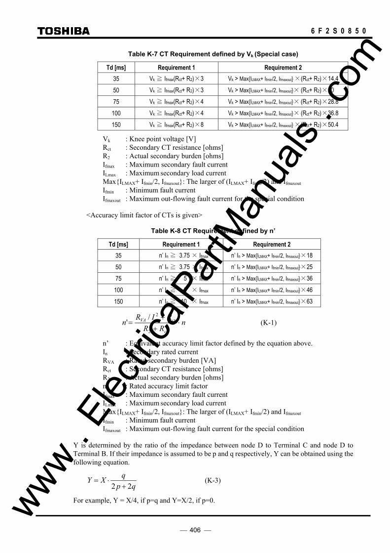
406
6 F 2 S 0 8 5 0
Table K-7 CT Requirement defined by Vk (Special case)
Td [ms] Requirement 1 Requirement 2 35 Vk ≧ Ifmax(Rct+ R2)×3 Vk > MaxILMAX+ Ifmin/2, Ifmaxout ×(Rct+ R2)×14.4
50 Vk ≧ Ifmax(Rct+ R2)×3 Vk > MaxILMAX+ Ifmin/2, Ifmaxout× (Rct+ R2)×20
75 Vk ≧ Ifmax(Rct+ R2)×4 Vk > MaxILMAX+ Ifmin/2, Ifmaxout× (Rct+ R2)×28.8
100 Vk ≧ Ifmax(Rct+ R2)×4 Vk > MaxILMAX+ Ifmin/2, Ifmaxout× (Rct+ R2)×36.8
150 Vk ≧ Ifmax(Rct+ R2)×8 Vk > MaxILMAX+ Ifmin/2, Ifmaxout ×(Rct+ R2)×50.4
Vk : Knee point voltage [V] Rct : Secondary CT resistance [ohms] R2 : Actual secondary burden [ohms] Ifmax : Maximum secondary fault current ILmax : Maximum secondary load current MaxILMAX+ Ifmin/2, Ifmaxout: The larger of (ILMAX+ Ifmin/2) and Ifmaxout Ifmin : Minimum fault current Ifmaxout : Maximum out-flowing fault current for the special condition
<Accuracy limit factor of CTs is given>
Table K-8 CT Requirement defined by n’
Td [ms] Requirement 1 Requirement 2 35 n’ In ≧ 3.75 × Ifmax n’ In > MaxILMAX+ Ifmin/2, Ifmaxout×18
50 n’ In ≧ 3.75 × Ifmax n’ In > MaxILMAX+ Ifmin/2, Ifmaxout×25
75 n’ In ≧ 5 × Ifmax n’ In > MaxILMAX+ Ifmin/2, Ifmaxout×36
100 n’ In ≧ 5 × Ifmax n’ In > MaxILMAX+ Ifmin/2, Ifmaxout×46
150 n’ In ≧ 10 × Ifmax n’ In > MaxILMAX+ Ifmin/2, Ifmaxout×63
nRRRIRnct
ctnVA ⋅+
+=
2
2/' (K-1)
n’ : Equivalent accuracy limit factor defined by the equation above. In : Secondary rated current RVA : Rated secondary burden [VA] Rct : Secondary CT resistance [ohms] R2 : Actual secondary burden [ohms] n : Rated accuracy limit factor Ifmax : Maximum secondary fault current ILmax : Maximum secondary load current MaxILMAX+ Ifmin/2, Ifmaxout: The larger of (ILMAX+ Ifmin/2) and Ifmaxout Ifmin : Minimum fault current Ifmaxout : Maximum out-flowing fault current for the special condition
Y is determined by the ratio of the impedance between node D to Terminal C and node D to Terminal B. If their impedance is assumed to be p and q respectively, Y can be obtained using the following equation.
qp
qXY22 +
⋅= (K-3)
For example, Y = X/4, if p=q and Y=X/2, if p=0. www . El
ectric
alPar
tMan
uals
. com

407
6 F 2 S 0 8 5 0
Note : The values in the table are based on the following assumption.
- 100% DC component is superimposed. - Only one CT is saturated. - No remnance flux is assumed.
www . El
ectric
alPar
tMan
uals
. com

408
6 F 2 S 0 8 5 0
ENVIRONMENTAL PERFORMANCE CLAIMS
Test Standards Details Atmospheric Environment Temperature IEC60068-2-1/2 Operating range: -10°C to +55°C.
Storage / Transit: -25°C to +70°C. Humidity IEC60068-2-78 56 days at 40°C and 93% relative humidity. Enclosure Protection IEC60529 IP51 (Rear: IP20) Mechanical Environment Vibration IEC60255-21-1 Response - Class 1
Endurance - Class 1 Shock and Bump IEC60255-21-2 Shock Response Class 1
Shock Withstand Class 1 Bump Class 1
Seismic IEC60255-21-3 Class 1 Electrical Environment Dielectric Withstand IEC60255-5 2kVrms for 1 minute between all terminals and earth.
2kVrms for 1 minute between independent circuits. 1kVrms for 1 minute across normally open contacts.
High Voltage Impulse IEC60255-5 Three positive and three negative impulses of 5kV(peak), 1.2/50µs, 0.5J between all terminals and between all terminals and earth.
Electromagnetic Environment High Frequency Disturbance / Damped Oscillatory Wave
IEC60255-22-1 Class 3, IEC61000-4-12 / EN61000-4-12
1MHz 2.5kV applied to all ports in common mode. 1MHz 1.0kV applied to all ports in differential mode.
Electrostatic Discharge
IEC60255-22-2 Class 3, IEC61000-4-2 / EN61000-4-2
6kV contact discharge, 8kV air discharge.
Radiated RF Electromagnetic Disturbance
IEC60255-22-3 Class 3, IEC61000-4-3 / EN61000-4-3
Field strength 10V/m for frequency sweeps of 80MHz to 1GHz and 1.7GHz to 2.2GHz. Additional spot tests at 80, 160, 450, 900 and 1890MHz.
Fast Transient Disturbance
IEC60255-22-4, IEC61000-4-4 / EN61000-4-4
4kV, 2.5kHz, 5/50ns applied to all inputs.
Surge Immunity IEC60255-22-5, IEC61000-4-5 / EN61000-4-5
1.2/50µs surge in common/differential modes: HV ports: 2kV/1kV (peak) PSU and I/O ports: 2kV/1kV (peak) RS485 port: 1kV (peak)
Conducted RF Electromagnetic Disturbance
IEC60255-22-6 Class 3, IEC61000-4-6 / EN61000-4-6
10Vrms applied over frequency range 150kHz to 100MHz. Additional spot tests at 27 and 68MHz.
Power Frequency Disturbance
IEC60255-22-7, IEC61000-4-16 / EN61000-4-16
300V 50Hz for 10s applied to ports in common mode. 150V 50Hz for 10s applied to ports in differential mode. Not applicable to AC inputs.
Conducted and Radiated Emissions
IEC60255-25, EN55022 Class A, IEC61000-6-4 / EN61000-6-4
Conducted emissions: 0.15 to 0.50MHz: <79dB (peak) or <66dB (mean) 0.50 to 30MHz: <73dB (peak) or <60dB (mean) Radiated emissions (at 30m): 30 to 230MHz: <30dB 230 to 1000MHz: <37dB
89/336/EEC Compliance with the European Commission Electromagnetic Compatibility Directive is demonstrated according to EN 61000-6-2 and EN 61000-6-4.
73/23/EEC Compliance with the European Commission Low Voltage Directive is demonstrated according to EN 50178 and EN 60255-5.
www . El
ectric
alPar
tMan
uals
. com

409
6 F 2 S 0 8 5 0
Appendix L
Symbols Used in Scheme Logic
www . El
ectric
alPar
tMan
uals
. com

410
6 F 2 S 0 8 5 0
Symbols used in the scheme logic and their meanings are as follows:
Signal names Marked with : Measuring element output signal
Marked with : Signal number
Marked with : Signal number and name of binary input by PLC function
Signal No. Signal name
Marked with [ ] : Scheme switch
Marked with " " : Scheme switch position
Unmarked : Internal scheme logic signal
AND gates
A B C Output 1 1 1 1
Other cases 0
A B C Output 1 1 0 1
Other cases 0
A B C Output 1 0 0 1
Other cases 0
OR gates
A B C Output 0 0 0 0
Other cases 1
A B C Output 0 0 1 0
Other cases 1
A B C Output 0 1 1 0
Other cases 1
A
Output B &
C
A
Output B ≥1
C
A
Output B &
C
A
Output B ≥1
C
A
Output B ≥1
C
A
Output B
C
&
www . El
ectric
alPar
tMan
uals
. com

411
6 F 2 S 0 8 5 0
Signal inversion
A Output 0 1 1 0
Timer Delayed pick-up timer with fixed setting
XXX: Set time
Delayed drop-off timer with fixed setting
XXX: Set time
Delayed pick-up timer with variable setting
XXX - YYY: Setting range
Delayed drop-off timer with variable setting
XXX - YYY: Setting range
One-shot timer
XXX - YYY: Setting range
Flip-flop S R Output 0 0 No change 1 0 1 0 1 0 1 1 0
Scheme switch
A Switch Output 1 ON 1 Other cases 0
Switch Output
ON 1 OFF 0
0 t
XXX
t 0
XXX
0 t
XXX - YYY
XXX - YYY
t 0
Output ON
Output ON
+
A
S Output F/F
R
Output A 1
XXX - YYY
A Output A
Output
www . El
ectric
alPar
tMan
uals
. com

412
6 F 2 S 0 8 5 0 www .
Elec
tricalP
artM
anua
ls . c
om

413
6 F 2 S 0 8 5 0
Appendix M
Multi-phase Autoreclose
www . El
ectric
alPar
tMan
uals
. com

414
6 F 2 S 0 8 5 0
Tables 1 and 2 show operations of the multi-phase autoreclose for different faults. The operations of the autoreclose depend on the settings of [ARC-M] and [MA-NOLK].
Cases 1 to 3 show the case when one of the double circuit lines is out of service. In MPAR2 and [MA-NOLK]=FT, only case 1 results in single-phase tripping and multi-phase reclosing. Other cases result in three-phase final tripping. In MPAR2 and [MA-NOLK]=FT or S+T, case 1 results in single-phase tripping and multi-phase reclosing, and cases 2 and 3 result in three-phase tripping and three-phase reclosing. In MPAR3 and [MA-NOLK]=FT, all cases result in three-phase final tripping. In MPAR3 and [MA-NOLK]=T, all cases result in three-phase tripping and three-phase reclosing. In MPAR3 and [MA-NOLK]=S+T, case 1 results in single-phase tripping and single-phase reclosing, and cases 2 and 3 result in three-phase tripping and three-phase reclosing.
In cases 4, 6, 7, 10 and 11, three different phases remain in the power transmission state, so both MPAR2 and MPAR3 perform fault phase(s) tripping and reclosing.
In case 5, 8, 12 and 13, two different phases remain in the power transmission state, so MPAR2 performs fault phase(s) tripping and multi-phase reclosing. In MPAR3 and [MA-NOLK]=FT, all cases result in three-phase final tripping. In MPAR3 and [MA-NOLK]=T, all cases result in three-phase tripping and three-phase reclosing. In MPAR3 and [MA-NOLK]=S+T, single- or three-phase tripping and single- or three-phase reclosing is performed according to fault phase(s).
In cases 9, 14 and 15, the number of remaining different phases is less than two, so the operations of the autoreclose depends on only the [MA-NOLK] setting. In [MA-NOLK]=FT, all cases result in three-phase final tripping. In [MA-NOLK]=T or S+T, all cases result in three-phase tripping and three-phase reclosing.
Table M-1 Reclosing in MPAR2 ([ARC-M]=M2 setting)
Fault phase Tripping and Reclosing (Tripping mode → Reclosing mode)
Case #1 line #2 line [MA-NOLK] = FT setting [MA-NOLK] = T setting [MA-NOLK] = S+T setting
No. A B C A B C #1 line #2 line #1 line #2 line #1 line #2 line
1 × 1φT→MPAR 1φT→MPAR 1φT→MPAR
2 × × 3φFT 3φT→TPAR 3φT→TPAR
3 × × × 3φFT 3φT→TPAR 3φT→TPAR
4 × 1φT→MPAR 1φT→MPAR 1φT→MPAR
5 × × 1φT→MPAR 1φT→MPAR 1φT→MPAR 1φT→MPAR 1φT→MPAR 1φT→MPAR
6 × × 2φT→MPAR 2φT→MPAR 2φT→MPAR
7 × × 1φT→MPAR 1φT→MPAR 1φT→MPAR 1φT→MPAR 1φT→MPAR 1φT→MPAR
8 × × × 2φT→MPAR 1φT→MPAR 2φT→MPAR 1φT→MPAR 2φT→MPAR 1φT→MPAR
9 × × × × 3φFT 3φFT 3φT→TPAR 3φT→TPAR 3φT→TPAR 3φT→TPAR
10 × × × 3φT→MPAR 3φT→MPAR 3φT→MPAR
11 × × × 2φT→MPAR 1φT→MPAR 2φT→MPAR 1φT→MPAR 2φT→MPAR 1φT→MPAR
12 × × × × 2φT→MPAR 2φT→MPAR 2φT→MPAR 2φT→MPAR 2φT→MPAR 2φT→MPAR
13 × × × × 3φT→MPAR 1φT→MPAR 3φT→MPAR 1φT→MPAR 3φT→MPAR 1φT→MPAR
14 × × × × × 3φFT 3φFT 3φT→TPAR 3φT→TPAR 3φT→TPAR 3φT→TPAR
15 × × × × × × 3φFT 3φFT 3φT→TPAR 3φT→TPAR 3φT→TPAR 3φT→TPAR
×: Fault, : The line is out of service MPAR: Multi-phase reclosing TPAR: Three-phase reclosing SPAR: Single-phase reclosing 3 φ FT: three-phase final tripping 1 φ T: single-phase tripping 2 φ T: two-phase tripping 3 φ T: three-phase tripping
www . El
ectric
alPar
tMan
uals
. com

415
6 F 2 S 0 8 5 0
Table M-2 Reclosing in MPAR3 ([ARC-M]=M3 setting)
Fault phase Tripping and Reclosing (Tripping mode → Reclosing mode)
Case #1 line #2 line [MA-NOLK] = FT setting [MA-NOLK] = T setting [MA-NOLK] = S+T setting
No. A B C A B C #1 line #2 line #1 line #2 line #1 line #2 line
1 × 3φFT 3φT→TPAR 1φT→SPAR
2 × × 3φFT 3φT→TPAR 3φT→TPAR
3 × × × 3φFT 3φT→TPAR 3φT→TPAR
4 × 1φT→MPAR 1φT→MPAR 1φT→MPAR
5 × × 3φFT 3φFT 3φT→TPAR 3φT→TPAR 1φT→SPAR 1φT→SPAR
6 × × 2φT→MPAR 2φT→MPAR 2φT→MPAR
7 × × 1φT→MPAR 1φT→MPAR 1φT→MPAR 1φT→MPAR 1φT→MPAR 1φT→MPAR
8 × × × 3φFT 3φFT 3φT→TPAR 3φT→TPAR 3φT→TPAR 1φT→SPAR
9 × × × × 3φFT 3φFT 3φT→TPAR 3φT→TPAR 3φT→TPAR 3φT→TPAR
10 × × × 3φT→MPAR 3φT→MPAR 3φT→MPAR
11 × × × 2φT→MPAR 1φT→MPAR 2φT→MPAR 1φT→MPAR 2φT→MPAR 1φT→MPAR
12 × × × × 3φFT 3φFT 3φT→TPAR 3φT→TPAR 3φT→TPAR 3φT→TPAR
13 × × × × 3φFT 3φFT 3φT→TPAR 3φT→TPAR 3φT→TPAR 1φT→SPAR
14 × × × × × 3φFT 3φFT 3φT→TPAR 3φT→TPAR 3φT→TPAR 3φT→TPAR
15 × × × × × × 3φFT 3φFT 3φT→TPAR 3φT→TPAR 3φT→TPAR 3φT→TPAR
www . El
ectric
alPar
tMan
uals
. com

416
6 F 2 S 0 8 5 0 www .
Elec
tricalP
artM
anua
ls . c
om

417
6 F 2 S 0 8 5 0
Appendix N
Data Transmission Format
www . El
ectric
alPar
tMan
uals
. com

418
6 F 2 S 0 8 5 0
Transmission Format
The data transmission format depends on the communication mode.
Figures N-1 and N-2 show the data transmission format that applies to the data transmission between terminals of the transmission lines by the relay. The individual parts of the transmission format are described below.
(1) Frame header
A signal indicating the head of a frame.
(2) Current data
12 bit data (incl. one sign bit) indicating the current value of sampling of each phase.
(3) SA flag and control data
Device data (CB, DS) and control data necessary for the protective function are transmitted by sub-commutation. Sub-commutation is used for signals that may be transmitted at low speed, and has the meaning that 1-bit information is different from frame to frame.
Frames are identified by the SA flag, which is also transmitted by sub-commutation. It detects the signal pattern of 00001 and identifies a frame number. One cycle of frame numbers covers 12 frames.
(4) SP flag and time data
The SP flag and time data for sampling time synchronization are transmitted by sub-commutation. Sub-commutation detects the signal pattern of 00001 and identifies a frame number.
The time data for sampling time synchronization has 16 bits.
(5) CRC (Cyclic Redundancy Check) data
CRC data is added to check transmitting data for transmission errors.
Data without the frame header is divided by a polynomial and the resultant remainder is transmitted as the CRC data.
On the receiving side, the CRC data is subtracted from the transmitted data, the result divided by the same polynomial, and the remainder checked for 0.
Polynomial: X16 + X12 + X5 + 1
(6) User configurable data
Number of user configurable data depends on the communication mode and whether a function is used or not. The transmission data and user configurable data is shown in Table N-1 and Figures N-1 and N-2.
www . El
ectric
alPar
tMan
uals
. com

419
6 F 2 S 0 8 5 0
Table N-1 User Configurable data
Transmission data Sending side Receiving side Remarks
Phase current 12 bits × (Ia, Ib, Ic) 12 bits × (Ia, Ib, Ic) Fixed.
Positive-sequence Voltage
A-MODE: V1 fixed. 4 bits / 1 frame (sent it by 3 frame shared)
B-/GPS-MODE: V1 for OST/FL. If the OST/FL are not used, the following are configurable.
V.COM1-S (Signal No.: 2096) V.COM2-S (Signal No.: 2097) V.COM3-S (Signal No.: 2098) S.V.COM1-S (Signal No.: 2100) to S.V.COM12-S (Signal No.: 2111)
A-MODE: V1 fixed. 4 bits / 1 frame (sent it by 3 frame shared) B-/GPS-MODE: V1 for OST/FL. If the OST/FL are not used, the following
are configurable.
V.COM1-R1 (Signal No.: 960) / V.COM1-R2 (Signal No.: 976) V.COM2-R1 (Signal No.: 961) / V.COM2-R2 (Signal No.: 977) V.COM3-R2 (Signal No.: 962) / V.COM3-R2 (Signal No.: 978) S.V.COM1-R1 (Sig. No.: 964) to S.V.COM12-R1 (Sig. No.: 975) / S.V.COM1-R2 (Sig. No.: 980) to S.V.COM12-R2 (Sig. No.: 991)
Zero-sequence current
A-MODE: I0 fixed. 4 bits / 1 frame (sent it by 3 frame shared)
B-/GPS-MODE: I1 for DIFG is assigned. If the DIFG is not used, the following are configurable.
I.COM1-S (Signal No.: 2112) I.COM2-S (Signal No.: 2113) I.COM3-S (Signal No.: 2114) S.I.COM1-S (Signal No.: 2116) to S.I.COM12-S (Signal No.: 2127)
A-MODE: I1 fixed. 4 bits / 1 frame (sent it by 3 frame shared) B-/GPS-MODE: I1 for DIFG. If the DIFG are not used, the following are
configurable.
I.COM1-R1 (Signal No.: 992) / I.COM1-R2 (Signal No.: 1008) I.COM2-R1 (Signal No.: 993) / I.COM2-R2 (Signal No.: 1009) I.COM3-R2 (Signal No.: 994) / I.COM3-R2 (Signal No.: 1010) S.I.COM1-R1 (Sig. No.: 996) to S.I.COM12-R1 (Sig. No.: 1007) / S.I.COM1-R2 (Sig. No.: 1012) to S.I.COM12-R2 (Sig. No.: 1023)
COM1 – COM3 A-MODE: DIF-A, -B, -C for model 513 fixed. For other models, these are configurable.
COM1-S (Signal No.: 2048) COM2-S (Signal No.: 2049) COM3-S (Signal No.: 2050)
COM1-R1 (Signal No.: 1088) / COM1-R2 (Signal No.: 1128) COM2-R1 (Signal No.: 1089) / COM2-R2 (Signal No.: 1129) COM3-R1 (Signal No.: 1090) / COM2-R2 (Signal No.: 1130)
The following are signals without two-time verification:
COM1-R1_UF (Sig. No.: 1096) / COM1-R2_UF (Sig. No.: 1136) COM2-R1_UF (Sig. No.: 1097) / COM2-R2_UF (Sig. No.: 1137) COM3-R1_UF (Sig. No.: 1098) / COM2-R2_UF (Sig. No.: 1138)
Available for only A-MODE except for model 513.
COM4, COM5 (85S1, 85S2)
Used for transfer signals. COM4-S (Signal No.: 2051) COM5-S (Signal No.: 2052)
COM4-R1 (Signal No.: 1091) / COM4-R2 (Signal No.: 1131) COM5-R1 (Signal No.: 1092) / COM5-R2 (Signal No.: 1132)
The following are signals without two-time verification:
COM4-R1_UF (Sig. No.: 1099) / COM4-R2_UF (Sig. No.: 1139) COM5-R1_UF (Sig. No.: 1100) / COM5-R2_UF (Sig. No.: 1140)
SUB2-COM (CBDS/RA1)
B-/GPS-MODE: RA∗ for RYIDSV is assigned. If RYIDSV is not used, the following are configurable.
SUB2_COM1-S (Signal No.: 2064) to SUB2_COM12-S (Signal No.: 2075)
SUB2_COM1-R1 (Sig. No.: 1112) to SUB2_COM12-R1 (Sig. No.: 1123) / SUB2_COM1-R2 (Sig. No.: 1152) to SUB2_COM12-R2 (Sig. No.: 1153)
Sent by 12 SSP cycle.
SP2/RA2 SUB3_COM1-S (Signal No.: 2080) to SUB3_COM12-S (Signal No.: 2091)
SUB3_COM1-R1 (Sig. No.: 1168) to SUB3_COM12-R1 (Sig. No.: 1179) / SUB3_COM1-R2 (Sig. No.: 1184) to SUB3_COM12-R2 (Sig. No.: 1195)
SA Configurable data. SUB_COM1-S (Signal No.: 2056) to SUB_COM5-S (Signal No.: 2060)
SUB_COM1-R1 (Sig. No.: 1104) to SUB_COM5-R1 (Sig. No.: 1108) / SUB_COM1-R2 (Sig. No.: 1144) to SUB_COM5-R2 (Sig. No.: 1148)
No. 2058, 2059 and 2060 in B-/GPS-MODE are not available.
www . El
ectric
alPar
tMan
uals
. com

420
6 F 2 S 0 8 5 0
COM1 COM2 COM3 COM4 COM5
DIF-A DIF-B DIF-C 85S1
Fixedbit
85S2
SUB2 COM
R D Y
S A
S P 1
S P 2
Frame header
1 Ia 1 Ia Ib 1 Ib 1 Ic 1 Ic V1 1 Io COM1 2 3
COM4
1 COM5
RA1
RDY
SA
SP
RA2
C R C
1 CRC 1 CRC
10 bits 8 1 4 4 1 8 1 8 1 4 4 1 4 3 1 1 1 1 1 1 1 1 2 1 8 1 6
88 bits
Frame No.
SUB2_COM SA SUB_COM
SP1 SP2
0 SUB2 COM1 CBDS-A 0 20 28 1 SUB2 COM2 -B 0 21 29 2 SUB2 COM3 -C 0 22 210 3 SUB2 COM4 CBDS-A 0 23 211 4 SUB2 COM5 -B 1 SP flag - 5 SUB2 COM5 -C SUB COM1 ARC BLOCK 24 212 6 SUB2 COM7 CBDS-A SUB COM2 Local Test 25 213 7 SUB2 COM8 -B SUB COM3 DIFG 26 214 8 SUB2 COM9 -C 1 27 215 9 SUB2 COM10 CBDS-A SUB COM5 SPARE - - 10 SUB2 COM11 -B SUB COM4 TFC - - 11 SUB2 COM12 -C S.F.C. - -
Legend Ia, Ib, Ic : Phase current V1 : Positive-sequence voltage Io : Zero-sequence current ON / OFF : Control data RDY : Ready SA : Sampling address SP : Sampling synchronization CRC : Cyclic redundancy check S.F.C. Simultaneous fault control (synchronized test trigger signal)
Next Frame
Timedata(*)
(*) Time data are transmitted once per two cycles.
(1) (2)
(3) (4)
(5)
Figure N-1 Data Transmission Format of A-MODE
User configurable commands are the followings:
COM1- to COM5-: These commands are sent every frame and used for high-speed signals such as a transfer trip and block signals.
SUB_COM1 to SUB_COM5: These commands are sent every 12 frames. SUB_COM1, SUB_COM2, SUB_COM3 and SUB_COM4 are assigned to ARC_BLOCK, Local test, DIFG, and TFC signals as default setting. If these signals are changed, the related functions cannot be applied.
www . El
ectric
alPar
tMan
uals
. com

421
6 F 2 S 0 8 5 0
COM1 COM2 COM3 COM4 COM5
SA SA SSA 85S1
Fixedbit
85S2
SUB2 COM
R D Y
S A
S P 1
SUB3 COM
RA2
Frame header
1 Ia 1 Ia Ib 1 Ib 1 Ic 1 Ic V1 1 Io 87SA/SSA
85S1
1 85S2
RA1
RDY
SA
SP
RA2
C R C
1 CRC 1 CRC
10 bits 8 1 4 4 1 8 1 8 1 4 4 1 4 3 1 1 1 1 1 1 1 1 2 1 8 1 6
88 bits
Frame No.
V1 Io SUB2-COM∗ CBDS / RA
SA SUB-COM∗
SP1 SUB3_COM∗ RA2
V.COM1 V.COM2 V.COM3 S.V.COM∗ I.COM1 I.COM2 I.COM3 S.I.COM∗ ∗ ∗ ∗ 0 1 V1 / SPARE 1 Io / SPARE 1 RA0 / CBDS-A 0 20, 28 1 RA3 / SPARE 1 2 V1 / SPARE 2 Io / SPARE 2 RA1 / CBDS-B 0 21, 29 2 RA4 / SPARE 2 3 V1 / SPARE 3 Io / SPARE 3 RA2 / CBDS-C 0 22, 210 3 RA5 / SPARE 3 4 V1 / SPARE 4 Io / SPARE 4 RA0 / CBDS-A 0 23, 211 4 RA3 / SPARE 4 V1 / V1 / V1 / 5 V1 / SPARE Io / Io / Io / 5 Io / SPARE 5 RA1 / CBDS-B 1 SP flag 5 RA4 / SPARE 5 SPARE SPARE SPARE 6 V1 / SPARE SPARE SPARE SPARE 6 Io / SPARE 6 RA2 / CBDS-C 1 ARC BLOCK 24, 212 6 RA5 / SPARE 6 7 V1 / SPARE 7 Io / SPARE 7 RA0 / CBDS-A 2 Local test 25, 213 7 RA3 / SPARE 7 8 V1 / SPARE 8 Io / SPARE 8 RA1 / CBDS-B 3 0 26, 214 8 RA4 / SPARE 8 9 V1 / SPARE 9 Io / SPARE 9 RA2 / CBDS-C 1 27, 215 9 RA5 / SPARE 9 10 V1 / SPARE 10 Io / SPARE 10 RA0 / CBDS-A 5 - 10 RA3 / SPARE 10 11 V1 / SPARE 11 Io / SPARE 11 RA1 / CBDS-B 4 - 11 RA1 / SPARE 11 12 V1 / SPARE 12 Io / SPARE 12 RA2 / CBDS-C S.F.C. - 12 RA2 / SPARE
Legend Ia, Ib, Ic : Phase current V1 : Positive-sequence voltage Io : Zero-sequence current ON / OFF : Control data RDY : Ready SA : Sampling address for a cycle SSA Sampling address for a second SP : Sampling synchronization CRC : Cyclic redundancy check S.F.C. Simultaneous fault control (synchronized test trigger signal)
Next Frame
Time data(*)
(*) Time data are transmitted once per two cycle.
(1) (2)
(3)
(4)
(5)
Figure N-2 Data Transmission Format of B-MODE and GPS-MODE
User configurable commands are as:
COM1 to COM3: Used for sampling address.
COM4 and COM5: Used for transfer signals.
SUB_COM: These commands are sent every 12 frames. SUB_COM1 and SUB_COM2 are assigned to ARC_BLOCK and Local test signals as default setting. If these signals are changed, the related functions cannot be applied.
V.COM1 to V.COM3 and S.V.COM1 to S.V.COM12: If the OST and FL functions are not used, the user can use these commands. The V.COM1 to V.COM3 commands are sent every frame. The S.V.COM1 to S.V.COM12 are sent every 12 frames.
I.COM1 to I.COM3 and S.I.COM1 to S.I.COM12: If the DIFG function is not used, the user can use these commands. The I.COM1 to I.COM3 commands are sent every frame. The S.I.COM1 to S.I.COM12 are sent every 12 frames. www .
Elec
tricalP
artM
anua
ls . c
om

422
6 F 2 S 0 8 5 0
SUB2_COM1 to SUB2_COM12: These commands are assigned to bits (RA∗) for relay address monitoring RYIDSV as default setting. If the RYIDSV is not used, the user can use these commands. If multi-phase autoreclosing function is applied, for example, these commands are assigned to CBDS-A, -B and –C such as shown in Figure N-1.
SUB3_COM1 to SUB3_COM12: These commands are also assigned to bits (RA∗) for relay address monitoring RYIDSV as default setting. If the RYIDSV is not used, the user can use these commands.
www . El
ectric
alPar
tMan
uals
. com

423
6 F 2 S 0 8 5 0
Appendix O
Example of Setting
www . El
ectric
alPar
tMan
uals
. com
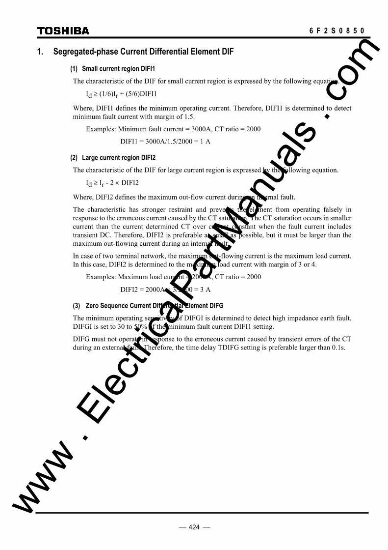
424
6 F 2 S 0 8 5 0
1. Segregated-phase Current Differential Element DIF
(1) Small current region DIFI1 The characteristic of the DIF for small current region is expressed by the following equation.
Id ≥ (1/6)Ir + (5/6)DIFI1
Where, DIFI1 defines the minimum operating current. Therefore, DIFI1 is determined to detect minimum fault current with margin of 1.5.
Examples: Minimum fault current = 3000A, CT ratio = 2000
DIFI1 = 3000A/1.5/2000 = 1 A
(2) Large current region DIFI2 The characteristic of the DIF for large current region is expressed by the following equation.
Id ≥ Ir - 2 × DIFI2
Where, DIFI2 defines the maximum out-flow current during an internal fault.
The characteristic has stronger restraint and prevents the element from operating falsely in response to the erroneous current caused by the CT saturation. The CT saturation occurs in smaller current than the current determined CT over current constant when the fault current includes transient DC. Therefore, DIFI2 is preferable as small as possible, but it must be larger than the maximum out-flowing current during an internal fault.
In case of two terminal network, the maximum out-flowing current is the maximum load current. In this case, DIFI2 is determined to the maximum load current with margin of 3 or 4.
Examples: Maximum load current = 2000A, CT ratio = 2000
DIFI2 = 2000A × 3/2000 = 3 A
(3) Zero Sequence Current Differential Element DIFG The minimum operating sensitivity of DIFGI is determined to detect high impedance earth fault. DIFGI is set to 30 to 50% of the minimum fault current DIFI1 setting.
DIFG must not operate in response to the erroneous current caused by transient errors of the CT during an external fault. Therefore, the time delay TDIFG setting is preferable larger than 0.1s.
www . El
ectric
alPar
tMan
uals
. com

425
6 F 2 S 0 8 5 0
2. Distance protection
2.1 Power System Data [Example system]
• Line impedance of A s/s - Bs/s
- Positive sequence impedance: 0.0197 + j0.2747 (ohms/km)
- Zero sequence impedance: 0.4970 + j1.4387 (ohms/km)
- Mutual impedance: 0.0212 + j0.3729 (ohms/km)
• Back impedance
- A s/s: 0.94 (%pu) at 100MVA base
- B s/s: 0.94 (%pu) at 100MVA base
• Normal load current: 594.7A
• Minimum fault current: 2.05kA
2.2 Relay Setting - Relay application:
Relay type: GRL100-701
Protection scheme: BOP (Blocking overreach protection), 3 zone time-stepped distance protection
Autoreclose mode: 1 + 3
2.3 Setting Calculation Normal load current To calculate load current, back impedance is converted from a percent unit value to an impedance value.
Base impedance Zbase = (Vbase)2/VAbase
= (150kV/ 3 )2/100MVA
= 75 ohms
Therefore, load current IL is:
IL = (Source voltage)/(A s/s back impedance + Line impedance + B s/s impedance)
= (150kV/ 3 )/(0.94 × 75 + 16.8 × (0.01972 + 0.27472) + 0.94 × 75)
= 594.7A
CT: 600/5A VT: 150kV/ 3 : 110V/ 3
Line length: 16.8km
B s/s A s/s
CT: 600/5A VT: 150kV/ 3 : 110V/ 3
www . El
ectric
alPar
tMan
uals
. com

426
6 F 2 S 0 8 5 0
2.4 Minimum fault current The minimum fault current Ifmin on a protected transmission line is the current of the phase to earth fault on the nearest remote terminal.
To calculate Ifmin, zero sequence earth fault current (Io), positive sequence earth fault current (I1) and negative earth fault current (I2) are calculated as follows:
I0 = I1 = I2 = (Source voltage)/(Back impedance of A s/s)
+ (Transmission line zero sequence impedance)
+ (Transmission line positive sequence impedance) × 2*
= (150kV/ 3 )/(0.94 × 75) + 16.8 × (0.49702 + 1.43872)
+ 2 × 16.8 × (0.01972 + 0.27472)
= 822.28A
So,
Ifmin= I0 + I1+ I2 = 3 × 822.28 = 2.47kA
*Note: Assuming that positive sequence impedance = negative sequence impedance.
2.5 Scheme setting
Element Contents Setting CRSCM Command protection scheme selection BOP DISCR Distance carrier ON DEFCR DEF carrier OFF ZS-C Mho or Quadrilateral characteristic Mho or Quad (Note *1) ZG-C Mho or Quadrilateral characteristic Mho or Quad (Note *1) CHSEL Carrier channel configuration SINGLE BOSW Carrier sending signal A ZONESEL Carrier control element Z2 ECHO ECHO carrier send ON WKIT Weak carrier trip ON CH-DEF DEF carrier channel -- PSB-Z1 PSB for Z1 elements ON PSB-Z2 PSB for Z2 elements ON PSB-Z3 PSB for Z3 elements ON PSB-CR PSB for carrier trip ON PSB-ZR PSB for ZR elements OFF
B s/s
Line length: 16.8km
A s/s
M Earth fault
GRL100
www . El
ectric
alPar
tMan
uals
. com

427
6 F 2 S 0 8 5 0
Element Contents Setting PSB-TP Trip under PSB ON Z1CNT Z1 trip mode 1 TPMODE Trip mode 1PH STUB STUB protection OFF SOTF-OC SOTF OC trip ON SOTF-Z1 SOTF Z1 trip OFF SOTF-Z2 SOTF Z2 trip OFF SOTF-Z3 SOTF Z3 trip OFF SOTF-R SOTF ZF trip OFF Z2TP Z2 element back-up trip ON Z3TP Z3 element back-up trip ON ZRBT ZR element back-up trip OFF OCBT OC back-up trip OFF OCIBT OCI back-up trip OFF EFBT EF back-up trip ON EFBTAL EF back-up trip alarm ON EFIBT EFI back-up trip F DEFFEN DEFF back-up trip ON DEFREN DEFR back-up trip OFF BF1 CBF re-trip OFF BF2 CBF related trip OFF BFEXT CBF initiation by ext. trip OFF OST Out of step trip OFF THMT Thermal trip OFF THMAL Thermal alarm OFF Autoreclose mode Autoreclosing mode SPAR&TPAR ARC-SM Multi. Shot ARC mode OFF ARC-CB ARC mode for 1.5CB system ONE ARC-DEF REC. by DG carr. trip OFF ARC-BU ARC initiated by back-up trip OFF ARC-EXT ARC initiated by ext. trip OFF VCHK TPAR condition LB VTPHSEL VT phase selection A VT-RATE VT rating PH/G 3PH-VT 3ph. VT location BUS
www . El
ectric
alPar
tMan
uals
. com
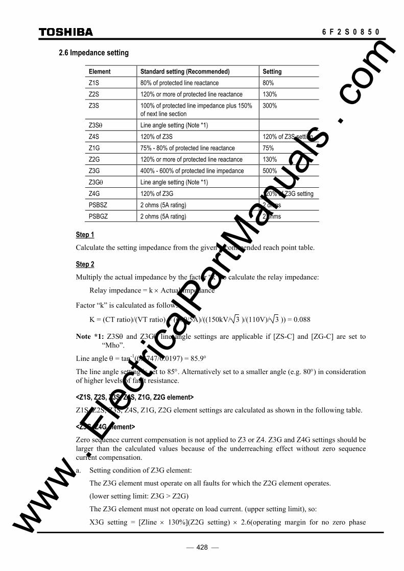
428
6 F 2 S 0 8 5 0
2.6 Impedance setting
Element Standard setting (Recommended) Setting Z1S 80% of protected line reactance 80% Z2S 120% or more of protected line reactance 130% Z3S 100% of protected line impedance plus 150%
of next line section 300%
Z3Sθ Line angle setting (Note *1) Z4S 120% of Z3S 120% of Z3S setting Z1G 75% - 80% of protected line reactance 75% Z2G 120% or more of protected line reactance 130% Z3G 400% - 600% of protected line impedance 500% Z3Gθ Line angle setting (Note *1) Z4G 120% of Z3G 120% of Z3G setting PSBSZ 2 ohms (5A rating) 2 ohms PSBGZ 2 ohms (5A rating) 2 ohms
Step 1 Calculate the setting impedance from the given recommended reach point table.
Step 2 Multiply the actual impedance by the factor “k” to calculate the relay impedance:
Relay impedance = k × Actual impedance
Factor “k” is calculated as follows:
K = (CT ratio)/(VT ratio) = (600/5A)/((150kV/ 3 )/(110V)/ 3 )) = 0.088
Note *1: Z3Sθ and Z3Gθ line angle settings are applicable if [ZS-C] and [ZG-C] are set to “Mho”.
Line angle θ = tan-1(0.2747/0.0197) = 85.9°
The line angle setting is set to 85°. Alternatively set to a smaller angle (e.g. 80°) in consideration of higher levels of fault resistance.
<Z1S, Z2S, Z3S, Z4S, Z1G, Z2G element> Z1S, Z2S, Z3S, Z4S, Z1G, Z2G element settings are calculated as shown in the following table.
<Z3G, Z4G element> Zero sequence current compensation is not applied to Z3 or Z4. Z3G and Z4G settings should be larger than the calculated values because of the underreaching effect without zero sequence current compensation.
a. Setting condition of Z3G element:
The Z3G element must operate on all faults for which the Z2G element operates.
(lower setting limit: Z3G > Z2G)
The Z3G element must not operate on load current. (upper setting limit), so:
X3G setting = [Zline × 130%](Z2G setting) × 2.6(operating margin for no zero phase www . El
ectric
alPar
tMan
uals
. com

429
6 F 2 S 0 8 5 0
sequence current compensation) × 1.5(operating margin)
= 500% of Zline
b. Setting condition of Z4G element
The operation zone of the Z4G element includes the operating zone of the Z3G element remote terminal relay.
Element Actual impedance (ohms)
k factor Relay impedance (ohms)
Z1S 3.692 0.32 Z2S 5.999 0.53 Z3S 13.84 1.22 Z4S 16.61 1.46 Z1G 3.461 0.088 0.30 Z2G 5.999 0.53 Z3G 23.07 2.03 Z4G 27.68 2.44 PSBSZ ----- 2.00 PSBGZ ----- 2.00
2.7 Blinder setting Zero sequence compensation is not applied to the blinder elements.
Recommended setting: 5.00 ohms
These elements should not operate under maximum load current:
Rset < load impedance/margin
< V rating/(2.5 times of I rating)
= (110V/ 3 )/(2.5 × 5A)
= 5.08
Element Setting BFRS 5.00 Ω BFLS θ 120° BRRS 5.00 Ω BRLS Linked with BFRS BFRG 5.00 Ω BFLG θ 120° BRRG 5.00 Ω BRLG Linked with BRRG
www . El
ectric
alPar
tMan
uals
. com

430
6 F 2 S 0 8 5 0
2.8 Zero sequence compensation
In the GRZ100, vector type zero sequence compensation is applied to Zone 1 and Zone 2, and the compensation factor is given in the resistive and reactive components independently.
Step 1 Calculate the positive, zero sequence impedance and mutual impedance:
Z1 = [R1: 0.0197] + j[X1: 0.2747] (ohms)
Z0 = [R0: 0.497] + j[X0: 1.4287] (ohms)
Zm = [Rm: 0.0212] + j[Xm: 0.3729] (ohms)
Step 2 Calculate the zero and mutual sequence compensation factor setting according to the following equations:
KRS = R0/R1 × 100 = 0.497/0.0197 = 2523*
KXS = X0/X1 × 100 = 1.4387/0.2747 = 524
KRm = Rm/R1 × 100 = 0.0212/0.0197 = 108
KXm = Xm/X1 × 100 = 0.3729/0.2747 = 136
*Note: If the calculated value exceeds 1000, then a setting of 1000 should be applied, this being considered to be the maximum practical value.
Element Setting KRS 1000
KXS 524
KRm 108
KXm 136
2.9 Current setting a. Definite time earth fault protection (EF)
The EF element may be used either to provide back-up earth fault protection or, alternatively, open circuit protection. For example, to detect open faults of the CT circuit, the operating value of the detector should be lower than the normal load current on the line:
EF ≤ (normal load current/CT ratio) × 0.5
= (594.7 × 5/600) × 0.5
= 2.48A
Element Setting (A) EF 2.4
b. Directional earth fault element (DEF)
The DEF element should not be operated by the unbalance current or voltage present in normal conditions. It is recommended to set the current and voltage after measuring the actual unbalance residual current and voltage on the site.
DEFFI, DEFRI > Max. zero sequence current (3Io) in normal conditions www . El
ectric
alPar
tMan
uals
. com
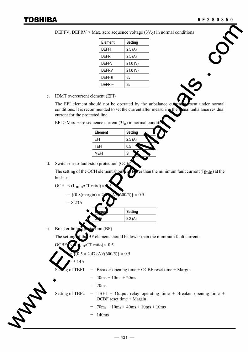
431
6 F 2 S 0 8 5 0
DEFFV, DEFRV > Max. zero sequence voltage (3Vo) in normal conditions
Element Setting DEFFI 2.5 (A) DEFRI 2.5 (A) DEFFV 21.0 (V) DEFRV 21.0 (V) DEFF θ 85 DEFR θ 85
c. IDMT overcurrent element (EFI)
The EFI element should not be operated by the unbalance current present under normal conditions. It is recommended to set the current after measuring the actual unbalance residual current for the protected line.
EFI > Max. zero sequence current (3Io) in normal condition
Element Setting EFI 2.5 (A) TEFI 0.5 MEFI S
d. Switch-on-to-fault/stub protection (OCH)
The setting of the OCH element should be lower than the minimum fault current (Ifmin) at the busbar:
OCH < (Ifmin/CT ratio) × 0.5
= (0.8(margin) × 2.47kA)/(600/5) × 0.5
= 8.23A
Element Setting OCH 8.2 (A)
e. Breaker failure protection (BF)
The setting of the BF element should be lower than the minimum fault current:
OCBF < (Ifmin/CT ratio) × 0.5
= (0.5 × 2.47kA)/(600/5) × 0.5
= 5.14A
Setting of TBF1 = Breaker opening time + OCBF reset time + Margin
= 40ms + 10ms + 20ms
= 70ms
Setting of TBF2 = TBF1 + Output relay operating time + Breaker opening time + OCBF reset time + Margin
= 70ms + 10ms + 40ms + 10ms + 10ms
= 140ms www . El
ectric
alPar
tMan
uals
. com

432
6 F 2 S 0 8 5 0
Element Setting OCBF 5.1 (A) TBF1 70ms TBF2 140ms
2.10 Undervoltage element a. Undervoltage element with current compensation (Phase selector)
(1) Undervoltage element (UVCV)
The UVCV element should be set not to work with the current of the power system.
UVCV < rated voltage × 0.7
= 63.5V × 0.7
= 44.5
(2) Reach setting (UVCZ)
The UVCZ element is set to the line impedance value:
UVCZ = 16.8 × (0.01972 + 0.27472) × 0.088
= 0.41 ohms
Element Setting UVCV 45V UVCZ 0.41 UVC θ 85
b. VT failure supervision
The undervoltage element for VT failure supervision (UVFS, UVFG) is set to about 50% of the rated voltage.
Element Setting UVFS 52V UVFG 30V
c. Weak infeed tripping function
The undervoltage element for weak infeed tripping (UVLS, UVLG) is set to 70% of the rated voltage.
Element Setting UVLS 77V UVLG 45V
2.11 Time setting a. Time delay setting for zone distance protection
b. Coordination time setting for protection signaling channel
This time setting is required only for the Blocking scheme. The time should be set larger than the time delay of protection signaling equipment (PSE) including propagation time of PLC (Power Line Carrier) or other communication link. The time setting should include an operation margin of 5ms. www .
Elec
tricalP
artM
anua
ls . c
om
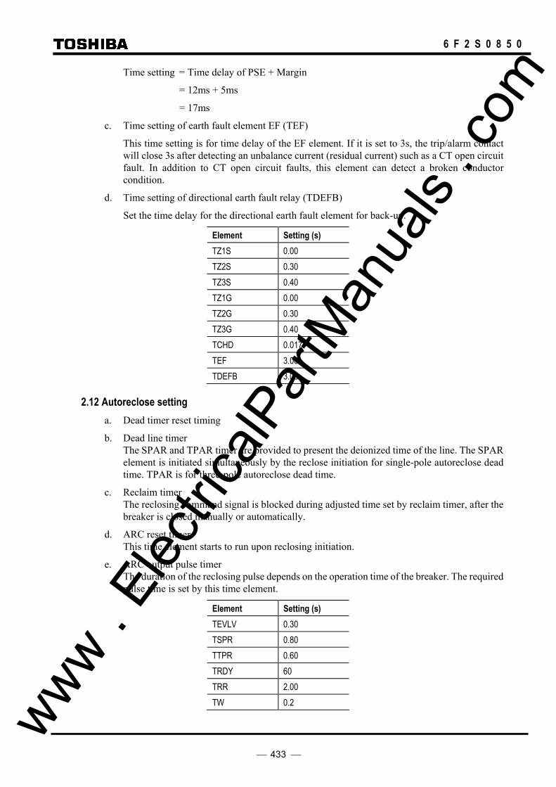
433
6 F 2 S 0 8 5 0
Time setting = Time delay of PSE + Margin
= 12ms + 5ms
= 17ms
c. Time setting of earth fault element EF (TEF)
This time setting is for time delay of the EF element. If it is set to 3s, the trip/alarm contact will close 3s after detecting an unbalance current (residual current) such as a CT open circuit fault. In addition to CT open circuit faults, this element can detect a broken conductor condition.
d. Time setting of directional earth fault relay (TDEFB)
Set the time delay for the directional earth fault element for back-up.
Element Setting (s) TZ1S 0.00 TZ2S 0.30 TZ3S 0.40 TZ1G 0.00 TZ2G 0.30 TZ3G 0.40 TCHD 0.017 TEF 3.00 TDEFB 3.00
2.12 Autoreclose setting a. Dead timer reset timing
b. Dead line timer The SPAR and TPAR timer are provided to present the deionized time of the line. The SPAR element is initiated simultaneously by the reclose initiation for single-pole autoreclose dead time. TPAR is for three-pole autoreclose dead time.
c. Reclaim timer The reclosing command signal is blocked during adjusted time set by reclaim timer, after the breaker is closed manually or automatically.
d. ARC reset timer This time element starts to run upon reclosing initiation.
e. ARC output pulse timer The duration of the reclosing pulse depends on the operation time of the breaker. The required pulse time is set by this time element.
Element Setting (s) TEVLV 0.30 TSPR 0.80 TTPR 0.60 TRDY 60 TRR 2.00 TW 0.2 www .
Elec
tricalP
artM
anua
ls . c
om

434
6 F 2 S 0 8 5 0
2.13 Synchronism check element The synchronism check element setting is as follows.
Element Setting SY1UV 83V SY10V 51V SY1 θ 30deg. TSYN1 1.00s TDBL1 0.05s TLBD1 0.05s OVB 51V UVB 13V OVL1 51V UVL1 13V
www . El
ectric
alPar
tMan
uals
. com

435
6 F 2 S 0 8 5 0
Appendix P
Programmable Reset Characteristics and Implementation of Thermal Model to IEC60255-8
www . El
ectric
alPar
tMan
uals
. com

436
6 F 2 S 0 8 5 0
Programmable Reset Characteristics
The overcurrent stages for phase and earth faults, OC1 and EF1, each have a programmable reset feature. Resetting may be instantaneous or definite time delayed.
Instantaneous resetting is normally applied in multi-shot auto-reclosing schemes, to ensure correct grading between relays at various points in the scheme.
The definite time delayed reset characteristic may be used to provide faster clearance of intermittent (‘pecking’ or ‘flashing’) fault conditions. An example of where such phenomena may be experienced is in plastic insulated cables, where the fault energy melts the cable insulation and temporarily extinguishes the fault, after which the insulation again breaks down and the process repeats.
An inverse time overcurrent protection with instantaneous resetting cannot detect this condition until the fault becomes permanent, thereby allowing a succession of such breakdowns to occur, with associated damage to plant and danger to personnel. If a definite time reset delay of, for example, 60 seconds is applied, on the other hand, the inverse time element does not reset immediately after each successive fault occurrence. Instead, with each new fault inception, it continues to integrate from the point reached during the previous breakdown, and therefore operates before the condition becomes permanent. Figure P-1 illustrates this theory.
Figure P-1
TRIP LEVEL
TRIP LEVEL
Inverse Time Relay with Instantaneous Reset
Intermittent Fault Condition
Inverse Time Relay with Definite Time Reset
Delayed Reset
www . El
ectric
alPar
tMan
uals
. com

437
6 F 2 S 0 8 5 0
Implementation of Thermal Model to IEC60255-8
Heating by overload current and cooling by dissipation of an electrical system follow exponential time constants. The thermal characteristics of the electrical system can be shown by equation (1).
θ = II
eAOL
t2
2 1 100−
×−
τ % (1)
where:
θ = thermal state of the system as a percentage of allowable thermal capacity,
I = applied load current,
IAOL = allowable overload current of the system,
τ = thermal time constant of the system.
The thermal stateθis expressed as a percentage of the thermal capacity of the protected system, where 0% represents the cold state and 100% represents the thermal limit, that is the point at which no further temperature rise can be safely tolerated and the system should be disconnected. The thermal limit for any given electrical plant is fixed by the thermal setting IAOL. The relay gives a trip output when θ = 100%.
If current I is applied to a cold system, then θ will rise exponentially from 0% to (I2/IAOL2 × 100%), with time
constant τ, as in Figure P-2. If θ = 100%, then the allowable thermal capacity of the system has been reached.
Figure P-2
A thermal overload protection relay can be designed to model this function, giving tripping times according to the IEC60255-8 ‘Hot’ and ‘Cold’ curves.
t =τ·Ln II IAOL
2
2 2−
(1) ····· Cold curve
t =τ·Ln I II I
P
AOL
2 2
2 2−
−
(2) ····· Hot curve
where:
IP = prior load current.
θ (%)
t (s)
100%
%100122
×−=
− τθ
t
AOLeI
I
%10022
×AOLI
I
www . El
ectric
alPar
tMan
uals
. com
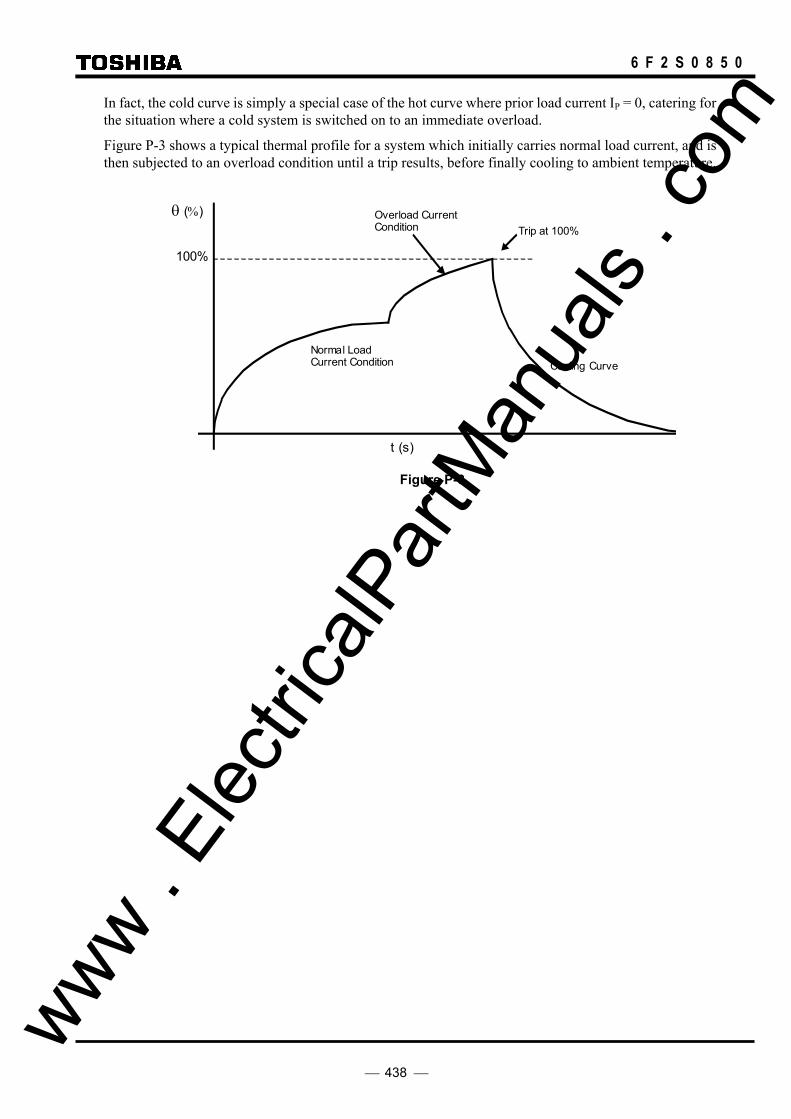
438
6 F 2 S 0 8 5 0
In fact, the cold curve is simply a special case of the hot curve where prior load current IP = 0, catering for the situation where a cold system is switched on to an immediate overload.
Figure P-3 shows a typical thermal profile for a system which initially carries normal load current, and is then subjected to an overload condition until a trip results, before finally cooling to ambient temperature.
θ (%)
t (s)
100%
Normal Load Current Condition Cooling Curve
Overload Current Condition Trip at 100%
Figure P-3
www . El
ectric
alPar
tMan
uals
. com

439
6 F 2 S 0 8 5 0
Appendix Q
IEC60870-5-103: Interoperability
www . El
ectric
alPar
tMan
uals
. com
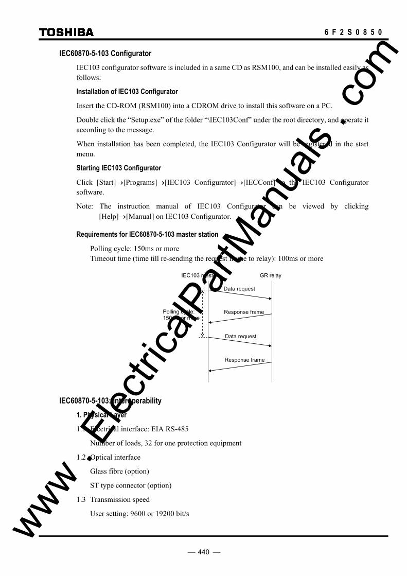
440
6 F 2 S 0 8 5 0
IEC60870-5-103 Configurator IEC103 configurator software is included in a same CD as RSM100, and can be installed easily as follows:
Installation of IEC103 Configurator
Insert the CD-ROM (RSM100) into a CDROM drive to install this software on a PC.
Double click the “Setup.exe” of the folder “\IEC103Conf” under the root directory, and operate it according to the message.
When installation has been completed, the IEC103 Configurator will be registered in the start menu.
Starting IEC103 Configurator
Click [Start]→[Programs]→[IEC103 Configurator]→[IECConf] to the IEC103 Configurator software.
Note: The instruction manual of IEC103 Configurator can be viewed by clicking [Help]→[Manual] on IEC103 Configurator.
Requirements for IEC60870-5-103 master station
Polling cycle: 150ms or more Timeout time (time till re-sending the request frame to relay): 100ms or more
IEC103 master GR relay
Data request
Data request
Response frame
Response frame
Polling cycle: 150ms or more
IEC60870-5-103: Interoperability 1. Physical Layer
1.1 Electrical interface: EIA RS-485
Number of loads, 32 for one protection equipment
1.2 Optical interface
Glass fibre (option)
ST type connector (option)
1.3 Transmission speed
User setting: 9600 or 19200 bit/s
www . El
ectric
alPar
tMan
uals
. com
441
6 F 2 S 0 8 5 0
2. Application Layer
COMMON ADDRESS of ASDU
One COMMON ADDRESS OF ASDU (identical with station address)
3. List of Information
The following items can be customized with the original software tool “IEC103 configurator”. (For details, refer to “IEC103 configurator” manual No.6F2S0839.)
- Items for “Time-tagged message”: Type ID(1/2), INF, FUN, Transmission condition(Signal number), COT
- Items for “Time-tagged measurands”: INF, FUN, Transmission condition(Signal number), COT, Type of measurand quantities
- Items for “General command”: INF, FUN, Control condition(Signal number)
- Items for “Measurands”: Type ID(3/9), INF, FUN, Number of measurand, Type of measurand quantities
- Common setting
• Transmission cycle of Measurand frame • FUN of System function • Test mode, etc.
CAUTION: To be effective the setting data written via the RS232C, turn off the DC supply of the relay and turn on again.
3. 1 IEC60870-5-103 Interface
3.1.1 Spontaneous events
The events created by the relay will be sent using Function type (FUN) / Information numbers (INF) to the IEC60870-5-103 master station.
3.1.2 General interrogation
The GI request can be used to read the status of the relay, the Function types and Information numbers that will be returned during the GI cycle are shown in the table below.
For details, refer to the standard IEC60870-5-103 section 7.4.3.
3.1.3 Cyclic measurements
The relay will produce measured values using Type ID=3 or 9 on a cyclical basis, this can be read from the relay using a Class 2 poll. The rate at which the relay produces new measured values can be customized.
3.1.4 Commands
The supported commands can be customized. The relay will respond to non-supported commands with a cause of transmission (COT) of negative acknowledgement of a command.
For details, refer to the standard IEC60870-5-103 section 7.4.4.
3.1.5 Test mode
In test mode, both spontaneous messages and polled measured values, intended for processing in the control system, are designated by means of the CAUSE OF TRANSMISSION ‘test mode’. www .
Elec
tricalP
artM
anua
ls . c
om

442
6 F 2 S 0 8 5 0
This means that CAUSE OF TRANSMISSION = 7 ‘test mode’ is used for messages normally transmitted with COT=1 (spontaneous) or COT=2 (cyclic).
For details, refer to the standard IEC60870-5-103 section 7.4.5.
3.1.6 Blocking of monitor direction
If the blocking of the monitor direction is activated in the protection equipment, all indications and measurands are no longer transmitted.
For details, refer to the standard IEC60870-5-103 section 7.4.6.
3.2 List of Information
The followings are the default settings.
www . El
ectric
alPar
tMan
uals
. com

443
6 F 2 S 0 8 5 0
List of Information IEC103 Configurator Default setting
INF Description Contents GI Type COT FUN DPI ID Signal No. OFF ON
Standard Information numbers in monitor directionSystem Function
0 End of General Interrogation Transmission completion of GI items. -- 8 10 255 -- -- --
0 Time Synchronization Time Synchronization ACK. -- 6 8 255 -- -- --
2 Reset FCB Reset FCB(toggle bit) ACK -- 5 3 192 -- -- --
3 Reset CU Reset CU ACK -- 5 4 192 -- -- --
4 Start/Restart Relay start/restart -- 5 5 192 -- -- --
5 Power On Relay power on. Not supported -- -- --
Status Indications
16 Auto-recloser active If it is possible to use auto-recloser, this item is setactive, if impossible, inactive. GI 1 1, 9, 11, 12 192 1411 1 2
17 Teleprotection active If protection using telecommunication is available,this item is set to active. If not, set to inactive. GI 1 1, 9, 12 192 1412 1 2
18 Protection active If the protection is available, this item is set toactive. If not, set to inactive. GI 1 1, 9, 12 192 1413 1 2
19 LED reset Reset of latched LEDs -- 1 1, 11, 12 192 1409 -- 2
20 Monitor direction blocked Block the 103 transmission from a relay to controlsystem. IECBLK: "Blocked" settimg. GI 1 9, 11 192 1241 1 2
21 Test mode Transmission of testmode situation froma relay tocontrol system. IECTST "ON" setting. GI 1 9, 11 192 1242 1 2
22 Local parameter Setting When a setting change has done at the local, theevent is sent to control system. Not supported
23 Characteristic1 Setting group 1 active GI 1 1, 9, 11, 12 192 1243 1 2
24 Characteristic2 Setting group 2 active GI 1 1, 9, 11, 12 192 1244 1 2
25 Characteristic3 Setting group 3 active GI 1 1, 9, 11, 12 192 1245 1 2
26 Characteristic4 Setting group 4 active GI 1 1, 9, 11, 12 192 1246 1 2
27 Auxiliary input1 Binary input 1 No set
28 Auxiliary input2 Binary input 2 No set
29 Auxiliary input3 Binary input 3 No set
30 Auxiliary input4 Binary input 4 No set
Supervision Indications32 Measurand supervision I Zero sequence current supervision GI 1 1, 9 192 1267 1 2
33 Measurand supervision V Zero sequence voltage supervision GI 1 1, 9 192 1268 1 2
35 Phase sequence supervision Negative sequence voltage supevision GI 1 1, 9 192 1269 1 2
36 Trip circuit supervision Output circuit supervision Not supported
37 I>>backup operation Not supported
38 VT fuse failure VT failure GI 1 1, 9 192 891 1 2
39 Teleprotection disturbed CF(Communication system Fail) supervision GI 1 1, 9 192 226 1 2
46 Group warning Only alarming GI 1 1, 9 192 1258 1 2
47 Group alarm Trip blocking and alarming GI 1 1, 9 192 1252 1 2
Earth Fault Indications48 Earth Fault L1 A phase earth fault No set
49 Earth Fault L2 B phase earth fault No set
50 Earth Fault L3 C phase earth fault No set
51 Earth Fault Fwd Earth fault forward Not supported
52 Earth Fault Rev Earth fault reverse Not supported
www . El
ectric
alPar
tMan
uals
. com

444
6 F 2 S 0 8 5 0
IEC103 Configurator Default setting
INF Description Contents GI Type COT FUN DPI ID Signal NO. OFF ON
Fault Indications64 Start/pick-up L1 A phase, A-B phase or C-A phase element pick-up No set
65 Start/pick-up L2 B phase, A-B phase or B-C phase element pick-up No set
66 Start/pick-up L3 C phase, B-C phase or C-A phase element pick-up No set
67 Start/pick-up N Earth fault element pick-up No set
68 General trip Any trip -- 2 1 192 1280 -- 2
69 Trip L1 A phase, A-B phase or C-A phase trip No set
70 Trip L2 B phase, A-B phase or B-C phase trip No set
71 Trip L3 C phase, B-C phase or C-A phase trip No set
72 Trip I>>(back-up) Back up trip No set
73 Fault location X In ohms Fault location -- 4 1 192 1048 -- --
74 Fault forward/line Forward fault Not supported
75 Fault reverse/Busbar Reverse fault Not supported
76 Teleprotection Signaltransmitted Carrier signal sending Not supported
77 Teleprotection Signal received Carrier signal receiving Not supported
78 Zone1 Zone 1 trip -- 2 1 192 895 -- 2
79 Zone2 Zone 2 trip -- 2 1 192 896 -- 2
80 Zone3 Zone 3 trip -- 2 1 192 897 -- 2
81 Zone4 Zone 4 trip No set
82 Zone5 Zone 5 trip No set
83 Zone6 Zone 6 trip No set
84 General Start/Pick-up Any elements pick-up No set
85 Breaker Failure CBF trip or CBF retrip -- 2 1 192 92 -- 2
86 Trip measuring system L1 Not supported
87 Trip measuring system L2 Not supported
88 Trip measuring system L3 Not supported
89 Trip measuring system E Not supported
90 Trip I> Inverse time OC trip -- 2 1 192 114 -- 2
91 Trip I>> Definite time OC trip -- 2 1 192 113 -- 2
92 Trip IN> Inverse time earth fault OC trip -- 2 1 192 117 -- 2
93 Trip IN>> Definite time earth fault OC trip -- 2 1 192 115 -- 2
Autoreclose indications128 CB 'ON' by Autoreclose CB close command output -- 1 1 192 177 -- 2
129 CB 'ON' by long-timeAutoreclose Not supported
130 Autoreclose Blocked Autoreclose block GI 1 1, 9 192 121 2 1
Details of Fault location settings in IEC103 configurator
INF Tbl Offset Data type Coeff73 5 26 short 0.1
www . El
ectric
alPar
tMan
uals
. com
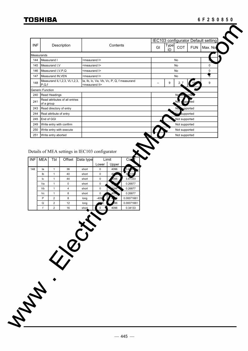
445
6 F 2 S 0 8 5 0
IEC103 configurator Default settingINF Description Contents GI Type
ID COT FUN Max. No.
Measurands144 Measurand I <meaurand I> No 0
145 Measurand I,V <meaurand I> No 0
146 Measurand I,V,P,Q <meaurand I> No 0
147 Measurand IN,VEN <meaurand I> No 0
148 Measurand IL1,2,3, VL1,2,3,P,Q,f
Ia, Ib, Ic, Va, Vb, Vc, P, Q, f measurand<meaurand II> -- 9 2, 7 192 9
Generic Function240 Read Headings Not supported
241 Read attributes of all entriesof a group Not supported
243 Read directory of entry Not supported
244 Real attribute of entry Not supported
245 End of GGI Not supported
249 Write entry with confirm Not supported
250 Write entry with execute Not supported
251 Write entry aborted Not supported
Details of MEA settings in IEC103 configurator
INF MEA Tbl Offset Data type Limit CoeffLower Upper
148 Ia 1 36 short 0 4096 3.41333
Ib 1 40 short 0 4096 3.41333
Ic 1 44 short 0 4096 3.41333
Va 1 0 short 0 4096 0.26877
Vb 1 4 short 0 4096 0.26877
Vc 1 8 short 0 4096 0.26877
P 2 8 long -4096 4096 0.00071661
Q 2 12 long -4096 4096 0.00071661
f 2 16 short 0 4096 0.34133
www . El
ectric
alPar
tMan
uals
. com

446
6 F 2 S 0 8 5 0
IEC103 Configurator Default settingControl
directionType
ID COT FUN
Selection of standard information numbers in control directionSystem functions
0 Initiation of generalinterrogation -- 7 9 255
0 Time synchronization -- 6 8 255
General commands16 Auto-recloser on/off ON/OFF 20 20 192
17 Teleprotection on/off ON/OFF 20 20 192
18 Protection on/off (*1) ON/OFF 20 20 192
19 LED reset Reset indication of latched LEDs. ON 20 20 192
23 Activate characteristic 1 Setting Group 1 ON 20 20 192
24 Activate characteristic 2 Setting Group 2 ON 20 20 192
25 Activate characteristic 3 Setting Group 3 ON 20 20 192
26 Activate characteristic 4 Setting Group 4 ON 20 20 192
Generic functions
240 Read headings of all definedgroups Not supported
241 Read values or attributes of allentries of one group Not supported
243 Read directory of a singleentry Not supported
244 Read values or attributes of asingle entry Not supported
245 General Interrogation ofgeneric data Not supported
248 Write entry Not supported
249 Write entry with confirmation Not supported
250 Write entry with execution Not supported
INF Description Contents
(∗1) Note: While the relay receives the "Protection off" command, "IN SERVICE LED" is off.
Details of Command settings in IEC103 configurator
INF DCOSig off Sig on Rev Valid time
16 2684 2684 0
17 2685 2685 0
18 2686 2686 0
19 0 2688 200
23 0 2640 1000
24 0 2641 1000
25 0 2642 1000
26 0 2643 1000 : signal reverse
www . El
ectric
alPar
tMan
uals
. com

447
6 F 2 S 0 8 5 0
Description Contents GRL100 supported Comment
Basic application functionsTest mode Yes
Blocking of monitor direction Yes
Disturbance data No
Generic services No
Private data Yes
Miscellaneous
Measurand Max. MVAL = ratedvalue times
Current L1 Ia Configurable
Current L2 Ib Configurable
Current L3 Ic Configurable
Voltage L1-E Va Configurable
Voltage L2-E Vb Configurable
Voltage L3-E Vc Configurable
Active power P P Configurable
Reactive power Q Q Configurable
Frequency f f Configurable
Voltage L1 - L2 Vab Configurable
Details of Common settings in IEC103 configurator
- Setting file’s remark: GRL100_1.01 - Remote operation valid time [ms]: 4000 - Local operation valid time [ms]: 4000 - Measurand period [s]: 2 - Function type of System functions: 192 - Signal No. of Test mode: 1242 - Signal No. for Real time and Fault number: 1279
www . El
ectric
alPar
tMan
uals
. com

448
6 F 2 S 0 8 5 0
[Legend]
GI: General Interrogation (refer to IEC60870-5-103 section 7.4.3)
Type ID: Type Identification (refer to IEC60870-5-103 section 7.2.1)
1 : time-tagged message 2 : time-tagged message with relative time 3 : measurands I 4 : time-tagged measurands with relative time 5 : identification 6 : time synchronization 8 : general interrogation termination 9 : measurands II 10: generic data 11: generic identification 20: general command 23: list of recorded disturbances 26: ready for transmission for disturbance data 27: ready for transmission of a channel 28: ready for transmission of tags 29: transmission of tags 30: transmission of disturbance values 31: end of transmission
COT: Cause of Transmission (refer to IEC60870-5-103 section 7.2.3) 1: spontaneous 2: cyclic 3: reset frame count bit (FCB) 4: reset communication unit (CU) 5: start / restart 6: power on 7: test mode 8: time synchronization 9: general interrogation 10: termination of general interrogation 11: local operation 12: remote operation 20: positive acknowledgement of command 21: negative acknowledgement of command 31: transmission of disturbance data 40: positive acknowledgement of generic write command 41: negative acknowledgement of generic write command 42: valid data response to generic read command 43: invalid data response to generic read command 44: generic write confirmation
FUN: Function type (refer to IEC60870-5-103 section 7.2.5.1)
DPI: Double-point Information (refer to IEC60870-5-103 section 7.2.6.5)
DCO: Double Command (refer to IEC60870-5-103 section 7.2.6.4)
www . El
ectric
alPar
tMan
uals
. com
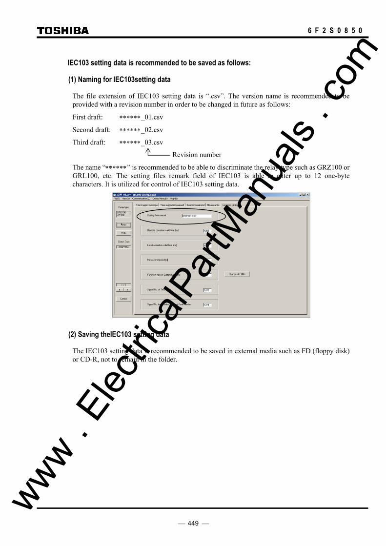
449
6 F 2 S 0 8 5 0
IEC103 setting data is recommended to be saved as follows:
(1) Naming for IEC103setting data
The file extension of IEC103 setting data is “.csv”. The version name is recommended to be provided with a revision number in order to be changed in future as follows:
First draft: ∗∗∗∗∗∗_01.csv
Second draft: ∗∗∗∗∗∗_02.csv
Third draft: ∗∗∗∗∗∗_03.csv
Revision number
The name “∗∗∗∗∗∗” is recommended to be able to discriminate the relay type such as GRZ100 or GRL100, etc. The setting files remark field of IEC103 is able to enter up to 12 one-byte characters. It is utilized for control of IEC103 setting data.
(2) Saving theIEC103 setting data
The IEC103 setting data is recommended to be saved in external media such as FD (floppy disk) or CD-R, not to remain in the folder.
www . El
ectric
alPar
tMan
uals
. com

450
6 F 2 S 0 8 5 0
Troubleshooting
No. Phenomena Supposed causes Check / Confirmation
Object Procedure
Address setting is incorrect. BCU
RY
Match address setting between BCU and relay.
Avoid duplication of address with other relay.
Transmission baud rate setting is incorrect.
BCU
RY
Match transmission baud rate setting between BCU and relay.
Start bit, stop bit and parity settings of data that BCU transmits to relay is incorrect.
BCU Go over the following settings by BCU. Relay setting is fixed as following settings. - Start bit: 1bit - Stop bit: 1bit - Parity setting: even
The PRTCL1 setting is incorrect. (The model with PRTCL1 setting.)
RY Change the PRTCL1 setting. Relation between PRTCL1 setting and available transmission protocol is referred to the following table.
RS485 port at the back of the relay
PRTCL1 =HDLC
PRTCL1=IEC
COM1 (CH1) HDLC IEC
COM2 (CH2) IEC ―
RS485 or optical cable interconnection is incorrect.
Cable - Check the connection port.(CH1/CH2) - Check the interconnection of RS485 A/B/COM - Check the send and received interconnection of
optical cable.
The setting of converter is incorrect. (RS485/optic conversion is executed with the transmission channel, etc.)
Converter In the event of using G1IF2, change the DIPSW setting in reference to INSTRUCTION MANUAL (6F2S0794).
The relationship between logical “0/1” of the signal and Sig.on/off is incorrect. (In the event of using optical cable)
BCU Check the following; Logical0 : Sig.on Logical1:Sig.off
Terminal resistor is not offered. (Especially when RS485 cable is long.)
cable Impose terminal resistor (150[ohms]) to both ends of RS 485 cable.
Relay cannot receive the requirement frame from BCU.
(The timing coordination of sending and receiving switch control is irregular in half-duplex communication.)
BCU Check to secure the margin more than 15ms between receiving the reply frame from the relay and transmitting the next requirement frame on BCU.
1 Communication trouble (IEC103 communication is not available.)
The requirement frame from BCU and the reply frame from relay contend.
(The sending and receiving timing coordination is irregular in half-duplex communication.)
BCU Check to set the time-out of reply frame from the relay.
Time-out setting: more than 100ms (acceptable value of response time 50ms plus margin)
www . El
ectric
alPar
tMan
uals
. com

451
6 F 2 S 0 8 5 0
No. Phenomena Supposed causes Check / Confirmation
Object Procedure
The relevant event sending condition is not valid.
RY Change the event sending condition (signal number) of IEC103 configurator if there is a setting error. When the setting is correct, check the signal condition by programmable LED, etc.
The relevant event Information Number (INF) and/or Function Type (FUN) may be different between the relay and SAS.
RY
SAS
Match the relevant event Information Number (INF) or Function Type (FUN) between the relay and SAS.
The relay is not initialised after writing IEC103 configurator setting.
RY Check the sum value of IEC103 setting data from the LCD screen. When differing from the sum value on IEC103 configurator, initialise the relay.
2 HMI does not display IEC103 event on the SAS side.
It changes to the block mode. RY Change the IECBR settling to Normal.
BCU does not transmit the frame of time synchronisation.
BCU Transmit the frame of time synchronisation. 3 Time can be synchronised with IEC103 communication. The settling of time synchronisation
source is set to other than IEC. RY Change the settling of time synchronisation
source to IEC.
(Note) BCU: Bay control unit, RY: Relay
www . El
ectric
alPar
tMan
uals
. com

452
6 F 2 S 0 8 5 0 www .
Elec
tricalP
artM
anua
ls . c
om

453
6 F 2 S 0 8 5 0
Appendix R
Inverse Time Characteristics
www . El
ectric
alPar
tMan
uals
. com
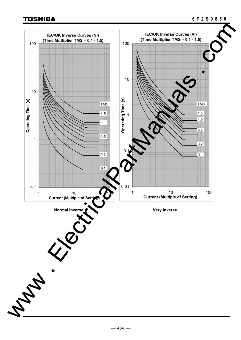
454
6 F 2 S 0 8 5 0
IEC/UK Inverse Curves (NI)(Time Multiplier TMS = 0.1 - 1.5)
0.1
1
10
100
1 10 100Current (Multiple of Setting)
Ope
ratin
g Ti
me
(s)
1.
0.5
0.1
0.2
1.5
TMS
IEC/UK Inverse Curves (VI)(Time Multiplier TMS = 0.1 - 1.5)
0.01
0.1
1
10
100
1 10 100Current (Multiple of Setting)
Ope
ratin
g Ti
me
(s)
1.0
0.5
0.2
0.1
1.5
TMS
Normal Inverse Very Inverse
www . El
ectric
alPar
tMan
uals
. com

455
6 F 2 S 0 8 5 0
IEC/UK Inverse Curves (EI)(Time Multiplier TMS = 0.1 - 1.5)
0.01
0.1
1
10
100
1000
1 10 100Current (Multiple of Setting)
Ope
ratin
g Ti
me
(s)
1.0
0.5
0.2
0.1
1.5
TMS
UK Inverse Curves (LTI)(Time Multiplier TMS = 0.1 - 1.5)
0.1
1
10
100
1000
1 10 100Current (Multiple of Setting)
Ope
ratin
g Ti
me
(s)
1.0
0.2
0.5
0.1
1.5
TMS
Extremely Inverse Long Time Inverse
www . El
ectric
alPar
tMan
uals
. com

456
6 F 2 S 0 8 5 0 www .
Elec
tricalP
artM
anua
ls . c
om

457
6 F 2 S 0 8 5 0
Appendix S Failed Module Tracing and Replacement
www . El
ectric
alPar
tMan
uals
. com
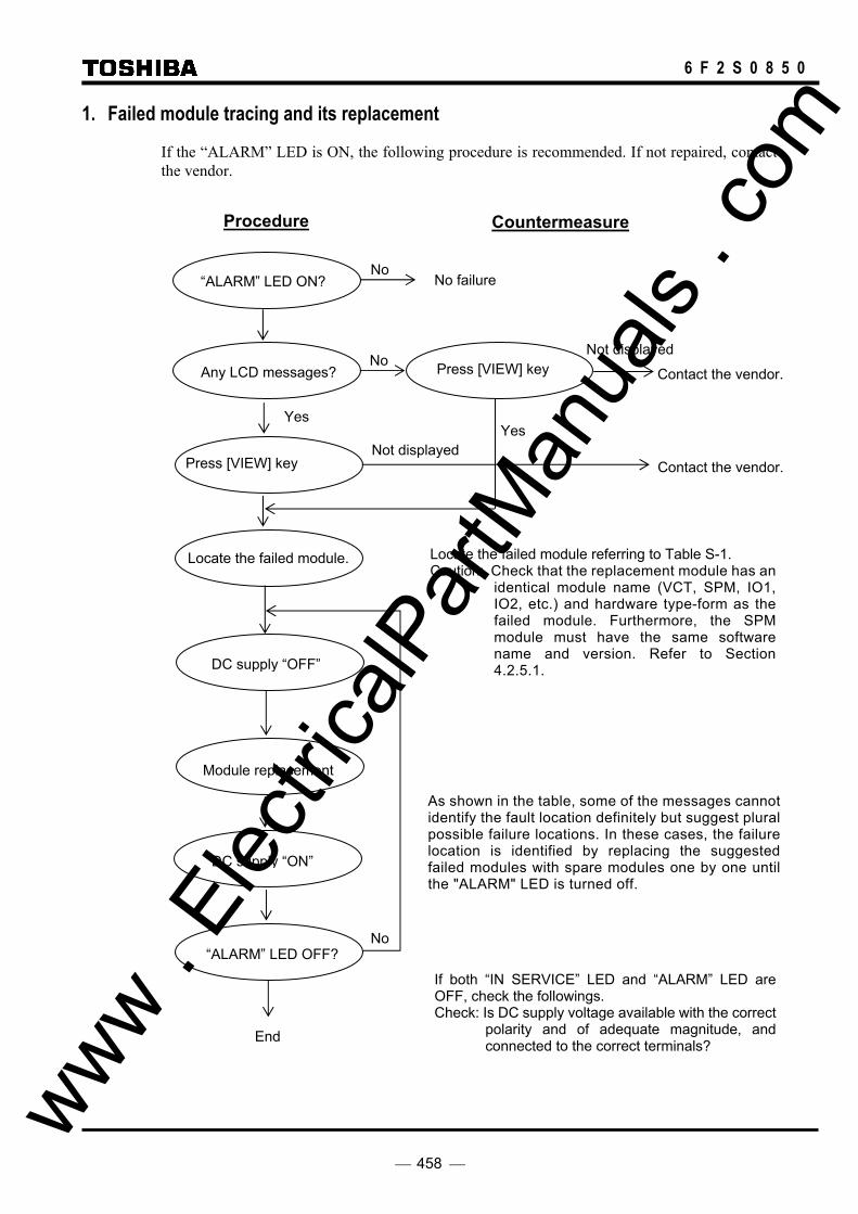
458
6 F 2 S 0 8 5 0
1. Failed module tracing and its replacement
If the “ALARM” LED is ON, the following procedure is recommended. If not repaired, contact the vendor.
“ALARM” LED ON?
Any LCD messages?
Locate the failed module.
Module replacement
If both “IN SERVICE” LED and “ALARM” LED are OFF, check the followings. Check: Is DC supply voltage available with the correct
polarity and of adequate magnitude, and connected to the correct terminals?
NoNo failure
Locate the failed module referring to Table S-1. Caution: Check that the replacement module has an
identical module name (VCT, SPM, IO1, IO2, etc.) and hardware type-form as the failed module. Furthermore, the SPM module must have the same software name and version. Refer to Section 4.2.5.1.
Countermeasure
As shown in the table, some of the messages cannot identify the fault location definitely but suggest plural possible failure locations. In these cases, the failure location is identified by replacing the suggested failed modules with spare modules one by one until the "ALARM" LED is turned off.
DC supply “OFF”
DC supply “ON”
“ALARM” LED OFF?
NoContact the vendor.
End
No
Not displayed Press [VIEW] key
Contact the vendor.Not displayed
Press [VIEW] key
Yes Yes
Procedure
www . El
ectric
alPar
tMan
uals
. com

459
6 F 2 S 0 8 5 0
Table S-1 LCD Message and Failure Location
Message Failure location
VCT SPM (GCOM)
IO1 IO2 IO3, IO5, IO6
IO4 HMI Channel Discon- nector
AC cable
Checksum err × ROM-RAM err × SRAM err × BU-RAM err × DPRAM err × EEPROM err × ROM data err × A/D err × V0 err × (2) × (1) × (2) V2 err × (2) × (1) × (2) I0 err × (2) × (1) × (2) Id err × (2) × (1) × (2) CT err × (2) × (2) × (1) Sampling err × DIO err × (2) × (1) × (1) × (1) × (1) RSM err × (2) × (1) COM_ ….err × FD: … err × (2) × (1) O/P circuit fail × (2) × (1) DS fail × (2) × (2) × (1) Com.1 fail, Com.2 fail × (2)* × (2)* × (2)* × (1)* Sync.1 fail, Sync.2 fail × (2)* × (2)* × (2)* × (1)* TX1 level err, TX2 level err
× (1)* × (2)* × (2)* × (1)*
RX1 level err, RX2 level err
× (2)* × (2)* × (2)* × (1)*
CLK 1 fail, CLK 2 fail × (2)* × (2)* × (2)* × (1)* Term1 rdy off, Term2 rdy off
× (2)* × (1)*
RYID1 err, RYID2 err × (2)* × (1)* CT fail × (2) × (2) × (1) No-working of LCD × (2) × (1)
The location marked with (1) has a higher probability than the location marked with (2). The item of location marked with (*): also check the remote terminal relays and equipment.
www . El
ectric
alPar
tMan
uals
. com
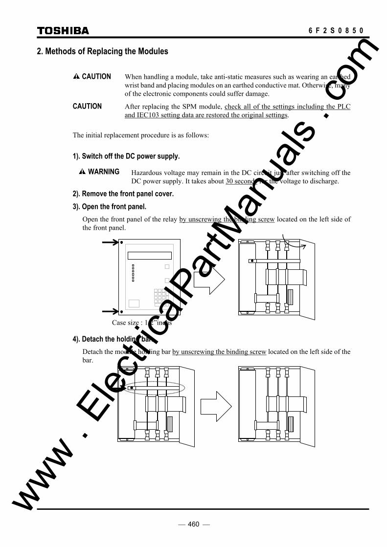
460
6 F 2 S 0 8 5 0
2. Methods of Replacing the Modules
CAUTION When handling a module, take anti-static measures such as wearing an earthed wrist band and placing modules on an earthed conductive mat. Otherwise, many of the electronic components could suffer damage.
CAUTION After replacing the SPM module, check all of the settings including the PLC and IEC103 setting data are restored the original settings.
The initial replacement procedure is as follows:
1). Switch off the DC power supply.
Hazardous voltage may remain in the DC circuit just after switching off the DC power supply. It takes about 30 seconds for the voltage to discharge.
2). Remove the front panel cover. 3). Open the front panel. Open the front panel of the relay by unscrewing the binding screw located on the left side of
the front panel.
Case size : 1/2”inchs
4). Detach the holding bar. Detach the module holding bar by unscrewing the binding screw located on the left side of the
bar.
WARNING
www . El
ectric
alPar
tMan
uals
. com

461
6 F 2 S 0 8 5 0
5). Unplug the cables. Unplug the ribbon cable running among the modules by nipping the catch (in case of black
connector) and by pushing the catch outside (in case of gray connector) on the connector.
6). Pull out the module. Pull out the failure module by pulling up or down the top and bottom levers (white).
7). Insert the replacement module. Insert the replacement module into the same slots where marked up.
. 8). Do the No.5 to No.1 steps in reverse order.
CAUTION Supply DC power after checking that all the modules are in their original positions and the ribbon cables are plugged in. If the ribbon cables are not plugged in enough (especially the gray connectors), the module could suffer damage.
Gray connector
Black connector
SPM module
Details of the gray connector on modules (top side)
×Not enough Enough
www . El
ectric
alPar
tMan
uals
. com

462
6 F 2 S 0 8 5 0
9). Lamp Test • RESET key is pushed 1 second or more by LCD display off.
• It checks that all LCDs and LEDs light on.
10). Check the automatic supervision functions. • LCD not display “Auto-supervision” screens in turn, and Event Records
• Checking the “IN SERVICE” LED light on and “ALARM LED” light off.
www . El
ectric
alPar
tMan
uals
. com

463
6 F 2 S 0 8 5 0
Appendix T
PLC Setting Sample
www . El
ectric
alPar
tMan
uals
. com

464
6 F 2 S 0 8 5 0
1. PLC setting sample for distance protection
To enable the distance protection Z1, Z2, Z3 and ZR tripping only when communication failure and differential protection blocked in current differential protection, assign signals by PLC function as follows:
(1) Zone 1 Trip Mode Control Circuit First, disconnect all the default PLC settings of Zone 1 Trip Mode Control Circuit shown in Figure T-1.1. (*)
DIF_OUT_SERV
Z1CNT_INST +
43C ON
[Z1CNT] Z1_INST_TP 1936785
786
787
788
Z1CNT_3PTP
Z1CNT_ARCBLK
Z1CNT_TPBLK
Z1_3PTP 1968
Z1_ARC_BLOCK 1847
Z1G_BLOCK 1888
Z1S_BLOCK 1904
Z1 can trip instantaneously.
Z1 performs three-phase trip.
Z1 performs final tripping for all faults.Z1G trip is blocked.
Z1S trip is blocked.
Defalt setting
DIF_OUT 2015
TripModeControlLogic
Zone 1
1
≥1 789
DIF BLOCK
Communication failure, etc.
+ [DIF]
"OFF" Defalt setting
: Disconnect the PLC default setting.
Figure T-1.1
And then, assign the invert signal of DIF_OUT_SERV (789) to [Z1G_BLOCK] and [Z1S_BLOCK] by PLC as shown in Figure T-1.2.
(2) Zone 2, Zone 3 and Zone R Tripping circuit Next, assign the invert signal of DIF_OUT_SERV (789) to [Z2G_BLOCK] to [ZRS_BLOCK] by PLC as shown in Figure T-1.2.
Note (*): [Z1CNT] does not function, because Zone 1 Trip Mode Control Circuit is disabled due to disconnect all the PLC default settings.
www . El
ectric
alPar
tMan
uals
. com

465
6 F 2 S 0 8 5 0
S-TRIP& Trip
modecontrol
M-TRIP
TZ2Gt 0
&
Z1G
Z2G
Phase selection logic
Sigle-phase tripping command
0.00 - 10.00s
[PSB-Z1]
PSBG_DET
+ [Z2TP]
[PSB-Z2]
NON VTF
Three-phase tripping command
TZ1G t 0
0.00 - 10.00s
&
Z1S
"ON"
[PSB-Z1]
TZ1S t 0
0.00 - 10.00s
Z2G_BLOCK1890
TZ2St 0
&
0.00 - 10.00s
"ON"
"ON"
Z2S
[PSB-Z2]
Z2S_BLOCK1906
"ON"
≥ 1
"ON"
TZ3Gt 0
&
Z3G
0.00 - 10.00s
+ [Z3TP]
[PSB-Z3]
Z3G_BLOCK1891
TZ3St 0
&
0.00 - 10.00s
"ON"
Z3S
[PSB-Z3]
Z3S_BLOCK1907
"ON""ON"
TZRGt 0
&
ZRG
0.00 - 10.00s
+ [ZRTP]
[PSB-ZR]
ZRG_BLOCK1894
TZRSt 0
&
0.00 - 10.00s
"ON"
ZRS
[PSB-ZR]
ZRS_BLOCK1910
"ON""ON"
PSBS_DET
DIF_OUT_SERV
Z1CNT_INST +
43C ON
[Z1CNT] Z1_INST_TP1936785
786
787
788
Z1CNT_3PTP
Z1CNT_ARCBLK
Z1CNT_TPBLK
Z1_3PTP 1968
Z1_ARC_BLOCK 1847
Z1G_BLOCK1888
Z1S_BLOCK1904
Z1 can trip instantaneously.
Z1 performs three-phase trip.
Z1 performs final tripping for all faults. Z1G trip is blocked.
Z1S trip is blocked.
DIF_OUT 2015
TripModeControlLogic
Zone 1
1
≥1 789
DIF BLOCK
Communication failure, etc.
+ [DIF]
"OFF"
1
PLC setting
circuit
Figure T-1.2 Assigning Signal by PLC
www . El
ectric
alPar
tMan
uals
. com

466
6 F 2 S 0 8 5 0
2. PLC setting sample for autoreclosing (UARCSW application)
If the follower Terminal is reclosed after checking the leader Terminal reclosed in the autoreclose mode “SPAR”, the leader Terminal is assigned to the signal number 1 with signal name “CONSTANT_1” and the follower Terminal assigned to the signal number 498 with signal name “3PLL” as shown in Figure T-2.1.
Single-phase trip
+ [ARC-M]
"SPAR", "SPAR & TPAR"
& ≥1
No-Link & Single-phase trip
+ [ARC-M]
"MPAR2", "MPAR3"
&
&0.01-10s
t 0TSPR1
SPR.L-REQ1824
CONSTANT 1
& ≥1 0.1 - 10s
TW1
ARC
MSARC
ARC (For Leader CB)
Leader Terminal
Single-phase trip
+ [ARC-M]
"SPAR", "SPAR & TPAR"
& ≥1
No-Link & Single-phase trip
+ [ARC-M]
"MPAR2", "MPAR3"
&
&0.01-10s
t 0TSPR1
SPR.L-REQ1824
3PLL
& ≥1 0.1 - 10s
TW1
ARC
MSARC
ARC (For Leader CB)
Follower Terminal
Figure T-2.1
In this case, the reclosing condition of [SPR.L-REQ] is the difference between the leader Terminal and the follower Terminal. If the same setting is required for the reclosing condition of [SPR.L-REQ], set the PLC using the [UARCSW] described in 2.10.2 as follows:
"P1"
& ≥1
+
[UARCSW]
"3PLL"
&0.01-10s
t 0TSPR1
SPR.L-REQ1824
& ≥1 0.1 - 10s
TW1
ARC
MSARC
ARC (For Leader CB)
"P2"
Figure T-2.2
The reclose condition can be changed by the position of [UARCSW].
[UARCSW] = P1: (No condition for reclosing)
[UARCSW] = P2: 3PLL (Three phase live line condition for reclosing)
The [UARCSW] is effective when the reclosing condition of PLC setting has the difference between the leader Terminal and the follower Terminal.
www . El
ectric
alPar
tMan
uals
. com

467
6 F 2 S 0 8 5 0
Appendix U
Ordering
www . El
ectric
alPar
tMan
uals
. com

468
6 F 2 S 0 8 5 0
Ordering 1. Line Differential Protection Relay a. Two-terminal application
Terminal B
Communication route
Terminal A
GRL100GRL100
Relay Type:
Line differential protection relay GRL100
Relay Model: -Model700: With distance protection and autoreclose for two-breaker scheme 25 BIs, 19 BOs, 6 trip BOs 28 BIs, 37 BOs, 6 trip BOs
701 702
Ratings:
1A, 50Hz, 110V/125Vdc 1A, 60Hz, 110V/125Vdc 5A, 50Hz, 110V/125Vdc 5A, 60Hz, 110V/125Vdc 1A, 50Hz, 220V/250Vdc 1A, 60Hz, 220V/250Vdc 5A, 50Hz, 220V/250Vdc 5A, 60Hz, 220V/250Vdc 1A, 50Hz, 48V/54V/60Vdc 1A, 60Hz, 48V/54V/60Vdc 5A, 50Hz, 48V/54V/60Vdc 5A, 60Hz, 48V/54V/60Vdc 1A, 50Hz, 24V/54V/60Vdc 1A, 60Hz, 24V/30Vdc 5A, 50Hz, 24V/30Vdc 5A, 60Hz, 24V/30Vdc
1 2 3 4 5 6 7 8 A B C D E F G H
Differential relay communication interface:
Electrical interface (CCITT-G703-1.2.1) Electrical interface (CCITT-G703-1.2.2 or 1.2.3) Optical interface(Short wavelength light: GI: 2km class) Optical interface(Long wavelength light: SM: 30km class) Optical interface(Long wavelength light: DSF: 80km class) Electrical interface (RS530, X.21)
1 2 3 6 7 9
Communications:
RS485 Fibre optic Dual RS485 Dual Fibre optic RS485 + Fibre optic (*Note) Fibre optic is available for model702.
1 2 3 4 9
Miscellaneous:
None GPS opt.. input
0 1
LED label:
Standard Option: User configurable LED label
None J
GRL100 − B− − -
www . El
ectric
alPar
tMan
uals
. com

469
6 F 2 S 0 8 5 0
b. Three-terminal application
Terminal B
Communication route #2
Communication route #1
Terminal A
GRL100
GRL100 GRL100
Relay Type:
Line differential protection relay GRL100
Relay Model: -Model700: With distance protection and autoreclose for two-breaker scheme 25 BIs, 19 BOs, 6 trip BOs 28 BIs, 37 BOs, 6 trip BOs
711 712
Ratings:
1A, 50Hz, 110V/125Vdc 1A, 60Hz, 110V/125Vdc 5A, 50Hz, 110V/125Vdc 5A, 60Hz, 110V/125Vdc 1A, 50Hz, 220V/250Vdc 1A, 60Hz, 220V/250Vdc 5A, 50Hz, 220V/250Vdc 5A, 60Hz, 220V/250Vdc 1A, 50Hz, 48V/54V/60Vdc 1A, 60Hz, 48V/54V/60Vdc 5A, 50Hz, 48V/54V/60Vdc 5A, 60Hz, 48V/54V/60Vdc 1A, 50Hz, 24V/30Vdc 1A, 60Hz, 24V/30Vdc 5A, 50Hz, 24V/30Vdc 5A, 60Hz, 24V/30Vdc
1 2 3 4 5 6 7 8 A B C D E F G H
Differential relay communication interface:
Electrical interface (CCITT-G703-1.2.1) x 2 Electrical interface (CCITT-G703-1.2.2 or 1.2.3) x 2 Optical interface(Short wavelength light: GI: 2km class) x 2 Optical interface(Long wavelength light: SM: 30km class) x 2 Optical interface(Long wavelength light: DSF: 80km class) x 2 Electrical interface (RS530, X.21) x 2 Optical I/F (2km class) + Optical I/F (30km class) Optical I/F (2km class) + Optical I/F (80km class)
1 2 3 6 7 9 G H
Communications:
RS485 Fibre optic Dual RS485 Dual Fibre optic RS485 + Fibre optic (*Note) Fibre optic is available for model 712.
1 2 3 4 9
Miscellaneous:
None GPS opt.. input
0 1
LED label:
Standard Option: User configurable LED label
None J
GRL100 − B− − -
www . El
ectric
alPar
tMan
uals
. com
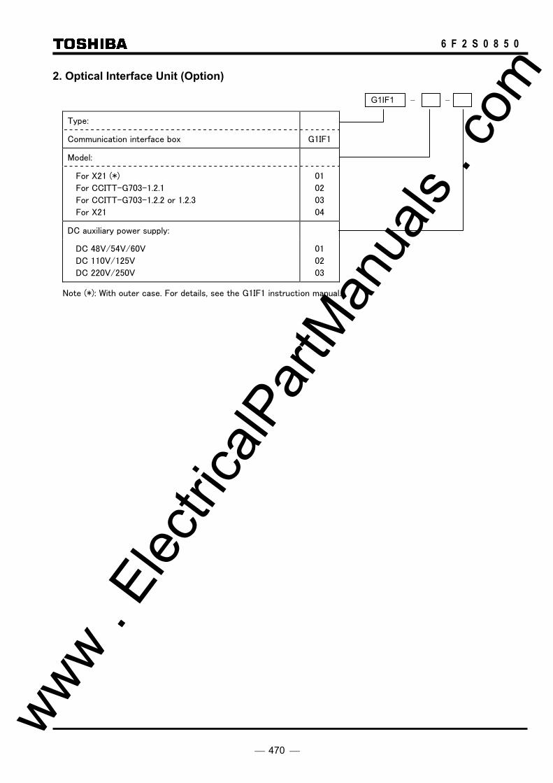
470
6 F 2 S 0 8 5 0
2. Optical Interface Unit (Option)
Type:
Communication interface box G1IF1
Model:
For X21 (*)
For CCITT-G703-1.2.1
For CCITT-G703-1.2.2 or 1.2.3
For X21
01
02
03
04
DC auxiliary power supply:
DC 48V/54V/60V
DC 110V/125V
DC 220V/250V
01
02
03
Note (*): With outer case. For details, see the G1IF1 instruction manual.
G1IF1 − −
www . El
ectric
alPar
tMan
uals
. com

471
6 F 2 S 0 8 5 0
Version-up Records
Version No.
Date Revised Section Contents
0.0 Feb. 16, 2006 First issue. 0.1 Nov. 20, 2006 2.2.8
2.3 to 2.5, 2,9, 2.10, 2.12 to 2.14, 2.16, 2.17 3.1 to 3.5 4.1, 4.2 6.4, 6.5, 6.7 Appendices
Modified the description and added Figure 2.2.8.1. Modified entirely the description related to distance protection, directional earth fault protection and over- and under-voltage protection, etc. Modified the description. Modified the description of LED. Modified the description. Modified Appendix A to E, G to K, O, Q, S and T.
0.2 Jul. 09, 2007 2.2.13.2 2.3.1.3 2.9.1, 2.9.2 2.10 2.15.2.2 2.16.11 4.2.3.1 4.2.4.6, 4.2.4.7 4.4 5.5 6.7.2 6.7.3 Appendices
Modified the description. Modified the description and Figures 2.3.1.11 and 2.3.1.12. Modified the description and the setting range table. Modified the description the setting range table. Modified the description and Figure 2.15.2.8. Added the description of OV∗1 – 4 and UV∗1 – 4. Added recording items to fault record screen. Modified the description. Modified the description. Modified the description. Modified the description and Table 6.7.2.1. Modified the description. Added Appendix R. (Old R→S, S→T, T→U) Modified Appendix E, F, G, K, O, Q, S and U.
0.3 Sep. 13, 2007 2.3.1.3 2.4.1 4.2.7.5 Appendices
Modified the description of ‘Blinder setting’ and Figure 2.3.1.11. Modified the description and Figures 2.4.1.3 and 2.4.1.6. Added the description of ‘Note’. Modified Appendix G, K and U.
www . El
ectric
alPar
tMan
uals
. com

www . El
ectric
alPar
tMan
uals
. com
Related Documents