DW 433-000 ESE01834-EN4 2015-04 Original manual Instruction Manual CPM-I-D60 Constant-Pressure Modulating Inlet Valve

Welcome message from author
This document is posted to help you gain knowledge. Please leave a comment to let me know what you think about it! Share it to your friends and learn new things together.
Transcript

DW 433-000
ESE01834-EN4 2015-04
Original manual
Instruction Manual
CPM-I-D60 Constant-Pressure Modulating Inlet Valve

Table of contents
The information herein is correct at the time of issue but may be subject to change without prior notice
1. EC Declaration of Conformity .. . . . . . . . . . . . . . . . . . . . . . . . . . . . . . . . . . . . . . . . . . . . . . . . . . . . . . . . . . . . . . . . . . . . . . 4
2. Safety ... . . . . . . . . . . . . . . . . . . . . . . . . . . . . . . . . . . . . . . . . . . . . . . . . . . . . . . . . . . . . . . . . . . . . . . . . . . . . . . . . . . . . . . . . . . . . . . . . . 52.1. Important information .. . . . . . . . . . . . . . . . . . . . . . . . . . . . . . . . . . . . . . . . . . . . . . . . . . . . . . . . . . . . . . . . . . . . . . . . . . . . 52.2. Warning signs .. .. . . . . . . . . . . . . . . . . . . . . . . . . . . . . . . . . . . . . . . . . . . . . . . . . . . . . . . . . . . . . . . . . . . . . . . . . . . . . . . . . . 52.3. Safety precautions .. . .. . . . . . . . . . . . . . . . . . . . . . . . . . . . . . . . . . . . . . . . . . . . . . . . . . . . . . . . . . . . . . . . . . . . . . . . . . . . 6
3. Installation .. . . . . . . . . . . . . . . . . . . . . . . . . . . . . . . . . . . . . . . . . . . . . . . . . . . . . . . . . . . . . . . . . . . . . . . . . . . . . . . . . . . . . . . . . . . . . 73.1. Unpacking/delivery . . .. . . . . . . . . . . . . . . . . . . . . . . . . . . . . . . . . . . . . . . . . . . . . . . . . . . . . . . . . . . . . . . . . . . . . . . . . . . . 73.2. General installation .. . .. . . . . . . . . . . . . . . . . . . . . . . . . . . . . . . . . . . . . . . . . . . . . . . . . . . . . . . . . . . . . . . . . . . . . . . . . . . . 83.3. Welding .. . . . . . . . . . . . . . . . . . . . . . . . . . . . . . . . . . . . . . . . . . . . . . . . . . . . . . . . . . . . . . . . . . . . . . . . . . . . . . . . . . . . . . . . . . . 103.4. Fitting of Booster (optional extra) . . . . . . . . . . . . . . . . . . . . . . . . . . . . . . . . . . . . . . . . . . . . . . . . . . . . . . . . . . . . . . . . 113.5. Recycling information .. . . . . . . . . . . . . . . . . . . . . . . . . . . . . . . . . . . . . . . . . . . . . . . . . . . . . . . . . . . . . . . . . . . . . . . . . . . . 13
4. Operation ... . . . . . . . . . . . . . . . . . . . . . . . . . . . . . . . . . . . . . . . . . . . . . . . . . . . . . . . . . . . . . . . . . . . . . . . . . . . . . . . . . . . . . . . . . . . . 144.1. Operation .. .. . . . . . . . . . . . . . . . . . . . . . . . . . . . . . . . . . . . . . . . . . . . . . . . . . . . . . . . . . . . . . . . . . . . . . . . . . . . . . . . . . . . . . . 144.2. Fault finding .. . . . . . . . . . . . . . . . . . . . . . . . . . . . . . . . . . . . . . . . . . . . . . . . . . . . . . . . . . . . . . . . . . . . . . . . . . . . . . . . . . . . . . 164.3. Recommended cleaning ... . . . . . . . . . . . . . . . . . . . . . . . . . . . . . . . . . . . . . . . . . . . . . . . . . . . . . . . . . . . . . . . . . . . . . . 17
5. Maintenance .. . .. . . . . . . . . . . . . . . . . . . . . . . . . . . . . . . . . . . . . . . . . . . . . . . . . . . . . . . . . . . . . . . . . . . . . . . . . . . . . . . . . . . . . . . 195.1. General maintenance .. . . . . . . . . . . . . . . . . . . . . . . . . . . . . . . . . . . . . . . . . . . . . . . . . . . . . . . . . . . . . . . . . . . . . . . . . . . . 195.2. Dismantling .. . . . . . . . . . . . . . . . . . . . . . . . . . . . . . . . . . . . . . . . . . . . . . . . . . . . . . . . . . . . . . . . . . . . . . . . . . . . . . . . . . . . . . . 205.3. Assembly . . .. . . . . . . . . . . . . . . . . . . . . . . . . . . . . . . . . . . . . . . . . . . . . . . . . . . . . . . . . . . . . . . . . . . . . . . . . . . . . . . . . . . . . . . 23
6. Technical data ... . . . . . . . . . . . . . . . . . . . . . . . . . . . . . . . . . . . . . . . . . . . . . . . . . . . . . . . . . . . . . . . . . . . . . . . . . . . . . . . . . . . . . . 276.1. Technical data .. .. . . . . . . . . . . . . . . . . . . . . . . . . . . . . . . . . . . . . . . . . . . . . . . . . . . . . . . . . . . . . . . . . . . . . . . . . . . . . . . . . . 276.2. Selection / Pressure drop - capacity diagram ... . .. . . . . . . . . . . . . . . . . . . . . . . . . . . . . . . . . . . . . . . . . . . . 28
7. Parts lists and service kit . . . . . . . . . . . . . . . . . . . . . . . . . . . . . . . . . . . . . . . . . . . . . . . . . . . . . . . . . . . . . . . . . . . . . . . . . . . . 297.1. CPM-I-D60 .. . . . . . . . . . . . . . . . . . . . . . . . . . . . . . . . . . . . . . . . . . . . . . . . . . . . . . . . . . . . . . . . . . . . . . . . . . . . . . . . . . . . . . . 297.2. Booster . . . . . . . . . . . . . . . . . . . . . . . . . . . . . . . . . . . . . . . . . . . . . . . . . . . . . . . . . . . . . . . . . . . . . . . . . . . . . . . . . . . . . . . . . . . . 33
3
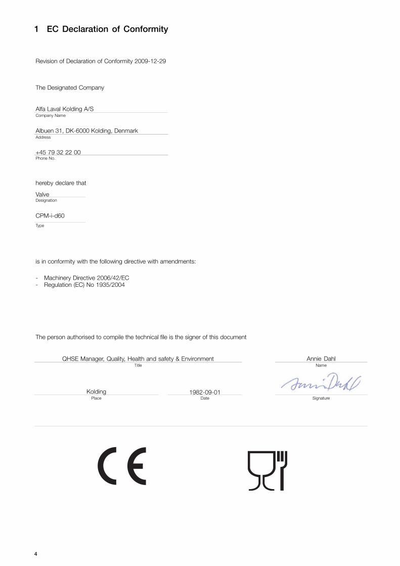
1 EC Declaration of Conformity
Revision of Declaration of Conformity 2009-12-29
The Designated Company
Alfa Laval Kolding A/SCompany Name
Albuen 31, DK-6000 Kolding, DenmarkAddress
+45 79 32 22 00Phone No.
hereby declare that
ValveDesignation
CPM-i-d60
Type
is in conformity with the following directive with amendments:
- Machinery Directive 2006/42/EC- Regulation (EC) No 1935/2004
The person authorised to compile the technical file is the signer of this document
QHSE Manager, Quality, Health and safety & Environment Annie DahlTitle Name
Kolding 1982-09-01Place Date Signature
4
2 Safety
Unsafe practices and other important information are emphasized in this manual.Warnings are emphasized by means of special signs.
2.1 Important information
Always read the manual before using the valve!
WARNINGIndicates that special procedures must be followed to avoid severe personal injury.
CAUTIONIndicates that special procedures must be followed to avoid damage to the valve.
NOTEIndicates important information to simplify or clarify procedures.
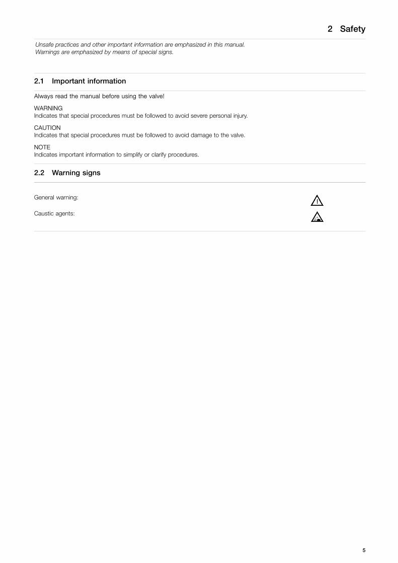
2.2 Warning signs
General warning:
Caustic agents:
5
2 Safety
Unsafe practices and other important information are emphasized in this manual.Warnings are emphasized by means of special signs.
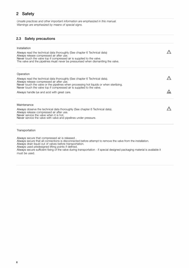
2.3 Safety precautions
Installation
Always read the technical data thoroughly (See chapter 6 Technical data)Always release compressed air after use.Never touch the valve top if compressed air is supplied to the valve.The valve and the pipelines must never be pressurised when dismantling the valve.
Operation
Always read the technical data thoroughly (See chapter 6 Technical data).Always release compressed air after use.Never touch the valve or the pipelines when processing hot liquids or when sterilizing.Never touch the valve top if compressed air is supplied to the valve.
Always handle lye and acid with great care.
Maintenance
Always observe the technical data thoroughly (See chapter 6 Technical data).Always release compressed air after use.Never service the valve when it is hot.Never service the valve with valve and pipelines under pressure.
Transportation
Always secure that compressed air is released .Always secure that all connections is disconnected before attempt to remove the valve from the installation.Always drain liquid out of valves before transportation.Always used predesigned lifting points if defined.Always secure sufficient fixing of the valve during transportation - if special designed packaging material is available itmust be used.
6

3 Installation
The instruction manual is part of the delivery.Study the instructions carefully.
3.1 Unpacking/delivery
Step 1CAUTIONAlfa Laval cannot be held responsible for incorrect unpacking.
Check the delivery:1. Complete valve.2. Delivery note.3. Instruction manual.
Step 2Remove possible packing materials from the valve ports. Remove packing materials!
TD 433-001
Step 31. Inspect the valve for visible transport damage. Inspection!
TD 433-001
Step 4Avoid damaging the air connection and the valve ports. Caution!
TD 433-001
7

3 Installation
Study the instructions carefully and pay special attention to the warnings!The valve has welding ends as standard but can also be supplied with fittings.The required product pressure is preset by means of an air pressure regulating valve (optional extra).
3.2 General installation
Step 1
Always read the technical data thoroughly.
Always release compressed air after use.Never touch the valve top if compressed air is supplied to thevalve.
CAUTIONAlfa Laval cannot be held responsible for incorrectinstallation.
Step 2Ensure that the flow direction is correct.
Correct
Outlet
TD 433-002
Inlet
Step 3Avoid stressing the valve.Pay special attention to:- Vibrations.- Thermal expansion of the tubes.- Excessive welding.- Overloading of the pipelines.
Risk of damage!
TD 433-003_1
8

3 Installation
Study the instructions carefully and pay special attention to the warnings!The valve has welding ends as standard but can also be supplied with fittings.The required product pressure is preset by means of an air pressure regulating valve (optional extra).
Step 4Fittings:Ensure that the connections are tight.
Rememberseal rings!
TD 433-004
Step 5Air connection:
R1/4 " (BSP)
Air
TD 433-005
Step 6Air pressure regulating valve (optional extra):It is recommended to install the air pressure regulating valve asclose as possible to the valve.
Pressure regulating valve
As close as possible!
Air
TD 433-006
9
3 Installation
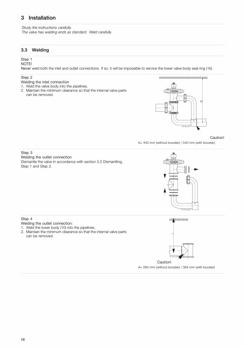
Study the instructions carefully.The valve has welding ends as standard. Weld carefully.
3.3 Welding
Step 1NOTE!Never weld both the inlet and outlet connections. If so, it will be impossible to service the lower valve body seal ring (16)
Step 2Welding the inlet connection1. Weld the valve body into the pipelines.2. Maintain the minimum clearance so that the internal valve parts
can be removed.
TD 433-007
A
Caution!A= 440 mm (without booster) / 540 mm (with booster)
Step 3Welding the outlet connectionDismantle the valve in accordance with section 5.2 Dismantling,Step 1 and Step 2.
TD 433-008_1
Step 4Welding the outlet connection:1. Weld the lower body (10) into the pipelines.2. Maintain the minimum clearance so that the internal valve parts
can be removed.
TD 433-009
A
Caution!A= 284 mm (without booster) / 384 mm (with booster)
10

3 Installation
Study the instructions carefully and pay special attention to the warnings!The items refer to the parts list and service kits section.The valve can be fitted with a Booster to increase the permitted product pressure.
Step 5Welding the outlet connection:Assemble the valve in accordance with section 5.3 Assembly,Step 10 and Step 11.
Step 6Pre-use check:Lift and lower the valve top several times to ensure that the valveoperates smoothly.Pay special attention to the warning!
Lift and lower by hand!
TD 433-011
3.4 Fitting of Booster (optional extra)
Step 1
Never touch the valve or the pipelines when processing hot liquidsor when sterilizing.The valve and the pipelines must never be pressurised whendismantling the valve.
Burningdanger!
Atmospheric pressure required!
TD 433-012
11
3 Installation
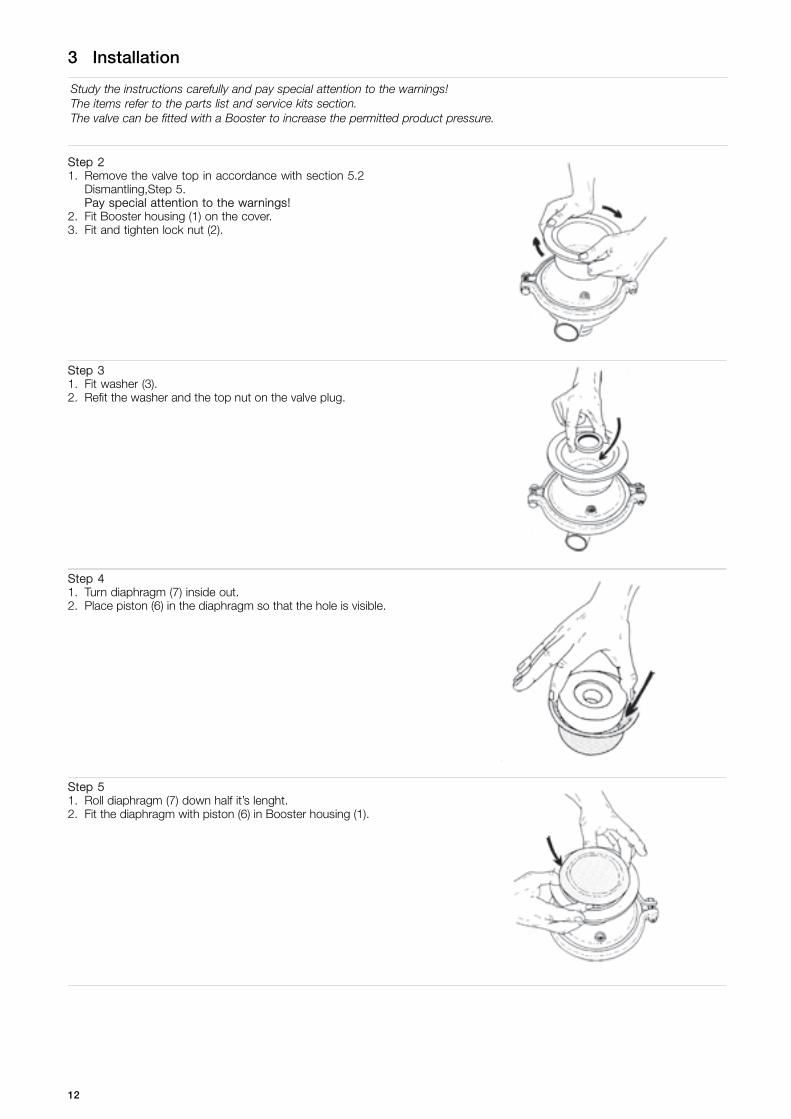
Study the instructions carefully and pay special attention to the warnings!The items refer to the parts list and service kits section.The valve can be fitted with a Booster to increase the permitted product pressure.
Step 21. Remove the valve top in accordance with section 5.2
Dismantling,Step 5.Pay special attention to the warnings!
2. Fit Booster housing (1) on the cover.3. Fit and tighten lock nut (2).
Step 31. Fit washer (3).2. Refit the washer and the top nut on the valve plug.
Step 41. Turn diaphragm (7) inside out.2. Place piston (6) in the diaphragm so that the hole is visible.
Step 51. Roll diaphragm (7) down half it’s lenght.2. Fit the diaphragm with piston (6) in Booster housing (1).
12

3 Installation
Study the instructions carefully and pay special attention to the warnings!The items refer to the parts list and service kits section.The valve can be fitted with a Booster to increase the permitted product pressure.
Step 61. Fit cover (8) on Booster housing (1).2. Fit and tighten clamp (9).3. The valve and the Booster are now ready for operation.
3.5 Recycling information
• Unpacking
- Packing material consists of wood, plastics, cardboard boxes and in some cases metal straps- Wood and cardboard boxes can be reused, recycled or used for energy recovery- Plastics should be recycled or burnt at a licensed waste incineration plant- Metal straps should be sent for material recycling
• Maintenance
- During maintenance oil and wear parts in the machine are replaced- All metal parts should be sent for material recycling- Worn out or defective electronic parts should be sent to a licensed handler for material recycling- Oil and all non metal wear parts must be taken care of in agreement with local regulations
• Scrapping
- At end of use, the equipment shall be recycled according to relevant, local regulations. Beside the equipment itself, anyhazardous residues from the process liquid must be considered and dealt with in a proper manner. When in doubt, or in theabsence of local regulations, please contact the local Alfa Laval sales company
13

4 Operation
The valve is lubricated, adjusted and tested before delivery.Study the instructions carefully and pay special attention to the warnings!
4.1 Operation
Step 1
Always read the technical data thoroughly.
Always release compressed air after use.
CAUTIONAlfa Laval cannot be held responsible for incorrectoperation.
Step 2
Never touch the valve or the pipelines when processing hot liquidsor when sterilizing.
Burning danger!
TD 433-021
Step 3
Never touch the valve top if compressed air is supplied to thevalve.
Air Cutting danger!
TD 433-013
Step 4CAUTION!There must not be vacuum in the valve as air can be drawn intothe product and diaphragms (17) can then be pulled out fromsupport sectors (20).
18
17
20
TD 433-014
No vacuum!
14
4 Operation
The valve is lubricated, adjusted and tested before delivery.Study the instructions carefully and pay special attention to the warnings!
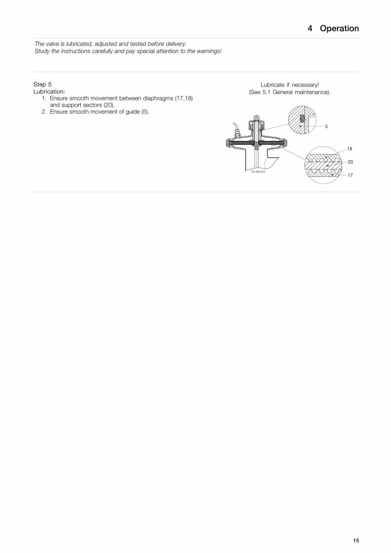
Step 5Lubrication:
1. Ensure smooth movement between diaphragms (17,18)and support sectors (20).
2. Ensure smooth movement of guide (5).
Lubricate if necessary!(See 5.1 General maintenance).
5
18
17
20
TD 433-015
15
4 Operation
Pay attention to possible break-down.Study the instructions carefully.The items refer to the parts list and service kits section.
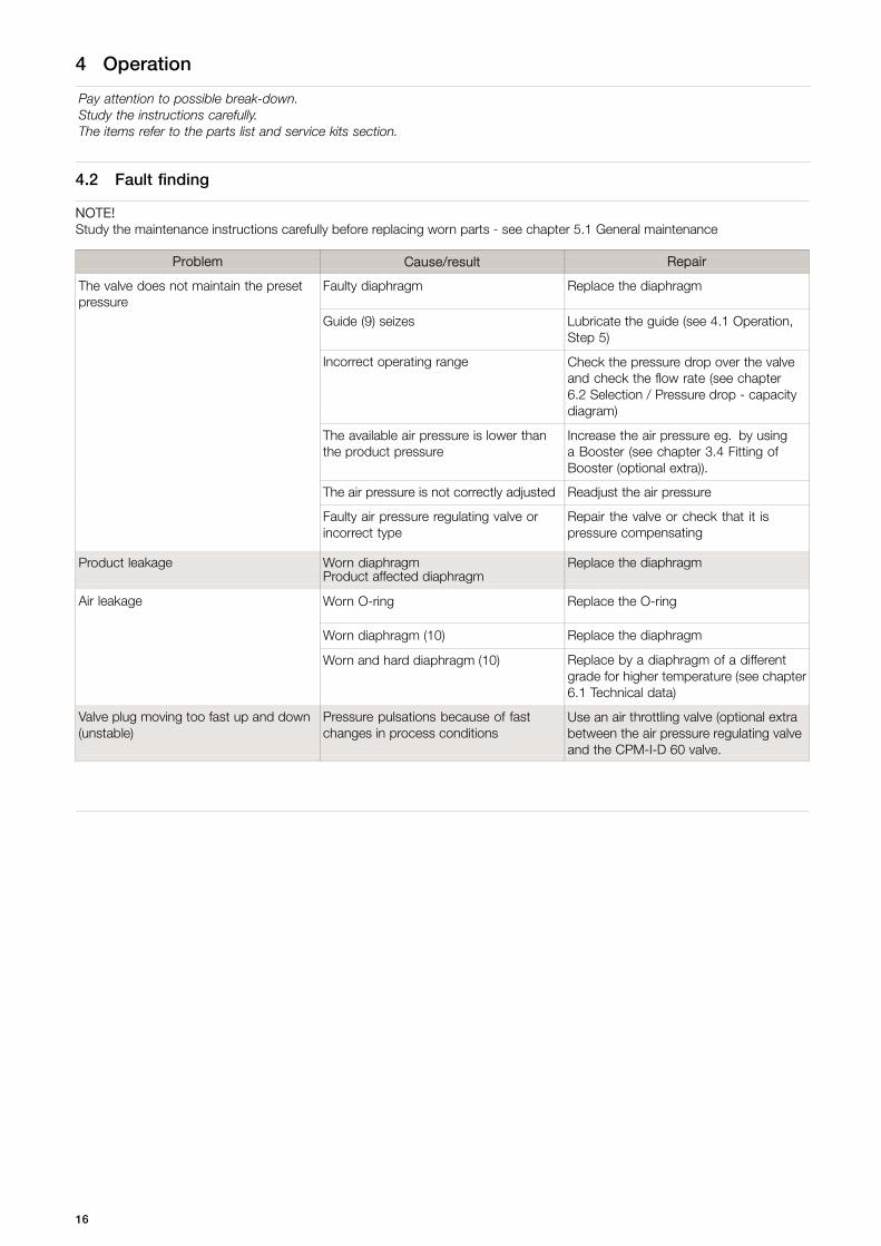
4.2 Fault finding
NOTE!Study the maintenance instructions carefully before replacing worn parts - see chapter 5.1 General maintenance
Problem Cause/result Repair
The valve does not maintain the presetpressure
Faulty diaphragm Replace the diaphragm
Guide (9) seizes Lubricate the guide (see 4.1 Operation,Step 5)
Incorrect operating range Check the pressure drop over the valveand check the flow rate (see chapter6.2 Selection / Pressure drop - capacitydiagram)
The available air pressure is lower thanthe product pressure
Increase the air pressure eg. by usinga Booster (see chapter 3.4 Fitting ofBooster (optional extra)).
The air pressure is not correctly adjusted Readjust the air pressure
Faulty air pressure regulating valve orincorrect type
Repair the valve or check that it ispressure compensating
Product leakage Worn diaphragm Replace the diaphragmProduct affected diaphragm
Air leakage Worn O-ring Replace the O-ring
Worn diaphragm (10) Replace the diaphragm
Worn and hard diaphragm (10) Replace by a diaphragm of a differentgrade for higher temperature (see chapter6.1 Technical data)
Valve plug moving too fast up and down(unstable)
Pressure pulsations because of fastchanges in process conditions
Use an air throttling valve (optional extrabetween the air pressure regulating valveand the CPM-I-D 60 valve.
16
4 Operation
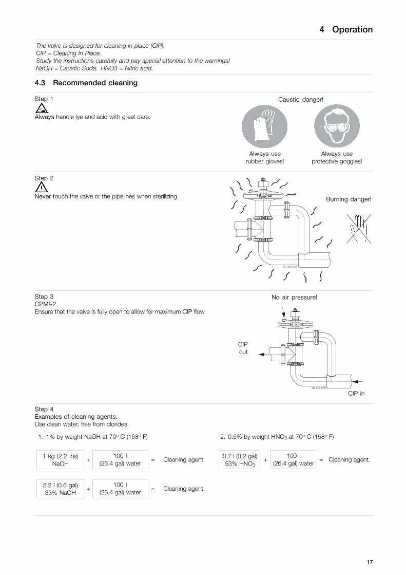
The valve is designed for cleaning in place (CIP).CIP = Cleaning In Place.Study the instructions carefully and pay special attention to the warnings!NaOH = Caustic Soda. HNO3 = Nitric acid.
4.3 Recommended cleaning
Step 1
Always handle lye and acid with great care.
Caustic danger!
Always userubber gloves!
Always useprotective goggles!
Step 2
Never touch the valve or the pipelines when sterilizing. Burning danger!
TD 433-021
Step 3CPMI-2Ensure that the valve is fully open to allow for maximum CIP flow.
No air pressure!
CIPout
TD 433-016
CIP in
Step 4Examples of cleaning agents:Use clean water, free from clorides.
1. 1% by weight NaOH at 70o C (158o F) 2. 0.5% by weight HNO3 at 70o C (158o F)
1 kg (2.2 lbs)NaOH
+100 l
(26.4 gal) water = Cleaning agent. 0.7 l (0.2 gal)53% HNO3
+100 l
(26.4 gal) water = Cleaning agent.
2.2 l (0.6 gal)33% NaOH
+100 l
(26.4 gal) water = Cleaning agent.
17

4 Operation
The valve is designed for cleaning in place (CIP).CIP = Cleaning In Place.Study the instructions carefully and pay special attention to the warnings!NaOH = Caustic Soda. HNO3 = Nitric acid.
Step 51. Avoid excessive concentration of the cleaning agent.
- Dose gradually.2. Adjust the cleaning flow to the process.
- Sterilization of milk/viscous liquids.- Increase the cleaning flow.
3. Always rinse well with clean water after the cleaning.
Step 6NOTEThe cleaning agents must be stored/disposed of in accordance with current rules/directives.
18

5 Maintenance
Maintain the valve carefully.Study the instructions carefully and pay special attention to the warnings!Always keep spare diaphrams and o-rings in stock.
5.1 General maintenance
Step 1
Always read the technical data thoroughly.See chapter 6.1 Technical data
Always disconnect the compressed air before service.
NOTEAll scrap must be stored/discharged in accordancewith current rules/directives.
Step 2
Never service the valve when it is hot.
Never service the valve with valve and pipelines under pressure.
Atmosphericpressurerequired!
Burningdanger!
TD 433-012
Recommended spare parts: Service kitsOrder service kits from the service kits list.
Ordering spare partsContact the Sales Department.
Diaphragms O-ring
Preventive maintenance Replace after 12 months Replace when replacing the diaphragms
Maintenance after leakage (leakagenormally starts slowly)
Replace by the end of the day Replace when replacing the diaphragms
Planned maintenance - Regular inspection for leakage andsmooth operation
- Keep a record of the valve- Use the statistics for planning of
inspections
Replace when replacing diaphragms
Replace after leakage
Lubrication (before assembly)Guide: Molycote longtherm 2 PlusSectors: Molycote 111.Threads: Molycote TP42.
19

5 Maintenance
Study the instructions carefully.The items refer to the parts list and service kits section.Handle scrap correctly.
5.2 Dismantling
Step 11. Remove clamps (14,15).2. Loosen the connection between valve body (12) and inlet tube
(9).
TD 433-017_1
Step 21. Remove inlet tube (9) and lower valve body (10).2. Remove seal rings (8, 16).
TD 433-008_2
Step 3Remove clamp (22, 23)
Step 4Remove cover (19) together with the internal parts of the valve.
20

5 Maintenance
Study the instructions carefully.The items refer to the parts list and service kits section.Handle scrap correctly.
Step 5Remove top nut (1), washer (2) and top (3).
Counterhold!
Step 6Remove plug (7) from the diaphragm unit and guide (5).
CAUTION!Ensure that cover (19) is turned downwards and plug (7) is pulledupwards so that sectors (20) are not separated from diaphragms(17, 18).
Step 7Remove lower inner ring (13) and lower diaphragm (17).
Step 8Remove sectors (20).
21
5 Maintenance
Study the instructions carefully.The items refer to the parts list and service kits section.Handle scrap correctly.
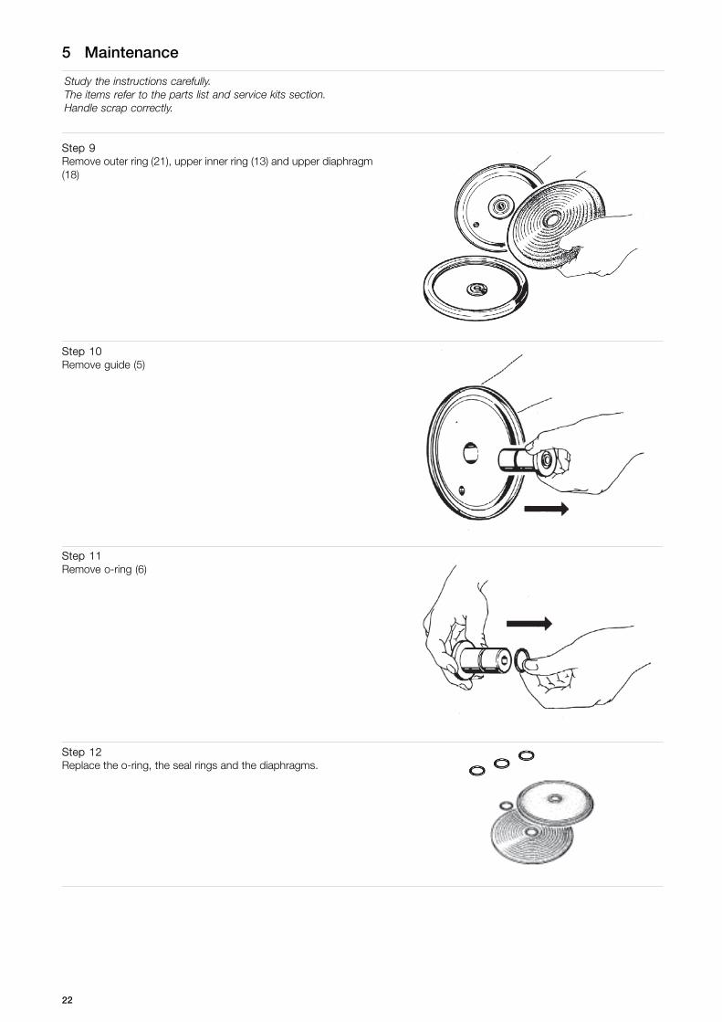
Step 9Remove outer ring (21), upper inner ring (13) and upper diaphragm(18)
Step 10Remove guide (5)
Step 11Remove o-ring (6)
Step 12Replace the o-ring, the seal rings and the diaphragms.
22
5 Maintenance
Study the instructions carefully.Lubricate the guide, the sectors and the threads before assembly.The items refer to the parts list and service kits section.
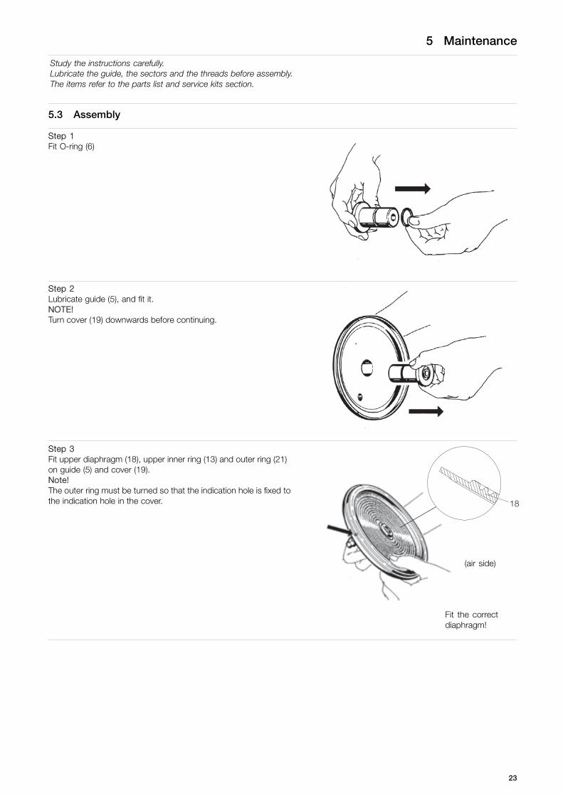
5.3 Assembly
Step 1Fit O-ring (6)
Step 2Lubricate guide (5), and fit it.NOTE!Turn cover (19) downwards before continuing.
Step 3Fit upper diaphragm (18), upper inner ring (13) and outer ring (21)on guide (5) and cover (19).Note!The outer ring must be turned so that the indication hole is fixed tothe indication hole in the cover.
(air side)
Fit the correctdiaphragm!
23
5 Maintenance
Study the instructions carefully.Lubricate the guide, the sectors and the threads before assembly.The items refer to the parts list and service kits section.
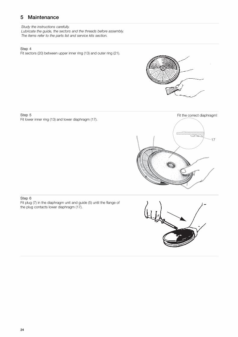
Step 4Fit sectors (20) between upper inner ring (13) and outer ring (21).
Step 5Fit lower inner ring (13) and lower diaphragm (17).
Fit the correct diaphragm!
Step 6Fit plug (7) in the diaphragm unit and guide (5) until the flange ofthe plug contacts lower diaphragm (17).
24

5 Maintenance
Study the instructions carefully.Lubricate the guide, the sectors and the threads before assembly.The items refer to the parts list and service kits section.
Step 7Fit top (3), washer (2) and top nut (1).
Counterhold!
Step 8Fit cover (19) together with the internal parts of the valve.
Step 9Fit and tighten clamp (22, 23).
Step 101. Fit seal rings (8, 16).2. Fit lower valve body (10) and inlet tube (9)
TD 433-008_1
25
5 Maintenance
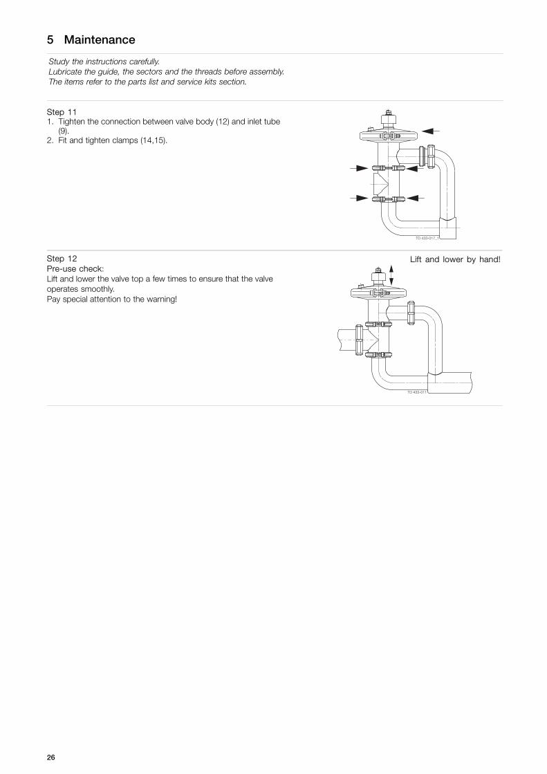
Study the instructions carefully.Lubricate the guide, the sectors and the threads before assembly.The items refer to the parts list and service kits section.
Step 111. Tighten the connection between valve body (12) and inlet tube
(9).2. Fit and tighten clamps (14,15).
TD 433-017_1
Step 12Pre-use check:Lift and lower the valve top a few times to ensure that the valveoperates smoothly.Pay special attention to the warning!
Lift and lower by hand!
TD 433-011
26
6 Technical data
It is important to observe the technical data during installation, operation and maintenance.Inform the personnel about the technical data.
6.1 Technical data
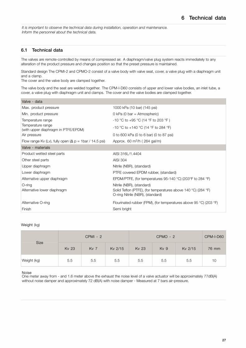
The valves are remote-controlled by means of compressed air. A diaphragm/valve plug system reacts immediately to anyalteration of the product pressure and changes position so that the preset pressure is maintained.
Standard design The CPMI-2 and CPMO-2 consist of a valve body with valve seat, cover, a valve plug with a diaphragm unitand a clamp.The cover and the valve body are clamped together.
The valve body and the seat are welded together. The CPM-I-D60 consists of upper and lower valve bodies, an inlet tube, acover, a valve plug with diaphragm unit and clamps. The cover and the valve bodies are clamped together.
Valve - data
Max. product pressure 1000 kPa (10 bar) (145 psi)
Min. product pressure 0 kPa (0 bar = Atmospheric)
Temperature range -10 °C to +95 °C (14 °F to 203 °F )Temperature range(with upper diaphragm in PTFE/EPDM) -10 °C to +140 °C (14 °F to 284 °F)
Air pressure 0 to 600 kPa (0 to 6 bar) (0 to 87 psi)
Flow range Kv (Lv), fully open (Δ p = 1bar / 14.5 psi) Approx. 60 m3/h ( 264 gal/m)
Valve - materials
Product wetted steel parts AISI 316L/1.4404
Other steel parts AISI 304
Upper diaphragm Nitrile (NBR), (standard)
Lower diaphragm PTFE covered EPDM rubber, (standard)
Alternative upper diaphragm EPDM/PTFE, (for temperatures 95-140 °C) (203°F to 284 °F)
O-ring Nitrile (NBR), (standard)Alternative lower diaphragm Solid Teflon (PTFE), (for temperatures above 140 °C) (284 °F)
O-ring Nitrile (NBR), (standard)
Alternative O-ring Flourinated rubber (FPM), (for temperatures above 95 °C) (203 °F)
Finish Semi bright
Weight (kg)
CPMI - 2 CPMO - 2 CPM-I-D60
Size
Kv 23 Kv 7 Kv 2/15 Kv 23 Kv 9 Kv 2/15 76 mm
Weight (kg) 5.5 5.5 5.5 5.5 5.5 5.5 10
NoiseOne meter away from - and 1.6 meter above the exhaust the noise level of a valve actuator will be approximately 77dB(A)without noise damper and approximately 72 dB(A) with noise damper - Measured at 7 bars air-pressure.
27
6 Technical data
It is important to observe the technical data during installation, operation and maintenance.Inform the personnel about the technical data.
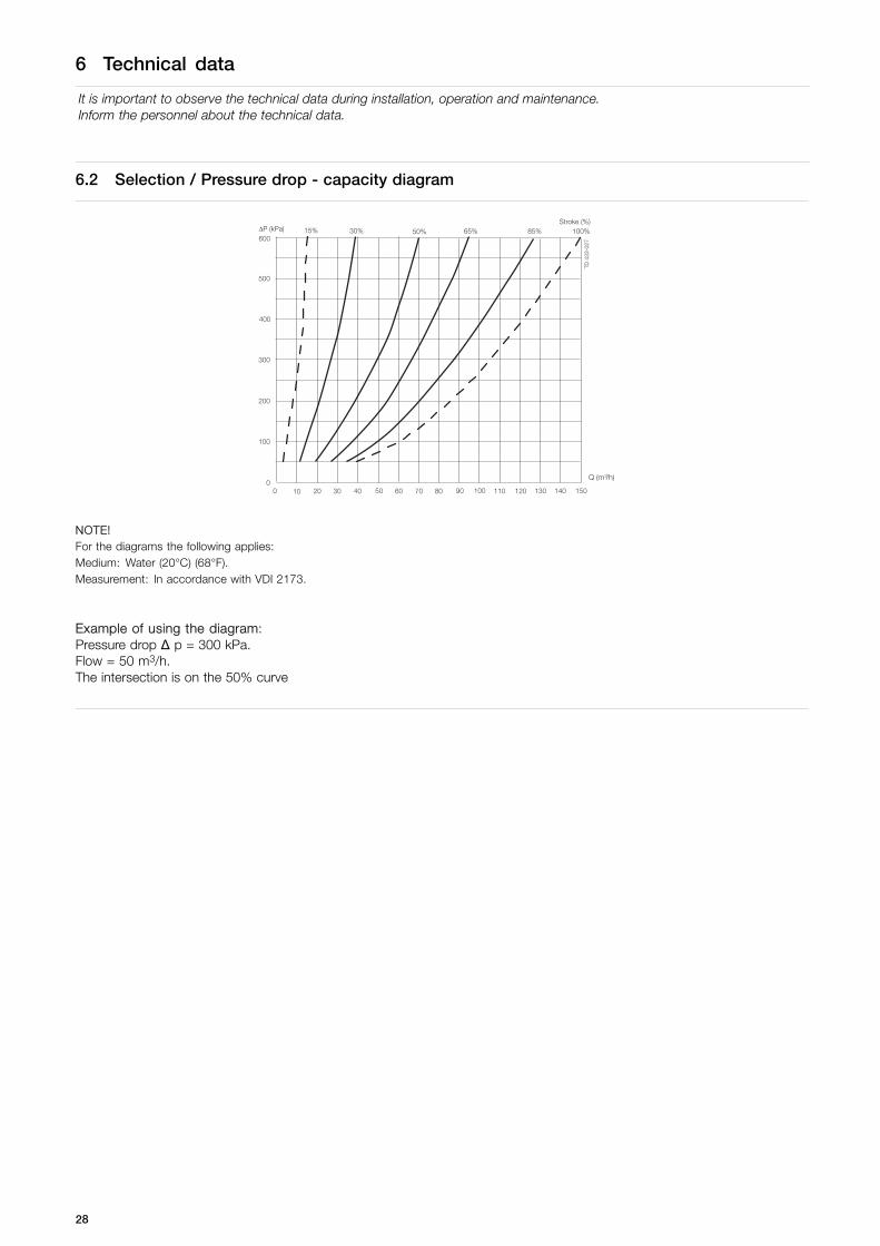
6.2 Selection / Pressure drop - capacity diagram
Q (m /h) 3
NOTE!For the diagrams the following applies:Medium: Water (20°C) (68°F).Measurement: In accordance with VDI 2173.
Example of using the diagram:Pressure drop Δ p = 300 kPa.Flow = 50 m3/h.The intersection is on the 50% curve
28
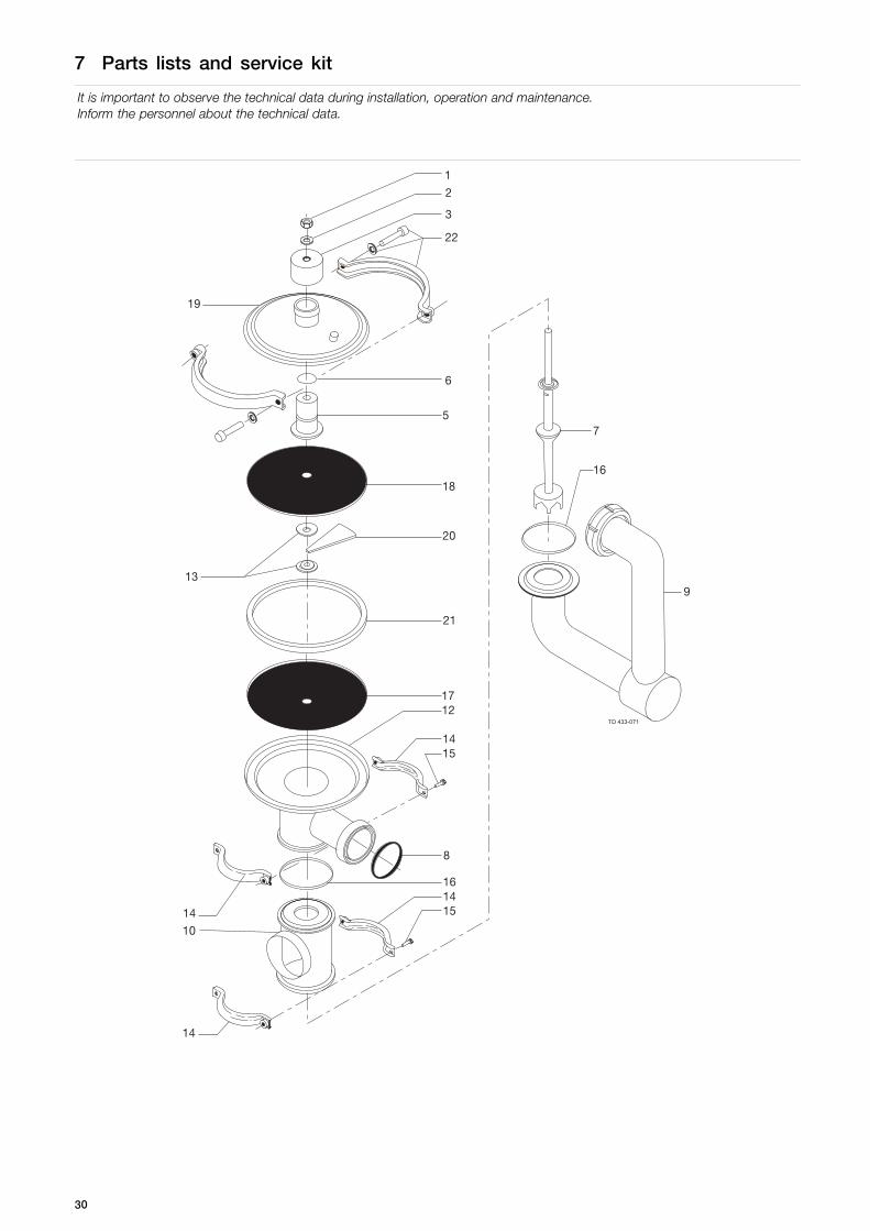
7 Parts lists and service kit
It is important to observe the technical data during installation, operation and maintenance.Inform the personnel about the technical data.
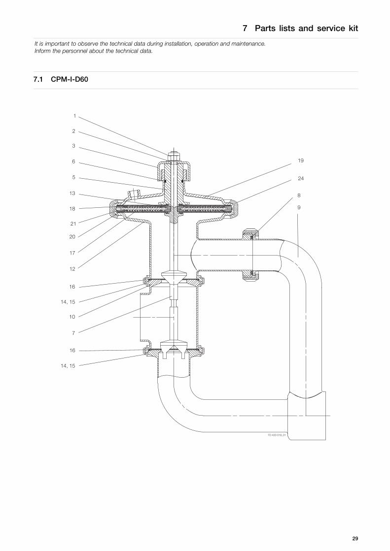
7.1 CPM-I-D60
TD 433-018_01
1
2
3
6
5
13
18
21
20
17
12
16
14, 15
10
7
16
14, 15
19
24
8
9
29
7 Parts lists and service kit
It is important to observe the technical data during installation, operation and maintenance.Inform the personnel about the technical data.
TD 433-071
30

7 Parts lists and service kit
It is important to observe the technical data during installation, operation and maintenance.Inform the personnel about the technical data.
Parts list
Pos. Qty Denomination
2 Screw (Period 8209-9310)1 1 Nut2 1 Washer3 1 Top5 1 Guide6 1 O-ring7 1 Plug8 1 Seal ring9 1 Inlet tube10 1 Valve body, lower12 1 Valve body13 2 Inner ring14+15 2 Clamps and screws (Period
9209-)14 4 Clamp half (Period -9209)15 4 Screw (Period -9209)16 2 Valve body seal ring17 1 Diaphragm, PTFE covered EPDM
(std.) (product side)18 1 Diaphragm19 1 Cover20 12 Support sector21 1 Outer ring22 1 Clamp
Service kits
Denomination
Product wetted parts Service kit . . . . . . . . . . . . . . . . . . . . . . . . . . . . . . . . . . . . . . . . . . . . . . . . . . . . . . 9611920119
Parts marked with are included in Service kit.
Recommended spare parts: Service kit.
900-126/0
31

.
32

7 Parts lists and service kit
It is important to observe the technical data during installation, operation and maintenance.Inform the personnel about the technical data.
7.2 Booster
33

7 Parts lists and service kit
It is important to observe the technical data during installation, operation and maintenance.Inform the personnel about the technical data.
34

7 Parts lists and service kit
It is important to observe the technical data during installation, operation and maintenance.Inform the personnel about the technical data.
Parts list
Pos. Qty Denomination
1 1 Booster housing2 1 Lock nut3 1 Washer4 1 Spring washer5 1 Nut6 1 Booster piston7 1 Diaphragm8 1 Booster cover9 1 Clamps and screws
35

How to contact Alfa LavalContact details for all countries arecontinually updated on our website.Please visit www.alfalaval.com to access the information directly.
© Alfa Laval Corporate ABThis document and its contents is owned by Alfa Laval Corporate AB and protected by laws governing intellectual property and thereto related rights. It is the responsibility of the user of thisdocument to comply with all applicable intellectual property laws. Without limiting any rights related to this document, no part of this document may be copied, reproduced or transmitted in anyform or by any means (electronic, mechanical, photocopying, recording, or otherwise), or for any purpose, without the expressed permission of Alfa Laval Corporate AB. Alfa Laval Corporate ABwill enforce its rights related to this document to the fullest extent of the law, including the seeking of criminal prosecution.
Related Documents