. ky Alfa Laval CPM Constant-Pressure Modulating Valve Control the Pressure of your System . Concept CPMI-2, CPMI-D60 and CPMO-2 are hygienic constant-pressure valves. CPMI-2 and CPMI-D60 (Constant-Pressure Modulating Inlet) maintain a constant pressure in the process line at the inlet side of the valve. Typical applications are after separators, heat exchangers or overflow valves. CPMO-2 (Constant-Pressure Modulating Outlet) maintains a constant pressure in the process line at the outlet side of the valve. Typical applications are before filling/bottling machines etc. Working principle The valves are remote-controlled by means of compressed air. A diaphragm/valve plug system reacts immediately to any alteration of the product pressure and changes position so that the preset pressure is maintained. Standard design The CPMI-2 and CPMO-2 consist of a valve body with valve seat, cover, a valve plug with a diaphragm unit and a clamp. The cover and the valve body are clamped together. The valve body and the seat are welded together. The CPM-I-D60 consists of upper and lower valve bodies, an inlet tube, a cover, a valve plug with diaphragm unit and clamps. The cover and the valve bodies are clamped together. TECHNICAL DATA Max. product pressure: .......... 1000 kPa (10 bar). Min. product pressure: .......... 0 kPa (0 bar). Temperature range: ............. -10°C to 95°C (EPDM). Temperature range with upper diaphragm in PTFE/EPDM: ............... -10° C to +140° C. (Higher on request). Air pressure (CPMI-2/CPMO-2): ..... 0 to 800 kPa (0 to 8 bar). Air pressure (CPM-I-D60): ........ 0 to 600 kPa (0 to 6 bar). Flow Kv 23, fully open (Dp = 1 bar): . . Approx 23 m 3 /h. Flow Kv 7 (∆p = 1 bar): .......... Approx 7 m 3 /h. Flow Kv 9 (∆p = 1 bar): .......... Approx 9 m 3 /h. Flow Kv2/15, low capacity (∆p = 1 bar): Approx 2 m 3 /h. (Alternative size) ............... (regulating area). Approx. 15 m 3 /h. (CIP area). Flow range Kv60, fully open (∆p = 1 bar) (CPM-I-D60) ................. Approx 60 m 3 /h. PHYSICAL DATA Materials Product wetted steel parts: ........ 1.4404 (316L). Other steel parts: .............. 1.4301(304). Lower diaphragm: .............. PTFE covered EPDM rubber Upper diaphragm .............. NBR Air Connections R 1/4" (BSP), internal thread. .

Welcome message from author
This document is posted to help you gain knowledge. Please leave a comment to let me know what you think about it! Share it to your friends and learn new things together.
Transcript
.
kyAlfa Laval CPM Constant-Pressure Modulating ValveControl the Pressure of your System
.
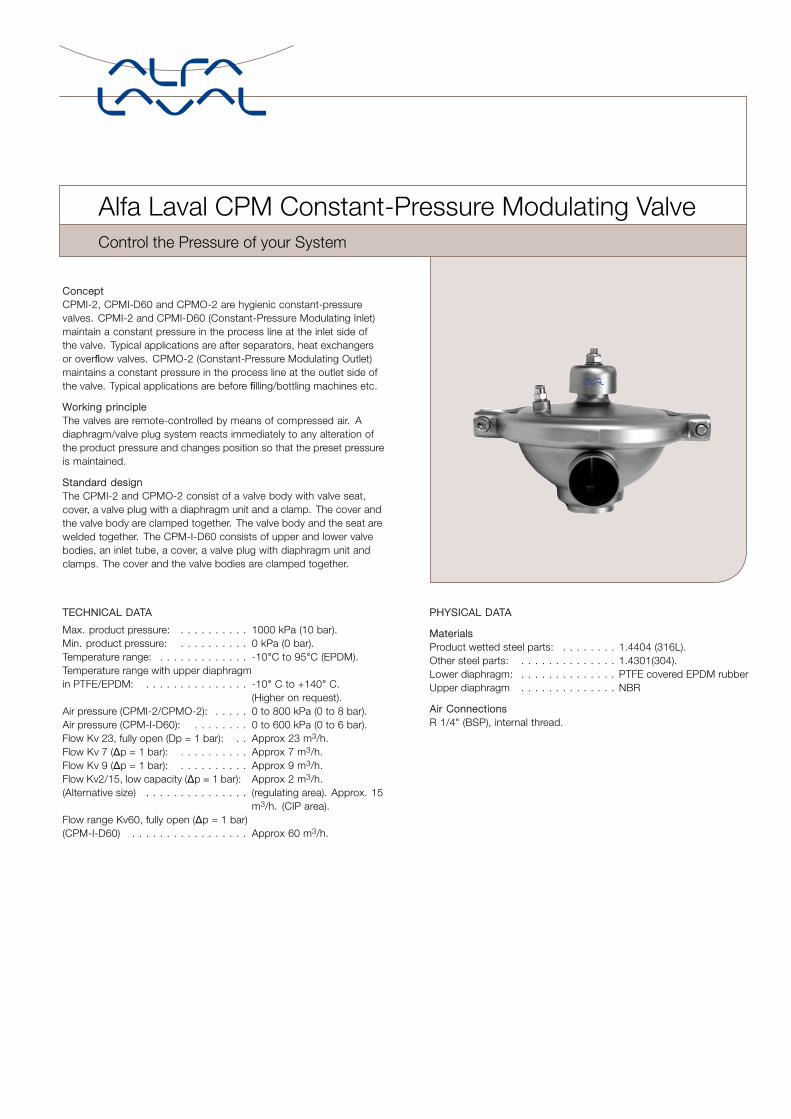
ConceptCPMI-2, CPMI-D60 and CPMO-2 are hygienic constant-pressurevalves. CPMI-2 and CPMI-D60 (Constant-Pressure Modulating Inlet)maintain a constant pressure in the process line at the inlet side ofthe valve. Typical applications are after separators, heat exchangersor overflow valves. CPMO-2 (Constant-Pressure Modulating Outlet)maintains a constant pressure in the process line at the outlet side ofthe valve. Typical applications are before filling/bottling machines etc.
Working principleThe valves are remote-controlled by means of compressed air. Adiaphragm/valve plug system reacts immediately to any alteration ofthe product pressure and changes position so that the preset pressureis maintained.
Standard designThe CPMI-2 and CPMO-2 consist of a valve body with valve seat,cover, a valve plug with a diaphragm unit and a clamp. The cover andthe valve body are clamped together. The valve body and the seat arewelded together. The CPM-I-D60 consists of upper and lower valvebodies, an inlet tube, a cover, a valve plug with diaphragm unit andclamps. The cover and the valve bodies are clamped together.
TECHNICAL DATA
Max. product pressure: . . . . . . . . . . 1000 kPa (10 bar).Min. product pressure: . . . . . . . . . . 0 kPa (0 bar).Temperature range: . . . . . . . . . . . . . -10°C to 95°C (EPDM).Temperature range with upper diaphragmin PTFE/EPDM: . . . . . . . . . . . . . . . -10° C to +140° C.
(Higher on request).Air pressure (CPMI-2/CPMO-2): . . . . . 0 to 800 kPa (0 to 8 bar).Air pressure (CPM-I-D60): . . . . . . . . 0 to 600 kPa (0 to 6 bar).Flow Kv 23, fully open (Dp = 1 bar): . . Approx 23 m3/h.Flow Kv 7 (∆p = 1 bar): . . . . . . . . . . Approx 7 m3/h.Flow Kv 9 (∆p = 1 bar): . . . . . . . . . . Approx 9 m3/h.Flow Kv2/15, low capacity (∆p = 1 bar): Approx 2 m3/h.(Alternative size) . . . . . . . . . . . . . . . (regulating area). Approx. 15
m3/h. (CIP area).Flow range Kv60, fully open (∆p = 1 bar)(CPM-I-D60) . . . . . . . . . . . . . . . . . Approx 60 m3/h.
PHYSICAL DATA
MaterialsProduct wetted steel parts: . . . . . . . . 1.4404 (316L).Other steel parts: . . . . . . . . . . . . . . 1.4301(304).Lower diaphragm: . . . . . . . . . . . . . . PTFE covered EPDM rubberUpper diaphragm . . . . . . . . . . . . . . NBR
Air ConnectionsR 1/4" (BSP), internal thread.
.
OptionsA. Male parts or clamp liners in accordance with required standard.B. Air pressure regulating valve kit, 0-8 bar.C. Air throttling valve for adjustment of regulating speed for the CPM-2
valve.D. Booster for product pressure exceeding the available air pressure.
(Product pressure = 1.8 x air pressure).E. US 3A version available on request for CPM-2 valves only
Material grades CPM-2
F. Upper diaphragm of PTFE covered EPDM and O-ring of FPMcovered EPDM, (for temperature 95-140°C).
G. Both diaphragms of solid PTFE and O-ring of FPM (for temperaturesabove 140°C).
Material grades CPM-I-D60
H. Upper diaphragm of PTFE covered EPDM.I. Valve body seal rings of NBR or FPM.J. Guide O-ring of FPM (for temperatures above 95°C).
.
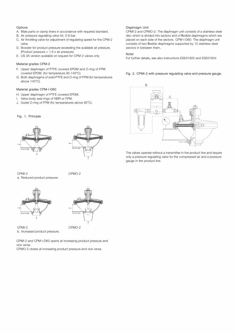
Fig. 1. Principle
TD 417-039 TD 417-040
CPMI-2 CPMO-2a. Reduced product pressure.
TD 417-038 TD 417-041
CPMI-2 CPMO-2b. Increased product pressure.
CPMI-2 and CPM-I-D60 opens at increasing product pressure andvice versa.CPMO-2 closes at increasing product pressure and vice versa.
Diaphragm UnitCPMI-2 and CPMO-2: The diaphragm unit consists of a stainless steeldisc which is divided into sectors and of flexible diaphragms which areplaced on each side of the sectors. CPM-I-D60: The diaphragm unitconsists of two flexible diaphragms supported by 12 stainless steelsectors in between them.
Note!For further details, see also instructions ESE01825 and ESE01834
.
...Fig. 2. CPMI-2 with pressure regulating valve and pressure gauge.
.
B
C
The valves operate without a transmitter in the product line and requireonly a pressure regulating valve for the compressed air and a pressuregauge in the product line.
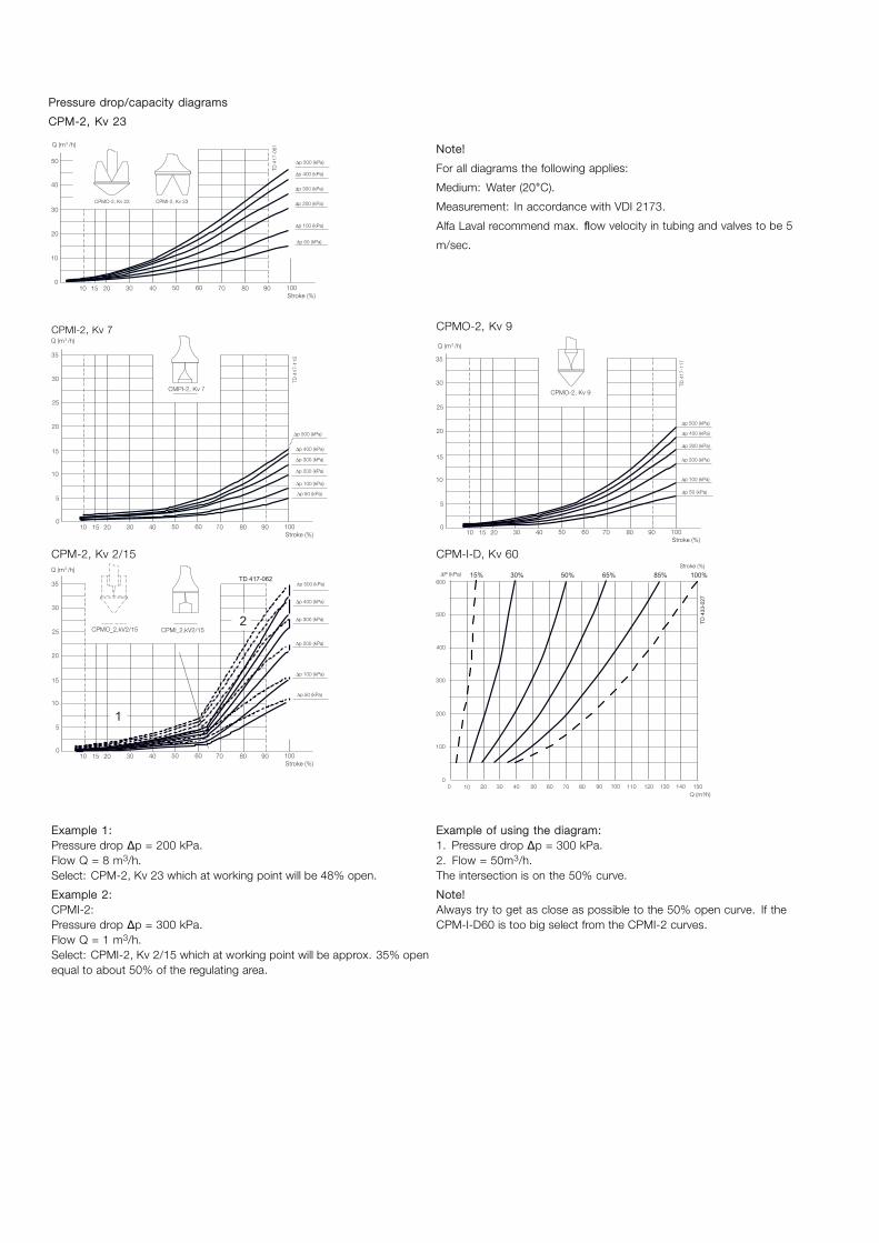
Pressure drop/capacity diagrams
CPM-2, Kv 23
Note!
For all diagrams the following applies:
Medium: Water (20°C).
Measurement: In accordance with VDI 2173.
Alfa Laval recommend max. flow velocity in tubing and valves to be 5
m/sec.
CPMI-2, Kv 7 CPMO-2, Kv 9
CPM-2, Kv 2/15
1
2
TD 417-062
CPM-I-D, Kv 60
Q (m /h) 3
TD 4
33-0
27
15% 30% 50% 65% 85% 100%
Example 1:Pressure drop ∆p = 200 kPa.Flow Q = 8 m3/h.Select: CPM-2, Kv 23 which at working point will be 48% open.
Example 2:CPMI-2:Pressure drop ∆p = 300 kPa.Flow Q = 1 m3/h.Select: CPMI-2, Kv 2/15 which at working point will be approx. 35% openequal to about 50% of the regulating area.
Example of using the diagram:1. Pressure drop ∆p = 300 kPa.2. Flow = 50m3/h.The intersection is on the 50% curve.
Note!Always try to get as close as possible to the 50% open curve. If theCPM-I-D60 is too big select from the CPMI-2 curves.
.
TD 417-069
TD 417-043
TD 433-026
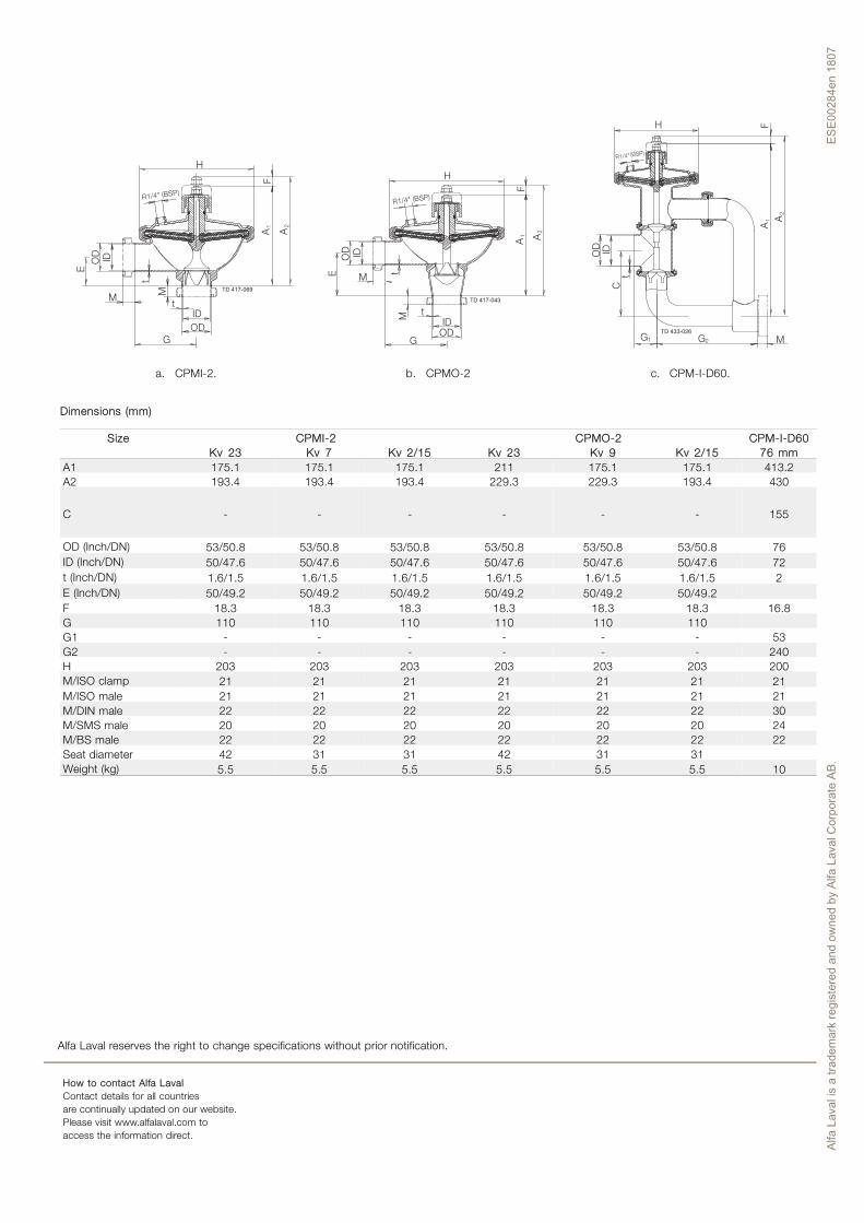
a. CPMI-2. b. CPMO-2 c. CPM-I-D60.
Dimensions (mm)
Size CPMI-2 CPMO-2 CPM-I-D60Kv 23 Kv 7 Kv 2/15 Kv 23 Kv 9 Kv 2/15 76 mm
A1 175.1 175.1 175.1 211 175.1 175.1 413.2A2 193.4 193.4 193.4 229.3 229.3 193.4 430
C - - - - - - 155
OD (Inch/DN) 53/50.8 53/50.8 53/50.8 53/50.8 53/50.8 53/50.8 76ID (Inch/DN) 50/47.6 50/47.6 50/47.6 50/47.6 50/47.6 50/47.6 72t (Inch/DN) 1.6/1.5 1.6/1.5 1.6/1.5 1.6/1.5 1.6/1.5 1.6/1.5 2E (Inch/DN) 50/49.2 50/49.2 50/49.2 50/49.2 50/49.2 50/49.2F 18.3 18.3 18.3 18.3 18.3 18.3 16.8G 110 110 110 110 110 110G1 - - - - - - 53G2 - - - - - - 240H 203 203 203 203 203 203 200M/ISO clamp 21 21 21 21 21 21 21M/ISO male 21 21 21 21 21 21 21M/DIN male 22 22 22 22 22 22 30M/SMS male 20 20 20 20 20 20 24M/BS male 22 22 22 22 22 22 22Seat diameter 42 31 31 42 31 31Weight (kg) 5.5 5.5 5.5 5.5 5.5 5.5 10
.
Alfa Laval reserves the right to change specifications without prior notification.
How to contact Alfa LavalContact details for all countriesare continually updated on our website.Please visit www.alfalaval.com toaccess the information direct.
Alfa
Lav
al is
a tr
adem
ark
regi
ster
ed a
nd o
wne
d by
Alfa
Lav
al C
orpo
rate
AB.
ES
E002
84en
180
7
Related Documents