Installation, Operation, and Maintenance Manual Model 3410

Welcome message from author
This document is posted to help you gain knowledge. Please leave a comment to let me know what you think about it! Share it to your friends and learn new things together.
Transcript
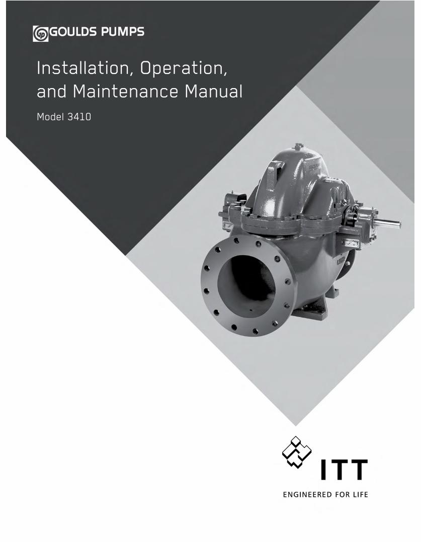
Installation, Operation,and Maintenance ManualModel 3410

Table of Contents
Model 3410 Installation, Operation, and Maintenance Manual 1
Table of Contents
Introduction and Safety .......................................................................................................... 4Introduction ............................................................................................................................. 4Safety ...................................................................................................................................... 5Safety terminology and symbols ............................................................................................. 5Environmental safety .............................................................................................................. 6User safety .............................................................................................................................. 6
Precautions before work ....................................................................................................... 7Precautions during work ....................................................................................................... 7
Safety regulations for Ex-approved products in potentially explosive atmospheres ................ 8Product approval standards .................................................................................................. 10Product warranty ................................................................................................................... 11
Transportation and Storage ................................................................................................. 12Inspect the delivery ............................................................................................................... 12
Inspect the package ........................................................................................................... 12Inspect the unit ................................................................................................................... 12
Transportation guidelines ...................................................................................................... 12Pump handling ................................................................................................................... 12Lifting methods ................................................................................................................... 12
Storage guidelines ................................................................................................................ 15Pump storage requirements ............................................................................................... 15
Product Description .............................................................................................................. 16General description ............................................................................................................... 16Nameplate information .......................................................................................................... 20
Installation ............................................................................................................................. 22Preinstallation ....................................................................................................................... 22
Pump location guidelines .................................................................................................... 22Foundation requirements ................................................................................................... 23
Set the baseplate .................................................................................................................. 23Pump-to-driver alignment ...................................................................................................... 24
Alignment checks ............................................................................................................... 24Align the pump using a straight edge .................................................................................. 25Align the pump using a dial indicator .................................................................................. 26
Grout the baseplate .............................................................................................................. 27Piping checklists ................................................................................................................... 28
General piping checklist ..................................................................................................... 28Suction piping checklist ...................................................................................................... 29Suction-piping valve considerations ................................................................................... 32Discharge piping considerations ......................................................................................... 33Pressure gauges ................................................................................................................ 33
Pump doweling ..................................................................................................................... 33
Commissioning, Startup, Operation, and Shutdown ......................................................... 34Preparation for startup .......................................................................................................... 34Pump priming ........................................................................................................................ 35Fill the system ....................................................................................................................... 35Start the pump ...................................................................................................................... 36Operational checklist ............................................................................................................. 36Check the rotation - Frame Mounted ..................................................................................... 37Couple the pump and driver .................................................................................................. 38Bearing lubrication ................................................................................................................ 38
Table of Contents
Model 3410 Installation, Operation, and Maintenance Manual2
Lubricate the bearings with grease ..................................................................................... 38Lubricate the bearings with oil (optional) ............................................................................ 38Bar adjustment ................................................................................................................... 39
Seal the shaft with a packed stuffing box .............................................................................. 39Mechanical seal options ........................................................................................................ 41Connection of sealing liquid for a packed stuffing box .......................................................... 45Connection of cooling water piping ....................................................................................... 45Mechanical seal flushing and cooling .................................................................................... 46Connection of drain piping .................................................................................................... 46Pump priming ........................................................................................................................ 46Start the pump ...................................................................................................................... 47Pump operation precautions ................................................................................................. 47Inspect the packed box after startup ..................................................................................... 48Inspect the mechanical seal after startup .............................................................................. 48Shut down the pump ............................................................................................................. 49Make the final alignment of the pump and driver ................................................................... 50
Maintenance ........................................................................................................................... 51Maintenance schedule .......................................................................................................... 51Flood-damaged pumps ......................................................................................................... 52Bearing maintenance ............................................................................................................ 52
Regrease the grease-lubricated bearings .......................................................................... 52Lubricate the oil-lubricated bearings ................................................................................... 54Bearing temperatures ......................................................................................................... 55Bearing conditions .............................................................................................................. 55Emergency ball bearing replacement ................................................................................. 55Coupling lubrication ............................................................................................................ 55
Shaft-seal maintenance ........................................................................................................ 56Packed stuffing box maintenance ....................................................................................... 56Mechanical seal maintenance ............................................................................................ 56
Disassembly ......................................................................................................................... 57Disassembly precautions ................................................................................................... 57Drain the pump ................................................................................................................... 57Remove the coupling guard ................................................................................................ 57Remove the rotating element ............................................................................................. 60Remove the bearings ......................................................................................................... 61Remove the seals ............................................................................................................... 62Remove the shaft sleeve .................................................................................................... 62Remove the impeller ........................................................................................................... 62
Preassembly inspections ...................................................................................................... 63Replace impeller wear rings ............................................................................................... 64Radial clearances ............................................................................................................... 65
Reassembly .......................................................................................................................... 66Install the impeller ............................................................................................................... 66Assemble the rotating element ........................................................................................... 67Install the bearings ............................................................................................................. 67Install the rotating element ................................................................................................. 67Assemble the casing .......................................................................................................... 67Complete the assembly ...................................................................................................... 68Bolt Torque Values - 3410 IOM .......................................................................................... 68
Spare parts ........................................................................................................................... 68
Troubleshooting .................................................................................................................... 70Troubleshooting .................................................................................................................... 70
Parts Listings and Cross-Sectionals ................................................................................... 74Drawings ............................................................................................................................... 74
Table of Contents
Model 3410 Installation, Operation, and Maintenance Manual 3
Parts list ................................................................................................................................ 75
Introduction and Safety
Model 3410 Installation, Operation, and Maintenance Manual4
Introduction and Safety
IntroductionPurpose of this manual
The purpose of this manual is to provide necessary information for:
• Installation
• Operation
• Maintenance
CAUTION:Failure to observe the instructions contained in this manual could result in personal injury andproperty damage, and may void the warranty. Read this manual carefully before installing andusing the product.
NOTICE:Save this manual for future reference and keep it readily available.
Requesting other information
Special versions can be supplied with supplementary instruction leaflets. See the salescontract for any modifications or special version characteristics. For instructions, situations, orevents that are not considered in this manual or in the sales documents, please contact thenearest ITT representative.Always specify the exact product type and identification code when requesting technicalinformation or spare parts.
Introduction and Safety
Model 3410 Installation, Operation, and Maintenance Manual 5
Safety
WARNING:• The operator must be aware of the pumpage and take appropriate safety precautions to
prevent physical injury.• Risk of serious injury or death. If any pressure-containing device is over-pressurized, it can
explode, rupture, or discharge its contents. It is critical to take all necessary measures toavoid over-pressurization.
• Risk of death, serious personal injury, and property damage. Installing, operating, ormaintaining the unit using any method not prescribed in this manual is prohibited.Prohibited methods include any modification to the equipment or use of parts not providedby ITT. If there is any uncertainty regarding the appropriate use of the equipment, pleasecontact an ITT representative before proceeding.
• Risk of injury and/or property damage. Operating a pump in an inappropriate applicationcan cause over pressurization, overheating, and/or unstable operation. Do not change theservice application without the approval of an authorized ITT representative.
• Running a pump without safety devices exposes operators to risk of serious personalinjury or death. Never operate a unit unless appropriate safety devices (guards, etc.) areproperly installed. See specific information about safety devices in other sections of thismanual.
• Risk of death, serious personal injury, and property damage. Heat and pressure buildupcan cause explosion, rupture, and discharge of pumpage. Never operate the pump withsuction and/or discharge valves closed.
• Never operate the pump with the suction valve closed.• Precautions must be taken to prevent physical injury. The pump may handle hazardous
and/or toxic fluids. Proper personal protective equipment should be worn. Pumpage mustbe handled and disposed of in conformance with applicable environmental regulations.
Safety terminology and symbolsAbout safety messages
It is extremely important that you read, understand, and follow the safety messages andregulations carefully before handling the product. They are published to help prevent thesehazards:
• Personal accidents and health problems
• Damage to the product
• Product malfunction
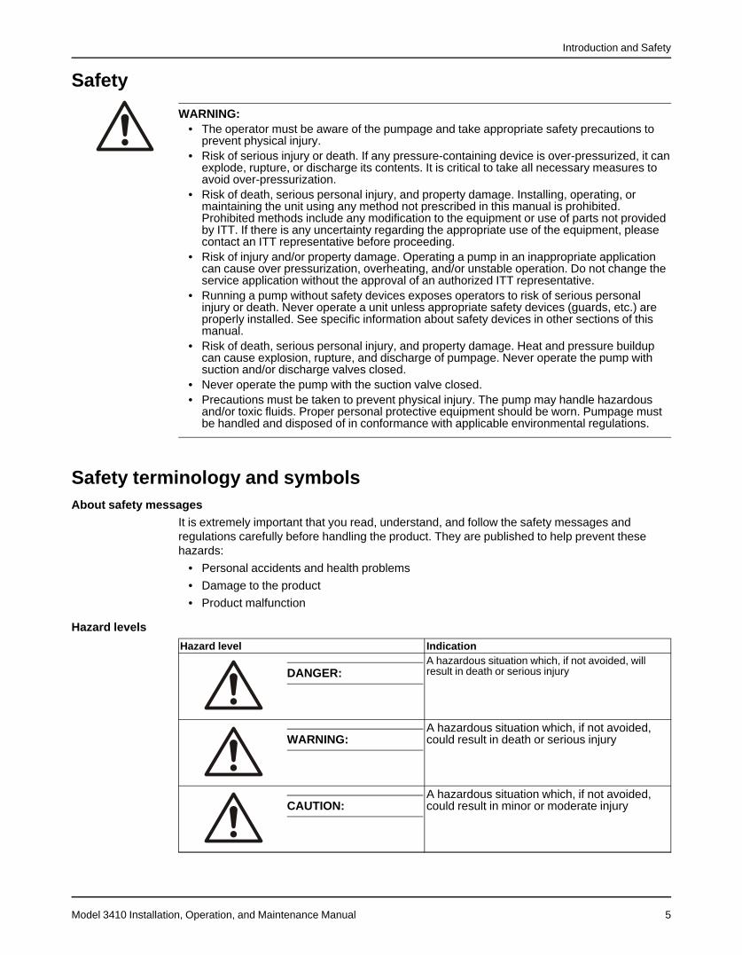
Hazard levels
Hazard level Indication
DANGER:A hazardous situation which, if not avoided, willresult in death or serious injury
WARNING:A hazardous situation which, if not avoided,could result in death or serious injury
CAUTION:A hazardous situation which, if not avoided,could result in minor or moderate injury
Introduction and Safety
Model 3410 Installation, Operation, and Maintenance Manual6
Hazard level Indication
NOTICE:• A potential situation which, if not avoided,
could result in undesirable conditions• A practice not related to personal injury
Hazard categoriesHazard categories can either fall under hazard levels or let specific symbols replace theordinary hazard level symbols.Electrical hazards are indicated by the following specific symbol:
Electrical Hazard:
These are examples of other categories that can occur. They fall under the ordinary hazardlevels and may use complementing symbols:
• Crush hazard
• Cutting hazard
• Arc flash hazard
The Ex symbol
The Ex symbol indicates safety regulations for Ex-approved products when used inatmospheres that are potentially explosive or flammable.
Environmental safetyThe work area
Always keep the pump station clean to avoid and/or discover emissions.
Recycling guidelinesAlways recycle according to these guidelines:
1. If the unit or parts are accepted by an authorized recycling company, then follow localrecycling laws and regulations.
2. If the unit or parts are not accepted by an authorized recycling company, then return themto the nearest ITT representative.
Waste and emissions regulationsObserve these safety regulations regarding waste and emissions:
• Dispose appropriately of all waste.
• Handle and dispose of the pumped fluid in compliance with applicable environmentalregulations.
• Clean up all spills in accordance with safety and environmental procedures.
• Report all environmental emissions to the appropriate authorities.
Reference for electrical installationFor electrical installation requirements, consult your local electric utility.
User safetyGeneral safety rules
These safety rules apply:
Introduction and Safety
Model 3410 Installation, Operation, and Maintenance Manual 7
• Always keep the work area clean.
• Pay attention to the risks presented by gas and vapors in the work area.
• Avoid all electrical dangers. Pay attention to the risks of electric shock or arc flash hazards.
• Always bear in mind the risk of drowning, electrical accidents, and burn injuries.
Safety equipmentUse safety equipment according to the company regulations. Use this safety equipment withinthe work area:
• Helmet
• Safety goggles, preferably with side shields
• Protective shoes
• Protective gloves
• Gas mask
• Hearing protection
• First-aid kit
• Safety devices
Electrical connectionsElectrical connections must be made by certified electricians in compliance with all internation-al, national, state, and local regulations. For more information about requirements, see sectionsdealing specifically with electrical connections.
Precautions before workObserve these safety precautions before you work with the product or are in connection withthe product:
• Provide a suitable barrier around the work area, for example, a guard rail.
• Make sure that all safety guards are in place and secure.
• Make sure that the equipment is properly insulated when it operates at extremetemperatures.
• Allow all system and pump components to cool before you handle them.
• Make sure that you have a clear path of retreat.
• Make sure that the product cannot roll or fall over and injure people or damage property.
• Make sure that the lifting equipment is in good condition.
• Use a lifting harness, a safety line, and a breathing device as required.
• Make sure that the product is thoroughly clean.
• Make sure that there are no poisonous gases within the work area.
• Make sure that you have quick access to a first-aid kit.
• Disconnect and lock out power before servicing.
• Check the explosion risk before you weld or use electric hand tools.
Precautions during workObserve these safety precautions when you work with the product or are in connection with theproduct:
• Never work alone.
• Always wear protective clothing and hand protection.
• Stay clear of suspended loads.
• Always lift the product by its lifting device.
• Beware of the risk of a sudden start if the product is used with an automatic level control.
• Beware of the starting jerk, which can be powerful.
• Rinse the components in water after you disassemble the pump.
Introduction and Safety
Model 3410 Installation, Operation, and Maintenance Manual8
• Do not exceed the maximum working pressure of the pump.
• Do not open any vent or drain valve or remove any plugs while the system is pressurized.Make sure that the pump is isolated from the system and that pressure is relieved beforeyou disassemble the pump, remove plugs, or disconnect piping.
• Never operate a pump without a properly installed coupling guard.
• Always bear in mind the risk of drowning, electrical accidents, and burn injuries.
• Never heat the condition monitor to temperatures in excess of 300°F (149°C).
• Never expose the condition monitor to open flames.
• Do not use the condition monitor in atmospheres containing acetic acid.
• Always wear protective gloves. The pump and condition monitor can be hot.
Wash the skin and eyes
1. Follow these procedures for chemicals or hazardous fluids that have come into contact withyour eyes or your skin:
Condition ActionChemicals or hazardousfluids in eyes
1. Hold your eyelids apart forcibly with your fingers.2. Rinse the eyes with eyewash or running water for at least 15 minutes.3. Seek medical attention.
Chemicals or hazardousfluids on skin
1. Remove contaminated clothing.2. Wash the skin with soap and water for at least 1 minute.3. Seek medical attention, if necessary.
Safety regulations for Ex-approved products in potentiallyexplosive atmospheresDescription of ATEX
The ATEX directives are a specification enforced in Europe for electrical and non-electricalequipment. ATEX deals with the control of potentially explosive atmospheres and thestandards of equipment and protective systems used within these atmospheres. The relevanceof the ATEX requirements is not limited to Europe. You can apply these guidelines toequipment installed in any potentially explosive atmosphere.
Guidelines for complianceCompliance is only fulfilled when the pump is operated within its intended use, for examplewithin its intended hydraulic range. The conditions of the service must not be changed withoutapproval of an authorized ITT representative. When installing or maintaining explosion-proofpumps, follow these guidelines:
• Always install ATEX-approved equipment in compliance with the directive and applicablestandards (IEC/EN 60079–14).
• Do not install explosion proof products in locations that are classified as hazardous in thenational electric code, ANSI/NFPA 70–2005.
WARNING:Risk of serious personal injury. Applying heat to impellers, propellers, or their retaining devicescan cause trapped liquid to rapidly expand and result in a violent explosion. This manual clearlyidentifies accepted methods for disassembling units. These methods must be adhered to.Never apply heat to aid in their removal unless explicitly stated in this manual.
If there are any questions regarding these requirements, the intended use, or if the equipmentrequires modification, contact an ITT representative before you proceed.
Personnel requirementsITT disclaims all responsibility for work done by untrained and unauthorized personnel.
Introduction and Safety
Model 3410 Installation, Operation, and Maintenance Manual 9
These are the personnel requirements for Ex-approved products in potentially explosiveatmospheres:
• All work on the product must be carried out by certified electricians and ITT-authorizedmechanics. Special rules apply to installations in explosive atmospheres.
• All users must know about the risks of electric current and the chemical and physicalcharacteristics of the gas and/or vapor present in hazardous areas.
• Any maintenance for Ex-approved products must conform to international and nationalstandards (for example IEC/EN 60079-17).
Product and product handling requirementsThese are the product and product handling requirements for Ex-approved products inpotentially explosive atmospheres:
• Only use the product in accordance with the approved motor data stated on thenameplates.
• The Ex-approved product must never run dry during normal operation. Dry running duringservice and inspection is only permitted outside the classified area.
• Never start a pump without the proper priming.
• Before you start working with the product, make sure that the product and the control panelare isolated from the power supply and the control circuit, so they cannot be energized.
• Do not open the product while it is energized or in an explosive gas atmosphere.
• Make sure that thermal contacts are connected to a protection circuit according to theapproval classification of the product.
• Intrinsically safe circuits are normally required for the automatic level-control system by thelevel regulator if mounted in zone 0.
• The yield stress of fasteners must be in accordance with the approval drawing and theproduct specification.
• Make sure that the equipment is properly maintained:
• Monitor the pump components and the end temperature of the liquid.
• Maintain proper bearing lubrication.
• Do not modify the equipment without approval from an authorized ITT representative.
• Only use parts that have been provided by an authorized ITT representative.
Equipment for monitoringFor additional safety, use condition-monitoring devices. Condition-monitoring devices includebut are not limited to these devices:
• Pressure gauges
• Flow meters
• Level indicators
• Motor load readings
• Temperature detectors
• Bearing monitors
• Leak detectors
• PumpSmart control system
Introduction and Safety
Model 3410 Installation, Operation, and Maintenance Manual10
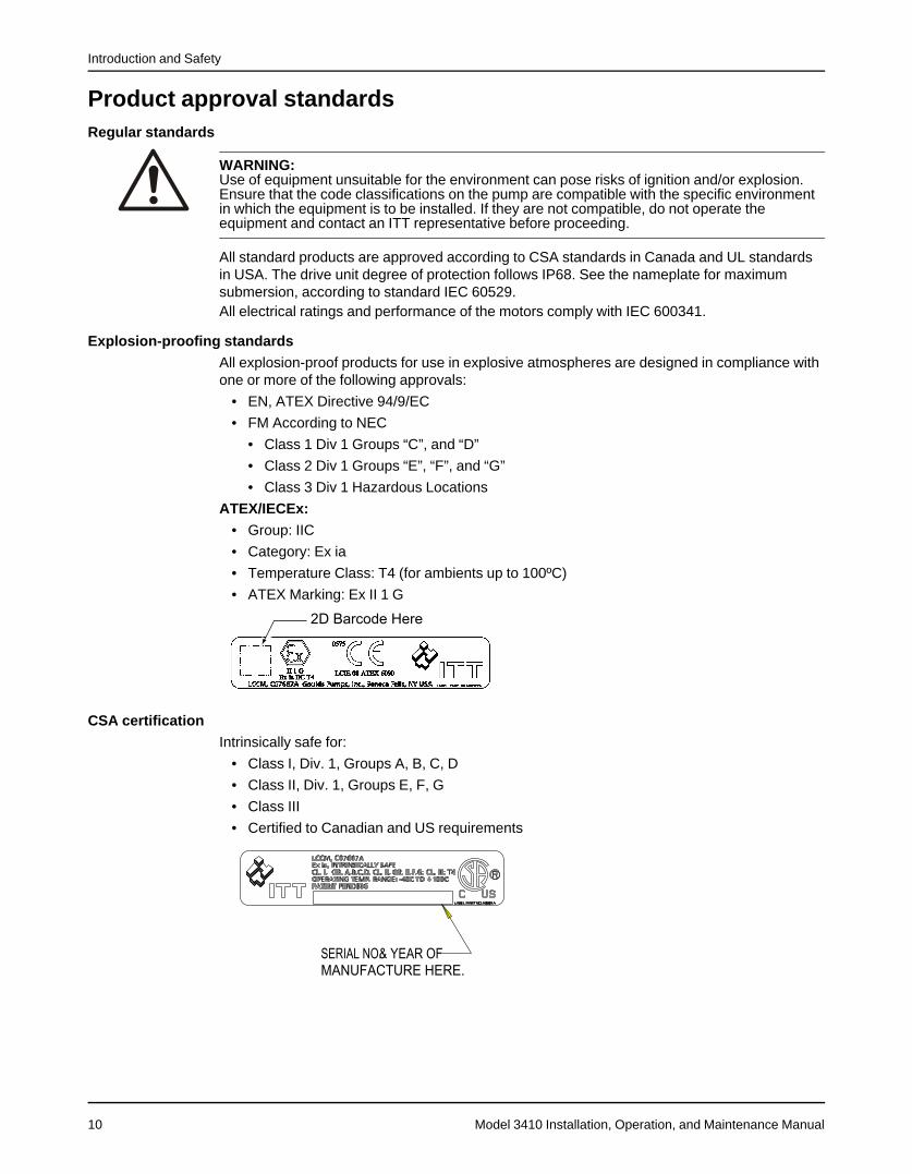
Product approval standardsRegular standards
WARNING:Use of equipment unsuitable for the environment can pose risks of ignition and/or explosion.Ensure that the code classifications on the pump are compatible with the specific environmentin which the equipment is to be installed. If they are not compatible, do not operate theequipment and contact an ITT representative before proceeding.
All standard products are approved according to CSA standards in Canada and UL standardsin USA. The drive unit degree of protection follows IP68. See the nameplate for maximumsubmersion, according to standard IEC 60529.All electrical ratings and performance of the motors comply with IEC 600341.
Explosion-proofing standardsAll explosion-proof products for use in explosive atmospheres are designed in compliance withone or more of the following approvals:
• EN, ATEX Directive 94/9/EC
• FM According to NEC
• Class 1 Div 1 Groups “C”, and “D”
• Class 2 Div 1 Groups “E”, “F”, and “G”
• Class 3 Div 1 Hazardous Locations
ATEX/IECEx:• Group: IIC
• Category: Ex ia
• Temperature Class: T4 (for ambients up to 100ºC)
• ATEX Marking: Ex II 1 G
CSA certificationIntrinsically safe for:
• Class I, Div. 1, Groups A, B, C, D
• Class II, Div. 1, Groups E, F, G
• Class III
• Certified to Canadian and US requirements
Introduction and Safety
Model 3410 Installation, Operation, and Maintenance Manual 11
Product warrantyCoverage
ITT undertakes to remedy faults in products from ITT under these conditions:
• The faults are due to defects in design, materials, or workmanship.
• The faults are reported to an ITT representative within the warranty period.
• The product is used only under the conditions described in this manual.
• The monitoring equipment incorporated in the product is correctly connected and in use.
• All service and repair work is done by ITT-authorized personnel.
• Genuine ITT parts are used.
• Only Ex-approved spare parts and accessories authorized by ITT are used in Ex-approvedproducts.
LimitationsThe warranty does not cover faults caused by these situations:
• Deficient maintenance
• Improper installation
• Modifications or changes to the product and installation made without consulting ITT
• Incorrectly executed repair work
• Normal wear and tear
ITT assumes no liability for these situations:
• Bodily injuries
• Material damages
• Economic losses
Warranty claimITT products are high-quality products with expected reliable operation and long life. However,should the need arise for a warranty claim, then contact your ITT representative.
Transportation and Storage
Model 3410 Installation, Operation, and Maintenance Manual12
Transportation and Storage
Inspect the deliveryInspect the package
1. Inspect the package for damaged or missing items upon delivery.2. Note any damaged or missing items on the receipt and freight bill.3. File a claim with the shipping company if anything is out of order.
If the product has been picked up at a distributor, make a claim directly to the distributor.
Inspect the unit1. Remove packing materials from the product.
Dispose of all packing materials in accordance with local regulations.2. Inspect the product to determine if any parts have been damaged or are missing.3. If applicable, unfasten the product by removing any screws, bolts, or straps.
For your personal safety, be careful when you handle nails and straps.4. Contact your sales representative if anything is out of order.
Transportation guidelinesPrecautions
WARNING:• Stay clear of suspended loads.• Observe accident prevention regulations in force.
Pump handling
WARNING:Dropping, rolling or tipping units, or applying other shock loads, can cause property damageand personal injury. Ensure that the unit is properly supported and secure during lifting andhandling.
CAUTION:Risk of injury or equipment damage from use of inadequate lifting devices. Ensure liftingdevices (such as chains, straps, forklifts, cranes, etc.) are rated to sufficient capacity.
Lifting methodsWARNING:
• All lifting must be done in compliance with all applicable regulations/standards.• Safe lifting points are specifically identified in this manual. It is critical to lift the equipment
only at these points. Integral lifting eyes or eye bolts on pump and motor components areintended for use in lifting the individual components only.
• Lifting and handling heavy equipment poses a crush hazard. Use caution during lifting andhandling and wear appropriate Personal Protective Equipment (PPE, such as steel-toedshoes, gloves, etc.) at all times. Seek assistance if necessary.
• Do not attach sling ropes to shaft ends.
The unit must be unloaded and handled by lifting equally at four or more points on thebaseplate. The lugs on the upper half casing are designed for lifting the upper half of the casingonly.
Transportation and Storage
Model 3410 Installation, Operation, and Maintenance Manual 13
Pumps mounted horizontally
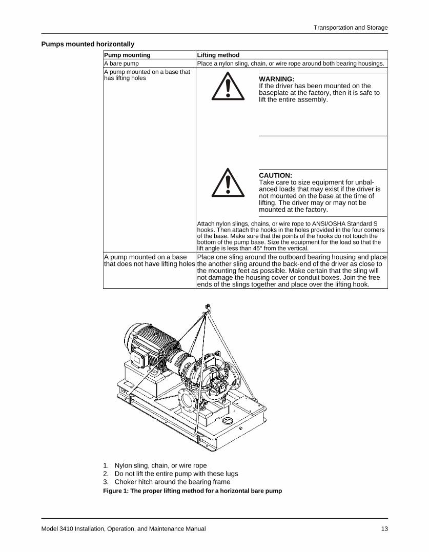
Pump mounting Lifting methodA bare pump Place a nylon sling, chain, or wire rope around both bearing housings.A pump mounted on a base thathas lifting holes WARNING:
If the driver has been mounted on the baseplate at the factory, then it is safe to lift the entire assembly.
CAUTION:Take care to size equipment for unbal-anced loads that may exist if the driver isnot mounted on the base at the time oflifting. The driver may or may not bemounted at the factory.
Attach nylon slings, chains, or wire rope to ANSI/OSHA Standard Shooks. Then attach the hooks in the holes provided in the four cornersof the base. Make sure that the points of the hooks do not touch thebottom of the pump base. Size the equipment for the load so that thelift angle is less than 45° from the vertical.
A pump mounted on a basethat does not have lifting holes
Place one sling around the outboard bearing housing and placethe another sling around the back-end of the driver as close tothe mounting feet as possible. Make certain that the sling willnot damage the housing cover or conduit boxes. Join the freeends of the slings together and place over the lifting hook.
1. Nylon sling, chain, or wire rope2. Do not lift the entire pump with these lugs3. Choker hitch around the bearing frameFigure 1: The proper lifting method for a horizontal bare pump
Transportation and Storage
Model 3410 Installation, Operation, and Maintenance Manual14
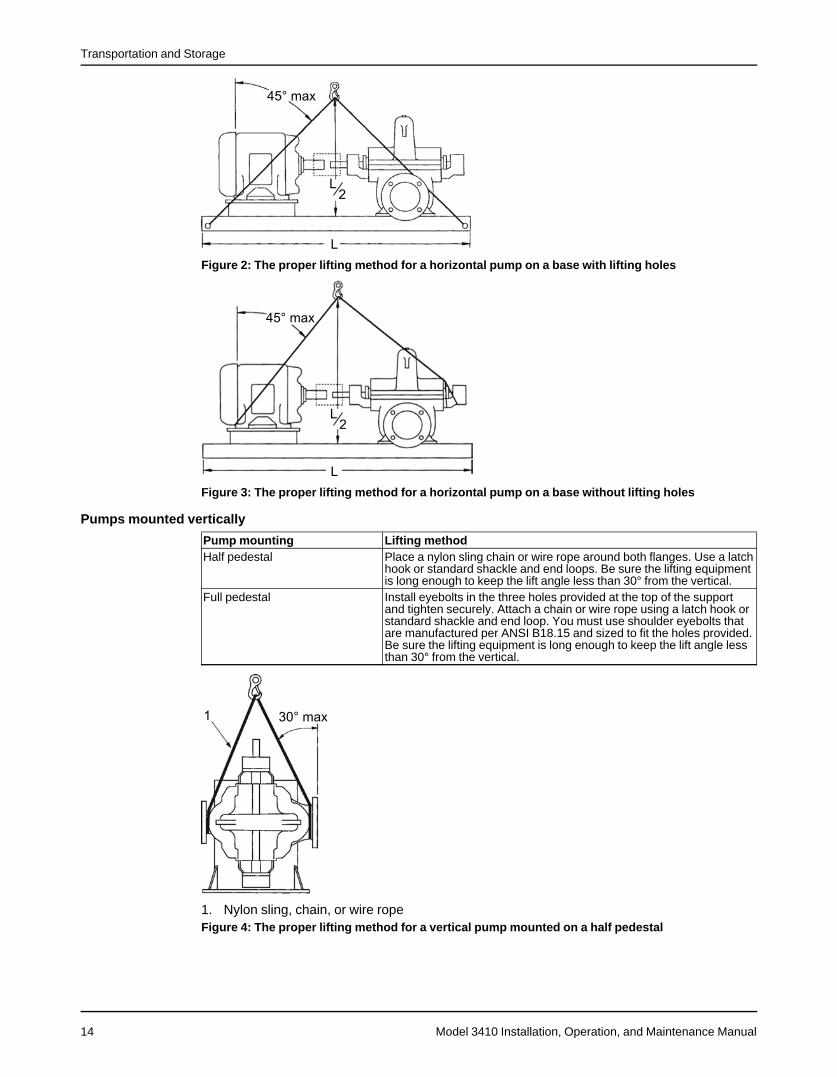
Figure 2: The proper lifting method for a horizontal pump on a base with lifting holes
Figure 3: The proper lifting method for a horizontal pump on a base without lifting holes
Pumps mounted vertically
Pump mounting Lifting methodHalf pedestal Place a nylon sling chain or wire rope around both flanges. Use a latch
hook or standard shackle and end loops. Be sure the lifting equipmentis long enough to keep the lift angle less than 30° from the vertical.
Full pedestal Install eyebolts in the three holes provided at the top of the supportand tighten securely. Attach a chain or wire rope using a latch hook orstandard shackle and end loop. You must use shoulder eyebolts thatare manufactured per ANSI B18.15 and sized to fit the holes provided.Be sure the lifting equipment is long enough to keep the lift angle lessthan 30° from the vertical.
1. Nylon sling, chain, or wire ropeFigure 4: The proper lifting method for a vertical pump mounted on a half pedestal
Transportation and Storage
Model 3410 Installation, Operation, and Maintenance Manual 15
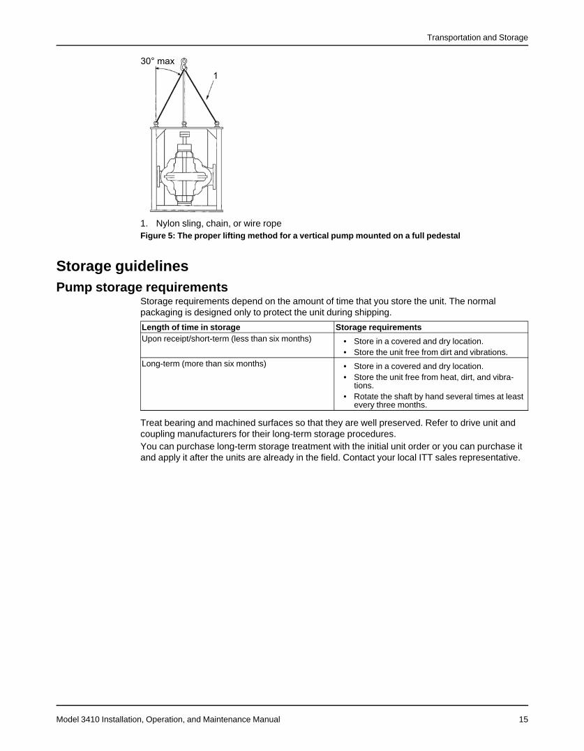
1. Nylon sling, chain, or wire ropeFigure 5: The proper lifting method for a vertical pump mounted on a full pedestal
Storage guidelinesPump storage requirements
Storage requirements depend on the amount of time that you store the unit. The normalpackaging is designed only to protect the unit during shipping.
Length of time in storage Storage requirementsUpon receipt/short-term (less than six months) • Store in a covered and dry location.
• Store the unit free from dirt and vibrations.Long-term (more than six months) • Store in a covered and dry location.
• Store the unit free from heat, dirt, and vibra-tions.
• Rotate the shaft by hand several times at leastevery three months.
Treat bearing and machined surfaces so that they are well preserved. Refer to drive unit andcoupling manufacturers for their long-term storage procedures.You can purchase long-term storage treatment with the initial unit order or you can purchase itand apply it after the units are already in the field. Contact your local ITT sales representative.
Product Description
Model 3410 Installation, Operation, and Maintenance Manual16
Product Description
General descriptionProduct description
Goulds Model 3410 is a single-stage, double-suction pump with the following capabilities:
Measurement Maximum toleranceCapacity 12,000 gpm (45,425 lpm)Head 530 ft (161 m)Pressure • Cast iron: 175 psig (1,200 kPa)
• Ductile iron or steel: 250 psig (1,725 kPa)Temperature 350°F (177°C)
Pump sizes with an H designation are designed for a higher flow than the equivalent sizestandard pump. External casing dimensions are the same, but the H pumps have wider casingcutwaters and impellers.The complete model line has four different shafts with only two bearing assemblies. Standardconstructions are all-iron, bronze fitted, 316SS fitted, and all 316SS. Other constructions areavailable upon request.Right-hand rotation is standard. Left-hand rotation is available as an option. The rotation can bechanged after installation without any additional parts.
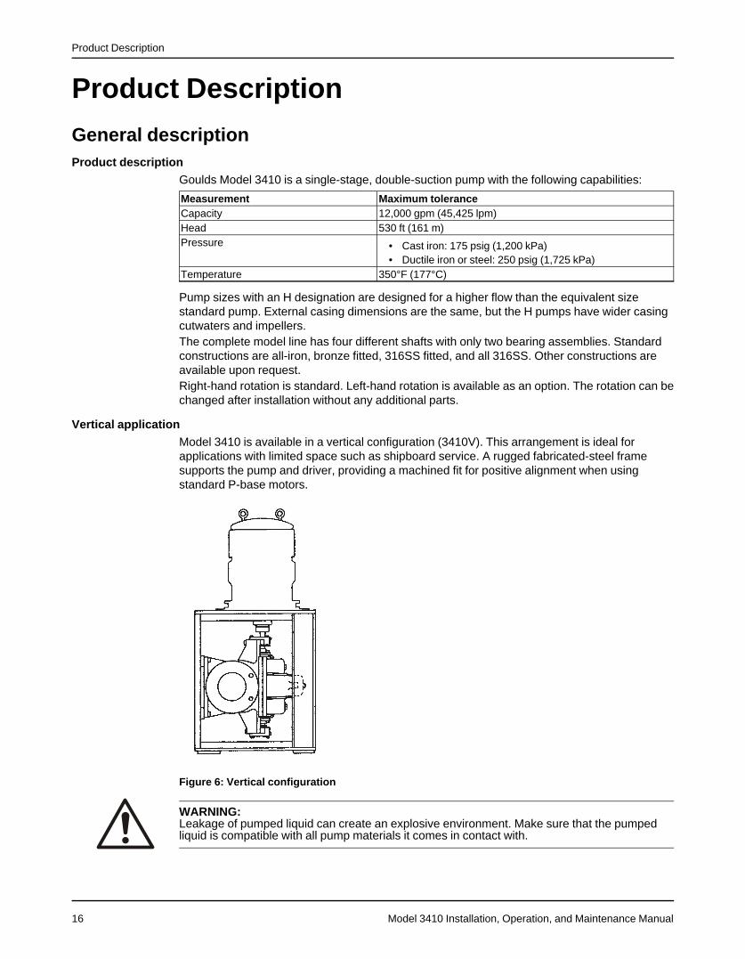
Vertical applicationModel 3410 is available in a vertical configuration (3410V). This arrangement is ideal forapplications with limited space such as shipboard service. A rugged fabricated-steel framesupports the pump and driver, providing a machined fit for positive alignment when usingstandard P-base motors.
Figure 6: Vertical configuration
WARNING:Leakage of pumped liquid can create an explosive environment. Make sure that the pumpedliquid is compatible with all pump materials it comes in contact with.
Product Description
Model 3410 Installation, Operation, and Maintenance Manual 17
1 This casing uses a partial splitter.
CasingThe casing is split horizontally. The upper and lower halves are held together with capscrewsand studs on the side of each stuffing box to aid in disassembly and reassembly. The casing issupported by integrally cast feet. Separate bearing housings are attached directly to machinedfits in each end of the casing with capscrews.Fourteen of the 27 casings are double volute as follows:
• 4x6-11
• 4x6-11H
• 6x8-11
• 8x10-21
• 8x10-12
• 8x10-14
• 8x10-17
• 8x10-17H
• 10x12-12
• 10x12-12H1
• 10x12-14
• 10x12-17
• 10x12-15
• 12x14-14
• 12x14-15
Flanged suction and discharge connections are located in the lower half of the casing andconform to ANSI 16.1/16.5 class 125/150. The 125# flat-face flanges are standard with 250#flat-face available as an option.DIN flanges may also be provided on all sizes except the 6x8-22. The flanges are provided inaccordance with EN 1092-2. These flanges are smooth, flat faced and meet or exceed theminimum thickness required by the PN rating. The flanges provided are PN16 on smaller sizesand PN10 on the larger sizes.The casings are standard with the following parts:
• Two jackscrews (except S group)
• Two lifting lugs
• Two tapered dowel pins for alignment
• One 0.030 in. (0.0762 cm) parting gasket
The upper-half casing has a vent connection, a priming connection, and two stuffing box sealring connections. The lower half has two drain connections.
Impeller• Enclosed, double suction
• Axial hydraulic balance
• Key driven
• Dynamically balanced, when the diameter to width ratio is less than six
Wear rings• Casing wear rings are supplied as standard to maintain proper running clearance and to
minimize leakage between the suction and discharge chambers in the casing. Each casingring is held in place by a single anti-rotation pin located in a milled slot at the horizontalparting surface.
Product Description
Model 3410 Installation, Operation, and Maintenance Manual18
• Optional impeller wear rings are available on all pump sizes. The impeller wear rings areheld in position by axial setscrews. Field installation of impeller rings requires aremachining of the impeller hubs.
• The casing rings remain the same for designs with or without impeller rings.
ShaftThe shaft is a heavy-duty design that minimizes deflection and vibration. The shaft deflection isa maximum of 0.002 in. (0.051 mm) at the stuffing box face under the worst operatingconditions. The shaft on M, L, and XL group pumps is completely dry with gasket sealsbetween the impeller hubs and shaft sleeves. The S group does not have a completely dryshaft. The S group is standard with a 420 stainless steel shaft. The M, L, and XL sizes have anANSI 4140 steel shaft standard with an option for 316 stainless steel.
Shaft sleevesThe M, L and XL group pumps have standard shaft sleeves. They are keyed to the shaft at theimpeller and held axially in place using threaded sleeve nuts. The S group pumps are standardwithout shaft sleeves, but sleeves are available.
Stuffing boxNon-asbestos stuffing box packing is standard. The stuffing box contains split lantern rings andrenewable stuffing box throat bushings. Tapped openings are provided for water sealing fromeither the pump casing or an outside source. Bypass piping is optional. Two-piece, investmentcast, 316 stainless steel, non-quench glands are standard on all 3410 pumps.
Mechanical seals• Mechanical seals are available as an option on the Model 3410. Oversize stuffing box
bores are standard on pumps with factory-installed mechanical seals. This providesgreater flexibility and an improved operating environment.
• Pumps that are supplied with standard packed boxes can be converted to mechanicalseals in the field. This conversion requires either remachining of the stuffing box toaccommodate the mechanical seal or remachining of the gland to adapt to the existingstuffing box. If the stuffing box bores are remachined, then all standard Model 3410mechanical seals and the standard I.D. pilot glands can be used.
• Balanced seals require conversion to stepped sleeves. Most unbalanced mechanical sealswill fit in the standard packed box bores, but this requires remachining the I.D. pilot off theglands. In this case, the glands must be centered on the shaft or the sleeve using a feelergauge.
• Pumps supplied with mechanical seals can also be converted to packed boxes in the field.A cartridge conversion kit is available and includes a box of fittings plus sleeves to convertoversize bores to standard packed-box bores.
Bearings• The Model 3410 is standard with double-row ball thrust bearings and a single-row deep
groove ball bearing at the coupling end. There are only two sizes of bearing housings andbearings used on the Model 3410 product line. The S and M groups use identical bearings,as do the L and XL groups. The thrust bearing is held in position with a tapered snap ringand is locked in the thrust bearing housing to take any unbalanced axial thrust load. Theradial bearing is free to float axially in the bearing housing taking radial loads only.
• Grease lubrication is standard. Oil lubrication is optional and uses the same shaft,bearings, and bearing housings. Bearing cooling is available with oil lubrication only and isrequired for temperatures over 250°F (121°C). The bearing housings are completelysealed by Inpro VBS bearing isolators.
Product Description
Model 3410 Installation, Operation, and Maintenance Manual 19
BedplatesCast iron bedplates are furnished as standard. They include a drip collection chamber with atapped drain connection and an opening suitable for grouting. Fabricated steel bedplates areavailable as an option.
Intended applicationsThe Goulds 3410 model line is designed for a wide range of industrial, municipal, and marineservices, which includes:
• Process – Quench water, stripper bottoms, reboiler circulation, and cooling tower
• Pulp and paper – Primary and secondary cleaner, filtrate, mill water supply, and fan pump
• Primary metals – Cooling water, quench, and leaching
• Municipal – High lift, low lift, wash water, waste water, and raw water
• Utilities – Cooling tower, component cooling, and service water
• Marine – Bilge and ballast, cargo, cooling service, and fire pump
Product Description
Model 3410 Installation, Operation, and Maintenance Manual20
Nameplate informationImportant information for ordering
Every pump has a nameplate that provides information about the pump. The nameplate islocated on the pump casing.When you order spare parts, identify this pump information:
• Model
• Size
• Serial number
• Item numbers of the required parts
Refer to the nameplate on the pump casing for most of the information. See Parts List for itemnumbers.
Nameplate typesNameplate DescriptionPump casingPump
Provides information about the hydraulic characteristics of the pump.The formula for the pump size is: Discharge x Suction - Nominal Maximum Impeller Diameter in inches.(Example: 2x3-8)
ATEX If applicable, your pump unit might have an ATEX nameplate affixed to the pump, the baseplate, or thedischarge head. The nameplate provides information about the ATEX specifications of this pump.
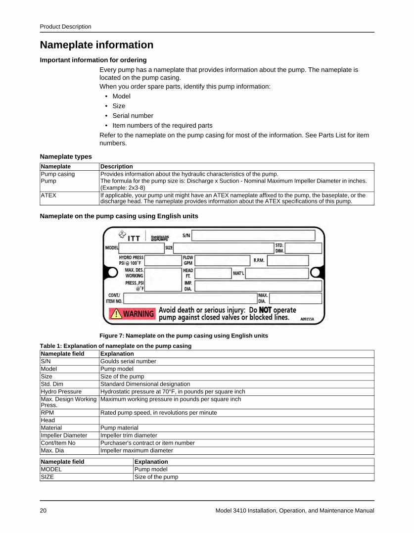
Nameplate on the pump casing using English units
Figure 7: Nameplate on the pump casing using English units
Table 1: Explanation of nameplate on the pump casingNameplate field ExplanationS/N Goulds serial numberModel Pump modelSize Size of the pumpStd. Dim Standard Dimensional designationHydro Pressure Hydrostatic pressure at 70°F, in pounds per square inchMax. Design WorkingPress.
Maximum working pressure in pounds per square inch
RPM Rated pump speed, in revolutions per minuteHeadMaterial Pump materialImpeller Diameter Impeller trim diameterCont/Item No Purchaser's contract or item numberMax. Dia Impeller maximum diameter
Nameplate field ExplanationMODEL Pump modelSIZE Size of the pump
Product Description
Model 3410 Installation, Operation, and Maintenance Manual 21
Nameplate field ExplanationFLOW Rated pump flow, in gallons per minuteHEAD Rated pump head, in feetRPM Rated pump speed, in revolutions per minuteHYDRO PRESS Hydrostatic pressure at 100°F, in pounds per square inchMAX. DES. WORKING PRESS Maximum working pressure at temperature °F, in pounds per square inchS/N Serial number of the pumpCONT./ITEM NO. Customer contract or item numberIMP. DIA. Rated impeller diameterMAX. DIA. Maximum impeller diameterSTD. DIM. Standard ANSI dimensional codeMAT'L Material of construction
ATEX nameplate
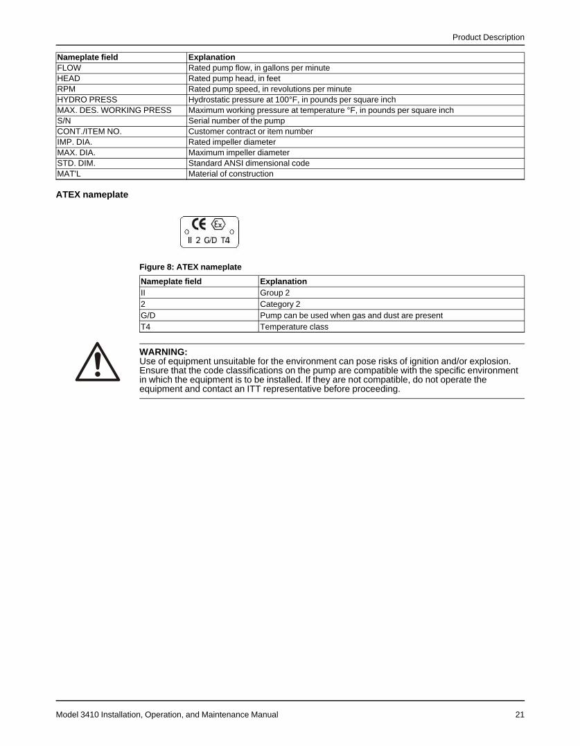
Figure 8: ATEX nameplate
Nameplate field ExplanationII Group 22 Category 2G/D Pump can be used when gas and dust are presentT4 Temperature class
WARNING:Use of equipment unsuitable for the environment can pose risks of ignition and/or explosion.Ensure that the code classifications on the pump are compatible with the specific environmentin which the equipment is to be installed. If they are not compatible, do not operate theequipment and contact an ITT representative before proceeding.
Installation
Model 3410 Installation, Operation, and Maintenance Manual22
Installation
PreinstallationPrecautions
WARNING:
• When installing in a potentially explosive environment, ensure that the motor isproperly certified.
• All equipment being installed must be properly grounded to prevent unexpecteddischarge. Discharge can cause equipment damage, electric shock, and result in seriousinjury. Test the ground lead to verify it is connected correctly.
NOTICE:• Supervision by an authorized ITT representative is recommended to ensure proper
installation. Improper installation may result in equipment damage or decreased perfor-mance.
• Electrical connections must be made by certified electricians in compliance with allinternational, national, state and local regulations.
Pump location guidelinesGuideline Explanation/commentKeep the pump as close to the liquid source aspractically possible.
This minimizes the friction loss and keeps thesuction piping as short as possible.
Make sure that the space around the pump is suffi-cient.
This facilitates ventilation, inspection, mainte-nance, and service.
If you require lifting equipment such as a hoist ortackle, make sure that there is enough space abovethe pump.
This makes it easier to properly use the liftingequipment and safely remove and relocate thecomponents to a safe location.
Protect the unit from weather and water damage dueto rain, flooding, and freezing temperatures.If the possibility of freezing exists during a shutdownperiod, then drain the pump completely and usecompressed air to blow out all passages and pocketswhere liquid might collect.
This is applicable if nothing else is specified.
Do not install and operate the equipment in closedsystems unless the system is constructed with proper-ly-sized safety devices and control devices.
Acceptable devices:• Pressure relief valves• Compression tanks• Pressure controls• Temperature controls• Flow controls
If the system does not include these devices,consult the engineer or architect in charge beforeyou operate the pump.
Take into consideration the occurrence of unwantednoise and vibration.
The best pump location for noise and vibrationabsorption is on a concrete floor with subsoilunderneath.
If the pump location is overhead, undertake specialprecautions to reduce possible noise transmission.
Consider a consultation with a noise specialist.
When possible, locate the pump below the fluid level. This facilitates priming, ensures a steady flow ofliquid, and provides a positive suction head onthe pump.
Make sure there is a suitable power source availablefor the pump driver.
If the pump is motor-driven, then the electricalcharacteristics of the power source should beidentical to those shown on motor data plate.
Installation
Model 3410 Installation, Operation, and Maintenance Manual 23
The installation must be evaluated to determine that the Net Positive Suction Head Available(NPSHA) meets or exceeds the Net Positive Suction Head Required (NPSHR), as stated by thepump performance curve.
Foundation requirements
Requirements• The foundation must be able to absorb any type of vibration and form a permanent, rigid
support for the unit.
• The foundation must weigh at least five times the weight of the pump unit.
• Provide a flat, substantial concrete foundation in order to prevent strain and distortionwhen you tighten the foundation bolts.
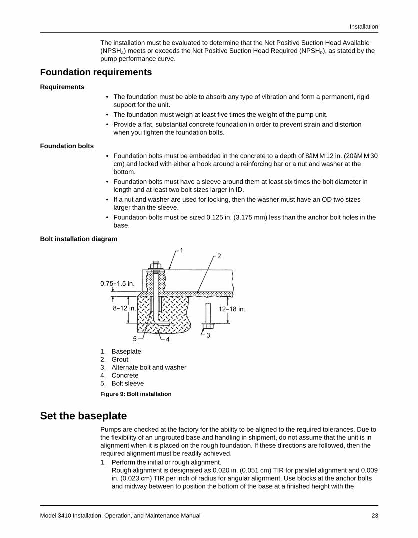
Foundation bolts• Foundation bolts must be embedded in the concrete to a depth of 8âM M 12 in. (20âM M 30
cm) and locked with either a hook around a reinforcing bar or a nut and washer at thebottom.
• Foundation bolts must have a sleeve around them at least six times the bolt diameter inlength and at least two bolt sizes larger in ID.
• If a nut and washer are used for locking, then the washer must have an OD two sizeslarger than the sleeve.
• Foundation bolts must be sized 0.125 in. (3.175 mm) less than the anchor bolt holes in thebase.
Bolt installation diagram
1. Baseplate2. Grout3. Alternate bolt and washer4. Concrete5. Bolt sleeve
Figure 9: Bolt installation
Set the baseplatePumps are checked at the factory for the ability to be aligned to the required tolerances. Due tothe flexibility of an ungrouted base and handling in shipment, do not assume that the unit is inalignment when it is placed on the rough foundation. If these directions are followed, then therequired alignment must be readily achieved.1. Perform the initial or rough alignment.
Rough alignment is designated as 0.020 in. (0.051 cm) TIR for parallel alignment and 0.009in. (0.023 cm) TIR per inch of radius for angular alignment. Use blocks at the anchor boltsand midway between to position the bottom of the base at a finished height with the
Installation
Model 3410 Installation, Operation, and Maintenance Manual24
foundation bolts extending through the holes in the baseplate. Instead of blocks and shims,you can also use metal wedges with a small taper.
2. If the unit has a non-flexible coupling, such as a Falk Gear coupling, then disconnect thecoupling halves.This is usually not necessary on flexible-type couplings, such as Wood’s Sure-Flexcoupling.
3. Tighten all pump and motor bolts.This ensures that bolts have not loosened or that a soft foot has not occurred due to basedistortion during shipment. A soft foot causes a change in the alignment when one bolt isloosened.
4. If the driver is being installed in the field, then make sure it is centered in its bolt holes withshims added to bring the driver into rough alignment with the pump.Move the pump also, if necessary.
NOTICE:Risk of improper alignment. Do not use more than six shims and use the thickest shimspossible. Place thin shims in between thick shims.
5. Level and plumb the pump shaft, coupling faces, and flanges by adding or removing shimsbetween the blocks and the bottom of the base.
6. Hand-tighten the anchor bolt nuts. Then tighten the nuts with a wrench, taking care not todistort the base.Do not reconnect the non-flexible coupling until after you complete the alignment operation.The baseplate does not need to be level.
7. After the foundation bolts are lightly torqued, recheck the alignment requirements.If the alignment must be corrected, then add or remove shims or wedges under thebaseplate.
Pump-to-driver alignmentPrecautions
WARNING:• Misalignment can cause decreased performance, equipment damage, and even catas-
trophic failure of frame-mounted units leading to serious injury. Proper alignment is theresponsibility of the installer and the user of the unit. Check the alignment of all drivecomponents prior to operating the unit.• Follow the coupling installation and operation procedures from the coupling manufactur-
er.• Failure to disconnect and lock out driver power may result in serious physical injury or
death. Always disconnect and lock out power to the driver before performing anyinstallation or maintenance tasks.• Electrical connections must be made by certified electricians in compliance with all
international, national, state, and local rules.• Refer to driver/coupling/gear manufacturer's installation and operation manuals (IOM)
for specific instructions and recommendations.
Alignment checks
When to perform alignment checksYou must perform alignment checks under these circumstances:
• The process temperature changes.
• The piping changes.
• The pump has been serviced.
Installation
Model 3410 Installation, Operation, and Maintenance Manual 25
Types of misalignment
Type of misalignment DescriptionAngular misalignment Shafts have an axis concentric at the intersection but not parallel.Parallel offset misalignment Shafts have an axis parallel but offset.
Check and correct angular misalignment before correcting parallel misalignment.
Permissible coupling misalignment
Type of misalignment Single element coupling Double element (spacer) couplingParallel misalignment 0.1 mm | 0.004 in. TIR (4 mils) 1.52 mm | 0.060 in. TIR per foot of
spacer lengthAngular misalignment 0.1 mm | 0.004 in. TIR per inch of
radius.0.51 mm | 0.002 in. TIR per inch ofradius
Types of alignment checks
Type of check When it is usedInitial alignment (cold alignment)check
Prior to operation when the pump and the driver are at ambienttemperature.
Final alignment (hot alignment)check
After operation when the pump and the driver are at operatingtemperature.
To make the final alignment, move and shim the motor on its base until the coupling hubs arewithin the recommended tolerances measured in total runout. Take all measurements with thepump and driver bolts tightened. Make the final alignment check after the unit has attained itsfinal operating temperature.
Initial alignment (cold alignment) checks
When WhyBefore you grout the baseplate This ensures that alignment can be accomplished.After you grout the baseplate This ensures that no changes have occurred during the grouting
process.After you connect the piping This ensures that pipe strains have not altered the alignment.
Final alignment (hot alignment) checks
When WhyAfter the first run This ensures correct alignment when both the pump and the driver
are at operating temperature.Periodically This follows the plant operating procedures.
Cold settings for parallel vertical alignment
IntroductionThis section shows the recommended preliminary (cold) settings for electric motor-drivenpumps based on different temperatures of pumped fluid. Consult driver manufacturers forrecommended cold settings for other types of drivers such as steam turbines and engines.
Recommended settings
Pumped fluid temperature Recommended setting for driver shaftAmbient 0.05 mm | 0.002 in. to 0.102 mm | 0.004 in., low38°C | 100°F 0.00 mm | 0.000 in. to 0.05 mm | 0.002 in, high93°C | 200°F 0.102 mm | 0.004 in. to 0.152 mm | 0.006 in., high149°C | 300°F 0.203 mm | 0.008 in. to 0.254 mm | 0.010 in., high204°C | 400°F 0.305 mm | 0.012 in. to 0.356 mm | 0.014 in., high
Align the pump using a straight edgeBefore you begin, you must have a straight edge and a taper gauge or set of feeler gauges.
Installation
Model 3410 Installation, Operation, and Maintenance Manual26
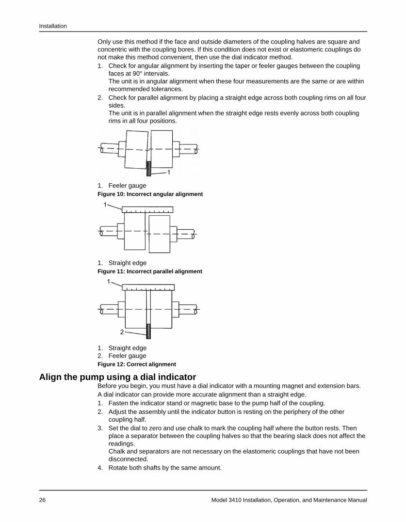
Only use this method if the face and outside diameters of the coupling halves are square andconcentric with the coupling bores. If this condition does not exist or elastomeric couplings donot make this method convenient, then use the dial indicator method.1. Check for angular alignment by inserting the taper or feeler gauges between the coupling
faces at 90° intervals.The unit is in angular alignment when these four measurements are the same or are withinrecommended tolerances.
2. Check for parallel alignment by placing a straight edge across both coupling rims on all foursides.The unit is in parallel alignment when the straight edge rests evenly across both couplingrims in all four positions.
1. Feeler gaugeFigure 10: Incorrect angular alignment
1. Straight edgeFigure 11: Incorrect parallel alignment
1. Straight edge2. Feeler gaugeFigure 12: Correct alignment
Align the pump using a dial indicatorBefore you begin, you must have a dial indicator with a mounting magnet and extension bars.A dial indicator can provide more accurate alignment than a straight edge.1. Fasten the indicator stand or magnetic base to the pump half of the coupling.2. Adjust the assembly until the indicator button is resting on the periphery of the other
coupling half.3. Set the dial to zero and use chalk to mark the coupling half where the button rests. Then
place a separator between the coupling halves so that the bearing slack does not affect thereadings.Chalk and separators are not necessary on the elastomeric couplings that have not beendisconnected.
4. Rotate both shafts by the same amount.
Installation
Model 3410 Installation, Operation, and Maintenance Manual 27
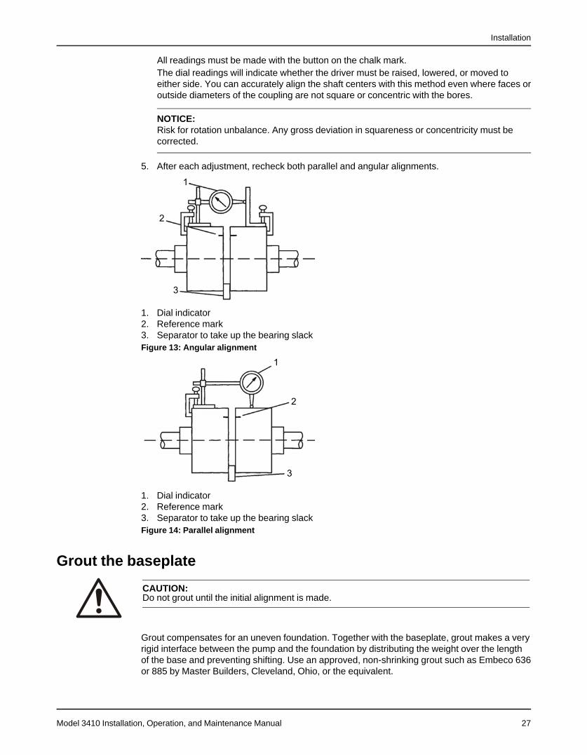
All readings must be made with the button on the chalk mark.The dial readings will indicate whether the driver must be raised, lowered, or moved toeither side. You can accurately align the shaft centers with this method even where faces oroutside diameters of the coupling are not square or concentric with the bores.
NOTICE:Risk for rotation unbalance. Any gross deviation in squareness or concentricity must becorrected.
5. After each adjustment, recheck both parallel and angular alignments.
1. Dial indicator2. Reference mark3. Separator to take up the bearing slackFigure 13: Angular alignment
1. Dial indicator2. Reference mark3. Separator to take up the bearing slackFigure 14: Parallel alignment
Grout the baseplate
CAUTION:Do not grout until the initial alignment is made.
Grout compensates for an uneven foundation. Together with the baseplate, grout makes a veryrigid interface between the pump and the foundation by distributing the weight over the lengthof the base and preventing shifting. Use an approved, non-shrinking grout such as Embeco 636or 885 by Master Builders, Cleveland, Ohio, or the equivalent.
Installation
Model 3410 Installation, Operation, and Maintenance Manual28
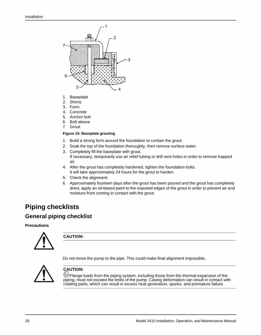
1. Baseplate2. Shims3. Form4. Concrete5. Anchor bolt6. Bolt sleeve7. Grout
Figure 15: Baseplate grouting
1. Build a strong form around the foundation to contain the grout.2. Soak the top of the foundation thoroughly, then remove surface water.3. Completely fill the baseplate with grout.
If necessary, temporarily use air relief tubing or drill vent holes in order to remove trappedair.
4. After the grout has completely hardened, tighten the foundation bolts.It will take approximately 24 hours for the grout to harden.
5. Check the alignment.6. Approximately fourteen days after the grout has been poured and the grout has completely
dried, apply an oil-based paint to the exposed edges of the grout in order to prevent air andmoisture from coming in contact with the grout.
Piping checklistsGeneral piping checklist
Precautions
CAUTION:
Do not move the pump to the pipe. This could make final alignment impossible.
CAUTION:
Flange loads from the piping system, including those from the thermal expansion of thepiping, must not exceed the limits of the pump. Casing deformation can result in contact withrotating parts, which can result in excess heat generation, sparks, and premature failure.
Installation
Model 3410 Installation, Operation, and Maintenance Manual 29
NOTICE:Vary the capacity with the regulating valve in the discharge line. Never throttle the flow from thesuction side. This action can result in decreased performance, unexpected heat generation,and equipment damage.
Piping guidelinesGuidelines for piping are given in the Hydraulic Institute Standards available from the HydraulicInstitute at 9 Sylvan Way, Parsippany, NJ 07054-3802. You must review this document beforeyou install the pump.
Checklist
Check Explanation/comment CheckedCheck that all piping is supportedindependently of, and lined upnaturally with, the pump flange.
This helps to prevent:• Strain on the pump• Misalignment between the pump and the drive unit• Wear on the pump bearings, seal, and shafting
Keep the piping as straight aspossible. Avoid unnecessarybends. Use 45° or long radius 90°fittings where necessary.
This helps to minimize friction losses.
Check that only necessary fittingsare used.
This helps to minimize friction losses.
Make sure that the inside diame-ters match properly when you useflange joints.
—
Do not connect the piping to thepump until:
• The grout for the baseplateor sub-base becomes hard.
• The hold-down bolts for thepump are tightened.
—
Make sure that all the piping jointsand fittings are airtight.
This prevents air from entering the piping system orleaks that occur during operation.
If the pump handles corrosivefluids, make sure that the pipingallows you to flush out the liquidbefore you remove the pump.If the pump handles liquids atelevated temperatures, makesure that the expansion loops andjoints are properly installed.
This helps to prevent misalignment due to thermalexpansion of the piping.
Make sure that all piping compo-nents, valves and fittings, andpump branches are clean prior toassembly.
—
Suction piping checklistThe sizing and installation of the suction piping is extremely important. It must be selected andinstalled so that pressure losses are minimized and sufficient liquid flows into the pump when itis started and operated. Many NPSH problems can be directly attributed to improper suctionpiping systems.
CAUTION:• Flange loads from the piping system, including those from the thermal expansion of the
piping, must not exceed the limits of the pump. Deformation can result in contact withrotating parts, which can result in excess heat generation, sparks, and premature failure.
• Air pockets can form in the top of the reducer and the pipe when operating on suction lift.Never use a concentric reducer in a horizontal line.
Installation
Model 3410 Installation, Operation, and Maintenance Manual30
Piping checklist
Check Explanation/comment CheckedCheck that the elbows in the suctionpiping for horizontal double-suctionpumps are installed per the HydraulicsInstitute Standards since there is al-ways an uneven turbulent flow aroundan elbow.
When there is an elbow in a position other thanthe vertical when in relation to the pump suctionnozzle, this causes more liquid to enter one sideof the impeller than the other. The result is highlyunequalized thrust loads that overheat the bear-ings and cause rapid wear, which adverselyaffects the hydraulic performance. See the Ex-ample of unbalanced loading figure.
Check that pipe reducers on the inletside have no more than one pipediameter reduction in a single reducer.
This avoids excessive turbulence and noise.
When operating on a suction lift, checkthat the suction pipe slopes upward tothe pump nozzle.
A horizontal suction line must have a gradualrise to the pump. Any high point in the pipe canbecome filled with air and prevent proper opera-tion of the pump.
(Optional) You can install a short sec-tion of pipe adjacent to the suctionflange such as Dutchman or a spoolpiece that is designed so that it can bereadily dropped out of the line.
This facilitates the cleansing of the liquid pas-sage of the pump without dismantling the pump.With this arrangement, anything that clogs theimpeller is accessible with the removal of thespool piece or pipe section.
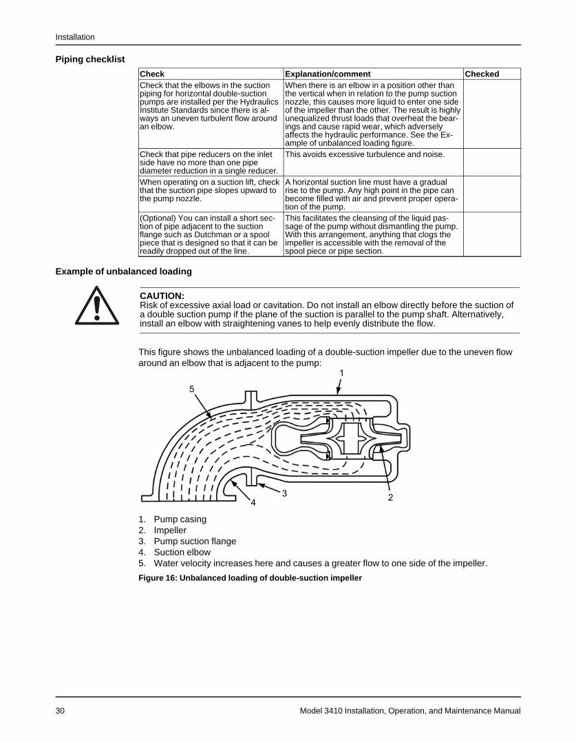
Example of unbalanced loading
CAUTION:Risk of excessive axial load or cavitation. Do not install an elbow directly before the suction ofa double suction pump if the plane of the suction is parallel to the pump shaft. Alternatively,install an elbow with straightening vanes to help evenly distribute the flow.
This figure shows the unbalanced loading of a double-suction impeller due to the uneven flowaround an elbow that is adjacent to the pump:
1. Pump casing2. Impeller3. Pump suction flange4. Suction elbow5. Water velocity increases here and causes a greater flow to one side of the impeller.
Figure 16: Unbalanced loading of double-suction impeller
Installation
Model 3410 Installation, Operation, and Maintenance Manual 31
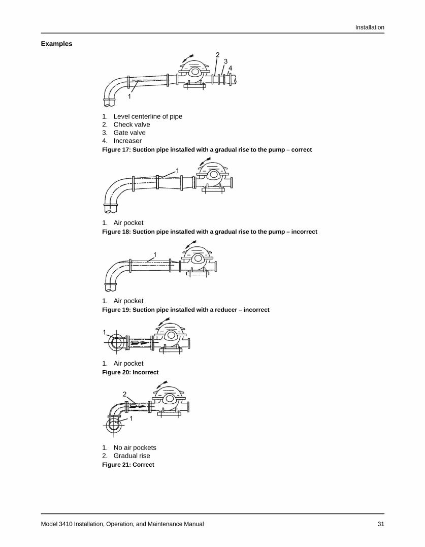
Examples
1. Level centerline of pipe2. Check valve3. Gate valve4. IncreaserFigure 17: Suction pipe installed with a gradual rise to the pump – correct
1. Air pocketFigure 18: Suction pipe installed with a gradual rise to the pump – incorrect
1. Air pocketFigure 19: Suction pipe installed with a reducer – incorrect
1. Air pocketFigure 20: Incorrect
1. No air pockets2. Gradual riseFigure 21: Correct
Installation
Model 3410 Installation, Operation, and Maintenance Manual32
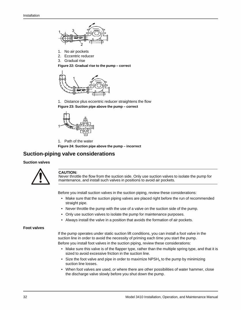
1. No air pockets2. Eccentric reducer3. Gradual riseFigure 22: Gradual rise to the pump – correct
1. Distance plus eccentric reducer straightens the flowFigure 23: Suction pipe above the pump – correct
1. Path of the waterFigure 24: Suction pipe above the pump – incorrect
Suction-piping valve considerations
Suction valves
CAUTION:Never throttle the flow from the suction side. Only use suction valves to isolate the pump formaintenance, and install such valves in positions to avoid air pockets.
Before you install suction valves in the suction piping, review these considerations:
• Make sure that the suction piping valves are placed right before the run of recommendedstraight pipe.
• Never throttle the pump with the use of a valve on the suction side of the pump.
• Only use suction valves to isolate the pump for maintenance purposes.
• Always install the valve in a position that avoids the formation of air pockets.
Foot valvesIf the pump operates under static suction lift conditions, you can install a foot valve in thesuction line in order to avoid the necessity of priming each time you start the pump.Before you install foot valves in the suction piping, review these considerations:
• Make sure this valve is of the flapper type, rather than the multiple spring type, and that it issized to avoid excessive friction in the suction line.
• Size the foot valve and pipe in order to maximize NPSHA to the pump by minimizingsuction line losses.
• When foot valves are used, or where there are other possibilities of water hammer, closethe discharge valve slowly before you shut down the pump.
Installation
Model 3410 Installation, Operation, and Maintenance Manual 33
Check valvesIn normal applications, check valves are placed in the discharge piping. Before you use acheck valve in the suction piping, consider the added pressure drop to the pump, the potentialof water hammer, and the chance of allowing the entire pump volute to be exposed to thedischarge pressure.
Gate valvesWhere two or more pumps are connected to the same suction line, install gate valves so thatany pump can be isolated from the line.Before you install gate valves, review these considerations:
• Always install gate valves on the suction side of the pumps with a positive pressure formaintenance purposes.
• Always install gate valves with the stems in a horizontal position to avoid air pockets.
• Globe valves should not be used, particularly where NPSH is critical.
Discharge piping considerationsBefore you construct discharge piping, review these considerations:
• If the discharge piping is short, then the pipe diameter can be the same as the dischargeopening.
• If the piping is long, then the pipe diameter should be one or two sizes larger than thedischarge opening.
• On long horizontal runs, it is desirable to maintain the most even grade possible.
• Avoid high spots, such as loops. High spots will collect air and throttle the system or lead toerratic pumping.
• A check valve and an isolating gate valve should be installed in the discharge line.
• The check valve is placed between the pump and the gate valve. This protects thepump from excessive backpressure and prevents liquid from running back through thepump in case of power failure.
• The gate valve is used for priming and starting and also shutting down the pump.
Pressure gaugesInstall properly sized pressure gauges in both the suction and discharge nozzles in the gaugetaps provided. The gauges enable the operator to observe the operation of the pump and todetermine whether the pump is operating in conformance with the performance curve. Ifcavitation, vapor binding, or other unstable operations occur, then widely fluctuating dischargepressure will be noted.
Pump dowelingPump units can be doweled on diagonally opposite feet. Do not do this until the unit has run fora sufficient length of time and alignment is within the required alignment tolerance.
Commissioning, Startup, Operation, and Shutdown
Model 3410 Installation, Operation, and Maintenance Manual34
Commissioning, Startup, Operation, andShutdown
Preparation for startup
WARNING:• Failure to disconnect and lock out driver power may result in serious physical injury or
death. Always disconnect and lock out power to the driver before performing anyinstallation or maintenance tasks.• Electrical connections must be made by certified electricians in compliance with all
international, national, state, and local rules.• Refer to driver/coupling/gear manufacturer's installation and operation manuals (IOM)
for specific instructions and recommendations.• Electrical connections must be made by certified electricians in compliance with all
international, national, state, and local rules.• Running a pump without safety devices exposes operators to risk of serious personal
injury or death. Never operate a unit unless appropriate safety devices (guards, etc.) areproperly installed.
• Check the rotation of the power unit and pump in relation to that of the drive as shown bythe arrows on the case. Rotate the drive manually before you apply power-checkingrotation. Do not operate in the reverse direction of these arrows as serious damage orinjury can occur.
CAUTION:• Serious damage to the pump may result if it is started dry. Make sure that the pump is
completely filled with liquid before it is started.
System flushingFlush new and old systems in order to eliminate all foreign matter. Heavy scale, weldingsplatter, and wire or other large foreign matter can clog the pump impeller. This reduces thecapacity of the pump which then causes cavitation, excessive vibration, and/or damage toclose clearance parts such as wear rings, seals, and sleeves.
Pre-operation inspections
NOTICE:Foreign objects in the pumped liquid or piping system can block the flow and cause excessheat generation, sparks and premature failure. Make sure that the pump and systems are freeof foreign objects before and during operation.
Perform these inspections before you start the pump:
• Check the alignment between the pump and motor.See Coupling alignment in the Installation chapter for alignment requirements.
• Check all connections to the motor and starting device against the wiring diagram.Check the voltage, phase, and frequency on the motor nameplate against the line circuit.
• Check the suction and discharge piping and the pressure gauges for proper operation.
• Check that you can turn the rotating element by hand in order to verify that it rotates freely.
• Check the stuffing box adjustment, lubrication, and piping.
• Check the driver lubrication.Refer to the driver Installation, Operation, and Maintenance manual.
Commissioning, Startup, Operation, and Shutdown
Model 3410 Installation, Operation, and Maintenance Manual 35
• Check that the pump bearings are properly lubricated.
• If the pump is oil lubrication, check that the oil level is correct prior to starting pump.
• If the pump is oil mist lubrication, check that the mist is flowing properly prior to startingpump.
• Check that the coupling is properly lubricated, if required.
• Check that the pump is full of liquid and that all valves are properly set and operational,with the discharge valve closed and the suction valve fully open. Purge all air from the topof the casing.
• Check the direction of the rotation.Be sure that the driver operates in the direction indicated by the arrow on the pump casing.Serious damage can result if you operate the pump with the incorrect rotation. Check therotation each time you disconnect the motor leads.
Pump priming
CAUTION:Do not run the pump dry.
When to prime the pumpYou must prime the pump before startup. When it is possible, locate the pump below the fluidlevel in order to facilitate priming and to ensure a steady flow of liquid. This condition provides apositive suction head on the pump. It is also possible to prime the pump by pressurizing thesuction vessel.
Methods for pump priming
Pump installation Priming methodPositive head on the suction Open the suction valve and loosen the vent plug on top of the
casing. This allows air to be purged from the casing. While youvent the air from the pump body, always rotate the pump shafta few times by hand.
Suction lift Priming must be done by other methods such as foot valves,ejectors, or by manually filling the casing and suction line.
Fill the system
DANGER:All openings (e.g. pipe connections, flanges) must be sealed off with proper fitting and materialprior to filling pump. Failure to plug all openings will result in personal injury.
1. Locate the vents at the highest point so that trapped gases and air can escape.However, if the gases are flammable, toxic, or corrosive, then vent them to an appropriateplace in order to prevent harm to personnel or to other parts of the system.
2. Check the pipe hangers and anchors to make sure that they are properly set to take theadditional weight of the pumped fluid.
3. Close all of the drains.4. Fill the system slowly so that excessive velocities do not cause rotation of the pumping
elements.Rotation of the pumping elements can cause damage to the pump or its driver.
5. Check the adequacy of the anchors and hangers:a) Mount a dial indicator off of any rigid structure not tied to the piping.
Commissioning, Startup, Operation, and Shutdown
Model 3410 Installation, Operation, and Maintenance Manual36
b) Set the indicator button on the pump flange in the axial direction of the nozzle.If the indicator moves as the filling proceeds, then the anchors and supports are notadequate or are not set properly. Take corrective measures.
Start the pump1. Close the drain valves.2. Completely open all valves in the suction and discharge lines.3. Turn on the seal water to the stuffing box.
These lines must always be left open if the pumped fluid is dirty or if there is the possibilityof air leaks.
4. Prime the pump.
NOTICE:Make sure that the pump is properly primed. If it is not, then shut down the pump andcorrect the condition.
5. Start the pump driver.Turbines and engines can require a brief warm-up period. Consult the instructions providedby the engine manufacturer.
6. When the pump is operating at full speed, make sure that the check valve has opened.The check valve must open five seconds or less after startup in order to prevent damage tothe pump by operating at zero flow.
7. Adjust the liquid seal valves to produce the recommended pressure for either themechanical seal or the packed stuffing box.
Operational checklistCheck Explanation/comment CheckedDriver rotation Check the rotation each time the motor leads are discon-
nected.
WARNING:Check the rotation of the power unitand pump in relation to that of thedrive as shown by the arrows onthe case. Rotate the drive manuallybefore you apply power-checkingrotation. Do not operate in the re-verse direction of these arrows asserious damage or injury can occur.
Stuffing box adjustment Make stuffing box packing gland and lubrication adjust-ments.
Flow It is difficult to accurately measure flow rate (volume/time). Any of the following methods of measuring can beused:
• Venturi meters• Flow nozzles• Orifice plates• Timing the draw down in the wet well
Record any reading for future reference.
Commissioning, Startup, Operation, and Shutdown
Model 3410 Installation, Operation, and Maintenance Manual 37
Check Explanation/comment CheckedPressure Check and record both suction and discharge pressure
gauge readings for future reference. Also record thefollowing:
• Voltage• Amperage per phase• Kilowatts (if an indicating wattmeter is available)• Pump speed
Temperature Check and record bearing temperatures using athermometer. The temperature should not exceed 180°F(82°C).
Vibration and sound The acceptable vibration level of a centrifugal pumpdepends on the rigidity of the pump and the supportingstructure. Recommended values for vibration can varybetween 0.20–0.60 ips (inches per second) velocitydepending on the operating characteristics and thestructure. Refer to the Centrifugal Pump section of theHydraulic Institute Standards for a complete descriptionand charts on various pumps.Field sound levels are difficult to measure because ofbackground noise from piping, valves, drivers, gears,and other parts. Follow the recommendations in theHydraulic Institute Standards.
Check the rotation - Frame Mounted
WARNING:• Starting the pump in reverse rotation can result in the contact of metal parts, heat
generation, and breach of containment. Ensure correct driver settings prior to starting anypump.
• Failure to disconnect and lock out driver power may result in serious physical injury ordeath. Always disconnect and lock out power to the driver before performing anyinstallation or maintenance tasks.• Electrical connections must be made by certified electricians in compliance with all
international, national, state, and local rules.• Refer to driver/coupling/gear manufacturer's installation and operation manuals (IOM)
for specific instructions and recommendations.
1. Lock out power to the driver.2. Make sure that the coupling hubs are fastened securely to the shafts.3. Make sure that the coupling spacer is removed.
The pump ships with the coupling spacer removed.4. Unlock power to the driver.5. Make sure that everyone is clear, and then jog the driver long enough to determine that the
direction of rotation corresponds to the arrow on the pump.6. Lock out power to the driver.
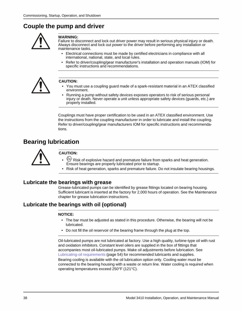
Commissioning, Startup, Operation, and Shutdown
Model 3410 Installation, Operation, and Maintenance Manual38
Couple the pump and driver
WARNING:Failure to disconnect and lock out driver power may result in serious physical injury or death.Always disconnect and lock out power to the driver before performing any installation ormaintenance tasks.
• Electrical connections must be made by certified electricians in compliance with allinternational, national, state, and local rules.
• Refer to driver/coupling/gear manufacturer's installation and operation manuals (IOM) forspecific instructions and recommendations.
CAUTION:• You must use a coupling guard made of a spark-resistant material in an ATEX classified
environment.• Running a pump without safety devices exposes operators to risk of serious personal
injury or death. Never operate a unit unless appropriate safety devices (guards, etc.) areproperly installed.
Couplings must have proper certification to be used in an ATEX classified environment. Usethe instructions from the coupling manufacturer in order to lubricate and install the coupling.Refer to driver/coupling/gear manufacturers IOM for specific instructions and recommenda-tions.
Bearing lubrication
CAUTION:
• Risk of explosive hazard and premature failure from sparks and heat generation.Ensure bearings are properly lubricated prior to startup.
• Risk of heat generation, sparks and premature failure. Do not insulate bearing housings.
Lubricate the bearings with greaseGrease-lubricated pumps can be identified by grease fittings located on bearing housing.Sufficient lubricant is inserted at the factory for 2,000 hours of operation. See the Maintenancechapter for grease lubrication instructions.
Lubricate the bearings with oil (optional)
NOTICE:• The bar must be adjusted as stated in this procedure. Otherwise, the bearing will not be
lubricated.
• Do not fill the oil reservoir of the bearing frame through the plug at the top.
Oil-lubricated pumps are not lubricated at factory. Use a high quality, turbine-type oil with rustand oxidation inhibitors. Constant level oilers are supplied in the box of fittings thataccompanies most oil-lubricated pumps. Make oil adjustments before lubrication. SeeLubricating-oil requirements (page 54) for recommended lubricants and supplies.Bearing cooling is available with the oil lubrication option only. Cooling water must beconnected to the bearing housing with a waste or return line. Water cooling is required whenoperating temperatures exceed 250°F (121°C).
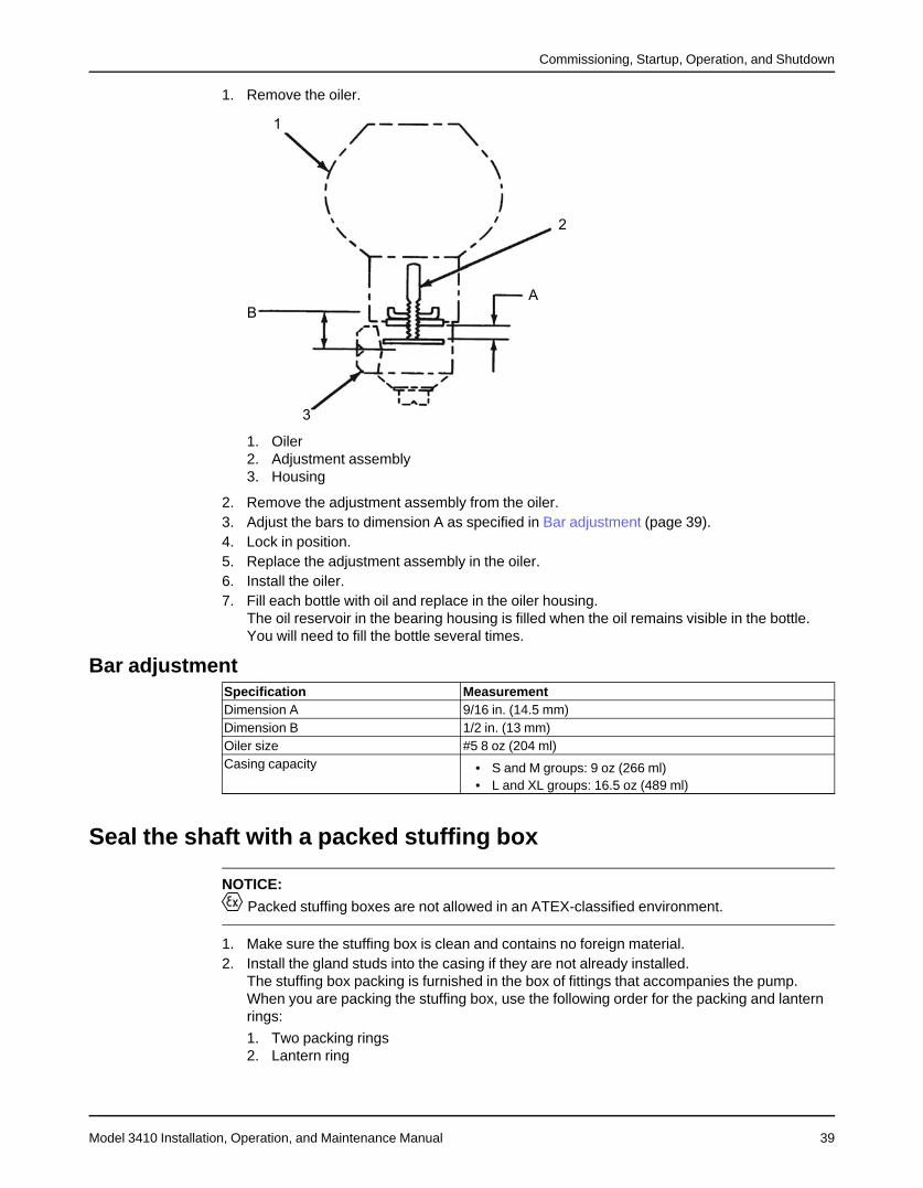
Commissioning, Startup, Operation, and Shutdown
Model 3410 Installation, Operation, and Maintenance Manual 39
1. Remove the oiler.
1. Oiler2. Adjustment assembly3. Housing
2. Remove the adjustment assembly from the oiler.3. Adjust the bars to dimension A as specified in Bar adjustment (page 39).4. Lock in position.5. Replace the adjustment assembly in the oiler.6. Install the oiler.7. Fill each bottle with oil and replace in the oiler housing.
The oil reservoir in the bearing housing is filled when the oil remains visible in the bottle.You will need to fill the bottle several times.
Bar adjustmentSpecification MeasurementDimension A 9/16 in. (14.5 mm)Dimension B 1/2 in. (13 mm)Oiler size #5 8 oz (204 ml)Casing capacity • S and M groups: 9 oz (266 ml)
• L and XL groups: 16.5 oz (489 ml)
Seal the shaft with a packed stuffing box
NOTICE:
Packed stuffing boxes are not allowed in an ATEX-classified environment.
1. Make sure the stuffing box is clean and contains no foreign material.2. Install the gland studs into the casing if they are not already installed.
The stuffing box packing is furnished in the box of fittings that accompanies the pump.When you are packing the stuffing box, use the following order for the packing and lanternrings:
1. Two packing rings2. Lantern ring
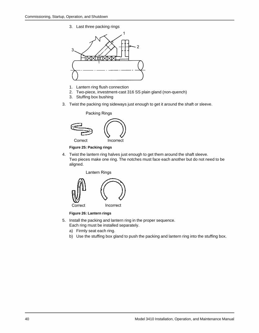
Commissioning, Startup, Operation, and Shutdown
Model 3410 Installation, Operation, and Maintenance Manual40
3. Last three packing rings
1. Lantern ring flush connection2. Two-piece, investment-cast 316 SS plain gland (non-quench)3. Stuffing box bushing
3. Twist the packing ring sideways just enough to get it around the shaft or sleeve.
Figure 25: Packing rings
4. Twist the lantern ring halves just enough to get them around the shaft sleeve.Two pieces make one ring. The notches must face each another but do not need to bealigned.
Figure 26: Lantern rings
5. Install the packing and lantern ring in the proper sequence.Each ring must be installed separately.a) Firmly seat each ring.b) Use the stuffing box gland to push the packing and lantern ring into the stuffing box.

Commissioning, Startup, Operation, and Shutdown
Model 3410 Installation, Operation, and Maintenance Manual 41
c) Stagger the joints in each ring by 90 degrees.Make sure the center of the lantern ring lines up with the flush tap in the stuffing box.Any extra rings are spares.
1. Gland2. packing
6. Hand-tighten the gland nuts evenly but not tight.7. To remove the packing from the stuffing box, do the following:
a) Remove the gland assembly.b) Remove the packing with a packing hook.c) Remove the lantern ring by inserting a wire hook into the ring on the outer edge.d) Clean the stuffing box.An alternate method of removing the packing is to remove the upper-half casing (see theMaintenance chapter). Remove the packing and lantern ring, and then inspect the sleevesor the shaft. Replace the sleeves or the shaft if either is deeply grooved.
Mechanical seal options
NOTICE:Mechanical seals used in an ATEX classified environment must be properly certified. Failure toensure this may result in equipment damage or physical injury.
When mechanical seals are furnished, the description and identification are indicated on theorder forms. Installation drawings from the seal manufacturer are attached to pump. Most sealsare installed and adjusted at the factory. File these drawings for future use in maintenance andadjustment of the seal whenever the pump is disassembled.
Prepare the seal for operationTo properly prepare the seal for operation, various cooling and flushing flows may have to beconnected. In some cases, these flows are recirculated from pump casing. In other cases,liquid from an outside source may be used. Connect cooling and flushing flows to the seal asdirected in instructions supplied by the manufacturer.All Model 3410 mechanical seals use O-ring mounted stationary seats and a flush gland with apilot fit in the ID of the stuffing box as standard. All S group pumps are standard without shaftsleeves; sleeves are optional. M, L, and XL groups are standard with shaft sleeves and sleevenuts.
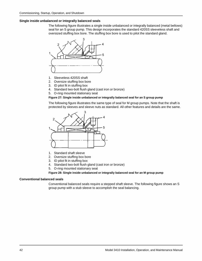
Commissioning, Startup, Operation, and Shutdown
Model 3410 Installation, Operation, and Maintenance Manual42
Single inside unbalanced or integrally balanced sealsThe following figure illustrates a single inside unbalanced or integrally balanced (metal bellows)seal for an S group pump. This design incorporates the standard 420SS sleeveless shaft andoversized stuffing box bore. The stuffing box bore is used to pilot the standard gland.
1. Sleeveless 420SS shaft2. Oversize stuffing box bore3. ID pilot fit in stuffing box4. Standard two-bolt flush gland (cast iron or bronze)5. O-ring mounted stationary seatFigure 27: Single inside unbalanced or integrally balanced seal for an S group pump
The following figure illustrates the same type of seal for M group pumps. Note that the shaft isprotected by sleeves and sleeve nuts as standard. All other features and details are the same.
1. Standard shaft sleeve2. Oversize stuffing box bore3. ID pilot fit in stuffing box4. Standard two-bolt flush gland (cast iron or bronze)5. O-ring mounted stationary seatFigure 28: Single inside unbalanced or integrally balanced seal for an M group pump
Conventional balanced sealsConventional balanced seals require a stepped shaft sleeve. The following figure shows an Sgroup pump with a stub sleeve to accomplish the seal balancing.
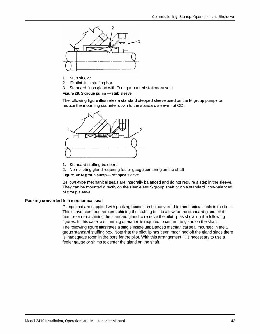
Commissioning, Startup, Operation, and Shutdown
Model 3410 Installation, Operation, and Maintenance Manual 43
1. Stub sleeve2. ID pilot fit in stuffing box3. Standard flush gland with O-ring mounted stationary seatFigure 29: S group pump — stub sleeve
The following figure illustrates a standard stepped sleeve used on the M group pumps toreduce the mounting diameter down to the standard sleeve nut OD.
1. Standard stuffing box bore2. Non-piloting gland requiring feeler gauge centering on the shaftFigure 30: M group pump — stepped sleeve
Bellows-type mechanical seals are integrally balanced and do not require a step in the sleeve.They can be mounted directly on the sleeveless S group shaft or on a standard, non-balancedM group sleeve.
Packing converted to a mechanical sealPumps that are supplied with packing boxes can be converted to mechanical seals in the field.This conversion requires remachining the stuffing box to allow for the standard gland pilotfeature or remachining the standard gland to remove the pilot lip as shown in the followingfigures. In this case, a shimming operation is required to center the gland on the shaft.The following figure illustrates a single inside unbalanced mechanical seal mounted in the Sgroup standard stuffing box. Note that the pilot lip has been machined off the gland since thereis inadequate room in the bore for the pilot. With this arrangement, it is necessary to use afeeler gauge or shims to center the gland on the shaft.
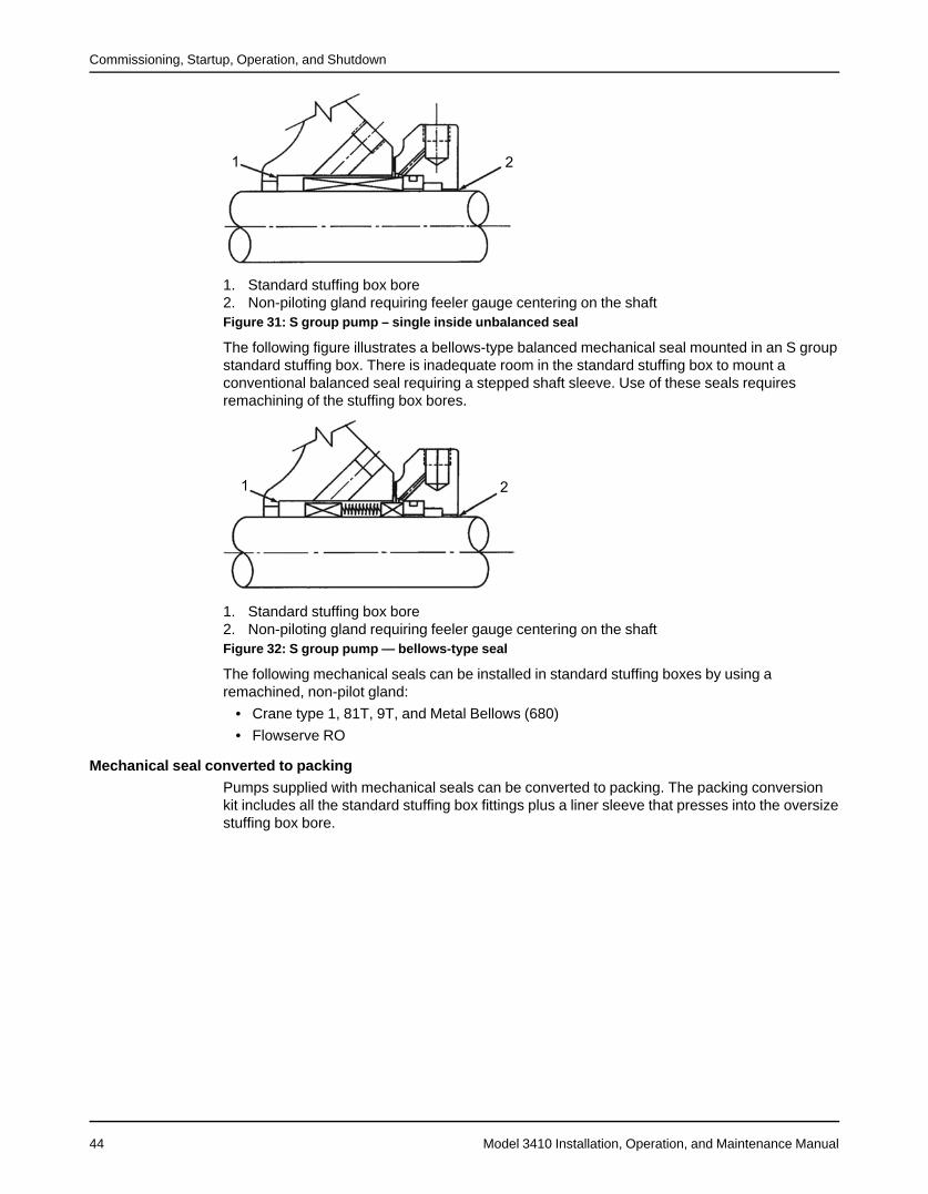
Commissioning, Startup, Operation, and Shutdown
Model 3410 Installation, Operation, and Maintenance Manual44
1. Standard stuffing box bore2. Non-piloting gland requiring feeler gauge centering on the shaftFigure 31: S group pump – single inside unbalanced seal
The following figure illustrates a bellows-type balanced mechanical seal mounted in an S groupstandard stuffing box. There is inadequate room in the standard stuffing box to mount aconventional balanced seal requiring a stepped shaft sleeve. Use of these seals requiresremachining of the stuffing box bores.
1. Standard stuffing box bore2. Non-piloting gland requiring feeler gauge centering on the shaftFigure 32: S group pump — bellows-type seal
The following mechanical seals can be installed in standard stuffing boxes by using aremachined, non-pilot gland:
• Crane type 1, 81T, 9T, and Metal Bellows (680)
• Flowserve RO
Mechanical seal converted to packingPumps supplied with mechanical seals can be converted to packing. The packing conversionkit includes all the standard stuffing box fittings plus a liner sleeve that presses into the oversizestuffing box bore.
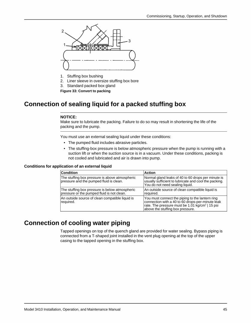
Commissioning, Startup, Operation, and Shutdown
Model 3410 Installation, Operation, and Maintenance Manual 45
1. Stuffing box bushing2. Liner sleeve in oversize stuffing box bore3. Standard packed box glandFigure 33: Convert to packing
Connection of sealing liquid for a packed stuffing box
NOTICE:Make sure to lubricate the packing. Failure to do so may result in shortening the life of thepacking and the pump.
You must use an external sealing liquid under these conditions:
• The pumped fluid includes abrasive particles.
• The stuffing-box pressure is below atmospheric pressure when the pump is running with asuction lift or when the suction source is in a vacuum. Under these conditions, packing isnot cooled and lubricated and air is drawn into pump.
Conditions for application of an external liquid
Condition ActionThe stuffing box pressure is above atmosphericpressure and the pumped fluid is clean.
Normal gland leaks of 40 to 60 drops per minute isusually sufficient to lubricate and cool the packing.You do not need sealing liquid.
The stuffing box pressure is below atmosphericpressure or the pumped fluid is not clean.
An outside source of clean compatible liquid isrequired.
An outside source of clean compatible liquid isrequired.
You must connect the piping to the lantern ringconnection with a 40 to 60 drops-per-minute leakrate. The pressure must be 1.01 kg/cm2 | 15 psiabove the stuffing box pressure.
Connection of cooling water pipingTapped openings on top of the quench gland are provided for water sealing. Bypass piping isconnected from a T-shaped joint installed in the vent plug opening at the top of the uppercasing to the tapped opening in the stuffing box.
Commissioning, Startup, Operation, and Shutdown
Model 3410 Installation, Operation, and Maintenance Manual46
Mechanical seal flushing and cooling
NOTICE:
• The mechanical seal must have an appropriate seal-flush system. Failure to do so willresult in excess heat generation and seal failure.
• Sealing systems that are not self-purging or self-venting, such as plan 23, requiremanual venting prior to operation. Failure to do so will result in excess heat generation andseal failure.
A liquid film is required between the seal faces for proper lubrication. If the liquid flashes tovapor, then the faces will run dry and become damaged. This requires that the liquid be cooledso that vapor pressure is well below stuffing box pressure. Consult with ITT Goulds for arecommendation if there is any uncertainty. Refer to the drawing supplied by the sealmanufacturer for the location of the taps. You can use the following methods to flush and coolthe seal:
Cool liquid flushingmethod
Description
External source A clean, cool, compatible liquid is injected from an outside source directly intothe seal gland. Flushing liquid must be at a pressure 5–15 psi (0.34–1.03 bar)greater than the pressure in the stuffing box. You must inject 1.5–2 gpm (2–8lpm). You can install a control valve and rotometer in the inlet line for accurateregulation.
Product cooling Pumped liquid is piped from the pump casing, is cooled in an external heatexchanger, and is injected into the seal gland. You can install a control valveand rotometer in the inlet line for accurate regulation.
Other piping plans are available.
Connection of drain pipingTapped openings around the stuffing box for draining leakage are optional. Check theassembly dimension print for size and location. Check the rotor for free turning.
WARNING:Explosion risk. Rubbing could lead to excess heat generation and sparks. Rotate the shaft byhand to make sure it rotates smoothly and that there is no rubbing.
Pump priming
CAUTION:Do not run the pump dry.
When to prime the pumpYou must prime the pump before startup. When it is possible, locate the pump below the fluidlevel in order to facilitate priming and to ensure a steady flow of liquid. This condition provides apositive suction head on the pump. It is also possible to prime the pump by pressurizing thesuction vessel.
Commissioning, Startup, Operation, and Shutdown
Model 3410 Installation, Operation, and Maintenance Manual 47
Methods for pump priming
Pump installation Priming methodPositive head on the suction Open the suction valve and loosen the vent plug on top of the
casing. This allows air to be purged from the casing. While youvent the air from the pump body, always rotate the pump shafta few times by hand.
Suction lift Priming must be done by other methods such as foot valves,ejectors, or by manually filling the casing and suction line.
Start the pump1. Close the drain valves.2. Completely open all valves in the suction and discharge lines.3. Turn on the seal water to the stuffing box.
These lines must always be left open if the pumped fluid is dirty or if there is the possibilityof air leaks.
4. Prime the pump.
NOTICE:Make sure that the pump is properly primed. If it is not, then shut down the pump andcorrect the condition.
5. Start the pump driver.Turbines and engines can require a brief warm-up period. Consult the instructions providedby the engine manufacturer.
6. When the pump is operating at full speed, make sure that the check valve has opened.The check valve must open five seconds or less after startup in order to prevent damage tothe pump by operating at zero flow.
7. Adjust the liquid seal valves to produce the recommended pressure for either themechanical seal or the packed stuffing box.
Pump operation precautionsGeneral considerations
Operation at reduced capacity
WARNING:• Risk of breach of containment and equipment damage. Excessive vibration levels can
cause damage to bearings, stuffing box, seal chamber, and/or mechanical seal. Observepump for vibration levels, bearing temperature, and excessive noise. If normal levels areexceeded, shut down and resolve.
• Risk of explosion and serious physical injury. Do not operate pump with blocked systempiping or with suction or discharge valves closed. This can result in rapid heating andvaporization of pumpage.
• Risk of equipment damage and serious physical injury. Heat build-up can cause rotatingparts to score or seize. Observe pump for excessive heat build-up. If normal levels areexceeded, shut down and resolve.
CAUTION:• Avoid increased radial load. Failure to do so can cause stress on the shaft and bearings.
Commissioning, Startup, Operation, and Shutdown
Model 3410 Installation, Operation, and Maintenance Manual48
NOTICE:Cavitation can cause damage to the internal surfaces of the pump. Ensure net positive suctionhead available (NPSHA) always exceeds NPSH required (NPSH3) as shown on the publishedperformance curve of the pump.
Operation under freezing conditions
NOTICE:Do not expose an idle pump to freezing conditions. Drain all liquid that is inside the pump.Failure to do so can cause liquid to freeze and damage the pump.
Operation at reduced headOn motor-driven pumps, the pump capacity increases with reduced head along withhorsepower consumption, so if the discharge head or pressure drops far below the rated pointfor any length of time, then the motor should be watched for heating. If this condition is likely topersist, then arrangements should be made either to manually or automatically throttle thedischarge valve to build up head to a safe point.
Operation with surge conditionsIf a pump is installed with a quick-closing valve in the discharge line that closes when the pumpis running, then dangerous pressure surges can build up that can cause damage to the pumpor line. In this situation, you must provide a cushioning arrangement to protect the pumpingequipment.
Inspect the packed box after startupNewly installed packing requires time to run in. During this period, frequent attention andcareful adjustments are necessary. Use the following instructions to adjust the stuffing boxgland while the pump is running at rated speed.1. Draw the gland nuts up evenly and only 1/6 of a turn at a time.
Allow sufficient time between adjustments for the packing to adjust itself and for you toobserve the effect on leakage.
2. If any sign of heating is evident, then shut down the pump and allow the box to cool.Several starts may be necessary before the box runs cool. Do not back off the gland nutson a hot box because this can result in leakage between the outer edge of the packing andthe stuffing box bore.
Inspect the mechanical seal after startup
NOTICE:Never run the pump with a dry seal. Make sure that any flush cooling lines are operatingproperly.
The mechanical seal is adjusted at the factory. If the seal leaks slightly when the pump is firststarted, then allow a few hours of run-in for the seal to adjust itself.
Commissioning, Startup, Operation, and Shutdown
Model 3410 Installation, Operation, and Maintenance Manual 49
Shut down the pump
WARNING:Precautions must be taken to prevent physical injury. The pump may handle hazardous and/ortoxic fluids. Proper personal protective equipment should be worn. Pumpage must be handledand disposed of in conformance with applicable environmental regulations.
1. Slowly close the discharge valve.2. Shut down and lock out the driver to prevent accidental rotation.
Commissioning, Startup, Operation, and Shutdown
Model 3410 Installation, Operation, and Maintenance Manual50
Make the final alignment of the pump and driver
WARNING:• Failure to disconnect and lock out driver power may result in serious physical injury or
death. Always disconnect and lock out power to the driver before performing anyinstallation or maintenance tasks.• Electrical connections must be made by certified electricians in compliance with all
international, national, state, and local rules.• Refer to driver/coupling/gear manufacturer's installation and operation manuals (IOM)
for specific instructions and recommendations.• Misalignment can cause decreased performance, equipment damage, and even catas-
trophic failure of frame-mounted units leading to serious injury. Proper alignment is theresponsibility of the installer and the user of the unit. Check the alignment of all drivecomponents prior to operating the unit.• Follow the coupling installation and operation procedures from the coupling manufactur-
er.
You must check the final alignment after the pump and driver are at operating temperature. Forinitial alignment instructions, see the Installation chapter.1. Run the unit under actual operating conditions for enough time to bring the pump, driver,
and associated system to operating temperature.2. Shut down the pump and the driver.3. Remove the coupling guard.
See Remove the coupling guard in the Maintenance chapter.4. Check the alignment while the unit is still hot.
See Pump-to-driver alignment in the Installation chapter.5. Reinstall the coupling guard.6. Restart the pump and driver.
Maintenance
Model 3410 Installation, Operation, and Maintenance Manual 51
Maintenance
Maintenance schedule
CAUTION:Shorten the inspection intervals if the pumped liquid is abrasive or corrosive, or if theenvironment is classified as potentially explosive.
NOTICE:This timetable assumes that the unit has been constantly monitored after startup. Adjust thetimetable for any extreme or unusual applications or conditions.
Monthly inspectionsCheck the bearing temperature with a thermometer. Do not check the temperature by hand. Ifthe bearings are running over 180°F (82°C), then there is too much or too little lubricant.If changing the lubricant or adjusting to the proper level does not correct the condition, thendisassemble and inspect the bearings.
Three-month inspectionsPerform these tasks every three months:
• Check the oil on oil-lubricated units.
• Check the grease-lubricated bearings for saponification. This condition is usually causedby the infiltration of water or other fluid. Saponification gives the grease a whitish color. Ifthis condition occurs, then wash out the bearings with a clean industrial solvent andreplace the grease with the proper type as recommended.
Six-month inspectionsPerform these tasks every six months:
• Check the packing and replace if necessary. Use the grade recommended. Make sure theseal cages are centered in the stuffing box at the entrance of the stuffing box pipingconnection.
• Take vibration readings on the bearing housings. Compare the readings with the last set ofreadings to check for possible pump component failure.
• Check the shaft or shaft sleeve for scoring. Scoring accelerates packing wear.
• Check the alignment of the pump and driver. Shim the units if necessary. If misalignmentreoccurs frequently, then inspect the entire piping system. Unbolt the piping at the suctionand discharge flanges to see if it springs away, which indicates strain on the casing.Inspect all piping supports for soundness and effective support of load. Correct asnecessary.
Annual inspectionsPerform these inspections one time each year:
• Remove the upper half of the casing. Inspect the pump thoroughly for wear. Orderreplacement parts if necessary.
• Check the wear ring clearances. Replace the wear rings when clearances become threetimes their normal clearance or when you observe a significant decrease in dischargepressure for the same flow rate.Refer to Radial clearances (page 65) for standard clearances.
• Remove any deposit or scaling.
Maintenance
Model 3410 Installation, Operation, and Maintenance Manual52
• Clean out the stuffing box piping.
• Measure the total dynamic suction and discharge head in order to test pump performanceand pipe condition. Record the figures and compare them with the figures of the last test.This is especially important where the pumped liquid tends to form a deposit on internalsurfaces.
• Inspect foot valves and check valves. A faulty foot or check valve will cause poorperformance. The check valve safeguards against water hammer when the pump stops.
Flood-damaged pumpsIf the pump is properly sealed at all joints and connected to both suction and discharge, then itwill exclude outside liquid. Therefore, it is only necessary to service the bearings, stuffing box,and coupling after flood damage.Perform the following service on a centrifugal pump after a flooded condition:
• Dismantle the frame, and then inspect the bearings for any rusted or badly worn surfaces.Clean as necessary. If the bearings are free from rust and wear, then reassemble andrelubricate them with one of the recommended lubricants. Depending on the length of timethe pump has remained in the flooded area, it is unlikely that bearing replacement isnecessary. Only replace the bearings if rust or worn surfaces appear.
• Inspect the stuffing box and clean out any foreign matter that will clog the box. Replacepacking that appears to be worn or no longer regulates leakage properly. Clean andthoroughly flush mechanical seals.
• Dismantle and thoroughly clean the couplings. Lubricate the couplings where required withone of the lubricants recommended by the coupling manufacturer.
Bearing maintenanceThese bearing lubrication sections list different temperatures of the pumped fluid. If the
pump is ATEX-certified and the temperature of the pumped fluid exceeds the permittedtemperature values, then consult your ITT representative.
Regrease the grease-lubricated bearings
CAUTION:Grease-lubricated bearings are lubricated at the factory. Do not grease too frequently.
NOTICE:Risk of equipment damage. Ensure that the grease container, the greasing device, and thefittings are clean. Failure to do so can result in impurities entering the bearing housing whileregreasing the bearings.
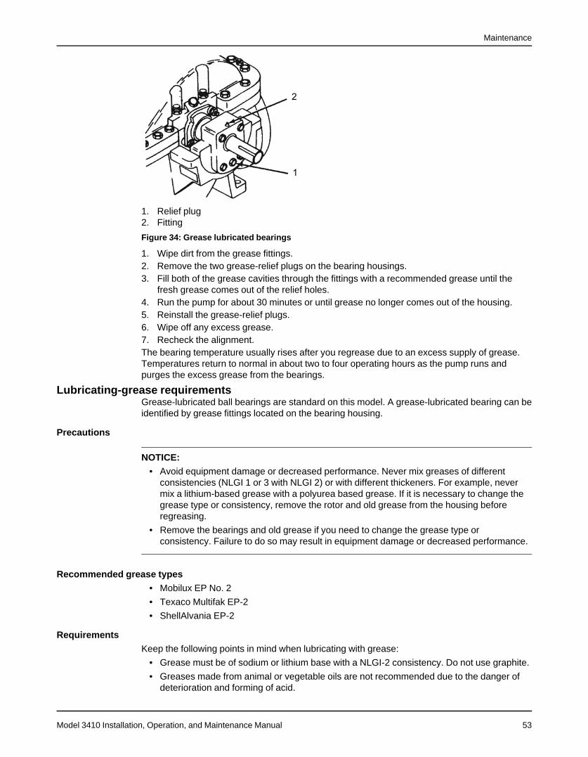
Maintenance
Model 3410 Installation, Operation, and Maintenance Manual 53
1. Relief plug2. Fitting
Figure 34: Grease lubricated bearings
1. Wipe dirt from the grease fittings.2. Remove the two grease-relief plugs on the bearing housings.3. Fill both of the grease cavities through the fittings with a recommended grease until the
fresh grease comes out of the relief holes.4. Run the pump for about 30 minutes or until grease no longer comes out of the housing.5. Reinstall the grease-relief plugs.6. Wipe off any excess grease.7. Recheck the alignment.The bearing temperature usually rises after you regrease due to an excess supply of grease.Temperatures return to normal in about two to four operating hours as the pump runs andpurges the excess grease from the bearings.
Lubricating-grease requirementsGrease-lubricated ball bearings are standard on this model. A grease-lubricated bearing can beidentified by grease fittings located on the bearing housing.
Precautions
NOTICE:• Avoid equipment damage or decreased performance. Never mix greases of different
consistencies (NLGI 1 or 3 with NLGI 2) or with different thickeners. For example, nevermix a lithium-based grease with a polyurea based grease. If it is necessary to change thegrease type or consistency, remove the rotor and old grease from the housing beforeregreasing.
• Remove the bearings and old grease if you need to change the grease type orconsistency. Failure to do so may result in equipment damage or decreased performance.
Recommended grease types• Mobilux EP No. 2
• Texaco Multifak EP-2
• ShellAlvania EP-2
RequirementsKeep the following points in mind when lubricating with grease:
• Grease must be of sodium or lithium base with a NLGI-2 consistency. Do not use graphite.
• Greases made from animal or vegetable oils are not recommended due to the danger ofdeterioration and forming of acid.
Maintenance
Model 3410 Installation, Operation, and Maintenance Manual54
• Additional or replacement lubricant must be added after 2,000 hours or at three-monthintervals.
• Replace the lubricant in the housings at least once annually. This must be done when anoverhaul is made.
• When greasing anti-friction bearings, do not use high-pressure equipment. High pressurecan damage the bearings or seals, cause unnecessary loss of grease, create a danger ofoverheating due to over greasing, and produce unsightly conditions around the bearing.
• Excess grease is the most common cause of overheating. Maintain the grease level atabout the capacity of the bearing and 1/3 to 1/2 of the cavity between the bearing andgrease fitting. Any greater amount will be discharged by the seal or vent.
Lubricate the oil-lubricated bearingsOil-lubricated ball bearings are optional. Oil-lubricated pumps are supplied with oilers thatmaintain a constant oil level in the bearing housing.For an illustration of the oiler, see Lubricate the bearings with oil (optional) (page 38).1. After the pump has been installed, flush the housings to remove dirt, grit, and other
impurities that have entered the bearing housing during shipment or installation.2. Fill the oiler bottles on both bearing housings with the proper lubricant and place on the
oiler housing.The oil reservoir in the bearing housing is filled when a constant oil level remains in thebottle. Several fillings of the bottle are required for initial lubrication. Never put oil into theoiler housing without the use of the oiler bottle.
Lubricating-oil requirements
Oil requirements based on temperatureFor the majority of operating conditions, bearing temperatures run between 49°C | 120°F and 82°C |180°F, and you can use an oil of ISO viscosity grade 68 at 38°C | 100°F. If temperatures exceed 82°C |180°F, refer to the table for temperature requirements.Temperature Oil requirementBearing temperatures exceed 82°C | 180°F Use ISO viscosity grade 100. Bearing temperatures
are generally about 11°C | 20°F higher than bear-ing-housing outer surface temperatures.
Pumped-fluid temperatures are extreme Refer to the factory or a lubrication expert.
Acceptable oil for lubricating bearings
Acceptable lubricants
Brand Lubricant typeChevron GTS Oil 68Exxon Teresstic EP 68Mobil DTE 26 300 SSU @ 38°C | 100°FPhilips Mangus Oil 315Shell -29-0°C | -20-32°F: Tellus Oil 23
0-65°C | 32-150°F: Tellus Oil 6865-93°C | 150-200°F: Turbo Oil 150
Royal Purple SYNFILM ISO VG 68 Synthetic LubeTexaco Below 26.7°C | 80°F: Regal Oil R&O-46 #10 weight
Above 26.7°C | 80°F (): Regal Oil R&O-46 #20weight
Lubricate new bearings with oil for the first timeNew bearings should be lubricated as described in Lubricate the bearings with oil (optional)(page 38).
Maintenance
Model 3410 Installation, Operation, and Maintenance Manual 55
Bearing temperatures• Bearing temperatures up to 180°F (82°C) are normal. For accurate measurement, place a
contact-type thermometer against the bearing housing. Record the reading in a convenientlocation for reference.
• The stability of the temperature, rather than the number of degrees, is the best indicationof normal operation. A sudden increase in temperature is an indication of danger and asignal to investigate. Check the unit for abnormal hydraulic operation and unnecessaryloads, such as coupling misalignment. See Troubleshooting (page 70).
• Do not use the human hand as a thermometer. A temperature that feels hot to the handcan vary from 120°F (49°C) to 130°F (54°C) depending upon the individual. Above thistemperature, the human hand can not accurately estimate temperature.
Bearing conditionsThe life of a bearing can be drastically reduced if contaminated with even a small amount ofdust or dirt. All bearing assembly operations must be done in an environment that is as free ofdust as possible. All tools and hands must be kept clean.
If... Then...New bearings need to be installed They must not be unwrapped, cleaned, or washed until just
before the time of installation.Old bearings are contaminated They must be replaced. Washing bearings does not guarantee
cleanliness.There is any question as to the conditionof bearings
It is always best to replace them. This may prevent anunplanned shutdown. Check the bearing housing seals andreplace as required.
Clean contaminated bearingsIf new bearings are not available and immediate reassembly is necessary, then contaminatedbearings can be cleaned using the following procedure.1. Pour 1–2 quarts (0.9–1.9 liters) of clean, water-free kerosene into a clean pail.2. Dip the bearings into the kerosene and agitate slowly.3. Blow-dry the bearings with air that is clean, filtered, and compressed.
Hold the two races together but allow the inner race to rotate a few turns now and then todislodge the kerosene from the retainer pockets.
4. When the bearings are dry, oil the bearings immediately with a good grade of cleanmachine oil to prevent corrosion or rust.
Emergency ball bearing replacementIf the outboard-end ball bearing needs replacement and it is not desirable to overhaul the entirepump, then the bearing can be replaced without disassembling the entire pump. See theDisassembly and Reassembly sections for details.
Coupling lubrication
Grid or gear-tooth couplingsGrid or gear-tooth couplings, such as Falk Grid Steelflex or Falk Crowned Tooth coupling, areinitially lubricated with Falk Long Term Grease (LTG) and do not require relubrication for up tothree years. If the coupling leaks grease or is exposed to extreme temperatures or excessivemoisture, then more frequent lubrication is required.Use the grease recommendations from the coupling manufacturer for the best performance.
Flexible couplingsFlexible couplings, such as Wood’s Sure-Flex or Falk Torus coupling, provide smoothtransmission of power. There is no rubbing action of metal against rubber to cause wear.Couplings are not affected by abrasives, dirt, or moisture. This eliminates the need forlubrication or maintenance and provides clean and quiet performance.
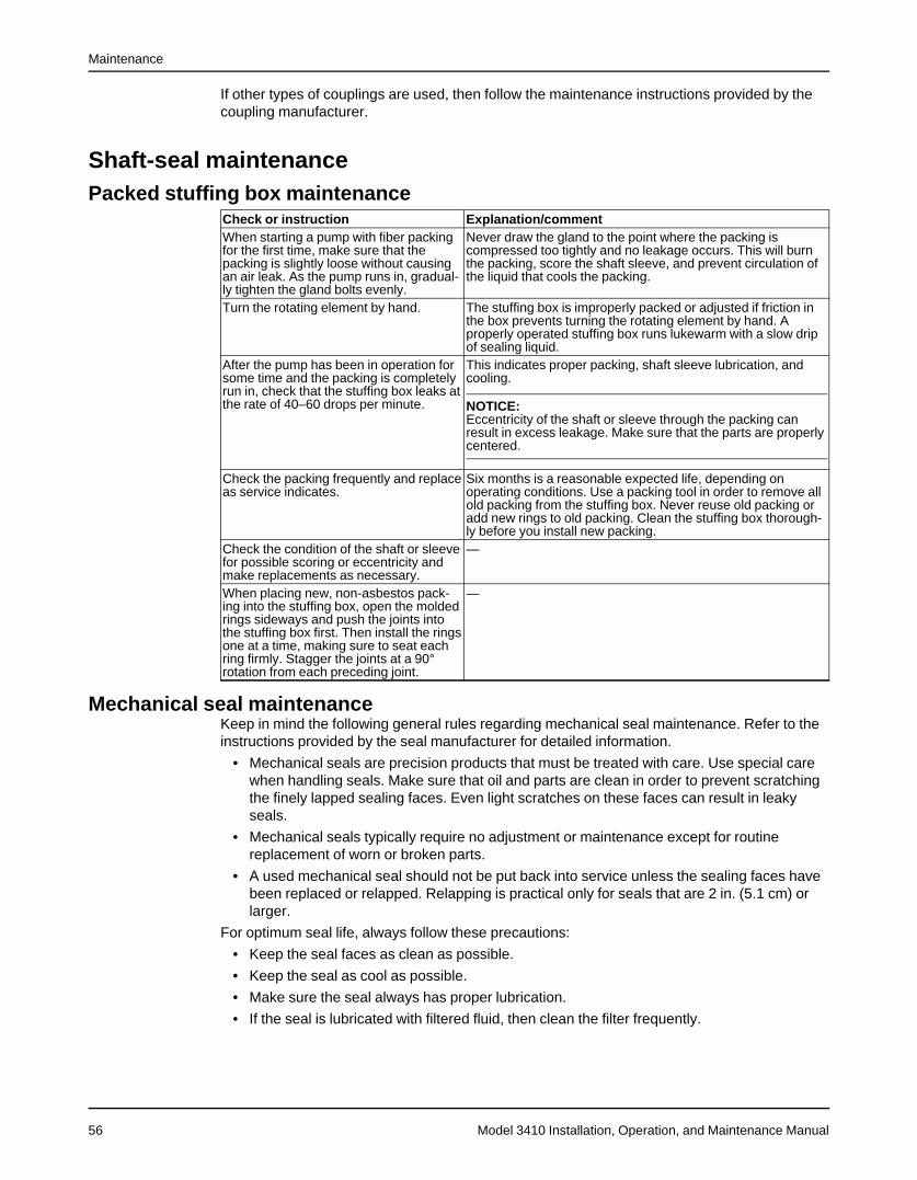
Maintenance
Model 3410 Installation, Operation, and Maintenance Manual56
If other types of couplings are used, then follow the maintenance instructions provided by thecoupling manufacturer.
Shaft-seal maintenancePacked stuffing box maintenance
Check or instruction Explanation/commentWhen starting a pump with fiber packingfor the first time, make sure that thepacking is slightly loose without causingan air leak. As the pump runs in, gradual-ly tighten the gland bolts evenly.
Never draw the gland to the point where the packing iscompressed too tightly and no leakage occurs. This will burnthe packing, score the shaft sleeve, and prevent circulation ofthe liquid that cools the packing.
Turn the rotating element by hand. The stuffing box is improperly packed or adjusted if friction inthe box prevents turning the rotating element by hand. Aproperly operated stuffing box runs lukewarm with a slow dripof sealing liquid.
After the pump has been in operation forsome time and the packing is completelyrun in, check that the stuffing box leaks atthe rate of 40–60 drops per minute.
This indicates proper packing, shaft sleeve lubrication, andcooling.
NOTICE:Eccentricity of the shaft or sleeve through the packing canresult in excess leakage. Make sure that the parts are properlycentered.
Check the packing frequently and replaceas service indicates.
Six months is a reasonable expected life, depending onoperating conditions. Use a packing tool in order to remove allold packing from the stuffing box. Never reuse old packing oradd new rings to old packing. Clean the stuffing box thorough-ly before you install new packing.
Check the condition of the shaft or sleevefor possible scoring or eccentricity andmake replacements as necessary.
—
When placing new, non-asbestos pack-ing into the stuffing box, open the moldedrings sideways and push the joints intothe stuffing box first. Then install the ringsone at a time, making sure to seat eachring firmly. Stagger the joints at a 90°rotation from each preceding joint.
—
Mechanical seal maintenanceKeep in mind the following general rules regarding mechanical seal maintenance. Refer to theinstructions provided by the seal manufacturer for detailed information.
• Mechanical seals are precision products that must be treated with care. Use special carewhen handling seals. Make sure that oil and parts are clean in order to prevent scratchingthe finely lapped sealing faces. Even light scratches on these faces can result in leakyseals.
• Mechanical seals typically require no adjustment or maintenance except for routinereplacement of worn or broken parts.
• A used mechanical seal should not be put back into service unless the sealing faces havebeen replaced or relapped. Relapping is practical only for seals that are 2 in. (5.1 cm) orlarger.
For optimum seal life, always follow these precautions:
• Keep the seal faces as clean as possible.
• Keep the seal as cool as possible.
• Make sure the seal always has proper lubrication.
• If the seal is lubricated with filtered fluid, then clean the filter frequently.
Maintenance
Model 3410 Installation, Operation, and Maintenance Manual 57
DisassemblyDisassembly precautions
WARNING:• Risk of serious physical injury or death from rapid depressurization. Ensure pump is
isolated from system and pressure is relieved before disassembling pump, removingplugs, opening vent or drain valves, or disconnecting piping.
• Risk of serious personal injury. Applying heat to impellers, propellers, or their retainingdevices can cause trapped liquid to rapidly expand and result in a violent explosion. Thismanual clearly identifies accepted methods for disassembling units. These methods mustbe adhered to. Never apply heat to aid in their removal unless explicitly stated in thismanual.
• Failure to disconnect and lock out driver power may result in serious physical injury ordeath. Always disconnect and lock out power to the driver before performing anyinstallation or maintenance tasks.• Electrical connections must be made by certified electricians in compliance with all
international, national, state, and local rules.• Refer to driver/coupling/gear manufacturer's installation and operation manuals (IOM)
for specific instructions and recommendations.• Handling heavy equipment poses a crush hazard. Use caution during handling and wear
appropriate Personal Protective Equipment (PPE, such as steel-toed shoes, gloves, etc.)at all times.
• Precautions must be taken to prevent physical injury. The pump may handle hazardousand/or toxic fluids. Proper personal protective equipment should be worn. Pumpage mustbe handled and disposed of in conformance with applicable environmental regulations.
• Risk of serious personal injury from exposure to hazardous or toxic liquids. A small amountof liquid will be present in certain areas like the seal chamber upon disassembly.
CAUTION:• Avoid injury. Worn pump components can have sharp edges. Wear appropriate gloves
while handling these parts.
Drain the pump1. Close the isolation valves on the suction and discharge sides of the pump.
You must drain the system if no valves are installed.2. Open the drain valve.
Do not proceed until liquid stops coming out of the drain valve. If liquid continues to flowfrom the drain valve, the isolation valves are not sealing properly and you must repair thembefore you proceed.
3. Leave the drain valve open.Do not close the drain valve until the reassembly is complete.
4. Drain the liquid from the piping and flush the pump if it is necessary.5. Disconnect all auxiliary piping and tubing.6. Remove the coupling guard.
Remove the coupling guard1. Remove the nut, bolt, and washers from the slotted hole in the center of the coupling guard.
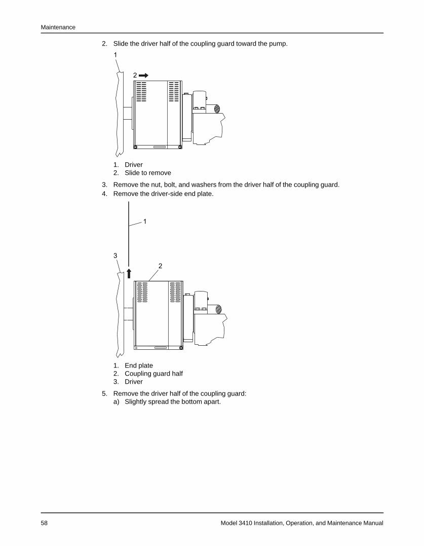
Maintenance
Model 3410 Installation, Operation, and Maintenance Manual58
2. Slide the driver half of the coupling guard toward the pump.
1. Driver2. Slide to remove
3. Remove the nut, bolt, and washers from the driver half of the coupling guard.4. Remove the driver-side end plate.
1. End plate2. Coupling guard half3. Driver
5. Remove the driver half of the coupling guard:a) Slightly spread the bottom apart.
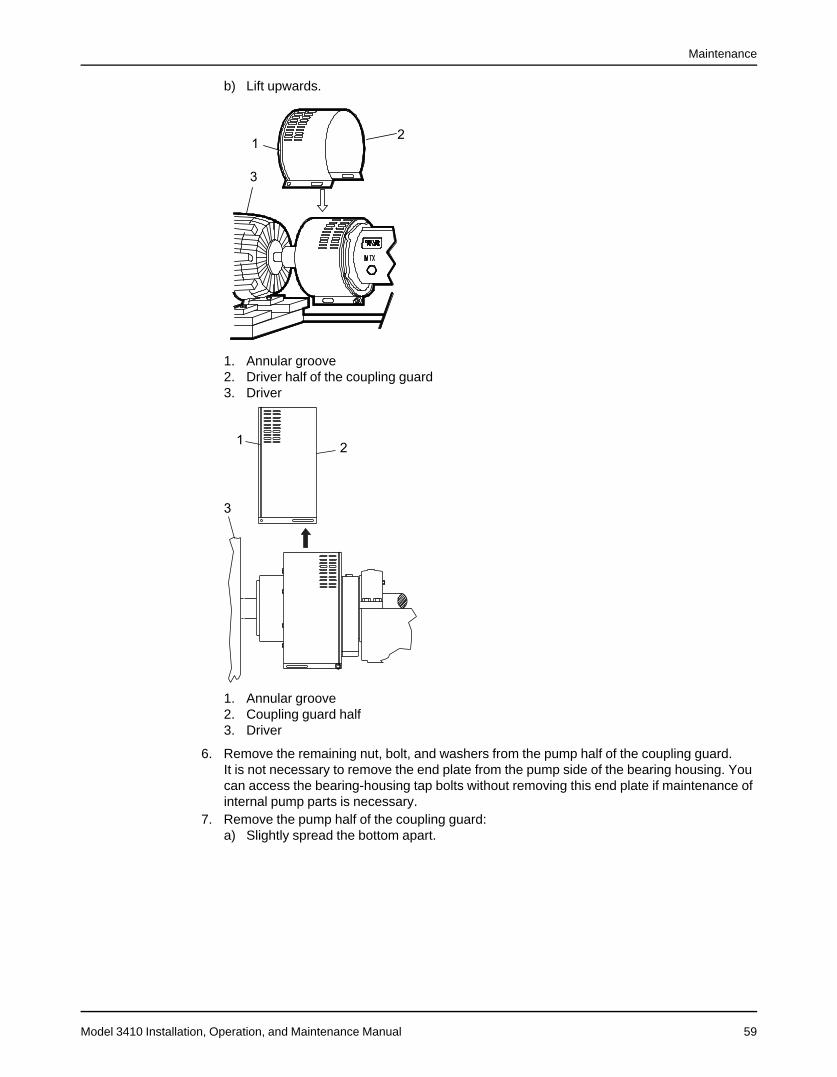
Maintenance
Model 3410 Installation, Operation, and Maintenance Manual 59
b) Lift upwards.
1. Annular groove2. Driver half of the coupling guard3. Driver
1. Annular groove2. Coupling guard half3. Driver
6. Remove the remaining nut, bolt, and washers from the pump half of the coupling guard.It is not necessary to remove the end plate from the pump side of the bearing housing. Youcan access the bearing-housing tap bolts without removing this end plate if maintenance ofinternal pump parts is necessary.
7. Remove the pump half of the coupling guard:a) Slightly spread the bottom apart.
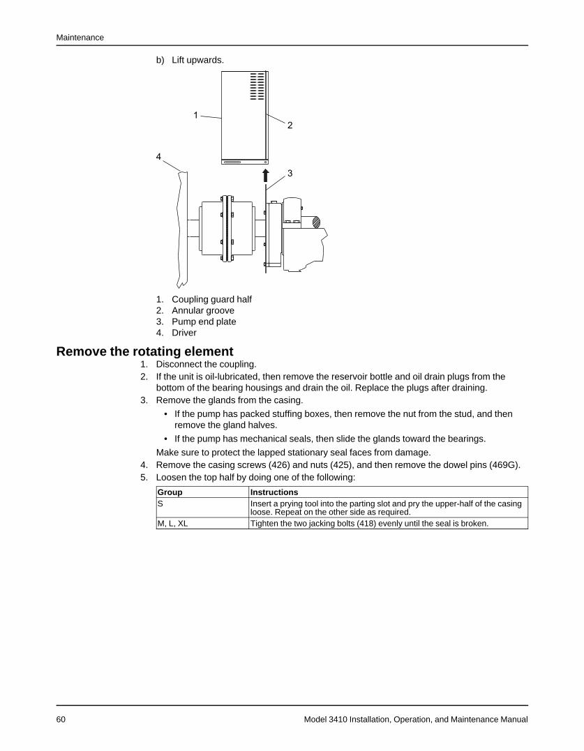
Maintenance
Model 3410 Installation, Operation, and Maintenance Manual60
b) Lift upwards.
1. Coupling guard half2. Annular groove3. Pump end plate4. Driver
Remove the rotating element1. Disconnect the coupling.2. If the unit is oil-lubricated, then remove the reservoir bottle and oil drain plugs from the
bottom of the bearing housings and drain the oil. Replace the plugs after draining.3. Remove the glands from the casing.
• If the pump has packed stuffing boxes, then remove the nut from the stud, and thenremove the gland halves.
• If the pump has mechanical seals, then slide the glands toward the bearings.
Make sure to protect the lapped stationary seal faces from damage.4. Remove the casing screws (426) and nuts (425), and then remove the dowel pins (469G).5. Loosen the top half by doing one of the following:
Group InstructionsS Insert a prying tool into the parting slot and pry the upper-half of the casing
loose. Repeat on the other side as required.M, L, XL Tighten the two jacking bolts (418) evenly until the seal is broken.
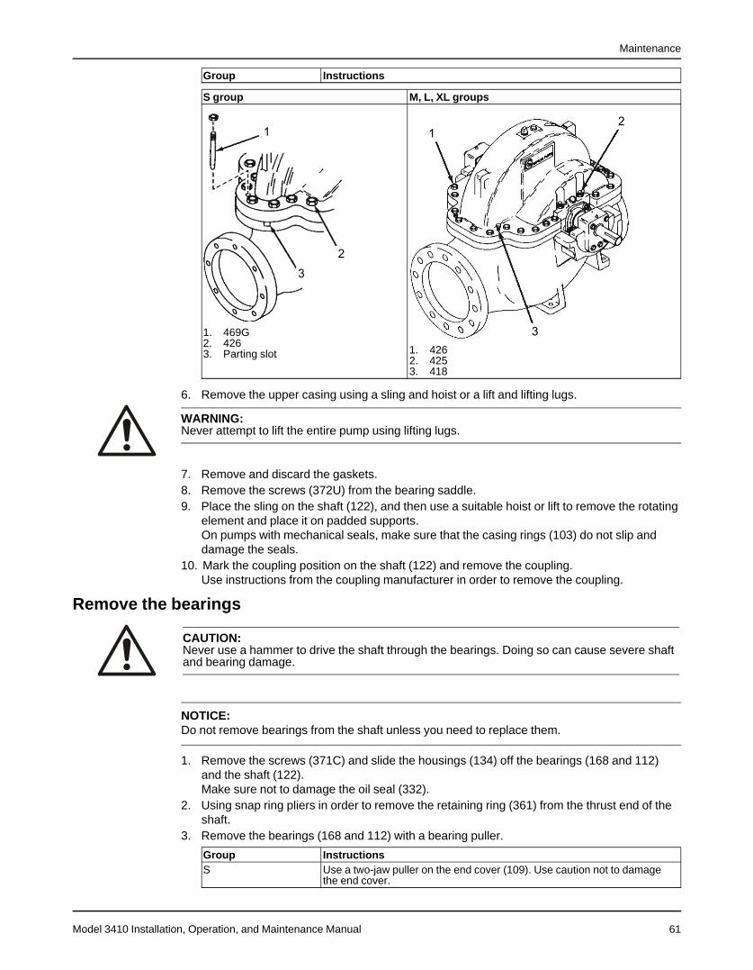
Maintenance
Model 3410 Installation, Operation, and Maintenance Manual 61
Group Instructions
S group M, L, XL groups
1. 469G2. 4263. Parting slot 1. 426
2. 4253. 418
6. Remove the upper casing using a sling and hoist or a lift and lifting lugs.
WARNING:Never attempt to lift the entire pump using lifting lugs.
7. Remove and discard the gaskets.8. Remove the screws (372U) from the bearing saddle.9. Place the sling on the shaft (122), and then use a suitable hoist or lift to remove the rotating
element and place it on padded supports.On pumps with mechanical seals, make sure that the casing rings (103) do not slip anddamage the seals.
10. Mark the coupling position on the shaft (122) and remove the coupling.Use instructions from the coupling manufacturer in order to remove the coupling.
Remove the bearings
CAUTION:Never use a hammer to drive the shaft through the bearings. Doing so can cause severe shaftand bearing damage.
NOTICE:Do not remove bearings from the shaft unless you need to replace them.
1. Remove the screws (371C) and slide the housings (134) off the bearings (168 and 112)and the shaft (122).Make sure not to damage the oil seal (332).
2. Using snap ring pliers in order to remove the retaining ring (361) from the thrust end of theshaft.
3. Remove the bearings (168 and 112) with a bearing puller.
Group InstructionsS Use a two-jaw puller on the end cover (109). Use caution not to damage
the end cover.
Maintenance
Model 3410 Installation, Operation, and Maintenance Manual62
Group InstructionsM, X, XL Use a split-jaw puller on the back of the bearing (168 and 112).
Make sure not to damage the bearings. If the bearing needs to be reinstalled, then protect itfrom contamination by wrapping it in clean cloth or paper.
4. For L and XL groups only, remove the radial bearing spacer (443T).5. Remove the gaskets (360), bearing end covers (109), and deflectors (123).6. Remove the outboard seal (332) from the coupling-end bearing housing, and remove the
inboard seal (333) from each end cover (109).You can discard the old bearings and gasket.
Remove the seals1. Do one of the following:
• If the pump has mechanical seals, then slide the glands with the stationary seat inplace off the shaft. Make sure not to damage the lapped seal faces.
• If the pump has packed stuffing boxes, then remove the nuts (355), gland (107),packing (106), lantern rings (105), and stuffing box bushings (125).
2. Slide the casing wear ring (103) off the impeller and shaft.3. Remove the rotating portion of both seals.
Remove the shaft sleeve
NOTICE:Do not remove the optional shaft sleeve on S group pumps unless you intend to replace it.
1. Remove the shaft sleeve as follows:When you remove the sleeve (126), use a very fine emery cloth to smooth the shaft in orderto prevent binding.
Group InstructionsS 1. Loosen the sleeve (126) with low heat, approximately 350–400°F
(177–222°C). Use a temperature stick or other measuring device tomonitor the temperature.
2. Apply torque with a strap wrench.3. Slide the sleeve carefully off the shaft.
M, L, XL 1. Loosen the setscrew (222B) on the sleeve nut (124).2. Use a spanner or strap wrench to unscrew the sleeve nut (124).3. Remove and discard the O-rings (497).4. Carefully slide the sleeve (126) off the shaft.5. Remove and discard the sleeve-to-impeller gasket (428) located on the
end of the sleeve nearest the impeller.
Remove the impeller
CAUTION:Do not damage the impeller hub surface that is sealed by the sleeve gasket.
1. Do one of the following:
Group InstructionsS 1. Use snap ring pliers to remove the retaining rings (361H).
2. Drive or press the impeller (101) off the shaft.3. Remove the key (178).See the Retaining ring configuration in the Parts Listings and Cross-sectional Drawings chapter for an illustration of the S group retaining ringconfiguration.
Maintenance
Model 3410 Installation, Operation, and Maintenance Manual 63
Group InstructionsM, L, XL 1. Draw a mark on the shaft to indicate the location of the impeller hub.
2. Drive or press the impeller (101) off the shaft.3. Remove the key (178).
Preassembly inspectionsO-rings
Inspect the O-rings (497) and replace them if damaged.
Wear ringsWhen hydraulic performance has substantially reduced, replace the casing wear rings.The original radial clearance between the impeller and the casing wear rings is shown in Radialclearances (page 65).
Impeller wear ringsIf the unit has impeller wear rings (142) and it is necessary to replace the rings, then proceedas specified in Replace impeller wear rings (page 64).
NOTICE:If the impeller was supplied without wear rings and excessive wear has occurred, then wearrings can be fitted in the field. The impeller must then be remachined. Contact your local ITTrepresentative for details.
Casing joint gasketInspect the parting gaskets (331). If they are torn or otherwise damaged, then cut a new gasketof 1/32 in. (0.8 mm) non-asbestos material using the recommendations below. Use the upperhalf of the casing as a template. Strike the face with a soft-face hammer. This will cut thegasket against the edge of the casing. The gasket must cover the entire surface of the partingflange, especially around the wear ring locks and stuffing box. Otherwise, internal leakage fromhigh to low pressure zones in the pump will occur.The following gasket materials are recommended if pre-cut replacement gaskets are notavailable:
• JM - 961
• Durable - Durlon
• Garlock Blue Guard 3000
• Armstrong - N8090
• Rodgers - D7031
ShaftCheck the shaft (122) for runout to make sure that it is not bent. Straighten or replace the shaftas necessary. Bearing seats must be in perfect condition. Check keyways for burrs or foreignmatter.
ImpellerCheck the impeller (101). Replace the impeller if any of the following conditions exist:
• Excessive erosion, especially on inlet vanes
• Deterioration of the gasket mating surface to the point that the gasket (428) cannot sealproperly
• Excessive erosion of surfaces
If the impeller diameter needs to be cut, then make sure that it is dynamically-balanced. Grindthe outside of the shrouds near the periphery in order to correct imbalance.

Maintenance
Model 3410 Installation, Operation, and Maintenance Manual64
Shaft sleeveThe sleeve (126) surface in the stuffing box area must be smooth and free of grooves. If thereare grooves, replace the shaft sleeve. The O-ring groove in the end of the sleeve nut must be ingood condition. The impeller end of the sleeve must be in good condition to ensure that thegasket (428) will seal properly. The original diametric clearance between the shaft sleeve andthe stuffing box bushing is 0.030–0.034" (0.76–0.86 mm). If this clearance has increased tomore than 0.050–0.060" (1.27–1.5 mm), then the sleeve, and possibly the stuffing box bushing,must be replaced.
BearingsCheck ball bearings (112 and 168) for visible wear. Slowly turn the races and look for pits orworn areas on the balls or raceways.Hold the inner race and spin the outer race. If there are rasping noises or the bearing catchesor binds, then replace the bearing. If any wear on the race is apparent, then replace thebearing.Replace ball bearings that are worn, loose, rough, or noisy when rotated.
SealsCheck the seals (332 and 333) for wear, cracks, cuts, deformities, and signs of excessiveleakage. Check the thrust-bearing end cover (109A) for signs of leakage and damage. Checkthe grease fittings (113) or oil breathers (113A) (oil option) for serviceability and replace asrequired.
GeneralClean all parts before reassembly. This is especially important at O-ring grooves, gasketsurfaces, mating surfaces, and bearing areas. Check that threads on dowels, screws, nuts,studs, and all gasket surfaces are in good condition. Make sure the anti-rotation pins (445A)are firmly pressed into the wear rings (103).Refer to Bearing maintenance (page 52) for specific instructions on cleaning bearings.
Replace impeller wear rings1. Remove the old rings:
a) Remove the three setscrews (320).b) Pull the ring (142) off the impeller hub.
2. Clean the hub and press on a new ring (142).3. Drill and tap three holes 120° (1,600 mils) apart with a 7/32-in. drill and a 1/4-in. 20NC tap
on each ring.4. Insert the setscrews.
Make sure to use 5/16 in. x 1/4 in. cup point safety setscrews.5. Tighten the screws and lightly upset the threads. Do not use the existing holes.
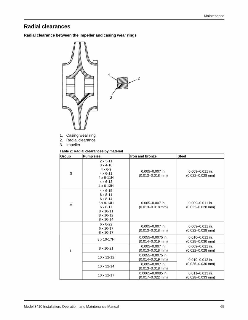
Maintenance
Model 3410 Installation, Operation, and Maintenance Manual 65
Radial clearances
Radial clearance between the impeller and casing wear rings
1. Casing wear ring2. Radial clearance3. Impeller
Table 2: Radial clearances by materialGroup Pump size Iron and bronze Steel
S
2 x 3-113 x 4-104 x 6-94 x 6-11
4 x 6-11H4 x 6-13
4 x 6-13H
0.005–0.007 in.(0.013–0.018 mm)
0.009–0.011 in.(0.022–0.028 mm)
M
4 x 6-156 x 8-116 x 8-14
6 x 8-14H6 x 8-178 x 10-118 x 10-128 x 10-14
0.005–0.007 in.(0.013–0.018 mm)
0.009–0.011 in.(0.022–0.028 mm)
L
6 x 8-226 x 10-178 x 10-17
0.005–0.007 in.(0.013–0.018 mm)
0.009–0.011 in.(0.022–0.028 mm)
8 x 10-17H 0.0055–0.0075 in.(0.014–0.019 mm)
0.010–0.012 in.(0.025–0.030 mm)
8 x 10-21 0.005–0.007 in.(0.013–0.018 mm)
0.009–0.011 in.(0.022–0.028 mm)
10 x 12-12 0.0055–0.0075 in.(0.014–0.019 mm) 0.010–0.012 in.
(0.025–0.030 mm)10 x 12-14 0.005–0.007 in.
(0.013–0.018 mm)
10 x 12-17 0.0065–0.0085 in.(0.017–0.022 mm)
0.011–0.013 in.(0.028–0.033 mm)
Maintenance
Model 3410 Installation, Operation, and Maintenance Manual66
Group Pump size Iron and bronze Steel
XL
10 x 12-12H10 x 12-15
0.0055–0.0075 in.(0.014–0.019 mm)
0.010–0.012 in.(0.025–0.030 mm)
12 x 14-15 0.0065–0.0085 in.(0.017–0.022 mm)
0.011–0.013 in.(0.028–0.033 mm)
ReassemblyInstall the impeller
CAUTION:
Check for magnetism on the pump shaft and demagnetize the shaft if there is anydetectable magnetism. Magnetism attracts ferritic objects to the impeller, seal, and bearingswhich can result in excessive heat generation, sparks, and premature failure.
NOTICE:
The impeller and wear-ring clearance setting procedures must be followed. Improperlysetting the clearance or not following any of the proper procedures can result in sparks,unexpected heat generation, and equipment damage.
1. Insert the key (178) into the shaft (122).2. Determine the correct positioning of the impeller (101) on the shaft (122).
Facing the coupling-end of shaft, determine the proper rotation of the unit.3. For S group pumps, install the retaining ring (361H) in the inboard (coupling-end) retaining
groove.4. Slide the impeller (101) on the shaft and drive the impeller flush with the retaining ring
(361H).5. If you are reinstalling the shaft and impeller, then line up the impeller hub with the mark
made on the shaft during disassembly.6. Install the shaft sleeve.
Pump group InstructionsS 1. Install the retaining ring so that the tapered side is facing the outboard
end of the shaft.The inward pressure asserted by the double taper automatically centersthe impeller and eliminates lateral play.The outboard (thrust-end) retaining ring groove and retaining ring (361H)are tapered.
2. If the pump does not use the optional sleeve, then you are finished. If thepump uses the optional sleeve, then continue to complete the followingsteps.
3. Make sure that the shaft is free of dirt, grease, and bonding compounds.4. Apply a thin coat of Loctite 635 or equivalent to the shaft sleeve area and
the inside of the sleeve.5. Slide the sleeve on the outboard end of the shaft and seat the sleeve
firmly against the shaft shoulder.M, L, XL 1. Place the sleeve-to-impeller gasket (428) on the impeller (101).
Make sure that the gasket is aligned with the key (178).2. Slide the sleeve (126) onto the shaft.3. Slide the O-rings (497) onto the shaft by stretching them over the
threaded end.4. Using a spanner or strap wrench to tighten the sleeve nuts (124),
adjusting the impeller to approximate center.Do not tighten the setscrew. You will need to adjust the impeller againwhen the rotating element is placed in the casing.
7. Position the casing wear rings (103) on the impeller.Make sure that the anti-rotation pins (445A) are seated firmly.
Maintenance
Model 3410 Installation, Operation, and Maintenance Manual 67
Assemble the rotating element1. Slide the stuffing box bushing (125) onto the shaft or sleeve.
Units with mechanical seals do not have a stuffing box bushing.2. If the unit is equipped with mechanical seals, then install the seals at this time.
Refer to the instructions provided by the seal manufacturer for details.3. Slide the deflectors (123), bearing end covers (109), and gaskets (360) onto the shaft.
Install the bearings1. Apply a thin film of machine oil to the bearing seats on the shaft.2.
NOTICE:There are several methods you can use to install bearings. The recommended method is touse an induction heater that heats and demagnetizes the bearings. Bearings can get hotand can cause physical injury.
Start the bearings (112 and 168) onto the shaft by tapping the inner race with a hammer ormallet.Keep the bearing square at all times.
3. After the bearing is started on shaft, use a driving sleeve in order to press or drive thebearing until it contacts the shoulder on the inboard side of the seal.Make sure that the sleeve contacts only one inner race.
4. For the outboard (thrust) bearing, install a tapered bearing-retaining ring (361) in theretaining ring groove on the outboard (thrust) end of the shaft (122).
5. Slide the bearing housings (134) over the bearings.6. Tighten the screws (371C) in two stages:
a) Using an X pattern, tighten the screws to 8 ft-lbs (11 Nm).b) Again, using an X pattern, tighten the screws to 12 ft-lbs (16.3 Nm).c) Repeat these steps on the opposite side.
Install the rotating element
NOTICE:
The impeller and wear-ring clearance setting procedures must be followed. Improperlysetting the clearance or not following any of the proper procedures can result in sparks,unexpected heat generation, and equipment damage.
1. Install the rotating element in the lower casing with a sling, adequate hoist, or lift.Make sure that the casing wear ring (103) and anti-rotation pins (445A) seat properly in thewear ring grooves and pin grooves.
2. Tighten or loosen the sleeve nuts with a strap wrench as required in order to center theimpeller in the seated wear rings.For M, L, and XL groups, tighten the sleeve nuts (124) to 30 ft-lbs (40.7 Nm).
3. Tighten the sleeve nut setscrews (222B).Make sure that the stuffing box bushings (125) are aligned properly in the stuffing boxes.
4. Tighten the bearing housing to the lower casing on each side.a) Install and tighten the screws (372U) until snug.b) Tighten the screws on each side to 40 ft-lbs (55 Nm).c) Tighten each side to 59 ft-lbs (80 Nm).
Assemble the casingMake sure that the mating surfaces on the upper and lower halves of the casing are clean.1. Install the gasket (351).2. Carefully align and install the upper casing using a hoist, lift, and sling attached to lifting
lugs on the upper casing.
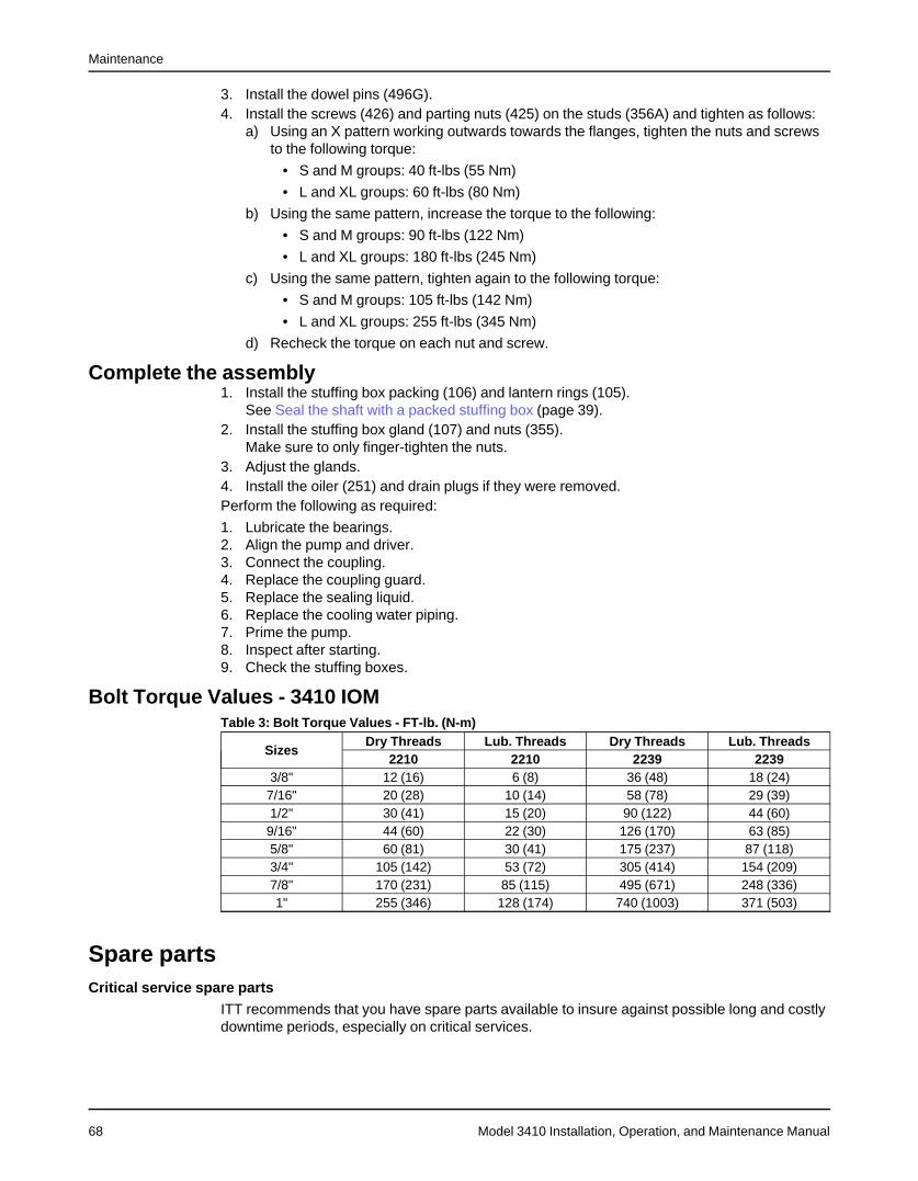
Maintenance
Model 3410 Installation, Operation, and Maintenance Manual68
3. Install the dowel pins (496G).4. Install the screws (426) and parting nuts (425) on the studs (356A) and tighten as follows:
a) Using an X pattern working outwards towards the flanges, tighten the nuts and screwsto the following torque:
• S and M groups: 40 ft-lbs (55 Nm)
• L and XL groups: 60 ft-lbs (80 Nm)
b) Using the same pattern, increase the torque to the following:
• S and M groups: 90 ft-lbs (122 Nm)
• L and XL groups: 180 ft-lbs (245 Nm)
c) Using the same pattern, tighten again to the following torque:
• S and M groups: 105 ft-lbs (142 Nm)
• L and XL groups: 255 ft-lbs (345 Nm)
d) Recheck the torque on each nut and screw.
Complete the assembly1. Install the stuffing box packing (106) and lantern rings (105).
See Seal the shaft with a packed stuffing box (page 39).2. Install the stuffing box gland (107) and nuts (355).
Make sure to only finger-tighten the nuts.3. Adjust the glands.4. Install the oiler (251) and drain plugs if they were removed.Perform the following as required:
1. Lubricate the bearings.2. Align the pump and driver.3. Connect the coupling.4. Replace the coupling guard.5. Replace the sealing liquid.6. Replace the cooling water piping.7. Prime the pump.8. Inspect after starting.9. Check the stuffing boxes.
Bolt Torque Values - 3410 IOMTable 3: Bolt Torque Values - FT-lb. (N-m)
SizesDry Threads Lub. Threads Dry Threads Lub. Threads
2210 2210 2239 22393/8" 12 (16) 6 (8) 36 (48) 18 (24)7/16" 20 (28) 10 (14) 58 (78) 29 (39)1/2" 30 (41) 15 (20) 90 (122) 44 (60)9/16" 44 (60) 22 (30) 126 (170) 63 (85)5/8" 60 (81) 30 (41) 175 (237) 87 (118)3/4" 105 (142) 53 (72) 305 (414) 154 (209)7/8" 170 (231) 85 (115) 495 (671) 248 (336)1" 255 (346) 128 (174) 740 (1003) 371 (503)
Spare partsCritical service spare parts
ITT recommends that you have spare parts available to insure against possible long and costlydowntime periods, especially on critical services.
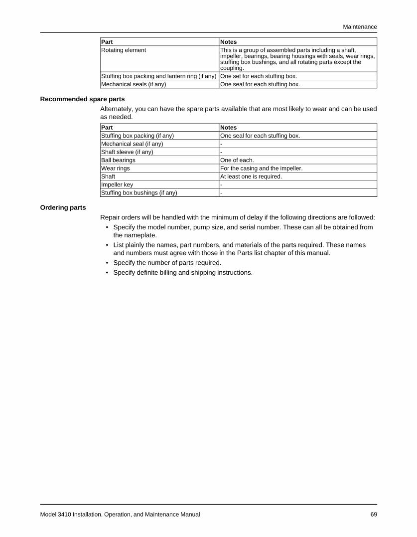
Maintenance
Model 3410 Installation, Operation, and Maintenance Manual 69
Part NotesRotating element This is a group of assembled parts including a shaft,
impeller, bearings, bearing housings with seals, wear rings,stuffing box bushings, and all rotating parts except thecoupling.
Stuffing box packing and lantern ring (if any) One set for each stuffing box.Mechanical seals (if any) One seal for each stuffing box.
Recommended spare partsAlternately, you can have the spare parts available that are most likely to wear and can be usedas needed.
Part NotesStuffing box packing (if any) One seal for each stuffing box.Mechanical seal (if any) -Shaft sleeve (if any) -Ball bearings One of each.Wear rings For the casing and the impeller.Shaft At least one is required.Impeller key -Stuffing box bushings (if any) -
Ordering partsRepair orders will be handled with the minimum of delay if the following directions are followed:
• Specify the model number, pump size, and serial number. These can all be obtained fromthe nameplate.
• List plainly the names, part numbers, and materials of the parts required. These namesand numbers must agree with those in the Parts list chapter of this manual.
• Specify the number of parts required.
• Specify definite billing and shipping instructions.
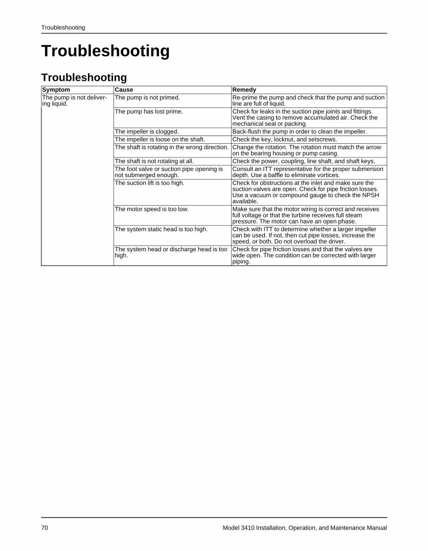
Troubleshooting
Model 3410 Installation, Operation, and Maintenance Manual70
Troubleshooting
TroubleshootingSymptom Cause RemedyThe pump is not deliver-ing liquid.
The pump is not primed. Re-prime the pump and check that the pump and suctionline are full of liquid.
The pump has lost prime. Check for leaks in the suction pipe joints and fittings.Vent the casing to remove accumulated air. Check themechanical seal or packing.
The impeller is clogged. Back-flush the pump in order to clean the impeller.The impeller is loose on the shaft. Check the key, locknut, and setscrews.The shaft is rotating in the wrong direction. Change the rotation. The rotation must match the arrow
on the bearing housing or pump casing.The shaft is not rotating at all. Check the power, coupling, line shaft, and shaft keys.The foot valve or suction pipe opening isnot submerged enough.
Consult an ITT representative for the proper submersiondepth. Use a baffle to eliminate vortices.
The suction lift is too high. Check for obstructions at the inlet and make sure thesuction valves are open. Check for pipe friction losses.Use a vacuum or compound gauge to check the NPSHavailable.
The motor speed is too low. Make sure that the motor wiring is correct and receivesfull voltage or that the turbine receives full steampressure. The motor can have an open phase.
The system static head is too high. Check with ITT to determine whether a larger impellercan be used. If not, then cut pipe losses, increase thespeed, or both. Do not overload the driver.
The system head or discharge head is toohigh.
Check for pipe friction losses and that the valves arewide open. The condition can be corrected with largerpiping.

Troubleshooting
Model 3410 Installation, Operation, and Maintenance Manual 71
Symptom Cause RemedyThe pump is not deliver-ing enough liquid or pres-sure.
The suction piping has air leaks. Check the suction piping for air pockets and air leaks.The stuffing box has air leaks. Check the packing or seal and replace if necessary.
Check for the proper amount of lubrication.The motor speed is too low. Make sure that the motor wiring is correct and receives
full voltage or that the turbine receives full steampressure. The motor can have an open phase.
The discharge head is too high. Check for pipe friction losses and that the valves arewide open. The condition can be corrected with largerpiping.
The suction lift is too high. Check for obstructions at the inlet and make sure thesuction valves are open. Check for pipe friction losses.Use a vacuum or compound gauge to check the NPSHavailable.
The impeller is clogged. Back-flush the pump in order to clean the impeller.The amount of available NPSH is notsufficient.
1. Increase the positive suction head by lowering thepump or increasing the suction pipe and fittings size.
2. Sub-cool the suction piping at the inlet to lower thetemperature of liquid that is entering the pump.
3. Pressurize the suction vessel.The impeller or wear rings are worn orbroken.
Inspect the impeller and wear rings and replace if any ofthe following conditions are present:
• The impeller or wear rings are damaged.• The vane sections are severely eroded.• The wear ring clearance is three times normal.
The foot valve is too small or partiallyobstructed.
Check the valve and replace with the correct size ifnecessary.
The suction inlet is not submersed deepenough.
If the inlet cannot be lowered or if the problem persistsafter the inlet is lowered, then chain a board to thesuction pipe. The board will be drawn into the eddies andsmother the vortex.
The shaft is rotating in the wrong direction. Change the rotation. The rotation must match the arrowon the bearing housing or pump casing.
The system static head is too high. Check with ITT to determine whether a larger impellercan be used. If not, then you can cut pipe losses,increase the speed, or both. Do not overload the driver.
The mechanical seal is worn or broken. Repair or replace the seal as necessary.The liquid passages are obstructed. Make sure that the suction and discharge valves are fully
open. Disassemble the pump and inspect the passagesand casing. Remove the obstruction.
Air or gases are trapped in the liquid. Consult with ITT.The pump starts and thenstops pumping.
The suction lift is too high. Check for obstructions at the inlet and make sure thesuction valves are open. Check for pipe friction losses.Use a vacuum or compound gauge to check the NPSHavailable.
The impeller is clogged. Back-flush the pump in order to clean the impeller.The suction piping has air leaks. Check the suction piping for air pockets and air leaks.The stuffing box has air leaks. Check the packing or seal and replace if necessary.
Check for the proper amount of lubrication.There is not enough suction head for hot orvolatile liquids.
Consult with ITT about increasing the suction head.
The foot valve or suction pipe opening arenot submerged enough.
Consult an ITT representative for the proper submersiondepth. Use a baffle in order to eliminate vortices.
Air or gases are trapped in the liquid. Consult with ITT.The casing gasket is damaged. Check the gaskets and replace if necessary.
The bearings are runninghot.
The shaft is bent. Straighten the shaft or replace it if necessary.The bearings are worn out or improperlylubricated.
Inspect the bearings and replace them if necessary.
There is excessive pipe strain on the pumpcasing.
Relieve the strain and check the alignment. Consult ITT ifnecessary.
The pump and driver are not alignedproperly.
Realign the pump and driver.
The lubrication has not been applied prop-erly.
Check the lubricant for suitability and level.
The lubrication is not cooled properly. Check the cooling system.
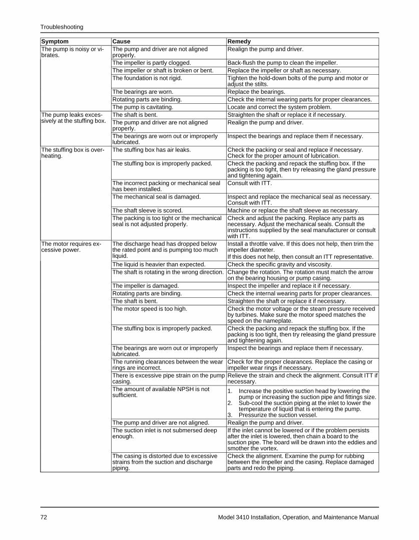
Troubleshooting
Model 3410 Installation, Operation, and Maintenance Manual72
Symptom Cause RemedyThe pump is noisy or vi-brates.
The pump and driver are not alignedproperly.
Realign the pump and driver.
The impeller is partly clogged. Back-flush the pump to clean the impeller.The impeller or shaft is broken or bent. Replace the impeller or shaft as necessary.The foundation is not rigid. Tighten the hold-down bolts of the pump and motor or
adjust the stilts.The bearings are worn. Replace the bearings.Rotating parts are binding. Check the internal wearing parts for proper clearances.The pump is cavitating. Locate and correct the system problem.
The pump leaks exces-sively at the stuffing box.
The shaft is bent. Straighten the shaft or replace it if necessary.The pump and driver are not alignedproperly.
Realign the pump and driver.
The bearings are worn out or improperlylubricated.
Inspect the bearings and replace them if necessary.
The stuffing box is over-heating.
The stuffing box has air leaks. Check the packing or seal and replace if necessary.Check for the proper amount of lubrication.
The stuffing box is improperly packed. Check the packing and repack the stuffing box. If thepacking is too tight, then try releasing the gland pressureand tightening again.
The incorrect packing or mechanical sealhas been installed.
Consult with ITT.
The mechanical seal is damaged. Inspect and replace the mechanical seal as necessary.Consult with ITT.
The shaft sleeve is scored. Machine or replace the shaft sleeve as necessary.The packing is too tight or the mechanicalseal is not adjusted properly.
Check and adjust the packing. Replace any parts asnecessary. Adjust the mechanical seals. Consult theinstructions supplied by the seal manufacturer or consultwith ITT.
The motor requires ex-cessive power.
The discharge head has dropped belowthe rated point and is pumping too muchliquid.
Install a throttle valve. If this does not help, then trim theimpeller diameter.If this does not help, then consult an ITT representative.
The liquid is heavier than expected. Check the specific gravity and viscosity.The shaft is rotating in the wrong direction. Change the rotation. The rotation must match the arrow
on the bearing housing or pump casing.The impeller is damaged. Inspect the impeller and replace it if necessary.Rotating parts are binding. Check the internal wearing parts for proper clearances.The shaft is bent. Straighten the shaft or replace it if necessary.The motor speed is too high. Check the motor voltage or the steam pressure received
by turbines. Make sure the motor speed matches thespeed on the nameplate.
The stuffing box is improperly packed. Check the packing and repack the stuffing box. If thepacking is too tight, then try releasing the gland pressureand tightening again.
The bearings are worn out or improperlylubricated.
Inspect the bearings and replace them if necessary.
The running clearances between the wearrings are incorrect.
Check for the proper clearances. Replace the casing orimpeller wear rings if necessary.
There is excessive pipe strain on the pumpcasing.
Relieve the strain and check the alignment. Consult ITT ifnecessary.
The amount of available NPSH is notsufficient.
1. Increase the positive suction head by lowering thepump or increasing the suction pipe and fittings size.
2. Sub-cool the suction piping at the inlet to lower thetemperature of liquid that is entering the pump.
3. Pressurize the suction vessel.The pump and driver are not aligned. Realign the pump and driver.The suction inlet is not submersed deepenough.
If the inlet cannot be lowered or if the problem persistsafter the inlet is lowered, then chain a board to thesuction pipe. The board will be drawn into the eddies andsmother the vortex.
The casing is distorted due to excessivestrains from the suction and dischargepiping.
Check the alignment. Examine the pump for rubbingbetween the impeller and the casing. Replace damagedparts and redo the piping.
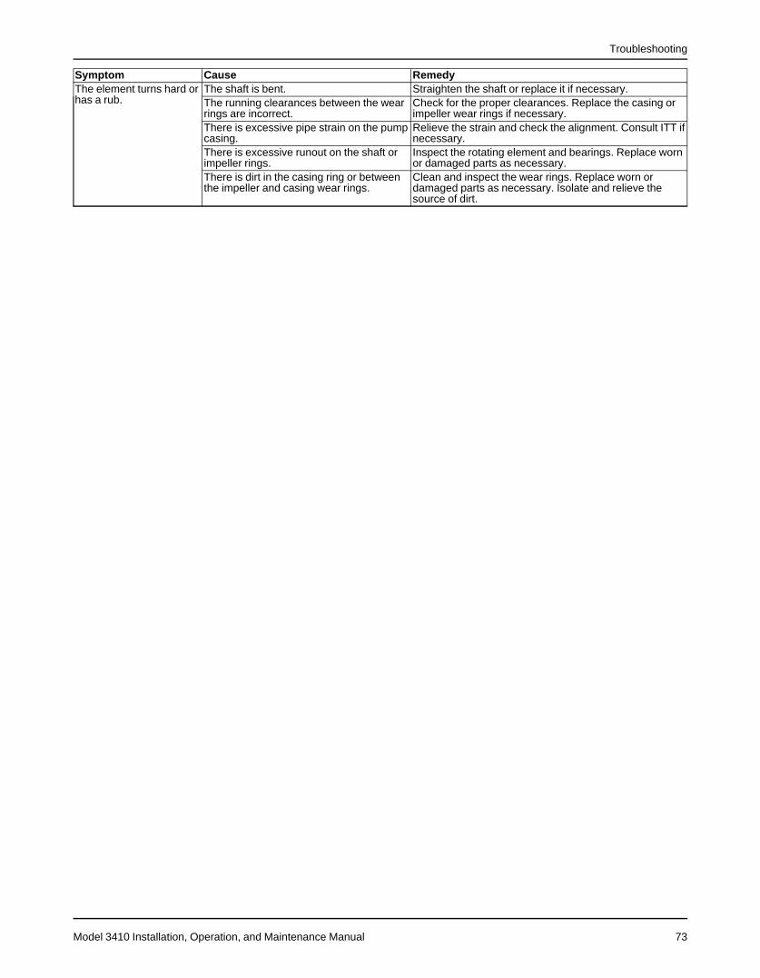
Troubleshooting
Model 3410 Installation, Operation, and Maintenance Manual 73
Symptom Cause RemedyThe element turns hard orhas a rub.
The shaft is bent. Straighten the shaft or replace it if necessary.The running clearances between the wearrings are incorrect.
Check for the proper clearances. Replace the casing orimpeller wear rings if necessary.
There is excessive pipe strain on the pumpcasing.
Relieve the strain and check the alignment. Consult ITT ifnecessary.
There is excessive runout on the shaft orimpeller rings.
Inspect the rotating element and bearings. Replace wornor damaged parts as necessary.
There is dirt in the casing ring or betweenthe impeller and casing wear rings.
Clean and inspect the wear rings. Replace worn ordamaged parts as necessary. Isolate and relieve thesource of dirt.
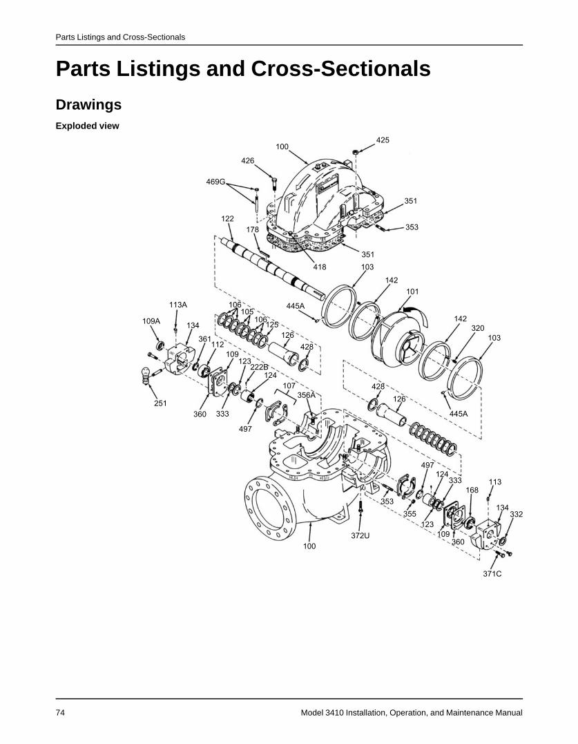
Parts Listings and Cross-Sectionals
Model 3410 Installation, Operation, and Maintenance Manual74
Parts Listings and Cross-Sectionals
DrawingsExploded view
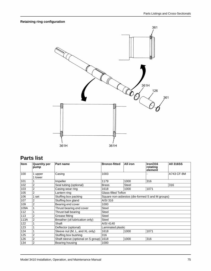
Parts Listings and Cross-Sectionals
Model 3410 Installation, Operation, and Maintenance Manual 75
Retaining ring configuration
Parts listItem Quantity per
pumpPart name Bronze-fitted All iron Iron/316
rotatingelement
All 316SS
100 1 upper1 lower
Casing 1003 - A743 CF-8M
101 1 Impeller 1179 1000 316102 2 Seal tubing (optional) Brass Steel 316103 2 Casing wear ring 1618 1000 1071105 2 Lantern ring Glass-filled Teflon106 1 set Stuffing box packing Square non-asbestos (die-formed S and M groups)107 2 Stuffing box gland AISI 316109 2 Bearing end cover 1000109A 1 Thrust bearing end cover Steel112 1 Thrust ball bearing Steel113 2 Grease fitting Steel113A 2 Breather (oil lubrication only) Steel122 1 Shaft AISI 4140123 1 Deflector (optional) Laminated plastic124 1 Sleeve nut (M, L, and XL only) 1618 1000 1071125 2 Stuffing box bushing 316126 2 Shaft sleeve (optional on S group) 1618 1000 316134 2 Bearing housing 1000
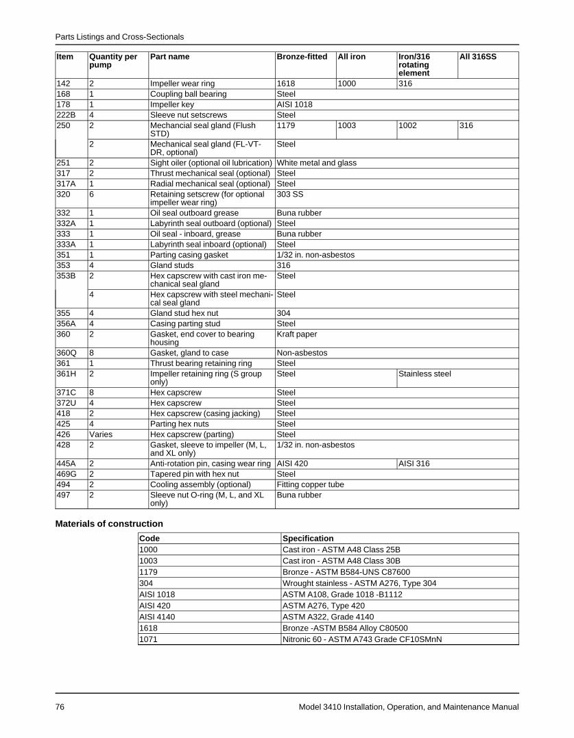
Parts Listings and Cross-Sectionals
Model 3410 Installation, Operation, and Maintenance Manual76
Item Quantity perpump
Part name Bronze-fitted All iron Iron/316rotatingelement
All 316SS
142 2 Impeller wear ring 1618 1000 316168 1 Coupling ball bearing Steel178 1 Impeller key AISI 1018222B 4 Sleeve nut setscrews Steel250 2 Mechancial seal gland (Flush
STD)1179 1003 1002 316
2 Mechanical seal gland (FL-VT-DR, optional)
Steel
251 2 Sight oiler (optional oil lubrication) White metal and glass317 2 Thrust mechanical seal (optional) Steel317A 1 Radial mechanical seal (optional) Steel320 6 Retaining setscrew (for optional
impeller wear ring)303 SS
332 1 Oil seal outboard grease Buna rubber332A 1 Labyrinth seal outboard (optional) Steel333 1 Oil seal - inboard, grease Buna rubber333A 1 Labyrinth seal inboard (optional) Steel351 1 Parting casing gasket 1/32 in. non-asbestos353 4 Gland studs 316353B 2 Hex capscrew with cast iron me-
chanical seal glandSteel
4 Hex capscrew with steel mechani-cal seal gland
Steel
355 4 Gland stud hex nut 304356A 4 Casing parting stud Steel360 2 Gasket, end cover to bearing
housingKraft paper
360Q 8 Gasket, gland to case Non-asbestos361 1 Thrust bearing retaining ring Steel361H 2 Impeller retaining ring (S group
only)Steel Stainless steel
371C 8 Hex capscrew Steel372U 4 Hex capscrew Steel418 2 Hex capscrew (casing jacking) Steel425 4 Parting hex nuts Steel426 Varies Hex capscrew (parting) Steel428 2 Gasket, sleeve to impeller (M, L,
and XL only)1/32 in. non-asbestos
445A 2 Anti-rotation pin, casing wear ring AISI 420 AISI 316469G 2 Tapered pin with hex nut Steel494 2 Cooling assembly (optional) Fitting copper tube497 2 Sleeve nut O-ring (M, L, and XL
only)Buna rubber
Materials of construction
Code Specification1000 Cast iron - ASTM A48 Class 25B1003 Cast iron - ASTM A48 Class 30B1179 Bronze - ASTM B584-UNS C87600304 Wrought stainless - ASTM A276, Type 304AISI 1018 ASTM A108, Grade 1018 -B1112AISI 420 ASTM A276, Type 420AISI 4140 ASTM A322, Grade 41401618 Bronze -ASTM B584 Alloy C805001071 Nitronic 60 - ASTM A743 Grade CF10SMnN


Visit our website for the latest version of thisdocument and more information:
http://www.gouldspumps.com
ITT Goulds Pumps240 Fall StreetSeneca Falls, NY 13148USA
© 2016 ITT CorporationThe original instruction is in English. All non-English instructions are translations of the originalinstruction.
Form IOM-3410.en-US.2016-11
Related Documents