Installation, Operation & Maintenance Manual Model CDLR 19, 25, 26, 35 Effective: January, 2007 Rev: 01 Copyright© 2006 LEWCO, Inc www.lewcoinc.com An ISO 9001:2008 Registered Company LEWCO, Inc. 706 Lane Street Sandusky, Ohio 44870 Phone 419.625.4014 Fax 419.625.1247 www.lewcoinc.com

Welcome message from author
This document is posted to help you gain knowledge. Please leave a comment to let me know what you think about it! Share it to your friends and learn new things together.
Transcript

Installation, Operation & Maintenance Manual
Model CDLR 19, 25, 26, 35
Effective: January, 2007
Rev: 01 Copyright© 2006 LEWCO, Inc
www.lewcoinc.com An ISO 9001:2008 Registered Company
LEWCO, Inc. 706 Lane Street Sandusky, Ohio 44870 Phone 419.625.4014 Fax 419.625.1247 www.lewcoinc.com
Model CDLR
Page 2
Table of Contents
Safety .....................................................................................................................................................................3 Support Installation .................................................................................................................................................5 Conveyor Set Up ....................................................................................................................................................5 Chain Installation – Multiple Section Conveyors ....................................................................................................6 Pre-Startup Checks ................................................................................................................................................6 Maintenance ...........................................................................................................................................................7 Troubleshooting ......................................................................................................................................................8 Replacement Parts .................................................................................................................................................9
Installation, Operation & Maintenance
Page 3 Copyright® 2006 LEWCO, Inc.
Safety
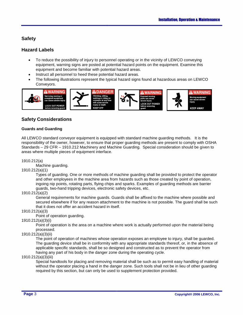
Hazard Labels
To reduce the possibility of injury to personnel operating or in the vicinity of LEWCO conveying
equipment, warning signs are posted at potential hazard points on the equipment. Examine this
equipment and become familiar with potential hazard areas.
Instruct all personnel to heed these potential hazard areas.
The following illustrations represent the typical hazard signs found at hazardous areas on LEWCO
Conveyors.
Safety Considerations Guards and Guarding All LEWCO standard conveyor equipment is equipped with standard machine guarding methods. It is the responsibility of the owner, however, to ensure that proper guarding methods are present to comply with OSHA Standards – 29 CFR – 1910.212 Machinery and Machine Guarding. Special consideration should be given to areas where multiple pieces of equipment interface. 1910.212(a)
Machine guarding. 1910.212(a)(1)
Types of guarding. One or more methods of machine guarding shall be provided to protect the operator and other employees in the machine area from hazards such as those created by point of operation, ingoing nip points, rotating parts, flying chips and sparks. Examples of guarding methods are barrier guards, two-hand tripping devices, electronic safety devices, etc.
1910.212(a)(2) General requirements for machine guards. Guards shall be affixed to the machine where possible and secured elsewhere if for any reason attachment to the machine is not possible. The guard shall be such that it does not offer an accident hazard in itself.
1910.212(a)(3) Point of operation guarding.
1910.212(a)(3)(i) Point of operation is the area on a machine where work is actually performed upon the material being processed.
1910.212(a)(3)(ii) The point of operation of machines whose operation exposes an employee to injury, shall be guarded. The guarding device shall be in conformity with any appropriate standards thereof, or, in the absence of applicable specific standards, shall be so designed and constructed as to prevent the operator from having any part of his body in the danger zone during the operating cycle.
1910.212(a)(3)(iii) Special handtools for placing and removing material shall be such as to permit easy handling of material without the operator placing a hand in the danger zone. Such tools shall not be in lieu of other guarding required by this section, but can only be used to supplement protection provided.

Model CDLR
Page 4
Operation & Use
Only experienced and trained personnel should operate the conveyor.
Personnel should be trained in operation under normal and emergency conditions.
Personnel on or near the conveyor should be instructed as to the location and operation of stopping
devices.
Keep starting and stopping controls free from obstructions, and instruct personnel working at or near the
conveyor of their locations.
Do not wear loose clothing while operating the conveyor. Long hair and jewelry are potential hazards of
entanglement.
Watch for hazardous conditions—sharp edges and protruding parts, etc.
Use the conveyor to transport only material it is capable of being handled safely.
Keep area around loading and unloading points free from obstructions.
Prohibit personnel from riding on the conveyor.
Before turning the conveyor ON, inspect it for foreign objects that could injure personnel or damage the
equipment.
Alert personnel in the area prior to starting conveyor.
Check belt tracking to make sure it is running straight on the conveyor.
After startup, make sure all areas of the conveyor are operating properly.
Maintenance & Troubleshooting
Only experienced and trained personnel should perform maintenance, including lubrication and
adjustments.
A maintenance program should be established to insure that all conveyor components are maintained in
a condition which does not constitute a hazard to personnel.
Turn OFF and lockout the main power switches to the conveyor, following lockout/tagout procedures.
Do not perform any work on the conveyor while it is running unless the nature of the maintenance
absolutely requires operation of the conveyor. If the conveyor must be operated to perform maintenance
procedures, allow only experienced conveyor maintenance personnel to do the work.
Do not wear loose clothing while performing maintenance on an operating conveyor.
Use extreme care when using mechanical aids such as hoists, cables, and other equipment to perform
maintenance. They can cause damage to the conveyor and cause a dangerous condition when the
conveyor is turned on.
Poor housekeeping practices cause accidents and inefficient conveyor operation. Keep area and
conveyor clean from spilled lubricants and other materials. Make sure no material is caught or lodged in
the movable parts of the conveyor unless necessary during maintenance.
Before Re-Starting the Conveyor
Inspect the conveyor and make certain all safety devices and guards are in place.
Make sure all tools and/or maintenance equipment have been removed from the conveyor area.
Make sure no material is caught or lodged in the movable parts of the conveyor.
Make sure all personnel are clear of the conveyor and are alerted that the conveyor is about to be started.
Allow only authorized personnel to start the conveyor following maintenance or any emergency shut-off.
Installation, Operation & Maintenance
Page 5 Copyright® 2006 LEWCO, Inc.
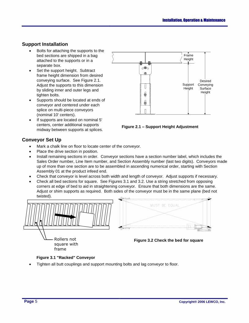
Support Installation
Bolts for attaching the supports to the
bed sections are shipped in a bag
attached to the supports or in a
separate box.
Set the support height. Subtract
frame height dimension from desired
conveying surface. See Figure 2.1.
Adjust the supports to this dimension
by sliding inner and outer legs and
tighten bolts.
Supports should be located at ends of
conveyor and centered under each
splice on multi-piece conveyors
(nominal 10' centers).
If supports are located on nominal 5'
centers, center additional supports
midway between supports at splices.
Conveyor Set Up
Mark a chalk line on floor to locate center of the conveyor.
Place the drive section in position.
Install remaining sections in order. Conveyor sections have a section number label, which includes the
Sales Order number, Line Item number, and Section Assembly number (last two digits). Conveyors made
up of more than one section are to be assembled in ascending numerical order, starting with Section
Assembly 01 at the product infeed end.
Check that conveyor is level across both width and length of conveyor. Adjust supports if necessary.
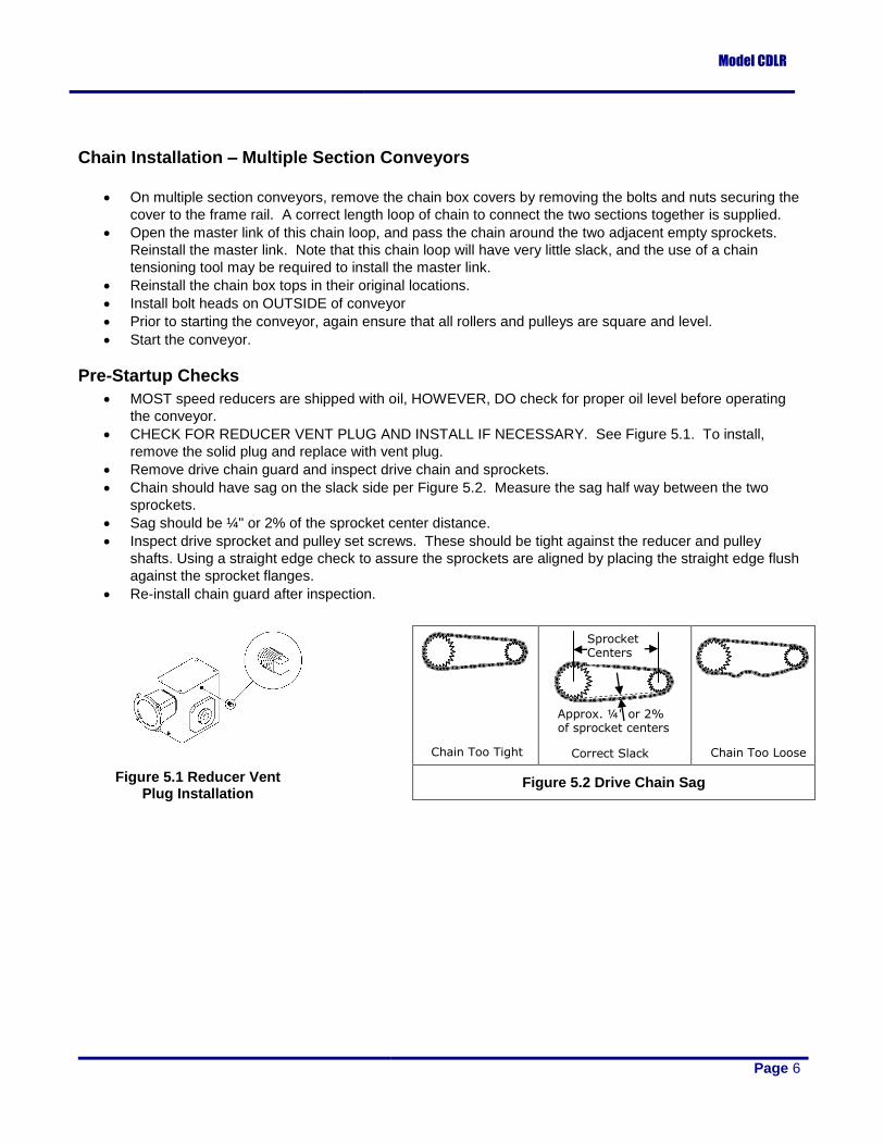
Check all bed sections for square. See Figures 3.1 and 3.2. Use a string stretched from opposing
corners at edge of bed to aid in straightening conveyor. Ensure that both dimensions are the same.
Adjust or shim supports as required. Both sides of the conveyor must be in the same plane (bed not
twisted).
Tighten all butt couplings and support mounting bolts and lag conveyor to floor.
Figure 2.1 – Support Height Adjustment
Frame Height
Support Height
Desired Conveying
Surface Height
Rollers not
square with
frame
Figure 3.2 Check the bed for square
Figure 3.1 "Racked" Conveyor
Model CDLR
Page 6
Chain Installation – Multiple Section Conveyors
On multiple section conveyors, remove the chain box covers by removing the bolts and nuts securing the
cover to the frame rail. A correct length loop of chain to connect the two sections together is supplied.
Open the master link of this chain loop, and pass the chain around the two adjacent empty sprockets.
Reinstall the master link. Note that this chain loop will have very little slack, and the use of a chain
tensioning tool may be required to install the master link.
Reinstall the chain box tops in their original locations.
Install bolt heads on OUTSIDE of conveyor
Prior to starting the conveyor, again ensure that all rollers and pulleys are square and level.
Start the conveyor.
Pre-Startup Checks
MOST speed reducers are shipped with oil, HOWEVER, DO check for proper oil level before operating
the conveyor.
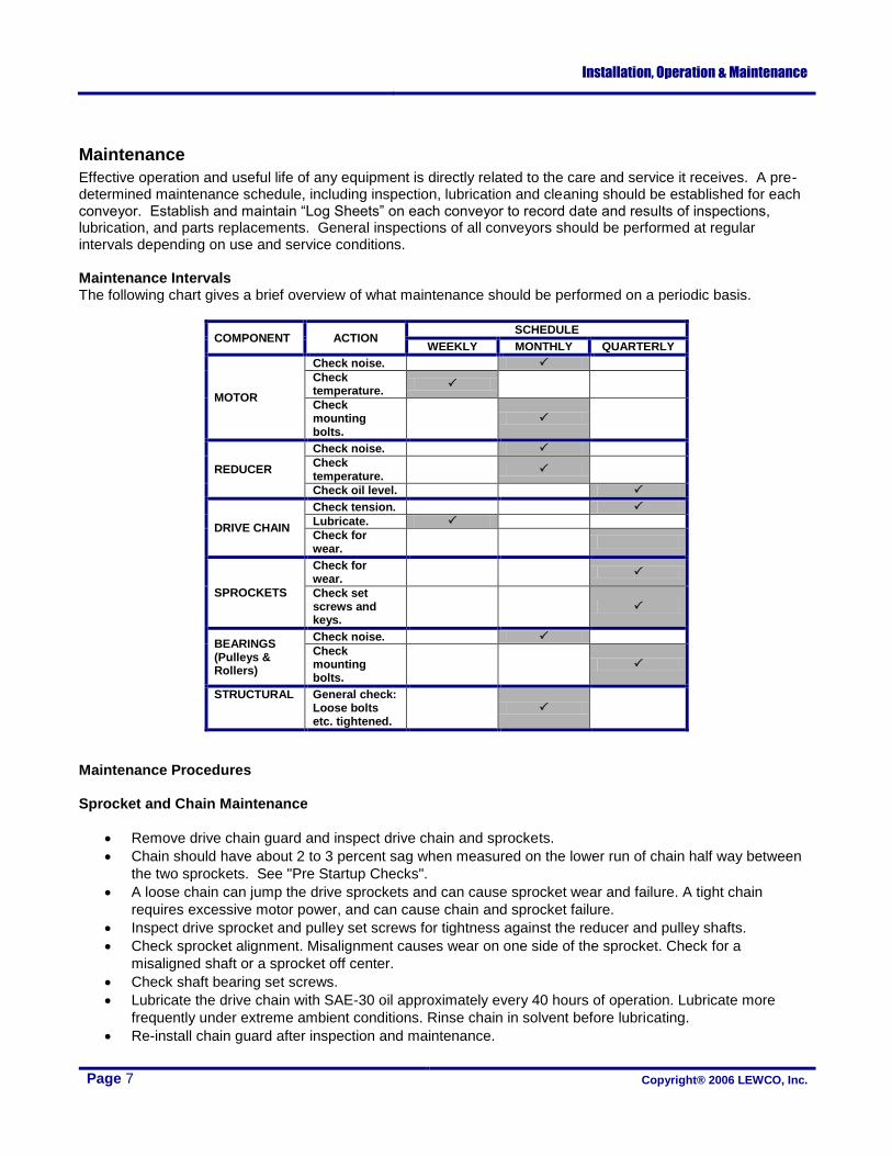
CHECK FOR REDUCER VENT PLUG AND INSTALL IF NECESSARY. See Figure 5.1. To install,
remove the solid plug and replace with vent plug.
Remove drive chain guard and inspect drive chain and sprockets.
Chain should have sag on the slack side per Figure 5.2. Measure the sag half way between the two
sprockets.
Sag should be ¼" or 2% of the sprocket center distance.
Inspect drive sprocket and pulley set screws. These should be tight against the reducer and pulley
shafts. Using a straight edge check to assure the sprockets are aligned by placing the straight edge flush
against the sprocket flanges.
Re-install chain guard after inspection.
Figure 5.2 Drive Chain Sag
Chain Too Tight
Approx. ¼" or 2% of sprocket centers
Sprocket Centers
Correct Slack Chain Too Loose
Figure 5.1 Reducer Vent Plug Installation
Installation, Operation & Maintenance
Page 7 Copyright® 2006 LEWCO, Inc.
Maintenance
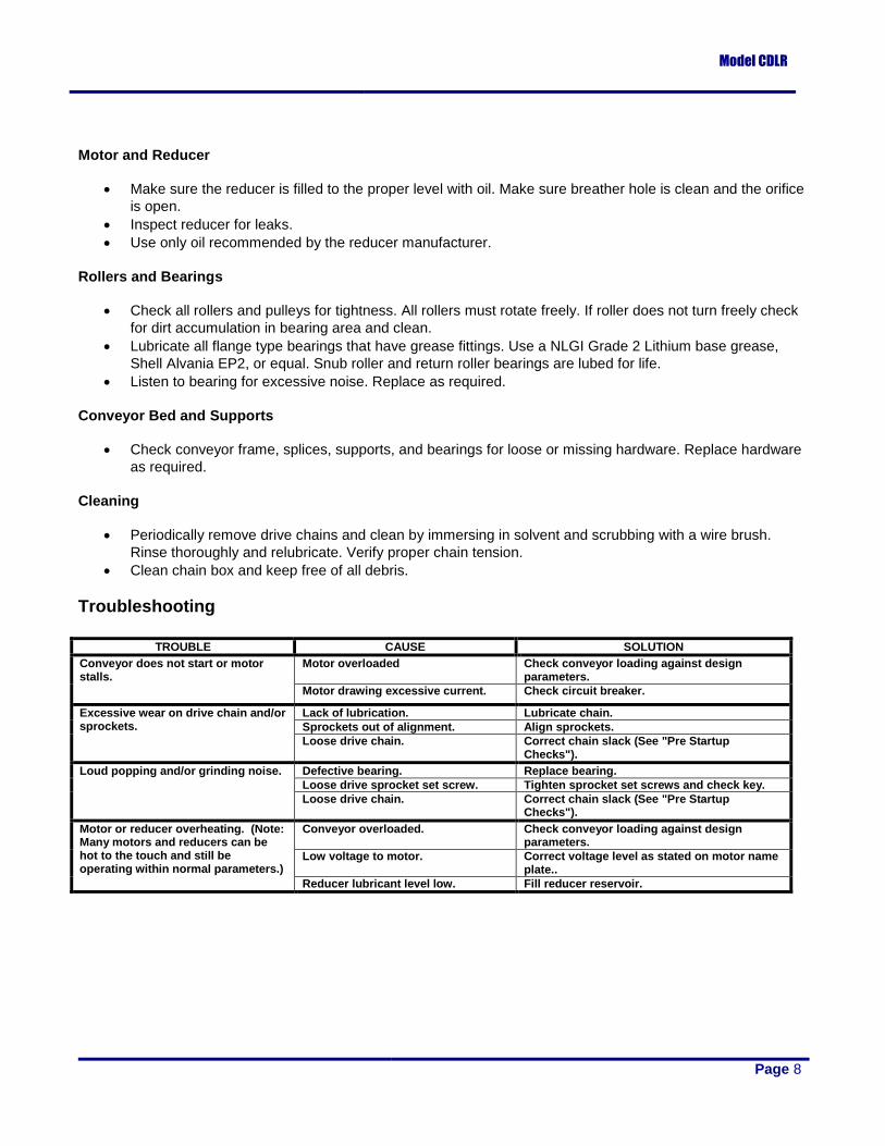
Effective operation and useful life of any equipment is directly related to the care and service it receives. A pre-determined maintenance schedule, including inspection, lubrication and cleaning should be established for each conveyor. Establish and maintain “Log Sheets” on each conveyor to record date and results of inspections, lubrication, and parts replacements. General inspections of all conveyors should be performed at regular intervals depending on use and service conditions. Maintenance Intervals The following chart gives a brief overview of what maintenance should be performed on a periodic basis.
COMPONENT ACTION SCHEDULE
WEEKLY MONTHLY QUARTERLY
MOTOR
Check noise.
Check temperature.
Check mounting bolts.
REDUCER
Check noise.
Check temperature.
Check oil level.
DRIVE CHAIN
Check tension.
Lubricate.
Check for wear.
SPROCKETS
Check for wear.
Check set screws and keys.
BEARINGS (Pulleys & Rollers)
Check noise.
Check mounting bolts.
STRUCTURAL General check: Loose bolts etc. tightened.
Maintenance Procedures Sprocket and Chain Maintenance
Remove drive chain guard and inspect drive chain and sprockets.
Chain should have about 2 to 3 percent sag when measured on the lower run of chain half way between
the two sprockets. See "Pre Startup Checks".
A loose chain can jump the drive sprockets and can cause sprocket wear and failure. A tight chain
requires excessive motor power, and can cause chain and sprocket failure.
Inspect drive sprocket and pulley set screws for tightness against the reducer and pulley shafts.
Check sprocket alignment. Misalignment causes wear on one side of the sprocket. Check for a
misaligned shaft or a sprocket off center.
Check shaft bearing set screws.
Lubricate the drive chain with SAE-30 oil approximately every 40 hours of operation. Lubricate more
frequently under extreme ambient conditions. Rinse chain in solvent before lubricating.
Re-install chain guard after inspection and maintenance.
Model CDLR
Page 8
Motor and Reducer
Make sure the reducer is filled to the proper level with oil. Make sure breather hole is clean and the orifice
is open.
Inspect reducer for leaks.
Use only oil recommended by the reducer manufacturer.
Rollers and Bearings
Check all rollers and pulleys for tightness. All rollers must rotate freely. If roller does not turn freely check
for dirt accumulation in bearing area and clean.
Lubricate all flange type bearings that have grease fittings. Use a NLGI Grade 2 Lithium base grease,
Shell Alvania EP2, or equal. Snub roller and return roller bearings are lubed for life.
Listen to bearing for excessive noise. Replace as required.
Conveyor Bed and Supports
Check conveyor frame, splices, supports, and bearings for loose or missing hardware. Replace hardware
as required.
Cleaning
Periodically remove drive chains and clean by immersing in solvent and scrubbing with a wire brush.
Rinse thoroughly and relubricate. Verify proper chain tension.
Clean chain box and keep free of all debris.
Troubleshooting
TROUBLE CAUSE SOLUTION
Conveyor does not start or motor stalls.
Motor overloaded Check conveyor loading against design parameters.
Motor drawing excessive current. Check circuit breaker.
Excessive wear on drive chain and/or sprockets.
Lack of lubrication. Lubricate chain.
Sprockets out of alignment. Align sprockets.
Loose drive chain. Correct chain slack (See "Pre Startup Checks").
Loud popping and/or grinding noise. Defective bearing. Replace bearing.
Loose drive sprocket set screw. Tighten sprocket set screws and check key.
Loose drive chain. Correct chain slack (See "Pre Startup Checks").
Motor or reducer overheating. (Note: Many motors and reducers can be hot to the touch and still be operating within normal parameters.)
Conveyor overloaded. Check conveyor loading against design parameters.
Low voltage to motor. Correct voltage level as stated on motor name plate..
Reducer lubricant level low. Fill reducer reservoir.

Installation, Operation & Maintenance
Page 9 Copyright® 2006 LEWCO, Inc.
Replacement Parts
How to Order Provide the MODEL NUMBER, and SERIAL NUMBER [located on unit label], when ordering parts for your LEWCO Conveyor. There is one unit label on each section of conveyor. To order parts please contact your local LEWCO distributor. If unable to contact your local distributor or the original distributor that supplied the equipment, please contact LEWCO, Inc. by phone at 419-625-4014, or Fax 419-625-1247. Ask for the conveyor sales parts department.
LEWCO, Inc. Serial No.: 026563-001
Model No.: CDLR25-13-4-120-30-36-36-D16-F23-G99-M03- A51-V98-SCC5-P94
Section No.: 026563-001-01
Figure 7.1 Location of Serial Number, Model Number, and Section Number on Typical Unit Label
Model CDLR
Page 10
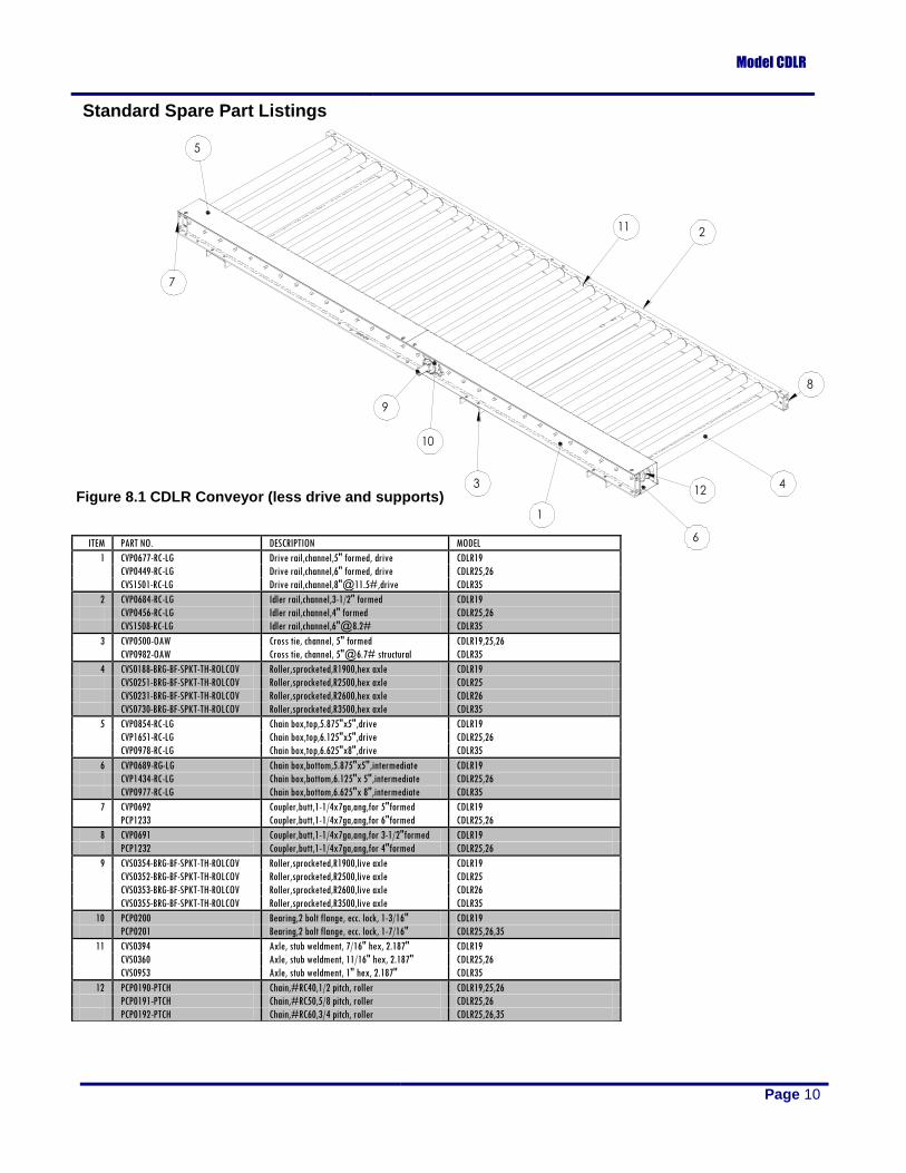
ITEM PART NO. DESCRIPTION MODEL
1 CVP0677-RC-LG Drive rail,channel,5" formed, drive CDLR19
CVP0449-RC-LG Drive rail,channel,6" formed, drive CDLR25,26
CVS1501-RC-LG Drive rail,channel,8"@11.5#,drive CDLR35
2 CVP0684-RC-LG Idler rail,channel,3-1/2" formed CDLR19
CVP0456-RC-LG Idler rail,channel,4" formed CDLR25,26
CVS1508-RC-LG Idler rail,channel,6"@8.2# CDLR35
3 CVP0500-OAW Cross tie, channel, 5" formed CDLR19,25,26
CVP0982-OAW Cross tie, channel, 5"@6.7# structural CDLR35
4 CVS0188-BRG-BF-SPKT-TH-ROLCOV Roller,sprocketed,R1900,hex axle CDLR19
CVS0251-BRG-BF-SPKT-TH-ROLCOV Roller,sprocketed,R2500,hex axle CDLR25
CVS0231-BRG-BF-SPKT-TH-ROLCOV Roller,sprocketed,R2600,hex axle CDLR26
CVS0730-BRG-BF-SPKT-TH-ROLCOV Roller,sprocketed,R3500,hex axle CDLR35
5 CVP0854-RC-LG Chain box,top,5.875"x5",drive CDLR19
CVP1651-RC-LG Chain box,top,6.125"x5",drive CDLR25,26
CVP0978-RC-LG Chain box,top,6.625"x8",drive CDLR35
6 CVP0689-RG-LG Chain box,bottom,5.875"x5",intermediate CDLR19
CVP1434-RC-LG Chain box,bottom,6.125"x 5",intermediate CDLR25,26
CVP0977-RC-LG Chain box,bottom,6.625"x 8",intermediate CDLR35
7 CVP0692 Coupler,butt,1-1/4x7ga,ang,for 5"formed CDLR19
PCP1233 Coupler,butt,1-1/4x7ga,ang,for 6"formed CDLR25,26
8 CVP0691 Coupler,butt,1-1/4x7ga,ang,for 3-1/2"formed CDLR19
PCP1232 Coupler,butt,1-1/4x7ga,ang,for 4"formed CDLR25,26
9 CVS0354-BRG-BF-SPKT-TH-ROLCOV Roller,sprocketed,R1900,live axle CDLR19
CVS0352-BRG-BF-SPKT-TH-ROLCOV Roller,sprocketed,R2500,live axle CDLR25
CVS0353-BRG-BF-SPKT-TH-ROLCOV Roller,sprocketed,R2600,live axle CDLR26
CVS0355-BRG-BF-SPKT-TH-ROLCOV Roller,sprocketed,R3500,live axle CDLR35
10 PCP0200 Bearing,2 bolt flange, ecc. lock, 1-3/16" CDLR19
PCP0201 Bearing,2 bolt flange, ecc. lock, 1-7/16" CDLR25,26,35
11 CVS0394 Axle, stub weldment, 7/16" hex, 2.187" CDLR19
CVS0360 Axle, stub weldment, 11/16" hex, 2.187" CDLR25,26
CVS0953 Axle, stub weldment, 1" hex, 2.187" CDLR35
12 PCP0190-PTCH Chain,#RC40,1/2 pitch, roller CDLR19,25,26
PCP0191-PTCH Chain,#RC50,5/8 pitch, roller CDLR25,26
PCP0192-PTCH Chain,#RC60,3/4 pitch, roller CDLR25,26,35
Figure 8.1 CDLR Conveyor (less drive and supports)
Standard Spare Part Listings
Installation, Operation & Maintenance
Page 11 Copyright® 2006 LEWCO, Inc.
ABBREVIATION DESCRIPTION
BF BETWEEN FRAME
LG LENGTH
BRG BEARING
OAW OVERALL WIDTH
SPKT SPROCKET STYLE
TH NO. OF TEETH
ROLCOV ROLLER COVER
PTCH NO. OF PITCHES
CASE REDUCER CASE SIZE
NS NO. OF STRANDS
RATIO REDUCTION RATIO
OS OUTPUT SHAFT ASSY
MOUNT MOTOR MOUNT SIZE
TH NO. OF TEETH
GC GUARD CENTER TO CENTER
BORE BORE SIZE
CC CHAIN CENTER
BW BELT WIDTH
RCC ROLLER CENTER TO CENTER
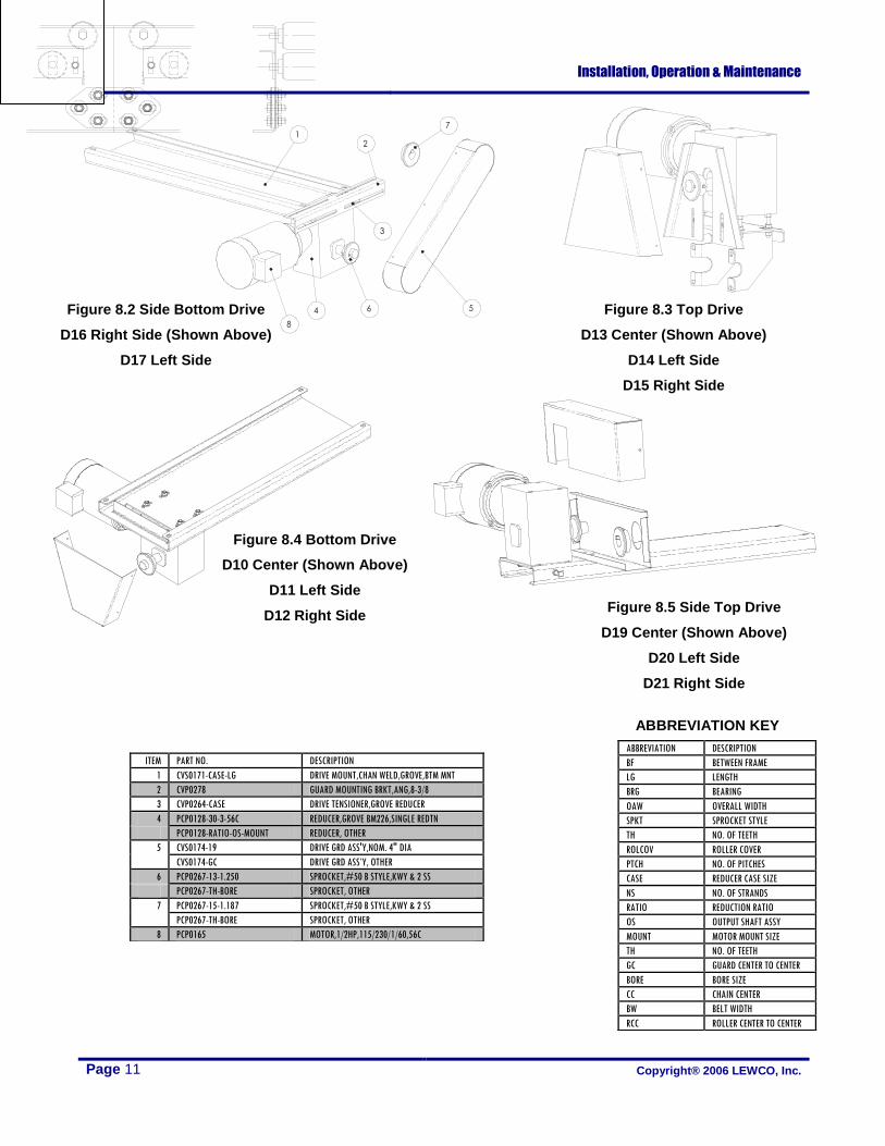
ITEM PART NO. DESCRIPTION
1 CVS0171-CASE-LG DRIVE MOUNT,CHAN WELD,GROVE,BTM MNT
2 CVP0278 GUARD MOUNTING BRKT,ANG,8-3/8
3 CVP0264-CASE DRIVE TENSIONER,GROVE REDUCER
4 PCP0128-30-3-56C REDUCER,GROVE BM226,SINGLE REDTN
PCP0128-RATIO-OS-MOUNT REDUCER, OTHER
5 CVS0174-19 DRIVE GRD ASS'Y,NOM. 4" DIA
CVS0174-GC DRIVE GRD ASS’Y, OTHER
6 PCP0267-13-1.250 SPROCKET,#50 B STYLE,KWY & 2 SS
PCP0267-TH-BORE SPROCKET, OTHER
7 PCP0267-15-1.187 SPROCKET,#50 B STYLE,KWY & 2 SS
PCP0267-TH-BORE SPROCKET, OTHER
8 PCP0165 MOTOR,1/2HP,115/230/1/60,56C
Figure 8.2 Side Bottom Drive
D16 Right Side (Shown Above)
D17 Left Side
Figure 8.4 Bottom Drive
D10 Center (Shown Above)
D11 Left Side
D12 Right Side
Figure 8.3 Top Drive
D13 Center (Shown Above)
D14 Left Side
D15 Right Side
Figure 8.5 Side Top Drive
D19 Center (Shown Above)
D20 Left Side
D21 Right Side
ABBREVIATION KEY
Related Documents