U.S. Department of the Interior U.S. Geological Survey Data Series 955 Prepared in cooperation with Colorado Water Conservation Board and the Bureau of Reclamation Installation of a Groundwater Monitoring-Well Network on the East Side of the Uncompahgre River in the Lower Gunnison River Basin, Colorado, 2014

Welcome message from author
This document is posted to help you gain knowledge. Please leave a comment to let me know what you think about it! Share it to your friends and learn new things together.
Transcript
U.S. Department of the InteriorU.S. Geological Survey
Data Series 955
Prepared in cooperation with Colorado Water Conservation Board and the Bureau of Reclamation
Installation of a Groundwater Monitoring-Well Network on the East Side of the Uncompahgre River in the Lower Gunnison River Basin, Colorado, 2014

Cover: Left, Core from monitoring well, lower Gunnison River Basin, Montrose County, Colorado, April 2014. Photo by Judith Thomas, U.S. Geological Survey. Right, Monitoring well adjacent to agricultural field, lower Gunnison River Basin, Montrose County, Colorado, August 2013. Photo by Judith Thomas, U.S. Geological Survey.

Installation of a Groundwater Monitoring-Well Network on the East Side of the Uncompahgre River in the Lower Gunnison River Basin, Colorado, 2014
By Judith C. Thomas
Prepared in cooperation with Colorado Water Conservation Board and the Bureau of Reclamation
Data Series 955
U.S. Department of the InteriorU.S. Geological Survey
U.S. Department of the InteriorSALLY JEWELL, Secretary
U.S. Geological SurveySuzette M. Kimball, Acting Director
U.S. Geological Survey, Reston, Virginia: 2015
For more information on the USGS—the Federal source for science about the Earth, its natural and living resources, natural hazards, and the environment—visit http://www.usgs.gov or call 1–888–ASK–USGS.
For an overview of USGS information products, including maps, imagery, and publications, visit http://www.usgs.gov/pubprod/.
Any use of trade, firm, or product names is for descriptive purposes only and does not imply endorsement by the U.S. Government.
Although this information product, for the most part, is in the public domain, it also may contain copyrighted materials as noted in the text. Permission to reproduce copyrighted items must be secured from the copyright owner.
Suggested citation:Thomas, J.C., 2015, Installation of a groundwater monitoring-well network on the east side of the Uncompahgre River in the Lower Gunnison River Basin, Colorado, 2014: U.S. Geological Survey Data Series 955, 44 p., http://dx.doi.org/10.3133/ds955.
ISSN 2327-638X (online)

iii
Contents
Abstract ...........................................................................................................................................................1
Introduction.....................................................................................................................................................1
Network Design..............................................................................................................................................2
Phase II Site Selection .........................................................................................................................2
Well Drilling and Installation ........................................................................................................................2
Well Development ..........................................................................................................................................2
References Cited............................................................................................................................................7
Appendix 1. Lithologic Logs ......................................................................................................................9
Appendix 2. Well-Construction Diagrams ............................................................................................17
Appendix 3. Well-Development Records ..............................................................................................37
Figures
1. Location of study area on the east side of the Uncompahgre River Basin, Colorado ..........3
2. Location of the 30 equal-area polygons and randomly selected monitoring sites within each (primary, secondary, and tertiary), east side of the Uncompahgre River Basin, Colorado ...................................................................................................................4
3. Location of monitoring wells installed April and June of calendar year 2014, east side of the Uncompahgre River Basin, Colorado ....................................................................5
Table
1. Summary of groundwater monitoring-well locations, construction, and depth to water ..........................................................................................................................................6

iv
Conversion Factors
Inch/Pound to SIMultiply By To obtain
Lengthinch (in.) 2.54 centimeter (cm)foot (ft) 0.3048 meter (m)mile (mi) 1.609 kilometer (km)millimeter (mm) 0.0393701 inch (in.)
Areasquare mile (mi2) 2.590 square kilometer (km2)
Volumegallon (gal) 3.785 liter (L)
Flow rategallon per minute (gal/min) 0.06309 liter per second (L/s)
Hydraulic conductivityfoot per day (ft/d) 0.3048 meter per day (m/d)
International System of Units to Inch/PoundMultiply By To obtain
Volumeliter (L) 0.2642 gallon (gal)
Massgram (g) 0.03527 ounce, avoirdupois (oz)
Temperature in degrees Celsius (°C) may be converted to degrees Fahrenheit (°F) as follows:°F=(1.8×°C)+32
Temperature in degrees Fahrenheit (°F) may be converted to degrees Celsius (°C) as follows:°C=(°F–32)/1.8
Vertical coordinate information was referenced to North American Vertical Datum of 1988 (NAVD 88).
Horizontal coordinate information was referenced to North American Datum of 1983 (NAD 83).
Specific conductance was given in microsiemens per centimeter at 25 degrees Celsius (µS/cm at 25 °C).

Installation of a Groundwater Monitoring-Well Network on the East Side of the Uncompahgre River in the Lower Gunnison River Basin, Colorado, 2014
By Judith C. Thomas
the 85th percentile chronic aquatic-life standard for dis-solved selenium (4.6 micrograms per liter) as established by the State of Colorado (Thomas and others, 2008; Butler and Leib, 2002). Despite the implementation of control projects in the region that were designed to limit the mobilization of selenium, there are indications that selenium loads may be increasing (Moore, 2011).
Perennial streamflow on the east side of the Uncompahgre River Basin is supported by seasonal tributary inflow, irrigation-return flows, and shallow groundwater discharge from areas underlain by selenium-bearing shale. Previous work in the basin (Bureau of Reclamation, 1982) supports a conceptual model of water-table (unconfined) groundwater conditions present beneath irrigated areas and in proximity to streams. Discharge of groundwater containing dissolved selenium contributes to surface-water selenium concentrations and loads; however, the groundwater system on the east side of the Uncompahgre River Basin is not well characterized. Additional information such as depth to water, extent and thickness of saturation, hydraulic conductivity, and groundwater selenium concentrations are needed to understand the characteristics of the groundwater system. Understanding the groundwater system can provide managers with an additional metric for evaluating the effective-ness of salinity and selenium control projects. Coupled with current surface-water monitoring, groundwater monitoring can provide a more complete understanding of the factors involved in achieving successful control projects. The USGS, in coopera-tion with Colorado Water Conservation Board and the Bureau of Reclamation, has established a groundwater-monitoring network on the east side of the Uncompahgre River Basin. This report describes the second phase of the implementation of a monitoring-well network (20 of the 30 wells were installed in April and June 2014) to characterize the groundwater quality on the east side of the Uncompahgre River Basin. The first phase of the project involved the installation of 10 of the 30 wells (polys 8, 11, 12, 13, 15, 16, 20, 24, 26, and 28) that were installed earlier in October/November 2012 and are not included in this report (Thomas and Arnold, 2015).
The purpose of this project was to design and install a groundwater-monitoring network to characterize ground-water quality and groundwater levels on the east side of the
AbstractThe east side of the Uncompahgre River Basin has been a
known contributor of dissolved selenium to recipient streams. Discharge of groundwater containing dissolved selenium contributes to surface-water selenium concentrations and loads; however, the groundwater system on the east side of the Uncompahgre River Basin is not well characterized. The U.S. Geological Survey, in cooperation with the Colorado Water Conservation Board and the Bureau of Reclamation, has estab-lished a groundwater-monitoring network on the east side of the Uncompahgre River Basin. Thirty wells total were installed for this project: 10 in 2012 (DS 923, http://dx.doi.org/10.3133/ds923), and 20 monitoring wells were installed during April and June 2014 which are presented in this report. This report presents location data, lithologic logs, well-construction dia-grams, and well-development information. Understanding the groundwater system can provide managers with an additional metric for evaluating the effectiveness of salinity and selenium control projects.
IntroductionThe east side of the Uncompahgre River Basin has
been a known contributor of dissolved selenium to recipient streams. The U.S. Fish and Wildlife Service (USFWS) and the U.S. Geological Survey (USGS), as part of National Irrigation Water Quality Program (NIQWP), found that dissolved selenium concentrations were elevated for both groundwater and river systems in irrigated parts of the Uncompahgre River Basin in the lower Gunnison River Basin (Butler and others, 1996). As a result, selenium sourced from irrigated areas was thought to be detrimentally affecting native Colorado River Basin fish species. The Colorado Department of Public Health and Environment (CDPHE) has since adopted standards for selenium in the lower Gunnison River Basin. Many riv-ers and streams of the east side of the Uncompahgre River Basin are selenium impaired for cold water fisheries on the Colorado’s 303(d) list , and concentrations have exceeded

2 Installation of a Groundwater Monitoring-Well Network, Uncompahgre River, Gunnison River Basin, Colorado, 2014
Uncompahgre River Basin in Colorado (fig. 1). The purpose of this report is to document network design, well drilling and installation, and well development of 20 of the 30 wells that make up this network.
Network DesignIn order to better understand the shallow groundwater
system, a 30-well uniform randomized groundwater-monitoring network was developed to provide a statistically robust groundwater monitoring network design. The study area is on the east side of the Uncompahgre River Basin (fig. 1), where irrigation is taking place within the Bureau of Reclamation’s Uncompahgre Irrigation Project. The Uncompahgre Irrigation Project is in west-central Colorado and includes lands that surround the town of Montrose and extend 34 miles (mi) along both sides of the Uncompahgre River to Delta, Colorado (Bureau of Reclamation, 2014). The project is a series of dams, canals, laterals, and drains that draws water from the Uncompahgre and Gunnison Rivers for irrigation of land within the project area. Network design was based on methods described by Alley (1993) and has been used by the USGS National Water Quality Assessment program in national investigations. The network design was created using a computerized technique (Scott, 1990) that generates a random distribution of potential groundwater sam-pling sites. The study area was determined by clipping digital maps of irrigated land to an outline of the Uncompahgre Irrigation Project. The resulting study area was used as input to Scott’s computerized technique for site selection. The random site-selection process divided the study area into 30 equal-area polygons and then generated three potential groundwater monitoring sites within each polygon: a primary, secondary, and tertiary location (fig. 2). When establishing sites, the primary location is considered first, followed by the secondary and tertiary sites.
Phase II Site Selection
Final well locations were established based on land-owner permission and site accessibility (fig. 3). Ten of the 30 randomly-determined locations were installed in October and November of calendar year 2012 (Thomas and Arnold, 2015). The remaining 20 wells were installed during April and June 2014 and are presented in this report.
Well Drilling and InstallationMonitoring well drilling and installation occurred during
April and June 2014 (table 1). Drilling services were provided by the Bureau of Reclamation Drilling Operations Group of Pleasant Grove, Utah. Borehole drilling and well installation
was overseen by a USGS hydrologist, who documented daily drilling operations, logged and packaged geologic materi-als encountered while drilling, and prepared well construc-tion reports. Well installation was completed in accordance with USGS Guidelines (http://ga.water.usgs.gov/gwqa/gwpd.7.4.16.html, accessed June 25, 2012) and State of Colorado drilling regulations (http://water.state.co.us/groundwater/BOE/Pages/BOERules.aspx, accessed December 31, 2013). USGS staff was responsible for coordi-nation of drilling services and obtaining permits required by the State of Colorado for well drilling.
Eighteen of the 20 boreholes for monitoring wells were drilled with a truck-mounted CME85 drilling rig. Two of the boreholes for monitoring wells were drilled using a Gus Pech 300 CHR drilling rig (LGRB Poly 6 and LGRB Poly 23). In both cases, boreholes were advanced with 4.25-inch (in) inside diameter (ID) hollow-stem augers, and continuous cores of geologic materials were collected where possible to properly identify lithologic intervals for well installation. Lithologic logs were developed on the basis of visual inspection of cores and auger cuttings (appendix 1). Lithologic descriptions are based on the Wentworth classification system (Wentworth, 1922).
Individual well construction diagrams are presented in appendix 2. Wells were constructed using 2-in diam-eter, Schedule 40 polyvinyl chloride (PVC) casing (ASTM D1785-12, http://www.astm.org/Standards/D1785.htm) with a locking cap and protective surface casing. Well screens were either 5 or 10-feet (ft) long and installed near the bottom of the saturated thickness. A 0.5- to 3-ft long sump was installed below the screen in some of the monitoring wells where pos-sible. Annular space adjacent to the screened interval was backfilled with a graded sand pack, annular space above the screened interval was plugged with bentonite, and a concrete well pad was placed at the surface. Other aspects of well construction were in accordance with USGS specifications for water-quality wells (Lapham and others, 1997) and Colorado State regulations (http://water.state.co.us/groundwater/BOE/Pages/BOERules.aspx, accessed December 31, 2013).
Well Development
Wells were developed after drilling to remove mud and any foreign material from the well and to help improve the hydraulic connection between the well and aquifer material. Well development was completed in July 2014, and was accomplished using a combination of bailing, pumping, and mechanical surging for a maximum of 8 hours or until the produced water was clear and parameters such as turbid-ity, specific conductance, and pH were stable. A Waterra Hydrolift 2 inertial pump system was used to develop wells. Well development information is provided for each well in appendix 3.

Well Development 3
Figure 1. Location of study area on the east side of the Uncompahgre River Basin, Colorado.
DELTA COUNTYMONTROSE COUNTY
5092
50
550
Dry
Uncom
pahgre
Cedar
Sprin
g
Smith
Loutsenhizer Arroyo
ForkCr
eek
Cree
k
Creek
River
Gunnison River
107°45'108°00'
38°39'
38°23'30"
0
0
5 MILES
5 KILOMETERS
Delta
Olathe
Hotchkiss
Montrose
Base from Environmental Research Systems Institute (esri) digital data, 2009, 1:24,000 and U.S. Geological Survey digital data, 2010, 1:100,000Universal Transverse Mercator, zone 13 North
Geology modifed from Tweto, 1979
EXPLANATION
Geology
Quaternary deposits
Cretacous Mancos Shale
Irrigated land (2005)
Study area boundary
Study Area
COLORADO

4 Installation of a Groundwater Monitoring-Well Network, Uncompahgre River, Gunnison River Basin, Colorado, 2014
Figure 2. Location of the 30 equal-area polygons and randomly selected monitoring sites within each (primary, secondary, and tertiary), east side of the Uncompahgre River Basin, Colorado. Each polygon is represented using a unique color.
DELTA COUNTYMONTROSE COUNTY
Dry
Uncom
pahgre
Cedar
Sprin
g
Smith
Loutsenhizer Arroyo
ForkCr
eek
Cree
k
Creek
River
Delta
Olathe
Montrose
107°45'108°00'
38°39'
38°23'30"
5092
50
550
0
0
5 MILES
5 KILOMETERS
Randomly selected sites
Equal area polygonsEXPLANATION
Primary siteSecondary siteTertiary site
Each of the 30 polygons for both phases I and II is represented using a unique color (sample box shows an example)
Base from Environmental Research Systems Institute (esri) digital data, 2009, 1:24,000 and U.S. Geological Survey digital data, 2010, 1:100,000Universal Transverse Mercator, zone 13 north
Gunnison River

Well Development 5
Figure 3. Location of monitoring wells installed April and June of calendar year 2014, east side of the Uncompahgre River Basin, Colorado.
DELTA COUNTYMONTROSE COUNTY
Dry
Uncom
pahgre
Cedar
Sprin
g
Smith
ForkCr
eek
Cree
k
Creek
River
Loutse nhizer Ar royo
Delta
Olathe
Montrose
107°45'108°00'
38°39'
38°23'30"
5092
50
550
0
0
5 MILES
5 KILOMETERS
Monitoring wells installed
Equal area polygons
EXPLANATION
Each of the 30 polygons is represented using a unique color
LGRB Poly 23
LGRB Poly 25
LGRB Poly 27
LGRB Poly 23
LGRB Poly 22
LGRB Poly 14
LGRB Poly 19
LGRB Poly 18
LGRB Poly 6
LGRB Poly 5
LGRB Poly 4
LGRB Poly 9
LGRB Poly 7
LGRB Poly 17
LGRB Poly 3
LGRB Poly 30
Phase I monitoring-well locations
Phase II monitoring-well locations withsite identifier labels
LGRB Poly 2
LGRB Poly 1
LGRB Poly 21
LGRB Poly 29
LGRB Poly 10
Base from Environmental Research Systems Institute (esri) digital data, 2009, 1:24,000 and U.S. Geological Survey digital data, 2010, 1:100,000Universal Transverse Mercator, zone 13 north
Gunnison River

6
Installation of a Groundw
ater Monitoring-W
ell Netw
ork, Uncom
pahgre River, Gunnison River B
asin, Colorado, 2014
Table 1. Summary of groundwater monitoring-well locations, construction, and depth to water.
[LGRB, lower Gunnison River Basin; Poly, polygon number; DDMMSS, degrees, minutes, seconds; stick-up height in feet above land surface; all depths in feet below land surface]
Well identifierUSGS
site identification number
Latitude (DDMMSS)
Longitude (DDMMSS)
Date completed
Depth to water at time
of drilling
Stick-up height
Depth to top of screen
Depth to bottom of
screen
Depth to top of
annular seal
Depth to top of
sand pack
Depth to bottom of sand pack
Total well depth
Total borehole
depth
LGRB Poly 1 383626107581501 383626 1075815 4/26/2014 8.5 2.4 15.7 20.7 2.0 14.0 21.0 21.0 21.5LGRB Poly 2 383852107583301 383852 1075833 4/14/2014 7.7 3.1 6.5 11.5 2.0 5.0 13.5 13.5 13.5LGRB Poly 3 384110107591801 384110 1075918 4/11/2014 3.8 2.6 7.2 12.2 2.0 6.0 14.7 14.7 23.5LGRB Poly 4 384240108000701 384240 1080007 4/24/2014 11.2 2.4 17.4 22.4 2.0 15.2 22.7 22.7 22.7LGRB Poly 5 384306108013801 384306 1080138 4/24/2014 20.4 2.9 21.7 26.7 2.0 19.0 27.0 27.0 27.0LGRB Poly 6 384329108031301 384329 1080313 6/9/2014 29.5 2.6 34.5 44.5 2.0 30.0 46.5 46.5 46.5LGRB Poly 7 384428107573901 384428 1075739 4/23/2014 20.5 2.2 22.2 27.2 2.0 20.5 28.2 28.2 28.2LGRB Poly 9 383730107570501 383730 1075705 4/25/2014 9.5 2.2 26.0 31.0 2.0 24.5 31.3 31.3 31.3LGRB Poly 10 383520107565901 383520 1075659 4/9/2014 14.2 2.7 16.0 21.0 2.0 14.5 23.5 23.5 23.5LGRB Poly 14 383401107563001 383401 1075630 4/27/2014 22.2 2.9 26.7 36.7 6.0 25.0 42.0 42.0 42.0LGRB Poly 17 384300107561801 384300 1075618 4/11/2014 7.1 2.9 16.3 21.3 1.9 13.8 23.3 23.3 23.3LGRB Poly 18 384559107565201 384559 1075652 4/23/2014 14.8 2.7 12.5 17.5 1.8 10.5 18.5 18.5 18.5LGRB Poly 19 383510107540801 383510 1075408 4/26/2014 7.5 3.1 7.5 17.5 2.0 6.0 18.5 18.5 18.5LGRB Poly 21 383051107525501 383051 1075255 4/28/2014 8.5 3.1 12.1 17.1 2.0 10.0 18.1 18.1 18.1LGRB Poly 22 382954107515101 382954 1075151 4/14/2014 21.3 –0.3 23.0 33.0 2.0 20.0 33.8 33.8 33.8LGRB Poly 23 382859107531901 382859 1075319 6/9/2014 8.1 –0.2 14.5 19.5 2.0 6.0 20.9 21.1 21.6LGRB Poly 25 382427107491401 382427 1074914 4/28/2014 9.8 2.9 8.2 13.2 2.0 6.0 16.2 16.2 16.2LGRB Poly 27 382736107491201 382736 1074912 4/10/2014 2.0 2.9 21.3 26.3 1.3 19.6 28.3 28.3 28.3LGRB Poly 29 382917107483101 382917 1074831 4/12/2014 7.0 2.8 7.5 12.5 2.0 5.5 15.0 15.0 18.0LGRB Poly 30 382947107465801 382947 1074658 4/16/2014 5.0 2.8 14.1 19.1 2.0 12.2 19.5 19.5 23.1

References Cited 7
References Cited
Alley, W.M., ed., 1993, Regional ground-water quality: New York, Van Nostrand Reinhold, 634 p.
Bureau of Reclamation, 1982, Lower Gunnison Basin Unit feasibility report—Appendix B Hydrosalinity: Colorado River Water Quality Improvement Program.
Bureau of Reclamation, 2014, Uncompahgre Project: Bureau of Reclamation, accessed August 25, 2014 at http://www.usbr.gov/projects/Project.jsp?proj_Name=Uncompahgre%20Project.
Butler, D.L., and Leib, K.J., 2002, Characterization of selenium in the lower Gunnison River Basin, Colorado, 1988–2000: U.S. Geological Survey Water-Resources Investigations Report 02–4151, 26 p. [Available at http://pubs.usgs.gov/wri/wri02-4151/.]
Butler, D.L., Wright, W.G., Stewart, K.C., Osmundson, B.C., Krueger, R.P., and Crabtree, D.W., 1996, Detailed study of selenium and other constituents in water, bottom sediment, soil, alfalfa, and biota associated with irrigation drainage in the Uncompahgre Project Area and in the Grand Valley, west-central Colorado, 1991–93: U.S. Geological Survey Water-Resources Investigations Report 96–4138, 136 p. [Available at http://pubs.er.usgs.gov/publication/wri964138.]
Munsell Color, 2013, Munsell Rock Color Book with genuine Munsell color chips: Grand Rapids, Mich., Munsell Color, 10 p.
Lapham, W.W., Franceska, D.W., and Koterba, M.T., 1997, Guidelines and standard procedures for studies of ground-water quality—Selection and installation of wells, and supporting documentation: U.S. Geological Survey Water-Resources Investigations Report 96–4233, 110 p. [Available at http://pubs.usgs.gov/wri/wri964233/.]
Moore, J.L., 2011, Characterization of salinity and selenium loading and land-use change in Montrose Arroyo, West-ern Colorado, from 1992 to 2010: U.S. Geological Survey Scientific Investigations Report 2011–5106, 23 p., [Avail-able at http://pubs.usgs.gov/sir/2011/5106/.]
Scott, J.C., 1990, Computerized stratified random site-selection approaches for design of a ground-water-quality sampling network: U.S. Geological Survey Water-Resources Investigations Report 90–4101, 109 p. [Available at http://pubs.er.usgs.gov/publication/wri904101.]
Thomas, J.C., and Arnold, L.R., 2015, Installation groundwa-ter monitoring-well network on the east side of the Uncom-pahgre River in the Lower Gunnison River Basin, Colo-rado, 2012: U.S. Geological Survey Data Series 923, 29 p, http://dx.doi.org/10.3133/ds923.
Thomas, J.C., Leib, K.J., and Mayo, J.W., 2008, Analysis of dissolved selenium loading for selected sites in the lower Gunnison River Basin, Colorado, 1978–2005: U.S. Geo-logical Survey Scientific Investigations Report 2007–5287, 25 p. [Available at http://pubs.usgs.gov/sir/2007/5287/.]
Tweto, Ogden, comp., 1979, Geologic map of Colorado: U.S. Geological Survey State Geologic Map, scale 1:500,000 (reprinted). [Available at http://ngmdb.usgs.gov/Prodesc/proddesc_68589.htm.]
Wentworth, C.K., 1922, A scale of grade and class terms for clastic sediments: Journal of Geology, v. 30, p. 377–392. [Available at http://www.jstor.org/stable/30063207?seq=1#page_scan_tab_contents.]


Appendix 1. Lithologic Logs 9
Appendix 1. Lithologic Logs[LGRB, lower Gunnison River Basin; Poly, polygon number]
LGRB Poly 1
Date well completed: 4/26/2014
Log prepared by J.C. Thomas
[Depth intervals in feet below land surface; mm, millimeters; ft, feet; HCl, hydrochloric acid]
Depth Sample type Description1
0–15.5 cuttings and core Colluvium—Mudflow deposit, clay with little sand moderate yellowish brown (10YR5/4) mottled, with gray (N5), damp soft to medium soft limonite staining, dry to damp reacts to HCl
15.5–21.5 core Weathered Mancos Shale—Dark gray (N3) abundant gypsum crystals in partings, fissile moderately well consoli-dated, medium stiff to stiff, clay, saturated in partings (horizontal and vertical) from about 18 to 20 ft
1Grain size based on the Wentworth classification system (Wentworth, 1922). Proportions defined using the following terms: “trace” (0–10 percent), “little” (10–20 percent), “some” (20–35 percent), and “and” (35–50 percent). Color codes (for example, 10YR6/2) refer to the Munsell color system (Munsell Color, 2013).
LGRB Poly 2
Date well completed: 4/14/2014
Log prepared by J.C. Thomas
[Depth intervals in feet below land surface; cm, centimeters; mm, millimeters; ft, feet; HCl, hydrochloric acid]
Depth Sample type Description1
0–10.5 cuttings and core Alluvium—Sand with gravel, very coarse, with trace cobbles (cobbles to 8 cm), moderate yellowish brown to dark yellowish brown (10YR5/4 to 10YR4/2), very loose to loose sand, subangular to rounded, poorly sorted. 8.5 to 10.5 ft saturated zone, gravel layer.
10.5–13.5 core Alluvium—clay with little sand, moderate yellowish brown (10YR5/4), reacts to HCl, damp to moist, me-dium soft
1Grain size based on the Wentworth classification system (Wentworth, 1922). Proportions defined using the following terms: “trace” (0–10 percent), “little” (10–20 percent), “some” (20–35 percent), and “and” (35–50 percent). Color codes (for example, 10YR6/2) refer to the Munsell color system (Munsell Color, 2013).
LGRB Poly 3
Date well completed: 4/11/2014
Log prepared by J.C. Thomas
[Depth intervals in feet below land surface; mm, millimeters; ft, feet; HCl, hydrochloric acid]
Depth Sample type Description1
0–12.5 cuttings and core Alluvium—Clay with some sand, grayish orange to dark yellowish brown (10YR7/4 to 10YR 4/2), coarse sand layer, moist
12.5-23.5 core Weathered Mancos Shale—Clay to clay with sand, grayish orange to dark yellowish brown (10YR7/4 to 10YR4/2) becoming darker with depth, dark gray (N3), stiff to hard becoming less weathered with depth, gypsum crystals, dry to moist, saturated from 18.3 to 21.8 ft, becoming more consolidated with depth, trace fossils, fossil shells, mollusks, limonite staining, gypsum crystals
1Grain size based on the Wentworth classification system (Wentworth, 1922). Proportions defined using the following terms: “trace” (0–10 percent), “little” (10–20 percent), “some” (20–35 percent), and “and” (35–50 percent). Color codes (for example, 10YR6/2) refer to the Munsell color system (Munsell Color, 2013).

10 Installation of a Groundwater Monitoring-Well Network, Uncompahgre River, Gunnison River Basin, Colorado, 2014
LGRB Poly 4
Date well completed: 4/24/2014
Log prepared by J.C. Thomas
[Depth intervals in feet below land surface; mm, millimeters; ft, feet; HCl, hydrochloric acid]
Depth Sample type Description1
0–7.7 cuttings and core Colluvium—Mudflow deposit, dark yellowish orange (10YR6/6) to dusky yellow (5Y6/4), clay with little sand, poorly sorted, medium soft to stiff, loose, dry to damp, limonite staining
7.7–22.7 core Weathered Mancos Shale—Dark yellowish brown (10YR4/2) to dark gray (N3), abundant gypsum crystals, more competent with depth, saturated in partings from 17.7 to 21.3 ft, dry from 21.3 to 22.7 ft, fissile, limo-nite staining, stiff to very stiff, low plasticity, reacts to HCl
1Grain size based on the Wentworth classification system (Wentworth, 1922). Proportions defined using the following terms: “trace” (0–10 percent), “little” (10–20 percent), “some” (20–35 percent), and “and” (35–50 percent). Color codes (for example, 10YR6/2) refer to the Munsell color system (Munsell Color, 2013).
LGRB Poly 5
Date well completed: 4/24/2014
Log prepared by J.C. Thomas
[Depth intervals in feet below land surface; mm, millimeters; ft, feet; HCl, hydrochloric acid]
Depth Sample type Description1
0–15.5 cuttings and core Alluvium—Mudflow deposit, dark yellowish orange (10YR6/6) to dusky yellow (5Y6/4), clayey sand, chunks of black shale in fine grained, poorly sorted, dry to damp gypsum crystals, reacts with HCl
15.5–27.0 core Weathered Mancos Shale—Clay, dark gray (N3), gypsum crystals in partings, moderately well consolidated, fissile limonite staining, very stiff to hard, saturated in fractures from 21.0 to 25.0 ft, abundant fossils from 21.0 to 23.0 ft, reacts with HCl
1Grain size based on the Wentworth classification system (Wentworth, 1922). Proportions defined using the following terms: “trace” (0–10 percent), “little” (10–20 percent), “some” (20–35 percent), and “and” (35–50 percent). Color codes (for example, 10YR6/2) refer to the Munsell color system (Munsell Color, 2013).
LGRB Poly 6
Date well completed: 6/9/2014
Log prepared by J.C. Thomas
[Depth intervals in feet below land surface; mm, millimeters; ft, feet; HCl, hydrochloric acid]
Depth Sample type Description1
0–46.5 cuttings and core Alluvium—Cobble gravel, grayish orange (10YR7/4), cobbles up to 150 mm, trace sand (fine), some clay, poorly sorted, dense, unconsolidated, angular to rounded, water encountered between 28.4 and 36.5 ft
1Grain size based on the Wentworth classification system (Wentworth, 1922). Proportions defined using the following terms: “trace” (0–10 percent), “little” (10–20 percent), “some” (20–35 percent), and “and” (35–50 percent). Color codes (for example, 10YR6/2) refer to the Munsell color system (Munsell Color, 2013).

Appendix 1. Lithologic Logs 11
LGRB Poly 7
Date well completed: 4/23/2014
Log prepared by J.C. Thomas
[Depth intervals in feet below land surface; mm, millimeters; ft, feet; HCl, hydrochloric acid]
Depth Sample type Description1
0–3.2 cuttings Alluvium—Clay with a trace of sand, dry, 10YR6/2, poorly sorted, reacts to HCl
3.2–28.2 core Alluvium— Clay with trace sand, stiff to very stiff, poorly sorted, damp to moist, moderate yellowish brown (10YR5/4), gypsum, limonite staining, water-bearing zone from 26.7 to 28.2 ft with white to clear gypsum crystals
1Grain size based on the Wentworth classification system (Wentworth, 1922). Proportions defined using the following terms: “trace” (0–10 percent), “little” (10–20 percent), “some” (20–35 percent), and “and” (35–50 percent). Color codes (for example, 10YR6/2) refer to the Munsell color system (Munsell Color, 2013).
LGRB Poly 9
Date well completed: 4/25/2014
Log prepared by J.C. Thomas
[Depth intervals in feet below land surface; mm, millimeters; ft, feet; HCl, hydrochloric acid]
Depth Sample type Description1
0–25.5 cuttings and core Alluvium—Mudflow deposit, pale yellowish brown (10YR6/2) becoming moderate yellowish brown (10YR5/4), abundant limonite staining, clay with little sand, dry to damp, medium soft, reacts to HCl
25.5–31.3 core Weathered Mancos Shale—Dusky yellowish brown (10YR2/2) becoming dark gray (N3) with depth moderate-ly well consolidated becoming more consolidated with depth, clay, stiff to very stiff, water in partings from 28.3 to 31.2 ft, limonite staining becoming less with depth, gypsum crystals in partings, fissile, reacts to HCl
1Grain size based on the Wentworth classification system (Wentworth, 1922). Proportions defined using the following terms: “trace” (0–10 percent), “little” (10–20 percent), “some” (20–35 percent), and “and” (35–50 percent). Color codes (for example, 10YR6/2) refer to the Munsell color system (Munsell Color, 2013).
LGRB Poly 10
Date well completed: 4/9/2014
Log prepared by J.C. Thomas
[Depth intervals in feet below land surface; mm, millimeters; ft, feet; HCl, hydrochloric acid]
Depth Sample type Description1
0–2 cuttings Alluvium—Clay with silt and fine sand, poorly sorted, yellowish brown (10YR4/2) to moderate yellow brown (10YR5/4), medium soft to stiff, damp, reacts to HCL
2–23.5 core Weathered Mancos Shale—Clay, mottled dusky yellow (5Y6/4) to light olive gray (5Y5/2), becoming olive gray (5Y3/2) with depth, trace very fine sand, fissile, very stiff-hard, damp-moist, trace small gypsum crys-tals and iron staining, reacts to HCl, water-bearing fractures and partings from 18.5 to 19.3 ft
1Grain size based on the Wentworth classification system (Wentworth, 1922). Proportions defined using the following terms: “trace” (0–10 percent), “little” (10–20 percent), “some” (20–35 percent), and “and” (35–50 percent). Color codes (for example, 10YR6/2) refer to the Munsell color system (Munsell Color, 2013).

12 Installation of a Groundwater Monitoring-Well Network, Uncompahgre River, Gunnison River Basin, Colorado, 2014
LGRB Poly 14
Date well completed: 4/27/2014
Log prepared by J.C. Thomas
[Depth intervals in feet below land surface; mm, millimeters; ft, feet; HCl, hydrochloric acid]
Depth Sample type Description1
0–14.0 cuttings and core Colluvium— Mudflow deposit, clay with trace sand, dark yellowish brown (10YR4/2), poorly sorted soft, damp, limonite staining, reacts to HCl
14.0-42.0 core Weathered Mancos Shale—Dark gray (N3), clay, fissile, very stiff to hard dry, moist at about 33 ft., well consolidated fossils, abundant gypsum crystals, water in partings at 33 ft. , reacts to HCl
1Grain size based on the Wentworth classification system (Wentworth, 1922). Proportions defined using the following terms: “trace” (0–10 percent), “little” (10–20 percent), “some” (20–35 percent), and “and” (35–50 percent). Color codes (for example, 10YR6/2) refer to the Munsell color system (Munsell Color, 2013).
LGRB Poly 17
Date well completed: 4/11/2014
Log prepared by J.C. Thomas
[Depth intervals in feet below land surface; mm, millimeters; ft, feet; HCl, hydrochloric acid]
Depth Sample type Description1
0–5.5 cuttings and core Alluvium—Sand with some clay and gravel, grayish orange (10YR7/4) to dark yellowish orange (10YR4/2), soft to medium soft, poorly sorted, angular to subangular, loose fine to coarse grained, moist, reacts to HCl
5.5–23.3 core Weathered Mancos Shale—Clay with sand to clay, grayish orange (10YR7/4) becoming darker with depth, dark gray (N3), stiff to hard, moist to saturated becoming more consolidated with depth, trace fossils, fossil shells, mollusks, limonite staining, gypsum crystals, saturated from 18.3 to 21.8 ft
1Grain size based on the Wentworth classification system (Wentworth, 1922). Proportions defined using the following terms: “trace” (0–10 percent), “little” (10–20 percent), “some” (20–35 percent), and “and” (35–50 percent). Color codes (for example, 10YR6/2) refer to the Munsell color system (Munsell Color, 2013).
LGRB Poly 18
Date well completed: 4/23/2014
Log prepared by J.C. Thomas
[Depth intervals in feet below land surface; mm, millimeters; ft, feet; HCl, hydrochloric acid]
Depth Sample type Description1
0–7.7 cuttings and core Alluvium—Very fine sand and little clay, dark yellowish brown (10YR4/2), damp to dry, poorly sorted
7.7–18.5 core Alluvium—Coarse sand with trace clay, pebbles (20 mm to 80 mm), poorly sorted subangular to rounded, loose to medium dense sand, damp at 8.5 ft, becoming saturated from 11.5 to 18.5 ft, dark yellowish brown to dusky yellowish brown to moderate brown (10YR4/2 to 10YR2/2 to 5YR3/4) throughout
1Grain size based on the Wentworth classification system (Wentworth, 1922). Proportions defined using the following terms: “trace” (0–10 percent), “little” (10–20 percent), “some” (20–35 percent), and “and” (35–50 percent). Color codes (for example, 10YR6/2) refer to the Munsell color system (Munsell Color, 2013).

Appendix 1. Lithologic Logs 13
LGRB Poly 19
Date well completed: 4/26/2014
Log prepared by J.C. Thomas
[Depth intervals in feet below land surface; mm, millimeters; ft, feet; HCl, hydrochloric acid]
Depth Sample type Description1
0–18.5 cuttings and core Colluvium—Mudflow deposit, dark yellowish brown (10YR4/2), clay with little sand, very soft, poorly sorted, moist becoming saturated at gravel layer at 8.1 ft
1Grain size based on the Wentworth classification system (Wentworth, 1922). Proportions defined using the following terms: “trace” (0–10 percent), “little” (10–20 percent), “some” (20–35 percent), and “and” (35–50 percent). Color codes (for example, 10YR6/2) refer to the Munsell color system (Munsell Color, 2013).
LGRB Poly 21
Date well completed: 4/28/2014
Log prepared by J.C. Thomas
[Depth intervals in feet below land surface; mm, millimeters; ft, feet; HCl, hydrochloric acid]
Depth Sample type Description1
0–14.0 cuttings and core Colluvium—Mudflow deposit, clay with trace sand, pale yellowish brown (10YR6/2), poorly sorted, damp to saturated from 0 to 4.1 ft, dry from 4.1 to 14.0 ft, limonite staining, reacts to HCl
14.0–18.1 core Weathered Mancos Shale—Medium dark gray (N4) to dark gray (N3), clay, fissile, very stiff , water in part-ings from 14.0 to 16.5 ft, reacts to HCl
1Grain size based on the Wentworth classification system (Wentworth, 1922). Proportions defined using the following terms: “trace” (0–10 percent), “little” (10–20 percent), “some” (20–35 percent), and “and” (35–50 percent). Color codes (for example, 10YR6/2) refer to the Munsell color system (Munsell Color, 2013).
LGRB Poly 22
Date well completed: 4/14/2014
Log prepared by J.C. Thomas
[Depth intervals in feet below land surface; mm, millimeters; ft, feet; HCl, hydrochloric acid]
Depth Sample type Description1
0–18.8 cuttings and core Alluvium/fill—Clay with little fine sand dark yellowish brown to dusky yellowish brown (10YR4/2 to 10YR2/2), moist very soft, poorly sorted, reacts to HCl
18.8-23.8 core Alluvium—Clay with little sand, moderate yellowish brown (10YR5/4), damp to moist, medium soft, reacts to HCl
23.8-29.8 core Alluvium—Sand with little clay, coarse sand, trace gravel, dark yellowish brown to dark yellowish orange (10YR4/2 to 10YR6/6), loose to medium dense sand, poorly sorted, angular to subrounded, saturated from 28.0 to 29.8 ft
29.8-33.8 core Weathered Mancos Shale—Clay, dark yellowish orange (10YR6/6), mottled with medium gray (N5), saturated1Grain size based on the Wentworth classification system (Wentworth, 1922). Proportions defined using the following terms: “trace” (0–10 percent), “little”
(10–20 percent), “some” (20–35 percent), and “and” (35–50 percent). Color codes (for example, 10YR6/2) refer to the Munsell color system (Munsell Color, 2013)

14 Installation of a Groundwater Monitoring-Well Network, Uncompahgre River, Gunnison River Basin, Colorado, 2014
LGRB Poly 23
Date well completed: 6/9/2014
Log prepared by J.C. Thomas
[Depth intervals in feet below land surface; mm, millimeters; ft, feet; HCl, hydrochloric acid]
Depth Sample type Description1
0–21.6 cuttings and core Alluvium—Cobble gravel, grayish orange (10YR7/4), cobbles up to 150 mm some sand (fine to coarse), trace clay, poorly sorted, dense, unconsolidated, angular-founded, saturated at about 12 ft
1Grain size based on the Wentworth classification system (Wentworth, 1922). Proportions defined using the following terms: “trace” (0–10 percent), “little” (10–20 percent), “some” (20–35 percent), and “and” (35–50 percent). Color codes (for example, 10YR6/2) refer to the Munsell color system (Munsell Color, 2013).
LGRB Poly 25
Date well completed: 4/28/2014
Log prepared by J.C. Thomas
[Depth intervals in feet below land surface; mm, millimeters; ft, feet; HCl, hydrochloric acid]
Depth Sample type Description1
0–16.2 cuttings and core Weathered Mancos Shale—clay, dark gray (N3), clay, becoming saturated below 8.0 ft, fissile, gypsum crystals in partings
1Grain size based on the Wentworth classification system (Wentworth, 1922). Proportions defined using the following terms: “trace” (0–10 percent), “little” (10–20 percent), “some” (20–35 percent), and “and” (35–50 percent). Color codes (for example, 10YR6/2) refer to the Munsell color system (Munsell Color, 2013).
LGRB Poly 27
Date well completed: 4/10/2014
Log prepared by J.C. Thomas
[Depth intervals in feet below land surface; mm, millimeters; ft, feet; HCl, hydrochloric acid]
Depth Sample type Description1
0–24.6 cuttings and core Weathered Mancos Shale—Clay, mottled yellowish brown (10YR4/2) to moderate yellow brown (10YR5/4) becoming darker with depth, trace very fine sand, fissile, reacts to HCl very stiff-hard, damp-moist, trace small gypsum crystals and iron staining, trace fossils at about 8 ft, reacts to HCl, water-bearing fractures and partings from 18.6 to 19.0 ft and from 22.5 to 24.6 ft (major water bearing zone)
24.6–28.3 core Weathered Mancos Shale—Clay, dark gray (N3), trace very fine sand, fissile, very stiff–hard, well consolidated, damp, trace small gypsum crystals, reacts to HCl
1Grain size based on the Wentworth classification system (Wentworth, 1922). Proportions defined using the following terms: “trace” (0–10 percent), “little” (10–20 percent), “some” (20–35 percent), and “and” (35–50 percent). Color codes (for example, 10YR6/2) refer to the Munsell color system (Munsell Color, 2013).

Appendix 1. Lithologic Logs 15
LGRB Poly 29
Date well completed: 4/12/2014
Log prepared by J.C. Thomas
[Depth intervals in feet below land surface; mm, millimeters; ft, feet; HCl, hydrochloric acid]
Depth Sample type Description1
0–7.6 cuttings and core Alluvium—Clay with some sand, moderate yellowish brown to dark yellowish brown (10YR5/4 to 10YR 4/2), fine grained sand, poorly sorted, damp to moist, very soft, no reaction with HCl
7.6–13.0 core Alluvium—Sand with clay, dark yellowish brown (10YR4/2), coarse grained sand with clay, poorly sorted, saturated, very loose sand, angular-subrounded, no reaction to HCl, coarse water bearing sand layer at 7.6 ft
13.0–18.0 core Alluvium—Clay with some sand, dark yellowish brown (10YR4/2), mottled with gray and black, well sorted, dense, moist to saturated, no reaction to HCl
1Grain size based on the Wentworth classification system (Wentworth, 1922). Proportions defined using the following terms: “trace” (0–10 percent), “little” (10–20 percent), “some” (20–35 percent), and “and” (35–50 percent). Color codes (for example, 10YR6/2) refer to the Munsell color system (Munsell Color, 2013).
LGRB Poly 30
Date well completed: 4/16/2014
Log prepared by J.C. Thomas
[Depth intervals in feet below land surface; mm, millimeters; ft, feet; HCl, hydrochloric acid]
Depth Sample type Description1
0–8.4 cuttings and core Alluvium—Clay with some sand and little gravel and cobbles (up to 70 mm in size), medium soft to stiff, poorly sorted, dry to damp, moderate yellowish brown to dark yellowish brown (10YR5/4 to 10YR4/2), limonite staining, reacts to HCl
8.4–23.1 core Weathered Mancos Shale—Clay with little sand, dark yellowish brown to dusky yellowish brown (10YR4/2 to 10YR2/2), medium soft to stiff, damp, from 18.2 to 21.2 ft saturated zone, dry below 21.2 ft, dark yel-lowish brown to light olive gray to dark gray (10YR4/2 to 5Y5/2 to N3) color evolution with depth becom-ing more competent with depth, fissile, gypsum crystals, reacts to HCl
1Grain size based on the Wentworth classification system (Wentworth, 1922). Proportions defined using the following terms: “trace” (0–10 percent), “little” (10–20 percent), “some” (20–35 percent), and “and” (35–50 percent). Color codes (for example, 10YR6/2) refer to the Munsell color system (Munsell Color, 2013).


Appendix 2. Well-Construction Diagrams 17
Appendix 2. Well-Construction Diagrams
[LGRB, lower Gunnison River Basin; Poly, polygon number; PVC, polyvinyl chloride; ft, feet; in, inch; diam., diameter; Sch. 40, Schedule 40]

18 Installation of a Groundwater Monitoring-Well Network, Uncompahgre River, Gunnison River Basin, Colorado, 2014
LGRB Poly 1
Protective steel surface casing–2.6 to 2.0 ft
Ground surface
2-in diameter Schedule 40 PVC riser–2.4 to 15.7 ft
Bentonite 2.0–14.0 ft
2-in diam. Sch. 40 PVC 0.01-in slot screen15.7–20.7 ft
2-in diam. Sch. 40 PVC end cap20.7–21.0 ft
20–40 mesh silica sand pack14.0–21.0 ft
Native material21.0–21.5 ft
Concrete surface seal and pad0 to 2.0 ft
Depth to water on 4/26/20148.5 ft
Total well depth: 21.0 ftTotal borehole depth: 21.5 ft

Appendix 2. Well-Construction Diagrams 19
LGRB Poly 2
Protective steel surface casing–3.2 to 2.0 ft
Ground surface
2-in diameter Schedule 40 PVC riser–3.1 to 6.5 ft
Bentonite 2.0–5.0 ft
2-in diam. Sch. 40 PVC 0.01-in slot screen6.5–11.5 ft
2-in diam. Sch. 40 PVC sump and end cap11.5–13.5 ft
20–40 mesh silica sand pack5.0–13.5 ft
Concrete surface seal and pad0 to 2.0 ft
Depth to water on 4/14/20147.7 ft
Total well depth: 13.5 ftTotal borehole depth: 13.5 ft

20 Installation of a Groundwater Monitoring-Well Network, Uncompahgre River, Gunnison River Basin, Colorado, 2014
LGRB Poly 3
Protective steel surface casing–2.7 to 2.4 ft
Ground surface
2-in diameter Schedule 40 PVC riser–2.6 to 7.2 ft
Bentonite 14.7–23.5 ft
2-in diam. Sch. 40 PVC 0.01-in slot screen7.2–12.2 ft
2-in diam. Sch. 40 PVC sump and end cap12.2–14.7 ft
20–40 mesh silica sand pack6.0–14.7 ft
Concrete surface seal and pad0 to 2.0 ft
Depth to water on 4/11/20143.8 ft
Total well depth: 14.7 ftTotal borehole depth: 23.5 ft

Appendix 2. Well-Construction Diagrams 21
LGRB Poly 4
Protective steel surface casing–3.0 to 2.0 ft
Ground surface
2-in diameter Schedule 40 PVC riser–2.4 to 17.4 ft
Bentonite 2.0–15.2 ft
2-in diam. Sch. 40 PVC 0.01-in slot screen17.4–22.4 ft
2-in diam. Sch. 40 PVC end cap22.4–22.7 ft
20–40 mesh silica sand pack15.2–22.7 ft
Concrete surface seal and pad0 to 2.0 ft
Depth to water on 4/24/201411.2 ft
Total well depth: 22.7 ftTotal borehole depth: 22.7 ft

22 Installation of a Groundwater Monitoring-Well Network, Uncompahgre River, Gunnison River Basin, Colorado, 2014
LGRB Poly 5
Protective steel surface casing–3.0 to 2.0 ft
Ground surface
2-in diameter Schedule 40 PVC riser–2.9 to 21.7 ft
Bentonite 2.0–19.0 ft
2-in diam. Sch. 40 PVC 0.01-in slot screen21.7–26.7 ft
2-in diam. Sch. 40 PVC end cap26.7–27.0 ft
20–40 mesh silica sand pack19.0–27.0 ft
Concrete surface seal and pad0 to 2.0 ft
Depth to water on 4/24/201420.4 ft
Total well depth: 27.0 ftTotal borehole depth: 27.0 ft

Appendix 2. Well-Construction Diagrams 23
LGRB Poly 6
Protective steel surface casing–2.9 to 2.0 ft
Ground surface
2-in diameter Schedule 40 PVC riser–2.6 to 34.5 ft
Bentonite 2.0–30.0 ft
2-in diam. Sch. 40 PVC 0.01-in slot screen34.5–44.5 ft
2-in diam. Sch. 40 PVC sump and end cap44.5–46.5 ft
20–40 mesh silica sand pack30.0–46.5 ft
Concrete surface seal and pad0 to 2.0 ft
Depth to water on 6/09/201429.5 ft
Total well depth: 46.5 ftTotal borehole depth: 46.5 ft

24 Installation of a Groundwater Monitoring-Well Network, Uncompahgre River, Gunnison River Basin, Colorado, 2014
LGRB Poly 7
Protective steel surface casing–2.9 to 2.0 ft
Ground surface
2-in diameter Schedule 40 PVC riser–2.2 to 22.2 ft
Bentonite 2.0–20.5 ft
2-in diam. Sch. 40 PVC 0.01-in slot screen22.2–27.2 ft
2-in diam. Sch. 40 PVC sump and end cap27.2–28.2 ft
20–40 mesh silica sand pack20.5–28.2 ft
Concrete surface seal and pad0 to 2.0 ft
Depth to water on 4/23/201420.5 ft
Total well depth: 28.2 ftTotal borehole depth: 28.2 ft

Appendix 2. Well-Construction Diagrams 25
LGRB Poly 9
Protective steel surface casing–2.6 to 2.0 ft
Ground surface
2-in diameter Schedule 40 PVC riser–2.2 to 26.0 ft
Bentonite 2.0–24.5 ft
2-in diam. Sch. 40 PVC 0.01-in slot screen26.0–31.0 ft
2-in diam. Sch. 40 PVC end cap31.0–31.3 ft
20–40 mesh silica sand pack24.5–31.3 ft
Concrete surface seal and pad0 to 2.0 ft
Depth to water on 4/25/20149.5 ft
Total well depth: 31.3 ftTotal borehole depth: 31.3 ft

26 Installation of a Groundwater Monitoring-Well Network, Uncompahgre River, Gunnison River Basin, Colorado, 2014
LGRB Poly 10
Protective steel surface casing–2.9 to 2.0 ft
Ground surface
2-in diameter Schedule 40 PVC riser–2.7 to 16.0 ft
Bentonite 2.0–14.5 ft
2-in diam. Sch. 40 PVC 0.01-in slot screen16.0–21.0 ft
2-in diam. Sch. 40 PVC end cap21.0–23.5 ft
20–40 mesh silica sand pack14.5–23.5 ft
Concrete surface seal and pad0 to 2.0 ft
Depth to water on 4/09/201414.2 ft
Total well depth: 23.5 ftTotal borehole depth: 23.5 ft
Appendix 2. Well-Construction Diagrams 27
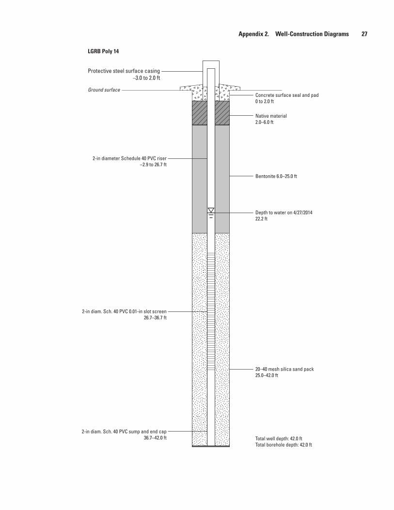
LGRB Poly 14
Protective steel surface casing–3.0 to 2.0 ft
Ground surface
2-in diameter Schedule 40 PVC riser–2.9 to 26.7 ft
Bentonite 6.0–25.0 ft
2-in diam. Sch. 40 PVC 0.01-in slot screen26.7–36.7 ft
2-in diam. Sch. 40 PVC sump and end cap36.7–42.0 ft
20–40 mesh silica sand pack25.0–42.0 ft
Native material2.0–6.0 ft
Concrete surface seal and pad0 to 2.0 ft
Depth to water on 4/27/201422.2 ft
Total well depth: 42.0 ftTotal borehole depth: 42.0 ft

28 Installation of a Groundwater Monitoring-Well Network, Uncompahgre River, Gunnison River Basin, Colorado, 2014
LGRB Poly 17
Protective steel surface casing–3.0 to 1.9 ft
Ground surface
2-in diameter Schedule 40 PVC riser–2.9 to 16.3 ft
Bentonite 1.9–13.8 ft
2-in diam. Sch. 40 PVC 0.01-in slot screen16.3–21.3 ft
2-in diam. Sch. 40 PVC sump and end cap21.3–23.3 ft
20–40 mesh silica sand pack13.8–23.3 ft
Concrete surface seal and pad0 to 1.9 ft
Depth to water on 4/11/20147.1 ft
Total well depth: 23.3 ftTotal borehole depth: 23.3 ft

Appendix 2. Well-Construction Diagrams 29
LGRB Poly 19
Protective steel surface casing–3.2 to 2.0 ft
Ground surface
2-in diameter Schedule 40 PVC riser–3.1 to 7.5 ft
Bentonite 2.0–6.0 ft
2-in diam. Sch. 40 PVC 0.01-in slot screen7.5–17.5 ft
2-in diam. Sch. 40 PVC sump and end cap17.5–18.5 ft
20–40 mesh silica sand pack6.0–18.5 ft
Concrete surface seal and pad0 to 2.0 ft
Depth to water on 4/26/20147.5 ft
Total well depth: 18.5 ftTotal borehole depth: 18.5 ft

30 Installation of a Groundwater Monitoring-Well Network, Uncompahgre River, Gunnison River Basin, Colorado, 2014
LGRB Poly 21
Protective steel surface casing–3.1 to 2.0 ft
Ground surface
2-in diameter Schedule 40 PVC riser–3.1 to 12.1 ft
Bentonite 2.0–10.0 ft
2-in diam. Sch. 40 PVC 0.01-in slot screen12.1–17.1 ft
2-in diam. Sch. 40 PVC end cap17.1–18.1 ft
20–40 mesh silica sand pack10.0–18.1 ft
Concrete surface seal and pad0 to 2.0 ft
Depth to water on 4/28/20148.5 ft
Total well depth: 18.1 ftTotal borehole depth: 18.1 ft

Appendix 2. Well-Construction Diagrams 31
LGRB Poly 22
Flush mount capGround surface
2-in diameter Schedule 40 PVC riser–0.3 to 22.0 ft
Bentonite 2.0–20.0 ft
2-in diam. Sch. 40 PVC 0.01-in slot screen23.0–33.0 ft
2-in diam. Sch. 40 PVC sump and end cap33.0–33.8 ft
20–40 mesh silica sand pack20.0–33.8 ft
Concrete surface seal and pad0 to 2.0 ft
Depth to water on 4/14/201421.3 ft
Total well depth: 33.8 ftTotal borehole depth: 33.8 ft

32 Installation of a Groundwater Monitoring-Well Network, Uncompahgre River, Gunnison River Basin, Colorado, 2014
LGRB Poly 23
Flush mount cap0 to 2.0 ft
Ground surface
2-in diameter Schedule 40 PVC riser–0.2 to 14.5 ft
Bentonite 2.0–6.0 ft
2-in diam. Sch. 40 PVC 0.01-in slot screen14.5–19.5 ft
2-in diam. Sch. 40 PVC sump and end cap19.5–21.1 ft
20–40 mesh silica sand pack6.0–20.9 ft
Concrete surface seal and pad0 to 2.0 ft
Depth to water on 6/09/20148.1 ft
Total well depth: 21.1 ftTotal borehole depth: 21.6 ft

Appendix 2. Well-Construction Diagrams 33
LGRB Poly 25
Protective steel surface casing–3.0 to 2.0 ft
Ground surface
2-in diameter Schedule 40 PVC riser–2.9 to 8.2 ft
Bentonite 2.0–6.0 ft
2-in diam. Sch. 40 PVC 0.01-in slot screen8.2–13.2 ft
2-in diam. Sch. 40 PVC sump and end cap13.2–16.2 ft
20–40 mesh silica sand pack6.0–16.2 ft
Concrete surface seal and pad0 to 2.0 ft
Depth to water on 4/28/20149.8 ft
Total well depth: 16.2 ftTotal borehole depth: 16.2 ft
34 Installation of a Groundwater Monitoring-Well Network, Uncompahgre River, Gunnison River Basin, Colorado, 2014
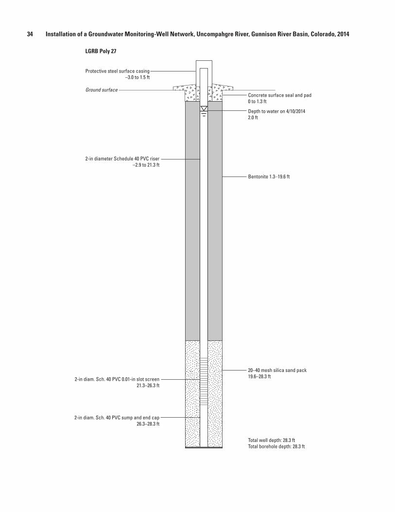
LGRB Poly 27
Protective steel surface casing–3.0 to 1.5 ft
Ground surface
2-in diameter Schedule 40 PVC riser–2.9 to 21.3 ft
Bentonite 1.3–19.6 ft
2-in diam. Sch. 40 PVC 0.01-in slot screen21.3–26.3 ft
2-in diam. Sch. 40 PVC sump and end cap26.3–28.3 ft
20–40 mesh silica sand pack19.6–28.3 ft
Concrete surface seal and pad0 to 1.3 ft
Depth to water on 4/10/20142.0 ft
Total well depth: 28.3 ftTotal borehole depth: 28.3 ft

Appendix 2. Well-Construction Diagrams 35
LGRB Poly 29
Protective steel surface casing–3.0 to 2.0 ft
Ground surface
2-in diameter Schedule 40 PVC riser–2.8 to 7.5 ft
Bentonite 2.0–5.5 ft
2-in diam. Sch. 40 PVC 0.01-in slot screen7.5–12.5 ft
2-in diam. Sch. 40 PVC sump and end cap12.5–15.0 ft
20–40 mesh silica sand pack5.5–15.0 ft
Concrete surface seal and pad0 to 2.0 ft
Depth to water on 4/12/20147.0 ft
Total well depth: 15.0 ftTotal borehole depth: 18.0 ft
Bentonite 15.0–18.0 ft
36 Installation of a Groundwater Monitoring-Well Network, Uncompahgre River, Gunnison River Basin, Colorado, 2014
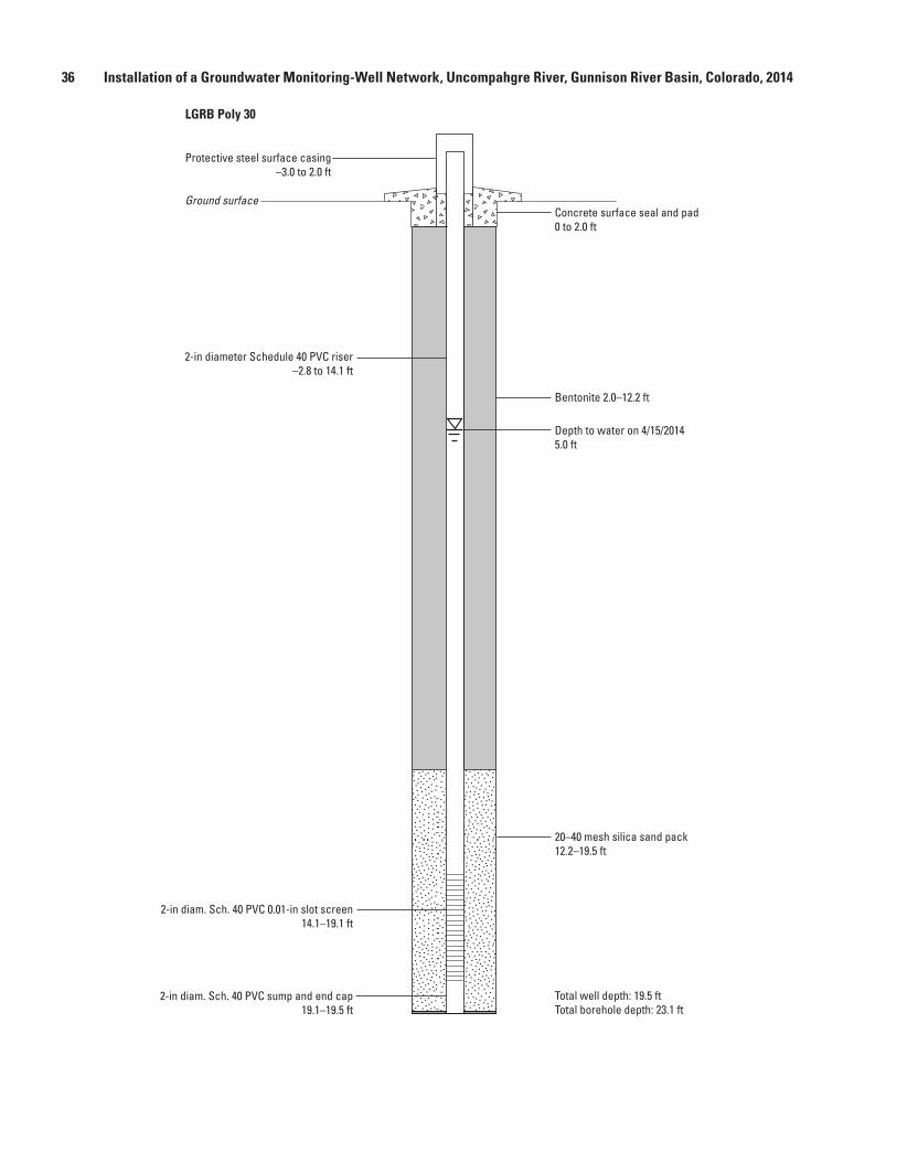
LGRB Poly 30
Protective steel surface casing–3.0 to 2.0 ft
Ground surface
2-in diameter Schedule 40 PVC riser–2.8 to 14.1 ft
Bentonite 2.0–12.2 ft
2-in diam. Sch. 40 PVC 0.01-in slot screen14.1–19.1 ft
2-in diam. Sch. 40 PVC sump and end cap19.1–19.5 ft
20–40 mesh silica sand pack12.2–19.5 ft
Concrete surface seal and pad0 to 2.0 ft
Depth to water on 4/15/20145.0 ft
Total well depth: 19.5 ftTotal borehole depth: 23.1 ft

Appendix 3. Well-Development Records 37
Appendix 3. Well-Development Records
[LGRB, lower Gunnison River Basin; Poly, polygon number]
LGRB Poly 1
Date developed: 6/24/2014
[gal/min, gallons per minute; °C, degrees Celsius; μS/cm, microsiemens per centimeter; NTU, nephelometric turbidity units; --, no data; >, greater than; gal, gallon]
Pumping duration (minutes)
Temperature (°C)
Specific conductance (µS/cm)
Turbidity (NTU)
Pumping rate (gal/min)
Appearance
0 -- -- -- pump on60 11.6 13,610 >1,000 0.5–0.6 Muddy90 11.7 13,620 >1,000 0.5–0.6 Muddy
120 12.2 13,600 >1,000 0.5–0.6 Muddy200 -- -- -- pump off Muddy225 12.2 13,590 >1,000 10 gal 1st bail, muddy250 12.1 13,590 1,000 1 gal 2nd bail, murky275 12.3 13,600 1,000 10 gal 3rd bail, murky300 13.5 13,590 475 10 gal 4th bail, slightly murky325 13.3 13,590 42.3 10 gal 5th bail, clear
LGRB Poly 2
Date developed: 6/3/2014
[gal/min, gallons per minute; °C, degrees Celsius; μS/cm, microsiemens per centimeter; NTU, nephelometric turbidity units; --, no data; >, greater than]
Pumping duration (minutes)
Temperature (°C)
Specific conductance (µS/cm)
Turbidity (NTU)
Pumping rate (gal/min)
Appearance
0 -- -- -- pump on60 11.6 2,880 >1,000 0.5–0.6 Muddy80 11.8 2,870 >1,000 0.5–0.6 Muddy
120 11.8 2,840 >1,000 0.5–0.6 Muddy/murky140 11.2 2,830 >1,000 0.5–0.6 Muddy/murky160 11.4 2,820 >1,000 0.5–0.6 Muddy/murky190 11.8 2,820 >1,000 0.5–0.6 Muddy/murky220 12.4 2,850 >1,000 0.5 Muddy240 11.8 2,840 >1,000 0.5 Muddy/murky360 12.5 2,820 >1,000 0.5 Murky410 -- removed surge block -- 0.1–0.5435 12.9 2,840 1000 0.1–0.4 Murky460 -- -- -- pump off
LGRB Poly 3
Date developed: 6/2/2014
[gal/min, gallons per minute; °C, degrees Celsius; μS/cm, microsiemens per centimeter; NTU, nephelometric turbidity units; --, no data; >, greater than]
Pumping duration (minutes)
Temperature (°C)
Specific conductance (µS/cm)
Turbidity (NTU)
Pumping rate (gal/min)
Appearance
0 -- -- -- pump on60 11 5,300 >1,000 0.4 Muddy80 11.2 5,330 >1,000 0.4 Muddy/murky100 11.6 5,310 >1,000 0.4 Muddy/murky120 11.4 5,260 >1,000 0.4 Muddy/murky130 11.5 5,160 569 0.25 Murky140 11.1 5,060 >1,000 0.25 Murky150 11.6 5,010 589 0.25 Slightly murky160 11.7 4,970 58.7 0.25 Clear161 -- -- -- pump off

38 Installation of a Groundwater Monitoring-Well Network, Uncompahgre River, Gunnison River Basin, Colorado, 2014
LGRB Poly 4
Date developed: 5/21/2014
[gal/min, gallons per minute; °C, degrees Celsius; μS/cm, microsiemens per centimeter; NTU, nephelometric turbidity units; --, no data; >, greater than]
Pumping duration (minutes)
Temperature (°C)
Specific conductance (µS/cm)
Turbidity (NTU)
Pumping rate (gal/min)
Appearance
0 -- -- -- pump on60 13.7 4,170 >1,000 0.5 Muddy85 14.2 4,160 >1,001 1 Muddy/murky
110 14.6 4,140 >1,002 1 Muddy/murky130 15 4,140 >1,003 0.2 Muddy/murky155 14.6 4,170 >1,004 1 Murky190 14 4,170 >1,005 1 Murky210 13.6 4,170 >1,006 1 Murky211 -- -- -- pump off
LGRB Poly 5
Date developed: 5/20/2014 and 5/21/2014
[gal/min, gallons per minute; °C, degrees Celsius; μS/cm, microsiemens per centimeter; NTU, nephelometric turbidity units; --, no data; >, greater than]
Pumping duration (minutes)
Temperature (°C)
Specific conductance (µS/cm)
Turbidity (NTU)
Pumping rate (gal/min)
Appearance
0 -- -- -- pump on Very muddy180 -- -- -- pump off Very muddy
0 -- -- -- pump on Muddy80 13.1 2,830 >1,000 0.8 Muddy
100 13.1 2,830 >1,000 0.8 Muddy120 13.1 2,840 >1,000 0.8 Muddy140 13.5 2,840 >1,000 0.5 Very muddy160 13.5 2,850 >1,000 0.5 Very muddy162 -- -- -- pump off180 12.6 2,970 877 5 gal 1st bail, muddy/murky200 12.5 2,890 283 5 gal 2nd bail, murky
LGRB Poly 6
Date developed: 6/23/2014
[gal/min, gallons per minute; °C, degrees Celsius; μS/cm, microsiemens per centimeter; NTU, nephelometric turbidity units; --, no data; >, greater than]
Pumping duration (minutes)
Temperature (°C)
Specific conductance (µS/cm)
Turbidity (NTU)
Pumping rate (gal/min)
Appearance
0 -- -- -- pump on50 14.5 2,550 >1,000 2 Muddy70 14.5 2,550 1,000 2 Muddy90 14.5 2,550 735 2 Murky
110 14.5 2,550 446 2 Murky130 14.5 2,540 330 2 Murky150 14.5 2,540 274 2 Murky180 15 2,540 156 1 Slightly murky210 15 2,540 119 1 Slightly murky230 14.9 2,540 99.8 1 Slightly murky240 14.9 2,540 99.9 1 Slightly murky250 -- -- -- pump off

Appendix 3. Well-Development Records 39
LGRB Poly 7
Date developed: 5/20/2014
[gal/min, gallons per minute; °C, degrees Celsius; μS/cm, microsiemens per centimeter; NTU, nephelometric turbidity units; --, no data; >, greater than]
Pumping duration (minutes)
Temperature (°C)
Specific conductance (µS/cm)
Turbidity (NTU)
Pumping rate (gal/min)
Appearance
0 -- -- -- 0.3 Muddy40 13.5 40,000 >1,000 0.3 Murky yellowish tinge60 13.8 43,800 320 0.3 Yellowish, slightly murky70 14.3 43,900 260 0.3 Yellowish, slightly murky80 13.7 44,000 96.4 0.3 Clear90 13.8 44,000 71.1 0.3 Clear
100 14.8 44,000 58.2 0.3 Clear—degassing110 14.4 44,000 61.4 0.3 Clear—degassing112 -- -- -- pump off
LGRB Poly 9
Date developed: 6/23/2014 and 6/24/2014
[gal/min, gallons per minute; °C, degrees Celsius; μS/cm, microsiemens per centimeter; NTU, nephelometric turbidity units; --, no data; <, less than]
Pumping duration (minutes)
Temperature (°C)
Specific conductance (µS/cm)
Turbidity (NTU)
Pumping rate (gal/min)
Appearance
0 -- -- -- pump on90 -- -- -- <0.1 Very muddy
117 -- -- -- pump off120 -- -- -- 2 gal 1st bail, very muddy
1093 11.8 5,140 81.4 5 gal 2nd bail, slightly murky1467 12.3 5,120 112 5 gal 3rd bail, slightly murky
LGRB Poly 10
Date developed: 6/25/2014
[gal/min, gallons per minute; °C, degrees Celsius; μS/cm, microsiemens per centimeter; NTU, nephelometric turbidity units; --, no data]
Pumping duration (minutes)
Temperature (°C)
Specific conductance (µS/cm)
Turbidity (NTU)
Pumping rate (gal/min)
Appearance
0 12.6 4,170 >1,000 15 gal 1st bail, muddy15 12.4 4,190 1,000 25 gal 2nd bail, muddy30 12.7 4,180 1,000 10 gal 3rd bail, muddy45 12.1 4,190 1,000 10 gal 4th bail, muddy60 12.2 4,190 581 10 gal 5th bail, murky75 12.2 4,190 491 5 gal 6th bail, murky90 12 4,180 284 5 gal 7th bail, slightly murky
105 12 4,190 321 5 gal 8th bail, slightly murky120 12.9 4,190 108 5 gal 9th bail, slightly murky135 12.5 4,190 73.6 5 gal 10th bail, clear

40 Installation of a Groundwater Monitoring-Well Network, Uncompahgre River, Gunnison River Basin, Colorado, 2014
LGRB Poly 14
Date developed: 6/25/2014
[gal/min, gallons per minute; °C, degrees Celsius; μS/cm, microsiemens per centimeter; NTU, nephelometric turbidity units; --, no data]
Pumping duration (minutes)
Temperature (°C)
Specific conductance (µS/cm)
Turbidity (NTU)
Pumping rate (gal/min)
Appearance
0 13.7 37,400 1,000 15 gal 1st bail, murky30 14.6 25,300 17.6 10 gal 2nd bail, murky60 15 24,300 8.77 4 gal 3rd bail, clear yellow90 15.1 28,100 11.3 4 gal 4th bail, clear yellow
LGRB Poly 17
Date developed: 6/19/2014
[gal/min, gallons per minute; °C, degrees Celsius; μS/cm, microsiemens per centimeter; NTU, nephelometric turbidity units; --, no data; >, greater than]
Pumping duration (minutes)
Temperature (°C)
Specific conductance (µS/cm)
Turbidity (NTU)
Pumping rate (gal/min)
Appearance
0 -- -- -- pump on50 10.7 6,300 >1,000 1 Muddy90 10.4 6,320 >1,000 1 Murky
110 10.4 6,320 >1,000 1 Murky140 10.6 6,320 1,000 1 Murky180 10.8 6,320 >1,000 0.5–1.2 Murky210 11.3 6,320 >1,000 1 Murky240 10.6 6,320 1,000 1 Murky360 11.3 6,320 912 0.5–1 Slightly murky380 11 6,320 668 0.4–0.5 Slightly murky440 11.4 6,330 436 0.4–0.5 Slightly murky480 11.7 6,320 370 0.5 Slightly murky485 -- -- -- pump off
LGRB Poly 18
Date developed: 5/20/2014
[gal/min, gallons per minute; °C, degrees Celsius; μS/cm, microsiemens per centimeter; NTU, nephelometric turbidity units; --, no data; >, greater than]
Pumping duration (minutes)
Temperature (°C)
Specific conductance (µS/cm)
Turbidity (NTU)
Pumping rate (gal/min)
Appearance
0 -- -- -- pump on Muddy1 -- -- >1,000 0.3 Muddy
70 13.1 2,920 255 0.4 Murky80 12.9 2,930 76.5 -- Slightly murky90 13 2,920 41.3 0.4 Mostly clear
100 13.1 2,930 20.4 0.4 Mostly clear110 13.1 2,920 24.7 0.4 Clear120 13.5 2,920 16.8 0.4 Clear129 -- -- -- pump off

Appendix 3. Well-Development Records 41
LGRB Poly 19
Date developed: 7/18/2014
[gal/min, gallons per minute; °C, degrees Celsius; μS/cm, microsiemens per centimeter; NTU, nephelometric turbidity units; --, no data; >, greater than]
Pumping duration (minutes)
Temperature (°C)
Specific conductance (µS/cm)
Turbidity (NTU)
Pumping rate (gal/min)
Appearance
0 -- -- -- pump on Muddy60 16.4 4,100 >1,000 0.3 Muddy
155 15.7 4,030 >1,000 0.5 Muddy205 15.6 4,030 >1,000 0.3 Muddy223 16.5 3,860 854 0.25 Muddy250 -- -- -- pump off265 15.0 3,870 486 5 gal 1st bail, murky
LGRB Poly 21
Date developed: 7/8/2014
[gal/min, gallons per minute; °C, degrees Celsius; μS/cm, microsiemens per centimeter; NTU, nephelometric turbidity units; --, no data]
Pumping duration (minutes)
Temperature (°C)
Specific conductance (µS/cm)
Turbidity (NTU)
Pumping rate (gal/min)
Appearance
0 -- -- -- pump on60 13.6 3,400 1,000 0.2 Muddy87 14 3,410 146 0.2 Clear96 14 3,400 108 0.2 Clear
106 14.1 3,390 65.9 0.2 Clear116 14.1 3,380 53.9 0.2 Clear126 14 3,380 43.3 0.2 Clear136 -- -- -- pump off
LGRB Poly 22
Date developed: 7/8/2014
[gal/min, gallons per minute; °C, degrees Celsius; μS/cm, microsiemens per centimeter; NTU, nephelometric turbidity units; --, no data]
Pumping duration (minutes)
Temperature (°C)
Specific conductance (µS/cm)
Turbidity (NTU)
Pumping rate (gal/min)
Appearance
0 -- -- -- pump on50 14 8,550 1,000 1 Muddy/murky
100 14.6 8,600 907 1 Murky115 14.5 8,610 689 1 Murky144 14.4 8,650 450 1 Slightly murky, degassing160 14.6 8,660 225 1 Slightly murky, degassing180 14.5 8,640 168 1 Clear yellow181 -- -- -- pump off

42 Installation of a Groundwater Monitoring-Well Network, Uncompahgre River, Gunnison River Basin, Colorado, 2014
LGRB Poly 23
Date developed: 7/2/2014
[gal/min, gallons per minute; °C, degrees Celsius; μS/cm, microsiemens per centimeter; NTU, nephelometric turbidity units; --, no data; >, greater than]
Pumping duration (minutes)
Temperature (°C)
Specific conductance (µS/cm)
Turbidity (NTU)
Pumping rate (gal/min)
Appearance
0 -- -- -- pump on80 12 1,729 >1,000 1 Muddy
120 12.6 1,734 >1,000 1 Muddy180 12.7 1,728 >1,000 1 Muddy240 12.4 1,723 >1,000 1 Muddy290 12.2 1,728 1,000 1 Muddy344 12.3 1,725 1,000 1 Muddy352 -- -- -- pump off
LGRB Poly 25
Date developed: 6/30/2014
[gal/min, gallons per minute; °C, degrees Celsius; μS/cm, microsiemens per centimeter; NTU, nephelometric turbidity units; --, no data]
Pumping duration (minutes)
Temperature (°C)
Specific conductance (µS/cm)
Turbidity (NTU)
Pumping rate (gal/min)
Appearance
0 -- -- -- pump on30 12.4 2,910 284 0.2 Slightly murky40 12.2 2,920 149 0.2 Slightly murky50 12.2 2,940 72.1 0.2 Clear60 12 2,930 29.4 0.2 Clear70 12.2 2,930 25.3 0.2 Clear80 -- -- -- pump off
LGRB Poly 27
Date developed: 6/30/2014
[gal/min, gallons per minute; °C, degrees Celsius; μS/cm, microsiemens per centimeter; NTU, nephelometric turbidity units; --, no data]
Pumping duration (minutes)
Temperature (°C)
Specific conductance (µS/cm)
Turbidity (NTU)
Pumping rate (gal/min)
Appearance
0 -- -- -- pump on60 12.4 9,700 1,000 1 Muddy yellowish90 12 9,680 1,000 1 Muddy yellowish, degassing
110 12.5 9,710 971 1 Muddy yellowish, degassing160 12.4 9,690 723 1 Murky yellowish180 11.9 9,690 675 1 Murky yellowish210 -- -- -- pump off

Appendix 3. Well-Development Records 43
LGRB Poly 29
Date developed: 7/16/2014
[gal/min, gallons per minute; °C, degrees Celsius; μS/cm, microsiemens per centimeter; NTU, nephelometric turbidity units; --, no data; >, greater than; gals, gallons]
Pumping duration (minutes)
Temperature (°C)
Specific conductance (µS/cm)
Turbidity (NTU)
Pumping rate (gal/min)
Appearance
0 -- -- -- pump on76 14.4 3,470 >1,000 0.3 Muddy
100 13.1 3,480 >1,000 0.3 Muddy253 13.4 3,480 >1,000 0.125 Muddy, moved surge block293 14.2 3,480 >1,000 0.1 Muddy330 14 3,480 >1,000 0.3 Muddy331 -- -- -- pump off350 12.4 3,480 910 5 gals 1st bail, murky, clearing370 12.4 3,480 109 5 gals 2nd bail, clearing
LGRB Poly 30
Date developed: 7/18/2014
[gal/min, gallons per minute; °C, degrees Celsius; μS/cm, microsiemens per centimeter; NTU, nephelometric turbidity units; --, no data; >, greater than; gals, gallons]
Pumping duration (minutes)
Temperature (°C)
Specific conductance (µS/cm)
Turbidity (NTU)
Pumping rate (gal/min)
Appearance
0 -- -- -- pump on60 12.9 4,210 >1,000 0.4 Muddy90 -- -- -- 0.3 Very muddy
135 13.4 4,400 >1,000 0.5 Very muddy 188 13.4 4,350 >1,000 0.5 Very muddy213 -- -- -- pump off230 11.8 4,350 >1,000 5 gals 1st bail, muddy250 11.8 4,340 964 5 gals 2nd bail, murky270 12.0 4,340 690 5 gals 3rd bail, murky290 11.9 4,340 597 5 gals 4th bail, murky
Publishing support provided by: Denver Publishing Service Center, Denver, Colorado
For more information concerning this publication, contact: Director, USGS Colorado Water Science Center Box 25046, Mail Stop 415 Denver, CO 80225 (303) 236-4882
Or visit the Colorado Water Science Center Web site at: http://co.water.usgs.gov/
This publication is available online at: http://dx.doi.org/10.3133/ds955


Thomas, J.C.—
Installation of a Groundw
ater Monitoring-W
ell Netw
ork, Uncom
pahgre River, Lower G
unnison River Basin, Colorado, 2014—
Data Series 955ISSN 2327-638X (online)http://dx.doi.org/10.3133/ds955
Related Documents