Installation Manual DLP Cinema ® Projector NC1000C DLP Cinema ® Projector Model No. NP-NC1000C

Welcome message from author
This document is posted to help you gain knowledge. Please leave a comment to let me know what you think about it! Share it to your friends and learn new things together.
Transcript
Installation Manual
DLP Cinema® Projector
NC1000C
DLP Cinema® Projector
Model No.NP-NC1000C
2
Introduction
DLP Cinema Projector Installation and Adjustment NEC Display Solutions, Ltd. Manual (This document) describes the procedures
to install, adjust and maintain the projector (NC1000C) and peripheral devices. For safe and correct installation, adjustment and use
of the projector, carefully read this document before installation.
Refer to the operation manuals of the applicable products for basic operation and remarks of the projector. This document expects
the readers who have basic knowledge about projector installation. After reading, please keep this document under care of the
company which installed or adjusted the projector.
The product name used in this manualIn this manual, the device name is written as listed below. If the function has difference by devices, the product name is written in
the text.
• NC1000C Projector
• NP-90MS02 Media block or IMB
• Digital Cinema Communicator DCC
3
Important Information
Precautions: Please read this manual carefully before using
your NC1000C and keep the manual handy for future
reference.
The NC1000C (projector unit) is called the “projector”, and the
NP-90MS02 (integrated media server) is called the “media
block” or “IMB” in this manual.
• DLP, DLP Cinema and their respective logos are trademarks
or registered trademarks of Texas Instruments.
• CineLink is a trademark of Texas Instruments.
• Other product names and manufacturer names described in
this manual are the registered trademarks or trademarks of
their respective companies.
• The display screens and illustrations shown in this manual
may differ slightly from the actual ones.
• GPL/LGPL Software Licenses
The product includes software licensed under GNU General
Public License (GPL), GNU Lesser General Public License
(LGPL), and others.
For more information on each software, see “readme.pdf”
inside the “about GPL&LGPL” folder on the supplied
CD-ROM.
WARNING:
TO PREVENT FIRE OR SHOCK HAZARDS, DO NOT EXPOSE THIS UNIT TO RAIN OR MOISTURE.
CAUTION:
TO REDUCE THE RISK OF ELECTRIC SHOCK, DO NOT OPEN COVER. NO USER-SERVICEABLE PARTS INSIDE. REFER SERVICING TO QUALIFIED SERVICE PERSONNEL.
This symbol warns the user that uninsulated volt-
age within the unit may have sufficient magnitude
to cause electric shock. Therefore, it is dangerous
to make any kind of contact with any part inside of
this unit.
This symbol alerts the user that important literature
concerning the operation and maintenance of this
unit has been included. Therefore, it should be
read carefully in order to avoid any problems.
DOC compliance Notice
This Class A digital apparatus meets all requirements of the
Canadian Interference-Causing Equipment Regulations.
Machine Noise Information Regulation - 3. GPSGV,
The highest sound pressure level is less than 70 dB (A) in accor-
dance with EN ISO 7779.
WARNING:
This is a Class A product. In a domestic environment this product may cause radio interference in which case the user may be required to take adequate measures.
CAUTION:
• In order to reduce any interference with radio and televi-sion reception use a signal cable with ferrite core attached. Use of signal cables without a ferrite core attached may cause interference with radio and television reception.
• This equipment has been tested and found to comply with the limits for a Class A digital device, pursuant to Part 15 of the FCC Rules. These limits are designed to provide reasonable protection against harmful interference when the equipment is operated in a commercial environment. This equipment generates, uses, and can radiate radio frequency energy and, if not installed and used in accor-dance with the installation manual, may cause harmful interference to radio communications. Operation of this equipment in a residential area is likely to cause harmful interference in which case the user will be required to correct the interference at his own expense.
Important Safeguards
These safety instructions are to ensure the long life of your pro-
jector and to prevent fire and shock. Please read them carefully
and heed all warnings.
Installation
1. Consult your dealer for information about transporting and
installing the projector. Do not attempt to transport and
install the projector yourself.
The projector must be installed by qualified technicians in
order to ensure proper operation and reduce the risk of
bodily injury.
2. Place the projector on a flat, level surface in a dry area away
from dust and moisture. Tilting the front of the projector up
or down from level could reduce lamp life.
Do not put the projector on its side when the lamp is on.
Doing so may cause damage to the projector.
3. Do not place the projector in direct sunlight, near heaters or
heat radiating appliances.
4. Exposure to direct sunlight, smoke or steam could harm
internal components.
5. Handle your projector carefully. Dropping or jarring your
projector could damage internal components.
6. To carry the projector, a minimum of four persons are
required.
7. Do not hold the lens part with your hand. Otherwise the
projector may tumble or drop, causing personal injury.
8. Do not place heavy objects on top of the projector.
4
Important Information
9. Turn off the projector, and disconnect the power cable
before moving the projector.
10. The cooling fan settings need to be configured when using
the projector in a location at an altitude of approximately
5500 feet/1600 meters or higher. Refer to “About High Alti-
tude mode” (page 6) for details.
11. Do not install and store the projector in the below circum-
stances.Failure to do so may cause of malfunction.
• In powerful magnetic fields
• In corrosive gas environment
• Outdoors
12. If you wish to have the projector installed on the ceiling;
• Do not attempt to install the projector yourself.
• The projector must be installed by qualified technicians
in order to ensure proper operation and reduce the risk
of bodily injury.
• In addition, to prevent ceiling collapse, the ceiling should
be able to support total weight of 50kg (projector weight
of 44kg, lens weight of 3kg, IMS weight of 3kg) for an
extended period of time, and the installation must be in
accordance with any local building codes.
• Please consult your dealer for more information.
Refer to “2-2-1. Installing the Projector on the Ceiling”
(page 32) for details on the attachment positions when
installing on the ceiling.
WARNING:
1. Do not cover the lens with the supplied lens cap or equiv-alent while the projector is on. Doing so can lead to dis-torting or melting of the cap and burning your hands due to the heat emitted from the light output.
2. Do not place any objects, which are easily affected by heat, in front of the projector lens. Doing so could lead to the object melting from the heat that is emitted from the light output.
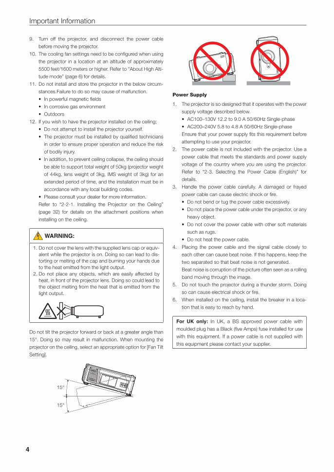
Do not tilt the projector forward or back at a greater angle than
15°. Doing so may result in malfunction. When mounting the
projector on the ceiling, select an appropriate option for [Fan Tilt
Setting].
15°
15°
Power Supply
1. The projector is so designed that it operates with the power
supply voltage described below.
• AC100–130V 12.2 to 9.0 A 50/60Hz Single-phase
• AC200–240V 5.8 to 4.8 A 50/60Hz Single-phase
Ensure that your power supply fits this requirement before
attempting to use your projector.
2. The power cable is not included with the projector. Use a
power cable that meets the standards and power supply
voltage of the country where you are using the projector.
Refer to “2-3. Selecting the Power Cable (English)” for
details.
3. Handle the power cable carefully. A damaged or frayed
power cable can cause electric shock or fire.
• Do not bend or tug the power cable excessively.
• Do not place the power cable under the projector, or any
heavy object.
• Do not cover the power cable with other soft materials
such as rugs.
• Do not heat the power cable.
4. Placing the power cable and the signal cable closely to
each other can cause beat noise. If this happens, keep the
two separated so that beat noise is not generated.
Beat noise is corruption of the picture often seen as a rolling
band moving through the image.
5. Do not touch the projector during a thunder storm. Doing
so can cause electrical shock or fire.
6. When installed on the ceiling, install the breaker in a loca-
tion that is easy to reach by hand.
For UK only: In UK, a BS approved power cable with
moulded plug has a Black (five Amps) fuse installed for use
with this equipment. If a power cable is not supplied with
this equipment please contact your supplier.
5
Important Information
CAUTION:
The power cable stopper (shown in below) is supplied with this projector.To prevent the power cable from coming loose, make sure that all the prongs of the power cable are fully inserted into the AC IN terminal of the projector before using the power cable stopper to fix the power cable. A loose contact of the power cable may cause a fire or electric shock. For using the power cable stopper, refer to the user’s manual.
Fire and Shock Precautions
1. Ensure that there is sufficient ventilation and that vents are
unobstructed to prevent potentially dangerous concentra-
tions of ozone and the build-up of heat inside your projec-
tor. Allow at least 12 inches (30cm) of space between your
projector and a wall. In particular, clear a space of 27.6
inches (70 cm) or more in front of the air outlet on the rear
surface and 19.8 inches (50 cm) or more in front of the air
outlet on the lamp side. (See page 16)
2. Prevent foreign objects such as paper clips and bits of
paper from falling into your projector. Do not attempt to
retrieve any objects that might fall into your projector. Do
not insert any metal objects such as a wire or screwdriver
into your projector. If something should fall into your projec-
tor, disconnect it immediately and have the object removed
by a qualified service person.
3. Turn off the projector, unplug the power cable and have the
projector serviced by a qualified service personnel under
the following conditions:
• When the power cable or plug is damaged or frayed.
• If liquid has been spilled into the projector, or if it has
been exposed to rain or water.
• If the projector does not operate normally when you fol-
low the instructions described in this user’s manual.
• If the projector has been dropped or the cabinet has
been damaged.
• If the projector exhibits a distinct change in performance,
indicating a need for service.
4. Keep any items such as magnifying glass out of the light
path of the projector. The light being projected from the lens
is extensive, therefore any kind of abnormal objects that
can redirect light coming out of the lens, can cause unpre-
dictable outcome such as fire or injury to the eyes.
5. When using a LAN cable:
For safety, do not connect to the connector for peripheral
device wiring that might have excessive Voltage.
6. Do not look into the lens while the projector is on. Serious
damage to your eyes could result.
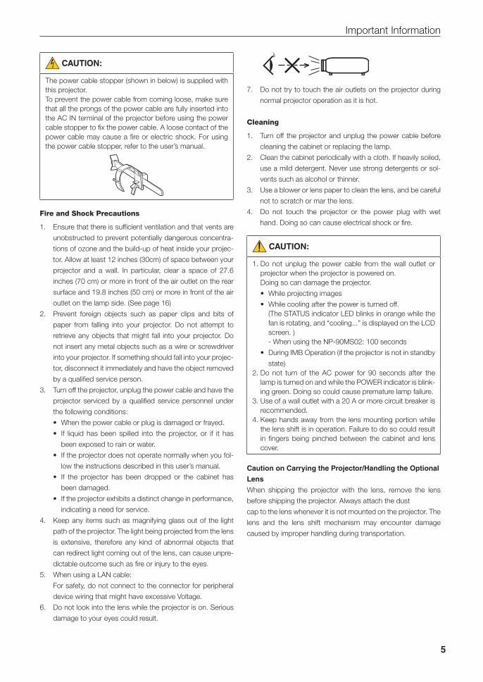
7. Do not try to touch the air outlets on the projector during
normal projector operation as it is hot.
Cleaning
1. Turn off the projector and unplug the power cable before
cleaning the cabinet or replacing the lamp.
2. Clean the cabinet periodically with a cloth. If heavily soiled,
use a mild detergent. Never use strong detergents or sol-
vents such as alcohol or thinner.
3. Use a blower or lens paper to clean the lens, and be careful
not to scratch or mar the lens.
4. Do not touch the projector or the power plug with wet
hand. Doing so can cause electrical shock or fire.
CAUTION:
1. Do not unplug the power cable from the wall outlet or projector when the projector is powered on.
Doing so can damage the projector.
• While projecting images
• While cooling after the power is turned off. (The STATUS indicator LED blinks in orange while the
fan is rotating, and “cooling...” is displayed on the LCD screen. )- When using the NP-90MS02: 100 seconds
• During IMB Operation (if the projector is not in standby
state)2. Do not turn of the AC power for 90 seconds after the
lamp is turned on and while the POWER indicator is blink-ing green. Doing so could cause premature lamp failure.
3. Use of a wall outlet with a 20 A or more circuit breaker is recommended.
4. Keep hands away from the lens mounting portion while the lens shift is in operation. Failure to do so could result in fingers being pinched between the cabinet and lens cover.
Caution on Carrying the Projector/Handling the Optional
Lens
When shipping the projector with the lens, remove the lens
before shipping the projector. Always attach the dust
cap to the lens whenever it is not mounted on the projector. The
lens and the lens shift mechanism may encounter damage
caused by improper handling during transportation.
6
Important Information
Handling the Battery
• Take care when handling the battery, as it could cause fire,
injury, or damage to surrounding objects.
- Do not short out, dismantle, or place batteries in a fire.
• Dispose of used batteries according to your local
regulations.
• There is a battery mounted on the electronic circuit board
within the main unit. When disposing of the main unit, do not
dismantle the device or remove the internal circuit board, and
contact the shop where you purchased the product or your
local government agency.
Peripheral Devices and Connecting Cables
Use shielded cables for the cables connecting the IMB with
peripheral devices (GPI, GPO, AES cables). If you use a non-
shielded cable, there is a risk that radio interference may occur.
WARNING TO CALIFORNIA RESIDENTS:
Handling the cables supplied with this product will expose
you to lead, a chemical known to the State of California to
cause birth defects or other reproductive harm. WASH
HANDS AFTER HANDLING
Note for US Residents
The lamp in this product contains mercury.
Please dispose according to Local, State or
Federal Laws.
Lamp Replacement
1. Use the specified lamp for safety and performance.
2. To replace the lamp, follow all instructions provided on the
user’s manual.
3. Due to the lamp being sealed in a pressurized environment,
there is a small risk of explosion, if not operated correctly.
There is minimal risk involved, if the unit is in proper working
order, but if damaged or operated beyond the recom-
mended hours, the risk of explosion increases. Please note
that there is a warning system built in, that displays follow-
ing message when you reach a preset operating time
“Lamp1 OverTime” or “Lamp2 OverTime”. When you see
this message please replace the lamp 1 or lamp 2. If the
lamp does explode, smoke will be discharged from the
vents located on the back of the unit. Do not stand in front
of the vents during the operation. This smoke is comprised
of glass in particulate form and Mercury gas, and will not
cause harm if kept out of your eyes. If your eyes have been
exposed to this gas, please flush your eyes out with water
immediately and seek immediate medical attention. Do not
rub your eyes! This could cause serious injury.
A Lamp Characteristic
The projector has a discharge lamp for special purposes as
a light source.
A lamp has a characteristic that its brightness gradually
decreases with age. Also repeatedly turning the lamp on
and off will increase the possibility of its lower brightness.
CAUTION:
• DO NOT TOUCH THE LAMP immediately after it has been used. It will be extremely hot. Turn the projector off and then disconnect the power cable. Allow at least one hour for the lamp to cool before handling.
• When removing the lamp from a ceiling-mounted projec-tor, make sure that no one is under the projector. Glass fragments could fall if the lamp has been burned out.
About High Altitude mode
• Set [Fan Speed Mode] to [High Altitude] when using the pro-
jector at altitudes approximately 5500 feet/1600 meters or
higher.
Using the projector at altitudes approximately 5500 feet/1600
meters or higher without setting to [High Altitude] can cause
the projector to overheat and the projector could shut down.
If this happens, wait a couple minutes and turn on the
projector.
• Using the projector at altitudes less than approximately 5500
feet/1600 meters and setting to [High Altitude] can cause the
lamp to overcool, causing the image to flicker. Switch [Fan
Speed Mode] to [Auto].
• Using the projector at altitudes approximately 5500 feet/1600
meters or higher can shorten the life of internal parts such as
the lamp.
7
Important Information
Disposing of your used product
EU-wide legislation as implemented in each Mem-
ber State requires that used electrical and elec-
tronic products carrying the mark (left) must be
disposed of separately from normal household
waste.
This includes projectors and their electrical acces-
sories or lamps. When you dispose of such prod-
ucts, please follow the guidance of your local
authority and/or ask the shop where you pur-
chased the product.
After collecting the used products, they are reused
and recycled in a proper way. This effort will help
us reduce the wastes as well as the negative
impact such as mercury contained in a lamp to the
human health and the environment at the mini-
mum level.
The mark on the electrical and electronic products
only applies to the current European Union Mem-
ber States.
For questions relating to unclear points or repairs
Contact your dealer or the following support branch for ques-
tions relating to unclear points, malfunctions and repairs of the
product.
In Europe
Company Name: NEC Display Solutions Europe GmbH
Address: Landshuter Allee 12-14, D-80637 Munich, Germany
Telephone: +49 89 99699 0
Fax Line: +49 89 99699 500
Email Address: [email protected]
WEB Address: http://www.nec-display-solutions.com
In North America
Company Name: NEC Display Solutions of America, Inc.
Address: 500 Park Boulevard, Suite 1100 Itasca, Illinois 60143,
U.S.A.
Telephone: +1 800 836 0655
Fax Line: +1 800 356 2415
Email Address: [email protected]
WEB Address: http://www.necdisplay.com/
In China
Company Name: NEC Solutions (China) Co., Ltd.
Address: Rm 1903, Shining Building, 35 Xueyuan Rd,
Haidian District Beijing 100191, P.R.C.
Telephone: +8610-4008-900-678
Email Address: [email protected]
In Hong Kong and Taiwan
Company Name: Strong Westrex, Inc.
Address: Room 4108 China Resources Building, No. 26
Harbour Road, Wanchai, Hong Kong
Telephone: +852 2827 8289
Fax Line: +852 2827 5993
Email Address: [email protected]
In South Korea
Company Name: Hyosung ITX Co., Ltd.
Address: 1F, Ire Building, 2, Yangpyeong-dong 4-ga,
Yeongdeungpo-gu, Seoul, Korea 150-967
Telephone: +82-2-2102-8591
Fax Line: +82-2-2102-8600
Email Address: [email protected]
WEB Address: http://www.hyosungitx.com
In Australia and New Zealand
Company Name: NEC Australia Pty Ltd
Address: 26 Rodborough Road Frenchs Forest NSW 2086
Telephone: 131 632 (from anywhere in Australia)
Email Address: [email protected]
WEB Address: http://www.nec.com.au
In Thailand, Singapore, Malaysia, Indonesia and
Philippines
Company Name: Goldenduck International Co., Ltd.
Address: 65 Soi Phutthamothon Sai 1, 21 Bangramad,
Talingchan, Bangkok, Thailand 10170
Telephone: +66-2887-8807
Fax Line: +66-2887-8808
Email Address: [email protected]
8
Wichtige Informationen
Vorsichtsmaßnahmen: Lesen Sie sich dieses Handbuch bitte
sorgfaltig durch, bevor Sie den NC1000C benutzen, und
bewahren Sie das Bedienungshandbuch in greifbarer Nahe als
spätere Referenz auf.
In diesem Handbuch wird der NC1000C (Projektoreinheit) „Pro-
jektor“ und das NP-90MS02 (integrieter Media-Server) „Media
Block“ oder „IMB“ genannt.
• DLP, DLP Cinema und die entsprechenden Logos sind
Warenzeichen oder registrierte Warenzeichen von Texas
Instruments.
• CineLink ist ein Warenzeichen von Texas Instruments.
• Andere in diesem Handbuch genannte Produkt- und Herstel-
lernahmen sind eingetragene Warenzeichen oder Warenzei-
chen der entsprechenden Unternehmen.
• Die Bildschirmanzeigen und Abbildungen in diesen Hand-
buch können leicht von den tatsächlichen Anzeigen
abweichen.
• GPL/LGPL Softwarelizenzen
Das Produkt beinhaltet Software, die unter GNU General
Public License (GPL), GNU Lesser General Public License
(LGPL) und anderen lizenziert ist.
Für weitere Informationen zu jeder Software lesen Sie bitte
die „readme.pdf“ im Ordner „about GPL&LGPL“ auf der mit-
gelieferten CD-ROM.
WARNUNG:
ZUR VERMEIDUNG VON FEUER UND ELEKTRISCHEN SCHLÄGEN DARF DAS GERÄT WEDER REGEN NOCH FEUCHTIGKEIT AUSGESETZT WERDEN.
ACHTUNG:
ZUR VERMEIDUNG EINES ELEKTRISCHEN SCHLAGES ÖFFNEN SIE NICHT DAS GEHÄUSE. INNERHALB DES GEHÄUSES BEFINDEN SICH KEINE FÜR DIE BEDIENUNG DES GERÄTES ERFORDERLICHEN TEILE. LASSEN SIE DEN KUNDENDIENST NUR VON HIERFÜR QUALIFIZIER-TEN PERSONEN DURCHFÜHREN.
Dieses symbol warnt den bediener, dass innerhalb
des gerätes unisolierte teile vorhanden sind, die
hochspannung führen und deren berührung einen
elektrischen schlag verursachen kann.
Dieses symbol macht den bëdiener darauf auf-
merksam, dass wichtige, den betrieb und die war-
tung des gerätes betreffende schriften beigefügt
sind. um irgendwelche probleme zu vermeiden,
sollten diese beschreibungen sorgfältig gelesen
werden.
Maschinenlärminformations-Verordnung – 3. GPSGV,
Der höchste Schalldruckpegel beträgt 70 dB(A) oder weniger
gemäß EN ISO 7779.
WARNUNG:
Dieses Gerät ist ein Produkt der Klasse A. Der Betrieb die-ses Gerätes in Wohngebieten kann erhebliche Störungen des Funkempfangs verursachen. In diesem Fall muss der Benutzer diese Störungen beseitigen.
ACHTUNG:
• Verwenden Sie ein Signalkabel mit Ferritkern, um Störun-gen beim Radio- und Fernsehempfang zu reduzieren. Die Verwendung eines Signalkabels ohne Ferritkern kann Störungen beim Radio- und Fernsehempfang verursachen.
• Durch Prüfung dieses Gerätes nach FCC, Part 15 wurde die Einhaltung der Grenzwerte für digitale „Class A“- Geräte bestätigt. Diese Grenzwerte gelten für einen wirk-samen Schutz gegen Störungen in Gewerbegebieten.Dieses Gerät erzeugt und verwendet Funkfrequenzener-gie und kann diese ausstrahlen und kann, wenn es nicht entsprechend dem Bedienungshandbuch aufgestellt und betrieben wird, Störungen beim Radio- und Fernseh-empfang verursachen. Die Verwendung dieses Gerätes in Wohngebieten verursacht wahrscheinlich Störungen,die der Benutzer in eigener Verantwortung zu beseitigen hat.
Wichtige Sicherheitshinweise
Diese Sicherheitshinweise sollen eine lange Lebensdauer Ihres
Projektors sicherstellen und vor Feuer und elektrischen Schlä-
gen schützen. Lesen Sie diese Hinweise sorgfältig durch und
beachten Sie alle Warnungen.
Installation
1. Wenn Sie Informationen zum Transport und zur Installation
des Projektors wünschen, wenden Sie sich an Ihren Händ-
ler. Versuchen Sie nicht, den Projektor selbst zu transpor-
tieren oder zu installieren.
Zur Gewährleistung eines ordnungsgemäßen Betriebs des
Projektors und zur Minimierung des Risikos von Verletzun-
gen von Personen muss der Projektor von qualifizierten
Technikern installiert werden.
2. Stellen Sie den Projektor auf eine flache, waagerechte Flä-
che in einer trockenen Umgebung; frei von Staub und
Feuchtigkeit.
3. Stellen Sie den Projektor weder in direktes Sonnenlicht
noch in die Nähe einer Heizung oder sonstiger Hitze
abstrahlender Einrichtungen.
9
Wichtige Informationen
4. Wenn das Gerät direktem Sonnenlicht, Rauch oder Dampf
ausgesetzt wird, können interne Komponenten beschadigt
werden.
5. Behandeln Sie Ihren Projektor vorsichtig. Fallenlassen oder
starkes Schutteln kann interne Komponenten
beschädigen.
6. Zum Tragen des Projektors werden mindestens vier Perso-
nen benötigt.
7. Halten Sie den Projektor nicht mit der Hand am Linsenbe-
reich fest. Anderenfalls kann der Projektor umkippen oder
herunterfallen und Verletzungen verursachen.
8. Legen Sie keine schweren Gegenstände auf den
Projektor.
9. Schalten Sie den Projektor aus, und ziehen Sie das Netz-
kabel ab, bevor Sie den Projektor umsetzen.
10. Die Einstellungen des Kuhlgeblases mussen angepasst
werden, wenn der Projektor in Hohenlagen von ca. 5500
Fuß / 1600 Meter oder hoher verwendet wird. Einzelheiten
dazu finden Sie unter „Über den Modus Große Höhe“ (Seite
12).
11. Installieren und bewahren Sie den Projektor nicht unter den
nachfolgend aufgeführten Umständen auf. Nichtbeachtung
kann eine Fehlfunktion verursachen.
• In starken Magnetfeldern
• In einer Umgebung mit Schadgas
• Im Freien
12. Wenn der Projektor an der Decke installiert werden soll:
• Versuchen Sie nicht, den Projektor selbst zu installieren.
• Der Projektor muss von qualifiziertem Servicepersonal
installiert werden, um einen ordnungsgemäßen Betrieb
sicherzustellen und die Verletzungsgefahr zu
reduzieren.
• Die Decke muss zudem wegen Einsturzgefahr für das
Gesamtgewicht von 50 kg (Gewicht des Projektors von
44 kg, Objektivgewicht von 3 kg und IMS-Gewicht von 3
kg) dauerhaft eine ausreichende Festigkeit aufweisen
und die Installation muss entsprechend den örtlichen
Bauvorschriften ausgeführt werden.
• Weitere Informationen erhalten Sie von Ihrem
Fachhändler.
Einzelheiten zu den Befestigungspositionen bei Decken-
montage finden Sie unter „2-2-1. Installing the Projector on
the Ceiling“ (Seite 32).
WARNUNG:
1. Bedecken Sie die Linse nicht mit der mitgelieferten Lin-senkape o.ä. wärend der Projektor eingeschaltet ist. Dies kann eine Verformung oder ein Schmelzen der Kappe verursachen. Darüber hinaus würden Sie sich aufgrund der vom Lichtausgang abgestrahlten Hitze wahrschein-lich die Hände verbrennen.
2. Platzieren Sie keine hitzeempfi ndlichen Objekte vor der Projektorlinse. Dies könnte zum Schmelzen des Objekts durch die Hitze am Lichtausgang führen.
Kippen Sie den Projektor nicht mehr als 15° nach vorn oder
hinten. Dies könnte zu Fehlfunktionen führen. Wählen Sie nach
dem Anbringen des Projektors an der Decke eine geeignete
Option für den [Fan Tile Setting].
15°
15°
Spannungsversorgung
1. Der Projektor wurde so konzipiert, dass er mit der unten
aufgeführten Netzspannung läuft.
• 100–130 V Wechselstrom 12,2 bis 9,0 A 50/60 Hz Ein-
phasenstrom
• 200–240 V Wechselstrom 5,8 bis 4,8 A 50/60 Hz Ein-
phasenstrom
Stellen Sie sicher, dass die vorhandene Spannungsversor-
gung diesen Vorgaben entspricht, bevor Sie versuchen,
Ihren Projektor zu betreiben.
2. Es wird kein Netzkabel mit dem Projektor geliefert. Verwen-
den Sie ein Netzkabel, das die Normen und Netzspannung
des Landes, in dem der Projektor verwendet wird, erfüllt.
Siehe „2-4. Auswahl des Netzkabels (Deutsch)“ betreffend
den Einzelheiten.
3. Behandeln Sie das Netzkabel vorsichtig. Ein beschädigtes
oder durchgescheuertes Netzkabel kann elektrische
Schläge oder einen Brand verursachen.
10
Wichtige Informationen
• Biegen oder ziehen Sie das Netzkabel nicht übermäßig.
• Legen Sie das Netzkabel nicht unter den Projektor oder
unter einen anderen schweren Gegenstand.
• Bedecken Sie das Netzkabel auch nicht mit weichen
Materialien, z. B. mit Teppichen.
• Erhitzen Sie das Netzkabel nicht.
4. Wenn Sie das Netzkabel und das Signalkabel in unmittel-
barer Nähe zueinander platzieren, kann Überlagerungsrau-
schen auftreten. Vergrößern Sie in einem derartigen Fall
den Abstand zwischen diesen beiden Kabeln.
5. Berühren Sie den Projektor auf keinen Fall während eines
Gewitters. Wenn Sie dies nicht beachten, kann dies zu
einem elektrischen Schlag oder einem Feuer führen.
6. Wenn der Projektor an der Decke montiert wird, installieren
Sie den Leistungsschalter an einer Stelle, die von Hand
leicht erreichbar ist.
ACHTUNG:
Der nachfolgend abgebildete Netzkabelstopper wird mit diesem Projektor mitgeliefert.Um zu verhindern, dass sich das Netzkabel löst, stellen Sie sicher, dass alle Stifte des Netzkabels vollständig in den Wechselstromeingangsanschluss des Projektors ein-gesteckt sind, bevor Sie den Netzkabelstopper verwenden, um das Netzkabel zu fixieren. Ein lockerer Kontakt des Netzkabels kann einen Brand oder Stromschlag verursa-chen. Informationen zur Verwendung des Netzkabelstop-pers finden Sie im Benutzerhandbuch.
Vorsichtsmasnahmen zur Vermeidung von Bränden
und elektrischen Schlägen
1. Sorgen Sie für ausreichende Belüftung und stellen Sie
außerdem sicher, dass die Lüftungsschlitze frei bleiben,
damit sich innerhalb des Projektors kein Hitzestau bilden
kann. Lassen Sie mindestens 30 cm Abstand zwischen
Ihrem Projektor und der Wand. Halten Sie insbesondere
einen Freiraum von mindestens 70 cm vor dem Luftauslass
auf der Rückseite und von mindestens 50 cm vor dem Luft-
auslass auf der Lampenseite ein. (Seite 18)
2. Vermeiden Sie, dass Fremdgegenstande wie Büroklam-
mern und Papierschnipsel in den Projektor fallen. Versu-
chen Sie nicht, in den Projektor gefallene Gegenstände
selbst zu entfernen. Stecken Sie keine Metallgegenstände
wie einen Draht oder Schraubendreher in Ihren Projektor.
Wenn etwas in den Projektor gefallen ist, müssen Sie sofort
den Netzstecker ziehen und den Gegenstand von qualifi-
ziertem Servicepersonal entfernen lassen.
3. Schalten Sie den Projektor aus, ziehen Sie das Netzkabel
ab und lassen Sie den ihn von einem qualifi - zierten Ser-
vicetechniker überprüfen, falls einer der folgenden Falle
zutrifft:
• Wenn das Netzkabel oder der Netzstecker beschädigt
oder ausgefranst ist.
• Falls Flüssigkeit in den Projektor gelangt ist, oder wenn
er Regen oder Wasser ausgesetzt war.
• Falls der Projektor nicht normal arbeitet, obwohl Sie die
in diesem Bedienungshandbuch beschriebenen Anlei-
tungen befolgen.
• Wenn der Projektor fallengelassen oder das Gehäuse
beschädigt wurde.
• Wenn der Projektor eine eindeutige Leistungsverände-
rung aufweist, die einer Wartung bedarf.
4. Lichtkegel des Projektors fern. Da das von der Linse proji-
zierte Licht umfassend ist, können alle abnormalen Gegen-
stände, die in der Lage sind, das aus der Linse austretende
Licht umzulenken, unvorhersehbare Ereignisse wie z.B.
einen Brand oder Augenverletzungen verursachen.
5. Wenn ein LAN-Kabel verwendet wird:
Schließen Sie es aus Sicherheitsgründen nicht an den
Anschluss der Peripheriegeräte-Verbindung an, das sie
eine zu hohe Spannung führen könnte.
6. Schauen Sie nicht in die Linse, wenn der Projektor einge-
schaltet ist. Dies könnte schwere Augenverletzungen zur
Folge haben.
7. Berühren Sie während des normalen Projektorbetriebs
nicht den Luftauslass am Projektor, da dieser heiß ist.
WARNUNG:
Sehen Sie nicht direkt in den leuchtintensiven Lichtstrahl.• Die in diesem Produkt befindliche Lampe ist eine inten-
sive Licht- und Hitzequelle. Ultraviolettes Licht ist ein Bestandteil des von der Lampe abgestrahlten Lichts. Die Aufstellung und Inbetriebnahme dieses Produkts darf ausschliesslich durch lizensierte Fachkräfte oder geschulte Benutzer erfolgen, die ausreichend über die möglichen Gefahren unterrichtet sind, die von der in die-sem Gerät entstehenden Ultraviolett-Strahlung ausgehen können.
Reinigung
1. Schalten Sie den Projektor aus und trennen Sie das Netz-
kabel ab, bevor das Gehäuse gereinigt oder die Lampe
ausgetauscht wird.
11
Wichtige Informationen
2. Reinigen Sie das Gehäuse regelmäßig mit einem Tuch. Bei
starker Verschmutzung verwenden Sie ein mildes Reini-
gungsmittel. Reinigen Sie das Gerät niemals mit starken
Reinigungsoder Lösungs-mitteln wiez.B. Alkohol oder
Verdünner.
3. Reinigen Sie die Linse mit einer Blaseinrichtung oder einem
Linsentuch. Beachten Sie dabei, dass die Linsenoberfläche
weder zerkratzt noch auf andere Weise beschädigt wird.
4. Berühren Sie den Projektor oder den Netzstecker nicht mit
nassen Händen. Andernfalls kann es zu elektrischen Schlä-
gen oder zu einem Brand kommen.
ACHTUNG:
1. Ziehen Sie das Netzkabel nicht aus der Steckdose oder vom Projektor ab, während der Projektor mit Strom ver-sorgt wird.
Anderenfalls kann der Projektor beschädigt werden.
• Während der Projizierung von Bildern
• Während des Abkühlens nach Ausschalten der
Stromzufuhr. (Die STATUS-Anzeige blinkt orange, wahrend das
Geblase in Betrieb ist, und auf der LCD-Anzeige wird „cooling…“ angezeigt.)- Bei Verwendung des NP-90MS02: 100 Sekunden
2. Schalten Sie den Wechselstrom 90 Sekunden lang nicht aus, nachdem die Lampe eingeschaltet wurde und wäh-rend die POWER-Anzeige grün blinkt. Anderenfalls könnte die Lampe vorzeitig ausfallen.
3. Es wird empfohlen, eine Steckdose mit einem Schutz-schalter von mindestens 20 A zu benutzen.
4. Halten Sie die Hände fern vom Linsenmontageteil, wäh-rend der Linsenversatz in Betrieb ist. Anderenfalls könn-ten Finger zwischen Gehäuse und Linsendeckel einge-klemmt werden.
Vorsicht beim Transportieren des Projektors/Umgang mit
der optischen Linse
Wenn Sie den Projektor mit der Linse verschicken, entfernen
Sie die Linse vor dem Versand. Bringen Sie immer die Staub-
schutzkappe an der Linse an, wenn diese nicht am Projektor
angebracht ist. Die Linse und der Lens Shift Mechanismus kön-
nen durch unsachgemäße Handhabung während des Trans-
ports beschädigt werden.
Umgang mit der Batterie
• Seien Sie äusserst vorsichtig beim Hantieren der Batterie, um
jedes Risiko von Brand, Verletzungen oder Beschädigungen
anderer Objekte.
- Nicht kurzschließen, auseinanderbauen oder Batterien ins
Feuer legen.
• Entsorgen Sie verbrauchte Batterien entsprechend den in
Ihrem Land geltenden Bestimmungen.
• Auf der Leiterplatte der Haupteinheit ist eine Batterie mon-
tiert. Zerlegen Sie die Haupteinheit beim Entsorgen nicht,
und entfernen Sie nicht die interne Leiterplatte. Wenden Sie
sich stattdessen an den Händler, bei dem Sie das Gerät
erworben haben, oder an die zuständige Behörde.
Peripheriegeräte und Verbindungskabel
Verwenden Sie abgeschirmte Kabel für die Verbindungskabel
zwischen dem IMB mit Peripheriegeräten (GPI-, GPO-, AES-
Kabel). Wenn Sie ein nicht abgeschirmtes Kabel verwenden,
besteht die Gefahr, dass Funkstörungen auftreten.
Austausch der Lampe
1. Verwenden Sie für Sicherheit und Leistung die angegebene
Lampe.
2. Um die Lampe auszuwechseln, folgen Sie allen Anweisun-
gen in der Bedienungsanleitung.
3. Aufgrund der unter Druck luftdicht verschlossenen Lampe
besteht bei falscher Handhabung eine geringe Explosions-
gefahr. Wenn sich das Gerät in einwandfreiem Zustand
befindet, ist dieses Risiko minimal; die Explosionsgefahr
erhöht sich jedoch im Falle einer Beschädigung oder bei
einer Benutzung über die empfohlenen Betriebsstunden
hinaus. Beachten Sie bitte, dass im Gerät ein Warnsystem
integriert ist, das bei Erreichen der voreingestellten
Betriebsdauer die nachfolgende Meldung anzeigt: „Lamp1
Over Time“ oder „Lamp2 Over Time“. Wenn Sie diese Mel-
dung sehen, wechseln Sie bitte die Lampe 1 oder Lampe 2
aus.
Im Falle einer Lampenexplosion tritt aus den Lüftungsschlit-
zen der Rückseite des Gerätes Rauch aus. Stehen Sie nicht
vor den Entlüftungsöffnungen während des Betriebes. Die-
ser Rauch besteht aus einer ganz besonderen Form von
Glas und aus Quecksilbers. Solange dieser Rauch nicht in
die Augen gelangt, bestehen keinerlei gesundheitliche
Risiken.
Wenn Ihre Augen dem Gas ausgesetzt worden sind, spülen
Sie die Augen bitte sofort mit Wasser aus und konsultieren
Sie einen Arzt. Reiben Sie die Augen nicht!
Dies könnte ernsthafte Verletzungen zur Folge haben.
Eine Lampeneigenschaft:
Als Lichtquelle dient dem Projektor eine spezielle Entla-
dungslampe.
Zu den Eigenschaften der Lampe gehört es, dass ihre
Helligkeit mit zunehmendem Alter teilweise abnimmt. Auch
ein wiederholtes Ein- und Ausschalten der Lampe erhöht
die Wahrscheinlichkeit einer geringeren Helligkeit.
12
Wichtige Informationen
ACHTUNG:
• BERÜHREN SIE DIE LAMPE direkt nach der Benutzung NICHT. Sie ist dann noch immer extrem heiß. Schalten Sie den Projektor aus und trennen Sie anschließend das Netzkabel ab. Lassen Sie die Lampe für mindestens eine Stunde abkühlen, evor Sie sie handhaben.
• Stellen Sie beim Entnehmen der Lampe aus einem an der Decke montierten Projektro sicher, dass sich keine Per-sonen unter dem Projektor aufhalten. Bei einer ausge-brannten Lampe könnten Glassplitter herausfallen.
Über den Modus Große Höhe
• Stellen Sie den [Fan Speed Mode] auf [High Altitude], wenn
Sie den Projektor in Höhenlagen bei ca. 5500 Fuß / 1600
Meter oder höher verwenden.
Wenn Sie den Projektor in Höhenlagen bei ca. 5500 Fuß/1600
Meter ohne die Einstellung des Projektors auf [High Altitude]
verwenden, kann dies dazu führen, dass sich der Projektor
überhitzt und selbst ausschaltet.
Warten Sie in diesem Fall einige Minuten und schalten Sie
den Projektor wieder ein.
• Verwenden Sie den Projektor in Höhenlagen unterhalb von
ca. 5500 Fuß/1600 Meter mit der Einstellung des Projektors
auf [High Altitude], kann dies zu einer Unterkühlung der
Lampe führen und dadurch das Bild flimmern.
Schalten Sie den [Fan Speed Mode] auf [Auto].
• Die Verwendung des Projektors bei Höhenlagen von ca.
5500 Fuß/1600 Metern oder höher kann die Lebensdauer
der inneren Komponenten, wie beispielsweise der Lampe,
verkürzen.
Entsorgung Ihres benutzten Gerätes
Die EU-weite Gesetzgebung, wie sie in jedem einzelnen Mitgliedstaat gilt, bestimmt, dass benutzte elektrische und elektronische Geräte mit dieser Markierung (links) getrennt vom nor-malen Haushaltsabfall entsorgt werden müssen.Dies schließt Projektoren und deren elektrisches Zubehör oder ihre Lampen mit ein. Folgen Sie beim Entsorgen eines solchen Gerätes bitte den Anweisungen Ihrer örtliche Behörde und/oder konsultieren Sie den Händler, bei dem Sie das Gerät erworben haben.Nach der Sammlung benutzter Geräte werden diese erneut verwendet und entsprechend den Umweltbestimmungen recycelt. Das trägt dazu bei, die Abfallmenge zu reduzieren sowie die negativen Auswirkungen beispielsweise des in der Lampe enthaltenen Quecksilbers auf die Gesundheit und die Umwelt möglichst gering zu halten.Die Markierung auf elektrischen und elektroni-schen Geräten gilt nur für die gegenwärtigen Mitgliedstaaten der Europäischen Union.
Bei Fragen, die sich aus unklaren Punkten oder
Reparaturarbeiten ergeben
Bei Fragen, die sich aus unklaren Punkten, Fehlfunktionen oder
Reparaturarbeiten am Produkt ergeben, wenden Sie sich an
Ihren Händler oder an die folgende Niederlassung.
In Europa
Firmenname: NEC Display Solutions Europe GmbH
Adresse: Landshuter Allee 12-14, D-80637 Munich, Germany
Telefon: +49 89 99699 0
Fax-Nummer: +49 89 99699 500
E-Mail-Adresse: [email protected]
Web-Adresse: http://www.nec-display-solutions.com
13
In Nordamerika
Firmenname: NEC Display Solutions of America, Inc.
Adresse: 500 Park Boulevard, Suite 1100 Itasca, Illinois 60143,
U.S.A.
Telefon: +1 800 836 0655
Fax-Nummer: +1 800 356 2415
E-Mail-Adresse: [email protected]
Web-Adresse: http://www.necdisplay.com/
In China
Firmenname: NEC Solutions (China) Co., Ltd.
Addresse: Rm 1903, Shining Building, 35 Xueyuan Rd,
Haidian District Beijing 100191, P.R.C.
Telefon: +8610-4008-900-678
E-Mail-Adresse: [email protected]
In Hongkong und Taiwan
Firmenname: Strong Westrex, Inc.
Adresse: Room 4108 China Resources Building, No. 26
Harbour Road, Wanchai, Hong Kong
Telefon: +852 2827 8289
Fax-Nummer: +852 2827 5993
E-Mail-Adresse: [email protected]
In Südkorea
Firmenname: Hyosung ITX Co., Ltd.
Adresse: 1F, Ire Building, 2, Yangpyeong-dong 4-ga,
Yeongdeungpo-gu, Seoul, Korea 150-967
Telefon: +82-2-2102-8591
Fax-Nummer: +82-2-2102-8600
E-Mail-Adresse: [email protected]
Web-Adresse: http://www.hyosungitx.com
In Australien und Neuseeland
Firmenname: NEC Australia Pty Ltd
Adresse: 26 Rodborough Road Frenchs Forest NSW 2086
Telefon: 131 632 (von überall in Australien)
E-Mail-Adresse: [email protected]
Web-Adresse: http://www.nec.com.au
In Thailand, Singapur, Malaysia, Indonesien und
Philippinen
Firmenname: Goldenduck International Co., Ltd.Adresse: 65 Soi Phutthamothon Sai 1, 21 Bangramad,
Talingchan, Bangkok, Thailand 10170Telefon: +66-2887-8807Fax-Nummer: +66-2887-8808E-Mail-Adresse: [email protected]
14
Introduction ......................................................................................................................................................................... 2Important Information ........................................................................................................................................................ 3Wichtige Informationen ...................................................................................................................................................... 8
1. Before Setting Up Your Projector ............................................... 161-1. Clearance for Installing the Projector (English) ................................................................................................... 161-2. Freiraum bei der Projektorinstallation (Deutsch) ................................................................................................. 181-3. Selecting the lens unit ............................................................................................................................................ 20
1-3-1. Screen Type .................................................................................................................................................. 201-3-2. Calculating the lens zoom magnification to use ....................................................................................... 22
1-4. Carrying the projector ............................................................................................................................................ 241-5. Removing the Projector Covers ............................................................................................................................. 25
1-5-1. Removing and Mounting the Front Cover .................................................................................................. 261-5-2. Removing and Mounting the Side Cover ................................................................................................... 281-5-3. Removing and Mounting the Lamp Cover ................................................................................................. 301-5-4. Removing and Mounting the Filter Cover .................................................................................................. 301-5-5. Removing and Mounting the Notch Filter Cover ....................................................................................... 30
2. Setting Up Your Projector .......................................................... 312-1. Setup Procedure ..................................................................................................................................................... 312-2. Projector Installation .............................................................................................................................................. 32
2-2-1. Installing the Projector on the Ceiling ....................................................................................................... 322-3. Selecting the Power Cable (English) ..................................................................................................................... 33
2-3-1. AC Power Work Specifications .................................................................................................................... 342-4. Auswahl des Netzkabels (Deutsch) ....................................................................................................................... 37
2-4-1. Netzstrom-Spezifikationen .......................................................................................................................... 382-5. Mounting the Lens Unit .......................................................................................................................................... 41
2-5-1. Removing the lens ....................................................................................................................................... 432-6. Mounting the Lamp ................................................................................................................................................. 442-7. Mounting the Option Board ................................................................................................................................... 44
2-7-1. Make the option board usable .................................................................................................................... 46
3. Projector Adjustment and Connecting ....................................... 483-1. Flow of Adjustment and Connecting ..................................................................................................................... 483-2. Recovering from Tamper Errors ............................................................................................................................. 49
3-2-1. Clearing tamper events ............................................................................................................................... 503-3. Turning your Projector On...................................................................................................................................... 523-4. Setting the Date and Time in the Projector ........................................................................................................... 533-5. Setting the Projector Projection Method............................................................................................................... 543-6. Adjusting the Lens ................................................................................................................................................. 56
3-6-1. Set the Lens Type ......................................................................................................................................... 563-6-2. Carry out Calibration of the Lens ............................................................................................................... 573-6-3. Display the Test Pattern ............................................................................................................................... 573-6-4. Adjusting the Screen Angle ........................................................................................................................ 58
3-7. Replacing the Notch Filter ..................................................................................................................................... 593-8. Connecting with the Image Input Port .................................................................................................................. 623-9. Connecting the Various Control Terminal ............................................................................................................. 63
4. LCD Menu .................................................................................. 644-1. List of Menu ............................................................................................................................................................. 64
4-1-1. When You Use the Service Personnel Menu .............................................................................................. 664-2. Title Select ............................................................................................................................................................... 66
4-2-1. Title select (Title Memory) ........................................................................................................................... 664-2-2. Test Pattern ................................................................................................................................................... 66
4-3. Configuration .......................................................................................................................................................... 674-3-1. Lamp Setup .................................................................................................................................................. 67
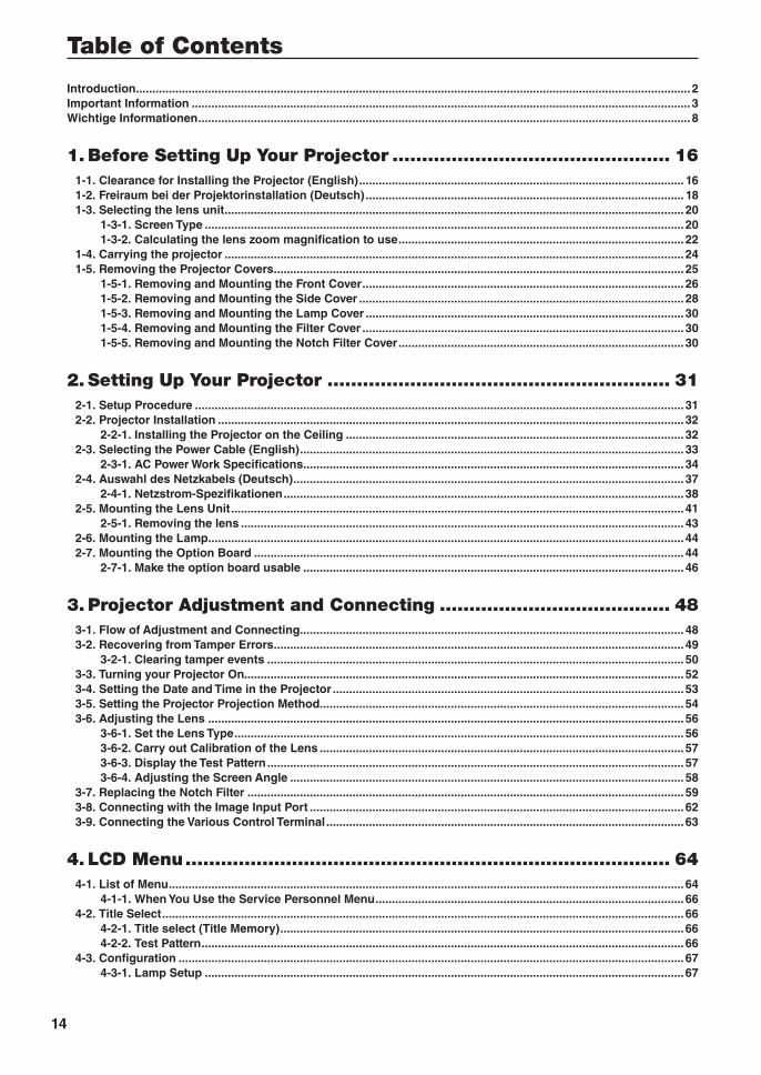
Table of Contents
15
Table of Contents
4-3-2. Lens Control ................................................................................................................................................. 684-3-3. Reset ............................................................................................................................................................. 694-3-4. Setup ............................................................................................................................................................. 724-3-5. Installation .................................................................................................................................................... 764-3-6. Memory ......................................................................................................................................................... 81
4-4. Title Setup ............................................................................................................................................................... 824-4-1. Preset Button ................................................................................................................................................ 82
4-5. Information .............................................................................................................................................................. 834-5-1. Lamp ............................................................................................................................................................. 834-5-2. Lens Type ...................................................................................................................................................... 834-5-3. Preset Button ................................................................................................................................................ 844-5-4. Usage ............................................................................................................................................................ 844-5-5. Error Code .................................................................................................................................................... 844-5-6. Version .......................................................................................................................................................... 854-5-7. IP Address..................................................................................................................................................... 854-5-8. Setup Date .................................................................................................................................................... 864-5-9. Option Status ............................................................................................................................................... 86
5. Appendix .................................................................................... 875-1. List of Registered Titles (when shipped from the factory) .................................................................................. 875-2. Error Code List ........................................................................................................................................................ 885-3. Remote Interlock Connector .................................................................................................................................. 925-4. Index ........................................................................................................................................................................ 94
16
1. Before Setting Up Your Projector
1-1. Clearance for Installing the Projector (English)Allow ample clearance between the projector and its surroundings as shown below.
Avoid installing the projector in a place where air movement from the HVAC is directed at the projector.
Heated air from the HVAC can be taken in by the projector’s intake vent. If this happens, the temperature inside the projector will
rise too high causing the over-temperature protector to automatically turn off the projectors power.
Example 1 – If there are walls on both sides of the projector.
30cm/12" or greater
50cm/19.8" or greater
NOTE The drawing shows the proper clearance required for the front, back and top of the projector.
Example 2 – If there is a wall behind the projector.(1) For floor installation:
GP I/O3DRS-232USBREMOTE LAN
PWR
70cm/27.6" or greater
Lens
NOTE The drawing shows the proper clearance required for the back, sides and top of the projector.
17
Before Setting Up Your Projector
(2) For ceiling mounting:
GP I/O3DRS-232USBREMOTE LAN
PWR
70cm/27.6" or greater
Lens
30cm
/12"
or
gre
ater
NOTE • The drawing shows the proper clearance required for the front, sides, back and bottom of the projector.• If suspending the projector 30 cm/12 inches away from the ceiling, allow ample clearance for all four sides and the
under the projector.
18
Before Setting Up Your Projector
1-2. Freiraum bei der Projektorinstallation (Deutsch)Achten Sie auf ausreichenden Freiraum zwischen dem Projektor und seiner Umgebung, wie unten gezeigt.
Vermeiden Sie es, den Projektor an einer Stelle zu installieren, an der er den Luftströmungen von Klimaanlagen ausgesetzt ist.
Die aufgeheizte Luft aus einer Klimaanlage kann vom Lüftungseinlass des Projektors aufgenommen werden. Dadurch wird die
Innentemperatur des Projektors zu stark erhöht, was dazu führt, dass der Überhitzungsschutz des Projektors diesen automatisch
ausschaltet.
Beispiel 1 - Wenn sich Wände auf beiden Seiten des Projektors befinden.
30 cm oder mehr
50 cm oder mehr
HINWEIS Die Abbildung zeigt den ordnungsgemäßen Abstand für die Vorder-, Rück- und Oberseite des Projektors.
Beispiel 2 - Wenn sich eine Wand hinter dem Projektor befindet.(1) Bei Installation auf einem fl achen Untergrund:
GP I/O3DRS-232USBREMOTE LAN
PWR
70 cm oder mehr
Linse
HINWEIS Die Abbildung zeigt den ordnungsgemäßen Abstand für die linke, rechte, Rück- und Oberseite des Projektors.
19
Before Setting Up Your Projector
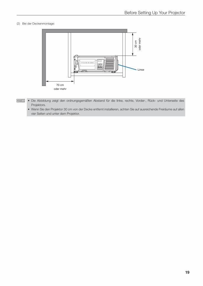
(2) Bei der Deckenmontage:
GP I/O3DRS-232USBREMOTE LAN
PWR
70 cm oder mehr
Linse
30 c
m
oder
meh
r
HINWEIS • Die Abbildung zeigt den ordnungsgemäßen Abstand für die linke, rechte, Vorder-, Rück- und Unterseite des Projektors.
• Wenn Sie den Projektor 30 cm von der Decke entfernt installieren, achten Sie auf ausreichende Freiräume auf allen vier Seiten und unter dem Projektor.
20
Before Setting Up Your Projector
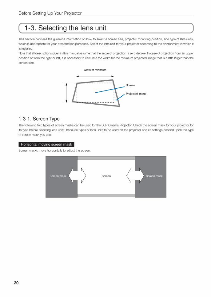
1-3. Selecting the lens unitThis section provides the guideline information on how to select a screen size, projector mounting position, and type of lens units,
which is appropriate for your presentation purposes. Select the lens unit for your projector according to the environment in which it
is installed.
Note that all descriptions given in this manual assume that the angle of projection is zero degree. In case of projection from an upper
position or from the right or left, it is necessary to calculate the width for the minimum projected image that is a little larger than the
screen size.
Width of minimum
Screen
Projected image
1-3-1. Screen TypeThe following two types of screen masks can be used for the DLP Cinema Projector. Check the screen mask for your projector for
its type before selecting lens units, because types of lens units to be used on the projector and its settings depend upon the type
of screen mask you use.
Horizontal moving screen mask
Screen masks move horizontally to adjust the screen.
ScreenScreen mask Screen mask
21
Before Setting Up Your Projector
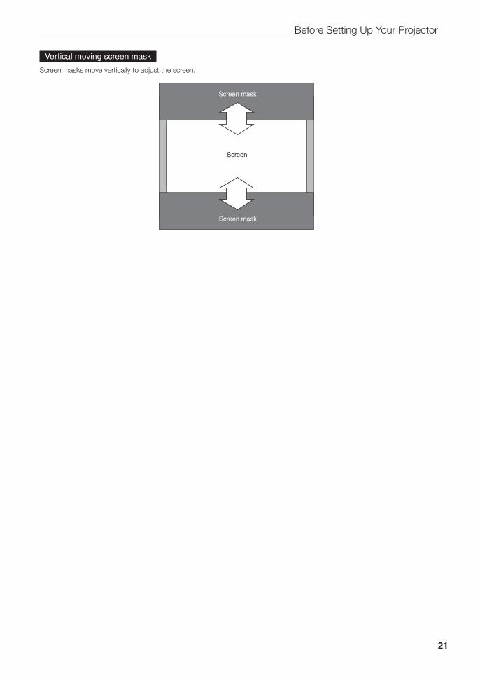
Vertical moving screen mask
Screen masks move vertically to adjust the screen.
Screen
Screen mask
Screen mask
22
Before Setting Up Your Projector
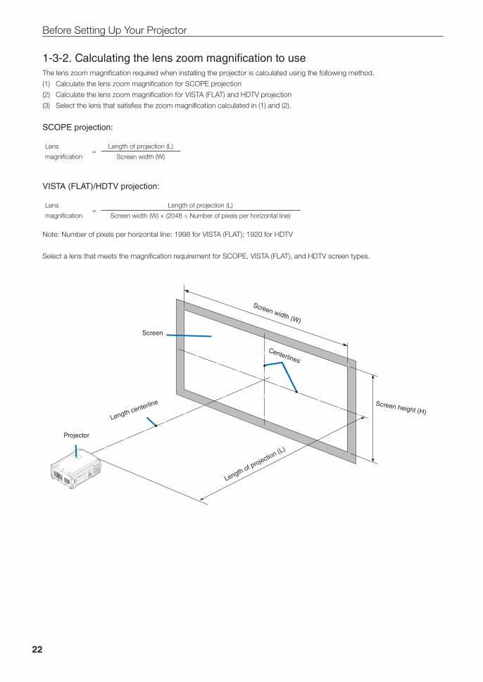
1-3-2. Calculating the lens zoom magnification to useThe lens zoom magnification required when installing the projector is calculated using the following method.
(1) Calculate the lens zoom magnification for SCOPE projection
(2) Calculate the lens zoom magnification for VISTA (FLAT) and HDTV projection
(3) Select the lens that satisfies the zoom magnification calculated in (1) and (2).
SCOPE projection:
Lens
magnification=
Length of projection (L)
Screen width (W)
VISTA (FLAT)/HDTV projection:
Lens
magnification=
Length of projection (L)
Screen width (W) × (2048 ÷ Number of pixels per horizontal line)
Note: Number of pixels per horizontal line: 1998 for VISTA (FLAT); 1920 for HDTV
Select a lens that meets the magnification requirement for SCOPE, VISTA (FLAT), and HDTV screen types.
Screen width (W)
Screen height (H)
Projector
Length of projection (L)
Screen
Length centerline
Centerlines
23
Before Setting Up Your Projector
Option lenses
The lens units that can be attached to this projector are shown in the following table.
MODEL Magnifying Lens memory support
NP-9LS16Z1 1.63–2.03 -
NP-9LS20Z1 2.03–2.72 -
NP-9LS40Z 4.07–6.34 -
NP-9LS12ZM1 1.2–1.72 NP-9LS13ZM1 1.33–2.1 NP-9LS16ZM1 1.62–2.7 NP-9LS20ZM1 2.09–3.9 NP-9LS40ZM1 4.07–6.34
Examples of selecting the lens unit
If the “projection distance (L) = 30 m, the screen width (W) = 15 m”:
SCOPE projection =30m
= 2.0x15m
VISTA (FLAT) projection =30m
= 1.95x15m×(2048÷1998)
HDTV projection =30m
= 1.88x15m×(2048÷1920)
Therefore, the following lens units, which satisfy the magnifications in all of the above projections, are selected.
Not using the lens memory function NP-9LS16Z1
Using the lens memory function NP-9LS13ZM1 or NP-9LS16ZM1
24
Before Setting Up Your Projector
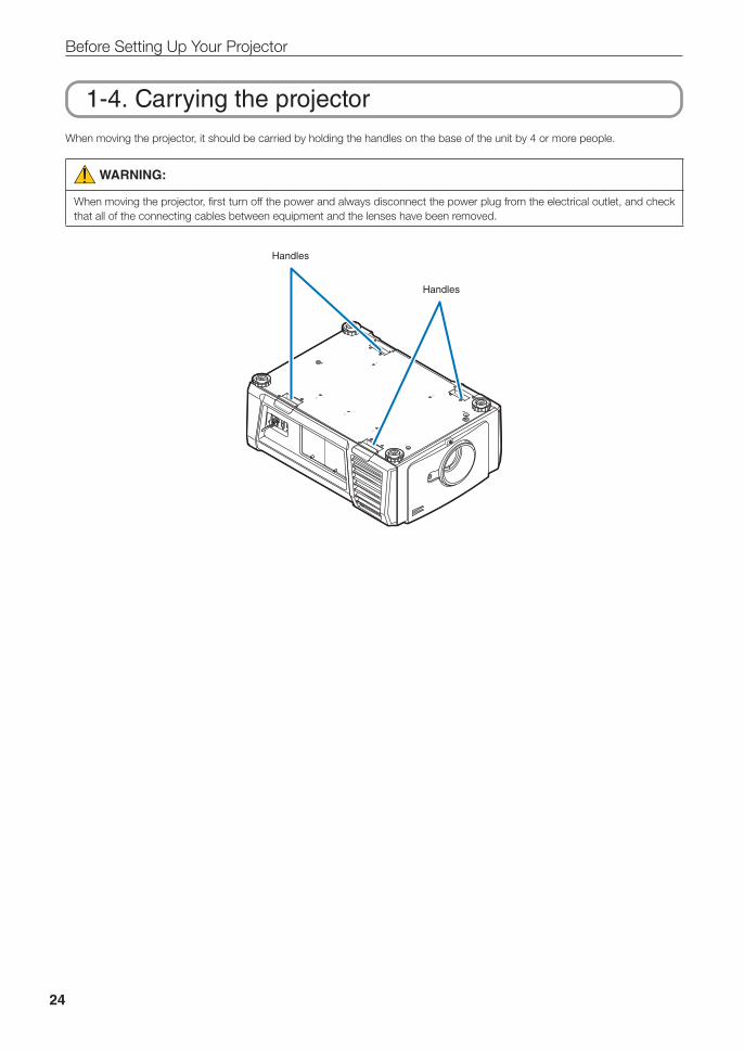
1-4. Carrying the projectorWhen moving the projector, it should be carried by holding the handles on the base of the unit by 4 or more people.
WARNING:
When moving the projector, first turn off the power and always disconnect the power plug from the electrical outlet, and check that all of the connecting cables between equipment and the lenses have been removed.
Handles
Handles
25
Before Setting Up Your Projector
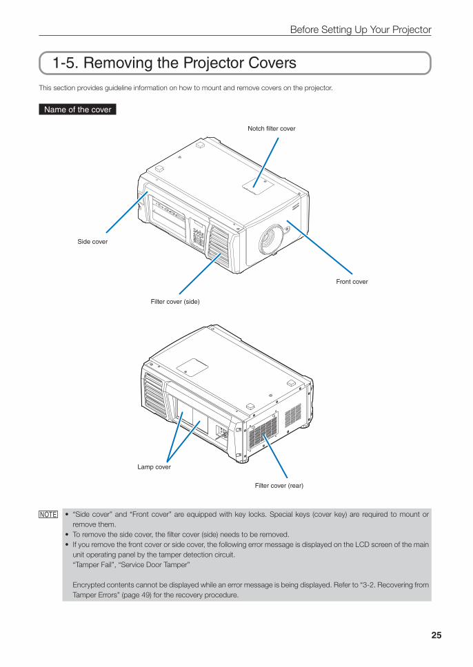
1-5. Removing the Projector CoversThis section provides guideline information on how to mount and remove covers on the projector.
Name of the cover
Side cover
Notch filter cover
Filter cover (side)
Front cover
Filter cover (rear)
Lamp cover
NOTE • “Side cover” and “Front cover” are equipped with key locks. Special keys (cover key) are required to mount or remove them.
• To remove the side cover, the filter cover (side) needs to be removed.• If you remove the front cover or side cover, the following error message is displayed on the LCD screen of the main
unit operating panel by the tamper detection circuit.“Tamper Fail”, “Service Door Tamper”
Encrypted contents cannot be displayed while an error message is being displayed. Refer to “3-2. Recovering from Tamper Errors” (page 49) for the recovery procedure.
26
Before Setting Up Your Projector
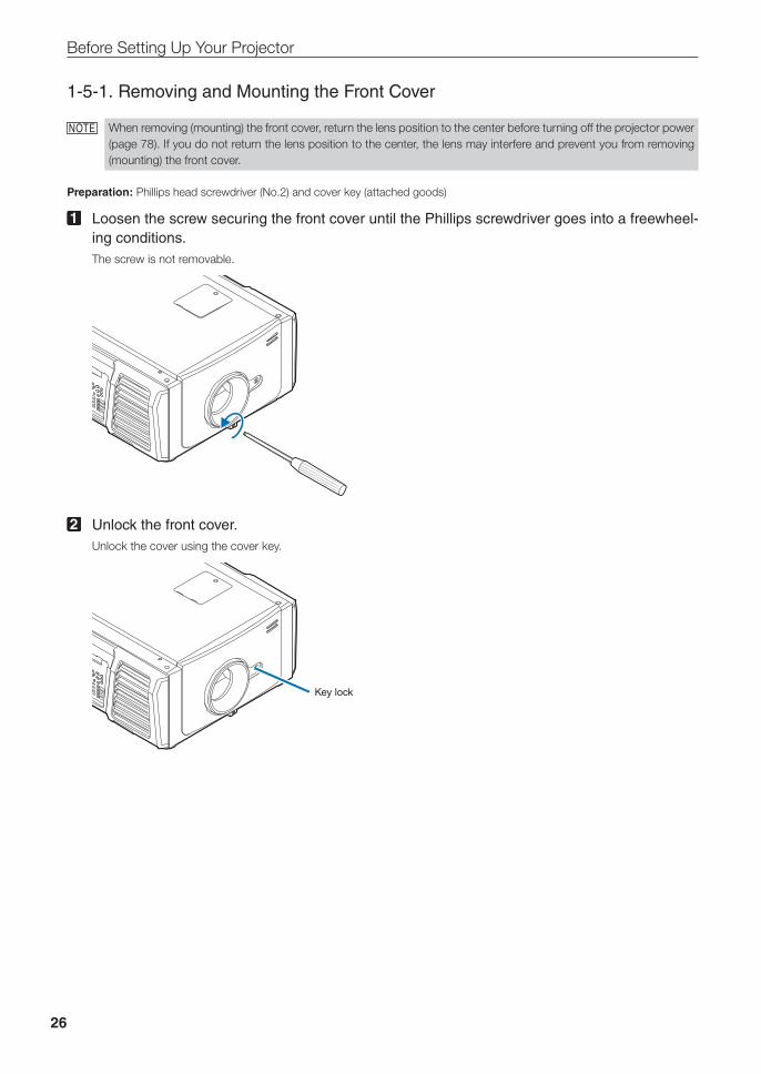
1-5-1. Removing and Mounting the Front Cover
NOTE When removing (mounting) the front cover, return the lens position to the center before turning off the projector power (page 78). If you do not return the lens position to the center, the lens may interfere and prevent you from removing (mounting) the front cover.
Preparation: Phillips head screwdriver (No.2) and cover key (attached goods)
1 Loosen the screw securing the front cover until the Phillips screwdriver goes into a freewheel-ing conditions.The screw is not removable.
2 Unlock the front cover.Unlock the cover using the cover key.
Key lock
27
Before Setting Up Your Projector
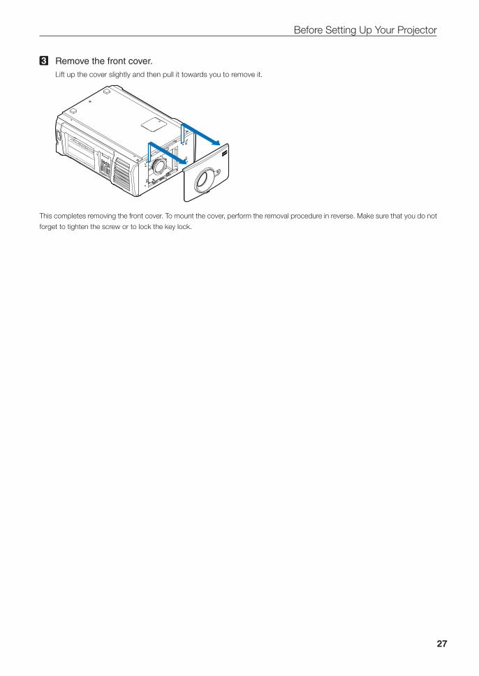
3 Remove the front cover.Lift up the cover slightly and then pull it towards you to remove it.
This completes removing the front cover. To mount the cover, perform the removal procedure in reverse. Make sure that you do not
forget to tighten the screw or to lock the key lock.
28
Before Setting Up Your Projector
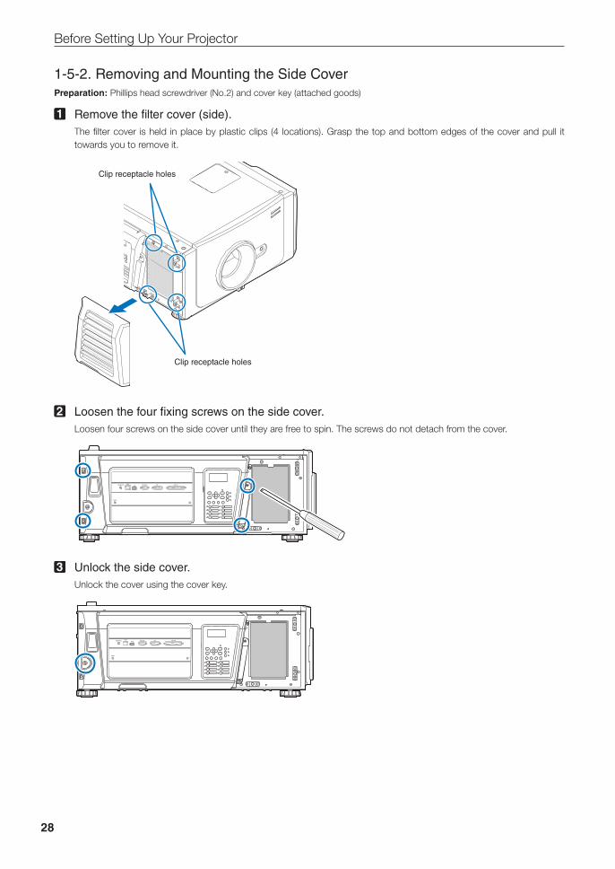
1-5-2. Removing and Mounting the Side CoverPreparation: Phillips head screwdriver (No.2) and cover key (attached goods)
1 Remove the filter cover (side).The filter cover is held in place by plastic clips (4 locations). Grasp the top and bottom edges of the cover and pull it towards you to remove it.
Clip receptacle holes
Clip receptacle holes
2 Loosen the four fixing screws on the side cover.Loosen four screws on the side cover until they are free to spin. The screws do not detach from the cover.
GP I/O3DRS-232USBREMOTE LAN
PWR
3 Unlock the side cover.Unlock the cover using the cover key.
GP I/O3DRS-232USBREMOTE LAN
PWR
29
Before Setting Up Your Projector
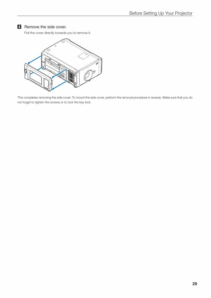
4 Remove the side cover.Pull the cover directly towards you to remove it.
This completes removing the side cover. To mount the side cover, perform the removal procedure in reverse. Make sure that you do
not forget to tighten the screws or to lock the key lock.

30
Before Setting Up Your Projector
1-5-3. Removing and Mounting the Lamp CoverRefer to the projector User’s Manual for details on how to remove and attach the lamp cover.
1-5-4. Removing and Mounting the Filter CoverRefer to the projector User’s Manual for details on how to remove and attach the filter cover.
1-5-5. Removing and Mounting the Notch Filter CoverRefer to “3-7. Replacing the Notch Filter” (page 59) for details on how to remove and attach the notch filter cover.
31
2. Setting Up Your Projector
2-1. Setup ProcedureSet up the projector according to the procedure below. This chapter describes the installation of procedure until turning on of the
power.
• Step1Projector Installation (See page 32)
• Step2Selecting the Power Cable (See page 33)
Connecting the Power Cable (See Projector User’s Manual)
• Step3Mounting the Lens Unit (See page 41)
• Step4Mounting the Lamp (See Projector User’s Manual)
• Step5Mounting the following optional parts as required.
- Installing the Media Block (NP-90MS02) (See page 44)
32
Setting Up Your Projector
2-2. Projector InstallationMove the projector to the projection position and install it corresponding to the screen and projection conditions.
To correct the inclination to the right or left of the projector, use the level adjusters at 4 positions. You can extend the level adjuster
to 35 mm at the maximum (Rotate it counterclockwise for extension).
CAUTION:
• Do not extend the adjuster by more than 35 mm. Rotating it forcefully may cause the adjuster to come off or be damaged.• To adjust the level adjusters of the projector, extend the two level adjusters at the front and the back at the same time so that
the weight is imposed to them equally. If you adjust only one adjuster, the weight is not imposed equally, which may result in level adjuster failure.
Level adjusters (in four positions)
GP I/O3DRS-232USBREMOTE LAN
PWR
2-2-1. Installing the Projector on the CeilingTo install the projector on the ceiling, install it by referring to the following specifications.
115.3
300
400
33280
33
Setting Up Your Projector
2-3. Selecting the Power Cable (English)The power cable is not included with the projector. Refer to “2-3-1. AC Power Work Specifications” (page 34) and provide the
necessary power cable.
WARNING:
Carefully read the contents described in this section before connection and connect the cables according to the proper proce-dure. Inappropriate handling may cause fatal, serious or other bodily injuries due to fire or electric shock.
CAUTION:
• For details on connecting the power cable, refer to the projector User’s Manual.• Before connecting the power cables, check that the main power switch of the projector is turned off. Implement the connec-
tion with AC power shut off.• Be sure to ground the equipment to ensure safety. Use a power cable that meets the standards and power supply voltage of
the country where you are using the projector (page 35), and always connect the equipment to the ground. If the ground is not connected, it may cause electrical shocks.
• When connecting the power cable plugs to the AC IN and the electrical outlet, securely insert the plugs all the way in. If the connection between the power cable plug and the electrical outlet is loose, the plug area may generate heat, causing burns and accidents.
• Switch the power cable and power supply voltage of the projector to match the projector to the voltage of the electrical outlet you are connecting to. If selected incorrectly, it may cause damage or fires.
• In order to prevent the power plug from being disconnected from the projector, fix the power cable by using the power cable stopper supplied with this unit. For how to use the power cable stopper, refer to the User’s Manual of your projector.
34
Setting Up Your Projector
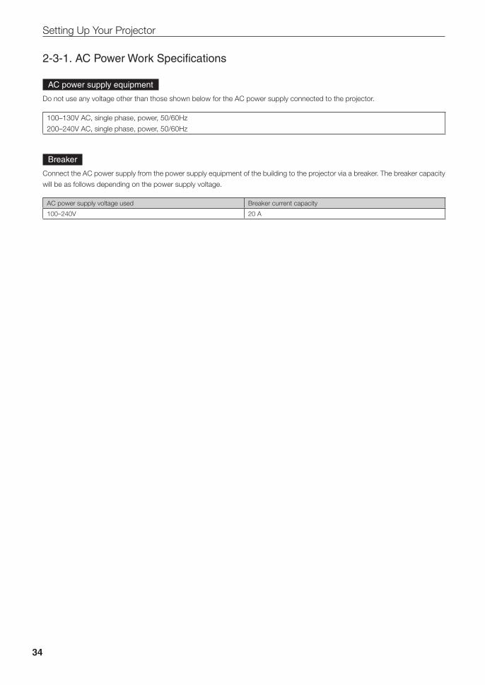
2-3-1. AC Power Work Specifications
AC power supply equipment
Do not use any voltage other than those shown below for the AC power supply connected to the projector.
100–130V AC, single phase, power, 50/60Hz
200–240V AC, single phase, power, 50/60Hz
Breaker
Connect the AC power supply from the power supply equipment of the building to the projector via a breaker. The breaker capacity
will be as follows depending on the power supply voltage.
AC power supply voltage used Breaker current capacity
100–240V 20 A
35
Setting Up Your Projector
AC power supply cable for the projector
The projector is equipped with an IEC60320 C19 connector to connect an AC power supply cable. Ensure that the AC power cables
that connect the connectors built into the projector to the AC power mains have the current capacities as shown below.
Power supply voltage Projector input current Power cable current capacity
AC 100–130V 12.2 to 9.0A 125V 15A or higher
250V 15A or higher
AC 200–240V 5.8 to 4.8A 250V 15A or higher
Furthermore, use plugs, cables, and connectors that are suitable for the regulations of the country of installation, as shown in the
following table.
NOTE For users in North AmericaUse a power cable no longer than 4.5m/14.76 ft according to National Electrical Code.
Cable
Plug
Connector
GermanyPlug Cable Connector
CEE 7 H05VV-F 3G1.5 IEC 320 C19
USAPlug Cable Connector
NEMA 5-15P SJT 3 x AWG 14 IEC 320 C19
JapanPlug Cable Connector
JIS C 8303 VCTF 3 x 2.0mm IEC 320 C19
36
Setting Up Your Projector
ChinaPlug Cable Connector
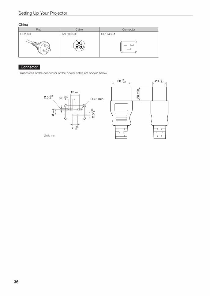
GB2099 RVV 300/500 GB17465.1
Connector
Dimensions of the connector of the power cable are shown below.
7 +0.5-0
28 +0-0.9 20 +0
-0.7
6.0 +0.5-0
2.5
+0.5
-0
2.5 +0.5-0
8±0.2
13 ±0.2
Unit: mm
R3.5 min 20 m
in
37
Setting Up Your Projector
2-4. Auswahl des Netzkabels (Deutsch)Es wird kein Netzkabel mit dem Projektor geliefert. Nehmen Sie auf „2-4-1. Netzstrom-Spezifikationen“ (Seite 38) Bezug, und
beschaffen Sie das notwendige Netzkabel.
WARNUNG:
Lesen Sie diesen Abschnitt vor dem Herstellen der Verbindungen sorgfältig durch, und schließen Sie die Kabel anhand der ordnungsgemäßen Verfahren an. Falsche Handhabung kann zu schweren oder sogar tödlichen Verletzungen durch Brand oder einen elektrischen Schlag führen.
ACHTUNG:
• Für Einzelheiten zum Anschließen des Netzkabels siehe des Projektors Bedienungshandbuch.• Bevor Sie das Netzkabel anschließen, prüfen Sie, ob die Hauptstromschalter des Projektors ausgeschaltet ist. Stellen Sie die
Verbindungen bei ausgeschaltetem Netzstrom her.• Erden Sie das Gerät, um die Sicherheit zu gewährleisten. Verwenden Sie ein Netzkabel, das die Normen und Netzspannung
des Landes, in dem der Projektor verwendet wird, erfüllt (Seite 39), und schließen Sie das Gerät stets an Erde an. Wenn keine Erde angeschlossen wird, kann es zu elektrischen Schlägen kommen.
• Führen Sie die Netzkabelstecker beim Anschließen bis zum Anschlag in den Netzeingang und die Netzsteckdose ein. Sitzt der Netzstecker nicht fest in der Netzsteckdose, kann Wärme im Steckerbereich erzeugt werden, die zu Verbrennungen und Unfällen führen kann.
• Wechseln Sie das Netzkabel und die Versorgungsspannung des Projektors, um den Projektor an die Spannung der verwen-deten Netzsteckdose anzupassen. Eine falsche Einstellung kann zu Beschädigung oder Bränden führen.
• Um eine Trennung des Netzsteckers vom Projektor zu verhindern, fixieren Sie das Netzkabel, indem Sie den mit diesem Gerät gelieferten Netzkabelstopper verwenden. Die Verwendung des Netzkabelstoppers finden Sie im Benutzerhandbuch Ihres Projektors erläutert.
38
Setting Up Your Projector
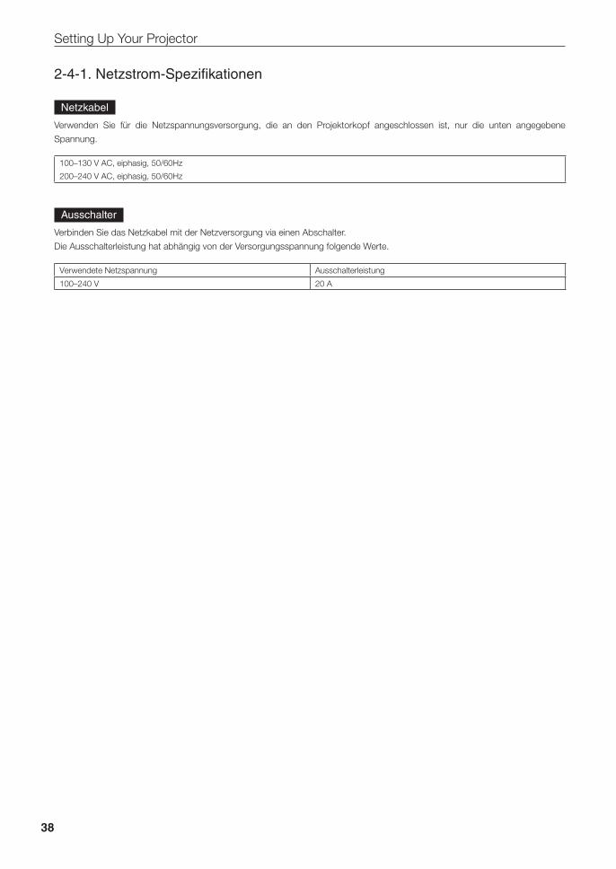
2-4-1. Netzstrom-Spezifikationen
Netzkabel
Verwenden Sie für die Netzspannungsversorgung, die an den Projektorkopf angeschlossen ist, nur die unten angegebene
Spannung.
100–130 V AC, eiphasig, 50/60Hz
200–240 V AC, eiphasig, 50/60Hz
Ausschalter
Verbinden Sie das Netzkabel mit der Netzversorgung via einen Abschalter.
Die Ausschalterleistung hat abhängig von der Versorgungsspannung folgende Werte.
Verwendete Netzspannung Ausschalterleistung
100–240 V 20 A
39
Setting Up Your Projector
Netzkabel für den Projektor
Der Projektor ist mit einem C19-Steckverbinder gemäß IEC60320 zum Anschließen des Netzkabels ausgestattet. Sorgen Sie dafür,
dass die Netzkabel, die von den Steckverbindern am Projektor zum Netzanschluss führen, über die unten angegebenen Stromka-
pazitäten verfügen.
Netzspannung Projektor-Eingangsstrom Netzkabel-Stromkapazität
100–130 V Wechselstrom 12,2 bis 9,0A 125 V 15 A oder höher
250 V 15 A oder höher
200–240 V Wechselstrom 5,8 bis 4,8A 250 V 15 A oder höher
Verwenden Sie zudem Stecker, Kabel und Steckverbinder, die den Vorgaben des jeweiligen Landes entsprechen (siehe dazu fol-
gende Tabelle).
Kabel
Stecker
Steckverbinder
Deutschland
Stecker Kabel Steckverbinder
CEE 7 H05VV-F 3G1.5 IEC 320 C19
USA
Stecker Kabel Steckverbinder
NEMA 5-15P SJT 3 x AWG 14 IEC 320 C19
Japan
Stecker Kabel Steckverbinder
JIS C 8303 VCTF 3 x 2.0mm IEC 320 C19
40
Setting Up Your Projector
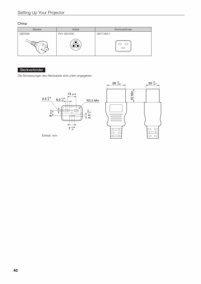
China
Stecker Kabel Steckverbinder
GB2099 RVV 300/500 GB17465.1
Steckverbinder
Die Abmessungen des Netzkabels sind unten angegeben.
7 +0.5-0
28 +0-0.9 20 +0
-0.7
6.0 +0.5-0
2.5
+0.5
-0
2.5 +0.5-0
8±0.2
13 ±0.2
Einheit: mm
R3.5 Min 20 M
in
41
Setting Up Your Projector
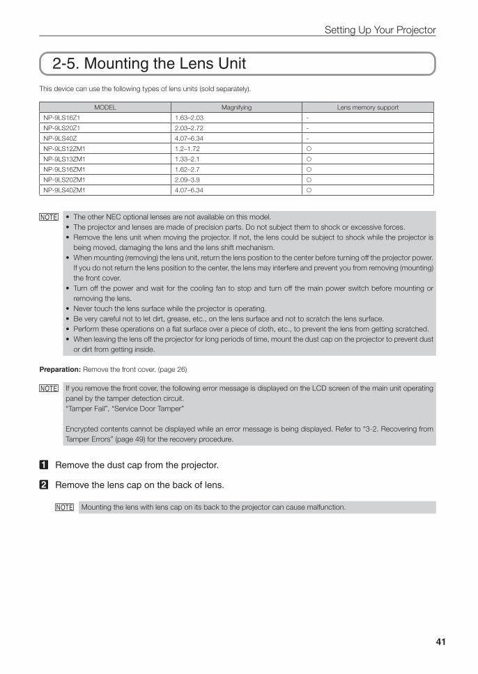
2-5. Mounting the Lens UnitThis device can use the following types of lens units (sold separately).
MODEL Magnifying Lens memory support
NP-9LS16Z1 1.63–2.03 -
NP-9LS20Z1 2.03–2.72 -
NP-9LS40Z 4.07–6.34 -
NP-9LS12ZM1 1.2–1.72 NP-9LS13ZM1 1.33–2.1 NP-9LS16ZM1 1.62–2.7 NP-9LS20ZM1 2.09–3.9 NP-9LS40ZM1 4.07–6.34
NOTE • The other NEC optional lenses are not available on this model.• The projector and lenses are made of precision parts. Do not subject them to shock or excessive forces.• Remove the lens unit when moving the projector. If not, the lens could be subject to shock while the projector is
being moved, damaging the lens and the lens shift mechanism.• When mounting (removing) the lens unit, return the lens position to the center before turning off the projector power.
If you do not return the lens position to the center, the lens may interfere and prevent you from removing (mounting) the front cover.
• Turn off the power and wait for the cooling fan to stop and turn off the main power switch before mounting or removing the lens.
• Never touch the lens surface while the projector is operating.• Be very careful not to let dirt, grease, etc., on the lens surface and not to scratch the lens surface.• Perform these operations on a flat surface over a piece of cloth, etc., to prevent the lens from getting scratched.• When leaving the lens off the projector for long periods of time, mount the dust cap on the projector to prevent dust
or dirt from getting inside.
Preparation: Remove the front cover. (page 26)
NOTE If you remove the front cover, the following error message is displayed on the LCD screen of the main unit operating panel by the tamper detection circuit.“Tamper Fail”, “Service Door Tamper”
Encrypted contents cannot be displayed while an error message is being displayed. Refer to “3-2. Recovering from Tamper Errors” (page 49) for the recovery procedure.
1 Remove the dust cap from the projector.
2 Remove the lens cap on the back of lens.
NOTE Mounting the lens with lens cap on its back to the projector can cause malfunction.
42
Setting Up Your Projector
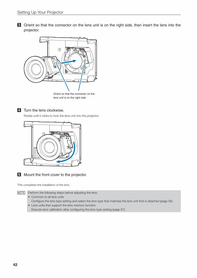
3 Orient so that the connector on the lens unit is on the right side, then insert the lens into the projector.
Orient so that the connector on the lens unit is on the right side
4 Turn the lens clockwise.Rotate until it clicks to lock the lens unit into the projector.
5 Mount the front cover to the projector.
This completes the installation of the lens.
NOTE Perform the following steps before adjusting the lens.• Common to all lens units
Configure the lens type setting and select the lens type that matches the lens unit that is attached (page 56).• Lens units that support the lens memory function
Execute lens calibration after configuring the lens type setting (page 57).
43
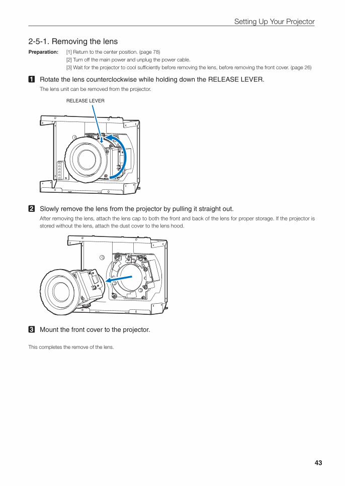
Setting Up Your Projector
2-5-1. Removing the lensPreparation: [1] Return to the center position. (page 78)
[2] Turn off the main power and unplug the power cable.
[3] Wait for the projector to cool sufficiently before removing the lens, before removing the front cover. (page 26)
1 Rotate the lens counterclockwise while holding down the RELEASE LEVER. The lens unit can be removed from the projector.
RELEASE LEVER
2 Slowly remove the lens from the projector by pulling it straight out.After removing the lens, attach the lens cap to both the front and back of the lens for proper storage. If the projector is stored without the lens, attach the dust cover to the lens hood.
3 Mount the front cover to the projector.
This completes the remove of the lens.
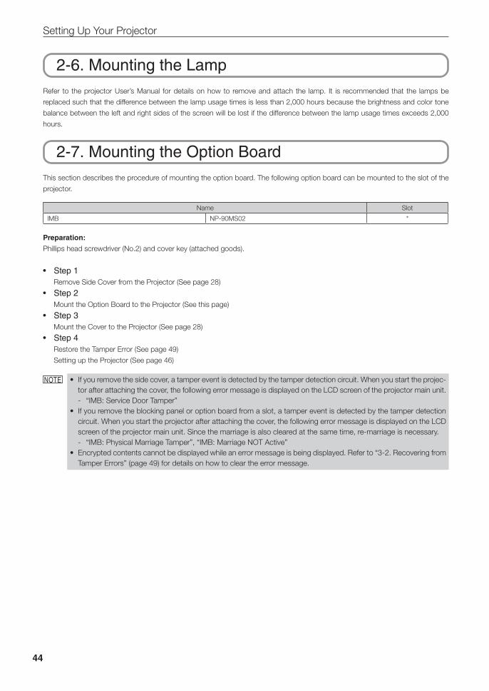
44
Setting Up Your Projector
2-6. Mounting the LampRefer to the projector User’s Manual for details on how to remove and attach the lamp. It is recommended that the lamps be
replaced such that the difference between the lamp usage times is less than 2,000 hours because the brightness and color tone
balance between the left and right sides of the screen will be lost if the difference between the lamp usage times exceeds 2,000
hours.
2-7. Mounting the Option BoardThis section describes the procedure of mounting the option board. The following option board can be mounted to the slot of the
projector.
Name Slot
IMB NP-90MS02 *
Preparation:
Phillips head screwdriver (No.2) and cover key (attached goods).
• Step1Remove Side Cover from the Projector (See page 28)
• Step2Mount the Option Board to the Projector (See this page)
• Step3Mount the Cover to the Projector (See page 28)
• Step4Restore the Tamper Error (See page 49)
Setting up the Projector (See page 46)
NOTE • If you remove the side cover, a tamper event is detected by the tamper detection circuit. When you start the projec-tor after attaching the cover, the following error message is displayed on the LCD screen of the projector main unit. - “IMB: Service Door Tamper”
• If you remove the blocking panel or option board from a slot, a tamper event is detected by the tamper detection circuit. When you start the projector after attaching the cover, the following error message is displayed on the LCD screen of the projector main unit. Since the marriage is also cleared at the same time, re-marriage is necessary. - “IMB: Physical Marriage Tamper”, “IMB: Marriage NOT Active”
• Encrypted contents cannot be displayed while an error message is being displayed. Refer to “3-2. Recovering from Tamper Errors” (page 49) for details on how to clear the error message.
45
Setting Up Your Projector
1 Remove the side cover.Side cover of the projector should be removed to mount the option board. For the procedure of removing the side cover, refer to “1-5-2. Removing and Mounting the Side Cover” (page 28).
2 Remove the blocking panel from slot.
1. Loosen the knurled screws (2 places) of slot until their rotations become idle ( ). Screws cannot be removed.
2. Remove the blocking panel ( ).
Slot
GP I/O3DRS-232USBREMOTE LAN
NOTE Carefully store the blocking panel and screws that you removed.
3 Mount the option board to the projector.
1. Insert the board by following the guide on either side of the slot.2. Tighten up the knurled screws (2 places) until it fix.
guide (left/right)
4 Mount the side cover to the projector.This completes the mounting of option board. Next, recover the tamper error. For the procedure of recovering, refer to “3-2. Recov-
ering from Tamper Errors” (page 49). A setting to use option board is needed, after recovering from tamper error. For the proce-
dure, refer to “2-7-1. Make the option board usable” (page 46).
46
Setting Up Your Projector
2-7-1. Make the option board usableBy registering the mounted option board to the slot, you can use option board by setting up the projector. This procedure is
described for the example, when IMB (NP-90MS02) is mounted to slot. For the operation of the projector, refer to projector’s “Users
Manual”.
TIP DCC can be used to set up.For the procedure by using DCC, refer to “Digital Cinema Communicator Installation Manual”.
1 Set the projector in standby mode.
2 Enable the service personnel menu.These settings are for our service personnel and cannot normally (user mode) be used. You need to enter a passcode to enable the service personnel menu. Refer to the “4-1-1. When You Use the Service Personnel Menu” (page 66) for the procedure.
3 Press the MENU button on the control panel.“Title Select” is displayed in the menu. From this procedure on, control panel of the projector will be used.
4 Press the LEFT/RIGHT button to display “Configuration” and press the DOWN button.
5 Press the LEFT/RIGHT button to display “Installation” and press the DOWN button.
6 Press the LEFT/RIGHT button to display “Option Slot” and press the DOWN button.
47
Setting Up Your Projector
7 Press the LEFT/RIGHT button to display “IMB”.
8 Press the ENTER button.(*) is displayed to the selected item.
9 Press the EXIT button several times.The projector exits the menu and goes back to the regular screen.If you press the EXIT button and then select “Yes” and press the ENTER button on a regular screen, you will returned to user mode.
This completes the setting of the projector.
TIP Settings of slot can be confirmed at projector’s [Information] - [Option Status]
48
3. Projector Adjustment and Connecting
3-1. Flow of Adjustment and ConnectingAdjustment and Connecting of the projector accord to the procedure below.
• Step1Turning Your Projector On (See page 52)
• Step2Setting The Date and Time in the Projector (See page 53)
• Step3Setting the Projector Projection Method (See page 54)
• Step4Adjusting the Lens (See page 56)
Display the test pattern to adjust the screen size, screen angle and focus.
• Step5Replacing the notch filter (See page 59)
• Step6Connecting with the Image Input Port (See page 62)
• Step7Connecting the Various Control Terminal (See page 63)
This chapter explains the adjustment and connection of the projector with Steps 1 to 7.
Steps 1 to 7 complete the adjustment and connection of the projector. Next, carry out various settings such as color adjustment
using DCC. Refer to the “Digital Cinema Communicator Installation Manual” for the procedure.
49
Projector Adjustment and Connecting
3-2. Recovering from Tamper ErrorsThe tamper detection circuit is fitted in the projector.
If any of the following actions is performed, an error message will be displayed on the LCD screen of the main unit control panel by
tamper detection circuit.
Action Error code Error message
Cover removed
•Front cover
•Side cover
586 IMB: Service Door Tamper
Slot device or blocking panel removed
•Blocking panel
•Media block
582
584
(582) IMB: Physical Marriage Tamper
(584) IMB: Marriage NOT Active
TIP Error codes can be checked when using the DCC.
While the above error messages are being displayed, encrypted contents cannot be displayed. Refer to “3-2-1. Clearing tamper
events” (page 50) for details on how to recover from tamper errors.
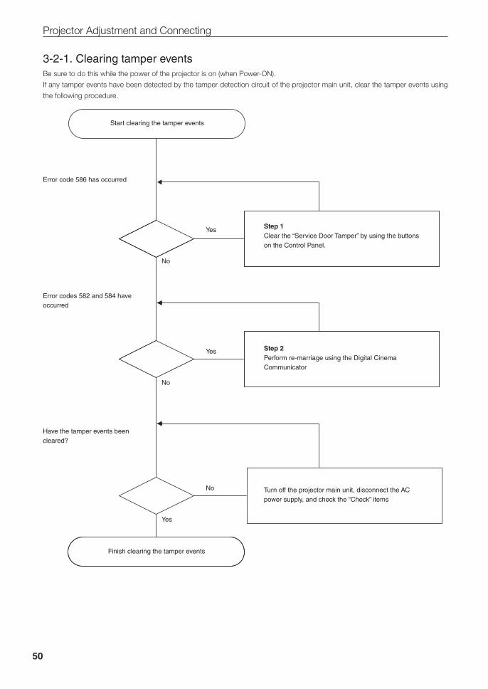
50
Projector Adjustment and Connecting
3-2-1. Clearing tamper eventsBe sure to do this while the power of the projector is on (when Power-ON).
If any tamper events have been detected by the tamper detection circuit of the projector main unit, clear the tamper events using
the following procedure.
Start clearing the tamper events
Finish clearing the tamper events
Error codes 582 and 584 have occurred
Error code 586 has occurred
Have the tamper events been cleared?
Step 2Perform re-marriage using the Digital Cinema Communicator
Step 1Clear the “Service Door Tamper” by using the buttons on the Control Panel.
Turn off the projector main unit, disconnect the AC power supply, and check the “Check” items
Yes
No
No
Yes
Yes
No
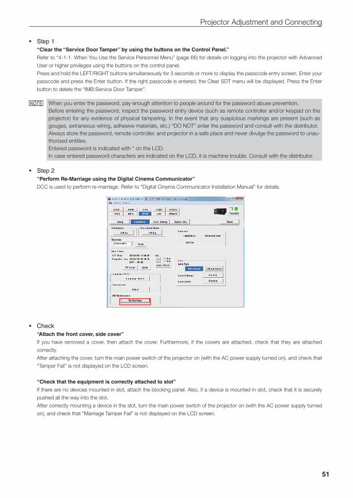
51
Projector Adjustment and Connecting
• Step1“Clear the “Service Door Tamper” by using the buttons on the Control Panel.”
Refer to “4-1-1. When You Use the Service Personnel Menu” (page 66) for details on logging into the projector with Advanced
User or higher privileges using the buttons on the control panel.
Press and hold the LEFT/RIGHT buttons simultaneously for 3 seconds or more to display the passcode entry screen. Enter your
passcode and press the Enter button. If the right passcode is entered, the Clear SDT menu will be displayed. Press the Enter
button to delete the “IMB:Service Door Tamper”.
NOTE When you enter the password, pay enough attention to people around for the password abuse prevention.Before entering the password, inspect the password entry device (such as remote controller and/or keypad on the projector) for any evidence of physical tampering. In the event that any suspicious markings are present (such as gouges, extraneous wiring, adhesive materials, etc.) “DO NOT” enter the password and consult with the distributor.Always store the password, remote controller, and projector in a safe place and never divulge the password to unau-thorized entities.Entered password is indicated with * on the LCD.In case entered password characters are indicated on the LCD, it is machine trouble. Consult with the distributor.
• Step2“Perform Re-Marriage using the Digital Cinema Communicator”
DCC is used to perform re-marriage. Refer to “Digital Cinema Communicator Installation Manual” for details.
• Check“Attach the front cover, side cover”
If you have removed a cover, then attach the cover. Furthermore, if the covers are attached, check that they are attached
correctly.
After attaching the cover, turn the main power switch of the projector on (with the AC power supply turned on), and check that
“Tamper Fail” is not displayed on the LCD screen.
“Check that the equipment is correctly attached to slot”
If there are no devices mounted in slot, attach the blocking panel. Also, if a device is mounted in slot, check that it is securely
pushed all the way into the slot.
After correctly mounting a device in the slot, turn the main power switch of the projector on (with the AC power supply turned
on), and check that “Marriage Tamper Fail” is not displayed on the LCD screen.
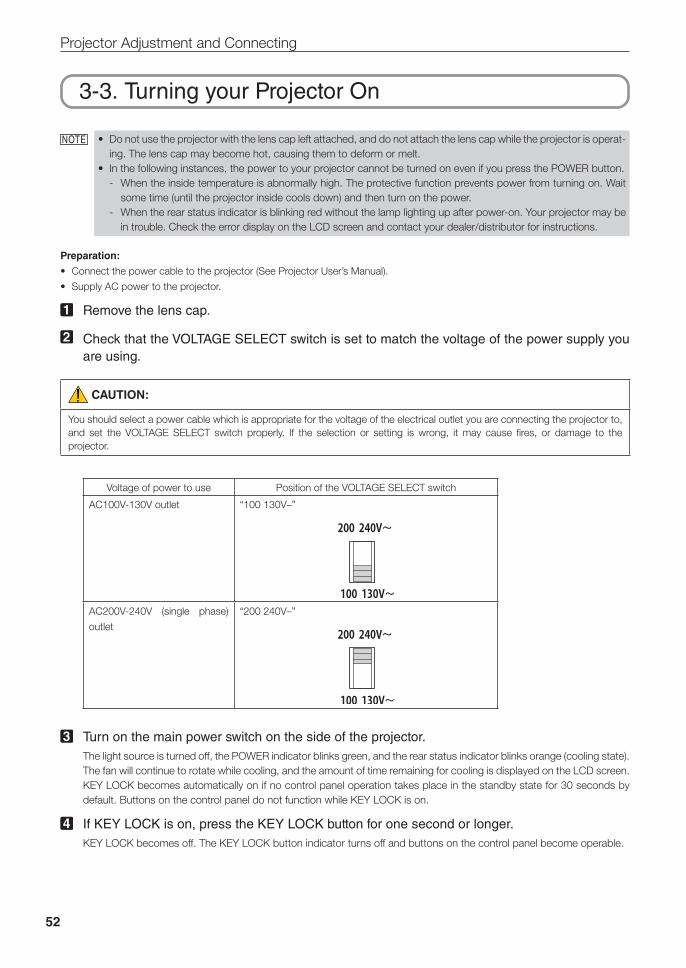
52
Projector Adjustment and Connecting
3-3. Turning your Projector On
NOTE • Do not use the projector with the lens cap left attached, and do not attach the lens cap while the projector is operat-ing. The lens cap may become hot, causing them to deform or melt.
• In the following instances, the power to your projector cannot be turned on even if you press the POWER button. - When the inside temperature is abnormally high. The protective function prevents power from turning on. Wait
some time (until the projector inside cools down) and then turn on the power. - When the rear status indicator is blinking red without the lamp lighting up after power-on. Your projector may be
in trouble. Check the error display on the LCD screen and contact your dealer/distributor for instructions.
Preparation:
• Connect the power cable to the projector (See Projector User’s Manual).
• Supply AC power to the projector.
1 Remove the lens cap.
2 Check that the VOLTAGE SELECT switch is set to match the voltage of the power supply you are using.
CAUTION:
You should select a power cable which is appropriate for the voltage of the electrical outlet you are connecting the projector to, and set the VOLTAGE SELECT switch properly. If the selection or setting is wrong, it may cause fires, or damage to the projector.
Voltage of power to use Position of the VOLTAGE SELECT switch
AC100V-130V outlet “100 130V–”
AC200V-240V (single phase)
outlet
“200 240V–”
3 Turn on the main power switch on the side of the projector.The light source is turned off, the POWER indicator blinks green, and the rear status indicator blinks orange (cooling state). The fan will continue to rotate while cooling, and the amount of time remaining for cooling is displayed on the LCD screen.KEY LOCK becomes automatically on if no control panel operation takes place in the standby state for 30 seconds by default. Buttons on the control panel do not function while KEY LOCK is on.
4 If KEY LOCK is on, press the KEY LOCK button for one second or longer.KEY LOCK becomes off. The KEY LOCK button indicator turns off and buttons on the control panel become operable.
53
Projector Adjustment and Connecting
5 Press the POWER button on the control panel of your projector three seconds or longer.Projector turns on.The POWER button indicator lights up green after the completion of activation.
6 Press the LAMP ON/OFF button on the control panel for five seconds or longer.The lamp is turned on and the screen glows light about 15 seconds later. The LAMP ON/OFF button indicator brinks in cycles of 2 (and changes to steady green light 90 seconds later). The douser is closed until the screen glows light (the DOUSER button indicator lights green). When the douser is open, the DOUSER button indicator turns off.
3-4. Setting the Date and Time in the ProjectorThe internal clock in the projector operates on coordinated universal time (UTC). You can set the internal projector time to the time
in your region by setting the time difference between the standard time in your region and UTC.
If you are using DCC, you can easily set the date and time in the projector by reading the date and time settings of the computer
where DCC is installed. Refer to “Digital Cinema Communicator Installation Manual” for details.
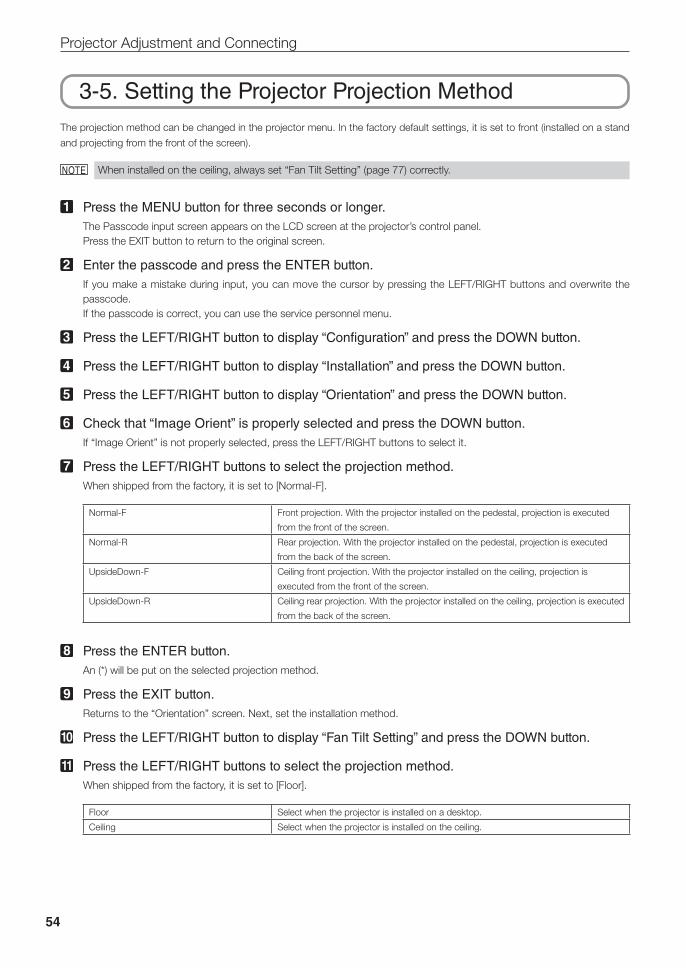
54
Projector Adjustment and Connecting
3-5. Setting the Projector Projection MethodThe projection method can be changed in the projector menu. In the factory default settings, it is set to front (installed on a stand
and projecting from the front of the screen).
NOTE When installed on the ceiling, always set “Fan Tilt Setting” (page 77) correctly.
1 Press the MENU button for three seconds or longer.The Passcode input screen appears on the LCD screen at the projector’s control panel.Press the EXIT button to return to the original screen.
2 Enter the passcode and press the ENTER button.If you make a mistake during input, you can move the cursor by pressing the LEFT/RIGHT buttons and overwrite the passcode.If the passcode is correct, you can use the service personnel menu.
3 Press the LEFT/RIGHT button to display “Configuration” and press the DOWN button.
4 Press the LEFT/RIGHT button to display “Installation” and press the DOWN button.
5 Press the LEFT/RIGHT button to display “Orientation” and press the DOWN button.
6 Check that “Image Orient” is properly selected and press the DOWN button.If “Image Orient” is not properly selected, press the LEFT/RIGHT buttons to select it.
7 Press the LEFT/RIGHT buttons to select the projection method.When shipped from the factory, it is set to [Normal-F].
Normal-F Front projection. With the projector installed on the pedestal, projection is executed
from the front of the screen.
Normal-R Rear projection. With the projector installed on the pedestal, projection is executed
from the back of the screen.
UpsideDown-F Ceiling front projection. With the projector installed on the ceiling, projection is
executed from the front of the screen.
UpsideDown-R Ceiling rear projection. With the projector installed on the ceiling, projection is executed
from the back of the screen.
8 Press the ENTER button.An (*) will be put on the selected projection method.
9 Press the EXIT button.Returns to the “Orientation” screen. Next, set the installation method.
10 Press the LEFT/RIGHT button to display “Fan Tilt Setting” and press the DOWN button.
11 Press the LEFT/RIGHT buttons to select the projection method.When shipped from the factory, it is set to [Floor].
Floor Select when the projector is installed on a desktop.
Ceiling Select when the projector is installed on the ceiling.

55
Projector Adjustment and Connecting
12 Press the ENTER button.An (*) will be put on the selected fan operating mode.
13 Press the EXIT button several times.The projector exits the menu and goes back to the regular screen.If you press the EXIT button and then select “Yes” and press the ENTER button on a regular screen, you are returned to user mode.
56
Projector Adjustment and Connecting
3-6. Adjusting the LensAfter attaching the lens unit, check that the lens type is set correctly. Furthermore, if you have attached a lens unit that supports the
lens memory function, always execute calibration before adjusting the lens. After this, display the test pattern and adjust the screen
size, focus and screen position with the lens unit.
Preparation:
Enable the service personnel menu (page 66).
3-6-1. Set the Lens Type
1 Press the MENU button on the control panel.“Title Select” is displayed in the menu.
2 Press the LEFT/RIGHT button to display “Configuration” and press the DOWN button.
3 Press the LEFT/RIGHT button to display “Installation” and press the DOWN button.
4 Press the LEFT/RIGHT button to display “Lens Type” and press the DOWN button.
5 Press the LEFT/RIGHT button to select the type of lens attached to the projector.When shipped from the factory, it is set to [Without Sensor].
Without Sensor Select when using a lens unit that does not support the lens memory function.
With Sensor Select when using a lens unit that supports the lens memory function.
6 Press the ENTER button. (*) is displayed to the selected item.
7 Press the EXIT button several times.The projector exits the menu and goes back to the regular screen.
57
Projector Adjustment and Connecting
3-6-2. Carry out Calibration of the LensIf you have attached a lens unit that supports the lens memory function, always execute calibration before making adjustments.
Preparation:
• Check that the lens is attached correctly (page 41).
• Set the lens type (page 56).
1 Press the MENU button on the control panel.“Title Select” is displayed in the menu.
2 Press the LEFT/RIGHT button to display “Configuration” and press the DOWN button.
3 Press the LEFT/RIGHT button to display “Installation” and press the DOWN button.
4 Press the LEFT/RIGHT button to display “Lens Calibrate” and press the DOWN button.
5 Check that “Execute” is displayed and press the ENTER button. The confirmation screen will appear.
6 Select “Yes” in the confirmation screen, and then press the ENTER button. Carry out calibration in the order of focus lens and zoom lens.
3-6-3. Display the Test Pattern
1 Press the MENU button.“Title Select” is displayed on the LCD screen at the projector’s control panel.
2 Press the DOWN button.
3 Press the LEFT/RIGHT buttons to select “TEST Pattern”.
4 Press the DOWN button.
5 Press the LEFT/RIGHT buttons to select “Cross Hatch”.
6 Press the ENTER button.An (*) will be put on the selected test pattern.
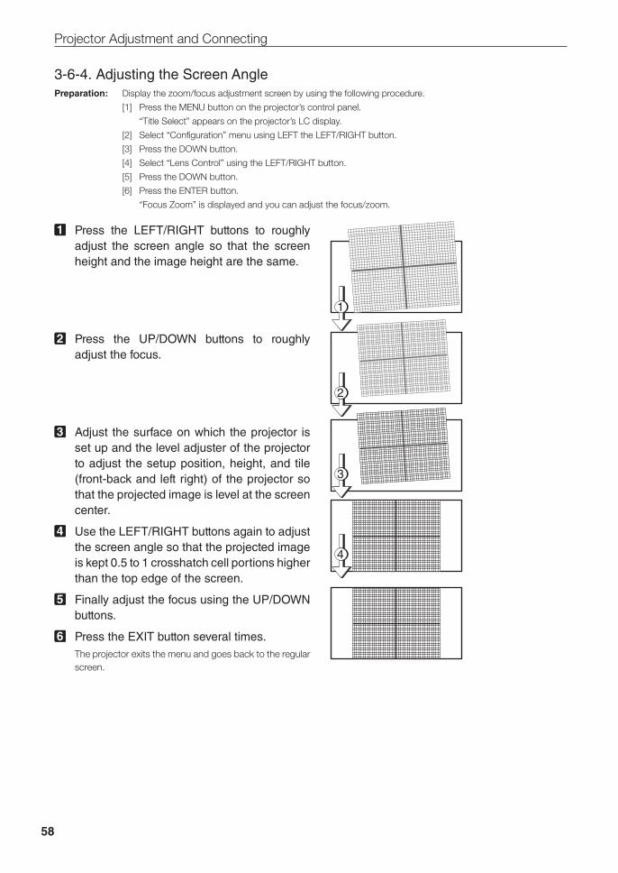
58
Projector Adjustment and Connecting
3-6-4. Adjusting the Screen AnglePreparation: Display the zoom/focus adjustment screen by using the following procedure.
[1] Press the MENU button on the projector’s control panel.
“Title Select” appears on the projector’s LC display.
[2] Select “Configuration” menu using LEFT the LEFT/RIGHT button.
[3] Press the DOWN button.
[4] Select “Lens Control” using the LEFT/RIGHT button.
[5] Press the DOWN button.
[6] Press the ENTER button.
“Focus Zoom” is displayed and you can adjust the focus/zoom.
1 Press the LEFT/RIGHT buttons to roughly adjust the screen angle so that the screen height and the image height are the same.
2 Press the UP/DOWN buttons to roughly adjust the focus.
3 Adjust the surface on which the projector is set up and the level adjuster of the projector to adjust the setup position, height, and tile (front-back and left right) of the projector so that the projected image is level at the screen center.
4 Use the LEFT/RIGHT buttons again to adjust the screen angle so that the projected image is kept 0.5 to 1 crosshatch cell portions higher than the top edge of the screen.
5 Finally adjust the focus using the UP/DOWN buttons.
6 Press the EXIT button several times.The projector exits the menu and goes back to the regular screen.
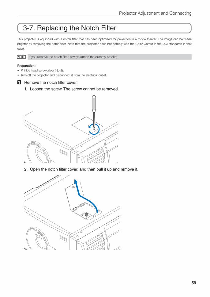
59
Projector Adjustment and Connecting
3-7. Replacing the Notch FilterThis projector is equipped with a notch filter that has been optimized for projection in a movie theater. The image can be made
brighter by removing the notch filter. Note that the projector does not comply with the Color Gamut in the DCI standards in that
case.
NOTE If you remove the notch filter, always attach the dummy bracket.
Preparation:
• Phillips head screwdriver (No.2).
• Turn off the projector and disconnect it from the electrical outlet.
1 Remove the notch filter cover.
1. Loosen the screw. The screw cannot be removed.
2. Open the notch filter cover, and then pull it up and remove it.
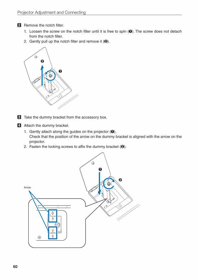
60
Projector Adjustment and Connecting
2 Remove the notch filter.
1. Loosen the screw on the notch filter until it is free to spin ( ). The screw does not detach from the notch filter.
2. Gently pull up the notch filter and remove it ( ).
3 Take the dummy bracket from the accessory box.
4 Attach the dummy bracket.
1. Gently attach along the guides on the projector ( ). Check that the position of the arrow on the dummy bracket is aligned with the arrow on the
projector.2. Fasten the locking screws to affix the dummy bracket ( ).
Arrow
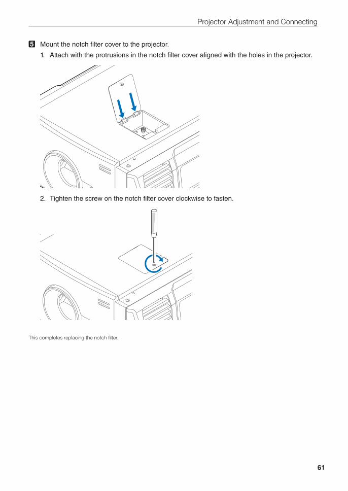
61
Projector Adjustment and Connecting
5 Mount the notch filter cover to the projector.
1. Attach with the protrusions in the notch filter cover aligned with the holes in the projector.
2. Tighten the screw on the notch filter cover clockwise to fasten.
This completes replacing the notch filter.
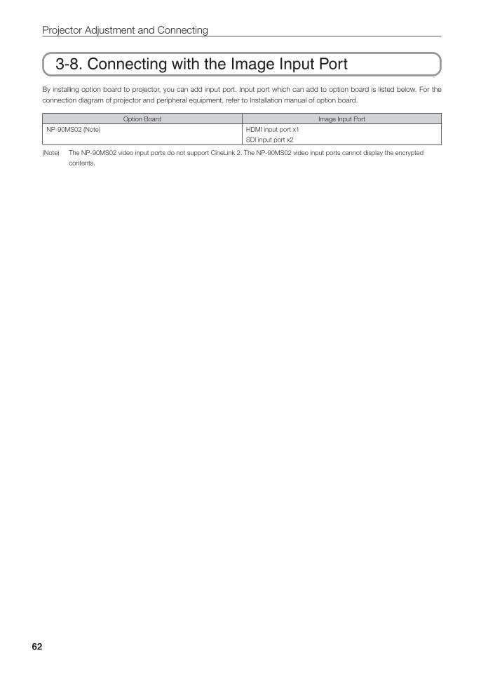
62
Projector Adjustment and Connecting
3-8. Connecting with the Image Input PortBy installing option board to projector, you can add input port. Input port which can add to option board is listed below. For the
connection diagram of projector and peripheral equipment, refer to Installation manual of option board.
Option Board Image Input Port
NP-90MS02 (Note) HDMI input port x1
SDI input port x2
(Note) The NP-90MS02 video input ports do not support CineLink 2. The NP-90MS02 video input ports cannot display the encrypted
contents.
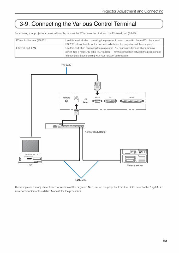
63
Projector Adjustment and Connecting
3-9. Connecting the Various Control TerminalFor control, your projector comes with such ports as the PC control terminal and the Ethernet port (RJ-45).
PC control terminal (RS-232) Use this terminal when controlling the projector in serial connection from a PC. Use a retail
RS-232C straight cable for the connection between the projector and the computer.
Ethernet port (LAN) Use this port when controlling the projector in LAN connection from a PC or a cinema
server. Use a retail LAN cable (10/100Base-T) for the connection between the projector and
the computer after checking with your network administrator.
GP I/O3DRS-232USB
REMOTE LAN
RS-232C
PC Cinema server
LAN cable
Network hub/Router
This completes the adjustment and connection of the projector. Next, set up the projector from the DCC. Refer to the “Digital Cin-
ema Communicator Installation Manual” for the procedure.
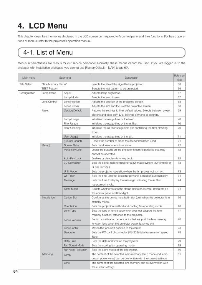
64
4. LCD MenuThis chapter describes the menus displayed in the LCD screen on the projector’s control panel and their functions. For basic opera-
tions of menus, refer to the projector’s operation manual.
4-1. List of MenuMenus in parentheses are menus for our service personnel. Normally, these menus cannot be used. If you are logged in to the
projector with Installation privileges, you cannot use [FactoryDefault] - [LAN] (page 69).
Main menu Submenu DescriptionReference
page
Title Select “Title Memory Name” Selects the title of the signal to be projected. 66
TEST Pattern Selects the test pattern to be projected. 66
Configuration Lamp Setup Adjust Adjusts lamp brightness. 67
Lamp Mode Selects the lamp to use. 67
Lens Control Lens Position Adjusts the position of the projected screen. 68
Focus Zoom Adjusts the size and focus of the projected screen. 68
Reset (FactoryDefault) Returns the settings to their default values. Selects between preset
buttons and titles only, LAN settings only and all settings.
69
Lamp Usage Initializes the usage time of the lamp. 70
Filter Usage Initializes the usage time of the air filter. 70
Fliter Cleaning Initializes the air filter usage time (for confirming the filter cleaning
time).
70
(Fan Usage) Initializes the usage time of the fan. 71
(Douser Count) Resets the number of times the douser has been used. 71
(Setup) Douser Setup Sets the douser open/close state. 72
Panel Key Lock Locks the buttons on the projector’s control panel so that they
cannot be operated.
72
Auto Key Lock Enables or disables Auto Key Lock. 73
3D Connector Sets the signal input terminal for a 3D image system (3D terminal or
GPI/O terminal).
73
Unlit Mode Sets the projector operation when the lamp does not turn on. 73
Off Timer Sets the time until the projector power is turned off automatically. 74
Message Sets the time to display the message indicating the air filter
replacement cycle.
74
Silent Mode Selects whether to use the status indicator, buzzer, indicators on
the control panel and backlight.
74
(Installation) Option Slot Configures the device installed in slot (only when the projector is in
standby mode).
76
Orientation Sets the projection method and cooling fan operating mode. 76
Lens Type Sets the type of lens (supports or does not support the lens
memory function) attached to the projector.
77
Lens Calibrate Performs calibration on lens units that support the lens memory
function (only when the projector power is turned on).
78
Lens Center Moves the lens shift position to the center. 78
Baudrate Sets the PC control connector (RS-232) data transmission speed
(bps).
78
Date/Time Sets the date and time on the projector. 79
Fan Speed Mode Sets the cooling fan operating mode. 79
Fan Noise Reduction Sets the silent mode of the cooling fan. 80
(Memory) Lamp The content of the selected lamp memory (lamp mode and lamp
output power value) can be overwritten with the current settings.
81
Lens The content of the selected lens memory can be overwritten with
the current settings.
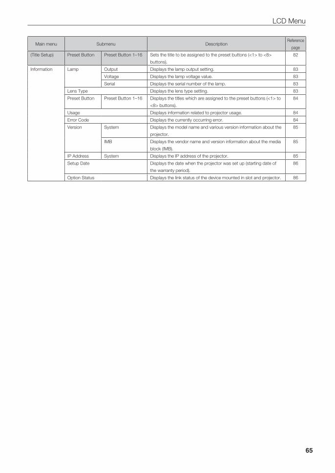
65
LCD Menu
Main menu Submenu DescriptionReference
page
(Title Setup) Preset Button Preset Button 1–16 Sets the title to be assigned to the preset buttons (<1> to <8>
buttons).
82
Information Lamp Output Displays the lamp output setting. 83
Voltage Displays the lamp voltage value. 83
Serial Displays the serial number of the lamp. 83
Lens Type Displays the lens type setting. 83
Preset Button Preset Button 1–16 Displays the titles which are assigned to the preset buttons (<1> to
<8> buttons).
84
Usage Displays information related to projector usage. 84
Error Code Displays the currently occurring error. 84
Version System Displays the model name and various version information about the
projector.
85
IMB Displays the vendor name and version information about the media
block (IMB).
85
IP Address System Displays the IP address of the projector. 85
Setup Date Displays the date when the projector was set up (starting date of
the warranty period).
86
Option Status Displays the link status of the device mounted in slot and projector. 86

66
LCD Menu
4-1-1. When You Use the Service Personnel MenuTo use the menu for service personnel, you need to input the passcode. This section describes how to display the passcode entry
screen and how to enter the passcode. Refer to the Projector Manual for details on how to enter text.
1 Press the MENU button for three seconds or longer.The passcode input screen will be displayed on the LCD screen at the projector’s control panel.Press the EXIT button to return to the original screen.
2 Enter the passcode and press the ENTER button.If you make a mistake during input, you can move the cursor by pressing the LEFT/RIGHT buttons and overwrite the passcode.If the passcode is correct, you can use the menu for service personnel.
NOTE When you enter the password, pay enough attention to people around for the password abuse prevention.If you have anxiety the password is cheated, change the password immediately.Before entering the password, inspect the password entry device (such as remote controller and/or keypad on the projector) for any evidence of physical tampering. In the event that any suspicious markings are present (such as gouges, extraneous wiring, adhesive materials, etc.) “DO NOT” enter the password and consult with the distributor.Always store the password, remote controller, and projector in a safe place and never divulge the password to unau-thorized entities.Entered password is indicated with * on the LCD.In case entered password characters are indicated on the LCD, it is machine trouble. Consult with the distributor.
4-2. Title Select
4-2-1. Title select (Title Memory)Select the title of the signal to be projected.
You can register up to 100 titles. You can also assign registered titles to the preset buttons <1> to <8> on the projector’s control
panel and call them up directly using those buttons. (See page 84)
← Displays the currently selected item with asterisk (*).
← Selects the title to be projected.
4-2-2. Test PatternSelects the test pattern to be projected.
← Displays the currently selected item with asterisk (*).
← Selects the test pattern to be projected.
OFF, Alignment, Cross Hatch, Convergence, Red, Green, Blue, White, Black, White 50% [IRE], H-Ramp, Logo
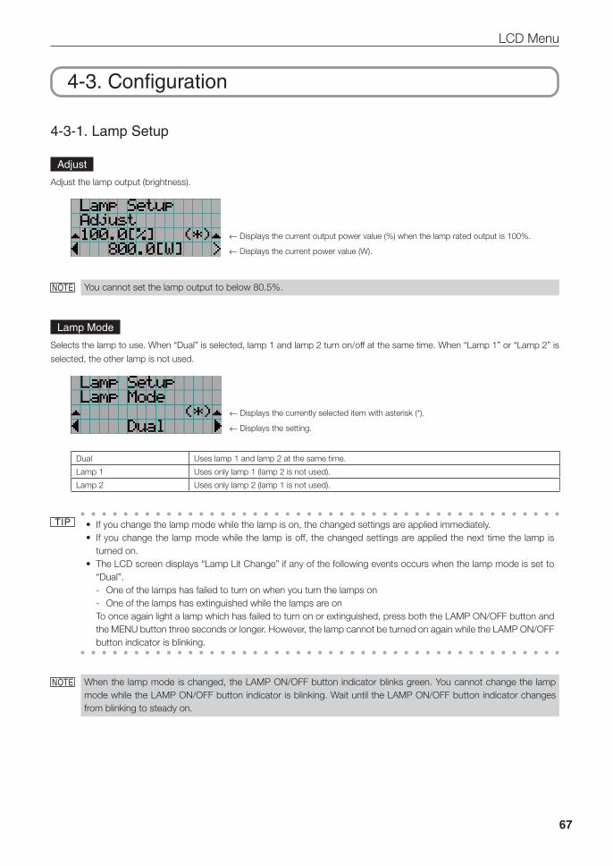
67
LCD Menu
4-3. Configuration
4-3-1. Lamp Setup
Adjust
Adjust the lamp output (brightness).
← Displays the current output power value (%) when the lamp rated output is 100%.
← Displays the current power value (W).
NOTE You cannot set the lamp output to below 80.5%.
Lamp Mode
Selects the lamp to use. When “Dual” is selected, lamp 1 and lamp 2 turn on/off at the same time. When “Lamp 1” or “Lamp 2” is
selected, the other lamp is not used.
← Displays the currently selected item with asterisk (*).
← Displays the setting.
Dual Uses lamp 1 and lamp 2 at the same time.
Lamp 1 Uses only lamp 1 (lamp 2 is not used).
Lamp 2 Uses only lamp 2 (lamp 1 is not used).
TIP • If you change the lamp mode while the lamp is on, the changed settings are applied immediately.• If you change the lamp mode while the lamp is off, the changed settings are applied the next time the lamp is
turned on.• The LCD screen displays “Lamp Lit Change” if any of the following events occurs when the lamp mode is set to
“Dual”. - One of the lamps has failed to turn on when you turn the lamps on - One of the lamps has extinguished while the lamps are on
To once again light a lamp which has failed to turn on or extinguished, press both the LAMP ON/OFF button and the MENU button three seconds or longer. However, the lamp cannot be turned on again while the LAMP ON/OFF button indicator is blinking.
NOTE When the lamp mode is changed, the LAMP ON/OFF button indicator blinks green. You cannot change the lamp mode while the LAMP ON/OFF button indicator is blinking. Wait until the LAMP ON/OFF button indicator changes from blinking to steady on.
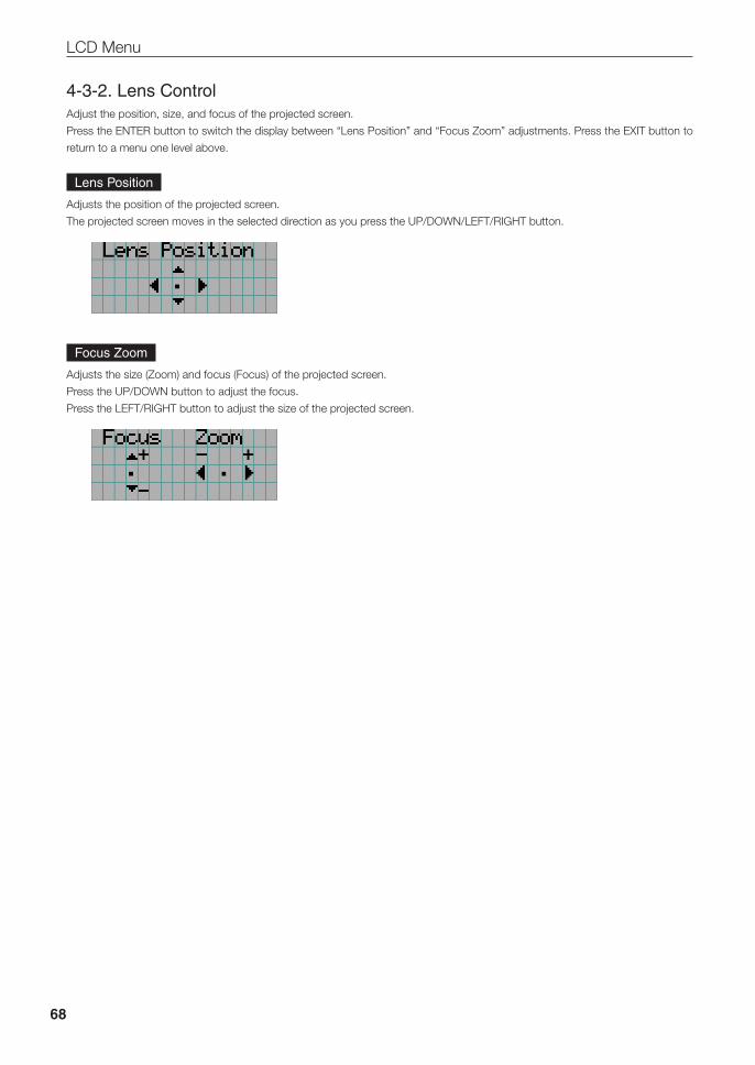
68
LCD Menu
4-3-2. Lens ControlAdjust the position, size, and focus of the projected screen.
Press the ENTER button to switch the display between “Lens Position” and “Focus Zoom” adjustments. Press the EXIT button to
return to a menu one level above.
Lens Position
Adjusts the position of the projected screen.
The projected screen moves in the selected direction as you press the UP/DOWN/LEFT/RIGHT button.
Focus Zoom
Adjusts the size (Zoom) and focus (Focus) of the projected screen.
Press the UP/DOWN button to adjust the focus.
Press the LEFT/RIGHT button to adjust the size of the projected screen.
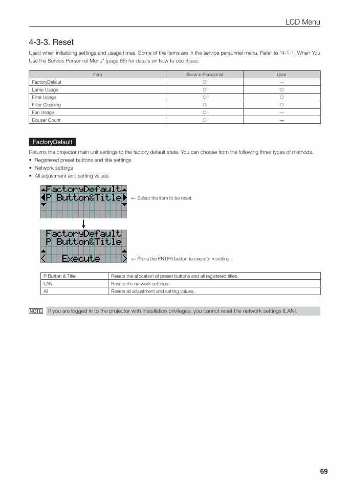
69
LCD Menu
4-3-3. ResetUsed when initializing settings and usage times. Some of the items are in the service personnel menu. Refer to “4-1-1. When You
Use the Service Personnel Menu” (page 66) for details on how to use these.
Item Service Personnel User
FactoryDefalut —
Lamp Usage Filter Usage Filter Cleaning Fan Usage —
Douser Count —
FactoryDefault
Returns the projector main unit settings to the factory default state. You can choose from the following three types of methods.
• Registered preset buttons and title settings
• Network settings
• All adjustment and setting values
← Select the item to be reset.
← Press the ENTER button to execute resetting.
P Button & Title Resets the allocation of preset buttons and all registered titles.
LAN Resets the network settings.
All Resets all adjustment and setting values.
NOTE If you are logged in to the projector with Installation privileges, you cannot reset the network settings (LAN).
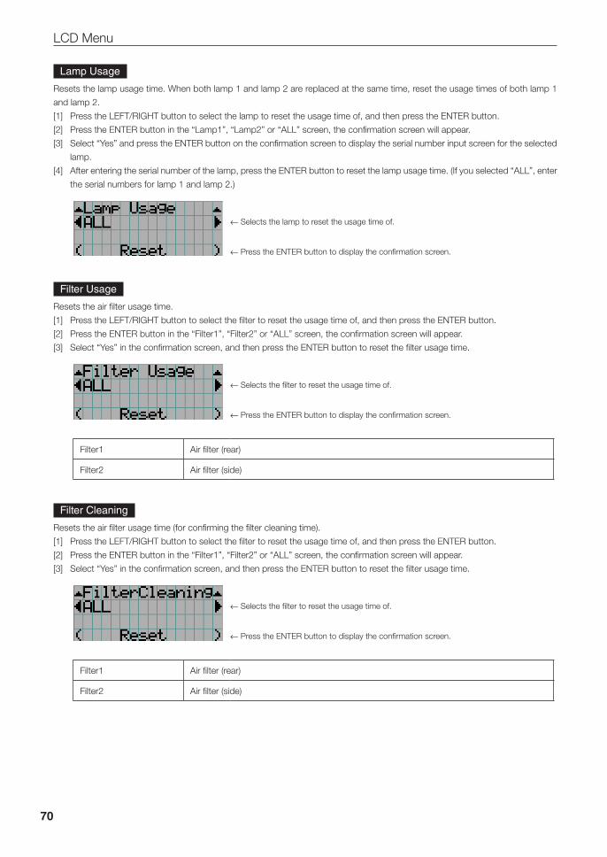
70
LCD Menu
Lamp Usage
Resets the lamp usage time. When both lamp 1 and lamp 2 are replaced at the same time, reset the usage times of both lamp 1
and lamp 2.
[1] Press the LEFT/RIGHT button to select the lamp to reset the usage time of, and then press the ENTER button.
[2] Press the ENTER button in the “Lamp1”, “Lamp2” or “ALL” screen, the confirmation screen will appear.
[3] Select “Yes” and press the ENTER button on the confirmation screen to display the serial number input screen for the selected
lamp.
[4] After entering the serial number of the lamp, press the ENTER button to reset the lamp usage time. (If you selected “ALL”, enter
the serial numbers for lamp 1 and lamp 2.)
← Selects the lamp to reset the usage time of.
← Press the ENTER button to display the confirmation screen.
Filter Usage
Resets the air filter usage time.
[1] Press the LEFT/RIGHT button to select the filter to reset the usage time of, and then press the ENTER button.
[2] Press the ENTER button in the “Filter1”, “Filter2” or “ALL” screen, the confirmation screen will appear.
[3] Select “Yes” in the confirmation screen, and then press the ENTER button to reset the filter usage time.
← Selects the filter to reset the usage time of.
← Press the ENTER button to display the confirmation screen.
Filter1 Air filter (rear)
Filter2 Air filter (side)
Filter Cleaning
Resets the air filter usage time (for confirming the filter cleaning time).
[1] Press the LEFT/RIGHT button to select the filter to reset the usage time of, and then press the ENTER button.
[2] Press the ENTER button in the “Filter1”, “Filter2” or “ALL” screen, the confirmation screen will appear.
[3] Select “Yes” in the confirmation screen, and then press the ENTER button to reset the filter usage time.
← Selects the filter to reset the usage time of.
← Press the ENTER button to display the confirmation screen.
Filter1 Air filter (rear)
Filter2 Air filter (side)
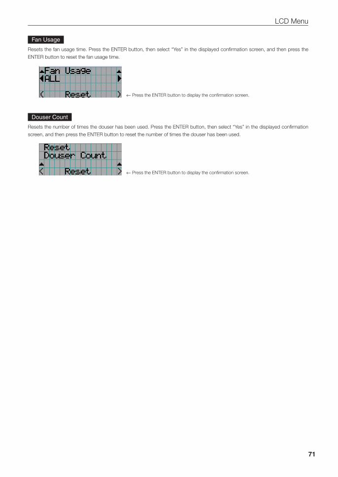
71
LCD Menu
Fan Usage
Resets the fan usage time. Press the ENTER button, then select “Yes” in the displayed confirmation screen, and then press the
ENTER button to reset the fan usage time.
← Press the ENTER button to display the confirmation screen.
Douser Count
Resets the number of times the douser has been used. Press the ENTER button, then select “Yes” in the displayed confirmation
screen, and then press the ENTER button to reset the number of times the douser has been used.
← Press the ENTER button to display the confirmation screen.
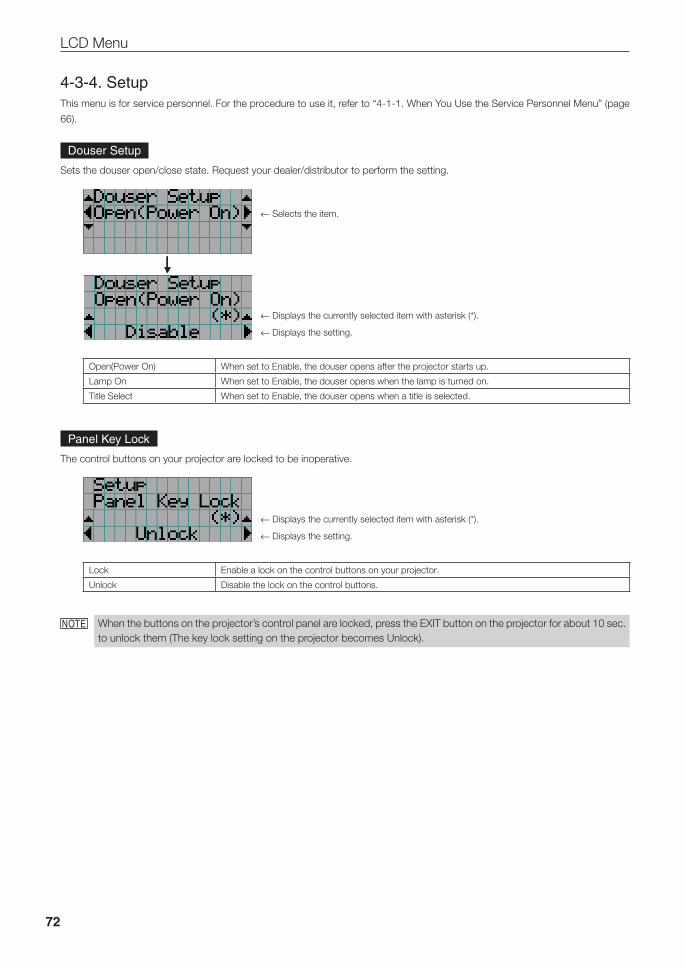
72
LCD Menu
4-3-4. SetupThis menu is for service personnel. For the procedure to use it, refer to “4-1-1. When You Use the Service Personnel Menu” (page
66).
Douser Setup
Sets the douser open/close state. Request your dealer/distributor to perform the setting.
← Selects the item.
← Displays the currently selected item with asterisk (*).
← Displays the setting.
Open(Power On) When set to Enable, the douser opens after the projector starts up.
Lamp On When set to Enable, the douser opens when the lamp is turned on.
Title Select When set to Enable, the douser opens when a title is selected.
Panel Key Lock
The control buttons on your projector are locked to be inoperative.
← Displays the currently selected item with asterisk (*).
← Displays the setting.
Lock Enable a lock on the control buttons on your projector.
Unlock Disable the lock on the control buttons.
NOTE When the buttons on the projector’s control panel are locked, press the EXIT button on the projector for about 10 sec. to unlock them (The key lock setting on the projector becomes Unlock).
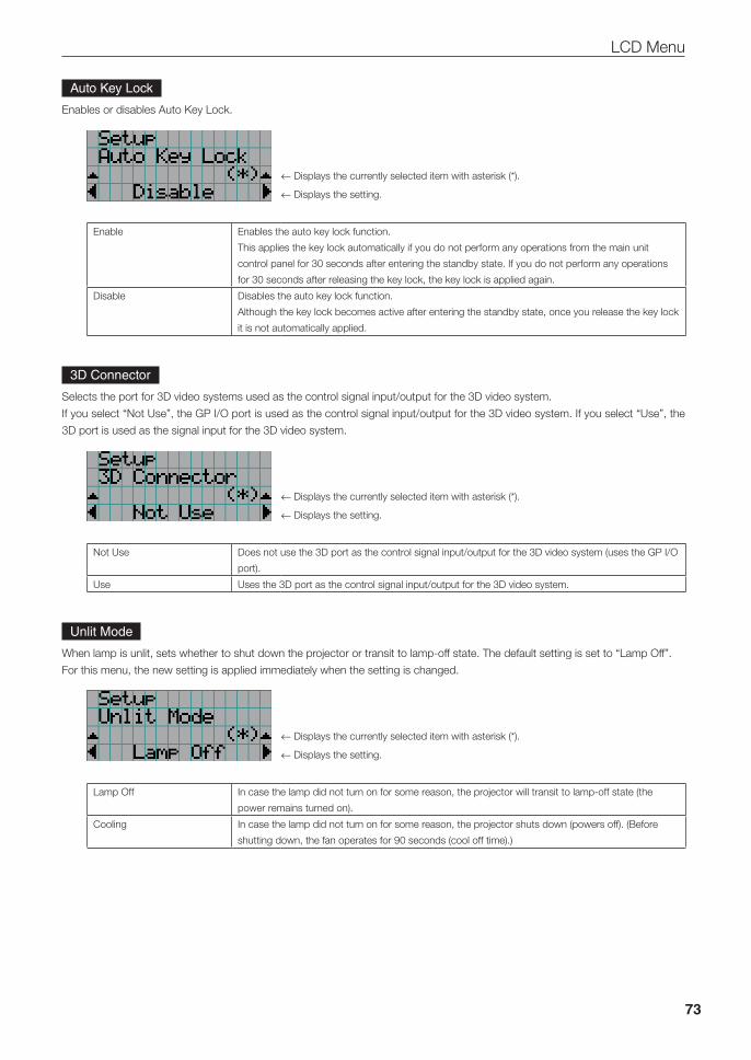
73
LCD Menu
Auto Key Lock
Enables or disables Auto Key Lock.
← Displays the currently selected item with asterisk (*).
← Displays the setting.
Enable Enables the auto key lock function.
This applies the key lock automatically if you do not perform any operations from the main unit
control panel for 30 seconds after entering the standby state. If you do not perform any operations
for 30 seconds after releasing the key lock, the key lock is applied again.
Disable Disables the auto key lock function.
Although the key lock becomes active after entering the standby state, once you release the key lock
it is not automatically applied.
3D Connector
Selects the port for 3D video systems used as the control signal input/output for the 3D video system.
If you select “Not Use”, the GP I/O port is used as the control signal input/output for the 3D video system. If you select “Use”, the
3D port is used as the signal input for the 3D video system.
← Displays the currently selected item with asterisk (*).
← Displays the setting.
Not Use Does not use the 3D port as the control signal input/output for the 3D video system (uses the GP I/O
port).
Use Uses the 3D port as the control signal input/output for the 3D video system.
Unlit Mode
When lamp is unlit, sets whether to shut down the projector or transit to lamp-off state. The default setting is set to “Lamp Off”.
For this menu, the new setting is applied immediately when the setting is changed.
← Displays the currently selected item with asterisk (*).
← Displays the setting.
Lamp Off In case the lamp did not turn on for some reason, the projector will transit to lamp-off state (the
power remains turned on).
Cooling In case the lamp did not turn on for some reason, the projector shuts down (powers off). (Before
shutting down, the fan operates for 90 seconds (cool off time).)
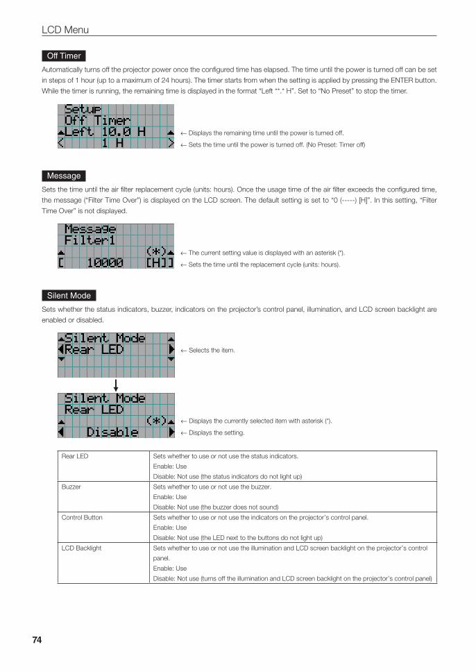
74
LCD Menu
Off Timer
Automatically turns off the projector power once the configured time has elapsed. The time until the power is turned off can be set
in steps of 1 hour (up to a maximum of 24 hours). The timer starts from when the setting is applied by pressing the ENTER button.
While the timer is running, the remaining time is displayed in the format “Left **.* H”. Set to “No Preset” to stop the timer.
← Displays the remaining time until the power is turned off.
← Sets the time until the power is turned off. (No Preset: Timer off)
Message
Sets the time until the air filter replacement cycle (units: hours). Once the usage time of the air filter exceeds the configured time,
the message (“Filter Time Over”) is displayed on the LCD screen. The default setting is set to “0 (-----) [H]”. In this setting, “Filter
Time Over” is not displayed.
← The current setting value is displayed with an asterisk (*).
← Sets the time until the replacement cycle (units: hours).
Silent Mode
Sets whether the status indicators, buzzer, indicators on the projector’s control panel, illumination, and LCD screen backlight are
enabled or disabled.
← Selects the item.
← Displays the currently selected item with asterisk (*).
← Displays the setting.
Rear LED Sets whether to use or not use the status indicators.
Enable: Use
Disable: Not use (the status indicators do not light up)
Buzzer Sets whether to use or not use the buzzer.
Enable: Use
Disable: Not use (the buzzer does not sound)
Control Button Sets whether to use or not use the indicators on the projector’s control panel.
Enable: Use
Disable: Not use (the LED next to the buttons do not light up)
LCD Backlight Sets whether to use or not use the illumination and LCD screen backlight on the projector’s control
panel.
Enable: Use
Disable: Not use (turns off the illumination and LCD screen backlight on the projector’s control panel)

75
LCD Menu
TIP When LCD Backlight is set to Disable, you can change the setting to Enable by long-pressing (3 seconds or more) the EXIT button and UP button.
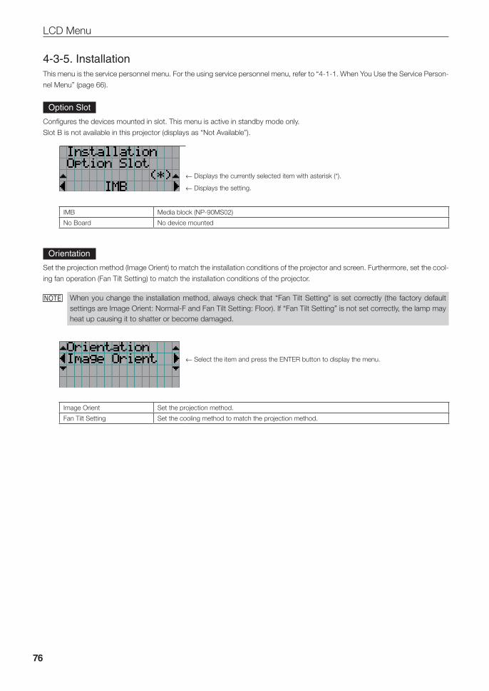
76
LCD Menu
4-3-5. InstallationThis menu is the service personnel menu. For the using service personnel menu, refer to “4-1-1. When You Use the Service Person-
nel Menu” (page 66).
Option Slot
Configures the devices mounted in slot. This menu is active in standby mode only.
Slot B is not available in this projector (displays as “Not Available”).
← Displays the currently selected item with asterisk (*).
← Displays the setting.
IMB Media block (NP-90MS02)
No Board No device mounted
Orientation
Set the projection method (Image Orient) to match the installation conditions of the projector and screen. Furthermore, set the cool-
ing fan operation (Fan Tilt Setting) to match the installation conditions of the projector.
NOTE When you change the installation method, always check that “Fan Tilt Setting” is set correctly (the factory default settings are Image Orient: Normal-F and Fan Tilt Setting: Floor). If “Fan Tilt Setting” is not set correctly, the lamp may heat up causing it to shatter or become damaged.
← Select the item and press the ENTER button to display the menu.
Image Orient Set the projection method.
Fan Tilt Setting Set the cooling method to match the projection method.
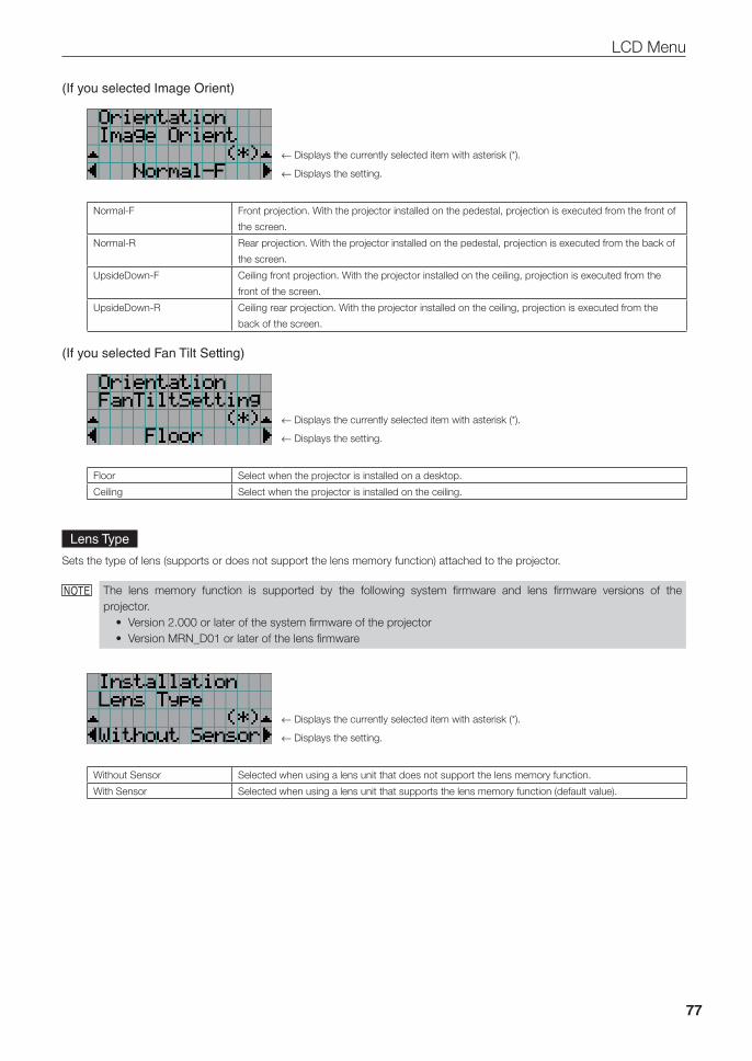
77
LCD Menu
(If you selected Image Orient)
← Displays the currently selected item with asterisk (*).
← Displays the setting.
Normal-F Front projection. With the projector installed on the pedestal, projection is executed from the front of
the screen.
Normal-R Rear projection. With the projector installed on the pedestal, projection is executed from the back of
the screen.
UpsideDown-F Ceiling front projection. With the projector installed on the ceiling, projection is executed from the
front of the screen.
UpsideDown-R Ceiling rear projection. With the projector installed on the ceiling, projection is executed from the
back of the screen.
(If you selected Fan Tilt Setting)
← Displays the currently selected item with asterisk (*).
← Displays the setting.
Floor Select when the projector is installed on a desktop.
Ceiling Select when the projector is installed on the ceiling.
Lens Type
Sets the type of lens (supports or does not support the lens memory function) attached to the projector.
NOTE The lens memory function is supported by the following system firmware and lens firmware versions of the projector.
• Version 2.000 or later of the system firmware of the projector• Version MRN_D01 or later of the lens firmware
← Displays the currently selected item with asterisk (*).
← Displays the setting.
Without Sensor Selected when using a lens unit that does not support the lens memory function.
With Sensor Selected when using a lens unit that supports the lens memory function (default value).
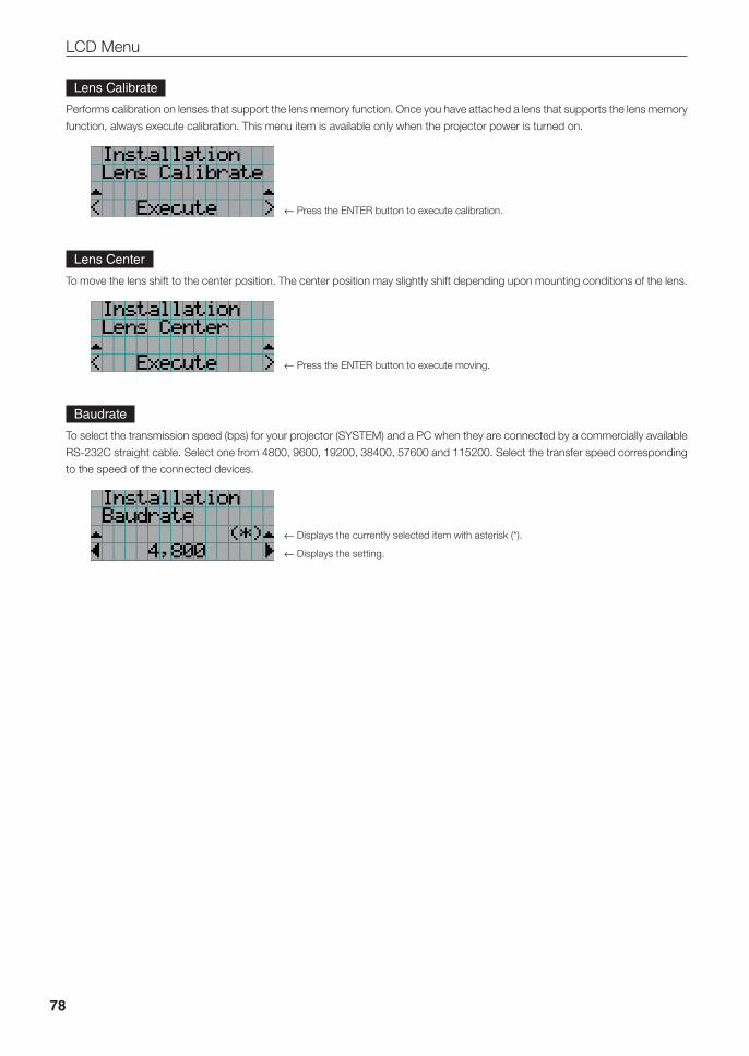
78
LCD Menu
Lens Calibrate
Performs calibration on lenses that support the lens memory function. Once you have attached a lens that supports the lens memory
function, always execute calibration. This menu item is available only when the projector power is turned on.
← Press the ENTER button to execute calibration.
Lens Center
To move the lens shift to the center position. The center position may slightly shift depending upon mounting conditions of the lens.
← Press the ENTER button to execute moving.
Baudrate
To select the transmission speed (bps) for your projector (SYSTEM) and a PC when they are connected by a commercially available
RS-232C straight cable. Select one from 4800, 9600, 19200, 38400, 57600 and 115200. Select the transfer speed corresponding
to the speed of the connected devices.
← Displays the currently selected item with asterisk (*).
← Displays the setting.
79
LCD Menu
Date/Time
Use this to set the date and time on the projector.
The internal clock in the projector uses coordinated universal time (UTC). This sets the time difference between the standard time
in your region and UTC.
← Displays the currently setting with asterisk (*).
← Sets the time difference between the standard time in your region and UTC.
Press the ENTER button to check the time difference between the built-in projector clock
and UTC.
TIP If you are using DCC, you can set the date and time from your computer. Refer to “Digital Cinema Communicator Installation Manual” for details.
Fan Speed Mode
It adjusts the rotation speed of the internal cooling fan.
← Displays the currently selected item with asterisk (*).
← Displays the setting.
Auto The fan rotates at the optimal speed according to the temperature sensor inside the projector.
High Speed The fan always rotates at high speed.
High Altitude Select when using the projector in locations with low air pressure, such as at high elevations of
altitude approximately 5500 feet (1600 m) or higher. The fan always rotates at high speed.
NOTE • It is recommended that you select “High Speed” if you use the projector non-stop for consecutive days.• Set “Fan Speed Mode” to “High Altitude” when using the projector at altitudes approximately 5500 feet/1600
meters or higher.• Using the projector at altitudes approximately 5500 feet/1600 meters or higher without setting to “High Altitude”
can cause the projector to overheat and the protector could shut down. If this happens, wait a couple minutes and turn on the projector.
• Using the projector at altitudes less than approximately 5500 feet/1600 meters and setting to “High Altitude” can cause the lamp to overcool, causing the image to flicker. Switch “Fan Speed Mode” to “Auto”.
• Using the projector at altitudes approximately 5500 feet/1600 meters or higher can shorten the life of internal parts such as the lamp.
80
LCD Menu
Fan Noise Reduction
Sets the cooling fan quiet mode.
Off Quiet mode off (default value)
On Quiet mode on
NOTE When turning quiet mode on, consult your dealer.
81
LCD Menu
4-3-6. MemoryThis menu is the service personnel menu. For the using service personnel menu, refer to “4-1-1. When You Use the Service Person-
nel Menu” (page 66).
The selected lens memory (lens adjustment value) and the content of the lamp memory (lamp mode and lamp output power value)
can be overwritten with the current settings. Press the LEFT/RIGHT buttons to select the lamp memory or the lens memory then
press the “ENTER” button to display the confirmation screen. Select “Yes” in the confirmation screen, and then press the ENTER
button. The selected memory (lamp memory or lens memory) is overwritten with the current settings.
NOTE • Lens memory and lamp memory cannot be newly registered. Use DCC to register the lens memory and lamp memory in advance. Refer to “Digital Cinema Communicator Installation Manual” for details registering the lens memory and lamp memory.
• The lens memory function cannot be used when the lens type is set to “Without Sensor”.
← Select the lamp memory or lens memory.
← Select the memory name of the setting to overwrite and press the ENTER button to display
the confirmation screen.
Lamp Select to change the values of the lamp memory settings.
Lens Select to change the values of the lens memory settings.
82
LCD Menu
4-4. Title SetupThis menu is the service personnel menu. For the using service personnel menu, refer to “4-1-1. When You Use the Service Person-
nel Menu” (page 66).
4-4-1. Preset ButtonUse this button to set the titles to be assigned to the preset buttons (<1> to <8> buttons).
You cannot assign the same title to several preset buttons. If you want to assign any title to another number, cancel the assignment
once and then set it to any button again.
The “Preset Button 1 to Preset Button 8” settings correspond to buttons <1> to <8> on the control panel. To select the titles allo-
cated to “Preset Button 9 to Preset Button 16”, press the <1> to <8> button while holding down the <Up> button on the control
panel.
← Select the preset button number (1 to 16).
← Display the selected number of the title.
← Select the titles to be assigned to the preset buttons.
Select the titles from those registered in advance.
To clear assignment to preset buttons, select “---”.
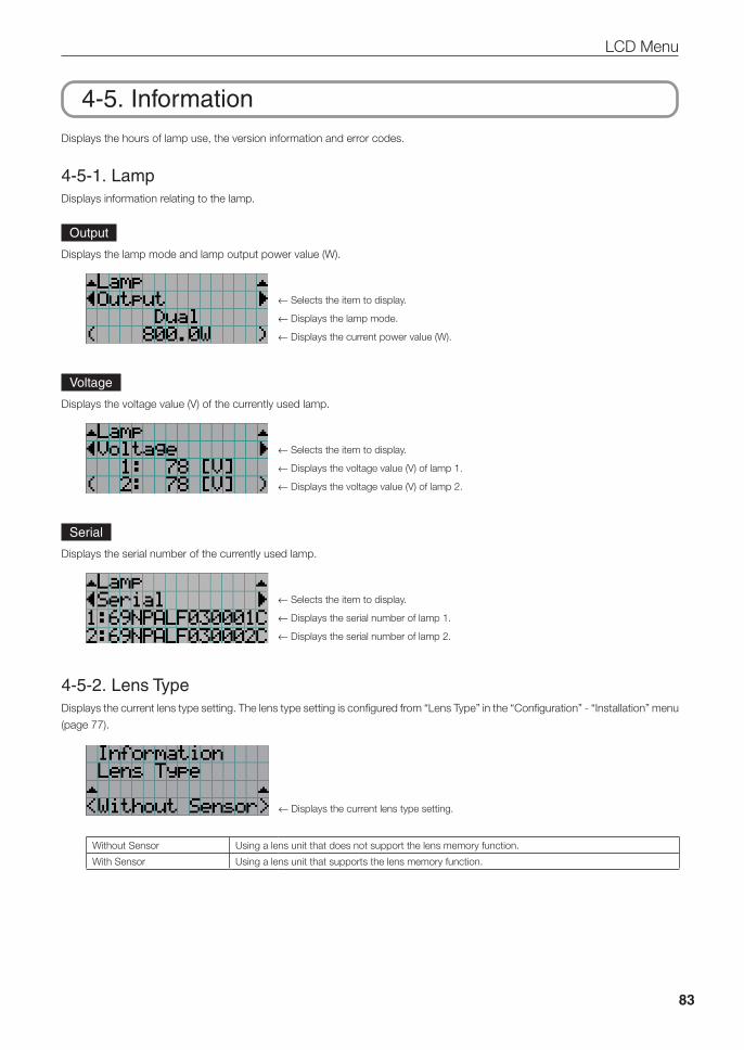
83
LCD Menu
4-5. InformationDisplays the hours of lamp use, the version information and error codes.
4-5-1. LampDisplays information relating to the lamp.
Output
Displays the lamp mode and lamp output power value (W).
← Selects the item to display.
← Displays the lamp mode.
← Displays the current power value (W).
Voltage
Displays the voltage value (V) of the currently used lamp.
← Selects the item to display.
← Displays the voltage value (V) of lamp 1.
← Displays the voltage value (V) of lamp 2.
Serial
Displays the serial number of the currently used lamp.
← Selects the item to display.
← Displays the serial number of lamp 1.
← Displays the serial number of lamp 2.
4-5-2. Lens TypeDisplays the current lens type setting. The lens type setting is configured from “Lens Type” in the “Configuration” - “Installation” menu
(page 77).
← Displays the current lens type setting.
Without Sensor Using a lens unit that does not support the lens memory function.
With Sensor Using a lens unit that supports the lens memory function.
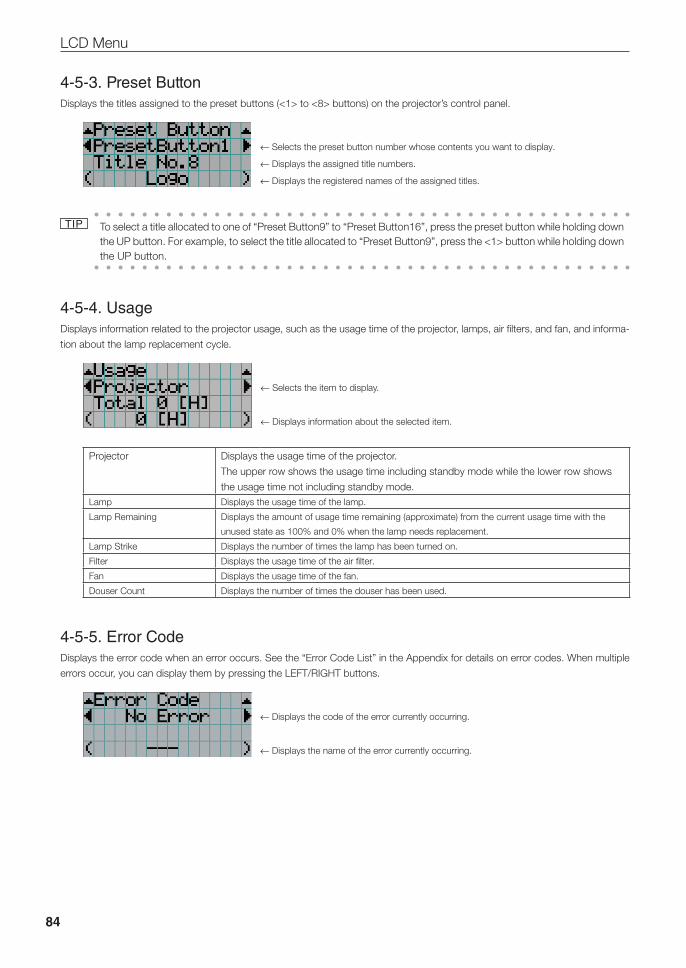
84
LCD Menu
4-5-3. Preset ButtonDisplays the titles assigned to the preset buttons (<1> to <8> buttons) on the projector’s control panel.
← Selects the preset button number whose contents you want to display.
← Displays the assigned title numbers.
← Displays the registered names of the assigned titles.
TIP To select a title allocated to one of “Preset Button9” to “Preset Button16”, press the preset button while holding down the UP button. For example, to select the title allocated to “Preset Button9”, press the <1> button while holding down the UP button.
4-5-4. UsageDisplays information related to the projector usage, such as the usage time of the projector, lamps, air filters, and fan, and informa-
tion about the lamp replacement cycle.
← Selects the item to display.
← Displays information about the selected item.
Projector Displays the usage time of the projector.
The upper row shows the usage time including standby mode while the lower row shows
the usage time not including standby mode.Lamp Displays the usage time of the lamp.
Lamp Remaining Displays the amount of usage time remaining (approximate) from the current usage time with the
unused state as 100% and 0% when the lamp needs replacement.
Lamp Strike Displays the number of times the lamp has been turned on.
Filter Displays the usage time of the air filter.
Fan Displays the usage time of the fan.
Douser Count Displays the number of times the douser has been used.
4-5-5. Error CodeDisplays the error code when an error occurs. See the “Error Code List” in the Appendix for details on error codes. When multiple
errors occur, you can display them by pressing the LEFT/RIGHT buttons.
← Displays the code of the error currently occurring.
← Displays the name of the error currently occurring.
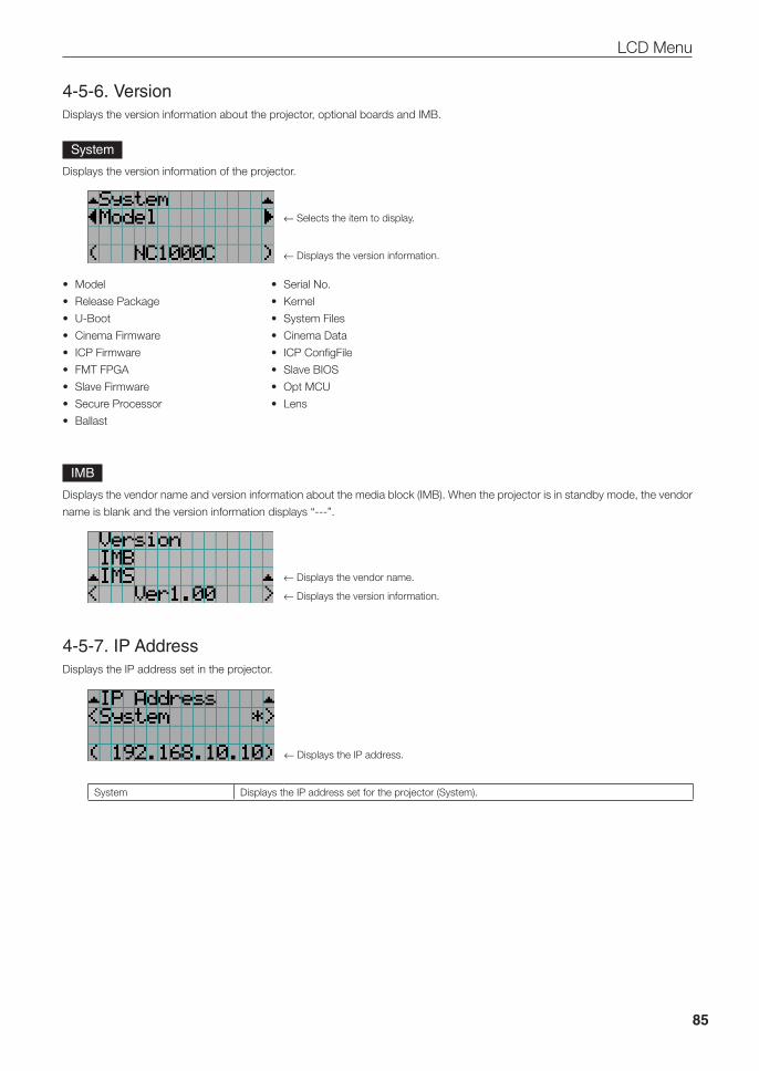
85
LCD Menu
4-5-6. VersionDisplays the version information about the projector, optional boards and IMB.
System
Displays the version information of the projector.
← Selects the item to display.
← Displays the version information.
• Model • SerialNo.
• ReleasePackage • Kernel
• U-Boot • SystemFiles
• CinemaFirmware • CinemaData
• ICPFirmware • ICPConfigFile
• FMTFPGA • SlaveBIOS
• SlaveFirmware • OptMCU
• SecureProcessor • Lens
• Ballast
IMB
Displays the vendor name and version information about the media block (IMB). When the projector is in standby mode, the vendor
name is blank and the version information displays “---”.
← Displays the vendor name.
← Displays the version information.
4-5-7. IP AddressDisplays the IP address set in the projector.
← Displays the IP address.
System Displays the IP address set for the projector (System).
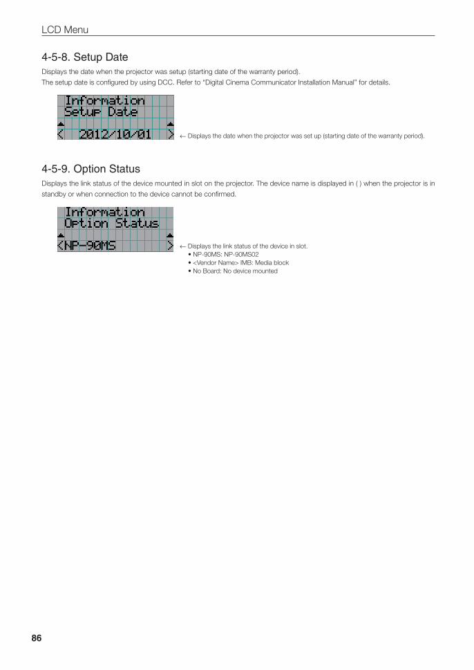
86
LCD Menu
4-5-8. Setup DateDisplays the date when the projector was setup (starting date of the warranty period).
The setup date is configured by using DCC. Refer to “Digital Cinema Communicator Installation Manual” for details.
← Displays the date when the projector was set up (starting date of the warranty period).
4-5-9. Option StatusDisplays the link status of the device mounted in slot on the projector. The device name is displayed in ( ) when the projector is in
standby or when connection to the device cannot be confirmed.
← Displays the link status of the device in slot. •NP-90MS:NP-90MS02 •<VendorName>IMB:Mediablock •NoBoard:Nodevicemounted
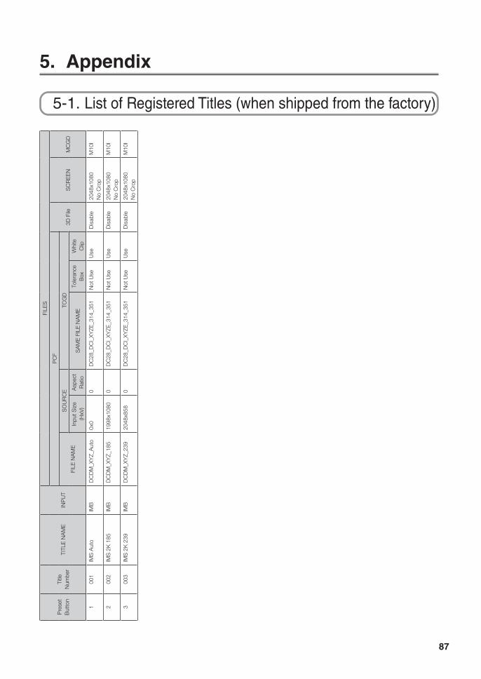
87
5. Appendix
5-1. List of Registered Titles (when shipped from the factory)
Pre
set
But
ton
Title
N
umbe
rTI
TLE
NA
ME
INP
UT
FILE
S
PC
F
3D F
ileS
CR
EE
NM
CG
DFI
LE N
AM
E
SO
UR
CE
TCG
D
Inpu
t Siz
e (H
xV)
Asp
ect
Rat
ioS
AM
E F
ILE
NA
ME
Tole
ranc
e B
oxW
hite
C
lip
100
1IM
S A
uto
IMB
DC
DM
_XY
Z_A
uto
0x0
0D
C28
_DC
I_XY
ZE_3
14_3
51N
ot U
seU
seD
isab
le20
48x1
080
N
o C
rop
M10
I
200
2IM
S 2
K 1
85IM
BD
CD
M_X
YZ_
185
1998
x108
00
DC
28_D
CI_
XYZE
_314
_351
Not
Use
Use
Dis
able
2048
x108
0
No
Cro
pM
10I
300
3IM
S 2
K 2
39IM
BD
CD
M_X
YZ_
239
2048
x858
0D
C28
_DC
I_XY
ZE_3
14_3
51N
ot U
seU
seD
isab
le20
48x1
080
N
o C
rop
M10
I
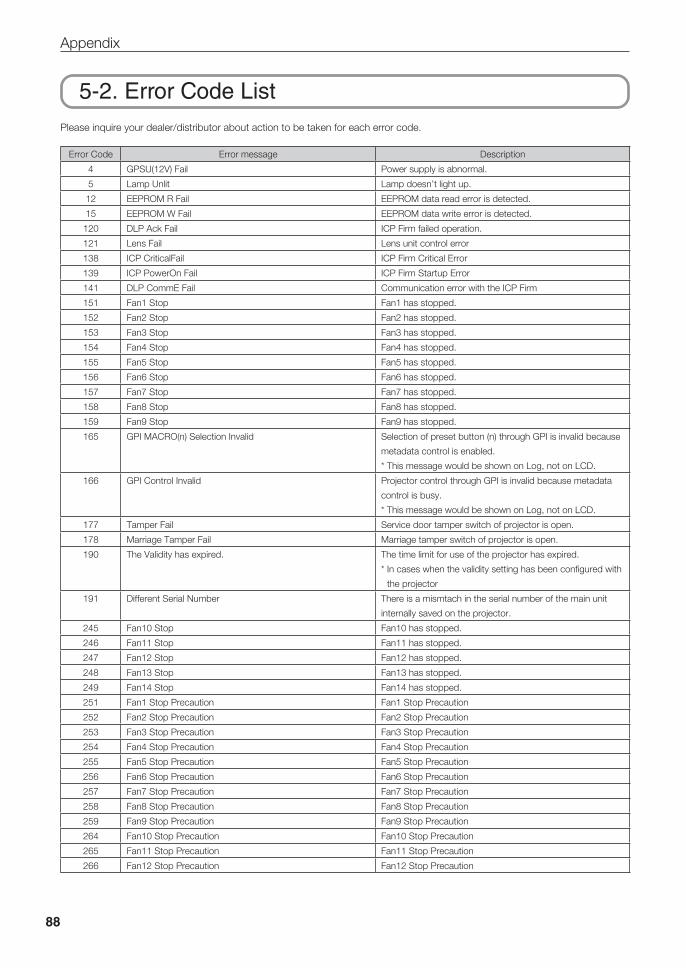
88
Appendix
5-2. Error Code ListPlease inquire your dealer/distributor about action to be taken for each error code.
Error Code Error message Description
4 GPSU(12V) Fail Power supply is abnormal.
5 Lamp Unlit Lamp doesn’t light up.
12 EEPROM R Fail EEPROM data read error is detected.
15 EEPROM W Fail EEPROM data write error is detected.
120 DLP Ack Fail ICP Firm failed operation.
121 Lens Fail Lens unit control error
138 ICP CriticalFail ICP Firm Critical Error
139 ICP PowerOn Fail ICP Firm Startup Error
141 DLP CommE Fail Communication error with the ICP Firm
151 Fan1 Stop Fan1 has stopped.
152 Fan2 Stop Fan2 has stopped.
153 Fan3 Stop Fan3 has stopped.
154 Fan4 Stop Fan4 has stopped.
155 Fan5 Stop Fan5 has stopped.
156 Fan6 Stop Fan6 has stopped.
157 Fan7 Stop Fan7 has stopped.
158 Fan8 Stop Fan8 has stopped.
159 Fan9 Stop Fan9 has stopped.
165 GPI MACRO(n) Selection Invalid Selection of preset button (n) through GPI is invalid because
metadata control is enabled.
* This message would be shown on Log, not on LCD.
166 GPI Control Invalid Projector control through GPI is invalid because metadata
control is busy.
* This message would be shown on Log, not on LCD.
177 Tamper Fail Service door tamper switch of projector is open.
178 Marriage Tamper Fail Marriage tamper switch of projector is open.
190 The Validity has expired. The time limit for use of the projector has expired.
* In cases when the validity setting has been configured with
the projector
191 Different Serial Number There is a mismtach in the serial number of the main unit
internally saved on the projector.
245 Fan10 Stop Fan10 has stopped.
246 Fan11 Stop Fan11 has stopped.
247 Fan12 Stop Fan12 has stopped.
248 Fan13 Stop Fan13 has stopped.
249 Fan14 Stop Fan14 has stopped.
251 Fan1 Stop Precaution Fan1 Stop Precaution
252 Fan2 Stop Precaution Fan2 Stop Precaution
253 Fan3 Stop Precaution Fan3 Stop Precaution
254 Fan4 Stop Precaution Fan4 Stop Precaution
255 Fan5 Stop Precaution Fan5 Stop Precaution
256 Fan6 Stop Precaution Fan6 Stop Precaution
257 Fan7 Stop Precaution Fan7 Stop Precaution
258 Fan8 Stop Precaution Fan8 Stop Precaution
259 Fan9 Stop Precaution Fan9 Stop Precaution
264 Fan10 Stop Precaution Fan10 Stop Precaution
265 Fan11 Stop Precaution Fan11 Stop Precaution
266 Fan12 Stop Precaution Fan12 Stop Precaution
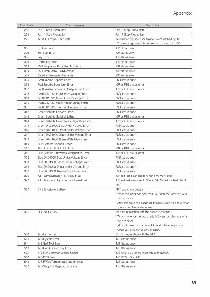
89
Appendix
Error Code Error message Description
267 Fan13 Stop Precaution Fan13 Stop Precaution
268 Fan14 Stop Precaution Fan14 Stop Precaution
271 IMB:SD Tamper Terminate Terminated service door tamper event latched by IMB.
* This message would be shown on Log, not on LCD.
301 System Error ICP status error
302 Self Test Error ICP status error
305 Key Error ICP status error
306 Certificate Error ICP status error
329 FMT Sequence Data File Mismatch ICP status error
330 FMT DMD Data File Mismatch ICP status error
333 Satellite Hardware Mismatch ICP status error
335 Red Satellite Reports Reset FSB status error
336 Red Satellite Serial Link Error ICP or FSB status error
337 Red Satellite Firmware Configuration Error ICP or FSB status error
338 Red DAD1000 Bias Under Voltage Error FSB status error
339 Red DAD1000 Reset Under Voltage Error FSB status error
340 Red DAD1000 Offset Under Voltage Error FSB status error
341 Red DAD1000 Thermal Shutdown Error FSB status error
342 Green Satellite Reports Reset FSB status error
343 Green Satellite Serial Link Error ICP or FSB status error
344 Green Satellite Firmware Configuration Error ICP or FSB status error
345 Green DAD1000 Bias Under Voltage Error FSB status error
346 Green DAD1000 Reset Under Voltage Error FSB status error
347 Green DAD1000 Offset Under Voltage Error FSB status error
348 Green DAD1000 Thermal Shutdown Error FSB status error
349 Blue Satellite Reports Reset FSB status error
350 Blue Satellite Serial Link Error ICP or FSB status error
351 Blue Satellite Firmware Configuration Error ICP or FSB status error
352 Blue DAD1000 Bias Under Voltage Error FSB status error
353 Blue DAD1000 Reset Under Voltage Error FSB status error
354 Blue DAD1000 Offset Under Voltage Error FSB status error
355 Blue DAD1000 Thermal Shutdown Error FSB status error
370 ICP Frame Memory Test Result Fail ICP self test error due to “Frame memory error”
372 ICP Data Path Signature Test Result Fail ICP self test error due to “Data Path Signature Test Result
Fail”
380 DRS Error(Low Battery) FMT board low battery
* When this error has occurred, IMB can not Marriage with
the projector.
* After this error has occurred, Integrity Error will occur when
you turn on the power again.
381 SEC No Battery No communication with the secure processor.
* When this error has occurred, IMB can not Marriage with
the projector.
* After this error has occurred, Integrity Error may occur
when you turn on the power again.
500 IMB Comm Fail No communication with the IMB.
510 IMB:System Error IMB Status error
511 IMB:Self Test Error IMB Status error
519 IMB:Certificate or Key Error IMB Status error
520 IMB:ICP Communications Status IMB fails to do logical marriage to projector.
537 IMB:RTC Error IMB RTC is “invalid”.
543 IMB:FPGA Temperature out of range IMB Status error
550 IMB:Supply voltage out of range IMB Status error
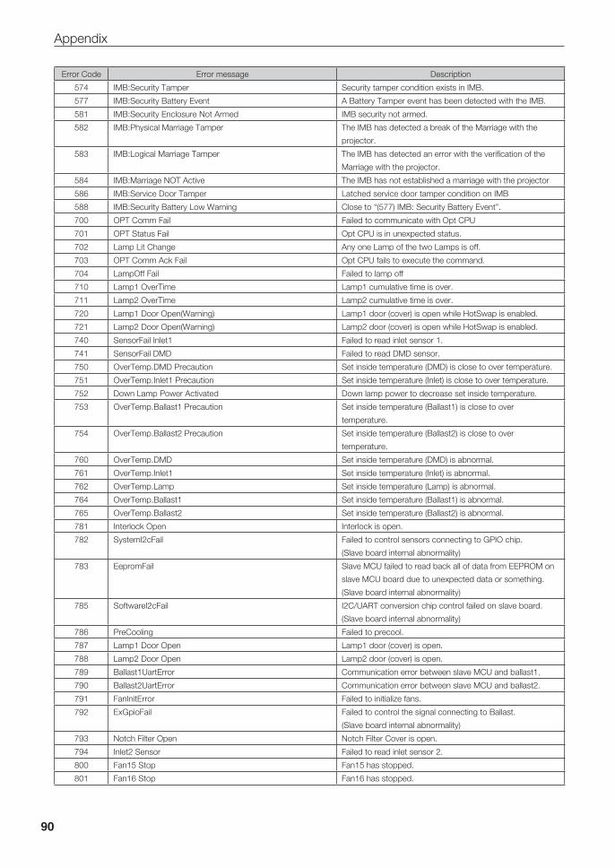
90
Appendix
Error Code Error message Description
574 IMB:Security Tamper Security tamper condition exists in IMB.
577 IMB:Security Battery Event A Battery Tamper event has been detected with the IMB.
581 IMB:Security Enclosure Not Armed IMB security not armed.
582 IMB:Physical Marriage Tamper The IMB has detected a break of the Marriage with the
projector.
583 IMB:Logical Marriage Tamper The IMB has detected an error with the verification of the
Marriage with the projector.
584 IMB:Marriage NOT Active The IMB has not established a marriage with the projector
586 IMB:Service Door Tamper Latched service door tamper condition on IMB
588 IMB:Security Battery Low Warning Close to “(577) IMB: Security Battery Event”.
700 OPT Comm Fail Failed to communicate with Opt CPU
701 OPT Status Fail Opt CPU is in unexpected status.
702 Lamp Lit Change Any one Lamp of the two Lamps is off.
703 OPT Comm Ack Fail Opt CPU fails to execute the command.
704 LampOff Fail Failed to lamp off
710 Lamp1 OverTime Lamp1 cumulative time is over.
711 Lamp2 OverTime Lamp2 cumulative time is over.
720 Lamp1 Door Open(Warning) Lamp1 door (cover) is open while HotSwap is enabled.
721 Lamp2 Door Open(Warning) Lamp2 door (cover) is open while HotSwap is enabled.
740 SensorFail Inlet1 Failed to read inlet sensor 1.
741 SensorFail DMD Failed to read DMD sensor.
750 OverTemp.DMD Precaution Set inside temperature (DMD) is close to over temperature.
751 OverTemp.Inlet1 Precaution Set inside temperature (Inlet) is close to over temperature.
752 Down Lamp Power Activated Down lamp power to decrease set inside temperature.
753 OverTemp.Ballast1 Precaution Set inside temperature (Ballast1) is close to over
temperature.
754 OverTemp.Ballast2 Precaution Set inside temperature (Ballast2) is close to over
temperature.
760 OverTemp.DMD Set inside temperature (DMD) is abnormal.
761 OverTemp.Inlet1 Set inside temperature (Inlet) is abnormal.
762 OverTemp.Lamp Set inside temperature (Lamp) is abnormal.
764 OverTemp.Ballast1 Set inside temperature (Ballast1) is abnormal.
765 OverTemp.Ballast2 Set inside temperature (Ballast2) is abnormal.
781 Interlock Open Interlock is open.
782 SystemI2cFail Failed to control sensors connecting to GPIO chip.
(Slave board internal abnormality)
783 EepromFail Slave MCU failed to read back all of data from EEPROM on
slave MCU board due to unexpected data or something.
(Slave board internal abnormality)
785 SoftwareI2cFail I2C/UART conversion chip control failed on slave board.
(Slave board internal abnormality)
786 PreCooling Failed to precool.
787 Lamp1 Door Open Lamp1 door (cover) is open.
788 Lamp2 Door Open Lamp2 door (cover) is open.
789 Ballast1UartError Communication error between slave MCU and ballast1.
790 Ballast2UartError Communication error between slave MCU and ballast2.
791 FanInitError Failed to initialize fans.
792 ExGpioFail Failed to control the signal connecting to Ballast.
(Slave board internal abnormality)
793 Notch Filter Open Notch Filter Cover is open.
794 Inlet2 Sensor Failed to read inlet sensor 2.
800 Fan15 Stop Fan15 has stopped.
801 Fan16 Stop Fan16 has stopped.
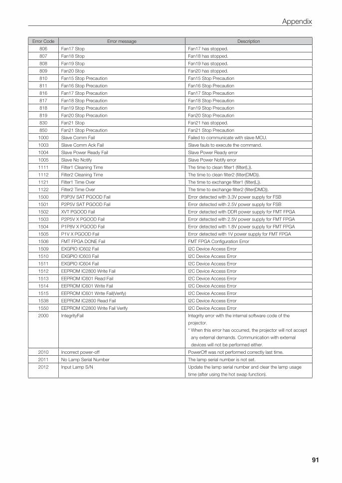
91
Appendix
Error Code Error message Description
806 Fan17 Stop Fan17 has stopped.
807 Fan18 Stop Fan18 has stopped.
808 Fan19 Stop Fan19 has stopped.
809 Fan20 Stop Fan20 has stopped.
810 Fan15 Stop Precaution Fan15 Stop Precaution
811 Fan16 Stop Precaution Fan16 Stop Precaution
816 Fan17 Stop Precaution Fan17 Stop Precaution
817 Fan18 Stop Precaution Fan18 Stop Precaution
818 Fan19 Stop Precaution Fan19 Stop Precaution
819 Fan20 Stop Precaution Fan20 Stop Precaution
830 Fan21 Stop Fan21 has stopped.
850 Fan21 Stop Precaution Fan21 Stop Precaution
1000 Slave Comm Fail Failed to communicate with slave MCU.
1003 Slave Comm Ack Fail Slave fauls to execute the command.
1004 Slave Power Ready Fail Slave Power Ready error
1005 Slave No Notify Slave Power Notify error
1111 Filter1 Cleaning Time The time to clean filter1 (filter(L)).
1112 Filter2 Cleaning Time The time to clean filter2 (filter(DMD)).
1121 Filter1 Time Over The time to exchange filter1 (filter(L)).
1122 Filter2 Time Over The time to exchange filter2 (filter(DMD)).
1500 P3P3V SAT PGOOD Fail Error detected with 3.3V power supply for FSB
1501 P2P5V SAT PGOOD Fail Error detected with 2.5V power supply for FSB
1502 XVT PGOOD Fail Error detected with DDR power supply for FMT FPGA
1503 P2P5V X PGOOD Fail Error detected with 2.5V power supply for FMT FPGA
1504 P1P8V X PGOOD Fail Error detected with 1.8V power supply for FMT FPGA
1505 P1V X PGOOD Fail Error detected with 1V power supply for FMT FPGA
1506 FMT FPGA DONE Fail FMT FPGA Configuration Error
1509 EXGPIO IC602 Fail I2C Device Access Error
1510 EXGPIO IC603 Fail I2C Device Access Error
1511 EXGPIO IC604 Fail I2C Device Access Error
1512 EEPROM IC2800 Write Fail I2C Device Access Error
1513 EEPROM IC601 Read Fail I2C Device Access Error
1514 EEPROM IC601 Write Fail I2C Device Access Error
1515 EEPROM IC601 Write Fail(Verify) I2C Device Access Error
1538 EEPROM IC2800 Read Fail I2C Device Access Error
1550 EEPROM IC2800 Write Fail Verify I2C Device Access Error
2000 IntegrityFail Integrity error with the internal software code of the
projector.
* When this error has occurred, the projector will not accept
any external demands. Communication with external
devices will not be performed either.
2010 Incorrect power-off PowerOff was not performed correctly last time.
2011 No Lamp Serial Number The lamp serial number is not set.
2012 Input Lamp S/N Update the lamp serial number and clear the lamp usage
time (after using the hot swap function).
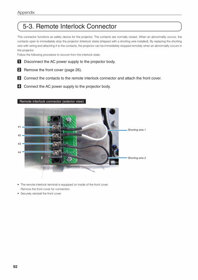
92
Appendix
5-3. Remote Interlock ConnectorThis connector functions as safety device for the projector. The contacts are normally closed. When an abnormality occurs, the
contacts open to immediately stop the projector (interlock state) (shipped with a shorting wire installed). By replacing the shorting
wire with wiring and attaching it to the contacts, the projector can be immediately stopped remotely when an abnormality occurs in
the projector.
Follow the following procedure to recover from the interlock state.
1 Disconnect the AC power supply to the projector body.
2 Remove the front cover (page 26).
3 Connect the contacts to the remote interlock connector and attach the front cover.
4 Connect the AC power supply to the projector body.
Remote interlock connector (exterior view)
#1
#2
#3
#4
Shorting wire 1
Shorting wire 2
• The remote interlock terminal is equipped on inside of the front cover.
Remove the front cover for connection.
• Securely reinstall the front cover.
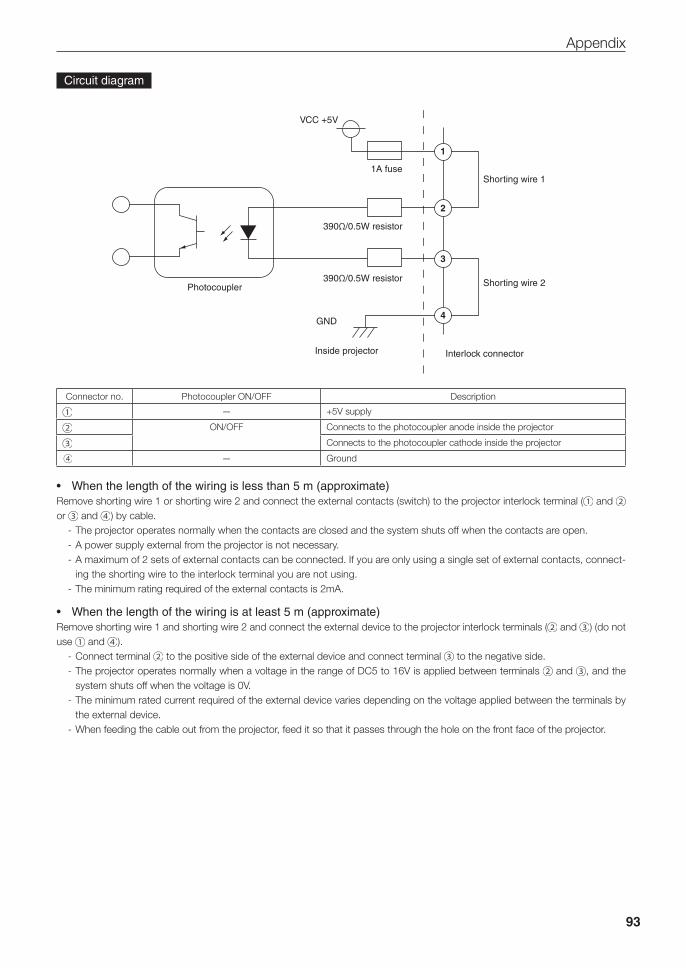
93
Appendix
Circuit diagram
1
2
3
4
Photocoupler
VCC +5V
1A fuse
390Ω/0.5W resistor
390Ω/0.5W resistor
GND
Inside projector
Shorting wire 1
Shorting wire 2
Interlock connector
Connector no. Photocoupler ON/OFF Description
— +5V supply
ON/OFF Connects to the photocoupler anode inside the projector
Connects to the photocoupler cathode inside the projector
— Ground
• Whenthelengthofthewiringislessthan5m(approximate)Remove shorting wire 1 or shorting wire 2 and connect the external contacts (switch) to the projector interlock terminal ( and or and ) by cable.
- The projector operates normally when the contacts are closed and the system shuts off when the contacts are open.- A power supply external from the projector is not necessary.- A maximum of 2 sets of external contacts can be connected. If you are only using a single set of external contacts, connect-
ing the shorting wire to the interlock terminal you are not using.- The minimum rating required of the external contacts is 2mA.
• Whenthelengthofthewiringisatleast5m(approximate)Remove shorting wire 1 and shorting wire 2 and connect the external device to the projector interlock terminals ( and ) (do not use and ).
- Connect terminal to the positive side of the external device and connect terminal to the negative side.- The projector operates normally when a voltage in the range of DC5 to 16V is applied between terminals and , and the
system shuts off when the voltage is 0V.- The minimum rated current required of the external device varies depending on the voltage applied between the terminals by
the external device.- When feeding the cable out from the projector, feed it so that it passes through the hole on the front face of the projector.
94
Appendix
5-4. Index
Numbers
3D Connector ..................................................................... 73
A
Adjust .................................................................................. 67
Auto Key Lock ..................................................................... 73
B
Baudrate ............................................................................. 78
C
Ceiling ....................................................................32, 54, 77
Configuration ...................................................................... 67
Connector ........................................................................... 36
D
Date setting ......................................................................... 53
Date/Time ........................................................................... 79
Douser Count ..................................................................... 71
Douser Setup ...................................................................... 72
E
Error Code ................................................................... 84, 88
Ethernet port....................................................................... 63
F
FactoryDefault .................................................................... 69
Fan Noise Reduction .......................................................... 80
Fan Speed Mode ................................................................ 79
Fan Tilt Setting ............................................................. 54, 77
Fan Usage .......................................................................... 71
Filter Cleaning..................................................................... 70
Filter cover ................................................................... 25, 30
Filter Usage ........................................................................ 70
Focus ........................................................................... 56, 68
Front cover ................................................................... 25, 26
I
Image Orient ....................................................................... 77
IMB .................................................................44, 76, 85, 86
Installation .......................................................................... 76
IP Address .......................................................................... 85
L
Lamp cover .................................................................. 25, 30
Lamp Mode ......................................................................... 67
Lamp Setup ........................................................................ 67
Lamp Usage ....................................................................... 70
LCD menu .......................................................................... 64
Lens Calibrate ..................................................................... 78
Lens Center ........................................................................ 78
Lens Control ....................................................................... 68
Lens Position ...................................................................... 68
Lens Type ..................................................................... 77, 83
Lens unit ...................................................................... 20, 41
Lens zoom magnification .................................................... 22
Level adjuster ..................................................................... 32
List of titles .......................................................................... 87
M
Media block............................................................44, 76, 86
N
Notch filter .......................................................................... 59
Notch filter cover ....................................................25, 30, 59
O
Off Timer ..............................................................................74
Option board ................................................................ 44, 62
Option lens ......................................................................... 23
Option Slot .......................................................................... 76
Option Status ...................................................................... 86
Orientation .......................................................................... 76
Output ................................................................................. 83
95
Appendix
P
Panel Key Lock ................................................................... 72
PC control terminal ............................................................. 63
Power cable ........................................................................ 33
Preset Button ............................................................... 82, 84
Projection method ............................................................... 54
Projector cover .................................................................... 25
R
Remote interlock connector ................................................ 92
Reset .................................................................................. 69
RS-232 ............................................................................... 63
S
Serial .................................................................................. 83
Service personnel menu ..................................................... 66
Setup .................................................................................. 72
Setup Date .......................................................................... 86
Side cover .................................................................... 25, 28
Silent Mode ..........................................................................74
System ................................................................................ 85
T
Tamper error ....................................................................... 49
Test Pattern ......................................................................... 66
Time setting ........................................................................ 53
Title Memory ....................................................................... 66
Title Select .......................................................................... 66
Title Setup .......................................................................... 82
U
Unlit Mode .......................................................................... 73
Usage ................................................................................. 84
V
Version ................................................................................ 85
Voltage ................................................................................ 83
VOLTAGE SELECT switch .................................................. 52
Z
Zoom .................................................................................. 68

96
(MEMO)
Appendix

© NEC Display Solutions, Ltd. 2016-2018Ver.2 1/18
Related Documents